Помогите разобраться с ошибками при создании netlist
Присоединяйтесь к обсуждению
Вы можете написать сейчас и зарегистрироваться позже.
Если у вас есть аккаунт, авторизуйтесь, чтобы опубликовать от имени своего аккаунта.
Skip to main content
![]()
![]()
Welcome to EDAboard.com
Welcome to our site! EDAboard.com is an international Electronics Discussion Forum focused on EDA software, circuits, schematics, books, theory, papers, asic, pld, 8051, DSP, Network, RF, Analog Design, PCB, Service Manuals… and a whole lot more! To participate you need to register. Registration is free. Click here to register now.
-
EDA Software
-
Software Problems, Hints and Reviews
You are using an out of date browser. It may not display this or other websites correctly.
You should upgrade or use an alternative browser.
Orcad Capture cis lite 16.6 error
-
Thread starterjainjose
-
Start dateJun 23, 2016
- Status
- Not open for further replies.
-
#1
- Joined
- May 27, 2016
- Messages
- 6
- Helped
- 0
- Reputation
-
0
- Reaction score
- 0
- Trophy points
- 1
- Activity points
-
49
Hello,
Am using Orcad Capture CIS Lite 16.6 and when am running a simple circuit i get the following error for INA103 component.
WARNING(ORNET-1119): The part/device cannot be simulated. No PSpiceTemplate found on U1, ignoring this part/device from simulation netlist.
Thanks in Advance.
-
#2
- Joined
- Jul 25, 2015
- Messages
- 34
- Helped
- 0
- Reputation
-
2
- Reaction score
- 1
- Trophy points
- 8
- Activity points
-
263
X^@REFDES %ANODE %CATHODE @MODEL
part property pspicetemplate
(that is for a diode part)
select the part, properties, add or edit the pspicetemplate
- Status
- Not open for further replies.
-
EDA Software
-
Software Problems, Hints and Reviews
-
This site uses cookies to help personalise content, tailor your experience and to keep you logged in if you register.
By continuing to use this site, you are consenting to our use of cookies.
ki9 Asks: Two public IPs from a single interface to two routers
My ISP provides me with two static public IP addresses which come in on the same ethernet wire. I want to use two routers (running OpenWrt) with one public IP per router. To achieve this, I have a Debian 11 machine (which I will call «the box») to direct traffic for each IP to its respective router.
So I want traffic for IP X.X.X.2 to go to Router A and traffic for X.X.X.3 to go to Router B. The ISP provided X.X.X.1 as the gateway address. These are all global IP addresses. In this example, I’ve named the interfaces «wan», «lan1», and «lan2» as below:
Code:
               ISP
                │
           ┌────▼─────┐
           │   wan    │
           │          │
           │ THE BOX  │
           │          │
     ┌─────┤lan1  lan2├────┐
     │     └──────────┘    │
     │                     │
┌────▼─────┐          ┌────▼─────┐
│   wan    │          │   wan    │
│          │          │          │
│ ROUTER A │          │ ROUTER B │
│          │          │          │
└──────────┘          └──────────┘
What I’ve tried to do is assign X.X.X.2/32 to Router A’s wan interface. Correct me if I’m wrong, but my thinking is that none of the box’s interfaces should be assigned an IP address, because it only forwards traffic, and is not the final destination for any packets. I suppose this means it will be unable to access the internet itself.
With the static address and routes configured, Router A looks like this:
Code:
root@RouterA:~# ip addr show dev wan
7: wan@eth0: <BROADCAST,MULTICAST,UP,LOWER_UP> mtu 1500 qdisc noqueue state UP qlen 1000
    link/ether ZZ:ZZ:ZZ:ZZ:ZZ:ZZ brd ff:ff:ff:ff:ff:ff
    inet X.X.X.2/32 brd 255.255.255.255 scope global wan
       valid_lft forever preferred_lft forever
root@RouterA:~# ip route
default via X.X.X.1 dev wan
X.X.X.1 dev wan scope link
And on the box, I set no static IPs on any interfaces and created these static routes:
Code:
root@TheBox:~# ip route
default via X.X.X.1 dev wan
X.X.X.1 dev wan scope link
X.X.X.2 dev lan1 scope link
X.X.X.3 dev lan2 scope link
Then I try to ping the ISP’s gateway address (X.X.X.1) from Router A and get 100% packet loss. To check that the packets are being sent to the box correctly, I ran a packet sniffer on the box and got some ARP requests:
Code:
root@TheBox:~# tcpdump -i lan1 -vv
14:55:48.202508 ARP, Etherenet (len 6), IPv4 (len 4), Request who-has X.X.X.1 tell X.X.X.2, length 46
14:55:49.212438 ARP, Etherenet (len 6), IPv4 (len 4), Request who-has X.X.X.1 tell X.X.X.2, length 46
14:55:50.252491 ARP, Etherenet (len 6), IPv4 (len 4), Request who-has X.X.X.1 tell X.X.X.2, length 46
The fact that the box has no assigned IP address makes me think that I might need to hardcode the gateway’s MAC address in there somewhere. That’s as far as I’ve gotten; I don’t know much about layer 2.
Similar questions:
- How to assign IPs in server interfaces when connected to two similar routers [closed]: Vague wording, doesn’t answer my question
- Two routers, one modem, dual IPs, second address drops connection occasionally: Same setup but with a different OS and solution was «defective router»
SolveForum.com may not be responsible for the answers or solutions given to any question asked by the users. All Answers or responses are user generated answers and we do not have proof of its validity or correctness. Please vote for the answer that helped you in order to help others find out which is the most helpful answer. Questions labeled as solved may be solved or may not be solved depending on the type of question and the date posted for some posts may be scheduled to be deleted periodically. Do not hesitate to share your thoughts here to help others.
$begingroup$
I’m doing a schematic on OrCAD and when I did the Design Rules Check I got a warning that says:
Checking Electrical Rules
WARNING(ORCAP-1608): Net has no driving source N30274
I have a fairly large circuit that spans three pages, so is there any way that I could search for where the error happened? And what does this warning mean? I don’t have any part called N30274.
asked Mar 8, 2015 at 7:53
![]()
$endgroup$
1
$begingroup$
N30274 is the name of the net connecting two parts. If you go to your top level in the design explorer and do a search with that name you will find it. Orcad auto generates net names for every wire connection you make.
Like Andy says it’s trying to warn you that you have an input with no output, but it’s probably not an issue. If you edit the part in the library and right click on the pin I think you can see properties. One will have a pull down for input, output, passive, etc. if you set it to passive for both parts connected to that bet the warning will go away.
Personally I never use this feature and just set things to passive all the time, but it could be useful say to protect yourself from hooking up a serial port wrong. It only makes sense if when you build all your library parts that you set the correct attribute for each pin. Otherwise you’ll always find warnings like this.
answered Mar 8, 2015 at 15:05
![]()
$endgroup$
$begingroup$
When you do a design rule check there is a radio box you can tick that displays warnings directly on the circuit. They look like green circles.
This warning is trivial if in reality — it means that all devices sharing that common net are not designated as an output. Normally one is an output whilst the others are inputs or passive. This is set up in the part library editor but, like I say it’s trivial.
answered Mar 8, 2015 at 9:25
![]()
Andy akaAndy aka
427k28 gold badges347 silver badges758 bronze badges
$endgroup$
$begingroup$
Maybe the net is floating over. I have used Orcad long time ago and I couldn’t find a clear solution.
The net will be associated by the component names too. So you can easily identify which net is that. Check the netlist once again.
answered Mar 8, 2015 at 8:46
![]()
$endgroup$
PSpice Tip) ERROR(ORPSIM-15142): Node (노드명) is floating
![]()
PSpice
![]()
2017. 10. 30. 13:56
![]()
https://blog.naver.com/kingreddrake/221128487289
«ERROR(ORPSIM-15142): Node (노드명) is floating«의 경우 해당 노드가 0 그라운드(기준전압)와 로직적으로 연결이 되지 않아 발생하는 에러입니다.
1. 0 그라운드가 없는 경우
원인:
에러가 발생하는 첫번째 이유는 0 그라운드 가 없는 경우 입니다. 아래와 같은 경우에 발생합니다.

( 그라운드를 배치 하지 않았을 경우)

(0 그라운드 외의 그라운드를 배치하였을 경우)
위와 같은 경우 Capture 창에서 «WARNING(ORNET-1039): Warnings were reported. check Session Log»라는 메세지 창과 함께 …

세션창에서 «WARNING(ORNET-1085): Your design does not contain a Ground (0) net. You may not be able to run analog simulation on this design. To run analog simulation, your design must have?at least one?Ground (0) net. Use at least one PSpice Ground (0) symbol in the design. Ignore this warning, if this is a digital design.
INFO(ORNET-1156): PSpice netlist generation complete» 이라는 메세지가 출력되며,..

PSpice A/D 창에서 «ERROR(ORPSIM-15142): Node (노드명) is floating»에 메세지가 출력됩니다.

해결1:
Place Power(또는 Place Ground)를 클릭합니다. 그리고 0/CAPSYM, O/SOURCE 중에 하나를 선택합니다.
( Symbol 이름이 0 이며, 라이브러리 파일 이름이 CAPSYM과 SOURCE 입니다.)

그리고 기준 전압 위치에 0그라운드를 배치합니다.

해결2:
Place Net Alias를 클릭한 다음 Alias에 0을 입력하고 OK 버튼을 클릭합니다.

그리고 기준전압의 NET(Wire)에 배치합니다.

2. C (커패시터)가 있는경우
원인 1 :
아래 그림과 같이 커패시터가 2개가 직렬로 연결되어 있는 경우에 그림의 ERR 넷은 «ERROR(ORPSIM-15142): Node (노드명) is floating» 에러가 발생합니다.


이는 Bias Point 해석 단계(Time Domain, AC Sweep, DC Sweep 의 모든 해석에서 먼저 Bias Point를 실행하게 됩니다.)에서 회로를 직류 전압에 대하여 해석 시 커패시터는 Open (단선)된 상태가 되게 때문에 아래 그림과 같이 ERR 노드는 0그라운드와 연결이 되지 않는 상태가 됩니다.

해결 1 :
커패시터와 병렬로 1G의 큰 저항을 연결하여 시뮬레이션하면 됩니다.


원인 2 :
아래 그림과 같이 전류원과 커패시터가 직렬로 연결된 상태에서는 커패시터 양단의 전압을 알 수 없는 상태 이기 때문에 …

Bias Point 계산 단계에서 «ERROR(ORPSIM-15142): Node (노드명) is floating» 가 발생합니다.

해결 2 :
전류원의 경우 전류원과 병렬로 1G의 큰저항을 연결합니다.

큰 전항을 연결하면 아래 그림과 같이 결과가 출력됩니다.

PS. 전압원을 이용하여 출력한 임피던스와 전류로 출력한 임피던스 결과 같이 동일.
( V=IZ 이므로 I가 1일 경우 V=Z, Z=V/I에서 V가 1일 경우 Z=1/I)

Skip to main content
![]()
![]()
Welcome to EDAboard.com
Welcome to our site! EDAboard.com is an international Electronics Discussion Forum focused on EDA software, circuits, schematics, books, theory, papers, asic, pld, 8051, DSP, Network, RF, Analog Design, PCB, Service Manuals… and a whole lot more! To participate you need to register. Registration is free. Click here to register now.
-
EDA Software
-
Software Problems, Hints and Reviews
You should upgrade or use an alternative browser.
Orcad Capture cis lite 16.6 error
-
Thread starterjainjose
-
Start date
- Status
- Not open for further replies.
-
#1
- Joined
- May 27, 2016
- Messages
- 6
- Helped
- 0
- Reputation
-
0
- Reaction score
- 0
- Trophy points
- 1
- Activity points
-
49
Am using Orcad Capture CIS Lite 16.6 and when am running a simple circuit i get the following error for INA103 component.
WARNING(ORNET-1119): The part/device cannot be simulated. No PSpiceTemplate found on U1, ignoring this part/device from simulation netlist.
Thanks in Advance.
-
#2
- Joined
- Jul 25, 2015
- Messages
- 34
- Helped
- 1
- Reputation
-
2
- Reaction score
- 1
- Trophy points
- 8
- Activity points
-
263
part property pspicetemplate
(that is for a diode part)
select the part, properties, add or edit the pspicetemplate
- Status
- Not open for further replies.
-
EDA Software
-
Software Problems, Hints and Reviews
-
This site uses cookies to help personalise content, tailor your experience and to keep you logged in if you register.
By continuing to use this site, you are consenting to our use of cookies.

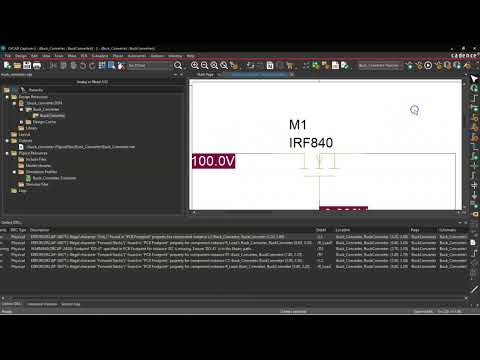
ORCOMMN-2302 Error
Kirsch Mackey
This error can happen when you try to start a new PSPICE simulation profile in OrCAD Capture, but it won’t let you.
No worries though. There is a simple way you can fix this…
First, Close OrCAD Capture.
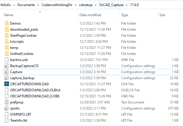
Then go to Windows File Explorer, and enter this: %HOME% and hit Enter. This will take you to the installation directory for your OrCAD software.
Rename the PSPICE.ini file
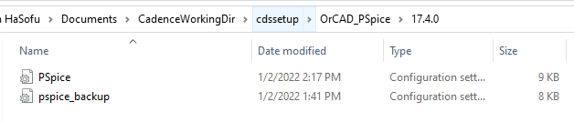
Go into the cdssetup > OrCAD PSpice > 17.x. folder within that folder.
Rename the PSpice.ini file to pspice_backup.ini.
Repeat this by going into the cdssetup > OrCAD Capture > 17.x. Capture.ini to capture_backup.ini.
Then re-open OrCAD Capture.
Try the simulation again. That should fix the problem.
More information can be found here:
https://techsupport.ema-eda.com/support/solutions/articles/48000971419-delete-the-pspice-and-capture-ini-file
As an electrical engineer, it’s hard to keep up with project tasks at work, while also making you’re making maximum use of your electrical engineering PCB design software.
Get some support from our team so you can spend more time designing and doing your best creative work with your team.
Email us at [email protected] or call 972-559-9232 to set up a call today.
Created with