 Loading…
![]()
Cat. No. I533-E1-04
SMARTSTEP A SERIES
R7M-A@ (Servomotors)
R7D-AP@ (Servo Drivers)
Servomotors/Servo Drivers
USER’S MANUAL

Thank you for choosing this SMARTSTEP A-series product. Proper use and handling of the product will ensure proper product performance, will lengthen product life, and may prevent possible accidents.
Please read this manual thoroughly and handle and operate the product with care. Please keep this manual handy for reference after reading it.
1.To ensure safe and proper use of the OMRON Inverters, please read this USER’S MANUAL (Cat. No. I533-E1) to gain sufficient knowledge of the devices, safety information, and precautions before actual use.
2.The products are illustrated without covers and shieldings for closer look in this USER’S MANUAL. For actual use of the products, make sure to use the covers and shieldings as specified.
3.This USER’S MANUAL and other related user’s manuals are to be delivered to the actual end users of the products.
4.Please keep this manual close at hand for future reference.
5.If the product has been left unused for a long time, please inquire at our sales representative.
NOTICE
1.This manual describes information about installation, wiring, switch setting, and troubleshooting of the SMARTSTEP A-series Servomotors and Servo Drivers. For information about actual operating procedures using a Parameter Unit, refer to the SMARTSTEP A Series Operation Manual (I534).
2.Be sure that this manual accompanies the product to its final user.
3.Although care has been given in documenting the product, please contact your OMRON representative if you have any suggestions on improving this manual.
4.Assume that anything not specifically described in this manual is not possible.
5.Do not allow the Servomotor or Servo Driver to be wired, set, or operated (from a Parameter Unit) by anyone that is not a profession electrical engineer or the equivalent.
6.We recommend that you add the following precautions to any instruction manuals you prepare for the system into which the product is being installed.
•Precautions on the dangers of high-voltage equipment.
•Precautions on touching the terminals of the product even after power has been turned OFF. (These terminals are live even with the power turned OFF.)
7.Specifications and functions may be changed without notice in order to improve product performance.
8.Positive and negative rotation of AC Servomotors described in this manual are defined as looking at the end of the output shaft of the motor as follows: Counterclockwise rotation is positive and clockwise rotation is negative.
9.Do not perform withstand-voltage or other megameter tests on the product. Doing so may damage internal components.
10.Servomotors and Servo Drivers have a finite service life. Be sure to keep replacement products on hand and to consider the operating environment and other conditions affecting the service life.
11.Do not set values for any parameters not described in this manual. Operating errors may result. Consult your OMRON representative if you have questions.
12.Before using the product under conditions which are not described in the manual or applying the product to nuclear control systems, railroad systems, aviation systems, vehicles, combustion systems, medical equipment, amusement machines, safety equipment, and other systems, machines, and equipment that may have a serious influence on lives and property if used improperly, consult your OMRON representative.
Items to Check Before Unpacking
1.Check the following items before removing the product from the package:
•Has the correct product been delivered (i.e., the correct model number and specifications)?
•Has the product been damaged in shipping?
2.Check that the following accessories have been delivered.
•Safety Precautions
No connectors or mounting screws are provided. Obtain these separately.

USER’S MANUAL
SMARTSTEP ASERIES
MODELS R7M-A@ (Servomotors)
R7D-AP@ (Servo Drivers)
Servomotors/Servo Drivers
Notice:
OMRON products are manufactured for use according to proper procedures by a qualified operator and only for the purposes described in this manual.
The following conventions are used to indicate and classify precautions in this manual. Always heed the information provided with them. Failure to heed precautions can result in injury to people or damage to property.
!DANGER Indicates an imminently hazardous situation which, if not avoided, will result in death or serious injury. Additionally, there may be severe property damage.
!WARNING Indicates a potentially hazardous situation which, if not avoided, could result in death or serious injury. Additionally, there may be severe property damage.
!Caution Indicates a potentially hazardous situation which, if not avoided, may result in minor or moderate injury, or property damage.
OMRON Product References
All OMRON products are capitalized in this manual. The word “Unit” is also capitalized when it refers to an OMRON product, regardless of whether or not it appears in the proper name of the product.
The abbreviation “Ch,” which appears in some displays and on some OMRON products, often means “word” and is abbreviated “Wd” in documentation in this sense.
The abbreviation “PC” means Programmable Controller and is not used as an abbreviation for anything else.
Visual Aids
The following headings appear in the left column of the manual to help you locate different types of information.
Note Indicates information of particular interest for efficient and convenient operation of the product.
OMRON, 2001
All rights reserved. No part of this publication may be reproduced, stored in a retrieval system, or transmitted, in any form, or by any means, mechanical, electronic, photocopying, recording, or otherwise, without the prior written permission of OMRON.
No patent liability is assumed with respect to the use of the information contained herein. Moreover, because OMRON is constantly striving to improve its high-quality products, the information contained in this manual is subject to change without notice. Every precaution has been taken in the preparation of this manual. Nevertheless, OMRON assumes no responsibility for errors or omissions. Neither is any liability assumed for damages resulting from the use of the information contained in this publication.
General Warnings
Observe the following warnings when using the SMARTSTEP Servomotor and Servo Driver and all connected or peripheral devices.
This manual may include illustrations of the product with protective covers removed in order to describe the components of the product in detail. Make sure that these protective covers are on the product before use.
Consult your OMRON representative when using the product after a long period of storage.
!WARNING Always connect the frame ground terminals of the Servo Driver and the Servomotor to a class-3 ground (to 100 Ω or less). Not connecting to a class-3 ground may result in electric shock.
!WARNING Do not touch the inside of the Servo Driver. Doing so may result in electric shock.
!WARNING Do not remove the front cover, terminal covers, cables, or optional items while the power is being supplied. Doing so may result in electric shock.
!WARNING Installation, operation, maintenance, or inspection must be performed by authorized personnel. Not doing so may result in electric shock or injury.
!WARNING Wiring or inspection must not be performed for at least five minutes after turning OFF the power supply. Doing so may result in electric shock.
!WARNING Do not damage, press, or put excessive stress or heavy objects on the cables. Doing so may result in electric shock.
!WARNING Do not touch the rotating parts of the Servomotor in operation. Doing so may result in injury.
!WARNING Do not modify the product. Doing so may result in injury or damage to the product.
!WARNING Provide a stopping mechanism on the machine to ensure safety. The holding brake is not designed as a stopping mechanism for safety purposes.
!WARNING Provide an external emergency stopping mechanism that can stop operation and shutting off the power supply immediately. Not doing so may result in injury.
!WARNING Do not come close to the machine immediately after resetting momentary power interruption to avoid an unexpected restart. (Take appropriate measures to secure safety against an unexpected restart.) Doing so may result in injury.
!Caution Use the Servomotors and Servo Drivers in a specified combination. Using them incorrectly may result in fire or damage to the products.
!Caution Do not store or install the product in the following places. Doing so may result in fire, electric shock, or damage to the product.
•Locations subject to direct sunlight.
•Locations subject to temperatures or humidity outside the range specified in the specifications.
•Locations subject to condensation as the result of severe changes in temperature.
•Locations subject to corrosive or flammable gases.
•Locations subject to dust (especially iron dust) or salts.
•Locations subject to shock or vibration.
•Locations subject to exposure to water, oil, or chemicals.
!Caution Do not touch the Servo Driver radiator, Servo Driver regeneration resistor, or Servomotor while the power is being supplied or soon after the power is turned OFF. Doing so may result in a skin burn due to the hot surface.
Storage and Transportation Precautions
!Caution Do not hold the product by the cables or motor shaft while transporting it. Doing so may result in injury or malfunction.
!Caution Do not place any load exceeding the figure indicated on the product. Doing so may result in injury or malfunction.
Installation and Wiring Precautions
!Caution Do not step on or place a heavy object on the product. Doing so may result in injury.
!Caution Do not cover the inlet or outlet ports and prevent any foreign objects from entering the product. Doing so may result in fire.
!Caution Be sure to install the product in the correct direction. Not doing so may result in malfunction.
!Caution Provide the specified clearances between the Servo Driver and the control panel or with other devices. Not doing so may result in fire or malfunction.
!Caution Do not apply any strong impact. Doing so may result in malfunction.
!Caution Be sure to wire correctly and securely. Not doing so may result in motor runaway, injury, or malfunction.
!Caution Be sure that all the mounting screws, terminal screws, and cable connector screws are tightened to the torque specified in the relevant manuals. Incorrect tightening torque may result in malfunction.
!Caution Use crimp terminals for wiring. Do not connect bare stranded wires directly to terminals. Connection of bare stranded wires may result in burning.
!Caution Always use the power supply voltage specified in the User’s Manual. An incorrect voltage may result in malfunction or burning.
!Caution Take appropriate measures to ensure that the specified power with the rated voltage and frequency is supplied. Be particularly careful in places where the power supply is unstable. An incorrect power supply may result in malfunction.
!Caution Install external breakers and take other safety measures against short-circuiting in external wiring. Insufficient safety measures against short-circuiting may result in burning.
!Caution Take appropriate and sufficient countermeasures when installing systems in the following locations. Failure to do so may result in damage to the product.
•Locations subject to static electricity or other forms of noise.
•Locations subject to strong electromagnetic fields and magnetic fields.
•Locations subject to possible exposure to radioactivity.
•Locations close to power supplies.
Operation and Adjustment Precautions
!Caution Confirm that no adverse effects will occur in the system before performing the test operation. Not doing so may result in equipment damage.
!Caution Check the newly set parameters and switches for proper execution before actually running them. Not doing so may result in equipment damage.
!Caution Do not make any extreme adjustments or setting changes. Doing so may result in unstable operation and injury.
!Caution Separate the Servomotor from the machine, check for proper operation, and then connect to the machine. Not doing so may cause injury.
!Caution When an alarm occurs, remove the cause, reset the alarm after confirming safety, and then resume operation. Not doing so may result in injury.
!Caution Do not use the built-in brake of the Servomotor for ordinary braking. Doing so may result in malfunction.
Maintenance and Inspection Precautions
!WARNING Do not attempt to disassemble, repair, or modify any Units. Any attempt to do so may result in malfunction, fire, or electric shock.
!Caution Resume operation only after transferring to the new Unit the contents of the data required for operation. Not doing so may result in an unexpected operation.
![]()
Warning Labels
Warning labels are pasted on the product as shown in the following illustration. Be sure to follow the instructions given there.
Warning label
Example from R7D-AP01L
Example from R7D-AP01L

Read and Understand this Manual
Please read and understand this manual before using the product. Please consult your OMRON representative if you have any questions or comments.
Warranty and Limitations of Liability
WARRANTY
OMRON’s exclusive warranty is that the products are free from defects in materials and workmanship for a period of one year (or other period if specified) from date of sale by OMRON.
OMRON MAKES NO WARRANTY OR REPRESENTATION, EXPRESS OR IMPLIED, REGARDING NONINFRINGEMENT, MERCHANTABILITY, OR FITNESS FOR PARTICULAR PURPOSE OF THE PRODUCTS. ANY BUYER OR USER ACKNOWLEDGES THAT THE BUYER OR USER ALONE HAS DETERMINED THAT THE PRODUCTS WILL SUITABLY MEET THE REQUIREMENTS OF THEIR INTENDED USE. OMRON DISCLAIMS ALL OTHER WARRANTIES, EXPRESS OR IMPLIED.
LIMITATIONS OF LIABILITY
OMRON SHALL NOT BE RESPONSIBLE FOR SPECIAL, INDIRECT, OR CONSEQUENTIAL DAMAGES, LOSS OF PROFITS OR COMMERCIAL LOSS IN ANY WAY CONNECTED WITH THE PRODUCTS, WHETHER SUCH CLAIM IS BASED ON CONTRACT, WARRANTY, NEGLIGENCE, OR STRICT LIABILITY.
In no event shall the responsibility of OMRON for any act exceed the individual price of the product on which liability is asserted.
IN NO EVENT SHALL OMRON BE RESPONSIBLE FOR WARRANTY, REPAIR, OR OTHER CLAIMS REGARDING THE PRODUCTS UNLESS OMRON’S ANALYSIS CONFIRMS THAT THE PRODUCTS WERE PROPERLY HANDLED, STORED, INSTALLED, AND MAINTAINED AND NOT SUBJECT TO CONTAMINATION, ABUSE, MISUSE, OR INAPPROPRIATE MODIFICATION OR REPAIR.

Application Considerations
SUITABILITY FOR USE
OMRON shall not be responsible for conformity with any standards, codes, or regulations that apply to the combination of products in the customer’s application or use of the products.
At the customer’s request, OMRON will provide applicable third party certification documents identifying ratings and limitations of use that apply to the products. This information by itself is not sufficient for a complete determination of the suitability of the products in combination with the end product, machine, system, or other application or use.
The following are some examples of applications for which particular attention must be given. This is not intended to be an exhaustive list of all possible uses of the products, nor is it intended to imply that the uses listed may be suitable for the products:
•Outdoor use, uses involving potential chemical contamination or electrical interference, or conditions or uses not described in this manual.
•Nuclear energy control systems, combustion systems, railroad systems, aviation systems, medical equipment, amusement machines, vehicles, safety equipment, and installations subject to separate industry or government regulations.
•Systems, machines, and equipment that could present a risk to life or property.
Please know and observe all prohibitions of use applicable to the products.
NEVER USE THE PRODUCTS FOR AN APPLICATION INVOLVING SERIOUS RISK TO LIFE OR PROPERTY WITHOUT ENSURING THAT THE SYSTEM AS A WHOLE HAS BEEN DESIGNED TO ADDRESS THE RISKS, AND THAT THE OMRON PRODUCTS ARE PROPERLY RATED AND INSTALLED FOR THE INTENDED USE WITHIN THE OVERALL EQUIPMENT OR SYSTEM.
PROGRAMMABLE PRODUCTS
OMRON shall not be responsible for the user’s programming of a programmable product, or any consequence thereof.

Disclaimers
CHANGE IN SPECIFICATIONS
Product specifications and accessories may be changed at any time based on improvements and other reasons.
It is our practice to change model numbers when published ratings or features are changed, or when significant construction changes are made. However, some specifications of the products may be changed without any notice. When in doubt, special model numbers may be assigned to fix or establish key specifications for your application on your request. Please consult with your OMRON representative at any time to confirm actual specifications of purchased products.
DIMENSIONS AND WEIGHTS
Dimensions and weights are nominal and are not to be used for manufacturing purposes, even when tolerances are shown.
PERFORMANCE DATA
Performance data given in this manual is provided as a guide for the user in determining suitability and does not constitute a warranty. It may represent the result of OMRON’s test conditions, and the users must correlate it to actual application requirements. Actual performance is subject to the OMRON Warranty and Limitations of Liability.
ERRORS AND OMISSIONS
The information in this manual has been carefully checked and is believed to be accurate; however, no responsibility is assumed for clerical, typographical, or proofreading errors, or omissions.
|
Table of Contents |
|||||
|
Chapter 1. Introduction. . . . . . . . . . . . . . . . . . . . . . . . . . . . . . . . . . . . |
1-1 |
||||
|
1-1 |
Features. . . . . . . . . . . . . . . . . . . . . . . . . . . . . . . . . . . . . . . . . . . . . . . . . . . . . . . . . . . . . . . . . . |
1-2 |
|||
|
1-2 |
System Configuration . . . . . . . . . . . . . . . . . . . . . . . . . . . . . . . . . . . . . . . . . . . . . . . . . . . . . . . |
1-4 |
|||
|
1-3 |
Servo Driver Nomenclature . . . . . . . . . . . . . . . . . . . . . . . . . . . . . . . . . . . . . . . . . . . . . . . . . . |
1-5 |
|||
|
1-4 |
Applicable Standards . . . . . . . . . . . . . . . . . . . . . . . . . . . . . . . . . . . . . . . . . . . . . . . . . . . . . . . |
1-6 |
|||
|
1-5 |
System Block Diagrams . . . . . . . . . . . . . . . . . . . . . . . . . . . . . . . . . . . . . . . . . . . . . . . . . . . . . |
1-7 |
|||
|
Chapter 2. Standard Models and Specifications. . . . . . . . . . . . . . . . |
2-1 |
||||
|
2-1 |
Standard Models. . . . . . . . . . . . . . . . . . . . . . . . . . . . . . . . . . . . . . . . . . . . . . . . . . . . . . . . . . . |
2-2 |
|||
|
2-2 |
External and Mounted Dimensions . . . . . . . . . . . . . . . . . . . . . . . . . . . . . . . . . . . . . . . . . . . . |
2-6 |
|||
|
2-3 |
Servo Driver Specifications . . . . . . . . . . . . . . . . . . . . . . . . . . . . . . . . . . . . . . . . . . . . . . . . . . |
2-17 |
|||
|
2-4 |
Servomotor Specifications . . . . . . . . . . . . . . . . . . . . . . . . . . . . . . . . . . . . . . . . . . . . . . . . . . . |
2-31 |
|||
|
2-5 |
Reduction Gear Specifications . . . . . . . . . . . . . . . . . . . . . . . . . . . . . . . . . . . . . . . . . . . . . . . . |
2-39 |
|||
|
2-6 |
Cable and Connector Specifications. . . . . . . . . . . . . . . . . . . . . . . . . . . . . . . . . . . . . . . . . . . . |
2-43 |
|||
|
2-7 |
Servo Relay Units and Cable Specifications . . . . . . . . . . . . . . . . . . . . . . . . . . . . . . . . . . . . . |
2-58 |
|||
|
2-8 |
Parameter Unit Specifications . . . . . . . . . . . . . . . . . . . . . . . . . . . . . . . . . . . . . . . . . . . . . . . . |
2-111 |
|||
|
2-9 |
External Regeneration Resistor Specifications. . . . . . . . . . . . . . . . . . . . . . . . . . . . . . . . . . . . |
2-113 |
|||
|
2-10 |
DC Reactors . . . . . . . . . . . . . . . . . . . . . . . . . . . . . . . . . . . . . . . . . . . . . . . . . . . . . . . . . . . . . . |
2-114 |
|||
|
Chapter 3. System Design and Installation . . . . . . . . . . . . . . . . . . . . |
3-1 |
||||
|
3-1 |
Installation Conditions . . . . . . . . . . . . . . . . . . . . . . . . . . . . . . . . . . . . . . . . . . . . . . . . . . . . . . |
3-3 |
|||
|
3-2 |
Wiring. . . . . . . . . . . . . . . . . . . . . . . . . . . . . . . . . . . . . . . . . . . . . . . . . . . . . . . . . . . . . . . . . . . |
3-8 |
|||
|
3-3 |
Regenerative Energy Absorption . . . . . . . . . . . . . . . . . . . . . . . . . . . . . . . . . . . . . . . . . . . . . . |
3-37 |
|||
|
Chapter 4. Operation. . . . . . . . . . . . . . . . . . . . . . . . . . . . . . . . . . . . . . |
4-1 |
||||
|
4-1 |
Operational Procedure . . . . . . . . . . . . . . . . . . . . . . . . . . . . . . . . . . . . . . . . . . . . . . . . . . . . . . |
4-3 |
|||
|
4-2 |
Switch Settings . . . . . . . . . . . . . . . . . . . . . . . . . . . . . . . . . . . . . . . . . . . . . . . . . . . . . . . . . . . . |
4-4 |
|||
|
4-3 |
Preparing for Operation . . . . . . . . . . . . . . . . . . . . . . . . . . . . . . . . . . . . . . . . . . . . . . . . . . . . . |
4-7 |
|||
|
4-4 |
Trial Operation . . . . . . . . . . . . . . . . . . . . . . . . . . . . . . . . . . . . . . . . . . . . . . . . . . . . . . . . . . . . |
4-9 |
|||
|
4-5 |
Gain Adjustments . . . . . . . . . . . . . . . . . . . . . . . . . . . . . . . . . . . . . . . . . . . . . . . . . . . . . . . . . . |
4-11 |
|||
|
4-6 |
User Parameters . . . . . . . . . . . . . . . . . . . . . . . . . . . . . . . . . . . . . . . . . . . . . . . . . . . . . . . . . . . |
4-15 |
|||
|
4-7 |
Operating Functions . . . . . . . . . . . . . . . . . . . . . . . . . . . . . . . . . . . . . . . . . . . . . . . . . . . . . . . . |
4-26 |
|||
|
Chapter 5. Troubleshooting . . . . . . . . . . . . . . . . . . . . . . . . . . . . . . . . |
5-1 |
||||
|
5-1 |
Measures when Trouble Occurs . . . . . . . . . . . . . . . . . . . . . . . . . . . . . . . . . . . . . . . . . . . . . . . |
5-2 |
|||
|
5-2 |
Alarms . . . . . . . . . . . . . . . . . . . . . . . . . . . . . . . . . . . . . . . . . . . . . . . . . . . . . . . . . . . . . . . . . . |
5-5 |
|||
|
5-3 |
Troubleshooting . . . . . . . . . . . . . . . . . . . . . . . . . . . . . . . . . . . . . . . . . . . . . . . . . . . . . . . . . . . |
5-7 |
|||
|
5-4 |
Overload Characteristics (Electron Thermal Characteristics) . . . . . . . . . . . . . . . . . . . . . . . . |
5-15 |
|||
|
5-5 |
Periodic Maintenance . . . . . . . . . . . . . . . . . . . . . . . . . . . . . . . . . . . . . . . . . . . . . . . . . . . . . . . |
5-16 |
|||
|
Chapter 6. Appendix . . . . . . . . . . . . . . . . . . . . . . . . . . . . . . . . . . . . . . |
6-1 |
||||
|
6-1 |
Connection Examples. . . . . . . . . . . . . . . . . . . . . . . . . . . . . . . . . . . . . . . . . . . . . . . . . . . . . . . |
6-2 |
|||
|
Revision History. . . . . . . . . . . . . . . . . . . . . . . . . . . . . . . . . . . . . . . . . . |
R-1 |
||||

Chapter 1
Introduction
1-1 Features
1-2 System Configuration
1-3 Servo Driver Nomenclature
1-4 Applicable Standards
1-5 System Block Diagrams

1-1 Features
The SMARTSTEP A-series Servomotors and Servo Drivers have been developed as pulse string input-type Position Controllers to replace stepping motors in simple positioning systems. The SMARTSTEP A-series Servomotors and Servo Drivers combine the stepping motor’s ease of use with faster positioning resulting from high speed and high torque, higher reliability with no loss of positioning accuracy even during sudden load changes, and other advanced features.
■ Faster Response and Rotation Speed
SMARTSTEP A-series Servomotors and Servo Drivers incorporate the same high-speed and hightorque features, unachievable with stepping motors, as the OMNUC W Series. The SMARTSTEP A- series Servomotors provide faster rotation speeds of up to 4,500 r/min, with constant operation possible at this speed. Faster output torque of up to 1 s can output up to approximately 300% of the rated torque, providing even faster middleand long-stroke positioning.
■ Constant Accuracy
The A-series product line’s higher encoder resolution of 2,000 pulses/rotation provides feedback control enabling continuous operation without loss of positioning accuracy, even with sudden load changes or sudden acceleration or deceleration.
■ Minimal Setting with Servo Driver Front Panel Switches
The SMARTSTEP A Series can be operated immediately without time-consuming parameter setting. The A-series Servo Drivers’ front panel switches enable easier alteration of function or positioning resolution settings.
● Resolution Settings
SMARTSTEP A-series Servomotor resolution can be selected from the following four levels: 500 pulses/rotation (0.72°/step); 1,000 pulses/rotation (0.36°/step) (default setting); 5,000 pulses/ rotation (0.072°/step); or 10,000 pulses/rotation (0.036°/step)
● Command Pulse Input Setting
SMARTSTEP A-series command pulse input setting can be switched between CW/CCW (2-pulse) and SIGN/PULS (single-pulse) methods to easily adapt to Position Controller output specifications.
● Dynamic Brake Setting
SMARTSTEP A-series Servomotors can be forcibly decelerated to a stop at RUN OFF or when an alarm occurs.
● Gain Setting
A special rotary switch on SMARSTEP A-series Servo Drivers enables easy gain setting. Online autotuning can also be activated with the flick of a switch, and responsiveness can be easily matched to the machinery to be used.
1-2
Note Using a Parameter Unit or personal computer enables operation with parameter settings.
■ Cylinder-style and Flat-style Servomotors
The SMARTSTEP A Series offers Flanged Cylinder-style Servomotors, with a smaller mounting area, and Flat-style Servomotors, with a shorter overall length. The Flat Servomotor depth dimensions are approximately the same as those of stepping motors of the same output capacity. Servomotors can be selected by size, thereby making equipment more compact.
■ A Wider Selection of Programming Devices
Special SMARTSTEP A-series Parameter Units and personal computer monitoring software are available. The special monitoring software enables performing parameter setting, speed and current monitoring, speed and current waveform displays, I/O monitoring, autotuning, jogging, and other operations from a computer. It is also possible to perform multiple-axis communications that set the parameters and monitor operations for multiple Servo Drivers. For details, refer to the Servo Driver Personal Computer Monitor Software (CD-ROM) for Windows 95/98, Version 2.0 (WMON Win Ver.2.0) (Catalog No.: SBCE-011).
1-3

1-2 System Configuration
|
SYSMAC + Position Control Unit with pulse string output |
||||
|
B.B INP |
TGON |
REF POWER |
||
|
VCMP |
||||
|
NC413 |
||||
|
MACHINE |
||||
|
No. |
||||
|
CN1 CN2 |
||||
|
R7A–PR02A PARAMETER UNIT |
||||
|
RESET |
SCROLL |
MODE/SET |
||
|
Pulse String |
||||
|
SYSMAC CJ/CS/C/CV |
Position Control Units |
JOG |
DATA |
|
|
RUN |
||||
|
Programmable Controller |
CJ1W-NC113/213/413 |
|||
|
CJ1W-NC133/233/433 |
READ |
WRITE |
||
|
CS1W-NC113/213/413 |
DRIVER |
PR PR |
DRIVER |
|
|
CS1W-NC133/233/433 |
R7A-PR02A Parameter Unit |
|||
|
C200HW-NC113/213/413 |
(Hand-held) |
|||
|
C500-NC113/211 |
||||
|
SYSMAC Programmable Controllers with pulse outputs |
|
SYSMAC CPM2A |
SYSMAC CPM2C |
PA203
POWER

 /
/

SYSMAC CQM1H
Single-shaft Positioner with pulse string output
|
MS |
OP |
EN |
|||
|
NS |
No. |
OPEN |
|||
|
13F88M- |
LINE |
||||
|
M0 |
DRT141 |
LINE |
|||
|
AXIS |
CW |
||||
|
M1 |
POSITIONER |
CCW |
|
M2 |
ALARM |
||||||||||
|
2 |
34 |
NA |
M2 |
LS |
IT |
||||||
|
9 |
M1 |
FT LIM |
|||||||||
|
78 |
×10 |
M0 |
SO SRH NG |
||||||||
|
ORG |
R ALM |
||||||||||
|
2 |
34 |
CODE |
|||||||||
|
9 |
EN |
STOP M |
|||||||||
|
87 |
×1 |
DRIVE |
R AL |
||||||||
|
R |
|||||||||||
|
1 |
DR0 |
OTHE |
|||||||||
|
2 ON |
|||||||||||
|
3 ↓ |
DR1 |
N |
|||||||||
|
L/R |
ED : |
) |
MUNICATIO |
||||||||
|
(R |
COM |
||||||||||
|
H |
SPEEDbps |
||||||||||
|
DIP SW |
ITC |
125k |
|||||||||
|
DR1 |
250kbps |
||||||||||
|
DR0 |
O |
FF |
|||||||||
|
F |
500kbps |
||||||||||
|
OFF |
OF |
− |
|||||||||
|
ON |
LOCAL/REMOTE |
||||||||||
|
ON |
ON |
||||||||||
|
OFF |
H |
MODE |
|||||||||
|
ON |
ITC |
REMOTEL |
MODE |
||||||||
|
P SW |
|||||||||||
|
DI |
L/R |
LOCA |
|||||||||
|
OFF |
|||||||||||
|
ON |
I/O
3F88M-DRT141 Single-shaft Positioner for DeviceNet
SMARTSTEP A-series
R7D-AP@ Servo Driver
SMARTSTEP A-series
R7M-A@ Servomotor
1-4
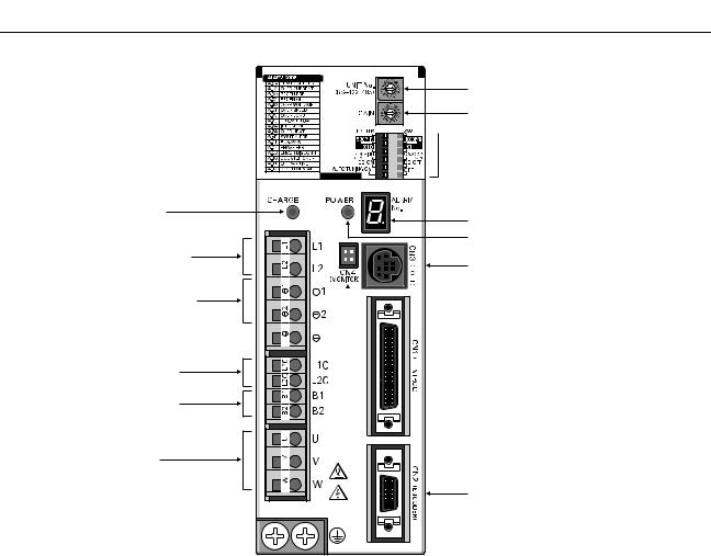
1-3 Servo Driver Nomenclature
|
Main-circuit power supply |
|
indicator |
|
Main-circuit power |
|
supply input terminals |
|
DC reactor connection terminals |
|
Control-circuit power supply |
|
input terminals |
|
External regeneration |
|
resistance terminals |
|
Servomotor power terminals |
FG terminals for power supply and  servomotor power
Rotary switch for unit No. selection
Rotary switch for gain adjustment

 Function selection switches:
• Switch/parameter setting enable switch
• Resolution setting
• Command pulse input setting
•Dynamic braking setting
•Online autotuning switch
Alarm display
Control-circuit power supply indicator
Communications connector (CN3)

 Monitor output connector (CN4)

 Control I/O connector (CN1)
Encoder input connector (CN2)
1-5

|
Introduction |
Chapter 1 |
||
1-4 Applicable Standards |
|||
|
■ EC Directives |
|||
|
EC Directives |
Product |
Applicable standards |
Remarks |
|
Low Voltage |
AC Servo Drivers |
EN50178 |
Safety requirements for electrical |
|
Directive |
devices for measurement, control, |
||
|
and research facilities |
|||
|
AC Servomotors |
IEC60034-1, -5, -8, -9 |
Rotating electrical equipment |
|
|
EN60034-1, -9 |
|||
|
EMC Directives |
AC Servo Drivers and |
EN55011 class A group 1 |
Wireless interference and measure- |
|
AC Servomotors |
ment methods for radio-frequency |
||
|
devices for industry, science, and |
|||
|
medical application |
|||
|
EN61000-6-2 |
Electromagnetic compatibility and |
||
|
immunity standards for industrial |
|||
|
environments |
|||
Note Installation under the conditions stipulated in 3-2-5 EMC-compatible Wiring must be met to ensure conformance to EMC Directives.
■ UL and cUL Standards
|
Standards |
Product |
Applicable standards |
File No. |
Remarks |
||
|
UL |
AC Servo Drivers |
UL508C |
E179149 |
Power conversion devices |
||
|
AC Servomotors |
UL1004 |
E179189 |
Electric motors |
|||
|
cUL |
AC Servo Drivers |
cUL C22.2 |
No. 14 |
E179149 |
Industrial control devices |
|
|
AC Servomotors |
cUL C22.2 |
No. 100 |
E179189 |
Motors and generators |
||
1-6
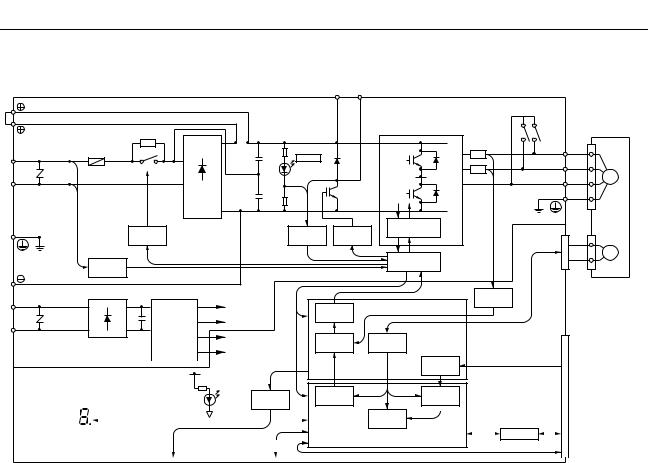
1-5 System Block Diagrams
■ 100 V AC: R7D-APA3L/-APA5L/-AP01L/-AP02L/-AP04L
|
AC Servo Driver |
||||||||||||
|
1 |
B1 |
B2 |
||||||||||
|
2 |
AC Servomotor |
|||||||||||
|
Fuse |
P1 |
P2 |
U |
U |
||||||||
|
R |
CHARGE |
|||||||||||
|
V |
||||||||||||
|
L1 |
V |
|||||||||||
|
W |
M |
|||||||||||
|
T |
W |
|||||||||||
|
L2 |
+ |
(See note.) |
||||||||||
|
− |
N2 |
|||||||||||
|
N1 |
||||||||||||
|
Relay |
Voltage |
Gate drive |
||||||||||
|
overcurrent protection |
CN2 |
|||||||||||
|
drive |
detection |
Gate drive |
||||||||||
|
Interface |
E |
|||||||||||
|
Voltage |
||||||||||||
|
detection |
||||||||||||
|
L1C |
Current |
|||||||||||
|
+ |
+ |
±5 V |
PWM |
ASIC |
detection |
|||||||
|
− |
− |
DC/DC |
+16.5 V |
generation |
||||||||
|
L2C |
conversion |
+5 V |
Digital |
Encoder signal |
CN1 |
|||||||
|
±15 V |
current amp |
processing |
||||||||||
|
Command |
||||||||||||||||||||||
|
+5 V |
pulse |
Command |
||||||||||||||||||||
|
processing |
pulse input |
|||||||||||||||||||||
|
POWER |
Analog |
Current |
Position |
|||||||||||||||||||
|
command |
||||||||||||||||||||||
|
voltage |
processing |
control |
||||||||||||||||||||
|
0 V |
conversion |
Speed |
||||||||||||||||||||
|
Serial port |
control |
I/O |
Control I/O |
|||||||||||||||||||
|
Alarm code display |
CPU |
|||||||||||||||||||||
|
RS-422 |
||||||||||||||||||||||
|
CN4 |
CN3 |
Note |
Only on R7D-AP04H/AP04L. |
|||||||||||||||||||
|
Analog monitor output |
Parameter Unit/computer |
1-7

■ 200 V AC: R7D-APA3H/-APA5H/-AP01H/-AP02H/-AP04H
|
AC Servo Driver |
||||||
|
1 |
B1 |
B2 |
||||
|
2 |
P1 |
AC Servomotor |
||||
|
Fuse |
P2 |
U |
U |
|||
|
CHARGE |
||||||
|
R |
V |
|||||
|
+ |
V |
|||||
|
L1 |
W |
M |
||||
|
T |
− |
W |
||||
|
L2 |
(See note.) |
N2
N1
|
Relay |
Voltage |
Gate drive |
|
|
Gate drive |
overcurrent protection |
||
|
drive |
detection |
CN2 |
|
Interface |
E |
||||||||
|
Voltage |
|||||||||
|
detection |
|||||||||
|
L1C |
Current |
||||||||
|
+ |
±5 V |
PWM |
ASIC |
detection |
|||||
|
+ |
|||||||||
|
− |
DC/DC |
+16.5 V |
generation |
||||||
|
− |
|||||||||
|
L2C |
conversion |
+5 V |
Digital |
Encoder signal |
CN1 |
||||
|
±15 V |
current amp |
processing |
|||||||
|
Command |
||||||||||||||||||||||
|
+5 V |
pulse |
Command |
||||||||||||||||||||
|
processing |
pulse input |
|||||||||||||||||||||
|
POWER |
Analog |
Current |
Position |
|||||||||||||||||||
|
command |
||||||||||||||||||||||
|
voltage |
processing |
control |
||||||||||||||||||||
|
0 V |
conversion |
|||||||||||||||||||||
|
Speed |
||||||||||||||||||||||
|
Serial port |
control |
I/O |
Control I/O |
|||||||||||||||||||
|
Alarm code display |
CPU |
|||||||||||||||||||||
|
RS-422 |
||||||||||||||||||||||
|
CN4 |
CN3 |
Note |
Only on R7D-AP04H/AP04L. |
|||||||||||||||||||
|
Analog monitor output |
Parameter Unit/computer |
■ 200 V AC: R7D-AP08H
AC Servo Driver
|
1 |
B1 B2 B3 |
FAN |
|
±12 V |
||
|
2 |
AC Servomotor |
|
|
P |
P |
U |
U |
||||||
|
R |
Fuse |
CHARGE |
|||||||
|
V |
|||||||||
|
L1 |
+ |
V |
|||||||
|
W |
M |
||||||||
|
S |
− |
W |
|||||||
|
L2 |
|||||||||
|
L3 |
T |
N |
N |
||||||
|
Relay |
Voltage |
Gate |
Gate drive over- |
||||||
|
current protection |
CN2 |
||||||||
|
drive |
detection |
drive |
Ther- |
||||||
|
mistor |
E |
||||||||
|
Voltage |
Interface |
||||||||
|
detection |
|
L1C |
Current |
|||||||||||||||||||||||||||||||
|
ASIC |
detection |
|||||||||||||||||||||||||||||||
|
+ |
±5 V |
PWM |
||||||||||||||||||||||||||||||
|
+ |
||||||||||||||||||||||||||||||||
|
− |
− |
DC/DC |
+16.5 V |
generation |
||||||||||||||||||||||||||||
|
conversion |
CN1 |
|||||||||||||||||||||||||||||||
|
L2C |
+5 V |
Digital |
Encoder |
|||||||||||||||||||||||||||||
|
current amp |
signal |
|||||||||||||||||||||||||||||||
|
±15 V |
processing |
|||||||||||||||||||||||||||||||
|
Command |
Command |
|||||||||||||||||||||||||||||||
|
pulse |
||||||||||||||||||||||||||||||||
|
+5 V |
processing |
pulse input |
||||||||||||||||||||||||||||||
|
Position |
||||||||||||||||||||||||||||||||
|
POWER |
Analog |
Current |
||||||||||||||||||||||||||||||
|
command |
||||||||||||||||||||||||||||||||
|
voltage |
control |
|||||||||||||||||||||||||||||||
|
processing |
||||||||||||||||||||||||||||||||
|
0 V |
conversion |
|||||||||||||||||||||||||||||||
|
Speed |
||||||||||||||||||||||||||||||||
|
Serial port |
control |
I/O |
Control I/O |
|||||||||||||||||||||||||||||
|
Alarm code display |
CPU |
|||||||||||||||||||||||||||||||
|
RS-422 |
||||||||||||||||||||||||||||||||
|
CN4 |
CN3 |
|||||||||||||||||||||||||||||||
|
Analog monitor output |
Parameter Unit/computer |
1-8

Chapter 2
Standard Models and
Specifications
2-1 Standard Models
2-2 External and Mounted Dimensions
2-3 Servo Driver Specifications
2-4 Servomotor Specifications
2-5 Reduction Gear Specifications
2-6 Cable and Connector Specifications
2-7 Servo Relay Units and Cable Specifications
2-8 Parameter Unit Specifications
2-9 External Regeneration Resistor Specifications
2-10 DC Reactors

|
Standard Models and Specifications |
Chapter 2 |
|
2-1 Standard Models
■ Servomotors
● 3,000-r/min Cylinder-style Servomotors
|
Specifications |
Model |
|||
|
Without |
Straight shaft |
30 W |
R7M-A03030 |
|
|
brake |
without key |
|||
|
50 W |
R7M-A05030 |
|||
|
100 W |
R7M-A10030 |
|||
|
200 W |
R7M-A20030 |
|||
|
400 W |
R7M-A40030 |
|||
|
750 W |
R7M-A75030 |
|||
|
Straight shaft |
30 W |
R7M-A03030-S1 |
||
|
with key |
||||
|
50 W |
R7M-A05030-S1 |
|||
|
100 W |
R7M-A10030-S1 |
|||
|
200 W |
R7M-A20030-S1 |
|||
|
400 W |
R7M-A40030-S1 |
|||
|
750 W |
R7M-A75030-S1 |
|||
|
With |
Straight shaft |
30 W |
R7M-A03030-B |
|
|
brake |
without key |
|||
|
50 W |
R7M-A05030-B |
|||
|
100 W |
R7M-A10030-B |
|||
|
200 W |
R7M-A20030-B |
|||
|
400 W |
R7M-A40030-B |
|||
|
750 W |
R7M-A75030-B |
|||
|
Straight shaft |
30 W |
R7M-A03030-BS1 |
||
|
with key |
||||
|
50 W |
R7M-A05030-BS1 |
|||
|
100 W |
R7M-A10030-BS1 |
|||
|
200 W |
R7M-A20030-BS1 |
|||
|
400 W |
R7M-A40030-BS1 |
|||
|
750 W |
R7M-A75030-BS1 |
|||
● 3,000-r/min Flat-style Servomotors
|
Specifications |
Model |
|||
|
Without |
Straight shaft |
100 W |
R7M-AP10030 |
|
|
brake |
without key |
|||
|
200 W |
R7M-AP20030 |
|||
|
400 W |
R7M-AP40030 |
|||
|
750 W |
R7M-AP75030 |
|||
|
Straight shaft |
100 W |
R7M-AP10030-S1 |
||
|
with key |
||||
|
200 W |
R7M-AP20030-S1 |
|||
|
400 W |
R7M-AP40030-S1 |
|||
|
750 W |
R7M-AP75030-S1 |
|||
|
With |
Straight shaft |
100 W |
R7M-AP10030-B |
|
|
brake |
without key |
|||
|
200 W |
R7M-AP20030-B |
|||
|
400 W |
R7M-AP40030-B |
|||
|
750 W |
R7M-AP75030-B |
|||
|
Straight shaft |
100 W |
R7M-AP10030-BS1 |
||
|
with key |
||||
|
200 W |
R7M-AP20030-BS1 |
|||
|
400 W |
R7M-AP40030-BS1 |
|||
|
750 W |
R7M-AP75030-BS1 |
■ Servo Drivers
|
Specifications |
Model |
||
|
Single-phase |
30 W |
R7D-APA3L |
|
|
100 V AC |
|||
|
50 W |
R7D-APA5L |
||
|
100 W |
R7D-AP01L |
||
|
200 W |
R7D-AP02L |
||
|
400 W |
R7D-AP04L |
||
|
Single-phase |
30 W |
R7D-APA3H |
|
|
200 V AC |
|||
|
50 W |
R7D-APA5H |
||
|
100 W |
R7D-AP01H |
||
|
200 W |
R7D-AP02H |
||
|
400 W |
R7D-AP04H |
||
|
750 W |
R7D-AP08H |
||
2-2
|
Standard Models and Specifications |
Chapter 2 |
■ Reduction Gears (Straight Shaft with Key)
●For Cylinder-style Servomotors (Backlash = 3′ Max.)
|
Specifications |
Model |
|
|
Servomotor |
Reduction gears |
|
|
capacity |
(deceleration ratio) |
|
|
50 W |
1/5 |
R7G-VRSFPB05B50 |
|
1/9 |
R7G-VRSFPB09B50 |
|
|
1/15 |
R7G-VRSFPB15B50 |
|
|
1/25 |
R7G-VRSFPB25B50 |
|
|
100 W |
1/5 |
R7G-VRSFPB05B100 |
|
1/9 |
R7G-VRSFPB09B100 |
|
|
1/15 |
R7G-VRSFPB15B100 |
|
|
1/25 |
R7G-VRSFPB25B100 |
|
|
200 W |
1/5 |
R7G-VRSFPB05B200 |
|
1/9 |
R7G-VRSFPB09C400 |
|
|
1/15 |
R7G-VRSFPB15C400 |
|
|
1/25 |
R7G-VRSFPB25C200 |
|
|
400 W |
1/5 |
R7G-VRSFPB05C400 |
|
1/9 |
R7G-VRSFPB09C400 |
|
|
1/15 |
R7G-VRSFPB15C400 |
|
|
1/25 |
R7G-VRSFPB25D400 |
|
|
750 W |
1/5 |
R7G-VRSFPB05C750 |
|
1/9 |
R7G-VRSFPB09D750 |
|
|
1/15 |
R7G-VRSFPB15D750 |
|
|
1/25 |
R7G-VRSFPB25E750 |
|
Note There are no reduction gears for 30-W Servomotors.
●For Cylinder-style Servomotors (Backlash = 45′ Max.)
|
Specifications |
Model |
|
|
Servomotor |
Reduction gears |
|
|
capacity |
(deceleration ratio) |
|
|
50 W |
1/5 |
R7G-RGSF05B50 |
|
1/9 |
R7G-RGSF09B50 |
|
|
1/15 |
R7G-RGSF15B50 |
|
|
1/25 |
R7G-RGSF25B50 |
|
|
100 W |
1/5 |
R7G-RGSF05B100 |
|
1/9 |
R7G-RGSF09B100 |
|
|
1/15 |
R7G-RGSF15B100 |
|
|
1/25 |
R7G-RGSF25B100 |
|
|
200 W |
1/5 |
R7G-RGSF05B200 |
|
1/9 |
R7G-RGSF09C400 |
|
|
1/15 |
R7G-RGSF15C400 |
|
|
1/25 |
R7G-RGSF25C400 |
|
|
400 W |
1/5 |
R7G-RGSF05C400 |
|
1/9 |
R7G-RGSF09C400 |
|
|
1/15 |
R7G-RGSF15C400 |
|
|
1/25 |
R7G-RGSF25C400 |
|
|
750 W |
1/5 |
R7G-RGSF05C750 |
|
1/9 |
R7G-RGSF09C750 |
|
|
1/15 |
R7G-RGSF15C750 |
|
|
1/25 |
R7G-RGSF25C750 |
|
Note There are no reduction gears for 30-W Servomotors.
●For Flat-style Servomotors (Backlash = 3′ Max.)
|
Specifications |
Model |
|
|
Servomotor |
Reduction gears |
|
|
capacity |
(deceleration ratio) |
|
|
100 W |
1/5 |
R7G-VRSFPB05B100P |
|
1/9 |
R7G-VRSFPB09B100P |
|
|
1/15 |
R7G-VRSFPB15B100P |
|
|
1/25 |
R7G-VRSFPB25C100P |
|
|
200 W |
1/5 |
R7G-VRSFPB05B200P |
|
1/9 |
R7G-VRSFPB09C400P |
|
|
1/15 |
R7G-VRSFPB15C400P |
|
|
1/25 |
R7G-VRSFPB25C200P |
|
|
400 W |
1/5 |
R7G-VRSFPB05C400P |
|
1/9 |
R7G-VRSFPB09C400P |
|
|
1/15 |
R7G-VRSFPB15C400P |
|
|
1/25 |
R7G-VRSFPB25D400P |
|
|
750 W |
1/5 |
R7G-VRSFPB05C750P |
|
1/9 |
R7G-VRSFPB09D750P |
|
|
1/15 |
R7G-VRSFPB15D750P |
|
|
1/25 |
R7G-VRSFPB25E750P |
|
●For Flat-style Servomotors (Backlash = 45′ Max.)
|
Specifications |
Model |
|
|
Servomotor |
Reduction gears |
|
|
capacity |
(deceleration ratio) |
|
|
100 W |
1/5 |
R7G-RGSF05B100P |
|
1/9 |
R7G-RGSF09B100P |
|
|
1/15 |
R7G-RGSF15B100P |
|
|
1/25 |
R7G-RGSF25B100P |
|
|
200 W |
1/5 |
R7G-RGSF05B200P |
|
1/9 |
R7G-RGSF09C400P |
|
|
1/15 |
R7G-RGSF15C400P |
|
|
1/25 |
R7G-RGSF25C400P |
|
|
400 W |
1/5 |
R7G-RGSF05C400P |
|
1/9 |
R7G-RGSF09C400P |
|
|
1/15 |
R7G-RGSF15C400P |
|
|
1/25 |
R7G-RGSF25C400P |
|
|
750 W |
1/5 |
R7G-RGSF05C750P |
|
1/9 |
R7G-RGSF09C750P |
|
|
1/15 |
R7G-RGSF15C750P |
|
|
1/25 |
R7G-RGSF25C750P |
|
2-3
|
Standard Models and Specifications |
Chapter 2 |
■ Servo Relay Units for CN1
|
Specifications |
Model |
|||
|
Servo |
For CS1W-NC113/133 |
XW2B-20J6-1B |
||
|
Relay Unit |
CJ1W-NC113/133 |
|||
|
C200HW-NC113 |
||||
|
C200H-NC112 |
||||
|
3F88M-DRT141 |
||||
|
(No communications supported.) |
||||
|
For CS1W-NC213/233/413/433 |
XW2B-40J6-2B |
|||
|
CJ1W-NC213/233/413/433 |
||||
|
C200HW-NC213/413 |
||||
|
C500-NC113/211 |
||||
|
C200H-NC211 |
||||
|
(No communications supported.) |
||||
|
For CS1W-HCP22 |
XW2B-20J6-3B |
|||
|
CQM1H-PLB21 |
||||
|
CQM1-CPU43-V1 |
||||
|
(No communications supported.) |
||||
|
For CS1W-NC213/233/413/433 |
XW2B-40J6-4A |
|||
|
CJ1W-NC213/233/413/433 |
||||
|
(Communications supported.) |
||||
|
For CJ1M-CPU21/CPU22/ |
XW2B-20J6-8A |
|||
|
CPU23 |
||||
|
XW2B-40J6-9A |
||||
|
For CS1W-HCP22-V1 and |
XW2B-80J7-1A |
|||
|
FQM1-MMP21 |
||||
|
Servo |
No communications |
1 m |
XW2Z-100J-B5 |
|
|
Driver |
supported. |
|||
|
2 m |
XW2Z-200J-B5 |
|||
|
Cable |
||||
|
Communications sup- |
1 m |
XW2Z-100J-B7 |
||
|
ported. |
||||
|
2 m |
XW2Z-200J-B7 |
|||
|
For FQM1-MMP21 |
1 m |
XW2Z-100J-B10 |
||
|
2 m |
XW2Z-200J-B10 |
|||
|
For CS1W-HCP22-V1 |
1 m |
XW2Z-100J-B12 |
||
|
2 m |
XW2Z-200J-B12 |
|||
|
Position |
For CQM1H-PLB21, |
0.5 m |
XW2Z-050J-A3 |
|
|
Control |
CQM1-CPU43-V1 |
|||
|
1 m |
XW2Z-100J-A3 |
|||
|
Unit Cable |
||||
|
For C200H-NC112 |
0.5 m |
XW2Z-050J-A4 |
||
|
1 m |
XW2Z-100J-A4 |
|||
|
For C200H-NC211, |
0.5 m |
XW2Z-050J-A5 |
||
|
C500-NC113/211 |
||||
|
1 m |
XW2Z-100J-A5 |
|||
|
For CS1W-NC113, |
0.5 m |
XW2Z-050J-A8 |
||
|
C200HW-NC113 |
||||
|
1 m |
XW2Z-100J-A8 |
|||
|
For CS1W-NC213/413, |
0.5 m |
XW2Z-050J-A9 |
||
|
C200HW-NC213/413 |
||||
|
1 m |
XW2Z-100J-A9 |
|||
|
For CS1W-NC133 |
0.5 m |
XW2Z-050J-A12 |
||
|
1 m |
XW2Z-100J-A12 |
|||
|
For CS1W-NC233/433 |
0.5 m |
XW2Z-050J-A13 |
||
|
1 m |
XW2Z-100J-A13 |
|||
|
For CJ1W-NC113 |
0.5 m |
XW2Z-050J-A16 |
||
|
1 m |
XW2Z-100J-A16 |
|||
|
For CJ1W-NC213/413 |
0.5 m |
XW2Z-050J-A17 |
||
|
1 m |
XW2Z-100J-A17 |
|||
|
For CJ1W-NC133 |
0.5 m |
XW2Z-050J-A20 |
||
|
1 m |
XW2Z-100J-A20 |
|||
|
For CJ1W-NC233/433 |
0.5 m |
XW2Z-050J-A21 |
||
|
1 m |
XW2Z-100J-A21 |
|||
|
For CS1W-HCP22 |
0.5 m |
XW2Z-050J-A22 |
||
|
(1 axis) |
||||
|
1 m |
XW2Z-100J-A22 |
|||
|
For CS1W-HCP22 |
0.5 m |
XW2Z-050J-A23 |
||
|
(2 axes) |
||||
|
1 m |
XW2Z-100J-A23 |
|||
|
For 3F88M-DRT141 |
0.5 m |
XW2Z-050J-A25 |
||
|
1 m |
XW2Z-100J-A25 |
|||
|
Specifications |
Model |
|||
|
Position |
For CJ1M-CPU21/ |
1 m |
XW2Z-100J-A26 |
|
|
Control |
CPU22/CPU23 |
|||
|
Unit Cable |
||||
|
For FQM1-MMP21 for |
0.5 m |
XW2Z-050J-A28 |
||
|
general-purpose I/O |
||||
|
1 m |
XW2Z-100J-A28 |
|||
|
For CS1W-HCP22-V1 |
0.5 m |
XW2Z-050J-A29 |
||
|
for general-purpose I/O |
||||
|
1 m |
XW2Z-100J-A29 |
|||
|
For FQM1-MMP21 for |
0.5 m |
XW2Z-050J-A30 |
||
|
special I/O |
||||
|
1 m |
XW2Z-100J-A30 |
|||
|
For CS1W-HCP22-V1 |
0.5 m |
XW2Z-050J-A32 |
||
|
for special I/O |
||||
|
1 m |
XW2Z-100J-A32 |
|||
|
■ Control Cables for CN1 |
|
Specifications |
Model |
||
|
General-purpose Control Cable |
1 m |
R88A-CPU001S |
|
|
(with Connector on one end) |
|||
|
2 m |
R88A-CPU002S |
||
|
Connector Terminal Block Cable |
1 m |
R88A-CTU001N |
|
|
2 m |
R88A-CTU002N |
||
|
Connector Terminal Blocks |
XW2B-40F5-P |
||
■ Integrated Servomotor Cables
|
Specifications |
Model |
||
|
For Servomotors without |
3 m |
R7A-CEA003S |
|
|
brakes (both Cylinderand |
|||
|
5 m |
R7A-CEA005S |
||
|
Flat-style) |
|||
|
10 m |
R7A-CEA010S |
||
|
15 m |
R7A-CEA015S |
||
|
20 m |
R7A-CEA020S |
||
|
For Servomotors with |
3 m |
R7A-CEA003B |
|
|
brakes (both Cylinderand |
|||
|
5 m |
R7A-CEA005B |
||
|
Flat-style) |
|||
|
10 m |
R7A-CEA010B |
||
|
15 m |
R7A-CEA015B |
||
|
20 m |
R7A-CEA020B |
||
■ Separate Servomotor Cables
● Power Cables
|
Specifications |
Standard cable |
Robot cable |
||
|
model |
model |
|||
|
For Servo- |
3 m |
R88A-CAWA003S |
R88A-CAWA003SR |
|
|
motors with- |
||||
|
5 m |
R88A-CAWA005S |
R88A-CAWA005SR |
||
|
out brakes |
||||
|
(both Cylin- |
10 m |
R88A-CAWA010S |
R88A-CAWA010SR |
|
|
derand |
15 m |
R88A-CAWA015S |
R88A-CAWA015SR |
|
|
Flat-style) |
||||
|
20 m |
R88A-CAWA020S |
R88A-CAWA020SR |
||
|
For Servo- |
3 m |
R88A-CAWA003B |
R88A-CAWA003BR |
|
|
motors with |
||||
|
5 m |
R88A-CAWA005B |
R88A-CAWA005BR |
||
|
brakes (both |
||||
|
10 m |
R88A-CAWA010B |
R88A-CAWA010BR |
||
|
Cylinder- |
||||
|
and Flat- |
15 m |
R88A-CAWA015B |
R88A-CAWA015BR |
|
|
style) |
||||
|
20 m |
R88A-CAWA020B |
R88A-CAWA020BR |
||
● Encoder Cables
|
Specifications |
Standard cable |
Robot cable |
||
|
model |
model |
|||
|
For Servo- |
3 m |
R7A-CRA003C |
R7A-CRA003CR |
|
|
motors (Cyl- |
||||
|
5 m |
R7A-CRA005C |
R7A-CRA005CR |
||
|
inder-style or |
||||
|
Flat-style) |
10 m |
R7A-CRA010C |
R7A-CRA010CR |
|
|
15 m |
R7A-CRA015C |
R7A-CRA015CR |
||
|
20 m |
R7A-CRA020C |
R7A-CRA020CR |
||
Note Use a robot cable if cable flexibility is required.
2-4
|
Standard Models and Specifications |
Chapter 2 |
||||||||||
|
■ Peripheral Cable Connectors |
|||||||||||
|
Specifications |
Model |
||||||||||
|
Analog Monitor Cable (CN4) |
1 m |
R88A-CMW001S |
|||||||||
|
Computer Monitor Cable (CN3) |
DOS |
2 m |
R7A-CCA002P2 |
||||||||
|
PC98 |
2 m |
R7A-CCA002P3 |
|||||||||
|
Control I/O Connector (CN1) |
R88A-CNU01C |
||||||||||
|
Encoder Connector (CN2) |
R7A-CNA01R |
||||||||||
|
Encoder Connector (Servomotor end) |
R7A-CNA02R |
||||||||||
|
Communications Cable |
1 m |
XW2Z-100J-C1 |
|||||||||
|
2 m |
XW2Z-200J-C1 |
||||||||||
|
■ Parameter Units |
|||||||||||
|
Specifications |
Model |
||||||||||
|
Hand-held (with 1-m cable) |
R7A-PR02A |
||||||||||
|
■ External Regeneration Resistors |
|||||||||||
|
Specifications |
Model |
||||||||||
|
Resistor |
220 W 47 Ω |
R88A-RR22047S |
|||||||||
|
■ DC Reactors |
|||||||||||
|
Specifications |
Model |
||||||||||
|
For R7D-APA3L/APA5L/APA01L |
R88A-PX5063 |
||||||||||
|
For R7D-AP02L |
R88A-PX5062 |
||||||||||
|
For R7D-AP04L |
R88A-PX5061 |
||||||||||
|
For R7D-APA3H/APA5H/AP01H |
R88A-PX5071 |
||||||||||
|
For R7D-AP02H |
R88A-PX5070 |
||||||||||
|
For R7D-AP04H |
R88A-PX5069 |
||||||||||
|
For R7D-AP08H |
R88A-PX5061 |
||||||||||
|
■ Front-panel Brackets |
|||||||||||
|
Specifications |
Model |
||||||||||
|
For the SMARTSTEP A Series |
R88A-TK01W |
2-5

|
Standard Models and Specifications |
Chapter 2 |
|
2-2 External and Mounted Dimensions
2-2-1 Servo Drivers
■Single-phase 100 V AC: R7D-APA3L/-APA5L/-AP01L/-AP02L (30 W to 200 W) Single-phase 200 V AC: R7D-APA3H/-APA5H/-AP01H/-AP02H (30 W to 200 W)
● Wall Mounting
|
External dimensions |
Mounted dimensions |
17
● Front Panel Mounting (Using Mounting Brackets)
External dimensions
|
195 |
180 |
|||
Mounted dimensions
|
7.5 |
Two, M4 |
|
|
6 |
||
|
10 |
||
|
195 |
180±0.5 |
(168) |
(7.5)  6
6
2-6

|
Standard Models and Specifications |
Chapter 2 |
■Single-phase 100 V AC: R7D-AP04L (400 W) Single-phase 200 V AC: R7D-AP04H (400 W)
● Wall Mounting
|
External dimensions |
Mounted dimensions |
|
5.5 |
5 dia. |
5.5 |
|||
|
160 |
149.5 |
160 |
149.5±0.5 |
||
|
(5) |
5 |
(5) |
|||
|
12 |
(75) |
130 |
|||
|
75 |
17
● Front Panel Mounting (Using Mounting Brackets)
|
External dimensions |
|||
|
5 dia. |
24.5 |
||
|
7.5 |
52 |
1.5 |
2 |
|
195 |
180 |
|||
Mounted dimensions
|
7.5 |
Two, M4 |
|
|
6 |
||
|
10 |
||
|
195 |
180±0.5 |
(168) |
(7.5)  6
6
2-7

|
Standard Models and Specifications |
Chapter 2 |
■ Single-phase/Three-phase 200 V AC: R7D-AP08H (750 W)
● Wall Mounting
|
External dimensions |
Mounted dimensions |
|
5.5 |
5 dia. |
5.5 |
|
|
160 |
149.5 |
160 |
149.5±0.5 |
|
(5) |
90 |
(5) |
|
17
● Front Panel Mounting (Using Mounting Brackets)
External dimensions
|
5 dia. |
24.5 |
||||||
|
7.5 |
52 |
12.5 |
2 |
||||
|
195 |
180 |
|||||||||
|
(7.5) |
5 |
||||||
|
43.5 |
|||||||
|
42 |
22.5 |
||||||
Mounted dimensions
|
7.5 |
Two, M4 |
|
|
6 |
||
|
10 |
||
|
195 |
180±0.5 |
(168) |
(7.5)  6
6
2-8

|
Standard Models and Specifications |
Chapter 2 |
2-2-2 Parameter Unit
■ R7A-PR02A Hand-held Parameter Unit
17 0.8
|
B.B |
INP TGON REF POWER |
|
VCMP |
R7A–PR02A PARAMETER UNIT
SCROLL MODE/SET
RESET
JOG
DATA
RUN
READ WRITE
4.8 dia.
2-9

|
Standard Models and Specifications |
Chapter 2 |
2-2-3 Servomotors
■ Cylinder-style Servomotors without a Brake
● 30 W/50 W/100 W R7M-A03030(-S1)/-A05030(-S1)/-A10030(-S1)
300±30
|
19.5 |
20 |
300±30 |
21.5 |
5 |
||||
|
9.5 |
Two, 4.3 dia. |
Dimensions of shaft end with key (-S1) |
||||||
|
11 |
dia.S |
dia.30h7 |
46 |
40 |
h |
|||
|
dia. |
b |
|||||||
|
14 |
t1 |
|||||||
|
5 |
2.5 |
40 |
||||||
|
LL |
25 |
|||||||
|
Model |
Dimensions (mm) |
|||||||
|
LL |
S |
b |
h |
t1 |
||||
|
R7M-A03030-@ |
69.5 |
6h6 |
2 |
2 |
1.2 |
|||
|
R7M-A05030-@ |
77 |
6h6 |
2 |
2 |
1.2 |
|||
|
R7M-A10030-@ |
94.5 |
8h6 |
3 |
3 |
1.8 |
|||
|
■ Cylinder-style Servomotors with a Brake |
● 30 W/50 W/100 W R7M-A03030-B(S1)/-A05030-B(S1)/-A10030-B(S1)
300±30
|
6 dia. |
7 dia. |
300±30 |
|||||
|
19.5 |
27 |
21.5 |
5 |
||||
|
9.5 |
Two, 4.3 dia. |
Dimensions of shaft end with key (-BS1) |
|||||
|
11 |
dia.S |
dia.30h7 |
46 |
40 |
h |
||
|
dia. |
b |
||||||
|
14 |
t1 |
||||||
|
5 |
2.5 |
40 |
|||||
|
LL |
25 |
|
Model |
Dimensions (mm) |
||||
|
LL |
S |
b |
h |
t1 |
|
|
R7M-A03030-B@ |
101 |
6h6 |
2 |
2 |
1.2 |
|
R7M-A05030-B@ |
108.5 |
6h6 |
2 |
2 |
1.2 |
|
R7M-A10030-B@ |
135 |
8h6 |
3 |
3 |
1.8 |
2-10

|
Standard Models and Specifications |
Chapter 2 |
■ Cylinder-style Servomotors without a Brake
● 200 W/400 W/750 W R7M-A20030(-S1)/-A40030(-S1)/-A75030(-S1)
300±30
|
6 dia. |
Dimensions of output section of 750-W Servomotors |
|||||||
|
13 |
7 dia. |
|||||||
|
20 |
300±30 |
21.5 |
||||||
|
9 |
Four, Z dia. |
|||||||
|
2 |
||||||||
|
11 |
dia. |
D1 |
dia. |
Dimensions of shaft end with key (-S1) |
||||
|
S |
||||||||
|
D2dia. |
||||||||
|
C |
5 |
|||||||
|
5 |
||||||||
|
G |
3 |
C |
QK |
3 |
||||
|
LL |
LR |
|
Model |
Dimensions (mm) |
||||||||
|
LL |
LR |
C |
D1 |
D2 |
G |
Z |
S |
QK |
|
|
R7M-A20030-@ |
96.5 |
30 |
60 |
70 |
50h7 |
6 |
5.5 |
14h6 |
20 |
|
R7M-A40030-@ |
124.5 |
30 |
60 |
70 |
50h7 |
6 |
5.5 |
14h6 |
20 |
|
R7M-A75030-@ |
145 |
40 |
80 |
90 |
70h7 |
8 |
7 |
16h6 |
30 |
■ Cylinder-style Servomotors with a Brake
● 200 W/400 W/750 W R7M-A20030-B(S1)/-A40030-B(S1)/-A75030-B(S1)
300±30
|
6 dia. |
7 dia. |
|
|
13 |
27 |
300±30 |
|
21.5 |
||
|
9 |
Four, Z dia. |
|
|
11 |
dia. |
D |
1 |
dia. |
|
|
S |
|||||
|
D2 dia. |
C |
||||
|
G |
3 |
C |
|||
|
LL |
LR |
Dimensions of output section of 750-W Servomotors
2
Dimensions of shaft end with key (-BS1)
|
Model |
Dimensions (mm) |
||||||||
|
LL |
LR |
C |
D1 |
D2 |
G |
Z |
S |
QK |
|
|
R7M-A20030-B@ |
136 |
30 |
60 |
70 |
50h7 |
6 |
5.5 |
14h6 |
20 |
|
R7M-A40030-B@ |
164 |
30 |
60 |
70 |
50h7 |
6 |
5.5 |
14h6 |
20 |
|
R7M-A75030-B@ |
189.5 |
40 |
80 |
90 |
70h7 |
8 |
7 |
16h6 |
30 |
2-11

|
Standard Models and Specifications |
Chapter 2 |
■ Flat-style Servomotors without a Brake
● 100 W/200 W/400 W/750 W R7M-AP10030(-S1)/-AP20030(-S1)/-AP40030(-S1)/AP75030(-S1)
|
13 |
dia. |
|
|
7 |
||
|
300±30 |
||
|
A2 |
||
|
A1 |
A5 |
|
|
D1 |
Dimensions of shaft end with key (-S1) |
||
|
dia. |
h |
||
|
b |
|||
|
C |
|||
|
QK |
t1 |
|
Model |
Dimensions (mm) |
|||||||||||||||||
|
Basic servomotor dimensions |
With key (shaft |
Cable outlet dimensions |
||||||||||||||||
|
end dimensions) |
||||||||||||||||||
|
LL |
LR |
C |
D1 |
D2 |
F |
G |
Z |
S |
QK |
b |
h |
t1 |
A1 |
A2 |
A3 |
A4 |
A5 |
|
|
R7M-AP10030-@ |
62 |
25 |
60 |
70 |
50h7 |
3 |
6 |
5.5 |
8h6 |
14 |
3 |
3 |
1.8 |
9 |
18 |
25 |
21 |
14 |
|
R7M-AP20030-@ |
67 |
30 |
80 |
90 |
70h7 |
3 |
8 |
7 |
14h6 |
16 |
5 |
5 |
3 |
|||||
|
R7M-AP40030-@ |
87 |
|||||||||||||||||
|
R7M-AP75030-@ |
86.5 |
40 |
120 |
145 |
110h7 |
3.5 |
10 |
10 |
16h6 |
22 |
5 |
5 |
3 |
28 |
38 |
19 |
■ Flat-style Servomotors with a Brake
● 100 W/200 W/400 W/750 W R7M-AP10030-B(S1)/-AP20030-B(S1)/-AP40030-B(S1)/AP75030-B(S1)
300±30
|
6 dia. |
|
|
7 dia. |
|
|
13 |
300±30 |
|
A2 |
|
|
A1 |
A5 |
|
S dia. |
D1 |
Dimensions of shaft end with key (-BS1) |
||
|
dia. |
h |
|||
|
D2 dia. |
C |
b |
||
|
QK |
t1 |
|
Model |
Dimensions (mm) |
||||||||||||||||||
|
Basic servomotor dimensions |
With key (shaft |
Cable outlet dimensions |
|||||||||||||||||
|
end dimensions) |
|||||||||||||||||||
|
LL |
LR |
C |
D1 |
D2 |
F |
G |
Z |
S |
QK |
b |
h |
t1 |
A1 |
A2 |
A3 |
A4 |
A5 |
||
|
R7M-AP10030-B@ |
91 |
25 |
60 |
70 |
50h7 |
3 |
6 |
5.5 |
8h6 |
14 |
3 |
3 |
1.8 |
9 |
18 |
25 |
21 |
23 |
|
|
R7M-AP20030-B@ |
98.5 |
30 |
80 |
90 |
70h7 |
3 |
8 |
7 |
14h6 |
16 |
5 |
5 |
3 |
||||||
|
R7M-AP40030-B@ |
118.5 |
||||||||||||||||||
|
R7M-AP75030-B@ |
120 |
40 |
120 |
145 |
110h7 |
3.5 |
10 |
10 |
16h6 |
22 |
5 |
5 |
3 |
28 |
38 |
26 |
2-12

|
Standard Models and Specifications |
Chapter 2 |
||||||||||||||||||||||||
|
2-2-4 |
Reduction Gears |
||||||||||||||||||||||||
|
■ For Cylinder-style Servomotors (Backlash = 3′ |
Max.) |
||||||||||||||||||||||||
|
Model |
Dimensions (mm) |
Weight |
|||||||||||||||||||||||
|
(kg) |
|||||||||||||||||||||||||
|
LM |
LR |
C1 |
C2 |
D1 |
D2 |
D3 |
D4 |
E3 |
F |
G |
S |
T |
Z1 |
Z2 |
AT* |
l |
Key dimensions |
||||||||
|
QK |
b |
h |
t1 |
||||||||||||||||||||||
|
50 W |
1/5 |
R7G-VRSFPB05B50 |
67.5 |
32 |
52 |
40 |
46 |
60 |
50 |
45 |
10 |
3 |
6 |
12 |
20 |
M4 |
M5 |
M3 |
12 |
16 |
4 |
4 |
2.5 |
0.55 |
|
|
1/9 |
R7G-VRSFPB09B50 |
67.5 |
32 |
52 |
40 |
46 |
60 |
50 |
45 |
10 |
3 |
6 |
12 |
20 |
M4 |
M5 |
M3 |
12 |
16 |
4 |
4 |
2.5 |
0.55 |
||
|
1/15 |
R7G-VRSFPB15B50 |
78 |
32 |
52 |
40 |
46 |
60 |
50 |
45 |
10 |
3 |
6 |
12 |
20 |
M4 |
M5 |
M3 |
12 |
16 |
4 |
4 |
2.5 |
0.7 |
||
|
1/25 |
R7G-VRSFPB25B50 |
78 |
32 |
52 |
40 |
46 |
60 |
50 |
45 |
10 |
3 |
6 |
12 |
20 |
M4 |
M5 |
M3 |
12 |
16 |
4 |
4 |
2.5 |
0.7 |
||
|
100 W |
1/5 |
R7G-VRSFPB05B100 |
67.5 |
32 |
52 |
40 |
46 |
60 |
50 |
45 |
10 |
3 |
6 |
12 |
20 |
M4 |
M5 |
M3 |
12 |
16 |
4 |
4 |
2.5 |
0.55 |
|
|
1/9 |
R7G-VRSFPB09B100 |
67.5 |
32 |
52 |
40 |
46 |
60 |
50 |
45 |
10 |
3 |
6 |
12 |
20 |
M4 |
M5 |
M3 |
12 |
16 |
4 |
4 |
2.5 |
0.55 |
||
|
1/15 |
R7G-VRSFPB15B100 |
78 |
32 |
52 |
40 |
46 |
60 |
50 |
45 |
10 |
3 |
6 |
12 |
20 |
M4 |
M5 |
M3 |
12 |
16 |
4 |
4 |
2.5 |
0.7 |
||
|
1/25 |
R7G-VRSFPB25C100 |
92 |
50 |
78 |
40 |
46 |
90 |
70 |
62 |
17 |
3 |
6 |
19 |
30 |
M4 |
M6 |
M3 |
20 |
22 |
6 |
6 |
3.5 |
1.7 |
||
|
200 W |
1/5 |
R7G-VRSFPB05B200 |
72.5 |
32 |
52 |
60 |
70 |
60 |
50 |
45 |
10 |
3 |
10 |
12 |
20 |
M5 |
M5 |
M4 |
12 |
16 |
4 |
4 |
2.5 |
0.72 |
|
|
1/9 |
R7G-VRSFPB09C400 |
89.5 |
50 |
78 |
60 |
70 |
90 |
70 |
62 |
17 |
3 |
8 |
19 |
30 |
M5 |
M6 |
M4 |
20 |
22 |
6 |
6 |
3.5 |
1.7 |
||
|
1/15 |
R7G-VRSFPB15C400 |
100 |
50 |
78 |
60 |
70 |
90 |
70 |
62 |
17 |
3 |
8 |
19 |
30 |
M5 |
M6 |
M4 |
20 |
22 |
6 |
6 |
3.5 |
2.1 |
||
|
1/25 |
R7G-VRSFPB25C400 |
100 |
50 |
78 |
60 |
70 |
90 |
70 |
62 |
17 |
3 |
8 |
19 |
30 |
M5 |
M6 |
M4 |
20 |
22 |
6 |
6 |
3.5 |
2.1 |
||
|
400 W |
1/5 |
R7G-VRSFPB05C400 |
89.5 |
50 |
78 |
60 |
70 |
90 |
70 |
62 |
17 |
3 |
8 |
19 |
30 |
M5 |
M6 |
M4 |
20 |
22 |
6 |
6 |
3.5 |
1.7 |
|
|
1/9 |
R7G-VRSFPB09C400 |
89.5 |
50 |
78 |
60 |
70 |
90 |
70 |
62 |
17 |
3 |
8 |
19 |
30 |
M5 |
M6 |
M4 |
20 |
22 |
6 |
6 |
3.5 |
1.7 |
||
|
1/15 |
R7G-VRSFPB15C400 |
100 |
50 |
78 |
60 |
70 |
90 |
70 |
62 |
17 |
3 |
8 |
19 |
30 |
M5 |
M6 |
M4 |
20 |
22 |
6 |
6 |
3.5 |
2.1 |
||
|
1/25 |
R7G-VRSFPB25D400 |
104 |
61 |
98 |
60 |
70 |
115 |
90 |
75 |
18 |
5 |
8 |
24 |
40 |
M5 |
M8 |
M4 |
20 |
30 |
8 |
7 |
4 |
3.2 |
||
|
750 W |
1/5 |
R7G-VRSFPB05C750 |
93.5 |
50 |
78 |
80 |
90 |
90 |
70 |
62 |
17 |
3 |
10 |
19 |
30 |
M6 |
M6 |
M4 |
20 |
22 |
6 |
6 |
3.5 |
2.1 |
|
|
1/9 |
R7G-VRSFPB09D750 |
97.5 |
61 |
98 |
80 |
90 |
115 |
90 |
75 |
18 |
5 |
10 |
24 |
40 |
M6 |
M8 |
M4 |
20 |
30 |
8 |
7 |
4 |
3.4 |
||
|
1/15 |
R7G-VRSFPB15D750 |
110 |
61 |
98 |
80 |
90 |
115 |
90 |
75 |
18 |
5 |
10 |
24 |
40 |
M6 |
M8 |
M4 |
20 |
30 |
8 |
7 |
4 |
3.8 |
||
|
1/25 |
R7G-VRSFPB25E750 |
135 |
75 |
125 |
80 |
90 |
135 |
110 |
98 |
17 |
5 |
10 |
32 |
55 |
M6 |
M10 |
M4 |
20 |
45 |
10 |
8 |
5 |
7.2 |
||
* «AT» in the table refers to the set bolt.
External Diagrams
Four, Z1 dia.
Set bolt (AT)
|
E3 |
|||
|
F |
|||
|
Sh6 dia. |
D4 dia. |
D3h7 dia. |
|
|
G |
T |
||
|
LM |
LR |
Key dimensions
b
Four, Z2 dia. (effective depth: l)
2-13

|
Standard Models and Specifications |
Chapter 2 |
|||||||||||||||||||||||||
|
■ For Cylinder-style Servomotors (Backlash = 45′ Max.) |
||||||||||||||||||||||||||
|
Model |
Dimensions (mm) |
Weight |
||||||||||||||||||||||||
|
(kg) |
||||||||||||||||||||||||||
|
LM |
LR |
C1 |
C2 |
D1 |
D2 |
D3 |
D4 |
E3 |
F |
G |
S |
T |
Z1 |
Z2 |
AT* |
l |
Key dimensions |
|||||||||
|
QK |
b |
h |
t1 |
|||||||||||||||||||||||
|
50 W |
1/5 |
R7G-RGSF05B50 |
67.5 |
32 |
52 |
40 |
46 |
60 |
50 |
45 |
10 |
3 |
6 |
12 |
20 |
M4 |
M5 |
M3 |
12 |
16 |
4 |
4 |
2.5 |
0.55 |
||
|
1/9 |
R7G-RGSF09B50 |
67.5 |
32 |
52 |
40 |
46 |
60 |
50 |
45 |
10 |
3 |
6 |
12 |
20 |
M4 |
M5 |
M3 |
12 |
16 |
4 |
4 |
2.5 |
0.55 |
|||
|
1/15 |
R7G-RGSF15B50 |
78 |
32 |
52 |
40 |
46 |
60 |
50 |
45 |
10 |
3 |
6 |
12 |
20 |
M4 |
M5 |
M3 |
12 |
16 |
4 |
4 |
2.5 |
0.70 |
|||
|
1/25 |
R7G-RGSF25B50 |
78 |
32 |
52 |
40 |
46 |
60 |
50 |
45 |
10 |
3 |
6 |
12 |
20 |
M4 |
M5 |
M3 |
12 |
16 |
4 |
4 |
2.5 |
0.70 |
|||
|
100 W |
1/5 |
R7G-RGSF05B100 |
67.5 |
32 |
52 |
40 |
46 |
60 |
50 |
45 |
10 |
3 |
6 |
12 |
20 |
M4 |
M5 |
M3 |
12 |
16 |
4 |
4 |
2.5 |
0.55 |
||
|
1/9 |
R7G-RGSF09B100 |
67.5 |
32 |
52 |
40 |
46 |
60 |
50 |
45 |
10 |
3 |
6 |
12 |
20 |
M4 |
M5 |
M3 |
12 |
16 |
4 |
4 |
2.5 |
0.55 |
|||
|
1/15 |
R7G-RGSF15B100 |
78 |
32 |
52 |
40 |
46 |
60 |
50 |
45 |
10 |
3 |
6 |
12 |
20 |
M4 |
M5 |
M3 |
12 |
16 |
4 |
4 |
2.5 |
0.70 |
|||
|
1/25 |
R7G-RGSF25B100 |
78 |
32 |
52 |
40 |
46 |
60 |
50 |
45 |
10 |
3 |
6 |
12 |
20 |
M4 |
M5 |
M3 |
12 |
16 |
4 |
4 |
2.5 |
0.70 |
|||
|
200 W |
1/5 |
R7G-RGSF05B200 |
72.5 |
32 |
52 |
60 |
70 |
60 |
50 |
45 |
10 |
3 |
10 |
12 |
20 |
M5 |
M5 |
M4 |
12 |
16 |
4 |
4 |
2.5 |
0.72 |
||
|
1/9 |
R7G-RGSF09C400 |
89.5 |
50 |
78 |
60 |
70 |
90 |
70 |
62 |
17 |
3 |
8 |
19 |
30 |
M5 |
M6 |
M4 |
20 |
22 |
6 |
6 |
3.5 |
1.7 |
|||
|
1/15 |
R7G-RGSF15C400 |
100 |
50 |
78 |
60 |
70 |
90 |
70 |
62 |
17 |
3 |
8 |
19 |
30 |
M5 |
M6 |
M4 |
20 |
22 |
6 |
6 |
3.5 |
2.1 |
|||
|
1/25 |
R7G-RGSF25C400 |
100 |
50 |
78 |
60 |
70 |
90 |
70 |
62 |
17 |
3 |
8 |
19 |
30 |
M5 |
M6 |
M4 |
20 |
22 |
6 |
6 |
3.5 |
2.1 |
|||
|
400 W |
1/5 |
R7G-RGSF05C400 |
89.5 |
50 |
78 |
60 |
70 |
90 |
70 |
62 |
17 |
3 |
8 |
19 |
30 |
M5 |
M6 |
M4 |
20 |
22 |
6 |
6 |
3.5 |
1.7 |
||
|
1/9 |
R7G-RGSF09C400 |
89.5 |
50 |
78 |
60 |
70 |
90 |
70 |
62 |
17 |
3 |
8 |
19 |
30 |
M5 |
M6 |
M4 |
20 |
22 |
6 |
6 |
3.5 |
1.7 |
|||
|
1/15 |
R7G-RGSF15C400 |
100 |
50 |
78 |
60 |
70 |
90 |
70 |
62 |
17 |
3 |
8 |
19 |
30 |
M5 |
M6 |
M4 |
20 |
22 |
6 |
6 |
3.5 |
2.1 |
|||
|
1/25 |
R7G-RGSF25C400 |
100 |
50 |
78 |
60 |
70 |
90 |
70 |
62 |
17 |
3 |
8 |
19 |
30 |
M5 |
M6 |
M4 |
20 |
22 |
6 |
6 |
3.5 |
2.1 |
|||
|
750 W |
1/5 |
R7G-RGSF05C750 |
93.5 |
50 |
78 |
80 |
90 |
90 |
70 |
62 |
17 |
3 |
10 |
19 |
30 |
M6 |
M6 |
M4 |
20 |
22 |
6 |
6 |
3.5 |
2.1 |
||
|
1/9 |
R7G-RGSF09C750 |
93.5 |
50 |
78 |
80 |
90 |
90 |
70 |
62 |
17 |
3 |
10 |
19 |
30 |
M6 |
M6 |
M4 |
20 |
22 |
6 |
6 |
3.5 |
2.1 |
|||
|
1/15 |
R7G-RGSF15C750 |
110 |
50 |
78 |
80 |
90 |
90 |
70 |
62 |
17 |
3 |
10 |
19 |
30 |
M6 |
M6 |
M4 |
20 |
22 |
6 |
6 |
3.5 |
2.5 |
|||
|
1/25 |
R7G-RGSF25C750 |
110 |
50 |
78 |
80 |
90 |
90 |
70 |
62 |
17 |
3 |
10 |
19 |
30 |
M6 |
M6 |
M4 |
20 |
22 |
6 |
6 |
3.5 |
2.5 |
|||
* «AT» in the table refers to the set bolt.
External Diagrams
Four, Z1 dia.
Set bolt (AT)
|
E3 |
|||
|
F |
|||
|
Sh6 dia. |
D4 dia. |
D3h7 dia. |
|
|
G |
T |
||
|
LM |
LR |
Key dimensions
b
Four, Z2 dia. (effective depth: l)
2-14
![]()
|
Standard Models and Specifications |
Chapter 2 |
||||||||||||||||||||||||||
|
■ For Flat-style Servomotors (Backlash = 3′ |
Max.) |
||||||||||||||||||||||||||
|
Model |
Dimensions (mm) |
Weight |
|||||||||||||||||||||||||
|
(kg) |
|||||||||||||||||||||||||||
|
LM |
LR |
C1 |
C2 |
D1 |
D2 |
D3 |
D4 |
E3 |
F |
G |
S |
T |
Z1 |
Z2 |
AT* |
l |
Key dimensions |
||||||||||
|
QK |
b |
h |
t1 |
||||||||||||||||||||||||
|
100 W |
1/5 |
R7G-VRSFPB05B100P |
72.5 |
32 |
52 |
60 |
70 |
60 |
50 |
45 |
10 |
3 |
10 |
12 |
20 |
M5 |
M5 |
M4 |
12 |
16 |
4 |
4 |
2.5 |
0.72 |
|||
|
1/9 |
R7G-VRSFPB09B100P |
72.5 |
32 |
52 |
60 |
70 |
60 |
50 |
45 |
10 |
3 |
10 |
12 |
20 |
M5 |
M5 |
M4 |
12 |
16 |
4 |
4 |
2.5 |
0.72 |
||||
|
1/15 |
R7G-VRSFPB15B100P |
83 |
32 |
52 |
60 |
70 |
60 |
50 |
45 |
10 |
3 |
10 |
12 |
20 |
M5 |
M5 |
M4 |
12 |
16 |
4 |
4 |
2.5 |
0.77 |
||||
|
1/25 |
R7G-VRSFPB25C100P |
92 |
50 |
78 |
60 |
70 |
90 |
70 |
62 |
17 |
3 |
10 |
19 |
30 |
M5 |
M6 |
M3 |
20 |
22 |
6 |
6 |
3.5 |
1.8 |
||||
|
200 W |
1/5 |
R7G-VRSFPB05B200P |
72.5 |
32 |
52 |
80 |
90 |
60 |
50 |
45 |
10 |
3 |
12 |
12 |
20 |
M6 |
M5 |
M4 |
12 |
16 |
4 |
4 |
2.5 |
0.85 |
|||
|
1/9 |
R7G-VRSFPB09C400P |
93.5 |
50 |
78 |
80 |
90 |
90 |
70 |
62 |
17 |
3 |
12 |
19 |
30 |
M6 |
M6 |
M4 |
20 |
22 |
6 |
6 |
3.5 |
1.8 |
||||
|
1/15 |
R7G-VRSFPB15C400P |
100 |
50 |
78 |
80 |
90 |
90 |
70 |
62 |
17 |
3 |
12 |
19 |
30 |
M6 |
M6 |
M4 |
20 |
22 |
6 |
6 |
3.5 |
2.2 |
||||
|
1/25 |
R7G-VRSFPB25C200P |
100 |
50 |
78 |
80 |
90 |
90 |
70 |
62 |
17 |
3 |
12 |
19 |
30 |
M6 |
M6 |
M4 |
20 |
22 |
6 |
6 |
3.5 |
2.2 |
||||
|
400 W |
1/5 |
R7G-VRSFPB05C400P |
93.5 |
50 |
78 |
80 |
90 |
90 |
70 |
62 |
17 |
3 |
10 |
19 |
30 |
M6 |
M6 |
M4 |
20 |
22 |
6 |
6 |
3.5 |
1.8 |
|||
|
1/9 |
R7G-VRSFPB09C400P |
93.5 |
50 |
78 |
80 |
90 |
90 |
70 |
62 |
17 |
3 |
12 |
19 |
30 |
M6 |
M6 |
M4 |
20 |
22 |
6 |
6 |
3.5 |
1.8 |
||||
|
1/15 |
R7G-VRSFPB15C400P |
100 |
50 |
78 |
80 |
90 |
90 |
70 |
62 |
17 |
3 |
12 |
19 |
30 |
M6 |
M6 |
M4 |
20 |
22 |
6 |
6 |
3.5 |
2.2 |
||||
|
1/25 |
R7G-VRSFPB25D400P |
109 |
61 |
98 |
80 |
90 |
115 |
90 |
75 |
18 |
5 |
12 |
24 |
40 |
M6 |
M8 |
M4 |
20 |
30 |
8 |
7 |
4 |
3.4 |
||||
|
750 W |
1/5 |
R7G-VRSFPB05C750P |
98 |
50 |
78 |
120 |
145 |
90 |
70 |
62 |
17 |
3 |
15 |
19 |
30 |
M8 |
M6 |
M4 |
20 |
22 |
6 |
6 |
3.5 |
2.6 |
|||
|
1/9 |
R7G-VRSFPB09D750P |
97.5 |
61 |
98 |
120 |
145 |
115 |
90 |
75 |
18 |
5 |
15 |
24 |
40 |
M8 |
M8 |
M4 |
20 |
30 |
8 |
7 |
4 |
3.8 |
||||
|
1/15 |
R7G-VRSFPB15D750P |
110 |
61 |
98 |
120 |
145 |
115 |
90 |
75 |
18 |
5 |
15 |
24 |
40 |
M8 |
M8 |
M4 |
20 |
30 |
8 |
7 |
4 |
4.2 |
||||
|
1/25 |
R7G-VRSFPB25E750P |
155 |
75 |
125 |
120 |
145 |
135 |
110 |
98 |
17 |
5 |
15 |
32 |
55 |
M8 |
M10 |
M4 |
20 |
45 |
10 |
8 |
5 |
7.8 |
* «AT» in the table refers to the set bolt.
External Diagrams
|
E3 |
|||||
|
Four, Z1 dia. |
F |
Four, Z2 dia. |
|||
|
(effective depth: l) |
|||||
|
D1 |
dia. |
D2 |
dia. |
||
|
Sh6 dia. |
D4 dia. |
D3h7 dia. |
Set bolt (AT)
Key dimensions
b
2-15

|
Standard Models and Specifications |
Chapter 2 |
|||||||||||||||||||||||||
|
■ For Flat-style Servomotors (Backlash = 45′ Max.) |
||||||||||||||||||||||||||
|
Model |
Dimensions (mm) |
Weight |
||||||||||||||||||||||||
|
(kg) |
||||||||||||||||||||||||||
|
LM |
LR |
C1 |
C2 |
D1 |
D2 |
D3 |
D4 |
E3 |
F |
G |
S |
T |
Z1 |
Z2 |
AT* |
l |
Key dimensions |
|||||||||
|
QK |
b |
h |
t1 |
|||||||||||||||||||||||
|
100 W |
1/5 |
R7G-RGSF05B100P |
72.5 |
32 |
52 |
60 |
70 |
60 |
50 |
45 |
10 |
3 |
10 |
12 |
20 |
M5 |
M5 |
M4 |
12 |
16 |
4 |
4 |
2.5 |
0.72 |
||
|
1/9 |
R7G-RGSF09B100P |
72.5 |
32 |
52 |
60 |
70 |
60 |
50 |
45 |
10 |
3 |
10 |
12 |
20 |
M5 |
M5 |
M4 |
12 |
16 |
4 |
4 |
2.5 |
0.72 |
|||
|
1/15 |
R7G-RGSF15B100P |
78 |
32 |
52 |
60 |
70 |
60 |
50 |
45 |
10 |
3 |
8 |
12 |
20 |
M5 |
M5 |
M4 |
12 |
16 |
4 |
4 |
2.5 |
0.77 |
|||
|
1/25 |
R7G-RGSF25B100P |
78 |
32 |
52 |
60 |
70 |
60 |
50 |
45 |
10 |
3 |
8 |
12 |
20 |
M5 |
M5 |
M4 |
12 |
16 |
4 |
4 |
2.5 |
0.77 |
|||
|
200 W |
1/5 |
R7G-RGSF05B200P |
72.5 |
32 |
52 |
80 |
90 |
60 |
50 |
45 |
10 |
3 |
12 |
12 |
20 |
M6 |
M5 |
M4 |
12 |
16 |
4 |
4 |
2.5 |
0.85 |
||
|
1/9 |
R7G-RGSF09C400P |
89.5 |
50 |
78 |
80 |
90 |
90 |
70 |
62 |
17 |
3 |
12 |
19 |
30 |
M6 |
M6 |
M4 |
20 |
22 |
6 |
6 |
3.5 |
1.8 |
|||
|
1/15 |
R7G-RGSF15C400P |
100 |
50 |
78 |
80 |
90 |
90 |
70 |
62 |
17 |
3 |
12 |
19 |
30 |
M6 |
M6 |
M4 |
20 |
22 |
6 |
6 |
3.5 |
2.2 |
|||
|
1/25 |
R7G-RGSF25C400P |
100 |
50 |
78 |
80 |
90 |
90 |
70 |
62 |
17 |
3 |
12 |
19 |
30 |
M6 |
M6 |
M4 |
20 |
22 |
6 |
6 |
3.5 |
2.2 |
|||
|
400 W |
1/5 |
R7G-RGSF05C400P |
89.5 |
50 |
78 |
80 |
90 |
90 |
70 |
62 |
17 |
3 |
12 |
19 |
30 |
M6 |
M6 |
M4 |
20 |
22 |
6 |
6 |
3.5 |
1.8 |
||
|
1/9 |
R7G-RGSF09C400P |
89.5 |
50 |
78 |
80 |
90 |
90 |
70 |
62 |
17 |
3 |
12 |
19 |
30 |
M6 |
M6 |
M4 |
20 |
22 |
6 |
6 |
3.5 |
1.8 |
|||
|
1/15 |
R7G-RGSF15C400P |
100 |
50 |
78 |
80 |
90 |
90 |
70 |
62 |
17 |
3 |
12 |
19 |
30 |
M6 |
M6 |
M4 |
20 |
22 |
6 |
6 |
3.5 |
2.2 |
|||
|
1/25 |
R7G-RGSF25C400P |
100 |
50 |
78 |
80 |
90 |
90 |
70 |
62 |
17 |
3 |
12 |
19 |
30 |
M6 |
M6 |
M4 |
20 |
22 |
6 |
6 |
3.5 |
2.2 |
|||
|
750 W |
1/5 |
R7G-RGSF05C750P |
93.5 |
50 |
78 |
120 |
145 |
90 |
70 |
62 |
17 |
3 |
15 |
19 |
30 |
M8 |
M6 |
M4 |
20 |
22 |
6 |
6 |
3.5 |
2.5 |
||
|
1/9 |
R7G-RGSF09C750P |
93.5 |
50 |
78 |
120 |
145 |
90 |
70 |
62 |
17 |
3 |
15 |
19 |
30 |
M8 |
M6 |
M4 |
20 |
22 |
6 |
6 |
3.5 |
2.5 |
|||
|
1/15 |
R7G-RGSF15C750P |
110 |
50 |
78 |
120 |
145 |
90 |
70 |
62 |
17 |
3 |
15 |
19 |
30 |
M8 |
M6 |
M4 |
20 |
22 |
6 |
6 |
3.5 |
2.9 |
|||
|
1/25 |
R7G-RGSF25C750P |
110 |
50 |
78 |
120 |
145 |
90 |
70 |
62 |
17 |
3 |
15 |
19 |
30 |
M8 |
M6 |
M4 |
20 |
22 |
6 |
6 |
3.5 |
2.9 |
|||
* «AT» in the table refers to the set bolt.
External Diagrams
Four, Z1 dia.
Set bolt (AT)
|
E3 |
||||
|
F |
Four, Z2 dia. |
|||
|
(effective depth: l) |
||||
|
D2 |
dia. |
|||
|
Sh6 dia. |
D4 dia. |
D3h7 dia. |
||
|
G |
T |
@C1 |
||
|
LM |
LR |
Key dimensions
b
2-16

|
Standard Models and Specifications |
Chapter 2 |
2-3 Servo Driver Specifications
■ SMARTSTEP A-series R7D-AP@ Servo Drivers
Select a Servo Driver to match the Servomotor to be used.
2-3-1 General Specifications
|
Item |
Specifications |
|
Ambient operating temperature |
0 to 55°C |
|
Ambient operating humidity |
90% max. (with no condensation) |
|
Ambient storage temperature |
–20 to 85°C |
|
Ambient storage humidity |
90% max. (with no condensation) |
|
Storage and operating atmo- |
No corrosive gasses. |
|
sphere |
|
|
Vibration resistance |
10 to 55 Hz in X, Y, and Z directions with 0.1-mm double amplitude; accel- |
|
eration: 4.9 m/s2 max. |
|
|
Impact resistance |
Acceleration 19.6 m/s2 max., in X, Y, and Z directions, three times |
|
Insulation resistance |
Between power line terminals and case: 0.5 MΩ min. (at 500 V DC) |
|
Dielectric strength |
Between power line terminals and case: 1,500 V AC for 1 min at 50/60 Hz |
|
Between each control signal and case: 500 V AC for 1 min |
|
|
Protective structure |
Built into panel (IP10). |
|
Note |
1. |
The above items reflect individual evaluation testing. The results may differ under compound |
|
conditions. |
||
|
Note |
2. |
Absolutely do not conduct a withstand voltage test with a Megger tester on the Servo Driver. |
|
If such tests are conducted, internal elements may be damaged. |
||
|
Note |
3. |
Depending on the operating conditions, some Servo Driver parts will require maintenance. |
|
Refer to 5-5 Periodic Maintenance for details. |
||
|
Note |
4. |
The service life of the Servo Driver is 50,000 hours at an average ambient temperature of |
|
40°C at 80% of the rated torque. |
2-17
|
Standard Models and Specifications |
Chapter 2 |
2-3-2 Performance Specifications
■ Control Specifications
● 100-V AC Input Type
|
Item |
R7D-APA3L |
R7D-APA5L |
R7D-AP01L |
R7D-AP02L |
R7D-AP04L |
||
|
Continuous output cur- |
0.42 A |
0.6 A |
0.89 A |
2.0 A |
2.6 A |
||
|
rent (rms) |
|||||||
|
Momentary maximum out- |
1.3 A |
1.9 A |
2.8 A |
6.0 A |
8.0 A |
||
|
put current (rms) |
|||||||
|
Input power |
Main cir- |
Single-phase 100/115 V AC (85 to 127 V) 50/60 Hz (double voltage method) |
|||||
|
supply |
cuits |
||||||
|
Control |
Single-phase 100/115 V AC (85 to 127 V) 50/60 Hz |
||||||
|
circuits |
|||||||
|
Heating value |
Main cir- |
3.1 W |
4.6 W |
6.7 W |
13.3 W |
20.0 W |
|
|
cuits |
|||||||
|
Control |
13 W |
13 W |
13 W |
13 W |
13 W |
||
|
circuits |
|||||||
|
Control method |
All-digital servo |
||||||
|
Speed feedback |
2,000 pulses/revolution, incremental encoder |
||||||
|
Inverter method |
PWM method based on IGBT |
||||||
|
PWM frequency |
11.7 kHz |
||||||
|
Maximum applicable fre- |
250 kpps |
||||||
|
quency (command pulse |
|||||||
|
application) |
|||||||
|
Weight |
Approx. 0.8 kg |
Approx. 0.8 kg |
Approx. 0.8 kg |
Approx. 0.8 kg |
Approx. 1.1 kg |
||
|
Applicable Servomotor |
30 W |
50 W |
100 W |
200 W |
400 W |
||
|
wattage |
|||||||
|
Applicable |
Cylinder- |
A03030 |
A05030 |
A10030 |
A20030 |
A40030 |
|
|
Servomotor |
style |
||||||
|
(R7M-) |
|||||||
|
Flat-style |
– |
– |
AP10030 |
AP20030 |
AP40030 |
||
● 200-V AC Input Type (Single-phase Input)
|
Item |
R7D- |
R7D- |
R7D- |
R7D- |
R7D- |
R7D- |
|
|
APA3H |
APA5H |
AP01H |
AP02H |
AP04H |
AP08H |
||
|
Continuous output cur- |
0.42 A |
0.6 A |
0.89 A |
2.0 A |
2.6 A |
4.4 A |
|
|
rent (rms) |
|||||||
|
Momentary maximum |
1.3 A |
1.9 A |
2.8 A |
6.0 A |
8.0 A |
13.9 A |
|
|
output current (rms) |
|||||||
|
Input power |
Main cir- |
Single-phase 200/230 V AC (170 to 253 V) 50/60 Hz (for R7D–AP08H only, three- |
|||||
|
supply |
cuits |
phase input possible) |
|||||
|
Control |
Single-phase 200/230 V AC (170 to 253 V) 50/60 Hz |
||||||
|
circuits |
|||||||
|
Heating |
Main cir- |
3.1 W |
4.6 W |
6.7 W |
13.3 W |
20 W |
47 W |
|
value |
cuits |
||||||
|
Control |
20 W |
20 W |
20 W |
20 W |
20 W |
20 W |
|
|
circuits |
|||||||
|
Control method |
All-digital servo |
||||||
2-18

|
Standard Models and Specifications |
Chapter 2 |
||||||||
|
Item |
R7D- |
R7D- |
R7D- |
R7D- |
R7D- |
R7D- |
|||
|
APA3H |
APA5H |
AP01H |
AP02H |
AP04H |
AP08H |
||||
|
Speed feedback |
2,000 pulses/revolution, incremental encoder |
||||||||
|
Inverter method |
PWM method based on IGBT |
||||||||
|
PWM frequency |
11.7 kHz |
||||||||
|
Maximum applicable |
250 kpps |
||||||||
|
frequency (command |
|||||||||
|
pulse application) |
|||||||||
|
Weight |
Approx. |
Approx. |
Approx. |
Approx. |
Approx. |
Approx. |
|||
|
0.8 kg |
0.8 kg |
0.8 kg |
0.8 kg |
1.1 kg |
1.7 kg |
||||
|
Applicable Servomotor |
30 W |
50 W |
100 W |
200 W |
400 W |
750 W |
|||
|
wattage |
|||||||||
|
Applicable |
Cylinder- |
A03030 |
A05030 |
A10030 |
A20030 |
A40030 |
A75030 |
||
|
Servomotor |
type |
||||||||
|
(R7M-) |
|||||||||
|
Flat-type |
– |
– |
AP10030 |
AP20030 |
AP40030 |
AP75030 |
|||
|
2-3-3 |
Terminal Block Specifications |
||
|
Signal |
Function |
Condition |
|
|
L1 |
Main circuits power |
R7D–AP@H: Single-phase 200/230 V AC (170 to 253 V AC) 50/60 Hz |
|
|
supply input |
R7D–AP@L: Single-phase 100/115 V AC (85 to 127 V AC) 50/60 Hz |
||
|
L2 |
|||
|
Note: Only the R7D–AP08H (750 W) has an L3 terminal, enabling three- |
|||
|
L3 |
|||
|
phase input: Three-phase 200/230 V AC (170 to 253 V AC) 50/60 Hz |
|||
|
+1 |
DC Reactor termi- |
Normally short-circuit between +1 and +2. |
|
|
nal for power sup- |
If harmonic control measures are required, connect a DC Reactor between +1 |
||
|
+2 |
|||
|
ply harmonic |
|||
|
and +2. |
|||
|
control |
|||
–Main circuit DC outDo not connect anything. put (Reverse)
|
L1C |
Control circuits |
R7D-AP@H: Single-phase 200/230 V AC (170 to 253 V AC) 50/60 Hz |
|||||
|
power supply input |
R7D-AP@L: Single-phase 100/115 V AC (85 to 127 V AC) 50/60 Hz |
||||||
|
L2C |
|||||||
|
B1 |
External regenera- |
30 to 200 W: No External Regeneration Resistor can be connected. |
|||||
|
tion resistance con- |
400 W: This terminal does not normally need to be connected. If regenerative |
||||||
|
B2 |
|||||||
|
nection terminals |
energy is high, connect an External Regeneration Resistor between B1 and |
||||||
|
B3 |
|||||||
|
B2. |
|||||||
|
750 W: Normally shorted between B2 and B3. If there is high regenerative |
|||||||
|
energy, remove the short bar between B2 and B3 and connect an External |
|||||||
|
Regeneration Resistor between B1 and B2. |
|||||||
|
U |
Servomotor con- |
Red |
These are the terminals for outputs to the Servomotor. Be sure to |
||||
|
nection terminals |
wire these terminals correctly. |
||||||
|
V |
White |
||||||
|
W |
Blue |
||||||
|
Green/ |
|||||||
|
Yellow |
|||||||
|
Frame ground |
This is the ground terminal. Ground to a minimum of 100 Ω (class D, class 3). |
||||||
2-19

|
Standard Models and Specifications |
Chapter 2 |
2-3-4 Control I/O Specifications (CN1)
|
■ Control I/O and External Signals for Position Control |
||||||||
|
Reverse pulse |
+CW |
1 200 Ω |
8 |
INP |
||||
|
Positioning |
||||||||
|
−CW |
2 |
completed output |
||||||
|
3 200 Ω |
(See |
Maximum operating |
||||||
|
+CCW |
7 |
BKIR |
voltage: 30 V DC |
|||||
|
Forward pulse |
note 2.) |
|||||||
|
Brake interlock |
Maximum Output |
|||||||
|
Current: |
||||||||
|
−CCW |
4 |
10 |
OGND |
Phase Z: 20 mA DC |
||||
|
Deviation |
(See |
Other than Phase Z: |
||||||
|
5 200 Ω |
50 mA DC |
|||||||
|
counter reset |
+ECRST |
note 2.) |
32 |
Z |
||||
|
Phase Z |
||||||||
|
−ECRST |
6 |
33 |
ZCOM |
|||||
|
(See |
||||||||
|
note 2.) |
34 |
ALM |
||||||
|
Alarm output |
||||||||
|
35 |
ALMCOM |
|||||||
|
(See |
||||||||
|
note 2.) |
||||||||
|
24 V DC |
+24VIN |
13 |
22 |
TXD+ |
||||
|
Transmission data |
(See note 1.) |
|||||||
|
RUN command |
RUN |
14 |
3.3 k |
23 |
TXD− |
|||
|
20 |
RXD+ |
|||||||
|
Alarm reset |
Reception data |
|||||||
|
RESET |
18 |
3.3 k |
||||||
|
21 |
RXD− |
|||||||
|
24 |
RT |
|||||||
|
Terminating |
||||||||
|
resistance terminal |
||||||||
|
Shell |
FG |
|||||||
|
Frame ground |
||||||||
|
Note |
1. Interface for RS-422: |
•Applicable line driver: T.I. SN75174, MC3487 or equivalent
•Applicable line receiver: T.I. SN75175, MC3486 or equivalent
Note 2. Automatic-reset fuses are used for output protection. If overcurrent causes the fuse to operate, current will not flow, and after a fixed period of time it will automatically reset.
2-20
|
Standard Models and Specifications |
Chapter 2 |
||||||||
|
■ Control I/O Signals |
|||||||||
|
● CN1 Control Inputs |
|||||||||
|
Pin |
Signal name |
Function |
Contents |
||||||
|
No. |
|||||||||
|
1 |
+PULS/CW/A |
Feed pulses, reverse |
Pulse string input terminals for position commands. |
||||||
|
pulses, or 90° phase |
Line-driver input: 7 mA at 3 V |
||||||||
|
2 |
–PULS/CW/A |
||||||||
|
difference pulses |
Maximum response frequency: 250 kpps |
||||||||
|
(phase A) |
|||||||||
|
Open-collector input: 7 to 15 mA |
|||||||||
|
3 |
+SIGN/CCW/B |
Direction signal, for- |
|||||||
|
Maximum response frequency: 250 kpps |
|||||||||
|
ward pulses, or 90° |
|||||||||
|
4 |
–SIGN/CCW/B |
Any of the following can be selected by means of a Pn200.0 |
|||||||
|
phase difference |
setting: feed pulses or direction signals (PULS/SIGN); forward |
||||||||
|
pulses (phase B) |
|||||||||
|
or reverse pulses (CW/CCW); 90° phase difference (phase A/B) |
|||||||||
|
signals (A/B). |
|||||||||
|
5 |
+ECRST |
Deviation counter |
Line-driver input: 7 mA at 3 V |
||||||
|
reset |
Open-collector input: 7 to 15 mA |
||||||||
|
6 |
–ECRST |
||||||||
|
ON: Pulse commands prohibited and deviation counter cleared. |
|||||||||
|
Note Input for at least 20 s. |
|||||||||
|
13 |
+24VIN |
+24-V power supply |
Power supply input terminal (+24 V DC) for sequence inputs |
||||||
|
input for control DC |
(pins 14 and 18). |
||||||||
|
14 |
RUN |
RUN command input |
ON: Servo ON (Starts power to Servomotor.) |
||||||
|
18 |
RESET |
Alarm reset input |
ON: Servo alarm status is reset. |
||||||
|
● CN1 Control Outputs |
|||||||||
|
Pin |
Signal |
Function |
Contents |
||||||
|
No. |
name |
||||||||
|
32 |
Z |
Phase Z output |
Outputs the Encoder’s phase Z. (1 pulse/revolution) |
||||||
|
Open collector output (maximum output voltage: 30 V DC max; |
|||||||||
|
33 |
ZCOM |
||||||||
|
maximum output current: 20 mA) |
|||||||||
|
34 |
Alarm output |
When the Servo Driver generates an alarm, the output turns |
|||||||
|
ALM |
|||||||||
|
OFF. Open collector output (maximum operating voltage: 30 V |
|||||||||
|
35 |
ALMCOM |
||||||||
|
DC; maximum output current: 50 mA) |
|||||||||
|
7 |
BKIR |
Brake interlock output |
Outputs the holding brake timing signals. |
||||||
|
8 |
INP |
Positioning completed |
ON when the position error is within the positioning completed |
||||||
|
output |
range (Pn500). |
||||||||
|
10 |
OGND |
Output ground common |
Ground common for sequence outputs (pins 7 and 8). |
||||||
|
Note |
An open-collector output interface is used for pin-7 and -8 sequence outputs. (Maximum operating volt- |
||||||||
|
age: 30 V DC; maximum output current: 50 mA) |
2-21

|
Standard Models and Specifications |
Chapter 2 |
|||
|
● Interface for RS-422 |
||||
|
Pin |
Signal name |
Function |
Contents |
|
|
No. |
||||
|
20 |
RXD+ |
Reception data |
Interface for RS-422A transmission and reception. |
|
|
21 |
RXD– |
|||
|
22 |
TXD+ |
Transmission data |
||
|
23 |
TXD– |
|||
|
24 |
RT |
Terminating resistance terminal |
Connect to pin 21 (RXD–) on the end Unit. |
|
|
19 |
GND |
RS-422A ground |
Ground for RS-422A. |
|
■ CN1: Pin Arrangement
|
1 |
+PULS |
+ feed pulse, |
|||
|
+ reverse pulse, |
|||||
|
− feed pulse, |
/+CW/+A |
||||
|
−PULS |
+ phase A |
||||
|
2 |
− reverse pulse, |
||||
|
/−CW/−A |
+ direction |
||||
|
− phase A |
+SIGN |
signal, |
|||
|
3 |
|||||
|
− direction |
+ forward pulse, |
||||
|
/+CCW/+B |
|||||
|
4 |
−SIGN |
signal, |
+ phase B |
||
|
/−CCW |
− forward pulse, |
||||
|
/−B |
− phase B |
+ deviation |
|||
|
5 |
+ECRST |
||||
|
6 |
−ECRST |
Deviation |
counter reset |
||
|
counter reset |
|||||
|
7 |
BKIR |
Brake interlock |
|||
|
output |
|||||
|
Positioning |
|||||
|
8 |
|||||
|
INP |
completed |
||||
|
output |
9 |
||||
|
10 |
OGND |
Output ground |
|||
|
common |
|||||
|
11 |
|||||
|
12 |
|||||
|
13 |
+24VIN |
Control DC |
|||
|
RUN command |
+24-V input |
||||
|
14 |
RUN |
input |
|||
|
15 |
|||||
|
16 |
|||||
|
17 |
|||||
|
18 |
RESET |
Alarm reset |
|||
|
input |
|||||
|
20 |
RXD+ |
Reception |
|||
|
data + |
|||||
|
22 |
TXD+ |
Transmission |
|||
|
data + |
|||||
|
Terminating |
|||||
|
24 |
resistance |
||||
|
RT |
terminal |
||||
|
26 |
|||||
|
28 |
|||||
|
30 |
|||||
|
Encoder |
|||||
|
32 |
Z |
phase-Z |
|||
|
output |
|||||
|
34 |
Alarm output |
||||
|
ALM |
|||||
|
36 |
|||||
|
19 |
GND |
Ground for |
|
|
RS-422A |
|||
|
21 |
RXD− |
Reception |
|
|
data − |
|||
|
23 |
TXD− |
Transmission |
|
|
data − |
|||
|
25 |
|||
|
27 |
|||
|
29 |
|||
|
31 |
|||
|
33 |
ZCOM |
Phase-Z |
|
|
output ground |
|||
|
35 |
ALMCOM |
Alarm output |
|
|
ground |
|||
Note Do not wire the empty pins.
● CN1 Connectors (36P)
|
Servo Driver receptacle |
10236-52A2JL (Sumitomo 3M) |
|
Cable solder plug |
10136-3000VE (Sumitomo 3M) |
|
Cable case |
10336-52A0-008 (Sumitomo 3M) |
2-22

|
Standard Models and Specifications |
Chapter 2 |
■ Control Input Circuits
● Position Command Pulse Inputs and Deviation Counter Reset Inputs
Line Driver Input
Controller
+
−
Applicable line driver: AM26LS31A or equivalent
Servo Driver
|
+ |
200 Ω |
|
|
Input current: 7 mA, 3 V |
||
|
− |
Open Collector Input
Using External Power Supply
|
Vcc |
|||
|
R |
+ |
200 |
Ω |
|
Input current: 7 to 15 mA |
|||
|
− |
Note Select a value for resistance R so that the input current will be from 7 to 15 mA.
|
Vcc |
R |
|
24 V |
1.6 to 2.4 kΩ |
|
12 V |
750 to 1.1 kΩ |
|
5 V |
None |
● Sequence Inputs
Servo Driver
External power supply:
24 V + 1 V DC
Power supply capacity: 50 mA min. (per Unit)
|
+24VIN |
13 |
|
|
Photocoupler input: 24 V DC, 7 mA |
||
|
14 |
3.3 k |
|
|
Minimum ON time: 2 ms |
|
To other input circuit GNDs |
To other input circuits |
Signal Levels ON level: Minimum (+24VIN-11) V OFF level: Maximum (+24VIN-1) V
2-23

|
Standard Models and Specifications |
Chapter 2 |
■ Control Output Circuits
|
● Sequence and Alarm Outputs |
|||||
|
Servo Driver |
|||||
|
To other output circuits |
|||||
|
+ |
X |
||||
|
External power supply |
Maximum operating voltage: |
30 V DC |
|||
|
− |
Di |
24 V DC ± 1 V |
Maximum output current: |
50 mA |
|
|
(See note.) |
Di: Diode for preventing surge voltage (Use speed diodes.) |
||||
Note Automatic-reset fuses are used for output protection. If overcurrent causes the fuse to operate, current will not flow, and after a fixed period of time it will automatically reset.
|
● Phase-Z Output |
|||
|
Servo Driver |
Controller |
||
|
32 |
Z |
||
|
33 |
ZCOM |
Maximum operating voltage: 30 V DC |
|
|
Maximum output current: |
20 mA |
||
|
(See note.) |
FG |
Note Automatic-reset fuses are used for output protection. If overcurrent causes the fuse to operate, current will not flow, and after a fixed period of time it will automatically reset.
2-24
Hide thumbs
Also See for SMARTSTEP R7D-AP Series:
- User manual (251 pages)
-
Contents
-
Table of Contents
-
Troubleshooting
-
Bookmarks
Quick Links
Cat. No. I533-E1-04
SMARTSTEP A SERIES
R7M-A@ (Servomotors)
R7D-AP@ (Servo Drivers)
USER’S MANUAL
Related Manuals for Omron SMARTSTEP R7D-AP Series
-

-
-
-
-
Amplifier OMRON V1000 User Manual
Compact vector control drive 200 v class three-phase input 0.1 to 15 kw, 200 v class single-phase input 0.1 to 4.0 kw, 400 v class three-phase input 0.2 to 15 kw (411 pages)


Summary of Contents for Omron SMARTSTEP R7D-AP Series
-
Page 1
Cat. No. I533-E1-04 SMARTSTEP A SERIES R7M-A@ (Servomotors) R7D-AP@ (Servo Drivers) Servomotors/Servo Drivers USER’S MANUAL… -
Page 2
2. The products are illustrated without covers and shieldings for closer look in this USER’S MANUAL. For actual use of the products, make sure to use the covers and shieldings as specified. 3. This USER’S MANUAL and other related user’s manuals are to be delivered to the actual end users of the products. -
Page 3
USER’S MANUAL SMARTSTEP A SERIES MODELS R7M-A@ (Servomotors) R7D-AP@ (Servo Drivers) Servomotors/Servo Drivers… -
Page 5
OMRON, 2001 All rights reserved. No part of this publication may be reproduced, stored in a retrieval system, or transmitted, in any form, or by any means, mechanical, electronic, photocopying, recording, or otherwise, without the prior written permission of OMRON. -
Page 7
This manual may include illustrations of the product with protective covers removed in order to describe the components of the product in detail. Make sure that these protective covers are on the product before use. Consult your OMRON representative when using the product after a long period of storage. -
Page 8
Installation and Wiring Precautions !Caution Do not step on or place a heavy object on the product. Doing so may result in injury. !Caution Do not cover the inlet or outlet ports and prevent any foreign objects from entering the product. -
Page 9
When an alarm occurs, remove the cause, reset the alarm after confirming safety, and then resume operation. Not doing so may result in injury. !Caution Do not use the built-in brake of the Servomotor for ordinary braking. Doing so may result in malfunction. -
Page 10
Maintenance and Inspection Precautions !WARNING Do not attempt to disassemble, repair, or modify any Units. Any attempt to do so may result in malfunction, fire, or electric shock. !Caution Resume operation only after transferring to the new Unit the contents of the data… -
Page 11
Warning Labels Warning labels are pasted on the product as shown in the following illustration. Be sure to follow the instructions given there. Warning label Example from R7D-AP01L Example from R7D-AP01L… -
Page 13
WHETHER SUCH CLAIM IS BASED ON CONTRACT, WARRANTY, NEGLIGENCE, OR STRICT LIABILITY. In no event shall the responsibility of OMRON for any act exceed the individual price of the product on which liability is asserted. IN NO EVENT SHALL OMRON BE RESPONSIBLE FOR WARRANTY, REPAIR, OR OTHER CLAIMS… -
Page 14
The following are some examples of applications for which particular attention must be given. This is not intended to be an exhaustive list of all possible uses of the products, nor is it intended to imply that the uses listed may be suitable for the products: •… -
Page 15
PERFORMANCE DATA Performance data given in this manual is provided as a guide for the user in determining suitability and does not constitute a warranty. It may represent the result of OMRON’s test conditions, and the users must correlate it to actual application requirements. -
Page 17: Table Of Contents
2-9 External Regeneration Resistor Specifications……..
-
Page 19: Chapter 1. Introduction
Chapter 1 Introduction Features System Configuration Servo Driver Nomenclature Applicable Standards System Block Diagrams…
-
Page 20: Features
Servomotors provide faster rotation speeds of up to 4,500 r/min, with constant operation pos- sible at this speed. Faster output torque of up to 1 s can output up to approximately 300% of the rated torque, providing even faster middle- and long-stroke positioning.
-
Page 21
Flat-style Servomotors, with a shorter overall length. The Flat Servomotor depth dimen- sions are approximately the same as those of stepping motors of the same output capacity. Servo- motors can be selected by size, thereby making equipment more compact. -
Page 22: System Configuration
Introduction Chapter 1 System Configuration SYSMAC + Position Control Unit with pulse string output TGON TGON POWER POWER VCMP VCMP R7A–PR02A PARAMETER UNIT SCROLL SCROLL MODE/SET MODE/SET RESET Pulse String Position Control Units SYSMAC CJ/CS/C/CV DATA DATA Programmable Controller CJ1W-NC113/213/413…
-
Page 23: Servo Driver Nomenclature
Chapter 1 Introduction Servo Driver Nomenclature Rotary switch for unit No. selection Rotary switch for gain adjustment Function selection switches: • Switch/parameter setting enable switch • Resolution setting • Command pulse input setting • Dynamic braking setting • Online autotuning switch…
-
Page 24: Applicable Standards
EN61000-6-2 Electromagnetic compatibility and immunity standards for industrial environments Note Installation under the conditions stipulated in 3-2-5 EMC-compatible Wiring must be met to ensure conformance to EMC Directives. UL and cUL Standards ■ Standards Product Applicable standards File No.
-
Page 25: System Block Diagrams
Introduction Chapter 1 System Block Diagrams 100 V AC: R7D-APA3L/-APA5L/-AP01L/-AP02L/-AP04L ■ AC Servo Driver B1 B2 AC Servomotor Fuse CHARGE (See note.) − Gate drive Voltage Relay overcurrent protection Gate drive detection drive Interface Voltage detection Current detection ∼ ASIC ±5 V…
-
Page 26
Chapter 1 Introduction 200 V AC: R7D-APA3H/-APA5H/-AP01H/-AP02H/-AP04H ■ AC Servo Driver B1 B2 AC Servomotor Fuse CHARGE − (See note.) Gate drive Relay overcurrent protection Voltage Gate drive drive detection Interface Voltage detection Current detection ∼ ASIC ±5 V generation +16.5 V… -
Page 27: Chapter 2. Standard Models And Specifications
Chapter 2 Standard Models and Specifications Standard Models External and Mounted Dimensions Servo Driver Specifications Servomotor Specifications Reduction Gear Specifications Cable and Connector Specifications Servo Relay Units and Cable Specifications Parameter Unit Specifications External Regeneration Resistor Specifications 2-10 DC Reactors…
-
Page 28: Standard Models
Standard Models and Specifications Chapter 2 Standard Models Servomotors Servo Drivers ■ ■ Specifications Model Single-phase 30 W R7D-APA3L ● 3,000-r/min Cylinder-style Servomotors 100 V AC 50 W R7D-APA5L Specifications Model 100 W R7D-AP01L Without Straight shaft 30 W R7M-A03030…
-
Page 29
1/15 R7G-VRSFPB15D750 1/15 R7G-RGSF15C750 1/25 R7G-VRSFPB25E750 1/25 R7G-RGSF25C750 Note There are no reduction gears for 30-W Servo- Note There are no reduction gears for 30-W Servo- motors. motors. ● For Flat-style Servomotors ● For Flat-style Servomotors (Backlash = 3′ Max.) (Backlash = 45′… -
Page 30
(1 axis) XW2Z-100J-A22 Flat-style) 10 m R7A-CRA010C R7A-CRA010CR For CS1W-HCP22 0.5 m XW2Z-050J-A23 15 m R7A-CRA015C R7A-CRA015CR (2 axes) XW2Z-100J-A23 20 m R7A-CRA020C R7A-CRA020CR For 3F88M-DRT141 0.5 m XW2Z-050J-A25 XW2Z-100J-A25 Note Use a robot cable if cable flexibility is required. -
Page 31
Chapter 2 Standard Models and Specifications Peripheral Cable Connectors ■ Specifications Model Analog Monitor Cable (CN4) 1 m R88A-CMW001S Computer Monitor Cable (CN3) DOS 2 m R7A-CCA002P2 PC98 2 m R7A-CCA002P3 Control I/O Connector (CN1) R88A-CNU01C Encoder Connector (CN2) R7A-CNA01R… -
Page 32: External And Mounted Dimensions
Chapter 2 Standard Models and Specifications External and Mounted Dimensions 2-2-1 Servo Drivers ■ Single-phase 100 V AC: R7D-APA3L/-APA5L/-AP01L/-AP02L (30 W to 200 W) Single-phase 200 V AC: R7D-APA3H/-APA5H/-AP01H/-AP02H (30 W to 200 W) ● Wall Mounting Mounted dimensions External dimensions…
-
Page 33
Standard Models and Specifications Chapter 2 Single-phase 100 V AC: R7D-AP04L (400 W) ■ Single-phase 200 V AC: R7D-AP04H (400 W) ● Wall Mounting Mounted dimensions External dimensions 5 dia. Two, M4 (75) ● Front Panel Mounting (Using Mounting Brackets) -
Page 34
Chapter 2 Standard Models and Specifications Single-phase/Three-phase 200 V AC: R7D-AP08H (750 W) ■ ● Wall Mounting External dimensions Mounted dimensions 5 dia. Two, M4 (75) ● Front Panel Mounting (Using Mounting Brackets) External dimensions Mounted dimensions 5 dia. 24.5 12.5… -
Page 35
Chapter 2 Standard Models and Specifications 2-2-2 Parameter Unit R7A-PR02A Hand-held Parameter Unit ■ TGON TGON POWER POWER VCMP VCMP R7A–PR02A PARAMETER UNIT SCROLL MODE/SET RESET J O G DATA RU N READ WRITE WRITE DRIVER DRIVER DRIVER DRIVER 4.8 dia. -
Page 36
■ 30 W/50 W/100 W R7M-A03030(-S1)/-A05030(-S1)/-A10030(-S1) ● 300±30 6 dia. 7 dia. 21.5 19.5 300±30 Two, 4.3 dia. Dimensions of shaft end with key (-S1) Model Dimensions (mm) R7M-A03030-@ 69.5 R7M-A05030-@ R7M-A10030-@ 94.5 Cylinder-style Servomotors with a Brake ■ ●… -
Page 37
Chapter 2 Cylinder-style Servomotors without a Brake ■ ● 200 W/400 W/750 W R7M-A20030(-S1)/-A40030(-S1)/-A75030(-S1) 300±30 6 dia. Dimensions of output section of 750-W Servomotors 7 dia. 21.5 300±30 Four, Z dia. Dimensions of shaft end with key (-S1) Model Dimensions (mm) R7M-A20030-@ 96.5… -
Page 38
Chapter 2 Flat-style Servomotors without a Brake ■ ● 100 W/200 W/400 W/750 W R7M-AP10030(-S1)/-AP20030(-S1)/-AP40030(-S1)/AP75030(-S1) 300±30 300±30 Dimensions of shaft end with key (-S1) Four, Z dia. Model Dimensions (mm) Basic servomotor dimensions With key (shaft Cable outlet dimensions end dimensions) -
Page 39
1/25 R7G-VRSFPB25E750 125 80 135 110 98 10 32 M6 M10 M4 10 8 * «AT» in the table refers to the set bolt. External Diagrams Four, Z2 dia. (effective depth: l) Four, Z1 dia. Set bolt (AT) Key dimensions… -
Page 40
M6 M6 M4 3.5 2.5 1/25 R7G-RGSF25C750 110 10 19 M6 M6 M4 3.5 2.5 * «AT» in the table refers to the set bolt. External Diagrams Four, Z2 dia. (effective depth: l) Four, Z1 dia. Set bolt (AT) Key dimensions… -
Page 41
1/25 R7G-VRSFPB25E750P 155 125 120 145 135 110 98 17 5 15 32 55 M8 M10 M4 10 8 * «AT» in the table refers to the set bolt. External Diagrams Four, Z2 dia. Four, Z1 dia. (effective depth: l) -
Page 42
3.5 2.9 1/25 R7G-RGSF25C750P 110 120 145 90 17 3 M8 M6 M4 3.5 2.9 * «AT» in the table refers to the set bolt. External Diagrams Four, Z2 dia. Four, Z1 dia. (effective depth: l) Set bolt (AT) Key dimensions… -
Page 43: Servo Driver Specifications
Note 1. The above items reflect individual evaluation testing. The results may differ under compound conditions. Note 2. Absolutely do not conduct a withstand voltage test with a Megger tester on the Servo Driver. If such tests are conducted, internal elements may be damaged.
-
Page 44
PWM frequency 11.7 kHz Maximum applicable fre- 250 kpps quency (command pulse application) Weight Approx. 0.8 kg Approx. 0.8 kg Approx. 0.8 kg Approx. 0.8 kg Approx. 1.1 kg Applicable Servomotor 30 W 50 W 100 W 200 W 400 W… -
Page 45
These are the terminals for outputs to the Servomotor. Be sure to nection terminals wire these terminals correctly. White Blue Green/ Yellow This is the ground terminal. Ground to a minimum of 100 Ω (class D, class 3). Frame ground 2-19… -
Page 46
• Applicable line receiver: T.I. SN75175, MC3486 or equivalent Note 2. Automatic-reset fuses are used for output protection. If overcurrent causes the fuse to oper- ate, current will not flow, and after a fixed period of time it will automatically reset. -
Page 47
(Pn500). OGND Output ground common Ground common for sequence outputs (pins 7 and 8). Note An open-collector output interface is used for pin-7 and -8 sequence outputs. (Maximum operating volt- age: 30 V DC; maximum output current: 50 mA) 2-21… -
Page 48
Reception data Interface for RS-422A transmission and reception. RXD– TXD+ Transmission data TXD– Terminating resistance terminal Connect to pin 21 (RXD–) on the end Unit. RS-422A ground Ground for RS-422A. CN1: Pin Arrangement ■ + feed pulse, Ground for +PULS… -
Page 49
200 Ω Input current: 7 to 15 mA − Note Select a value for resistance R so that the input current will be from 7 to 15 mA. 1.6 to 2.4 k Ω 24 V 750 to 1.1 k Ω… -
Page 50
(See note.) Di: Diode for preventing surge voltage (Use speed diodes.) Note Automatic-reset fuses are used for output protection. If overcurrent causes the fuse to operate, current will not flow, and after a fixed period of time it will automatically reset. -
Page 51
CN1 pin 4: –Direction Signal (–SIGN), –Forward Pulse (–CCW), –90 ° Phase Difference Signals (Phase B) (–B) Functions The function of these signals depends on the setting of Pn200.0 (command pulse mode: position control setting 1). Logic Pn200.0 Command pulse… -
Page 52
– pulse 3: +CCW – 90 ° phase differ- 1: +A ence signals ( × 1) – 90 ° phase differ- 3: +B ence signals ( × 2) – 90 ° phase differ- ence signals ( × 4) -
Page 53
Standard Models and Specifications Chapter 2 Command Pulse Timing The following wave forms are for positive logic. Conditions are the same for negative logic. Command pulse Timing mode Feed pulse and direc- Forward rotation command Reverse rotation command tion signal… -
Page 54
RUN Command Input (14: RUN) This is the input that turns ON the power drive circuit for the main circuit of the Servo Driver. If this signal is not input (i.e., servo-OFF status), the Servomotor cannot operate except for JOG opera- tions. -
Page 55
Chapter 2 Standard Models and Specifications ● Positioning Completed Output (8: INP) The INP signal turns ON when the number of accumulated pulses in the deviation counter is less than Pn500 (positioning completed range). Brake Interlock Output (7: BKIR) ●… -
Page 56
Pin No. Symbol Signal name Function/Interface Speed monitor Speed monitor output: 1 V per 1,000 r/min Forward rotation: – voltage; reverse rotation: + voltage The output accuracy is approximately ± 15%. Current monitor Current monitor output: 1 V / rated torque Forward rotation: –… -
Page 57: Servomotor Specifications
V-15 Mounting method Flange-mounting Note 1. Vibration may be amplified due to sympathetic resonance of machinery, so use the Servo- motor Driver under conditions that will not exceed 80% of the specification values over a long period of time. Note 2. The above items reflect individual evaluation testing. The results may differ under compound conditions.
-
Page 58
Allowable thrust load Without brake Approx. 0.3 Approx. 0.4 Approx. 0.5 Approx. 1.1 Approx. 1.7 Approx. 3.4 With brake Approx. 0.6 Approx. 0.7 Approx. 0.8 Approx. 1.6 Approx. 2.2 Approx. 4.3 t6 × @250 mm (Al) Radiation shield dimensions… -
Page 59
Note 1. *The values for items marked by asterisks are the values at an armature winding tempera- ture of 100 ° C, combined with the Servo Driver. Other values are at normal conditions (20 ° C, 65%). The momentary maximum torque shown above indicates the standard value. -
Page 60
● 3,000-r/min Cylinder-style Servomotors: Torque and Rotation Speed Characteristics The following graphs show the characteristics with a 3-m standard cable, and a 100-V AC input for R7D-AP@L Servo Drivers, or a 200-V AC input for R7D-AP@H Servo Drivers. R7M-A05030 (50 W) R7M-A03030 (30 W) (N·m) -
Page 61
Approx. 0.7 Approx. 1.4 Approx. 2.1 Approx. 4.2 With brake Approx. 0.9 Approx. 1.9 Approx. 2.6 Approx. 5.7 t6 × @250 mm (Al) t12 × @300 mm Radiation shield dimensions (mate- rial) (Al) Applicable Servo 100 VAC AP01L AP02L AP04L –… -
Page 62
Note 1. *The values for items marked by asterisks are the values at an armature winding tempera- ture of 100 ° C, combined with the Servo Driver. Other values are at normal conditions (20 ° C, 65%). The momentary maximum torque shown above indicates the standard value. -
Page 63
Standard Models and Specifications 3,000-r/min Flat-style Servomotors: Torque and Rotation Speed Characteristics The following graphs show the characteristics with a 3-m standard cable, and a 100-V AC input for R7D-AP@L Servo Drivers, or a 200-V AC input for R7D-AP@H Servo Drivers. -
Page 64
When the normal temperature of 20 ° C and –10 ° C are compared, the momentary maximum torque increases by approximately 4%. Conversely, when the magnet warms up to 80 ° C from the normal temperature of 20 ° C, the momentary maximum torque decreases by approximately 8%. -
Page 65: Reduction Gear Specifications
(Backlash 3 max. and backlash 45 max.) There are four reduction ratios: 1/5, 1/9, 1/15, and 1/25. Select a reduction ratio to match the ca- pacity of the Servomotor. Note There are no 30-W reduction gears for Cylinder-style Servomotors. Reduction Gears for Cylinder-style Servomotors ■…
-
Page 66
Note 2. The enclosure rating for Servomotors with reduction gears is IP44. Note 3. The allowable radial torque is the value for the center of the shaft. Note 4. These are the allowable torque values for the reduction gears. Do not exceed these values. 2-40… -
Page 67
Note 1. The reduction gear inertia indicates the Servomotor shaft conversion value. Note 2. The enclosure rating for Servomotors with reduction gears is IP44. Note 3. The allowable radial torque is the value for the center of the shaft. 2-41… -
Page 68
Note 2. The enclosure rating for Servomotors with reduction gears is IP44. Note 3. The allowable radial torque is the value for the center of the shaft. Note 4. These are the allowable torque values for the reduction gears. Do not exceed these values. 2-42… -
Page 69: Cable And Connector Specifications
Note There is one method for connecting to a Controller with no special cable provided, and another method for using connector Terminal Block cable and a connector Terminal Block.
-
Page 70
Cable: AWG24 × 18P UL20276 Note Wires with the same wire color and the same number of marks form twisted pairs. For example, the orange wire with one red mark (–) is twisted together with the orange wire with one black mark (–). -
Page 71
OGND +24VIN RESET RXD+ RXD− TXD+ TXD− Servo Driver connector: Connector plug: 10136-3000VE (Sumitomo 3M) Connector case: 10336-52A0-008 (Sumitomo 3M) Terminal block connector Connector plug: FCN-361J040-AU (Fujitsu) ZCOM Connector case: FCN-360C040-B (Fujitsu) ALMCOM Cable: AWG24 × 18P UL20276 Shell 2-45… -
Page 72
A Robot Cable uses materials that enable a service life of 20 million bendings minimum under the fol- lowing conditions for the minimum bending radius (R) or larger. Note 1. The service life data on bending durability consists of test values. Use this data only as ref- erence values, and allow margin in actual application. -
Page 73
● Bending Test Stroke 320 mm Bending radius (R) 100 times/minute 2-6-3 Specifications of Integrated Cables ■ Integrated Cables for Servomotors without Brakes (R7A-CEA@@@S) ● Cable Models Model Length (L) Outer diameter of sheath Weight R7A-CEA003S 12.4 dia. Approx. 0.8 kg R7A-CEA005S Approx. -
Page 74
V phase 350780-1 (Tyco Electronics AMP) AWG20 Blue W phase Connector socket: AWG20 Green/Yellow M4 crimp terminal 350570-3 (Tyco Electronics AMP) Integrated Cables for Servomotors with Brakes (R7A-CEA@@@B) ■ ● Cable Models Model Length (L) Outer diameter of sheath Weight R7A-CEA003B 12.4 dia. -
Page 75
Chapter 2 Standard Models and Specifications ● Connection Configuration and External Dimensions Servomotor Servo Driver R7M-A@ R7D-AP@ 43.7 t=12 t=12.7 27.4 t=28.4 Wiring ● Servo Driver Symbol Servomotor Symbol AWG22 Black Connector kit: AWG22 Red − 54280-0800 (Molex Japan) AWG24 Green AWG24 Green/White S−… -
Page 76
Specifications of Standard Power Cables (R88A-CAWA@@@@) ■ Select a Power Cable to match the Servomotor being used. The cable length is 3 to 20 m. (The maximum distance between the Servomotor and the Servo Driver is 20 m.) Power Cables for Servomotors without Brakes… -
Page 77
Specifications of Robot Power Cables (R88A-CAWA@@@R) ■ Use one of the following Robot Power Cables if the cable will be used in an environment that requires cable flexibility or if it will be used with moving parts. Power Cables for Servomotors without Brakes… -
Page 78
Approx. 0.4 kg R7A-CRA010CR 10 m Approx. 0.9 kg R7A-CRA015CR 15 m Approx. 1.3 kg R7A-CRA020CR 20 m Approx. 1.7 kg Note The connection configuration, external dimensions, and wiring are the same for both Standard Cables and Robot Cables. 2-52… -
Page 79
Chapter 2 Standard Models and Specifications ● Connection Configuration and External Dimensions 43.7 Servo Driver Servomotor R7D-AP@ R7M-A@ t=12 t=12.7 ● Wiring Servo Driver Symbol Servomotor Symbol AWG22 Black Connector kit: AWG22 Red − 54280-0800 (Molex Japan) AWG24 Green AWG24 Green/White S−… -
Page 80
2-6-5 Peripheral Cables and Connector Specifications Analog Monitor Cable (R88A-CMW001S) ■ This is cable for connecting to the Servo Driver’s Monitor Output Connector (CN4). It is required for connecting monitor outputs to external devices such as measuring instruments. ● Cable Model… -
Page 81
Servo Drivers are required to use a personal computer for monitoring and setting parameters for a Servo Driver. There are two kinds of cable, one for DOS personal computers, and the other for NEC PC98 notebook computers (but not for PC98 desktop computers). -
Page 82
Connector case: 10314-52F0-008 (Sumitomo 3M) Control I/O Connector (R88A-CNU01C) ■ This is the connector for connecting to the Servo Driver’s Control I/O Connector (CN1). This connec- tor is used when the cable is prepared by the user. ● External Dimensions… -
Page 83
Encoder Connector (R7A-CNA0@R) ■ This is the connector for the Encoder Cable. This connector is used when the cable is prepared by the user. It is a soldered-type connector, and the applicable cable is as follows. • Applicable cable: AWG16 max. -
Page 84: Servo Relay Units And Cable Specifications
Standard Models and Specifications Servo Relay Units and Cable Specifications This section provides the specifications for the Servo Relay Units and cables used for connecting to OMRON Position Control Units. Select the models that match the Position Control Unit being used. For details, refer to 3-2-1 Connecting Cable.
-
Page 85
Com- Com- Com- Com- Com- RESET ALMCOM Note 1. The XB contact is used to turn ON/OFF External the electromagnetic brake. interrupt 2. Do not connect unused terminals. (See note 1.) 3. The 0 V terminal is internally connected to the common terminals. -
Page 86
24 V DC 24 V DC 24 V DC Note 1. The XB contact is used to turn ON/OFF the electromagnetic brake. 2. Do not connect unused terminals. 3. The 0 V terminal is internally connected to the common terminals. -
Page 87
1.) (See note 2.) 24 V DC Note 1. If these signals are input, the CQM1 output pulse can be input into the High- speed Counter. Note 2. Input this output signal to the CQM1 Input Unit. Note 3. The XB contact is used to turn ON/OFF the electromagnetic brake. -
Page 88
Chapter 2 Standard Models and Specifications XW2B-40J6-4A ■ This Servo Relay Unit connects to the following OMRON Position Control Units. Communications are supported. • CS1W-NC213/-NC233/-NC413/-NC433 • CJ1W-NC213/-NC233/-NC413/-NC433 ● External Dimensions X-axis Servo Y-axis Servo Position Control Unit connector Driver connector Driver connector 247.5… -
Page 89
Servo Driver connector Two, 3.5 dia. Note Terminal pitch: 7.62 mm ● Wiring Note1. The CW limit input signal and CCW limit input signal can be Origin input through an Input Unit. The following flags function as +24 V prox-… -
Page 90
Chapter 2 Standard Models and Specifications XW2B-40J6-9A ■ This Servo Relay Unit connects to the following OMRON Programmable Controllers. Communications are not sup- ported. • CJ1M-CPU21/-CPU22/-CPU23 External Dimensions ● CJ1M-CPU connector X-axis Servo Driver connector Y-axis Servo Driver connector Two, 3.5 dia. -
Page 91
(CIO 2960.09) 24 V DC Note1. The CW limit input signal and CCW limit input signal can be input through an Input Unit. The follow- ing flags function as the CW/CCW limit input signals in the CJ1M: Pulse Output 0: CW: A540.08, CCW: A540.09 Pulse Output 1: CW: A541.08, CCW: A541.09… -
Page 92
Chapter 2 Standard Models and Specifications ● External Dimensions Terminating resistance selector Signal selectors 4.5 dia. Communications support connectors Servo B phase selectors Y-axis Servo Driver Controller general-purpose I/O X-axis Servo Driver Controller special I/O 2-66… -
Page 93
TXD − TXD+ RXD − RXD+ Shell 2. Screwless Clamp Terminal Blocks Use the screwless clamp terminal blocks to wire controller general-purpose I/O and Servo Driver control signals. Upper terminal block Lower terminal block Upper Terminal Block Pin Arrangement 2-67… -
Page 94
4. Terminating Resistance Selector Set this selector to ON if there is no wiring from port 2 of the Servo Relay Unit to port 1 of another Servo Relay Unit when the Servo Relay Unit is positioned at the end of an RS-422 line. -
Page 95
Screwless clamp terminal blocks enable wiring without securing the wires with screws. Special fer- rules must be attached to the cables for sensors or external devices if sensors or external devices are also to be connected when wiring the Servo Driver and the control signal. -
Page 96
Servo Relay Unit Wiring Example ■ I/O power is supplied from terminals 20-0, 21-1, and 60-40 when a Servo Relay Unit is used. As shown in the following example, wiring can be performed by simply connecting the signals. Upper terminal block… -
Page 97
Standard Models and Specifications Chapter 2 Lower Terminal Block Pin Arrangement 24 V 2-71… -
Page 98
2-7-2 Cables for Servo Relay Units Servo Driver Cables (XW2Z-@J-B5) ■ These Servo Driver Cables connect a Servo Driver and a Servo Relay Unit. These Cables are used when connecting a Servo Relay Unit that does not support communications. ●… -
Page 99
Chapter 2 Standard Models and Specifications Servo Driver Cables (XW2Z-@J-B7) ■ These Servo Driver Cables connect a Servo Driver and a Servo Relay Unit. These Cables are used when connecting a Servo Relay Unit that supports communications (XW2B-40J6-4A). Cable Models ●… -
Page 100
Chapter 2 Servo Driver Cables (XW2Z-@@@J-B12) ■ These Servo Driver Cables connect a Servo Driver and a Servo Relay Unit. Use these cables to con- nect to a Customizable Counter Unit (CSW-HCP22-V1) or Servo Relay Unit (XW2B-80J7-1A). ● Cable Models… -
Page 101
Cable: AWG28 × 6P + AWG28 × 9C Servo Driver Cables (XW2Z-@@@J-B10) ■ These Servo Driver Cables connect a Servo Driver and a Servo Relay Unit. Use these cables to con- nect to a Customizable Counter Unit (FQM1-MMP21) or Servo Relay Unit (XW2B-80J7-1A). 2-75… -
Page 102
Servo Relay Unit Servo Driver Symbol +24VIN OGND +CCW −CCW −CW +ECRST −ECRST ZCOM RESET ALMCOM BKIR Connector plug: 10136-3000VE (Sumitomo 3M) Connector case: 10336-52A0-008 (Sumitomo 3M) RXD+ RXD- TXD+ TXD- Shell Cable: AWG28 × 6P + AWG28 × 9C 2-76… -
Page 103
Standard Models and Specifications Chapter 2 Position Control Unit Cables (XW2Z-@J-A3) ■ These Position Control Unit Cables connect a CQM1-CPU43-V1 or CQM1H-PLB21 Programma- ble Controller and an XW2B-20J6-3B Servo Relay Unit. ● Cable Models Model Length (L) Outer diameter of sheath… -
Page 104
Chapter 2 Standard Models and Specifications Position Control Unit Cables (XW2Z-@J-A4) ■ These Position Control Unit Cables connect a C200H-NC112 Position Control Unit and an XW2B- 20J6-1B Servo Relay Unit. ● Cable Models Model Length (L) Outer diameter of sheath… -
Page 105
Chapter 2 Standard Models and Specifications Position Control Unit Cable (XW2Z-@J-A5) ■ These Position Control Unit Cables connect a C200H-NC211, C500-NC113, or C500-NC211 Posi- tion Control Unit and an XW2B-40J6-2B Servo Relay Unit. Cable Models ● Model Length (L) Outer diameter of sheath… -
Page 106
Chapter 2 Standard Models and Specifications ● Wiring Servo Relay Unit Position Control Unit Cable: AWG28 × 6P + AWG28 × 19C 2-80… -
Page 107
Chapter 2 Standard Models and Specifications Position Control Unit Cables (XW2Z-@J-A8) ■ These Position Control Unit Cables connect a CS1W-NC113 or C200HW-NC113 Position Control Unit and an XW2B-20J6-1B Servo Relay Unit. Cable Models ● Model Length (L) Outer diameter of sheath… -
Page 108
Chapter 2 Standard Models and Specifications Position Control Unit Cables (XW2Z-@J-A9) ■ These Position Control Unit Cables connect a CS1W-NC213, CS1W-NC413, C200HW-NC213 or C200HW-NC413 Position Control Unit and an XW2B-40J6-2B or XW2B-40J6-4A Servo Relay Unit. ● Cable Models Model Length (L) -
Page 109
Chapter 2 Standard Models and Specifications ● Wiring Servo Relay Unit Position Control Unit A1/B1 A2/B2 A24/B24 A20/B20 A15/B15 Cable: AWG28 × 6P + AWG28 ×17C Crimp terminal 2-83… -
Page 110
Chapter 2 Standard Models and Specifications Position Control Unit Cables (XW2Z-@J-A12) ■ These Position Control Unit Cables connect a CS1W-NC133 Position Control Unit and an XW2B- 20J6-1B Servo Relay Unit. ● Cable Models Model Length (L) Outer diameter of sheath… -
Page 111
Chapter 2 Standard Models and Specifications Position Control Unit Cables (XW2Z-@J-A13) ■ These Position Control Unit Cables connect a CS1W-NC233 or CS1W-NC433 Position Control Unit and an XW2B-40J6-2B or XW2B-40J6-4A Servo Relay Unit. Cable Models ● Model Length (L) Outer diameter of sheath… -
Page 112
Chapter 2 Standard Models and Specifications ● Wiring Position Control Unit Servo Relay Unit AWG20 Black A3/B3 AWG20 Red A4/B4 A1/B1 A2/B2 A24/B24 A20/B20 A15/B15 Cable: AWG28 × 6P + AWG28 × 17C Crimp terminal 2-86… -
Page 113
Chapter 2 Standard Models and Specifications Position Control Unit Cables (XW2Z@J-A16) ■ These Position Control Unit Cables connect a CJ1W-NC113 Position Control Unit and an XW2B- 20J6-1B Servo Relay Unit. Cable Models ● Model Length (L) Outer diameter of sheath… -
Page 114
Chapter 2 Standard Models and Specifications ● Wiring Servo Relay Unit Position Control Unit Cable: AWG28 × 4P + AWG28 × 9C Crimp terminal 2-88… -
Page 115
Chapter 2 Standard Models and Specifications Position Control Unit Cables (XW2Z@J-A17) ■ These Position Control Unit Cables connect a CJ1W-NC213 or CJ1W-NC413 Position Control Unit and an XW2B-40J6-2B or XW2B-40J6-4A Servo Relay Unit. Cable Models ● Model Length (L) Outer diameter of sheath… -
Page 116
Chapter 2 Standard Models and Specifications ● Wiring Servo Relay Unit Position Control Unit A1/B1 A2/B2 A20/B20 A16/B16 A13/B13 Cable: AWG28 × 6P + AWG28 × 17C Crimp terminal 2-90… -
Page 117
Chapter 2 Standard Models and Specifications Position Control Unit Cables (XW2Z-@J-A20) ■ These Position Control Unit Cables connect a CJ1W-NC133 Position Control Unit and an XW2B- 20J6-1B Servo Relay Unit. Cable Models ● Model Length (L) Outer diameter of sheath… -
Page 118
Chapter 2 Standard Models and Specifications ● Wiring Position Control Unit Servo Relay Unit AWG20 Black AWG20 Red Cable: AWG28 × 4P + AWG28 × 9C Crimp terminal 2-92… -
Page 119
Chapter 2 Standard Models and Specifications Position Control Unit Cables (XW2Z-@J-A21) ■ These Position Control Unit Cables connect a CJ1W-NC233 or CJ1W-NC433 Position Control Unit and an XW2B-40J6-2B or XW2B-40J6-4A Servo Relay Unit. Cable Models ● Model Length (L) Outer diameter of sheath… -
Page 120
Chapter 2 Standard Models and Specifications ● Wiring Position Control Unit Servo Relay Unit AWG20 Black A3/B3 AWG20 Red A4/B4 A1/B1 A2/B2 A20/B20 A13/B13 Cable: AWG28 × 6P + AWG28 × 17C Crimp terminal 2-94… -
Page 121
Chapter 2 Standard Models and Specifications Position Control Unit Cable (XW2Z-@J-A22) ■ These Position Control Unit Cables connect a CS1W-HCP22 Position Control Unit and an XW2B- 20J6-3B Servo Relay Unit. Cable Models ● Model Length (L) Outer diameter of sheath… -
Page 122
Chapter 2 Standard Models and Specifications Position Control Unit Cables (XW2Z-@J-A23) ■ These Position Control Unit Cables connect a CS1W-HCP22 Position Control Unit and an XW2B- 20J6-3B Servo Relay Unit. ● Cable Models Model Length (L) Outer diameter of sheath… -
Page 123
Chapter 2 Standard Models and Specifications ● Wiring Servo Relay Unit Position Control Unit Cable: AWG28 × 4P + AWG28 × 4C Servo Relay Unit Cable: AWG28 × 4P + AWG28 × 4C Crimp terminal 2-97… -
Page 124
Chapter 2 Standard Models and Specifications Position Control Unit Cables (XW2Z-@J-A25) ■ These Position Control Unit Cables connect a 3F88M-DRT141 Single-shaft Positioner (for DeviceNet) and an XW2B-20J6-1B Servo Relay Unit. ● Cable Models Model Length (L) Outer diameter of sheath… -
Page 125
Chapter 2 Standard Models and Specifications ● Wiring Servo Relay Unit Position Control Unit A16/B16 Cable: AWG28 × 8P + AWG28 ×16C Crimp terminal Crimp terminal (Y-type) (Round) 2-99… -
Page 126
Chapter 2 Standard Models and Specifications CJ1M-CPU Unit Cables (XW2Z-100J-A26) ■ These CJ1M-CPU Unit Cables connect a CJ1M Unit with built-in pulse I/O (CJ1M-CPU21/-CPU22/- CPU23) and a Servo Relay Unit (XW2B-20J6-8A and XW2B-40J6-9A). ● Cable Models Model Length (L) Outer diameter of sheath… -
Page 127
Chapter 2 Standard Models and Specifications ● Wiring Servo Relay Unit CJ1M-CPU Unit Cable: AWG28 × 6P + AWG28 ×17C 2-101… -
Page 128
Chapter 2 Standard Models and Specifications Customizable Counter Unit Cables for Special I/O ■ These Customizable Counter Unit Cables connect a Customizable Counter Unit (CS1W-HCP22-V1) and a Servo Relay Unit (XW2B-80J7-1A). ● Cable Models Model Length (L) Outer diameter of sheath… -
Page 129
Chapter 2 Standard Models and Specifications ● Wiring Servo Relay Unit Customizable Counter Unit Cable: AWG28 × 6P + AWG28 ×17C Crimp terminals 2-103… -
Page 130
Chapter 2 Standard Models and Specifications Customizable Counter Unit Cables for General-purpose I/O ■ These Customizable Counter Unit Cables a Customizable Counter Unit (CS1W-HCP22-V1) and the general-purpose I/O of a Servo Relay Unit (XW2B-80J7-1A). ● Cable Models Model Length (L) -
Page 131
Chapter 2 Standard Models and Specifications ● Wiring Servo Relay Unit Customizable Counter Unit Crimp terminals Cable: AWG28 × 6P + AWG28 ×17C 2-105… -
Page 132
Chapter 2 Standard Models and Specifications Motion Controller Cables for Special I/O ■ These Motion Controller Cables connect a Motion Control Module (FQM1-MMP21) and the special I/ O of a Servo Relay Unit (XW2B-80J7-1A). ● Cable Models Model Length (L) -
Page 133
Chapter 2 Standard Models and Specifications ● Wiring Servo Relay Unit Motion Control Module Crimp terminals 2-107… -
Page 134
Chapter 2 Standard Models and Specifications Motion Controller Cable for General-purpose I/O ■ These Motion Controller Cables connect a Motion Control Module (FQM1-MMP21) and the general- purpose I/O of a Servo Relay Unit (XW2B-80J7-1A). ● Cable Models Model Length (L) -
Page 135
Chapter 2 Standard Models and Specifications ● Wiring Servo Relay Unit Motion Control Module Crimp terminals 2-109… -
Page 136
Chapter 2 Standard Models and Specifications Communications Cables (XW2Z-@J-C1) ■ These Communications Cables connect the communications port of an XW2B-40J6-4A Servo Relay Unit that supports communications and a Programmable Controller Serial Communications Unit or Board. ● Cable Models Model Length (L) -
Page 137: Parameter Unit Specifications
Standard Models and Specifications Chapter 2 Parameter Unit Specifications R7A-PR02A Hand-held Parameter Unit ■ A Parameter Unit is required for setting parameters to operate and control the Servo Driver, for copying Servo Driver parameters, and for other func- TGON TGON POWER…
-
Page 138
Function Mode Executing functions Alarm displays Displaying alarms Parameter copying Reading and saving parameters from the Servo Driver to the Parameter Unit; writing parameters from the Parameter Unit to the Servo Driver; and comparing Servo Driver and Parameter Unit parameters. 2-112… -
Page 139: External Regeneration Resistor Specifications
If the Servomotor’s regenerative energy is excessive, connect an External Regeneration Resistor. Note 1. External Regeneration Resistors cannot be connected to Servo Drivers of between 30 to 200 W. Connection to a 400-W Servo Driver is usually not required. If the Servomotor’s regenerative energy is excessive, connect an External Regeneration Resistor between B1 and B2.
-
Page 140: Dc Reactors
Standard Models and Specifications Chapter 2 2-10 DC Reactors Connect a DC Reactor to the Servo Driver’s DC Reactor connection terminal as a harmonic current control measure. Select a model to match the Servo Driver being used. R88A-PX@ DC Reactors ■…
-
Page 141: Chapter 3. System Design And Installation
Chapter 3 System Design and Installation Installation Conditions Wiring Regenerative Energy Absorption…
-
Page 142
System Design and Installation Installation and Wiring Precautions !Caution Do not step on or place a heavy object on the product. Doing so may result in injury. !Caution Do not cover the inlet or outlet ports and prevent any foreign objects from entering the product. -
Page 143: Installation Conditions
• Temperature rise in any Unit installed in a closed space, such as a control box, will cause the Servo Driver’s ambient temperature to rise. Use a fan or air conditioner to prevent the Servo Driver’s ambi- ent temperature from exceeding 55 °…
-
Page 144
If a Servo Driver is always operated at the maxi- mum ambient temperature of 40 ° C and at 80% of the rated torque, then a service life of approxi- mately 50,000 hours can be expected. A drop of 10 ° C in the ambient temperature will double the expected service life. -
Page 145
• When connecting to a V-belt or timing belt, consult the maker for belt selection and tension. A radial load twice the belt tension will be placed on the motor shaft. Do not allow a radial load exceeding specifications to be placed on the motor shaft due to belt tension. -
Page 146
• Absolutely do not remove the encoder cover or take the motor apart. The magnet and the encoder are aligned in the AC Servomotor. If they become misaligned, the motor will not operate. -
Page 147
If the system configuration requires that a SMARTSTEP A-series Motor be used in combination with a reduction gear from another company, select the reduction gear so that the loads on the motor shaft (i.e., both the radial and thrust loads) are with the allowable values. (Refer to 2-4-2 Performance Specifications for details on the allowable loads for motors.) Also, control the motor speed and output… -
Page 148: Wiring
Wiring 3-2-1 Connecting Cable This section shows the types of connecting cable used in a SMARTSTEP A-series system. The wide selection of cables provided for configuring a servo system using a Position Control Unit makes wiring simple. System Configuration Parameter Unit…
-
Page 149
System Design and Installation Selecting Connecting Cables ■ 1. Servo Relay Unit Cables Select a Servo Relay Unit and Cable to match the Position Control Unit that is to be used. ● Selecting Connecting Cables without Communications Support Position Control Unit… -
Page 150
XW2Z-@@@J-B10 XW2Z-@@@J-A28 Note 1. The empty boxes in the model numbers are for cable length. The Position Control Unit cable length can be 0.5 or 1 meter long. (For example, XW2Z-050J-A9 is 0.5 meters long.) The Servo Driver cable length can be 1 or 2 meters long. (For example, XW2Z-100J-B7 is 1 meter long.) -
Page 151
3. General Control Cables and Control I/O Connector These cables and connector are used for connecting to Controllers for which no special cable is pro- vided, and when the cable for the Servo Driver’s control I/O connector is prepared by the user. -
Page 152
Only 2-meter cables are available. book computer 6. Analog Monitor Cable This is the cable for connecting to the Servo Driver’s analog monitor connector (CN4). It is required for connecting analog monitor outputs to an external device (such as a measuring instrument). Name/specifications… -
Page 153: Connection Examples
Also, connect a thermal switch output so that the power supply will be turned OFF when open. User 4. If an External Regeneration Resistor is to be connected to a 750-W Servo Driver, remove the short bar between B2 and B3. control 5.
-
Page 154
Connect if the regenerative energy exceeds the individual Servo Driver’s regenerative capacity. Also, connect the thermal switch output so that the power supply will be turned OFF when open. 4. If an External Regeneration Resistor is to be connected, User remove the short bar between B2 and B3. -
Page 155
30 to 200 W: An External Regeneration Resistor cannot be connected to these ation resistance terminals. connection termi- 400 W: These terminals normally do not need to be connected. If there is high nals regenerative energy, connect an External Regeneration Resistor between B1 and B2. -
Page 156
Frame ground Screw – size N ⋅ m Torque No-fuse breaker or fuse A (rms) capacity Note 1. Use the same wire sizes for 2, B1, and B2. Note 2. Connect an OMRON Servomotor Cable to the Servomotor connection terminals. 3-16… -
Page 157
Note 2. Connect an OMRON Servomotor Cable to the Servomotor connection terminals. Wire Sizes and Allowable Current ■ The following table shows the allowable current for when there are three wires. ● 600-V Heat-resistant Vinyl Wiring (HIV) (Reference Values) AWG size… -
Page 158
There are two ways to open the wire insertion slots, as follows: • Pry the slot open using the lever that comes with the Servo Driver (as in Fig. A). • Insert a flat-blade screwdriver (end width: 3.0 to 3.5 mm) into the opening for Servo Driver in- stallation, and press down firmly to open the slot (as in Fig. -
Page 159
System Design and Installation 4. Insert the wire into the slot. With the slot held open, insert the end of the wire. Then let the slot close by releasing the pressure from the lever or the screwdriver. 5. Mount the Terminal Block to the Servo Driver. -
Page 160
• If no-fuse breakers are installed at the top and the power supply line is wired from the lower duct, use metal tubes for wiring and make sure that there is adequate distance between the input lines and the internal wiring. -
Page 161
Therefore, select no-fuse breakers with an operating time of at least five seconds at 300% of the rated maximum output. General-pur- pose and low-speed no-fuse breakers are generally suitable. The table in 3-2-3 Terminal Block Wir- ing shows the rated power supply input currents for each Servomotor. -
Page 162
Note 2. Refer to the manufacturers’ documentation for operating details. Note 3. The surge immunity is for a standard impulse current of 8/20 µ s. If pulses are wide, either decrease the current or change to a larger-capacity surge absorber. -
Page 163
Note 3. If multiple Servo Drivers are to be connected to a single noise filter, select a noise filter with a rated current at least two times the total rated current of all the Servo Drivers. -
Page 164
R7D-AP08H 16 mA Note 1. The above leakage current is for cases where Servomotor power line length is less than 5 meters. (It varies depending on the Servomotor cable length and the insulation.) Note 2. The above leakage current is for normal temperature and humidity. (It varies depending on the temperature and humidity.) -
Page 165
• Always use the specified Encoder Cables. • If lines are interrupted in the middle, be sure to connect them with connectors, making sure that the cable insulation is not peeled off for more than 50 mm. In addition, always use shielded cable. -
Page 166
• If the control power supply wiring is long, noise resistance can be improved by adding 1- µ F lami- nated ceramic capacitors between the control power supply and ground at the Servo Driver input section or the controller output section. -
Page 167
Clamp plate power supply Ferrite core Controller Note 1. The cable wiring for the ferrite core must be 1.5 turns. Note 2. Remove the sheath from the cable and ground it directly to the metal plate at the clamps. 3-27… -
Page 168
• If no-fuse breakers are installed at the top and the power supply line is wired from the lower duct, use metal tubes for wiring and make sure that there is adequate distance between the input lines and the internal wiring. -
Page 169
● Case Structure • Use a metal control panel with welded joints on the top, bottom, and all sides. The case must be electrically conductive. • When assembling the control panel, remove the coating from all joints (or mask the joints when coating) to ensure electrical conductivity. -
Page 170
Chapter 3 System Design and Installation • Be sure that no gaps are created when installing the cover, as gaps can be caused by distortion when tightening screws. Case Cover Cover Oil-proof packing Conductive packing Control Panel A-B Cross-section Oil-proof packing… -
Page 171
Note 1. Refer to the manufacturers’ documentation for operating details. Note 2. The surge immunity is for a standard impulse current of 8/20 µ s. If pulses are wide, either decrease the current or change to a larger-capacity surge absorber. -
Page 172
Chapter 3 System Design and Installation Dimensions (The dimensions given below are for noise filters with lead-wire terminals. For the dimensions of noise filters with different types of terminals, contact the manufacturer.) For single-phase input (FN2070-6/07, FN2070-10/07) 45.4 Model FN2070-6/07… -
Page 173
Chapter 3 System Design and Installation For three-phase input (FN258L-16/07) 300±10 ● Noise filter for brake power supply Use the following noise filter for the brake power supply. Model Rated current Rated voltage Leakage current Manufacturer SUP-P5H-EPR 250 V 0.6 mA (at 250 Vrms, 60 Hz) Okaya Electric Industries Co., Ltd. -
Page 174
When selecting leakage breakers, remember to also add the leakage current from devices other than the Servomotor, such as machines using a switching power supply, noise filters, inverters, and so on. For details on leakage breakers, refer to the manufacturer’s catalog. -
Page 175
• Always use the specified Encoder Cables. • If lines are interrupted in the middle, be sure to connect them with connectors, making sure that the cable insulation is not peeled off for more than 50 mm. In addition, always use shielded cable. -
Page 176
• If the control power supply wiring is long, noise resistance can be improved by adding 1- µ F lami- nated ceramic capacitors between the control power supply and ground at the Servo Driver input section or the controller output section. -
Page 177: Regenerative Energy Absorption
Servomotor operation −N Servomotor output torque Note In the output torque graph, acceleration in the positive direction is shown as positive, and acceleration in the negative direction is shown as negative. • The regenerative energy values for E and E are derived from the following equations.
-
Page 178
• For Servo Driver models with internal capacitors for absorbing regenerative energy (i.e., models of 400 W or less.), the values for both Eg1 or Eg2 (unit: J) must be lower than the Servo Driver’s regenerative energy absorption capacity. (The capacity varies depending on the model. For details, refer to 3-3-2 Servo Driver Regenerative Energy Absorption Capacity.) -
Page 179
Deceleration time [s] Constant-velocity travel time when falling [s] Note There is some loss due to winding resistance, so the actual regenerative energy will be approx- imately 90% of the values derived from these equations. • For Servo Driver models with internal capacitors for absorbing regenerative energy (i.e., models of 400 W or less.), the values for both E… -
Page 180
– R7D-AP08H – Note These are the values at 100 V AC for 100-V AC models, and at 200 V AC for 200-V AC models. 3-3-3 Regenerative Energy Absorption by External Regeneration Resistance For 400- to 750-W Servo Drivers, if the regenerative energy exceeds the absorption capacity of the Servo Driver by itself, then external regeneration resistance can be connected. -
Page 181
Iwaki Musen Kenkyujo. For details, refer to the manufacturer’s documentation. RH120N50 Ω J 50 Ω ± 5% 30 W (Amount of regeneration at 120 ° C) RH300N50 Ω J 50 Ω ± 5% 75 W (Amount of regeneration at 120 ° C) RH500N50 Ω… -
Page 182
● R7D-AP08H Remove the short-circuit wiring between B2 and B2, and then connect an External Regeneration Resistor between the B1 and B2 terminals. External Regeneration Resistor Note 1. The short-circuit wiring between B2 and B3 must be removed. -
Page 183: Chapter 4. Operation
Chapter 4 Operation Operational Procedure Switch Settings Preparing for Operation Trial Operation Gain Adjustments User Parameters Operating Functions…
-
Page 184
Chapter 4 Precautions !Caution Confirm that there will be no effect on the equipment, and then perform a test operation. Not doing so may result in equipment damage. !Caution Check the newly set parameters and switches with their switches for proper exe- cution before actually running them. -
Page 185: Operational Procedure
EC Directives. Refer to 3-2 Wiring. 3. Switch settings Make sure that the power supply is turned OFF, and set the Servo Driver’s front panel switches. Refer to 4-2 Switch Settings.
-
Page 186: Switch Settings
To increase (speed up) the Servomotor’s response, set the gain adjustment rotary switch to a high value. Note If the gain adjustment rotary switch is set to 0, the Servomotor will operate according to the Servo Driver’s internal parameter.
-
Page 187
Switch turned OFF 4-2-2 Setting Function Switches Switch/Parameter Switch (Switch 6) ■ Switch 6 sets whether the Servo Driver is to be operated using the function switches, or using the parameter settings. Switch 6 Switch/parameter switch Function switches are enabled. (Enables switches 1 to 5.) Parameter settings are enabled. -
Page 188
RUN command is turned OFF or when an alarm occurs. Switch 2 Dynamic brake setting Dynamic braking is disabled. (When the RUN command is turned OFF or when an alarm occurs, the Servomotor will coast to a stop.) Dynamic braking is enabled. -
Page 189: Preparing For Operation
• The main-circuit power supply inputs (L1/L2 or L1/L2/L3) and the control-circuit power supply inputs (L1C/L2C) must be properly connected to the terminal block. • The Servomotor’s red (U), white (V), and blue (W) power lines and the yellow/green ground wire ( ) must be properly connected to the terminal block.
-
Page 190
ON. • The ALM output will take approximately 2 seconds to turn ON after the power has been turned ON. Do not attempt to detect an alarm using the Host Controller during this time (when power is being supplied with the Host Controller connected). -
Page 191: Trial Operation
● Turning OFF the Servomotor Set up the system so that the power and the RUN command can be turned OFF so that the Ser- vomotor can be immediately turned OFF if an abnormality occurs in the system. Trial Operation ■…
-
Page 192
3. Loaded Low-speed Operation • Send a low-speed command from the Host Controller to rotate the Servomotor. (The definition of low speed varies depending on the mechanical system, but a rough estimate is 1/10 to 1/5 of the normal operating speed.) •… -
Page 193: Gain Adjustments
(Refer to 4-5-2 Manual Tuning.) • When the load inertia fluctuates below 200 ms • When the rotation speed does not exceed 500 r/min, or when the output torque does not ex- ceed 50% of the rated torque •…
-
Page 194
(See note 1 and note 2.) Stop operation. Note 1. When the online autotuning switch is turned OFF, the tuning results will be stored in param- eter Pn103 (inertia ratio). Operation from this point will run according to the value stored in Pn103. -
Page 195
• Setting the gain adjustment rotary switch during online autotuning sets the servo system’s target speed loop gain and position loop gain. • Select a switch setting from the following 10 levels (switches A to F are the same setting) to suit the mechanical system. -
Page 196
Set the gain adjustment rotary switch. destablize the operation. Adjust the (Refer to the previous page for setting the gain adjustment rotary switch.) gain a little at a time while checking the Servomotor operation. -
Page 197: User Parameters
(I534) for detailed operation procedures. 4-6-1 Parameter Tables • The parameters for which each digit number must be set separately are given with the digit number added to the parameter number. For example, Pn001.0 (i.e., digit 0 of parameter Pn001).
-
Page 198
Deviation counter reset only when an alarm occurs. Not used. – Pn202 Electronic gear The pulse rate for the command pulses and Servo Servomotor travel dis- – 1 to 65535 ratio G1 (numera- tance tor) 0.01 ≤ G1/G2 ≤ 100… -
Page 199
2 (dynamic brake setting) is used. Note 2. If the parameter is set to 0 or 1 and the Servomotor is turned by an external force to 20 r/min or faster after the dynamic brake has stopped the Servomotor, the Servo ON status will not be entered even if the RUN signal turns ON. -
Page 200
• Increase the setting (i.e., increase the gain) to increase servo rigidity. Generally, the greater the inertia ratio, the higher the setting. There is a risk of vibration, however, if the gain is too high. When the speed loop gain is manipulated, the response will change as shown in the following dia- gram. -
Page 201
30 to 50 (1/s) for general-use and assembly machines, and 10 to 30 (1/s) for production robots. The default position loop gain is 40 (1/s), so be sure to lower the setting for machines with low rigidity. -
Page 202
• 2: Do not execute autotuning. (This setting is recommended for general operation.) Note If function switch 6 is OFF to enable the function switch settings, this parameter is ignored and the setting on function switch 1 (online autotuning setting) is used. -
Page 203
• When calculating load inertia using online autotuning, set whether the effects of adhesive friction (load torque proportional to rotation speed) on the servo system should be considered. • If adhesive friction is to be considered, set whether the adhesive friction is large or small to improve the accuracy of the load inertia calculations. -
Page 204
• Sets whether the deviation counter will be reset when the servo goes OFF and when an alarm occurs. • If the deviation counter is not reset (setting 1 or 2), the Servomotor will rotate only to the number of deviation counter residual pulses the next time the servo is turned ON,. Be careful, because the servo begins to operate as soon as the power is turned ON. -
Page 205
Unit Default Restart? • Sets the soft start for the command pulses. The soft start characteristic is for a primary filter (expo- nentiation function). Note 1. The soft start characteristics also includes linear acceleration and deceleration. (Set the time constant using Pn208.) Select the filter you want to use using Pn207.0 (position com- mand filter selection). -
Page 206
Settings 0 to 800 Unit Default Restart? • Set Pn402 (forward torque limit) and Pn403 (reverse torque limit) as a percentage (%) of the Servo- motor rated torque. Note Refer to 4-7-3 Torque Limiting for details. Pn500 Positioning completed range… -
Page 207
• If using an External Regeneration Resistor or External Regeneration Resistance Unit, set the regeneration absorption capacity. Set the regeneration absorption capacity for when the tempera- ture rises above 120 ° C, not the nominal capacity. (Refer to 3-3-3 Regenerative Energy Absorption by External Regeneration Resistance for details.) •… -
Page 208: Operating Functions
• The Servomotor rotates using the value of the pulse train input multiplied by the electronic gear ratio (Pn202, Pn203). Note If function switch 6 is OFF to enable the function switch settings, this parameter is ignored and the setting on function switches 4 and 5 (resolution setting) is used.
-
Page 209
Deenergized Note 1. The time from turning ON the brake power supply to the brake being released is 200 ms max. Set the speed command (pulse command) to be given after the brake has been re- leased, taking this delay into account. -
Page 210
Note 1. During the approximately 10 ms from the Servomotor de-energizing to the dynamic brake being applied, the Servomotor will continue to rotate due to its momentum. Note 2. If the Servomotor rotation speed falls below 100 r/min, the BKIR (brake interlock) signal is turned OFF. -
Page 211
(setting range: 0% to 800%). Note 1. Set these parameters to 350 (the default setting) when the torque limit function is not being used. Note 2. If the connected Servomotor is set to a value greater than the maximum momentary torque, the maximum momentary torque will become the set limit. -
Page 212
Note 2. These parameters become effective when the power is turned ON again after having been turned OFF. (Check to see that the LED display has gone OFF.) Note 3. With the default setting (G1/G2 = 4), the Servomotor will rotate once when 2,000 pulses are input. -
Page 213
(setting range = 0 to 6400 ( × 0.01 ms)). constant 2 (linear acceler- ation and deceleration) Note If not using the position command filter function, set each to 0 (i.e., the default setting). Operation ■ • The characteristics for each filter are shown below. -
Page 214
Chapter 4 Operation ● Linear Acceleration and Deceleration Speed Command pulse input frequency Time Pn208 Pn208 4-32… -
Page 215: Chapter 5. Troubleshooting
Chapter 5 Troubleshooting Measures when Trouble Occurs Alarms Troubleshooting Overload Characteristics (Electron Thermal Char- acteristics) Periodic Maintenance…
-
Page 216: Measures When Trouble Occurs
• Make sure that the voltage of the sequence input power supply (+24 VIN Terminal (pin CN1-13)) is within the range 23 to 25 VDC. If the voltage falls outside of this range, there is a risk of malfunc- tion, so make sure that the power supply is correct.
-
Page 217
• If the encoder signal is lost, the Servomotor may run away, or an error may be generated. Make sure the Servomotor is disconnected from the mechanical system before checking the encoder sig- nal. -
Page 218
1. Make a note of the parameters. • If using a Parameter Unit, transfer all of the parameter settings to the Parameter Unit using the Parameter Unit’s copy function. You can also use the Parameter Unit and write down all of the parameter settings. -
Page 219: Alarms
A.10, A.bF, A.C2, and A.C3. Note 3. If an alarm is canceled while RUN is turned ON, the Servo Driver will start as soon as the alarm is cleared, which is dangerous. Be sure to turn OFF the RUN command before can- celing the alarm.
-
Page 220
(A.32) is reached. An alarm may be generated if the Ser- vomotor continues to operate. Note These alarms are not displayed on the alarm indicator on the front of the Servo Driver. They appears on the display of the Parameter Unit. -
Page 221: Troubleshooting
Chapter 5 Troubleshooting Troubleshooting If an error occurs in the machinery, check the type of error using the alarm indicators and operation status, verify the cause, and take appropriate countermeasures. 5-3-1 Error Diagnosis Using Alarm Display Display Error Status when…
-
Page 222
Regeneration Occurs during Regenerative energy Calculate the regenerative overload operation. exceeds tolerance. energy, and connect an exter- nal Regeneration Resistor with the required regeneration absorption capacity. Setting error in Pn600 Set Pn600 correctly. (regeneration resistor capacity) Main-circuit power supply… -
Page 223
Servomotor winding is Check the winding resistance. burned out. Replace the Servomotor if the winding is burned out. Servo Driver is burned out. Replace the Servo Driver. Dynamic Occurs when the Energy required for stop- Lower the rotation speed. brake over-… -
Page 224
Servomotor power line is startup. wired incorrectly. Servo turned ON when the Adjust servo ON timing. Servomotor was rotated from the outside. Servo Driver is burned out. Replace the Servo Driver. Phase error Occurs when Encoder is wired incor- Rewire correctly. detected. rectly. -
Page 225
Reset the parameter correctly. overflow level) setting is too large. Resolution setting switch Reset the switches correctly. (switches 4 and 5) setting is too low. Pn202 and Pn203 (elec- Reset the parameters correctly. tronic gear ratio) setting is too large. -
Page 226
Parameter Unit use. function. then ON again. Internal element is Replace the Parameter Unit. faulty. 5-3-2 Troubleshooting by Means of Operating Status Symptom Probable cause Items to check Countermeasures The power sup- Power supply lines are Check whether the control-circuit Correct the power supply. -
Page 227
Servomotor power lines Check Servomotor power lines. Rewire correctly. are incorrectly wired. Command pulse is incor- Check the command pulse wiring. Rewire correctly. rectly wired. Check the command pulse volt- Connect a resistor match- age. ing the voltage. The Servomotor… -
Page 228
40 ° C. high. ture. Ventilation is obstructed. Check to see whether anything is Ensure adequate ventila- blocking ventilation. tion. There is an overload. Check the torque command value Lighten the load. -
Page 229: Overload Characteristics (Electron Thermal Characteristics)
Flat-style Servomotors: 100 to 400 W B: Cylinder-style Servomotors: 750 W Flat-style Servomotors: 750 W Note 1. The load ratio is the ratio of the motor current to the rated motor current as a percentage. Motor current × 100 Load ratio (%) = Rated motor current Note 2.
-
Page 230: Periodic Maintenance
• Recommended Periodic Maintenance Aluminum analytical capacitors: 50,000 hours, at an ambient Servo Driver operating temperature of 40 ° C, 80% output of the rated operation (rated torque), installed as described in operation man- ual. Axle fan: 30,000 hours, at an ambient Servo Driver operating temperature of 40 ° C and an ambient humidity of 65%.
-
Page 231
Servo Drivers. • If the Servomotor or Servo Driver is not to be used for a long time, or if they are to be used under conditions worse than those described above, a periodic inspection schedule of five years is recom- mended. -
Page 233: Chapter 6. Appendix
Chapter 6 Appendix Connection Examples…
-
Page 234
Note 3. Use mode 2 for origin search. Note 4. Use the 24-V DC power supply for command pulse signals as a dedicated power supply. Note 5. The diode recommended for surge absorption is the ERB44-02 (Fuji Electric) or equivalent. -
Page 235
Note 3. Use mode 2 for origin search. Note 4. Use the 5-V DC power supply for command pulse signals as a dedicated power supply. Note 5. The diode recommended for surge absorption is the ERB44-02 (Fuji Electric) or equivalent. -
Page 236
Note 3. Use mode 2 for origin search. Note 4. Use the 24-V DC power supply for command pulse signals as a dedicated power supply. Note 5. The diode recommended for surge absorption is the ERB44-02 (Fuji Electric) or equivalent. -
Page 237
Note 3. Use mode 2 for origin search. Note 4. Use the 5-V DC power supply for command pulse signals as a dedicated power supply. Note 5. The diode recommended for surge absorption is the ERB44-02 (Fuji Electric) or equivalent. -
Page 238
Note 2. Leave unused signal lines open and do not wire them. Note 3. Use the 24-V DC power supply for command pulse signals as a dedicated power supply. Note 4. The diode recommended for surge absorption is the ERB44-02 (Fuji Electric) or equivalent. -
Page 239
Note 3. The diode recommended for surge absorption is the ERB44-02 (Fuji Electric) or equivalent. Note 4. Do not use the 24-V DC brake power supply for the 24-V DC control power. Note 5. General-purpose I/O is one allocation example. The emergency stop and limit input contacts… -
Page 240
Note 3. Use mode 2 for origin search. Note 4. Use the 24-V DC power supply for command pulse signals as a dedicated power supply. Note 5. The diode recommended for surge absorption is the ERB44-02 (Fuji Electric) or equivalent. -
Page 241
Note 3. Use mode 2 for origin search. Note 4. Use the 24-V DC power supply for command pulse signals as a dedicated power supply. Note 5. The diode recommended for surge absorption is the ERB44-02 (Fuji Electric) or equivalent. -
Page 242
Note 2. Leave unused signal lines open and do not wire them. Note 3. The diode recommended for surge absorption is the ERB44-02 (Fuji Electric) or equivalent. Note 4. Do not use the 24-V DC brake power supply for the 24-V DC control power. 6-10… -
Page 243
Note 2. Leave unused signal lines open and do not wire them. Note 3. The diode recommended for surge absorption is the ERB44-02 (Fuji Electric) or equivalent. Note 4. Do not use the 24-V DC brake power supply for the 24-V DC control power. 6-11… -
Page 244
Note 2. Leave unused signal lines open and do not wire them. Note 3. The diode recommended for surge absorption is the ERB44-02 (Fuji Electric) or equivalent. Note 4. Do not use the 24-V DC brake power supply for the 24-V DC control power. 6-12… -
Page 245
Note 3. The diode recommended for surge absorption is the ERB44-02 (Fuji Electric) or equivalent. Note 4. Do not use the 24-V DC brake power supply for the 24-V DC control power. Note 5. Do not use XDRST as a general-purpose output. -
Page 246
Note 2. Leave unused signal lines open and do not wire them. Note 3. Use the 24-V DC power supply for command pulse signals as a dedicated power supply. Note 4. The diode recommended for surge absorption is the ERB44-02 (Fuji Electric) or equivalent. -
Page 247
Note 2. Leave unused signal lines open and do not wire them. Note 3. Use the 24-V DC power supply for command pulse signals as a dedicated power supply. Note 4. The diode recommended for surge absorption is the ERB44-02 (Fuji Electric) or equivalent. -
Page 249: Revision History
Revision History A manual revision code appears as a suffix to the catalog number on the front cover of the manual. Cat. No. I533-E1-04 Revision code The following table outlines the changes made to the manual during each revision. Page numbers refer to the previous version.
Политика конфиденциальности
Политика конфиденциальности
- Любая информация, переданная Сторонами друг другу при пользовании ресурсами Сайта (http://www.techtrends.ru), является конфиденциальной информацией.
- Пользователь дает разрешение Администрации Сайта на сбор, обработку и хранение своих личных персональных данных, а также на рассылку текстовой и графической информации рекламного характера.
- Стороны обязуются соблюдать данное соглашение, регламентирующее правоотношения связанные с установлением, изменением и прекращением режима конфиденциальности в отношении личной информации Сторон и не разглашать конфиденциальную информацию третьим лицам.
- Администрация Сайта собирает два вида информации о Пользователе:
— персональную информацию, которую Пользователь сознательно раскрыл Администрации Сайта в целях пользования ресурсами Сайта;
— техническую информацию, автоматически собираемую программным обеспечением Сайта во время его посещения.Во время посещения Пользователем Сайта службе поддержки автоматически становится доступной информация из стандартных журналов регистрации сервера (server logs). Сюда входит IP-адрес компьютера Пользователя (или прокси-сервера, если он используется для выхода в интернет), имя интернет-провайдера, имя домена, тип браузера и операционной системы, информация о сайте, с которого Пользователь совершил переход на Сайт, страницах Сайта, которые посещает Пользователь, дате и времени этих посещений, файлах, которые Пользователь загружает. Эта информация анализируется программно в агрегированном (обезличенном) виде для анализа посещаемости Сайта, и используется при разработке предложений по его улучшению и развитию. Связь между IP-адресом и персональной информацией Пользователя никогда не раскрывается третьим лицам, за исключением тех случаев, когда это требуется законодательство страны, резидентом которой является Пользователь.
- Администрация Сайта очень серьезно относится к защите персональных данных Пользователя и никогда не предоставляет персональную информацию Пользователя кому бы то ни было, кроме случаев, когда этого прямо требует уполномоченный государственный орган (например, по письменному запросу суда). Вся персональная информация Пользователя используются для связи с ним, для исполнения сделки, заключенной между Пользователями Сайта с помощью ресурсов Сайта, для анализа посещаемости Сайта, для разработки предложений по его улучшению и развитию и может быть раскрыта иным третьим лицам только с его разрешения.
- Администрация Сайта осуществляет защиту персональной информации Пользователя, применяя общепринятые методы безопасности для обеспечения защиты информации от потери, искажения и несанкционированного распространения. Безопасность реализуется программными средствами сетевой защиты, процедурами проверки доступа, применением криптографических средств защиты информации, соблюдением политики конфиденциальности.
- С любыми вопросами по обработке Ваших персональных данных, а также с запросами об информации, предложениями и жалобами просим обращаться на почту: info@ntc-eco.ru
| Автор | Сообщение |
|---|---|
|
Заголовок сообщения: Omron r7d-ap04h сброс ошибок
|
|
|
Регистрация: Вс окт 09, 2016 17:53 |
Здрасвуйте. После пробоя входного варистора сервопривод выдает ошибку А.С2 (сбой фазы). Варистор заменен, как можно сбросить ошибку? В мануале на этот счет информации нет. Спасибо. |
| В начало |
|
|
simati |
Заголовок сообщения: Re: Omron r7d-ap04h сброс ошибок
|
|
Регистрация: Чт окт 19, 2017 12:06 |
Аналогичная проблема,тот же драйв — Omron r7d-ap04h, та же ошибка А С2 , тот же варистор ))) .реально ли восстановить? |
| В начало |
|
-
Tundra9965
- Новичок
- Сообщения: 37
- Зарегистрирован: 02 июл 2022, 08:28
- Репутация: 0
- Контактная информация:
Omron r7d-ap04h
Спецы отзовитесь, помогите подключить драйвер к leetro 6565.
-
Tundra9965
- Новичок
- Сообщения: 37
- Зарегистрирован: 02 июл 2022, 08:28
- Репутация: 0
- Контактная информация:
Re: Omron r7d-ap04h
Сообщение
Tundra9965 » 20 июл 2022, 00:09
Подойдёт ли такой мотор таскать головку лазерную со2 без редуктора на 16мм ремне м5 на портале 1700мм.
- Вложения
-
-
Tundra9965
- Новичок
- Сообщения: 37
- Зарегистрирован: 02 июл 2022, 08:28
- Репутация: 0
- Контактная информация:
Re: Omron r7d-ap04h
Сообщение
Tundra9965 » 20 июл 2022, 08:00
Доброе утро. Силовую часть я уже подключил вызывает сомнение что надо подать +24 вольта на разъём cn1 контакт 13.а куда тогда минус, по схеме на контакт 14 run и контакт 18 сброс ошибок, но что это минусовая полярность ни где не написано.
Также подключение контроллера, в мануале что-то про 3 вольта написано а с контроллера 5 выходит и с контроллера 3 провода а в привод 4 входа.
Ещё по схеме на run и сброс через кнопку сигнал, это кратковременные сигнал или постоянная подача напряжения.
- Вложения
-
-
-
-
-
Tundra9965
- Новичок
- Сообщения: 37
- Зарегистрирован: 02 июл 2022, 08:28
- Репутация: 0
- Контактная информация:
Re: Omron r7d-ap04h
Сообщение
Tundra9965 » 22 июл 2022, 14:21
Pulse string input terminals for position commands.
pulses, or 90° phase Line-driver input: 7 mA at 3 V
Maximum response frequency: 250 kpps
Open-collector input: 7 to 15 mA
Maximum response frequency: 250 kpps
Any of the following can be selected by means of a Pn200.0
setting: feed pulses or direction signals (PULS/SIGN); forward
or reverse pulses (CW/CCW); 90° phase difference (phase A/B)
signals (A/B).
-
Tundra9965
- Новичок
- Сообщения: 37
- Зарегистрирован: 02 июл 2022, 08:28
- Репутация: 0
- Контактная информация:
Re: Omron r7d-ap04h
Сообщение
Tundra9965 » 22 июл 2022, 14:25
c RUN Разобрался заработало мотор в удержании что делать с импульсами.
Народ отзовитесь или грамотных нет что ли.
Заказать оборудование Omron
Частотные преобразователи имеют отношение к сложной производственной и промышленной электроники, которая пользуется всемирно известной популярностью по всему миру. Ведь с постоянным развитием и изобретением новых технологий не существует такое промышленное предприятие, на котором бы не работал частотный преобразователь.
Однако при постоянной и непрерывной работе, даже самое надежное оборудование, может ломаться.
.jpg "Ошибки преобразователя Omron")
Часто возникающие ошибки преобразователей частоты
Преобразователи частоты созданы для управления за двигателями, моторами и полностью оснащены не слишком большими экранами, на которых появляется информация, показывающая коды ошибок. При обнаружении ошибки, пользователь может ее расшифровать и узнать истинную причину возникновения.
Некоторые ошибки преобразователей частоты устраняются автоматически, а некоторые ошибки можно устранить только при обращении в специальный сервис по обслуживанию и ремонту преобразователей.
Расшифровка ошибок
- Е01 — увеличение электрического питания при постоянной скорости вращении.
- Е02 — увеличение электрического питания в период торможения.
- Е03 — увеличение электрического напряжения во время начала работы.
- Е04 — увеличение электрического питания при работе другого режима.
Данные ошибки свидетельствует о том, что возникло замыкание частотного преобразователя, либо был заблокирован вал, либо нагрузка слишком большая. Все это привело к экстренному выключению частотного преобразователя. Причиной также может являться подключение электрических цепей с 2-мя элементами электрического питания.
- Е05 — включилась защита от перегрузки. Данная ошибка возникает при том моменте, когда электрическая функция тепловой защиты обнаружила перегрузка частотного преобразователя. В этом случае необходимо проверить возможность снижения электроэнергии пиковых токов, а также правильность параметров двигателя.
- Е06 — перегрузка тормозного резистора, в этом случае защитная функция выключает выход частотного преобразователя.
- E07 — повышенное электрическое напряжение.
- E08 — повышенная температура окружающей среды либо увеличение радиоволн.
- Е09 — пониженное напряжение приводит перегреванию частотного преобразователя.
- Е11 — сбой.
- Е14 — произошло замыкание на землю.
- Е15 — электрическое напряжение было превышено на входе. Возникает при остановке частотного преобразователя свыше полторы минуты.
- Е21 — повышенная температура теплового датчика.
- Е22 — ошибка при обмене данными между 2-мя частотными преобразователями.
- Е30 — возникает при перегрузке электрического напряжения.
- Е37 — возникает при подаче сигналов безопасного отключения и остановки.
- Е43 — ошибка программе памяти.
- Е45 — ошибка команды лига обнаружения невыполнимой команды.
- Е80 — отсоединение энкодера.
- Е81 — повышенная скорость в работе частотного преобразователя.
.jpg "Ошибки преобразователя Omron")
Частотные преобразователи
Компания Олниса — ведущая мультибрендовая компания, которая занимается продажей оборудования по всей территории Российской Федерации и в странах СНГ. Олниса поставляет оборудование одновременно от нескольких производителей США, Европы и Азии. На все оборудование предоставляется гарантия до 18 месяцев и скидка. Доставка осуществляется в оговоренные сроки. Также существует экспресс-доставка от одного дня.
Для того, чтобы заказать оборудование, Вам необходимо заполнить форму обратной заявки, либо позвонить по телефону нашим операторам, которые могут оперативно ответить на все вопросы по поводу заказа, доставки, а также по монтажу оборудования.
|
|
 Сервисный центр «Кернел» предлагает выполнить качественный ремонт сервопривода Omron в на компонентном уровне в максимально сжатые сроки. Сервопривод относятся к сложной промышленной электронике именно поэтому ремонтом сервоприводов Omron, впрочем, как и других производителей должны заниматься специалисты, имеющие не только высшее техническое образование, но и солидный опыт в ремонте подобной промышленной электроники.
Также для восстановления подобного промышленного оборудования понадобится хорошая материально-техническая база. При выполнении всех выше перечисленных условий, шансы на успешный ремонт сервоприводов Omron возрастают в геометрической прогрессии.
Именно поэтому за ремонтом сервоприводов, независимо от производителя лучше всего обращаться в специализированный сервисный центр, который отвечает всем техническим требованиям, такой как Кернел. Наш цент имеет отличную материально-техническую базу, а за время существования с 2002 года специалисты компании накопили бесценный опыт в том числе опыт в ремонте сервоприводов Omron.
Особенности ремонта сервопривода Omron
 Ремонт сервоприводов имеет ряд индивидуальных особенностей, это связано с конструктивными особенностями данного промышленного оборудования. По аналогии с частотными преобразователями они состоят из двух взаимосвязанных частей, это:
- Аппаратная часть;
- Программная часть.
В первую очередь ремонтируется аппаратная часть промышленного сервопривода. После глубокой диагностики неисправного блока выявляются все неисправные компоненты, которые в последствии заменяются на оригинальные запасные части (по возможности), в случае если сервопривод уже давно снят с производства и найти оригинальные запчасти просто невозможно они заменяются на аналоги.
Данный вид ремонта называется компонентным. От других видов его отличает две немаловажные детали.
- Значительное удешевление ремонта сервопривода;
- Существенное сокращение времени ремонта.
По завершении ремонта аппаратной части сервопривода наступает очередь программной. В зависимости от серии выбирается программный продукт и зашивается в блок.
Заключительный этап ремонта сервопривода Omron это проверка на специализированном стенде. Все блоки проверяются без нагрузки и с нагрузкой не менее двух часов.
Коды предупреждений и ошибок сервопривода Omron Accurax G5
Предупреждающие коды
|
№ |
Название сигнала |
Фиксация*1 |
Условие срабатывания сигнала |
Выбор выхода сигнала (Pn440, Pn441) *2 |
Настройка маски сигнала (Pn638) |
|
A0 |
Предупреждение о перегрузке |
V |
Коэффициент загрузки составляет 85% и более от уровня защиты. |
1 |
7 бит |
|
A1 |
Предупреждение о чрезмерной рекуперации |
V |
Коэффициент нагрузки рекуперации 85% и более от уровня защиты. |
2 |
5 бит |
|
A2 |
Предупреждение о низком уровне зарядки батареи |
Всегда фиксировано без временного ограничения |
Напряжение аккумулятора составляет 3,2 В или меньше. |
3 |
0 бит |
|
A3 |
Предупреждение об остановке вентилятора |
V |
Состояние остановки вентилятора продолжается в течение 1 с. |
4 |
6 бит |
|
A4 |
Предупреждение об ошибке связи с энкодером |
V |
Количество непрерывных появлений ошибки связи с энкодером превысило указанное значение. |
5 |
4 бита |
|
A5 |
Предупреждение о перегреве энкодера |
V |
Энкодер обнаружил предупреждение о перегреве. |
6 |
3 бита |
|
A6 |
Предупреждение об обнаружении вибрации |
V |
Обнаружена вибрация. |
7 |
9 бит |
|
A7 |
Предупреждение об обнаружении предельного значения |
Всегда фиксировано с отсутствием задержки |
Предельное значение конденсатора вентилятора ниже указанного. |
8 |
2 бита |
|
A8 |
Предупреждение об ошибке внешнего энкодера |
V |
Ошибка связи внешнего энкодера. |
9 |
8 бит |
|
A9 |
Ошибка связи внешнего энкодера |
V |
Количество появлений ошибки связи с внешним энкодером превысило указанное значение. |
10 |
10 бит |
*1. Поля, отмеченные знаком «V», могут быть установлены на значения от 1 до 10 в выборе времени фиксации предупреждения (Pn627) или настроены на отсутствие задержки. Однако, предупреждение о низком уровне зарядки батареи фиксируется с отсутствием задержки.
*2. Выберите тип выводящегося предупреждения в выходе предупреждающего сигнала 1 (WARN1) и выходе предупреждающего сигнала 2 (WARN2) в выборе выхода предупреждающего сигнала 1 (Pn440) и выборе выхода предупреждающего сигнала 2 (Pn441). При установке значения 0 будут выводиться все типы сигналов. Не устанавливайте другие значения, кроме указанных выше.
*3. Каждое обнаружение предупреждения может быть скрыто, используя настройки маски предупреждений
(Pn638). Таблица показывает соответствующие биты.
Коды ошибок
|
Номер ошибки |
Функция обнаружения ошибки |
Обстоятельства обнаружения и вероятная причина |
Свойство |
|||
|
Главный |
Подразд. |
История |
Возм. сброса |
Авар. останов *1 |
||
|
11 |
0 |
Пониженное напряжение сети |
Напряжение звена постоянного тока упало ниже указанного значения, когда команда Серво ВКЛ (RUN) была активна (ON). |
— |
V |
— |
|
12 |
0 |
Перенапряжение |
Напряжение звена постоянного тока слишком высокое. |
V |
V |
— |
|
13 |
0 |
Пониженное напряжение основного источника питания (недостаточное напряжение между P и N) |
Напряжение звена постоянного тока понижено. |
— |
V |
— |
|
1 |
Пониженное напряжение основного источника питания (обнаружено отключение переменного тока) |
Обнаружено место, к которому не подводится питание переменного тока цепи питания. |
— |
V |
— |
|
|
14 |
0 |
Превышение тока |
Перегрузки по току в БТИЗ. |
V |
— |
— |
|
1 |
Ошибка интеллектуального управления питанием |
Замыкание на землю проводки двигателя или короткое замыкание. |
V |
— |
— |
|
|
15 |
0 |
Перегрев привода |
Температура радиатора привода превысила указанное значение. |
V |
— |
V |
|
16 |
0 |
Перегрузка |
Работа со значительно превышающим допустимое значение крутящим моментом в течение от нескольких секунд до нескольких десятков секунд. |
V |
V |
— |
|
18 |
0 |
Перегрузка рекуперации |
Рекуперативная энергия превышает мощность тормозного резистора. |
V |
— |
V |
|
1 |
Перегрузка рекуперации |
Обнаружена ошибка в приводном устройстве рекуперации привода Tr. |
V |
— |
— |
|
|
21 |
0 |
Ошибка разрыва связи энкодера |
Кабель энкодера отключен. |
V |
— |
— |
|
1 |
Ошибка связи энкодера |
Обнаружена ошибка связи энкодера. |
V |
— |
— |
|
|
23 |
0 |
Ошибка передачи данных энкодера |
Невозможность передачи данных между энкодером и приводом. |
V |
— |
— |
|
24 |
0 |
Переполнение счетчика ошибок |
Число накопленных импульсов в счетчике ошибок превысило установленное значение для уровня переполнение счетчика ошибок (Pn014). |
V |
V |
V |
|
25 |
0 |
Чрезмерная гибридная ошибка |
Во время управления с полностью замкнутым контуром разница между положением груза от внешнего энкодера и положением двигателя, определенным энкодером, была больше, чем количество импульсов, установленных в уставке чрезмерной гибридной ошибки (Pn332). |
V |
— |
V |
|
26 |
0 |
Повышенная частота вращения |
Скорость вращения двигателя превысила установленное значение в уставке уровня повышенной частоты вращения (Pn513). |
V |
V |
V |
|
1 |
Повышенная частота вращения 2 |
Скорость вращения двигателя превысила установленное значение в уставке уровня повышенной частоты вращения 2 (Pn615). |
V |
V |
— |
|
|
27 |
0 |
Задание импульсной последовательностью |
Обнаружена ошибка частоты задания импульсной последовательностью. |
V |
V |
V |
Посмотреть все коды ошибок сервопривода Omron Accurax G5
Схемы подключения сервоприводов Omron
В некоторых случает может понадобится схема подключения сервоприводов, ниже мы показаны схемы сервопривода Omron Accurax G5.
|
Схема подключения сервопривода Omron Accurax G5 Однофазный сервопривод на напряжение 230 В~ (модель с портом EtherCAT или MECHATROLINK-II) |
Схема подключения сервопривода Omron Accurax G5 Трехфазный сервопривод на напряжение 400 В~ (модель с портом EtherCAT или MECHATROLINK-II) |
|
|

|
|
Схема подключения сервопривода Omron Accurax G5 Однофазный сервопривод на напряжение 230 В~ (модели с аналоговым/импульсным входом) |
Схема подключения сервопривода Omron Accurax G5 Трехфазный сервопривод на напряжение 400 В~ (модели с аналоговым/импульсным входом) |
|
|

|


Преимущество ремонта сервоприводов Omron в нашем сервисном центре
Во время эксплуатации электроприводов Omron может возникнуть проблема, далеко не всегда возникшую проблему можно исправить на месте своими силами, наш сервисный центр готов вам в этом помочь, выполнив качественный ремонт сервоприводов Omron в сжатые сроки с полугодовой гарантией.
Мы не только восстановим неисправный блок, но и подскажем как действовать в той или иной ситуации для максимально долгой и безаварийной работы сервопривода.
Работы, проводимые при ремонте сервопривода Omron:
![]()
- Предварительный осмотр на возможность восстановления бесплатный;
- Мы производим ремонт сервопривода Omron на компонентном уровне (экономия бюджета и времени)
- При ремонте сервоприводов ни каких конструктивных изменений не вносим;
- Ремонт блоков с применением оригинальных запасных частей (по возможности).
- Вы платите исключительно за результат — работающий сервопривод;
- Гарантия на ремонт сервопривода Omron и на запасные части замененные в процессе ремонта 6 месяцев;
- Сроки ремонта варьируются от 5 до 15 рабочих дней;
За два десятилетия существования сервисного центра нашими специалистами были успешно проведены тысячи подобных ремонтов с каждым разом поднимая квалификацию наших инженеров.
Оставить заявку на ремонт сервопривода Omron
У вас остались вопросы, связанные с ремонтом или сбросом ошибок, а также программированием и настройкой сервоприводов Omron? Оставьте заявку на ремонт сервопривода Omron в нашим менеджерам. Связаться с ними можно несколькими способами:

- Заказав обратный звонок (кнопка в правом нижнем углу сайта)
- Посредством чата (кнопка расположена с левой стороны сайта)
- Позвонив по номеру телефона: +7(8482) 79-78-54; +7(917) 121-53-01
- Написав на электронную почту: 89171215301@mail.ru
Далеко не полный список производителей промышленной электроники и оборудования, ремонтируемой в нашей компании.
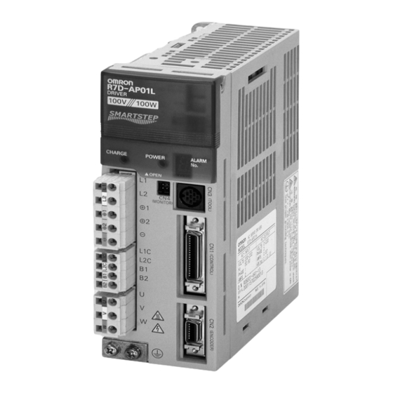
-
Contents
-
Table of Contents
-
Troubleshooting
-
Bookmarks
Quick Links
Cat. No. I533-E1-04
SMARTSTEP A SERIES
R7M-A@ (Servomotors)
R7D-AP@ (Servo Drivers)
USER’S MANUAL
Related Manuals for Omron SMARTSTEP R7D-AP Series
Summary of Contents for Omron SMARTSTEP R7D-AP Series
-
Page 1
Cat. No. I533-E1-04 SMARTSTEP A SERIES R7M-A@ (Servomotors) R7D-AP@ (Servo Drivers) Servomotors/Servo Drivers USER’S MANUAL… -
Page 2
2. The products are illustrated without covers and shieldings for closer look in this USER’S MANUAL. For actual use of the products, make sure to use the covers and shieldings as specified. 3. This USER’S MANUAL and other related user’s manuals are to be delivered to the actual end users of the products. -
Page 3
USER’S MANUAL SMARTSTEP A SERIES MODELS R7M-A@ (Servomotors) R7D-AP@ (Servo Drivers) Servomotors/Servo Drivers… -
Page 5
OMRON, 2001 All rights reserved. No part of this publication may be reproduced, stored in a retrieval system, or transmitted, in any form, or by any means, mechanical, electronic, photocopying, recording, or otherwise, without the prior written permission of OMRON. -
Page 7
This manual may include illustrations of the product with protective covers removed in order to describe the components of the product in detail. Make sure that these protective covers are on the product before use. Consult your OMRON representative when using the product after a long period of storage. -
Page 8
Installation and Wiring Precautions !Caution Do not step on or place a heavy object on the product. Doing so may result in injury. !Caution Do not cover the inlet or outlet ports and prevent any foreign objects from entering the product. -
Page 9
When an alarm occurs, remove the cause, reset the alarm after confirming safety, and then resume operation. Not doing so may result in injury. !Caution Do not use the built-in brake of the Servomotor for ordinary braking. Doing so may result in malfunction. -
Page 10
Maintenance and Inspection Precautions !WARNING Do not attempt to disassemble, repair, or modify any Units. Any attempt to do so may result in malfunction, fire, or electric shock. !Caution Resume operation only after transferring to the new Unit the contents of the data… -
Page 11
Warning Labels Warning labels are pasted on the product as shown in the following illustration. Be sure to follow the instructions given there. Warning label Example from R7D-AP01L Example from R7D-AP01L… -
Page 13
WHETHER SUCH CLAIM IS BASED ON CONTRACT, WARRANTY, NEGLIGENCE, OR STRICT LIABILITY. In no event shall the responsibility of OMRON for any act exceed the individual price of the product on which liability is asserted. IN NO EVENT SHALL OMRON BE RESPONSIBLE FOR WARRANTY, REPAIR, OR OTHER CLAIMS… -
Page 14
The following are some examples of applications for which particular attention must be given. This is not intended to be an exhaustive list of all possible uses of the products, nor is it intended to imply that the uses listed may be suitable for the products: •… -
Page 15
PERFORMANCE DATA Performance data given in this manual is provided as a guide for the user in determining suitability and does not constitute a warranty. It may represent the result of OMRON’s test conditions, and the users must correlate it to actual application requirements. -
Page 17: Table Of Contents
2-9 External Regeneration Resistor Specifications……..
-
Page 19: Chapter 1. Introduction
Chapter 1 Introduction Features System Configuration Servo Driver Nomenclature Applicable Standards System Block Diagrams…
-
Page 20: Features
Servomotors provide faster rotation speeds of up to 4,500 r/min, with constant operation pos- sible at this speed. Faster output torque of up to 1 s can output up to approximately 300% of the rated torque, providing even faster middle- and long-stroke positioning.
-
Page 21
Flat-style Servomotors, with a shorter overall length. The Flat Servomotor depth dimen- sions are approximately the same as those of stepping motors of the same output capacity. Servo- motors can be selected by size, thereby making equipment more compact. -
Page 22: System Configuration
Introduction Chapter 1 System Configuration SYSMAC + Position Control Unit with pulse string output TGON TGON POWER POWER VCMP VCMP R7A–PR02A PARAMETER UNIT SCROLL SCROLL MODE/SET MODE/SET RESET Pulse String Position Control Units SYSMAC CJ/CS/C/CV DATA DATA Programmable Controller CJ1W-NC113/213/413…
-
Page 23: Servo Driver Nomenclature
Chapter 1 Introduction Servo Driver Nomenclature Rotary switch for unit No. selection Rotary switch for gain adjustment Function selection switches: • Switch/parameter setting enable switch • Resolution setting • Command pulse input setting • Dynamic braking setting • Online autotuning switch…
-
Page 24: Applicable Standards
EN61000-6-2 Electromagnetic compatibility and immunity standards for industrial environments Note Installation under the conditions stipulated in 3-2-5 EMC-compatible Wiring must be met to ensure conformance to EMC Directives. UL and cUL Standards ■ Standards Product Applicable standards File No.
-
Page 25: System Block Diagrams
Introduction Chapter 1 System Block Diagrams 100 V AC: R7D-APA3L/-APA5L/-AP01L/-AP02L/-AP04L ■ AC Servo Driver B1 B2 AC Servomotor Fuse CHARGE (See note.) − Gate drive Voltage Relay overcurrent protection Gate drive detection drive Interface Voltage detection Current detection ∼ ASIC ±5 V…
-
Page 26
Chapter 1 Introduction 200 V AC: R7D-APA3H/-APA5H/-AP01H/-AP02H/-AP04H ■ AC Servo Driver B1 B2 AC Servomotor Fuse CHARGE − (See note.) Gate drive Relay overcurrent protection Voltage Gate drive drive detection Interface Voltage detection Current detection ∼ ASIC ±5 V generation +16.5 V… -
Page 27: Chapter 2. Standard Models And Specifications
Chapter 2 Standard Models and Specifications Standard Models External and Mounted Dimensions Servo Driver Specifications Servomotor Specifications Reduction Gear Specifications Cable and Connector Specifications Servo Relay Units and Cable Specifications Parameter Unit Specifications External Regeneration Resistor Specifications 2-10 DC Reactors…
-
Page 28: Standard Models
Standard Models and Specifications Chapter 2 Standard Models Servomotors Servo Drivers ■ ■ Specifications Model Single-phase 30 W R7D-APA3L ● 3,000-r/min Cylinder-style Servomotors 100 V AC 50 W R7D-APA5L Specifications Model 100 W R7D-AP01L Without Straight shaft 30 W R7M-A03030…
-
Page 29
1/15 R7G-VRSFPB15D750 1/15 R7G-RGSF15C750 1/25 R7G-VRSFPB25E750 1/25 R7G-RGSF25C750 Note There are no reduction gears for 30-W Servo- Note There are no reduction gears for 30-W Servo- motors. motors. ● For Flat-style Servomotors ● For Flat-style Servomotors (Backlash = 3′ Max.) (Backlash = 45′… -
Page 30
(1 axis) XW2Z-100J-A22 Flat-style) 10 m R7A-CRA010C R7A-CRA010CR For CS1W-HCP22 0.5 m XW2Z-050J-A23 15 m R7A-CRA015C R7A-CRA015CR (2 axes) XW2Z-100J-A23 20 m R7A-CRA020C R7A-CRA020CR For 3F88M-DRT141 0.5 m XW2Z-050J-A25 XW2Z-100J-A25 Note Use a robot cable if cable flexibility is required. -
Page 31
Chapter 2 Standard Models and Specifications Peripheral Cable Connectors ■ Specifications Model Analog Monitor Cable (CN4) 1 m R88A-CMW001S Computer Monitor Cable (CN3) DOS 2 m R7A-CCA002P2 PC98 2 m R7A-CCA002P3 Control I/O Connector (CN1) R88A-CNU01C Encoder Connector (CN2) R7A-CNA01R… -
Page 32: External And Mounted Dimensions
Chapter 2 Standard Models and Specifications External and Mounted Dimensions 2-2-1 Servo Drivers ■ Single-phase 100 V AC: R7D-APA3L/-APA5L/-AP01L/-AP02L (30 W to 200 W) Single-phase 200 V AC: R7D-APA3H/-APA5H/-AP01H/-AP02H (30 W to 200 W) ● Wall Mounting Mounted dimensions External dimensions…
-
Page 33
Standard Models and Specifications Chapter 2 Single-phase 100 V AC: R7D-AP04L (400 W) ■ Single-phase 200 V AC: R7D-AP04H (400 W) ● Wall Mounting Mounted dimensions External dimensions 5 dia. Two, M4 (75) ● Front Panel Mounting (Using Mounting Brackets) -
Page 34
Chapter 2 Standard Models and Specifications Single-phase/Three-phase 200 V AC: R7D-AP08H (750 W) ■ ● Wall Mounting External dimensions Mounted dimensions 5 dia. Two, M4 (75) ● Front Panel Mounting (Using Mounting Brackets) External dimensions Mounted dimensions 5 dia. 24.5 12.5… -
Page 35
Chapter 2 Standard Models and Specifications 2-2-2 Parameter Unit R7A-PR02A Hand-held Parameter Unit ■ TGON TGON POWER POWER VCMP VCMP R7A–PR02A PARAMETER UNIT SCROLL MODE/SET RESET J O G DATA RU N READ WRITE WRITE DRIVER DRIVER DRIVER DRIVER 4.8 dia. -
Page 36
■ 30 W/50 W/100 W R7M-A03030(-S1)/-A05030(-S1)/-A10030(-S1) ● 300±30 6 dia. 7 dia. 21.5 19.5 300±30 Two, 4.3 dia. Dimensions of shaft end with key (-S1) Model Dimensions (mm) R7M-A03030-@ 69.5 R7M-A05030-@ R7M-A10030-@ 94.5 Cylinder-style Servomotors with a Brake ■ ●… -
Page 37
Chapter 2 Cylinder-style Servomotors without a Brake ■ ● 200 W/400 W/750 W R7M-A20030(-S1)/-A40030(-S1)/-A75030(-S1) 300±30 6 dia. Dimensions of output section of 750-W Servomotors 7 dia. 21.5 300±30 Four, Z dia. Dimensions of shaft end with key (-S1) Model Dimensions (mm) R7M-A20030-@ 96.5… -
Page 38
Chapter 2 Flat-style Servomotors without a Brake ■ ● 100 W/200 W/400 W/750 W R7M-AP10030(-S1)/-AP20030(-S1)/-AP40030(-S1)/AP75030(-S1) 300±30 300±30 Dimensions of shaft end with key (-S1) Four, Z dia. Model Dimensions (mm) Basic servomotor dimensions With key (shaft Cable outlet dimensions end dimensions) -
Page 39
1/25 R7G-VRSFPB25E750 125 80 135 110 98 10 32 M6 M10 M4 10 8 * «AT» in the table refers to the set bolt. External Diagrams Four, Z2 dia. (effective depth: l) Four, Z1 dia. Set bolt (AT) Key dimensions… -
Page 40
M6 M6 M4 3.5 2.5 1/25 R7G-RGSF25C750 110 10 19 M6 M6 M4 3.5 2.5 * «AT» in the table refers to the set bolt. External Diagrams Four, Z2 dia. (effective depth: l) Four, Z1 dia. Set bolt (AT) Key dimensions… -
Page 41
1/25 R7G-VRSFPB25E750P 155 125 120 145 135 110 98 17 5 15 32 55 M8 M10 M4 10 8 * «AT» in the table refers to the set bolt. External Diagrams Four, Z2 dia. Four, Z1 dia. (effective depth: l) -
Page 42
3.5 2.9 1/25 R7G-RGSF25C750P 110 120 145 90 17 3 M8 M6 M4 3.5 2.9 * «AT» in the table refers to the set bolt. External Diagrams Four, Z2 dia. Four, Z1 dia. (effective depth: l) Set bolt (AT) Key dimensions… -
Page 43: Servo Driver Specifications
Note 1. The above items reflect individual evaluation testing. The results may differ under compound conditions. Note 2. Absolutely do not conduct a withstand voltage test with a Megger tester on the Servo Driver. If such tests are conducted, internal elements may be damaged.
-
Page 44
PWM frequency 11.7 kHz Maximum applicable fre- 250 kpps quency (command pulse application) Weight Approx. 0.8 kg Approx. 0.8 kg Approx. 0.8 kg Approx. 0.8 kg Approx. 1.1 kg Applicable Servomotor 30 W 50 W 100 W 200 W 400 W… -
Page 45
These are the terminals for outputs to the Servomotor. Be sure to nection terminals wire these terminals correctly. White Blue Green/ Yellow This is the ground terminal. Ground to a minimum of 100 Ω (class D, class 3). Frame ground 2-19… -
Page 46
• Applicable line receiver: T.I. SN75175, MC3486 or equivalent Note 2. Automatic-reset fuses are used for output protection. If overcurrent causes the fuse to oper- ate, current will not flow, and after a fixed period of time it will automatically reset. -
Page 47
(Pn500). OGND Output ground common Ground common for sequence outputs (pins 7 and 8). Note An open-collector output interface is used for pin-7 and -8 sequence outputs. (Maximum operating volt- age: 30 V DC; maximum output current: 50 mA) 2-21… -
Page 48
Reception data Interface for RS-422A transmission and reception. RXD– TXD+ Transmission data TXD– Terminating resistance terminal Connect to pin 21 (RXD–) on the end Unit. RS-422A ground Ground for RS-422A. CN1: Pin Arrangement ■ + feed pulse, Ground for +PULS… -
Page 49
200 Ω Input current: 7 to 15 mA − Note Select a value for resistance R so that the input current will be from 7 to 15 mA. 1.6 to 2.4 k Ω 24 V 750 to 1.1 k Ω… -
Page 50
(See note.) Di: Diode for preventing surge voltage (Use speed diodes.) Note Automatic-reset fuses are used for output protection. If overcurrent causes the fuse to operate, current will not flow, and after a fixed period of time it will automatically reset. -
Page 51
CN1 pin 4: –Direction Signal (–SIGN), –Forward Pulse (–CCW), –90 ° Phase Difference Signals (Phase B) (–B) Functions The function of these signals depends on the setting of Pn200.0 (command pulse mode: position control setting 1). Logic Pn200.0 Command pulse… -
Page 52
– pulse 3: +CCW – 90 ° phase differ- 1: +A ence signals ( × 1) – 90 ° phase differ- 3: +B ence signals ( × 2) – 90 ° phase differ- ence signals ( × 4) -
Page 53
Standard Models and Specifications Chapter 2 Command Pulse Timing The following wave forms are for positive logic. Conditions are the same for negative logic. Command pulse Timing mode Feed pulse and direc- Forward rotation command Reverse rotation command tion signal… -
Page 54
RUN Command Input (14: RUN) This is the input that turns ON the power drive circuit for the main circuit of the Servo Driver. If this signal is not input (i.e., servo-OFF status), the Servomotor cannot operate except for JOG opera- tions. -
Page 55
Chapter 2 Standard Models and Specifications ● Positioning Completed Output (8: INP) The INP signal turns ON when the number of accumulated pulses in the deviation counter is less than Pn500 (positioning completed range). Brake Interlock Output (7: BKIR) ●… -
Page 56
Pin No. Symbol Signal name Function/Interface Speed monitor Speed monitor output: 1 V per 1,000 r/min Forward rotation: – voltage; reverse rotation: + voltage The output accuracy is approximately ± 15%. Current monitor Current monitor output: 1 V / rated torque Forward rotation: –… -
Page 57: Servomotor Specifications
V-15 Mounting method Flange-mounting Note 1. Vibration may be amplified due to sympathetic resonance of machinery, so use the Servo- motor Driver under conditions that will not exceed 80% of the specification values over a long period of time. Note 2. The above items reflect individual evaluation testing. The results may differ under compound conditions.
-
Page 58
Allowable thrust load Without brake Approx. 0.3 Approx. 0.4 Approx. 0.5 Approx. 1.1 Approx. 1.7 Approx. 3.4 With brake Approx. 0.6 Approx. 0.7 Approx. 0.8 Approx. 1.6 Approx. 2.2 Approx. 4.3 t6 × @250 mm (Al) Radiation shield dimensions… -
Page 59
Note 1. *The values for items marked by asterisks are the values at an armature winding tempera- ture of 100 ° C, combined with the Servo Driver. Other values are at normal conditions (20 ° C, 65%). The momentary maximum torque shown above indicates the standard value. -
Page 60
● 3,000-r/min Cylinder-style Servomotors: Torque and Rotation Speed Characteristics The following graphs show the characteristics with a 3-m standard cable, and a 100-V AC input for R7D-AP@L Servo Drivers, or a 200-V AC input for R7D-AP@H Servo Drivers. R7M-A05030 (50 W) R7M-A03030 (30 W) (N·m) -
Page 61
Approx. 0.7 Approx. 1.4 Approx. 2.1 Approx. 4.2 With brake Approx. 0.9 Approx. 1.9 Approx. 2.6 Approx. 5.7 t6 × @250 mm (Al) t12 × @300 mm Radiation shield dimensions (mate- rial) (Al) Applicable Servo 100 VAC AP01L AP02L AP04L –… -
Page 62
Note 1. *The values for items marked by asterisks are the values at an armature winding tempera- ture of 100 ° C, combined with the Servo Driver. Other values are at normal conditions (20 ° C, 65%). The momentary maximum torque shown above indicates the standard value. -
Page 63
Standard Models and Specifications 3,000-r/min Flat-style Servomotors: Torque and Rotation Speed Characteristics The following graphs show the characteristics with a 3-m standard cable, and a 100-V AC input for R7D-AP@L Servo Drivers, or a 200-V AC input for R7D-AP@H Servo Drivers. -
Page 64
When the normal temperature of 20 ° C and –10 ° C are compared, the momentary maximum torque increases by approximately 4%. Conversely, when the magnet warms up to 80 ° C from the normal temperature of 20 ° C, the momentary maximum torque decreases by approximately 8%. -
Page 65: Reduction Gear Specifications
(Backlash 3 max. and backlash 45 max.) There are four reduction ratios: 1/5, 1/9, 1/15, and 1/25. Select a reduction ratio to match the ca- pacity of the Servomotor. Note There are no 30-W reduction gears for Cylinder-style Servomotors. Reduction Gears for Cylinder-style Servomotors ■…
-
Page 66
Note 2. The enclosure rating for Servomotors with reduction gears is IP44. Note 3. The allowable radial torque is the value for the center of the shaft. Note 4. These are the allowable torque values for the reduction gears. Do not exceed these values. 2-40… -
Page 67
Note 1. The reduction gear inertia indicates the Servomotor shaft conversion value. Note 2. The enclosure rating for Servomotors with reduction gears is IP44. Note 3. The allowable radial torque is the value for the center of the shaft. 2-41… -
Page 68
Note 2. The enclosure rating for Servomotors with reduction gears is IP44. Note 3. The allowable radial torque is the value for the center of the shaft. Note 4. These are the allowable torque values for the reduction gears. Do not exceed these values. 2-42… -
Page 69: Cable And Connector Specifications
Note There is one method for connecting to a Controller with no special cable provided, and another method for using connector Terminal Block cable and a connector Terminal Block.
-
Page 70
Cable: AWG24 × 18P UL20276 Note Wires with the same wire color and the same number of marks form twisted pairs. For example, the orange wire with one red mark (–) is twisted together with the orange wire with one black mark (–). -
Page 71
OGND +24VIN RESET RXD+ RXD− TXD+ TXD− Servo Driver connector: Connector plug: 10136-3000VE (Sumitomo 3M) Connector case: 10336-52A0-008 (Sumitomo 3M) Terminal block connector Connector plug: FCN-361J040-AU (Fujitsu) ZCOM Connector case: FCN-360C040-B (Fujitsu) ALMCOM Cable: AWG24 × 18P UL20276 Shell 2-45… -
Page 72
A Robot Cable uses materials that enable a service life of 20 million bendings minimum under the fol- lowing conditions for the minimum bending radius (R) or larger. Note 1. The service life data on bending durability consists of test values. Use this data only as ref- erence values, and allow margin in actual application. -
Page 73
● Bending Test Stroke 320 mm Bending radius (R) 100 times/minute 2-6-3 Specifications of Integrated Cables ■ Integrated Cables for Servomotors without Brakes (R7A-CEA@@@S) ● Cable Models Model Length (L) Outer diameter of sheath Weight R7A-CEA003S 12.4 dia. Approx. 0.8 kg R7A-CEA005S Approx. -
Page 74
V phase 350780-1 (Tyco Electronics AMP) AWG20 Blue W phase Connector socket: AWG20 Green/Yellow M4 crimp terminal 350570-3 (Tyco Electronics AMP) Integrated Cables for Servomotors with Brakes (R7A-CEA@@@B) ■ ● Cable Models Model Length (L) Outer diameter of sheath Weight R7A-CEA003B 12.4 dia. -
Page 75
Chapter 2 Standard Models and Specifications ● Connection Configuration and External Dimensions Servomotor Servo Driver R7M-A@ R7D-AP@ 43.7 t=12 t=12.7 27.4 t=28.4 Wiring ● Servo Driver Symbol Servomotor Symbol AWG22 Black Connector kit: AWG22 Red − 54280-0800 (Molex Japan) AWG24 Green AWG24 Green/White S−… -
Page 76
Specifications of Standard Power Cables (R88A-CAWA@@@@) ■ Select a Power Cable to match the Servomotor being used. The cable length is 3 to 20 m. (The maximum distance between the Servomotor and the Servo Driver is 20 m.) Power Cables for Servomotors without Brakes… -
Page 77
Specifications of Robot Power Cables (R88A-CAWA@@@R) ■ Use one of the following Robot Power Cables if the cable will be used in an environment that requires cable flexibility or if it will be used with moving parts. Power Cables for Servomotors without Brakes… -
Page 78
Approx. 0.4 kg R7A-CRA010CR 10 m Approx. 0.9 kg R7A-CRA015CR 15 m Approx. 1.3 kg R7A-CRA020CR 20 m Approx. 1.7 kg Note The connection configuration, external dimensions, and wiring are the same for both Standard Cables and Robot Cables. 2-52… -
Page 79
Chapter 2 Standard Models and Specifications ● Connection Configuration and External Dimensions 43.7 Servo Driver Servomotor R7D-AP@ R7M-A@ t=12 t=12.7 ● Wiring Servo Driver Symbol Servomotor Symbol AWG22 Black Connector kit: AWG22 Red − 54280-0800 (Molex Japan) AWG24 Green AWG24 Green/White S−… -
Page 80
2-6-5 Peripheral Cables and Connector Specifications Analog Monitor Cable (R88A-CMW001S) ■ This is cable for connecting to the Servo Driver’s Monitor Output Connector (CN4). It is required for connecting monitor outputs to external devices such as measuring instruments. ● Cable Model… -
Page 81
Servo Drivers are required to use a personal computer for monitoring and setting parameters for a Servo Driver. There are two kinds of cable, one for DOS personal computers, and the other for NEC PC98 notebook computers (but not for PC98 desktop computers). -
Page 82
Connector case: 10314-52F0-008 (Sumitomo 3M) Control I/O Connector (R88A-CNU01C) ■ This is the connector for connecting to the Servo Driver’s Control I/O Connector (CN1). This connec- tor is used when the cable is prepared by the user. ● External Dimensions… -
Page 83
Encoder Connector (R7A-CNA0@R) ■ This is the connector for the Encoder Cable. This connector is used when the cable is prepared by the user. It is a soldered-type connector, and the applicable cable is as follows. • Applicable cable: AWG16 max. -
Page 84: Servo Relay Units And Cable Specifications
Standard Models and Specifications Servo Relay Units and Cable Specifications This section provides the specifications for the Servo Relay Units and cables used for connecting to OMRON Position Control Units. Select the models that match the Position Control Unit being used. For details, refer to 3-2-1 Connecting Cable.
-
Page 85
Com- Com- Com- Com- Com- RESET ALMCOM Note 1. The XB contact is used to turn ON/OFF External the electromagnetic brake. interrupt 2. Do not connect unused terminals. (See note 1.) 3. The 0 V terminal is internally connected to the common terminals. -
Page 86
24 V DC 24 V DC 24 V DC Note 1. The XB contact is used to turn ON/OFF the electromagnetic brake. 2. Do not connect unused terminals. 3. The 0 V terminal is internally connected to the common terminals. -
Page 87
1.) (See note 2.) 24 V DC Note 1. If these signals are input, the CQM1 output pulse can be input into the High- speed Counter. Note 2. Input this output signal to the CQM1 Input Unit. Note 3. The XB contact is used to turn ON/OFF the electromagnetic brake. -
Page 88
Chapter 2 Standard Models and Specifications XW2B-40J6-4A ■ This Servo Relay Unit connects to the following OMRON Position Control Units. Communications are supported. • CS1W-NC213/-NC233/-NC413/-NC433 • CJ1W-NC213/-NC233/-NC413/-NC433 ● External Dimensions X-axis Servo Y-axis Servo Position Control Unit connector Driver connector Driver connector 247.5… -
Page 89
Servo Driver connector Two, 3.5 dia. Note Terminal pitch: 7.62 mm ● Wiring Note1. The CW limit input signal and CCW limit input signal can be Origin input through an Input Unit. The following flags function as +24 V prox-… -
Page 90
Chapter 2 Standard Models and Specifications XW2B-40J6-9A ■ This Servo Relay Unit connects to the following OMRON Programmable Controllers. Communications are not sup- ported. • CJ1M-CPU21/-CPU22/-CPU23 External Dimensions ● CJ1M-CPU connector X-axis Servo Driver connector Y-axis Servo Driver connector Two, 3.5 dia. -
Page 91
(CIO 2960.09) 24 V DC Note1. The CW limit input signal and CCW limit input signal can be input through an Input Unit. The follow- ing flags function as the CW/CCW limit input signals in the CJ1M: Pulse Output 0: CW: A540.08, CCW: A540.09 Pulse Output 1: CW: A541.08, CCW: A541.09… -
Page 92
Chapter 2 Standard Models and Specifications ● External Dimensions Terminating resistance selector Signal selectors 4.5 dia. Communications support connectors Servo B phase selectors Y-axis Servo Driver Controller general-purpose I/O X-axis Servo Driver Controller special I/O 2-66… -
Page 93
TXD − TXD+ RXD − RXD+ Shell 2. Screwless Clamp Terminal Blocks Use the screwless clamp terminal blocks to wire controller general-purpose I/O and Servo Driver control signals. Upper terminal block Lower terminal block Upper Terminal Block Pin Arrangement 2-67… -
Page 94
4. Terminating Resistance Selector Set this selector to ON if there is no wiring from port 2 of the Servo Relay Unit to port 1 of another Servo Relay Unit when the Servo Relay Unit is positioned at the end of an RS-422 line. -
Page 95
Screwless clamp terminal blocks enable wiring without securing the wires with screws. Special fer- rules must be attached to the cables for sensors or external devices if sensors or external devices are also to be connected when wiring the Servo Driver and the control signal. -
Page 96
Servo Relay Unit Wiring Example ■ I/O power is supplied from terminals 20-0, 21-1, and 60-40 when a Servo Relay Unit is used. As shown in the following example, wiring can be performed by simply connecting the signals. Upper terminal block… -
Page 97
Standard Models and Specifications Chapter 2 Lower Terminal Block Pin Arrangement 24 V 2-71… -
Page 98
2-7-2 Cables for Servo Relay Units Servo Driver Cables (XW2Z-@J-B5) ■ These Servo Driver Cables connect a Servo Driver and a Servo Relay Unit. These Cables are used when connecting a Servo Relay Unit that does not support communications. ●… -
Page 99
Chapter 2 Standard Models and Specifications Servo Driver Cables (XW2Z-@J-B7) ■ These Servo Driver Cables connect a Servo Driver and a Servo Relay Unit. These Cables are used when connecting a Servo Relay Unit that supports communications (XW2B-40J6-4A). Cable Models ●… -
Page 100
Chapter 2 Servo Driver Cables (XW2Z-@@@J-B12) ■ These Servo Driver Cables connect a Servo Driver and a Servo Relay Unit. Use these cables to con- nect to a Customizable Counter Unit (CSW-HCP22-V1) or Servo Relay Unit (XW2B-80J7-1A). ● Cable Models… -
Page 101
Cable: AWG28 × 6P + AWG28 × 9C Servo Driver Cables (XW2Z-@@@J-B10) ■ These Servo Driver Cables connect a Servo Driver and a Servo Relay Unit. Use these cables to con- nect to a Customizable Counter Unit (FQM1-MMP21) or Servo Relay Unit (XW2B-80J7-1A). 2-75… -
Page 102
Servo Relay Unit Servo Driver Symbol +24VIN OGND +CCW −CCW −CW +ECRST −ECRST ZCOM RESET ALMCOM BKIR Connector plug: 10136-3000VE (Sumitomo 3M) Connector case: 10336-52A0-008 (Sumitomo 3M) RXD+ RXD- TXD+ TXD- Shell Cable: AWG28 × 6P + AWG28 × 9C 2-76… -
Page 103
Standard Models and Specifications Chapter 2 Position Control Unit Cables (XW2Z-@J-A3) ■ These Position Control Unit Cables connect a CQM1-CPU43-V1 or CQM1H-PLB21 Programma- ble Controller and an XW2B-20J6-3B Servo Relay Unit. ● Cable Models Model Length (L) Outer diameter of sheath… -
Page 104
Chapter 2 Standard Models and Specifications Position Control Unit Cables (XW2Z-@J-A4) ■ These Position Control Unit Cables connect a C200H-NC112 Position Control Unit and an XW2B- 20J6-1B Servo Relay Unit. ● Cable Models Model Length (L) Outer diameter of sheath… -
Page 105
Chapter 2 Standard Models and Specifications Position Control Unit Cable (XW2Z-@J-A5) ■ These Position Control Unit Cables connect a C200H-NC211, C500-NC113, or C500-NC211 Posi- tion Control Unit and an XW2B-40J6-2B Servo Relay Unit. Cable Models ● Model Length (L) Outer diameter of sheath… -
Page 106
Chapter 2 Standard Models and Specifications ● Wiring Servo Relay Unit Position Control Unit Cable: AWG28 × 6P + AWG28 × 19C 2-80… -
Page 107
Chapter 2 Standard Models and Specifications Position Control Unit Cables (XW2Z-@J-A8) ■ These Position Control Unit Cables connect a CS1W-NC113 or C200HW-NC113 Position Control Unit and an XW2B-20J6-1B Servo Relay Unit. Cable Models ● Model Length (L) Outer diameter of sheath… -
Page 108
Chapter 2 Standard Models and Specifications Position Control Unit Cables (XW2Z-@J-A9) ■ These Position Control Unit Cables connect a CS1W-NC213, CS1W-NC413, C200HW-NC213 or C200HW-NC413 Position Control Unit and an XW2B-40J6-2B or XW2B-40J6-4A Servo Relay Unit. ● Cable Models Model Length (L) -
Page 109
Chapter 2 Standard Models and Specifications ● Wiring Servo Relay Unit Position Control Unit A1/B1 A2/B2 A24/B24 A20/B20 A15/B15 Cable: AWG28 × 6P + AWG28 ×17C Crimp terminal 2-83… -
Page 110
Chapter 2 Standard Models and Specifications Position Control Unit Cables (XW2Z-@J-A12) ■ These Position Control Unit Cables connect a CS1W-NC133 Position Control Unit and an XW2B- 20J6-1B Servo Relay Unit. ● Cable Models Model Length (L) Outer diameter of sheath… -
Page 111
Chapter 2 Standard Models and Specifications Position Control Unit Cables (XW2Z-@J-A13) ■ These Position Control Unit Cables connect a CS1W-NC233 or CS1W-NC433 Position Control Unit and an XW2B-40J6-2B or XW2B-40J6-4A Servo Relay Unit. Cable Models ● Model Length (L) Outer diameter of sheath… -
Page 112
Chapter 2 Standard Models and Specifications ● Wiring Position Control Unit Servo Relay Unit AWG20 Black A3/B3 AWG20 Red A4/B4 A1/B1 A2/B2 A24/B24 A20/B20 A15/B15 Cable: AWG28 × 6P + AWG28 × 17C Crimp terminal 2-86… -
Page 113
Chapter 2 Standard Models and Specifications Position Control Unit Cables (XW2Z@J-A16) ■ These Position Control Unit Cables connect a CJ1W-NC113 Position Control Unit and an XW2B- 20J6-1B Servo Relay Unit. Cable Models ● Model Length (L) Outer diameter of sheath… -
Page 114
Chapter 2 Standard Models and Specifications ● Wiring Servo Relay Unit Position Control Unit Cable: AWG28 × 4P + AWG28 × 9C Crimp terminal 2-88… -
Page 115
Chapter 2 Standard Models and Specifications Position Control Unit Cables (XW2Z@J-A17) ■ These Position Control Unit Cables connect a CJ1W-NC213 or CJ1W-NC413 Position Control Unit and an XW2B-40J6-2B or XW2B-40J6-4A Servo Relay Unit. Cable Models ● Model Length (L) Outer diameter of sheath… -
Page 116
Chapter 2 Standard Models and Specifications ● Wiring Servo Relay Unit Position Control Unit A1/B1 A2/B2 A20/B20 A16/B16 A13/B13 Cable: AWG28 × 6P + AWG28 × 17C Crimp terminal 2-90… -
Page 117
Chapter 2 Standard Models and Specifications Position Control Unit Cables (XW2Z-@J-A20) ■ These Position Control Unit Cables connect a CJ1W-NC133 Position Control Unit and an XW2B- 20J6-1B Servo Relay Unit. Cable Models ● Model Length (L) Outer diameter of sheath… -
Page 118
Chapter 2 Standard Models and Specifications ● Wiring Position Control Unit Servo Relay Unit AWG20 Black AWG20 Red Cable: AWG28 × 4P + AWG28 × 9C Crimp terminal 2-92… -
Page 119
Chapter 2 Standard Models and Specifications Position Control Unit Cables (XW2Z-@J-A21) ■ These Position Control Unit Cables connect a CJ1W-NC233 or CJ1W-NC433 Position Control Unit and an XW2B-40J6-2B or XW2B-40J6-4A Servo Relay Unit. Cable Models ● Model Length (L) Outer diameter of sheath… -
Page 120
Chapter 2 Standard Models and Specifications ● Wiring Position Control Unit Servo Relay Unit AWG20 Black A3/B3 AWG20 Red A4/B4 A1/B1 A2/B2 A20/B20 A13/B13 Cable: AWG28 × 6P + AWG28 × 17C Crimp terminal 2-94… -
Page 121
Chapter 2 Standard Models and Specifications Position Control Unit Cable (XW2Z-@J-A22) ■ These Position Control Unit Cables connect a CS1W-HCP22 Position Control Unit and an XW2B- 20J6-3B Servo Relay Unit. Cable Models ● Model Length (L) Outer diameter of sheath… -
Page 122
Chapter 2 Standard Models and Specifications Position Control Unit Cables (XW2Z-@J-A23) ■ These Position Control Unit Cables connect a CS1W-HCP22 Position Control Unit and an XW2B- 20J6-3B Servo Relay Unit. ● Cable Models Model Length (L) Outer diameter of sheath… -
Page 123
Chapter 2 Standard Models and Specifications ● Wiring Servo Relay Unit Position Control Unit Cable: AWG28 × 4P + AWG28 × 4C Servo Relay Unit Cable: AWG28 × 4P + AWG28 × 4C Crimp terminal 2-97… -
Page 124
Chapter 2 Standard Models and Specifications Position Control Unit Cables (XW2Z-@J-A25) ■ These Position Control Unit Cables connect a 3F88M-DRT141 Single-shaft Positioner (for DeviceNet) and an XW2B-20J6-1B Servo Relay Unit. ● Cable Models Model Length (L) Outer diameter of sheath… -
Page 125
Chapter 2 Standard Models and Specifications ● Wiring Servo Relay Unit Position Control Unit A16/B16 Cable: AWG28 × 8P + AWG28 ×16C Crimp terminal Crimp terminal (Y-type) (Round) 2-99… -
Page 126
Chapter 2 Standard Models and Specifications CJ1M-CPU Unit Cables (XW2Z-100J-A26) ■ These CJ1M-CPU Unit Cables connect a CJ1M Unit with built-in pulse I/O (CJ1M-CPU21/-CPU22/- CPU23) and a Servo Relay Unit (XW2B-20J6-8A and XW2B-40J6-9A). ● Cable Models Model Length (L) Outer diameter of sheath… -
Page 127
Chapter 2 Standard Models and Specifications ● Wiring Servo Relay Unit CJ1M-CPU Unit Cable: AWG28 × 6P + AWG28 ×17C 2-101… -
Page 128
Chapter 2 Standard Models and Specifications Customizable Counter Unit Cables for Special I/O ■ These Customizable Counter Unit Cables connect a Customizable Counter Unit (CS1W-HCP22-V1) and a Servo Relay Unit (XW2B-80J7-1A). ● Cable Models Model Length (L) Outer diameter of sheath… -
Page 129
Chapter 2 Standard Models and Specifications ● Wiring Servo Relay Unit Customizable Counter Unit Cable: AWG28 × 6P + AWG28 ×17C Crimp terminals 2-103… -
Page 130
Chapter 2 Standard Models and Specifications Customizable Counter Unit Cables for General-purpose I/O ■ These Customizable Counter Unit Cables a Customizable Counter Unit (CS1W-HCP22-V1) and the general-purpose I/O of a Servo Relay Unit (XW2B-80J7-1A). ● Cable Models Model Length (L) -
Page 131
Chapter 2 Standard Models and Specifications ● Wiring Servo Relay Unit Customizable Counter Unit Crimp terminals Cable: AWG28 × 6P + AWG28 ×17C 2-105… -
Page 132
Chapter 2 Standard Models and Specifications Motion Controller Cables for Special I/O ■ These Motion Controller Cables connect a Motion Control Module (FQM1-MMP21) and the special I/ O of a Servo Relay Unit (XW2B-80J7-1A). ● Cable Models Model Length (L) -
Page 133
Chapter 2 Standard Models and Specifications ● Wiring Servo Relay Unit Motion Control Module Crimp terminals 2-107… -
Page 134
Chapter 2 Standard Models and Specifications Motion Controller Cable for General-purpose I/O ■ These Motion Controller Cables connect a Motion Control Module (FQM1-MMP21) and the general- purpose I/O of a Servo Relay Unit (XW2B-80J7-1A). ● Cable Models Model Length (L) -
Page 135
Chapter 2 Standard Models and Specifications ● Wiring Servo Relay Unit Motion Control Module Crimp terminals 2-109… -
Page 136
Chapter 2 Standard Models and Specifications Communications Cables (XW2Z-@J-C1) ■ These Communications Cables connect the communications port of an XW2B-40J6-4A Servo Relay Unit that supports communications and a Programmable Controller Serial Communications Unit or Board. ● Cable Models Model Length (L) -
Page 137: Parameter Unit Specifications
Standard Models and Specifications Chapter 2 Parameter Unit Specifications R7A-PR02A Hand-held Parameter Unit ■ A Parameter Unit is required for setting parameters to operate and control the Servo Driver, for copying Servo Driver parameters, and for other func- TGON TGON POWER…
-
Page 138
Function Mode Executing functions Alarm displays Displaying alarms Parameter copying Reading and saving parameters from the Servo Driver to the Parameter Unit; writing parameters from the Parameter Unit to the Servo Driver; and comparing Servo Driver and Parameter Unit parameters. 2-112… -
Page 139: External Regeneration Resistor Specifications
If the Servomotor’s regenerative energy is excessive, connect an External Regeneration Resistor. Note 1. External Regeneration Resistors cannot be connected to Servo Drivers of between 30 to 200 W. Connection to a 400-W Servo Driver is usually not required. If the Servomotor’s regenerative energy is excessive, connect an External Regeneration Resistor between B1 and B2.
-
Page 140: Dc Reactors
Standard Models and Specifications Chapter 2 2-10 DC Reactors Connect a DC Reactor to the Servo Driver’s DC Reactor connection terminal as a harmonic current control measure. Select a model to match the Servo Driver being used. R88A-PX@ DC Reactors ■…
-
Page 141: Chapter 3. System Design And Installation
Chapter 3 System Design and Installation Installation Conditions Wiring Regenerative Energy Absorption…
-
Page 142
System Design and Installation Installation and Wiring Precautions !Caution Do not step on or place a heavy object on the product. Doing so may result in injury. !Caution Do not cover the inlet or outlet ports and prevent any foreign objects from entering the product. -
Page 143: Installation Conditions
• Temperature rise in any Unit installed in a closed space, such as a control box, will cause the Servo Driver’s ambient temperature to rise. Use a fan or air conditioner to prevent the Servo Driver’s ambi- ent temperature from exceeding 55 °…
-
Page 144
If a Servo Driver is always operated at the maxi- mum ambient temperature of 40 ° C and at 80% of the rated torque, then a service life of approxi- mately 50,000 hours can be expected. A drop of 10 ° C in the ambient temperature will double the expected service life. -
Page 145
• When connecting to a V-belt or timing belt, consult the maker for belt selection and tension. A radial load twice the belt tension will be placed on the motor shaft. Do not allow a radial load exceeding specifications to be placed on the motor shaft due to belt tension. -
Page 146
• Absolutely do not remove the encoder cover or take the motor apart. The magnet and the encoder are aligned in the AC Servomotor. If they become misaligned, the motor will not operate. -
Page 147
If the system configuration requires that a SMARTSTEP A-series Motor be used in combination with a reduction gear from another company, select the reduction gear so that the loads on the motor shaft (i.e., both the radial and thrust loads) are with the allowable values. (Refer to 2-4-2 Performance Specifications for details on the allowable loads for motors.) Also, control the motor speed and output… -
Page 148: Wiring
Wiring 3-2-1 Connecting Cable This section shows the types of connecting cable used in a SMARTSTEP A-series system. The wide selection of cables provided for configuring a servo system using a Position Control Unit makes wiring simple. System Configuration Parameter Unit…
-
Page 149
System Design and Installation Selecting Connecting Cables ■ 1. Servo Relay Unit Cables Select a Servo Relay Unit and Cable to match the Position Control Unit that is to be used. ● Selecting Connecting Cables without Communications Support Position Control Unit… -
Page 150
XW2Z-@@@J-B10 XW2Z-@@@J-A28 Note 1. The empty boxes in the model numbers are for cable length. The Position Control Unit cable length can be 0.5 or 1 meter long. (For example, XW2Z-050J-A9 is 0.5 meters long.) The Servo Driver cable length can be 1 or 2 meters long. (For example, XW2Z-100J-B7 is 1 meter long.) -
Page 151
3. General Control Cables and Control I/O Connector These cables and connector are used for connecting to Controllers for which no special cable is pro- vided, and when the cable for the Servo Driver’s control I/O connector is prepared by the user. -
Page 152
Only 2-meter cables are available. book computer 6. Analog Monitor Cable This is the cable for connecting to the Servo Driver’s analog monitor connector (CN4). It is required for connecting analog monitor outputs to an external device (such as a measuring instrument). Name/specifications… -
Page 153: Connection Examples
Also, connect a thermal switch output so that the power supply will be turned OFF when open. User 4. If an External Regeneration Resistor is to be connected to a 750-W Servo Driver, remove the short bar between B2 and B3. control 5.
-
Page 154
Connect if the regenerative energy exceeds the individual Servo Driver’s regenerative capacity. Also, connect the thermal switch output so that the power supply will be turned OFF when open. 4. If an External Regeneration Resistor is to be connected, User remove the short bar between B2 and B3. -
Page 155
30 to 200 W: An External Regeneration Resistor cannot be connected to these ation resistance terminals. connection termi- 400 W: These terminals normally do not need to be connected. If there is high nals regenerative energy, connect an External Regeneration Resistor between B1 and B2. -
Page 156
Frame ground Screw – size N ⋅ m Torque No-fuse breaker or fuse A (rms) capacity Note 1. Use the same wire sizes for 2, B1, and B2. Note 2. Connect an OMRON Servomotor Cable to the Servomotor connection terminals. 3-16… -
Page 157
Note 2. Connect an OMRON Servomotor Cable to the Servomotor connection terminals. Wire Sizes and Allowable Current ■ The following table shows the allowable current for when there are three wires. ● 600-V Heat-resistant Vinyl Wiring (HIV) (Reference Values) AWG size… -
Page 158
There are two ways to open the wire insertion slots, as follows: • Pry the slot open using the lever that comes with the Servo Driver (as in Fig. A). • Insert a flat-blade screwdriver (end width: 3.0 to 3.5 mm) into the opening for Servo Driver in- stallation, and press down firmly to open the slot (as in Fig. -
Page 159
System Design and Installation 4. Insert the wire into the slot. With the slot held open, insert the end of the wire. Then let the slot close by releasing the pressure from the lever or the screwdriver. 5. Mount the Terminal Block to the Servo Driver. -
Page 160
• If no-fuse breakers are installed at the top and the power supply line is wired from the lower duct, use metal tubes for wiring and make sure that there is adequate distance between the input lines and the internal wiring. -
Page 161
Therefore, select no-fuse breakers with an operating time of at least five seconds at 300% of the rated maximum output. General-pur- pose and low-speed no-fuse breakers are generally suitable. The table in 3-2-3 Terminal Block Wir- ing shows the rated power supply input currents for each Servomotor. -
Page 162
Note 2. Refer to the manufacturers’ documentation for operating details. Note 3. The surge immunity is for a standard impulse current of 8/20 µ s. If pulses are wide, either decrease the current or change to a larger-capacity surge absorber. -
Page 163
Note 3. If multiple Servo Drivers are to be connected to a single noise filter, select a noise filter with a rated current at least two times the total rated current of all the Servo Drivers. -
Page 164
R7D-AP08H 16 mA Note 1. The above leakage current is for cases where Servomotor power line length is less than 5 meters. (It varies depending on the Servomotor cable length and the insulation.) Note 2. The above leakage current is for normal temperature and humidity. (It varies depending on the temperature and humidity.) -
Page 165
• Always use the specified Encoder Cables. • If lines are interrupted in the middle, be sure to connect them with connectors, making sure that the cable insulation is not peeled off for more than 50 mm. In addition, always use shielded cable. -
Page 166
• If the control power supply wiring is long, noise resistance can be improved by adding 1- µ F lami- nated ceramic capacitors between the control power supply and ground at the Servo Driver input section or the controller output section. -
Page 167
Clamp plate power supply Ferrite core Controller Note 1. The cable wiring for the ferrite core must be 1.5 turns. Note 2. Remove the sheath from the cable and ground it directly to the metal plate at the clamps. 3-27… -
Page 168
• If no-fuse breakers are installed at the top and the power supply line is wired from the lower duct, use metal tubes for wiring and make sure that there is adequate distance between the input lines and the internal wiring. -
Page 169
● Case Structure • Use a metal control panel with welded joints on the top, bottom, and all sides. The case must be electrically conductive. • When assembling the control panel, remove the coating from all joints (or mask the joints when coating) to ensure electrical conductivity. -
Page 170
Chapter 3 System Design and Installation • Be sure that no gaps are created when installing the cover, as gaps can be caused by distortion when tightening screws. Case Cover Cover Oil-proof packing Conductive packing Control Panel A-B Cross-section Oil-proof packing… -
Page 171
Note 1. Refer to the manufacturers’ documentation for operating details. Note 2. The surge immunity is for a standard impulse current of 8/20 µ s. If pulses are wide, either decrease the current or change to a larger-capacity surge absorber. -
Page 172
Chapter 3 System Design and Installation Dimensions (The dimensions given below are for noise filters with lead-wire terminals. For the dimensions of noise filters with different types of terminals, contact the manufacturer.) For single-phase input (FN2070-6/07, FN2070-10/07) 45.4 Model FN2070-6/07… -
Page 173
Chapter 3 System Design and Installation For three-phase input (FN258L-16/07) 300±10 ● Noise filter for brake power supply Use the following noise filter for the brake power supply. Model Rated current Rated voltage Leakage current Manufacturer SUP-P5H-EPR 250 V 0.6 mA (at 250 Vrms, 60 Hz) Okaya Electric Industries Co., Ltd. -
Page 174
When selecting leakage breakers, remember to also add the leakage current from devices other than the Servomotor, such as machines using a switching power supply, noise filters, inverters, and so on. For details on leakage breakers, refer to the manufacturer’s catalog. -
Page 175
• Always use the specified Encoder Cables. • If lines are interrupted in the middle, be sure to connect them with connectors, making sure that the cable insulation is not peeled off for more than 50 mm. In addition, always use shielded cable. -
Page 176
• If the control power supply wiring is long, noise resistance can be improved by adding 1- µ F lami- nated ceramic capacitors between the control power supply and ground at the Servo Driver input section or the controller output section. -
Page 177: Regenerative Energy Absorption
Servomotor operation −N Servomotor output torque Note In the output torque graph, acceleration in the positive direction is shown as positive, and acceleration in the negative direction is shown as negative. • The regenerative energy values for E and E are derived from the following equations.
-
Page 178
• For Servo Driver models with internal capacitors for absorbing regenerative energy (i.e., models of 400 W or less.), the values for both Eg1 or Eg2 (unit: J) must be lower than the Servo Driver’s regenerative energy absorption capacity. (The capacity varies depending on the model. For details, refer to 3-3-2 Servo Driver Regenerative Energy Absorption Capacity.) -
Page 179
Deceleration time [s] Constant-velocity travel time when falling [s] Note There is some loss due to winding resistance, so the actual regenerative energy will be approx- imately 90% of the values derived from these equations. • For Servo Driver models with internal capacitors for absorbing regenerative energy (i.e., models of 400 W or less.), the values for both E… -
Page 180
– R7D-AP08H – Note These are the values at 100 V AC for 100-V AC models, and at 200 V AC for 200-V AC models. 3-3-3 Regenerative Energy Absorption by External Regeneration Resistance For 400- to 750-W Servo Drivers, if the regenerative energy exceeds the absorption capacity of the Servo Driver by itself, then external regeneration resistance can be connected. -
Page 181
Iwaki Musen Kenkyujo. For details, refer to the manufacturer’s documentation. RH120N50 Ω J 50 Ω ± 5% 30 W (Amount of regeneration at 120 ° C) RH300N50 Ω J 50 Ω ± 5% 75 W (Amount of regeneration at 120 ° C) RH500N50 Ω… -
Page 182
● R7D-AP08H Remove the short-circuit wiring between B2 and B2, and then connect an External Regeneration Resistor between the B1 and B2 terminals. External Regeneration Resistor Note 1. The short-circuit wiring between B2 and B3 must be removed. -
Page 183: Chapter 4. Operation
Chapter 4 Operation Operational Procedure Switch Settings Preparing for Operation Trial Operation Gain Adjustments User Parameters Operating Functions…
-
Page 184
Chapter 4 Precautions !Caution Confirm that there will be no effect on the equipment, and then perform a test operation. Not doing so may result in equipment damage. !Caution Check the newly set parameters and switches with their switches for proper exe- cution before actually running them. -
Page 185: Operational Procedure
EC Directives. Refer to 3-2 Wiring. 3. Switch settings Make sure that the power supply is turned OFF, and set the Servo Driver’s front panel switches. Refer to 4-2 Switch Settings.
-
Page 186: Switch Settings
To increase (speed up) the Servomotor’s response, set the gain adjustment rotary switch to a high value. Note If the gain adjustment rotary switch is set to 0, the Servomotor will operate according to the Servo Driver’s internal parameter.
-
Page 187
Switch turned OFF 4-2-2 Setting Function Switches Switch/Parameter Switch (Switch 6) ■ Switch 6 sets whether the Servo Driver is to be operated using the function switches, or using the parameter settings. Switch 6 Switch/parameter switch Function switches are enabled. (Enables switches 1 to 5.) Parameter settings are enabled. -
Page 188
RUN command is turned OFF or when an alarm occurs. Switch 2 Dynamic brake setting Dynamic braking is disabled. (When the RUN command is turned OFF or when an alarm occurs, the Servomotor will coast to a stop.) Dynamic braking is enabled. -
Page 189: Preparing For Operation
• The main-circuit power supply inputs (L1/L2 or L1/L2/L3) and the control-circuit power supply inputs (L1C/L2C) must be properly connected to the terminal block. • The Servomotor’s red (U), white (V), and blue (W) power lines and the yellow/green ground wire ( ) must be properly connected to the terminal block.
-
Page 190
ON. • The ALM output will take approximately 2 seconds to turn ON after the power has been turned ON. Do not attempt to detect an alarm using the Host Controller during this time (when power is being supplied with the Host Controller connected). -
Page 191: Trial Operation
● Turning OFF the Servomotor Set up the system so that the power and the RUN command can be turned OFF so that the Ser- vomotor can be immediately turned OFF if an abnormality occurs in the system. Trial Operation ■…
-
Page 192
3. Loaded Low-speed Operation • Send a low-speed command from the Host Controller to rotate the Servomotor. (The definition of low speed varies depending on the mechanical system, but a rough estimate is 1/10 to 1/5 of the normal operating speed.) •… -
Page 193: Gain Adjustments
(Refer to 4-5-2 Manual Tuning.) • When the load inertia fluctuates below 200 ms • When the rotation speed does not exceed 500 r/min, or when the output torque does not ex- ceed 50% of the rated torque •…
-
Page 194
(See note 1 and note 2.) Stop operation. Note 1. When the online autotuning switch is turned OFF, the tuning results will be stored in param- eter Pn103 (inertia ratio). Operation from this point will run according to the value stored in Pn103. -
Page 195
• Setting the gain adjustment rotary switch during online autotuning sets the servo system’s target speed loop gain and position loop gain. • Select a switch setting from the following 10 levels (switches A to F are the same setting) to suit the mechanical system. -
Page 196
Set the gain adjustment rotary switch. destablize the operation. Adjust the (Refer to the previous page for setting the gain adjustment rotary switch.) gain a little at a time while checking the Servomotor operation. -
Page 197: User Parameters
(I534) for detailed operation procedures. 4-6-1 Parameter Tables • The parameters for which each digit number must be set separately are given with the digit number added to the parameter number. For example, Pn001.0 (i.e., digit 0 of parameter Pn001).
-
Page 198
Deviation counter reset only when an alarm occurs. Not used. – Pn202 Electronic gear The pulse rate for the command pulses and Servo Servomotor travel dis- – 1 to 65535 ratio G1 (numera- tance tor) 0.01 ≤ G1/G2 ≤ 100… -
Page 199
2 (dynamic brake setting) is used. Note 2. If the parameter is set to 0 or 1 and the Servomotor is turned by an external force to 20 r/min or faster after the dynamic brake has stopped the Servomotor, the Servo ON status will not be entered even if the RUN signal turns ON. -
Page 200
• Increase the setting (i.e., increase the gain) to increase servo rigidity. Generally, the greater the inertia ratio, the higher the setting. There is a risk of vibration, however, if the gain is too high. When the speed loop gain is manipulated, the response will change as shown in the following dia- gram. -
Page 201
30 to 50 (1/s) for general-use and assembly machines, and 10 to 30 (1/s) for production robots. The default position loop gain is 40 (1/s), so be sure to lower the setting for machines with low rigidity. -
Page 202
• 2: Do not execute autotuning. (This setting is recommended for general operation.) Note If function switch 6 is OFF to enable the function switch settings, this parameter is ignored and the setting on function switch 1 (online autotuning setting) is used. -
Page 203
• When calculating load inertia using online autotuning, set whether the effects of adhesive friction (load torque proportional to rotation speed) on the servo system should be considered. • If adhesive friction is to be considered, set whether the adhesive friction is large or small to improve the accuracy of the load inertia calculations. -
Page 204
• Sets whether the deviation counter will be reset when the servo goes OFF and when an alarm occurs. • If the deviation counter is not reset (setting 1 or 2), the Servomotor will rotate only to the number of deviation counter residual pulses the next time the servo is turned ON,. Be careful, because the servo begins to operate as soon as the power is turned ON. -
Page 205
Unit Default Restart? • Sets the soft start for the command pulses. The soft start characteristic is for a primary filter (expo- nentiation function). Note 1. The soft start characteristics also includes linear acceleration and deceleration. (Set the time constant using Pn208.) Select the filter you want to use using Pn207.0 (position com- mand filter selection). -
Page 206
Settings 0 to 800 Unit Default Restart? • Set Pn402 (forward torque limit) and Pn403 (reverse torque limit) as a percentage (%) of the Servo- motor rated torque. Note Refer to 4-7-3 Torque Limiting for details. Pn500 Positioning completed range… -
Page 207
• If using an External Regeneration Resistor or External Regeneration Resistance Unit, set the regeneration absorption capacity. Set the regeneration absorption capacity for when the tempera- ture rises above 120 ° C, not the nominal capacity. (Refer to 3-3-3 Regenerative Energy Absorption by External Regeneration Resistance for details.) •… -
Page 208: Operating Functions
• The Servomotor rotates using the value of the pulse train input multiplied by the electronic gear ratio (Pn202, Pn203). Note If function switch 6 is OFF to enable the function switch settings, this parameter is ignored and the setting on function switches 4 and 5 (resolution setting) is used.
-
Page 209
Deenergized Note 1. The time from turning ON the brake power supply to the brake being released is 200 ms max. Set the speed command (pulse command) to be given after the brake has been re- leased, taking this delay into account. -
Page 210
Note 1. During the approximately 10 ms from the Servomotor de-energizing to the dynamic brake being applied, the Servomotor will continue to rotate due to its momentum. Note 2. If the Servomotor rotation speed falls below 100 r/min, the BKIR (brake interlock) signal is turned OFF. -
Page 211
(setting range: 0% to 800%). Note 1. Set these parameters to 350 (the default setting) when the torque limit function is not being used. Note 2. If the connected Servomotor is set to a value greater than the maximum momentary torque, the maximum momentary torque will become the set limit. -
Page 212
Note 2. These parameters become effective when the power is turned ON again after having been turned OFF. (Check to see that the LED display has gone OFF.) Note 3. With the default setting (G1/G2 = 4), the Servomotor will rotate once when 2,000 pulses are input. -
Page 213
(setting range = 0 to 6400 ( × 0.01 ms)). constant 2 (linear acceler- ation and deceleration) Note If not using the position command filter function, set each to 0 (i.e., the default setting). Operation ■ • The characteristics for each filter are shown below. -
Page 214
Chapter 4 Operation ● Linear Acceleration and Deceleration Speed Command pulse input frequency Time Pn208 Pn208 4-32… -
Page 215: Chapter 5. Troubleshooting
Chapter 5 Troubleshooting Measures when Trouble Occurs Alarms Troubleshooting Overload Characteristics (Electron Thermal Char- acteristics) Periodic Maintenance…
-
Page 216: Measures When Trouble Occurs
• Make sure that the voltage of the sequence input power supply (+24 VIN Terminal (pin CN1-13)) is within the range 23 to 25 VDC. If the voltage falls outside of this range, there is a risk of malfunc- tion, so make sure that the power supply is correct.
-
Page 217
• If the encoder signal is lost, the Servomotor may run away, or an error may be generated. Make sure the Servomotor is disconnected from the mechanical system before checking the encoder sig- nal. -
Page 218
1. Make a note of the parameters. • If using a Parameter Unit, transfer all of the parameter settings to the Parameter Unit using the Parameter Unit’s copy function. You can also use the Parameter Unit and write down all of the parameter settings. -
Page 219: Alarms
A.10, A.bF, A.C2, and A.C3. Note 3. If an alarm is canceled while RUN is turned ON, the Servo Driver will start as soon as the alarm is cleared, which is dangerous. Be sure to turn OFF the RUN command before can- celing the alarm.
-
Page 220
(A.32) is reached. An alarm may be generated if the Ser- vomotor continues to operate. Note These alarms are not displayed on the alarm indicator on the front of the Servo Driver. They appears on the display of the Parameter Unit. -
Page 221: Troubleshooting
Chapter 5 Troubleshooting Troubleshooting If an error occurs in the machinery, check the type of error using the alarm indicators and operation status, verify the cause, and take appropriate countermeasures. 5-3-1 Error Diagnosis Using Alarm Display Display Error Status when…
-
Page 222
Regeneration Occurs during Regenerative energy Calculate the regenerative overload operation. exceeds tolerance. energy, and connect an exter- nal Regeneration Resistor with the required regeneration absorption capacity. Setting error in Pn600 Set Pn600 correctly. (regeneration resistor capacity) Main-circuit power supply… -
Page 223
Servomotor winding is Check the winding resistance. burned out. Replace the Servomotor if the winding is burned out. Servo Driver is burned out. Replace the Servo Driver. Dynamic Occurs when the Energy required for stop- Lower the rotation speed. brake over-… -
Page 224
Servomotor power line is startup. wired incorrectly. Servo turned ON when the Adjust servo ON timing. Servomotor was rotated from the outside. Servo Driver is burned out. Replace the Servo Driver. Phase error Occurs when Encoder is wired incor- Rewire correctly. detected. rectly. -
Page 225
Reset the parameter correctly. overflow level) setting is too large. Resolution setting switch Reset the switches correctly. (switches 4 and 5) setting is too low. Pn202 and Pn203 (elec- Reset the parameters correctly. tronic gear ratio) setting is too large. -
Page 226
Parameter Unit use. function. then ON again. Internal element is Replace the Parameter Unit. faulty. 5-3-2 Troubleshooting by Means of Operating Status Symptom Probable cause Items to check Countermeasures The power sup- Power supply lines are Check whether the control-circuit Correct the power supply. -
Page 227
Servomotor power lines Check Servomotor power lines. Rewire correctly. are incorrectly wired. Command pulse is incor- Check the command pulse wiring. Rewire correctly. rectly wired. Check the command pulse volt- Connect a resistor match- age. ing the voltage. The Servomotor… -
Page 228
40 ° C. high. ture. Ventilation is obstructed. Check to see whether anything is Ensure adequate ventila- blocking ventilation. tion. There is an overload. Check the torque command value Lighten the load. -
Page 229: Overload Characteristics (Electron Thermal Characteristics)
Flat-style Servomotors: 100 to 400 W B: Cylinder-style Servomotors: 750 W Flat-style Servomotors: 750 W Note 1. The load ratio is the ratio of the motor current to the rated motor current as a percentage. Motor current × 100 Load ratio (%) = Rated motor current Note 2.
-
Page 230: Periodic Maintenance
• Recommended Periodic Maintenance Aluminum analytical capacitors: 50,000 hours, at an ambient Servo Driver operating temperature of 40 ° C, 80% output of the rated operation (rated torque), installed as described in operation man- ual. Axle fan: 30,000 hours, at an ambient Servo Driver operating temperature of 40 ° C and an ambient humidity of 65%.
-
Page 231
Servo Drivers. • If the Servomotor or Servo Driver is not to be used for a long time, or if they are to be used under conditions worse than those described above, a periodic inspection schedule of five years is recom- mended. -
Page 233: Chapter 6. Appendix
Chapter 6 Appendix Connection Examples…
-
Page 234
Note 3. Use mode 2 for origin search. Note 4. Use the 24-V DC power supply for command pulse signals as a dedicated power supply. Note 5. The diode recommended for surge absorption is the ERB44-02 (Fuji Electric) or equivalent. -
Page 235
Note 3. Use mode 2 for origin search. Note 4. Use the 5-V DC power supply for command pulse signals as a dedicated power supply. Note 5. The diode recommended for surge absorption is the ERB44-02 (Fuji Electric) or equivalent. -
Page 236
Note 3. Use mode 2 for origin search. Note 4. Use the 24-V DC power supply for command pulse signals as a dedicated power supply. Note 5. The diode recommended for surge absorption is the ERB44-02 (Fuji Electric) or equivalent. -
Page 237
Note 3. Use mode 2 for origin search. Note 4. Use the 5-V DC power supply for command pulse signals as a dedicated power supply. Note 5. The diode recommended for surge absorption is the ERB44-02 (Fuji Electric) or equivalent. -
Page 238
Note 2. Leave unused signal lines open and do not wire them. Note 3. Use the 24-V DC power supply for command pulse signals as a dedicated power supply. Note 4. The diode recommended for surge absorption is the ERB44-02 (Fuji Electric) or equivalent. -
Page 239
Note 3. The diode recommended for surge absorption is the ERB44-02 (Fuji Electric) or equivalent. Note 4. Do not use the 24-V DC brake power supply for the 24-V DC control power. Note 5. General-purpose I/O is one allocation example. The emergency stop and limit input contacts… -
Page 240
Note 3. Use mode 2 for origin search. Note 4. Use the 24-V DC power supply for command pulse signals as a dedicated power supply. Note 5. The diode recommended for surge absorption is the ERB44-02 (Fuji Electric) or equivalent. -
Page 241
Note 3. Use mode 2 for origin search. Note 4. Use the 24-V DC power supply for command pulse signals as a dedicated power supply. Note 5. The diode recommended for surge absorption is the ERB44-02 (Fuji Electric) or equivalent. -
Page 242
Note 2. Leave unused signal lines open and do not wire them. Note 3. The diode recommended for surge absorption is the ERB44-02 (Fuji Electric) or equivalent. Note 4. Do not use the 24-V DC brake power supply for the 24-V DC control power. 6-10… -
Page 243
Note 2. Leave unused signal lines open and do not wire them. Note 3. The diode recommended for surge absorption is the ERB44-02 (Fuji Electric) or equivalent. Note 4. Do not use the 24-V DC brake power supply for the 24-V DC control power. 6-11… -
Page 244
Note 2. Leave unused signal lines open and do not wire them. Note 3. The diode recommended for surge absorption is the ERB44-02 (Fuji Electric) or equivalent. Note 4. Do not use the 24-V DC brake power supply for the 24-V DC control power. 6-12… -
Page 245
Note 3. The diode recommended for surge absorption is the ERB44-02 (Fuji Electric) or equivalent. Note 4. Do not use the 24-V DC brake power supply for the 24-V DC control power. Note 5. Do not use XDRST as a general-purpose output. -
Page 246
Note 2. Leave unused signal lines open and do not wire them. Note 3. Use the 24-V DC power supply for command pulse signals as a dedicated power supply. Note 4. The diode recommended for surge absorption is the ERB44-02 (Fuji Electric) or equivalent. -
Page 247
Note 2. Leave unused signal lines open and do not wire them. Note 3. Use the 24-V DC power supply for command pulse signals as a dedicated power supply. Note 4. The diode recommended for surge absorption is the ERB44-02 (Fuji Electric) or equivalent. -
Page 249: Revision History
Revision History A manual revision code appears as a suffix to the catalog number on the front cover of the manual. Cat. No. I533-E1-04 Revision code The following table outlines the changes made to the manual during each revision. Page numbers refer to the previous version.
Troubleshooting
■
Code
Alarm
A.04
A.10
A.30
A.32
A.40
A.51
A.70
A.73
A.74
A.7A
A.bF
A.C1
A.C2
A.C3
A.d0
CPF00
CPF01
Warning
A.91
A.92
Note These alarms are not displayed on the alarm indicator on the front of the Servo Driver. They
appears on the display of the Parameter Unit.
5-6
ALM
Error detection function
OFF
Parameter setting error
OFF
Overcurrent
OFF
Regeneration error
OFF
Regeneration overload
OFF
Overvoltage/undervoltage Main circuit DC voltage outside the
OFF
Overspeed
OFF
Overload
OFF
Dynamic brake overload
OFF
Inrush resistance over-
load
OFF
Overheat
OFF
System error
OFF
Runaway detected
OFF
Phase error detected
OFF
Encoder disconnection
detected
OFF
Deviation counter over-
flow
—
Parameter Unit transmis-
sion error 1
—
Parameter Unit transmis-
sion error 2
—
Overload
—
Regeneration overload
Chapter 5
Cause of error
The Servomotor does not match the
Servo Driver.
Overcurrent detected, or improper radi-
ation shield temperature rise detected.
Regeneration circuit damaged due to
large amount of regenerative energy.
Regenerative energy exceeded the
regeneration resistance.
allowable range.
Servomotor rotation speed exceeded
the maximum speed.
Output torque exceeded 120% of rated
torque.
Regenerative energy exceeded the
dynamic brake resistance during
dynamic brake operation.
Inrush current exceeded the inrush
resistance during power supply inrush.
Abnormal temperature rise detected in
radiation shield.
A control circuit system error was
detected.
The Servomotor rotated in the opposite
direction from the command.
The Servomotor’s electrical angle was
incorrectly detected
Encoder phase A, B, or S is discon-
nected or shorted.
Deviation counter’s residual pulses
exceeded the deviation counter over-
flow level set in Pn505.
Data could not be transmitted after the
power supply was turned ON. (See
note.)
Transmission timeout error (See note.)
A warning occurs before the overload
alarm (A.70) is reached. An alarm may
be generated if the Servomotor contin-
ues to operate.
A warning occurs before the regenera-
tion overload alarm (A.32) is reached.
An alarm may be generated if the Ser-
vomotor continues to operate.
| Автор | Сообщение |
|---|---|
|
Заголовок сообщения: Omron r7d-ap04h сброс ошибок
|
|
|
|
Здрасвуйте. После пробоя входного варистора сервопривод выдает ошибку А.С2 (сбой фазы). Варистор заменен, как можно сбросить ошибку? В мануале на этот счет информации нет. Спасибо. |
| В начало |
|
|
simati |
Заголовок сообщения: Re: Omron r7d-ap04h сброс ошибок
|
|
|
Аналогичная проблема,тот же драйв — Omron r7d-ap04h, та же ошибка А С2 , тот же варистор ))) .реально ли восстановить? |
| В начало |
|
![]()
Cat. No. I533-E1-04
SMARTSTEP A SERIES
R7M-A@ (Servomotors)
R7D-AP@ (Servo Drivers)
Servomotors/Servo Drivers
USER’S MANUAL
Thank you for choosing this SMARTSTEP A-series product. Proper use and handling of the product will ensure proper product performance, will lengthen product life, and may prevent possible accidents.
Please read this manual thoroughly and handle and operate the product with care. Please keep this manual handy for reference after reading it.
1.To ensure safe and proper use of the OMRON Inverters, please read this USER’S MANUAL (Cat. No. I533-E1) to gain sufficient knowledge of the devices, safety information, and precautions before actual use.
2.The products are illustrated without covers and shieldings for closer look in this USER’S MANUAL. For actual use of the products, make sure to use the covers and shieldings as specified.
3.This USER’S MANUAL and other related user’s manuals are to be delivered to the actual end users of the products.
4.Please keep this manual close at hand for future reference.
5.If the product has been left unused for a long time, please inquire at our sales representative.
NOTICE
1.This manual describes information about installation, wiring, switch setting, and troubleshooting of the SMARTSTEP A-series Servomotors and Servo Drivers. For information about actual operating procedures using a Parameter Unit, refer to the SMARTSTEP A Series Operation Manual (I534).
2.Be sure that this manual accompanies the product to its final user.
3.Although care has been given in documenting the product, please contact your OMRON representative if you have any suggestions on improving this manual.
4.Assume that anything not specifically described in this manual is not possible.
5.Do not allow the Servomotor or Servo Driver to be wired, set, or operated (from a Parameter Unit) by anyone that is not a profession electrical engineer or the equivalent.
6.We recommend that you add the following precautions to any instruction manuals you prepare for the system into which the product is being installed.
•Precautions on the dangers of high-voltage equipment.
•Precautions on touching the terminals of the product even after power has been turned OFF. (These terminals are live even with the power turned OFF.)
7.Specifications and functions may be changed without notice in order to improve product performance.
8.Positive and negative rotation of AC Servomotors described in this manual are defined as looking at the end of the output shaft of the motor as follows: Counterclockwise rotation is positive and clockwise rotation is negative.
9.Do not perform withstand-voltage or other megameter tests on the product. Doing so may damage internal components.
10.Servomotors and Servo Drivers have a finite service life. Be sure to keep replacement products on hand and to consider the operating environment and other conditions affecting the service life.
11.Do not set values for any parameters not described in this manual. Operating errors may result. Consult your OMRON representative if you have questions.
12.Before using the product under conditions which are not described in the manual or applying the product to nuclear control systems, railroad systems, aviation systems, vehicles, combustion systems, medical equipment, amusement machines, safety equipment, and other systems, machines, and equipment that may have a serious influence on lives and property if used improperly, consult your OMRON representative.
Items to Check Before Unpacking
1.Check the following items before removing the product from the package:
•Has the correct product been delivered (i.e., the correct model number and specifications)?
•Has the product been damaged in shipping?
2.Check that the following accessories have been delivered.
•Safety Precautions
No connectors or mounting screws are provided. Obtain these separately.
USER’S MANUAL
SMARTSTEP ASERIES
MODELS R7M-A@ (Servomotors)
R7D-AP@ (Servo Drivers)
Servomotors/Servo Drivers
Notice:
OMRON products are manufactured for use according to proper procedures by a qualified operator and only for the purposes described in this manual.
The following conventions are used to indicate and classify precautions in this manual. Always heed the information provided with them. Failure to heed precautions can result in injury to people or damage to property.
!DANGER Indicates an imminently hazardous situation which, if not avoided, will result in death or serious injury. Additionally, there may be severe property damage.
!WARNING Indicates a potentially hazardous situation which, if not avoided, could result in death or serious injury. Additionally, there may be severe property damage.
!Caution Indicates a potentially hazardous situation which, if not avoided, may result in minor or moderate injury, or property damage.
OMRON Product References
All OMRON products are capitalized in this manual. The word “Unit” is also capitalized when it refers to an OMRON product, regardless of whether or not it appears in the proper name of the product.
The abbreviation “Ch,” which appears in some displays and on some OMRON products, often means “word” and is abbreviated “Wd” in documentation in this sense.
The abbreviation “PC” means Programmable Controller and is not used as an abbreviation for anything else.
Visual Aids
The following headings appear in the left column of the manual to help you locate different types of information.
Note Indicates information of particular interest for efficient and convenient operation of the product.
OMRON, 2001
All rights reserved. No part of this publication may be reproduced, stored in a retrieval system, or transmitted, in any form, or by any means, mechanical, electronic, photocopying, recording, or otherwise, without the prior written permission of OMRON.
No patent liability is assumed with respect to the use of the information contained herein. Moreover, because OMRON is constantly striving to improve its high-quality products, the information contained in this manual is subject to change without notice. Every precaution has been taken in the preparation of this manual. Nevertheless, OMRON assumes no responsibility for errors or omissions. Neither is any liability assumed for damages resulting from the use of the information contained in this publication.
General Warnings
Observe the following warnings when using the SMARTSTEP Servomotor and Servo Driver and all connected or peripheral devices.
This manual may include illustrations of the product with protective covers removed in order to describe the components of the product in detail. Make sure that these protective covers are on the product before use.
Consult your OMRON representative when using the product after a long period of storage.
!WARNING Always connect the frame ground terminals of the Servo Driver and the Servomotor to a class-3 ground (to 100 Ω or less). Not connecting to a class-3 ground may result in electric shock.
!WARNING Do not touch the inside of the Servo Driver. Doing so may result in electric shock.
!WARNING Do not remove the front cover, terminal covers, cables, or optional items while the power is being supplied. Doing so may result in electric shock.
!WARNING Installation, operation, maintenance, or inspection must be performed by authorized personnel. Not doing so may result in electric shock or injury.
!WARNING Wiring or inspection must not be performed for at least five minutes after turning OFF the power supply. Doing so may result in electric shock.
!WARNING Do not damage, press, or put excessive stress or heavy objects on the cables. Doing so may result in electric shock.
!WARNING Do not touch the rotating parts of the Servomotor in operation. Doing so may result in injury.
!WARNING Do not modify the product. Doing so may result in injury or damage to the product.
!WARNING Provide a stopping mechanism on the machine to ensure safety. The holding brake is not designed as a stopping mechanism for safety purposes.
!WARNING Provide an external emergency stopping mechanism that can stop operation and shutting off the power supply immediately. Not doing so may result in injury.
!WARNING Do not come close to the machine immediately after resetting momentary power interruption to avoid an unexpected restart. (Take appropriate measures to secure safety against an unexpected restart.) Doing so may result in injury.
!Caution Use the Servomotors and Servo Drivers in a specified combination. Using them incorrectly may result in fire or damage to the products.
!Caution Do not store or install the product in the following places. Doing so may result in fire, electric shock, or damage to the product.
•Locations subject to direct sunlight.
•Locations subject to temperatures or humidity outside the range specified in the specifications.
•Locations subject to condensation as the result of severe changes in temperature.
•Locations subject to corrosive or flammable gases.
•Locations subject to dust (especially iron dust) or salts.
•Locations subject to shock or vibration.
•Locations subject to exposure to water, oil, or chemicals.
!Caution Do not touch the Servo Driver radiator, Servo Driver regeneration resistor, or Servomotor while the power is being supplied or soon after the power is turned OFF. Doing so may result in a skin burn due to the hot surface.
Storage and Transportation Precautions
!Caution Do not hold the product by the cables or motor shaft while transporting it. Doing so may result in injury or malfunction.
!Caution Do not place any load exceeding the figure indicated on the product. Doing so may result in injury or malfunction.
Installation and Wiring Precautions
!Caution Do not step on or place a heavy object on the product. Doing so may result in injury.
!Caution Do not cover the inlet or outlet ports and prevent any foreign objects from entering the product. Doing so may result in fire.
!Caution Be sure to install the product in the correct direction. Not doing so may result in malfunction.
!Caution Provide the specified clearances between the Servo Driver and the control panel or with other devices. Not doing so may result in fire or malfunction.
!Caution Do not apply any strong impact. Doing so may result in malfunction.
!Caution Be sure to wire correctly and securely. Not doing so may result in motor runaway, injury, or malfunction.
!Caution Be sure that all the mounting screws, terminal screws, and cable connector screws are tightened to the torque specified in the relevant manuals. Incorrect tightening torque may result in malfunction.
!Caution Use crimp terminals for wiring. Do not connect bare stranded wires directly to terminals. Connection of bare stranded wires may result in burning.
!Caution Always use the power supply voltage specified in the User’s Manual. An incorrect voltage may result in malfunction or burning.
!Caution Take appropriate measures to ensure that the specified power with the rated voltage and frequency is supplied. Be particularly careful in places where the power supply is unstable. An incorrect power supply may result in malfunction.
!Caution Install external breakers and take other safety measures against short-circuiting in external wiring. Insufficient safety measures against short-circuiting may result in burning.
!Caution Take appropriate and sufficient countermeasures when installing systems in the following locations. Failure to do so may result in damage to the product.
•Locations subject to static electricity or other forms of noise.
•Locations subject to strong electromagnetic fields and magnetic fields.
•Locations subject to possible exposure to radioactivity.
•Locations close to power supplies.
Operation and Adjustment Precautions
!Caution Confirm that no adverse effects will occur in the system before performing the test operation. Not doing so may result in equipment damage.
!Caution Check the newly set parameters and switches for proper execution before actually running them. Not doing so may result in equipment damage.
!Caution Do not make any extreme adjustments or setting changes. Doing so may result in unstable operation and injury.
!Caution Separate the Servomotor from the machine, check for proper operation, and then connect to the machine. Not doing so may cause injury.
!Caution When an alarm occurs, remove the cause, reset the alarm after confirming safety, and then resume operation. Not doing so may result in injury.
!Caution Do not use the built-in brake of the Servomotor for ordinary braking. Doing so may result in malfunction.
Maintenance and Inspection Precautions
!WARNING Do not attempt to disassemble, repair, or modify any Units. Any attempt to do so may result in malfunction, fire, or electric shock.
!Caution Resume operation only after transferring to the new Unit the contents of the data required for operation. Not doing so may result in an unexpected operation.
![]()
Warning Labels
Warning labels are pasted on the product as shown in the following illustration. Be sure to follow the instructions given there.
Warning label
Example from R7D-AP01L
Example from R7D-AP01L
Read and Understand this Manual
Please read and understand this manual before using the product. Please consult your OMRON representative if you have any questions or comments.
Warranty and Limitations of Liability
WARRANTY
OMRON’s exclusive warranty is that the products are free from defects in materials and workmanship for a period of one year (or other period if specified) from date of sale by OMRON.
OMRON MAKES NO WARRANTY OR REPRESENTATION, EXPRESS OR IMPLIED, REGARDING NONINFRINGEMENT, MERCHANTABILITY, OR FITNESS FOR PARTICULAR PURPOSE OF THE PRODUCTS. ANY BUYER OR USER ACKNOWLEDGES THAT THE BUYER OR USER ALONE HAS DETERMINED THAT THE PRODUCTS WILL SUITABLY MEET THE REQUIREMENTS OF THEIR INTENDED USE. OMRON DISCLAIMS ALL OTHER WARRANTIES, EXPRESS OR IMPLIED.
LIMITATIONS OF LIABILITY
OMRON SHALL NOT BE RESPONSIBLE FOR SPECIAL, INDIRECT, OR CONSEQUENTIAL DAMAGES, LOSS OF PROFITS OR COMMERCIAL LOSS IN ANY WAY CONNECTED WITH THE PRODUCTS, WHETHER SUCH CLAIM IS BASED ON CONTRACT, WARRANTY, NEGLIGENCE, OR STRICT LIABILITY.
In no event shall the responsibility of OMRON for any act exceed the individual price of the product on which liability is asserted.
IN NO EVENT SHALL OMRON BE RESPONSIBLE FOR WARRANTY, REPAIR, OR OTHER CLAIMS REGARDING THE PRODUCTS UNLESS OMRON’S ANALYSIS CONFIRMS THAT THE PRODUCTS WERE PROPERLY HANDLED, STORED, INSTALLED, AND MAINTAINED AND NOT SUBJECT TO CONTAMINATION, ABUSE, MISUSE, OR INAPPROPRIATE MODIFICATION OR REPAIR.
Application Considerations
SUITABILITY FOR USE
OMRON shall not be responsible for conformity with any standards, codes, or regulations that apply to the combination of products in the customer’s application or use of the products.
At the customer’s request, OMRON will provide applicable third party certification documents identifying ratings and limitations of use that apply to the products. This information by itself is not sufficient for a complete determination of the suitability of the products in combination with the end product, machine, system, or other application or use.
The following are some examples of applications for which particular attention must be given. This is not intended to be an exhaustive list of all possible uses of the products, nor is it intended to imply that the uses listed may be suitable for the products:
•Outdoor use, uses involving potential chemical contamination or electrical interference, or conditions or uses not described in this manual.
•Nuclear energy control systems, combustion systems, railroad systems, aviation systems, medical equipment, amusement machines, vehicles, safety equipment, and installations subject to separate industry or government regulations.
•Systems, machines, and equipment that could present a risk to life or property.
Please know and observe all prohibitions of use applicable to the products.
NEVER USE THE PRODUCTS FOR AN APPLICATION INVOLVING SERIOUS RISK TO LIFE OR PROPERTY WITHOUT ENSURING THAT THE SYSTEM AS A WHOLE HAS BEEN DESIGNED TO ADDRESS THE RISKS, AND THAT THE OMRON PRODUCTS ARE PROPERLY RATED AND INSTALLED FOR THE INTENDED USE WITHIN THE OVERALL EQUIPMENT OR SYSTEM.
PROGRAMMABLE PRODUCTS
OMRON shall not be responsible for the user’s programming of a programmable product, or any consequence thereof.
Disclaimers
CHANGE IN SPECIFICATIONS
Product specifications and accessories may be changed at any time based on improvements and other reasons.
It is our practice to change model numbers when published ratings or features are changed, or when significant construction changes are made. However, some specifications of the products may be changed without any notice. When in doubt, special model numbers may be assigned to fix or establish key specifications for your application on your request. Please consult with your OMRON representative at any time to confirm actual specifications of purchased products.
DIMENSIONS AND WEIGHTS
Dimensions and weights are nominal and are not to be used for manufacturing purposes, even when tolerances are shown.
PERFORMANCE DATA
Performance data given in this manual is provided as a guide for the user in determining suitability and does not constitute a warranty. It may represent the result of OMRON’s test conditions, and the users must correlate it to actual application requirements. Actual performance is subject to the OMRON Warranty and Limitations of Liability.
ERRORS AND OMISSIONS
The information in this manual has been carefully checked and is believed to be accurate; however, no responsibility is assumed for clerical, typographical, or proofreading errors, or omissions.
|
Table of Contents |
|||||
|
Chapter 1. Introduction. . . . . . . . . . . . . . . . . . . . . . . . . . . . . . . . . . . . |
1-1 |
||||
|
1-1 |
Features. . . . . . . . . . . . . . . . . . . . . . . . . . . . . . . . . . . . . . . . . . . . . . . . . . . . . . . . . . . . . . . . . . |
1-2 |
|||
|
1-2 |
System Configuration . . . . . . . . . . . . . . . . . . . . . . . . . . . . . . . . . . . . . . . . . . . . . . . . . . . . . . . |
1-4 |
|||
|
1-3 |
Servo Driver Nomenclature . . . . . . . . . . . . . . . . . . . . . . . . . . . . . . . . . . . . . . . . . . . . . . . . . . |
1-5 |
|||
|
1-4 |
Applicable Standards . . . . . . . . . . . . . . . . . . . . . . . . . . . . . . . . . . . . . . . . . . . . . . . . . . . . . . . |
1-6 |
|||
|
1-5 |
System Block Diagrams . . . . . . . . . . . . . . . . . . . . . . . . . . . . . . . . . . . . . . . . . . . . . . . . . . . . . |
1-7 |
|||
|
Chapter 2. Standard Models and Specifications. . . . . . . . . . . . . . . . |
2-1 |
||||
|
2-1 |
Standard Models. . . . . . . . . . . . . . . . . . . . . . . . . . . . . . . . . . . . . . . . . . . . . . . . . . . . . . . . . . . |
2-2 |
|||
|
2-2 |
External and Mounted Dimensions . . . . . . . . . . . . . . . . . . . . . . . . . . . . . . . . . . . . . . . . . . . . |
2-6 |
|||
|
2-3 |
Servo Driver Specifications . . . . . . . . . . . . . . . . . . . . . . . . . . . . . . . . . . . . . . . . . . . . . . . . . . |
2-17 |
|||
|
2-4 |
Servomotor Specifications . . . . . . . . . . . . . . . . . . . . . . . . . . . . . . . . . . . . . . . . . . . . . . . . . . . |
2-31 |
|||
|
2-5 |
Reduction Gear Specifications . . . . . . . . . . . . . . . . . . . . . . . . . . . . . . . . . . . . . . . . . . . . . . . . |
2-39 |
|||
|
2-6 |
Cable and Connector Specifications. . . . . . . . . . . . . . . . . . . . . . . . . . . . . . . . . . . . . . . . . . . . |
2-43 |
|||
|
2-7 |
Servo Relay Units and Cable Specifications . . . . . . . . . . . . . . . . . . . . . . . . . . . . . . . . . . . . . |
2-58 |
|||
|
2-8 |
Parameter Unit Specifications . . . . . . . . . . . . . . . . . . . . . . . . . . . . . . . . . . . . . . . . . . . . . . . . |
2-111 |
|||
|
2-9 |
External Regeneration Resistor Specifications. . . . . . . . . . . . . . . . . . . . . . . . . . . . . . . . . . . . |
2-113 |
|||
|
2-10 |
DC Reactors . . . . . . . . . . . . . . . . . . . . . . . . . . . . . . . . . . . . . . . . . . . . . . . . . . . . . . . . . . . . . . |
2-114 |
|||
|
Chapter 3. System Design and Installation . . . . . . . . . . . . . . . . . . . . |
3-1 |
||||
|
3-1 |
Installation Conditions . . . . . . . . . . . . . . . . . . . . . . . . . . . . . . . . . . . . . . . . . . . . . . . . . . . . . . |
3-3 |
|||
|
3-2 |
Wiring. . . . . . . . . . . . . . . . . . . . . . . . . . . . . . . . . . . . . . . . . . . . . . . . . . . . . . . . . . . . . . . . . . . |
3-8 |
|||
|
3-3 |
Regenerative Energy Absorption . . . . . . . . . . . . . . . . . . . . . . . . . . . . . . . . . . . . . . . . . . . . . . |
3-37 |
|||
|
Chapter 4. Operation. . . . . . . . . . . . . . . . . . . . . . . . . . . . . . . . . . . . . . |
4-1 |
||||
|
4-1 |
Operational Procedure . . . . . . . . . . . . . . . . . . . . . . . . . . . . . . . . . . . . . . . . . . . . . . . . . . . . . . |
4-3 |
|||
|
4-2 |
Switch Settings . . . . . . . . . . . . . . . . . . . . . . . . . . . . . . . . . . . . . . . . . . . . . . . . . . . . . . . . . . . . |
4-4 |
|||
|
4-3 |
Preparing for Operation . . . . . . . . . . . . . . . . . . . . . . . . . . . . . . . . . . . . . . . . . . . . . . . . . . . . . |
4-7 |
|||
|
4-4 |
Trial Operation . . . . . . . . . . . . . . . . . . . . . . . . . . . . . . . . . . . . . . . . . . . . . . . . . . . . . . . . . . . . |
4-9 |
|||
|
4-5 |
Gain Adjustments . . . . . . . . . . . . . . . . . . . . . . . . . . . . . . . . . . . . . . . . . . . . . . . . . . . . . . . . . . |
4-11 |
|||
|
4-6 |
User Parameters . . . . . . . . . . . . . . . . . . . . . . . . . . . . . . . . . . . . . . . . . . . . . . . . . . . . . . . . . . . |
4-15 |
|||
|
4-7 |
Operating Functions . . . . . . . . . . . . . . . . . . . . . . . . . . . . . . . . . . . . . . . . . . . . . . . . . . . . . . . . |
4-26 |
|||
|
Chapter 5. Troubleshooting . . . . . . . . . . . . . . . . . . . . . . . . . . . . . . . . |
5-1 |
||||
|
5-1 |
Measures when Trouble Occurs . . . . . . . . . . . . . . . . . . . . . . . . . . . . . . . . . . . . . . . . . . . . . . . |
5-2 |
|||
|
5-2 |
Alarms . . . . . . . . . . . . . . . . . . . . . . . . . . . . . . . . . . . . . . . . . . . . . . . . . . . . . . . . . . . . . . . . . . |
5-5 |
|||
|
5-3 |
Troubleshooting . . . . . . . . . . . . . . . . . . . . . . . . . . . . . . . . . . . . . . . . . . . . . . . . . . . . . . . . . . . |
5-7 |
|||
|
5-4 |
Overload Characteristics (Electron Thermal Characteristics) . . . . . . . . . . . . . . . . . . . . . . . . |
5-15 |
|||
|
5-5 |
Periodic Maintenance . . . . . . . . . . . . . . . . . . . . . . . . . . . . . . . . . . . . . . . . . . . . . . . . . . . . . . . |
5-16 |
|||
|
Chapter 6. Appendix . . . . . . . . . . . . . . . . . . . . . . . . . . . . . . . . . . . . . . |
6-1 |
||||
|
6-1 |
Connection Examples. . . . . . . . . . . . . . . . . . . . . . . . . . . . . . . . . . . . . . . . . . . . . . . . . . . . . . . |
6-2 |
|||
|
Revision History. . . . . . . . . . . . . . . . . . . . . . . . . . . . . . . . . . . . . . . . . . |
R-1 |
||||
Chapter 1
Introduction
1-1 Features
1-2 System Configuration
1-3 Servo Driver Nomenclature
1-4 Applicable Standards
1-5 System Block Diagrams
1-1 Features
The SMARTSTEP A-series Servomotors and Servo Drivers have been developed as pulse string input-type Position Controllers to replace stepping motors in simple positioning systems. The SMARTSTEP A-series Servomotors and Servo Drivers combine the stepping motor’s ease of use with faster positioning resulting from high speed and high torque, higher reliability with no loss of positioning accuracy even during sudden load changes, and other advanced features.
■ Faster Response and Rotation Speed
SMARTSTEP A-series Servomotors and Servo Drivers incorporate the same high-speed and hightorque features, unachievable with stepping motors, as the OMNUC W Series. The SMARTSTEP A- series Servomotors provide faster rotation speeds of up to 4,500 r/min, with constant operation possible at this speed. Faster output torque of up to 1 s can output up to approximately 300% of the rated torque, providing even faster middleand long-stroke positioning.
■ Constant Accuracy
The A-series product line’s higher encoder resolution of 2,000 pulses/rotation provides feedback control enabling continuous operation without loss of positioning accuracy, even with sudden load changes or sudden acceleration or deceleration.
■ Minimal Setting with Servo Driver Front Panel Switches
The SMARTSTEP A Series can be operated immediately without time-consuming parameter setting. The A-series Servo Drivers’ front panel switches enable easier alteration of function or positioning resolution settings.
● Resolution Settings
SMARTSTEP A-series Servomotor resolution can be selected from the following four levels: 500 pulses/rotation (0.72°/step); 1,000 pulses/rotation (0.36°/step) (default setting); 5,000 pulses/ rotation (0.072°/step); or 10,000 pulses/rotation (0.036°/step)
● Command Pulse Input Setting
SMARTSTEP A-series command pulse input setting can be switched between CW/CCW (2-pulse) and SIGN/PULS (single-pulse) methods to easily adapt to Position Controller output specifications.
● Dynamic Brake Setting
SMARTSTEP A-series Servomotors can be forcibly decelerated to a stop at RUN OFF or when an alarm occurs.
● Gain Setting
A special rotary switch on SMARSTEP A-series Servo Drivers enables easy gain setting. Online autotuning can also be activated with the flick of a switch, and responsiveness can be easily matched to the machinery to be used.
1-2
Note Using a Parameter Unit or personal computer enables operation with parameter settings.
■ Cylinder-style and Flat-style Servomotors
The SMARTSTEP A Series offers Flanged Cylinder-style Servomotors, with a smaller mounting area, and Flat-style Servomotors, with a shorter overall length. The Flat Servomotor depth dimensions are approximately the same as those of stepping motors of the same output capacity. Servomotors can be selected by size, thereby making equipment more compact.
■ A Wider Selection of Programming Devices
Special SMARTSTEP A-series Parameter Units and personal computer monitoring software are available. The special monitoring software enables performing parameter setting, speed and current monitoring, speed and current waveform displays, I/O monitoring, autotuning, jogging, and other operations from a computer. It is also possible to perform multiple-axis communications that set the parameters and monitor operations for multiple Servo Drivers. For details, refer to the Servo Driver Personal Computer Monitor Software (CD-ROM) for Windows 95/98, Version 2.0 (WMON Win Ver.2.0) (Catalog No.: SBCE-011).
1-3
1-2 System Configuration
|
SYSMAC + Position Control Unit with pulse string output |
||||
|
B.B INP |
TGON |
REF POWER |
||
|
VCMP |
||||
|
NC413 |
||||
|
MACHINE |
||||
|
No. |
||||
|
CN1 CN2 |
||||
|
R7A–PR02A PARAMETER UNIT |
||||
|
RESET |
SCROLL |
MODE/SET |
||
|
Pulse String |
||||
|
SYSMAC CJ/CS/C/CV |
Position Control Units |
JOG |
DATA |
|
|
RUN |
||||
|
Programmable Controller |
CJ1W-NC113/213/413 |
|||
|
CJ1W-NC133/233/433 |
READ |
WRITE |
||
|
CS1W-NC113/213/413 |
DRIVER |
PR PR |
DRIVER |
|
|
CS1W-NC133/233/433 |
R7A-PR02A Parameter Unit |
|||
|
C200HW-NC113/213/413 |
(Hand-held) |
|||
|
C500-NC113/211 |
||||
|
SYSMAC Programmable Controllers with pulse outputs |
|
SYSMAC CPM2A |
SYSMAC CPM2C |
PA203
POWER
/
SYSMAC CQM1H
Single-shaft Positioner with pulse string output
|
MS |
OP |
EN |
|||
|
NS |
No. |
OPEN |
|||
|
13F88M- |
LINE |
||||
|
M0 |
DRT141 |
LINE |
|||
|
AXIS |
CW |
||||
|
M1 |
POSITIONER |
CCW |
|
M2 |
ALARM |
||||||||||
|
2 |
34 |
NA |
M2 |
LS |
IT |
||||||
|
9 |
M1 |
FT LIM |
|||||||||
|
78 |
×10 |
M0 |
SO SRH NG |
||||||||
|
ORG |
R ALM |
||||||||||
|
2 |
34 |
CODE |
|||||||||
|
9 |
EN |
STOP M |
|||||||||
|
87 |
×1 |
DRIVE |
R AL |
||||||||
|
R |
|||||||||||
|
1 |
DR0 |
OTHE |
|||||||||
|
2 ON |
|||||||||||
|
3 ↓ |
DR1 |
N |
|||||||||
|
L/R |
ED : |
) |
MUNICATIO |
||||||||
|
(R |
COM |
||||||||||
|
H |
SPEEDbps |
||||||||||
|
DIP SW |
ITC |
125k |
|||||||||
|
DR1 |
250kbps |
||||||||||
|
DR0 |
O |
FF |
|||||||||
|
F |
500kbps |
||||||||||
|
OFF |
OF |
− |
|||||||||
|
ON |
LOCAL/REMOTE |
||||||||||
|
ON |
ON |
||||||||||
|
OFF |
H |
MODE |
|||||||||
|
ON |
ITC |
REMOTEL |
MODE |
||||||||
|
P SW |
|||||||||||
|
DI |
L/R |
LOCA |
|||||||||
|
OFF |
|||||||||||
|
ON |
I/O
3F88M-DRT141 Single-shaft Positioner for DeviceNet
SMARTSTEP A-series
R7D-AP@ Servo Driver
SMARTSTEP A-series
R7M-A@ Servomotor
1-4
1-3 Servo Driver Nomenclature
|
Main-circuit power supply |
|
indicator |
|
Main-circuit power |
|
supply input terminals |
|
DC reactor connection terminals |
|
Control-circuit power supply |
|
input terminals |
|
External regeneration |
|
resistance terminals |
|
Servomotor power terminals |
FG terminals for power supply and servomotor power
Rotary switch for unit No. selection
Rotary switch for gain adjustment
Function selection switches:
• Switch/parameter setting enable switch
• Resolution setting
• Command pulse input setting
•Dynamic braking setting
•Online autotuning switch
Alarm display
Control-circuit power supply indicator
Communications connector (CN3)
Monitor output connector (CN4)
Control I/O connector (CN1)
Encoder input connector (CN2)
1-5
|
Introduction |
Chapter 1 |
||
1-4 Applicable Standards |
|||
|
■ EC Directives |
|||
|
EC Directives |
Product |
Applicable standards |
Remarks |
|
Low Voltage |
AC Servo Drivers |
EN50178 |
Safety requirements for electrical |
|
Directive |
devices for measurement, control, |
||
|
and research facilities |
|||
|
AC Servomotors |
IEC60034-1, -5, -8, -9 |
Rotating electrical equipment |
|
|
EN60034-1, -9 |
|||
|
EMC Directives |
AC Servo Drivers and |
EN55011 class A group 1 |
Wireless interference and measure- |
|
AC Servomotors |
ment methods for radio-frequency |
||
|
devices for industry, science, and |
|||
|
medical application |
|||
|
EN61000-6-2 |
Electromagnetic compatibility and |
||
|
immunity standards for industrial |
|||
|
environments |
|||
Note Installation under the conditions stipulated in 3-2-5 EMC-compatible Wiring must be met to ensure conformance to EMC Directives.
■ UL and cUL Standards
|
Standards |
Product |
Applicable standards |
File No. |
Remarks |
||
|
UL |
AC Servo Drivers |
UL508C |
E179149 |
Power conversion devices |
||
|
AC Servomotors |
UL1004 |
E179189 |
Electric motors |
|||
|
cUL |
AC Servo Drivers |
cUL C22.2 |
No. 14 |
E179149 |
Industrial control devices |
|
|
AC Servomotors |
cUL C22.2 |
No. 100 |
E179189 |
Motors and generators |
||
1-6
1-5 System Block Diagrams
■ 100 V AC: R7D-APA3L/-APA5L/-AP01L/-AP02L/-AP04L
|
AC Servo Driver |
||||||||||||
|
1 |
B1 |
B2 |
||||||||||
|
2 |
AC Servomotor |
|||||||||||
|
Fuse |
P1 |
P2 |
U |
U |
||||||||
|
R |
CHARGE |
|||||||||||
|
V |
||||||||||||
|
L1 |
V |
|||||||||||
|
W |
M |
|||||||||||
|
T |
W |
|||||||||||
|
L2 |
+ |
(See note.) |
||||||||||
|
− |
N2 |
|||||||||||
|
N1 |
||||||||||||
|
Relay |
Voltage |
Gate drive |
||||||||||
|
overcurrent protection |
CN2 |
|||||||||||
|
drive |
detection |
Gate drive |
||||||||||
|
Interface |
E |
|||||||||||
|
Voltage |
||||||||||||
|
detection |
||||||||||||
|
L1C |
Current |
|||||||||||
|
+ |
+ |
±5 V |
PWM |
ASIC |
detection |
|||||||
|
− |
− |
DC/DC |
+16.5 V |
generation |
||||||||
|
L2C |
conversion |
+5 V |
Digital |
Encoder signal |
CN1 |
|||||||
|
±15 V |
current amp |
processing |
||||||||||
|
Command |
||||||||||||||||||||||
|
+5 V |
pulse |
Command |
||||||||||||||||||||
|
processing |
pulse input |
|||||||||||||||||||||
|
POWER |
Analog |
Current |
Position |
|||||||||||||||||||
|
command |
||||||||||||||||||||||
|
voltage |
processing |
control |
||||||||||||||||||||
|
0 V |
conversion |
Speed |
||||||||||||||||||||
|
Serial port |
control |
I/O |
Control I/O |
|||||||||||||||||||
|
Alarm code display |
CPU |
|||||||||||||||||||||
|
RS-422 |
||||||||||||||||||||||
|
CN4 |
CN3 |
Note |
Only on R7D-AP04H/AP04L. |
|||||||||||||||||||
|
Analog monitor output |
Parameter Unit/computer |
1-7
■ 200 V AC: R7D-APA3H/-APA5H/-AP01H/-AP02H/-AP04H
|
AC Servo Driver |
||||||
|
1 |
B1 |
B2 |
||||
|
2 |
P1 |
AC Servomotor |
||||
|
Fuse |
P2 |
U |
U |
|||
|
CHARGE |
||||||
|
R |
V |
|||||
|
+ |
V |
|||||
|
L1 |
W |
M |
||||
|
T |
− |
W |
||||
|
L2 |
(See note.) |
N2
N1
|
Relay |
Voltage |
Gate drive |
|
|
Gate drive |
overcurrent protection |
||
|
drive |
detection |
CN2 |
|
Interface |
E |
||||||||
|
Voltage |
|||||||||
|
detection |
|||||||||
|
L1C |
Current |
||||||||
|
+ |
±5 V |
PWM |
ASIC |
detection |
|||||
|
+ |
|||||||||
|
− |
DC/DC |
+16.5 V |
generation |
||||||
|
− |
|||||||||
|
L2C |
conversion |
+5 V |
Digital |
Encoder signal |
CN1 |
||||
|
±15 V |
current amp |
processing |
|||||||
|
Command |
||||||||||||||||||||||
|
+5 V |
pulse |
Command |
||||||||||||||||||||
|
processing |
pulse input |
|||||||||||||||||||||
|
POWER |
Analog |
Current |
Position |
|||||||||||||||||||
|
command |
||||||||||||||||||||||
|
voltage |
processing |
control |
||||||||||||||||||||
|
0 V |
conversion |
|||||||||||||||||||||
|
Speed |
||||||||||||||||||||||
|
Serial port |
control |
I/O |
Control I/O |
|||||||||||||||||||
|
Alarm code display |
CPU |
|||||||||||||||||||||
|
RS-422 |
||||||||||||||||||||||
|
CN4 |
CN3 |
Note |
Only on R7D-AP04H/AP04L. |
|||||||||||||||||||
|
Analog monitor output |
Parameter Unit/computer |
■ 200 V AC: R7D-AP08H
AC Servo Driver
|
1 |
B1 B2 B3 |
FAN |
|
±12 V |
||
|
2 |
AC Servomotor |
|
|
P |
P |
U |
U |
||||||
|
R |
Fuse |
CHARGE |
|||||||
|
V |
|||||||||
|
L1 |
+ |
V |
|||||||
|
W |
M |
||||||||
|
S |
− |
W |
|||||||
|
L2 |
|||||||||
|
L3 |
T |
N |
N |
||||||
|
Relay |
Voltage |
Gate |
Gate drive over- |
||||||
|
current protection |
CN2 |
||||||||
|
drive |
detection |
drive |
Ther- |
||||||
|
mistor |
E |
||||||||
|
Voltage |
Interface |
||||||||
|
detection |
|
L1C |
Current |
|||||||||||||||||||||||||||||||
|
ASIC |
detection |
|||||||||||||||||||||||||||||||
|
+ |
±5 V |
PWM |
||||||||||||||||||||||||||||||
|
+ |
||||||||||||||||||||||||||||||||
|
− |
− |
DC/DC |
+16.5 V |
generation |
||||||||||||||||||||||||||||
|
conversion |
CN1 |
|||||||||||||||||||||||||||||||
|
L2C |
+5 V |
Digital |
Encoder |
|||||||||||||||||||||||||||||
|
current amp |
signal |
|||||||||||||||||||||||||||||||
|
±15 V |
processing |
|||||||||||||||||||||||||||||||
|
Command |
Command |
|||||||||||||||||||||||||||||||
|
pulse |
||||||||||||||||||||||||||||||||
|
+5 V |
processing |
pulse input |
||||||||||||||||||||||||||||||
|
Position |
||||||||||||||||||||||||||||||||
|
POWER |
Analog |
Current |
||||||||||||||||||||||||||||||
|
command |
||||||||||||||||||||||||||||||||
|
voltage |
control |
|||||||||||||||||||||||||||||||
|
processing |
||||||||||||||||||||||||||||||||
|
0 V |
conversion |
|||||||||||||||||||||||||||||||
|
Speed |
||||||||||||||||||||||||||||||||
|
Serial port |
control |
I/O |
Control I/O |
|||||||||||||||||||||||||||||
|
Alarm code display |
CPU |
|||||||||||||||||||||||||||||||
|
RS-422 |
||||||||||||||||||||||||||||||||
|
CN4 |
CN3 |
|||||||||||||||||||||||||||||||
|
Analog monitor output |
Parameter Unit/computer |
1-8
Chapter 2
Standard Models and
Specifications
2-1 Standard Models
2-2 External and Mounted Dimensions
2-3 Servo Driver Specifications
2-4 Servomotor Specifications
2-5 Reduction Gear Specifications
2-6 Cable and Connector Specifications
2-7 Servo Relay Units and Cable Specifications
2-8 Parameter Unit Specifications
2-9 External Regeneration Resistor Specifications
2-10 DC Reactors
|
Standard Models and Specifications |
Chapter 2 |
|
2-1 Standard Models
■ Servomotors
● 3,000-r/min Cylinder-style Servomotors
|
Specifications |
Model |
|||
|
Without |
Straight shaft |
30 W |
R7M-A03030 |
|
|
brake |
without key |
|||
|
50 W |
R7M-A05030 |
|||
|
100 W |
R7M-A10030 |
|||
|
200 W |
R7M-A20030 |
|||
|
400 W |
R7M-A40030 |
|||
|
750 W |
R7M-A75030 |
|||
|
Straight shaft |
30 W |
R7M-A03030-S1 |
||
|
with key |
||||
|
50 W |
R7M-A05030-S1 |
|||
|
100 W |
R7M-A10030-S1 |
|||
|
200 W |
R7M-A20030-S1 |
|||
|
400 W |
R7M-A40030-S1 |
|||
|
750 W |
R7M-A75030-S1 |
|||
|
With |
Straight shaft |
30 W |
R7M-A03030-B |
|
|
brake |
without key |
|||
|
50 W |
R7M-A05030-B |
|||
|
100 W |
R7M-A10030-B |
|||
|
200 W |
R7M-A20030-B |
|||
|
400 W |
R7M-A40030-B |
|||
|
750 W |
R7M-A75030-B |
|||
|
Straight shaft |
30 W |
R7M-A03030-BS1 |
||
|
with key |
||||
|
50 W |
R7M-A05030-BS1 |
|||
|
100 W |
R7M-A10030-BS1 |
|||
|
200 W |
R7M-A20030-BS1 |
|||
|
400 W |
R7M-A40030-BS1 |
|||
|
750 W |
R7M-A75030-BS1 |
|||
● 3,000-r/min Flat-style Servomotors
|
Specifications |
Model |
|||
|
Without |
Straight shaft |
100 W |
R7M-AP10030 |
|
|
brake |
without key |
|||
|
200 W |
R7M-AP20030 |
|||
|
400 W |
R7M-AP40030 |
|||
|
750 W |
R7M-AP75030 |
|||
|
Straight shaft |
100 W |
R7M-AP10030-S1 |
||
|
with key |
||||
|
200 W |
R7M-AP20030-S1 |
|||
|
400 W |
R7M-AP40030-S1 |
|||
|
750 W |
R7M-AP75030-S1 |
|||
|
With |
Straight shaft |
100 W |
R7M-AP10030-B |
|
|
brake |
without key |
|||
|
200 W |
R7M-AP20030-B |
|||
|
400 W |
R7M-AP40030-B |
|||
|
750 W |
R7M-AP75030-B |
|||
|
Straight shaft |
100 W |
R7M-AP10030-BS1 |
||
|
with key |
||||
|
200 W |
R7M-AP20030-BS1 |
|||
|
400 W |
R7M-AP40030-BS1 |
|||
|
750 W |
R7M-AP75030-BS1 |
■ Servo Drivers
|
Specifications |
Model |
||
|
Single-phase |
30 W |
R7D-APA3L |
|
|
100 V AC |
|||
|
50 W |
R7D-APA5L |
||
|
100 W |
R7D-AP01L |
||
|
200 W |
R7D-AP02L |
||
|
400 W |
R7D-AP04L |
||
|
Single-phase |
30 W |
R7D-APA3H |
|
|
200 V AC |
|||
|
50 W |
R7D-APA5H |
||
|
100 W |
R7D-AP01H |
||
|
200 W |
R7D-AP02H |
||
|
400 W |
R7D-AP04H |
||
|
750 W |
R7D-AP08H |
||
2-2
|
Standard Models and Specifications |
Chapter 2 |
■ Reduction Gears (Straight Shaft with Key)
●For Cylinder-style Servomotors (Backlash = 3′ Max.)
|
Specifications |
Model |
|
|
Servomotor |
Reduction gears |
|
|
capacity |
(deceleration ratio) |
|
|
50 W |
1/5 |
R7G-VRSFPB05B50 |
|
1/9 |
R7G-VRSFPB09B50 |
|
|
1/15 |
R7G-VRSFPB15B50 |
|
|
1/25 |
R7G-VRSFPB25B50 |
|
|
100 W |
1/5 |
R7G-VRSFPB05B100 |
|
1/9 |
R7G-VRSFPB09B100 |
|
|
1/15 |
R7G-VRSFPB15B100 |
|
|
1/25 |
R7G-VRSFPB25B100 |
|
|
200 W |
1/5 |
R7G-VRSFPB05B200 |
|
1/9 |
R7G-VRSFPB09C400 |
|
|
1/15 |
R7G-VRSFPB15C400 |
|
|
1/25 |
R7G-VRSFPB25C200 |
|
|
400 W |
1/5 |
R7G-VRSFPB05C400 |
|
1/9 |
R7G-VRSFPB09C400 |
|
|
1/15 |
R7G-VRSFPB15C400 |
|
|
1/25 |
R7G-VRSFPB25D400 |
|
|
750 W |
1/5 |
R7G-VRSFPB05C750 |
|
1/9 |
R7G-VRSFPB09D750 |
|
|
1/15 |
R7G-VRSFPB15D750 |
|
|
1/25 |
R7G-VRSFPB25E750 |
|
Note There are no reduction gears for 30-W Servomotors.
●For Cylinder-style Servomotors (Backlash = 45′ Max.)
|
Specifications |
Model |
|
|
Servomotor |
Reduction gears |
|
|
capacity |
(deceleration ratio) |
|
|
50 W |
1/5 |
R7G-RGSF05B50 |
|
1/9 |
R7G-RGSF09B50 |
|
|
1/15 |
R7G-RGSF15B50 |
|
|
1/25 |
R7G-RGSF25B50 |
|
|
100 W |
1/5 |
R7G-RGSF05B100 |
|
1/9 |
R7G-RGSF09B100 |
|
|
1/15 |
R7G-RGSF15B100 |
|
|
1/25 |
R7G-RGSF25B100 |
|
|
200 W |
1/5 |
R7G-RGSF05B200 |
|
1/9 |
R7G-RGSF09C400 |
|
|
1/15 |
R7G-RGSF15C400 |
|
|
1/25 |
R7G-RGSF25C400 |
|
|
400 W |
1/5 |
R7G-RGSF05C400 |
|
1/9 |
R7G-RGSF09C400 |
|
|
1/15 |
R7G-RGSF15C400 |
|
|
1/25 |
R7G-RGSF25C400 |
|
|
750 W |
1/5 |
R7G-RGSF05C750 |
|
1/9 |
R7G-RGSF09C750 |
|
|
1/15 |
R7G-RGSF15C750 |
|
|
1/25 |
R7G-RGSF25C750 |
|
Note There are no reduction gears for 30-W Servomotors.
●For Flat-style Servomotors (Backlash = 3′ Max.)
|
Specifications |
Model |
|
|
Servomotor |
Reduction gears |
|
|
capacity |
(deceleration ratio) |
|
|
100 W |
1/5 |
R7G-VRSFPB05B100P |
|
1/9 |
R7G-VRSFPB09B100P |
|
|
1/15 |
R7G-VRSFPB15B100P |
|
|
1/25 |
R7G-VRSFPB25C100P |
|
|
200 W |
1/5 |
R7G-VRSFPB05B200P |
|
1/9 |
R7G-VRSFPB09C400P |
|
|
1/15 |
R7G-VRSFPB15C400P |
|
|
1/25 |
R7G-VRSFPB25C200P |
|
|
400 W |
1/5 |
R7G-VRSFPB05C400P |
|
1/9 |
R7G-VRSFPB09C400P |
|
|
1/15 |
R7G-VRSFPB15C400P |
|
|
1/25 |
R7G-VRSFPB25D400P |
|
|
750 W |
1/5 |
R7G-VRSFPB05C750P |
|
1/9 |
R7G-VRSFPB09D750P |
|
|
1/15 |
R7G-VRSFPB15D750P |
|
|
1/25 |
R7G-VRSFPB25E750P |
|
●For Flat-style Servomotors (Backlash = 45′ Max.)
|
Specifications |
Model |
|
|
Servomotor |
Reduction gears |
|
|
capacity |
(deceleration ratio) |
|
|
100 W |
1/5 |
R7G-RGSF05B100P |
|
1/9 |
R7G-RGSF09B100P |
|
|
1/15 |
R7G-RGSF15B100P |
|
|
1/25 |
R7G-RGSF25B100P |
|
|
200 W |
1/5 |
R7G-RGSF05B200P |
|
1/9 |
R7G-RGSF09C400P |
|
|
1/15 |
R7G-RGSF15C400P |
|
|
1/25 |
R7G-RGSF25C400P |
|
|
400 W |
1/5 |
R7G-RGSF05C400P |
|
1/9 |
R7G-RGSF09C400P |
|
|
1/15 |
R7G-RGSF15C400P |
|
|
1/25 |
R7G-RGSF25C400P |
|
|
750 W |
1/5 |
R7G-RGSF05C750P |
|
1/9 |
R7G-RGSF09C750P |
|
|
1/15 |
R7G-RGSF15C750P |
|
|
1/25 |
R7G-RGSF25C750P |
|
2-3
|
Standard Models and Specifications |
Chapter 2 |
■ Servo Relay Units for CN1
|
Specifications |
Model |
|||
|
Servo |
For CS1W-NC113/133 |
XW2B-20J6-1B |
||
|
Relay Unit |
CJ1W-NC113/133 |
|||
|
C200HW-NC113 |
||||
|
C200H-NC112 |
||||
|
3F88M-DRT141 |
||||
|
(No communications supported.) |
||||
|
For CS1W-NC213/233/413/433 |
XW2B-40J6-2B |
|||
|
CJ1W-NC213/233/413/433 |
||||
|
C200HW-NC213/413 |
||||
|
C500-NC113/211 |
||||
|
C200H-NC211 |
||||
|
(No communications supported.) |
||||
|
For CS1W-HCP22 |
XW2B-20J6-3B |
|||
|
CQM1H-PLB21 |
||||
|
CQM1-CPU43-V1 |
||||
|
(No communications supported.) |
||||
|
For CS1W-NC213/233/413/433 |
XW2B-40J6-4A |
|||
|
CJ1W-NC213/233/413/433 |
||||
|
(Communications supported.) |
||||
|
For CJ1M-CPU21/CPU22/ |
XW2B-20J6-8A |
|||
|
CPU23 |
||||
|
XW2B-40J6-9A |
||||
|
For CS1W-HCP22-V1 and |
XW2B-80J7-1A |
|||
|
FQM1-MMP21 |
||||
|
Servo |
No communications |
1 m |
XW2Z-100J-B5 |
|
|
Driver |
supported. |
|||
|
2 m |
XW2Z-200J-B5 |
|||
|
Cable |
||||
|
Communications sup- |
1 m |
XW2Z-100J-B7 |
||
|
ported. |
||||
|
2 m |
XW2Z-200J-B7 |
|||
|
For FQM1-MMP21 |
1 m |
XW2Z-100J-B10 |
||
|
2 m |
XW2Z-200J-B10 |
|||
|
For CS1W-HCP22-V1 |
1 m |
XW2Z-100J-B12 |
||
|
2 m |
XW2Z-200J-B12 |
|||
|
Position |
For CQM1H-PLB21, |
0.5 m |
XW2Z-050J-A3 |
|
|
Control |
CQM1-CPU43-V1 |
|||
|
1 m |
XW2Z-100J-A3 |
|||
|
Unit Cable |
||||
|
For C200H-NC112 |
0.5 m |
XW2Z-050J-A4 |
||
|
1 m |
XW2Z-100J-A4 |
|||
|
For C200H-NC211, |
0.5 m |
XW2Z-050J-A5 |
||
|
C500-NC113/211 |
||||
|
1 m |
XW2Z-100J-A5 |
|||
|
For CS1W-NC113, |
0.5 m |
XW2Z-050J-A8 |
||
|
C200HW-NC113 |
||||
|
1 m |
XW2Z-100J-A8 |
|||
|
For CS1W-NC213/413, |
0.5 m |
XW2Z-050J-A9 |
||
|
C200HW-NC213/413 |
||||
|
1 m |
XW2Z-100J-A9 |
|||
|
For CS1W-NC133 |
0.5 m |
XW2Z-050J-A12 |
||
|
1 m |
XW2Z-100J-A12 |
|||
|
For CS1W-NC233/433 |
0.5 m |
XW2Z-050J-A13 |
||
|
1 m |
XW2Z-100J-A13 |
|||
|
For CJ1W-NC113 |
0.5 m |
XW2Z-050J-A16 |
||
|
1 m |
XW2Z-100J-A16 |
|||
|
For CJ1W-NC213/413 |
0.5 m |
XW2Z-050J-A17 |
||
|
1 m |
XW2Z-100J-A17 |
|||
|
For CJ1W-NC133 |
0.5 m |
XW2Z-050J-A20 |
||
|
1 m |
XW2Z-100J-A20 |
|||
|
For CJ1W-NC233/433 |
0.5 m |
XW2Z-050J-A21 |
||
|
1 m |
XW2Z-100J-A21 |
|||
|
For CS1W-HCP22 |
0.5 m |
XW2Z-050J-A22 |
||
|
(1 axis) |
||||
|
1 m |
XW2Z-100J-A22 |
|||
|
For CS1W-HCP22 |
0.5 m |
XW2Z-050J-A23 |
||
|
(2 axes) |
||||
|
1 m |
XW2Z-100J-A23 |
|||
|
For 3F88M-DRT141 |
0.5 m |
XW2Z-050J-A25 |
||
|
1 m |
XW2Z-100J-A25 |
|||
|
Specifications |
Model |
|||
|
Position |
For CJ1M-CPU21/ |
1 m |
XW2Z-100J-A26 |
|
|
Control |
CPU22/CPU23 |
|||
|
Unit Cable |
||||
|
For FQM1-MMP21 for |
0.5 m |
XW2Z-050J-A28 |
||
|
general-purpose I/O |
||||
|
1 m |
XW2Z-100J-A28 |
|||
|
For CS1W-HCP22-V1 |
0.5 m |
XW2Z-050J-A29 |
||
|
for general-purpose I/O |
||||
|
1 m |
XW2Z-100J-A29 |
|||
|
For FQM1-MMP21 for |
0.5 m |
XW2Z-050J-A30 |
||
|
special I/O |
||||
|
1 m |
XW2Z-100J-A30 |
|||
|
For CS1W-HCP22-V1 |
0.5 m |
XW2Z-050J-A32 |
||
|
for special I/O |
||||
|
1 m |
XW2Z-100J-A32 |
|||
|
■ Control Cables for CN1 |
|
Specifications |
Model |
||
|
General-purpose Control Cable |
1 m |
R88A-CPU001S |
|
|
(with Connector on one end) |
|||
|
2 m |
R88A-CPU002S |
||
|
Connector Terminal Block Cable |
1 m |
R88A-CTU001N |
|
|
2 m |
R88A-CTU002N |
||
|
Connector Terminal Blocks |
XW2B-40F5-P |
||
■ Integrated Servomotor Cables
|
Specifications |
Model |
||
|
For Servomotors without |
3 m |
R7A-CEA003S |
|
|
brakes (both Cylinderand |
|||
|
5 m |
R7A-CEA005S |
||
|
Flat-style) |
|||
|
10 m |
R7A-CEA010S |
||
|
15 m |
R7A-CEA015S |
||
|
20 m |
R7A-CEA020S |
||
|
For Servomotors with |
3 m |
R7A-CEA003B |
|
|
brakes (both Cylinderand |
|||
|
5 m |
R7A-CEA005B |
||
|
Flat-style) |
|||
|
10 m |
R7A-CEA010B |
||
|
15 m |
R7A-CEA015B |
||
|
20 m |
R7A-CEA020B |
||
■ Separate Servomotor Cables
● Power Cables
|
Specifications |
Standard cable |
Robot cable |
||
|
model |
model |
|||
|
For Servo- |
3 m |
R88A-CAWA003S |
R88A-CAWA003SR |
|
|
motors with- |
||||
|
5 m |
R88A-CAWA005S |
R88A-CAWA005SR |
||
|
out brakes |
||||
|
(both Cylin- |
10 m |
R88A-CAWA010S |
R88A-CAWA010SR |
|
|
derand |
15 m |
R88A-CAWA015S |
R88A-CAWA015SR |
|
|
Flat-style) |
||||
|
20 m |
R88A-CAWA020S |
R88A-CAWA020SR |
||
|
For Servo- |
3 m |
R88A-CAWA003B |
R88A-CAWA003BR |
|
|
motors with |
||||
|
5 m |
R88A-CAWA005B |
R88A-CAWA005BR |
||
|
brakes (both |
||||
|
10 m |
R88A-CAWA010B |
R88A-CAWA010BR |
||
|
Cylinder- |
||||
|
and Flat- |
15 m |
R88A-CAWA015B |
R88A-CAWA015BR |
|
|
style) |
||||
|
20 m |
R88A-CAWA020B |
R88A-CAWA020BR |
||
● Encoder Cables
|
Specifications |
Standard cable |
Robot cable |
||
|
model |
model |
|||
|
For Servo- |
3 m |
R7A-CRA003C |
R7A-CRA003CR |
|
|
motors (Cyl- |
||||
|
5 m |
R7A-CRA005C |
R7A-CRA005CR |
||
|
inder-style or |
||||
|
Flat-style) |
10 m |
R7A-CRA010C |
R7A-CRA010CR |
|
|
15 m |
R7A-CRA015C |
R7A-CRA015CR |
||
|
20 m |
R7A-CRA020C |
R7A-CRA020CR |
||
Note Use a robot cable if cable flexibility is required.
2-4
|
Standard Models and Specifications |
Chapter 2 |
||||||||||
|
■ Peripheral Cable Connectors |
|||||||||||
|
Specifications |
Model |
||||||||||
|
Analog Monitor Cable (CN4) |
1 m |
R88A-CMW001S |
|||||||||
|
Computer Monitor Cable (CN3) |
DOS |
2 m |
R7A-CCA002P2 |
||||||||
|
PC98 |
2 m |
R7A-CCA002P3 |
|||||||||
|
Control I/O Connector (CN1) |
R88A-CNU01C |
||||||||||
|
Encoder Connector (CN2) |
R7A-CNA01R |
||||||||||
|
Encoder Connector (Servomotor end) |
R7A-CNA02R |
||||||||||
|
Communications Cable |
1 m |
XW2Z-100J-C1 |
|||||||||
|
2 m |
XW2Z-200J-C1 |
||||||||||
|
■ Parameter Units |
|||||||||||
|
Specifications |
Model |
||||||||||
|
Hand-held (with 1-m cable) |
R7A-PR02A |
||||||||||
|
■ External Regeneration Resistors |
|||||||||||
|
Specifications |
Model |
||||||||||
|
Resistor |
220 W 47 Ω |
R88A-RR22047S |
|||||||||
|
■ DC Reactors |
|||||||||||
|
Specifications |
Model |
||||||||||
|
For R7D-APA3L/APA5L/APA01L |
R88A-PX5063 |
||||||||||
|
For R7D-AP02L |
R88A-PX5062 |
||||||||||
|
For R7D-AP04L |
R88A-PX5061 |
||||||||||
|
For R7D-APA3H/APA5H/AP01H |
R88A-PX5071 |
||||||||||
|
For R7D-AP02H |
R88A-PX5070 |
||||||||||
|
For R7D-AP04H |
R88A-PX5069 |
||||||||||
|
For R7D-AP08H |
R88A-PX5061 |
||||||||||
|
■ Front-panel Brackets |
|||||||||||
|
Specifications |
Model |
||||||||||
|
For the SMARTSTEP A Series |
R88A-TK01W |
2-5
|
Standard Models and Specifications |
Chapter 2 |
|
2-2 External and Mounted Dimensions
2-2-1 Servo Drivers
■Single-phase 100 V AC: R7D-APA3L/-APA5L/-AP01L/-AP02L (30 W to 200 W) Single-phase 200 V AC: R7D-APA3H/-APA5H/-AP01H/-AP02H (30 W to 200 W)
● Wall Mounting
|
External dimensions |
Mounted dimensions |
17
● Front Panel Mounting (Using Mounting Brackets)
External dimensions
|
195 |
180 |
|||
Mounted dimensions
|
7.5 |
Two, M4 |
|
|
6 |
||
|
10 |
||
|
195 |
180±0.5 |
(168) |
(7.5) 6
2-6
|
Standard Models and Specifications |
Chapter 2 |
■Single-phase 100 V AC: R7D-AP04L (400 W) Single-phase 200 V AC: R7D-AP04H (400 W)
● Wall Mounting
|
External dimensions |
Mounted dimensions |
|
5.5 |
5 dia. |
5.5 |
|||
|
160 |
149.5 |
160 |
149.5±0.5 |
||
|
(5) |
5 |
(5) |
|||
|
12 |
(75) |
130 |
|||
|
75 |
17
● Front Panel Mounting (Using Mounting Brackets)
|
External dimensions |
|||
|
5 dia. |
24.5 |
||
|
7.5 |
52 |
1.5 |
2 |
|
195 |
180 |
|||
Mounted dimensions
|
7.5 |
Two, M4 |
|
|
6 |
||
|
10 |
||
|
195 |
180±0.5 |
(168) |
(7.5) 6
2-7
|
Standard Models and Specifications |
Chapter 2 |
■ Single-phase/Three-phase 200 V AC: R7D-AP08H (750 W)
● Wall Mounting
|
External dimensions |
Mounted dimensions |
|
5.5 |
5 dia. |
5.5 |
|
|
160 |
149.5 |
160 |
149.5±0.5 |
|
(5) |
90 |
(5) |
|
17
● Front Panel Mounting (Using Mounting Brackets)
External dimensions
|
5 dia. |
24.5 |
||||||
|
7.5 |
52 |
12.5 |
2 |
||||
|
195 |
180 |
|||||||||
|
(7.5) |
5 |
||||||
|
43.5 |
|||||||
|
42 |
22.5 |
||||||
Mounted dimensions
|
7.5 |
Two, M4 |
|
|
6 |
||
|
10 |
||
|
195 |
180±0.5 |
(168) |
(7.5) 6
2-8
|
Standard Models and Specifications |
Chapter 2 |
2-2-2 Parameter Unit
■ R7A-PR02A Hand-held Parameter Unit
17 0.8
|
B.B |
INP TGON REF POWER |
|
VCMP |
R7A–PR02A PARAMETER UNIT
SCROLL MODE/SET
RESET
JOG
DATA
RUN
READ WRITE
4.8 dia.
2-9
|
Standard Models and Specifications |
Chapter 2 |
2-2-3 Servomotors
■ Cylinder-style Servomotors without a Brake
● 30 W/50 W/100 W R7M-A03030(-S1)/-A05030(-S1)/-A10030(-S1)
300±30
|
19.5 |
20 |
300±30 |
21.5 |
5 |
||||
|
9.5 |
Two, 4.3 dia. |
Dimensions of shaft end with key (-S1) |
||||||
|
11 |
dia.S |
dia.30h7 |
46 |
40 |
h |
|||
|
dia. |
b |
|||||||
|
14 |
t1 |
|||||||
|
5 |
2.5 |
40 |
||||||
|
LL |
25 |
|||||||
|
Model |
Dimensions (mm) |
|||||||
|
LL |
S |
b |
h |
t1 |
||||
|
R7M-A03030-@ |
69.5 |
6h6 |
2 |
2 |
1.2 |
|||
|
R7M-A05030-@ |
77 |
6h6 |
2 |
2 |
1.2 |
|||
|
R7M-A10030-@ |
94.5 |
8h6 |
3 |
3 |
1.8 |
|||
|
■ Cylinder-style Servomotors with a Brake |
● 30 W/50 W/100 W R7M-A03030-B(S1)/-A05030-B(S1)/-A10030-B(S1)
300±30
|
6 dia. |
7 dia. |
300±30 |
|||||
|
19.5 |
27 |
21.5 |
5 |
||||
|
9.5 |
Two, 4.3 dia. |
Dimensions of shaft end with key (-BS1) |
|||||
|
11 |
dia.S |
dia.30h7 |
46 |
40 |
h |
||
|
dia. |
b |
||||||
|
14 |
t1 |
||||||
|
5 |
2.5 |
40 |
|||||
|
LL |
25 |
|
Model |
Dimensions (mm) |
||||
|
LL |
S |
b |
h |
t1 |
|
|
R7M-A03030-B@ |
101 |
6h6 |
2 |
2 |
1.2 |
|
R7M-A05030-B@ |
108.5 |
6h6 |
2 |
2 |
1.2 |
|
R7M-A10030-B@ |
135 |
8h6 |
3 |
3 |
1.8 |
2-10
|
Standard Models and Specifications |
Chapter 2 |
■ Cylinder-style Servomotors without a Brake
● 200 W/400 W/750 W R7M-A20030(-S1)/-A40030(-S1)/-A75030(-S1)
300±30
|
6 dia. |
Dimensions of output section of 750-W Servomotors |
|||||||
|
13 |
7 dia. |
|||||||
|
20 |
300±30 |
21.5 |
||||||
|
9 |
Four, Z dia. |
|||||||
|
2 |
||||||||
|
11 |
dia. |
D1 |
dia. |
Dimensions of shaft end with key (-S1) |
||||
|
S |
||||||||
|
D2dia. |
||||||||
|
C |
5 |
|||||||
|
5 |
||||||||
|
G |
3 |
C |
QK |
3 |
||||
|
LL |
LR |
|
Model |
Dimensions (mm) |
||||||||
|
LL |
LR |
C |
D1 |
D2 |
G |
Z |
S |
QK |
|
|
R7M-A20030-@ |
96.5 |
30 |
60 |
70 |
50h7 |
6 |
5.5 |
14h6 |
20 |
|
R7M-A40030-@ |
124.5 |
30 |
60 |
70 |
50h7 |
6 |
5.5 |
14h6 |
20 |
|
R7M-A75030-@ |
145 |
40 |
80 |
90 |
70h7 |
8 |
7 |
16h6 |
30 |
■ Cylinder-style Servomotors with a Brake
● 200 W/400 W/750 W R7M-A20030-B(S1)/-A40030-B(S1)/-A75030-B(S1)
300±30
|
6 dia. |
7 dia. |
|
|
13 |
27 |
300±30 |
|
21.5 |
||
|
9 |
Four, Z dia. |
|
|
11 |
dia. |
D |
1 |
dia. |
|
|
S |
|||||
|
D2 dia. |
C |
||||
|
G |
3 |
C |
|||
|
LL |
LR |
Dimensions of output section of 750-W Servomotors
2
Dimensions of shaft end with key (-BS1)
|
Model |
Dimensions (mm) |
||||||||
|
LL |
LR |
C |
D1 |
D2 |
G |
Z |
S |
QK |
|
|
R7M-A20030-B@ |
136 |
30 |
60 |
70 |
50h7 |
6 |
5.5 |
14h6 |
20 |
|
R7M-A40030-B@ |
164 |
30 |
60 |
70 |
50h7 |
6 |
5.5 |
14h6 |
20 |
|
R7M-A75030-B@ |
189.5 |
40 |
80 |
90 |
70h7 |
8 |
7 |
16h6 |
30 |
2-11
|
Standard Models and Specifications |
Chapter 2 |
■ Flat-style Servomotors without a Brake
● 100 W/200 W/400 W/750 W R7M-AP10030(-S1)/-AP20030(-S1)/-AP40030(-S1)/AP75030(-S1)
|
13 |
dia. |
|
|
7 |
||
|
300±30 |
||
|
A2 |
||
|
A1 |
A5 |
|
|
D1 |
Dimensions of shaft end with key (-S1) |
||
|
dia. |
h |
||
|
b |
|||
|
C |
|||
|
QK |
t1 |
|
Model |
Dimensions (mm) |
|||||||||||||||||
|
Basic servomotor dimensions |
With key (shaft |
Cable outlet dimensions |
||||||||||||||||
|
end dimensions) |
||||||||||||||||||
|
LL |
LR |
C |
D1 |
D2 |
F |
G |
Z |
S |
QK |
b |
h |
t1 |
A1 |
A2 |
A3 |
A4 |
A5 |
|
|
R7M-AP10030-@ |
62 |
25 |
60 |
70 |
50h7 |
3 |
6 |
5.5 |
8h6 |
14 |
3 |
3 |
1.8 |
9 |
18 |
25 |
21 |
14 |
|
R7M-AP20030-@ |
67 |
30 |
80 |
90 |
70h7 |
3 |
8 |
7 |
14h6 |
16 |
5 |
5 |
3 |
|||||
|
R7M-AP40030-@ |
87 |
|||||||||||||||||
|
R7M-AP75030-@ |
86.5 |
40 |
120 |
145 |
110h7 |
3.5 |
10 |
10 |
16h6 |
22 |
5 |
5 |
3 |
28 |
38 |
19 |
■ Flat-style Servomotors with a Brake
● 100 W/200 W/400 W/750 W R7M-AP10030-B(S1)/-AP20030-B(S1)/-AP40030-B(S1)/AP75030-B(S1)
300±30
|
6 dia. |
|
|
7 dia. |
|
|
13 |
300±30 |
|
A2 |
|
|
A1 |
A5 |
|
S dia. |
D1 |
Dimensions of shaft end with key (-BS1) |
||
|
dia. |
h |
|||
|
D2 dia. |
C |
b |
||
|
QK |
t1 |
|
Model |
Dimensions (mm) |
||||||||||||||||||
|
Basic servomotor dimensions |
With key (shaft |
Cable outlet dimensions |
|||||||||||||||||
|
end dimensions) |
|||||||||||||||||||
|
LL |
LR |
C |
D1 |
D2 |
F |
G |
Z |
S |
QK |
b |
h |
t1 |
A1 |
A2 |
A3 |
A4 |
A5 |
||
|
R7M-AP10030-B@ |
91 |
25 |
60 |
70 |
50h7 |
3 |
6 |
5.5 |
8h6 |
14 |
3 |
3 |
1.8 |
9 |
18 |
25 |
21 |
23 |
|
|
R7M-AP20030-B@ |
98.5 |
30 |
80 |
90 |
70h7 |
3 |
8 |
7 |
14h6 |
16 |
5 |
5 |
3 |
||||||
|
R7M-AP40030-B@ |
118.5 |
||||||||||||||||||
|
R7M-AP75030-B@ |
120 |
40 |
120 |
145 |
110h7 |
3.5 |
10 |
10 |
16h6 |
22 |
5 |
5 |
3 |
28 |
38 |
26 |
2-12
|
Standard Models and Specifications |
Chapter 2 |
||||||||||||||||||||||||
|
2-2-4 |
Reduction Gears |
||||||||||||||||||||||||
|
■ For Cylinder-style Servomotors (Backlash = 3′ |
Max.) |
||||||||||||||||||||||||
|
Model |
Dimensions (mm) |
Weight |
|||||||||||||||||||||||
|
(kg) |
|||||||||||||||||||||||||
|
LM |
LR |
C1 |
C2 |
D1 |
D2 |
D3 |
D4 |
E3 |
F |
G |
S |
T |
Z1 |
Z2 |
AT* |
l |
Key dimensions |
||||||||
|
QK |
b |
h |
t1 |
||||||||||||||||||||||
|
50 W |
1/5 |
R7G-VRSFPB05B50 |
67.5 |
32 |
52 |
40 |
46 |
60 |
50 |
45 |
10 |
3 |
6 |
12 |
20 |
M4 |
M5 |
M3 |
12 |
16 |
4 |
4 |
2.5 |
0.55 |
|
|
1/9 |
R7G-VRSFPB09B50 |
67.5 |
32 |
52 |
40 |
46 |
60 |
50 |
45 |
10 |
3 |
6 |
12 |
20 |
M4 |
M5 |
M3 |
12 |
16 |
4 |
4 |
2.5 |
0.55 |
||
|
1/15 |
R7G-VRSFPB15B50 |
78 |
32 |
52 |
40 |
46 |
60 |
50 |
45 |
10 |
3 |
6 |
12 |
20 |
M4 |
M5 |
M3 |
12 |
16 |
4 |
4 |
2.5 |
0.7 |
||
|
1/25 |
R7G-VRSFPB25B50 |
78 |
32 |
52 |
40 |
46 |
60 |
50 |
45 |
10 |
3 |
6 |
12 |
20 |
M4 |
M5 |
M3 |
12 |
16 |
4 |
4 |
2.5 |
0.7 |
||
|
100 W |
1/5 |
R7G-VRSFPB05B100 |
67.5 |
32 |
52 |
40 |
46 |
60 |
50 |
45 |
10 |
3 |
6 |
12 |
20 |
M4 |
M5 |
M3 |
12 |
16 |
4 |
4 |
2.5 |
0.55 |
|
|
1/9 |
R7G-VRSFPB09B100 |
67.5 |
32 |
52 |
40 |
46 |
60 |
50 |
45 |
10 |
3 |
6 |
12 |
20 |
M4 |
M5 |
M3 |
12 |
16 |
4 |
4 |
2.5 |
0.55 |
||
|
1/15 |
R7G-VRSFPB15B100 |
78 |
32 |
52 |
40 |
46 |
60 |
50 |
45 |
10 |
3 |
6 |
12 |
20 |
M4 |
M5 |
M3 |
12 |
16 |
4 |
4 |
2.5 |
0.7 |
||
|
1/25 |
R7G-VRSFPB25C100 |
92 |
50 |
78 |
40 |
46 |
90 |
70 |
62 |
17 |
3 |
6 |
19 |
30 |
M4 |
M6 |
M3 |
20 |
22 |
6 |
6 |
3.5 |
1.7 |
||
|
200 W |
1/5 |
R7G-VRSFPB05B200 |
72.5 |
32 |
52 |
60 |
70 |
60 |
50 |
45 |
10 |
3 |
10 |
12 |
20 |
M5 |
M5 |
M4 |
12 |
16 |
4 |
4 |
2.5 |
0.72 |
|
|
1/9 |
R7G-VRSFPB09C400 |
89.5 |
50 |
78 |
60 |
70 |
90 |
70 |
62 |
17 |
3 |
8 |
19 |
30 |
M5 |
M6 |
M4 |
20 |
22 |
6 |
6 |
3.5 |
1.7 |
||
|
1/15 |
R7G-VRSFPB15C400 |
100 |
50 |
78 |
60 |
70 |
90 |
70 |
62 |
17 |
3 |
8 |
19 |
30 |
M5 |
M6 |
M4 |
20 |
22 |
6 |
6 |
3.5 |
2.1 |
||
|
1/25 |
R7G-VRSFPB25C400 |
100 |
50 |
78 |
60 |
70 |
90 |
70 |
62 |
17 |
3 |
8 |
19 |
30 |
M5 |
M6 |
M4 |
20 |
22 |
6 |
6 |
3.5 |
2.1 |
||
|
400 W |
1/5 |
R7G-VRSFPB05C400 |
89.5 |
50 |
78 |
60 |
70 |
90 |
70 |
62 |
17 |
3 |
8 |
19 |
30 |
M5 |
M6 |
M4 |
20 |
22 |
6 |
6 |
3.5 |
1.7 |
|
|
1/9 |
R7G-VRSFPB09C400 |
89.5 |
50 |
78 |
60 |
70 |
90 |
70 |
62 |
17 |
3 |
8 |
19 |
30 |
M5 |
M6 |
M4 |
20 |
22 |
6 |
6 |
3.5 |
1.7 |
||
|
1/15 |
R7G-VRSFPB15C400 |
100 |
50 |
78 |
60 |
70 |
90 |
70 |
62 |
17 |
3 |
8 |
19 |
30 |
M5 |
M6 |
M4 |
20 |
22 |
6 |
6 |
3.5 |
2.1 |
||
|
1/25 |
R7G-VRSFPB25D400 |
104 |
61 |
98 |
60 |
70 |
115 |
90 |
75 |
18 |
5 |
8 |
24 |
40 |
M5 |
M8 |
M4 |
20 |
30 |
8 |
7 |
4 |
3.2 |
||
|
750 W |
1/5 |
R7G-VRSFPB05C750 |
93.5 |
50 |
78 |
80 |
90 |
90 |
70 |
62 |
17 |
3 |
10 |
19 |
30 |
M6 |
M6 |
M4 |
20 |
22 |
6 |
6 |
3.5 |
2.1 |
|
|
1/9 |
R7G-VRSFPB09D750 |
97.5 |
61 |
98 |
80 |
90 |
115 |
90 |
75 |
18 |
5 |
10 |
24 |
40 |
M6 |
M8 |
M4 |
20 |
30 |
8 |
7 |
4 |
3.4 |
||
|
1/15 |
R7G-VRSFPB15D750 |
110 |
61 |
98 |
80 |
90 |
115 |
90 |
75 |
18 |
5 |
10 |
24 |
40 |
M6 |
M8 |
M4 |
20 |
30 |
8 |
7 |
4 |
3.8 |
||
|
1/25 |
R7G-VRSFPB25E750 |
135 |
75 |
125 |
80 |
90 |
135 |
110 |
98 |
17 |
5 |
10 |
32 |
55 |
M6 |
M10 |
M4 |
20 |
45 |
10 |
8 |
5 |
7.2 |
||
* «AT» in the table refers to the set bolt.
External Diagrams
Four, Z1 dia.
Set bolt (AT)
|
E3 |
|||
|
F |
|||
|
Sh6 dia. |
D4 dia. |
D3h7 dia. |
|
|
G |
T |
||
|
LM |
LR |
Key dimensions
b
Four, Z2 dia. (effective depth: l)
2-13
|
Standard Models and Specifications |
Chapter 2 |
|||||||||||||||||||||||||
|
■ For Cylinder-style Servomotors (Backlash = 45′ Max.) |
||||||||||||||||||||||||||
|
Model |
Dimensions (mm) |
Weight |
||||||||||||||||||||||||
|
(kg) |
||||||||||||||||||||||||||
|
LM |
LR |
C1 |
C2 |
D1 |
D2 |
D3 |
D4 |
E3 |
F |
G |
S |
T |
Z1 |
Z2 |
AT* |
l |
Key dimensions |
|||||||||
|
QK |
b |
h |
t1 |
|||||||||||||||||||||||
|
50 W |
1/5 |
R7G-RGSF05B50 |
67.5 |
32 |
52 |
40 |
46 |
60 |
50 |
45 |
10 |
3 |
6 |
12 |
20 |
M4 |
M5 |
M3 |
12 |
16 |
4 |
4 |
2.5 |
0.55 |
||
|
1/9 |
R7G-RGSF09B50 |
67.5 |
32 |
52 |
40 |
46 |
60 |
50 |
45 |
10 |
3 |
6 |
12 |
20 |
M4 |
M5 |
M3 |
12 |
16 |
4 |
4 |
2.5 |
0.55 |
|||
|
1/15 |
R7G-RGSF15B50 |
78 |
32 |
52 |
40 |
46 |
60 |
50 |
45 |
10 |
3 |
6 |
12 |
20 |
M4 |
M5 |
M3 |
12 |
16 |
4 |
4 |
2.5 |
0.70 |
|||
|
1/25 |
R7G-RGSF25B50 |
78 |
32 |
52 |
40 |
46 |
60 |
50 |
45 |
10 |
3 |
6 |
12 |
20 |
M4 |
M5 |
M3 |
12 |
16 |
4 |
4 |
2.5 |
0.70 |
|||
|
100 W |
1/5 |
R7G-RGSF05B100 |
67.5 |
32 |
52 |
40 |
46 |
60 |
50 |
45 |
10 |
3 |
6 |
12 |
20 |
M4 |
M5 |
M3 |
12 |
16 |
4 |
4 |
2.5 |
0.55 |
||
|
1/9 |
R7G-RGSF09B100 |
67.5 |
32 |
52 |
40 |
46 |
60 |
50 |
45 |
10 |
3 |
6 |
12 |
20 |
M4 |
M5 |
M3 |
12 |
16 |
4 |
4 |
2.5 |
0.55 |
|||
|
1/15 |
R7G-RGSF15B100 |
78 |
32 |
52 |
40 |
46 |
60 |
50 |
45 |
10 |
3 |
6 |
12 |
20 |
M4 |
M5 |
M3 |
12 |
16 |
4 |
4 |
2.5 |
0.70 |
|||
|
1/25 |
R7G-RGSF25B100 |
78 |
32 |
52 |
40 |
46 |
60 |
50 |
45 |
10 |
3 |
6 |
12 |
20 |
M4 |
M5 |
M3 |
12 |
16 |
4 |
4 |
2.5 |
0.70 |
|||
|
200 W |
1/5 |
R7G-RGSF05B200 |
72.5 |
32 |
52 |
60 |
70 |
60 |
50 |
45 |
10 |
3 |
10 |
12 |
20 |
M5 |
M5 |
M4 |
12 |
16 |
4 |
4 |
2.5 |
0.72 |
||
|
1/9 |
R7G-RGSF09C400 |
89.5 |
50 |
78 |
60 |
70 |
90 |
70 |
62 |
17 |
3 |
8 |
19 |
30 |
M5 |
M6 |
M4 |
20 |
22 |
6 |
6 |
3.5 |
1.7 |
|||
|
1/15 |
R7G-RGSF15C400 |
100 |
50 |
78 |
60 |
70 |
90 |
70 |
62 |
17 |
3 |
8 |
19 |
30 |
M5 |
M6 |
M4 |
20 |
22 |
6 |
6 |
3.5 |
2.1 |
|||
|
1/25 |
R7G-RGSF25C400 |
100 |
50 |
78 |
60 |
70 |
90 |
70 |
62 |
17 |
3 |
8 |
19 |
30 |
M5 |
M6 |
M4 |
20 |
22 |
6 |
6 |
3.5 |
2.1 |
|||
|
400 W |
1/5 |
R7G-RGSF05C400 |
89.5 |
50 |
78 |
60 |
70 |
90 |
70 |
62 |
17 |
3 |
8 |
19 |
30 |
M5 |
M6 |
M4 |
20 |
22 |
6 |
6 |
3.5 |
1.7 |
||
|
1/9 |
R7G-RGSF09C400 |
89.5 |
50 |
78 |
60 |
70 |
90 |
70 |
62 |
17 |
3 |
8 |
19 |
30 |
M5 |
M6 |
M4 |
20 |
22 |
6 |
6 |
3.5 |
1.7 |
|||
|
1/15 |
R7G-RGSF15C400 |
100 |
50 |
78 |
60 |
70 |
90 |
70 |
62 |
17 |
3 |
8 |
19 |
30 |
M5 |
M6 |
M4 |
20 |
22 |
6 |
6 |
3.5 |
2.1 |
|||
|
1/25 |
R7G-RGSF25C400 |
100 |
50 |
78 |
60 |
70 |
90 |
70 |
62 |
17 |
3 |
8 |
19 |
30 |
M5 |
M6 |
M4 |
20 |
22 |
6 |
6 |
3.5 |
2.1 |
|||
|
750 W |
1/5 |
R7G-RGSF05C750 |
93.5 |
50 |
78 |
80 |
90 |
90 |
70 |
62 |
17 |
3 |
10 |
19 |
30 |
M6 |
M6 |
M4 |
20 |
22 |
6 |
6 |
3.5 |
2.1 |
||
|
1/9 |
R7G-RGSF09C750 |
93.5 |
50 |
78 |
80 |
90 |
90 |
70 |
62 |
17 |
3 |
10 |
19 |
30 |
M6 |
M6 |
M4 |
20 |
22 |
6 |
6 |
3.5 |
2.1 |
|||
|
1/15 |
R7G-RGSF15C750 |
110 |
50 |
78 |
80 |
90 |
90 |
70 |
62 |
17 |
3 |
10 |
19 |
30 |
M6 |
M6 |
M4 |
20 |
22 |
6 |
6 |
3.5 |
2.5 |
|||
|
1/25 |
R7G-RGSF25C750 |
110 |
50 |
78 |
80 |
90 |
90 |
70 |
62 |
17 |
3 |
10 |
19 |
30 |
M6 |
M6 |
M4 |
20 |
22 |
6 |
6 |
3.5 |
2.5 |
|||
* «AT» in the table refers to the set bolt.
External Diagrams
Four, Z1 dia.
Set bolt (AT)
|
E3 |
|||
|
F |
|||
|
Sh6 dia. |
D4 dia. |
D3h7 dia. |
|
|
G |
T |
||
|
LM |
LR |
Key dimensions
b
Four, Z2 dia. (effective depth: l)
2-14
![]()
|
Standard Models and Specifications |
Chapter 2 |
||||||||||||||||||||||||||
|
■ For Flat-style Servomotors (Backlash = 3′ |
Max.) |
||||||||||||||||||||||||||
|
Model |
Dimensions (mm) |
Weight |
|||||||||||||||||||||||||
|
(kg) |
|||||||||||||||||||||||||||
|
LM |
LR |
C1 |
C2 |
D1 |
D2 |
D3 |
D4 |
E3 |
F |
G |
S |
T |
Z1 |
Z2 |
AT* |
l |
Key dimensions |
||||||||||
|
QK |
b |
h |
t1 |
||||||||||||||||||||||||
|
100 W |
1/5 |
R7G-VRSFPB05B100P |
72.5 |
32 |
52 |
60 |
70 |
60 |
50 |
45 |
10 |
3 |
10 |
12 |
20 |
M5 |
M5 |
M4 |
12 |
16 |
4 |
4 |
2.5 |
0.72 |
|||
|
1/9 |
R7G-VRSFPB09B100P |
72.5 |
32 |
52 |
60 |
70 |
60 |
50 |
45 |
10 |
3 |
10 |
12 |
20 |
M5 |
M5 |
M4 |
12 |
16 |
4 |
4 |
2.5 |
0.72 |
||||
|
1/15 |
R7G-VRSFPB15B100P |
83 |
32 |
52 |
60 |
70 |
60 |
50 |
45 |
10 |
3 |
10 |
12 |
20 |
M5 |
M5 |
M4 |
12 |
16 |
4 |
4 |
2.5 |
0.77 |
||||
|
1/25 |
R7G-VRSFPB25C100P |
92 |
50 |
78 |
60 |
70 |
90 |
70 |
62 |
17 |
3 |
10 |
19 |
30 |
M5 |
M6 |
M3 |
20 |
22 |
6 |
6 |
3.5 |
1.8 |
||||
|
200 W |
1/5 |
R7G-VRSFPB05B200P |
72.5 |
32 |
52 |
80 |
90 |
60 |
50 |
45 |
10 |
3 |
12 |
12 |
20 |
M6 |
M5 |
M4 |
12 |
16 |
4 |
4 |
2.5 |
0.85 |
|||
|
1/9 |
R7G-VRSFPB09C400P |
93.5 |
50 |
78 |
80 |
90 |
90 |
70 |
62 |
17 |
3 |
12 |
19 |
30 |
M6 |
M6 |
M4 |
20 |
22 |
6 |
6 |
3.5 |
1.8 |
||||
|
1/15 |
R7G-VRSFPB15C400P |
100 |
50 |
78 |
80 |
90 |
90 |
70 |
62 |
17 |
3 |
12 |
19 |
30 |
M6 |
M6 |
M4 |
20 |
22 |
6 |
6 |
3.5 |
2.2 |
||||
|
1/25 |
R7G-VRSFPB25C200P |
100 |
50 |
78 |
80 |
90 |
90 |
70 |
62 |
17 |
3 |
12 |
19 |
30 |
M6 |
M6 |
M4 |
20 |
22 |
6 |
6 |
3.5 |
2.2 |
||||
|
400 W |
1/5 |
R7G-VRSFPB05C400P |
93.5 |
50 |
78 |
80 |
90 |
90 |
70 |
62 |
17 |
3 |
10 |
19 |
30 |
M6 |
M6 |
M4 |
20 |
22 |
6 |
6 |
3.5 |
1.8 |
|||
|
1/9 |
R7G-VRSFPB09C400P |
93.5 |
50 |
78 |
80 |
90 |
90 |
70 |
62 |
17 |
3 |
12 |
19 |
30 |
M6 |
M6 |
M4 |
20 |
22 |
6 |
6 |
3.5 |
1.8 |
||||
|
1/15 |
R7G-VRSFPB15C400P |
100 |
50 |
78 |
80 |
90 |
90 |
70 |
62 |
17 |
3 |
12 |
19 |
30 |
M6 |
M6 |
M4 |
20 |
22 |
6 |
6 |
3.5 |
2.2 |
||||
|
1/25 |
R7G-VRSFPB25D400P |
109 |
61 |
98 |
80 |
90 |
115 |
90 |
75 |
18 |
5 |
12 |
24 |
40 |
M6 |
M8 |
M4 |
20 |
30 |
8 |
7 |
4 |
3.4 |
||||
|
750 W |
1/5 |
R7G-VRSFPB05C750P |
98 |
50 |
78 |
120 |
145 |
90 |
70 |
62 |
17 |
3 |
15 |
19 |
30 |
M8 |
M6 |
M4 |
20 |
22 |
6 |
6 |
3.5 |
2.6 |
|||
|
1/9 |
R7G-VRSFPB09D750P |
97.5 |
61 |
98 |
120 |
145 |
115 |
90 |
75 |
18 |
5 |
15 |
24 |
40 |
M8 |
M8 |
M4 |
20 |
30 |
8 |
7 |
4 |
3.8 |
||||
|
1/15 |
R7G-VRSFPB15D750P |
110 |
61 |
98 |
120 |
145 |
115 |
90 |
75 |
18 |
5 |
15 |
24 |
40 |
M8 |
M8 |
M4 |
20 |
30 |
8 |
7 |
4 |
4.2 |
||||
|
1/25 |
R7G-VRSFPB25E750P |
155 |
75 |
125 |
120 |
145 |
135 |
110 |
98 |
17 |
5 |
15 |
32 |
55 |
M8 |
M10 |
M4 |
20 |
45 |
10 |
8 |
5 |
7.8 |
* «AT» in the table refers to the set bolt.
External Diagrams
|
E3 |
|||||
|
Four, Z1 dia. |
F |
Four, Z2 dia. |
|||
|
(effective depth: l) |
|||||
|
D1 |
dia. |
D2 |
dia. |
||
|
Sh6 dia. |
D4 dia. |
D3h7 dia. |
Set bolt (AT)
Key dimensions
b
2-15
|
Standard Models and Specifications |
Chapter 2 |
|||||||||||||||||||||||||
|
■ For Flat-style Servomotors (Backlash = 45′ Max.) |
||||||||||||||||||||||||||
|
Model |
Dimensions (mm) |
Weight |
||||||||||||||||||||||||
|
(kg) |
||||||||||||||||||||||||||
|
LM |
LR |
C1 |
C2 |
D1 |
D2 |
D3 |
D4 |
E3 |
F |
G |
S |
T |
Z1 |
Z2 |
AT* |
l |
Key dimensions |
|||||||||
|
QK |
b |
h |
t1 |
|||||||||||||||||||||||
|
100 W |
1/5 |
R7G-RGSF05B100P |
72.5 |
32 |
52 |
60 |
70 |
60 |
50 |
45 |
10 |
3 |
10 |
12 |
20 |
M5 |
M5 |
M4 |
12 |
16 |
4 |
4 |
2.5 |
0.72 |
||
|
1/9 |
R7G-RGSF09B100P |
72.5 |
32 |
52 |
60 |
70 |
60 |
50 |
45 |
10 |
3 |
10 |
12 |
20 |
M5 |
M5 |
M4 |
12 |
16 |
4 |
4 |
2.5 |
0.72 |
|||
|
1/15 |
R7G-RGSF15B100P |
78 |
32 |
52 |
60 |
70 |
60 |
50 |
45 |
10 |
3 |
8 |
12 |
20 |
M5 |
M5 |
M4 |
12 |
16 |
4 |
4 |
2.5 |
0.77 |
|||
|
1/25 |
R7G-RGSF25B100P |
78 |
32 |
52 |
60 |
70 |
60 |
50 |
45 |
10 |
3 |
8 |
12 |
20 |
M5 |
M5 |
M4 |
12 |
16 |
4 |
4 |
2.5 |
0.77 |
|||
|
200 W |
1/5 |
R7G-RGSF05B200P |
72.5 |
32 |
52 |
80 |
90 |
60 |
50 |
45 |
10 |
3 |
12 |
12 |
20 |
M6 |
M5 |
M4 |
12 |
16 |
4 |
4 |
2.5 |
0.85 |
||
|
1/9 |
R7G-RGSF09C400P |
89.5 |
50 |
78 |
80 |
90 |
90 |
70 |
62 |
17 |
3 |
12 |
19 |
30 |
M6 |
M6 |
M4 |
20 |
22 |
6 |
6 |
3.5 |
1.8 |
|||
|
1/15 |
R7G-RGSF15C400P |
100 |
50 |
78 |
80 |
90 |
90 |
70 |
62 |
17 |
3 |
12 |
19 |
30 |
M6 |
M6 |
M4 |
20 |
22 |
6 |
6 |
3.5 |
2.2 |
|||
|
1/25 |
R7G-RGSF25C400P |
100 |
50 |
78 |
80 |
90 |
90 |
70 |
62 |
17 |
3 |
12 |
19 |
30 |
M6 |
M6 |
M4 |
20 |
22 |
6 |
6 |
3.5 |
2.2 |
|||
|
400 W |
1/5 |
R7G-RGSF05C400P |
89.5 |
50 |
78 |
80 |
90 |
90 |
70 |
62 |
17 |
3 |
12 |
19 |
30 |
M6 |
M6 |
M4 |
20 |
22 |
6 |
6 |
3.5 |
1.8 |
||
|
1/9 |
R7G-RGSF09C400P |
89.5 |
50 |
78 |
80 |
90 |
90 |
70 |
62 |
17 |
3 |
12 |
19 |
30 |
M6 |
M6 |
M4 |
20 |
22 |
6 |
6 |
3.5 |
1.8 |
|||
|
1/15 |
R7G-RGSF15C400P |
100 |
50 |
78 |
80 |
90 |
90 |
70 |
62 |
17 |
3 |
12 |
19 |
30 |
M6 |
M6 |
M4 |
20 |
22 |
6 |
6 |
3.5 |
2.2 |
|||
|
1/25 |
R7G-RGSF25C400P |
100 |
50 |
78 |
80 |
90 |
90 |
70 |
62 |
17 |
3 |
12 |
19 |
30 |
M6 |
M6 |
M4 |
20 |
22 |
6 |
6 |
3.5 |
2.2 |
|||
|
750 W |
1/5 |
R7G-RGSF05C750P |
93.5 |
50 |
78 |
120 |
145 |
90 |
70 |
62 |
17 |
3 |
15 |
19 |
30 |
M8 |
M6 |
M4 |
20 |
22 |
6 |
6 |
3.5 |
2.5 |
||
|
1/9 |
R7G-RGSF09C750P |
93.5 |
50 |
78 |
120 |
145 |
90 |
70 |
62 |
17 |
3 |
15 |
19 |
30 |
M8 |
M6 |
M4 |
20 |
22 |
6 |
6 |
3.5 |
2.5 |
|||
|
1/15 |
R7G-RGSF15C750P |
110 |
50 |
78 |
120 |
145 |
90 |
70 |
62 |
17 |
3 |
15 |
19 |
30 |
M8 |
M6 |
M4 |
20 |
22 |
6 |
6 |
3.5 |
2.9 |
|||
|
1/25 |
R7G-RGSF25C750P |
110 |
50 |
78 |
120 |
145 |
90 |
70 |
62 |
17 |
3 |
15 |
19 |
30 |
M8 |
M6 |
M4 |
20 |
22 |
6 |
6 |
3.5 |
2.9 |
|||
* «AT» in the table refers to the set bolt.
External Diagrams
Four, Z1 dia.
Set bolt (AT)
|
E3 |
||||
|
F |
Four, Z2 dia. |
|||
|
(effective depth: l) |
||||
|
D2 |
dia. |
|||
|
Sh6 dia. |
D4 dia. |
D3h7 dia. |
||
|
G |
T |
@C1 |
||
|
LM |
LR |
Key dimensions
b
2-16
|
Standard Models and Specifications |
Chapter 2 |
2-3 Servo Driver Specifications
■ SMARTSTEP A-series R7D-AP@ Servo Drivers
Select a Servo Driver to match the Servomotor to be used.
2-3-1 General Specifications
|
Item |
Specifications |
|
Ambient operating temperature |
0 to 55°C |
|
Ambient operating humidity |
90% max. (with no condensation) |
|
Ambient storage temperature |
–20 to 85°C |
|
Ambient storage humidity |
90% max. (with no condensation) |
|
Storage and operating atmo- |
No corrosive gasses. |
|
sphere |
|
|
Vibration resistance |
10 to 55 Hz in X, Y, and Z directions with 0.1-mm double amplitude; accel- |
|
eration: 4.9 m/s2 max. |
|
|
Impact resistance |
Acceleration 19.6 m/s2 max., in X, Y, and Z directions, three times |
|
Insulation resistance |
Between power line terminals and case: 0.5 MΩ min. (at 500 V DC) |
|
Dielectric strength |
Between power line terminals and case: 1,500 V AC for 1 min at 50/60 Hz |
|
Between each control signal and case: 500 V AC for 1 min |
|
|
Protective structure |
Built into panel (IP10). |
|
Note |
1. |
The above items reflect individual evaluation testing. The results may differ under compound |
|
conditions. |
||
|
Note |
2. |
Absolutely do not conduct a withstand voltage test with a Megger tester on the Servo Driver. |
|
If such tests are conducted, internal elements may be damaged. |
||
|
Note |
3. |
Depending on the operating conditions, some Servo Driver parts will require maintenance. |
|
Refer to 5-5 Periodic Maintenance for details. |
||
|
Note |
4. |
The service life of the Servo Driver is 50,000 hours at an average ambient temperature of |
|
40°C at 80% of the rated torque. |
2-17
|
Standard Models and Specifications |
Chapter 2 |
2-3-2 Performance Specifications
■ Control Specifications
● 100-V AC Input Type
|
Item |
R7D-APA3L |
R7D-APA5L |
R7D-AP01L |
R7D-AP02L |
R7D-AP04L |
||
|
Continuous output cur- |
0.42 A |
0.6 A |
0.89 A |
2.0 A |
2.6 A |
||
|
rent (rms) |
|||||||
|
Momentary maximum out- |
1.3 A |
1.9 A |
2.8 A |
6.0 A |
8.0 A |
||
|
put current (rms) |
|||||||
|
Input power |
Main cir- |
Single-phase 100/115 V AC (85 to 127 V) 50/60 Hz (double voltage method) |
|||||
|
supply |
cuits |
||||||
|
Control |
Single-phase 100/115 V AC (85 to 127 V) 50/60 Hz |
||||||
|
circuits |
|||||||
|
Heating value |
Main cir- |
3.1 W |
4.6 W |
6.7 W |
13.3 W |
20.0 W |
|
|
cuits |
|||||||
|
Control |
13 W |
13 W |
13 W |
13 W |
13 W |
||
|
circuits |
|||||||
|
Control method |
All-digital servo |
||||||
|
Speed feedback |
2,000 pulses/revolution, incremental encoder |
||||||
|
Inverter method |
PWM method based on IGBT |
||||||
|
PWM frequency |
11.7 kHz |
||||||
|
Maximum applicable fre- |
250 kpps |
||||||
|
quency (command pulse |
|||||||
|
application) |
|||||||
|
Weight |
Approx. 0.8 kg |
Approx. 0.8 kg |
Approx. 0.8 kg |
Approx. 0.8 kg |
Approx. 1.1 kg |
||
|
Applicable Servomotor |
30 W |
50 W |
100 W |
200 W |
400 W |
||
|
wattage |
|||||||
|
Applicable |
Cylinder- |
A03030 |
A05030 |
A10030 |
A20030 |
A40030 |
|
|
Servomotor |
style |
||||||
|
(R7M-) |
|||||||
|
Flat-style |
– |
– |
AP10030 |
AP20030 |
AP40030 |
||
● 200-V AC Input Type (Single-phase Input)
|
Item |
R7D- |
R7D- |
R7D- |
R7D- |
R7D- |
R7D- |
|
|
APA3H |
APA5H |
AP01H |
AP02H |
AP04H |
AP08H |
||
|
Continuous output cur- |
0.42 A |
0.6 A |
0.89 A |
2.0 A |
2.6 A |
4.4 A |
|
|
rent (rms) |
|||||||
|
Momentary maximum |
1.3 A |
1.9 A |
2.8 A |
6.0 A |
8.0 A |
13.9 A |
|
|
output current (rms) |
|||||||
|
Input power |
Main cir- |
Single-phase 200/230 V AC (170 to 253 V) 50/60 Hz (for R7D–AP08H only, three- |
|||||
|
supply |
cuits |
phase input possible) |
|||||
|
Control |
Single-phase 200/230 V AC (170 to 253 V) 50/60 Hz |
||||||
|
circuits |
|||||||
|
Heating |
Main cir- |
3.1 W |
4.6 W |
6.7 W |
13.3 W |
20 W |
47 W |
|
value |
cuits |
||||||
|
Control |
20 W |
20 W |
20 W |
20 W |
20 W |
20 W |
|
|
circuits |
|||||||
|
Control method |
All-digital servo |
||||||
2-18
|
Standard Models and Specifications |
Chapter 2 |
||||||||
|
Item |
R7D- |
R7D- |
R7D- |
R7D- |
R7D- |
R7D- |
|||
|
APA3H |
APA5H |
AP01H |
AP02H |
AP04H |
AP08H |
||||
|
Speed feedback |
2,000 pulses/revolution, incremental encoder |
||||||||
|
Inverter method |
PWM method based on IGBT |
||||||||
|
PWM frequency |
11.7 kHz |
||||||||
|
Maximum applicable |
250 kpps |
||||||||
|
frequency (command |
|||||||||
|
pulse application) |
|||||||||
|
Weight |
Approx. |
Approx. |
Approx. |
Approx. |
Approx. |
Approx. |
|||
|
0.8 kg |
0.8 kg |
0.8 kg |
0.8 kg |
1.1 kg |
1.7 kg |
||||
|
Applicable Servomotor |
30 W |
50 W |
100 W |
200 W |
400 W |
750 W |
|||
|
wattage |
|||||||||
|
Applicable |
Cylinder- |
A03030 |
A05030 |
A10030 |
A20030 |
A40030 |
A75030 |
||
|
Servomotor |
type |
||||||||
|
(R7M-) |
|||||||||
|
Flat-type |
– |
– |
AP10030 |
AP20030 |
AP40030 |
AP75030 |
|||
|
2-3-3 |
Terminal Block Specifications |
||
|
Signal |
Function |
Condition |
|
|
L1 |
Main circuits power |
R7D–AP@H: Single-phase 200/230 V AC (170 to 253 V AC) 50/60 Hz |
|
|
supply input |
R7D–AP@L: Single-phase 100/115 V AC (85 to 127 V AC) 50/60 Hz |
||
|
L2 |
|||
|
Note: Only the R7D–AP08H (750 W) has an L3 terminal, enabling three- |
|||
|
L3 |
|||
|
phase input: Three-phase 200/230 V AC (170 to 253 V AC) 50/60 Hz |
|||
|
+1 |
DC Reactor termi- |
Normally short-circuit between +1 and +2. |
|
|
nal for power sup- |
If harmonic control measures are required, connect a DC Reactor between +1 |
||
|
+2 |
|||
|
ply harmonic |
|||
|
and +2. |
|||
|
control |
|||
–Main circuit DC outDo not connect anything. put (Reverse)
|
L1C |
Control circuits |
R7D-AP@H: Single-phase 200/230 V AC (170 to 253 V AC) 50/60 Hz |
|||||
|
power supply input |
R7D-AP@L: Single-phase 100/115 V AC (85 to 127 V AC) 50/60 Hz |
||||||
|
L2C |
|||||||
|
B1 |
External regenera- |
30 to 200 W: No External Regeneration Resistor can be connected. |
|||||
|
tion resistance con- |
400 W: This terminal does not normally need to be connected. If regenerative |
||||||
|
B2 |
|||||||
|
nection terminals |
energy is high, connect an External Regeneration Resistor between B1 and |
||||||
|
B3 |
|||||||
|
B2. |
|||||||
|
750 W: Normally shorted between B2 and B3. If there is high regenerative |
|||||||
|
energy, remove the short bar between B2 and B3 and connect an External |
|||||||
|
Regeneration Resistor between B1 and B2. |
|||||||
|
U |
Servomotor con- |
Red |
These are the terminals for outputs to the Servomotor. Be sure to |
||||
|
nection terminals |
wire these terminals correctly. |
||||||
|
V |
White |
||||||
|
W |
Blue |
||||||
|
Green/ |
|||||||
|
Yellow |
|||||||
|
Frame ground |
This is the ground terminal. Ground to a minimum of 100 Ω (class D, class 3). |
||||||
2-19
|
Standard Models and Specifications |
Chapter 2 |
2-3-4 Control I/O Specifications (CN1)
|
■ Control I/O and External Signals for Position Control |
||||||||
|
Reverse pulse |
+CW |
1 200 Ω |
8 |
INP |
||||
|
Positioning |
||||||||
|
−CW |
2 |
completed output |
||||||
|
3 200 Ω |
(See |
Maximum operating |
||||||
|
+CCW |
7 |
BKIR |
voltage: 30 V DC |
|||||
|
Forward pulse |
note 2.) |
|||||||
|
Brake interlock |
Maximum Output |
|||||||
|
Current: |
||||||||
|
−CCW |
4 |
10 |
OGND |
Phase Z: 20 mA DC |
||||
|
Deviation |
(See |
Other than Phase Z: |
||||||
|
5 200 Ω |
50 mA DC |
|||||||
|
counter reset |
+ECRST |
note 2.) |
32 |
Z |
||||
|
Phase Z |
||||||||
|
−ECRST |
6 |
33 |
ZCOM |
|||||
|
(See |
||||||||
|
note 2.) |
34 |
ALM |
||||||
|
Alarm output |
||||||||
|
35 |
ALMCOM |
|||||||
|
(See |
||||||||
|
note 2.) |
||||||||
|
24 V DC |
+24VIN |
13 |
22 |
TXD+ |
||||
|
Transmission data |
(See note 1.) |
|||||||
|
RUN command |
RUN |
14 |
3.3 k |
23 |
TXD− |
|||
|
20 |
RXD+ |
|||||||
|
Alarm reset |
Reception data |
|||||||
|
RESET |
18 |
3.3 k |
||||||
|
21 |
RXD− |
|||||||
|
24 |
RT |
|||||||
|
Terminating |
||||||||
|
resistance terminal |
||||||||
|
Shell |
FG |
|||||||
|
Frame ground |
||||||||
|
Note |
1. Interface for RS-422: |
•Applicable line driver: T.I. SN75174, MC3487 or equivalent
•Applicable line receiver: T.I. SN75175, MC3486 or equivalent
Note 2. Automatic-reset fuses are used for output protection. If overcurrent causes the fuse to operate, current will not flow, and after a fixed period of time it will automatically reset.
2-20
|
Standard Models and Specifications |
Chapter 2 |
||||||||
|
■ Control I/O Signals |
|||||||||
|
● CN1 Control Inputs |
|||||||||
|
Pin |
Signal name |
Function |
Contents |
||||||
|
No. |
|||||||||
|
1 |
+PULS/CW/A |
Feed pulses, reverse |
Pulse string input terminals for position commands. |
||||||
|
pulses, or 90° phase |
Line-driver input: 7 mA at 3 V |
||||||||
|
2 |
–PULS/CW/A |
||||||||
|
difference pulses |
Maximum response frequency: 250 kpps |
||||||||
|
(phase A) |
|||||||||
|
Open-collector input: 7 to 15 mA |
|||||||||
|
3 |
+SIGN/CCW/B |
Direction signal, for- |
|||||||
|
Maximum response frequency: 250 kpps |
|||||||||
|
ward pulses, or 90° |
|||||||||
|
4 |
–SIGN/CCW/B |
Any of the following can be selected by means of a Pn200.0 |
|||||||
|
phase difference |
setting: feed pulses or direction signals (PULS/SIGN); forward |
||||||||
|
pulses (phase B) |
|||||||||
|
or reverse pulses (CW/CCW); 90° phase difference (phase A/B) |
|||||||||
|
signals (A/B). |
|||||||||
|
5 |
+ECRST |
Deviation counter |
Line-driver input: 7 mA at 3 V |
||||||
|
reset |
Open-collector input: 7 to 15 mA |
||||||||
|
6 |
–ECRST |
||||||||
|
ON: Pulse commands prohibited and deviation counter cleared. |
|||||||||
|
Note Input for at least 20 s. |
|||||||||
|
13 |
+24VIN |
+24-V power supply |
Power supply input terminal (+24 V DC) for sequence inputs |
||||||
|
input for control DC |
(pins 14 and 18). |
||||||||
|
14 |
RUN |
RUN command input |
ON: Servo ON (Starts power to Servomotor.) |
||||||
|
18 |
RESET |
Alarm reset input |
ON: Servo alarm status is reset. |
||||||
|
● CN1 Control Outputs |
|||||||||
|
Pin |
Signal |
Function |
Contents |
||||||
|
No. |
name |
||||||||
|
32 |
Z |
Phase Z output |
Outputs the Encoder’s phase Z. (1 pulse/revolution) |
||||||
|
Open collector output (maximum output voltage: 30 V DC max; |
|||||||||
|
33 |
ZCOM |
||||||||
|
maximum output current: 20 mA) |
|||||||||
|
34 |
Alarm output |
When the Servo Driver generates an alarm, the output turns |
|||||||
|
ALM |
|||||||||
|
OFF. Open collector output (maximum operating voltage: 30 V |
|||||||||
|
35 |
ALMCOM |
||||||||
|
DC; maximum output current: 50 mA) |
|||||||||
|
7 |
BKIR |
Brake interlock output |
Outputs the holding brake timing signals. |
||||||
|
8 |
INP |
Positioning completed |
ON when the position error is within the positioning completed |
||||||
|
output |
range (Pn500). |
||||||||
|
10 |
OGND |
Output ground common |
Ground common for sequence outputs (pins 7 and 8). |
||||||
|
Note |
An open-collector output interface is used for pin-7 and -8 sequence outputs. (Maximum operating volt- |
||||||||
|
age: 30 V DC; maximum output current: 50 mA) |
2-21
|
Standard Models and Specifications |
Chapter 2 |
|||
|
● Interface for RS-422 |
||||
|
Pin |
Signal name |
Function |
Contents |
|
|
No. |
||||
|
20 |
RXD+ |
Reception data |
Interface for RS-422A transmission and reception. |
|
|
21 |
RXD– |
|||
|
22 |
TXD+ |
Transmission data |
||
|
23 |
TXD– |
|||
|
24 |
RT |
Terminating resistance terminal |
Connect to pin 21 (RXD–) on the end Unit. |
|
|
19 |
GND |
RS-422A ground |
Ground for RS-422A. |
|
■ CN1: Pin Arrangement
|
1 |
+PULS |
+ feed pulse, |
|||
|
+ reverse pulse, |
|||||
|
− feed pulse, |
/+CW/+A |
||||
|
−PULS |
+ phase A |
||||
|
2 |
− reverse pulse, |
||||
|
/−CW/−A |
+ direction |
||||
|
− phase A |
+SIGN |
signal, |
|||
|
3 |
|||||
|
− direction |
+ forward pulse, |
||||
|
/+CCW/+B |
|||||
|
4 |
−SIGN |
signal, |
+ phase B |
||
|
/−CCW |
− forward pulse, |
||||
|
/−B |
− phase B |
+ deviation |
|||
|
5 |
+ECRST |
||||
|
6 |
−ECRST |
Deviation |
counter reset |
||
|
counter reset |
|||||
|
7 |
BKIR |
Brake interlock |
|||
|
output |
|||||
|
Positioning |
|||||
|
8 |
|||||
|
INP |
completed |
||||
|
output |
9 |
||||
|
10 |
OGND |
Output ground |
|||
|
common |
|||||
|
11 |
|||||
|
12 |
|||||
|
13 |
+24VIN |
Control DC |
|||
|
RUN command |
+24-V input |
||||
|
14 |
RUN |
input |
|||
|
15 |
|||||
|
16 |
|||||
|
17 |
|||||
|
18 |
RESET |
Alarm reset |
|||
|
input |
|||||
|
20 |
RXD+ |
Reception |
|||
|
data + |
|||||
|
22 |
TXD+ |
Transmission |
|||
|
data + |
|||||
|
Terminating |
|||||
|
24 |
resistance |
||||
|
RT |
terminal |
||||
|
26 |
|||||
|
28 |
|||||
|
30 |
|||||
|
Encoder |
|||||
|
32 |
Z |
phase-Z |
|||
|
output |
|||||
|
34 |
Alarm output |
||||
|
ALM |
|||||
|
36 |
|||||
|
19 |
GND |
Ground for |
|
|
RS-422A |
|||
|
21 |
RXD− |
Reception |
|
|
data − |
|||
|
23 |
TXD− |
Transmission |
|
|
data − |
|||
|
25 |
|||
|
27 |
|||
|
29 |
|||
|
31 |
|||
|
33 |
ZCOM |
Phase-Z |
|
|
output ground |
|||
|
35 |
ALMCOM |
Alarm output |
|
|
ground |
|||
Note Do not wire the empty pins.
● CN1 Connectors (36P)
|
Servo Driver receptacle |
10236-52A2JL (Sumitomo 3M) |
|
Cable solder plug |
10136-3000VE (Sumitomo 3M) |
|
Cable case |
10336-52A0-008 (Sumitomo 3M) |
2-22
|
Standard Models and Specifications |
Chapter 2 |
■ Control Input Circuits
● Position Command Pulse Inputs and Deviation Counter Reset Inputs
Line Driver Input
Controller
+
−
Applicable line driver: AM26LS31A or equivalent
Servo Driver
|
+ |
200 Ω |
|
|
Input current: 7 mA, 3 V |
||
|
− |
Open Collector Input
Using External Power Supply
|
Vcc |
|||
|
R |
+ |
200 |
Ω |
|
Input current: 7 to 15 mA |
|||
|
− |
Note Select a value for resistance R so that the input current will be from 7 to 15 mA.
|
Vcc |
R |
|
24 V |
1.6 to 2.4 kΩ |
|
12 V |
750 to 1.1 kΩ |
|
5 V |
None |
● Sequence Inputs
Servo Driver
External power supply:
24 V + 1 V DC
Power supply capacity: 50 mA min. (per Unit)
|
+24VIN |
13 |
|
|
Photocoupler input: 24 V DC, 7 mA |
||
|
14 |
3.3 k |
|
|
Minimum ON time: 2 ms |
|
To other input circuit GNDs |
To other input circuits |
Signal Levels ON level: Minimum (+24VIN-11) V OFF level: Maximum (+24VIN-1) V
2-23
|
Standard Models and Specifications |
Chapter 2 |
■ Control Output Circuits
|
● Sequence and Alarm Outputs |
|||||
|
Servo Driver |
|||||
|
To other output circuits |
|||||
|
+ |
X |
||||
|
External power supply |
Maximum operating voltage: |
30 V DC |
|||
|
− |
Di |
24 V DC ± 1 V |
Maximum output current: |
50 mA |
|
|
(See note.) |
Di: Diode for preventing surge voltage (Use speed diodes.) |
||||
Note Automatic-reset fuses are used for output protection. If overcurrent causes the fuse to operate, current will not flow, and after a fixed period of time it will automatically reset.
|
● Phase-Z Output |
|||
|
Servo Driver |
Controller |
||
|
32 |
Z |
||
|
33 |
ZCOM |
Maximum operating voltage: 30 V DC |
|
|
Maximum output current: |
20 mA |
||
|
(See note.) |
FG |
Note Automatic-reset fuses are used for output protection. If overcurrent causes the fuse to operate, current will not flow, and after a fixed period of time it will automatically reset.
2-24
Loading…