 Частотные преобразователи относятся к сложной промышленной электронике достаточно дорогой и в тоже время широко распространенной по всему миру. На сегодняшний день трудно себе даже представить какое-либо производство, на котором бы не работало данное промышленное оборудование.
К сожалению, в процессе эксплуатации выходит из строя даже самое надежное промышленное оборудование. В данной статье мы разберем частотный преобразователь Omron, точнее ошибки частотного преобразователя Omron mx2, коды ошибок и их расшифровка. Частотники в наше время нашли широкое применения в абсолютно всех сферах промышленности управляя как мини моторами в оргтехнике, так и гигантскими двигателями в горнодобывающей промышленности.
Для простоты общения со столь сложной электроникой все частотные преобразователи оснащены небольшими дисплеями с помощью которых выводятся информационные сообщения с кодами ошибок, расшифровав которые можно сразу же узнать причину ее возникновения. Если учесть распространенность данной промышленной электроники, то появляется острая нужда в расшифровке кодов ошибок частотных преобразователей.
Существует несколько видов ошибок, некоторые из них можно устранить автоматически, а некоторые возможно исправить только, обратившись в специализированный сервисный центр. В таблицах ниже приведены все коды ошибок частотного преобразователя Omron и их расшифровка, то есть причина по которой возникла та или иная ошибка.
|
Код ошибки |
Расшифровка |
Причина возникновения ошибки |
|
E01 |
Превышение тока при вращении с постоянной скоростью. |
Короткое замыкание на выходе преобразователя частоты, заблокирован вал двигателя или тяжелая нагрузка. По одной из этих причин чрезмерно возрос ток преобразователя частоты, что привело к аварийному отключению выхода преобразователя частоты. Допущена ошибка при подключении цепей двигателя с двумя напряжениями питания. |
|
E02 |
Превышение тока во время торможения. |
|
|
E03 |
Превышение тока во время разгона. |
|
|
E04 |
Превышение тока при других режимах. |
|
|
E05 |
Защита от перегрузки. |
Когда электронная функция тепловой защиты распознает перегрузку двигателя, преобразователь частоты переходит в состояние ошибки и снимает напряжение со своего выхода. Проверьте, допускает ли ваша система более плавный (медленный) разгон, позволяющий снизить пиковые токи F002/F202/A092/A292). Проверьте, правильно ли заданы параметры двигателя (H020…H034) с учетом выбранного метода управления двигателем (A044/A244). |
|
E06 |
Защита от перегрузки тормозного резистора. |
Если коэффициент включения тормозного резистора превышает значение параметра «b090», эта функция защиты отключает выход преобразователя частоты и индицирует код ошибки. |
|
E07 |
Защита от повышенного напряжения. |
Напряжение шины постоянного тока превысило пороговый уровень вследствие возврата энергии двигателем в генераторном режиме. |
|
E08 |
Ошибка ЭСППЗУ. |
При наличии ошибок в работе встроенной микросхемы ЭСППЗУ из-за воздействия помех или повышенной температуры преобразователь частоты переходит в состояние ошибки и отключает свой выход. |
|
E09 |
Ошибка пониженного напряжения. |
Падение напряжения внутренней шины постоянного тока ниже порогового уровня приводит к отказу схемы управления. Пониженное напряжение также может быть причиной чрезмерного нагрева двигателя или низкого вращающего момента. Преобразователь частоты сигнализирует ошибку и отключает свой выход. |
|
E10 |
Ошибка определения тока. |
При возникновении ошибки во внутренней системе определения тока преобразователь частоты снимает напряжение со своего выхода и индицирует код ошибки. |
|
E11 |
Ошибка ЦПУ. |
Произошел сбой в работе встроенного ЦПУ, поэтому преобразователь частоты перешел в состояние ошибки и снял напряжение с двигателя. |
|
E12 |
Внешнее отключение выход. |
Поступил сигнал на дискретный вход, которому была назначена функция «EXT». Преобразователь частоты перешел в состояние ошибки и снял напряжение с двигателя. |
|
E13 |
USP. |
В момент подачи питания на преобразователь частоты сигнал «Ход» уже присутствовал, однако в преобразователе частоты была включена защита от безнадзорного запуска (USP). Преобразователь частоты перешел в состояние ошибки и не перейдет в режим «Ход», пока не будет сброшена ошибка. |
|
E14 |
Замыкание на землю. |
Во время подготовки к работе после включения питания преобразователь частоты может обнаруживать наличие коротких замыканий в цепях между выходом преобразователя частоты и двигателем. Данная функция защищает преобразователь частоты, но не защищает людей. |
|
E15 |
Превышение входного напряжения. |
После пребывания в режиме останова дольше 100 секунд преобразователь частоты проверяет вход на отсутствие повышенного напряжения. Если напряжение на входе превышает допустимый уровень, преобразователь частоты переходит в состояние ошибки. После устранения ошибки преобразователь частоты вновь может перейти в режим хода. |
|
E21 |
Отключение при срабатывании тепловой защиты. |
Если внутренняя температура преобразователя частоты становится выше порогового значения, тепловой датчик преобразователя частоты распознает чрезмерно высокую температуру силовых элементов и сигнализирует ошибку, снимая напряжение с выхода преобразователя частоты. |
|
E22 |
Ошибка связи ЦПУ. |
При возникновении ошибки обмена данными между двумя ЦПУ преобразователь частоты отключает свой выход и отображает код ошибки. |
|
E25 |
Ошибка силовой схемы (*3). |
Если установившееся состояние источника питания не может быть распознано вследствие воздействия помех или повреждения какого-либо элемента в цепи первичного электропитания, преобразователь частоты отключает свой выход. |
|
E30 |
Ошибка преобразователя частоты. |
При кратковременной перегрузке по току ПЧ отключит выход IGBT-модуля с целью защиты элементов силовой цепи. После отключения вследствие срабатывания данной функции защиты ПЧ не может возобновить работу. |
|
E35 |
Термистор. |
Если к клеммам [5] и [L] подключен термистор и преобразователь частоты определил, что температура слишком высока, выход преобразователя частоты отключается и действует состояние ошибки. |
|
E36 |
Ошибка тормоза. |
Если параметру b120 (Включение управления тормозом) назначено значение «01», преобразователь частоты отключает выход, если после выдачи сигнала отпускания тормоза в течение времени ожидания сигнала подтверждения от тормоза (b124) сигнал подтверждения от тормоза не поступает. Или если выходной ток не достигает заданного уровня отпускания тормоза (b126) в течение времени отпускания тормоза (b121). |
|
E37 |
Безопасный останов. |
Подан сигнал безопасного останова. |
|
E38 |
Защита от перегрузки в области малых скоростей. |
Если во время вращения двигателя с очень низкой скоростью возникает перегрузка, преобразователь частоты распознает перегрузку и снимает напряжение со своего выхода. |
|
E40 |
Подключение панели управления. |
Если клавишная панель управления отсоединяется от преобразователя частоты, преобразователь частоты отключает свой выход и индицирует код ошибки. |
|
E41 |
Ошибка интерфейса связи Modbus. |
Если в качестве действия при возникновении ошибки связи выбрано «отключение выхода» (C076=00), выход преобразователя частоты отключается по истечении контрольного времени. |
|
E43 |
Неверная команда EzSQ. |
Повреждена программа в памяти преобразователя частоты либо вход «PRG» был включен при отсутствии программы в памяти преобразователя частоты. |
|
E44 |
Ошибка числа вложений EzSQ. |
В подпрограммах, операторе «if» или цикле «for-next» допущено более восьми уровней вложения. |
|
E45 |
Ошибка команды EzSQ. |
Преобразователь частоты обнаружил программу, которая не может быть выполнена. |
|
E50 |
EzSQ, аварийное событие пользователя (0…9). |
Если возникает аварийное событие, определенное пользователем, преобразователь частоты отключает свой выход и отображает код ошибки. |
|
E51 |
||
|
E52 |
||
|
E53 |
||
|
E54 |
||
|
E55 |
||
|
E56 |
||
|
E57 |
||
|
E58 |
||
|
E59 |
||
|
E60 |
Ошибки дополнительных карт (ошибка в подключенной дополнительной карте, значение зависит от типа подключенной карты). |
Эти ошибки зарезервированы для дополнительных карт. Значения кодов ошибок для разных дополнительных карт могут отличаться. Значение кода ошибки для конкретной дополнительной карты смотрите в руководстве пользователя и документации на эту карту. |
|
E61 |
||
|
E62 |
||
|
E63 |
||
|
E64 |
||
|
E65 |
||
|
E66 |
||
|
E67 |
||
|
E68 |
||
|
E69 |
||
|
E80 |
Отсоединение энкодера. |
В случае отсоединения энкодера, обнаружения ошибки подключения энкодера, отказа энкодера или применения энкодера без выходного формирователя уровня RS-422 преобразователь частоты отключает свой выход и отображает код ошибки, показанный слева. |
|
E81 |
Чрезмерная скорость. |
Если скорость вращения двигателя становится выше, чем «максимальная частота (A004) x уровень обнаружения ошибки превышения скорости (P026)», преобразователь частоты отключает свой выход и отображает код ошибки, показанный слева. |
|
E83 |
Ошибка отклонения положения. |
Если текущее положение ротора двигателя выходит за установленные границы позиционирования (P072-P073), преобразователь частоты отключает свой выход и отображает код ошибки. |
Частотный преобразователь показывает коды ошибок не только в процессе работы, но и на этапе настройки. Коды ошибок частотного преобразователя появляются в том случае если заданное значение вводимого параметра идет в разрез со значениями других параметров. В следующей таблице приведены все возможные коды ошибок частотного преобразователя Omron mx2 выводимые частотником при конфликте параметров в процессе настройки преобразователя.
|
Коды предупреждения об ошибке |
Причины вывода кода предупреждения об ошибке |
||
|
001 |
Верхняя граница частоты (A061). |
> |
Максимальная частота (A004). |
|
002 |
Нижняя граница частоты (A062). |
> |
|
|
005 |
Установка выходной частоты (F001) Предустановленная частота 0 (A020). |
> |
|
|
015 |
Установка выходной частоты (F001) Предустановленная частота 0 (A020). |
> |
Верхняя граница частоты (A061). |
|
025 |
Нижняя граница частоты (A062). |
> |
Установка выходной частоты (F001) Предустановленная частота 0 (A020). |
|
031 |
Начальная частота (A082). |
> |
Верхняя граница частоты (A061). |
|
032 |
> |
Нижняя граница частоты (A062). |
|
|
035 |
> |
Установка выходной частоты (F001) Предустановленная частота 0 (A020). |
|
|
036 |
> |
Предустановленная частота 1…15 (A021-A035). |
|
|
037 |
> |
Частота толчкового хода (A038). |
|
|
085 |
Установка выходной частоты (F001) Предустановленная частота 0 (A020). |
= |
Частота пропуска (A063/A063/A063±A064/A066/A068). |
|
086 |
Предустановленная частота 1…15 (A021-A035). |
||
|
091 |
Частота произв. V/f-хар. 7. |
> |
Верхняя граница частоты (A061). |
|
092 |
> |
Нижняя граница частоты (A062). |
|
|
095 |
> |
Установка выходной частоты (F001) Предустановленная частота 0 (A020). |
|
|
201 |
Верхняя граница частоты (A261). |
> |
Максимальная частота (A204). |
|
202 |
Нижняя граница частоты (A262). |
> |
|
|
205 |
Установка выходной частоты (F001) Предустановленная частота 0 (A220). |
> |
|
|
015 |
> |
Верхняя граница частоты (A261). |
|
|
225 |
Нижняя граница частоты (A262). |
> |
Установка выходной частоты (F001) Предустановленная частота 0 (A220). |
|
231 |
Начальная частота (A082). |
> |
Верхняя граница частоты (A261). |
|
232 |
> |
Нижняя граница частоты (A262). |
|
|
235 |
> |
Установка выходной частоты (F001) Предустановленная частота 0 (A220). |
|
|
285 |
Установка выходной частоты (F001) Предустановленная частота 0 (A220). |
= |
Частота пропуска (A063/A063/A063±A064/A066/A068). |
|
291 |
Частота произв. V/f-хар. 7. |
> |
Верхняя граница частоты (A261). |
|
292 |
> |
Нижняя граница частоты (A262). |
|
|
295 |
> |
Установка выходной частоты (F001) Предустановленная частота 0 (A220). |
Конечно, ошибку частотного преобразователя можно сбросить, но для предотвращения рецидива мы настоятельно советуем найти первопричину вызвавшую аварийную остановку оборудования. Преобразователь частоты Omron mx2 хранит в своей памяти пять последних ошибок, посмотреть которые можно с помощью функции контроля (dxxx). Воспользуйтесь параметром d081 и выберете интересующую вас ошибку. Ошибки хранятся в параметрах от d082 до d086 и при возникновении новой перезаписывают первый параметр смещая их из параметров d081 — d085 в параметры d082 — d086 при этом затирается самая старшая ошибка частотного преобразователя Omron находившаяся в параметре d086.
Ниже приведена схема меню режима мониторинга, которая наглядно показывает доступ к кодам ошибок частотного преобразователя Omron mx2. В случае возникновения ошибки воспользуйтесь этой схемой для их просмотра. Для полной ясности в параметре d081 хранится самая последняя ошибка, а в параметре d086 самая старшая.

После выявления причины возникновения ошибки и ее устранения можно сбросить ошибки частотного преобразователя Omron и восстановить заводские настройки частотника.

Восстановление заводских настроек частотного преобразователя Omron.
|
Функция (b) |
||
|
Код функции |
Название функции |
Описание функции |
|
b084 |
Режим инициализации (параметров или журнала аварийных отключений). |
Выберите инициализируемые данные (5 возможных кодов): 00 Инициализация выключена. 01 Очистка журнала аварийных отключений. 02 Инициализация всех параметров. 03 Очистка журнала аварийных отключений и инициализация всех параметров. 04 Очистка журнала аварийных отключений, инициализация всех параметров и программы EzSQ. |
|
b094 |
Выбор инициализируемых данных. |
Выберите инициализируемые параметры (возможно 4 кода): 00 Все параметры. 01 Все параметры, кроме входных/выходных клемм и интерфейса связи. 02 Только параметры, зарегистрированные в Uxxx. 03 Все параметры, кроме параметров, зарегистрированных в Uxxx, и параметра b037. |
|
b085 |
Выбор зоны для начальных данных. |
Выберите зону применения преобразователя частоты для инициализации данных: 00 (Япония/США). 01 (Европа). |
|
b080 |
Запуск инициализации. |
Служит для выполнения инициализации в соответствии с введенными значениями параметров b084, b085 и b094. Два возможных кода: 00 Инициализация выключена. 01 Выполнить инициализацию. |
Значение параметра b084 не сохраняется в памяти ЭСППЗУ чтобы исключить случайную инициализацию данных.
Сброс ошибок и Ремонт частотников в сервисном центре
Компания «Кернел» производит ремонт промышленной электроники и оборудования с 2002 года. За это время мы накопили колоссальный опыт в том числе опыт в ремонте частотных преобразователей. ![]() Ремонт подобной промышленной электроники ответственное и сложное занятие, требующие максимальной отдачи, профессионализма и максимально полной материальной базе.
Ремонт подобной промышленной электроники ответственное и сложное занятие, требующие максимальной отдачи, профессионализма и максимально полной материальной базе.
Специалисты нашего сервисного центра уделяют максимальное внимание к качеству исполнения ремонта, программирования и настройке промышленного преобразователя частоты, не зависимо от производителя данного промышленного оборудования. Именно поэтому мы смело даем гарантию на все выполненные работы шесть месяцев.
Ремонт частотных преобразователей Omron производится исключительно с использованием оригинальных запасных частей, на компонентном уровне с применением высокотехнологичного оборудования, квалифицированным персоналом с инженерным образованием.
Если на вашем производстве появились проблемы с частотным преобразователем, которые вы не можете решить самостоятельно, мы всегда рады вам помочь. Обращайтесь в сервисный центр «Кернел». Специалисты нашей компании в минимальные сроки проведут глубокую диагностику и последующий ремонт частотного преобразователя. Оставьте заказ на ремонт оборудования используя форму на сайте, либо свяжетесь с нашими менеджерами, сделать это очень просто.
Как с нами связаться
У вас остались вопросы, связанные с ремонтом, программированием и настройкой промышленной электроники? Задайте их нашим менеджерам. Связаться с ними можно несколькими способами:

- Заказав обратный звонок (кнопка в правом нижнем углу сайта)
- Посредством чата (кнопка расположена с левой стороны сайта)
- Позвонив по номеру телефона:
- +7(8482) 79-78-54;
- +7(8482) 55-96-39;
- +7(917) 121-53-01
- Написав на электронную почту: 89171215301@mail.ru
Далеко не полный список производителей промышленной электроники и оборудования, ремонтируемой в нашей компании.
Заказать оборудование Omron
Частотные преобразователи имеют отношение к сложной производственной и промышленной электроники, которая пользуется всемирно известной популярностью по всему миру. Ведь с постоянным развитием и изобретением новых технологий не существует такое промышленное предприятие, на котором бы не работал частотный преобразователь.
Однако при постоянной и непрерывной работе, даже самое надежное оборудование, может ломаться.
.jpg "Ошибки преобразователя Omron")
Часто возникающие ошибки преобразователей частоты
Преобразователи частоты созданы для управления за двигателями, моторами и полностью оснащены не слишком большими экранами, на которых появляется информация, показывающая коды ошибок. При обнаружении ошибки, пользователь может ее расшифровать и узнать истинную причину возникновения.
Некоторые ошибки преобразователей частоты устраняются автоматически, а некоторые ошибки можно устранить только при обращении в специальный сервис по обслуживанию и ремонту преобразователей.
Расшифровка ошибок
- Е01 — увеличение электрического питания при постоянной скорости вращении.
- Е02 — увеличение электрического питания в период торможения.
- Е03 — увеличение электрического напряжения во время начала работы.
- Е04 — увеличение электрического питания при работе другого режима.
Данные ошибки свидетельствует о том, что возникло замыкание частотного преобразователя, либо был заблокирован вал, либо нагрузка слишком большая. Все это привело к экстренному выключению частотного преобразователя. Причиной также может являться подключение электрических цепей с 2-мя элементами электрического питания.
- Е05 — включилась защита от перегрузки. Данная ошибка возникает при том моменте, когда электрическая функция тепловой защиты обнаружила перегрузка частотного преобразователя. В этом случае необходимо проверить возможность снижения электроэнергии пиковых токов, а также правильность параметров двигателя.
- Е06 — перегрузка тормозного резистора, в этом случае защитная функция выключает выход частотного преобразователя.
- E07 — повышенное электрическое напряжение.
- E08 — повышенная температура окружающей среды либо увеличение радиоволн.
- Е09 — пониженное напряжение приводит перегреванию частотного преобразователя.
- Е11 — сбой.
- Е14 — произошло замыкание на землю.
- Е15 — электрическое напряжение было превышено на входе. Возникает при остановке частотного преобразователя свыше полторы минуты.
- Е21 — повышенная температура теплового датчика.
- Е22 — ошибка при обмене данными между 2-мя частотными преобразователями.
- Е30 — возникает при перегрузке электрического напряжения.
- Е37 — возникает при подаче сигналов безопасного отключения и остановки.
- Е43 — ошибка программе памяти.
- Е45 — ошибка команды лига обнаружения невыполнимой команды.
- Е80 — отсоединение энкодера.
- Е81 — повышенная скорость в работе частотного преобразователя.
.jpg "Ошибки преобразователя Omron")
Частотные преобразователи
Компания Олниса — ведущая мультибрендовая компания, которая занимается продажей оборудования по всей территории Российской Федерации и в странах СНГ. Олниса поставляет оборудование одновременно от нескольких производителей США, Европы и Азии. На все оборудование предоставляется гарантия до 18 месяцев и скидка. Доставка осуществляется в оговоренные сроки. Также существует экспресс-доставка от одного дня.
Для того, чтобы заказать оборудование, Вам необходимо заполнить форму обратной заявки, либо позвонить по телефону нашим операторам, которые могут оперативно ответить на все вопросы по поводу заказа, доставки, а также по монтажу оборудования.
Частотные преобразователи относятся к сложной промышленной электронике достаточно дорогой и в тоже время широко распространенной по всему миру. На сегодняшний день трудно себе даже представить какое-либо производство, на котором бы не работало данное промышленное оборудование.
К сожалению, в процессе эксплуатации выходит из строя даже самое надежное промышленное оборудование. В данной статье мы разберем частотный преобразователь Omron, точнее ошибки частотного преобразователя Omron mx2, коды ошибок и их расшифровка. Частотники в наше время нашли широкое применения в абсолютно всех сферах промышленности управляя как мини моторами в оргтехнике, так и гигантскими двигателями в горнодобывающей промышленности.
Для простоты общения со столь сложной электроникой все частотные преобразователи оснащены небольшими дисплеями с помощью которых выводятся информационные сообщения с кодами ошибок, расшифровав которые можно сразу же узнать причину ее возникновения. Если учесть распространенность данной промышленной электроники, то появляется острая нужда в расшифровке кодов ошибок частотных преобразователей.
Существует несколько видов ошибок, некоторые из них можно устранить автоматически, а некоторые возможно исправить только, обратившись в специализированный сервисный центр. В таблицах ниже приведены все коды ошибок частотного преобразователя Omron и их расшифровка, то есть причина по которой возникла та или иная ошибка.
|
Код ошибки |
Расшифровка |
Причина возникновения ошибки |
|
E01 |
Превышение тока при вращении с постоянной скоростью. |
Короткое замыкание на выходе преобразователя частоты, заблокирован вал двигателя или тяжелая нагрузка. По одной из этих причин чрезмерно возрос ток преобразователя частоты, что привело к аварийному отключению выхода преобразователя частоты. Допущена ошибка при подключении цепей двигателя с двумя напряжениями питания. |
|
E02 |
Превышение тока во время торможения. |
|
|
E03 |
Превышение тока во время разгона. |
|
|
E04 |
Превышение тока при других режимах. |
|
|
E05 |
Защита от перегрузки. |
Когда электронная функция тепловой защиты распознает перегрузку двигателя, преобразователь частоты переходит в состояние ошибки и снимает напряжение со своего выхода. Проверьте, допускает ли ваша система более плавный (медленный) разгон, позволяющий снизить пиковые токи F002/F202/A092/A292). Проверьте, правильно ли заданы параметры двигателя (H020…H034) с учетом выбранного метода управления двигателем (A044/A244). |
|
E06 |
Защита от перегрузки тормозного резистора. |
Если коэффициент включения тормозного резистора превышает значение параметра «b090», эта функция защиты отключает выход преобразователя частоты и индицирует код ошибки. |
|
E07 |
Защита от повышенного напряжения. |
Напряжение шины постоянного тока превысило пороговый уровень вследствие возврата энергии двигателем в генераторном режиме. |
|
E08 |
Ошибка ЭСППЗУ. |
При наличии ошибок в работе встроенной микросхемы ЭСППЗУ из-за воздействия помех или повышенной температуры преобразователь частоты переходит в состояние ошибки и отключает свой выход. |
|
E09 |
Ошибка пониженного напряжения. |
Падение напряжения внутренней шины постоянного тока ниже порогового уровня приводит к отказу схемы управления. Пониженное напряжение также может быть причиной чрезмерного нагрева двигателя или низкого вращающего момента. Преобразователь частоты сигнализирует ошибку и отключает свой выход. |
|
E10 |
Ошибка определения тока. |
При возникновении ошибки во внутренней системе определения тока преобразователь частоты снимает напряжение со своего выхода и индицирует код ошибки. |
|
E11 |
Ошибка ЦПУ. |
Произошел сбой в работе встроенного ЦПУ, поэтому преобразователь частоты перешел в состояние ошибки и снял напряжение с двигателя. |
|
E12 |
Внешнее отключение выход. |
Поступил сигнал на дискретный вход, которому была назначена функция «EXT». Преобразователь частоты перешел в состояние ошибки и снял напряжение с двигателя. |
|
E13 |
USP. |
В момент подачи питания на преобразователь частоты сигнал «Ход» уже присутствовал, однако в преобразователе частоты была включена защита от безнадзорного запуска (USP). Преобразователь частоты перешел в состояние ошибки и не перейдет в режим «Ход», пока не будет сброшена ошибка. |
|
E14 |
Замыкание на землю. |
Во время подготовки к работе после включения питания преобразователь частоты может обнаруживать наличие коротких замыканий в цепях между выходом преобразователя частоты и двигателем. Данная функция защищает преобразователь частоты, но не защищает людей. |
|
E15 |
Превышение входного напряжения. |
После пребывания в режиме останова дольше 100 секунд преобразователь частоты проверяет вход на отсутствие повышенного напряжения. Если напряжение на входе превышает допустимый уровень, преобразователь частоты переходит в состояние ошибки. После устранения ошибки преобразователь частоты вновь может перейти в режим хода. |
|
E21 |
Отключение при срабатывании тепловой защиты. |
Если внутренняя температура преобразователя частоты становится выше порогового значения, тепловой датчик преобразователя частоты распознает чрезмерно высокую температуру силовых элементов и сигнализирует ошибку, снимая напряжение с выхода преобразователя частоты. |
|
E22 |
Ошибка связи ЦПУ. |
При возникновении ошибки обмена данными между двумя ЦПУ преобразователь частоты отключает свой выход и отображает код ошибки. |
|
E25 |
Ошибка силовой схемы (*3). |
Если установившееся состояние источника питания не может быть распознано вследствие воздействия помех или повреждения какого-либо элемента в цепи первичного электропитания, преобразователь частоты отключает свой выход. |
|
E30 |
Ошибка преобразователя частоты. |
При кратковременной перегрузке по току ПЧ отключит выход IGBT-модуля с целью защиты элементов силовой цепи. После отключения вследствие срабатывания данной функции защиты ПЧ не может возобновить работу. |
|
E35 |
Термистор. |
Если к клеммам [5] и [L] подключен термистор и преобразователь частоты определил, что температура слишком высока, выход преобразователя частоты отключается и действует состояние ошибки. |
|
E36 |
Ошибка тормоза. |
Если параметру b120 (Включение управления тормозом) назначено значение «01», преобразователь частоты отключает выход, если после выдачи сигнала отпускания тормоза в течение времени ожидания сигнала подтверждения от тормоза (b124) сигнал подтверждения от тормоза не поступает. Или если выходной ток не достигает заданного уровня отпускания тормоза (b126) в течение времени отпускания тормоза (b121). |
|
E37 |
Безопасный останов. |
Подан сигнал безопасного останова. |
|
E38 |
Защита от перегрузки в области малых скоростей. |
Если во время вращения двигателя с очень низкой скоростью возникает перегрузка, преобразователь частоты распознает перегрузку и снимает напряжение со своего выхода. |
|
E40 |
Подключение панели управления. |
Если клавишная панель управления отсоединяется от преобразователя частоты, преобразователь частоты отключает свой выход и индицирует код ошибки. |
|
E41 |
Ошибка интерфейса связи Modbus. |
Если в качестве действия при возникновении ошибки связи выбрано «отключение выхода» (C076=00), выход преобразователя частоты отключается по истечении контрольного времени. |
|
E43 |
Неверная команда EzSQ. |
Повреждена программа в памяти преобразователя частоты либо вход «PRG» был включен при отсутствии программы в памяти преобразователя частоты. |
|
E44 |
Ошибка числа вложений EzSQ. |
В подпрограммах, операторе «if» или цикле «for-next» допущено более восьми уровней вложения. |
|
E45 |
Ошибка команды EzSQ. |
Преобразователь частоты обнаружил программу, которая не может быть выполнена. |
|
E50 |
EzSQ, аварийное событие пользователя (0…9). |
Если возникает аварийное событие, определенное пользователем, преобразователь частоты отключает свой выход и отображает код ошибки. |
|
E51 |
||
|
E52 |
||
|
E53 |
||
|
E54 |
||
|
E55 |
||
|
E56 |
||
|
E57 |
||
|
E58 |
||
|
E59 |
||
|
E60 |
Ошибки дополнительных карт (ошибка в подключенной дополнительной карте, значение зависит от типа подключенной карты). |
Эти ошибки зарезервированы для дополнительных карт. Значения кодов ошибок для разных дополнительных карт могут отличаться. Значение кода ошибки для конкретной дополнительной карты смотрите в руководстве пользователя и документации на эту карту. |
|
E61 |
||
|
E62 |
||
|
E63 |
||
|
E64 |
||
|
E65 |
||
|
E66 |
||
|
E67 |
||
|
E68 |
||
|
E69 |
||
|
E80 |
Отсоединение энкодера. |
В случае отсоединения энкодера, обнаружения ошибки подключения энкодера, отказа энкодера или применения энкодера без выходного формирователя уровня RS-422 преобразователь частоты отключает свой выход и отображает код ошибки, показанный слева. |
|
E81 |
Чрезмерная скорость. |
Если скорость вращения двигателя становится выше, чем «максимальная частота (A004) x уровень обнаружения ошибки превышения скорости (P026)», преобразователь частоты отключает свой выход и отображает код ошибки, показанный слева. |
|
E83 |
Ошибка отклонения положения. |
Если текущее положение ротора двигателя выходит за установленные границы позиционирования (P072-P073), преобразователь частоты отключает свой выход и отображает код ошибки. |
Частотный преобразователь показывает коды ошибок не только в процессе работы, но и на этапе настройки. Коды ошибок частотного преобразователя появляются в том случае если заданное значение вводимого параметра идет в разрез со значениями других параметров. В следующей таблице приведены все возможные коды ошибок частотного преобразователя Omron mx2 выводимые частотником при конфликте параметров в процессе настройки преобразователя.
|
Коды предупреждения об ошибке |
Причины вывода кода предупреждения об ошибке |
||
|
001 |
Верхняя граница частоты (A061). |
> |
Максимальная частота (A004). |
|
002 |
Нижняя граница частоты (A062). |
> |
|
|
005 |
Установка выходной частоты (F001) Предустановленная частота 0 (A020). |
> |
|
|
015 |
Установка выходной частоты (F001) Предустановленная частота 0 (A020). |
> |
Верхняя граница частоты (A061). |
|
025 |
Нижняя граница частоты (A062). |
> |
Установка выходной частоты (F001) Предустановленная частота 0 (A020). |
|
031 |
Начальная частота (A082). |
> |
Верхняя граница частоты (A061). |
|
032 |
> |
Нижняя граница частоты (A062). |
|
|
035 |
> |
Установка выходной частоты (F001) Предустановленная частота 0 (A020). |
|
|
036 |
> |
Предустановленная частота 1…15 (A021-A035). |
|
|
037 |
> |
Частота толчкового хода (A038). |
|
|
085 |
Установка выходной частоты (F001) Предустановленная частота 0 (A020). |
= |
Частота пропуска (A063/A063/A063±A064/A066/A068). |
|
086 |
Предустановленная частота 1…15 (A021-A035). |
||
|
091 |
Частота произв. V/f-хар. 7. |
> |
Верхняя граница частоты (A061). |
|
092 |
> |
Нижняя граница частоты (A062). |
|
|
095 |
> |
Установка выходной частоты (F001) Предустановленная частота 0 (A020). |
|
|
201 |
Верхняя граница частоты (A261). |
> |
Максимальная частота (A204). |
|
202 |
Нижняя граница частоты (A262). |
> |
|
|
205 |
Установка выходной частоты (F001) Предустановленная частота 0 (A220). |
> |
|
|
015 |
> |
Верхняя граница частоты (A261). |
|
|
225 |
Нижняя граница частоты (A262). |
> |
Установка выходной частоты (F001) Предустановленная частота 0 (A220). |
|
231 |
Начальная частота (A082). |
> |
Верхняя граница частоты (A261). |
|
232 |
> |
Нижняя граница частоты (A262). |
|
|
235 |
> |
Установка выходной частоты (F001) Предустановленная частота 0 (A220). |
|
|
285 |
Установка выходной частоты (F001) Предустановленная частота 0 (A220). |
= |
Частота пропуска (A063/A063/A063±A064/A066/A068). |
|
291 |
Частота произв. V/f-хар. 7. |
> |
Верхняя граница частоты (A261). |
|
292 |
> |
Нижняя граница частоты (A262). |
|
|
295 |
> |
Установка выходной частоты (F001) Предустановленная частота 0 (A220). |
Конечно, ошибку частотного преобразователя можно сбросить, но для предотвращения рецидива мы настоятельно советуем найти первопричину вызвавшую аварийную остановку оборудования. Преобразователь частоты Omron mx2 хранит в своей памяти пять последних ошибок, посмотреть которые можно с помощью функции контроля (dxxx). Воспользуйтесь параметром d081 и выберете интересующую вас ошибку. Ошибки хранятся в параметрах от d082 до d086 и при возникновении новой перезаписывают первый параметр смещая их из параметров d081 — d085 в параметры d082 — d086 при этом затирается самая старшая ошибка частотного преобразователя Omron находившаяся в параметре d086.
Ниже приведена схема меню режима мониторинга, которая наглядно показывает доступ к кодам ошибок частотного преобразователя Omron mx2. В случае возникновения ошибки воспользуйтесь этой схемой для их просмотра. Для полной ясности в параметре d081 хранится самая последняя ошибка, а в параметре d086 самая старшая.
После выявления причины возникновения ошибки и ее устранения можно сбросить ошибки частотного преобразователя Omron и восстановить заводские настройки частотника.
Восстановление заводских настроек частотного преобразователя Omron.
|
Функция (b) |
||
|
Код функции |
Название функции |
Описание функции |
|
b084 |
Режим инициализации (параметров или журнала аварийных отключений). |
Выберите инициализируемые данные (5 возможных кодов): 00 Инициализация выключена. 01 Очистка журнала аварийных отключений. 02 Инициализация всех параметров. 03 Очистка журнала аварийных отключений и инициализация всех параметров. 04 Очистка журнала аварийных отключений, инициализация всех параметров и программы EzSQ. |
|
b094 |
Выбор инициализируемых данных. |
Выберите инициализируемые параметры (возможно 4 кода): 00 Все параметры. 01 Все параметры, кроме входных/выходных клемм и интерфейса связи. 02 Только параметры, зарегистрированные в Uxxx. 03 Все параметры, кроме параметров, зарегистрированных в Uxxx, и параметра b037. |
|
b085 |
Выбор зоны для начальных данных. |
Выберите зону применения преобразователя частоты для инициализации данных: 00 (Япония/США). 01 (Европа). |
|
b080 |
Запуск инициализации. |
Служит для выполнения инициализации в соответствии с введенными значениями параметров b084, b085 и b094. Два возможных кода: 00 Инициализация выключена. 01 Выполнить инициализацию. |
Значение параметра b084 не сохраняется в памяти ЭСППЗУ чтобы исключить случайную инициализацию данных.
Сброс ошибок и Ремонт частотников в сервисном центре
Компания «Кернел» производит ремонт промышленной электроники и оборудования с 2002 года. За это время мы накопили колоссальный опыт в том числе опыт в ремонте частотных преобразователей. ![]() Ремонт подобной промышленной электроники ответственное и сложное занятие, требующие максимальной отдачи, профессионализма и максимально полной материальной базе.
Ремонт подобной промышленной электроники ответственное и сложное занятие, требующие максимальной отдачи, профессионализма и максимально полной материальной базе.
Специалисты нашего сервисного центра уделяют максимальное внимание к качеству исполнения ремонта, программирования и настройке промышленного преобразователя частоты, не зависимо от производителя данного промышленного оборудования. Именно поэтому мы смело даем гарантию на все выполненные работы шесть месяцев.
Ремонт частотных преобразователей Omron производится исключительно с использованием оригинальных запасных частей, на компонентном уровне с применением высокотехнологичного оборудования, квалифицированным персоналом с инженерным образованием.
Если на вашем производстве появились проблемы с частотным преобразователем, которые вы не можете решить самостоятельно, мы всегда рады вам помочь. Обращайтесь в сервисный центр «Кернел». Специалисты нашей компании в минимальные сроки проведут глубокую диагностику и последующий ремонт частотного преобразователя. Оставьте заказ на ремонт оборудования используя форму на сайте, либо свяжетесь с нашими менеджерами, сделать это очень просто.
Как с нами связаться
У вас остались вопросы, связанные с ремонтом, программированием и настройкой промышленной электроники? Задайте их нашим менеджерам. Связаться с ними можно несколькими способами:
- Заказав обратный звонок (кнопка в правом нижнем углу сайта)
- Посредством чата (кнопка расположена с левой стороны сайта)
- Либо позвонив по номеру: +7(8482) 79-78-54; +7(917) 121-53-01
- Написав на электронную почту: 89171215301@mail.ru
Далеко не полный список производителей промышленной электроники и оборудования, ремонтируемой в нашей компании.
Monitoring Trip Events, History, & Conditions
6-2-2
procedure 6-3 Restoring Factory Default Settings on page 245 (setting
B084
00
=
will clear the trip history but leave inverter settings intact).
An error code will appear on the display automatically when a fault causes the
inverter to trip. The following table lists the cause associated with the error.
Erro
Name
Code
E01
Over-current event while at
constant speed
E02
Over-current event during
deceleration
E03
Over-current event during
acceleration
E04
Over-current event during
other conditions
E05
Overload protection
E06
Braking resistor overload
protection
E07
Over-voltage protection
E08
EEPROM error
E09
Under-voltage error
E10
Current detection error
E11
CPU error
E12
External trip
E13
USP
E14
Ground fault
E15
Input over-voltage
Cause(s)
The inverter output was short-circuited, or the
motor shaft is locked or has a heavy load.
These conditions cause excessive current for
the inverter, so the inverter output is turned
OFF.
The dual-voltage motor is wired incorrectly.
When a motor overload is detected by the
electronic thermal function, the inverter trips
and turns OFF its output.
Check if the application can accept softer accel-
eration rates to minimize peak currents F002/
F202/A092/A292).
Check if motor parameters are not correctly set
(H020 to H034), depending in motor control
method (A044/A244).
When the BRD operation rate exceeds the set-
ting of «b090», this protective function shuts off
the inverter output and displays the error code.
When the DC bus voltage exceeds a threshold,
due to regenerative energy from the motor.
When the built-in EEPROM memory has prob-
lems due to noise or excessive temperature,
the inverter trips and turns OFF its output to the
motor.
A decrease of internal DC bus voltage below a
threshold results in a control circuit fault. This
condition can also generate excessive motor
heat or cause low torque. The inverter trips and
turns OFF its output.
If an error occurs in the internal current detec-
tion system, the inverter will shut off its output
and display the error code.
A malfunction in the built-in CPU has occurred,
so the inverter trips and turns OFF its output to
the motor.
A signal on an intelligent input terminal
configured as EXT has occurred. The inverter
trips and turns OFF the output to the motor.
When the Unattended Start Protection (USP)
is enabled, an error occurred when power is
applied while a Run signal is present. The
inverter trips and does not go into Run Mode
until the error is cleared.
The inverter is protected by the detection of
ground faults between the inverter output and
the motor upon during powerup tests. This
feature protects the inverter, and does not pro-
tect humans.
The inverter tests for input over-voltage after
the inverter has been in Stop Mode for 100 sec-
onds. If an over-voltage condition exists, the
inverter enters a fault state. After the fault is
cleared, the inverter can enter Run Mode again.
Section 6-2
239
Частотные преобразователи относятся к сложной промышленной электронике достаточно дорогой и в тоже время широко распространенной по всему миру. На сегодняшний день трудно себе даже представить какое-либо производство, на котором бы не работало данное промышленное оборудование.
К сожалению, в процессе эксплуатации выходит из строя даже самое надежное промышленное оборудование. В данной статье мы разберем частотный преобразователь Omron, точнее ошибки частотного преобразователя Omron mx2, коды ошибок и их расшифровка. Частотники в наше время нашли широкое применения в абсолютно всех сферах промышленности управляя как мини моторами в оргтехнике, так и гигантскими двигателями в горнодобывающей промышленности.
Для простоты общения со столь сложной электроникой все частотные преобразователи оснащены небольшими дисплеями с помощью которых выводятся информационные сообщения с кодами ошибок, расшифровав которые можно сразу же узнать причину ее возникновения. Если учесть распространенность данной промышленной электроники, то появляется острая нужда в расшифровке кодов ошибок частотных преобразователей.
Существует несколько видов ошибок, некоторые из них можно устранить автоматически, а некоторые возможно исправить только, обратившись в специализированный сервисный центр. В таблицах ниже приведены все коды ошибок частотного преобразователя Omron и их расшифровка, то есть причина по которой возникла та или иная ошибка.
Причина возникновения ошибки
Превышение тока при вращении с постоянной скоростью.
Короткое замыкание на выходе преобразователя частоты, заблокирован вал двигателя или тяжелая нагрузка. По одной из этих причин чрезмерно возрос ток преобразователя частоты, что привело к аварийному отключению выхода преобразователя частоты. Допущена ошибка при подключении цепей двигателя с двумя напряжениями питания.
Превышение тока во время торможения.
Превышение тока во время разгона.
Превышение тока при других режимах.
Защита от перегрузки.
Когда электронная функция тепловой защиты распознает перегрузку двигателя, преобразователь частоты переходит в состояние ошибки и снимает напряжение со своего выхода. Проверьте, допускает ли ваша система более плавный (медленный) разгон, позволяющий снизить пиковые токи F002/F202/A092/A292). Проверьте, правильно ли заданы параметры двигателя (H020. H034) с учетом выбранного метода управления двигателем (A044/A244).
Защита от перегрузки тормозного резистора.
Если коэффициент включения тормозного резистора превышает значение параметра «b090», эта функция защиты отключает выход преобразователя частоты и индицирует код ошибки.
Защита от повышенного напряжения.
Напряжение шины постоянного тока превысило пороговый уровень вследствие возврата энергии двигателем в генераторном режиме.
При наличии ошибок в работе встроенной микросхемы ЭСППЗУ из-за воздействия помех или повышенной температуры преобразователь частоты переходит в состояние ошибки и отключает свой выход.
Ошибка пониженного напряжения.
Падение напряжения внутренней шины постоянного тока ниже порогового уровня приводит к отказу схемы управления. Пониженное напряжение также может быть причиной чрезмерного нагрева двигателя или низкого вращающего момента. Преобразователь частоты сигнализирует ошибку и отключает свой выход.
Ошибка определения тока.
При возникновении ошибки во внутренней системе определения тока преобразователь частоты снимает напряжение со своего выхода и индицирует код ошибки.
Произошел сбой в работе встроенного ЦПУ, поэтому преобразователь частоты перешел в состояние ошибки и снял напряжение с двигателя.
Внешнее отключение выход.
Поступил сигнал на дискретный вход, которому была назначена функция «EXT». Преобразователь частоты перешел в состояние ошибки и снял напряжение с двигателя.
В момент подачи питания на преобразователь частоты сигнал «Ход» уже присутствовал, однако в преобразователе частоты была включена защита от безнадзорного запуска (USP). Преобразователь частоты перешел в состояние ошибки и не перейдет в режим «Ход», пока не будет сброшена ошибка.
Замыкание на землю.
Во время подготовки к работе после включения питания преобразователь частоты может обнаруживать наличие коротких замыканий в цепях между выходом преобразователя частоты и двигателем. Данная функция защищает преобразователь частоты, но не защищает людей.
Превышение входного напряжения.
После пребывания в режиме останова дольше 100 секунд преобразователь частоты проверяет вход на отсутствие повышенного напряжения. Если напряжение на входе превышает допустимый уровень, преобразователь частоты переходит в состояние ошибки. После устранения ошибки преобразователь частоты вновь может перейти в режим хода.
Отключение при срабатывании тепловой защиты.
Если внутренняя температура преобразователя частоты становится выше порогового значения, тепловой датчик преобразователя частоты распознает чрезмерно высокую температуру силовых элементов и сигнализирует ошибку, снимая напряжение с выхода преобразователя частоты.
При возникновении ошибки обмена данными между двумя ЦПУ преобразователь частоты отключает свой выход и отображает код ошибки.
Ошибка силовой схемы (*3).
Если установившееся состояние источника питания не может быть распознано вследствие воздействия помех или повреждения какого-либо элемента в цепи первичного электропитания, преобразователь частоты отключает свой выход.
Ошибка преобразователя частоты.
При кратковременной перегрузке по току ПЧ отключит выход IGBT-модуля с целью защиты элементов силовой цепи. После отключения вследствие срабатывания данной функции защиты ПЧ не может возобновить работу.
Если к клеммам [5] и [L] подключен термистор и преобразователь частоты определил, что температура слишком высока, выход преобразователя частоты отключается и действует состояние ошибки.
Если параметру b120 (Включение управления тормозом) назначено значение «01», преобразователь частоты отключает выход, если после выдачи сигнала отпускания тормоза в течение времени ожидания сигнала подтверждения от тормоза (b124) сигнал подтверждения от тормоза не поступает. Или если выходной ток не достигает заданного уровня отпускания тормоза (b126) в течение времени отпускания тормоза (b121).
Подан сигнал безопасного останова.
Защита от перегрузки в области малых скоростей.
Если во время вращения двигателя с очень низкой скоростью возникает перегрузка, преобразователь частоты распознает перегрузку и снимает напряжение со своего выхода.
Подключение панели управления.
Если клавишная панель управления отсоединяется от преобразователя частоты, преобразователь частоты отключает свой выход и индицирует код ошибки.
Ошибка интерфейса связи Modbus.
Если в качестве действия при возникновении ошибки связи выбрано «отключение выхода» (C076=00), выход преобразователя частоты отключается по истечении контрольного времени.
Неверная команда EzSQ.
Повреждена программа в памяти преобразователя частоты либо вход «PRG» был включен при отсутствии программы в памяти преобразователя частоты.
Ошибка числа вложений EzSQ.
В подпрограммах, операторе «if» или цикле «for-next» допущено более восьми уровней вложения.
Ошибка команды EzSQ.
Преобразователь частоты обнаружил программу, которая не может быть выполнена.
EzSQ, аварийное событие пользователя (0. 9).
Если возникает аварийное событие, определенное пользователем, преобразователь частоты отключает свой выход и отображает код ошибки.
Ошибки дополнительных карт (ошибка в подключенной дополнительной карте, значение зависит от типа подключенной карты).
Эти ошибки зарезервированы для дополнительных карт. Значения кодов ошибок для разных дополнительных карт могут отличаться. Значение кода ошибки для конкретной дополнительной карты смотрите в руководстве пользователя и документации на эту карту.
В случае отсоединения энкодера, обнаружения ошибки подключения энкодера, отказа энкодера или применения энкодера без выходного формирователя уровня RS-422 преобразователь частоты отключает свой выход и отображает код ошибки, показанный слева.
Если скорость вращения двигателя становится выше, чем «максимальная частота (A004) x уровень обнаружения ошибки превышения скорости (P026)», преобразователь частоты отключает свой выход и отображает код ошибки, показанный слева.
Ошибка отклонения положения.
Если текущее положение ротора двигателя выходит за установленные границы позиционирования (P072-P073), преобразователь частоты отключает свой выход и отображает код ошибки.
Коды предупреждений об ошибке при настройке параметров частотного преобразователя Omron
Частотный преобразователь показывает коды ошибок не только в процессе работы, но и на этапе настройки. Коды ошибок частотного преобразователя появляются в том случае если заданное значение вводимого параметра идет в разрез со значениями других параметров. В следующей таблице приведены все возможные коды ошибок частотного преобразователя Omron mx2 выводимые частотником при конфликте параметров в процессе настройки преобразователя.
Коды предупреждения об ошибке
Причины вывода кода предупреждения об ошибке
Верхняя граница частоты (A061).
Максимальная частота (A004).
Нижняя граница частоты (A062).
Установка выходной частоты (F001) Предустановленная частота 0 (A020).
Установка выходной частоты (F001) Предустановленная частота 0 (A020).
Верхняя граница частоты (A061).
Нижняя граница частоты (A062).
Установка выходной частоты (F001) Предустановленная частота 0 (A020).
Начальная частота (A082).
Верхняя граница частоты (A061).
Нижняя граница частоты (A062).
Установка выходной частоты (F001) Предустановленная частота 0 (A020).
Предустановленная частота 1. 15 (A021-A035).
Частота толчкового хода (A038).
Установка выходной частоты (F001) Предустановленная частота 0 (A020).
Частота пропуска (A063/A063/A063±A064/A066/A068).
Предустановленная частота 1. 15 (A021-A035).
Частота произв. V/f-хар. 7.
Верхняя граница частоты (A061).
Нижняя граница частоты (A062).
Установка выходной частоты (F001) Предустановленная частота 0 (A020).
Верхняя граница частоты (A261).
Максимальная частота (A204).
Нижняя граница частоты (A262).
Установка выходной частоты (F001) Предустановленная частота 0 (A220).
Верхняя граница частоты (A261).
Нижняя граница частоты (A262).
Установка выходной частоты (F001) Предустановленная частота 0 (A220).
Начальная частота (A082).
Верхняя граница частоты (A261).
Нижняя граница частоты (A262).
Установка выходной частоты (F001) Предустановленная частота 0 (A220).
Установка выходной частоты (F001) Предустановленная частота 0 (A220).
Частота пропуска (A063/A063/A063±A064/A066/A068).
Частота произв. V/f-хар. 7.
Верхняя граница частоты (A261).
Нижняя граница частоты (A262).
Установка выходной частоты (F001) Предустановленная частота 0 (A220).
Ниже приведена схема меню режима мониторинга, которая наглядно показывает доступ к кодам ошибок частотного преобразователя Omron mx2. В случае возникновения ошибки воспользуйтесь этой схемой для их просмотра. Для полной ясности в параметре d081 хранится самая последняя ошибка, а в параметре d086 самая старшая.
После выявления причины возникновения ошибки и ее устранения можно сбросить ошибки частотного преобразователя Omron и восстановить заводские настройки частотника.
Восстановление заводских настроек частотного преобразователя Omron.
Режим инициализации (параметров или журнала аварийных отключений).
Выберите инициализируемые данные (5 возможных кодов):
00 Инициализация выключена.
01 Очистка журнала аварийных отключений.
02 Инициализация всех параметров.
03 Очистка журнала аварийных отключений и инициализация всех параметров.
04 Очистка журнала аварийных отключений, инициализация всех параметров и программы EzSQ.
Выбор инициализируемых данных.
Выберите инициализируемые параметры (возможно 4 кода):
01 Все параметры, кроме входных/выходных клемм и интерфейса связи.
02 Только параметры, зарегистрированные в Uxxx.
03 Все параметры, кроме параметров, зарегистрированных в Uxxx, и параметра b037.
Выбор зоны для начальных данных.
Выберите зону применения преобразователя частоты для инициализации данных:
Служит для выполнения инициализации в соответствии с введенными значениями параметров b084, b085 и b094. Два возможных кода:
00 Инициализация выключена.
01 Выполнить инициализацию.
Значение параметра b084 не сохраняется в памяти ЭСППЗУ чтобы исключить случайную инициализацию данных.
Сброс ошибок и Ремонт частотников в сервисном центре
Специалисты нашего сервисного центра уделяют максимальное внимание к качеству исполнения ремонта, программирования и настройке промышленного преобразователя частоты, не зависимо от производителя данного промышленного оборудования. Именно поэтому мы смело даем гарантию на все выполненные работы шесть месяцев.
Ремонт частотных преобразователей Omron производится исключительно с использованием оригинальных запасных частей, на компонентном уровне с применением высокотехнологичного оборудования, квалифицированным персоналом с инженерным образованием.
Если на вашем производстве появились проблемы с частотным преобразователем, которые вы не можете решить самостоятельно, мы всегда рады вам помочь. Обращайтесь в сервисный центр «Кернел». Специалисты нашей компании в минимальные сроки проведут глубокую диагностику и последующий ремонт частотного преобразователя. Оставьте заказ на ремонт оборудования используя форму на сайте, либо свяжетесь с нашими менеджерами, сделать это очень просто.
Как с нами связаться
У вас остались вопросы, связанные с ремонтом, программированием и настройкой промышленной электроники? Задайте их нашим менеджерам. Связаться с ними можно несколькими способами:
Далеко не полный список производителей промышленной электроники и оборудования, ремонтируемой в нашей компании.
Источник
Данное описание аварий и неисправностей подходит для преобразователей частоты серии A1000 фирмы Yaskawa (аналогично Omron-Yaskawa, OYMC)
Список ошибок
Детализация ошибок
Список заказных кодов
Обнаружение ошибок производится с целью предотвращения повреждения преобразователя частоты. Для работы с ошибками преобразователей частоты фирмы Yaskawa в первую очередь необходимо знать назначение индикаторов модуля ЦПУ.

Для правильного определения мер по устранению проблемы необходимо четко различать ошибки (faults) и предупреждения (alarms).
Когда ПЧ обнаруживает ошибку:
- • На дисплее цифровой панели отображается соответствующий текстовый код ошибки; индикатор «ALM» не погаснет до тех пор, пока ошибка не будет сброшена.
- • С выхода ПЧ снимается напряжение, двигатель останавливается самовыбегом.
- • Для некоторых ошибок пользователь может выбрать способ остановки двигателя.
- • Клеммы выхода сигнализации ошибки MA-MC замыкаются, а клеммы MB-MC размыкаются.
Пока ошибка не устранена, работу преобразователя частоты возобновить невозможно
Когда ПЧ выдает предупреждение или обнаруживает незначительную ошибку:
- • На дисплее цифровой панели отображается соответствующий текстовый код предупреждения или незначительной ошибки; индикатор «ALM» мигает.
- • Как правило, преобразователь не прекращает вращение двигателя, хотя для некоторых предупреждений пользователь может выбрать способ остановки.
- • Если один из многофункциональных релейных выходов сконфигурирован для сигнализации незначительных ошибок (H2- = 10), этот выход замыкается (предупреждение к замыканию выхода не приводит).
Для сброса незначительной ошибки или предупреждения следует устранить причину возникновения
Для более детального анализа аварии, вы можете просмотреть детальную информацию по текущей ошибке (U2 — детализация ошибки) и журнал шибок (U3 — хронология ошибок), в котором содержится список предыдущих аварий.
Краткий список ошибок
Ниже содержится краткий обзор возможных видов ошибок.
boL — Ошибка перегрузки тормозного транзистора
bUS — Ошибка дополнительного интерфейса
CE — Ошибка интерфейса MEMOBUS/Modbus
CF — Ошибка регулирования
CPF00, CPF01- Ошибка схемы управления
CPF02 — Ошибка А/Ц-преобразования
CPF03 -Ошибка подключения платы управления
CPF06 — Ошибка данных памяти ЭСППЗУ
CPF07, CPF08 — Ошибка подключения клеммной платы
CPF20, CPF21 — Ошибка схемы управления
CPF22 — Ошибка гибридной ИС
CPF23 — Ошибка подключения платы управления
CPF24 — Ошибка сигнала мощности привода
CPF26…CPF34 — Ошибка схемы управления
dEv — Чрезмерное отклонение скорости (для режима управления с PG)
dv1 — Обнаружение спада импульса Z
dv2 — Ошибочное обнаружение импульса Z вследствие помехи
dv3 — Обнаружение инверсии
dv4 — Обнаружение предотвращения инверсии
E5 — Ошибка сторожевого таймера SI-T3
EF0 — Внешняя ошибка от дополнительной карты
EF1…EF8 — Внешняя ошибка (входная клемма S1…S8)
Err — Ошибка записи ЭСППЗУ
oFC03, oFC11 — Ошибка дополнительной карты (CN5-C)
oFC12…oFC17 — Ошибка подключения дополнительной карты (CN5-C)
oFC30… oFC43 — Ошибка дополнительной карты (CN5-C)
oH, oH1 — Перегрев радиатора
oH3 — Перегрев двигателя 1 (вход PTC)
oH4 — Перегрев двигателя 2 (вход PTC)
oL1 — Перегрузка двигателя
oL2 — Перегрузка преобразователя частоты
oL3 — Обнаружение превышения момента 1
oL4 — Обнаружение превышения момента 2
oL5 — Обнаружение износа механической системы 1
oL7 — OL при торможении с повышенным скольжением
oPr — Ошибка подключения панели управления
oS — Превышение скорости (для режима управления с PG)
FAn — Ошибка внутреннего вентилятора
FbH — Чрезмерный уровень сигнала обратной связи ПИД
FbL — Потеря сигнала ОС ПИД-регулятора
GF — Замыкание на землю
LF — Потеря выходной фазы
LF2 — Асимметрия токов
nSE — Ошибка настройки узла
oC — Перегрузка по току
oFA00, oFA12…oFA17, oFA30…oFA43 — Ошибка подключения дополнительной карты (CN5-A)
oFA01, oFA03…oFA06, oFA10, oFA11 — Ошибка дополнительной карты (CN5-A)
oFb00, oFb12…oFb17, oFb30…oFb43 — Ошибка подключения дополнительной карты (CN5-B)
oFb01, oFb02, oFb03, oFb11 — Ошибка дополнительной карты (CN5-B)
oFC00 — Ошибка подключения дополнительной карты (CN5-C)
oFC01, oFC02 — Ошибка дополнительной карты (CN5-C)
ov — Превышение напряжения
PF — Пропадание фазы на входе
PGo — Отсоединение PG (для режима управления с PG)
PGoH — Аппаратный сбой PG (при использовании PG-X3)
rF — Ошибка тормозного резистора
rH — Резистор динамического торможения
rr — Транзистор динамического торможения
SEr — Превышение числа повторных попыток определения скорости
STo — Обнаружение выхода из синхронизма
SvE — Ошибка серворегулирования на 0 Гц
UL3 — Обнаружение пониженного момента 1
UL4 — Обнаружение пониженного момента 2
UL5 — Обнаружение износа механической системы 2
Uv1 — Пониженное напряжение
Uv2 — Пониженное напряжение питания схемы управления
Uv3 — Ошибка схемы плавного заряда
voF — Ошибка определения выходного напряжения
Существуют также коды незначительных ошибок и предупреждений, ошибки управления, ошибки автонастройки, ошибки копирования.
Для детального описания ошибок пользуйтесь руководством по эксплуатации. Обратитесь в наш сервисный центр, если не можете разобраться с ошибкой сами, и мы поможем Вам.
Детализация ошибок
Для детального анализа ошибки посмотрите в меню U2 — детализация ошибки:
U2-01 (80H) — Текущая ошибка (Все режимы)
U2-02 (81H) — Предыдущая ошибка (Все режимы)
U2-03 (82H) — Задание частоты при предыдущей ошибке (Все режимы)
U2-04 (83H) — Выходная частота при предыдущей ошибке (Все режимы)
U2-05 (84H) — Выходной ток при предыдущей ошибке (Все режимы)
U2-06 (85H) — Скорость двигателя при предыдущей ошибке (Режимы: V/f V/f w/P G OLV CLV OLV/PM AOLV/PM CLV/PM)
U2-07 (86H) — Выходное напряжение при предыдущей ошибке (Все режимы)
U2-08 (87H) — Напряжение шины постоянного тока при предыдущей ошибке (Все режимы)
U2-09 (88H) — Выходная мощность при предыдущей ошибке (Все режимы)
U2-10 (89H) — Задание вращающего момента при предыдущей ошибке (Режимы V/f V/f w/PG OLV CLV OLV/PM AOLV/PM CLV/PM)
U2-11 (8AH) — Состояние входных клемм при предыдущей ошибке (Все режимы)
U2-12 (8BH) — Состояние выходных клемм при предыдущей ошибке (Все режимы)
U2-13 (8CH) — Состояние привода при предыдущей ошибке (Все режимы)
U2-14 (8DH) — Общее время наработки при предыдущей ошибке (Все режимы)
U2-15 (7E0H) — Задание скорости после мягкого пуска при предыдущей ошибке (Все режимы)
U2-16 (7E1H) — ок двигателя по оси q при предыдущей ошибке (Режимы: V/f V/f w/PG OLV CLV OLV/PM AOLV/PM CLV/PM)
U2-17 (7E2H) — ок двигателя по оси d при предыдущей ошибке (Режимы: V/f V/f w/PG OLV CLV OLV/PM AOLV/PM CLV/PM )
U2-19 (7ECH) — Отклонение ротора при предыдущей ошибке (Режимы: V/f V/f w/PG OLV CLV OLV/PM AOLV/PM CLV/PM )
U2-20 (8EH) — Температура радиатора при предыдущей ошибке (Все режимы)
Список заказных кодов
Полный список заказных кодов серии A1000 класса 200 В для которых подходит описание аварий.
CIMR-A4A0002 ,CIMR-A4A0004 ,CIMR-A4A0005 ,CIMR-A4A0007 ,CIMR-A4A0009 ,CIMR-A4A0011 ,CIMR-A4A0018 ,CIMR-A4A0023 ,CIMR-A4A0031 ,CIMR-A4A0038 ,CIMR-A4A0044 ,CIMR-A4A0058 ,CIMR-A4A0072 ,CIMR-A4A0088 ,CIMR-A4A0103 ,CIMR-A4A0139 ,CIMR-A4A0165 ,CIMR-A4A0208 ,CIMR-A4A0250 ,CIMR-A4A0296 ,CIMR-A4A0362 ,CIMR-A4A0414 ,CIMR-A4A0515 ,CIMR-A4A0675
Полный список заказных кодов серии A1000 класса 200 В для которых подходит описание аварий.
CIMR-A2A0004, CIMR-A2A0006, CIMR-A2A0010, CIMR-A2A0012, CIMR-A2A0021, CIMR-A2A0030, CIMR-A2A0040, CIMR-A2A0056, CIMR-A2A0069, CIMR-A2A0081, CIMR-A2A0110, CIMR-A2A0138, CIMR-A2A0169, CIMR-A2A0211, CIMR-A2A0250, CIMR-A2A0312, CIMR-A2A0360, CIMR-A2A0415
-
Page 1
Manual No. YEG-TOE-S616-56.1-OY VARISPEED E7 Variable Torque Frequency Inverter USER’S MANUAL… -
Page 2: Table Of Contents
Safety Precautions and Instructions for Use ……….VIII EMC Compatibility ………………X Line Filters ………………..XII Registered Trademarks …………….XV Handling Inverters …………..1-1 Varispeed E7 Introduction …………….1-2 Varispeed E7 Applications………………..1-2 Varispeed E7 Models…………………. 1-2 Confirmations upon Delivery ……………1-4 Checks……………………..1-4 Nameplate Information ………………..
-
Page 3
Checks ……………………. 2-26 Installing and Wiring Option Cards …………2-27 Option Card Models ………………… 2-27 Installation ……………………2-27 Digital Operator and Modes…………3-1 Digital Operator ………………. 3-2 Digital Operator Display ………………..3-2 Digital Operator Keys ………………… 3-2 Modes ………………….3-4 Inverter Modes ………………….. 3-4 Switching Modes …………………. -
Page 4
Protection Function Parameters: L …………….5-32 N: Special Adjustments………………..5-38 Digital Operator Parameters: o ………………5-39 T: Motor Autotuning ………………… 5-42 U: Monitor Parameters ………………..5-43 Setting Values that Change with the V/f Pattern Selection (E1-03) ……5-48 Factory Settings that Change with the Inverter Capacity (o2-04) …….. 5-49 Parameter Settings by Function………. -
Page 5
Restarting Operation After Transient Error (Auto Restart Function) ……6-44 Inverter Protection ………………6-46 Inverter Overheat Protection ………………6-46 Input Phase Loss Detection Level…………….6-46 Ground Fault Protection ………………..6-47 Cooling Fan Control ………………… 6-47 Setting the Ambient Temperature …………….6-48 OL2 Characteristics at Low Speed ……………. -
Page 6
Troubleshooting ………………7-12 If Parameters Cannot Be Set………………7-12 If the Motor Does Not Operate ………………7-13 If the Direction of the Motor Rotation is Reversed …………7-14 If the Motor Does Not Put Out Torque or If Acceleration is Slow……..7-14 If the Motor Operates at Higher Speed than the Frequency Reference ……. -
Page 8: Warnings
Warnings CAUTION Cables must not be connected or disconnected, nor signal tests carried out, while the power is switched on. The Varispeed DC bus capacitor remains charged even after the power has been switched off. To avoid an electric shock hazard, disconnect the frequency inverter from the mains before carrying out maintenance.
-
Page 9: Safety Precautions And Instructions For Use
Safety Precautions and Instructions for Use General Please read these safety precautions and instructions for use thoroughly before installing and operating this inverter. Also read all of the warning signs on the inverter and ensure they are never damaged or removed. Live and hot inverter components may be accessible during operation.
-
Page 10
This also applies to equipment with the CE mark. It is the responsibility of the manufacturer of the system or machine to ensure conformity with EMC limits. Your supplier or Omron Yaskawa Motion Control representative must be contacted when using leakage cur- rent circuit breaker in conjunction with frequency inverters. -
Page 11: Emc Compatibility
EMC Compatibility Introduction This manual was compiled to help system manufacturers using OMRON YASKAWA Motion Control (OYMC) frequency inverters design and install electrical switchgear. It also describes the measures necessary to comply with the EMC Directive. The manual’s installation and wiring instructions must therefore be fol- lowed.
-
Page 12
The grounding surfaces must be highly conductive bare metal. Remove any coats of varnish and paint. –Ground the cable shields at both ends. –Ground the motor of the machine. You can find further informations in the document EZZ006543 which can be ordered at Omron Yaskawa Motion Control. -
Page 13: Line Filters
Line Filters Recommended Line Filters for Varispeed E7 Inverter Model Line Filter Current Weight Dimensions Varispeed E7 Model 55011 (kg) W x D x H Class* CIMR-E7Z40P4 B, 25 m* CIMR-E7Z40P7 B, 25 m* 3G3RV-PFI3010-SE 141 x 46 x 330…
-
Page 14
Inverter Model Line Filters Current Weight Dimensions Varispeed E7 Type 55011 (kg) W x D x H Class CIMR-E7Z20P4 B, 25 m* CIMR-E7Z20P7 3G3RV-PFI3010-SE B, 25 m* 141 x 45 x 330 B, 25 m* CIMR-E7Z21P5 CIMR-E7Z22P2 3G3RV-PFI3018-SE B, 25 m*… -
Page 15
Installation inverters and EMC filters L1 L3 Ground Bonds ( remove any paint ) Line Inverter Filter Load Cable Length as short as possible Metal Plate Motor cable screened Ground Bonds ( remove any paint ) -
Page 16: Registered Trademarks
Registered Trademarks The following registered trademarks are used in this manual. DeviceNet is a registered trademark of the ODVA (Open DeviceNet Vendors Association, Inc.). • InterBus is a registered trademark of Phoenix Contact Co. • ControlNet is a registered trademark of ControlNet International, Ltd. •…
-
Page 18: Handling Inverters
Handling Inverters This chapter describes the checks required upon receiving or installing an Inverter. Varispeed E7 Introduction…………1-2 Confirmations upon Delivery……….1-4 Exterior and Mounting Dimensions ……..1-8 Checking and Controlling the Installation Site …..1-11 Installation Orientation and Space ……..1-12 Removing and Attaching the Terminal Cover ……1-13…
-
Page 19: Varispeed E7 Introduction
4-1, Trial Operation. Varispeed E7 Models es: 200 V and 400 V. The maximum motor capacities The Varispeed E7 Series includes Inverters in two voltage class vary from 0.55 to 300 kW (42 models). Models Table 1.1 Varispeed E7 Models Specifications Varispeed E7 (Always specify through the protective structure when ordering.)
-
Page 20
Table 1.1 Varispeed E7 Models Specifications Varispeed E7 (Always specify through the protective structure when ordering.) Maximum Voltage Motor Output Open Chassis Enclosed Wall-mounted Class Capacity kW Capacity Basic Model Number (IEC IP00) (IEC IP20, NEMA 1) CIMR-E7Z CIMR-E7Z 0.55… -
Page 21: Confirmations Upon Delivery
Use a screwdriver or other tools to check for tightness. If you find any irregularities in the above items, contact the agency from which you purchased the Inverter or your Omron Yaskawa Motion Control representative immediately. Nameplate Information There is a nameplate attached to the side of each Inverter. The nameplate shows the model number, specifica- tions, lot number, serial number, and other information on the Inverter.
-
Page 22
The model number of the Inverter on the nameplate indicates the specification, voltage class, and maximum motor capacity of the Inverter in alphanumeric codes. CIMR – E7 Z 2 0 P4 Inverter Varispeed E7 Specification Max. Motor Capacity European Standard 0.55 kW… -
Page 23: Component Names
Component Names Inverters of 18.5 kW or Less The external appearance and component names of the Inverter are shown in 1.4. The Inverter with the ter- minal cover removed is shown in Fig 1.5 Top protective cover (Part of Enclosed Wall- mounted Type (IEC IP20, NEMA Type 1) Mounting hole Front cover…
-
Page 24
Inverters of 22 kW or More The external appearance and component names of the Inverter are shown in Fig 1.6 The Inverter with the ter- minal cover removed is shown in Fig 1.7 Mounting holes Inverter cover Cooling fan Front cover Digital Operator Nameplate Terminal cover… -
Page 25: Exterior And Mounting Dimensions
Exterior and Mounting Dimensions Open Chassis Inverters (IP00) Exterior diagrams of the Open Chassis Inverters are shown below. 200 V Class Inverters of 22 or 110 kW 200 V/400 V Class Inverters of 0.55 to 18.5 kW 400 V Class Inverters of 22 to 160 kW 400 V Class Inverters of 185 to 300 kW Fig 1.8 Exterior Diagrams of Open Chassis Inverters…
-
Page 26: Enclosed Wall-Mounted Inverters (Nema1)
Enclosed Wall-mounted Inverters (NEMA1) Exterior diagrams of the Enclosed Wall-mounted Inverters (NEMA1) are shown below. Grommet 200 V/400 V Class Inverters of 0.55 to 18.5 kW 200 V Class Inverters of 22 or 75 kW 400 V Class Inverters of 22 to 160 kW Fig 1.9 Exterior Diagrams of Enclosed Wall-mounted Inverters…
-
Page 27
Table 1.3 Inverter Dimensions (mm) and Masses (kg) of E7 inverters from 0.4 to 160kW Caloric Value Dimensions (mm) Max. Appli- Open Chassis (IP00) Enclosed Wall-mounted (NEMA1) Cool- Total Voltage cable Heat Appr Appr Class Motor Metho Exter Inter- nting Gen- Output Hole… -
Page 28: Checking And Controlling The Installation Site
Checking and Controlling the Installation Site Install the Inverter in the installation site described below and maintain optimum conditions. Installation Site Install the Inverter under the following conditions in a pollution degree 2 environment. Type Ambient Operating Temperature Humidity -10 to + 40 °C Enclosed wall-mounted 95% RH or less (no condensation) -10 to + 45 °C…
-
Page 29: Installation Orientation And Space
Installation Orientation and Space Install the Inverter vertically so as not to reduce the cooling effect. When installing the Inverter, always pro- vide the following installation space to allow normal heat dissipation. 30 mm min. 120 mm min. 30 mm min. 50 mm min.
-
Page 30: Removing And Attaching The Terminal Cover
Removing and Attaching the Terminal Cover Remove the terminal cover to wire cables to the control circuit and main circuit terminals. Removing the Terminal Cover Inverters of 18.5 kW or Less Loosen the screw at the bottom of the terminal cover, press in on the sides of the terminal cover in the direc- tions of arrows 1, and then lift up on the terminal in the direction of arrow 2.
-
Page 31: Removing/Attaching The Digital Operator And
Removing/Attaching the Digital Operator and Front Cover Inverters of 18.5 kW or Less To attach optional cards or change the terminal card connector, remove the Digital Operator and front cover in addition to the terminal cover. Always remove the Digital Operator from the front cover before removing the front cover.
-
Page 32
Removing the Front Cover Press the left and right sides of the front cover in the directions of arrows 1 and lift the bottom of the cover in the direction of arrow 2 to remove the front cover as shown in the following illustration. Fig 1.14 Removing the Front Cover (Model CIMR-E7Z45P5 Shown Above) Mounting the Front Cover After wiring the terminals, mount the front cover to the Inverter by performing the steps to remove the front… -
Page 33
1. Do not remove or attach the Digital Operator or mount or remove the front cover using methods other than those described above, otherwise the Inverter may break or malfunction due to imperfect contact. 2. Never attach the front cover to the Inverter with the Digital Operator attached to the front cover. Imperfect contact can result. -
Page 34: Inverters Of 22 Kw Or More
Inverters of 22 kW or More For inverters with an output of 22 kW or more, remove the terminal cover and then use the following proce- dures to remove the Digital Operator and front cover. Removing the Digital Operator Use the same procedure as for Inverters with an output of 18.5 kW or less. Removing the Front Cover Lift up at the location label 1 at the top of the control circuit terminal card in the direction of arrow 2.
-
Page 36: Wiring
Wiring This chapter describes wiring terminals, main circuit terminal connections, main circuit terminal wiring specifications, control circuit terminals, and control circuit wiring specifications. Connections to Peripheral Devices……..2-2 Connection Diagram …………..2-3 Terminal Block Configuration……….2-5 Wiring Main Circuit Terminals ……….2-6 Wiring Control Circuit Terminals ……….2-19 Wiring Check…………….2-26 Installing and Wiring Option Cards ……..2-27…
-
Page 37: Connections To Peripheral Devices
Connections to Peripheral Devices Examples of connections between the Inverter and typical peripheral devices are shown in 2.1. Power supply Molded-case circuit breaker Magnetic con- tactor (MC) AC reactor for power factor improvement Input noise filter DC reactor for power factor improvement Inverter Ground…
-
Page 38: Connection Diagram
The connection diagram of the Inverter is shown in 2.2. When using the Digital Operator, the motor can be operated by wiring only the main circuits. DC reactor to improve input power factor (optional) Short-circuit bar Main contactor Varispeed E7 Fuse Motor 3-phase power R/L1 U/T1 supply CIMR-…
-
Page 39: Circuit Descriptions
Circuit Descriptions Refer to the numbers indicated in 2.2. These circuits are hazardous and are separated from accessible surfaces by protective separation. These circuits are separated from all other circuits by protective separation consisting of double and reinforced insulation. These circuits may be interconnected with SELV (or equivalent) or non- SELV circuits, but not both.
-
Page 40: Terminal Block Configuration
Terminal Block Configuration The terminal arrangements are shown in Fig 2.3 2.4. Control circuit terminals Main circuit terminals Charge indicator Ground terminal Fig 2.3 Terminal Arrangement (200 V/400 V Class Inverter of 0.4 kW) Control Control circuit circuit terminals terminals Charge indicator Main circuit…
-
Page 41: Wiring Main Circuit Terminals
Wiring Main Circuit Terminals Applicable Wire Sizes and Closed-loop Connectors Select the appropriate wires and crimp terminals from Table 2.1 Table 2.2. Refer to instruction manual TOE-C726-2 for wire sizes for Braking Units and Braking Resistor Units. Table 2.1 200 V Class Wire Sizes Recom- Possible Inverter…
-
Page 42
Table 2.1 200 V Class Wire Sizes Recom- Possible Inverter Termi- Tightening mended Wire Wire Sizes Model Terminal Symbol Torque Wire Type Size mm CIMR- Screws (N•m) (AWG) (AWG) 70 to 95 R/L1, S/L2, T/L3, 1 U/T1, 17.6 to 22.5 (2/0 to 4/0) (2/0) V/T2, W/T3, R1/L11, S1/L21, T1/L31… -
Page 43
Table 2.2 400 V Class Wire Sizes Recom- Possible Inverter Termi- Tightening mended Wire Wire Sizes Model Terminal Symbol Torque Wire Type Size mm CIMR- Screws (N•m) (AWG) (AWG) R/L1, S/L2, T/L3, 2, B1, B2, 1.5 to 4 U/T1, V/T2, W/T3 E7Z40P4 1.2 to 1.5 (14 to 10) -
Page 44
Table 2.2 400 V Class Wire Sizes Recom- Possible Inverter Termi- Tightening mended Wire Wire Sizes Model Terminal Symbol Torque Wire Type Size mm CIMR- Screws (N•m) (AWG) (AWG) 35 to 50 R/L1, S/L2, T/L3, 1, U/T1, V/T2, W/ 9.0 to 10.0 (2 to 1/0) T3, R1/L11, S1/L21, T1/L31 10 to 16… -
Page 45
Table 2.2 400 V Class Wire Sizes Recom- Possible Inverter Termi- Tightening mended Wire Wire Sizes Model Terminal Symbol Torque Wire Type Size mm CIMR- Screws (N•m) (AWG) (AWG) 150 × 2P R/L1, S/L2, T/L3 (300 × 2P) 120 × 2P U/T1, V/T2, W/T3, R1/L11, S1/L21, T1/L33 (250 ×… -
Page 46: Main Circuit Terminal Functions
Main Circuit Terminal Functions Main circuit terminal functions are summarized according to terminal symbols in Table 2.3. Wire the termi- nals correctly for the desired purposes. Table 2.3 Main Circuit Terminal Functions (200 V Class and 400 V Class) Model: CIMR-E7Z Purpose Terminal Symbol 200 V Class…
-
Page 47: Main Circuit Configurations
CIMR-E7Z4022 to 4055 CIMR-E7Z2022, 2030 Power Control Power Control supply circuits supply circuits CIMR-E7Z4075 to 4300 CIMR-E7Z2037 to 2110 Power Control Power Control supply circuits supply circuits Note:Consult your Omron Yaskawa Motion Control representative before using 12-phase rectification.
-
Page 48: Standard Connection Diagrams
Standard Connection Diagrams Standard Inverter connection diagrams are shown in 2.5. These are the same for both 200 V Class and 400 V Class Inverters. The connections depend on the Inverter capacity. CIMR-E7Z20P4 to 2018 and 40P4 to 4018 CIMR-E7Z2022, 2030, and 4022 to 4055 Braking Resistor Braking Resistor Unit (optional)
-
Page 49: Wiring The Main Circuits
Wiring the Main Circuits This section describes wiring connections for the main circuit inputs and outputs. Wiring Main Circuit Inputs Observe the following precautions for the main circuit power supply input. Installing Fuses To protect the inverter, it is recommended to use semiconductor fuses like they are shown in the table below. Table 2.5 Input Fuses FUSE Inverter Type…
-
Page 50
Installing a Moulded-case Circuit Breaker When connecting the power input terminals (R/L2, S/L2, and T/L3) to the power supply using a moulded-case circuit breaker (MCCB) observe that the circuit breaker is suitable for the Inverter. Choose an MCCB with a capacity of 1.5 to 2 times of the inverter’s rated current. •… -
Page 51
Wiring the Output Side of Main Circuit Observe the following precautions when wiring the main output circuits. Connecting the Inverter and Motor Connect output terminals U/T1, V/T2, and W/T3 respective to the motor lead wires U, V, and W. Check that the motor rotates forward with the forward run command. Switch over any two of the output termi- nals to each other and reconnect if the motor rotates in reverse with the forward run command. -
Page 52
Installing a Thermal Overload Relay Contact for Motor Protection This Inverter has an electronic thermal protection function to protect the motor from overheating. If, however, more than one motor is operated with one Inverter or a multi-polar motor is used, always install a thermal relay (THR) between the Inverter and the motor and set L1-01 to 0 (no motor protection). -
Page 53
200 V and 400 V Class Inverters with 0.4 to 18.5 kW Output Capacity LKEB Braking CDBR Braking Resistor Unit Unit Thermal protector Inverter trip contact Thermal overload relay trip contact 200 V and 400 V Class Inverters with 22 kW or higher Output LKEB Braking CDBR Braking… -
Page 54: Wiring Control Circuit Terminals
Wiring Control Circuit Terminals Wire Sizes For remote operation using analog signals, keep the control line length between the Analog Operator or oper- ation signals and the Inverter to 50 m or less, and separate the lines from main power lines or other control cir- cuits to reduce induction from peripheral devices.
-
Page 55
Straight Solderless Terminals for Signal Lines Models and sizes of straight solderless terminal are shown in the following table. Table 2.8 Straight Solderless Terminal Sizes Model Manufacturer Wire Size mm (AWG) 0.25 (24) AI 0.25 — 8YE 12.5 0.5 (20) AI 0.5 — 8WH 0.75 (18) AI 0.75 — 8GY… -
Page 56: Control Circuit Terminal Functions
Control Circuit Terminal Functions The functions of the control circuit terminals are shown in Table 2.9. Use the appropriate terminals for the cor- rect purposes. Table 2.9 Control Circuit Terminals with default settings Signal Name Function Signal Level Type Forward run/stop command Forward run when ON;…
-
Page 57
Fig 2.11 * 3. When driving a reactive load, such as a relay coil with DC power supply, always insert a flywheel diode as shown in Flywheel diode The rating of the flywheel diode Coil must be at least as high as the cir- External power: 1 A max. -
Page 58
The settings of switch S1 and jumper CN15 are described in the following table. Name Function Setting RS-485 and RS-422 terminating resis- OFF: No terminating resistance S1-1 ON: Terminating resistance of 110 Ω tance V: 0 to 10 V (internal resistance: 20 kΩ) S1-2 Input method for analog input A2 I: 4 to 20 mA (internal resistance: 250 Ω) -
Page 59: Control Circuit Terminal Connections
Control Circuit Terminal Connections Connections to Inverter control circuit terminals are shown in 2.14. Varispeed E7 CIMR-E7Z47P5 ≈ ≈ Forward Run/Stop Fault contact output 250 VAC, 1 A max. Reverse Run/Stop 30 VDC, 1 A max. External fault Fault reset…
-
Page 60: Control Circuit Wiring Precautions
Control Circuit Wiring Precautions Observe the following precautions when wiring control circuits. Separate control circuit wiring from main circuit wiring (terminals R/L1, S/L2, T/L3, U/T1, V/T2, W/T3, • 2, and 3) and other high-power lines. Separate wiring for control circuit terminals MA, MB, MC, M1, M2, M3, and M4 (contact outputs) from •…
-
Page 61: Wiring Check
Wiring Check Checks Check all wiring after wiring has been completed. Do not perform continuity check on control circuits. Per- form the following checks on the wiring. Is all wiring correct? • Have no wire clippings, screws, or other foreign material been left? •…
-
Page 62: Installing And Wiring Option Cards
Installing and Wiring Option Cards Option Card Models Option cards for field bus communications can be mounted in the Inverter like shown in 2.15. Table 2.11 lists the type of Option Cards and their specifications. Table 2.11 Option Cards Card Model SI-N1/ DeviceNet communications card…
-
Page 64: Digital Operator And Modes
Digital Operator and Modes This chapter describes Digital Operator displays and functions, and pro- vides an overview of operating modes and switching between modes. Digital Operator…………..3-2 Modes ………………3-4…
-
Page 65: Digital Operator
Digital Operator This section describes the displays and functions of the Digital Operator. Digital Operator Display The key names and functions of the Digital Operator are described below. Drive Mode Indicators FWD: Lights up when a forward run command is input.
-
Page 66
Table 3.1 Key Functions Name Function Selects the rotation direction of the motor when the Inverter is being FWD/REV Key operated from the Digital Operator. Sets the active digit when programming user parameters. Shift/RESET Key Also acts as the Reset key when a fault has occurred. Selects menu items, sets user parameter numbers, and increments set Increment Key values. -
Page 67: Modes
Modes This section describes the Inverter’s modes and switching between modes. Inverter Modes The Inverter’s user parameters and monitoring functions are organized in groups called modes that make it easier to read and set user parameters.The Inverter is equipped with 5 modes. The 5 modes and their primary functions are shown in the Table 3.17.
-
Page 68: Switching Modes
Switching Modes The mode selection display will appear when the MENU key is pressed from a monitor or setting display. Press the MENU key from the mode selection display to switch between the modes. Press the DATA/ENTER key from the mode selection display to monitor data and from a monitor display to access the setting display.
-
Page 69: Drive Mode
Drive Mode The Drive mode is the mode in which the Inverter can be operated. The following monitor displays are possi- ble in drive mode: The frequency reference, output frequency, output current, and output voltage, as well as fault information and the fault history. When b1-01 (Reference selection) is set to 0, the frequency can be changed from the frequency setting display using the Increment, Decrement, and Shift/ keys.
-
Page 70: Quick Programming Mode
Quick Programming Mode In quick programming mode, the parameters required for Inverter trial operation can be monitored and set. Parameters can be changed from the setting displays. Use the Increment, Decrement, and Shift/RESET keys to change the frequency. The user parameter will be written and the monitor display will be returned to when the DATA/ENTER key is pressed after changing the setting.
-
Page 71: Advanced Programming Mode
Advanced Programming Mode In advanced programming mode all Inverter parameters can be monitored and set. Parameters can be changed from the setting displays. Use the Increment, Decrement, and Shift/RESET keys to change the parameter. The user parameter will be written and the display will return to monitor display when the DATA/ENTER key is pressed after changing the setting.
-
Page 72
Setting User Parameters Below the procedure to change C1-01 (Acceleration Time 1) from 10 s to 20 s is shown. Table 3.3 Setting User Parameters in Advanced Programming Mode Step Digital Operator Display Description Power supply turned ON. MENU Key pressed to enter drive mode. MENU Key pressed to enter quick program- ming mode. -
Page 73: Verify Mode
Verify Mode Verify mode is used to display any parameters that have been changed from their default settings in a pro- gramming mode or by autotuning. “None” will be displayed if no settings have been changed. Even in verify mode, the same procedures can be used to change settings as they are used in the programming modes.
-
Page 74: Autotuning Mode
Autotuning Mode Autotuning automatically measures and sets the motor line-to-line resistance of the motor and motor cable to compensate the voltage drop and thereby to achieve the best performance. Example of Operation Set the motor rated output power (in kW) and the motor rated current, specified on the motor nameplate and then press the RUN key.
-
Page 76: Trial Operation
Trial Operation This chapter describes the procedures for trial operation of the Inverter and provides an example of trial operation. Trial Operation Procedure…………4-2 Trial Operation ……………4-3 Adjustment Suggestions …………4-11…
-
Page 77: Trial Operation Procedure
Trial Operation Procedure Perform trial operation according to the following flowchart. START Installation Wiring Set power supply voltage. Turn ON power Confirm status Select operating Basic settings method. (Quick programming mode) Set E1-03. V/f default: 200V/50Hz (400V/50Hz) Motor cable over 50 m or heavy load possibly causing motor to stall or overload?
-
Page 78: Trial Operation
Trial Operation The procedure for the trial operation is described in order in this section. Application Confirmation First, confirm the application before using the Inverter. It is designed for: Fan, blower, pump • Setting the Power Supply Voltage Jumper (400 V Class Inverters of 75 kW or Higher) The power supply voltage jumper must be set for 400 V Class Inverters of 75 kW or higher.
-
Page 79: Power On
Power ON Confirm all of the following items and then turn ON the power supply. Check that the power supply is of the correct voltage. • 200 V class: 3-phase 200 to 240 VDC, 50/60 Hz • 400 V class: 3-phase 380 to 480 VDC, 50/60 Hz •…
-
Page 80: Checking The Display Status
Checking the Display Status After normal power up without any faults the operator display will show the following: The frequency reference monitor is dis- Display for normal operation played in the data display section. When a fault has occurred, the details of the fault will be displayed instead of the above display. In that case, refer to Chapter 7, Troubleshooting.
-
Page 81
Table 4.1 Basic Parameter Settings : Must be set. : Set as required. Setting Factory Parameter Class Name Description Page Number Range Setting Sets the carrier frequency. The factory Depends Carrier frequency 5-20 C6-02 setting and setting range depends on the 0 to F on setting selection… -
Page 82: Selecting The V/F Pattern
Selecting the V/f pattern Set either one of the fixed patterns (0 to D) in E1-03 (V/f Pattern Selection) or set F in E1-03 to specify a • user-set pattern as required for the motor and load characteristics in E1-04 to E1-13 in advanced program- ming mode.
-
Page 83: Application Settings
Digital Operator Displays during Autotuning The following displays will appear on the Digital Operator during autotuning. Digital Operator Display Description Motor rated power and current: T1-02 and T1-04 The autotuning start display will appear when all set- tings through T1-04 have been completed. The A.TUNE and DRIVE indicators will be lit.
-
Page 84: No-Load Operation
No-load Operation This section describes trial operation in which the motor is in no-load state, that means the machine is not con- nected to the motor. To avoid failures caused due to the wiring of the control circuit it’s recommended to use the LOCAL mode.
-
Page 85: Check And Recording User Parameters
Check and Recording User Parameters Use verify mode (i.e., when the VERIFY indicator on the Digital Operator lights up) to check user parameters that have been changed for trial operation and record them in a user parameter table. Any user parameters that have been changed by autotuning will also be displayed in verify mode. If required, the copy function (parameters o3-01 and o3-02 displayed in advanced programming mode) can be used to copy the changed settings from the inverter to a recording area in the Digital Operator.
-
Page 86: Adjustment Suggestions
Adjustment Suggestions If hunting, vibration, or other problems originated by the control system occur during trial operation, adjust the parameters listed in the following table according to the control method. This table lists the most com- monly used user parameters only. Name (Parameter Factory Set- Recommended…
-
Page 88: User Parameters
User Parameters This chapter describes all user parameters that can be set in the Inverter. User Parameter Descriptions……….5-2 Digital Operation Display Functions and Levels ….5-3 User Parameter Tables…………5-10…
-
Page 89: User Parameter Descriptions
User Parameter Descriptions This section describes the contents of the user parameter tables. Description of User Parameter Tables User parameter tables are structured as shown below. Here b1-01 (Frequency Reference Selection) is used as an example. Change Param- MEMO- Setting Factory during Access…
-
Page 90: Digital Operation Display Functions And Levels
Digital Operation Display Functions and Levels The following figure shows the Digital Operator display hierarchy for the Inverter. Function Page MENU Drive Mode Status Monitor Parameters 5-43 Fault Trace 5-46 Inverter can be operated and its Fault History 5-47 status can be displayed. Initialize Mode 5-10 User-specified Setting Mode…
-
Page 91: User Parameters Available In Quick Programming Mode
User Parameters Available in Quick Programming Mode The minimum user parameters required for Inverter operation can be monitored and set in quick programming mode. The user parameters displayed in quick programming mode are listed in the following table. These, and all other user parameters, are also displayed in advanced programming mode.
-
Page 92
Change Parame- MEMO- Setting Factory during Access ter Num- Name Description Range Setting Opera- Level Register tion Sets P-control proportional gain. 0.00 Proportional b5-02 P-control is not performed when the set- 1.00 1A6H gain (P) ting is 0.00. 25.00 Sets I-control integral time. 0.0 to b5-03 Integral (I) time… -
Page 93
Change Parame- MEMO- Setting Factory during Access ter Num- Name Description Range Setting Opera- Level Register tion Sets the unit for b5-19, U1-38 and U1-24 0: 0.01 Hz 1: 0.01% (the maximum output fre- quency E1-04 is taken as 100%. 2 –… -
Page 94
Change Parame- MEMO- Setting Factory during Access ter Num- Name Description Range Setting Opera- Level Register tion Sets the acceleration time to accelerate Acceleration C1-01 from 0 Hz to the maximum output fre- 200H time 1 quency. 0.0 to 10.0 s 6000.0 Sets the deceleration time to decelerate Deceleration… -
Page 95
Change Parame- MEMO- Setting Factory during Access ter Num- Name Description Range Setting Opera- Level Register tion 0: Stop (Operation follows the frequency reference.) Operation when 1: Operation continues at the frequency, L4-05 frequency refer- set in parameter L4-06. 0 or 1 49DH ence is missing Frequency reference loss means that the… -
Page 96
Change Parame- MEMO- Setting Factory during Access ter Num- Name Description Range Setting Opera- Level Register tion Sets the brightness on the optional LCD operator (JVOP-160-OY). 0: light o1-05 LCD-Focus 0 to 5 509H 3: normal 5: dark Selects the monitor that is displayed and 2nd Monitor o1-07 locked in the second line of the operator… -
Page 97: User Parameter Tables
User Parameter Tables A: Setup Settings Initialize Mode: A1 Change Param- MEMO- Setting Factory during Access eter Name Description Page Range Setting Opera- Level Number Register tion Used to select the language dis- played on the Digital Operator JVOP-160-OY only. 0: English 1: Japanese Language selec-…
-
Page 98
User-set Parameters: A2 The parameters set by the user are listed in the following table. Change Param- MEMO- Setting Factory during Access eter Name Description Page Range Setting Opera- Level Number Register tion Used to select the function for each of the user specified parameters. -
Page 99: Application Parameters: B
Application Parameters: b Operation Mode Selections: b1 Change Param- MEMO- Setting Factory during Access eter Name Description Page Range Setting Opera- Level Number Register tion Sets the frequency reference input method. 0: Digital Operator Reference source b1-01 1: Control circuit terminal (ana- 0 to 3 180H selection…
-
Page 100
Change Param- MEMO- Setting Factory during Access eter Name Description Page Range Setting Opera- Level Number Register tion Sets the source of frequency refer- ence for HAND operation. HAND Fref b1-12 0: Digital Operator 0 or 1 01E0 – Source* 1: Control Circuit Terminal (ana- log input) * This parameter is effective only, if the HOA operator JVOP-162 is used. -
Page 101
Speed Search: b3 Change Param- MEMO- Setting Factory during Access eter Name Description Page Range Setting Opera- Level Number Register tion Enables/disables the speed search function for the RUN command and sets the speed search method. 0:Disabled, speed calculation 1: Enabled, speed calculation 2: Disabled, current detection 3: Enabled, current detection Speed Calculation:… -
Page 102
Timer Function: b4 Change Param- MEMO- Setting Factory during Access eter Name Description Page Range Setting Opera- Level Number Register tion Sets the timer function output ON- delay time (dead time) for the timer Timer function 0.0 to b4-01 function input, in 1-second units. 0.0 s 1A3H 6-83… -
Page 103
Change Param- MEMO- Setting Factory during Access eter Name Description Page Range Setting Opera- Level Number Register tion 0: No detection of PI feedback loss. 1: Detection of PI feedback loss. Operation continues during Selection of PI detection, the fault contact is b5-12 feedback signal 0 to 2… -
Page 104
Change Param- MEMO- Setting Factory during Access eter Name Description Page Range Setting Opera- Level Number Register tion Sets the feedback level at which 0 to b5-24 Wake-Up Level the inverter wakes up from snooze 1E6H 6-84 operation. Sets the PI setpoint boost when the snooze mode is activated. -
Page 105: Tuning Parameters: C
Tuning Parameters: C Acceleration/Deceleration: C1 Change Param- MEMO- Setting Factory during Access eter Name Description BUS Reg- Page Range Setting Opera- Level Number ister tion Sets the acceleration time to accel- Acceleration 4-11 C1-01 erate from 0 Hz to the 200H time 1 6-15…
-
Page 106
S-Curve Acceleration/Deceleration: C2 Param- Change MEMO- eter Setting Factory during Access Name Description Page Num- Range Setting Opera- Level Register tion When the S-curve characteristic time is set, the accel time will increase by only half of the S-curve characteristic times S-curve charac- at start and end. -
Page 107
Carrier Frequency: C6 Param- Change MEMO- eter Setting Factory during Access Name Description Page Num- Range Setting Opera- Level Register tion Selects the carrier frequency. Carrier fre- 4-11 C6-02 Select F to enable detailed settings 0 to F 224H quency selection using parameters C6-03 to C6-05. -
Page 108: Reference Parameters: D
Reference Parameters: d Preset Reference: d1 Change Param- MEMO- Setting Factory during Access eter Name Description Page Range Setting Opera- Level Number Register tion Frequency 0.00 d1-01 Sets the frequency reference. 280H reference 1 Sets the frequency reference when Frequency 0.00 d1-02 multi-step speed command 1 is ON…
-
Page 109
Jump Frequencies: d3 Change Param- MEMO- Setting Factory during Access eter Name Description Page Range Setting Opera- Level Number Register tion Set the center values of the jump frequencies in Hz. d3-01 Jump frequency 1 0.0 Hz 294H 6-23 This function is disabled when the jump frequency is set to 0 Hz. -
Page 110: Motor Parameters: E
Motor Parameters: E V/f Pattern: E1 Param- Change MEMO- eter Setting Factory during Access Name Description Page Num- Range Setting Opera- Level Register tion Sets the Inverter input voltage. 155 to Input voltage set- 200 V E1-01 This setting is used as a reference value 300H 6-96 ting…
-
Page 111
Motor Setup: E2 Change Param- MEMO- Setting Factory during Access eter Name Description Page Range Setting Opera- Level Number Register tion Sets the motor rated current. This set value will become the ref- 0.32 to Motor rated cur- erence value for motor protection 1.90 A 6-32 E2-01… -
Page 112: Option Parameters: F
Option Parameters: F Communications Option Cards: F6 Change Param- MEMO- Setting Factory during Access eter Name Description Page Range Setting Opera- Level Number Register tion Set the stopping method for com- munications errors. 0: Deceleration to stop using the Operation selec- deceleration time in C1-02 F6-01 tion after commu-…
-
Page 113: Terminal Function Parameters: H
Terminal Function Parameters: H Multi-function Digital Inputs: H1 Change Param- MEMO- Setting Factory during Access eter Name Description Page Range Setting Opera- Level Number Register tion Terminal S3 H1-01 Multi-function digital input 1 0 to 6F 400H – function selection Terminal S4 H1-02 Multi-function digital input 2…
-
Page 114
Setting Function Page Value Analog frequency reference sample/hold 6-57 External fault 20 to 2F 6-60 Input mode: NO contact/NC contact, Detection mode: Normal/during operation PI control integral reset (reset when reset command is input or when stopped during PI control) 6-84 PI control integral hold (ON: Hold) 6-84… -
Page 115
Setting Function Page Value Inverter operation ready 6-62 READY: After initialization or no faults During DC bus undervoltage (UV) detection 6-62 During baseblock (NO contact, ON: during baseblock) 6-62 Frequency reference source selection (ON: Frequency reference from Operator) 6-62 Run command source selection status (ON: Run command from Operator) 6-62 Overtorque/undertorque detection 1 NO (NO contact, ON: Overtorque/undertorque detection) 6-30… -
Page 116
Change Parame- MEMO- Setting Factory during Access ter Num- Name Description Page Range Setting Opera- Level Register tion Sets the input level when terminal -100.0 Bias (terminal A2 is 0 V (4 mA/0 mA) accord- H3-11 0.0% 41AH 6-21 ing to the 100% value of the func- +100.0 tion set in parameter H3-09. -
Page 117
Multi-function Analog Outputs: H4 Change Param- MEMO- Setting Factory during Access eter Name Description Page Range Setting Opera- Level Number Register tion Monitor selec- Sets the number of the monitor H4-01 tion (terminal item to be output (U1- ) at ter- 1 to 53 41DH 6-64… -
Page 118
MEMOBUS Communications: H5 Change Param- MEMO- Setting Factory during Access eter Name Description Page Range Setting Opera- Level Number Register tion 0 to 20 H5-01 Station address Sets the Inverter’s node address. 425H 6-66 Sets the baud rate for MEMOBUS communications. -
Page 119: Protection Function Parameters: L
Protection Function Parameters: L Motor Overload: L1 Change Param- MEMO- Setting Factory during Access eter Name Description Page Range Setting Opera- Level Number Register tion Sets whether the motor overload function is enabled or disabled at electric thermal overload relay. 0: Disabled Motor protection 1: General-purpose motor protec-…
-
Page 120
Power Loss Ride Through: L2 Change Param- MEMO- Setting Factory during Access eter Name Description Page Range Setting Opera- Level Number Register tion 0: Disabled (DC bus undervoltage (UV1) detection) 1: Enabled (Restarted when the power returns within the time set in L2-02. -
Page 121
Stall Prevention: L3 Change Param- MEMO- Setting Factory during Access eter Name Description Page Range Setting Opera- Level Number Register tion 0: Disabled (Acceleration as set. With a heavy load, the motor may stall.) 1: Enabled (Acceleration stopped when L3-02 level is exceeded. Stall prevention Acceleration starts again when L3-01… -
Page 122
Reference Detection: L4 Change Param- MEMO- Setting Factory during Access eter Name Description Page Range Setting Opera- Level Number Register tion Effective when «f agree 1», Speed agreement 0.0 to «Frequency detection 1» or «Fre- L4-01 0.0 Hz 499H 6-25 detection level 200.0 quency detection 2″… -
Page 123
Torque Detection: L6 Change Param- MEMO- Setting Factory during Access eter Name Description Page Range Setting Opera- Level Number Register tion 0: Overtorque/undertorque detec- tion disabled. 1: Overtorque detection only with speed agreement; operation continues (warning is output). 2: Overtorque detected continu- ously during operation;… -
Page 124
Hardware Protection: L8 Change Param- MEMO- Setting Factory during Access eter Name Description Page Range Setting Opera- Level Number Register tion Sets the detection temperature for the Inverter overheat detection pre- alarm in °C. Overheat pre- 50 to 95 °C* L8-02 4AEH 6-46… -
Page 125: N: Special Adjustments
N: Special Adjustments Hunting Prevention Function: N1 Change Param- MEMO- Setting Factory during Access eter Name Description Page Range Setting Opera- Level Number Register tion 0: Hunting-prevention function Hunting-preven- disabled N1-01 tion function 0 or 1 580H 6-28 1: Hunting-prevention function selection enabled Hunting-preven-…
-
Page 126: Digital Operator Parameters: O
Digital Operator Parameters: o Monitor Select: o1 Change Param- MEMO- Setting Factory during Access eter Name Description Page Range Setting Opera- Level Number Register tion Set the number of the 3rd. monitor item to be displayed in the Drive o1-01 Monitor selection 6 to 53 500H 6-104…
-
Page 127
Multi-function Selections: o2 Change Param- MEMO- Setting Factory during Access eter Name Description Page Range Setting Opera- Level Number Register tion Sets the Digital Operator Local/ Remote key LOCAL/ 0: Disabled o2-01 REMOTE key 0 or 1 505H 6-105 1: Enabled (Switches between the enable/disable Digital Operator and the param- eter settings b1-01, b1-02.) -
Page 128
Change Param- MEMO- Setting Factory during Access eter Name Description Page Range Setting Opera- Level Number Register tion 1: American Spec. 2: Europe Spec. o2-09 Initialize Mode 1 or 5 50DH 4: PV-A Spec. 5: PV-E Spec. Set the initial value of the fan oper- Fan operation ation time. -
Page 129: T: Motor Autotuning
T: Motor Autotuning Change Param- MEMO- Setting Factory during Access eter Name Description Page Range Setting Opera- Level Number Register tion 0.40 Motor output Sets the output power of the motor 0.00 to T1-02 702H power in kilowatts. 650.00 0.32 to Motor rated cur- Sets the rated current of the motor 1.90 A…
-
Page 130: U: Monitor Parameters
U: Monitor Parameters Status Monitor Parameters: U1 Param- MEMO- Output Signal Level During Multi- Min. eter Name Description Function Analog Output Unit Number Register Frequency refer- Monitors/sets the frequency ref- 10 V: Max. frequency 0.01 U1-01 ence erence value.* (0 to + 10 V possible) 10 V: Max.
-
Page 131
Param- MEMO- Output Signal Level During Multi- Min. eter Name Description Function Analog Output Unit Number Register Inverter operating status. 1: Zero speed 1: Reverse 1: Reset signal input U1-12 Operation status (Cannot be output.) – 1: Speed agree 1: Inverter ready 1: Minor fault 1: Major fault Monitors the total operating time… -
Page 132
Param- MEMO- Output Signal Level During Multi- Min. eter Name Description Function Analog Output Unit Number Register 0.01 U1-38 PI setpoint PI setpoint 10 V: 100% PI setpoint Shows MEMOBUS errors. 1: CRC error 1: Data length error Not used (always 0) 1: Parity error MEMOBUS… -
Page 133
Fault Trace: U2 Param- Output Signal Level During MEMO- Min. eter Name Description Multi-Function Analog Out- Unit Number Register U2-01 Current fault The content of the current fault. – U2-02 Last fault The error content of the last fault. – Reference frequency at The reference frequency when the 0.01… -
Page 134
Fault History: U3 Param- MEMO- Output Signal Level During Min. eter Name Description Multi-Function Analog Output Unit Number Register U3-01 Last fault The error content of 1st last fault. – The error content of 2nd last U3-02 Second last fault –… -
Page 135: Setting Values That Change With The V/F Pattern Selection (E1-03)
Setting Values that Change with the V/f Pattern Selection (E1-03) 200 V and 400 V Class Inverters of 0.4 to 1.5 kW Parameter Number Unit Factory Setting E1-03 E1-04 50.0 60.0 60.0 72.0 50.0 50.0 60.0 60.0 50.0 50.0 60.0 60.0 90.0 120.0…
-
Page 136: Factory Settings That Change With The Inverter Capacity (O2-04)
Factory Settings that Change with the Inverter Capacity (o2-04) 200 V Class Inverters Parame- ter Num- Name Unit Factory Setting – Inverter Capacity 0.75 o2-04 kVA selection – Energy-saving coeffi- b8-04 – 288.20 223.70 169.40 156.80 122.90 94.75 72.69 70.44 63.13 cient Carrier frequency selec-…
-
Page 137
400 V Class Inverters Parame- ter Num- Name Unit Factory Setting – Inverter Capacity 0.75 o2-04 kVA selection – Energy-saving coeffi- b8-04 – 576.40 447.40 338.80 313.60 245.80 236.44 189.50 145.38 140.88 126.26 cient Carrier frequency selec- C6-02 – tion E2-01 Motor rated current 1.00… -
Page 138
Parame- ter Num- Name Unit Factory Setting – Inverter Capacity o2-04 kVA selection – Energy-saving coeffi- b8-04 – 30.13 30.57 27.13 21.76 cient Carrier frequency selec- C6-02 – tion E2-01 Motor rated current 270.0 310.0 370.0 500.0 E2-03 Motor no-load current 70.0 81.0 96.0… -
Page 140: Parameter Settings By Function
Parameter Settings by Function Carrier Frequency Selection ……….6-2 Frequency Reference …………6-4 Run Command……………6-8 Stopping Methods …………..6-10 Acceleration and Deceleration Characteristics ….6-15 Adjusting Frequency References………6-21 Speed Limit (Frequency Reference Limit Function)…..6-24 Frequency Detection…………6-25 Improved Operating Efficiency ……….6-27 Machine Protection …………..6-29 Automatic Restart …………..6-37 Inverter Protection…………..6-46 Input Terminal Functions…………6-50 Output Terminal Functions ………..6-61…
-
Page 141: Carrier Frequency Selection
Carrier Frequency Selection Setting the Carrier Frequency Using the following parameters the carrier frequency setting can be fitted to the applications requirements. Related Parameters Changes Setting Factory During Access Param- Name Details Range Setting Opera- Level eter No. tion? Selects the carrier frequency. Carrier frequency selec- C6-02 0 to F…
-
Page 142
Carrier Frequency C6-03 Output frequency x C6-05 x K* C6-04 Output frequency E1-04 Max. Output Frequency * K is the coefficient determined by the set value in C6-03. C6-03 ≥ 10.0 kHz: K=3 10.0 kHz > C6-03 ≥ 5.0 kHz: K=2 5.0 kHz >… -
Page 143: Frequency Reference
Frequency Reference This section explains how to input the frequency reference. Selecting the Frequency Reference Source Set parameter b1-01 to select the frequency reference source. Related Parameters Change Param- Setting Factory during Access eter Name Description Range Setting Opera- Level Number tion Set the frequency reference source…
-
Page 144
2-Step Switching: Master/Auxiliary If 2-step switching between master and auxiliary speed frequencies is performed, input the master speed fre- quency reference to control circuit terminal A1, and input the auxiliary speed frequency reference to A2. When terminal S3 (multi-step speed command 1) is OFF, terminal A1 input (master speed frequency refer- ence) will be the Inverter frequency reference, and when terminal S3 is ON, terminal A2 input (auxiliary speed frequency reference) will be the Inverter frequency reference. -
Page 145: Using Multi-Step Speed Operation
Using Multi-Step Speed Operation With Varispeed-E7 series Inverters, you can change the speed to a maximum of 5 steps, using 4 multi-step fre- quency references, and one jog frequency reference. The following example of a multi-function input terminal function shows a 5-step operation using multi-step references 1 and 2 and jog frequency selection functions.
-
Page 146
Connection Example and Time Chart The following diagram shows a time chart and control circuit terminal connection example during a 9-step operation. Inverter Forward/stop Reverse/stop Error reset Multi-step command 1 Multi-step command 2 Jog frequency External fault Digital input neutral Fig 6.7 Control Circuit Terminal During 5-step Operation Frequency reference 4… -
Page 147: Run Command
Run Command This section explains input methods for the run command. Selecting the Run Command Source Set parameter b1-02 to select the source for the run command. Related Parameters Change Param- Setting Factory during Access eter Name Description Range Setting Opera- Level Number…
-
Page 148
Performing Operations Using 3-Wire Control When any parameter from H1-01 to H1-05 (multi-function digital input terminals S3 to S7) is set to 0, termi- nals S1 and S2 are used for a 3-wire control, and the multi-function input terminal that has been set to 0 works as a forward/reverse selection command terminal. -
Page 149: Stopping Methods
Stopping Methods This section explains methods of stopping the Inverter. Selecting the Stopping Method when a Stop Command is Input There are four methods of stopping the Inverter when a stop command is input: Deceleration to stop • Coast to stop •…
-
Page 150
Deceleration to Stop If the stop command is input (the run command is turned OFF) when b1-03 is set to 0, the motor decelerates to stop according to the deceleration time that has been set. (Factory setting: C1-02 (Deceleration Time 1)). If the output frequency when decelerating to stop falls below b2-01, the DC injection brake will be applied using the DC current set in b2-02 for the time set in b2-04. -
Page 151: Using The Dc Injection Brake
Coast to Stop with Timer If the stop command is input (i.e., the run command is turned OFF) when b1-03 is set to 3, the Inverter output is switched off so that the motor coasts to stop. After the stop command is input, run commands are ignored until the time T has elapsed.
-
Page 152: Motor Pre-Heat Function
Motor Pre-heat Function The motor pre-heat function can be used to prevent e.g. moisture inside the motor due to condensation. The pre-heat current can be set in b2-09. Using a digital input which is set for motor pre-heat (H1- =60) the function can be enabled or disabled.
-
Page 153: Using An Emergency Stop
Using an Emergency Stop Set a multi-function input terminal (H1- ) to 15 or 17 (emergency stop) to decelerate to stop using the deceleration time set in C1-09. If inputting the emergency stop with an NO contact, set the multi-function input terminal (H1- ) to 15, and if inputting the emergency stop with an NC contact, set the multi-function input terminal (H1-…
-
Page 154: Acceleration And Deceleration Characteristics
Acceleration and Deceleration Characteristics This section explains the acceleration and deceleration characteristics of the Inverter. Setting Acceleration and Deceleration Times Acceleration time indicates the time to increase the output frequency from 0% to 100% of the maximum out- put frequency (E1-04). Deceleration time indicates the time to decrease the output frequency from 100% to 0% of (E1-04).
-
Page 155
Switching Acceleration and Deceleration Time Automatically Use this setting when you want to switch acceleration/deceleration time automatically using the output fre- quency. When the output frequency reaches the set value in C1-11, the Inverter switches the acceleration/deceleration time automatically as shown in the following diagram. Set C1-11 to a value other than 0.0 Hz. -
Page 156: Preventing The Motor From Stalling During Acceleration (Stall Prevention During Acceleration Function)
Setting Example The S-curve characteristic when switching operation (forward/reverse) is shown in the following diagram. Forward Reverse Output frequency Fig 6.18 S-curve Characteristic during Operation Switching Preventing the Motor from Stalling During Acceleration (Stall Prevention During Acceleration Function) The Stall Prevention During Acceleration function prevents the motor from stalling if a heavy load is applied to the motor, or sudden rapid acceleration is performed.
-
Page 157
Time Chart The following figure shows the frequency characteristics when L3-01 is set to 1. Output current Stall level during acceleration L3-02 85% of L3-02 Time Output frequency *1 The acceleration rate is lowered *2 The acceleration rate is stopped to reduce the output current *3 The acceleration is restarted Time Fig 6.19 Time Chart for Stall Prevention During Acceleration… -
Page 158: Preventing Overvoltage During Deceleration (Stall Prevention During Deceleration Function)
Preventing Overvoltage During Deceleration (Stall Prevention During Deceleration Function) This function automatically lengthens the deceleration time with respect to the DC-bus voltage to avoid over- voltage tripping. Related Parameters Change Param- Setting Factory during Access eter Name Description Range Setting Opera- Level Number…
-
Page 159
Setting Precautions The stall prevention level during deceleration differs depending on the inverter rated voltage and input • voltage. Refer to the following table for details. Inverter Rated/Input Voltage Stall Prevention Level during Deceleration (V) 200 V class E1-01 ≥ 400 V 400 V class E1-01 <… -
Page 160: Adjusting Frequency References
Adjusting Frequency References Adjusting Analog Frequency References The analog reference values can be adjusted using the gain and bias functions for the analog inputs. Related Parameters Change Param- Setting Factory during Access eter Name Description Range Setting Opera- Level Number tion Frequency reference terminal Sets the frequency as a percentage of the maximum…
-
Page 161
Refer to Fig 6.22 for adjusting the signal using the gain and bias functions. Frequency reference Frequency reference Terminal A2 input Terminal voltage (current) input voltage 0V (4 mA/0 mA) Terminal A2 input Terminal A1 input Fig 6.22 Terminals A1 and A2 Inputs Adjusting Frequency Bias Using an Analog Input When parameter H3-09 is set to 0 (Frequency Bias), the frequency equivalent to the terminal A2 input voltage is added to A1 as a bias. -
Page 162: Operation Avoiding Resonance (Jump Frequency Function)
Operation Avoiding Resonance (Jump Frequency Function) This function allows the prohibition or “jumping” of certain frequencies within the Inverter’s output fre- • quency range so that the motor can operate without resonant oscillations caused by some machine systems. It can also be used for deadband control. •…
-
Page 163: Speed Limit (Frequency Reference Limit Function)
Speed Limit (Frequency Reference Limit Function) This section explains how to limit the motor speed. Limiting Maximum Output Frequency If you do not want the motor to rotate above a given frequency, use parameter d2-01. Set the upper limit value of the frequency reference as a percentage, taking E1-04 (Maximum Output Fre- quency) to be 100%.
-
Page 164: Frequency Detection
Frequency Detection Speed Agreement Function There are four different types of frequency detection methods available. The digital multifunction outputs M1 to M4 can be programmed for this function and can be used to indicate a frequency detection or agreement to any external equipment.
-
Page 165
Time Charts The following table shows the time charts for each of the speed agreement functions. L4-01: Speed Agree Level Related parameter L4-02: Speed Agree Width Agree 1 Freq. Ref. L4-02 Output Frequency Agree Freq. Ref. L4-02 Agree (Multi-function output setting = 2) Agree 1 (ON at the following conditions during frequency agree) L4-02… -
Page 166: Improved Operating Efficiency
Improved Operating Efficiency This section explains functions for improving motor operating efficiency. Torque Compensation for Sufficient Torque at Start and Low-speed Operation The torque compensation function detects a rising motor load, and increases the output torque. The inverter calculates the motor primary loss voltage and adjusts the output voltage (V) to compensate insuf- ficient torque at startup and during low-speed operation.
-
Page 167: Hunting-Prevention Function
Hunting-Prevention Function The hunting-prevention function suppresses hunting when the motor is operating with a light load. If high response has the priority to vibration suppression this function should be disabled (N1-01 = 0). Related Parameters Change Param- Setting Factory during Access eter Name…
-
Page 168: Machine Protection
Machine Protection Preventing Motor Stalling During Operation Stall prevention during operation prevents the motor from stalling by automatically lowering the Inverter’s output frequency when a transient overload occurs while the motor is operating at a constant speed. If the Inverter output current continues to exceed the setting in parameter L3-06 for 100 ms or longer, the motor speed is reduced.
-
Page 169: Detecting Motor Torque
Detecting Motor Torque If an excessive load is applied to the machinery (overtorque) or the load suddenly drops (undertorque), you can output an alarm signal to one of the multi-function output terminal M1-M2 or M3-M4. To use the overtorque/undertorque detection function, set B or 17 (overtorque/undertorque detection NO/NC) in one of the parameter H2-01 and H2-02 (multi-function output terminals M1-M2 and M3-M4 function selec- tion).
-
Page 170
L6-01 Set Value and Operator Display The relationship between alarms displayed on the Digital Operator when overtorque or undertorque is detected and the setting in L6-01 is shown in the following table. Operator Function Overtorque/ Under- Value torque Detection 1 Overtorque/undertorque detection disabled. -
Page 171: Motor Overload Protection
Motor Overload Protection The motor can be protected from overload using the Inverter’s built-in electronic thermal overload relay func- tion. Related Parameters Change Param- Setting Factory during Access eter Name Description Range Setting Opera- Level Number tion Sets the motor rated current of motor 1. 0.32 to 1.90 A This set value becomes the base value for motor…
-
Page 172
Setting Motor Protection Operation Time (L1-02) Set the motor protection operation time in L1-02. The motor protection operation time is the time for that the motor can handle a 150% overload when it was running with the rated load before (i.e. operating temperature was reached before applying the 150% over- load). -
Page 173: Motor Overheat Protection Using Ptc Thermistor Inputs
Motor Overheat Protection Using PTC Thermistor Inputs This function provides a motor overheating protection using a thermistor (PTC characteristic – Positive Tem- perature Coefficient) that is built into the windings of each motor phase. Related Parameters Change Param- Setting Factory during Access eter…
-
Page 174
Operation during Motor Overheating The operation when the motor overheats can be selected using the parameters L1-03 and L1-04. Set the motor temperature input filter time parameter in L1-05. If the motor overheats, the OH3 and OH4 error codes will be displayed on the Digital Operator. -
Page 175: Limiting Motor Rotation Direction And Output Phase Rotation
Limiting Motor Rotation Direction and Output Phase Rotation If the motor reverse rotation is prohibited, a reverse run command will not be accepted, even if it is input. Use this setting for applications in which reverse motor rotation can cause problems (e.g., fans, pumps, etc.) It is also possible to change the output phase order by changing b1-04 to 2 or 3.
-
Page 176: Automatic Restart
Automatic Restart This section explains functions for continuing or automatically restarting Inverter operation after a momentary power loss. Restarting Automatically After Momentary Power Loss After a momentary power loss, the Inverter can be restarted automatically to continue motor operation. To restart the Inverter after power is recovered, set L2-01 to 1 or 2. If L2-01 is set to 1, the inverter will restart, when power is recovered within the time set in L2-02.
-
Page 177: Speed Search
Speed Search The speed search function finds the actual speed of a motor that is coasting without control, and then starts smoothly from that speed. It is also activated after momentary power loss detection when L2-01 is set to enabled. Related Parameters Change Param-…
-
Page 178
Multi-function Digital Inputs Set Value Function External search command 1 OFF: Speed search disabled (Start from lowest output frequency) ON: Speed calculation (Calculates the motor speed, and starts search from calculated speed) Current detection (Starts speed search from maximum output frequency) External search command 2 OFF: Speed search disabled (Start from lowest output frequency) ON: Speed calculation (Calculates the motor speed, and starts search from calculated speed) (Same operation as… -
Page 179
Speed Search Selection The speed search method can be selected using b3-01. If b3-01 is set to 0 the search method is speed calcula- tion. It has to be activated by a multi-function input (H1- set to 61 or 62). If b3-01 is set to 1, the search method is speed calculation too, but speed search is performed at every RUN command and has not to be activated by a multifunction input. -
Page 180
Speed Search after Short Baseblock (during Power Loss Recovery, etc.) Loss Time shorter than the Minimum Baseblock Time (L2-03) • AC power supply Set frequency Start using reference speed detected Output frequency Output current 10 ms *1. After AC power supply recovery, motor waits for the minimum Speed Search Wait Time (b3-05). -
Page 181
Speed Search after Short Baseblock (during Power Loss Recovery, etc.) Loss time shorter than minimum baseblock time • AC power supply Output frequency before power loss Set frequency Deceleration time reference set in b3-03 Output frequency b3-02 speed search operating current Output current *1 Baseblock time may be reduced by the output frequency immediately before baseblock. -
Page 182: Continuing Operation At Constant Speed When Frequency Reference Is Lost
Continuing Operation at Constant Speed When Frequency Reference Is Lost The frequency reference loss detection function can be used to continue operation at reduced speed using the set value in parameter L4-06 as frequency reference value. When using an analog input as frequency reference source, a frequency reference loss is detected, when the reference value drops over 90 % in 400 ms or less.
-
Page 183: Restarting Operation After Transient Error (Auto Restart Function)
Restarting Operation After Transient Error (Auto Restart Function) If an Inverter error occurs during operation, the Inverter will perform self-diagnosis. If no error is detected, the Inverter will automatically restart. This is called the auto restart function. The auto restart function can be applied to the following errors. •…
-
Page 184
Auto Restart External Outputs To output auto restart signals externally, set H2-01 or H2-02 (multi-function contact output terminals M1-M2 or M3-M4 function selection) to 1E (auto restart). Related Parameters Change Param- Setting Factory during Access eter Name Description Range Setting Opera- Level Number… -
Page 185: Inverter Protection
Inverter Protection Inverter Overheat Protection The Inverter is protected against overheating using a thermistor that detects the heatsink temperature. When the overheat temperature level is reached the inverter output is switched off. To prevent a suddenly and unexpected stop of the inverter due to an overtemperature, an overheating pre- alarm can be output.
-
Page 186: Ground Fault Protection
Related Parameters Change Param- Setting Factory during Access eter Name Description Range Setting Opera- Level Number tion Allowed DC bus ripple before input phase loss is detected in percent of the OV trip level. Input Phase Loss Detection 0.0 to L8-06 5.0 % Level…
-
Page 187: Setting The Ambient Temperature
Setting the Ambient Temperature The overload capability of the inverter depends on the ambient temperature. At ambient temperatures higher than 45°C (40°C for IP20/NEMA1 types) the output current capacity is reduced, i.e. the OL2 alarm level will be lowered. Related Parameters Parame- Change Setting…
-
Page 188: Soft Cla Selection
Soft CLA Selection Soft CLA is a current detection level for the output IGBT protection. Using parameter L8-18 Soft CLA can be enabled or disabled. Related Parameters Parame- Change Setting Factory Access ter Num- Name Description during Range Setting Level Operation 0: Disable L8-18…
-
Page 189: Input Terminal Functions
Input Terminal Functions Temporarily Switching Operation between Digital Operator and Control Circuit Terminals You can switch the Inverter run command inputs and frequency reference inputs between local (i.e., Digital Operator) and remote (input method set in b1-01 and b1-02). If any input from H1-01 to H1-05 (multi-function digital input terminal S3 to S7 function selection) has been set to 1 (local/remote selection), this input can be used to switch over between local and remote.
-
Page 190: Blocking The Inverter Output (Baseblock Command)
Blocking the Inverter Output (Baseblock Command) Set 8 or 9 (Baseblock command NO/NC) in one of the parameters H1-01 to H1-05 (multi-function digital input terminal S3 to S7 function selection) to perform baseblock commands using the terminal’s ON/OFF operation, and thereby to block the inverter output. Clear the baseblock command to restart the operation using the speed search method set in b3-01 (speed search selection).
-
Page 191: Drive Enable/Disable
Drive Enable/Disable If a digital input is programmed for this function (H1- = 6A) the drive can be enabled or disabled by switching the digital input ON/OFF (ON – Drive enabled). If the input is switched OFF while a RUN command is active the inverter will stop using the stopping method set in b1-03.
-
Page 192: Raising And Lowering Frequency References Using Contact Signals (Up/Down)
Multi-function Digital Inputs (H1-01 to H1-05) Set Value Function Accel./Decel. Ramp Hold Time Chart The time chart when using Acceleration/Deceleration Ramp Hold commands is given below. Power supply Forward/Stop Acceleration/Deceleration Ramp Hold Frequency reference Output frequency Hold Hold Fig 6.37 Acceleration/Deceleration Ramp Hold Raising and Lowering Frequency References Using Contact Signals (UP/ DOWN) The UP and DOWN commands raise and lower Inverter frequency references by turning ON and OFF a multi-…
-
Page 193
Related Parameters Change Param- Setting Factory during Access eter Name Description Range Setting Opera- Level Number tion Sets the frequency reference upper limit as a per- Frequency reference upper 0.0 to d2-01 cent, taking the maximum output frequency to be 100.0% limit 110.0… -
Page 194
Connection Example and Time Chart The time chart and settings example when the UP command is allocated to the multi-function Digital Input terminal S3, and the DOWN command is allocated to terminal S4, are shown below. Parameter Name Set Value H1-01 Multi-function input (terminal S3) H1-02… -
Page 195: Trim Control Function (+/- Speed)
Trim Control Function (+/– Speed) The +/– speed function increments or decrements the frequency reference from analog input by the value set in parameter d4-02 (+/– Speed Limit) using two digital inputs. To use this function, set two of the parameters H1-01 to H1-05 (multi-function contact terminal inputs S3 to S7 function selection) to 1C (Trim Control Increase command) and 1D (Trim Control Decrease command).
-
Page 196: Hold Analog Frequency Using User-Set Timing
Hold Analog Frequency Using User-set Timing When one of the parameters H1-01 to H1-05 (multi-function digital input terminal S3 to S7 function selection) is set to 1E (sample/hold analog frequency command), the analog frequency reference will be held from 100 ms after the terminal is turned ON, and operation will continue at this frequency.
-
Page 197: Switching Operation Source To Communication Option Card
Switching Operation Source to Communication Option Card The source of frequency reference and RUN command can be switched between a Communication option card and the sources selected in b1-01 and b1-02. Set one of the parameters H1-01 to H1-05 (multi-function digital inputdigital inputs S3 to S7 function selection) to 2 or 36 to enable operation source switchover.
-
Page 198: Auto/Hand Mode Switching By Digital Input
AUTO/HAND Mode Switching by Digital Input The settings 6D and 6E for H1-01 to H1-05 allow to switch between HAND and AUTO mode by digital input. Both signals cannot both be programmed simultaneously. If the Auto Mode Selection is programmed into a digital input, the Auto mode will be selected whenever that input is closed.
-
Page 199: Stopping The Inverter On External Device Errors (External Error Function)
Stopping the Inverter on External Device Errors (External Error Function) The external error function activates the error contact output and stops the Inverter operation. Using this func- tion the inverter operation can be stopped on peripheral devices break down or other errors. The digital opera- tor will display EFx (External error [input terminal Sx]).
-
Page 200: Output Terminal Functions
Output Terminal Functions The digital multifunction outputs can be set for several functions using the H2-01 and H2-02 parameters (ter- minal M1 to M4 function selection). These functions are described in the following section. Related Parameters Parame- Change Setting Factory Access ter Num- Name…
-
Page 201
Zero Speed (Setting: 1) The output frequency is higher than the zero speed level (b2-01). The output frequency is lower than the zero speed level (b2-01). Output frequency Zero speed level (b2-01) Zero-speed output Fig 6.42 Timing Chart for Zero-speed Inverter Operation Ready (Setting: 6) If a multifunction output is programmed for this function the output will be switched ON when the initialisa- tion of the inverter at startup has finished without any faults. -
Page 202
Fault Reset Command Active (Setting: 11) If a multifunction output is set for this function the output is switched ON as long as a fault reset command is input at one of the digital inputs. Reverse Direction (Setting: 1A) If a multifunction output is programmed for this function the output is switched ON whenever the drive is turning the motor in the direction that corresponds to reverse direction. -
Page 203: Monitor Parameters
Monitor Parameters This section explains the analog monitor and pulse monitor parameters. Using the Analog Monitor Parameters Related Parameters Change Param- Setting Factory during Access eter Name Description Range Setting Opera- Level Number tion Monitor selection (terminal Sets the number of the monitor item to be output H4-01 1 to 38 (U1-…
-
Page 204
Adjusting the Meter The influence of the settings of gain and bias on the analog output channel is shown on three examples in 6.50. Output voltage Gain: 170% Bias: Gain: 100% Bias: Gain: Bias: 100% Monitor item (e.g. Output Frequency) 100% Fig 6.43 Monitor Output Adjustment… -
Page 205: Individual Functions
Individual Functions Using MEMOBUS Communications You can perform serial communications with Programmable Logic Controls (PLCs) or similar devices using the MEMOBUS protocol. MEMOBUS Communications Configuration MEMOBUS communications are configured using 1 master (PLC) and a maximum of 31 slaves. Serial com- munications between master and slave are normally started by the master and the slaves respond.
-
Page 206
Communications Connection Terminal The MEMOBUS communications use the following terminals: S+, S-, R+, and R-. Enable the terminating resistance by turning ON pin 1 of switch S1 for the last Inverter (seen from the PLC) only. Terminating re- RS-422A or sistance RS-485 Terminating resistance (1/2W, 110 Ohms) -
Page 207
Related Parameters Change Param- Setting Factory during Access eter Name Description Range Setting Opera- Level Number tion Sets the frequency reference input source 0: Digital Operator b1-01 Reference source selection 1: Control circuit terminal (analog input) 0 to 3 2: MEMOBUS communications 3: Option Card Sets the run command input source 0: Digital Operator… -
Page 208
Message Format In MEMOBUS communications, the master sends commands to the slave, and the slave responds. The mes- sage format is configured for both sending and receiving as shown below, and the length of data packets depends on the command (function) content. Slave address Function code Data… -
Page 209
Error Check Errors during communications are detected using CRC-16 (cyclic redundancy check, checksum method). The result of the checksum calculation is stored in a data-word (16 bit), which starting value is FFFH. The value of this word is manipulated using Exclusive OR- and SHIFT operations together with the data package that should be sent (slave address, function code, data) and the fixed value A001H. -
Page 210
The following example clarifies the calculation method. It shows the calculation of a CRC-16 code with the slave address 02H (0000 0010) and the function code 03H (0000 0011). The resulting CRC-16 code is D1H for the lower and 40H for the higher byte. The example calculation in this example is not done completely (normally data would follow the function code). -
Page 211
MEMOBUS Message Example An example of MEMOBUS command/response messages is given below. Reading Inverter Memory Register Contents The content of maximum 16 inverter memory registers can be readout at a time. Among other things the command message must contain the start address of the first register that is to be read out and the quantity of registers that should be read out. -
Page 212
Loopback Test The loopback test returns command messages directly as response messages without changing the contents to check the communications between the master and slave. You can set user-defined test code and data values. The following table shows a message example when performing a loopback test with the slave no. 1. Response Message Response Message Command Message… -
Page 213
Data Tables The data tables are shown below. The types of data are as follows: Reference data, monitor data, and broadcast data. Reference Data The reference data table is shown below. These data can be read and written. They cannot be used for monitor- ing functions. -
Page 214
Monitor Data The following table shows the monitor data. Monitor data can only be read. Register No. Contents Inverter status signal Bit 0 During run Bit 1 Zero speed Bit 2 During reverse operation Bit 3 Reset signal active 0010H Bit 4 During speed agree Bit 5… -
Page 215
Register No. Contents Fault Content 2 Bit 0 EF3, External fault set on terminal S3 Bit 1 EF4, External fault set on terminal S4 Bit 2 EF5, External fault set on terminal S5 Bit 3 EF6, External fault set on terminal S6 Bit 4 EF7, External fault set on terminal S7 Bit 5… -
Page 216
Register No. Contents Alarm Content 1 Bit 0 UV, DC bus undervoltage Bit 1 OV, DC bus overvoltage Bit 2 OH, Inverter heatsink overheat pre-alarm Bit 3 OH2, Inverter overheat alarm input by a digital input Bit 4 OL3, Overtorque detection 1 Bit 5 Not used Bit 6… -
Page 217
Register No. Contents Error details Bit 0 Overcurrent (OC), Ground fault (GF) Bit 1 Main circuit overvoltage (OV) Bit 2 Inverter overload (OL2) Bit 3 Inverter overheat (OH1, OH2) Bit 4 Not used Bit 5 Fuse blown (PUF) Bit 6 PI feedback lost (FbL) Bit 7 External error (EF, EFO) -
Page 218
Register No. Contents Inverter status Bit 0 Operation 1: Operating Bit 1 Zero speed 1: Zero speed Bit 2 Frequency agree 1: Agreement Bit 3 User-defined speed agree 1: Agreement 1: Output frequency ≤ L4-01 Bit 4 Frequency detection 1 1: Output frequency ≥… -
Page 219
Broadcast Data Using broadcast data a command can be given to all slaves at the same time. The slave address in the com- mand message must be set to 00H. All slaves will receive the message. They will not respond. The following table shows the broadcast data. -
Page 220
ENTER Command When writing parameters to the Inverter from the PLC using MEMOBUS communications, the parameters are temporarily stored in the parameter data area in the Inverter. To enable these parameters the ENTER command must be used. There are two types of ENTER commands: ENTER commands that enable parameter data in RAM, and ENTER commands that write data to EEPROM (non-volatile memory) in the Inverter at the same time as enabling the data in RAM. -
Page 221
Slave Not Responding In the following cases, the slave will ignore the write function. When a communications error (overrun, framing, parity, or CRC-16) is detected in the command message. • When the slave address in the command message and the slave address in the Inverter do not agree. •… -
Page 222: Using The Timer Function
Using the Timer Function The multi-function digital input terminals S3 to S7 can be used as timer function input terminals, and multi- function output terminals M1-M2 and M3-M4 can be used as timer function output terminals. By setting the delay time, you can prevent chattering of the sensors and switches. Set one of the parameters H1-01 to H1-05 (multi-function digital input terminal S3 to S7) to 18 (timer •…
-
Page 223: Using Pi Control
Using PI Control PI control is a method of making the feedback value (detection value) match the set target value. By combin- ing proportional control (P) and integral control (I), you can even control system with load fluctuation. The characteristics of the PI control operations are given below. The output of a P-element is proportional to the input (deviation).
-
Page 224
Related Parameters Change Param- Setting Factory during Access eter Name Description Range Setting Opera- Level Number tion 0: Disabled b5-01 PI control mode selection 1: Enabled 0, 1, 3 3: PI control enabled (frequency reference + PI output) 0.00 Sets P-control proportional gain. b5-02 Proportional gain (P) 1.00… -
Page 225
Change Param- Setting Factory during Access eter Name Description Range Setting Opera- Level Number tion Sets the unit for b5-19, U1-38 and U1-24 0: 0.01 Hz 1: 0.01% (the maximum output frequency E1-04 is taken as 100%. 2 – 39: rpm, set value is equal to motor poles 40 –… -
Page 226
Multi-Function Digital Inputs (H1-01 to H1-05) Set Value Function PI control disable (ON: PI control disabled) PI control integral reset (reset when reset command is input or when stopped during PI control) PI control integral hold (ON: Integral hold) PI soft starter PI input characteristics switch Multi-Function Analog Input (H3-09) Set Value… -
Page 227
PI Feedback Input Methods Select one of the following PI control feedback input methods Input Method Setting Conditions Analog input A2 Set H3-09 (Multi-function Analog Input Terminal A2 Selection) to B (PI feedback). Analog input A1 (Differential Set H3-09 to 16. Analog input A1 becomes the feedback 1 input and the analog input A2 Mode) becomes the feedback 2 input. -
Page 228
Suppressing Long-cycle Vibration If vibration occurs with a longer cycle than the integral time (I) set value, lengthen the integral time (I) to sup- press the vibration. Response Before adjustment After adjustment Time Suppressing Short Cycle Vibration If short cycle vibration occurs reduce the proportional gain (P), or increase the PI primary delay time constant. Response Before adjustment After adjustment… -
Page 229
PI Control Block The following diagram shows the PI control block in the Inverter. Fig 6.50 PI Control Block Diagram… -
Page 230
PI Feedback Loss Detection When performing PI control, be sure to use the PI feedback loss detection function. Otherwise if the PI feed- back gets lost, the Inverter output frequency may accelerate to the maximum output frequency. When b5-12 is set to 1 and the PI feedback value falls below the PI feedback loss detection level (b5-13) for a time longer than the PI feedback loss detection time (b5-14), a Fbl alarm (Feedback loss) will be displayed at the operator and inverter operation is continued. -
Page 231
PI Snooze Function By setting b5-21 to 2 the PI snooze function can be enabled. This software observes the output frequency (Softstarter output) and the PI feedback value to turn the inverter ON and OFF automatically as the system requires. Snooze Activation •… -
Page 232
Square Root Feedback Operation If parameter b5-28 is set to 1 the feedback value is converted into a value that equals the square root of the actual feedback. This can be used to control the flow rate when a pressure sensor is used to generate a feed- back value. -
Page 233: Energy-Saving
Energy-saving To perform energy saving, set b8-01 (Energy Saving Mode Selection) to 1. Related Parameters Chang Param- e Dur- Setting Factory Access eter Name Details Range Setting Level Number Opera- tion Select whether to enable or disable energy-saving control. b8-01 Energy-saving mode selection 0 or 1 0: Disable…
-
Page 234: Setting Motor Parameters
Setting Motor Parameters Related Parameters Change Param- Setting Factory during Access eter Name Description Range Setting Opera- Level Number tion Sets the motor rated current. 0.32 to This set value will become the reference value for 1.90 A E2-01 Motor rated current 6.40 motor protection and torque limits.
-
Page 235: Setting The V/F Pattern
Setting the V/f Pattern Using the E1- parameters the Inverter input voltage and the V/f pattern can be set as needed. It is not rec- ommended to change the settings when the motor is used in open loop vector control mode. Related Parameters Change Param-…
-
Page 236
Characteristic Application Specifications Value 0 (F) 50 Hz specifications These patterns are used in general applications 60 Hz specifications Constant Torque where the load torque is fixed, regardless of rota- Characteristic 60 Hz specifications, voltage saturation at 50 Hz tion speed, e.g. for linear transport systems. 72 Hz specifications, voltage saturation at 60 Hz 50 Hz specifications, cubical torque characteris- 50 Hz specifications, quadratic torque character-… -
Page 237
0.4 to 1.5 kW V/f Pattern The diagrams show characteristics for a 200-V class motor. For a 400-V class motor, multiply all voltages by 2. Constant Torque Characteristics (Set Value: 0 to 3) • Set Value 0 50 Hz Set Value 1 60 Hz Set Value 2 60 Hz… -
Page 238
2.2 to 45 kW V/f Pattern The diagrams show characteristics for a 200-V class motor. For a 400-V class motor, multiply all voltages by 2. Constant Torque Characteristics (Set Value: 0 to 3) • Set Value 0 50 Hz Set Value 1 60 Hz Set Value 2 60 Hz… -
Page 239
55 to 300 kW V/f Pattern The diagrams show characteristics for a 200-V class motor. For a 400-V class motor, multiply all voltages by 2. Constant Torque Characteristics (Set Value: 0 to 3) • Set Value 0 50 Hz Set Value 1 60 Hz Set Value 2 60 Hz… -
Page 240
When E1-03 is set to F (User-defined V/f pattern), you can set the parameters E1-04 to E1-10. If E1-03 is set to anything other than F, you can only read parameters E1-04 to E1-10. If the V/f characteristics INFO are linear, set E1-07 and E1-09 to the same value. In this case, E1-08 will be ignored. Output voltage (V) Frequency (Hz) Fig 6.54 User-Set V/f Pattern… -
Page 241: High Slip Braking
High Slip Braking If the load inertia is large the high slip braking function can be used to shorten the deceleration time compared to the normal deceleration time without using a braking option, e.g. for emergency stops. The function must be activated by a multifunction input. Note the following: The HSB function is not comparable with the normal deceleration function.
-
Page 242: Digital Operator Functions
Digital Operator Functions Setting Digital Operator Functions Related Parameters Change Param- Setting Factory during Access eter Name Description Range Setting Opera- Level Number tion Set the number of the 3rd. monitor item to be dis- played in the Drive Mode. (U1- o1-01 Monitor selection 4 to 33…
-
Page 243
Change Param- Setting Factory during Access eter Name Description Range Setting Opera- Level Number tion Sets the operation when the Digital Operator is dis- connected. 0: Disabled (Operation continues even if the Dig- Operation selection when dig- ital Operator is disconnected.) o2-06 0 or 1 ital operator is disconnected… -
Page 244
Disabling the LOCAL/REMOTE Key (o2-01) Set o2-01 to 0 to disable the LOCAL/REMOTE Key on the Digital Operator. If the key is disabled, it cannot be used anymore to switch over the frequency reference source or the RUN command source between LOCAL and REMOTE. Disabling the STOP Key (o2-02) This parameter is used to set whether the STOP key on the operator is active during remote control (b1-02 ≠… -
Page 245: Copying Parameters
Energy Monitor Initialize (o2-14) This function can be used to initialize the energy monitor by setting parameter o2-14 to 1. HAND Key Funktion Selection (o2-15) With this parameter the HAND key can be enabled by setting parameter o2-15 to 1. The factory setting is 0, HAND key disabled.
-
Page 246
Storing Inverter set values in the Digital Operator (READ) To store Inverter set values in the Digital Operator use the following method. Step Digital Operator Display Explanation Press the MENU key, and select advanced program- ming mode. Press the DATA/ENTER key to enter programming mode. -
Page 247
Writing Parameter Set Values Stored in the Digital Operator to the Inverter (COPY) To write parameter set values stored in the Digital Operator to the Inverter, use the following method. Step Digital Operator Display Explanation Press the MENU key, and select advanced program- ming mode. -
Page 248
Comparing Inverter Parameters and Digital Operator Parameter Set Values (VERIFY) To compare Inverter parameters and Digital Operator parameter set values, use the following method. Step Digital Operator Display Explanation Press the MENU key. and select advanced program- ming mode. Press the DATA/ENTER key to enter the parameters monitor display. -
Page 249: Prohibiting Writing Parameters From The Digital Operator
Prohibiting Writing Parameters from the Digital Operator If you set A1-01 to 0, all parameters except A1-01 and A1-04 are write protected, U1- , U2- , and U3- will be displayed. If A1-01 is set to 1, only the parameters A1-01, A1-04 and A2- can be read or written, U1- , U2-…
-
Page 250: Displaying User-Set Parameters Only
Displaying User-set Parameters Only The A2 parameters (user-set parameters) and A1-01 (parameter access level) can be used to establish a param- eter set that contains only the most important parameters. Set the number of the parameter to which you want to refer in A2-01 to A2-32, and then set A1-01 to 1. Using the advanced programming mode you can read and modify A1-01 to A1-03 and the parameters set in A2-01 to A2-32 only.
-
Page 252: Troubleshooting
Troubleshooting This chapter describes the fault displays and countermeasure for Inverter and motor problems. Protective and Diagnostic Functions……..7-2 Troubleshooting …………..7-12…
-
Page 253: Protective And Diagnostic Functions
Protective and Diagnostic Functions This section describes the alarm functions of the Inverter. The alarm functions include fault detection, alarm detection, operation error detection, and autotuning error detection. Fault Detection When the Inverter detects a fault, the fault contact output operates, and the Inverter output is switched OFF causing the motor to coast to stop.
-
Page 254
Display Meaning Probable Causes Corrective Actions Main Circuit Undervoltage The main circuit DC voltage is below the Undervoltage Detection • An open-phase error occurred at the Level (L2-05). input power supply. 200 V class: Approx. 190 V • A momentary power loss occurred. 400 V class: Approx. -
Page 255
Display Meaning Probable Causes Corrective Actions The load is too heavy. The accelera- Check the size of the load and the tion time, deceleration time, and cycle length of the acceleration, deceler- Motor Overload time are too short. ation, and cycle times. The motor overload protection The V/f characteristics voltage is too function has operated based on the… -
Page 256
Display Meaning Probable Causes Corrective Actions MEMOBUS Communications Check the communications Error devices and communications sig- A normal receive was not possible – nals. for 2 s or longer after control data were received once. Option Communications Error A communications error was Check the communications detected during a run command or devices and communications sig-… -
Page 257
Display Meaning Probable Causes Corrective Actions The Option Card is not connected Turn off the power and insert the properly. Card again. Communications Option Card A/D converter error The Option Card’s A/D converter is Replace the Communications faulty. Option Card. Communications Option Card self diagnostic error Communications Option Card… -
Page 258: Alarm Detection
(blink- Replace the cooling fan. (Contact cooling fin exceeded the setting in ing) The Inverter cooling fan has stopped. your Omron Yaskawa Motion Con- L8-02. trol representative.) Check the size of the load and the length of the acceleration, decelera- Motor overheating tion, and cycle times.
-
Page 259
Display Meaning Probable causes Corrective Actions External fault (Input terminal S3) (blink- ing) External fault (Input terminal S4) (blink- ing) An external fault was input from a Remove the cause of the external External fault (Input terminal S5) multi-function input terminal (S3 to (blink- fault. -
Page 260: Operation Errors
Operation Errors An operation error will occur if there is an invalid setting or a contradiction between two parameter settings. It won’t be possible to start the Inverter until the parameters have been set correctly. (The alarm output and fault contact outputs will not operate.) When an operation error has occurred, refer to the following table to identify and correct the cause of the errors.
-
Page 261: Errors During Autotuning
Errors During Autotuning The errors that can occur during autotuning are given in the following table. If an error is detected, the motor will coast to a stop and an error code will be displayed on the Digital Operator. The error contact output and alarm output will not function.
-
Page 262
Func- Display Meaning Probable causes Corrective Actions tion Use the copy function for the same The Inverter product code or soft- ID does not match product code and software number ware number is different. only. The capacity of the Inverter being Inverter capacity Use the copy function for the same copied and the capacity stored in the… -
Page 263: Troubleshooting
Troubleshooting Due to parameter setting errors, faulty wiring, and so on, the Inverter and motor may not operate as expected when the system is started up. If that occurs, use this section as a reference and perform the appropriate counter measures. If the contents of the fault are displayed, refer to Protective and Diagnostic Functions.
-
Page 264: If The Motor Does Not Operate
If the Motor Does Not Operate The motor does not operate when the RUN key on the Digital Operator is pressed. The following causes are possible. The operation method setting is wrong. If parameter b1-02 (Operation Method Selection) is set to 1 (control circuit terminal), the motor will not oper- ate when the RUN key is pressed.
-
Page 265: If The Direction Of The Motor Rotation Is Reversed
The frequency reference is too low. If the frequency reference is set below the frequency set in E1-09 (Minimum Output Frequency), the Inverter will not operate. Raise the frequency reference to at least the minimum output frequency. The motor stops during acceleration or when a load is connected. The load may be too heavy.
-
Page 266: If Motor Deceleration Is Slow
A signal is being input to the multifunction analog input terminal A2. When “0” (frequency bias) is set for parameter H3-09 (Multi-function Analog Input Terminal A2 Function Selection), a frequency corresponding to the terminal A2 input voltage (current) is added to the frequency ref- erence.
-
Page 267: If Peripheral Devices Like Plc’s Or Other Are Influenced By The Starting Or Running Inverter
If peripheral devices like PLC’s or other are influenced by the starting or running inverter If electrical noise is generated by Inverter perform the following countermeasures: Change the Inverter’s Carrier Frequency Selection (C6-02) to lower the carrier frequency. • Install an Input Noise Filter at the Inverter’s power supply input. •…
-
Page 268: If The Motor Rotates Even When Inverter Output Is Stopped
If the Motor Rotates Even When Inverter Output is Stopped If the motor coasts at low speed after a deceleration to stop has been executed, it means that the DC injection braking is not decelerating enough. Adjust the DC injection braking as follows: Increase the parameter b2-02 (DC Injection Braking Current) setting.
-
Page 270: Maintenance And Inspection
Maintenance and Inspection This chapter describes basic maintenance and inspection for the Inverter. Maintenance and Inspection ……….8-2…
-
Page 271: Maintenance And Inspection
Maintenance and Inspection Outline of Maintenance The maintenance period of the Inverter is as follows: Maintenance Period: Within 18 months from shipping from the factory or within 12 months from being deliv- ered to the final user, whichever comes first. Daily Inspection Check the following items with the system in operation.
-
Page 272: Periodic Maintenance Of Parts
Periodic Maintenance of Parts The Inverter consists of many parts, and these parts must be operating properly in order to ensure full func- tioning of the Inverter. Among the electronic components, there are some that require maintenance depending on their usage condi- tions.
-
Page 273: Cooling Fan Replacement Outline
Cooling Fan Replacement Outline 200 V and 400 V Class Inverters of 18.5 kW or Less A cooling fan is attached to the bottom of the Inverter. If the Inverter is installed using the mounting holes on the back of the Inverter, the cooling fan can be replaced without removing the Inverter from the installation panel.
-
Page 274
200 V and 400 V Class Inverters of 22 kW or More A cooling fan is attached to the top panel inside the Inverter. The cooling fan can be replaced without removing the Inverter from the installation panel. Removing the Cooling Fan 1. -
Page 275: Removing And Mounting The Control Circuit Terminal Card
Removing and Mounting the Control Circuit Terminal Card Removing the Control Circuit Terminal Card 1. Remove the Digital Operator and front cover. 2. Remove the connecting line connectors connected to FE and NC on the control circuit terminal card. 3. Loosen the mounting screws (1) on the left and right sides of the control terminals until they are free. (It is not necessary to remove these screws completely.
-
Page 276: Specifications
Specifications This chapter describes the basic specifications of the Inverter and specifications for options and peripheral devices. Standard Inverter Specifications ……….9-2…
-
Page 277: Standard Inverter Specifications
Standard Inverter Specifications The standard Inverter specifications are listed by capacity in the following tables. Specifications by Model Specifications are given by model in the following tables. 200V Class Model Number 20P4 20P7 21P5 22P2 23P7 25P5 27P5 2011 2015 2018 2022 2030…
-
Page 278
400 V Class Model Number 40P4 40P7 41P5 42P2 43P7 44P0 45P5 47P5 4011 4015 4018 CIMR-E7Z Max. applicable motor output 0.55 0.75 18.5 (kW) Rated output capacity (kVA) Rated output current (A) 12.5 Max. output voltage (V) 3-phase; 380, 400, 415, 440, 460, or 480 VAC (Proportional to input voltage.) Max. -
Page 279: Common Specifications
Common Specifications The following specifications apply to both 200 V and 400 V Class Inverters. Model Number Specification CIMR-E7Z Sine wave PWM Control method V/f control Speed control range 1:40 Speed control accuracy ±3 (25°C ± 10°C) Frequency control range 0.0to 200.0 Hz Digital references: ±…
-
Page 280: Appendix
Appendix This chapter provides precautions for the Inverter, motor, and peripheral devices and also provides lists of parameters. Inverter Application Precautions ……….10-2 Motor Application Precautions ……….10-5 User Parameters…………..10-7…
-
Page 281: Inverter Application Precautions
If a large initial torque is required, select an Inverter with a somewhat larger capacity or increase the capacity of both, the motor and the inverter. Options Terminals 3 are for connecting only the options specifically provided by Omron Yaskawa Motion Control. Never connect any other devices to these terminals.
-
Page 282: Installation
Installation Observe the following precautions when installing an Inverter. Installation in Enclosures Either install the Inverter in a clean location where it is not subjected to oil mist, dust, and other contaminants, or install the Inverter in a completely enclosed panel. Provide cooling measures and sufficient panel space so that the temperature surrounding the Inverter does not go beyond the allowable temperature.
-
Page 283: Handling
Handling Observe the following precautions when wiring or performing maintenance for an Inverter. Wiring Check The Inverter will be internally damaged if the power supply voltage is applied to output terminal U, V, or W. Check wiring for any mistakes before supplying power. Check all wiring and control sequences carefully. Magnetic Contactor Installation Do not start and stop operation frequently with a magnetic contactor installed on the power supply line.
-
Page 284: Motor Application Precautions
Installation Withstand Voltage If the input voltage is high (480 V or higher) or the wiring distance is long, the motor insulation voltage must be considered. Contact your Omron Yaskawa Motion Control representative for details. Acoustic Noise Noise varies with the carrier frequency. At high carrier frequencies, the noise is almost the same when the motor is operated with a commercial power supply.
-
Page 285: Power Transmission Mechanism (Speed Reducers, Belts And Chains)
Power Transmission Mechanism (Speed Reducers, Belts and Chains) If an oil-lubricated gearbox or speed reducer is used in the power transmission mechanism, oil lubrication will be affected when the motor operates only in the low speed range. The power transmission mechanism will make noise and experience problems with service life and durability if the motor is operated at low speeds continuously.
-
Page 286: User Parameters
User Parameters Factory settings are given in the following table. These are factory settings for a 200 V Class Inverter with 0.4 kW (open loop vector control). Factory Name Setting Setting A1-00 Language selection for digital operator display (JVOP-160-OY) A1-01 Parameter access level A1-03 Initialize…
-
Page 287
Factory Name Setting Setting b5-17 Acceleration/deceleration time for PI reference 0.0 s b5-18 PI Setpoint Selection b5-19 PI Setpoint 0.0% b5-20 PI Setpoint Scaling b5-21 PI Sleep Function Selection b5-22 Snooze Level b5-23 Snooze Delay Time b5-24 Wake Up-level b5-25 Setpoint Boost b5-26 Maximum Boost Time… -
Page 288
Factory Name Setting Setting d4-01 Frequency reference hold function selection d4-02 + — Speed limits E1-01 Input voltage setting 200 V E1-03 V/f pattern selection E1-04 Max. output frequency 50.0 Hz E1-05 Max. voltage 200.0 V E1-06 Base frequency 50.0 Hz E1-07 Mid. -
Page 289
Factory Name Setting Setting H4-07 Analog output 1 signal level selection H4-08 Analog output 2 signal level selection H5-01 Station address H5-02 Communications speed selection H5-03 Communications parity selection H5-04 Stopping method after communications error H5-05 Communications error detection selection H5-06 Send wait time 5 ms… -
Page 290
Factory Name Setting Setting L8-18 Soft CLA selection L8-19 Frequency reference during OH pre-alarm 20.0% N1-01 Hunting-prevention function selection N1-02 Hunting-prevention gain 1.00 N3-01 High-slip braking deceleration frequency width N3-02 High-slip braking current limit 150% N3-03 High-slip braking stop dwell time 1.0 s N3-04 High-slip braking OL time…
Частотные преобразователи относятся к сложной промышленной электронике достаточно дорогой и в тоже время широко распространенной по всему миру. На сегодняшний день трудно себе даже представить какое-либо производство, на котором бы не работало данное промышленное оборудование.
К сожалению, в процессе эксплуатации выходит из строя даже самое надежное промышленное оборудование. В данной статье мы разберем частотный преобразователь Omron, точнее ошибки частотного преобразователя Omron mx2, коды ошибок и их расшифровка. Частотники в наше время нашли широкое применения в абсолютно всех сферах промышленности управляя как мини моторами в оргтехнике, так и гигантскими двигателями в горнодобывающей промышленности.
Для простоты общения со столь сложной электроникой все частотные преобразователи оснащены небольшими дисплеями с помощью которых выводятся информационные сообщения с кодами ошибок, расшифровав которые можно сразу же узнать причину ее возникновения. Если учесть распространенность данной промышленной электроники, то появляется острая нужда в расшифровке кодов ошибок частотных преобразователей.
Существует несколько видов ошибок, некоторые из них можно устранить автоматически, а некоторые возможно исправить только, обратившись в специализированный сервисный центр. В таблицах ниже приведены все коды ошибок частотного преобразователя Omron и их расшифровка, то есть причина по которой возникла та или иная ошибка.
|
Код ошибки |
Расшифровка |
Причина возникновения ошибки |
|
E01 |
Превышение тока при вращении с постоянной скоростью. |
Короткое замыкание на выходе преобразователя частоты, заблокирован вал двигателя или тяжелая нагрузка. По одной из этих причин чрезмерно возрос ток преобразователя частоты, что привело к аварийному отключению выхода преобразователя частоты. Допущена ошибка при подключении цепей двигателя с двумя напряжениями питания. |
|
E02 |
Превышение тока во время торможения. |
|
|
E03 |
Превышение тока во время разгона. |
|
|
E04 |
Превышение тока при других режимах. |
|
|
E05 |
Защита от перегрузки. |
Когда электронная функция тепловой защиты распознает перегрузку двигателя, преобразователь частоты переходит в состояние ошибки и снимает напряжение со своего выхода. Проверьте, допускает ли ваша система более плавный (медленный) разгон, позволяющий снизить пиковые токи F002/F202/A092/A292). Проверьте, правильно ли заданы параметры двигателя (H020…H034) с учетом выбранного метода управления двигателем (A044/A244). |
|
E06 |
Защита от перегрузки тормозного резистора. |
Если коэффициент включения тормозного резистора превышает значение параметра «b090», эта функция защиты отключает выход преобразователя частоты и индицирует код ошибки. |
|
E07 |
Защита от повышенного напряжения. |
Напряжение шины постоянного тока превысило пороговый уровень вследствие возврата энергии двигателем в генераторном режиме. |
|
E08 |
Ошибка ЭСППЗУ. |
При наличии ошибок в работе встроенной микросхемы ЭСППЗУ из-за воздействия помех или повышенной температуры преобразователь частоты переходит в состояние ошибки и отключает свой выход. |
|
E09 |
Ошибка пониженного напряжения. |
Падение напряжения внутренней шины постоянного тока ниже порогового уровня приводит к отказу схемы управления. Пониженное напряжение также может быть причиной чрезмерного нагрева двигателя или низкого вращающего момента. Преобразователь частоты сигнализирует ошибку и отключает свой выход. |
|
E10 |
Ошибка определения тока. |
При возникновении ошибки во внутренней системе определения тока преобразователь частоты снимает напряжение со своего выхода и индицирует код ошибки. |
|
E11 |
Ошибка ЦПУ. |
Произошел сбой в работе встроенного ЦПУ, поэтому преобразователь частоты перешел в состояние ошибки и снял напряжение с двигателя. |
|
E12 |
Внешнее отключение выход. |
Поступил сигнал на дискретный вход, которому была назначена функция «EXT». Преобразователь частоты перешел в состояние ошибки и снял напряжение с двигателя. |
|
E13 |
USP. |
В момент подачи питания на преобразователь частоты сигнал «Ход» уже присутствовал, однако в преобразователе частоты была включена защита от безнадзорного запуска (USP). Преобразователь частоты перешел в состояние ошибки и не перейдет в режим «Ход», пока не будет сброшена ошибка. |
|
E14 |
Замыкание на землю. |
Во время подготовки к работе после включения питания преобразователь частоты может обнаруживать наличие коротких замыканий в цепях между выходом преобразователя частоты и двигателем. Данная функция защищает преобразователь частоты, но не защищает людей. |
|
E15 |
Превышение входного напряжения. |
После пребывания в режиме останова дольше 100 секунд преобразователь частоты проверяет вход на отсутствие повышенного напряжения. Если напряжение на входе превышает допустимый уровень, преобразователь частоты переходит в состояние ошибки. После устранения ошибки преобразователь частоты вновь может перейти в режим хода. |
|
E21 |
Отключение при срабатывании тепловой защиты. |
Если внутренняя температура преобразователя частоты становится выше порогового значения, тепловой датчик преобразователя частоты распознает чрезмерно высокую температуру силовых элементов и сигнализирует ошибку, снимая напряжение с выхода преобразователя частоты. |
|
E22 |
Ошибка связи ЦПУ. |
При возникновении ошибки обмена данными между двумя ЦПУ преобразователь частоты отключает свой выход и отображает код ошибки. |
|
E25 |
Ошибка силовой схемы (*3). |
Если установившееся состояние источника питания не может быть распознано вследствие воздействия помех или повреждения какого-либо элемента в цепи первичного электропитания, преобразователь частоты отключает свой выход. |
|
E30 |
Ошибка преобразователя частоты. |
При кратковременной перегрузке по току ПЧ отключит выход IGBT-модуля с целью защиты элементов силовой цепи. После отключения вследствие срабатывания данной функции защиты ПЧ не может возобновить работу. |
|
E35 |
Термистор. |
Если к клеммам [5] и [L] подключен термистор и преобразователь частоты определил, что температура слишком высока, выход преобразователя частоты отключается и действует состояние ошибки. |
|
E36 |
Ошибка тормоза. |
Если параметру b120 (Включение управления тормозом) назначено значение «01», преобразователь частоты отключает выход, если после выдачи сигнала отпускания тормоза в течение времени ожидания сигнала подтверждения от тормоза (b124) сигнал подтверждения от тормоза не поступает. Или если выходной ток не достигает заданного уровня отпускания тормоза (b126) в течение времени отпускания тормоза (b121). |
|
E37 |
Безопасный останов. |
Подан сигнал безопасного останова. |
|
E38 |
Защита от перегрузки в области малых скоростей. |
Если во время вращения двигателя с очень низкой скоростью возникает перегрузка, преобразователь частоты распознает перегрузку и снимает напряжение со своего выхода. |
|
E40 |
Подключение панели управления. |
Если клавишная панель управления отсоединяется от преобразователя частоты, преобразователь частоты отключает свой выход и индицирует код ошибки. |
|
E41 |
Ошибка интерфейса связи Modbus. |
Если в качестве действия при возникновении ошибки связи выбрано «отключение выхода» (C076=00), выход преобразователя частоты отключается по истечении контрольного времени. |
|
E43 |
Неверная команда EzSQ. |
Повреждена программа в памяти преобразователя частоты либо вход «PRG» был включен при отсутствии программы в памяти преобразователя частоты. |
|
E44 |
Ошибка числа вложений EzSQ. |
В подпрограммах, операторе «if» или цикле «for-next» допущено более восьми уровней вложения. |
|
E45 |
Ошибка команды EzSQ. |
Преобразователь частоты обнаружил программу, которая не может быть выполнена. |
|
E50 |
EzSQ, аварийное событие пользователя (0…9). |
Если возникает аварийное событие, определенное пользователем, преобразователь частоты отключает свой выход и отображает код ошибки. |
|
E51 |
||
|
E52 |
||
|
E53 |
||
|
E54 |
||
|
E55 |
||
|
E56 |
||
|
E57 |
||
|
E58 |
||
|
E59 |
||
|
E60 |
Ошибки дополнительных карт (ошибка в подключенной дополнительной карте, значение зависит от типа подключенной карты). |
Эти ошибки зарезервированы для дополнительных карт. Значения кодов ошибок для разных дополнительных карт могут отличаться. Значение кода ошибки для конкретной дополнительной карты смотрите в руководстве пользователя и документации на эту карту. |
|
E61 |
||
|
E62 |
||
|
E63 |
||
|
E64 |
||
|
E65 |
||
|
E66 |
||
|
E67 |
||
|
E68 |
||
|
E69 |
||
|
E80 |
Отсоединение энкодера. |
В случае отсоединения энкодера, обнаружения ошибки подключения энкодера, отказа энкодера или применения энкодера без выходного формирователя уровня RS-422 преобразователь частоты отключает свой выход и отображает код ошибки, показанный слева. |
|
E81 |
Чрезмерная скорость. |
Если скорость вращения двигателя становится выше, чем «максимальная частота (A004) x уровень обнаружения ошибки превышения скорости (P026)», преобразователь частоты отключает свой выход и отображает код ошибки, показанный слева. |
|
E83 |
Ошибка отклонения положения. |
Если текущее положение ротора двигателя выходит за установленные границы позиционирования (P072-P073), преобразователь частоты отключает свой выход и отображает код ошибки. |
Коды предупреждений об ошибке при настройке параметров частотного преобразователя Omron
Частотный преобразователь показывает коды ошибок не только в процессе работы, но и на этапе настройки. Коды ошибок частотного преобразователя появляются в том случае если заданное значение вводимого параметра идет в разрез со значениями других параметров. В следующей таблице приведены все возможные коды ошибок частотного преобразователя Omron mx2 выводимые частотником при конфликте параметров в процессе настройки преобразователя.
|
Коды предупреждения об ошибке |
Причины вывода кода предупреждения об ошибке |
||
|
001 |
Верхняя граница частоты (A061). |
> |
Максимальная частота (A004). |
|
002 |
Нижняя граница частоты (A062). |
> |
|
|
005 |
Установка выходной частоты (F001) Предустановленная частота 0 (A020). |
> |
|
|
015 |
Установка выходной частоты (F001) Предустановленная частота 0 (A020). |
> |
Верхняя граница частоты (A061). |
|
025 |
Нижняя граница частоты (A062). |
> |
Установка выходной частоты (F001) Предустановленная частота 0 (A020). |
|
031 |
Начальная частота (A082). |
> |
Верхняя граница частоты (A061). |
|
032 |
> |
Нижняя граница частоты (A062). |
|
|
035 |
> |
Установка выходной частоты (F001) Предустановленная частота 0 (A020). |
|
|
036 |
> |
Предустановленная частота 1…15 (A021-A035). |
|
|
037 |
> |
Частота толчкового хода (A038). |
|
|
085 |
Установка выходной частоты (F001) Предустановленная частота 0 (A020). |
= |
Частота пропуска (A063/A063/A063±A064/A066/A068). |
|
086 |
Предустановленная частота 1…15 (A021-A035). |
||
|
091 |
Частота произв. V/f-хар. 7. |
> |
Верхняя граница частоты (A061). |
|
092 |
> |
Нижняя граница частоты (A062). |
|
|
095 |
> |
Установка выходной частоты (F001) Предустановленная частота 0 (A020). |
|
|
201 |
Верхняя граница частоты (A261). |
> |
Максимальная частота (A204). |
|
202 |
Нижняя граница частоты (A262). |
> |
|
|
205 |
Установка выходной частоты (F001) Предустановленная частота 0 (A220). |
> |
|
|
015 |
> |
Верхняя граница частоты (A261). |
|
|
225 |
Нижняя граница частоты (A262). |
> |
Установка выходной частоты (F001) Предустановленная частота 0 (A220). |
|
231 |
Начальная частота (A082). |
> |
Верхняя граница частоты (A261). |
|
232 |
> |
Нижняя граница частоты (A262). |
|
|
235 |
> |
Установка выходной частоты (F001) Предустановленная частота 0 (A220). |
|
|
285 |
Установка выходной частоты (F001) Предустановленная частота 0 (A220). |
= |
Частота пропуска (A063/A063/A063±A064/A066/A068). |
|
291 |
Частота произв. V/f-хар. 7. |
> |
Верхняя граница частоты (A261). |
|
292 |
> |
Нижняя граница частоты (A262). |
|
|
295 |
> |
Установка выходной частоты (F001) Предустановленная частота 0 (A220). |
Конечно, ошибку частотного преобразователя можно сбросить, но для предотвращения рецидива мы настоятельно советуем найти первопричину вызвавшую аварийную остановку оборудования. Преобразователь частоты Omron mx2 хранит в своей памяти пять последних ошибок, посмотреть которые можно с помощью функции контроля (dxxx). Воспользуйтесь параметром d081 и выберете интересующую вас ошибку. Ошибки хранятся в параметрах от d082 до d086 и при возникновении новой перезаписывают первый параметр смещая их из параметров d081 — d085 в параметры d082 — d086 при этом затирается самая старшая ошибка частотного преобразователя Omron находившаяся в параметре d086.
Ниже приведена схема меню режима мониторинга, которая наглядно показывает доступ к кодам ошибок частотного преобразователя Omron mx2. В случае возникновения ошибки воспользуйтесь этой схемой для их просмотра. Для полной ясности в параметре d081 хранится самая последняя ошибка, а в параметре d086 самая старшая.
После выявления причины возникновения ошибки и ее устранения можно сбросить ошибки частотного преобразователя Omron и восстановить заводские настройки частотника.
Восстановление заводских настроек частотного преобразователя Omron.
|
Функция (b) |
||
|
Код функции |
Название функции |
Описание функции |
|
b084 |
Режим инициализации (параметров или журнала аварийных отключений). |
Выберите инициализируемые данные (5 возможных кодов): 00 Инициализация выключена. 01 Очистка журнала аварийных отключений. 02 Инициализация всех параметров. 03 Очистка журнала аварийных отключений и инициализация всех параметров. 04 Очистка журнала аварийных отключений, инициализация всех параметров и программы EzSQ. |
|
b094 |
Выбор инициализируемых данных. |
Выберите инициализируемые параметры (возможно 4 кода): 00 Все параметры. 01 Все параметры, кроме входных/выходных клемм и интерфейса связи. 02 Только параметры, зарегистрированные в Uxxx. 03 Все параметры, кроме параметров, зарегистрированных в Uxxx, и параметра b037. |
|
b085 |
Выбор зоны для начальных данных. |
Выберите зону применения преобразователя частоты для инициализации данных: 00 (Япония/США). 01 (Европа). |
|
b080 |
Запуск инициализации. |
Служит для выполнения инициализации в соответствии с введенными значениями параметров b084, b085 и b094. Два возможных кода: 00 Инициализация выключена. 01 Выполнить инициализацию. |
Значение параметра b084 не сохраняется в памяти ЭСППЗУ чтобы исключить случайную инициализацию данных.
Сброс ошибок и Ремонт частотников в сервисном центре
Компания «Кернел» производит ремонт промышленной электроники и оборудования с 2002 года. За это время мы накопили колоссальный опыт в том числе опыт в ремонте частотных преобразователей. ![]() Ремонт подобной промышленной электроники ответственное и сложное занятие, требующие максимальной отдачи, профессионализма и максимально полной материальной базе.
Ремонт подобной промышленной электроники ответственное и сложное занятие, требующие максимальной отдачи, профессионализма и максимально полной материальной базе.
Специалисты нашего сервисного центра уделяют максимальное внимание к качеству исполнения ремонта, программирования и настройке промышленного преобразователя частоты, не зависимо от производителя данного промышленного оборудования. Именно поэтому мы смело даем гарантию на все выполненные работы шесть месяцев.
Ремонт частотных преобразователей Omron производится исключительно с использованием оригинальных запасных частей, на компонентном уровне с применением высокотехнологичного оборудования, квалифицированным персоналом с инженерным образованием.
Если на вашем производстве появились проблемы с частотным преобразователем, которые вы не можете решить самостоятельно, мы всегда рады вам помочь. Обращайтесь в сервисный центр «Кернел». Специалисты нашей компании в минимальные сроки проведут глубокую диагностику и последующий ремонт частотного преобразователя. Оставьте заказ на ремонт оборудования используя форму на сайте, либо свяжетесь с нашими менеджерами, сделать это очень просто.
Как с нами связаться
У вас остались вопросы, связанные с ремонтом, программированием и настройкой промышленной электроники? Задайте их нашим менеджерам. Связаться с ними можно несколькими способами:
- Заказав обратный звонок (кнопка в правом нижнем углу сайта)
- Посредством чата (кнопка расположена с левой стороны сайта)
- Позвонив по номеру телефона:
- +7(8482) 79-78-54;
- +7(8482) 55-96-39;
- +7(917) 121-53-01
- Написав на электронную почту: 89171215301@mail.ru
Далеко не полный список производителей промышленной электроники и оборудования, ремонтируемой в нашей компании.
-
Page 1
Manual No. YEG-TOE-S616-56.1-OY VARISPEED E7 Variable Torque Frequency Inverter USER’S MANUAL… -
Page 2: Table Of Contents
Safety Precautions and Instructions for Use ……….VIII EMC Compatibility ………………X Line Filters ………………..XII Registered Trademarks …………….XV Handling Inverters …………..1-1 Varispeed E7 Introduction …………….1-2 Varispeed E7 Applications………………..1-2 Varispeed E7 Models…………………. 1-2 Confirmations upon Delivery ……………1-4 Checks……………………..1-4 Nameplate Information ………………..
-
Page 3
Checks ……………………. 2-26 Installing and Wiring Option Cards …………2-27 Option Card Models ………………… 2-27 Installation ……………………2-27 Digital Operator and Modes…………3-1 Digital Operator ………………. 3-2 Digital Operator Display ………………..3-2 Digital Operator Keys ………………… 3-2 Modes ………………….3-4 Inverter Modes ………………….. 3-4 Switching Modes …………………. -
Page 4
Protection Function Parameters: L …………….5-32 N: Special Adjustments………………..5-38 Digital Operator Parameters: o ………………5-39 T: Motor Autotuning ………………… 5-42 U: Monitor Parameters ………………..5-43 Setting Values that Change with the V/f Pattern Selection (E1-03) ……5-48 Factory Settings that Change with the Inverter Capacity (o2-04) …….. 5-49 Parameter Settings by Function………. -
Page 5
Restarting Operation After Transient Error (Auto Restart Function) ……6-44 Inverter Protection ………………6-46 Inverter Overheat Protection ………………6-46 Input Phase Loss Detection Level…………….6-46 Ground Fault Protection ………………..6-47 Cooling Fan Control ………………… 6-47 Setting the Ambient Temperature …………….6-48 OL2 Characteristics at Low Speed ……………. -
Page 6
Troubleshooting ………………7-12 If Parameters Cannot Be Set………………7-12 If the Motor Does Not Operate ………………7-13 If the Direction of the Motor Rotation is Reversed …………7-14 If the Motor Does Not Put Out Torque or If Acceleration is Slow……..7-14 If the Motor Operates at Higher Speed than the Frequency Reference ……. -
Page 8: Warnings
Warnings CAUTION Cables must not be connected or disconnected, nor signal tests carried out, while the power is switched on. The Varispeed DC bus capacitor remains charged even after the power has been switched off. To avoid an electric shock hazard, disconnect the frequency inverter from the mains before carrying out maintenance.
-
Page 9: Safety Precautions And Instructions For Use
Safety Precautions and Instructions for Use General Please read these safety precautions and instructions for use thoroughly before installing and operating this inverter. Also read all of the warning signs on the inverter and ensure they are never damaged or removed. Live and hot inverter components may be accessible during operation.
-
Page 10
This also applies to equipment with the CE mark. It is the responsibility of the manufacturer of the system or machine to ensure conformity with EMC limits. Your supplier or Omron Yaskawa Motion Control representative must be contacted when using leakage cur- rent circuit breaker in conjunction with frequency inverters. -
Page 11: Emc Compatibility
EMC Compatibility Introduction This manual was compiled to help system manufacturers using OMRON YASKAWA Motion Control (OYMC) frequency inverters design and install electrical switchgear. It also describes the measures necessary to comply with the EMC Directive. The manual’s installation and wiring instructions must therefore be fol- lowed.
-
Page 12
The grounding surfaces must be highly conductive bare metal. Remove any coats of varnish and paint. –Ground the cable shields at both ends. –Ground the motor of the machine. You can find further informations in the document EZZ006543 which can be ordered at Omron Yaskawa Motion Control. -
Page 13: Line Filters
Line Filters Recommended Line Filters for Varispeed E7 Inverter Model Line Filter Current Weight Dimensions Varispeed E7 Model 55011 (kg) W x D x H Class* CIMR-E7Z40P4 B, 25 m* CIMR-E7Z40P7 B, 25 m* 3G3RV-PFI3010-SE 141 x 46 x 330…
-
Page 14
Inverter Model Line Filters Current Weight Dimensions Varispeed E7 Type 55011 (kg) W x D x H Class CIMR-E7Z20P4 B, 25 m* CIMR-E7Z20P7 3G3RV-PFI3010-SE B, 25 m* 141 x 45 x 330 B, 25 m* CIMR-E7Z21P5 CIMR-E7Z22P2 3G3RV-PFI3018-SE B, 25 m*… -
Page 15
Installation inverters and EMC filters L1 L3 Ground Bonds ( remove any paint ) Line Inverter Filter Load Cable Length as short as possible Metal Plate Motor cable screened Ground Bonds ( remove any paint ) -
Page 16: Registered Trademarks
Registered Trademarks The following registered trademarks are used in this manual. DeviceNet is a registered trademark of the ODVA (Open DeviceNet Vendors Association, Inc.). • InterBus is a registered trademark of Phoenix Contact Co. • ControlNet is a registered trademark of ControlNet International, Ltd. •…
-
Page 18: Handling Inverters
Handling Inverters This chapter describes the checks required upon receiving or installing an Inverter. Varispeed E7 Introduction…………1-2 Confirmations upon Delivery……….1-4 Exterior and Mounting Dimensions ……..1-8 Checking and Controlling the Installation Site …..1-11 Installation Orientation and Space ……..1-12 Removing and Attaching the Terminal Cover ……1-13…
-
Page 19: Varispeed E7 Introduction
4-1, Trial Operation. Varispeed E7 Models es: 200 V and 400 V. The maximum motor capacities The Varispeed E7 Series includes Inverters in two voltage class vary from 0.55 to 300 kW (42 models). Models Table 1.1 Varispeed E7 Models Specifications Varispeed E7 (Always specify through the protective structure when ordering.)
-
Page 20
Table 1.1 Varispeed E7 Models Specifications Varispeed E7 (Always specify through the protective structure when ordering.) Maximum Voltage Motor Output Open Chassis Enclosed Wall-mounted Class Capacity kW Capacity Basic Model Number (IEC IP00) (IEC IP20, NEMA 1) CIMR-E7Z CIMR-E7Z 0.55… -
Page 21: Confirmations Upon Delivery
Use a screwdriver or other tools to check for tightness. If you find any irregularities in the above items, contact the agency from which you purchased the Inverter or your Omron Yaskawa Motion Control representative immediately. Nameplate Information There is a nameplate attached to the side of each Inverter. The nameplate shows the model number, specifica- tions, lot number, serial number, and other information on the Inverter.
-
Page 22
The model number of the Inverter on the nameplate indicates the specification, voltage class, and maximum motor capacity of the Inverter in alphanumeric codes. CIMR – E7 Z 2 0 P4 Inverter Varispeed E7 Specification Max. Motor Capacity European Standard 0.55 kW… -
Page 23: Component Names
Component Names Inverters of 18.5 kW or Less The external appearance and component names of the Inverter are shown in 1.4. The Inverter with the ter- minal cover removed is shown in Fig 1.5 Top protective cover (Part of Enclosed Wall- mounted Type (IEC IP20, NEMA Type 1) Mounting hole Front cover…
-
Page 24
Inverters of 22 kW or More The external appearance and component names of the Inverter are shown in Fig 1.6 The Inverter with the ter- minal cover removed is shown in Fig 1.7 Mounting holes Inverter cover Cooling fan Front cover Digital Operator Nameplate Terminal cover… -
Page 25: Exterior And Mounting Dimensions
Exterior and Mounting Dimensions Open Chassis Inverters (IP00) Exterior diagrams of the Open Chassis Inverters are shown below. 200 V Class Inverters of 22 or 110 kW 200 V/400 V Class Inverters of 0.55 to 18.5 kW 400 V Class Inverters of 22 to 160 kW 400 V Class Inverters of 185 to 300 kW Fig 1.8 Exterior Diagrams of Open Chassis Inverters…
-
Page 26: Enclosed Wall-Mounted Inverters (Nema1)
Enclosed Wall-mounted Inverters (NEMA1) Exterior diagrams of the Enclosed Wall-mounted Inverters (NEMA1) are shown below. Grommet 200 V/400 V Class Inverters of 0.55 to 18.5 kW 200 V Class Inverters of 22 or 75 kW 400 V Class Inverters of 22 to 160 kW Fig 1.9 Exterior Diagrams of Enclosed Wall-mounted Inverters…
-
Page 27
Table 1.3 Inverter Dimensions (mm) and Masses (kg) of E7 inverters from 0.4 to 160kW Caloric Value Dimensions (mm) Max. Appli- Open Chassis (IP00) Enclosed Wall-mounted (NEMA1) Cool- Total Voltage cable Heat Appr Appr Class Motor Metho Exter Inter- nting Gen- Output Hole… -
Page 28: Checking And Controlling The Installation Site
Checking and Controlling the Installation Site Install the Inverter in the installation site described below and maintain optimum conditions. Installation Site Install the Inverter under the following conditions in a pollution degree 2 environment. Type Ambient Operating Temperature Humidity -10 to + 40 °C Enclosed wall-mounted 95% RH or less (no condensation) -10 to + 45 °C…
-
Page 29: Installation Orientation And Space
Installation Orientation and Space Install the Inverter vertically so as not to reduce the cooling effect. When installing the Inverter, always pro- vide the following installation space to allow normal heat dissipation. 30 mm min. 120 mm min. 30 mm min. 50 mm min.
-
Page 30: Removing And Attaching The Terminal Cover
Removing and Attaching the Terminal Cover Remove the terminal cover to wire cables to the control circuit and main circuit terminals. Removing the Terminal Cover Inverters of 18.5 kW or Less Loosen the screw at the bottom of the terminal cover, press in on the sides of the terminal cover in the direc- tions of arrows 1, and then lift up on the terminal in the direction of arrow 2.
-
Page 31: Removing/Attaching The Digital Operator And
Removing/Attaching the Digital Operator and Front Cover Inverters of 18.5 kW or Less To attach optional cards or change the terminal card connector, remove the Digital Operator and front cover in addition to the terminal cover. Always remove the Digital Operator from the front cover before removing the front cover.
-
Page 32
Removing the Front Cover Press the left and right sides of the front cover in the directions of arrows 1 and lift the bottom of the cover in the direction of arrow 2 to remove the front cover as shown in the following illustration. Fig 1.14 Removing the Front Cover (Model CIMR-E7Z45P5 Shown Above) Mounting the Front Cover After wiring the terminals, mount the front cover to the Inverter by performing the steps to remove the front… -
Page 33
1. Do not remove or attach the Digital Operator or mount or remove the front cover using methods other than those described above, otherwise the Inverter may break or malfunction due to imperfect contact. 2. Never attach the front cover to the Inverter with the Digital Operator attached to the front cover. Imperfect contact can result. -
Page 34: Inverters Of 22 Kw Or More
Inverters of 22 kW or More For inverters with an output of 22 kW or more, remove the terminal cover and then use the following proce- dures to remove the Digital Operator and front cover. Removing the Digital Operator Use the same procedure as for Inverters with an output of 18.5 kW or less. Removing the Front Cover Lift up at the location label 1 at the top of the control circuit terminal card in the direction of arrow 2.
-
Page 36: Wiring
Wiring This chapter describes wiring terminals, main circuit terminal connections, main circuit terminal wiring specifications, control circuit terminals, and control circuit wiring specifications. Connections to Peripheral Devices……..2-2 Connection Diagram …………..2-3 Terminal Block Configuration……….2-5 Wiring Main Circuit Terminals ……….2-6 Wiring Control Circuit Terminals ……….2-19 Wiring Check…………….2-26 Installing and Wiring Option Cards ……..2-27…
-
Page 37: Connections To Peripheral Devices
Connections to Peripheral Devices Examples of connections between the Inverter and typical peripheral devices are shown in 2.1. Power supply Molded-case circuit breaker Magnetic con- tactor (MC) AC reactor for power factor improvement Input noise filter DC reactor for power factor improvement Inverter Ground…
-
Page 38: Connection Diagram
The connection diagram of the Inverter is shown in 2.2. When using the Digital Operator, the motor can be operated by wiring only the main circuits. DC reactor to improve input power factor (optional) Short-circuit bar Main contactor Varispeed E7 Fuse Motor 3-phase power R/L1 U/T1 supply CIMR-…
-
Page 39: Circuit Descriptions
Circuit Descriptions Refer to the numbers indicated in 2.2. These circuits are hazardous and are separated from accessible surfaces by protective separation. These circuits are separated from all other circuits by protective separation consisting of double and reinforced insulation. These circuits may be interconnected with SELV (or equivalent) or non- SELV circuits, but not both.
-
Page 40: Terminal Block Configuration
Terminal Block Configuration The terminal arrangements are shown in Fig 2.3 2.4. Control circuit terminals Main circuit terminals Charge indicator Ground terminal Fig 2.3 Terminal Arrangement (200 V/400 V Class Inverter of 0.4 kW) Control Control circuit circuit terminals terminals Charge indicator Main circuit…
-
Page 41: Wiring Main Circuit Terminals
Wiring Main Circuit Terminals Applicable Wire Sizes and Closed-loop Connectors Select the appropriate wires and crimp terminals from Table 2.1 Table 2.2. Refer to instruction manual TOE-C726-2 for wire sizes for Braking Units and Braking Resistor Units. Table 2.1 200 V Class Wire Sizes Recom- Possible Inverter…
-
Page 42
Table 2.1 200 V Class Wire Sizes Recom- Possible Inverter Termi- Tightening mended Wire Wire Sizes Model Terminal Symbol Torque Wire Type Size mm CIMR- Screws (N•m) (AWG) (AWG) 70 to 95 R/L1, S/L2, T/L3, 1 U/T1, 17.6 to 22.5 (2/0 to 4/0) (2/0) V/T2, W/T3, R1/L11, S1/L21, T1/L31… -
Page 43
Table 2.2 400 V Class Wire Sizes Recom- Possible Inverter Termi- Tightening mended Wire Wire Sizes Model Terminal Symbol Torque Wire Type Size mm CIMR- Screws (N•m) (AWG) (AWG) R/L1, S/L2, T/L3, 2, B1, B2, 1.5 to 4 U/T1, V/T2, W/T3 E7Z40P4 1.2 to 1.5 (14 to 10) -
Page 44
Table 2.2 400 V Class Wire Sizes Recom- Possible Inverter Termi- Tightening mended Wire Wire Sizes Model Terminal Symbol Torque Wire Type Size mm CIMR- Screws (N•m) (AWG) (AWG) 35 to 50 R/L1, S/L2, T/L3, 1, U/T1, V/T2, W/ 9.0 to 10.0 (2 to 1/0) T3, R1/L11, S1/L21, T1/L31 10 to 16… -
Page 45
Table 2.2 400 V Class Wire Sizes Recom- Possible Inverter Termi- Tightening mended Wire Wire Sizes Model Terminal Symbol Torque Wire Type Size mm CIMR- Screws (N•m) (AWG) (AWG) 150 × 2P R/L1, S/L2, T/L3 (300 × 2P) 120 × 2P U/T1, V/T2, W/T3, R1/L11, S1/L21, T1/L33 (250 ×… -
Page 46: Main Circuit Terminal Functions
Main Circuit Terminal Functions Main circuit terminal functions are summarized according to terminal symbols in Table 2.3. Wire the termi- nals correctly for the desired purposes. Table 2.3 Main Circuit Terminal Functions (200 V Class and 400 V Class) Model: CIMR-E7Z Purpose Terminal Symbol 200 V Class…
-
Page 47: Main Circuit Configurations
CIMR-E7Z4022 to 4055 CIMR-E7Z2022, 2030 Power Control Power Control supply circuits supply circuits CIMR-E7Z4075 to 4300 CIMR-E7Z2037 to 2110 Power Control Power Control supply circuits supply circuits Note:Consult your Omron Yaskawa Motion Control representative before using 12-phase rectification.
-
Page 48: Standard Connection Diagrams
Standard Connection Diagrams Standard Inverter connection diagrams are shown in 2.5. These are the same for both 200 V Class and 400 V Class Inverters. The connections depend on the Inverter capacity. CIMR-E7Z20P4 to 2018 and 40P4 to 4018 CIMR-E7Z2022, 2030, and 4022 to 4055 Braking Resistor Braking Resistor Unit (optional)
-
Page 49: Wiring The Main Circuits
Wiring the Main Circuits This section describes wiring connections for the main circuit inputs and outputs. Wiring Main Circuit Inputs Observe the following precautions for the main circuit power supply input. Installing Fuses To protect the inverter, it is recommended to use semiconductor fuses like they are shown in the table below. Table 2.5 Input Fuses FUSE Inverter Type…
-
Page 50
Installing a Moulded-case Circuit Breaker When connecting the power input terminals (R/L2, S/L2, and T/L3) to the power supply using a moulded-case circuit breaker (MCCB) observe that the circuit breaker is suitable for the Inverter. Choose an MCCB with a capacity of 1.5 to 2 times of the inverter’s rated current. •… -
Page 51
Wiring the Output Side of Main Circuit Observe the following precautions when wiring the main output circuits. Connecting the Inverter and Motor Connect output terminals U/T1, V/T2, and W/T3 respective to the motor lead wires U, V, and W. Check that the motor rotates forward with the forward run command. Switch over any two of the output termi- nals to each other and reconnect if the motor rotates in reverse with the forward run command. -
Page 52
Installing a Thermal Overload Relay Contact for Motor Protection This Inverter has an electronic thermal protection function to protect the motor from overheating. If, however, more than one motor is operated with one Inverter or a multi-polar motor is used, always install a thermal relay (THR) between the Inverter and the motor and set L1-01 to 0 (no motor protection). -
Page 53
200 V and 400 V Class Inverters with 0.4 to 18.5 kW Output Capacity LKEB Braking CDBR Braking Resistor Unit Unit Thermal protector Inverter trip contact Thermal overload relay trip contact 200 V and 400 V Class Inverters with 22 kW or higher Output LKEB Braking CDBR Braking… -
Page 54: Wiring Control Circuit Terminals
Wiring Control Circuit Terminals Wire Sizes For remote operation using analog signals, keep the control line length between the Analog Operator or oper- ation signals and the Inverter to 50 m or less, and separate the lines from main power lines or other control cir- cuits to reduce induction from peripheral devices.
-
Page 55
Straight Solderless Terminals for Signal Lines Models and sizes of straight solderless terminal are shown in the following table. Table 2.8 Straight Solderless Terminal Sizes Model Manufacturer Wire Size mm (AWG) 0.25 (24) AI 0.25 — 8YE 12.5 0.5 (20) AI 0.5 — 8WH 0.75 (18) AI 0.75 — 8GY… -
Page 56: Control Circuit Terminal Functions
Control Circuit Terminal Functions The functions of the control circuit terminals are shown in Table 2.9. Use the appropriate terminals for the cor- rect purposes. Table 2.9 Control Circuit Terminals with default settings Signal Name Function Signal Level Type Forward run/stop command Forward run when ON;…
-
Page 57
Fig 2.11 * 3. When driving a reactive load, such as a relay coil with DC power supply, always insert a flywheel diode as shown in Flywheel diode The rating of the flywheel diode Coil must be at least as high as the cir- External power: 1 A max. -
Page 58
The settings of switch S1 and jumper CN15 are described in the following table. Name Function Setting RS-485 and RS-422 terminating resis- OFF: No terminating resistance S1-1 ON: Terminating resistance of 110 Ω tance V: 0 to 10 V (internal resistance: 20 kΩ) S1-2 Input method for analog input A2 I: 4 to 20 mA (internal resistance: 250 Ω) -
Page 59: Control Circuit Terminal Connections
Control Circuit Terminal Connections Connections to Inverter control circuit terminals are shown in 2.14. Varispeed E7 CIMR-E7Z47P5 ≈ ≈ Forward Run/Stop Fault contact output 250 VAC, 1 A max. Reverse Run/Stop 30 VDC, 1 A max. External fault Fault reset…
-
Page 60: Control Circuit Wiring Precautions
Control Circuit Wiring Precautions Observe the following precautions when wiring control circuits. Separate control circuit wiring from main circuit wiring (terminals R/L1, S/L2, T/L3, U/T1, V/T2, W/T3, • 2, and 3) and other high-power lines. Separate wiring for control circuit terminals MA, MB, MC, M1, M2, M3, and M4 (contact outputs) from •…
-
Page 61: Wiring Check
Wiring Check Checks Check all wiring after wiring has been completed. Do not perform continuity check on control circuits. Per- form the following checks on the wiring. Is all wiring correct? • Have no wire clippings, screws, or other foreign material been left? •…
-
Page 62: Installing And Wiring Option Cards
Installing and Wiring Option Cards Option Card Models Option cards for field bus communications can be mounted in the Inverter like shown in 2.15. Table 2.11 lists the type of Option Cards and their specifications. Table 2.11 Option Cards Card Model SI-N1/ DeviceNet communications card…
-
Page 64: Digital Operator And Modes
Digital Operator and Modes This chapter describes Digital Operator displays and functions, and pro- vides an overview of operating modes and switching between modes. Digital Operator…………..3-2 Modes ………………3-4…
-
Page 65: Digital Operator
Digital Operator This section describes the displays and functions of the Digital Operator. Digital Operator Display The key names and functions of the Digital Operator are described below. Drive Mode Indicators FWD: Lights up when a forward run command is input.
-
Page 66
Table 3.1 Key Functions Name Function Selects the rotation direction of the motor when the Inverter is being FWD/REV Key operated from the Digital Operator. Sets the active digit when programming user parameters. Shift/RESET Key Also acts as the Reset key when a fault has occurred. Selects menu items, sets user parameter numbers, and increments set Increment Key values. -
Page 67: Modes
Modes This section describes the Inverter’s modes and switching between modes. Inverter Modes The Inverter’s user parameters and monitoring functions are organized in groups called modes that make it easier to read and set user parameters.The Inverter is equipped with 5 modes. The 5 modes and their primary functions are shown in the Table 3.17.
-
Page 68: Switching Modes
Switching Modes The mode selection display will appear when the MENU key is pressed from a monitor or setting display. Press the MENU key from the mode selection display to switch between the modes. Press the DATA/ENTER key from the mode selection display to monitor data and from a monitor display to access the setting display.
-
Page 69: Drive Mode
Drive Mode The Drive mode is the mode in which the Inverter can be operated. The following monitor displays are possi- ble in drive mode: The frequency reference, output frequency, output current, and output voltage, as well as fault information and the fault history. When b1-01 (Reference selection) is set to 0, the frequency can be changed from the frequency setting display using the Increment, Decrement, and Shift/ keys.
-
Page 70: Quick Programming Mode
Quick Programming Mode In quick programming mode, the parameters required for Inverter trial operation can be monitored and set. Parameters can be changed from the setting displays. Use the Increment, Decrement, and Shift/RESET keys to change the frequency. The user parameter will be written and the monitor display will be returned to when the DATA/ENTER key is pressed after changing the setting.
-
Page 71: Advanced Programming Mode
Advanced Programming Mode In advanced programming mode all Inverter parameters can be monitored and set. Parameters can be changed from the setting displays. Use the Increment, Decrement, and Shift/RESET keys to change the parameter. The user parameter will be written and the display will return to monitor display when the DATA/ENTER key is pressed after changing the setting.
-
Page 72
Setting User Parameters Below the procedure to change C1-01 (Acceleration Time 1) from 10 s to 20 s is shown. Table 3.3 Setting User Parameters in Advanced Programming Mode Step Digital Operator Display Description Power supply turned ON. MENU Key pressed to enter drive mode. MENU Key pressed to enter quick program- ming mode. -
Page 73: Verify Mode
Verify Mode Verify mode is used to display any parameters that have been changed from their default settings in a pro- gramming mode or by autotuning. “None” will be displayed if no settings have been changed. Even in verify mode, the same procedures can be used to change settings as they are used in the programming modes.
-
Page 74: Autotuning Mode
Autotuning Mode Autotuning automatically measures and sets the motor line-to-line resistance of the motor and motor cable to compensate the voltage drop and thereby to achieve the best performance. Example of Operation Set the motor rated output power (in kW) and the motor rated current, specified on the motor nameplate and then press the RUN key.
-
Page 76: Trial Operation
Trial Operation This chapter describes the procedures for trial operation of the Inverter and provides an example of trial operation. Trial Operation Procedure…………4-2 Trial Operation ……………4-3 Adjustment Suggestions …………4-11…
-
Page 77: Trial Operation Procedure
Trial Operation Procedure Perform trial operation according to the following flowchart. START Installation Wiring Set power supply voltage. Turn ON power Confirm status Select operating Basic settings method. (Quick programming mode) Set E1-03. V/f default: 200V/50Hz (400V/50Hz) Motor cable over 50 m or heavy load possibly causing motor to stall or overload?
-
Page 78: Trial Operation
Trial Operation The procedure for the trial operation is described in order in this section. Application Confirmation First, confirm the application before using the Inverter. It is designed for: Fan, blower, pump • Setting the Power Supply Voltage Jumper (400 V Class Inverters of 75 kW or Higher) The power supply voltage jumper must be set for 400 V Class Inverters of 75 kW or higher.
-
Page 79: Power On
Power ON Confirm all of the following items and then turn ON the power supply. Check that the power supply is of the correct voltage. • 200 V class: 3-phase 200 to 240 VDC, 50/60 Hz • 400 V class: 3-phase 380 to 480 VDC, 50/60 Hz •…
-
Page 80: Checking The Display Status
Checking the Display Status After normal power up without any faults the operator display will show the following: The frequency reference monitor is dis- Display for normal operation played in the data display section. When a fault has occurred, the details of the fault will be displayed instead of the above display. In that case, refer to Chapter 7, Troubleshooting.
-
Page 81
Table 4.1 Basic Parameter Settings : Must be set. : Set as required. Setting Factory Parameter Class Name Description Page Number Range Setting Sets the carrier frequency. The factory Depends Carrier frequency 5-20 C6-02 setting and setting range depends on the 0 to F on setting selection… -
Page 82: Selecting The V/F Pattern
Selecting the V/f pattern Set either one of the fixed patterns (0 to D) in E1-03 (V/f Pattern Selection) or set F in E1-03 to specify a • user-set pattern as required for the motor and load characteristics in E1-04 to E1-13 in advanced program- ming mode.
-
Page 83: Application Settings
Digital Operator Displays during Autotuning The following displays will appear on the Digital Operator during autotuning. Digital Operator Display Description Motor rated power and current: T1-02 and T1-04 The autotuning start display will appear when all set- tings through T1-04 have been completed. The A.TUNE and DRIVE indicators will be lit.
-
Page 84: No-Load Operation
No-load Operation This section describes trial operation in which the motor is in no-load state, that means the machine is not con- nected to the motor. To avoid failures caused due to the wiring of the control circuit it’s recommended to use the LOCAL mode.
-
Page 85: Check And Recording User Parameters
Check and Recording User Parameters Use verify mode (i.e., when the VERIFY indicator on the Digital Operator lights up) to check user parameters that have been changed for trial operation and record them in a user parameter table. Any user parameters that have been changed by autotuning will also be displayed in verify mode. If required, the copy function (parameters o3-01 and o3-02 displayed in advanced programming mode) can be used to copy the changed settings from the inverter to a recording area in the Digital Operator.
-
Page 86: Adjustment Suggestions
Adjustment Suggestions If hunting, vibration, or other problems originated by the control system occur during trial operation, adjust the parameters listed in the following table according to the control method. This table lists the most com- monly used user parameters only. Name (Parameter Factory Set- Recommended…
-
Page 88: User Parameters
User Parameters This chapter describes all user parameters that can be set in the Inverter. User Parameter Descriptions……….5-2 Digital Operation Display Functions and Levels ….5-3 User Parameter Tables…………5-10…
-
Page 89: User Parameter Descriptions
User Parameter Descriptions This section describes the contents of the user parameter tables. Description of User Parameter Tables User parameter tables are structured as shown below. Here b1-01 (Frequency Reference Selection) is used as an example. Change Param- MEMO- Setting Factory during Access…
-
Page 90: Digital Operation Display Functions And Levels
Digital Operation Display Functions and Levels The following figure shows the Digital Operator display hierarchy for the Inverter. Function Page MENU Drive Mode Status Monitor Parameters 5-43 Fault Trace 5-46 Inverter can be operated and its Fault History 5-47 status can be displayed. Initialize Mode 5-10 User-specified Setting Mode…
-
Page 91: User Parameters Available In Quick Programming Mode
User Parameters Available in Quick Programming Mode The minimum user parameters required for Inverter operation can be monitored and set in quick programming mode. The user parameters displayed in quick programming mode are listed in the following table. These, and all other user parameters, are also displayed in advanced programming mode.
-
Page 92
Change Parame- MEMO- Setting Factory during Access ter Num- Name Description Range Setting Opera- Level Register tion Sets P-control proportional gain. 0.00 Proportional b5-02 P-control is not performed when the set- 1.00 1A6H gain (P) ting is 0.00. 25.00 Sets I-control integral time. 0.0 to b5-03 Integral (I) time… -
Page 93
Change Parame- MEMO- Setting Factory during Access ter Num- Name Description Range Setting Opera- Level Register tion Sets the unit for b5-19, U1-38 and U1-24 0: 0.01 Hz 1: 0.01% (the maximum output fre- quency E1-04 is taken as 100%. 2 –… -
Page 94
Change Parame- MEMO- Setting Factory during Access ter Num- Name Description Range Setting Opera- Level Register tion Sets the acceleration time to accelerate Acceleration C1-01 from 0 Hz to the maximum output fre- 200H time 1 quency. 0.0 to 10.0 s 6000.0 Sets the deceleration time to decelerate Deceleration… -
Page 95
Change Parame- MEMO- Setting Factory during Access ter Num- Name Description Range Setting Opera- Level Register tion 0: Stop (Operation follows the frequency reference.) Operation when 1: Operation continues at the frequency, L4-05 frequency refer- set in parameter L4-06. 0 or 1 49DH ence is missing Frequency reference loss means that the… -
Page 96
Change Parame- MEMO- Setting Factory during Access ter Num- Name Description Range Setting Opera- Level Register tion Sets the brightness on the optional LCD operator (JVOP-160-OY). 0: light o1-05 LCD-Focus 0 to 5 509H 3: normal 5: dark Selects the monitor that is displayed and 2nd Monitor o1-07 locked in the second line of the operator… -
Page 97: User Parameter Tables
User Parameter Tables A: Setup Settings Initialize Mode: A1 Change Param- MEMO- Setting Factory during Access eter Name Description Page Range Setting Opera- Level Number Register tion Used to select the language dis- played on the Digital Operator JVOP-160-OY only. 0: English 1: Japanese Language selec-…
-
Page 98
User-set Parameters: A2 The parameters set by the user are listed in the following table. Change Param- MEMO- Setting Factory during Access eter Name Description Page Range Setting Opera- Level Number Register tion Used to select the function for each of the user specified parameters. -
Page 99: Application Parameters: B
Application Parameters: b Operation Mode Selections: b1 Change Param- MEMO- Setting Factory during Access eter Name Description Page Range Setting Opera- Level Number Register tion Sets the frequency reference input method. 0: Digital Operator Reference source b1-01 1: Control circuit terminal (ana- 0 to 3 180H selection…
-
Page 100
Change Param- MEMO- Setting Factory during Access eter Name Description Page Range Setting Opera- Level Number Register tion Sets the source of frequency refer- ence for HAND operation. HAND Fref b1-12 0: Digital Operator 0 or 1 01E0 – Source* 1: Control Circuit Terminal (ana- log input) * This parameter is effective only, if the HOA operator JVOP-162 is used. -
Page 101
Speed Search: b3 Change Param- MEMO- Setting Factory during Access eter Name Description Page Range Setting Opera- Level Number Register tion Enables/disables the speed search function for the RUN command and sets the speed search method. 0:Disabled, speed calculation 1: Enabled, speed calculation 2: Disabled, current detection 3: Enabled, current detection Speed Calculation:… -
Page 102
Timer Function: b4 Change Param- MEMO- Setting Factory during Access eter Name Description Page Range Setting Opera- Level Number Register tion Sets the timer function output ON- delay time (dead time) for the timer Timer function 0.0 to b4-01 function input, in 1-second units. 0.0 s 1A3H 6-83… -
Page 103
Change Param- MEMO- Setting Factory during Access eter Name Description Page Range Setting Opera- Level Number Register tion 0: No detection of PI feedback loss. 1: Detection of PI feedback loss. Operation continues during Selection of PI detection, the fault contact is b5-12 feedback signal 0 to 2… -
Page 104
Change Param- MEMO- Setting Factory during Access eter Name Description Page Range Setting Opera- Level Number Register tion Sets the feedback level at which 0 to b5-24 Wake-Up Level the inverter wakes up from snooze 1E6H 6-84 operation. Sets the PI setpoint boost when the snooze mode is activated. -
Page 105: Tuning Parameters: C
Tuning Parameters: C Acceleration/Deceleration: C1 Change Param- MEMO- Setting Factory during Access eter Name Description BUS Reg- Page Range Setting Opera- Level Number ister tion Sets the acceleration time to accel- Acceleration 4-11 C1-01 erate from 0 Hz to the 200H time 1 6-15…
-
Page 106
S-Curve Acceleration/Deceleration: C2 Param- Change MEMO- eter Setting Factory during Access Name Description Page Num- Range Setting Opera- Level Register tion When the S-curve characteristic time is set, the accel time will increase by only half of the S-curve characteristic times S-curve charac- at start and end. -
Page 107
Carrier Frequency: C6 Param- Change MEMO- eter Setting Factory during Access Name Description Page Num- Range Setting Opera- Level Register tion Selects the carrier frequency. Carrier fre- 4-11 C6-02 Select F to enable detailed settings 0 to F 224H quency selection using parameters C6-03 to C6-05. -
Page 108: Reference Parameters: D
Reference Parameters: d Preset Reference: d1 Change Param- MEMO- Setting Factory during Access eter Name Description Page Range Setting Opera- Level Number Register tion Frequency 0.00 d1-01 Sets the frequency reference. 280H reference 1 Sets the frequency reference when Frequency 0.00 d1-02 multi-step speed command 1 is ON…
-
Page 109
Jump Frequencies: d3 Change Param- MEMO- Setting Factory during Access eter Name Description Page Range Setting Opera- Level Number Register tion Set the center values of the jump frequencies in Hz. d3-01 Jump frequency 1 0.0 Hz 294H 6-23 This function is disabled when the jump frequency is set to 0 Hz. -
Page 110: Motor Parameters: E
Motor Parameters: E V/f Pattern: E1 Param- Change MEMO- eter Setting Factory during Access Name Description Page Num- Range Setting Opera- Level Register tion Sets the Inverter input voltage. 155 to Input voltage set- 200 V E1-01 This setting is used as a reference value 300H 6-96 ting…
-
Page 111
Motor Setup: E2 Change Param- MEMO- Setting Factory during Access eter Name Description Page Range Setting Opera- Level Number Register tion Sets the motor rated current. This set value will become the ref- 0.32 to Motor rated cur- erence value for motor protection 1.90 A 6-32 E2-01… -
Page 112: Option Parameters: F
Option Parameters: F Communications Option Cards: F6 Change Param- MEMO- Setting Factory during Access eter Name Description Page Range Setting Opera- Level Number Register tion Set the stopping method for com- munications errors. 0: Deceleration to stop using the Operation selec- deceleration time in C1-02 F6-01 tion after commu-…
-
Page 113: Terminal Function Parameters: H
Terminal Function Parameters: H Multi-function Digital Inputs: H1 Change Param- MEMO- Setting Factory during Access eter Name Description Page Range Setting Opera- Level Number Register tion Terminal S3 H1-01 Multi-function digital input 1 0 to 6F 400H – function selection Terminal S4 H1-02 Multi-function digital input 2…
-
Page 114
Setting Function Page Value Analog frequency reference sample/hold 6-57 External fault 20 to 2F 6-60 Input mode: NO contact/NC contact, Detection mode: Normal/during operation PI control integral reset (reset when reset command is input or when stopped during PI control) 6-84 PI control integral hold (ON: Hold) 6-84… -
Page 115
Setting Function Page Value Inverter operation ready 6-62 READY: After initialization or no faults During DC bus undervoltage (UV) detection 6-62 During baseblock (NO contact, ON: during baseblock) 6-62 Frequency reference source selection (ON: Frequency reference from Operator) 6-62 Run command source selection status (ON: Run command from Operator) 6-62 Overtorque/undertorque detection 1 NO (NO contact, ON: Overtorque/undertorque detection) 6-30… -
Page 116
Change Parame- MEMO- Setting Factory during Access ter Num- Name Description Page Range Setting Opera- Level Register tion Sets the input level when terminal -100.0 Bias (terminal A2 is 0 V (4 mA/0 mA) accord- H3-11 0.0% 41AH 6-21 ing to the 100% value of the func- +100.0 tion set in parameter H3-09. -
Page 117
Multi-function Analog Outputs: H4 Change Param- MEMO- Setting Factory during Access eter Name Description Page Range Setting Opera- Level Number Register tion Monitor selec- Sets the number of the monitor H4-01 tion (terminal item to be output (U1- ) at ter- 1 to 53 41DH 6-64… -
Page 118
MEMOBUS Communications: H5 Change Param- MEMO- Setting Factory during Access eter Name Description Page Range Setting Opera- Level Number Register tion 0 to 20 H5-01 Station address Sets the Inverter’s node address. 425H 6-66 Sets the baud rate for MEMOBUS communications. -
Page 119: Protection Function Parameters: L
Protection Function Parameters: L Motor Overload: L1 Change Param- MEMO- Setting Factory during Access eter Name Description Page Range Setting Opera- Level Number Register tion Sets whether the motor overload function is enabled or disabled at electric thermal overload relay. 0: Disabled Motor protection 1: General-purpose motor protec-…
-
Page 120
Power Loss Ride Through: L2 Change Param- MEMO- Setting Factory during Access eter Name Description Page Range Setting Opera- Level Number Register tion 0: Disabled (DC bus undervoltage (UV1) detection) 1: Enabled (Restarted when the power returns within the time set in L2-02. -
Page 121
Stall Prevention: L3 Change Param- MEMO- Setting Factory during Access eter Name Description Page Range Setting Opera- Level Number Register tion 0: Disabled (Acceleration as set. With a heavy load, the motor may stall.) 1: Enabled (Acceleration stopped when L3-02 level is exceeded. Stall prevention Acceleration starts again when L3-01… -
Page 122
Reference Detection: L4 Change Param- MEMO- Setting Factory during Access eter Name Description Page Range Setting Opera- Level Number Register tion Effective when «f agree 1», Speed agreement 0.0 to «Frequency detection 1» or «Fre- L4-01 0.0 Hz 499H 6-25 detection level 200.0 quency detection 2″… -
Page 123
Torque Detection: L6 Change Param- MEMO- Setting Factory during Access eter Name Description Page Range Setting Opera- Level Number Register tion 0: Overtorque/undertorque detec- tion disabled. 1: Overtorque detection only with speed agreement; operation continues (warning is output). 2: Overtorque detected continu- ously during operation;… -
Page 124
Hardware Protection: L8 Change Param- MEMO- Setting Factory during Access eter Name Description Page Range Setting Opera- Level Number Register tion Sets the detection temperature for the Inverter overheat detection pre- alarm in °C. Overheat pre- 50 to 95 °C* L8-02 4AEH 6-46… -
Page 125: N: Special Adjustments
N: Special Adjustments Hunting Prevention Function: N1 Change Param- MEMO- Setting Factory during Access eter Name Description Page Range Setting Opera- Level Number Register tion 0: Hunting-prevention function Hunting-preven- disabled N1-01 tion function 0 or 1 580H 6-28 1: Hunting-prevention function selection enabled Hunting-preven-…
-
Page 126: Digital Operator Parameters: O
Digital Operator Parameters: o Monitor Select: o1 Change Param- MEMO- Setting Factory during Access eter Name Description Page Range Setting Opera- Level Number Register tion Set the number of the 3rd. monitor item to be displayed in the Drive o1-01 Monitor selection 6 to 53 500H 6-104…
-
Page 127
Multi-function Selections: o2 Change Param- MEMO- Setting Factory during Access eter Name Description Page Range Setting Opera- Level Number Register tion Sets the Digital Operator Local/ Remote key LOCAL/ 0: Disabled o2-01 REMOTE key 0 or 1 505H 6-105 1: Enabled (Switches between the enable/disable Digital Operator and the param- eter settings b1-01, b1-02.) -
Page 128
Change Param- MEMO- Setting Factory during Access eter Name Description Page Range Setting Opera- Level Number Register tion 1: American Spec. 2: Europe Spec. o2-09 Initialize Mode 1 or 5 50DH 4: PV-A Spec. 5: PV-E Spec. Set the initial value of the fan oper- Fan operation ation time. -
Page 129: T: Motor Autotuning
T: Motor Autotuning Change Param- MEMO- Setting Factory during Access eter Name Description Page Range Setting Opera- Level Number Register tion 0.40 Motor output Sets the output power of the motor 0.00 to T1-02 702H power in kilowatts. 650.00 0.32 to Motor rated cur- Sets the rated current of the motor 1.90 A…
-
Page 130: U: Monitor Parameters
U: Monitor Parameters Status Monitor Parameters: U1 Param- MEMO- Output Signal Level During Multi- Min. eter Name Description Function Analog Output Unit Number Register Frequency refer- Monitors/sets the frequency ref- 10 V: Max. frequency 0.01 U1-01 ence erence value.* (0 to + 10 V possible) 10 V: Max.
-
Page 131
Param- MEMO- Output Signal Level During Multi- Min. eter Name Description Function Analog Output Unit Number Register Inverter operating status. 1: Zero speed 1: Reverse 1: Reset signal input U1-12 Operation status (Cannot be output.) – 1: Speed agree 1: Inverter ready 1: Minor fault 1: Major fault Monitors the total operating time… -
Page 132
Param- MEMO- Output Signal Level During Multi- Min. eter Name Description Function Analog Output Unit Number Register 0.01 U1-38 PI setpoint PI setpoint 10 V: 100% PI setpoint Shows MEMOBUS errors. 1: CRC error 1: Data length error Not used (always 0) 1: Parity error MEMOBUS… -
Page 133
Fault Trace: U2 Param- Output Signal Level During MEMO- Min. eter Name Description Multi-Function Analog Out- Unit Number Register U2-01 Current fault The content of the current fault. – U2-02 Last fault The error content of the last fault. – Reference frequency at The reference frequency when the 0.01… -
Page 134
Fault History: U3 Param- MEMO- Output Signal Level During Min. eter Name Description Multi-Function Analog Output Unit Number Register U3-01 Last fault The error content of 1st last fault. – The error content of 2nd last U3-02 Second last fault –… -
Page 135: Setting Values That Change With The V/F Pattern Selection (E1-03)
Setting Values that Change with the V/f Pattern Selection (E1-03) 200 V and 400 V Class Inverters of 0.4 to 1.5 kW Parameter Number Unit Factory Setting E1-03 E1-04 50.0 60.0 60.0 72.0 50.0 50.0 60.0 60.0 50.0 50.0 60.0 60.0 90.0 120.0…
-
Page 136: Factory Settings That Change With The Inverter Capacity (O2-04)
Factory Settings that Change with the Inverter Capacity (o2-04) 200 V Class Inverters Parame- ter Num- Name Unit Factory Setting – Inverter Capacity 0.75 o2-04 kVA selection – Energy-saving coeffi- b8-04 – 288.20 223.70 169.40 156.80 122.90 94.75 72.69 70.44 63.13 cient Carrier frequency selec-…
-
Page 137
400 V Class Inverters Parame- ter Num- Name Unit Factory Setting – Inverter Capacity 0.75 o2-04 kVA selection – Energy-saving coeffi- b8-04 – 576.40 447.40 338.80 313.60 245.80 236.44 189.50 145.38 140.88 126.26 cient Carrier frequency selec- C6-02 – tion E2-01 Motor rated current 1.00… -
Page 138
Parame- ter Num- Name Unit Factory Setting – Inverter Capacity o2-04 kVA selection – Energy-saving coeffi- b8-04 – 30.13 30.57 27.13 21.76 cient Carrier frequency selec- C6-02 – tion E2-01 Motor rated current 270.0 310.0 370.0 500.0 E2-03 Motor no-load current 70.0 81.0 96.0… -
Page 140: Parameter Settings By Function
Parameter Settings by Function Carrier Frequency Selection ……….6-2 Frequency Reference …………6-4 Run Command……………6-8 Stopping Methods …………..6-10 Acceleration and Deceleration Characteristics ….6-15 Adjusting Frequency References………6-21 Speed Limit (Frequency Reference Limit Function)…..6-24 Frequency Detection…………6-25 Improved Operating Efficiency ……….6-27 Machine Protection …………..6-29 Automatic Restart …………..6-37 Inverter Protection…………..6-46 Input Terminal Functions…………6-50 Output Terminal Functions ………..6-61…
-
Page 141: Carrier Frequency Selection
Carrier Frequency Selection Setting the Carrier Frequency Using the following parameters the carrier frequency setting can be fitted to the applications requirements. Related Parameters Changes Setting Factory During Access Param- Name Details Range Setting Opera- Level eter No. tion? Selects the carrier frequency. Carrier frequency selec- C6-02 0 to F…
-
Page 142
Carrier Frequency C6-03 Output frequency x C6-05 x K* C6-04 Output frequency E1-04 Max. Output Frequency * K is the coefficient determined by the set value in C6-03. C6-03 ≥ 10.0 kHz: K=3 10.0 kHz > C6-03 ≥ 5.0 kHz: K=2 5.0 kHz >… -
Page 143: Frequency Reference
Frequency Reference This section explains how to input the frequency reference. Selecting the Frequency Reference Source Set parameter b1-01 to select the frequency reference source. Related Parameters Change Param- Setting Factory during Access eter Name Description Range Setting Opera- Level Number tion Set the frequency reference source…
-
Page 144
2-Step Switching: Master/Auxiliary If 2-step switching between master and auxiliary speed frequencies is performed, input the master speed fre- quency reference to control circuit terminal A1, and input the auxiliary speed frequency reference to A2. When terminal S3 (multi-step speed command 1) is OFF, terminal A1 input (master speed frequency refer- ence) will be the Inverter frequency reference, and when terminal S3 is ON, terminal A2 input (auxiliary speed frequency reference) will be the Inverter frequency reference. -
Page 145: Using Multi-Step Speed Operation
Using Multi-Step Speed Operation With Varispeed-E7 series Inverters, you can change the speed to a maximum of 5 steps, using 4 multi-step fre- quency references, and one jog frequency reference. The following example of a multi-function input terminal function shows a 5-step operation using multi-step references 1 and 2 and jog frequency selection functions.
-
Page 146
Connection Example and Time Chart The following diagram shows a time chart and control circuit terminal connection example during a 9-step operation. Inverter Forward/stop Reverse/stop Error reset Multi-step command 1 Multi-step command 2 Jog frequency External fault Digital input neutral Fig 6.7 Control Circuit Terminal During 5-step Operation Frequency reference 4… -
Page 147: Run Command
Run Command This section explains input methods for the run command. Selecting the Run Command Source Set parameter b1-02 to select the source for the run command. Related Parameters Change Param- Setting Factory during Access eter Name Description Range Setting Opera- Level Number…
-
Page 148
Performing Operations Using 3-Wire Control When any parameter from H1-01 to H1-05 (multi-function digital input terminals S3 to S7) is set to 0, termi- nals S1 and S2 are used for a 3-wire control, and the multi-function input terminal that has been set to 0 works as a forward/reverse selection command terminal. -
Page 149: Stopping Methods
Stopping Methods This section explains methods of stopping the Inverter. Selecting the Stopping Method when a Stop Command is Input There are four methods of stopping the Inverter when a stop command is input: Deceleration to stop • Coast to stop •…
-
Page 150
Deceleration to Stop If the stop command is input (the run command is turned OFF) when b1-03 is set to 0, the motor decelerates to stop according to the deceleration time that has been set. (Factory setting: C1-02 (Deceleration Time 1)). If the output frequency when decelerating to stop falls below b2-01, the DC injection brake will be applied using the DC current set in b2-02 for the time set in b2-04. -
Page 151: Using The Dc Injection Brake
Coast to Stop with Timer If the stop command is input (i.e., the run command is turned OFF) when b1-03 is set to 3, the Inverter output is switched off so that the motor coasts to stop. After the stop command is input, run commands are ignored until the time T has elapsed.
-
Page 152: Motor Pre-Heat Function
Motor Pre-heat Function The motor pre-heat function can be used to prevent e.g. moisture inside the motor due to condensation. The pre-heat current can be set in b2-09. Using a digital input which is set for motor pre-heat (H1- =60) the function can be enabled or disabled.
-
Page 153: Using An Emergency Stop
Using an Emergency Stop Set a multi-function input terminal (H1- ) to 15 or 17 (emergency stop) to decelerate to stop using the deceleration time set in C1-09. If inputting the emergency stop with an NO contact, set the multi-function input terminal (H1- ) to 15, and if inputting the emergency stop with an NC contact, set the multi-function input terminal (H1-…
-
Page 154: Acceleration And Deceleration Characteristics
Acceleration and Deceleration Characteristics This section explains the acceleration and deceleration characteristics of the Inverter. Setting Acceleration and Deceleration Times Acceleration time indicates the time to increase the output frequency from 0% to 100% of the maximum out- put frequency (E1-04). Deceleration time indicates the time to decrease the output frequency from 100% to 0% of (E1-04).
-
Page 155
Switching Acceleration and Deceleration Time Automatically Use this setting when you want to switch acceleration/deceleration time automatically using the output fre- quency. When the output frequency reaches the set value in C1-11, the Inverter switches the acceleration/deceleration time automatically as shown in the following diagram. Set C1-11 to a value other than 0.0 Hz. -
Page 156: Preventing The Motor From Stalling During Acceleration (Stall Prevention During Acceleration Function)
Setting Example The S-curve characteristic when switching operation (forward/reverse) is shown in the following diagram. Forward Reverse Output frequency Fig 6.18 S-curve Characteristic during Operation Switching Preventing the Motor from Stalling During Acceleration (Stall Prevention During Acceleration Function) The Stall Prevention During Acceleration function prevents the motor from stalling if a heavy load is applied to the motor, or sudden rapid acceleration is performed.
-
Page 157
Time Chart The following figure shows the frequency characteristics when L3-01 is set to 1. Output current Stall level during acceleration L3-02 85% of L3-02 Time Output frequency *1 The acceleration rate is lowered *2 The acceleration rate is stopped to reduce the output current *3 The acceleration is restarted Time Fig 6.19 Time Chart for Stall Prevention During Acceleration… -
Page 158: Preventing Overvoltage During Deceleration (Stall Prevention During Deceleration Function)
Preventing Overvoltage During Deceleration (Stall Prevention During Deceleration Function) This function automatically lengthens the deceleration time with respect to the DC-bus voltage to avoid over- voltage tripping. Related Parameters Change Param- Setting Factory during Access eter Name Description Range Setting Opera- Level Number…
-
Page 159
Setting Precautions The stall prevention level during deceleration differs depending on the inverter rated voltage and input • voltage. Refer to the following table for details. Inverter Rated/Input Voltage Stall Prevention Level during Deceleration (V) 200 V class E1-01 ≥ 400 V 400 V class E1-01 <… -
Page 160: Adjusting Frequency References
Adjusting Frequency References Adjusting Analog Frequency References The analog reference values can be adjusted using the gain and bias functions for the analog inputs. Related Parameters Change Param- Setting Factory during Access eter Name Description Range Setting Opera- Level Number tion Frequency reference terminal Sets the frequency as a percentage of the maximum…
-
Page 161
Refer to Fig 6.22 for adjusting the signal using the gain and bias functions. Frequency reference Frequency reference Terminal A2 input Terminal voltage (current) input voltage 0V (4 mA/0 mA) Terminal A2 input Terminal A1 input Fig 6.22 Terminals A1 and A2 Inputs Adjusting Frequency Bias Using an Analog Input When parameter H3-09 is set to 0 (Frequency Bias), the frequency equivalent to the terminal A2 input voltage is added to A1 as a bias. -
Page 162: Operation Avoiding Resonance (Jump Frequency Function)
Operation Avoiding Resonance (Jump Frequency Function) This function allows the prohibition or “jumping” of certain frequencies within the Inverter’s output fre- • quency range so that the motor can operate without resonant oscillations caused by some machine systems. It can also be used for deadband control. •…
-
Page 163: Speed Limit (Frequency Reference Limit Function)
Speed Limit (Frequency Reference Limit Function) This section explains how to limit the motor speed. Limiting Maximum Output Frequency If you do not want the motor to rotate above a given frequency, use parameter d2-01. Set the upper limit value of the frequency reference as a percentage, taking E1-04 (Maximum Output Fre- quency) to be 100%.
-
Page 164: Frequency Detection
Frequency Detection Speed Agreement Function There are four different types of frequency detection methods available. The digital multifunction outputs M1 to M4 can be programmed for this function and can be used to indicate a frequency detection or agreement to any external equipment.
-
Page 165
Time Charts The following table shows the time charts for each of the speed agreement functions. L4-01: Speed Agree Level Related parameter L4-02: Speed Agree Width Agree 1 Freq. Ref. L4-02 Output Frequency Agree Freq. Ref. L4-02 Agree (Multi-function output setting = 2) Agree 1 (ON at the following conditions during frequency agree) L4-02… -
Page 166: Improved Operating Efficiency
Improved Operating Efficiency This section explains functions for improving motor operating efficiency. Torque Compensation for Sufficient Torque at Start and Low-speed Operation The torque compensation function detects a rising motor load, and increases the output torque. The inverter calculates the motor primary loss voltage and adjusts the output voltage (V) to compensate insuf- ficient torque at startup and during low-speed operation.
-
Page 167: Hunting-Prevention Function
Hunting-Prevention Function The hunting-prevention function suppresses hunting when the motor is operating with a light load. If high response has the priority to vibration suppression this function should be disabled (N1-01 = 0). Related Parameters Change Param- Setting Factory during Access eter Name…
-
Page 168: Machine Protection
Machine Protection Preventing Motor Stalling During Operation Stall prevention during operation prevents the motor from stalling by automatically lowering the Inverter’s output frequency when a transient overload occurs while the motor is operating at a constant speed. If the Inverter output current continues to exceed the setting in parameter L3-06 for 100 ms or longer, the motor speed is reduced.
-
Page 169: Detecting Motor Torque
Detecting Motor Torque If an excessive load is applied to the machinery (overtorque) or the load suddenly drops (undertorque), you can output an alarm signal to one of the multi-function output terminal M1-M2 or M3-M4. To use the overtorque/undertorque detection function, set B or 17 (overtorque/undertorque detection NO/NC) in one of the parameter H2-01 and H2-02 (multi-function output terminals M1-M2 and M3-M4 function selec- tion).
-
Page 170
L6-01 Set Value and Operator Display The relationship between alarms displayed on the Digital Operator when overtorque or undertorque is detected and the setting in L6-01 is shown in the following table. Operator Function Overtorque/ Under- Value torque Detection 1 Overtorque/undertorque detection disabled. -
Page 171: Motor Overload Protection
Motor Overload Protection The motor can be protected from overload using the Inverter’s built-in electronic thermal overload relay func- tion. Related Parameters Change Param- Setting Factory during Access eter Name Description Range Setting Opera- Level Number tion Sets the motor rated current of motor 1. 0.32 to 1.90 A This set value becomes the base value for motor…
-
Page 172
Setting Motor Protection Operation Time (L1-02) Set the motor protection operation time in L1-02. The motor protection operation time is the time for that the motor can handle a 150% overload when it was running with the rated load before (i.e. operating temperature was reached before applying the 150% over- load). -
Page 173: Motor Overheat Protection Using Ptc Thermistor Inputs
Motor Overheat Protection Using PTC Thermistor Inputs This function provides a motor overheating protection using a thermistor (PTC characteristic – Positive Tem- perature Coefficient) that is built into the windings of each motor phase. Related Parameters Change Param- Setting Factory during Access eter…
-
Page 174
Operation during Motor Overheating The operation when the motor overheats can be selected using the parameters L1-03 and L1-04. Set the motor temperature input filter time parameter in L1-05. If the motor overheats, the OH3 and OH4 error codes will be displayed on the Digital Operator. -
Page 175: Limiting Motor Rotation Direction And Output Phase Rotation
Limiting Motor Rotation Direction and Output Phase Rotation If the motor reverse rotation is prohibited, a reverse run command will not be accepted, even if it is input. Use this setting for applications in which reverse motor rotation can cause problems (e.g., fans, pumps, etc.) It is also possible to change the output phase order by changing b1-04 to 2 or 3.
-
Page 176: Automatic Restart
Automatic Restart This section explains functions for continuing or automatically restarting Inverter operation after a momentary power loss. Restarting Automatically After Momentary Power Loss After a momentary power loss, the Inverter can be restarted automatically to continue motor operation. To restart the Inverter after power is recovered, set L2-01 to 1 or 2. If L2-01 is set to 1, the inverter will restart, when power is recovered within the time set in L2-02.
-
Page 177: Speed Search
Speed Search The speed search function finds the actual speed of a motor that is coasting without control, and then starts smoothly from that speed. It is also activated after momentary power loss detection when L2-01 is set to enabled. Related Parameters Change Param-…
-
Page 178
Multi-function Digital Inputs Set Value Function External search command 1 OFF: Speed search disabled (Start from lowest output frequency) ON: Speed calculation (Calculates the motor speed, and starts search from calculated speed) Current detection (Starts speed search from maximum output frequency) External search command 2 OFF: Speed search disabled (Start from lowest output frequency) ON: Speed calculation (Calculates the motor speed, and starts search from calculated speed) (Same operation as… -
Page 179
Speed Search Selection The speed search method can be selected using b3-01. If b3-01 is set to 0 the search method is speed calcula- tion. It has to be activated by a multi-function input (H1- set to 61 or 62). If b3-01 is set to 1, the search method is speed calculation too, but speed search is performed at every RUN command and has not to be activated by a multifunction input. -
Page 180
Speed Search after Short Baseblock (during Power Loss Recovery, etc.) Loss Time shorter than the Minimum Baseblock Time (L2-03) • AC power supply Set frequency Start using reference speed detected Output frequency Output current 10 ms *1. After AC power supply recovery, motor waits for the minimum Speed Search Wait Time (b3-05). -
Page 181
Speed Search after Short Baseblock (during Power Loss Recovery, etc.) Loss time shorter than minimum baseblock time • AC power supply Output frequency before power loss Set frequency Deceleration time reference set in b3-03 Output frequency b3-02 speed search operating current Output current *1 Baseblock time may be reduced by the output frequency immediately before baseblock. -
Page 182: Continuing Operation At Constant Speed When Frequency Reference Is Lost
Continuing Operation at Constant Speed When Frequency Reference Is Lost The frequency reference loss detection function can be used to continue operation at reduced speed using the set value in parameter L4-06 as frequency reference value. When using an analog input as frequency reference source, a frequency reference loss is detected, when the reference value drops over 90 % in 400 ms or less.
-
Page 183: Restarting Operation After Transient Error (Auto Restart Function)
Restarting Operation After Transient Error (Auto Restart Function) If an Inverter error occurs during operation, the Inverter will perform self-diagnosis. If no error is detected, the Inverter will automatically restart. This is called the auto restart function. The auto restart function can be applied to the following errors. •…
-
Page 184
Auto Restart External Outputs To output auto restart signals externally, set H2-01 or H2-02 (multi-function contact output terminals M1-M2 or M3-M4 function selection) to 1E (auto restart). Related Parameters Change Param- Setting Factory during Access eter Name Description Range Setting Opera- Level Number… -
Page 185: Inverter Protection
Inverter Protection Inverter Overheat Protection The Inverter is protected against overheating using a thermistor that detects the heatsink temperature. When the overheat temperature level is reached the inverter output is switched off. To prevent a suddenly and unexpected stop of the inverter due to an overtemperature, an overheating pre- alarm can be output.
-
Page 186: Ground Fault Protection
Related Parameters Change Param- Setting Factory during Access eter Name Description Range Setting Opera- Level Number tion Allowed DC bus ripple before input phase loss is detected in percent of the OV trip level. Input Phase Loss Detection 0.0 to L8-06 5.0 % Level…
-
Page 187: Setting The Ambient Temperature
Setting the Ambient Temperature The overload capability of the inverter depends on the ambient temperature. At ambient temperatures higher than 45°C (40°C for IP20/NEMA1 types) the output current capacity is reduced, i.e. the OL2 alarm level will be lowered. Related Parameters Parame- Change Setting…
-
Page 188: Soft Cla Selection
Soft CLA Selection Soft CLA is a current detection level for the output IGBT protection. Using parameter L8-18 Soft CLA can be enabled or disabled. Related Parameters Parame- Change Setting Factory Access ter Num- Name Description during Range Setting Level Operation 0: Disable L8-18…
-
Page 189: Input Terminal Functions
Input Terminal Functions Temporarily Switching Operation between Digital Operator and Control Circuit Terminals You can switch the Inverter run command inputs and frequency reference inputs between local (i.e., Digital Operator) and remote (input method set in b1-01 and b1-02). If any input from H1-01 to H1-05 (multi-function digital input terminal S3 to S7 function selection) has been set to 1 (local/remote selection), this input can be used to switch over between local and remote.
-
Page 190: Blocking The Inverter Output (Baseblock Command)
Blocking the Inverter Output (Baseblock Command) Set 8 or 9 (Baseblock command NO/NC) in one of the parameters H1-01 to H1-05 (multi-function digital input terminal S3 to S7 function selection) to perform baseblock commands using the terminal’s ON/OFF operation, and thereby to block the inverter output. Clear the baseblock command to restart the operation using the speed search method set in b3-01 (speed search selection).
-
Page 191: Drive Enable/Disable
Drive Enable/Disable If a digital input is programmed for this function (H1- = 6A) the drive can be enabled or disabled by switching the digital input ON/OFF (ON – Drive enabled). If the input is switched OFF while a RUN command is active the inverter will stop using the stopping method set in b1-03.
-
Page 192: Raising And Lowering Frequency References Using Contact Signals (Up/Down)
Multi-function Digital Inputs (H1-01 to H1-05) Set Value Function Accel./Decel. Ramp Hold Time Chart The time chart when using Acceleration/Deceleration Ramp Hold commands is given below. Power supply Forward/Stop Acceleration/Deceleration Ramp Hold Frequency reference Output frequency Hold Hold Fig 6.37 Acceleration/Deceleration Ramp Hold Raising and Lowering Frequency References Using Contact Signals (UP/ DOWN) The UP and DOWN commands raise and lower Inverter frequency references by turning ON and OFF a multi-…
-
Page 193
Related Parameters Change Param- Setting Factory during Access eter Name Description Range Setting Opera- Level Number tion Sets the frequency reference upper limit as a per- Frequency reference upper 0.0 to d2-01 cent, taking the maximum output frequency to be 100.0% limit 110.0… -
Page 194
Connection Example and Time Chart The time chart and settings example when the UP command is allocated to the multi-function Digital Input terminal S3, and the DOWN command is allocated to terminal S4, are shown below. Parameter Name Set Value H1-01 Multi-function input (terminal S3) H1-02… -
Page 195: Trim Control Function (+/- Speed)
Trim Control Function (+/– Speed) The +/– speed function increments or decrements the frequency reference from analog input by the value set in parameter d4-02 (+/– Speed Limit) using two digital inputs. To use this function, set two of the parameters H1-01 to H1-05 (multi-function contact terminal inputs S3 to S7 function selection) to 1C (Trim Control Increase command) and 1D (Trim Control Decrease command).
-
Page 196: Hold Analog Frequency Using User-Set Timing
Hold Analog Frequency Using User-set Timing When one of the parameters H1-01 to H1-05 (multi-function digital input terminal S3 to S7 function selection) is set to 1E (sample/hold analog frequency command), the analog frequency reference will be held from 100 ms after the terminal is turned ON, and operation will continue at this frequency.
-
Page 197: Switching Operation Source To Communication Option Card
Switching Operation Source to Communication Option Card The source of frequency reference and RUN command can be switched between a Communication option card and the sources selected in b1-01 and b1-02. Set one of the parameters H1-01 to H1-05 (multi-function digital inputdigital inputs S3 to S7 function selection) to 2 or 36 to enable operation source switchover.
-
Page 198: Auto/Hand Mode Switching By Digital Input
AUTO/HAND Mode Switching by Digital Input The settings 6D and 6E for H1-01 to H1-05 allow to switch between HAND and AUTO mode by digital input. Both signals cannot both be programmed simultaneously. If the Auto Mode Selection is programmed into a digital input, the Auto mode will be selected whenever that input is closed.
-
Page 199: Stopping The Inverter On External Device Errors (External Error Function)
Stopping the Inverter on External Device Errors (External Error Function) The external error function activates the error contact output and stops the Inverter operation. Using this func- tion the inverter operation can be stopped on peripheral devices break down or other errors. The digital opera- tor will display EFx (External error [input terminal Sx]).
-
Page 200: Output Terminal Functions
Output Terminal Functions The digital multifunction outputs can be set for several functions using the H2-01 and H2-02 parameters (ter- minal M1 to M4 function selection). These functions are described in the following section. Related Parameters Parame- Change Setting Factory Access ter Num- Name…
-
Page 201
Zero Speed (Setting: 1) The output frequency is higher than the zero speed level (b2-01). The output frequency is lower than the zero speed level (b2-01). Output frequency Zero speed level (b2-01) Zero-speed output Fig 6.42 Timing Chart for Zero-speed Inverter Operation Ready (Setting: 6) If a multifunction output is programmed for this function the output will be switched ON when the initialisa- tion of the inverter at startup has finished without any faults. -
Page 202
Fault Reset Command Active (Setting: 11) If a multifunction output is set for this function the output is switched ON as long as a fault reset command is input at one of the digital inputs. Reverse Direction (Setting: 1A) If a multifunction output is programmed for this function the output is switched ON whenever the drive is turning the motor in the direction that corresponds to reverse direction. -
Page 203: Monitor Parameters
Monitor Parameters This section explains the analog monitor and pulse monitor parameters. Using the Analog Monitor Parameters Related Parameters Change Param- Setting Factory during Access eter Name Description Range Setting Opera- Level Number tion Monitor selection (terminal Sets the number of the monitor item to be output H4-01 1 to 38 (U1-…
-
Page 204
Adjusting the Meter The influence of the settings of gain and bias on the analog output channel is shown on three examples in 6.50. Output voltage Gain: 170% Bias: Gain: 100% Bias: Gain: Bias: 100% Monitor item (e.g. Output Frequency) 100% Fig 6.43 Monitor Output Adjustment… -
Page 205: Individual Functions
Individual Functions Using MEMOBUS Communications You can perform serial communications with Programmable Logic Controls (PLCs) or similar devices using the MEMOBUS protocol. MEMOBUS Communications Configuration MEMOBUS communications are configured using 1 master (PLC) and a maximum of 31 slaves. Serial com- munications between master and slave are normally started by the master and the slaves respond.
-
Page 206
Communications Connection Terminal The MEMOBUS communications use the following terminals: S+, S-, R+, and R-. Enable the terminating resistance by turning ON pin 1 of switch S1 for the last Inverter (seen from the PLC) only. Terminating re- RS-422A or sistance RS-485 Terminating resistance (1/2W, 110 Ohms) -
Page 207
Related Parameters Change Param- Setting Factory during Access eter Name Description Range Setting Opera- Level Number tion Sets the frequency reference input source 0: Digital Operator b1-01 Reference source selection 1: Control circuit terminal (analog input) 0 to 3 2: MEMOBUS communications 3: Option Card Sets the run command input source 0: Digital Operator… -
Page 208
Message Format In MEMOBUS communications, the master sends commands to the slave, and the slave responds. The mes- sage format is configured for both sending and receiving as shown below, and the length of data packets depends on the command (function) content. Slave address Function code Data… -
Page 209
Error Check Errors during communications are detected using CRC-16 (cyclic redundancy check, checksum method). The result of the checksum calculation is stored in a data-word (16 bit), which starting value is FFFH. The value of this word is manipulated using Exclusive OR- and SHIFT operations together with the data package that should be sent (slave address, function code, data) and the fixed value A001H. -
Page 210
The following example clarifies the calculation method. It shows the calculation of a CRC-16 code with the slave address 02H (0000 0010) and the function code 03H (0000 0011). The resulting CRC-16 code is D1H for the lower and 40H for the higher byte. The example calculation in this example is not done completely (normally data would follow the function code). -
Page 211
MEMOBUS Message Example An example of MEMOBUS command/response messages is given below. Reading Inverter Memory Register Contents The content of maximum 16 inverter memory registers can be readout at a time. Among other things the command message must contain the start address of the first register that is to be read out and the quantity of registers that should be read out. -
Page 212
Loopback Test The loopback test returns command messages directly as response messages without changing the contents to check the communications between the master and slave. You can set user-defined test code and data values. The following table shows a message example when performing a loopback test with the slave no. 1. Response Message Response Message Command Message… -
Page 213
Data Tables The data tables are shown below. The types of data are as follows: Reference data, monitor data, and broadcast data. Reference Data The reference data table is shown below. These data can be read and written. They cannot be used for monitor- ing functions. -
Page 214
Monitor Data The following table shows the monitor data. Monitor data can only be read. Register No. Contents Inverter status signal Bit 0 During run Bit 1 Zero speed Bit 2 During reverse operation Bit 3 Reset signal active 0010H Bit 4 During speed agree Bit 5… -
Page 215
Register No. Contents Fault Content 2 Bit 0 EF3, External fault set on terminal S3 Bit 1 EF4, External fault set on terminal S4 Bit 2 EF5, External fault set on terminal S5 Bit 3 EF6, External fault set on terminal S6 Bit 4 EF7, External fault set on terminal S7 Bit 5… -
Page 216
Register No. Contents Alarm Content 1 Bit 0 UV, DC bus undervoltage Bit 1 OV, DC bus overvoltage Bit 2 OH, Inverter heatsink overheat pre-alarm Bit 3 OH2, Inverter overheat alarm input by a digital input Bit 4 OL3, Overtorque detection 1 Bit 5 Not used Bit 6… -
Page 217
Register No. Contents Error details Bit 0 Overcurrent (OC), Ground fault (GF) Bit 1 Main circuit overvoltage (OV) Bit 2 Inverter overload (OL2) Bit 3 Inverter overheat (OH1, OH2) Bit 4 Not used Bit 5 Fuse blown (PUF) Bit 6 PI feedback lost (FbL) Bit 7 External error (EF, EFO) -
Page 218
Register No. Contents Inverter status Bit 0 Operation 1: Operating Bit 1 Zero speed 1: Zero speed Bit 2 Frequency agree 1: Agreement Bit 3 User-defined speed agree 1: Agreement 1: Output frequency ≤ L4-01 Bit 4 Frequency detection 1 1: Output frequency ≥… -
Page 219
Broadcast Data Using broadcast data a command can be given to all slaves at the same time. The slave address in the com- mand message must be set to 00H. All slaves will receive the message. They will not respond. The following table shows the broadcast data. -
Page 220
ENTER Command When writing parameters to the Inverter from the PLC using MEMOBUS communications, the parameters are temporarily stored in the parameter data area in the Inverter. To enable these parameters the ENTER command must be used. There are two types of ENTER commands: ENTER commands that enable parameter data in RAM, and ENTER commands that write data to EEPROM (non-volatile memory) in the Inverter at the same time as enabling the data in RAM. -
Page 221
Slave Not Responding In the following cases, the slave will ignore the write function. When a communications error (overrun, framing, parity, or CRC-16) is detected in the command message. • When the slave address in the command message and the slave address in the Inverter do not agree. •… -
Page 222: Using The Timer Function
Using the Timer Function The multi-function digital input terminals S3 to S7 can be used as timer function input terminals, and multi- function output terminals M1-M2 and M3-M4 can be used as timer function output terminals. By setting the delay time, you can prevent chattering of the sensors and switches. Set one of the parameters H1-01 to H1-05 (multi-function digital input terminal S3 to S7) to 18 (timer •…
-
Page 223: Using Pi Control
Using PI Control PI control is a method of making the feedback value (detection value) match the set target value. By combin- ing proportional control (P) and integral control (I), you can even control system with load fluctuation. The characteristics of the PI control operations are given below. The output of a P-element is proportional to the input (deviation).
-
Page 224
Related Parameters Change Param- Setting Factory during Access eter Name Description Range Setting Opera- Level Number tion 0: Disabled b5-01 PI control mode selection 1: Enabled 0, 1, 3 3: PI control enabled (frequency reference + PI output) 0.00 Sets P-control proportional gain. b5-02 Proportional gain (P) 1.00… -
Page 225
Change Param- Setting Factory during Access eter Name Description Range Setting Opera- Level Number tion Sets the unit for b5-19, U1-38 and U1-24 0: 0.01 Hz 1: 0.01% (the maximum output frequency E1-04 is taken as 100%. 2 – 39: rpm, set value is equal to motor poles 40 –… -
Page 226
Multi-Function Digital Inputs (H1-01 to H1-05) Set Value Function PI control disable (ON: PI control disabled) PI control integral reset (reset when reset command is input or when stopped during PI control) PI control integral hold (ON: Integral hold) PI soft starter PI input characteristics switch Multi-Function Analog Input (H3-09) Set Value… -
Page 227
PI Feedback Input Methods Select one of the following PI control feedback input methods Input Method Setting Conditions Analog input A2 Set H3-09 (Multi-function Analog Input Terminal A2 Selection) to B (PI feedback). Analog input A1 (Differential Set H3-09 to 16. Analog input A1 becomes the feedback 1 input and the analog input A2 Mode) becomes the feedback 2 input. -
Page 228
Suppressing Long-cycle Vibration If vibration occurs with a longer cycle than the integral time (I) set value, lengthen the integral time (I) to sup- press the vibration. Response Before adjustment After adjustment Time Suppressing Short Cycle Vibration If short cycle vibration occurs reduce the proportional gain (P), or increase the PI primary delay time constant. Response Before adjustment After adjustment… -
Page 229
PI Control Block The following diagram shows the PI control block in the Inverter. Fig 6.50 PI Control Block Diagram… -
Page 230
PI Feedback Loss Detection When performing PI control, be sure to use the PI feedback loss detection function. Otherwise if the PI feed- back gets lost, the Inverter output frequency may accelerate to the maximum output frequency. When b5-12 is set to 1 and the PI feedback value falls below the PI feedback loss detection level (b5-13) for a time longer than the PI feedback loss detection time (b5-14), a Fbl alarm (Feedback loss) will be displayed at the operator and inverter operation is continued. -
Page 231
PI Snooze Function By setting b5-21 to 2 the PI snooze function can be enabled. This software observes the output frequency (Softstarter output) and the PI feedback value to turn the inverter ON and OFF automatically as the system requires. Snooze Activation •… -
Page 232
Square Root Feedback Operation If parameter b5-28 is set to 1 the feedback value is converted into a value that equals the square root of the actual feedback. This can be used to control the flow rate when a pressure sensor is used to generate a feed- back value. -
Page 233: Energy-Saving
Energy-saving To perform energy saving, set b8-01 (Energy Saving Mode Selection) to 1. Related Parameters Chang Param- e Dur- Setting Factory Access eter Name Details Range Setting Level Number Opera- tion Select whether to enable or disable energy-saving control. b8-01 Energy-saving mode selection 0 or 1 0: Disable…
-
Page 234: Setting Motor Parameters
Setting Motor Parameters Related Parameters Change Param- Setting Factory during Access eter Name Description Range Setting Opera- Level Number tion Sets the motor rated current. 0.32 to This set value will become the reference value for 1.90 A E2-01 Motor rated current 6.40 motor protection and torque limits.
-
Page 235: Setting The V/F Pattern
Setting the V/f Pattern Using the E1- parameters the Inverter input voltage and the V/f pattern can be set as needed. It is not rec- ommended to change the settings when the motor is used in open loop vector control mode. Related Parameters Change Param-…
-
Page 236
Characteristic Application Specifications Value 0 (F) 50 Hz specifications These patterns are used in general applications 60 Hz specifications Constant Torque where the load torque is fixed, regardless of rota- Characteristic 60 Hz specifications, voltage saturation at 50 Hz tion speed, e.g. for linear transport systems. 72 Hz specifications, voltage saturation at 60 Hz 50 Hz specifications, cubical torque characteris- 50 Hz specifications, quadratic torque character-… -
Page 237
0.4 to 1.5 kW V/f Pattern The diagrams show characteristics for a 200-V class motor. For a 400-V class motor, multiply all voltages by 2. Constant Torque Characteristics (Set Value: 0 to 3) • Set Value 0 50 Hz Set Value 1 60 Hz Set Value 2 60 Hz… -
Page 238
2.2 to 45 kW V/f Pattern The diagrams show characteristics for a 200-V class motor. For a 400-V class motor, multiply all voltages by 2. Constant Torque Characteristics (Set Value: 0 to 3) • Set Value 0 50 Hz Set Value 1 60 Hz Set Value 2 60 Hz… -
Page 239
55 to 300 kW V/f Pattern The diagrams show characteristics for a 200-V class motor. For a 400-V class motor, multiply all voltages by 2. Constant Torque Characteristics (Set Value: 0 to 3) • Set Value 0 50 Hz Set Value 1 60 Hz Set Value 2 60 Hz… -
Page 240
When E1-03 is set to F (User-defined V/f pattern), you can set the parameters E1-04 to E1-10. If E1-03 is set to anything other than F, you can only read parameters E1-04 to E1-10. If the V/f characteristics INFO are linear, set E1-07 and E1-09 to the same value. In this case, E1-08 will be ignored. Output voltage (V) Frequency (Hz) Fig 6.54 User-Set V/f Pattern… -
Page 241: High Slip Braking
High Slip Braking If the load inertia is large the high slip braking function can be used to shorten the deceleration time compared to the normal deceleration time without using a braking option, e.g. for emergency stops. The function must be activated by a multifunction input. Note the following: The HSB function is not comparable with the normal deceleration function.
-
Page 242: Digital Operator Functions
Digital Operator Functions Setting Digital Operator Functions Related Parameters Change Param- Setting Factory during Access eter Name Description Range Setting Opera- Level Number tion Set the number of the 3rd. monitor item to be dis- played in the Drive Mode. (U1- o1-01 Monitor selection 4 to 33…
-
Page 243
Change Param- Setting Factory during Access eter Name Description Range Setting Opera- Level Number tion Sets the operation when the Digital Operator is dis- connected. 0: Disabled (Operation continues even if the Dig- Operation selection when dig- ital Operator is disconnected.) o2-06 0 or 1 ital operator is disconnected… -
Page 244
Disabling the LOCAL/REMOTE Key (o2-01) Set o2-01 to 0 to disable the LOCAL/REMOTE Key on the Digital Operator. If the key is disabled, it cannot be used anymore to switch over the frequency reference source or the RUN command source between LOCAL and REMOTE. Disabling the STOP Key (o2-02) This parameter is used to set whether the STOP key on the operator is active during remote control (b1-02 ≠… -
Page 245: Copying Parameters
Energy Monitor Initialize (o2-14) This function can be used to initialize the energy monitor by setting parameter o2-14 to 1. HAND Key Funktion Selection (o2-15) With this parameter the HAND key can be enabled by setting parameter o2-15 to 1. The factory setting is 0, HAND key disabled.
-
Page 246
Storing Inverter set values in the Digital Operator (READ) To store Inverter set values in the Digital Operator use the following method. Step Digital Operator Display Explanation Press the MENU key, and select advanced program- ming mode. Press the DATA/ENTER key to enter programming mode. -
Page 247
Writing Parameter Set Values Stored in the Digital Operator to the Inverter (COPY) To write parameter set values stored in the Digital Operator to the Inverter, use the following method. Step Digital Operator Display Explanation Press the MENU key, and select advanced program- ming mode. -
Page 248
Comparing Inverter Parameters and Digital Operator Parameter Set Values (VERIFY) To compare Inverter parameters and Digital Operator parameter set values, use the following method. Step Digital Operator Display Explanation Press the MENU key. and select advanced program- ming mode. Press the DATA/ENTER key to enter the parameters monitor display. -
Page 249: Prohibiting Writing Parameters From The Digital Operator
Prohibiting Writing Parameters from the Digital Operator If you set A1-01 to 0, all parameters except A1-01 and A1-04 are write protected, U1- , U2- , and U3- will be displayed. If A1-01 is set to 1, only the parameters A1-01, A1-04 and A2- can be read or written, U1- , U2-…
-
Page 250: Displaying User-Set Parameters Only
Displaying User-set Parameters Only The A2 parameters (user-set parameters) and A1-01 (parameter access level) can be used to establish a param- eter set that contains only the most important parameters. Set the number of the parameter to which you want to refer in A2-01 to A2-32, and then set A1-01 to 1. Using the advanced programming mode you can read and modify A1-01 to A1-03 and the parameters set in A2-01 to A2-32 only.
-
Page 252: Troubleshooting
Troubleshooting This chapter describes the fault displays and countermeasure for Inverter and motor problems. Protective and Diagnostic Functions……..7-2 Troubleshooting …………..7-12…
-
Page 253: Protective And Diagnostic Functions
Protective and Diagnostic Functions This section describes the alarm functions of the Inverter. The alarm functions include fault detection, alarm detection, operation error detection, and autotuning error detection. Fault Detection When the Inverter detects a fault, the fault contact output operates, and the Inverter output is switched OFF causing the motor to coast to stop.
-
Page 254
Display Meaning Probable Causes Corrective Actions Main Circuit Undervoltage The main circuit DC voltage is below the Undervoltage Detection • An open-phase error occurred at the Level (L2-05). input power supply. 200 V class: Approx. 190 V • A momentary power loss occurred. 400 V class: Approx. -
Page 255
Display Meaning Probable Causes Corrective Actions The load is too heavy. The accelera- Check the size of the load and the tion time, deceleration time, and cycle length of the acceleration, deceler- Motor Overload time are too short. ation, and cycle times. The motor overload protection The V/f characteristics voltage is too function has operated based on the… -
Page 256
Display Meaning Probable Causes Corrective Actions MEMOBUS Communications Check the communications Error devices and communications sig- A normal receive was not possible – nals. for 2 s or longer after control data were received once. Option Communications Error A communications error was Check the communications detected during a run command or devices and communications sig-… -
Page 257
Display Meaning Probable Causes Corrective Actions The Option Card is not connected Turn off the power and insert the properly. Card again. Communications Option Card A/D converter error The Option Card’s A/D converter is Replace the Communications faulty. Option Card. Communications Option Card self diagnostic error Communications Option Card… -
Page 258: Alarm Detection
(blink- Replace the cooling fan. (Contact cooling fin exceeded the setting in ing) The Inverter cooling fan has stopped. your Omron Yaskawa Motion Con- L8-02. trol representative.) Check the size of the load and the length of the acceleration, decelera- Motor overheating tion, and cycle times.
-
Page 259
Display Meaning Probable causes Corrective Actions External fault (Input terminal S3) (blink- ing) External fault (Input terminal S4) (blink- ing) An external fault was input from a Remove the cause of the external External fault (Input terminal S5) multi-function input terminal (S3 to (blink- fault. -
Page 260: Operation Errors
Operation Errors An operation error will occur if there is an invalid setting or a contradiction between two parameter settings. It won’t be possible to start the Inverter until the parameters have been set correctly. (The alarm output and fault contact outputs will not operate.) When an operation error has occurred, refer to the following table to identify and correct the cause of the errors.
-
Page 261: Errors During Autotuning
Errors During Autotuning The errors that can occur during autotuning are given in the following table. If an error is detected, the motor will coast to a stop and an error code will be displayed on the Digital Operator. The error contact output and alarm output will not function.
-
Page 262
Func- Display Meaning Probable causes Corrective Actions tion Use the copy function for the same The Inverter product code or soft- ID does not match product code and software number ware number is different. only. The capacity of the Inverter being Inverter capacity Use the copy function for the same copied and the capacity stored in the… -
Page 263: Troubleshooting
Troubleshooting Due to parameter setting errors, faulty wiring, and so on, the Inverter and motor may not operate as expected when the system is started up. If that occurs, use this section as a reference and perform the appropriate counter measures. If the contents of the fault are displayed, refer to Protective and Diagnostic Functions.
-
Page 264: If The Motor Does Not Operate
If the Motor Does Not Operate The motor does not operate when the RUN key on the Digital Operator is pressed. The following causes are possible. The operation method setting is wrong. If parameter b1-02 (Operation Method Selection) is set to 1 (control circuit terminal), the motor will not oper- ate when the RUN key is pressed.
-
Page 265: If The Direction Of The Motor Rotation Is Reversed
The frequency reference is too low. If the frequency reference is set below the frequency set in E1-09 (Minimum Output Frequency), the Inverter will not operate. Raise the frequency reference to at least the minimum output frequency. The motor stops during acceleration or when a load is connected. The load may be too heavy.
-
Page 266: If Motor Deceleration Is Slow
A signal is being input to the multifunction analog input terminal A2. When “0” (frequency bias) is set for parameter H3-09 (Multi-function Analog Input Terminal A2 Function Selection), a frequency corresponding to the terminal A2 input voltage (current) is added to the frequency ref- erence.
-
Page 267: If Peripheral Devices Like Plc’s Or Other Are Influenced By The Starting Or Running Inverter
If peripheral devices like PLC’s or other are influenced by the starting or running inverter If electrical noise is generated by Inverter perform the following countermeasures: Change the Inverter’s Carrier Frequency Selection (C6-02) to lower the carrier frequency. • Install an Input Noise Filter at the Inverter’s power supply input. •…
-
Page 268: If The Motor Rotates Even When Inverter Output Is Stopped
If the Motor Rotates Even When Inverter Output is Stopped If the motor coasts at low speed after a deceleration to stop has been executed, it means that the DC injection braking is not decelerating enough. Adjust the DC injection braking as follows: Increase the parameter b2-02 (DC Injection Braking Current) setting.
-
Page 270: Maintenance And Inspection
Maintenance and Inspection This chapter describes basic maintenance and inspection for the Inverter. Maintenance and Inspection ……….8-2…
-
Page 271: Maintenance And Inspection
Maintenance and Inspection Outline of Maintenance The maintenance period of the Inverter is as follows: Maintenance Period: Within 18 months from shipping from the factory or within 12 months from being deliv- ered to the final user, whichever comes first. Daily Inspection Check the following items with the system in operation.
-
Page 272: Periodic Maintenance Of Parts
Periodic Maintenance of Parts The Inverter consists of many parts, and these parts must be operating properly in order to ensure full func- tioning of the Inverter. Among the electronic components, there are some that require maintenance depending on their usage condi- tions.
-
Page 273: Cooling Fan Replacement Outline
Cooling Fan Replacement Outline 200 V and 400 V Class Inverters of 18.5 kW or Less A cooling fan is attached to the bottom of the Inverter. If the Inverter is installed using the mounting holes on the back of the Inverter, the cooling fan can be replaced without removing the Inverter from the installation panel.
-
Page 274
200 V and 400 V Class Inverters of 22 kW or More A cooling fan is attached to the top panel inside the Inverter. The cooling fan can be replaced without removing the Inverter from the installation panel. Removing the Cooling Fan 1. -
Page 275: Removing And Mounting The Control Circuit Terminal Card
Removing and Mounting the Control Circuit Terminal Card Removing the Control Circuit Terminal Card 1. Remove the Digital Operator and front cover. 2. Remove the connecting line connectors connected to FE and NC on the control circuit terminal card. 3. Loosen the mounting screws (1) on the left and right sides of the control terminals until they are free. (It is not necessary to remove these screws completely.
-
Page 276: Specifications
Specifications This chapter describes the basic specifications of the Inverter and specifications for options and peripheral devices. Standard Inverter Specifications ……….9-2…
-
Page 277: Standard Inverter Specifications
Standard Inverter Specifications The standard Inverter specifications are listed by capacity in the following tables. Specifications by Model Specifications are given by model in the following tables. 200V Class Model Number 20P4 20P7 21P5 22P2 23P7 25P5 27P5 2011 2015 2018 2022 2030…
-
Page 278
400 V Class Model Number 40P4 40P7 41P5 42P2 43P7 44P0 45P5 47P5 4011 4015 4018 CIMR-E7Z Max. applicable motor output 0.55 0.75 18.5 (kW) Rated output capacity (kVA) Rated output current (A) 12.5 Max. output voltage (V) 3-phase; 380, 400, 415, 440, 460, or 480 VAC (Proportional to input voltage.) Max. -
Page 279: Common Specifications
Common Specifications The following specifications apply to both 200 V and 400 V Class Inverters. Model Number Specification CIMR-E7Z Sine wave PWM Control method V/f control Speed control range 1:40 Speed control accuracy ±3 (25°C ± 10°C) Frequency control range 0.0to 200.0 Hz Digital references: ±…
-
Page 280: Appendix
Appendix This chapter provides precautions for the Inverter, motor, and peripheral devices and also provides lists of parameters. Inverter Application Precautions ……….10-2 Motor Application Precautions ……….10-5 User Parameters…………..10-7…
-
Page 281: Inverter Application Precautions
If a large initial torque is required, select an Inverter with a somewhat larger capacity or increase the capacity of both, the motor and the inverter. Options Terminals 3 are for connecting only the options specifically provided by Omron Yaskawa Motion Control. Never connect any other devices to these terminals.
-
Page 282: Installation
Installation Observe the following precautions when installing an Inverter. Installation in Enclosures Either install the Inverter in a clean location where it is not subjected to oil mist, dust, and other contaminants, or install the Inverter in a completely enclosed panel. Provide cooling measures and sufficient panel space so that the temperature surrounding the Inverter does not go beyond the allowable temperature.
-
Page 283: Handling
Handling Observe the following precautions when wiring or performing maintenance for an Inverter. Wiring Check The Inverter will be internally damaged if the power supply voltage is applied to output terminal U, V, or W. Check wiring for any mistakes before supplying power. Check all wiring and control sequences carefully. Magnetic Contactor Installation Do not start and stop operation frequently with a magnetic contactor installed on the power supply line.
-
Page 284: Motor Application Precautions
Installation Withstand Voltage If the input voltage is high (480 V or higher) or the wiring distance is long, the motor insulation voltage must be considered. Contact your Omron Yaskawa Motion Control representative for details. Acoustic Noise Noise varies with the carrier frequency. At high carrier frequencies, the noise is almost the same when the motor is operated with a commercial power supply.
-
Page 285: Power Transmission Mechanism (Speed Reducers, Belts And Chains)
Power Transmission Mechanism (Speed Reducers, Belts and Chains) If an oil-lubricated gearbox or speed reducer is used in the power transmission mechanism, oil lubrication will be affected when the motor operates only in the low speed range. The power transmission mechanism will make noise and experience problems with service life and durability if the motor is operated at low speeds continuously.
-
Page 286: User Parameters
User Parameters Factory settings are given in the following table. These are factory settings for a 200 V Class Inverter with 0.4 kW (open loop vector control). Factory Name Setting Setting A1-00 Language selection for digital operator display (JVOP-160-OY) A1-01 Parameter access level A1-03 Initialize…
-
Page 287
Factory Name Setting Setting b5-17 Acceleration/deceleration time for PI reference 0.0 s b5-18 PI Setpoint Selection b5-19 PI Setpoint 0.0% b5-20 PI Setpoint Scaling b5-21 PI Sleep Function Selection b5-22 Snooze Level b5-23 Snooze Delay Time b5-24 Wake Up-level b5-25 Setpoint Boost b5-26 Maximum Boost Time… -
Page 288
Factory Name Setting Setting d4-01 Frequency reference hold function selection d4-02 + — Speed limits E1-01 Input voltage setting 200 V E1-03 V/f pattern selection E1-04 Max. output frequency 50.0 Hz E1-05 Max. voltage 200.0 V E1-06 Base frequency 50.0 Hz E1-07 Mid. -
Page 289
Factory Name Setting Setting H4-07 Analog output 1 signal level selection H4-08 Analog output 2 signal level selection H5-01 Station address H5-02 Communications speed selection H5-03 Communications parity selection H5-04 Stopping method after communications error H5-05 Communications error detection selection H5-06 Send wait time 5 ms… -
Page 290
Factory Name Setting Setting L8-18 Soft CLA selection L8-19 Frequency reference during OH pre-alarm 20.0% N1-01 Hunting-prevention function selection N1-02 Hunting-prevention gain 1.00 N3-01 High-slip braking deceleration frequency width N3-02 High-slip braking current limit 150% N3-03 High-slip braking stop dwell time 1.0 s N3-04 High-slip braking OL time…
Схема открывания защитных крышек
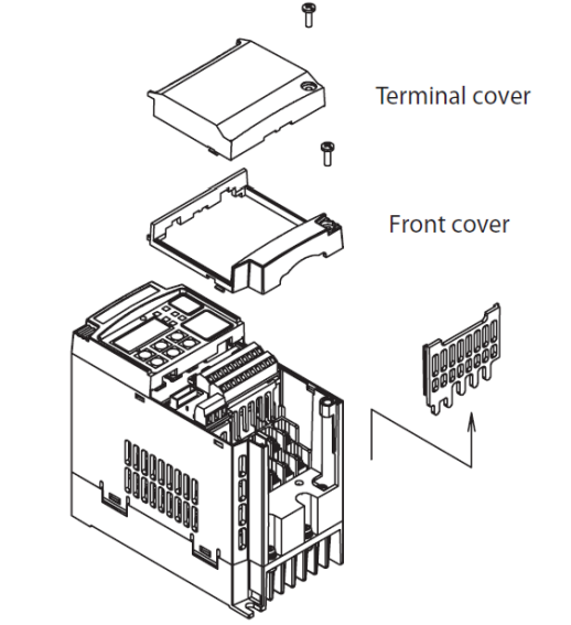
Особенности
- Пусковой крутящий момент до 200% на частотах близких к 0.5 Гц
- Двойная шкала мощности VT-переменный момент нагрузки с перегрузкой до 120% в течении 1мин и CT-постоянный момент нагрузки с перегрузкой до 150% в течении 1мин
- Управление двигателем с короткозамкнутым ротором или постоянными магнитами на роторе
- Безопасность в соответствии с ISO13849-1 Категория 3
- Встроенный программируемый логический контроллер ПЛК
- RS485 интерфейс для связи «Инвертор-Инвертор» или ModBus
- Режим позиционирования
Схема подключения входного сетевого питания и мотора
- Преобразователь частоты с однофазным напряжением питания (MX2-AB***-E) 220В.
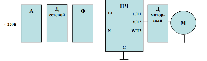
2. Преобразователь частоты с трехфазным напряжением питания (MX2-A4***-E) 380В.
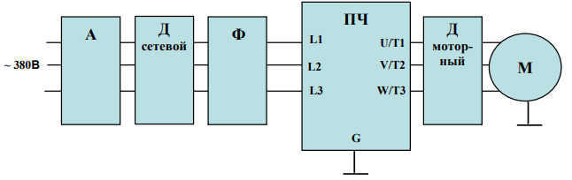
Клеммы цепи управления
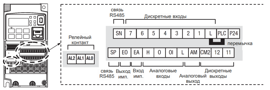
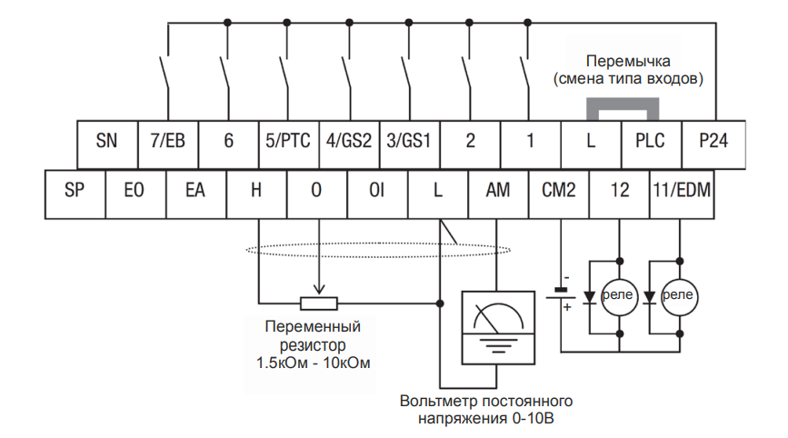
Спецификация клемм управления и сигнализации.
| Обозначение клеммы | Описание | Номинальная характеристика. Примечания |
| P24 | +24В для логических входов | +24В для питания логических входов. Максимальный ток 100мА. Не подключайте к питающей сети или заземлению. Не соединяйте с клеммой L. |
| PLC | Общая клемма логических входов | Заводская установка: истоковый тип (PLC соединена с L) клемма Р24 – опорное напряжение для входов 1-7. Для изменения типа входов нужно установить перемычку на клеммы PLC и P24, в этом случае клемма L – опорное напряжение для входов 1-7 |
| 1, 2, 3/GS1, 4/GS2, 5/PTC, 6, 7/EB |
Программируемые дискретные логические входы | Напряжение относительно клеммы PLC: Включение 18В и более, Выключение 3В и меньше, Максимальное допустимое 27В, Потребляемый ток входа 5мА (при 24В) |
| GS1 (3) | Вход безопасной остановки GS1 | Функционирование основано на ISO13849-1 |
| GS2 (4) | Вход безопасной остановки GS2 | Функционирование основано на ISO13849-1 |
| PTC (5) | Вход для термистора мотора | Подключите термистор мотора между клеммами PTC и L и установите функцию 19 в параметре С005. Авария происходит если температура мотора возросла на столько, что сопротивление превышает 3кОм. |
| EB (7) | Вход В последовательности импульсов | Максимум 2 кГц. Относительно клеммы PLC. |
| EA | Вход А последовательности импульсов | Максимум 32 кГц. Относительно клеммы L. |
| L (верхний ряд) | Общая для дискретных входов | Общая для клемм 1 ÷ 7. Не заземлять. |
| 11/EDM | Дискретный логический выход, имеющий двойную функцию | Тип – открытый коллектор, максимальный ток: 50мА, Максимальное напряжение: 27В, относительно клеммы CM2. Функционирование EDM основано на ISO13849-1 |
| 12 | Дискретный логический выход | Тип – открытый коллектор, максимальный ток: 50мА, Максимальное напряжение: 27В, относительно клеммы CM2. |
| CM2 | Общая для дискретных выходов | 100мА, общий ток выходов 11 и 12 |
| АМ | Аналоговый выход напряжения | 0-10В пост., 1мА максимум |
| ЕО | Выход импульсный | 10В пост., 2мА макс, 32кГц макс |
| L (нижний ряд) | Общая для аналоговых сигналов | Проходит общий ток клемм OI, O и Н |
| OI | Аналоговый вход для токового сигнала | 4 – 19.6мА диапазон, 20мА номинал, Внутреннее сопротивление 250Ом |
| O | Аналоговый вход для сигнала напряжения | 0 – 9.8В диапазон, 10В номинал, Внутреннее сопротивление 10кОм |
| H | +10В для аналоговых входов | 10В номинал, 10мА макс. |
| SP, SN | Клеммы сетевого подключения | Для сети ModBus по RS485 |
| AL0 | Общий контакт реле аварийной сигнализации | 250 VAC 2.5 A (актив) мaкс. 250 VAC 0.2 A (индуктив) макс. 100 VAC 10 mA мин. 30 VDC 3.0 A (актив) max. 30 VDC 0.7 A (индуктив) макс. 5 VDC 100 mA мин. |
| AL1 | Контакт реле. Нормально открыт. |
250 VAC 2.5 A (актив) мaкс. 250 VAC 0.2 A (индуктив) макс. 100 VAC 10 mA мин. 30 VDC 3.0 A (актив) max. 30 VDC 0.7 A (индуктив) макс. 5 VDC 100 mA мин. |
| AL3 | Контакт реле. Нормально закрыт. |
250 VAC 2.5 A (актив) мaкс. 250 VAC 0.2 A (индуктив) макс. 100 VAC 10 mA мин. 30 VDC 3.0 A (актив) max. 30 VDC 0.7 A (индуктив) макс. 5 VDC 100 mA мин. |
Примечания:
- Обе клеммы L соединены между собой внутри инвертора.
- Рекомендуем использовать клемму L (верхний ряд) как общий для дискретных входов и L (нижний ряд) как общий для аналоговых входов/выходов.
Общая схема соединений
Cхема подключения питания, двигателя, дискретных и аналоговых входов и выходов.
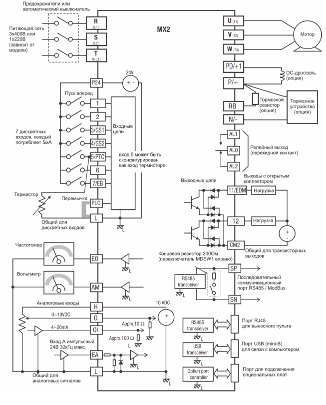
Элементы пульта оператора
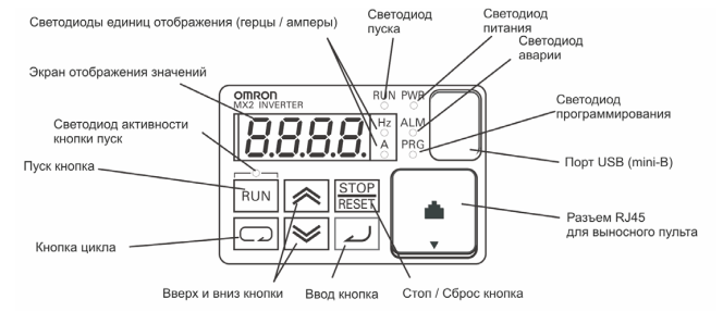
- Светодиод пуска – загорается при подаче команды на запуск двигателя во время начала вращения и отключается при остановке мотора.
- Светодиод программирования – загорается при готовности к изменению значений параметров и отключается в режиме контроля текущих параметров.
- Светодиод активности кнопки пуск – загорается при активированной кнопке и возможности с нее подать команду на запуск мотора.
- Кнопка пуска Run – при нажатии производится запуск двигателя (сначала должен светиться светодиод над кнопкой). Направление вращения двигателя можно задавать через функцию F004.
- Кнопка Stop/Reset – при нажатии производится остановка двигателя (при этом используется значение времени замедления), а также, происходит сброс возникающих ошибок.
- Экран отображения значений – 4-х разрядный, 7-ми сегментный индикатор для программирования и отображения параметров и текущих значений.
- Светодиоды: Hz, A – загораются при отображении на экране частоты или тока, соответственно.
- Светодиод Power – загорается при подаче питания на инвертор.
- Светодиод Alarm – загорается, когда инвертор в состоянии “Сбой”.
- Кнопка цикла – используется для входа в режим программирования, перемещения по группам параметров и функций.
- Кнопки вверх и вниз – используются для перемещения вверх/вниз по списку внутри 1 группы параметров и функций отображаемых на индикаторе и для изменения их значений.
- Кнопка ввода – используется для входа в отображаемый параметр или функцию, для выхода из нее с сохранением установленного значения в памяти EEPROM.
Порядок работы со списком параметров и функций
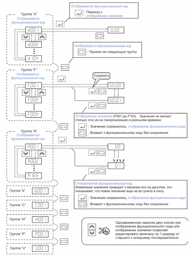
Коды ошибок
Преобразователи частоты серии МХ2 имеют защиту от перегрузки по току, от повышенного/ пониженного напряжения и много других. При срабатывании защиты отключается выход инвертора и остановка двигателя происходит в режиме свободного выбега. Перезагрузка частотного преобразователя и сброс ошибки производится нажатием кнопки STOP/RESET.
| Код ошибки | Наименование | Возможные причины сбоя |
| E01 | Защита от перегрузки по току при постоянной скорости | Замыкание на выходе инвертора Блокировка вала двигателя Слишком большая нагрузка Неправильно совершено подключение мотора Замечание: для серии SJ200 защита от перегрузки по току будет срабатывать при перегрузке 200% от номинального тока |
| E02 | Защита от перегрузки по току при замедлении | Замыкание на выходе инвертора Блокировка вала двигателя Слишком большая нагрузка Неправильно совершено подключение мотора Замечание: для серии SJ200 защита от перегрузки по току будет срабатывать при перегрузке 200% от номинального тока |
| E03 | Защита от перегрузки по току при разгоне | Замыкание на выходе инвертора Блокировка вала двигателя Слишком большая нагрузка Неправильно совершено подключение мотора Замечание: для серии SJ200 защита от перегрузки по току будет срабатывать при перегрузке 200% от номинального тока |
| E04 | Защита от перегрузки по току при других условиях | Установлен слишком большой тормозной момент (А054) Влияние электромагнитных помех на трансформатор тока |
| E05 | Защита от перегрузки | Электронное тепловое реле определило перегрев мотора |
| E06 | Защита от перегрузки тормозного резистора | Превышается время или коэффициент использования регенеративного торможения, слишком большой ток торможения |
| E07 | Защита от повышенного напряжения | Энергия, отдаваемая двигателем при торможении, вызывает увеличение напряжения в контуре постоянного тока выше порогового значения |
| E08 | Ошибка EEPROM | Влияние электромагнитных помех или высокой температуры на встроенную память EEPROM |
| E09 | Защита от пониженного напряжения | Пониженное напряжение в контуре постоянного тока может вызвать неправильное функционирование инвертора |
| E10 | Ошибка измерения тока | Выход из строя цепей измерения потребляемого мотором тока |
| E11 | Ошибка CPU | Сбои в работе микропроцессорного модуля CPU |
| E12 | Сбой во внешней цепи | Подан сигнал на дискретный вход с функцией [EXT] (сбой в работе внешнего устройства) |
| E13 | USP – предотвращение перезапуска при восстановлении питания | Когда на инвертор подаётся питание при наличии команды Пуск мотора происходит сбой с блокировкой возможность запуска пока не сброшен сбой, если активна функция USP |
| E14 | Защита от замыкания на землю | Замыкание на землю между выходом инвертора и корпусом мотора (заземлением) в момент теста питания (между подачей питания на ПЧ и пуском мотора). Данная функция обеспечивает защиту инвертора, но не людей. |
| E15 | Защита от повышенного напряжения на входе | Сетевое напряжение превышало допустимое значение в течение 100сек режима Стоп. |
| E21 | Тепловая защита | Внутренняя температура инвертора (силового модуля) превышает пороговое значение. |
| E22 | Ошибка связи с CPU | Ошибка связи между двумя процессорами |
| E25 | Авария основных цепей | Влияние помех или повреждение цепей основных элементов |
| E30 | Ошибка драйвера | Внутренняя ошибка в цепях защиты между CPU и драйвером из-за влияния помех или повреждения. |
| E35 | Термисторная защита | Происходит если термистор, подключенный к клеммам 5 (с функцией ТНМ) и L слишком сильно нагрелся |
| E36 | Ошибка тормоза | Происходит если в b120 установлен 01 и не получен сигнал подтверждения от тормоза после истечения времени b124. Или когда выходной ток не достигает значения b126 в течение времени b121 |
| E37 | Безопасный стоп | Подан сигнал безопасного стопа |
| E38 | Защита от перегрузки на маленькой скорости | Перегрузка во время работы мотора на очень маленькой скорости |
| E40 | Ошибка пульта оператора | Проблема связи между инвертором и клавиатурой пульта оператора |
| E41 | Ошибка связи сети ModBus | Если С076=00 и произошла проблема связи в сети ModBus |
| E43 | Некорректная инструкция в программе EzSQ | Программа сохраненная в памяти инвертора уничтожена, или терминал PRG был включен без программы загруженной в инвертор. |
| E44 | Ошибка счета в программе EzSQ | Подпрограммы, if-условия, или for-циклы вложены в более чем в восемь уровней |
| E45 | Ошибка инструкции в программе EzSQ | Инвертор обнаруживал команду, которая не может быть выполнена (взаимопротиворечие). |
| E50 – E59 | Пользовательские ошибки (0 – 9) в программе EzSQ | Ошибка пользователя, заложенная в программе EzSQ |
| E60 – E69 | Ошибки в подключенных опциональных платах | Детальные пояснения каждой из ошибок в инструкции к опциональной плате |
| E80 | Отключение энкодера | Если провода энкодера разъединены, обнаружена ошибка подключения, повреждение энкодера или выходной сигнал энкодера не поддерживается преобразователем |
| E81 | Превышение скорости | Скорость мотора выше значения А004хР026 |
| E82 | Ошибка диапазона позиционирования | Если текущая позиция превышает диапазон позиционирования P072-P073 |
Скачать полную документацию.
RU
ENG

22
Omron HEM-907
Omron HEM-907
23
Код ошибки
Причина возникновения
Способ устранения
Er1
Сбой в процессе нагнетания.
• Давление не достигает величины 15 мм рт. ст.
при работе компрессора в течение 15 секунд
после нажатия кнопки START.
• Давление в манжете не достигает заданной
величины после начала нагнетания.
• Проверьте, плотно ли вставлен разъем
резиновой трубки, соединяющей манжету
с основным прибором. Соедините его пра-
вильно и затем произведите измерение.
• Проверьте, не изогнута ли резиновая
трубка, соединяющая манжету с основ-
ным прибором. Выпрямите ее и затем
произведите измерение.
• Проверьте, плотно ли наложена манжета.
Наложите ее правильно и затем произве-
дите измерение.
Er2
Сбой в процессе сброса давления.
• Скорость сброса давления в процессе изме-
рения слишком велика.
• Скорость сброса давления в процессе изме-
рения слишком мала.
• Процесс измерения не заканчивается за ус-
тановленное время.
• Давление поддерживается более 5 минут.
Er3
Слишком высокое давление.
• Давление в манжете достигает значения бо-
лее 299 мм рт. ст.
• Проверьте, не изогнута ли резиновая
трубка, соединяющая манжету с основ-
ным прибором. Выпрямите ее и затем
произведите измерение.
Er4
Давление нагнетания недостаточно большое.
• Артериальное давление не может быть изме-
рено вследствие недостаточного нагнетания.
• Если измерение производится при уста-
новке переключателя выбора режимов
P-SET в положение AUTO, попросите
пациента не шевелить рукой и сохранять
неподвижность в процессе нагнетания.
• Если переключатель выбора режимов
установлен в положение AUTO, поверните
переключатель против часовой стрелки,
до щелчка.
• При помощи переключателя P-SET уста-
новите давление нагнетания на 30 – 40 мм
рт. ст. выше ожидаемого систолического
давления и затем произведите измере-
ние.
Er5
Невозможно определить артериальное давление.
• Артериальное давление невозможно изме-
рить, несмотря на то, что давление, поданное
в манжету, достигло заданной величины.
• Проверьте, плотно ли наложена манжета.
Наложите ее правильно и затем произве-
дите измерение.
Er6
Пульсовая волна слишком слаба.
• Проверьте, плотно ли наложена манжета.
Наложите ее правильно и затем произве-
дите измерение.
• Не накладывайте манжету на одежду из
плотной ткани или поверх закатанного
рукава пиджака или рубашки.
Er7
Ошибка измерения.
• Ненормальное соотношение между систоли-
ческим и диастолическим давлением.
• Проверьте, не страдает ли пациент арит-
мией.
• Попросите пациента не шевелить рукой и
сохранять неподвижность во время изме-
рения.
Er8
Ошибка в определении пульсовых волн.
• Частота пульса выходит за пределы диапазо-
на 30 – 199 уд/мин.
Er9
Ошибка прибора.
• Неисправность основного блока измерителя
артериального давления.
• Свяжитесь с Вашим дилером или с бли-
жайшим отделением фирмы OMRON.
Перечень кодов ошибок