Предписание
В этом руководстве описаны функции, рабочие параметры и области применения для оптимального использования продукта. Пожалуйста, соблюдайте следующие правила при использовании этого продукта:
• Этот продукт предназначен для использования только квалифицированным персоналом, знакомым с электрическими системами.
• Внимательно прочтите и усвойте содержание данного руководства перед использованием оборудования, чтобы обеспечить правильную работу оборудования.
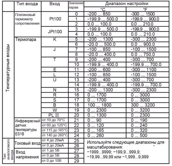
Типы подключаемых датчиков и входов
Примечание:
- Значение по умолчанию: 5.
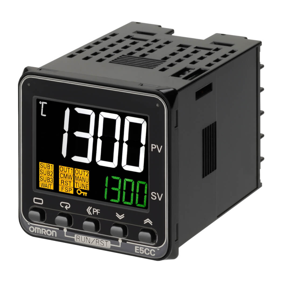
- S.ERR отображается, если при подключении платинового термометра сопротивления
соответствующим образом не будет настроен тип входа. Для снятия отображения S.ERR необходимо правильно выполнить подсоединения при этом выключить и снова включить
питание.
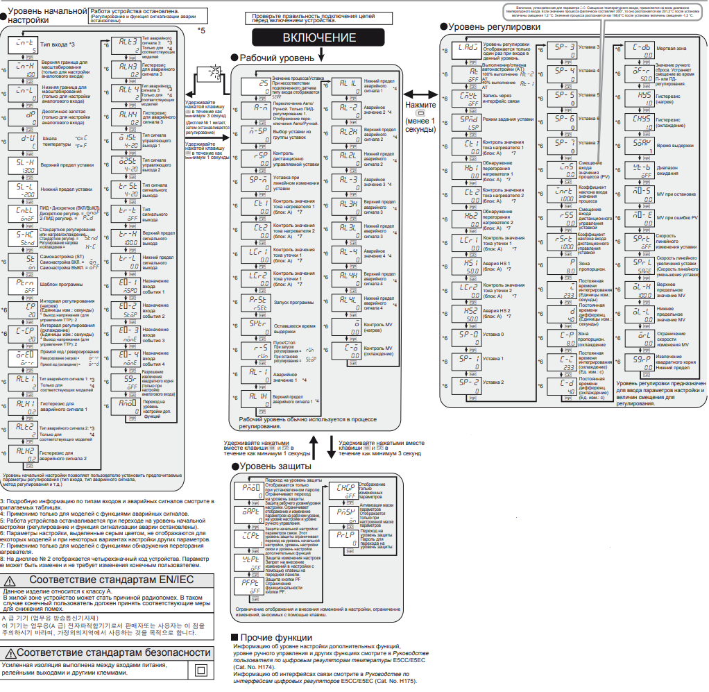
Программирование и настройка прибора
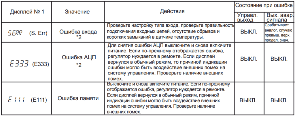
Список возможных ошибок
В случае возникновения ошибки на дисплее № 1 отображается код ошибки.
Примите необходимые меры в соответствии с кодом ошибки, руководствуясь таблицей ниже.
Примечание:
Если входной сигнал находится в пределах диапазона регулирования, но выходит за диапазон отображения значений на дисплее (-1999…9999), на дисплее отобразится [[[[, если значение меньше -1999, и ]]]], если значение больше 9999. При такой индикации выходы управления и сигнализации аварий работают в своем обычном режиме.
*2: Ошибка отображается только в режиме «Значение процесса / Уставка».
В других режимах ошибка не отображаются.
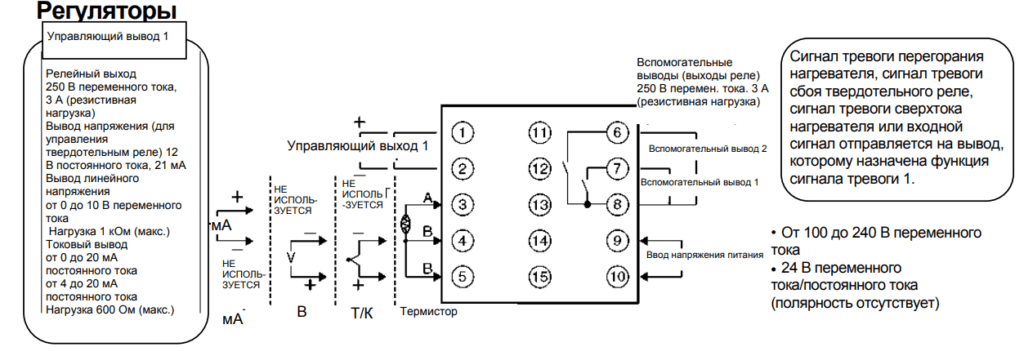
Схема подключения прибора
Внимание!
Выход напряжения (выход управления срабатыванием твердотельного реле) не изолирован гальванически от внутренних цепей. При использовании заземленной термопары не подключайте к земле какие-либо управляющие выходные клеммы. Если клеммы выхода управления подключен к земле, измеренные значения температуры будут неправильными из-за тока утечки.
Скачать полную документацию.
RU
-
Contents
-
Table of Contents
-
Troubleshooting
-
Bookmarks
Quick Links
Digital Temperature Controllers
Communications Manual
E5@C
1
Communications
Methods
2
CompoWay/F Commu-
nications Procedures
3
Communications
Data for CompoWay/F
4
Modbus Communica-
tions Procedure
5
Communications
Data for Modbus
6
Programless
Communications
7
Component
Communications
A
Appendices
I
Index
H175-E1-14
Related Manuals for Omron E5CC
Summary of Contents for Omron E5CC
-
Page 1
Communications Methods CompoWay/F Commu- nications Procedures Digital Temperature Controllers Communications Data for CompoWay/F Modbus Communica- Communications Manual tions Procedure E5@C Communications Data for Modbus Programless Communications Component Communications Appendices Index H175-E1-14… -
Page 3: Preface
OMRON. No patent liability is assumed with respect to the use of the information contained herein. Moreover, because OMRON is constantly striving to improve its high-quality products, the information contained in this manual is subject to change without notice.
-
Page 4: Terms And Conditions Agreement
Omron’s exclusive warranty is that the Products will be free from defects in materials and workmanship for a period of twelve months from the date of sale by Omron (or such other period expressed in writing by Omron). Omron disclaims all other warranties, express or implied.
-
Page 5: Application Considerations
Disclaimers Performance Data Data presented in Omron Company websites, catalogs and other materials is provided as a guide for the user in determining suitability and does not constitute a warranty. It may represent the result of Omron’s test conditions, and the user must correlate it to actual application requirements. Actual perfor- mance is subject to the Omron’s Warranty and Limitations of Liability.
-
Page 6: Safety Precautions
Safety Precautions Safety Precautions Definition of Precautionary Information The following notation is used in this manual to provide precautions required to ensure safe usage of the E5@C Digital Controllers. The safety precautions that are provided are extremely important to safety. Always read and heed the information provided in all safety precautions.
-
Page 7
Safety Precautions Safety Precautions CAUTION Minor injury due to electric shock may occasionally occur. Do not touch the terminals while power is being supplied. Electric shock, fire, or malfunction may occasionally occur. Do not allow metal objects, conductors, cuttings from installation work, moisture, or other foreign matter to enter the Digital Controller, the Setup Tool ports, or between the pins on the connectors on the Setup Tool cable. -
Page 8
To maintain safety in the event of malfunction of the Digital Controller, take appropriate safety measures, such as installing a monitoring device on a separate line. The specified torque is 0.5 N·m for the E5CC-U. E5@C Digital Temperature Controllers Communications Manual (H175) -
Page 9: Precautions For Safe Use
AWG24 to AWG16) *1 Use UL-recognized (RC) ferrules. Use the specified size of crimped terminals to wire the E5CC, E5EC, E5AC, E5DC, and E5GC (models with screw terminal blocks) as well as the E5CC-U (plug-in models). Crimp Terminal Sizes…
-
Page 10
• Always touch a grounded piece of metal before touching the Digital Temperature Controller to discharge static electricity from your body. • For compliance with Lloyd’s standards, the E5CC, E5CC-U, E5CC-B, E5EC, E5EC-B, E5AC, or E5DC must be installed under the conditions that are specified in Shipping Standards in the E5 Digital Temperature Controller User’s Manual (Cat. -
Page 11
Precautions for Safe Use • Do not bend the communications cables past their natural bending radius. Do not pull on the communications cables. • For the E5DC, when you attach the Main Unit to the Terminal Unit, make sure that the hooks on the Main Unit are securely inserted into the Terminal Unit. -
Page 12: Trademarks
Trademarks Trademarks • MELSEC and GX-Works are trademarks of the Mitsubishi Electric Corporation. • Keyence KV STUDIO is a registered trademark of Keyence Corporation. Other company names and product names in this document are the trademarks or registered trade- marks of their respective companies. E5@C Digital Temperature Controllers Communications Manual (H175)
-
Page 13: Versions
Versions Versions Check the version on the nameplate on the E5@C Controller or on the label on the packing box. If the version is not given, the version of the E5@C Controller is version 1.0. Product nameplate Package label The version is given here. The version is given here.
-
Page 14: Revision History
Revision History Revision History A manual revision code appears as a suffix to the catalog number on the front cover of the manual. H175-E1-14 Cat. No. Revision code Revision code Date Revised content December 2011 Original production January 2012 Page 9: Made correction in Precautions for Safe Use. May 2012 Added the following sections: Section 6 Programless Communications and Section 7 Component Communications.
-
Page 15
Revision History Revision code Date Revised content March 2016 Added information on version 2.1 of the E5@C-B. Corrected mistakes. July 2016 Corrected mistakes and added explanations. October 2017 Added NX1P2-series, NJ-series and Mitsubishi’s iQ-R-series to programless communications. Corrected mistakes. E5@C Digital Temperature Controllers Communications Manual (H175) -
Page 16
Revision History E5@C Digital Temperature Controllers Communications Manual (H175) -
Page 17: Sections In This Manual
Sections in This Manual Sections in This Manual How This Manual is Organized Descriptions in this manual are separated by the communications method. Read the sections that are applicable to the system being used. Communications Methods CompoWay/F Communications Procedures Communications Data for CompoWay/F Modbus Communications Procedure Communications Data for Modbus Programless Communications…
-
Page 18: Table Of Contents
CONTENTS Preface ……………………1 Terms and Conditions Agreement…………….2 Warranty, Limitations of Liability ……………………. 2 Application Considerations ……………………. 3 Disclaimers …………………………3 Safety Precautions ………………..4 Definition of Precautionary Information ………………….. 4 Symbols …………………………4 Precautions for Safe Use………………7 Trademarks ………………….
-
Page 19
Detailed Description of the Services ………………2-8 2-3-1 Read Variable Area ……………………2-8 2-3-2 Write Variable Area……………………2-9 2-3-3 Composite Read from Variable Area ………………2-10 2-3-4 Composite Write to Variable Area ……………….. 2-12 2-3-5 Read Controller Attributes ………………….2-13 2-3-6 Read Controller Status …………………. -
Page 20
Controlling Programless Communications…………….. 6-18 6-3-1 Controlling Programless Communications with the Request Flag ……….6-18 6-3-2 Response Flag …………………….. 6-19 6-3-3 Range of Operation for Programless Communications…………. 6-20 6-3-4 Operation Command Codes ………………… 6-20 6-3-5 Confirming Operation of Programless Communications …………6-20 6-3-6 Write Mode…………………….. -
Page 21
Section 7 Component Communications Component Communications ………………..7-2 7-1-1 Introduction ……………………..7-2 7-1-2 Wiring……………………….7-2 7-1-3 E5@C Setup ……………………..7-3 Operation for Component Communications…………….. 7-6 Troubleshooting ……………………7-7 Section A Appendices A-1 ASCII List……………………..A-2 A-2 Troubleshooting ……………………A-3 Index E5@C Digital Temperature Controllers Communications Manual (H175) -
Page 22
E5@C Digital Temperature Controllers Communications Manual (H175) -
Page 23
Communications Methods This section briefly describes the supported communications methods and how to wire equipment. Refer to this section when setting up equipment. 1-1 Overview of Communications Methods ……1-2 1-1-1 Introduction . -
Page 24: Overview Of Communications Methods
CompoWay/F is OMRON’s standard communications format for general serial communications. This format uses a standard frame format as well as the well-established FINS* commands used for OMRON’s PLCs. Therefore, it can simplify communications between components and the host. FINS (Factory Interface Network service) The FINS protocol provides message communications between controllers in OMRON FA networks.
-
Page 25
1 Communications Methods Communications baud rate, data length, stop bits and vertical parity can each be set independently in the communications setting level. Highlighted values indicate default settings. E5@C Digital Temperature Controllers Communications Manual (H175) 1 — 3… -
Page 26: Transmission Procedure
1 Communications Methods 1-1-3 Transmission Procedure When the host transmits a command frame, the E5@C transmits a response frame that corresponds to the command frame. A single response frame is returned for each command frame. The following dia- gram shows the operation of the command and response frames. Command frame Command frame Host…
-
Page 27: Wiring
• The RS-485 connection can be either one-to-one or one-to-N. Up to 32 units including the host can be connected in a one-to-N system. • The total cable length is 500 m max. • Use shielded twisted-pair cable. For detailed wiring specifications, refer to Precautions for Safe Use on page 7. E5CC/EC/AC Communications transceiver Host RS-485…
-
Page 28
1 Communications Methods E5@C-B (Models with Push-In Plus Terminal Blocks) Communications transceiver E5@C-B Host RS-485 RS-485 Abbreviation Abbreviation A (−) − A (−) B (+) B (+) 6.8 V Shield A < B: “1” Mark Terminating resistance E5@C-B A > B: “0” Space Ω… -
Page 29
1 Communications Methods E5DC Communications transceiver Host RS-485 E5DC RS-485 Abbrevi a ti o n Abbreviation − A (−) B (+) 6.8 V Terminating Shield A < B: «1» Mark resistance E5DC A > B: «0» Space 120 Ω End node (1/2 W) RS-485 Abbreviation… -
Page 30: Communications Parameters
1 Communications Methods 1-1-6 Communications Parameters The E5@C’s communications specifications are set in the communications setting level. These param- eters are set on the E5@C’s front panel. The following table shows the communications parameters and their setting ranges. Item Code Settings Set Values Communications protocol…
-
Page 31: Communications Parameter Setup
1 Communications Methods 1-1-7 Communications Parameter Setup Before you carry out communications with the E5@C, set up the communications unit number, baud rate, and other parameters by carrying out the following procedure. For details on operations other than communications parameter setup, refer to the E5 C Digital Temperature Controllers User’s Manual (Cat.
-
Page 32: Description Of Communications Parameters
1 Communications Methods 1-1-8 Description of Communications Parameters When communications parameter settings have been changed, the new settings must be enabled by resetting the Controller. • Protocol Setting (psel) The communications protocol can be selected. Set CompoWay/F or Modbus. • Communications Unit No. (u-no) This parameter is for setting a unique unit number for each of the Digital Controllers.
-
Page 33: Compoway/F Communications Procedures
CompoWay/F Communications Procedures Read this section if you are to communicate using the CompoWay/F format. 2-1 Data Format ……….2-2 2-1-1 Command Frame .
-
Page 34: Data Format
2 CompoWay/F Communications Procedures Data Format Hexadecimal values are expressed by adding the prefix H’ before the number, e.g., H’02. Numbers shown without the H’ prefix are ASCII characters. The number underneath each item in a frame indicates the number of bytes. 2-1-1 Command Frame Text…
-
Page 35: Bcc Calculation Example
2 CompoWay/F Communications Procedures 2-1-2 BCC Calculation Example The BCC (Block Check Character) is determined by calculating the exclusive OR of the bytes from the node number up to ETX. The 8-bit result is written to the BCC byte at the end of the frame. Node number Command text Sub-address…
-
Page 36: Communications Data
2 CompoWay/F Communications Procedures 2-1-4 Communications Data Communications Set (monitor) Negative values Decimal point format values CompoWay/F 8-digit hexadecimal 2’s complement Decimal point is removed and the result is converted to hexadecimal. Example conversion: 105.0 → 1050 → H’0000041A 2-1-5 End Code Example The following examples show the end code when a command did not end normally.
-
Page 37
2 CompoWay/F Communications Procedures Example 4) No Sub-address and Illegal BCC • Command Node number • Response Node number Sub-address End code The sub-address is “00” and the end code is “13” (BCC error). E5@C Digital Temperature Controllers Communications Manual (H175) 2 — 5… -
Page 38: Structure Of Command Text
2 CompoWay/F Communications Procedures Structure of Command Text 2-2-1 PDU Structure An MRC (Main Request Code) and SRC (Sub-Request Code) followed by the various required data is transferred to the command text. • Service Request PDU Data MRC SRC The MRES (Main Response Code) and SRES (Sub-Response Code) are transferred to the response frame following the above MRC/SRC.
-
Page 39: Addresses
2 CompoWay/F Communications Procedures The variable type is converted to 2-byte ASCII and loaded to the frame. The following table shows the available variable types. Variable type Description C0/80 R/O (read only) parameter for setup area 0. C1/81 R/W parameter for setup area 0. C3/83 R/W parameter for setup area 1.
-
Page 40: Detailed Description Of The Services
2 CompoWay/F Communications Procedures Detailed Description of the Services 2-3-1 Read Variable Area This service reads data from the variable area. • Service Request PDU Read start Number of Variable MRC SRC type position address elements 0 1 0 1 •…
-
Page 41: Write Variable Area
2 CompoWay/F Communications Procedures • Error Occurred Response code Error name Cause 1001 Command too long The command is too long. 1002 Command too short The command is too short. 1101 Area type error The variable type is wrong. Start address out-of-range error The read start address is out of 1103 range.
-
Page 42: Composite Read From Variable Area
2 CompoWay/F Communications Procedures (4) Response Code • Normal Completion Response code Name Description 0000 Normal completion No errors were found. • Error Occurred Response code Error name Cause 1002 Command too short The command is too short. 1101 Area type error The variable type is wrong.
-
Page 43
2 CompoWay/F Communications Procedures (1) Variable Type and Read Start Address For details on variable types and read start addresses, refer to Section 3 Communications Data for CompoWay/F. (2) Bit Position Bit access is not supported. Fixed to “00.” (3) Number of Read Data Items (Variable Type + Read Data + Bit Position Counted As 1 Item) Read data length Number of read data items For double word (variable type C0, C1, or C3) -
Page 44: Composite Write To Variable Area
2 CompoWay/F Communications Procedures 2-3-4 Composite Write to Variable Area This service writes in order the contents of specified addresses to a variable area. • Service Request PDU Write Variable Write data MRC SRC position address type 0 1 1 3 Number of elements ×8 or 4 Write Variable…
-
Page 45: Read Controller Attributes
0 0 D 9 (1) Model Number The model number is expressed in 10-byte ASCII. Example: The model is given as shown below for the E5CC-RX2ASM-000 (relay output, 2 auxiliary outputs, and no options). (2) Buffer Size The communications buffer size is expressed in 2-byte hexadecimal, and read after being converted to 4-byte ASCII.
-
Page 46: Read Controller Status
2 CompoWay/F Communications Procedures (3) Response Code • Normal Completion Response code Name Description 0000 Normal completion No errors were found. • Error Occurred Response code Error name Description 1001 Command too long The command is too long. 2203 Operation error Non-volatile memory error 2-3-6 Read Controller Status…
-
Page 47: Echoback Test
2 CompoWay/F Communications Procedures (3) Response Code • Normal Completion Response code Name Description 0000 Normal completion No errors were found. • Error Occurred Response code Error name Description 1001 Command too long The command is too long. 2203 Operation error Non-volatile memory error 2-3-7 Echoback Test…
-
Page 48: Operation Command
2 CompoWay/F Communications Procedures 2-3-8 Operation Command • Communications Writing • RUN/STOP • Multi-SP • AT Execute/Cancel • Write Mode • Save RAM Data • Software Reset • Move to Setup Area 1 • Move to Protect Level • Auto/Manual Switch •…
-
Page 49
2 CompoWay/F Communications Procedures Command code Command content Related Information Alarm Latch Cancel 00: Alarm 1 latch cancel 01: Alarm 2 latch cancel 02: Alarm 3 latch cancel 03: HB alarm latch cancel 04: HS alarm latch cancel 05: Alarm 4 latch cancel 0F: All alarm latch cancel SP Mode 00: Local SP mode… -
Page 50
2 CompoWay/F Communications Procedures • Multi-SP Set eight set points beforehand in the adjustment level so that you can switch to a desired set point. The setting can be accepted in both setup area 0 and setup area 1. An operation error will occur in the following situations. -
Page 51
2 CompoWay/F Communications Procedures • Software Reset Restarts processing from the point when power is turned ON. The setting can be accepted in both setup area 0 and setup area 1. • Move to Setup Area 1 This command moves to “setup area 1” and can be accepted at both setup areas 0 and 1. If the “initial setting/communications protect”… -
Page 52
2 CompoWay/F Communications Procedures “operation error” will be generated. (These settings are the same as the ones used when “FACT” is selected for the setting data’s set value initialization.) • Alarm Latch Cancel The applicable alarm latch can be cleared with the related information setting. The setting can be accepted in both setup area 0 and setup area 1. -
Page 53: Response Code List
2 CompoWay/F Communications Procedures Response Code List Normal Completion Error detection Response code Name Description priority 0000 Normal completion No errors were found. None Error Occurred Error Response code Name Description detection priority Unsupported command The service function for the relevant 0401 command is not supported.
-
Page 54
2 CompoWay/F Communications Procedures 2 — 22 E5@C Digital Temperature Controllers Communications Manual (H175) -
Page 55: Communications Data For Compoway/F
Communications Data for CompoWay/F This section lists the details of the communications data in the CompoWay/F communications protocol. 3-1 Variable Area (Setting Range) List ……. . 3-2 3-2 Status and Status 2 .
-
Page 56: Variable Area (Setting Range) List
3 Communications Data for CompoWay/F Variable Area (Setting Range) List • For communications using a variable type not enclosed in parentheses in the following table, the set value is double-word data (8 digits). For communications using a variable type enclosed in parentheses, the set value is single-word data (4 digits).
-
Page 57
3 Communications Data for CompoWay/F Variable Address Parameter name Setting (monitor) value Level type C1 (81) 0000 Operation/Adjustm H’00000000 (0): No restrictions in operation and Protect ent Protect adjustment levels H’00000001 (1): Move to adjustment level is prohibited. H’00000002 (2): Display and change of only «PV» and «PV/SP»… -
Page 58
3 Communications Data for CompoWay/F Variable Address Parameter name Setting (monitor) value Level type C1 (81) 0016 Integral Time Standard, heating/cooling, or close Adjustment position-proportional control: H’00000000 to H’0000270F (0 to 9999: Integral/derivative time unit is 1 s.) (0.0 to 999.9: Integral/derivative time unit is 0.1 s.) Floating position-proportional control: H’00000001 to H’0000270F (1 to 9999: Integral/derivative time unit is 1 s.) -
Page 59
3 Communications Data for CompoWay/F Variable Address Parameter name Setting (monitor) value Level type C1 (81) 0024 Manual MV Standard Models Manual Standard control: Control H’FFFFFFCE to H’0000041A (−5.0 to 105.0) Heating and cooling control: H’FFFFFBE6 to H’0000041A (−105.0 to 105.0) Position-proportional Models Close position-proportional control with the Direct Setting of Position Proportional MV parameter set… -
Page 60
3 Communications Data for CompoWay/F Variable Address Parameter name Setting (monitor) value Level type C1 (81) 002C MV Change Rate H’00000000 to H’000003E8 (0.0 to 100.0) Adjustment Limit C1 (81) 002D Position H’00000001 to H’00000064 (0.1 to 10.0) Proportional Dead Band C1 (81) 002E… -
Page 61
3 Communications Data for CompoWay/F Variable Address Parameter name Setting (monitor) value Level type C1 (81) 003C SP Ramp Fall H’FFFFFFFF (−1): Same (Same as SP Ramp Set Adjustment Value Value.) H’00000000(0): OFF H’00000001 to H’0000270F (1 to 9999) C1 (81) 003D Work Bit 1 ON H’00000000 to H’0000270F (0 to 9999) -
Page 62
0 to 5 V H’0000001D (29): 0 to 10 V H’0000001E (30): 0 to 50 mV* Selection is possible only for E5CC-U Controllers and only if they are manufactured in May 2014 or later (version 2.2). C3 (83) 0001 Scaling Upper… -
Page 63
3 Communications Data for CompoWay/F Variable Parameter Address Setting (monitor) value Level type name C3 (83) 0006 SP Lower Limit The range of values (without decimal point) is as follows: Initial Temperature input: Input range lower limit to SP upper setting limit −… -
Page 64
3 Communications Data for CompoWay/F Variable Parameter Address Setting (monitor) value Level type name C3 (83) 0010 Communications H’00000000 to H’00000063 (0 to 99) Commu nications Unit No. setting C3 (83) 0011 Communications H’00000003 (3): 9.6 H’00000004 (4): 19.2 Baud Rate H’00000005 (5): 38.4 H’00000006 (6): 57.6 C3 (83) -
Page 65
3 Communications Data for CompoWay/F Variable Address Parameter name Setting (monitor) value Level type C3 (83) 0016 Event Input H’00000000 (0): None Initial H’00000001 (1): RUN/STOP setting Assignment 1 H’00000002 (2): Auto/Manual Switch H’00000003 (3): Program Start H’00000004 (4): Direct/Reverse Operation H’00000005 (5): SP Mode Switch H’00000006 (6):… -
Page 66
3 Communications Data for CompoWay/F Variable Address Parameter name Setting (monitor) value Level type C3 (83) 0020 Auxiliary Output 2 H’00000000 (0): Close in alarm Advance Open in Alarm H’00000001 (1): Open in alarm d function setting C3 (83) 0021 Alarm 2 Hysteresis H’00000001 to H’0000270F Initial… -
Page 67
3 Communications Data for CompoWay/F Variable Address Parameter name Setting (monitor) value Level type C3 (83) 0038 Alarm 1 ON Delay H’00000000 to H’000003E7 (0 to 999) Advanced function C3 (83) 0039 Alarm 2 ON Delay H’00000000 to H’000003E7 (0 to 999) setting C3 (83) 003A… -
Page 68
P.END (program end output) can be set even when the program pattern is set to OFF, but the function will be disabled. Selection is possible only with the E5CC-U, E5DC, and E5GC and only when there is a control output that is a linear current output. -
Page 69
3 Communications Data for CompoWay/F Variable Address Parameter name Setting (monitor) value Level type C3 (83) 0050 Auxiliary Output 1 H’00000000 (0): Not assigned. Advanced Assignment H’00000001 (1): Control output (heating) function setting H’00000002 (2): Control output (cooling) H’00000003 (3): Alarm 1 H’00000004 (4): Alarm 2 H’00000005 (5): Alarm 3 H’00000006 (6): Alarm 4… -
Page 70
3 Communications Data for CompoWay/F Variable Address Parameter name Setting (monitor) value Level type C3 (83) 0059 PV Dead Band H’00000000 to H’0000270F (0 to 9999) Advanced C3 (83) 005B Manual MV Limit H’00000000 (0): OFF function setting Enable H’00000001 (1): ON C3 (83) 005C Direct Setting of… -
Page 71
3 Communications Data for CompoWay/F Variable Address Parameter name Setting (monitor) value Level type C3 (83) 006D PF Setting H’00000000 (0): Disabled. Advanced H’00000001 (1): Run function setting H’00000002 (2): Stop H’00000003 (3): RUN/STOP H’00000004 (4): 100% AT execute H’00000005 (5): 40% AT execute H’00000006 (6): Alarm latch cancel H’00000007 (7): Auto/manual switch H’00000008 (8): Monitor/setting item… -
Page 72
3 Communications Data for CompoWay/F Variable Address Parameter name Setting (monitor) value Level type C3 (83) 0073 PV/SP No. 1 Display H’00000000 (0): Nothing displayed. Advanced Selection H’00000001 (1): PV/SP function H’00000002 (2): PV setting H’00000003 (3): PV/SP (character display) H’00000004 (4): PV/SP/MV H’00000005 (5): PV/SP/Multi-SP No. -
Page 73
3 Communications Data for CompoWay/F Variable Address Parameter name Setting (monitor) value Level type C3 (83) 008D Control Output 2 H’00000000 (0): 4 to 20 mA Initial setting Signal H’00000001 (1): 0 to 20 mA C3 (83) 008E Transfer Output H’00000000 (0): 4 to 20 mA Signal H’00000001 (1): 1 to 5 V… -
Page 74
3 Communications Data for CompoWay/F Variable Address Parameter name Setting (monitor) value Level type C3 (83) 0096 Highest H’00000000 to H’00000063 (0 to 99) Communications Communications Unit setting C3 (83) 0097 Area • When Protocol Setting Parameter Is Set to FINS H’00000000 (0): DM H’00000001 (1): EM0… -
Page 75
C3 (83) 00B8 LCT Cooling Output H’00000001 to H’0000000A (0.1 to 1.0) Advanced Minimum ON Time function setting (Not supported on version 2.0 or earlier of the E5CC, E5EC, or E5AC.) E5@C Digital Temperature Controllers Communications Manual (H175) 3 — 21… -
Page 76
H’00000001 (1): Estimated opening Monitor Selection Selection is possible only with the E5CC-U, E5DC, and E5GC and only when there is a control output that is a linear current output. (The E5CC-U must be manufactured in May 2014 or later (version 2.2 or higher) and the E5DC must be manufactured in July 2014 or later (version 2.2 or higher).) -
Page 77: Status And Status 2
3 Communications Data for CompoWay/F Status and Status 2 The figure below shows the structure of the status data. Status Structure Outputs Input error Error status Bit position Heater overcurrent (CT1) Heater current hold (CT1) A/D converter error HS alarm (CT1) RSP input error Input error Potentiometer input error…
-
Page 78
3 Communications Data for CompoWay/F Status 2 Structure Spare Operating status Bit position Work bit 1 Work bit 2 Work bit 3 Work bit 4 Work bit 5 Work bit 6 Work bit 7 Work bit 8 Event Operating Spare Spare Spare… -
Page 79
3 Communications Data for CompoWay/F Status Details Bit Description Bit position Status Status Heater overcurrent (CT1) Not generated Generated (lower Heater current hold (CT1)* Update Hold word) A/D converter error Not generated Generated HS alarm (CT1) RSP input error Not generated Generated Spare… -
Page 80
3 Communications Data for CompoWay/F Status 2 Details Bit Description Bit position Status Status Work bit 1 (lower Work bit 2 word) Work bit 3 Work bit 4 Work bit 5 Work bit 6 Work bit 7 Work bit 8 Spare Spare Spare… -
Page 81
Modbus Communications Procedure Read this section if you are to communicate using the Modbus format. 4-1 Data Format ……….4-2 4-1-1 Command Frame . -
Page 82: Data Format
4 Modbus Communications Procedure Data Format The data format complies with the Modbus (RTU) communications protocol, so commands from the host and responses from the E5@C are contained in data blocks called frames. The structure of the command and response frames is described below. In the following explanations, hexadecimal values are expressed by adding the prefix H’ before the number, e.g., H’02.
-
Page 83
4 Modbus Communications Procedure CRC-16 Calculation Example Messages are processed one byte at a time in the work memory (a 16-bit register known as the CRC register). (1) The CRC register is initialized to H’FFFF. (2) An XOR operation is performed on the content of the CRC register and the first byte of the message, and the result is returned to the CRC register. -
Page 84: Response Frame
4 Modbus Communications Procedure 4-1-2 Response Frame Normal Response Frame Slave Function Data CRC-16 address code 2 bytes CRC-16 calculation range Error Response Frame Function Slave Error CRC-16 code address code 2 bytes CRC-16 calculation range The number specified in the command frame is entered as-is. This is the unit Slave address number of the Unit returning the response.
-
Page 85: Error Codes
4 Modbus Communications Procedure 4-1-3 Error Codes Error End code Name Description detection priority H’01 Function code An unsupported function code was received. error H’02 Variable address The specified variable area address is out-of-range. error H’03 Variable data The amount of data does not match the number of error elements.
-
Page 86: Function List
4 Modbus Communications Procedure Function List The following table lists the function codes. Function Code List Function code Name Process 03 (H’03) Read variable This function reads from the variable area. (multiple) It is possible to read two or more consecutive variables. 16 (H’10) Write variable This function writes to the variable area.
-
Page 87: Variable Area
4 Modbus Communications Procedure Variable Area The variable area is the region of memory used to exchange data with the E5@C through communica- tions. Operations such as reading the process value and reading/writing parameters are performed on the variable area. On the other hand, operation commands do not use the variable area.
-
Page 88: Detailed Description Of The Functions
4 Modbus Communications Procedure Detailed Description of the Functions 4-4-1 Variable Read, Multiple To read from the variable area, set the required data in the command frame, as shown in the following diagram. Command Frame Number of Slave Function CRC-16 Read start address Elements address…
-
Page 89
4 Modbus Communications Procedure Response Frame Read data (for the number of Slave Function Byte CRC-16 elements) address code count H’03 0 to 212 (2 × 10⁶) Name Description Slave address The value from the command frame is entered as-is. Function code This is the received function code. -
Page 90: Variable Write, Multiple
4 Modbus Communications Procedure 4-4-2 Variable Write, Multiple To write data to the variable area, set the required data in the command frame, as shown in the follow- ing diagram. Command Frame Write data (for the number of CRC-16 Slave Function Number of Write start address…
-
Page 91
4 Modbus Communications Procedure Response Frame Function Slave CRC-16 Number of Write start address code address Elements H’ 10 2 bytes Name Description Slave address The value from the command frame is entered as-is. Function code This is the received function code. When the function ended normally, the function code is left as-is. -
Page 92: Variable Write, Single/Operation Command
4 Modbus Communications Procedure Writing Undisplayed Parameters It is possible to write the parameters that are not displayed due to display settings as well as the parameters that are never displayed in the Controller. • Example Command and Response The following example shows the command/response when writing the Alarm Value Upper Limit 1 and Alarm Value Lower Limit 1 parameters.
-
Page 93
4 Modbus Communications Procedure (2) Command Code and Related Information Command Command content Related information code Communications writing 00: OFF (disabled) 01: ON (enabled) RUN/STOP 00: Run 01: Stop Multi-SP 00: Set point 0 01: Set point 1 02: Set point 2 03: Set point 3 04: Set point 4 05: Set point 5… -
Page 94
4 Modbus Communications Procedure (3) Response Code • Normal Completion Function code Error code Name Description Normal No errors were found. completion • Error Occurred Error Function code Name Description code Variable The write variable address is incorrect. address error Variable data The write data is incorrect. -
Page 95: Echoback Test
4 Modbus Communications Procedure 4-4-4 Echoback Test Command Frame Slave Function CRC-16 Test data Fixed data address code H’08 H’00 H’00 2 bytes Response Frame Slave Function CRC-16 Fixed data Test data address code H’08 H’00 H’00 2 bytes Note: When the command is executed normally, the response returns the same data sent in the command. (1) Test Data Enter any 2-byte hexadecimal data.
-
Page 96
4 Modbus Communications Procedure 4 — 16 E5@C Digital Temperature Controllers Communications Manual (H175) -
Page 97: Communications Data For Modbus
Communications Data for Modbus This section lists the details of the communications data in the Modbus communications protocol. 5-1 Variable Area (Setting Range) List ……. . 5-2 5-2 Status .
-
Page 98: Variable Area (Setting Range) List
5 Communications Data for Modbus Variable Area (Setting Range) List • Four-byte Mode One element uses 4 bytes of data (H’00000000 to H’FFFFFFFF), so specify two-element units. Reading and writing in 4-byte units is executed by specifying an even address and specifying the number of elements in multiples of 2.
-
Page 99
5 Communications Data for Modbus Address Parameter name Setting (monitor) value Level Four-byte Two-byte mode mode 0500 2500 Operation/Adjustment H’00000000 (0): No restrictions in operation and adjustment levels Protect Protect H’00000001 (1): Move to adjustment level is prohibited. H’00000002 (2): Display and change of only “PV”… -
Page 100
5 Communications Data for Modbus Address Parameter name Setting (monitor) value Level Four-byte Two-byte mode mode 0702 2701 Proportional Band H’00000001 to H’0000270F (0.1 to 999.9) Adjustment (Cooling) 0704 2702 Integral Time (Cooling) H’00000000 to H’0000270F (0 to 9999: Integral/derivative time unit is 1 s.) (0.0 to 999.9: Integral/derivative time unit is 0.1 s.) 0706 2703… -
Page 101
5 Communications Data for Modbus Address Parameter name Setting (monitor) value Level Four-byte Two-byte mode mode 074A 2725 Heater Burnout Detection H’00000000 to H’000001F4 (0.0 to 50.0) Adjustment 074C 2726 Leakage Current 2 H’00000000 to H’00000226 (0.0 to 55.0) Operation Monitor 074E 2727… -
Page 102
5 Communications Data for Modbus Address Parameter name Setting (monitor) value Level Four-byte Two-byte mode mode 0810 2808 Extraction of Square Root H’00000000 to H’000003E8 (0.0 to 100.0) Adjustment Low-cut Point 0900 2900 SP 0 SP lower limit to SP upper limit 0904 2902 Alarm Value 1… -
Page 103
H’0000001C (28): 0 to 5 V H’0000001D (29): 0 to 10 V H’0000001E (30): 0 to 50 mV* * Selection is possible only for E5CC-U Controllers and only if they are manufactured in May 2014 or later (version 2.2). 0C02… -
Page 104
5 Communications Data for Modbus Address Parameter name Setting (monitor) value Level Four-byte Two-byte mode mode 0D24 2D12 Direct/Reverse Operation H’00000000 (0): Reverse operation Initial setting H’00000001 (1): Direct operation 0D26 2D13 Close/Floating H’00000000 (0): Floating H’00000001 (1): Close 0D28 2D14 PID ON/OFF H’00000000 (0): ON/OFF… -
Page 105
P.END (program end output) can be set even when the program pattern is set to OFF, but the function will be disabled. Selection is possible only with the E5CC-U, E5DC, and E5GC and only when there is a control output that is a linear current output. -
Page 106
5 Communications Data for Modbus Address Parameter name Setting (monitor) value Level Four-byte Two-byte mode mode 0E14 2E0A Event Input Assignment 1 H’00000000 (0): None Initial setting H’00000001 (1): RUN/STOP H’00000002 (2): Auto/Manual Switch H’00000003 (3): Program Start H’00000004 (4): Direct/Reverse Operation H’00000005 (5): SP Mode Switch H’00000006 (6): 100% AT Execute/Cancel H’00000007 (7): 40% AT Execute/Cancel… -
Page 107
H’FFFFF831 to H’0000270F (−1999 to 9999) Lower Limit Selection is possible only with the E5CC-U, E5DC, and E5GC and only when there is a control output that is a linear current output. (The E5CC-U must be manufactured in May 2014 or later (version 2.2 or higher) and the E5DC must be manufactured in July 2014 or later (version 2.2 or higher).) -
Page 108
5 Communications Data for Modbus Address Parameter name Setting (monitor) value Level Four-byte Two-byte mode mode 0E48 2E24 Extraction of Square Root H’00000000 (0): OFF Initial setting Enable H’00000001 (1): ON 0E60 2E30 Travel Time H’00000001 to H’000003E7 (1 to 999) 0F00 2F00 Alarm 1 Type… -
Page 109
5 Communications Data for Modbus Address Parameter name Setting (monitor) value Level Four-byte Two-byte mode mode 0F1C 2F0E Auxiliary Output 2 Open H’00000000 (0): Close in alarm Advanced in Alarm H’00000001 (1): Open in alarm function setting 0F1E 2F0F Auxiliary Output 3 Open H’00000000 (0): Close in alarm in Alarm H’00000001 (1): Open in alarm… -
Page 110
5 Communications Data for Modbus Address Parameter name Setting (monitor) value Level Four-byte Two-byte mode mode 1100 3100 Protocol Setting (See H’00000000 (0): CompoWay/F Communicat note.) H’00000001 (1): Modbus ions setting 1102 3101 Communications Unit No. H’00000000 to H’00000063 (0 to 99) 1104 3102 Communications Baud… -
Page 111
5 Communications Data for Modbus Address Parameter name Setting (monitor) value Level Four-byte Two-byte mode mode 1302 3301 SP Tracking H’00000000 (0): OFF Advanced H’00000001 (1): ON function setting 1308 3304 PV Dead Band H’00000000 to H’0000270F (0 to 9999) 130A 3305 Cold Junction… -
Page 112
H’00000003 (3): Water cooling 136A 3335 LCT Cooling Output H’00000001 to H’0000000A (0.1 to 1.0) Minimum ON Time (Not supported on version 2.0 or earlier of the E5CC, E5EC, or E5AC.) 5 — 16 E5@C Digital Temperature Controllers Communications Manual (H175) -
Page 113: Status
5 Communications Data for Modbus Status The status data for Modbus is the same as that for CompoWay/F. Refer to page 3-23. E5@C Digital Temperature Controllers Communications Manual (H175) 5 — 17…
-
Page 114
5 Communications Data for Modbus 5 — 18 E5@C Digital Temperature Controllers Communications Manual (H175) -
Page 115: Programless Communications
This section describes programless communications for the E5@C. Programless communications are not supported by version 1.0 of the E5CC/EC. 6-1 Programless Communications ……..6-3 6-1-1 Introduction .
-
Page 116
6 Programless Communications 6-5 Connecting to CJ-series PLCs ……..6-33 6-5-1 Configuration and Procedure . -
Page 117: Introduction
6-1-2 Features • You can connect to an OMRON CS/CJ-series or CP-series PLC, to a Mitsubishi Q-series, L-series, or FX-series PLC, or to a Keyence KV-series PLC. • Up to 13 E5@C parameters can be assigned for reading and up to 13 E5@C parameters can be assigned for writing in PLC memory.
-
Page 118: Operation For Programless Communications
6 Programless Communications 6-1-3 Operation for Programless Communications Programless communications are performed in the following order of communications unit numbers. 0 (master) → 1 → 2 → … → Highest communications unit number → 0 → 1… The master (the Controller with communications unit number 0) starts programless communications approximately five seconds after the power supply to it is turned ON.
-
Page 119: Connectable Plcs
6 Programless Communications 6-1-5 Connectable PLCs The PLCs that can be connected are given below. SYSMAC CS/CJ-series and CP-series PLCs Communications ports Name Model number Port 1 Port 2 Serial Communications Units CJ1W-SCU21-V1 RS-232C RS-232C CJ1W-SCU22 CJ1W-SCU41-V1 RS-422A/485 RS-232C CJ1W-SCU42 (Cannot be used.) CS1W-SCU21-V1 RS-232C…
-
Page 120
6 Programless Communications MELSEC Q-series, L-series, FX-series, and iQ-R-series PLCs Communications ports Name Model number Port 1 Port 2 iQ-R Corresponding Serial Communication RS-232C RS-422/485 RJ71C24 Module (Cannot be used.) Q Corresponding Serial Communication RS-232C RS-422/485 QJ71C24N Module (Cannot be used.) QJ71C24N-R4 RS-422/485 RS-422/485… -
Page 121: E5C Setup
6-2-1 Protocol Setting Set the Protocol Setting parameter to fins to connect to an OMRON PLC, mcp4 to connect to a Mit- subishi Q-series or L-series PLC, fxp4 to connect to a Mitsubishi FX-series or Keyence KV-series PLC, and cmp to use component communications. Refer to 6-1-5 Connectable PLCs for lists of the PLCs that can be connected.
-
Page 122: Communications Unit No. And Communications Baud Rate
Make sure that setting of the Highest Communications Unit No. parameter agrees with the unit num- bers of the E5@C Controllers that are actually connected. Set the communications The highest communica- unit numbers starting tions unit number is 2. from 0. E5CC E5CC E5CC No.0 No.1 No.2 6 — 8…
-
Page 123: Areas And First Address Of Linked Data
6 Programless Communications Communications Setting Level Display condition: The Protocol Setting parameter must be set to fins, mcp4, or fxp4, or the Protocol Setting parameter must be set to cmp and the Communications Unit No. parameter must be set to 0 (master).
-
Page 124
6 Programless Communications Communications Setting Level Display condition: The Protocol Setting parameter must be set to fins, mcp4, or fxp4. Parameter name Displayed characters Setting range Default Area • When Protocol Setting Parameter Is Set to FINS area EM10 EM11 EM12 EM13 EM14… -
Page 125: Receive Data Wait Time
6-2-7 Communications Node Number Set the communications node number to the Host Link unit number for an OMRON PLC and to the sta- tion number for a Mitsubishi PLC. You can normally use the default setting. Communications Setting Level Display condition: The Protocol Setting parameter must be set to fins, mcp4, or fxp4.
-
Page 126: Upload Settings And Download Settings
6 Programless Communications 6-2-8 Upload Settings and Download Settings There are 13 upload settings and 13 download settings. Communications Setting Level Display condition: The Protocol Setting parameter must be set to fins, mcp4, or fxp4. Parameter name Displayed characters Setting range Default Upload Setting 1 0 to 98…
-
Page 127
6 Programless Communications You can use the settings in the following table for the upload settings and download settings. Set value Set value Nothing assigned. SP 5 Communications Monitor SP 6 Status (Upper Word) SP 7 Status (Lower Word) Process Value Input Shift Status 2 (Upper Word) PV Input Slope Coefficient Status 2 (Lower Word) -
Page 128: Copying Parameter Settings
Make sure that the system will not be adversely affected before you copy parameter settings. Case in which copying The model numbers and versions are the same. Example:E5CC-RX2ASM-002(V1.1) → E5CC-RX2ASM-002(V1.1) is possible The model numbers are different. Example:E5CC-RX2ASM-002 → E5CC-QX2ASM-002…
-
Page 129
6 Programless Communications (5) copy and execute the copy operation. If you select all, the parameters settings will be copied to all of the slaves. If you select a number, the parameters settings will be copied to the slave with the selected communications unit number. -
Page 130: Communications Writing
6 Programless Communications Note: 1 If you cycle the power supply to the E5@C Controllers after the error occurs, perform procedure “a” given above. 2 If you cannot solve the problem with the above flowchart or if the situation becomes too confusing, cycle the power supply to all of the E5@C Controllers and then perform procedure “a”…
-
Page 131: Communications Monitor Parameter
E5CC No.0 No.1 No.2 No.0 Order of communications Cycle time of E5CC with communications unit number 0 Adjustment Level Display condition: The Protocol Setting parameter must be set to fins, mcp4, or fxp4. Displayed Parameter name Monitor range* Default characters Communications Normal operation: 0 to 9999 ms.
-
Page 132: Controlling Programless Communications
6 Programless Communications Controlling Programless Communications The section describes the methods that are used to control programless communications from the PLC. 6-3-1 Controlling Programless Communications with the Request Flag There are the following three ways to control programless communications. The Request Flag in PLC memory is used to change the control method.
-
Page 133: Response Flag
6 Programless Communications 6-3-2 Response Flag The Response Flag changes as shown below for the values of the Request Flag. Response Flag Request Flag Normal Error 0: Disable Writing eeee 1: Enable Writing e001 to e013 8000 or Operation Command Code 2: Initialize Download Areas eeee If a communications error prevents reading data for the Request Flag, the Response Flag will change to eeee.
-
Page 134: Range Of Operation For Programless Communications
6 Programless Communications 6-3-3 Range of Operation for Programless Communications Programless communications start operating after the power supply is turned ON or after the E5@C is reset. They stop operating when the initial setting level is entered. Levels Programless communications Operation level, adjustment level, manual control level, Setting area 0 Operates…
-
Page 135: Write Mode
6 Programless Communications 6-3-6 Write Mode The E5@C normally writes the set values to non-volatile memory (i.e., in Backup Mode). If you fre- quently change set values with programless communications, use an operation command to change to RAM Write Mode. In RAM Write Mode, however, the set values will be restored to the values in non-volatile memory every time the power supply is cycled.
-
Page 136: Connecting To Cp-Series Plcs
The following configuration is used as an example in giving the setup and application procedures for programless communications. • All of the E5CC Controllers must be the same model. (Copying parameter settings is not possible if the models are different.) •…
-
Page 137: Switch Settings And Wiring
6-4-3 PLC Setup Set up communications on the CP1E to enable communicating with the E5CC Controllers. PLC operation will stop and the power supply will be cycled during the setup procedure. Make sure that this will not create any problems in the controlled system.
-
Page 138
6 Programless Communications (3) Select the USB connection Check Box and click the Connect Button. (4) Select the Transfer IO table and Special Unit Setup Check Box and click the Yes Button. (5) After the data has been transferred, click the OK Button. 6 — 24 E5@C Digital Temperature Controllers Communications Manual (H175) -
Page 139
6 Programless Communications Communications Settings for the Serial Communications Option Board (1) The PLC operating mode must be changed to PROGRAM mode to enable changing the communications settings in the PLC Setup. − − Select PLC Program from the menu bar. A confirmation dialog Operating Mode box will be displayed. -
Page 140: E5@C Controller Setup
6 Programless Communications − (4) Select Options Transfer to PLC from the menu bar in the window that is shown above. The settings will be transferred. Close the window and cycle the power to the PLC. This completes the PLC setup procedure.
-
Page 141
6 Programless Communications (d) Confirm that the setting of the copy parameter on the No. 0 Controller changes to off (i.e., copying completed), and then return the No. 0 Controller to the operation level. (e) Programless communications should now be operating. Confirm that the COMM indicator on the CP1W-CIF11 is flashing. -
Page 142: Checking Operation
The SP and RUN/STOP status of the E5@C Controllers will be changed to check operation. Make sure that this will not create any problems in the controlled system. Checking E5CC Monitor Values (1) The PLC operating mode must be changed to PROGRAM mode to enable changing values in PLC memory.
-
Page 143
Hexadecimal to return the display to hexadecimal values. play (5) We will check the E5CC monitor values. The area where monitor values are checked is called the upload area. D0000 to D0014 is the upload area for the No. 0 Controller, D0030 to D0044 is the upload area for the No. -
Page 144
D0074 Nothing assigned. If the default settings are used and a sensor is not connected, the PV display on the E5CC will show an input error (s.err) and the process value in the upload area will be 1320 (528 hex). -
Page 145
SP Ramp Set Value 0 (0000 hex) (2) We will initialize the download areas with the set values from the E5CC Controllers. The download areas have not been initialized, so we will initialize them with the set values from the E5CC Controllers. Double-click D0015 (Request Flag) in the PLC Memory Win- dow. -
Page 146
Display (2) We will stop the No. 0 Controller. Change the RUN/STOP parameter (r-s) in the operation level of the E5CC to RUN (run). For a Controller with event inputs, the Event Input 2 Assignment parameter (ev-2) in the initial setting level is set to RUN/STOP (stop), so the RUN/STOP parameter will not be dis- played. -
Page 147: Connecting To Cj-Series Plcs
The following configuration is used as an example in giving the setup and application procedures for programless communications. • All of the E5CC Controllers must be the same model. (Copying parameter settings is not possible if the models are different.) •…
-
Page 148: Switch Settings And Wiring
6-5-3 PLC Setup Set up communications on the CJ1W-SCU21-V1 to enable communicating with the E5CC Controllers. PLC operation will stop and the power supply will be cycled during the setup procedure. Make sure that this will not create any problems in the controlled system.
-
Page 149
6 Programless Communications Communications Settings in the Serial Communications Unit (SCU) (1) The PLC operating mode must be changed to PROGRAM mode to enable changing the SCU communications settings. − − Select PLC Program from the menu bar. A confirmation dialog box Operating Mode will be displayed. -
Page 150
6 Programless Communications (4) We will change the communications settings for port 1. Set Port 1: Port settings to User settings, set Port 1: Baud rate to 57600 bps, and then click the Transfer [PC to Unit] Button. Use the defaults settings for the other parameters. Note: If you change the unit number, refer to 6-2-7 Communications Node Number. -
Page 151: E5@C Controller Setup
6 Programless Communications Click the Yes Button to restart the Unit. Select All ports and then click the OK Button. A dialog box will be displayed when the Unit has been restarted. Click the OK Button. This completes the PLC setup procedure. You will use the CX-Programmer to check operation, so leave it online.
-
Page 152: Connecting To The Nx1P2
The following configuration is used as an example in giving the setup and application procedures for programless communications. • The same model is used for all of the E5CC Controllers. (The parameter settings cannot be copied if the models are different.) •…
-
Page 153: Switch Settings And Wiring
Manual (Cat. No. W579). 6-6-3 PLC Setup Set up communications on the NX1P2 to enable communicating with the E5CC Controllers. PLC operation will stop during the setup procedure. Make sure that this will not create any problems in the controlled system.
-
Page 154
6 Programless Communications (3) Select the Direct Connection via Ethernet Option and click the OK Button. (4) Place the PLC online. − Select Controller Online from the menu bar to change to Online Mode. Communications Settings for the Serial Communications Option Board (1) Change the communications settings of the Option Board. -
Page 155
6 Programless Communications (2) On the Multiview Explorer, double-click Option Board Settings under Configuration − and Setup Controller Setup. The Option Board Settings Tab Page will be displayed. Select NX1W-CIF11 from the Option board 1 Box under Configuration. (3) Change the following serial communications setting of Option Board 1. Change the baud rate to 57600 bps. -
Page 156
6 Programless Communications (5) Transfer the project that was created on the Sysmac Studio to the PLC. − Select Controller Online from the menu bar to go online and then select Controller- − To Controller. The Transfer to Controller Dialog Box will be displayed. Click the Transfer Execute Button to transfer the project to the Controller. -
Page 157: E5@C Controller Setup
(1) Change to Offline Mode to enable changing the product on the Sysmac Studio. − Select Controller Offline from the menu bar. (2) Create variables on the Sysmac Studio to check the values of E5CC parameters. − (a) Double-click Global Variables under Programming Data.
-
Page 158
6 Programless Communications [0..89] in the data type indicates the first and last array numbers in the array variable. Programless communications for E5C Controllers use 30 words of PLC memory for each − Controller. If the first word is 0, then the last word is 30 x n Here, n is the number of E5C Controllers used in the same programless communications. -
Page 159
6 Programless Communications (4) Make settings to access the variables that you created in step 2. − (a) Select View Watch Tab Page from the menu bar. (b) If you enter the name of the variable that you created in step 2 in the Name column of the Watch (Table) 1 Tab Page displayed at the bottom of the window, the contents of D000 to D038 will be displayed. -
Page 160
D074 Spare If the default settings are used and a sensor is not connected, the PV display on the E5CC will show an input error and the process value in the upload area will be 1320 (528 hex). 6 — 46… -
Page 161
Page and press the Enter Key. D015 to D029 is the download area for the No. 0 Controller (E5CC), D045 to D059 is the download area for the No. 1 Controller, and D075 to D089 is the download area for the No. 2 Controller. -
Page 162
Stopping the E5CC Controller (1) Run the No. 0 Controller. Change the RUN/STOP parameter (r-s) in the operation level of the E5CC to RUN (run). (2) Switch the No. 0 Controller to STOP. Confirm that D015 (Request Flag) in the Watch Tab Page is 0001 hex (Enable Writing), enter 0101 hex (Stop) for D016 (Operation Command Code), and press the Enter Key. -
Page 163: Connecting To Nj-Series Plcs
The following configuration is used as an example in giving the setup and application procedures for programless communications. • The same model is used for all of the E5CC Controllers. (The parameter settings cannot be copied if the models are different.) •…
-
Page 164: Switch Settings And Wiring
Programmable Controller Operation Manual (Cat. No. W393). 6-7-3 PLC Setup Set up communications on the CJ1W-SCU22 to enable communicating with the E5CC Controllers. PLC operation will stop during the setup procedure. Make sure that this will not create any problems in the controlled system.
-
Page 165
6 Programless Communications (3) Select the Direct Connection via USB Option and click the OK Button. (4) Place the PLC online. Select Controller − Online from the menu bar to change to Online Mode. Communications Settings in the Serial Communications Unit (SCU) (1) The PLC operating mode must be changed to PROGRAM mode to enable changing the SCU communications settings. -
Page 166
6 Programless Communications (2) On the Multiview Explorer, click Units under Configurations and Setup − CPU/Expansion Racks − CPU Rack to display the Units connected in the PLC. (3) Double-click CJ1W-SCU22. The CJ1W-SCU22 Setting Tab Page will be displayed. (4) Change the communications settings for port 1. Set Port 1: Port settings to User settings, set Port 1: Baud rate to 57600 bps, and then click the Transfer to Controller Button. -
Page 167: E5@C Controller Setup
6 Programless Communications Click the Yes Button in the transfer confirmation dialog box to transfer the settings. To restart the Unit and enable the transferred settings, click the Yes Button in the restart confirmation dialog box. In the Port Selection Dialog Box, select All ports and click the OK Button. Click the OK Button in the dialog box that says the transfer was successfully completed.
-
Page 168: Connecting To Melsec Q-Series Plcs
The following configuration is used as an example in giving the setup and application procedures for programless communications. • All of the E5CC Controllers must be the same model. (Copying parameter settings is not possible if the models are different.) •…
-
Page 169: Wiring
6-8-3 PLC Setup Set up communications on the QJ71C24N-R4 to enable communicating with the E5CC Controllers. PLC operation will stop and the power supply will be cycled during the setup procedure. Make sure that this will not create any problems in the controlled system.
-
Page 170
6 Programless Communications (4) Click the OK Button. (5) Click the Execute Button. 6 — 56 E5@C Digital Temperature Controllers Communications Manual (H175) -
Page 171
6 Programless Communications (6) When the set values have been read, click the Close Button. Also close the above dialog box. Communications Settings in the Serial Communication Module (1) Double-click Switch Setting. The Switch Setting Dialog Box for communications will be displayed. -
Page 172
6 Programless Communications (2) We will change the communications settings for CH1. Change the following settings, and then click the OK Button. Use the defaults settings for the other parameters. • Parity Bit: Exist • Even/odd parity: Even • Stop bit: 2 •… -
Page 173
6 Programless Communications (4) We will write set values to the PLC. Click the Intelligent Function Module Tab and select the check box for the Serial Communication Module in the Valid Column. Then click the PLC Module Tab, select the check box for the parameters in the Target Column, and then click the Execute Button. -
Page 174: E5@C Controller Setup
6 Programless Communications (5) We will write set values to the PLC. Some dialog boxes will be displayed before and after the following dialog box. Click the Yes Button for of them, or click the Yes to All Button. When the following dialog box is displayed, click the Close Button. Also close the dialog box to write set values, and then cycle the power supply to the PLC.
-
Page 175: Checking Operation
The SP and RUN/STOP status of the E5@C Controllers will be changed to check operation. Make sure that this will not create any problems in the controlled system. Checking E5CC Monitor Values (1) We will display PLC memory in a dialog box.
-
Page 176
Option in the Monitor Format Area, select the 10 Points Option in the Word Device Word Multi-point Format Area, and then click the OK Button. (4) We will check the E5CC monitor values. The area where monitor values are checked is called the upload area. -
Page 177
· · · Not used. If the default settings are used and a sensor is not connected, the PV display on the E5CC will show an input error (s.err) and the process value in the upload area will be 1320 (528 hex). -
Page 178
SP Ramp Set Value 0 (0000 hex) (2) We will initialize the download areas with the set values from the E5CC Controllers. The download areas have not been initialized, so we will initialize them with the set values from the E5CC Controllers. -
Page 179
Stopping the E5CC Controllers (1) We will run the No. 0 Controller. Change the RUN/STOP parameter (r-s) in the operation level of the E5CC to RUN (run). For a Controller with event inputs, the Event Input 2 Assignment parameter (ev-2) in the initial setting level is set to RUN/STOP (stop), so the RUN/STOP parameter will not be dis- played. -
Page 180: Connecting To Melsec-Fx-Series Plcs
The following configuration is used as an example in giving the setup and application procedures for programless communications. • All of the E5CC Controllers must be the same model. (Copying parameter settings is not possible if the models are different.) •…
-
Page 181: Wiring
6-9-3 PLC Setup Set up communications on the FX3U-485ADP-MB to enable communicating with the E5CC Controllers. PLC operation will stop and the power supply will be cycled during the setup procedure. Make sure that this will not create any problems in the controlled system.
-
Page 182
6 Programless Communications (4) Double-click the Serial USB Icon, select the USB Option, and click the OK Button. (5) Click the OK Button. 6 — 68 E5@C Digital Temperature Controllers Communications Manual (H175) -
Page 183
6 Programless Communications (6) Click the Parameter + Program Button and then click the Execute Button. (7) When the set values have been read, click the Close Button. Also close the above dialog box. E5@C Digital Temperature Controllers Communications Manual (H175) 6 — 69… -
Page 184
6 Programless Communications Setting Up Communications for the Special Communication Adapter (1) Double-click PC Parameter. The FX Parameter Setting Dialog Box will be displayed. (2) We will change the communications settings for CH1. Click the PC System Setup (2) Tab, change the following settings, and click the Finish Setup Button. -
Page 185
6 Programless Communications (3) Select Online — Write to PLC. A dialog box to write the set values will be displayed. (4) We will write set values to the PLC. Confirm that PC Parameters is selected and click the Execute Button. E5@C Digital Temperature Controllers Communications Manual (H175) 6 — 71… -
Page 186: E5@C Controller Setup
6 Programless Communications (5) We will write set values to the PLC. When the following dialog box is displayed, click the Close Button to close it and cycle the power to the PLC. This completes the PLC setup procedure. You will use GX Works2 to check operation, so leave it online.
-
Page 187: Connecting To Melsec Iq-R-Series Plcs
The following configuration is used as an example in giving the setup and application procedures for programless communications. • All of the E5CC Controllers must be the same model. (Copying parameter settings is not possible if the models are different.) •…
-
Page 188: Wiring
6 Programless Communications 6-10-2 Wiring Wire the RJ71C24 to E5CC Controllers as shown below. RJ71C24 RJ71C24 Terminating resistance Ω B(+) B(+) B(+) (1/2 W) Shield Shield Shield A(−) A(−) A(−) Terminating E5CC E5CC E5CC resistance No.0 No.1 No.2 Note: 1 Use a terminating resistance of at least 54 Ω.
-
Page 189: Plc Setup
6 Programless Communications 6-10-3 PLC Setup Set up communications on the RJ71C24 to enable communicating with the E5CC Controllers. PLC operation will stop and the PLC will be reset during the setup procedure. Make sure that this will not create any problems in the controlled system.
-
Page 190
6 Programless Communications (5) The following window will be displayed. Click the Close Button. (6) Double-click Module Configuration and then click the OK Button in the dialog box that appears. 6 — 76 E5@C Digital Temperature Controllers Communications Manual (H175) -
Page 191
6 Programless Communications (7) Select Online − Read Module Configuration from PLC and then click the OK Button in the dialog box that appears. When Completed is displayed, click the OK Button. E5@C Digital Temperature Controllers Communications Manual (H175) 6 — 77… -
Page 192
6 Programless Communications Communications Settings in the Serial Communication Module (1) The above procedure reads the Module configuration that is actually connected in the PLC. Double-click the Serial Communication Module in the diagram. Click the Yes Button in the dialog box. (2) Messages will be displayed asking whether or not to add labels for mounted Modules. -
Page 193
6 Programless Communications (3) A setting item tab page will be display for the Serial Communication Module you double-clicked in the Module configuration. Make the settings for the corresponding channel. In the following example, channel 2 (RS-422/485) is set for the RJ71C24 Module. Setting item Value Communications protocol setting… -
Page 194
6 Programless Communications (2) Select Convert − Convert. The program will be converted automatically. (3) Select Online − Write to PLC to write the set values to the PLC. (4) Select the check box for Untitled Project on the window that is displayed and click the Execute Button. -
Page 195: E5@C Controller Setup
6 Programless Communications (5) The following dialog box will be displayed. Click the Close Button after the process ends. (Messages will be displayed during the process, but just click the OK Button.) (6) Open the front cover on the CPU Module and set the switch in the middle to RESET. When the CPU Module indicators go out, return the switch to the original position.
-
Page 196: Checking Operation
The SP and RUN/STOP status of the E5C Controllers will be changed to check operation. Make sure that this will not create any problems in the controlled system. Checking E5CC Monitor Values (1) Display PLC memory in a dialog box.
-
Page 197
The area where monitor values are checked is called the upload area. D0 to D14 is the upload area for the No. 0 Controller (E5CC), D30 to D44 is the upload area for the No. 1 Controller, and D60 to D74 is the upload area for the No. 2 Controller. -
Page 198
… Spare If the default settings are used and a sensor is not connected, the PV display on the E5CC will show an input error ( ) and the process value in the upload area will be 1320 (528 hex). -
Page 199
SP Ramp Set Value 0 (0000 hex) (2) Initialize the download areas with the set values from the E5CC Controllers. The download areas have not been initialized, so we will initialize them with the set values from the E5CC Controllers. -
Page 200
Stopping the E5CC Controller (1) Run the No. 0 Controller. Change the RUN/STOP parameter (r-s) in the operation level of the E5CC to RUN (run). (2) Switch the No. 0 Controller to STOP. In the Device Memory Dialog Box, make sure that D15 (Request Flag) is 1 (Enable Writing) and then double-click D16 (Operation Command Code). -
Page 201: Connecting To Keyence Kv-Series Plcs
The following configuration is used as an example in giving the setup and application procedures for programless communications. • All of the E5CC Controllers must be the same model. (Copying parameter settings is not possible if the models are different.) •…
-
Page 202: Wiring
6 Programless Communications 6-11-2 Wiring Set the terminating resistance switch on the front panel of the KV-L21V to TERM and wire the E5CC Controllers as shown below. − S/R( S/R(+) 120 Ω (1/2 W) B(+) B(+) B(+) Shield Shield Shield terminating resistance −…
-
Page 203: E5@C Controller Setup
(3) Change the display format to make the values easier to check. Select the first display format and change it to Signed decimal 16 bits. (4) We will check the E5CC monitor values. The area where monitor values are checked is called the upload area.
-
Page 204
Do not use (reserved). If the default settings are used and a sensor is not connected, the PV display on the E5CC will show an input error (s.err) and the process value in the upload area will be 1320 (528 hex). -
Page 205
SP Ramp Set Value 0 (0000 hex) (2) We will initialize the download areas with the set values from the E5CC Controllers. The download areas have not been initialized, so we will initialize them with the set values from the E5CC Controllers. -
Page 206
6 Programless Communications 6 — 92 E5@C Digital Temperature Controllers Communications Manual (H175) -
Page 207: Component Communications
This section describes component communications for the E5@C. Component communications are not supported by version 1.0 of the E5CC/EC. 7-1 Component Communications ……..7-2 7-1-1 Introduction .
-
Page 208: Introduction
E5@C Controllers. The operation will not work correctly if the position of the decimal point is different. 7-1-2 Wiring Wire the E5@C Controllers as shown below. E5CC/EC/AC 120 Ω (1/2 W) 120 Ω (1/2 W) B(+) B(+)
-
Page 209: E5@C Setup
7 Component Communications E5@C-B (Models with Push-In Plus Terminal Blocks) B(+) B(+) B(+) B(+) 120 Ω (1/2 W) 120 Ω (1/2 W) terminating resistance terminating resistance − − − − No.0 No.1 No.2 No.n * Terminals 17 and 18 and terminals 19 and 20 are connected internally.
-
Page 210
7 Component Communications Power ON Adjustment Level Press O Key for less than 1 s. l.adj Adjustment Level Operation Level Display 1234 AT Execute/Cancel cmwt Communications Writing Press O Key Press O Key for at least 3 s. for at least 1 s. Communications Setting Level Press O Key for less than 1 s. -
Page 211
7 Component Communications SP Calculations The set point (SP) of a slave can be calculated from the set point of the master as shown below. The slave performs the calculation only during operation. The value is not written to the slave if it exceeds the set point limiter. -
Page 212: Operation For Component Communications
7 Component Communications Operation for Component Communications Only two parameter settings can be sent from the master to the slaves: the Set Point (SP) and the RUN/STOP parameters. If the set point or the RUN/STOP status is changed at the master, the new value is sent to the slaves starting with the slave with communications unit number 1 and continuing on to the slave with the high- est communications unit number.
-
Page 213: Troubleshooting
7 Component Communications Troubleshooting Possible problems that can occur with component communications and corrective actions are given in the following table. Status Cause and corrective action Page The set point or RUN/STOP status The wiring to the slave is not correct. will not change for a slave (i.e., a The communications settings for the slave are not Controller with a communications…
-
Page 214
7 Component Communications 7 — 8 E5@C Digital Temperature Controllers Communications Manual (H175) -
Page 215: Appendices
Appendices A-1 ASCII List ……….. . A-2 A-2 Troubleshooting .
-
Page 216
A Appendices A-1 ASCII List ‘ 0 NUL SPACE ” STX DC2 3 ETX DC3 E0T DC4 5 ENQ NAK & ACK SYN ’ BEL ETB BS CAN HT EM LF SUB VT ESC CR GS A — 2 E5@C Digital Temperature Controllers Communications Manual (H175) -
Page 217: Troubleshooting
If communications are not functioning properly, check the items in the following table before requesting repairs. If normal operation cannot be restored even after checking everything, return the product to your OMRON representative. Problem: Communications are not possible or communications errors occur.
-
Page 218
A Appendices Item Confirmation Page The host device is detecting the The Controller does not return responses for broadcast or absence of a response as an software reset commands. 2-17 error after broadcasting a command or sending a software 4-14 reset command. -
Page 219: Index
Index E5@C Digital Temperature Controllers Communications Manual (H175)
-
Page 220
addresses Echoback Test CompoWay/F …………2-7 CompoWay/F ……….2-7, 2-15 Modbus …………..4-7 Modbus …………4-6, 4-15 area definitions ………….. 2-6 end codes areas and first address of linked data ……6-9 CompoWay/F …………2-3, 2-4 ASCII list …………….A-2 error codes Modbus …………..4-5 ETX ……………. -
Page 221
range of operation for programless communications variable area …………..4-7 ……………… 6-20 variable area (setting range) list Read Controller Attributes (CompoWay/F) ..2-7, 2-13 CompoWay/F …………3-2 Read Controller Status (CompoWay/F) ….2-7, 2-14 Modbus …………..5-2 Read Variable Area (CompoWay/F) …… 2-7, 2-8 Variable Read, Multiple (Modbus) ……… -
Page 222
E5@C Digital Temperature Controllers Communications Manual (H175) -
Page 224
The Netherlands Hoffman Estates, IL 60169 U.S.A. Tel: (31)2356-81-300/Fax: (31)2356-81-388 Tel: (1) 847-843-7900/Fax: (1) 847-843-7787 © OMRON Corporation 2011-2017 All Rights Reserved. OMRON (CHINA) CO., LTD. OMRON ASIA PACIFIC PTE. LTD. In the interest of product improvement, Room 2211, Bank of China Tower, No.
A Appendices
A-4 Error Displays
When an error occurs, the error contents are shown on the No. 1 or the No. 2 display.
This section describes how to check error codes on the display, and the actions to be taken to remedy
the problems.
s.err
Meaning
The input value has exceeded the control range. *
The input type setting is not correct.
The sensor is disconnected or shorted.
The sensor wiring is not correct.
The sensor is not wired.
* Control Range
Resistance thermometer,
thermocouple input:
ES1B input:
Analog input:
Action
Check the wiring of inputs for miswiring, disconnections, and short-circuits and check the input type.
If no abnormality is found in the wiring and input type, turn the power OFF then back ON again.
If the display remains the same, the Controller must be replaced. If the display is restored, then the
probable cause is electrical noise affecting the control system. Check for electrical noise.
Note: With resistance thermometer input, a break in the A, B, or B’ line is regarded as a disconnection.
Operation
After an error occurs, the error is displayed and the alarm outputs function as if the upper limit has
been exceeded.
It will also operate as if transfer output exceeded the upper limit. If an input error is assigned to a
control output or auxiliary output, the output will turn ON when the input error occurs. The error
message will appear in the display for the PV.
Note: The heating and cooling control outputs will turn OFF. When the manual MV, MV at stop, or MV at error
is set, the control output is determined by the set value.
A — 10
Input Error
Temperature setting lower limit −20°C to temperature setting upper limit +20°C
(Temperature setting lower limit −40°F to temperature setting upper limit +40°F)
Same as input indication range
−5% to +105% of scaling range
E5@C Digital Temperature Controllers User’s Manual (H174)