- Высокая эффективность
- Высокий пусковой момент
- Широкий круг применения
- Векторное управление без датчика обратной связи при частоте 0 Гц
- Функция аварийного выключения
- Встроенная схема торможения
- Функция подхвата вращающегося электродвигателя
- Управляемое торможение при пропадании сетевого напряжения
- Удобство в использовании
- Соответствие стандартам безопасности
- Директива RoHS
Стандартная схема подключения
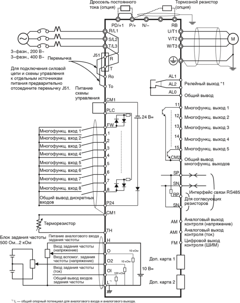
Клеммы силовых цепей.
| Обозначения клемм | Название клеммы | Описание |
| R/L1, S/L2, T/L3 | Клеммы ввода электропитания | Служат для подключения преобразователя частоты к источнику электропитания. |
| U/T1,V/T2, W/T3 | Клеммы питания электродвигателя | Служат для подключения к 3-фазному электродвигателю. |
| PD/+1, P/+ | Клеммы для внешнего дросселя постоянного тока | Отсоедините перемычку от клемм PD/+1 и P/+ и подключите дополнительный дроссель постоянного тока для повышения коэффициента мощности. |
| P/+, RB | Клеммы для подключения тормозного резистора | Служат для подключения дополнительного наружного тормозного резистора. (Клемма RB предусмотрена в преобразователях мощностью 22 кВт и ниже.) |
| P/+, N/- | Клеммы для подключения блока генераторного торможения | Служат для подключения дополнительных блоков генераторного торможения. |
| G |
Клемма заземления | Клемма для заземления корпуса преобразователя частоты. Подсоедините эту клемму к цепи заземления (типа D для класса 200 В, типа C для класса 400 В) |
Пункты меню режима дополнительной настройки
Для перехода между пунктами меню дополнительной настройки используйте клавиши ![]()
или
![]()
.
| Параметр | Содержание | Диапазон настройки | По умолчанию |
| Язык (Language) | Язык дисплея | 01: Английский 02: Немецкий 03: Французский 04: Испанский 05: Итальянский 06: Португальский 07: Японский 08: Китайский 09: Турецкий 10: Русский |
01 |
| Дата и время (Date and Time) | Установка даты и времени часов цифровой панели с ЖК-дисплеем | Дата: 2000/1/1…2099/12/31 Время: 00:00…23:59 Формат: 1, 2, 3 | 2009/01/01 00:00 1 |
| Запрет чтения (Read Lock) | Чтобы значения параметров, хранящиеся в памяти цифровой панели с ЖК-дисплеем, не могли быть изменены, выберите значение «Enable» (Включено) для параметра «Read lock». | 01: Включено (Enable) 02: Выключено (Disable) | 02 |
| Выбор модели ПЧ (INV Type Select) | Укажите серию используемого преобразователя частоты в данном параметре. В случае ввода неверного значения автоматически отобразится ошибка связи (COM ERROR). | 01: Модель 1 (MX2, LX, RX) (Type 1) 02: Модель 2 (JX) (Type 2) |
01 |
| Режим хранения для чтения/записи (R/W Storage Mode) | Данный параметр задает количество хранимых наборов параметров для режимов чтения (READ) и записи (WRITE). | 01: Один (Single) 02: Четыре (Quad) |
02 |
| Автоматическое выключение подсветки (Backlight Auto-Off) | Если в течение 1 минуты ни одна из клавиш цифровой панели не оказывается нажатой, задняя подсветка ЖК-дисплея гаснет. При нажатии любой клавиши подсветка вновь включается. Функция автоматического выключения задней подсветки не действует при возникновении аварийного отключения. | 01: Выключена (Off) 02: 1 минута (1 minute) |
01 |
| Backlight Flicker (Мигание подсветки) | Данный параметр позволяет разрешить или запретить свечение подсветки оранжевым цветом. | 01: Включено (Enable) 02: Выключено (Disable) |
01 |
| Сброс панели управления (Operator Reset) | Данная функция позволяет вернуть параметры цифровой панели с ЖК-дисплеем к принимаемым по умолчанию значениям. Сбрасываются значения следующих параметров: 1: Язык: Английский 2: Дата и время: 2009/01/01 ЧТВ 00:00 3: Формат времени: 01:ГГ/ММ/ДД 4: Запрет чтения: Выключено 5: Режим хранения для чтения/записи: Четыре 6: Автоматическое выключение задней подсветки: Выключена 7: Мигание подсветки: Включено После инициализации параметров необходимо установить правильные значения даты и времени. | 01: Да (YES) 02: Нет (NO) | 02 |
| Режим проверки (Check Mode) | В этом режиме можно проверить работоспособность светодиодных индикаторов, клавиш и т. п. | Проверка клавиш и светодиодов (Key&Led Check), проверка ЖКД (LCD Check), проверка ЭСППЗУ (EEPROM Check), проверка часов (RTC Check), проверка связи (Serial Loopback), режим отладки (Debug Mode), версия прошивки (Firmware Version). | — |
Список параметров для программирования
Режим настройки основных функций
| Номер параметра | Название функции | Диапазон настройки или контроля значений | Значение по умолчанию | Изменение во время работы | Ед. изм. |
| F001 | Установка/ контроль выходной частоты | 0,0/начальная частота…макс. частота двигателя 1/2/3 0,00…400,00 | 0,00 | Да | Гц |
| F002 | Время разгона 1 | 0,01…3600,00 | 10,00 | Да | с |
| d001 | Контроль выходной частоты | 0,00…400,00 | ⎯ | Да | Гц |
| d002 | Контроль выходного тока | 0,0…9999,0 | ⎯ | ⎯ | А |
| d003 | Контроль направления вращения | FWD: Прямое направление STOP: Стоп REV: Обратное направление | ⎯ | ⎯ | ⎯ |
| d004 | Контроль обратной связи ПИД-регулятора | 0,00…999000,00 (Отображается, если включена функция ПИДрегулирования) | ⎯ | ⎯ | ⎯ |
| d005 | Контроль многофункциональных входов | ⎯ | ⎯ | ⎯ | |
| d006 | Контроль многофункциональных выходов | ⎯ | ⎯ | ⎯ | |
| d007 | Контроль выходной частоты (после преобразования) | 0,00…39960,00 (Выходная частота x масштабный коэффициент (b086)) | ⎯ | Да | ⎯ |
| d008 | Контроль фактической частоты | -400,00…400,00 | ⎯ | ⎯ | Гц |
| d009 | Контроль задания момента | -200…200 | ⎯ | ⎯ | % |
| d010 | Контроль смещения момента | -200…200 | ⎯ | ⎯ | % |
| d012 | Контроль выходного момента | -200…200 | ⎯ | ⎯ | % |
| d013 | Контроль выходного напряжения | 0,0…600,0 | ⎯ | ⎯ | В |
Режим контроля
| Номер параметра | Название функции | Диапазон настройки или контроля значений | Значение по умолчанию | Изменение во время работы | Ед. изм. |
| d014 | Контроль входной мощности | 0,0…999,9 | ⎯ | ⎯ | Вт |
| d015 | Контроль потребленной энергии (кВт-ч) | 0,0…999999,9 | ⎯ | ⎯ | ⎯ |
| d016 | Контроль времени наработки в режиме «Ход» | 0…999999 | ⎯ | ⎯ | час |
| d017 | Контроль времени наработки при включенном питании | 0…999999 | ⎯ | ⎯ | час |
| d018 | Контроль температуры радиатора | -020, …200,0 | ⎯ | ⎯ | °C |
| d019 | Контроль температуры двигателя | -020, …200,0 | ⎯ | ⎯ | °C |
| d022 | Контроль продолжительности службы | ⎯ | ⎯ | ⎯ | |
| d023 | Контроль счетчика программы | 0…1024 | ⎯ | ⎯ | ⎯ |
| d024 | Контроль номера программы | 0…9999 | ⎯ | ⎯ | ⎯ |
| d025 | Контрольный параметр программирования привода (UM0) | -2147483647…2147483647 | ⎯ | ⎯ | ⎯ |
| d026 | Контрольный параметр программирования привода (UM1) | -2147483647…2147483647 | ⎯ | ⎯ | ⎯ |
| d027 | Контрольный параметр программирования привода (UM2) | -2147483647…2147483647 | ⎯ | ⎯ | ⎯ |
| d028 | Контроль счетчика импульсов | 0…2147483647 | ⎯ | ⎯ | ⎯ |
| d029 | Контроль задания положения | -1 073 741 823…1 073 741 823, если выбран режим HAPR -268 435 456…268 435 456, если выбран режим APR2 | ⎯ | ⎯ | ⎯ |
| d030 | Контроль текущего положения | -1 073 741 823…1 073 741 823, если выбран режим HAPR -268 435 456…268 435 456, если выбран режим APR2 | ⎯ | ⎯ | ⎯ |
| d031 | Часы | Установка даты и времени для цифровой панели управления с ЖК-дисплеем | ⎯ | ⎯ | ⎯ |
| d060 | Контроль режима работы ПЧ | 00…01 | ⎯ | ⎯ | ⎯ |
| d080 | Контроль количества аварийных отключений | 0…65535 | ⎯ | ⎯ | раз |
| d081 d082 d083 d084 d085 d086 | Контроль аварийных отключений 1 (последнее отключение) Контроль аварийных отключений 2 Контроль аварийных отключений 3 Контроль аварийных отключений 4 Контроль аварийных отключений 5 Контроль аварийных отключений 6 |
Код ошибки (условия при возникновении) →Выходная частота [Гц] → Выходной ток [A] →Напряжение шины пост. тока [В] →Общее время работы в режиме «Ход» [ч] →Общее время работы [ч] | ⎯ | ⎯ | ⎯ |
| d090 | Контроль состояния предупреждения | Код предупреждения 0…385 | ⎯ | ⎯ | ⎯ |
| d102 | Контроль напряжения постоянного тока | 0,0…999,9 | ⎯ | ⎯ | В |
| d103 | Контроль коэффициента нагрузки тормозного резистора | 0,0…100,0 | ⎯ | ⎯ | % |
| d104 | Контроль электронной тепловой защиты | 0,0…100,0 | ⎯ | ⎯ | % |
Параметры работы с двигателем
| F202 | * Время разгона 1 двигателя 2 | 0,01…3600,00 | 10,00 | Да | с |
| F302 | * Время разгона 1 двигателя 3 | 0,01…3600,00 | 10,00 | Да | с |
| F003 | Время торможения 1 | 0,01…3600,00 | 10,00 | Да | с |
| F203 | * Время торможения 1 двигателя 2 | 0,01…3600,00 | 10,00 | Да | с |
| F303 | * Время торможения 1 двигателя 3 | 0,01…3600,00 | 10,00 | Да | с |
| F004 | Выбор направления вращения для управления с панели | 00: Прямое (FWD) 01: Обратное (REV) | 00 | Нет | ⎯ |
| H002/H202 | Выбор параметров двигателя | 00: Стандартные параметры двигателя 01: Параметры автонастройки 02: Параметры автонастройки (включена оперативная автонастройка) | 00 | ⎯ |
| H003/H203 | Выбор мощности двигателя | 0,20…160,00 | Заводск. предуст. | кВт |
| H004/H204 | Выбор числа полюсов двигателя | 2/4/6/8/10 | 4 | Полюс |
| H030/H230 | Параметр R1 двигателя (значение для автонастройки) | 0,001…65,535 | Зависит от мощности двигателя. | ⎣ |
| H031/H231 | Параметр R2 двигателя (значение для автонастройки) | 0,001…65,535 | Зависит от мощности двигателя. | Ом |
| H032/H232 | Параметр L двигателя (значение для автонастройки) | 0,01…655,35 | Зависит от мощности двигателя. | мГн |
| H033/H233 | Параметр Io двигателя (значение для автонастройки) | 0,01…655,35 | Зависит от мощности двигателя. | А |
| H034/H234 | Параметр J двигателя (значение для автонастройки) | 0,001…9999,000 | Зависит от мощности двигателя. | кг*м2 |
| A003 | Основная частота | 30…макс. частота | 50 | Гц |
| A051 | Выбор торможения постоянным током | 00: Отключено (OFF) 01: Включено (ON) 02: Включено, когда частота < A052 (ON (FQ)) |
01 | ⎯ |
| A082 | Выбор напряжения для функции AVR | 200/215/220/230/240: значения для класса 200 В 380/400/415/440/460/480: значения для класса 400 В | 200/400 | ⎯ |
Расширенные функции
| Номер параметра | Название функции | Диапазон настройки или контроля значений | Значение по умолчанию | Изменение во время работы | Ед. изм. |
| A001 | Выбор способа ввода задания частоты | 00: Потенциометр FREQ на цифровой панели управления (VR) (Возможно только при использовании 3G3AX-OP01.) 01: Клемма 02: Цифровая панель управления (F001) 03: Интерфейс ModBus (RS485) 04: Дополнительная карта 1 05: Дополнительная карта 2 06: Импульсный вход задания частоты 07: Программирование привода (EzSQ) 10: Результат математической операции (Math) |
01 | Нет | — |
| A002 | Выбор способа подачи команды «Ход» | 01: Клемма 02: Цифровая панель управления (F001) 03: Интерфейс ModBus (RS485) 04: Дополнительная карта 1 05: Дополнительная карта 2 |
01 | Нет | ⎯ |
| A003 A203 A303 |
Основная частота * Основная частота двигателя 2 * Основная частота двигателя 3 |
30…максимальная частота [A004] 30…максимальная частота двигателя 2 [A204] 30…максимальная частота двигателя 3 [A304] |
50 50 50 |
Нет | Гц |
| A004 A204 A304 |
Максимальная частота *Максимальная частота двигателя 2 *Максимальная частота двигателя 3 | A003…400 A203…400 A303…400 |
50 50 50 |
Нет | Гц |
| A005 | Выбор входов O/OI | 00: Переключение между входом O и входом OI с помощью клеммы AT ([O]/ [OI]) 01: Переключение между входом O и входом O2 с помощью клеммы AT ([O]/ [O2]) 02: Переключение между входом O и потенциометром FREQ с помощью клеммы AT ([O]/VR) (Возможно только при использовании 3G3AX-OP01.) 03: Переключение между входом OI и потенциометром FREQ с помощью клеммы AT ([OI]/VR) (Возможно только при использовании 3G3AX-OP01.) 04: Переключение между входом O2 и потенциометром FREQ с помощью клеммы AT ([O2]/VR) (Возможно только при использовании 3G3AX-OP01.) | 00 | Нет | ⎯ |
| A006 | Выбор входа O2 | 00: Только вход O2 [O2] 01: Вспомогательное задание частоты O/ OI-P (не реверсируемое) 02: Вспомогательное задание частоты O/ OI-PM (реверсируемое) 03: Вход O2 отключен | 03 | Нет | ⎯ |
| A011 | Минимальная частота шкалы входа O | 0,00…400,00 | 0,00 | Нет | Гц |
| A012 | Максимальная частота шкалы входа O | 0,00…400,00 | 0,00 | Нет | Гц |
| A013 | Минимальный уровень сигнала шкалы входа O | 0…100 | 0 | Нет | % |
| A014 | Максимальный уровень сигнала шкалы входа O | 0…100 | 100 | Нет | % |
| A015 | Выбор начальной частоты для входа O | 00: Минимальная частота шкалы (значение в A011) 01: 0 Гц | 01 | Нет | ⎯ |
| A016 | Интервал опроса O, O2, OI | 1…30 31 (постоянная фильтра 500 мс, гистерезис ± 0,1 Гц) | 31 | Нет | ⎯ |
| A017 | Выбор программирования привода (EzSQ) | 0: Выключено 1: Запуск программы [PRG] 2: Всегда включено | 00 | Нет | ⎯ |
| A019 | Выбор ступенчатого переключения скорости | 00: Двоичный: выбор 16-ти ступеней с помощью 4 входов 01: Битовый: выбор 8-ми ступеней с помощью 7 входов | 00 | Нет | ⎯ |
| A020 | Задание ступенчатого переключения скорости 0 | 0,00…макс. частота [A004] | 6,00 | Да | Гц |
| A220 | *Задание ступенчатого переключения скорости 0 двигателя 2 | 0,00…макс. частота [A204] | 6,00 | Да | Гц |
| A320 | *Задание ступенчатого переключения скорости 0 двигателя 3 | 0,00…макс. частота [A304] | 6,00 | Да | Гц |
| A038 | Частота толчкового хода | 0,00/Начальная частота…9,99 | 6,00 | Да | Гц |
| A039 | Выбор способа остановки толчкового хода | 00: Выбег в толчковом режиме, отключено во время работы (FRS) 01: Торможение до остановки в толчковом режиме, отключено во время работы (DEC) 02: Торможение постоянным током в толчковом режиме, отключено во время работы (DB) 03: Выбег в толчковом режиме, включено во время работы (FRS (RUN)) 04: Торможение до остановки в толчковом режиме, включено во время работы (DEC (RUN)) 05: Торможение постоянным током в толчковом режиме, включено во время работы (DB (RUN)) | 04 | Нет | ⎯ |
| A051 | Выбор торможения постоянным током | 00: Отключено (OFF) 01: Включено (ON) 02: Включено, когда частота < A052 (ON (FQ)) | 01 | Нет | ⎯ |
| A052 | Частота начала торможения постоянным током | 0,00…400,00 | 0,50 | Нет | Гц |
| A053 | Время задержки торможения постоянным током | 0,0…5,0 | 0,0 | Нет | с |
| A054 | Сила торможения постоянным током | 0…100 (0,4…55 кВт) 0…80 (75…132 кВт) |
50 40 | Нет | % |
| A055 | Продолжительность торможения постоянным током | 0,0…60,0 | 0,5 | Нет | с |
| A056 | Выбор способа запуска торможения постоянным током | 00: Управление фронтом сигнала 01: Управление уровнем сигнала | 01 | Нет | ⎯ |
| A057 | Сила торможения постоянным током при запуске | 0…100 (0,4…55 кВт) 0…80 (75…132 кВт) | 0 | Нет | % |
| A058 | Продолжительность торможения постоянным током при запуске | 0,0…60,0 | 0,0 | Нет | с |
| A059 | Несущая частота при торможении постоянным током | 0,5…15,0 (0,4…55 кВт) 0,5…10,0 (75…132 кВт) |
5,0 3,0 | Нет | кГц |
| A061 A261 | Верхнее предельное значение частоты *Верхнее предельное значение частоты для двигателя 2 | 0,00/нижнее предельное значение частоты…макс. частота 0,00/нижнее предельное значение частоты для двигателя 2…макс. частота для двигателя 2 | 0,00 | Нет | Гц |
| A062 A262 | Нижнее предельное значение частоты *Нижнее предельное значение частоты для двигателя 2 | 0,00/начальная частота…верхнее предельное значение частоты 0,00/начальная частота…верхнее предельное значение частоты для двигателя 2 | 0,00 | Нет | Гц |
| A063 A064 A065 A066 A067 A068 | Частота пропуска 1 Ширина полосы частот пропуска 1 Частота пропуска 2 Ширина полосы частот пропуска 2 Частота пропуска 3 Ширина полосы частот пропуска 3 |
Центральная частота пропуска: 0,0…400,0 Ширина полосы частот (гистерезис) пропуска: 0,0…10,0 | 0,00 0,50 0,00 0,50 0,00 0,50 | Нет | Гц |
| A069 | Частота приостановки разгона | 0,00…400,00 | 0,00 | Нет | Гц |
| A070 | Время приостановки разгона | 0,0…60,0 | 0,0 | Нет | с |
| A071 | Выбор ПИДрегулирования | 00: Отключено (OFF) 01: Включено (ON (+)) 02: Включено, разрешен реверс выхода (ON (+/-)) | 00 | Нет | ⎯ |
| A072 | Коэффициент передачи П-звена ПИД-регулятора | 0,2…5,0 | 1,0 | Да | ⎯ |
| A073 | Коэффициент передачи И-звена ПИД-регулятора | 0,0…3600,0 | 1,0 | Да | с |
| A074 | Коэффициент передачи Д-звена ПИД-регулятора | 0,00…100,00 | 0,00 | Да | с |
| A075 | Масштабный коэффициент ПИДрегулятора | 0,01…99,99 | 1,00 | Нет | раз |
| A076 | Выбор входа сигнала обратной связи ПИДрегулятора | 00: Вход OI 01: Вход O 02: Интерфейс связи RS485 (Modbus) 03: Вход импульсной последовательности (Pulse) 10: Результат математической операции (Math) | 00 | Нет | ⎯ |
| A077 | Работа ПИДрегулятора в обратном направлении | 00: Рассогласование = уставка — значение сигнала обратной связи (OFF) 01: Рассогласование = значение сигнала обратной связи — уставка (ON) | 00 | Нет | ⎯ |
| A078 | Ограничение выхода ПИДрегулятора | 0,0…100,0 | 0,0 | Нет | % |
| A079 | Выбор входа управления с упреждением ПИДрегулятора | 00: Выключено 01: Вход O 02: Вход OI 03: Вход O2 | 00 | Нет | ⎯ |
| A081 | Выбор функции AVR | 00: Всегда включено 01: Всегда выключено 02: Выключено при торможении | 02 | Нет | ⎯ |
| A082 | Выбор напряжения для функции AVR | Класс 200 В: 200/215/220/230/240 Класс 400 В: 380/400/415/440/460/480 | 200/ 400 | Нет | В |
| A092 A292 A392 A093 A293 A393 | Время разгона 2 * Время разгона 2 двигателя 2 * Время разгона 2 двигателя 3 Время торможения 2 * Время торможения 2 двигателя 2 * Время торможения 2 двигателя 3 |
0,01…3600,00 | 10,00 10,00 10,00 10,00 10,00 10,00 | Да | с |
| A094 A294 | Выбор способа переключения на темп разгона/ торможения 2 *Выбор способа переключения на темп разгона/ торможения 2 для двигателя 2 | 00: С помощью многофункционального входа 09 (2CH) 01: По достижении заданной частоты (Preset FQ) 02: Только при переключении направления (прямое/обратное) (FWD-REV) | 00 00 | Нет | ⎯ |
| A095 A295 A096 A296 | Частота переключения на темп разгона 2 Частота переключения на темп разгона 2 для двигателя 2 Частота переключения на темп торможения 2 Частота переключения на темп торможения 2 для двигателя 2 |
0,00…400,00 | 0,00 0,00 0,00 0,00 | Нет | Гц |
| A097 A098 | Выбор профиля разгона Выбор профиля торможения | 00: Линейный профиль 01: S-профиль 02: U-профиль 03: Обращенный U-профиль 04: EL-S-профиль | 01 01 |
Нет | ⎯ |
| A141 A142 | Выбор входа A задания частоты Выбор входа B задания частоты | 00: Цифровая панель управления (F001) (Operator) 01: Потенциометр FREQ на цифровой панели управления (VR) (Возможно только при использовании 3G3AX-OP01.) 02: Вход O (O) 03: Вход OI (OI) 04: Интерфейс связи RS485 (Modbus) 05: Дополнительная карта 1 06: Дополнительная карта 2 07: Вход импульсной последовательности (Pulse) | 02 03 | Нет Нет | ⎯ |
| A143 | Выбор математической операции | 00: Сложение (A + B) (ADD) 01: Вычитание (A — B) (SUB) 02: Умножение (A x B) (MUL) | 00 | Нет | ⎯ |
| A145 | Поправка частоты | 0,00…99,99 100,0…400,0 | 0,00 | Нет | Гц |
| A146 | Выбор знака поправки частоты | 00: Добавление значения A145 к выходной частоте (ADD) 01: Вычитание значения A145 из выходной частоты (SUB) | 00 | Нет | ⎯ |
| A150 | Показатель кривизны EL-Sпрофиля в точке 1 во время разгона | 0…50 | 10 | Нет | % |
| A151 | Показатель кривизны EL-Sпрофиля в точке 2 во время разгона | 0…50 | 10 | Нет | % |
| A152 | Показатель кривизны EL-Sпрофиля в точке 1 во время торможения | 0…50 | 10 | Нет | % |
| A153 | Показатель кривизны EL-Sпрофиля в точке 2 во время торможения | 0…50 | 10 | Нет | % |
Список кодов ошибок Omron 3G3RX
| Название | Описание | Код ошибки | Возможные причины и способы устранения |
| Аварийное отключение из-за повышенного тока | Если вращению двигателя препятствуют внешние механические силы (заблокирован вал и т. п.), либо скорость вращения изменяется слишком быстро (в сторону увеличения или уменьшения), через преобразователь частоты протекает ток большой силы, что приводит к возникновению неисправности. Если ток становится больше установленного порогового уровня, выход ПЧ отключается и сигнализируется ошибка. Данная функция защиты распознает повышенный ток с помощью детектора переменного тока (CT). Схема защиты срабатывает и обесточивает выход ПЧ, если выходной ток приблизительно в 2,2 раза (220%) превосходит номинальный выходной ток ПЧ. | E01.0 E02.0 E03.0 E04.0 | Резко изменился уровень нагрузки. (Не допускать резкие перепады нагрузки.) Короткое замыкание в выходной цепи. (Проверить кабель питания двигателя.) Имеется замыкание на землю. (Проверить кабель питания двигателя и сам двигатель.) Слишком высокий темп торможения. (Увеличить время торможения.) Слишком высокий темп разгона. (Увеличить время разгона.) Заблокирован вал двигателя. (Проверить двигатель и кабель.) Слишком высокий «подъем» момента. (Уменьшить величину «подъема» момента.) Избыточное торможение постоянным током. (Уменьшить торможение постоянным током.) Неисправен детектор тока (CT). (Отремонтировать или заменить детектор тока.) |
| Аварийное отключение из-за перегрузки *1 | Контролируется выходной ток преобразователя частоты. Если функция электронной тепловой защиты обнаруживает перегрузку двигателя, выход ПЧ отключается и сигнализируется ошибка. Уровень срабатывания зависит от настройки параметров функции электронной тепловой защиты. | E05.0 | Слишком большая нагрузка. (Уменьшить коэффициент нагрузки.) Неправильно задан уровень срабатывания электронной тепловой защиты. (Задать подходящий уровень срабатывания тепловой защиты.) Примечание. Функция электронной тепловой защиты легко настраивается для работы при частоте вращения 5 Гц и ниже. При работе на высокоинерционную нагрузку функция защиты от перегрузки может срабатывать в начале разгона, так как высокий момент инерции нагрузки препятствует разгону. Если это происходит, следует увеличить величину «подъема» момента или принять другие меры для устранения этой ситуации. |
| Аварийное отключение из-за перегрузки тормозного резистора | Если коэффициент использования тормозного резистора превышает значение, заданное параметром b090, выход ПЧ отключается и сигнализируется ошибка. | E06.0 | Слишком высокий темп торможения. (Увеличить время торможения.) Высокая частота пусков/остановов. (Уменьшить частоту пусков/остановов.) Установлено слишком низкое значение коэффициента использования тормозного резистора (b090). (Задать подходящее значение.) Примечание. Также необходимо учитывать допустимую мощность рассеяния резистора. |
| Аварийное отключение из-за повышенного напряжения | Слишком высокое напряжение постоянного тока между полюсами P/+ и N/- может привести к повреждениям. Поэтому данная функция защиты отключает выход ПЧ и сигнализирует ошибку, если напряжение постоянного тока между полюсами P/+ и N/- становится больше установленного порогового уровня из-за возврата энергии двигателем в генераторном режиме или повышения входного напряжения во время работы. Отключение происходит, когда напряжение между полюсами P/+ и N/- достигает приблизительно 400 В= (для моделей класса 200 В) или 800 В= (для моделей класса 400 В). | E07.0 | Слишком высокий темп торможения. (Увеличить время торможения.) Имеется замыкание на землю. (Проверить кабель питания двигателя и сам двигатель.) Двигатель вращается/приводится в движение под действием внешней силы на стороне нагрузки. (Уменьшить энергию, генерируемую двигателем.) |
| Ошибка ЭСППЗУ *2 *3 |
Если из-за воздействия помех или нарушения температурного режима возникает ошибка в работе встроенной микросхемы ЭСППЗУ, выход преобразователя частоты отключается и сигнализируется ошибка. Примечание. В некоторых случаях вместо ошибки ЭСППЗУ может сигнализироваться ошибка центрального процессора. |
E08.0 | Поблизости есть источник электрических помех большой мощности. (Принять меры против электрических помех.) Снизилась эффективность охлаждения. (Проверить охлаждающий вентилятор и радиатор и очистить их при необходимости.) (Заменить охлаждающий вентилятор, если он неисправен.) |
| Аварийное отключение из-за пониженного напряжения | Если напряжение питающей электросети становится меньше установленного порогового уровня, выход преобразователя частоты отключается. Это вызвано тем, что при слишком низком напряжении на входе преобразователя частоты перестает работать схема управления. Отключение происходит, когда напряжение постоянного тока между полюсами P/+ и N/- снижается приблизительно до 175 В= (для моделей класса 200 В) или 345 В= (для моделей класса 400 В). | E09.0 | Понизилось входное напряжение. (Проверить напряжение питающей электросети.) Недостаточная мощность источника питания. (Проверить тех. характеристики источника питания.) Поврежден тиристор внутренней схемы плавного заряда. (Проверить тиристор.) |
| Ошибка CT | Если возникает ошибка в работе встроенного детектора тока (CT), выход преобразователя частоты отключается. Отключение происходит, если при поданном питании выходное напряжение CT составляет приблизительно 0,6 В или больше. | E10.0 | Неисправность в преобразователе частоты. (Выполнить ремонт или замену.) |
| Ошибка ЦПУ *1 | Если центральный процессор преобразователя частоты работает неправильно, выход преобразователя частоты отключается и сигнализируется ошибка. Примечание. В ряде случаев ошибка ЦПУ может сигнализироваться в результате считывания некорректных данных из ЭСППЗУ. | E11.0 | Поблизости есть источник электрических помех большой мощности. (Принять меры против помех.) Неисправность в преобразователе частоты. (Выполнить ремонт или замену.) |
| Внешнее отключение выхода | Если в работе внешнего оборудования или устройства возникает ошибка, на преобразователь частоты подается сигнал аварийного отключения. Выход ПЧ отключается. (Действует, только если выбрана функция внешнего отключения выхода.) | E12.0 | Включена функция внешнего отключения выхода, в работе внешнего оборудования произошла ошибка и на ПЧ был подан сигнал отключения. (Устранить ошибку во внешнем устройстве.) |
| Аварийное отключение из-за безнадзорного запуска | Если при включении питания на входе преобразователя частоты уже присутствует сигнал «Ход», выход ПЧ отключается. (Действует, только если выбрана функция защиты от безнадзорного пуска (USP)) | E13.0 | Включена функция защиты от безнадзорного пуска, питание ПЧ было включено, когда на входе ПЧ присутствовал сигнал «Ход». (Перед подачей питания выключить сигнал «Ход».) |
| Аварийное отключение из-за замыкания на землю *1 | Данная функция обеспечивает защиту преобразователя частоты при обнаружении замыкания на землю в цепи между ПЧ и электродвигателем в момент подачи питания на ПЧ. (Данная функция не работает при наличии остаточного напряжения на двигателе.) | E14.0 | Имеется замыкание на землю. (Проверить кабель питания двигателя и сам двигатель.) Ошибка или неисправность в самом ПЧ. (Отсоединить и проверить кабель питания двигателя.) Ошибка или неисправность силовой цепи. (Проверить силовую цепь. См. главу 6.) (Выполнить ремонт или замену.) |
| Аварийное отключение из-за повышенного входного напряжения | Если напряжение, поступающее на преобразователь частоты, дольше 100 секунд превышает указанное в технических характеристиках значение, в то время как ПЧ остановлен, выход ПЧ отключается. Отключение происходит, когда напряжение шины постоянного тока достигает приблизительно 390 В= (для моделей класса 200 В) или 780 В= (для моделей класса 400 В). | E15.0 | Когда ПЧ остановлен, на его вход поступает слишком высокое напряжение питания. (Уменьшить входное напряжение, устранить чрезмерные колебания напряжения. При необходимости, установить дроссель переменного тока в цепи ввода электропитания.) |
| Аварийное отключение из-за кратковременного прерывания электропитания | Если напряжение питания пропадает больше чем на 15 мс, выход преобразователя частоты отключается. Если подача электропитания прерывается надолго, это обычно воспринимается как полное отключение питания. Следует также иметь ввиду, что если выбран перезапуск двигателя, ПЧ возобновит вращение двигателя при восстановлении электроснабжения, если к тому времени все еще будет присутствовать команда «Ход». | E16.0 | Пониженное напряжение питающей электросети. (Восстановить нормальное электропитание.) Неисправен контакт АВЛК и/или ЭМК. (Заменить АВЛК и/или ЭМК.) |
| Ошибка температуры при уменьшении скорости вращения охлаждающего вентилятора | Данный код ошибки отображается, если при возникновении ошибки температуры обнаруживается снижение скорости вращения охлаждающего вентилятора. | E20.0 | Снизилась эффективность охлаждения. (Заменить охлаждающий вентилятор.) Засорилось пространство между пластинами радиатора. (Почистить радиатор.) |
| Ошибка температуры | Если температура в силовой цепи чересчур велика из-за высокой температуры окружающей среды, выход преобразователя частоты отключается. | E21.0 | ПЧ не установлен в вертикальном положении. (Проверить, как установлен ПЧ) Повышенная температура окружающей среды. (Уменьшить температуру окружающей среды.) |
| Ошибка связи с преобразовательной схемой | Если возникает ошибка при обмене данными между центральным процессором и преобразовательной схемой, выход ПЧ отключается. | E23.0 | Поблизости есть источник электрических помех большой мощности. (Принять меры противодействия электрическим помехам.) Отсоединился какой-либо кабель внутри ПЧ. (Проверить разъемы.) |
| Аварийное отключение из-за обрыва фазы | Неполнофазное питание может привести к повреждению преобразователя частоты. Если включена защита от пропадания входной фазы (b006=01), при пропадании фазы питающей сети выход ПЧ отключается. Отключение происходит, если фаза отсутствует приблизительно 1 с или дольше. | E24.0 | Обрыв одной из фаз входного напряжения. (Проверить входные цепи электропитания.) Неисправен контакт АВЛК и/или ЭМК. (Заменить АВЛК и/или ЭМК.) |
| Ошибка силовой цепи *1 | Если преобразовательная схема не может подтвердить включение/ выключение IGBT-модуля из-за отказа силового элемента, короткого замыкания в цепи нагрузки или неправильной работы вследствие воздействия излучаемых помех, выход преобразователя частоты отключается. | E25.0 | Поблизости есть источник электрических помех большой мощности. (Принять меры противодействия электрическим помехам.) Поврежден силовой элемент/IGBTмодуль. Короткое замыкание в выходной цепи. (Проверить IGBT-модуль.) Преобразователь частоты неисправен. (Выполнить ремонт или замену.) |
| Ошибка IGBTмодуля | В случае кратковременной перегрузки по току, ошибки температуры силового элемента или снижения управляющего напряжения силового элемента выход преобразователя частоты отключается с целью защиты силового элемента. (Автоматическое возобновление работы для этой ошибки не предусмотрено.) | E30.0 | Короткое замыкание в выходной цепи. (Проверить кабель питания двигателя.) Имеется замыкание на землю. (Проверить кабель питания двигателя и сам двигатель.) Поврежден силовой элемент. (Проверить IGBT-модуль.) Засорилось пространство между пластинами радиатора. (Почистить радиатор.) |
| Ошибка терморезистора | Преобразователь частоты следит за температурой двигателя по величине сопротивления терморезистора, подсоединенного к клемме TH. Если температура двигателя становится выше допустимого уровня, выход ПЧ отключается. | E35.0 | Двигатель слишком сильно нагревается. (Проверить температуру двигателя.) Поврежден терморезистор внутри двигателя. (Проверить терморезистор.) На сигнал терморезистора накладывается помеха. (Отделите цепи терморезистора от источника помех.) |
| Ошибка внешнего тормоза | Данная ошибка сигнализируется, когда включена функция управления внешним тормозом (b120 = 01) и после выдачи преобразователем частоты сигнала отпускания тормоза в течение заданного времени ожидания (b124) от тормоза не поступает сигнал подтверждения включения/выключения. | E36.0 | Тормоз не срабатывает на включение/ выключение. (Проверить внешний тормоз.) Заданное время ожидания b124 слишком мало. (Увеличить b124.) Обрыв в цепи сигнала подтверждения тормоза. (Проверить цепь сигнала подтверждения.) |
| Аварийное выключение *2 | Если переключатель SW1 на плате схемы управления находится в положении «ON», при поступлении сигнала на вход «EMR» (многофункц. вход 3) выход преобразователя частоты обесточивается (аппаратно) и сигнализируется ошибка. | E37.0 | Включена функция аварийного выключения, в работе внешнего оборудования произошла ошибка и на ПЧ был подан сигнал выключения. (Устранить ошибку во внешнем устройстве.) |
| Аварийное отключение из-за перегрузки в области малых скоростей | Если при очень низких оборотах двигателя (не более 0,2 Гц) электронная функция тепловой защиты преобразователя частоты обнаруживает перегрузку, выход ПЧ отключается. (В журнале ошибок, однако, может быть зарегистрировано более высокое значение частоты.) | E38.0 | Слишком большая нагрузка. (Уменьшить коэффициент нагрузки.) |
| Ошибка интерфейса связи Modbus | Данная ошибка сигнализируется, если в процессе обмена данными по интерфейсу Modbus-RTU по какойлибо причине (обрыв провода и т. п.) оказывается превышено время ожидания. (Действия ПЧ при ошибке связи определяются параметром C076.) | E41.0 | Неверное значение скорости связи. Превышена допустимая длина кабеля связи. (Проверить настройку параметров связи и кабель связи.) |
| Ошибка доп. карты 1 | Обнаружена ошибка карты, установленной в порт для доп. карты 1. | E60.0 … E69.0 | Дополнительная карта плохо зафиксирована. (Проверить, правильно ли выполнен монтаж карты.) |
| Ожидание из-за пониженного напряжения | Если входное напряжение опускается ниже допустимого уровня, преобразователь частоты отключает выход и ожидает с указанной индикацией. Данная ошибка также сигнализируется при кратковременном прерывании питания. | UV Wait | Пониженное напряжение питающей электросети. (Восстановить нормальное электропитание.) Неисправен контакт АВЛК и/или ЭМК. (Заменить АВЛК и/или ЭМК.) Напряжение между полюсами P/+ и N/- не соответствует норме. (Проверить напряжение между P/+ и N/-.) |
| Ошибка связи | Данная ошибка сигнализируется при нарушении обмена данными между преобразователем частоты и цифровой панелью управления. | COM ERROR | Неправильно подсоединен кабель панели управления. (Проверить правильность подсоединения кабеля.) Неправильно подсоединена цифровая панель управления. (Проверить подсоединение цифровой панели управления.) |
| Ожидание повторной попытки перезапуска | Данный код ошибки отображается во время ожидания повторной попытки запуска двигателя, когда действует функция возобновления работы после кратковременного прерывания питания или аварийного отключения выхода преобразователя частоты. | Restart Wait F-adj Wait |
В случае запуска с нулевой частоты. В случае запуска с подхватом скорости. |
| Отключение питания | Данный код ошибки сигнализируется при отключении электропитания преобразователя частоты. | Power OFF | ⎯ |
| Недопустимая команда «Ход» | Данная ошибка сигнализируется, если на преобразователь частоты поступает команда «Ход» в направлении, которое запрещено параметром b035. | RUN CMD. Disable | ⎯ |
Примечание:
Если вам необходим более широкий функционал частотного преобразователя, обратитесь к полной инструкции.
Скачать полное руководство по эксплуатации.
- Manuals
- Brands
- Omron Manuals
- DC Drives
- 3G3RX Series
Manuals and User Guides for Omron 3G3RX Series. We have 4 Omron 3G3RX Series manuals available for free PDF download: User Manual, Quick Start Manual
Omron 3G3RX Series User Manual (453 pages)
Brand: Omron
|
Category: DC Drives
|
Size: 6.71 MB
Table of Contents
-
Application Considerations
5
-
Alert Symbols in this Document
7
-
Meanings of Signal Words
7
-
Safety Precautions
7
-
Precautions for Safe Use
9
-
Precautions for Correct Use
11
-
Warning Description
12
-
Warning Labels
12
-
-
Checking before Unpacking
13
-
Revision History
14
-
About this Manual
15
-
Table of Contents
17
-
Chapter 1 Overview
19
-
Functions Description
20
-
RX Inverter Models
20
-
High Performance
21
-
Various Applications
21
-
Human Environment-Friendly Features
22
-
Appearance and Names of Parts
23
-
-
Chapter 2 Design
25
-
Installation
26
-
Safety Information
27
-
Precautions for Use
27
-
Safe Installation
27
-
Main Circuit Power Supply
27
-
Installation Environment
28
-
Heat Radiation According to the Inverter Capacity
28
-
Backing Plate
29
-
-
Wiring
30
-
Standard Connection Diagram
30
-
Main Circuit Terminals
31
-
Control Circuit Terminal
31
-
Slide Switch (SW1) Settings
34
-
Emergency Shutoff Function (Factory Default: Disabled)
34
-
Wiring the Main Circuit Terminals
36
-
Main Power Supply Input Terminals (R/L1, S/L2, T/L3)
36
-
Inverter Output Terminals (U/T1, V/T2, W/T3)
37
-
DC Reactor Connection Terminal (PD/+1, P/+)
37
-
External Braking Resistor Connection Terminal (P/+, Rb)/Regenerative Braking Unit Connection Terminal (P/+, N/-)
37
-
Ground Terminal
38
-
Installing Screws in the Main Circuit Terminal Block
38
-
Arrangement of Main Circuit Terminals
39
-
Recommended Cable Size, Wiring Device and Crimp Terminal
42
-
Connection for Separating Inverter Control Circuit Power Supply from Main Power Supply
44
-
Wiring Control Circuit Terminals
45
-
Arrangement of the Control Circuit Terminal Block
45
-
Selecting the Input Control Logic
45
-
Selecting the Sequence Input Method (Sink/Source Logic)
46
-
Selecting the Sequence Output Method (Sink/Source Logic)
46
-
Wiring the Digital Operator
47
-
EMC Filters
48
-
EMC Compliant Installation of Drive Systems
48
-
Selection of Line Filter to Reduce Line-Conducted Interference
48
-
Filter Installation
49
-
Minimizing Radiated Interference
50
-
Achievable Line Conducted Interference Limits Classes
51
-
Maximizing Immunity. Control and Signal Lines
51
-
Installing the Motor Cable
54
-
Shielding and Grounding Layout in Control Cabinets
55
-
Influence of Motor Cable Length
57
-
Multiple Motor Applications
57
-
Influence of Ground Fault Monitoring Devices
57
-
Components Susceptible to Interference
57
-
Built-In Filter Specifications
58
-
Operation
59
-
Safe Operation and Adjustment
60
-
-
-
Chapter 3 Operation
62
-
Operation Method
62
-
LCD Display
63
-
Backlight
63
-
-
Test Run Procedure
64
-
Changing the Display Modes
65
-
-
Operation
65
-
Option Mode
66
-
Details of Option Mode
67
-
Monitor-A Display Mode
68
-
Monitor-B Display Mode
69
-
Function Mode
70
-
Trip Mode
71
-
-
Read/Write Function and Operation
72
-
R/W Storage Mode — Single READ/WRITE Function
72
-
R/W Storage Mode — Quad READ Function
72
-
-
Test Run Operation
73
-
Power on
73
-
Display Status Check
73
-
Parameter Initialization
74
-
No-Load Operation
75
-
Actual Load Operation
75
-
Operation Via the Digital Operator
75
-
Checking the Operating Status
75
-
-
Part Names and Descriptions of the Digital Operator
76
-
Display System and Key Sequence of each Code
77
-
-
Parameter Transition
78
-
User Functions
79
-
-
Parameter List
80
-
Monitor Mode
80
-
Basic Function Mode
82
-
Extended Function Mode
83
-
Basic Setting
83
-
Analog Input, Others
83
-
Multi-Step Speed, Jogging
84
-
V/F Characteristics
86
-
DC Injection Braking
87
-
Upper/Lower Limiter, Jump
87
-
PID Control
88
-
Avr
88
-
RUN Mode, Acceleration/Deceleration Functions
88
-
External Frequency Adjustment
90
-
Accel/Decel
90
-
Operation Frequency
90
-
Acceleration/Deceleration
90
-
Momentary Power Interruption/Trip Restart
91
-
Electronic Thermal
92
-
Overload Limit, Overcurrent Protection
93
-
Lock
93
-
Other Parameters
94
-
Torque Limit
94
-
Vf Free Setting
98
-
Multi-Function Input Terminals
100
-
Multi-Function Output Terminal
102
-
Analog Monitor
103
-
Level and Output Terminal Status
104
-
Communication Function
105
-
Adjustment
106
-
Meter Adjustment
106
-
Terminal
106
-
Output Terminal Operation Function
107
-
Input Terminal Response
108
-
Control Parameter
109
-
Options
112
-
Absolute Position Control
115
-
User Parameter
117
-
-
-
Chapter 4 Functions
119
-
Functions: Monitor Mode
120
-
Output Frequency Monitor [D001]
120
-
Output Current Monitor [D002]
120
-
Rotation Direction Monitor [D003], PID Feedback Value Monitor [D004]
120
-
Multi-Function Input Monitor [D005]
121
-
Multi-Function Output Monitor [D006]
121
-
Output Frequency Monitor (after Conversion) [D007]
121
-
Real Frequency Monitor [D008]
122
-
Torque Reference Monitor [D009]
122
-
Torque Bias Monitor [D010]
122
-
Output Torque Monitor [D012], Output Voltage Monitor [D013]
122
-
Input Power Monitor [D014]
123
-
Power on Time Monitor [D015]
123
-
Total RUN Time [D016]
123
-
Power on Time Monitor [D017], Fin Temperature Monitor [D018]
123
-
Motor Temperature Monitor [D019]
124
-
Life Assessment Monitor [D022]
124
-
Program Counter [D023], Program Number [D024]
124
-
Drive Programming Monitor (UM0 to UM2) [D025 to D027]
124
-
Pulse Counter Monitor [D028]
125
-
Position Command Monitor (Absolute Position Control Mode) [D029]
125
-
Current Position Monitor (Absolute Position Control Mode) [D030]
125
-
Clock [D031], Inverter Mode [D060], Fault Frequency Monitor [D080]
125
-
Warning Monitor [D090]
126
-
DC Voltage Monitor [D102]
126
-
Regenerative Braking Load Rate Monitor [D103]
126
-
Electronic Thermal Monitor [D104]
126
-
Group F: Basic Function Parameters
127
-
Output Frequency Setting/Monitor
127
-
Acceleration/Deceleration Time
127
-
Function Mode
127
-
Operator Rotation Direction Selection
128
-
Group A: Standard Function Parameters
129
-
Frequency Reference Selection
129
-
RUN Command Selection
130
-
Base Frequency
130
-
Maximum Frequency
131
-
Analog Input (O, O2, OI)
131
-
External Frequency (Voltage/Current) Adjustment
133
-
Adjusting the O2-L and OI-L Terminals
133
-
Adjusting the O2-L Terminal
134
-
O, O2, OI Sampling
134
-
Multi-Step Speed Operation Function
135
-
Binary Operation
136
-
Jogging Operation Function
137
-
Bit Operation
137
-
Jogging Frequency
137
-
Torque Boost
138
-
Jogging Stop Selection
138
-
Manual Torque Boost
139
-
Automatic Torque Boost
139
-
Control Method (V/F Characteristics)
140
-
Constant Torque Characteristics (VC)
140
-
Special Reduced Torque Characteristics (Special VP)
141
-
Free V/F Setting
141
-
Output Voltage Gain
143
-
DC Injection Braking Parameters
143
-
DC Injection Braking Carrier Frequency
144
-
External DC Injection Braking
144
-
Internal DC Injection Braking (A051: 01)
145
-
Frequency Limit
147
-
Internal DC Injection Braking (Operates Only at the Set Frequency) (A051: 02)
147
-
Frequency Jump Function
149
-
Acceleration Stop Function
149
-
PID Function
150
-
Basic Structure of PID Control (Example)
150
-
PID Operation
151
-
Feedback Selection
151
-
Feedforward Selection
152
-
Reverse PID Function
152
-
PID Output Limit Function
153
-
PID Reverse Output
153
-
PID Gain Adjustment
153
-
Excessive Deviation/Output, Feedback Comparison Signal
153
-
AVR Function
154
-
PID Feedback Value Monitor
154
-
PID Integral Reset
154
-
Automatic Energy-Saving Operation Function
155
-
Automatic Optimum Acceleration/Deceleration
155
-
2-Step Acceleration/Deceleration Function
156
-
Acceleration/Deceleration Pattern
157
-
Pattern Selection
158
-
Pattern Curve Parameter (Curve Factor)
159
-
EL-S Curve Ratio
159
-
Operation Frequency Function
160
-
Frequency Addition Function
160
-
Group B: Detailed Function Parameters
161
-
Momentary Power Interruption/Trip Retry (Restart)
161
-
Restart During Momentary Power Interruption
161
-
Alarm Output for Momentary Power Interruption/Undervoltage During Stop
163
-
Restarting Procedure
164
-
Input Power Supply Phase Loss Protection Function Selection
165
-
Electronic Thermal Function
165
-
Electronic Thermal Level (Motor Protection Level)
166
-
Electronic Thermal Characteristics
166
-
Reduced Torque Characteristics
166
-
Constant Torque Characteristics
166
-
Free Setting
167
-
Thermal Warning
167
-
Overload Limit/Overload Warning
168
-
Overcurrent Suppression Function
170
-
Soft Lock Function
170
-
RUN Time/Power on Time Exceeded
171
-
Rotation Direction Limit Selection
171
-
Reduced Voltage Startup Selection
172
-
Display Selection
172
-
Individual Display of Functions
173
-
User Setting
174
-
Data Comparison Display
174
-
Initial Screen Selection (Initial Screen at Power-ON)
175
-
Basic Display
175
-
User Parameter Automatic Setting Function
176
-
Torque Limit Function
176
-
Reverse Rotation Prevention Function
178
-
Torque LADSTOP Function
178
-
Dual Rating Selection
179
-
Momentary Power Interruption Non-Stop Function
182
-
Momentary Power Interruption Non-Stop Deceleration Stop (B050 = 01)
183
-
Momentary Power Interruption Non-Stop DC Voltage Constant Control
184
-
Window Comparator (Disconnection Detection Odc/Oidc/O2Dc)
185
-
Starting Frequency
187
-
Carrier Frequency
187
-
Parameter Initialization Parameters
189
-
STOP Key Selection
189
-
Stop Selection
189
-
Free-Run Stop Selection
190
-
Automatic Carrier Frequency Reduction Function
192
-
Regenerative Braking Function
193
-
Cooling Fan Control
193
-
External Thermistor (TH)
194
-
Brake Control Function
195
-
Parameters Required for Brake Control Function
196
-
Overvoltage Protection Function During Deceleration
197
-
Group C: Multi-Function Terminal Function
198
-
Multi-Function Input Selection
198
-
2Nd/3Rd Control Function
201
-
External Trip
203
-
Power Recovery Restart Prevention Function
203
-
Commercial Switching
204
-
Reset
206
-
3-Wire Input Function
207
-
Control Gain Switching Function
208
-
UP/DOWN Function
209
-
Forced Operator Function
210
-
P/PI Switching Function
211
-
Forced Terminal Block Function (F-TM)
212
-
Analog Command Hold Function
212
-
Multi-Function Pulse Counter (PCNT, PCC)
213
-
Multi-Function Output Terminal Selection
214
-
Multi-Function Output Terminal Contact Selection
215
-
Specifications of Multi-Function Output Terminals 11 to 15
216
-
Specifications of the Relay Output Terminals
216
-
Signal During RUN
217
-
Frequency Arrival Signal
217
-
Constant Speed Arrival Output (01: FA1)
218
-
Set-Frequency-Exceeded Output (02: FA2, 24: FA4)
218
-
Set-Frequency-Only Output (06: FA3, 25: FA5)
218
-
Overtorque (OTQ)
219
-
0-Hz Detection Signal
220
-
Alarm Code Output (AC0 to AC3)
220
-
Output Signal Logic Operation
221
-
Capacitor Life Warning Signal
222
-
Network Error
223
-
Cooling Fan Speed Drop Signal
223
-
Starting Contact Signal
224
-
Fin Overheat Warning
224
-
Light Load Detection Signal
225
-
Operation Ready Signal
225
-
Forward Run Signal
226
-
Reverse Run Signal
226
-
Fatal Fault Signal
226
-
Multi-Function Output Terminal on Delay/Off Delay
227
-
Input Terminal Response Time
227
-
Digital FM Terminal
228
-
FM Selection
228
-
Analog Output AM/AMI Terminals
229
-
FM Adjustment
229
-
AM/AMI Selection
229
-
Group H: Motor Control Parameters
230
-
Operation Selection During Option Error
230
-
Offline Auto-Tuning Function
230
-
AM/AMI Adjustment
230
-
Online Auto-Tuning Function
232
-
Secondary Resistance Compensation Function (Temperature Compensation)
233
-
Motor Parameter Selection
234
-
Sensorless Vector Control
235
-
Arbitrary Motor Parameter
235
-
0-Hz Sensorless Vector Control
236
-
Torque Monitor Function
237
-
Preliminary Excitation Function (FOC)
238
-
High-Torque Multi-Operation
238
-
Stabilization Parameter
239
-
Auto Return Initial Display
239
-
Data Read/Write Selection
239
-
Option I/F CMD W Register 1 to 10
239
-
Option I/F CMD R Register 1 to 10
240
-
Profibus Communications
240
-
Componet Communications
240
-
Devicenet Communications
241
-
MECHATROLINK-II Communications
241
-
Functions When PG Option Board (3G3AX-PG01) Is Used
242
-
Functions that Need 3G3AX-PG01
242
-
V2 Control Mode Selection
243
-
Sensor Vector Control (Speed Control)
244
-
Torque Bias Function
245
-
Torque Control
245
-
Pulse Train Position Control Mode
246
-
Electronic Gear Function
248
-
Motor Gear Ratio Setting Function
252
-
Position Bias Function
252
-
Speed Bias Function
253
-
Orientation Function
253
-
Absolute Position Control Mode
255
-
Absolute Position Control Operation
257
-
Multi-Step Position Switching Function (CP1/CP2/CP3)
258
-
Speed/Position Switching Function (SPD)
259
-
Zero Return Function
260
-
Forward/Reverse Run Stop Function (FOT/ROT)
261
-
Position Range Setting Function
261
-
Teaching Function
261
-
Servo on Function
262
-
Pulse Train Frequency Input
263
-
Pulse Train Frequency Processing Block
263
-
Communication Specifications
264
-
RS485 Communication Settings
265
-
Communication Test Mode
266
-
ASCII Method
267
-
Communication Procedure
267
-
Positive/Negative Responses
280
-
BCC (Block Check Code) Calculation Method
282
-
Modbus-RTU Method
283
-
Message Configuration: Query
284
-
Message Configuration: Response
285
-
Exception Code
286
-
Explanation of each Function Code
287
-
Saving the Change to the Holding Register (Enter Command)
293
-
EEPROM Write Mode
293
-
Difference between Enter Command and EEPROM Write Mode
294
-
Register Number List
295
-
Coil Number List
295
-
Holding Register Number List (Frequency Reference and Trip Monitor)
299
-
Inverter Trip Factor List
302
-
Holding Register Number List (Monitor)
303
-
Holding Register Number List
304
-
Holding Register Number List (Function Mode)
305
-
Holding Register Number List (2Nd Setting)
335
-
Holding Register Number List (Function Mode 2Nd Setting)
335
-
Holding Register Number List (3Rd Setting)
339
-
Holding Register Number List (Function Mode 3Rd Setting)
339
-
-
-
-
Chapter 5 Maintenance Operations
341
-
Protective Functions and Troubleshooting
342
-
Error Code List
342
-
LCD Digital Operator Error Message
347
-
Option Board Protection Function List
348
-
Function List of the DIP Switches on the PG Board (3G3AX-PG01)
348
-
How to Read the Input Mode List
349
-
Function List of the DIP and Rotary Switches on the Digital Command Board (3G3AX-DI01)
349
-
Trip Monitor Display
350
-
-
Warning Function
351
-
Inspection and Maintenance
353
-
-
Chapter 6 Inspection and Maintenance
353
-
Operation Stop Command
354
-
Daily Inspection
355
-
Cleaning
355
-
Periodic Inspection
355
-
Daily Inspection and Periodic Inspection
356
-
Megger Test
360
-
Withstand Voltage Test
360
-
Checking the Inverter and Converter
360
-
Measurement Methods of I/O Voltage, Current, and Electric Power
362
-
-
Chapter 7 Specifications
365
-
Standard Specification List
366
-
Three-Phase 400-V Class
368
-
Common Specifications
369
-
-
Dimensional Drawing
372
-
Braking Unit
380
-
Options
380
-
Braking Resistor
381
-
Simplified Selection Table for Braking Unit and Braking Resistor
384
-
DC Reactor
386
-
External EMC Filter
388
-
Output AC Reactor
389
-
Input AC Reactor
391
-
Chokes
392
-
Digital Operator
394
-
-
-
Appendix
395
-
Appendix-1 Parameter List
396
-
Appendix-2 Product Life Curve
442
-
Appendix-3 Life Alarm Output
443
-
Appendix-4EC Declaration of Conformity
444
-
Index
447
-
Advertisement
Omron 3G3RX Series User Manual (442 pages)
High-function General-purpose Inverter
Brand: Omron
|
Category: Inverter
|
Size: 13.03 MB
Table of Contents
-
Dimensions and Weights
6
-
Safety Precautions
7
-
Precautions for Safe Use
9
-
Precautions for Correct Use
10
-
Checking before Unpacking
12
-
Checking the Accessories
12
-
Revision History
13
-
About this Manual
14
-
Table of Contents
15
-
Chapter 1 Overview
17
-
Functions
18
-
Appearance and Names of Parts
21
-
-
Chapter 2 Design
23
-
Installation
24
-
Safety Information
25
-
Precautions for Use
25
-
Installation Environment
26
-
Backing Plate
28
-
-
Wiring
29
-
Standard Connection Diagram
29
-
Main Circuit Terminals
30
-
-
Control Circuit Terminal
30
-
Wiring the Main Circuit Terminals
35
-
Wiring Control Circuit Terminals
45
-
Conforming to Ec Directives
47
-
Operation Method
49
-
Operation and Adjustment
50
-
-
-
Chapter 3 Operation
52
-
Operation Method
52
-
Test Run Procedure
54
-
Test Run Operation
55
-
Parameter Initialization
56
-
Actual Load Operation
57
-
-
Part Names and Descriptions of the Digital Operator
58
-
Keys
61
-
Parameter Transition
62
-
Parameter List
68
-
Extended Function Mode
71
-
-
-
Chapter 4 Functions
110
-
Monitor Mode
110
-
Function Mode
117
-
Frequency Reference Selection
119
-
Run Command Selection
120
-
Base Frequency
120
-
Maximum Frequency
121
-
Binary Operation
126
-
Bit Operation
127
-
Torque Boost
128
-
Manual Torque Boost
129
-
-
Automatic Torque Boost
130
-
Constant Torque Characteristics (VC)
131
-
Output Voltage Gain
133
-
DC Injection Braking
133
-
External DC Injection Braking
134
-
Frequency Limit
137
-
Frequency Jump Function
139
-
Pid Function
140
-
Avr Function
144
-
-
Automatic Energy-Saving Operation Function
145
-
Automatic Optimum Acceleration/Deceleration
145
-
Acceleration/Deceleration Pattern
147
-
Frequency Addition Function
150
-
Electronic Thermal Function
155
-
Thermal Warning
158
-
Overcurrent Suppression Function
160
-
Rotation Direction Limit Selection
161
-
Reduced Voltage Startup Selection
162
-
-
Display Selection
162
-
Basic Display
165
-
User Parameter Automatic Setting Function
166
-
Torque Limit Function
166
-
Reverse Rotation Prevention Function
168
-
Torque Ladstop Function
168
-
Starting Frequency
174
-
-
Carrier Frequency
174
-
Stop Key Selection
177
-
Stop Selection
177
-
Automatic Carrier Frequency Reduction Function
180
-
Regenerative Braking Function
181
-
-
Cooling Fan Control
181
-
Brake Control Function
182
-
External Trip
191
-
Commercial Switching
192
-
Wire Input Function
195
-
Control Gain Switching Function
196
-
Analog Command Hold Function
200
-
Forward Run Signal
213
-
Fatal Fault Signal
213
-
Input Terminal Response Time
214
-
Motor Parameter Selection
221
-
Sensorless Vector Control
222
-
-
Hz Sensorless Vector Control
223
-
Torque Monitor Function
225
-
Stabilization Parameter
226
-
-
-
Functions When Option PG Board (3G3AX-PG01) Is Used
227
-
Torque Control
230
-
Pulse Train Position Control Mode
231
-
Electronic Gear Function
233
-
Position Bias Function
237
-
Speed Bias Function
238
-
Orientation Function
238
-
Absolute Position Control Mode
240
-
Zero Return Function
244
-
Teaching Function
245
-
Pulse Train Frequency Input
247
-
-
Communication Function
248
-
Ascii Method
251
-
Communication Procedure
251
-
Explanation of each Function Code
271
-
-
-
Chapter 5 Maintenance Operations
325
-
Protective Functions and Troubleshooting
326
-
Error Code List
326
-
Trip Monitor Display
334
-
-
Warning Function
335
-
-
Chapter 6 Inspection and Maintenance
337
-
Inspection and Maintenance
337
-
Daily Inspection
339
-
Periodic Inspection
339
-
Daily Inspection and Periodic Inspection
340
-
Megger Test
344
-
Withstand Voltage Test
344
-
-
-
Chapter 7 Specifications
349
-
Standard Specification List
350
-
Common Specifications
352
-
Dimensional Drawing
355
-
Options
363
-
Specifications
366
-
Operating Environment
379
-
-
-
Appendix
393
-
Appendix-1 Parameter List
394
-
D086 Fault Monitor
395
-
Reference
397
-
-
Appendix-2 Product Life Curve
434
-
Appendix-3 Life Alarm Output
435
Omron
3G3MX2 Series
User Manual
Omron 3G3RX Series User Manual (196 pages)
Drive Programming
Brand: Omron
|
Category: Inverter
|
Size: 17.82 MB
Table of Contents
-
Intended Readers
4
-
Introduction
4
-
Manual Configuration
5
-
Manual Structure
6
-
Special Information
7
-
Sections in this Manual
8
-
Table of Contents
9
-
Contents
10
-
Terms and Conditions Agreement
12
-
Safety Precautions
13
-
Operation and Adjustment
15
-
Precautions for Safe Use
15
-
Regulations and Standards
16
-
Related Manuals
17
-
Revision History
18
-
Overview
20
-
Overview of Drive Programming
21
-
Preparation and System Configuration
23
-
-
Specifications
26
-
Inverter Are Available
29
-
-
Operation Procedure for Drive Programming
30
-
Operation Procedure
31
-
Parameters Related to Drive Programming
34
-
Program Structure
42
-
Tasks
42
-
Subroutines
42
-
Task Processing
42
-
Drive Programming Start/Stop and Task Operation
44
-
Drive Programming Restart
46
-
Task Operation on Trip
47
-
-
-
Drive Programming Editor
49
-
Starting Drive Programming Editor
49
-
Parts of Drive Programming Editor
53
-
Drive Programming Editor
53
-
Toolbar
53
-
Drive Programming Area
56
-
Toolbox Window
60
-
Block Parameters Window
61
-
Properties Window
62
-
Error List Tab in Output Window
63
-
-
Adding, Deleting and Renaming Tasks
64
-
Inserting, Deleting and Calling Subroutines
65
-
Creating Flowchart Programs
66
-
Creating Text Programs
67
-
Editing Transferred (Uploaded) Programs
68
-
Saving Programs
69
-
Transferring and Verifying Programs
71
-
Executing Programs (Drive Programming Function Selection)
72
-
4-11 Other Useful Functions
75
-
-
Drive Programming User Variables
80
-
User Variables and User Parameters
81
-
Input/Output Terminal Variables
84
-
Timer Variables
89
-
Inverter Setting Variables
91
-
Inverter Monitor Variables
93
-
Multi-Function Input Variables
96
-
MX2 and RX
96
-
MX2 Only
97
-
RX Only
98
-
Multi-Function Output Variables
99
-
MX2 and RX
99
-
-
Drive Programming Commands
102
-
Command Categories
103
-
Command Format
104
-
Command List
105
-
Additional Information
106
-
Timer Control
109
-
Program Control Commands
111
-
Arithmetic Operation and Logical Operation Commands
124
-
I/O Control Commands
137
-
Timer Control Commands
147
-
Parameter Control Commands
153
-
Parameter Control
153
-
Inverter Control Commands
159
-
Inverter Control
159
-
-
Precautions for Use of Parameters for Drive Programming
166
-
Inverter Parameters Affected by Setting Order
167
-
Parameters Affected by Rated Current [%]
169
-
Parameters Affected by PID Enabled/Disabled
170
-
-
Section 8 Errors and Remedies
173
-
Troubleshooting
173
-
Drive Programming Operation on Error
173
-
Drive Programming Operation on Error Reset
174
-
Alarm Code List
175
-
-
-
Section 9 LX Inverter
177
-
Preparation and System Configuration
177
-
Specifications
178
-
Commands Program Control Com
178
-
Unconditional Branch («Goto»)
178
-
Time Control («Wait»)
178
-
Conditional Branch («If Then», «Ifs Then», «Select Case», «Until», «While»)
178
-
Arithmetic Commands
178
-
Four Arithmetic Operations (, , *, and /)
178
-
Remainder («Mod») and Assignment ()
178
-
Logical Operations («Or», «And», «Xor», «Not»)
178
-
Multi-Function I/O (Bit Input, Word Input, Bit Output, and Word Output)
178
-
Executes and Stops Forward/Reverse Operation
179
-
Generates a Trip by the Drive Programming (E50 to E59/10 Points)
179
-
Frequency Reference and Acceleration/Deceleration Time Settings
179
-
FM, Iout, Dir, PID-FB, F-CNV, Tmon, Vout, Power, RUN-Time, ON-Time, POS, STATUS, DCV, ERR-CNT, ERR(1) to ERR(6), and Umon(0) to Umon
179
-
Drive Programming Editor
180
-
Executing a Program
180
-
-
Drive Programming User Variables
181
-
Input/Output Terminal Variables
181
-
Multi-Function Input Variables
185
-
Multi-Function Output Variables
186
-
-
Drive Programming Commands
187
-
I/O Control Commands
187
-
Inverter Control Commands
191
-
-
Precautions for Use of Parameters for Drive Programming
193
-
Parameters Affected by Rated Current (%)
193
-
Product Code
196
-
-
Advertisement

Omron 3G3RX Series Quick Start Manual (54 pages)
200 V Class Three-Phase Input 0.4 to 55 kW 400 V Class Three-Phase Input 0.4 to 132 kW
Brand: Omron
|
Category: Servo Drives
|
Size: 1.85 MB
Table of Contents
-
Table of Contents
3
-
1 Specifications
5
-
Upon Receipt
5
-
Technical Specification
6
-
Power Ratings
7
-
-
2 Installation
8
-
Wiring Sizes and Protection
8
-
Terminal Symbols, Screw Size and Tightening Torque
8
-
Installation Dimensions
9
-
Installation Environment Clearance
11
-
Wiring Overview
12
-
Power Wiring
12
-
Control Wiring
14
-
Digital Inputs SINK/SOURCE (NPN/PNP) Settings
16
-
-
3 Programming Rx
16
-
Digital Operator
16
-
Navigation
17
-
Language Selection
17
-
Initialization
18
-
Inverter Modes
18
-
Basic Settings
19
-
Auto Tuning (Vector Control Modes)
20
-
Ramps Adjustment
22
-
DC Braking
23
-
V/F Curve
25
-
Torque Boost Function
25
-
Analog Inputs
26
-
Digital Inputs
27
-
Digital Outputs
29
-
Analogue Outputs
31
-
Torque Limit
32
-
Torque Control
33
-
Electronic Thermal Overload
33
-
Carrier Frequency (PWM)
34
-
PID Function
34
-
Current Limitation Functions
35
-
Overvoltage Protection
36
-
Controlled Stop at Power Loss
36
-
-
4 Parameter List
37
-
Parameter Group D: Monitors
37
-
Parameter Group a
39
-
Parameter Group B
42
-
Parameter Group C
45
-
Parameter Group H
48
-
Parameter Group P
49
-
Parameter Group F
52
-
Parameter Group U: User Parameters
52
-
Advertisement
Related Products
-
Omron SYSDRIVE 3G3MX-AE004
-
Omron SYSDRIVE 3G3MX-A2022
-
Omron SYSDRIVE 3G3MX-A2055
-
Omron SYSDRIVE 3G3MX-A4007
-
Omron SYSDRIVE 3G3MX-A4015
-
Omron SYSDRIVE 3G3MX-A4022
-
Omron SYSDRIVE 3G3MX-A4075
-
Omron SYSDRIVE 3G3MX-A4055
-
Omron SYSDRIVE 3G3MX-A4037
-
Omron 3G3MX-A4002
Omron Categories
Blood Pressure Monitor
Controller
Accessories
![]()
Switch
Inverter
More Omron Manuals
5Maintenance Operations
5-1 Protective Functions and
Troubleshooting
Error Code List
Name
If the motor is
restrained or rapidly
accelerated or
decelerated, a large
current flows through
5
the Inverter, which
results in a
malfunction. The
current exceeding
the specified level
shuts off the output
Overcurrent
and an error
trip
appears.
This protection
function detects an
overcurrent through
the AC CT (current
detector).
The protection circuit
is activated at
approximately 220%
of the Inverter rated
output current and a
trip occurs.
Monitors the Inverter output current
and shuts off the output, displaying
Overload
an error if the built-in electronic
trip
thermal function detects overload
*1
against the motor.
Trips depending on the electronic
thermal function settings.
Braking
Shuts off the output and displays an
resistor
error if the usage rate of
overload
regenerative braking circuit exceeds
trip
the b090 set value.
5-1
Description
Error Code
Constant
E01.0
speed
Deceleration
E02.0
Acceleration
E03.0
Others
E04.0
E05.0
E06.0
Points to check and remedy
Is there any rapid load fluctuation?
(Eliminate load fluctuation.)
Is there any output short-circuit?
(Check the output wires.)
Is there any ground fault?
(Check the output wires and motor.)
Is there any rapid deceleration?
(Increase the deceleration time.)
Is there any rapid acceleration?
(Increase the acceleration time.)
Has the motor shaft been locked?
(Check the motor and wires.)
Is the torque boost too high?
(Lower the torque boost.)
Is the DC injection braking too high?
(Lower the injection breaking.)
Is there any error on CT?
(Replace or repair the CT.)
Is the load too large?
(Reduce the loading factor.)
Is the thermal level correct?
(Adjust the thermal level to an appropriate
level.)
Note: The electronic thermal function is set to
work easily at 5 Hz or lower. If a large
load inertial moment is applied, the
overload protect function works when
the motor starts accelerating, and the
load prevents it from accelerating. In
this case, increase the torque boost or
take other measures for adjustment.
Is there any rapid deceleration?
(Increase the deceleration time.)
Is the operation cycle frequent?
(Decrease the number of operation cycles.)
Is the usage rate setting of the regenerative
braking function low?
(Set to an appropriate level.)
Note: Pay attention to the allowable power of
the resistor.
Reference
page
4-8
4-37
4-8
4-37
4-24
4-46
4-8
4-74
 Частотные преобразователи относятся к сложной промышленной электронике достаточно дорогой и в тоже время широко распространенной по всему миру. На сегодняшний день трудно себе даже представить какое-либо производство, на котором бы не работало данное промышленное оборудование.
К сожалению, в процессе эксплуатации выходит из строя даже самое надежное промышленное оборудование. В данной статье мы разберем частотный преобразователь Omron, точнее ошибки частотного преобразователя Omron mx2, коды ошибок и их расшифровка. Частотники в наше время нашли широкое применения в абсолютно всех сферах промышленности управляя как мини моторами в оргтехнике, так и гигантскими двигателями в горнодобывающей промышленности.
Для простоты общения со столь сложной электроникой все частотные преобразователи оснащены небольшими дисплеями с помощью которых выводятся информационные сообщения с кодами ошибок, расшифровав которые можно сразу же узнать причину ее возникновения. Если учесть распространенность данной промышленной электроники, то появляется острая нужда в расшифровке кодов ошибок частотных преобразователей.
Существует несколько видов ошибок, некоторые из них можно устранить автоматически, а некоторые возможно исправить только, обратившись в специализированный сервисный центр. В таблицах ниже приведены все коды ошибок частотного преобразователя Omron и их расшифровка, то есть причина по которой возникла та или иная ошибка.
|
Код ошибки |
Расшифровка |
Причина возникновения ошибки |
|
E01 |
Превышение тока при вращении с постоянной скоростью. |
Короткое замыкание на выходе преобразователя частоты, заблокирован вал двигателя или тяжелая нагрузка. По одной из этих причин чрезмерно возрос ток преобразователя частоты, что привело к аварийному отключению выхода преобразователя частоты. Допущена ошибка при подключении цепей двигателя с двумя напряжениями питания. |
|
E02 |
Превышение тока во время торможения. |
|
|
E03 |
Превышение тока во время разгона. |
|
|
E04 |
Превышение тока при других режимах. |
|
|
E05 |
Защита от перегрузки. |
Когда электронная функция тепловой защиты распознает перегрузку двигателя, преобразователь частоты переходит в состояние ошибки и снимает напряжение со своего выхода. Проверьте, допускает ли ваша система более плавный (медленный) разгон, позволяющий снизить пиковые токи F002/F202/A092/A292). Проверьте, правильно ли заданы параметры двигателя (H020…H034) с учетом выбранного метода управления двигателем (A044/A244). |
|
E06 |
Защита от перегрузки тормозного резистора. |
Если коэффициент включения тормозного резистора превышает значение параметра «b090», эта функция защиты отключает выход преобразователя частоты и индицирует код ошибки. |
|
E07 |
Защита от повышенного напряжения. |
Напряжение шины постоянного тока превысило пороговый уровень вследствие возврата энергии двигателем в генераторном режиме. |
|
E08 |
Ошибка ЭСППЗУ. |
При наличии ошибок в работе встроенной микросхемы ЭСППЗУ из-за воздействия помех или повышенной температуры преобразователь частоты переходит в состояние ошибки и отключает свой выход. |
|
E09 |
Ошибка пониженного напряжения. |
Падение напряжения внутренней шины постоянного тока ниже порогового уровня приводит к отказу схемы управления. Пониженное напряжение также может быть причиной чрезмерного нагрева двигателя или низкого вращающего момента. Преобразователь частоты сигнализирует ошибку и отключает свой выход. |
|
E10 |
Ошибка определения тока. |
При возникновении ошибки во внутренней системе определения тока преобразователь частоты снимает напряжение со своего выхода и индицирует код ошибки. |
|
E11 |
Ошибка ЦПУ. |
Произошел сбой в работе встроенного ЦПУ, поэтому преобразователь частоты перешел в состояние ошибки и снял напряжение с двигателя. |
|
E12 |
Внешнее отключение выход. |
Поступил сигнал на дискретный вход, которому была назначена функция «EXT». Преобразователь частоты перешел в состояние ошибки и снял напряжение с двигателя. |
|
E13 |
USP. |
В момент подачи питания на преобразователь частоты сигнал «Ход» уже присутствовал, однако в преобразователе частоты была включена защита от безнадзорного запуска (USP). Преобразователь частоты перешел в состояние ошибки и не перейдет в режим «Ход», пока не будет сброшена ошибка. |
|
E14 |
Замыкание на землю. |
Во время подготовки к работе после включения питания преобразователь частоты может обнаруживать наличие коротких замыканий в цепях между выходом преобразователя частоты и двигателем. Данная функция защищает преобразователь частоты, но не защищает людей. |
|
E15 |
Превышение входного напряжения. |
После пребывания в режиме останова дольше 100 секунд преобразователь частоты проверяет вход на отсутствие повышенного напряжения. Если напряжение на входе превышает допустимый уровень, преобразователь частоты переходит в состояние ошибки. После устранения ошибки преобразователь частоты вновь может перейти в режим хода. |
|
E21 |
Отключение при срабатывании тепловой защиты. |
Если внутренняя температура преобразователя частоты становится выше порогового значения, тепловой датчик преобразователя частоты распознает чрезмерно высокую температуру силовых элементов и сигнализирует ошибку, снимая напряжение с выхода преобразователя частоты. |
|
E22 |
Ошибка связи ЦПУ. |
При возникновении ошибки обмена данными между двумя ЦПУ преобразователь частоты отключает свой выход и отображает код ошибки. |
|
E25 |
Ошибка силовой схемы (*3). |
Если установившееся состояние источника питания не может быть распознано вследствие воздействия помех или повреждения какого-либо элемента в цепи первичного электропитания, преобразователь частоты отключает свой выход. |
|
E30 |
Ошибка преобразователя частоты. |
При кратковременной перегрузке по току ПЧ отключит выход IGBT-модуля с целью защиты элементов силовой цепи. После отключения вследствие срабатывания данной функции защиты ПЧ не может возобновить работу. |
|
E35 |
Термистор. |
Если к клеммам [5] и [L] подключен термистор и преобразователь частоты определил, что температура слишком высока, выход преобразователя частоты отключается и действует состояние ошибки. |
|
E36 |
Ошибка тормоза. |
Если параметру b120 (Включение управления тормозом) назначено значение «01», преобразователь частоты отключает выход, если после выдачи сигнала отпускания тормоза в течение времени ожидания сигнала подтверждения от тормоза (b124) сигнал подтверждения от тормоза не поступает. Или если выходной ток не достигает заданного уровня отпускания тормоза (b126) в течение времени отпускания тормоза (b121). |
|
E37 |
Безопасный останов. |
Подан сигнал безопасного останова. |
|
E38 |
Защита от перегрузки в области малых скоростей. |
Если во время вращения двигателя с очень низкой скоростью возникает перегрузка, преобразователь частоты распознает перегрузку и снимает напряжение со своего выхода. |
|
E40 |
Подключение панели управления. |
Если клавишная панель управления отсоединяется от преобразователя частоты, преобразователь частоты отключает свой выход и индицирует код ошибки. |
|
E41 |
Ошибка интерфейса связи Modbus. |
Если в качестве действия при возникновении ошибки связи выбрано «отключение выхода» (C076=00), выход преобразователя частоты отключается по истечении контрольного времени. |
|
E43 |
Неверная команда EzSQ. |
Повреждена программа в памяти преобразователя частоты либо вход «PRG» был включен при отсутствии программы в памяти преобразователя частоты. |
|
E44 |
Ошибка числа вложений EzSQ. |
В подпрограммах, операторе «if» или цикле «for-next» допущено более восьми уровней вложения. |
|
E45 |
Ошибка команды EzSQ. |
Преобразователь частоты обнаружил программу, которая не может быть выполнена. |
|
E50 |
EzSQ, аварийное событие пользователя (0…9). |
Если возникает аварийное событие, определенное пользователем, преобразователь частоты отключает свой выход и отображает код ошибки. |
|
E51 |
||
|
E52 |
||
|
E53 |
||
|
E54 |
||
|
E55 |
||
|
E56 |
||
|
E57 |
||
|
E58 |
||
|
E59 |
||
|
E60 |
Ошибки дополнительных карт (ошибка в подключенной дополнительной карте, значение зависит от типа подключенной карты). |
Эти ошибки зарезервированы для дополнительных карт. Значения кодов ошибок для разных дополнительных карт могут отличаться. Значение кода ошибки для конкретной дополнительной карты смотрите в руководстве пользователя и документации на эту карту. |
|
E61 |
||
|
E62 |
||
|
E63 |
||
|
E64 |
||
|
E65 |
||
|
E66 |
||
|
E67 |
||
|
E68 |
||
|
E69 |
||
|
E80 |
Отсоединение энкодера. |
В случае отсоединения энкодера, обнаружения ошибки подключения энкодера, отказа энкодера или применения энкодера без выходного формирователя уровня RS-422 преобразователь частоты отключает свой выход и отображает код ошибки, показанный слева. |
|
E81 |
Чрезмерная скорость. |
Если скорость вращения двигателя становится выше, чем «максимальная частота (A004) x уровень обнаружения ошибки превышения скорости (P026)», преобразователь частоты отключает свой выход и отображает код ошибки, показанный слева. |
|
E83 |
Ошибка отклонения положения. |
Если текущее положение ротора двигателя выходит за установленные границы позиционирования (P072-P073), преобразователь частоты отключает свой выход и отображает код ошибки. |
Коды предупреждений об ошибке при настройке параметров частотного преобразователя Omron
Частотный преобразователь показывает коды ошибок не только в процессе работы, но и на этапе настройки. Коды ошибок частотного преобразователя появляются в том случае если заданное значение вводимого параметра идет в разрез со значениями других параметров. В следующей таблице приведены все возможные коды ошибок частотного преобразователя Omron mx2 выводимые частотником при конфликте параметров в процессе настройки преобразователя.
|
Коды предупреждения об ошибке |
Причины вывода кода предупреждения об ошибке |
||
|
001 |
Верхняя граница частоты (A061). |
> |
Максимальная частота (A004). |
|
002 |
Нижняя граница частоты (A062). |
> |
|
|
005 |
Установка выходной частоты (F001) Предустановленная частота 0 (A020). |
> |
|
|
015 |
Установка выходной частоты (F001) Предустановленная частота 0 (A020). |
> |
Верхняя граница частоты (A061). |
|
025 |
Нижняя граница частоты (A062). |
> |
Установка выходной частоты (F001) Предустановленная частота 0 (A020). |
|
031 |
Начальная частота (A082). |
> |
Верхняя граница частоты (A061). |
|
032 |
> |
Нижняя граница частоты (A062). |
|
|
035 |
> |
Установка выходной частоты (F001) Предустановленная частота 0 (A020). |
|
|
036 |
> |
Предустановленная частота 1…15 (A021-A035). |
|
|
037 |
> |
Частота толчкового хода (A038). |
|
|
085 |
Установка выходной частоты (F001) Предустановленная частота 0 (A020). |
= |
Частота пропуска (A063/A063/A063±A064/A066/A068). |
|
086 |
Предустановленная частота 1…15 (A021-A035). |
||
|
091 |
Частота произв. V/f-хар. 7. |
> |
Верхняя граница частоты (A061). |
|
092 |
> |
Нижняя граница частоты (A062). |
|
|
095 |
> |
Установка выходной частоты (F001) Предустановленная частота 0 (A020). |
|
|
201 |
Верхняя граница частоты (A261). |
> |
Максимальная частота (A204). |
|
202 |
Нижняя граница частоты (A262). |
> |
|
|
205 |
Установка выходной частоты (F001) Предустановленная частота 0 (A220). |
> |
|
|
015 |
> |
Верхняя граница частоты (A261). |
|
|
225 |
Нижняя граница частоты (A262). |
> |
Установка выходной частоты (F001) Предустановленная частота 0 (A220). |
|
231 |
Начальная частота (A082). |
> |
Верхняя граница частоты (A261). |
|
232 |
> |
Нижняя граница частоты (A262). |
|
|
235 |
> |
Установка выходной частоты (F001) Предустановленная частота 0 (A220). |
|
|
285 |
Установка выходной частоты (F001) Предустановленная частота 0 (A220). |
= |
Частота пропуска (A063/A063/A063±A064/A066/A068). |
|
291 |
Частота произв. V/f-хар. 7. |
> |
Верхняя граница частоты (A261). |
|
292 |
> |
Нижняя граница частоты (A262). |
|
|
295 |
> |
Установка выходной частоты (F001) Предустановленная частота 0 (A220). |
Конечно, ошибку частотного преобразователя можно сбросить, но для предотвращения рецидива мы настоятельно советуем найти первопричину вызвавшую аварийную остановку оборудования. Преобразователь частоты Omron mx2 хранит в своей памяти пять последних ошибок, посмотреть которые можно с помощью функции контроля (dxxx). Воспользуйтесь параметром d081 и выберете интересующую вас ошибку. Ошибки хранятся в параметрах от d082 до d086 и при возникновении новой перезаписывают первый параметр смещая их из параметров d081 — d085 в параметры d082 — d086 при этом затирается самая старшая ошибка частотного преобразователя Omron находившаяся в параметре d086.
Ниже приведена схема меню режима мониторинга, которая наглядно показывает доступ к кодам ошибок частотного преобразователя Omron mx2. В случае возникновения ошибки воспользуйтесь этой схемой для их просмотра. Для полной ясности в параметре d081 хранится самая последняя ошибка, а в параметре d086 самая старшая.

После выявления причины возникновения ошибки и ее устранения можно сбросить ошибки частотного преобразователя Omron и восстановить заводские настройки частотника.

Восстановление заводских настроек частотного преобразователя Omron.
|
Функция (b) |
||
|
Код функции |
Название функции |
Описание функции |
|
b084 |
Режим инициализации (параметров или журнала аварийных отключений). |
Выберите инициализируемые данные (5 возможных кодов): 00 Инициализация выключена. 01 Очистка журнала аварийных отключений. 02 Инициализация всех параметров. 03 Очистка журнала аварийных отключений и инициализация всех параметров. 04 Очистка журнала аварийных отключений, инициализация всех параметров и программы EzSQ. |
|
b094 |
Выбор инициализируемых данных. |
Выберите инициализируемые параметры (возможно 4 кода): 00 Все параметры. 01 Все параметры, кроме входных/выходных клемм и интерфейса связи. 02 Только параметры, зарегистрированные в Uxxx. 03 Все параметры, кроме параметров, зарегистрированных в Uxxx, и параметра b037. |
|
b085 |
Выбор зоны для начальных данных. |
Выберите зону применения преобразователя частоты для инициализации данных: 00 (Япония/США). 01 (Европа). |
|
b080 |
Запуск инициализации. |
Служит для выполнения инициализации в соответствии с введенными значениями параметров b084, b085 и b094. Два возможных кода: 00 Инициализация выключена. 01 Выполнить инициализацию. |
Значение параметра b084 не сохраняется в памяти ЭСППЗУ чтобы исключить случайную инициализацию данных.
Сброс ошибок и Ремонт частотников в сервисном центре
Компания «Кернел» производит ремонт промышленной электроники и оборудования с 2002 года. За это время мы накопили колоссальный опыт в том числе опыт в ремонте частотных преобразователей. ![]() Ремонт подобной промышленной электроники ответственное и сложное занятие, требующие максимальной отдачи, профессионализма и максимально полной материальной базе.
Ремонт подобной промышленной электроники ответственное и сложное занятие, требующие максимальной отдачи, профессионализма и максимально полной материальной базе.
Специалисты нашего сервисного центра уделяют максимальное внимание к качеству исполнения ремонта, программирования и настройке промышленного преобразователя частоты, не зависимо от производителя данного промышленного оборудования. Именно поэтому мы смело даем гарантию на все выполненные работы шесть месяцев.
Ремонт частотных преобразователей Omron производится исключительно с использованием оригинальных запасных частей, на компонентном уровне с применением высокотехнологичного оборудования, квалифицированным персоналом с инженерным образованием.
Если на вашем производстве появились проблемы с частотным преобразователем, которые вы не можете решить самостоятельно, мы всегда рады вам помочь. Обращайтесь в сервисный центр «Кернел». Специалисты нашей компании в минимальные сроки проведут глубокую диагностику и последующий ремонт частотного преобразователя. Оставьте заказ на ремонт оборудования используя форму на сайте, либо свяжетесь с нашими менеджерами, сделать это очень просто.
Как с нами связаться
У вас остались вопросы, связанные с ремонтом, программированием и настройкой промышленной электроники? Задайте их нашим менеджерам. Связаться с ними можно несколькими способами:

- Заказав обратный звонок (кнопка в правом нижнем углу сайта)
- Посредством чата (кнопка расположена с левой стороны сайта)
- Позвонив по номеру телефона:
- +7(8482) 79-78-54;
- +7(8482) 55-96-39;
- +7(917) 121-53-01
- Написав на электронную почту: 89171215301@mail.ru
Далеко не полный список производителей промышленной электроники и оборудования, ремонтируемой в нашей компании.
Преимущества серии RX:
- Высокая эффективность
- Высокий пусковой момент
- Широкий круг применения
- Векторное управление без датчика обратной связи при частоте 0 Гц
- Функция аварийного выключения
- Встроенная схема торможения
- Функция подхвата вращающегося электродвигателя
- Управляемое торможение при пропадании сетевого напряжения
- Удобство в использовании
- Соответствие стандартам безопасности
- Директива RoHS
Стандартная схема подключения
Клеммы силовых цепей.
| Обозначения клемм | Название клеммы | Описание |
| R/L1, S/L2, T/L3 | Клеммы ввода электропитания | Служат для подключения преобразователя частоты к источнику электропитания. |
| U/T1,V/T2, W/T3 | Клеммы питания электродвигателя | Служат для подключения к 3-фазному электродвигателю. |
| PD/+1, P/+ | Клеммы для внешнего дросселя постоянного тока | Отсоедините перемычку от клемм PD/+1 и P/+ и подключите дополнительный дроссель постоянного тока для повышения коэффициента мощности. |
| P/+, RB | Клеммы для подключения тормозного резистора | Служат для подключения дополнительного наружного тормозного резистора. (Клемма RB предусмотрена в преобразователях мощностью 22 кВт и ниже.) |
| P/+, N/- | Клеммы для подключения блока генераторного торможения | Служат для подключения дополнительных блоков генераторного торможения. |
| G |
Клемма заземления | Клемма для заземления корпуса преобразователя частоты. Подсоедините эту клемму к цепи заземления (типа D для класса 200 В, типа C для класса 400 В) |
Пункты меню режима дополнительной настройки
Для перехода между пунктами меню дополнительной настройки используйте клавиши ![]() или
или ![]() .
.
| Параметр | Содержание | Диапазон настройки | По умолчанию |
| Язык (Language) | Язык дисплея | 01: Английский 02: Немецкий 03: Французский 04: Испанский 05: Итальянский 06: Португальский 07: Японский 08: Китайский 09: Турецкий 10: Русский |
01 |
| Дата и время (Date and Time) | Установка даты и времени часов цифровой панели с ЖК-дисплеем | Дата: 2000/1/1…2099/12/31 Время: 00:00…23:59 Формат: 1, 2, 3 | 2009/01/01 00:00 1 |
| Запрет чтения (Read Lock) | Чтобы значения параметров, хранящиеся в памяти цифровой панели с ЖК-дисплеем, не могли быть изменены, выберите значение «Enable» (Включено) для параметра «Read lock». | 01: Включено (Enable) 02: Выключено (Disable) | 02 |
| Выбор модели ПЧ (INV Type Select) | Укажите серию используемого преобразователя частоты в данном параметре. В случае ввода неверного значения автоматически отобразится ошибка связи (COM ERROR). | 01: Модель 1 (MX2, LX, RX) (Type 1) 02: Модель 2 (JX) (Type 2) |
01 |
| Режим хранения для чтения/записи (R/W Storage Mode) | Данный параметр задает количество хранимых наборов параметров для режимов чтения (READ) и записи (WRITE). | 01: Один (Single) 02: Четыре (Quad) |
02 |
| Автоматическое выключение подсветки (Backlight Auto-Off) | Если в течение 1 минуты ни одна из клавиш цифровой панели не оказывается нажатой, задняя подсветка ЖК-дисплея гаснет. При нажатии любой клавиши подсветка вновь включается. Функция автоматического выключения задней подсветки не действует при возникновении аварийного отключения. | 01: Выключена (Off) 02: 1 минута (1 minute) |
01 |
| Backlight Flicker (Мигание подсветки) | Данный параметр позволяет разрешить или запретить свечение подсветки оранжевым цветом. | 01: Включено (Enable) 02: Выключено (Disable) |
01 |
| Сброс панели управления (Operator Reset) | Данная функция позволяет вернуть параметры цифровой панели с ЖК-дисплеем к принимаемым по умолчанию значениям. Сбрасываются значения следующих параметров: 1: Язык: Английский 2: Дата и время: 2009/01/01 ЧТВ 00:00 3: Формат времени: 01:ГГ/ММ/ДД 4: Запрет чтения: Выключено 5: Режим хранения для чтения/записи: Четыре 6: Автоматическое выключение задней подсветки: Выключена 7: Мигание подсветки: Включено После инициализации параметров необходимо установить правильные значения даты и времени. | 01: Да (YES) 02: Нет (NO) | 02 |
| Режим проверки (Check Mode) | В этом режиме можно проверить работоспособность светодиодных индикаторов, клавиш и т. п. | Проверка клавиш и светодиодов (Key&Led Check), проверка ЖКД (LCD Check), проверка ЭСППЗУ (EEPROM Check), проверка часов (RTC Check), проверка связи (Serial Loopback), режим отладки (Debug Mode), версия прошивки (Firmware Version). | — |
Список параметров для программирования
Режим настройки основных функций
| Номер параметра | Название функции | Диапазон настройки или контроля значений | Значение по умолчанию | Изменение во время работы | Ед. изм. |
| F001 | Установка/ контроль выходной частоты | 0,0/начальная частота…макс. частота двигателя 1/2/3 0,00…400,00 | 0,00 | Да | Гц |
| F002 | Время разгона 1 | 0,01…3600,00 | 10,00 | Да | с |
| d001 | Контроль выходной частоты | 0,00…400,00 | ⎯ | Да | Гц |
| d002 | Контроль выходного тока | 0,0…9999,0 | ⎯ | ⎯ | А |
| d003 | Контроль направления вращения | FWD: Прямое направление STOP: Стоп REV: Обратное направление | ⎯ | ⎯ | ⎯ |
| d004 | Контроль обратной связи ПИД-регулятора | 0,00…999000,00 (Отображается, если включена функция ПИДрегулирования) | ⎯ | ⎯ | ⎯ |
| d005 | Контроль многофункциональных входов | ⎯ | ⎯ | ⎯ | |
| d006 | Контроль многофункциональных выходов | ⎯ | ⎯ | ⎯ | |
| d007 | Контроль выходной частоты (после преобразования) | 0,00…39960,00 (Выходная частота x масштабный коэффициент (b086)) | ⎯ | Да | ⎯ |
| d008 | Контроль фактической частоты | -400,00…400,00 | ⎯ | ⎯ | Гц |
| d009 | Контроль задания момента | -200…200 | ⎯ | ⎯ | % |
| d010 | Контроль смещения момента | -200…200 | ⎯ | ⎯ | % |
| d012 | Контроль выходного момента | -200…200 | ⎯ | ⎯ | % |
| d013 | Контроль выходного напряжения | 0,0…600,0 | ⎯ | ⎯ | В |
Режим контроля
| Номер параметра | Название функции | Диапазон настройки или контроля значений | Значение по умолчанию | Изменение во время работы | Ед. изм. |
| d014 | Контроль входной мощности | 0,0…999,9 | ⎯ | ⎯ | Вт |
| d015 | Контроль потребленной энергии (кВт-ч) | 0,0…999999,9 | ⎯ | ⎯ | ⎯ |
| d016 | Контроль времени наработки в режиме «Ход» | 0…999999 | ⎯ | ⎯ | час |
| d017 | Контроль времени наработки при включенном питании | 0…999999 | ⎯ | ⎯ | час |
| d018 | Контроль температуры радиатора | -020, …200,0 | ⎯ | ⎯ | °C |
| d019 | Контроль температуры двигателя | -020, …200,0 | ⎯ | ⎯ | °C |
| d022 | Контроль продолжительности службы | ⎯ | ⎯ | ⎯ | |
| d023 | Контроль счетчика программы | 0…1024 | ⎯ | ⎯ | ⎯ |
| d024 | Контроль номера программы | 0…9999 | ⎯ | ⎯ | ⎯ |
| d025 | Контрольный параметр программирования привода (UM0) | -2147483647…2147483647 | ⎯ | ⎯ | ⎯ |
| d026 | Контрольный параметр программирования привода (UM1) | -2147483647…2147483647 | ⎯ | ⎯ | ⎯ |
| d027 | Контрольный параметр программирования привода (UM2) | -2147483647…2147483647 | ⎯ | ⎯ | ⎯ |
| d028 | Контроль счетчика импульсов | 0…2147483647 | ⎯ | ⎯ | ⎯ |
| d029 | Контроль задания положения | -1 073 741 823…1 073 741 823, если выбран режим HAPR -268 435 456…268 435 456, если выбран режим APR2 | ⎯ | ⎯ | ⎯ |
| d030 | Контроль текущего положения | -1 073 741 823…1 073 741 823, если выбран режим HAPR -268 435 456…268 435 456, если выбран режим APR2 | ⎯ | ⎯ | ⎯ |
| d031 | Часы | Установка даты и времени для цифровой панели управления с ЖК-дисплеем | ⎯ | ⎯ | ⎯ |
| d060 | Контроль режима работы ПЧ | 00…01 | ⎯ | ⎯ | ⎯ |
| d080 | Контроль количества аварийных отключений | 0…65535 | ⎯ | ⎯ | раз |
| d081 d082 d083 d084 d085 d086 | Контроль аварийных отключений 1 (последнее отключение) Контроль аварийных отключений 2 Контроль аварийных отключений 3 Контроль аварийных отключений 4 Контроль аварийных отключений 5 Контроль аварийных отключений 6 |
Код ошибки (условия при возникновении) →Выходная частота [Гц] → Выходной ток [A] →Напряжение шины пост. тока [В] →Общее время работы в режиме «Ход» [ч] →Общее время работы [ч] | ⎯ | ⎯ | ⎯ |
| d090 | Контроль состояния предупреждения | Код предупреждения 0…385 | ⎯ | ⎯ | ⎯ |
| d102 | Контроль напряжения постоянного тока | 0,0…999,9 | ⎯ | ⎯ | В |
| d103 | Контроль коэффициента нагрузки тормозного резистора | 0,0…100,0 | ⎯ | ⎯ | % |
| d104 | Контроль электронной тепловой защиты | 0,0…100,0 | ⎯ | ⎯ | % |
Параметры работы с двигателем
| F202 | * Время разгона 1 двигателя 2 | 0,01…3600,00 | 10,00 | Да | с |
| F302 | * Время разгона 1 двигателя 3 | 0,01…3600,00 | 10,00 | Да | с |
| F003 | Время торможения 1 | 0,01…3600,00 | 10,00 | Да | с |
| F203 | * Время торможения 1 двигателя 2 | 0,01…3600,00 | 10,00 | Да | с |
| F303 | * Время торможения 1 двигателя 3 | 0,01…3600,00 | 10,00 | Да | с |
| F004 | Выбор направления вращения для управления с панели | 00: Прямое (FWD) 01: Обратное (REV) | 00 | Нет | ⎯ |
| H002/H202 | Выбор параметров двигателя | 00: Стандартные параметры двигателя 01: Параметры автонастройки 02: Параметры автонастройки (включена оперативная автонастройка) | 00 | ⎯ |
| H003/H203 | Выбор мощности двигателя | 0,20…160,00 | Заводск. предуст. | кВт |
| H004/H204 | Выбор числа полюсов двигателя | 2/4/6/8/10 | 4 | Полюс |
| H030/H230 | Параметр R1 двигателя (значение для автонастройки) | 0,001…65,535 | Зависит от мощности двигателя. | ⎣ |
| H031/H231 | Параметр R2 двигателя (значение для автонастройки) | 0,001…65,535 | Зависит от мощности двигателя. | Ом |
| H032/H232 | Параметр L двигателя (значение для автонастройки) | 0,01…655,35 | Зависит от мощности двигателя. | мГн |
| H033/H233 | Параметр Io двигателя (значение для автонастройки) | 0,01…655,35 | Зависит от мощности двигателя. | А |
| H034/H234 | Параметр J двигателя (значение для автонастройки) | 0,001…9999,000 | Зависит от мощности двигателя. | кг*м2 |
| A003 | Основная частота | 30…макс. частота | 50 | Гц |
| A051 | Выбор торможения постоянным током | 00: Отключено (OFF) 01: Включено (ON) 02: Включено, когда частота < A052 (ON (FQ)) |
01 | ⎯ |
| A082 | Выбор напряжения для функции AVR | 200/215/220/230/240: значения для класса 200 В 380/400/415/440/460/480: значения для класса 400 В | 200/400 | ⎯ |
Расширенные функции
| Номер параметра | Название функции | Диапазон настройки или контроля значений | Значение по умолчанию | Изменение во время работы | Ед. изм. |
| A001 | Выбор способа ввода задания частоты | 00: Потенциометр FREQ на цифровой панели управления (VR) (Возможно только при использовании 3G3AX-OP01.) 01: Клемма 02: Цифровая панель управления (F001) 03: Интерфейс ModBus (RS485) 04: Дополнительная карта 1 05: Дополнительная карта 2 06: Импульсный вход задания частоты 07: Программирование привода (EzSQ) 10: Результат математической операции (Math) |
01 | Нет | — |
| A002 | Выбор способа подачи команды «Ход» | 01: Клемма 02: Цифровая панель управления (F001) 03: Интерфейс ModBus (RS485) 04: Дополнительная карта 1 05: Дополнительная карта 2 |
01 | Нет | ⎯ |
| A003 A203 A303 |
Основная частота * Основная частота двигателя 2 * Основная частота двигателя 3 |
30…максимальная частота [A004] 30…максимальная частота двигателя 2 [A204] 30…максимальная частота двигателя 3 [A304] |
50 50 50 |
Нет | Гц |
| A004 A204 A304 |
Максимальная частота *Максимальная частота двигателя 2 *Максимальная частота двигателя 3 | A003…400 A203…400 A303…400 |
50 50 50 |
Нет | Гц |
| A005 | Выбор входов O/OI | 00: Переключение между входом O и входом OI с помощью клеммы AT ([O]/ [OI]) 01: Переключение между входом O и входом O2 с помощью клеммы AT ([O]/ [O2]) 02: Переключение между входом O и потенциометром FREQ с помощью клеммы AT ([O]/VR) (Возможно только при использовании 3G3AX-OP01.) 03: Переключение между входом OI и потенциометром FREQ с помощью клеммы AT ([OI]/VR) (Возможно только при использовании 3G3AX-OP01.) 04: Переключение между входом O2 и потенциометром FREQ с помощью клеммы AT ([O2]/VR) (Возможно только при использовании 3G3AX-OP01.) | 00 | Нет | ⎯ |
| A006 | Выбор входа O2 | 00: Только вход O2 [O2] 01: Вспомогательное задание частоты O/ OI-P (не реверсируемое) 02: Вспомогательное задание частоты O/ OI-PM (реверсируемое) 03: Вход O2 отключен | 03 | Нет | ⎯ |
| A011 | Минимальная частота шкалы входа O | 0,00…400,00 | 0,00 | Нет | Гц |
| A012 | Максимальная частота шкалы входа O | 0,00…400,00 | 0,00 | Нет | Гц |
| A013 | Минимальный уровень сигнала шкалы входа O | 0…100 | 0 | Нет | % |
| A014 | Максимальный уровень сигнала шкалы входа O | 0…100 | 100 | Нет | % |
| A015 | Выбор начальной частоты для входа O | 00: Минимальная частота шкалы (значение в A011) 01: 0 Гц | 01 | Нет | ⎯ |
| A016 | Интервал опроса O, O2, OI | 1…30 31 (постоянная фильтра 500 мс, гистерезис ± 0,1 Гц) | 31 | Нет | ⎯ |
| A017 | Выбор программирования привода (EzSQ) | 0: Выключено 1: Запуск программы [PRG] 2: Всегда включено | 00 | Нет | ⎯ |
| A019 | Выбор ступенчатого переключения скорости | 00: Двоичный: выбор 16-ти ступеней с помощью 4 входов 01: Битовый: выбор 8-ми ступеней с помощью 7 входов | 00 | Нет | ⎯ |
| A020 | Задание ступенчатого переключения скорости 0 | 0,00…макс. частота [A004] | 6,00 | Да | Гц |
| A220 | *Задание ступенчатого переключения скорости 0 двигателя 2 | 0,00…макс. частота [A204] | 6,00 | Да | Гц |
| A320 | *Задание ступенчатого переключения скорости 0 двигателя 3 | 0,00…макс. частота [A304] | 6,00 | Да | Гц |
| A038 | Частота толчкового хода | 0,00/Начальная частота…9,99 | 6,00 | Да | Гц |
| A039 | Выбор способа остановки толчкового хода | 00: Выбег в толчковом режиме, отключено во время работы (FRS) 01: Торможение до остановки в толчковом режиме, отключено во время работы (DEC) 02: Торможение постоянным током в толчковом режиме, отключено во время работы (DB) 03: Выбег в толчковом режиме, включено во время работы (FRS (RUN)) 04: Торможение до остановки в толчковом режиме, включено во время работы (DEC (RUN)) 05: Торможение постоянным током в толчковом режиме, включено во время работы (DB (RUN)) | 04 | Нет | ⎯ |
| A051 | Выбор торможения постоянным током | 00: Отключено (OFF) 01: Включено (ON) 02: Включено, когда частота < A052 (ON (FQ)) | 01 | Нет | ⎯ |
| A052 | Частота начала торможения постоянным током | 0,00…400,00 | 0,50 | Нет | Гц |
| A053 | Время задержки торможения постоянным током | 0,0…5,0 | 0,0 | Нет | с |
| A054 | Сила торможения постоянным током | 0…100 (0,4…55 кВт) 0…80 (75…132 кВт) |
50 40 | Нет | % |
| A055 | Продолжительность торможения постоянным током | 0,0…60,0 | 0,5 | Нет | с |
| A056 | Выбор способа запуска торможения постоянным током | 00: Управление фронтом сигнала 01: Управление уровнем сигнала | 01 | Нет | ⎯ |
| A057 | Сила торможения постоянным током при запуске | 0…100 (0,4…55 кВт) 0…80 (75…132 кВт) | 0 | Нет | % |
| A058 | Продолжительность торможения постоянным током при запуске | 0,0…60,0 | 0,0 | Нет | с |
| A059 | Несущая частота при торможении постоянным током | 0,5…15,0 (0,4…55 кВт) 0,5…10,0 (75…132 кВт) |
5,0 3,0 | Нет | кГц |
| A061 A261 | Верхнее предельное значение частоты *Верхнее предельное значение частоты для двигателя 2 | 0,00/нижнее предельное значение частоты…макс. частота 0,00/нижнее предельное значение частоты для двигателя 2…макс. частота для двигателя 2 | 0,00 | Нет | Гц |
| A062 A262 | Нижнее предельное значение частоты *Нижнее предельное значение частоты для двигателя 2 | 0,00/начальная частота…верхнее предельное значение частоты 0,00/начальная частота…верхнее предельное значение частоты для двигателя 2 | 0,00 | Нет | Гц |
| A063 A064 A065 A066 A067 A068 | Частота пропуска 1 Ширина полосы частот пропуска 1 Частота пропуска 2 Ширина полосы частот пропуска 2 Частота пропуска 3 Ширина полосы частот пропуска 3 |
Центральная частота пропуска: 0,0…400,0 Ширина полосы частот (гистерезис) пропуска: 0,0…10,0 | 0,00 0,50 0,00 0,50 0,00 0,50 | Нет | Гц |
| A069 | Частота приостановки разгона | 0,00…400,00 | 0,00 | Нет | Гц |
| A070 | Время приостановки разгона | 0,0…60,0 | 0,0 | Нет | с |
| A071 | Выбор ПИДрегулирования | 00: Отключено (OFF) 01: Включено (ON (+)) 02: Включено, разрешен реверс выхода (ON (+/-)) | 00 | Нет | ⎯ |
| A072 | Коэффициент передачи П-звена ПИД-регулятора | 0,2…5,0 | 1,0 | Да | ⎯ |
| A073 | Коэффициент передачи И-звена ПИД-регулятора | 0,0…3600,0 | 1,0 | Да | с |
| A074 | Коэффициент передачи Д-звена ПИД-регулятора | 0,00…100,00 | 0,00 | Да | с |
| A075 | Масштабный коэффициент ПИДрегулятора | 0,01…99,99 | 1,00 | Нет | раз |
| A076 | Выбор входа сигнала обратной связи ПИДрегулятора | 00: Вход OI 01: Вход O 02: Интерфейс связи RS485 (Modbus) 03: Вход импульсной последовательности (Pulse) 10: Результат математической операции (Math) | 00 | Нет | ⎯ |
| A077 | Работа ПИДрегулятора в обратном направлении | 00: Рассогласование = уставка — значение сигнала обратной связи (OFF) 01: Рассогласование = значение сигнала обратной связи — уставка (ON) | 00 | Нет | ⎯ |
| A078 | Ограничение выхода ПИДрегулятора | 0,0…100,0 | 0,0 | Нет | % |
| A079 | Выбор входа управления с упреждением ПИДрегулятора | 00: Выключено 01: Вход O 02: Вход OI 03: Вход O2 | 00 | Нет | ⎯ |
| A081 | Выбор функции AVR | 00: Всегда включено 01: Всегда выключено 02: Выключено при торможении | 02 | Нет | ⎯ |
| A082 | Выбор напряжения для функции AVR | Класс 200 В: 200/215/220/230/240 Класс 400 В: 380/400/415/440/460/480 | 200/ 400 | Нет | В |
| A092 A292 A392 A093 A293 A393 | Время разгона 2 * Время разгона 2 двигателя 2 * Время разгона 2 двигателя 3 Время торможения 2 * Время торможения 2 двигателя 2 * Время торможения 2 двигателя 3 |
0,01…3600,00 | 10,00 10,00 10,00 10,00 10,00 10,00 | Да | с |
| A094 A294 | Выбор способа переключения на темп разгона/ торможения 2 *Выбор способа переключения на темп разгона/ торможения 2 для двигателя 2 | 00: С помощью многофункционального входа 09 (2CH) 01: По достижении заданной частоты (Preset FQ) 02: Только при переключении направления (прямое/обратное) (FWD-REV) | 00 00 | Нет | ⎯ |
| A095 A295 A096 A296 | Частота переключения на темп разгона 2 Частота переключения на темп разгона 2 для двигателя 2 Частота переключения на темп торможения 2 Частота переключения на темп торможения 2 для двигателя 2 |
0,00…400,00 | 0,00 0,00 0,00 0,00 | Нет | Гц |
| A097 A098 | Выбор профиля разгона Выбор профиля торможения | 00: Линейный профиль 01: S-профиль 02: U-профиль 03: Обращенный U-профиль 04: EL-S-профиль | 01 01 |
Нет | ⎯ |
| A141 A142 | Выбор входа A задания частоты Выбор входа B задания частоты | 00: Цифровая панель управления (F001) (Operator) 01: Потенциометр FREQ на цифровой панели управления (VR) (Возможно только при использовании 3G3AX-OP01.) 02: Вход O (O) 03: Вход OI (OI) 04: Интерфейс связи RS485 (Modbus) 05: Дополнительная карта 1 06: Дополнительная карта 2 07: Вход импульсной последовательности (Pulse) | 02 03 | Нет Нет | ⎯ |
| A143 | Выбор математической операции | 00: Сложение (A + B) (ADD) 01: Вычитание (A — B) (SUB) 02: Умножение (A x B) (MUL) | 00 | Нет | ⎯ |
| A145 | Поправка частоты | 0,00…99,99 100,0…400,0 | 0,00 | Нет | Гц |
| A146 | Выбор знака поправки частоты | 00: Добавление значения A145 к выходной частоте (ADD) 01: Вычитание значения A145 из выходной частоты (SUB) | 00 | Нет | ⎯ |
| A150 | Показатель кривизны EL-Sпрофиля в точке 1 во время разгона | 0…50 | 10 | Нет | % |
| A151 | Показатель кривизны EL-Sпрофиля в точке 2 во время разгона | 0…50 | 10 | Нет | % |
| A152 | Показатель кривизны EL-Sпрофиля в точке 1 во время торможения | 0…50 | 10 | Нет | % |
| A153 | Показатель кривизны EL-Sпрофиля в точке 2 во время торможения | 0…50 | 10 | Нет | % |
| Название | Описание | Код ошибки | Возможные причины и способы устранения |
| Аварийное отключение из-за повышенного тока | Если вращению двигателя препятствуют внешние механические силы (заблокирован вал и т. п.), либо скорость вращения изменяется слишком быстро (в сторону увеличения или уменьшения), через преобразователь частоты протекает ток большой силы, что приводит к возникновению неисправности. Если ток становится больше установленного порогового уровня, выход ПЧ отключается и сигнализируется ошибка. Данная функция защиты распознает повышенный ток с помощью детектора переменного тока (CT). Схема защиты срабатывает и обесточивает выход ПЧ, если выходной ток приблизительно в 2,2 раза (220%) превосходит номинальный выходной ток ПЧ. | E01.0 E02.0 E03.0 E04.0 | Резко изменился уровень нагрузки. (Не допускать резкие перепады нагрузки.) Короткое замыкание в выходной цепи. (Проверить кабель питания двигателя.) Имеется замыкание на землю. (Проверить кабель питания двигателя и сам двигатель.) Слишком высокий темп торможения. (Увеличить время торможения.) Слишком высокий темп разгона. (Увеличить время разгона.) Заблокирован вал двигателя. (Проверить двигатель и кабель.) Слишком высокий «подъем» момента. (Уменьшить величину «подъема» момента.) Избыточное торможение постоянным током. (Уменьшить торможение постоянным током.) Неисправен детектор тока (CT). (Отремонтировать или заменить детектор тока.) |
| Аварийное отключение из-за перегрузки *1 | Контролируется выходной ток преобразователя частоты. Если функция электронной тепловой защиты обнаруживает перегрузку двигателя, выход ПЧ отключается и сигнализируется ошибка. Уровень срабатывания зависит от настройки параметров функции электронной тепловой защиты. | E05.0 | Слишком большая нагрузка. (Уменьшить коэффициент нагрузки.) Неправильно задан уровень срабатывания электронной тепловой защиты. (Задать подходящий уровень срабатывания тепловой защиты.) Примечание. Функция электронной тепловой защиты легко настраивается для работы при частоте вращения 5 Гц и ниже. При работе на высокоинерционную нагрузку функция защиты от перегрузки может срабатывать в начале разгона, так как высокий момент инерции нагрузки препятствует разгону. Если это происходит, следует увеличить величину «подъема» момента или принять другие меры для устранения этой ситуации. |
| Аварийное отключение из-за перегрузки тормозного резистора | Если коэффициент использования тормозного резистора превышает значение, заданное параметром b090, выход ПЧ отключается и сигнализируется ошибка. | E06.0 | Слишком высокий темп торможения. (Увеличить время торможения.) Высокая частота пусков/остановов. (Уменьшить частоту пусков/остановов.) Установлено слишком низкое значение коэффициента использования тормозного резистора (b090). (Задать подходящее значение.) Примечание. Также необходимо учитывать допустимую мощность рассеяния резистора. |
| Аварийное отключение из-за повышенного напряжения | Слишком высокое напряжение постоянного тока между полюсами P/+ и N/- может привести к повреждениям. Поэтому данная функция защиты отключает выход ПЧ и сигнализирует ошибку, если напряжение постоянного тока между полюсами P/+ и N/- становится больше установленного порогового уровня из-за возврата энергии двигателем в генераторном режиме или повышения входного напряжения во время работы. Отключение происходит, когда напряжение между полюсами P/+ и N/- достигает приблизительно 400 В= (для моделей класса 200 В) или 800 В= (для моделей класса 400 В). | E07.0 | Слишком высокий темп торможения. (Увеличить время торможения.) Имеется замыкание на землю. (Проверить кабель питания двигателя и сам двигатель.) Двигатель вращается/приводится в движение под действием внешней силы на стороне нагрузки. (Уменьшить энергию, генерируемую двигателем.) |
| Ошибка ЭСППЗУ *2 *3 |
Если из-за воздействия помех или нарушения температурного режима возникает ошибка в работе встроенной микросхемы ЭСППЗУ, выход преобразователя частоты отключается и сигнализируется ошибка. Примечание. В некоторых случаях вместо ошибки ЭСППЗУ может сигнализироваться ошибка центрального процессора. |
E08.0 | Поблизости есть источник электрических помех большой мощности. (Принять меры против электрических помех.) Снизилась эффективность охлаждения. (Проверить охлаждающий вентилятор и радиатор и очистить их при необходимости.) (Заменить охлаждающий вентилятор, если он неисправен.) |
| Аварийное отключение из-за пониженного напряжения | Если напряжение питающей электросети становится меньше установленного порогового уровня, выход преобразователя частоты отключается. Это вызвано тем, что при слишком низком напряжении на входе преобразователя частоты перестает работать схема управления. Отключение происходит, когда напряжение постоянного тока между полюсами P/+ и N/- снижается приблизительно до 175 В= (для моделей класса 200 В) или 345 В= (для моделей класса 400 В). | E09.0 | Понизилось входное напряжение. (Проверить напряжение питающей электросети.) Недостаточная мощность источника питания. (Проверить тех. характеристики источника питания.) Поврежден тиристор внутренней схемы плавного заряда. (Проверить тиристор.) |
| Ошибка CT | Если возникает ошибка в работе встроенного детектора тока (CT), выход преобразователя частоты отключается. Отключение происходит, если при поданном питании выходное напряжение CT составляет приблизительно 0,6 В или больше. | E10.0 | Неисправность в преобразователе частоты. (Выполнить ремонт или замену.) |
| Ошибка ЦПУ *1 | Если центральный процессор преобразователя частоты работает неправильно, выход преобразователя частоты отключается и сигнализируется ошибка. Примечание. В ряде случаев ошибка ЦПУ может сигнализироваться в результате считывания некорректных данных из ЭСППЗУ. | E11.0 | Поблизости есть источник электрических помех большой мощности. (Принять меры против помех.) Неисправность в преобразователе частоты. (Выполнить ремонт или замену.) |
| Внешнее отключение выхода | Если в работе внешнего оборудования или устройства возникает ошибка, на преобразователь частоты подается сигнал аварийного отключения. Выход ПЧ отключается. (Действует, только если выбрана функция внешнего отключения выхода.) | E12.0 | Включена функция внешнего отключения выхода, в работе внешнего оборудования произошла ошибка и на ПЧ был подан сигнал отключения. (Устранить ошибку во внешнем устройстве.) |
| Аварийное отключение из-за безнадзорного запуска | Если при включении питания на входе преобразователя частоты уже присутствует сигнал «Ход», выход ПЧ отключается. (Действует, только если выбрана функция защиты от безнадзорного пуска (USP)) | E13.0 | Включена функция защиты от безнадзорного пуска, питание ПЧ было включено, когда на входе ПЧ присутствовал сигнал «Ход». (Перед подачей питания выключить сигнал «Ход».) |
| Аварийное отключение из-за замыкания на землю *1 | Данная функция обеспечивает защиту преобразователя частоты при обнаружении замыкания на землю в цепи между ПЧ и электродвигателем в момент подачи питания на ПЧ. (Данная функция не работает при наличии остаточного напряжения на двигателе.) | E14.0 | Имеется замыкание на землю. (Проверить кабель питания двигателя и сам двигатель.) Ошибка или неисправность в самом ПЧ. (Отсоединить и проверить кабель питания двигателя.) Ошибка или неисправность силовой цепи. (Проверить силовую цепь. См. главу 6.) (Выполнить ремонт или замену.) |
| Аварийное отключение из-за повышенного входного напряжения | Если напряжение, поступающее на преобразователь частоты, дольше 100 секунд превышает указанное в технических характеристиках значение, в то время как ПЧ остановлен, выход ПЧ отключается. Отключение происходит, когда напряжение шины постоянного тока достигает приблизительно 390 В= (для моделей класса 200 В) или 780 В= (для моделей класса 400 В). | E15.0 | Когда ПЧ остановлен, на его вход поступает слишком высокое напряжение питания. (Уменьшить входное напряжение, устранить чрезмерные колебания напряжения. При необходимости, установить дроссель переменного тока в цепи ввода электропитания.) |
| Аварийное отключение из-за кратковременного прерывания электропитания | Если напряжение питания пропадает больше чем на 15 мс, выход преобразователя частоты отключается. Если подача электропитания прерывается надолго, это обычно воспринимается как полное отключение питания. Следует также иметь ввиду, что если выбран перезапуск двигателя, ПЧ возобновит вращение двигателя при восстановлении электроснабжения, если к тому времени все еще будет присутствовать команда «Ход». | E16.0 | Пониженное напряжение питающей электросети. (Восстановить нормальное электропитание.) Неисправен контакт АВЛК и/или ЭМК. (Заменить АВЛК и/или ЭМК.) |
| Ошибка температуры при уменьшении скорости вращения охлаждающего вентилятора | Данный код ошибки отображается, если при возникновении ошибки температуры обнаруживается снижение скорости вращения охлаждающего вентилятора. | E20.0 | Снизилась эффективность охлаждения. (Заменить охлаждающий вентилятор.) Засорилось пространство между пластинами радиатора. (Почистить радиатор.) |
| Ошибка температуры | Если температура в силовой цепи чересчур велика из-за высокой температуры окружающей среды, выход преобразователя частоты отключается. | E21.0 | ПЧ не установлен в вертикальном положении. (Проверить, как установлен ПЧ) Повышенная температура окружающей среды. (Уменьшить температуру окружающей среды.) |
| Ошибка связи с преобразовательной схемой | Если возникает ошибка при обмене данными между центральным процессором и преобразовательной схемой, выход ПЧ отключается. | E23.0 | Поблизости есть источник электрических помех большой мощности. (Принять меры противодействия электрическим помехам.) Отсоединился какой-либо кабель внутри ПЧ. (Проверить разъемы.) |
| Аварийное отключение из-за обрыва фазы | Неполнофазное питание может привести к повреждению преобразователя частоты. Если включена защита от пропадания входной фазы (b006=01), при пропадании фазы питающей сети выход ПЧ отключается. Отключение происходит, если фаза отсутствует приблизительно 1 с или дольше. | E24.0 | Обрыв одной из фаз входного напряжения. (Проверить входные цепи электропитания.) Неисправен контакт АВЛК и/или ЭМК. (Заменить АВЛК и/или ЭМК.) |
| Ошибка силовой цепи *1 | Если преобразовательная схема не может подтвердить включение/ выключение IGBT-модуля из-за отказа силового элемента, короткого замыкания в цепи нагрузки или неправильной работы вследствие воздействия излучаемых помех, выход преобразователя частоты отключается. | E25.0 | Поблизости есть источник электрических помех большой мощности. (Принять меры противодействия электрическим помехам.) Поврежден силовой элемент/IGBTмодуль. Короткое замыкание в выходной цепи. (Проверить IGBT-модуль.) Преобразователь частоты неисправен. (Выполнить ремонт или замену.) |
| Ошибка IGBTмодуля | В случае кратковременной перегрузки по току, ошибки температуры силового элемента или снижения управляющего напряжения силового элемента выход преобразователя частоты отключается с целью защиты силового элемента. (Автоматическое возобновление работы для этой ошибки не предусмотрено.) | E30.0 | Короткое замыкание в выходной цепи. (Проверить кабель питания двигателя.) Имеется замыкание на землю. (Проверить кабель питания двигателя и сам двигатель.) Поврежден силовой элемент. (Проверить IGBT-модуль.) Засорилось пространство между пластинами радиатора. (Почистить радиатор.) |
| Ошибка терморезистора | Преобразователь частоты следит за температурой двигателя по величине сопротивления терморезистора, подсоединенного к клемме TH. Если температура двигателя становится выше допустимого уровня, выход ПЧ отключается. | E35.0 | Двигатель слишком сильно нагревается. (Проверить температуру двигателя.) Поврежден терморезистор внутри двигателя. (Проверить терморезистор.) На сигнал терморезистора накладывается помеха. (Отделите цепи терморезистора от источника помех.) |
| Ошибка внешнего тормоза | Данная ошибка сигнализируется, когда включена функция управления внешним тормозом (b120 = 01) и после выдачи преобразователем частоты сигнала отпускания тормоза в течение заданного времени ожидания (b124) от тормоза не поступает сигнал подтверждения включения/выключения. | E36.0 | Тормоз не срабатывает на включение/ выключение. (Проверить внешний тормоз.) Заданное время ожидания b124 слишком мало. (Увеличить b124.) Обрыв в цепи сигнала подтверждения тормоза. (Проверить цепь сигнала подтверждения.) |
| Аварийное выключение *2 | Если переключатель SW1 на плате схемы управления находится в положении «ON», при поступлении сигнала на вход «EMR» (многофункц. вход 3) выход преобразователя частоты обесточивается (аппаратно) и сигнализируется ошибка. | E37.0 | Включена функция аварийного выключения, в работе внешнего оборудования произошла ошибка и на ПЧ был подан сигнал выключения. (Устранить ошибку во внешнем устройстве.) |
| Аварийное отключение из-за перегрузки в области малых скоростей | Если при очень низких оборотах двигателя (не более 0,2 Гц) электронная функция тепловой защиты преобразователя частоты обнаруживает перегрузку, выход ПЧ отключается. (В журнале ошибок, однако, может быть зарегистрировано более высокое значение частоты.) | E38.0 | Слишком большая нагрузка. (Уменьшить коэффициент нагрузки.) |
| Ошибка интерфейса связи Modbus | Данная ошибка сигнализируется, если в процессе обмена данными по интерфейсу Modbus-RTU по какойлибо причине (обрыв провода и т. п.) оказывается превышено время ожидания. (Действия ПЧ при ошибке связи определяются параметром C076.) | E41.0 | Неверное значение скорости связи. Превышена допустимая длина кабеля связи. (Проверить настройку параметров связи и кабель связи.) |
| Ошибка доп. карты 1 | Обнаружена ошибка карты, установленной в порт для доп. карты 1. | E60.0 … E69.0 | Дополнительная карта плохо зафиксирована. (Проверить, правильно ли выполнен монтаж карты.) |
| Ожидание из-за пониженного напряжения | Если входное напряжение опускается ниже допустимого уровня, преобразователь частоты отключает выход и ожидает с указанной индикацией. Данная ошибка также сигнализируется при кратковременном прерывании питания. | UV Wait | Пониженное напряжение питающей электросети. (Восстановить нормальное электропитание.) Неисправен контакт АВЛК и/или ЭМК. (Заменить АВЛК и/или ЭМК.) Напряжение между полюсами P/+ и N/- не соответствует норме. (Проверить напряжение между P/+ и N/-.) |
| Ошибка связи | Данная ошибка сигнализируется при нарушении обмена данными между преобразователем частоты и цифровой панелью управления. | COM ERROR | Неправильно подсоединен кабель панели управления. (Проверить правильность подсоединения кабеля.) Неправильно подсоединена цифровая панель управления. (Проверить подсоединение цифровой панели управления.) |
| Ожидание повторной попытки перезапуска | Данный код ошибки отображается во время ожидания повторной попытки запуска двигателя, когда действует функция возобновления работы после кратковременного прерывания питания или аварийного отключения выхода преобразователя частоты. | Restart Wait F-adj Wait |
В случае запуска с нулевой частоты. В случае запуска с подхватом скорости. |
| Отключение питания | Данный код ошибки сигнализируется при отключении электропитания преобразователя частоты. | Power OFF | ⎯ |
| Недопустимая команда «Ход» | Данная ошибка сигнализируется, если на преобразователь частоты поступает команда «Ход» в направлении, которое запрещено параметром b035. | RUN CMD. Disable | ⎯ |
Примечание:
Если вам необходим более широкий функционал частотного преобразователя, обратитесь к полной инструкции.
Скачать полную документацию.
RU
5Maintenance Operations
5-1 Protective Functions and
Troubleshooting
Error Code List
Name
If the motor is
restrained or rapidly
accelerated or
decelerated, a large
current flows through
5
the Inverter, which
results in a
malfunction. The
current exceeding
the specified level
shuts off the output
Overcurrent
and an error
trip
appears.
This protection
function detects an
overcurrent through
the AC CT (current
detector).
The protection circuit
is activated at
approximately 220%
of the Inverter rated
output current and a
trip occurs.
Monitors the Inverter output current
and shuts off the output, displaying
Overload
an error if the built-in electronic
trip
thermal function detects overload
*1
against the motor.
Trips depending on the electronic
thermal function settings.
Braking
Shuts off the output and displays an
resistor
error if the usage rate of
overload
regenerative braking circuit exceeds
trip
the b090 set value.
5-1
Description
Error Code
Constant
E01.0
speed
Deceleration
E02.0
Acceleration
E03.0
Others
E04.0
E05.0
E06.0
Points to check and remedy
Is there any rapid load fluctuation?
(Eliminate load fluctuation.)
Is there any output short-circuit?
(Check the output wires.)
Is there any ground fault?
(Check the output wires and motor.)
Is there any rapid deceleration?
(Increase the deceleration time.)
Is there any rapid acceleration?
(Increase the acceleration time.)
Has the motor shaft been locked?
(Check the motor and wires.)
Is the torque boost too high?
(Lower the torque boost.)
Is the DC injection braking too high?
(Lower the injection breaking.)
Is there any error on CT?
(Replace or repair the CT.)
Is the load too large?
(Reduce the loading factor.)
Is the thermal level correct?
(Adjust the thermal level to an appropriate
level.)
Note: The electronic thermal function is set to
work easily at 5 Hz or lower. If a large
load inertial moment is applied, the
overload protect function works when
the motor starts accelerating, and the
load prevents it from accelerating. In
this case, increase the torque boost or
take other measures for adjustment.
Is there any rapid deceleration?
(Increase the deceleration time.)
Is the operation cycle frequent?
(Decrease the number of operation cycles.)
Is the usage rate setting of the regenerative
braking function low?
(Set to an appropriate level.)
Note: Pay attention to the allowable power of
the resistor.
Reference
page
4-8
4-37
4-8
4-37
4-24
4-46
4-8
4-74

- Manuals
- Brands
- Omron Manuals
- DC Drives
- 3G3RX Series
- User manual
-
Contents
-
Table of Contents
-
Troubleshooting
-
Bookmarks
Quick Links
Cat. No. I560-E2-05A
RX
Customised to your machine
Model: 3G3RX
200 V Class Three-Phase Input 0.4 to 55 kW
400 V Class Three-Phase Input 0.4 to 132 kW
USER’S MANUAL
Related Manuals for Omron 3G3RX
Summary of Contents for Omron 3G3RX
-
Page 1
Cat. No. I560-E2-05A Customised to your machine Model: 3G3RX 200 V Class Three-Phase Input 0.4 to 55 kW 400 V Class Three-Phase Input 0.4 to 132 kW USER’S MANUAL… -
Page 3
Introduction Introduction Thank you for choosing the general-purpose Inverter RX Series. This User’s Manual (hereinafter called «this manual») describes the parameter setting methods required for installation/wiring and operation of the RX model, as well as troubleshooting and inspection methods. This manual should be delivered to the actual end user of the product. … -
Page 4
PRODUCTS, WHETHER SUCH CLAIM IS BASED ON CONTRACT, WARRANTY, NEGLIGENCE, OR STRICT LIABILITY. In no event shall the responsibility of OMRON for any act exceed the individual price of the product on which liability is asserted. IN NO EVENT SHALL OMRON BE RESPONSIBLE FOR WARRANTY, REPAIR, OR OTHER CLAIMS… -
Page 5
Application Considerations SUITABILITY FOR USE OMRON shall not be responsible for conformity with any standards, codes, or regulations that apply to the combination of products in the customer’s application or use of the products. At the customer’s request, OMRON will provide applicable third party certification documents identifying ratings and limitations of use that apply to the products. -
Page 6
Performance data given in this manual is provided as a guide for the user in determining suitability and does not constitute a warranty. It may represent the result of OMRON’s test conditions, and the users must correlate it to actual application requirements. Actual performance is subject to the OMRON Warranty and Limitations of Liability. -
Page 7
Safety Precautions Safety Precautions Indications and Meanings of Safety Information In this user’s manual, the following precautions and signal words are used to provide information to ensure the safe use of the RX Inverter. The information provided here is vital to safety. Strictly observe the precautions provided. Meanings of Signal Words Indicates an imminently hazardous situation which, if not avoided, DANGER… -
Page 8
Safety Precautions CAUTION Do not connect resistors to the terminals (PD/+1, P/+, N/-) directly. Doing so might result in a small- scale fire, heat generation or damage to the unit. Install a stop motion device to ensure safety. Not doing so might result in a minor injury. (A holding brake is not a stop motion device designed to ensure safety.) Be sure to use a specified type of braking resistor/regenerative braking unit. -
Page 9
Precautions for Safe Use Precautions for Safe Use Installation and Storage Do not store or use the product in the following places. •Locations subject to direct sunlight. •Locations subject to ambient temperature exceeding the specifications. •Locations subject to relative humidity exceeding the specifications. •Locations subject to condensation due to severe temperature fluctuations. -
Page 10
Precautions for Safe Use The following display must be indicated when products using lithium primary batteries (with more than 6 ppb of perchlorate) are transport to or through the State of California, USA. Perchlorate Material — special handling may apply. See www.dtsc.ca.gov/hazardouswaste/perchlorate The 3G3AX-OP05 has the lithium primary battery (with more than 6 ppb of perchlorate). -
Page 11
Precautions for Correct Use Precautions for Correct Use Installation •Mount the product vertically on a wall with the product’s longer sides upright. The material of the wall has to be noninflammable such as a metal plate. Main Circuit Power Supply •Confirm that the rated input voltage of the Inverter is the same as AC power supply voltage. -
Page 12
Precautions for Correct Use Warning Labels Warning labels are located on the Inverter as shown in the following illustration. Be sure to follow the instructions. WARNING LOCAL READ WRITE REMOTE Warning Description… -
Page 13
On delivery, be sure to check that the delivered product is the Inverter RX model that you ordered. Should you find any problems with the product, immediately contact your nearest local sales representative or OMRON sales office. Checking the Nameplate… -
Page 14
Revision History Revision History A manual revision code appears as a suffix to the catalog number located at the lower left of the front and back covers. I560-E2-05 Cat. No. Revision code Revision code Revision date Description April 2009 First version February 2012 Major changes December 2012… -
Page 15
About This Manual About This Manual This User’s Manual is compiled chapter by chapter for user’s convenience as follows. Understanding the following configuration ensures more effective use of the product. Overview Chapter 1 Overview Describes features and names of parts. Provides external dimensions, installation dimensions, peripheral device Chapter 2 Design design/selection instructions, and other information necessary for… -
Page 16
About This Manual… -
Page 17: Table Of Contents
Contents Introduction………………..1 Read and Understand this Manual …………2 Safety Precautions ………………5 Precautions for Safe Use……………..7 Precautions for Correct Use …………..9 Checking Before Unpacking …………..11 Revision History………………12 About This Manual……………….13 Chapter 1 Overview Functions ………………..1-1 Appearance and Names of Parts………….1-4 Chapter 2 Design Installation………………..2-1 Wiring…………………..2-5 Chapter 3 Operation…
-
Page 18
Contents Chapter 7 Specifications Standard Specification List…………..7-1 Dimensional Drawing …………….7-7 Options………………..7-15 Chapter App Appendix Appendix-1Parameter List …………….. App-1 Appendix-2Product Life Curve …………….App-47 Appendix-3Life Alarm Output…………….App-48 Appendix-4EC Declaration of Conformity …………App-49 Index………………… Index-1… -
Page 19: Functions
Chapter 1 Overview 1-1 Functions …………1-1 1-2 Appearance and Names of Parts ….1-4…
-
Page 20
1-1 Functions 1Overview 1-1 Functions RX Inverter Models Rated voltage Enclosure rating Max. applicable motor capacity Model 0.4 kW 3G3RX-A2004 0.75 kW 3G3RX-A2007 1.5 kW 3G3RX-A2015 2.2 kW 3G3RX-A2022 3.7 kW 3G3RX-A2037 5.5 kW 3G3RX-A2055 7.5 kW 3G3RX-A2075 3-phase 200 V AC… -
Page 21
1-1 Functions International Standards Models (EC Directives and UL/cUL Standards) The RX Inverter meets the EC Directives and UL/cUL standard requirements for worldwide use. Classification Applicable standard EC Directives EMC Directive EN61800-3: 2004 Low-voltage Directive EN61800-5-1: 2007 UL/cUL Standards UL508C Human Environment-friendly, High-performance, General-purpose Inverters Suitable for Various Advanced Applications High Performance… -
Page 22
1-1 Functions Human Environment-friendly Features More Simplified Parameter Settings and View •Only parameters that have been changed from the default settings can be viewed. •With the user setting function, only 12 parameters for frequent use can be viewed. Compliance With Safety Standards The RX Series meets the requirements of the CE and UL/cUL and complies with various standards. -
Page 23: Appearance And Names Of Parts
1-2 Appearance and Names of Parts 1-2 Appearance and Names of Parts When the product is unpacked, it appears as below. (Example of 3G3RX-A2150/A4150 to A2220/ A4220) Front cover WARNING Digital Operator LOCAL READ WRITE REMOTE Terminal block cover Open the terminal block cover and you can connect cables to the main circuit terminal block, as well as the control circuit terminal block.
-
Page 24
1-2 Appearance and Names of Parts… -
Page 25: Installation
Chapter 2 Design 2-1 Installation …………2-1 2-2 Wiring …………..2-5…
-
Page 26: Wiring
2-1 Installation 2Design 2-1 Installation DANGER Turn off the power supply and implement wiring correctly. Not doing so may result in a serious injury due to an electric shock. Wiring work must be carried out only by qualified personnel. Not doing so may result in a serious injury due to an electric shock.
-
Page 27
2-1 Installation Safety Information Installation and Storage Do not store or use the product in the following places. •Locations subject to direct sunlight. •Locations subject to ambient temperature exceeding the specifications. •Locations subject to relative humidity exceeding the specifications. •Locations subject to condensation due to severe temperature fluctuations. •Locations subject to corrosive or flammable gases. -
Page 28
2-1 Installation Installation Environment •Increased ambient temperatures will shorten the life of the Inverter. •Keep the Inverter away from heating elements (such as a braking resistor, DC reactor, etc.). If the Inverter is installed in an enclosure, keep the ambient temperature within the range of the specifications, taking dimensions and ventilation into consideration. -
Page 29
2-1 Installation Backing Plate Inverter with 22 kW or Lower Capacity When running cables, cut the points between the backing plate and unnecessary portions with nippers or a wire cutter, and remove. Connecting points Unnecessary portion Inverter with 30 kW or Higher Capacity For Connection Without Cable Conduit Make a cut in the rubber bushing of the backing plate with nippers or a wire cutter, and insert a ca- ble. -
Page 30
2-2 Wiring 2-2 Wiring Standard Connection Diagram Braking resistor DC reactor (optional) (optional) PD/+1 R/L1 U/T1 V/T2 S/L2 T/L3 W/T3 3-phase 200 V AC 3-phase 400 V AC Short-circuit wire To wire the control circuit power supply and main circuit power supply separately, be sure to Relay output *1 remove the J51 connector… -
Page 31
2-2 Wiring Main Circuit Terminals Terminal symbol Terminal name Description R/L1, S/L2, Main power supply input Connect the input power supply. T/L3 terminal U/T1,V/T2, Inverter output terminal Connect to the 3-phase motor. W/T3 PD/+1, P/+ External DC reactor Remove the short-circuit bar between terminals «PD/+1» terminal and «P/+», and connect the optional power factor improvement DC reactor. -
Page 32
2-2 Wiring Terminal Terminal name Description Specifications symbol Multi-function analog This terminal outputs a signal selected from Allowable max. current: output the «0 to 10 V DC Voltage Output» monitor 2 mA (Voltage) items: Output frequency, Output current, Output torque (with/without sign), Output voltage, Input power, Electronic thermal load rate, LAD frequency, Motor temperature, and Fin temperature. -
Page 33
2-2 Wiring Terminal Terminal name Description Specifications symbol Forward rotation When the FW signal is ON, the motor runs [Contact input ON command terminal forward. When it is OFF, the motor decelerates condition] and stops. Voltage between each input terminal and the PLC terminal :18 V DC or more Multi-function input… -
Page 34
2-2 Wiring Terminal Terminal name Description Specifications symbol External thermistor Connect an external thermistor to this terminal, Allowable input input Terminal to trip the Inverter when a temperature error voltage range occurs. 0 to 8 V DC The CM1 terminal functions as the common [Input circuit] terminal. -
Page 35
2-2 Wiring * Before operating slide switch SW1, make sure that the input power supply is OFF. Slide switch SW1 setting and status of multi-function input terminals 1 and 3 Slide switch Multi-function input terminal 1 Multi-function input terminal 3 (SW1) Multi-function input 1 Multi-function input 1… -
Page 36
2-2 Wiring *5. Once slide switch SW1 is set to [ON], allocation of multi-function input terminals 1 and 3 will not be restored, even if SW1 is reset to [OFF] afterward. Re-allocate the terminal function. Slide switch SW1 Slide lever (factory default: OFF) Wiring the Main Circuit Terminals Main Power Supply Input Terminals (R/L1, S/L2, T/L3) •… -
Page 37
2-2 Wiring • In the following cases, the internal converter module may be damaged. Use caution to avoid them: Imbalance of power supply voltage is 3% or more. Power supply capacity is ten times or more than the Inverter capacity, and also 500 kVA or more. Rapid change in power supply voltage. -
Page 38
Inverter Installing Screws in the Main Circuit Terminal Block • For the main circuit terminal blocks of 3G3RX-A2055/-A2075/-A4055/-A4075, be sure to install the terminal block screw washers with their grooved sides aligned vertically, as shown below. Not doing so may result in a contact failure or fire. -
Page 39
CHARGE LED indicator When not using the DC reactor, keep the PD/+1 — P/+ short-circuit bar PD/+1 — P/+ short-circuit bar attached. 3G3RX-A2004 to A2037 [EMC filter function switching method] 3G3RX-A4004 to A4037 In order to enable the EMC filter Dummy plug… -
Page 40
2-2 Wiring Terminal arrangement Applicable model CHARGE LED indicator 3G3RX-A2150 to A2185 3G3RX-A4150 to A4220 R/L1 S/L2 T/L3 PD/+1 U/T1 V/T2 W/T3 Ro,To: M4 Ground terminal: M6 PD/+1 — P/+ short-circuit Others: M6 Ground terminal with short-circuit When not using the DC… -
Page 41
T/L3 PD/+1 U/T1 V/T2 W/T3 PD/+1-P/+ short-circuit bar Ground terminal with 3G3RX-A2450 short-circuit bar (shaded area) When not using the DC 3G3RX-A4450 for EMC filter function switching reactor, keep the PD/+1-P/+ 3G3RX-A4550 short-circuit bar attached. [EMC filter function switching method]… -
Page 42
Inverter model between terminal er or leakage (kW) U, V, W, size N•m PD/+1 and fuse breaker PD/+1, RB (mm (ELB) P/+, N/- 3G3RX-A2004 1.25 1.25 1.25 1.25-4 30 A (max.1.8) 0.75 3G3RX-A2007 1.25 1.25 1.25 1.25-4 30 A (max.1.8) 3G3RX-A2015 30 A (max.1.8) -
Page 43
Inverter model between terminal er or leakage (kW) U, V, W, size N•m PD/+1 and fuse breaker PD/+1, RB (mm (ELB) P/+, N/- 3G3RX-A4004 1.25 1.25 1.25 1.25-4 20 A (max.1.8) 0.75 3G3RX-A4007 1.25 1.25 1.25 1.25-4 20 A (max.1.8) 3G3RX-A4015 20 A (max.1.8) -
Page 44
2-2 Wiring Connection for Separating Inverter Control Circuit Power Supply from Main Power Supply If the Inverter protection circuit is activated to turn off the magnetic contactor of the Inverter input power supply, the power to the Inverter control circuit is also turned off, and the alarm signal cannot be kept on. -
Page 45
2-2 Wiring Wiring Control Circuit Terminals • Terminals L and CM1 are insulated from each other via the input and output signal common terminals. Do not short-circuit or ground these common terminals. Do not ground these common terminals via external equipment. (Check the external equipment ground conditions.) •… -
Page 46
2-2 Wiring Selecting the Sequence Input Method (Sink/Source Logic) When external power supply is used When the Inverter’s internal interface power supply is (Remove the short-circuit bar from the control used terminal block.) Short-circuit 24 V DC 24 V DC DC24V Output unit etc. -
Page 47
Concept of Conformity EMC Directive OMRON products are the electrical devices incorporated and used in various machines or manufacturing equipment. For this reason, we make efforts to conform our products to their related EMC standards so that the machines or equipment which have incorporated our products should easily conform to the EMC standards. -
Page 48
To reduce line-conducted interference, use the appropriate line filter for each frequency inverter. The below table show you a list of the available line filters for OMRON 3G3RX frequency inverter. The line filters up to 46A (200V class) or 58A (400V class) rated current are built in footprint style, they are fitted behind the respective frequency inverter, and thus require no additional surface space for installation. -
Page 49
2-2 Wiring Voltage Inverter model Listed filter Voltage Inverter model Listed filter 3 x 200V 3G3RX-A2004 AX-FIR2018-RE 3 x 400V 3G3RX-A4004 AX-FIR3010-RE 3G3RX-A2007 3G3RX-A4007 3G3RX-A2015 3G3RX-A4015 3G3RX-A2022 3G3RX-A4022 3G3RX-A2037 3G3RX-A4040 3G3RX-A2055 AX-FIR2053-RE 3G3RX-A4055 AX-FIR3030-RE 3G3RX-A2075 3G3RX-A4075 3G3RX-A2110 3G3RX-A4110 3G3RX-A2150 AX-FIR2110-RE… -
Page 50
(figure corresponds to a 400V, 55kW case.) Minimizing radiated interference The 3G3RX frequency inverters meet the limits of EN61800-3, C1/C2/C3, for radiated interference, if the specified line filter is used and installation is performed according to our instructions, and internal line filter is disabled. -
Page 51
2-2 Wiring Achievable line conducted interference limits classes: Test standard Test Comment EN61800-3: 2004 Conducted emissions Pass Category C1/C2 25m motor cable EN61800-3: 2004 Conducted emissions Pass Category C2 100m motor cable EN61800-3: 2004 Radiated emissions Pass Category C1/C2 25m motor cable EN61800-3: 2004 Radiated emissions Pass… -
Page 52
2-2 Wiring Controller signal shields connect only to the ends: Single end or both but never midway. Control signals are not emitter, therefore the target is to create a coverage acting as antenna for the radiated emissions and drain them through single point to the ground… multiple shielding points at different potentials will create undesirable recirculating noise currents through ground loops. -
Page 53
2-2 Wiring Direct connection as much as possible: Direct connection to the communications port of the control unit is mandatory to reduce connection impedance. This is very important, if there is a long distance between the system and you expect there can be different PE-Potential between the systems. -
Page 54
2-2 Wiring If control system recommendations conflict with these in this section: Always follow additional recommendations of control system manufacturer. If these recommendations happen to conflict with those in this section is usually beacuse the control system has a different internal power and isolation structure. -
Page 55
The following figure shows a 3G3RX 400V 1.5kW inverter installed with a footprint filter, and some additional devices (ferrite to minimize high frequency emissions from motor cable and DC reactor to countermeasure harmonic distorsion effect in supply network). -
Page 56
2-2 Wiring The following figure shows a 3G3RX 400V 55kW inverter installed with a booktype filter, and some additional devices (ferrite to minimize high frequency emissions from motor cable and DC reactor to countermeasure harmonic distorsion effect in supply network). -
Page 57
2-2 Wiring Additional notes Influence of motor cable length Shielded motor cables have quite a high cable capacity towards ground, which increases linearly as cable length increases. A typical rule-of-thumb figure is 200 pF per meter of cable. But these figures vary among different types of cables and are also dependent on the current-carrying capacity. -
Page 58
•Devices which do not comply with the pertinent EMC requirements Built-in filter specifications 3G3RX-E1F includes a embedded EMC filter. However, when using the inverter in Europe, you should comply with the following specifications and requirements to meet the EMC Directive and other standards in Europe: •Power supply requirements:… -
Page 59
Chapter 3 Operation 3-1 Operation Method ……….3-3 3-2 LCD Display …………3-4 3-3 Test Run Procedure ……… 3-5 3-4 Operation …………3-6 3-5 Read/Write function and operation ….3-13 3-6 Test Run Operation………. 3-14 3-7 Part Names and Descriptions of the Digital Operator ………… -
Page 60
3Operation DANGER Do not change wiring and slide switches (SW1), put on or take off Digital Operator and optional devices, replace cooling fans while the input power is being supplied. Doing so may result in a serious injury due to an electric shock. Do not remove the terminal block cover during the power supply and 10 minutes after the power shutoff. -
Page 61
Precautions for Use Error Retry Function •Do not come close to the machine when using the error retry function because the machine may abruptly start when stopped by an alarm. •Be sure to confirm the RUN signal is turned off before resetting the alarm because the machine may abruptly start. -
Page 62: Operation Method
3-1 Operation Method 3-1 Operation Method This Inverter has the following operation methods that are selected by the RUN command/ frequency reference settings. The features and the requirements for each operation method are also given below: To enter the RUN command/frequency reference via the Digital Operator This action operates the Inverter via a key sequence of the standard or optional Digital Operator.
-
Page 63: Lcd Display
3-2 LCD Display 3-2 LCD Display Backlight There are two backlight colors in the LCD display, white and orange. They reflect the state of the inverter as follows: Backlight Color Contents White Normal (not related to inverter driving/stop) Orange Warning (Parameter mismatch) White <->…
-
Page 64: Test Run Procedure
• Make sure that an appropriate power supply voltage is supplied and that the power input terminals (R/L1, S/L2, and T/L3) are wired correctly. • 3G3RX-A2: 3-phase 200 to 240 V AC • 3G3RX-A4: 3-phase 380 to 480 V AC •…
-
Page 65: Operation
3-4 Operation 3-4 Operation 1- Changing the Display Modes LCD digital operator has four display modes which can be changed from one to another by pressing the key at Navigation level. Moreover, there are 3 other models called Read mode, Write mode and Option mode. In any display mode, it moves to Read mode or Write mode via key or key, and moves to Option mode…
-
Page 66
3-4 Operation 2- Option Mode 1- Please press key at the same time to enter into the OPTION MODE. The cursor will appear in the first row of the Option Mode menu. Use key to move between the option Mode menu. To return to the navigator layer, press the key. -
Page 67
3-4 Operation 3- Details of Option Mode Item Content Setting range Default 01: English 02: German 03: French 04: Spanish 05: Italian Language Setting language 06: Portuguese 07: Japanese 08: Chinese 09: Turkish 10: Russian Date: 2000/1/1-2099/12/31 2009/01/01 Setting Date and Time for the LCD digital Date and Time Time: 00:00 — 23:59 00:00… -
Page 68
3-4 Operation 4- Monitor-A Display Mode 1- Please select monitor mode A by using the key at the navigation layer. The cursor will be displayed in the Monitor-A pressing key. 2- After that, use the key to select the function code to be displayed into the Monitor-A. -
Page 69
3-4 Operation 5- Monitor-B Display Mode 1- Please select the Display Mode Monitor-B using the key at the navigation layer. 2- After pressing the key the cursor will appear on the first row of the four «d» group inverter parameters. Use the key to move between the four Monitor-B inverter parameters. -
Page 70
3-4 Operation 6- Function Mode 1- Please select Function Mode by using the key at the navigation level. 2- Pressing the key the cursor will appear in the function code. Then use the key to select the function that will be changed. 3- After that, pressing key the cursor will appear in the parameter value. -
Page 71
3-4 Operation 7- Trip Mode 1- Select the key to select trip mode at the navigation layer. 2- Pressing the key, the past trip information (6 trip errors) and the warning information (1 time), that are recorded on the inverter, will be displayed. -
Page 72: Read/Write Function And Operation
3-5 Read/Write function and operation 3-5 Read/Write function and operation LCD digital operator can read and save inverter parameter settings and copy them to another inverter. Specifically LCD digital operator can save four inverter’s parameter sets or one inverter’s parameter set and its Drive Programming.
-
Page 73: Test Run Operation
•Make sure that an appropriate power supply voltage is supplied and that the power input terminals (R/L1, S/L2, and T/L3) are wired correctly. 3G3RX- A2: 3-phase 200 to 240 V AC 3G3RX- A4: 3-phase 380 to 480 V AC •Make sure that the motor output terminals (U/T1, V/T2, and W/T3) are connected to the motor correctly.
-
Page 74
3-6 Test Run Operation Parameter Initialization •Initialize the parameters using the following procedure. •To initialize the parameters, set parameter b084 to «2» and parameter b180 to «1». Key sequence Display example Description MONITOR-A M1-STOP ALL d001 Output FQ Power On 0.00Hz F001 0.00Hz… -
Page 75
3-6 Test Run Operation Key sequence Display example Description FUNCTION M1-STOP ALL With the Prev. Page, Next Page, Up and Down keys put the Initialize trigger parameter b180 to 1. :Initialize [00 – 01] Press the Set key to change the parameter b180 to 1 and initialize parameters. -
Page 76: Part Names And Descriptions Of The Digital Operator
3-7 Part Names and Descriptions of the Digital Operator 3-7 Part Names and Descriptions of the Digital Operator Part Names and Descriptions RUN LED WARNING LED POWER LED ALARM LED LCD display OPERATION REMOTE LED ENABLED LED Name Function POWER LED indicator Light on when the power is supplied to the LCD digital operator.
-
Page 77
3-7 Part Names and Descriptions of the Digital Operator Name Function It is used to move up the cursor, it increases a function code in UP key 1 or increases a parameter value. It is used to move down the cursor, it decreases a function code DOWN key in 1 or it decreases a value. -
Page 78: Parameter Transition
3-8 Parameter Transition 3-8 Parameter Transition Operation Example for Complete Display (Default: «b037 = 00») Displays all parameters. FUNCTION M1-STOP ALL A001 FUNCTION M1-STOP ALL A001 Frequency source :Terminal Frequency source [00 – 10] A153 01:Terminal [00 – 10] FUNCTION M1-STOP ALL b001 Restart mode UV…
-
Page 79: Monitor Mode
3-8 Parameter Transition User Functions The extended function mode U is the parameter to optionally register (or automatically record) other extended function codes, and differs in operation from other extended function modes. A001 Extended function mode A A153 b001 Extended function mode B b180 C001…
-
Page 80: Parameter List
3-9 Parameter List 3-9 Parameter List Monitor Mode (d) •The default setting displays «d001» at power-on. To select the optional display, change the setting in «b038». Changes Parameter Default Function name Monitor or data range during Unit Page setting operation Output frequency …
-
Page 81
3-9 Parameter List Changes Parameter Default Function name Monitor or data range during Unit Page setting operation Motor temperature C d019 -020. to 200.0 monitor 1: Main circuit board capacitor service life MONITOR-A M1-STOP ALL 2: Cooling fan rpm reduction d022 Life(C/F) Life assessment … -
Page 82: Function Mode
3-9 Parameter List Basic Function Mode (F) Changes Parameter Default Function name Monitor or data range during Unit Page setting operation 0.0/Starting frequency to 1st/2nd/3rd max. Output frequency F001 frequency 0.00 setting/monitor 0.00 to 400.00 F002 Acceleration time 1 0.01 to 3600.00 10.00 * 2nd acceleration F202…
-
Page 83
3-9 Parameter List Extended Function Mode Changes Parameter Default Function name Monitor or data range during Unit Page setting operation 00: VR (Digital Operator (FREQ adjuster)) (Enabled when 3G3AX-OP01 is used.) 01: Terminal 02: Digital Operator (F001) Frequency reference 03: RS485 (ModBus communication) 4-10 … -
Page 84
3-9 Parameter List Changes Parameter Default Function name Monitor or data range during Unit Page setting operation A011 O start frequency 0.00 to 400.00 0.00 A012 O end frequency 0.00 to 400.00 0.00 A013 O start ratio 0 to 100 4-14 A014 O end ratio… -
Page 85
3-9 Parameter List Changes Parameter Default Function name Monitor or data range during Unit Page setting operation Multi-step speed A021 0.00 reference 1 Multi-step speed A022 0.00 reference 2 Multi-step speed A023 0.00 reference 3 Multi-step speed A024 0.00 reference 4 Multi-step speed A025 0.00… -
Page 86
3-9 Parameter List Changes Parameter Default Function name Monitor or data range during Unit Page setting operation Torque boost A041 selection 00: Manual torque boost 01: Automatic torque boost * 2nd torque boost A241 selection Manual torque boost A042 voltage * 2nd manual torque A242… -
Page 87
3-9 Parameter List Changes Parameter Default Function name Monitor or data range during Unit Page setting operation 00: OFF (Disabled) DC injection braking 01: ON (Enabled) 4-24 A051 selection 02: ON (FQ) (Frequency control [A052 set 4-112 value]) DC injection braking 4-24 A052 0.00 to 400.00… -
Page 88
3-9 Parameter List Changes Parameter Default Function name Monitor or data range during Unit Page setting operation 00: OFF (Disabled) A071 PID selection 01: ON (+) (Enabled) 02: ON (+/-) (Reverse output enabled) A072 PID P gain 0.2 to 5.0 A073 PID I gain 0.0 to 3600.0… -
Page 89
3-9 Parameter List Changes Parameter Default Function name Monitor or data range during Unit Page setting operation A092 Acceleration time 2 10.00 * 2nd acceleration A292 10.00 time 2 * 3rd acceleration A392 10.00 time 2 0.01 to 3600.00 A093 Deceleration time 2 10.00 * 2nd deceleration… -
Page 90
3-9 Parameter List Changes Parameter Default Function name Monitor or data range during Unit Page setting operation A101 OI start frequency 0.00 0.00 to 400.00 A102 OI end frequency 0.00 A103 OI start ratio 0 to OI end ratio 4-14 A104 OI end ratio OI start ratio to 100… -
Page 91
3-9 Parameter List Changes Parameter Default Function name Monitor or data range during Unit Page setting operation 00: TRIP (Alarm) 01: 0 Hz start 02: f-match (Frequency matching start) b001 Retry selection 03: f-match Trip (Trip after frequency matching deceleration stop) 4-42 04: Actv. -
Page 92
3-9 Parameter List Changes Parameter Default Function name Monitor or data range during Unit Page setting operation Electronic thermal b012 level * 2nd electronic Rated b212 0.20 × Rated current to 1.00 × Rated current thermal level current * 3rd electronic b312 thermal level Electronic thermal… -
Page 93
3-9 Parameter List Changes Parameter Default Function name Monitor or data range during Unit Page setting operation 00: OFF (Disabled) 01: ON-Acc/Cnst (Enabled in acceleration/ constant speed operation) Overload limit 02: ON-Cnst (Enabled in constant speed b021 selection operation) 03: ON-A/C(R) (Enabled in acceleration/ constant speed operation (Accelerates during regeneration)) -
Page 94
3-9 Parameter List Changes Parameter Default Function name Monitor or data range during Unit Page setting operation RUN time/Power ON b034 0 to 65535 4-52 time setting 00: FREE (Forward and Reverse are Rotation direction enabled) b035 4-52 limit selection 01: FWD (Only Forward is enabled) 02: REV (Only Reverse is enabled) Reduced voltage… -
Page 95
3-9 Parameter List Changes Parameter Default Function name Monitor or data range during Unit Page setting operation 00: OFF (Disabled) Selection of non-stop 01: V-Cnst (STOP) (Enabled (deceleration function at b050 stop)) momentary power 02: NS1 (Enabled (without recovery)) interruption 03: NS2 (Enabled (with recovery)) Starting voltage of… -
Page 96
3-9 Parameter List Changes Parameter Default Function name Monitor or data range during Unit Page setting operation Set an upper limit level. Window comparator Setting range: 0 to 100 b060 O upper limit level Lower limit: Lower limit level + Hysteresis width ×… -
Page 97
3-9 Parameter List Changes Parameter Default Function name Monitor or data range during Unit Page setting operation Integrated power Cleared with the Enter key after changing to b078 clear Integrated power b079 1 to 1000 display gain b082 Starting frequency 0.10 to 9.99 0.50… -
Page 98
3-9 Parameter List Changes Parameter Default Function name Monitor or data range during Unit Page setting operation b100 Free V/f frequency 1 0 to Free V/f frequency 2 b101 Free V/f voltage 1 0.0 to 800.0 b102 Free V/f frequency 2 0 to Free V/f frequency 3 b103 Free V/f voltage 2… -
Page 99
3-9 Parameter List Changes Parameter Default Function name Monitor or data range during Unit Page setting operation Overvoltage 00: OFF (Disabled) protection function b130 01: V-const (DC voltage kept constant) selection during 02: Accel (Acceleration enabled) deceleration Overvoltage 200-V class: 330 to 390 380/ b131 protection level… -
Page 100
3-9 Parameter List Changes Parameter Default Function name Monitor or data range during Unit Page setting operation 01: RV (reverse) 02: CF1 (multi-step speed setting binary 1) 03: CF2 (multi-step speed setting binary 2) Multi-function input 1 04: CF3 (multi-step speed setting binary 3) C001 05: CF4 (multi-step speed setting binary 4) selection… -
Page 101
3-9 Parameter List Changes Parameter Default Function name Monitor or data range during Unit Page setting operation Multi-function input 1 C011 operation selection Multi-function input 2 C012 operation selection Multi-function input 3 C013 operation selection Multi-function input 4 C014 operation selection Multi-function input 5 00: NO … -
Page 102
3-9 Parameter List Changes Parameter Default Function name Monitor or data range during Unit Page setting operation 00: RUN (signal during RUN) 01: FA1 (constant speed arrival signal) 02: FA2 (over set frequency arrival signal) Multi-function output 03: OL (overload warning) C021 terminal 04: OD (excessive PID deviation) -
Page 103
3-9 Parameter List Changes Parameter Default Function name Monitor or data range during Unit Page setting operation When inverter is in sensor vector control (A044=05) the real motor speed from the motor encoder (d008 monitor) is used instead of the output frequency. 00: Output FQ (Output frequency) 01: Output I (Output current) 02: Output TRQ (Output torque) -
Page 104
3-9 Parameter List Changes Parameter Default Function name Monitor or data range during Unit Page setting operation Multi-function output C031 terminal 11 contact selection Multi-function output C032 terminal 12 contact selection Multi-function output 00: NO C033 terminal 13 contact 01: NC selection … -
Page 105
3-9 Parameter List Changes Parameter Default Function name Monitor or data range during Unit Page setting operation Overtorque level 0 to 200 (0.4 to 55 kW) C055 (Forward power 0 to 180 (75 to 132 kW) running) Overtorque level 0 to 200 (0.4 to 55 kW) C056 (Reverse 0 to 180 (75 to 132 kW) -
Page 106
3-9 Parameter List Changes Parameter Default Function name Monitor or data range during Unit Page setting operation Factory C081 O adjustment 0 to 65535 default Factory C082 OI adjustment 0 to 65535 default Factory C083 O2 adjustment 0 to 65535… -
Page 107
3-9 Parameter List Changes Parameter Default Function name Monitor or data range during Unit Page setting operation C130 Output 11 ON delay 0.0 to 100.0 C131 Output 11 OFF delay 0.0 to 100.0 C132 Output 12 ON delay 0.0 to 100.0 C133 Output 12 OFF delay 0.0 to 100.0 C134… -
Page 108
3-9 Parameter List Changes Parameter Default Function name Monitor or data range during Unit Page setting operation Logic output signal 4 Same as options for C021 to C026 C152 selection 2 (excluding LOG1 to LOG6) 00: AND Logic output signal 4 C153 01: OR operator selection… -
Page 109
3-9 Parameter List Changes Parameter Default Function name Monitor or data range during Unit Page setting operation 00: OFF (Disabled) H001 Auto-tuning selection 01: ON (STOP) 4-111 02: ON (Rotation) Motor parameter 00: Standard motor parameter H002 4-111 selection 01: Auto-tuning parameter … -
Page 110
3-9 Parameter List Changes Parameter Default Function name Monitor or data range during Unit Page setting operation Depends on the H023 Motor parameter IO motor capacity. 0.01 to 655.35 Depends * 2nd motor on the H223 parameter IO motor capacity. 4-115 Depends on the… -
Page 111
3-9 Parameter List Changes Parameter Default Function name Monitor or data range during Unit Page setting operation Depends Motor parameter J on the H034 (auto-tuning data) motor capacity. 4-111 0.001 to 9999.000 4-115 Depends * 2nd motor on the H234 parameter J motor (auto-tuning data) -
Page 112
3-9 Parameter List Changes Parameter Default Function name Monitor or data range during Unit Page setting operation Operation selection 00: Trip P001 at option 1 error 01: RUN (Continues operation) 4-111 Operation selection 00: Trip P002 at option 2 error 01: RUN (Continues operation) 4-124 P011… -
Page 113
3-9 Parameter List Changes Parameter Default Function name Monitor or data range during Unit Page setting operation Motor gear ratio P028 1 to 9999 numerator 4-133 Motor gear ratio P029 1 to 9999 denominator 00: OPE (Digital Operator) Acceleration/ 01: Option 1 … -
Page 114
3-9 Parameter List Changes Parameter Default Function name Monitor or data range during Unit Page setting operation 0: Basic speed I/O 1: Extended speed I/O 2: Extended speed and Torque control 3: Special I/O 4: Extended control I/O P046 Instance Number 5: Extended control I/O and multifunction I/O… -
Page 115
3-9 Parameter List Changes Parameter Default Function name Monitor or data range during Unit Page setting operation Position range specification (reverse side) to Multi-step position P060 Position range specification (forward side) command 0 -268435455 to 268435455 Position range specification (reverse side) to Multi-step position P061 Position range specification (forward side) -
Page 116
3-9 Parameter List Changes Parameter Default Function name Monitor or data range during Unit Page setting operation Position range -268435455 to 0 (at P012 = 02) P073 specification -268435455 -1073741823 to 0 (at P012 = 03) (reverse) 00: X00 (Multi-step position command 0 (P060)) 01: X01 (Multi-step position command 1 (P061)) -
Page 117
3-9 Parameter List Changes Parameter Default Function name Monitor or data range during Unit Page setting operation U001 User 1 selection no/d001 to P196 U002 User 2 selection no/d001 to P196 U003 User 3 selection no/d001 to P196 U004 User 4 selection no/d001 to P196 U005 User 5 selection… -
Page 118
3-9 Parameter List 3-59… -
Page 119
Chapter 4 Functions 4-1 Monitor Mode………… 4-1 4-2 Function Mode……….4-8 4-3 Functions When PG Option Board (3G3AX- PG01) Is Used ……….. 4-123 4-4 Communication Function…….. 4-145… -
Page 120
4-1 Monitor Mode 4Functions 4-1 Monitor Mode Output Frequency Monitor [d001] Displays the set point of output frequency of the Inverter afected by acceleration and deceleration ramps but without compensations. During stop, «0.00» is displayed. (Display) 0.00 to 400.00 : Displays in increments of 0.01 Hz. Note: When the frequency reference is set using the Digital Operator, the output frequency can be changed with the Increment/Decrement key during operation only. -
Page 121
4-1 Monitor Mode Multi-function Input Monitor [d005] •This monitor indicates the input status of the multi-function input terminals. •The item that the built-in CPU recognizes to be «significant» is indicated as being ON. This does not depend on the NO/NC contact setting. (Example) FW, Multi-function input terminals 7, 2, 1: ON Multi-function input terminals 8, 6, 5, 4, 3: OFF… -
Page 122
4-1 Monitor Mode Note: When the frequency reference is set using the Digital Operator, the output frequency can be changed with the Increment/Decrement key during operation only. The frequency setting changed with this monitor will be reflected in frequency reference F001. Pressing the Enter key overwrites the currently selected frequency reference. -
Page 123
4-1 Monitor Mode Input Power Monitor [d014] Displays the input power (instantaneous value) of the Inverter. (Display) 0.0 to 999.9: Displays in increments of 0.1 W. Power ON Time Monitor [d015] •Displays the integrated power (integrated value of input power) of the Inverter. The gain conversion of displayed data is performed with integrated power display gain b079. -
Page 124
4-1 Monitor Mode Motor Temperature Monitor [d019] •Displays the temperature of the thermistor connected between the control circuit terminals TH and CM1. •Set thermistor selection b098 to «02» (NTC enabled). (Display) -020. to 200.0: Displays in increments of 0.1C. Note: When b098 = «01» (PTC enabled), the motor temperature monitor is disabled. Life Assessment Monitor [d022] •This monitor indicates a life assessment result. -
Page 125
4-1 Monitor Mode Pulse Counter Monitor [d028] You can monitor a total pulse count of multi-function input function pulse counter 74 (PCNT). Display: 0 to 2147483647 Position Command Monitor (Absolute Position Control Mode) [d029] You can monitor a position command in absolute position control mode. Note: This monitor is enabled only when V2 control mode selection P012 is set to «02»… -
Page 126
4-1 Monitor Mode Fault Monitors 1 to 6 [d081] to [d086] Chapter 3.4 Operation. Refer to 7. Trip Mode in Warning Monitor [d090] •If the set data is inconsistent with other data, a warning code is displayed. •While this warning remains in effect, the Warning LED indicator stays lit until forced to rewrite or correct the data. -
Page 127
4-2 Function Mode 4-2 Function Mode <Group F: Basic Function Parameters> Output Frequency Setting/Monitor •Set the Inverter output frequency. •With frequency reference selection A001 set to 02, you can set the output frequency with F001. For other methods, refer to the [A001] section in «Frequency Reference Selection» (page 4-10). (If A001 is set other than to «02», F001 functions as the frequency reference monitor.) •If a frequency is set in F001, the same value is automatically set in multi-step speed reference 0 (A020). -
Page 128
4-2 Function Mode •The set time here indicates the acceleration/deceleration time from 0 Hz to the maximum frequency. Output frequency Max. frequency A004/A204/A304 Output frequency set value Actual Actual deceleration acceleration time time F003/F203/F303 F002/F202/F302 •When the LAD cancel (LAC) function is selected in the multi-function input selection and the signal is turned on, the acceleration/deceleration time is ignored, and the output frequency instantaneously follows the reference frequency. -
Page 129
4-2 Function Mode <Group A: Standard Function Parameters> Frequency Reference Selection Select the method for using the frequency reference. Parameter No. Function name Data Default setting Unit 00: VR (Digital Operator (FREQ adjuster)) 01: Terminal 02: Digital Operator (F001) Frequency reference 03: RS485 (ModBus communication) … -
Page 130
4-2 Function Mode RUN Command Selection Select the method for using the RUN/STOP command. Parameter No. Function name Data Default setting Unit 01: Terminal 02: Digital Operator (F001) RUN command A002 03: RS485 (ModBus communication) selection 04: Option 1 05: Option 2 Related functions F004, C001 to C008, C019… -
Page 131
4-2 Function Mode Maximum Frequency •Set the maximum value of the output frequency. •The value set here is the maximum value (e.g.,10 V in the range from 0 to 10 V) of the external analog input (frequency reference). •The maximum Inverter output voltage from base to maximum frequencies is the voltage set in AVR voltage selection A082. -
Page 132
4-2 Function Mode •The frequency reference and reversibility depend on whether «16» (AT) is allocated to a multi- function input, and depend on the combination of A005 and A006, as shown below. If the frequency reference is «reversible», the motor runs in the reverse direction when «main frequency reference + auxiliary frequency reference»… -
Page 133
4-2 Function Mode External Frequency (Voltage/Current) Adjustment •External analog input (frequency reference) O-L terminal: 0 to 10 V (voltage input) OI-L terminal: 4 to 20 mA (current input) O2-L terminal: -10 to 10 V (voltage input) Also set an output frequency for the FREQ adjuster on the Digital Operator. Adjusting the O2-L and OI-L Terminals Default Parameter No. -
Page 134
4-2 Function Mode Adjusting the O2-L Terminal Default Parameter No. Function name Data Unit setting -400.00 to 400.00 A111 O2 start frequency 0.00 (Set a start frequency.) -400.00 to 400.00 A112 O2 end frequency 0.00 (Set an end frequency.) -100 to O2 end ratio: A113 O2 start ratio (Set a start ratio relative to an external… -
Page 135
4-2 Function Mode Multi-step Speed Operation Function •You can set RUN speeds using codes and switch between the set speeds via the terminal. •For multi-step speed operation, you can select either 4-terminal binary operation (with 16 steps max.) or 7-terminal bit operation (with 8 steps max.). Parameter No. -
Page 136
4-2 Function Mode Binary Operation •By allocating 02 to 05 (CF1 to CF4) to any of multi-function inputs 1 to 8 (C001 to C008), you can select from multi-step speeds 0 to 15. •Use A021 to A035 (multi-step speeds 1 to 15) to set frequencies for speeds 1 to 15. •When the Digital Operator is selected as the frequency reference, speed 0 is set with A020/A220/ A320 or F001 (refer to page 4-8). -
Page 137
4-2 Function Mode Bit Operation •By allocating 32 to 38 (SF1 to SF7) to any of multi-function inputs selection 1 to 8 (C001 to C008), you can select from multi-step speeds 0 to 7. •For SF1 to SF7 frequency settings, set multi-step speeds 1 to 7 (A021 to A027). Frequency from the Multi-step speeds Digital Operator or… -
Page 138
4-2 Function Mode Jogging Stop Selection Note: To perform the jogging operation, turn on the JG terminal before the FW or RV terminal. (Do the same if the RUN command source is set to the Digital Operator.) (Example 1) (Example 2) Deceleration Normal operation… -
Page 139
4-2 Function Mode Manual Torque Boost •Outputs the voltage set in A042/A242/A342 or A043/A243/A343. •In A042/A242/A342, set a ratio based on the voltage set in the motor voltage selection as 100%. Output voltage (%) A042/A242/A342 A043/A243/A343 Base frequency Output frequency (100%) •If you raise the set value of the manual torque boost, be careful about motor overexcitation. -
Page 140
4-2 Function Mode Control Method (V/f Characteristics) You can set V/f characteristics (output voltage/output frequency). Parameter No. Function name Data Default setting Unit Heavy duty V/f characteristics 00: VC (Constant torque characteristics) A044 selection 01: VP (Special reduced torque characteristics) 02: Free V/f (characteristics) *2nd V/f characteristics A244… -
Page 141
4-2 Function Mode Special Reduced Torque Characteristics (Special VP) Suitable for a fan or pump that requires torque in a low speed range. These have VC characteristics only for low deceleration in reduced torque characteristics. Output voltage (100%) VP(f ) Output frequency (Hz) 10% of base… -
Page 142
4-2 Function Mode (Example) Output voltage (V) V2, V3 Output frequency (Hz) * Even if free V/f voltages 1 to 7 are set to 800 V, the Inverter cannot output voltage higher than the input voltage or the value of the motor voltage selection. Use thorough caution to verify that the output characteristic setting is proper. -
Page 143
4-2 Function Mode Output Voltage Gain •Changes the Inverter output voltage, based on the voltage selected in AVR voltage selection A082 as 100%. •You can avoid motor hunting by reducing the output voltage gain. Parameter No. Function name Data Default setting Unit A045 Output voltage gain… -
Page 144
4-2 Function Mode DC Injection Braking Carrier Frequency You can set a DC injection braking carrier frequency in A059. Note that setting a 5 kHz or higher frequency automatically reduces the braking power. Refer to the following figure (DC injection braking power limit). -
Page 145
4-2 Function Mode (a) Edge operation (A056: 00) (b) Level operation (A056: 01) (Example 3-a) (Example 3-b) Free running Output Output Free running frequency frequency A053 A053 A055 Internal DC Injection Braking (A051: 01) •DC injection braking is applied without terminal operation at start/stop of the Inverter. To use internal DC injection braking, set DC injection braking selection A051 to 01. -
Page 146
4-2 Function Mode (a) Edge operation (b) Level operation (ii) During stop (example 5-a) (ii) During stop (example 5-b) Free running Free running Output frequency Output frequency A053 A053 A055 A055 A052 A052 (iii) During stop (example 6-a) (iii) During stop (example 6-b) Output frequency Output frequency A055… -
Page 147
4-2 Function Mode Internal DC Injection Braking (Operates Only at the Set Frequency) (A051: 02) •DC injection braking can be applied when the output frequency becomes lower than the DC injection braking frequency (A052). •Neither (2) external nor (3) internal DC injection braking is available while this function is selected. •Operates only when the RUN command is turned on. -
Page 148
4-2 Function Mode * To switch to the 2nd/3rd control, allocate 08 (SET)/17 (SET3) to the desired multi-function input and then turn it •Does not accept any frequency reference beyond the upper/lower limits. •Set the upper limit first. Make sure that the upper limit (A061/A261) is larger than the lower limit (A062/A262). -
Page 149
4-2 Function Mode Frequency Jump Function •The frequency jump function helps avoid resonant points of loaded machines. Parameter No. Function name Data Default setting Unit A063 Jump frequency 1 A065 Jump frequency 2 0.00 to 400.00 0.00 A067 Jump frequency 3 A064 Jump frequency width 1 A066… -
Page 150
4-2 Function Mode PID Function •This function enables process control of such elements as flow rate, air volume, and pressure. Parameter No. Function name Data Default setting Unit 00: OFF (Disabled) 01: ON (+) (Enabled) A071 PID selection 02: ON (+/-) (Reverse output enabled) … -
Page 151
4-2 Function Mode PID Operation P Operation •Operation where the control volume is proportional to the target value Step transition Ramp transition Target value Large Large A072 A072 Control volume Small Small I Operation •Operation where the control volume increases linearly according to time Target value Small Small… -
Page 152
4-2 Function Mode <ASCII (C078 = 00)> Transfer data using «command 01». To transfer feedback data, set the most significant byte of frequency data to «1». (Example) To send 5 Hz: «000500» Transmission data is «set value × 100» and expressed in 6 bytes … -
Page 153
4-2 Function Mode PID Output Limit Function •This function limits PID output within a variable range relative to the target value. •To use this function, set PID output limit function A078. The output frequency will be limited within a range of «target value ± (A078)», with the maximum frequency defined as 100%. •With A078 set to 0.0, this function is disabled. -
Page 154
4-2 Function Mode C052 (OFF level) PID feedback C053 (ON level) Time PID Feedback Value Monitor •You can monitor the PID feedback value. •The monitor value is displayed as the product of the feedback value and PID scale A075. «Monitor display» = «Feedback value (%)» × «A075 setting» PID Integral Reset •Clears the integral value of PID operation. -
Page 155
4-2 Function Mode Automatic Energy-saving Operation Function •This function automatically minimizes the Inverter output power during constant speed operation, and is suitable for load with reduced torque characteristics (e.g. fan, pump). Parameter No. Function name Data Default setting Unit 00: Normal operation … -
Page 156
4-2 Function Mode Note 5: If the jogging operation is performed when the automatic operation is selected, the Inverter performs automatic acceleration, which is different from normal jogging operation. Note 6: When the applied load is larger than the rating, deceleration time may be prolonged. Note 7: If acceleration and deceleration are frequently repeated, the Inverter may trip. -
Page 157
4-2 Function Mode •Select an acceleration/deceleration time switching method from the following three: Switching via a multi-function input Automatic switching at a specified frequency Automatic switching only when switching between forward/reverse If the 3rd control function is selected, however, switching by the 2-step acceleration/deceleration frequency is disabled. -
Page 158
4-2 Function Mode Parameter No. Function name Data Default setting Unit EL-S-curve ratio 1 during A150 acceleration 0 to 50 EL-S-curve ratio 2 during A151 acceleration EL-S-curve ratio 1 during A152 deceleration 0 to 50 EL-S-curve ratio 2 during A153 deceleration •To select an acceleration or deceleration pattern, use A097 or A098, respectively. -
Page 159
4-2 Function Mode Pattern Curve Parameter (Curve Factor) •Determine a curve factor with reference to the figures below. Output frequency (Hz) Output frequency (Hz) Output frequency (Hz) Target Target Target frequency frequency frequency (100%) (100%) (100%) 99.6 96.9 10 02 93.8 82.4 87.5… -
Page 160
4-2 Function Mode Operation Frequency Function •Two systems of frequency reference operation results are available for the frequency reference and PID feedback value. Parameter No. Function name Data Default setting Unit 00: Operator (Digital Operator (F001)) Operation frequency (A020/A220/A320) A141 01: VR (Digital Operator (FREQ adjuster)) input A setting… -
Page 161
4-2 Function Mode <Group B: Detailed Function Parameters> Momentary Power Interruption/Trip Retry (Restart) Restart During Momentary Power Interruption •You can set whether the Inverter trips or retries (restarts) when a momentary power interruption or undervoltage occurs. •If the retry function is selected in retry selection b001, the Inverter retries for the number of times set in b005 (for momentary power interruption) or b009 (for undervoltage), and trips on the next time. -
Page 162
4-2 Function Mode Parameter No. Function name Data Default setting Unit Active Frequency 0.20 × Rated current to 2.00 × Rated current (0.4 to 55 kW) b028 Matching restart 0.20 × Rated current to 1.80 × Rated current (75 to 132 kW) Rated current level Current limit level at Active Frequency Matching restart… -
Page 163
4-2 Function Mode (Example 4) Motor frequency (rpm) < b007 (Example 3) Motor frequency (rpm) > b007 Power supply Power supply Inverter output Inverter output Free running Free running b007 b007 Motor frequency Motor frequency (rpm) (rpm) Frequency matching start 0-Hz start Alarm Output for Momentary Power Interruption/Undervoltage During Stop •Use b004 to select whether to enable an alarm output in case of momentary power interruption or… -
Page 164
4-2 Function Mode (Exampleb004: 00 Inverter is stopped Inverter is running Power supply Power supply RUN command RUN command Inverter output Inverter output Alarm Alarm Signal during momentary Signal during momentary power interruption (IP) power interruption (IP) Inverter is stopped Inverter is running (Example 9) b004: 01 Power supply…
-
Page 165
4-2 Function Mode Input Power Supply Phase Loss Protection Function Selection •This function outputs an alarm when the Inverter’s input power supply has phase loss. Parameter No. Function name Data Default setting Unit Input phase loss protection 00: OFF (Disabled) … -
Page 166
•The reduced torque characteristics are designed to fit the heat radiation of a general-purpose motor. Reduced Torque Characteristics Multiplied by the time limit characteristics set in b012/b212/b312 for each frequency. (Example) 3G3RX-A2150 (Rated current: 64 A), b012 = 64 Base frequency = 60 Hz Output frequency = 20 Hz… -
Page 167
4-2 Function Mode Free Setting To protect the motor according to load, you can freely set the electronic thermal characteristics. Below is the setting range. Torque Output current value (A) x1.0 b020 b018 x0.8 b016 Inverter output frequency (Hz) b015 b017 b019 A004/A204/A304 Max. -
Page 168
4-2 Function Mode Overload Limit/Overload Warning This function helps prevent an overcurrent trip due to rapid load fluctuation in acceleration or constant speed operation. Parameter No. Function name Data Default setting Unit b021 Overload limit selection 00: OFF (Disabled) 01: ON-Acc/Cnst (Enabled in acceleration/ constant speed operation) 02: ON-Cnst (Enabled in constant speed… -
Page 169
4-2 Function Mode Increase the overload limit level (b022/b025). Overload limit level b022/b025 Decelerates according to the set overload limit parameter. Output current Max. frequency A004/A204/A304 Target frequency F001 Inverter output frequency b023/b026 Overload Warning •If the applied load is large, the Inverter can output an overload warning signal before an overload trip occurs. -
Page 170
4-2 Function Mode Overcurrent Suppression Function •This function suppresses overcurrent caused by a steep current rise in rapid acceleration. •You can set whether to enable or disable this function with b027. Parameter No. Function name Data Default setting Unit Overcurrent suppression 00: ÖFF (Disabled) … -
Page 171
4-2 Function Mode RUN Time/Power ON Time Exceeded •If the total RUN time of the Inverter exceeds the time set in ON time setting b034, a RUN/Power ON ‘time exceeded’ (RNT/ONT) signal is output. Parameter No. Function name Data Default setting Unit RUN time/Power ON … -
Page 172
4-2 Function Mode Reduced Voltage Startup Selection •Slowly increases voltage during motor startup. •To increase torque during startup, reduce the set value of reduced voltage startup selection b036. Note that if the value is too small, the motor starts in full-voltage starting mode, possibly resulting in an overcurrent trip. -
Page 173
4-2 Function Mode Individual Display of Functions •If a specific function is not selected, its relevant parameter is not displayed. •For details on the display requirements, refer to the following table. Display requirements Parameters displayed when the requirements are met A005, A006, A011 to A016, A101, A102 A001 = 01 A111 to A114, C081 to C083, C121 to C123… -
Page 174
4-2 Function Mode Display requirements Parameters displayed when the requirements are met Any of C001 to C008 = 08, and H202, H205, H250, H251, H252 A244 = 03, 04 Any of C001 to C008 = 08, and H260, H261 A244 = 04 Any of C001 to C008 = 08, H220 to H224 A244 = 03, 04, and H202 = 00… -
Page 175
4-2 Function Mode Basic Display •Displays basic parameters. •Below are the parameters displayed when this function is enabled. Data Function name Data Function name d001 to d104 Monitor display A045 Output voltage gain F001 Output frequency setting/monitor A085 RUN mode selection F002 Acceleration time 1 b001… -
Page 176
4-2 Function Mode User Parameter Automatic Setting Function •When user parameter automatic setting function b039 is set to «01» (enabled), the parameters subjected to a data change are automatically stored in sequence (from U001 to U012). This data can be used as changed data. •The screen information is stored when the Enter key is pressed. -
Page 177
4-2 Function Mode •You can select any of the following four torque limit functions from torque limit selection b040. <Four-quadrant separate setting mode> Sets torque limits 1 to 4 (b041 to b044) for four quadrants (forward power running, regeneration, reverse power running, and regeneration). <Terminal switching mode>… -
Page 178
4-2 Function Mode Reverse Rotation Prevention Function •This function is enabled when «03» (sensorless vector control), «04» (0-Hz sensorless vector control), or «05» (sensor vector control) is selected in control method A044/A244. •Because of the Inverter’s control characteristics, the Inverter may output a rotation signal in the direction opposite to that of the RUN command (e.g. -
Page 179
4-2 Function Mode Dual Rating Selection •Ratings of the inverter are switched to Heavy Duty (CT) and Normal Duty (VT) and it enables it. The ratings current value changes by switching Heavy Duty (CT) and Normal Duty (VT). •The method of switching a Heavy Duty and a Normal Duty is done by Heavy Duty/Normal Duty selection (b049) in the operator. -
Page 180
4-2 Function Mode •In the Normal Duty (VT), there is an item limited in the parameter of the operator by the setting range. Function code Function name A044/A244 1st/2nd V/f characteristics selection A054 DC injection braking power A057 Startup DC injection braking power A059 DC injection braking carrier frequency A085… -
Page 181
4-2 Function Mode •Intelligent output terminal that cannot set Normal Duty. Code Intelligent output terminal name 19: BRK Brake release 20: BER Brake error 22: DSE Excessive speed deviation 23: POK Position ready •When the parameter becomes outside a set range when changing to Heavy Duty -> Normal Duty, it changes to an initial value. -
Page 182
4-2 Function Mode Momentary Power Interruption Non-stop Function •After the power is shut off during operation, this function decelerates the Inverter to a stop while keeping the voltage below the overvoltage level. •You can select from three modes in momentary power interruption non-stop selection b050. Parameter No. -
Page 183
4-2 Function Mode Momentary Power Interruption Non-stop Deceleration Stop (b050 = 01) •After the power is shut off during operation, this function decelerates the Inverter to a stop while keeping the voltage below the momentary power interruption non-stop deceleration level (b052). •To use this function, remove the J51 connector cable connected between terminals Ro and To, and connect the cable from main terminal P to Ro, and from N to To. -
Page 184
4-2 Function Mode Momentary Power Interruption Non-stop DC Voltage Constant Control (b050 = 02: without recovery, b050 = 03: with recovery) •If a momentary power interruption or main circuit DC voltage drop occurs during operation, the Inverter decelerates while keeping the main circuit DC voltage at the value set in momentary power interruption non-stop target voltage (OV-LADSTOP level) b052. -
Page 185
4-2 Function Mode (Example 1) (Example 2) Main circuit DC voltage Main circuit P-N voltage Main circuit P-N voltage at power recovery Vpn (V) Vpn (V) b052 b052 Power recovery b051 b051 Main circuit DC voltage DC voltage kept constant DC voltage kept constant Time Time… -
Page 186
4-2 Function Mode Parameter No. Function name Data Default setting Unit b062 (O) Set a hysteresis width for the upper and lower limit levels. b065 (OI) Window comparator Setting range: 0 to 10 O/OI/O2 hysteresis width Upper limit: (Upper limit level — Lower limit b068 (O2) level) ×… -
Page 187
4-2 Function Mode Starting Frequency •Set the frequency for starting Inverter output when the RUN signal is turned on. Parameter No. Function name Data Default setting Unit b082 Starting frequency 0.10 to 9.99 0.50 •Use mainly to adjust the starting torque. •With starting frequency b082 set high, the starting current increases, possibly causing the current to exceed the overload limit and overcurrent protection to work to trip the Inverter. -
Page 188
4-2 Function Mode Voltage 200-V class 400-V class Derating at fc = Derating at fc = Max. fc Derating at fc = Derating at fc = Max. fc 12 kHz (8kHz 15 kHz (10 kHz Capacity (kHz) 12 kHz (ND) 15 kHz (HD) (kHz) for 75 to 132… -
Page 189
4-2 Function Mode Parameter Initialization •You can initialize the rewritten set values and reset to the factory default. •You can clear trip data. •You cannot clear the P100 to P131 set values, RUN time, or power ON time. Parameter No. Function name Data Default setting… -
Page 190
4-2 Function Mode •If the RUN command is input again during free running, the Inverter restarts according to free-run stop selection b088. (Refer to «Free-run Stop Selection» (page 4-71).) Parameter No. Function name Data Default setting Unit 00: Decel-Stop (Deceleration … -
Page 191
4-2 Function Mode •The setting of this function is applied to the FRS terminal, and also to the status when the Inverter is reset from free running. (Example 1) 0-Hz start (Example 2): Frequency matching start Free running 0-Hz start Free running Motor Motor… -
Page 192
4-2 Function Mode Automatic Carrier Frequency Reduction Function •This function automatically reduces carrier frequency according to an increase in output current. •This function is enabled when automatic carrier frequency reduction selection b089 is set to «01». Parameter No. Function name Data Default setting Unit… -
Page 193
Regenerative Braking Function •This function applies to the Inverter models with a built-in regenerative braking circuit (3G3RX-A2220/A4220 or lower models). •With the built-in regenerative braking circuit, this function allows an external braking resistor to consume the motor’s regeneration energy as heat. -
Page 194
4-2 Function Mode External Thermistor (TH) •This function enables thermal protection of the external equipment (e.g. motor) if its internal thermistor is connected to the Inverter. Parameter No. Function name Data Default setting Unit 00: Disabled b098 Thermistor selection 01: PTC enabled 02: NTC enabled 0 to 9999:… -
Page 195
4-2 Function Mode Brake Control Function •This function allows the Inverter to control the external brake of equipment, including an elevating system. When brake control selection b120 is set to «01» (enabled), the Inverter operates as follows: (1) At RUN command input, the Inverter starts output, and accelerates to the release frequency. (2) After the release frequency is reached, the Inverter outputs the brake release signal (BRK) after the brake release establishment wait time (b121) elapses. -
Page 196
4-2 Function Mode •Allocate the brake release signal (19: BRK) to any of multi-function output terminals 11 to 15 (C021 to C025). Also, to use a brake error output signal, allocate the brake error signal (20: BER). •To use the brake control function, you are recommended to select «sensorless vector control» (A044 = 03), «0-Hz sensorless vector control»… -
Page 197
4-2 Function Mode Overvoltage Protection Function During Deceleration •This function helps avoid an overvoltage trip due to regenerative energy from the motor during deceleration. •You can set whether to enable or disable this function with overvoltage protection function selection during deceleration b130. •If overvoltage protection function selection b130 is set to «01»… -
Page 198
4-2 Function Mode *1. If the b131 set value is lower than the incoming voltage or equivalent, the motor may not be stopped. *2. When b130 = 01, PI control works to keep the internal DC voltage constant. •Though quicker response is expected with a larger proportional gain (b133), control tends to be divergent and may easily lead to a trip. -
Page 199
4-2 Function Mode Parameter Data Function name Reference item Page : Soft lock Soft lock 4-51 : Analog input switching External analog input 4-12 SET3 : 3rd control 2nd/3rd control function 4-82 : Reset Reset 4-87 : 3-wire start : 3-wire stop 3-wire input function 4-88 : 3-wire forward/reverse… -
Page 200
4-2 Function Mode Parameter Data Function name Reference item Page FOC : Preliminary excitation Preliminary excitation function 4-119 : Drive Programming input 1 : Drive Programming input 2 : Drive Programming input 3 : Drive Programming input 4 Drive Programming input 1 to 8 : Drive Programming input 5 : Drive Programming input 6 : Drive Programming input 7… -
Page 201
4-2 Function Mode 2nd/3rd Control Function •You can switch between three motors to control the Inverter by allocating 08 (SET)/17 (SET3) to any of multi-function inputs 1 to 8 (C001 to C008) and then turning on/off the SET/SET3 terminal. Parameter No. Function name Data Default setting… -
Page 202
4-2 Function Mode The functions switchable via the SET/SET3 terminal are: F002/F202/F302 * : 1st/2nd/3rd acceleration time F003/F203/F303 * : 1st/2nd/3rd deceleration time A003/A203/A303 : 1st/2nd/3rd base frequency A004/A204/A304 : 1st/2nd/3rd maximum frequency A020/A220/A320 * : 1st/2nd/3rd multi-step speed reference 0 A041/A241 : 1st/2nd torque boost selection… -
Page 203
4-2 Function Mode External Trip •This function trips the Inverter via an error (trip) signal from a peripheral system. To use this function, allocate «12» (EXT) to any of multi-function inputs 1 to 8 (C001 to C008). Data Symbol Function name Status Description Sets the motor to free-run status by shutting off output. -
Page 204
4-2 Function Mode •The following shows how the power recovery restart prevention function works. (Example 1) (Example 2) (Example 3) Power Power Power supply supply supply Alarm Alarm Alarm Output Output Output frequency frequency frequency Commercial Switching •You can use this function to drive a system with large moment of inertia during acceleration and deceleration by using the Inverter, and during constant speed by using a commercial power supply. -
Page 205
4-2 Function Mode Timing example of switching from Timing example of switching from Inverter to commercial power commercial power to Inverter Interlock time of MC2 and MC3 (0.5 to 1 s) Retry wait time b003 Inverter output 0.5 to 1 s Operation frequency Operation… -
Page 206
4-2 Function Mode Reset •This function resets an Inverter trip. Parameter No. Function name Data Default setting Unit 0.3 to 100.0: (Refer to «Momentary Power Interruption/ b003 Retry wait time Trip Retry (Restart)» (page 4-42).) Time from reset to restart Frequency matching 0.00 to 400.00: b007… -
Page 207
4-2 Function Mode (Example 3) If «01» (frequency matching start) is selected in reset frequency matching selection C103, frequency matching start is also enabled when the power is turned on again. When C103 = 00 (0-Hz start), the retry wait time (b003) is ignored. Even if «frequency matching start» is selected, however, the Inverter may start at 0 Hz if: •… -
Page 208
4-2 Function Mode •The following operations become possible when 20 (STA), 21 (STP), and 22 (F/R) are allocated to any of multi-function inputs 1 to 8 (C001 to C008). Allocating the STP terminal disables the FW and RV terminals. •Below are the outputs via terminal operation. Forward Output frequency Reverse… -
Page 209
4-2 Function Mode UP/DOWN Function •This function allows you to change the Inverter output frequency using the UP and DWN terminals of the multi-function inputs. Data Symbol Function name Status Description Increases the current speed during the signal UP/DWN function input period. -
Page 210
4-2 Function Mode Forced Operator Function •This function forcibly enables operation via the Digital Operator by turning on/off the multi-function terminal if the frequency reference/RUN command sources are not set to the Digital Operator. Data Symbol Function name Status Description Prioritizes the command from the Digital Operator (A020, A220 set values) over the A001 and A002 settings. -
Page 211
4-2 Function Mode P/PI Switching Function •This function allows you to switch the control (compensation) method for the speed control system between proportional integral compensation and proportional compensation, when «sensorless vector control», «0-Hz sensorless vector control», or «sensor vector control» is selected as the control method. -
Page 212
4-2 Function Mode Forced Terminal Block Function (F-TM) •This function forcibly enables operation via the control terminal block by turning on/off the multi- function terminal if the frequency reference/RUN command sources are not set to the control terminal block. Data Symbol Function name Description… -
Page 213
4-2 Function Mode Multi-function Pulse Counter (PCNT, PCC) •The Inverter can input pulse trains via a multi-function input. •With pulse counter monitor d028, you can monitor the total count of input pulses. Parameter No. Function name Data Default setting Unit Multi-function inputs 74: PCNT (pulse counter) … -
Page 214
4-2 Function Mode Multi-function Output Terminal Selection •You can allocate the following functions to any of multi-function output terminals 11 to 15 (C021 to C025) or the alarm relay output terminal (C026). •Multi-function output terminals 11 to 15 provide open-collector output. The alarm relay output terminal provides relay output. -
Page 215
4-2 Function Mode Data Description Reference item Page LOG1: Logic operation output 1 LOG2: Logic operation output 2 LOG3: Logic operation output 3 Logic operation function 4-102 LOG4: Logic operation output 4 LOG5: Logic operation output 5 LOG6: Logic operation output 6 WAC: Capacitor life warning signal Capacitor life warning signal 4-103… -
Page 216
4-2 Function Mode Specifications of Multi-function Output Terminals 11 to 15 •Below are the specifications of multi-function output terminals 11 to 15. Inside the Inverter Power Output C031 to C035 set values Electrical characteristics supply status Between each terminal and CM2 Voltage drop 4 V max. -
Page 217
4-2 Function Mode Signal During RUN •While the Inverter is running, this signal is output via multi-function output terminals 11 to 15 or the relay output terminal. •Allocate «00» (RUN) to any of multi-function output terminals 11 to 15 (C021 to C025) or the relay output terminal (C026). -
Page 218
4-2 Function Mode Constant Speed Arrival Output (01: FA1) A signal is output when the output frequency has reached the level set in the frequency setting (F001, A020, A220, and A320) or multi-step speed (A021 to A035). : 1% of the max. frequency Set frequency : 2% of the max. -
Page 219
4-2 Function Mode Overtorque (OTQ) •This function outputs a signal when detecting a motor output torque estimated value exceeding a specified level. Parameter No. Function name Data Default setting Unit Multi-function output C021 to C025 terminal 11 to 15 selection … -
Page 220
4-2 Function Mode 0-Hz Detection Signal •This function outputs a detection signal when the Inverter’s output frequency falls below the 0-Hz detection value set in 0-Hz detection level C063. Parameter No. Function name Data Default setting Unit Multi-function output C021 to C025 terminal 11 to 15 selection… -
Page 221
4-2 Function Mode Multi-function output terminals With 4-bit code selected With 3-bit code selected Factor code Trip cause Factor code Trip cause EEPROM error, CPU error, E08, E11 GA communication error, Main E23, E25 circuit error CT error E12, E13 External trip, USP error,… -
Page 222
4-2 Function Mode •You can select from three types of operators (AND, OR, and XOR). Output signal 1 Output signal 2 LOGx (AND) LOGx (OR) LOGx (XOR) •The setting parameters vary depending on the logic operation output selected. Refer to the following table to set the necessary parameters. Operand 1 Operand 2 Operator… -
Page 223: Communication Function
4-2 Function Mode Network Error •Enabled only when ModBus-RTU is selected for RS485 communication. •If a reception timeout error occurs, this signal is output until reception of the next data. •Set a time before reception timeout in communication error timeout C077. •For details, refer to «4-4 Communication Function».
-
Page 224
4-2 Function Mode Starting Contact Signal •While the Inverter is receiving the RUN command, a starting contact signal is output. •The output is enabled regardless of the setting of RUN command source selection A002. •If inputs FW and RV are simultaneously turned on, the Inverter stops. Parameter No. -
Page 225
4-2 Function Mode Light Load Detection Signal •This signal is output when output current falls below the light load detection level (C039). •In light load signal output mode C038, you can set whether this output is enabled in any operation mode, or only in constant speed operation. -
Page 226
4-2 Function Mode Forward Run Signal •This signal is output while the Inverter is running forward. •While the Inverter is running in reverse, or when stopped, this signal is turned off. Parameter No. Function name Data Default setting Unit Multi-function output … -
Page 227
4-2 Function Mode Multi-function Output Terminal ON Delay/OFF Delay •You can set ON/OFF delay times for each output terminal. Output terminal ON delay time OFF delay time C130 C131 C132 C133 C134 C135 C136 C137 C138 C139 RY (AL*) C140 C141 •All output signals immediately turn on/off when the specified conditions are satisfied. -
Page 228
4-2 Function Mode Digital FM Terminal •You can monitor the output frequency and current using the FM terminal on the control circuit terminal block. •The FM terminal provides pulse output. FM Selection •Select a signal to output from the following table. For «03»… -
Page 229
4-2 Function Mode FM Adjustment •Adjust the Inverter output gain according to the meter connected to the FM terminal. Parameter No. Function name Data Default setting Unit C105 FM gain setting 50 to 200: Set a gain for the FM monitor. Related functions C027, b081 Analog Output AM/AMI Terminals… -
Page 230
4-2 Function Mode AM/AMI Adjustment •Adjust the Inverter output gain according to the meters connected to the AM and AMI terminals. Parameter No. Function name Data Default setting Unit C106 AM gain setting 50 to 200: Set a gain for the AM monitor. 0 to 100: C109 AM bias setting… -
Page 231
4-2 Function Mode Parameter No. Function name Data Default setting Unit Motor parameter L Depends on the H032/H232 0.01 to 655.35 (auto-tuning data) motor capacity. Motor parameter IO Depends on the H033/H233 0.01 to 655.35 (auto-tuning data) motor capacity. Motor parameter J Depends on the H034/H234 0.001 to 9999.000… -
Page 232
4-2 Function Mode Operating Procedure (1) Set auto-tuning selection H001 to «01» or «02». (2) Turn on the RUN command. Turning on the RUN command starts automatic operation in the following sequence. (1) 1st AC excitation (Motor does not run.) … -
Page 233
4-2 Function Mode •With «DC injection braking during stop» selected, online auto-tuning starts after DC injection braking is completed. •If FOC and SON are allocated to terminals, online auto-tuning is not performed. Operating Procedure (1) Set motor parameter selection H002 to «02» (online auto-tuning enabled). (Set auto-tuning selection H001 to «00»… -
Page 234
4-2 Function Mode Motor Parameter Selection •Set this parameter according to your motor. •To use several motors with a single Inverter in the «VC», «special VP», or «free V/F setting» control mode, calculate the total capacity of the motors and select the closest value in the motor capacity selection. -
Page 235
4-2 Function Mode Arbitrary Motor Parameter •For arbitrary settings of motor parameters, the function codes vary depending on the setting of 1st/ 2nd control and on the set value of the motor parameter selection. • When 1st/2nd control is enabled and the motor parameter selection is set to «00» Directly enter H020 to H024. -
Page 236
4-2 Function Mode 0-Hz Sensorless Vector Control •This function enables high-torque operation in the 0-Hz range (0- to 3-Hz frequency reference). This control method is particularly suitable for applications such as an elevating system, which requires sufficient torque in a low-frequency range at startup (e.g. crane, hoist). •To use this function, set V/f characteristics selection A044/A244 to «04». -
Page 237
4-2 Function Mode Note 1: Make sure that the carrier frequency (b083) is not lower than 2.1 kHz. If the carrier frequency is at 2.1 kHz or lower, the Inverter does not operate normally. Note 2: Set a torque limit value (b041 to b044), while keeping the value , calculated with the following formula, at 200% or lower. -
Page 238
4-2 Function Mode Preliminary Excitation Function (FOC) •This function supplies excitation current from an input terminal to establish magnetic flux preliminarily, when «03» (sensorless vector control), «04» (0-Hz sensorless vector control), or «05» (sensor vector control) is selected in V/f characteristics selection A004/A244. •Allocate 55 (FOC) to the desired multi-function input. -
Page 239
4-2 Function Mode Stabilization Parameter •This function adjusts to reduce motor hunting. •In case of motor hunting, check whether motor capacity H003/H203 and motor pole number selection H004/H204 match your motor. If they do not, match them. If the motor’s primary resistance is smaller than that of the standard motor, increase the H006/H206/H306 set value gradually. -
Page 240
4-2 Function Mode Option I/F cmd R Register 1 to 10 •When communication option board is used these parameters are used to define a user exchange area with the master unit. Refer to especific option board manual for details. Parameter No. Function name Data Default setting… -
Page 241
4-2 Function Mode DeviceNet Communications •Use these parameters to configure DeviceNet network when 3G3AX-RX-DRT unit is used. Parameter No. Function name Data Default setting DeviceNet comm Watch P044 0.00 to 99.99 1.00 dog timer 00: Trip 01: Decel-Trip (Trip after deceleration stop) Operation setting at P045 02: Ignore… -
Page 242: Functions When Pg Option Board (3G3Ax-Pg01) Is Used
4-3 Functions When PG Option Board (3G3AX-PG01) Is Used 4-3 Functions When PG Option Board (3G3AX-PG01) Is Used Functions That Need 3G3AX-PG01 •Generally, the Feedback Option Board (3G3AX-PG01) is required for the following two cases: • «05» (V2: sensor vector control) is selected in V/f characteristics selection A044. •…
-
Page 243
4-3 Functions When PG Option Board (3G3AX-PG01) Is Used V2 Control Mode Selection Select a control method in V2 control mode selection P012. When «00» (ASR) is selected in P012, speed control mode is enabled. Select a frequency reference in frequency reference selection A001. When «01»… -
Page 244
4-3 Functions When PG Option Board (3G3AX-PG01) Is Used Sensor Vector Control (Speed Control) To use this function, set V/f characteristics selection A044 to «05» (V2), and V2 control mode selec- tion P012 to «00» (speed control). («Sensor vector control» can be selected for 1st control only.) To use this function, make sure that the motor parameter settings are suitable for your motor. -
Page 245
4-3 Functions When PG Option Board (3G3AX-PG01) Is Used Torque Bias Function This function applies bias to the torque reference generated by speed control, and is useful for ele- vating applications (e.g. elevator). Parameter No. Function name Data Default setting Unit 00: OFF (Disabled) 01: OPE (Digital Operator) -
Page 246
4-3 Functions When PG Option Board (3G3AX-PG01) Is Used Parameter No. Function name Data Default setting Unit Speed limit value in P039 0.00 to Maximum frequency 0.00 torque control (forward) Speed limit value in P040 0.00 to Maximum frequency 0.00 torque control (reverse) 00: OFF (None) 01: OPE (Digital Operator) -
Page 247
4-3 Functions When PG Option Board (3G3AX-PG01) Is Used Parameter No. Function name Data Default setting Unit 0 to 10000: Position ready P017 Set a value equivalent to encoder ×4 range setting multiplication. Position ready P018 0.00 to 9.99 0.00 delay time setting Electronic gear setting… -
Page 248
4-3 Functions When PG Option Board (3G3AX-PG01) Is Used •Mode 1: Forward/Reverse command + Pulse train (Pulse train input) (Forward/Reverse command) Detected pulses Forward Reverse Time •Mode 2: Forward pulse train + Reverse pulse train (Forward pulse train input) (Reverse pulse train input) Detected pulses Forward… -
Page 249
4-3 Functions When PG Option Board (3G3AX-PG01) Is Used Note: Below are the block diagrams of the electronic gear function. First-order lag filter Position control feedforward gain P022 1+sT Position loop gain P019 = 00 (FB) Position Speed P023 command command Electronic gear Position feedback… -
Page 250
4-3 Functions When PG Option Board (3G3AX-PG01) Is Used Configuration Example •Main motor : Number of encoder pulses = 1024 •Sub motor : Number of encoder pulses = 3000 •Main motor rpm:Sub motor rpm = 2:1 For operation under the above conditions, set the following data in the slave Inverter. Pulse train mode selection (P013) : 00 (pulse with 90… -
Page 251
4-3 Functions When PG Option Board (3G3AX-PG01) Is Used FFWG Position control feedforward gain Position loop gain Electronic gear setting position =01(REF) selected 4-132… -
Page 252
4-3 Functions When PG Option Board (3G3AX-PG01) Is Used Motor Gear Ratio Setting Function This function is useful for a system with an optional encoder installed on the machine side. Set the number of actual encoder pulses in encoder pulses P011. Set a motor-to-encoder rpm ratio in motor gear ratio numerator/denominator P028/P029. -
Page 253
4-3 Functions When PG Option Board (3G3AX-PG01) Is Used Speed Bias Function This function applies speed command bias in the pulse train position control mode. Set a bias value in frequency addition amount A145, and select a sign in frequency addition direc- tion A146. -
Page 254
4-3 Functions When PG Option Board (3G3AX-PG01) Is Used RUN commands (FW/RV) ORT terminal Output frequency Orientation speed setting (P015) Position ready range setting (P017) Z pulse POK signal Position ready delay time setting (P018) Speed control Position control (1) When the RUN command is turned on with the ORT terminal turned on, the Inverter accelerates to the orientation speed (P015), and then performs constant speed operation. -
Page 255
4-3 Functions When PG Option Board (3G3AX-PG01) Is Used Absolute Position Control Mode •To use this function, set V/f characteristics selection A044 to «05» (V2), and V2 control mode selection P012 to «02» (APR2: Absolute position control). •When «03» (high-resolution absolute position control) is selected in V2 control mode selection P012, control is based on ×4 the number of pulses used for internal operations. -
Page 256
4-3 Functions When PG Option Board (3G3AX-PG01) Is Used Parameter No. Function name Data Default setting Unit Position range 0 to 268435455: When APR2 is selected P072 specification 268435455 0 to 1073741823: When HAPR is selected (forward) Position range 268435455 to 0: When APR2 is selected 268435455 … -
Page 257
4-3 Functions When PG Option Board (3G3AX-PG01) Is Used Absolute Position Control Operation RUN command Output frequency (Hz) Speed command When the position command level is low, the motor decelerates and its position is determined before the output frequency reaches the speed Position ready range setting (P017) command level. -
Page 258
4-3 Functions When PG Option Board (3G3AX-PG01) Is Used Multi-step Position Switching Function (CP1/CP2/CP3) By allocating «66» to «68» (CP1 to CP3) to any of multi-function inputs 1 to 8 (C001 to C008), you can select multi-step positions 0 to 7. Set position commands in multi-step position commands 0 to 7 (P060 to P067). -
Page 259
4-3 Functions When PG Option Board (3G3AX-PG01) Is Used Speed/Position Switching Function (SPD) Allocate 73 (SPD) to one of the multi-function inputs. While the SPD terminal is turned on, the current position counter is retained at «0». Therefore, if the SPD terminal is turned off during operation, the Inverter shifts to the position control mode. -
Page 260
4-3 Functions When PG Option Board (3G3AX-PG01) Is Used Zero Return Function This function performs three types of zero return operations depending on the setting of zero return mode P068. When zero return is complete, the current position is cleared to zero. You can select the zero return direction in zero return direction selection P069. -
Page 261
4-3 Functions When PG Option Board (3G3AX-PG01) Is Used Forward/Reverse Run Stop Function (FOT/ROT) With a signal from the control range limit switch, this function prevents the Inverter from running out- side the specified operation range. The torque limit is set to 10% on the forward side when the FOT terminal is turned on, and on the reverse side when the ROT terminal is turned on. -
Page 262
4-3 Functions When PG Option Board (3G3AX-PG01) Is Used (4) The current position is set to the area corresponding to the position command source set in teaching selection P074. (However, the P074 setting is not stored. After the power is shut off or after reset, this parameter is indicated as «00»… -
Page 263
4-3 Functions When PG Option Board (3G3AX-PG01) Is Used Pulse Train Frequency Input This function allows you to use a pulse train input to the SAP-SAN terminals as frequency reference or PID feedback value in each control mode. (This function can be used in all control modes.) Set the input frequency at the maximum frequency in pulse train frequency scale P055. -
Page 264
4-4 Communication Function Communication Function •This function allows the Inverter to communicate with an external controller via the RS485 interface from the TM2 terminal on the Inverter’s control terminal block board. Communication Specifications Item ASCII method ModBus-RTU method Note Select using Transmission speed 2400/4800/9600/19200 bps the Digital Operator. -
Page 265
4-4 Communication Function Single wire 0.14 to 1.5 mm (If two equal-sized wires are connected to one pole: 0.14 to 0.5 mm Stranded wire 0.14 to 1.0 mm (If two equal-sized wires are connected to one pole: 0.14 to 0.2 mm Stranded wire with solderless terminal 0.25 to 0.5 mm Wire strip length… -
Page 266
4-4 Communication Function Parameter No. Function name Data Default setting Unit 0 to 1000: Time to wait for response from the C078 Communication wait time Inverter Communication method 00: ASCII C079 selection 01: ModBus-RTU Related functions A001, A002 Communication Test Mode •The communication test mode allows you to check the RS485 communication line (hardware). -
Page 267
4-4 Communication Function ASCII Method Communication Procedure •The following shows the communication procedure between the Inverter and external controller. External controller Inverter Time C078 Wait time (Set via the Digital Operator.) (1): Indicates a frame sent from the external controller to the Inverter. (2): Indicates a frame sent back from the Inverter to the external controller. -
Page 268
4-4 Communication Function <Command 00> Inputs the forward/reverse/stop command. (To use this command, set A002 to «03» (RS485).) •Transmission frame Frame format Station No. Command Data Description Data size Setting Control code (Start of TeXt) 1 byte STX (0x02) 01 to 32, and FF (Communication Station No. -
Page 269
4-4 Communication Function Note 1: Data is a value obtained by mulplying the set value by 100. (Example) 5 (Hz) 500 000500 ASCII conversion 30 30 30 35 30 30 Note 2: To use the data as PID control feedback data, set «1» in the MSB of the data. (Example) 5 (%) … -
Page 270
4-4 Communication Function * Data (hexadecimal) and description of multi-function terminals (For details, refer to «Multi-function Input Selection» (page 4-79).) Data (hex) Description Data (hex) Description 0000000000000001 FWD : Forward 0000000100000000 : Multi-step speed setting bit 1 : Reverse : Multi-step speed setting bit 2 0000000000000002 0000000200000000 0000000000000004… -
Page 271
4-4 Communication Function * Data (hexadecimal) and description of multi-function terminals corresponding to 12 commands (For details, refer to «Multi-function Input Terminal Function».) Data (hex) Description Data (hex) Description 0000000000000001 0000000100000000 0000000000000002 AHD: Analog command held 0000000200000000 … -
Page 272
4-4 Communication Function •Response frame Positive response: Refer to page 4-161. Negative response: Refer to page 4-161. <Command 03> Reads all monitor data. •Transmission frame Frame format Station No. Command Description Data size Setting Control code (Start of TeXt) 1 byte STX (0x02) Station No. -
Page 273
4-4 Communication Function * Each monitor value Monitor item Unit Magnification Data size Description Output frequency × 100 8 bytes Decimal ASCII code Output current × 10 8 bytes Decimal ASCII code 0: Stop, 1: Forward, Rotation direction 8 bytes 2: Reverse PID feedback monitor… -
Page 274
4-4 Communication Function <Command 04> Reads the Inverter status. •Transmission frame Frame format Station No. Command Description Data size Setting Control code (Start of TeXt) 1 byte STX (0x02) Station No. Station No. of the target Inverter 2 bytes 01 to 32 Command Transmission command 2 bytes… -
Page 275
4-4 Communication Function <Command 05> Reads trip data. •Transmission frame Frame format Station No. Command Description Data size Setting Control code (Start of TeXt) 1 byte STX (0x02) Station No. Station No. of the target Inverter 2 bytes 01 to 32 Command Transmission command 2 bytes… -
Page 276
4-4 Communication Function •Response frame Frame format Station No. Data Description Data size Setting Control code (Start of TeXt) 1 byte STX (0x02) Station No. Station No. of the target Inverter 2 bytes 01 to 32 Each monitor’s data at the time of Data 440 bytes tripping… -
Page 277
4-4 Communication Function •Response frame Positive response Frame format Station No. Data Description Data size Setting Control code (Start of TeXt) 1 byte STX (0x02) Station No. Station No. of the target Inverter 2 bytes 01 to 32 Control code (ACKnowledge) 1 byte ACK (0x06) Data… -
Page 278
4-4 Communication Function <Command 07> Writes data to a specified setting item. •Transmission frame Frame format Station No. Command Parameter Data Description Data size Setting Control code (Start of TeXt) 1 byte STX (0x02) 01 to 32, and FF (Communication Station No. -
Page 279
4-4 Communication Function <Command 09> Checks if a set value can be stored in EEPROM. •Transmission frame Frame format Station No. Command Description Data size Setting Control code (Start of TeXt) 1 byte STX (0x02) Station No. Station No. of the target Inverter 2 bytes 01 to 32 Command… -
Page 280
4-4 Communication Function <Command 0B> Re-calculates internal parameters. Recalculation is required when the base frequency and H*** parameters are changed via RS485 communication. •Transmission frame Frame format Station No. Command Description Data size Setting Control code (Start of TeXt) 1 byte STX (0x02) Station No. -
Page 281
4-4 Communication Function <Negative Response> •Response frame Frame format Station No. Error code Description Data size Setting Control code (Start of TeXt) 1 byte STX (0x02) Station No. Station No. of the target Inverter 2 bytes 01 to 32 Control code 1 byte NAK (0x15) (Negative AcKnowledge) -
Page 282
4-4 Communication Function BCC (Block Check Code) Calculation Method (Example) To set «5 Hz» using command 01 (frequency reference setting) (When the target station No. is «01») Transmission Frame Structure Station No. Command Data ASCII code (0x 02) (0x 30 31) (0x 30 31) 000500 (0x 30 30 30 35 30 30) -
Page 283
4-4 Communication Function ModBus-RTU Method Follow the procedures below in regards to communication between the external controller and the Inverter. External controller Time Inverter (3) Communication error timeout C077 Wait time (silent interval + C078) (Operates according to communication error selection C076 when reception times out.) (1) : Frame to be sent from the external control device to the Inverter (Query) (2) : Frame to be returned from the Inverter to the external controller (Response) -
Page 284
4-4 Communication Function Below is each frame format (command). Message Configuration: Query Header (Silent interval) Slave address Function code Data Error check Trailer (Silent interval) <Slave Address> •Pre-set numbers ranging from 1 to 247 in each Inverter (slave). (Only the Inverter having the same slave address as the query takes in the corresponding query.) •Broadcasting can be performed by setting the slave address to «0». -
Page 285
4-4 Communication Function CRC-16 Calculation Example CRC-16 calculation CRC register (2 bytes) = FFFFh Exists Target data = CRC XOR target data All target data completed Completed 8-bit shift Bits left Shift CRC = CRC by 1 bit to Interchange the Hi and Lo the right bytes of CRC Overflow bit… -
Page 286
4-4 Communication Function <Abnormal Response> Field Configuration Slave address Function code Exception code CRC-16 •If an error (aside from a communication error) is found in the query content, the Inverter returns exception responses without performing any operation. •To determine the cause of an error, check the function code of the response. The function code of the exception response is the value of the query function code to which 80h is added. -
Page 287
4-4 Communication Function Explanation of Each Function Code <Reading Coil Status [01h]> Reads out the coil status (ON/OFF). (Example) Read multi-function input terminals 1 to 6 on the Inverter with slave address 8. Refer to the following table for the multi-function input terminal status. Multi-function Coils 13 and 14 are OFF. -
Page 288
4-4 Communication Function <Reading Holding Register Content [03h]> Reads consecutively the specified number of holding register contents from the specified holding register address. (Example) Read past trip data from the Inverter with slave address 5. Below is the data on past three trips: RX command d081 (Previous factor) d081 (Previous Inverter status) -
Page 289
4-4 Communication Function <Writing Into the Coil [05h]> Writes into one coil. The following table shows the coil status change. Coil status OFF ON ON OFF Change data (MSB) Change data (LSB) (Example) Issue the RUN command to the Inverter with slave address 10. To run the Inverter, set «03»… -
Page 290
4-4 Communication Function <Writing Into the Holding Register [06h]> Writes data into the specified holding register. (Example) Write 50 Hz into the Inverter with slave address 5 as the base frequency (A003). The data resolution of the holding register «1203h» of the base frequency (A003) is 1 Hz. To set 50 Hz, set the change data to «50 (0032h)». -
Page 291
4-4 Communication Function <Writing Into Multiple Coils [0Fh]> Rewrites consecutive multiple coils. (Example) Change the status of multi-function input terminals 1 to 6 on the Inverter with slave address 5. Set the multi-function input terminals as shown in the following table. Multi-function input terminals Coil No. -
Page 292
4-4 Communication Function <Writing Into Multiple Holding Register [10h]> Writes into consecutive multiple holding registers. (Example) Set acceleration time 1 (F002) to «3000 sec.» for the Inverter with slave address 1. The data resolution of the holding register «1103h, 1104h» of acceleration time 1 (F002) is 0.01 sec- onds. -
Page 293
4-4 Communication Function Function code Exception code Exception Query Code Description response An unsupported function has been specified. Specified address does not exist. Specified data has an unacceptable format. Data is out of the Inverter’s range for writing into the holding register. The Inverter does not allow this function. -
Page 294
4-4 Communication Function Difference between Enter Command and EEPROM Write Mode Enter command EEPROM write mode 3G3MX2 Master Master 3G3MX2 Parameter change EEPROM write mode Write into RAM enabled 902h=1 Parameter change Write into RAM Parameter change Write into RAM Parameter change Write into RAM and EEPROM… -
Page 295
4-4 Communication Function Register Number List R/W in the list shows whether the coil or holding register accepts reading and/or writing. R: Read only R/W: Read and write enabled <Coil Number List> Coil No. Item Description 0000h Not used 1: Run 0001h RUN command… -
Page 296
4-4 Communication Function Coil No. Item Description 1: ON 0016h OL (overload warning) 0: OFF 1: ON 0017h OD (excessive PID deviation) 0: OFF 1: ON 0018h AL (alarm output) 0: OFF FA3 (set-frequency-only arrival 1: ON 0019h signal) 0: OFF 1: ON 001Ah OTQ (overtorque) -
Page 297
4-4 Communication Function Coil No. Item Description ODc (analog O disconnection 1: ON 002Eh detection) 0: OFF OIDc (analog OI disconnection 1: ON 002Fh detection) 0: OFF O2Dc (analog O2 disconnection 1: ON 0030h detection) 0: OFF 0031h Not used 1: ON 0032h FBV (PID FB status output) -
Page 298
4-4 Communication Function Coil No. Item Description 1: ON 0044h MO6 (Drive Programming output 6) 0: OFF 1: ON 0045h IRDY (operation ready signal) 0: OFF 1: ON 0046h FWR (forward run signal) 0: OFF 1: ON 0047h RVR (reverse run signal) 0: OFF 1: ON 0048h… -
Page 299
4-4 Communication Function <Holding Register Number List (Frequency Reference and Trip Monitor)> Register Function Function name Monitor and setting parameters Resolution code F001 0001h (HIGH) 0.00 to 400.00 0.01 Output frequency setting/monitor (Enabled when A001 = 03) [Hz] F001 0002h (LOW) 0: Initial status 1: … -
Page 300
4-4 Communication Function Register Function Function name Monitor and setting parameters Resolution code See «Inverter Trip Factor List» 001Ch Fault monitor 2 factor (page 4-183). See «Inverter Trip Factor List» 001Dh Fault monitor 2 Inverter status (page 4-183). 001Eh Fault monitor 2 frequency (HIGH) 0.01… -
Page 301
4-4 Communication Function Register Function Function name Monitor and setting parameters Resolution code See «Inverter Trip Factor List» 003Ah Fault monitor 5 factor (page 4-183). See «Inverter Trip Factor List» 003Bh Fault monitor 5 Inverter status (page 4-183). 003Ch Fault monitor 5 frequency (HIGH) 0.01… -
Page 302
4-4 Communication Function Inverter Trip Factor List Trip factor high-order (factor) Trip factor low-order (Inverter status) Name Code Name Code No trip factor During reset Overcurrent protection during constant speed During stop Overvoltage protection during deceleration During deceleration Overcurrent protection during acceleration During constant speed Overcurrent protection during stop During acceleration… -
Page 303
4-4 Communication Function <Holding Register Number List (Monitor)> Register Function Function name Monitor and setting parameters Rresolution code d001 1001h (HIGH) Output frequency monitor 0.00 to 400.00 0.01 [Hz] d001 1002h (LOW) 1003h Output current monitor d002 0.0 to 9999.0 0.1 [A] FWD: Forward … -
Page 304
4-4 Communication Function Register Function Function name Monitor and setting parameters Rresolution code 101Eh Not used 1025h 1026h DC voltage monitor d102 0.0 to 999.9 0.1 [V] Regenerative braking load 1027h d103 0.0 to 100.0 0.1 [%] rate monitor 1028h Electronic thermal monitor… -
Page 305
4-4 Communication Function Register Function Function name Monitor and setting parameters Resolution code Operator rotation direction 00: FWD (Forward) 1107h F004 selection 01: REV (Reverse) 1108h Not used 1200h <Holding Register Number List (Function Mode)> Register Function Resolu- Function name… -
Page 306
4-4 Communication Function Register Function Resolu- Function name Monitor and setting parameters code tion 1210h O end ratio A014 0 to 100 1 [%] 00: External start frequency 1211h O start selection A015 (A011 set value) 01: 0 Hz 1 to 30 1212h O, O2, OI sampling… -
Page 307
4-4 Communication Function Register Function Resolu- Function name Monitor and setting parameters code tion A028 1226h (HIGH) Multi-step speed 0.01 0/Starting frequency to Max. frequency reference 8 [Hz] A028 1227h (LOW) A029 1228h (HIGH) Multi-step speed 0.01 0/Starting frequency to Max. frequency reference 9 [Hz] A029… -
Page 308
4-4 Communication Function Register Function Resolu- Function name Monitor and setting parameters code tion 00: Manual torque boost 123Bh Torque boost selection A041 01: Automatic torque boost Manual torque boost 123Ch A042 0.0 to 20.0 0.1 [%] voltage Manual torque boost 123Dh A043 0.0 to 50.0… -
Page 309
4-4 Communication Function Register Function Resolu- Function name Monitor and setting parameters code tion A063 1253h (HIGH) 0.01 Jump frequency 1 0.00 to 400.00 [Hz] A063 1254h (LOW) 0.01 1255h Jump frequency width 1 A064 0.00 to 10.00 [Hz] A065 1256h (HIGH) 0.01… -
Page 310
4-4 Communication Function Register Function Resolu- Function name Monitor and setting parameters code tion 200-V class: 0 (200) 1 (215) 2 (220) 3 (230) 4 (240) 126Ah AVR voltage selection A082 400-V class: 5 (380) 6 (400) 7 (415) 8 (440) 9 (460) 10 (480) -
Page 311
4-4 Communication Function Register Function Resolu- Function name Monitor and setting parameters code tion 127Fh Not used 1280h Not used A101 1281h (HIGH) 0.01 OI start frequency 0.00 to 400.00 [Hz] A101 1282h (LOW) A102 1283h (HIGH) -
Page 312
4-4 Communication Function Register Function Resolu- Function name Monitor and setting parameters code tion 00: Operator (Digital Operator (F001)) 01: VR (Digital Operator (FREQ adjuster)) 02: O (Input O) Operation frequency input 03: OI (Input OI) 12B0h A142 B setting 04: Modbus (RS485 communication) 05: Option 1 06: Option 2… -
Page 313
4-4 Communication Function Register Function Resolu- Function name Monitor and setting parameters code tion b007 1307h (HIGH) Frequency matching lower 0.01 0.00 to 400.00 limit frequency setting [Hz] b007 1308h (LOW) 00: TRIP (Alarm) 01: 0-Hz start 02: f-match (Frequency matching start) … -
Page 314
4-4 Communication Function Register Function Resolu- Function name Monitor and setting parameters code tion 00: OFF (Disabled) 01: ON-Acc/Cnst (Enabled in acceleration/constant speed operation) 1319h Overload limit selection 2 b024 02: ON-Cnst (Enabled during constant speed operation) 03: ON-A/C (R) (Enabled in acceleration/ constant speed operation (accelerates during regeneration)) 0.20 x Rated current to 2.00 x Rated… -
Page 315
4-4 Communication Function Register Function Resolu- Function name Monitor and setting parameters code tion 00: All (Complete display) 01: Utilized (Individual display of functions) 1327h Display selection b037 02: User (User setting) 03: Compare (Data comparison display) 04: Basic (Basic display) … -
Page 316
4-4 Communication Function Register Function Resolu- Function name Monitor and setting parameters code tion Deceleration starting width of non-stop function at 0.01 1339h b054 0.00 to 10.00 momentary power [Hz] interruption Proportional gain setting of non-stop function at 133Ah b055 0.00 to 2.55 0.01 momentary power… -
Page 317
4-4 Communication Function Register Function Resolu- Function name Monitor and setting parameters code tion 1348h Not used Analog operation level at 1349h b070 0 to 100/no (ignored) 1 [%] O disconnection Analog operation level at 134Ah b071 0 to 100/no (ignored) 1 [%] OI disconnection… -
Page 318
4-4 Communication Function Register Function Resolu- Function name Monitor and setting parameters code tion 00: OFF (Disabled) Regenerative braking 01: RUN-ON (Enabled (Disabled during 1362h function operation b095 stop)) selection 02: Alws-ON (Enabled (Enabled during stop)) Regenerative braking 330 to 380 1363h b096 1 [V]… -
Page 319
4-4 Communication Function Register Function Resolu- Function name Monitor and setting parameters code tion Overvoltage protection 00: OFF (Disabled) 1385h function selection during b130 01: V-const (DC voltage kept constant) deceleration 02: Accel (Acceleration enabled) Overvoltage protection 200-V class: 330 to 390 (V) 1386h b131 1 [V]… -
Page 320
4-4 Communication Function Register Function Resolu- Function name Monitor and setting parameters code tion 01: RV (reverse) 02: CF1 (multi-step speed setting binary 1) 03: CF2 (multi-step speed setting binary 2) Multi-function input 1 04: CF3 (multi-step speed setting binary 3) … -
Page 321
4-4 Communication Function Register Function Resolu- Function name Monitor and setting parameters code tion Multi-function input 1 140Bh C011 operation selection Multi-function input 2 140Ch C012 operation selection Multi-function input 3 140Dh C013 operation selection Multi-function input 4 … -
Page 322
4-4 Communication Function Register Function Resolu- Function name Monitor and setting parameters code tion 00: RUN (signal during RUN) 01: FA1 (constant speed arrival signal) 02: FA2 (over set frequency arrival signal) 03: OL (overload warning) Multi-function output 1415h C021 04: OD (excessive PID deviation) terminal 11 selection… -
Page 323
4-4 Communication Function Register Function Resolu- Function name Monitor and setting parameters code tion 00: Output FQ (Output frequency) 01: Output I (Output current) 02: Output TRQ (Output torque) 03: Pulse FQ (Digital output frequency) 04: Output V (Output voltage) 05: Power 06: Thermal (Thermal load rate) … -
Page 324
4-4 Communication Function Register Function Resolu- Function name Monitor and setting parameters code tion Multi-function output 141Fh terminal 11 contact C031 selection Multi-function output 1420h terminal 12 contact C032 selection Multi-function output 00: NO 1421h terminal 13 contact C033 01: NC selection… -
Page 325
4-4 Communication Function Register Function Resolu- Function name Monitor and setting parameters code tion C046 1431h (HIGH) Arrival frequency during 0.01 0.00 to 400.00 deceleration 2 [Hz] C046 1432h (LOW) 1433h Not used 1437h 1438h PID FB upper limit C052 0.0 to 100.0 0.1 [%]… -
Page 326
4-4 Communication Function Register Function Resolu- Function name Monitor and setting parameters code tion 00: Trip 01: Decel-Trip (Trip after deceleration Communication error stop) 1450h C076 selection 02: Ignore 03: Free-RUN (Free-run stop) 04: Decel-Stop (Deceleration stop) Communication error 1451h C077 0.00 to 99.99… -
Page 327
4-4 Communication Function Register Function Resolu- Function name Monitor and setting parameters code tion 1474h Not used 147Ch 147Dh O zero adjustment C121 0 to 65535 147Eh OI zero adjustment C122 0 to 65535 147Fh O2 zero adjustment C123 0 to 65535 1480h… -
Page 328
4-4 Communication Function Register Function Resolu- Function name Monitor and setting parameters code tion 00: AND Logic output signal 4 149Dh C153 01: OR operator selection 02: XOR Logic output signal 5 Same as C021 to C026 149Eh C154 selection 1 (except LOG1 to LOG6) -
Page 329
4-4 Communication Function Register Function Resolu- Function name Monitor and setting parameters code tion H005 1505h (HIGH) Speed response 0.001 to 80.000 0.001 H005 1506h (LOW) 1507h Stabilization parameter H006 0 to 255 1508h Not used 1514h H020 1515h (HIGH) -
Page 330
4-4 Communication Function Register Function Resolu- Function name Monitor and setting parameters code tion H034 152Ch (HIGH) Motor parameter J 0.001 0.001 to 9999.000 (auto-tuning data) [kgm H034 152Dh (LOW) 152Eh Not used 153Ch 153Dh PI proportional gain H050 0.0 to 1000.0 0.1 [%]… -
Page 331
4-4 Communication Function Register Function Resolu- Function name Monitor and setting parameters code tion Starting frequency to Max. frequency 0.01 160Fh Orientation speed setting P015 (upper limit: 120.0) [Hz] Orientation direction 00: FWD (Forward side) 1610h P016 setting 01: REV (Reverse side) Position ready range 1611h P017… -
Page 332
4-4 Communication Function Register Function Resolu- Function name Monitor and setting parameters code tion 00: OFF (None) 01: OPE (Digital Operator) 1624h Torque bias mode P036 02: O2 (Terminal O2) 05: Option 1 06: Option 2 -200 to 200 (0.4 to 55 kW) 1625h Torque bias value P037… -
Page 333
4-4 Communication Function Register Function Resolu- Function name Monitor and setting parameters code tion Pulse train frequency filter 163Ah P056 0.01 to 2.00 0.01 [s] time constant Pulse train frequency bias 163Bh P057 -100 to 100 1 [%] amount 163Ch Pulse train frequency limit P058 0 to 100… -
Page 334
4-4 Communication Function Register Function Resolu- Function name Monitor and setting parameters code tion P072 1652h (HIGH) Position range 0 to 268435455 (at P012 = 02)/ specification (forward) 0 to 1073741823 (at P012 = 03) P072 1653h (LOW) P073 1654h (HIGH) Position range -268435455 to 0 (at P012 = 02)/… -
Page 335
4-4 Communication Function Register Function Resolu- Function name Monitor and setting parameters code tion 00: Auto 01: 10Kbps 02: 20Kbps 03: 50Kbps CANOpen communication 16BCh P186 04: 125Kbps speed 05: 250Kbps 06: 500Kbps 07: 800Kbps 08: 1Mbps 16C0h CompoNet node address P190 0 to 63… -
Page 336
4-4 Communication Function Register Function Function name Monitor and setting parameters Resolution code A220 2216h (HIGH) 2nd multi-step speed 0.00 to 2nd Max. frequency 0.01 [Hz] reference 0 A220 2217h (LOW) 2218h Not used 223Ah 00: Manual torque boost … -
Page 337
4-4 Communication Function Register Function Function name Monitor and setting parameters Resolution code 00: 2CH-Terminal (Switched via multifunction input 09) 2nd 2-step acceleration/ 2273h A294 01: Preset FQ (Switched by setting) deceleration selection 02: FWD-REV (Enabled only when switching forward/reverse) A295 2274h (HIGH) -
Page 338
4-4 Communication Function Register Function Function name Monitor and setting parameters Resolution code H222 2519h (HIGH) 2nd motor parameter L 0.01 to 655.35 0.01 [mH] H222 251Ah (LOW) H223 251Bh (HIGH) 2nd motor parameter IO 0.01 to 655.35 0.01 [A] H223 251Ch (LOW) -
Page 339
4-4 Communication Function Register Function Function name Monitor and setting parameters Resolution code 2549h Not used 3102h * Data on H203 (2nd motor capacity selection) is the following code data. Code data Motor capacity (kW) 0.75 Code data… -
Page 340
4-4 Communication Function Register Function Function name Monitor and setting parameters Resolution code 323Fh to Not used 326Ch A392 326Dh (HIGH) 3rd acceleration time 2 0.01 to 3600.00 0.01 [s] A392 326Eh (LOW) A393 326Fh (HIGH) 3rd deceleration time 2 0.01 to 3600.00 0.01 [s] A393… -
Page 341: Protective Functions And Troubleshooting
Chapter 5 Maintenance Operations 5-1 Protective Functions and Troubleshooting … 5-1 5-2 Warning Function……….5-10…
-
Page 342
5-1 Protective Functions and Troubleshooting 5Maintenance Operations 5-1 Protective Functions and Troubleshooting Error Code List Reference Name Description Error Code Points to check and remedy page If the motor is Is there any rapid load fluctuation? restrained or rapidly (Eliminate load fluctuation.) accelerated or Constant Is there any output short-circuit? -
Page 343
5-1 Protective Functions and Troubleshooting Reference Name Description Error Code Points to check and remedy page Extremely high DC voltage between P/+ and N/- may result in failure. This function therefore shuts off the output and displays an error if the DC Is there any rapid deceleration? voltage between P/+ and N/- exceeds (Increase the deceleration time.) -
Page 344
5-1 Protective Functions and Troubleshooting Reference Name Description Error Code Check point and remedy page If an error occurs in the external equipment or devices, the Inverter Has any error occurred in the external External receives an input signal, then the devices when the external trip function is E12.0 4-84… -
Page 345
5-1 Protective Functions and Troubleshooting Reference Name Description Error Code Check point and remedy page Prevents Inverter damage due to Is there any input power supply phase input phase loss when the input loss? Input open phase loss protection selection is (Check the input wiring.) … -
Page 346
5-1 Protective Functions and Troubleshooting Reference Name Description Error Code Check point and remedy page E60.0 Has the option board been securely Option 1 Detects an error on the board mounted? error mounted on option port 1. E69.0 (Check that the mounting is correct.) E70.0 Has the option board been securely Option 2… -
Page 347
5-1 Protective Functions and Troubleshooting LCD Digital Operator Error Message Resetting Display Cause Check item Action method -Avoid issuing the RESET -Reset the inverter. signal continuously for -Check inverter type. more than 5 sec. -No signal is received from COM ERROR -Check the connector for -Change the correct the inverter within 4 sec. -
Page 348
5-1 Protective Functions and Troubleshooting Option Board Protection Function List E6*.(OP1-*) appears when the option board is mounted on option port 1 (Digital Operator connecter side) , and E7*.(OP2-*) appears when it is mounted on option port 2 (control circuit terminal block side). •Protection function list when the PG board (3G3AX-PG01) is mounted Name Description… -
Page 349
5-1 Protective Functions and Troubleshooting Function List of the DIP and Rotary Switches on the digital command board (3G3AX-DI01) Resolution setting Rotary DIP switch Torque Posi- switch Acceleration/Deceleration (TYPE) Set frequency limit tion (CODE) time setting setting setting Switch No. Setting 0.01 Hz 0.1 Hz… -
Page 350
5-1 Protective Functions and Troubleshooting Trip Monitor Display (1) Trip factor Explanation of display E 12.1 E 12.1 TRIP M1-STOP ALL E12.1 Indicates the cause of the trip. Indicates the Inverter status at the time of tripping. 50.00Hz Ext. Trip : During initialization at power-on or with the reset terminal set to ON. -
Page 351: Warning Function
5-2 Warning Function 5-2 Warning Function •The following table shows the details of warning display and parameter correction. Target code Condition Base code Frequency upper limit A061/A261 > Frequency lower limit A062/A262 > Base frequency A003/A203/A303 > Maximum frequency Output frequency F001, Multi-step speed reference 0 A004/A204/A304 >…
-
Page 352
5-2 Warning Function Target code Condition Base code Free V/f frequencies 1 to 3 b100, b102, b104 > Free V/f frequency 4 b106 Free V/f frequencies 5, 6 b108, b110 < Free V/f frequencies 1 to 4 b100, b102, b104, b106 >… -
Page 353: Inspection And Maintenance
Chapter 6 Inspection and Maintenance 6-1 Inspection and Maintenance ……6-1…
-
Page 354
6-1 Inspection and Maintenance 6Inspection and Maintenance 6-1 Inspection and Maintenance DANGER Do not change wiring and slide switches (SW1), put on or take off Digital Operator and optional devices, replace cooling fans while the input power is being supplied. Doing so may result in a serious injury due to an electric shock. -
Page 355
Periodic Inspection •Check the parts that cannot be checked without stopping operation, as well as those that require periodic inspection. •Contact OMRON Corporation for periodic inspections. •Check that there are no errors in the cooling system… Clean the air filter. -
Page 356
6-1 Inspection and Maintenance Daily Inspection and Periodic Inspection Inspection period Inspection Inspection Inspection point Periodic Inspection method Criteria Meter part item Daily 1 year 2 years Ambient temperature Check ambient 10C to 50C, Thermomet Ambient temperature, as Refer to «2-1 no freezing. -
Page 357
6-1 Inspection and Maintenance Inspection period Inspection Inspection Inspection point Periodic Inspection method Criteria Meter part item Daily 1 year 2 years Check that any parts which may Tighten securely. No faults need tightening are secure. General Check that no part … -
Page 358
6-1 Inspection and Maintenance Inspection period Inspection Inspection Inspection point Periodic Inspection method Criteria Meter part item Daily 1 year 2 years Phase-to-phase Check the balance Measure the voltage voltage balance of output voltage between Inverter 200-V class: levels between main circuit terminals 4 V max. -
Page 359
6-1 Inspection and Maintenance Inspection period Inspection Inspection Inspection point Periodic Inspection method Criteria Meter part item Daily 1 year 2 years Check that there are no abnormal Acoustic, feeling, and/ No faults vibrations or or visual inspection sounds. General Check that there is no Check that there… -
Page 360
6-1 Inspection and Maintenance Megger test •For a megger test of the external circuit, be sure to disconnect all the terminals of the Inverter so as not to apply the test voltage to the Inverter. •Use a high resistance tester for a power distribution test of the control circuit. Do not use a megger or buzzer. -
Page 361
6-1 Inspection and Maintenance Note 2: A nearly infinite value is shown in a no-conduction state. However, the value may not be infinite if the momentary conduction occurs through the influence of the smoothing capacitor The value shown ranges from a few to a few dozen in a conduction state. The Inverter or converter is in good shape if the values from various parameters are nearly equal, though they are not consistent depending on the types of elements or testers. -
Page 362
6-1 Inspection and Maintenance Measurement Methods of I/O Voltage, Current, and Electric Power Below is a general measurement device for input/output voltages, current, and electric power. R/L1 U/T1 Power S/L2 V/T2 Motor supply T/L3 W/T3 Measurement Measurement point Measurement device Note Measurement value reference item… -
Page 363
6-1 Inspection and Maintenance Note 1: For output voltage, use Measurement Method of Output Voltage a measurement device that displays effective values of fundamental R/L1 U/T1 wave. For current and electric power, use a Power supply Motor S/L2 V/T2 measurement device that displays all T/L3 W/T3… -
Page 364
6-1 Inspection and Maintenance 6-11… -
Page 365
Chapter 7 Specifications 7-1 Standard Specification List ……7-1 7-2 Dimensional Drawing……..7-7 7-3 Options………….. 7-15… -
Page 366: Standard Specification List
7-1 Standard Specification List 7Specifications 7-1 Standard Specification List Three-phase 200-V Class Class 3-phase 200 V Model name (3G3RX-) A2004 A2007 A2015 A2022 A2037 A2055 A2075 A2110 A2150 A2185 Max. 0.75 18.5 at CT applicable 0.75 18.5 at VT motor 4P 11.0…
-
Page 367
7-1 Standard Specification List Class 3-phase 200 V Model name (3G3RX-) A2220 A2300 A2370 A2450 A2550 at CT Max. applicable motor 4P at VT 32.9 41.9 50.2 63.0 76.2 at CT 200 V 39.1 49.5 59.2 72.7 93.5 at VT… -
Page 368
7-1 Standard Specification List Three-phase 400-V Class Class 3-phase 400 V Model name (3G3RX-) A4004 A4007 A4015 A4022 A4040 A4055 A4075 A4110 A4150 A4185 Max. 0.75 18.5 at CT applicable 0.75 18.5 at VT motor 4P 13.1 17.3 22.1 26.3… -
Page 369
7-1 Standard Specification List Common Specifications Item Specifications Enclosure rating IP20 up to 55 kW, IP00 from 75 to 132 kW Cooling method Forced air cooling Control method Phase-to-phase sinusoidal modulation PWM Output frequency range 0.1 to 400 Hz Digital command: ±0.01% of the max. frequency Frequency precision Analog command: ±0.2% of the max. -
Page 370
7-1 Standard Specification List Item Specifications 8 terminals, NO/NC switchable, sink/source logic switchable [Terminal function] 8 functions can be selected from among 61. Reverse (RV), Multi-step speed setting binary 1 (CF1), Multi-step speed setting binary 2 (CF2), Multi-step speed setting binary 3 (CF3), Multi-step speed setting binary 4 (CF4), Jogging (JG), DC injection braking (DB), 2nd control (SET), 2-step acceleration/ deceleration (2CH), Free-run stop (FRS), External trip (EXT), USP function (USP), Commercial switching (CS), Soft lock (SFT), Analog input switching (AT), 3rd control… -
Page 371
Humidity 3G3RX-A004 to A220 5.9 m/s (0.6G), 10 to 55 Hz Vibration * 3G3RX-A300 to A550, B4750 to B413K 2.94 m/s (0.3G), 10 to 55 Hz Location At a maximum altitude of 1,000 m; indoors (without corrosive gases or dust) -
Page 372: Dimensional Drawing
7-2 Dimensional Drawing 7-2 Dimensional Drawing 3G3RX-A2004/A2007/A2015/A2022/A2037 A4004/A4007/A4015/A4022/A4040 2-6 WARNING LOCAL READ WRITE REMOTE…
-
Page 373
7-2 Dimensional Drawing 3G3RX-A2055/A2075/A2110 A4055/A4075/A4110 2-7 WARNING LOCAL READ WRITE REMOTE… -
Page 374
7-2 Dimensional Drawing 3G3RX-A2150/A2185/A2220 A4150/A4185/A4220 2-7 WARNING LOCAL READ WRITE REMOTE… -
Page 375
7-2 Dimensional Drawing 3G3RX-A2300/A4300 2-10 WARNING LOCAL READ WRITE REMOTE 7-10… -
Page 376
7-2 Dimensional Drawing 3G3RX-A2370/A2450 A4370/A4450/A4550 2-12 WARNING LOCAL READ WRITE REMOTE 7-11… -
Page 377
7-2 Dimensional Drawing 3G3RX-A2550 2-12 WARNING LOCAL READ WRITE REMOTE 7-12… -
Page 378
7-2 Dimensional Drawing 3G3RX-B4750/B4900 2-12 WARNING LOCAL READ WRITE REMOTE 7-13… -
Page 379
7-2 Dimensional Drawing 3G3RX-B411K/B413K 2-12 WARNING LOCAL READ WRITE REMOTE 7-14… -
Page 380: Options
7-3 Options 7-3 Options Braking Unit (AX-BCR-TE) Dimensional Drawing OVERCURRENT ACTIVE POWER DANGER HIGH VOLTAGE ! Dimensions Reference AX-BCR4015045-TE 82.5 40.5 AX-BCR4017068-TE AX-BCR2035090-TE AX-BCR2070130-TE 64.5 AX-BCR4035090-TE AX-BCR4070130-TE AX-BCR4090240-TE 64.5 Specifications Specifications Permanent Peak (5s max) Voltage Reference Minimum Superfast connectable fuse F2 (A) Brake power Brake power…
-
Page 381
7-3 Options Braking Resistor (AX-REMK-IE) Dimensional Drawing AX-REM00K1200/400-IE AX-REM00K2/4/5/6[][][]-IE Weight Specifications Dimensions Type Resistance ( Power (W) AX-REM00K2070-IE AX-REM00K2120-IE AX-REM00K2200-IE AX-REM00K4075-IE AX-REM00K4035-IE 0.425 AX-REM00K4030-IE AX-REM00K5120-IE 0.58 AX-REM00K6100-IE 0.73 AX-REM00K6035-IE 7-16… -
Page 382
7-3 Options AX-REM00K9-IE Weight Specifications Dimensions Type Resistance ( Power (W) AX-REM00K9070-IE AX-REM00K9020-IE 1.41 AX-REM00K9017-IE AX-REM01K9-IE Specifications Dimensions Weight Type Power (W) Resistance ( AX-REM01K9070-IE 1900 AX-REM01K9017-IE 1900 7-17… -
Page 383
7-3 Options AX-REM02/03K-IE Weight Specifications Dimensions Type Power (W) Resistance ( AX-REM02K1070-IE 2100 AX-REM02K1017-IE 2100 AX-REM03K5035-IE 3500 AX-REM03K5010-IE 3500 AX-REM19/38K-IE Weight Specifications Dimensions Type Power (W) Resistance ( AX-REM19K0030-IE 19000 AX-REM19K0020-IE 19000 AX-REM19K0008-IE 19000 AX-REM19K0006-IE 19000 AX-REM38K0012-IE 38000 14.5 7-18… -
Page 384
7-3 Options Simplified Selection Table for Braking Unit and Braking Resistor Inverter Braking resistor unit External resistor 10%ED Inverter mounted type 10 sec max for built-in Braking min. Braking Braking (3 %ED, 10 sec max) Max. motor 5 sec max for Braking Unit Unit resistance torque… -
Page 385
7-3 Options (3)Table above just contain typical recommended values that could work correctly in a wide range of applications. But special precaution and selection should be done when very large braking torque or continous regeneration is required (for example cranes). (5) The specified conditions contain restrictions. -
Page 386
7-3 Options DC Reactor (AX-RC-DE) Dimensional Drawing Figure 1 Figure 2 Dimensions Reference Voltage AX-RC 1.22 10700032-DE 06750061-DE 1.60 03510093-DE 1.95 02510138-DE 3.20 01600223-DE 5.20 01110309-DE 6.00 00840437-DE 200V 00590614-DE 11.4 182.6 14.3 00440859-DE 17.0 00301275-DE 162.5 00231662-DE 25.5 34.0 00192015-DE 38.0 00162500-DE… -
Page 387
7-3 Options Specifications Inverter Type Max. applicable Voltage Reference Current value (A) Inductance (mH) motor output kW A2004 AX-RC10700032-DE 10.70 A2007 AX-RC06750061-DE 6.75 A2015 AX-RC03510093-DE 3.51 A2022 AX-RC02510138-DE 13.8 2.51 A2037 AX-RC01600223-DE 22.3 1.60 A2055 AX-RC01110309-DE 30.9 1.11 A2075 AX-RC00840437-DE 43.7 0.84 200V… -
Page 388
7-3 Options External EMC Filter (AX-FIR-RE) Dimensional Drawing Footprint Dimensions Book Type Dimensions drive mounts output flexes Dimensions Weight Voltage Inverter model Model Filter type 3G3RX-A2004 3G3RX-A2007 3G3RX-A2015 AX-FIR2018-RE 3G3RX-A2022 Footprint 3G3RX-A2037 3G3RX-A2055 3G3RX-A2075 AX-FIR2053-RE 3×200 V 3G3RX-A2110 3G3RX-A2150 3G3RX-A2185… -
Page 389
7-3 Options Output AC Reactor (AX-RAO-DE) Dimensional Drawing Dimensions Weight Reference AX-RAO11500026-DE 1.78 AX-RAO07600042-DE 1.78 AX-RAO04100075-DE 2.35 AX-RAO03000105-DE 2.35 AX-RAO01830160-DE AX-RAO01150220-DE AX-RAO00950320-DE AX-RAO00630430-DE AX-RAO00490640-DE AX-RAO00390800-DE 16.0 AX-RAO00330950-DE 16.0 AX-RAO00251210-DE 16.0 AX-RAO00191450-DE 18.6 AX-RAO00161820-DE 27.0 AX-RAO00132200-DE 27.0 AX-RAO16300038-DE 1.78 AX-RAO11800053-DE 2.35 AX-RAO07300080-DE 2.35 AX-RAO04600110-DE… -
Page 390
7-3 Options Dimensions Weight Reference AX-RAO00531100-DE 27.0 AX-RAO00401490-DE 44.0 AX-RAO00331760-DE 44.0 AX-RAO00262170-DE 70.0 AX-RAO00212600-DE 70.0 Specifications Max. applicable Current value Inductance Voltage Reference motor output kW (mH) AX-RAO11500026-DE 11.50 0.75 AX-RAO07600042-DE 7.60 AX-RAO04100075-DE 4.10 AX-RAO03000105-DE 10.5 3.00 AX-RAO01830160-DE 16.0 1.83 AX-RAO01150220-DE 22.0 1.15… -
Page 391
7-3 Options Input AC Reactor (AX-RAI-DE) Dimensional Drawing Dimensions Weight Voltage Reference AX-RAI02800100-DE 2.35 AX-RAI00880200-DE AX-RAI00350335-DE 200V AX-RAI00180670-DE AX-RAI00091000-DE AX-RAI00071550-DE 11.7 AX-RAI00042300-DE 16.0 AX-RAI07700050-DE 1.78 AX-RAI03500100-DE 2.35 AX-RAI01300170-DE AX-RAI00740335-DE 400V AX-RAI00360500-DE AX-RAI00290780-DE 11.7 AX-RAI00191150-DE 16.0 AX-RAI00111850-DE 16.0 AX-RAI00072700-DE 27.0 7-26… -
Page 392
7-3 Options Specifications Max. applicable Current value Inductance Voltage Reference motor output kW 0.4 to 1.5 AX-RAI02800100-DE 10.0 2.2 to 3.7 AX-RAI00880200-DE 20.0 0.88 5.5 to 7.5 AX-RAI00350335-DE 33.5 0.35 3 phase 200V 11.0 to 15.0 AX-RAI00180670-DE 67.0 0.18 18.5 to 22.0 AX-RAI00091000-DE 100.0 0.09… -
Page 393
7-3 Options 3G3AX-OP05 7-28… -
Page 394
7-3 Options Digital Operator (3G3AX-OP) 3G3AX-OP01 Data display RUN command LED indicator Operation keys FREQ adjuster 2-M3 d 20.5 2-4 Panel cut dimensions External dimensions Height (55 mm) × Width (70 mm) × Depth (10 mm) 7-29… -
Page 395
Appendix Appendix-1 Parameter List…….. App-1 Appendix-2 Product Life Curve……App-47 Appendix-3 Life Alarm Output ……App-48 Appendix-4 EC Declaration of Conformity..App-49… -
Page 396
Appendix-1 Parameter List AppAppendix Appendix-1 Parameter List Monitor Mode (d) •The default setting displays «d001» at power-on. To select the optional display, change the setting in «b038». Changes Parameter Default Function name Monitor or data range during Unit Page setting operation Output frequency … -
Page 397
Appendix-1 Parameter List Changes Parameter Default Function name Monitor or data range during Unit Page setting operation Input power monitor d014 0.0 to 999.9 [Input Power] Power ON time d015 monitor 0.0 to 999999.9 [Watt-hour] Total RUN time … -
Page 398
Appendix-1 Parameter List Changes Parameter Default Function name Monitor or data range during Unit Page setting operation Inverter mode d060 00 to 01 [Inverter mode] Fault frequency d080 monitor 0 to 65535 Time [Trip Counter] Fault monitor 1 (Latest) d081 [ERR1]… -
Page 399
Appendix-1 Parameter List Basic Function Mode (F) Changes Parameter Default Function name Monitor or data range during Unit Page setting operation Output frequency 0.0/Starting frequency to 1st/2nd/3rd max. setting/monitor F001 frequency 0.00 [SetFrequency 0.00 to 400.00 (TM)] Acceleration time 1 F002 0.01 to 3600.00 10.00… -
Page 400
Appendix-1 Parameter List Extended Function Mode Changes Parameter Default Function name Monitor or data range during Unit Page setting operation 00: VR (Digital Operator (FREQ adjuster)) (Enabled when 3G3AX-OP01 is used.) 01: Terminal 02: Digital Operator (F001) Frequency reference 03: RS485 (ModBus communication) 4-10 … -
Page 401
Appendix-1 Parameter List Changes Parameter Default Function name Monitor or data range during Unit Page setting operation 00: [O2] only 01: [O/OI-P] auxiliary frequency reference O2 selection (not reversible) A006 4-12 [O2 Select] 02: [O/OI-PM] auxiliary frequency reference (reversible) 03: [OFF] O2 disabled O start frequency A011… -
Page 402
Appendix-1 Parameter List Changes Parameter Default Function name Monitor or data range during Unit Page setting operation Multi-step speed A021 reference 1 0.00 [Multispeed 1] Multi-step speed A022 reference 2 0.00 [Multispeed 2] Multi-step speed A023 reference 3 0.00 [Multispeed 3] Multi-step speed A024 reference 4… -
Page 403
Appendix-1 Parameter List Changes Parameter Default Function name Monitor or data range during Unit Page setting operation Jogging frequency A038 0.00/Starting frequency to 9.99 6.00 [Jog frequency] 00: FRS (Free running on jogging stop/ Disabled in operation) 01: DEC (Deceleration stop on jogging stop/ Disabled in operation) 02: DB (DC injection braking on jogging stop/ 4-18… -
Page 404
Appendix-1 Parameter List Changes Parameter Default Function name Monitor or data range during Unit Page setting operation 00: VC (Constant torque characteristics) 01: VP (Special reduced torque V/f characteristics characteristics) A044 selection 02: Free V/f (characteristics) [V/F select] 03: SLV (Sensorless vector control) 04: 0SLV (0-Hz sensorless vector control) 05: V2 (Sensor vector control) 00: VC (Constant torque characteristics) -
Page 405
Appendix-1 Parameter List Changes Parameter Default Function name Monitor or data range during Unit Page setting operation 00: OFF (Disabled) DC injection braking 01: ON (Enabled) 4-24 A051 selection 02: ON (FQ) (Frequency control [A052 set 4-112 [DB enable] value]) DC injection braking A052… -
Page 406
Appendix-1 Parameter List Changes Parameter Default Function name Monitor or data range during Unit Page setting operation Jump frequency 1 A063 0.00 [Jump FQ1 Center] Jump frequency A064 width 1 0.50 [Jump FQ1 Width] Jump frequency 2 A065 0.00 [Jump FQ2 Center] Jump frequency: 0.0 to 400.0 Jump frequency Jump frequency width: 0.0 to 10.0… -
Page 407
Appendix-1 Parameter List Changes Parameter Default Function name Monitor or data range during Unit Page setting operation 00: Always ON AVR selection A081 01: Always OFF [AVR select] 02: OFF during deceleration 4-35 AVR voltage 200-V class: 200/215/220/230/240 200/ A082 selection 400-V class: 380/400/415/440/460/480… -
Page 408
Appendix-1 Parameter List Changes Parameter Default Function name Monitor or data range during Unit Page setting operation Acceleration time 2 A092 10.00 [Accel.time2] * 2nd acceleration A292 time 2 10.00 [Accel.time2-M2] * 3rd acceleration A392 time 2 10.00 [Accel.time2-M3] 0.01 to 3600.00 Deceleration time 2 A093 10.00… -
Page 409
Appendix-1 Parameter List Changes Parameter Default Function name Monitor or data range during Unit Page setting operation OI start frequency A101 0.00 [[OI] start FQ] 0.00 to 400.00 OI end frequency A102 0.00 [[OI] end FQ] OI start ratio A103 0 to OI end ratio 4-14 [[OI] start %]… -
Page 410
Appendix-1 Parameter List Changes Parameter Default Function name Monitor or data range during Unit Page setting operation EL-S-curve ratio 1 A150 during acceleration 0 to 50 [EL-S start accel] EL-S-curve ratio 2 A151 during acceleration 0 to 50 [EL-S end accel] 4-39 EL-S-curve ratio 1 A152… -
Page 411
Appendix-1 Parameter List Changes Parameter Default Function name Monitor or data range during Unit Page setting operation Undervoltage retry 00: 16 times b009 time selection 01: No limit [Under voltage retry] Overvoltage/ overcurrent retry time b010 selection 1 to 3 Time [No. -
Page 412
Appendix-1 Parameter List Changes Parameter Default Function name Monitor or data range during Unit Page setting operation Free setting, electronic thermal b015 frequency 1 [Free E.Thermal FQ- Free setting, electronic thermal b017 frequency 2 0 to 400 [Free E.Thermal FQ- Free setting, electronic thermal b019… -
Page 413
Appendix-1 Parameter List Changes Parameter Default Function name Monitor or data range during Unit Page setting operation 00: OFF (Disabled) 01: ON-Acc/Cnst (Enabled in acceleration/ constant speed operation) Overload limit 02: ON-Cnst (Enabled in constant speed b021 selection operation) [OL restrict mode] 03: ON-A/C(R) (Enabled in acceleration/ constant speed operation (Accelerates… -
Page 414
Appendix-1 Parameter List Changes Parameter Default Function name Monitor or data range during Unit Page setting operation 00: Lock (SFT) (Data other than b031 cannot be changed when terminal SFT is ON) 01: Only FQ (SFT) (Data other than b031 and the specified frequency parameter cannot be changed when terminal SFT is ON) 02: Lock (Data other than b031 cannot be… -
Page 415
Appendix-1 Parameter List Changes Parameter Default Function name Monitor or data range during Unit Page setting operation Torque limit 2 0 to 200 (0.4 to 55 kW) (Four-quadrant mode b042 0 to 180 (75 to 132 kW) reverse regeneration) no (Torque limit disabled) [TRQ limit RV/REG] Torque limit 3 (Four-quadrant mode… -
Page 416
Appendix-1 Parameter List Changes Parameter Default Function name Monitor or data range during Unit Page setting operation Selection of non-stop 00: OFF (Disabled) function at 01: V-Cnst (STOP) (Enabled (deceleration b050 momentary power stop)) interruption 02: NS1 (Enabled (without recovery)) [Ctrld decel. -
Page 417
Appendix-1 Parameter List Changes Parameter Default Function name Monitor or data range during Unit Page setting operation Window comparator Set an upper limit level. O upper limit level Setting range: 0 to 100 b060 [Windw comp [O] Lower limit: Lower limit level + Hysteresis max] width ×… -
Page 418
Appendix-1 Parameter List Changes Parameter Default Function name Monitor or data range during Unit Page setting operation Integrated power Cleared with the Enter key after changing to b078 clear [Clear kWh data] Integrated power b079 display gain 1 to 1000 [kWh display gain] Starting frequency b082… -
Page 419
Appendix-1 Parameter List Changes Parameter Default Function name Monitor or data range during Unit Page setting operation 00: Disabled Thermistor selection b098 01: PTC enabled [Thermistor select] 02: NTC enabled 4-75 Thermistor error level b099 0 to 9999 3000 [Thermistor level] Free V/f frequency 1… -
Page 420
Appendix-1 Parameter List Changes Parameter Default Function name Monitor or data range during Unit Page setting operation Brake control 00: OFF (Disabled) b120 selection 01: ON (Enabled) [Brake control sel] Brake wait time for b121 release 0.00 to 5.00 0.00 [Brake w.time Rels] Brake wait time for… -
Page 421
Appendix-1 Parameter List Changes Parameter Default Function name Monitor or data range during Unit Page setting operation Initialize trigger 00: No action b180 [Initialize trigger] 01: Initialize 01: RV (reverse) 02: CF1 (multi-step speed setting binary 1) 03: CF2 (multi-step speed setting binary 2) Multi-function input 1 04: CF3 (multi-step speed setting binary 3) C001… -
Page 422
Appendix-1 Parameter List Changes Parameter Default Function name Monitor or data range during Unit Page setting operation Multi-function input 1 C011 operation selection [Input [1] actv. State] Multi-function input 2 C012 operation selection [Input [2] actv. State] Multi-function input 3 C013 operation selection [Input [3] actv. -
Page 423
Appendix-1 Parameter List Changes Parameter Default Function name Monitor or data range during Unit Page setting operation 00: RUN (signal during RUN) 01: FA1 (constant speed arrival signal) 02: FA2 (over set frequency arrival signal) Multi-function output 03: OL (overload warning) C021 terminal 11 selection 04: OD (excessive PID deviation) -
Page 424
Appendix-1 Parameter List Changes Parameter Default Function name Monitor or data range during Unit Page setting operation When inverter is in sensor vector control (A044=05) the real motor speed from the motor encoder (d008 monitor) is used instead of the output frequency. 00: Output FQ (Output frequency) 01: Output I (Output current) 02: Output TRQ (Output torque) -
Page 425
Appendix-1 Parameter List Changes Parameter Default Function name Monitor or data range during Unit Page setting operation Multi-function output terminal 11 contact C031 selection [Output [11] actv. state] Multi-function output terminal 12 contact C032 selection [Output [12] actv. state] Multi-function output terminal 13 contact 00: NO C033… -
Page 426
Appendix-1 Parameter List Changes Parameter Default Function name Monitor or data range during Unit Page setting operation Arrival frequency C042 during acceleration 0.00 to 400.00 0.00 [FQ arrive accel.1] 4-98 Arrival frequency C043 during deceleration 0.00 to 400.00 0.00 [FQ arrive decel.1] PID deviation C044 excessive level… -
Page 427
Appendix-1 Parameter List Changes Parameter Default Function name Monitor or data range during Unit Page setting operation 02: Loop-back test Communication 03: 2400 bps speed selection C071 04: 4800 bps (Baud rate selection) 05: 9600 bps [Comm. baud rate] 06: 19200 bps Communication … -
Page 428
Appendix-1 Parameter List Changes Parameter Default Function name Monitor or data range during Unit Page setting operation UP/DWN selection 00: Not save (Do not store the frequency C101 [UP/DWN memory data) 4-90 mode] 01: Save (Store the frequency data) 00: ON-RESET (Trip reset at power-on) 01: OFF-RESET (Trip reset when the power Reset selection… -
Page 429
Appendix-1 Parameter List Changes Parameter Default Function name Monitor or data range during Unit Page setting operation Output 11 ON delay C130 [Output [11] ON 0.0 to 100.0 delay] Output 11 OFF delay C131 [Output [11] OFF 0.0 to 100.0 delay] Output 12 ON delay C132… -
Page 430
Appendix-1 Parameter List Changes Parameter Default Function name Monitor or data range during Unit Page setting operation Logic output signal 1 00: AND C144 operator selection 01: OR [Log.out 1 operator] 02: XOR Logic output signal 2 Same as options for C021 to C026 C145 selection 1 (excluding LOG1 to LOG6) -
Page 431
Appendix-1 Parameter List Changes Parameter Default Function name Monitor or data range during Unit Page setting operation Input terminal C160 response time 1 0 to 200 (× 2 ms) [Input [1] resp.time] Input terminal C161 response time 2 0 to 200 (× 2 ms) [Input [2] resp.time] Input terminal C162… -
Page 432
Appendix-1 Parameter List Changes Parameter Default Function name Monitor or data range during Unit Page setting operation 00: OFF (Disabled) Auto-tuning selection H001 01: ON (STOP) 4-111 [Auto-tuning select] 02: ON (Rotation) Motor parameter H002 selection 00: Standard motor parameter [Motor data select] 4-111 01: Auto-tuning parameter… -
Page 433
Appendix-1 Parameter List Changes Parameter Default Function name Monitor or data range during Unit Page setting operation Depends Motor parameter R1 on the H020 [M.const R1] motor capacity. 0.001 to 65.535 Depends * 2nd motor on the H220 parameter R1 motor [M.const R1-M2] capacity. -
Page 434
Appendix-1 Parameter List Changes Parameter Default Function name Monitor or data range during Unit Page setting operation Motor parameter R1 Depends (auto-tuning data) on the H030 [M.const R1 motor (A.Tune)] capacity. 0.001 to 65.535 * 2nd motor Depends parameter R1 on the H230 (auto-tuning data) -
Page 435
Appendix-1 Parameter List Changes Parameter Default Function name Monitor or data range during Unit Page setting operation PI proportional gain H050 100.0 [PI P gain] 0.0 to 1000.0 * 2nd PI proportional H250 gain 100.0 [PI P gain-M2] PI integral gain H051 100.0 [PI I gain]… -
Page 436
Appendix-1 Parameter List Changes Parameter Default Function name Monitor or data range during Unit Page setting operation Operation selection at option 1 error 00: Trip P001 [Error mode OP1 01: RUN (Continues operation) card] 4-111 Operation selection at option 2 error 00: Trip … -
Page 437
Appendix-1 Parameter List Changes Parameter Default Function name Monitor or data range during Unit Page setting operation Position ready range 4-127 P017 setting 0 to 10000 Pulse 4-134 [Home search range] Position ready delay 4-127 P018 time setting 0.00 to 9.99 0.00 4-134 [Home search delay]… -
Page 438
Appendix-1 Parameter List Changes Parameter Default Function name Monitor or data range during Unit Page setting operation 00: O (Terminal O) 01: OI (Terminal OI) Torque reference 02: O2 (Terminal O2) P033 input selection 03: OPE (Digital Operator) [TRQ cmd source] 06: Option 1 07: Option 2 Torque reference… -
Page 439
Appendix-1 Parameter List Changes Parameter Default Function name Monitor or data range during Unit Page setting operation 00: Trip Operation setting at 01: Decel-Trip (Trip after deceleration stop) P048 idle mode detection 02: Ignore [Act. Network idle] 03: Free RUN 04: Decel-Stop (Deceleration stop) Polarity setting for 0/2/4/6/8/10/12/14/16/18/20/22/24/26/28/30/… -
Page 440
Appendix-1 Parameter List Changes Parameter Default Function name Monitor or data range during Unit Page setting operation Low-speed zero return frequency P070 0.00 to 10.00 0.00 [LowSpeed homing High-speed zero P071 return frequency 0.00 to Maximum frequency 0.00 4-136 [HiSpeed homing FQ] Position range specification 0 to 268435455 (at P012 = 02) -
Page 441
Appendix-1 Parameter List Changes Parameter Default Function name Monitor or data range during Unit Page setting operation Profibus Map 00: PPO selection P182 01: Conventional [Profibus Map 02: Flexible Mode selection] CANOpen Node address P185 0 to 127 [CANOpen Node adrs] 00: Auto… -
Page 442
Appendix-2 Product Life Curve Appendix-2 Product Life Curve Ambient temperature (°C) 24-hour power supply/day Capacitor life (year) Note 1: Ambient temperature refers to the temperature measured at the location approximately 5 cm from the bottom center of the Inverter. (atmospheric temperature) It refers to the temperature inside if the Inverter is stored in an enclosure. -
Page 443
Appendix-3 Life Alarm Output Appendix-3 Life Alarm Output •When the product life becomes close to the end for the parts including the on-board smoothing capacitor or cooling fan, but excluding the main circuit smoothing capacitor, an alarm can be output through the self-diagnostic function. -
Page 444
Appendix-4 EC Declaration of Conformity Appendix-4 EC Declaration of Conformity App-49… -
Page 445
Appendix-4 EC Declaration of Conformity App-50… -
Page 446
Appendix-4 EC Declaration of Conformity App-51… -
Page 447: Index
Index…
-
Page 448
Index Numerics 0-Hz sensorless vector control ……4-117 data comparison display……… 4-53, 4-55 2-step acceleration/deceleration……4-37 DC injection braking ……….4-24 3-wire input function ……….4-88 DC voltage monitor………… 4-7 deceleration time 2 ……….4-37 derating…………..4-68 digital operator……….2-22, 3-3 display selection ………. -
Page 449
Index frequency matching ……….4-71 frequency pull-in restart ……..4-43, 4-45 frequency reference selection ……… 4-10 NDc……………. 4-104 FRS …………….. 4-71 no…………….4-79 F-TM ……………. 4-93 function mode …………4-8 FV …………….2-20 FW …………….2-8 OD …………….4-34 FWR …………..4-107 offline auto-tuning ………. -
Page 450
Index real frequency monitor……….4-3 test run…………… 3-4 reduced voltage startup ……….. 4-53 thermistor…………..4-75 relay output terminals ……….4-97 THM…………….. 4-48 reset…………….. 4-87 TL …………….4-58 retry selection …………4-42 torque bias monitor………… 4-3 reverse rotation prevention……..4-59 torque boost…………. 4-19 reverse run signal ………. -
Page 452
OmRON EUROPE B.V. Wegalaan 67-69, NL-2132 JD, Hoofddorp, The Netherlands. Tel: +31 (0) 23 568 13 00 Fax: +31 (0) 23 568 13 88 industrial.omron.eu Austria France Netherlands Spain Tel: +43 (0) 2236 377 800 Tel: +33 (0) 1 56 63 70 00…
Частотные преобразователи относятся к сложной промышленной электронике достаточно дорогой и в тоже время широко распространенной по всему миру. На сегодняшний день трудно себе даже представить какое-либо производство, на котором бы не работало данное промышленное оборудование.
К сожалению, в процессе эксплуатации выходит из строя даже самое надежное промышленное оборудование. В данной статье мы разберем частотный преобразователь Omron, точнее ошибки частотного преобразователя Omron mx2, коды ошибок и их расшифровка. Частотники в наше время нашли широкое применения в абсолютно всех сферах промышленности управляя как мини моторами в оргтехнике, так и гигантскими двигателями в горнодобывающей промышленности.
Для простоты общения со столь сложной электроникой все частотные преобразователи оснащены небольшими дисплеями с помощью которых выводятся информационные сообщения с кодами ошибок, расшифровав которые можно сразу же узнать причину ее возникновения. Если учесть распространенность данной промышленной электроники, то появляется острая нужда в расшифровке кодов ошибок частотных преобразователей.
Существует несколько видов ошибок, некоторые из них можно устранить автоматически, а некоторые возможно исправить только, обратившись в специализированный сервисный центр. В таблицах ниже приведены все коды ошибок частотного преобразователя Omron и их расшифровка, то есть причина по которой возникла та или иная ошибка.
|
Код ошибки |
Расшифровка |
Причина возникновения ошибки |
|
E01 |
Превышение тока при вращении с постоянной скоростью. |
Короткое замыкание на выходе преобразователя частоты, заблокирован вал двигателя или тяжелая нагрузка. По одной из этих причин чрезмерно возрос ток преобразователя частоты, что привело к аварийному отключению выхода преобразователя частоты. Допущена ошибка при подключении цепей двигателя с двумя напряжениями питания. |
|
E02 |
Превышение тока во время торможения. |
|
|
E03 |
Превышение тока во время разгона. |
|
|
E04 |
Превышение тока при других режимах. |
|
|
E05 |
Защита от перегрузки. |
Когда электронная функция тепловой защиты распознает перегрузку двигателя, преобразователь частоты переходит в состояние ошибки и снимает напряжение со своего выхода. Проверьте, допускает ли ваша система более плавный (медленный) разгон, позволяющий снизить пиковые токи F002/F202/A092/A292). Проверьте, правильно ли заданы параметры двигателя (H020…H034) с учетом выбранного метода управления двигателем (A044/A244). |
|
E06 |
Защита от перегрузки тормозного резистора. |
Если коэффициент включения тормозного резистора превышает значение параметра «b090», эта функция защиты отключает выход преобразователя частоты и индицирует код ошибки. |
|
E07 |
Защита от повышенного напряжения. |
Напряжение шины постоянного тока превысило пороговый уровень вследствие возврата энергии двигателем в генераторном режиме. |
|
E08 |
Ошибка ЭСППЗУ. |
При наличии ошибок в работе встроенной микросхемы ЭСППЗУ из-за воздействия помех или повышенной температуры преобразователь частоты переходит в состояние ошибки и отключает свой выход. |
|
E09 |
Ошибка пониженного напряжения. |
Падение напряжения внутренней шины постоянного тока ниже порогового уровня приводит к отказу схемы управления. Пониженное напряжение также может быть причиной чрезмерного нагрева двигателя или низкого вращающего момента. Преобразователь частоты сигнализирует ошибку и отключает свой выход. |
|
E10 |
Ошибка определения тока. |
При возникновении ошибки во внутренней системе определения тока преобразователь частоты снимает напряжение со своего выхода и индицирует код ошибки. |
|
E11 |
Ошибка ЦПУ. |
Произошел сбой в работе встроенного ЦПУ, поэтому преобразователь частоты перешел в состояние ошибки и снял напряжение с двигателя. |
|
E12 |
Внешнее отключение выход. |
Поступил сигнал на дискретный вход, которому была назначена функция «EXT». Преобразователь частоты перешел в состояние ошибки и снял напряжение с двигателя. |
|
E13 |
USP. |
В момент подачи питания на преобразователь частоты сигнал «Ход» уже присутствовал, однако в преобразователе частоты была включена защита от безнадзорного запуска (USP). Преобразователь частоты перешел в состояние ошибки и не перейдет в режим «Ход», пока не будет сброшена ошибка. |
|
E14 |
Замыкание на землю. |
Во время подготовки к работе после включения питания преобразователь частоты может обнаруживать наличие коротких замыканий в цепях между выходом преобразователя частоты и двигателем. Данная функция защищает преобразователь частоты, но не защищает людей. |
|
E15 |
Превышение входного напряжения. |
После пребывания в режиме останова дольше 100 секунд преобразователь частоты проверяет вход на отсутствие повышенного напряжения. Если напряжение на входе превышает допустимый уровень, преобразователь частоты переходит в состояние ошибки. После устранения ошибки преобразователь частоты вновь может перейти в режим хода. |
|
E21 |
Отключение при срабатывании тепловой защиты. |
Если внутренняя температура преобразователя частоты становится выше порогового значения, тепловой датчик преобразователя частоты распознает чрезмерно высокую температуру силовых элементов и сигнализирует ошибку, снимая напряжение с выхода преобразователя частоты. |
|
E22 |
Ошибка связи ЦПУ. |
При возникновении ошибки обмена данными между двумя ЦПУ преобразователь частоты отключает свой выход и отображает код ошибки. |
|
E25 |
Ошибка силовой схемы (*3). |
Если установившееся состояние источника питания не может быть распознано вследствие воздействия помех или повреждения какого-либо элемента в цепи первичного электропитания, преобразователь частоты отключает свой выход. |
|
E30 |
Ошибка преобразователя частоты. |
При кратковременной перегрузке по току ПЧ отключит выход IGBT-модуля с целью защиты элементов силовой цепи. После отключения вследствие срабатывания данной функции защиты ПЧ не может возобновить работу. |
|
E35 |
Термистор. |
Если к клеммам [5] и [L] подключен термистор и преобразователь частоты определил, что температура слишком высока, выход преобразователя частоты отключается и действует состояние ошибки. |
|
E36 |
Ошибка тормоза. |
Если параметру b120 (Включение управления тормозом) назначено значение «01», преобразователь частоты отключает выход, если после выдачи сигнала отпускания тормоза в течение времени ожидания сигнала подтверждения от тормоза (b124) сигнал подтверждения от тормоза не поступает. Или если выходной ток не достигает заданного уровня отпускания тормоза (b126) в течение времени отпускания тормоза (b121). |
|
E37 |
Безопасный останов. |
Подан сигнал безопасного останова. |
|
E38 |
Защита от перегрузки в области малых скоростей. |
Если во время вращения двигателя с очень низкой скоростью возникает перегрузка, преобразователь частоты распознает перегрузку и снимает напряжение со своего выхода. |
|
E40 |
Подключение панели управления. |
Если клавишная панель управления отсоединяется от преобразователя частоты, преобразователь частоты отключает свой выход и индицирует код ошибки. |
|
E41 |
Ошибка интерфейса связи Modbus. |
Если в качестве действия при возникновении ошибки связи выбрано «отключение выхода» (C076=00), выход преобразователя частоты отключается по истечении контрольного времени. |
|
E43 |
Неверная команда EzSQ. |
Повреждена программа в памяти преобразователя частоты либо вход «PRG» был включен при отсутствии программы в памяти преобразователя частоты. |
|
E44 |
Ошибка числа вложений EzSQ. |
В подпрограммах, операторе «if» или цикле «for-next» допущено более восьми уровней вложения. |
|
E45 |
Ошибка команды EzSQ. |
Преобразователь частоты обнаружил программу, которая не может быть выполнена. |
|
E50 |
EzSQ, аварийное событие пользователя (0…9). |
Если возникает аварийное событие, определенное пользователем, преобразователь частоты отключает свой выход и отображает код ошибки. |
|
E51 |
||
|
E52 |
||
|
E53 |
||
|
E54 |
||
|
E55 |
||
|
E56 |
||
|
E57 |
||
|
E58 |
||
|
E59 |
||
|
E60 |
Ошибки дополнительных карт (ошибка в подключенной дополнительной карте, значение зависит от типа подключенной карты). |
Эти ошибки зарезервированы для дополнительных карт. Значения кодов ошибок для разных дополнительных карт могут отличаться. Значение кода ошибки для конкретной дополнительной карты смотрите в руководстве пользователя и документации на эту карту. |
|
E61 |
||
|
E62 |
||
|
E63 |
||
|
E64 |
||
|
E65 |
||
|
E66 |
||
|
E67 |
||
|
E68 |
||
|
E69 |
||
|
E80 |
Отсоединение энкодера. |
В случае отсоединения энкодера, обнаружения ошибки подключения энкодера, отказа энкодера или применения энкодера без выходного формирователя уровня RS-422 преобразователь частоты отключает свой выход и отображает код ошибки, показанный слева. |
|
E81 |
Чрезмерная скорость. |
Если скорость вращения двигателя становится выше, чем «максимальная частота (A004) x уровень обнаружения ошибки превышения скорости (P026)», преобразователь частоты отключает свой выход и отображает код ошибки, показанный слева. |
|
E83 |
Ошибка отклонения положения. |
Если текущее положение ротора двигателя выходит за установленные границы позиционирования (P072-P073), преобразователь частоты отключает свой выход и отображает код ошибки. |
Частотный преобразователь показывает коды ошибок не только в процессе работы, но и на этапе настройки. Коды ошибок частотного преобразователя появляются в том случае если заданное значение вводимого параметра идет в разрез со значениями других параметров. В следующей таблице приведены все возможные коды ошибок частотного преобразователя Omron mx2 выводимые частотником при конфликте параметров в процессе настройки преобразователя.
|
Коды предупреждения об ошибке |
Причины вывода кода предупреждения об ошибке |
||
|
001 |
Верхняя граница частоты (A061). |
> |
Максимальная частота (A004). |
|
002 |
Нижняя граница частоты (A062). |
> |
|
|
005 |
Установка выходной частоты (F001) Предустановленная частота 0 (A020). |
> |
|
|
015 |
Установка выходной частоты (F001) Предустановленная частота 0 (A020). |
> |
Верхняя граница частоты (A061). |
|
025 |
Нижняя граница частоты (A062). |
> |
Установка выходной частоты (F001) Предустановленная частота 0 (A020). |
|
031 |
Начальная частота (A082). |
> |
Верхняя граница частоты (A061). |
|
032 |
> |
Нижняя граница частоты (A062). |
|
|
035 |
> |
Установка выходной частоты (F001) Предустановленная частота 0 (A020). |
|
|
036 |
> |
Предустановленная частота 1…15 (A021-A035). |
|
|
037 |
> |
Частота толчкового хода (A038). |
|
|
085 |
Установка выходной частоты (F001) Предустановленная частота 0 (A020). |
= |
Частота пропуска (A063/A063/A063±A064/A066/A068). |
|
086 |
Предустановленная частота 1…15 (A021-A035). |
||
|
091 |
Частота произв. V/f-хар. 7. |
> |
Верхняя граница частоты (A061). |
|
092 |
> |
Нижняя граница частоты (A062). |
|
|
095 |
> |
Установка выходной частоты (F001) Предустановленная частота 0 (A020). |
|
|
201 |
Верхняя граница частоты (A261). |
> |
Максимальная частота (A204). |
|
202 |
Нижняя граница частоты (A262). |
> |
|
|
205 |
Установка выходной частоты (F001) Предустановленная частота 0 (A220). |
> |
|
|
015 |
> |
Верхняя граница частоты (A261). |
|
|
225 |
Нижняя граница частоты (A262). |
> |
Установка выходной частоты (F001) Предустановленная частота 0 (A220). |
|
231 |
Начальная частота (A082). |
> |
Верхняя граница частоты (A261). |
|
232 |
> |
Нижняя граница частоты (A262). |
|
|
235 |
> |
Установка выходной частоты (F001) Предустановленная частота 0 (A220). |
|
|
285 |
Установка выходной частоты (F001) Предустановленная частота 0 (A220). |
= |
Частота пропуска (A063/A063/A063±A064/A066/A068). |
|
291 |
Частота произв. V/f-хар. 7. |
> |
Верхняя граница частоты (A261). |
|
292 |
> |
Нижняя граница частоты (A262). |
|
|
295 |
> |
Установка выходной частоты (F001) Предустановленная частота 0 (A220). |
Конечно, ошибку частотного преобразователя можно сбросить, но для предотвращения рецидива мы настоятельно советуем найти первопричину вызвавшую аварийную остановку оборудования. Преобразователь частоты Omron mx2 хранит в своей памяти пять последних ошибок, посмотреть которые можно с помощью функции контроля (dxxx). Воспользуйтесь параметром d081 и выберете интересующую вас ошибку. Ошибки хранятся в параметрах от d082 до d086 и при возникновении новой перезаписывают первый параметр смещая их из параметров d081 — d085 в параметры d082 — d086 при этом затирается самая старшая ошибка частотного преобразователя Omron находившаяся в параметре d086.
Ниже приведена схема меню режима мониторинга, которая наглядно показывает доступ к кодам ошибок частотного преобразователя Omron mx2. В случае возникновения ошибки воспользуйтесь этой схемой для их просмотра. Для полной ясности в параметре d081 хранится самая последняя ошибка, а в параметре d086 самая старшая.
После выявления причины возникновения ошибки и ее устранения можно сбросить ошибки частотного преобразователя Omron и восстановить заводские настройки частотника.
Восстановление заводских настроек частотного преобразователя Omron.
|
Функция (b) |
||
|
Код функции |
Название функции |
Описание функции |
|
b084 |
Режим инициализации (параметров или журнала аварийных отключений). |
Выберите инициализируемые данные (5 возможных кодов): 00 Инициализация выключена. 01 Очистка журнала аварийных отключений. 02 Инициализация всех параметров. 03 Очистка журнала аварийных отключений и инициализация всех параметров. 04 Очистка журнала аварийных отключений, инициализация всех параметров и программы EzSQ. |
|
b094 |
Выбор инициализируемых данных. |
Выберите инициализируемые параметры (возможно 4 кода): 00 Все параметры. 01 Все параметры, кроме входных/выходных клемм и интерфейса связи. 02 Только параметры, зарегистрированные в Uxxx. 03 Все параметры, кроме параметров, зарегистрированных в Uxxx, и параметра b037. |
|
b085 |
Выбор зоны для начальных данных. |
Выберите зону применения преобразователя частоты для инициализации данных: 00 (Япония/США). 01 (Европа). |
|
b080 |
Запуск инициализации. |
Служит для выполнения инициализации в соответствии с введенными значениями параметров b084, b085 и b094. Два возможных кода: 00 Инициализация выключена. 01 Выполнить инициализацию. |
Значение параметра b084 не сохраняется в памяти ЭСППЗУ чтобы исключить случайную инициализацию данных.
Сброс ошибок и Ремонт частотников в сервисном центре
Компания «Кернел» производит ремонт промышленной электроники и оборудования с 2002 года. За это время мы накопили колоссальный опыт в том числе опыт в ремонте частотных преобразователей. ![]() Ремонт подобной промышленной электроники ответственное и сложное занятие, требующие максимальной отдачи, профессионализма и максимально полной материальной базе.
Ремонт подобной промышленной электроники ответственное и сложное занятие, требующие максимальной отдачи, профессионализма и максимально полной материальной базе.
Специалисты нашего сервисного центра уделяют максимальное внимание к качеству исполнения ремонта, программирования и настройке промышленного преобразователя частоты, не зависимо от производителя данного промышленного оборудования. Именно поэтому мы смело даем гарантию на все выполненные работы шесть месяцев.
Ремонт частотных преобразователей Omron производится исключительно с использованием оригинальных запасных частей, на компонентном уровне с применением высокотехнологичного оборудования, квалифицированным персоналом с инженерным образованием.
Если на вашем производстве появились проблемы с частотным преобразователем, которые вы не можете решить самостоятельно, мы всегда рады вам помочь. Обращайтесь в сервисный центр «Кернел». Специалисты нашей компании в минимальные сроки проведут глубокую диагностику и последующий ремонт частотного преобразователя. Оставьте заказ на ремонт оборудования используя форму на сайте, либо свяжетесь с нашими менеджерами, сделать это очень просто.
Как с нами связаться
У вас остались вопросы, связанные с ремонтом, программированием и настройкой промышленной электроники? Задайте их нашим менеджерам. Связаться с ними можно несколькими способами:
- Заказав обратный звонок (кнопка в правом нижнем углу сайта)
- Посредством чата (кнопка расположена с левой стороны сайта)
- Позвонив по номеру телефона:
- +7(8482) 79-78-54;
- +7(8482) 55-96-39;
- +7(917) 121-53-01
- Написав на электронную почту: 89171215301@mail.ru
Далеко не полный список производителей промышленной электроники и оборудования, ремонтируемой в нашей компании.