-
Contents
-
Table of Contents
-
Troubleshooting
-
Bookmarks
Quick Links
Service & Maintenance Manual
Electric Pallet Truck
PTE15Q
WARNING
Do not use the pallet truck before reading and
understanding these operating instructions.
NOTE:
Please check the designations of your present
type at the last page of this document as well
as on the ID-plate.
Keep for future reference.
Tell:4008-836115
Version 01/2022
Related Manuals for Noblelift PTE15Q
Summary of Contents for Noblelift PTE15Q
-
Page 1
Tell:4008-836115 Service & Maintenance Manual Electric Pallet Truck PTE15Q WARNING Do not use the pallet truck before reading and understanding these operating instructions. NOTE: Please check the designations of your present Version 01/2022 type at the last page of this document as well as on the ID-plate. -
Page 2: Table Of Contents
TABLE OF CONTENTS REGULAR MAINTENANCE ………………….. 2 Maintenance checklist……………………2 Lubrication points ……………………..4 Check and refill hydraulic oil ………………….4 Check electrical fuses ……………………5 TROUBLE SHOOTING ……………………6 Common trouble shooting ………………….. 6 Fault code ……………………….6 WIRING/CIRCUIT DIAGRAM ………………….9 Electrical circuit diagram …………………….
-
Page 3
Parameter setting …………………….. 34 Parameter monitoring ……………………35 Fault information ……………………… 36 System Settings ……………………..37 Mechanical dimensions …………………… 38… -
Page 4: Regular Maintenance
1. REGULAR MAINTENANCE a. Maintenance checklist Safety button / Belly button Tiller Magnetic lock Discharge indicator and charging indicating LED Emergence button Hydraulic unit cover chassis Load roller 10. Battery 11. Apron 12. Driving unit 13. Side roller (option)
-
Page 5
Maintenance checklist Interval(Month) 3 6 12 Hydraulic Check the hydraulic cylinder(s), piston for damage noise and leakage Check the hydraulic joints for damage and leakage Inspect the hydraulic oil level, refill if necessary Refill the hydraulic oil ( 12 month or 1500 working hours) … -
Page 6: Lubrication Points
33 Check the air gap of the electromagnetic brake 34 Test the emergency braking 35 Test the reverse and regenerative braking 36 Test the safety (belly) button function 37 Check the steering function 38 Check the lifting and lowering function …
-
Page 7: Check Electrical Fuses
Waste material like oil, used batteries or other must be probably disposed and recycled according to the national regulations and if necessary brought to a recycling company. The oil level height shall be in the not lifted position min. 0.3L to 0.5L. If necessarily add oil at the filling point.
-
Page 8: Trouble Shooting
2. TROUBLE SHOOTING a. Common trouble shooting Table 3: Trouble shooting TROUBLE CAUSE REPAIR Lift only the max. capacity, mentioned Load weight too high on the ID-plate Battery discharged Charge the battery Check and eventually replace the Lifting fuse faulty Load can’t be lifted lifting fuse Check and eventually refill hydraulic…
-
Page 9
Fault code Fault name Fault description Solution Fault source Number displayed on handle The interlock switch is closed in the upright driving mode. If the upright driving switch (tortoise speed switch) is released, the fault has not been the interlock switch is closed when upright driving cleared after resetting the interlock: BM24C10-CAN controller (UpRight_Fault) -
Page 10
2. If the internal temperature sensor of the battery fails, replace the battery; temperature inside the battery. reserve reserve BM24C10-CAN controller Motor_Temp_Fault reserve The lifting switch is closed before opening BM24C10-CAN controller PumpSRO_Fault reserve System task failure reserve BM24C10-CAN controller PTE15Q Fault code… -
Page 11: Wiring/Circuit Diagram
3. WIRING/CIRCUIT DIAGRAM a. Electrical circuit diagram PTE15Q Table 4: Description of electrical diagram Code. Item Code Item Battery CAN tiller Controller Proximity switch Pump motor Traction motor Pump contactor Electromagnetic brake Emergency button 10A fuse Electromagnetic valve FU01 70A fuse…
-
Page 12: Hydraulic Circuit
Micro switch b. Hydraulic circuit Lifting cylinder Lowering valve Throttle valve Pressure control valve Hydraulic power unit Oil tank Table 5: Hydraulic oil inspection Degree of purity Smell Status Result Clear and same color as before Good Good Can be used Transparent Good Mixed with other oil…
-
Page 13: Maintenance Of Main Components
4. MAINTENANCE OF MAIN COMPONENTS Battery replacement Unplug the plug, flip the switch outward to remove the battery. Battery and charger 1. 8A&12A…
-
Page 14: Battery Introduction
2. Battery introduction Outer-appearance parts 1.Remove the Electronically controlled cover and unscrew 4 screws to remove the cover.
-
Page 15
2.Driving wheel cover There are 2 fixed screws in the small cover. There are 4 fixed screws in the small cover. -
Page 16: Tiller
Tiller 1.Remove the two fixed screws to open the rear cover. Remove the internal wiring harness and remove the handle. 2.Disassembly of air spring Remove the screw with Remove circlip Remove the axle. Remove the circlip and 5mm Allen wrench. with circlip plier.
-
Page 17: Disassembly Of Cylinder
3.Assembly of air spring Put the air spring into Insert the axle. Make hole of axle and Support the air spring the tiller arm. hole of screw on the with flat metal tool to fix same level with Allen the screw. wrench.
-
Page 18
Pull out the protective Disconnect the cylinder cover from top. from pump with 5mm Allen wrench. During assembly, it’s required to apply thread locker with 1243 model. For PTE15Q, there is a O ring on the valve. Please keep it. -
Page 19: Pump Disassemble From Machine
Pump disassemble from machine Remove the left screw Remove the right screw Remove the top screw Put a wooden block with 5mm Allen wrench. with 5mm Allen wrench. with 5mm Allen wrench. under the chassis. Power on the truck, Turn over the cylinder. Disconnect the cylinder After disconnection, activate the lowering…
-
Page 20: Disassembly Of Driving Unit
Disassembly of driving unit Remove the screw with 6mm Remove 4 screws with 6mm Remove the driving unit from Allen wrench. It’s required to Allen wrench. the chassis. apply thread locker with 1243 model. Pad the hole in the middle First remove the bearing, then Remove the screw with 5mm with an iron sheet or other…
-
Page 21: Disassembly Of Brake
Disassembly of brake Remove the plastic cover Remove three screws with before replacement of brake, 4mm Allen wrench to take it’s connected with glue out the brake. Driving wheel Cut the plastic strip then Remove 10 screws with 5mm disconnect the plug. Allen wrench, take out the wheel ring.
-
Page 22: Disassembly Of Emergency Button
J. Disassembly of emergency button Remove the cable Remove two screws Remove the screws on Remove the cable clamp with on the right side of the the left side of the clamp. Make sure screwdriver. frame with 5mm Allen frame with 5mm Allen during assembly of the wrench.
-
Page 23: Disassembly Of Controller
K. Disassembly of controller PTE15Q It’s recommended to Remove the plugs. Remove two screws with make picture for 5mm Allen wrench to take routing and connection out the controller. before controller is disconnected. Four plugs here from top to bottom…
-
Page 24: Disassembly Of Chassis
M. Disassembly of chassis Remove the elastic pin Remove the circlip First remove four to take out the axle, then disconnect rock arm elastic pins. Note: disconnect rock arm from body. elastic pin specification from chassis. is 6*40.5*30. Note: elastic specification is 6*40.
-
Page 25: Pump Motor
N. Pump motor Remove cable terminals from the There are four carbon motor with 10mm wrench, and then brushes after motor cover is remove two screws on top of the removed. Every two are motor with 10mm wrench to take welded to the positive and out the motor.
-
Page 26
avoid vehicle and personal safety accidents. The hand-held unit will automatically save the modification parameters, just need to close the key switch and restart. The CURTIS handheld unit can be connected in the event of a controller power or power failure The process of reading fault code After connecting the handheld unit with the controller, open the key switch From the menu list of CURTIS handheld units, find: Faults… -
Page 27
The Curtis 1313 handheld programmer is used to configure Curtis motor control systems. With the programmer, you can adjust and save parameter settings, monitor real-time data, and perform diagnostics and troubleshooting. Warning: The control system can affect the vehicle’s acceleration rate, deceleration rate, hydraulic system and braking. -
Page 28
Connect the handheld programmer into the control system by plugging it into the controller’s charger/programmer port. The programmer automatically powers up, and displays this screen while it loads information from the controller. -
Page 29
Softkeys These three keys are blank, because their function is context-specific. At any given time, their function is shown directly above them on the LCD screen. The symbol “»” indicates more options; pressing the soft key under the “»” will scroll to another set of options. Arrow keys With these four keys you can scroll up and down and right and left, within the display. -
Page 30
The nine menus DIAGNOSTICS MENU In the Main Menu, highlight the Diagnostics icon and press the “Select” soft key to go to the Diagnostics menu. You can return to the Main Menu at any time by pressing the Main Menu key ( ). The Diagnostics menu contains two folders: Present Errors and Fault History. -
Page 31
Fault History folder This folder lists all the faults encountered since the Fault History was last cleared. You can clear the entire contents of this folder to allow a fresh Fault History to be started. “Clear All” is used to empty the Fault History folder. -
Page 32: Handheld Unit With Electric Control Of Jiachen
6. Handheld Unit with Electric Control of Jiachen Function introduction Function description The Handheld Unit is a powerful and intuitive programming and diagnostic tool that can monitor and modify controller parameters online, allows users to save parameter files online, saves the parameter files to the Handheld Unit or an external USB storage device, and sends the edited parameter files to the motor controller when online.
-
Page 33: Technical Parameters
Direct access to controller parameters and can be modified; Technical parameters parameter value unit Rated operational voltage 12~96 ℃ Rated operational voltage -20~70 ℃ Storage temperature -40~85 Working humidity 95% RH max Degree of protection IP51 on the front, IP40 on the back Interface pin definition The external power supply and communication interface of the Handheld Unit adopts the RJ45 network port, which is connected to the electric control through a spiral adapter cable, and the…
-
Page 34: Button
The interface pin definition: Pin number Description Pin number Description CAN_L / RS232_RX CAN_H / RS232_TX Button The Handheld Unit uses silicone buttons, a total of 13 buttons, which are up, down, left, right, increase, decrease, F1~F3 function buttons, power button, favorites button, home button, and help button.
-
Page 35: Function Description
2) After the Handheld Unit is turned off, press the power button for 1 second, and it will restart to run. Home button: Press this button in the main interface to cycle through various applications. Press the main interface key in other interfaces to return to the main interface display. Function description 1.
-
Page 36: System Information
Set the current backlight brightness, System settings communication mode, and USB mode; 2.System Information Select the «SysInfo» function icon in the main interface and press the «F3» key to enter the system information viewing sub-interface; this interface displays the product serial number, hardware version number, and software version number.
-
Page 37: Parameter Monitoring
After entering the parameter modification interface, as shown in the lower left corner of picture, use the “± key“ to modify the parameter value. Each time you press it, the parameter will increase or decrease by 1; if you increase or decrease by 10 each time, you can press the function key “F1“…
-
Page 38: Fault Information
R. Fault information Select the «ErrorInfo» function icon on the main interface, You can view the current faults and historical faults of the controller. Error information interface…
-
Page 39: System Settings
S. System Settings Select the «SysSet» function icon in the main interface to set the current backlight brightness, communication mode (RS232 or CAN), USB mode and system language and other local settings. a) Backlight brightness: adjust between 10~100, press the corresponding «+» and «-» keys, the value will increase or decrease correspondingly;…
-
Page 40: Mechanical Dimensions
T. Mechanical dimensions Unit: mm…
![]()
NOBLELIFT Forklift FE3D series Truck Error Codes DTC
Code display on the programmer — Code display on the instrument — Troubleshoot — Fault cause
Controller Overcurrent — 1.2 — controller current overload
1、motor outside U,V or Wconnection shour current
2、motor parameter mismatching
3、controller failure
Current Sensor Fault — 1.3 — Current sensor failure
1,motor U、V、W truck circuit,lead to current leakage
2,controller failure
Precharge Failed — 1.4 — Precharge failure
1,battery can’t charged
Controller Severe Undertemp — 1.5 — Controller temperature too low
1,The controller working environment is too harsh
Controller Severe Overtemp — 1.6 — Controller temperature too high
1,The controller working environment is too harsh
2,truck overloaded
3,the controller is wrongly assembled
Severe Undervoltage — 1.7 — Voltage too low
1, battery parameter is wrongly setted
2, non controller system power consumption
3, The battery impedance is too large
4, battery connection is disconnected
5,the fuse is disconnected, or main contactor is not connected
Severe Overvoltage — 1.8 — Voltage too high
1,Battery parameter is wrongly setted
2,The battery impedance is too large
3,Regenerative braking when the battery connection is disconnected
Controller Overtemp Cutback — 2.2 — Controller temperature too high, as a result the performance is not good
1, The controller working environment is too harsh
2,truck overloaded
3,the controller is wrongly assembled
Undervoltage Cutback — 2.3 — Voltage too low, as a result the performance is not good
1, battery power is insufficient
2, Battery parameter is wrongly setted
3, non controller system power consumption
4, The battery impedance is too large
5, battery connection is disconnected
6, the fuse is disconnected, or main contactor is not connected
Code display on the programmer — Code display on the instrument — Troubleshoot — Fault cause
Overvoltage Cutback — 2.4 — Voltage too high, as a result the performance is not good
1, during the process of regenerative braking, regenerative braking current lead the battery voltage to rise
2, Battery parameter is wrongly setted
3, The battery impedance is too large
4, when regenerative braking +5V Supply Failure 2.5 Controller output 5v, poer supply failre
1, external load impedance is too low
Digital Out 6 Failure — 2.6 — Drive 6 output overcurrent
1, external load impedance is too low
Digital Out 7 Overcurrent — 2.7 — Drive 7 output overcurrent
1, external load impedance is too low
Motor Temp Hot Cutback — 2.8 — The motor is too hot, as a result the performance is not good
1,The motor temperature reach or above the setted program alert temperature, lead the current output to reduce
2, motor temperature parameter is wrongly setted
3, If the motor has not used the temperature sensor, programming parameters
“Temp compensation” and “Temp cutback ”must be setted“ OFF”。
Motor Temp Sensor Fault — 2.9 — Motor temperature sensor failure
1, Motor temperature sensor is wrongly connecttedly
2, If the motor has not used the temperature sensor, parameter programming “MotorTemp Sensor Enable” must be setted “OFF”
Coil 1 Driver Open / Short — 3.1 — Drive 1 output linkng coil is open circuit or short circuit
1, connected load is open circuit or short circuit
2, connecting pin is stained
3, wrong wiring
Main Open / Short — 3.1 — Main contactor coil is open circuit or short circuit
1, connected load is open circuit or short circuit
2, connecting pin is stained
3, wrong wiring
Code display on the programmer — Code display on the instrument — Troubleshoot — Fault cause
Coil2 Driver Open / Short — 3.2 — Drive 2 output linkng coil is open circuit or short circuit
1. connected load is open circuit or short circuit
2. connecting pin is stained
3. wrong wiring
EMBrake Open / Short — 3.2 — Electromagnetic brake coil is open circuit or short circuit
1, connected load is open circuit or short circuit
2, connecting pin is stained
3, wrong wiring
Coil3 Driver Open / Short — 3.3 — Drive 3 output linkng coil is open circuit or short circuit
1,connected load is open circuit or short circuit
2, connecting pin is stained
3, wrong wiring
Coil4 Driver Open / Short — 3.4 — Drive 4 output linkng coil is open circuit or short circuit
1,connected load is open circuit or short circuit
2, connecting pin is stained
3,wrong wiring
PD Open / Short — 3.5 — Proportional driving is open circuit or short circuit
1, connected load is open circuit or short circuit
2, connecting pin is stained
3, wrong wiring
Encoder Fault — 3.6 — Encoder failure
1,motor encoder is failure
2, wrong wiring
Motor Open — 3.7 — Motor is open corcuit
1, motor phase
2, wrong wiring
Main Contactor Welded — 3.8 — Main contactor adhesions
1, Main contactor contact welding
2, motor U or V disconnected or default phase
3,circuit that connecting B+ terminal will electricize the battery
Main Contactor Did Not Close — 3.9 — Main contactor is not closed
1, main contactor is not closed
2,Main contactor pin is oxydic, melted, or not stable when connected
3, external device electricize the battery
4, fuse is disconnected
Throttle Wiper High — 4.1 — Accelerator output is high
1,accelerator and potentiometer output voltage is too high
Throttle Wiper Low — 4.2 — Accelerator output is low
1,accelerator and potentiometer output voltage is too low
Pot2 Wiper High — 4.3 — potentiometer 2 output is too high
1,potentiometer 2 output voltage is too high
Pot2 Wiper Low — 4.4 — potentiometer 2 output is too low
1,potentiometer 2 output voltage is too low
Pot Low Overcurrent — 4.5 — potentiometer current is too low
1,potentiometer impedance is too low
EEPROM Failure — 4.6 — EEPROM failure
1,EEPROM storage failure
Code display on the programmer — Code display on the instrument — Troubleshoot — Fault cause
HPD / Sequencing Fault — 4.7 — High pedal protection / operation order failure
1,The key start, interlock, direction, and the accelerator input order is wrongly setted.
2, Wiring, switch key, interlock, direction, or accelerator input failure
Emer Rev HPD — 4.7 — Emergenvy reverse high pedal protection
1,Emergency reverse operation is over, but the forward, reverse input and interlock of the accelerator are not resetted
Parameter Change Fault — 4.9 — Parameter change failure / wrong
1,In order to ensure the safety of the truck, some specific parameter changes must come into force after the key switch is restarted
OEM Faults — 5.1-6.7 — OEM failure(custom failure)
1,The user can define by themself the fault, use VCL code to note.
VCL Run Time Error — 6.8 — VCL running time is wrong
1,VCL code running time is overtime
External Supply Out of Range — 6.9 — Externial battery output is out og range
1, externial loading is between 5V and 12V , battery current is too big or too small
2, in the“inspection menu (Checking Menu)”, parameter is wrong, such as “ExtSupply Max”,“Ext Supply Min”
OS General — 7.1 — Operation system failure
1,internial controller failure
PDO Timeout — 7.2 — PDO overtime
1,CAN PDO information reception time exceeds PDOtime limition
Stall Detected — 7.3 — Motor stalling
1, Motor stalling
2, motor encoder failure
3, wrong connection
4, input motor encoder battery failure
Motor Characterization Fault — 8.7 — Motor matching failure
1, In the process of motor matching, code contrast:
0=normal
1= The controller receives the encoder signal, but impulse quantity is undefined. Please manually set pulse value
2=motor temperature sensor failure
3= motor high temperature response failure
4=motor overheating response failure
5= motor low temperature sensor failure
6=low voltage response failure
7=high pressure response failure
8= Controller cannot detect the encoder signal, channel signals disappears
9= Motor parameter settings exceed the scope
Code display on the programmer — Code display on the instrument — Troubleshoot — Fault cause
Motor Type Fault — 8.9 — Motor type failure
1,motor type(Motor Type) parameters exceed the scope
VLC/OS Mismatch — 9.1 — VCL/OS not matched
1,VCL and OS of the controller program are not matching
EM Brake Failed to Set — 9.2 — Electromagnetic setting failure
1, the truck still not move after the electromagnetic brake command is setted.
2, Electromagnetic brake braking force is too small
Encoder LOS (Limited Operating Strategy) — 9.3 — Encoder operation is limited
1,Because motor blocked or encoder failure, the limited operating state is activated
2, wrong wiring
3, truck stall
Emer Rev Timeout — 9.4 — Emergency reverse response time is overtime
1, because EMR Timer expires, so the emergency switch is actiated overtime
2, emergent reverse switch has been on the “on” position all the time
Illegal Model Number — 9.5 — Controller type is wrong
1, controller moder can recognize
2, software and hardware type are not matching
3, controller is damaged
-
Bookmarks
Quick Links
Service & Maintenance Manual
Electric Pallet Truck
PTE15Q
WARNING
Do not use the pallet truck before reading and
understanding these operating instructions.
NOTE:
Please check the designations of your present
type at the last page of this document as well
as on the ID-plate.
Keep for future reference.
Tell:4008-836115
Version 01/2022
Related Manuals for Noblelift PTE15Q
Summary of Contents for Noblelift PTE15Q
-
Page 1
Tell:4008-836115 Service & Maintenance Manual Electric Pallet Truck PTE15Q WARNING Do not use the pallet truck before reading and understanding these operating instructions. NOTE: Please check the designations of your present Version 01/2022 type at the last page of this document as well as on the ID-plate. -
Page 2
TABLE OF CONTENTS REGULAR MAINTENANCE ………………….. 2 Maintenance checklist……………………2 Lubrication points ……………………..4 Check and refill hydraulic oil ………………….4 Check electrical fuses ……………………5 TROUBLE SHOOTING ……………………6 Common trouble shooting ………………….. 6 Fault code ……………………….6 WIRING/CIRCUIT DIAGRAM ………………….9 Electrical circuit diagram ……………………. -
Page 3
Parameter setting …………………….. 34 Parameter monitoring ……………………35 Fault information ……………………… 36 System Settings ……………………..37 Mechanical dimensions …………………… 38… -
Page 4
1. REGULAR MAINTENANCE a. Maintenance checklist Safety button / Belly button Tiller Magnetic lock Discharge indicator and charging indicating LED Emergence button Hydraulic unit cover chassis Load roller 10. Battery 11. Apron 12. Driving unit 13. Side roller (option) -
Page 5
Maintenance checklist Interval(Month) 3 6 12 Hydraulic Check the hydraulic cylinder(s), piston for damage noise and leakage Check the hydraulic joints for damage and leakage Inspect the hydraulic oil level, refill if necessary Refill the hydraulic oil ( 12 month or 1500 working hours) … -
Page 6
33 Check the air gap of the electromagnetic brake 34 Test the emergency braking 35 Test the reverse and regenerative braking 36 Test the safety (belly) button function 37 Check the steering function 38 Check the lifting and lowering function … -
Page 7
Waste material like oil, used batteries or other must be probably disposed and recycled according to the national regulations and if necessary brought to a recycling company. The oil level height shall be in the not lifted position min. 0.3L to 0.5L. If necessarily add oil at the filling point. -
Page 8
2. TROUBLE SHOOTING a. Common trouble shooting Table 3: Trouble shooting TROUBLE CAUSE REPAIR Lift only the max. capacity, mentioned Load weight too high on the ID-plate Battery discharged Charge the battery Check and eventually replace the Lifting fuse faulty Load can’t be lifted lifting fuse Check and eventually refill hydraulic… -
Page 9
Fault code Fault name Fault description Solution Fault source Number displayed on handle The interlock switch is closed in the upright driving mode. If the upright driving switch (tortoise speed switch) is released, the fault has not been the interlock switch is closed when upright driving cleared after resetting the interlock: BM24C10-CAN controller (UpRight_Fault) -
Page 10
2. If the internal temperature sensor of the battery fails, replace the battery; temperature inside the battery. reserve reserve BM24C10-CAN controller Motor_Temp_Fault reserve The lifting switch is closed before opening BM24C10-CAN controller PumpSRO_Fault reserve System task failure reserve BM24C10-CAN controller PTE15Q Fault code… -
Page 11
3. WIRING/CIRCUIT DIAGRAM a. Electrical circuit diagram PTE15Q Table 4: Description of electrical diagram Code. Item Code Item Battery CAN tiller Controller Proximity switch Pump motor Traction motor Pump contactor Electromagnetic brake Emergency button 10A fuse Electromagnetic valve FU01 70A fuse… -
Page 12
Micro switch b. Hydraulic circuit Lifting cylinder Lowering valve Throttle valve Pressure control valve Hydraulic power unit Oil tank Table 5: Hydraulic oil inspection Degree of purity Smell Status Result Clear and same color as before Good Good Can be used Transparent Good Mixed with other oil… -
Page 13
4. MAINTENANCE OF MAIN COMPONENTS Battery replacement Unplug the plug, flip the switch outward to remove the battery. Battery and charger 1. 8A&12A… -
Page 14
2. Battery introduction Outer-appearance parts 1.Remove the Electronically controlled cover and unscrew 4 screws to remove the cover. -
Page 15
2.Driving wheel cover There are 2 fixed screws in the small cover. There are 4 fixed screws in the small cover. -
Page 16
Tiller 1.Remove the two fixed screws to open the rear cover. Remove the internal wiring harness and remove the handle. 2.Disassembly of air spring Remove the screw with Remove circlip Remove the axle. Remove the circlip and 5mm Allen wrench. with circlip plier. -
Page 17
3.Assembly of air spring Put the air spring into Insert the axle. Make hole of axle and Support the air spring the tiller arm. hole of screw on the with flat metal tool to fix same level with Allen the screw. wrench. -
Page 18
Pull out the protective Disconnect the cylinder cover from top. from pump with 5mm Allen wrench. During assembly, it’s required to apply thread locker with 1243 model. For PTE15Q, there is a O ring on the valve. Please keep it. -
Page 19
Pump disassemble from machine Remove the left screw Remove the right screw Remove the top screw Put a wooden block with 5mm Allen wrench. with 5mm Allen wrench. with 5mm Allen wrench. under the chassis. Power on the truck, Turn over the cylinder. Disconnect the cylinder After disconnection, activate the lowering… -
Page 20
Disassembly of driving unit Remove the screw with 6mm Remove 4 screws with 6mm Remove the driving unit from Allen wrench. It’s required to Allen wrench. the chassis. apply thread locker with 1243 model. Pad the hole in the middle First remove the bearing, then Remove the screw with 5mm with an iron sheet or other… -
Page 21
Disassembly of brake Remove the plastic cover Remove three screws with before replacement of brake, 4mm Allen wrench to take it’s connected with glue out the brake. Driving wheel Cut the plastic strip then Remove 10 screws with 5mm disconnect the plug. Allen wrench, take out the wheel ring. -
Page 22
J. Disassembly of emergency button Remove the cable Remove two screws Remove the screws on Remove the cable clamp with on the right side of the the left side of the clamp. Make sure screwdriver. frame with 5mm Allen frame with 5mm Allen during assembly of the wrench. -
Page 23
K. Disassembly of controller PTE15Q It’s recommended to Remove the plugs. Remove two screws with make picture for 5mm Allen wrench to take routing and connection out the controller. before controller is disconnected. Four plugs here from top to bottom… -
Page 24
M. Disassembly of chassis Remove the elastic pin Remove the circlip First remove four to take out the axle, then disconnect rock arm elastic pins. Note: disconnect rock arm from body. elastic pin specification from chassis. is 6*40.5*30. Note: elastic specification is 6*40. -
Page 25
N. Pump motor Remove cable terminals from the There are four carbon motor with 10mm wrench, and then brushes after motor cover is remove two screws on top of the removed. Every two are motor with 10mm wrench to take welded to the positive and out the motor. -
Page 26
avoid vehicle and personal safety accidents. The hand-held unit will automatically save the modification parameters, just need to close the key switch and restart. The CURTIS handheld unit can be connected in the event of a controller power or power failure The process of reading fault code After connecting the handheld unit with the controller, open the key switch From the menu list of CURTIS handheld units, find: Faults… -
Page 27
The Curtis 1313 handheld programmer is used to configure Curtis motor control systems. With the programmer, you can adjust and save parameter settings, monitor real-time data, and perform diagnostics and troubleshooting. Warning: The control system can affect the vehicle’s acceleration rate, deceleration rate, hydraulic system and braking. -
Page 28
Connect the handheld programmer into the control system by plugging it into the controller’s charger/programmer port. The programmer automatically powers up, and displays this screen while it loads information from the controller. -
Page 29
Softkeys These three keys are blank, because their function is context-specific. At any given time, their function is shown directly above them on the LCD screen. The symbol “»” indicates more options; pressing the soft key under the “»” will scroll to another set of options. Arrow keys With these four keys you can scroll up and down and right and left, within the display. -
Page 30
The nine menus DIAGNOSTICS MENU In the Main Menu, highlight the Diagnostics icon and press the “Select” soft key to go to the Diagnostics menu. You can return to the Main Menu at any time by pressing the Main Menu key ( ). The Diagnostics menu contains two folders: Present Errors and Fault History. -
Page 31
Fault History folder This folder lists all the faults encountered since the Fault History was last cleared. You can clear the entire contents of this folder to allow a fresh Fault History to be started. “Clear All” is used to empty the Fault History folder. -
Page 32
6. Handheld Unit with Electric Control of Jiachen Function introduction Function description The Handheld Unit is a powerful and intuitive programming and diagnostic tool that can monitor and modify controller parameters online, allows users to save parameter files online, saves the parameter files to the Handheld Unit or an external USB storage device, and sends the edited parameter files to the motor controller when online. -
Page 33
Direct access to controller parameters and can be modified; Technical parameters parameter value unit Rated operational voltage 12~96 ℃ Rated operational voltage -20~70 ℃ Storage temperature -40~85 Working humidity 95% RH max Degree of protection IP51 on the front, IP40 on the back Interface pin definition The external power supply and communication interface of the Handheld Unit adopts the RJ45 network port, which is connected to the electric control through a spiral adapter cable, and the… -
Page 34
The interface pin definition: Pin number Description Pin number Description CAN_L / RS232_RX CAN_H / RS232_TX Button The Handheld Unit uses silicone buttons, a total of 13 buttons, which are up, down, left, right, increase, decrease, F1~F3 function buttons, power button, favorites button, home button, and help button. -
Page 35
2) After the Handheld Unit is turned off, press the power button for 1 second, and it will restart to run. Home button: Press this button in the main interface to cycle through various applications. Press the main interface key in other interfaces to return to the main interface display. Function description 1. -
Page 36
Set the current backlight brightness, System settings communication mode, and USB mode; 2.System Information Select the «SysInfo» function icon in the main interface and press the «F3» key to enter the system information viewing sub-interface; this interface displays the product serial number, hardware version number, and software version number. -
Page 37
After entering the parameter modification interface, as shown in the lower left corner of picture, use the “± key“ to modify the parameter value. Each time you press it, the parameter will increase or decrease by 1; if you increase or decrease by 10 each time, you can press the function key “F1“… -
Page 38
R. Fault information Select the «ErrorInfo» function icon on the main interface, You can view the current faults and historical faults of the controller. Error information interface… -
Page 39
S. System Settings Select the «SysSet» function icon in the main interface to set the current backlight brightness, communication mode (RS232 or CAN), USB mode and system language and other local settings. a) Backlight brightness: adjust between 10~100, press the corresponding «+» and «-» keys, the value will increase or decrease correspondingly;… -
Page 40
T. Mechanical dimensions Unit: mm…
Регионы с которыми мы работаем: Севастополь, Симферополь, Керчь, Евпатория, Феодосия, Москва, Санкт-Петербург, Новосибирск, Екатеринбург, Нижний Новгород, Казань, Челябинск, Омск, Самара, Ростов-на-Дону, Уфа, Красноярск, Пермь, Воронеж, Волгоград, Краснодар, Саратов, Тюмень, Тольятти, Ижевск, Барнаул, Иркутск, Ульяновск, Хабаровск, Владивосток, Ярославль, Махачкала, Томск, Оренбург, Кемерово, Новокузнецк, Рязань, Астрахань, Набережные Челны, Пенза, Липецк, Тюмень, Тобольск, Ишим, Ялуторовск, Заводоуковск, Сургут, Нефтеюганск, Нижневартовск, Ханты-Мансийск, Когалым, Нягань, Мегион, Радужный, Лангепас, Пыть-Ях, Урай, Лянтор, Югорск, Советский, Белоярский, Покачи, Пойковский, Фёдоровский, Излучинск, Белый Яр, Междуреченский, Новоаганск, Ноябрьск, Новый Уренгой, Надым, Салехард, Муравленко, Лабытнанги, Губкинский, Тарко-Сале, Пангоды, Уренгой.
ООО «ПОДЪЕМНО-ДОРОЖНЫЕ МАШИНЫ»
ИНН 7202234999
ОГРН 1127232037635
| Модель | PT E15N | |
|---|---|---|
| Тип | Самоходная | |
| Положение оператора | Пеший | |
| Грузоподъемность | Q (кг) | 1500 |
| Центр загрузки | c (мм) | 600 |
| Расстояние от центра оси до вил | x (мм) | 947 |
| Колесная база | y (мм) | 1185 |
| Масса | кг | 123 |
| Нагрузка на переднюю/заднюю ось с грузом | кг | 500/1123 |
| Нагрузка на переднюю/заднюю ось без груза | кг | 96/27 |
| Тип колес | Полиуретан (PU) | |
| Размер передних (ведущих) колес | мм | Ø210х70 |
| Размер задних колес | мм | Ø80х93 (тандем: Ø80х70) |
| Дополнительные колеса | мм | — / Ø80х30 |
| Кол-во колес спереди/сзади (х-ведущие) | 1х/2 (1х/4) или 1х+2/2 (1х+2/4) | |
| Колея передних колес | b10 (мм) | — / 420 |
| Колея задних колес | b11 (мм) | 380 |
| Высота подъема | h3 (мм) | 115 |
| Высота ручки (min/max) | h14 (мм) | 700/1160 |
| Высота вил в нижнем положении | h13 (мм) | 80 |
| Общая длина | l1 (мм) | 1530 |
| Длина до фронта вил | l2 (мм) | 380 |
| Общая ширина | b1 (мм) | 540 |
| Размеры вил | s/e/l (мм) | 47/160/1150 |
| Ширина вил | b5 (мм) | 540 |
| Клиренс в центре базы | m2 (мм) | 33 |
| Ширина прохода с паллетой 800×1200 | Ast (мм) | 2000 |
| Радиус разворота | Wa (мм) | 1130 |
| Скорость движения (с грузом / без груза) | км/ч | 4.6/4.8 |
| Скорость подъема (с грузом / без груза) | мм/с | 0.020/0.025 |
| Скорость движения вил вниз (с грузом / без груза) | мм/с | 0.05/0.04 |
| Преодолимый уклон max (с грузом / без груза) | % | 4/16 |
| Тормозная система | Электромагнитная | |
| Мощность двигателя движения S2 60мин | кВт | 0.65 |
| Мощность двигателя подъема S3 10% | кВт | 0.5 |
| Стандарт АКБ | Нет | |
| Напряжение питания, номинальная емкость АКБ | В/Ач | 24В/20Ач (опция: 24/30, 24/36) |
| Масса АКБ | кг | 4.6 |
| Потребление энергии в соотв. с циклом VDI | кВтч/ч | 0.18 |
| Тип управления ходом | DC speed control | |
| Уровень шума | dB(A) | <70 |
Завод изготовитель складской техники и оборудования Noblelift презентовал новый класс современной бюджетной складской техники – компактные самоходные тележки серии PTE-N.
Электрическая тележка: Noblelift PTE15N
Габаритные размеры: 1530 / 540 / 650
Грузоподъемность: 1500 кг
Длина вил: 1150 / 800 мм
Тип батареи: Li-ion (литиевая)
Ёмкость батареи: 24V/20А.ч.
Время работы: 2-4 часа
Время зарядки: 2.5 часа (батарея 24V/20А.ч)
Данный класс техники предназначен для небольших складов, производств и магазинов, чтобы заменить обычные гидравлические тележки, позволить исключить физический труд, оптимизировать процесс перемещения груза.
Применения современных технологий, а именно установка литиевых тяговых аккумуляторов, позволяет заряжать эти паллетоперевозчики без использование специальных зарядных комнат (закрытая Li-ion батарея не требует обслуживания, не выделяет вредные вещества). Наличие PIN-кода позволяет исключить несогласованное использование техники. Функция «медленного хода» помогает безопасно маневрировать на складе.
Скорость зарядки до 100% составляет менее 2.5 часов, заряжать можно при любом уровне заряда батареи, при необходимости можно купить дополнительную батарею (быстрая замена батареи включена в стандартную комплектацию) — все это обеспечит бесперебойную работу вашего склада.
Компактные размеры (длина 1530 мм; ширина 540 мм) и относительно небольшой вес 123 кг позволяет использовать тележки внутри автомобиля, лифте и стесненном пространстве. Для транспортировки можно легко демонтировать ручку, уменьшив габаритную высоту до 650 мм
-
Новый класс палетоперевозчиков, встретили его на Семате, закупили на склад, отличная замена рохлям.
2022-05-25
-
Закупили на склады и в точки продажи овощей и фруктов самоходные тележки PTE15N с литиевыми батарейками на замену гидравлическим. Скорость обработки груза выросла и удобство несранимо выше.
2022-04-20
-
Технику Ноблелифт используем с 2012 года, тележку купили год назад на особых условиях, как постоянный клиент, рекомендуем.
2022-04-10
Выбор Электроштабелера – Основные Моменты
08.06.2023 00:00
Если у вас есть магазин или склад, и вам нужно перемещать тяжелые товары, электрический штабелер может стать ценным вложением. Тем не менее, с таким количеством вариантов, доступных на рынке, может быть трудно понять, с чего начать, выбирая тот, который соответствует…
Сотрудничество Toyota Mh И Noblelift
05.06.2023 00:00
Toyota Material Handling выпустила новый электрический штабелер под торговой маркой Tora-Max, пополнив растущий портфель продуктов и решений для обработки материалов.
Новый портативный штабелер дополняет линейку электрических продуктов Toyota и предназначен для…
Электротележка для перевозки грузов конструкция шасси
24.02.2023 00:00
Складские электро тележки, оснащенные поворотной рукоятью, должны сочетать отличную тяговитость с повышенной устойчивостью. Данные характеристики исключают опрокидывание массивных поддонов при резком изменении направления перемещения
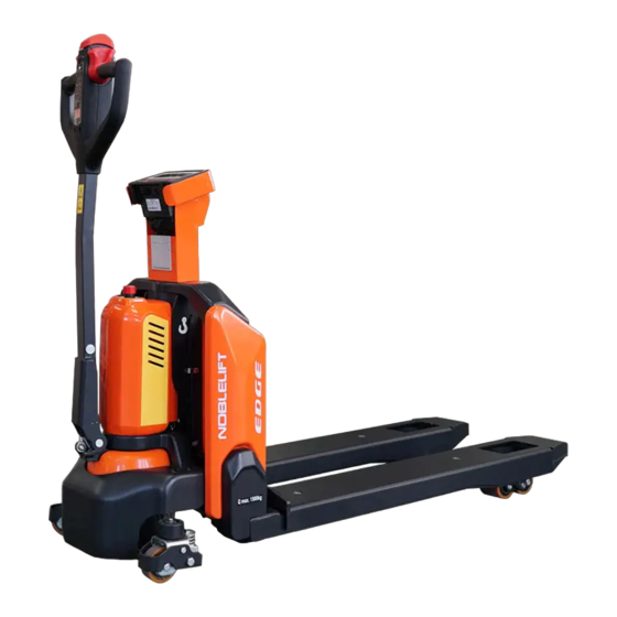
Вилочный штабелер ноблелифт EDGE
05.09.2022 00:00
Серия EDGE — самоходные электрические штабелеры, предназначенные для оптимизации внутрискладских производственных процессов посредством автоматизированной обработки паллет. Оборудование не нуждается в использовании физической силы оператора, но при работе требует пеш…
Складская техника на литиевой АКБ
25.08.2022 00:00
Литий-ионные АКБ — вид аккумуляторов с интеркалированным соединением лития на положительном электроде и в основном с графитом на отрицательном. При подаче напряжения ионы лития направляются от отрицательного электрода через электролит к положительному, что сопровожда…
21.07.2022 00:00
Электрические тележки (электророхли, транспортировщики паллет) — многофункциональное оборудование для складов. Помогает увеличить скорость обработки поддонов и уменьшить объем физического труда при обслуживании терминалов, складских помещений, мест розничной торговли
НОВОСТИ NOBLELIFT
06.07.2022 00:00
Noblelift North America скоро откроет свой второй офис в США, а объект в Онтарио, штат Калифорния, откроется к 1 сентября. «Мы очень рады, что наш новейший филиал в Калифорнии поможет осуществить продажу оборудования, доставку и (предоставить) эффективную складскую п…
Иновации в складской техники и оборудовании
14.06.2022 00:00
Многие технологические инновации для вилочных погрузчиков, предназначенные для повышения эффективности, также способствуют повышению безопасности. Показательным примером является сенсорная технология, которая не только повышает производительность за счет сбора данных…
ОБЗОР НАПОЛЬНОЙ СКЛАДСКАЯ ТЕХНИКИ
07.06.2022 00:00
Какое оборудование вы найдете на каждом складе, складе розничной торговли и распределительном центре, от продуктовых магазинов до ИКЕА, по всему миру? Если бы вы сказали самоходный штабелер или транспортировщик паллет, вы были бы правы. Мелисса Барнетт рассматривает …
На данный продукт загрузочных файлов не найдено
NOBLELIFT Forklift FE3D series Truck Error Codes DTC
Code display on the programmer — Code display on the instrument — Troubleshoot — Fault cause
Controller Overcurrent — 1.2 — controller current overload
1、motor outside U,V or Wconnection shour current
2、motor parameter mismatching
3、controller failure
Current Sensor Fault — 1.3 — Current sensor failure
1,motor U、V、W truck circuit,lead to current leakage
2,controller failure
Precharge Failed — 1.4 — Precharge failure
1,battery can’t charged
Controller Severe Undertemp — 1.5 — Controller temperature too low
1,The controller working environment is too harsh
Controller Severe Overtemp — 1.6 — Controller temperature too high
1,The controller working environment is too harsh
2,truck overloaded
3,the controller is wrongly assembled
Severe Undervoltage — 1.7 — Voltage too low
1, battery parameter is wrongly setted
2, non controller system power consumption
3, The battery impedance is too large
4, battery connection is disconnected
5,the fuse is disconnected, or main contactor is not connected
Severe Overvoltage — 1.8 — Voltage too high
1,Battery parameter is wrongly setted
2,The battery impedance is too large
3,Regenerative braking when the battery connection is disconnected
Controller Overtemp Cutback — 2.2 — Controller temperature too high, as a result the performance is not good
1, The controller working environment is too harsh
2,truck overloaded
3,the controller is wrongly assembled
Undervoltage Cutback — 2.3 — Voltage too low, as a result the performance is not good
1, battery power is insufficient
2, Battery parameter is wrongly setted
3, non controller system power consumption
4, The battery impedance is too large
5, battery connection is disconnected
6, the fuse is disconnected, or main contactor is not connected
Code display on the programmer — Code display on the instrument — Troubleshoot — Fault cause
Overvoltage Cutback — 2.4 — Voltage too high, as a result the performance is not good
1, during the process of regenerative braking, regenerative braking current lead the battery voltage to rise
2, Battery parameter is wrongly setted
3, The battery impedance is too large
4, when regenerative braking +5V Supply Failure 2.5 Controller output 5v, poer supply failre
1, external load impedance is too low
Digital Out 6 Failure — 2.6 — Drive 6 output overcurrent
1, external load impedance is too low
Digital Out 7 Overcurrent — 2.7 — Drive 7 output overcurrent
1, external load impedance is too low
Motor Temp Hot Cutback — 2.8 — The motor is too hot, as a result the performance is not good
1,The motor temperature reach or above the setted program alert temperature, lead the current output to reduce
2, motor temperature parameter is wrongly setted
3, If the motor has not used the temperature sensor, programming parameters
“Temp compensation” and “Temp cutback ”must be setted“ OFF”。
Motor Temp Sensor Fault — 2.9 — Motor temperature sensor failure
1, Motor temperature sensor is wrongly connecttedly
2, If the motor has not used the temperature sensor, parameter programming “MotorTemp Sensor Enable” must be setted “OFF”
Coil 1 Driver Open / Short — 3.1 — Drive 1 output linkng coil is open circuit or short circuit
1, connected load is open circuit or short circuit
2, connecting pin is stained
3, wrong wiring
Main Open / Short — 3.1 — Main contactor coil is open circuit or short circuit
1, connected load is open circuit or short circuit
2, connecting pin is stained
3, wrong wiring
Code display on the programmer — Code display on the instrument — Troubleshoot — Fault cause
Coil2 Driver Open / Short — 3.2 — Drive 2 output linkng coil is open circuit or short circuit
1. connected load is open circuit or short circuit
2. connecting pin is stained
3. wrong wiring
EMBrake Open / Short — 3.2 — Electromagnetic brake coil is open circuit or short circuit
1, connected load is open circuit or short circuit
2, connecting pin is stained
3, wrong wiring
Coil3 Driver Open / Short — 3.3 — Drive 3 output linkng coil is open circuit or short circuit
1,connected load is open circuit or short circuit
2, connecting pin is stained
3, wrong wiring
Coil4 Driver Open / Short — 3.4 — Drive 4 output linkng coil is open circuit or short circuit
1,connected load is open circuit or short circuit
2, connecting pin is stained
3,wrong wiring
PD Open / Short — 3.5 — Proportional driving is open circuit or short circuit
1, connected load is open circuit or short circuit
2, connecting pin is stained
3, wrong wiring
Encoder Fault — 3.6 — Encoder failure
1,motor encoder is failure
2, wrong wiring
Motor Open — 3.7 — Motor is open corcuit
1, motor phase
2, wrong wiring
Main Contactor Welded — 3.8 — Main contactor adhesions
1, Main contactor contact welding
2, motor U or V disconnected or default phase
3,circuit that connecting B+ terminal will electricize the battery
Main Contactor Did Not Close — 3.9 — Main contactor is not closed
1, main contactor is not closed
2,Main contactor pin is oxydic, melted, or not stable when connected
3, external device electricize the battery
4, fuse is disconnected
Throttle Wiper High — 4.1 — Accelerator output is high
1,accelerator and potentiometer output voltage is too high
Throttle Wiper Low — 4.2 — Accelerator output is low
1,accelerator and potentiometer output voltage is too low
Pot2 Wiper High — 4.3 — potentiometer 2 output is too high
1,potentiometer 2 output voltage is too high
Pot2 Wiper Low — 4.4 — potentiometer 2 output is too low
1,potentiometer 2 output voltage is too low
Pot Low Overcurrent — 4.5 — potentiometer current is too low
1,potentiometer impedance is too low
EEPROM Failure — 4.6 — EEPROM failure
1,EEPROM storage failure
Code display on the programmer — Code display on the instrument — Troubleshoot — Fault cause
HPD / Sequencing Fault — 4.7 — High pedal protection / operation order failure
1,The key start, interlock, direction, and the accelerator input order is wrongly setted.
2, Wiring, switch key, interlock, direction, or accelerator input failure
Emer Rev HPD — 4.7 — Emergenvy reverse high pedal protection
1,Emergency reverse operation is over, but the forward, reverse input and interlock of the accelerator are not resetted
Parameter Change Fault — 4.9 — Parameter change failure / wrong
1,In order to ensure the safety of the truck, some specific parameter changes must come into force after the key switch is restarted
OEM Faults — 5.1-6.7 — OEM failure(custom failure)
1,The user can define by themself the fault, use VCL code to note.
VCL Run Time Error — 6.8 — VCL running time is wrong
1,VCL code running time is overtime
External Supply Out of Range — 6.9 — Externial battery output is out og range
1, externial loading is between 5V and 12V , battery current is too big or too small
2, in the“inspection menu (Checking Menu)”, parameter is wrong, such as “ExtSupply Max”,“Ext Supply Min”
OS General — 7.1 — Operation system failure
1,internial controller failure
PDO Timeout — 7.2 — PDO overtime
1,CAN PDO information reception time exceeds PDOtime limition
Stall Detected — 7.3 — Motor stalling
1, Motor stalling
2, motor encoder failure
3, wrong connection
4, input motor encoder battery failure
Motor Characterization Fault — 8.7 — Motor matching failure
1, In the process of motor matching, code contrast:
0=normal
1= The controller receives the encoder signal, but impulse quantity is undefined. Please manually set pulse value
2=motor temperature sensor failure
3= motor high temperature response failure
4=motor overheating response failure
5= motor low temperature sensor failure
6=low voltage response failure
7=high pressure response failure
8= Controller cannot detect the encoder signal, channel signals disappears
9= Motor parameter settings exceed the scope
Code display on the programmer — Code display on the instrument — Troubleshoot — Fault cause
Motor Type Fault — 8.9 — Motor type failure
1,motor type(Motor Type) parameters exceed the scope
VLC/OS Mismatch — 9.1 — VCL/OS not matched
1,VCL and OS of the controller program are not matching
EM Brake Failed to Set — 9.2 — Electromagnetic setting failure
1, the truck still not move after the electromagnetic brake command is setted.
2, Electromagnetic brake braking force is too small
Encoder LOS (Limited Operating Strategy) — 9.3 — Encoder operation is limited
1,Because motor blocked or encoder failure, the limited operating state is activated
2, wrong wiring
3, truck stall
Emer Rev Timeout — 9.4 — Emergency reverse response time is overtime
1, because EMR Timer expires, so the emergency switch is actiated overtime
2, emergent reverse switch has been on the “on” position all the time
Illegal Model Number — 9.5 — Controller type is wrong
1, controller moder can recognize
2, software and hardware type are not matching
3, controller is damaged
Регионы с которыми мы работаем: Севастополь, Симферополь, Керчь, Евпатория, Феодосия, Москва, Санкт-Петербург, Новосибирск, Екатеринбург, Нижний Новгород, Казань, Челябинск, Омск, Самара, Ростов-на-Дону, Уфа, Красноярск, Пермь, Воронеж, Волгоград, Краснодар, Саратов, Тюмень, Тольятти, Ижевск, Барнаул, Иркутск, Ульяновск, Хабаровск, Владивосток, Ярославль, Махачкала, Томск, Оренбург, Кемерово, Новокузнецк, Рязань, Астрахань, Набережные Челны, Пенза, Липецк, Тюмень, Тобольск, Ишим, Ялуторовск, Заводоуковск, Сургут, Нефтеюганск, Нижневартовск, Ханты-Мансийск, Когалым, Нягань, Мегион, Радужный, Лангепас, Пыть-Ях, Урай, Лянтор, Югорск, Советский, Белоярский, Покачи, Пойковский, Фёдоровский, Излучинск, Белый Яр, Междуреченский, Новоаганск, Ноябрьск, Новый Уренгой, Надым, Салехард, Муравленко, Лабытнанги, Губкинский, Тарко-Сале, Пангоды, Уренгой.
ООО «ПОДЪЕМНО-ДОРОЖНЫЕ МАШИНЫ»
ИНН 7202234999
ОГРН 1127232037635
0%

Описание
Назначение: самоходная тележка NOBLELIFT PTE15N используется на складах и в магазинах. Подходит для перемещения различных грузов, вес которых не превышает 1500 килограмм.Привод: оборудование оснащено приводным DC-двигателем с потребляемой мощностью 650 Вт, обеспечивающим скорость передвижения до 4,8 км/ч. Питание осуществляется от литий-ионной батареи с напряжением 24 Вольта.Преимущества: устройство оборудовано контроллером Curtis и ПИН панелью. Функция электроподъема значительно увеличивает производительность. Также конструкцией предусмотрен электромагнитный тормоз.Купить складскую тележку с гарантией производителя можно на сайте Диам Алмаз.
Тип двигателя
аккумуляторный
Двигатель привода, кВт
0,65
Двигатель подъема, кВт
0,5
Тип тележки
самоходная, электрическая
Грузоподъемность, кг
1500
Высота вил в нижнем положении, мм
80
Скорость движения (с грузом/без груза), км/ч
4,6/4,8
Скорость подъёма (с грузом/без груза), мм/с
20/25
Скорость спуска (с грузом/без груза), мм/с
50/40
Макс. преодолеваемый уклон, %
6/16
Радиус разворота, мм
1330
Рабочий коридор с паллетом 800х1200 мм, мм
2000
Тележка самоходная с электроподъемом Noblelift PTE15N
Добавить к сравнению
Самовывоз. Бесплатная доставка до ТК.
Наличный и безналичный расчет, банковские карты
Отзывы
Хотите оставить отзыв?Поставьте свою оценку!
Сделайте выбор!
-
Bookmarks
Quick Links
Service & Maintenance Manual
Electric Pallet Truck
PTE15Q
WARNING
Do not use the pallet truck before reading and
understanding these operating instructions.
NOTE:
Please check the designations of your present
type at the last page of this document as well
as on the ID-plate.
Keep for future reference.
Tell:4008-836115
Version 01/2022
Related Manuals for Noblelift PTE15Q
Summary of Contents for Noblelift PTE15Q
-
Page 1
Tell:4008-836115 Service & Maintenance Manual Electric Pallet Truck PTE15Q WARNING Do not use the pallet truck before reading and understanding these operating instructions. NOTE: Please check the designations of your present Version 01/2022 type at the last page of this document as well as on the ID-plate. -
Page 2
TABLE OF CONTENTS REGULAR MAINTENANCE ………………….. 2 Maintenance checklist……………………2 Lubrication points ……………………..4 Check and refill hydraulic oil ………………….4 Check electrical fuses ……………………5 TROUBLE SHOOTING ……………………6 Common trouble shooting ………………….. 6 Fault code ……………………….6 WIRING/CIRCUIT DIAGRAM ………………….9 Electrical circuit diagram ……………………. -
Page 3
Parameter setting …………………….. 34 Parameter monitoring ……………………35 Fault information ……………………… 36 System Settings ……………………..37 Mechanical dimensions …………………… 38… -
Page 4
1. REGULAR MAINTENANCE a. Maintenance checklist Safety button / Belly button Tiller Magnetic lock Discharge indicator and charging indicating LED Emergence button Hydraulic unit cover chassis Load roller 10. Battery 11. Apron 12. Driving unit 13. Side roller (option) -
Page 5
Maintenance checklist Interval(Month) 3 6 12 Hydraulic Check the hydraulic cylinder(s), piston for damage noise and leakage Check the hydraulic joints for damage and leakage Inspect the hydraulic oil level, refill if necessary Refill the hydraulic oil ( 12 month or 1500 working hours) … -
Page 6
33 Check the air gap of the electromagnetic brake 34 Test the emergency braking 35 Test the reverse and regenerative braking 36 Test the safety (belly) button function 37 Check the steering function 38 Check the lifting and lowering function … -
Page 7
Waste material like oil, used batteries or other must be probably disposed and recycled according to the national regulations and if necessary brought to a recycling company. The oil level height shall be in the not lifted position min. 0.3L to 0.5L. If necessarily add oil at the filling point. -
Page 8
2. TROUBLE SHOOTING a. Common trouble shooting Table 3: Trouble shooting TROUBLE CAUSE REPAIR Lift only the max. capacity, mentioned Load weight too high on the ID-plate Battery discharged Charge the battery Check and eventually replace the Lifting fuse faulty Load can’t be lifted lifting fuse Check and eventually refill hydraulic… -
Page 9
Fault code Fault name Fault description Solution Fault source Number displayed on handle The interlock switch is closed in the upright driving mode. If the upright driving switch (tortoise speed switch) is released, the fault has not been the interlock switch is closed when upright driving cleared after resetting the interlock: BM24C10-CAN controller (UpRight_Fault) -
Page 10
2. If the internal temperature sensor of the battery fails, replace the battery; temperature inside the battery. reserve reserve BM24C10-CAN controller Motor_Temp_Fault reserve The lifting switch is closed before opening BM24C10-CAN controller PumpSRO_Fault reserve System task failure reserve BM24C10-CAN controller PTE15Q Fault code… -
Page 11
3. WIRING/CIRCUIT DIAGRAM a. Electrical circuit diagram PTE15Q Table 4: Description of electrical diagram Code. Item Code Item Battery CAN tiller Controller Proximity switch Pump motor Traction motor Pump contactor Electromagnetic brake Emergency button 10A fuse Electromagnetic valve FU01 70A fuse… -
Page 12
Micro switch b. Hydraulic circuit Lifting cylinder Lowering valve Throttle valve Pressure control valve Hydraulic power unit Oil tank Table 5: Hydraulic oil inspection Degree of purity Smell Status Result Clear and same color as before Good Good Can be used Transparent Good Mixed with other oil… -
Page 13
4. MAINTENANCE OF MAIN COMPONENTS Battery replacement Unplug the plug, flip the switch outward to remove the battery. Battery and charger 1. 8A&12A… -
Page 14
2. Battery introduction Outer-appearance parts 1.Remove the Electronically controlled cover and unscrew 4 screws to remove the cover. -
Page 15
2.Driving wheel cover There are 2 fixed screws in the small cover. There are 4 fixed screws in the small cover. -
Page 16
Tiller 1.Remove the two fixed screws to open the rear cover. Remove the internal wiring harness and remove the handle. 2.Disassembly of air spring Remove the screw with Remove circlip Remove the axle. Remove the circlip and 5mm Allen wrench. with circlip plier. -
Page 17
3.Assembly of air spring Put the air spring into Insert the axle. Make hole of axle and Support the air spring the tiller arm. hole of screw on the with flat metal tool to fix same level with Allen the screw. wrench. -
Page 18
Pull out the protective Disconnect the cylinder cover from top. from pump with 5mm Allen wrench. During assembly, it’s required to apply thread locker with 1243 model. For PTE15Q, there is a O ring on the valve. Please keep it. -
Page 19
Pump disassemble from machine Remove the left screw Remove the right screw Remove the top screw Put a wooden block with 5mm Allen wrench. with 5mm Allen wrench. with 5mm Allen wrench. under the chassis. Power on the truck, Turn over the cylinder. Disconnect the cylinder After disconnection, activate the lowering… -
Page 20
Disassembly of driving unit Remove the screw with 6mm Remove 4 screws with 6mm Remove the driving unit from Allen wrench. It’s required to Allen wrench. the chassis. apply thread locker with 1243 model. Pad the hole in the middle First remove the bearing, then Remove the screw with 5mm with an iron sheet or other… -
Page 21
Disassembly of brake Remove the plastic cover Remove three screws with before replacement of brake, 4mm Allen wrench to take it’s connected with glue out the brake. Driving wheel Cut the plastic strip then Remove 10 screws with 5mm disconnect the plug. Allen wrench, take out the wheel ring. -
Page 22
J. Disassembly of emergency button Remove the cable Remove two screws Remove the screws on Remove the cable clamp with on the right side of the the left side of the clamp. Make sure screwdriver. frame with 5mm Allen frame with 5mm Allen during assembly of the wrench. -
Page 23
K. Disassembly of controller PTE15Q It’s recommended to Remove the plugs. Remove two screws with make picture for 5mm Allen wrench to take routing and connection out the controller. before controller is disconnected. Four plugs here from top to bottom… -
Page 24
M. Disassembly of chassis Remove the elastic pin Remove the circlip First remove four to take out the axle, then disconnect rock arm elastic pins. Note: disconnect rock arm from body. elastic pin specification from chassis. is 6*40.5*30. Note: elastic specification is 6*40. -
Page 25
N. Pump motor Remove cable terminals from the There are four carbon motor with 10mm wrench, and then brushes after motor cover is remove two screws on top of the removed. Every two are motor with 10mm wrench to take welded to the positive and out the motor. -
Page 26
avoid vehicle and personal safety accidents. The hand-held unit will automatically save the modification parameters, just need to close the key switch and restart. The CURTIS handheld unit can be connected in the event of a controller power or power failure The process of reading fault code After connecting the handheld unit with the controller, open the key switch From the menu list of CURTIS handheld units, find: Faults… -
Page 27
The Curtis 1313 handheld programmer is used to configure Curtis motor control systems. With the programmer, you can adjust and save parameter settings, monitor real-time data, and perform diagnostics and troubleshooting. Warning: The control system can affect the vehicle’s acceleration rate, deceleration rate, hydraulic system and braking. -
Page 28
Connect the handheld programmer into the control system by plugging it into the controller’s charger/programmer port. The programmer automatically powers up, and displays this screen while it loads information from the controller. -
Page 29
Softkeys These three keys are blank, because their function is context-specific. At any given time, their function is shown directly above them on the LCD screen. The symbol “»” indicates more options; pressing the soft key under the “»” will scroll to another set of options. Arrow keys With these four keys you can scroll up and down and right and left, within the display. -
Page 30
The nine menus DIAGNOSTICS MENU In the Main Menu, highlight the Diagnostics icon and press the “Select” soft key to go to the Diagnostics menu. You can return to the Main Menu at any time by pressing the Main Menu key ( ). The Diagnostics menu contains two folders: Present Errors and Fault History. -
Page 31
Fault History folder This folder lists all the faults encountered since the Fault History was last cleared. You can clear the entire contents of this folder to allow a fresh Fault History to be started. “Clear All” is used to empty the Fault History folder. -
Page 32
6. Handheld Unit with Electric Control of Jiachen Function introduction Function description The Handheld Unit is a powerful and intuitive programming and diagnostic tool that can monitor and modify controller parameters online, allows users to save parameter files online, saves the parameter files to the Handheld Unit or an external USB storage device, and sends the edited parameter files to the motor controller when online. -
Page 33
Direct access to controller parameters and can be modified; Technical parameters parameter value unit Rated operational voltage 12~96 ℃ Rated operational voltage -20~70 ℃ Storage temperature -40~85 Working humidity 95% RH max Degree of protection IP51 on the front, IP40 on the back Interface pin definition The external power supply and communication interface of the Handheld Unit adopts the RJ45 network port, which is connected to the electric control through a spiral adapter cable, and the… -
Page 34
The interface pin definition: Pin number Description Pin number Description CAN_L / RS232_RX CAN_H / RS232_TX Button The Handheld Unit uses silicone buttons, a total of 13 buttons, which are up, down, left, right, increase, decrease, F1~F3 function buttons, power button, favorites button, home button, and help button. -
Page 35
2) After the Handheld Unit is turned off, press the power button for 1 second, and it will restart to run. Home button: Press this button in the main interface to cycle through various applications. Press the main interface key in other interfaces to return to the main interface display. Function description 1. -
Page 36
Set the current backlight brightness, System settings communication mode, and USB mode; 2.System Information Select the «SysInfo» function icon in the main interface and press the «F3» key to enter the system information viewing sub-interface; this interface displays the product serial number, hardware version number, and software version number. -
Page 37
After entering the parameter modification interface, as shown in the lower left corner of picture, use the “± key“ to modify the parameter value. Each time you press it, the parameter will increase or decrease by 1; if you increase or decrease by 10 each time, you can press the function key “F1“… -
Page 38
R. Fault information Select the «ErrorInfo» function icon on the main interface, You can view the current faults and historical faults of the controller. Error information interface… -
Page 39
S. System Settings Select the «SysSet» function icon in the main interface to set the current backlight brightness, communication mode (RS232 or CAN), USB mode and system language and other local settings. a) Backlight brightness: adjust between 10~100, press the corresponding «+» and «-» keys, the value will increase or decrease correspondingly;… -
Page 40
T. Mechanical dimensions Unit: mm…
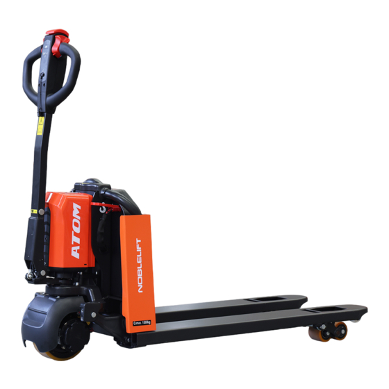
NOBLELIFT PTE15Q ATOM
Компания NOBLELIFT INTELLEGENT представляет новую инновационную серию складской подъемно-транспортной техники под названием ATOM. Высокотехнологичные продукты NOBLELIFT ATOM это электрические самоходные тележки и паллетоперевозчики (транспортировщики паллет) NOBLELIFT PTE15Q и поводковые электрические штабелеры PSE12Q, которые способны обеспечить высокоэффективную замену гидравлической ручной и полу электрической складской техники с минимальными вложениями на покупку и затратами на обслуживание.
Новая самоходная электрическая тележка для транспортировки паллет и поддонов с грузов NOBLELIFT PTE15Q ATOM с литий-ионными аккумуляторными батареями разработана в соответствии с современными промышленными тенденциями в области складской логистики, безопасности эксплуатации и высокими стандартами экологичности.
Серия ATOM продолжает концепцию популярной и надежной серии EDGE (NOBLELIFT PTE15N/NOBLELIFT PTE20N), сочетая в себе компактный, продуманный и эргономичный дизайн, современные системы безопасности, оптимальную производительность и современные технологии. Незначительное снижение функционала, ограничение списка опций относительно серии EDGE позволило снизить издержки при производстве что в результате позволило предложить потребителям доступное решение в области складской логистики по более привлекательной и доступной цене.
NOBLELIFT PTE15Q ATOM предлагает функции и решения в области перевозки грузов, которые обычно используются и доступны в более дорогом и премиальном сегменте малой складской напольной техники:
- индикатор с отображением уровня заряда аккумуляторной батареи с возможностью отображения кодов неисправностей;
- CAN-BUS шина;
- Электрическое управление всеми основными функциями: движение, подъем и спуск вил;
- Функция управления с вертикальным положением руля;
- Литий-ионные аккумуляторы с функцией быстрой зарядки и легкой и быстрой смены;
Система пропорционального контроля скорости позволяет с точностью регулировать ускорение, максимальную скорость самоходной тележки по желанию и предпочтениям заказчика.
Угол поворота рулевого колеса 208° обеспечивает плавное и легкое маневрирование и точную управляемость
СЕРВИС И ОБСЛУЖИВАНИЕ
Удобный и быстрый доступ к любому компоненту электрической тележки NOBLELIFT ATOM за счет простой и удобной конструкции, которая не требует наличия специального инструмента.
Транспортировщик паллет оснащен современным программируемым логическим контролером CURTIS с системой самодиагностики и индикацией кодов ошибок на ручке управления. Высокоскоростной протокол передачи данных по CAN – шине не только ускоряет передачу сигналов, но и упрощает процессы диагностики и устранения неисправностей.
В гидравлической системе транспортировщиков NOBLELIFT PTE15Q ATOM не используются шланги или трубки, что значительно повышает надежность и снижает количество потенциальных проблем, связанных с утечками через соединительные каналы или их уплотнения.
Литий-ионные аккумуляторные батареи диагностируются через CAN-шину с помощью специального диагностического оборудования и программного обеспечения, с помощью которых можно узнать всю техническую информацию о состоянии аккумулятора: баланс ячеек, количество циклов и параметрах зарядки/разрядки, потребляемой энергии, напряжении и температуре в каждой ячейке и т.д, а так же неисправностях и предупреждениях выявленных при эксплуатации.
БЕЗОПАСНОСТЬ И ОХРАНА ТРУДА
Современные технические требования и регламенты заставляют уделять производителей промышленного оборудования больше внимания безопасности и здоровью персонала. Работодатель в современных условиях вынужден обращать внимание не только на эффективность, производительность и стоимость оборудования, но и на факторы, которые снижают риски получения травм и сокращают возникновение несчастных случаев.
По статистике, большинство производственных травм, связано с применением операторами чрезмерно физической силы, необходимой для того, чтобы переместить груз с места или поднять его на высоту. Растяжения мышц рук и предплечий, травмы спины и конечностей – самые частые профессиональные заболевания грузчиков и операторов техники, занятых в сфере обработки грузов.
Все эти риски могут быть легко устранены с продуктами из новой линейки ATOM от компании NOBLELIFT INTELLEGENT, которую Вы можете приобрести у официального дилера и авторизированного сервисного партнера: СКЛАДСКИЕ МАШИНЫ
-
Contents
-
Table of Contents
-
Troubleshooting
-
Bookmarks
Quick Links
Instruction Manual
Electric Pallet Truck with Scale
PTE15N SC
WARNING
Do not use the pallet truck before reading
and understanding these instructions.
NOTE:
• Please check the designation of your
truck type at the last page of this
manual as well as on the ID-plate.
• Keep this manual for reference.
•
Related Manuals for Noblelift PTE15N SC
Summary of Contents for Noblelift PTE15N SC
-
Page 1
Instruction Manual Electric Pallet Truck with Scale PTE15N SC WARNING Do not use the pallet truck before reading and understanding these instructions. NOTE: • Please check the designation of your truck type at the last page of this manual as well as on the ID-plate. -
Page 3
FOREWORD Before operating the truck, read this ORIGINAL INSTRUCTION MANUAL carefully and understand the usage of the truck completely. Improper operation could create danger. This manual describes the usage of different electric pallet trucks. When you operate or maintain the truck, make sure, that it applies to your type. -
Page 4: Table Of Contents
TABLE OF CONTENTS 1. CORRECT APPLICATION …………Tõrge! Järjehoidjat pole määratletud. 2. DESCRIPTION OF THE PALLET TRUCK ……. Tõrge! Järjehoidjat pole määratletud. a. Overview of the main components ……..Tõrge! Järjehoidjat pole määratletud. b. Main technical data …………… Tõrge! Järjehoidjat pole määratletud. c.
-
Page 5
9. PIN-CODE PANEL ……………………..22 a. Introduction ……………………….22 b. Main parameters ……………………..22 c. Main codes and functions ……………………. 23 10. BATTERY CHARGING AND REPLACEMENT ……………… 23 a. Replacement ……………………….. 23 b. Battery indicator ……………………..24 c. Charging ……………………….25 11. -
Page 6: Correct Application
1. CORRECT APPLICATION It is only allowed to use this electric pallet truck according to this instruction manual. The trucks described in this manual are self-propelled electric power pallet trucks. The trucks are designed to lift, lower and transport palletized loads. A wrong usage can cause human injuries or can damage the equipment.
-
Page 7: Description Of The Pallet Truck
2. DESCRIPTION OF THE PALLET TRUCK Overview of the main parts Fig. 1: Overview main parts Safety (belly) button Fork Tiller Load roller Pin-code panel 10. Battery Battery discharge indicator 11. Apron Emergency button 12. Drive Unit Motor cover 13. Display Chassis 14.
-
Page 8: Main Technical Data
Main technical data Fig. 2: Main technical data…
-
Page 9
Table 1: Main technical data for standard version Type sheet for industrial truck acc. to VDI 2198 PTE15N SC Manufacturer`s type designation Drive Battery Operator type Pedestrian Load Capacity / rated load Q (t) Load centre distance c (mm) Load distance ,centre of drive axle to fork… -
Page 10: Description Of The Safety Devices And Warning Labels (Europe And Other, Except Usa)
Energy consumption acc. to VDI cycle kWh/h 0.19 Type of drive control DC speed Control Sound level at driver`s ear acc. to EN dB(A) <70 12053 Features weighing accuracy: +3kg for loading 1500kg Description of the safety devices and warning labels (Europe and other, excepting USA) Decal: No Passengers Decal: Crane Hook…
-
Page 11: Warnings, Residual Risk And Safety Instructions
Fig. 4: Identification plate (take practicality as standard) 3. WARNINGS, RESIDUAL RISK AND SAFETY INSTRUCTIONS DO NOT • Put feet or hands under or into the lifting mechanism. • Allow other person than the operator to stand in front of or behind the truck when it is moving or lifting/lowering.
-
Page 12: Commissioning, Transporting, Decommissioning
• To prevent unintended sudden movements when not operating the truck (i.e. from another person, etc.), turn off the truck. 4. COMMISSIONING, TRANSPORTING, DECOMMISSIONING Commissioning Table 2: Commissioning data Type PTE15N SC(562X1150) PTE15N SC(707X1150) Commissioning weight [kg] 180kg 185kg Dimensions [mm]…
-
Page 13: Decommissioning
Fig. 6: Holes for hook Fig. 5: Lifting with a crane c. Decommissioning For storage, remove the load, lower the truck to the lowest position, grease all greasing points (regular inspection) mentioned in this manual to protect the truck against corrosion and dust.
-
Page 14: Operating Instructions
• Check if all bolts and nuts are tightened firmly. • Visual check if there are any broken electric wires. • If the truck equips with a backrest, check it for damages and correct assembling. 6. OPERATING INSTRUCTIONS BEFORE OPERATING THIS TRUCK, PLEASE FOLLOW THE WARNINGS AND SAFETY INSTRUCTIONS…
-
Page 15: Steering
Fig. 9: Operating direction Turn the accelerator to the desired direction forward ‘Fw.’ or backwards Bw.’ (Fig. 9). Control the travelling speed by moving the accelerator (Fig.7,13) carefully until you reach the desired speed. If you move the accelerator back to the neutral position, the controller decelerates the truck until the truck stops.
-
Page 16: Malfunctions
the tiller is in the operating zone. Malfunctions If there are any malfunctions or the truck is inoperative, please stop using the truck and activate the emergency button (5) by pressing it. If possible, park the truck on a safe area and press “X” button of pin- code panel.
-
Page 17: Errors
Errors Zero tare functions…
-
Page 18: Summation (Total) Function
Summation (total) function…
-
Page 19: Printout (Optional)
Printer (Optional) Thermal Printer Up to 65 mm/sec (max.) Printer Print speed Front side paper feed, easy to Function -10~55℃ Temperature range install paper Thermal roll, maximum diameter 85x85x54mm Paper Dimensions is 50mm, width is 58mm DC5V, DC5V-9V 8 dots/ mm, 384 dots/ line Resolution Power supply (optional)
-
Page 20: Indicator Display
Paper replacement 8. Indicator display Button and Display Check Operations: With the display off, long press and hold Zero button, then press On/ Off button, the device will enter hardware check state. Release Zero button when screen shows “0 OK”. When the screen displays “0 KEY”, press Zero button, the screen shows “0 OK”;…
-
Page 21: Backlight Mode Settings
Check the default unit setting when the screen displays “UNIT”. Then press Tare (Confirm) button to confirm entering into this mode. Operations: Press the Tare (Confirm) button to enter Default Unit Settings when in UNIT interface. Check the default unit at the right of the screen. Press the Gross (<—>) button to switch the unit. Press the Tare (Confirm) button again to confirm when the screen shows the desired unit.
-
Page 22: Battery Replacement
Battery Replacement Storage battery: 6V/4.5A (68.5mm*46.5mm*100mm). First remove the screws of the battery cover, then replace the used batteries with the new ones. At last put back the battery cover and fix it with screws. Indicator operation panel Note: this weighing display has 5 dynamic cursors: Hold (lock cursor), ~(dynamic cursor), Net (net weight cursor), Light (backlight cursor), →0←…
-
Page 23: Sensors Installation
Short press or long press one button or press two buttons at the same time to achieve different functions. Sensors Installation 1) Before the sensors installation, please make sure to power off the device head. The sensors will be in loop detection state if the device head is powered on. Operation with electricity will cause wrong data.
-
Page 24
Short Press — lock / unlock the weight value displayed on the current screen ; in weighing mode, press the «Hold» button on the operation panel, the current weight displayed will be locked, and the lock cursor will show at this time. If the weight is in the locked state, press the «Hold»… -
Page 25: Pin-Code Panel
device is in «BL ON» mode, and the backlight cursor is displayed, long press to the button to turn on the backlight. Short Press – power on / power off. 2) Combined Button Function Press “lb/kg” and “Gross” button at the same time to restore factory settings (handle with care).
-
Page 26: Replacement
• The batteries are lithium batteries. • Recycling of batteries undergoes national regulations. Please follow these regulations. • By handling batteries, open fire is prohibited! • In the area of battery charging neither burning materials nor burning liquids are allowed. Smoking is prohibited and the area must be ventilated. •…
-
Page 27: Charging
The display can indicate a code corresponding to the type of fault, and the wrench mark is flashing at the same time. Battery State of charge The battery’s state of charge indication is integrated in the LCD display; it is shown by ten notches. Each notch represent the 10% of the battery charge.
-
Page 28: Regular Maintenance
Fig.12: Battery charging Table 3: Charger LED LED- signal Function Charging Green Fully charged Table 4: Charger Model Specification Input Output DZL2420SS02 24V5A (Chinese sticker) 180Vac -240Vac~2.0A MAX 29.4V 5.0A DZL2420SS02 24V5A (English sticker) 100Vac -240Vac~2.0A MAX 29.4V 5.0A DZL300SS02 24V8A (Chinese sticker) 180Vac -240Vac~3.0A MAX 29.4V 8.0A…
-
Page 29: Maintenance Checklist
they should have no abnormal abrasion. Check the items emphasized in maintenance checklist. a. Maintenance checklist Table 5: Maintenance checklist Interval (Month) Hydraulic • Check the hydraulic cylinder(s), piston for damage noise and leakage Check the hydraulic joints for damage and leakage •…
-
Page 30: Lubricating Points
Check the main power cable for damages • Check the start-up protection during charging • Function • Check the horn function • Check the air gap of the electromagnetic brake Test the emergency braking • Test the reverse and regenerative braking •…
-
Page 31: Check Electrical Fuses
If necessary add oil till oil level reaches the filling mark. d. Check electrical fuses Fig. 14: Location of fuses Table 6: Size of the fuses Rate FU 1 FU 01 TROUBLE SHOOTING • If the truck has malfunctions follow the instructions, mentioned in chapter 6. Table 7: Trouble shooting Fault Possible cause…
-
Page 32
Tiller is not in the operating position Move the tiller firstly to the braking zone If the truck has malfunctions and can not be operated out of the working zone, jack the truck up and put the load handling equipment under the truck and ensure the safety of the truck. Then move the truck out of the aisle. -
Page 33: Wiring/ Circuit Diagram
13. WIRING/ CIRCUIT DIAGRAM a. Electrical circuit diagram Without speed reduction on curves Fuse 1: 10A Fuse 01: 70A Fig.15: Electric circuit diagram (without speed reduction on curves)
-
Page 34
Table 8: Description of electrical components Code Item Code Item Battery CANTiller Controller Proximity Switch Pump Motor Traction Motor Pump Contactor Electromagnetic Brake Emergency button 10A Fuse Electromagnetic Valve FU01 70A Fuse Microswitch… -
Page 35
With speed reduction on curves… -
Page 36: Hydraulic Circuit Diagram
FU1 : 10A FU01 : 70A Fig.16: Electric circuit diagram (with speed reduction on curves) Table 9: Description of electrical components Code Item Code Item Battery CAN Tiller Controller Proximity Switch Pump Motor Traction Motor Pump Contactor Electromagnetic Brake Emergency Button 10A Fuse Electromagnetic Valve Proximity Switch…