-
- Новое
Модератор: central
Сброс ошибок на NCR безе перезагрузки банкомата
![]() Sterialmurder » 02 апр 2016, 16:11
Sterialmurder » 02 апр 2016, 16:11
Помогите разобраться. Выхожу из ПО банкомата. Попадаю на рабочий стол. Далее запускаю NCR Aptra, ошибки сбрасываются, а вот где найти bat файл для запуска рабочего состояния банкомата?
p/s на некоторых УС лежит на рабочем столе, а на других нет.
- Sterialmurder
- Сбербанк

- Сообщения: 2
- Зарегистрирован: 02 апр 2016, 15:08
-

Sinbadsup - Сбербанк
- Сообщения: 59
- Зарегистрирован: 15 апр 2015, 13:48

-

TichoblinII - Сбербанк
- Сообщения: 397
- Зарегистрирован: 29 янв 2011, 02:45

Сообщений: 3
• Страница 1 из 1
Вернуться в APTRA
Кто сейчас на конференции
Сейчас этот форум просматривают: нет зарегистрированных пользователей и гости: 1
Слайд 1Банкоматы
NCR
Курс базового уровня
Б-003
v.1.0

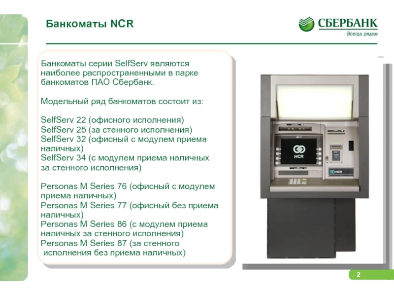
Слайд 2Банкоматы NCR
Банкоматы серии SelfServ являются
наиболее распространенными в
парке
банкоматов ПАО Сбербанк.
Модельный ряд банкоматов состоит из:
SelfServ 22 (офисного исполнения)
SelfServ 25 (за стенного исполнения)
SelfServ 32 (офисный с модулем приема
наличных)
SelfServ 34 (с модулем приема наличных
за стенного исполнения)
Personas M Series 76 (офисный с модулем
приема наличных)
Personas M Series 77 (офисный без приема
наличных)
Personas M Series 86 (с модулем приема
наличных за стенного исполнения)
Personas M Series 87 (за стенного
исполнения без приема наличных)
Слайд 3Основные элементы устройства
банкоматов NCR
Назначение и расположение

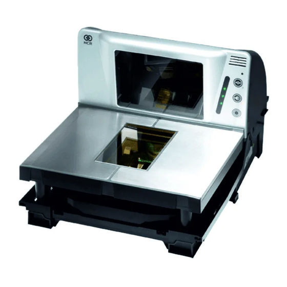
Слайд 4Элементы и их расположение
Банкоматы серии SelfServ являются
наиболее распространенными в парке банкоматов ПАО Сбербанк.
А представленная модель SelfSerf 6632 является наиболее популярным офисным банкоматом.

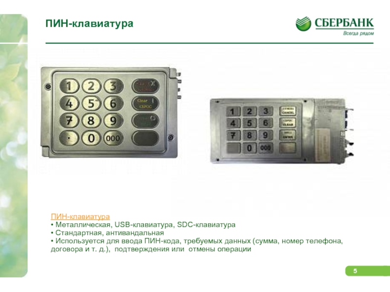
Слайд 5ПИН-клавиатура
ПИН-клавиатура
• Металлическая, USB-клавиатура, SDC-клавиатура
• Стандартная, антивандальная
•
Используется для ввода ПИН-кода, требуемых данных (сумма,
номер телефона, договора и т. д.), подтверждения или отмены операции
Слайд 6Чековый принтер
Принтер квитанций: печатает и выдает отчет
о каждой транзакции по запросу держателя карты.
Печатающая головка печатает непосредственно на термографической бумаге, поэтому лента для принтера не используется. Технология, используемая в термографическом принтере, позволяет печатать графику и расширенные наборы символов.
В моделях серии SelfServ используются принтеры с шиной – USB
В моделях серии PersonaS – COM (офисные), SDC (застенные)
Термобумага для чековых принтеров банкоматов NCR.
Размер: 80×200×18 (мм), 0,55 г/ м²
Расположение термослоя: Внутренний
Основные узлы:
Печатающая головка.
Транспорт выдачи чеков.

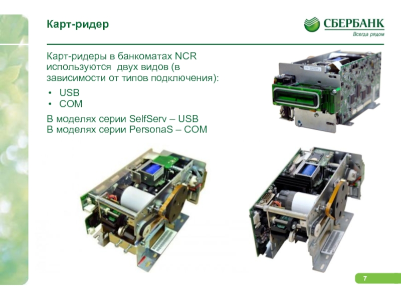
Слайд 7Карт-ридер
Карт-ридеры в банкоматах NCR используются двух видов
(в зависимости от типов подключения):
USB
COM
В моделях серии
SelfServ – USB
В моделях серии PersonaS – COM
Слайд 8Панель оператора
Банкоматы за стенного исполнения имеют «Панель
оператора».
Она предназначена для проведения сервисного обслуживания и
выполнения административного функционала находясь в сервисной зоне ( не зоне обслуживания клиентов).
Так же, есть возможность переключить отображения экрана с панели оператора на главный монитор.
Существует два типа консолей оператора, в зависимости от моделей устройств :
На PersonaS – «аналогавая» (консоль со встроенным ЖК-экраном с аналоговыми кнопками.
На SelfSerf — «цифровая» (10,4 – дюймовый сенсорный ЖК-экран).

Слайд 9Диспенсер
Банкоматы NCR в своих диспенсерах используют вакуумный
набор купюр.
Диспенсер состоит из презенторной части и
двух сдвоенных пик-модулей. Оснащается четырьмя кассетами для банкнот и одной кассетой для отбракованных или забытых купюр (реджект кассета).
Основное назначение модуля выдачи наличных (диспенсера) — набрать из кассет необходимое количество купюр, собрать их в пачку и выдать клиенту.
Кассета для купюр, представляет из себя пластиковый бокс с установленными планками-направляющими для купюр и планка с магнитами-герконами, для настройки типа кассеты.
Реджект кассета – пластиковый бокс.
Герконы для определения типа кассеты

Слайд 10Депозитный модуль – модуль приема наличных
BNA (Bunch
Note Acceptor) – модуль приема банкнот (наличных).
Прием
до 30 банкнот пачкой и распознавание до 50 номиналов.
Две приемные кассеты общей вместимостью 3500 купюр.
Закрытый бункер с индикацией вскрытия.
Условное депонирование с функцией возврата пачки пользователю.

Слайд 11Депозитная кассета
Различают:
Передняя «F» и задняя «R» кассета
депозита.
В первую очередь заполняется задняя кассета, потом
передняя.
Емкость кассеты ориентировочно 1750 купюр.

Слайд 12Сброс счетчика задержанных карт
Перевести переключатель «SUPERVISOR/NORMAL» в
положение «SUPERVISOR».
Ввести на клавиатуре код и
пароль.
На дисплее появится «Основной экран оператора».
Перейти в режим «Открытие/Закрытие операционного дня».
Выбрать пункт «Диспенсер».
Выбрать пункт «Дополнительные операции» -«Сброс счетчика задержанных карт».

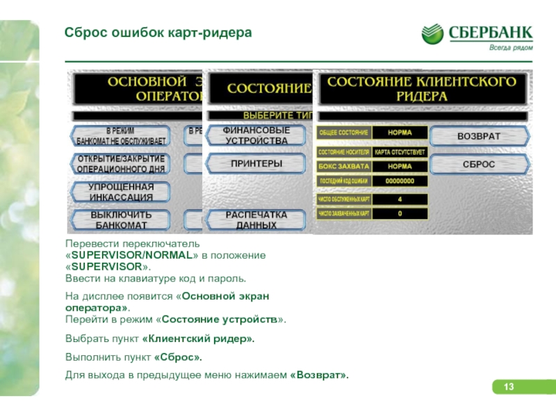
Слайд 13Сброс ошибок карт-ридера
Перевести переключатель «SUPERVISOR/NORMAL» в положение
«SUPERVISOR».
Ввести на клавиатуре код и пароль.
На
дисплее появится «Основной экран оператора».
Перейти в режим «Состояние устройств».
Выбрать пункт «Клиентский ридер».
Выполнить пункт «Сброс».
Для выхода в предыдущее меню нажимаем «Возврат».
Слайд 14Сброс ошибок чекового принтера
Перевести переключатель «SUPERVISOR/NORMAL» в
положение «SUPERVISOR».
Ввести на клавиатуре код и
пароль.
На дисплее появится «Основной экран оператора».
Перейти в режим «Состояние устройств».
Выбрать пункт «Принтеры».
Выбрать пункт «Чековый принтер».
Выполнить пункт «Сброс».
Для выхода в предыдущее меню нажимаем «Возврат».

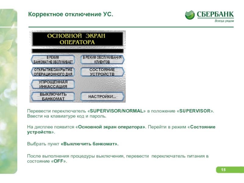
Слайд 15Корректное отключение УС.
Перевести переключатель «SUPERVISOR/NORMAL» в положение
«SUPERVISOR».
Ввести на клавиатуре код и пароль.
На
дисплее появится «Основной экран оператора». Перейти в режим «Состояние устройств».
Выбрать пункт «Выключить банкомат».
После выполнения процедуры выключения, перевести переключатель питания в состояние «OFF».
Слайд 16СПАСИБО ЗА ВНИМАНИЕ!
ДЛЯ ПРОДОЛЖЕНИЯ ОБУЧЕНИЯ ВАМ НЕОБХОДИМО
ПРОЙТИ ТЕСТ ПО КУРСУ «Б-003» НА ПОРТАЛЕ

-
Contents
-
Table of Contents
-
Troubleshooting
-
Bookmarks
Quick Links
NCR RealScan 74
(7874)
OFX
Release 1.1
User Guide
25315
B005-0000-1822
Issue C
Related Manuals for NCR 74 OFX (7874)
Summary of Contents for NCR 74 OFX (7874)
-
Page 1: User Guide
NCR RealScan 74 (7874) Release 1.1 User Guide 25315 B005-0000-1822 Issue C…
-
Page 2
The product described in this book is a licensed product of NCR Corporation. NCR is a registered trademark of NCR Corporation. NCR RealPOS, NCR RealPrice, NCR RealScan, NCR EasyPoint and NCR FastLane are either registered trademarks or trademarks of NCR Corporation in the United States and/or other countries. IBM is a registered trademark of IBM Corporation. Symbol is a registered trademark of Symbol Technologies Incorporated. Metrologic is a registered trademark of Metrologic Instruments Incorporated. Sensormatic is a registered trademark of Sensormatic Electronics Corporation. Checkpoint is a registered trademark of Checkpoint Systems Incorporated. Mettler Toledo is a registered trademark of Mettler Toledo Corporation. It is the policy of NCR Corporation (NCR) to improve products as new technology, components, software, and firmware become available. NCR, therefore, reserves the right to change specifications without prior notice. All features, functions, and operations described herein may not be marketed by NCR in all parts of the world. In some instances, photographs are of equipment prototypes. Therefore, before using this document, consult with your NCR representative or NCR office for information that is applicable and current. To maintain the quality of our publications, we need your comments on the accuracy, clarity, organization, and value of this book. Address correspondence to: Manager, Information Products NCR Corporation 2651 Satellite Blvd. Duluth, GA 30096 Copyright © 2008 By NCR Corporation Dayton, Ohio U.S.A. All Rights Reserved … -
Page 3
Preface Audience This book is written for hardware installer/service personnel, system integrators, and field engineers. Notice: This document is NCR proprietary information and is not to be disclosed or reproduced without consent. References • NCR Scanner Programming Tags (BST0‐2121‐74) • NCR Scanner/Scale Interface Programmer’s Guide (BD20‐1074‐A) • NCR RealScan Safety and Regulatory Information (B005‐0000‐1699) … -
Page 4: Table Of Contents
Table of Contents Chapter 1: Product Information Available Models………………….1-2 Features and Options ………………….1-2 Bi-Optic Scanning …………………1-2 Communications Protocol ………………1-4 Autodiscrimination………………..1-4 Remote Compact Display ………………1-5 Dual Peripheral RS232 Ports ……………….1-5 USB……………………..1-7 Firmware Flashing ………………..1-7 Operator Interface…………………1-8 Voice Messages …………………1-8 Power Supply ………………….1-9 PACESETTER ………………….1-9 PACESETTER Plus …………………1-10 PACESETTER III………………..1-10…
-
Page 5
Specific Function Programming ……………3-28 Power-up the System ………………3-32 Check Sensormatic® Deactivation System ………….3-33 Step 9: Operational Unit Verification …………..3-34 NCR RealScan 74 Scanner-Only Models …………3-34 NCR RealScan 74 Scanner/Scale Models…………3-34 RealScan 74 Power-On Wellness Check …………..3-35 Checkout Reading Operation …………….3-35… -
Page 6
Programming the RealScan 74…………….3-43 Programming RealScan 2357 Hand-Held Scanner if Connected through the USB Peripheral Port ………………3-44 NCR RealScan 2356 and Symbol (Motorola) Type Hand-Held Scanner ..3-45 Programming the RealScan 2356 Hand-Held if Connected through the Auxiliary RS232 Port ………………3-45 Programming the RealScan 74…………….3-46… -
Page 7
Multiple Reads ………………….4-10 Operating Instructions………………..4-11 Turning the RealScan 74 On and Off …………..4-11 Scanner Only Model……………….4-11 Scanner/Scale Model ………………4-11 Scanning Procedure ………………..4-12 Weighing Procedure………………..4-12 Sensormatic® Security Tag Deactivation Procedure ………4-13 Normal Operation ………………..4-13 Manual Deactivation ………………4-14 Adjusting the Good Read Tone…………….4-14 Not-On-File Error………………..4-15 Cleaning Instructions………………..4-16 Scanner Body ………………….4-16… -
Page 8
Program Parameter Descriptions …………….5-18 Communications Protocol ………………5-18 IBM Slot Scanner………………..5-18 IBM USB…………………..5-18 NCR (RS232 USB) ………………..5-18 RS232 ……………………5-19 Good Read Tone………………….5-19 Tone On/Off …………………..5-20 Tone Frequency (Hertz)………………5-20 Tone Length (Milliseconds)…………….5-20 Tone Volume …………………..5-20 Not-On-File Volume……………….5-21 Timers ……………………5-22 Lockout Time ………………….5-22 Restart Lockout Timer ………………5-23… -
Page 9
Scans Required………………..5-29 Overlap Characters…………………5-29 Minimum Segment Size………………5-29 Bar Codes–3 ………………….5-30 Interleaved 2 of 5 ………………..5-30 Bar Code Length ………………..5-31 Value 1 and 2…………………..5-31 Check Digit Present………………..5-31 Transmit Check Digit ………………5-31 Interleaved 2 of 5 Tone………………5-32 Tone Length………………….5-32 Tone Frequency………………..5-32 Interleaved 2 of 5 Check Digit Length1 …………5-32 Interleaved 2 of 5 Check Digit Length2 …………5-33 Enable Interleaved 2 of 5 Stitching…………..5-33 Scans Required………………..5-33… -
Page 10
viii Codabar Stitch…………………5-39 Number of Codabar Scans Required ……………5-39 Bar Codes–7 ………………….5-39 Pharmacode Check Digit Transmission …………5-39 Label Identifiers ………………….5-40 Identifier Type…………………5-40 Common Byte 1 and Common Byte 2 ………….5-41 Bar Code Type…………………5-42 Common Byte………………….5-42 Unique Identifier ………………..5-42 RS232 Parameters 1………………..5-43 Baud Rate………………….5-43 Parity ……………………5-43 Stop Bits and Character Length …………….5-44… -
Page 11
Dual Cable Interface ………………..5-54 Avery Scale Emulation………………5-54 Programming Worksheets ……………….5-55 Communications Protocol ………………5-55 Good Read Tone………………….5-56 Timers ……………………5-57 Bar Codes–1 ………………….5-58 Bar Codes–2 ………………….5-59 Bar Codes–3 ………………….5-60 Bar Codes–4 ………………….5-61 Bar Codes–5 ………………….5-62 Bar Codes–6 ………………….5-63 Bar Codes–7 ………………….5-63 Label Identifiers ………………….5-64 Number System Character ………………5-65 Sensormatic Deactivation Tone Frequency …………5-65 Sensormatic Deactivation Tone Pulse …………..5-65… -
Page 12
Code 39 Minimum and Maximum Length ………….5-74 Interleaved 2 of 5 Tone Length ……………..5-74 Interleaved 2 of 5 Tone Frequency …………..5-75 Interleaved 2 of 5 Tone………………5-75 Interleaved 2 of 5 CD Length1 …………….5-75 Interleaved 2 of 5 CD Length2 …………….5-76 Interleaved 2 of 5 Scans Required …………..5-76 Interleaved 2 of 5 Overlap ……………..5-76 Interleaved 2 of 5 Minimum Segment Size ………….5-77… -
Page 13
Ignore RS232 Commands from POS …………..5-84 Enable UPC NS5 Coupon ………………5-85 GS1 DataBar AI 8110 coupons …………….5-85 EAN–13 98 coupons ……………….5-85 EAN–13 99 coupons ……………….5-85 Expand E to EAN–13 Directly …………….5-85 Checkpoint Interlock………………5-86 Scanner Power-On State ………………5-86 ASCII Code Chart ………………..5-86 Special Programming………………..5-87 Set Current Parameters to Default Values…………5-87 Enable Soft Defaults ……………….5-87… -
Page 14
Firmware Flashing Procedure…………….5-98 RealScan Flash Drive Support ……………….5-101 NCR RealScan Flash Drive Prep Application ………..5-101 Flash Drive Prep Application Installation …………5-101 RealScan Flash Drive Prep Application Functions ……….5-105 Diagnostic Download or Memory Dump ………….5-105 Parameters Upload……………….5-108 Parameters Download ………………5-111 Firmware Upload …………………5-114 Firmware Download ………………5-117… -
Page 15
Revision Record Issue Date Remarks A May 23, 2008 Release 1.1 B Sept. 19, 2008 Various artwork updates Updated Shift Test and Decreasing Load Test information C December 19, 2008 Updated scanner dimensions, checkstand cutout dimensions, and scale calibration test procedures Safety and Regulatory Information The NCR RealScan 74 conforms to all applicable legal requirements. To view the compliance statements refer to the NCR RealScan Safety and Regulatory Information (B005‐0000‐1699). -
Page 17: Chapter 1: Product Information
1 Product Information Chapter 1: The NCR RealScan 74 is a state‐of‐the‐art bi‐optic scanner. Its primary use is in high‐performance checkout areas of food distribution and general merchandise sales. The RealScan 74 can read bar codes on all six sides of the product as it passes through the scan zone. This and other features reduce the amount of operator training and increase operator efficiency. …
-
Page 18: Available Models
Chapter 1: Product Information Available Models NCR RealScan 74 Scanner/Scale NCR RealScan 74 Scanner Only 25319 The NCR RealScan 74 is available in six RoHS‐compliant models. The following table identifies the major models along with a brief description of each. Model Description RealScan 7874–3000 Third‐party scale ready Scanner (sold with a 15.7ʺ top plate) RealScan 7874–3020 13.9“ Compact Scanner Only RealScan 7874–4xxx 15.7” or 16” Scanner Only RealScan 7874–5xxx 15.7” or 16” Scanner/Scale RealScan 7874‐4xxx (Plus 7874‐K200) 20” Scanner Only RealScan 7874‐5xxx (Plus 7874‐K200) 20” Scanner/Scale Features and Options The RealScan 74 is rich in features and options which puts it in a class by itself. This section identifies the many features and options that are available. …
-
Page 19
Chapter 1: Product Information The RealScan 74 vertical scan window is mounted to a tower that rises above the checkstand surface. The upper console is designed to withstand constant impact from items being scanned. The horizontal scan window is flush–mounted to a part plastic, part steel top plate, permitting users to slide a product across the top plate without lifting the product. Furthermore, loosely wrapped products cannot snag on the top plate. Because of its expanded scan zone, the RealScan 74 is very easy to use. It can read labels on all six sides of the product as they pass through the scan zone. Products can be read from right to left or from left to right. The following is the scan pattern produced on both the vertical and horizontal scan windows. Horizontal Scan Pattern 24 scan lines Vertical Scan Pattern 30 scan lines 25318 … -
Page 20: Communications Protocol
Chapter 1: Product Information Communications Protocol The RealScan 74 communicates with the host terminal through: • RS232 • USB • IBM 46xx • Dual‐cable RS232 Autodiscrimination The RealScan 74 can decode a variety of bar codes. The ability to discriminate among the different bar code types is a standard feature of the RealScan 74. The following lists the different bar code types. • UPC–A and UPC–E • UPC–A and UPC–E with two‐digit Add‐on Symbols • UPC–A and UPC–E with five‐digit Add‐on Symbols • GS1–128 Coupon Extended Code • Code 128 Markdown Code • EAN–8 and EAN–13 • EAN–13 with two‐digit Add‐on Symbols • EAN–13 with five‐digit Add‐on Symbols • GS1 DataBar, formerly Reduced Space Symbology (RSS) GS1 DataBar–14 GS1 DataBar–14 Stacked Omni–directional GS1 DataBar Expanded GS1 DataBar Expanded Stacked …
-
Page 21: Remote Compact Display
Chapter 1: Product Information Remote Compact Display 16217 The RealScan 74 Scanner/Scale units are available with no weight display or with a remote post mounted display. When no display is used, scale information is sent to the host terminal and displayed on the terminalʹs customer display. However, this is not available for all host terminals, and in some countries Weight and Measures authorities do not permit this configuration. Note: It is acceptable to use the host terminal display if the host terminal is approved to perform the live/gross scale weight. Also, most countries require that both the operator and the consumer must be able to observe the scale live/gross weight display and the sale weight platform during a weighing operation. When a display is needed, use the RealScan 25 Remote Compact Display. It is available with one or two display modules. Dual Peripheral RS232 Ports The RealScan 74 includes the Dual Peripheral Ports feature. The purpose of this feature is to permit other peripheral devices to connect to the host terminal through the RealScan 74. This eliminates the need of the host terminal having additional RS232 ports. A typical use of this feature is to connect a hand–held scanner for items too large to place on the checkstand. It also provides a connection for some security tag deactivation systems. …
-
Page 22
Chapter 1: Product Information Special programming is required for each peripheral device using a peripheral port. The connector is wired as follows. Auxiliary RS232 Peripheral Port Pin Number Signal Name 1 +5 Vdc 2 NC 3 GND 4 TXD 5 RXD 6 +12 Vdc 7 CTS 8 RTS The RealScan 74 Auxiliary RS232 Peripheral Port hardware is limited to the following fixed parameters. Baud Rate 9600 Parity Even Stop Bits 1 Number of Data Bits 7 … -
Page 23: Usb
Chapter 1: Product Information The two auxiliary RS232 ports are both located at the back of the unit. Port 1 (located on the right side when facing the rear of the unit) is the most convenient port for connecting a hand–held scanner. Each peripheral device using a peripheral port requires special programming. The total combined +5V current for the one USB peripheral port and two RS232 auxiliary ports should be less than 750mA. The total combined +12V current for two RS232 auxiliary ports should be less than 350mA. The RealScan 74 includes a single USB Peripheral port, a Main (POS) USB Communication Port, and a Main (POS) RS232/RS485 Communication Port. These ports are included to permit easy connections for peripherals and to improve the scanner’s capabilities by permitting the devices to be hot‐swappable (connecting or disconnecting devices without restarting the unit). The USB peripheral port is located on the left‐most side on the rear of the unit. The purpose of the USB peripheral port is to permit other peripheral devices with IBM SurePOS USB handheld interfaces to connect to the host terminal through the RealScan 74. The Main (POS) USB and Main (POS) RS232/RS485 Communication Ports are located on the right side at the back of the unit. These ports are used to connect the scanner to the host terminal. The total combined +5V current for the one USB peripheral port plus two Auxiliary RS232 ports should be less than 750mA. The maximum +5V current for the USB peripheral port should be less than 500mA. The total combined +12V current for two RS232 auxiliary ports should be less than 350mA. The RealScan 74 is compatible with both the NCR 2356 and NCR 2357 Handheld scanners. Note: Normally, other SurePOS–compliant handheld scanners are compatible with the RealScan 74. However, NCR recommends a thorough integration testing before using any 3rd–party handheld scanner. Firmware Flashing The RealScan 74 includes Firmware Flashing. This permits upgrades to the scanner’s firmware. The latest firmware may be downloaded from NCR web site then flashed to the scanner through a PC, POS terminal, or a flash drive. The software comes in two forms. The first one is free from The http://www5.ncr.com/support/support_drivers_patches.asp?Class=retail_RealScan. others provide various Enterprise functions and are sold separately. …
-
Page 24: Operator Interface
Chapter 1: Product Information Refer to the “Firmware Flashing” section in Chapter 5 for more information on firmware flashing. Operator Interface There is very little interface required between the operator and the RealScan 74. Messages are sent from the RealScan 74 to the operator through status indicators on the Operator Display Panel, audio tones, and voice messages. Light Bar Status Indicator Motion Detector Scale Zero Button Volume Adjust Button Manual Deactivation Button 25317 Note: Refer to Chapter 4 for more details on the functions of the status indicators and buttons of the Operator Display Panel. Voice Messages If the RealScan 74 has voice enabled, certain mode changes and error conditions are alerted by synthesized voice messages. These messages give either the changed mode or the error message with the suggested corrective action. Voice is enabled and disabled in the Miscellaneous Parameter program. The scanner provides audible voice messages during the following events. • When checking the communications protocol (Diagnostic Mode) •…
-
Page 25: Power Supply
Chapter 1: Product Information Power Supply 23756 A green light at the corner of the power supply indicates that the power supply is On. The optional Power Supply provides the necessary 12V DC voltage required by the RealScan 74 if power is not supplied from the POS terminal. The Power Cord plugs into an electrical outlet and connects to the Power Supply. A low voltage Power Cable is integrated with the Power Supply. Several Power Cords are available depending on the country installation. The Power Supply input can be 90 Vac to 264 Vac at a frequency of 47 Hz to 63 Hz. In addition, some POS interface types can power the RealScan 74 without the use of this power supply. Please contact your NCR sales representative for details. The following table shows the Power Requirement Matrix for the RealScan 74: Power source RealScan 74 Power Requirements Matrix 115Vac 230Vac 12Vdc Typical Operating Power (Motor and Laser On) 7 W 8 W 6 W Typical Standby Power (Motor and Laser off) 3 W 4 W 2 W PACESETTER NCR has continually improved its PACESETTER technology used on NCR RealScan products. Starting out as PACESETTER, it progressed to PACESETTER Plus, and then to PACESETTER III. Vendors and printers regularly supply products with …
-
Page 26: Pacesetter Plus
1-10 Chapter 1: Product Information PACESETTER Plus PACESETTER Plus determines what is wrong with a bar code label, fixes the data, and then transfers the information to the host terminal. It provides information on possible bar code printer problems but is not a bar code specification conformity verifier. The three modes of PACESETTER Plus operation are summarized in the following paragraphs. Mode 1–Inquiry PACESETTER Plus can be used as a management tool by store personnel and chain management to monitor and report the status of label readability. Tally counters are kept for the following. • Good reads • No read due to lack of full label (missing bars or folded label) • Good reads with overprinted bars • Good reads with underprinted bars • Missing margins • Missing print lines In Mode 1, the tally count displays on the RealScan 25 Remote Compact Display. The percentage of each error type to the good reads tally also displays. All tally counts can be reset to zero. Mode 2–Demonstration Mode In Mode 2, the scanner is offline. Each subsequent scan of a bar code causes the scanner to indicate the status of label readability. The scanner recognizes missing bars in labels, highly overprinted or underprinted labels, missing margins, or a “no read” condition. Mode 3–Operations Mode 3 is the normal operating mode. The scanner can be programmed to add …
-
Page 27: Pacesetter Iii
Chapter 1: Product Information 1-11 PACESETTER III also detects, corrects, and reports errors discovered in UPC Number System Two and Number System Four labels. These two label types are printed in the store and account for a significant number of unreadable labels due to failures of the in–store printing mechanism. PACESETTER III looks for errors in these labels and learns from each attempted scan. After seeing a particular printing error a number of times, PACESETTER III may determine that an error is present in the label and that the error may be correctable. If the correction capability of PACESETTER III is enabled, the scanner attempts an error–free correction of the label and passes the results to the host terminal. Whenever an error–free correction is not possible, PACESETTER III does not pass label data to the terminal. Parameter Programming The NCR RealScan 74 may need to be configured to meet specific installation needs. The RealScan 74 uses special programming tags to modify the various programming parameters (refer to Chapter 5). This programming data may be scanned with special tags, sent from a PC with the free tools or http://www5.ncr.com/support/support_drivers_patches.asp?Class=retail_RealScan remotely through the POS using special software (sold separately). Scan Doctor Diagnostics Scan Doctor is the state‐of‐the‐art diagnostic software included in every RealScan 74. It continually monitors the unit to identify components that are not functioning correctly. It also provides inquiry capability for the host terminal to access specific diagnostic data. Scan Doctor diagnoses the RealScan 74 each time power is applied and continually during operation. When a problem is found, it notifies the operator through patterns of color LEDs on the Scan Adviser (beside the Vertical Window), an error code on the remote display (if attached), and voice messages. It lists the most probable causes first. Many Scan Doctor statuses are available from the scanner using NCR software tools sold separately. Refer to the RealScan 74 Diagnostics and Troubleshooting section on chapter 5 for more information. …
-
Page 28: Ongoing Wellness Check
1-12 Chapter 1: Product Information • Spinner Motor • Scale Board • Laser Diodes • FPGA • Scale Hardware If Scan Doctor finds a problem hindering proper operation of the RealScan 74, it disables the unit; otherwise the problem is identified and operation continues. Ongoing Wellness Check Scan Doctor runs all the time, from the moment the RealScan 74 is turned on. It constantly monitors RAM, the Spinner Motor, Laser Diodes and Scale Hardware. Service Diagnostics Scan Doctor includes service diagnostics for the trained service technician. These go beyond the wellness checks and are accessed through the use of special programming tags. Refer to Appendix B for more information on the Scanner Service Diagnostics Tests. Soft Power Down/Power Up The RealScan 74 senses periods of scanner inactivity. The scannerʹs soft power down feature extends the life of the RealScan 74 by disabling major portions of the unit, including the laser diodes, spinner motor, and associated electronics. The length of the inactive period prior to the soft power down is user‐selected and programmed remotely or through tags. Scanner power up occurs when the RealScan 74 motion detector detects movement. This detector is located on the operator display panel, to the right of the vertical scan window. The RealScan 74 can also be powered up with the checker signs on the host terminal. This capability assumes appropriate host terminal software. …
-
Page 29: Chapter 2: Site Preparation
2 Site Preparation Chapter 2: Customer Responsibilities The NCR customer is responsible in preparing the site for installation of the NCR RealScan 74. The following information is provided to help with this task. The customer must do or provide the following. • When required by NCR, provide the NCR Customer Services Representative with appropriate drawings that indicate the following. Location of equipment Site wiring (power and signal, paths, and lengths) Location of other equipment capable of generating large amounts of electrical noise, electromagnetic interference, heat, and so forth • Provide floor coverings and environmental systems that prevent static electricity build‐up and discharge. • Provide and install necessary power distribution boxes, conduits, grounds, lightning arrestors, and associated hardware. • Ensure clear space and environmental requirements of the unit are met. • Make all building alterations necessary to meet wiring and other site requirements. • Ensure all applicable codes, regulations, and laws (including, but not limited to, electrical, building, safety, and health) are met. • Provide and install all communication cables, wall jacks, special connectors, and associated hardware. • Provide and install auxiliary power or other equipment as required. …
-
Page 30: Preparing The Site
Chapter 2: Site Preparation Preparing the Site This document contains information necessary for the preparation of a site conforming to NCR specifications. It is important that the site complies with the requirements specified in this document because, once the equipment has been installed, deficiencies in the site or the problems caused by these deficiencies are much more difficult to detect and correct. Further, failure to comply with these requirements or to take proper steps to protect equipment against risks identified in this document may cause serious damage to the equipment and to the customerʹs business. In addition to the need to comply with the requirements specified, electrical wiring and mechanical systems must also comply with all relevant codes, laws, and regulations. It is important that a customer or a customer agent who is very familiar with the special requirements of electronic equipment prepare the site. The responsibility of ensuring that the site is prepared in compliance with this document remains with the customer. For information and guidance purposes only, a list of Customer Responsibilities is provided, in general terms, of those matters for which the customer is responsible. This list is not intended to be comprehensive, and in no way modifies, alters, or limits the responsibility of the customer for all aspects of adequate site preparation. No comment, suggestion, or advice offered or not offered about preparation of the site nor any inspection of the site whether before or after preparation is to be taken as approval of the location of the site and equipment or of its preparation, and NCR is not liable in respect of any comment, suggestion, or advice given by its staff or in respect of any failure to give advice. Finally, only the customer can know the full extent of damage that may be caused to his business by reason of failure of the equipment that is to be installed. For this reason, it is the customerʹs responsibility to ascertain the extent of any such possible damage to his existing or planned business, and to effect full insurance in respect of it. …
-
Page 31: Weight
Chapter 2: Site Preparation Weight The weight of the RealScan 74 depends on the model. The following are the installed weights of basic models. Note: Weight of the power supply and power cord are not included. With Top Plate Without Top Plate Model Kilograms Pounds Kilograms Pounds RealScan 7874‐3000 4.25 9.37 2.90 6.20 RealScan 7874‐3020 4.50 9.90 2.90 6.20 RealScan 7874‐4xxx 4.25 9.37 3.43 7.56 RealScan 7874‐5xxx 5.06 11.15 4.24 9.34 RealScan 7874‐4xxx (Plus 7874‐K200) …
-
Page 32: Checkstand Cutout
(a flat-sided box) when measuring the checkstand for a fit. Do not take advantage of voids or angles in the design of the scanner base as NCR reserves the right to change the profile without notice as long as the change does not impact overall outside dimensions.
-
Page 33: Realscan 7874-3000/4Xxx/5Xxx (15.7 Inch)
(a flat-sided box) when measuring the checkstand for a fit. Do not take advantage of voids or angles in the design of the scanner base as NCR reserves the right to change the profile without notice as long as the change does not impact overall outside dimensions.
-
Page 34: Realscan 7874-4Xxx/5Xxx With F030 / K002 (40.6 Cm / 16 Inch)
(a flat-sided box) when measuring the checkstand for a fit. Do not take advantage of voids or angles in the design of the scanner base as NCR reserves the right to change the profile without notice as long as the change does not impact overall outside dimensions.
-
Page 35: Realscan 7874-4Xxx/5Xxx With 7874-K200 (50.8 Cm / 20 Inch)
(a flat-sided box) when measuring the checkstand for a fit. Do not take advantage of voids or angles in the design of the scanner base as NCR reserves the right to change the profile without notice as long as the change does not impact overall outside dimensions.
-
Page 36: No Side Rails
(a flat-sided box) when measuring the checkstand for a fit. Do not take advantage of voids or angles in the design of the scanner base as NCR reserves the right to change the profile without notice as long as the change does not impact overall outside dimensions.
-
Page 37: Realscan Checkstand Wiring
Circuit Breakers Isolated/Insulated Ground Bus NCR circuits should be run in separate metal Conduits. Note: NCR circuits must be dedicated to NCR equipment or other logically connected electronic equipment (modems, DAA, bridges, etc.)
-
Page 38: Power Considerations
2-10 Chapter 2: Site Preparation Power Considerations The RealScan 74 receives power from an external DC power supply or from +12V DC supplied by the POS terminal. The power supply mounts in a remote location close to the RealScan 74. The NCR supplied power supply is a 40‐watt switching power supply with the following inputs. • Voltage: 90 to 264 Vac • Frequency: 47 to 63 Hz • Current: 0.9 A The RealScan 74 has no power switch in the unit, therefore the operator of RealScan74 must have a way to remove AC power in the event of an emergency. The power supply has a green LED which is lit when there is an AC voltage present and the power supply is functioning correctly. Power Transient Protection Voltage transients, surges, sags, impulses, and spikes may be experienced routinely or sporadically. When such phenomena occur, the equipment requires the use of protective devices to ensure proper operation. Cable Connections The following diagram shows the wiring connections located at the rear of the RealScan 74. Scale Display Port Main (POS) Auxiliary RS232 Port 1…
-
Page 39: Service Clearance
Chapter 2: Site Preparation 2-11 Service Clearance Although many of the RealScan 74 components are accessed without removing the unit from the checkstand, service clearance must be provided. Clearance is also required for cleaning the unit. Refer to the following illustration for the required clearances. Mounting surface for keyboard must be removable for the following. • Servicing the unit • Replacing the vertical window Item Flow Area A = 20.32 cm (8.00 in) minimum if checkstand structure is not removable for servicing. 2.54 cm (1.00 in) minimum if checkstand structure is removable for servicing.
-
Page 40: Environmental Considerations
2-12 Chapter 2: Site Preparation Environmental Considerations The RealScan 74 operates in most standard working environments. Temperature ranges permitted are greater when the RealScan 74 is in storage or transit. The RealScan 74 can operate up to one hour at extreme temperatures without suffering damage. The following table gives the various environmental requirements: Physical Extreme Operating Normal Operating Storage Transit Variable (One Hour Maximum) 5ºC-40ºC -0ºC-45ºC -10ºC-55ºC -40ºC-60ºC Temperature 41ºF-104ºF 32ºF-113ºF 14ºF-131ºF -40ºF-140ºF 10ºC/hour Temperature 20ºC/hour 20ºC/hour 20ºC/hour Change 18ºF/hour 36ºF/hour 36ºF/hour 36ºF/hour Relative 20% to 80%…
-
Page 41: Realscan 25 Compact Display Dimensions
Chapter 2: Site Preparation 2-13 RealScan 25 Compact Display Dimensions The following are dimensions of the RealScan 25 Compact Display. The holes are spaced to align with those of the older RealScan 25 Remote Post Display and with some competitor models. BASE 115.31 mm 93.98 mm 3.96 mm 7.62 mm 84.83 mm 4.54 in 3.70 in 0.156 in 0.30 in 3.34 in 11.17 mm 16.25 mm 41.65 mm 266.19 mm 104.39 mm 314.96 mm 0.44 in 0.64 in 1.64 in…
-
Page 43: Chapter 3: Installation
3 Installation Chapter 3: Installing the RealScan 74 consists of eight main steps. Sometimes additional information is required depending on the installation. Information about enabling special functions is provided in Programming chapter. …
-
Page 44: Installation Steps
1. Verify installation preparation (scanner and checkstand) 2. Cable installation preparation 3. Install Sensormatic® or Checkpoint antenna (optional) 4. Connect Cables 5. Put RealScan 74 in checkstand cutout 6. Verify Top Plate alignment 7. Calibrate the scale 8. Setup Sensormatic® or Checkpoint deactivation (applicable only if Sensormatic® or Checkpoint antenna is installed) 9. Verify unit is operational Step 1: Verify Installation Preparation Reporting a Damaged Unit After receiving the NCR RealScan 74, inspect the shipping carton for damage. If the RealScan 74 is damaged due to shipping, notify the carrier, the NCR representative, or the supplier if the unit is not purchased directly from NCR. Package Contents After unpacking the RealScan 74, take inventory to ensure that all components are received. The following list identifies the package contents. • NCR RealScan 74 • Power Supply (separate package if ordered) •…
-
Page 45: Step 2: Cable Installation Preparation
Chapter 3: Installation Step 2: Cable Installation Preparation Note: Before attempting to install the RealScan 74, the site must be prepared in accordance with the requirements described in Site Preparation chapter. Note: The RealScan 74 ships complete from the factory and requires no operator assembly. The laser module is an integral part of the factory assembled device and does not have any controls that can increase the level of laser light or collateral radiation from the RealScan 74. Follow these steps in preparation to install the NCR RealScan 74 cables to the scanner. 1. Verify that the RealScan 74 power receptacle switch is off. Plug the power cord into the RealScan 74 power supply unit. Pass the power cable from the power supply through the checkstand opening. 2. Connect the communications interface cable to the host terminal. Refer to the terminal documentation for instructions on how to connect the interface cables. Note: Some terminals may require a trained service technician to open the terminal and connect the interface cables. 3. Pass the interface cables through the checkstand opening. 4. If connecting a remote display, pass the remote display cable through the checkstand opening. 5. If connecting an RS232 peripheral device below the checkstand, pass its interface cable through the checkstand opening. 6. Place the unit so that a portion of the tower end is directly over the hole in the checkstand. Skip to “Step 4: Cable Connection” when not installing a RealScan 74 with a Sensormatic® deactivation system. …
-
Page 46: Step 3: Sensormatic® Coil Installation
Chapter 3: Installation Step 3: Sensormatic® Coil Installation To install the Sensormatic® Coil, perform the following procedure. 1. Position the RealScan 74 facing the operator. 2. Remove the Top Plate. Hold the front edge of the Top Plate between your fingers. Lift the Top Plate to remove it from the RealScan 74. 25518 3. Remove the Front Bezel. Place one hand and slightly apply downward pressure on the top corner of the Bezel. Use a flat tip screw driver to push the snap features found at the bottom‐corner of the Bezel. Note: Do this procedure on both sides of the Bezel to detach it from the scanner. 25464…
-
Page 47
Chapter 3: Installation Lift the Bezel up and set aside. 25572 5. Install the Sensormatic® Coil. Connect the horizontal coil cable and the vertical coil cable as shown. 25692 Route the coil cable at the bottom of the tower as shown and press the strain relief into the notch. 25691 … -
Page 48
Chapter 3: Installation Lay the horizontal coil down and around the horizontal window. 25690 Install the three screws to hold the horizontal coil in place. 25659 Route the horizontal coil cable on the tower as shown. 25693 … -
Page 49
Chapter 3: Installation Attach the vertical coil around the vertical window and route the vertical coil cable on the tower as shown. 25657 6. Replace the Bezel. Align the top edge of the Tower Cabinet with the top edge of the Front Bezel. 25571 Ensure to route the horizontal coil wires under the notch found on the bottom of the Front Bezel. The scanner will have scale issues if the wires are not routed properly under the Front Bezel. horizontal wires properly horizontal wires not properly routed under the bezel routed under the bezel Correct Wrong 25911 … -
Page 50
Chapter 3: Installation Press the bottom–left and bottom–right corners of the Front Bezel towards the tower cabinet to latch it in place. 25512 7. Replace the Top Plate. Holding the front edge of the Top Plate, lay the back edge on the two rear support posts on the RealScan 74. Lay the front of the Top Plate down onto the two front support posts. 25517 … -
Page 51: Step 4: Cable Connection
Chapter 3: Installation Step 4: Cable Connection RealScan 74 Power Cable Power Supply RS-232 Power Cord Peripheral Host Terminal Interface Cable 25505 Note: Ensure that the power is off before connecting or disconnecting cables. If the scanner is powered by a POS terminal, turn off the POS terminal. Otherwise, disconnect the AC power from the power brick. To install the cables in the RealScan 74, perform the following procedure. 1. If used, install the optional Checkpoint® Antenna. Remove the Top Plate. Remove the Front Bezel. …
-
Page 52
3-10 Chapter 3: Installation Route the Checkpoint cable as shown below. Tape may be used to hold the loop in place 25695 Route the cable out the left side of the unit. 25696 2. If used, connect the optional DC Power Cable from the Power Supply to the DC Power connector. 3. Connect the interface cable to the Scanner connector or the USB + Power Connector. Note: The scanner can connect to a separate “POS scale interface cable” through “Port 1”. Full details are added on the firmwareʹs release. 4. If used, connect the remote display cable to the Remote Display connector. 5. If the configuration includes a USB device, connect it to the USB peripheral port. 6. If used, connect one end of the Sensormatic® Communications Cable to the RS232 Port 2 connector at the back of the RealScan 74. The other end connects to the POS connector on the Sensormatic® AMB9010 Controller. 7. If used, connect the Sensormatic Coil Cable to the Coil connector on the Sensormatic® AMB9010 Controller. … -
Page 53: Step 5: Realscan 74 Installation In Checkstand Cutout
Chapter 3: Installation 3-11 8. If used, Connect the Sensormatic® AC Power Cord. 9. If used, connect the Checkpoint® interlock cable. 10. Turn on the scanner by turning on the POS terminal or by turning on the AC power of the scanner. Note: Some peripherals are limited to which port they can use. Step 5: RealScan 74 Installation in Checkstand Cutout 25510 To install the RealScan 74 in the checkstand cutout, perform the following procedure. 1. Verify that the top of the RealScan 74 supports are set to the initial distance from the top of the checkstand. Check dimensions on the “Checkstand Cutout” section in the Site Preparation chapter. 2. Holding the handles on the back of the tower cabinet and the front of the unit, slowly lower the RealScan 74 into the checkstand cutout. It should sit on supports at the bottom of the checkstand cutout. 3. Install the Top Plate on the four supports on the scanner. Note: It is important that the RealScan 74 does not rock on its supports. Make sure that all adjustable supports are securely fastened and that the RealScan 74 is sitting on all supports. Note: Place the power supply in a position where spilled liquids cannot fall onto it. …
-
Page 54: Step 6: Top Plate Alignment Verification
Verification”. Step 7: Scale Calibration Note: Only certified personnel can perform the scale calibration procedure and place the scale into service for trade to comply with governmental weights and measures regulations. The RealScan 74 must meet the following accuracy requirements. • The RealScan 74 is considered a new unit each time the scale is calibrated. This status lasts for thirty (30) days. • The RealScan 74 is considered an in‐service unit thirty (30) days after the scale is calibrated. During factory testing, the scale is calibrated one or more times to test the scale calibrating function. This calibration test is not sufficient to make the scale ready for weighing in trade.The scale MUST be calibrated when any of the following occur (this is a government requirement). • Initial installation of a RealScan 74 • When the scale cannot be zeroed • When the diagnostics indicate a calibration error • When the Scale Assembly is changed The calibration procedure sets the scale and the electronics to interpret the weight of an item accurately. The scale can be calibrated after power has been supplied for 30 minutes and if the ambient air condition has been 20° C (68° F) or above for at least 24 hours. If the ambient air condition has not been met (below 20° C (68° F)), then the scale must be on for at least 6 hours before it can be calibrated. One or more certified weight sets are required to calibrate and certify the scale. The following are examples: • Whole Pound Weight Set: NCR Part Number 998‐0633009 • Fractional Pound Weight Set: NCR Part Number 998‐0633012 • Kilogram Weight Set: Obtain locally …
-
Page 55: Perform The Calibration Procedure
Chapter 3: Installation 3-13 The RealScan 74 maintains an audit trail of scale calibration and weighs parameter setting. The audit trail consists of two even counters. Display the audit trail count by pressing and holding the Scale Zero button on the Operator Display Panel. The display alternates between and . The Cal value is the number of Cal xxx Par xxx times the scale has been calibrated. The Par value is associated with the weigh parameter setting and should never change. Note: The audit trail displays only on units with the RealScan 25 Remote Display. Note: Some host terminals can corrupt the calibration settings if they are connected during scale calibration. Therefore, NCR recommends disconnecting the interface cable before starting calibration of the scale and then reconnect it after completing the calibration procedure. Perform the Calibration Procedure Note: If a protective plastic covering is present on the Top Plate or the clear plastic door below the Top Plate, ensure that it is removed before calibrating the Scale. The scale firmware controls the calibration procedure. It waits for a response to each prompt before going to the next step. The firmware uses the voice feature and the display to identify how much weight to place on the Top Plate. After the required weight has been placed on the Top Plate and the Scale Zero button is pressed, the firmware sounds a single tone and goes to the next prompt. The calibration procedure can be ended before completion by turning the unit off. However, if this is done, the scale must still be calibrated before placing it into service. Note: The pound and kilogram weights used for calibration are not equivalent values. They are the actual weights the firmware needs to perform the calibration. …
-
Page 56
3-14 Chapter 3: Installation Calibrating and Exercising the RealScan 74 1. Determine the type of weight set to use for calibration. There a two weight sets, Kilograms and Pounds. • For the Kilogram weight set, you must have a calibrated KG weight set, 12.5 KG total. Weight combinations 2.5kg, 7.5kg, and 12.5kg are required, with suggested individual weights made up of a set of two 5 kg weights, one 2kg weight, and one 500g weight. • For the Pound weight set, you must have a calibrated LB weight set, 30 pounds total. Weight combinations 5 lb, 15 lb, and 30 lb are required, with suggested individual weights made up of a set of two10 lb weights, one 5 lb weight, two 2 lb weights, and one 1 lb weight. 2. Apply power to the RealScan 74 if it is off. The unit needs to be ON for 30 minutes prior to calibration, unless it is cool in the environment (below 20° C (68° F)), in which case the scale must be on for at least 6 hours before it can be calibrated. 3. EXERCISE THE SCALE Note: You MUST exercise the scale BEFORE the scale can be calibrated a. Remove the Top Plate. b. Press the Calibration Switch. i. Remove the clear plastic Switch Cover located on the right–front corner of the unit. Lift the left side of the cover to unlatch and remove it. 25918 If the Calibration Switch Security Cover is secured with a lead/wire or … -
Page 57
Chapter 3: Installation 3-15 ii. Unscrew the green sealing screw and pull up on the cover to access the blue Calibration Switch button. 25917 25915 iii. Press the small blue Calibration Switch button ( this button is very small s “Press and very recessed). When you press the button, the scanner speak Deck”. Scale Calibration Switch 25914 The unit will IMMEDIATELY begin a continuous clicking sound along with a steady tone. … -
Page 58
3-16 Chapter 3: Installation Note: You MUST replace the Calibration Switch Cover and Top Plate, and complete the scale exercise procedure within 90 seconds. If not, the scanner will report a ‘Calibration Error Code 8’ and you will see 1 blue and 1 green LED on the Light Bar. green blue 25688 Note: The unit prompts to perform the press‐down procedure twice, otherwise the unit will report ‘Calibration Error Code 8’. c. PRESS DOWN PROCEDURE. i. Once the Top Plate is back on and all the LEDs in the tower Light Bar are off, use both hands and press down HARD on the Top Plate with a constant and increasing pressure. Note: It will take a LOT of pressure. You might have to fully LEAN on the scale ‐ you will not break it. The goal is to light ALL 5 LEDs and keep them on for 4 seconds. … -
Page 59
Chapter 3: Installation 3-17 ii. As you press on the scale deck, an increasing number of LEDs will turn on indicating the amount of pressure you are applying. Increasing pressure orange orange orange orange orange orange orange orange orange orange orange 25689 iii. As you press, the tone also increases in pitch, producing a different, higher tone for each additional LED that lights up. If you let go, the tone will decrease in pitch as the LEDs progressively turn off. … -
Page 60
3-18 Chapter 3: Installation iv. At the highest pitch, with ALL 5 LEDs on, you MUST CONTINUE pressing down with continuous consistent pressure until the 5 LEDs turn solid red and the scanner beeps four times. 25795 v. Finally, the scanner will say “Complete” and all the 5 LEDs will turn solid blue. You can then release your hands from the deck. blue blue blue blue blue 25796 vi. Scanner will again say “Press deck”. vii. Repeat the Press Down steps again until the scanner says “Complete”. … -
Page 61
Chapter 3: Installation 3-19 4. Once the exercising is complete (press‐down done twice), the scanner will require a delay before continuing with calibration. It will say “Please wait 20 seconds…15 seconds…10 seconds…five seconds…complete”. There is a countdown shown on the 7825 remote display if one is attached. 5. The regular calibration procedure will begin after exercising is complete. Use the following procedures: Note: Use the type of calibration procedure according to the type of weight sets being used. Note: Place weights in circles shown when calibrating to ensure even distribution of weight during calibration. Start at the center and work outward horizontally with increasing weight. Do not scatter weights around the Top Plate Calibration Using Kilogram Weights a. Scanner speaks “Place zero kilograms on deck then press Scale Zero”. Make sure the scale has no weights on it (is empty) then press Scale Zero. Wait. b. Scanner speaks “Place 2.5 kilograms on deck then press Scale Zero”. Put 2.5 kg on the scale then press Scale Zero. Wait. c. Scanner speaks “Place 7.5 kilograms on deck then press Scale Zero”. Add 5.0 kg on the scale then press Scale Zero. Wait. d. Scanner speaks “Place 12.5 kilograms on deck then press Scale Zero”. Add 5.0 kg on the scale then press Scale Zero. Wait. e. Scanner speaks “Place zero kilograms on deck then press Scale Zero”. Take all the weights off the scale then press Scale Zero. Wait. Scanner speaks “Calibration complete” upon successful calibration. … -
Page 62
3-20 Chapter 3: Installation d. Scanner speaks “Place 30 pounds on deck then press Scale Zero”. Add 15 more pounds to make 30 lb on the scale then press Scale Zero. Wait. e. Scanner speaks “Place zero pounds on deck then press Scale Zero”. Take all the weights off the scale then press Scale Zero. Wait. Scanner speaks “Calibration complete” upon successful calibration. 6. When successful calibration is concluded, take the Top Plate off, ensure the Scale Calibration Switch cover is closed, and tighten the green sealing screw. 7. Seal the Calibration Switch Security Cover with one of the following seals: • Lead/Wire Seal (NCR Part Number: 603–8001097) using a Lead/Wire Seal Press (NCR Part Number: 603–9000157) • Film/Paper Seal (Obtain locally—Must meet the requirements of the local government) Note: Depending on local laws, Weights and Measures officials may be required to attach the seal. 8. Reinstall the Top plate. If Scan Doctor detects an error during the calibration procedure, one of the following error codes may be given. Error Code Problem Suspect Components Possible out of range calibration Digital Board… -
Page 63: 1. Increasing Load Test
Chapter 3: Installation 3-21 After calibrating the scale, the accuracy must be verified to assure it meets the government requirements. This consists of a series of four tests that must be run in the continuous sequence given. 1. Increasing Load Test 2. Over‐Capacity Test 3. Decreasing Load Test 4. Shift Test Increasing Load Test This test checks the scale’s accuracy when incrementally adding weight to the center of the Top Plate. Use weights that correspond to the RealScan 74 weight features. Step Weight Feature Add Weight Remove Weight Display Result Kilogram 0.100 kg 0.100 0.000 kg Pound 0.20 lb 0.20 0.00 lb Kilogram 2.500 kg 0.10 kg…
-
Page 64: Decreasing Load Test
3-22 Chapter 3: Installation Place additional weight on the center of the Top Plate as shown in the following table. Use the weight that corresponds to the RealScan 74 weight feature. The display shows a series of dashes to indicate an over‐capacity condition. Step Weight Feature Add Weight Remove Weight Display Result Kilogram 0.050 kg —.— Pound 0.10 lb —.— Kilogram 0.050 kg 15.000 kg Pound 0.10 lb 30.00 lb 24180 Note: Do NOT remove any weight from the Top Plate after completing this test. Decreasing Load Test This test checks the scaleʹs accuracy when incrementally removing weight from the …
-
Page 65: Shift Test
Chapter 3: Installation 3-23 Shift Test This test involves moving a weight off the center point of the Top Plate to check for continued accuracy. Test Pattern 25344 1. Place an appropriate Test Load weight for each weight feature on each of the four circles individually. The display must show the same weight between any of the 4 readings. Note: Each circle is half‐way between the center of the Top Plate and the corner. 2. Remove all weights. The display must read 0.000 ± 0.005 kg (0.00 ± 0.01 lb). Test max thirty pounds (30.00 lb) in center only. 3. Press and hold the Scale Zero button. Record the Cal and Par values shown on the display. Position Weight Feature Test Load Display Result Kilogram 5.000 kg 5.000 kg Pound 10.00 lb 10.00 lb Kilogram 5.000 kg 5.000 kg…
-
Page 66: Securing The Calibration Switch
3-24 Chapter 3: Installation Securing the Calibration Switch After performing a scale calibration, attach a seal to the scale calibration security cover. Depending on the local laws, Weights and Measures officials may be required to attach the seal. Note: In the United States and Canada, the audit trail serves as an acceptable security seal when the RealScan 25 Compact Display is present. Perform the following procedure to secure the calibration switch. 1. Remove the Top Plate. 2. Remove the clear plastic Calibration Switch Cover located on the right–front corner of the unit. Lift the left side of the cover to unlatch and remove it. 25918 3. Move the Calibration Switch Security Cover until the screw holes and the seal holes are properly aligned and fasten the green thumbscrew in the Calibration Switch Security Cover to secure the Calibration Switch. 25916 …
-
Page 67
Chapter 3: Installation 3-25 4. Seal the Calibration Switch Security Cover with one of the following seals: • Lead/Wire Seal (NCR Part Number: 603‐8001097) using a Lead/Wire Seal Press (NCR Part Number: 603‐9000157) • Film/Paper Seal (Obtain locally—Must meet the requirements of the local government) 5. Install the Calibration Switch Cover. 25979 6. Turn the scanner over and install the four leveling screws. 25987 7. Turn the scanner back to its upright position and install the Top Plate. … -
Page 68: Step 8: Sensormatic® Deactivation Setup
3-26 Chapter 3: Installation Step 8: Sensormatic® Deactivation Setup Sensormatic Tag Deactivation Connect the Sensormatic® Tag Deactivation System to the RS232 auxiliary port, which is Port 2. If a hand‐held scanner is used, connect the hand‐held to Port 1. When the RealScan 74 scanner reads a tag, the Sensormatic® hardware needs to receive an interlock signal for it to function. When the system is installed, the Sensormatic® Interlock Signal must be enabled. There are two modes of Sensormatic operation, Interlocked and Non‐interlocked. The mode is controlled by the Scan Enable Time which is a setting in the Sensormatic controller. When the Scan Enable Time is set to a value between 1 and 29, the system will run in the Interlock Mode. If the value is 0 or 30 the system will run in the Non‐ interlock Mode. Interlock Mode The scanner reads the Scan Enable Time from the controller. If it is between 1 to 29, it will enable the controller for deactivation for this many seconds after a bar code is read and then will disable the controller until the next bar code. Interlock mode is used in self service lanes and cashier assisted lanes. Non-Interlock Mode If the Scan Enable value is 0 or 30, the scanner will enable the Sensormatic controller for deactivation any time the scanner is enabled to read tags. In most systems, this corresponds to the time the cashier is signed into the POS Terminal. The terminal sends an “enable” to the scanner at cashier sign in and this is passed on to the Sensormatic controller. At cashier sign out, the POS sends a “disable” to the scanner and the Sensormatic controller is disabled. This is called Non‐interlock Mode. This mode is designed for the cashier lanes. Sensormatic® Online Offline Indication If the scanner is programmed for Sensormatic operation when the scanner powers up …
-
Page 69
Chapter 3: Installation 3-27 Cashier Sign In Offline Alert There is a feature to alert the cashier of the EAS system state at sign in. When the sign in occurs and the scanner is enabled if the EAS system is offline the “EAS Offline message will be spoken”. There is a programmable time limit on how long the sign out period must be before the offline message is spoken in order to prevent extraneous messages when cashier must sign in and out frequently. This message is from 1 to 15 minutes and is selected with the following programming tag sequence. 1. Program Mode—puts the scanner in programming mode. 2. Hex 7, Hex C, Hex x—where x is the time in minutes (1 to 15). 3. Save and Reset—saves the enabled setting and resets the RealScan 74. EAS Status LED There is an LED indicator beside the Manual Deactivation Button used to indicate the EAS system status. The LED will be on solid when the system is connected and operating properly. If the system is connected but not communicating the LED will be flashing. The LED is off when the EAS feature is disabled. Enable Sensormatic® Communications Scan the following sequence of programming tags to enable the Sensormatic® communications. These must be the first tags scanned after applying power to the RealScan 74. 1. Program Mode—puts the scanner in programming mode. 2. Hex 4, Hex 2, Hex B—enables Sensormatic® Interlock Signal. 3. Save and Reset—saves the enabled setting and resets the RealScan 74. … -
Page 70: Specific Function Programming
3-28 Chapter 3: Installation Scan the following sequence of programming tags to change the tone frequency of the RealScan 74. 1. Program Mode—puts scanner in programming mode. 2. Hex 5, Hex 8, Hex B—increments to the next frequencies. Continue scanning Hex B to get the desired frequency. There are eight frequencies to choose from: • 570 Hz (default) • 637 Hz • 721 Hz • 829 Hz • 976 Hz • 1186 Hz • 1512 Hz • 2083 Hz 3. End—completes the programming sequence. 4. Save and Reset—stores the setting and resets the RealScan 74. Sensormatic® Deactivation Tone Pulse Length Scan the following sequence of programming tags to change the number of pulses in the deactivation tone of the RealScan 74. 1. Program Mode—puts scanner in programming mode. 2.
-
Page 71
Chapter 3: Installation 3-29 Scanning this tag is a toggle function. The number of beeps indicates how the function is set. • 1 Beep—Manual Deactivation function is disabled • 2 Beeps—Manual Deactivation function is enabled—Factory Default • 3 Beeps—Function is enabled plus 048589999977 bar code sent After enabling or disabling the Manual Deactivation function, scan the following Reset tag to make the setting permanent in the RealScan 74. Bar Code Label Hold-Off The purpose of the Bar Code Label Hold‐Off function is to force the user to bring the bar code closer to the scanner when a live EAS tag is present on the item being scanned. When the RealScan 74 detects a live EAS tag it emits a clicking sound and sets a ½‐second timer (optional). The timer will be restarted and will not expire as long as the EAS tag is detected. During this time the RealScan 74 does not beep or send bar code data to the host terminal even though it may read the bar code. The timer will not be restarted once the EAS tag is deactivated. After the timer expires, the RealScan 74 beeps and sends bar code data to the host terminal. If the bar code has been removed from the scan field, it may have to be returned to the field to be read and sent to the host. The Bar Code Label Hold‐Off function is enabled and disabled by scanning the Bar Code Label Hold‐Off tag. Scanning this tag is a toggle function. The number of beeps indicates how the function is set. • 1 Beep—Bar Code Label Hold‐Off function is disabled … -
Page 72
3-30 Chapter 3: Installation • 2 Beeps—Bar Code Label Hold‐Off function is enabled—Factory Default After enabling or disabling the Bar Code Label Hold‐Off function, scan the following Reset tag to make the setting permanent in the RealScan 74. Audible Detection The Audible Detection function provides direct feedback to the user when a live EAS tag is in the field of view of the scanner. Clicks are enabled on the scanner. The Audible Detection (click) function toggles between 1, 2, and 3 beeps with each scan. • 1 Beep—Audible Detection function is disabled • 2 Beeps—Audible Detection function is enabled • 3 Beeps—Audible Detection function is enabled plus deactivation tone EAS Optional Communications The EAS Optional Communications function alerts the host application with a bar code communication message in three ways. This permits the host to control the sequence of events at the scanner. • The RealScan 74 sends the Error bar code (048589999999) if an EAS detection signal occurs after a bar code is read by the scanner (for example, the Sensormatic® tag is still live). The Error Bar Code Timer defines the window for permitting a deactivation to occur after a bar code is read. The timer can be set from ½ second to 4 seconds in ½‐second increments. If the timer expires and no EAS deactivation has occurred, the Error bar code is sent to the host application. • The RealScan 74 can send a Detect bar code (048589999988) every 4 seconds when EAS detections are occurring (a live EAS tag is in the detection field). • The RealScan 74 can send both bar codes if both conditions are met. … -
Page 73
Chapter 3: Installation 3-31 Scan the following EAS Communications Function tag to set the EAS Communication function. The function changes each time this tag is scanned. The number of beeps indicates how the function is set. • 1 Beep—EAS Communications function is disabled—Factory default • 2 Beeps—RealScan 74 sends Error bar code (048589999999) • 3 Beeps—RealScan 74 sends Error bar code (048589999999) and Detect bar code (048589999988) • 4 Beeps—RealScan 74 sends Detect bar code (048589999988) The following tag increments the Error bar code timer. Each time the tag is read, the time is incremented ½ second until the maximum time is reached. It then starts over with the least time. The number of beeps indicates how the timer is set. • 1 Beep—½ second • 2 Beeps—1 second • 3 Beeps—1½ seconds • 4 Beeps—2 seconds • 5 Beeps—2½ seconds • 6 Beeps—3 seconds • 7 Beeps—3½ seconds • 8 Beeps—4 seconds … -
Page 74: Power-Up The System
3-32 Chapter 3: Installation After setting the EAS Optional Communication function and the Error Bar code timer, scan the following Reset tag to make the setting permanent in the RealScan 74. Reset Bar Code Error, Detect, and Manual Deactivation Bar Codes The following are the Error, Detect, and Manual Deactivation bar codes, respectively. These bar codes are used for testing the POS system. Scan the bar code to simulate the effect on the POS system. • Error Bar Code • Detect Bar Code • Manual Deactivation Bar Code Power-up the System Note: Refer to the Sensormatic® AMB9010 Controller documentation for additional information about setting up the controller. Perform the following procedure to power‐up the system. 1. Turn on the RealScan 74. When the RealScan 74 is first turned on, all Sensormatic® parameters should be at their default settings: …
-
Page 75: Check Sensormatic® Deactivation System
Note: Voice message EAS Online must be given before continuing. If voice message EAS Online is not given, turn off the power to all components. Check all cable connections and then repeat this procedure starting at Step 1. If voice message EAS Online is still not given and the Manual Deactivation Button flashes, scan the Reset programming tag. If EAS Online status is still not given, follow instructions on the Sensormatic Card—Before You Call About…. The problem may be a bad Antenna cable. 4. Position a Hard Tag over the top of the RealScan 74. As the Hard Tag is moved, the RealScan 74 starts clicking when the tag moves within four inches of the center of the Top Plate. If the clicking sound is not generated, scan the Reset programming tag, then go to Step 3. If the second attempt fails, call for technical assistance. Refer to Appendix D for NCR Technical Support contact information. Check Sensormatic® Deactivation System Check the System Position a Hard tag above the RealScan 74 Top Plate. As the tag moves within four inches of the Top Plate, a clicking sound is heard (if programmed). Refer to the previous topic, “Audible Detection,” for instructions on enabling the clicking sound. If the Hard tag has to be closer than four inches to from the Top Plate to get the clicks, consult the Sensormatic® Card–Before You Call About…. X Axis Orientation Y Axis Orientation 4″ Above Top Plate 5″ Above Top Plate 25354 …
-
Page 76: Step 9: Operational Unit Verification
3-34 Chapter 3: Installation Next, obtain a security tag that has not been deactivated. Scan a bar code and immediately pass the security tag through the deactivation zone. The Good Read Tone should sound indicating a good read of the bar code and deactivation of the security tag. Refer to the “Sensormatic Tag Deactivation Procedure” section in chapter 4 for detailed operating instructions. Call Sensormatic® After the NCR RealScan 74 Sensormatic® configuration is installed, call Sensormatic® to have them test, tune, and phase their system. Step 9: Operational Unit Verification When power is applied to the RealScan 74, the Scan Doctor software checks many of the scanner components. NCR RealScan 74 Scanner-Only Models After passing the Scan Doctor Power‐On Wellness Check, the Scan Adviser will start out with five blue LEDs and transitions through a range of colors, and leaves only the three center LEDs lit in green. The RealScan 74 is now operational. NCR RealScan 74 Scanner/Scale Models After passing the Scan Doctor Power‐On Wellness Check, the RealScan 74 runs scale diagnostics. During this time, all segments on the RealScan 25 Remote Display are turned ON so the operator can verify the display works correctly. Then the display reads 0.000 kg (0.00 lb). The Light Bar starts out momentarily with five blue LEDs, changes to five red LEDs and blinks them five times. The unit beeps once after that and the RealScan 74 is now operational. …
-
Page 77: Realscan 74 Power-On Wellness Check
Chapter 3: Installation 3-35 RealScan 74 Power-On Wellness Check If an error occurs during the Power‐On Wellness Check, the RealScan 25 Remote Display (if the unit has one) displays an error code, and if enabled, the RealScan 74 emits an audible description of the error and what action to take. There may be some simple steps that can be performed to correct the problem (refer to chapter 6 for more information). If the problem cannot be corrected, contact the maintenance provider for warranty and service information. Checkout Reading Operation The RealScan 74 comes from the factory with the programming parameters set to default values. The Communications Protocol is set to the specifications on the order. However, some parameter changes for a particular installation can be made. Refer to chapter 5 for more information. Flash Latest Firmware The RealScan 74 includes firmware flashing. This permits upgrades to the firmware without replacing the actual firmware chip. It is possible to flash the scanner completely unattended from the POS terminal using NCR software (sold separately). Note: There is a set of instructions for loading the appropriate flash tools based on the firmware currently in the scanner. Refer to the “Firmware Flashing” section in Chapter 5 for more detailed information. …
-
Page 78: Special Host Terminal Connections
3-36 Chapter 3: Installation Special Host Terminal Connections Scanner Connected to IBM Terminals The scanner and scanner interface to any IBM system is basically Plug‐and‐Play, assuming the RealScan unit is programmed for IBM Communications (Refer to the “Programming Worksheets” section on Chapter 5 for more information). These systems are always single‐cable, that is, one cable carries traffic for the scanner. There are no configurable parameters in the IBM interface—the protocol is standardized and without any flexibility as far as bar code data formatting or interface characteristics such as baud rate. The terminal port into which the RealScan unit is plugged varies with the type of terminal. The older 468x series of terminals require the RealScan unit to be plugged into port 17. Newer IBM terminals no longer have this port; instead they use cable 1416‐C070‐0040 to plug into port 9x (the “x” varies depending on the terminal model). SNI Beetle Host Terminal For the RealScan 74 to communicate with an SNI Beetle Host Terminal, the communication parameters must be properly set. Scanning the following sequence of programming tags enables a typical installation; however, some variations may be necessary for any specific installation. The following programming tags must be the first ones scanned after applying power to the RealScan 74. 1. Program Mode—enables programming mode 2. Hex 3, Hex 4, Hex F, Hex 0, Hex 0—chooses Wincor‐Nixdorf Beetle parameters 3. Save and Reset—save Beetle parameters 4.
-
Page 79: Peripheral Connections
= «N» (4Eh) Pharmacode = «A» (41h) 25592 Peripheral Connections Please be aware that these Hand‐Held setup instructions assume Code 128, Code 39 and Interleaved 2 of 5 are enabled on the RealScan 74. Otherwise, if any of those bar code types are scanned with any of the Hand‐Helds, and they are not also enabled on the RealScan 74, then the RealScan 74 produces a “bad” tone and will NOT transmit the barcode data. Metrologic Hand-Held Scanner A Metrologic Hand‐Held Scanner can be connected to one of the RS232 auxiliary ports on the NCR RealScan 74. If the Metrologic Hand‐Held is the only peripheral device, it can be connected to either port. However, if connecting another peripheral device, there may be restrictions for the Metrologic port connection. Note: These were recently tested on a Metrologic Voyager (Metrologic MS9540) and worked. However, each additional model needs to be verified. Metrologic RealScan 74 Cable: 53-53220A No external power needed 25789 …
-
Page 80: Programming The Metrologic Hand-Held Scanner If Connected Through The Auxiliary Rs232 Port
3-38 Chapter 3: Installation Programming the Metrologic Hand-Held Scanner if Connected through the Auxiliary RS232 Port Scan the following sequence of tags with the Metrologic Hand‐Held Scanner. If the scanner encounters problems reading these tags, use the tags printed in the Metrologic Installation and User’s Guide: http://www.metrologic.com/corporate/products/pos/ms9520/ Enter Config Mode ³ 9 9 9 9 9 9 Recall Defaults ³ 9 9 9 9 9 8 …
-
Page 81
Chapter 3: Installation 3-39 UPC Prefix Id ³ 1 1 6 6 1 7 CR-LF on ³ 2 1 6 6 3 2 UPC Format ³ 8 0 7 5 1 3 0 0 … -
Page 82
3-40 Chapter 3: Installation ITF «b» ³ 8 0 6 7 0 9 8 0 Code 39 «a» ³ 8 0 6 0 0 9 7 0 Code 128 «f» ³ 8 0 6 1 1 0 2 0 … -
Page 83: Programming The Realscan 74
Chapter 3: Installation 3-41 Programming the RealScan 74 When installing a Metrologic Hand‐Held Scanner, certain programming options must be set in the RealScan 74. Program these options as follows. There are four options that must be programmed on the RealScan 74. Scan the following tags to set these options. These must be the first tags scanned after applying power to the RealScan 74. Hand-Held Processing Selection Programming Tag Sequence Setting Enable Programming Mode, Hex 4, Hex 0, Hex 1, Save and Reset Required Disable Programming Mode, Hex 4, Hex 0, Hex 0, Save and Reset …
-
Page 84: Ncr Realscan 2357 And Hand-Held Products (Honeywell) Type Hand-Held Scanner
3-42 Chapter 3: Installation NCR RealScan 2357 and Hand-Held Products (Honeywell) Type Hand-Held Scanner These instructions apply to all Hand‐Held Products scanners and 7837 models (except the 7837‐1000 specifically), including the 3800g and 4600 series imagers. When connecting a RealScan 2357 Hand‐Held Scanner , certain programming options must be set on both the RealScan 74 and the Handheld Scanner. These options are given as follows. Programming Hand-Held Products Scanner if Connected through the Auxiliary RS232 Port If the RealScan 2357 Hand‐Held Scanner (any model) is connected to the RealScan 74 through the auxiliary RS232 port, program the Hand‐Held Products Scanner by scanning the following bar codes in order. If a triple beep is emitted from the Hand‐ Held scanner, start over with the first bar code. FACTORY DEFAULT Prefixes / Code 39 — a, Code 128 — f, Code I 2of 5 — b …
-
Page 85: Programming The Realscan 74
Chapter 3: Installation 3-43 Programming the RealScan 74 There are four options that must be programmed on the RealScan 74. Scan the following programming tags to set these options. These must be the first tags scanned after applying power to the RealScan 74. Hand-Held Processing Selection Programming Tag Sequence Setting Enable Programming Mode, Hex 4, Hex 0, Hex 1, Save and Reset Required Disable Programming Mode, Hex 4, Hex 0, Hex 0, Save and Reset …
-
Page 86: Programming Realscan 2357 Hand-Held Scanner If Connected Through The Usb Peripheral Port
3-44 Chapter 3: Installation Programming RealScan 2357 Hand-Held Scanner if Connected through the USB Peripheral Port Prerequisites: Firmware Levels: • 7874, 497‐0461146 ‐ USB HH (pdf417 support not available) Programming: Use the following programming sequence if you want to make the scanner beep whenever it receives a valid barcode data through the USB host port (the scanner does not beep by default): Selection Programming Tag Sequence Setting Enable Programming Mode, Hex 4, Hex 0, Hex 5, Save and Reset Required Disable Programming Mode, Hex 4, Hex 0, Hex 4, Save and Reset…
-
Page 87: Ncr Realscan 2356 And Symbol (Motorola) Type Hand-Held Scanner
Chapter 3: Installation 3-45 NCR RealScan 2356 and Symbol (Motorola) Type Hand-Held Scanner A RealScan 2356 Hand‐Held Scanner can be connected to one of the auxiliary RS232 ports on the NCR RealScan 74. If the RealScan 2356‐4208 is the only peripheral device, it can be connected to either port. However, if connecting another peripheral device, like Sensormatic® for example, there may be restrictions for the RealScan 2356 port connection. NCR RealScan 2356 Hand-Held Scanner RealScan 74 Cable: 1432-C014-0025 497-0452606 25790 Programming the RealScan 2356 Hand-Held if Connected through the Auxiliary RS232 Port For any RealScan 2356 connected to the RealScan 74 through the RS232 port, program …
-
Page 88: Programming The Realscan 74
3-46 Chapter 3: Installation RTS/CTS Option 2 Host: Low RTS Auto-discriminate Supplementals Programming the RealScan 74 There are four options that must be programmed on the RealScan 74. Scan the following programming tags to set these options. These must be the first tags scanned after applying power to the RealScan 74. Hand-Held Processing Selection Programming Tag Sequence Setting Enable Programming Mode, Hex 4, Hex 0, Hex 1, Save and Reset Required Disable Programming Mode, Hex 4, Hex 0, Hex 0, Save and Reset…
-
Page 89: Programming Realscan 2356 Hand-Held Scanner If Connected Through The Usb Peripheral Port
Chapter 3: Installation 3-47 Programming RealScan 2356 Hand-Held Scanner if Connected through the USB Peripheral Port Prerequisites: Firmware Levels: • 7874, 497‐0461146 ‐ USB HH (pdf417 support not available) Programming: Use the following programming sequence if you want to make the scanner beep whenever it receives a valid barcode data through the USB host port (the scanner does not beep by default): Selection Programming Tag Sequence Setting Enable Programming Mode, Hex 4, Hex 0, Hex 5, Save and Reset Required Disable Programming Mode, Hex 4, Hex 0, Hex 4, Save and Reset…
-
Page 90
3-48 Chapter 3: Installation If it is desired to scan PDF 417 (2D) bar codes with the Hand‐Held, you can enable the RealScan 74 to allow the pass‐through of the data without the RealScan 74 itself having the capability to read that type of bar code. The following programming sequence is only for USB‐configured Hand‐Helds: Selection Programming Tag Sequence Setting Enable Programming Mode, Hex 7, Hex F, Hex 9, Save and Reset Disable Programming Mode, Hex 7, Hex F, Hex 8, Save and Reset Default 27023 … -
Page 91: Ncr Realscan 2356-4278 Wireless Hand-Held Scanner
Chapter 3: Installation 3-49 NCR RealScan 2356-4278 Wireless Hand-Held Scanner A RealScan 2356 Wireless Hand‐Held Scanner can be connected to one of the auxiliary RS232 ports on the NCR RealScan 74. If the RealScan 2356 Wireless Hand‐Held Scanner is the only peripheral device, it can be connected to either port. However, if connecting another peripheral device, like Sensormatic® for example, there may be restrictions for the port connection. NCR RealScan 2356 Wireless RealScan 74 Hand-Held Scanner Cable: 1416-C127-0020 497-0444160 25791 Programming the RealScan 2356 Wireless Hand-Held Scanner Scan the following sequence of tags with the RealScan 2356 Wireless Hand‐Held Scanner. If the scanner encounters problems reading the tags, use the tags printed in the Symbol Technologies documentation. Set All Defaults …
-
Page 92: Programming The Realscan 74
3-50 Chapter 3: Installation Even Parity RTS/CTS Option 2 Host: Low RTS After scanning the last tag, remove power from the RealScan 2356 Wireless Hand‐ Held Scanner by unplugging the cable, then plugging it back in. Programming the RealScan 74 There are four options that must be programmed on the RealScan 74. Scan the following programming tags to set these options. These must be the first tags scanned after applying power to the RealScan 74. Hand-Held Processing Selection Programming Tag Sequence Setting Enable Programming Mode, Hex 4, Hex 0, Hex 1, Save and Reset Required Disable Programming Mode, Hex 4, Hex 0, Hex 0, Save and Reset…
-
Page 93: Chapter 4: Operation
4 Operation Chapter 4: The NCR RealScan 74 requires very little attention during operation. It is designed to reduce the amount of bar code orientation prior to scanning an item. Most people become proficient in a very short time because of the bi‐optic design and the PACESETTER functionality. …
-
Page 94: System Components
Chapter 4: Operation System Components A — Manual Deactivation F- Remote Compact Display B — Volume Adjust Button G — Vertical Scan Window C — Scale Zero Button H — Top Plate D — Motion Detector I — Horizontal Scan Window E — Speaker J — Scan Adviser Status Indicator 25893…
-
Page 95: Scan Adviser Status Indicator
Chapter 4: Operation The Motion Detector is located at the upper‐right of the Operator Display Panel. The laser diodes and spinner motor turn off after a user selectable period of operator inactivity. This prolongs the life of the RealScan 74. The default non‐active time is fifteen (15) minutes, but can be increased by programming. An item passing in front of the Motion Detector causes the RealScan 74 to turn on. This movement is the normal item scanning movement. Scan Adviser Status Indicator Scan Adviser Status Indicator 25509 The Scan Adviser Status Indicator is located diagonally to the left side of the Operator Display Panel buttons. The three center LEDs turn dim green when the RealScan 74 is ready to read a bar code. When the scanner reads a bar code, all five LEDs light up brightly for an instant. During power‐up, if the unit goes into the Failure Mode, the Scan Adviser Status Indicator displays a distinct LED pattern of colors to point to the probable scanner error code that is used by the field engineer to repair the unit. Voice messages are used to indicate errors as well. The Scan Adviser Status Indicator will display one dimly‐lit green LED in the center when the RealScan 74 enters sleep mode. When using IBM‐485 communications, the Scan Adviser Status Indicator slowly flashes a red‐green‐green pattern nine times, then delays, then repeats indefinitely when the RealScan 74 does not detect the 12V TRMPWR voltage from the IBM terminal. It is still possible to successfully scan and weigh items with this Scan Adviser pattern displayed. Possible causes for this red‐green‐green indication may be one of the following: • Host IBM terminal is not turned on. • Interface cable is not connected between the POS and scanner. • IBM port 9x being used by the scanner is not generating the 12V TRMPWR signal. •…
-
Page 96: Scale Zero Button
Chapter 4: Operation Other interfaces can also disable the scanner under software control, resulting in all five LEDs on the Scan Adviser indicator turning dim RED. When the scanner is disabled, no bar codes can be read. Scale Zero Button The Scale Zero button is the top most button on the Operator Display Panel. The function of this button is reserved for RealScan 74 Scanner/Scale models. Scale Zero Button 25340 The Scale Zero button resets the scale to zero within legal limits according to local Weights and Measures regulations. Volume Adjust Button The Volume Adjust button is the middle button on the Operator Display Panel. Volume Adjust Button 25341 The Volume Adjust button is used for two operations: …
-
Page 97: Manual Deactivation Button
Chapter 4: Operation • Controlling Speaker Volume–Volume is controlled by pressing and then releasing the button. The Speaker emits a sound for each press/release of the button. • Controlling Speaker Frequency–Frequency is controlled by continuous pressing of the button. The Speaker emits a sound and cycles through all different frequencies when the button is pressed continuously. Note: Button Settings can be saved using the Reset Tag. Note: Permanent changes to tone volume and frequencies require changes through programming. Refer to chapter 5 for more information. Manual Deactivation Button Manual Deactivation Button 25342 The Manual Deactivation button is located at the lower‐right corner of the Operator Display Panel. It permits the user to disable scanning and enable the Sensormatic deactivator for three seconds with each touch of the Manual Deactivation button on the Operator Display Panel. It also turns off the scanner laser to prevent reading the item bar code a second time. …
-
Page 98: Remote Compact Display
Chapter 4: Operation Remote Compact Display Normally, the scale automatically re–zeros itself when there is no weight on the Top Plate. If the RealScan 25 Remote Compact Display (if fitted) is blank or indicates a weight other than zero, yet no weight is currently on the scale, pressing the Scale Zero button re‐zeros the scale. If “Error Code 5 ‐‐‐ “displays on the RealScan 25 Remote Compact Display, remove any weight from the scale and press the Scale Zero button. If the error code persists, thoroughly clean the area under the Top Plate and try again before calling service. Note: Refer to chapter 6 for other error codes and the steps to resolve these errors. The RealScan 25 Remote Compact Display is used with scale units to display weight and scale status information. It connects to the back of the RealScan 74 with a cable. The display is also used to display error codes that indicate specific scale failures. When an error code is displayed, the scale does not operate until the error is corrected. During scale calibration, certain messages are displayed on the remote display which provides guidance through the calibration procedure. Inspection audit trail information relating to calibration changes are also displayed when the Scale Zero button is pressed and held. …
-
Page 99: Scan Adviser Led Scanner State Indicators
Chapter 4: Operation Scan Adviser LED Scanner State Indicators Scanner State LED color Brightness Activity Number of LEDs Idle (Enabled) Green Dim Solid 3 Center Enabled and in Sleep Green Dim Solid 1 Center LED Mode Good Scan Green Bright Solid 5 LEDs Disabled and Awake Red Bright Solid 5 LEDs Scan Disabled and in Sleep …
-
Page 100: Speaker
Chapter 4: Operation Speaker A tone can be programmed to sound when the RealScan 74 accurately reads a bar code. The tone provides a means of determining a good read without having to observe the Status Indicator. The Good Read Tone can be enabled or disabled through programming. If the tone is enabled, its frequency, volume, and duration can be specified. The details for programming the tone are described in Programming chapter. The RealScan 74 factory default has the tone enabled. To adjust the Good Read Tone volume temporarily, use the Volume Adjust button. If voice is enabled, audible voice messages may be heard during the following events: • When the Sensormatic® goes online or offline from the scanner • When the Communications Protocol is checked • When item tags are tested using PACESETTER Plus • When certain error conditions occur • When there is interference with the scale • Generally during diagnostics, programming with tags and during power–on wellness check Vertical and Horizontal Scan Windows The RealScan 74 Vertical Scan Window is mounted in the tower cabinet that rises above the checkstand surface. The vertical scan pattern emanates from this window. The tower is designated to withstand occasional impact from elbows and purses. The RealScan 74 Horizontal Scan Window is flush–mounted in the stainless steel Top Plate. A scratch‐resistant window is provided. The horizontal scan pattern passes through this window. The flush‐mounted Horizontal Scan Window permits users to slide a product across the Top Plate without lifting the product. Vertical Scan Window Horizontal Scan Window 25348 …
-
Page 101: Top Plate
Chapter 4: Operation Top Plate The ruggedized plastic and steel Top Plate contains the Horizontal Scan Window. Items being scanned are passed from the checkstand, across the Top Plate, and back onto the checkstand. The checkstand construction permits the items to be slid along the surface without lifting the product (or Power slide, see the Scanning Procedure section below). The Top Plate also provides a surface for placing new items when weighing them. Occasionally, dirt and debris can collect under the Top Plate. The Top Plate can be easily removed to clean these obstructions. 13.9 INCH 15.7 INCH 20 INCH 25982 …
-
Page 102: Label Orientation
4-10 Chapter 4: Operation Label Orientation Because the RealScan 74 produces an omni‐directional scan pattern, bar code labels can be read from many different angles. The RealScan 74 reads the labels on the leading side of a package, the trailing side, the bottom side, the top side, the side opposite the operator, and the side next to the operator. Products can be read from right to left or from left to right. Active Scan Zone The active scan zone is the area where the unit can read a bar code label. The colored lines in the illustrations indicate this area. The illustration on the right shows the scan zone for the leading, trailing, bottom, and the back (opposite the operator) sides. The illustration on the left shows the top‐down zone where the unit can read the top of an item and the front‐up zone where the unit can read the front of an item. 25504 Multiple Reads Only one good read is reported if a bar code label is placed on the scanner window and left there. The scanner firmware inhibits a second read of the same label if it occurs within a preset time of a good read. The preset time is programmable from 350 ms to 450 ms, then 450 ms to 1500 ms—in increments of 150 ms. The default is 450ms. To read the label a second time, remove the label from the scan window and scan the label again when the time‐out period has elapsed. …
-
Page 103: Operating Instructions
Chapter 4: Operation 4-11 Operating Instructions The RealScan 74 is extremely easy to operate. However, there are certain functions and procedures that the operator needs to understand in order to be proficient at operating the RealScan 74. Turning the RealScan 74 On and Off The RealScan 74 does not have an ON/OFF switch. If powered by the 12V external power supply, turn on power by applying AC power to the external power supply. Turn off power by removing power from the AC power supply. For terminal powered installations, turn on power by turning on the POS terminal and turn off power by turning off the POS terminal. When power is supplied to the RealScan 74, it performs specific diagnostics that check various components. If a scanner error occurs during these diagnostics, an error code tone sounds and the Scan Adviser flashes an error code. Call a supervisor, the Service Company, or NCR for assistance. Scanner Only Model When power is applied, the Scan Adviser LEDs light up in a multi‐colored progression (or the Scan Adviser starts out with five blue LEDs and transitions through a range of colors) and a tone sounds. The Scan Adviser’s 3 center LEDs then turns green and the RealScan 74 is ready to use. Scanner/Scale Model When power is applied, the Scan Adviser Status Indicator LEDs light up and all segments on the display are turned on for five (5) seconds. Momentarily, the Scan Adviser flashes red, a tone sounds, and the RealScan 25 Remote Customer Display reads 0.000 kg or 0.00 lb. The Scan Adviser Status Indicator then turns green and the RealScan 74 is ready to use. …
-
Page 104: Scanning Procedure
4-12 Chapter 4: Operation Scanning Procedure 25507 To scan items with the NCR RealScan 74, use the following procedure. 1. Verify the scanner is ready (Scan Adviser’s 3 center LEDs are green). 2. Pass the item across the RealScan 74 lower window. Slide the item from the checkstand, across the Top Plate, and back onto the checkstand. 3. If a good read occurs, the Scan Adviser flashes 5 green LEDs and a tone is emitted (if programmed). If the Scan Adviser does not flash, the RealScan 74 did not read the bar code label. Try to orient the label and scan the item again. If this does not work after two (2) more tries, manually enter information for the item. Then continue to scan. Weighing Procedure Scale Zero Button Top Plate 25506 Weigh items using the following procedure. 1. Verify the display reads 0.000 kg (0.00 lb). …
-
Page 105: Sensormatic® Security Tag Deactivation Procedure
3. Press the “weight request key” (for example, “4 0 1 1 [PLU]”) on the terminal. The weight is communicated to the terminal. The following are possible responses after weighing an item: • If enabled through programming, a Good Tone is emitted to indicate transmission of a stable, non–zero weight. • If a bad weigh occurs, weigh the package again (Refer to Step 2.) • If the Light Bar displays an error code, remove the item from the Top Plate. Then remove the Top Plate and check for debris under it. If there is debris, clean it. Replace the Top Plate, and then press the Scale Zero button to reset the scale. • Wait for the 0.000 kg (0.00 lb) message to be displayed. When it is displayed, weigh the item again. Note: If the Light Bar still displays an error code, contact a supervisor, the Service Company, or NCR Customer Services. Sensormatic® Security Tag Deactivation Procedure Normal Operation The operating procedures can vary according to the parameter settings. The following procedure assumes the Sensormatic® parameters are set to the following values. • Security tag deactivation function is enabled • Security tag deactivated tone is enabled • Security tag detected tone is enabled Following this procedure assumes the RealScan 74 and the Sensormatic® AMB9010 Controller are turned on and functioning properly. 1. Pass an item across the scanner. Note: As the bar code goes through the scan zone, the RealScan 74 reads it. …
-
Page 106: Manual Deactivation
4-14 Chapter 4: Operation Note: As the security tag goes through the Sensormatic® Deactivation zone, the Sensormatic® system deactivates the security tag and the deactivation tone is produced by the scanner. If the security tag is not deactivated, a clicking tone is generated. Both options can be changed through firmware programming. 2. Place the item against the gray label (area above the deactivation coil). The clicking tone stops when the security tag is deactivated. The security tag must be detected by the Sensormatic® system before the Scan Enable Timer expires or it is not deactivated even when it does come into the deactivation zone. In this case, the Security tag Detected Tone sounds while the tag is in the deactivation zone. The sound is a rapid clicking. When this condition occurs, the security tag must be deactivated manually. These options can be changed through firmware programming. Manual Deactivation If for some reason the security tag is not deactivated through normal operation, it can be deactivated manually. This usually occurs when too much time elapses after the RealScan 74 reads the bar code. There are two ways to initiate a manual security tag deactivation. • Press the Manual Deactivation Button on the RealScan 74. The RealScan 74 laser light turns off, disabling the scanner. • Pass the Security Tag into the deactivation zone. The Security Tag Detected Tone sounds (a rapid clicking) and the tag is deactivated and the deactivation tone is heard. If the deactivation tone is heard first, the detection tone will not be heard if the EAS tag is deactivated. Note: The laser light is turned off for manual deactivation to keep the scanner from reading the bar code a second time. Adjusting the Good Read Tone The RealScan 74 has a Volume Adjust button that permits the operator to change the …
-
Page 107: Not-On-File Error
Chapter 4: Operation 4-15 Permanent changes to tone length, tone volume, and tone frequency require changes through programming. To adjust the tone length, volume, or frequency, refer to the following table: Settings Programming steps Expected Behavior Increment Good Repeatedly scan/enter the programming Scanner tone length Tone Length sequence Programming Mode, Hex 1, Hex changes from max 1, Hex C, Save & Reset until the desired to min or vice versa. tone length is achieved. Increment Good Repeatedly scan/enter the programming Scanner tone sequence Programming Mode, Hex 1, Hex Tone Volume volume changes 1, Hex D, Save & Reset until the desired from max to min or tone volume is achieved. vice versa. Increment Good Repeatedly scan/enter programming Scanner tone Tone Frequency sequence Programming Mode, Hex 1, Hex frequency changes 1, Hex B, Save & Reset until the desired from max to min or tone frequency is achieved. vice versa. …
-
Page 108: Cleaning Instructions
4-16 Chapter 4: Operation Cleaning Instructions The RealScan 74 should be kept in good operating condition by performing the following routine maintenance. Keeping the scan windows clean helps keep the read rate exceptionally high. During normal operation of the RealScan 74, the Horizontal Scan Window gets dirty. If dirt is permitted to accumulate, performance degrades to the point where the scanner can no longer read bar codes. The Horizontal Scan Window should be cleaned at least once a day. Note: Before cleaning the RealScan 74, ensure that the scanner is OFF. Note: When cleaning the RealScan 74, do not spray or pour lukewarm water onto the RealScan 74. Moisten a soft cloth with lukewarm water, and then wipe the components. Scanner Body Clean the scanner body using the following. • Soft cloth dampened by lukewarm water and mild soap. • Soft, dry cloth to wipe the surface dry. Clean the scanner body using the damp cloth first, followed by the dry cloth to finish. Vertical Scan Window Clean the Vertical Scan Window with a soft cloth damped with lukewarm water. Top Plate and Horizontal Scan Window 1. Remove the Top Plate with the Horizontal Scan Window and clean the glass using a soft cloth moistened with lukewarm water. 2. Clean the plastic cover that is under the Top Plate (and the window with it) by wiping the surfaces with the moistened cloth. …
-
Page 109: Chapter 5: Programming
5 Programming Chapter 5: The RealScan 74 can be programmed to meet most installation requirements. This includes communications with the host terminal and various RealScan 74 features and functions. …
-
Page 110: Programming Description
Chapter 5: Programming Programming Description The RealScan 74 can be remotely programmed from its attached POS with no local intervention. To achieve this, special POS software must be purchased from NCR. This section describes programming a scanner with special bar code tags. Programming the RealScan 74 consists of setting programming parameters to match specific needs. This is accomplished by scanning a specific sequence of programming tags. The factory sets most programming parameters to default values or values originally specified. In most installations, few, if any, programming changes need to be made. Creating the Program Creating a program consists of three basic steps. Details of these steps are given in various areas of this programming information. Write the Program 1. Identify requirements. The first thing is to determine the requirements of the RealScan 74 installation. This includes information about the communications protocol, the types of bar codes to be scanned, the use of good read tones, and scanner time–outs. 2. Complete the programming worksheets. Using the descriptions contained in this document, complete each programming worksheet. Write the entries of the program in the space provided. Refer to the “Programming Worksheet” section in Chapter 5 for specific information about each parameter. Enter the Program 1. Enter the programming mode. Scan the Program Mode tag. This must be the first tag scanned after supplying power to the RealScan 74 (or the first tag after scanning the Reset tag). 2. Enter the parameters for each specific program. Scan the two Hex tags to select a …
-
Page 111: Save The Program
2. Save programming worksheets. Be sure to save the programming worksheets that contain the scanner program. It is much easier to reenter the program, or change some of it, if a written record of the program exists. Normal Operating Mode Normal Operating Mode Programming Mode Tag Programming Mode Parameter Program Parameter Program Save and Reset Tag 16402 Programming Tags After completing the worksheets, enter the information using the special programming tags contained in the NCR Scanner Programming Tags (BST0‐2121‐74) available at www.info.ncr.com. (The tags are also included in Appendix A of this document.) A large number of special programming tags are not needed. There are only five (5) unique tags and sixteen (16) hexadecimal (Hex) character tags. The following identifies each programming tag, its function, and the associated indicators. ABORT Function–In Base Program Mode If the Abort tag is scanned in the Base Program Mode, programming is terminated and previously entered parameters are not saved. …
-
Page 112: Default
Chapter 5: Programming Indication–In Program Mode • Scan Adviser Status indicator is initially 3 center LEDs dim green and then flashes bright green (5 LEDs) showing the tag was read. Scanner will reboot and perform power up sequence (the Scan Adviser turns off momentarily, then comes on with 5 bright blue LEDs followed by a gradual change to bright green, then back to normal state of the center three LEDs at dim green). • Short beep as soon as tag is read—Good Read tone • Motor stop momentarily while scanner reboots, then they come up to full speed Function–In a Parameter Programming If this tag is scanned in a Parameter Program sequence, only the parameter sequence which was aborted is not saved. Any prior sequence that successfully ended with the scanner saying ʺProgram Modeʺ is saved and the RealScan 74 stays in Program Mode. Indication–In a Parameter Program • Scan Adviser Status indicator flashes green (5 LEDs) once and then returns to 3 dim green LEDs in the center • Short beep as soon as tag is read—Good Read tone • Programming returns to Program Mode • Scanner beeps to indicate it accepted the Abort tag, and then says ʺProgram Modeʺ DEFAULT Function This tag causes most parameters to reset to default values. However, scanning this tag does not change a few parameters, including the Communications Protocol. The …
-
Page 113: End
Chapter 5: Programming Function This tag ends certain input sequences. Since the parameter program determines the end of most sequences, this tag is not used often. Indication • Scan Adviser Status indicator is initially 3 center LEDs dim green and then flashes bright green (5 LEDs) showing the tag was read. • Short beep as soon as tag is read—Good Read tone. • Scanner beeps to indicate it read the End tag, then it says “Program Mode” as it goes into Program Mode. HEX 0–HEX F Function These sixteen (16) tags enter the selections for each of the parameters in the Parameter Programs. They also select the Parameter Program Indication • Hex 0—Scanner says “Zero” with no beeps. If voice disabled, scanner produces a short beep, different frequency from Good Read tone. • Hex 1 through Hex F—Scanner says “<tag value>” with no beeps. If voice is disabled, the scanner produces a number of beeps according to the tag value. Multiples of 4 short beeps grouped together. Example: Hex D Scanner says “D”. If voice is disabled, Hex D is indicated by 12 short beeps (3 sets of 4) followed by 1 beep, for a total of 13. PROGRAM MODE Function This tag sets the RealScan 74 into Program Mode. It must be the first tag scanned after applying power to the RealScan 74, or after scanning the Default tag or the Reset tag. Indication • Scan Adviser Status indicator is initially 3 center LEDs dim green and then flashes bright green (5 LEDs) showing the tag was read. …
-
Page 114: Save And Reset
Chapter 5: Programming SAVE AND RESET Function This tag instructs the RealScan 74 to save and start using the programming data. It is used in the Program Mode. Indication • Scan Adviser LEDs flashes five LEDs red twice, then Scanner will reboot and perform power up sequence (the Scan Adviser turns off momentarily, then comes on with 5 bright blue LEDs followed by a gradual change to bright green, then back to normal state of the center three LEDs at dim green). • Short beep as soon as tag is read—Good Read tone • Motor stops momentarily while scanner reboots, then they come up to full speed. • One beep when the scanner has completed power cycling. • Reboots with no voice. SPEAK BAR CODES CURRENTLY ENABLED This bar code prompts the scanner to speak a list of the bar code symbologies that the scanner has been programmed to recognize and read. Indication • The three center LEDs in the Scan Adviser stay dim green. • Scanner begins speaking as soon as bar code is scanned. It talks and lists all the bar codes currently enabled in the scanner. Example: “UPC EAN is ON, Periodical P2 is ON…Periodical P5 is ON…Code 128 is ON.” • Scanner beeps when it is done speaking the enabled symbologies. …
-
Page 115: Program Entry Procedure
Chapter 5: Programming • If the scanner says “Scanner S N 0 0 0 0 0 0 0 0 0 0”, then the actual serial number is NOT stored in memory. • The scanner beeps when it is done speaking the serial number. Program Entry Procedure Enter All Parameters To enter all parameters in a Parameter Program, scan the two Hex codes that set the RealScan 74 in the Parameter Program, and then make parameter changes in the order described on the programming worksheet for that mode. When programming all parameters in a specific mode, proceed directly through the work sheet. When making a change in a parameter, the scanner proceeds to the next parameter to be changed or it goes back to Program Mode if the selection ends programming in that particular Parameter Program. The following figure shows how to proceed through a Specific Programming Mode where all parameters are entered. It presents the Parameter Program for the Bar Codes 2 program parameters. The figure shows how to proceed through the Parameter Program by entering all available parameters. Notice that (in this example) if Code 39 bar codes are disabled, programming immediately returns to Program Mode. However, if Code 39 bar codes are enabled, the scanner directs the user to continue entering parameter information. …
-
Page 116
Chapter 5: Programming PROGRAM MODE Bar Codes — 2 Parameter Program Code 39 Disable Enable Minimum Characters Allowed Full ASCII Disable Enable Check Digit Present Disable Enable Transmit Check Digit Disable Enable Allow 1- or 2-Character Disable Enable Tags 11722 … -
Page 117: Enter Specific Parameters (Shortcut Method)
Chapter 5: Programming Program Entry Procedure The following example is a typical program entry procedure. 1. Disconnect scanner from POS. 2. Apply power to the RealScan 74 (or scan the Reset tag). 3. Scan the Program Mode tag. 4. Scan the two Hex tags corresponding to the worksheet number. 5. Scan appropriate Hex tags to enter parameters. 6. Repeat steps 4 and 5 until all the parameters are entered. 7. Scan the Save and Reset tag. All parameter changes are saved and RealScan 74 is reset (goes through initial power‐up sequence). The RealScan 74 now operates using the new program. Enter Specific Parameters (Shortcut Method) To enter only one specific parameter in a Parameter Program, scan the two numbered Hex tags that correspond to that Parameter Program. However, once the Parameter Program has been entered instead of immediately changing parameters with numbered Hex tags, use the lettered Hex tags to choose the one particular parameter to be changed. After the new parameter setting has been selected, the scanner immediately returns to Program Mode. If one decides to do additional programming with these parameter options, reenter the Parameter Program by scanning the two Hex tags again. The following figure shows how to proceed through a Parameter Program where shortcuts are used to change only one of the parameters. This figure presents the Parameter Program for Bar Codes 2 program parameters. Notice that once the Parameter Program has been entered, if the Hex A, Hex B, Hex C, Hex D, Hex E, or Hex F tag is scanned, the specific parameters that correspond to that tag can be …
-
Page 118
5-10 Chapter 5: Programming PROGRAM MODE Bar Codes — 2 Parameter Program Code 39 Disable Enable Minimum 2- F Characters Allowed Full ASCII Disable Enable Check Digit Present Disable Enable Transmit Check Digit Disable Enable Allow 1- or 2-Character Disable Enable Tags 11723 … -
Page 119: Parameter Defaults
Chapter 5: Programming 5-11 Program Entry Procedure (Shortcut Method) The following example is a typical program entry procedure. 1. Disconnect scanner from POS. 2. Apply power to the RealScan 74 (or scan the Reset tag). 3. Scan the Program Mode tag. 4. Scan the two Hex tags corresponding to the worksheet number. 5. Scan specific parameter tag (Hex A–F). 6. Scan appropriate Hex tags to enter parameters. 7. Repeat steps 4 thru 6 until all the parameters are entered. 8. Scan the Save and Reset tag. All parameter changes are saved and RealScan 74 is reset (goes through initial power–up sequence). The RealScan 74 now operates using the new program. Parameter Defaults Programming Mode Program Parameters Default Setting No default value— Communications Protocol remains as Protocol …
-
Page 120
5-12 Chapter 5: Programming Programming Mode Program Parameters Default Setting UPC/EAN Enable Unused Disable Extend UPC–A to EAN–13 Disable Extend UPC–E to UPC–A Disable Bar Codes‐1 Periodical Codes Disable Periodical Code Extension No default value Send Data Data As Decoded Set 2 Tag Label Off Code 39 Disable Minimum Characters Allowed 8 Full ASCII Disable Check Digit Present Disable Transmit Check Digit Disable Allow 1‐ or 2‐Character Tags Disable Code 39 Tone Disable … -
Page 121
Chapter 5: Programming 5-13 Programming Mode Program Parameters Default Setting Interleaved 2 of 5 Disable Bar Code Length Range Specific Value 1 0 8 Value 2 1 6 Check Digit Present Disable Transmit Check Digit Disable Interleaved 2 of 5 Tone Disable Bar Codes‐3 Tone Length 75 Milliseconds Tone Frequency 1071 Hertz Interleaved 2 of 5 Check Digit Length 1 0 0 Interleaved 2 of 5 Check Digit Length 2 0 0 Scans Required 2 scans Overlap Characters 1 Minimum Segment Size 3 Code 128 Disable … -
Page 122
5-14 Chapter 5: Programming Programming Mode Program Parameters Default Setting Codabar Decoding Disable Codabar Length Range Check 4‐36 Codabar Specific Length Check 4‐36 Codabar Check Digit Disable Codabar Check Digit Transmission Enable Codabar Tone Length 75 ms Codabar Tone Frequency 1071 Hertz Bar Codes‐6 Codabar Tone Disable Codabar Halves Disable Codabar Stitch Disable Codabar Require Start/Stop Match Disable Codabar Require Quiet Zones Disable Codabar Start/Stop Transmission Enable Codabar Hard Correlation Disable Number of Codabar Scans Required 1 Scan … -
Page 123
Chapter 5: Programming 5-15 Programming Mode Program Parameters Default Setting Baud Rate 9600 Parity Odd 1 Stop Bit and 7–bit RS232 Parameters‐1 Stop Bits and Character Length Length RTS High, Wait For Hand Shake CTS Disable—Scanner‐ Only models BCC Options Enable— Scanner/Scale Models RS232 Parameters‐2 Interface Control None Enable UPC–A Enable EAN–8 Check Digit Enable EAN–13 Disable UPC–E Prefix Byte Disable RS232 Prefix Byte ASCII Code 0 2 Terminator Byte 1 … -
Page 124
5-16 Chapter 5: Programming Programming Mode Program Parameters Default Setting Model Number No default value Address 6E set by selecting IBM 468x IBM Address on Communications Protocol Worksheet Scale Parameters Normal Vibration Vibration Filter Filter Argentina Cero Display Mode Display Mode Host Tone Control Disable IBM Retransmit Control 3 times Miscellaneous Parameters Enable/Disable Voice Messages No default setting IBM‐485 / IBM‐USB Tag Data Format Hex … -
Page 125: Programming Tips
Chapter 5: Programming 5-17 Programming Tips The following are some tips to help when programming the RealScan 74. • Turn the host terminal Off or disconnect all interface cables to the RealScan 74 before entering the program. Some host terminals can corrupt the program if they are running and are connected to the RealScan 74 while entering the program. • To exit a Parameter Program without entering all the parameters, scan the Abort tag. Only the parameter sequence which was aborted is not saved. Any prior sequence that successfully ended with the scanner saying ʺProgram Modeʺ is saved. To save the changed parameters, scan the Save and Reset tag. • To exit programming mode without saving any parameter changes, scan the Abort tag while in Program Mode. The RealScan 74 goes through initial startup and operates using the old program. • If unknown how the RealScan 74 is programmed, set all parameters to default values, then enter any required changes. Do this by scanning the Default tag first after applying power to the RealScan 74. Next, scan the Program Mode tag to enter the Program Mode and enter the programming changes. Note: Some parameters do not have default values and are not changed when the Default tag is scanned. …
-
Page 126: Program Parameter Descriptions
Your Program Communications Protocol Protocol Protocol RS-232 Slot Scanner Hand-Held Bar Code Reader IBM USB Wedge (RS-232) 24036 The Communications Protocol programming mode selects the protocol that the RealScan 74 uses to communicate with the host terminal. Note: The factory sets the Communications Protocol according to the specifications on the order. Since there is no default Communications Protocol; the Default tag does not change this parameter. IBM Slot Scanner All models of the RealScan 74 support the IBM 468x/9x format and use the same protocol found on IBM terminals. The scanner uses any port number beginning with 9 or 5 (as in 9B or 5B) and the select address is set to 4B. IBM USB The RealScan 74 can communicate to the host terminal through a USB cable. This parameter enables the scanner to use IBM’s proprietary version of HID–type USB protocol. NCR (RS232 USB) The RealScan 74 can communicate with the host terminal through a USB cable. This parameter enables the NCR (RS232) format. …
-
Page 127: Rs232
Chapter 5: Programming 5-19 Note: Two programming tags must be scanned to enable this parameter: Hex E followed by Hex 0. RS232 RS232 is used to connect the RealScan 74 to almost any RS232 type of communications device. This protocol uses 7‐bit ASCII by default to send tag data to the device. Good Read Tone Your Program Good Read Tone Protocol Tone On/Off When entering Tone Frequency, the adjustment can be Tone incremented upward by scanning the Hex B tag. Each time Frequency you scan the Hex B , the tone frequency increases one unit.
-
Page 128: Tone On/Off
5-20 Chapter 5: Programming Tone On/Off The Hex A tag selects the Tone On/Off programming parameter, which offers two options, On and Off. The Hex 0 tag turns the Good Read Tone off and the Hex 1 tag turns the Good Read Tone on. Tone Frequency (Hertz) The Hex B tag sets the frequency of the Good Read tone. Each time the Hex B tag is scanned, the tone increments one unit. After reaching the highest frequency, the sequence starts over with the lowest frequency. End this mode by scanning the End tag or another valid Hex tag. The Good Read Tone frequency can have one of the following eight values: 702 Hz 781 Hz 868 Hz 961 Hz 1071 Hz 1187 Hz 570 Hz 633 Hz Tone Length (Milliseconds) The Hex C tag sets the length of the Good Read Tone. Each time the Hex C tag is scanned, the tone length changes from the shortest to the longest, and then back again. End this mode by scanning the End tag or another valid Hex tag. The Good Read Tone length is from 15 ms to 225 ms in 15 ms increments (15 total values). Tone Volume The Hex D tag selects the volume of the Good Read tone by increasing it as the Hex D tag is repeatedly scanned. After the loudest volume is reached, the sequence begins again with the softest volume. End this mode by scanning the End tag or another valid Hex tag. There are eight different volume settings available on the RealScan 74. However, there is a programming sequence which allows the user to access eleven volumes. Refer to …
-
Page 129: Not-On-File Volume
Chapter 5: Programming 5-21 Not-On-File Volume The Hex E tag sets the volume of the Not–On–File tone by listening to it as the Hex E tag is repeatedly scanned. The new tone sounds for two seconds. End this mode by scanning the End tag or another valid Hex tag. The Not‐On‐File tone goes off when the scanner receives a command from the terminal to do so. In RS232 protocol, there is a Not–On–File command. Refer to the NCR Scanner/Scale Interface Programmerʹs Guide (BD20‐1074‐A) for more information about the Not‐On‐File command. …
-
Page 130: Timers
900ms NOTE: Direct Entry Only. Lockout Timer Disable Enable Restart Limit NOTE: NCR suggests that you do not set the Active Time parameter to 0. Leaving the laser light on all the time reduces its life expectancy. 22762 The Timers programming mode controls the two RealScan 74 timers: Lockout Time …
-
Page 131: Restart Lockout Timer
Chapter 5: Programming 5-23 Restart Lockout Timer The Restart Lockout Timer parameter controls restarting the lockout timer each time the scanner reads the same bar code. Turning on the Restart Lockout Timer option has the following effect. If a bar code moves out of the scan pattern after being read and then back into the scan pattern before the lockout timer times out, the lockout timer restarts. The Hex 0 tag turns off this option and the Hex 1 tag turns it on. Active Time The specific lengths of time that the RealScan 74 stays ON after the last good read can be programmed. There are four options in the Active Time parameter: no shut down, shut down after 15 minutes, shut down after 30 minutes, and shut after 60 minutes. Select these times using the Hex 0 through Hex 3 tags, respectively. Note: NCR suggests that the Active Time parameter not be set to 0. When set to 0, the laser lights will be ON all the time which reduces the life expectancy of the laser diodes. 900ms Lockout Timer Restart Limit The 900ms Lockout Timer Restart Limit parameter is OFF by default. Scan Hex 1 to enable 900ms Lockout Timer Restart Limit. If the 900ms Lockout Timer Restart Limit is ON then the Restart Lockout Timer is also ON (refer to the “Restart Lockout Timer” section in this chapter for more information). If an item moves in (and the tag is read), out, and then back in the scan zone, the firmware recognizes the bar code as the same bar code that it has already read. In this case, the Lockout Timer is restarted only if it has been on for less than 900ms. …
-
Page 132: Bar Codes-1
5-24 Chapter 5: Programming Bar Codes–1 Your Program Bar Codes — 1 UPC/EAN Unused Extend Extend Periodical Periodical Send Set 2 Tag UPC-A UPC-E Codes Code Data Label Extension UPC/EAN Disable Enable B Unused Disable C Extend UPC-A To EAN-13 Disable Enable D Extend UPC-E…
-
Page 133: Extend Upc-A To Ean-13
Chapter 5: Programming 5-25 If reading UPC/EAN bar codes is disabled, there are no other entries allowed for this parameter. However, if reading UPC/EAN bar codes is enabled, the remaining parameters can be programmed. Extend UPC–A to EAN–13 The Extend UPC–A to EAN–13 parameter determines whether to pad the tag data, changing 12‐digit UPC tags to 13‐Character EAN tags. The program does this by putting a zero (0) at the front of the tag data. Scan the Hex 0 tag to disable this option or the Hex 1 tag to enable it. Extend UPC–E to UPC–A The Extend UPC–E to UPC–A parameter determines whether to pad the tag data, changing 6‐digit UPC tags to 12–digit UPC–A tags. Scan the Hex 0 tag to disable this option or the Hex 1 tag to enable it. Add-On Bar Codes The Add‐On Bar Codes parameter controls the processing of Add‐On Bar Codes. Disable Add‐On Bar Codes by scanning the Hex 0 tag and enable them by scanning the Hex 1 tag. If Add‐On Bar Codes is disabled, there are no other entries allowed for this parameter. Scanning the Hex 0 tag also causes the scanner to go back to the Program Mode. However, if Add‐On Bar Codes is enabled, the Add‐On Code Length and Send Data parameters must also be programmed. Add-On Code Length The Add‐On Code Length parameter has three selections: 2‐digit Add‐On only, 5‐digit Add‐On only, and either 2‐ or 5‐digit Add‐Ons. Scan the Hex 0 tag for 2‐digit only, the Hex 1 tag for 5‐digit extension, or the Hex 2 tag for both the 2‐ and 5‐digit. Send Data Send Data parameter has only one option: Data As Decoded. If the Hex 0 tag is …
-
Page 134: Bar Codes-2
5-26 Chapter 5: Programming Bar Codes–2 Your Program Bar Codes — 2 Code 39 Minimum Full Check Digit Transmit Allow 1- Characters ASCII Present Check Digit Allowed 2-Character Tags Code 39 Disable Enable Minimum 2 — F Default Characters Allowed Full ASCII Disable Enable…
-
Page 135: Allow 1- Or 2-Character Tags
Chapter 5: Programming 5-27 Minimum Characters The Minimum Characters Allowed parameter defines how many characters in a bar code must be read the same by two separate scans before determining a valid read has occurred. This option should be set to the number of characters in a typical tag which ensures that the scanner reads typical tags with at least two complete good scans before sending the tag data to the host terminal. There are 14 selections for this parameter option (2 through 15 characters). Scan the proper Hex tag (Hex 2 through Hex F). The default is 8 characters. Note: 10 = Hex A, 11 = Hex B, 12 = Hex C… Full ASCII Code 39 permits full ASCII capability by encoding the additional characters. Disable this function by scanning the Hex 0 tag, and scan the Hex 1 tag to enable this function. In this mode, the presence of a special character before an upper‐case letter denotes that the character is lower‐case. Check Digit Present The Check Digit Present parameter determines if the bar code must contain a correct check digit to be identified as valid. If this function is enabled, the bar code is ignored if a check digit is not present. Scan the Hex 0 tag to disable this option, or the Hex 1 tag to enable it. Transmit Check Digit The Transmit Check Digit parameter selects whether to send the check digit to the host terminal. Scan the Hex 0 tag to disable this option, or the Hex 1 tag to enable this option. Allow 1- or 2-Character Tags The Allow One‐ or Two‐Character Tags parameter selects whether or not to permit the scanner to read a 1‐ or 2‐character Code 39 label. If the application does not …
-
Page 136: Tone Length
5-28 Chapter 5: Programming Tone Length The Tone Length parameter permits you to set the length of the Code 39 tone. Set this parameter by scanning the appropriate Hex tag (Hex 0 to Hex F). Each Hex tag is incremented by 15 milliseconds. For example, Hex 0 = 0 ms, Hex 1 = 15 ms, Hex 2 = 30 ms, Hex 3 = 45 ms, and so forth. The default Code 39 Tone Length is 75 ms (Hex 5). Tone Frequency This parameter permits you to set the frequency of the Code 39 tone. Set this parameter by scanning the appropriate Hex tag (Hex 0 to Hex 7). Hex Tag Frequency in Hertz Hex 0 702 Hz Hex 1 781 Hz Hex 2 868 Hz Hex 3 961 Hz Hex 4 1071 Hz Hex 5 1187 Hz Hex 6 570 Hz Hex 7 633 Hz Note: The default Code 39 tone frequency is 1071 Hertz (Hex 4). Code 39 Halves Enable This parameter attempts to build a Code 39 tag on the three longest tag lengths seen …
-
Page 137: Code 39 Stitch Check Digit
Chapter 5: Programming 5-29 Code 39 Stitch Check Digit This parameter permits tag lengths containing a Code 39 Check Digit to be stitched if Code 39 Stitch Enable is active. Check Digit Length1 and Length2 These Check Digit lengths are programmed to permit specific length of Code 39 tag to require a Code 39 Check Digit. These can be any length in the range of 01‐36 and are not required to be in the range of C39 Minimum Length and C39 Maximum Length programming. Scans Required This parameter sets the number of scans required to read a Code 39 bar code. Increasing the number of scans can improve reading nominal bar codes. There are four settings: 1 scan, 2 scans, 3 scans, and 4 scans. The default is 1 scan. Set this parameter by scanning the appropriate Hex tag (Hex 1 to Hex 4). Overlap Characters This parameter sets the minimum number of characters which each segment must contain when tag stitching is done. There are four settings: 1 overlap character (Hex 1), 2 overlap characters (Hex 2) (default), 3 overlap characters (Hex 3), and 4 overlap characters (Hex 4). Set this parameter by scanning the appropriate Hex tag (Hex 1 to Hex 4). Minimum Segment Size This parameter sets the minimum number of characters which each segment must contain when tag stitching is done. Set this parameter by scanning the appropriate Hex tag (Hex 2 to Hex 9). The default is Hex 3. …
-
Page 138: Bar Codes-3
5-30 Chapter 5: Programming Bar Codes–3 Your Program Bar Codes — 3 Interleaved Bar Code Value 1 Value 2 Check Digit Transmit 2 of 5 Length Present Check Digit Interleaved 2 of 5 Disable Enable Bar Code Length Range Specific Check Check Character…
-
Page 139: Bar Code Length
Chapter 5: Programming 5-31 Bar Code Length The Bar Code Length parameter selects the method for determining if an Interleaved 2 of 5 bar code is a valid length. The Range Check method identifies a length range by specifying the minimum and maximum number of characters. The Specific Check method identifies two specific bar code lengths by specifying the number of characters in each. With this option, the number of characters in all Interleaved 2 of 5 bar codes must be one of the two numbers. Scan the Hex 0 tag to use the Range Check method, scan the Hex 1 tag to use the Specific Check method. It is best not to use ITF if more than one length of bar code is used. The symbology has an inherent weakness where any scanner can see part of the bar code and think it is complete. The options below provide protection against this. From strongest protection to weakest protection they are: • Specific length, same value as “Value 1” and “Value 2” • Specific check, different values as Values 1 and 2 • Range Check Value 1 and 2 The Value 1 and Value 2 parameters specify the valid Interleaved 2 of 5 bar code lengths. Use these options with the Bar Code Length parameter option described in Bar Code Length. If the Range Check method is selected, Value 1 specifies the minimum number of characters in a valid Interleaved 2 of 5 bar code and Value 2 specifies the maximum number of characters. If the Specific Check method is selected, Value 1 contains one specific number of characters and Value 2 contains another. Accepted values for Value 1 and Value 2 are 04 to 58 readable characters. The number of readable characters must be an even number; if an odd number is specified, it returns a Program Tag Error. Each value is input using two Hex tags. The first can be Hex 0 through Hex 5 and the second can be Hex 0 through Hex 9. Check Digit Present The Check Digit Present parameter determines if the bar code must contain a correct …
-
Page 140: Interleaved 2 Of 5 Tone
5-32 Chapter 5: Programming Interleaved 2 of 5 Tone This parameter permits you to enable or disable the Interleaved 2 of 5 tone. Scan Hex 0 to disable the tone (default) or Hex 1 to enable it. If disabled, the Interleaved 2 of 5 tone is under control of the UPC tone control (general good read tone). Tone Length The Tone Length parameter permits you to set the length of the Interleaved 2 of 5 tone. Set this parameter by scanning the appropriate Hex tag (Hex 0 to Hex F). Each Hex tag is incremented by 15 milliseconds. For example, Hex 0 = 0 ms, Hex 1 = 15 ms, Hex 2 = 30 ms, Hex 3 = 45 ms, and so forth. The default Interleaved 2 of 5 Tone Length is 75 ms (Hex 5). Tone Frequency This parameter permits you to set the frequency of the Interleaved 2 of 5 tone. Set this parameter by scanning the appropriate Hex tag (Hex 0 to Hex 7). Hex Tag Frequency in Hertz Hex 0 702 Hz Hex 1 781 Hz Hex 2 868 Hz Hex 3 961 Hz Hex 4 1071 Hz Hex 5 1187 Hz Hex 6 …
-
Page 141: Interleaved 2 Of 5 Check Digit Length2
Chapter 5: Programming 5-33 Interleaved 2 of 5 Check Digit Length2 Interleaved 2 of 5 Check Digit Length2 sets the number of data characters defining the tag length2 that requires a Check Digit. This tag length could be outside the normal specific length or range of tag lengths programming for Interleaved 2 of 5. Enable Interleaved 2 of 5 Stitching This parameter is only valid if the Interleaved 2 of 5 Specific Length is programmed as active. Scanning Hex C enables Interleaved 2 of 5 tag stitching. It is recommended that stitching be enabled only if one tag Interleaved 2 of 5 length is programmed. Scanning Hex D disables Interleaved 2 of 5 Tag Stitching. Scans Required This parameter sets the number of scans required to read an Interleaved 2 of 5 bar code. Increasing the number of scans can improve reading nominal bar codes. There are four settings: 1 scan, 2 scans, 3 scans, and 4 scans. The default is 2 scans. Set this parameter by scanning the appropriate Hex tag (Hex 1 to Hex 4). Overlap Characters This parameter sets the minimum number of characters which each segment must contain when tag stitching is done. There are four settings: 1 overlap character (Hex 1) (default), 2 overlap characters (Hex 2), 3 overlap characters (Hex 3), and 4 overlap characters (Hex 4). Set this parameter by scanning the appropriate Hex tag (Hex 1 to Hex 4). Minimum Segment Size This parameter sets the minimum number of characters which each segment must …
-
Page 142: Bar Codes-4
5-34 Chapter 5: Programming Bar Codes–4 Your Program Bar Codes — 4 Code 128 Minimum UCC 128 Partial Data Decoding Characters Allowed Code 128 Disable Enable Minimum Data Characters Allowed EAN/UCC 128 Disable Enable Partial Decoding 22766 Disable Enable The Bar Codes 4 programming mode contains programming parameters for Code 128 …
-
Page 143: Tone Frequency
Chapter 5: Programming 5-35 Tone Frequency This parameter permits you to set the frequency of the Code 128 tone. Set this parameter by scanning the appropriate Hex tag (Hex 0 to Hex 7). Hex Tag Frequency in Hertz Hex 0 702 Hz Hex 1 781 Hz Hex 2 868 Hz Hex 3 961 Hz Hex 4 1071 Hz Hex 5 1187 Hz Hex 6 570 Hz Hex 7 633 Hz Note: The default Code 128 tone frequency is 1071 Hertz (Hex 4). Code 128 Stitch Enable This parameter determines whether Code 128 tag stitching is enabled or disabled. Scan the Hex C to disable Code 128 Stitching (default) or Hex D to enable it. Scans Required This parameter sets the number of scans required to read a Code 128 bar code. …
-
Page 144: Bar Codes-5
5-36 Chapter 5: Programming Bar Codes–5 Your Program Bar Codes — 5 GS1 DataBar Scans Required Scans Required UCC-128 Enable On GS1 DataBar 14 On GS1 DataBar E Emulation Mode GS1 DataBar Enable Disable Enable Enable Enable GS1 DataBar 14 GS1 DataBar E GS1 DataBar 14 Only…
-
Page 145: Ucc–128 Emulation Mode
Chapter 5: Programming 5-37 Scans Required on GS1 DataBar–E This parameter sets the number of scans required to read a GS1 DataBar–E bar code. Increasing the number of scans can improve reading nominal bar codes. There are four settings: 1 scan, 2 scans, 3 scans, and 4 scans. Set this parameter by scanning the appropriate programming tag, Hex 1 through Hex 4. UCC–128 Emulation Mode The UCC–128 Emulation Mode refers to the Uniform Code Council Code 128 Data Formatted Start Code. Two choices are available for this parameter. Scan the Hex 0 programming tag for normal mode or the Hex 1 programming tag to enable UCC–128 Emulation. Bar Codes–6 Your Program Bar Codes — 6 Codabar Codabar Codabar Codabar Decoding Legth Check Digit Check Digit Transmission Codabar Decoding Disable Enable…
-
Page 146: Codabar Tone Length
5-38 Chapter 5: Programming Codabar Check Digit The Codabar Check Digit parameter permits control of Codabar check digit requirement. Scan the appropriate Hex tag (Hex 1 to Hex 0) to enable or disable the check digit. The default is Hex 0—Disable Codabar check digit. Codabar Check Digit Transmission The Codabar Check Digit Transmission parameter selects whether to send the check digit to the host terminal. Scan the Hex 0 tag to disable this option, or the Hex 1 tag to enable this option. Codabar Tone Length The Codabar Tone Length parameter permits you to set the length of the Codabar tone. Set this parameter by scanning the appropriate Hex tag (Hex 0 to Hex F). Each Hex tag is incremented by 15 milliseconds. For example, Hex 0 = 0 ms, Hex 1 = 15 ms, Hex 2 = 30 ms, Hex 3 = 45 ms, and so forth. The default Codabar Tone Length is 75 ms (Hex 5). Codabar Tone Frequency This parameter permits you to set the frequency of the Interleaved 2 of 5 tone. Set this parameter by scanning the appropriate Hex tag (Hex 0 to Hex 7). Hex Tag Frequency in Hertz Hex 0 702 Hz Hex 1 781 Hz Hex 2 868 Hz …
-
Page 147: Codabar Halves
Chapter 5: Programming 5-39 Codabar Halves This parameter attempts to build a Codabar tag on the longest tag length seen. Codabar Halves Enabled programming requires a half tag partial longer than one‐half of the longest Codabar tag ever seen by a scanner in order to prevent getting a short tag from a longer one. Scan the Hex 2 tag to disable this option, or the Hex 3 tag to enable this option Codabar Stitch This parameter attempts to stitch a tag to the longest tag scanned by a full strike across the whole tag. Scan the Hex 4 tag to disable this option, or the Hex 5 tag to enable this option. Number of Codabar Scans Required This parameter sets the number of scans required to read a Codabar bar code. Increasing the number of scans can improve reading nominal bar codes. There are four settings: 1 scan, 2 scans, 3 scans, and 4 scans. The default is 1 scan. Set this parameter by scanning the appropriate Hex tag (Hex 1 to Hex 4). Bar Codes–7 Your Program Bar Codes — 7 Pharmacode Disable Enable Pharmacode Check Digit Disable Enable Transmission 25516…
-
Page 148: Label Identifiers
0 — 7 0 — F Common Byte and Unique Identifier Defaults vary Hex Character Hex Character according to Bar Code Type (ASCII Code Chart) (ASCII Code Chart) 25514 The Label Identifiers programming mode selects the parameters for adding label identifiers to communication messages. These identifiers apply to the NCR USB and RS232 communication protocols. Label identifiers for the other modes of communication are determined by the firmware and are not programmable. Refer to the “Parameter Defaults” section earlier in this chapter for the factory defined default value of each programming parameter. Identifier Type The Identifier Type parameter defines the type and placement of label identifiers. Default identifiers that prefix the message data, unique prefix identifiers, or no identifiers can be selected. …
-
Page 149: Common Byte 1 And Common Byte 2
Chapter 5: Programming 5-41 Select the Identifier Type parameter by scanning the appropriate tag (Hex 0, Hex 2, or Hex 3). If default identifiers are selected, do not enter any other parameter in this programming mode. Default Prefix Scan the Hex 0 tag to use the default prefix. The default label identifiers vary depending on the type of bar code read. Following are the default identifiers for each bar code type: Bar Code Type ASCII UPC-A UPC-E EAN-8 46H 46H EAN-13 Code 39 42H 31H Interleaved 2 of 5 42H 32H Code 128 42H 33H GS1 DataBar-14 5DH 65H 30H GS1 DataBar-Expanded 5DH 65H 30H Pharmacode…
-
Page 150: Bar Code Type
5-42 Chapter 5: Programming Note: Refer to the ASCII Code Chart for the Hex Characters; however, values of 20 to 7E are recommended. Do not use the same characters as the Terminator Byte or the message may terminate too soon. Also, a Common Byte cannot be 00. If not using a Common Byte, scan any Hex tag twice except Hex 0 or the Terminator Byte value. Note: Four (4) tags must be scanned to go to the next parameter. Bar Code Type The Bar Code Type parameter selects the bar code type for entering its associated label identifier information. After entering a Bar Code Type, enter the Common Byte and Unique Identifier. This procedure repeats until the label identifiers are specified for each bar code type. Scan the Hex 0 through Hex 9 tag to enter the appropriate Bar Code Type. Note: UPC Version D is always disabled. Common Byte The Common Byte parameter selects which common bytes, if any, to add to the bar code data message. Each entry is unique to the previously specified Bar Code Type. Scan the Hex 0 tag for no Common Bytes, the Hex 1 tag for Common Byte 1, the Hex 2 tag for Common Byte 2, the Hex 3 tag for both Common Bytes, or the Hex 4 tag for AIM ID on GS1 DataBar. Unique Identifier The Unique Identifier parameter permits the specification of the data sent to the host terminal in the Unique Identifier field. Each entry is unique to the previously specified Bar Code Type. Enter this data as two (2) Hex characters using recommended values of 20 to 7E (Refer to the “ASCII Code Chart” section in chapter 5). Note: If the same characters are used as in the Terminator Byte, the message may terminate too soon. …
-
Page 151: Rs232 Parameters 1
Chapter 5: Programming 5-43 RS232 Parameters 1 Your Program RS-232 Baud Parity Stop Bits Handshake Parameters — 1 Rate Character Length Baud Rate 1200 2400 4800 9600 19200 Parity Even None Stop Bits 1 Stop Bit 1 Stop Bit 2 Stop Bits 2 Stop Bits Character 7-Bit Character…
-
Page 152: Stop Bits And Character Length
5-44 Chapter 5: Programming Stop Bits and Character Length The Stop Bits and Character Length parameter contains four selections: 1 Stop Bit and 7‐bit Character Length, 1 Stop Bit and 8‐bit Character Length, 2 Stop Bits and 7‐bit Character Length, and 2 Stop Bits and 8‐bit Character Length. Choosing no parity and 7‐bit Character Length causes the RealScan 74 to send two (2) stop bits; the scanner must also receive two (2) stop bits. If 8‐bit Character length and parity is selected, only one (1) stop bit is sent. Scan the appropriate Hex 0 through Hex 3 tag to set the Stop Bits and Character Length. Handshake The Handshake parameter contains six selections. When considering these, note that the scanner controls only RTS; however, it can monitor CTS. The following list identifies each Handshake option. • RTS is always low, CTS is ignored (Hex 0 tag). • RTS is always high, CTS is ignored (Hex 1 tag). • Scanner raises RTS and waits for CTS to go high before transmitting (Hex 2 tag). • Scanner raises RTS before transmitting and ignores the state of CTS (Hex 3 tag). • RTS is always low and scanner waits for CTS to go high before transmitting (Hex 4 tag). • RTS is always high and scanner waits for CTS to go high before transmitting (Hex 5 tag). Scan the appropriate Hex 0 through Hex 5 tag to set the Handshake option. …
-
Page 153: Rs232 Parameters 2
Chapter 5: Programming 5-45 RS232 Parameters 2 Your Program RS-232 BCC Options Interface Control Check Digit Parameters — 2 BCC Options Disable Enable Interface Control None ACK/NAK XOn/XOff ACK/NAK & XOn/XOff Check Digit Disable UPC-A Enable UPC-A Disable UPC-A Enable UPC-A Disable EAN-8 Enable EAN-8 Disable EAN-8…
-
Page 154: Interface Control
5-46 Chapter 5: Programming Interface Control The Interface Control parameter permits control of the transfer of data between the scanner and the host terminal. The options are None, enable ACK/NAK, enable XOn/XOff, and enable both ACK/NAK and XOn/XOff. If enable ACK/NAK is selected, each message sent to the host terminal must be acknowledged before sending the next message. Receiving the message properly causes an ACK to be sent, and if there are any errors, a NAK is sent instead and the scanner sends the message again. Also, any valid message other than NAK or XOn/XOff, if enabled, serves as an ACK as long as the message from the scanner is completed before the host terminal starts sending the valid message to the scanner. An XOff message turns the scanner transmitter off until the scanner receives an XOn message. An XOn message can be received at any time. If the scanner is sending a message when it receives an XOff, since these messages can be received any time, data transmission stops after sending the current byte. When the scanner receives the next XOn, it sends the remainder of the message. The scanner does not acknowledge XOff and XOn messages with ACK or NAK messages. Select the interface by scanning the appropriate Hex 0 through Hex 5 tag. Check Digit The Check Digit parameter permits control of the transmission of UPC–A, UPC–E, EAN–8, and EAN–13 check digits. Scan the appropriate Hex tag (Hex 0 to Hex F) to independently enable or disable UPC–A, UPC–E, EAN–8, and EAN–13 check digits. The default is Hex 1—Enable UPC–A, EAN–8, and EAN–13; Disable UPC–E. RS232 Prefix Byte Your Program RS-232 Prefix Byte ASCII Code Prefix Byte Prefix Byte Disable Enable…
-
Page 155: Prefix Byte
Chapter 5: Programming 5-47 The RS232 Prefix Byte programming mode controls the use of prefix bytes. If an RS232 Prefix Byte is used, it is the leading character in each message sent to the host terminal. Following it is the message data. Refer to the “Parameter Defaults” section earlier in this chapter for the factory defined default value of each programming parameter. Prefix Byte The Prefix Byte parameter contains two selections: Disable and Enable. Scan the Hex 0 tag to disable the Prefix Byte, or the Hex 1 tag to enable it. ASCII Code The ASCII Code parameter permits the specification of what ASCII code to use for the Prefix Byte. Enter the selection by scanning the appropriate two Hex tags (shown in the ASCII Code Chart in Programming chapter). Any value from 01 through 0F can be selected; however, the recommendation is to use the Start Of Text (STX) ASCII Code which is 02 Hex. Scan the two appropriate Hex tags (Hex 0 through Hex 7 for the first character and Hex 0 through Hex F for the second). Note: ASCII Code parameter for the RS232 Terminator Byte has the same function. RS232 Terminator Byte Your Program RS-232 Terminator ASCII Code Terminator ASCII Code Terminator Byte Byte 1 Byte 2 NOTE: Terminator Byte 1 is required on a Terminator Byte 1 scale unit.
-
Page 156: Terminator Byte
5-48 Chapter 5: Programming The RS232 Terminator Byte programming mode controls the use of terminator bytes. If an RS232 Terminator Byte is used, it goes at the end of the message sent to the host terminal. If a BCC is included, it follows the Terminator Byte and includes the Terminator Byte in the calculation. Refer to the “Parameter Defaults” section earlier in this chapter for the factory defined default value of each programming parameter. Terminator Byte There are two RS232 Terminator Bytes available–the second Terminator Byte being a direct entry only. Therefore after programming the First Terminator Byte Hex 2, Hex 3 and Hex C must be scanned to be able to program the Second Terminator Byte. ASCII Code The ASCII Code parameter for RS232 Terminator Byte and Prefix Byte has the same function. Refer to the “RS232 Prefix Byte” section of this chapter for more information. RS232 Communications Options Your Program Communication RS-232 Scanner or Good Options Delay Scanner / Weigh Scale Format Tone RS-232 Delay 1 0 1 0 1 0 1 0 1 2 No Delay 10 Milliseconds 50 Milliseconds…
-
Page 157: Message Delay
Label Identifier Tag Data Terminator Byte BCC Byte Shading indicates optional information. 16564 The normal (default) format for scanner/scale tag data messages is as follows: • Scanner/Scale Tag Data • Message Format Prefix Byte Label Identifier Tag Data Terminator Byte BCC Byte Add FC Shading indicates optional information. 16565 The difference between the scanner only and the scanner/scale format is that the scanner/scale format has an address and a function code following the optional Prefix Byte. For more detailed information on message formats refer to the NCR Scanner/Scale Interface Programmerʹs Guide (BD20‐1074‐A). …
-
Page 158: Normal Or Eavesdrop Mode
5-50 Chapter 5: Programming Normal or Eavesdrop Mode The normal mode is used for most RS232 connections. Eavesdrop mode is also available to permit another device to monitor the communications between the RealScan 74 and the host terminal. Scan the Hex 6 tag to select the normal mode or the Hex 7 tag to select the eavesdrop mode. Good Weigh Tone The RealScan 74 can be programmed to sound a tone following a successful item weigh function. Scan the Hex 8 tag to disable this function and the Hex 9 tag to enable it. Scale Parameters Your Program Scale Model Parameters Address Model Scanner/Scale Scanner Only IBM address Address 6A Address 6B Address 6E 22818 The Scale Parameters programming mode controls specific parameters associated …
-
Page 159: Ibm Address
Chapter 5: Programming 5-51 IBM Address When programming a RealScan 74 for IBM communications, the proper scale communications address must be selected. Selecting the IBM 468x communications protocol sets the scale address to 6E; however, it may need to be changed to 6A or 6B, depending on the IBM configuration in the particular IBM customer retail application. Scan the Hex 5 tag for address 6A, the Hex 6 tag for address 6B, or the Hex 7 tag for address 6E. The IBM terminal integrated scanner/scale driver normally uses address 6E. However, if the scanner works but the scale does not, try using the other two scale addresses. Miscellaneous Parameters Your Program Miscellaneous Host Tone IBM Retransmit Speech IBM-485 / IBM-USB Parameters Control Control Tag Data Format Host Tone Control Disable Enable IBM Retransmit Control 3 Times Forever Speech…
-
Page 160: Enable/Disable Voice Messages
5-52 Chapter 5: Programming IBM Retransmit Control When an IBM terminal is used and the scale detects a bad message from the terminal, this parameter controls how the original message gets retransmitted. If enable is selected by scanning the Hex 7 tag, the scale retransmits the original message three (3) times, and then terminates the sequence. If forever is selected by scanning the Hex 8 tag, the scale retransmits the original message until it is accepted, or until the scale is told to reset by the terminal. Do not use the enable selection unless advised to do so by NCR to solve a problem. Enable/Disable Voice Messages The RealScan 74 uses voice messages for diagnostics, and clerk messages. If voice messages are enabled, the messages are heard at the appropriate time; if they are disabled, the beep tones are heard instead. To enable or disable voice messages, scan the following sequence of programming tags. These tags must be the first tags scanned after applying power to the unit. All Voice Messages Off/On • Program Mode • Hex 3 • Hex 2 • Hex D • Save and Reset Clerk Messages On •…
-
Page 161: Ibm-485 / Ibm-Usb Tag Data Format
Chapter 5: Programming 5-53 The three clerk messages are: 1. Scale failed, clean under scale deck 2. Scale failed, code 5, clean under scale deck Next, do scale calibration Next, change scale 3. Scale failed, code 4 Stop checkstand mechanical vibration Next, change scale IBM–485 / IBM–USB Tag Data Format This option is included because most IBM devices that have a select address of 4B require the bar code data to be transmitted as ASCII characters. Therefore, when selecting Communications Protocol choice 4 or B, NCR recommends that the tag format be set to ASCII. For handheld bar code readers, refer to the “Communications Protocol” section earlier in this chapter. Number System Character Parameter Your Program Number System UPC-A & UPC-E UPC-E UPC-A Character Number System Number…
-
Page 162: Dual Cable Interface
5-54 Chapter 5: Programming • Hex 5—UPC–E Number System Character Sent • Hex 6—UPC–A Number System Character Not Sent • Hex 7—UPC–A Number System Character Sent Dual Cable Interface The Dual Cable Interface programming mode identifies the scale type to the host terminal. The scale type normally does not need changing unless you are connecting the RealScan 74 to a competitive host terminal. Avery Scale Emulation To enable Avery Scale Emulation, scan the following Hex tags. • Program Mode, Hex 4, Hex 0, Hex 1—enable AUX port processing • Hex 4, Hex 0, Hex 2—enable AUX port 1 • Hex 5, Hex 5, Hex 6—enable Avery Scale Emulation …
-
Page 163: Programming Worksheets
Chapter 5: Programming 5-55 Programming Worksheets The programming worksheets provide a convenient method of defining the RealScan 74 program before loading it into the unit. Each worksheet relates to a Parameter Program. The programming worksheets permit the exact sequence of tags to scan for each programming parameter to be determined. It also provides a hard copy of the program for possible future use. The top half of each worksheet identifies the programming parameters and the specific tags for each one. Most of the worksheets contain arrows that guide through the proper sequence. The bottom half of each worksheet provides a place to write in each selection. Most of the worksheets contain shortcuts that permit specific parameters to be entered without entering the entire worksheet. These parameters have an alpha character in a box just left of the parameter name. Scanning the Hex tag that corresponds to the alpha character enables input for that parameter. Scan the tags that pertain to that parameter. After entering the specified parameter, the program returns to Program Mode. Communications Protocol Your Program Communications Protocol Protocol Protocol RS-232 Slot Scanner Hand-Held Bar Code Reader IBM USB Wedge (RS-232) 24036 …
-
Page 164: Good Read Tone
5-56 Chapter 5: Programming Good Read Tone Your Program Good Read Tone Protocol Tone On/Off Tone When entering Tone Frequency, the adjustment can be incremented upward by scanning the Hex B tag. Each time Frequency you scan the Hex B , the tone frequency increases one unit. (Hertz) Scan the End tag or a valid Hex tag to end this mode.
-
Page 165: Timers
(Minutes) 900ms NOTE: Direct Entry Only. Lockout Timer Disable Enable Restart Limit NOTE: NCR suggests that you do not set the Active Time parameter to 0. Leaving the laser light on all the time reduces its life expectancy. 22762 …
-
Page 166: Bar Codes-1
5-58 Chapter 5: Programming Bar Codes–1 Your Program Bar Codes — 1 UPC/EAN Unused Extend Extend Periodical Periodical Send Set 2 Tag UPC-A UPC-E Codes Code Data Label Extension UPC/EAN Disable Enable B Unused Disable C Extend UPC-A To EAN-13 Disable Enable D Extend UPC-E…
-
Page 167: Bar Codes-2
Chapter 5: Programming 5-59 Bar Codes–2 Your Program Bar Codes — 2 Code 39 Minimum Full Check Digit Transmit Allow 1- Characters ASCII Present Check Digit Allowed 2-Character Tags Code 39 Disable Enable Minimum 2 — F Default Characters Allowed Full ASCII Disable Enable…
-
Page 168: Bar Codes-3
5-60 Chapter 5: Programming Bar Codes–3 Your Program Bar Codes — 3 Interleaved Bar Code Value 1 Value 2 Check Digit Transmit 2 of 5 Length Present Check Digit Interleaved 2 of 5 Disable Enable Bar Code Length Range Specific Check Check Character…
-
Page 169: Bar Codes-4
Chapter 5: Programming 5-61 Bar Codes–4 Your Program Bar Codes — 4 Code 128 Minimum UCC 128 Partial Data Decoding Characters Allowed Code 128 Disable Enable Minimum Data Characters Allowed EAN/UCC 128 Disable Enable Partial Decoding 22766 Disable Enable …
-
Page 170: Bar Codes-5
5-62 Chapter 5: Programming Bar Codes–5 Your Program Bar Codes — 5 GS1 DataBar Scans Required Scans Required UCC-128 Enable On GS1 DataBar 14 On GS1 DataBar E Emulation Mode GS1 DataBar Enable Disable Enable Enable Enable GS1 DataBar 14 GS1 DataBar E GS1 DataBar 14 Only…
-
Page 171: Bar Codes-6
Chapter 5: Programming 5-63 Bar Codes–6 Your Program Bar Codes — 6 Codabar Codabar Codabar Codabar Decoding Legth Check Digit Check Digit Transmission Codabar Decoding Disable Enable Codabar Codabar Length Range Check Length 1-36 1-36 Minimum Length Maximum Length (Default = 4) (Default = 36) Codabar Specific Length Check 1-36…
-
Page 172: Label Identifiers
5-64 Chapter 5: Programming Label Identifiers Your Program Label Identifier Common Common Bar Code Common Unique Identifier Identifiers Type Byte 1 Byte 2 Type Byte Identifier Type Default Prefix None Unique Prefix Common Byte 1 0 — 7 0 — F Default Hex Character Hex Character…
-
Page 173: Number System Character
Chapter 5: Programming 5-65 Number System Character Your Program Number System UPC-A & UPC-E UPC-E UPC-A Character Number System Number Number System System UPC-A & UPC-E Number System Not Sent Sent UPC-E Number System Not Sent Sent UPC-A Number System Not Sent Sent 24040…
-
Page 174: Rs232 Parameters 1
5-66 Chapter 5: Programming RS232 Parameters 1 Your Program RS-232 Baud Parity Stop Bits Handshake Parameters — 1 Rate Character Length Baud Rate 1200 2400 4800 9600 19200 Parity Even None Stop Bits 1 Stop Bit 1 Stop Bit 2 Stop Bits 2 Stop Bits Character 7-Bit Character…
-
Page 175: Rs232 Parameters 2
Chapter 5: Programming 5-67 RS232 Parameters 2 Your Program RS-232 BCC Options Interface Control Check Digit Parameters — 2 BCC Options Disable Enable Interface Control None ACK/NAK XOn/XOff ACK/NAK & XOn/XOff Check Digit Disable UPC-A Enable UPC-A Disable UPC-A Enable UPC-A Disable EAN-8 Enable EAN-8 Disable EAN-8…
-
Page 176: Rs232 Prefix Byte
5-68 Chapter 5: Programming RS232 Prefix Byte Your Program RS-232 Prefix Byte ASCII Code Prefix Byte Prefix Byte Disable Enable ASCII Code 0 — 7 0 — F Default Hex Character Hex Character (ASCII Code Chart) (ASCII Code Chart) 22774 …
-
Page 177: Rs232 Communications Options
Chapter 5: Programming 5-69 RS232 Communications Options Your Program Communication RS-232 Scanner or Good Options Delay Scanner / Weigh Scale Format Tone RS-232 Delay 1 0 1 0 1 0 1 0 1 2 No Delay 10 Milliseconds 50 Milliseconds Scanner or Scanner / Scanner Only…
-
Page 178: Miscellaneous Options
5-70 Chapter 5: Programming Miscellaneous Options Miscellaneous Parameters Your Program Miscellaneous Host Tone IBM Retransmit Speech IBM-485 / IBM-USB Parameters Control Control Tag Data Format Host Tone Control Disable Enable IBM Retransmit Control 3 Times Forever Speech Toggle Between Enable and Disable Speech IBM-485 / IBM-USB Tag Data Format…
-
Page 179: Code 128 Tone Frequency
Chapter 5: Programming 5-71 Code 128 Tone Frequency Setting Selection Programming Tag Sequence 702 Hz Programming Mode, Hex 7, Hex 4, Hex 1, Hex 0, Save and Reset 781 Hz Programming Mode, Hex 7, Hex 4, Hex 1, Hex 1, Save and Reset 868 Hz Programming Mode, Hex 7, Hex 4, Hex 1, Hex 2, Save and Reset 961 Hz…
-
Page 180: Code 39 Tone Length
5-72 Chapter 5: Programming Code 39 Tone Length Selection Programming Tag Sequence 0 ms Programming Mode, Hex 7, Hex 0, Hex 3, Hex 0, Save and Reset 15 ms Programming Mode, Hex 7, Hex 0, Hex 3, Hex 1, Save and Reset 30 ms Programming Mode, Hex 7, Hex 0, Hex 3, Hex 2, Save and Reset 45 ms…
-
Page 181: Code 39 Quiet Zone
Chapter 5: Programming 5-73 Code 39 Quiet Zone Selection Programming Tag Sequence Disable Programming Mode, Hex 7, Hex 0, Hex 5, Hex 2, Save and Reset Enable Programming Mode, Hex 7, Hex 0, Hex 5, Hex 3, Save and Reset 24389 …
-
Page 182: Code 39 Cd Length2
5-74 Chapter 5: Programming Code 39 CD Length2 24455 Code 39 Minimum and Maximum Length 25787 Interleaved 2 of 5 Tone Length Selection Programming Tag Sequence 0 ms Programming Mode, Hex 7, Hex 0, Hex 6, Hex 0, Save and Reset 15 ms Programming Mode, Hex 7, Hex 0, Hex 6, Hex 1, Save and Reset 30 ms…
-
Page 183: Interleaved 2 Of 5 Tone Frequency
Chapter 5: Programming 5-75 Interleaved 2 of 5 Tone Frequency Setting Selection Programming Tag Sequence 702 Hz Programming Mode, Hex 7, Hex 0, Hex 7, Hex 0, Save and Reset 781 Hz Programming Mode, Hex 7, Hex 0, Hex 7, Hex 1, Save and Reset 868 Hz Programming Mode, Hex 7, Hex 0, Hex 7, Hex 2, Save and Reset 961 Hz…
-
Page 184: Interleaved 2 Of 5 Cd Length2
4 scans Programming Mode, Hex 6, Hex B, Hex 5, Hex 4, Save and Reset Note: This is an Advanced Programming Feature and should only be done under the recommendation and direction of NCR; otherwise, unexpected results may occur. 25645 …
-
Page 185: Interleaved 2 Of 5 Minimum Segment Size
Programming Mode, Hex 6, Hex B, Hex E, Hex 9, Save and Reset Note: This is an Advanced Programming Feature and should only be done under the recommendation and direction of NCR; otherwise, unexpected results may occur. 25647 Enable/Disable Interleaved 2 of 5 Partials…
-
Page 186: Gs1 Databar Tone Frequency
5-78 Chapter 5: Programming GS1 DataBar Tone Frequency Setting Selection Programming Tag Sequence 702 Hz Programming Mode, Hex 7, Hex 4, Hex 1, Hex 0, Save and Reset 781 Hz Programming Mode, Hex 7, Hex 4, Hex 1, Hex 1, Save and Reset 868 Hz Programming Mode, Hex 7, Hex 4, Hex 1, Hex 2, Save and Reset 961 Hz…
-
Page 187: Gs1 Databar-E Ai 95 To Interleaved 2 Of 5 Tag Data Conversion
Chapter 5: Programming 5-79 GS1 DataBar–E AI 95 to Interleaved 2 of 5 Tag Data Conversion Setting Selection Programming Tag Sequence Disable Programming Mode, Hex 7, Hex 0, Hex 9, Hex A, Save and Reset Default Enable Programming Mode, Hex 7, Hex 0, Hex 9, Hex B, Save and Reset 24958 …
-
Page 188: Codabar Tone
5-80 Chapter 5: Programming Codabar Tone Selection Programming Tag Sequence Setting Disable Programming Mode, Hex 7, Hex 4, Hex 5, Hex 0, Save and Reset Default Enable Programming Mode, Hex 7, Hex 4, Hex 5, Hex 1, Save and Reset 25324 …
-
Page 189: Codabar Start/Stop Transmission
Chapter 5: Programming 5-81 Codabar Start/Stop Transmission 25322 Selection Programming Tag Sequence Setting abcd Programming Mode, Hex 6, Hex B, Hex 1, Hex 0, Save and Reset Default ABCD Programming Mode, Hex 6, Hex B, Hex 1, Hex 1, Save and Reset tn*e Programming Mode, Hex 6, Hex B, Hex 1, Hex 2, Save and Reset TN*e…
-
Page 190: Number Of Coupon Scans Required
5-82 Chapter 5: Programming Number of Coupon Scans Required Selection Programming Tag Sequence 0 scan Programming Mode, Hex 6, Hex B, Hex 0, Hex 0, Save and Reset 1 scan Programming Mode, Hex 6, Hex B, Hex 0, Hex 1, Save and Reset 2 scans Programming Mode, Hex 6, Hex B, Hex 0, Hex 2, Save and Reset 3 scans…
-
Page 191: Number Of Code 128 Scans Required
Chapter 5: Programming 5-83 Number of Code 128 Scans Required Selection Programming Tag Sequence 1 scan Programming Mode, Hex 6, Hex B, Hex 7, Hex 1, Save and Reset 2 scans Programming Mode, Hex 6, Hex B, Hex 7, Hex 2, Save and Reset 3 scans Programming Mode, Hex 6, Hex B, Hex 7, Hex 3, Save and Reset 4 scans…
-
Page 192: Number Of Minimum Interleaved 2 Of 5 Characters In Interleaved 2 Of 5 Partial
5-84 Chapter 5: Programming Number of Minimum Interleaved 2 of 5 Characters in Interleaved 2 of 5 Partial Selection Programming Tag Sequence 2 characters Programming Mode, Hex 6, Hex B, Hex E, Hex 2, Save and Reset 3 characters Programming Mode, Hex 6, Hex B, Hex E, Hex 3, Save and Reset 4 characters Programming Mode, Hex 6, Hex B, Hex E, Hex 4, Save and Reset 5 characters…
-
Page 193: Enable Upc Ns5 Coupon
Chapter 5: Programming 5-85 Enable UPC NS5 Coupon Selection Programming Tag Sequence Setting Enable Programming Mode, Hex 7, Hex 1, Hex C, Save and Reset Default Disable Programming Mode, Hex 7, Hex 1, Hex D, Save and Reset 24964 GS1 DataBar AI 8110 coupons GS1 DataBar 8110 Specific Disable Selection…
-
Page 194: Checkpoint Interlock
5-86 Chapter 5: Programming Checkpoint Interlock 25685 Scanner Power-On State Selection Programming Tag Sequence Setting Disable Programming Mode, Hex 8, Hex 0, Hex 1, Save and Reset Enable Programming Mode, Hex 8, Hex 0, Hex 0, Save and Reset Default 27079 …
-
Page 195: Special Programming
Chapter 5: Programming 5-87 Special Programming Some of the RealScan 74 features require programming that is somewhat different than the normal programming. The following sections describe the Special Programming options. Set Current Parameters to Default Values The RealScan 74 comes from the factory with specific default values already determined for the various programming parameters. Sometimes other default values are desired. This function permits the current parameter settings to be stored as soft default values. When this is done, scanning the Default tag sets the parameters to these values rather than the factory defined values. Enable Soft Defaults Scan the following sequence of programming tags. 1. Diagnostic Mode, Hex 5, and Hex E—sets current parameters as soft defaults 2. Program Mode, Hex 3, Hex 4, and Hex E—enables Soft Default option 3. Save and Reset—saves the program change One of three voice messages is given. • ʺSet New Default Parameter Completeʺ—If any defaults were changed, followed by ʺSave and Reset Nextʺ—to save the new soft default values • ʺNo Default Parameter Changeʺ—If there are no changes to the current default parameters • ʺError Full Parameter Change Bufferʺ—If too many default changes are attempted. An error tone also sounds Disable Soft Defaults To have the Default tag set program parameters to factory defined values, disable the …
-
Page 196: Convert Upc-E Tags To Ean-13 Tags
5-88 Chapter 5: Programming Convert UPC–E Tags to EAN–13 Tags UPC–E tags can be converted directly to EAN–13 tags. This function is only needed if UPC–A tags are not to be converted to EAN–13 tags. The default is to disable this function. • Enable Converting UPC–E to EAN–13—Program Mode, Hex 4, Hex 7, Hex 7, Save and Reset • Disable Converting UPC–E to EAN–13—Program Mode, Hex 4, Hex 7, Hex 6, Save and Reset Check Digits on Price Fields UPC‐A and EAN‐13 barcodes which begin with a Number System 2 and contain either a 4 or 5 digit price or weight value. To increase the security of reading a price or weight from a bar code symbol, the Check Digit for these special fields is subject to additional scrutiny and mathematical calculations in addition to the standard check digit verification performed on every UPC bar code. The basic principle of the Check Digit calculation is that each digit position in a price or weight field is assigned a weighing factor. Weighing factors are 2‐, 3, 5+, and 5‐. Each weighing factor affects the particular calculation for the position concerned. The detailed calculation and method used for calculating this weighing factor is described in the GS1 General Specifications, Section 3, of Version 7.1, specifically 3.A.1.2 Check Digit Calculation for Price/Weight Fields. The scanner can be programmed to enforce this price check for 4 or 5 digit price tags. Note: If the check digit is encoded incorrectly in the barcode, the scanner will NOT read it. It will be treated as if the bar code does not exist. Mandatory 4 Digit Price Check Selection Programming Tag Sequence Setting…
-
Page 197: Enable/Disable Code-128 Partials
Chapter 5: Programming 5-89 Enable/Disable Code–128 Partials When decoding Code 128 using partial scans, sometimes a Decode error is generated. However, several conditions must occur to cause the misread. If having problems reading Code 128 bar codes, try disabling partials. • Disable Code 128 Partials—Program Mode, Hex 1, Hex 7, Hex F, Hex 0, and Save and Reset • Enable Code 128 Partials—Program Mode, Hex 1, Hex 7, Hex F, Hex 1, and Save and Reset Good Read Tone The Good Read tone is composed of three elements: volume, frequency (tone), and length. Three different presets, each with a different combination of volume, tone, and tone length settings, are available that permit the Good Read tone to be set by scanning just one sequence of Programming Tags. Preset 0 is the default for this parameter. Preset 0 11 12 Programming Mode Hex 4 Hex 3 Hex 0 Save and Reset Volume Tone Length Preset 1…
-
Page 198: Gs1 Databar
5-90 Chapter 5: Programming GS1 DataBar GS1 Databar, formerly Reduced Space Symbology (RSS) permits more data to be recorded in a smaller physical space. This is accomplished by encoding the data in large symbol characters rather than encoding each data character separately. Also, no quiet zone is required around the symbols. The RealScan 74 can read four types of GS1 Databar barcodes. GS1 Databar GS1 Databar, formerly Reduced Space Symbology (RSS) permits more data to be recorded in a smaller physical space. This is accomplished by encoding the data in large symbol characters rather than encoding each data character separately. Also, no quiet zone is required around the symbols. The RealScan 74 can read four types of GS1 Databar barcodes. GS1 Databar–14 GS1 Databar–14 is a linear symbology that encodes 14 UCC/EAN digits. This structure provides four segments that can be scanned and decoded separately, then reconstructed. The total symbol contains 96 modules combined into 46 elements (bars and spaces). 0100012345678905 19254 GS1 Databar–14 Stacked GS1 Databar–14 Stacked is a 2–row format. The bottom row is higher than the top row and the two are separated with a separator pattern. The stacked format is used when not enough linear space is available. An example use is marking produce in a grocery store. 0100991234567899 19255…
-
Page 199: Gs1 Databar-Expanded
Chapter 5: Programming 5-91 GS1 Databar–Expanded GS1 Databar–Expanded is a variable length linear symbology. It can encode 74 numeric or 41 alpha characters. RSS Expanded can be scanned and decoded in up to 22 segments and then reconstructed 9987 6543 2101 2345 6789 8888 19256 GS1 Databar–Expanded Stacked GS1 Databar–Expanded Stacked is similar to GS1 Databar–14 Stacked except it uses the GS1 Databar–Expanded format for creating the symbol. 0192 1234 5698 7457 3202 0000 9939 0200 296 19257 Enable/Disable GS1 DataBar GS1 DataBar permits more data to be recorded in a smaller physical space. The RealScan 74 can be programmed to read GS1 DataBar tags. When programming the GS1 DataBar feature, the programming tags must be the first tags scanned after applying power to the RealScan 74. • Enable—Program Mode, Hex 1, Hex 8, Hex A, Hex 3, Save and Reset. …
-
Page 200: Terminal Coupon Interface Parameters
5-92 Chapter 5: Programming Terminal Coupon Interface Parameters Certain parameters must be set to permit the unit to transmit coupon data to the host terminal. These are in addition to the general parameters that are required for other scanner functions. Note: Selection of optional Add‐On bar codes may require additional programming. To set the Coupon Interface Parameters, perform a series of steps in a designated order. First, set the Terminal Coupon Select 1 parameters, and then set the Terminal Coupon Select 2 parameters. Select one of the parameters below to display the procedure. Terminal Coupon Select 1 1. Scan the Program Mode tag. 2. Scan the Hex 3 and Hex 8 tags to select this parameter. 3. Scan a Hex 0 through Hex F tag to set a Coupon Select 1 parameter. Coupon Select 1 Parameter Disable Enable Coupon with P5 optional Hex 0 Hex 1 Coupon with 128 Add–On optional Hex 2 Hex 3 Coupon with 128 Add–On mandatory Hex 4 …
-
Page 201: Terminal Coupon Select 2
Chapter 5: Programming 5-93 Terminal Coupon Select 2 1. Scan the Program Mode tag. 2. Scan the Hex 3 and Hex D tags to select this parameter. 3. Scan a Hex 0 through Hex 7 tag to set a Coupon Select 2 parameter: Coupon Select 2 Parameter Disable Enable Coupon and P5 or 128 optional (EAN‐99) Hex 0 Hex 1 Coupon and 128 mandatory (EAN‐99) Hex 2 Hex 3 Markdown Tone Hex 4 Hex 5 Early Tone for Optional Add–On Hex 6 Hex 7 4. Scan the Save and Reset tag to save the program. Note: Repeat steps 1 through 4 to set the other option, if needed. 5. Scan Program Mode, Hex 1, Hex 7, Hex F, Hex 0, and Save and Reset tags to complete the programming function. Note: Scanning the Default tag resets all options. Voice Messages—Enable/Disable The RealScan 74 uses voice messages for diagnostics, and clerk messages. If voice …
-
Page 202: Voice Volume
5-94 Chapter 5: Programming Clerk Messages Off 1. Program Mode 2. Hex 3 3. Hex 3 4. Hex 0 5. Save and Reset Note: Because the clerk messages are a subset of the Voice Messages, disabling all voice messages disables the clerk messages also. All Voice Messages must be enabled for the Clerk Messages to be enabled. Following are the three clerk messages. • Scale failed, clean under scale deck • Scale failed, code 5, clean under scale deck Next, do scale calibration Next, change scale • Scale failed, code 4 Stop checkstand mechanical vibration Next, change scale Voice Volume To change the volume of the voice (speech) on the RealScan 74, scan the following tags. • Program Mode, Hex 5, Hex 7, Hex 0, Save and Reset—Maximum voice volume • Program Mode, Hex 5, Hex 7, Hex 1, Save and Reset—High voice volume •…
-
Page 203: Volume Levels
Chapter 5: Programming 5-95 Volume Levels There are eight standard volume settings in the RealScan 74. However, there is a programming sequence which activates eleven. This gives the operator greater flexibility in selecting the appropriate volume of the Good read Tone. This parameter does not have a default value, however, the RealScan 74 is shipped from the factory with this parameter disabled. The default setting of the RealScan 74 is eight volume levels. • Enable—Program Mode, Hex 4, Hex 2, Hex 5, and Save and Reset • Disable—Program Mode, Hex 4, Hex 2, Hex 4, and Save and Reset Enable/Disable Volume Adjust Button Through programming, the Volume Adjust button can be enabled or disabled. If disabled, the Good Read tone volume and tone are set using the various programming tags; and pressing the button does not change the Good Read tone. If the Volume Adjust Button is disabled, be sure to set the volume, tone, and tone length to the desired settings first. Note: Scanning the Default tag enables the Volume Adjust Button. • Enable—Program Mode, Hex 3, Hex E, Hex 1, and Save and Reset • Disable—Program Mode, Hex 3, Hex E, Hex 0, and Save and Reset Enable Volume Adjust Button To enable the Volume Adjust button, scan the following sequence of programming tags. These tags must scanned first after applying power to the RealScan 74. 1. Program Mode—puts scanner in the programming mode 2. Hex 3, Hex E, Hex 1—enables the Volume Adjust button 3.
-
Page 204: Single Volume Adjust Bar Code
Single Volume Adjust Bar Code There is a single Volume Adjustment bar code in the Programming Tag booklet, NCR Scanner Programming Tags (BST0–2121–74) available at www.info.ncr.com. (The tags are also included in Appendix A of this document.). This bar code functions exactly in the same manner as pressing the volume adjust button, except the disable Volume Adjust Button sequence has no effect when reading this bar code. The volume obtained by using this bar code is temporary. That is, if used outside a Program Mode/Save & Reset sequence, the original programmed volume level will return when the scanner is power cycled. But if the Volume Adjustment bar code is scanned within a Program Mode/Save&Reset sequence, or the Reset bar code from the booklet is scanned, the volume is saved as if it had been changed by using Worksheet 11. Firmware Flashing Firmware flashing permits updates to be installed to the scanner firmware without replacing the actual chip on the Digital Board. The RealScan 74 must be connected to a PC or POS Terminal through an RS232 cable or USB cable. Also, the PC or POS Terminal must contain the NCR Flash Tool software utility and the new scanner firmware file. Firmware flashing may also be done using a USB flash drive. Refer to the RealScan Flash Drive Support section below for more information. Obtaining the Utility and New Firmware New firmware for the RealScan 74 is available on the NCR web site. It is flashed to the RealScan 74 using the NCR Flash Tool software utility. No version of the RealScan 74 scanner will use the older EasyFlash utility. 1. Go to the NCR Website: http://www5.ncr.com/support/support_drivers_patches.asp?Class=retail_RealScan 2. Download the Flash Tool and the needed firmware, and put them into a temporary subdirectory on your hard drive. You can also choose to install the tool directly from the website. …
-
Page 205: Firmware Version
PXA Scanner Firmware (7874) Part Number Release Date Download 497‐xxxxxxx dd mmm yyyy 04xxxxx.zip 3. After downloading, run the self‐extracting zip called NCRFlashLimited.exe. 4. Select Next when it asks if you want to install. 5. Click on the check box to accept the terms of the EULA, and select Next. 6. Select Install. 7. The application will now install all the necessary components. Keep selecting Next until the installation is finished. Note: You might have to close a DOS box, if the application asks you to. 8. If you copied the firmware file into a temporary subdirectory, put it in the directory where the Flash Tool is installed. The default directory is C:\Program Files\NCR\RealScan\NCRRSFlash. Note: Ensure that the firmware is unzipped when placed in the Flash Tool directory. The Flash Tool cannot read the firmware when it is still zipped. Firmware Version To identify the firmware already in the scanner, scan the Diagnostic Mode, Hex 4, and Hex A programming tags. These must be the first tags scanned after applying power to the unit. The RealScan 74 gives a voice message containing the 497–xxxxxxx number of its firmware. …
-
Page 206: Firmware Flashing Procedure
5-98 Chapter 5: Programming Firmware Flashing Procedure Perform the following procedure to flash firmware on the RealScan 74: 1. Apply power to the RealScan 74. 2. Connect the scanner to the PC terminal using an RS232 cable or USB cable appropriate for RealScan 74 scanner. The RS232 cable is part number 497‐0300422 (1416‐C019‐004), and the USB cable is 497‐0445079 (1432‐C158‐0040). Main (POS) RS232 / RS485 Communication Port Main (POS) USB Communication Port 25508 3. Run the Flash Tool application by double‐clicking on the FlashGUI icon on the desktop. …
-
Page 207
Chapter 5: Programming 5-99 Note: Ensure that the 7874 Scanner tab is in front. This displays the RealScan 74 settings. 4. See what firmware is under the heading “Firmware Update Flags”. Select the Modify INI File button on the right side. 5. Use the pull‐down menu under “Firmware Level” to point to the desired new firmware version. Note: There will be no item present under this combo box if there is no firmware (.bin) file in the NCR Flash Tool directory. 6. Under “Firmware Update Flags”, select Y (for Yes) on the “Update FW” and “FlashOverride” selection boxes. 7. Under Com Settings, ensure the COM Port is 1, and Port Type is RS232. Ensure the RS232 cable is connected between the PC and the scanner. The Com Port for the RS232 cable is the one immediately to the left of the power jack. If using a USB, select IBM‐USB under the Port Type selection, and the Com Port should be set to 1. Note: The port type selected in this utility must be the same with the communication protocol being used. 8. Select the Save button found on the right side of the application to save the settings in the INI file. … -
Page 208
5-100 Chapter 5: Programming 9. Scan the Firmware Flashing tag. Ensure the scanner motor is OFF, the orange LEDs on the side of the bezel are ON, and the Scan Adviser on top turns pink and may flash depending on the firmware already in the unit. Firmware Flashing 24984 This Flash Mode tag is also included in the NCR Scanner Programming Tags booklet BST0‐2121‐74. 10. Select the Run Flash Program button to start the flashing process and select OK when asked about the cable. Caution: Do not remove the communication cable while the flashing process is not completed. 11. The unit should begin flashing. The process should take between 3 and 5 minutes. Note: The unit resets itself when it’s done. Reprogramming for the original POS interface is not needed. 12. Once the flash process is finished, a “Completed Successfully” message will display on the edit box in the NCR Flash Tool utility and the scanner will restart. You can also verify if the scanner has been flashed with the desired Firmware version by selecting the Query Firmware button. 13. Exit the NCR Flash Tool utility and disconnect the scanner from the PC terminal. … -
Page 209: Realscan Flash Drive Support
Servicing or installing a scanner by flash drive is not a remote operation. A technician will be needed on‐site to attach the flash drive to the scanner. A flash drive firmware upgrade is the fastest available means for upgrading the firmware of a scanner. The scanner flash drive support files includes an INI file (created by the Flash Drive Manager) that informs the scanner what tasks are to be performed, a firmware flash file for upgrading a scanner to a particular version, and a configuration file to configure a scanner for a particular end‐user. The scanner flash drive support files will be downloaded to the flash drive using the internet at the site currently used to download flash update files and tools (excluding the configuration file which is customer specific). NCR RealScan Flash Drive Prep Application In order to minimize the need for a PC at the scanner site, The NCR RealScan Flash Drive Manager preps a flash drive so that the scanner could understand its contents and performs the tasks defined inside the device prepared by the application. This flash drive could then be taken to each scanner to perform its tasks without changing anything on the flash drive in between scanners. All of the processes involved in setting communication parameters and running applications is replaced by a single flash drive properly configured by the NCR RealScan Flash Drive Manager application. The application provides a user interface that displays the options the user can select for their scanners and then prepare the flash drive accordingly. Flash Drive Prep Application Installation To install the flash drive manager, perform the following procedure. 1. Download the Prep Application from the NCR website: …
-
Page 210
5-102 Chapter 5: Programming 2. Select to run the installer. The following window displays. setup.exe 3. After the progress bar completes, the following window displays. … -
Page 211
Chapter 5: Programming 5-103 4. Select Next. The following window displays. 5. Select I Agree and select Next. The following window displays. … -
Page 212
5-104 Chapter 5: Programming 6. If desired, change the target folder where the Prep Application is to be installed. Select Everyone from the options to select who uses the application and then select Next. The following window displays. 7. Select Next. The Flash Drive Prep Application installs. The following window displays after completing the installation. … -
Page 213: Realscan Flash Drive Prep Application Functions
Chapter 5: Programming 5-105 8. Select Close to exit. The installer places an icon on the desktop. The following is a sample image of the icon. The following window displays after selecting the flash drive prep tool icon. The application automatically detects the flash drive upon inserting it in the USB drive. Select Submit to continue. RealScan Flash Drive Prep Application Functions The following are the various functions in preparing a flash drive using the NCR RealScan Flash Drive Manager: Diagnostic Download or Memory Dump This function provides diagnostic information (in ASCII text) that is typically used by the Firmware Engineering group when analyzing scanner problem. 1. Select the NCR RealScan Flash Drive Prep Tool icon. The following window displays. 2. Insert the flash drive to be used. The application detects the flash drive installed. …
-
Page 214
5-106 Chapter 5: Programming 3. Select Submit. The following window displays. 4. Select OK. The following window displays. 5. On the Target Scanner tab, select 7874 as the target scanner. … -
Page 215
Chapter 5: Programming 5-107 6. On the Clone/Memory Dump tab select the Memory Dump checkbox under the Dumps groupbox. 7. Select the Prep Flash Drive button. The application then preps the flash drive. The following message box displays after a successful flash drive prep. Right‐click the Safely Remove Hardware icon on the system tray to safely remove the flash drive. A Safe to Remove Hardware balloon message displays near the system tray. The application preps the flash drive plugged‐in. A message box appears if it has successfully prepped the flash drive or not. … -
Page 216: Parameters Upload
5-108 Chapter 5: Programming 9. Plug the Flash Drive in the scannerʹs USB peripheral port. The scanner gives off a triple beep of ascending frequency, which indicates that the USB peripheral port recognized the Flash Drive and was able to enumerate. The triple beep sounds off regardless of the contents of the Flash Drive. If the scanner fails to give off the triple beep, this indicates a USB peripheral port failure or the USB peripheral port was not able to communicate with the Flash Drive. The scanner sounds off a low frequency triple beep, which indicates that the Flash Drive can now be safely removed. 10. Unplug the Flash drive from the scannerʹs USB peripheral port. A descending triple beep sounds off., which indicates a successful shutdown of the Flash Driveʹs firmware. Parameters Upload This function uploads the scanner configuration from the scanner to the flash drive. 1. Select the NCR RealScan Flash Drive Prep Tool icon. The following window displays. 2. Insert the flash drive to be used. The application detects the flash drive installed. 3. Select Submit. The following window displays. …
-
Page 217
Chapter 5: Programming 5-109 4. Select OK. The following window displays. 5. On the Target Scanner tab, select 7874 as the target scanner. 6. On the PARAMETERS groupbox, select the Update scanner with: checkbox. 7. Select the EEPROM from the dropdown menu. Note: If the Extract from scanner to: groupbox is enabled upon selecting the Update scanner with: checkbox, the following error message displays. … -
Page 218
5-110 Chapter 5: Programming 8. Select the Prep Flash Drive button. The application then preps the flash drive. The following message box displays after a successful flash drive prep. The Down arrow of the 2nd line in the Scanner Configuration Preview Panel under 7874 highlights. 9. Right‐click the Safely Remove Hardware icon on the system tray to safely remove the flash drive. A Safe to Remove Hardware balloon message displays near the system tray. 10. Plug the Flash Drive to the scannerʹs USB peripheral port. The scanner gives off a triple beep of ascending frequency, which indicates that the USB peripheral port recognized the Flash Drive and was able to enumerate. The triple beep sounds off regardless of the contents of the Flash Drive. If the scanner fails to give off the triple beep, this indicates a USB peripheral port failure or the USB peripheral port was not able to communicate with the Flash Drive. The scanner then sounds off a low frequency triple beep, which indicates that the Flash Drive can be safely removed. 11. Unplug the Flash drive from the scannerʹs USB peripheral port. A descending triple beep is sounded, which indicates a successful shutdown of the Flash Driveʹs firmware. The EEPROM binary file (with a filename specified on step 3) must be present in the Flash Driveʹs root directory. … -
Page 219: Parameters Download
Chapter 5: Programming 5-111 Parameters Download This function downloads the scanner configuration from the flash drive to the scanner. This is similar with the Flash tool except that the EEPROM image comes from the flash drive instead of from the PC. 1. Select the NCR RealScan Flash Drive Prep Tool icon. The following window displays. 2. Insert the flash drive to be used. The application detects the flash drive installed. 3. Select Submit. The following window displays. …
-
Page 220
5-112 Chapter 5: Programming 4. Select OK. The following window displays. 5. On the Target Scanner tab, select 7874 as the target scanner. 6. On the PARAMETERS groupbox, select the Extract from scanner to: checkbox. 7. Enter a filename. Ensure that the filename must have a file extension or else .bin an error exclamation symbol displays beside the textbox. The Prep Flash Drive button is also disabled if an incorrect filename is entered. The following is a sample filename with the correct file extension. … -
Page 221
Chapter 5: Programming 5-113 Note: If the Update scanner with: groupbox is enabled upon selecting the Extract from scanner to: checkbox, the following error message displays. 8. Select the Prep Flash Drive button. The application then preps the flash drive. The following message box displays after a successful flash drive prep. The Up arrow of the 2nd line in the Scanner Configuration Preview Panel under 7874 highlights. 9. Right‐click the Safely Remove Hardware icon on the system tray to safely remove the flash drive. A Safe to Remove Hardware balloon message displays near the system tray. 10. Plug the Flash Drive in the scannerʹs USB peripheral port. The scanner gives off a triple beep of ascending frequency, which indicates that the USB peripheral port recognized the Flash Drive and was able to enumerate. The triple beep sounds off regardless of the contents of the Flash Drive. If the scanner fails to give off the triple beep, this indicates a USB peripheral port failure or the USB peripheral port was not able to communicate with the Flash Drive. The scanner then speaks ʺLoad program in 3 seconds…2…1…0…ʺ then the scanner resets. … -
Page 222: Firmware Upload
5-114 Chapter 5: Programming A triple beep of ascending frequency follows. The scanner then sounds off a low frequency triple beep, which indicates that the Flash Drive can be safely removed. Unplug the Flash drive from the scannerʹs USB peripheral port. Firmware Upload This function uploads the scanner firmware from the scanner to the flash drive. 1. Select the NCR RealScan Flash Drive Prep Tool icon. The following window displays. 2. Insert the flash drive to be used. The application detects the flash drive installed. 3. Select Submit. The following window displays. …
-
Page 223
Chapter 5: Programming 5-115 4. Select OK. The following window displays. 5. On the Target Scanner tab, select 7874. 6. On the FIRMWARE groupbox, select the Extract from scanner to: checkbox. 7. Enter a filename. Ensure that the filename must have a file extension or else .bin an error exclamation symbol displays beside the textbox. The Prep Flash Drive button is also disabled if an incorrect filename is entered. … -
Page 224
5-116 Chapter 5: Programming The following is a sample filename with the correct file extension. Note: If the Update scanner with: groupbox is enabled upon selecting the Extract from scanner to: checkbox, the following error message displays. 8. Select the Prep Flash Drive button. The application then preps the flash drive. The following message box displays after a successful flash drive prep. The Up arrow of the 1st line in the Scanner Configuration Preview Panel for the 7874 highlights. 9. Right‐click the Safely Remove Hardware icon on the system tray to safely remove the flash drive. A Safe to Remove Hardware balloon message displays near the system tray. … -
Page 225: Firmware Download
Chapter 5: Programming 5-117 10. Plug the Flash Drive in the scannerʹs USB peripheral port. The following lists the different actions the scanner initiates: The scanner gives off a triple beep of ascending frequency, which indicates that the USB peripheral port recognized the Flash Drive and was able to enumerate. The triple beep sounds off regardless of the contents of the Flash Drive. If the scanner fails to give off the triple beep, this indicates a USB peripheral port failure or the USB peripheral port was not able to communicate with the Flash Drive. The scanner speaks ʺLoad program in 3 seconds…2…1…0…ʺ. The scanner resets after this message. The scanner beeps and a triple beep of ascending frequency follows. All five LEDs light up, then each one goes off from right to left. The scanner reboots after a successful firmware download. The scanner beeps and a triple beep of ascending frequency follows. The scanner gives off a low frequency triple beep, which indicates that the Flash Drive can be safely removed. 11. Unplug the flash drive from the scannerʹs USB peripheral port. The scanner then gives off a descending triple beep sound, which indicates a successful shutdown of the Flash Drive firmware. 12. Check the log file in the flash drive. 13. Check if the firmware extracted is present in the flash drive. The firmware binary file (with a filename specified on step 3) must be present in the flash driveʹs root directory. Firmware Download This function downloads the scanner firmware from the flash drive to the scanner. 1. Select the NCR RealScan Flash Drive Prep Tool icon. The following window displays. 2. Insert the flash drive to be used. The application detects the flash drive installed. 3. Select Submit. The following window displays. …
-
Page 226
5-118 Chapter 5: Programming 4. Select OK. The following window displays. 5. On the Target Scanner tab, select 7874. 6. On the FIRMWARE groupbox, select the checkbox under Update scanner with:. 7. Select the Firmware from the dropdown menu. … -
Page 227
Chapter 5: Programming 5-119 Note: If the Extract from scanner to: groupbox is enabled upon selecting the Update scanner with: checkbox, the following error message displays. 8. Select the Prep Flash Drive button. The application then preps the flash drive. The following message box displays after a successful flash drive prep. The Down arrow of the 1st line in the Scanner Configuration Preview Panel for the 7874 highlights. 9. Right‐click the Safely Remove Hardware icon on the system tray to safely remove the flash drive. A Safe to Remove Hardware balloon message displays near the system tray. 10. Plug the Flash Drive in the scannerʹs USB peripheral port. The following lists the different actions the scanner initiates: The scanner gives off a triple beep of ascending frequency, indicating that the USB peripheral port recognized the Flash Drive and was able to enumerate. The triple beep sound off regardless of the contents of the Flash Drive. If the scanner fails to give off the triple beep, this indicates a USB peripheral port failure or the USB peripheral port was not able to communicate with the Flash Drive. … -
Page 228: Reset Tallies
5-120 Chapter 5: Programming The scanner speaks ʺLoad program in 3 seconds…2…1…0…ʺ. The scanner resets after this message. The scanner beeps and a triple beep of ascending frequency follows. The LEDs blink from left to right while in flash mode. The scanner reboots after a successful firmware download. The scanner beeps and a triple beep of ascending frequency follows. The scanner gives off a low frequency triple beep, which indicates that the Flash Drive can be safely removed. 11. Unplug the flash drive from the scannerʹs USB peripheral port. The scanner then gives off a descending triple beep sound, which indicates a successful shutdown of the Flash Driveʹs firmware. Reset Tallies This function clears the tallies performed and saved in the scanner. 1. Select the NCR RealScan Flash Drive Prep Tool icon. The following window displays. 2. Insert the flash drive to be used. The application detects the flash drive installed. 3. Select Submit. The following window displays. …
-
Page 229
Chapter 5: Programming 5-121 4. Select OK. The following window displays. 5. On the Target Scanner tab, select 7874 as the target scanner. … -
Page 230
5-122 Chapter 5: Programming 6. On the Clone/Memory Dump tab, select the Memory Dump checkbox. This enables the Clear Tallies Afterward checkbox under the Dumps groupbox. 7. Select the Clear Tallies Afterwards checkbox. 8. Select the Prep Flash Drive button. The application then preps the flash drive. The following message box displays after a successful flash drive prep. 9. Right‐click the Safely Remove Hardware icon on the system tray to safely remove the flash drive. A Safe to Remove Hardware balloon message displays near the system tray. … -
Page 231: Scanner Cloning
Chapter 5: Programming 5-123 10. Plug the Flash Drive in the scannerʹs USB peripheral port. The scanner gives off a triple beep of ascending frequency, which indicates that the USB peripheral port recognized the Flash Drive and was able to enumerate. The triple beep sounds off regardless of the contents of the Flash Drive. If the scanner fails to give off the triple beep, this indicates a USB peripheral port failure or the USB peripheral port was not able to communicate with the Flash Drive. The scanner sounds off a low frequency triple beep, which indicates that the Flash Drive can be safely removed. 11. Unplug the Flash drive from the scannerʹs USB peripheral port. A descending triple beep sounds off, which indicates a successful shutdown of the Flash Driveʹs firmware. Scanner Cloning Cloning uploads (from the scanner) a golden (fully configured for a customer site or enterprise) scannerʹs firmware file and/or configuration file and download the files or images into one or several target scanners. This is useful if all scanners must have the same firmware and configuration, if desired. 1. Identify the scanner to be labeled as the GOLD unit. Note: The GOLD unit is the scanner to be cloned. 2. Select the NCR RealScan Flash Drive Prep Tool icon. The following window displays. 3. Insert the flash drive to be used. The application detects the flash drive installed. 4. Select Submit. The following window displays. …
-
Page 232
5-124 Chapter 5: Programming 5. Select OK. The following window displays. 6. On the Target Scanner tab, select 7874 as the target scanner. … -
Page 233
Chapter 5: Programming 5-125 7. On the Clone/Memory Dump Tab, under the Clone Mode groupbox, select the parameters to be cloned. In this procedure, select either or both Firmware and EEPROM checkboxes, which means either or both Firmware and EEPROM of the GOLD unit, are cloned to the target scanner. The following is a sample window that displays after selecting Firmware. … -
Page 234
5-126 Chapter 5: Programming The following window displays after selecting EEPROM. 8. Select OK. The Confirm button is now enabled. 9. Select Confirm. The following window displays. The following window displays if EEPROM was previously selected. Note: All other settings; including settings in other tabs, are disabled after selecting Confirm. 10. Select the Prep Flash Drive button. The application then preps the flash drive plugged in. The following window displays after successfully prepping the flash drive. 11. Right‐click the Safely Remove Hardware icon on the system tray to safely remove the flash drive. A Safe to Remove Hardware balloon message displays near the system tray. … -
Page 235
Chapter 5: Programming 5-127 12. Plug the Flash Drive in the scannerʹs USB peripheral port. The scanner gives off a triple beep of ascending frequency, which indicates that the USB peripheral port recognized the Flash Drive and was able to enumerate. The triple beep sounds off regardless of the contents of the Flash Drive. If the scanner fails to give off the triple beep, this indicates a USB peripheral port failure or the USB peripheral port was not able to communicate with the Flash Drive. The scanner speaks ʺLoad program in 3 seconds…2…1…0…ʺ. The scanner resets after this message. The scanner beeps and a triple beep of ascending frequency follows. All five LEDs light up, then each one goes off from right to left. The scanner reboots after a successful firmware and/or EEPROM upload depending on the parameters chosen by the user on Step 4. The scanner beeps and a triple beep of ascending frequency follows. The scanner sounds off a low frequency triple beep, which indicates that the Flash Drive can be safely removed. 13. Unplug the Flash drive from the scannerʹs USB peripheral port. A descending triple beep sounds off, which indicates a successful shutdown of the Flash Driveʹs firmware. 14. Plug the Flash Drive into the TARGET scannerʹs USB peripheral port. The scanner gives off a triple beep of ascending frequency, which indicates that the USB peripheral port recognized the Flash Drive and was able to enumerate. The triple beep sounds off regardless of the contents of the Flash Drive. If the scanner fails to give off the triple beep, this indicates a USB peripheral port failure or the USB peripheral port was not able to communicate with the Flash Drive. The scanner speaks ʺLoad program in 3 seconds…2…1…0…ʺ. The scanner resets after this message. The scanner beeps and a triple beep of ascending frequency follows. The LEDs blink from left to right while in flash mode. The scanner reboots after a successful firmware and/or EEPROM download. The scanner beeps and a triple beep of ascending frequency follows. The scanner sounds off a low frequency triple beep, which indicates that the Flash Drive can be safely removed. 15. Unplug the Flash drive from the scannerʹs USB peripheral port. A descending triple sounds off, which indicates a successful shutdown of the Flash Driveʹs … -
Page 236: File Viewer
HEX D SAVE & RESET This sequence clones Firmware only. • PROGRAM MODE HEX 7 HEX F HEX E SAVE & RESET This sequence clones Parameters only. The scanner then resets. Let the scanner copy the requested clone data onto the flash drive. If the firmware is successfully cloned, the scanner speaks ʺLoad program in 3 seconds …2…1…0ʺ. 5. Select the target scanner. File Viewer Every time an operation is performed (Firmware upload, Parameter download, Memory dump, and so forth), the application creates a log ( ) and dump ( ) .log .dmp file. This option permits the user to view and delete these files. 1. Select the NCR RealScan Flash Drive Prep Tool icon. The following window displays. 2. Insert the flash drive to be used. The application detects the flash drive installed. …
-
Page 237
Chapter 5: Programming 5-129 3. Select Submit. The following window displays. 4. Select OK. The following window displays. 5. On the Target Scanner tab, select 7874 as the target scanner. … -
Page 238
5-130 Chapter 5: Programming 6. Select the File Viewer tab. The following window displays. 7. Select which file to work with using the dropdown menu in either Scanner Logs or Scanner Memory Dump. 8. Select View to view the file (Wordpad format), Delete to delete the file, or Delete All to delete all .log or .dmp files available. The following is a sample selection of the log file. The following is a sample selection of the dump file. … -
Page 239
Chapter 5: Programming 5-131 After selecting Delete, the following window displays. Note: This is a sample window if the Scanner Logs Delete button is selected. If Delete All is selected, the following window displays. This is a sample window if the Scanner Memory Dump Delete All button is selected. … -
Page 241: Chapter 6: Troubleshooting
6 Troubleshooting Chapter 6: This chapter contains troubleshooting charts that are designed for locating and correcting certain problems without the aid of a trained technician. If the problem cannot be corrected using these charts, a trained technician can use Scan Doctor to help identify a faulty component. …
-
Page 242: Realscan 74 Diagnostics And Troubleshooting
Chapter 6: Troubleshooting RealScan 74 Diagnostics and Troubleshooting There are two kinds of diagnostics that run on each scanner unit. The Level 0 Diagnostics run every time the scanner unit is powered up. This determines if the unit is operational. The Operational Diagnostics continuously check laser diode, spinner motor, communications, and bar code reading. Scale Diagnostics Scale Level 0 Diagnostics are performed on power–up to ensure the scale is operating normally. An error code is displayed on the RealScan 25 Remote Display or Light Bar identifies the problem. The following table lists the error codes and problems that may be detected by the Level 0 or operational diagnostics: Note: The scale error code is also displayed on the Remote Scale Display, if one is present. …
-
Page 243: Scale Troubleshooting Codes
Chapter 6: Troubleshooting Scale Troubleshooting Codes Note: LED 1 is the first LED from the bottom of the Scan Adviser. Scan Adviser Error Corrective Action Possible Cause Patterns Code Code 1: 1— 1. Calibrate scale. Out of range LED 1 = blue 2— calibration error 2. If error code persists, check: LED 2 = orange 3— Scale cables and Power Supply LED 3 = orange…
-
Page 244: Scanner Diagnostic Codes
Chapter 6: Troubleshooting Scanner Diagnostic Codes Level 0 diagnostics are run every time the RealScan 74 is powered up. This diagnostic determines if the unit is operational. Level 0 diagnostics are also run when the unit is in Base Programming Mode and when the Default, Save and Reset, or Abort tag is read. Refer to chapter 5 for more information. The following table lists the scanner error codes and problems that may be found by the Level 0 or operational diagnostics: Note: LED 1 is the first LED from the bottom of the Scan Adviser. Error Suspect Scan Adviser Problem Codes Component/s Patterns Power Supply No LED light None Power/communication cable disconnected or POS terminal turned off. Optics Engine/Digital Board Assembly Tower Board Assembly LED 1 = red Optics Engine/…
-
Page 245: Isolating Sensormatic® Problems
Chapter 6: Troubleshooting Isolating Sensormatic® Problems Possible Cause Corrective Action Problem Does not Check the On/Off switch on the ScanMax ™ Sensormatic ® ScanMax ™ Pro deactivate tags Pro Controller if it is turned on. Controller not turned on Does not Faulty Sensormatic ®…
-
Page 247: Appendix A: Ncr Scanner Programming Tags
A NCR Scanner Programming Tags Appendix A: Scanner Programming Tags BST0-2121-74 Release O 27064 Volume Adjustment 11817 …
-
Page 248
Appendix A: NCR Scanner Programming Tags Reset 11818 Default R0046 Programming Mode R0042 … -
Page 249
Appendix A: NCR Scanner Programming Tags R0043 Save and Reset R0044 Abort R0045 … -
Page 250
Appendix A: NCR Scanner Programming Tags Diagnostic Mode R0041 Speak Scanner Serial Number Available with firmware version 497-0433606 or later. 22786 Speak Barcodes Currently Enabled Available with firmware version 497-0433606 or later. 22785 … -
Page 251
Appendix A: NCR Scanner Programming Tags Mode 1 Slot Scanner (PACESETTER Plus) 11500 Mode 2 Slot Scanner (PACESETTER Plus) 11501 Reset Tallies Slot Scanner (PACESETTER Plus) 11502 … -
Page 252
Appendix A: NCR Scanner Programming Tags Firmware Flashing Super ASIC Models 20600 Hex 0 R0048 Hex 1 R0049 … -
Page 253
Appendix A: NCR Scanner Programming Tags Hex 2 R0050 Hex 3 R0051 Hex 4 R0052 … -
Page 254
Appendix A: NCR Scanner Programming Tags Hex 5 R0053 Hex 6 R0054 Hex 7 R0055 … -
Page 255
Appendix A: NCR Scanner Programming Tags Hex 8 R0056 Hex 9 R0057 Hex A R0058 … -
Page 256
A-10 Appendix A: NCR Scanner Programming Tags Hex B R0059 Hex C R0060 Hex D R0061 … -
Page 257
Appendix A: NCR Scanner Programming Tags A-11 Hex E R0062 Hex F R0063 ASCII Code Chart NULL » & < > R0040… -
Page 259: Appendix B: Additional Diagnostic Functions
B Additional Diagnostic Functions Appendix B: Scale Note: The following diagnostic functions are available only for SuperASIC firmware dated AFTER January 2007. DM–4–3 Speak Weight To enable the scanner to speak the weight shown in the display, scan the Diagnostic Mode, Hex 4, and Hex 3 programming tags. If it is not valid or there is no scale, the scanner will speak ʺNot Scaleʺ. DM–4–B Speak and Display Calibration Date Scan the Diagnostic Mode, Hex 4, and Hex B programming tags to take the calibration date (which must have been previously set by a command) and enable the scanner to speak and display the date in format. ‘C MM.DD.YY’ Scanner Service Diagnostics Service Diagnostics provide tests that are not available in the Power‐On Wellness Check or On‐Going Wellness Check diagnostics. To access Service Diagnostics, scan the Diagnostic Mode tag as the first tag after applying power to the RealScan 74. This causes the RealScan 74 to enter the Base Diagnostic State where specific diagnostic tests are available. Scan the appropriate Hex tags to select a diagnostic test. To end Service Diagnostics, remove power from the RealScan 74. The following table identifies the Service Diagnostic tests. Hex 3 Communication Protocol Base Diagnostic…
-
Page 260
Appendix B: Additional Diagnostic Functions Communication Protocol Perform the following procedure to determine the communications protocol programmed in your RealScan 74. 1. Scan the Diagnostic Mode tag to enter Base Diagnostic state— this must be the first tag scanned after applying power to the RealScan 74. 2. Scan the Hex 3 tag. The Good Read tone for this tag sounds (three beeps). If the RealScan 74 has the Voice feature enabled, the scanner will speak its communications protocol type. • RS232 • RS232 USB • IBM 4A • IBM 4A USB Display Firmware Version This routine displays the version level of the firmware on the RealScan 74 Digital Board. There are no pass/fail points for this routine; it can only be used to read information. Perform the following procedure. 1. Scan the Diagnostic Mode tag to enter the Base Diagnostic state—this must be the first tag scanned after applying power to the RealScan 74. 2. Scan the Hex 4 tag, then the Hex A tag to read the firmware version level. 3. At this point, the scanner will begin speaking the firmware version. The Scanner will speak “Version Two Scanner 4 9 7 x x x x x x x”, where the ‘x x x x x x x’ refers to the firmware release number. 4. After taking a note of the firmware version, the scanner must power cycle (power off, then power on) to put it back into operational state. The Reset Tag can be … -
Page 261
Appendix B: Additional Diagnostic Functions 4. Scan the Diagnostic Mode tag to enter the Base Diagnostic state – must be the first tag scanned after applying power to the RealScan 74. 5. Scan the Hex 2 tag to start the RS232 Turnaround test. • Test Passes – a Good Read tone is emitted, the scanner will speak “RS232 Passed”, and “232 232” will appear on the remote display • Test Fails – the scanner will speak “RS232 Failed” 6. Repeat steps 4 and 5 to repeat the test. 7. Remove power from the RealScan 74. 8. Disconnect the turnaround plug. • Connect interface cable to connector where you removed the turnaround plug. • Set the RealScan 74 into the hole in the checkstand and install the Top Plate. 9. Supply power the RealScan 74. Possible Bad Component • Optics Engine\Digital Board Assembly Toad Test The Toad test checks the scannerʹs ability to read UPC bar codes in various parts of the scan pattern. The test repeats until ended by removing power from the RealScan 74. 1. Scan the Diagnostic Mode tag to enter the Base Diagnostic state—must be the first tag scanned after applying power to the RealScan 74. 2. -
Page 262
Appendix B: Additional Diagnostic Functions Vibration Check The Vibration Check tests the level of vibration or movement in the checkstand and scanner/scale. There is no pass/fail point for this test; it can only be used as a diagnostic tool. Perform the following procedure. 1. Remove power from the RealScan 74. 2. If the RealScan 74 does not have a RealScan 25 Remote Customer Display, remove the Tower Cabinet and connect the Field Service Calibration Display to the display connector on the Digital Board. 3. Apply power to the RealScan 74. 4. Scan the Diagnostic Mode tag to enter the Base Diagnostic state—must be first tag scanned after applying power to the RealScan 74. 5. Scan the Hex 4 tag, then the Hex 1 tag to enter the Vibration Check test. 6. Place a small weight on the scale (for example, a medium size coin). 7. Watch the display for 10 to 15 seconds and note the range of readings. 8. If the readings vary more than ± 0.001 kg (± 0.004 lb), there may be a problem. 9. If possible, move the RealScan 74 to a known stable location (like the floor) and take measurements again. a. If the readings vary less than they did in the checkstand, the vibration is probably in the checkstand. This could be the result of belt motors, ventilation fans, and so forth. b. If the readings are about the same, the problem could be in the RealScan 74. If you need assistance resolving this problem, contact the Retail Global Support Center. 10. -
Page 263: Appendix C: Obtaining Information Products
C Obtaining Information Products Appendix C: Additional information about the NCR RealScan 74 can be obtained by contacting an NCR representative. Information Products are available through several different channels. An order form is needed if using fax, e‐mail, or mail order. Order forms are available to NCR personnel through QuickLook. In QuickLook, click on QuickLook Services, Forms and Templates, and then select Information Products Order Form. Web Site • http://inforetail.AtlantaGA.NCR.COM (NCR internal only) • http://www.info.NCR.COM (Anyone) Online Order Connect System (NCR only) Phone Order 800‐543‐2010 (select option #2) Fax Order 770‐831‐2821 Email ERI210013@exchange.DaytonOH.NCR.COM Mail Order NCR Corporation—Sales Service Center 3200 Shawnee Industrial Way Suwanee, Georgia 30024…
-
Page 265
D Technical Support Appendix D: Sometimes situations arise that require more information than what is provided in this NCR RealScan 74 User Guide. Technical support is available as follows: • In the United States : 1‐800‐262‐7782 • In other countries : call the local NCR office • To order parts : 1‐800‐438‐7830… -
Page 267
E User Feedback Appendix E: Please print this page, answer the questions, and fax it to us at 770‐813‐3963. Information Product : RealScan 74 User Guide Order Number : B005‐0000‐1724 Issue Level : A Please enter your rating by circling the appropriate number. How do you rate the technical accuracy of this document? Poor 1 2 3 4 5 Excellent How you rate the organization of this document? Poor 1 … -
Page 268
Appendix E: User Feedback Please enter any additional comments. Please enter the following so we can contact you concerning your comments. Name : Address : Phone : Fax : Email …
Step 1 – Solve Ncr Atm Journal Error Codes
Is Ncr Atm Journal Error Codes appearing? Would you like to safely and quickly eliminate atm response code which additionally can lead to a blue screen of death?
When you manually edit your Windows Registry trying to take away the invalid atm error codes list keys you’re taking a authentic chance. Unless you’ve got been adequately trained and experienced you’re in danger of disabling your computer system from working at all. You could bring about irreversible injury to your whole operating system. As very little as just 1 misplaced comma can preserve your Pc from even booting every one of the way by!
Troubleshooting sbi atm response code list pdf Windows XP, Vista, 7, 8 & 10
Simply because this chance is so higher, we hugely suggest that you make use of a trusted registry cleaner plan like CCleaner (Microsoft Gold Partner Licensed). This system will scan and then fix any Ncr Atm Journal Error Codes complications.
Registry cleaners automate the entire procedure of finding invalid registry entries and missing file references (including the Journal error) likewise as any broken hyperlinks inside of your registry.
Issue with sbi atm response code list 068 means
Backups are made immediately prior to each and every scan providing you with the choice of undoing any changes with just one click. This protects you against doable damaging your pc. Another advantage to these registry cleaners is that repaired registry errors will strengthen the speed and performance of one’s procedure drastically.
- http://www.access-cash.com/error-codes.php
- https://www.scribd.com/doc/33660134/Secrets-of-ATM-Troubleshooting-Book
- http://atmequipment.com/s.nl/it.I/id.19/.f
- http://chcatm.com/FAQ-pages/ATM-error-codes.htm
Cautionary Note: Yet again, for those who are not an state-of-the-art consumer it’s very encouraged that you simply refrain from editing your Windows Registry manually. If you make even the smallest error within the Registry Editor it can result in you some serious issues that may even call for a brand new set up of Windows. Not all difficulties attributable to incorrect Registry Editor use are solvable.
Fixed: atm response code 070
Symptoms of Ncr Atm Journal Error Codes
“Ncr Atm Journal Error Codes” appears and crashes the energetic method window.
Your Personal computer routinely crashes with Ncr Atm Journal Error Codes when running the exact same system.
“Ncr Atm Journal Error Codes” is shown.
Windows operates sluggishly and responds little by little to mouse or keyboard input.
Your computer periodically “freezes” for the number of seconds in a time.
Will cause of Ncr Atm Journal Error Codes
Corrupt obtain or incomplete set up of Windows Operating System software program.
Corruption in Windows registry from a new Windows Operating System-related application adjust (install or uninstall).
Virus or malware infection which has corrupted Windows method documents or Windows Operating System-related application data files.
Another method maliciously or mistakenly deleted Windows Operating System-related files.
Mistakes this sort of as “Ncr Atm Journal Error Codes” can be brought about by several different elements, so it really is important that you troubleshoot every of the achievable brings about to forestall it from recurring.
Simply click the beginning button.
Variety “command” inside the lookup box… Will not hit ENTER nonetheless!
Although keeping CTRL-Shift in your keyboard, hit ENTER.
You’re going to be prompted that has a authorization dialog box.
Click on Of course.
A black box will open having a blinking cursor.
Variety “regedit” and hit ENTER.
Within the Registry Editor, choose the atm error codes list connected key (eg. Windows Operating System) you wish to back again up.
Within the File menu, choose Export.
Inside the Preserve In list, pick out the folder in which you wish to save the Windows Operating System backup key.
Inside the File Title box, sort a reputation for the backup file, these types of as “Windows Operating System Backup”.
From the Export Vary box, ensure that “Selected branch” is selected.
Click on Help you save.
The file is then saved by using a .reg file extension.
You now use a backup within your sbi atm response code list pdf related registry entry.
Solution to your atm response code 072 problem
There are actually some manual registry editing measures that can not be talked about in this article due to the high chance involved for your laptop or computer method. If you want to understand more then check out the links below.
Additional Measures:
One. Conduct a Thorough Malware Scan
There’s a probability the Codes Error Journal Ncr Atm error is relevant to some variety of walware infection. These infections are malicious and ready to corrupt or damage and possibly even delete your ActiveX Control Error files. Also, it’s attainable that your Ncr Atm Journal Error Codes is actually connected to some element of that malicious plan itself.
2. Clean atm error code 3-da001 Disk Cleanup
The a lot more you employ your computer the extra it accumulates junk files. This comes from surfing, downloading packages, and any sort of usual computer system use. When you don’t clean the junk out occasionally and keep your program clean, it could turn into clogged and respond slowly. That is when you can encounter an Ncr error because of possible conflicts or from overloading your hard drive.
Once you clean up these types of files using Disk Cleanup it could not just remedy Ncr Atm Journal Error Codes, but could also create a dramatic change in the computer’s efficiency.
Tip: While ‘Disk Cleanup’ is definitely an excellent built-in tool, it even now will not completely clean up atm response discovered on your PC. There are numerous programs like Chrome, Firefox, Microsoft Office and more, that cannot be cleaned with ‘Disk Cleanup’.
Since the Disk Cleanup on Windows has its shortcomings it is extremely encouraged that you use a specialized sort of challenging drive cleanup and privacy safety application like CCleaner. This system can clean up your full pc. If you run this plan after each day (it could be set up to run instantly) you are able to be assured that your Pc is generally clean, often operating speedy, and always absolutely free of any Journal error associated with your temporary files.
How Disk Cleanup can help diebold atm error codes
1. Click your ‘Start’ Button.
2. Style ‘Command’ into your search box. (no ‘enter’ yet)
3. When holding down in your ‘CTRL-SHIFT’ important go ahead and hit ‘Enter’.
4. You will see a ‘permission dialogue’ box.
5. Click ‘Yes’
6. You will see a black box open up plus a blinking cursor.
7. Variety in ‘cleanmgr’. Hit ‘Enter’.
8. Now Disk Cleanup will start calculating the amount of occupied disk space you will be able to reclaim.
9. Now a ‘Disk Cleanup dialogue box’ seems. There will be a series of checkboxes for you personally to pick. Generally it will likely be the ‘Temporary Files’ that consider up the vast majority of your disk area.
10. Verify the boxes that you want cleaned. Click ‘OK’.
How to repair sbi atm response code 168
3. System Restore can also be a worthwhile device if you ever get stuck and just desire to get back to a time when your computer system was working ideal. It will work without affecting your pics, paperwork, or other crucial information. You can discover this option with your User interface.
atm response
Manufacturer
Device
Operating System
Ncr Atm Journal Error Codes
5 out of
5
based on
38 ratings.
Предложите, как улучшить StudyLib
(Для жалоб на нарушения авторских прав, используйте
другую форму
)
Ваш е-мэйл
Заполните, если хотите получить ответ
Оцените наш проект
1
2
3
4
5