8. Обнаружение и устранение неисправностей
Неисправность
1. После включения насос не
запускается.
2. Насос постоянно выключен. a) Величина включения не достигнута
3. MP 204 даёт неправильный
сигнал управления.
4. IO 112 даёт неправильный
сигнал управления.
9. Технические данные
Материал
Толстолистовая сталь
3 x 220-440 В, 50/60 Гц,
Электропитание
заземление
DOL: Прямое включение
Схема включения при
SD: Пуск звезда/треугольник
пуске
SS: Плавный пуск
DOL: 3-103 A
Номинальный ток
SD: 3-103 A
SS: 3-103 A
DOL: от -20 °C до +50 °C
Рабочая температура
SD: от -20 °C до +50 °C
SS: от -10 °C до +40 °C
DOL: от -25 °C до +60 °C
Температура хранения
SD: от -25 °C до +60 °C
SS: от -10 °C до +60 °C
Влажность
80 % при +25 °C
Класс защиты
IP54
Климатические условия УХЛ 4 —
Экранированный кабель
Сигнальные кабели
«витая пара».
10. Утилизация отходов
Данное изделие, а также узлы и детали должны быть
утилизированы экологически безопасным способом:
1. Используйте общественные или частные службы сбора
мусора.
2. Если такие организации или фирмы отсутствуют,
свяжитесь с ближайшим филиалом или Сервисным
центром Grundfos (не применимо для России).
11. Гарантии изготовителя
На все установки предприятие-производитель предоставляет
гарантию 24 месяца со дня продажи. При продаже изделия,
покупателю выдается Гарантийный талон. Условия
выполнения гарантийных обязательств см. в Гарантийном
талоне.
Условия подачи рекламаций
Рекламации подаются в Сервисный центр Grundfos (адреса
указаны в гарантийном талоне), при этом необходимо
предоставить правильно заполненный Гарантийный талон.
30
Возможная причина
a) Отсутствует электропитание.
b) Повреждение главного выключателя или
контактора.
c) Величина включения не достигнута
(уровень/давление).
d) Неисправность реле.
e) Неисправность проводки.
f)
Неисправность насоса.
g) Проверить аварийный журнал MP 204.
(уровень/давление).
b) Неисправность реле управления.
c) Неисправность реле или датчика.
a) Неисправность MP 204.
b) Неправильная настройка MP 204.
a) Неисправность IO 112.
b) Неправильная настройка IO 112.
Устранение неисправности
Проверить кабели питания.
Заменить главный выключатель или контактор.
Проверить величины включения.
Заменить реле.
Заменить кабель.
Проверить или, при необходимости,
заменить насос.
Проверить тип неисправности.
Более подробно смотрите руководство по
монтажу и эксплуатации для MP 204.
Проверить величины включения.
Заменить реле управления.
Заменить реле или датчик.
Более подробно смотрите руководство по
монтажу и эксплуатации для MP 204.
Смотрите руководство по монтажу
и эксплуатации IO 112.
12. Транспортирование и хранение
Транспортирование ШУН должно производиться всеми
видами транспорта в закрытых транспортных средствах по
правилам, принятым транспортными организациями.
Условия транспортирования ШУН в части воздействия
климатических факторов внешней среды аналогичны
условиям хранения 5 по ГОСТ 15150, в части воздействия
механических факторов при транспортировании – С по
ГОСТ 23216.
Условия хранения ШУН в части воздействия климатических
факторов среды – 2 по ГОСТ 15150.
13. Сведения о сертификации
ШУН прошёл сертификацию в системе ГОСТ Р.
14. Свидетельство о приёмке
ШУН изготовлен и принят в соответствии с требованиями
ТУ 3432-007-59379130-2006 и технического задания.
Число, месяц, год:_______________________
Ответственный за приёмку:________________
15. Предприятие изготовитель
ООО «Грундфос Истра»
143581, Московская область,
Истринский район, д. Лешково, д. 188
По всем вопросам просим обращаться:
ООО «Грундфос»
109544, г. Москва, ул. Школьная, д. 39-41, стр. 1
Телефон +7 (495) 737 30 00
Факс +7 (495) 737 75 36.
Сохраняется право на внесение технических изменений.
- Manuals
- Brands
- Grundfos Manuals
- Protection Device
- MP 204
- Installation and operating instructions manual
-
Contents
-
Table of Contents
-
Bookmarks
Quick Links
GRUNDFOS INSTRUCTIONS
MP 204
Installation and operating instructions
Related Manuals for Grundfos MP 204
Summary of Contents for Grundfos MP 204
-
Page 1
GRUNDFOS INSTRUCTIONS MP 204 Installation and operating instructions… -
Page 2
Declaration of Conformity We, Grundfos, declare under our sole responsibility that the product MP 204, to which this declaration relates, is in conformity with these Council directives on the approximation of the laws of the EC member states: – Low Voltage Directive (2006/95/EC). -
Page 3: Table Of Contents
Fault finding GENIbus. 16.1 Warning and trip codes The power supply to the MP 204 is in parallel with Disposal the supply to the motor. Motor currents up to 120 A are passed directly through the MP 204. The MP 204…
-
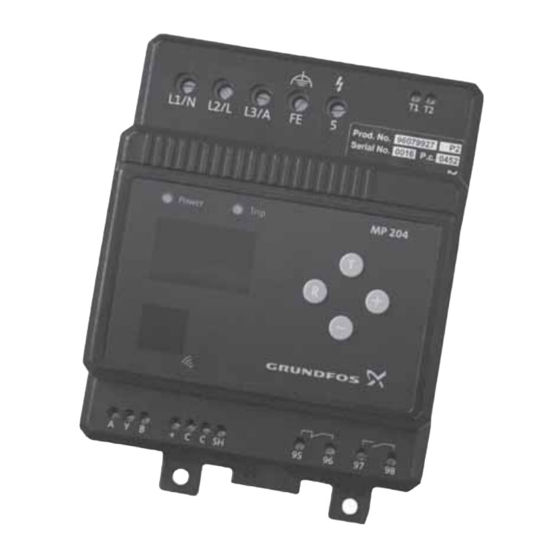
Page 4: Nameplates
The MP 204 is designed for single- and three-phase Tripping conditions motors. In single-phase motors, the starting and run • Overload capacitors are also measured. Cos ϕ is measured in • Underload (dry running) both single- and three-phase systems. • Temperature (Tempcon sensor, PTC/thermal switch and Pt sensor) 2.
-
Page 5: Mechanical Installation
5. Mechanical installation 5.1 MP 204 in control cabinet The MP 204 is designed for mounting in a control cabinet, either on a mounting plate or on a DIN rail. 5.2 MP 204 on DIN rail Mounting and removal of an MP 204 mounted on a DIN rail is shown in figs.
-
Page 6: Connection
6. Connection 6.1 Overview Pos. 1 Pos. 3 Pos. 2 MP 204 Pos. 7 Pos. 4 Pos. 5 Pos. 6 Terminals Cable entries Fig. 6 Fig. 5 Pos. Designation Three-phase connection Single-phase connection Cable Entry for phase L1 to motor Entry for neutral Max.
-
Page 7: Input For Pt100/Pt1000
L1-L2-L3 and «5» to the MP 204 must be protected separately with max. 10 A fuses. See fig. 8. If current transformers are used, the L1-L2-L3 and «5» to the MP 204 must be protected with max. 10 A fuses. For installation examples, see figs.
-
Page 8: Wiring Diagrams
50 A is therefore not required. If larger back-up fuses are used, the voltage to the L1, L2 and L3 must be protected separately. A maxi- mum of 10 A or less is recommended. Max. 10 A MP 204 Pt100 Pt100/Pt1000 Three-phase connection Fig. 8…
-
Page 9
6.5.2 Three-phase system with external current transformers Max. 10 A MP 204 Pt100 Pt100/Pt1000 Three-phase connection with current transformers Fig. 9 Fig. 10 Five windings per phase through the MP 204… -
Page 10
6.5.3 Single-phase system with starting and run capacitors start MP 204 Pt100/Pt1000 Pt100 Fig. 11 Single-phase connection… -
Page 11: External Current Transformers
Fit the transformers as shown in fig. 12. Note: Take the three measuring cables through the three holes in the MP 204 five times per phase. See fig. 13. Note: The three current transformers must be fitted in the same direction, and the measuring cables must be connected in the same way.
-
Page 12: Start-Up
7. Start-up 7.1.3 Button Normally the actual current or temperature appears A basic setting of the MP 204 can be made on the in the display. Press the button to show informa- control panel. tion in the display, according to the following…
-
Page 13
Press the buttons simultaneously for a tons (1 phase, 3 phases (non-earthed) or 3 phases minimum of 5 seconds to place the MP 204 in the w. FE (functional earth)). programming mode. When the display shows «..», the buttons can be released. -
Page 14
Status display Press for approx. 5 seconds Set rated current The value is not stored 10 seconds The value is not stored Set nominal voltage The value is stored 10 seconds The value is stored Set trip class The value is stored 10 seconds The value is stored Set number of phases… -
Page 15: Learning Function
10 seconds. The dot in the right side of the display is flashing. The MP 204 is waiting for current to pass through the unit for a minimum of 120 seconds. Then the phase sequence is measured and stored.
-
Page 16: R100 Menus
• Service interval Display of • Number of automatic restarts • Supply overview • Units/display • Average current • MP 204 display • Average voltage • GENIbus ID number • Tempcon sensor • Learning function. • Pt100/Pt1000 sensor • Power input and energy consumption •…
-
Page 17: Operating The R100
In the menus OPERATION, STATUS, LIMITS and INSTALLATION, data are exchanged between the Change of menu R100 and the MP 204 each time the button [OK] is [<] or [>] steps from one menu to the other. The bot- pressed.
-
Page 18: Setting With The R100
The time «1min» indicates the time which has passed since the MP 204 tripped. Note: The time is measured only as long as the If the MP 204 is tripped, the cause of the trip is indi- MP 204 is powered. The clock stops when the cated.
-
Page 19: Menu 2. Status
When a single-phase motor is connected correctly, the «N» shows 0 V. The MP 204 measures the phase voltage as well as For a list of trip and warning codes, see section the voltage across the auxiliary winding. The current 9.1.8 Alarm log 4…
-
Page 20
See section 9.4.9. lated as follows: Note: The learning function registers whether a Pt100/Pt1000 sensor is connected. When using a three-core Pt-sensor connection, the MP 204 auto- ———————————- — A average matically compensates for cable impedances. -
Page 21
9.2.8 Phase sequence 9.2.11 Trip counter of hours and starts Actual phase sequence and frequency: Trip counter counting the number of operating hours and the number of motor starts. Can be reset. • L1-L2-L3 (correct direction of rotation) • L1-L3-L2. 9.2.12 Starting capacitor Note: The actual phase sequence is accepted as correct and stored when the learning function is ter-… -
Page 22: Menu 3. Limits
Note: The trip limits must be set in accordance with the • The value is shown only if the MP 204 has been motor manufacturer’s specifications. set up for three-phase, earthed operation. The warning limits should be set to a less critical •…
-
Page 23
9.3.2 Pt sensor 9.3.4 Current warning Set the warning and trip limits for the Pt sensor. Set the warning limits for «Max.» and «Min.». Set the max. warning limit in the «Max.» field. Factory setting: The value is set in ampere. •… -
Page 24
9.3.7 Current unbalance 9.3.10 Insulation resistance Set the warning and trip limits for current unbalance. Set the warning and trip limits for the insulation For calculation, see section 9.2.9. resistance in the installation. The value set should be low enough to allow for an early indication of faults in Factory setting: the installation. -
Page 25: Menu 4. Installation
9.4 Menu 4. INSTALLATION 9.4.4 External current transformers In this menu, it is possible to set a number of operat- ing data and thus match the MP 204 to the actual installation. The installation values should not be changed unless the pump has stopped.
-
Page 26
Note: The learning function registers automatically whether a Pt100/Pt1000 sensor is connected. 9.4.10 Insulation resistance measurement Set the time after which the MP 204 is to attempt automatic restarting of motor after cut-out. The time runs from the moment when the value which triggered the fault has returned to normal. -
Page 27
Line 2: Select the MP 204 display indication during normal operation. Line 1: Set the number of hours of motor operation at Display: which the MP 204 is to give a service warning in the • Crnt (current) (factory setting) display. • Tcon (Tempcon temperature) Factory setting: •… -
Page 28
See been operating for a minimum of 120 seconds. The section 7.1.3. dot in the right side of the MP 204 display is flashing. During the storing of the measured values, «LRN» cos ϕ: appears in the MP 204 display. -
Page 29: Mp 204 With Genibus
Each of the units in the chain must be assigned an 10. MP 204 with GENIbus identification number with the R100, see section If several MP 204 units are connected to the same 9.4.7. GENIbus, the connection is to be made as shown in For further information about the GENIbus, see fig.
-
Page 30: Submersible Pumps
Wastewater pumps may incorporate a PTC/thermal 35 are the optimum choice. Apply IEC trip class 45 switch to be connected direct to the MP 204. for the pumping of liquids of extremely high viscosity Wastewater pumps may also be connected to a or liquids containing many solid particles.
-
Page 31: Curves
• Set the trip delay to 900 ms. Fig. 25, curve 1: The pump has an abnormal start-up time, and the current exceeds 10 A. The MP 204 trips after 900 ms. Fig. 25, curve 2: The pump has a normal start-up time, and the cur- rent exceeds 10 A only briefly (<…
-
Page 32: Iec Trip Curves
• Set the MP 204 to IEC trip class 20. • Set the overload limit to 10 A (the rated motor cur- rent is stated on the nameplate). At a motor current of 22.5 A (10 x 2.25), the MP 204 trips after approx. 170 seconds.
-
Page 33: Technical Data
Min. load 5 V/10 mA Max. load power AC/DC 400 VA/48 W Example: NO (normally open Contact type The MP 204 is connected to 3 x 400 V. contact) ≅ • — — 400 327 V test…
-
Page 34: Measuring Ranges
15.4 Measuring ranges Measuring range Accuracy Resolution Current without external current trans- 3 — 120 A ±1% 0.1 A former Current with external current transformer 120 — 999 A ±1% Phase-to-phase voltage 80 — 610 VAC ±1% Frequency 47 — 63 Hz ±1% 0.5 Hz Insulation resistance…
-
Page 35: Fault Finding
Communication alarm for main system – Commanded trip (not in alarm log) Low insulation resistance – Too many starts per hour – The motor is operating even if the MP 204 is tripped Overvoltage Undervoltage Overload Underload Overtemperature, Tempcon measurement Overtemperature, Pt100/Pt1000 measurement –…
-
Page 36
Dimensions All dimensions in mm. -
Page 37
GRUNDFOS Pumps (Hong Kong) Ltd. Turkey BiH-71000 Sarajevo Unit 1, Ground floor New Zealand GRUNDFOS POMPA San. ve Tic. Ltd. Sti. Phone: +387 33 713 290 Siu Wai Industrial Centre GRUNDFOS Pumps NZ Ltd. Gebze Organize Sanayi Bölgesi Telefax: +387 33 659 079 29-33 Wing Hong Street &… -
Page 38
Thinking ahead makes it possible Innovation is the essence 96650480 0510 Repl. 96079899 1006 The name Grundfos, the Grundfos logo, and the payoff Be–Think–Innovate are registrated trademarks owned by Grundfos Management A/S or Grundfos A/S, Denmark. All rights reserved worldwide. www.grundfos.com…
File Specifications:1915/1915148-mp_204.pdf file (13 Feb 2023) |
Accompanying Data:
Grundfos MP 204 Control Systems, Control Unit PDF Installation And Operating Instructions Manual (Updated: Monday 13th of February 2023 10:52:58 AM)
Rating: 4.5 (rated by 75 users)
Compatible devices: DW Series, MSS Series, PS.G Series, AP40, CU 3×2, CMBE TWIN, LCD Series, MG.
Recommended Documentation:
Installation And Operating Instructions Manual (Text Version):
(Ocr-Read Summary of Contents of some pages of the Grundfos MP 204 Document (Main Content), UPD: 13 February 2023)
-
1, Control MP 204 Installation and operating instructions GRUNDFOS INSTRUCTIONS Installation and operating instructions http://net.grundfos.com/qr/i/99304312
… -
2, Grundfos MP 204 English (GB) 2 English (GB) Installation and operating instructions Original installation and operating instructions These installation and operating instructions describe Grundfos Control MP 204. Sections 1-3 give the information necessary to be able to unpack, install and start up the product in a safe way. Sections 4-9 give important information about the product as well as information on service, fault finding and disposal of the product. CONTENTS Page 1. General information 1.1…
-
3, English (GB) 3 1.3 Scope of delivery These installation and operating instructions apply to the Grundfos Control MP 204. The Control MP 204 is a control cabinet with built-in motor protection. These instructions only focus on the Control MP 204 control cabinet. The main component in the control cabinet is an MP 204 motor protector. This component is not described in detail in this manual. Further documentation supplied with the Control MP 204: •…
-
4, English (GB) 4 2.2.1 Terminal blocks The cables and wires must be connected as shown in the wiring diagram supplied with the Control MP 204. Fig. 3 DOL example, terminals in control cabinet Terminal block for mains supply, X0 Fig. 4 Terminal block for mains supply, X0 Terminal block for pump, X1, DOL Fig. 5 Terminal block for pump, X1 The following connections must be made directly on the MP 204: • T1-T2, PTC sensor or thermistor. They must be short-circuited if no sensor or …
-
5, English (GB) 5 Terminal block for pump alarm, X11 Fig. 6 Terminal block for pump alarm, X11 Terminal block for pressure switch or level switch, X10 Fig. 7 Terminal block for pressure switch or level switch, X10 TM06 9439 2317 — TM06 9636 2617 Connection Description 32-33 Pump run, 2 A 34-35 Fault, MP 204, 2 A 36-37 Fault, water shortage, 2 A X11 32 33 343 3 3765 Q12 X11 K10 K8 13 14 34 34 31 31 32 33 34 35 36 37 Pump run Fault, MP 204 Fault, water shortage TM06 9440 2717 Connection D…
-
6, English (GB) 6 3. Commissioning the product Checks before first startup: • The pump is installed according to the installation and operating instructions for the pump type used. • The MP 204 is configured either by use of a PC Tool or with Grundfos GO Remote according to the motor and pump specifications. 3.1 Startup The motor current and trip conditions have to be adjusted and set during startup. To adjust and set these parameters, see installation and op…
-
7, English (GB) 7 4.2 Grundfos GO Remote The product is designed for infrared communication with Grundfos GO Remote. MP 204 must be configured using Grundfos GO Remote. Grundfos GO Remote enables setting of functions and gives access to status overviews, technical product information, alarm logs and actual operating parameters. Fig. 9 Grundfos GO Remote communication via infrared connection, IR 4.2.1 Infrared communication When communicating v…
-
8, Grundfos MP 204 English (GB) 8 5. Control functions This section describes the available control modes: • Switch control – Control MP 204 controlled by a pressure switch – Control MP 204 controlled by a float switch – Control MP 204 controlled by a main control system, for example a PLC. 5.1 Switch control Control MP 204 controlled by a pressure switch If a constant pressure is required in a closed system, a pressure switch can be connected. The pressure switch starts and stops th…
-
9, English (GB) 9 7. Fault finding the product 8. Technical data 9. Disposal of the product This product or parts of it must be disposed of in an environmentally sound way: 1. Use the public or private waste collection service. 2. If this is not possible, contact the nearest Grundfos company or service workshop. WARNING Electric shock Death or serious personal injury Before starting any work on the product, make sure …
-
10, Appendix 10 Appendix 1 1. 中国 RoHS ӗ૱ѝᴹᇣ⢙䍘Ⲵ〠৺䟿 䜘Ԧ〠 ᴹᇣ⢙䍘 䫵 ;WďͿ ⊎ ;,ŐͿ 䭹 ;ĚͿ ޝԧ䬜 ;ƌϲнͿ ཊⓤ㚄㤟 ;WͿ ཊⓤ㚄㤟䟊 ;WͿ ঠࡧ⭥䐟ᶯ y K K K K K ㍗പԦ y K K K K K ᵜ㺘Ṭᦞ ^:dϭϭϯϲϰ Ⲵ㿴ᇊ㕆ࡦ K˖㺘⽪䈕ᴹᇣ⢙䍘�…
-
11, Grundfos companies Argentina Bombas GRUNDFOS de Argentina S.A. Ruta Panamericana km. 37.500 Centro Industrial Garin 1619 Garín Pcia. de B.A. Phone: +54-3327 414 444 Telefax: +54-3327 45 3190 Australia GRUNDFOS Pumps Pty. Ltd. P.O. Box 2040 Regency Park South Australia 5942 Phone: +61-8-8461-4611 Telefax: +61-8-8340 0155 Austria GRUNDFOS Pumpen Vertrieb Ges.m.b.H. Grundfosstraße 2 A-5082 Grödig/Salzburg Tel.: +43-6246-883-0 Tele…
-
12, 99304312 0320 ECM: 1283517 Trademarks displayed in this material, including but not limited to Grundfos, the Grundfos logo and “be think innovate” are registered trademarks owned by The Grundfos Group. All rights reserved. © 2020 Grundfos Holding A/S, all rights reserved. www.grundfos.com
…
-
Grundfos MP 204 User Manual
-
Grundfos MP 204 User Guide
-
Grundfos MP 204 PDF Manual
-
Grundfos MP 204 Owner’s Manuals
Recommended: B10, FM350A, CUV4X-V, CP-602U-I-T
Links & Tools
Operating Impressions, Questions and Answers:
16.1 Warning and trip codes
MP 204 display
A = Trip
E = Warning
Fault code
Fault code
Trip
2
3
4
9
12
15
18
20
21
26
32
40
48
56
64
71
91
111
112
113
120
123
124
175
17. Disposal
This product or parts of it must be disposed of in an
environmentally sound way:
1. Use the public or private waste collection service.
2. If this is not possible, contact the nearest
Grundfos company or service workshop.
A
32
Warning
A
–
A
–
A
–
A
–
–
E
A
–
A
–
A
E
–
E
–
E
A
E
A
E
A
E
A
E
A
E
A
E
–
E
A
E
A
E
A
E
A
–
A
E
A
E
–
E
Cause of trip/warning
Missing phase
PTC/thermal switch
Too many automatic restarts per 24 hours
Wrong phase sequence
Service warning
Communication alarm for main system
Commanded trip (not in alarm log)
Low insulation resistance
Too many starts per hour
The motor is operating even if the MP 204 is tripped
Overvoltage
Undervoltage
Overload
Underload
Overtemperature, Tempcon measurement
Overtemperature, Pt100/Pt1000 measurement
Signal fault, Tempcon sensor
Current unbalance
Cos ϕ, max.
Cos ϕ, min.
Auxiliary winding fault
Starting capacitor, low
Run capacitor, low
Signal fault, Pt100/Pt1000 sensor
Subject to alterations.
35
Грундфос МР 204 – это насосная станция, используемая в различных отраслях промышленности и бытовых условиях. В процессе эксплуатации таких систем у операторов могут возникать проблемы и ошибки, которые могут потребовать быстрого реагирования. Поэтому знание кодов ошибок Грундфос МР 204 является необходимым для обслуживающего персонала.
Главной задачей обслуживающего персонала является обеспечение надежной работы насосной станции и предотвращение возможных поломок. Для этого следует знать коды ошибок, которые могут быть выведены на индикаторе управления. Это информация, которая предоставляет причину возникновения проблемы и позволяет оперативно принять соответствующие меры.
Коды ошибок описываются в руководстве пользователя для Грундфос МР 204, но их перевод и предоставление простой и понятной информации обычно требует определенных усилий. В нашей статье мы предоставляем вам полный список кодов ошибок и их значения для Грундфос МР 204, позволяя вам быстро и эффективно решать проблемы и обеспечивать бесперебойную работу системы.
Содержание
- Коды ошибок Грундфос МР 204 – важная информация
- Список кодов ошибок Грундфос МР 204
- Что делать при возникновении ошибки?
- Обслуживающему персоналу необходимо знать
Коды ошибок Грундфос МР 204 – важная информация
Грундфос МР 204 – это циркуляционный насос с встроенным микропроцессором, который обеспечивает надежное и эффективное функционирование системы отопления. Однако даже с таким надежным оборудованием, иногда могут возникать ошибки.
Знание кодов ошибок Грундфос МР 204 очень важно для обслуживающего персонала, поскольку их поможет быстро определить и исправить проблему. В данной статье представлены коды ошибок и их описание для вашего удобства.
Список кодов ошибок Грундфос МР 204
| Код ошибки | Описание |
|---|---|
| 219 | Нет контакта между циркуляционным насосом и АСУ ГВС |
| 301 | Проблема с электропитанием – напряжение слишком низкое или отсутствует |
| 302 | Проблема с электропитанием – напряжение слишком высокое |
| 303 | Короткое замыкание в цепи |
| 304 | Перегрузка цепи |
Важно отметить, что это не полный список кодов ошибок Грундфос МР 204, но он включает наиболее распространенные. Если вы столкнулись с кодом ошибки, который не указан в этом списке, следует обратиться к документации или связаться с производителем для получения дополнительной информации.
Что делать при возникновении ошибки?
Когда вы обнаруживаете код ошибки на дисплее Грундфос МР 204, первым делом необходимо проверить, нет ли очевидных причин для появления ошибки. Например, убедитесь, что питание подключено правильно, все провода целые и не повреждены.
Если проблему не удалось решить, следует обратиться к документации или связаться с производителем для получения подробной информации о конкретном коде ошибки и рекомендациях по ее устранению. В некоторых случаях может потребоваться вызвать специалиста для диагностики и ремонта оборудования.
Не пытайтесь самостоятельно ремонтировать оборудование, если у вас нет необходимых навыков и опыта. Неправильные действия могут привести к дальнейшему повреждению системы и нанести ущерб вашему зданию.
В заключение, знание кодов ошибок Грундфос МР 204 и правильные действия при их возникновении являются важным компонентом обслуживания и устранения неисправностей. Будьте внимательны и в случае сомнений обратитесь к специалистам для получения помощи.
Обслуживающему персоналу необходимо знать
При работе с насосом Грундфос МР 204 обслуживающему персоналу необходимо знать следующую важную информацию:
- Коды ошибок – знание кодов ошибок поможет идентифицировать причину возникновения проблемы и принять соответствующие меры.
- Процедуры обслуживания – обслуживающий персонал должен быть знаком с процедурами обслуживания насоса, включая его установку, запуск и осмотр.
- Методы технического обслуживания – обслуживающий персонал должен знать методы технического обслуживания насоса, включая проверку и замену деталей, регулировку и диагностику.
- Расположение основных элементов – обслуживающий персонал должен знать расположение основных элементов насоса, таких как клапаны, фильтры, датчики и т.д.
- Принцип работы – обслуживающий персонал должен понимать основной принцип работы насоса и процесс передачи и перекачки жидкости.
- Безопасность – обслуживающий персонал должен быть обучен правилам безопасности при работе с насосом, включая использование защитных средств и предотвращение аварийных ситуаций.
Знание и понимание вышеперечисленной информации позволят обслуживающему персоналу более эффективно и безопасно работать с насосом Грундфос МР 204, а также своевременно выявлять и устранять возможные проблемы.