|
|
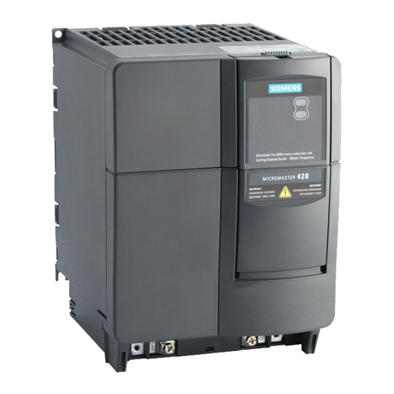
Ремонт MICROMASTER 420
 Компания «Кернел» производит ремонт частотных преобразователей с 2002 года. За это время мы накопили колоссальный опыт в том числе опыт в ремонте MICROMASTER 420 такого известного производителя как SIEMENS. Ремонт подобной промышленной электроники ответственное и сложное занятие, требующие максимальной отдачи, профессионализма и максимально полной материальной базе.
По причине особой сложности Ремонт MICROMASTER 420 производится исключительно на территории сервисного центра. Частотный преобразователь MICROMASTER 420 является крайне сложной промышленной электроникой соответственно ремонт MICROMASTER 420 можно доверить только настоящим профессионалам своего дела с богатым опытом работы в данном направлении.
Все специалисты нашего сервисного центра имеют высшее техническое образование, огромный опыт и максимально полную материальную базу включая новейшее высокотехнологичное диагностическое оборудование благодаря чему ремонт MICROMASTER 420 проходит максимально эффективно.
Инженеры сервисного центра уделяют максимальное внимание к качеству исполнения ремонта, программирования и настройке частотного преобразователя, не зависимо от производителя данного промышленного оборудования. Именно поэтому мы смело даем гарантию на ремонт MICROMASTER 420 и замененные в процессе ремонта компоненты шесть месяцев.
Особое внимание заслуживает тот факт, что ремонт MICROMASTER 420 в производится исключительно с использованием оригинальных запасных частей, на компонентном уровне с применением высокотехнологичного оборудования, квалифицированным персоналом с инженерным образованием.
Ремонт распространенных частотнрых преобразователей MICROMASTER 420
Если на вашем производстве появились проблемы с частотным преобразователем MICROMASTER 420, ошибка которую вы не можете сбросить самостоятельно, мы всегда рады вам помочь. Обращайтесь в сервисный центр «Кернел». Специалисты нашей компании в минимальные сроки проведут глубокую диагностику частотного преобразователя и последующий ремонт MICROMASTER 420 в . Оставьте заявку на ремонт частотного преобразователя используя форму на сайте.
Ниже приведен далеко не полный список частотных преобразователей MICROMASTER 420 ремонт которых выполняет наш сервисный центр.
|
6SE6420-2UC11-2AA1 6SE6420-2UC12-5AA1 6SE6420-2UC13-7AA1 6SE6420-2UC15-5AA1 6SE6420-2UC17-5AA1 6SE6420-2UC21-1BA1 6SE6420-2UC21-5BA1 6SE6420-2UC22-2BA1 6SE6420-2UC23-0CA1 6SE6420-2AB11-2AA1 |
6SE6420-2AB12-5AA1 6SE6420-2AB13-7AA1 6SE6420-2AB15-5AA1 6SE6420-2AB17-5AA1 6SE6420-2AB21-1BA1 6SE6420-2AB21-5BA1 6SE6420-2AB22-2BA1 6SE6420-2AB23-0CA1 6SE6420-2UC25-5CA1 6SE6420-2UC24-0CA1 |
Ошибки MICROMASTER 420
При появлении неисправности на дисплее частотного преобразователя MICROMASTER 420 отобразится код ошибки, в файле ниже приведены все ошибки MICROMASTER 420 и возможные способы их устранения.
При возникновении ошибки преобразователь отключается и на индикации появляется код ошибки.
УКАЗАНИЕ
Сообщения об ошибках могут квитироваться следующим образом:
- Возможность 1: Отключить преобразователь от сети и снова подключить
- Возможность 2: на AOP или BOP
- Возможность 3: Через цифровой вход 3
 Сообщения об ошибках сохраняются в параметре r0947 под своим кодовым номером (к примеру, F0003 = 3). Соответствующее слово ошибки находится в параметре r0949. Если слово ошибки у ошибки отсутствует, то вносится значение 0. Кроме этого, можно запросить момент времени возникновения ошибки (r0948) и число сохраненных в параметре r0947 сообщений об ошибках (P0952). Подробное описание всех сообщений об ошибках можно найти в Списке параметров.
Предупреждения
Предупреждения сохраняются в параметре r2110 под своим кодовым номером (к примеру, A0503 = 503) и могут загружаться оттуда. Подробное описание всех предупреждений можно найти в Списке параметров.
Сброс сообщений об ошибках, предупреждений
Работа без сбоев с точки зрения приложения является решающим критерием приемлемости приводной системы. Но для специальных приложений бесперебойная работа требуется и тогда, когда имеет место перегрузка или внешние обстоятельства вызывают ошибку. В таких приложениях (к примеру, мешалка) бесперебойная работа более важна, чем защита приводной системы. В MICROMASTER 420 можно подавить до 3-х сообщений об ошибках/предупреждений с индексированными параметрами P2100 и P2101. Выбор сообщений об ошибках/предупреждений (см. раздел «Сообщения об ошибках/предупреждения») устанавливается с помощью параметра P2100, а реакция выбирается с помощью параметра P2101. Корреляция между подавлением и реакцией осуществляется через индекс 0 — 2 обоих параметров. Для реакций возможны следующие установки:
- 0 нет реакции, нет индикации
- 1 реакция останова ВЫКЛ1
- 2 реакция останова ВЫКЛ2
- 3 реакция останова ВЫКЛ3
- 4 нет реакции, только предупреждение
Пример:
Предупреждение A0911 указывает на то, что привод увеличивает врем выбега по рампе, чтобы не допустить перенапряжения. Для подавления этого сообщения установить следующие параметры:
p2100[0] = 911 (выбор предупреждения A0911)
P2101[0] = 0 (нет реакции, нет индикации)
Все возможные предупреждения и ошибки MICROMASTER 420 описаны в руководстве пользователя, которое вы можете скачать с нашего сайта в удобном формате- pdf.
Скачать руководство пользователя MICROMASTER 420 мануал.pdf
Устранение причины ошибки частотного преобразователя MICROMASTER 420 и ее сброс позволит в кратчайшие сроки возобновить работу дорогостоящего оборудования. К сожалению не все ошибки можно исправить самостоятельно, некоторые ошибки MICROMASTER 420 возможно исправить только в специализированных сервисных центрах.
MICROMASTER 420 программирование
 На ряду с ремонтом, специалисты сервисного центра «Кернел» выполняют программирование MICROMASTER 420 и настройку параметров системы частотного преобразователя. Подобную услугу мы оказываем на территории сервисного центра, также в исключительных случаях инженер компании может выполнить программирование MICROMASTER 420 на территории заказчика.
Настройка параметров, программирование MICROMASTER 420 в является заключительным звеном в процессе ремонта частотного преобразователя и требует профессионального подхода. Именно финальный этап программирования MICROMASTER 420 наглядно покажет качество выполненного ремонта MICROMASTER 420.
К слову, мы уделяем особое внимание качеству и смело даем гарантию на все выполненные ремонтно-восстановительные работы шесть месяцев, гарантия так же распространяется на запасные части, которые были заменены в процессе ремонта.
Хочется обратить внимание на то, что мы стараемся провести ремонт и программирование MICROMASTER 420 в максимально сжатые сроки, тем самым минимизируем простой дорогостоящего промышленного оборудования.
MICROMASTER 420 ввод в эксплуатацию
Инженеры сервисного центра «Кернел» не только выполняют качественный ремонт MICROMASTER 420 и программирование частотного преобразователя. Так же мы предоставляем услугу запуска в эксплуатацию оборудования от стадии проектирования до выпуска первой продукции.
Именно этап запуска в эксплуатацию MICROMASTER 420 отвечает за долгий и безаварийный процесс работы промышленного оборудования, тем самым позволяя получить максимальную прибыль и сэкономить на незапланированном ремонте.
По-настоящему качественный ввод в эксплуатацию MICROMASTER 420 может выполнить только высококвалифицированный специалист с богатым опытом работы в данном направлении. Найти подобного специалиста достаточно сложно, но, если вы обращаетесь в наш сервисный центр вам не придется об этом думать.
ДляпараметрированияпреобразователяВыможетеиспользоватьоднуизоп-ционныхоператорскихпанелей, таких как «Базовая Операторская Панель»(BOP) или «Расширенная Панель Оператора» (AOP). Для более удобного обслуживания и параметрирования преобразователей можно использовать специальный инструмент – Drive Monitor – программу для настройки и документирования.
|
Блок схема MICROMASTER 420 |
|
|

В нашей команде работают исключительно профессионалы своего дела, а за время существования нашей компании мы ввели в эксплуатацию не одну сотню частотных преобразователей в том числе и MICROMASTER 420, с каждым разом получая и накапливая драгоценный опыт.
О MICROMASTER 420
 Частотный преобразователь MICROMASTER 420 снабжен пультом отображения состояния (Status Display Panel) (SDP). Чтобы изменять и устанавливать требуемые параметры, необходимо использовать базовый пульт оператора (Basic Operator Panel) (BOP), расширенный пульт оператора (Advanced Operator Panel) (AOP) или последовательный интерфейс связи.
Базовая панель оператора (BOP), поставляемая как опция, дает возможность доступа к параметрам преобразователя и обеспечивает специфическую пользовательскую настройку MICROMASTER 420. BOP может использоваться для конфигурирования большинства преобразователей MICROMASTER 420. Поэтому нет необходимости покупать свою панель BOP для каждого преобразователя. Панель имеет сегментные индикаторы для чтения и записи параметров преобразователя. Панель не имеет возможности собственного хранения информации и параметров после её снятия.
Линейка промышленной электроники, которую восстанавливают специалисты сервисного центра «Кернел» не имеет ограничений, мы выполняем качественный ремонт промышленной электроники и оборудования абсолютно любых производителей не зависимо от года выпуска и наличия технической документации.
Оставить заявку на ремонт MICROMASTER 420
Оставить заявку на ремонт или программирование MICROMASTER 420 в можно с помощью специальной формы, которая вызывается нажатием одноименной кнопки в верхней части страницы. Все вопросы, связанные с ремонтом MICROMASTER 420 в вы можете задать нашим менеджерам. Связаться с ними можно несколькими способами:

- Заказав обратный звонок (кнопка в правом нижнем углу сайта)
- Посредством чата (кнопка расположена с левой стороны сайта)
- Позвонив по номеру телефона:
- +7(8482) 79-78-54;
- +7(8482) 55-96-39;
- +7(917) 121-53-01
- Написав на электронную почту: 89171215301@mail.ru
Вот далеко не полный список производителей промышленной электроники и оборудования, ремонтируемой в нашей компании.
 В процессе работы выходит из строя даже самое надежное промышленное оборудование. В данной статье мы приведем ошибки частотного преобразователя Siemens, а точнее Siemens MICROMASTER 440. Частотники в наше время нашли широкое применения в абсолютно всех сферах промышленности управляя как мини моторами в оргтехнике, так и гигантскими двигателями в горнодобывающей промышленности.
Для простоты общения со столь сложной электроникой все частотные преобразователи оснащены небольшими дисплеями с помощью которых выводятся информационные сообщения с кодами ошибок, расшифровав которые можно сразу же узнать причину ее возникновения. Если учесть распространенность данной промышленной электроники, то появляется острая нужда в расшифровке кодов ошибок частотных преобразователей. В этой статье мы рассмотрим одного из самых известных производителей промышленной электроники имеющему уважение во всем мире, Siemens.
Существует несколько видов ошибок, некоторые из них можно устранить автоматически, а некоторые возможно исправить только, обратившись в специализированный сервисный центр. В таблицах ниже приведены коды ошибок частотного преобразователя Siemens и их расшифровка.
Индикация- статусная панель, устранение неисправностей с помощью статусной панели.
|
Светодиоды |
Приоритет |
Описание состояния преобразователя |
|
|
Зеленый |
Желтый |
||
|
Не горит |
Не горит |
1 |
|
|
Не горит |
Горит |
8 |
|
|
Горит |
Не горит |
13 |
|
|
Горит |
Горит |
14 |
|
|
Не горит |
Мигает R1 |
4 |
|
|
Мигает R1 |
Не горит |
5 |
|
|
Мигает R1 |
Горит |
7 |
|
|
Горит |
Мигает R1 |
8 |
|
|
Мигает R1 |
Мигает R1 |
9 |
|
|
Мигает R1 |
Мигает R1 |
11 |
|
|
Мигает R1 |
Мигает R2 |
6/10 |
|
|
Мигает R2 |
Мигает R1 |
12 |
|
|
Мигает R2 |
Мигает R2 |
2 |
|
|
Мигает R2 |
Мигает R2 |
3 |
|
|
R1 – время включенного состояния 900 мС |
|

При появлении неисправности на дисплее частотного преобразователя Siemens MICROMASTER 440 отобразится код ошибки, в таблице ниже приведены все коды ошибок привода Siemens
|
Код сбоя |
Описание |
Возможные причины |
Диагностика и способы устранения |
|
F0001 |
Перегрузка по току |
|
|
|
F0002 |
Перенапряжение |
|
|
|
F0003 |
Пониженное напряжение |
|
|
|
F0004 |
Перегрев преобразователя |
Температура окружающей среды выше допустимого предела. Неисправность вентилятора |
|
|
F0005 |
Превышение по I2t |
|
|
|
F0011 |
Перегрев двигателя по I2t |
|
|
|
F0041 |
Ошибка при измерении сопротивления статора |
|
|
|
F0051 |
Ошибка параметра в EEPROM |
|
|
|
F0052 |
Ошибка стека |
|
|
|
F0060 |
Нет ответа от специализированной ASIC – платы. |
|
|
|
F0070 |
Ошибка задания через плату связи |
|
|
|
F0071 |
Нет данных по последующему протоколу (RS232) в течение времени ожидания. |
|
|
|
F0072 |
Нет данных по последующему протоколу (RS485) в течение времени ожидания. |
|
|
|
F0080 |
Нет входного сигнала на аналоговом входе. |
|
|
|
F0085 |
Внешний сбой |
|
|
|
F0101 |
Переполнение стека |
|
|
|
F0221 |
Обратная связь ПИ- регулятора ниже минимального значения |
|
|
|
F0222 |
Обратная связь ПИ-регулятора выше максимального значения |
|
|
|
F0450 (только в сервисном режиме) |
Ошибка при BIST — тестировании |
Значение ошибки:
|
|
Таблица кодов предупреждения частотного преобразователя Siemens MICROMASTER 440
|
А0501 |
Ограничение тока нагрузки |
|
|
|
А0502 |
Достигнут верхний предел напряжения питания. |
|
Примечание: |
|
А0503 |
Достигнут нижний предел напряжения питания. |
|
|
|
А0504 |
Перегрев преобразователя |
|
|
|
А0505 |
Превышение по I2t |
|
|
|
А0506 |
Нагрузочный цикл преобразователя |
|
|
|
А0511 |
Перегрев двигателя по I2 t |
|
|
|
А0600 |
Перегрузка операционной системы реального времени. |
|
|
|
А0700 |
СВ предупреждение 1 |
|
|
|
А0701 |
СВ предупреждение 2 |
|
|
|
А0702 |
СВ предупреждение 3 |
|
|
|
А0703 |
СВ предупреждение 4 |
|
|
|
А0704 |
СВ предупреждение 5 |
|
|
|
А0705 |
СВ предупреждение 6 |
|
|
|
А0706 |
СВ предупреждение 7 |
|
|
|
А0707 |
СВ предупреждение 8 |
|
|
|
А0708 |
СВ предупреждение 9 |
|
|
|
А0709 |
СВ предупреждение 10 |
|
|
|
А0710 |
Ошибка связи СВ |
|
|
|
А0711 |
Ошибка конфигурирования СВ |
|
|
|
А0910 |
Деактивирован регулятор Vdc-max |
|
|
|
А0911 |
Vdc-max регулятор активен |
|
|
|
А0920 |
Неправильно установлен параметр аналогового входа |
|
|
|
А0921 |
Неправильно установлен параметр аналогового выхода |
|
|
|
А0922 |
К приводу не подключена нагрузка |
|
|
|
А0923 |
Активны сигналы «Толчок» вправо и «Толчок» влево (JOG) |
|
|
Сброс ошибок и Ремонт частотных преобразователей Siemens в сервисном центре
Компания «Кернел» производит ремонт промышленной электроники и оборудования с 2002 года. За это время мы накопили колоссальный опыт в том числе опыт в ремонте частотных преобразователей Siemens. ![]() Ремонт подобной промышленной электроники ответственное и сложное занятие, требующие максимальной отдачи, профессионализма и максимально полной материальной базе.
Ремонт подобной промышленной электроники ответственное и сложное занятие, требующие максимальной отдачи, профессионализма и максимально полной материальной базе.
Специалисты нашего сервисного центра уделяют максимальное внимание к качеству исполнения ремонта, программирования и настройке промышленного преобразователя частоты, не зависимо от производителя данного промышленного оборудования. Именно поэтому мы смело даем гарантию на все выполненные работы шесть месяцев.
Ремонт частотных преобразователей производится исключительно с использованием оригинальных запасных частей, на компонентном уровне с применением высокотехнологичного оборудования, квалифицированным персоналом с инженерным образованием.
Если на вашем производстве появились проблемы с частотным преобразователем, которые вы не можете решить самостоятельно, мы всегда рады вам помочь. Обращайтесь в сервисный центр «Кернел». Специалисты нашей компании в минимальные сроки проведут глубокую диагностику и последующий ремонт частотного преобразователя. Оставьте заказ на ремонт оборудования используя форму на сайте, либо свяжетесь с нашими менеджерами, сделать это очень просто.
Как с нами связаться
У вас остались вопросы, связанные с ремонтом, программированием и настройкой приводов Siemens? Задайте их нашим менеджерам. Связаться с ними можно несколькими способами:

- Заказав обратный звонок (кнопка в правом нижнем углу сайта)
- Посредством чата (кнопка расположена с левой стороны сайта)
- Либо позвонив по номеру: +7(8482) 79-78-54; +7(917) 121-53-01
- Написав на электронную почту: 89171215301@mail.ru
Далеко не полный список производителей промышленной электроники и оборудования, ремонтируемой в нашей компании.
Авария F0001 является хронологическим продолжением предупреждения А0501.
Если появляется предупреждение, а до аварийного сообщения дело не доходит, то причины, вызвавшие предупреждение, скоротечны. Чаще всего такое происходит при разгоне и торможении при малых значениях парамеров Р1120 и Р1121.
Если после кратковременной демонстрации предупреждения A0501 появляется F0001, то имеем дело скорее всего с несоответствием параметров подключенного двигателя к преобразователю, неправильной параметризацией или заклиниванием двигателя. Также длина подключенного кабеля в цепи нагрузки слишком большая.
Мгновенное появление сообщения об аварии после подачи импульсов говорит о коротком замыкании или замыкании на землю в нагрузке преобразователя.
Если сообщение F0001 появилось после подачи напряжения и не сбрасывается, то проверьте состояние разъемов, к которым подключаются платы Micromaster. Для того, чтобы устранить причину возникновения ошибки, достаточно подогнуть гнезда разъемов для лучшего электрического контакта.
Был также случай в моей практике, когда при замене платы дискретных входов B01 на A06 Микромастер включался с ошибкой F0001(B01 и A06 — версии hardware). В принципе, никаких проблем совместимости у этих плат нет, но победить сообщение удалось лишь с возвратом платы В01 на старое место.
В описании на Micromaster:
1. Ошибка F0001 — Перегрузка по току.
Квитирование ошибки.
Устранить ошибку и сбросить память ошибок через:
— Отключить преобразователь от сети и снова подключить.
— На BOP или AOP нажать клавишу Fn.
— Квитировать ошибку P2103, P2104.
— P0952 (общая память ошибок).
Возможные причины:
— Короткое замыкание на выходе.
— Замыкание на землю.
— Слишком большой двигатель (мощность двигателя P0307 больше мощности преобразователя r0206).
— Неисправный оконечный каскад.
Диагностика и устранение:
— Соблюдены ли предельные значения для длин кабелей ?
— Имеет место короткое замыкание или замыкание на землю кабеля двигателя или двигателя ?
— Соответствуют ли параметры двигателя таковым используемого двигателя ?
— Двигатель перегружен или заблокирован ?
— Увеличить время разгона.
— Уменьшить усиление.
— Подключить двигатель меньшего размера (наверное меньшей мощности).
— Сопротивление статора (P0350) правильное ?
2. Предупреждение AO571 — …. Нет в описании, возможно надо смотреть версию документации для Вашего ПЧ.
Если это ошибка, а код А0541, то надо сделать идентификацию двигателя.
- 24 Июл 2016
Dear guys,
could you help me, please, with my problem?
I have driver Siemens Micromaster 420 (6SE6420-2AB21-5BA1 — use as driver for machine, which get honey from honeycomb), 1,5kW. A few days ago, I tried to change maximal frequency from 50Hz to 80Hz and when I change two parameters (max. freq (P1082) and refer. freq (P2000)) and start motor rotation, I got F0001 and I’m still not able to clear this fault.
I tried to set driver to default setting, used other motor with other cable, ran driver without cable nor motor and always when I tried to start motor rotation, I got F0001.
I remember, that a year ago I had similar problem with this one driver — I got A501 alarm and current on BOP display was really big — around 12A. So I clean driver with compressed air and all was OK.
But now cleaning by air does not solve my problem. I tried to measure bigger resistors and all of them are OK. I measured voltage on flex cables and it is OK too. But I simply do not believe, that main transistor block is KO.
Could you help me, please, with my problem.
Many thanks for your answers.
Petr Filipi
The Czech Republic
► MM420 driver.pdf
- 24 Июл 2016
Most likely you have defective power module Semikron.
Once assembled, a multimeter, check the state of power switches with respect to the + and — power bus and the output to the motor.
- 24 Июл 2016
I tried to measure output terminals (UxV, UxW, VxW, UxPE, VxPE, WxPE) by multimeter set to diode test (set to 2MOhm).
Results:
U+ x V-:810mV (0,2MOhm)
U+ x W-:1900mV goes to infinity (infinity MOhm)
V+ x W-:1900mV goes to infinity(1,5MOhm)
U- x V+:1900mV goes to infinity (1,5MOhm)
U- x W+:1900mV goes to infinity (infinity MOhm)
V- x W+:800mV (0,2MOhm)
U+ x PE-:infinity MOhm
V+ x PE-:infinity MOhm
W+ x PE-:infinity MOhm
U- x PE+:infinity MOhm
V- x PE+:infinity MOhm
W- x PE+:infinity MOhm
Why would Semikron module go to hell? Motor was small from washmashine (60W, 270 rpm, 2A max).
Petr Filipi
- 24 Июл 2016
Your information is not clear.
Please see p.30 from manual.
ссылка скрыта от публикации
Please check by multimeter (diode test) DC+ to U V W and DC- to U V W in both direction.
You must see the same results on one side check and infinity in another.
If test is ok.
Please resolder two current mesurement resistor (0.05 Ohm ect.) on DC+ and DC- wire inside the drive. If module is ok it is the solution for F001 error.
If module is broken — you need to replace module. You must check gate driver or replace them before install new module.
- 25 Июл 2016
Many thanks for your answer.
I measured what you offered and results are here:
Terminal DC+ (plus Metex) / Terminal U (minus Metex) = OL mV
Terminal DC+ (plus Metex) / Terminal V (minus Metex) = 717 mV
Terminal DC+ (plus Metex) / Terminal W (minus Metex) = OL mV
Terminal DC+ (minus Metex) / Terminal U (plus Metex) = 390 mV
Terminal DC+ (minus Metex) / Terminal V (plus Metex) = 370 mV
Terminal DC+ (minus Metex) / Terminal W (plus Metex) = 390 mV
Terminal DC- (plus Metex) / Terminal U (minus Metex) = 390 mV
Terminal DC- (plus Metex) / Terminal V (minus Metex) = 380 mV
Terminal DC- (plus Metex) / Terminal W (minus Metex) = 390 mV
Terminal DC- (minus Metex) / Terminal U (plus Metex) = OL mV
Terminal DC- (minus Metex) / Terminal V (plus Metex) = OL mV
Terminal DC- (minus Metex) / Terminal W (plus Metex) = OL mV
I did not have enough of time to reassemble driver to check resistor (marked as R005), but I measured it yesterday and resistor was OK (resp. I was unable measure it exactly due to small resistance, but it has really small resistance). But there is no problem to remove it from driver and measure it by Ohm law.
Petr Filipi
- 25 Июл 2016
petrfilipi сказал(а):
Many thanks for your answer.
I measured what you offered and results are here:Terminal DC+ (plus Metex) / Terminal U (minus Metex) = OL mV
Terminal DC+ (plus Metex) / Terminal V (minus Metex) = 717 mV
Terminal DC+ (plus Metex) / Terminal W (minus Metex) = OL mVPetr Filipi
Please retest this way (see above). If result is the same you have something wrong in IGBT module.. and it must be replaced.
By the way.. resistor (005 Ohm) soldering is broken after long thermal cycling and F0001 is apear (aprox 5 time founded in this type of VFD and cleared by resoldering). But maybe now IGBT is wrong. Check carefully. First test that you post, declare about wrong IGBT.
- 25 Июл 2016
petrfilipi сказал(а):
Terminal DC+ (plus Metex) / Terminal V (minus Metex) = 717 mV
Please re-check this measurement and , if result is a same — You got a dead top switch (for V phase) in a Semicron bridge…is a sad.
- 26 Июл 2016
You have a problem with the engine parameters!Read a book,there is a speed and current engine parameters do Not put high frequency,start with 50 Hz and note the parameters acceleration and braking!I think the drive is OK!Good luck!
Добавлено 26-07-2016 08:51
kratmel сказал(а):
Many thanks for your answer.
I measured what you offered and results are here:Terminal DC+ (plus Metex) / Terminal U (minus Metex) = OL mV
Terminal DC+ (plus Metex) / Terminal V (minus Metex) = 717 mV
Terminal DC+ (plus Metex) / Terminal W (minus Metex) = OL mVPetr Filipi
Please retest this way (see above). If result is the same you have something wrong in IGBT module.. and it must be replaced.
By the way.. resistor (005 Ohm) soldering is broken after long thermal cycling and F0001 is apear (aprox 5 time founded in this type of VFD and cleared by resoldering). But maybe now IGBT is wrong. Check carefully. First test that you post, declare about wrong IGBT.
I agree,we need to check ,but it is a consequence of improper settings of the engine!
- 27 Июл 2016
Guys, many thanks for answers.
I measured IGBT module and it is really KO. I still measure around 717mV between DC+ and Terminal V. So i tried to remove IGBT module and between this terminals was infinity resistance. So problem is in IGBT module. Finally i tried to desolder R005 resistor, it is OK, I soldered it back and F0001 is still there.
The inverter (was older when I bought it) cost around 100USD so I think it is nonsense to buy new module and try to replace it.
But I have to disagree, that broken module was caused by impoper setting. This driver can control motor up to 650 Hz, so 80Hz should not be a problem.
So thanks one more for your answer, guys.
Petr Filipi
- 28 Июл 2016
petrfilipi сказал(а):
….
But I have to disagree, that broken module was caused by impoper setting. This driver can control motor up to 650 Hz, so 80Hz should not be a problem.
Petr Filipi
Yes it is right, but only if all motor nameplate data is entered correctly and (or) autotuning find correct motor parameter.
Siemens MM420 have a lot «hidden» parameter that was visible in connected to drive software and hard to program by hand.
That if you replace drive — try to setup new one carefully.
P.S. Some motor that worked «fine» in normal grid, is not good for VFD and you can find same error on another drive in future.
That you must check motor insulation, motor current and thermal condition in normal grid.
- 28 Июл 2016
I will add. As I understood, an engine was used in the drive of centrifuge. For such applications it is recommended to set the quadratic law of U/f. (P1300=2,I tried to set driver to default setting, after a reset to factory settings =0)
- 1 Авг 2016
I think I had some normal law. My friend, who is owner of honey centrifuge, helped to rotor in first seconds — it means he opened lid and spuned rotor with honey frames by hands. And startup time was set to 25s, so motor and driver had enough of time to reach full rotation. But deceleration we set to 0s, (=free run down), because my friend had some mechanical brake. But inertia of rotor is really big — diameter of drum is around 1m and there is 8 frames with honey and each one can have max. 2kg.
I have call to Semikron dealer about interior scheme of IGBT module. But this module is custom designed, so there is not any chance to get schematics.
Fortunately I have found in my job unused motor driver, it is Siemens again, so I will not have to buy new driver.
Petr Filipi
31 января 2023 г. 08:35

При работе промышленной электроники Siemens в системах вентиляции, теплоснабжения или автоматизированном производственном оборудовании часто возникают неисправности, распознать которые можно считав коды ошибок и выполнив расшифровку этих кодов по инструкции на конкретную модель электронного оборудования. Расшифровка ошибок может значительно ускорить диагностику и ремонт преобразователей частоты, подробнее об этом написано здесь.
Частотные преобразователи Siemens имеют следующие распространенные ошибки:
Наиболее частые ошибки Siemens Micromaster (error list):
Ошибка F0001 (error f0001) — перегрузка по току;
Ошибка F0002 (error f0002) — перенапряжение;
Ошибка F0003 (error f0003) — пониженое напряжение;
Ошибка F0004 (error f0004) — перегрев преобразователя частоты;
Ошибка F0005 (error f0005) — превышение по I^2t;
Ошибка F0011 (error f0011) — перегрев двигателя по I^2t;
Ошибка F0041 (error f0041) — ошибка при измерении сопротивления обмоток статора электродвигателя;
Ошибка F0051 (error f0051) — ошибка памяти EEPROM;
Ошибка F0052 (error f0052) — ошибка чтения данных силового стека;
Ошибка F0060 (error f0060) — программная ошибка специализированной ASIC-платы;
Ошибка F0070 (error f0070) — ошибка связи с коммуникационной платой;
Ошибка F0071 (error f0071) — ошибка связи(таймаут) с устройством RS232;
Ошибка F0072 (error f0072) — ошибка связи(таймаут) с устройством RS485;
Ошибка F0080 (error f0080) — нет сигнала на аналоговом входе, обрыв датчика;
Ошибка F0085 (error f0085) — внешняя неисправность;
Ошибка F0101 (error f0101) — программная ошибка переполнения стека, сбой процессора;
Ошибка F0221 (error f0221) — уровень сигнала обратной связи ПИ-регулятора ниже минимального заданного значения;
Ошибка F0222 (error f0222) — уровень сигнала обратной связи ПИ-регулятора выше максимального заданного значения;
Ошибка F0450 (error f0450) — ошибка при BIST тестировании в сервисном режиме;
Контакты
Время выполнения запроса: 0,00237703323364 секунды.
International English
6.3
In the event of a failure, the inverter switches off and a fault code appears on the display.
Table 6-2
Fault Code
F0001
Overcurrent
F0002
Overvoltage
F0003
Undervoltage
F0004
Inverter
Overtemperature
F0005
Inverter I
F0011
Motor Overtemperature
2
I
F0041
Stator resistance
measurement failure
94
MICROMASTER 420 Fault Codes
Description
1. Motor power does not
correspond to the inverter
power.
2. Motor lead short circuit
3. Earth fault
Supply voltage out of tolerance
load is regenerating.
Mains supply removed when
inverter is running.
Ambient temperature outside of
limits,
Fan failure
2
T
Inverter is overloaded
1. Motor overloaded.
T
2. Motor data incorrect.
3. Check parameter for motor
thermal time constant.
4. Check parameter for motor I
warning level.
5. Long time period operating at
low speeds
Stator resistance measurement
failure
Possible Causes
2
t
6. TROUBLESHOOTING
Diagnosis & Remedy
1. Check whether the motor power
corresponds to the inverter
power.
2. Check that the cable length limits
have not been exceeded.
3. Check motor cable and motor for
short-circuits and earth faults.
4. Check whether the motor
parameters correspond with the
motor being used.
5. Check the stator resistance
(P0350).
6. Increase the ramp-up-time
(P1120).
7. Reduce the boost set in (P1310),
(P1311) and (P1312).
8. Check whether the motor is
obstructed or overloaded.
1. Check whether the supply voltage
is within the limits indicated on the
rating plate.
2. Check if dc-link voltage
controller (P1240) is enabled and
parameterized correctly.
3. Increase the ramp-down time
(P1121).
1. Check whether the supply voltage
is within the limits indicated on the
rating plate.
2. Check the supply is not subject to
temporary failures or voltage
reductions.
1. Check that the integral fan rotates
when drive is running.
2. Check if pulse frequency is set to
default value.
3. Ambient temperature could be
higher than specified for the
inverter.
4. Check that air inlet and outlet
points are not obstructed.
1. Check if load duty-cycle is within
specified limits.
2. Check that motor power
corresponds to inverter power
1. Check motor data.
2. Check loading on motor.
3. Boost settings too high (P1310,
P1311, P1312)
1. Check if the motor is connected to
the inverter
2. Check that the motor data has
been entered correctly.
MICROMASTER 420 Operating Instructions
6SE6400-5AA00-0BP0
-
Contents
-
Table of Contents
-
Troubleshooting
-
Bookmarks
Quick Links
MICROMASTER 420
0.12 kW — 11 kW
Operating Instructions
User Documentation
6SE6400-5AA00-0BP0
Issue 07/04
Related Manuals for Siemens MICROMASTER 420
Summary of Contents for Siemens MICROMASTER 420
-
Page 1
MICROMASTER 420 0.12 kW — 11 kW Operating Instructions Issue 07/04 User Documentation 6SE6400-5AA00-0BP0… -
Page 2
Gives information about features of the MICROMASTER 420, Installation, Commissioning, Control modes, System Parameter structure, Troubleshooting, Specifications and available options of the MICROMASTER 420. Parameter List The Parameter List contains the description of all Parameters structured in functional order and a detailed description. -
Page 3
Overview Installation Commissioning MICROMASTER 420 0.12 kW — 11 kW Troubleshooting MICROMASTER 420 Operating Instructions specifications User Documentation Options Electro-magnetic compatibility (EMC) Appendices Valid for Release Issue 07/04 Index Inverter Type Control Version MICROMASTER 420 V1.1 0.12 kW — 11 kW… -
Page 4
The information contained in this document is reviewed © Siemens AG 2001, 2002, 2004. All Rights Reserved. regularly and any necessary changes will be included in the next edition. We welcome suggestions for MICROMASTER®… -
Page 5
& support to the support tools in the shop. http://www.siemens.com/automation/service&support Contact address Should any questions or problems arise while reading this manual, please contact the Siemens office concerned using the form provided at the back this manual. MICROMASTER 420 Operating Instructions 6SE6400-5AA00-0BP0… -
Page 6
Earth voltage. This connection is normally used to ground the motor. Use for intended purpose only The equipment may be used only for the application stated in the manual and only in conjunction with devices and components recommended and authorized by Siemens. MICROMASTER 420 Operating Instructions 6SE6400-5AA00-0BP0… -
Page 7: Safety Instructions
Please read the information carefully, since it is provided for your personal safety and will also help prolong the service life of your MICROMASTER 420 Inverter and the equipment you connect to it. General…
-
Page 8
The connection of power, motor and control cables to the inverter must be carried out as shown in Fig. 2-8 on page 33, to prevent inductive and capacitive interference from affecting the correct functioning of the inverter. MICROMASTER 420 Operating Instructions 6SE6400-5AA00-0BP0… -
Page 9
EN 60204, 9.2.5.4) Repair WARNING Repairs on equipment may only be carried out by Siemens Service, by repair centers authorized by Siemens or by qualified personnel who are thoroughly acquainted with all the warnings and operating procedures contained in this manual. -
Page 10
Safety Instructions Issue 07/04 MICROMASTER 420 Operating Instructions 6SE6400-5AA00-0BP0… -
Page 11: Table Of Contents
Issue 07/04 Table of Contents Table of Contents Overview …………………… 17 The MICROMASTER 420………………18 Features……………………19 Installation ………………….21 General ……………………23 Ambient operating conditions …………….. 23 Mechanical installation……………….. 25 Electrical installation ………………..27 Functions………………….. 35 Parameters ………………….38 Operator panels for MICROMASTER…………..
-
Page 12
Troubleshooting………………..151 Troubleshooting with the SDP …………….152 Troubleshooting with the BOP …………….153 Fault messages and alarm messages …………..154 MICROMASTER 420 specifications…………..157 Options …………………… 165 Device-independent options …………….. 165 Device-dependent options ………………165 Electro-magnetic compatibility (EMC) ………….. 167 Electro-magnetic compatibility (EMC)………….. -
Page 13
Forming ……………………..23 Fig. 2-2 Ambient operating temperature ……………….. 23 Fig. 2-3 Installation altitude…………………… 24 Fig. 2-4 Drill pattern for MICROMASTER 420 ………………. 25 Fig. 2-5 MICROMASTER 420 connection terminals…………….29 Fig. 2-6 Motor and Power Connections ………………… 30 Fig. 2-7 Control terminals of MICROMASTER 420……………. -
Page 14: Fig
Drive inverter response …………………. 136 Fig. 3-57 PTC characteristic for 1LG / 1LA motors …………….137 Fig. 3-58 Connecting a temperature sensor to MICROMASTER 420……….138 Fig. 3-59 Drive inverter response to an overload condition …………… 140 Fig. 3-60 Overload response of the drive inverter (P0290)…………..141 Fig.
-
Page 15
Issue 07/04 Table of Contents List of Tables Table 2-1 Dimensions and Torques of MICROMASTER 420…………… 25 Table 3-1 Parameter attributes ………………….40 Table 3-2 Parameter P0700 ……………………. 44 Table 3-3 Parameter P1000 ……………………. 45 Table 3-4 Parameter P0719 ……………………. 46 Table 3-5 Normalized interfaces…………………. -
Page 16
Table of Contents Issue 07/04 MICROMASTER 420 Operating Instructions 6SE6400-5AA00-0BP0… -
Page 17: Overview
Issue 07/04 1 Overview Overview This Chapter contains: A summary of the major features of the MICROMASTER 420 range. The MICROMASTER 420………………18 Features……………………19 MICROMASTER 420 Operating Instructions 6SE6400-5AA00-0BP0…
-
Page 18: The Micromaster 420
Comprehensive protective functions provide excellent inverter and motor protection. The MICROMASTER 420 with its default factory settings, is ideal for a large range of simple motor control applications. The MICROMASTER 420 can also be used for more advanced motor control applications via its comprehensive parameter lists.
-
Page 19: Features
Built-in DC injection brake Compound braking to improve braking performance Setpoint input via: Analog input Communication interface JOG function Motorized potentiometer Fixed frequencies Ramp function generator With smoothing Without smoothing Closed-loop control with proportional-integral controller function (PI) MICROMASTER 420 Operating Instructions 6SE6400-5AA00-0BP0…
-
Page 20
1 Overview Issue 07/04 Protection characteristics Overvoltage/undervoltage protection Overtemperature protection for the inverter Ground fault protection Short-circuit protection t thermal motor protection PTC for motor protection Options Refer to Chapter 6 MICROMASTER 420 Operating Instructions 6SE6400-5AA00-0BP0… -
Page 21: Installation
General data relating to installation Dimensions of Inverter Wiring guidelines to minimize the effects of EMI Details concerning electrical installation General ……………………23 Ambient operating conditions …………….. 23 Mechanical installation……………….. 24 Electrical installation ………………..27 MICROMASTER 420 Operating Instructions 6SE6400-5AA00-0BP0…
-
Page 22
The connection of power, motor and control cables to the inverter must be carried out as shown in Fig. 2-8 on page 33, to prevent inductive and capacitive interference from affecting the correct functioning of the inverter. MICROMASTER 420 Operating Instructions 6SE6400-5AA00-0BP0… -
Page 23: General
Storage period 3 and more years Prior to energizing, form according to the curve Time t [h] Fig. 2-1 Forming Ambient operating conditions Temperature Permissible output current [°C] Operating temperature Fig. 2-2 Ambient operating temperature MICROMASTER 420 Operating Instructions 6SE6400-5AA00-0BP0…
-
Page 24: Fig. 2-3 Installation Altitude
The inverters can be mounted without any clearance at either side. Allow 100 mm clearance above and below the inverter. Make sure that the cooling vents in the inverter are positioned correctly to allow free movement of air. MICROMASTER 420 Operating Instructions 6SE6400-5AA00-0BP0…
-
Page 25: Mechanical Installation
Ø 4.5 mm 174 mm 5.43″ 0.17″ 6.85″ Fig. 2-4 Drill pattern for MICROMASTER 420 Table 2-1 Dimensions and Torques of MICROMASTER 420 Frame-Size Overall Dimensions Fixing Method Tightening Torque 73 x 173 x 149 2 x M4 Bolts Width x 2.5 Nm…
-
Page 26
1. To disengaged the release mechanism of the inverter, insert a screwdriver into the release mechanism. 2. Apply a downward pressure and the lower rail latch will disengage. 3. Pull the inverter from the rail. MICROMASTER 420 Operating Instructions 6SE6400-5AA00-0BP0… -
Page 27: Electrical Installation
5 minutes to allow the unit to discharge after switching off before carrying out any installation work. CAUTION The control, power supply and motor leads must be laid separately. Do not feed them through the same cable conduit/trunking. MICROMASTER 420 Operating Instructions 6SE6400-5AA00-0BP0…
-
Page 28
All inverters will operate at full specification with cable lengths up to 50 m screened or 100 m unscreened. When using output reactors as shown in Catalog DA 51.2, the following cable lengths are possible for all of the types of construction/sizes: Shielded: 200 m Non-shielded: 300 m MICROMASTER 420 Operating Instructions 6SE6400-5AA00-0BP0… -
Page 29: Fig. 2-5 Micromaster 420 Connection Terminals
You can gain access to the mains and motor terminals by removing the covers (see also Appendices A and B). The mains and motor connections must be made as shown in Fig. 2-6. L2/N L1/L Fig. 2-5 MICROMASTER 420 connection terminals MICROMASTER 420 Operating Instructions 6SE6400-5AA00-0BP0…
-
Page 30: Fig. 2-6 Motor And Power Connections
Single Phase Optional Optional Contactor line choke Filter MICROMASTER Motor Fuse L/L1 N/L2 Three Phase Optional Optional Contactor line choke Filter MICROMASTER Motor Fuse 1) with and without filter Fig. 2-6 Motor and Power Connections MICROMASTER 420 Operating Instructions 6SE6400-5AA00-0BP0…
-
Page 31: Fig. 2-7 Control Terminals Of Micromaster 420
Digital output / Changeover contact DAC+ Analog output (+) DAC- Analog output (-) RS485 port RS485 port Fig. 2-7 Control terminals of MICROMASTER 420 A detailed description of the inputs and outputs is provided in Section 3.6. MICROMASTER 420 Operating Instructions 6SE6400-5AA00-0BP0…
-
Page 32
Use screened or armored cables for the motor connections and ground the screen at both ends using the cable clamps WARNING Safety regulations must not be compromised when installing inverters! MICROMASTER 420 Operating Instructions 6SE6400-5AA00-0BP0… -
Page 33: Fig. 2-8 Wiring Guidelines To Minimize The Effects Of Emi
Control cable Motor cable Footprint filter Metal back plate Use suitable clips to fix motor and control cable screens securely to metal back plate Screening cables Fig. 2-8 Wiring Guidelines to Minimize the Effects of EMI MICROMASTER 420 Operating Instructions 6SE6400-5AA00-0BP0…
-
Page 34
2 Installation Issue 07/04 MICROMASTER 420 Operating Instructions 6SE6400-5AA00-0BP0… -
Page 35: Functions
An overview of the various ways of commissioning the MICROMASTER 420 A description of the inputs and outputs Possibilities of controlling the MICROMASTER 420 A description of the various functions of the MICROMASTER 420 and their implementation Explanation and information on the protective functions Parameters ………………….
-
Page 36
Open-loop/closed-loop control technique …………. 143 3.21.1 V/f control………………….143 3.21.1.1 Voltage boost ………………….145 3.21.1.2 V/f open-loop control with flux current control (FCC)……….147 3.21.1.3 Slip compensation………………..148 3.21.1.4 V/f resonance damping………………149 3.21.1.5 Current limiting (Imax controller)…………….150 MICROMASTER 420 Operating Instructions 6SE6400-5AA00-0BP0… -
Page 37
The drive unit may not be used as ‘Emergency switching-off device’ (refer to EN 60204, 9.2.5.4). CAUTION Only qualified personnel may commission (start-up) the equipment. Safety measures and warnings must be always extremely carefully observed and fulfilled. MICROMASTER 420 Operating Instructions 6SE6400-5AA00-0BP0… -
Page 38: Parameters
748, bit 01 P0719[1] setting parameter 719 index 1 P0013[0…19] setting parameter 13 with 20 indices (indices 0 to 19) Abbreviated notation P0013[20] setting parameter 13 with 20 indices (indices 0 to 19) MICROMASTER 420 Operating Instructions 6SE6400-5AA00-0BP0…
-
Page 39
In addition to the parameter number and parameter text, every setting and monitoring parameter has different attributes which are used to individually define the properties/characteristics of the parameter. The attributes are listed in the following Table (refer to Table 3-1) which are used for MICROMASTER. MICROMASTER 420 Operating Instructions 6SE6400-5AA00-0BP0… -
Page 40: Table 3-1 Parameter Attributes
No dimension Percentage Ampere Volt Microseconds Milliseconds Seconds Hertz Kilohertz 1/min Revolutions per minute [RPM] Meters per second Newton meter Watt Kilowatt Horse power Kilowatt hours °C Degrees Celsius Meter Kilograms ° Degrees (angular degrees) MICROMASTER 420 Operating Instructions 6SE6400-5AA00-0BP0…
-
Page 41
This parameter attribute identifies as to whether the parameter is included in the quick commissioning (start-up) (P0010 = 1). The parameter is not included in the quick commissioning (start-up) The parameter is included in the quick commissioning (start-up) MICROMASTER 420 Operating Instructions 6SE6400-5AA00-0BP0… -
Page 42: Fig. 3-2 Header Line For Parameter P0305
Rated motor current Min: 0.01 Level: CStat: Datatype: Float Unit Def: 3.25 P-Group: MOTOR Active: first confirm QuickComm. Yes Max: 10000.00 Group QuickComm. Wertebereich Active Datatype CStat Unit Fig. 3-2 Header line for parameter P0305 MICROMASTER 420 Operating Instructions 6SE6400-5AA00-0BP0…
-
Page 43: Fig. 3-3 Parameter Grouping / Access
Digital I/O P1200 … P1299 P0700 … P0749 P0004 = 8 P0004 = 10 P0800 … P0899 Analogue I/O Setpoint Channel & P0750 … P0799 Ramp Generator P1000 … P1199 Fig. 3-3 Parameter grouping / access MICROMASTER 420 Operating Instructions 6SE6400-5AA00-0BP0…
-
Page 44: Table 3-2 Parameter P0700
The following internal or external sources / interfaces can be selected for the frequency setpoint source P1000. In addition to the main setpoint (1 position), a supplementary setpoint (2 position) can be selected (refer to Table 3-3). MICROMASTER 420 Operating Instructions 6SE6400-5AA00-0BP0…
-
Page 45: Table 3-3 Parameter P1000
When modifying P0700 or P1000, then the drive inverter also changes the subordinate BICO parameters (refer to the parameter list for P0700 or P1000 and the appropriate tables) No priority has assigned between the direct BICO parameterization and P0700/P1000. The last modification is valid. MICROMASTER 420 Operating Instructions 6SE6400-5AA00-0BP0…
-
Page 46: Table 3-4 Parameter P0719
Contrary to parameter P0700 and P1000, subordinate BICO parameters are not changed for parameter P0719. This characteristic/feature can be used during service if the control authority must be briefly and quickly re-assigned (e.g. selecting and executing the motor data identification routine using a PC-based tool). MICROMASTER 420 Operating Instructions 6SE6400-5AA00-0BP0…
-
Page 47: Fig. 3-4 Binectors
BI parameter (e.g.: Interconnecting the «BO» parameter r0751 with «BI» parameter P0731 P0731 = 751). Abbreviation and symbol Name Function Binector input Data flow (signal receiver) Pxxxx Function BI: … Binector output Data flow (signal source) rxxxx Function BO: … Fig. 3-4 Binectors MICROMASTER 420 Operating Instructions 6SE6400-5AA00-0BP0…
-
Page 48: Fig. 3-5 Connectors
Name Function Connector input Data flow (signal receiver) Pxxxx Function CI: … Connector output Data flow (signal source) rxxxx Function CO: … Binector/connector Data flow output rxxxx (signal source) Functions CO/BO: … Fig. 3-5 Connectors MICROMASTER 420 Operating Instructions 6SE6400-5AA00-0BP0…
-
Page 49: Fig. 3-6 Bico Connections (Examples)
BI: Function of digital output 1 P0731 P0731 P0731 Function (52:3) P0731 = 52.3 Fig. 3-6 BICO connections (examples) NOTE BICO parameters with the CO, BO or CO/BO attributes can be used a multiple number of times. MICROMASTER 420 Operating Instructions 6SE6400-5AA00-0BP0…
-
Page 50: Table 3-5 Normalized Interfaces
Designation Value (100 % / 4000 Units P2000 Reference frequency P2000 P2001 Reference voltage P2001 P2002 Reference current P2002 Reference speed P2000 * 60 / r0313 Reference temperature 100 °C °C Reference energy 100 kWh MICROMASTER 420 Operating Instructions 6SE6400-5AA00-0BP0…
-
Page 51: Fig. 3-7 Normalization / De-Normalization
For instance, if for a NEMA motor the parameter is set to 60 Hz and P2000 is not changed, then the analog setpoint / actual value at 100 % or a setpoint/actual value signal at 4000 h is limited to 50 Hz! MICROMASTER 420 Operating Instructions 6SE6400-5AA00-0BP0…
-
Page 52: Operator Panels For Micromaster
BOP and drive inverter. A BOP does not have a local memory. This means that it is not possible to save a parameter set on the BOP. MICROMASTER 420 Operating Instructions 6SE6400-5AA00-0BP0…
-
Page 53: Description Of The Aop (Advanced Operator Panel)
For DriveMonitor, the default value for the USS-PZD length is set to 2. This results in a conflict if the AOP and the DriveMonitor are operated, alternating, at the same interface. Remedy: Increase the USS-PZD length to 4. MICROMASTER 420 Operating Instructions 6SE6400-5AA00-0BP0…
-
Page 54: Fig. 3-9 Operator Panel Keys
Pressing this button increases the displayed value. value Decrease Pressing this button decreases the displayed value. value AOP menu Calls the AOP menu prompting (this is only available for AOP). Fig. 3-9 Operator panel keys MICROMASTER 420 Operating Instructions 6SE6400-5AA00-0BP0…
-
Page 55: Fig. 3-10 Changing Parameters Using The Bop
(the display which the customer has defined) Fig. 3-10 Changing parameters using the BOP NOTE The BOP sometimes display when changing parameter values. This means that the drive inverter is presently handling another higher-priority task. MICROMASTER 420 Operating Instructions 6SE6400-5AA00-0BP0…
-
Page 56: Block Diagram
50 Hz COM link RS485 The analog input circuit can be DIP switch alternatively configured to provide an additional digital U,V,W input (DIN4): automatic Option DIN4 24 V Fig. 3-11 MICROMASTER 420 – block diagram MICROMASTER 420 Operating Instructions 6SE6400-5AA00-0BP0…
-
Page 57: Factory Setting
P0304 Rated motor current P0305 Rated motor frequency P0310 (We recommend a Siemens standard motor.) Further, the following conditions must be fulfilled: Control (ON/OFF command) via digital inputs (refer to Table 3-7) Setpoint input via analog input 1 P1000 = 2…
-
Page 58: Fig. 3-13 Recommended Wiring For The Factory Setting
If settings have to be made which go beyond the factory setting, then depending on the complexity of the application, when commissioning the drive system, the particular function description as well as the parameter list including function charts must be carefully taken into consideration. MICROMASTER 420 Operating Instructions 6SE6400-5AA00-0BP0…
-
Page 59: Commissioning
P0344 = ? P0340 = 1 Series commissioning Section 3.5.6 Stator resistance known? P0350 = ? P1910 = 1 P0340 = 1 A0541 Application commissioning Section 3.5.5 End of commissioning Fig. 3-14 Procedure when commissioning MICROMASTER 420 Operating Instructions 6SE6400-5AA00-0BP0…
-
Page 60: Installation
If commissioning is interrupted due to a power failure, then parameters could be lost. In this case, commissioning must always be re-started (it may be necessary to restore the parameters to the factory setting (refer to Section 3.5.7). MICROMASTER 420 Operating Instructions 6SE6400-5AA00-0BP0…
-
Page 61: Fig. 3-15 Dip Switch To Change-Over Between 50/60 Hz
Power in hp Frequency 50 Hz Frequency 60 Hz Frequency 60 Hz P0100 = 0 P0100 = 2 P0100 = 1 Fig. 3-16 Mode of operation of the 50/60 Hz DIP switch in conjunction with P0100 MICROMASTER 420 Operating Instructions 6SE6400-5AA00-0BP0…
-
Page 62: Quick Commissioning
The frequency inverter is adapted to the motor using the quick commissioning function and important technological parameters are set. The quick commissioning shouldn’t be carried-out if the rated motor data saved in the frequency inverter (4-pole 1LA Siemens motor, star circuit configuration frequency inverter (FU)- specific) match the rating plate data.
-
Page 63
Force-cooled: Using separately powered cooling fan 150 % Motor overload factor P0640 =… (Motor overload factor in [%] relative to P0305) This defines the limit of the maximum output current as a % of the rated motor current (P0305). MICROMASTER 420 Operating Instructions 6SE6400-5AA00-0BP0… -
Page 64
End of quick commissioning/ drive setting ENDE If additional functions must be implemented at the drive inverter, please use the instructions in Section 3.5.5 «Commissioning the application». We recommend this procedure for drives with a high dynamic response.. MICROMASTER 420 Operating Instructions 6SE6400-5AA00-0BP0… -
Page 65: Fig. 3-17 Example Of A Typical Motor Rating Plate
In order to ensure a straightforward, successful commissioning, it is important that the circuit connection in the motor terminal box (refer to Fig. 3-18) matches the rated motor voltage entered in P0304 or the rated motor current P0305. MICROMASTER 420 Operating Instructions 6SE6400-5AA00-0BP0…
-
Page 66: Fig. 3-18 Motor Terminal Box
3-19) must be made and then entered. NOTE The outer conductor voltage/phase-to-phase voltage (voltage U between outer conductors L1, L2) and the outer conductor current (phase current) I are always specified on the rating plate. MICROMASTER 420 Operating Instructions 6SE6400-5AA00-0BP0…
-
Page 67: Fig. 3-19 Star / Delta Circuit Configurations
N∆ N∆ f = frequency (400 V) n = speed N∆ N∆ p = pole pair No. (230 V) N∆ ∆ (50 Hz) (87 Hz) Fig. 3-20 V/f characteristic MICROMASTER 420 Operating Instructions 6SE6400-5AA00-0BP0…
-
Page 68: Table 3-8 Example 1La7060-4Ab10
DriveMonitor offer, in conjunction with the drive inverter, parameter-orientated quick commissioning where the user is navigated through the menu tree mentioned above. NOTE The MICROMASTER series of drive units is not available for 3-ph. 690 V AC. MICROMASTER 420 Operating Instructions 6SE6400-5AA00-0BP0…
-
Page 69: Table 3-9 Parameter For Motor/Control Data
When exiting the quick commissioning with P3900 > 0 (refer to Section 3.5.2), internally P0340 is set to 1 (complete parameterization). For the motor data identification (refer to Section 3.5.4), after the measurement has been completed, internally P0340 is set to 3. MICROMASTER 420 Operating Instructions 6SE6400-5AA00-0BP0…
-
Page 70: Motor Data Identification (Stator Resistance)
The following formula can be applied to check the correctness of the motor rating plate data: = 3 V with rated motor power rated motor voltage (star / delta) rated motor current (star / delta) power factor efficiency MICROMASTER 420 Operating Instructions 6SE6400-5AA00-0BP0…
-
Page 71
Alarm message A0541 (motor data identification routine active) is output. A0541 After the motor data identification routine has been completed: 1. P1910 is reset (P1910 = 0) 2. A0541 is withdrawn MICROMASTER 420 Operating Instructions 6SE6400-5AA00-0BP0… -
Page 72: Commissioning The Application
19200 baud Defines the number of 16-bit words in PZD part of USS telegram. 38400 baud 57600 baud USS PKW length P2013 =… Defines the number of 16-bit words in PKW part of USS telegram. MICROMASTER 420 Operating Instructions 6SE6400-5AA00-0BP0…
-
Page 73: Selection Of Command Source
12.3 ms debounce time DIN channel Kl.8 P24 Function of DIN 1 Debounce time: DIN 0 … 99 0 … 3 P0701 (1) Kl.9 0 V P0724 (3) 24 V & r0722 r0722 CO/BO: Bin.inp.val MICROMASTER 420 Operating Instructions 6SE6400-5AA00-0BP0…
-
Page 74
Fixed frequency USS on BOP link USS on COM link CB on COM link Sequence control P1000 = Additonal setpoint Setpoint Motor BOP link channel control P1000 = 1 Main setpoint COM link COM link MICROMASTER 420 Operating Instructions 6SE6400-5AA00-0BP0… -
Page 75
P0780 =… Width of DAC deadband P0781 =… P0777 P0779 100 % Sets width of deadband in [mA] for analog output. DAC channel r0774 P0781 P0773 Function r0xxx P0771 dead scaling zone P0771 = xxx MICROMASTER 420 Operating Instructions 6SE6400-5AA00-0BP0… -
Page 76
Fixed frequency 6 P1006 =… 17 = Binary coded selection + ON command (BCD-coded + On/ Off1) 30.00 Hz Fixed frequency 7 P1007 =… The BCD-coded operating mode is effective for digital inputs 1 to 3. MICROMASTER 420 Operating Instructions 6SE6400-5AA00-0BP0… -
Page 77
Skip frequency bandwidth P1101 =… (entered in Hz) 10.00 s Ramp-up time P1120 =… (enters the accelerating time in s) P1082 10.00 s Ramp-down time P1121 =… (enters the deceleration time in s) P1120 P1121 MICROMASTER 420 Operating Instructions 6SE6400-5AA00-0BP0… -
Page 78: Motor Control
Voltage boost as a % relative to P0305 (rated motor current) and P0350 (stator resistance). P1310 is valid for all V/f versions (refer to P1300). At low output frequencies, the effective resistance values of the winding can no longer be neglected in order to maintain the motor flux. MICROMASTER 420 Operating Instructions 6SE6400-5AA00-0BP0…
-
Page 79
Slip compensation (entered in %) P1335 =… Dynamically adjusts output frequency of inverter so that motor speed is kept constant independent of motor load. 0.00 Resonance damping gain V/f P1338 =… Defines resonance damping gain for V/f. MICROMASTER 420 Operating Instructions 6SE6400-5AA00-0BP0… -
Page 80
Motor overload factor [%] P0640 =… Defines motor overload current limit in [%] relative to P0305 (rated motor current). Limited to maximum inverter current or to 400 % of rated motor current (P0305), whichever is the lower. MICROMASTER 420 Operating Instructions 6SE6400-5AA00-0BP0… -
Page 81: Flying Start
Defines the time interval during which the frequency inverter runs with the min. frequency P1080 after magnetizing, before the ramp-up starts. 1.0 s Holding time after ramp-down (entered in s) P1217 =… Defines time for which inverter runs at minimum frequency (P1080) after ramping down. MICROMASTER 420 Operating Instructions 6SE6400-5AA00-0BP0…
-
Page 82: Compound Braking
Sets the ramp-up time for the PID setpoint 1.00 s Ramp-down time for PID setpoint P2258 =… Sets ramp-down time for PID setpoint 755.0 CI: PID feedback P2264 =… Selects the source of the PID feedback signal. MICROMASTER 420 Operating Instructions 6SE6400-5AA00-0BP0…
-
Page 83
For the DriveMonitor start-up program, «NC» (not connected) or «drive busy» is displayed. The «busy» text is displayed at the BOP operator panel After reset has been completed, for the start-up programs STARTER and DriveMonitor and the BOP operator panel, communications are automatically re- established. MICROMASTER 420 Operating Instructions 6SE6400-5AA00-0BP0… -
Page 84: Fig. 3-21 Upread / Download Using Aop And Pc Tools
This means that it is possible to transfer the parameter set from drive inverter A to drive inverter B which, for identical applications (e.g. series machines, group drives) allows data to be copied and therefore in turn fast commissioning. MICROMASTER 420 Operating Instructions 6SE6400-5AA00-0BP0…
-
Page 85
If the motor holding brake (refer to Section 3.13) is controlled by the MICROMASTER, then series commissioning may not be carried-out for potentially hazardous loads (e.g. suspended loads for crane applications). MICROMASTER 420 Operating Instructions 6SE6400-5AA00-0BP0… -
Page 86: Parameter Reset To The Factory Setting
For the DriveMonitor start-up program, «NC» (not connected) or «drive busy» is displayed. The «busy» text is displayed at the BOP operator panel After reset has been completed, for the start-up programs STARTER and DriveMonitor or the BOP operator panel, communications are automatically re- established. MICROMASTER 420 Operating Instructions 6SE6400-5AA00-0BP0…
-
Page 87: Inputs / Outputs
0 … 1 P24 (PNP) P0701 P0725 (1) Kl.9 0 V (NPN) Debounce time: DIN 0 … 3 24 V P0724 (3) Function 24 V & Pxxxx BI: … r0722 r0722 CO/BO: Bin.inp.val Fig. 3-22 Digital inputs MICROMASTER 420 Operating Instructions 6SE6400-5AA00-0BP0…
-
Page 88: Table 3-10 Parameters P0701 — P0706
Disable additional frequency setpoint Enable BICO parameterization Example: An ON/OFF1 command should be realized using digital input DIN1. P0700 = 2 Control enabled via terminal strip (digital inputs) P0701 = 1 ON/OFF1 via digital input 1 (DIN1) MICROMASTER 420 Operating Instructions 6SE6400-5AA00-0BP0…
-
Page 89
P0701 = 99 BICO enabled for DIN1 P0840 = 722.0 ON/OFF1 via DIN1 NOTE Only experienced users should use the BICO parameterization and for applications where the possibilities provided by P0701 – P0704 are no longer adequate. MICROMASTER 420 Operating Instructions 6SE6400-5AA00-0BP0… -
Page 90: Fig. 3-23 Digital Output
(digital output). For the definition, the «BO» parameter number or «CO/BO» parameter number and the bit number of the particular state should be entered into P0731. Frequently used states including the parameter number and bit are shown in the following Table (refer to Table 3-11). MICROMASTER 420 Operating Instructions 6SE6400-5AA00-0BP0…
-
Page 91: Table 3-11 Parameter P0731 (Frequently Used Functions / States)
Act. frequency f_act > P1080 (f_min) 53.3 Act. current r0027 >= P2170 53.6 Act. frequency f_act >= setpoint NOTE A complete list of all of the binary status parameters (refer to «CO/BO» parameters) can be taken from the parameter list. MICROMASTER 420 Operating Instructions 6SE6400-5AA00-0BP0…
-
Page 92: Fig. 3-24 Connection Example For Adc Voltage Input
ADC channel r0754 P1000 P0756 P0761 P0753 Setpoint ADC+ dead r0755 Pxxxx scaling type zone r0752 P0756 P0761 F0080 Wire breakage sensing r0751 r0722 1.7 V r0722.3 Pxxxx P0704 3.9 V Function Fig. 3-25 ADC channel MICROMASTER 420 Operating Instructions 6SE6400-5AA00-0BP0…
-
Page 93: Fig. 3-26 Wire Breakage Monitoring
Note The wire-breakage monitoring function is only possible for unipolar analog inputs. Input range 0 to 0.5 * P0761 of the analog input must be excluded when activating the wire breakage monitoring for normal operation. MICROMASTER 420 Operating Instructions 6SE6400-5AA00-0BP0…
-
Page 94: Fig. 3-27 Signal Output Through The Dac Channel
Fig. 3-28 DAC channel NOTE The analog output only provides the current output (0 … 20 mA). A 0 … 10 V voltage signal can be generated by connecting a 500 Ohm resistor across the output. MICROMASTER 420 Operating Instructions 6SE6400-5AA00-0BP0…
-
Page 95: Communications
FP2700, FP2710 USS at COM link FP2600, FP2610 USS at BOP link FP2500, FP2510 MICROMASTER 420 has 2 serial communication interfaces which can be simultaneously used. These interfaces are designated as follows in the following text: BOP link COM link…
-
Page 96: Table 3-12 Bop Link
COM link – interface CB on COM link USS on COM link P2040 r2053 P2009[0] r2024[0] P2041 r2054 P2010[0] r2025[0] r2050 r2090 P2011[0] r2026[0] P2051 r2091 P2012[0] r2027[0] P2013[0] r2028[0] P2014[0] r2029[0] r2018 r2030[0] P2019 r2031[0] r2036 r2037 MICROMASTER 420 Operating Instructions 6SE6400-5AA00-0BP0…
-
Page 97
– both in the drive converter as well as in the connected drive unit or in the connected option module. In this case, the relevant operating instructions should be used for the AOP and for the communication modules. MICROMASTER 420 Operating Instructions 6SE6400-5AA00-0BP0… -
Page 98: Fig. 3-30 Rs485 Terminator
RS485 Terminator may be used to terminate the bus by using P+ and N- only, for the bus is powered by the last drive as explained. NOTE The supply for the pull up/ pull down resistors must be available whenever RS485 communication is in progress! MICROMASTER 420 Operating Instructions 6SE6400-5AA00-0BP0…
-
Page 99: Fixed Frequencies (Ff)
If several fixed frequencies are simultaneously active, then the selected frequencies are added. Table 3-14 Example for direct coding via digital inputs DIN3 DIN2 DIN1 0 Hz P1001 P1002 P1003 FF1+FF2 FF1+FF2+FF3 MICROMASTER 420 Operating Instructions 6SE6400-5AA00-0BP0…
-
Page 100
ON command is not required. The following is obtained essentially analog to the example shown above: a) Standard method P0701 = 16 b) BICO method P0701 = 99, P1020 = 722.0, P1016 = 2 MICROMASTER 420 Operating Instructions 6SE6400-5AA00-0BP0… -
Page 101: Table 3-15 Example For Binary Coding Via Digital Inputs
-650.00 … 650.00 [Hz] P1001.D (0.00) CO: Act. FF r1024 Fixed frequency 7 1 1 1 -650.00 … 650.00 [Hz] P1007.D (30.00) Fig. 3-33 Example for selecting FF1 via DIN1 and FF2 via DIN2 using the binary-coded method MICROMASTER 420 Operating Instructions 6SE6400-5AA00-0BP0…
-
Page 102: Motorized Potentiometer (Mop)
P0700, the BICO parameter is appropriately modified. Example: Command source via «USS on BOP link» interface a) Standard method P0700 = 4 b) BICO method P1035 = 2032.13 P1036 = 2032.14 :::: (refer to P0700 for a complete list) MICROMASTER 420 Operating Instructions 6SE6400-5AA00-0BP0…
-
Page 103: Table 3-16 Mode Of Operation Of The Mop
BOP or AOP: Table 3-17 Selecting the motorized potentiometer Parameters / keys AOP (at the BOP link) Command P0700 source Setpoint P1000 source P1035 2032.13 (2032.D) P1036 2032.14 (2032.E) Raise MOP output frequency Lower MOP output frequency MICROMASTER 420 Operating Instructions 6SE6400-5AA00-0BP0…
-
Page 104: Jog
These «JOG keys» are selected using the BICO parameters P1055 and P1056. A0923 A0923 «1» JOG right P1055 «0» «1» JOG left BOP link P1056 «0» COM link P1082 P1058 COM link P1059 -P1082 Fig. 3-35 JOG counter-clockwise and JOG clockwise MICROMASTER 420 Operating Instructions 6SE6400-5AA00-0BP0…
-
Page 105
Example: Command source via «USS on BOP link» interface a) Standard method P0700 = 4 b) BICO method P1055 = 2032.8 P1056 = 2032.9 :::: (refer to P0700 for a complete list) MICROMASTER 420 Operating Instructions 6SE6400-5AA00-0BP0… -
Page 106: Pid Controller (Technological Controller)
(refer to Fig. 3-36). P2254 Motor control P2253 Output BOP link P2264 COM link P2265 P2271 P2200 COM link Fig. 3-36 Structure of the technological controller (PID controller) MICROMASTER 420 Operating Instructions 6SE6400-5AA00-0BP0…
-
Page 107
(upper limit for the PID output) and P2292 (lower limit for the PID output). As soon as these limits have been reached, the dynamic response of the PID controller is no longer limited by this ramp-up/ramp-down time (P2293). MICROMASTER 420 Operating Instructions 6SE6400-5AA00-0BP0… -
Page 108: Table 3-18 Correspondence Between The Parameters
BI: Enable MOP (UP-command) P2236[3] BI: Enable PID-MOP (DOWN-cmd) P1036[3] BI: Enable MOP (DOWN-command) P2240[3] Setpoint of PID-MOP P1040[3] Setpoint of the MOP r2250 CO: Output setpoint of PID-MOP r1050 CO: Act. output freq. of the MOP MICROMASTER 420 Operating Instructions 6SE6400-5AA00-0BP0…
-
Page 109: Pid Fixed Setpoint (Pid-Ff)
P0701 = 99, P2220 = 722.0, P2216 = 1 P2220 DIN1 r0722.0 ..P2201 ..r2224 Fig. 3-38 Example to directly select the PID fixed frequency of fixed frequency 1 via DIN1 MICROMASTER 420 Operating Instructions 6SE6400-5AA00-0BP0…
-
Page 110: Setpoint Channel
Depending on external circumstances, the supplementary setpoint can be dynamically disconnected or switched-in to the summation point (refer to Fig. 3-40). This functionality can be used to advantage, especially for discontinuous processes. MICROMASTER 420 Operating Instructions 6SE6400-5AA00-0BP0…
-
Page 111
Using suppression frequencies, MICROMASTER allows these resonant frequencies to be passed through as quickly as possible. This means that the suppression frequencies increase the availability of the driven load over the long term. MICROMASTER 420 Operating Instructions 6SE6400-5AA00-0BP0… -
Page 112: Ramp-Function Generator (Rfg)
P1121. This allows a controlled transition when the setpoint is changed (refer to Fig. 3-42). P1120 P1121 P1130 P1131 P1132 P1133 down P1120 P1130 P1131) P1082 P1130 P1131) P1120 P1082 P1121 P1132 P1133) P1082 P1132 P1133) P1121 down P1082 Fig. 3-42 Ramp-function generator MICROMASTER 420 Operating Instructions 6SE6400-5AA00-0BP0…
-
Page 113
Rounding off after an OFF1 command In addition to the rounding-off times, the ramp-function generator can be influenced using external signals. The ramp-function generator provides the following functionality using BICO parameters P1140, P1141 and P1142. MICROMASTER 420 Operating Instructions 6SE6400-5AA00-0BP0… -
Page 114: Table 3-19 Bico Parameters For Ramp-Function Generator
-P1082 or 0 Hz for the direction of rotation inhibit) the setpoint speed for the control is obtained (r1170). NOTE The maximum drive inverter frequency is defined in the setpoint channel using parameter P1080. The maximum possible frequency is 650 Hz. MICROMASTER 420 Operating Instructions 6SE6400-5AA00-0BP0…
-
Page 115: Off/Braking Functions
DIN3 is active. OFF1 can be combined with DC current braking or compound braking. When the motor holding brake MHB (P1215) is activated, for an OFF1, P2167 and P2168 are not taken into account. MICROMASTER 420 Operating Instructions 6SE6400-5AA00-0BP0…
-
Page 116
Bit02 P1135 Operation P1135 Pulse down P1082 cancellation Fig. 3-46 OFF3 NOTE OFF3 can be entered using a wide range of command sources via BICO parameters P0848 (BI: 1. OFF3) and P0849 (BI: 2. OFF3). MICROMASTER 420 Operating Instructions 6SE6400-5AA00-0BP0… -
Page 117: Table 3-20 Examples For The Parameter Settings Of P0810
For MICROMASTER 420, indexed parameter P0719 and BICO parameter P0810 are used to change over between the manual and automatic mode. The command and setpoint sources are defined using P0719 (refer to Table 3-21), whereby P0719 index 0 (P0719[0]) defines the automatic mode and P0719 index 1 (P0719[1]) the manual mode.
-
Page 118: Table 3-21 Possible Parameter Settings For P0719
Setpoint = Analog setpoint Cmd = CB on COM link Setpoint = Fixed frequency Cmd = CB on COM link Setpoint = USS on BOP link Cmd = CB on COM link Setpoint = USS on COM link MICROMASTER 420 Operating Instructions 6SE6400-5AA00-0BP0…
-
Page 119: Motor Holding Brake (Mhb)
P1216 «Holding brake release delay» (refer to Fig. 3-48). ON / OFF1/OFF3: OFF1/OFF3 Motor excitation finished r0056 Bit04 P0346 fmin (P1080) P1216 P1217 r0052.C Point 1 Point 2 Fig. 3-48 Motor holding brake after ON / OFF1 MICROMASTER 420 Operating Instructions 6SE6400-5AA00-0BP0…
-
Page 120
Via status signal using the serial interface (USS or PROFIBUS) The master must process the status signal. The signal must be connected to the digital output of the master to which the contactor / relay for the motor holding brake is connected. MICROMASTER 420 Operating Instructions 6SE6400-5AA00-0BP0… -
Page 121
Lower the load to the floor, or Clamp the load using the motor holding brake (Caution: During the series commissioning, MICROMASTER must be prevented from controlling the motor holding brake). MICROMASTER 420 Operating Instructions 6SE6400-5AA00-0BP0… -
Page 122: Electronic Brakes
3 Functions Issue 07/04 3.14 Electronic brakes MICROMASTER 420 has 2 electronic brakes: DC braking (refer to Section 3.14.1) Compound braking (refer to Section 3.14.2) These brakes can actively brake the drive and avoid a possible DC link overvoltage condition. An inter-dependency as shown in Fig. 3-50 is present.
-
Page 123
P1232. The status is displayed using signal r0053 bit 00. The inverter pulses are inhibited after the braking time has expired. OFF1/OFF3 P0347 OFF2 OFF2 DC braking DC braking active r0053 Bit00 P1233 Fig. 3-51 DC braking after OFF1 / OFF3 MICROMASTER 420 Operating Instructions 6SE6400-5AA00-0BP0… -
Page 124
When parameterizing and setting the drive system, then as far as possible, it should be tested using real loads ! 5. DC braking is independent of the ON command. This means that it can even be selected in the «Ready» state. MICROMASTER 420 Operating Instructions 6SE6400-5AA00-0BP0… -
Page 125: Compound Braking
DC-Comp parameter P1254 (Auto detect V switch-on levels) either directly using the line supply voltage P0210 or indirectly using the DC link voltage and r1242 (refer to the formula in Fig. 3-53). MICROMASTER 420 Operating Instructions 6SE6400-5AA00-0BP0…
-
Page 126
Auto-detect function disabled (P1254 = 0): 0210 Comp The V threshold is immediately re-calculated after entering P0210 DC-Comp P0210 must be adapted to the particular installation location MICROMASTER 420 Operating Instructions 6SE6400-5AA00-0BP0… -
Page 127: Automatic Restart
Fault acknowl. Fault acknowl. restart restart Fault acknowl. Fault acknowl. Fault acknowl. Restart restart restart restart Fault acknowl. Fault acknowl. Fault acknowl. Fault acknowl. Fault acknowl. Restart restart restart restart restart restart MICROMASTER 420 Operating Instructions 6SE6400-5AA00-0BP0…
-
Page 128
MICROMASTER is powered-down. However, when the line supply returns, motors can automatically start to run again without any operator intervention. If the operating range of the motors is entered in this status, this can result in death, severe injury or material damage. MICROMASTER 420 Operating Instructions 6SE6400-5AA00-0BP0… -
Page 129: Flying Restart
Once this state has been reached, the search frequency is kept constant and the output voltage is changed to the voltage value of the V/f characteristic with the magnetizing time P0346 (refer to Fig. 3-54). MICROMASTER 420 Operating Instructions 6SE6400-5AA00-0BP0…
-
Page 130
0, it is possible that the drive is accelerated as a result of the search current ! If the operating range of the motors is entered when the drive is in this state, this can result in death, severe injury or material damage. MICROMASTER 420 Operating Instructions 6SE6400-5AA00-0BP0… -
Page 131: Closed-Loop Vdc Control
Fig. 3-55). If the DC link threshold r1242 is again fallen below, then the Vdc_max controller withdraws the extension of the braking ramp. r1242 -controller active DC_max A0911 r0056 Bit 14 Fig. 3-55 Vdc_max controller MICROMASTER 420 Operating Instructions 6SE6400-5AA00-0BP0…
-
Page 132
Auto-detect function disabled (P1254 = 0): 0210 The V threshold is immediately re-calculated after entering P0210 DC-Comp P0210 must be adapted to the particular installation location. MICROMASTER 420 Operating Instructions 6SE6400-5AA00-0BP0… -
Page 133: Monitoring Functions / Messages
CO/BO: Status word – motor control r0722 CO/BO: Status, digital inputs r0747 CO/BO: Status, digital outputs r2197 CO/BO: Messages 1 Frequently used monitoring functions / messages including parameter number and bit are shown in the following Table. MICROMASTER 420 Operating Instructions 6SE6400-5AA00-0BP0…
-
Page 134: Table 3-24 Partial Excerpt Of Monitoring Functions / Messages
|f_act| > P1082 (f_max) 2197.6 f_act == setpoint (f_set) 2197.7 FP4110 i_act r0068 >= P2170 53.3 2197.8 FP4100 Approx. Vdc_act < P2172 53.7 2197.9 FP4110 Approx. Vdc_act > P2172 53.8 2197.A FP4110 No-load operation 2197.B MICROMASTER 420 Operating Instructions 6SE6400-5AA00-0BP0…
-
Page 135: Thermal Motor Protection And Overload Responses
Faults F0011 Function chart number: MICROMASTER 420 has a completely new integrated concept for thermal motor protection. There are numerous possibilities of effectively protecting the motor but at the same time ensuring high motor utilization. The basic philosophy of this innovative concept is to detect critical thermal states, output warnings and initiate the appropriate responses.
-
Page 136
If thermal data of a third-party motor is not entered, then values are used that are based on a Siemens motor. Thermal motor data should be taken from the appropriate motor Catalogs. MICROMASTER 420… -
Page 137: Table 3-25 Thermal Classes
If the resistance of the PTC temperature Fig. 3-57 PTC characteristic for sensor exceeds the shutdown (trip) 1LG / 1LA motors threshold (motor overtemperature condition), then Fault F0085 is output (external fault). MICROMASTER 420 Operating Instructions 6SE6400-5AA00-0BP0…
-
Page 138
The specified circuit examples apply for the PTC temperature sensor from the M11 Motor Catalog (motor protection using PTC thermistors, Code Z = A10 – A16) — that is used for the 1LA and 1LG Siemens motors. NOTE In order to avoid noise from being coupled into the drive inverter electronics — with the associated disturbances — none of the free conductors in the motor cable may be used to connect the temperature sensor to the drive inverter. -
Page 139: Power Module Protection
«Warning and response» column can be modified by the user to optimize the system. These values have default settings so that the «Fault and shutdown» thresholds do not respond. MICROMASTER 420 Operating Instructions 6SE6400-5AA00-0BP0…
-
Page 140: Thermal Monitoring Functions And Overload Responses
However, the possibilities of assigning parameters only involves interventions below the shutdown threshold which cannot be changed by users. MICROMASTER 420 has the following thermal monitoring functions: Heatsink temperature The monitoring of the heatsink temperature r0037[0] of the power semiconductor (IGBT).
-
Page 141
When the output frequency is reduced, this significantly reduces the drive inverter output current and in turn reduces the losses in the power module. MICROMASTER 420 Operating Instructions 6SE6400-5AA00-0BP0… -
Page 142
NOTE If the drive inverter fan fails, this would be indirectly detected by the measurement of the heatsink temperature. A wire breakage or short circuit of the temperature sensor(s) is also monitored. MICROMASTER 420 Operating Instructions 6SE6400-5AA00-0BP0… -
Page 143: Open-Loop/Closed-Loop Control Technique
In order to keep the flux constant, when frequency f changes, the voltage V must be changed in proportion so that a constant magnetizing current I flows. The V/f characteristic control is derived from these basic principles. MICROMASTER 420 Operating Instructions 6SE6400-5AA00-0BP0…
-
Page 144: Table 3-27 V/F Characteristic (Parameter P1300)
Characteristic which takes into able consideration the torque r0071 character- characteristic of the motor / istic driven load (e.g. synchronous P0304 P1300 = 3 motor). P1325 P1323 P1321 P1310 0 Hz P1320 P1322 P1324 P0310 P1082 MICROMASTER 420 Operating Instructions 6SE6400-5AA00-0BP0…
-
Page 145: Table 3-28 Voltage Boost
Vmax Validity range (P0304) actual V Boost ConBoost,100 P1310 active ConBoost,50 f max Boost,end (P1316) (P0310) (P1082) \\erlf305a\Graphics_PLI\Images\p1310_linear_MM420.vsd P1311 Voltage boost when The voltage boost is only effective when accelerating accelerating- / braking or braking. MICROMASTER 420 Operating Instructions 6SE6400-5AA00-0BP0…
-
Page 146
(the motor overheats) ! The voltage value at 0 Hz is determined from the product of rated motor current P0305, stator resistance P0350 and the appropriate parameters P1310 – P1312. MICROMASTER 420 Operating Instructions 6SE6400-5AA00-0BP0… -
Page 147: V/F Open-Loop Control With Flux Current Control (Fcc)
The «V/f with FCC» control type (P1300 = 1) has proven itself in many applications. It has the following advantages with respect to the standard V/f control: Higher motor efficiency Improved stabilizing characteristics higher dynamic response improved behavior to disturbances / control MICROMASTER 420 Operating Instructions 6SE6400-5AA00-0BP0…
-
Page 148: Slip Compensation
P1335. This therefore eliminates the speed reduction, caused by the load, by boosting (increasing) the drive inverter output frequency (refer to Fig. 3-62). Without Slip compensation With Slip compensation out M2 out M1 Fig. 3-62 Slip compensation MICROMASTER 420 Operating Instructions 6SE6400-5AA00-0BP0…
-
Page 149: V/F Resonance Damping
The phase output currents are displayed for an output frequency of 45 Hz. Without V/f resonance damping (P1338 = 0) V/f resonance damping active (P1338 = 1) Fig. 3-63 Effect of V/f resonance damping MICROMASTER 420 Operating Instructions 6SE6400-5AA00-0BP0…
-
Page 150: Current Limiting (Imax Controller)
0.000 … 50.000 [s] P1345.D (0.250) P1346.D (0.300) Fig. 3-64 Imax controller NOTE A reduction in the frequency only reduces the load if the load decreases at lower speeds (e.g. square-law torque-speed characteristic of the driven load). MICROMASTER 420 Operating Instructions 6SE6400-5AA00-0BP0…
-
Page 151: Troubleshooting
Operating statuses and messages of the inverter with the SDP Notes on troubleshooting with the BOP A list of the alarms and fault messages Troubleshooting with the SDP …………….152 Troubleshooting with the BOP …………….153 Fault messages………………… 154 MICROMASTER 420 Operating Instructions 6SE6400-5AA00-0BP0…
-
Page 152: Troubleshooting With The Sdp
4 Troubleshooting Issue 07/04 WARNING Repairs on equipment may only be carried out by Siemens Service , by repair centers authorized by Siemens or by qualified personnel who are thoroughly acquainted with all the warnings and operating procedures contained in this manual.
-
Page 153: Troubleshooting With The Bop
Now use a switch between terminals 5 and 8 on the control board. The drive should now run to the defined setpoint by analogue input. NOTICE Motor data must relate to the inverter data power range and voltage. MICROMASTER 420 Operating Instructions 6SE6400-5AA00-0BP0…
-
Page 154: Fault Messages And Alarm Messages
Alarm messages are stored in parameter r2110 under their code number (e.g. A0503 = 503) and can be read out from there. A detailed description of the alarm messages is provided in the parameter list. MICROMASTER 420 Operating Instructions 6SE6400-5AA00-0BP0…
-
Page 155
All of the fault messages are assigned the standard response to OFF2 (refer to the fault/alarm list). The standard responses of several fault messages, caused by the hardware — e.g. overcurrent F0001 — can neither be suppressed nor modified. MICROMASTER 420 Operating Instructions 6SE6400-5AA00-0BP0… -
Page 156
4 Troubleshooting Issue 07/04 MICROMASTER 420 Operating Instructions 6SE6400-5AA00-0BP0… -
Page 157: Micromaster 420 Specifications
Issue 07/04 5 MICROMASTER 420 specifications MICROMASTER 420 specifications This Chapter contains: Table 5-1 contains the general technical specifications for the MICROMASTER 420 inverter Table 5-2 contains terminal tightening torques Table 5-3 contains information on reducing the current as a function of the…
-
Page 158: Table 5-1 Micromaster Performance Ratings
5 MICROMASTER 420 specifications Issue 07/04 Table 5-1 MICROMASTER Performance Ratings Feature Specification Mains operating voltage 1 AC 200 V to 240 V 10 % 0,12 kW – 3,0 kW (0,16 hp – 4,0 hp) 3 AC 200 V to 240 V 10 % 0,12 kW –…
-
Page 159: Table 5-2 Dimensions, Required Cooling Air Flow And Tightening Torques For Power Terminals
Issue 07/04 5 MICROMASTER 420 specifications Table 5-2 Dimensions, required cooling air flow and tightening torques for power terminals Frame Required cooling air Tightening torque for Dimensions Size flow power connections W x H x D 10.2 lbf.in inch 2.87 6.81…
-
Page 160: Table 5-4 Micromaster 420 Specifications
5 MICROMASTER 420 specifications Issue 07/04 Table 5-4 MICROMASTER 420 Specifications In order to have a UL compliant installation fuses from the SITOR range with the appropriate current rating must be used. Input voltage range 1 AC 200 V – 240 V, ± 10 %…
-
Page 161
Issue 07/04 5 MICROMASTER 420 specifications Input voltage range 1 AC 200 V – 240 V, ± 10 % (Unfiltered) Order No. 6SE6420- 2UC11 2UC12 2UC13 2UC15 2UC17 2UC21 2UC21 2UC22 2UC23 -2AA1 -5AA1 -7AA1 -5AA1 -5AA1 -1BA1 -5BA1 -2BA1… -
Page 162
5 MICROMASTER 420 specifications Issue 07/04 Input voltage range 3 AC 200 V – 240 V, ± 10 % (Unfiltered) Order No. 6SE6420- 2UC11- 2UC12- 2UC13- 2UC15- 2UC17- 2UC21- 2UC21- 2UC22- 2AA1 5AA1 7AA1 5AA1 5AA1 1BA1 5BA1 2BA1 [kW] 0.12… -
Page 163
Issue 07/04 5 MICROMASTER 420 specifications Input voltage range 3 AC 380 V – 480 V, ± 10 % (with built in Class A Filter) Order No. 6SE6420- 2AD22- 2AD23- 2AD24- 2AD25- 2AD27- 2AD31- 2BA1 0BA1 0BA1 5CA1 5CA1 1CA1 [kW] 11.0… -
Page 164
5 MICROMASTER 420 specifications Issue 07/04 Input voltage range 3 AC 380 V – 480 V, ± 10 % (Unfiltered) Order No. 6SE6420- 2UD13- 2UD15- 2UD17- 2UD21- 2UD21- 2UD22- 2UD23- 2UD24- 7AA1 5AA1 5AA1 1AA1 5AA1 2BA1 0BA1 0BA1 [kW] 0.37… -
Page 165: Options
Issue 07/04 6 Options Options An overview of the options available for the MICROMASTER 420 is given in this section. For further information about options, please refer to the catalog or the documentation CD. Device-independent options Basic Operator Panel (BOP)
-
Page 166
6 Options Issue 07/04 MICROMASTER 420 Operating Instructions 6SE6400-5AA00-0BP0… -
Page 167: Electro-Magnetic Compatibility (Emc)
Issue 07/04 7 Electro-magnetic compatibility (EMC) Electro-magnetic compatibility (EMC) This Chapter contains: EMC information. Electro-magnetic compatibility (EMC)…………..168 MICROMASTER 420 Operating Instructions 6SE6400-5AA00-0BP0…
-
Page 168: Electro-Magnetic Compatibility (Emc)
EC type examination certificate This approach is only applicable to radio communication transmitting apparatus. All MICROMASTER units are certified for compliance with the EMC directive, when installed in accordance with the recommendations in Section 2. MICROMASTER 420 Operating Instructions 6SE6400-5AA00-0BP0…
-
Page 169: Table 7-1 Permissible Harmonic Current Emissions
EN 61000-3-2 «Limits for harmonic current emissions (equipment input 16 A per phase)». All Siemens variable speed drives of the MICROMASTER, MIDIMASTER, MICROMASTER Eco and COMBIMASTER ranges, which are classified as «Professional Equipment» within the terms of the standard, fulfill the requirements of the standard.
-
Page 170: Table 7-2 Class 1 — General Industrial
ENV 50 140 80-1000 MHz, 10 V/m, 80% AM, power Field, amplitude modulated and signal lines Radio-frequency Electromagnetic Field, ENV 50 204 900 MHz, 10 V/m 50% duty cycle, 200 Hz pulse modulated repetition rate MICROMASTER 420 Operating Instructions 6SE6400-5AA00-0BP0…
-
Page 171: Table 7-4 Class 3 — Filtered For Residential, Commercial And Light Industry
The MICROMASTER inverters are intended exclusively for professional applications . Therefore, they do not fall within the scope of the harmonics emissions specification EN 61000-3-2. Maximum mains supply voltage when filters are fitted is 460 V. MICROMASTER 420 Operating Instructions 6SE6400-5AA00-0BP0…
-
Page 172: Table 7-5 Compliance Table
Frame size A units 400-480 V with external Class A footprint filters 6SE6400-2FA00-6AD0 Class 3 – Filtered for residential, commercial and light industry 6SE6420-2U***-**A0 with Unfiltered units fitted with external Class B footprint filters. 6SE6400-2FB0*-***0 * denotes any value is allowed. MICROMASTER 420 Operating Instructions 6SE6400-5AA00-0BP0…
-
Page 173: Appendices
Issue 07/04 Changing the Operator Panel Appendices Changing the Operator Panel MICROMASTER 420 Operating Instructions 6SE6400-5AA00-0BP0…
-
Page 174: B Removing Covers
Removing Covers Issue 07/04 Removing Covers Removing Covers Frame Size A MICROMASTER 420 Operating Instructions 6SE6400-5AA00-0BP0…
-
Page 175: Removing Covers Frame Size B And C
Issue 07/04 Removing Covers Removing Covers Frame Size B and C » MICROMASTER 420 Operating Instructions 6SE6400-5AA00-0BP0…
-
Page 176: C Removing ‘Y’ Cap
Removing ‘Y’ Cap Issue 07/04 Removing ‘Y’ Cap Removing ‘Y’ Cap Frame Size A LK 700 MICROMASTER 420 Operating Instructions 6SE6400-5AA00-0BP0…
-
Page 177: Removing ‘Y’ Cap Frame Size B And C
Issue 07/04 Removing ‘Y’ Cap Removing ‘Y’ Cap Frame Size B and C MICROMASTER 420 Operating Instructions 6SE6400-5AA00-0BP0…
-
Page 178: D Removing Fan
Removing fan Issue 07/04 Removing fan Removing fan, Frame Size A MICROMASTER 420 Operating Instructions 6SE6400-5AA00-0BP0…
-
Page 179: Removing Fan, Frame Sizes B And C
Issue 07/04 Removing fan Removing fan, Frame Sizes B and C MICROMASTER 420 Operating Instructions 6SE6400-5AA00-0BP0…
-
Page 180: E Applicable Standards
EMC Product Standard for Power Drive Systems EN61800-3. Underwriters Laboratories UL and CUL LISTED POWER CONVERSION EQUIPMENT 5B33 for use in a pollution degree 2 ISO 9001 Siemens plc operates a quality management system, which complies with the requirements of ISO 9001. MICROMASTER 420 Operating Instructions 6SE6400-5AA00-0BP0…
-
Page 181: List Of Abbreviations
Common (terminal that is connected to NO or NC) COM-Link Communication link Commissioning, ready to run Constant torque Commissioning, run, ready to run Clockwise Digital analog converter Digital analog converter Direct current Drive data set Digital input MICROMASTER 420 Operating Instructions 6SE6400-5AA00-0BP0…
-
Page 182
Light emitting diode Length Motor holding brake MICROMASTER 4th. Generation Motor potentiometer Normally closed Normally open Operating instructions Power drive system PID controller (proportional, integral, derivative) Parameter ID Parameter ID value Programmable logic controller Parameter list MICROMASTER 420 Operating Instructions 6SE6400-5AA00-0BP0… -
Page 183
Radio-frequency interference Revolutions per minute Scaling Status display panel SLVC Sensorless vector control Control word Start of text Space vector modulation Transistor-transistor logic Universal serial interface Vector control Variable torque Status word ZUSW Additional setpoint MICROMASTER 420 Operating Instructions 6SE6400-5AA00-0BP0… -
Page 184: Index
Index Altitude…………24 DC braking ……….122 Ambient operating conditions ….23 Dimensions and Torques……25 Altitude ……….24 Drill pattern for MICROMASTER 420 ..25 Atmospheric Pollution ……24 Electromagnetic Radiation….24 Humidity ……….24 Electrical Installation …….. 27 Installation and cooling ……24 Electro-Magnetic Compatibility Shock …………24…
-
Page 185: General
Protection characteristics……20 Removing ‘Y’ Cap Frame Size B and C. 177 specifications ……..157 Removing Covers Frame Size A … 174 MICROMASTER 420 Specifications ..160 Removing Covers Frame Size B and C. 175 MICROMASTER Performance Ratings .158 Removing fan Monitoring functions / messages….133 Frame Size A……..
-
Page 186: Commissioning
8 dismantling & disposal……9 general ……….. 7 operation ……….9 V/f control ……….143 repair …………9 Current limiting……..150 transport & storage……… 8 Vibration ………..24 Water hazard ……….. 24 Wiring Guidelines EMI ……33 MICROMASTER 420 Operating Instructions 6SE6400-5AA00-0BP0…
-
Page 187: Issue
Suggestions and/or Corrections Suggestions Siemens AG Automation & Drives Group Corrections SD VM 4 Postfach 3269 For Publication/Manual: D-91050 Erlangen MICROMASTER 420 Bundesrepublik Deutschland Email: Technical.documentation@con.siemens.co.uk User Documentation Operating Instructions From Order Number: Name: 6SE6400-5AA00-0BP0 Date of Issue: 04/04 Company/Service Department…
-
Page 188
MICROMASTER 420 Operating Instructions 6SE6400-5AA00-0BP0… -
Page 189
Issue 07/04 View of Unit View of Unit Frame Size A Frame Size B & C fitted Power Terminal Connections Control Terminal Connections Access to «Y Cap » MICROMASTER 420 Operating Instructions 6SE6400-5AA00-0BP0… -
Page 190
Siemens AG Bereich Automation and Drives (A&D) Geschäftsgebiet Standard Drives (SD) Postfach 3269, D-91050 Erlangen © Siemens AG, 2001, 2002, 2004 Federal Republic of Germany Object to change without prior notice Siemens Aktiengesellschaft Order No.: 6SE6400-5AA00-0BP0 Date: 07/04…
Предложите, как улучшить StudyLib
(Для жалоб на нарушения авторских прав, используйте
другую форму
)
Ваш е-мэйл
Заполните, если хотите получить ответ
Оцените наш проект
1
2
3
4
5
Siemens Micromaster 420: Troubleshooting Faults and Alarms
A blog we posted earlier this week about the Micromaster 420 troubleshooting referenced the Faults and Alarms list for the Micromaster series, so we decided that it would make sense to make the list of Micromaster 420 Faults and Alarms directly available. This is from the corresponding manual for the Micromaster 420 series, but it is buried within the manual which most people most likely don’t even have. Hopefully, this helps with your troubleshooting of Siemens drive fault codes and alarms.
Be sure to also check out our list of Siemens Micromaster 440 fault codes and our article touching on Siemens Simodrive E/R Module Fault Troubleshooting, along with other Siemens series coverage.
If you’re looking to purchase a Siemens Micromaster drive, view our 420 Micromaster Drives in stock. For more information or to request a quote, please call 800-691-8511 or email sales@mroelectric.com. We also provide pre-priced Micromaster 420 Repairs.
MICROMASTER 420 Fault Messages
In the event of a failure, the inverter switches off and a fault code appears on the
display.
NOTE
To reset the fault code, one of three methods listed below can be used:
1. Cycle the power to the drive.
2. Press the button on the BOP or AOP.
3. Via Digital Input 3 (default setting)
| Fault | Possible Causes | Diagnose & Remedy | Reaction |
| F0001 Overcurrent |
• Motor power does not correspond to the inverter power • Motor lead short circuit • Earth fault |
Check the following: 1. Motor power (P0307) must correspond to inverter power (P0206) 2. Cable length limits must not be exceeded 3. Motor cable and motor must have no short- circuits or earth faults 4. Motor parameters must match the motor in use 5. Value of stator resistance (P0350) must be correct 6. Motor must not be obstructed or overloaded • Increase the ramp time • Reduce the boost level |
OFF2 |
| F0002 Overvoltage |
• DC-link voltage (r0026) exceeds trip level (P2172) • Overvoltage can be caused either by too high main supply voltage or if motor is in regenerative mode • Regenerative mode can be cause by fast ramp downs or if the motor is driven from an active load |
Check the following: 1. Supply voltage (P0210) must lie within limits indicated on rating plate 2. DC-link voltage controller must be enabled (P1240) and parameterized properly 3. Ramp-down time (P1121) must match inertia of load |
OFF2 |
| F0003 Undervoltage |
• Main supply failed • Shock load outside specified limits |
Check the following: 1. Supply voltage (P0210) must lie within limits indicated on rating plate 2. Supply must not be susceptible to temporary failures or voltage reductions |
OFF2 |
| F0004 Inverter Over- temperature |
• Ambient temperature outside of limits, • Fan failure |
Check the following: 1. Fan must turn when inverter is running 2. Pulse frequency must be set to default value 3. Air inlet and outlet points are not obstructed Ambient temperature could be higher than specified for the inverter |
OFF2 |
| F0005 Inverter I2t |
• Inverter overloaded • Duty cycle too demanding • Motor power (P0307) exceeds inverter power capability (P0206) |
Check the following: 1. Load duty cycle must lie within specified limits 2. Motor power (P0307) must match inverter power (P0206) |
OFF2 |
| F0011 Motor Over- temperature I2t |
• Motor overloaded • Motor data incorrect • Long time period operating at low speeds |
1. Check motor data 2. Check loading on motor 3. Boost settings too high (P1310,P1311, P1312) 4. Check parameter for motor thermal time constant 5. Check parameter for motor I2t warning level |
OFF1 |
| F0041 Stator resistance measurement failure |
Stator resistance measurement failure | 1. Check if the motor is connected to the inverter 2. Check that the motor data has been entered correctly |
OFF2 |
| F0051 Parameter EEPROM Fault |
Reading or writing of the non-volatile parameter storage has failed | 1. Factory reset and new parameterization 2. Change inverter |
OFF2 |
| F0052 Powerstack Fault |
Reading of the powerstack information has failed or the data is invalid |
Change inverter | OFF2 |
| F0060 Asic Timeout |
Internal communications failure | 1. Acknowledge fault 2. Change inverter if repeated |
OFF2 |
| F0070 Communicatio ns board setpoint error |
No setpoint received from communications board during telegram off time |
1. Check connections to the communications board 2. Check the master |
OFF2 |
| F0071 No Data for USS (RS232 link) during Telegramm Off Time |
No response during telegram off time via USS (BOP link) |
1. Check connections to the communications board 2. Check the master |
OFF2 |
| F0072 No Data from USS (RS485 link) during Telegram Off Time |
No response during telegram off time via USS (COM link) |
1. Check connections to the communications board 2. Check the master |
OFF2 |
| F0080 Analogue input – lost input signal |
• Broken wire • Signal out of limits |
Check connection to analogue input | OFF2 |
| F0085 External Fault |
External fault is triggered via terminal inputs |
Disable terminal input for fault trigger | OFF2 |
| F0101 Stack Overflow |
Software error or processor failure | 1. Run self test routines 2. Change inverter |
OFF2 |
| F0221 PI Feedback below mini- mum value |
PID Feedback below minimum value P2268 |
1. Change value of P2268 2. Adjust feedback gain |
OFF2 |
| F0222 PI Feedback above maximum value |
PID Feedback above maximum value P2267 |
1. Change value of P2267 2. Adjust feedback gain |
OFF2 |
| F0450 (Service mode only) BIST Tests Failure |
Fault value 1 Some of the power section tests have failed 2 Some of the control board tests have failed 4 Some of the functional tests have failed 8 Some of the IO module tests have failed 16 The Internal RAM has failed its check on power-up |
1. Inverter may run but certain actions will not function correctly 2. Replace inverter |
OFF2 |
MICROMASTER 420 Alarm Messages
| Fault | Possible Causes | Diagnose & Remedy | Reaction |
| A0501 Current Limit |
• Motor power does not correspond to the inverter power • Motor leads are too short • Earth faults |
1. Check whether the motor power corresponds to the inverter power 2. Check that the cable length limits have not been exceeded 3. Check motor cable and motor for short- circuits and earth faults 4. Check whether the motor parameters correspond with the motor being used 5. Check the stator resistance 6. Increase the ramp-up-time 7. Reduce the boost 8. Check whether the motor is obstructed or overloaded |
— |
| A0502 Overvoltage limit |
• Mains supply too high • Load regenerative • Ramp-down time too short |
1. Check that mains supply voltage is within allowable range 2. Increase ramp down times Note: Vdc-max controller is active, ramp-down times will be automatically increased |
— |
| A0503 Undervoltage Limit |
• Mains supply too low • Short mains interruption |
Check main supply voltage (P0210) | — |
| A0504 Inverter Over- temperature |
Warning level of inverter heat-sink temperature (P0614) is exceeded, resulting in pulse frequency reduction and/or output frequency reduction (depending on parametrization in (P0610) |
1. Check if ambient temperature is within specified limits 2. Check load conditions and duty cycle 3. Check if fan is turning when drive is running |
— |
| A0505 Inverter I2t |
Warning level is exceeded; current will be reduced if parameterized (P0610 = 1) |
Check if duty cycle is within specified limits | — |
| A0506 Inverter Duty Cycle |
Heatsink temperature and thermal junction model are outside of allowable range |
Check if duty cycle are within specified limits | — |
| A0511 Motor Over- temperature I2t |
Motor overloaded | Check the following: 1. P0611 (motor i2t time constant) should be set to appropriate value 2. P0614 (Motor i2t overload warning level) should be set to suitable level 3. Are long periods of operation at low speed occuring 4. Check that boost settings are not too high |
— |
| A0541 Motor Data Identification Active |
Motor data identification (P1910) selected or running |
Wait until motor identification is finished | — |
| A0600 RTOS Overrun Warning |
Software error | ||
| A0700 CB warning 1 |
CB (communication board) specific | See CB user manual | — |
| A0701 CB warning 2 |
CB (communication board) specific | See CB user manual | — |
| A0702 CB warning 3 |
CB (communication board) specific | See CB user manual | — |
| A0703 CB warning 4 |
CB (communication board) specific | See CB user manual | — |
| A0704 CB warning 5 |
CB (communication board) specific | See CB user manual | — |
| A0705 CB warning 6 |
CB (communication board) specific | See CB user manual | — |
| A0706 CB warning 7 |
CB (communication board) specific | See CB user manual | — |
| A0707 CB warning 8 |
CB (communication board) specific | See CB user manual | — |
| A0708 CB warning 9 |
CB (communication board) specific | See CB user manual | — |
| A0709 CB warning 10 |
CB (communication board) specific | See CB user manual | — |
| A0710 CB communi- cation error |
Communication with CB (communication board) is lost | Check CB hardware | — |
| A0711 CB configu- ration error |
CB (communication board) reports a configuration error |
Check CB parameters | — |
| A0910 Vdc-max controller de- activated |
Vdc max controller has been de- activated, since controller is not capable of keeping DC-link voltage (r0026) within limits (P2172) • Occurs if main supply voltage (P0210) is permanently too high • Occurs if motor is driven by an active load, causing motor to goes into regenerative mode • Occurs at very high load inertias, when ramping down |
Check the following: 1. Input voltage (P0756) lies within range? 2. Load must match In certain cases apply braking resistor |
— |
| A0911 Vdc-max controller active |
Vdc max controller is active; so ramp- down times will be increased automatically to keep DC-link voltage (r0026) within limits (P2172) |
1. Check parameter inverter input voltage 2. Check ramp-down times |
— |
| A0912 Vdc-min controller active |
Vdc min controller will be activated if DC-link voltage (r0026) falls below minimum level (P2172) • The kinetic energy of the motor is used to buffer the DC-link voltage, thus causing deceleration of the drive! • So short mains failures do not necessarily lead to an undervoltage trip |
— | |
| A0920 ADC parameters not set properly |
ADC parameters should not be set to identical values, since this would produce illogical results. • Index 0: Parameter settings for output identical • Index 1: Parameter settings for input identical • Index 2: Parameter settings for input do not correspond to ADC type |
Analogue input parameters should not be set to the same value as each other |
— |
| A0921 DAC parameters not set properly |
DAC parameters should not be set to identical values, since this would produce illogical results. • Index 0: Parameter settings for output identical • Index 1: Parameter settings for input identical • Index 2: Parameter settings for output do not correspond to DAC type |
Analogue Output parameters should not be set to the same value as each other | — |
| A0922 No load applied to inverter |
• No Load is applied to the inverter • As a result, some functions may not work as under normal load conditions Low output voltage eg when 0 boost applied at 0 Hz |
1. Check that load is applied to the inverter 2. Check motor parameters correspond to motor attached 3. As a result, some functions may not work correctly, because there is no normal load condition |
— |
| A0923 Both JOG Left and JOG Right are requested |
Both JOG right and JOG left (P1055/P1056) have been requested. This freezes the RFG output frequency at its current value. JOG right and JOG left signals active together |
Make sure that JOG right and JOG left signals are not applied simultaneously | — |
Troubleshooting with the BOP
Warnings and faults are displayed on the BOP with Axxx and Fxxx respectively. The individual messages are shown in the Parameter list.
If the motor fails to start when the ON command has been given:
- Check that P0010 = 0. ¾ Check that a valid ON signal is present.
- Check that P0700 = 2 (for digital input control) or P0700 = 1 (for BOP control).
- Check that the setpoint is present (0 to 10V on Terminal 3) or the setpoint has been entered into the correct parameter, depending upon the setpoint source (P1000). See the Parameter List for further details.
If the motor fails to run after changing the parameters, set P0010 = 30 then P0970 = 1 and press P to reset the inverter to the factory default parameter values. Now use a switch between terminals 5 and 8 on the control board. The drive should now run to the defined setpoint by analogue input.
Fault Messages
In the event of a failure, the inverter switches off and a fault code appears on the display. NOTE: To reset the fault code, one of three methods listed below can be used:
- Cycle the power to the drive.
- Press the Fn button on the BOP or AOP.
- Via Digital Input 3 (default setting)
Fault messages are stored in parameter r0947 under their code number (e.g. F0003 = 3). The associated error value is found in parameter r0949. The value 0 is entered if a fault has no error value. It is furthermore possible to read out the point in time that a fault occurred (r0948) and the number of fault messages (P0952) stored in Parameter r0947.
Alarm messages are stored in parameter r2110 under their code number (e.g. A0503 = 503) and can be read out from there.
Updated on July 28, 2022 by