-
Page 1
Original instructions Reach trucks FM-X, FM-X N, FM-X W, FM-X EW FM-X-10 FM-X-12 FM-X-14 FM-X-17 FM-X-20 FM-X-22 FM-X-25 1900 1901 1902 1903 1904 1905 1906 1907 1908 1909 1910 1914 1915 1916 1917 1918 1919 1920 1921 1922 50988078001 EN — 04/2015… -
Page 3: Table Of Contents
Table of contents Foreword Your truck …………2 General .
-
Page 4
Table of contents Safety information for FM-X Wide, Extra Wide (W, EW) ……32 Warning regarding non-original parts ……..32 Damage, defects and misuse of safety systems . -
Page 5
Table of contents Commissioning ……….. . . 65 Climbing into and out of the truck . -
Page 6
Table of contents Fork extension (variant) ……….117 Working platforms . -
Page 7
Table of contents Lift height preselector (variant) ……… . 156 General . -
Page 8
Table of contents Disconnecting the battery male connector ……..199 Battery replacement using a crane . -
Page 9
VDI datasheet FM-X 10 (N), FM-X 12 (N)* ……. . . -
Page 11: Foreword
Foreword…
-
Page 12: Your Truck
Foreword Your truck Your truck General The truck described in these operating instruc- These operating instructions provide the tions corresponds to the applicable standards necessary information to do this. Read and and safety regulations. observe the information provided before commissioning the truck. This will prevent The trucks have been fitted with state-of-the- accidents and ensure that the warranty art technology.
-
Page 13: Ec Declaration Of Conformity In Accordance With Machinery Directive
Foreword Your truck EC declaration of conformity in accordance with Machinery Directive Declaration STILL GmbH Berzeliusstraße 10 D-22113 Hamburg Germany We declare that the according to these operating instructions Industrial truck according to these operating instructions Model conforms to the latest version of the Machinery Directive 2006/42/EC.
-
Page 14: Information About The Documentation
Foreword Information about the documentation Information about the documentation Documentation scope • Operating instructions • Operating instructions for attachments (variant) • Spare parts list • VDMA rules for the proper use of industrial trucks These operating instructions describe all mea- sures necessary for the safe operation and proper maintenance of your truck in all pos- sible variants available at the time of printing.
-
Page 15: Issue Date And Topicality Of The Operating Instructions
The issue date of these operating instructions can be found on the title page. STILL is constantly engaged in the further development of trucks. These operating instructions are subject to change, and any claims based on the information and/or illustrations contained in them cannot be asserted.
-
Page 16: List Of Abbreviations
Foreword Information about the documentation CAUTION Indicates procedures that must be strictly adhered to in order to prevent material damage and/or destruction. NOTE For technical requirements that require special attention. ENVIRONMENT NOTE To prevent environmental damage. List of abbreviations NOTE This list of abbreviations applies to all types of operating instructions.
-
Page 17
Foreword Information about the documentation Meaning Abbreviation Decibels Remote data transmission DFÜ German standard European Community European standard Fédération Européene de la Manutention Maximum power Grams Industrial inspectorate If applicable If applicable GPRS General Packet Radio Service Hours per day (time driven each day in hours) ID no. -
Page 18
Foreword Information about the documentation Meaning Abbreviation Metres per second squared Maximum workplace concentration Max. Maximum Min. Minimum Minutes Revolution(s) per minute Millimetres Newtons Newton metres Personal identification number Superelastic Snap-in tyre for simplified assembly German Road Traffic Licensing Regulations StVZO Tonnes Technical Regulations for Hazardous Substances… -
Page 19: Defining Directions
Foreword Information about the documentation Defining directions General: • left (1) • right (2) Drive directions: • Travelling in the load direction (backwards) • Travelling in the drive direction (forwards) Movements of the reach carriage: • Extending the reach carriage (in the load direction) (5) •…
-
Page 20: Schematic Views
Foreword Information about the documentation Schematic views View of functions and operating proce- dures At many points in this documentation, the (mostly sequential) operation of certain func- tions or operating procedures is explained. To illustrate these operations, schematic views of a reach truck are used.
-
Page 21: Environmental Considerations
Foreword Environmental considerations Environmental considerations Packaging During delivery of the truck, certain parts are packaged to provide protection during transport. This packaging must be removed completely prior to initial start-up. ENVIRONMENT NOTE The packaging material must be disposed of properly after delivery of the truck. Disposal of components and batteries The truck is composed of different materials.
-
Page 22
Foreword Environmental considerations 50988078001 [EN]… -
Page 23: Introduction
Introduction…
-
Page 24: Using The Truck
Introduction Using the truck Using the truck Proper usage The truck described in these operating in- structions is suitable for lifting, transporting and stacking loads. The truck may only be used for its proper purpose as set out and described in these operating instructions.
-
Page 25: Place Of Use
Introduction Using the truck Place of use The truck is only approved for indoor use. The ground must have an adequate load capacity (concrete, asphalt) and a rough surface. Roadways, working areas and aisle widths must conform to the specifications in these operating instructions;…
-
Page 26: Using Working Platforms
Introduction Using the truck Using working platforms WARNING The use of working platforms is regulated by na- tional law. The use of working platforms is only permitted by virtue of the jurisdiction in the country of use. – Observe national legislation. –…
-
Page 27: Residual Risk
Introduction Residual risk Residual risk Residual dangers, residual risks Despite careful working and compliance with standards and regulations, the occurrence of other risks when using the truck cannot be entirely excluded. The truck and all other system components comply with current safety requirements. Nevertheless, even when the truck is used for its proper purpose and all instructions are followed, some residual risk cannot be…
-
Page 28: Special Risks Associated With Using The Truck And Attachments
Introduction Residual risk The manufacturer is not held responsible for accidents involving the truck caused by the failure of the operating company to comply with these regulations either intentionally or carelessly. Stability The stability of the truck has been tested to the latest technological standards and is guaranteed if the truck is used properly and according to its intended purpose.
-
Page 29
Introduction Residual risk 50988078001 [EN]… -
Page 30: Overview Of Hazards And Countermeasures
Introduction Residual risk Overview of hazards and counter- measures NOTE This table is intended to help evaluate the hazards in your facility and applies to all drive types. It does not claim to be complete. NOTE Observe the national regulations for your country! Hazard Measure…
-
Page 31
Introduction Residual risk Hazard Measure Check note Notes √ actioned — not applicable Impermissible usage Issuing of operating BetrSichVO (improper usage) instructions (Workplace Safety Ordinance) and ArbSchG (Health and Safety at Work Act) Written notice of BetrSichVO instruction to driver (Workplace Safety Ordinance) and ArbSchG (Health and… -
Page 32: Danger To Employees
Introduction Residual risk Hazard Measure Check note Notes √ actioned — not applicable With driverless transport systems Roadway quality Clean/clear driveways BetrSichVO inadequate (Workplace Safety Ordinance) Load carrier Reattach load to pallet BetrSichVO incorrect/slipped (Workplace Safety Ordinance) Drive behaviour Employee training BetrSichVO unpredictable (Workplace Safety…
-
Page 33
Introduction Residual risk tachments possess their own CE labelling and likewise are not included for that reason. The operating company must, however, select the type and equipment of the trucks so as to com- ply with the local provisions for deployment. The result must be documented (§… -
Page 34
Introduction Residual risk 50988078001 [EN]… -
Page 35: Safety
Safety…
-
Page 36: Definition Of Terms Used For Responsible Persons
Safety Definition of terms used for responsible persons Definition of terms used for responsible persons Operating company The operating company is the natural or legal person or group who operates the truck or on whose authority the truck is used. The operating company must ensure that the truck is only used for its proper purpose and in compliance with the safety regulations set out…
-
Page 37: Drivers
Safety Definition of terms used for responsible persons regarding the industrial truck to be tested and the risk being assessed Drivers This truck may only be driven by suitable per- sons who are at least 18 years of age, have been trained in driving, have demonstrated their skills in driving and handling loads to the operating company or an authorised rep-…
-
Page 38
Safety Definition of terms used for responsible persons DANGER The use of drugs, alcohol or medications that affect reactions impair the ability to drive the truck! Individuals under the influence of the aforementio- ned substances are not permitted to perform work of any kind on or with the truck. -
Page 39: Basic Principles For Safe Operation
There is a risk of accident due to restricted visibility. Additional attachments (e.g. terminals, printers, mirrors) in the driver’s compartment area can restrict the driver’s field of vision. – Only install attachments (variants) that have been specifically approved by STILL in accor- dance with the safety regulations. 50988078001 [EN]…
-
Page 40
Safety Basic principles for safe operation Only restraint systems (variants) that have been specifically approved by STILL may be installed and used. DANGER Risk of injury if truck tips over! Even if the driver has fastened the seat belt (variant), there is still a residual risk of injury if the truck tips over. -
Page 41: Modifications To The Overhead Guard And Cabs
Safety Basic principles for safe operation – Name and address of the company imple- menting the modification. Modifications to the overhead guard and cabs DANGER The overhead guard or the weather protection cab/cold store cab may fail. A falling load or the truck tipping over could result in fatal consequences for the driver.
-
Page 42: Safety Information For Fm-X Wide, Extra Wide (W, Ew)
– Do not mount any additional roof loads on the truck. Safety information for FM-X Wide, Extra Wide (W, EW) The W (Wide) and EW (Extra Wide) versions differ from the standard truck by having additional cover sheets (1) between the overhead guard and the widened chassis.
-
Page 43: Damage, Defects And Misuse Of Safety Systems
Safety Basic principles for safe operation Damage, defects and misuse of safety systems Damage or other defects on the truck or attachment must be reported to the supervisor or responsible fleet manager immediately so that they can have the defect rectified. Trucks and attachments that are not functional or safe to drive may not be used until they have been properly repaired.
-
Page 44: Medical Equipment
Safety Basic principles for safe operation Medical equipment WARNING Electromagnetic interference may occur on medical devices! Only use equipment that is sufficiently protected against electromagnetic interference. Medical equipment, such as pacemakers or hearing aids, may not work properly when the truck is in operation.
-
Page 45: Safety Tests
Safety Safety tests Safety tests Regular safety inspection of the truck Safety inspection based on time and extraordinary incidents The operating company must ensure that the truck is checked by a specialist at least once a year or after particular incidents. As part of this inspection, a complete check of the technical condition of the truck must be performed with regard to accident safety.
-
Page 46: Safety Regulations For Handling Consumables
Safety Safety regulations for handling consumables Measuring the battery’s insulation resistance NOTE Nominal battery voltage < test voltage < 500 – Measure the insulation resistance with a suitable measuring device. The insulation resistance can be considered sufficient if it measures at least 500 /V for the nominal battery voltage against ground.
-
Page 47: Oils
Safety Safety regulations for handling consumables Oils DANGER Oils are flammable! – Follow the statutory regulations. – Do not allow oils to come into contact with hot engine parts. – No smoking, fires or naked flames! DANGER Oils are toxic! –…
-
Page 48: Hydraulic Fluid
Safety Safety regulations for handling consumables ENVIRONMENT NOTE Oil is a water-polluting substance! Always store oil in containers that comply • with the applicable regulations. Avoid spilling oils. • Spilt oil should be removed immediately • with oil-binding agents and disposed of according to the regulations.
-
Page 49: Battery Acid
Safety Safety regulations for handling consumables ENVIRONMENT NOTE Hydraulic fluid is a water-polluting substance. Always store hydraulic fluid in containers • that comply with regulations Avoid spills • Spilt hydraulic fluid should be removed • immediately with oil-binding agents and disposed of according to the regulations Dispose of old hydraulic fluid according to •…
-
Page 50: Brake Fluid
Safety Safety regulations for handling consumables Brake fluid WARNING Brake fluid is poisonous! – Avoid swallowing. In the event of swallowing, do not induce vomiting. Rinse out your mouth thoroughly with water and ask a doctor for advice. – Avoid aerosolisation and inha- lation.
-
Page 51: Disposal Of Consumables
Safety Emissions ENVIRONMENT NOTE Brake fluid is a water pollutant! Always store brake fluid in containers • complying with the regulations.. Do not spill brake fluid. • Spilt brake fluid must be removed immedia- • tely using an oil binding agent and disposed of in accordance with regulations Dispose of old brake fluid according to the •…
-
Page 52
Safety Emissions dard (noise measurement for industrial trucks based on EN 12001 and EN ISO 3744 and the requirements of EN ISO 4871). This machine emits the following sound pressure level: Continuous sound pressure level in the driver’s compartment < 69.5 dB(A) The values were determined in the test cycle on an identical machine from the weighted values for operating statuses and idling. -
Page 53
Safety Emissions The personal vibration load on the driver over a working day must be determined in accordance with Directive 2002/44/EC by the operating company at the actual place of use, in order to consider all additional influences, such as driving route, intensity of use etc. Battery DANGER Risk of explosion due to flammable… -
Page 54
Safety Emissions 50988078001 [EN]… -
Page 55: Overviews
Overviews…
-
Page 56: Overview
Overviews Overview Overview Overhead guard Battery Driver’s compartment Side support (tilt protection) Lift mast Control compartment Fork arms Drive wheel Load wheel Step Battery frame 50988078001 [EN]…
-
Page 57: Overview Of The Driver’s Compartment
Overviews Overview of the driver’s compartment Overview of the driver’s compartment 2 3 4 5 Steering wheel Operating devices for hydraulic and traction Working spotlight push button (variant) functions Key switch or push button (variant) Emergency off switch Reserved Push button for additional hydraulic func- Electrical seat adjustment push button tions (variant)
-
Page 58: Operating Devices And Display Elements
Overviews Operating devices and display elements Operating devices and display elements Display and operating unit Display of the operating statuses Keypad for lift height preselection (variant) or PIN code access (variant) Keypad for onboard diagnostics, parame- terising Drive programme button (P1-P4) Blue-Q button Parking brake button Operating devices for hydraulic and…
-
Page 59: Joystick 4Plus
Overviews Operating devices and display elements Joystick 4Plus «Transition shift» slider «Transition shift/tilt centre position» push Shift button «F» (auxiliary hydraulics con- button (variant) troller) Reserve Drive direction switch Pictograms for operation of the 5th and 6th Joystick, «lifting/lowering» function hydraulic function (variant) Joystick, «shifting»…
-
Page 60: Fingertip
Overviews Operating devices and display elements Fingertip «Lift/lower» operating lever «Transition shift/tilt centre position» push «Shift» operating lever button (variant) «Tilt» operating lever Reserve «Transition shift» operating lever «Auxiliary hydraulics» push button (variant) Emergency off switch Drive direction switch «Enable» push button (variant) Signal horn button «Load measurement»…
-
Page 61: Identification Points
Overviews Identification points Identification points Overview 400-600 1000 10200 1150 9800 1110 1300 9500 1050 1200 1400 9300 1080 1240 1450 9000 1160 1320 1500 8750 1200 1600 1600 8300 1270 1700 1700 7100 X<= 15mm 50988078001 [EN]…
-
Page 62: Nameplate
Overviews Identification points Warning sign: Do not stand underneath the Decal information: Electrical seat adjust- fork/Do not stand on the fork/Danger due to ment (variant) shearing/Danger due to high fluid pressure Decal information: FEM test Decal information: Caution/read the operat- Decal information: FEM test (inspection ing instructions sticker)
-
Page 63: Production Number
Overviews Identification points Production number xx xxxx x xxxxx NOTE The production number is used to identify the truck. It can be found on the nameplate and must be referred to in all technical questions. The production number contains the following coded information: (1) Production location (2) Model…
-
Page 64
Overviews Identification points 50988078001 [EN]… -
Page 65: Operation
Operation…
-
Page 66: Checks And Tasks To Be Carried Out Prior To Commissioning
Operation Checks and tasks to be carried out prior to commissioning Checks and tasks to be carried out prior to commissioning Visual inspections WARNING Risk of accident due to damage or other defects on the truck or on the attachment (variant)! Damage to the truck or the attachment (variant) can lead to unpredictable and dangerous situations.
-
Page 67
Operation Checks and tasks to be carried out prior to commissioning cab (variant) must be undamaged and securely mounted • Attachments (variant) must be properly attached and function according to their operating instructions • All decal information signs must be in place and legible. -
Page 68: Filling The Washer System (Variant)
Operation Checks and tasks to be carried out prior to commissioning WARNING Risk of component damage! A deformed or damaged battery male connector can cause overheating and related consequential damage. – Check the battery male connector for damage. – If necessary, have the battery male connector replaced by the authorised service centre.
-
Page 69: Checking The Condition Of The Wheels And Tyres
Operation Checks and tasks to be carried out prior to commissioning Checking the condition of the wheels and tyres WARNING Risk of accident! Uneven wear reduces the stability of the truck and increases the braking distance. – If the tyres are worn or damaged, inform the authorised service centre immediately NOTE Only approved tyre types may be used;…
-
Page 70: Adjusting The Msg 65/Msg 75 Driver’s Seat
Operation Checks and tasks to be carried out prior to commissioning Adjusting the MSG 65/MSG 75 driver’s seat DANGER There is a risk of accident if the seat or seat backrest shifts suddenly, which could cause the driver to move in an uncontrolled manner. This can result in unintentional actuation of the steering or the operating devices and thus cause uncontrolled movements of the truck or load.
-
Page 71
Operation Checks and tasks to be carried out prior to commissioning Adjusting the seat backrest Do not put pressure on the seat backrest while disengaging it. – Lift the lever (2) and hold. – Push the seat backrest into the desired position. -
Page 72
Operation Checks and tasks to be carried out prior to commissioning Adjusting the lumbar support (variant) NOTE The lumbar support can be adjusted to suit the contours of the individual driver’s spine. Adjusting the lumbar support moves a convex support cushion into the upper or lower part of the backrest. -
Page 73: (Variant)
Operation Checks and tasks to be carried out prior to commissioning Switching the seat heater (variant) on and off NOTE The seat heater only functions if the seat contact switch is active, i.e. when the driver is sitting on the driver’s seat. –…
-
Page 74: Electrical Driver’s Compartment Adjustment (Variant)
Operation Checks and tasks to be carried out prior to commissioning Electrical driver’s compartment adjustment (variant) WARNING Risk of accident, risk of crushing The pedal plate and seat console move during adjustment. – Change settings only when the truck is at a standstill.
-
Page 75: Adjusting The Steering Column
Operation Commissioning Adjusting the steering column DANGER Risk of accident! – Ensure that the steering column is securely attached. Never adjust the steering column while driving. – Push the steering column adjustment lever (1) forwards to release the steering column lock.
-
Page 76
Operation Commissioning WARNING Risk of injury when jumping out of the truck! If the driver jumps out the truck while it is moving, he or she could fall under the truck or be crushed by an obstacle. If the driver’s clothing or jewellery (watch, ring etc.) become stuck on components, this can lead to serious injuries, e.g. -
Page 77: Shelves And Cup Holders
Operation Commissioning Shelves and cup holders WARNING Objects may fall into the footwell and obstruct the pedals, which poses a risk of accident! Objects to be stored must be of the correct size so that they do not fall from the shelves (1, 4) or out of the cup holder (2).
-
Page 78: Enabling Truck Functions Using The Foot Switch And Seat Switch
Operation Commissioning Enabling truck functions using the foot switch and seat switch The foot switch and seat switch are there for safety purposes during operation of the truck. The complete range of truck functions is available only when the driver is sitting on the driver’s seat and then actuates the foot switch.
-
Page 79
Operation Commissioning The hydraulic functions are only enabled if: • The seat switch has been actuated • The switch is functioning correctly The drive function is only enabled if: • The parking brake has been released • The seat switch has been actuated but the accelerator pedals have not •… -
Page 80: Unlocking The Emergency Off Switch
Operation Commissioning Unlocking the emergency off switch Unlocking the emergency off switch – Pull the emergency off switch (1) upwards until it is unlocked. Switching on the key switch WARNING Before switching on the key switch, all tests prior to commissioning must be performed without any defects being detected.
-
Page 81
Operation Commissioning – Insert switch key (1) into the key switch and turn to position «I». This initiates a self-test. All symbols on the display and operating unit are displayed briefly until the truck controllers have started up completely. When the truck is switched on, the fork carriage and the reach carriage must initially be in the basic position. -
Page 82
Operation Commissioning Displays after the switch-on process (for trucks with default options) NOTE Depending on the truck equipment, further information may be visible on the display and operating unit. Battery charge(1) The usable battery charge is shown in the display field. NOTE After connecting a «partially»… -
Page 83: Access Authorisation With Pin Code (Variant)
Operation Commissioning direction is only selected when the drive direction switch has been actuated once. Operating hours(3) The current value of the hour meter is shown in the display field. Drive programme(4) The current drive programme (1-4) is shown in the display field.
-
Page 84: Entering Truck Operating Data Via The Display And Operating Unit
Operation Commissioning Entering truck operating data via the display and operating unit Authorisation levels The authorisation levels determine which operating data and functions the user can access. The higher the authorisation level, the more comprehensive the access to truck operating data. The display and operating unit is used to access operating data at three authorisation levels:…
-
Page 85
Operation Commissioning Level 3 (authorised service centre) Access: Press OK and ESC for 4 seconds and enter the password for level 3 Authorisations: Maintenance interval PIN for remote data transfer via SIM card Delete error list Accessing the main menu without a password (authorisation level 1) First of all, press the OK button to open the main menu at authorisation level 1. -
Page 86
Operation Commissioning If the password is invalid, a corresponding message appears on the display and operat- ing unit. PASSWORD NOT VALID The message appears for three seconds and then the display and operating unit shows the input screen for the password again. The password can be entered again. -
Page 87
Operation Commissioning Entering operating data in the main menu The menus on the display and operating unit are controlled using the OK button (1), ESC button (3) and arrow buttons (2). – Press the arrow buttons to navigate through the menus –… -
Page 88
Operation Commissioning Authori- sation Main menu Submenu (level) Edit/select Comment CONFIGU- RATION VX.XX UNITS DISTANCE miles LOAD ERROR CUSTOMER MODE LIST SERVICE A–Z, *: all DEVICE devices current error TYPE since reset since deletion Error e.g. X XX XX 12 12 Teach-in ADJUST Lift heights… -
Page 89: Operating The Signal Horn
Operation Commissioning Operating the signal horn NOTE The signal horn is used to warn people against imminent danger or to announce your intention to overtake. – Push the signal horn button (1). The signal horn sounds. Checking the brake system for correct function DANGER If the brake system fails, the truck will be braked…
-
Page 90
Operation Commissioning Checking the reverse brake – Accelerate the truck without a load in a clear area; see «Driving» chapter. – Change the drive direction in inching mode; see the chapter entitled «Selecting the drive direction». The braking and subsequent acceleration processes in the opposite direction must be gentle and not subject to jerking movements. -
Page 91: Checking The Steering System For Correct Function
Operation Commissioning Checking the steering system for correct function – Operate the steering wheel (1). The steer- ing must be continuous and move freely. NOTE In the «180° steering» variant, the drive’s maximum steering angle is ±90°. 5060_003-031 Checking the emergency off function –…
-
Page 92: Checking The «Automatic Tilting Centre Position» (Variant) For Correct Function
Operation Commissioning Checking the «automatic tilting centre position» (variant) for correct function NOTE The «automatic tilting centre position» lift mast function (variant) must be executed whenever the truck is commissioned. The driver can use the «automatic tilting centre position» function to position the tilt of the fork arms to 0°…
-
Page 93: Setting The Drive Programme
Operation Commissioning Setting the drive programme Setting The driving and braking characteristics of the drive can be set on the display and operating unit. Four different drive programmes can be set. Depending on the drive programme selected, different driving characteristics are applied in relation to the maximum speed, acceleration behaviour* and deceleration behaviour**.
-
Page 94: Optispeed — Continuously Variable Reduction In Driving Speed Or Hydraulic Functions (Variant)
DANGER The stability limits defined by the laws of physics are still in effect even when the «reduction of speed when turning» function is active. There is a risk of tipping! – Before using this function, familiarise yourself with the change to the truck’s driving and steering…
-
Page 95: Driving
Operation Driving • Cornering with an inadequately secured load. • Cornering too fast on a smooth or wet roadway. Reduction in speed of hydraulic functions This variant optimises the speed of the hy- draulic functions, taking the lift height and load weight into account.
-
Page 96
There is a risk of accident! – Do not use devices during travel or when hand- ling loads. – Set the volume so that warning signals can still be heard. WARNING In areas where the use of mobile phones is prohi- bited, it is absolutely not permitted to use a mobile phone or radio telephone. -
Page 97
Operation Driving Visibility when driving The driver must look in the drive direction and have a sufficient view of the driving lane. In a reach truck, the driver’s visibility may be restricted by the lift mast or the load in particular. -
Page 98: Roadways
Max. permissible gradient in With load Without load FM-X 10, FM-X 12, FM-X 14, FM-X 17, FM-X 20, FM-X 25 FM-X 10N, FM-X 12N, FM-X 14N, FM-X 17N, FM-X 20N Picking up a load, putting down a load, stack- ing or unstacking is only permitted on a hori- zontal, level surface.
-
Page 99
Operation Driving designed for this purpose. However, movable parts may project beyond the truck contour and be damaged or torn off. Examples of such components include: • Extended lift mast • Additional attachments (mirrors, monitors etc. ) • Cab doors Condition of the roadways Roadways must be sufficiently firm, smooth and even. -
Page 100: Side Chassis Supports
Operation Driving Side chassis supports Side chassis supports (1) on the rear left and right of the truck support the truck if it tips to the side. The permissible distance «X» for the ground clearance of the chassis supports (2) is noted on the load capacity diagram on the truck.
-
Page 101: Selecting The Drive Direction
Operation Driving • Fingertip; see the chapter entitled Actuating the drive direction switch, fingertip. NOTE The drive direction can also be changed during travel. Your foot can remain on the accelerator pedal. The truck decelerates and is then accelerated again in the opposite direction (reversing).
-
Page 102: Actuating The Drive Direction Switch, Joystick 4Plus
Operation Driving Actuating the drive direction switch, joystick 4Plus – For «travelling in the load direction», press the drive direction switch (1)up. – For «travelling in the drive direction», press the drive direction switch (1)down. Actuating the drive direction switch, fingertip –…
-
Page 103
Operation Driving Observe the information in the chapter entitled «Safety regulations when driving». The driver’s seat is equipped with a seat switch. In the event of an operating error or malfunction, see the chapter entitled «Enabling truck functions using the foot switch and seat switch». -
Page 104: Starting Drive Mode, Dual-Pedal Version (Variant)
The truck cannot be driven again until the accelerator pedal has been released and then actuated again. If the truck still cannot be operated, park it securely and contact your authorised service centre. Starting drive mode, dual-pedal…
-
Page 105
Operation Driving – To «travel in the load direction», press the right-hand accelerator pedal (1). – To «travel in the drive direction», press the left-hand accelerator pedal (2). NOTE In the dual pedal version, any drive direction switches on the operating devices will not function. -
Page 106: Operating The Service Brake
The truck cannot be driven again until the accelerator pedal has been released and then actuated again, provided that the electrical fault has been corrected. If the truck still cannot be operated, park it securely and contact your authorised service centre.
-
Page 107: Applying The Electromagnetic Parking Brake
Operation Driving DANGER At speeds that are too high, there is a danger that the truck could slip or overturn! The braking distance of the truck depends on the weather conditions and the level of contamination on the roadway. – Adapt your driving and braking style to suit the weather conditions and the level of contamina- tion on the roadway.
-
Page 108
Operation Driving Functions of the parking brake when the truck is at a standstill Actuation by the driver – Push the push button (1) to apply the parking brake. The parking brake is applied audibly and the symbol (2) is shown on the display and operating unit. -
Page 109
Operation Driving Releasing the parking brake by pushing the button When the truck is ready for operation, the driver can release the parking brake at any time by pushing the button. – Sit down on the driver’s seat. – Push the push button (1) to release the parking brake. -
Page 110: Steering
Operation Driving – Push the push button (1) to apply the parking brake. The parking brake is applied immediately and audibly, and brings the truck to a standstill. The symbol (2) is shown in the display and operating unit. Actuation triggered automatically Cause Effect The parking brake is…
-
Page 111
Operation Driving 360° steering (standard) The steering wheel has no mechanical stops and can be continuously turned. Starting in the straight-ahead position, the steered wheel reaches the 90° position after 2, 2½ or 3 revolutions (can be configured) of the steering wheel. This position corresponds to the truck’s smallest turning radius. -
Page 112: Lifting
Operation Lifting Reverse steering (variant) If the steering wheel is turned clockwise when travelling in the load direction, the truck will move to the right. If the steering wheel is turned anticlockwise when travelling in the load direction, the truck will move to the left. Trucks with reverse steering are marked with an adhesive label (1) next to the steering wheel adjustment mechanism.
-
Page 113: Automatic Lift Cut Out (Variant)
Operation Lifting Automatic lift cut out (variant) The automatic lift cut out (variant) means that the load cannot be lifted above a certain height. This height is predefined by a sensor on the lift mast and cannot be changed at a later date.
-
Page 114: Reach-Lower Lock (Variant)
Operation Lifting Reach-lower lock (variant) The reach-lower lock prevents the load forks from being lowered between the load wheel posts whenever the reach carriage is in the retracted position. As a result, wide loads cannot accidentally come to rest on the load wheel posts during lowering and become unstable.
-
Page 115: Automatic Centre Position (Variant)
Operation Lifting Automatic centre position (variant) Automatic transition shift centre position (variant) The driver can use the «automatic transition shift centre position» function to position the transition shift in the centre automatically. In order to do this, the push button must be pushed until the function switches off auto- matically.
-
Page 116: Lift Mast Versions
Operation Lifting Lift mast versions One of the following lift masts may be installed in the truck: Telescopic lift mast During lifting, the lift mast rises above the outer lift cylinders, bringing the fork carriage with it via the chains (fork carriage rises twice as fast as the inner lift mast).
-
Page 117: Malfunctions In Lifting Mode
Operation Lifting Malfunctions in lifting mode Incorrect extension sequence DANGER Risk of accident! With triple lift masts (variant), an incorrect extension sequence may occur, i.e. the inner lift mast may extend before the free lift has finished. As a result, the overall height is exceeded and damage can be caused when passing through entrances or in areas with low ceilings.
-
Page 118: Lifting System Operating Devices
Operation Lifting – If the fork carriage rollers are blocked in the lift mast due to contamination, lift the fork carriage until the chains are under tension again. Remove the contamination before resuming work. WARNING Risk of injury! – Observe the safety regulations for working on the lift mast, see the chapter entitled «Working at the front of the truck».
-
Page 119: Joystick 4Plus Lifting System
Operation Lifting Joystick 4Plus lifting system A / B Lowering/lifting the fork carriage E / F Transition shift (variant) C / D Tilting the lift mast (variant) G / H Shifting DANGER Reaching or climbing between moving parts of the truck (e.g.
-
Page 120
Operation Lifting In this version, the hydraulic functions are controlled using the joystick 4Plus. The pictogram (1) shows the basic hydraulic functions and how they are controlled using the joystick. The pictogram (2) shows the 3rd and 4th function and their operation. Lifting/lowering the fork carriage To lift the fork carriage: –… -
Page 121
Operation Lifting Tilting the lift mast or fork carriage (variant) Depending on the truck equipment, either the entire lift mast is tilted or just the fork carriage (fork tilt device). To tilt the lift mast backwards: – Push the rocker button (2) towards » «. -
Page 122: Fingertip Lifting System
Operation Lifting Shifting To extend the reach carriage: – Push the joystick (4) in the direction of » «. To retract the reach carriage: – Push the joystick (4) in the direction of » «. NOTE The pictograms on the base of the joystick show the direction of movement for the corresponding hydraulic function.
-
Page 123
Operation Lifting DANGER Reaching or climbing between moving parts of the truck (e.g. lift mast, sideshifts, working equipment, load carrying devices etc.) can lead to serious injury or death and is therefore prohibited. – Always observe the safety regulations for hand- ling loads;… -
Page 124: Load Backrest (Variant)
Operation Lifting – Push the «transition shift» operating lever (4) forwards. Transition shift to the right: – Pull the «transition shift» operating lever (4) backwards. NOTE The pictograms on the operating levers show the direction of movement for the corresponding hydraulic function. Load backrest (variant) The load backrest (1) prevents individual packages from falling backwards when…
-
Page 125
Operation Lifting WARNING There is a risk of injury when changing the fork arms; the fork arms’ weight could cause them to fall on your legs, feet or knees. The space to the left and right of the fork is a danger area. –… -
Page 126
Operation Lifting Removal – Extend the reach carriage fully. – Select a pallet corresponding to the fork arm size. – Position the pallet to the left or right of the fork carriage. – Raise the fork carriage until the lower edges of the fork arms are approx. -
Page 127: Fork Extension (Variant)
Operation Lifting Fork extension (variant) DANGER There is a risk of being run over if the truck rolls away, and therefore a danger to life. – Do not park the truck on a gradient. – Apply the parking brake. – Change the fork extension in a separate, safe location on a level surface.
-
Page 128: Working Platforms
Operation Lifting – Remove the securing bolt from the fork extension (1). – Push the fork extension onto the fork arms until it is flush with the fork back. – Insert the securing bolts located behind the fork back fully into the fork extension. –…
-
Page 129: Handling Loads
Operation Handling loads Handling loads Safety regulations when handing loads The safety regulations for handling loads are shown in the following sections. DANGER There is a risk to life caused by falling loads or if parts of the truck are being lowered. –…
-
Page 130
Operation Handling loads WARNING The figures show examples. Only the capacity rating plates on the truck are valid! The attachment of additional weights to increase load capacity is prohibited. DANGER Risk to life from the truck losing stability! Never exceed the maximum loads shown! These values apply to compact and homogeneous loads. -
Page 131: Picking Up Loads
Operation Handling loads mation shown on the truck and the attachment. 88 0 kg 5230 Picking up loads To make sure that the load is securely sup- ported, it must be ensured that the fork arms are sufficiently far apart and are positioned as far as possible under the load.
-
Page 132: Danger Area
Operation Handling loads of dynamic forces such as braking. A load which is otherwise resting safely on the fork arms may move forward and fall. However, If the fork arms are too long they can catch on loading units behind the load, which then fall over when the load is raised.
-
Page 133: Transporting Pallets
Operation Handling loads DANGER Risk of injury! – Do not step on the fork. DANGER Risk of injury! – Do not step under the raised forks. DANGER People may be injured in the danger area of the truck! The danger area of the truck must be completely clear of all personnel, except the driver in his normal operating position.
-
Page 134: Transporting Swinging Loads
Operation Handling loads Transporting swinging loads Before transporting swinging loads, consult the national regulatory authorities (in Ger- many, the employer’s liability insurance asso- ciations). National regulations may place restrictions on these operations. Contact the relevant authorities. DANGER Swinging loads can result in the following risks: •…
-
Page 135: Picking Up A Load
Operation Handling loads DANGER Risk of accident! When transporting hanging loads, never abruptly perform or end driving and load movements. Never drive on upward or downward gradients with a hanging load! It is not permissible to transport containers holding fluids as hanging loads. Picking up a load NOTE Loads may only be picked up and set down on…
-
Page 136
Operation Handling loads – Tilt the fork arms or lift mast until the fork arms are horizontal. – Raise the fork carriage to a position for clear entry into the pallet or load. – Release the brake. – Drive up to the racking until the truck chassis is as close as possible. -
Page 137
Operation Handling loads – Retract the reach carriage fully. – Release the brake. DANGER Risk of accident! – Beware of any people in the danger area. – Ensure that the roadway on the drive side is clear. Move backwards carefully and slowly until the load is clear of the racking. -
Page 138: Transporting Loads
Operation Handling loads – Lower the load carefully while maintaining ground clearance. Lower wider loads that do not fit between the load wheel posts only until they are not resting on the posts. – Tilt the fork tips or lift mast fully to the drive side into the driving position.
-
Page 139
Operation Handling loads DANGER The higher a load is lifted, the less stable it beco- mes. The truck can tip over or the load can fall, increasing the risk of accident! Driving with a raised load and the lift mast tilted forward is not permitted. -
Page 140: Setting Down Loads
Operation Handling loads – Never drive with a load protruding on one side or with a load shifted to the side (sideshift). The centre of gravity of the load must always be positioned on the longitudinal axis of the truck. Setting down loads DANGER Risk of accident due to changed moment of tilt!
-
Page 141
Operation Handling loads load capacity diagram must be created as the stability will be affected. Contact the authorised service centre on • this matter. – With the load lowered in accordance with regulations, approach the racking and align the load as accurately as possible. –… -
Page 142: Driving On Upward And Downward Gradients
Operation Handling loads Driving on upward and downward gradients DANGER Danger to life! On upward and downward gradients, the load must be carried facing uphill. It is only permitted to drive on upward and down- ward gradients if they are marked as traffic routes and can be used safely.
-
Page 143
Operation Handling loads Determining the total actual weight – Park the truck securely. – Determine the unit weights by reading the truck nameplate and, if necessary, the attachment (variant) nameplate and, if Type-Modèle-Typ / Serial no.-No. de série-Serien-Nr. / year-année-Baujahr necessary, by weighing the load to be lifted. -
Page 144: Working With Attachments
Fitting attachments If the truck is equipped with an integrated attachment (variant) at the factory, the specifi- cations in the STILL operating instructions for integrated attachments must be observed. If attachments are fitted at the place of use, the specifications in the operating instructions of the attachment manufacturer must be observed.
-
Page 145
Operation Working with attachments DANGER There is risk to life caused by a falling load! During installation of a clamp with integral sideshift, ensure that the clamp does not open when the sideshift is actuated. – Notify your authorised service centre before installation. -
Page 146: Releasing The Pressure From The Auxiliary Hydraulics
Operation Working with attachments Releasing the pressure from the auxiliary hydraulics Attachments must only be fitted by competent persons in accordance with the information provided by the manufacturer and supplier of the attachments. After each installation, the attachment must be checked for correct function prior to initial commissioning.
-
Page 147: General Instructions For Controlling Attachments
Operation Working with attachments DANGER When activating the valves for the purpose of depressurising the hydraulic lines, unexpected hydraulic movements may occur. The «release the pressure from the hydraulics» truck function can be used to depressurise the entire hydraulic system. For example, this means that the fork may lower faster than expected when the «lowering»…
-
Page 148
Operation Working with attachments WARNING Use of attachments can give rise to additional hazards such as a change in the centre of gravity, additional danger areas etc. Attachments must only be used for their intended purpose as described in the relevant operating instructions. -
Page 149
Operation Working with attachments – Actuate the shift button «F»(1). – Move the joystick in the direction of the arrow «4» or «5». Or: – Move the vertical rocker button (6) to the left or right. NOTE The movement/action of these additional functions can be found in the operating instructions of the fitted attachment. -
Page 150
Operation Working with attachments Operating device Function of the attachment Joystick + shift Fork prong positioner: close/open button «F» Vertical rocker Fork positioner: forwards/backwards button + shift button «F» Vertical rocker Rotator: left/right button + shift button «F» Vertical rocker Clamp: close/open button + shift button «F»… -
Page 151: Controlling Attachments (Variant) With The Fingertip (5Th/6Th Hydraulic Function)
Operation Working with attachments Controlling attachments (variant) with the fingertip (5th/6th hydraulic function) The designation «5th/6th function» refers to the fact that the four operating levers control four functions, while additional functions can be controlled by switching functions. In this version, the attachments are controlled using the operating levers (1).
-
Page 152
Operation Working with attachments changed if necessary. Please contact the authorised service centre if necessary. Overview of the pictograms – Note the following attachment functions and pictograms! Function of the attachment Fork prong positioner: close/open Fork positioner: forwards/backwards Rotator: left/right Clamp: close/open Load retainer: close/open Additional fork carriage: lift/lower… -
Page 153: Operating The Clamp Locking Mechanism (Variant) With A Joystick 4Plus
Operation Working with attachments Operating the clamp locking mecha- nism (variant) with a joystick 4Plus This truck can be fitted with a clamp locking mechanism as a variant. This prevents the clamp from opening unintentionally if the operating function is inadvertently triggered. DANGER There is a risk of fatal injury from falling loads if the correct function of the clamp locking mechanism is…
-
Page 154
Operation Working with attachments The LED (4) indicating the clamp locking mechanism has been unlocked lights up and the clamp can now be opened. If the clamp locking mechanism is locked again, the LED will go out. – To open the clamp, press and hold shift button «F»… -
Page 155: Operating The Clamp Locking Mechanism (Variant) With The Fingertip Switch
Operation Working with attachments Operating the clamp locking mech- anism (variant) with the fingertip switch This truck can be fitted with a clamp locking mechanism as a variant. This prevents the clamp from opening unintentionally if the operating function is inadvertently triggered. DANGER There is a risk of fatal injury from falling loads if the correct function of the clamp locking mechanism is…
-
Page 156: Picking Up A Load Using Attachments
Operation Working with attachments The LED (4) indicating the clamp locking mechanism has been unlocked lights up and the clamp can now be opened. If the clamp locking mechanism is locked again, the LED will go out. – To open the clamp, press and hold shift button «F»…
-
Page 157: Operating Auxiliary Equipment
Operation Operating auxiliary equipment Operating auxiliary equipment Switching the working spotlights (variant) on and off There is an option to have the truck fitted with one or several working spotlights (1) to improve illumination of the working area. – Switch on the truck. –…
-
Page 158: Clipboard (Variant)
FleetManager (variant), which is in- stalled in the truck’s acceleration sensor. The acceleration sensor records data in the event of an accident. This data can be electronically read out and evaluated. For further informa- tion, contact your STILL service centre. 50988078001 [EN]…
-
Page 159: Active Load Stabilisation Als (Variant)
Even if vibration damping of the lift mast is inactive, the driver can still operate all of the truck’s hydraulic functions. – If active vibration damping fails, take the change in vibration characteristics into consideration.
-
Page 160: Camera/Monitor System (Variant)
Operation Operating auxiliary equipment Camera/monitor system (variant) CAUTION Risk of accident due to collision of the lift mast or load with the racking or low ceilings. – Also, when using the system, always consider the vibration characteristics of the lift mast and the load.
-
Page 161
Operation Operating auxiliary equipment For this reason, load measurement is disabled during the following truck activities: • Driving • Lifting • Lowering Once the fork has been in the inactive posi- tion for two seconds, load measurement is enabled. Load measurement is now possible. The measured weight of the load is shown on the display and operating unit. -
Page 162: Battery Change Frame (Variant)
Operation Battery change frame (variant) After releasing the button, the display switches back to the speed indicator after 2.5 seconds. If the button is pressed for more than two minutes, the display switches back to the speed indicator but message «A3440» also appears.
-
Page 163: Safe Handling
Operation Battery change frame (variant) Safe handling WARNING Risk of physical injury Battery racks are used for moving heavy weights. Especially for versions with manual drive, there is always the risk of being trapped or crushing hands or fingers. The greatest possible care must therefore be taken to ensure that the battery is against its stop and that when the battery moves along the guides your fingers or hands are not in the…
-
Page 164: Adjusting The Transfer Height
Operation Battery change frame (variant) a double battery rack is available, a freshly charged battery can also be carried on the second roller channel. Adjusting the transfer height – Use an external spirit level or straight-edge to check the height of the battery rack and that it is level.
-
Page 165: Battery Replacement Area
Operation Battery change frame (variant) Battery replacement area Requirements for the battery replace- ment area There must be sufficient space to allow the change frames to be positioned and for the truck to be driven through the area. The battery replacement area must be hori- zontal, level and have a sufficient load capac- ity.
-
Page 166: Lift Height Preselector (Variant)
Operation Lift height preselector (variant) CAUTION Risk of damage to property It depends on conditions on site whether or not an extension cable for connecting the battery to the truck is required during battery replacement. If an extension cable is required, only a cable with an appropriate cross-section and approved plugs must be used.
-
Page 167: Definition Of Terms
Operation Lift height preselector (variant) Definition of terms Level 1-20 Level Area A-H One target height can be assigned to each level. Valid levels can be reached semi- automatically. Area A warehouse can be divided into eight areas and each area can contain up to 20 levels. Placing into stock Placing into stock (3) is the insertion of a pallet into the rack.
-
Page 168: Auto Mode Function
Operation Lift height preselector (variant) Pallet free lift The pallet free lift (10) is the difference in height by which the load support is raised or lowered after shifting in order to place a load into stock or remove a load from stock. This value can be individually adjusted for placing into and removing from stock at each level by using the service software.
-
Page 169
Operation Lift height preselector (variant) • AUTO MODE height preselection «Without fork cycle» • AUTO MODE height preselection «Start only with fork below target height» AUTO MODE height preselection «Basic position» In the «Basic position» configuration, the assistant also specifies, in addition to the height preselection, the respective position of the reach carriage. -
Page 170
Operation Lift height preselector (variant) Once the area and level have been entered, the place into/remove from stock function must be selected to activate height preselection. • Regardless of the position of the reach car- riage, only lifting or lowering is enabled and is specified by the assistant accordingly. -
Page 171: Operating The Lift Height Preselector
NOTE If height preselection is active, only the arrow symbols for movements that are still possible will light up on the function symbols in the assistant (1). The required movement is identified in each case by a corresponding flashing arrow symbol.
-
Page 172
Operation Lift height preselector (variant) When the truck has been switched ON, area «A» (2) is automatically selected. The area can be changed by pressing the button (3). If «H» is reached, «A» is repeated. This enables area preselection. A level can be selected (1-20) by entering a digit using the alphanumeric keypad (4). -
Page 173
Operation Lift height preselector (variant) – After entering the target level (e.g. A1), press the button for placing into stock (1). The symbol for placing into stock (3) and «auto» for automatic operation (4) appear in the assistant (2). The display (5) changes from the target height to the distance to the target (target difference). -
Page 174
Operation Lift height preselector (variant) Example: Removing from stock in fully automatic mode NOTE Removing from stock can only be selected if valid heights were assigned to the levels during the teach-in process. Levels that are invalid or that have not had a height assigned to them are not activated in automatic mode. -
Page 175: Teach-In, General
Operation Lift height preselector (variant) – Activate the lift function (displayed by the assistant). The exact selected height is reached and the automatic stop is per- formed (6). The display (5) shows a dis- tance to the target ≤ 6 mm. –…
-
Page 176: Performing A Teach-In
Operation Lift height preselector (variant) This can only be done using the service software. The following parameters, among others, can be changed using the service software: • Pallet free lift height • Pallet free lowering height • Accuracy and speed of pallet free lift and pallet free lowering •…
-
Page 177
Operation Lift height preselector (variant) level, see the chapter entitled «Onboard truck configuration/General». – Press the «ESC» (4) and «OK» (6) buttons for three seconds. The following appears on the display field (1): PASSWORD _ _ _ _ – Using the enter keys (3), enter a password for authorisation level «2»… -
Page 178
Operation Lift height preselector (variant) Entering and saving lift heights for height preselection The programmable lift heights are entered using the enter keys on the control panel. The result of each entry is displayed in the display field (1). To ensure saved lift heights can be selected at a later stage, three items of information must be entered for each lift height: •… -
Page 179: Cab Operation (Variant)
Operation Cab operation (variant) Programming the lift height (example: area A, level 07, lift height 5500 mm) Display Button Action A07 05 (X flashes) XX Press, the flashing digit is —> the cursor advances one replaced place A07 055 (X flashes) X Press, the flashing digit is —>…
-
Page 180: Opening The Cab Door
Operation Cab operation (variant) Opening the cab door DANGER Risk of fatal injury as a result of driving with the cab door open! The driver can be injured if he does not keep his entire body within the protective cab, or if he falls off the truck.
-
Page 181: Closing The Cab Door
Operation Cab operation (variant) Closing the cab door DANGER Risk of fatal injury as a result of driving with the cab door open! The driver can be injured if he does not keep his entire body within the protective cab, or if he falls off the truck.
-
Page 182: Cab Operating Devices
Operation Cab operation (variant) – Pull both locking knobs (1) upwards until the window (2) can be opened outwards. – Ensure that the surrounding area is safe, push the window outwards and climb out of the truck to the side. –…
-
Page 183: Cab Interior Lighting (Variant)
Operation Cab operation (variant) Operating device Function Heating system rocker Selection of two heating levels for the warm air heating system switch (door), 2-stage in the door Ventilation fan rocker Selection of two blower speeds switch, 2-stage Heating system rocker Selection of two heating levels for the warm air heating system switch (footwell), 2-stage under the steering wheel…
-
Page 184: Heating System In The Cab (Variant)
Operation Cab operation (variant) Heating system in the cab (variant) Switching on the blower and heating system DANGER There is a risk of poisoning if heavily polluted surrounding air is aspirated into the closed cab! The heater must not be operated in the vicinity of storage areas or the like, in which fuel vapours or fine dust (e.g.
-
Page 185: Cold Store Application
Operation Cold store application – Switch on the desired heating function by actuating the relevant rocker switch; see the chapter entitled «Cab operating devices». Switching off the heating system and blower DANGER The heating system overheats if the hot air cannot escape from it. There is a risk of fire! The blower may only be turned off if the heating system is turned off.
-
Page 186: Areas Of Application
Operation Cold store application Areas of application Distinction is drawn between 4 different areas of application, and between various different modes of operation within these areas: Area of Cold store Temperature Operating time Comment application equipment range up to Not required Typical -10°C Brief…
-
Page 187: Battery In The Cold Store
Operation Cold store application Battery in the cold store The drive batteries of the industrial trucks may under no circumstances reach the temperature of the cold store (-30°C) or shock cold store (-42°C). This means that they must either be in operation or charging. The batteries must not remain in the cold store overnight without power drain or charging.
-
Page 188: Warming Up The Truck
Operation Operating the display and operating unit order to keep the most important compo- nents at operating temperature. • Precautions are taken to allow any conden- sation water to drain off without it getting into the electrics. • The lift cylinders and other hydraulic parts are fitted with special seals where required.
-
Page 189
Operation Operating the display and operating unit Item no. Display Comment Battery charging state Steering angle display combined with drive direction Time display (digital) Joystick 4Plus (operating error) Display is dependent on truck parameters (e.g. driving speed, reach position, lift Multifunction indicator height) Display field for the selected default setting… -
Page 190: Blue-Q Efficiency Mode
Operation Blue-Q efficiency mode Item no. Display Comment Battery water level display too low (variant) — Battery not locked Blue-Q efficiency mode Functional description The Blue-Q efficiency mode affects both the drive unit and the activation of the additional consumers, and reduces the truck’s energy consumption.
-
Page 191: Fault Displays
Operation Fault displays Fault displays View on the display and operating unit Error messages Malfunctions are indicated by error numbers on the display (2). In addition to the error message, symbol (1) lights up. NOTE If the error cannot be rectified by switching on and off or by operating the truck correctly, please call the authorised service centre.
-
Page 192
Operation Operating in special operating situations Determining the total actual weight – Park the truck securely; see the chapter entitled «Parking the truck securely». – Determine the unit weights by reading the truck nameplate and, if necessary, the Type-Modèle-Typ / Serial no.-No. de série-Serien-Nr. / year-année-Baujahr attachment (variant) nameplate. -
Page 193
Operation Operating in special operating situations Lashing down the truck CAUTION Abrasive lashing straps can rub against the surface of the truck and cause damage. – Position slip-resistant pads underneath the lifting points (3) (e.g. rubber mats or foam). DANGER The load may slip if the lashing straps slide off! The truck must be lashed securely so that it cannot move during transportation. -
Page 194: Towing
Operation Operating in special operating situations Towing DANGER The brake system on the towing vehicle may fail. There is a risk of accident! If the brake system of the towing vehicle is not adequately sized, the vehicle may not brake safely or the brakes may fail.
-
Page 195
– Only manoeuvre with a guide. If the truck’s steering still functions and the brake is released, the truck can be towed with ropes. – Select a towing speed that allows the truck and towing vehicle to be braked and controlled effectively at all times. -
Page 196: Crane Loading
Operation Operating in special operating situations the heavy-duty rollers must be placed under- neath the drive wheel or underneath the posts on the side of the truck. As the drive wheel does not come into contact with the ground when using this towing method, the brakes can also no longer operate.
-
Page 197
Operation Operating in special operating situations Hooking on the lifting straps CAUTION Harnesses may damage the truck’s paintwork! Harnesses may damage paintwork by rubbing and pressing on the surface of the truck. Particularly hard or sharp-edged harnesses, such as wires or chains, can quickly damage the surface. -
Page 198
Operation Operating in special operating situations Hooking on the lifting straps to a truck without a lift mast • Attach two suitable shackles (4) in the upper mast bearings of the truck • Guide the lifting strap upwards through the two shackles and through the struts of the overhead guard. -
Page 199: Procedure In Emergencies
Operation Procedure in emergencies Loading the truck DANGER If the raised truck swings in an uncontrolled manner, it may crush people. There is a risk of fatal injury! – Never walk or stand underneath suspended loads. – Do not allow the truck to bump into anything whilst it is being lifted, or allow it to move in an uncontrolled manner.
-
Page 200: Emergency Shutdown
Operation Procedure in emergencies connector is disconnected. – Do not disconnect the battery male connector while the truck is switched on except in the case of an emergency. CAUTION Risk of accident in the event of an emergency shutdown of the truck whilst the load is raised. In the event of an emergency shutdown of the truck whilst the load is raised, the fork carriage must be fully lowered once and the reach carriage fully…
-
Page 201: Procedure If Truck Tips Over
Operation Procedure in emergencies Procedure if truck tips over DANGER If the truck tips over, the driver could fall out and slide under the truck with potentially fatal conse- quences. There is a risk to life. Failure to comply with the limits specified in these operating instructions, e.g.
-
Page 202: Emergency Lowering
Operation Handling the battery In the event of a power failure, the forks can be lowered manually so that the truck can be moved to a safe position. The emergency lowering valve is operated remotely by means of a flexible drive. The handle for operation is located on the reach carriage near the mast fixture.
-
Page 203
Operation Handling the battery DANGER Risk of accident! The battery could fall from the lifting accessory, or the lifting accessory could tip over or become damaged. If this happens, there is a risk to life. The battery must be removed only when the truck is on level, smooth ground with sufficient load capacity. -
Page 204
Operation Handling the battery WARNING DANGER The battery is very heavy. There is a risk of serious injury if any parts of the body remain under the battery. There is a risk of crushing/shearing! – Always wear safety footwear during battery replacement. Fire protection measures DANGER No flammable materials or spark-… -
Page 205
Operation Handling the battery Maintaining the battery The cell covers of the battery must be kept dry and clean. Any spilt battery acid must be neutralised immediately. Observe the safety regulations for handling battery acid; see the chapter entitled «Battery acid». Terminals and cable shoes must be clean, lightly coated with battery grease and screwed on tightly. -
Page 206: General Information On Battery Replacement
Operation Handling the battery Damage to cables CAUTION There is a risk of short circuit if the cables are damaged. – Check the connecting cable for damage. – When removing and reinstalling the battery, ensure that the battery cables are not damaged. General information on battery replacement CAUTION…
-
Page 207: Actuating The Battery Lock
Operation Handling the battery The battery can be removed using the follo- wing lifting accessories: • Crane (with standard equipment) • Change frame (with roller channel variant for side battery replacement) The load capacity of the lifting accessory used must at least match the battery weight (see battery identification plate).
-
Page 208
Operation Handling the battery – Move the actuating lever into the zero position once – Actuate the actuating lever again and retract the reach carriage to the drive side into the end position – Pull the release lever (3) for the battery lock upwards The battery is unlocked and can be extended to the load side together with the reach… -
Page 209: Disconnecting The Battery Male Connector
Operation Handling the battery NOTE If the acoustic warning signal sounds again and the «creep speed» symbol reappears, the battery was not extended to the load side by at least one third of the reach travel once it was unlocked. Extend and retract the battery again to lock the battery.
-
Page 210: Battery Replacement Using A Crane
Operation Handling the battery – Disconnect the battery male connector (1) from the plug connection by pulling in the direction of the arrow. – Place the battery male connector on the battery. CAUTION There is a risk of short circuit if the cables are damaged.
-
Page 211
Operation Handling the battery The battery sits in a frame. To replace the battery, this frame is extended in the load direction together with the reach carriage. Before the reach carriage is extended, the battery lock lever must be actuated. When the reach carriage is fully retracted, the battery frame is mechanically locked again. -
Page 212
Operation Handling the battery – Extend the reach carriage fully together with the battery (2). – Switch off the truck. – Push the emergency off switch. CAUTION Risk of component damage! If you remove the battery male connector while the truck is switched on (under load), an arc will be produced. -
Page 213
Operation Handling the battery Installing the battery WARNING Risk of corrosion The electrolyte (battery acid) is toxic and corrosive on contact. When handling battery acid, the speci- fied safety measures must be observed without fail. For newly charged batteries in particular, be aware of the risk of explosion in the gassing area. -
Page 214
Operation Handling the battery – Return the hexagon key for the emergency lowering mechanism to its position in the driver’s compartment underneath the steering wheel. Activities after installation of the battery DANGER If the battery is not locked correctly, the battery can slide out of the truck, with potentially fatal consequences! –… -
Page 215: Changing The Battery Using The Internal Roller Channel (Variant)
Operation Handling the battery – Make sure that the battery cable cannot become trapped when the reach carriage is retracted with the battery. – Unlock the emergency off switch. – Switch on the truck. – Press the foot switch. – Retract the reach carriage with the battery fully until the battery lock engages.
-
Page 216
Operation Handling the battery WARNING Risk of crushing if the battery falls out. Releasing the battery lock, as described below, must only be carried out on horizontal, level ground using a suitable battery change frame. The battery lock lever may be actuated only when the truck is stationary and the reach carriage is fully retracted. -
Page 217
Operation Handling the battery – Position the truck and battery rack parallel to each other. – Position the truck and the battery rack so that the roller channels of the truck and battery rack are exactly aligned with each other. Extending the battery The battery sits in a frame. -
Page 218
Operation Handling the battery – Disconnect the battery male connector (3). CAUTION There is a risk of short circuit if the cables are damaged! Position the battery cable on the battery in such a way that it cannot be crushed when removing or inserting the battery. -
Page 219
Operation Handling the battery – Swing the swing bolt (2) up to the stop (3). DANGER The battery can now move freely and may roll away unimpeded, creating a risk of crushing! People must not stand directly in the battery’s direction of travel. -
Page 220
Operation Handling the battery CAUTION Risk of component damage! If you connect the battery male connector when the truck is switched on (under load), an arc will be produced. This can cause the contacts to erode, which considerably shortens their service life. –… -
Page 221: Battery Commissioning
Operation Handling the battery Battery commissioning CAUTION battery, as it has had to be transported over a long distance (e.g. from overseas). Please Risk of accident, risk of injury from crushing and follow the information and guidelines from the shear points battery manufacturer precisely.
-
Page 222
This is achieved by placing suitable washers beneath rubber buffers (2) on the load side. If the lock still does not function properly despite all of these adjustment options, check whether the correct reach cylinder has been… -
Page 223: Setting The Battery Data
Operation Handling the battery Setting the battery data Adjustment instructions To enable the truck controller to determine the residual capacity of the battery correctly, the technical data for the installed battery must be entered using the following buttons on the display: –…
-
Page 224
Operation Handling the battery – Push the arrow buttons on the keypad (2) to select. Once the correct value is set, confirm by pushing the «OK» button on the keypad (2). – The capacity is read from the nameplate on the battery and is input as a column of numbers. -
Page 225: Battery Transport With Crane
Operation Handling the battery Battery transport with crane DANGER If the load is dropped, the conse- quences could potentially be fatal! Type-Modèle-Typ / Serial no.-No. de série-Serien-Nr. / year-année-Baujahr – Never walk or stand underneath Rated capacity Unladen mass suspended loads. Capacité…
-
Page 226: Maintaining The Battery
Operation Handling the battery Maintaining the battery DANGER Risk of explosion! – Observe the safety regulations when handling the battery; see the chapter entitled «Safety regulations when handling the battery». DANGER Risk of accident! If the battery has to be removed for maintenance, this must only be carried out using the specified de- vices;…
-
Page 227
Operation Handling the battery after another. If the permissible discharge depth of 20% residual capacity is reached, only the last segment will still flash. This indicates that the lift cut out has been reached. After connecting a partially charged battery: •… -
Page 228
Operation Handling the battery – Fully extend the battery together with the reach carriage to the load side before charging the battery in the truck (see the chapter entitled «Changing the battery») CAUTION Risk of component damage! If you remove the battery male connector while the truck is switched on (under load), an arc will be produced. -
Page 229
Operation Handling the battery – Before the charging process, inspect the battery cable and charging cable for damage and change if necessary. CAUTION Risk of component damage! If you connect the battery male connector while the battery charger is switched on (under load), an arc will be produced. -
Page 230: Decommissioning
Operation Decommissioning – Reconnect the battery male connector to the truck; see the chapter entitled «Con- necting the battery male connector». – Fully retract the battery together with the reach carriage to the drive side (see the chapter entitled «Changing the battery») Decommissioning Parking the truck securely DANGER…
-
Page 231
Operation Decommissioning – Lower the fork to the ground. – Tilt the lift mast forwards until the tips of the fork arms rest on the ground. – If attachments (variant) are fitted, retract the working cylinders. – Turn the switch key (variant) to the left and pull it out. -
Page 232: Shutting Down And Storing The Truck
Operation Decommissioning Shutting down and storing the truck CAUTION Component damage due to incorrect storage! If the truck is stored or shut down in an improper manner for more than two months, it may suffer cor- rosion damage. If the truck is parked in an ambient temperature of below -10°C for an extended period, the batteries will cool down.
-
Page 233: Re-Commissioning After Shutdown
Operation Decommissioning NOTE Only store batteries that are fully charged. – Spray all exposed electrical contacts with a suitable contact spray. CAUTION Danger of tyre deformation by continuously loading on one side! Jack up the truck so that all wheels are off the ground.
-
Page 234: Cleaning
Operation Cleaning – Carry out checks and operations before the first commissioning. – Change the brake fluid. – Put the truck into operation. During commissioning, the following must be checked in particular: • Drive, controller, steering • Brakes (service brake, parking brake) •…
-
Page 235: Cleaning Load Chains
Operation Cleaning – Use equipment such as stepladders or platforms to reach inaccessible areas Cleaning the truck exterior – Clean the truck exterior using water-soluble cleaning materials and water (sponge, cloth) – Clean all accessible areas, the oil filling openings and their surroundings, and clean the lubricating nipples before lubricating NOTE The more often the truck is cleaned, the more…
-
Page 236: After Cleaning
Operation Cleaning After cleaning – Carefully dry the truck (e.g. with com- pressed air). – Sit in the driver’s seat and start up the truck in accordance with the regulations. CAUTION Risk of short circuit! – If any moisture has penetrated the motors despite the precautionary measures taken, first dry them using compressed air.
-
Page 237: Maintenance
Maintenance…
-
Page 238: General Maintenance Information
Maintenance General maintenance information General maintenance information Personnel qualifications Only qualified and authorised personnel are allowed to perform maintenance work. The annual testing must be carried out by a qualified person. The examination and assessment by the qualified person must not be affected by operational and economic conditions and must be conducted solely from a safety perspective.
-
Page 239
Maintenance General maintenance information vides optimal performance and service life. It is also a precondition for any warranty claims. Maintenance timeframe – The maintenance check lists indicate the maintenance work that is due. – Carry out maintenance work on the truck based on the hour meter. -
Page 240
Maintenance General maintenance information 50988078001 [EN]… -
Page 241: Maintenance — 1000 Hours/Year
Maintenance General maintenance information Maintenance — 1000 hours/year At operating hours Carried 1000 2000 4000 5000 7000 8000 10000 11000 13000 14000 Chassis, bodywork and fittings Examine the chassis, covers, support elements and mast mounting for cracks or damage (visual inspection) Check the overhead guard/cab and panes of glass for damage;…
-
Page 242
Maintenance General maintenance information At operating hours Carried 1000 2000 4000 5000 7000 8000 10000 11000 13000 14000 Check the steering turntable bearing for ease of movement and wear Check the steering gears for play, and lubricate Hydraulic brake system Check the condition of all mechanical and hydraulic brake parts, check for correct function and clean Check the brake linings and replace if necessary… -
Page 243
Maintenance General maintenance information At operating hours Carried 1000 2000 4000 5000 7000 8000 10000 11000 13000 14000 Measure the battery voltage under load Perform insulation testing Measure the tray for short circuits Hydraulic system Check the condition of the hydraulic system and check for damage, correct function and leak tightness Check the hydraulic pump for leak tightness Check the hydraulic oil level… -
Page 244
Maintenance General maintenance information At operating hours Carried 1000 2000 4000 5000 7000 8000 10000 11000 13000 14000 Check the attachments for wear and damage; observe the manufacturer’s mainten- ance instructions Clean excessive dirt from the battery change frame and check it for deformation/da- mage Check the freedom of movement of the rollers and keep the surface of the rollers free of corrosion using a film of oil Lubricating… -
Page 245: Maintenance — 3000 Hours/Every Two Years
Maintenance General maintenance information Maintenance — 3000 hours/every two years Carried At operating hours 3000 6000 9000 12000 15000 Chassis, bodywork and fittings Examine the chassis, covers, support elements and mast mounting for cracks or damage (visual inspection) Check the overhead guard/cab and panes of glass for damage;…
-
Page 246
Maintenance General maintenance information Carried At operating hours 3000 6000 9000 12000 15000 Check that the steering wheel is securely attached and check the turning handle for damage Check the function of the steering system Check the steering turntable bearing for ease of movement and wear Check the steering gears for play, and lubricate Hydraulic brake system Check the condition of all mechanical and hydraulic brake parts, check for correct… -
Page 247
Maintenance General maintenance information Carried At operating hours 3000 6000 9000 12000 15000 Check the battery for damage and acid density; observe the manufacturer’s mai- ntenance instructions Check the battery male connector and cables for damage Measure the battery voltage under load Perform insulation testing Measure the tray for short circuits Hydraulic system… -
Page 248: Additional Maintenance Guidelines For Using The Truck In A Cold Store — 500 Hours Or Every 12 Weeks
Maintenance General maintenance information Carried At operating hours 3000 6000 9000 12000 15000 Special equipment Check the heating system for damage; observe the manufacturer’s maintenance instructions Check the attachments for wear and damage; observe the manufacturer’s mainten- ance instructions Clean excessive dirt from the battery change frame and check it for deformation/da- mage Check the freedom of movement of the rollers and keep the surface of the rollers free of corrosion using a film of oil…
-
Page 249: Ordering Spare Parts And Wearing Parts
Maintenance General maintenance information At operating hours Carried 1000 1500 2000 2500 3000 3500 4000 4500 Perform a visual inspection of the fork arms Check the ease of movement of the limit switches Lubricating Lubricate using approved lubricants in accordance with the lubrication plan In addition, lubricate the lubricating nipple for the door hinges and the door closing mechanism every six weeks Ordering spare parts and wearing…
-
Page 250: Maintenance Data Table
Maintenance General maintenance information When topping up working materials, use only clean containers! Maintenance data table CAUTION Risk of damage to property Trucks for cold store operation must be lubricated using different lubricants; see the chapter entitled «Cold store application». Additive/consum- Specifications Unit…
-
Page 251
Maintenance General maintenance information Additive/consum- Specifications Unit Measurement able As required Lift mast Super-pressure SKD 3400 adhesive lubricant ID no. 0147873 Load chains Chain lubrication Stabylan 2100 As required ID no. 8010100 — Setting Distance to support 35 mm under the top roller edge of the inner mast Brake system… -
Page 252: Safety Regulations For Maintenance
Maintenance Safety regulations for maintenance Safety regulations for maintenance General information To prevent accidents during maintenance and repair work, all necessary safety measures must be taken, e.g.: • Ensuring that unintentional movement or undesired start-up of the truck is prevented (by applying the parking brake, having the truck jacked up by the authorised service centre).
-
Page 253: Safety Devices
Maintenance Safety regulations for maintenance Safety devices After maintenance and repair work, all safety devices must be reinstalled and tested for operational reliability. Set values The device-dependent set values must be observed when making repairs and when changing hydraulic and electrical compo- nents.
-
Page 254
Maintenance Safety regulations for maintenance DANGER Risk of accident! – Use only chains with adequate lifting capacity to secure the particular lift mast. CAUTION Potential damage to the ceiling! – Note the maximum lift height of the lift mast. Removing the lift mast DANGER Risk of accident! –… -
Page 255: Servicing
Maintenance Servicing Securing the triple mast – Extend the lift mast. – Route the chain over the cross beam of the outer mast (1) and under the cross beam of the middle mast (2). – Lower the lift mast until it strikes the chain. –…
-
Page 256: Maintaining Wheels And Tyres
Maintenance Servicing – Open filler cap (1) and check the acid level. For batteries with «caged cell plugs», the acid must reach the bottom of the cage; for batteries without «caged cell plugs», it must cover the lead plates by about 10–15 mm. –…
-
Page 257
Maintenance Servicing Checking the condition and wear of the tyres WARNING Tyre quality affects the stability and handling of the truck. Changes must only be made following consultation with the manufacturer. When changing wheels or tyres, ensure that this does not cause the truck to tilt to one side (e.g. always replace right-hand and left-hand wheels at the same time). -
Page 258: Checking The Hydraulic System For Leaks
Maintenance Servicing Checking the hydraulic system for leaks WARNING Hydraulic oil under pressure can escape from leaking lines and cause injuries to the skin. Wear suitable protective gloves, industrial goggles etc. WARNING Hydraulic hoses become brittle over time! Hydraulic hoses must not be used for a period longer than six years.
-
Page 259: Greasing The Lift Mast And Roller Tracks
Maintenance Servicing Greasing the lift mast and roller tracks – Remove dirt and lubricant residue from the roller tracks – Lubricate the roller tracks (1) of the outer mast, middle mast and inner mast with a super-pressure adhesive lubricant to reduce wear;…
-
Page 260
Maintenance Servicing 50988078001 [EN]… -
Page 261: Technical Data
Technical data…
-
Page 262: Dimensions
Technical data Dimensions Dimensions Measurements h and b customised and can be taken from the order confirmation. 50988078001 [EN]…
-
Page 263: Vdi Datasheet Fm-X 10 (N), Fm-X 12 (N)
Technical data VDI datasheet FM-X 10 (N), FM-X 12 (N)* VDI datasheet FM-X 10 (N), FM-X 12 (N)* *Subject to change DS = drive side LS = load side All dimensions include sideshift/fork tilt; mast sideshift not possible. Decreases for larger batteries by 90 mm in each case depending on battery size…
-
Page 264
Technical data VDI datasheet FM-X 10 (N), FM-X 12 (N)* Wheels, chassis frame FM-X 12 FM-X 10 FM-X 10 N FM-X 12 3.1 Tyres Polyureth. Polyureth. Polyureth. Polyureth. Ø 360 x Ø 360 x Ø 360 x 3.2 Front tyre size mm Ø… -
Page 265
Technical data VDI datasheet FM-X 10 (N), FM-X 12 (N)* FM-X 12 FM-X 10 FM-X 10 N FM-X 12 Ground clearance with 4.31 load under lift mast Ground clearance at 4.32 centre of wheelbase Working width when handling pallets 4.34.1… -
Page 266
Technical data VDI datasheet FM-X 10 (N), FM-X 12 (N)* Electric motor FM-X 12 FM-X 10 FM-X 10 N FM-X 12 Traction motor, power rating, S2=60 min. Lift motor, power rating, S3=15% Battery in accordance with DIN 43531/35/36 A, 43531C /… -
Page 267: Vdi Datasheet Fm-X 14 (N), Fm-X 17 (N)
Technical data VDI datasheet FM-X 14 (N), FM-X 17 (N)* VDI datasheet FM-X 14 (N), FM-X 17 (N)* *Subject to change DS = drive side LS = load side All dimensions include sideshift/fork tilt; mast sideshift not possible. Decreases for larger batteries by 90 mm in each case depending on battery size…
-
Page 268
Technical data VDI datasheet FM-X 14 (N), FM-X 17 (N)* Wheels, chassis frame FM-X 17 FM-X 14 FM-X 14 N FM-X 17 3.1 Tyres Polyureth. Polyureth. Polyureth. Polyureth. Ø 360 x Ø 360 x Ø 360 x 3.2 Front tyre size mm Ø… -
Page 269
Technical data VDI datasheet FM-X 14 (N), FM-X 17 (N)* FM-X 17 FM-X 14 FM-X 14 N FM-X 17 Ground clearance with 4.31 load under lift mast Ground clearance at 4.32 centre of wheelbase Working width when handling pallets 4.34.1… -
Page 270
Technical data VDI datasheet FM-X 14 (N), FM-X 17 (N)* Electric motor FM-X 17 FM-X 14 FM-X 14 N FM-X 17 Traction motor, power rating, S2=60 min. Lift motor, power rating, S3=15% Battery in accordance with DIN 43531/35/36 A, 43531C /… -
Page 271: Vdi Datasheet Fm-X 20 (N, W, Ew)
Technical data VDI datasheet FM-X 20 (N, W, EW)* VDI datasheet FM-X 20 (N, W, EW)* *Subject to change DS = drive side LS = load side All dimensions include sideshift/fork tilt; mast sideshift not possible. Decreases for larger batteries by 90 mm in each case depending on battery size…
-
Page 272
Technical data VDI datasheet FM-X 20 (N, W, EW)* Wheels, chassis frame FM-X 20 FM-X 20 FM-X 20 FM-X 20 N 3.1 Tyres Polyureth. Polyureth. Polyureth. Polyureth. Ø 360 x Ø 360 x Ø 360 x 3.2 Front tyre size mm Ø… -
Page 273
Technical data VDI datasheet FM-X 20 (N, W, EW)* FM-X 20 FM-X 20 FM-X 20 FM-X 20 N Ground clearance with 4.31 load under lift mast Ground clearance at 4.32 centre of wheelbase Working width when handling pallets 4.34.1 measuring 1000×1200… -
Page 274: Vdi Datasheet Fm-X 22
Technical data VDI datasheet FM-X 22* Electric motor FM-X 20 FM-X 20 FM-X 20 FM-X 20 N Traction motor, power rating, S2=60 min. Lift motor, power rating, S3=15% Battery in accordance with DIN 43531/35/36 A, 43531C / 43531B / 43531C /…
-
Page 275
Technical data VDI datasheet FM-X 22* All dimensions include sideshift/fork tilt; mast sideshift not possible. Decreases for larger batteries by 90 mm in each case depending on battery size Calculation in accordance with VDI 3597; extended for larger batteries by 90 mm in each case depending on battery size Dependent on the lift mast;… -
Page 276
Technical data VDI datasheet FM-X 22* Basic dimensions FM-X 22 Lift mast/fork carriage tilt, forwards/back- a/b (°) ° wards Height with lift mast retracted 5200 Free lift 4578 Lift 12,500 Height with lift mast extended 13,122 Height of overhead guard (cab) -
Page 277
Technical data VDI datasheet FM-X 22* Performance data FM-X 22 Driving speed with/without load km/h 14/14 Driving speed with/without load when 5.11 km/h reversing 14/14 Lifting speed with/without load 0.34/0.50 Lowering speed with/without load 0.52/0.50 Reach speed with/without load 0.18… -
Page 278
Technical data VDI datasheet FM-X 22* FM-X 22 Distributed load in accordance with VDI kg/m2 2199 50988078001 [EN]… -
Page 279: Vdi Datasheet Fm-X 25
Technical data VDI datasheet FM-X 25* VDI datasheet FM-X 25* *Subject to change DS = drive side LS = load side All dimensions include sideshift/fork tilt; mast sideshift not possible. Decreases for larger batteries by 90 mm in each case depending on battery size…
-
Page 280
Technical data VDI datasheet FM-X 25* Wheels, chassis frame FM-X 25 Tyres Polyureth. Front tyre size Ø 360 x 140 Rear tyre size Ø 350 x 100 Number of wheels at front/rear (× = driven) 1x/2 Rear track width 1167… -
Page 281
Technical data VDI datasheet FM-X 25* FM-X 25 Turning radius 4.35 1915 Length across the load wheel supports 4.37 2066 Step height 4.43 Performance data FM-X 25 Driving speed with/without load km/h 14/14 Driving speed with/without load when km/h 5.11… -
Page 282: Wheels And Tyres
FM-X 14 (N) (standard versions) ∅ 360 x 130 FM-X 17 (N) (standard versions) ∅ 360 x 130 FM-X 20 (N, W, EW) (standard versions) ∅ 360 x 130 FM-X 22 (standard versions) ∅ 360 x 140 FM-X 25 (standard versions) ∅…
-
Page 283
FM-X 14 (N) (standard versions) ∅ 285 x 100 FM-X 17 (N) (standard versions) ∅ 285 x 100 FM-X 20 (N, W, EW) (standard versions) ∅ 350 x 100 FM-X 22 (standard versions) ∅ 350 x 100 FM-X 25 (standard versions) ∅… -
Page 284
Technical data Wheels and tyres 50988078001 [EN]… -
Page 285
Index NUMBERS AND SYMBOLS Battery change frame Adjusting the transfer height ..154 180° steering ….101 Area of application . -
Page 286
Index Changing the battery Display and operating unit … 48 Battery change frame … 205 Accessing the main menu with a password . -
Page 287
Index Emissions ….. . . 41 Insulation testing ….35 Battery . -
Page 288
Index Overview ……46 Identification points ….51 Maintenance data table . -
Page 289
Index Safety regulations for maintenance Steering ……100 General information … . 242 Steering column Safety devices . -
Page 290
Index Working at the front of the truck ..243 Working on the electrical equipment . . . 242 Warning regarding non-original parts . . . 32 Working on the hydraulic equipment . . . 242 Wheels and tyres Checking the condition . -
Page 292
STILL GmbH Berzeliusstrasse 10 D-22113 Hamburg Ident no. 50988078001 EN…
| Расшифровка кодов неисправностей Cummins блок CM2150C (Китайские автомобили) | ||||
| Код ошибки | Lamp Color | Цвет лампы | Cummins Description | Описание ошибки Cummins |
| 111 | Red | Красный | Engine Control Module Critical internal failure — Bad intelligent Device or Component | Критический внутренний сбой в модуле управления двигателем — Неисправно интеллектуальное (программируемое) устройство или компонент |
| 115 | Red | Красный | Engine Speed/Position Sensor Circuit lost both of two signals from the magnetic pickup sensor — Data Erratic, Intermittent, or incorrect | Цепь датчика числа оборотов/положения двигателя потеря двух сигналов от электромагнитного датчика — Данные ошибочны, нестационарны или неправильны |
| 122 | Amber | Янтарный (Жёлтый) | Intake Manifold Pressure Sensor Circuit- Voltage Above Normal, or Shorted to High Source | Цепь датчика давления во впускном коллекторе — Напряжение выше нормы, или замкнута накоротко на источник высокого напряжения |
| 123 | Amber | Янтарный (Жёлтый) | Intake Manifold Pressure Sensor Circuit — Voltage Below Normal, or Shorted to Low Source | Цепь датчика давления во впускном коллекторе — Напряжение ниже нормы, или замкнута накоротко на источник низкого напряжения |
| 131 | Red | Красный | Accelerator Pedal or Lever Position Sensor Circuit -Voltage Above Normal, or Shorted to High Source | Цепь датчика положения педали или рычага акселератора — напряжение выше нормы, или замкнута накоротко на источник высокого напряжения |
| 132 | Red | Красный | Accelerator Pedal or Lever Position Sensor Circuit -Voltage Below Normal, or Shorted to Low Source | Цепь датчика положения педали/рычага акселератора — Напряжение ниже нормы, или замкнута накоротко на источник низкого напряжения |
| 133 | Red | Красный | Remote Accelerator Pedal or Lever Position Sensor Circuit — Voltage Above Normal, or Shorted to High Source | Цепь датчика положения удаленной педали или рычага акселератора — Напряжение выше нормы, или замкнута накоротоко на источник высокого напряжения |
| 134 | Red | Красный | Remote Accelerator Pedal or Lever Position Sensor Circuit — Voltage Below Normal, or Shorted to Low Source | Цепь датчика положения удаленной педали или рычага акселератора — Напряжение ниже нормы, или замкнута накоротоко на источник низкого напряжения |
| 135 | Amber | Янтарный (Жёлтый) | Oil Pressure Sensor Circuit — Voltage Above Normal, or Shorted to High Source | Цепь датчика давления масла — Напряжение выше нормы или замкнута накоротко на источник высокого напряжения |
| 141 | Amber | Янтарный (Жёлтый) | Oil Pressure Sensor Circuit — Voltage Below Normal, or Shorted to Low Source | Цепь датчика давления масла — Напряжение ниже нормы или замкнута накоротко на источник низкого напряжения |
| 143 | Amber | Янтарный (Жёлтый) | Oil Pressure Low- Data Valid but Below Normal Operational Range — Moderately Severe Level | Низкое давление масла — Данные достоверны, но ниже нормального рабочего диапазона — Умеренно интенсивный уровень |
| 144 | Amber | Янтарный (Жёлтый) | Coolant Temperature Sensor Circuit — Voltage Above Normal, or Shorted to High Source | Цепь датчика температуры охлаждающей жидкости — Напряжение выше нормы, или замкнута накоротко на источник высокого напряжения |
| 145 | Amber | Янтарный (Жёлтый) | Coolant Temperature Sensor Circuit — Voltage Below Mormal. or Shorted to Low Source | Цепь датчика температуры охлаждающей жидкости — Напряжение ниже нормы, или замкнута накоротко на источник низкого напряжения |
| 146 | Amber | Янтарный (Жёлтый) | Coolant Temperature High — Data Valid but Above Normal Operational Range — Moderately Severe Level | Высокая температура охлаждающей жидкости — Данные достоверны, но выше нормального рабочего диапазона — умеренно интенсивный уровень |
| 147 | Red | Красный | Accelerator Pedal or Lever Position Sensor Circuit -Abnormal Frequency. Pulse Width, or Period | Цепь датчика положения педали или рычага ускорителя — Анормальная частота. Длительность импульса или Период. |
| 148 | Red | Красный | Accelerator Pedal or Lever Position Sensor Circuit -Abnormal Frequency. Pulse Width, or Period | Цепь датчика положения педали или рычага акселератора — Анормальная частота. Длительность импульса или Период. |
| 151 | Red | Красный | Coolant Temperature Low — Data Valid but Above Normal Operational Range — Most Severe Level | Низкая температура охлаждающей жидкости — Данные достоверны, но выше нормального рабочего диапазона — Самый интенсивный уровень |
| 153 | Amber | Янтарный (Жёлтый) | Intake Manifold Air Temperature Sensor Circuit -Voltage Above Normal, or Shorted to High Source | Цепь датчика температуры воздуха во впускном коллекторе — Напряжение выше нормы, или замкнута накоротко на источник высокого напряжения |
| 154 | Amber | Янтарный (Жёлтый) | Intake Manifold Air Temperature Sensor Circuit -Voltage Below Normal, or Shorted to Low Source | Цепь датчика температуры воздуха во впускном коллекторе — Напряжение ниже нормы, или замкнута накоротко на источник низкого напряжения |
| 155 | Red | Красный | Intake Manifold Air Temperature High — Data Valid Dut Above Normal Operational Range — Most Severe _evel | Высокая температура воздуха во впускном коллекторе — Данные достоверны, но выше нормального рабочего диапазона — Самый интенсивный уровень |
| 187 | Amber | Янтарный (Жёлтый) | Sensor Supply Voltage #2 Circuit — Voltage Below Normal, or Shorted to Low Source | Цепь №2 питания датчика — Напряжение ниже нормы, или замкнута накоротко на источник низкого напряжения |
| 195 | Amber | Янтарный (Жёлтый) | Coolant Level Sensor Circuit — Voltage Above Normal, or Shorted to High Source | Цепь датчика уровня охлаждающей жидкости — Ннапряжение выше нормы, или замкнута накоротко на источник высокого напряжения |
| 196 | Amber | Янтарный (Жёлтый) | Coolant Level Sensor Circuit — Voltage Below Normal, or Shorted to Low Source | Цепь датчика уровня охлаждающей жидкости — Напряжение ниже нормы, или замкнута накоротко на источник низкого напряжения |
| 197 | Amber | Янтарный (Жёлтый) | Coolant Level — Data Valid but Below Normal Operational Range — Moderately Severe Level | Уровень охладающей жидкости — Данные достоверны, но ниже нормального рабочего диапазона — Умеренно интенсивный уровень |
| 211 | None | Отсутствует | Additional Auxiliary Diagnostic Codes logged -Condition Exists | Дополнительные вспомогательные диагностические коды зарегистрированы — Условие существует |
| 212 | Amber | Янтарный (Жёлтый) | Engine Oil Temperature Sensor 1 Circuit — Voltage Above Normal, or Shorted to High Source | Цепь датчика 1 температуры масла двигателя — Напряжение выше нормы, или замкнута накоротко на источник высокого напряжения |
| 213 | Amber | Янтарный (Жёлтый) | Engine Oil Temperature Sensor 1 Circuit — Voltage Below Normal, or Shorted to Low Source | Цепь датчика 1 температуры масла двигателя — Напряжение ниже нормы, или замкнута накоротко на источник низкого напряжения |
| 214 | Red | Красный | Engine Oil Temperature — Data Valid but Above Normal Operational Range — Most Severe Level | Температура масла двигателя — Данные достоверны, но выше нормального рабочего диапазона — Самый интенсивный уровень |
| 221 | Amber | Янтарный (Жёлтый) | Barometric Pressure Sensor Circuit — Voltage Above Mormal. or Shorted to High Source | Цепь датчика барометрического давления — Напряжение выше нормы или замкнута накоротко на источник высокого напряжения |
| 222 | Amber | Янтарный (Жёлтый) | Barometric Pressure Sensor Circuit — Voltage Below Normal, or Shorted to Low Source | Цепь датчика барометрического давления — Напряжение ниже нормы или замкнута накоротко на источник низкого напряжения |
| 227 | Amber | Янтарный (Жёлтый) | Sensor Supply Voltage #2 Circuit — Voltage Above Mormal. or Shorted to High Source | Цепь №2 питания датчика — Напряжение выше нормы, или замкнута накоротко на источник высокого напряжения |
| 231 | Amber | Янтарный (Жёлтый) | Coolant Pressure Sensor Circuit — Voltage Above Normal, or Shorted to High Source | Цепь датчика давления охлаждающей жидкости — Напряжение выше нормы, или замкнута накоротко на источник высокого напряжения |
| 232 | Amber | Янтарный (Жёлтый) | Coolant Pressure Sensor Circuit — Voltage Below Normal, or Shorted to Low Source | Цепь датчика давления охлаждающей жидкости — Напряжение ниже нормы, или замкнута накоротко на источник низкого напряжения |
| 233 | Amber | Янтарный (Жёлтый) | Coolant Pressure — Data Valid but Below Normal Operational Range — Moderately Severe Level | Давление охлаждающей жидкости — Данные достоверны, но ниже нормального рабочего диапазона — Умеренно интенсивный уровень |
| 234 | Red | Красный | Engine Speed High — Data Valid but Above Normal Operational Range — Most Severe Level | Высокое число оборотов двигателя — Данные достоверны, но выше нормального рабочего диапазона — Самый интенсивный уровень |
| 235 | Red | Красный | Coolant Level Low — Data Valid but Below Normal Operational Range — Most Severe Level | Низкий уровень охлаждающей жидкости — Данные достоверны, но ниже нормального рабочего диапазона — Самый интенсивный уровень |
| 237 | Amber | Янтарный (Жёлтый) | External Speed Input (Multiple Unit Synchronization) -Data Erratic. Intermittent, or Incorrect | Внешние входные данные по скорости (синхронизация комбинированного устройства) — Данные ошибочны, нестационарны или неправильны |
| 238 | Amber | Янтарный (Жёлтый) | Sensor Supply Voltage #3 Circuit — Voltage Below Normal, or Shorted to Low Source | Цепь №3 питания датчика — Напряжение ниже нормы, или замкнута накоротко на источник низкого напряжения |
| 241 | Amber | Янтарный (Жёлтый) | Vehicle Speed Sensor Circuit — Data Erratic, ntermittent. or Incorrect | Цепь датчика скорости транспортного средства — Данные ошибочны, нестационарны или неправильны |
| 242 | Amber | Янтарный (Жёлтый) | Vehicle Speed Sensor Circuit tampering has been detected — Abnormal Rate of Change | Обнаружено искажение цепи датчика скорости транспортного средства — Анормальная скорость обмена |
| 245 | Amber | Янтарный (Жёлтый) | Fan Control Circuit — Voltage Below Normal, or Shorted to Low Source | Цепь управления вентилятором — Напряжение ниже нормы или замкнута накоротко на источник низкого напряжения |
| 249 | Amber | Янтарный (Жёлтый) | Ambient Air Temperature Sensor Circuit — Voltage Above Normal, or Shorted to High Source | Цепь датчика температуры окружающего воздуха — Напряжения выше нормы, или замкнута накоротко на источник высокого напряжения |
| 256 | Amber | Янтарный (Жёлтый) | Ambient Air Temperature Sensor Circuit — Voltage Below Normal, or Shorted to Low Source | Цепь датчика температуры окружающего воздуха — Напряжение ниже нормы, или замкнута накоротко на источник низкого напряжения |
| 261 | Amber | Янтарный (Жёлтый) | Engine Fuel Temperature — Data Valid but Above Mormal Operational Range — Moderately Severe Level | Температура топлива двигателя — Данные достоверны, но выше нормального рабочего режима — Умеренно интенсивный уровень |
| 263 | Amber | Янтарный (Жёлтый) | Engine Fuel Temperature Sensor 1 Circuit — Voltage Above Normal, or Shorted to High Source | Цепь датчика 1 температуры топлива двигателя — Напряжение выше нормы, или замкнута накоротко на источник высокого напряжения |
| 265 | Amber | Янтарный (Жёлтый) | Engine Fuel Temperature Sensor 1 Circuit — Voltage Below Normal, or Shorted to Low Source | Цепь датчика 1 температуры топлива двигателя — Напряжение ниже нормы, или замкнута накоротко на источник низкого напряжения |
| 268 | Amber | Янтарный (Жёлтый) | Fuel Pressure Sensor Circuit — Data Erratic, ntermittent. or Incorrect | Цепь датчика давления топлива — Данные ошибочны, нестационарны или неправильны |
| 271 | Amber | Янтарный (Жёлтый) | High Fuel Pressure Solenoid Valve Circuit — Voltage Below Normal, or Shorted to Low Source | Цепь клапана высокого давления топлива с соленоидным управлением — Напряжение ниже нормы, или замкнута накоротко на источник низкого напряжения |
| 272 | Amber | Янтарный (Жёлтый) | High Fuel Pressure Solenoid Valve Circuit — Voltage Above Normal, or Shorted to High Source | Цепь клапана высокого давления топлива с соленоидным управлением- Напряжение выше нормы, или замкнута накоротко на источник высокого напряжения |
| 275 | Amber | Янтарный (Жёлтый) | Fuel Pumping Element (Front)- Mechanical System Mot Responding Properly or Out of Adjustment | Элемент нагнетания топлива (Спереди) — Механическая система не срабатывает верно или не отрегулирована |
| 281 | Amber | Янтарный (Жёлтый) | High Fuel Pressure Solenoid Valve #1 — Mechanical System Not Responding Properly or Out of Adjustment | Клапан №1 высокого давления топлива с соленоидным управлением — Механическая система не срабатывает верно или не отрегулирована |
| 284 | Amber | Янтарный (Жёлтый) | Engine Speed/Position Sensor (Crankshaft) Supply Voltage Circuit — Voltage Below Normal, or Shorted to Low Source | Цепь питания датчика числа оборотов/положения (коленчатого вала) двигателя — Напряжение ниже нормы, или замкнута накоротко на источник низкого напряжения |
| 285 | Amber | Янтарный (Жёлтый) | SAE J1939 Multiplexing PGN Timeout Error -Abnormal Update Rate | Ошибка тайм-аута (время простоя) PGN при мультиплексировании SAE J1939 — Анормальная скорость обновления |
| 286 | Amber | Янтарный (Жёлтый) | SAE J1939 Multiplexing Configuration Error -Out of Calibration | Ошибка конфигурации мультиплексирования SAE J1939 — Неоткалибровано |
| 287 | Red | Красный | SAE J1939 Multiplexing Accelerator Pedal or Lever Sensor System Error — Received Network Data In Error | Системная ошибка датчика педали или рычага акселератора при мультиплескировании SAE J1939 |
| 288 | Red | Красный | SAE J1939 Multiplexing Remote Accelerator Pedal or Lever Data Error- Received Network Data In Error | Ошибка в данных удаленной педали/рычага акселератора при мультиплексировании SAE J1939 — Ошибка получения данных в сети |
| 293 | Amber | Янтарный (Жёлтый) | Auxiliary Temperature Sensor Input # 1 Circuit -Voltage Above Normal, or Shorted to High Source | Цепь №1 входа вспомогательного датчика температуры — напряжение выше нормы, или замкнута накоротко на источник высокого напряжения |
| 294 | Amber | Янтарный (Жёлтый) | Auxiliary Temperature Sensor Input # 1 Circuit -Voltage Below Normal, or Shorted to Low Source | Цепь №1 входа вспомогательного датчика температуры — Напряжение ниже нормы, или замкнута накоротко на источник низкого напряжения |
| 295 | Amber | Янтарный (Жёлтый) | Barometric Pressure Sensor Circuit — Data Erratic, Intermittent, or Incorrect | Цепь датчика барометрического давления — Данные ошибочны, нестационарны или неправильны |
| 296 | Red | Красный | Auxiliary Pressure Sensor Input 1 — Special nstructions | Вход 1 вспомогательного датчика давления — Специальные инструкции |
| 297 | Amber | Янтарный (Жёлтый) | Auxiliary Pressure Sensor Input # 2 Circuit — Voltage Above Normal, or Shorted to High Source | Цепь №2 входа вспомогательного датчика давления — Напряжение выше нормы, или замкнута накоротко на источник высокого напряжения |
| 298 | Amber | Янтарный (Жёлтый) | Auxiliary Pressure Sensor Input # 2 Circuit — Voltage Below Normal, or Shorted to Low Source | Цепь №2 входа вспомогательного датчика давления — Напряжение ниже нормы, или замкнута накоротко на источник низкого напряжения |
| 319 | Maint | ТО | Real Time Clock Power Interrupt — Data Erratic, ntermittent. or Incorrect | Перебой питания часов реального времени — Данные ошибочны, нестационарны или неправильны |
| 322 | Amber | Янтарный (Жёлтый) | Injector Solenoid Cylinder #1 Circuit — Current Below Normal, or Open Circuit | Цепь №1 цилиндра электромагнита форсунки — Ток ниже нормы, или Разомкнутая цепь |
| 323 | Amber | Янтарный (Жёлтый) | Injector Solenoid Cylinder #5 Circuit — Current Below Mormal. or Open Circuit | Цепь №5 цилиндра электромагнита форсунки — Ток ниже нормы или Размокнутая цепь |
| 324 | Amber | Янтарный (Жёлтый) | Injector Solenoid Cylinder #3 Circuit — Current Below Mormal. or Open Circuit | Цепь №3 цилиндра электромагнита форсунки — Ток ниже нормы, или Разомкнутая цепь |
| 325 | Amber | Янтарный (Жёлтый) | Injector Solenoid Cylinder #6 Circuit — Current Below Normal, or Open Circuit | Цепь №6 цилиндра электромагнита форсунки — Ток ниже нормы, или Разомкнутая цепь |
| 331 | Amber | Янтарный (Жёлтый) | Injector Solenoid Cylinder #2 Circuit — Current Below Mormal. or Open Circuit | Цепь №2 цилиндра электромагнита форсунки — Ток ниже нормы, или Разомкнутая цепь |
| 332 | Amber | Янтарный (Жёлтый) | Injector Solenoid Cylinder #4 Circuit — Current Below Normal, or Open Circuit | Цепь №4 цилиндра электромагнита форсунки — Ток ниже нормы, или Разомкнутая цепь |
| 334 | Amber | Янтарный (Жёлтый) | Coolant Temperature Sensor Circuit — Data Erratic, Intermittent, or Incorrect | Цепь датчика температуры охлаждающей жидкости — Данные ошибочны, нестационарны или неправильны |
| 338 | Amber | Янтарный (Жёлтый) | Idle Shutdown Vehicle Accessories Relay Driver Circuit — Voltage Above Normal, or Shorted to High Source | Вспомогательные приборы транспортного средства выключения работы на холостом ходу Цепь возбуждения реле — Напряжение выше нормы, или замкнуто накоротко на источник высокого напряжения |
| 339 | Amber | Янтарный (Жёлтый) | Idle Shutdown Vehicle Accessories Relay Driver Circuit — Voltage Below Normal, or Shorted to Low Source | Вспомогательные приборы транспортного средства выключения работы на холостом ходу Цепь возбуждения реле — Напряжение ниже нормы, или замкнуто накоротко на источник низкого напряжения |
| 341 | Amber | Янтарный (Жёлтый) | Engine Control Module data lost — Data Erratic, ntermittent. or Incorrect | Потеря данных модуля управления двигателем — Данные ошибочны, нестационарны или непраильны |
| 342 | Red | Красный | Electronic Calibration Code Incompatibility — Out of Calibration | Несовместимость электронного кода калибровки — Неоткалибровано |
| 343 | Amber | Янтарный (Жёлтый) | Engine Control Module Warning internal hardware Failure — Bad Intelligent Device or Component | Модуль контроля двигателя Внутренний сбой оборудования — Неисправно интеллектуальное (программируемое) устройство или компонент |
| 351 | Amber | Янтарный (Жёлтый) | Injector Power Supply — Bad Intelligent Device or Component | Источник питания форсунки — Неисправно интеллектуальное (программируемое) устройство или компонент |
| 352 | Amber | Янтарный (Жёлтый) | Sensor Supply Voltage #1 Circuit — Voltage Below Normal, or Shorted to Low Source | Цепь №1 питания датчика — Напряжение ниже нормы, или замкнута накоротко на источник низкого напряжения |
| 386 | Amber | Янтарный (Жёлтый) | Sensor Supply Voltage #1 Circuit — Voltage Above Mormal. or Shorted to High Source | Цепь №1 питания датчика — Напряжение выше нормы, или замкнута накоротко на источник высокого напряжения |
| 387 | Amber | Янтарный (Жёлтый) | Accelerator Pedal or Lever Position Sensor Supply Voltage Circuit — Voltage Above Normal, or Shorted to High Source | Цепь питания датчика положения педали или рычага акселератора — Напряжение выше нормы, или замкнута накоротко на источник высокого напряжения |
| 415 | Red | Красный | Oil Pressure Low- Data Valid but Below Normal Operational Range — Most Severe Level | Низкое давление масла — Данные достоверны, но ниже нормального рабочего диапазона — Самый интенсивный уровень |
| 418 | Maint. | Water in Fuel Indicator High — Data Valid but Above Normal Operational Range — Least Severe Level | Высокий показатель воды в топливе — Данные достоверны, но выше нормального рабочего диапазона — Наименьший интенсивный уровень | |
| 422 | Amber | Янтарный (Жёлтый) | Coolant Level — Data Erratic, Intermittent, or Incorrect | Уровень охладающей жидкости — Данные ошибочны, нестационарны или неправильны |
| 425 | Amber | Янтарный (Жёлтый) | Engine Oil Temperature — Data Erratic, Intermittent, or Incorrect | Температура масла двигателя — Данные ошибочны, нестационарны или неправильны |
| 428 | Amber | Янтарный (Жёлтый) | Water in Fuel Sensor Circuit — Voltage Above Normal, or Shorted to High Source | Вода в цепи датчика топлива — Напряжение выше нормы или Замкнута накоротко на источник высокого напряжения |
| 429 | Amber | Янтарный (Жёлтый) | Water in Fuel Sensor Circuit — Voltage Below Normal, or Shorted to Low Source | Вода в цепи датчика топлива — Напряжение ниже нормы или Замкнута накоротко на источник низкого напряжения |
| 431 | Amber | Янтарный (Жёлтый) | Accelerator Pedal or Lever Idle Validation Circuit -Data Erratic, Intermittent, or Incorrect | Цепь проверки работы на холостом ходу Педаль или рычаг акселератора — Данные ошибочны, нестационарны или неправильны |
| 432 | Red | Красный | Accelerator Pedal or Lever Idle Validation Circuit -Out of Calibration | Цепь проверки работы на холостом ходу, Педаль или рычаг акселератора — Неоткалибровано |
| 433 | Amber | Янтарный (Жёлтый) | ntake Manifold Pressure Sensor Circuit — Data Erratic, Intermittent, or Incorrect | Цепь датчика давления во впускном коллекторе — Данные ошибочны, нестационарны или неправильны |
| 434 | Amber | Янтарный (Жёлтый) | Power Lost without Ignition Off — Data Erratic, Intermittent, or Incorrect | Отказ питания без отключения зажигания (Ignition Off) — Данны ошибочны, нестационарны или неправильны |
| 435 | Amber | Янтарный (Жёлтый) | Oil Pressure Sensor Circuit — Data Erratic, Intermittent, or Incorrect | Цепь датчика давления масла — Данные ошибочны, нестационарны или неправильны |
| 441 | Amber | Янтарный (Жёлтый) | Battery #1 Voltage Low — Data Valid but Below Mormal Operational Range- Moderately Severe Level | Низкое напряжение батареи №1 — Данные достоверны, но ниже нормального рабочего диапазона — Умеренно интенсивный уровень |
| 442 | Amber | Янтарный (Жёлтый) | Battery #1 Voltage High — Data Valid but Above Mormal Operational Range- Moderately Severe Level | Высокое напряжение батареи №1 — Данные достоверны, но выше нормального рабочего диапазона — Умеренно интенсивный уровень |
| 443 | Amber | Янтарный (Жёлтый) | Accelerator Pedal or Lever Position Sensor Supply Voltage Circuit — Voltage Below Normal, or Shorted to _ow Source | Цепь питания датчика положения педали или рычага акселератора — Напряжение ниже нормы, или замкнута накоротко на источник низкого напряжения |
| 449 | Red | Красный | Fuel Pressure High — Data Valid but Above Normal Operational Range — Moderately Severe Level | Высокое давление топлива — Данные достоверны, но выше нормального рабочего диапазона — Умеренно интенсивный уровень |
| 451 | Amber | Янтарный (Жёлтый) | Injector Metering Rail #1 Pressure Sensor Circuit -Voltage Above Normal, or Shorted to High Source | Рейка дозировки топлива для форсунки №1 Цепь датчичка давления — Напряжение выше нормы, или Замкнута накоротко на источник высокого напряжения |
| 452 | Amber | Янтарный (Жёлтый) | Injector Metering Rail #1 Pressure Sensor Circuit -Voltage Below Normal, or Shorted to Low Source | Рейка дозировки топлива для форсунки №1 Цепь датчичка давления — Напряжение ниже нормы, или Замкнута накоротко на источник низкого напряжения |
| 488 | Amber | Янтарный (Жёлтый) | Intake Manifold 1 Temperature — Data Valid but Above Normal Operational Range — Moderately Severe Level | Температура во впускном коллекторе 1 — Данные достоверны, но выше нормального рабочего диапазона — Умеренно интенсивный уровень |
| 497 | Amber | Янтарный (Жёлтый) | Multiple Unit Synchronization Switch Circuit — Data Erratic, Intermittent, or Incorrect | Цепь переключателя синхронизации многофункционального устройства — Данные ошибочны, нестационарны, неправильны |
| 523 | Amber | Янтарный (Жёлтый) | OEM Intermediate (PTO) Speed switch Validation -Data Erratic, Intermittent, or Incorrect | Проверка переключателя промежуточной скорости ОЕМ (вал отбор мощности) — Данные ошибочны, нестационарны или неправильны |
| 527 | Amber | Янтарный (Жёлтый) | Auxiliary Input/Output 2 Circuit — Voltage Above Mormal. or Shorted to High Source | Цепь вспомогательного Ввода/Вывода 2 — Напряжение выше нормы, или замкнута накоротко на источник высокого напряжения |
| 528 | Amber | Янтарный (Жёлтый) | Auxiliary Alternate Torque Validation Switch — Data Erratic, Intermittent, or Incorrect | Переключатель подтверждения достоверности вспомогательного переменного крутящего момента — Данные ошибочны, нестационарны или неправильны |
| 529 | Amber | Янтарный (Жёлтый) | Auxiliary Input/Output 3 Circuit — Voltage Above Normal, or Shorted to High Source | Цепь вспомогательного Ввода/Вывода 3 — Напряжение выше нормы, или замкнута накоротко на источник высокого напряжения |
| 551 | Amber | Янтарный (Жёлтый) | Accelerator Pedal or Lever Idle Validation Circuit -Voltage Below Normal, or Shorted to Low Source | Цепь подтверждения достоверности работы на холостом ходу, рычаг/педаль акселератора — Напряжение выше нормы, или закмнута накоротко на источник низкого напряжения |
| 553 | Amber | Янтарный (Жёлтый) | Injector Metering Rail #1 Pressure High — Data Valid but Above Normal Operational Range — Moderately Severe Level | Высокое давление в рейке дозировки топлива для форсунки №1 — Данные достоверны, но выше нормального рабочего диапазона — Умеренно интнесивный уровень |
| 554 | Amber | Янтарный (Жёлтый) | Fuel Pressure Sensor Error — Data Erratic, ntermittent. or Incorrect | Ошибка в датчике давления топлива — Данные ошибочны, нестационарны или неправильны |
| 559 | Amber | Янтарный (Жёлтый) | Injector Metering Rail #1 Pressure Low- Data Valid but Below Normal Operational Range — Moderately Severe Level | Низкое давление в рейке дозировки топлива для форсунки №1 — Данные достоверны, но ниже нормального рабочего диапазона — Умеренно интенсивный уровень |
| 584 | Amber | Янтарный (Жёлтый) | Starter Relay Circuit — Voltage Above Normal, or Shorted to High Source | Цепь реле стартера — Напряжение выше нормы, или замкнута накоротко на источник высокого напряжения |
| 585 | Amber | Янтарный (Жёлтый) | Starter Relay Circuit — Voltage Below Normal, or Shorted to Low Source | Цепь реле стартера — Напряжение ниже нормы, или замкнута накоротко на источник низкого напряжения |
| 595 | Amber | Янтарный (Жёлтый) | Turbocharger #1 Speed High — Data Valid but Above Normal Operational Range — Moderately Severe Level | Высокая скорость турбонагнетателя №1 — Данные достоверны, но выше нормального рабочего диапазона — Умеренно интенсивный уровень |
| 596 | Amber | Янтарный (Жёлтый) | Electrical Charging System Voltage High — Data Valid but Above Normal Operational Range — Moderately Severe Level | Высокое напряжение электросистемы зарядки — Данные достоверны, но выше нормального рабочего диапазона — Умеренно интенсивный уровень |
| 597 | Amber | Янтарный (Жёлтый) | Electrical Charging System Voltage Low- Data Valid but Below Normal Operational Range — Moderately Severe Level | Низкое напряжение электросистемы зарядки — Данные достоверны, но ниже нормального рабочего диапазона — Умеренно интенсивный уровень |
| 598 | Red | Красный | Electrical Charging System Voltage Low- Data Valid Dut Below Normal Operational Range — Most Severe Level | Низкое напряжение электросистемы зарядки — Данные достоверны, но ниже нормального рабочего диапазона — Самый интенсивный уровень |
| 649 | Maint | ТО | Change Lubricating Oil and Filter- Condition Exists | Заменить смазочное масло и фильтр — Условие существует |
| 687 | Amber | Янтарный (Жёлтый) | Turbocharger #1 Speed Low — Data Valid but Below Mormal Operational Range- Moderately Severe Level | Низкая скорость турбонагнетателя №1 — Данные достоверны, но ниже нормального рабочего диазона — Умеренно интенсивный уровень |
| 689 | Amber | Янтарный (Жёлтый) | Primary Engine Speed Sensor Error- Data Erratic, ntermittent. or Incorrect | Ошибка датчика первичного числа оборотов двигателя — Данные ошибочны, нестационарны или неправильны |
| 691 | Amber | Янтарный (Жёлтый) | Turbocharger #1 Compressor Inlet Temperature Sensor Circuit — Voltage Above Normal, or Shorted to High Source | Цепь датчика температуры на входе к компрессору (турбонагнетателя №1)- Напряжение выше нормы, или замкнуто накоротко на источник высокого напряжения |
| 692 | Amber | Янтарный (Жёлтый) | Turbocharger #1 Compressor Inlet Temperature Sensor Circuit — Voltage Below Normal, or Shorted to Low Source | Цепь датчика температуры на входе к компрессору (турбонагнетатель №1)- Напряжение ниже нормы, или замкнуто накоротко на источник низкого напряжения |
| 697 | Amber | Янтарный (Жёлтый) | ECM Internal Temperature Sensor Circuit — Voltage Above Normal, or Shorted to High Source | Цепь внутреннего датчика температуры в ECM (электронный модуль управления) — Напряжение выше нормы, или замкнута накоротко на источник высокого напряжения |
| 698 | Amber | Янтарный (Жёлтый) | ECM Internal Temperature Sensor Circuit — Voltage Below Normal, or Shorted to Low Source | Цепь внутреннего датчика температуры в ECM (электронный модуль управления) — Напряжение ниже нормы, или замкнута накоротко на источник низкого напряжения |
| 719 | Amber | Янтарный (Жёлтый) | Extended Crankcase Blow-by Pressure Circuit -Voltage Above Normal, or Shorted to High Source | Расширенная цепь давления прорыва газов в картер двигателя — Напряжение выше нормы, или замкнута накоротко на источник высокого напряжения |
| 729 | Amber | Янтарный (Жёлтый) | Extended Crankcase Blow-by Pressure Circuit -Voltage Below Normal, or Shorted to Low Source | Расширенная цепь давления прорыва газов в картер двигателя — Напряжение ниже нормы, или замкнута накоротко на источник низкого напряжения |
| 731 | Amber | Янтарный (Жёлтый) | Engine Speed/Position #2 mechanical misalignment Detween camshaft and crankshaft sensors -Mechanical System Not Responding Properly or Out of Adjustment | Число оборотов/положение двигателя №2 механическая несоосность между датчиками распеределительного и коленчатого валов — Механическая система срабатывает неверно или неотрегулирована |
| 753 | Amber | Янтарный (Жёлтый) | Engine Speed/Position #2 Camshaft sync error — Data Erratic, Intermittent, or Incorrect | Число оборотов/положение двигателя № 2 Ошибка синхронизации распределительного вала — Данные ошибочны, нестационарны или неправильны |
| 757 | Amber | Янтарный (Жёлтый) | Electronic Control Module data lost — Condition Exists | Потерянные данные модуля управления двигателем — Условие существует |
| 778 | Amber | Янтарный (Жёлтый) | Engine Speed Sensor (Camshaft) Error — Data Erratic, Intermittent, or Incorrect | Ошибка датчика числа оборотов двигателя (распределительный вал) — Данные ошибочны, нестационарные или неправильны |
| 779 | Amber | Янтарный (Жёлтый) | Warning Auxiliary Equipment Sensor Input # 3 (OEM Switch) — Root Cause Not Known | Вход №3 датчика вспомогательного оборудования оповещения (Переключатель ОЕМ) — Основная причина неизвестна |
| 951 | None | Отсутствует | Cylinder Power Imbalance Between Cylinders — Data Erratic, Intermittent, or Incorrect | Нарушение баланса мощности между цилиндрами — Данные ошибочны, нестационарны или неправильны |
| 1117 | None | Отсутствует | ^ower Lost With Ignition On — Data Erratic, Intermittent, or Incorrect | Отказ питания при включенном зажигании (Ignition On) — Данны ошибочны, нестационарны или неправильны |
| 1139 | Amber | Янтарный (Жёлтый) | njector Cylinder #1 — Mechanical System Not Responding Properly or Out of Adjustment | Цилиндр форсунки №1 — Механическая система срабатывает неверно или неотрегулирована |
| 1141 | Amber | Янтарный (Жёлтый) | njector Cylinder #2 — Mechanical System Not Responding Properly or Out of Adjustment | Цилиндр форсунки №2 — Механическая система срабатывает неверно или неотрегулирована |
| 1142 | Amber | Янтарный (Жёлтый) | njector Cylinder #3 — Mechanical System Not Responding Properly or Out of Adjustment | Цилиндр форсунки №3 — Механическая система срабатывает неверно или неотрегулирована |
| 1143 | Amber | Янтарный (Жёлтый) | njector Cylinder #4 — Mechanical System Not Responding Properly or Out of Adjustment | Цилиндр форсунки №4 — Механическая система срабатывает неверно или неотрегулирована |
| 1144 | Amber | Янтарный (Жёлтый) | Injector Cylinder #5 — Mechanical System Not Responding Properly or Out of Adjustment | Цилиндр форсунки №5 — Механическая система срабатывает неверно или неотрегулирована |
| 1145 | Amber | Янтарный (Жёлтый) | njector Cylinder #6 — Mechanical System Not Responding Properly or Out of Adjustment | Цилиндр форсунки №6 — Механическая система срабатывает неверно или неотрегулирована |
| 1239 | Amber | Янтарный (Жёлтый) | Accelerator Pedal or Lever Position Sensor 2 Circuit -Voltage Above Normal, or Shorted to High Source | Цепь датчика 2 положения педали/рычага акселератора — Напряжение выше нормы, или замкнута накоротко на источник высокого напряжения |
| 1241 | Amber | Янтарный (Жёлтый) | Accelerator Pedal or Lever Position Sensor 2 Circuit -Voltage Below Normal, or Shorted to Low Source | Цепь датчика 2 положения педали/рычага акселератора — Напряжение ниже нормы или замкнута накоротко на источник низкого напряжения |
| 1242 | Red | Красный | Accelerator Pedal or Lever Position Sensor 1 and 2 -Data Erratic. Intermittent, or Incorrect | Датчик 1 и 2 положения педали/рычага акселератора — Данные ошибочны, нестационарны или неправильны |
| 1256 | Amber | Янтарный (Жёлтый) | Control Module Identification Input State Error- Data Erratic, Intermittent, or Incorrect | Ошибка состояния идентификационного входа модуля управления — Данные ошибочны, нестационарны или неправильны |
| 1257 | Red | Красный | Control Module Identification Input State Error- Data Erratic, Intermittent, or Incorrect | Ошибка состояния идентификационного входа модуля управления — Данные ошибочны, нестационарны или неправильны |
| 1911 | Amber | Янтарный (Жёлтый) | Injector Metering Rail 1 Pressure — Data Valid but Above Normal Operational Range — Most Severe Level | Давление рейки 1 дозирования топлива для инжектора — Данные достоверны+E149, но выше нормального рабочего диапазона — Самый интенсивный уровень |
| 2111 | Amber | Янтарный (Жёлтый) | Coolant Temperature 2 Sensor Circuit — Voltage Above Normal, or Shorted to High Source | Цепь датчика 2 температуры охлаждающей жидкости — Напряжение выше нормы, или замкнута накоротко на источник высокого напряжения |
| 2112 | Amber | Янтарный (Жёлтый) | Coolant Temperature 2 Sensor Circuit — Voltage Below Normal, or Shorted to Low Source | Цепь датчика 2 температуры охлаждающей жидкости — Напряжение ниже нормы, или замкнута накоротко на источник низкого напряжения |
| 2113 | Amber | Янтарный (Жёлтый) | Coolant Temperature 2 — Data Valid but Above Mormal Operational Range — Moderately Severe Level | Температура охлаждающей жидкости 2 — Данные достоверны, но выше нормального рабочего диапазона — Умеренно интенсивный уровень |
| 2114 | Red | Красный | Coolant Temperature 2 — Data Valid but Above Normal Operational Range — Most Severe Level | Температура охлаждающей жидкости 2 — Данные достоверны, но выше нормального рабочего диапазона — Самый интенсивный уровень |
| 2115 | Amber | Янтарный (Жёлтый) | Coolant Pressure 2 Circuit — Voltage Above Normal, or Shorted to High Source | Цепь давления охлаждающей жидкости 2 — Напряжение выше нормы, или замкнута накоротко на источник высокого напряжения |
| 2116 | Amber | Янтарный (Жёлтый) | Coolant Pressure 2 Circuit — Voltage Below Normal, or Shorted to Low Source | Цепь давления охлаждающей жидкости 2 — Напряжение ниже нормы, или замкнута накоротко на источник низкого напряжения |
| 2117 | Amber | Янтарный (Жёлтый) | Coolant Pressure 2 — Data Valid but Below Normal Operational Range — Moderately Severe Level | Давление охлаждающей жидкости — Данные достоверны, но ниже нормального рабочего диапазона — Умеренно интесивный уровень |
| 2185 | Amber | Янтарный (Жёлтый) | Sensor Supply Voltage #4 Circuit — Voltage Above Normal, or Shorted to High Source | Цепь питания датчика №4 — Напряжение выше нормы, или замкнута накоротко на источник высокого напряжения |
| 2186 | Amber | Янтарный (Жёлтый) | Sensor Supply Voltage #4 Circuit — Voltage Below Normal, or Shorted to Low Source | Цепь питания датчика №4 — Напряжение ниже нормы, или замкнута накоротко на источник низкого напряжения |
| 2195 | Red | Красный | Auxiliary Equipment Sensor Input 3 Engine Protection Critical — Special Instructions | Вход 3 датчика вспомогательного оборудования Критическая защита двигателя — Специальные инструкции |
| 2215 | Amber | Янтарный (Жёлтый) | Fuel Pump Delivery Pressure — Data Valid but Beloxv Mormal Operational Range — Moderately Severe Level | Давление подачи топлива насосом — Данные достоверны, но ниже нормального рабочего диапазона — Умеренно интенсивный уровень |
| 2216 | Amber | Янтарный (Жёлтый) | Fuel Pump Delivery Pressure — Data Valid but Above Mormal Operational Range — Moderately Severe Level | Давление подачи топлива насосом — Данные достоверны, но выше нормального рабочего диапазона — Умеренно интенсивный уровень |
| 2217 | Amber | Янтарный (Жёлтый) | ECM Program Memory (RAM) Corruption — Condition Exists | Искажение памяти (RAM — память с произвольной выборкой) программ ЕСМ (электронный модуль управления) — Условие существует |
| 2249 | Amber | Янтарный (Жёлтый) | Injector Metering Rail 1 Pressure — Data Valid but Below Normal Operational Range — Most Severe Level | Давление рейки 1 дозирования топлива для инжектора — Данные достоверны, но ниже нормального рабочего диапазона — Самый интенсивный уровень |
| 2265 | Amber | Янтарный (Жёлтый) | -uel Priming Pump Control Signal Circuit — Voltage Above Normal, or Shorted to High Source | Цепь сигнала управления пусковым насосом — Напряжение выше нормы, или замкнута накоротко на источник высокого напряжения |
| 2266 | Amber | Янтарный (Жёлтый) | Fuel Priming Pump Control Signal Circuit — Voltage Below Normal, or Shorted to Low Source | Цепь сигнала управления пусковым насосом — Напряжение ниже нормы, или замкнута накоротко на источник низкого напряжения |
| 2292 | Amber | Янтарный (Жёлтый) | Fuel Inlet Meter Device — Data Valid but Above Normal Operational Range — Moderately Severe Level | Устройство дозировки топлива — Данные достоверны, но выше нормального рабочего диапазона — Умеренно интенсивный уровень |
| 2293 | Amber | Янтарный (Жёлтый) | Fuel Inlet Meter Device flow demand lower than expected — Data Valid but Below Normal Operational Range — Moderately Severe Level | Устройство дозировки топлива — потребность расхода ниже, чем ожидалось — Данные достоверны, но ниже нормального рабочего диапазона — Умеренно интенсивный уровень |
| 2311 | Amber | Янтарный (Жёлтый) | Fueling Actuator #1 Circuit Error — Condition Exists | Ошибка в цепи актуатора заправки №1 — Условие существует |
| 2321 | None | Отсутствует | Engine Speed / Position Sensor #1 — Data Erratic, Intermittent, or Incorrect | Датчик №1 числа оборотов/положения двигателя — Данные ошибочны, нестационарны или неправильны |
| 2322 | None | Отсутствует | Engine Speed / Position Sensor #2 — Data Erratic, Intermittent, or Incorrect | Датчик №2 числа оборотов/положения двигателя — Данные ошибочны, нестационарны или неправильны |
| 2345 | Amber | Янтарный (Жёлтый) | Turbocharger speed invalid rate of change detected -Abnormal Rate of Change | Выявлена неверная скорость обмена (турбонагнетатель) — Анормальная скорость обмена |
| 2346 | None | Отсутствует | Turbocharger Turbine Inlet Temperature (Calculated) — Data Valid but Above Normal Operational Range -Least Severe Level | Температура на входе к турбине турбонагнетателя (вычислено) — Данные достоверны, но выше нормального рабочего диапазона — Наименьший интенсивный уровень |
| 2347 | None | Отсутствует | Turbocharger Compressor Outlet Temperature (Calculated) — Data Valid but Above Normal Operational Range — Least Severe Level | Температура на выходе от комперссора турбонагнетателя (вычислено) — Данные достоверны, но выше нормального рабочего диапазона — Наименьший интенсивный уровень |
| 2362 | Amber | Янтарный (Жёлтый) | Engine Brake Actuator Circuit #1 — Voltage Below Normal, or Shorted to Low Source | Цепь актуатора моторного тормоза №1 — Напряжение ниже нормы, или замкнута накоротко на источник низкого напряжения |
| 2363 | Amber | Янтарный (Жёлтый) | Engine Brake Actuator Circuit #2 — Voltage Below Normal, or Shorted to Low Source | Цепь актуатора моторного тормоза №2 — Напряжение ниже нормы, или замкнута накоротко на источник низкого напряжения |
| 2366 | Amber | Янтарный (Жёлтый) | Engine Brake Actuator Circuit #1 — Voltage Above Mormal. or Shorted to High Source | Цепь актуатора моторного тормоза №1 — Напряжение выше нормы, или замкнута накоротко на источник высокого напряжения |
| 2367 | Amber | Янтарный (Жёлтый) | Engine Brake Actuator Circuit #2 — Voltage Above Normal, or Shorted to High Source | Цепь актуатора моторного тормоза №2 — Напряжение выше нормы, или замкнута накоротко на источник высокого напряжения |
| 2377 | Amber | Янтарный (Жёлтый) | Fan Control Circuit — Voltage Above Normal, or Shorted to High Source | Цепь управления вентилятором — Напряжение выше нормы или замкнута накоротко на источник высокого напряжения |
| 2384 | Amber | Янтарный (Жёлтый) | VGT Actuator Driver Circuit — Voltage Below Normal, or Shorted to Low Source | Цепь запуска актуатора VGT (турбины переменной геометрии) — Напряжение ниже нормы, или замкнута накоротко на источник низкого напряжения |
| 2385 | Amber | Янтарный (Жёлтый) | VGT Actuator Driver Circuit — Voltage Above Normal, or Shorted to High Source | Цепь запуска актуатора VGT (турбины переменной геометрии) — Напряжение выше нормы, или замкнута накоротко на источник высокого напряжения |
| 2555 | Amber | Янтарный (Жёлтый) | Intake Air Heater #1 Circuit — Voltage Above Normal, or Shorted to High Source | Цепь подогревателя поступающего возуха №1 — Напряжение выше нормы, или замкнута накоротко на источник высокого напряжения |
| 2556 | Amber | Янтарный (Жёлтый) | Intake Air Heater #1 Circuit — Voltage Below Normal, or Shorted to Low Source | Цепь подогревателя поступающего возуха №1 — Напряжение ниже нормы, или замкнута накоротко на источник низкого напряжения |
| 2557 | Amber | Янтарный (Жёлтый) | Auxiliary PWM Driver #1 — Voltage Above Normal, or Shorted to High Source | Вспомогательное запускающее устройство ШИМ (широтно-импульсной модуляции) №1 — Напряжение выше нормы, или замкнута накоротко на источник высокого напряжения |
| 2558 | Amber | Янтарный (Жёлтый) | Auxiliary PWM Driver #1 — Voltage Below Normal, or Shorted to Low Source | Вспомогательное запускающее устройство ШИМ (широтно-импульсной модуляции) №1 — Напряжяние ниже нормы, или замкнута накоротко на источник низкого напряжения |
| 2963 | None | Отсутствует | Engine Coolant Temperature High — Data Valid but Above Normal Operational Range — Least Severe Level | Высокая температура охлаждающей жидкости двигателя — Данные достоверны, но выше нормального рабочего диапазона — Наименьший интенсивный уровень |
| 2964 | None | Отсутствует | Intake Manifold Temperature High — Data Valid but Above Normal Operational Range — Least Severe Level | Высокая температура во впускном коллекторе — Данные достоверны, но выше нормального рабочего диапазона — Наименьший интенсивный уровень |
| 2973 | Amber | Янтарный (Жёлтый) | Intake Manifold Pressure Sensor Circuit — Data Erratic, Intermittent, or Incorrect | Цепь датчика давления во впускном коллекторе — Данные ошибочны, не стационарны или неправильны |
Зная код ошибки рефрижератора Carrier Maxima, вы сможете определить источник проблемы. Делимся таблицей наиболее распространённых кодов неисправностей.

Carrier — один из ведущих мировых производителей холодильных установок. Агрегаты, разработанные этой компанией, — и Carrier Maxima в частности — отличаются превосходными эксплуатационными характеристиками и высокой энергоэффективностью.
Однако любой, даже самый надёжный рефрижератор может рано или поздно потребовать ремонта. Определить источник неисправностей «Кариер Максима» помогают коды ошибок, которые высвечиваются на дисплее.
Причины возникновения ошибок могут быть самыми разными. Но, зная основные коды неисправностей «Кариер Максима», вы сможете как минимум локализовать проблему. Далеко не все ошибки приводят к полному отключению холодильной установки. Тем не менее, при их появлении лучше по возможности обратиться в сервисный центр.
Иногда после возникновения ошибок на «Карриер Максима» и их самостоятельного устранения ситуация может повториться. Все коды следует фиксировать и сообщать о них мастеру, который занимается сервисным обслуживанием вашего агрегата.
Таблица ошибок «Кариер Максима»
Аварийные сигналы автономных агрегатов Махima и агрегатов серии S
| Код | Отображение на дисплее | Описание |
| AL0 | ENG OIL | Низкое давление масла |
| AL1 | ENG HOT | Высокая температура охлаждающей жидкости |
| AL2 | НI РRESS | Высокое давление |
| AL3 | SТАРТ FAIL | Отказ при запуске |
| AL4 | LOW ВАТТ | Низкое напряжение батареи |
| AL5 | HI ВАТТ | Высокое напряжение батареи |
| AL6 | DEFR FAIL | Отмена оттаивания |
| AL7 | ALT AUX | Дополнительный выход генератора |
| AL8 | STARTER | Стартер |
| AL9 | RA SENSOR | Датчик возвратного воздуха |
| AL10 | SА SENSOR | Датчик подаваемого воздуха |
| AL11 | WT SENSOR | Датчик температуры охлаждающей жидкости |
| AL12 | HIGH CDT | Высокая температура нагнетания |
| AL13 | SD SENSOR | Датчик температуры нагнетания |
| AL14 | SBY MOTOR | Перегрузка стояночного электромотора |
| AL15 | FUSE BAD | Перегорание предохранителя |
| AL16 | SYSTEM СК | Проверка системы |
| AL17 | DISPLAY | Дисплей |
| AL18 | SERVICE1 | Счетчик часов обслуживания 1 |
| AL19 | SERVICE2 | Счетчик часов обслуживания 2 |
| AL20 | RAS OUT | Нарушение температурного режима в основной камере |
| AL21 | 2RA OUT | Нарушение температурного режима в дополнительной камере 2 |
| AL22 | 3RA OUT | Нарушение температурного режима в дополнительной камере 3 |
| AL23 | NO POWER | Отсутствует электропитание для стояночного режима |
Как минимизировать ошибки рефрижератора «Кариер Максима»? Регулярно проходить техобслуживание, которое включает в себя замену рабочих жидкостей, фильтров, очистку радиатора от загрязнений и другие необходимые процедуры. Также рекомендуется проводить предрейсовую подготовку, чтобы исключить риски появления неисправностей в дороге.
Если ошибки Carrier Maxima всё же дали о себе знать, устранить их вам помогут мастера «Целой фуры». Почему нам доверяют:
- Являемся единственным официальным дилером Carrier в Омске и знаем всё об обслуживании техники этого бренда.
- Располагаем собственным складом деталей, где представлены оригинальные запчасти Carrier. Если для ремонта требуется редкая деталь, мы заказываем её напрямую у дистрибьютора, и она поступает к нам в кратчайшие сроки.
- У нас есть специальные производственные площади для диагностики и ремонта рефрижераторов, оснащённые всем необходимым оборудованием.
Выберите удобное время и запишитесь на обслуживание через форму на нашем сайте. Ждём вас в сервисном центре «Целой фуры» в с. Троицкое Омской области.
Добрый день, ошибка Е114 говорит о том, что произошло короткое замыкание на одном из выходов контроллера электродвигателя хода

- 3.png (1.61 КБ) 12360 просмотров
X6.1, X6.3, X6.4 или X6.6
1. Произошло короткое замыкание либо на катушке главного контактора K1, тормозной катушке Y1, катушке контактора подъема K2, либо в звуковом сигнале.
2. Произошло короткое замыкание в кабелях, которые соединяются с компонентами, или в диодах свободного хода, или в конденсаторе, который подавляет звуковой сигнал.
Очень может быть, что это внутреннее короткое замыкание в контроллере и нужно будет его поменять.
Рекомендуем для диагностики и ремонта обратиться к официальным представителям Atlet в Вашем регионе.
See also: Jungheinrich Service Repair Manuals PDF
Jungheinrich Error Codes Manual PDF
Password: https://truckmanualshub.com/
| Title | File Size | Download Links |
| Jungheinrich EJC112 / E1202 Event Messages Codes List PDF [PDF] | 616.6kb | Download |
| Jungheinrich Error Codes List PDF [PDF] | 198.4kb | Download |
| Jungheinrich Fault Codes [PDF] | 769kb | Download |
| Jungheinrich LISTADO ERRORES [PDF] | 198.4kb | Download |
| Jungheinrich System Error Codes list [PDF] | 162.3kb | Download |
Jungheinrich system error table
| Error | Description | Component | Display text | Cause / Action | Effect |
| 1 | Low voltage during system start | F, H, L,
F-AC, H-AC |
Low voltage ELECTRICAL SYSTEM | Check battery voltage, charge battery; Check wire connection to controller; check main current fuse; check main contactor; replace control part; Replace component;
(Limit VN = 80V: VBatt < 64V or VCap. < 56V Limit VN = 48V: VBatt < 34V or VCap. < 34V Limit VN = 24V: VBatt <17V) |
Travel is inhibited.
Reduced power for travel and lifting. Warning symbol flashing (Else-Check). |
| 2 | Over voltage | F, H, L,
F-AC, H-AC |
Over voltage BATTERY CONTROLLER | Check battery voltage; replace controller part; replace component; (Limit VN = 80V: VBatt > 92 V
Limit VN = 48V: VBatt > 62 V Limit VN = 24V: VBatt > 28 V) |
No travel or hydraulic functions Warning symbol
flashing (Else-Check). |
| 3 | Temperature limit for controllers
> 80°C (>70°C MP1510C) or ACS only: Info at > 85°C Err at > 115°C Err at < -20°C |
F, H, L,
F-AC, H-AC |
TEMPERATURE CONTROLLER | Check sensor and wire connections Allow controllers to cool down; check fan operation, improve cooling.
Warm up the controller and operate at reduced level until the controller has warmed up. |
Reduced power for travel and lifting.
Warning symbol flashing (Else-Check). |
| 4 | Emergency Disconnect applied during travel | F | POWER SUPPLY | Warning
(V < 20V MP1510C) |
Brake applies, travel inhibited |
| Error | Description | Component | Display text | Cause / Action | Effect |
| 1 | Low voltage during system start | F, H, L,
F-AC, H-AC |
Low voltage ELECTRICAL SYSTEM | Check battery voltage, chargebattery; Checkwireconnectiontocontroller; check main current fuse; check main contactor; replace control part; Replacecomponent;
(Limit VN = 80V: VBatt < 64V or VCap. < 56V Limit VN = 48V: VBatt < 34V or VCap. < 34V Limit VN = 24V: VBatt <17V) |
Travel is inhibited.
Reduced power for travel and lifting. Warning symbol flashing (Else-Check). |
| 2 | Overvoltage | F, H, L,
F-AC, H-AC |
Overvoltage BATTERY CONTROLLER | Check battery voltage; replace controllerpart; replace component; (Limit VN = 80V: VBatt > 92 V
Limit VN = 48V: VBatt > 62 V Limit VN = 24V: VBatt > 28 V) |
No travel or hydraulic functions Warning symbol
flashing (Else-Check). |
| 3 | Temperature limit for controllers
> 80°C (>70°C MP1510C) or ACS only: Info at > 85°C Err at > 115°C Err at < -20°C |
F, H, L,
F-AC, H-AC |
TEMPERATURE CONTROLLER | Check sensor and wire connections Allow controllers to cool down; check fan operation, improve cooling.
Warm up the controller and operate at reduced level until the controller has warmed up. |
Reduced power for travel and lifting.
Warning symbol flashing (Else-Check). |
| 4 | Emergency Disconnect applied during travel | F | POWER SUPPLY | Warning
(V < 20V MP1510C) |
Brake applies, travel inhibited |
| Error | Description | Component | Display text | Cause / Action | Effect |
| 5 | Over voltage | F, F-AC, H-AC | ELECTRICAL SYSTEM | Check wire connection to battery, check Battery, replace controller part; Replace component;
(Limit for Retrak: VBatt > 62 V Limit for MP1510C: V > 32 V) |
Brake applies, travel inhibited |
| 6 | Wire breakage:
– Travel set point device |
C, I2, I3, I4, I5,
Travel switch |
TRAVEL SWITCH | Check wire connection; Replace travel set point device; Replace Canion/ Interface; | Travel stop. “Warning” symbol flashes (Else-Check). Hydraulic functions possible |
| 7 | Key switch applied during travel | F,F-AC,H-AC | KEY SWITCH | Warning
(V < 13V for 200ms MP1510C) |
Brake applies, travel inhibited |
| 8 | 2 travel directions applied simultaneously | F-AC, H-AC, C,
MP, S, I2, I3, I5, FS |
ELECTRICAL SYSTEM | Warning, replace travel direction switch, replace Interface 7 Canion; replace Multi-pilot / Solo-pilot
For twin pedal, check the electrical system. |
Travel stop. “Warning” symbol flashing (Else-Check).
Hydraulic functions possible |
| 9 | Operator protection switch faulty | I2, FS | ELECTRICAL SYSTEM | Check switch, check wire connections | |
| 10 | V Cap. <> V Batt; (main
contactor jammed or not open) |
F, H,
F-AC, H-AC L |
MAIN CONTACTOR | Check main contactor, check wire connection; check output pin 2 (ACS) of traction controller; replace component | No travel, hydraulics Warning symbol
Flashing warning (Else-Check). |
| 11 | Offset error armature / field current (DC) Stator current (AC); Current measurement
point |
F, H, L,
F-AC, H-AC |
CONTROLLER | Check main current wire, replace component | Travel no function |
| 12 | Disable driver field rheostat faulty for DC Disable driver power stage faulty (for AC) | F, H
F-AC, H-AC L |
CONTROLLER | Replace component;
for AC: Check flat belt wire connection; replace power part |
No travel, hydraulics Warning symbol
Flashing warning (Else-Check). |
| Error | Description | Component | Display text | Cause / Action | Effect |
| 13 | Disable Watchdog field faulty | F, H | CONTROLLER | Replace components | Travel no function |
| 14 | – Main contactor not closed
– Field power stage cannot be switched on (DC) |
F, H,
F-AC, H-AC |
CONTROLLER/ MAIN CONTACTOR | Check wire connection; check main contactor; check charging connection, Check field supply fuse,
Replace component. |
No travel, hydraulics Warning symbol
Flashing warning (Else-Check). |
| 15 | Disable field faulty; Illegal address (for AC) | F, H,
F-AC, H-AC L |
CONTROLLER | Replace control part; replace component | Travel no function |
| 16 | Disable driver armature
actuator faulty; Software reset (for AC) |
F, H,
F-AC, H-AC |
CONTROLLER | Replace control part (AC); replace component | Travel no function |
| 17 | Disable Watchdog armature faulty | F, H | CONTROLLER | Replace components | Travel no function |
| 18 | DC: Armature power stage cannot be switched on
AC: one of the 3 phases cannot be switched on |
F, H, F-AC, H-AC L | CONTROLLER | Check armature wire connection; replace power part; replace component | Travel no function |
| Error | Description | Component | Display text | Cause / Action | Effect |
| 19 | Disable armature faulty; Power stage short circuit (for AC)
The error may be triggered by the faulty speed sensor in connection with AS4814Plus controllers. Sensor wheel wobbles (elliptical) or the sensor- sensor wheel gap is too big. In this case the component is not faulty. A short circuit cannot be resolved by switching the truck off/on. |
F, H, F-AC ,H- AC,
L-AC |
CONTROLLER | Replace power part; Replace component.
Can occur in connection with error 70, in this case: check power supply behind the main contactor contact, in the event of an error the voltage will be much lower here than the rated operating voltage. Disconnect the positive supply from the components to target the error cause. The exception here is the F1 traction controller which must remain connected. One component overloads the testing voltage due to internal short circuit. The testing voltage arises by charging the internal capacitor batteries via a resistor to the level of the control voltage supply. |
Travel no function |
| Check sensor, replace sensor and / or sensor wheel. | |||||
| 20 | Armature incorrectly connected | F, H | ELECTRICAL SYSTEM | Check armature main current wire connection | Travel no function |
| 21 | Armature over voltage (short circuit / high side faulty) | F, H, F-AC, H-AC L | CONTROLLER/ ELECTR | Check main current wire to armature; check settings(for AC);
A Armature > 360A for 250ms (MP1510); Replace component. |
| Error | Description | Component | Display text | Cause / Action | Effect |
| 22 | Watchdog error; Watchdog does not run out | F, H, L, M, S, A, I2, I3, I4, C,
F-AC, H-AC, FS |
CONTROLLER/ CANION | Truck reset,
Replace controlpart; replace component |
No travel, hydraulics Warning symbol
Flashing warning (Else-Check). |
| 23 | – Computer overload
– Permanent interrupt – “ACS” timeout on CAN connection |
F, H, L, M, S, A, I2, I3, I4, C,
F-AC, H-AC, FS |
CONTROLLER / CAN | Check CAN bus connection; Check CANION connector and component;
Replace component |
No travel, hydraulics Warning symbol
Flashing warning (Else-Check). |
| 24 | EEPROM cannot be contacted / parameters not plausible / parameter set to default
Faulty checksum |
F, H, L, I2, I3, I4, C,
F-AC, H-AC MFC brake MFC hydr. , travel switch |
CONTROLLER/ CANION | Check battery cable; check VBatt; set trucktype, set default parameters; replace control part; replace component
Delete logbook, change parameters, set hourmeter, replace component |
Flashing warning symbol (Else- Check). |
| 25 | No telegrams:
– no logon from interface – no telegrams from Can-Bus travel switch |
F, H, I4, I8
F-AC, H-AC L |
INTERFACE / CAN | Check CANBus connection, check wire connection between proportional valve
– modulation; check fuse 1F8; replace iInterface (I2, I4, I8) ; replace lift potentiometer, Multipilot, Solopilot or interface; MP1510C: Voltage collapses, controller logs on again, interface does not, controller remains blocked and waits for interface. Check battery voltage (with load!); charge or replace battery if necessary; AS2409K: no “live” telegram received from CAN Bus travel switch for more than 300 ms; replace travel switch |
| Error | Description | Component | Display text | Cause / Action | Effect |
| 26 | Wire breakage:
– Lift potentiometer |
M, S, I2, I3 | MULTIPILOT / SOLOPILOT / LIFT POTENTIOMETER | Check wire connection | Lift stop. “Warning” symbol flashes (Else-Check), travel enabled |
| 27 | Wire breakage:
– Steering setpoint device; à Reach truck: for 45° steering bolster movement no flank from proximity switch. à Canion: “Steer angle acquire active” parameter has incorrect value à Juniors PM2402L: “Operating mode” parameter incorrectly set |
C, L, I3, I4 | STEER ACTUAL ANGLE | Check wire connection; Replace steer angle sensor / potentiometer;
Replace Canion / Interface; Replace steering; PM2402L from software version 1.60: set parameter P511 “operating mode” correctly à 1 = analog sensor (potentiometer), 2 = digital sensor on steer motor |
Crawl speed,
Flashing warning symbol (Else- Check), hydraulic functions enabled. This error produces an emergency stop on the reach truck and the Juniors. |
| 28 | Wire breakage:
– Steering sensor |
C, L, I3, I4 | STEER NOMINAL ANGLE | Check wire connection, replace steering wheel sensor;replace Canion / interface; replace steering | Crawl speed,
Flashing warning symbol (Else- Check), hydraulic functions enabled. This error produces an emergency stop on the reach truck |
| 29 | Wire breakage:
– Traverse potentiometer |
M | Traverse nominal value MULTIPILOT | Replace Multipilot | |
| 30 | Wire breakage:
– Tilt potentiometer |
M | Tilt nominal value MULTIPILOT | Replace Multipilot,
Teach Multipilot (Hall sensor 2003 only) |
|
| 31 | Wire breakage:
– ZH1 setpoint device – Initial lift / lower Setpoint device |
M, S
Travel switch |
Sideshift nominal value MULTIPILOT / SOLOPILOT | Replace Multipilot / Solopilot, Teach Multipilot (Hall sensor 2003 only);
Travel switch: Check / replace switch |
Hydraulic functions stop, “Warning” symbol flashes (Else-Check), travel enabled |
| Error | Description | Component | Display text | Cause / Action | Effect |
| 32 | Wire breakage:
– ZH2 setpoint device |
M, S | MULTIPILOT / SOLOPILOT | Replace Multipilot / Solopilot,
Teach Multipilot (Hall sensor 2003 only) |
Hydraulic functions stop, “Warning” symbol flashes (Else-Check), travel enabled |
| 33 | Wire breakage:
– ZH3 setpoint device |
M, I8 | MULTIPILOT | Replace Multipilot | |
| 34 | CANBus damaged | F, H, L, M, S, A,
I2, I3, I4, I5, C, F- AC, H-AC Travel switch |
CAN-BUS | Check CAN bus connection; replace faulty component; Check terminal resistances | No travel, hydraulics Warning symbol
Flashing warning (Else-Check). Only stored in logbook (from 2004). |
| 35 | No travel zero position Deadman and accelerator pedal applied when truck switched on | I2, I3, I4, C
Travel switch |
TRAVEL ZERO POSITION | Warning, check travel switch; Intermittent contact in interface power supply (12 volts)
Check Canion, for twin pedal check electrical system |
Travel stop,
Flashing warning symbol (Else- Check), hydraulic functions enabled. |
| 36 | No lift zero position | M, I2, I3,FS | LIFT ZERO POSITION | Warning, check lift setpoint device. | Hydraulic functions stop, “Warning” symbol flashes (Else-Check), travel enabled |
| 37 | No steering angle nominal value | L | CONTROLLER / CAN | Check steering setpoint device;Check CANBus connection; check “steer type” parameter; Replace component (I5) | |
| 38 | Component does not log on, self test not concluded. | F, H, L, I2, I3, I4,
C, A, M, S, F-AC, H-AC |
CONTROLLER / CAN | Check CAN-Bus connection and voltage; check DIL switch 7 encoding (MP1510); steering controller monitoring activated? (AS2412F); check ACS encoding; replace component | No travel, lifting Warning symbol
Flashing warning (Else-Check). |
| Error | Description | Component | Display text | Cause / Action | Effect |
| 39 | Implausible truck type
1. Discovered during the self test phase that at least one component has a different truck type as a parameter. A different truck type was discovered in operating mode. Caused by intermittent contacts in the power supply connections |
F, H, L, I2, I3, I4, I5, A, M,
F-AC, H-AC |
TRUCK TYPE | For 1. Set truck type;
For 2. Examine and if necessary replace switch (key switch) or rectify intermittent contact in power supply plug connections. Set truck type. |
|
| 40 | Motor overtemperature Traction motor overtemperature in operating mode.> 150°C And travel speed < 1km/h For ACS:
Info > 145°C Err > 165°C |
L, F, H
F-AC, H-AC |
TEMPERATURE MOTOR | Warning; check motor sensor system and wire connections;
Check motor; traction motor brake open? |
Reduced power for travel and lifting.
Warning symbol flashing (Else-Check). For steering only warning symbol flashing. |
| 41 | Brake magnet potentiometer Potentiometer voltage less than 0.3 volts or greater than 2.7 volts for more than 500ms. | L | BRAKE MAGNETPOTENTIOM ETER | Check potentiometer; check potentiometer attachment; check wire connection |
| Error | Description | Component | Display text | Cause / Action | Effect |
| 42 | – Short circuit between the output and battery positive. (EJC, ELE)
-Brake magnet control, below minimum difference on potentiometer for 500ms when magnet applied. (150mV ) No brake pressure during initialization. Brake pressure after the Emergency Stop magnet has applied; |
L,F | BRAKE MAGNET | Check wire connection, check brake
magnet; replace component |
|
| 43 | Adjust brake | L | ADJUST BRAKE | Adjust brake; check potentiometer | |
| 44 | -Brake not connected or connection wire short circuit
-Brake cable torn Only for steer category_3: Internal driver of fail safe brake cannot connect the relay Or short circuit bypass (contact jams) on the output during power up test |
L,F | BRAKE FAULTY | -Check brake wiring, replace brake if necessary
-Replace brake cable, check potentiometer; Check potentiometer attachment; Only for steer category_3: -Check brake driver output, check switch contact plausibility, Replace steer component. |
No release |
| Error | Description | Component | Display text | Cause / Action | Effect |
| 45 | Too many pulses from steering set point device Intermittent contact or perturbing radiation.
More than 255 pulses identified within 100ms |
L,I5 | STEERING WHEEL | Check wire connection, replace sensor bearing; replace component | |
| 46 | Steering set point device wrongly connected AS4803L: More than 3 pulses identified in one direction and more than 3 pulses in another within 100ms. | L,I5 | STEERING WHEEL | Check sensor bearing connection; check wire connection AS4803L: Check steering wheel recognition input. | |
| 47 | No pulses from steer set point device ETVQ steering wheel no pulses from 1st sensor bearing. More than 10 pulses were obtained from the stepper motor but fewer than 3 pulses were counted within 200ms from the sensor bearing. | L,I5 | STEERING WHEEL | Check wire connection, replace sensor bearing; replace component | No release |
| Error | Description | Component | Display text | Cause / Action | Effect |
| 48 | Does not match the “Steering type” parameter ETVQ steering wheel no pulses from stepper motor or 2nd sensor bearing.
More than 10 pulses were obtained from the sensor bearing but fewer than 2 pulses were counted within 200ms from the stepper motor sensor bearing. |
L | STEERING TYPE | Set steering type correctly
ETVQ: Check stepper motor coupling, tighten grub screw. Test both setpoint device branches, set defaults and truck type Otherwise faulty, replace component. |
|
| 49 | CAN supply interrupted; Supply above 14 volts or less than 10 volts, Can or sensor bearing incorrectly
supplied |
AS 2412 F,H-AC | Can Bus CAN supply | Suply on CAN connector greater than 14 volts (electrical system short circuit, component) | Travel disabled |
| 50 | NRG Multipilot wire breakage Horizontal tilt | M | Setpoint device horizontal | Check Multipilot wire connection Parameter 540 set to 1 by mistake | Travel and lifting disabled. |
| 51 | Teach-In: steering actual value potentiometer | L | Incorrect setting SETTING | Repeat calibration, check wire connection;check potentiometer;replace component | |
| 52 | Teach-In: Brake magnet potentiometer | L | Incorrect setting SETTING | Repeat calibration, check wire connection;check potentiometer;replace component | |
| 53 | Teach-In: Steering setpoint potentiometer | L | Incorrect setting SETTING | Repeat calibration, check wire connection;check potentiometer;replace component |
| Error | Description | Component | Display text | Cause / Action | Effect |
| 54 | Motor wire breakage during power-up test ETVQ: Temperature voltage level less than 0.3 volts or greater than 2.7
volts |
L, F, H | MOTOR WIRE BREAKAGE | Check wire connection;
Check temperature sensor lines; replace component; replace motor |
|
| 55 | Motor short circuit; Current not ok; Power stage faulty | L, F-AC, H-AC | SHORT CIRCUIT MOTOR | Check wire connection; Replace motor; Replace component | Traction motor stops, Hydraulic motor stops Warning symbol
flashing (Else-Check). |
| 56 | Motor or actual value transmitter incorrectly connected | L,F.H | MOTOR REVERSE POLARITY | Check motor connection; check actual value transmitter potentiometer; AC: Phases L1,L2 or L3 swapped on motor; | |
| 57 | No actual value change Motor turns despite control signal | L,F,H | Steering controller ACTUAL VALUE TRANSMITTER | Check motor; check actual angle potentiometer; rectify mechanical wheel block;
AS4803L: Check incremental bearings; replace component; AC: Check actual value transmitter wire breakage signals PM2402L check operating mode |
|
| 58 | Steering angle actual value fluctuates
ETVQ: Reference mark 0° could not be started within 5 seconds or no valid segment reached. Steer motor does not turn |
L | STEER ACTUAL ANGLE | Check actual value transmitter (on steer motor)
Check steer motor, fuse and incremental bearing, rectify mechanical wheel block; Check proximity switch distance. |
| Error | Description | Component | Display text | Cause / Action | Effect |
| 59 | Steering angle nominal value fluctuates | L | Steer angle setpoint device
TILLER POTENTIOMETER |
Check setpoint device potentiometer (on tiller) | |
| 60 | Swivelling bolster does not follow steering wheel directions
Deviation of > 15° for 100ms The wheel turns more than 5°without change of nominal value on steering wheel, less than 2°/sec after reaching the nominal position. Tyres over-tensioned, the actual value cannot follow the nominal value. |
L | STEERING CONTROL | Check steering bolster mechanics; check chain and chain tension; check motor; check actual value transmitter attachment;
Check tyres, replace wheel if necessary. |
|
| 61 | Power stage error | L | CONTROLLER | Replace controller | |
| 62 | Power stage error | L | CONTROLLER | Replace controller | |
| 63 | Sensor power supply out of range
AS4803L: < 10V oder >16V |
L,F-AC,H-AC | CONTROLLER | The 12 volt supply not in valid range. Monitoring of 12 volt sensor supply greater than 15 volts and less than 11 volts.
Switch controller off and on, replace fuse and controller if necessary. |
|
| 64 | Software version differs | L | CONTROLLER | Different software versions in the AS4803Ls in the ETV-Q. Update software to same level. |
| Error | Description | Component | Display text | Cause / Action | Effect |
| 65 | NRG Multipilot wire breakage centre shifter | M | Centre switch MP centre shifter | Check Multipilot wire connection Parameter 540 set to 1 by mistake | Travel and lifting disabled. |
| 66 | NRG Multipilot wire breakage
180° / 360° steering toggle |
M | 180-360 switch
MP toggle switch 180°/ 360° |
Check Multipilot wire connection Parameter 543 set to 1 by mistake | Travel and lifting disabled. |
| 67 | NRG-Multipilot setpoint device travel direction switch jams on MP when system starts | M | Travel direction MP setpoint device | Check Multipilot switch, values in Judit MP teach window, recalibrate values | Travel and lifting disabled. |
| 68 | Safety switch wire breakage | I2, I3, I4, I5 | DEADMAN | Check wire connection to safety switch (deadman, seat switch); replace safety switch | |
| 69 | Both lift and lower requested simultaneously | I2, I5, FS | LIFT/LOWERSWITCH | Check wire connection; check switch | |
| 70 | Component fails to respond orresponds incorrectly to self test | F-AC, H-AC, M, S, A,
I2, C |
SELF TEST | Check displays on basic component (LED); note other error messages on basic card; Check wireconnectionsandcheck connector; check power supply behind the main contactor contact, in the event of an error the voltage will be much lower here than the rated operating voltage. Disconnect the positive supply from the components to target the error cause. One component overloads the testing voltage due to internal short circuit.
The testing voltage arises by charging the internal capacitor batteries via a resistor to the level of the control voltage supply. |
No travel, hydraulics Warning symbol
Flashing warning (Else-Check). |
| Error | Description | Component | Display text | Cause / Action | Effect |
| 71 | Lower potentiometer wire breakage | I2, FS | LOWER POTENTIOMETER | Check wire connection; replace lower potentiometer; replace Multipilot; replace interface | |
| 72 | No lowering zero position | I2, FS | LOWER RESTPOSITION | Warning, check lower setpoint device | |
| 73 | Valve output interface faulty | I2 | VALVE OUTPUT | Warning, check valve outputs | |
| 74 | Interface valve output faulty | I2 | INTERFACE FAULTY | Replace interface | |
| 75 | Proportional valve does not draw any current Correct Multipilot ?? | I2,I4,C | PROP. VALVE | Check wire connection, replace proportional valve;replace Canion / interface; replace proportional valve | Flashing warning symbol (Else- Check). |
| 76 | Proportional valve short circuit | I2, I4C | PROP. VALVE | Check wire connection, replace proportional valve;replace Canion / interface; replace proportional valve | Flashing warning symbol (Else- Check). |
| 77 | Button wire breakage | I2, | BUTTON WIRE BREAKAGE | Check wire connection; replace button; replace interface | |
| 78 | Button and travel switch pressed simultaneously | I2 | BUTTON / TRAVEL SWITCH | Warning: Check wire connection; replace button; replace interface | |
| 79 | Switch and deadman switch pressed simultaneously | I2 | BUTTON / DEADMAN | Warning: Check wire connection; replace button; replace interface | |
| 80 | 2 travel directions simultaneously | I2 | ELECTRICAL SYSTEM | Check wire connection; replace button; replace interface | |
| 81 | Different parameters for the two traction controllers | F, F-AC | MOTORS | reset parameters (EFG traction controllers) | Travel inhibited |
| 82 | Sensor wire breakage | I2 | ELECTRICAL SYSTEM | Safety height: Check wire connection; replace button; replace interface |
| Error | Description | Component | Display text | Cause / Action | Effect |
| 83 | 2 of the same components report on the truck
e.g. AS4803L: Key switch voltage cannot be assigned to components Elle_1,Elle_2 or Elle_3 |
F, H, I4, F-AC L-AC | ELECTRICAL SYSTEM | Check component encoding; check wire connection; replace component; | Travel inhibited |
| 84 | Faulty speed sensor:
à AS4803L: – Speed changes by 50% within 4ms; – Reference speed less than half the rated speed; – Steer transmission blocked; – Tear identification: a valid sensor reading is reduced to zero within 4ms and remains at this level for 50ms without producing a new valid reading. à PM2402L/2 from V1.60: – Too many pulses on encoder 3 on steer motor |
F,H,L-AC | SPEED SENSOR | Check speed sensor; Sensor bearing drift; Check wire connection; Replace speed sensor; Replace component;
Check wire routing, do not route together with motor supply wires! |
Travel stop, Lift stop,
Flashing warning symbol (Else- Check), hydraulic functions enabled. |
| 85 | Power release low voltage Travel/Steer:
Capacitor voltage drops to 30V (48V) for 0.5 seconds |
F,H-AC L-AC | ELECTRICAL SYSTEM TRAVEL | Switch truck on and off; check battery; check battery cable connections; check fuse;
Check power connections; replace component |
Travel, hydraulics no function, warning symbol
Flashing warning (Else-Check). |
| Error | Description | Component | Display text | Cause / Action | Effect |
| 86 | Improbable speed, sudden change:
à AS4803L: 2 sensor systems differ from each other. à PM2402L/2 from V1.60: Encoders 3 and 4 supply different sensor signalse |
F,H-AC L-AC | SPEED IMPLAUS | Check wire connection; Replace speed sensor; Replace component;
Pulse counts correct: 8 or 64 pulses/ revolution? Check wiring and plug connections, check wire routing, do not route together with motor supply wires! |
|
| 87 | Sensor line interrupted AS4803L: no voltage drop on a 100 Ohm internal measurement resistor MFC brake: load wheel
speed sensing |
F-AC L-AC
MFC brake |
Electrics DISCONNECTION SENSOR BEARING | Sensor wire disconnected, motor consumes maximum current and makes buzzing noise. Check sensor wires. | |
| 88 | Hydraulic speed sensor faulty on AS4814H | H (AS4814H) | SPEED SENSOR H | Check speed sensor;
Check wire connection; replace speed sensor; replace component; |
Hydraulics stop,
Flashing warning symbol (Else- Check), travel enabled. |
| 89 | Hydraulics power release low voltage | H | ELECTRICS- HYDRAULICS | Check battery, check battery wire connection;
Check fuse; replace component |
Reduced power for travel and lifting.
Warning symbol flashing (Else-Check). |
| 90 | Travel with handbrake on | C | ELECTRICAL SYSTEM | Check magnetic brake switch | Flashing warning symbol (Else- Check). |
| 91 | 24 volts out of range Info at <17 V
Err at <15 V |
C | ELECTRICAL SYSTEM | Check power supply; check wire connection | For a warning, only the warning symbol flashes (Else-Check).
For an error, the truck stops. |
| Error | Description | Component | Display text | Cause / Action | Effect |
| 92 | Wrong component reporting on Canion | M, S, A | ELECTRICAL SYSTEM | Check Master/Solopilot; check display; replace component
Check jumper in XB 27 and XB 44 from pin 2 to pin 6, |
Travel, lifting
function, warning symbol flashes (Else-Check). |
| 93 | ACS capacitors not charged | F, H, C | ELECTRICAL SYSTEM | Check charging connection, main contactor
does not apply, check bus voltage, check transformer, fuses and cable set, Replace component |
Travel, lifting no function, warning symbol flashes (Else-Check). |
| 94 | SDO error | F, H, C | SDO ERROR | Software incompatible check software version
Reload software. Check jumper in XB 41 from pin 12 to pin 13. |
Travel, lifting no function, warning symbol flashes (Else-Check). |
| 95 | Pin code error | C | PIN CODE ERROR | Component pin codes not identical | Travel, lifting no function, warning symbol flashes (Else-Check). |
| 96 | No zero position for hydraulics Masterpilot, Solopilot, | M,S | Hydraulics zero position MP/SOLOPILOT | Check Master/Solopilot; lift, lower, tilt, ZH1, ZH2, ZH3, horn switch not in zero position
Replace component |
Hydraulic functions stop, “Warning” symbol flashes (Else-Check), travel enabled |
| 97 | Segment beyond tolerance limits
à PM2402L/2 from V1.60: Referencing error on power up, no switch signal from proximity switch (NS) or time interval exceeded |
L | FAULTY SEGMENT | Segment on swivelling bolster not within tolerance level.
Check wiring and proximity switch, check distance from switch to trip cam on swivelling bolster |
| Error | Description | Component | Display text | Cause / Action | Effect |
| 98 | The position of the sensor bearing and proximity switch (segment) deviate by more than 1.1 degrees. When the truck starts up, the direction of rotation from the steering wheel sensor system to the motor power connection or the steer motor sensor system is inversed.
à PM2402L/2 from V1.60: Referencing error during operation, unexpected switch signal from proximity switch. |
L | POSITION DEVIATION | Check wiring.
Check wiring and proximity switch, check distance from switch to trip cam on swivelling bolster |
|
| 99 | CANBus damaged; CANBus driver temporarily deactivated | F,H,M,S,A, I3, I4, C | CAN-BUS | Check wire connection, check terminal resistors, install truck anti- interferencemeasures; | Travel, hydraulics no function, warning symbol flashes (Else-Check). |
| 100 | NRG software versions of internal component parts
implausible |
M | Multipilot software | Replace component part with corresponding component, as flashing currently not possible in the
field. |
| Error | Description | Component | Display text | Cause / Action | Effect |
| 101 | Input / output error | JUBES | Jubes input/output | Check I/Oa, rectify contact error, check operating voltage, replace external transmitter
Index info in display: a— Sensor 1 supplies values, but not defined. Check parameters 11-17 b— Sensor 2 supplies values, but not defined. Check parameters 20-26 c— Sensor 3 supplies values, but not defined. Check parameters 29-35 Or a sensor 1-3 supplies a voltage outside the range of 0.5V – 9.5V. |
Shown in the driver’s display with error 101 |
| 102 | Internal error | JUBES | Jubes internal | Check operating voltage. Index info in display:
a — Communication between access module and data recording faulty, check connection e — Radio module faulty f — Radio channel number is “0”, should be >0, check parameter 100 g — Radio transmitting power is “0”, Check parameter 101 h — Lock number is invalid, replace access module i — Impact sensor faulty, replace data recorder |
Shown in the driver’s display with error 102 |
| Error | Description | Component | Display text | Cause / Action | Effect |
| 103 | Parameter error | JUBES | Jubes parameters | Set parameters Index info in display:
a — Parameter 5 greater than parameter 6, should be smaller. b — Differential value of parameter 11 is greater than the differential values of the various stages of parameters 12-17 c — Differential value of parameter 20 is greater than the differential values of the various stages of parameters 21-26 d — Differential value of parameter 29 is greater than the differential values of the various stages of parameters 30-35 e — the stages of parameters 12-17 … f — the stages of parameters 21-26 … g — the stages of parameters 30-35 … h — Impact stages of parameters 47-49 … i — Impact stages of parameters 50-52 … …are not in increasing order |
Shown in the driver’s display with error 103 |
| 104 | Sensor bearing provides
no pulses on system start up |
F,H | (SENSOR BEARING) | Check sensor bearing and wire, replace sensor bearing or
controller |
|
| 105 | Motor temperature gauge
provides incorrect values Sensor line wire breakage |
F,H,L | Temp.Motor | Check sensor connection and lines, if
possible replace sensor, otherwise replace the entire motor… |
|
| 106 | Controller temperature gauge provides incorrect
values |
F,H,L | Temp. controller | Internal error, replace controller. |
| Error | Description | Component | Display text | Cause / Action | Effect |
| 107 | Key switch voltage out of range
Hardware encoding incorrect |
F,H,L
MFC hydr. MFC brake |
Electrics | Error in controller connection (Saab connector) on component | No travel No lifting No steering
Main contactor open |
| 108 | Calibration reading incorrect | F,H | (CONTROLLER
internal) |
Internal error, replace controller. | |
| 109 | Brake pedal faulty | MFC brake | BRAKE PEDAL | Brake pedal signals implausible | |
| 110 | Current output faulty | MFC brake MFC hydr. MFC option | CONTROLLER | Check outputs for short circuits | MFC_Hydr.: no lifting MFC_Brake: crawl speed only |
| 111 | Steering controller is monitored by traction controller for signs of life telegrams
Traction controller does not receive these telegrams. The Can Bus is overloaded. |
F | Steering controller | Check steering controller | Travel inhibited Main contactor open |
| 112 | Steering controller_2 is monitored by traction controller_1 for signs of life telegrams
The Can Bus is overloaded. |
F | Traction controller | Check Can Bus, measure terminal resistor 60Ohm | |
| 113 | Lift controller does not send lift telegrams | H | LIFT CONTROLLER | ||
| 114 | No traverse distance reference on power up | MFC hydr. | Info 32
Traverse reference |
None | Reduced traverse speed until both stops have been reached once. |
| Error | Description | Component | Display text | Cause / Action | Effect |
| 115 | Main contactor improbable,
contacts not closed. Wire connection interrupted, faulty main contactor driver on traction controller |
F,H,L
?? |
Main contactor improbable | Check wire connection.
If error 19 is also present, disconnect the shorted power stage Disconnect the power positive. Check driver voltage (switched against negative). If reading OK, check contactor coil and mechanics. |
No truck functions |
| 116 | After software flashing (field operation), the item number of the software is implausible and parameters may also be implausible. | F,H,
MFC brake MFC prop |
Info 54
SET TRUCK TYPE |
Set truck type and switch truck off / on (wait approx. 35 seconds).
On request, automatically: all parameters are set to default, the software item number is set to plausible, the log book is deleted, the hourmeter set to zero and entry 116 made in the log book. |
In the log book only error 116 stands as a marker for this process and all parameters can be at default. |
| 117 | Cab position implausible, rotary potentiometer value does not match 180
degree switch |
CANION | Cab position | Check rotary potentiometer, re-adjust if necessary, check 180 degree switch | No TRAVEL release |
| 118 | Steering controller reports error | L | Steering controller | Check display on steering controller | TRAVEL inhibited, EMERGENCY STOP activated |
| 119 | Weigher button faulty | MFC brake | Button faulty | Check wire and button | Weighing interrupted |
| 120 | Weigher pressure sensor faulty | MFC hydraulics | Sensor faulty | Check wire and sensor | Weighing interrupted |
| 121 | Battery incorrectly locked | F-AC | Battery lock | Locking strips stuck. Check proximity switch | No truck functions |
| 201 | Optical sensor faulty | Rack height select | sensor |
| Error | Description | Component | Display text | Cause / Action | Effect |
| 202 | Too many reference points during calibration | Rack height select | Calibration wrong | ||
| 203 | Sensor evaluation improbable | Rack height select | sensor | ||
| 204 | Error when reading EEPROM | Rack height select | Controller | All settings set to default | |
| 205 | No Multipilot in truck | Rack height select | MP missing | ||
| 240 | Internal process interrupted | Rack height select | Controller | ||
| 250 | No height actual value on job input | Rack height select | The height is invalid for the warehouse level entered | ||
| 252 | Rack height select incorrect | Rack height select | |||
| 253 | Rotary field implausible –
transmission overloaded, excess load on incline |
F | Controller | None, switch truck off/on | Main contactor opened |
| 254 | Diagnostics piratry | Judit Box | None | Create authorisation | No diagnosis possible |
Components
| A | C = 064 | Display / Operation (LISA / JULIA) |
| C = 065 | Display / Operation (Else-Check) | |
| C = 066 | Display/Operation (CANCode) | |
| C = 067 | Display (CANDis) | |
| C = 068 | Display/Operation (on board computer) | |
| C = 3 | Comfort display [CANopen] | |
| C | Canion (Atlas Copco) [CANopen] | |
| C = 1 | – Master | |
| C = 11 | – Slave | |
| F | C = 016 | Travel (MP1510C / AS2405F / AS2409K / AS2412F) |
| C = 016 | Travel 1 (MP1514F / AS4814Fplus) | |
| C = 017 | Travel 2 (MP1514F / AS4814Fplus) | |
| F-AC | C = 016 | Travel (AS4812/14F) |
| C = 8 | ACS Traction (Atlas Copco AC 8011/18, Inmotion) [CANopen] | |
| Travel switch | C = 096 | Can-Bus travel switch |
| H | C = 032 | Lift (MP1514H / AS4814Hplus) |
| H-AC | C = 032 | Lift (AS4814H) |
| C = 7 | ACS Pump (Atlas Copco AC 8011/18, Inmotion) [CANopen] | |
| Rack height select | C = 128 | Rack Select |
| I | C = 21 | I/O-Board 1 [CANopen] |
| C = 22 | I/O-Board 2 [CANopen] | |
| C = 23 | I/O-Board 3 [CANopen] | |
| C = 24 | I/O-Board 4 [CANopen] |
| I2 | C = 146 | Interface 2 |
| C = 155 | Interface 21 | |
| C = 156 | Interface 71 | |
| I3 | C = 147 | Interface 3 |
| I4 | C = 148 | Interface 4 = MFC_brake |
| I5 | C = 149 | Interface 5 |
| I6 | C = 150 | Interface 6 = MFC_Prop |
| I7 | C = 151 | Interface 7 |
| I8 | C = 152 | Interface 8 = MFC_Option |
| Jubes | C = 069 | ISM Access Module |
| C = 29 | ISM Access Module [CANopen] | |
| C = 070 | ISM-Data recorder | |
| C = 071 | ISM-radio module | |
| L | C = 048 | Steer (MP1502L / PM2402L / AS4803L) |
| C = 048 | Steer 1 (AS4803L) | |
| C = 049 | Steer 2 (AS4803L) | |
| C = 050 | Steer 3 (AS4803L) | |
| C = 4 | Steer computer [CANopen] | |
| M | C = 096 | Multipilot / Masterpilot |
| C = 2 | Multipilot / Solopilot [CANopen] | |
| S | C = 112 | Solopilot / Hand lever |
Travel setpoint device: travel potentiometer, accelerator pedal
Steering actual value transmitter: steer potentiometer, proximity switch (on steered wheel)
ONLY in 1st generation!
All messages numbered above 100 come from the interface and correspond to messages 1- xx -99!
| Warning / Information Messages | |||||
| INFO 01 | SEAT SWITCH_OPEN | ||||
| INFO 02 | NO_TRAVEL DIRECTION | ||||
| INFO 03 | NO_TRAVEL RELEASE | ||||
| INFO 04 | NO_NOMINAL VALUE | ||||
| INFO 05 | LIFTING OFF | ||||
| INFO 06 | DEADMAN KEY OPEN | ||||
| INFO 07 | START_INCORRECT | ||||
| INFO 08 | PARKING BRAKE | ||||
| INFO 09 | SLOW SPEED | ||||
| INFO 10 | TEMPERATURE DRIVE MOTOR | ||||
| INFO 11 | TEMP_LIFT_MOTOR | ||||
| INFO 12 | TEMP_STEER_MOTOR | ||||
| INFO 13 | BRUSH WEAR OUT_DRIVE_MOTOR | ||||
| INFO 14 | BRUSH WEAR OUT_LIFT_MOTOR | ||||
| INFO 15 | BRUSH WEAR OUT_STEER_MOTOR | ||||
| INFO 16 | DRIVING DISABLE | ||||
| INFO 17 | LIFT END DIS. | ||||
| INFO 18 | SECURITY HEIGHT | ||||
| INFO 19 | DOOR OPEN | ||||
| INFO 20 | AISLE MODE | ||||
| INFO 21 | RESCUE STEERING | ||||
| INFO 22 | STEERING MISSING | ||||
| INFO 23 | DIAGNOSTIC_MODE | ||||
| INFO 24 | SWITCH POWER OFF | ||||
| INFO 25 | TEMP_TRAVEL | ||||
| INFO 26 | TEMP_LIFT | ||||
| INFO 27 | TEMP_STEER | ||||
| INFO 28 | SPARE_1 | ||||
| INFO 29 | DISPLAY SWITCHES THE EXTERNAL
BUZZER |
| INFO 30 | TWIN PEDAL BOTH APPLIED | ||||
| INFO 31 | NO ZERO POSITION | ||||
| INFO 32 | NO TRAVERSE REFERENCE ON POWER UP | ||||
| INFO 33 | ONLY CRAWL SPEED POSSIBLE AS
BATTERY NOT LOCKED |
||||
| INFO 34 | ONLY CRAWL SPEED POSSIBLE, AS INFO
FROM STEERING CONTROLLER |
||||
| INFO 35 | LOW VOLTAGE TRAVEL | ||||
| INFO 36 | LOW VOLTAGE LIFT | ||||
| INFO 37 | LOW VOLTAGE STEER | ||||
| INFO 40 | CHECK MOTOR SENSOR SYSTEM | ||||
| INFO 48 | IMPACT EVENT VERTICAL FORCE 1 | ||||
| INFO 49 | IMPACT EVENT VERTICAL FORCE 2 | ||||
| INFO 50 | IMPACT EVENT VERTICAL FORCE 3 | ||||
| INFO 51 | IMPACT EVENT HORIZONTAL
FORCE 1 |
||||
| INFO 52 | IMPACT EVENT HORIZONTAL
FORCE 2 |
||||
| INFO 53 | IMPACT EVENT HORIZONTAL
FORCE 3 |
||||
| INFO 54 | SET TRUCK TYPE | ||||
| INFO 73 | CHECK VALVE OUTPUTS |

![]()
Jungheinrich System Error Codes list.pdf
Adobe Acrobat Document
168.2 KB
![]()
Jungheinrich Fault Codes.pdf
Adobe Acrobat Document
720.8 KB
![]()
Jungheinrich Error Codes List PDF.pdf
Adobe Acrobat Document
191.8 KB
![]()
Jungheinrich EJC112 & E1202 Event Messag
Adobe Acrobat Document
582.8 KB
Event Messages
Z This display units shows a four-digit event message for every
event. Trucks that only use one luminous display (e.g. LED) show
the event through a flashing code (see «Display System”).
Each event message is also stored in the master logbook. The
master logbook describes the event in more detail through the sub
index behind the event message (FEXX).
Event numbering display
F E XX S
F Function group; E Event group
XX Event number S Sub index
The first two characters “F, E” refer to the category. The middle
two digits “XX” refer to the event. From these two digits the range:
• 1 to 50 describes standard events (uniform basic events)
which can occur in any function group.
• 51 to 99 describes specific events.
The event is described in further detail through the last characters
“S” (single digit / multi-digit).
This process ensures that a unique number is assigned to each
event. Example:

0 Fault reset or
no fault
1 General fault / additional functions
Example:
Logic error, e.g. both directions selected simultaneously
2 Current
(input interface, device-internal, output interface)
3 Voltage
(input interface, device-internal, output interface)
4 Temperature
5 Hardware
Example: Output transformer short circuit, EEPROM not
responding, …
6 Software
(internal software, application software, data record /
parameters)
Example: EEPROM data error
7 Additional modules
8 CAN monitoring
9 External fault
Example: ISM

Jungheinrich Service Manual
Jungheinrich DFG/TFG
660-690 Operating Instructions
Models: DFG 670; DFG
680; DFG 690; DFG S80; DFG S90; TFG 660; TFG 670; TFG 680; TFG 690; TFG S80; TFG S90; DFG S90.
Jungheinrich DFG S80
Service Manual
Models: TFG 680; DFG 670; DFG 660; DFG 680; DFG 690; DFG S80; DFG S90; TFG 660; TFG 670; TFG 690; TFG S80; TFG S90.
Jungheinrich DFG TFG
316-435 Operating Instructions
Models: TFG 430; DFG 320; DFG 425; DFG 430; DFG 435; TFG 316; TFG 320; TFG 425; TFG 435.
Jungheinrich EFG-Vac 22-30/ 25L/S/SL Service Manual Download
Jungheinrich ECE 225 (90309857) Spare Parts Catalogue Download
Jungheinrich EJC 110/112 Operating instructions Download
Jungheinrich DFG/TFG 16 — 50 A/B/C-K Operating instructions Download
Jungheinrich DFG 660 Service Manual Download
Jungheinrich DFG 670 Service Manual Download
Jungheinrich DFG S80 Service Manual Download
Jungheinrich DFG_TFG 316-435 Operating Instructions Download
Jungheinrich ECE 225 Spare Parts Catalogue Download
Jungheinrich EFG 213-320 Operating Manual Download
Jungheinrich EFG-Vac 22 Service Manual Download
Jungheinrich EFG-Vac 25L Service Manual Download
Jungheinrich EFG-Vac 30 Service Manual Download
Jungheinrich EJD 220 Service Manual Download
Jungheinrich ERE 120 Service Manual Download
Jungheinrich ETM 214 Service Manual Download
Jungheinrich ETM 216 Service Manual Download
Jungheinrich ETM 325 Service Manual Download
Jungheinrich ETV 214 Service Manual Download
Jungheinrich ETV 216 Service Manual Download
Jungheinrich ETV 318Service Manual Download
Jungheinrich ETV 320 Service Manual Download
Jungheinrich ETV 325 Service Manual Download
Jungheinrich EZS 330 XL Operating Instructions Manual Download
Jungheinrich EZS 350 XL Operating Instructions Manual Download
Jungheinrich SLH 200 Service Manual Download
Jungheinrich TFG 660 Service Manual Download
Jungheinrich Fault Codes
Jungheinrich Fault Codes Download
Jungheinrich EJC112 & E1202 Event Messages Codes List Download
Jungheinrich Error Codes List Download
Jungheinrich Fault Codes Download
Jungheinrich LISTADO ERRORES Download
Jungheinrich System Error Codes list Download
Jungheinrich System Error Codes list Download
Jungheinrich System Error Codes list Download
Jungheinrich forklifts
The manufacturer of forklifts is Jungheinrich, which is a leader in the production and sale of industrial, warehouse and material handling equipment. The company began its journey from 1953, when
a small loader company was founded, and by 2011 the company had several factories at its disposal.
Purpose
Forklifts are mainly used to work in warehouses, but without them they are very rarely managed in large-scale industries. They carry loads that are placed on pallets. Due to the version with a
closed cabin, they are able to work even in places with unfavorable external environment, namely, with wind, dust, sparks, sawdust, steam, and so on.
Electric
Electric loaders are represented by 5 series, which differ in load capacity, low unloading height, technology, maneuverability, as well as convenience of the operator’s workplace.
1 series EFG 110/113/115. The letters mean that this is an electric forklift, the first number indicates the series, and the second two are the maximum carrying
capacity in hundreds of kilograms. These are lightweight and compact loaders that have just one rear wheel. Thanks to these parameters, they have excellent maneuverability and can move even
inside the truck body. However, these «kids» are able to work with a weight of from 1 to 1.5 tons and lift the load to a height of 6.5 meters. AC control electronics may be updated.
EFG 213/215 / 216k / 216 / 218k / 218/220. The index k near some models indicates that the model has a smaller battery, a shorter base and a shorter fork body. This series has
the same dimensions and related benefits. However, the maximum load capacity is increased, as well as equipped with a large number of technologies. In the loader, an electric power steering was
added, the ability to independently configure 5 work programs, replace batteries, a more thoughtful security system, an automatic parking brake, smart electronics, and a maintenance-free brake
system and electric motor. The case in these loaders is integral, which provides greater stability when maneuvering.
EFG 316 / 316k / 318 / 318k / 320. The main differences between these trucks from previous models is that they have 4 wheels and a fully enclosed cab with front and rear window
cleaner. The control system is now electro-hydraulic, which provides better handling. Cab stances were enhanced, and the lighting system and battery compartment received additional protection.
EFG 540k / 540 / 545k / 545/550 / S40 / S30. These are the most powerful and big electric lift trucks. The maximum unloading height has also been increased, but only to 7.18
meters. You can use various packages of additional functions that determine the operation of the loader. In this series, more attention is paid to operator safety, as well as comfort and
ergonomics of the workplace.
Password: https://www.pdfmanual4trucks.com/
|
Title |
File Size |
Download Links |
|
Jungheinrich EJC112 / E1202 Event Messages Codes List PDF |
619.4kb |
Download |
|
Jungheinrich Error Codes List PDF [PDF] |
199kb |
Download |
|
Jungheinrich Fault Codes [PDF] |
769kb |
Download |
|
Jungheinrich LISTADO ERRORES [PDF] |
199kb |
Download |
|
Jungheinrich System Error Codes list [PDF] |
162.7kb |
Download |
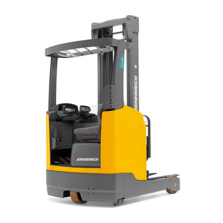
|
Display error code |
Cause |
Action |
|
1901 |
During system start-up, the accelerator pedal zero position could not |
Do not press the accelerator pedal during system start-up. |
|
1904 |
Accelerator pedal pressed, but no travel direction selected. |
Take your foot off the accelerator pedal, select a travel direction and set off. |
|
1909 |
Accelerator pedal pressed and parking brake not released via parking |
Release the parking brake by pressing the parking brake button. |
|
1917 |
Accelerator and brake pedals pressed simultaneously. |
Press one pedal at a time only. |
|
2951 |
Lift function activated on multi-/ solo PILOT during system start- up. |
Do not apply the multi-/ solo PILOT during system start- up. – – – |
|
1952 |
Travel direction switch pressed during system start-up. |
Do not press the travel direction switch during system start-up |
|
9961 |
ISM (option) has detected a shock event in the vertical |
Obtain acknowledgement from authorized person (warehouse manager) and |
|
9962 |
ISM (option) has detected a shock event in the horizontal |
Obtain acknowledgement from authorized person (warehouse manager) and |
|
5990 |
The electrolyte level sensor check (battery-management option) on the |
Add electrolyte. |
|
5992 |
After switching on the truck, no radio network could be established |
– – – – |
|
5408/ 5409 |
Lithium-ion battery overtemperature |
Stop work. |
|
5413 |
Lithium-ion battery low temperature |
Move truck to warm environment. |
For all other warning messages switch the truck off and on again. If the warning message appears again call the service department.
The code lock enables an operator or a group of operators to be assigned an individual user code. The user code is configured with a master code and is outlined in the following sections of this
chapter.
When you have entered the valid user code the truck will be operational. The truck will be able to perform travel, steering and hydraulic operations.
When you have entered the valid master code the truck will be switched on. Travel operations are inhibited. The truck will be able to perform steering and hydraulic operations. The code lock is
in programming mode. When you enter one of the following parameters the settings in the code lock can be changed.
|
Parameters |
Description |
|
0-0-0 |
– To change the master code |
|
0-0-1 |
– To add user codes |
|
0-0-2 |
– To change a user code |
|
0-0-3 |
– To clear a user code |
|
0-0-4 |
– To clear all user codes |
|
0-1-0 |
– To set the automatic cutout of the truck |
Newly supplied trucks have the code indicated on a sticker. When using the truck for the first time change the master and user codes and remove the sticker.
- User code factory setting: 2-5-8-0
- Master code factory setting: 7-2-9-5
German-made Jungheinrich loading equipment is distinguished by excellent durability and
performance. Benefit from consistently high handling speeds with maximum comfort. This European-quality equipment perfectly adapts to various operating conditions, meets strict safety standards,
is distinguished by high working and driving qualities for moving and storing goods for work both in an open area and inside a closed warehouse or a freight railway container.
Jungheinrich LPG trucks, like trucks from other brands of this type, have a number of advantages. This is a universal warehouse
equipment, which is very economical if, when buying it, you correctly calculate the basic requirements for the height of lifting of loads, carrying capacity, speed of movement, weight of the
machine, its dimensions and, of course, the types of cargo with which the machine has to deal. If the calculation is carried out carefully, and the optimal model is chosen, the costs for it,
given the low price of gas, will pay off in a few months. And due to its high ecological class, it can work on a shift all day long with practically different cargoes that require specific
transportation conditions. The peculiarity of gas forklifts is that you can start them in any weather without any problems, which can not be said about diesel or gasoline ones.
Jungheinrich electric forklift EFG 115
The EFG 115 is the most compact electric forklift from the German concern Jungheinrich. It can be used in the smallest rooms,
including wagons and wagons. It has the following technical characteristics:
The distribution of weight to the front axle is 3805/1270.
Carrying capacity — 1500 kg.
Total weight 2870 kg.
Engine:
running — 4 kW;
lifting — 6 kW.
The maximum speed is 12.5 km / h.
Clearance — 100 mm.
The wheelbase is 1200 mm.
The center of gravity of the load on the forks is 500 mm.
Mast tilt (a / b) in degrees — 5/6.
Mast — 2000-3550 mm.
Working corridor width:
across — 3114 mm;
along — 3236 mm.
The total width is 990 mm.
The total length is 2935 mm.
The service brake is hydraulic.
The maximum lifting height is 3000 mm.
The maximum climb is 16 degrees.
Fork dimensions (LxWxH) — 1150x100x35 mm.
Lifting speed with / without load — 240/500 mm / s.
Lowering speed with / without load — 580/600 mm / s.
It is worth noting that it is quite difficult to find a new Jungheinrich EFG 115 loader in the domestic market. However, these
forklifts are quite widely used, and here the price depends on the condition of the machine. In general, the cost can vary from 3,000 to 10,000 euros. The new EFG 115 will cost about 18,500
euros.
Electric forklift Jungheinrich EFG 215
The second series of EFG loaders differs from the first in a large set of technical options. All this could not but affect the cost, which will be
slightly higher than the 115 model. However, first, let’s look at the technical specifications:
The distribution of weight to the front axle is 3870/1310.
Carrying capacity — 1500 kg.
Total weight 2978 kg.
Engine:
running — 4.6 kW;
lifting — 11.5 kW.
Storage battery (voltage V / capacity kW * h) — 48/500.
The maximum speed is 16 km / h.
Clearance — 100 mm.
The wheelbase is 1249 mm.
The center of gravity of the load on the forks is 500 mm.
Mast tilt (a / b) in degrees — 7/7.
Mast — 2000-3560 mm.
Working corridor width:
across — 3104 mm;
Along — 3226 mm.
The total width is 1060 mm.
The total length is 2924 mm.
The service brake is electromechanical.
The maximum lifting height is 3000 mm.
The maximum climb is 35 degrees.
Turning radius — 1440 mm.
Fork dimensions (LxWxH) — 1150x100x35 mm.
Lifting speed with / without load — 460/600 mm / s.
Lowering speed with / without load — 550/550 mm / s.
As you can see from the technical characteristics, this car has almost the same dimensions as the previous model, but with more powerful motors and
improved other indicators.
 Loading…

|
õUNGHEINRICH |
System Messages |
08.06 |
1 |
G |
|||||||
|
Error |
Description |
Component |
Display text |
Cause / Action |
Effect |
||||||
|
1 |
Low voltage during |
F, H, L, |
Low voltage |
Check battery voltage, chargebattery; |
Travel is inhibited. |
||||||
|
system start |
F-AC, H-AC |
Checkwireconnectiontocontroller; |
|||||||||
|
ELECTRICAL SYSTEM |
check main current fuse; check main |
Reduced power for |
|||||||||
|
contactor; replace control part; |
travel and lifting. |
||||||||||
|
Replacecomponent; |
Warning symbol |
||||||||||
|
(Limit VN = 80V: VBatt < 64V or |
flashing (Else-Check). |
||||||||||
|
VCap. < 56V |
|||||||||||
|
Limit VN = 48V: VBatt < 34V or |
|||||||||||
|
VCap. < 34V |
|||||||||||
|
Limit VN = 24V: VBatt <17V) |
|||||||||||
|
2 |
Overvoltage |
F, H, L, |
Overvoltage |
Check battery voltage; replace |
No travel or hydraulic functions |
||||||
|
F-AC, H-AC |
BATTERY |
controllerpart; replace component; |
Warning symbol |
||||||||
|
CONTROLLER |
(Limit VN = 80V: VBatt > 92 V |
flashing (Else-Check). |
|||||||||
|
Limit VN = 48V: VBatt > 62 V |
|||||||||||
|
Limit VN = 24V: VBatt > 28 V) |
|||||||||||
|
3 |
Temperature limit for |
F, H, L, |
TEMPERATURE |
Check sensor and wire connections |
Reduced power for |
||||||
|
controllers |
F-AC, H-AC |
CONTROLLER |
Allow controllers to cool down; check |
travel and lifting. |
|||||||
|
> 80°C (>70°C MP1510C) |
fan operation, improve cooling. |
Warning symbol |
|||||||||
|
or |
Warm up the controller and operate at |
flashing (Else-Check). |
|||||||||
|
ACS only: |
reduced level until the controller has |
||||||||||
|
Info at > 85°C |
warmed up. |
||||||||||
|
Err at > 115°C |
|||||||||||
|
Err at < -20°C |
|||||||||||
|
4 |
Emergency Disconnect |
F |
POWER SUPPLY |
Warning |
Brake applies, travel inhibited |
||||||
|
applied during travel |
(V < 20V MP1510C) |
|
õUNGHEINRICH |
System Messages |
08.06 |
2 |
G |
|||||||
|
Error |
Description |
Component |
Display text |
Cause / Action |
Effect |
||||||
|
5 |
Overvoltage |
F, F-AC, H-AC |
ELECTRICAL SYSTEM |
Check wire connection to battery, |
Brake applies, travel inhibited |
||||||
|
checkBattery, replacecontroller part; |
|||||||||||
|
Replace component; |
|||||||||||
|
(Limit for Retrak: VBatt > 62 V |
|||||||||||
|
Limit for MP1510C: V > 32 V) |
|||||||||||
|
6 |
Wire breakage: |
C, I2, I3, I4, I5, |
TRAVEL SWITCH |
Check wire connection; |
Travel stop. “Warning” symbol flashes |
||||||
|
— Travel setpoint device |
Travel switch |
Replace travel setpoint device; |
(Else-Check). Hydraulic functions |
||||||||
|
Replace Canion/ Interface; |
possible |
||||||||||
|
7 |
Key switch applied |
F,F-AC,H-AC |
KEY SWITCH |
Warning |
Brake applies, travel inhibited |
||||||
|
duringtravel |
(V < 13V for 200ms MP1510C) |
||||||||||
|
8 |
2 travel directions applied |
F-AC, H-AC, C, |
ELECTRICAL SYSTEM |
Warning, replace travel direction |
Travel stop. “Warning” symbol |
||||||
|
simultaneously |
MP, S, I2, I3, I5, |
switch, replace Interface 7 Canion; |
flashing (Else-Check). |
||||||||
|
FS |
replace Multipilot / Solopilot |
Hydraulic functions possible |
|||||||||
|
For twin pedal, check the electrical |
|||||||||||
|
system. |
|||||||||||
|
9 |
Operator protection switch |
I2, FS |
ELECTRICAL SYSTEM |
Check switch, check wire connections |
|||||||
|
faulty |
|||||||||||
|
10 |
V Cap. <> V Batt; (main |
F, H, |
MAIN CONTACTOR |
Check main contactor, check wire |
No travel, hydraulics |
||||||
|
contactor jammed or not |
F-AC, H-AC |
connection; check output pin 2 (ACS) of |
Warning symbol |
||||||||
|
open) |
L |
traction controller; replace component |
Flashing warning (Else-Check). |
||||||||
|
11 |
Offset error armature / |
F, H, L, |
CONTROLLER |
Check main current wire, replace |
Travel no function |
||||||
|
field current (DC) |
F-AC, H-AC |
component |
|||||||||
|
Stator current (AC); |
|||||||||||
|
Current measurement |
|||||||||||
|
point |
|||||||||||
|
12 |
Disable driver field |
F, H |
CONTROLLER |
Replace component; |
No travel, hydraulics |
||||||
|
rheostat faulty for DC |
F-AC, H-AC |
for AC: Check flat belt wire connection; |
Warning symbol |
||||||||
|
Disable driver power |
L |
replace power part |
Flashing warning (Else-Check). |
||||||||
|
stage faulty (forAC) |
|||||||||||

|
õUNGHEINRICH |
System Messages |
08.06 |
3 |
G |
|||||||
|
Error |
Description |
Component |
Display text |
Cause / Action |
Effect |
||||||
|
13 |
Disable Watchdog field |
F, H |
CONTROLLER |
Replace components |
Travel no function |
||||||
|
faulty |
|||||||||||
|
14 |
— Main contactor notclosed |
F, H, |
CONTROLLER/ |
Check wire connection; check main |
No travel, hydraulics |
||||||
|
— Field power stage cannot |
F-AC, H-AC |
MAIN CONTACTOR |
contactor; check charging connection, |
Warning symbol |
|||||||
|
be switched on (DC) |
Check field supply fuse, |
Flashing warning (Else-Check). |
|||||||||
|
Replace component. |
|||||||||||
|
15 |
Disable field faulty; |
F, H, |
CONTROLLER |
Replace controlpart; replace |
Travel no function |
||||||
|
Illegal address (for AC) |
F-AC, H-AC |
component |
|||||||||
|
L |
|||||||||||
|
16 |
Disable driver armature |
F, H, |
CONTROLLER |
Replace controlpart (AC); replace |
Travel no function |
||||||
|
actuator faulty; |
F-AC, H-AC |
component |
|||||||||
|
Software reset (for AC) |
|||||||||||
|
17 |
Disable Watchdog |
F, H |
CONTROLLER |
Replace components |
Travel no function |
||||||
|
armature faulty |
|||||||||||
|
18 |
DC: Armature power |
F, H, F-AC, H-AC |
CONTROLLER |
Check armature wire connection; |
Travel no function |
||||||
|
stage cannot be switched |
L |
replace power part; replace component |
|||||||||
|
on |
|||||||||||
|
AC: one of the 3 phases |
|||||||||||
|
cannot be switched on |
|
õUNGHEINRICH |
System Messages |
08.06 |
4 |
G |
||||||
|
Error |
Description |
Component |
Display text |
Cause / Action |
Effect |
|||||
|
19 |
Disable armature faulty; |
F, H, F-AC ,H- |
CONTROLLER |
Replace power part; Replace |
Travel no function |
|||||
|
Power stage short circuit |
AC, |
component. |
||||||||
|
(for AC) |
L-AC |
Can occur in connection with error 70, |
||||||||
|
The error may be |
in this case: |
|||||||||
|
triggered by the faulty |
check power supply behind the main |
|||||||||
|
speed sensor in |
contactor contact, in the event of an |
|||||||||
|
connection with |
error the voltage will be much lower |
|||||||||
|
AS4814Plus controllers. |
here than the rated operating voltage. |
|||||||||
|
Sensor wheel wobbles |
Disconnect the positive supply from the |
|||||||||
|
(elliptical) or the sensor- |
components to target the error cause. |
|||||||||
|
sensor wheel gap is too |
The exception here is the F1 traction |
|||||||||
|
big. In this case the |
controller which must remain |
|||||||||
|
component is not faulty. |
connected. One component overloads |
|||||||||
|
A short circuit cannot be |
the testing voltage due to internal short |
|||||||||
|
resolved by switching the |
circuit. |
|||||||||
|
truck off/on. |
The testing voltage arises by charging |
|||||||||
|
the internal capacitor batteries via a |
||||||||||
|
resistor to the level of the control |
||||||||||
|
voltage supply. |
||||||||||
|
Check sensor, replace sensor and / or |
||||||||||
|
sensor wheel. |
||||||||||
|
20 |
Armature incorrectly |
F, H |
ELECTRICAL SYSTEM |
Check armature main current wire |
Travel no function |
|||||
|
connected |
connection |
|||||||||
|
21 |
Armature overvoltage |
F, H, F-AC, H-AC |
CONTROLLER/ |
Check main current wire to armature; |
||||||
|
(short circuit / high side |
L |
ELECTR |
check settings(for AC); |
|||||||
|
faulty) |
AArmature > 360A for 250ms (MP1510); |
|||||||||
|
Replace component. |
||||||||||

|
õUNGHEINRICH |
System Messages |
08.06 |
5 |
G |
|||||||
|
Error |
Description |
Component |
Display text |
Cause / Action |
Effect |
||||||
|
22 |
Watchdog error; |
F, H, L, M, S, A, |
CONTROLLER/ |
Truck reset, |
No travel, hydraulics |
||||||
|
Watchdog does not run |
I2, I3, I4, C, |
CANION |
Replace controlpart; replace |
Warning symbol |
|||||||
|
out |
F-AC, H-AC, FS |
component |
Flashing warning (Else-Check). |
||||||||
|
23 |
— Computer overload |
F, H, L, M, S, A, |
CONTROLLER / CAN |
Check CAN bus connection; |
No travel, hydraulics |
||||||
|
— Permanent interrupt |
I2, I3, I4, C, |
Check CANION connector and |
Warning symbol |
||||||||
|
— “ACS” timeout on |
F-AC, H-AC, FS |
component; |
Flashing warning (Else-Check). |
||||||||
|
CAN connection |
Replace component |
||||||||||
|
24 |
EEPROM cannot be |
F, H, L, I2, I3, I4, |
CONTROLLER/ |
Check battery cable; check VBatt; set |
Flashing warning symbol (Else- |
||||||
|
contacted / parameters |
C, |
CANION |
trucktype, set default parameters; |
Check). |
|||||||
|
not plausible / parameter |
F-AC, H-AC |
replace control part; replace |
|||||||||
|
set to default |
MFC brake |
component |
|||||||||
|
Faulty checksum |
MFC hydr. , travel |
Delete logbook, change parameters, |
|||||||||
|
switch |
set hourmeter, replace component |
||||||||||
|
25 |
No telegrams: |
F, H, I4, I8 |
INTERFACE / CAN |
Check CANBus connection, check wire |
|||||||
|
— no logon from |
F-AC, H-AC |
connection between proportional valve |
|||||||||
|
interface |
L |
– modulation; check fuse 1F8; replace |
|||||||||
|
iInterface (I2, I4, I8) ; replace lift |
|||||||||||
|
potentiometer, Multipilot, Solopilot or |
|||||||||||
|
interface; |
|||||||||||
|
MP1510C: Voltage collapses, controller |
|||||||||||
|
logs on again, interface does not, |
|||||||||||
|
controller remains blocked and waits for |
|||||||||||
|
interface. |
|||||||||||
|
Check battery voltage (with load!); |
|||||||||||
|
charge or replace battery if necessary; |
|||||||||||
|
— no telegrams from |
AS2409K: no “live” telegram received |
||||||||||
|
from CAN Bus travel switch for more |
|||||||||||
|
Can-Bus travel switch |
than 300 ms; replace travel switch |
|
õUNGHEINRICH |
System Messages |
08.06 |
6 |
G |
|||||||
|
Error |
Description |
Component |
Display text |
Cause / Action |
Effect |
||||||
|
26 |
Wire breakage: |
M, S, I2, I3 |
MULTIPILOT / |
Check wire connection |
Lift stop. “Warning” symbol flashes |
||||||
|
— Lift potentiometer |
SOLOPILOT / LIFT |
(Else-Check), travel enabled |
|||||||||
|
POTENTIOMETER |
|||||||||||
|
27 |
Wire breakage: |
C, L, I3, I4 |
STEER ACTUAL |
Check wire connection; |
Crawl speed, |
||||||
|
— Steering setpoint device; |
ANGLE |
Replace steer angle sensor / |
Flashing warning symbol (Else- |
||||||||
|
◊ Reach truck: for 45° |
potentiometer; |
Check), hydraulic functions enabled. |
|||||||||
|
steering bolster movement |
Replace Canion / Interface; |
This error produces an emergency |
|||||||||
|
no flank from proximity |
Replace steering; |
stop on the reach truck and the |
|||||||||
|
switch. |
PM2402L from software version 1.60: |
Juniors. |
|||||||||
|
◊ Canion: “Steer angle |
|||||||||||
|
acquire active” parameter |
set parameter P511 “operating mode” |
||||||||||
|
has incorrect value |
correctly ◊ 1 = analog sensor |
||||||||||
|
◊ Juniors PM2402L: |
(potentiometer), |
||||||||||
|
“Operating mode” |
2 = digital sensor on steer motor |
||||||||||
|
parameter incorrectly set |
|||||||||||
|
28 |
Wire breakage: |
C, L, I3, I4 |
STEER NOMINAL |
Check wire connection, replace |
Crawl speed, |
||||||
|
— Steering sensor |
ANGLE |
steering wheel sensor;replace Canion / |
Flashing warning symbol (Else- |
||||||||
|
interface; replace steering |
Check), hydraulic functions enabled. |
||||||||||
|
This error produces an emergency |
|||||||||||
|
stop on the reach |
truck |
||||||||||
|
29 |
Wire breakage: |
M |
Traverse nominal value |
Replace Multipilot |
|||||||
|
— Traverse potentiometer |
MULTIPILOT |
||||||||||
|
30 |
Wire breakage: |
M |
Tilt nominal value |
Replace Multipilot, |
|||||||
|
— Tilt potentiometer |
MULTIPILOT |
Teach Multipilot (Hall sensor 2003 only) |
|||||||||
|
31 |
Wire breakage: |
M, S |
Sideshift nominal value |
Replace Multipilot / Solopilot, |
Hydraulic functions stop, “Warning” |
||||||
|
— ZH1 setpoint device |
MULTIPILOT / |
Teach Multipilot (Hall sensor 2003 |
symbol flashes (Else-Check), travel |
||||||||
|
SOLOPILOT |
only); |
enabled |
|||||||||
|
— Initial lift / lower |
Travel switch |
Travel switch: Check / replace switch |
|||||||||
|
Setpoint device |
|||||||||||

|
õUNGHEINRICH |
System Messages |
08.06 |
7 |
G |
|||||||
|
Error |
Description |
Component |
Display text |
Cause / Action |
Effect |
||||||
|
32 |
Wire breakage: |
M, S |
MULTIPILOT / |
Replace Multipilot / Solopilot, |
Hydraulic functions stop, “Warning” |
||||||
|
— ZH2 setpoint device |
SOLOPILOT |
Teach Multipilot (Hall sensor 2003 only) |
symbol flashes (Else-Check), travel |
||||||||
|
enabled |
|||||||||||
|
33 |
Wire breakage: |
M, I8 |
MULTIPILOT |
Replace Multipilot |
|||||||
|
— ZH3 setpoint device |
|||||||||||
|
34 |
CANBus damaged |
F, H, L, M, S, A, |
CAN-BUS |
Check CAN bus connection; |
No travel, hydraulics |
||||||
|
I2, I3, I4, I5, C, F- |
replace faulty component; |
Warning symbol |
|||||||||
|
AC, H-AC |
Check terminal resistances |
Flashing warning (Else-Check). Only |
|||||||||
|
Travel switch |
stored in logbook (from 2004). |
||||||||||
|
35 |
No travel zero position |
I2, I3, I4, C |
TRAVEL ZERO |
Warning, check travel switch; |
Travel stop, |
||||||
|
Deadman and accelerator |
Travel switch |
POSITION |
Intermittent contact in interface power |
Flashing warning symbol (Else- |
|||||||
|
pedal applied when truck |
supply (12 volts) |
Check), hydraulic functions enabled. |
|||||||||
|
switched on |
Check Canion, for twin pedal check |
||||||||||
|
electrical system |
|||||||||||
|
36 |
No lift zero position |
M, I2, I3,FS |
LIFT ZERO POSITION |
Warning, check lift setpoint device. |
Hydraulic functions stop, “Warning” |
||||||
|
symbol flashes (Else-Check), travel |
|||||||||||
|
enabled |
|||||||||||
|
37 |
No steering angle nominal |
L |
CONTROLLER / CAN |
Check steering setpoint device;Check |
|||||||
|
value |
CANBus connection; check “steer type” |
||||||||||
|
parameter; Replace component (I5) |
|||||||||||
|
38 |
Component does not log |
F, H, L, I2, I3, I4, |
CONTROLLER / CAN |
Check CAN-Bus connection and |
No travel, lifting |
||||||
|
on, self test not |
C, A, M, S, F-AC, |
voltage; check DIL switch 7 encoding |
Warning symbol |
||||||||
|
concluded. |
H-AC |
(MP1510); steering controller |
Flashing warning (Else-Check). |
||||||||
|
monitoring activated? (AS2412F); |
|||||||||||
|
check ACS encoding; replace |
|||||||||||
|
component |

|
õUNGHEINRICH |
System Messages |
08.06 |
8 |
G |
||||||
|
Error |
Description |
Component |
Display text |
Cause / Action |
Effect |
|||||
|
39 |
Implausible truck type |
F, H, L, I2, I3, I4, |
TRUCK TYPE |
For 1. Set truck type; |
||||||
|
1. Discovered during the |
I5, A, M, |
For 2. Examine and if necessary |
||||||||
|
self test phase that at |
F-AC, H-AC |
replace switch (key switch) or rectify |
||||||||
|
least one component |
intermittent contact in power supply |
|||||||||
|
has a different truck |
plug connections. |
|||||||||
|
type as a parameter. |
Set truck type. |
|||||||||
|
A different truck type was |
||||||||||
|
discovered in operating |
||||||||||
|
mode. Caused by |
||||||||||
|
intermittent contacts in the |
||||||||||
|
power supply connections |
||||||||||
|
40 |
Motor overtemperature |
L, F, H |
TEMPERATURE |
Warning; check motor sensor system |
Reduced power for |
|||||
|
Traction motor |
F-AC, H-AC |
MOTOR |
and wire connections; |
travel and lifting. |
||||||
|
overtemperature in |
Check motor; traction motor brake |
Warning symbol |
||||||||
|
operating mode.> 150°C |
open? |
flashing (Else-Check). For steering |
||||||||
|
And travel speed < 1km/h |
only |
|||||||||
|
For ACS: |
warning symbol flashing. |
|||||||||
|
Info > 145°C |
||||||||||
|
Err > 165°C |
||||||||||
|
41 |
Brake magnet |
L |
BRAKE |
Check potentiometer; check |
||||||
|
potentiometer |
MAGNETPOTENTIOM |
potentiometer attachment; check wire |
||||||||
|
Potentiometer voltage less |
ETER |
connection |
||||||||
|
than 0.3 volts or greater |
||||||||||
|
than 2.7 volts for more |
||||||||||
|
than 500ms. |

|
õUNGHEINRICH |
System Messages |
08.06 |
9 |
G |
|||||
|
Error |
Description |
Component |
Display text |
Cause / Action |
Effect |
||||
|
42 |
— Short circuit between |
L,F |
BRAKE MAGNET |
Check wire connection, check brake |
|||||
|
the output and battery |
magnet; replace component |
||||||||
|
positive.(EJC, ELE) |
|||||||||
|
-Brake magnet control, |
|||||||||
|
below minimum difference |
|||||||||
|
on potentiometer for 500 |
|||||||||
|
ms when magnet applied. |
|||||||||
|
(150mV ) |
|||||||||
|
No brake pressure during |
|||||||||
|
initialization. |
|||||||||
|
Brake pressure after the |
|||||||||
|
Emergency Stop magnet |
|||||||||
|
has applied; |
|||||||||
|
43 |
Adjust brake |
L |
ADJUST BRAKE |
Adjust brake; check potentiometer |
|||||
|
44 |
—Brake not connected or |
L,F |
BRAKE FAULTY |
-Check brake wiring, replace brake if |
No release |
||||
|
connection wire short |
necessary |
||||||||
|
circuit |
-Replace brake cable, check |
||||||||
|
potentiometer; Check potentiometer |
|||||||||
|
-Brake cable torn |
attachment; |
||||||||
|
Only for steer category_3: |
Only for steer category_3: |
||||||||
|
Internal driver of failsafe |
|||||||||
|
brake cannot connect the |
-Check brake driver output, check |
||||||||
|
relay |
switch contact plausibility, |
||||||||
|
Or short circuit bypass |
Replace steer component. |
||||||||
|
(contact jams) on the |
|||||||||
|
output during power up |
|||||||||
|
test |
![]()
Jungheinrich System Error Codes list.pdf
Adobe Acrobat Document
168.2 KB
![]()
Jungheinrich Fault Codes.pdf
Adobe Acrobat Document
720.8 KB
![]()
Jungheinrich Error Codes List PDF.pdf
Adobe Acrobat Document
191.8 KB
![]()
Jungheinrich EJC112 & E1202 Event Messag
Adobe Acrobat Document
582.8 KB
Event Messages
Z This display units shows a four-digit event message for every
event. Trucks that only use one luminous display (e.g. LED) show
the event through a flashing code (see «Display System”).
Each event message is also stored in the master logbook. The
master logbook describes the event in more detail through the sub
index behind the event message (FEXX).
Event numbering display
F E XX S
F Function group; E Event group
XX Event number S Sub index
The first two characters “F, E” refer to the category. The middle
two digits “XX” refer to the event. From these two digits the range:
• 1 to 50 describes standard events (uniform basic events)
which can occur in any function group.
• 51 to 99 describes specific events.
The event is described in further detail through the last characters
“S” (single digit / multi-digit).
This process ensures that a unique number is assigned to each
event. Example:
0 Fault reset or
no fault
1 General fault / additional functions
Example:
Logic error, e.g. both directions selected simultaneously
2 Current
(input interface, device-internal, output interface)
3 Voltage
(input interface, device-internal, output interface)
4 Temperature
5 Hardware
Example: Output transformer short circuit, EEPROM not
responding, …
6 Software
(internal software, application software, data record /
parameters)
Example: EEPROM data error
7 Additional modules
8 CAN monitoring
9 External fault
Example: ISM
German-made Jungheinrich loading equipment is distinguished by excellent durability and
performance. Benefit from consistently high handling speeds with maximum comfort. This European-quality equipment perfectly adapts to various operating conditions, meets strict safety standards,
is distinguished by high working and driving qualities for moving and storing goods for work both in an open area and inside a closed warehouse or a freight railway container.
Jungheinrich LPG trucks, like trucks from other brands of this type, have a number of advantages. This is a universal warehouse
equipment, which is very economical if, when buying it, you correctly calculate the basic requirements for the height of lifting of loads, carrying capacity, speed of movement, weight of the
machine, its dimensions and, of course, the types of cargo with which the machine has to deal. If the calculation is carried out carefully, and the optimal model is chosen, the costs for it,
given the low price of gas, will pay off in a few months. And due to its high ecological class, it can work on a shift all day long with practically different cargoes that require specific
transportation conditions. The peculiarity of gas forklifts is that you can start them in any weather without any problems, which can not be said about diesel or gasoline ones.
Jungheinrich electric forklift EFG 115
The EFG 115 is the most compact electric forklift from the German concern Jungheinrich. It can be used in the smallest rooms,
including wagons and wagons. It has the following technical characteristics:
The distribution of weight to the front axle is 3805/1270.
Carrying capacity — 1500 kg.
Total weight 2870 kg.
Engine:
running — 4 kW;
lifting — 6 kW.
The maximum speed is 12.5 km / h.
Clearance — 100 mm.
The wheelbase is 1200 mm.
The center of gravity of the load on the forks is 500 mm.
Mast tilt (a / b) in degrees — 5/6.
Mast — 2000-3550 mm.
Working corridor width:
across — 3114 mm;
along — 3236 mm.
The total width is 990 mm.
The total length is 2935 mm.
The service brake is hydraulic.
The maximum lifting height is 3000 mm.
The maximum climb is 16 degrees.
Fork dimensions (LxWxH) — 1150x100x35 mm.
Lifting speed with / without load — 240/500 mm / s.
Lowering speed with / without load — 580/600 mm / s.
It is worth noting that it is quite difficult to find a new Jungheinrich EFG 115 loader in the domestic market. However, these
forklifts are quite widely used, and here the price depends on the condition of the machine. In general, the cost can vary from 3,000 to 10,000 euros. The new EFG 115 will cost about 18,500
euros.
Electric forklift Jungheinrich EFG 215
The second series of EFG loaders differs from the first in a large set of technical options. All this could not but affect the cost, which will be
slightly higher than the 115 model. However, first, let’s look at the technical specifications:
The distribution of weight to the front axle is 3870/1310.
Carrying capacity — 1500 kg.
Total weight 2978 kg.
Engine:
running — 4.6 kW;
lifting — 11.5 kW.
Storage battery (voltage V / capacity kW * h) — 48/500.
The maximum speed is 16 km / h.
Clearance — 100 mm.
The wheelbase is 1249 mm.
The center of gravity of the load on the forks is 500 mm.
Mast tilt (a / b) in degrees — 7/7.
Mast — 2000-3560 mm.
Working corridor width:
across — 3104 mm;
Along — 3226 mm.
The total width is 1060 mm.
The total length is 2924 mm.
The service brake is electromechanical.
The maximum lifting height is 3000 mm.
The maximum climb is 35 degrees.
Turning radius — 1440 mm.
Fork dimensions (LxWxH) — 1150x100x35 mm.
Lifting speed with / without load — 460/600 mm / s.
Lowering speed with / without load — 550/550 mm / s.
As you can see from the technical characteristics, this car has almost the same dimensions as the previous model, but with more powerful motors and
improved other indicators.
Password: https://www.pdfmanual4trucks.com/
|
Title |
File Size |
Download Links |
|
Jungheinrich EJC112 / E1202 Event Messages Codes List PDF |
619.4kb |
Download |
|
Jungheinrich Error Codes List PDF [PDF] |
199kb |
Download |
|
Jungheinrich Fault Codes [PDF] |
769kb |
Download |
|
Jungheinrich LISTADO ERRORES [PDF] |
199kb |
Download |
|
Jungheinrich System Error Codes list [PDF] |
162.7kb |
Download |
|
Display error code |
Cause |
Action |
|
1901 |
During system start-up, the accelerator pedal zero position could not |
Do not press the accelerator pedal during system start-up. |
|
1904 |
Accelerator pedal pressed, but no travel direction selected. |
Take your foot off the accelerator pedal, select a travel direction and set off. |
|
1909 |
Accelerator pedal pressed and parking brake not released via parking |
Release the parking brake by pressing the parking brake button. |
|
1917 |
Accelerator and brake pedals pressed simultaneously. |
Press one pedal at a time only. |
|
2951 |
Lift function activated on multi-/ solo PILOT during system start- up. |
Do not apply the multi-/ solo PILOT during system start- up.
–
–
– |
|
1952 |
Travel direction switch pressed during system start-up. |
Do not press the travel direction switch during system start-up |
|
9961 |
ISM (option) has detected a shock event in the vertical |
Obtain acknowledgement from authorized person (warehouse manager) and |
|
9962 |
ISM (option) has detected a shock event in the horizontal |
Obtain acknowledgement from authorized person (warehouse manager) and |
|
5990 |
The electrolyte level sensor check (battery-management option) on the |
Add electrolyte. |
|
5992 |
After switching on the truck, no radio network could be established |
–
–
–
– |
|
5408/ 5409 |
Lithium-ion battery overtemperature |
Stop work. |
|
5413 |
Lithium-ion battery low temperature |
Move truck to warm environment. |
For all other warning messages switch the truck off and on again. If the warning message appears again call the service department.
The code lock enables an operator or a group of operators to be assigned an individual user code. The user code is configured with a master code and is outlined in the following sections of this
chapter.
When you have entered the valid user code the truck will be operational. The truck will be able to perform travel, steering and hydraulic operations.
When you have entered the valid master code the truck will be switched on. Travel operations are inhibited. The truck will be able to perform steering and hydraulic operations. The code lock is
in programming mode. When you enter one of the following parameters the settings in the code lock can be changed.
|
Parameters |
Description |
|
0-0-0 |
– To change the master code |
|
0-0-1 |
– To add user codes |
|
0-0-2 |
– To change a user code |
|
0-0-3 |
– To clear a user code |
|
0-0-4 |
– To clear all user codes |
|
0-1-0 |
– To set the automatic cutout of the truck |
Newly supplied trucks have the code indicated on a sticker. When using the truck for the first time change the master and user codes and remove the sticker.
- User code factory setting: 2-5-8-0
- Master code factory setting: 7-2-9-5

Codes Displayed by the MicroBasic Controller
REASON FOR LIFT NOT STARTING (A) COMPONENT A01 Safety circuit fuse (FM) blown A02 Safety circuit open A03 Motor therms or machine room temperature device tripped A04 110% load A05 Attendant control active A06 Door contact open — manual doors A07 Door open push (PAP) or door sensitivity (SEN) or photocell (CEL) open A08 Car door contact and landing lock circuit open A09 Car or hall call for floor where car is positioned (keeping doors open)
LIST OF CONDITIONS (E)
CONDITION — (DIGIT NOT FLASHING) CONDITION — (DIGIT NOT FLASHING) E01 100% overload (active) E15 Firemans switch [car] (active) E02 Attendant control (active) E16 Levelling down direction E03 car door & landing locks (closed) E17 Firemans switch [landing] (active) E04 Safety zone, levelling (active) E18 High speed relay (active) E05 Safety cct prior to locks (active) E19 Relay (CB) or (CL) (active) E06 Not in use E20 Safety circuit fuse [FM] (closed) E07 Level circuit (closed) E21 Pin f-P2 active, arrival gong trig E08 Not in use E22 Lift resetting E09 Lower prelimit [slow limit] (closed) E23 Temporarily out of service E10 Upper prelimit [slow limit](closed) E24 Permanently out of service E11 Inspection control (active) E25 Lift in travel E12 Manual Doors — series cct (closed) E26 Lift in slow speed E13 Door open cct PAP SEL SEN (closed) E27 End of service E14 STOP cct [sill switch] (open)
ERRORS (F) REASON REASON F01 Running timer tripped F12 PAP SEL SEN circuit open too long F02 Safety circuit open F13 Car between floors prelimits open F03 Final limit opened and re-closed F14 Both prelimits open F04 Stuck contactor circuit tripped F15 Up prelimit opens in down travel F05 Repeat fault — door interlock circuit F16 Down prelimit opens in up travel F06 Series of open doors in operation F17 Parameters incorrect (new input) F07 Series of open interlocks during
service F18 Inverter drive fault (traction lifts)
F08 Misregulation of pulses F19 Button of operating panel stuck F09 Control fuse (FM) or supply open F26 Lift level CPS circuit open F10 MicroBasic PCB fault F27 CPS not changing going into floor F11 Door circuit open too long

Technical Dossier
PROVISIONAL AND PARTIAL
V0.2, MAR.04
English / 3VFMAC-DSP_UK
Installation • Assembly• Star-Up Use • Maintenance • Repair
3VFMAC-DSP Frequency Converter

PRODUCT TECHNICAL MANUAL
3VFMAC-DSP FREQUENCY CONVERTER
V0.2 MAR.04 Page 1 3VFMAC-DSP_UK
Provisional
VERY IMPORTANT: This document is provisional and includes
partial information only, which is complemented by the 3VFMAC1
v3.00 frequency changer manual. For any doubts that may arise
during the operating of the frequency changer, please consult MP
Lifts.
CONTENTS
1. COMPATIBILITY BETWEEN F SERIES AND DSP VERSIONS………………………………………………………………… 2
2. GENERAL FEATURES……………………………………………………………………………………………………………….. 3
2.1. New features………………………………………………………………………………………………………………. 3
2.2. Technological improvements …………………………………………………………………………………………… 3
2.3. Improvements in comfort……………………………………………………………………………………………….. 3
3. UNIVERSAL CONNECTION………………………………………………………………………………………………………… 4
4. GENERAL DIAGRAMS………………………………………………………………………………………………………………. 6
4.1. MicroBASIC controller……………………………………………………………………………………………………. 6
4.2. SERIE controller…………………………………………………………………………………………………………… 7
5. INFORMATION SUPPLIED BY THE BOARD……………………………………………………………………………………… 8
5.1. Led indicator lights……………………………………………………………………………………………………….. 9
5.2. Five-digit display (console)……………………………………………………………………………………………… 9
6. USER INTERFACE…………………………………………………………………………………………………………………..11
6.1. Parameterisation………………………………………………………………………………………………………….12
6.2. Visualising the information through display (monitoring)…………………………………………………………13
6.3. PALM control ………………………………………………………………………………………………………………14
7. LIST OF PARAMETERS …………………………………………………………………………………………………………….14
8. DESCRIPTION OF ERRORS ……………………………………………………………………………………………………….20
9. ADJUSTMENT AND FINE-TUNING OF THE INSTALLATION ………………………………………………………………….22
9.1. Preliminary aspects ………………………………………………………………………………………………………22
9.2. General adjustments …………………………………………………………………………………………………….23
9.3. Levelling adjustment …………………………………………………………………………………………………….24
9.4. Vibrations ………………………………………………………………………………………………………………….25

PRODUCT TECHNICAL MANUAL
3VFMAC-DSP FREQUENCY CONVERTER
V0.2 MAR.04 Page 2 3VFMAC-DSP_UK
Provisional
1. COMPATIBILITY BETWEEN F SERIES AND DSP VERSIONS
The new DSP frequency changer is fully compatible with the old F series version, to such an extent that if it is
necessary to replace the latter with the new DSP version, neither the wiring nor the original fastenings of the controller
need be changed. It is only necessary to reduce the number of poles of the plug-in terminal that is connected in the
bottom-left corner of the frequency changer (XC4), which should be reduced from 8 to 6 poles, eliminating the two
upper end terminals which are never wired (in F series controllers). The instructions to make this change are described
in detail below.
INSTRUCTIONS TO CONNECT THE XC4 PACKAGE:
1. Photo 1 shows the connector with terminals 30 and 31 which overhang from the XC4 package of the
frequency changer.
2. Photo 2 shows where this connector must be separated (terminals 30 and 31 which are never wired) and the
removal of its end cover.
3. Photo 3 shows the new connector with two poles less, with the end cover positioned on the side of terminal
32 which was uncovered.
4. Photo 4 shows the final connection in the PCB of the 3VF-DSP.
Photo 1 Photo 2
Photo 4 Photo 3
End cover
Uncovered side

PRODUCT TECHNICAL MANUAL
3VFMAC-DSP FREQUENCY CONVERTER
V0.2 MAR.04 Page 3 3VFMAC-DSP_UK
Provisional
2. GENERAL FEATURES
IMPORTANT: On the date that this document was published, part of the features described below were not yet
operational. These are marked with the symbol (†).
2.1. New features
• Control of the asynchronous and synchronous motor. (†)
• Elimination of roll-back effect in start-up, by means of a weight reading by using MP’s VK2P weighing
system.
• Modelling of the machine by the direct parameterisation of the motor electrical constants (vector control).
(†)
• High connectivity of encoders with a high number of pulses.
• Communication interfaces available: RS-485, ENDAT, SSI, Irda and CAN-BUS, which make it possible to
monitor and control the system remotely. (†)
2.2. Technological improvements
• Latest generation DSP technology (Texas Instruments) with 32-bit Flash
technology and instruction times of up to 6 nanoseconds.
• User-friendly scheduling interface, by using a market PDA terminal (PALM O.S.)
without cables (infrared, Irda) or by using an on-board keyboard.
• Application to gearless motor by operation at very low electrical frequencies
(precision: 0.0078Hz). High precision vector control with Space-Vector
modulation which makes it possible to reduce the heat of the power transistors, allowing higher switching
frequencies.
2.3. Improvements in comfort
• Direct access due to exact positioning, which makes
it possible to remove the landing approach span,
eliminating unnecessary waiting times for users. (†)
• Direct access to landing due to indirect calculation of
car weight, eliminating the need for load-weighing
switches.
• Complete lack of electrical noise of the motor due to
its switching frequency of up to 20 Khz, enabling its
installation in machine room less lifts.
• Quality of ride, thanks to self-adjustment of jerk, which eliminates the unpleasant sensation caused by
acceleration during starting and stopping.
• Precision on stopping, without position encoder. Levelling by time or by position (†).
• Standard performance, independent of the supply voltage, thanks to its system which adapts to the
network voltage.

PRODUCT TECHNICAL MANUAL
3VFMAC-DSP FREQUENCY CONVERTER
V0.2 MAR.04 Page 4 3VFMAC-DSP_UK
Provisional
PCB3VFDSP
B1
B2
323334353637
111213141516171819
1
23
45
XC
2
XC11
XC
4
XC6
111213141516171819
XC6
XC4
XC2
123
45
323334353637
VW U
S
T
R
+CEC1
T1T2
20212223
C2
-CE
+
—
+
—
C1+C1-C2+C2-
20212223
0Vdc24Vdc
K1
KRFR
0Vac
110Vac
48
4950
XC9
XC10
K1
K2
M~3
XC
3X
C5
XC3
W
V
U
RL3
TRIAC
RL1K2
R
(+) 10V(-) 0V
FLC
A1
A2 A2
A1
3. UNIVERSAL CONNECTION
Voltage-free contact control
General power supply
Control signals
Input filter
Machine
Contactors
CAPACITORS (Only in 10HP, 15HP and 20HP. Supplied with capacitor)
Ventilation fan
Brake resistance: 5HP 400V: 60hms, 520W 230V: 20hms, 600W 10HP 400V: 40hms, 1040W 230V: 14hms, 1040W 15HP 400V: 30hms, 1400W 20HP 400V: 30hms, 400W
Multipole encoder 5Vdc
Pulse reading
Low cost encoder
Brake control
Contactor control
*RUN
*Nominal speed
2 speeds
*Inspection speed
2 Accel. / Decel.
*Up / down
Reset Error
* Necessary connections Ground network
Output filter
Communication VS: encoder
Communication CAN control
Communication VS: control
Safety series
Contactor reading filter

PRODUCT TECHNICAL MANUAL
3VFMAC-DSP FREQUENCY CONVERTER
V0.2 MAR.04 Page 5 3VFMAC-DSP_UK
Provisional
It is important to pay special attention to the power cables so that all of these cables (U, V, W, C1, C2, CE+, CE-,
B1, B2) remain above the strip of pins in the way the installation is wired in the following photo.
Strip of pins

PRODUCT TECHNICAL MANUAL
3VFMAC-DSP FREQUENCY CONVERTER
V0.2 MAR.04 Page 6 3VFMAC-DSP_UK
Provisional
COND
FE
RS
T
+ CE- CE
RS
T
UV
WC2
C1
B1B23VF-DSP
TRM110 Vs20 Vs60 Vs48 Vs80 Vs0 Vs
380 Vp
220 Vp
0 Vp
14
15
106 FMRM
T 1
SCC 56
128
102
105
SAF
SCE104
SP
SACSIR
SPRS
SPRB
103STOPF
STOPSTLH
220SLVH
SCTH
SFISFS
L1L2
L3
K1L1L2
L3
QIM21
TT
T
0 Vdc
5
RMT1
A1A1
A2A2
AK1
K2A
RMT227
11 A2 A1
KRNSA
G2R — 2 110 Vac
RMR
RZS
13RVR2324
RMKRSE
9 57
3435KRL 2 3VF-DSP
RB
9
RS
2526
A1A2
KRSEA
MY 4
110 Vac
RZS
17
RMP
RZS
00
RPA
220 Vp48 Vs60 Vp110 Vs
0 Vp
0 VsGRF( + )
( — )
~1~2K2
1314
206 ( SM )
204 ( SM )
( + )
( — )
220 Vp0 Vp
48 Vs60 Vp
0 Vs110 Vs
KRLE
KRLE11
14
2124
GRLLE ( — )
LE ( + )
LE -LE +
K2T1
T2T3
FSU
VW
B2B1
RF
M3 ~
2021
2223
2021
22( + )
( — )( IN1 )
XC33VF-DSP
SM
22 ( MB )
K1K2
KRNS
3 ( MB )
4 ( MB )
6162
6162
1112
12345
C1 +
C1 —
C2 +
C2 —
C2-
C2+
C1+-+ C1-
XC6
SM
3VF-DSP+ 24 Vdc
+ 5 Vdc
1112
1314
1516
ac
RET
2421
KRREV
KRNS1211
MicroBASIC
1718
1936
37
KRL3
KRSE1211
3VF-DSP
19 ( MB )
BYT11 — 1000
KRREVA1A2
208
G2R224 Vdc
KRFR1
3KRFR8
6
L1L2
L3
T3T2
T1
K113
14A
D~1~2
+ 24 Vdc0 Vdc
KRFR2 7M
K2P24 Vdc
BYT11 — 1000
PIN103
B
3VF-DSP
FLC
FLC
4. GENERAL DIAGRAMS
4.1. MicroBASIC controller
Industrial en
coder con
nection
Low cost
Enco
der
connection
Con
tactor read
ing filter

PRODUCT TECHNICAL MANUAL
3VFMAC-DSP FREQUENCY CONVERTER
V0.2 MAR.04 Page 7 3VFMAC-DSP_UK
Provisional COND
FE
RS
T
+ CE- CE
RS
T
UV
WC2
C1
B1B23VF-DSP
TRM110 Vs
20 Vs0 Vs
0 Vs
380 Vp
220 Vp
0 Vp
L1L2
L3
K1L1L2
L3
A1A1
A2A2
K1K2
3435KRL 2
3VF-DSP
220 Vp48 Vs60 Vp110 Vs
0 Vp
0 VsGRF( + )
( — )
~1~2K2
1314
F1 ( SM )
F2 ( SM )
K2T1
T2T3
FSU
VW
B2B1RF
M3 ~
2021
2223
2021
22( + )
( — )( IN1 )
XC33VF-DSP
SM
24G(XSM
1)
K1 K2
KP1(XSM
1)
61 62 61 62
12345
C1 +
C1 —
C2 +
C2 —
C2-
C2+
C1+-+ C1-
XC6
SM
3VF-DSP+ 24 Vdc
+ 5 Vdc
1112
3637
KRL33VF-DSP
KRFR1
3KRFR8
6
L1L2
L3
T3T2
T1
K113
14A
+ 24 Vdc0 Vdc
KRFR2 7M
K2P24 Vdc
BYT11 — 1000
QIM21
1H
8H8C
7C7H
6H6S
5S5H
5H
4C3C
3´C2H
2C
PCB-SM
XC10
XENC
XC11
X3VF
FLC
FLC
STLHSFI
SFSSLVH
SACSTOPC
SIR
SIB
SIS
STOPFSPC
SCE
BS
4.2. SERIE controller
Con
tactor con
trol
In case of exact
positio
nin
g
Industrial en
coder co
nnection
Low cost
encod
er con
nection
Con
tactor read
ing filter

PRODUCT TECHNICAL MANUAL
3VFMAC-DSP FREQUENCY CONVERTER
V0.2 MAR.04 Page 8 3VFMAC-DSP_UK
Provisional
5. INFORMATION SUPPLIED BY THE BOARD
Below we have included a diagram of the PCB which shows the elements that supply visual information. All of this
information is included in the following points.
CONSOLE

PRODUCT TECHNICAL MANUAL
3VFMAC-DSP FREQUENCY CONVERTER
V0.2 MAR.04 Page 9 3VFMAC-DSP_UK
Provisional
5.1. LED indicator lights
BLOCK GENERAL DESCRIPTION LED NO. DESCRIPTION OF LED COLOUR
A High voltage HIGH
VOLTAGE ON: there is a high voltage Red
B Control of contactors 12 ON: contactors active Red
B RUN signal 13 ON: start command Red
B Nominal speed 14 ON: nominal speed command Red
B Second speeds 15 ON: second set of speeds active Red
B Inspection speed 16 OFF: inspection speed Red
B Second
acceleration/deceleration 17 ON: second set of accelerations and decelerations active Red
B Up/down 18 ON: up Red
B Reset error 19 ON: error reset active Red
C CAN communication CAN Not applicable Green
D Emergency EM Not applicable Green
D Speed limit SP ON: above speed limit Green
D Contactors K ON: contactors active Green
D Brake BK ON: brake with power supply Green
E Encoder ENCODER Not applicable Green
E RS-485 communication RS-485 Indicator: there is communication Green
F RUN RUN ON FIJO: RUN command not active
INDICATOR: RUN command active Green
5.2. Five-digit display (console)
See point “6.2. Visualising information through display (monitoring)”
POSITION VISUALISATION GENERAL DESCRIPTION
0 Frec Command Frequency (Hz)
1 Encod Encoder pulses
2 int s Current intensity of U phase (digital units)
3 int r Current intensity of V phase (digital units)
4 Ad in rms output current intensity to motor (Ampere)
5 tens Bus voltage (Volts dc)
6 Uerr Last error
7 int d Measured Magnetisation Current Intensity (Ampere)
8 int u Measured Par Current Intensity (Ampere)
9 UEL Measured speed (electric Hz)
10 rEU Measured speed (r.p.m.)
11 EiUEL Error in Built-in Terminal of speed PI (digital units)
12 EPUEL Error in Proportional Terminal of speed PI (digital units)
13 An Electrical angle
14 Udd Magnetisation component of output voltage vector to motor (digital units)
15 Uud Par component of output voltage vector to motor (digital units)
16 UdE X component of output voltage vector to motor (digital units)

PRODUCT TECHNICAL MANUAL
3VFMAC-DSP FREQUENCY CONVERTER
V0.2 MAR.04 Page 10 3VFMAC-DSP_UK
Provisional
POSITION VISUALISATION GENERAL DESCRIPTION
17 UuE Y component of output voltage vector to motor (digital units)
18 SEno Sine of electrical angle (digital units)
19 CoSE Cosine of electrical angle (digital units)
20 iurEF Par current intensity of reference (digital units)
21 USlip Slip (digital units)
22 UrEF Mechanical reference speed (digital units)
23 Pso Weight (Kg), if load cell available
24 Uer Software version
25 SEriE Equipment serial number
26 HOurS Equipment operating hours
27 E4 Start phase
28 E2 Slip term in vector control (machine constant)
29 E3 Reference mechanical speed in Hz*128
30 E4 Output Iq of the filtered speed PI
31 E5 Electrical frequency
32 E6 Proportional constant of the speed PI
33 E7 Whole constant of the speed PI
34 E8 Weight offset
35 E9 VEL.10 parameter interpretation
36 E10 Maximum torque intensity (digital units)
37 E11 Minimum value of effective intensity in an electrical cycle (digital units)
38 E12 Reference magnetisation intensity
39 E13 Power control set point
40 E14 Electrical frequency offset 1 in stop for torque compensation (Hz*100)
41 E15 Approach speed 1 calculated according to torque compensation (Hz*100)
42 E16 Sine curve time (ms)
43 E17 Machine control variable of torque compensation statuses

PRODUCT TECHNICAL MANUAL
3VFMAC-DSP FREQUENCY CONVERTER
V0.2 MAR.04 Page 11 3VFMAC-DSP_UK
Provisional
6. USER INTERFACE
The user interface is the area where the controller represents the information of its internal state (errors,
functioning modes, etc.) and enables the maintainers to carry out a set of operations related to maintenance
(configuration, metering, etc.)
The interface that the user will find consists of 5 digits which show information and 4 push buttons, as shown in
this diagram.
The access keys are:
P/R: This push button has different functions, described below:
• Back or return to previous menu, provided that the user is already inside a menu.
• Enter Programming Mode. Press button down continuously.
• Recording of Parameters. Once inside a parameter, this button must be pressed to record it and then exit.
Izq ÿ: This push button has different functions, depending on the level reached:
At the menu level, it produces a movement to the left
At the operations level, it reduces the value being operated
At the parameters level it produces a movement to the left between the digits
Drch ÷: This push button has different functions, depending on the level reached:
• At the menu level, it produces a movement to the right
• At the operations level, it increases the value being operated
• At the parameters level it produces a movement to the right between the digits
Intro ü: This push button has various functions:
• At the menu level, to enter inside the menu
• At the operations level, execution of commands
• At the parameters level, increase of value

PRODUCT TECHNICAL MANUAL
3VFMAC-DSP FREQUENCY CONVERTER
V0.2 MAR.04 Page 12 3VFMAC-DSP_UK
Provisional
P/R
…
…
P/R
1s
1sP/R
P/R P/R
6.1. Parameterisation
The monitoring of the parameterisation is shown below.
These parameters are described in detail in chapter 7 of this manual
CUSTOMER CODE
CODE EXAMPLE
ACCEPTED
GOES TO BLOCKS OF PARAMETERS
RETURN TO BLOCK 1 “CNF”
VALUE
NEW VALUE
ACCEPTED AND RETURNED
START
EXAMPLE OF PARAMETERISATION IN BLOCK -CNF-

PRODUCT TECHNICAL MANUAL
3VFMAC-DSP FREQUENCY CONVERTER
V0.2 MAR.04 Page 13 3VFMAC-DSP_UK
Provisional
0.2s0.2s
0.2s0.2s
0.2s0.2s
0.2s
0.2s0.2s
0.2s0.2s
0.2s0.2s
0.2s0.2s
0.2s0.2s
0.2s0.2s
0.2s0.2s
0.2s0.2s
0.2s0.2s
0.2s0.2s
0.2s0.2s
0.2s
0.2s
Pos. 0
Pos. 15
Pos. 16
Pos. 1
Pos. 14
Pos. 17
Pos. 30
Pos. 2
Pos. 13
Pos. 18
Pos. 29
Pos. 3
Pos. 12
Pos. 19
Pos. 28
Pos. 4
Pos. 11
Pos. 20
Pos. 27
Pos. 5
Pos. 10
Pos. 21
Pos. 26
Pos. 6
Pos. 9
Pos. 22
Pos. 25
Pos. 7
Pos. 8
Pos. 23
Pos. 24
P/R
6.2. Visualising the information through display (monitoring)
VALU
E
VALU
E
VALU
E
VALU
E
VALU
E
VALU
E
VALU
E
VALU
E
VALU
E
VALU
E
VALU
E
VALU
E
VALU
E
VALU
E
VALU
E
VALU
E
VALU
E
VALU
E
VALU
E
VALU
E
VALU
E
VALU
E
VALU
E
VALU
E
VALU
E
VALU
E
VALU
E
VALU
E
VALU
E
VALU
E
RETU
RN
TO
PO
SIT
ION
0
VALU
E
START

PRODUCT TECHNICAL MANUAL
3VFMAC-DSP FREQUENCY CONVERTER
V0.2 MAR.04 Page 14 3VFMAC-DSP_UK
Provisional
6.3. PALM control
Not available in this version.
7. LIST OF PARAMETERS
PERMITS ii
GROUP PARAM
F
SERIES
EQUIV.i DESCRIPTION
N A DESCRIPTION OF VALUES RANGE
FACTORY
VALUE
CNF.00 15 Control Type 2 2 This parameter will determine whether it works
in open or closed loop
0: Scale
1:Vector 1
CNF.01 24 Inverter type 1 1 Inverter model in terms of power supply and
power.
2:10CV/400Vac
3:10CV/220Vac
4:15CV/400Vac
6:20CV/400Vac
S/M
CNF.02 30 Autoreset 2 2
Maximum no. of errors that may appear in 3
minutes. After this period, the inverter is
blocked until one of the following actions is
taken:
The power supply is cut off
-Terminal 19 activated
-It enters in programming
0…5 5
CNF.03 N/A Origin of
commands 2 2
Specifies whether the origin of the commands
will be the terminals or via CAN
0: Terminals
1:CAN 0
CNF.04 N/A CAN monitor 2 2 Specifies whether to activate the monitoring via
CAN
0:NO
1: YES 0
CNF.08 N/A
Customer’s
access code to
parameters
2 0 0…9999 0
CNF.09 N/A
Customer’s
access code to
parameters
2 0
In both, the customer’s code to access
parameters is specified. It is done this way in
order not to enter a value accidentally which
later makes the parameterisation impossible. 0…9999 0
CNF.10 N/A Series number 1 1
Gives information on the installation’s series
number. This value is unique for each
installation.
0…65535 S/P
CNF
General
Configuration
CNF.11 N/A Software version
1 1 Reports the software version that the machine has recorded.
N/A S/P
TR0.00 5 Inspection
speed 2 2 Speed in Inspection Operation (maintenance) 5.00…65.00Hz 15.00Hz
TR0.01 31 Speed limit 2 2
Electrical output frequency (scale) or motor
rotation speed (vector), which when exceeded
switches the KRL1 relay. A (0 Hz) does not
activate RL1 (terminals 30 _ 31 and 32)
0.00,0.25…
…45.00Hz 0.00Hz
TR0
Travelling.
General
parameters
TR0.02 N/A Speed limit
relay logic 2 2
Enables logic of speed limit relay to be
configured. With a positive logic ( 1), the relay
will go to ON when the speed is above the set
limit and Off when below. With a negative logic
(0), The relay will be ON when the speed is
below the set limit or is zero, and it will be OFF
when it is above the limit. We take speed to
mean Electrical output frequency (scale) or
motor rotation speed (vector).
0: negative logic
1: positive logic 1
TR1
Travelling TR1.00 1 Nominal speed 2 2 Nominal speed 1 10.00…65.00Hz 50.00Hz

PRODUCT TECHNICAL MANUAL
3VFMAC-DSP FREQUENCY CONVERTER
V0.2 MAR.04 Page 15 3VFMAC-DSP_UK
Provisional PERMITS ii
GROUP PARAM
F
SERIES
EQUIV.i DESCRIPTION
N A DESCRIPTION OF VALUES RANGE
FACTORY
VALUE
TR1.01 2 Approach speed 2 2 Approach speed 1 01.00…15.00Hz 05.00Hz
TR1.02 9 Acceleration
time 2 2 Acceleration ramp time 00.30…10.00s 02.50s
TR1.03 N/A
Acceleration
Progressivity
Factor
2 2
The higher the value, the smoother the start of
the curve and less smooth the end of the curve.
Only operational on sine curve (RSN.00 = 2).
Value 1 = neutral
0.10…15.00 1.50
TR1.04 10 Deceleration
time 2 2 Deceleration ramp time 1 00.30…10.00s 02.20s
TR1
Travelling
TR1.05 N/A
Deceleration
Progressivity
Factor
2 2
The higher the value, the smoother the start of
the curve and less smooth the end of the curve.
Value 1 = neutral
0.10…15.00 1.00
TR2.00 3 Nominal speed 2 2 Nominal speed 2 10.00…65.00Hz 30.00Hz
TR2.01 4 Approach speed 2 2 Approach speed 2 01.00…15.00Hz 05.00Hz
TR2.02 11 Acceleration
time 2 2 Acceleration ramp time 2 00.30…10.00s 01.00s
TR2.03 N/A
Acceleration
Progressivity
Factor
2 2
The higher the value, the smoother the start of
the curve and less smooth the end of the curve.
Value 1 = neutral
0.10…15.00 01.50
TR2.04 12 Deceleration
time 2 2 Deceleration ramp time 2 00.30…10.00s 02.20s
TR2
Travelling
Group 2
TR2.05 N/A
Deceleration
Progressivity
Factor
2 2
The higher the value, the smoother the start of
the curve and less smooth the end of the curve.
Value 1 = neutral
0.10…15.00 1.00
RSN.00 N/A Reverse Curve 2 2 Reverse Curve 0: Standard
2: Sine 2
RSN.01 25 Reverse Curve 2 2 Smoothness at the start of the acceleration
ramp. Greater number: Greater smoothness 1…999 50
RSN.02 26 K End of
Acceleration 2 2
Smoothness at the end of the acceleration ramp.
Greater number: Greater smoothness 1…999 50
RSN.03 27 K Start of
Deceleration 2 2
Smoothness at the start of the deceleration
ramp. Greater number: Greater smoothness 1…999 10
RSN.04 28 K End of
Deceleration 2 2
Smoothness at the end of the deceleration
ramp. Greater number: Greater smoothness 1…999 50
RSN.05 N/A Stopping curve
time 2 2 Time in milliseconds of stopping curve 1…3000 0.800
RSN
Normal
reverse ramp
RSN.06 13 Levelling
adjustment 2 2 Levelling adjustment for load compensation 0..200 100
RSC.00 N/A Extension time
on short floor 2 2
Expressed in milliseconds, this is the time the
speed maintains on a short floor 0…6000 0.000 RSC
Short Reverse
Ramp
RSC.01 N/A
Percentage of
increase of
command
2 2
Expressed in %. The higher the percentage, the
smoother the speed rectification on a short floor
(reducing the approach time)
0…100 50
STC.00 22 (T3) Delay in brake
before start 2 2
Delay between order to open brake and start of
motor rotation 00.01…02.50s 00.30s STC
Start/Stop
Control STC.01 8 (T5) Delay in brake
before stopping 2 2 Time between 0 speed and deactivation of brake 00.01…02.50s 00.20s

PRODUCT TECHNICAL MANUAL
3VFMAC-DSP FREQUENCY CONVERTER
V0.2 MAR.04 Page 16 3VFMAC-DSP_UK
Provisional PERMITS ii
GROUP PARAM
F
SERIES
EQUIV.i DESCRIPTION
N A DESCRIPTION OF VALUES RANGE
FACTORY
VALUE
STC.02 23 (T4) Delay in brake
after stopping 2 2
Time between deactivation of brake and cut-off
of motor energy in stopping. 00.01…02.50s 00.50s
STC.03 N/A (T2)
Switching
waiting time of
contactors in
start
1 1 00.01…01.00s 00.15s
STC.04 N/A
Practical 0
speed in
stopping.
1 2 Digit 0, 1: practical 0 speed OFF Digit 2, 3: practical 0 speed ON
00…99cHz 00…99cHz
00.10
STC.05 N/A
Current
intensity value
close to 0
0 1 1…33 5
STC.06 N/A
Maximum time
permitted for
fall in current
intensity
0 1 00.01…02.50s 1.00s
STC
Start/Stop
Control
STC.07 N/A (T6)
Additional time
so that residual
current
intensity is
equal to zero.
0 1 00.01…02.50s 0.02s
PSO.00 32 Maximum Car
Load 2 2
Maximum car load in kilograms. Only operational
if weight control function is present. 50…3000Kg
10CV: 450Kg 15CV: 630Kg 20CV: 900Kg
PSO
Weight Control
PSO.01 33 Extra Par % 2 2
Extra par percentage with respect to nominal
applied to maximum load. Only operational if
weight control function is present.
0 – 50 0
ENC
Encoder ENC.00 21
Number of
return pulses 2 2 Number of return pulses of encoder
4..8, 500…5000
2000
DRI.00 N/A Motor typeiii 1 1 Defines whether the motor is synchronous or
asynchronous.
0: Asynchronous
or induction 0
DRI.01 N/A
Time constant
of rotor as
motor
1 2 Time constant of the rotor when this acts as the
motor 10.0 – 1000.0ms 90.0ms
DRI.02 N/A
Time constant
of the rotor as
generator
1 2 Time constant of the rotor when this acts as the
generator 10.0 – 1000.0ms 90.0ms
DRI.03 20 Number of
poles 2 2
Number of poles of motor. NOT NUMBER OF
PAIRS OF POLES. 2…50 4
DRI
Machine Data
DRI.04 N/A Motor Model 1 2
Specifies the motor model. In doing so, vacuum
current intensity is established, as well as the
rotor time and the number of pairs of poles
associated to the machine.
The value does not last.
0, table codesiv 0

PRODUCT TECHNICAL MANUAL
3VFMAC-DSP FREQUENCY CONVERTER
V0.2 MAR.04 Page 17 3VFMAC-DSP_UK
Provisional PERMITS ii
GROUP PARAM
F
SERIES
EQUIV.i DESCRIPTION
N A DESCRIPTION OF VALUES RANGE
FACTORY
VALUE
INT.00 19 Id 2 2
Corresponds to the no-load intensity of the
motor. Normally, do not modify the factory
value.
2.0..24.0A
10/400:
10.0 A
10/220:
15.0 A
15/400:
12.0 A
20/400:
14.0 A
INT.01 N/A Start intensity 2 2
Gradually increase until correct lift
operation is achieved in all load situations
(including the maximum). DO NO EXCEED.
Only valid in scale control
2.0..24.0A
10/400:
10.0 A
10/220:
15.0 A
15/400:
12.0 A
20/400:
14.0 A
INT.02 N/A Iq Filter 1 2
The gradient between the output Iq of the speed
PI and the Iq of the control system is:
(Iq Speed PI — Iq control system)
2(INT.01)
1…2048 150
INT.03 N/A
Proportional
Constant
PI Current
Intensity Id
1 1 Expressed in digital units. 0…512 1
INT.04 N/A
Built-in
Constant
Id Current
Intensity PI
1 2 Expressed in digital units. 1…2048 150
INT.05 N/A
Proportional
Constant
Id Current
Intensity PI
1 1 Expressed in digital units. 0…512 1
INT.06 N/A
Built-in
Constant
Id Current
Intensity PI
1 2 Expressed in digital units. 0…50 0
INT
Intensity
Control
INT.07 N/A
Percentage of
Overmagnetisat
ion at 0 speed
At nominal speed, the no-load intensity
applied is INT.00.
At speed 0, INT.00+(INT.00xINT.06)/100.
NOT VALID IN SCALE CONTROL.

PRODUCT TECHNICAL MANUAL
3VFMAC-DSP FREQUENCY CONVERTER
V0.2 MAR.04 Page 18 3VFMAC-DSP_UK
Provisional PERMITS ii
GROUP PARAM
F
SERIES
EQUIV.i DESCRIPTION
N A DESCRIPTION OF VALUES RANGE
FACTORY
VALUE
VEL.00 N/A
Proportional
Constant in
Start
1 2 Expressed in digital units. 1…64000 8000
VEL.01 N/A
Proportional
Constant
Nominal Speed
PI
1 2 Expressed in digital units. 1…64000 8000
VEL.02 N/A
Built-in
Constant
Nominal Speed
PI
1 2 Expressed in digital units. 0…512 10
VEL.03 N/A
Proportional
constant
Approx. Speed
PI
1 2 Expressed in digital units. 1…64000 15000
VEL.04 N/A
Built-in
Constant
Approx. Speed
PI
1 2 Expressed in digital units. 0…512 20
VEL.05 N/A
Built-in
Constant
Stopping Speed
PI
1 2 Expressed in digital units. 0…512 5
VEL.06 N/A Reserved 0 0
VEL.07 N/A Measured motor
speed filter 1 2
The gradient between the measured Wmotor
and the Wused in speed PI and frequency
generation is:
(measured Wmotor – W Piw)
2(VEL.06)
0…10 3
VEL.08 N/A
Time for the
speed stability
criterion
1 1 Expressed in milliseconds. Once reached,
operates the built-in terminal. 0…3.000 0.512
VEL.09 N/A Approx time
established 1 1
Expressed in milliseconds. Only operational
when the VEL.10 1 bit is at 1. 0…3.000 0.512
VEL
Speed Control
VEL.10 N/A Control of
Speed PI 1 2
— If the 0 digit (right) is at 1, a constant
Id,Iq,We control will be carried out during
approach. Adjusted with 0 value.
— If the 1 digit is at 1, a constant Id,Iq,We
control will be carried out during stopping.
Adjusted with 0 value (activate with low inertia
machine).
— If the 2 digit is at 1, the speed PI will only be
activated if a new speed has been read. If at 0, it is always activated.
— If digit 3 is at 1, the “overboost” will be
activated. If it is at 0, it deactivates. Only
operational in magnet vector control.
0 or 1 every digit 1000

PRODUCT TECHNICAL MANUAL
3VFMAC-DSP FREQUENCY CONVERTER
V0.2 MAR.04 Page 19 3VFMAC-DSP_UK
Provisional PERMITS ii
GROUP PARAM
F
SERIES
EQUIV.i DESCRIPTION
N A DESCRIPTION OF VALUES RANGE
FACTORY
VALUE
PEC.00 14 Switching
Frequency 2 2 05.500KHz 5.5 — 20.0KHz. 15.0KHz
PEC.01 N/A Modulation
Type 2 2 Modulation Type
0: Triangular PWM
1:Space Vector 1
PEC.02 N/A Dead Time 0 1 Value in microseconds 00.500..03.000µs 00.500µs
PEC
Power
Electronic
Converter
PEC.03 N/A Minimum pulse
width 0 1 Value in microseconds 00.000..03.000µs 00.000µs
ADJ.00 N/A Ir reading gain 0 1 0…65535
ADJ.01 N/A Is reading gain 0 1 0…65535 ADJ
Channel
adjustment ADJ.02 N/A Vdc 1 reading
gain 0 1 0…65535
i The numbering begins at 0.
ii Legend of permit types:
N: Normal
A: Advanced
Permits legend:
0: Not displayed
1: Displayed but value may not be changed
2: Displayed and value may be changed
iii Synchronous motor not operational.
iv Table of motor models.
IO(A) MACHINE CONSTANT
(ms) CODE BRAND MODEL HP KW POLES
400V 230V Motor Generator
100 REIVAJ 075.22.0.30 7.5 5.5 4 8.0 13.9 79.4 79.4
101 REIVAJ 095.22.0.60 9.5 7 4 9.9 17.2 78.4 78.4
102 REIVAJ 130.20.0.90 7.5 5.5 6 10.5 18.2 50.3 50.3
103 REIVAJ 145.20.0.90 9.5 7 6 13.5 19.1 51.7 51.7
200 SASSI 240095A-WF4 5.5 4 4 4.7 8.1 82.3 61.7
201 SASSI 240095A-WF4 8.0 5.9 4 8.4 14.6 71.6 53.7
202 SASSI 240118A-WF4 10.0 7.35 4 9.6 16.6 90.9 68.2
203 SASSI 240142A-WF4 12.5 9.2 4 11.2 19.4 94.3 70.7
204 SASSI 240142A-WF4 15.0 11 4 14.2 24.6 88.5 66.4
205 SASSI 240171A-WF4 18.0 13.2 4 15.5 26.9 95.0 71.3

PRODUCT TECHNICAL MANUAL
3VFMAC-DSP FREQUENCY CONVERTER
V0.2 MAR.04 Page 20 3VFMAC-DSP_UK
Provisional
8. DESCRIPTION OF ERRORS
ERROR DESCRIPTION CAUSE SOLUTION
Err01 Not used
Err02 Overcurrent
Working situation detected in which
the motor instantly consumes a
higher current intensity that the
maximum offered by the installation.
Always caused by external causes,
which are usually serious problems:
badly connected power cables, faulty
connector, encoder with specific
reading errors, too sudden
acceleration or deceleration,
Machine flywheels with high inertia,
etc.
Locate the error. The repetition of this error
may cause the destruction of the installation.
If it is not possible to solve it, contact
MacPuarsa and describe the error location in
detail.
Err03 High network voltage
Maximum voltage permitted by
installation exceeded:
400 Model: Maximum 440Vac
220 Model: Maximum 242Vac
Check the power supply being applied to the
installation. EXCESSIVELY HIGH VOLTAGE
CAUSES THE DESTRUCTION OF THE
INSTALLATION. IF 400 Vac ARE APPLIED TO
THE INSTALLATION, IT WILL BE TOTALLY
DESTROYED
Err04 Low network voltage
Lower voltage than minimum
voltage permitted by the installation
applied:
400 Model: Minimum 360Vac
220 Model: Minimum 195Vac
Check the power supply being applied to the
installation. An excessively low voltage may
prevent the installation form starting.
Provisional power supply, heavy machinery
close to the installation, etc…. are possible
causes of an instantaneous low network
voltage error
Err05 Error in encoder The installation detects an incorrect
reading of the encoder
In general, check that the connections are
correct. Check that the correct information
has been entered in the ENC.00 parameter.
Check that this fulfils all of that described in
chapter 3 (manual 3VFMAC1).
Err06 Motor blocked
The installation has supplied the
maximum current intensity for 6
seconds
The most usual causes are:
1. Operating in scale control. This may be due
to the INT.00 parameter being excessively
low, and when the car is under a heavy load,
the lift does not start.
2. Operating in vector control. It is possible
that it has been configured as vector control
and the encoder has not been installed. The
installation will consider 0 speed and apply
the maximum current intensity.
3. The machine brake does not open.
If the car is overloaded and the lift may not
start (both in scale and vector control), this
error will appear.

PRODUCT TECHNICAL MANUAL
3VFMAC-DSP FREQUENCY CONVERTER
V0.2 MAR.04 Page 21 3VFMAC-DSP_UK
Provisional ERROR DESCRIPTION CAUSE SOLUTION
Err07 Power terminals C1 — C2 not
connected
The terminals C1 — C2 must be
shorted (with power cable) whilst
energy is supplied. If this disappears
instantly, the error will be generated
Consult point 2.3 of the 3VFMAC1 manual to
see how the C1 — C2 terminals should be
shorted with the K1 and K2 contactors. Check
the connections. It is also possible that the
power contact is damaged in one of the
contactors.
Err08 Short circuit
This error will appear when a short
circuit occurs at the installation
output.
Err09 Excess temperature
Excess temperature is due to a high
rate working situation, with long
approach speed spans, and a high
ambient temperature
Try to reduce the approach speed span and
operate in vector flow control (consumptions
are lower). There is the possibility (although
it is unlikely) that the installation ventilation
fans become damaged. Check whether these
remain off when energy is supplied to the
inverter (lift in motion). If so, replace the
installation.
Err10
Motor not connected. There is no
load connected at the output of the
frequency changer
Err11 Overspeed The motor exceeds 20% of the
theoretical speed
This may be caused in motors with defects,
when there is excess load in the car, etc. The
error may also appear if the installation is
parameterised incorrectly.
Err12
No connection to motor. Imbalance.
If a connection error appears in one
of the motor stages, or there is a
strong imbalance of consumption in
the stages, the error will be
generated
Check the power cables from the output of
the frequency changer (U — V — W) up to the
motor terminals. Check the correct state of
the motor (by measuring the resistance
between stages)
Err13
Error in capacitor (10 / 15 / 20 ) or
low network voltage at start of a
service
Check that the network voltage is not too
low. If the problem persists, replace the
Electrolytic Capacitors. VERY IMPORTANT:
Before replacing the electrolytic capacitors,
MAKE SURE that the HIGH VOLTAGE LED is
fully switched off. If not, there is a risk of an
electric shock which may cause death
Err0A Not used
Err0B Error in parameters
A serious error in the installation’s
configuration data has been
detected. This error may not be
reset
Check and correct all the parameters until the
error disappears
Err0C Not used

PRODUCT TECHNICAL MANUAL
3VFMAC-DSP FREQUENCY CONVERTER
V0.2 MAR.04 Page 22 3VFMAC-DSP_UK
Provisional ERROR DESCRIPTION CAUSE SOLUTION
Err0E Uncontrolled opening of
contactors
During a service, the EMERGENCY
STOP signal (terminal no. 12)
disappears; in other words, the K1
and K2 contactors are deactivated
unexpectedly
This error usually occurs when during a
service, a contact of the safety chain is
opened unexpectedly.
This error never renders the installation out
of use. This is automatically reset indefinitely.
In MACPUARSA controllers, during inspections
mode, the series are opened suddenly when a
movement is stopped. This causes the FE
error to appear after each movement in
inspections.
Err0d Error in access code
The CNF.08 and CNF.09 values
(corresponding to the access code)
must be the same
9. ADJUSTMENT AND FINE-TUNING OF THE INSTALLATION
9.1. Preliminary aspects
• Installation of positioning and levelling elements
The positioning elements must be installed correctly: speed change pulses (start of deceleration) and
levelling. The most important aspect is assuring that the distances between the start of deceleration and the
levelling are CONSTANT, such that they are the same for ALL FLOORS.
Logically, when the magnets (or shields) are initial installed, the levelling will not be entirely perfect (nor is it
necessary), but level differences must not be too acute (maximum of 3 to 5 cm).
Remember that a highly inaccurate and unequal installation of the pulse magnets (or shields) and highly
inaccurate initial levelling will mean that, after adjusting the parameters (as stated below), the magnets will
have to be repositioned, thereby having to repeat the entire adjustment process.
• Counterweight
Before proceeding to adjust the parameters, ensure that the lift counterweight is correct (equilibrium is
reached at 50% of the car load). If the installation is adjusted using an incorrect counterweight, and
subsequently the necessary weights for correct equilibrium are added, it is very probable that the adjustment
process will have to be repeated.
• Friction
In order to ensure adequate comfort and levelling of the lift, the installation must necessarily be adjusted
when the friction (mainly with the guides) is not abnormal. Acute friction, caused by incorrect guide
separation distances, may make an adequate adjustment infeasible.
Friction with the guides immediately after the lift is installed reduces until it reaches a normal situation after
hours of operation. Make an initial adjustment after installing the lift, and subsequently after one month of
operation, check to see if it is necessary to slightly alter any parameter.
NOTE: These effects are much more acute in lifts with a sling-frame chassis.

PRODUCT TECHNICAL MANUAL
3VFMAC-DSP FREQUENCY CONVERTER
V0.2 MAR.04 Page 23 3VFMAC-DSP_UK
Provisional
9.2. General adjustments
• Nominal frequency, tr1.00: adjust the frequency in order to reach the nominal speed of the machine. See
the specifications plaque.
• Approach frequency, tr1.01: Normally at 5.00 Hz for 1 m/sec, and 3.50 Hz for 1.6 m/sec. On some
occasions when operating in scale control at 1 m/sec., it must be lowered in order to achieve appropriate
levelling. Initially, attempt to adjust the levelling at a value of 5.00 Hz, and if an acceptable level is not
achieved, lower it, down to a minimum of 4.20 Hz (only in scale control).
• No-load intensity, int.00, and start intensity in scale control, int.01: Configure the lift in scale control
(cnf.00 = 0), and order it to operate without any load in the car, thereby executing long runs. When it moves
at nominal speed, read the “int d” magnitude. Take the reading while going both up and down. The figure
obtained in both cases will be very similar. Enter the LOWER of both readings in int.00 and int.01.
• NOTE: If, when performing this test, the lift does not start when starting from the highest floor to the lowest
floor (service with no load in the car going down), slightly and gradually raise int.01 until it does start. If,
after performing the test, the value obtained (for the “int d” readings) is below what was entered in int.01, do
not modify this parameter, and only enter the reading obtained in int.00.
• Type of comfort curve (S-curve), rsn.00: the 3VFMAC-DSP frequency changer incorporates a new, SINE
type of comfort curve system, thereby providing a jerk very appropriate to human physiology. Normally, use
this type, thereby setting rsn.00=2 (the equipment originally comes configured with this value). All other
adjustments that are described below in this chapter are for this type of SINE curve.
• In the hypothetical case that you want to use the classic S-curves (MP ASITRON frequency changer), set
rsn.00=0, and appropriately adjust the parameters, rsn.01, 02, 03 and 04 (parameters that in the sine type
are NOT operational).
• Number of pulses per encoder revolution, enc.00, and number of motor poles, dri.03: If operating in
vector control (cnf.00 = 1), ensure that these two parameters have the correct values.
• Switching frequency, pec.00: If operating in vector control, set the frequency at 15.0 kHz; the electrical
hiss will thus disappear completely. Operating in scale control, the maximum value is 10.0 kHz. The
equipment automatically sets the frequency at this value when configured in scale control, such that if it is
subsequently placed in vector control, the frequency will have to be modified and raised to 15 kHz.
• Acceleration time, tr1.02, and acceleration progressivity, tr1.03: The criteria to observe for adequate
adjustment is to obtain a good comfort level. From the factory, the values are tr1.02 = 2.5 and tr1.03=1.5
(which are normally appropriate). By increasing tr1.03, the start of acceleration is smoother and the end of
acceleration is quicker. NOTE: This parameter (tr1.03) is only operational with the S-type sine curve (rsn.00
= 2).
• Deceleration time, tr1.04, and deceleration progressivity, tr1.05: The criteria to observe for adequate
adjustment is to obtain a good comfort level and to ENSURE an approach speed span (slow) of at least 1 to 2
seconds before levelling. When working in vector control (cnf.00 = 1), an “E” will appear in the left-hand digit

PRODUCT TECHNICAL MANUAL
3VFMAC-DSP FREQUENCY CONVERTER
V0.2 MAR.04 Page 24 3VFMAC-DSP_UK
Provisional
in the “FrEC” information (where the set point frequency is represented at all times) when the speed is
stabilised. During the approach, the “E” must appear at approximately 1 to 2 seconds.
The factory values of deceleration time and progressivity are tr1.04 = 2.2 and tr1.05=1.0, respectively,
values that are normally appropriate. Adequately readjust tr1.04 in order to achieve the aforementioned 1-
to 2-second approach speed. Slowly and gradually reduce tr1.05 in order to smooth out the final deceleration
area (just before reaching the approach speed), thereby simultaneously making the start of deceleration
quicker.
• 1 floor (or short floor) service, rsc.01: On occasions, the nominal speed is not reached in a service, either
because the floor is especially short or because it is not reached in service between contiguous floors (i.e., in
1.6 m/sec., or in 1 m/sec. lifts that work with large deceleration spans. Whenever this circumstance occurs
(it will be noted because the nominal frequency will not be reached in “FrEC”), the rsc.01 parameter must be
adjusted. It leaves the factory with a value of 50. It should be adjusted such that, by executing the service
from floor to immediate floor, the (slow) approach speed span that is obtained before levelling is from 2 to 3
seconds (in vector control, it will be noted by the appearance of an “E” in the first digit of the “FrEC”
representation). If rsc.01 is increased, the approach time will be reduced (and vice versa).
9.3. Levelling adjustment
• NOTES:
o Make the adjustments following the stated sequence. If the process is inverted, it will very difficult to
correctly level the lift.
o During the adjustment processes, it should not be endeavoured to level with the landing exactly. The
objective is to achieve a uniform stop point (always the same), regardless of the load and of whether the
service is going up or down. At the end, the levelling magnets (or shields) will be moved in order to
make the lift stop point coincide with the level of the landing.
• Adjustment in order to compensate for the car load, rsn.06
The services that must be made in order to adjust the parameter that compensates for the load (rsn.06), shall
ALWAYS be made going DOWN, WITH AND WITHOUT A LOAD in the car, thereby starting at the top level and
going to an intermediate level (always the same) that is at least two floors from the top floor. After modifying
the parameter, the indicated service shall be made (always the same) WITH and WITHOUT A LOAD in the car,
thereby confirming if the levelling point coincides in both cases.
If operating in vector control (cnf.00 = 1), with both an industrial encoder as well as with magnets, it is
normally not necessary to modify the value of rsn.06 (which originally has a value of 100), given that the load
is automatically compensated in this mode. In any event, if it were necessary, slightly increase the parameter
(i.e., 110 … 120).
If operating in scale control (cnf.00 = 0), it will be necessary to increase the value considerably. Start from
a value of 130 to 140, and gradually increase (or decrease) until adequate levelling is achieved, both with and
without a load in the car. NOTE: Prefect levelling is not achieved in scale control (as it is in vector control),
wherefore deviations of +/- 1 cm must be allowed. If this is not achieved, slightly lower the approach speed,
tr01.01, but do not adjust to values below 4.2 Hz. Only lifts with very reduced and regular friction levels
allow an adjustment of the approach speed below 4.2 Hz while operating in scale control.

PRODUCT TECHNICAL MANUAL
3VFMAC-DSP FREQUENCY CONVERTER
V0.2 MAR.04 Page 25 3VFMAC-DSP_UK
Provisional
• Levelling in up and down, rsn.05
The services that must be performed in order to adjust the parameter that allows levelling at the same point
in both up and down (rsn.05) shall ALWAYS be WITHOUT A LOAD in the car and have an intermediate floor
(ALWAYS THE SAME) as the destination floor, thereby starting in one case from an upper floor (down testing)
and in the other case, starting from a lower floor (up testing). The origin and destination floors shall be at
least two floors distant. After each modification of the parameter, the two indicated services shall be
performed (always the same as regards the destination and objective floors, and without a load in the car),
thereby confirming if the levelling point coincides in both cases.
If, in the down service, a stop point is obtained that is higher than the one obtained in the up service, slightly
and gradually increase rsn.05 (i.e., from 0.800 to 0.850).
If, in the down service, a stop point is obtained that is lower than the one obtained in the up service, slightly
and gradually lower rsn.05 (i.e., from 0.800 to 0.750).
• Repositioning the level magnets (shields)
The prior adjustments allow making the lift stop at the same point, with and without a load, in up and down.
Now, this point (already uniform) must be made to coincide with the landing level. To do so, appropriately
move the magnets (shields) that determine the levelling point of each floor, thereby correcting the deviations
that exist at each stop.
NOTE: If the modification in any case is greater than 5 cm, the deceleration start points will have to be
modified (pulse magnets or shields) so that the deceleration and approach span to each floor is kept constant.
9.4. Vibrations
If there are considerable vibrations during the (slow) approach speed, try to reduce them by taking the following
actions:
• Modify vel.03; vibrations are normally reduced by raising its value.
• Modify dri.01, if there are vibrations going down, with one person in the car
• Modify dri.02, if there are vibrations going up, with one person in the car.
If they persist, contact MP.

* Machineroomless Lifts (SCM).
50 Hz
10 CV / 400 V
0 1 2 3 4 5 6 7 8 9
10 11 12 13 14 15
10
Ref. MAC.
Ref. Cliente.
Nombre Cliente
Comments
Soft starter
OMRON
3VFMAC1
Frecuency:
Hydraulic
delta/star start
2 Speed
1 Speed
Hydraulic
direct start
Power/Voltage
Motor/Central
Sequence:
P1 P2 P3 P4 P5 P6 P7 P8 P9 P10 P11 P12 P13 P14 P15 P16
N§ of stops:
Industrial encoder
Cuadruplex
Full Selective
Encoder Imanes
Triplex
Up Selective
Duplex
Down Selective
MicroBASIC
Simplex
Universal
Features
:O/Reference
Y/Reference
: :Customer
Customer Dates
Tel.:+34 954 630 562 — Fax:+34 954 657 955
41092 — SEVILLA — ESPA¥A
ASCENSORES
Leonardo da Vinci, s/n, Parc. TA-13
MACPUARSA

Made
Modified
Approved
0
MAC
Technical Department
AGC
Name
1
24.Feb.2003
27.Feb.2003
Date Controller Technical department
Leonardo da Vinci, s/n, Parc. TA-13 Tlf.: +34 954 630 562 — Fax.: +34 954 657 955
Ref. MAC.
2 3
Down Selective. Simplex.
3VFMAC1 (ASCM)
Client ref.
4
Ref. Cliente.
5
10 CV / 400 V
General table of contents
Nombre Cliente
6 7 8
29.Mar.2004 Page //
ASCENSORES
9
2
Page
Contentsssd
General table of contents
28
Change 1C/1H
27
Change 2C/2H
26
Change 2C/1H
25
Telephone
24
Cam signal operator.
23
Tree-phase operator
22
Single-phase operator
21
Mac magnetic switch325.
20
Shaft and car ground.
19
Inspecti¢n box.
18
Car calls connectors.
17
Lighting. upper/lower terminal stopping switch. stop
16
Landing calls connectors.
15
Lightins
14
WEIGHT CONTROLLER
13
Auxiliary relay contact.
12
Industrial encoder
11
Speed governor
10
Battery
9Safety series
8Main contactor
7Controller tranformer
6Power connections
5Filters.
4Components abbreviation definition
3Quality control certyficate
2General table of contents
1Presentation

e-mail: [email protected]
e-mail: [email protected]
Tel.: +34 95 463 05 62 — Fax.: +34 95 465 79 55
Tel.: +34 97 678 82 61 — Fax.: +34 97 678 81 53
50180 Utebo ZARAGOZA — SPAIN
41092 SEVILLA — SPAIN
Polg. Ind. El µguila, Ctra. de Logro¤o Km. 13,400
C\ Leonardo da Vinci, s\n — Parcela TA-13.
MAC-PUAR,S.A.
Quality departament
Francisco Jose Lora Caballero
Date:
29.Mar.2004
Place: Sevilla
Signature:
dated 16.06.1993, 12.12.1997 and 12.09.1999.
to conditions of Office of Technical Inspection decision no. UDT-017/4
Elements of a/m control board were manufactured and assembled according
In the manufactoring there is quality system type ISO-9001.
operation states ended with positive result.
5. Device realizes correctly all expected functions. Symulation of
protection fulfill the requirements of obligatory rules.
4. The state of isolation of electric circuits and device as well as shock
3. Section and type of used wires corespond with the one in project.
2. Symbols of clamps and devices corespond with symbols in electric scheme.
1. Electric connections were installed according to project.
Serial no.:
Ref. MAC.
Model no.:
MicroBASIC
Type of equipment:
Control driving for electric and oil-dynamic lifts
Manufacturer’s name:MACPUARSA
QUALITY CONTROL CERTYFICATE FOR CONTROL BOARD
ASCENSORES

Made
Modified
Approved
0
MAC
Technical Department
AGC
Name
1
24.Feb.2003
27.Feb.2003
Date Controller Technical department
Leonardo da Vinci, s/n, Parc. TA-13 Tlf.: +34 954 630 562 — Fax.: +34 954 657 955
Ref. MAC.
2 3
Down Selective. Simplex.
3VFMAC1 (ASCM)
Client ref.
4
Ref. Cliente.
5
10 CV / 400 V
Components abbreviation definition
Nombre Cliente
6 7 8
29.Mar.2004 Page //
ASCENSORES
9
4
Components abbreviation definition
BO: Landing push-button panel connector
CAC:Car lighting connector
CAF: Pit power supply connector
CAH: Shaft lighting connector
CAR: Inspection box power supply connector
CB: Car push-button panel — inspection box connector
CB1: Car push-button panel — controller connector
CC1: Car connections 1
CC2: Car connections 2
CC3: Car connections 3
CCA1: Car auxiliary connector
CCTF: Controller panel — inspection box telephone connector
CCS: Overload and complete connector
CF: Magnetic switch / photoswitch connector
CH1: Shaft connections 1
CH2: Shaft connections 2
CHA: Landing auxiliary connector
CHTF: Pit telephone connector
CR2: Inspection box-controller connector
CR3: Door operator connector
CRA1: Inspection box auxiliary connector
CRTF: Inspection box telephone connector
CTS: Pit stop connector
C1: Fan supply
C2: Digital inputs.Control box signal connection
C3: Magnets encoder connection
C4: Relay outputs
C5: Series communication
C6: Industrial encoder connection
ENC: Encoder conector
LA: Lighting power supply
LF: Power supply switch
ML2D: Load control connector
P1: MicroBASIC PCB connector
P2: MicroBASIC PCB connector
P2: MicroBASIC PCB connector
P3: MicroBASIC PCB connector
RB: Shaft light connector
RB’: Top car light connector
SMF: Machine room connectore. Power wiring.
SMM: Machine room connectors. Control wiring
TS: THERMAL PROBE CONNECTORS:
XAFI: Lower stopping limit switch connector
XAFS: Upper stopping limit switch connector
XCE: Landing door lock connector
XCT: Hatch contact connector
XFC: Final switch connector
XCTS: Shaft stop connector
XCTL: Limiter cable tension contact connector
XLV: Speed limiter contact connector
XCS: Doors series connector
XCA: Outside locks series connector

Made
Modified
Approved
0
MAC
Technical Department
AGC
Name
1
24.Feb.2003
27.Feb.2003
Date Controller Technical department
Leonardo da Vinci, s/n, Parc. TA-13 Tlf.: +34 954 630 562 — Fax.: +34 954 657 955
Ref. MAC.
2 3
Down Selective. Simplex.
3VFMAC1 (ASCM)
Client ref.
4
Ref. Cliente.
5
10 CV / 400 V
Filters.
Nombre Cliente
6 7 8
29.Mar.2004 Page //
ASCENSORES
9
5
TYPE A FILTER
BLACK
TYPE A FILTER
220 Ohm2W
R11
2
220 Kp400V
C11
2
CONTACTOR COIL
FILTER CONNECTION
220 Ohm2W
R11
2
220 Kp400V
C11
2
BLACK
k1A1
A2
TYPE B FILTER
TYPE B FILTER
TYPE B FILTER
THREE-PHASE OPERATOR
FILTER CONNECTION
BLUE
TRANSFORMER
FILTER CONNECTION
SMF
SMF
220 Ohm2W
R11
2
100 Kp400V
C11
2
TYPE B FILTER
220 Ohm2W
R11
2
100 Kp400V
C11
2
220 Ohm2W
R11
2
100 Kp400V
C11
2
U
220 Ohm2W
R11
2
100 Kp400V
C11
2
U
TRM
110
0Vp
80
220
60
380
48 20 0Vs
V
W
TYPE B FILTER
BLUE
SMF
220 Ohm2W
R11
2
100 Kp400V
C11
2
V W
(-) *1
BRAKE FILTER CONNECTION
GREEN
PINK
YELLOW
TYPE C FILTER
UF-3010
PANJIT
*1
220 Ohm2W
R11
2
V11
2
UF-3010
PANJIT
TYPE C FILTER
SMF
220 Ohm2W
R11
2
V11
2
206(+)
RESISTENCE
470 ohm 220V
220 ohm 110V
100 ohm 60V
204(-)
*2
(-) *2
RED
RED
RED
Orange(-) (-)
UF-3010
PANJIT
CAM FILTER
CONNECTION
TYPE D FILTER
V11
2
TYPE D FILTER
UF-3010
PANJIT
V11
2
LE (+)
RED(+) +)
LE (-)SMM
PINK
UF-3010
PANJIT
VALVES FILTER CONNECTION
UF-3010
PANJIT
V11
2
V11
2
281
GREEN
UF-3010
PANJIT
UF-3010
PANJIT
FV VALVES FILTER
V21
2
V21
2
240
BLUE
UF-3010
PANJIT
UF-3010
PANJIT
V31
2
V31
2
206
RED
UF-3010
PANJIT
UF-3010
PANJIT
V41
2
V41
2
205
BLACK
204

Made
Modified
Approved
0
MAC
Technical Department
AGC
Name
1
24.Feb.2003
09.Sep.2003
Date Controller Technical department
Leonardo da Vinci, s/n, Parc. TA-13 Tlf.: +34 954 630 562 — Fax.: +34 954 657 955
Ref. MAC.
2 3
Down Selective. Simplex.
3VFMAC1 (ASCM)
Client ref.
4
Ref. Cliente.
5
10 CV / 400 V
Power connections
Nombre Cliente
6 7 8
29.Mar.2004 Page //
ASCENSORES
9
6
Power
supply switch
3VFMAC1
PE
Brown
4 mmý
R
PCB R
R
L1
SMF R
16A a(10CV)Curva C
QF
R
Rï
S
Sï
T
Tï
25A300mA
FF
R S T N
L1
INPUT
FILTER
Black
4 mmý
S
S
S
L2
S
L2
White
4 mmý
T
T
T
L3
T
L3
6 mmý
PE
N
L3
L2
L1
PE
PE
DISTRIBUTE
TO ALL EARTH
CONNECTIONS
white/blue
6 mmý
6 mmý
+CE
+CE
2200æF400Vdc
C1(+)
(-)
2200æF400Vdc
C2(+)
(-)
Condenser
2W220K
R11
2
2W220K
R21
2
-CE
-CE
RF
40 Ohms/1040W
B1
B1
SM B1
B1
Brake
resistance
B2
B2
B2
B2
OUTPUT
FILTER
U
U
U
U
K28.4
L1
T1
SMF U
M1
U V W
PE
V
V
V
V
K18.4
L1
T1
L2
T2
V
Main
switch
W
W
W
W
L2
T2
L3
T3
W
PE
L3
T3
PE
C1
C1
C2
C2
/7.0L3
/7.0L2
/15.0T
/15.0N

Made
Modified
Approved
0
MAC
Technical Department
AGC
Name
1
24.Feb.2003
09.Sep.2003
Date Controller Technical department
Leonardo da Vinci, s/n, Parc. TA-13 Tlf.: +34 954 630 562 — Fax.: +34 954 657 955
Ref. MAC.
2 3
Down Selective. Simplex.
3VFMAC1 (ASCM)
Client ref.
4
Ref. Cliente.
5
10 CV / 400 V
Controller tranformer
Thermal probe
Nombre Cliente
6 7 8
29.Mar.2004 Page //
ASCENSORES
9
7
General
switch
6.9/L36.9/L2
6A
QIG
1
2
Controller
transformer
TRM
110
0Vp
80
230
60
400
48 20 0Vs
white/blue
Connect B
type filter
as shown
in page 5
PE
Connect
C type
filter as
shown in
page 5
Connect brake
filter as shown
in page 5
Black
Brake
KRFR13.6
6
8
3,15A
FF1
RECT01Brake
rectifier
GRF
~1
—
~2
+
K18.4
13
14
SMM 204
Y1-
+
Red
PE
KRFR13.6
3
1
3,15A
FF2
K28.4
13
14
206
Ventilator
0VP
MAX. 1A !
Blue
Exhaust fan
motor
220VP
brown
2000 tms thermal probe
1
TS 1
3,15A
F11
2
2
1 2 7.8
RL1A1
A2
3
3
SMM TS1
Motorthemperaturethermistor
RTE1
2
White
4
4
TS2
White
TS
RL17.8
1
2
5
11
14
Machine
room temperature
A1
Us
A2
BTST
/10.0j(P2)/8.0L24VDC
/8.0L0VDC/9.0L110VS
/8.0L20VS/8.0L0VS
/8.0L220VP/8.0L0VP

Made
Modified
Approved
0
MAC
Technical Department
AGC
Name
1
24.Feb.2003
25.Jun.2003
Date Controller Technical department
Leonardo da Vinci, s/n, Parc. TA-13 Tlf.: +34 954 630 562 — Fax.: +34 954 657 955
Ref. MAC.
2 3
Down Selective. Simplex.
3VFMAC1 (ASCM)
Client ref.
4
Ref. Cliente.
5
10 CV / 400 V
Main contactor
Nombre Cliente
6 7 8
29.Mar.2004 Page //
ASCENSORES
9
8
PCB MICROBASIC
7.9/L20VS7.9/L220VP
7.9/L0VP7.9/L0VDC7.9/L0VS
7.9/L24VDC
P1 10
3,15A
FOP
1
KSG9.5
14
11
ROPA2
3
2
ROPC3 4
4
3
K28.4
62
61
K18.4
62
61
Stuch contactor activation
/22.4221
/22.4222
/22.4223
4
KRNS8.6
12
11
Pcb
microbasic
ground
Green-yellow
5
PE
4
7
KRSE8.5
5
9
Connect
A type
filter as
shown in
page 5
RB3
2
13 14 7.353 54 13.1
61 62 8.1
83 84 14.8L1 T1 6.8
L2 T2 6.8L3 T3 6.8
K1A2
A1
Main
contactor
13
Connect
A type
filter as
shown in
page 5
RVR2
3
/13.0C4(35)
/13.0C4(34)
13 14 7.453 54 13.1
61 62 8.1
L1 T1 6.7L2 T2 6.8
L3 T3 6.8
K2A2
A1
Main
contactor
RZS2
3
4
4
4
Connect
A type
filter as
shown in
page 5
RM3
2
4
9
5 9 8.38 12 13.3
MY4N110Vac
KRSEA2
A1
Sense
relay
RS3
2
Connect
A type
filter as
shown in
page 5
RB3
2
11
11 12 8.221 24 13.1
G2R-2110VAC
KRNSA2
A1
Nominal
speed relay
4
14
RMT12
3
4
/9.6RTM1
16
RET1
2
P2 A C
/9.63KRB
P3 25
/13.0C/13.0A/9.027/9.023
/11.0L220VP/11.0L0VP/10.0L0VDC
/9.0L0VS/10.0L24VDC
26

Made
Modified
Approved
0
MAC
Technical Department
AGC
Name
1
24.Feb.2003
27.Feb.2003
Date Controller Technical department
Leonardo da Vinci, s/n, Parc. TA-13 Tlf.: +34 954 630 562 — Fax.: +34 954 657 955
Ref. MAC.
2 3
Down Selective. Simplex.
3VFMAC1 (ASCM)
Client ref.
4
Ref. Cliente.
5
10 CV / 400 V
Safety series
Nombre Cliente
6 7 8
29.Mar.2004 Page //
ASCENSORES
9
9
RMT6
7
P1 15
PCB MICROBASIC
Machine gear contact
for emergency
rescue system.
Components
in inspection box
5
2A
FM
7.9/L110VS8.9/L0VS
8.9/238.9/27
SPRB19.3
3
4
12
SM EM1
SEM1
2
8
EM2
SPRS19.3
3
4
travelling cable
0.75 mmý
Safety
gear
Slack rope
switch
CC2 102
CR2 102
SAC1
2
Car door look contact
SEC21
2
Car door look contact
SEC11
2
SAF1
2
SIR19.2
Car safety
series
Inspection
push-button
stop
220
220
STOP19.3
2
1
CH2 220
XLV
Speedlimitercontact
SLVH1
2
XLV
XFCS
Upperfinal limit
switch
SFS1
2
XFCS
XFCI
Lowerfinal limit
switch
SFI1
2
XFCI
Shaft
safety
series
Black
Pit
limiter
cable
tension
contact
PIN 103
103
XCTS
Landingstop
buttom
STOPF1
2
XCTS
XTL
STLH1
2
XTL
19.5
3
4
Black
Connect
A type
filter as
shown in
page 5
Green
11 14 8.1
G2R110Vac
KSGA1
A2
Safety
series relay
104
PE
PE
PE
8.9/3KRB
8.7/RTM1
Brown
SCE
SCE
SCE
XCA
XCA
XCA
XCA
XCA
XCA
Outside
locks
series
CC2 00
Level P1
Level P2
Level pn
Number
of stop
refered
to order
RMP1
8
P3 17 24 23
RPA4
1
CH2 105
6
Black
travelling cable
0.75 mmý
PE
CC2 105
CR2 105
RZS1
8
RZS6
7
SCC
Car
locks
series
5
106
106
PIN RME
RMT22
3
4
P3 27

Made
Modified
Approved
0
MAC
Technical Department
AGC
Name
1
24.Feb.2003
18.Abr.2003
Date Controller Technical department
Leonardo da Vinci, s/n, Parc. TA-13 Tlf.: +34 954 630 562 — Fax.: +34 954 657 955
Ref. MAC.
2 3
Down Selective. Simplex.
3VFMAC1 (ASCM)
Client ref.
4
Ref. Cliente.
5
10 CV / 400 V
Battery
Nombre Cliente
6 7 8
29.Mar.2004 Page //
ASCENSORES
9
10
PCB MICROBASIC
B
P2 B
7.9/j(P2)8.9/L24VDC8.9/L0VDC
D
D
F
F
External wiring
Varistor
36V
RVAR2
1
J
J
K
K
I
I
G
G
H
H
18
P3 18
19
19
Serial interface
T1
P4 T1
T2
T2
20
P3 20
21
21
22
22
Black
31
31
Red
32
32
2A
F3
12V1,3A/h
BAT
+
—
Battery
/19.0KRL/14.0F/14.0D/14.0B
/12.0L24VDC/12.0L0VDC

Made
Modified
Approved
0
MAC
Technical Department
AGC
Name
1
24.Feb.2003
27.Feb.2003
Date Controller Technical department
Leonardo da Vinci, s/n, Parc. TA-13 Tlf.: +34 954 630 562 — Fax.: +34 954 657 955
Ref. MAC.
2 3
Down Selective. Simplex.
3VFMAC1 (ASCM)
Client ref.
4
Ref. Cliente.
5
10 CV / 400 V
Speed governor
Nombre Cliente
6 7 8
29.Mar.2004 Page //
ASCENSORES
9
11
8.9/L0VP
8.9/L220VP
TURNING THE KEY
CLOCKWISE
ANTICLOCKWISE
Speed governor
OPERATION
TRIP
RESET
SIGNAL
RL1
RL2
ALJO Mod. 2129 ESA2/ED
CHA1 RL2
SALV
Overspeed
gobernor
controller
OFF
F12A
A1
A2
RL1 CRL
/14.0L220VP

Made
Modified
Approved
0
MAC
Technical Department
AGC
Name
1
24.Feb.2003
25.Jun.2003
Date Controller Technical department
Leonardo da Vinci, s/n, Parc. TA-13 Tlf.: +34 954 630 562 — Fax.: +34 954 657 955
Ref. MAC.
2 3
Down Selective. Simplex.
3VFMAC1 (ASCM)
Client ref.
4
Ref. Cliente.
5
10 CV / 400 V
Industrial encoder
Nombre Cliente
6 7 8
29.Mar.2004 Page //
ASCENSORES
9
12
10.9/L24VDC
10.9/L0VDC
Orange
Orange
24VDC
0Vc
0Vc
5VDC
PE
Red
ENC +
+
Industrial
encoder
Black
—
—
3VFMAC1
1
C6 1
PE
PE
2
2
C1+
C1+
Channel 1
3
3
C1-
C1-
4
4
C2+
C2+
Channel 2
5
5
C2-
C2-
cable braided
and shielded
LIKA I58-H-2000-ZCU-48RL7
White/Grey
STEGMANN QD6L75JO
STEGMANN HG-660
5Vdc0VdcC1+C1-C2+C2-
5Vdc 120Vdc 10C1+ 5C1- 6C2+ 8C2- 1
5Vdc0VdcC1+C1-C2+C2-
5Vdc (Vcc)0Vdc (GND)C1+(A+)C1-(A-)C2+(B+)C2-(B-)
HOHMER
RedblackYellowblueGreenOrangeNot to connect
GreyWhitePinkBrownGreenYellow
RedblueWhiteBrownPinkBlack
RedBlackYellowBrownGreenblue
/13.0L24VDC
/13.0L0VDC

Made
Modified
Approved
0
MAC
Technical Department
AGC
Name
1
24.Feb.2003
25.Jun.2003
Date Controller Technical department
Leonardo da Vinci, s/n, Parc. TA-13 Tlf.: +34 954 630 562 — Fax.: +34 954 657 955
Ref. MAC.
2 3
Down Selective. Simplex.
3VFMAC1 (ASCM)
Client ref.
4
Ref. Cliente.
5
10 CV / 400 V
Auxiliary relay contact.
Nombre Cliente
6 7 8
29.Mar.2004 Page //
ASCENSORES
9
13
3VFMAC1
8.9/C8.9/A
8.4/C4(34)8.4/C4(35)12.8/L24VDC12.8/L0VDC
11
C2 11
Braided
12
12Braided
K18.4
53
54
K28.4
54
53
External wiring
14
14
KRNS8.6
24
21
15
15
16
16
KRREV19.4
12
11
17
17
18
18
KRSE8.5
8
12
13
13
3VFMAC1
C4 33
RL22
1
34
External wiring
3
35
RL31
2
36 37
1 3 7.46 8 7.3
MK2P24Vdc
KRFR2
7
Brake
relay
3VFMAC1
T1
C5 T1
External wiring
T2
T2
/14.0T1/14.0T2
/14.0L24VDC/19.0L0VDC

Made
Modified
Approved
0
MAC
Technical Department
AGC
Name
1
24.Feb.2003
25.Jun.2003
Date Controller Technical department
Leonardo da Vinci, s/n, Parc. TA-13 Tlf.: +34 954 630 562 — Fax.: +34 954 657 955
Ref. MAC.
2 3
Down Selective. Simplex.
3VFMAC1 (ASCM)
Client ref.
4
Ref. Cliente.
5
10 CV / 400 V
VK2P
Nombre Cliente
6 7 8
29.Mar.2004 Page //
ASCENSORES
9
14
Red
VK2P
EXC+
Load cell
Black
NOTE: SEE TECHNICAL DOSSIER VK-2P
EXC-
13.8/T113.8/T210.9/B10.9/D10.9/F
11.8/L220VP13.8/L24VDC
Green
+IN
White
-IN
Mesh
MALLA
Pink
travelling cable
2mts
Serial interface
RS-485
T1
CBA1 T1
CBC1 T1
Green
T2
T2
T2
Green-yellow
t
PE
Red
C1
AL-C
(FULL)
1
2
3
C3
Red
S4
XPC +24
4
5
AL-S
(OVERLOAD)
6
Violet
travelling cable
2mts
S6
91
CBS 91
CCS 91
Full/overload
White-blue
107
107
107
216
216
Orange
Overload light
HLSB1
2
Orange
Buzer
Car display
D+
XDSC D+
Car
display
MB-D
Orange
Kg
D-
D-
Blue
0Vac
Brown
travelling cable
2mts
220Vac
CRA2 220VP
CCA2 220VP
F22A
Brown
HOLD
INH
INH
K18.4
84
83
White-blue
HOLD
/19.00Vcc(CR2)/22.2L0VP(CR3)
/18.0+24(CB1)

Made
Modified
Approved
0
MAC
Technical Department
AGC
Name
1
24.Feb.2003
27.Feb.2003
Date Controller Technical department
Leonardo da Vinci, s/n, Parc. TA-13 Tlf.: +34 954 630 562 — Fax.: +34 954 657 955
Ref. MAC.
2 3
Down Selective. Simplex.
3VFMAC1 (ASCM)
Client ref.
4
Ref. Cliente.
5
10 CV / 400 V
Lightins
Nombre Cliente
6 7 8
29.Mar.2004 Page //
ASCENSORES
9
15
Car
XTCC
1 PE 2
6.9/N
6.9/T
Inspection box
power socket
PE
travelling cable
0.75 mmý
6 mmý brown
6 mmý brown
FNC 210C
5A/250vCar light
switch
SALC
CAC 211C
CACï 211
CAC 211
CAR 211
10ACar
lighting
QAC
1
2
3
4
212C
212C
212
212
212
25A30mA
FA
1
2
3
4
HACCar lighting
HAC
N L
Controller
lighting
FNA 210A
CAA 211A
CAAï 211A
10A
QASM
1
2
3
4
212A
212A
212A
4 mmý brown
4 mmý brown
Microswitch
up
protection box
power socket
XHA1 IF1
SHA1
Controller
XTCA
1 PE 2
IF2
PE
R1
Microswitch
down
XHA2 IF1
SHA2
Shatf
lighting
XF11 211
FNH 210H
HA1
IF2
10A
QAH
1
2
3
4
212
212H
R2
S1
Light in controler
Shaft lightconmutated switch
10A/250V
SALH1
2
XF21 211
XF12 211
HA2
3
212
212
1.5 mmý brown
S2
Light in controler
CAH 211H
CAHï 211H
CAH 211H
Pit
XTCF1 PE 2PE
XF22 211
1.5 mmý blue
212H
212H
212H
212
Pit power
socket cts
1.5 mmý brown
CA
R3
1.5 mmý brown
NOA
NOA
NOA
SAHF 2
1
Shaft light
conmutated
switch
XF31 211
1.5 mmý brown
3
HA3
NCA
NCA
NCA
212
S3
Light in controler
1.5 mmý brown
RB 212
SALH Y SALC: IN
PROTECTION BOX
XF32 211
HRB11 2
HRB21 2
HRBn1 2
Shaft
lighting
212
1.5 mmý blue
1.5 mmý brown
1.5 mmý blue
1.5 mmý brown
1.5 mmý blue
211
travelling cable
0.75 mmý
1.5 mmý brown
RB’ 212
RB’ RBF
HRB’
1.5 mmý blue
Shatf
lighting in
car
211
RBN
1.5 mmý brown
CAM 212
/20.0L1/20.0N1
HAM
1.5 mmý blue
Light
on the
machine
211

Made
Modified
Approved
0
MAC
Technical Department
AGC
Name
1
24.Feb.2003
27.Feb.2003
Date Controller Technical department
Leonardo da Vinci, s/n, Parc. TA-13 Tlf.: +34 954 630 562 — Fax.: +34 954 657 955
Ref. MAC.
2 3
Down Selective. Simplex.
3VFMAC1 (ASCM)
Client ref.
4
Ref. Cliente.
5
10 CV / 400 V
Landing calls connectors.
Nombre Cliente
6 7 8
29.Mar.2004 Page //
ASCENSORES
9
16
PCB MICROBASIC
110
CH1 110
blue
SPE: LANDING CALL PUSH
BUTTON
VRE: LANDING CALL
REGISTER
111
111
SPEP1
3
4
red
24V
VREP1
1
2
112
112
SPEP2
3
4
External wiring
red
24V
VREP2
1
2
113
113
SPEP3
3
4
red
24V
VREP3
1
2
View sequence in covert of this document
114
114
SPEP4
3
4
red
24V
VREP4
1
2
115
115
SPEP5
3
4
red
24V
VREP5
1
2
116
116
SPEP6
3
4
red
24V
VREP6
1
2
117
117
SPEP7
3
4
red
24V
VREP7
1
2
118
118
SPEP8
3
4
red
24V
VREP8
1
2
119
119
SPEP9
3
4
red
24V
VREP9
1
2
120
120
SPEP10
3
4
red
24V
VREP10
1
2
+24
+24
red
A
A
B
B
C
C
D
D
/17.0+24(CH1)/17.00Vcc(CH2)

Made
Modified
Approved
0
MAC
Technical Department
AGC
Name
1
24.Feb.2003
27.Feb.2003
Date Controller Technical department
Leonardo da Vinci, s/n, Parc. TA-13 Tlf.: +34 954 630 562 — Fax.: +34 954 657 955
Ref. MAC.
2 3
Down Selective. Simplex.
3VFMAC1 (ASCM)
Client ref.
4
Ref. Cliente.
5
10 CV / 400 V
Lighting. Upper/Lower terminal stopping switch. Stop
Shaft indications
Nombre Cliente
6 7 8
29.Mar.2004 Page //
ASCENSORES
9
17
PCB MICROBASIC
5
CH2 5
16.8/0Vcc(CH2)16.8/+24(CH1)
10
10
External wiring
Violet
0VDC
0VDC
AFI +24
LAFI
Lower
stopping limit
switch
White-Blue
226
226
AFI 226
24V
SAFI1
2
0Vdc
AFS +24
LAFS
Upper
stopping limit
switch
Black
228
228
AFS 228
24V
SAFS1
2
0Vdc
Violet
213
213
BO2 213
Yellow
217
217
217
24V
Shaftup
light
VLSH1
2
Shaft indications
Grey
218
218
218
24V
Shaftdownlight
VLBH1
2
215
215
294
294
214
214
/19.0+24(CH1)

Made
Modified
Approved
0
MAC
Technical Department
AGC
Name
1
24.Feb.2003
18.Abr.2003
Date Controller Technical department
Leonardo da Vinci, s/n, Parc. TA-13 Tlf.: +34 954 630 562 — Fax.: +34 954 657 955
Ref. MAC.
2 3
Down Selective. Simplex.
3VFMAC1 (ASCM)
Client ref.
4
Ref. Cliente.
5
10 CV / 400 V
Car calls connectors.
Nombre Cliente
6 7 8
29.Mar.2004 Page //
ASCENSORES
9
18
travelling cable
0.75 mmý
PCB MICROBASIC
109
CC1 109
CB1 109
SPC: CAR CALL PUSH
BUTTON
VRC: CAR CALL
REGISTER
Blue
111
111
111
SPCP1
3
4
14.9/+24(CB1)
Red
24V
VRCP1
1
2
19.0
111(CB1)
112
112
112
SPCP2
3
4
External wiring
Red
24V
VRCP2
1
2
19.0
112(CB1)
113
113
113
SPCP3
3
4
Red
24V
VRCP3
1
2
View sequence in covert of this document
114
114
114
SPCP4
3
4
Red
24V
VRCP4
1
2
115
115
115
SPCP5
3
4
Red
24V
VRCP5
1
2
116
116
116
SPCP6
3
4
Red
24V
VRCP6
1
2
117
117
117
SPCP7
3
4
Red
24V
VRCP7
1
2
118
118
118
SPCP8
3
4
Red
24V
VRCP8
1
2
119
119
119
SPCP9
3
4
Red
24V
VRCP9
1
2
120
120
120
SPCP10
3
4
Red
24V
VRCP10
1
2
Red
Binary position
indicator
mod. 633
+24
+24
+24
+24
0VDC
Black
A
A
A
A
Black
B
B
B
B
Black
C
C
C
C
/19.00Vcc(CB)/19.0+24(CB1)
Black
D
D
D
D

Made
Modified
Approved
0
MAC
Technical Department
AGC
Name
1
24.Feb.2003
25.Jun.2003
Date Controller Technical department
Leonardo da Vinci, s/n, Parc. TA-13 Tlf.: +34 954 630 562 — Fax.: +34 954 657 955
Ref. MAC.
2 3
Down Selective. Simplex.
3VFMAC1 (ASCM)
Client ref.
4
Ref. Cliente.
5
10 CV / 400 V
Inspecti¢n box.
Nombre Cliente
6 7 8
29.Mar.2004 Page //
ASCENSORES
9
19
PCB MICROBASIC
travelling cable
0.75 mmý
18.2/112(CB1)18.1/111(CB1)17.9/+24(CH1)18.9/+24(CB1)18.9/0Vcc(CB)
10.9/KRL13.8/L0VDC
14.9/0Vcc(CR2)
2
CC2 2
CR2 2
Doorsensitivity
switch
SSEN
CB PAP2
Dooropening
push-button
SPAP
Green
External wiring
NORM
208
208
208
Inspectionswitch
SIR9.1
3
4
CB +24
Violet
INSPECTION
Inspecti¢n box
STOP9.2
3
4
Inspectionup
push-button
SPRS9.1
3
4
112
Identified
wire conect
to 208(CC2)
Inspectiondown
push-button
SPRB9.0
3
4
111
Inspection relay
Grey
11 12 13.2
G2R224Vdc
KRREVA2
A1
Orange
Red
XCTS 208
Stop of pit
STOPF9.4
3
4
XCTS +24
travelling cable
0.75 mmý
9
9
CR2 9
CB 9BB
Orange
0VCC
0VCC
0Vcc
0Vcc
Black
203
203
203
blue
207
207
Green
Level led
PIN 207
11 12 19.8
G2R24Vdc
KRLA1
A2
VRL
KRL19.8
11
12
CLN +
1K5
Levelled
VNIVEL
CLN —
/21.1207/21.1203
/20.0+24(CB)/20.0NC/20.0COM
/20.00Vcc(CR2)

Made
Modified
Approved
0
MAC
Technical Department
AGC
Name
1
24.Feb.2003
27.Feb.2003
Date Controller Technical department
Leonardo da Vinci, s/n, Parc. TA-13 Tlf.: +34 954 630 562 — Fax.: +34 954 657 955
Ref. MAC.
2 3
Down Selective. Simplex.
3VFMAC1 (ASCM)
Client ref.
4
Ref. Cliente.
5
10 CV / 400 V
Shaft/car ground.
Nombre Cliente
6 7 8
29.Mar.2004 Page //
ASCENSORES
9
20
PCB MicroBASIC
217
CC2 217
15.9/L115.9/N1
19.8/COM19.8/NC
19.8/0Vcc(CR2)19.8/+24(CB)
218
218
External wiring
travelling cable
0.75 mmýGreen-Yellow
Green-Yellow
T
T
CR2 t
CR2 t
PECar
ground
1.5 mmý brown
1.5 mmý blue
Green-Yellow
T
CH2 T
PEShaftground
PE
SLV
PE
SP
PE
SCE
Box of
Inspection
1
0Vac
CAR
2
220Vac
0,1A
F(220v)
Pink
0V
V1
R1
CB LED+
3
+24
Blue
NO
6V
EmergencyLight
HPLB
L+
4
COMWhite
NC
C-
5
Emergency
system
222 REV
Brown
AL1
6
+BAT
6V750mAh
BAT
Brown
Alarmbuttom
SAL4
3
AL2
7
-BAT
Orange
3,15A
Fbat
Orange
Photoelectric
cell
H1
8
Alarm
speaker
0V
+24
OUT
<— Conectar Fotoc‚lula.
/21.10Vcc(CR2)/21.1+24(CB)

Made
Modified
Approved
0
MAC
Technical Department
AGC
Name
1
24.Feb.2003
18.Abr.2003
Date Controller Technical department
Leonardo da Vinci, s/n, Parc. TA-13 Tlf.: +34 954 630 562 — Fax.: +34 954 657 955
Ref. MAC.
2 3
Down Selective. Simplex.
3VFMAC1 (ASCM)
Client ref.
4
Ref. Cliente.
5
10 CV / 400 V
Mac magnetic
switch325.
Nombre Cliente
6 7 8
29.Mar.2004 Page //
ASCENSORES
9
21
20.8/+24(CB)
19.8/203
20.8/0Vcc(CR2)
19.8/207
Pulses
red
CF +24
Mac magnetic
switch 325
MAC325
blue
203
black
0Vdc
Level
green
207

Made
Modified
Approved
0
MAC
Technical Department
AGC
Name
1
24.Feb.2003
27.Feb.2003
Date Controller Technical department
Leonardo da Vinci, s/n, Parc. TA-13 Tlf.: +34 954 630 562 — Fax.: +34 954 657 955
Ref. MAC.
2 3
Down Selective. Simplex.
3VFMAC1 (ASCM)
Client ref.
4
Ref. Cliente.
5
10 CV / 400 V
Single-phase operator.
Nombre Cliente
6 7 8
29.Mar.2004 Page //
ASCENSORES
9
22
14.9/L0VP(CR3)
PCB MicroBASIC
travelling cable
0.75 mmý
CC3 0VP
CR3 0VP
orange
8.2/221
8.2/222
8.2/223
Motor
monophasic
operator
223
223
Automaticdoor openingfinal limit
switch
SFCAP3
4
U
M2
Open 0Vp
blue
V W
PE
C1
1 2
222
222
Automaticdoor closurefinal limit
switch
SFCCP1
2
Close 0Vp
red
OPERATOR
221
221
220Vp
Black

Made
Modified
Approved
0
MAC
Technical Department
AGC
Name
1
24.Feb.2003
27.Feb.2003
Date Controller Technical department
Leonardo da Vinci, s/n, Parc. TA-13 Tlf.: +34 954 630 562 — Fax.: +34 954 657 955
Ref. MAC.
2 3
Down Selective. Simplex.
3VFMAC1 (ASCM)
Client ref.
4
Ref. Cliente.
5
10 CV / 400 V
Tree-phase operator.
Nombre Cliente
6 7 8
29.Mar.2004 Page //
ASCENSORES
9
23
PCB MicroBASIC
24.2/L0VP(CR3)
travelling cable
0.75 mmý
CC3 0VP
CC3′ 0VP
CR3′ 0VP
orange
24.3/221
24.3/222
24.3/223
223
KCCP23.3
22
21
21 22 23.3L1 T1 23.6
L2 T2 23.7
L3 T3 23.7
Open doorcontactor
KCAPA1
A2
237
237
Automaticdoor openingfinal limit
switch
SFCAP3
4
Open 0Vp
orange
222
KCAP23.2
22
21
21 22 23.2L1 T1 23.7
L2 T2 23.8
L3 T3 23.8
Close doorcontactor
KCCPA1
A2
233
233
Automaticdoor closurefinal limit
switch
SFCCP1
2
Close 0Vp
grey grey
221
FRTP23.6
96
95
234238
234238
220Vp
orange
TSR
U1
U1
Power
supply switch
Tree-phase
opertor
motor
3,15A
FR
Black
KCAP23.2
L1
T1
FRTP23.5
M2
3,15A
FS
L2
T2
V1
V1
L3
T3
red
PE
3,15A
FT
W1
W1
KCCP23.3
L1
T1
blue
L2
T2
L3
T3
Connect three-phase operator
filter as shown in page 3

Made
Modified
Approved
0
MAC
Technical Department
AGC
Name
1
24.Feb.2003
27.Feb.2003
Date Controller Technical department
Leonardo da Vinci, s/n, Parc. TA-13 Tlf.: +34 954 630 562 — Fax.: +34 954 657 955
Ref. MAC.
2 3
Down Selective. Simplex.
3VFMAC1 (ASCM)
Client ref.
4
Ref. Cliente.
5
10 CV / 400 V
Cam signal operator.
Nombre Cliente
6 7 8
29.Mar.2004 Page //
ASCENSORES
9
24
23.1/L0VP(CR3)
PCB MicroBASIC
travelling cable
0.75 mmý
CC3 0VP
CR3 0VP
orange
0Vp
220 vac power
supply
23.2/221
23.2/222
23.2/223
Door operator
control unit
223
223
220Vp
Open 0Vp
Cam signal operator
222
222
red
222
Close 0Vp
220vac cam
signal
Black
221
221
Black
221
220Vp
REVECO

Made
Modified
Approved
0
MAC
Technical Department
AGC
Name
1
24.Feb.2003
27.Feb.2003
Date Controller Technical department
Leonardo da Vinci, s/n, Parc. TA-13 Tlf.: +34 954 630 562 — Fax.: +34 954 657 955
Ref. MAC.
2 3
Down Selective. Simplex.
3VFMAC1 (ASCM)
Client ref.
4
Ref. Cliente.
5
10 CV / 400 V
Telephone
Nombre Cliente
6 7 8
29.Mar.2004 Page //
ASCENSORES
9
25
TFN
red
CTS TFN
CHTF
Shaft telephone socket
TFN
red
TFN
Controller
telephone socket
travelling cable
0.75 mmý
ADAPRJ11
TFN
CCTF
TFN
SAL20.5
P25
Car telephone
Violet
FONOMAC
TLF.
U37 TFN
TFN
Violet
TFN
TFN
CRTF TFN
Inspecti¢n box
telephone socket
TFN

Made
Modified
Approved
0
MAC
Technical Department
AGC
Name
1
24.Feb.2003
27.Feb.2003
Date Controller Technical department
Leonardo da Vinci, s/n, Parc. TA-13 Tlf.: +34 954 630 562 — Fax.: +34 954 657 955
Ref. MAC.
2 3
Down Selective. Simplex.
3VFMAC1 (ASCM)
Client ref.
4
Ref. Cliente.
5
10 CV / 400 V
Change 2C/1H
Nombre Cliente
6 7 8
29.Mar.2004 Page //
ASCENSORES
9
26
-Donït install magnets near of speed governor cable.
-Glue is not neccesary.
-Place magnets on guides.
-Guide should be cleaned previously.
INSTRUCTIONS
INSTALLATION
magnetic switches.
Mark
magnets will activate
Sounth face D1 and D2
ABOUT MAGNETS…
Sounth face
North face
D4
SWITCH
MAGNETIC
MAGNET
+24
2030Vdc207
MAC 325
SFI
Pulse
signal
Level
signal
LOWER
FINAL
LIMIT
SWITCH
DISDISTANCE BETWEEN FLOORS (>=3,5mm)
Level 1
D3 MAGNET FOR SPEED CHANGING.
DESCENT SLIPPAGE.
LENGTH EQUAL TO SUM OF ASCENT AND
D2 STOPPING MAGNET (LEVELLING)
SAFI
Level 2
D4<= 20mm.
D3
>=0,4m
>=3,5m
D3 =
DIST FREN mm.
D3
D2<= 100mm.
D2
Level 3
D1= 100mm.
SAFS
D1
Level n
UPPER
FINAL
LIMIT
SWITCH
SFS
Speed =
VEL. ASC m/seg

Made
Modified
Approved
0
MAC
Technical Department
AGC
Name
1
24.Feb.2003
27.Feb.2003
Date Controller Technical department
Leonardo da Vinci, s/n, Parc. TA-13 Tlf.: +34 954 630 562 — Fax.: +34 954 657 955
Ref. MAC.
2 3
Down Selective. Simplex.
3VFMAC1 (ASCM)
Client ref.
4
Ref. Cliente.
5
10 CV / 400 V
Change 2C/2H
Nombre Cliente
6 7 8
29.Mar.2004 Page //
ASCENSORES
9
27
or magnets are not correctly installed.
-F26 and F27 could appear if either magnetics switches
(*) VERY IMPORTANT
-Donït install magnets near of speed governor cable.
-Glue is not neccesary.
-Place magnets on guides.
-Guide should be cleaned previosly.
INSTRUCTIONS
INSTALLATION magnetic switches.
Mark
magnets will activate
South face of D1 and D2
ABOUT MAGNETS…
south face
North face
these magnets
in the installation of
D4
Pay special attencion
SWITCH
MAGNETIC
!MAGNET
Descent
pulse
signal
Ascent
pulse
signal
Level
signal
203B
0Vdc
+24
+24
203S
0Vdc
207
D3 MAGNET FOR SPEED
CHANGING.
(*)
MAC 324
MAC 325
LOWER
FINAL
LIMIT
SWITCH
SFI
Level 1
D2 STOPPING MAGNET
(LEVELLING) LENGTH EQUAL
TO SUM OF ASCENT AND
DESCENT SLIPPAGE.
!SAFI
Level 2
D3
D4>=20mm.
>=0,4m
D3
>=0,4m
D3 =
DIST FREN mm.
Level 3
D2<=100mm.
!
D1=100mm.
SAFS
D1
D2
Level n
UPPER
FINAL
LIMIT
SWITCH
Speed =
VEL. ASC m/seg
SFS

Made
Modified
Approved
0
MAC
Technical Department
AGC
Name
1
24.Feb.2003
27.Feb.2003
Date Controller Technical department
Leonardo da Vinci, s/n, Parc. TA-13 Tlf.: +34 954 630 562 — Fax.: +34 954 657 955
Ref. MAC.
2 3
Down Selective. Simplex.
3VFMAC1 (ASCM)
Client ref.
4
Ref. Cliente.
5
10 CV / 400 V
Change 1C/1H
Nombre Cliente
6 7 8
29.Mar.2004 Page //
ASCENSORES
9
28
-Donït install magnets near of speed governor cable.
-Glue is not neccesary.
-Place magnets on guides.
-Guide should be cleaned previously.
INSTRUCTIONS
INSTALLATION
Mark
South face
North face
magnets will activate
magnetic switches.
South face of D1 and D2
ABOUT MAGNETS…
D4
SWITCH
MAGNETIC
MAGNET
+24
203
0Vdc207
MAC 325
D3 MAGNET FOR SPEED CHANGING.
DISTANCE BETWEEN FLOORS
(>=3,5M)
Level
signal
Pulse
signal
SFI
LOWER
FINAL
LIMIT
SWITCH
D2 STOPPING MAGNET (LEVELLING)
LENGTH EQUAL TO SUM OF ASCENT
AND DESCENT SLIPPAGE
Level 1
SAFI
D4<= 20mm.
Level 2
D3
D3 =
DIST FREN mm.
>=3,50
>=0,4 m
D2<= 100mm.
D3
D1= 100mm.
D2
Level 3
D1
SAFS
Level n
UPPER
FINAL
LIMIT
SWITCH
SFS
Speed =
VEL. ASC m/seg

ASSEMBLY MANUAL FOR
SCM-07 COMPLETE LIFT
Technical Manual V 0.00, Nov. 03
English / MACSCM07En
Installation • Assembly • Start-up Use • Maintenance • Repair

PRODUCT TECHNICAL MANUAL SCM-07 Complete Lift
V 0.00, Nov. 03 Page 2/41 MACSCM-07
TABLE OF CONTENTS Chapter 1 • RESCUE OF PASSENGERS……………………………………………………………….. 3 1.1 Procedure for the rescue of passengers in an SCM lift……………………………………… 3 Chapter 2 • INSTALLATION AND ASSEMBLY………….…………………………………………….. 4 -Introduction……………………………………………………………………………………….. 4 2.1 Arrival at the site………………………………………………………………………………..… 4 2.2 Unloading materials………………………………………………………………………….……. 4 2.3 Lifeline…………………………………………………………………………………………………. 5 2.4 Shaft layout and inspection……………………………………………………………..………… 5 -Diagram of plumb lines……………………………………………………………………..….. 6 2.5 Assembly of side guide brackets…………………………………………………..………………. 8 2.6 Positioning of bed plate…………………………………………………………….……………….. 8 2.7 Car and counterweight guide rails ……………………………………………………………. 9 2.8 Assembly of car frame…………………………………………………………………..………… 11 2.9 Assembly of machine bedframe………………………………………………………..……….. 12 2.10 Positioning of interlock housing………………………………………………………..……….. 14 2.11 Assembly of fixed point in beam or wall……………………………………………………… 15 2.12 Assembly of counterweight frame…………………………………………………………….. 16 2.13 Inserting weights in counterweight frame……………………………………..………………… 16 2.14 Assembly of driving ropes …………………………………………………………….………….. 17 2.15 Fastening the controller box……………………………………………………………………. 20 2.16 Connecting the terminal box……………………………………………………..………………… 21 2.17 Performing the electrical installation of the machine………………………………………. 21 2.18 Assembly of the overspeed governor………………………………………………………….. 22 2.19 Assembly of the doors……………………………………………………………………………. 23 2.20 Assembly of the car…………………………………………………………………………..……. 23 2.21 Assembly of the car operator………………………………………………….……………………… 24 2.22 Assembly of the SCM-07 lift rescue system ………………………………………………….. 24 2.23 Assembly of the counterweight buffers and car frame……………………………………….. 25 2.24 Assembly of the counterweight protection screen……………………………………….…. 25 2.25 Tools………………………..………………………………………………………………………………… 26 Conclusion ………………………………………………………………………………………………………………………. 26 Chapter 3 • START-UP……………………………………………………………………………………. 27 3.1 Inspection and testing…………………………………………………………………………… 27 3.2 Car and counterweight…………………………………………………………………………… 30 Chapter 4 • USE OF THE SCM LIFT……………………………………………………………………. 31 4.1 Purpose of instructions………………………………………………….………………………………. 31 4.2 Intended use of lift……………………………………………………………………….………… 31 4.3 Type of controllers………………………………………………………………………………… 33 4.4 Information on the standard use of the lift……………………………………………………. 35 Chapter 5 • MAINTENANCE……………………………………………………………………….……. 36 5.1 Description of components ……………………………………………………………………. 36 5.2 Lift shaft……………………………………………………………………………………………….. 37 5.3 Guide rails…………………………………………………………………………………………. 37 5.4 Access doors………………………………………………………………………………..………. 37 5.5 Ropes……………………………………………………………………………………………….. 38 5.6 Machine and bedframe………………………………………………………………………….. 39 5.7 Overspeed governor…………………………………………………………………………..…. 40 5.8 Buffers…………………………………………………………………………………..…………….. 40 5.9 Alarm device………………………………………………………………………………………….. 40 5.10 Rescue system……………………………………………………………………………….…….. 40 5.11 Counterweight…………………………………………………………………………………….. 41 5.12 Guide shoes ………………………………………………………………………………………. 41 5.13 Safety gear………………………………………………………………………………………… 41 5.14 Batteries……………………………………………………………………………………………. 41 5.15 Load weighing switches …………………………………………………………………………. 41 5.16 Electrical safety circuits……………………………………………………………….……………. 41 5.17 Signs and controllers……………………………………………………………………….…….. 41 5.18 Controller box………………………………………………………………………………….….. 41

PRODUCT TECHNICAL MANUAL SCM-07 Complete Lift
V 0.00, Nov. 03 Page 3/41 MACSCM-07
Chapter 1 • RESCUE OF PASSENGERS 1.1 Procedure for Rescuing Passengers in an SCM Lift
1. Contact the lift technician. The SAFETY DEVICES must always be SWITCHED ON.
2. DISCONNECT THE MAIN SWITCH OF THE LIFT in the top compartment of the controller box next the lift door on the last floor. 3. CHECK THE POSITION OF THE CAR. CALM THE TRAPPED PASSENGERS DOWN and tell them that they are going to be rescued and that the car will move. Tell them not to try to open the doors or leave the car until they have been told that they may do so safely. 4. CHECK THAT ALL THE LANDING DOORS ARE CLOSED AND BLOCKED, AND THAT THE CAR DOORS REMAIN SHUT. Place the “OUT OF USE” sign at each lift entrance. 5. LOCATE THE FLYWHEEL THAT IS UNASSEMBLED INSIDE THE CABINET AND SCREW IT IN. 6. RELEASE THE BRAKE OF THE MACHINE, VERY SLOWLY PUTTING PRESSURE ON THE FLY WHEEL. Turn this to revolve the pulley manually. CAUTION: It may be necessary to slightly turn the flywheel in both directions whilst pressing down. So that the system meshes fully, the flywheel must be pressed right down to the bottom.
WARNING: The car may move up or down alone. In the event of car overspeed, turn the flywheel outwards. If the car is blocked due to the safety gear, or if the car does not move, notify a qualified technician.
7. RELEASE THE BRAKE (TURNING THE FLYWHEEL OUTWARDS) ONCE THE POSITION IS REACHED. THE CAR MUST REMAIN INSIDE THE INTERLOCKING ZONE. The indicator LED, located in the top compartment, indicates whether the car is on the floor level. When you release the brake, once the desired car position is reached, move the flywheel in both directions, making sure that this turns freely. 8. UNBLOCK AND OPEN THE LANDING DOORS WITH THE EMERGENCY KEY to free the passengers (use of this key must be restricted to authorised and trained personnel who are familiar with the rescue procedure).
8.1 LOCATE THE UNLOCKING TRIANGLE IN THE DOOR FRAME. All doors have an unlocking triangle. In MP doors, this is on the door lintel.
8.2 INSERT THE KEY IN THE TRIANGLE, to mesh the mechanism. TURN THE KEY THE APPROPRIATE WAY TO UNLOCK THE DOOR, AND OPEN THE DOOR by applying pressure with your hand on the door edge.
8.3 Once the landing door is open, THE CAR DOOR IS NOT BLOCKED and it may be opened without using the wrench.
WARNING: If the car is not quite on the floor level, take special care to protect the passengers when they leave the car. 9. Once the passengers have been freed, make sure that ALL THE DOORS ARE CLOSED AND CORRECTLY BLOCKED, leaving ALL DEVICES AND DRIVES OF THE RESCUE SYSTEM IN THEIR INITIAL POSITION. 10. NOTIFY THE TECHNICAL SERVICE so that the lift is checked before being put into use again.
WARNING: The lift’s power supply must remain off until assistance from the Technical Service. 1.2 Procedure to open the landing doors with the emergency key.
In the event of an emergency, in order to gain access to the shaft or to the car, you must use the unlocking key for the landing doors. For safety reasons, the use of this key must be restricted to authorised and trained staff who are familiar with the rescue procedure.
WARNING: If it is necessary to open the landing door to establish the car’s position or to free the passengers, take extra care to avoid falling into the shaft. Do not leave the landing doors open unless the entrance is suitably protected and secure, to avoid anyone falling into the shaft. 1. LOCATE AND HAVE THE UNLOCKING KEY READY. 2. DISCONNECT THE MAIN LIFT SWITCHES, WHICH ARE IN THE CONTROL CABINET. 3. LOCATE THE UNLOCKING TRIANGLE IN THE DOOR FRAME. All doors have an unlocking triangle. In MP doors, this is on the door lintel. 4. INSERT THE KEY IN THE TRIANGLE, TO MESH THE MECHANISM. TURN THE KEY THE APPROPRIATE WAY TO UNLOCK
THE DOOR. 5. AT THE SAME TIME, OPEN THE DOOR BY APPLYING PRESSURE WITH YOUR HAND ON THE DOOR EDGE. 6. ONCE THE LANDING DOOR IS OPEN, THE CAR DOOR IS NOT BLOCKED
AND IT MAY BE OPENED WITHOUT USING THE KEY.

PRODUCT TECHNICAL MANUAL SCM-07 Complete Lift
V 0.00, Nov. 03 Page 4/41 MACSCM-07
CHAPTER 2 • INSTALLATION AND ASSEMBLY Introduction: Welcome to the manual on the installation and assembly of the SCM-07 model of the range of MP lifts, which fulfils all the safety requirements of the European Directive. MP’s SCM series stands out in that it saves space since it is machine-room-less, and is able to use these metres for any other architectural use. This assembly manual will guide you through the steps of the lift’s installation and assembly process. This process is based on the methods, techniques and tools proposed by MP for the quick and safe installation of the lift. 2.1 Arrival at the Site
Ø When on site, a safety helmet must be worn at all times, to protect from falling objects. Also use boots with the sole protected from sharp objects, and the top toe area reinforced with metal to protect from knocks and crushing due to falling heavy materials.
Ø The shaft must be clean and free of obstacles, with the accesses protected from falling objects and persons, and built in accordance with the drawing specifications.
Ø Make sure that there are hooks in the overhead of the shaft which are necessary for the assembly and lifting of loads, which are installed by the manufacturer.
Ø There must be a three-phase and single-phase power supply, as well as Ø an area for storing materials as close to the shaft as possible.
2.2 Unloading Materials When unloading materials, for materials weighing more than 25 kg, always use the lifting equipment that is available on site (fork-lift trucks, pallet carriers, cranes, hand carts, etc, ). When lifting heavy loads, use neoprene lumbar belts to prevent back injuries. Materials must be unloaded on site by one or several workers from the installation company, assisted by site personnel, who shall provide the suitable resources to facilitate loading work and material distribution. For distribution and storage, the following must be taken into consideration:
1. That the materials are as near to the shaft as possible. 2. That they are in an area where neither water nor debris may fall, and away from machines that may create
dust. 3. That they are not in a thoroughfare area and that their storage does not present a danger for persons if they
fall. 4. The receiver of the material shall check the received material against the material that appears on the
shipping chart, counting it and checking the most important elements, such as: Ø Distance between car and counterweight frame guide rail. Ø Machine and bedframe. Ø Number, type and gripping mechanism of the doors. Ø Number and type of car and counterweight guide rails. Ø Number and diameter of driving ropes and overspeed governor. Ø Number of rope attachments. Ø Number and type of car and counterweight guide shoes. Ø The guide rails shall be supported on three points to avoid buckling. If this
has to be left on a finished floor, place some kind of material underneath (paper, plastic, etc) to avoid staining the floor with the grease from the guide rails.
Ø When inserting the guide rails in the shaft, rest the bottom part on the front of the pit, and the top part in the rear corners of the shaft.
Ø Leave the doors in a safe place, where there is no danger of them falling or becoming deformed. If possible, distribute them on the floors with the aid of a crane.
Ø The traction or driving assembly shall be discharged with the bedframe on the last floor of the installation.
Ø If for any reason material must be left outdoors, which must be avoided at all costs, cover it with plastic so that does not get wet. Do not leave it directly on the floor, but on pallets, bricks, planks, etc. Do not rely on the plastic covers that come with the material from the factory. The car must never be left outdoors, since water and damp may damage it significantly.
EVERYTHING DESCRIBED IN THIS POINT REGARDING SAFETY IS DONE SO IN GENERAL TERMS. AS WELL AS THIS MANUAL, YOU MUST ALSO AT ALL TIMES CARRY THE OCCUPATIONAL HEALTH AND SAFETY MANUAL, WHICH DESCRIBES THE SAFETY MEASURES IN GREATER DEPTH.
Compulsory foot Compulsory head Compulsory hand protection protection protection

PRODUCT TECHNICAL MANUAL SCM-07 Complete Lift
V 0.00, Nov. 03 Page 5/41 MACSCM-07
2.3 Lifeline
2.4 Shaft Layout and In
2.4 Shaft layout and inspection.
Compulsory foot protection
Compulsory head protection
Compulsory personal protection against falls
Compulsory hand protection
CAUTION Protect yourself from objects that may fall through the shaft, and from falling into gaps
Use safety protection when drilling, welding, cutting and driving nuts and screws To climb down to the pit use a ladder
Use the tools prepared for this purpose, positioning them in the shaft in accordance with the drawing of the installation and plumb lines. Once the ropes have been cast, check each one of the x-y shafts floor by floor to ensure the minimum
measurements indicated in the plan view drawing.
ATTENTION It is essential that you carry the LAYOUT AND ELEVATION drawing of the installation
2.4.1 Proceed to the shaft layout and inspection.
1. The first step in the assembly of the SCM-07 lift is the checking of the width and depth of the shaft. 2. Begin the layout process from the overhead area of the lift shaft, fastening the set square to the shaft wall,
at a height of 1300 to 1500 mm from the floor level of the last floor and as close as possible to the car opening.
3. Loosely fasten the tube to the set square, until you have checked this. 4. Through each one of the sides of the shaft, cast the plumb lines until they almost reach the pit; the top
layout system will predetermine the position between them. 5. Once the plumb lines have been cast, work with the minimum distances marked on the plan view drawings or
the drawing in perspective shown below. Check the shaft floor by floor, and if it is OK, fasten the bottom plumb line tool to preset the position of these (fasten the tube to the set square of “point 3”). If this is not OK, adjust the ropes from the last floor, releasing the tube from the set square, to make it possible to adjust in all directions.
6. Having preset the plumb lines to locate the guide rails, cast a rope with colouring from the preset position on the top tool, making a mark along the entire length of the shaft which must match the groove of the closest bracket to the car opening.
THE FOLLOWING PAGES SHOW THE LAYOUT OF BOTH DISTANCES BETWEEN GUIDES,. I.E. ONE PLAN VIEW DRAWING AND ONE DRAWING IN PERSPECTIVE.
Compulsory personal protection against
falls
The first operation to be performed inside the shaft shall be to install the “lifeline”, prepared to bear the weight of two persons, and hooks in each one of the shaft accesses. At the same time, strap on the safety belts. These operations will also be performed secured to a fixed point of the installation.

PRODUCT TECHNICAL MANUAL SCM-07 Complete Lift
V 0.00, Nov. 03 Page 6/41 MACSCM-07
2.4.2 Diagrams of plumb lines. E.G 1500 plumb line layout E.G 1200 plumb line layout
PLAN VIEW OF LAYOUT E.G 1500 CLOSE-UP A, 2:1

PRODUCT TECHNICAL MANUAL SCM-07 Complete Lift
V 0.00, Nov. 03 Page 7/41 MACSCM-07
A B C E.G 1500 1500 800 350 E.G 1200 1200 500 350
PHOTOS OF TOP AND BOTTOM LAYOUT TOOLS:
(1) Distance “X” (depends on shaft dimensions) + Distance “C”
(2) Position rope 1 + distance “B”
(3) Predetermine position by system
TOP LAYOUT TOOL BOTTOM LAYOUT TOOL

PRODUCT TECHNICAL MANUAL SCM-07 Complete Lift
V 0.00, Nov. 03 Page 8/41 MACSCM-07
2.5 Assembly of guide brackets.
Compulsory head protection
Compulsory foot protection Compulsory personal protection against falls
Compulsory hand protection
1. Following the distances indicated in the elevation drawing of the installation, position the brackets,
starting with the first length of guide rails. 2. The first bracket shall be positioned in the closest area to the car opening. 3. Take special care when matching the stain mark, obtained in the previous step of the assembly
process, with the groove in the middle of the bracket. 4. Check the right level of the bracket, both on the vertical and horizontal planes. 5. The second bracket shall be positioned levelled and at a distance of 1200 or 1500 mm, which will
always coincide with the distance between guides of the installation. 6. Then, assemble the bracket arms without tightening them, in order to facilitate the later
positioning of the guide rails. 7. Having completed all of the brackets, make sure that they are all at the relevant height and
levelled both vertically and horizontally. 2.6 Assembly of the bed plate.
Compulsory foot protection
Compulsory head protection
Compulsory hand protection
Following this, in the pit area, and as a prior step to the assembly of the car and counterweight guide rails, position the bed plate. Position the bed plate without fastening it to the floor for the time being, until the positions of the guide rails with respect to the plumb lines are established.
PLUMB LINE WITH COLOURING COMPLETE BRACKET FASTENING OF BOTH BRACKETS
SEE INSTALLATION MANUAL, SUPPLIED WITH SHAFT COMPONENTS
SEE INSTALLATION MANUAL, SUPPLIED WITH SHAFT COMPONENTS
CAR AND COUNTERWEIGHT GUIDE RAIL BASE PLATES

PRODUCT TECHNICAL MANUAL SCM-07 Complete Lift
V 0.00, Nov. 03 Page 9/41 MACSCM-07
2.7 Assembly of car and counterweight guide rails
Compulsory head protection
Compulsory personal protection against falls
Compulsory hand protection
Compulsory foot protection
1. So that the machine always remains in the right position, that is, accessible from the last floor, irrespective of the measurements of each shaft, cut the length specified in the elevation drawing from the counterweight guide rails.
2. If the actual shaft measurements are different to those indicated in the drawing, correct the length to be cut in accordance with the following formula:
How to calculate the length of guide rails to be cut. Although THE EXACT LENGTH TO BE CUT IS INDICATED IN THE ELEVATION DRAWING OF EACH PARTICULAR INSTALLATION, how to calculate this is described, and how to adapt the cut if the actual shaft measurements are different to those specified in the drawing.
3. After inserting the guide rails with the aid of a safety harness, begin assembly, always positioning the
counterweight guide rails with the sockets (1) facing upwards and the car guide rails with the sockets facing downwards (2) and assembling the guide rail sections measuring different lengths in the order indicated in the elevation plan.
3.1 THE CUT SECTIONS OF GUIDE RAILS MUST ALWAYS BE POSITIONED FIRST.
3.2 CLEAN THE GUIDE RAILS WITH GREASE REMOVAL LIQUID TO COMPLETELY ELIMINATE THE WAX ON THE SLIDING PART.
3.3 IF ANY BRACKET MATCHES WITH ANY GUIDE RAIL COUPLING, ASSEMBLE THIS UNDERNEATH.
LGC: total length of counterweight guide rails SENT in mm C: Length of section of counterweight guide rails to be CUT F: Height of pit (in mm) R: Distance between the first and last floor 1550*: Set distance at which the machine bedframe is positioned C=LGC-F-1550 THROW A TAPE MEASURE FROM DISTANCE 1550 mm, OVER THE LAST LANDING TO THE FLOOR OF THE PIT. If the length is DIFFERENT to that indicated in the drawing, ADAPT the length of counterweight guide rails to be cut by using the formula. EXAMPLE 1: Distance ACCORDING TO DRAWING from distance 1550 to the floor 15000 Cut ACCORDING TO DRAWING of counterweight guide rails= 200 mm Distance of ACTUAL MEASUREMENT from distance 1550 to the floor=15100 mm à ACTUAL MEASUREMENT of counterweight guide rails= 100 mm EXAMPLE 2: Distance ACCORDING TO DRAWING from distance 1550 to the floor=15000 mm Cut ACCORDING TO DRAWING of counterweight guide rails= 200 mm Distance of ACTUAL MEASUREMENT from distance 1550 to the floor=14900 mm à ACTUAL cut of counterweight guide rails= 300 mm *NOTE: Set cut for standard pit (1400 mm). For reduced pits, this distance will vary. See individual elevation.
SEE PREVIOUS POINT 2.4 “Shaft Layout and Inspection”

PRODUCT TECHNICAL MANUAL SCM-07 Complete Lift
V 0.00, Nov. 03 Page 10/41 MACSCM-07
4. To facilitate the assembly of the guides, a straightedge is supplied, which is fastened in the first section of
guide rails, being completely levelled with respect to the layout.
5. Having established the position of the car and counterweight guide rails, finish fastening the brackets. 6. In the first section, also fasten the guide rails of the bed plate with through screws in the case of the car
guide rails and with flanges in the case of the counterweight guide rails. 7. As a final step, check all the couplings, eliminating the occasional bumps with a body file.
GUIDE RAILS FASTENED BY STRAIGHTEDGES

PRODUCT TECHNICAL MANUAL SCM-07 Complete Lift
V 0.00, Nov. 03 Page 11/41 MACSCM-07
2.8 Assembly of car frame:
Compulsory head protection
Compulsory personal protection against falls
Compulsory hand protection
Compulsory foot protection
This assembly stage shall be performed in the pit area. Take into consideration the distances and measurements that appear in the layout and elevation drawing, regarding its correct position in the shaft. To fasten all the parts, use the suitable tools, taking special care when positioning the slings in the corners of the beams of the frame (as shown in the above photograph), in order to lift it with the hoist. ASSEMBLY SEQUENCE:
1. Assemble the two “L”s of the frame (these arrive at the site already assembled, including the wedging boxes), on the car guide rails and fasten them by inserting the top beam. This entire process shall be performed with the aid of a hoist (manual or electric)
2. Position the centre part of the car frame (pulleys). 3. Position the rest of the components of the frame.
4. Assembly of the scaffold or platform on the top part of the frame 5. With the aid of the hoist, lift the frame-platform and position the rest of the guide brackets (as indicated in
the photographs). • DO THIS BRACKET BY BRACKET DUE TO THE WEIGHT OF THE FRAME.
SEE INSTALLATION MANUAL SUPPLIED WITH CAR FRAME
FASTENING THE “L”S WITH THE TOP BEAM“L” OF FRAME

PRODUCT TECHNICAL MANUAL SCM-07 Complete Lift
V 0.00, Nov. 03 Page 12/41 MACSCM-07
2.9 Assembly of machine bedframe:
Compulsory head protection
Compulsory personal protection against falls
Compulsory hand protection
Compulsory foot protection
From the overhead area, begin this stage of the assembly by fastening the bedframe brackets on the counterweight guide rails. On these, position the main part of the bedframe, using the steel plates of different thicknesses if off-level. Having completed this step, fasten the arms to the main part of the bedframe and the set squares and brackets to the arms. The brackets must be attached to the car guide rails with fastening flanges. Next, assemble the fixed point in the bedframe. Continuing in the overhead area, and using the lifting system installed in the top part of the shaft, hoist the machine to its position on the bedframe. Next, fasten it definitively by screwing it to the main part of the bedframe and fastening it with the auxiliary elements supplied. The assembly sequence is shown on the following page. IMPORTANT: Position the bedframe on the right or left, depending on the layout.
SEE INSTALLATION MANUAL SUPPLIED WITH SHAFT COMPONENTS
EG. OF INSTALLATION, LAYOUT ON RIGHT, WITH FIXED POINT INSTALLED

PRODUCT TECHNICAL MANUAL SCM-07 Complete Lift
V 0.00, Nov. 03 Page 13/41 MACSCM-07
Assembly sequence of bedframe and machine:
1. Position the seats of the machine bedframe on the counterweight guide rails.
6. Connect the fixed point in the bedframe to the main part of the bedframe. NOTE: Carry out this operation before lifting the main part onto the counterweight guide rails.
2. Connect the main part of the bedframe to the previously positioned seats, using wedges if necessary.
7. Connect the machine to the bedframe
3. Connect the set of arms to the main part of the bedframe
8. Position the reinforcement machine to machine
4. Connect the bracket to the arms (repeat this operation 4 times)
9. Connect the screen brackets to the bedframe
5. Connect the set squares to the brackets (Repeat this operation 4 times)
10. Assembly of protection screen pulley machine to bedframe

PRODUCT TECHNICAL MANUAL SCM-07 Complete Lift
V 0.00, Nov. 03 Page 14/41 MACSCM-07
2.10 Assembly of interlock housing.
Compulsory head protection
Compulsory personal protection against falls
Compulsory hand protection
Compulsory foot protection
After assembling the bedframe, the following step is to position the interlock housing for the car frame. Perform this on the last bracket, located below the bedframe. The interlock housing shall be connected to the counterweight guide rail by M-12 flanges which are included in the mechanics box. It is extremely important that the two interlock housings are at the same height for the correct actuation of the interlocking locks.
SEE INSTALLATION MANUAL SUPPLIED WITH SHAFT COMPONENTS

PRODUCT TECHNICAL MANUAL SCM-07 Complete Lift
V 0.00, Nov. 03 Page 15/41 MACSCM-07
2.11 Positioning of fixed point in beam or wall.
Compulsory head protection
Compulsory personal protection against falls
Compulsory hand protection
Compulsory foot protection
Next, position the fixed point in the driving ropes, which, depending on the layout drawing of the installation, may be;
1- Fixed point in beam: When the space is standard 2- Fixed point in wall: When the space is reduced (less than 80)
The measurement that marks the fixed point to be positioned is indicated in the following diagram. PLAN VIEW OF LAYOUT DISTANCE, WHICH DEFINES THE FIXED POINT IN THE WALL OR BEAM. UP TO 80 mm à WALL FROM 80 mm à BEAM — Two possible cases are described below:
PHOTO OF FIXED POINT OF ROPES FROM CAR TO BEAM
FIXED POINT OF ROPES FROM CAR TO CONCRETE WALL FIXED POINT OF ROPES FROM CAR TO BRICK WALL
SEE INSTALLATION MANUAL SUPPLIED WITH SHAFT COMPONENTS
CLOSE-UP OF DISTANCE (*), ACCORDING TO LAYOUT DRAWING

PRODUCT TECHNICAL MANUAL SCM-07 Complete Lift
V 0.00, Nov. 03 Page 16/41 MACSCM-07
2.12 Assembly of counterweight frame.
Compulsory head protection
Compulsory personal protection against falls
Compulsory hand protection
Compulsory foot protection
The following step is the assembly of the counterweight frame to the guide rails, since this arrives from the factory fully assembled. Insert this with the aid of a mechanical hoist, on the first length of guide rails.
2.13 Inserting Weights in Counterweight Frame.
Compulsory foot protection
Compulsory head protection
Compulsory hand protection
IMPORTANT: Before positioning the lift in configuration, insert the necessary weights in the counterweight in order to balance the car frame, in accordance with the drawing specifications.
SEE INSTALLAITON MANUAL SUPPLIED WITH COUNTERWEIGHT FRAME
SEE INSTALLATION MANUAL SUPPLIED WITH COUNTERWEIGHT FRAME
DRAWING OF COUNTERWEIGHT FRAME, LAYOUT ON RIGHT EG. OF INSTALLATION, LAYOUT ON RIGHT

PRODUCT TECHNICAL MANUAL SCM-07 Complete Lift
V 0.00, Nov. 03 Page 17/41 MACSCM-07
2.14 Assembly of Driving Ropes.
Compulsory head protection
Compulsory personal protection against falls
Compulsory hand protection
Compulsory foot protection
2.14.1 How to unwind the ropes. The ropes are supplied in rolls or coils. The smaller diameter, flexible and shorter ropes are supplied in rolls, as well as the ropes that are easy to handle. The thick and long ropes are packed in bobbins. There are several ways to unwind a rope, but they must all be carried out carefully, to avoid curling the rope. Curling may cause deformation at certain points that unbalance the rope irreparably. (Fig. A) Although this straightens before assembling the rope, these points have a weak resistance as a result of the deformation, and because there are always ridges left which deteriorate prematurely due to abrasion (Fig. B) When the rope is supplied wound on a bobbin, to unwind it, place the bobbin so that it may turn freely on an axis resting on two supports. (Fig.C) If the rope is packed in a roll, this is undone by rolling it forward so that the turns are unwound without distortion. (Fig.D) If the rolls are heavy and large, and difficult to manage by hand, it is better to place the roll on a support in the form of a wheel, and turn the roll on this. (Fig.E).
If these recommendations are not followed when unwinding the ropes as shown in figures F and G, a number of acute twists will be caused in the ropes and permanent deformations may appear, or at the least the ropes will become “lively” and will react irregularly on the devices which support and operate the installation.
FIG. “C” FIG “D” FIG “E”
FIG. “F” FIG. “G”
Fig. A Fig. B

PRODUCT TECHNICAL MANUAL SCM-07 Complete Lift
V 0.00, Nov. 03 Page 18/41 MACSCM-07
2.14.2 Attaching the rope to the rope socket. Firstly, the close-up is shown of how the rope passes through the rope socket and some approximate measurements to attach them properly.
Close-up of the attachment of the terminals at the fixed point in the bedframe and the fixed point in the beam. 2.14.3 Assembly of driving ropes.
When starting the assembly of the ropes in the shaft, position yourself in the area of the shaft with the car frame and scaffold assembled on the top part of the frame.
Raise this assembly (frame-platform) to the overhead space with the aid of a mechanical or electric hoist.
TWO WORKERS must carry out this operation, one at the top of the scaffold (IT IS EXTREMELY IMPORTANT TO WEAR COMPULSORY PERSONAL PROTECTION AGAINST FALLS) and the other worker in the pit of the shaft, in order to pass the ropes up and down with the aid of a cord. The worker at the top of the scaffold shall attach the rope to the rope socket which is positioned at the fixed point in the beam or wall, as shown in the previous point, and drop the rope down to the pit. He shall then go down to the bottom part of the car frame, where the pulleys are located. With the aid of the cord, he shall then lift the rope, passing it through the grooves of the car frame pulleys, and then through the grooves of the machine traction pulley, then dropping the rope again. The worker in the pit catches the rope and is then in charge of passing it through the groove of the deflection pulley of the counterweight frame.
Finally, the worker at the top wall catches the rope with the cord and attaches this to the rope socket in the fixed point in the bedframe.
NOTE: The ropes shall be attached one after the other. Until the first rope is attached to the
fixed point in the beam or wall and to the fixed point in the bedframe, do not assemble the second rope.
RECOMMENDED DISTANCES FOR THE ROPES (1) Insulating tape (2) Rope clamps (3) Rope
FIXED POINT IN BEDFRAME FIXED POINT IN BEAM

PRODUCT TECHNICAL MANUAL SCM-07 Complete Lift
V 0.00, Nov. 03 Page 19/41 MACSCM-07
2.14.4 Travel of ropes.
SEQUENCE OF PASSING ROPES A- FIXED POINT IN BEAM B- ROPES ENTER CAR FRAME C- ROPES LEAVE CAR FRAME D- ROPES ENTER MACHINE TRACTION PULLEY E- ROPES LEAVE MACHINE TRACTION PULLEY B- ROPES ENTER DEFLECTION PULLEY OF COUNTERWEIGHT FRAME B- ROPES LEAVE DEFLECTION PULLEY OF COUNTERWEIGHT FRAME H- FIXED POINT IN BEDFRAME THE ASSEMBLY SHALL BE PERFORMED ROPE BY ROPE. THE FIRST ROPE SHALL BE ATTACHED TO THE FIXED POINT IN THE BEAM AND END AT THE FIXED POINT IN THE BEDFRAME

PRODUCT TECHNICAL MANUAL SCM-07 Complete Lift
V 0.00, Nov. 03 Page 20/41 MACSCM-07
2.15 Fastening the Controller Box.
Compulsory foot protection
Compulsory head protection
Compulsory hand protection
Fasten this with the brackets supplied, bearing in mind that as a prior step a provisional assembly shall be performed to position the terminal box. CAUTION: Under no circumstances must the controller box be installed in private premises.
1. The controller box shall be fastened on the landing of the last floor, next to the door frame, so that it is installed with the door. The box shall be located on the machine side with the gripping mechanism on the side of the door in which it is positioned.
2. Before assembling the controller box, the braking resistance must be positioned, as indicated in the pre-assembled manual. VERY IMPORTANT: This connection will be carried out voltage-free in the inverter.
3. The controller box shall be assembled and fastened in a similar way to the door frames. To see the assembly sequence, consult the pre-assembled technical manual.
SEE INSTALLATION MANUAL SUPPLIED WITH THE PRE-ASSEMBLED INSTALLATION FOR SCM LIFTS
ELECTRICAL PART OF CONTROLLER BOX GENERAL VIEW

PRODUCT TECHNICAL MANUAL SCM-07 Complete Lift
V 0.00, Nov. 03 Page 21/41 MACSCM-07
2.16 Connecting the terminal box.
Compulsory head protection
Compulsory personal protection against falls
Compulsory hand protection
Compulsory foot protection
This box, along with the necessary connectors, makes it possible to start up the machine and to use it for the assembly of the mechanical part of the ascent, and in this way, move the car up and down before performing the electrical installation.
CAUTION: It will be necessary to supply power to the controller and connect the machine to this. 2.17 Performing the Electrical Installation of the Machine.
Compulsory head protection
Compulsory personal protection against falls
Compulsory hand protection
Compulsory foot protection
• Disconnect the general switches of the installation. • Protect yourself from electrical discharges by using tools with an insulator of no less than 1000V. • Work clothing must not be made of fabric with plastic components (it is advised that this is made of cotton).
The electrical installation shall not vary much with respect to conventional installation. However, special care must be taken when routing the ropes through the shaft, since this determines the behaviour of the electromagnetic compatibility of the installation, as well as possibly interfering with car or door movement. All of the rope routing and the electrical part are explained in detail in the pre-assembled technical manual.
SEE INSTALLATION MANUAL SUPPLIED WITH PRE-ASSEMBLED SCM
SEE INSTALLATION MANUAL SUPPLIED WITH PRE-ASSEMBLED SCM AND WITH SASSI LEO MACHINE (DISC BRAKE MODEL)

PRODUCT TECHNICAL MANUAL SCM-07 Complete Lift
V 0.00, Nov. 03 Page 22/41 MACSCM-07
2.18 Assembly of overspeed governor.
Compulsory head protection
Compulsory personal protection against falls
Compulsory hand protection
Compulsory foot protection
At this stage of the assembly, install the overspeed governor, which will allow you to move with the lift safely. Begin by assembling the top part of the overspeed governor (see diagram in documentation supplied with this component), located in the overhead area, positioning this in the position indicated in the plan view drawing of the top part of the governor. Then, install the bottom part of the governor in the pit area, as indicated in the installation drawing. Finally, position the governor rope by fastening it to the control lever of the wedging box, which should have been correctly adjusted previously. NOTE: To connect the rope to the frame, see the frame and wedging box manual .
PHOTO OF TOP PART OF GOVERNOR
SEE INSTALLATION MANUAL SUPPLIED WITH SHAFT COMPONENTS
PLAN VIEW OF LAYOUT OF TOP PART OF GOVERNOR

PRODUCT TECHNICAL MANUAL SCM-07 Complete Lift
V 0.00, Nov. 03 Page 23/41 MACSCM-07
2.19 Assembly of Landing Doors.
Compulsory head protection
Compulsory personal protection against falls
Compulsory hand protection
Compulsory foot protection
Firstly, assemble the car floor, following the instructions included in the load-weighing switch installation manual, the car assembly manual and using the measurements shown on the installation drawing. Once you have assembled the car floor, you are ready to assemble the landing doors. Use the suitable tools for this operation. During the assembly, take special care to follow the instructions of the landing doors assembly manual, as well as to check that each door installed is properly levelled and blocked with the relevant flap lock. 2.20 Assembly of Car.
Compulsory head protection
Compulsory personal protection against falls
Compulsory hand protection
Compulsory foot protection
1. Before performing this operation, follow the points set out in ‘Shaft Layout and Inspection’. 2. Make sure you recheck the weight content in the counterweight frame. 3. Bear in mind the relevant clearances with respect to the landing doors. 4. Assemble the car, connecting the floor to the frame and continuing the assembly as indicated in the car
assembly manual.
SEE INSTALLATION MANUAL SUPPLIED WITH CAR
TOP CAR FASTENING
SEE INSTALLATION AND ASSEMBLY MANUAL OF LANDING DOORS

PRODUCT TECHNICAL MANUAL SCM-07 Complete Lift
V 0.00, Nov. 03 Page 24/41 MACSCM-07
2.21 Assembly of Car Operator.
Compulsory foot protection
Compulsory head protection
Compulsory hand protection
During the assembly of the different components and accessories of the electrical part, follow the points set out in ‘Shaft Layout and Inspection’ and that described in the section on the electrical installation of the machine. This component will be responsible for the suitable opening and closing of the telescopic panels of the doors. 2.22 Assembly of Rescue System of SCM-07 lift.
Compulsory foot protection
Compulsory head protection
Compulsory hand protection
The mechanical rescue system enables the car to be moved in the event of an emergency, until it is positioned at the height of the nearest landing, which will be indicated by the indicator LED located in the top part of the controller box. At this moment, the passengers may leave the lift safely. This system is comprised of two main subsets, known as the machine subset and cabinet subset, which are connected together by a flexible cable and a metal brake flexible cable. The components that are to be installed inside the shaft shall be assembled from the car roof. IMPORTANT: Carry out all the operations with the counterweight below, near the buffers. The brake flexible cable of the rescue system must always be tightened at the end of the inside of the shaft.
SEE INSTALLATION MANUAL SUPPLIED WITH DOOR OPERATOR
SEE INSTALLATION MANUAL SUPPLIED WITH MECHANICAL RESCUE SYSTEM
CAUTION: This assembly must be performed by 2 workers

PRODUCT TECHNICAL MANUAL SCM-07 Complete Lift
V 0.00, Nov. 03 Page 25/41 MACSCM-07
2.23 Assembly of counterweight buffers and car frame.
Compulsory foot protection
Compulsory head protection
Compulsory hand protection
1. To assemble the counterweight buffers, anchor these to the ground, using the holes of the bed plate prepared for this.
2. To assemble the pillar-buffers of the car frame, position these inside the frame, as close as possible to the pulley structure.
2.24 Assembly of counterweight protection screen.
Compulsory foot protection
Compulsory head protection
Compulsory hand protection
SEE INSTALLATION MANUAL SUPPLIED WITH SHAFT COMPONENTS
LOCATION OF PILLAR-BUFFER
PILLAR-BUFFER
HOLES IN BED PLATE
BUFFER
SEE INSTALLATION MANUAL SUPPLIED WITH SHAFT COMPONENTS
As a final component of the assembly of the mechanical part of the lift, assemble the protection screen of the counterweight frame. All the nuts and screws are in the mechanical box, including the steel plate flanges, which are used to connect the guides rails with the brackets.
Eg. Protection screen – counterweight frame layout

PRODUCT TECHNICAL MANUAL SCM-07 Complete Lift
V 0.00, Nov. 03 Page 26/41 MACSCM-07
2.25 Tools. The tools to which we will refer are the minimum that must be carried by the installation technician to perform the assembly, and are: • An electric or mechanical hoist for a minimum of 200 Kg of load. • An installation template for the car and counterweight guide rails. • A test button pendant. • A travelling cable. • A nylon or wire cord with the corresponding plumbs. • Tool box or boxes • A 300 gr plumb bob • Two 1500 gr plumb bob • Two extendable aluminium scaffolds • A plumb line (tracer). • A graduated metal set square. • A spirit level. • A hammer. • A cold chisel. • A 2 m flexible tape measure. • An electric drill hammer. • A small rotary hammer. • A drill holder with adaptor for iron drill bit. • An angle grinder. • An electric welder. • Grinding discs • Two adjustable wrenches (One large and one small). • A set of open wrenches from 6_7 to 27_29. • A set of Allen wrenches from 2 to 12. • A reversible ratchet handle. • Box wrenches for controller. • Combination pliers. • Snipe nose pliers. • Pliers for outer washers, with a curved blade • Electrician scissors. • A small, straight-bladed screwdriver. • A medium, straight-bladed screwdriver. • A large, straight-bladed screwdriver. • A star screwdriver. • A hexagon screwdriver. • A fixed saw bow. • Two steel hand saw blades. • A round file. • A flat file. • Four quick adjustable grips. • A self-gripping wrench. • A voltage multimeter or tester. • A scraper. • Two drill bits (One large and one small). • Widia concrete drill bits. Diameters 6,8,10,12,18. • One long brickwork drill bit, diameter 12 x 165. • Steel drill bits, diameter 2.25,3,5,7,9,11,13. • A portable light with protection. • An oil can. • A hacksaw. • A roll-up extension lead with several power sockets. • A set of feeler gauges. The above is the basic material required. The workers may use as many tools as they deem necessary, and may also use material from the site that is necessary to suitably perform their work. To avoid losing time, it may be a good idea to keep plugs, insulating tape, screws, terminals, terminal strips, rivets, etc., on hand, which may be necessary at any moment during the assembly. Conclusion:
Up to this point, we have covered the different steps of the installation and assembly process of the SCM-07 lift.
Each point may be found in more detail in the specific manuals of the various components. By way of conclusion, below is a summary of the lift’s main features:
Ø Being machine-room-less and with a fixed self-supporting structure supported on guide rails, the installation does not affect the building’s civil works, and requires a completely standard shaft.
Ø It generates the additional minimum loads, similar to those of a hydraulic lift. Ø Its structure is extremely compact, and is built from conventional components. Ø Due to easy access to the machine from the last floor, on the car roof, it is easy to maintain. Ø By following this procedure and using the specific tools and the methodology proposed by MP, the installation
time is similar to a conventional lift. Ø Use of the frequency converter system with weight control enables reduced consumption, and maximum
comfort, due a high stopping accuracy and the possibility of fully personalising the kinematics.

PRODUCT TECHNICAL MANUAL SCM-07 Complete Lift
V 0.00, Nov. 03 Page 27/41 MACSCM-07
Chapter 3 • START-UP IMPORTANT: Before start-up, check that the following is in position and correctly installed: •Car and landing doors. •Limit and pre-limit switches. •Ropes and their attachments. •Counterweight protection screen. •Machine-bedframe set (check the correct tightening torque for the nuts and screws). • Electric wiring in car, control cabinet and shaft (for the duplex configuration, consult the operation sequence to connect both lifts which may be found in the manuals relating to the electrical part). 3.1 Inspection and testing a) Locking devices. • Firstly, make sure that the landing doors are lined up with the car doors. There must be no friction between them
or with the door frame. • Check that the interlock and flap lock rollers are adjusted. • Check the door interlock, making sure that once the landing door is closed the car moves. You may also try
moving the door sideways when it is closed. There must be no movement. • The car will only move when the interlocking elements are fitted as shown in the diagrams.
EFFECTIVE INTERLOCKING IN CLOSED POSITION AND SAFETY ELECTRIC CONTACT ESTABLISHED (*) Distance of 9 mm minimum
REAR VIEW OF MECHANICAL LOCKING CAM SLIDE
MAX. 2
4
(*) 9

PRODUCT TECHNICAL MANUAL SCM-07 Complete Lift
V 0.00, Nov. 03 Page 28/41 MACSCM-07
b) Electric safety devices.
1. ELECTRICAL PROTECTIONS. Check that there are no loose contacts, and that the connections are tightly screwed, observing that:
Differential switches: These will have the suitable trip response and be of the same intensity as the magneto-caloric switch or higher. They must be disconnected manually and with the trial test (see manual). Magneto-caloric switches: Each one of the elements that protect under normal working conditions will, as a maximum, be the double of the intensity consumed.
When the current enters, it must go to the differential switch, always at the head end, from there to the magneto- caloric switch, and then to the installation.
These tests shall be performed in the power and light circuit.
2. CONTROLLER.
All cable connections must be checked, both at the inputs and the outputs, and especially the power connections must be correctly secured and adjusted, checking that there is no part of the wire outside the connection terminal. Check that all of the contacts are correctly adjusted, especially those corresponding to the auxiliary contact blocks of the contactors, making sure that they are properly adjusted in their housing. If necessary, dismantle relay capsule or contact blocks to adjust or blow on them to remove possible dust impurities. The thermal relay test shall be performed with the motor at the normal working temperature, after having made several journeys, forcing one of the motor stages to skip or blocking (disconnecting) the brake so that it does not open. The time that it takes to disconnect the controller must not exceed 10 seconds, nor be lower than 8. Check that the ground connection is connected properly in the controller and that the door is connected to the earth. 3. CAR, EXTERIOR AND MAXIMUM TRAVEL TIME TIMERS. Check that the calls from the car station have preference over the calls from the exterior control stations, with a difference of 2 seconds, at the minimum. Otherwise, adjust the car and exterior timers, making sure that the waiting times are not very long. For example: car timers 2 seconds, exterior timers 4 or 5 seconds. The maximum travel time timer must be adjusted so that, always in the most unfavourable case, this time is longer than how long it takes to cover the distance of the two consecutive floors. With this timer, the cut-off of the controller is also controlled in the event of rope slip on the pulley.
4. ELECTRIC CONTACT OF THE GOVERNOR. Check that when the governor is operated, this contact cuts off the controller. Also check the electric contact of the tension pulley. This will cut off the controller in the event of rope lengthening.
5. CAR SAFETY GEAR TRIPPING.
Check that the safety gear switch has cut off the controller.
6. OPERATING THE TOP CONTROL STATION. Check that the push buttons operate in the correct direction marked in each one, and that when the testing switch is pushed into this position, the lift no longer works and the car and exterior control stations stop operating.
Check that when the stop button is pressed, the lift does not work.
7. OPERATING THE END-OF-TRAVEL. Check that these cut off the controller when the lift goes beyond the travel at the extreme floors, before the car or the counterweight make contact with the buffers.
8. CAR ROOF SAFETY. Check that when the slackening of the ropes, the STOP button and any other safety device installed in the car roof are activated, the power supply of the controller is cut off, stopping the lift.
9. SAFETY SWITCHES TO CLOSE CAR DOORS.
Check that the door contacts work properly, the pin and sockets fit and the connecting wires are secured tightly.
10. PIT SOCKET AND STOP BUTTON. Check that there is a socket with a ground connection and Stop button to cut off the controller. 11. EMERGENCY LIGHTING.
Check that the illumination level is normal and once the current is cut off it is sufficient. The emergency lighting shall have sufficient autonomy to remain lit for one hour.
12. CHECK STOPPING ACCURACY AND SMOOTHNESS. With regard to standard EN81-70, this gives us the following parameters: the lift in stopping accuracy shall be more / less 10 mm and in levelling accuracy shall be more / less 20 mm.
13. BELL PUSHES (Exterior and car). Check that these make the lift work and that the numbers correspond with the floors. Check that the light indicators operate in order (occupied, door open, etc….).
14. LOAD WEIGHING SWITCH AND INDICATOR SIGN, CHECK THESE ARE WORKING. Check that the indicator LEDs are working and that when the car is loaded with more than its nominal load, the lift does not work and in the load indicator all the LEDs light up, and the inside overload warning buzzer sounds.
15. POSITION INDICATOR. Check that this works, indicating the car position in accordance with the floor situation.

PRODUCT TECHNICAL MANUAL SCM-07 Complete Lift
V 0.00, Nov. 03 Page 29/41 MACSCM-07
16. PHOTOELECTRIC CELL. Check that these operate when faced with an obstacle, making the doors move back in the case of the automatic landing and car doors. 17. DOOR OPENING PUSH BUTTON. Press this button and check that the doors move back, provided that the backward movement has not been cancelled and in any case, always 5 cm before closing. 18. CAR DOORS. Check that the doors fully close the entrance gap, with no spaces of more than 3.5 mm. There should be no noise when opening or closing and the lift should not start moving with an obstacle measuring more than 1.5 cm in thickness inserted in the door half. Check that the doors do not rub together and make no noise when moving. 19. GROUND CONNECTION Check that all the doors are connected by a conductor cable to the ground of the lift through a terminal.
c ) Suspension fittings and their attachments Check with a gauge that the diameter and shape of the rope is that indicated in Document no. 5 “Complete list of lift components” and Document no. 8 “Basic rope characteristics”. Check the perfect condition of the rope attachments, nuts, locknuts and safety pins of the terminals or rope sockets both in the car and in the counterweight (electric lifts). d ) Braking system Check that the brake is working properly. To do this, the car must carry 25% more than the nominal load. The test shall be performed at nominal speed and during the downwards movement, cutting off the motor and brake power supply. The brake must be able to stop the lift alone. e) Measurement of intensity or power, and measurement of speed. To check the lift speed, the lift must carry the average nominal load, checking with a tachometer that the working speed is in keeping with the project data. Check the current intensity with an ammeter clip when the lift starts and when it is working, making sure that this is correct in accordance with the motor characteristics. Make this measurement in the three phases. f) Electrical installation 1. Measurement of insulation resistance of the different circuits. By using an Ohmmeter, check that the insulation
resistance values are exceeded.
Nominal voltage of circuit (V) Testing voltage (DC) V Insulation resistance (MS) SEL 250 ≥ 0.25
≤ 500 500 ≥ 0.5
> 500 1000 ≥ 1 The insulation resistance must be measured between each live and earth wire.
To measure this, the electronic components must be disconnected. 2. Also check the continuity (connection between terminals) between the earth terminals of the machine room
with the motor, controller, guide rails, governors, tension pulley and car and any component which may accidentally remain live.

PRODUCT TECHNICAL MANUAL SCM-07 Complete Lift
V 0.00, Nov. 03 Page 30/41 MACSCM-07
3.2 Car and Counterweight: Adherence: Check visually that there is no slip between ropes and pulley when operating normally: Mark the pulley and ropes with chalk at the same point, and check that there is no change in their relative positions, after making a full journey (up and down) with the car carrying 125% of the nominal load. Repeat the same operation with the car empty. Balancing of counterweight: To perform this test, all of the car fittings must be assembled. By loading the car with half of the peak load permitted will take the car to half of the travel, such that the counterweight is more or less at the same height. From the controller box on the last floor, and opening the machine brake, move the fly-wheel smoothly (See Rescue System Manual). Check whether the lift moves up or down; depending on this there will be an excess or lack of weight on the counterweight. It is better to leave a lack of counterweight rather than balancing it or leaving an excess (in other words, it is better that the car moves downwards). i) OVERSPEED GOVERNOR. 1. To check the tripping speed of the governor, by using a tachometer check the speed at which the governor
works, making sure that this corresponds with the speed marked on the governor. For this purpose, the governor will not have the rope positioned. Work on the governor.
2. Check that when the governor contact is working it cuts off the controller. j) CAR SAFETY GEAR. Check that the safety gear has been properly assembled and adjusted. Check that the rollers or wedges do not rub with the guide rails, and therefore there must be sufficient space between the guide rails and car for the safety gear to work properly. 1. Descent test: With the car loaded with 125% of the nominal load which must be distributed evenly around the
car surface area, lock the remote governor with the push button in the control cabinet. The lift will travel at testing speed. Make sure that the car stops opposite a landing door, in order to be able to unload it and free the safety gear.
2. Ascent test: Perform this in the same way, but with the car empty, and with the lift moving at nominal speed. After the test, check that there has been no deterioration that may make the normal use of the lift difficult. Replace the braking components (wedges, rollers) as necessary. A visual inspection is considered sufficient.
k) BUFFERS. Energy accumulation type buffer (springs, buffers). Check this with the car carrying its nominal load in contact with the buffers, slackening the ropes and checking that the date corresponds with that given by the characteristic curve of the buffers. The distances established in Document no. 15 “Installation Drawings” must not be exceeded. l ) SOS DEVICE. Check that the two-way means of communication works properly. m) CAR MECHANICAL LOCKING SYSTEM. Check that the lock fits in its housing, that it moves easily in both directions and that the controller is disconnected when the frame and the car are locked. Load the car roof with 150 kg and check that the system resists without noticing any deterioration. (Caution: the car must remain empty). n) MECHANICAL RESCUE SYSTEM. Perform a simulation of the rescue operation, both in ascent and in descent. Check that after these operations the tension of the brake flexible cable is still suitable, and the mechanism that meshes the system returns to its initial position.

PRODUCT TECHNICAL MANUAL SCM-07 Complete Lift
V 0.00, Nov. 03 Page 31/41 MACSCM-07
CALL LL
Chapter 4 • USE OF THE SCM LIFT 4.1 Purpose of instructions. The purpose of this chapter is to provide the instructions necessary for the correct use of the SCM lift, in accordance with standard EN 81_1 and Royal Decree 1314/97, Attachment I, 6.2 (European Directive EC/95/16). This chapter provides the information necessary for the standard use of this lift by the user, stressing a series of points which, due to their difficulty or out of necessity, make the correct use of the lift possible. 4.2 Intended use of Lift The lift in question is manufactured to transport passengers in houses and public buildings, sometimes along with loads, the weights and dimensions of which must not exceed the lift capacity and the car dimensions. The transport of loads which may damage the installation or the car itself is completely prohibited. This lift may only be installed in those buildings in which there are no dwellings above the shaft used for the lift, nor passable areas underneath its travel. Inside the car there is a sign which specifies the lift’s nominal load, expressed in kilograms, as well as the maximum number of persons. The weight of the load permitted by the lift must never be exceeded (for this purpose, there is a device in the lift that notifies that it is overloaded, being necessary to remove the excess load). The number of passengers indicated on the sign must neither be exceeded, since this may cause the lift to become overloaded. The basic operation consists of the transfer of the loaded or empty car from one level to another. Therefore, the user stands in front of the access to the lift where there is an electric push button control panel. The control push buttons on the landing doors may have different symbols or abbreviations. Below, some of the symbols or abbreviations used in our range of lifts are shown. Once the lift has been called, its presence is detected when the doors are opened (automatic doors), when the car inside light is visible (manual door with vision panel) or when a light or sound indicator in the electric landing control panel indicates. Once the door/s are open, you may access the inside of the car where there a number of controls and a sign which specifies the lift’s nominal load expressed in kilograms, as well as the maximum number of persons.
Control push button: calls lift to go up or down
Control push button: calls lift to go up
Control push button: calls lift to go down

PRODUCT TECHNICAL MANUAL SCM-07 Complete Lift
V 0.00, Nov. 03 Page 32/41 MACSCM-07
Among the controls, there are a series of push buttons which are listed below:
There are also display panels indicating the floors, both inside and outside the car (landings). The user may find other engravings on the control push buttons and indicators, since these may have been specified by the owners.
Overload indicator.
Control push button to close doors.
Control push button to reopen doors.
Control push button for alarm (yellow).
Control push button to choose the floor desired (-2,-1,0,1,2,3, etc …) 0 1-1

PRODUCT TECHNICAL MANUAL SCM-07 Complete Lift
V 0.00, Nov. 03 Page 33/41 MACSCM-07
4.3 Types of Controllers: Distinctions must be made regarding the operating of the lift depending on the type of controller: 4.3.1. Simple Automatic Controller At the moment when the car doors close, the passenger in the car has a preference of 3 seconds over the passengers on the landing to call the lift. Operating the controller in ascent: once the desired level has been pressed, the car will go directly to the chosen level. If there are several passengers, the passenger on the lowest floor must press the button first. Once the desired level has been reached and the passengers have left, the doors close, the level of the next floor is pressed, and so on. Operating the controller in descent: the passengers on the landings call the car by pressing the call push button, provided that the engaged sign is not lit, otherwise the call is not registered, nor will be attended. Once the car is on the landing, which may be indicated by the door vision panel or by the car presence light indicators, the landing and car doors may be opened, and during the seconds of preference over any other passenger on the landing, the car may be called with no interference, as described above. 4.3.2 Collective Simple Controller in Descent The lifts equipped with this controller have a memory which records calls to go up and down made by the passengers in the car. On the other hand, only the calls to go down made by the passengers waiting on the landings are recorded in this memory, not the calls to go up. Operating the controller in ascent: the controls in the car also have a preference of 3 seconds over those on the landings, from the moment when the lift is in the working position (closed doors). These also have preference after the entry of each passenger in the car, in lifts with automatic doors, with a photoelectric cell in the door threshold. As the passengers enter the car, they press the push buttons corresponding to the levels that interest them. Once the last passenger has entered the lift, the car automatically starts, stopping on the floors requested. It starts again once the last passenger for that floor has left and the doors have closed. During the ascent, the lift does not answer any floor request, except for the highest floor, provided that this is above the highest floor pressed by the passengers in the car to go up. Once on this floor, the passenger/s leave, and as always, once the doors have closed, they have 3 seconds preference over all the floors called to decide the direction of movement. If a button is pressed for the lift to go higher, the lift will go up, even if it is called from a lower floor. Operating the controller in descent: the passengers will call the descent, and the lift will go down, stopping automatically on all the floors called. 4.3.3 Collective Simple Controller in Ascent and Descent With the simple controller in ascent and descent, the car not only stops and collects passengers on landings during the descent, as the last controller does, but also during the ascent. Operating the controller in ascent: as the passengers enter the car, they push the press buttons corresponding to the levels desired, and the calls are recorded in the memory. Once the last person has entered and the doors close, the car is set in motion, stopping successively on the levels requested by the passengers in the car, as well as on the levels on which the passengers on the landings have pressed the call button to go up. The lift will not respond to the calls to go down, even if these are recorded in the memory. However, it does answer the call to go down from the highest floor above the last floor that has been called to go up. Operating the controller in descent: the car collects all the passengers on all the levels that have called the lift to go down. As the passengers enter, they press the push button for the level they desire to record it in the memory. and always in descent, the car will stop on all the levels in the order pressed by the passengers in the car and on the landings until it reaches the ground floor. 4.3.4 Duplex Controller The Duplex controller is a single controller for two lifts. In this controller, there is one single landing station on each floor and only one lift may be called. It will always answer the nearest lift. The operating of the car controls is exactly the same as that of the lifts with a simple automatic controller. The passengers will order their calls by firstly pressing the button for the lowest floor. Once this has been reached and the passengers have left, the button for the next floor is pressed, and so on the passengers press the buttons for the floors desired, in the order from the lowest to the highest. The passengers on the landings press the call push button, only when the red engaged sign goes out, and the lift car that is free will arrive. If the two are free, the nearest lift car will arrive. If there is only one lift free, after the call push button is pressed, this will light up to indicate that the call has been recorded, and the red engaged sign will light up. If the two lift cars are free, the white call push button will light up, but not the engaged sign, since there is still one lift free.

PRODUCT TECHNICAL MANUAL SCM-07 Complete Lift
V 0.00, Nov. 03 Page 34/41 MACSCM-07
4.3.5 Collective Duplex Controller in Descent This controller is a combination of the duplex controller and the collective simple controller in descent. The layout and operating is the same as the collective controller in descent as far as the controls and signals are concerned, as well as the response to the calls for the passengers in the cars. The difference lies in that it only has one single control on each floor for the two lifts. Operating the controller in ascent: as the passengers enter the car, they press the push buttons corresponding to the destination level, and the calls are recorded in the controller memory. Once the last passenger has entered and the doors have closed, the car is automatically set in motion, stopping successively on the levels recorded and restarting when the passengers have left and the doors close. During the ascent, the lift does not answer any call to go down from a passenger on the landing, except for the highest floor, provided that this is above the highest floor pressed by the passengers in the car to go up. Once on this floor, the passenger/s leave, and as always, they have 3 seconds to press the push button and decide the direction of movement. If they press a push button to go up, the car will go up, even if it has been called to go down. Operating the controller in descent: if the passengers call the lift to go down, it will descend, stopping automatically on all the floors that have been called and in the order called by the passengers that have entered the car, provided that these are for lower floors, until the load is completed. From then onwards, the calls from lower floors will not be answered. 4.3.6. Selective Duplex controller in ascent and descent This controller is a combination of the duplex controller and the collective controller in ascent and descent. Operating the controller in ascent: as the passengers enter the car, they press the push buttons corresponding to the levels desired. Once the doors have closed, the car automatically starts, stopping on all the floors called by the passengers in the car, and in addition on the floors on which the passengers on the landing have pressed the call push button to go up. The lift will not stop on the floors on which the passengers on the landings have pressed the call push button to go down, although it records them in the memory to answer these calls during its descent. However, it will answer the call to go down from the highest floor above the last floor that has been called to go up. Operating the controller in descent: once all the calls to go up have been answered, the car goes up to the highest floor of those recorded by the passengers of the floors to go down, and after the passengers have entered the car and registered their calls, the lift begins its descent, stopping on all the floors that have been requested to go down. The lift does not answer the calls to go up, except those of the lowest floor of those that have been called, provided that this is below the last floor recorded to go down. In any case, the calls and ascents between the two lifts are distributed in accordance with a programmed standard, according to the use of the building. Having described the operating of the controller, we must now recall a number of points to bear in mind for the use of the lift: • At the end of the travel (ascent or descent), the lift will stop at the requested level (to find out the stopping level, consult the number displayed or listen to the level announcer). Wait until the doors have opened and then leave the car. When the outer door is manual, the user must push this open. • The lifts have a controller device for an excess of load. This device is activated when the passenger load exceeds 110 percent of the authorised load. The passengers will notice a light indicator which indicates an overload and hear a warning sound. The lift will not start until the necessary passengers have left the car to avoid going over the peak load. • The passengers must enter and leave the lift as lightly and in the most orderly fashion possible, avoiding getting stuck in the door threshold. If the lift has a reopening system (photoelectric cell, etc.) make sure that you do not block its path, since this will prevent the car doors from closing. • Take care when entering or leaving as you may catch clothing or objects on the doors. Try to keep away from the doors. • If an unexpected situation should occur (lift stopping), try to keep calm. If the lift stops suddenly, press a level and if the lift does not respond, press the alarm push button. If this does not exist, press the outer communication control and wait for an answer. If it is necessary to perform a rescue operation, wait for the relevant instructions and explanations.

PRODUCT TECHNICAL MANUAL SCM-07 Complete Lift
V 0.00, Nov. 03 Page 35/41 MACSCM-07
4.4 Information on the Standard Use of the Elevator: 4.4.1 Keeping documentation The lift user must be familiar with the instructions for use of a lift. These instructions must be kept so that they may be consulted at any time. In the machine room or inside the enclosure, it is advised to keep the detailed instructions to be followed if the lift stops at the wrong time, and especially the instructions on the manual rescue operation or the electrical rescue operation, and those referring to the landing door unlocking key. 4.4.2 Events that require the Intervention of Trained Staff To perform a rescue operation of passengers, as well as to use the door emergency key, it is always necessary to request the presence of trained staff. The abovementioned operations may only be performed by staff who are properly trained to do so. 4.4.3 Safe loading and unloading Special care must be taken when the car is loaded and unloaded, avoiding getting clothes, bags, packets, etc, caught on the doors. The loading and unloading procedure must be carried out in an orderly fashion, avoiding getting stuck in the door threshold. If the lift has a reopening system (photoelectric cell, etc.) make sure that you do not block its path, since this will prevent the doors from closing. The dimensions and weight of the load must not exceed the capacity permitted by the lift. The number of passengers must not exceed that indicated on the sign inside the car. 4.4.4 Openings free of obstacles on floors Avoid possible interference with the door opening due to any dangerous steps or objects (flower pots, bins, etc.) which may block safe access to the car. 4.4.5 Open Shafts Special caution should be taken when the lift is installed in an open or partially open shaft, avoiding objects falling into the shaft, as well any the insertion of any element that may damage the mobile part of the lift and interfere with the safe functioning of the lift. 4.4.6 Control cabinet / Last Floor In the access to the control cabinet, there is always a sign or poster with the following notice at least “Lift control cabinet_Danger_Access prohibited to all unauthorised staff”. This notice restricts access to the control cabinet, and only authorised staff may enter (maintenance, inspection and passenger rescue) with a key. During inspections, maintenance, rescue, start-up, etc., it must be checked that both the machine, the bedframe and the car roof are properly lit. 4.4.7 Use of the Emergency Key As we described in the point “events that require the intervention of trained staff”, the use of the emergency key is restricted to trained staff. How to use the emergency key is described in the rescue operation manual. 4.4.8 Maintenance The owner of the lift, being responsible for its use and that it is maintained under safety conditions, must hire the maintenance services from a qualified company. This company must have an incidents book for the lift, in which they note the intervention reports when important anomalies occur or components are changed in the lift, as well as interventions due to accidents. The incidents book must be made available to the owner if the latter should request so. The owner must request, in due time, the compulsory inspections and provide the maintenance company with access to perform the inspections and tests. If the installation is out of use for a long period of time, the owner must request a general inspection of the lift from the maintenance company. When any user detects an anomaly in the functioning of the lift, the owner must notify this immediately to the maintenance company and place an “Out of Use” on all of the lift doors. When the landings of the lift doors are cleaned, special care must be taken not to spill products (liquids or solids) inside the lift shaft.

PRODUCT TECHNICAL MANUAL SCM-07 Complete Lift
V 0.00, Nov. 03 Page 36/41 MACSCM-07
Swinging supply connection Level indicator Input supply network Alarm indicator (in multiplex installations) Upper panel Fixtures for Electrical protections installing rescue Lighting box and Emergency electric power socket control unit box(optional) Intercom set (optional) Reserved space for rescue system Upper part Upper-lower connections panel Transformer Control relay. AMB1 o AMB2 board Fuses. (according to installation) General interruptor. Temperature probe. Lower panel MicroBASIC board Lower door Shaft and car Thermoprobe board and input installation brake bridge rectifier board Shaft and car installing connection Inverter capacitors Braking resistor cable output Braking resistor swinging Speed governor remote operation Frecuency inverter Output filter Machine room connections Briefcase Contactors Level indicator battery Input supply machine
Chapter 5 • MAINTENANCE
5.1 Description of the electrical panel components:
CAUTION
ACCESS TO THE MACHINE ROOM (MACHINE, BEDFRAME, GOVERNOR, etc … ), IS GAINED FROM THE DOOR ON THE LAST FLOOR, WHERE THE CONTROLLER BOX IS LOCATED.
BEFORE ACCESSING THE CAR ROOF, STOP THIS AT A SUITABLE DISTANCE IN ORDER TO BE ABLE TO CROSS THE DOOR OPERATOR WITH EASE.
DO NOT LEAVE THE OPEN CABINET UNSUPERVISED UNDER ANY CIRCUMSTANCES. THE CAR ROOF IS DESIGNED TO BEAR THE LOAD CAUSED BY THE PRESENCE OF TWO PERSONS DURING THE
MAINTENANCE OPERATIONS.

PRODUCT TECHNICAL MANUAL SCM-07 Complete Lift
V 0.00, Nov. 03 Page 37/41 MACSCM-07
5.2 Lift Shaft: Inspection and tests to be performed during the maintenance inspections of the lift shaft. During these tests and inspections in the shaft, in order to contact with the exterior, the worker must always carry a telephone which may be connected in any of the telephone connection boxes. In order to access the pit, use a ladder which is hanging on one of the pit walls. 1. Check that there are no water leaks in the pit and that it does not contain combustible materials or materials that may affect the functioning of the lift. Check that the pit is clean, dry and free of refuse. 2. The lift premises and pit must have sufficient artificial lighting, in order to perform the inspections properly: Check that the system is working. 3. Check that the car top control station (car roof) is working correctly and that the lift does not respond to the calls from the floors nor to those pressed inside the car whilst the inspection control device is connected. 4. IMPORTANT: The ladder to access the pit must be kept on its fastening bracket, on one of the side walls of the pit, after the maintenance work. 5.3 Guide rails Inspection and tests to be performed during the maintenance inspections of the guide rails. 1. Check the state of the car guide rails and counterweight, and their fastenings. Check for possible changes in the distance between guides. 2. Should automatic lubricators be required in the car and counterweight, the level of oil must be controlled and refilled if necessary. Chen the guide rails have no automatic lubricator, it is recommended that the guide rails are lubricated every 2 to 3 months, depending on the level of use. Always use the relevant lubricant for each material.
An excess of lubrication may be as harmful as too little 5.4 Access Doors Inspection and tests to be performed during the maintenance inspections of the lift access doors. 1. Check that the series are working correctly in all doors. The lift will not operate if one of the contacts of the series fails. To check this in the case of automatic doors, prompt the failure by activating the lock. 2. Check that the mechanical locking of the door works properly. To do this, try moving the door sideways. There must be no movement.

PRODUCT TECHNICAL MANUAL SCM-07 Complete Lift
V 0.00, Nov. 03 Page 38/41 MACSCM-07
MAX. 2
4
(*) 9
3. In the case of automatic doors, both in start-up and periodic inspections, make sure there is no interference or overlap between the grips of the mechanical locking, as well the possibility of disconnection due to the movement of the door panel. Therefore, make sure that the distance of 9 millimetres is respected, as shown in the figure.
Effective interlocking in closed position and safety electric contact established
Rear view of mechanical locking cam slide
(*) Distance of 9 mm, minimum. For this distance, only measure the straight surface from the end of the curve. 4. During the periodic inspections, the following must be controlled: locking, sensitivity to reopening of the door when a passenger is hit or about to be so, failure to start with the door open, wear and tear of the door guide shoes, contacts, carriage wheels, etc. Clean, adjust or change as necessary, (consult landing doors assembly manual). 5.5 Ropes: Inspections and tests to be performed during the start-up inspections and maintenance inspections of the driving ropes and their fastenings. 1. Both in start-up and periodic inspections, check the state of the entire length of the cables. To do this, cut any broken wires. A broken cord or wires in one metre long of rope, makes it necessary to change all of the ropes. To detect broken wires, pass a cotton cloth along the length of the rope. Occasionally, broken wires occur due to wear and tear (friction); these can be checked visually. 2. Check the state of the rope fastenings to the counterweight and the car, especially the nuts of the rope attachments. 3. Check the lubrication of the ropes, bearing in mind that the ropes should be not covered with grease that makes it impossible to check their state. 5.5.1 Procedure to Replace the Ropes a) Lock the car in the bottom locking holder, and at the same time, hang the counterweight in the top part of the shaft, without exceeding the maximum load permitted by the hooks hanging in the overhead. b) Place additional safety slings on both frames.

PRODUCT TECHNICAL MANUAL SCM-07 Complete Lift
V 0.00, Nov. 03 Page 39/41 MACSCM-07
c) Change ropes by working from the pit for the car frame and with the assembly scaffolds located on the last landing for the counterweight and machine frame. 5.6 Machine and Bedframe: Inspection and tests to be performed during the start-up and maintenance inspections of the lift, bedframe and mechanical brake, (see Manual for Use and Maintenance of Sassi Leo Machine). 1. Check the correct tightening torque for the screws and fastenings of the machine-bedframe assembly. 2. Check the state of the rope anti-slip system and the pulley protection assembly. 3. During the periodic inspections, it must be checked that the machine is clean, with particular attention paid to the ventilator and electric components.
1. The disc brake of the machine does not require any type of adjustment, since it is delivered from the factory already fine-tuned and calibrated. If it is necessary to adjust it, consult the specific instructions of this device.
5.6.1 Procedure to Replace the Machine a) Lock the car in the top locking holder, and at the same time, hang the counterweight in the bottom part of the shaft, without exceeding the maximum load permitted by the hooks hanging in the overhead. b) Place additional safety slings on both frames. c) Dismantle the rope anti-slip system and the traction pulley protection. d) Remove the ropes of the driving pulley one by one, and leave them supported over the safety slings. e) Disconnect the electrical installation of the machine and dismantle the rescue system. f) Change the machine, ensuring its position hanging from the lifting system before dismantling the four fixing screws, without exceeding the maximum load permitted by the hooks hanging in the overhead. g) Remove the machine from the shaft without supporting it on the car roof. h) To assemble the new machine follow the process in reverse.

PRODUCT TECHNICAL MANUAL SCM-07 Complete Lift
V 0.00, Nov. 03 Page 40/41 MACSCM-07
5.6.2 Procedure to Replace the Pulley a) Lock the car in the top locking holder, and at the same time, hang the counterweight in the bottom part of the shaft, without exceeding the maximum load permitted by the hooks hanging in the overhead. b) Place additional safety slings on both frames. c) Dismantle the rope anti-slip system and the traction pulley protection. d) Mark each one of the ropes with its current position in the traction pulley to avoid them getting crossed or tangled up when they are repositioned. e) Remove the ropes of the traction pulley one by one, and leave them supported over the safety sling. f) Change the pulley. g) Reintroduce the ropes in the pulley. 5.7 Overspeed Governor: Inspection and tests to be performed during the start-up and maintenance inspections of the overspeed governor (consult overspeed governor installation and assembly manual). 1. Check that the governor works reliably and safely. The bearings must be checked and lubricated each year. 2. Check that the rope tension is maintained in the tension pulley. Make sure that the safety contact is working properly when slackening of the ropes occurs. 3. Check whether the governor rope has lengthened beyond the distance allowed, which may activate the safety contact in the tension pulley. If lengthening has occurred, trim the cable. 4. Check that the rope wires of the governor are not damaged. Should this occur, replace the rope. One method of finding out the state of the ropes is to check whether there are any broken cords or wires along a length of one metre. To detect these, pass a cotton cloth along the length of the cable. Occasionally, broken wires occur due to wear and tear (friction), these can be seen visually. 5. Frequently and safely check the functioning of the overspeed contact (governor contact). 6. Check the rope attachments and pulley grooves, cleaning foreign particles in order to ensure the proper functioning of the governor. 5.8 Buffers: Inspection and tests to be performed during the maintenance inspections of the buffers. 1. Check the buffers and their state (check maintenance, installation and use of buffers manual). 5.9 Alarm Device and Emergency Stopping: Inspection and tests to be performed during the maintenance inspections of the alarm device. 1. Check that this works and that it is audible from outside the shaft by the persons responsible for providing help. 2. Check that all the stopping switches (pits, car roof and car stop control stations) work correctly. 3. Check that all the systems of the lift for alarms, emergencies and rescue procedures work properly (emergency lighting, telephones, etc). 5.10 Rescue System: 5.10.1 Inspection and Tests to be performed during the Maintenance Inspections of the Rescue System. 1. Check the functioning and state of the meshing system with the machine shaft and remote brake opening from the rescue controller. Check the tension of the brake flexible cables (consult the rescue system manual). 5.10.2 Inspection and Tests of the Car and Access thereto 1. Check the general state of maintenance of the car and its frame. 2. Check that the car lighting is permanently on. 3. Check that the stopping switch in the car roof works correctly. 4. The distance between the car door and access door must not be more than 20 millimetres, except in the case of simultaneous automatic doors, which may reach up to 30 millimetres. 5. Check that there are toe guards in the car and in the access doors. 6. Check that the lift does not start with the car door open and that, once in motion, it stops when the door opens, except in the case of automatic doors with floor levelling, in which case the levelling may be checked during the opening of the doors. 7. Check that the car door operates freely, as well as the sensitivity of this to an obstacle. 8. Check that car doors make contact. 9. Check that the panels slide correctly, as well as the state of the guide shoes. If there is wear and tear, change them. 10. Check that there is a load plate inside the car. 11. Check that the call push buttons on the landing and the push buttons in the car (for example, to select a level or close the doors) work properly. 12. Check that the two-way communication channel is working (car with exterior). 5.11 Counterweight 5.11.1 Inspection and Tests of Counterweight 1. Check the state of maintenance of the frame that supports the weights, especially the nuts, locknuts, guide shoe brackets, etc. 2. Check rope clamps, nuts, locknuts and safety pins of the terminals or rope sockets.

PRODUCT TECHNICAL MANUAL SCM-07 Complete Lift
V 0.00, Nov. 03 Page 41/41 MACSCM-07
5.12 Guide shoes 1. The guide shoes must be changed one by one, but not simultaneously. 2. When the old guide shoes are taken off, make sure that the frame does not move too much, in order to place the new ones on easily. 5.13 Safety gear 5.13.1 Inspection and Tests of Safety gear 1. Check the state of the wedging box, and the absence of foreign bodies inside it. 2. Check that there is no corrosion in the safety gear or wedging box (consult wedging box installation and assembly manual). 5.14 Batteries 1. Check the state of the large and small emergency batteries of the installation, and that these have sufficient electric charge. 5.15 Load weighing switches 5.15.1 Inspection and Tests of Load Weighing Switches (consult the load weighing switch installation manual). 5.16 Electrical Safety Circuits (consult the preassembled electrical installation manual). 5.16.1 Inspection and Tests of the electrical safety circuits 1. Check that the ground lines that connect the door frames, flap locks, motor casing or motors and control unit are in a good condition, connected to the earth or to the metal guide rails. 2. Check that grounding of the conductors of the safety circuits cause the lift to stop. 3. Check the correct functioning of all the safety devices and these cause the lift to come to a complete stop. 4. Check the proper functioning of the electric rescue equipment, if the installation is equipped with this. 5. Check currents and voltages as necessary. 5.17 Signs and Controllers (consult the preassembled electrical installation manual). 5.17.1 Inspection and tests of signs or controllers 1. In the case of closed shafts with access doors without vision panels, and not automatic, there must be a
light indicator in front of the door that notifies of the presence of the car: Check that this works on each floor. 2. Check that the delay works, giving priority to controls from the car over exterior calls. 3. The final safety stop at the ends of the travel must be caused by the final safety switches which are
different to those that normally stop the lift at the top and ground floors. Check they work correctly and that the car clearances in the guide rails do not hinder their functioning. Check the correct levelling on all floors, both with the car empty and at full load.
4. Check the state of the relays and contactors, as well as their behaviour if a phase produces an error or if they invert.
5. Check the last recordings of errors if the controller is equipped with the error storage device. 5.18 Controller Box 5.18.1 Inspection and tests to be performed on the controller box 1. There is electric lighting in the controller box and a safety switch which keeps the lift at a stop when necessary for inspection. Check that this works. 2. Check the general switch, contactors, relays, fuses and the level of artificial lighting. 3. Inspection of feasibility and safety in the access to the controller box for the safety of the maintenance staff. 4. Check the state of the controller box flap locks, and that these make it possible to close it without using a key. Lubricate the flap locks regularly. 5. After each inspection, clear the access to the controller box.

INSTRUCTIONS: PR-2500-UD (V.50)
Date: 12-09-2002 Check: 01
DYNATECH PROGRESSIVE
SAFETY GEAR PR-2500-UD (V.50)
INSTRUCTIONS FOR USE AND MAINTENANCE

INSTRUCTIONS: PR-2500-UD (V.50)
Date: 12-09-2002 Check: 01
— 1 —

INSTRUCTIONS: PR-2500-UD (V.50)
Date: 12-09-2002 Check: 01
— 2 —

INSTRUCTIONS: PR-2500-UD (V.50)
Date: 12-09-2002 Check: 01
— 3 —

INSTRUCTIONS: PR-2500-UD (V.50)
Date: 12-09-2002 Check: 01
— 4 —

INSTRUCTIONS: PR-2500-UD (V.50)
Date: 12-09-2002 Check: 01
— 5 —

INSTRUCTIONS: PR-2500-UD (V.50)
Date: 12-09-2002 Check: 01
— 6 —

INSTRUCTIONS: PR-2500-UD (V.50)
Date: 12-09-2002 Check: 01
— 7 —
INSTRUCTIONS FOR USE AND MAINTENANCE_______________________________________________________________
1. GENERAL INDICATIONS.2. SAFETY GEAR INSTALLATION.
2.1. TO THE SLING MAKER.
2.2. TO THE INSTALLER.
3. USE AND MAINTENANCE.3.1 GUIDE RAILS.
3.1.1 GUIDE RAILS WITH A GRIPPING WIDTH OF 25mm OR
GREATER.
3.1.2 GUIDE RAILS WITH A GRIPPING WIDTH OF 20mm.
3.2 SPEED GOVERNOR.
3.3 RANGE OF USE.
3.3.1 GUIDE RAILS WITH A GRIPPING WIDTH OF 25mm OR
GREATER.
3.2.2 GUIDE RAILS WITH A GRIPPING WIDTH OF 20mm.
3.4 FRICTION PARTS REPLACEMENT.
3.5 MAINTENANCE.
3.5.1 CLEANING.
3.5.2 CORROSION.
4. GENERAL DRAWING._______________________________________________________________

INSTRUCTIONS: PR-2500-UD (V.50)
Date: 12-09-2002 Check: 01
— 8 —
1.-GENERAL INDICATIONS.
Each supplied set of safety gears has been regulated at the factory according to the
required use characteristics: Total weight (P+Q) and the guide rail thickness. These
characteristics, the EC type examination number and the serial number are shown on the
protection plates attached to the safety gear boxes.
It is absolutely forbidden:
a) To combine and install safety gear boxes with different serial numbers.
b) To use a set of safety gears for installations with different characteristics to the ones
shown on the protection plates of their safety gear sets.
c) To intervene on any safety gear component.
DYNATECH DYNAMICS & TECHNOLOGY, S.L. will not be responsible of any
damages caused by the unobservance of any point of these general indications.
2.-SAFETY GEAR INSTALLATION.
The Standard requires that the safety gear installation must be done including a
security contact of type AC — 15 or DC — 13 according to EN 60947 — 5 — 1.
2.1- TO THE SLING MAKER:
The fixing holes for the safety gear must be made in the sling sides according to the
dimensions and positions shown in the enclosed safety gear drawings, making sure the guide
rail axis center to the sling beams.

INSTRUCTIONS: PR-2500-UD (V.50)
Date: 12-09-2002 Check: 01
— 9 —
Once the safety gear is well placed and its roller trains are attached to the driving bars,
it should be checked that both trains act synchronized in accordance to the driving bar
commands. The sling maker is responsible for the proper location of the safety gear on the
sling as well as the adjustment checking and synchronized working of the driving bar. The pin
of the train, in its rest position, must be at the central point of the protection plates.
Rest position

INSTRUCTIONS: PR-2500-UD (V.50)
Date: 12-09-2002 Check: 01
— 10 —
Downwards engagement
Upwards engagement

INSTRUCTIONS: PR-2500-UD (V.50)
Date: 12-09-2002 Check: 01
— 11 —
As a suggestion for the safety gear fixing to the sling, the tightening torque of 8.8 M12
screws is 79.09 Nm and 111 Nm for those of 10.9.
Remark: The rollers for the downwards engagement marked with a “D” letter, must remain
always at the lower part of the safety gear. The letters which rollers are distinguished with
can be appreciated at first view trough the long hole of the protection plates.
2.2- TO THE INSTALLER:
During the installation at the well, first of all, the guide rails must be introduced in the
grooves of the safety gear housings. Then the position of the guide rail in the housing is
adjusted as follows: the side of the guide rail, 1.5 mm from the brake block, the guide head,
3mm from the bottom of the groove (see drawings). For these adjustments the sliders will be
handled without modifying the position of the safety gear in the sling because the sling maker

INSTRUCTIONS: PR-2500-UD (V.50)
Date: 12-09-2002 Check: 01
— 12 —
must have properly fixed the safety gear in its final position. For the correct safety gear
acting, the distances mentioned here above must be strictly respected by the installer.
To make easy the adjustment at work of the distances between the faces of the guide
rails and the parts of the safety gears which are opposite the guide rail, it will be possible to
use plates which will allow the emplacement of the guide rail in its correct position in the
grooves of the safety gear. The plates must be removed once the adjustment operation has
finished.
Remark: The installer must be sure that the sling maker has situated the rollers for the
downwards engagement, marked with a “D” letter, at the lower part of the safety gear.

INSTRUCTIONS: PR-2500-UD (V.50)
Date: 12-09-2002 Check: 01
— 13 —
3.-USE AND MAINTENANCE.
The non-fulfilment of the following prescriptions may produce deceleration values and
breaking distances which could not be in accordance with the Standard.
3.1-GUIDE RAILS:
3.1.1.-GUIDE RAILS WITH A GRIPPING WIDTH OF 25mm OR GREATER.
a) The guide rails used can be either the cold-drawn or the planed type. The admissible
tolerances for the guide rails thickness are between –0 and +0.10 mm.
b) The progressive safety gear PR-2500-UD can be used with this type of guide rails until a
nominal speed of 2m/s and the governor response maximum speed is 2.5 m/s.
c) If after the safety gear performance you find scratched guide zones placed within a
distance of less than 1 meter between them, it is recommended to substitute the affected
guide parts.
d) The guide rails must be lubricated with ISO VG 150 oil lubricant.
3.1.2.-GUIDE RAILS WITH A GRIPPING WIDTH OF 20mm.(for example T 65/A)
a) The guide rails used can be either the cold-drawn or the planed type. The admissible
tolerances for the guide rails thickness are between –0 and +0.10 mm.
b) The progressive safety gear PR-2500-UD can be used with this type of guide rails until a
nominal speed of 1m/s and the governor response maximum speed is 1.5 m/s.

INSTRUCTIONS: PR-2500-UD (V.50)
Date: 12-09-2002 Check: 01
— 14 —
c) If after the safety gear performance you find scratched guide zones placed within a
distance of less than 1 meter between them, it is recommended to substitute the affected
guide parts.
d) The guide rails must be lubricated with ISO VG 150 oil lubricant.
3.2-SPEED GOVERNOR:
The speed governor rope tension has to be big enough to warrant, during the governor
performance, a traction of 300 Nm at least in the connection point of the safety gear driving
bar.
3.3-RANGE OF USE:
3.1.1.-GUIDE RAILS WITH A GRIPPING WIDTH OF 25mm OR GREATER.
Here below the standard P+Q board is shown. The nominal values are those of the
central line.
-7’5% 567 658 764 859 963 1060 1178 1317 1454 1627 1808
P+Q 613 711 826 929 1041 1146 1274 1424 1572 1759 1955+7’5% 659 764 888 999 1119 1232 1370 1531 1690 1891 2102

INSTRUCTIONS: PR-2500-UD (V.50)
Date: 12-09-2002 Check: 01
— 15 —
3.1.2.-GUIDE RAILS WITH A GRIPPING WIDTH OF 20mm.(for example T 65/A)
-7’5% 621
P+Q 671+7’5% 721
3.4-FRICTION PARTS REPLACEMENT:
The friction parts, brake shoes and rollers, can support three free fall upwards
performances and three downwards performances, as it is exposed in the Standard EC type-
examination criteria.
Anyway, after having intervene in a real situation it is recommended to replace the
friction parts. In that case, contact Dynatech or its nearest distributor, in order to know the
procedure to be followed.
In order to obtain a better control, the maintenance person may have a register of the
safety gear performances. The safety gear serial number should be written in its register as
well as each and every acting.
It is not necessary the braking parts replacement, caused by normal inspection tests,
unless the braking distance surpass the double of the one obtained at the very first test of the
installation.

INSTRUCTIONS: PR-2500-UD (V.50)
Date: 12-09-2002 Check: 01
— 16 —
3.5-MAINTENANCE:
3.5.1.-CLEANING.
It is very important to make sure that there is not any alien element inside the safety
gear housing in order to guarantee the proper work of the moving parts.
3.5.2.-CORROSION.
Dynatech safety gears have anticorrosive protection in all cases. However, a
periodical checking must be done to make sure that all the moving elements of the safety
gear are still in perfect work conditions. A wedging test is not necessary, but a simple check
of its free movements and a visual checking of the surfaces general condition.
These verifications must be done more often when the installation is placed inside a
specially corrosive atmosphere.
4.-GENERAL DRAWING

INSTRUCTIONS: PR-2500-UD (V.50)
Date: 12-09-2002 Check: 01
— 17 —
1.5
21.529
d(mm)
22.529
22.029
24.529
25.529
25.029
24.029
23.529
23.029
258
178
120
72,753.5
1098Guide rail thickness
1411 12 13 1615
30,645
he
d
32.75
78.929
26.50
32.75
32.75
e(mm)
78.429
77.929
f(mm)
h(mm)
27.00
27.50
34.75
34.75
34.75
34.75
34.75
34.75
79.929
79.429
80.929
80.429
81.429
81.929
28.00
27.50
26.50
27.00
26.00
25.50
f
9,5
3
DY
NA
MIC
S &
TE
CH
NO
LO
GY
DY
NA
TEC
H
PR-2500-UD (V.50)

ITECHNICAL DOSSIER
VERSION 2.0 May 1999PRE-ASSEMBLED ELECTRICAL INSTALLATION IEPMBAS
SOFTWARE VERSIONS MB134 OR HIGHER
MicroBASICControl Board

DECLARACIÓ N DE CONFORMIDADDECLARATION OF CONFORMITYDECLARATION DE CONFORMITE
ÜBEREINSTIMMUNGSERKLAERUNG
Richtlinie, in Bezug auf die elektromagnetische Kompatibilität, deren Übereinstimmung bestätigt wird :
Directiva del Consejo, relativa a la compatibilidad electromagnética, con la que se declara conformidad :
Council Directive, concerning the electromagnetic compatibility, to which conformity is declared :
Directive du Conseil, concernant la compatibilité électro-magnétique, par laquelle est déclarée la conformité :
89 / 336 / CEE
Aplicación de las Normas : Application of the Standards : Application des Normes : Anwendung der Normen :
DRAFT pr EN 12015 (95) (94)EN 801-2 (91)
DRAFT pr EN 12016 (95)IEC 801-3 (84 + Rev.93)
EN 55011 (91)IEC 801-4 (88)
EN 50081-1 (94) EN 50082-1
Fabricante / Manufacturer’s name / Fabricant / Hersteller
Dirección / Manufacturer’s address / Adresse
Tipo de equipo / Type of equipment / Type d´équipement / Gerätetyp
Modelo / Model no. / Modèle / Modell
Mecanismos y Accesorios, S.A.
Poligono NAVISA c / E — 41006 — SEVILLA — ESPAÑA
Maniobra de control para ascensores eléctricos y oleodinámicosControl driving for electric and oil-dynamic lifts
Manoeuvre de contrôle pour ascenseurs électriques et hydrauliquesSteuerungselektronik für Seil- und Ölhydraulikaufzüge
MicroBASIC
El abajo firmante, declara que el equipo antes especificado cumple con la Directiva y las Normas mencionadas
I, the undersigned, hereby declare that equipment specified above conforms to the above Directive and Standard
Je, soussigné, déclare que l´équipement décrit ci-dessus remplit les conditions contenues dans la Directive et les Normes mentionnées
Der Unterzeichnende erklärt, dass das obenerwähnte Gerät der aufgeführten Richtlinie und den angegebenen Normen entspricht und diese erfüllt
Nombre / Full name / Prénom, Nom / UnterzeichnetGONZALO MADARIAGA PARIAS
Cargo / Position / Responsabilité / Stellung
PRESIDENTE MACPUARSA, S.A.
Lugar / Place / Lieu / Ort : SEVILLA
Fecha / Date / Datum : 26/06/96
Firma / Signature / Unterschrift :

i
CONTENTS
May 1999 • Version 2.0 • Control Board • MicroBASIC
Chapter 1 • PRESENTATIONGENERAL FEATURES …………………………………………………………………………………………………………………………………………….. 1
STANDARD DATA …………………………………………………………………………………………………………………………………………………… 1
SPECIAL DATA ………………………………………………………………………………………………………………………………………………………. 2
Chapter 2 • MAJOR COMPONENTS AND THEIR FUNCTIONMAJOR COMPONENTS AND CONFIGURATION ELEMENTS …………………………………………………………………………………….. 3
FUNCTION OF RELAYS AND VARISTORS (VOLTAGE LIMITERS)
RELAYS …………………………………………………………………………………………………………………………………………………………………. 4
VARISTORS (VOLTAGE LIMITERS) ………………………………………………………………………………………………………………………….. 5
Chapter 3 • CONFIGURATION AND ADJUSTMENT OF PARAMETERS
Chapter 4 • INFORMATION OFFERED BY CONTROLINDICATOR LIGHTS ……………………………………………………………………………………………………………………………………………… 17
POINTS ON THE DISPLAY …………………………………………………………………………………………………………………………………….. 17
VOLTAGE VALUES ………………………………………………………………………………………………………………………………………………… 17
DISPLAY WITH 3 DIGITS ……………………………………………………………………………………………………………………………………… 18
INDICATION OF SPECIAL INFORMATION ……………………………………………………………………………………………………………… 18
STANDARD INFORMATION ………………………………………………………………………………………………………………………………….. 19
DESCRIPTION OF BLOCKS OF INFORMATION ……………………………………………………………………………………………………… 19
VIEWING OF CONDITIONS OF ELEVATOR COMPONENTS …………………………………………………………………………………….. 21
TECHNIQUE OF REPRESENTATION OF ERRORS …………………………………………………………………………………………………… 22
ELEMENTS FOR CONFIGURATION
DIL Switches …………………………………………………………………………………………………………………………………………………………. 6
METHOD FOR PARAMETER ADJUSTMENT …………………………………………………………………………………………………………….. 6
RUN MODE ………………………………………………………………………………………………………………………………………………………….. 6
PROGRAM MODE ………………………………………………………………………………………………………………………………………………….. 7
Modification of parameters (PROGRAM Mode) …………………………………………………………………………………………………….. 8
DESCRIPTION OF PARAMETERS
Parameter [ 0 ] • [ 1 ] • [ 2 ] • [ 3 ] • [ 4 ] ……………………………………………………………………………………………………… 9
Parameter [ 5 ] • [ 6 ] ……………………………………………………………………………………………………………………………………… 10
Parameter [ 7 ] • [ 8 ] • [ 9 ] • [ 10 ] • [ 11 ] …………………………………………………………………………………………………. 11
Parameter [ 12 ] ………………………………………………………………………………………………………………………………………………. 12
Parameter [ 13 ] • [ 14 ] • [ 15 ] …………………………………………………………………………………………………………………….. 13
Parameter [ 16 ] • [ 17 ] • [ 18 ] • [ 19 ] ………………………………………………………………………………………………………… 14
Parameter [ 20 ] • [ 21 ] • [ 22 ] • [ 23 ] • [ 24 ] …………………………………………………………………………………………… 15
Parameter [ 28 ] ………………………………………………………………………………………………………………………………………………. 16
Chapter 5 • FUNCIONAMIENTO DE LA MANIOBRABASIC FUNCTIONAL STEPS
Luminous sequence ……………………………………………………………………………………………………………………………………………. 23
Return control (connection on final floor) ……………………………………………………………………………………………………………. 23
Criterion direction of correction …………………………………………………………………………………………………………………………… 23
Normal control ……………………………………………………………………………………………………………………………………………………. 24
Inspection control ……………………………………………………………………………………………………………………………………………….. 25
Emergency control (only for hydraulic elevators) …………………………………………………………………………………………………. 26

MicroBASIC • Control Board • Version 2.0 • May 1999
CONTENTS
DESCRIPTION OF SPECIAL FUNCTIONS
Repeated door close or interlock error ………………………………………………………………………………………………………………… 27
Interruption of photoelectric barrier in car or opening of automatic hoistway door …………………………………………….. 27
Repeated door close or interlock error ………………………………………………………………………………………………………………… 27
Fireman control …………………………………………………………………………………………………………………………………………………… 27
Fireman’s key switch in hoistway ………………………………………………………………………………………………………………………… 27
Fireman’s key switch in car …………………………………………………………………………………………………………………………………. 28
Mixed selective control ……………………………………………………………………………………………………………………………………….. 28
Asymmetric elevators …………………………………………………………………………………………………………………………………………. 28
Operation emergency power aggregate ……………………………………………………………………………………………………………… 29
Deletion of car calls …………………………………………………………………………………………………………………………………………….. 29
Re-levelling ………………………………………………………………………………………………………………………………………………………….. 29
Levelling with open doors ……………………………………………………………………………………………………………………………………. 31
Stopping on lowest floor (hydraulic elevators) …………………………………………………………………………………………………….. 31
Grave errors ………………………………………………………………………………………………………………………………………………………… 31
Stopping for opening and subsequent closing on final floor (hydraulic elevators, error F03) ………………………………. 31
i

May 1999 • Version 2.0 • Control Board • MicroBASIC
Chapter 1 PRESENTATION
GENERAL FEATURES
Monitor control for traction elevators and hydraulic elevators with a high cost/performance relation.Used in a very high number of installations (> 90%). Real time presentation of the condition of allcomponents of the installation and memorising of functional errors.
STANDARD DATA
• Traction elevator and hydraulic elevator with only one ‘PCB MicroBASIC’ control board.
• Configuration SIMPLEX :
Universal ……………………………………………………………………………. 16 floors.Collective selective control during descent ………………………… 10 floors.Collective selective control during ascent and descent ………. 6 floors.
• Configuration DUPLEX :
Universal ……………………………………………………………………………. 16 floors.Collective selective control during descent ………………………… 10 floors.Collective selective control during ascent and descent ………. 10 floors.
• With extension board AMB1: up to 16 floors, collective control, up and down direction, Simplex.• With extension board AMB2: up to 16 floors, collective control, up and down direction, Quadruplex,
remote control possible.
• Independent controllers will be supplied for Duplex and Quadruplex.
• Speed regulation by adding 3VFMAC1 (freqency converter).Optimised quality/cost solution for spee-regulation installations up to 1,6 m/sec. The product may be used for transformation of olderinstallations with 1 speed into installations with high operating quality.
• Voltage of safety circuit ……………………………………………………… 110V ac.• Control voltage …………………………………………………………………… 24V dc.
• Call registration at 24V dc (standard) with protection against overload and short circuits. Outlets forposition indicator (display). Standard : binary 24V dc. Optional: decimal for each voltage, dc or ac.
• Outlet for door drive motor. Standard: single-phase 220V ac or 220V ac + interlock magnet signal.Optional: ac current motor with 110V, 220V or 380V alternate current; dc current motor with 12V, 24Vand 48V direct current.
• Signal voltage hoistway: direction indicator ascent and descent, occupied, free, door open. Signalvoltage in car:direction indicator ascent and descent 24V dc. Standard: 24V dc. For other voltage valuesplease procure information first.
• Re-levelling and levelling with open doors (traction elevators and hydraulic elevators), with incorporatedlevelling device 538.
• Real time detection of errors in the installation. Analyses more than 20 types of errors. Memorisationof the last 32 errors.
• Display on PCB MicroBASIC, indicating the following points in real time:• Position of car.• Installation component which prevents movement of the elevator.• Type of call and floor served.• Registered hall calls ascent and descent.• Condition of elevator components.• Errors memorised.
1

MicroBASIC • Control Board • Version 2.0 • May 1999
PRESENTATION
• For hydraulic elevator — equipped with trigger for emergency valve, for completion of run on the nextfloor in down direction or any other floor (e.g.: on first floor).
• At minor increment of cost a complete system for the rescue of passengers may be added :• Traction elevator: Rescatamac 30.• Hydraulic elevator: Door opening function, 041, 042, 043.
• Very ample range of functions. Up to 30 configuration parameters.
• Fireman control with double key (car and hoistway).
• Connection of load weighing device (overload and full load), with car signal voltage 24V dc.
• Control emergency power aggregate.
• Asymmetric elevators (on upper or lower floors).
• Autocontrol of operating panels: If a call button remains blocked (active) for more than 60 secs., whilethe elevator is at floor-level, calls of this floor will be deleted, and the elevator continues to functionnormally. This floor will once again be served as soon as button is no longer blocked.
• Outlet for break and interlock magnet at any voltage.
• Optional signals with extension board MS — MPX:• Indicator light arrival (levelling).• Indicator light next run (direction indicator), both at any voltage, dc or ac.
SPECIAL DATA
Special functions may be set up in single installations, if desired.
Access control functions.
2

May 1999 • Version 2.0 • Control Board • MicroBASIC
R7
RL22
D32
R9
R85
+
R51
R29C29
C77
C78
C79
U4
U17
C38
R76 R78
U28
C87
U27
D95
PR2
V3
V4
V5
+
RBEXT
RL1
RL5
D1
R1
D11
DZ1
R27
C3
R30
U1
U5
R39
D66
C37
Q1
U9
U13
U15
U18 U19U22
RL2RL3
RL4
C2
RL6RL7 RL8 RL9RL10 RL11RL12RL13
RL14 RL16RL17RL18 RL19 RL20
RL21
D2D3D4
D5
D7
D8
D9
D10
D15
D16
D17
D18
D19
D20
D21
D22
D23
D24
D25
D26
D27
D28
D29
D30
D31
D33
D34D35
D36
D37
D38
D39
D40
D41
D42
D43D44
D45
D46
D47 D48
D49
D50
D51
D52D53
D54
D55
D56
D57
D58D59
D60
D61
D62
D63
D64
U30
D88D75
D76
D77
D78
D79
D80
D81
D82
D83
D84
D85
D86
C85
R3 R4R5 R6R10
R11
R12
R14R15R17
R18
F1 / FM
R21 C88
R23
R43
R45
R46
R47
R48
C91
DL10
D12
D13D14
F4 / FT
F5 / FF1R19
R24
F6 / FL
DZ2
DZ3
DZ4
DZ5
DZ6
DZ7
DZ8
DZ9
DZ10
DZ11
DZ12
DZ13
DZ14
DZ15
DZ16
DZ17
DZ18
DZ19
DZ20
DZ21
DZ22
DZ23DZ24
DZ25
DZ26DZ27 DZ28 DZ29 DZ30 DZ31 DZ32 DZ33
DZ34
R8
R25 R26
R49
R50
R52
R53
R28
R54
R55
C4 C5 C6 C7C8C9
C10
C11
C12
C13
C14
C15
C16
C17
C18
C19
C20
C21
C22
C23
C24
C25
C26
C27
C28
C30
C31
C32
C34C36
C44
C45
C46
C47
C48
C49C50C51 C52
C53
C54
C55
C56
C57
C58
C59 C60 C61 C62 C63 C64 C65 C66
C67
R31
R32
C92
R64R65
R36
D92
R80
R56
R57
U2
U3
U16
U6 U7
C81
C86
PR3 PR4
PR5 PR6
R68
R60
R62
R59
D87
C80
R61
R63
R69
R81
R70
R71
U26
D90
U24
U23
R82
R74 R75
R79
R67
R72
R73
R83R77
X16
D96
R87 U29
C90D94
C89
C119
V8
F3
FF2
FF1
LM2825
J4
FOP
FT
RBCAB
D92
DZ35
D69
D68
RME
RME1RME2
RME
5
103
SW
J2
J3
207
J1
10900
R32
CC2
CH2
FM
FL
NO LEVEL
S/N
k
j
i
h
g
f
e
d
c
b
a
SC SP IMP EMERG
P5
P4T2T1
C68C71
C70
C69C75
C73
C72C74
C76
X1
RET
ROPAROPCRZSRMPRLDORLBRLS
P3
P2
P1
VREG
DL11 DL7
DL10
+24V
DL8DL5
DL1
DL3 DL4 DL6
DL9+5V
RB
74HC164
RM
RMRRS RVR
RMT
PL1
U10
RDIP
0VCC
+24
RBCAB
D1D2D3 75176B
32 31 30 29 28 27 26 25 24 23 22 21 20 19 18 17
16
15
14
13
12
11
10
9
8
7
6
5
4
3
2
1
2212222230VP218103T220102208+12F2171052071062030VCC2103T2282202261040VCC105214294215218217213
CC1
CH1
110
DCBA+24120119118117116115114113112111109
UDN 2543
RMINV
RPA
RET RMT2 RMT3 RMT1
RLS RLB RLDO RMP RZS ROPC ROPA
RM RMR RB RS RVR
RDIPRDIPRDIP
UDN2981
74HC16574HC16574HC165
UDN2987
UDN2987
UDN2987
ULN2003
DM9368
74HC1474HC165 TLP-521
TLP-521
RDIP
74HC165
74HC165
SW
ST9040
FF2
CONFIGURATION ELEMENTS
CC1 CC2 CC3 CH1 CH2
TERMINALS CONNECTION IN CAR AND HOISTWAY
P1 P2 P3
TERMINALS CONNECTION WIRING IN CONTROLLER
P4
TRANSMISSION CABLE CIRCUIT (RS — 485) FOR DUPLEX CONNECTIONS WITH EXTENSION MB1 AND AMB2
PINS
PIN 103 PIN CONNECTION HYDRAULIC ELEVATORS WITH SPECIAL AGGREGATE
PIN RME PIN CONNECTION TIMER FOR RME (HYDRAULIC ELEVATORS WITH INTERLOCK MAGNET)
PIN 207 PIN CONNECTION WITH LEVELLING DEVICE 538. INDICATOR LIGHT BETWEEN FLOORS
JUMPERS
J1 DO NOT FIX JUMPER IF CFE (EMERGENCY FINAL CONTACT) IS USED
J2 FIX JUMPER, WITH THE EXCEPTION OF TRACTION ELEVATOR 1 SPEED
J3 ONLY FIX JUMPER IN CASE OF UNIVERSAL CONTROL
J4 FIX JUMPER, WITH THE EXCEPTION OF HYDRAULIC ELEVATORS WITH KLEEMAN AGGREGATE
FUSES
FOP FUSE PROCESSOR ( 3A )
FM FUSE CONTROLLER ( 1A )
FT FUSE CURRENT SOURCE 5 V DC 1A ), MAX. ( 1A )
FL FUSE SIGNALS ( 1A ), MAX. ( 3A )
FF1 FUSE CURRENT SOURCE 24 V DC 3A ), MAX. ( 3A )
FF2 FUSE 20 VS ( 3A ), MAX. ( 3A )
Chapter 2 MAJOR COMPONENTS AND THEIR FUNCTION
PCB MICROBASICSERIGRAPHY OF COMPONENTS
MAJOR COMPONENTS AND CONFIGURATION ELEMENTS
D1
IMP
D2
SP
D3
SC
SIGNALISATIONOF POINTSON THE DISPLAYS
PULSE:• ON. PULSE (LUMINOUS)• OFF. NO PULSE (NOT LUMINOUS)
DOOR CIRCUIT:• ON. CLOSED (LUMINOUS)• OFF. OPEN (NOT LUMINOUS)
INTERLOCK CIRCUIT:• ON. CLOSED (LUMINOUS)• OFF. OPEN (NOT LUMINOUS)
3

MicroBASIC • Control Board • Version 2.0 • May 1999
FUNCTION OF RELAYS AND VARISTORS (VOLTAGE LIMITERS)
Relays
RB : Descent.Active when car initiates or realises a descent, 24V dc. With red indicator light.
RCAB : Car call.Deletes car calls during inspection (terminal 109), 24V dc.
RBEXT : Hall call.Deletes hall calls (terminal 110), 24V dc, if jumper J3 is fixed (configuration Universal) andrelay is connected during service of elevator.
RET : Start (hydraulic elevators).Ventilation (traction elevators), 24 V dc.
RPA : Control relay RZS.Connected directly at microprocessor, permits connection of RZS, each time that the safetycontact CPS (terminals 00, 103) is closed, 24V dc.
RLB : Indicator light descent, 24V dc.
RLDO : Indicator light free (not active) and occupied (active), 24V dc.
RLS : Indicator light ascent, 24V dc.
RM : Run.Active when car is moving, 24V dc. With red, flashing indicator light.
RMP : Door circuit.Relay with 110V ac which is activated when ‘semiautomatic’ hoistway doors are closed, ifcontacts of safety circuits have been closed previously. With indicator light: Exactly on cen-tral digit of PCB MicroBASIC display.
RMR : Inspection.Active during inspection control, 24V dc. With red indicator light.
RMT : Voltage applied to control.There are 3 relays. Active during normal operation. Not active during emergency control‘hydraulic elevators’ 24V dc. With green indicator light.
ROPA : Relay opening of automatic door, gives command to open doors.
ROPC : Relay closing of automatic door, gives command to close doors.
RS : Ascent.Active when car initiates or realises an ascent, 24 V dc. With red indicator light.
RVR : High speed.Active during high-speed run of car. No activation if elevator is equipped with speed regulation
4
MAJOR COMPONENTS AND THEIR FUNCTION

May 1999 • Version 2.0 • Control Board • MicroBASIC
RZS : Safety zone.Active when contact CPS ‘terminals 00, 103’ is closed, and microprocessor commandsbridging of door circuits, interlocks and car doors. This occurs when car is in unlocking zone(and the safety contact or circuit connected to terminals 00 and 103 is closed). If, in this case,the car is running in slow speed, control starts advanced door opening (levelling with opendoors). This also happens during re-levelling with open doors. 110V ac.
Varistors (voltage limiters)
V3, V4 and V5: Varistor 275V ac.
A protection filter has been developed for the MicroBASIC printed circuit board. If supply with 220V acfor energising of board is higher than varistor voltage, this protection filter brings about the activation ofthe thermomagnetic switch. If the voltage value of 220V ac increases with respect to grounding, thefilter causes activation of differential switch.
V8 : Varistor 36V dc.
Protects 24V entry for supply of logic part of board. Blows (FT) if voltage exceeds nominal voltage ofvaristor, and thereby prevents circuits from being damaged.
V9 : Varistor 36V dc.
Protects 24V entry for supply of other circuits which use MicroBASIC printed circuit board, receiving 24V dc from it. Blows (FT) if voltage exceeds nominal voltage of varistor, and thereby prevents circuits frombeing damaged.
5
MAJOR COMPONENTS AND THEIR FUNCTION

MicroBASIC • Control Board • Version 2.0 • May 1999
CONFIGURATION AND ADJUSTMENT OF PARAMETERSChapter 3
ELEMENTS FOR CONFIGURATION
Microswitch bank SW1 and PL1 button are used for adjusting the parameters in the controller. Theyare situated in the upper left-hand area of the PCB MicroBASIC printed circuit board. By means of themthe chosen parameter value may be indicated on the display with 3 digits.
DIL Switches
METHOD FOR PARAMETER ADJUSTMENT
General method for adjustment of parameters:
Disconnect controller (thermomagnetic switch [ IG ]) and check which type of parameter shall bealtered. In RUN mode (Microswitch no. 1 [ OFF ]), only 3 parameters may be changed, whereas inPROGRAM mode (Microswitch no. 1 in [ ON ] position), more than 20 different parameters may bealtered.
RUN mode is used if only one of the timers (TG, TE oder MTR) is meant to be changed. For thispurpose microswitch no. 1 is brought in (OFF) position. By means of the 7 remaining microswitches theexact time of each timer may now be defined. Once the microswitch positions are fixed, control is onceagain activated (thermomagnetic switch [ IG ]), and the elevator begins normal service, operatingaccording to the new timer values.
PROGRAM mode is used for changing any other parameter. For this purpose, microswitch no. 1 isbrought in (ON) position and the controller is connected (thermomagnetic switch [ IG ]). Subsequently,PCB MicroBASIC starts showing information on the three-digit display. The following steps occur in thePROGRAM mode. Once the parameters are changed, control is once again disconnected, RUN mode isactuated and timer values are defined (see previous paragraph). Finally, control is re-activated, andelevator begins normal service. That is, after changing one parameter in PROGRAM mode, control mustbe disconnected, RUN mode must be selected, and timers must be adjusted. Finally, control is oncemore connected.
RUN Mode
Normal functioning mode of elevator. Select by bringing microswitch no. 1 (microswitch bank SW1)in [OFF] position, pointing upwards). In this mode, 3 parameters may be adjusted by means of the other7 microswitches:
TG General timer (microswitch 2 — 3 — 4), timer which defines the following points:
• maximum door closing time (detection interlock error).• time passing between end of run and initiation of the following (collective selective operation).
In the universal functioning mode, this value corresponds with value of car timer.
8761 2 3 4 5ON
OFF
8761 2 3 4 5ON
OFF
RUN Mode. Bank of [ SW.1 ] PROGRAM Mode. Bank of [ SW.1 ]
MICROSWITCH ( 1 ) IN (OFF) POSITIONNORMAL FUNCTIONING MODE OF ELEVATOR
MICROSWITCH ( 1 ) IN (ON) POSITIONFUNCTIONING MODE INPUT OF CONFIGURATION
PARAMETERS
SW1
2 Seg.
54321 6 7 8
OFFON
SW15 Seg.
54321 6 7 8ON
OFF
SW154321 6 7 86 Seg.ON
OFF
SW154321 6 7 87 Seg.ON
OFF
SW154321 6 7 8
8 Seg.ONOFF
SW154321 6 7 8
10 Seg.ONOFF
SW154321 6 7 8
12 Seg.ONOFF
SW154321 6 7 8
15 Seg.ONOFF
Chart : Parameter selection [TG]
6

May 1999 • Version 2.0 • Control Board • MicroBASIC
CONFIGURATION AND ADJUSTMENT OF PARAMETERS
TE Hall call timer (microswitches 5 — 6).
Once the general timer is finished, this timer records the time, from which the elevator serves ahall call without previously chosen direction. In universal functioning mode this timer coincides withthe classical hall call timer.
MTR Maximum running time (microswitches 7 — 8).
Defines maximum running time of elevator between two consecutive floors. If this value isexceeded, there is an error concerning maximum running time. This points to an abnormal functioningsituation (for example rope slip on traction sheaves).
PROGRAM Mode
In order to enter PROGRAM mode, microswitch no. 1 must be changed into ‘bank SW1 [ON] position,pointing upwards’. In PROGRAM mode, more than 20 parameters may be changed, by means of whichthe control functions of the installation may be adapted with accuracy.
Control parameters are always adjusted at the factory. Their values are functionally adapted to thecharacteristics of the order. On one page of this document, the parameter values are listed, as adjustedat the factory. That is, under normal conditions it is unnecessary to modify parameters in the PROGRAMmode.
S W 1
2 S e g .
54321 6 7 8
O F FO N
S W 14 S e g .
54321 6 7  N
N
O F F
S W 154321 6 7 8
6 S e g .O NO F F
S W 154321 6 7 8
1 0 S e g .O NO F F
Chart : Parameter selection [TE]
S W 1
8 S e g .
54321 6 7 8
O F FO N
S W 11 2 S e g .
54321 6 7 N
O F F
S W 154321 6 7 8
1 6 S e g .O NO F F
S W 154321 6 7 8
2 0 S e g .O NO F F
Chart : Parameter selection [MTR]
By means of parameter 23,‘PROGRAM mode’, these timesmay be tripled (special situations).
MAXIMUM RUNNING TIMEABOUT [MTR]
7

MicroBASIC • Control Board • Version 2.0 • May 1999
Modification of parameters (PROGRAM mode), using :
• Switch bank SW1
Microswitch …………………………No. 1 ………………………. always in [ON] position PROGRAM mode.Microswitch …………………………No. 2 — 3 — 4 — 5 — 6 …… defines binary number of parameter.Microswitch …………………………No. 7 — 8 …………………. defines new value of selected parameter.
• PL1 Button
Once the number of the parameter and its new value have been selected, they are memorised bypressing of button on PCB MicroBASIC .
• 3 — digit display
In PROGRAM mode, digits on left-hand side and in center indicate the number of the recentlyselected parameter, the digit on the right-hand side represents the memorised value of this parameter.That is, the new value only appears as digit on display, once it has been defined and once PL1 buttonis pressed, as by pressing the button the new value is memorised :
872 3 4 5 6
54321 6 7 8
ONOFF
SW.1
ONOFF
2 3 4 5 6
ONOFF
2 3 4 5 6
ONOFF
2 3 4 5 6
ONOFF
ONOFF
ONOFF
7 8
ONOFF
7 8
ONOFF
7 8
In ( ON ) positionPROGRAM mode
Defines new value ofselected parameter :
Defines binarynumber of parameter :
Parameter ( 0 )
Parameter ( 1 )
Parameter ( 2 )
Parameter ( 31 )
Value ( A )
Value ( B )
Value ( C )
Value ( D )
Selected parameter.Possible values :
( 00 ) ( 01 ) … ( 31 )
Actual value of selected parameter :Possible values  A ) ( B ) ( C ) ( D )
8
CONFIGURATION AND ADJUSTMENT OF PARAMETERS

May 1999 • Version 2.0 • Control Board • MicroBASIC
DESCRIPTION OF PARAMETERS
PARAMETERS ADJUSTABLE IN PROGRAM MODE :
PARAMETER [ 0 ] [ 1 ] : Number of floors of the installation.
Functional adjustment of parameter No. 0 and parameter No. 1 to number of floors.
PARAMETER [ 2 ] : Floor on which fireman’s key switch is located.
Value A : Key switch on lowest floor (first floor).Value B : Key switch on 2. floor.Value C : Key switch on 3. floor.Value D : Key switch on 4. floor.
PARAMETER [ 3 ] : Type of hoistway doors.
Value A : Semiautomatic hoistway door (irrespective of whether there are car doors, or whether thereare none).
Value B : Automatic hoistway door.Value C : Mixed, for all semiautomatic doors and for one (defined through the main floor) automatic
door.
PARAMETER [ 4 ] : Function.
Value A : Only 1 or 2 hall calls are accepted (Simplex or Duplex, respectively). Function according tonumber of floors:
Up to 10 floors: Connection of calls identical with selective control, descent. Possibility ofmemorising 1 car call. Signalisation of hall calls (levelling) is equivalent to registration of hallcalls.
From 11 to 16 floors: Special connection of calls. See diagrams. Only 1 car call is accepted.Hall call signalisation «levelling» may be procured by adding a MS-MPX printed circuit boardcontrolled by terminals 117, 118, 119 and 120 of parcel CH1 (PCB MicroBASIC).
Maximum number of calls :Simplex : 16Duplex : 16
Value B : Selective control, descent.Maximum number of floors :Simplex : 10Duplex : 10
Value C : Mixed selective control.This value is valid for Simplex and Duplex elevators, versions inferior to MB134, and for Duplexfrom this version onwards (inclusively). In functioning mode ‘mixed selective control’, severallower floors may be defined as ‘selective control, ascent’, defining the others as ‘selectivecontrol, descent’. Parameter no. 6 defines how many lower floors belong to ‘selective control,ascent’. It may be that the highest floor of those defined as ‘selective control, ascent’ receivesa call in the ascent and descent mode, the lower ones with call ‘ascent’, and the higher oneswith call ‘descent’ (see value B of parameter No. 5).Maximum number of floors:(1 call button on floor ‘descent’) 10; (2 call buttons on floor ‘descent’) 9.
Wert D : Selective control, ascent and descent.Maximum number of floors :Simplex : 6Duplex : 10
DDDDCCCCBBBBAAA
DCBADCBADCBADCB
1615141312111098765432
Chart : Adjustment of parameters [ 0 ] [ 1 ]
FLOORS
PARAMETER [0]
PARAMETER [1]
9
CONFIGURATION AND ADJUSTMENT OF PARAMETERS

MicroBASIC • Control Board • Version 2.0 • May 1999
PARAMETER [ 5 ] : Type of installation.
Value A : Simplex.
Always fix this value in elevators with Simplex universal control, ‘selective control, descent’,‘selective control, ascent and descent’, or ‘mixed selective control’ with only 1 call button onfloor «descent» (this floor must be the highest with hall call, ascent).See value C of parameter 4.
Value B : Simplex, mixed selective control, 2 calls, descent.
This value may only be selected if the value of parameter 4 is (C): Elevator ‘Simplex, mixedselective control’. By means of this parameter several lower floors may be defined as ‘selectivecontrol, ascent’, defining the others as ‘selective control, descent’.
Value B is selected if the highest floor of ‘selective control, ascent’ (as a rule, floor «descent»)is to be provided with a double button: ascent and descent. Thus, calls below this level will be‘ascent’ calls, and calls above this level will be ‘selective control, descent’. In this situation,the maximum number of floors is 9.
Value C orValue D : Elevator 1 or elevator 2 in Duplex.
If control is Duplex, one PCB MicroBASIC must be configured with value C, and the other withvalue D. The assignation is indifferent, with the exception of ‘Duplex, ascent and descent’ (valueD for parameter 4), as hall calls ‘descent’ will be connected in (elevator 1), and hall calls ‘ascent’in (elevator 2).
PARAMETER [ 6 ] : Number of floors ‘ascent’ in ‘mixed selective control’.
Value A : 2 floors.Value B : 3 floors.Value C : 4 floors.Value D : 5 floors.
Defines the number of lower floors with ascent button in the configuration ‘mixed selectivecontrol’ (see value C of parameter 4). Floors above the defined floors are provided with descentbuttons. If the value of parameter 5 is B ‘mixed selective control, 2 descent buttons on floor’,the highest floor of those defined in parameter 6, there must be 2 call buttons, ascent anddescent. Floors above this floor are defined as ‘descent’.
See examples :
ABC
CBC
BAC
120119118117116115114113112111654
PARAMETER CONNECTION HALL CALLS (CH1)
MIXED
MIXED
MIXED
SIMPLEX
SIMPLEX2 ON «DESCENT»
SIMPLEX2 ON «DESCENT»
3 F lo o r s
4 FLOORS
2 FLOORS
Floor1
Floor2
Floor3
Floor4
Floor5
Floor6
Floor7
Floor8
Floor9
Floor10
Floor1
Floor Floor3
Floor4
Floor5
Floor6
Floor7
Floor8
Floor9
Floor10
Floor1
Floor2
Floor3
Floor4
Floor5
Floor6
Floor7
Floor8
Floor9
Floor10
2
10
CONFIGURATION AND ADJUSTMENT OF PARAMETERS

May 1999 • Version 2.0 • Control Board • MicroBASIC
PARAMETER [ 7 ] [ 8 ] : Number of floors in lower and upper zone, respectively (asymmetric elevator)
Value A : 0Value B : 1Value C : 2Value D : 3
This function is only valid for Duplex installations. It facilitates definition of how many floors one of thetwo elevators does not serve in the lower zone (parameter 7) or in the upper zone (parameter 8), withrespect to the other elevator. Value A is selected for the elevator which arrives at all floors. The elevatorwhich does not serve any floor receives value B, C, or D.
IMPORTANT NOTEBoth PCB MicroBASIC must have the same value for parameters 0 and 1 (number of floorsof the installation), corresponding to the number of floors of the elevator which serves allof these.
In an asymmetric elevator, the terminals for connection of car calls corresponding with the floors notserved must be free. That is, if an elevator is asymmetric on 2 floors in the lower zone, terminals 111and 112 of plug CC1 remain free.
PARAMETER [ 9 ] : Type of elevator
Value A : Traction elevator 1 or 2 speeds.Note: Jumper J2 must always be fixed in value A, B and C, as well as in D, except in tractionelevators with 1 speed.
Value B : Hydraulic elevator.
Value C : Traction elevator speed regulation with 3VFMAC1, change 1C .
Value D : Traction elevator speed regulation with 3VFMAC1, change 2C .
PARAMETER [ 10 ] : Auxiliary timer
For traction elevator. Timer for ventilation:
Value A : 5 sec.Value B : 10 sec.Value C : 18 sec.Value D : 30 sec.
For hydraulic elevator. Timer delta connection:
Value A : 0,2 sec. Select this value in case of direct start.Value B : 1 sec.Value C : 2 sec.Value D : 3 sec.
PARAMETER [ 11 ] : Functions auxiliary entries
Facilitates definition of specific functions of auxiliary entries, terminals ( j ) and ( k ) of terminals P2, andPIN no. 20 of terminals P3.
Value A : PIN ( j P2 ). STOP Function.If voltage on this PIN (+24) disappears, the controller immediately stops the elevator andremains in this condition, until once again energised, and until a car call is pressed, producinga return to normal service. During the described period no hall calls are served.
PIN ( k P2 ): Unlocking zone for realisation of re-levelling.Once control decides to start re-levelling (hydraulic elevator), it analyses the voltage value onthis PIN. If there is no voltage, it ‘understands’ that the elevator is below floor level and initiatesre-levelling in upward direction.
11
CONFIGURATION AND ADJUSTMENT OF PARAMETERS

MicroBASIC • Control Board • Version 2.0 • May 1999
If there is a voltage of 24V dc, control knows that the elevator is above floor level and startsre-levelling in down direction. See parameter no. 24.
PIN No. 20 ( P3 ) : Door close button.As soon as voltage 24V dc is applied to this PIN, the door opening timer is switched off, andclosing of door is initiated immediately (only if there are car calls). Make sure that voltageappears on this pin ‘door close button connected’, when door is fully opened. Instead of theprocedure described above, doors with three-phase door drive motor must be provided witha contact (normally closed) of the door opening relay.
Value B : PIN ( j P2 ) STOP Function.
See value A, PIN ( j P2 ).PIN ( k P2 ) : Unlocking zone for re-levelling.See value A, PIN ( k P2 ).
PIN No. 20 ( P3 ) : Operation emergency power aggregate.As soon as voltage 24V dc is applied to this pin, control knows that it is being supplied by anemergency power aggregate (not by mains). Depending on the value of parameter no. 12,control will now initiate one or the other action.
Value C : PIN ( j P2 ). STOP Function.
See value A, PIN ( j P2 ).
PIN ( k P2 ). Unlocking zone for re-levelling.See value A, PIN ( k P2 ).
PIN No. 20 ( P3 ). Command to initiate re-levelling.PCB MicroBASIC initiates re-levelling, once the following factors occur simultaneously:A) Car is between floors.B) PIN no. 20 is energised with 24V dc.
If parameter 11 is given any other value, re-levelling is already initiated once a) ‘car is out ofservice’.
Value D : PIN ( f P2 ). Outlet for gong relay.
Actuates gong at arrival on floor.
PARAMETER [ 12 ] : Type of aggregate ( hydraulic elevator)
Value A : Standard.
Value B : Kleeman.
Delays power failure of pump behind floor on which car is stationed (ascents) for 1 second.In this case, control is provided with a special circuit for internal connection.
12
CONFIGURATION AND ADJUSTMENT OF PARAMETERS

May 1999 • Version 2.0 • Control Board • MicroBASIC
PARAMETER [ 13 ] : Functions auxiliary outlets
Facilitates definition of the specific functions of auxiliary outlets, PINs (h) and (i) of terminal block (P2).
Value A : Levelling, interlock magnet.
PIN (h/ P2) activates the relay for the neutral feeder of the signal voltage of ‘levelling’. It isactivated while elevator is moving in slow speed, and remains activated after end of run, untiltimer (TG) is finished.
.PIN (i /P2) activates a relay which in turn actuates the interlock magnet.
Value B : Levelling and standstill, interlock magnet.
PIN (h /P2) activates the relay for the neutral feeder of the signal voltage of ‘levelling’ and‘standstill’. It is activated while elevator moves in slow speed, and remains activated after endof run, until timer (TG) deactivates after end of operation ‘levelling’. It is also activated whilstelevator is situated at floor-level, without starting a run (standstill).
PIN (i /P2) activates a relay which in turn actuates the interlock magnet.
Value C : Travel-direction indicator, (arrows), interlock magnet.
PINs (h) and (i / P2) activate two relays for the neutral feeder of the travel-direction indicatorfor descent and ascent. Parameter No. 20 facilitates definition of different functional logicsfor the travel-direction indicator.
PIN (g/ P2), PIN for signalisation (complete), except if this value is activated temporarily anddeleted afterwards, during use of this PIN for connection of a relay which in turn actuates theinterlock magnet.
Value D : PIN (h /P2) for special hoistway signals, basically for elevators with universal function.Signal remains permanently luminous if semiautomatic door is open (contact of ‘doors opencircuit’).
Intermittent signal, with intervals of 1 sec., during movement of elevator.
In other situations, signals are not active.
PIN ( i / P2 ) activates relay which actuates interlock magnet..
PARAMETER [ 14 ] [ 15 ] : Main floor
Functional adjustment of parameters 14 and 15 to floor defined as main floor :
Chart : Adjustment of parameters [ 0 ] [ 1 ]
A
A
1 2
B
A DDDDCCCCBBBBAA
DCBADCBADCBADC
161514131211109876543FLOORS
PARAMETER [0]
PARAMETER [1]
13
CONFIGURATION AND ADJUSTMENT OF PARAMETERS

MicroBASIC • Control Board • Version 2.0 • May 1999
PARAMETER [ 16 ] : Time of return to main floor
Control permits return of elevator to floor defined as main floor (floor defined in parameter 14 andparameter 15), after a certain amount of time has passed. It is possible to initiate this function onlywhen elevator is situated on certain floors (see parameter 17).
Value A : Return function to main floor not initiated.
Value B : Return function initiated immediately after completing service of memorised calls.
Value C : Return after 1 minute without operating.
Value D : Return after 9 minutes without operating.
PARAMETER [ 17 ] : Floors on which return to main floor is initiated
The function of return to main floor may be limited to a fixed number of floors on which elevator issituated.
Value A : Function of return to main floor is initiated, irrespective of the floor on which elevator is situated.
Value B : Function of return to main floor is initiated only if elevator is on the next floor in down direction.
Value C : Only in case of the two next floors in down direction.
Value D : Only in case of the three next floors in down direction.
Note: In case of hydraulic elevators, the following parameter values become obligatory forcompliance with standard EN — 81.2 :
• Parameter 14 • Value A.• Parameter 15 • Value A.• Parameter 16 • Value D.• Parameter 17 • Value A.
For return to lowest floor after passing of 9 minutes.
PARAMETER [ 18 ] : Deceleration for re-levelling
Time during which elevator must be situated between floors, for initiation of re-levelling.
Value A : 0.5 sec.Value B : 1 sec.Value C : 2 sec.Value D : 5 sec.
PARAMETER [ 19 ] : Deletion of car calls
Control is provided with different functions for deletion of car calls. Multiple car calls may occur, dueto improper handling of operating panel (example: 1 single passenger presses all car buttons).
Value A : Without deletion.If this value is selected, control does not take any action in case of multiple car calls.
Value B : No deletion during reversal of door circuit or photoelectric cell contact.
If, by means of this system, control discovers that in 2 consecutive runs of an elevator, therehas been no opening of door circuit or actuation of photoelectric barrier (in series with dooropen button), all car calls are deleted, as nobody has entered or left car during both runs.
14
CONFIGURATION AND ADJUSTMENT OF PARAMETERS

May 1999 • Version 2.0 • Control Board • MicroBASIC
Value C : Maximum number of car calls: 3.Limits number of car calls which may be registered by control.
Value D : Maximum number of car calls: 6.Limits number of car calls which may be registered by control.
PARAMETER [ 20 ] : Options for travel-direction indicator
Value A : The travel-direction indicator is activated while elevator is moving in one direction and callsnot yet served are memorised, during slow speed and until start for serving of next call(moment at which it is deactivated). If there are no calls not yet served, both arrows remainluminous, until timer (TG) is finished.
Value B : Equivalent to value A, with the exception that both arrows remain luminous indefinitely if thereis no memorisation of calls not yet served.
Value C : Equivalent to value B, with the exception that both arrows are deactivated, if there is nomemorisation of calls not yet served.
PARAMETER [ 21 ] : Return floor
Initiates return control for correction, at activation of elevator or in case of miscorrection between floors.
Possible options:
Value A : Correction on the lowest floor.Value B : Correction on the highest floor.
PARAMETER [ 22 ] : Levelling with open doors
Initiation of preopening function of doors during levelling:
Value A : Not activeValue B : Active
PARAMETER [ 23 ] : Tripling time timer MTR (maximum running time and triple), TG (general timer)
Option only applicable to installations with very long running times between two consecutive floors(more than 20 seconds).
Value A : No. Normal option (values indicated in section RUN mode).
Value B : Yes. The new values for MTR are 24, 36, 48, and 60 seconds.
Value C : Triples times selected in TG, section RUN mode.
Value D : Triples MTR and TG.
PARAMETER [ 24 ] : Decision criterion for re-levelling direction
In this parameter, the decision criterion for direction of movement during re-levelling is defined.
Value A : Re-levelling function disconnected.Value B : For terminal.
15
CONFIGURATION AND ADJUSTMENT OF PARAMETERS

MicroBASIC • Control Board • Version 2.0 • May 1999
Depending on the presence or absence of voltage on PIN K (terminals P2), re-levelling will be realised bycontrol in one direction or the other :
• No voltage on PIN K ……………… re-levelling in up direction.• 24V dc on PIN K …………………… re-levelling in down direction.
PARAMETER [ 28 ] : Viewing of parameters
By pressing PL1 all parameters introduced sequentially may be viewed in this parameter.
16
CONFIGURATION AND ADJUSTMENT OF PARAMETERS

May 1999 • Version 2.0 • Control Board • MicroBASIC
Chapter 4 INFORMATION OFFERED BY CONTROL
There are three ways in which all information offered by control, concerning installation, conditionof components, etc., is supplied by PCB MicroBASIC :
• Indicator lights (LEDs).• Display with 3 digits, controlled by button.• Outlet for position indicator: Each time the position indicator in car (or hoistway) alternatively displays
the two lower (lowest) floors, there is information about a grave error of the installation, which leadsto a complete stop of the elevator.
INDICATOR LIGHTS
POINTS ON THE DISPLAY
IMP : Entry of pulses from pulse generator.At appearance of voltage 24V dc on terminal 203, indicator light is switched on. In case ofcorrect functioning, this happens 2 times, while car is moving from one floor to the next(including lowest and highest floor).
SP : Active when door circuit (and the previous safety contacts) are closed. That is, terminal 104is energised with a voltage of 110 Vac.
SC : Active when all circuits are closed. That is, terminal 106 is energised with a voltage of 110Vac.
VOLTAGE VALUES
5V : Active if there is a voltage of 5V dc for supply of microprocessor zone. In case of no voltage,check fuse (FT).
24V : Active if there is a voltage of 24V dc for supply of the relay actuation zone, as well as of allcomponents of the installation which work with this voltage. In case of no voltage, check fuses(FF1) and (FF2).
DL6
NO LEVEL EMERG
DL11 DL7
DL10
+24V
DL8
DL5
DL1
DL3 DL4
DL9
+5V
RBRM
RMR
RS RVR
RMT
D1
IMP
D2
SP
D3
SC
PCB MicroBASIC
17

MicroBASIC • Control Board • Version 2.0 • May 1999
INFORMATION OFFERED BY CONTROL
NO LEVEL : Green indicator light.Active while elevator is not on floor-level, levelling device closed: Terminal 207 connectedto 0V dc.
EMER : Red, intermittent indicator light.Only for hydraulic elevators, during operation of emergency control and only if, at initiationof emergency operation, the following points are accurate:• Battery voltage is adequate (> 10 V dc) at disconnection of mains supply.• All safety contacts and circuits closed• Elevator is not on floor-level (jumper J1 fixed), or contact CFE, connected betweenterminals 5 and 0V dc, is closed (jumper J1 not fixed).
RMT : Green indicator light.Active during normal operation of controller. If fuses (FF1) and (FF2) blow, indicator lightis switched off. Its condition informs about the condition of relays (RMT1, RMT2 and RMT3).
RM : Red, intermittent indicator light.Active during movement of elevator. Informs about the condition of run relay (RM).
RMR : Inspection control connected.Active in case of voltage 24V dc on terminal 208 (inspection switch activated).Informs about the condition of relay (RMR).
RB : Active at initiation or realisation of a descent.Informs about the condition of relay (RB).
RS : Active at initiation or realisation of an ascent.Informs about the condition of relay (RS).
RVR : Active during initiation or realisation of a high-speed run. Informs about the condition ofrelay (RVR).
DISPLAY WITH 3 DIGITS
• On the 3-digit display, full information about a multiplicity of data concerning the elevator is indicated.
• Denomination of digits :
INDICATION OF SPECIAL INFORMATION
Specific information is provided in special situations :
• Activation of control: At activation of control the number of the software version is displayed for 3seconds. Always indicate the number of the respective software version when contacting the MPgroup about any technical problem concerning control.
• Return process ‘correction’: While elevator is being returned, ‘effects correction at final floor’,information concerning position of elevator appears on display (flashing).
• Error in installation: Irrespective of the information actually on display, any error occuring in theinstallation is displayed, until ‘ PL1 ’ button is pressed. The error remains memorised, for later display.
A B CDisplay onPCB MicroBASIC
18

May 1999 • Version 2.0 • Control Board • MicroBASIC
INFORMATION OFFERED BY CONTROL
STANDARD INFORMATION
Different blocks of information are shown on display. In order to proceed from one block to the next,press ‘ PL1 ‘ button for a short time. Once the last block is on display, renewed pressing of button leadsto return to 1. block of information:
Block 1 :
• Car position.• Reasons preventing movement of car.• Floor and type of call served by car.
Block 2 : Memorised car calls.
Block 3 : Memorised hall calls ‘descent’.
Block 4 : Memorised hall calls ‘ascent’.
Block 5 : Conditions of elevator components.
Block 6 : Memorised errors.
DESCRIPTION OF BLOCKS OF INFORMATION
Block 1 : Alternating information about position of car.
• Viewing of information while elevator is not moving: Number of the component which mainlyprevents movement of elevator, and position of elevator, are displayed alternatingly.
• Display of information during movement of elevator: Alternating information about type of call andfloor served by elevator, and about actual position of elevator :
SERVES CAR CALL ONFLOOR 7
SERVES HALL CALL ‘DESCENT’ ONFLOOR 8
SERVES HALL CALL ‘ASCENT’ ONFLOOR 4
0 X
The (A) indicates thecomponent which mainly
prevents movement of elevator
No. of installation component thecondition of which prevents movementof elevator
0 X
(0) indicates viewing ofposition of elevator
Position ofcar
19

MicroBASIC • Control Board • Version 2.0 • May 1999
Block 2 : Informs cyclically about all memorised car calls. The following figure shows the mannerin which car calls to floors 2, 5 and 9 appear on display :
Block 3 : Informs cyclically about all memorised hall calls ‘descent’. The following figure showsthe manner in which memorised hall calls ‘descent’ to floors 3, 7, 8 and 10 appear ondisplay :
Block 4 : Informs cyclically about all memorised hall calls ‘ascent’. The following figure shows themanner in which memorised hall calls ‘ascent’ to floors 1 and 6 appear on display :
Block 5 : Conditions of elevator components. This block contains information about the conditionsof the different components of the installation. Each component is provided with anumber. If this number is flashing, the respective circuit is open, not active; if the numberis not flashing, the circuit of the component is closed or connected. Once this block isentered, indication is as follows :
If you wish to enter this block, wait 2 seconds until appearance of the following :
1 s e c . 1 s e c .
1 s e c . 1 s e c . 1 s e c .
1 s e c .
1 s e c .
N o in f o r m a tio n is d is p l a y e din th e s e d i g i t s
20
INFORMATION OFFERED BY CONTROL

May 1999 • Version 2.0 • Control Board • MicroBASIC
T h a t is , in f o r m a t io n is b e in g p r o v id e d c o n c e rn in g t h e c o n d i t io n o f c o m p o n e n t n o . 1 . B y p re s s in go f ‘ P L 1 ‘ b u t to n t h e o t h e r c o m p o n e n t s m a y b e v ie w e d c o n s e c u t iv e l y , u n t i l th e la s t o n e i s r e a c h e d .A t re n e w e d p r e s s in g o f b u t to n t h e ( E ) a p p e a r s w i t h o u t i n f o r m a t io n . I f b u t to n is n o t p r e s s e d a g a ina f te r w a r d s , w e r e m a in in b lo c k 5 ; i f b u t to n i s p r e s s e d o n c e a g a in , w e e n te r b l o c k 6 :
Block 6 : Memorised errors and defects.In this block, the last 64 errors and defects which have occured in the installation maybe viewed. At occurence of a new error it appears on display, irrespective of the blockwhich is actually being viewed, and is memorised on PCB MicroBASIC. In the process,the oldest memorised error is deleted (if already 64 errors were memorised).At entry into this block of information the error which has occured last appears first. Thismeans that the errors indicated start with the youngest and finish with the oldest. Eacherror is provided with a number informing about its age. Accordingly, error no. 3 musthave occured after no. 5.
L e a v e ‘ P L 1 ‘ b u t to n p r e s s e d fo r s e v e r a l s e c o n d s , i n o r d e r t o a r r i v e a t p o i n t ( • ) m o r e q u i c k l y .
VIEWING OF CONDITIONS OF ELEVATOR COMPONENTS
( • )
PRESSDO NOTPRESS
PRESS
PRESS
PROCEED TONEXT BLOCK
IMPORTANT NOTEABOUT VIEWING
If digits are blinking, condition ofcomponent is contrary to value indicatedin chart.
The (E) indicatescondition
Number of elevator component:Not flashing: Circuit closed or connectedFlashing: Circuit open or disconnected
21
INFORMATION OFFERED BY CONTROL

MicroBASIC • Control Board • Version 2.0 • May 1999
TECHNIQUE OF REPRESENTATION OF ERRORS
• The following information is displayed cyclically, with an interval of 1 second :
A) Age of error and error code.B) Floor on which it occured.
• If (PL1) button is pressed for less than 1 second, the next error (older than the previous one) appears,and so forth.
• If (PL1) button is pressed permanently at display of any error, the following appears :
• B y re le a s in g o f b u t t o n a n d r e n e w e d p r e s s in g t h e f o l l o w i n g b l o c k i s e n t e r e d .
PREVIOUSBLOCK PRESS PRESS
FOLLOWINGBLOCK
ERROR CODE FLOOR ON WHICH ERROROCCURED01 : LOWEST FLOOR
AGE OF ERROR
DO NOT PRESS
1 s e c .
1 s e c .
FOLLOWINGBLOCKPRESS
DO NOT PRESS
VIEWINGOF
ERRORS
22
INFORMATION OFFERED BY CONTROL

May 1999 • Version 2.0 • Control Board • MicroBASIC
CONTROL FUNCTIONSChapter 5
This chapter deals with the following points:
• Basic functional steps• Description of special functions• Functional problems
Knowledge of the information offered by control, listed in detail in chapter 4, is prerequisite for anypractical use of the following information. The information offered by control appears in the shape ofindicator lights (LEDs), and on displays with 3 digits.
BASIC FUNCTIONAL STEPS
Actuation of main switch ‘IG’ leads to the following :
• LED indicator light (DL9) + (5V) on, red: supply in microprocessor zone.• LED indicator light (DL10) + (24V) on, red: supply with 24V dc.• LED indicator light (DL8 , RMT) on, green: supply with 24V dc correct.
These 3 LED indicator lights must always be active during normal operation. In the course of 3 secondsafter the luminous sequence, a number corresponding with the software version appears on the 3displays. Always keep this number ready when contacting the MP group (technical department).
Luminous sequence
Both indications are blinking.
Return control (connection on final floor)
Characterised by the following points:
The information of block 1 indicated on display is blinking, during movement the following appears :
Criterion direction of correction
If car is situated on intermediate floors, correction is effected on furthest floor, as defined in parameterno.21 (value A: lowest floor; value B: highest floor).
If car is situated in outer zones (upper or lower), with open prelimit switch and without levelling (contact207 ÷ 0V dc closed) :
• Lower prelimit switch open: car is sent to 2. floor.• Upper prelimit switch open: car is sent to penultimate floor.
If car is situated in outer zones (upper or lower), with open prelimit switch and with levelling (contact207 ÷ 0V dc open), there is no movement of the elevator, and in 1. block of information (position ofelevator) the position of the elevator is indicated.
After completion of return control, information is displayed in block 1 (position of elevator), not flashing.
Return control always begins after luminous sequence, when the elevator undergoes a miscorrection(example: through lack of pulses), and after completion of an inspection control.
All other indicator lights and relays are connected as in normal control.
23
1 s e c .

MicroBASIC • Control Board • Version 2.0 • May 1999
CONTROL FUNCTIONS
Normal control
Once the elevator is stopped, the following information alternatingly appears on the displays:
• In case of semiautomatic hoistway doors.
• In case of automatic hoistway doors.
In the first case, there is indication of door circuit being closed (central point on display active): SP(door circuit), and of there being no possibility for starting, as door contacts are not closed (A08);logical, as in this case, there is no closure (whereby interlock magnet is actuated or car doors areclosed), as long as there is no door movement.
In case of automatic hoistway doors, door circuit is bridged (central point on display always active). Atclosing of interlock circuit, display-point on left-hand side is activated. This is normally the case, aselevator is stationed with closed doors. The information (AAA) shows that elevator is ready for serviceand capable of realising any requested run.
It may happen that the information does not appear as described above. For example:
• The central display-point is not active (SP): indicates that door circuit is open.
• (A08) or (AAA) do not appear: another cause prevents readiness for service (example: (A07)photoelectric barrier in car covered). See code chart/components which prevent run of elevator inchapter 5.
If a call is actuated in this situation, and the elevator is ready to serve this demand, the normalsequence is as follows:
• Closure of car door and actuation of interlock magnet. For this purpose, relay (ROPA) is deactivated,and relay (ROPC), as well as high-speed relay (RVR, LED DL6), are activated. In case of tractionelevators, relay ascent (RS, LED DL3) or relay descent (RB, LED DL4) are activated, whereby thecorresponding contact (relay) is connected. If there is an interlock magnet, the external relay of PCBMicroBASIC, (RLE), is connected. In case of hydraulic elevators, only relay (RLE) which actuates theinterlock magnet is connected.
• Once all circuits are closed (display-point on left-hand side active, interlock circuit), relay ‘RM’, withintermittent, red LED indicator light: ‘ DL5 ’, is activated. In case of hydraulic elevators, ‘ RS, withDL3 LED indicator light’ or ‘ RB, with DL4 LED indicator light’, is activated.
In case of hydraulic elevators, relay (RET, without LED indicator light, in the upper left-hand corner ofthe relay block on PCB MicroBASIC) produces the delay between the main switch relay (CG) and run(CM, direct start) or the time of the star phase (star/delta start).
• During movement, information block 1 on displays alternatingly shows actual position of elevator,and type of call as well as floor served.
Between two floors, the photoelectric barrier (fork) receives 2 pulses each time. These appear on thedisplay-point on the right-hand side (IMP). Furthermore, the DL11 (NO LEVEL) LED indicator light isactive (green) the whole time, with the exception of the short moment of levelling at each stop.
ACTUALPOSITIONOF CAR
1 s e c .
ACTUALPOSITION OF
CAR
1 s e c .
24

May 1999 • Version 2.0 • Control Board • MicroBASIC
CONTROL FUNCTIONS
• At change of speed (once the last pulse of the photoelectric barrier (fork) is reached), relay (RVR,LED DL6) is deactivated. During the whole distance in slow speed, information block 1 of the displayshas the following indication :
• Once the point of levelling is reached (contact 207: 0V dc, open), LED indicator light (DL11 NO LEVEL)is switched off and relay (RM, intermittent LED indicator light DL5) drops. Shortly afterwards, relayascent RS, red LED indicator light (DL4) or relay descent (RB, LED indicator light DL3) also drops.
Inspection control
Inspection control is initiated by actuation of inspection switch. By means of this switch the circuitbetween terminals 24V dc and (208) is closed:
• Relay of PCB MicroBASIC is activated (RMR, LED indicator light DL1).• Any activity of control just taking place is stopped.• Car and hoistway doors (if open) are closed.• Block 1 of the displays has the following information:
• If, for example, (A06) appears instead of (AAA), information is provided that car may not be movedin inspection control, as door circuit is open, see relation between codes/ the component whichprevents movement, in document 4.
In order to make the elevator move in inspection control, the same point (terminal) (208) is used asoperating panel (ascent and descent) which at actuation of buttons for last and first car call, respectively,is supplied with (24V dc).
PLEASE NOTE .. ! : During inspection control, elevator may not be moved further than prelimitswitches; that is, once, during ascent, the upper prelimit switch is reached, the elevator stops and isonly able to continue in down direction.
• Indication of information on display (block 1). At pressing of ascent the following appears :
ACTUALPOSITIONOF CAR
1 s e c .
INDICATES THATINSPECTION CONTROL IS
OPERATING
1 s e c .
CAR MOVES UPWARDS DURING INSPECTION
1 s e c .
25

MicroBASIC • Control Board • Version 2.0 • May 1999
ABOUT INSPECTION
CONTROL FUNCTIONS
At each pressing of ascent ordescent (during inspection) the followingappears, respectively:
(SSS) or (bbb). If car is not moving,movement is prevented by a component;that is, in this last case, (AAA) does notappear, but instead a code is displayedindicating the component whichprevents movement (for example: (A08),interlock circuit or car door circuit open).
• In order to change from inspection control to normal function, change inspection switch (contactbetween 208 and 24V dc is opened), disconnect relay (RMR, LED DL1) and actuate correction con-trol.
Emergency control (only for hydraulic elevators)
In case of hydraulic elevators, MicroBASIC control is provided with a thermomagnetic switch (IB, 6A)which must always be activated, except if control will not be operating for a longer period. Thus, thebattery may be recharged by means of PCB MicroBASIC loader during normal function, and will be ableto supply energy in case of emergency control. Normal voltage of battery must be between 13 and13.8V dc (except in unloaded condition). Check regularly for correct voltage.
PCB MicroBASIC is provided with a drain sensor for the lower battery voltage. Once this voltagereaches a value of 9V dc, emergency control is disconnected and stopped.
Emergency control may be actuated in case of the following :
• Power failure (energy supply from mains disconnected), therefore LED indicator lights (RMT, DL8),(24V, DL10) and (5V , DL9) are switched off.
• Thermomagnetic switch (IB, 6A) is activated.
• There must be a factor informing about end of emergency control. There are two possibilities :
A ) Emergency control is finished once elevator has reached next floor in down direction. For this purpose,magnet switches 326, 327, 328 or photoelectric barrier (fork) (MAC 523/12) may be used: Supplyis from points (+12F) and 0V dc, and their outlet (NIVELADOR) (=levelling device) is connected toterminals 207 and 0V dc. In this case, jumper J1(lower right-hand area of PCB MicroBASIC) must befixed. LED indicator light (NO LEVEL, DL11, green) is always luminous while elevator is between floors.That is, in this case, elevator will only realise emergency control if LED indicator light (NO LEVEL) isactive.
B ) In the second case, emergency control is completed at any other point of the run of the elevator,generally on the lowest floor.
In this context, the following points must be accurate:
• Do not fix jumper J1 (lower right-hand area of PCB MicroBASIC).
• Install additional contact in hoistway which is connected to terminals 5 and 0V dc and normally closed.Opening of this contact leads to end of emergency control.
• In addition to the points mentioned, it is necessary that all contacts of the safety circuit are closed,so that emergency control may be carried out.
• If all previously mentioned points are accurate, there is a voltage of (12Vdc) which is the voltage thebattery has at this moment, minus the voltage drop on cables at terminals 281 (+) and 280 (-) (pointsof connection of emergency valve). Indicator light (EMER, LED indicator light DL7 , red, intermittent)is switched on while outlet for emergency valve is energised. (NO LEVEL) indicator light stays on, untilelevator is at floor-level.
• At pressing of descent the following appears :
CAR MOVES UPWARDS DURING INSPECTION
1 s e c .
26

May 1999 • Version 2.0 • Control Board • MicroBASIC
Repeated door close or interlock error
Control realises closing of doors and actuation of interlock magnet during a maximum time (TG).
If circuit cannot be closed, command is given to open doors, and/or interlock magnet is disconnected.This is followed by a renewed attempt at closing, and accordingly up to 12 times. If circuit cannot beclosed, elevator changes into condition called ‘temporary out of service FST’. On PCB MicroBASIC display,error F05 is indicated which remains memorised for later display. In this situation, the elevator does notserve any hall calls. In order to return to normal function there must be a car call.
Interruption of photoelectric barrier in car or opening of automatic hoistway door
If ray of photoelectric barrier in car is interrupted (if door open button is pressed or microswitch fordoor sensitivity is open) or semiautomatic hoistway door remains open for more than 48 seconds,elevator changes into a temporary out of service and does not serve any hall calls (error F12 or F11 areindicated, respectively). In order to return to normal function it is sufficient that the respective componentchange into the closed circuit condition for five consecutive seconds.
Repeated door close or interlock error
If car is provided with automatic hoistway doors, and if it is stopped with closed doors, doors may beopened :
From outside : By pressing of call button.
From car : By pressing of door open button or of call button for the floor on which car is situated.
If doors are just being closed for running, closure may be interrupted :
From outside : By pressing of call button corresponding with service defined as next service to be carriedout by car
From car : By interrupting ray of photoelectric barrier, by actuating microswitch for door sensitivity(presence of obstacle), or by pressing of door open button or of call button of the flooron which car is situated.
In this case, door opening time is equivalent to door closing time, plus 2 seconds.
After the end of a run, command is given to open doors within a fixed time (TG). Once this time haspassed, command is given to close doors, if calls not yet served are memorised or if hoistway doors areautomatic.
Fireman control
MicroBASIC control permits connection of 2 fireman’s key switches, one in hoistway and one in car.
Fireman’s key switch in hoistway
Is usually located on main floor of building.
Activation by closing of circuit between terminals (10, CH2) and (+24 CH1).
If fireman’s key switch is actuated while elevator is moving, elevator stops run at next floor andstarts in direction of the floor, on which fireman’s key switch is located, without opening doors. If no stopwas necessary (as the actual direction of movement is adequate for reaching floor of fireman’s keyswitch), all calls are simply deleted, and the elevator is brought to floor of fireman’s key switch.
27
CONTROL FUNCTIONS
DESCRIPTION OF SPECIAL FUNCTIONS

MicroBASIC • Control Board • Version 2.0 • May 1999
If, at actuation of fireman’s key switch, elevator is stationed on fireman floor, doors always remainopen. In this situation, no call is served (neither hall calls, nor car calls), until fireman’s key switch is nolonger actuated, neither in car, nor in hoistway.
Fireman’s key switch in car
Activation by closing of circuit between terminals (9, CC2) and (+24, CC1).
Fireman’s key switch in car may only be actuated, once key switch in hoistway is activated andelevator is stationed.
If installation is provided with fireman’s key switch in hoistway, but there is none in car, terminals (9,CC2) and (+24, CC1) must be bridged. This leads to the same effect as if fireman’s key switch in car hadbeen actuated permanently.
Procedure after activation of fireman’s key switch in car:
Once elevator is stopped with open doors, no call is served. After activation of key switch in car, a callon car operating panel (car call) may be served, but no further calls will be registered and no hall callswill be served. Closing of doors is controlled by pressing of car call button. While button remains pressed,doors close. However, if it is released before complete closure, doors begin once again to open. Onceclosure is completed (elevator starts moving), no further pressing is necessary.
Fireman’s control is finished, once key switch in hoistway is deactivated. If there is key switch in car,it must also be deactivated, in order to make sure that there will be no undesired operations at lateractuations of fireman control.
Mixed selective control
This function is only applicable in case of Simplex control.
In addition to the current functions of selective control, descent and ascent, MicroBASIC facilitatesoperation in mixed selective control. Several hall calls to lower floors may operate as selective control,ascent. The remaining higher floors then operate as selective control, descent. This may for example beuseful in case of buildings with garages.
Configuration technique :
PARAMETER 4 : With value C, operates in mixed selective control.
PARAMETER 5 : With value B, facilitates provision of the highest floor of those configured as selectivecontrol, ascent, with 2 hall call buttons, one for ascent and one for descent. In orderto achieve this function, parameter 4 must have value C.
PARAMETER 6 : Defines number of lower floors which operate in mixed selective control.
Mixed selective control is applicable to buildings with up to 10 or 9 floors, thus parameter 5 receivesvalue B (two hall call buttons on main floor).
Asymmetric elevators
This function is only applicable in case of Duplex control.
If one of the elevators of a Duplex installation has no access to any one floor, it is called asymmetric.
PARAMETER 7 : Defines number of floors in lower zone on which elevator does not stop.
PARAMETER 8 : Defines number of floors in upper zone on which elevator does not stop. That is,asymmetry may occur in lower and upper zone; moreover, one elevator may beasymmetric on lower floors and the other may be asymmetric on upper floors.
In both elevators parameters 0 and1 (number of floors of the installation)must be configured with the same value.This value coincides with the totalnumber of floors of the installation.
The displays for binary inputconnected to both controllers must havethe same programming (sequence). Thismust also coincide with the total numberof floors of the installation.
In parcel for connection of car calls(CC1), terminals corresponding withfloors on which elevator does not stop(in case of absence of button on caroperating panel) must remain free.
ABOUT ASYMMETRICELEVATORS
28
CONTROL FUNCTIONS

May 1999 • Version 2.0 • Control Board • MicroBASIC
Relation to MicroBASIC control :
Door zone. Zone which defines moment at which car stops. Established by contact connected toterminals 207 and 0V dc (levelling device) :
Open : Within door zone.Closed : Outside of door zone.
Operation emergency power aggregate
This function is only applicable to Duplex elevators.
If parameter 11 is configured with value B, there is a special entry to control, informing control aboutwhether energy to motor is supplied by conventional mains or by an alternative emergency function(example: emergency power aggregate).
Once entry is connected to (+24), control understands that there is a case of emergency (function‘emergency power aggregate’, active). It operates in the usual manner, with the exception that callsnot yet served are only served once the other elevator is stopped. In this manner, the emergencyfunction only provides energy for one elevator at a time.
Deletion of car calls
Car calls registered due to improper handling of car operating panel are deleted automatically (example:a single person presses all call buttons).
By means of parameter 19 this function may be activated with the following options:
Value A : Function not activated, no deletion of car calls.
Value B : Deletes all registered calls, if in two consecutive runs circuit of semiautomatic door(connection 103/104) does not open or contact of photoelectric barrier in car (connection2/24V dc) does not change over. This option must not be used if elevator has neithersemiautomatic hoistway doors, nor a photoelectric barrier in car.
Value C/D : Registration of up to 3 or 6 car calls, respectively.
Re — levelling
C
D
E
A
FS
FBFZS
10300K2 K3 K1
B
RE-LEVELLING DURING DESCENT
FLOOR
RE-LEVELLING DURING DESCENT ZON
E (C
PS)
ZONE (CPS)
29
CONTROL FUNCTIONS

MicroBASIC • Control Board • Version 2.0 • May 1999
CONTROL FUNCTIONS
Re-levelling zone: Once car reaches this zone, control is informed that re-levelling must be initiated.Conventionally, this function is fulfilled by means of the same levelling component (levelling device)and/or contact of safety zone, in order to keep the number of components in hoistway as low aspossible.
As standard in MicroBASIC, re-levelling is initiated at leaving of door zone, that is, when contactbetween terminals 207 and 0V dc (levelling device closed) closes. Normally, this solution is acceptable.Exceptions are cases in which door zone is very short (hydraulic elevators with great stopping precision)and/or in which frequency and risk of misregulation are very high (example: hydraulic car elevators).
For such situations, there is an entry by means of which, at energising with 24 V dc, control isinformed that re-levelling zone is reached (only in this case re-levelling begins). For this purposeparameter 11 must be configured with value C. In this case, an additional component must be fixedin hoistway which closes contact (by energising with 24 V dc at entry).
Re-levelling direction. If car escapes from door zone in up direction, re-levelling must occur indown direction. If car escapes in down direction, re-levelling must occur in up direction. Depending onthe value of parameter 24, controller offers two possibilities for re-levelling :
Value A : Re-levelling function deleted. Selected if there shall be no re-levelling of elevator (generallyin case of traction elevators). For traction elevators 1 speed always select value A.
Value B : By means of terminal. Special input indicating that, depending on the voltage applied,elevator chooses one or the other direction for re-levelling :• No voltage: Re-levelling in up direction.• 24V dc: Re-levelling in down direction.
Normally, in case of hydraulic elevators, parameter 24 is given value B. If there is only re-levellingin up direction, no additional component needs to be installed.
Safety zone. Zone within unlocking zone of hoistway doors in which a safety contact or circuit maybe fixed for bridging of door circuits, interlock and car (connections 103, 104|104, 105|105, 106), sothat re-levelling will take place with open doors (EN-81).
Safety zone is defined by its safety contact or circuit which is connected between terminals (00)and (103) :
• Safety circuit open: outside of safety zone.
• Safety circuit closed : within safety zone.
PCB MicroBASIC always connects terminals (00) and (106) internally (thereby bridging door circuit,interlocks and car), when re-levelling is initiated or when car finishes slow-speed run (see specialfunction ‘levelling with open doors’).
If at beginning of re-levelling, there is a voltage of 110 V ac on terminal (00, that is, a safetycontact or circuit is bridged (103 with 00)), controller starts re-levelling, without changing condition ofdoors.
Further features of re-levelling in MicroBASIC control systems :Parameter 18 permits delaying initiation of re-levelling. Control always effects re-levelling as quicklyas possible.
In certain situations re-levelling control is not actuated, as this would make no sense in practice(example: elevator initiates new run).
The installation (levelling device 538)+ kit magnetic switch (magnetic kit) 327/328, is providedwith all functions for re-levelling and for levelling with open doors. These functions are applicable tohydraulic elevators as well as to traction elevators.
30

May 1999 • Version 2.0 • Control Board • MicroBASIC
VERY IMPORTANT NOTESThe controller analyses this situation by testing voltage on terminal (103). That is, we definitelydiscover when any contact (not only the final limit contacts) between terminals 102/220 or 103opens for more than about 3 seconds.
This function only operates in hydraulic elevators, during normal function or in case of firemancontrol (not during inspection).
By changing over of inspection switch permanent out of service may be annulled.
Levelling with open doors
Parameter 22 permits decision about whether this function is to be actuated.
Levelling with open doors may be realised during slow speed of car (in levelling zone). A safetycontact or circuit must be used which informs about door unlocking zone and which in turn bridgesdoor circuits, interlocks and car (terminals 103, 104|104, 105|105, 106). Connection at points (00)and (103, of CC2). This component is also used for re-levelling with open doors.
During slow-speed run, PCB MicroBASIC tests voltage on terminal (00). If there is 110 V ac, thisterminal is connected internally with (106, thereby bridging circuit), and command is given to opendoors.
Stopping on lowest floor (hydraulic elevators)
If elevator remains stationed for more than 7 minutes without running, it is automatically returnedto lowest floor. Only in case of hydraulic elevators.
Grave errors ( F1 | F2 | F3 | F4 | F9 | F14 | F10 | F15 | F16 | F17 | F26 | F27 )
If there is a grave error in the installation, so that the elevator may not carry out any further runs,it changes into a ‘permanent out of service’, immediately after discovery of grave error. In this case,the error (Fxy) appears on the PCB MicroBASIC displays. The error is memorised for later displays. Onthe car display (and/or display in hoistway, if existing) the 1. and 2. floors are indicated.
Stopping for opening and subsequent closing on final floor (hydraulic elevators, error F03)
If, after reaching of final floor and opening of final limit switch, car starts another run (final limitswitch is closed), car is stopped on lowest floor, and no further runs will be carried out. It changes intoa permanent out of service. On display, error (F03) is indicated.
31
CONTROL FUNCTIONS

Pol. Navisa, Calle E.Tfno. : + 34 95 4630562Fax : + 34 95 465795541006 Seville. SPAIN
AFFILIATED COMPANY
• MP THE ARGENTINESan Antonio, 1111/15/19Capital Federal Buenos aires — The ArgentineTf. +54.1.3027877Fax. +54.1.3032321e-mail : [email protected] : Mr. Abraham Lera
• MP AUSTRIATriesterstrasse, 142351 Wiener Neudorf — AustriaTf. + 43 2236 865626Fax. + 43 2236 86562620e-mail : [email protected] : Mr. Alvaro Rein
• MP BRAZILAv. Guido Caloi, 1985, G-8CEP 05802 — 140Capela do Socorro/Sao Paulo, SP — BrazilTf. + 55 11 58903338 / 58911245Fax. + 55 11 58903308e-mail : [email protected] : Mr. Juan López Herrera
• MP CHINESEN.1003, The Gateway Building10, Yabao Road, Chaoyang District100020 Beijing — ChineseTf. + 8610 65915851Fax. + 8610 65915852e-mail : [email protected] : Mr. Guillermo Maestre
• MP DEUTSCHLANDKrokusstrasse 9D — 12357 Berlin — DeutschlandTf. + 49 30 66 06 100Fax. + 49 30 66 06 10 60e-mail : [email protected] : Mr. Peter Erdmann
• MP GREECE461, Irakliou Ave.14122 N. Iraklio, Athens — GreeceTf. + 30 1 2840155Fax. + 30 1 2845183e-mail : [email protected] : Mr. Juan Ant. R. Toquero
• MP ITALYVia Lodi, 1Muggio, Milano — ItalyTel. + 39 039 792100 / 792154Fax. + 39 039 791912e-mail : [email protected] : Mr. Alberto Sordi
• MP THE NETHERLANDSDrukkersweg, 62031 EE Haarlem — The NetherlandsTf. + 31 (0) 23 5477834Fax. + 31 (0) 23 5477839e-mail : [email protected] : Mr. Rowan Lebbink
• MP POLANDUL Dozynkowa, 9H61-662 Poznan — PolandTf. +48.61.8266033Fax. +48.61.8266033e-mail : h[email protected] : Renata Jezewicz/Wieslaw Mielcarski
• MP PORTUGALRua das Lasge, 166; Z. Ind. San CaetanoValadares, Oporto — PortugalTf. + 351 2 7117971Fax. + 351 2 7120949e-mail : [email protected] : Mr. José Guerra
• MP CHILEEdificio Puerto 1 Local 3San Francisco 251 — Santiago (Centro) — ChileTf. + 56 2 3611982/83Fax. + 56 2 3611984e-mail : [email protected] : Patricio Mora
• MP THAILANDSuite 1401, level 14, 140 One Pacific PlaceSukhumvit RoadBangkok 10110 — ThailandTf. + 66 2 6535036Fax. + 66 2 6535130e-mail : [email protected] : Mr. Eric Tanguy
• MP UNITED KINGDOM13/14 Chartwell Business CentreThe AvenueBromley, Kent BR1 2BS — United KingdomTf. +44 (0) 20 8466 0810Fax. +44 (0) 20 8466 0737e-mail : [email protected] : Mr. Gary Gilbertson
LISBOA SubcidiarieBairro 16 Novembro, lote 50 1ªsq.Tires 2775 Parede — Lisboa SubcidiarieTf. + 351 1 4843078Fax. + 351 1 4843087Contact : Mr. José Guerra
BRANCH OFFICE IN SPAIN
• MP BARCELONAPol. can Parellada, c/ Colón 485, nave 1008228 Les Fonts de Terrassa — BarcelonaTf. + 34 93 7317333Fax. + 34 93 7310838e-mail : [email protected] : Mr. Daniel Rodriguez
• MP MADRIDPol. Fin de Semana, c/ Gumersindo Llorente, 6228022 — MadridTf. + 34 91 3294943Fax. + 34 91 3293719e-mail : [email protected] : Mr. Enrique Fuentes
• MP BILBAOPol. San Lorenzo, Pabellón 548930 Bedía — VizcayaTf. + 34 94 6313585Fax. + 34 94 6313529e-mail : [email protected] : Mr. Octavio Pérez
• MP VALENCIAPol. nº1 de Catarroja, c/ Proyecto 32, nave 2C46470 Catarroja — ValenciaTf. +34.96.1272540Fax. +34.96.1272528e-mail : [email protected] : Mr. Javier Lera
• MP CZECHPorícanská 465/3194 00 Praha 9Czech RepublicTf. + 420 2 90051417Fax. + 420 2 861518e-mail : [email protected] : Mr. Pavel Dvorský
• MP SOUTH AFRICA28 Visagie Street, Guaranty House 2º floorPretoria Central — South AfricaTf. + 271 2 3253234Fax. + 271 2 3256266e-mail :Contact : Mr. Tony Barbosa
• MP TURKEYKartal Caddesi, 71B1450 Yakacik — Istambul — TurkeyTf. + 90 216 3772880Fax. + 90 216 3094392e-mail : [email protected] : Mr. Tibet

Technical Dossierv0.00, JULY 01
Installation � Assembly � Start-UpUse � Maintenance � Repair
English / MSCM02Uk

Lift SCM 02
v0.00, JULY 01 Page 2 / 46 MSCM02UK
GENERAL TABLE OF CONTENTS
Chapter 1 � PASSENGERS RESCUE . . . . . . . . . . . . . . . . . . . . . . . . . . . . . . . . . . . . . . . . . . . . . . . . . . . . . . . . . . . . . . . . . . . 41.1 Procedure for a Passengers Rescue Operation in a SCM Lift. . . . . . . . . . . . . . . . . . . . . . . . . . . . . . . . . . . . . . . . . . . 41.2 Procedure for opening landing doors with the emergency key. . . . . . . . . . . . . . . . . . . . . . . . . . . . . . . . . . . . . . . . . 5
Chapter 2 � INSTALLATION AND ASSEMBLY . . . . . . . . . . . . . . . . . . . . . . . . . . . . . . . . . . . . . . . . . . . . . . . . . . . . . . . . . . . 62.1 The Works . . . . . . . . . . . . . . . . . . . . . . . . . . . . . . . . . . . . . . . . . . . . . . . . . . . . . . . . . . . . . . . . . . . . . . . . . . . . . 62.2 Materials Unloading . . . . . . . . . . . . . . . . . . . . . . . . . . . . . . . . . . . . . . . . . . . . . . . . . . . . . . . . . . . . . . . . . . . . . . 62.3 Life Rope . . . . . . . . . . . . . . . . . . . . . . . . . . . . . . . . . . . . . . . . . . . . . . . . . . . . . . . . . . . . . . . . . . . . . . . . . . . . . . 72.4 Shaft Ranging and Check-Up . . . . . . . . . . . . . . . . . . . . . . . . . . . . . . . . . . . . . . . . . . . . . . . . . . . . . . . . . . . . . . . . 72.5 Shaft Supports Assembly . . . . . . . . . . . . . . . . . . . . . . . . . . . . . . . . . . . . . . . . . . . . . . . . . . . . . . . . . . . . . . . . . . 112.6 Guides Assembly . . . . . . . . . . . . . . . . . . . . . . . . . . . . . . . . . . . . . . . . . . . . . . . . . . . . . . . . . . . . . . . . . . . . . . . . 122.7 Machine Bedframe Assembly . . . . . . . . . . . . . . . . . . . . . . . . . . . . . . . . . . . . . . . . . . . . . . . . . . . . . . . . . . . . . . . 162.8 Bedframe Assembly Sequence . . . . . . . . . . . . . . . . . . . . . . . . . . . . . . . . . . . . . . . . . . . . . . . . . . . . . . . . . . . . . . . 172.9 Placing the Machine On the Bedframe . . . . . . . . . . . . . . . . . . . . . . . . . . . . . . . . . . . . . . . . . . . . . . . . . . . . . . . . . 182.10 Securing the Electric Cabinet . . . . . . . . . . . . . . . . . . . . . . . . . . . . . . . . . . . . . . . . . . . . . . . . . . . . . . . . . . . . . . . 192.11 Carrying Out the Electrical Installation of the Machine . . . . . . . . . . . . . . . . . . . . . . . . . . . . . . . . . . . . . . . . . . . . . 202.12 Executing the Connection of the Revision Hose . . . . . . . . . . . . . . . . . . . . . . . . . . . . . . . . . . . . . . . . . . . . . . . . . . 202.13 Car and Counterweight Frame Assembly (wedge boxes should be assembled) . . . . . . . . . . . . . . . . . . . . . . . . . . . . . 212.14 Traction Ropes Assembly . . . . . . . . . . . . . . . . . . . . . . . . . . . . . . . . . . . . . . . . . . . . . . . . . . . . . . . . . . . . . . . . . 222.15 Machine Pulley Covers Kit Assembly . . . . . . . . . . . . . . . . . . . . . . . . . . . . . . . . . . . . . . . . . . . . . . . . . . . . . . . . . . 242.16 Instructions for Weights in the Counterweight Frame . . . . . . . . . . . . . . . . . . . . . . . . . . . . . . . . . . . . . . . . . . . . . . 242.17 Assembly of the Speed Governor and its Rope in the Car . . . . . . . . . . . . . . . . . . . . . . . . . . . . . . . . . . . . . . . . . . . 242.18 Car and Counterweight Buffer Support Pillars Assembly . . . . . . . . . . . . . . . . . . . . . . . . . . . . . . . . . . . . . . . . . . . . 252.19 Doors Assembly . . . . . . . . . . . . . . . . . . . . . . . . . . . . . . . . . . . . . . . . . . . . . . . . . . . . . . . . . . . . . . . . . . . . . . . 262.20 Car Assembly . . . . . . . . . . . . . . . . . . . . . . . . . . . . . . . . . . . . . . . . . . . . . . . . . . . . . . . . . . . . . . . . . . . . . . . . . 262.21 Doors Operator Assembly in the Car . . . . . . . . . . . . . . . . . . . . . . . . . . . . . . . . . . . . . . . . . . . . . . . . . . . . . . . . . . 272.22 Tools . . . . . . . . . . . . . . . . . . . . . . . . . . . . . . . . . . . . . . . . . . . . . . . . . . . . . . . . . . . . . . . . . . . . . . . . . . . . . . . 27
Chapter 3 � COMMISSIONING . . . . . . . . . . . . . . . . . . . . . . . . . . . . . . . . . . . . . . . . . . . . . . . . . . . . . . . . . . . . . . . . . . . . . . 293.1 Checks and Tests . . . . . . . . . . . . . . . . . . . . . . . . . . . . . . . . . . . . . . . . . . . . . . . . . . . . . . . . . . . . . . . . . . . . . . . . 293.2 Car and Counterweight . . . . . . . . . . . . . . . . . . . . . . . . . . . . . . . . . . . . . . . . . . . . . . . . . . . . . . . . . . . . . . . . . . . . 32
Chapter 4 � USE OF THE LIFT SCM . . . . . . . . . . . . . . . . . . . . . . . . . . . . . . . . . . . . . . . . . . . . . . . . . . . . . . . . . . . . . . . . . . . 344.1 Purpose of These Instructions . . . . . . . . . . . . . . . . . . . . . . . . . . . . . . . . . . . . . . . . . . . . . . . . . . . . . . . . . . . . . . . 344.2 The Intended Use of the Lift . . . . . . . . . . . . . . . . . . . . . . . . . . . . . . . . . . . . . . . . . . . . . . . . . . . . . . . . . . . . . . . . 344.3 Types of Control Units . . . . . . . . . . . . . . . . . . . . . . . . . . . . . . . . . . . . . . . . . . . . . . . . . . . . . . . . . . . . . . . . . . . . 36
4.3.1 Simplex Automatic Control Unit . . . . . . . . . . . . . . . . . . . . . . . . . . . . . . . . . . . . . . . . . . . . . . . . . . . . . 364.3.2 Simplex Collective Control Unit in Descent . . . . . . . . . . . . . . . . . . . . . . . . . . . . . . . . . . . . . . . . . . . . . . 364.3.3 Simplex Collective Control Unit in Ascent and Descent . . . . . . . . . . . . . . . . . . . . . . . . . . . . . . . . . . . . . 364.3.4 Duplex Control Unit . . . . . . . . . . . . . . . . . . . . . . . . . . . . . . . . . . . . . . . . . . . . . . . . . . . . . . . . . . . . . . 364.3.5 Duplex Collective Control Unit in Descent . . . . . . . . . . . . . . . . . . . . . . . . . . . . . . . . . . . . . . . . . . . . . . 374.3.6 Duplex Selective Control Unit in Ascent and Descent . . . . . . . . . . . . . . . . . . . . . . . . . . . . . . . . . . . . . . . 37
4.4 Information on the Normal Use of the Lift . . . . . . . . . . . . . . . . . . . . . . . . . . . . . . . . . . . . . . . . . . . . . . . . . . . . . . 384.4.1 Keep the Documentation . . . . . . . . . . . . . . . . . . . . . . . . . . . . . . . . . . . . . . . . . . . . . . . . . . . . . . . . . 384.4.2 Situations that Require Professional Intervention . . . . . . . . . . . . . . . . . . . . . . . . . . . . . . . . . . . . . . . . . 384.4.3 Entering and Exiting Safely . . . . . . . . . . . . . . . . . . . . . . . . . . . . . . . . . . . . . . . . . . . . . . . . . . . . . . . . 384.4.4 Lift Accesses Free from Obstacles at The Landings . . . . . . . . . . . . . . . . . . . . . . . . . . . . . . . . . . . . . . . . 384.4.5 Open Shafts . . . . . . . . . . . . . . . . . . . . . . . . . . . . . . . . . . . . . . . . . . . . . . . . . . . . . . . . . . . . . . . . . . 384.4.6 Control Unit Cabinet / Upper Floor . . . . . . . . . . . . . . . . . . . . . . . . . . . . . . . . . . . . . . . . . . . . . . . . . . . 384.4.7 Description of the Different Control Unit Cabinet Components . . . . . . . . . . . . . . . . . . . . . . . . . . . . . . . . 384.4.8 Use of the Emergency Key . . . . . . . . . . . . . . . . . . . . . . . . . . . . . . . . . . . . . . . . . . . . . . . . . . . . . . . . 394.4.9 Maintenance . . . . . . . . . . . . . . . . . . . . . . . . . . . . . . . . . . . . . . . . . . . . . . . . . . . . . . . . . . . . . . . . . . 39
Chapter 5 � MAINTENANCE . . . . . . . . . . . . . . . . . . . . . . . . . . . . . . . . . . . . . . . . . . . . . . . . . . . . . . . . . . . . . . . . . . . . . . . . 405.1 Description of Components . . . . . . . . . . . . . . . . . . . . . . . . . . . . . . . . . . . . . . . . . . . . . . . . . . . . . . . . . . . . . . . . . 405.2 Lift Shaft . . . . . . . . . . . . . . . . . . . . . . . . . . . . . . . . . . . . . . . . . . . . . . . . . . . . . . . . . . . . . . . . . . . . . . . . . . . . . 415.3 Guides . . . . . . . . . . . . . . . . . . . . . . . . . . . . . . . . . . . . . . . . . . . . . . . . . . . . . . . . . . . . . . . . . . . . . . . . . . . . . . . 415.4 Landing Doors . . . . . . . . . . . . . . . . . . . . . . . . . . . . . . . . . . . . . . . . . . . . . . . . . . . . . . . . . . . . . . . . . . . . . . . . . 415.5 Ropes . . . . . . . . . . . . . . . . . . . . . . . . . . . . . . . . . . . . . . . . . . . . . . . . . . . . . . . . . . . . . . . . . . . . . . . . . . . . . . . 42
5.5.1 Procedure for Replacing the Ropes . . . . . . . . . . . . . . . . . . . . . . . . . . . . . . . . . . . . . . . . . . . . . . . . . . . 435.6 Machine and Bedframe . . . . . . . . . . . . . . . . . . . . . . . . . . . . . . . . . . . . . . . . . . . . . . . . . . . . . . . . . . . . . . . . . . . 43
5.6.1 Procedure for Replacing the Machine . . . . . . . . . . . . . . . . . . . . . . . . . . . . . . . . . . . . . . . . . . . . . . . . . 435.6.2 Procedure for Replacing the Pulley . . . . . . . . . . . . . . . . . . . . . . . . . . . . . . . . . . . . . . . . . . . . . . . . . . . 44
5.7 Speed Governor . . . . . . . . . . . . . . . . . . . . . . . . . . . . . . . . . . . . . . . . . . . . . . . . . . . . . . . . . . . . . . . . . . . . . . . . 44

Lift SCM 02
v0.00, JULY 01 Page 3 / 46 MSCM02UK
5.8 Buffers . . . . . . . . . . . . . . . . . . . . . . . . . . . . . . . . . . . . . . . . . . . . . . . . . . . . . . . . . . . . . . . . . . . . . . . . . . . . . . . 445.9 Alarm Device and Emergency Stop . . . . . . . . . . . . . . . . . . . . . . . . . . . . . . . . . . . . . . . . . . . . . . . . . . . . . . . . . . . 445.10 Rescue System . . . . . . . . . . . . . . . . . . . . . . . . . . . . . . . . . . . . . . . . . . . . . . . . . . . . . . . . . . . . . . . . . . . . . . . . 44
5.10.1 Checks and Tests To Be Carried Out During the Maintenance Inspections of the Rescue System . . . . . . . . 445.10.2 Checks and Tests on the Car and Access to the Car . . . . . . . . . . . . . . . . . . . . . . . . . . . . . . . . . . . . . . 44
5.11 Counterweight . . . . . . . . . . . . . . . . . . . . . . . . . . . . . . . . . . . . . . . . . . . . . . . . . . . . . . . . . . . . . . . . . . . . . . . . 455.11.1 Checks and Tests on the Counterweight . . . . . . . . . . . . . . . . . . . . . . . . . . . . . . . . . . . . . . . . . . . . . . 45
5.12 Guide Shoes . . . . . . . . . . . . . . . . . . . . . . . . . . . . . . . . . . . . . . . . . . . . . . . . . . . . . . . . . . . . . . . . . . . . . . . . . . 455.13 Safety Gear . . . . . . . . . . . . . . . . . . . . . . . . . . . . . . . . . . . . . . . . . . . . . . . . . . . . . . . . . . . . . . . . . . . . . . . . . . 45
5.13.1 Checks and Tests on the Safety Gear . . . . . . . . . . . . . . . . . . . . . . . . . . . . . . . . . . . . . . . . . . . . . . . . 455.14 Batteries . . . . . . . . . . . . . . . . . . . . . . . . . . . . . . . . . . . . . . . . . . . . . . . . . . . . . . . . . . . . . . . . . . . . . . . . . . . . 455.15 Load Weighing Device . . . . . . . . . . . . . . . . . . . . . . . . . . . . . . . . . . . . . . . . . . . . . . . . . . . . . . . . . . . . . . . . . . . 45
5.15.1 Checks and Tests on the Load Weighing Device . . . . . . . . . . . . . . . . . . . . . . . . . . . . . . . . . . . . . . . . . 455.16 Safety Electric Circuits . . . . . . . . . . . . . . . . . . . . . . . . . . . . . . . . . . . . . . . . . . . . . . . . . . . . . . . . . . . . . . . . . . . 45
5.16.1 Checks and Tests on the Safety Electric Circuits . . . . . . . . . . . . . . . . . . . . . . . . . . . . . . . . . . . . . . . . 455.17 Signalling and Control Units . . . . . . . . . . . . . . . . . . . . . . . . . . . . . . . . . . . . . . . . . . . . . . . . . . . . . . . . . . . . . . . 45
5.17.1 Checks and Tests on the Signalling or Control Units Affecting Safety . . . . . . . . . . . . . . . . . . . . . . . . 455.18 Electric Cabinet . . . . . . . . . . . . . . . . . . . . . . . . . . . . . . . . . . . . . . . . . . . . . . . . . . . . . . . . . . . . . . . . . . . . . . . . 46
5.18.1 Checks and Tests on the Electric Cabinet . . . . . . . . . . . . . . . . . . . . . . . . . . . . . . . . . . . . . . . . . . . . . 46

Lift SCM 02
v0.00, JULY 01 Page 4 / 46 MSCM02UK
Chapter 1 � PASSENGERS RESCUE
1.1 Procedure for a Passengers Rescue Operation in a SCM Lift.
1. Contact the lift technician. SAFETY DEVICES should always remain ACTIVE.
2. TURN OFF THE MAIN SWITCH OF THE LIFT in the upper compartment of the electric cabinet, next to the lift door at the upper floor.
3. CHECK TO SEE THE POSITION OF THE CAR. TRY TO CALM TRAPPED PASSENGERS DOWN and inform them that the rescue operationis going to take place and the car will move. Tell them no to try to open the doors or leave the car until they are told to do so safely.
4. CHECK THAT ALL LANDING DOORS ARE CLOSED AND BLOCKED AND CAR DOORS ARE CLOSED. Put up an �OUT OF ORDER� sign ateach entrance.
5. SELECT THE MACHINE PULLEY TURNING DIRECTION (UPWARDS OR DOWNWARDS AS SUITABLE, TO RUN THE CARTO THE NEAREST LEVEL ) with the left handle of the upper compartment.
6. RUN THE CENTRAL LEVER, which operates on the machine pinion, while executing a slight swaying movement withthe lever, until it does fully go down, which means that the rescue device is perfectly connected. Then, secure the leverwith a through bolt.
7. LOOSEN THE MACHINE BRAKE, by pulling the lever VERY SLOWLY and move it to turn the pulley manually.
WARNING : AT THE END OF EACH CYCLE, LOOSEN THE BRAKE HANDLE. The car may go up ordown by itself; in the event of car overspeed (continuous noise and vibration in the rescuelever) loosen the brake immediately. If the car is blocked by the safety gear operation, or ifit does not move, contact a qualified technician.
8. LOOSEN THE BRAKE ONCE THE POSITION IS REACHED. THE CAR SHOULD REMAIN WITHIN THE INTERLOCK AREA; the level LED,installed on the check-up control station of the upper compartment, lights up when the car is at floor level.
9. OPEN LANDING DOORS WITH THE EMERGENCY KEY to free the passengers. Follow the instructions of the emergency key.
WARNING : If the car is not exactly at floor level, pay special attention to protect the passengers when leavingthe car.
10. ONCE THE PASSENGERS ARE OUT, MAKE SURE THAT ALL DOORS ARE CLOSED AND CORRECTLY BLOCKED.
11. LEAVE ALL DEVICES AND RESCUE SYSTEM OPERATIONS IN THEIR INITIAL POSITION.
12. WARN THE TECHNICAL DEPARTMENT so that the lift is checked before it is restarted.
WARNING : The lift should not have power supply until the assistance of the technical department.

Lift SCM 02
v0.00, JULY 01 Page 5 / 46 MSCM02UK
DOOR
Emergency Door Release Key
Emergency Door Release Operation
View of The EmergencyDoor Release Triangle
1.2 Procedure for opening landing doors with the emergency key.
In the event of an emergency, the landing door release key should be used to have access to the lift shaft or car. For safety reasons, onlytrained staff familiar with the rescue procedure are authorised to use this key.
WARNING : Should it be necessary to open the landing door to determine the position of the car or to free thepassengers, be particularly careful to avoid falls into the lift shaft.Do not leave landing doors open unless the entrance is properly protected and safe, thus avoiding falls into the liftshaft.
1. LOCATE AND PREPARE THE DOOR RELEASE KEY.
2. TURN OFF THE MAIN LIFT SWITCHES IN THE CONTROL UNIT CABINET.
3. LOCATE THE DOOR RELEASE TRIANGLE AT THE DOOR FRAME. All doors have a door release triangle. In the case of MACPUARSA doors,it is located at the door lintel.
4. INSERT THE KEY INTO THE TRIANGLE, TO ENGAGE THE DEVICE. TURN THE KEY IN THE APPROPRIATE DIRECTION TO RELEASE THEDOOR.
5. SIMULTANEOUSLY, OPEN THE DOOR BY PRESSING THE DOOR EDGE MANUALLY.
6. ONCE THE LANDING DOOR IS OPEN, THE CAR DOOR IS NO LONGER BLOCKED AND CAN BE OPENED MANUALLY WITHOUT USING THEKEY.

Lift SCM 02
v0.00, JULY 01 Page 6 / 46 MSCM02UK
Obligatory FeetProtection
Obligatory HeadProtection
Chapter 2 � INSTALLATION AND ASSEMBLY
EVERYTHING DETAILED HERE IN THE MATTER OF SAFETY IS EXPLAINED IN GENERAL TERMS. TOGETHER WITH THISDOSSIER ALWAYS HAVE A DOSSIER FOR THE PREVENTION OF LABOUR RISKS WITH YOU, SINCE ALL SAFETY
MEASURES ARE MORE WIDELY DETAILED.
2.1 The Works
� Always use a safety helmet within the area where the works are taking place, since it will protect you against a possible fall of objects.Also use boots with the soles protected against cutting objects and the upper area of the toes protected with metal reinforcementagainst knocks and crushing due to the fall of materials of a high weight.
� The lift shaft should always be clean and free from obstacles, with its accesses being protected against the fall of objects and people,and should be built according to the plan specifications.
� Ensure that the lift shaft has the necessary hooks in the clear overhead for the loads assembly and elevation, which must have beenpreviously installed by the builder.
� Check that power supply is three-phase and single-phase.� There should be an area to store the materials, which should be as near the shaft as possible.
2.2 Materials Unloading
When unloading materials, use the elevation devices available in the works (wheelbarrows, cranes, hand carriages, etc … ) for weightshigher than 25kg. Before making great efforts, use neoprene lumbar belts which will avoid injuries to your back.
Materials will be unloaded in the works by one or several operators of the company in charge of the installation, with the help of theworks staff, who will provide the appropriate means to facilitate the tasks of unloading and distributing the material.
The following must be taken into account when distributing and storing materials:� Materials should be near the lift shaft.� They should be located in a place into which water or rubbish may not fall, and far from machines generating dust.� They should not be located in a place for passing through and their storage should not entail any danger for people in the event offall.� The person receiving the material will buy it, together with a dispatch sheet, in order to check the most important elements, such as:
� Car and counterweight frame dbg.� Machine and bedframe.� Door number, type and hand.� Number and type of car and counterweight guides.� Number and diameter of traction ropes and overspeed governor.� Number of rope hitches.� Number and type of car and counterweight guiding.
� Guides will be supported on three points to avoid buckling. If it is necessary to place them on a finished floor, some material shouldbe put under them (paper, plastic, etc …), so that the floor does not get dirty with the guide grease.
� When introducing the guides into the lift shaft, the lower part should be supported on the front side of the pit, and the upper part onthe rear corners of the shaft.
� Leave doors in a safe place, where there is no risk of fall or deformation. If possible, place them at the different floors using a crane.� Traction or hydraulic lift equipment should be unloaded together with the bedframe at the upper floor of the installation. � In the case that some material had to be left in the open air, something which you should absolutely avoid, make sure that you cover
it with plastics in such a way that it does not get dry. Do not leave it supported directly on the floor; it should be placed on pallets,bricks, planks, etc. Check the plastics the material was protected with when manufactured. Never leave the car in the open air, sinceit could be seriously damaged by water and moisture.

Lift SCM 02
v0.00, JULY 01 Page 7 / 46 MSCM02UK
Obligatory individualprotection against falls
The first operation you should perform inside the shaft is installing the �life rope�, prepared to bear the weight oftwo persons, and hooks at each of the shaft accesses. It is also important to use safety belts.
Obligatory feetprotection
Obligatory headprotection
Obligatory handsprotection
Obligatory faceprotection
Obligatory individualprotection against falls
2.3 Life Rope
2.4 Shaft Ranging and Check-Up
CAUTIONProtect yourself against the fall of objects through the shaft and falls in the vacuum
Be careful when drilling, welding, cutting and tighteningTo go down to the pit use a ladder
Use the tools created to that purpose, placing them in the shaft, according to the installation plan; once the cords are suspended proceedto the check-up of each of their axis, floor by floor, to ensure the minimum dimensions indicated in the plan. See sketch.
Select the tools for the upper and lower part in the clear overhead and pit respectively. Using the plugs supplied, secure the open pipe1250 mm in length at a distance of 100 mm lower than distance X which is shown in the bob plumb scheme and ranging plan, trying toprevent the last guide support from interfering in the case of distance X.
Fix the squares inside the torn pipe as shown in the sketch, in such a way that the bob plumbs remain in the exact position indicatedin the scheme. Then, check these minimum measurements floor by floor. Once ensured, fix the side cords to the lower part, thus turningthe intermediary crosspiece, as shown in the sketch.
With the central bob plumb, using some colouring, mark a vertical line at the wall in the points corresponding to each guide support.This mark should later coincide with the medium point of each support. Once this operation is performed, the bob plumb can be removed.
Two portable scaffolds are supplied to facilitate the ranging and subsequent assembly of supports at each landing door. They have anangular part supported on the corner of the shaft with the floor level, and a tensile part faced to the wall. Scaffolds are light andmanageable; in the following pages some pictures show how to use them and how they should be adjusted.

Lift SCM 02
v0.00, JULY 01 Page 8 / 46 MSCM02UK
Ranging; Upper part, clear overhead
Ranging; Lower part, Pit
Tools for Ranging
Scaffolds supplied

Lift SCM 02
v0.00, JULY 01 Page 9 / 46 MSCM02UK
300
149
Plumbing Cordwith Colouring
Plumbing Cord
Distance�Y� = 151
Dis
tance
�X�
Plumbing Cord

Lift SCM 02
v0.00, JULY 01 Page 10 / 46 MSCM02UK
The bottom of the scaffolds is adjustable by 50 mm each time. Ifthey cannot be adjusted at the exact distance of the shaft bottom,fix the bottom of the scaffold slightly above the shaft bottom.
IMPORTANT
Maximum load per scaffold : 150 kg
When working in the scaffold and near theshaft, the use of the life rope is obligatory
Usage of mobile scaffolds and their packing together with the guide scantlings

Lift SCM 02
v0.00, JULY 01 Page 11 / 46 MSCM02UK
Obligatory headprotection
Obligatory feetprotection
Obligatory handsprotection
Obligatory faceprotection
Obligatory individualprotection against falls
Marking the wall with the colouring ofthe central bob plumb
1 : Mark2 : Support
The medium point of the support should coincide with the colouringmark
1º2º
2.5 Shaft Supports Assembly
Having used a bob plumb with some colouring, according to the distance of the ranging bob plumb scheme, make the coloured mark of thewall coincide with the slot in the medium point of the support.
The height for each support is shown in the installation elevation plan
IMPORTANTIn order to secure each support, use the horizontal tear first. Once it is pre-fixed in that position, check the correct levelof the piece, and finally, fix it with the vertical drill of the end. Then assemble the support arms, without tightening them.

Lift SCM 02
v0.00, JULY 01 Page 12 / 46 MSCM02UK
Obligatory feetprotection
Obligatory headprotection
Obligatory handsprotection
Obligatory faceprotection
Obligatory individualprotection against falls
Assembled guides start-up base
NOTES
In order to introduce the guides into the shaft,use a spring governor, which should beintroduced in one of the upper holes of the guidecoupling.
Distances depending on finished floor.
IMPORTANT
Before the assembly, cut the section remaining inthe counterweight guides (the male side),according to the distances in the elevation plan,see scheme �
2.6 Guides Assembly
For the guides assembly, place the guides start-up base according to the shaft dimensions and then proceed with the simultaneouscommissioning of car and counterweight guides, being the supplied scantlings of great use.
In counterweight guides, all female parts should be installed upwards. In car guides, downwards.

Lift SCM 02
v0.00, JULY 01 Page 13 / 46 MSCM02UK
A : Start-Up BaseB : Car GuidesC : Counterweight Guides
Installation of the 1st section of guides with 2 scantlings.A : Fixture to Counterweight GuideB : Bob plumb RegisterC : Fixture to Car Guide
Guides Scantling
Clean the guides provisionally using a degreasing liquid to remove wax from the sliding part.

Lift SCM 02
v0.00, JULY 01 Page 14 / 46 MSCM02UK
1 mm
1 mm
Two guide scantlings are supplied. They should be installed approximately 0.5 metres above and below the end of the guide sections, fixingthem to the guides. Once they are fixed, make the register of each scantling coincide with the bob plumbs, (thus leaving 1-mm spacebetween the cord and the angular register).
Once the position of the car and counterweight guides is defined, fix them to the shaft support, and then proceed with the installation ofthe next section.
Notes
� Do not secure the start-up base to the floor untilthe position of the guides is not determined inrelation to the bob plumbs; car guides should befixed with through bolts, and counterweight guides,with flanges. The base should be placed centred inrelation to the guides.
� In order to go up floor by floor, carrying out thesame operations for each guide section, use the 2portable scaffolds supplied.
� In the event that a counterweight guides couplingcoincides with the fixing support to the shaftsupport, the latter should be installed below.
� The guide tooling should be perfectly levelled inboth planes.
� Guides should be correctly aligned in the coupling.
� Finally, check all the guide couplings and in thecase there were any ribs, remove them using a file.

Lift SCM 02
v0.00, JULY 01 Page 15 / 46 MSCM02UK
Car and counterweight guides fixture toshaft support
General view of the guides and shaft supports

Lift SCM 02
v0.00, JULY 01 Page 16 / 46 MSCM02UK
Bedframe wedging
Fixture to car guidesA : Counterweight guides
Obligatory feetprotection
Obligatory headprotection
Obligatory handsprotection
Obligatory faceprotection
Obligatory individualprotection against falls
2.7 Machine Bedframe Assembly

Lift SCM 02
v0.00, JULY 01 Page 17 / 46 MSCM02UK
Main part
General view of the bedframe and its components. In the lower part there are supports for theframe interlock inside the pit, to be assembled on the first guide support.
Flanges to car guidesJoint to main partLower support for the interlock
Fixture to car guides throughflanges
Joining arms to the main part
Upper armsFixture to counterweight guides
2.8 Bedframe Assembly Sequence

Lift SCM 02
v0.00, JULY 01 Page 18 / 46 MSCM02UK
Obligatory feetprotection
Obligatory headprotection
Obligatory handsprotection
Obligatory faceprotection
Obligatory individualprotection against falls
View of the machine on the bedframe
A : Rope holding system
Load elevation system
Lighting inside the clear overhead
2.9 Placing the Machine On the Bedframe
Perform as explained in the first paragraph of section 2.2.
Using the elevation system installed on the upper part of the shaft, lift up the machine to its final position on the bedframe.

Lift SCM 02
v0.00, JULY 01 Page 19 / 46 MSCM02UK
Obligatory feetprotection
Obligatory headprotection
Obligatory handsprotection
Obligatory faceprotection
Obligatory individualprotection against falls
2.10 Securing the Electric Cabinet
Secure the electric cabinet using the supports supplied for that purpose, taking account of the fact that a provisional assembly should becarried out as a previous step to place the revision hose.
WARNING : Under no circumstances should the cabinet be installed inside an enclosure or a private place.
Firstly, fix the brackets in relation to the floor level, in order to install the panel and fix it according to the scheme.
See the installation dossier supplied together with the preassembled electrical installation.

Lift SCM 02
v0.00, JULY 01 Page 20 / 46 MSCM02UK
Obligatory feetprotection
Obligatory headprotection
Obligatory handsprotection
Obligatory faceprotection
Obligatory individualprotection against falls
2.11 Carrying Out the Electrical Installation of the Machine
� Disconnect the main switches of the installation.� Use tools with an insulator not less than 1000V against possible electrical discharges.� The working uniform should not be made of fabric with plastic components (cotton recommended).
See the installation dossier supplied together with the preassembled electrical installation and the installation dossier for the Machine SassiLeo (Model with Disc Brake).
2.12 Executing the Connection of the Revision Hose
See the installation dossier supplied together with the preassembled electrical installation.

Lift SCM 02
v0.00, JULY 01 Page 21 / 46 MSCM02UK
Obligatory feetprotection
Obligatory headprotection
Obligatory handsprotection
Obligatory faceprotection
Obligatory individualprotection against falls
A : Counterweight frameB : Car frame
Car mechanical interlock system assembly
2.13 Car and Counterweight Frame Assembly (wedge boxes should be assembled)
Before carrying out this task, follow the steps in section 4º and perform as explained in the first paragraph of section 2.2.
To assemble the frames, take account of the distances and dimensions in the plan for their correct location in the shaft.
Once they are pre-fixed to the plan dimensions, proceed with the installation of the ropes. See the assembly dossier for car andcounterweight frames and wedge boxes (safety gear).

Lift SCM 02
v0.00, JULY 01 Page 22 / 46 MSCM02UK
Obligatory feetprotection
Obligatory headprotection
Obligatory handsprotection
Obligatory faceprotection
Obligatory individualprotection against falls
2.14 Traction Ropes Assembly
Before carrying out this task perform as explained in section 4 and the first paragraph of section 2.2.
Try to unroll them one by one and in the same direction that they were coiled, in order to avoid loops in them, holding the rope roll andunroll it little by little.
The following drawings show how to attach the ropes to the rope sockets. This is how to attach the ropes to the car frame as well asto the counterweight frame. The first drawing shows in detail how to pass the rope through the rope socket.
No Part Name Qty
1 Rope Socket —
2 Rope —

Lift SCM 02
v0.00, JULY 01 Page 23 / 46 MSCM02UK
Rope hitch in counterweight
The next drawing shows in detail how the rope clamps are attached. Place two rope clamp clevis for each one of them. Once the ropeis attached, it is a good idea to affix the end of the rope to the rope itself (for example, with insulating tape). Short rope clamps with springsshould be installed on the counterweight and long rope clamps without springs, on the car frame.

Lift SCM 02
v0.00, JULY 01 Page 24 / 46 MSCM02UK
Obligatory handsprotection
Obligatory faceprotection
Obligatory feetprotection
Obligatory headprotection
Obligatory handsprotection
Obligatory faceprotection
Obligatory individualprotection against falls
Obligatory feetprotection
Obligatory headprotection
Obligatory handsprotection
Obligatory faceprotection
Obligatory individualprotection against falls
2.15 Machine Pulley Covers Kit Assembly
2.16 Instructions for Weights in the Counterweight Frame
Before carrying out this task, perform as explained in the section �Shaft Ranging and Check-Up�.
Before placing the lift in hitch, introduce the necessary weights to counterweight the car frame, as detailed in the plan.
2.17 Assembly of the Speed Governor and its Rope in the Car
IMPORTANT : Before placing the lift in hitch, introduce the necessary weights to counterweight the car frame, as detailed inthe plan. See the installation and assembly dossier for the speed governor.

Lift SCM 02
v0.00, JULY 01 Page 25 / 46 MSCM02UK
A : Counterweight screenB : Counterweight buffer support pillarC : Counterweight buffer
2.18 Car and Counterweight Buffer Support Pillars Assembly
Before commissioning a lift under revision ensure that there are no obstacles inside the shaft, and check that all accesses to the shaft areduly protected, thus preventing people not responsible for the installation from leaning over. Also make sure that people travelling in theassembly platform are not using the �life rope� during the travel.

Lift SCM 02
v0.00, JULY 01 Page 26 / 46 MSCM02UK
Obligatory feetprotection
Obligatory headprotection
Obligatory handsprotection
Obligatory faceprotection
Obligatory individualprotection against falls
Obligatory headprotection
Obligatory feetprotection
Obligatory handsprotection
Obligatory faceprotection
Obligatory individualprotection against falls
2.19 Doors Assembly
The car floor assembly should be carried out according to the installation of the car frame, as explained in the safety gear installationdossier, the car assembly dossier and the dimensions detailed in the assembly plan. Once the car floor is assembled, proceed with theinstallation of the landing doors. Use the appropriate tools.
Check that the corresponding lock blocks the door once it is installed. Perform as explained in the section �Shaft Ranging and Check-Up�and the first paragraph of section 2.2, (see landing doors assembly and installation dossier).
2.20 Car Assembly
Before carrying out this task, perform as explained in section �Shaft Ranging and Check-Up� and the first paragraph of section 2. Likewise,do not forget to check the weight in the counterweight frame again. The rest of the car should be installed, taking account of thecorresponding spaces in relation to the landing doors.
IMPORTANT : Before working from the car roof, and as a step for the car assembly, you should install the protection handrail.

Lift SCM 02
v0.00, JULY 01 Page 27 / 46 MSCM02UK
Obligatory faceprotection
Obligatory headprotection
Obligatory handsprotection
2.21 Doors Operator Assembly in the Car (see the installation dossier of the reveco operator).
In the assembly of the different components and accessories of the electrical part, perform as explained in section �Shaft Ranging andCheck-Up� and section �machine electric installation�.
2.22 Tools
The following tools are absolutely necessary to carry out the assembly of the different lift components:
� An electric or thermal hoist with a minimum load of 200 Kg.� A gauge for car and counterweight guides.� Control station with a plug.� A control unit hose.� A wire or nylon reel o with their corresponding plumbs.� Tool box or boxes.� A 300 gr bob plumb.� Two 1500 gr bob plumbs.� Two tensile aluminium scaffolds.� A tracer bob plumb (drawing pen).� A metal graduated bracket.� A level.� A mallet.� A flat chisel.� A 2 m metre.� A hammer drill.� A small normal drill.� A drill chuck with an adaptor for iron bits.� A wheel.� A welding machine.� Revolving cutters.� Two adjustable spanners (a big one and a small one).� A high security key set, 6-7 to 27-29. � An Allen key case, 2-12.� A reversible ratchet-spanner.� Box spanners for squaring.� A pair of universal pliers.� A pair of round-nosed pliers.� A pair of curved-nosed pliers for external washers.� A pair of electrical scissors.� A small straight-nosed screwdriver.� Un medium straight-nosed screwdriver.� Un big straight-nosed screwdriver.� A star screwdriver.� A stecker screwdriver.� A fixed saw bow.� Two steel handsaw blades.� A rat-tile file.� A flat file. � Four pairs of tongs for quick adjustment.� A pressure jaw.� A multimeter or voltage tester.� A conical smoother.� Two brushes (a big one and a small one) � Bits for widia concrete. Diameters, 6,8,10,12,18.� A long through bore bit; diameter, 12 x 165.� Bits for metals; diameter, 2.25,3,5,7,9,11,13.

Lift SCM 02
v0.00, JULY 01 Page 28 / 46 MSCM02UK
� A protected portable computer.� An oilcan.� Adjustable G Clamp.� A wound extension piece with different sockets.� A thickness gauge set.
This is the basic material. People responsible for the assembly of the different lift components can use as many more tools as they deemnecessary, and get the necessary material for the correct execution of their work. To avoid losing time, use plugs, insulating tape, screws,terminals, strips, rivets etc …, which may be necessary at any time during the assembly operations.

Lift SCM 02
v0.00, JULY 01 Page 29 / 46 MSCM02UK
Effective interlock in closed position and safetyelectric contact established
(*) Minimum height 9mm.
Interlock Cam Slide Closing Zone
MAX. 2
4
(*) 9
Rear view of the mechanical interlock cam slide
Chapter 3 � COMMISSIONING
IMPORTANT
Before a lift is commissioned, check the existence and correct installation of :� Car and landing doors.� Final limit switches and terminal stopping switches.� Ropes and rope hitches.� Counterweight protection screen.� Machine-bedframe set (check that nuts and screws are correctly tightened).� Electric wiring in the car, control unit cabinet and shaft (in duplex configuration, please consult the sequence of
operations to connect both lifts in the dossiers concerning the electrical section).
3.1 Checks and Tests
a) Locking Devices.
� First of all, make sure that landing doors are aligned with the car doors. They should not rub against each other or against thedoor frame.
� Check to see if interlock rollers and lock rollers are adjusted.� Check the door interlock to make sure that once the landing door is closed the car moves. Try to move the door sideways when
it is closed; there should be no movement at all. � The car will not be able to move until the locking elements are engaged as shown in the diagrams below:

Lift SCM 02
v0.00, JULY 01 Page 30 / 46 MSCM02UK
b) Safety Electric Devices (Appendix A / Regulations).
1. ELECTRIC SAFETY MEASURES.Ensure that there are no loose contacts and that all the connections are secured; observe the following:Differentials : These must have an appropriate triggering sensitivity (300 mA. Max for power and 30 mA. for lighting) and shouldhave at least the same current as the magnetothermic. They should be disconnected manually and should be tested.Magnetothermics : They should have a maximum of twice the power as the elements they protect under normal working
conditions. Ideally the current input should go to the magnetothermic, which should always be in the front and then to the differential. Finally,it should go to the installation.Theses checks should be carried out in the power and lighting circuit.
2. CONTROL PANEL.Check that the phase and inversion failure relay is present and works when necessary.Check all wire connections, both input and output, and especially heavy current connections, making sure that they are properlytightened and correctly adjusted. There should not be any wires outside the connection terminal.Ensure that all the contacts are properly adjusted, especially those which correspond to the contactor auxiliary contact blocks;check that they are properly adjusted in their housing. If necessary, disassemble the relay capsule or contact blocks to adjust themor blow to remove any possible dust. The thermal relay test should be performed with the motor at its normal working temperature, after having made several trips.Remove a phase from the motor or block (disconnect) the brake so it does not open. The time required to disconnect the controlunit should not be more than 10 seconds or less than 8. Check that the earth connection is well connected in the control panel and that the door (if any) is earthed.
3. CAR, OUTSIDE, AND MAXIMUM TRAVEL TIME TIMERS.Ensure that the car control station commands are given preference over the outside control stations for at least two seconds.If not, adjust the car and outside timers in such a way that the waiting times are not very long. For example: car timer, 2 seconds;outside timers, 4 to 5 seconds.The maximum travel time timer should be adjusted so that the maximum travel time is longer than what it takes the car to travelthe distance of two consecutive floors, always in the least favourable case. In the case of two-speed lifts, at slow speed, themaximum travel time should be 5 seconds above this time. This timer also controls the stopping of the operation if the ropes beginslipping on the sheave.
4. GOVERNOR ELECTRIC CONTACT.Check that when the governor contact is tripped, the operation stops. Also check the tension pulley electric contact. This contactshould stop the operation if a rope is stretched.
5. CAR SAFETY GEAR.Verify that the safety gear contact stops the operation.
6. REVISION OF THE CONTROL STATION OPERATION.Ensure that pushbuttons work in the correct direction. Check that the revision switch shuts down the lift operation as well as thecar and outside control stations. Check that the lift stops when the stop button is pressed.
7. FINAL LIMIT SWITCHES.Ensure that the operation is stopped when the lift overshoots the top- and bottom- stops before the car or counterweight makescontact with the buffers.
8. SAFETY MEASURES IN THE CAR ROOF.Make sure that the slack rope switch, the STOP button and any other safety devices installed on the car roof cut off the powerto the control unit and stop the lift when actuated.
9. CAR DOOR CLOSING SAFETY CONTACTS.Make sure that the door contacts function properly, that the male and female parts fit together well and that the connection wiresare well tightened.
10. PIT ELECTRICAL OUTLET AND STOPPING DEVICE.Check that there is a socket outlet base with an earth connection and a device for stopping the lift operation.
11.- EMERGENCY LIGHTING.Ensure that the lighting is sufficient with power on and off.The emergency lighting should be able to function for an hour.

Lift SCM 02
v0.00, JULY 01 Page 31 / 46 MSCM02UK
12. CHECK STOPPING PRECISION AND SMOOTHNESS.Ensure that for one-speed lifts, with half a load, the lift stops with no more than a 3-cm difference at the floor level of the car andlanding, both going up and down. For two-speed lifts, this difference should be no more than 1 cm. Check that for two-speed lifts, the gears shift smoothly and the car moves slowly for at least the last 10 cm before stopping.
13. CALL BUTTONS (Landing and Car Pushbuttons).Check that they cause the lift to work and the numbering corresponds to the floors. Check that the different light indicators (�occupied�,�door open�, etc.) work properly.
14. LOAD WEIGHING DEVICE AND INDICATOR SIGN, CHECK OPERATION.Make sure that the leds of the indicator sign work and that the lift does not move if the car load exceeds the rated load. In that case,all the leds light up in the load indicator, and the inside overload warning buzzer sounds.
15. POSITION INDICATOR.Check that it works. The number on the position indicator should correspond to the floor the car is on.
16. PHOTOELECTRIC CELL.Ensure that it works in automatic landing doors and car doors, and that it causes them to reopen when there is an obstacle.
17. DOOR OPENING PUSHBUTTON.Press and check that the doors are reopened, except when this command is cancelled. In any case, this should always take place within5 cm before closing.
18. CAR DOORS.Make sure the doors completely close off the entrance opening and there are no gaps greater than 3.5 mm. The doors should not makeany noise when closing or opening and the lift should not start moving if there is an object greater than 1.5 cm in width stuck betweenthe doors. The doors should not rub against each other, and should make no noise under operation.
19. EARTH CONNECTION.Ensure that all doors are connected to the lift�s earth through terminal.
c ) Suspension elements and their attachments.
Check that the rope diameter (use a gauge) and form are appropriate as per Document no. 5, �Complete List of Lift Components� andDocument no. 8 �Basic Rope Features�.
Ensure that the terminal and socket rope hitches, nuts, locknuts and safety pins, both in car and counterweight (electric lifts) are inperfect condition.
d ) Braking system.
Check the correct operation of the brake. For that purpose, the car should be loaded with 25% over the rated load. The test shouldbe carried out with the car descending at rated speed by cutting off the power supply to the motor and brake. The brake should beable to stop the lift by itself.
e ) Power or current measurement and speed measurement.
In order to check the lift speed, load the car with half the rated load and using a tachometer, make sure that the working speedcorresponds to that described in the plans. Use an ammeter clip to check the current at start-up and under operation and make sure they are correct according to the motorfeatures. This measurement should be taken in the three phases.

Lift SCM 02
v0.00, JULY 01 Page 32 / 46 MSCM02UK
f ) Electrical installation.
1. Measurement of the insulation resistance for the different circuits. Using an ohmmeter, check that they exceed the insulationresistance values.
Nominal Voltage of the Circuit (V) Test Voltage (DC) V Insulation Resistance (M����)
SEL 250 ≥ 0.25
≤ 500 500 ≥ 0.5
> 500 1000 ≥ 1
The insulation resistance should be measured between each live conductor and earth.
The electronic components should be disconnected to carry out these measurements
2. Also check the continuity (the union of the earth terminals to each other) between the machine room earth terminals and thatof the motor, control station, guides, governors, tension pulley and car and any other element that is subject to accidental dropin voltage.
g ) Final limit switches.
Check that the final limit switches stop the lift operation when the lift goes past the end stops.
h ) Checking adherence and verification of balance between the car and counterweight.Adherence :
Check visually that there is no slippage between ropes and pulley under normal operation.Counterweight balance :Load the car with half the maximum load allowed and take it to the middle of the travel, so that the counterweight is more or less atthe same distance from the machine room. Apply the brake by hand and slowly move the flywheel. If the lift tends to ascend or descendthere is either too much or too little weight in the counterweight.It is advisable to load the counterweight with slightly less weight than required rather than perfect equilibrium or too much weight.
3.2 Car and Counterweight
Adherence :Check visually that there is no slippage between ropes and pulley under normal operation: Using a piece of chalk mark the pulley and ropesat the same point and check there is no difference in their position, after the car has run up and down with 100% of the rated load. Performthis operation again with the car empty.
Counterweight balance :In order to carry out this test, all car decoration should be finished.Load the car with half the maximum load allowed and take it to the middle of the travel, so that the counterweight is more or less at thesame distance from the machine room. Apply the brake by hand and slowly move the flywheel. If the lift tends to ascend or descend thereis either too much or too little weight in the counterweight.It is advisable to load the counterweight with slightly less weight than required rather than perfect equilibrium or too much weight (thatis to say, it is better if the car tends to go down).
i ) OVERSPEED GOVERNOR.1. Use a tachometer to check the governor triggering speed; ensure that the speed corresponds to that indicated on the overspeed
governor. For that purpose, the governor should not have a rope attached. The operation must be carried out directly on thegovernor.
2. When the governor contact is tripped, operation should be interrupted.
j ) CAR SAFETY GEAR.Check the correct installation and adjustment of the safety gears. Ensure that neither the rollers nor the wedges rub against the guiderails. There should be enough space between the guides and the car to allow the lift to operate correctly.1. Test in descent: Load the car with 125% of the rated load, evenly distributed over the car area, and lock the overspeed governor
pressing the pushbutton in the control unit cabinet; the lift should run at checking speed.Ensure the car remains in front of a landing door, so as to unload it, thus unblocking the safety gear.
2. Test in ascent: This test is carried out in the same way, but with the car empty and the lift moving at rated speed. Afterperforming this test make sure that no deterioration has been caused that might affect the normal use of the lift. Replace brakingcomponents (wedges, rollers), if necessary. Visual check is considered to be sufficient.

Lift SCM 02
v0.00, JULY 01 Page 33 / 46 MSCM02UK
k ) BUFFERS.Energy storage type buffers (springs).For this test, the car with its rated load should be placed on the buffers and the ropes should be made slack. Check the compressioncorresponds to that given by the characteristic curve of the buffers. Do not exceed the distances indicated in Document no. 15�Installation Plans�.
l ) INTERCOM.Check the correct operation of the bidirectional communication device.
m) MECHANICAL CAR LOCKING DEVICE.Make sure that the latch fits in its housings, that it moves correctly in both directions and that the control unit is disabled when frameand car are locked. Load the car roof with 150 kg and check the system resists without any appreciable damage. (Warning: the carmust remain empty).
n) MECHANICAL RESCUE SYSTEM.Perform a simulated rescue operation, both in ascent and descent. After performing these operations, check that the towrope stretchingis still correct and that the pinion engaging the machine shaft remains in its initial position.

Lift SCM 02
v0.00, JULY 01 Page 34 / 46 MSCM02UK
Call Button : calls the lift to go up or down
Up Button : orders the lift to go upwards
Down Button : orders the lift to go downwards
Chapter 4 � USE OF THE LIFT SCM
4.1 Purpose of These Instructions
This chapter includes the necessary instructions for the normal use of the lift SCM, in accordance with standard EN 81-1 and Royal Decree1314/97 Appendix I, 6.2. This dossier provides the necessary information for the normal use of this lift by the user, placing great emphasison certain points which, due either to difficulty or necessity, will enable the correct use of it.
4.2 The Intended Use of the Lift
These lifts are designed to transport passengers in residential and public buildings. They may also be used to transport goods whose weightsand dimensions should not exceed the total load of the lift and the dimensions of the car.
It is absolutely forbidden to transport goods that might damage the installation or the car itself.
There is a sign inside the car indicating the rated load of the lift in kilograms and the maximum number of passengers allowed. Theload permitted by the lift should never be exceeded (for that purpose, there is a device in the lift that indicates when overload occurs; inthis case, the excess of load should be removed). Likewise, the number of passengers specified should never be exceeded as this couldcause an overload.
The basic operation of the lift consists in the movement of the car (loaded or empty) from one floor to another. For that purpose, theuser should stand in front of the entrance to the lift, where there is an electric control station.
Pushbuttons next to the landing doors may have different symbols or abbreviations. Some of the symbols or abbreviations used forthis range of lifts are detailed below.
Once the lift has been called, you will observe it has arrived when the doors open (automatic doors), when the inside light of the car canbe seen (manual door with vision panel) or when a light or an acoustic signal in the electric landing control station so indicates.
Once the doors are open, you can go into the car where there is a control station and a sign specifying the rated load of the lift inkilograms, as well as the maximum number of passengers.

Lift SCM 02
v0.00, JULY 01 Page 35 / 46 MSCM02UK
There are also displays which indicate the floor the lift is on, both inside and outside the car(floors).
Overload indicator.
Door Closed button to close the door(s).
Door Open button to re-open the door(s).
Alarm button to ring the alarm (yellow).
Intercom button for external communication.
Car pushbutton to choose the desired floor level (-2,-1,0,1,2,3, etc …)
There is a series of pushbuttons in the control stations, which are detailed below:
The user may also find other messages on the control panels and indicators, since they may have been specially requested by the owners.

Lift SCM 02
v0.00, JULY 01 Page 36 / 46 MSCM02UK
4.3 Types of Control Units
The lift operates differently depending on the type of control unit :
4.3.1 Simplex Automatic Control Unit
As soon as the car doors close, the passenger in the car has three seconds to move the car before the passengers at the floors cancall the lift.
Control unit operation in ascent: once a button is pressed, the car goes directly to the corresponding floor. If there is more than onepassenger, the one who is going to the lowest floor should press his floor first. When the desired floor is reached and the passenger hasleft the lift, the doors will close and the button should be pushed by the passenger going to the next lowest floor, and so on.
Control unit operation in descent: the passengers call the lift to their floors by pushing the call button, as long as the �occupied� signalis not lit; otherwise, the call will not be registered and the lift will not come. Once the car is at the floor, which can be noticed by lookingthrough the door vision panel or through a light signal indicating the presence of the car, the passenger can open car and landing doors,and during the few seconds of preference that the passenger in the car is given over another passenger at a landing, he can order themovement of the car, as explained before, without any risk of interference. 4.3.2 Simplex Collective Control Unit in Descent
Those lifts provided with this control unit have a memory which registers the up and down commands of the passengers in the car.However, this memory only registers the down commands of the passengers who are waiting at the floors, not their up commands.
Control unit operation in ascent: pushbuttons in the car are also given a three-second preference over those at the landings, from themoment when the lift is about to move (doors closed). In lifts with automatic doors with a photoelectric sensor at the door threshold, theyare also given preference whenever a passenger enters the car.
As the passengers enter the car, they press the buttons corresponding to the floors they want to go to. Once the last passenger is in,that car begins moving automatically, and it stops at the floors requested. When the last passenger has left the car at each floor, the doorsclose and the lift starts to move again. In ascent, it does not answer any call from the landings, except for the one from the highest floor,provided that it is above the highest one requested by the passengers going up inside the car. When the car reaches this floor, passengersget in and, as detailed before, once the doors are closed they are given a three-second preference over the landing calls, to choose thedirection of the travel. If someone presses a button to go further up, the lift will go up even though it has previously registered calls to godown.
Control unit operation in descent : passengers will give the down command and the lift will automatically descend and stop at thosefloors from which the command was given.
4.3.3 Simplex Collective Control Unit in Ascent and Descent
With the simplex collective control unit in ascent and descent, the car does not only stop and pick up passengers from the differentlandings on its way down, just like the previous control unit, but also on its way up.
Control unit operation in ascent : as the passengers enter the car and press the buttons that correspond to the floors desired, thesecommands are registered in the memory of the lift. Once the last person has gone in and the doors have closed, the lift begins to move.It stops successively at those floors requested by the passengers inside the car as well as those floors where passengers at the landing havepressed the �up� button. It will not respond to the calls from landings to go down, even though it does register them in its memory. Thelift will respond, however, to the �down� button of the highest floor above the last floor it has been ordered to go up to.
Control unit operation in descent : the car picks up all passengers from those floors where the down button has been pressed. As thepassengers enter, they press the button for the floor they want to go to, which is registered in the memory. As it descends to the groundfloor, the car stops at all those landings requested by the passengers of the car and landings.
4.3.4 Duplex Control Unit
Duplex control unit consists in a single control unit for two lifts. There is only one landing control station at each floor and only onecar can be called. The nearest car will always come.
The operation of the car control station is exactly equal to that of lifts with simplex automatic control unit. Passengers must order theircalls, pushing the button for the lowest floor first. Once the car has reached that floor and the passengers have left the lift, the button forthe next floor should be pressed, and so on. The passengers in the car should press the buttons corresponding to the floors they want togo to from the lowest to the highest one.

Lift SCM 02
v0.00, JULY 01 Page 37 / 46 MSCM02UK
The passengers at the landings should wait until the red �occupied� sign is no longer lit before calling the lift. The free car will then go tothat floor. If both lifts are free, the nearest car will go to the floor from which the call was given. If only one lift is free, once the button hasbeen pressed, it will light up to indicate that the call has been registered and the red �occupied� sign will also light up. If both cars are free,the white call button will light up, but not the �occupied� sign, since one of the lifts is free.
4.3.5 Duplex Collective Control Unit in Descent
It is a combination of duplex control unit and simplex collective control unit in descent.
It operates in the same way as the collective control unit in descent with regard to the control stations and signals and the way thecommands are carried out for the passenger in the car. The difference is that there is a single landing control station at each floor for bothlifts.
Control unit operation in ascent: as the passengers enter the car they press the buttons that correspond to the desired floors and thesecommands are registered in the memory of the control unit. Once the last passenger is in and the doors are closed, the car automaticallybegins to move and it stops successively at the floors requested, starting to move again once the passengers have left and the doors haveclosed. On its way up, it does not respond to any call to go down from the passengers at the floors, except for those from the highest floor,provided that this floor is above the highest floor requested by the passengers in the car. When the passengers at the highest floor haveentered the car, they have three seconds to press a button and choose the direction of the travel. If they press a button to go upwards,the car will ascend, even though calls to go down were previously registered.
Control unit operation in descent: if passengers press a button to go down, the lift will descend, stopping automatically at all floorsfrom which the calls were registered (provided that they are lower floors) as well as the floors requested by the passengers in the car. Oncethe lift has reached the lowest floor requested, it will not respond to calls from lower floors.
4.3.6 Duplex Selective Control Unit in Ascent and Descent
It is a combination of duplex control unit and collective control unit in ascent and descent.
Control unit operation in ascent: as the passengers enter the car, they press the buttons which correspond to the floors they want togo to. Once the doors are closed, the car automatically begins to move and it stops at all floors requested by the passengers inside the carand at those floors where passengers at the landings have pressed the �up� button. It will not stop at those floors where passengers at thelandings have pressed the �down� button, although this will be registered in the memory of the lift for the moment when the lift goes backdown. The lift will, however, respond to the �down� button at the highest floor above the last floor requested by the passengers inside thecar.
Control unit operation in descent: once the lift has responded to all the �up� commands, the car goes to the highest floor registeredby a passenger from a landing to go down. Once the passengers have entered the car and their calls have been registered, it begins to godown. It stops at all floors where the �down� button has been pressed. It does not respond to the �up� commands, except for those fromthe lowest floor requested, provided that this floor is below the last one registered to go down. Anyhow, the distribution of calls and ascentsbetween both lifts takes place according to a program, which depends on its intended use within the building.
Now that we have seen how the different control units work, there are certain points to keep in mind regarding the use of the lift:
� Once the lift has finished the travel (either upwards or downwards) the lift will stop at the floor requested (in order to know the floorthe lift is at, you only need to look at the number indicated on the display or listen to the floor announcement device). Wait until thedoors have opened and exit the car. When the landing door is manual, the user will have to push it open.
� The lifts have an overload control device. This device will be activated when the load of passengers exceeds 110% of the authorizedload. A light will come on and an acoustic signal will sound in the car to indicate an excess of load. When this happens, the lift will notstart up again until a sufficient number of passengers get out of the car to lessen the load below the overload level.
� Passengers should enter and exit the lift as quickly and orderly as possible and should avoid stopping in the doorway. If the lift hasa re-opening system (photoelectric cell, etc.), be sure not to remain in its path since this will prevent the car doors from closing.
� Upon entering and exiting, make sure that your clothes or other objects do not get caught in the door. To ensure that this does nothappen, do not stand too close to the door.
� Should an unexpected situation arise (e.g. the lift stops) the passengers should try to remain calm. If the lift stops unexpectedly, pressa floor button, and if the lift does not respond, press the alarm button. If there is no alarm button, press the exterior communicationbutton and wait for a response. If a rescue operation is necessary, wait for instructions as to what to do.

Lift SCM 02
v0.00, JULY 01 Page 38 / 46 MSCM02UK
4.4 Information on the Normal Use of the Lift
4.4.1 Keep the Documentation
The person using the lift should be familiar with the instructions for using a lift. These instructions should be kept so that they canbe consulted at any time. The detailed instructions to be followed in case the lift stops unexpectedly -and, especially, the instructions thatcorrespond to the manual rescue operation or the electrical rescue operation, as well as the landing door release key- should be kept inthe machine room or inside the machine room door.
4.4.2 Situations that Require Professional Intervention
Whenever it is necessary to perform a passenger rescue operation or use the emergency door key, professional workers should becalled in. These operations should only be performed by properly trained staff.
4.4.3 Entering and Exiting Safely
When entering or exiting the car, passengers should remember to be careful not to get clothes, bags, packages, etc. caught in thedoor. Passengers should enter and exit in an orderly fashion and should not stop in the doorway. If the lift has a re-opening system(photoelectric cell, etc.) be sure not to remain in its path since this will prevent the car doors form closing. The dimensions and weight ofthe load should not exceed those allowed by the lift. The number of passengers should not exceed that indicated on the sign inside the car.
4.4.4 Lift Accesses Free from Obstacles at The Landings
Any possible interference within the access to the lift — a stairway or any other object (e.g. plants, wastepaper bins, etc.)- should beavoided.
4.4.5 Open Shafts
If the lift is installed in an open or partially-open shaft, special precautions should be taken to prevent objects from falling into the shaftand to keep out anything that might damage the lift�s moving parts and interfere with its safe operation.
4.4.6 Control Unit Cabinet / Upper Floor
There should always be a sign at the entrance to the control unit cabinet indicating �Lift Control Panel — Danger — Authorized personnelOnly�. This inscription restricts access to the control unit cabinet; only authorized personnel (for maintenance, verification and passengersrescue operation) can go in using a key.
During the inspection, maintenance, rescue, start-up operations, etc., make sure that the machine as well as the bedframe and thecar roof are correctly lit.
4.4.7 Description of the Different Control Unit Cabinet Components
Upper Part
� Main switches� Protection box� Emergency device� Inspection box� Lighting switches
Lower Part
� Control Panel
For a more detailed description of switches, see chapter on maintenance.

Lift SCM 02
v0.00, JULY 01 Page 39 / 46 MSCM02UK
4.4.8 Use of the Emergency Key
As we have said, when a situation requires the intervention of trained personnel, the use of the emergency key is restricted to thetrained personnel. The use of the emergency key is described in the rescue operation manual.
4.4.9 Maintenance
The owner of the lift, as the person responsible for its use and its safety conditions, should contract a qualified company for themaintenance of the lift. This company should have a book of incidences of the lift, where a record is kept of repairs when important problemsor accidents occur or parts are replaced in the lift. This book should be at the disposal of the owner should he request it.
When necessary, the owner should request the compulsory inspections and facilitate the access to carry out these checks and tests.If the installation has not been used for a long time, he/she should request the maintenance company to execute a general check-up of thelift.
Whenever any user detects a problem in the way the lift operates, the owner should immediately communicate this anomaly to themaintenance company and put up �Out of Order� signs at all lift doors.
When the landing doors are being cleaned, special care should be taken so as not to spill or drop any products (liquid or solid) into thelift shaft.

Lift SCM 02
v0.00, JULY 01 Page 40 / 46 MSCM02UK
RT
SNt
210LV1212H211H212C211C 204206205LV2 212 U V W t
BAT
TS
SR T
BTST
FANOX
Protection panel :
FF . . . . . power differential.QF . . . . . power magnetothermic.FA . . . . . lighting differential.QAC . . . car lighting magnetothermic.QAH . . . shaft lighting magnetothermic.QASM . . machine room lighting magnetothermic.TC . . . . . earth connection.SAH . . . . shaft lighting switch.SAC . . . . car lighting switch.
Machine panel :
TRM . . . . control unit transformer.KRL . . . . level led relay.KRNS . . . rated speed relay.KRREV . . revision relay.KSG . . . . safety series relay.KRSE . . . direction relay.KRFR . . . brake relay.SLV . . . . speed governor operation pushbutton.SRLV . . . speed governor reset pushbutton.BTST . . . temperature probe.GRF . . . . brake rectifying plate.TS . . . . . thermal probe.COND . . condenser.3VFMAC . frequency changer.K1, K2 . . contactors.FS . . . . . output filter.BAT . . . . level led battery.F1 . . . . . speed governor operation fuse.F2 . . . . . speed governor reset fuse.F3 . . . . . level led fuse.F4 . . . . . VK2P load weighing device supply fuse.
Chapter 5 � MAINTENANCE
WARNING
THE ACCESS TO THE MACHINERY ( MACHINE, BEDFRAME, SPEED GOVERNOR, etc … ), TAKES PLACE FROM THE LASTFLOOR DOOR, WHERE THE ELECTRIC CABINET IS LOCATED.
BEFORE GETTING ACCESS TO THE CAR ROOF, STOP THE MACHINERY FROM AN APPROPRIATE DISTANCE IN ORDER TOLOCK THE DOOR OPERATOR EASILY.
UNDER NO CIRCUMSTANCES SHOULD THE CABINET BE LEFT OPEN WITHOUT SURVEILLANCE.THE CAR ROOF IS DESIGNED TO BEAR THE LOAD OF TWO PEOPLE DURING THE MAINTENANCE OPERATIONS.
5.1 Description of Components

Lift SCM 02
v0.00, JULY 01 Page 41 / 46 MSCM02UK
5.2 Lift Shaft
The following checks and tests should be carried out during the lift shaft maintenance inspections. In order to communicate with the outside,the maintenance personnel should always have a telephone susceptible of connection to any of the existing telephone coupling boxes whenthese checks and tests are being carried out inside the shaft. Use a ladder -it hangs at one of the pit walls- to get into the pit.
1. Check that there are no water leaks in the pit or combustible substances that might cause a malfunction of the lift. Ensure that thepit is clean, dry and free from waste.
2. The lift shaft and pit should have enough artificial lighting to perform this inspection properly: check that the system works.
3. Check that the revision pushbutton panel (car roof) woks properly and that the lift does not respond to calls either from the floors orfrom the inside of the car when the revision control device is on.
4. IMPORTANT : The ladder to get into the pit should be put back into its place, one of the pit side walls, after the maintenanceoperations.
5.3 Guides
The following checks and tests should be carried out during the guides maintenance inspections.
1. Check the condition of the car and counterweight guides and their fixture. Check any possible dbg variation.
2. If the lift has automatic greasers on the car and counterweight, check the oil level, and refill if necessary. If the lift does not have anautomatic greaser, it is advisable to grease the guides every two or three months, depending on how much the lift is used. Use theappropriate lubricant for each type of material.
Excessive lubrication can be as detrimental as not enough lubrication
5.4 Landing Doors
The following checks and tests should be carried out during the lift landing doors maintenance inspections.
1. Check the correct operation of the circuit in all the doors. Should only one of the contacts of the circuit fail, the lift will not work. Withautomatic doors, in order to check this, cause the malfunction by actuating the lock.
2. Ensure that the mechanical interlock of the door woks properly. To do so, try to slide the door sideways: the door should not move.

Lift SCM 02
v0.00, JULY 01 Page 42 / 46 MSCM02UK
Interlock in closed position and safety electriccontact established
Interlock Cam Slide Closing Zone
MAX. 2
4
(*) 9
Rear view of the mechanical interlock cam slide
(*) Minimum distance, 9mm. For this distance, only measure the straight surfacefrom the end of the curve.
3. With automatic doors, both in commissioning and in periodic inspections, check that the unlatching parts of the mechanical interlockdo not interfere with each other or overlap. Likewise, make sure that the door does not come unlatched due to door panel displacement.Also check that the 9-mm distance is not exceeded, as shown in the diagram.
4. The following should all be checked during the periodic inspections: the interlock; sensitivity of the door when a passenger is eitherhit or about to be hit by the closing door; that the lift does not start when the door is open; the wear of the slide shoes; the contacts;the door suspension carriage rollers; etc. If necessary, the different components should be cleaned, adjusted or replaced (see landingdoors assembly dossier).
5.5 Ropes
The following checks and tests should be carried out during the commissioning and maintenance inspections of the traction ropes andrope hitches.
1. Upon commissioning as well as in periodic inspections, check the condition of the ropes in their entirety. For that purpose, count thebroken wires. A broken cord or its equivalent in wires, in a one-metre length of rope, requires that all the ropes be replaced. In orderto find fractured threads, pass a cotton rag along the rope. Threads fractured due to wear (abrasion) must be detected visually.
2. Check the condition of the counterweight and car rope hitches; in particular, check that the nuts of the rope hitches are securelyfastened.
3. Check the lubrication of the ropes. Make sure that the grease on the rope does not impede its inspection.

Lift SCM 02
v0.00, JULY 01 Page 43 / 46 MSCM02UK
5.5.1 Procedure for Replacing the Ropes
a) Lock the car in the lower locking support, and at the same time, hung the counterweight in the upper part of the shaft, withoutexceeding the maximum load allowed for the hooks located in the clear overhead.
b) Put additional security slings in both frames.
c) In car frames, change the ropes from the pit and in counterweight frames and machine use the assembly scaffolds located on the lastfloor.
5.6 Machine and Bedframe
The following checks and tests should be carried out during the commissioning and maintenance inspections of the machine, bedframe andmechanical brake (see Use and Maintenance Dossier of the Machine Sassi Leo).
1. Check the screws and fixtures of the machine-bedframe set are correctly fastened.
2. Check the condition of the rope holding system and the pulley protection set.
3. During the periodic revisions, check that the machine is clean, paying special attention to the ventilation fan and the electriccomponents.
4. The disc brake of the machine does not need to be adjusted. It is supplied set up and callipered. Should any adjustment be necessary,see the specific instructions for this device.
5.6.1 Procedure for Replacing the Machine
a) Lock the car in the upper locking support, and at the same time, hung the counterweight in the lower part of the shaft, withoutexceeding the maximum load allowed for the hooks located in the clear overhead.
b) Put additional security slings in both frames.c) Disassemble the rope holding system and the traction pulley protection. d) One by one, get the ropes out of the traction pulley and rest them on the security sling.e) Disconnect the machine electric installation and disassemble the emergency system.f) Change the machine locating it suspended from the elevation system before disassembling the four fixing screws, trying not to exceed
the maximum load permitted for the hooks located in the clear overhead.g) Get the machine out of the shaft being careful not to rest it on the car roof.h) In order to assemble the new machine, execute the inverse procedure.

Lift SCM 02
v0.00, JULY 01 Page 44 / 46 MSCM02UK
5.6.2 Procedure for Replacing the Pulley
a) Lock the car in the upper locking support, and at the same time, hung the counterweight in the lower part of the shaft, withoutexceeding the maximum load allowed for the hooks located in the clear overhead.
b) Put additional security slings in both frames.c) Disassemble the rope holding system and the traction pulley protection.d) Mark each one of the ropes with its present position in the traction pulley, so as to prevent them from crossing or entangling with each
other when putting them back in their position.e) One by one, get the ropes out of the traction pulley and rest them on the security sling.f) Change the pulley.g) Introduce the ropes back into the pulley.
5.7 Speed Governor
The following checks and tests should be carried out during the commissioning and maintenance inspections of the speed governor (seethe installation and assembly dossier of the speed governor).
1. Ensure that the speed governor functions reliably and safely. The bearings should be checked and lubricated every year.2. Check that the rope of the tension pulley remains tense and the slack rope switch works properly. 3. Check that there is no excessive lengthening of the governor rope, which might trigger the safety contact in the tension pulley. If there
is, shorten the rope.4. Make sure that the threads of the governor rope are not damaged. If they are, replace the rope. You can check their condition by
observing if there is a fractured cord or its wire equivalent, in one metre of rope. In order to detect fractured cords or threads, passa cotton rag along the rope. Occasionally, there may be threads fractured because of wear (abrasion), which must be detected visually.
5. Check frequently and safely that the overspeed contact (governor contact) works properly.6. Check the rope hitches and the pulley grooves. Clean any strange particles from them to ensure the correct operation of the speed
governor.
5.8 Buffers
The following checks and tests should be carried out during the maintenance inspections of the buffers.
1. Ensure that there are buffers and check their state (see the dossier for maintenance, installation and use of the buffers).
5.9 Alarm Device and Emergency Stop
The following checks and tests should be carried out during the maintenance inspections of the alarm device.
1. Check that it works and it can be heard from the outside of the lift shaft by the people responsible for the emergency operations.2. Ensure that all the stop switches (pit, car roof and revision pushbutton panels) work properly.3. Make sure that all the lift systems for alarm, emergency and rescue operations work properly (emergency lights, telephone, etc …).
5.10 Rescue System
5.10.1 Checks and Tests To Be Carried Out During the Maintenance Inspections of the Rescue System
1. Check the correct operation and condition of the engaging system with the machine shaft and brake opening from the rescue panel.Check the towrope stretching (see the Installation and Adjustment Dossier of the Car Rescue System).
5.10.2 Checks and Tests on the Car and Access to the Car
1. Check the general condition of the car and its frame.2. Ensure that the car is permanently lit.3. Check that the stop switch at the car roof works properly.4. The distance between the car door and the landing door must not exceed 20 millimetres, except for simultaneous automatic doors,
where it can be up to 30 millimetres.5. Make sure that the car and landing doors have toe guards.6. Check that the lift does not start if the car door is open and that, once started, it stops when the door opens, except in the case of
automatic doors with stop levelling device, where the levelling may take place while the door is opening. 7. Check that the car door opens freely and that it is sensitive to obstacles.8. Check the car door contact closing.

Lift SCM 02
v0.00, JULY 01 Page 45 / 46 MSCM02UK
9. Ensure that the panels slide correctly and check the state of the guide shoes. If they are worn, replace them.10. Check that there is a load plate inside the car.11. Make sure that the landing and car pushbuttons (floor selection, open doors) work correctly.12. Check the correct operation of the two-way communication device (car — outside).
5.11 Counterweight
5.11.1 Checks and Tests on the Counterweight
1. Check the state of the counterweight frame, especially the nuts, locknuts, guide shoe supports, etc. 2. Check the rope clamps, nuts, locknuts and safety pins of the rope sockets or tighteners.
5.12 Guide Shoes
1. Guide shoes should be replaced one by one, not simultaneously.2. When removing the old guide shoes, be careful not to move the frame too much, so that the new ones can be introduced easily.
5.13 Safety Gear
5.13.1 Checks and Tests on the Safety Gear
1. Check the condition of the wedge boxes and ensure there are no strange elements inside.2. Check that the safety gear or wedge box are free of corrosion (see the installation and assembly dossier of wedge boxes).
5.14 Batteries
1. Check the good condition of the batteries and emergency batteries of the installation and make sure they have enough electric charge.
5.15 Load Weighing Device
5.15.1 Checks and Tests on the Load Weighing Device (see the installation dossier of the load weighing device).
5.16 Safety Electric Circuits (see the dossier for preassembled electrical installations).
5.16.1 Checks and Tests on the Safety Electric Circuits
1. Check that the ground wires that join the door frames, locks, motor casing and controller box are in good condition and are connectedto the earth or to metal guides.
2. Check that a grounding of the safety circuit conductors causes the lift to stop.3. Check the good working order of all safety devices. Make sure that they cause the lift to stop completely.4. If any, ensure that the electric rescue systems work properly.5. If necessary, check currents and voltages.
5.17 Signalling and Control Units (see the dossier for preassembled electrical installations).
5.17.1 Checks and Tests on the Signalling or Control Units Affecting Safety
1. In the case of closed shafts with blind, non-automatic landing doors, there should be a light to indicate that the car is on theother side of the door. Make sure that this light works at every floor.
2. Check that the delay works, so that priority is given to calls from inside the car over calls from the floors.3. The final safety stop at the end of the travel should be caused by final limit switches other than those causing the normal
stop at the upper and lower floors. Ensure that they work properly and that the car fits in the guides in such a way that itsmovement is not hindered. Check the car is properly levelled at all floors, both empty and with full load.
4. Check the condition of relays and contactors, and how they react if a phase fails or if phases are reversed.5. Should the control unit have a fault storage device, check the last faults registered.

Lift SCM 02
v0.00, JULY 01 Page 46 / 46 MSCM02UK
5.18 Electric Cabinet
5.18.1 Checks and Tests on the Electric Cabinet
1. The electric cabinet should have electric lighting and a safety switch to stop the lift during inspection. Make sure it works properly.2. Check the main switch, contactors, relays, fuses and the level of artificial lighting.3. Check that the access to the cabinet is safe.4. Check the condition of the cabinet locks and make sure it is possible to close it without a key.5. After every inspection leave the access to the electric cabinet free.

MP SPAINHEAD OFFICESPabellón MPC/ Leonardo Da Vinci, TA 13Isla de la Cartuja — 41092 SevillaTel. + 34.954.63.05.62Fax. +34 954 65.79.55e-mail: [email protected]: Sr. Antonio García de Alvear
BRANCH OFFICES IN SPAINMP BARCELONAContact : Sr. Daniel Rodrigueze — mail : [email protected]. : + 34 93 7317333 Fax : + 34 93 7310838Address : Pol. Can Parellada, c\ Colón
485, nave 10 / 08228 Les Fonts de Terrassa . Barcelona
AFFILIATED COMPANIESMP AUSTRIAContact : Sr. Alvaro Reine — mail : [email protected]. : + 43 — 2236 — 865626Fax : + 43 — 2236 — 86562620Address : Triesterstrasse, 14
2351 Wiener Neudorf, AustriaWeb : www.mp-deutschland.de
MP PORTUGAL (LISBOA)Contact : Sr. José Guerrae — mail :Tel. : + 351 1 4843078 Fax : + 351 1 4843087Address : Bairro 16 Novembro, lote 50 1ª sq
Tires 2775 Parede, Portugal
FACTORIES IN SEVILLEELECTRONIC and MECHANICPol. Ind. Navisa, C/E41006 SevillaTel. +34.954 93 28 40Fax. +34.954 92 58 32
MP BILBAOContact : Sr. Octavio Péreze — mail : [email protected]. : + 34 94 6313585 Fax : + 34 94 6313529Address : Pol. San Lorenzo, Pabellón 5
48390 Bedía Vizcaya
MP CZECHContact : Sr. Pavel Dvorskye — mail : [email protected]. : + 420 2 6721 9303Fax : + 420 2 7175 0659Address : Pra�ská 18 102 00 Praha 10
República Checa
MP UKContact : Sr. Gary Giltbertsone — mail : [email protected]. : + 44 0 2084660810 Fax : + 44 0 2084660737Address : 13/14 Chartwell Business Centre
The Avenue Bromley Kent BR 1 2BS
HYDRAULICPol. Ind. El Pino, Parcela 16, nº1-341016 SevillaTel. +34.954 52 72 28Fax. +34 954 25 89 59
MP MADRIDContact : Sr. Enrique Fuentese — mail : [email protected]. : + 34 91 3294943 Fax : + 34 91 3293719Address : Pol. Fin de Semana
c\ Gumersindo Llorente nº 62 28022 — Madrid
MP GERMANY GMBHContact : Sr. Peter Erdmanne — mail : [email protected]. : + 49 30 6606100 Fax : + 49 30 66061060Address : Krokusstrasse 9, 12357 — Berlín
AlemaniaWeb : www.mp-deutschland.de
MP ARGENTINAContact : Sr. Abraham Lerae — mail : [email protected]. : + 54 11 43011283 Fax : + 54 11 43032321Address : San Antonio, 1111/15/19
1276 Capital Federal Buenos Aires, Argentina
DOORSPol. Ind. Alcalá 10Ctra. Sevilla — Málaga km 6,341500 Alcalá de GuadairaTel. +34.955 63 58 30Fax. +34.955 63 16 19
MP VALENCIAContact : Sr. Pablo Montese — mail : [email protected]. : + 34 96 1272540 Fax : + 34 96 1272528Address : Pol. Nº 1 de Catarroja
c\ Proyecto 32, nave 2C 46470 Catarroja — Valencia
MP FRANCEContact : Sr. Xavier Malssignee — mail : [email protected]. : + 01 41 474230Fax : + 01 41 470488Address : 94 Avenue du Vieux Chemin
Saint Dennis / Site Artisanal, 92230 Gennevilliers — Francia
MP BRAZILContact : Sr. Paulo Pimentele — mail : [email protected]. : + 55 11 58903338 / 58911245Fax : + 5511 58903308Address : Av. Guido Caloi, 1985, G-8
CEP 05802 140 . Capela do Socorro Sao Paulo, SP — Brasil
FACTORIES IN ZARAGOZALOGÍSTICAPol. Ind. El AguilaAutovía de Logroño km 13,4 — naves 14 — 2050180 Utebo — ZaragozaTel. +34. 976 78 82 61Fax. +34. 976 78 81 53e-mail: [email protected]: Sr. Santiago Royo
MP GREECEContact : Sr. J. Antonio R. Toqueroe — mail : [email protected]. : + 30 1 2840155Fax : + 30 1 2845183Address : 461, Irakliou Ave.
14122 N. Irakliou, Atenas Grecia
MP CHILEContact : Sr. Patricio Morae — mail : [email protected]. : + 56 2 3611982 / 83 Fax : + 56 2 3611984Address : Edificio Puerto 1 Local 3
San Francisco 251 Santiago (Centro) — Chile
ESPECIAL LIFTPol. Malpica Alfindén, C/H, nº 21 — 2350171 La Puebla de Alfindén — ZaragozaTel. +34.976 10 77 60Fax. +34.976 10 71 24
MP ITALYContact : Sr. Alberto Sordie — mail : [email protected] Tel. : + 39 039 792100
+ 39 039 792154Fax : + 39 039 791912Address : Via Lodi 1 Muggio, Milan, Italia
MP CHINAContact : Sr. Shan Yuee — mail : [email protected]. : + 8610 65915851 Fax : + 8610 65915852Address : N.1003, The Gateway Building
10, Yabao Road, Chaoyang District 100020 Beijing — China
MP HOLLANDContact : Sr. Rowan Lebbinke — mail : [email protected]. : + 31 227 600 400Fax : + 31 227 600 090Address : De Stek 8b
1771 SP WIERINGERWERF Holanda
MP THAILANDContact : Sr. Eric Tanguye — mail : [email protected]. : + 66 2 6530805 — 6Fax : + 66 2 6530807Address : Suite 1912, level 19, 140 One
Pacific Place Bldg., Sukhumvit Road . Klongtoey 10110 Bangkok — Tailandia
MP POLANDContact : Sr. Wieslaw Mielcarskie — mail : [email protected]. : + 48 61 8475611Fax : + 48 61 8478249Address : 60 — 536 Poznan ul.
Koscielna 19 Polonia
MP TURKIAContact : Sr. Patricio Morae — mail : [email protected]. : + 56 2 3611982 / 83 Fax : + 56 2 3611984Address : Edificio Puerto 1 Local 3
San Francisco 251 Santiago (Centro) — Chile
MP PORTUGAL (OPORTO)Contact : Sr. José Guerrae — mail : [email protected]. : + 351 2 7117971Fax : + 351 2 7120949Address : Rua das Lasge, 166
Z. Ind. San Caetano, Valadares Oporto — Portugal
MP SOUTH AFRICAContact : Sr. Tony Barbosae — mail :Tel. : + 271 2 3253234 Fax : + 271 2 3256266Address : 28 Visagie Street, Guaranty House
2ª planta, Pretoria Central — República Sudafrica
MP AUSTRALIAContact : Sr. Mark Bartere — mail : [email protected]. : + 612 99600016Fax : + 612 99393247Address : Going up lifts.Pty Limited 17,
level 1 Bridgepoint, Brady Street Mosman, 2088 Sidney — New South Wales, Australia

Technical dossierv2.02, NOV. 02
Installation — Assembly — CommissioningUse — Maintenance — Repair
English / RMA4SCMUk
Mechanicalrescue systemLRM-101/A4
(for SCM-02 and SCM-07)

TECHNICAL DOSSIER
Mechanical rescue system A4 for SCM
v2.02, NOV. 02 Pag . 2 /10 RMA4SCMUk
INDEX
0. SAFETY MEASURES
1. COMPONENTS DESCRIPTION
2. RESCUE SYSTEM INSTALLATION
3. RESCUE SYSTEM ADJUSTMENT
4. RESCUE SYSTEM MAINTENANCE
5. SYSTEM FEATURES AND USE MANUAL: Passenger Rescue Operation

TECHNICAL DOSSIER
Mechanical rescue system A4 for SCM
v2.02, NOV. 02 Pag . 3 /10 RMA4SCMUk
Obligatory protectionof the head
Obligatory protectionof hands
Obligatory protectionof feet
0. SAFETY MEASURES
ASSEMBLY MUST BE PERFORMED BY TWO OPERATORS
EXECUTE ALL OPERATIONS OF THIS DOSSIER WITH THE CAR ABOVE, FROM THE CAR ROOF ANDWITH THE COUNTERWEIGHT NEXT TO THE BUFFERS..
DO NOT LOAD THE CAR EXCESSIVELY DURING THE INSTALLATION PROCESS
AND SYSTEM ADJUSTMENT.

TECHNICAL DOSSIER
Mechanical rescue system A4 for SCM
v2.02, NOV. 02 Pag . 4 /10 RMA4SCMUk
1. COMPONENTS DESCRIPTION:The mechanical rescue system A4 for SASSI LEO MACHINE is composed of thefollowing parts:
A) MACHINE SUB-ASSEMBLYIt is the four-column part. It is placed on the machine, once the rescue pinion, the
machine safety contact and the encoder are installed on its support.
B) CABINET SUB-ASSEMBLYIt is the component fixed to the upper compartment of the electric cabinet using
four screws.
C) FLEXIBLE ROPE + SHEATH
It connects the Machine Sub-assembly to the Cabinet Sub-assembly. It transmitsthe turning torque from the controller to the machine.
D) METAL BRAKE FLEXIBLE CABLEIt connects the Machine Sub-assembly to the Cabinet Sub-assembly.
Used to release the brake and operate on the clutch at the same time.

TECHNICAL DOSSIER
Mechanical rescue system A4 for SCM
v2.02, NOV. 02 Pag . 5 /10 RMA4SCMUk
NOTE: Fix the hoops in order to lift themachine, under the columns of a lower length.
2. RESCUE SYSTEM INSTALLATION
2.0) PREREQUISITE: The rescue pinion, the encoder and the safety
contact (supplied together with the machine) should be correctlyassembled on its support.
See Pre-assembled Electrical Installation Dossier.
2.1) INTRODUCE the Cabinet Sub-assembly from the inside part ofthe shaft and fix using four sidescrews.
2.2) ASSEMBLE the Machine Sub-assembly on the machine, and fix through the threaded columns in the housings of the blue screws of the
machine body.NOTE: Loose the nuts of union between the sheet of the rescue and the columns, and tighten them after ensuring that thesquare shaft slides and enters correctly in the rescue piñón of rescue.

TECHNICAL DOSSIER
Mechanical rescue system A4 for SCM
v2.02, NOV. 02 Pag . 6 /10 RMA4SCMUk
Fix the square piece supplied to the brake bar of the machine, as shown in the picture. –>
NOTE: CHECK that the machine brake opens when pushing the lever
DOWNWARDS. Otherwise, please contact
MP After-Sales Department (To receive instructions on how to
change the tripping direction).
<– 2.3) CONNECT the horizontal lever of the Cabinet sub-assembly and the Machine Sub-assemblylevers to the metal brake flexible cable. The plastic sheath of the brake flexible cable is installed
between the rear part of the cabinet and the Z-piece of the Machine Sub-assembly. The set-pin isfixed at the end of the brake flexible cable on the machine side.
2.4) CONNECT both sub-assemblies to the metal flexible shaft and itssheath, inserting the square ends into the pinions..
(In the extreme of machine: In the “right hand” setting, the cable is connected in the
opposite side to the brake, and in the «left hand” setting, in the same side; the MachineSub-assembly already comes assembled from factory according to the adequatesetting)

TECHNICAL DOSSIER
Mechanical rescue system A4 for SCM
v2.02, NOV. 02 Pag . 7 /10 RMA4SCMUk
NOTE:For a better operation of the flexible shaft, fix it, by means of the plastic band supplied, tothe angular piece of the machine bedframe
3) RESCUE SYSTEM ADJUSTMENT
3.1) THE CABINETAdjust the position of the support plate of the wheel in relation to the wheel extension piece bushing. To do that, move the wheel whiletightening screws and nuts and check the movement.
3.2) THE MACHINEAdjust the position of the Machine Sub-assembly plate (relieving and tightening columns) so that the square shaft placed in therescue pinion moves freely.Adjust the levers:
a) Place the machine trigger lever at 108 mm, between the brake flexible cable set-pin base and the brake flexible cable Z-support. Seefigure (NOTE: brake flexible cable Z- support should not be in contact with the machine, as to avoid vibrations).
b) Self-locking nut of the threaded rod triggering the brake bar on the machine should be fixed at 5 mm of its actuation point. See figure.

TECHNICAL DOSSIER
Mechanical rescue system A4 for SCM
v2.02, NOV. 02 Pag . 8 /10 RMA4SCMUk
c) Using the upper threaded rod nuts, place the pinion trigger lever (upper lever), in such a waythat the notched wheel of the pinion (Z=23) is 3 mm from the gear integral to the machine(Z=62).
Adjust the position of the machine contact on its support in height and depth (using the thread), in such a way that the pinion operates onthe contact when moving downwards:

TECHNICAL DOSSIER
Mechanical rescue system A4 for SCM
v2.02, NOV. 02 Pag . 9 /10 RMA4SCMUk
4) RESCUE SYSTEM MAINTENANCE
During the periodic revisions of the lift:
— Check the wheel moves easily.
— Check the brake flexible cable is correctly tightened.
— Ensure that dimensions and distances are respected regarding point 3, especially after executing a passenger rescue operation.
— Ensure that all the system springs are in good condition.
5) SYSTEM FEATURES AND USE MANUAL: Passenger Rescue Operation
The mechanical rescue system of the SCM-02 lift is capable of moving the car manually (using the wheel placed in the controller) in bothdirections, regardless of the load: Bidirectional System.(Provided that load does not exceed 125% of the rated load)
In case of compensated load (car load equal to half the rated load) the force necessary to move the car in any direction will be similar.
When the load in the lift is unbalanced, it will be easier to move the wheel in any direction. It is recommended to execute the rescue
operation, moving the car in the most favourable direction (should that be possible), since too much effort will not be necessary andthe time employed will be reduced.
WARNING: In some cases, it may not be necessary to make an effort on the wheel to move the car; hold the wheel and release slowly, as
to prevent the car overspeed.
The system operates as follows: When pushing the wheel, the lever system of the Machine Sub-assembly operates and makes the rescuepinion to descend, opening the machine safety contact, and then, another lever of the mechanism opens the brake.
From that moment, you control the car movement through the wheel.If you release the wheel, the system springs (in the cabinet, Machine Sub-assembly, pinion and the machine brake itself) make the systemgo back to its initial position.
NOTES:1) When pushing the wheel, if you observe it is difficult to take it to the end, the rescue pinion may not be lowering, possibly because its teethinterfere with that of the machine notched wheel. In this case, move the wheel slightly in both directions, while pushing it.
2) Due to the regenerative forces between the pinion and the machine notched wheel, they may be geared momentarily, even though thebrake is released. If you move the wheel slightly once it is completely out, the pinion goes back to its original position. It is convenient togrease the rescue pinion of the machine.

TECHNICAL DOSSIER
Mechanical rescue system A4 for SCM
v2.02, NOV. 02 Pag . 10 /10 RMA4SCMUk
PROCEDURE FOR A PASSENGERS RESCUE OPERATION:
1. Contact the lift technician. SAFETY DEVICES should always remain ACTIVE.
2. TURN OFF THE MAIN SWITCH OF THE LIFT in the upper compartment of the electric cabinet, next to the lift door on the last floor.
3. CHECK TO SEE THE POSITION OF THE CAR. TRY TO CALM TRAPPED PASSENGERS DOWN and inform them that the rescue
operation is going to take place and the car will move. Tell them no to try to open the doors or leave the car until they are told todo so safely.
4. CHECK THAT ALL LANDING DOORS ARE CLOSED AND BLOCKED AND CAR DOORS ARE CLOSED. Put upan “OUT OF ORDER” sign at each entrance.
5. LOCATE THE WHEEL WHICH IS UNASSEMBLED INSIDE THE CABINET AND SCREW.
6. RELEASE THE MACHINE BRAKE, PUSHING THE LEVER VERY SLOWLY and move it to turn the pulley manually.
WARNING: It may be necessary to turn the wheel slightly in both directions, while pushed, so that thesystem completely gears. The wheel should be pushed to the end.
WARNING :
The car may go up or down by itself; in the event of car overspeed,take the wheel outimmediately. If the car is blocked by the safety gear operation, or if it does not move,
contact a qualified technician.
7. RELEASE THE BRAKE ONCE THE POSITION IS REACHED. THE CAR SHOULD REMAIN WITHIN THEINTERLOCK AREA; the level LED, installed in the upper compartment, lights up when the car is at floor level.
When releasing the brake, once the position is reached, move the wheel in both directions and make sure it does turn freely.
8. UNLOCK AND OPEN LANDING DOORS USING THE EMERGENCY KEY to free the passengers. (Only trained staff familiar with
the rescue procedure are authorised to use this key).
8.1 LOCATE THE DOOR RELEASE TRIANGLE AT THE DOOR FRAME. All doors have a door release triangle. In the case of MACPUARSAdoors, it is located at the door lintel.
8.2 INSERT THE KEY INTO THE TRIANGLE, to engage the mechanism. TURN THE KEY IN THE APPROPRIATE DIRECTION TO RELEASETHE DOOR and OPEN THE DOOR by pressing the door edge manually.
8.3 Once the landing door is open, THE CAR DOOR IS NO LONGER BLOCKED and it can be opened manually without the key.
WARNING:
If the car is not exactly at floor level, pay special attention to protect the passengers when leaving the car.
9. Once the passengers are out, make sure that ALL DOORS ARE CLOSED AND CORRECTLY BLOCKED. LEAVE ALL DEVICES AND RESCUE
SYSTEM OPERATIONS BACK TO THEIR INITIAL POSITION.
10. WARN THE TECHNICAL DEPARTMENT so that the lift is checked before it is restarted.
WARNING: The lift should not have power supply until the assistance of the technical department.
C

PRODUCT TECHNICAL SPECIFICATIONS
PLATE TWO-PANEL CENTRAL-OPENING 3VF REVECO II OPERATOR
V0.00,ENE.04 FTORIIC23VFUK 1 / 5
GENERAL DESCRIPTION
2-panel central-opening car door operator, supplied with 230 Vac single-phase voltage. It is controlled by an electronic system enabling speedregulation through 3VF frequency variation/voltage variation. Reading of door speed, position and direction of movement is carried out throughdouble pulse encoder, integrated with the electronic circuit. There are no positioning microswitches.
Views of the operator
Noteworthy innovations:
• Considerable reduction in operator noise level.• Elimination of vibrations and electrical noises thanks to the new VVVF control. • Adjustment of braking ramps and sensitivity by potentiometers.• Wide door thrust and energy range adjustment.• Infra-red communication using IRDA port. • Greater operational robustness (supports anomalous situations in extreme operating conditions in temperatures up to 85º and voltages up to
260 V AC).• Complies with future standards for electromagnetic compatibility for the lift sector (prEN 12015:2001 and prEN 12016:2001).• Temperature detecting device to protect the motor from overheating.

PRODUCT TECHNICAL SPECIFICATIONS
PLATE TWO-PANEL CENTRAL-OPENING 3VF REVECO II OPERATOR
V0.00,ENE.04 FTORIIC23VFUK 2 / 5
2
2156
5
~
~
TWO-PANEL CENTRAL-OPENING 3VF REVECO II AUTOMATIC CAR DOOR
DIMENSIONS (mm) :
Model OR2C2XXX
VersionXXX
ClearEntrance Plate Guide Motor Dim.
A (1) B
POSITIONS FOR FIXING SET SQUARES
(2)
DOOR WEIGHT (Kg) PACKINGDimensions
(mm)
(3)F1 F2 F3 PANELS SILL Operator
+ PanelsStandard
(e=1 mm)
+PanelsOptional
(e=1.2 mm)
070 700 1310 1410 78 1460 48 560 700 850 380 1425 35 59 62 1430x370x610
080 800 1450 1610 78 1660 59 660 800 950 430 1625 39 65 68 1800x370x610
090 900 1600 1810 78 1860 74 760 900 1050 480 1825 42 75 79 2300x370x610
100 1000 1700 2010 78 2060 74 860 1000 1150 530 2025 43 78 82 2300x370x610
(1) Dimension A is the distance between the ends of both sides (guide ends or open car panels, depending on the case).(2) Values in shaded boxes correspond to the position of set squares, which is pre-defined at the factory.(3) Packing dimensions (length x width x height). Packed product weight: add 4 kg to the operator weight.
GUIDE
PLATE
PANEL
B
SILL
STAN
DARD
PAN
EL
HEIG
HT 2
010
PLATE
CAR DOOR
CLEAR ENTRANCE
LANDING DOOR
DIMENSION A
STAN
DARD
CAR H
EIG
HT 2
200
Installation of the operator on the car roof:
1. Horizontal regulation:• The green alignment point must be centred with car jamb and with the
door suspension green point (Landing door).• Keep a 5 mm distance between panels, and between panels and car
jamb with the door open. In MP cars install the operator at a distanceof 2 mm, from the car roof rim.S In cars not manufactured by MP, the distance of 2 mm must be
modified in relation with car door jamb width.
2. Vertical regulation:• The operator is supplied already adjusted for standard MP cars, with an
operator fastening height of 2200 mm, maintaining the distance of2156±5 mm between the green alignment point of the operator and thetop of the door track.S In cars with a standard door height of 2010 and other fastening
heights different to 2200, adjust the height of the operator brackets,to maintain the distance of 2156±5 mm.
S In cars with door heights over 2010, increase the distance of 2156depending on the increase in door height.
NOTE: RESPECT THE LINTEL DIMENSIONS AS TO AVOID INTERFERENCESIN THE OPERATOR. • In cars not manufactured by MP, it is necessary to keep the relation
between the operator fixation height (2200 mm, in standard MP car)and lintel maximum measures (2160 mm height, and 21 mm wide inthe 115 mm upper side), also the relation between the jamb width (37mm in MP cars) and the distance from the car roof rim (2 mm).
CLE
AR E
NTRAN
CE H
EIG
HT 2
000TO
TAL
HEIG
HT 2
460
Fixing distances fromoperator to car roof
GREEN ALIGNMENTPOINT OF THEOPERATOR
GREEN ALIGNMENTPOINT AXIS
LINTEL
CAR JAMB

PRODUCT TECHNICAL SPECIFICATIONS
PLATE TWO-PANEL CENTRAL-OPENING 3VF REVECO II OPERATOR
V0.00,ENE.04 FTORIIC23VFUK 3 / 5
105-
CH
2
106-
CH
2
105-
CR
2
106-
CR
2
223-
CR
3
0Vp-
CR
3
221-
CR
3
222-
CR
3
PAP
2-C
R2
223-
CR
3
0Vp-
CC
3
221-
CC
3
222-
CC
3
PAP
+24
Vdc
2-C
C2
C2V2V1 C1
(**)
OB2
(FO
T)
OBX
2-C
R2
C4C3
F2
N.O.N.C.
(*)
V1 V2
P12
C1 C2
F1
OBXOB2 C4C3
P5
U V
W
TO1
TO2
P2
M3
230 V
MOTOR
W
UV
T01T02
(*)
Group of Leds
Infraredreceiver
Electric connection scheme:
OPENING AND CLOSING OPERATING MODE
MODE Connections:C1,C2
Connections:C3,C4
MODE:A(1)
CAM SIGNAL:OPEN DOOR ………………………… (C1-C2)= 0 Vac/VdcCLOSE DOOR ………………………. (C1-C2)= 48 ÷ 220 Vac/Vdc
ADDITIONAL SIGN :LOW CLOSING SPEED = 48 ÷220 Vac / Vdc.(NO DETECTION OF OBSTACLE)
MODE:B(2)
OPEN DOOR………………….. (C1,C2)= 0 Vac / Vdc…….. and (C3,C4)= 48 ÷ 220 Vac / VdcCLOSE DOOR………………… (C1,C2)= 48 ÷ 220 Vac / Vdc ……. and (C3,C4)= 0 Vac / Vdc LOW CLOSING SPEED……… (C1,C2)= 48 ÷ 220 Vac / Vdc…….. and (C3,C4)= 48 ÷ 220 Vac / Vdc NO MOVEMENT OF DOOR…. (C1,C2)= 0 Vac / Vdc…….. and (C3,C4)= 0 Vac/Vdc
C RESERVED
D RESERVED
NOTES: (1) FACTORY-DEFINED OPERATING MODE (2) FACTORY OPERATING MODE WHEN MP ELECTRICAL INSTALLATION IS MBII
(3) FOR CHANGING THE OPERATING MODE USE TERMINAL PDA (INFRARED)
GR
EEN
-YEL
LOW
GR
EEN
GR
EEN
OR
AN
GE
BLA
CK
BR
OW
N
BR
OW
N
RED
BLU
E
GENERAL ELECTRICAL INSTALLATION
T01,T02 (White wires): PROTECTION THERMO-SWITCH(NC)
SWITCH
BOX INTERNAL SIDE
DOOR SAFETY SERIESCONTACT CONNECTION(TO CONTROL UNIT)
MP ELECTRICAL INSTALLATION
SCC: CONNECTOR FOR SAFETY CONTACT (door series)
MP INSPECTION BOX
SWITCHCONNECTION
SCC
MP CONTROL UNIT
V1-V2: SUPPLY 230 Vac ± 10%
OB2- OBX: DOOR OPENING CONTACTS 30Vdc,4 A/250 Vac, 2 A
C1-C2 AND C3-C4: OPEN/CLOSE SIGNAL, ACCORDINGTO OPERATING MODE TABLE: A,B,……
(*) C3 AND C4 ONLY WILL BE WIRED UP WHENOPERATING LIKE MODE: B
(**) INSERT CONTACTS GIVING DOOR OPENINGCOMMAND (example: photocell)
MODEL OF DOOR MOTOR PHASES
T2H/T3H (RIGHT)U= GREYV= BROWNW= BLACK
T2H/T3H (LEFT)C2H/C4H
U= BROWNV= GREYW= BLACK
FUSES(F1,F2) 2A
LED No. 1
SERIAL PORT FOR FIRMWARE PROGRAMMING
LED No.1CONFIGURATION OF MODE“ PRESENCE OF OBSTACLE”RELAY (NC/NO)
Bank ofmicroswitches
Potentiometers

PRODUCT TECHNICAL SPECIFICATIONS
PLATE TWO-PANEL CENTRAL-OPENING 3VF REVECO II OPERATOR
V0.00,ENE.04 FTORIIC23VFUK 4 / 5
POTENCIÓMETROS / POTENCIOMETER2ON: PUERTA DE RELLANO SEMIAUTOMÁTICA / SEMI-AUTOMATIC LANDING DOOR
OFF: PUERTA DE RELLANO AUTOMÁTICA / AUTOMATIC LANDING DOOR
LECTOR INFRARROJOS
INFRA-RED RECEIVER
ON: VELOCIDAD CIERRE LENTA / SLOW CLOSING SPEED
OFF: VELOCIDAD CIERRE RÁPIDA / FAST CLOSING SPEED
ON: VELOCIDAD APERTURA LENTA / SLOW OPENING SPEED
OFF: VELOCIDAD APERTURA RÁPIDA / FAST OPENING SPEED
ON: PROGRAMACIÓN FIRMWARE /
FIRMWARE PROGRAMMING
OFF: OPERACIÓN NORMAL / NORMAL OPERATION
8
T2HT3H
C4HC2H
MODELO DE PUERTA
TYPE OF DOOR
7
4
3
BANCO DE LEDS
BANK OF LEDS
ESCALA REGULACIÓN POTENCIÓMETROS
POTENCIOMETER ADJUSTING SCALE
¡
1
5 6
32
_
54
ON / HIGH VOLTAGE
6
+
7 BANCO DE MICROINTERRUPTORES
BANK OF MICROSWITCHES
FRENADA EN CIERRE
BRAKING IN CLOSING
FRENADA EN APERTURA
BRAKING IN OPENNIG
(IrDA)
SENSIBILIDAD
SENSITIVITY
4
0
+
1 _
7
8
4
5
32
6
BAJA / LOW
ALTA / HIGH
0_1
8
7+
2
3
4
5
6
RÁPIDA / FAST
PROGRESIVA
PROGRESSIVE
01 _
8
7+
4
3
2
5
6
RÁPIDA / FAST
PROGRESIVA
PROGRESSIVE
ON
OFF
ASCENSORES
65421 3 7 8
OPERADOR 3VF REVECO-II / 3VF REVECO-II OPERATORMICROINTERRUPTORES / MICROSWITCHES
ON: PROCESO LECTURA TAMAÑO PUERTA / DOOR SIZE READING PROCESS
OFF: OPERACIÓN NORMAL / NORMAL OPERATION1
ON: RESTAURAR PARÁMETROS DE
FÁBRICA / FACTORY SETTING
OFF: OPERACIÓN NORMAL /
NORMAL OPERATION
CONFIGURATION POSSIBILITIES: (Clear entrance, type of landing door, opening and closing speed, sensitivity to obstacles).Adhesive label for the identification of the operator controls and display of controls:
Representative Speed-Time graph of the operator Reveco II Parametrization of opening/closing curves(Eg.: Configuration of fast speed in opening and closing;and potentiometers in position 6)
DISPLAY OF THE INFORMATION PROVIDED BY THE EQUIPMENT: (Leds, acoustic signals)
Led 1: On: The equipment is powered (230 Vac, single-phase)/ Off: The equipment is not powered. No residual-internal stress.Led 2: Blinking: Encoder pulse representation.Led 3: On: Operator reading clear entrance./ Blinking: Door closing at slow speed (no detection of obstacles).Led 4: On: Error, overtemperature in the motor.Led 5: On: Clear entrance read, not supported./ Blinking: Error in E2PROM reading.Led 6: On: Error, mains voltage low./ Blinking: Error, mains voltage high.Led 7: On: Error, maximum travel time exceeded in opening or closing./ Blinking: Short circuit in motor output.
Acoustic signals (buzzer):• Clear entrance reading process:During clear entrance reading:……………………………….. Buzzer blinking each 0.5 sec. End of clear entrance reading:- Correct (Finish OK): …….. 1 long 3-sec. whistle. — Incorrect (Finish KO): …… Buzzer blinking each 0.1 sec.• First movement in normal operation:……………………………………………………………….. 2 sec. of buzzer blinking each 0.1 sec.• Permanent error: …………………………………………………………………………………………. Buzzer on 0.2 sec. and off 10 sec.LLLL Manual operation enabling (PDA):………………………………………………………………….Three short acoustic signals.LLLL Manual operation disabling (PDA):………………………………………………………………… Long acoustic signal.
Group of ledsPotentiometers for the analogadjustment of deceleration areas anddoor sensitivity
IRDA device for the configuration ofparameters via infrared
Description of microswitches functions
Bank ofmicroswitches
V1: Start-up speed (PDA)V2: Rated speed (Microswitch 3 or 4 / PDA)V3: Approach speed (PDA)V4: Stopping speed (PDA)
OPENING
T1: Drive lever curve time: Door release (PDA)T2: Acceleration curve time (PDA)T3: Deceleration curve time (PDA)T4: Stopping curve time (PDA)PA: End of deceleration in opening (Potentiometer)PC: End of deceleration in closing (Potentiometer)
CLOSING
Maximum opening speed ….0.54 m/s.Maximum closing speed ……..0.34 m/s.
Opening time ………………2.86 s.Closing time………………….4.03 s.
OPENING
CLOSING

PRODUCT TECHNICAL SPECIFICATIONS
PLATE TWO-PANEL SIDE-OPENING 3VF REVECO II OPERATOR
V0.00,ENE.04 FTORIIC23VFUK 5 / 5
GENERAL FEATURES
• Motor control through electronic system with voltage variation through 3VF frequency variation.• Reading of door position via double pulse train encoder.• Traditional control interface (connection to control unit); valid for any lift control unit. • Removal of final limit switches and presence-of-obstacle contacts.• Retiring lever for automatic landing door actuation.• Door release before opening.• Automatic reading of door size.• Easy access for the regulation of speeds and sensitivity to obstacles.• Mechanical elements reduction.• State-of-the-art electronic components, 90% of them being superficially assembled.• New supporting plate more rigid.• Embossed Polyester Epoxi Paint.
FUNCTIONAL FEATURES
• Frequency inverter (3VF) for the activation of a three-phase motor. Three-phase motor features. Type 125/40 IEC-34 900 rpm, Torque 35 Kgcm, V=230V For I=1,35 A, 50 Hz, IP-20 Class F Isolation. Protecting thermo-switch (NC).• Supply: 230 Vac ± 10% single-phase; 50/60 Hz.• Conventional control interface:
• V1-V2: Single-phase power supply 230 Vac ± 10%; 50/60 Hz.• OB2-OBX: Door opening contacts. Output through voltage-free contact (NC from the factory) 30 Vdc, 4 A; 250 Vac, 2A.• C1-C2 and C3-C4: Open/close signal, according to operating modes table (A, B,…..).S Earth.S SCC: Safety contact (door series).
• Includes a 16-bit Microcontroller with Three-phase PWM implementation hardware for Motor control. The Microcontroller has Flash Technology,which enables multiple in-circuit recordings.
• Complies with the Community directive on electromagnetic compatibility (CD 89/336/EEC). Includes all the electronics under a single card,regardless of the model of the governing motor. The response against the requirements in force concerning EMC (Electromagnetic Compatibility)is significantly improved.
• Parameter adjustment through microswitches and potentiometers (Analog Adjustment).Microswitches:• Door size reading: the equipment reads door size and automatically calculates acceleration and deceleration ramps, without setting the
parameters. All the factory-defined adjustment parameters are reestablish.• Automatic or semi-automatic landing door configuration.• Opening speed (slow or fast).• Closing speed (slow or fast).• Door model (T2H/C2H/T3H/C4H).• Firmware programming.Potentiometers:• Sensitivity to obstacles.• Braking in opening: regulation of the moment when the door finishes deceleration in opening.• Braking in closing: regulation of the moment when the door finishes deceleration in closing.
• IRDA configuration (Infra-Red Data Acquisition) for parameters reading and re-setting via infrared, through PAD device operating from the landing.• Door size reading, type of operator and type of external door.• Acceleration and deceleration zones.• Opening (Fast/Slow):
• Speeds in the different periods.• Times in the curves of the different periods.
• Closing (Fast/Slow)• Speeds in the different periods.• Times in the curves of the different periods.
• Operating mode.• Torque in opening.
• Total lack of noise in the motor when using a switching frequency above the audible range. It operates in closed loop. It has incremental doublepulse train encoder enabling to know the direction of door movement, position and actual speed in real time. This enables removing all traditionalmechanical operation switches (final limit switches, sensitivity microswitches…). It includes output through relay contact (common and NO or NC) simulating the traditional sensitivity microswitch, enabled upon detection of anobstacle in door closing or photocell cut. It is thus possible to install the operator with any control unit. Sensitivity is adjustable.
• Automatic double fuse protection (independent).• It has a switch to disconnect the equipment supply and to stop doors from moving.• Includes a bank of leds and a buzzer to inform of the state of the equipment and of possible operating errors. Information supplied:
• State of the equipment supply.• Representation of encoder pulses.• State of the clear entrance or door size reading process.• Error. Maximum travel time exceeded in opening or closing.• Error in E2PROM reading.• Error. Overtemperature in the motor.• Clear entrance reading not supported.• Error. Mains voltage low and high.• Short circuit in the output motor.• Permanent error.• Identification of the first movement in normal control unit. (Position reset).• Identification of the control state of the operator through PDA.• Identification of door closing in slow speed (No detection of obstacles).

PRODUCT TECHNICAL SPECIFICATIONS
PLATE TWO-PANEL SIDE-OPENING 3VF REVECO II OPERATOR
V2.00,ENE.04 FTORIIT23VFUK 1 / 5
GENERAL DESCRIPTION
2-panel side-opening car door operator, supplied with 230 Vac single-phase voltage. It is controlled by an electronic system enabling speed regulationthrough 3VF frequency variation/voltage variation. Reading of door speed, position and direction of movement is carried out through double pulseencoder, integrated with the electronic circuit. There are no positioning microswitches.
Views of the operator
Noteworthy innovations:
• Considerable reduction in operator noise level.• Elimination of vibrations and electrical noises thanks to the new VVVF control. • Adjustment of braking ramps and sensitivity by potentiometers.• Wide door thrust and energy range adjustment.• Infra-red communication using IRDA port. • Greater operational robustness (supports anomalous situations in extreme operating conditions in temperatures up to 85º and voltages up to
260 V AC).• Complies with future standards for electromagnetic compatibility for the lift sector (prEN 12015:2001 and prEN 12016:2001).• Temperature detecting device to protect the motor from overheating.

PRODUCT TECHNICAL SPECIFICATIONS
PLATE TWO-PANEL SIDE-OPENING 3VF REVECO II OPERATOR
V2.00,ENE.04 FTORIIT23VFUK 2 / 5
~
~
TWO-PANEL SIDE-OPENING 3VF REVECO II AUTOMATIC CAR DOOR
DIMENSIONS (mm) :
Model OR2T2XXX
VersionXXX
ClearEntrance Plate Motor Dim.
A (1)
POSITIONS FOR FIXING SET SQUARES(2) DOOR WEIGHT (Kg) PACKING
Dimensions(mm)
(4)F1 F2 (3) F3 (3) F4 F5 F6 F7 Panels Sill Operator+ PanelsStandard
(e=1 mm)
+PanelsOptional
(e=1.2 mm)
070 700 1120 98 1085 20 175 330 470 651 790 945 380 1075 36 59 62 1200x370x610
075 750 1170 98 1155 20 175 330 450 670 720 840 405 1150 37 61 64 1200x370x610
080 800 1270 98 1235 20 175 330 450 720 821 940 430 1225 39 64 67 1430x370x610
085 850 1320 98 1305 20 175 330 450 745 870 990 455 1300 40 71 74 1430x370x610
090 900 1420 98 1385 20 175 330 470 850 951 1090 480 1375 42 74 77 1800x370x610
100 1000 1570 98 1535 20 175 330 450 870 1000 1120 530 1525 45 79 83 1800x370x610
(1) Dimension A is the distance between the start of the clear entrance and the most outstanding point (the opening end of the operator or open car panels, dependingon the case).
(2) Values in shaded boxes correspond to the position of set squares, which is pre-defined at the factory.(3) Positions of set squares are only valid in the case of special position of the motor and electronic card in the opening side, when necessary in double landing at 90º.(4) Packing dimensions (length x width x height). Packed product weight: add 4 kg to the operator weight.
Car slampost
Greenalignment point
PLATE
PANEL
SILL
STAN
DARD
PAN
EL
HEIG
HT 2
010
PLATE
(START OF CLEAR ENTRANCE)
PLATE -98TRAVEL = CLEAR ENTRANCE +10
PLATE -311
DIMENSION ASTAN
DARD
CAR H
EIG
HT 2
200
Installation of the operator on the car roof:
1. Horizontal regulation:• The green alignment point must be aligned with the car slam post and with the door
suspension green point (Landing door).• Keep a 5 mm distance between panels, and between panels and car jamb with the door
open. In MP cars install the operator at a distance of 17 mm, from the car roof rim.- In cars not manufactured by MP, the distance of 17 mm must be modified in relation withopen door jamb width.
2. Vertical regulation:• The operator is supplied already adjusted for standard MP cars, with an operator fastening
height of 2200 mm, maintaining the distance of 2156±5 mm between the green alignmentpoint of the operator and the top of the door track.S In cars with a standard door height of 2010 and other fastening heights different to
2200, adjust the height of the operator brackets, to maintain the distance of 2156±5mm.
S In cars with door heights over 2010, increase the distance of 2156 depending on theincrease in door height.
NOTE: RESPECT THE LINTEL DIMENSIONS AS TO AVOID INTERFERENCES IN THE OPERATOR.S In cars not manufactured by MP, it is necessary to keep the relation between the operator
fixation height (2200 mm, in standard MP car) and lintel maximum measures (2160 mmheight, and 21 mm wide in the 115 mm upper side), also the relation between the jambwidth (37 mm in MP cars) and the distance from the car roof rim (17 mm).
CLE
AR E
NTRAN
CE H
EIG
HT 2
000
5
Possible special position ofmotor and electronic card onthe opening side, in cases ofdouble landings at 90º.
TO
TAL
HEIG
HT 2
460
Fixing distances fromoperator to car roof
Greenalignment pointof the operator
Gre
en a
lignm
ent
poi
nt
axis
LINTEL
CAR JAMB (DOOR OPEN)

PRODUCT TECHNICAL SPECIFICATIONS
PLATE TWO-PANEL SIDE-OPENING 3VF REVECO II OPERATOR
V2.00,ENE.04 FTORIIT23VFUK 3 / 5
105-
CH
2
106-
CH
2
105-
CR
2
106-
CR
2
223-
CR
3
0Vp-
CR
3
221-
CR
3
222-
CR
3
PAP
2-C
R2
223-
CR
3
0Vp-
CC
3
221-
CC
3
222-
CC
3
PAP
+24
Vdc
2-C
C2
C2V2V1 C1
(**)
OB2
(FO
T)
OBX
2-C
R2
C4C3
F2
N.O.N.C.
(*)
V1 V2
P12
C1 C2
F1
OBXOB2 C4C3
P5
U V
W
TO1
TO2
P2
M3
230 V
MOTOR
W
UV
T01T02
(*)
Group of Leds
Infraredreceiver
Electric connection scheme:
OPENING AND CLOSING OPERATING MODE
MODE Connections:C1,C2
Connections:C3,C4
MODE:A(1)
CAM SIGNAL:OPEN DOOR …………………….. (C1-C2)= 0 Vac/VdcCLOSE DOOR …………………… (C1-C2)= 48 ÷ 220 Vac/Vdc
ADDITIONAL SIGN :LOW CLOSING SPEED = 48 ÷220 Vac / Vdc.(NO DETECTION OF OBSTACLE)
MODE:B(2)
OPEN DOOR……………………… (C1,C2)= 0 Vac / Vdc………….and (C3,C4)= 48 ÷ 220 Vac / VdcCLOSE DOOR……………………. (C1,C2)= 48 ÷ 220 Vac / Vdc …………and (C3,C4)= 0 Vac / Vdc LOW CLOSING SPEED…………. (C1,C2)= 48 ÷ 220 Vac / Vdc………….and (C3,C4)= 48 ÷ 220 Vac / Vdc NO MOVEMENT OF DOOR…….. (C1,C2)= 0 Vac / Vdc………….and (C3,C4)= 0 Vac / Vdc
C RESERVED
D RESERVED
NOTES: (1) FACTORY-DEFINED OPERATING MODE (2) FACTORY OPERATING MODE WHEN MP ELECTRICAL INSTALLATION IS MBII
(3) FOR CHANGING THE OPERATING MODE USE TERMINAL PDA (INFRARED)
GR
EEN
-YEL
LOW
OR
AN
GE
BR
OW
N
BR
OW
N
GR
EEN
GR
EEN
BLA
CK
RED BLU
E
GENERAL ELECTRICAL INSTALLATION
T01,T02 (White wires): PROTECTION THERMO-SWITCH(NC)
SWITCH
BOX INTERNAL SIDE
DOOR SAFETY SERIESCONTACT CONNECTION(TO CONTROL UNIT)
MP ELECTRICAL INSTALLATION
SCC: CONNECTOR FOR SAFETY CONTACT (door series)
MP INSPECTION BOX
SWITCHCONNECTION
SCC
MP CONTROL UNIT
V1-V2: SUPPLY 230 Vac ± 10%
OB2- OBX: DOOR OPENING CONTACTS 30Vdc,4 A/250 Vac, 2 A
C1-C2 y C3-C4: OPEN/CLOSE SIGNAL, ACCORDINGTO OPERATING MODE TABLE: A,B,……
(*) C3 AND C4 ONLY WILL BE WIRED UP WHENOPERATING LIKE MODE: B
(**) INSERT CONTACTS GIVING DOOR OPENINGCOMMAND (example: photocell)
MODEL OF DOOR MOTOR PHASES
T2H/T3H (RIGHT)U= GREYV= BROWNW= BLACK
T2H/T3H (LEFT)C2H/C4H
U= BROWNV= GREYW= BLACK
FUSES(F1,F2) 2A
LED No. 1
SERIAL PORT FOR FIRMWARE PROGRAMMING
LED No.1CONFIGURATION OF MODE“ PRESENCE OF OBSTACLE”RELAY (NC/NO)
Bank ofmicroswitches
Potentiometers

PRODUCT TECHNICAL SPECIFICATIONS
PLATE TWO-PANEL SIDE-OPENING 3VF REVECO II OPERATOR
V2.00,ENE.04 FTORIIT23VFUK 4 / 5
POTENCIÓMETROS / POTENCIOMETER2ON: PUERTA DE RELLANO SEMIAUTOMÁTICA / SEMI-AUTOMATIC LANDING DOOR
OFF: PUERTA DE RELLANO AUTOMÁTICA / AUTOMATIC LANDING DOOR
LECTOR INFRARROJOS
INFRA-RED RECEIVER
ON: VELOCIDAD CIERRE LENTA / SLOW CLOSING SPEED
OFF: VELOCIDAD CIERRE RÁPIDA / FAST CLOSING SPEED
ON: VELOCIDAD APERTURA LENTA / SLOW OPENING SPEED
OFF: VELOCIDAD APERTURA RÁPIDA / FAST OPENING SPEED
ON: PROGRAMACIÓN FIRMWARE /
FIRMWARE PROGRAMMING
OFF: OPERACIÓN NORMAL / NORMAL OPERATION
8
T2HT3H
C4HC2H
MODELO DE PUERTA
TYPE OF DOOR
7
4
3
BANCO DE LEDS
BANK OF LEDS
ESCALA REGULACIÓN POTENCIÓMETROS
POTENCIOMETER ADJUSTING SCALE
¡
1
5 6
32
_
54
ON / HIGH VOLTAGE
6
+
7 BANCO DE MICROINTERRUPTORES
BANK OF MICROSWITCHES
FRENADA EN CIERRE
BRAKING IN CLOSING
FRENADA EN APERTURA
BRAKING IN OPENNIG
(IrDA)
SENSIBILIDAD
SENSITIVITY
4
0
+
1 _
7
8
4
5
32
6
BAJA / LOW
ALTA / HIGH
0_1
8
7+
2
3
4
5
6
RÁPIDA / FAST
PROGRESIVA
PROGRESSIVE
01 _
8
7+
4
3
2
5
6
RÁPIDA / FAST
PROGRESIVA
PROGRESSIVE
ON
OFF
ASCENSORES
65421 3 7 8
OPERADOR 3VF REVECO-II / 3VF REVECO-II OPERATORMICROINTERRUPTORES / MICROSWITCHES
ON: PROCESO LECTURA TAMAÑO PUERTA / DOOR SIZE READING PROCESS
OFF: OPERACIÓN NORMAL / NORMAL OPERATION1
ON: RESTAURAR PARÁMETROS DE
FÁBRICA / FACTORY SETTING
OFF: OPERACIÓN NORMAL /
NORMAL OPERATION
CONFIGURATION POSSIBILITIES: (Clear entrance, type of landing door, opening and closing speed, sensitivity to obstacles).Adhesive label for the identification of the operator controls and display of controls:
Representative Speed-Time graph of the operator Reveco II Parametrization of opening/closing curves(Eg.: Configuration of fast speed in opening and closing;and potentiometers in position 6)
DISPLAY OF THE INFORMATION PROVIDED BY THE EQUIPMENT: (Leds, acoustic signals)
Led 1: On: The equipment is powered (230 Vac, single-phase)/ Off: The equipment is not powered. No residual-internal stress.Led 2: Blinking: Encoder pulse representation.Led 3: On: Operator reading clear entrance./ Blinking: Door closing at slow speed (no detection of obstacles).Led 4: On: Error, overtemperature in the motor.Led 5: On: Clear entrance read, not supported./ Blinking: Error in E2PROM reading.Led 6: On: Error, mains voltage low./ Blinking: Error, mains voltage high.Led 7: On: Error, maximum travel time exceeded in opening or closing./ Blinking: Short circuit in motor output.
Acoustic signals (buzzer):• Clear entrance reading process:During clear entrance reading:…………………………………………Buzzer blinking each 0.5 sec. End of clear entrance reading:- Correct (Finish OK): ……………..1 long 3-sec. whistle. — Incorrect (Finish KO): ……………Buzzer blinking each 0.1 sec.• First movement in normal operation:………………………………………………………………………..2 sec. of buzzer blinking each 0.1 sec.• Permanent error: ………………………………………………………………………………………………….Buzzer on 0.2 sec. and off 10 sec.LLLL Manual operation enabling (PDA):……………………………………………………………………… ..Three short acoustic signals.LLLL Manual operation disabling (PDA):……………………………………………………………………….. Long acoustic signal.
Group of ledsPotentiometers for the analogadjustment of deceleration areas anddoor sensitivity
IRDA device for the configuration ofparameters via infrared
Description of microswitches functions
Bank ofmicroswitches
V1: Start-up speed (PDA)V2: Rated speed (Microswitch 3 or 4 / PDA)V3: Approach speed (PDA)V4: Stopping speed (PDA)
OPENING
T1: Drive lever curve time: Door release (PDA)T2: Acceleration curve time (PDA)T3: Deceleration curve time (PDA)T4: Stopping curve time (PDA)PA: End of deceleration in opening (Potentiometer)PC: End of deceleration in closing (Potentiometer)
CLOSING
Maximum opening speed ….0.54 m/s.Maximum closing speed ……..0.34 m/s.
Opening time ………………2.86 s.Closing time………………….4.03 s.
OPENING
CLOSING

PRODUCT TECHNICAL SPECIFICATIONS
PLATE TWO-PANEL SIDE-OPENING 3VF REVECO II OPERATOR
V2.00,ENE.04 FTORIIT23VFUK 5 / 5
GENERAL FEATURES
• Motor control through electronic system with voltage variation through 3VF frequency variation.• Reading of door position via double pulse train encoder.• Traditional control interface (connection to control unit); valid for any lift control unit. • Removal of final limit switches and presence-of-obstacle contacts.• Retiring lever for automatic landing door actuation.• Door release before opening.• Automatic reading of door size.• Easy access for the regulation of speeds and sensitivity to obstacles.• Mechanical elements reduction.• State-of-the-art electronic components, 90% of them being superficially assembled.• New supporting plate more rigid.• Embossed Polyester Epoxi Paint.
FUNCTIONAL FEATURES
• Frequency inverter (3VF) for the activation of a three-phase motor. Three-phase motor features. Type 125/40 IEC-34 900 rpm, Torque 35 Kgcm, V=230V For I=1,35 A, 50 Hz, IP-20 Class F Isolation. Protecting thermo-switch (NC).• Supply: 230 Vac ± 10% single-phase; 50/60 Hz.• Conventional control interface:
• V1-V2: Single-phase power supply 230 Vac ± 10%; 50/60 Hz.• OB2-OBX: Door opening contacts. Output through voltage-free contact (NC from the factory) 30 Vdc, 4 A; 250 Vac, 2A.• C1-C2 and C3-C4: Open/close signal, according to operating modes table (A, B,…..).S Earth.S SCC: Safety contact (door series).
• Includes a 16-bit Microcontroller with Three-phase PWM implementation hardware for Motor control. The Microcontroller has Flash Technology,which enables multiple in-circuit recordings.
• Complies with the Community directive on electromagnetic compatibility (CD 89/336/EEC). Includes all the electronics under a single card,regardless of the model of the governing motor. The response against the requirements in force concerning EMC (Electromagnetic Compatibility)is significantly improved.
• Parameter adjustment through microswitches and potentiometers (Analog Adjustment).Microswitches:• Door size reading: the equipment reads door size and automatically calculates acceleration and deceleration ramps, without setting the
parameters. All the factory-defined adjustment parameters are reestablish.• Automatic or semi-automatic landing door configuration.• Opening speed (slow or fast).• Closing speed (slow or fast).• Door model (T2H/C2H/T3H/C4H).• Firmware programming.Potentiometers:• Sensitivity to obstacles.• Braking in opening: regulation of the moment when the door finishes deceleration in opening.• Braking in closing: regulation of the moment when the door finishes deceleration in closing.
• IRDA configuration (Infra-Red Data Acquisition) for parameters reading and re-setting via infrared, through PAD device operating from the landing.• Door size reading, type of operator and type of external door.• Acceleration and deceleration zones.• Opening (Fast/Slow):
• Speeds in the different periods.• Times in the curves of the different periods.
• Closing (Fast/Slow)• Speeds in the different periods.• Times in the curves of the different periods.
• Operating mode.• Torque in opening.
• Total lack of noise in the motor when using a switching frequency above the audible range. It operates in closed loop. It has incremental doublepulse train encoder enabling to know the direction of door movement, position and actual speed in real time. This enables removing all traditionalmechanical operation switches (final limit switches, sensitivity microswitches…). It includes output through relay contact (common and NO or NC) simulating the traditional sensitivity microswitch, enabled upon detection of anobstacle in door closing or photocell cut. It is thus possible to install the operator with any control unit. Sensitivity is adjustable.
• Automatic double fuse protection (independent).• It has a switch to disconnect the equipment supply and to stop doors from moving.• Includes a bank of leds and a buzzer to inform of the state of the equipment and of possible operating errors. Information supplied:
• State of the equipment supply.• Representation of encoder pulses.• State of the clear entrance or door size reading process.• Error. Maximum travel time exceeded in opening or closing.• Error in E2PROM reading.• Error. Overtemperature in the motor.• Clear entrance reading not supported.• Error. Mains voltage low and high.• Short circuit in the output motor.• Permanent error.• Identification of the first movement in normal control unit. (Position reset).• Identification of the control state of the operator through PDA.• Identification of door closing in slow speed (No detection of obstacles).

Technical Dossierv1.31, MAR.03 Installation • Assembly • Commissioning
Use • Maintenance • RepairEnglish / MIEPSCMUK
Pre-AssembledElectrical InstallationFor Machineroomless
Lifts SCM

TECHNICAL DOSSIER
PRE-ASSEMBLED ELECTRICAL INSTALLATION FOR MACHINEROOMLESS LIFTS SCM
V1.31,MAR.03 1 / 23 MIEPSCMUK
CONTENTS
1. GENERAL FEATURES. . . . . . . . . . . . . . . . . . . . . . . . . . . . . . . . . . . . . . . . . . . . . . . . . . . . . . . . . . . . . . . . . 2
2. INSTALLATION REQUIREMENTS. . . . . . . . . . . . . . . . . . . . . . . . . . . . . . . . . . . . . . . . . . . . . . . . . . . . . . . . . . 2
3. ELECTRIC CABINET. . . . . . . . . . . . . . . . . . . . . . . . . . . . . . . . . . . . . . . . . . . . . . . . . . . . . . . . . . . . . . . . . . 23.1. Cabinet location and dimensions. . . . . . . . . . . . . . . . . . . . . . . . . . . . . . . . . . . . . . . . . . . . . . . . . 23.2. Cabinet components. . . . . . . . . . . . . . . . . . . . . . . . . . . . . . . . . . . . . . . . . . . . . . . . . . . . . . . . . . 23.3. Cabinet assembly. . . . . . . . . . . . . . . . . . . . . . . . . . . . . . . . . . . . . . . . . . . . . . . . . . . . . . . . . . . . 4
4. ELECTRICAL INSTALLATION. . . . . . . . . . . . . . . . . . . . . . . . . . . . . . . . . . . . . . . . . . . . . . . . . . . . . . . . . . . . 64.1. Electrical installation general scheme. . . . . . . . . . . . . . . . . . . . . . . . . . . . . . . . . . . . . . . . . . . . . . 64.2. Control panel general scheme. . . . . . . . . . . . . . . . . . . . . . . . . . . . . . . . . . . . . . . . . . . . . . . . . . . 7
4.2.1. Identified wire connections in control panel. . . . . . . . . . . . . . . . . . . . . . . . . . . . . . . . . . 84.3. Electrical protections scheme. . . . . . . . . . . . . . . . . . . . . . . . . . . . . . . . . . . . . . . . . . . . . . . . . . . . 94.4. SCM electrical installation special elements. . . . . . . . . . . . . . . . . . . . . . . . . . . . . . . . . . . . . . . . . 10
4.4.1. Installation general lighting. . . . . . . . . . . . . . . . . . . . . . . . . . . . . . . . . . . . . . . . . . . . 104.4.2. Machine gear contact. . . . . . . . . . . . . . . . . . . . . . . . . . . . . . . . . . . . . . . . . . . . . . . . . 114.4.3. Car-to-guides interlock contacts. . . . . . . . . . . . . . . . . . . . . . . . . . . . . . . . . . . . . . . . . 124.4.4. Speed governor remote control. . . . . . . . . . . . . . . . . . . . . . . . . . . . . . . . . . . . . . . . . . 134.4.5. VK-2P load weighing device. . . . . . . . . . . . . . . . . . . . . . . . . . . . . . . . . . . . . . . . . . . . 144.4.6. Encoder connection. . . . . . . . . . . . . . . . . . . . . . . . . . . . . . . . . . . . . . . . . . . . . . . . . . 154.4.7. Machine supply. . . . . . . . . . . . . . . . . . . . . . . . . . . . . . . . . . . . . . . . . . . . . . . . . . . . . 164.4.8. Shaft installation layout and wiring. . . . . . . . . . . . . . . . . . . . . . . . . . . . . . . . . . . . . . . 17
5. OPTIONAL EQUIPMENTS. . . . . . . . . . . . . . . . . . . . . . . . . . . . . . . . . . . . . . . . . . . . . . . . . . . . . . . . . . . . . . 185.1. Emergency electric control unit. . . . . . . . . . . . . . . . . . . . . . . . . . . . . . . . . . . . . . . . . . . . . . . . . 185.2. Terminal box. . . . . . . . . . . . . . . . . . . . . . . . . . . . . . . . . . . . . . . . . . . . . . . . . . . . . . . . . . . . . . 19
5.2.1. Without emergency electric control unit. . . . . . . . . . . . . . . . . . . . . . . . . . . . . . . . . . . . 195.2.2. With emergency electric control unit. . . . . . . . . . . . . . . . . . . . . . . . . . . . . . . . . . . . . . 20
5.3. Cabinet elevation system. . . . . . . . . . . . . . . . . . . . . . . . . . . . . . . . . . . . . . . . . . . . . . . . . . . . . 21
ANNEX I. ABBREVIATIONS. . . . . . . . . . . . . . . . . . . . . . . . . . . . . . . . . . . . . . . . . . . . . . . . . . . . . . . . . . . . . . 22
ANNEX II. DIFFERENCES BETWEEN VERSIONS 1.21, JUN.02 AND 1.31, MAR.03. . . . . . . . . . . . . . . . . . . . . . . . . 23

TECHNICAL DOSSIER
PRE-ASSEMBLED ELECTRICAL INSTALLATION FOR MACHINEROOMLESS LIFTS SCM
V1.31,MAR.03 2 / 23 MIEPSCMUK
RATED LOAD # 600Kg # 1000Kg
POWER 10CV 15CV
AVAILABLE VOLTAGES 400V 230V 400V
OUTSIDE SUPPLY CROSS-SECTION
(3 ONE-WIRE ROPESUNDER TUBE)
6mm2 10mm2 10mm2
EXTERNALTHERMOMAGNETIC
PROTECTION25A 32A 32A
850
2260
1410
180
385
1. GENERAL FEATURES
This product is designed for installations with the following features:
•Operation: electric traction drive.•Location: interior.•Machine situation: clear overhead.•Control unit cabinet situation: next to landing door,
at last floor•Emergency operation: manual.•No. of lifts: 1, 2.•Rated speed: 1 m/s.•Rated load: According to table.•No. of floors: 2 to 16•Landing: simple and double.•Control unit: MicroBASIC with 3VFMAC inverter.•Power supply:
Voltage: According to table.Mains frequency: 50 Hz
•Power: According to table.
2. INSTALLATION REQUIREMENTS
•Supply: on the last floor, for connection in the cabinet upper part.Features: cable cross-section and thermomagnetic protection according to table above.
•Rest of requirements, as in conventional installations.
Since MicroBASIC circuit board is the control unit used for this installation, only modifications in relation to ourconventional product are indicated below. The rest of the information coincides with that gathered in the MicroBASICPre-assembled Electrical Installation dossier.
3. ELECTRIC CABINET
3.1. Cabinet location and dimensions
The cabinet should be installed on the last floor, next to the door frame, so thatit becomes a part of it. The cabinet should be located at the side of the machineand the opening hand will correspond to the side of door where the cabinet islocated. If the cabinet is installed at the right side of door, it will be a right-handdoor and vice versa.
General dimensions of the cabinet are shown in the figure.
3.2. Cabinet components
There are two clearly differentiated parts in this cabinet, each of them having anindependent door.
— Upper Compartment : The installation electrical protections panel is located in this compartment, aswell as all the electric elements which, in a conventional installation, are usuallyinstalled in the machine room, outside the electric cabinet. Elements necessaryfor the manual emergency operation are also installed here. Mains supply goes in through the upper part of this compartment and isconnected to the corresponding terminals. Access to this compartment is only given both to the maintenance personnel andthe building property.
— Lower Compartment : It is the equivalent to the conventional electric cabinet. The control panel isinstalled in this compartment. Dimensions and silent elements included in it arethe main differences in relation to a standard controller.Access to this compartment must be restricted to the maintenance staff;therefore, the door is supplied with a different lock from that of the uppercompartment.
NOTE: The figure in the right shows a right-hand controller.

TECHNICAL DOSSIER
PRE-ASSEMBLED ELECTRICAL INSTALLATION FOR MACHINEROOMLESS LIFTS SCM
V1.31,MAR.03 3 / 23 MIEPSCMUK
SALV
SALH SACB
TC CA
BTST
FB FL FR
Room reserved foremergency mechanism
Emergency electric control unit box(optional)
Transformer
Lower door
Shaft and car installation input
Shaft and carinstallation connections
Braking resistanceconnection box
Level indicatorbattery
Machine roomconnections
Speed governorremote control
MicroBASIC board
Control unit relays.Fuses.Main switch.Temperature probe
Upper-lower compartmentconnections
Machine supplyinput
Contactors
Briefcase
Output filter
Frequency inverter
Thermal probe andbrake rectifier board
Invertercapacitors
Braking resistencecable outputs
Mains supply input
Electrical protections
Upper compartment
Lighting box andpower socket
Intercom set(optional)
Lower compartment
AMB1 or AMB2 boards(according to installation)
Upper door
Alarm indicator(in multiplex installations)
Level indicator
Speed governorremote control key
Supply connection box
The following figure shows the electric elements layout in both parts of the cabinet and in the corresponding doors(some of these elements are optional). Cable input/output points are also indicated. This configuration may varydepending on the specifications of each installation.Drawing represents a right-hand controller.

TECHNICAL DOSSIER
PRE-ASSEMBLED ELECTRICAL INSTALLATION FOR MACHINEROOMLESS LIFTS SCM
V1.31,MAR.03 4 / 23 MIEPSCMUK
B1B2
Through-bolt(Cable inputs)
Side fixed to header
Side fixed to wall
Front view of lower compartment
Braking resistance
Rear part of cabinet
Braking resistance cable output, right hand.
Fixed bracket
SCM cabinet
SCM cabinet support(Similar to doortrack support)
Fixed bracket
Bracket fixingsections
Braking resistancecable output, left hand.
Bracket fixing sections
3.3. Cabinet assembly
Before installing the cabinet, a braking resistance should be installed as shown in the left figure. For that purpose, thethrough-bolt should be a reference and should be fixed to the rear part of the control unit using the suppliedself-tapping screws. Once the resistance is installed, cables must be introduced in the through-bolt and connected toterminals «B1 B2», arranged in the controller. See 3VFMAC dossier, chapter 10 “EMC requirements”.VERY IMPORTANT: The frequency inverter should be voltage-free when making the connection.Installation of the cabinet is similar to the assembly of landing door frames, as shown in the right figure. (See fixingdetails in the left figure of next page).Fixing of the cabinet sides is as follows:The side adjacent to the door must be fixed to the header, if any. Otherwise, fix to the door frame; for that purpose,M6 rivet nuts are provided in each side of the cabinet, which coincide with holes both in the header and in the doorframe. To fix to wall use the securing pins, which have been removed from the door frame fixing. They must bescrewed on the existing rivet nuts of the free side of cabinet.

TECHNICAL DOSSIER
PRE-ASSEMBLED ELECTRICAL INSTALLATION FOR MACHINEROOMLESS LIFTS SCM
V1.31,MAR.03 5 / 23 MIEPSCMUK
EN 60204 — 1
Ν Α Τ Ο Π Ο Θ ΕΤΗ Θ ΕΙ ΣΤΗ Ν ΠΟΡΤΑ ΤΟΥ Π ΙΝ Α Κ Α Χ Ε ΙΡΙΣΜ ΟΥ
LOCATE AT ELECTRIC CABINET DOORPOSER SUR LA PORTE DE L’ARMOIRE ELECTRIQUE
AN DER SCHALTSCHRANKTÜR ANBRINGENLOKATIE OP DE BESTURINGSKAST DEUR
COLOCAR NA PORTA DO ARMÁRIO ELÉCTRICOMETTERLA NELLA PORTA DEL QUADRO DI MANOVRA
COLOCAR EN PUERTA DE ARMARIO ELÉCTRICO
Together with the documentation you will find the following electrical danger sticker.Once the cabinet is installed, put it at the door of each cabinet compartment.
Supplement for closingthe hole
Lower part
Upper part
Vertical fixing detail(rear view)
When doors have a special height (clear entrance: 2100, 100mm higher than standard height), it is necessary to placean additional supplement on the cabinet upper part, so as to close the hole between the upper part of cabinet and theroof (see right figure).

TECHNICAL DOSSIER
PRE-ASSEMBLED ELECTRICAL INSTALLATION FOR MACHINEROOMLESS LIFTS SCM
V1.31,MAR.03 6 / 23 MIEPSCMUK
R,S,T,N,t supply
Shaft installation
Upper final limit switch
Upper terminal stopping switch
3rd Floor
Machine
Cabinet
2nd floor
1st floor
Lower final limit switch
Lower terminal stopping switch
Travelling cables
U, V, W motor supply
Machine light
Through solid raceway
Through slotted raceway
String of lights (optional)
4. ELECTRICAL INSTALLATION
4.1. Electrical installation general scheme
The electrical installation does not vary much from the conventional installation. The following schemes give an overview of the elements layout and connections, as well as the particular wiring of theupper and lower compartments.Special care should be taken to the shaft wiring installation, since the installation electromagnetic compatibility couldbe affected and it could also prevent car or doors from moving. This scheme shows how ropes must be installed toavoid the above-mentioned problems.

TECHNICAL DOSSIER
PRE-ASSEMBLED ELECTRICAL INSTALLATION FOR MACHINEROOMLESS LIFTS SCM
V1.31,MAR.03 7 / 23 MIEPSCMUK
10CV-220V and 15CV-380V
Intermediate rail
In case of cam only
Lower rail
Earth with
flange
LE+
LE-
5354
K1
5354
K2M
BAS
KRET
AC
2124
KRN
S
12 8KR
SE
11 12 13 14 15 16 17 18 19
3VFMAC1 — 10 / 15 (400Vac)SERIE F
36 37KR
L3
KRFR2
MK2P
24 Vdc
BYT11 — 1000
0 Vdc
+ 24 Vdc1211 KR
REV
7
5 4 3 2 1
C6
C2-
C2+
C1-
C1+
M
CO
ND
302202
302402
RD
402502
6020Vdc 208
RD
111/B11X/S
INH220Vp
220Vp
0Vp12
+ —
0Vs48Vs60Vs110Vs
1114
KRLE
24Vdc0Vdc
TS
12345
20Vs
1114
A1
A2
Us
0
BTST
GR
F
110Vs60Vs48Vs
0Vs
0Vp220Vp
0Vp
220Vp
0Vs
20Vs
48Vs
80Vs
TRM
60Vs
110Vs
1 2
QIG
6A
0Vp
220Vp
TS1W
VU
tT
SR
2200
204206TS2
MicroBASIC
j kigfedcba h
0Vs0Vcc
+24Vcc 20Vs60Vs110Vs
16151413121110987654321
B
26 272523222120191817 24 3231302928
KRLE A2A1
BYT11-1000
K2 A1A2
A
K1 A1A2
A
1114
KRNS
KSG A1A2
A
PIN 103
RVAR36V
1114 KSG
380Vp
GR
L
KRNS A1A2
A
KRSE A1A2
A
61 (21)
62 (22)
K1
61 (21)
62 (22)
K2
KRREV A1A2
B1B2
EM1EM2
K1
91107216
21
L- L+
0Vdc
+24Vdc
CC
S
3435
3VFM
AC
1
95
KRSE
208
UVWC1
C2
RSTB1B2 CE +
CE —
L1T1
L2T2
L3T3
L1T1
L2T2
L3T3
PIN103
0Vdc
208CC2
111CC1
11_CC1
CH
A_C
CA_
CR
D
1314K1
1314 K2
2
1
+-
KRFR
KRFR
1(11)
8(31)
3(14)
6(34)
EM2*
C
83 (63)84 (64)
FP
FB
-+1211 KRL
BYT11-1000
KRL A1A2
BYT11-1000
PIN 207
CCA_CLN
T2 T1T1
CENC
C1+C1-C2+C2-+
—
+5Vdc
+24VdcFAL+24Vdc
de 11
de 12
BAT-
+T2
CBC_
208-C
C2
*
RL1RL2
CRL
SALVFL
~1~2( + )
( — )
K1 A1A2
K2 A1A2
3534 3VFMAC
( + )
( — )
CHA_CCA_
~1~2RK RK
Upper rail
Intermediate rail
Intermediate rail
Intermediate rail
Carril superiorInterm
ediate rail
In case of MES only
Lower rail
Lower rail
Upper rail
Identifiedrope.Connect to thetravelling cableCC2 group
Green
YellowBrow
nW
hite
4.2. Control panel general scheme

TECHNICAL DOSSIER
PRE-ASSEMBLED ELECTRICAL INSTALLATION FOR MACHINEROOMLESS LIFTS SCM
V1.31,MAR.03 8 / 23 MIEPSCMUK
Example of anidentified wire
Identified wires arelocated here
Conectar a:Connect to:
MICROBASIC
208 — CC2Conectar a:Connect to:
208 — CC2
CC2
208
Detail A: Identified wires connection A
4.2.1. Identified wire connections in control panel
The right figure shows a raceway inside which a series of identified wires should be connected once you have finishedthe electrical installation.These flag-type identifications show the corresponding connector and terminal where the spare wire must beconnected, generally to MicroBASIC board connectors.
Identified wires, which can be found according to the requirements or options of the installation, are:
•All installations:< 208 — CC2 (NOTE: This wire shall have a quick coupling for connection to wire 208 of shaft installation).
•In installations with emergency electric control unit:
< 11x/S — CC1< 11_/B — CC1
•In installations with double row of magnets:< 203 — CC2
•In installations with fire-brigade operation:< 10 — CH1< 9 — CC1 (in case of fire-brigade keyswitch in car)
•In installations with imminent departure, coming light, gong at each floor, multiplexed display:< A — CH1< B — CH1< C — CH1< D — CH1
•In installations with approach with open doors:< 00 — CC2
• In installations compliant with DM236 (Italy):< 105 — CH1
•Besides:
< In each shaft installation there is another identified wire (208 — CC2) which should be connected to one of theother two wires getting to this terminal, through the quick connector supplied with it.
< Other wires may be connected if installation so requires. In this case, they should be indicated in the specificdocumentation of each installation.
< In all cases, two wires should be connected to each of the terminals indicated, that wired at the factory and theidentified wire to be connected by the installer himself.

TECHNICAL DOSSIER
PRE-ASSEMBLED ELECTRICAL INSTALLATION FOR MACHINEROOMLESS LIFTS SCM
V1.31,MAR.03 9 / 23 MIEPSCMUK
S NTR t
S TR t
CAH CAC CAA
FNCFNH FNA
SALH
210H 212H 210C 212C 210A 212A
211H 212H 211C 212C 211A 212ANOA NCA
F N
NF NF NF
SR T
TR S
TR S NFA
FF
QAH QAC QASM
QF
SALC
SUPPLY
Cabinetlighting
Earth terminal
Earth terminal
Shaftlighting
Carlighting
Upper compartment
Lower compartment
4.3. Electrical protections scheme

TECHNICAL DOSSIER
PRE-ASSEMBLED ELECTRICAL INSTALLATION FOR MACHINEROOMLESS LIFTS SCM
V1.31,MAR.03 10 / 23 MIEPSCMUK
As to ensure sufficient light in the machine area, a screen should beinstalled on it, which will be enabled with the rest of the shaftlighting.Fixing of the screen will be made with the rings, plugs and hookssupplied with it and following the instructions in the inside.Fix the earth wire to the controller plate with a self-tapping screw.
Set of reactances and starters locatednext to the inverter input filter, underMicroBASIC board.
Fluorescent tube
Lighting boxinternal circuitry
CAH CAC CAA
FNCFNH FNA
SALH SALC
210H 212H 210C 212C 210A 212A
211H 212H 211C 212C 211A 212ANOA NCA
210C 212C
CAC
10A / 250 Vac
SALHTCFHRB
5A / 250 Vac
210H 212H
211H 212H NOA NCA
CAH
210A 212A
211A 212A
CAA
FNC FNH FNA
HA2
HRB’HAM
212 211211212NOANCA
CAH’ CAC’ CAA’
212 211
212 211211212NOANCA 212 211
R2
S2
2122
1121
2211
2122
1121
2211
XF21
XF22
HA3
R3
S3
2122
1121
2211
2122
1121
2211
XF31
XF32
CAH
211 212 NOA NCA
212211
CAC
212211
212211
RB’
212211
212211
RB
212211
212211
CAM
212211 CA
211 212 NOA NCACA
HAC
TCC
HA1
R1
S1
2122
1121
2211
2122
1121
2211
XF11
XF12
IF1 IF2
IF1 IF2
XHA1
SHA1
IF1 IF2
IF1 IF2
XHA2
SHA2
TCA
211C 212C
SALC
SALH
A
BAT
U V W tEM1 EM2
CAM
Pit box
LIGHTING BOX
Reactanceunder levelindicator raceway
Power socketTo lower compartmentthrough side top hat section Upper compartment
Lower compartment
Fluorescent tube
Fluorescent tube
Carroof
Shaft and car installation
Microswitch at upper cabinetdoor
Microswitch atupper cabinetdoor
Detail A
4.4. SCM electrical installation special elements
The electrical installation includes certain elements and the wiring, which the traditional installation does not have.
4.4.1. Installation general lighting

TECHNICAL DOSSIER
PRE-ASSEMBLED ELECTRICAL INSTALLATION FOR MACHINEROOMLESS LIFTS SCM
V1.31,MAR.03 11 / 23 MIEPSCMUK
Rope supplied
Lower compartment
Machine gearcontact
Lower compartment
BAT
U V W t
SEM
EM1 EM2
SM connector located on the left-hand bottom partof the control panel, with the rest of connectors corresponding to motor connections.
12 mB 8 mB
TS2 220 206TS1EM2EM1
EM2EM1
SEM12 mB 8 mB
SM2040V
4.4.2. Machine gear contact
Wiring should be connected to a contact located on the machine, which in case of manual emergency operation,prevents movement of the machine during rescue operation.
Figure shows connection of this contact to controller.A rope is provided together with the supply to perform this connection.
When this contact does not exist, fix a jumper between terminals EM1 and EM2.
Wiring is different when installation includes Emergency Electric Control Unit (see point 5.1).

TECHNICAL DOSSIER
PRE-ASSEMBLED ELECTRICAL INSTALLATION FOR MACHINEROOMLESS LIFTS SCM
V1.31,MAR.03 12 / 23 MIEPSCMUK
102
220
SEC1 SEC2
*
SPRS
SIR
SPRB
STOP
110 Vs
103PIN
103
220
812FM RMT1
5 615
SCTHSFS104 SP105106 SCESCC
SPRS
SIR
SPRB
STOP
SEM SAC SLVC
STLH
SEC2EM1 EM2
102
STLH SFI SLVH
SEC1 SAFCSCTC
STOPF
Inspection box
Inspection boxtravelling cable
To controller
Inspection box
Interlock 1contact
Car interlock contacts
Speed governor contact (in caseit is in the car)
Slack ropecontact
Hatch contact
Safety gear contact
Safety series:
PCB MicroBASIC
Shaft Shaft Shaft
Inspection box
CarMachine room
PCB MicroBASIC Car
Interlock 2contact
4.4.3. Car-to-guides interlock contacts
Wiring must be connected to 2 contacts preventing car from moving when locked on the guides during the machinemaintenance operations.In principle, they should only be used in Macpuarsa complete lifts. In other cases, they should be bridged.
Wiring and electric schemes
* Double speed governor voltage contact in shaft.
VERY IMPORTANT: Before closing the interlock bolts, make sure the installation isunder inspection mode. Likewise, before opening, check it remains under inspectionmode.
Inspection box is provided with ropes for connection of all these safety elements, except for that of thespeed governor in car, which is only supplied on request. In case some of these elements do not exist, fixthe appropriate jumpers.In case of Macpuarsa complete lift, the slack-rope contact does not exist, so a jumper should be fixed inboth cables.

TECHNICAL DOSSIER
PRE-ASSEMBLED ELECTRICAL INSTALLATION FOR MACHINEROOMLESS LIFTS SCM
V1.31,MAR.03 13 / 23 MIEPSCMUK
CHA_CHA_
RL2RL1
CRL
0 Vp*220 Vp*
FL (2A)
CRLRL1 RL2
OFF
RL1RL2CRL
SALV
XRLV
RL1RL2CRL CRL
RL1RL2
SALVL1
L2
CCA_CCA_
RL2RL1
CRL
RL1RL2CRL
XRLV
RL1RL2CRL CRL
RL1RL2
SALVL1
L2
High rail
BlueBlackBrown
Inspection box
Control panel wiring
PinkWhiteGreen
GreenWhitePink
Shaftinstallation
In case of speed governor in car
BlueBlackBrown
Keyswitch locatedon raceway coverin lower compartment
Travellingcable
Lower compartment
SALV TURNINGDIRECTION FUNCTION LIVE TERMINAL
CLOCKWISE INTERLOCK RL1
ANTICLOCKWISE RESET RL2
4.4.4. Speed governor remote control
To facilitate speed governor tests, controller is provided with remote control with a 3-position switch and automaticreturn to OFF central position. It is actuated using a key.Turning the key clockwise enables operation signal and when turned anti-clockwise it enables reset signal.Should the speed governor not require reset signal, do not connect the corresponding terminal.The installer should decide which speed governor coil is actuated or reset in his installation. On request, the speedgovernor may be located inside the car instead of shaft.
Wiring and electric schemes
* Remote control coil voltage may vary depending on order.
The following table shows the expected operation of the speed governor remote control:
In Macpuarsa complete lift installations, do not connect RL2.

TECHNICAL DOSSIER
PRE-ASSEMBLED ELECTRICAL INSTALLATION FOR MACHINEROOMLESS LIFTS SCM
V1.31,MAR.03 14 / 23 MIEPSCMUK
T2T1
T2T1
INH220
INH220
MENUAL-C
AL-S
AUXSERIE VK
MACPUARSA
— +
220 Vac HOLD
AL-C AL-SRS-485 VK-2P
EX
C +
EX
C —
+ IN
— IN
MA
LLA
SENSORKg
T1 T2
12
3
46
5
INH 220INH 0Vp
MACPUARSA
T2T1
T2T1
D-D+
91107
+24
D-D+S6 S4 C3 C1 T2 T1
INH220
+2491107
D-D+
(*)
MALLA -IN +IN EXC- EXC+
CBC_
CCA_
CBC_ CBC_
XPC
XDSC
CRA_
CBC_
CCA_
21610791C
BS
91107216
CCS21610791
21610791
CCS
Load weighing device VK-2P on car roof
Plate on filter
Intermediate rail
Inspection boxtravelling cable
Control stationtravelling cable
Inspection box
Lower compartment
Car control station
Connect gauges
ConF=1 (Normally energized overload andcomplete relay)
Note: the front side of connectorsis here represented, but connectionis carried out by turning these connectors.
4.4.5. VK-2P load weighing device
All installations of this kind must have this load weighing device, so as to optimize the speed inverter features.Wiring and general scheme:
(*) Optional connector, with MB-D display in control station only.For further information on load weighing device, see technical dossier “Load Control System VK-2P”.

TECHNICAL DOSSIER
PRE-ASSEMBLED ELECTRICAL INSTALLATION FOR MACHINEROOMLESS LIFTS SCM
V1.31,MAR.03 15 / 23 MIEPSCMUK
+ — C1+ C1- C2+ C2-
+ — C1+ C1-C2+ C2-
+-C1+C1-C2+C2-
+-C1+C1-C2+C2-
M-6CENC
H-6
H-7CENC’
+ — C1+ C1- C2+ C2-
+ — C1+ C1- C2+ C2-
M-6CENC
H-6
+ — C1+ C1- C2+ C2-
M-7CENC’
ENCODER WITH LONG ROPE
Control panel Control panel
Connections to be done by the installer
* ENCODER WITH SHORT ROPE
To encoder
3 metre rope3 braided and screened pairs supplied by MACPUARSA
Mesh MeshStegmann HG-660encoder rope
Connections to be done by the installer
Connections to be doneby the installer
To encoder
DETAIL
Stegmann HG-660encoder colours
Fixing mesh to controller withaluminium clamp and screw
Fixing mesh to controller withaluminium clamp and screw
Red
Blue
Whi
teBr
own
Pink
Blac
k
Mes
hBl
ack
Pink
Brow
nW
hite
Blue
Red Ye
llow
Viol
et
Red
Blue
Whi
te
Brow
n
Pink
Blac
k
Do not use
4.4.6. Encoder connection
* The encoder connection must be carried out according to the rope length. Should it be a short rope, the cablesupplied with the installation must be used. Should it be a long rope, (MACPUARSA lifts), it must be directly connectedto the control panel.

TECHNICAL DOSSIER
PRE-ASSEMBLED ELECTRICAL INSTALLATION FOR MACHINEROOMLESS LIFTS SCM
V1.31,MAR.03 16 / 23 MIEPSCMUK
Machine supply earth fixing.According to 3VFMACtechnical dossier, Chap. 10“EMC Requirements”
Encoder meshearth fixing
EM1 EM2 TS1 TS2 0~ 220 206 204 U V W t
211 212 + — C1+C1- C2-C2+
211 212 + — C1+ C1- C2-C2+
206, 204 Brake
0~, 220 Ventilation
TS1, TS2 Thermal probe
Encoder(See point 3.4.7)
Machine gear(See point 3.4.2)
Light on the machine(See point 3.4.5)
U, V, W + earthMachine supply
Lower rail
Machine light earth fixing. According to3VFMAC technical dossier, Chap. 10“EMC Requirements”
Lower compartment
Machine connection box
4.4.7. Machine supply

TECHNICAL DOSSIER
PRE-ASSEMBLED ELECTRICAL INSTALLATION FOR MACHINEROOMLESS LIFTS SCM
V1.31,MAR.03 17 / 23 MIEPSCMUK
CAF SAHF
STOPF
XCTS
CE1
TC
XRB
CAH
TFNTFN
RB’
211 212 NOA NCACA
211212NOANCA
CA
211212
NOANCACA
XTL’
103105 104
CH2
220
XFSXFI
TFNTFN
CHTF
XTLCFTF
TFNTFN
TFNTFN
CH1
208
CC2
+24
+24208
103
CEn
226 2280Vdc
XAFS
+24228
0
+24228
0
XAFI
+24226
0
+24226
0RL2 CRLRL1
RL2CRL
RL1
XRLV
RL2CRL
RL1
XCT
CHA_
XLV
t
+24208
103t
1
2
3
4
5*
8
9
7
6**
9
11
12
14
13
1
2
34
56
7
89
9
9
13
10
11
12
BO
10
1 Controller2 String of lights3 Speed governor contact4 Speed governor remote control5 Speed gov. rope voltage contact6 Hatch contact7 Upper final limit switch8 Upper terminal stopping switch9 External lock contact10 Landing control station connector11 Lower terminal stopping switch12 Lower final limit switch13 Tension pulley voltage contact14 Pit box
Some connections are not shown in this scheme. Only connections that may guidea correct shaft installationare represented.
** Optional.* In case of double speedgovernor rope voltagecontact.
4.4.8. Shaft installation layout and wiring

TECHNICAL DOSSIER
PRE-ASSEMBLED ELECTRICAL INSTALLATION FOR MACHINEROOMLESS LIFTS SCM
V1.31,MAR.03 18 / 23 MIEPSCMUK
Upper rail
1K5
SIR’
SPRS’
SPRB’
402502
0Vdc
602
RD208
111/B11X/S
CRD
11_ — CC1111 — CC1
208 — CC2
RD402302
RD402302
302202
302202
CCA CCA
CHA
208-CC2+24 Vdc SPRB
SPRS111/B-CB
11X/S-CB
SIR
12 — MBAS
8 — MBASPIN 103
0 Vdc
STOP
CHA
CRD SPRB’STOP’ SPRS’
SIR’
STOPF
SPRS
SPRB
SIRSTOP
STLHSCTH
SAF
SEC2
SEM
11X/S111/BRD2080Vdc
602502402
SEC1
MESSIR’ STOP’
SPRB’ SPRS’
SCTC
STLH*
MES box
In case of MES, you will find2 wires marked with 11x CC1and 111 CC1, which should beconnected to the controller inthe terminals corresponding toCC1 female connector, oncethe travelling cable is installed.11x being the upper call.
Car installation
Lower compartment
Emergency electric controlunit box (M.E.S. box)
Upper compartment
Intermediaterail
Intermediaterail
Inspection box
Shaft installation
Pit box
Inspection box MES box
MES boxCar CarShaftShaftShaftPCB MicroBASIC
Machine room Shaft
*110 Vs
103PIN
103
220
STOPF
8102
12FM RMT1
5 615
SFSSFI104 SP105106 SCE
STLH
SCC
SPRS
SIR
SPRB
STOP
402202 302
602
STOP’
SPRB’502
SIR’
SPRS’
SEM
SLVC
SAFC
SLVH
STLH ASCTH
SAC
EM1 EM2SEC1 SCTCSEC2
PCB MicroBASIC
*In case of double speed governor voltage contact STLH inside the shaft.
5. OPTIONAL EQUIPMENTS
5.1. Emergency electric control unit
Auxiliary box located in the cabinet upper compartment, which enables performing a rescue operation when energized.It may operate as the inspection box. It is inoperative when inspection box takes over control. NOTE: MES does bridge safety series; inspection control unit does not.
Electric schemes
Safety series. Special in installations with emergency electric control unit.

TECHNICAL DOSSIER
PRE-ASSEMBLED ELECTRICAL INSTALLATION FOR MACHINEROOMLESS LIFTS SCM
V1.31,MAR.03 19 / 23 MIEPSCMUK
Machine room connection box
Assembly control
CC1
M — 5H — 5220S
208B102
H — 16
H — 16CC2
H — 16CH2
STOP
t
t
EM1 EM2
(*)
103t
2282202261040Vcc105
t220
102208
105
106
2
119118117116115114113112111
120+24
102B
208S
220
Lower compartment
30m 5×0.75 mm2+ t rope
5.2. Terminal box
This box, together with the necessary connectors, enables commissioning of the machine and may be used for themechanical assembly of lift, so as to move the car upwards and downwards before performing the electricalinstallation.Controller should be powered and connected to the machine.Connectors should be plugged to the male connectors of the cabinet lower compartment, except for the connectorlocated in the machine room connection box, where a jumper must be fixed between terminals EM1 and EM2, asshown in both figures.Finally, terminal box should be connected to the female connector from the set of connectors.
There are two types of terminal box:
5.2.1. Without emergency electric control unit
(*) Connect to last call.

TECHNICAL DOSSIER
PRE-ASSEMBLED ELECTRICAL INSTALLATION FOR MACHINEROOMLESS LIFTS SCM
V1.31,MAR.03 20 / 23 MIEPSCMUK
CC1
M — 5H — 5202S
208B
302H — 16
H — 16CC2
H — 16CH2
STOP
t
t
EM1 EM2
(*)
103t
2282202261040Vcc105
t220
102208
105
106
2
119118117116115114113112111
120+24
302B208S
202
302202
302402RD
Lower compartment
30m 5×0.75 mm2+ t rope
MicroBASIC board
Assembly control
5.2.2. With emergency electric control unit
(*) Connect to last call.
Once this control is no longer necessary, disconnect all female parts shown in the figures and remove jumper EM1 andEM2. Then connect the rest of the electrical installation.

TECHNICAL DOSSIER
PRE-ASSEMBLED ELECTRICAL INSTALLATION FOR MACHINEROOMLESS LIFTS SCM
V1.31,MAR.03 21 / 23 MIEPSCMUK
DIN580 ring
Plate
Plate
Nut
5.3. Cabinet elevation system
Optionally, a set of pieces is supplied enabling elevation of the electric cabinet in the shaft, using a hoist, for itslocation at the last floor.
This assembly includes two plates, bracing the cabinet closing upper plate, and a DIN580 M12 ring and itscorresponding nut, thus enabling attaching an appropriate sling.
Assembly of this system on the electric cabinet is shown in the following figure.
The fixing hole of this assembly is protected with a rubber plug. Once the elevation operation is performed, this plugshould be put back into place, as to avoid the entrance of dirt into the cabinet.

TECHNICAL DOSSIER
PRE-ASSEMBLED ELECTRICAL INSTALLATION FOR MACHINEROOMLESS LIFTS SCM
V1.31,MAR.03 22 / 23 MIEPSCMUK
ANNEX I. ABBREVIATIONS
AARL Speed governor remote control key
BBAT BatteryBTST Temperature probe
CCAA Cabinet lighting connectorCAC Car lighting connectorCAH Shaft lighting connectorCAM Machine lighting connectorCBC Control station travelling cable auxiliary connectorCC2 Car travelling cable connectorCCA_ Car auxiliary connectorCCS Overload connectorCENC Encoder connectorCH2 Shaft installation connectorCHA_ Shaft auxiliary connectorCLN Level indicator connectorCOND CapacitorCRD Emergency electric control unit connector
FFA Lighting differentialFAL Power supplyFB Battery fuse FF Power differentialFL Speed governor remote control fuseFM Control unit fuseFNA Cabinet lighting screwed connectorFNC Car lighting screwed connectorFNH Shaft lighting screwed connectorFP VK-2P load weighing device supply fuseFS Output filter
GGRF Brake rectifier boardGRL Cam rectifier board
HHAC Car lightingHAM Machine lightingHRB String of lights in shaftHRB’ String of lights on car roofHA1/2/3 Cabinet lightingH-X X-pole female connector
KK1 Operation contactorK2 Operation contactorKRET Star-delta starting relayKRFR Brake relayKRL Level relayKRL3 Brake control relay (3VF)KRLE Cam relayKRNS Rated speed relayKRREV Inspection relayKRSE Direction relayKSG Safety series relay
MMES Emergency electric control unitM-X X-pole socket plug
QQAC Car lighting thermomagnetic switchQAH Shaft lighting thermomagnetic switchQASM Machine room lighting thermomagnetic switch
QF Power thermomagnetic switchQIG Control unit general switch
RRB Connector of string of lights in shaftRB’ Connector of string of lights in carRK Rectifier of contactor K1 and K2RMT1 Live control unit relayRVAR VaristorR1/2/3 Reactance
SSAC Safety gear contactSAFC Slack-rope contactSALC Car lighting switchSALH Shaft lighting switchSALV Speed governor remote control switchSCC Car door lock series SCE Landing door lock seriesSCM Machineroomless liftSCTC Car hatch contactSCTH Shaft hatch contactSEC1/2 Car interlock contactSEM Machine gear contactSFI Lower final limit switch contactSFS Upper final limit switch contactSHA1/2/3 Cabinet lighting microswitchSIR Inspection switchSIR’ Emergency electric control unit switchSLVC Speed governor contact in carSLVH Speed governor contact in shaftSM Machine room connection boxSP Landing door presence seriesSPRB Inspection down pushbuttonSPRB’ Emergency electric control unit down pushbuttonSPRS Inspection up pushbuttonSPRS’ Emergency electric control unit up pushbuttonSTLH Speed governor tension pulley contactSTOP Inspection box stop buttonSTOP’ Emergency electric control unit stop buttonSTOPF Pit box stop buttonS1/2/3 Starter
TTC Power socketTCA Cabinet power socketTCC Car power socketTCF Pit power socketTRM Control unit transformerTS Thermal probe
XXFxx Cabinet fluorescent tube connectorXHA1/2 Cabinet lighting connectors
3VFMAC Frequency inverter

TECHNICAL DOSSIER
PRE-ASSEMBLED ELECTRICAL INSTALLATION FOR MACHINEROOMLESS LIFTS SCM
V1.31,MAR.03 23 / 23 MIEPSCMUK
ANNEX II. DIFFERENCES BETWEEN VERSIONS 1.21, JUN.02 AND 1.31, MAR.03.
•Point 1: New powers 10CV — 230V and 15CV — 400V are included in the general features.
•Supply wiring requirements are included.
•Point 3.3: A supplement for closing the hole in case of door special height and an electric danger sticker to be put bythe client are included.
•Point 4.2: Wiring is modified for the above-mentioned new powers.
•Point 4.4.1: Scheme is modified, including old point 3.4.5.
•Points 4.4.3 and 5.1: Scheme is modified, correcting the wiring, which was wrong.
•Point 4.4.8: Scheme is modified, including more connectors.
•Point 5.3: Instructions are included on the cabinet elevation system.

Technical Dossierv1.30, MAY 02
Installation • Assembly • CommissioningUse • Maintenance • Repair
English / VK2PUk
VK — 2P
Load Control System

TECHNICAL DOSSIERVK-2P Load Control System
v1.30, MAY 02 Page 2 / 13 VK2PUK
GENERAL TABLE OF CONTENTS
Chapter 1 • INTRODUCTION . . . . . . . . . . . . . . . . . . . . . . . . . . . . . . . . . . . . . . . . . . . . . . . . . . . . . . . . . . . 31.1 Main Features of the VK — 2P Equipment . . . . . . . . . . . . . . . . . . . . . . . . . . . . . . . . . . . . . . . . . . . . 31.2 Selection of the Load Cell . . . . . . . . . . . . . . . . . . . . . . . . . . . . . . . . . . . . . . . . . . . . . . . . . . . . . . . 31.3 Description of the VK — 2P Equipment Operation . . . . . . . . . . . . . . . . . . . . . . . . . . . . . . . . . . . . . . . 3
Chapter 2 • DIMENSIONS AND DESCRIPTION OF THE WIRING . . . . . . . . . . . . . . . . . . . . . . . . . . . . . . . . . 42.1 Dimensions and Wiring . . . . . . . . . . . . . . . . . . . . . . . . . . . . . . . . . . . . . . . . . . . . . . . . . . . . . . . . 42.2 Description of the Wiring . . . . . . . . . . . . . . . . . . . . . . . . . . . . . . . . . . . . . . . . . . . . . . . . . . . . . . . 4
Chapter 3 • PROGRAMMING AND CALIBRATION . . . . . . . . . . . . . . . . . . . . . . . . . . . . . . . . . . . . . . . . . . . . 53.1 Access Keys to the Menu Parameters . . . . . . . . . . . . . . . . . . . . . . . . . . . . . . . . . . . . . . . . . . . . . . 53.2 Modification of a Parameter . . . . . . . . . . . . . . . . . . . . . . . . . . . . . . . . . . . . . . . . . . . . . . . . . . . . . 53.3 Programming Structure (Menus) . . . . . . . . . . . . . . . . . . . . . . . . . . . . . . . . . . . . . . . . . . . . . . . . . . 53.4 Equipment Calibration . . . . . . . . . . . . . . . . . . . . . . . . . . . . . . . . . . . . . . . . . . . . . . . . . . . . . . . . . 63.5 Alarms . . . . . . . . . . . . . . . . . . . . . . . . . . . . . . . . . . . . . . . . . . . . . . . . . . . . . . . . . . . . . . . . . . . . 73.6 Auxiliary Functions . . . . . . . . . . . . . . . . . . . . . . . . . . . . . . . . . . . . . . . . . . . . . . . . . . . . . . . . . . . 73.7 Rapid Programming Guide . . . . . . . . . . . . . . . . . . . . . . . . . . . . . . . . . . . . . . . . . . . . . . . . . . . . . . 7
Chapter 4 • ELECTRIC FEATURES . . . . . . . . . . . . . . . . . . . . . . . . . . . . . . . . . . . . . . . . . . . . . . . . . . . . . . . 84.1 Electric Features . . . . . . . . . . . . . . . . . . . . . . . . . . . . . . . . . . . . . . . . . . . . . . . . . . . . . . . . . . . . . 84.2 Change of Fuse . . . . . . . . . . . . . . . . . . . . . . . . . . . . . . . . . . . . . . . . . . . . . . . . . . . . . . . . . . . . . . 84.3 Low-consumption Mode . . . . . . . . . . . . . . . . . . . . . . . . . . . . . . . . . . . . . . . . . . . . . . . . . . . . . . . . 8
Chapter 5 • ERROR DISPLAY . . . . . . . . . . . . . . . . . . . . . . . . . . . . . . . . . . . . . . . . . . . . . . . . . . . . . . . . . . . 9
Chapter 6 • LOAD CELL INSTALLATION . . . . . . . . . . . . . . . . . . . . . . . . . . . . . . . . . . . . . . . . . . . . . . . . . . 106.1 Load Cell TCMP + VK — 2P Installation Under the Car . . . . . . . . . . . . . . . . . . . . . . . . . . . . . . . . . . 10
Chapter 7 • LOAD INDICATOR FOR VK — 2P . . . . . . . . . . . . . . . . . . . . . . . . . . . . . . . . . . . . . . . . . . . . . . . 117.1 MB-D Car Display . . . . . . . . . . . . . . . . . . . . . . . . . . . . . . . . . . . . . . . . . . . . . . . . . . . . . . . . . . . 11
Chapter 8 • DECLARATIONS OF CONFORMITY . . . . . . . . . . . . . . . . . . . . . . . . . . . . . . . . . . . . . . . . . . . . . 12

TECHNICAL DOSSIERVK-2P Load Control System
v1.30, MAY 02 Page 3 / 13 VK2PUK
Chapter 1 • INTRODUCTION
VK — 2P is a load control system for lifts and goods lifts. Its main function is immobilizing the car when it is overloaded orwarning the control panel when the car is full, in order to avoid unnecessary stops. It has another function, that ofindicating the load to a 3VFMAC frequency inverter, through a RS — 485 interface, to regulate the speed according to theload. In short, VK — 2P is not only a safety equipment, but it also contributes to comfort and rapidity in the service.
There are three elements comprising the load control system:
1. Control equipment . . . . . (VK — 2P).2. Load cell . . . . . . . . . . . . (Model TCMP).3. Car display . . . . . . . . . . (Optional).
1.1 Main Features of the VK — 2P Equipment
The main features of the VK — 2P weight controller include:
• Conditioning outputs for display in the car, 220Vac supply, inhibition input and chain compensation, communicationRS — 485.
• 4-digit weight indicator.• Supply capacity up to 16 cells, model TCMP 800.• Load adjustment without introducing a known weight in the car.• Two relay contact outputs. Complete load and overload alarm. • Output for remote display (2 wires with no polarity).
1.2 Selection of the Load Cell
TCMP 800 (load cell between frame and car)
This measuring system is recommended for new lifts, since it is easy to install when assembling the car. It is veryaccurate (0.1% FULL SCALE), since the guides friction does not influence the load measure. Besides, it is the only systemenabling speed regulation according to the load (operates with 3VFMAC). They can be supplied individually (requestingTCMP 800/I), or in groups of 4 pre-wired cells (requesting TCMP 800/G). This group of 4 pre-wired units is the basicconfiguration and enables measuring loads not exceeding 3.200 kg (Car weight + Useful load).Should it be necessary to measure higher loads (car weight + useful load is higher than 3.200 kg) individual cells or moregroups of 4 cells may be added. Example: For lifts where the car weight + the useful load is lower than 4.800 kg a set of4 cells besides 2 individual cells could be installed; should weight be lower than 6.400 Kg 2 groups of 4 could be installed.The maximum allowed is 16 cells TCMP 800 or 4 groups of 4 pre-wired cells TCMP 800.
In case of a malfunction in any cell of the pre-wired group (TCMP 800/G), cut the rope joining it to the group, replacewith an individual cell and then connect as shown in page 10 of this Technical Dossier.
1.3 Description of the VK — 2P Equipment Operation
VK — 2P is an electronic equipment that obtains the weight of the car, processing the signal received from a load celland then informs the 3VFMAC frequency inverter about this weight, every time it requests it, thus changing the state ofthe output relays, when the load exceeds the values programmed for each function.
Relays inform of complete lift and overloaded lift.

TECHNICAL DOSSIERVK-2P Load Control System
v1.30, MAY 02 Page 4 / 13 VK2PUK
SENSOR
EXC
.+
kg.
SERIE VK
220AL-C
RS-485
-IN+IN
EXC
.-
MAL
LARS-485
21 3 4
AL-S
5
6 kg.
AUX.AL-SAL-C
MENU
HOLD~
MACPUARSA
T2T1
VK-2P
Ø3.5
11
42
35
41
153
139
72 86
Load Cell
Relay output
Complete
Overload
Car Display
Mains
InhibitionVoltage24 — 220Vac / Vdc
Red
Bla
ckG
reen
White
Mes
h
Chapter 2 • DIMENSIONS AND DESCRIPTION OF THE WIRING
2.1 Dimensions and Wiring
2.2 Description of the Wiring
AL — C (Complete Relay)Should the load programmed in parameter ‘ AL — C ‘ be exceeded, its state changes.AL — S (Overload relay)Should the load programmed in parameter ‘ AL — S be exceeded, its state changes.
The quiescent state of the relays can be modified in parameter ‘ ConF ‘.
RS — 485 (2-wire communication)The car weight is transmitted to the 3VFMAC equipment through it. HOLD (Enabled with either alternating or direct voltage between 24V and 220V).When the lift is in operation, the weight measurement is not accurate, relays could be enabled and the car display couldbe unstable.
Enabling the HOLD input when the lift starts operating, the weight measurement is blocked, the display blinks and relaysas well as the car display keep their state until this input is disabled, after the lift stops.
Car Display Output
There are two types of output, which can be selected with parameter ‘ ConF ‘:a) Output energized in a flashing way, when overload occurs. The output has a polarity and can be valid to enable a led
and a buzzer (direct current 7,5V max.75mA). b) MB-D progressive display enabling (two-wire connection with no polarity).

TECHNICAL DOSSIERVK-2P Load Control System
v1.30, MAY 02 Page 5 / 13 VK2PUK

TECHNICAL DOSSIERVK-2P Load Control System
v1.30, MAY 02 Page 6 / 13 VK2PUK
Car display and relay state configuration
Car weight compensation
Adjustment with direct load cells
Adjustment with known weight
Reset adjustment
Overload alarm
Complete alarm
Weight Display
Chapter 3 • PROGRAMMING AND CALIBRATION
3.1 Access Keys to the Menu ParametersThe equipment has a menu to access the adjustment parameters.
By pressing this key successively, all programmable parameters are displayed in a cyclic way. To go back to the weight display, press this key until getting to the end of the menus. Press for 2 seconds.
When a specific parameter is displayed, press this key in order to modify it.
When a specific parameter is shown, pressing this key the display shows its content.
3.2 Modification of a Parameter
1) Press the ‘MENU’ key successively until the desired parameter is displayed. 2) Press the ‘ ’ key to go to the parameter modification option; the left digit will be blinking.3) Introduce the desired value in the display using the ‘ ’ ‘ ‘ keys.4) Press ‘ MENU ‘ twice.
When pressed for the first time, the value is introduced and the display is blinking for 10 seconds. The second time theoperation is confirmed.
1) If ‘ MENU ‘ is not pressed for a second time, before intermittency ends, the operation is not stored and the displayshows the parameter again.
2) In order to modify parameters ‘ PESO ‘ and ‘ CEro ‘, see point 3.4 (Equipment Calibration).
3.3 Programming Structure (Menus)

TECHNICAL DOSSIERVK-2P Load Control System
v1.30, MAY 02 Page 7 / 13 VK2PUK
3.4 Equipment Calibration
This section is necessary in order for the equipment to know the relation between the cell signal and the weight introducedin the car.
There are to ways of calibrating the equipment :
I ) Standard Calibration (suitable for all types of cells).
1) Reset :
a ) Go to the menu option ‘ CEro ‘.b ) Make sure the car is empty and press the ‘ ‘ key. Then press ‘ MENU ‘, while the display is flashing, to
confirm the reset. The operation starts with a countdown and then, the display will show parameter ‘PESO‘.If ‘ MENU ‘ is not pressed before intermittency ends, the operation is not stored and the display shows parameter‘ CERO ‘ again.
2) Weight Adjustment :
a ) Go to the menu option ‘ PESO ‘.b ) Introduce a known weight inside the car and press ‘ ‘.
The weight should be at least 50% of the maximum.
c ) Introduce the value of the weight placed inside the car with keys ‘ ‘ ‘ ‘.d ) To save the value press ‘ MENU ‘ twice (the value is stored). The display will then show the following
adjustment parameter: ‘ CELL ‘.
If ‘ MENU ‘ is not pressed for the second time before intermittency ends, the operation is not stored and thedisplay will show parameter ‘ PESO ‘ again.
II ) Calibration for cells between frame and car (model TCMP).
It is not necessary to introduce a known weight in the car, in order to carry out this operation.
1 ) Reset (as in standard calibration).
2 ) Weight Adjustment :
a ) Go to the menu option ‘ CELL ‘.b ) Press ‘ ‘ to access and assign the value.c ) Introduce the value of the cell load with keys ‘ ‘ ‘ ‘.
This information is shown in the cable end, and corresponds to the factory calibration value.
d ) Press the ‘ MENU ‘ key twice in order to save the value (the value is stored). The display will then show thefollowing adjustment parameter: ‘ CADE ‘.
If ‘ MENU ‘ is not pressed for a second time before intermittency ends, the operation is not stored, and thedisplay will show parameter ‘ CELL‘ again.

TECHNICAL DOSSIERVK-2P Load Control System
v1.30, MAY 02 Page 8 / 13 VK2PUK
Load value from which the lift is complete. When the load in the lift exceeds that value, thecomplete relay’s state changes and the MB-D car display will switch on up to the head.
Load value from which the lift is overloaded. When the load in the lift surpasses that value, theoverload relay’s state changes and the MB-D car display will indicate, both visually andacoustically, that the lift is overloaded. In the case a led is connected to a display output, it willintermittently switch on.
3.5 Alarms
Alarms are the load levels in which the state of relays changes. In order to adjust them no weight is necessary; justprogramme them with the keyboard.
See point 3.2 (Modification of a Parameter) for details about the alarm adjustment.
3.6 Auxiliary Functions
Configuration Relay State Display Output
ConF = 0 ON Intermittent Enabling ( LED )
ConF = 1 ON Progressive Enabling ( MB-D )
ConF = 2 OFF Intermittent Enabling ( LED )
ConF = 3 OFF Progressive Enabling ( MB-D )
3.7 Rapid Programming Guide
This section describes how to configure rapidly the most important parameters of the equipment.
a ) Press ‘ MENU ‘ successively to search the parameter to be modified and press ‘ ‘ to access this parameter.
b ) Modify using ‘ ‘ ‘ ‘.
c ) To save, press ‘ MENU ‘ twice.
d ) The most important parameters to be configured: :
1º. Introduce in ‘ AL C ‘ the load value from which the activation of the complete alarm is required.
2º. Introduce in ‘ AL S ‘ the load value from which the activation of the overload alarm is required.
3º. Reset the equipment with the lift empty :• Go to parameter ‘ CEro ‘• Press ‘è‘ ‘ MENU ‘ and a countdown starts.
4º. Adjust the weight :• Put a weight in the car (at least 50% of the maximum weight)• Introduce the value of the load put in the car in ‘ PESO ‘. • The equipment starts a countdown.
It is important to make the zero adjustment before the weight adjustment operation

TECHNICAL DOSSIERVK-2P Load Control System
v1.30, MAY 02 Page 9 / 13 VK2PUK
Chapter 4 • ELECTRIC FEATURES
4.1 Electric Features
Model : . . . . . . . . . . . . . . . VK — 2P.Rated voltage : . . . . . . . . . . 220V.Rated current : . . . . . . . . . . 60 mA.Rated frequency : . . . . . . . . 50 — 60 Hz.Fuse : . . . . . . . . . . . . . . . . . 100 mA.
4.2 Change of Fuse
1 ) Disconnect the equipment.
2 ) Open the equipment by removing the 5 screws holding the back cover.
3 ) Get the circuit out of the box and change the fuse installed in a vertical bayonet fuse carrier, next to the transformer.
4.3 Low-consumption Mode
Since the display is the element which consumes the most and it is not visible, a low-consumption mode has been takeninto consideration in which the display turns off showing a rotary segment to indicate it is still operative.
Cases where the equipment starts operating under the low-consumption function.
1 ) When connected to the mains, the equipment displays the weight for 3 minutes and in the case no key is touched,it automatically operates under low-consumption mode.
2 ) When an hour has passed since the last time a key was touched.
3 ) When the equipment displays the weight while pressing the key for two seconds.
Press any key to exit the low-consumption function.

TECHNICAL DOSSIERVK-2P Load Control System
v1.30, MAY 02 Page 10 / 13 VK2PUK
Chapter 5 • ERROR DISPLAY
‘ Err1 ‘ Load cell wrongly connected, damaged or fractured rope.
• Check cell connection.
‘ Err2 ‘ Negative flooding.
• The load cell is operating in the opposite direction or is wrongly connected.
‘ Err3 ‘ Positive flooding, the load cell is bearing a weight higher than the rated value.
• It is necessary to put a load cell with a higher rated value.
‘ Err4 ‘ Polarity error. (This error is detected when the equipment adjusts the weight with the polarity of the modifiedcell).
• Check cell connection.• Make the zero and weight adjustment again.
‘ Err5 ‘ Output for short-circuited car display (figure of a person).
• Locate and remove the short circuit.• Turn off the equipment (VK) and then turn it on again so that ‘ Err5‘ no longer exists in the display.
‘ Err6 ‘ Data loss in the memory. All parameters shall be programmed again.
1) When an error occurs, all alarms are enabled and the lift is blocked.
2) When ‘Err5‘ occurs, the equipment is blocked and it does not transmit information via thecommunications port, until the short circuit is removed.

TECHNICAL DOSSIERVK-2P Load Control System
v1.30, MAY 02 Page 11 / 13 VK2PUK
Cable length 1.5 m
Elastic plug
44
134
128
160190
31
M — 10
3
48
28
Ø 13
TCMP 800 DIMENSIONS
46
Cablelength 5 m
ELECTRICAL CONNECTION
Excitation ( + ) Red
Excitation ( — ) Black
( + ) IN Green
( — ) IN White
Load cellTCMP
AB
Cells may be installed eitherwith the base supported on thebedframe and the intermediatepoint in contact with the car orinverted.
This configuration weighs the car directly, so the guides friction errors are removed. Cellsmay be supplied individually (requesting TCMP 800/I), or in groups of 4 pre-wired cells(requesting TCMP 800/G). This group of 4 pre-wired units is the basic configuration andenables measuring loads not exceeding 3.200 kg (Car weight + Useful load).Should it be necessary to measure higher loads (car weight + useful load is higher than3.200 kg) individual cells or more groups of 4 cells may be added. Example: For lifts wherethe car weight + the useful load is lower than 4.800 kg a set of 4 cells besides 2 individualcells could be installed; should weight be lower than 6.400 Kg 2 groups of 4 could beinstalled. The maximum allowed is 16 cells TCMP 800 or 4 groups of 4 pre-wired cellsTCMP 800.
In case of a malfunction in any cell of the pre-wired group (TCMP 800/G), cut therope joining it to the group, replace with an individual cell and connect as shown in thisTechnical Dossier.
TCMP 800/G
CAR
Cable length 5m
800 kg.
1 2
3 4
800 kg.
800 kg. 800 kg.
SET OF 4 PRE-WIRED CELLS
TCMP 800/I
Chapter 6 • LOAD CELL INSTALLATION
6.1 Load Cell TCMP + VK — 2P Installation Under the Car

TECHNICAL DOSSIERVK-2P Load Control System
v1.30, MAY 02 Page 12 / 13 VK2PUK
FRONT VIEW REAR VIEW
2
2
+0 -0.1
-0.1+0
76.0
0
29.5
0
67.00
40.0
0
Ø4(4Tls.)
Ø5
Ø8
73.00
54.00
65.5
0
19
12.5
2-wire connectionwith no parity (series VK)
Chapter 7 • LOAD INDICATOR FOR VK — 2P
7.1 MB-D Car Display
• Progressive display. It has a figure of a person which progressively illuminates according to the weight. When it reaches the Completelevel, the figure will be completely illuminated. When it reaches the Overload level, the figure will flicker and the buzzer will be enabled.
• This car indicator, model MB-D, is an accessory installed inside the car.

TECHNICAL DOSSIERVK-2P Load Control System
v1.30, MAY 02 Page 13 / 13 VK2PUK
Chapter 8 • DECLARATIONS OF CONFORMITY
• EC declaration of conformity to directive 89 / 336 / EEC regarding electromagnetic compatibility.
• EC declaration of conformity to directive 73 / 23 / EEC of low voltage.