![]()
Linde Forklift H12 14 1618 20 Parts Manual
Linde Forklift H12 14 1618 20 Parts Manual
Linde Forklift H12 14 1618 20 Parts Manu
Adobe Acrobat Document
1.2 MB
![]()
Linde P200 Operator’s Manual
Linde P200 Operator’s Manual
Linde P200 Operator’s Manual.pdf
Adobe Acrobat Document
1.2 MB
![]()
Linde K10 K13 Operator’s Manual
Linde K10 K13 Operator’s Manual
Linde K10 K13 Operator’s Manual.pdf
Adobe Acrobat Document
855.7 KB
![]()
Linde E20 25 30 Forklift Trucks Service Manual PDF
Linde E20 25 30 Forklift Trucks Service Manual PDF
Linde E20 25 30 Forklift Trucks Service
Adobe Acrobat Document
2.4 MB
![]()
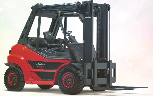
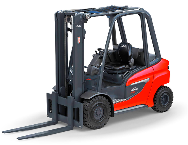
Linde H50 80 Forklift Trucks Operator’s Manual PDF
Linde H50 80 Forklift Trucks Operator’s Manual PDF
Linde H50 80 Forklift Trucks Operator’s
Adobe Acrobat Document
5.5 MB
![]()
Linde E16 20 Forklift Trucks Original Operator’s Manual PDF
Linde E16 20 Forklift Trucks Original Operator’s Manual PDF
Linde E16 20 Forklift Trucks Original Op
Adobe Acrobat Document
6.5 MB
Some LINDE Forklift Truck Service Manuals PDF with Wiring Diagrams & Error Codes DTC are above the page.
The history of Linde Material Handling began back in 1904, when Hugo Güldner, Karl von Linde and Georg von Kraus founded the joint venture Güldner Motoren-Gesellschaft
GmbH in Munich. Three years later, the company moved to Aschaffenburg.
In 1929, Linde’s Eismaschinen Aktiengesellschaft acquired all of the company’s shares and gradually restructured it. At that time, the most important products were engines and
agricultural tractors.
The company flourished in the middle of the last century and was associated with the active development of technological solutions.
In 1969, the company completely stopped the production of tractors and focused exclusively on the production and development of forklifts and material handling equipment.
Already in 1971, Linde presented the electric forklift at the famous exhibition Hannover Messe.
Since the 1970s, Linde has been actively expanding through the purchase of core assets around the world. So in 1977,
the Baker Material Handling Corporation was acquired by the manufacturer of loaders from the USA, in 1984 the French manufacturer of
forklift trucks Fenwick joined Linde, and in 1989 the British manufacturer of
forklifts Lansing Bagnall.
In 1993, Linde came to China with the help of forklift company Linde-Xiamen.
In 2006, Linde Material Handling, until then a division of Linde AG, moved to the
newly created group of companies KION.
From January 1, 2013, the hydraulics division was legally independent Linde Hydraulics separated from Linde Material Handling.
In 2010, Linde became the first industrial truck manufacturer in Europe to include a range of fuel cells in its range.
In 2014, the first cars with a lithium-ion battery appeared. Linde electric forklift drive technology has been offered since 2011 under
the Linde eMotion label for applications such as commercial electric drive trucks or electric forklifts.
In 2015, Linde introduced the first automated vehicles in cooperation with Balyo and the fleet management system connect.
Linde Forklifts: owner’s, service and maintenance manuals, error codes list, DTC, spare parts manuals & catalogues, wiring diagrams, schematics free download PDF
| Title | File Size | Download Links |
| Linde 1219 Technical Specifications [PDF] | 468.4kb | Download |
| Linde E 20-02, E 25-02, E 30-02, E 20 / 600-02, E 25 / 600-02, E 30 / 600-02 Forklift Operating Manual [PDF] | 7.6Mb | Download |
| Linde e16 Technical Specifications [PDF] | 463.8kb | Download |
| Linde E16C-03, E16P-03, E20P-03 Operating Manual [PDF] | 6.3Mb | Download |
| Linde E16C-03, E16P-03, E20P-03 Service Manual [PDF] | 13.5Mb | Download |
| Linde Electric Forklift E 20 / 25 / 30 Series 336 Service Manual [PDF] | 1.6Mb | Download |
| Linde H12 14 1618 20 Spare Parts catalog [PDF] | 1.2Mb | Download |
| Linde H12 / 16 / 18 / 20 Spare Parts Manual [PDF] | 1.2Mb | Download |
| Linde h25d h30d h35d 393 Operation and Maintenance Manual [PDF] | 8.5Mb | Download |
| Linde H25D, H30D, H35D Operator’s Manual [PDF] | 6.7Mb | Download |
| Linde H30d Manual [PDF] | 1.6Mb | Download |
| Linde H30D / H30T / H35D / H35T Linde IC Engined Truck Service Manual [PDF] | 11.6Mb | Download |
| Linde H50D, H 70 – 02 H 80 – 02, H 60 – 02, H 80 / 900 – 02, H 50 D, H 60 D, H 70 D, H 80 D, H 80 D / 900, H 50-02, H 60-02, H 70-02, H 80-02, H 80 / 900-02 Operator’s Manual [PDF] | 6.1Mb | Download |
| Linde H50D, H50D-03, H60D-03, H50T-03, H70D-03, H60T-03, H70T-03, H80D-03, H80T-03, H60D, H70D, H80D Service Manual [PDF] | 8.7Mb | Download |
| Linde H50T, H60T, H70T, H50D-02, H80T, H60 D-02, H50T-02, H60T-02, H70D-02, H80D-02, H70T-02, H80T-02 Service Manual [PDF] | 8.7Mb | Download |
| Linde K10, K13 Manual [PDF] | 1.4Mb | Download |
| Linde P200 Operator Manual [PDF] | 1.3Mb | Download |
| Linde R14 / R14HD / R16 / R16HD / R16N / R20 / R20N Series 115 Service Manual [PDF] | 10.9Mb | Download |
| Linde R14-R20 Technial Specifications Brochure [PDF] | 1.7Mb | Download |
| Linde Series115-03 Electrical Reach Truck Service Manual [PDF] | 23.7Mb | Download |
| Linde Stapler H 120, H 140, H 160 Operator Manual [PDF] | 3Mb | Download |
| Linde Stapler H 50, H 60, H 70 , H80 Operator Manual [PDF] | 944kb | Download |
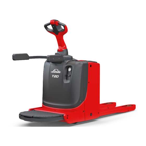
| Linde T20 Pallet Truck Service Manual [PDF] | 6.1Mb | Download |
| Linde T20AP, T20SP, T24AP, T24SP Manual [PDF] | 4.3Mb | Download |
Linde forklifts from Germany are utilized both indoors and outdoors. The firm manufactures a variety of items using electric propulsion systems or piston motors with a forced start. The electrical circuit of the Linde H60D forklift is equipped with a rechargeable battery that enables the engine to start reliably in any weather.
Electric Linde Forklifts
The electric-powered Linde forklift is intended to handle weights between 1200 and 8000 kg. The rear axle of the light-duty trucks of the E12-20 series has two wheels. At the customer’s request, machines can be supplied with a reduced chassis, an expanded base, and various center of gravity positions. Electric forklifts are equipped with maintenance-free AC motors. The driving axle is fitted with disc brakes that are submerged in oil.
Four-wheeled electric E20-80 versions are fitted with hydrostatic steering, powered by a separate pump. The hoisting of the mast parts is driven and regulated by separate electric motors. The traction motors give a top speed of 20 km/h, and the computerized controller allows for step-less adjustment. Hydromechanical brakes are used for stopping.
To maximize productivity or runtime on a single charge, the operator can pick from various driving modes. In addition, the machine’s size allows it to fit into ordinary shipping containers.
A variable displacement axial piston pumping station generates 170 bar of hydraulic operating pressure for the machines’ hydraulics. The oil supply is contingent upon the loader’s modification and carrying capacity. Using electric drives has decreased the noise level at the operator’s station to 50 decibels (A).
Linde diesel and gas forklifts
Linde forklifts with piston power units have a maximum load capacity of 18,000 kg. The design of the cargo mast includes torsion-type dampers, which minimize the amount of unit deformation. The greatest benefit is produced when the load is lifted to a larger height. The hydraulics of the mast is linked to a separate, adjustable pump.
The machines are powered by Cummins or Deutz diesel engines with four or six cylinders and up to 175 horsepower. Volkswagen inline gasoline engines produce up to 92 horsepower. Original design hydrostatic transmission is employed to drive the drive wheels. A separate, engine-mounted hydraulic pump drives the transmission.
An adjustable operator’s seat is installed within the forklift’s open cab. The base is fitted with a vibration-reducing shock absorber. A protective barrier is built above the driver, supported by a sturdy frame. The movement is controlled by two pedals and a steering wheel, while the cargo mast is maneuvered using joysticks.
The 1401 and 1411 series machines, which are suited for outdoor usage, have enclosed cabs with a larger glass area. The cabin foundation is attached to the loader by means of rubber dampers.
Typical faults and repairs for Linde forklifts
Local dealers provide warranty repairs on Linde forklifts.
Common flaws:
- A driving power reduction indicates a low working fluid temperature or a clogged clutch mechanism. Heating the fluid and correcting stuck mechanisms constitutes repair.
- If the oil level is low or if the radiators are damaged, the temperature of the fluid will rise. Therefore, it is necessary to inspect the system, repair any broken components, and clear the lines of filth. In addition, it is not advised to operate at high engine speeds.
- The hubs will heat up during movement if the bearings are broken, or there is no lubricant. Defective components are replaced, tightening adjustments are made, and the oil supply is supplied.
- Noise emanating from the drive axle indicates worn components or increased differential mechanism clearance. Repair involves changing components, correcting the gears’ position, and adding oil.
- Due to worn or overtightened bearings, small space between the gears, and lack of lubrication, the differential case heats up. To restore performance, damaged nodes must be replaced, and the gap must be set.
Linde H50
Some LINDE Forklift Truck Operator Manuals PDF above the page — H12, 14, 16, 18, 20, K10, 13, L10, 12, 14, P200, R14, 16, 20, H50, 60, 70, 80.
In 1929, Karl von Linde, together with Hugo Guldner founded the Guldner Motorenwerke plant in the German city of Munich, and three years later,
the headquarters of the firm was moved to Aschaffenburg.
Until 1938, the company specialized in the production of diesel engines, but starting this year, began production of tractors, whose task was to work in the field of agriculture.
1955 was marked by the fact that the hydrostatic transmission became the base of the process of production of special-purpose equipment.
Five years later, Linde decided to present her pride at Hannover Industrial Fair — the first Hubtrack.
In 1970, just for several weeks, the company stopped producing tractors and engines working on diesel. This made it possible to concentrate fully on the production of handling equipment, and a
year later, the Hanover Fair saw the first electric loader Linde.
1977 became famous for the acquisition of a controlling stake in the American company for the production of forklifts Baker Material Handling Corp., and 1984 — the purchase of
the French company Fenwick Manutention, which at that time was the largest manufacturer of forklifts.
1985 year marked the beginning of the release of the legendary 351-series automatic forklifts.
Four years later, the company acquired the British company Lansing Bagnall Ltd., which also specialized in the production of forklifts.
In 1991, the company’s products were awarded the first honorary badge «Red Dot Design Award». This is a well-known European award for merits in the field of industrial design.
Two years later, a plant in the south of China was founded, called Linde Xiamen Gabelstapler Gezelshaft.
The year 2002 became famous for the presentation of an innovative series of loaders — 39X.
Three years later, the company organized StaplerCup — the first competition among forklift truck drivers, and in the following year, 2006 saw the light of a 500,000th forklift.
2007 was a landmark event, as Linde became part of the KION group, a European leader in the manufacture of lifting and transporting equipment.
Since 2008, the company presents all sorts of research that is aimed at finding the engine of the future.
To date, Linde loading machines are manufactured in accordance with the most stringent standards of environmental purity and international quality. This technique is incredibly
reliable and safe, durable and technically thought-out.
According to the testimonies of independent specialized publications of different countries, Linde is one of the largest manufacturers of lifting and transport equipment all over
the world.
Manufacture of lifting and transport equipment of this company is established at nine plants in Germany, England, France, America and China. It should be noted that the German plant is the leader
in production — more than 39 thousand units of products per year.
In addition, Linde is one of the largest producers of various gases that are used in industry. In addition, the company carries out large-scale engineering development of
warehouse equipment, which is produced under the brands Linde and Still.
Linde serves more than 1.5 million consumers in more than 50 European countries, as well as in the Americas, Asia, Africa and Australia. The number of people who work in the
company’s factories reaches 50 thousand people
Linde Forklift operator’s, electrical wiring diagrams, workshop, service and repair manuals, spare parts catalogs, error codes in PDF download
|
Title |
File Size |
Download Links |
|
Linde 1219 Technical Specifications [PDF] |
717.5kb |
Download |
|
Linde E 20-02, E 25-02, E 30-02, E 20 / 600-02, E 25 / 600-02, E 30 / |
7.6Mb |
Download |
|
Linde e16 Technical Specifications [PDF] |
529.8kb |
Download |
|
Linde E16C-03, E16P-03, E20P-03 Operating Manual [PDF] |
6.5Mb |
Download |
|
Linde E16C-03, E16P-03, E20P-03 Service Manual [PDF] |
13.7Mb |
Download |
|
Linde Electric Forklift E 20 / 25 / 30 Series 336 Service Manual |
1.7Mb |
Download |
|
Linde H12 14 1618 20 Spare Parts catalog [PDF] |
1.2Mb |
Download |
|
Linde H12 / 16 / 18 / 20 Spare Parts Manual [PDF] |
1.2Mb |
Download |
|
Linde h25d h30d h35d 393 Operation and Maintenance Manual |
9.1Mb |
Download |
|
Linde H25D, H30D, H35D Operator’s Manual [PDF] |
7.1Mb |
Download |
|
Linde H30d Manual [PDF] |
1.9Mb |
Download |
|
Linde H30D / H30T / H35D / H35T Linde IC Engined Truck Service Manual |
12Mb |
Download |
|
Linde H50D, H 70 — 02 H 80 — 02, H 60 — 02, H 80 / 900 — 02, H 50 D, |
6.4Mb |
Download |
|
Linde H50D, H50D-03, H60D-03, H50T-03, H70D-03, H60T-03, H70T-03, |
8.7Mb |
Download |
|
Linde H50T, H60T, H70T, H50D-02, H80T, H60 D-02, H50T-02, H60T-02, |
8.7Mb |
Download |
|
Linde K10, K13 Manual [PDF] |
1.6Mb |
Download |
|
Linde P200 Operator Manual [PDF] |
1.6Mb |
Download |
|
Linde R14 / R14HD / R16 / R16HD / R16N / R20 / R20N Series 115 |
11Mb |
Download |
|
Linde R14-R20 Technical Specifications Brochure [PDF] |
2.2Mb |
Download |
|
Linde Series115-03 Electrical Reach Truck Service Manual [PDF] |
24Mb |
Download |
|
Linde Stapler H 120, H 140, H 160 Operator Manual [PDF] |
3.6Mb |
Download |
|
Linde Stapler H 50, H 60, H 70 , H80 Operator Manual [PDF] |
940.5kb |
Download |
|
Linde T20 Pallet Truck Service Manual [PDF] |
6.2Mb |
Download |
|
Linde T20AP, T20SP, T24AP, T24SP Manual [PDF] |
4.5Mb |
Download |
The lifting equipment of the German company Linde is used to work in premises and in open areas. The company produces a wide range of products equipped with electric power plants
or piston engines with a forced launch. The composition of the Linde H60D loader circuit includes a battery that provides confident engine start in any conditions.
The Linde forklift, equipped with an electric motor, is designed to work with loads weighing from 1200 to 8000 kg. The low-loading machines of the E12-20 series are equipped with
paired wheels on the rear axle. At the request of the customer, it is possible to supply machines with a reduced chassis or with an elongated base and a different location of the center of
gravity. On electric loaders, alternating current engines that do not require maintenance are used. The leading bridge is equipped with disk brake mechanisms placed in an oil bath.
Electric models of the E20-80 with 4 wheels are equipped with hydrostatic steering control, with a drive from a separate pump. For the movement and management of lifting the mast sections,
separate electric motors are used. Pin -high motors provide speeds of up to 20 km/h, unavailable adjustment is carried out by a digital controller. For stopping, hydromechanical brakes are used.
Machine hydraulics have a working pressure of 170 bar created by an axial piston pumping station with adjustable performance. The supply of oil depends on the modification and carrying capacity
of the loader. The use of electric drives made it possible to reduce the noise level at the site of the operator to 50 dB (a).
- Manuals
- Brands
- Linde Manuals
- Forklifts
- T 16
- Operating instructions manual
-
Contents
-
Table of Contents
-
Bookmarks
Quick Links
4
4
0
0
5
5
0
0
—
—
1
1
1
1
5
5
2
2
4
4
0
0
8
8
0
0
6
6
3
3
https://www.besttruckmanuals.com/
Operating instructions
Operating instructions
T 16 — T 18 — T 20
T 16 — T 18 — T 20
360 804 25 11
360 804 25 11
03/97
03/97
Related Manuals for Linde T 16
Summary of Contents for Linde T 16
-
Page 1
8 0 0 6 6 3 3 Operating instructions Operating instructions T 16 — T 18 — T 20 T 16 — T 18 — T 20 360 804 25 11 360 804 25 11 03/97 03/97 https://www.besttruckmanuals.com/… -
Page 2
https://www.besttruckmanuals.com/… -
Page 3
https://www.besttruckmanuals.com/… -
Page 4
Werk I, Aschaffenburg Werk I, Aschaffenburg Werk III, Kahl am Main Werk III, Kahl am Main Linde Heavy Truck Division Ltd., Merthyr Tydfil Linde Heavy Truck Division Ltd., Merthyr Tydfil https://www.besttruckmanuals.com/… -
Page 5
For repairs, be sure to use only o For repairs, be sure to use only o riginal LINDE parts. Only riginal LINDE parts. Only 4 4… -
Page 6: Plates And Labels
Plates and labels Plates and labels Identification plates Identification plates 1. 1. Identi Identificati fication plate on plate 2. 2. Man Manufa ufactur cturer er 3. 3. EC EC ma mark rk (this plate certifies that the machine (this plate certifies that the machine conforms to European regulations conforms to European regulations…
-
Page 7
4 0 5 0 — 1 1 5 2 4 0 8 0 6 3 https://www.besttruckmanuals.com/… -
Page 8: Table Of Contents
Table of contents Description Page Driving Page Page Plates a nd labe ls …………. 3 Fu se s …………….32 Instr uction s for use …………20 Tech nica l spec ific ation s ……….6 Checking the electrolyte level, and topping up Start ing …………….
-
Page 9: Tech Nica L Spec Ific Ation S
Technical specifications Description 4 0 5 0 — 1 1 5 2 4 0 8 0 6 3 https://www.besttruckmanuals.com/…
-
Page 10: Technical Description
Technical description Description T 16, T 18 and T 20 pallet trucks are high-performance Hydraulic system Built-in charger* machines, designed for intensive use. A compact motor pump unit, consisting of a motor, pump, tank, filter and descent valve, supplies the two lifting jac ks…
-
Page 11: Genera L View
General view T 16-18-20 1. Battery plug handle 2. Battery cover opening handle 3. Electric control unit 4. Motor-pump assembly 5. Battery cover 6. Battery 7 . H or n 8. Load wheels 9. Forks 10.
-
Page 12: Controls
Controls 1. Key switch 2. Horn button 3. Safety reverse switch 4. Travel control 5. Lift control 6. Lowering control 7. Battery cover opening handle 8. Battery plug handle 9. Battery plug 10. Hour meter*/Discharge limiter* 11.
-
Page 13: Indicators
Indicators Description Combination hour meter / If the hour meter has to be replaced, make a note of the NOTE: service hours recorded by the defective meter, in the place A potentiometer at the rear of the housing allows the cut- Discharge limiter/indicator provided for this purpose adjacent to the hour meter, and off threshold to be adjusted for any special operating…
-
Page 14: Safety Rules
Safety rules Before operation This instruction manual, and the VDMA booklet “Directive s Definition of terms relating to safety Use of materials governing the use of handling trucks in conformity with specifications and regulations” supplied with the truck, The terms DANGER, CAUTION, ATTENTION and NOTE Materials must always be used in conformity with the must be given to the relevant persons, a nd in particular to are used in this manual to indicate a particular risk or to…
-
Page 15: Periodic Inspections Of The Truck
Before operation Periodic inspection of trucks Checks prior to initial operation Daily checks prior to operation * Check forward and reverse controls The head of the establishment concerned must conduct IMPORTANT Check lift and lower controls periodic general inspections of the truck, or arrange for Before each shift, it is essential for the following operational Check operation of indicators these to be conducted, in order to ensure early detection…
-
Page 16: Checking The Forward/Reverse And Lift/Lo Wer Contr Ols
Before operation Daily checks and tasks prior to operation Checking forward/reverse and raise/lower ATTENTION Checking horn operation Please contact your local representative if you controls Press the horn button (4) on the control module. detect any anomaly in the steering mechanism. Th e ho rn s ou nd s.
-
Page 17: Checking The Battery Charge State
Before operation Daily checks and tasks prior to operation Checking the battery charge state Opening the battery cover Stop the machine, lower the forks. Before the start of the shift, check that the battery is Switch off and remove the key. correctly charged.
-
Page 18
Before operation Daily checks and tasks prior to operation DANGER Connect / disconnect the battery plug CAUTION Charging and servicing of the battery must be Never connect or disconnect the connector while carried out in conformity with the instructions current is flowing through the circuit — this may To disconnect supplied with the battery and the charger (if cause violent sparking and damage the con-… -
Page 19: Charging The Battery With A In-Built Charger
Commissioning Daily checks and commissioning checks Charging the battery with the built-in char- WARNING: IMPORTANT Do not disconnect the battery connector while The truck will operate only if the plug is replaced correc tly. ger ( from 07/2000 ) charging (green light flashing). Charger electrical specifications Every day the truck is used normally, or every two days in Problems while charging…
-
Page 20: Charger
Before operation Daily checks and tasks prior to operation Recharging the battery with an external CAUTION Checking the condition of battery cables, In order to avoid any sparks, always connect the charger terminals and connector. battery connector before switching on the char- ger, and disconnect it after switching off the charger.
-
Page 21: Checking The Electrolyte Level, And Topping Up With Water
Before operation Daily checks and tasks prior to operation The operations described below apply to lead-acid batte- ATTENTION We recommend measurement every week or two. Keep ries with liquid electrolyte. a record of the values measured in the service booklet for Use only demineralised water for topping up.
-
Page 22: Removal/Replacement Of The Battery
Before operation Daily checks and tasks prior to operation Removing/replacing the battery Changing the battery using a hoist Changing the battery using a gantry (front exit model) ATTENTION Fully lower the fork. The battery is a heavy and fragile component Remove the battery cover.
-
Page 23: Driving
Instructions for use Starting Indication of direction of travel The T 16, T 18 and T 20 pallet trucks are designed to be used inside non-dangerous atmospheres; the ambient Connect the battery plug. Tilt the til ler into are a ( 1) The discharge indicator (2) lights up.
-
Page 24: Forward Travel / Reverse Travel
Driving Forward travel Reverse travel Safety reverse button Gradually press the lower part of the accelerator control Gently press the upper part of the accelerator control with In order to protect the driver from being trapped between (1) with the thumb (rotation of accelerator control in the thumb (rotation of accelerator control in direction 3).
-
Page 25: Starting On A Slope
Driving Starting on a slope Steering Turning angle A robust and ergonomic tiller equipped with two grips Turning angle ……….180° When it is necessary to stop and then r estart on an incline, directly steers the traction wheel proceed as follows: The turning radius (Wa) depends on the fork length.
-
Page 26: Mechanical Brakes
Braking, Raising, Lowering, Horn Operation Mechanical brakes LBC * automatic braking (Linde Brake Con- Raising the forks trol) Press the control switch (4) on the tiller. Releasing the tiller applies the brake. Lowering the forks The braking is progressive, depending on the position of Release the accelerator butterfly valve the tiller in tilt areas (1) and (2).
-
Page 27: Loading
Load handing ATTENTION Loading Transporting the load Before lifting a load, ensure that its weight does Carefully approach the load Always carry loads in the forward direction of travel in not exceed the truck’s capacity. Adjust the height of the fork arms until they can be easily order to have the best visibility.
-
Page 28: Unloading
Load handing Unloading Before leaving the truck Carefully drive the truck to the desired location ATTENTION Raise the fork platform to the appropriate height Always stop the truck on level ground and away Carefully advance the load into the unloading area from traffic lanes.
-
Page 29: Slinging The Truck
Jacking and towing Slinging the truck Jacking the truck Transporting the truck When transporting the truck, ensure that it is properly CAUTION For certain servicing tasks, it is necessary to raise the chocked and protected against bad weather. Use only slings or hoists of adequate capacity, truck and protect all parts coming into con tact with the Storage…
-
Page 30: Maintenance
See the table of recommended lubricants. Check for leaks in hydraulic system This work can be carried out by your local LINDE Clean hydraulic filter representative under a service contract. If you prefer to Check level and specific gravity of battery electrolyte…
-
Page 31
Inspection and maintenance schedule Maintenance After Operation / Interval Prior to Daily first initial use checks required 50 hours Checks prior to initial operation (see page 12) ……•… -
Page 32: Inspection And Maintenance Schedule
Inspection and maintenance schedule Maintenance Every 500 hours Every 1000 hours Every 2000 hours Operation / Interval every 6 months every year every 2 years Check the braking system ……….•…
-
Page 33: Maintenance As Required
Maintenance as required Maintenance Cleaning the truck If, in spite of all precautions, water finds its way into the Check the free rotation of the wheels, and remove any object which might interfere with them. motors, the truck must be run to prevent the formation of Replace any worn or damaged wheels rust, so that it dries under its own heat.
-
Page 34: Opening The Front Cover
Maintenance as required Maintenance Opening the front cover Pull the flexible cover clear to access the reduction gearbox and the motor Unscrew the 2 screws (1) holding the cover. To close, position the lower locking pins (2) in the holes Pull the cover towards the back.
-
Page 35: Fuses
Maintenance as required Maintenance The operations described below apply to lead-acid batte- ATTENTION Remove the filler plug for each cell as described above. Using an acid hydrometer, carefully measure the specific ries with liquid electrolyte. Use only demineralised water for topping up. gravity in each cell.
-
Page 36: Checking The Condition Of The Battery Cables
Maintenance as required Maintenance Checking the condition of battery cables, Cleaning the battery and battery compart- Battery in sealed box terminals and connector ment Check that there is no electrolyte in the bottom of the box Check that cable insulation is undamaged, and that the CAUTION by connecting the suction bulb supplied with the battery connections show no sign of overheating.
-
Page 37: Maintenance Every 500 Hours
Maintenance every 500 hours Maintenance Checking and adjusting the brake control Checking and adjusting the belt tension Check the truck braking. If it proves to be unsatisfactory, With the truck lifted about 20 cm off the ground and then put Tighten the bolt (2) fitted with its washer (3).
-
Page 38: Checking The Hydraulic Fluid Level
Maintenance every 500 hours Maintenance Checking the hydraulic fluid level Checking for leaks in the hydraulic system Lower the forks to their full extent Inspect the hydraulic system: pipes, flexible hoses and Remove the front cover cover unions between the pump motor and the pressure The fluid level (1) must be between the min.
-
Page 39: Checking The Condition And Fastening Of Electrical Cables And Connections
Maintenance every 500 hours Maintenance ATTENTION Cleaning the electrical panel Cleaning and checking contacts for wear Before commencing any work on the electrical — Disconnect the battery connector. Disconnect the battery connector. equipment, the battery connector must be — Remove the front cover. Clean the contacts using compressed air, and check disconnected.
-
Page 40: Inspection/Replacement Of The Traction Motor Brus Hes
Maintenance every 500 hours Maintenance Inspection / replacement of the traction NOTE Checking miscellaneous joints Always replace brushes as a complete set. motor brushes Inspect and lubricate the various pivots: We recommend leaving this operation to your local Use oil or an aerosol lubricant. representative.
-
Page 41: Maintenance Every 1000 Hours
Maintenance every 1000 hours Maintenance Inspection / replacement of the pump motor Clean the hydraulic filter Checking the mechanical fixing of compon- brushes ents Put the lifting system into the down position. Clean the screen in the breather cap (1). Remove the pump motor unit.
-
Page 42: Maintenance Every 2000 Hours
Maintenance every 2000 hours Maintenance Changing the hydraulic fluid Remove the pump motor unit. Lower the fork arms to their full extent. Remove the two semi-circular collars (2). To check the fluid level. Detach the reservoir (1). The fluid level (7) must be between the min. and max. Drain the fluid.
-
Page 43: Recommended Lubricants
Recommended lubricants / Technical specifications Maintenance Unit Part / lubricant Capacity / adjustment value Hydraulic system Hydraulic fluid 1.25 l Hydraulic system Filter element Efficiency: 150 µ Hydraulic system Max. pressure 170 bar(start of opening) Reduction gear Grease Life lubricated Driven wheel Wheel nuts Torque setting :…
-
Page 44: Hydraulic System Diagram
Hydraulic system diagram 1. Lowering solenoid valve Restrictor (T 18) Flow regulator (T 20) 4. Adjustable pressure reducing valve Breather (built into the filling cap) 6 . Reser voir 7. Suction strainer 8. Pump Non-return valve Pressure filter Lift cylinders Hydraulic line…
-
Page 45: Electrical Circuit Diagram
Circuit diagram RESISTANCE CONTROL Mark Item Position Mark Item Position 2Y30 Lowering solenoid valve Control logic 10-22 Suppression diode 12,14-17, Potentiometer 20-22 24,27,30 Motor speed sensor Suppression circuit 14,23-24 Horn 26-27, Traction motor fuse 29-30 Control fuse Pump motor fuse Battery OPTION.INBUILT CHARGER 1K11 Forward travel contactor…
-
Page 46
Resistance 4 0 5 0 — 1 1 5 2 4 0 8 0 6 3 https://www.besttruckmanuals.com/… -
Page 47
Circuit diagram PULSE CONTROL LTM Mark Item Position Mark Item Position Lowering solenoid valve Traction pulse control 3-9,13-26 Suppression diode 15,17,31,34, 1 B1 Travel control potentiometer 23-25 Motor speed sensor Current meter shunt Suppression circuit 31-32 Horn Suppression capacitor 34-35,36-37 Fuse, traction motor OPTION COLD STORE Control current fuse… -
Page 48
Pulse control 4 0 5 0 — 1 1 5 2 4 0 8 0 6 3 https://www.besttruckmanuals.com/… -
Page 49
Circuit diagram PULSE CONTROL LTM WITH LBC BRAKING Mark Item Position Mark Item Position Traction pulse control 3-7, 9-21 Hour meter-battery discharge Circuit L.B.C. 22-34 limiter connector 1 B1 Travel control potentiometer 17-19 Lowering solenoid valve Current meter shunt Suppression diode 11, 13, 34-37 Tachometer Tachometer… -
Page 50
Pulse control with LBC braking 4 0 5 0 — 1 1 5 2 4 0 8 0 6 3 https://www.besttruckmanuals.com/… -
Page 51
Circuit diagram PULSE CONTROL LDC Mark Item Position Mark Item Position Traction pulse control 4-9,12-26 1 B1 Travel control potentiometer 24-26 Motor speed sensor OPTION COLD STORE Current meter shunt Horn Fuse, traction motor Resistor Control current fuse Resistor Pump motor fuse OPTION. -
Page 52
Pulse control LDC 4 0 5 0 — 1 1 5 2 4 0 8 0 6 3 https://www.besttruckmanuals.com/… -
Page 53: Index
Index Checking the electrolyte specific gravity …… 32 Checking the forward/reverse and lift/lower controls 13 Check ing the horn operation ……..13 Checking the hydraulic fluid level …….. 35 Automatic disconnection of charging in the event of a Checking the mechanical fitting of components..38 Gener al infor mation …………
This manual is also suitable for:
T 18T 20