2JZ/2JX/2JV/2H7-1
Code
C7912
Developing unit C EEPROM error
No response is issued from the device in
reading/writing for 5 ms or more and this
problem is repeated five times succes-
sively.
Mismatch of reading data from two loca-
tions occurs eight times successively.
Mismatch between writing data and
reading data occurs eight times succes-
sively.
C7913
Developing unit M EEPROM error
No response is issued from the device in
reading/writing for 5 ms or more and this
problem is repeated five times succes-
sively.
Mismatch of reading data from two loca-
tions occurs eight times successively.
Mismatch between writing data and
reading data occurs eight times succes-
sively.
C7914
Developing unit Y EEPROM error
No response is issued from the device in
reading/writing for 5 ms or more and this
problem is repeated five times succes-
sively.
Mismatch of reading data from two loca-
tions occurs eight times successively.
Mismatch between writing data and
reading data occurs eight times succes-
sively.
C7950
High voltage control PWB error
A communication error from high voltage
control PWB is detected 10 times in suc-
cession.
C8020
Punch motor problem (optional 3000-
sheet document finisher)
The error signal of the punch motor is
detected for more than 500 ms while the
punch motor is operating.
1-4-50
Contents
Causes
Check procedures/corrective measures
Poor contact in the
Check the connection of connector YC6 on
connector termi-
the sub front PWB and the continuity across
nals.
the connector terminals. Repair or replace if
necessary.
Defective develop-
Replace the developing unit C (see page 1-
ing PWB C.
5-34).
Poor contact in the
Check the connection of connector YC8 on
connector termi-
the sub front PWB and the continuity across
nals.
the connector terminals. Repair or replace if
necessary.
Defective develop-
Replace the developing unit M (see page 1-
ing PWB M.
5-34).
Poor contact in the
Check the connection of connector YC4 on
connector termi-
the sub front PWB and the continuity across
nals.
the connector terminals. Repair or replace if
necessary.
Defective develop-
Replace the developing unit Y (see page 1-
ing PWB Y.
5-34).
Poor contact in the
Check the connection of connector YC30 on
connector termi-
the engine PWB and the connector on the
nals.
high voltage control PWB, and the continuity
across the connector terminals. Repair or
replace if necessary.
Defective PWB.
Replace the high voltage control PWB or
engine PWB and check for correct opera-
tion.
Poor contact in the
Check the connection of connector on the
connector termi-
punch PWB and the continuity across the
nals.
connector terminals. Repair or replace if
necessary.
Defective punch
Replace the punch motor.
motor.
Defective PWB.
Replace the punch PWB or finisher main
PWB and check for correct operation.
Remarks
Все современные копировальные аппараты, мфу и принтеры Kyocera имеют возможность диагностировать все узлы устройства в режиме запуска и во время работы аппарата. По этому, если во время включения или во время работы произошел сбой, то техника Kyocera сможет сообщить о наличии ошибки.
В большинстве случаев у аппаратов Kyocera код ошибки отображается на дисплее, в остальных случаях тип ошибки зависит от последовательности и количества миганий индикаторов.
Если Ваш копировальный аппарат, МФУ или принтер Kyocera выдал на дисплее некий код, то узнать причину, описание возникновения ошибки, а так же в каком узле аппарата стоит искать проблему, Вы можете в этом разделе выбрав интересующую модель из списка.
Но диагностика не решит проблему сбоя аппарата, для этого лучше обратиться к профессиональным и опытным сервисным специалистам компании Kyomart! Позвоните нам по телефону
8 (343) 288-23-45 или отправьте запрос на электронную почту: sales@kyomart.ru , и мы обязательно свяжемся с Вами в кратчайшие сроки.
Код ошибки
Описание ошибки
Причина ошибки
0030
FAX control PWB system error
Processing with the fax software was disabled due to a hardware problem.
Defective FAX control PWB.
0060
Engine PWB type error
Defective engine sub PCB.
0070
FAX control PWB incompatible detection error
Abnormal detection of FAX control PWB incompatibility In the initial communication with the FAX control PWB, any normal communication command is not transmitted.
Defective FAX software
Defective FAX control PWB.
0100
Backup memory device error
Defective flash memory.
0120
MAC address data error
For data in which the MAC address is invalid.
Defective main PWB.
Defective flash memory.
Defective engine PWB.
0130
Backup memory read/write error (main PWB)
Defective flash memory.
Defective main PWB.
0140
Backup memory data error (main PWB)
Defective flash memory.
Defective main PWB.
0150
Backup memory read/write error (engine PWB)
Detecting engine PWB EEPROM communication error.
Improper installation engine PWB EEPROM.
Defective engine PWB.
Device damage of EEPROM.
0160
Backup memory data error (engine PWB)
Defective flash memory.
Defective engine PWB.
0170
Billing counting error
A checksum error is detected in the main and engine backup memories for the billing counters.
Data damage of EEPROM.
Defective PWB.
0180
Machine number mismatch
Machine number of main and engine does not match.
Data damage of EEPROM.
0320
I/O CPU communication error
A communication error is detected 10 times in succession.
Defective PWB.
0630
DMA error DMA transmission of image data does not complete within the specified period of time.
Poor contact in the connector terminals. Defective main PWB.
0800
Image processing error
JAM05 is detected twice.
Defective main PWB.
0830
FAX control PWB flash program area checksum error
A checksum error occurred with the program of the FAX control PWB.
Defective FAX software.
Defective FAX control PWB.
0840
Faults of RTC
The time is judged to go back based on the comparison of the RTC time and the current time or five years or more have passed.
The battery is disconnected from the main PWB.
Defective main PWB.
0870
FAX control PWB to main PWB high capacity data transfer error
High-capacity data transfer between the FAX control PWB and the main PWB of the machine was not normally performed even if the data transfer was retried the specified times.
Improper installation FAX control PWB.
Defective FAX control PWB or main PWB.
0920
Fax file system error
The backup data is not retained for file system abnormality of flash memory of the FAX control PWB.
Defective FAX control PWB.
1010
Lift motor error
After cassette 1 is inserted, lift sensor does not turn on within 12 s. This error is detected four times successively.
Defective bottom plate elevation mechanism in the cassette.
Defective connector cable or poor contact in the connector.
Defective drive transmission system of the lift motor.
Defective lift motor.
Defective engine PWB.
1020
PF lift motor error (paper feeder)
After cassette 2 is inserted, PF lift sensor 1 does not turn on within 12 s. This error is detected four times successively.
Defective bottom plate elevation mechanism in the cassette.
Defective connector cable or poor contact in the connector.
Defective drive transmission system of the PF lift motor 1.
Defective PF lift motor 1.
Defective PF main PWB.
1030
PF lift motor error (paper feeder)
After cassette 3 is inserted, PF lift sensor 2 does not turn on within 12 s. This error is detected four times successively.
Defective bottom plate elevation mechanism in the cassette.
Defective connector cable or poor contact in the connector.
Defective drive transmission system of the PF lift motor 2.
Defective PF lift motor 2.
Defective PF main PWB.
1800
Paper feeder communication error
A communication error is detected 10 times in succession.
Improper installation paper feeder.
Defective connector cable or poor contact in the connector.
Defective engine PWB.
Defective PF main PWB.
1900
Paper feeder EEPROM error
When writing the data, the write data and the read data is not continuously in agreement 5 times.
Defective PF main PWB.
Device damage of EEPROM.
2000
Main motor steady-state error
Stable OFF is detected for 1 s continuously after main motor stabilized.
Defective connector cable or poor contact in the connector.
Defective drive transmission system of the main motor.
Defective main motor.
Defective engine PWB.
2010
Main motor drive error
The main motor is not stabilized within 2 s after driving starts.
Defective connector cable or poor contact in the connector.
Defective drive transmission system of the main motor.
Defective main motor.
Defective engine PWB.
2101
Developer motor K steady-state error
The rated speed signal detected the stability OFF continuously for 1 s after the developer motor K stabilizes.
Defective connector cable or poor contact in the connector.
Defective drive transmission system.
Defective motor.
Defective PWB.
2102
Developer motor YCM steady-state error
The rated speed signal detected the stability OFF continuously for 1 s after the developer motor YCM stabilizes.
Defective connector cable or poor contact in the connector.
Defective drive transmission system.
Defective motor.
Defective PWB.
2111
Developer motor K startup error
Developer motor K is not stabilized within 2 s since the motor is activated.
Defective connector cable or poor contact in the connector
Defective drive transmission system.
Defective motor.
Defective PWB.
2112
Developer motor YCM startup error
Developer motor YCM is not stabilized within 2 s since the motor is activated.
Defective connector cable or poor contact in the connector
Defective drive transmission system.
Defective motor.
Defective PWB.
2300
Fuser motor steady-state error
The rated speed signal detected the stability OFF continuously for 1 s after the fuser motor stabilizes.
Defective connector cable or poor contact in the connector.
Defective drive transmission system.
Defective motor.
Defective PWB.
2310
Fuser motor startup error
Fuser motor is not stabilized within 2 s since the motor is activated.
Defective connector cable or poor contact in the connector.
Defective drive transmission system.
Defective motor.
Defective PWB.
2550
Conveying motor steady-state error
The rated speed signal detected the stability OFF continuously for 1 s after the conveying motor stabilizes.
Defective connector cable or poor contact in the connector.
Defective drive transmission system.
Defective motor.
Defective PWB.
2560
Conveying motor startup error
Conveying motor is not stabilized within 2 s since the motor is activated.
Defective connector cable or poor contact in the connector.
Defective drive transmission system.
Defective motor.
Defective PWB.
2600
PF drive motor error (paper feeder)
When the PF drive motor is driven, error signal is detected continuously for 1 s.
Defective connector cable or poor contact in the connector.
Defective drive transmission system of the PF drive motor.
Defective PF drive motor.
Defective PF main PWB.
2700
TC belt motor error
When the TC belt motor is driven, error signal is detected continuously for 1 s.
Defective connector cable or poor contact in the connector.
Defective drive transmission system of the PF drive motor.
Defective PF drive motor.
Defective PF main PWB.
3100
ISU home position error
The home position is not correct when the power is turned on or at the start of copying using the table.
Defective connector cable or poor contact in the connector.
Defective home position sensor.
Defective ISU motor.
Defective CCD PWB.
Defective engine PWB.
3200
Exposure lamp error
When input value at the time of exposure lamp illumination does not exceed the threshold value between 5 s.
Defective connector cable or poor contact in the connector.
Defective exposure lamp.
Defective CCD PWB.
Defective main PWB.
3500
Communication error between scanner and ASIC
An error code is detected 3 times in succession.
Defective connector cable or poor contact in the connector.
Defective CCD PWB.
Defective main PWB.
3600
Scanner sequence error
Defective main PWB or engine PWB.
4000
Polygon motor synchronization error
The polygon motor is not stabilized within 10 s after driving starts.
Defective connector cable or poor contact in the connector.
Defective polygon motor.
Defective engine PWB.
4001
Polygon motor (K) steady-state error
The rated speed signal detected the stability OFF continuously for 1 s after the polygon motor (K) stabilizes.
Defective connector cable or poor contact in the connector.
Defective motor
Defective PWB.
4002
Polygon motor (С) steady-state error
The rated speed signal detected the stability OFF continuously for 1 s after the polygon motor (С) stabilizes.
Defective connector cable or poor contact in the connector.
Defective motor
Defective PWB.
4003
Polygon motor (M) steady-state error
The rated speed signal detected the stability OFF continuously for 1 s after the polygon motor (M) stabilizes.
Defective connector cable or poor contact in the connector.
Defective motor
Defective PWB.
4004
Polygon motor (Y) steady-state error
The rated speed signal detected the stability OFF continuously for 1 s after the polygon motor (Y) stabilizes.
Defective connector cable or poor contact in the connector.
Defective motor
Defective PWB.
4010
Polygon motor steady-state error
Stable OFF is detected for 1 s continuously after polygon motor stabilized.
Defective connector cable or poor contact in the connector.
Defective polygon motor.
Defective engine PWB.
4011
Polygon motor (K) startup error
Polygon motor (K) is not stabilized within 10 s since the motor is activated.
Defective connector cable or poor contact in the connector.
Defective motor.
Defective PWB.
4012
Polygon motor (C) startup error
Polygon motor (C) is not stabilized within 10 s since the motor is activated.
Defective connector cable or poor contact in the connector.
Defective motor.
Defective PWB.
4013
Polygon motor (M) startup error
Polygon motor (M) is not stabilized within 10 s since the motor is activated.
Defective connector cable or poor contact in the connector.
Defective motor.
Defective PWB.
4014
Polygon motor (Y) startup error
Polygon motor (Y) is not stabilized within 10 s since the motor is activated.
Defective connector cable or poor contact in the connector.
Defective motor.
Defective PWB.
4100
BD initialization error
BD is not detected within 1 s after polygon motor stabilized.
Defective connector cable or poor contact in the connector.
Defective APC PWB.
Defective BD PWB.
Defective main PWB.
4600
LSU cleaning motor error
When the LSU cleaning motor is driven, an error signal is detected continuously for 1 s.
Defective connector cable or poor contact in the connector.
Defective drive transmission system.
Defective motor. Defective PWB.
4700
VIDEO ASIC device error
Defective connector cable or poor contact in the connector.
Defective main PWB or engine PWB.
4950
LSU CPU communication error
A communication error is detected 10 times in succession.
Defective connector cable or poor contact in the connector.
Defective PWB.
6000
Broken fuser heater wire
The detected temperature of fuser thermistor does not reach the specified temperature (ready indication temperature) after the fuser heater has been turned on continuously for 60 s in warming up. The fusing temperature at 7 seconds and 20 seconds since fuser temperature control has occurred differs by 43°C/109.4°F or less.
Defective connector cable or poor contact in the connector.
Deformed connector pin.
Defective triac.
Fuser thermostat triggered.
Broken fuser heater wire.
Defective engine PWB.
6000
6020
6030
6050
Broken fuser heater wire
Abnormally high fuser thermistor temperature Broken fuser thermistor wire Abnormally low fuser thermistor temperature
Deformed connector pin.
Defective triac.
6020
Abnormally high fuser thermistor temperature
The fuser thermistor detects a temperature higher than 230°C/446°F continuously for 40 ms. High fuser temperature signal detects a temperature of 255°C/491°F continuously for 40 ms.
Deformed connector pin.
Defective triac.
Shorted fuser thermistor.
Defective engine PWB.
6030
Broken fuser thermistor wire
A/D value of the fuser thermistor exceeds 251 bit continuously for 7 s during warming up.
Defective connector cable or poor contact in the connector.
Deformed connector pin.
Defective triac.
Defective fuser thermistor.
Defective engine PWB
6050
Abnormally low fuser thermistor temperature
As the stable temperature has reached the second time, the decrease in the fuser thermistor temperature of 60°C/140°F or greater is detected for one second.
Deformed connector pin.
Defective triac.
Defective fuser thermistor
Defective fuser heater.
Defective engine PWB.
6120
Abnormally high fuser thermistor 3 (press roller) temperature
The fuser temperature exceeds 200 °C/392 °F for 1 s.
Deformed connector pin.
Defective IH PWB.
Defective fuser thermistor.
Defective engine PWB.
6130
Fuser thermistor 3 (press roller) break error Fuser thermistor 3 detects a temperature of -14 °C/6.8 °F . Fuser thermistor 3 does not reach 30° C/86 °F even after20 s during warming up.
Defective connector cable or poor contact in the connector
Deformed connector pin.
Defective IH PWB.
Defective fuser thermistor.
Defective engine PWB.
6150
Abnormally low fuser thermistor 3 (press roller) temperature
The fuser temperature lower than 30 °C/86 °F is detected continuously for 1 s.
Deformed connector pin.
Defective fuser thermistor
Defective fuser heater.
Defective engine PWB.
6200
Broken fuser edge heater wire
Fuser thermistor 1 does not reach 50° C/122 °F even after20 s during warming up. The detected temperature of fuser thermistor1 does not reach the specified temperature (ready indication temperature) for 20 s in warming up after reaching 50° C/122 °F.
Defective connector cable or poor contact in the connector.
Deformed connector pin.
Fuser thermostat triggered.
Broken fuser heater wire.
Defective engine PWB.
6220
Abnormally high fuser thermistor 1 (edge) temperature
The fuser temperature exceeds 240 °C/464 °F for 1 s
Defective connector cable or poor contact in the connector.
Deformed connector pin.
Fuser thermostat triggered.
Broken fuser heater wire.
Defective engine PWB.
6230
Fuser thermistor 1 (edge) break error
During warming up a hearter, fuser thermistor 2 detects a temperature of 100 °C/212 °F or higher and, fuser thermistor 1 detects a temperature of 37 °C/99 °F or lower.
Defective connector cable or poor contact in the connector.
Deformed connector pin.
Fuser thermostat triggered.
Broken fuser heater wire.
Defective engine PWB.
6250
Abnormally low fuser thermistor 1 (edge) temperature
The fuser temperature lower than 100 °C/212 °F is detected continuously for 1 s during printing. The fuser temperature lower than 50 °C/122 °F is detected continuously for 1 s during pre-heating.
Defective connector cable or poor contact in the connector.
Deformed connector pin.
Fuser thermostat triggered.
Broken fuser heater wire.
Defective engine PWB.
6400
Zero-cross signal error
While fuser heater control is performed, the zero-cross signal is not input within 3 s.
Defective connector cable or poor contact in the connector
Defective power source PWB or engine PWB.
6410
Fuser unit type mismatch problem
Absence of the fuser unit is detected.
Fuser unit connector inserted incorrectly.
Different type of the fuser unit is installed.
6600
Belt rotation error
The belt was detected to stop for 1 s continuously during motor remote is on.
Defective fuser motor.
Defective IH belt.
Defective IH PWB.
Defective engine PWB.
7101
Toner sensor K error
Defective Developer unit.
Defective PWB.
7102
Toner sensor C error
Defective Developer unit.
Defective PWB.
7103
Toner sensor M error
Defective Developer unit.
Defective PWB.
7104
Toner sensor Y error
Defective Developer unit.
Defective PWB.
7401
Developing unit K type mismatch problem
Absence of the developing unit K is detected.
Developing unit connector inserted incorrectly.
Different type of the developing unit is installed.
Defective PWB.
7402
Developing unit C type mismatch problem
Absence of the developing unit C is detected.
Developing unit connector inserted incorrectly.
Different type of the developing unit is installed.
Defective PWB.
7403
Developing unit M type mismatch problem
Absence of the developing unit M is detected.
Developing unit connector inserted incorrectly.
Different type of the developing unit is installed.
Defective PWB.
7404
Developing unit Y type mismatch problem
Absence of the developing unit Y is detected.
Developing unit connector inserted incorrectly.
Different type of the developing unit is installed.
Defective PWB.
7411
Drum unit K type mismatch problem
Absence of the drum unit K is detected.
Drum unit connector inserted incorrectly.
Different type of the drum unit is installed.
Defective PWB.
7412
Drum unit C type mismatch problem
Absence of the drum unit C is detected.
Drum unit connector inserted incorrectly.
Different type of the drum unit is installed.
Defective PWB.
7413
Drum unit M type mismatch problem
Absence of the drum unit M is detected.
Drum unit connector inserted incorrectly.
Different type of the drum unit is installed.
Defective PWB.
7414
Drum unit Y type mismatch problem
Absence of the drum unit Y is detected.
Drum unit connector inserted incorrectly.
Different type of the drum unit is installed.
Defective PWB.
7420
Transfer belt unit type mismatch problem
Absence of the transfer belt unit is detected.
Transfer belt unit connector inserted incorrectly.
Different type of the transfer belt unit is installed.
Defective PWB.
7601
ID sensor 1 (front) error
Defective ID sensor.
Defective PWB.
7602
ID sensor 2 (rear) error
Defective ID sensor.
Defective PWB.
7611
ID sensor (K) density error
When ID sensor 2 detected CTD is 500 or less.
Defective ID sensor.
Defective PWB.
7612
ID sensor (C) density error
When ID sensor 2 detected CTD is 500 or less.
Defective ID sensor.
Defective PWB.
7613
ID sensor (M) density error
When ID sensor 2 detected CTD is 500 or less.
Defective ID sensor.
Defective PWB.
7614
ID sensor (Y) density error
When ID sensor 2 detected CTD is 500 or less.
Defective ID sensor.
Defective PWB.
7620
ID sensor timing error
Color registration correction was failed.
Defective ID sensor.
Defective PWB.
7800
Broken external thermistor wire
The thermistor output value is 0.3 V or less.
Defective connector cable or poor contact in the connector.
Defective temperature sensor.
7810
Short-circuited external thermistor wire
The thermistor output value is 3 V or more.
Defective connector cable or poor contact in the connector.
Defective temperature sensor.
7900
Drum unit EEPROM error
No response is issued from the device in reading/writing for 5 ms or more and this problem is repeated five times successively. Mismatch of reading data from two locations occurs eight times successively. Mismatch between writing data and reading data occurs eight times successively.
Defective connector cable or poor contact in the connector.
Defective drum unit.
7901
Drum K EEPROM error
No response is issued from the device in reading/writing for 5 ms or more and this problem is repeated five times successively. Mismatch of reading data from two locations occurs eight times successively. Mismatch between writing data and reading data occurs eight times successively.
Defective connector cable or poor contact in the connector.
Defective drum unit.
7902
Drum C EEPROM error
No response is issued from the device in reading/writing for 5 ms or more and this problem is repeated five times successively. Mismatch of reading data from two locations occurs eight times successively. Mismatch between writing data and reading data occurs eight times successively.
Defective connector cable or poor contact in the connector.
Defective drum unit.
7903
Drum M EEPROM error
No response is issued from the device in reading/writing for 5 ms or more and this problem is repeated five times successively. Mismatch of reading data from two locations occurs eight times successively. Mismatch between writing data and reading data occurs eight times successively.
Defective connector cable or poor contact in the connector.
Defective drum unit.
7904
Drum Y EEPROM error
No response is issued from the device in reading/writing for 5 ms or more and this problem is repeated five times successively. Mismatch of reading data from two locations occurs eight times successively. Mismatch between writing data and reading data occurs eight times successively.
Defective connector cable or poor contact in the connector.
Defective drum unit.
7910
Developer unit EEPROM error
No response is issued from the device in reading/writing for 5 ms or more and this problem is repeated five times successively. Mismatch of reading data from two locations occurs eight times successively. Mismatch between writing data and reading data occurs eight times successively.
Defective connector cable or poor contact in the connector.
Defective developer unit.
7911
Developing unit K EEPROM error
No response is issued from the device in reading/writing for 5 ms or more and this problem is repeated five times successively. Mismatch of reading data from two locations occurs eight times successively. Mismatch between writing data and reading data occurs eight times successively.
Poor contact in the connector terminals.
Defective developing PWB.
7912
Developing unit C EEPROM error
No response is issued from the device in reading/writing for 5 ms or more and this problem is repeated five times successively. Mismatch of reading data from two locations occurs eight times successively. Mismatch between writing data and reading data occurs eight times successively.
Poor contact in the connector terminals.
Defective developing PWB.
7913
Developing unit M EEPROM error
No response is issued from the device in reading/writing for 5 ms or more and this problem is repeated five times successively. Mismatch of reading data from two locations occurs eight times successively. Mismatch between writing data and reading data occurs eight times successively.
Poor contact in the connector terminals.
Defective developing PWB.
7914
Developing unit Y EEPROM error
No response is issued from the device in reading/writing for 5 ms or more and this problem is repeated five times successively. Mismatch of reading data from two locations occurs eight times successively. Mismatch between writing data and reading data occurs eight times successively.
Poor contact in the connector terminals.
Defective developing PWB.
8030
Tray upper limit detection problem (document finisher)
When the tray elevation motor raises a tray, the ON status of the tray upper limit sensor is detected.
Defective connector cable or poor contact in the connector.
Defective tray upper limit sensor, paper surface sensor 1/2.
Defective DF main PWB.
8040
Belt problem (document finisher)
The belt sensor does not turn on/off within specified time of the belt solenoid turning on.
Defective connector cable or poor contact in the connector.
Defective belt sensor.
Defective belt solenoid.
Defective DF main PWB.
8140
Tray elevation motor problem (document finisher)
The tray low limit sensor or paper surface sensor 1/2 cannot be detected to be on within 10 s since the tray elevation motor is activated.
Defective connector cable or poor contact in the connector.
Defective connector cable or poor contact in the connector.
The tray elevation motor malfunctions.
Defective tray lower limit sensor, paper surface sensor 1/2.
Defective DF main PWB.
8210
Stapler problem (document finisher)
Jam 7012 or 7023 is indicated.
Defective connector cable of staple or poor contact in the connector.
The stapler is blocked with a staple.
The stapler is broken
Defective DF main PWB.
8320
Adjustment motor 2 problem (document finisher)
The adjustment sensor 2 does not turn on/off within specified time of the adjustment motor 2 turning on.
Defective connector cable or poor contact in the connector.
Defective adjustment sensor 2.
Defective adjustment motor 2.
Defective DF main PWB.
8330
Adjustment motor 1 problem (document finisher)
The adjustment sensor 1 does not turn on/off within specified time of the adjustment motor 1 turning on.
Defective connector cable or poor contact in the connector.
Defective adjustment sensor 1.
Defective adjustment motor 1.
8350
Roller motor problem (document finisher)
The roller sensor does not turn on/off within specified time of the roller motor turning on.
Defective DF main PWB.
Defective connector cable or poor contact in the connector.
Defective roller sensor.
Defective roller motor.
Defective DF main PWB.
8360
Slide motor problem (document finisher)
The slide sensor does not turn on/off within specified time of the slide motor turning on.
Defective connector cable or poor contact in the connector.
Defective slide sensor.
Defective slide motor.
Defective DF main PWB.
8460
EEPROM problem (document finisher)
Reading from or writing to EEPROM cannot be performed.
Defective EEPROM or DF main PWB.
8800
Document finisher communication error
A communication error is detected 10 times in succession.
Defective connector cable or poor contact in the connector
Defective DF main PWB.
Defective engine PWB.
8830
Bridge communication error (document finisher)
A communication error is detected 10 times in succession.
Defective connector cable or poor contact in the connector.
Defective bridge PWB.
Defective engine PWB.
8990
Document finisher communication error
Defective connector cable or poor contact in the connector.
Defective DF main PWB.
Defective bridge PWB.
9000
Document processor communication error
A communication error is detected 10 times in succession.
Defective connector cable or poor contact in the connector.
Defective DP main PWB.
9060
DP EEPROM error Read and write data does not match. Data in the specified area of the backup memory does not match the specified values.
Defective DP main PWB.
Device damage of EEPROM.
9500
BRU communication error
IPU PWB error
9510
BRU PWB error
IPU PWB error
9520
BRU PWB data error
IPU PWB error
F000
Main PWB — operation panel PWB communication error
Defective main PWB.
Defective operation panel PWB.
F010
Main PWB checksum error
Defective main PWB.
F040
Main PWB — print engine communication error
Defective main PWB.
Defective engine PWB.
F050
Print engine ROM checksum error
Defective engine PWB.
C0030
Системная ошибка в управлении факсом
Обработка при помощи программного обеспечения факса была отключена из за проблем с оборудованием
Неисправность в системе управления факсом PWB
Заменить систему управления факсом PWB
C0070
Обнаружена несовместимость платы управления PWB
Обнаружена несовместимость при первичной инициализации системы управления факсом PWB. Никакие команды связи не проходят.
Дефект программного обеспечения факса
Установить программное обеспечение для факса
C0100
Ошибка при резервном копировании памяти устройства
Неисправна флеш память
Заменить плату управления PWB
C0120
Ошибка данных MAC адреса
Неисправность в плате управления PWB
Заменить плату управления PWB
C0130
Ошибка чтения/записи при резервном копировании
Неисправна флеш память
Заменить плату управления PWB
C0140
Ошибка при резервном копировании данных
Неисправна флеш память
Заменить плату управления PWB
C0150
Ошибка EEPROM платы управления PWB
Обнаружена ошибка связи PWB EEPROM (U17)
Неправильная установка PWB EEPROM (U17)
Проверить установку EEPROM (U17) и при необходимости исправить
C0170
Ошибка счетчика
1. Неисправность control PWB.
2. Повреждения данных PWB EEPROM (U17)
1. Заменить плату управления PWB.
2. Обратиться в сервис обслуживания
C0180
Номер аппарата не совпадает
Основной номер и номер двигателя не совпадают
1. Основная PWB или PWB двигателя была заменена.
2. Повреждения данных PWB EEPROM (U17)
1. U004 Задать номер.
2. Обратиться в сервис обслуживания
C0420
Ошибка связи с системой подачи бумаги
Ошибка коммуникации между платой PWB и дополнительным устройством подачи бумаги
1. Неправильная установка устройства подачи бумаги
2. Повреждение провода между платой PWB (YC30) и интерфесным разъемом устройства подачи, либо разъем подключен неправильно.
3. Неисправен кабель между PF основной PWB и подачей бумаги, либо разъем не вставлен. Плата PF неисправна.
4. Неисправность control PWB
1. Еще раз внимательно прочитайте инструкцию по установке.
2. Убедитесь, что разъем подключен, а кабель не поврежден. При необходимости — замените.
3. Убедитесь, что разъем подключен, а кабель не поврежден.Заменить печатную плату.
4. Заменить плату управления PWB.
C0830
Ошибка контрольной суммы прошивки FAX control PWB
Произошла ошибка контрольной суммы программы управления FAX control PWB
1. Дефект программного обеспечения факса.
2. Неисправность в системе управления факсом PWB
1. Установить программное обеспечение для факса.
2. Заменить плату управления факсом PWB
C0840
Неисправность RTС
Расхождение во времени между RTC и текущим пять и более лет.
1. Неисправность control PWB
2. Отсоединена батарея.
1. Заменить плату управления PWB.
2. Визуально проверить и при необходимости исправить.
C0870
Проблема передачи данных большой емкости между FAX control PWB и control PWB
Не выполняется передача данных между FAX control PWB и control PWB, даже при повторе через заданный промежуток
Неправильная установка FAX control PWB
Переставить FAX control PWB
C0920
Ошибка файловой системы факса
Резервное копирование данных не производится по причине ошибки файловой системы флеш-памяти
Неисправность в системе управления факсом PWB
Заменить плату управления факсом PWB
C2000
Ошибка главного двигателя
Главный двигатель не выходит на готовность в течение 2 секунд после включения
1. Неисправен кабель между основным двигателем (CN1) и платой PWB (YC17) или разъем вставлен неправильно.
2. Неисправен привод основного двигателя.
3. Неисправен двигатель.
4. Неисправность control PWB
1. Вставьте разъем. Проверьте целостность кабеля.
2. Проверьте плавность вращения роликов и шестерней. При необходимости смажьте. Убедитесь в отсутсвии разрывов передач.
3. Заменить.
4. Заменить.
C2610
Ошибка дигателя устройства подачи бумаги
Двигатель устройства подачи бумаги лотка 2 не выходит на готовность более чем через 2 секунды после включения.
Неисправность кабеля между двигателем устройства подачи бумаги и control PWB (YC4).
Вставьте разъем. Проверьте целостность кабеля (Обратитесь к инструкции)
C2620
Ошибка дигателя устройства подачи бумаги
Двигатель устройства подачи бумаги лотка 3 не выходит на готовность более чем через 2 секунды после включения.
Неисправность кабеля между двигателем устройства подачи бумаги и control PWB (YC4).
Вставьте разъем. Проверьте целостность кабеля (Обратитесь к инструкции)
C3100
Ошибка исходного положения ISU
1. Неисправность FFC между CCD PWB (YC1) и control PWB (YC8).
2. Неисправность FFC между control PWB (YC6) и сканера WPB (YC103) или неправильная установка FCC.
3. Неисправность датчика исходного положения.
4. Неисправность кабеля между двигателем ISU и сканером PWB (YC104) или разъем вставлен неправильно.
1. Заменить блок сканера ISU
2. Переставить FFC. Проверить на разрыв, при необходимости заменить.
3. Заменить датчик.
4. Вставьте разъем. Проверьте целостность кабеля.
C3200
Ошибка лампы экспозиции
Лампа экспозиции не включается
1. Повреждения FFC между сканером PWB (YC103) и control PWB (YC6), либо некорректная установка FFC.
2. Повреждения FFC между CCD PWB (YC1) и control PWB (YC8).
3. Неисправен кабель между CCD PWB (YC3) и LED приводом PWB (YC1) либо разъем не подключен.
4. Неисправен кабель между LED приводом PWB (YC2) и лампой экспонирования.
5. Лампа экспонирования вышла из строя.
6. Неисправен светодиодный привод.
1. Переустановите FFC. Проверьте целостность, при необходимости замените.
2. Заменить блок сканера.
3. Убедитесь, что разъем подключен, а кабель не поврежден. При необходимости — замените.
4. Убедитесь, что разъем подключен, а кабель не поврежден. При необходимости — замените.
5. Заменить лампу.
6. Заменить привод.
C3300
Ошибка AGC
1. Повреждения FFC между CCD PWB (YC1) и control PWB (YC8).
2. Лампа экспонирования вышла из строя.
3. Неисправность CCD PWB
4. Неисправность control PWB
1. Заменить блок сканера.
2. Заменить лампу.
3. Заменить CCD PWB
4. Заменить control PWB
C3500
Ошибка связи CPU — ASIC (CCD PWB)
Обнаружен код ошибки
1. Повреждения FFC между CCD PWB (YC1) и control PWB (YC8).
2. Неисправность CCD PWB.
3. Неисправность control PWB
1. Заменить блок сканера (ISU).
2. Заменить CCD PWB
3. Заменить control PWB
C4000
Ошибка полигон-мотора (блока лазерного сканера)
Полигон-мотор не выходит на готовность после 6 секунд после включения.
1. Поврежден кабель между полигон-мотором и control PWB (YC10) или разъем не вставлен.
2. Неисправен блок лазерного сканера.
3. Неисправность control PWB
1. Убедитесь, что разъем подключен, а кабель не поврежден. При необходимости — замените.
2. Заменить блок сканера.
3. Заменить control PWB
C4200
Ошибка BD (блока лазерного сканера)
1. BD датчик не обнаруживает лазерный луч из-за скопления конденсата на зеркале.
2. Неисправен блок лазерного сканера.
1. Выключите питание машины минимум на 30 минут, затем снова включите, если это не помогает необходимо менять блок сканера.
2. Заменить блок сканера.
C6000
Выход из строя термо-элемента (фьюзера)
Температура фьюзера не поднимается после включения устройства.
1. Плохой контакт клемм термистора фьюзера.
2. Плохой контакт в местах подключения нагревателя термоблока.
3. Термисторы фьюзера установлены неправильно.
4 . Срабатывает термореле
5. Нагреватель фьюзера установлен неправильно
6. Выход из строя термо-элемента
1. Проверьте контакты.
2. Проверьте контакты.
3. Заменить блок закрепления
4. Заменить блок закрепления
5. Заменить блок закрепления
6. Заменить блок закрепления
C6020
Слишком высокая температура фьюзера
Термистор фьюзера обнаружил аномально высокую температуру.
Пробой термистора фьюзера
Заменить блок закрепления
C6030
Поврежден шлейф термистора термоэлемента
Значени на входе термистора равно 0
1. Плохой контакт в клеммах термистора.
2. Неисправен шлейф термистора
3. Термистор установлен некорректно
4. Срабатывает термореле
Проверить контакты
Заменить блок закрепления
C6400
Ошибка пересечения нуля
Сигнал пересечения нуля не достигает контрольной платы за указанное время
1. Неисправен кабель между PWB высокого напряжения(YC202) и control PWB (YC23) или разъем не вставлен
2. Дефект соединения между источником питания PWB (YC103) и PWB высокого напряжения (YC201)
3. Неисправен источник питания PWB
4. Неисправность control PWB
1. Переподключите коннектор.Убедитесь что кабель не поврежден.
2. Переподключите коннектор
3. Заменить источник питания
4. Заменить control PWB
C7990
Бункер отработки переполнен
Датчик тонера обнаружил, что бункер для отработки переполнен
1. Бункер отработки драм-юнита переполнен.
2. Неисправен датчик отработки
3. Неисправность control PWB
1. Перезагрузите машину кратковременным выключением питания, если ошибка не исчезла замените драм-юнит.
2. Замените датчик.
3. Заменить control PWB
4. Очистите драм юнит (инструкция по очистке бункера отработанного тонера)
F000
Ошибка связи control PWB — панель управления PWB
1. Неисправность соединения панели управления PWB (YC1) и control PWB (YC7).
2. Неисправность панели управления
3. Неисправность control PWB
1. Переподключите коннектор.Убедитесь что кабель не поврежден.
2. Замените панель.
3. Заменить control PWB
F020
Ошибка контрольной суммы RAM control PWB
1. Неисправность основной микросхемы памяти (ОЗУ) на главной плате управления PWB
2. Неисправность платы расширения памяти (DIMM)
1. Перезагрузите машину кратковременным выключением питания, если ошибка не исчезла, замените control PWB
2. Замените плату расширения (DIMM)
F040
Ошибка связи control PWB двигателя
Обнаружена ошибка связи
Неисправность control PWB
Перезагрузите машину кратковременным выключением питания, если ошибка не исчезла, замените control PWB
F041
Ошибка связи между гланой платой управления и платой управления сканером
Обнаружена ошибка связи
Неисправна главная плата управления или управления сканером
Перезагрузите машину кратковременным выключением питания, если ошибка не исчезла, замените control PWB или scanner PWB
F050
Ошибка контрольной суммы платы управления двигателем
1. Такие ошибки могут происходить при обновлении прошивки control PWB
2. Неисправность control PWB
1. Скачайте прошивку снова
2. Перезагрузите машину кратковременным выключением питания, если ошибка не исчезла, замените control PWB
F186
Ошибка управления видеоданными главной панели управления
Неисправность control PWB
Перезагрузите машину кратковременным выключением питания, если ошибка не исчезла, замените control PWB
01-27-2023
#2
Re: C7911 C7912 C1950
TA-3552ci equivalent AFAIK
The Feed Image PWB is the first single point of failure for these 2 EEPROM Serial Data (SDA) branches, so it was a good shot.
The C791x EEPROM data comes from the Drum/Developer Relay PWB, and that is the next thing to try. It has a Serial control chip on the back that can fail, but be sure to check for bent pins on the drum/DV connectors and damaged sockets.
The Transfer EEPROM data (C1950) has a different path via the Transfer Connect PWB, but that is a simple wiring connection with no control chips. Look for broken or cracked board.
However the EEPROM Serial Data loop includes a connected system which can cause various codes indicating parts not directly related to the PWB which has failed.
Ultimately it all leads back to the Engine PWB which may have an issue, and a usual cause could be disconnecting parts with the power on, so ensure no one is doing that.
Good Luck
«Being ignorant is not so much a shame, as being unwilling to learn» — Benjamin Franklin
Ошибки Kyocera ECOSYS M5521cdn
- Code: 0030
- Description: FAX PWB system error The FAX process cannot be continued due to the malfunction of the FAX PWB.
- Remedy: FAX PWB 1. Unplug the power cord from the wall outlet, and wait five seconds. Then plug in the power cord and then turn on the power switch. 2. Reinstall the FAX firmware. 3. Replace the FAX PWB.
- Code: 0070
- Description: FAX PWB incompatible detection error In the initial communication with the FAX PWB, any normal communication command is not transmitted.
- Remedy: Main/engine PWB Replace the main/engine PWB.
- Code: 0100
- Description: Backup memory device error Outputs an abnormal status from the flash memory.
- Remedy: Flash memory (Main/Engine PWB) 1. Unplug the power cord from the wall outlet, and wait five seconds. Then plug in the power cord and then turn on the power switch. 2. Check that the connectors on the main/engine PWB are properly connected, and if not, re-connect them. 3. Replace the main/engine PWB.
- Code: 0120
- Description: MAC address data error In case MAC address is invalid data
- Remedy: Flash memory (Main/Engine PWB) 1. Unplug the power cord from the wall outlet, and wait five seconds. Then plug in the power cord and then turn on the power switch. 2. Check the MAC address on the network status page. 3. If it is blank, obtain an EEPROM with its MAC address written by the service support and install it. 4. Replace the main/engine PWB.
- Code: 0130
- Description: Backup memory Read/write error (Main/ Engine PWB) Read/write to the NAND memory cannot be executed.
- Remedy: Flash memory (Main/Engine PWB) 1. Unplug the power cord from the wall outlet, and wait five seconds. Then plug in the power cord and then turn on the power switch. 2. Check that the connectors on the main/engine PWB are properly connected, and if not, re-connect them. 3. Replace the main/engine PWB.
- Code: 0140
- Description: Backup memory data error (Main/Engine PWB) At power up, the data that was read from the NAND memory has been determined to be a error.
- Remedy: Flash memory (Main/Engine PWB) 1. Unplug the power cord from the wall outlet, and wait five seconds. Then plug in the power cord and then turn on the power switch. 2. Execute U021 initialize memory. 3. Replace the main/engine PWB.
- Code: 0150
- Description: EEPROM read/ write error (Main/Engine PWB) No response is issued from the device in reading/ writing for 5 ms or more and this problem is repeated 5 times successively. Mismatch of reading data from two locations occurs 8 times successively. Mismatch between writing data and reading data occurs 8 times successively.
- Remedy: EEPROM (Main/Engine PWB) 1. Unplug the power cord from the wall outlet, and wait five seconds. Then plug in the power cord and then turn on the power switch. 2. Check that the EEPROM is properly installed on the main/ engine PWB and if not, reinstall it. 3. Replace the main/engine PWB. 4. Check the EEPROM and if it is damaged, contact the service support.
- Code: 0160
- Description: EEPROM data error (Main/Engine PWB) Reading data from EEPROM is detected abnormal.
- Remedy: EEPROM (Main/Engine PWB) 1. Unplug the power cord from the wall outlet, and wait five seconds. Then plug in the power cord and then turn on the power switch. 2. Execute U021 initialize memory. 3. If the EEPROM data is corrupted, contact the service support.
- Code: 0170
- Description: Billing counting error Mismatch between the value of the main/engine PWB and EEPROM, in one of the value of billing counter, life counter, or scanner counter.
- Remedy: EEPROM (Main/Engine PWB) 1. Check that the EEPROM installed in the main/ engine PWB is correct and, if not, install the correct EEPROM for the model. 2. Replace the main/engine PWB. 3. If the EEPROM data is corrupted, contact the service support.
- Code: 0180
- Description: Machine number mismatch When the power is turned on, the machine number does not match the one stored in the main/engine PWB.
- Remedy: EEPROM (Main/Engine PWB) 1. Check that the EEPROM installed in the main/ engine PWB is correct and, if not, install the correct EEPROM for the model. 2. Confirm the serial number data for the main/ engine PWB by using U004. If the mutually different machine number data between «Machine No. (Main)» and «Machine No. (Eng)» is displayed, or if there is a difference between the actual machine number and the number of «Machine No. (Eng)», install the correct EEPROM, and then execute U004.
- Code: 0190
- Description: Backup memory device error (engine) Unable to read out data from the IC on the main unit PWB. Read out data from the IC on the main unit PWB. (3 retrials)
- Remedy: EEPROM (Main/Engine PWB) 1. Unplug the power cord from the wall outlet, and wait five seconds. Then plug in the power cord and then turn on the power switch. 2. Check that the connectors on the main/engine PWB are properly connected, and if not, re-connect them. 3. Contact service headquarters to get an EEPROM to install.
- Code: 0800
- Description: Image formation problems The printing sequence JAM (J010X) is detected for 2 consecutive times.
- Remedy: Main/Engine PWB 1. Check if the problem is a printing operation error detection in a particular file, and if it is possible to obtain the reproduction of the phenomena by the identification of the job that detected the error, and take the job log. 2. If the problem occurs in an unspecified job, check the connectors on the main/engine PWB, and reattach it. 3. Replace the main/engine PWB.
Коды ошибок > Kyocera > ECOSYS M5521cdn > стр. 3
-
Каталог
-
Вход
-
Контакты
-
Форум
-
Rus
- Коды ошибок
- Kyocera
- ECOSYS M5521cdn
- Все коды
Коды ошибок стр. 3
- Code: 0830
- Description: FAX PWB flash Program area Checksum error The program stored in the flash memory on the FAX PWB is broken and cannot be executed.
- Remedy: FAX firmware Reinstall the FAX firmware.
FAX PWB 1. Unplug the power cord from the wall outlet, and reinstall the FAX PWB, and then plug in the power cord and turn the power on. 2. Check the connection failure between the KUIO connector of the main/engine PWB and FAX PWB, and reconnect it. 3. Execute [Initializing] by U600. 4. Replace the FAX PWB.
- Code: 0840
- Description: Faults of RTC [Check at powerup] The RTC setting has reverted to a previous state. Or, the machine has not been turned on for 5 years (regularly compared with a set value stored in the EEPROM). The RTC setting is older than 00:01 on January 1, 2000. [Checked periodically (at every 5 minutes) after powerup.] The RTC setting has reverted to a state older than the last time it was checked. 10 minutes have been passed since the previous check.
- Remedy: Settings of RTC Execute Date Setting using the system menu.
Backup battery (Main/Engine PWB) 1. Check if the backup battery on the main/engine PWB is not short-circuited. 2. Unplug the power cord from the wall outlet, and wait five seconds. Then plug in the power cord and then turn on the power switch. Then plug in the power cord and then turn on the power switch. If the same service call error is displayed, replace the backup battery.
Main/Engine PWB 1. If the communication error (due to a noise, etc.) is present with the RTC on the main/engine PWB, check that the PWB is properly grounded or secured by screws. 2. Replace the main/engine PWB.
- Code: 0870
- Description: FAX PWB — Main/Engine PWB image data transfer error High-capacity data transfer between the FAX PWB and the main/engine PWB was not normally performed even if the data transfer was retried the specified times.
- Remedy: FAX PWB 1. Unplug the power cord from the wall outlet, and wait five seconds. Reinstall the FAX PWB, and then plug in the power cord and turn the power on. 2. Check the connection failure between the KUIO connector of the main/engine PWB and FAX PWB, and reconnect it. 3. Replace the F
- Code: 2200
- Description: Main motor steady-state error After the motor is stabilized, the ready signal is turned OFF for continuous 1 s.
- Remedy: Drum unit BK Check that the drum can be rotated by hand, and if it is locked, replace the drum unit BK.
Defective connector cable or poor contact in the connector 1. Reconnect the connector if its connection is loose. 2. Check the continuity within the connector wire. If none, replace the wire. Main motor — Main/Engine PWB (YC11)
Main motor drive transmission system 1. Check if the couplings and gears rotate smoothly, and if not, clean or grease the gears. 2. Check for broken couplings and gears, and replace if any are found.
Main motor Replace the main motor.
Main/Engine PWB Replace the main/engine PWB.
- Code: 2500
- Description: Paper feed motor error After the motor starting, the ready signal is not turned ON for continuous 2 s. In case the Ready signal does not turn ON 1s in succession after the motor is in the steady-state.
- Remedy: Defective connector cable or poor contact in the connector 1. Reconnect the connector if its connection is loose. 2. Check the continuity within the connector wire. If none, replace the wire. Paper feed motor — container relay PWB (YC11)
Drive transmission system for the paper feed motor 1. Check if the rollers and gears rotate smoothly. If not, clean or grease the bushes and gears. 2. Check for broken gears and replace if any are found.
Paper feed motor Replace the paper feed motor.
Main/Engine PWB Replace the main/engine PWB.
- Code: 3100
- Description: Carriage error When turning the power on, or when the reading of the original document by table or DP scanning has completed, the home position sensor is not turned off, even if the home position sensor is on and the scanner carriage moves to the scanning direction. ?Or, the home position sensor does not turn on, even if the home position sensor is off and the scanner carriage moves to the return direction.
- Remedy: Scanner motor 1. Move the scanner by hand to check whether it smoothly moves. 2. Check that the scanner drive belt is not disengaged. 3. Confirm that the wiring connector is firmly connected, and if necessary, connect the connector all the way in. Scanner motor — Main/Engine PWB (YC19) 4. If the wiring is disconnected, short-circuited or has a ground fault, replace the wire. 5. Replace the scanner motor.
Home position Sensor 1. Check that the sensor is correctly positioned. 2. Confirm that the wiring connector is firmly connected, and if necessary, connect the connector all the way in. Home position sensor — Main/Engine PWB (YC17) 3. Replace the home position sensor.
CIS Replace the image scanner carriage and execute U411.
Main/Engine PWB Replace the main/engine PWB.
- Code: 3200
- Description: CIS lamp error The white standard data obtained when the lamp is turned on at the time of an initialization is lower than the rated value.
- Remedy: CIS Replace the image scanner carriage and execute U411.
Main/Engine PWB Replace the main/engine PWB.
- Code: 3210
- Description: DP CIS lamp error The white standard data obtained when the lamp is turned on at the time of an initialization is lower than the rated value. (M26 ppm model only)
- Remedy: DP CIS 1. Confirm that the wiring connector is firmly connected, and if necessary, connect the connector all the way in. DP CIS — Main/Engine PWB(YC4) 2. Replace DP CIS and execute U411.
- Code: 3300
- Description: CIS AGC error In case a normal input could not be obtained from the CCD at AGC.
- Remedy: CIS 3. Confirm that the wiring connector is firmly connected, and if necessary, connect the connector all the way in. CIS — Main/Engine PWB(YC18) 4. If the wiring is disconnected, short-circuited or has a ground fault, replace the wire. 5. Replace the image scanner carriage and execute U411.
Main/Engine PWB Replace the main/engine PWB.
- Code: 3310
- Description: DP CIS AGC error In case a normal input could not be obtained from the CIS at AGC. (M36 ppm model only)
- Remedy: DP CIS 6. Confirm that the wiring connector is firmly connected, and if necessary, connect the connector all the way in. DPCIS — Main/Engine PWB(YC4) 7. Replace DPCIS and execute U411.
- Code: 3500
- Description: Scanner and ASIC communication error A communication error is detected. (Read back values are different.)
- Remedy: CIS 1. Confirm that the wiring connector is firmly connected, and if necessary, connect the connector all the way in. CIS — Main/Engine PWB(YC18) 2. If the wiring is disconnected, short-circuited or has a ground fault, replace the wire. 3. If the LED is not lit, replace the scanner carriage and execute U411.
Main/Engine PWB 1. Check the engine firmware and upgrade to the latest version if necessary. 2. Replace the main/engine PWB.
- Code: 4000
- Description: Polygon motor startup error After the polygon motor starts, the motor stable signal is not turned ON after 10 s.
- Remedy: Polygon motor 1. Confirm that the wiring connector is firmly connected, and if necessary, connect the connector all the way in. Polygon motor — Main/Engine PWB(YC20) 2. If the wiring is disconnected, short-circuited or has a ground fault, replace the wire. 3. Replace the LSU.
Main/Engine PWB 1. Check the engine firmware and upgrade to the latest version if necessary. 2. Replace the main/engine PWB.
- Code: 4010
- Description: Polygon motor steady-state error After the polygon motor stabilization, the motor stable signal is turned OFF for consecutive 1 s or more.
- Remedy: Polygon motor 1. Confirm that the wiring connector is firmly connected, and if necessary, connect the connector all the way in. Polygon motor — Main/Engine PWB (YC20) 2. If the wiring is disconnected, short-circuited or has a ground fault, replace the wire. 3. Replace the LSU.
Main/Engine PWB 1. Check the engine firmware and upgrade to the latest version if necessary. 2. Replace the main/engine PWB.
- Code: 4101
- Description: BD initialization error(K) In case the BD signal is not detected for 1s after starting the polygon motor drive.
- Remedy: Laser scanner unit (LSU) 1. Confirm that the wiring connector is firmly connected, and if necessary, connect the connector all the way in. LSU — Main/Engine PWB (YC21) 2. If the wiring is disconnected, short-circuited or has a ground fault, replace the wire. 3. Replace the LSU.
Main/Engine PWB 1. Check the controller firmware and engine firmware, and upgrade to the latest version. 2. Replace the main/engine PWB.
- Code: 4102
- Description: BD initialization error(C) In case the BD signal is not detected for 1s after starting the polygon motor drive.
- Remedy: Laser scanner unit (LSU) 1. Confirm that the wiring connector is firmly connected, and if necessary, connect the connector all the way in. LSU — Main/Engine PWB(YC21)If the wiring is disconnected, short-circuited or has a ground fault, replace the wire. 2. Replace the LSU.
Main/Engine PWB 1. Check the controller firmware and engine firmware, and upgrade to the latest version. 2. Replace the main/engine PWB.
- Code: 4103
- Description: BD initialization error(M) In case the BD signal is not detected for 1s after starting the polygon motor drive.
- Remedy: Laser scanner unit (LSU) 1. Confirm that the wiring connector is firmly connected, and if necessary, connect the connector all the way in. LSU — Main/Engine PWB (YC21) 2. If the wiring is disconnected, short-circuited or has a ground fault, replace the wire. 3. Replace the LSU.
Main/Engine PWB 1. Check the controller firmware and engine firmware, and upgrade to the latest version. 2. Replace the main/engine PWB.
- Code: 4104
- Description: BD initialization error(Y) In case the BD signal is not detected for 1s after starting the polygon motor drive.
- Remedy: Laser scanner unit (LSU) 1. Confirm that the wiring connector is firmly connected, and if necessary, connect the connector all the way in. LSU — Main/Engine PWB (YC21) 2. If the wiring is disconnected, short-circuited or has a ground fault, replace the wire. 3. Replace the LSU.
Main/Engine PWB 1. Check the controller firmware and engine firmware, and upgrade to the latest version. 2. Replace the main/engine PWB.
- Code: 4600
- Description: Cleaning motor error Over-current is detected for 5s during the LSU cleaning motor drive.
- Remedy: Cleaning wire 1. Execute [LSU cleaning] using [Adjustment/Maintenance] of the system menu. 2. Check that the drive gear and cleaning spiral can rotate and they are not unusually loaded, and if necessary, clean and grease.
Cleaning motor 1. Confirm that the cleaning motor has been firmly attached. 2. Replace the LSU.
Main/Engine PWB 1. Reconnect the connector if its connection is loose. 2. If a wire is pinched by another component, or has defective conduction, replace it. Cleaning motor — container relay PWB (YC13) 3. Replace the main/engine PWB.
- Code: 4700
- Description: VIDEO_ASIC device error Communication with the video ASIC has failed 5 times successively. After writing to the VIDEO ASIC, the error that the reading value from the same address does not match occurs 8 times successively.
- Remedy: Main/Engine PWB 1. Unplug the power cord from the wall outlet, and wait five seconds. Then plug in the power cord and then turn on the power switch. 2. Check that the connectors on the main/engine PWB are properly connected, and if not, re-connect them. 3. Replace the main/engine PWB.
High voltage PWB 1. Check if the main charger roller contact on the high voltage PWB is deformed or dirty. 2. Replace the high voltage PWB.
Main/Engine PWB Replace the main/engine PWB.
- Code: 6000
- Description: Broken fuser heater wire During warm up, the temperature detected by the thermistor does not reach 100 °C/212.0 °F for 20 s. During warm up, the temperature detected by the thermistor does not reach the stable display temperature for 40 s, after it reaches 100 °C/212.0 °F.
- Remedy: Fuser unit 1. Make sure there is no paper jam. 2. Confirm that the wiring connector is firmly connected, and if necessary, connect the connector all the way in. Fuser unit — Main/Engine PWB(YC23) 3. If the wiring is disconnected, short-circuited or has a ground fault, replace the wire. 4. If the fuser heater is not turned on (broken thermostat wire), replace the fuser unit.
Low voltage power supply PWB 1. Confirm that the wiring connector is firmly connected, and if necessary, connect the connector all the way in. Low voltage power supply PWB — Maine/Engine PWB(YC1) 2. Replace the main/engine PWB.
Main/Engine PWB 1. Check the engine firmware and upgrade to the latest version if necessary. 2. Replace the main/engine PWB.
- Code: 6020
- Description: Fuser thermistor High temperature error The temperature detected by the thermistor (edge) exceeded 220 °C/428.0 °F for 1s in succession.
- Remedy: Fuser unit 1. Make sure there is no paper jam. 2. Check if the fuser roller has foreign objects such as the toner contamination. 3. Confirm that the wiring connector is firmly connected, and if necessary, connect the connector all the way in. Fuser unit — Main/Engine PWB(YC23) 4. If the wiring is disconnected, short-circuited or has a ground fault, replace the wire. 5. Replace the fuser unit.
Low voltage power supply PWB 1. Confirm that the wiring connector is firmly connected, and if necessary, connect the connector all the way in. Low voltage power supply PWB — Maine/Engine PWB(YC1) 2. If the fuser heater is turned on at all times, replace the low voltage power supply PWB.
Main/Engine PWB 1. Check the engine firmware and upgrade to the latest version if necessary. 2. Check if the main/engine PWB is properly secured with screws. 3. Replace the main/engine PWB.
- Code: 6030
- Description: Fuser thermistor wire break The average AD value from ten values at every 2ms while deducting the maximum and minimum values is monitored at every 100ms and it is detected at the wire break level (1020 or more).
- Remedy: Fuser unit 1. Make sure there is no paper jam. 2. Confirm that the wiring connector is firmly connected, and if necessary, connect the connector all the way in. Fuser unit — Main/Engine PWB(YC23) 3. If the wiring is disconnected, short-circuited or has a ground fault, replace the wire. 4. Replace the fuser unit.
Main/Engine PWB 1. Check the engine firmware and upgrade to the latest version if necessary. 2. Replace the main/engine PWB.
- Code: 6050
- Description: Fuser thermistor Low temperature error In case the temperature detected by the thermistor (edge) continues 80 °C/ 176.0 °F or less for 1 second during ready or printing.
- Remedy: Reduction of the power supply voltage 1. Check that no voltage drop of more than 10% of the rated is caused during printing. 2. If the power is overloaded, change the AC outlet that supplies power.
Fuser unit 1. Make sure there is no paper jam. 2. Confirm that the wiring connector is firmly connected, and if necessary, connect the connector all the way in. Fuser unit — Main/Engine PWB(YC23) 3. If the wiring is disconnected, short-circuited or has a ground fault, replace the wire. 4. If the fuser heater is not turned on (broken thermostat wire), replace the fuser unit.
Low voltage power supply PWB 1. Confirm that the wiring connector is firmly connected, and if necessary, connect the connector all the way in. Low voltage power supply PWB — Main/Engine PWB(YC1) 2. Replace the low voltage power supply PWB.
Main/Engine PWB 1. Check the engine firmware and upgrade to the latest version if necessary. 2. Replace the main/engine PWB.
- Code: 6400
- Description: Zero-cross signal error During the fuser heater on, the zero-cross signal is not input for 1 s successively.
- Remedy: Low voltage power supply PWB 1. Confirm that the wiring connector is firmly connected, and if necessary, connect the connector all the way in. Low voltage power supply PWB — Maine/Engine PWB(YC1) 2. Replace the main/engine PWB.
Main/Engine PWB 1. Check the engine firmware and upgrade to the latest version if necessary. 2. Replace the main/engine PWB.
- Code: 6610
- Description: The fuser pressure release error The fuser release sensor does not turn on or off, after 10 s from starting pressurization or depressurization operation.
- Remedy: Fuser unit 1. Make sure there is no paper jam. 2. Check if the fuser pressure can be reduced by inverse rotation of the fuser gear by hand. 3. Check if the envelope sensor light is blocked out by the actuator during depressurization operation. 4. Confirm that the wiring connector is firmly connected, and if necessary, connect the connector all the way in. Fuser pressure release sensor — container relay PWB (YC2) 5. If the wiring is disconnected, short-circuited or has a ground fault, replace the wire. 6. Replace the fuser unit.
Main/Engine PWB 1. Check the engine firmware and upgrade to the latest version if necessary. 2. Replace the main/engine PWB.
- Code: 7101
- Description: Toner sensor error (Black) For a certain period of time, the sensor output value is less than 0.1V, or more than 3.2V.
- Remedy: Toner container 1. Check that the toner container is properly installed, and if necessary, re-install. 2. Check that the toner supply inlet of the toner container can be opened by the lever operation. 3. Replace the toner container.
Toner Sensor 1. Confirm that the connector of the developer unit is firmly connected, and if necessary, push the unit all the way in. Toner sensor — Unit relay PWB Unit relay PWB — Main/Engine PWB(YC7) 2. If the wire is disconnected, short-circuited or has a ground fault, or the connector pin is deformed, replace the wire. 3. Check if the gears and spirals in the developer unit rotate smoothly. 4. Replace the developer unit.
Toner Solenoid 1. Check that the toner solenoid is properly attached. 2. Check if the couplings and gears can rotate or if they are not unusually loaded, and if necessary, replace. 3. Confirm that the wiring connector is firmly connected, and if necessary, connect the connector all the way in. Toner solenoid — container relay PWB (YC3) 4. If the wire is disconnected, short-circuited or has a ground fault, or the connector pin is deformed, replace the wire. 5. Change the toner solenoid.
Unit relay PWB Replace the unit relay PWB.
Main/Engine PWB 1. Check the engine firmware and upgrade to the latest version if necessary. 2. Replace the main/engine PWB.
- Code: 7102
- Description: Toner sensor error (Cyan) For a certain period of time, the sensor output value is less than 0.1V, or more than 3.2V.
- Remedy: Toner container 1. Check that the toner container is properly installed, and if necessary, re-install. 2. Check that the toner supply inlet of the toner container can be opened by the lever operation. 3. Replace the toner container.
Toner Sensor 1. Confirm that the connector of the developer unit is firmly connected, and if necessary, push the unit all the way in. Toner sensor — Unit relay PWB Unit relay PWB — Main/Engine PWB(YC7) 2. If the wire is disconnected, short-circuited or has a ground fault, or the connector pin is deformed, replace the wire. 3. Check if the gears and spirals in the developer unit rotate smoothly. 4. Replace the developer unit.
Toner Solenoid 1. Check that the toner solenoid is properly attached. 2. Check if the couplings and gears can rotate or if they are not unusually loaded, and if necessary, replace. 3. Confirm that the wiring connector is firmly connected, and if necessary, connect the connector all the way in. Toner solenoid — container relay PWB (YC3) 4. If the wire is disconnected, short-circuited or has a ground fault, or the connector pin is deformed, replace the wire. 5. Change the toner solenoid.
Unit relay PWB Replace the unit relay PWB.
Main/Engine PWB 1. Check the engine firmware and upgrade to the latest version if necessary. 2. Replace the main/engine PWB.
- Code: 7103
- Description: Toner sensor error (Magenta) For a certain period of time, the sensor output value is less than 0.1V, or more than 3.2V.
- Remedy: Toner container 1. Check that the toner container is properly installed, and if necessary, re-install. 2. Check that the toner supply inlet of the toner container can be opened by the lever operation. 3. Replace the toner container.
Toner Sensor 1. Confirm that the connector of the developer unit is firmly connected, and if necessary, push the unit all the way in. Toner sensor — Unit relay PWB Unit relay PWB — Main/Engine PWB(YC7) 2. If the wire is disconnected, short-circuited or has a ground fault, or the connector pin is deformed, replace the wire. 3. Check if the gears and spirals in the developer unit rotate smoothly. 4. Replace the developer unit.
Toner Solenoid 1. Check that the toner solenoid is properly attached. 2. Check if the couplings and gears can rotate or if they are not unusually loaded, and if necessary, replace. 3. Confirm that the wiring connector is firmly connected, and if necessary, connect the connector all the way in. Toner solenoid — container relay PWB (YC3) 4. If the wire is disconnected, short-circuited or has a ground fault, or the connector pin is deformed, replace the wire. 5. Change the toner solenoid.
Unit relay PWB Replace the unit relay PWB.
Main/Engine PWB 1. Check the engine firmware and upgrade to the latest version if necessary. 2. Replace the main/engine PWB.
- Code: 7104
- Description: Toner sensor error (Yellow) For a certain period of time, the sensor output value is less than 0.1V, or more than 3.2V.
- Remedy: Toner container 1. Check that the toner container is properly installed, and if necessary, re-install. 2. Check that the toner supply inlet of the toner container can be opened by the lever operation. 3. Replace the toner container.
Toner Sensor 1. Confirm that the connector of the developer unit is firmly connected, and if necessary, push the unit all the way in. Toner sensor — Unit relay PWB Unit relay PWB — Main/Engine PWB(YC7) 2. If the wire is disconnected, short-circuited or has a ground fault, or the connector pin is deformed, replace the wire. 3. Check if the gears and spirals in the developer unit rotate smoothly. 4. Replace the developer unit.
Toner Solenoid 1. Check that the toner solenoid is properly attached. 2. Check if the couplings and gears can rotate or if they are not unusually loaded, and if necessary, replace. 3. Confirm that the wiring connector is firmly connected, and if necessary, connect the connector all the way in. Toner solenoid — container relay PWB (YC3) 4. If the wire is disconnected, short-circuited or has a ground fault, or the connector pin is deformed, replace the wire. 5. Change the toner solenoid.
Unit relay PWB Replace the unit relay PWB.
Main/Engine PWB 1. Check the engine firmware and upgrade to the latest version if necessary. 2. Replace the main/engine PWB.
- Code: 7200
- Description: Broken inner thermistor wire (Developer) The sensor input sampling value is greater than the reference value. (After detection, controlled at 25 °C/77.0 °F)
- Remedy: Developer unit BK 1. Confirm that the connector of the developer unit BK is firmly connected, and if necessary, push the unit all the way in. Toner sensor BK — Unit relay PWB (YC9) Unit relay PWB — Main/Engine PWB(YC7) 2. If the wire is disconnected, short-circuited or has a ground fault, or the connector pin is deformed, replace the wire. 3. Replace the developer unit BK.
Unit relay PWB Replace the unit relay PWB.
Main/Engine PWB 1. Check the engine firmware and upgrade to the latest version if necessary. 2. Replace the main/engine PWB.
- Code: 7210
- Description: Short-circuited inner thermistor (Developer) The sensor input sampling value is less than the reference value. (After detection, controlled at 25 °C/77.0 °F)
- Remedy: Developer unit BK 1. Confirm that the connector of the developer unit BK is firmly connected, and if necessary, push the unit all the way in. Toner sensor BK — Unit relay PWB (YC9) Unit relay PWB — Main/Engine PWB(YC7) 2. If the wire is disconnected, short-circuited or has a ground fault, or the connector pin is deformed, replace the wire. 3. Replace the developer unit BK.
Unit relay PWB Replace the unit relay PWB.
Main/Engine PWB 1. Check the engine firmware and upgrade to the latest version if necessary. 2. Replace the main/engine PWB.
- Code: 7221
- Description: Broken inner thermistor wire (LSU) The sensor input sampling value is greater than the reference value. (After detection, controlled at 25 °C/77.0 °F)
- Remedy: Laser scanner unit (LSU) 1. Confirm that the wiring connector of the LSU is firmly connected, and if necessary, connect the connector all the way in. LSU — Main/Engine PWB (YC21) 2. If the wire is disconnected, short-circuited or has a ground fault, or the connector pin is deformed, replace the wire. 3. Replace the LSU.
Main/Engine PWB 1. Check the engine firmware and upgrade to the latest version if necessary. 2. Replace the main/engine PWB.
- Code: 7231
- Description: Short-circuited inner thermistor (LSU) The sensor input sampling value is less than the reference value. (After detection, controlled at 25 °C/77.0 °F)
- Remedy: Laser scanner unit (LSU) 1. Confirm that the wiring connector of the LSU is firmly connected, and if necessary, connect the connector all the way in. LSU — Main/Engine PWB (YC21) 2. If the wire is disconnected, short-circuited or has a ground fault, or the connector pin is deformed, replace the wire. 3. Replace the LSU.
Main/Engine PWB 1. Check the engine firmware and upgrade to the latest version if necessary. 2. Replace the main/engine PWB.
- Code: 7401
- Description: Developer unit type Mismatch error (Black) Improper adaptation of the main unit and developer unit is detected.
- Remedy: Developer unit 1. Check if the developer unit of different models is mounted, and replace it to the correct one. 2. Confirm that the wiring connector is firmly connected, and if necessary, connect the connector all the way in. Developer unit — Unit relay PWB Unit relay PWB — Main/Engine PWB(YC7) 3. If the wiring is disconnected, short-circuited or has a ground fault, replace the wire.
Unit relay PWB Replace the unit relay PWB.
Main/Engine PWB 1. Check the engine firmware and upgrade to the latest version if necessary. 2. Replace the main/engine PWB.
- Code: 7402
- Description: Developer unit type Mismatch error (Cyan) Improper adaptation of the main unit and developer unit is detected.
- Remedy: Developer unit 1. Check if the developer unit of different models is mounted, and replace it to the correct one. 2. Confirm that the wiring connector is firmly connected, and if necessary, connect the connector all the way in. Developer unit — Unit relay PWB Unit relay PWB — Main/Engine PWB(YC7) 3. If the wiring is disconnected, short-circuited or has a ground fault, replace the wire.
Unit relay PWB Replace the unit relay PWB.
Main/Engine PWB 1. Check the engine firmware and upgrade to the latest version if necessary. 2. Replace the main/engine PWB.
- Code: 7403
- Description: Developer unit type Mismatch error (Magenta) Improper adaptation of the main unit and developer unit is detected.
- Remedy: Developer unit 1. Check if the developer unit of different models is mounted, and replace it to the correct one. 2. Confirm that the wiring connector is firmly connected, and if necessary, connect the connector all the way in. Developer unit — Unit relay PWB Unit relay PWB — Main/Engine PWB(YC7) 3. If the wiring is disconnected, short-circuited or has a ground fault, replace the wire.
Unit relay PWB Replace the unit relay PWB.
Main/Engine PWB 1. Check the engine firmware and upgrade to the latest version if necessary. 2. Replace the main/engine PWB.
- Code: 7404
- Description: Developer unit type mismatch error (Yellow) Improper adaptation of the main unit and developer unit is detected.
- Remedy: Developer unit 1. Check if the developer unit of different models is mounted, and replace it to the correct one. 2. Confirm that the wiring connector is firmly connected, and if necessary, connect the connector all the way in. Developer unit — Unit relay PWB Unit relay PWB — Main/Engine PWB(YC7) 3. If the wiring is disconnected, short-circuited or has a ground fault, replace the wire.
Unit relay PWB Replace the unit relay PWB.
Main/Engine PWB 1. Check the engine firmware and upgrade to the latest version if necessary. 2. Replace the main/engine PWB.
- Code: 7411
- Description: Drum unit type Mismatch error (Black) Improper adaptation of the main unit and drum unit is detected.
- Remedy: Drum unit 1. Check if the drum unit of different models is attached, and replace it to the correct one. 2. Confirm that the wiring connector is firmly connected, and if necessary, connect the connector all the way in. Drum unit — Unit relay PWB Unit relay PWB — Main/Engine PWB(YC7) 3. If the wiring is disconnected, short-circuited or has a ground fault, replace the wire.
Unit relay PWB Replace the unit relay PWB.
Main/Engine PWB 1. Check the engine firmware and upgrade to the latest version if necessary. 2. Replace the main/engine PWB.
- Code: 7412
- Description: Drum unit type Mismatch error (Cyan) Improper adaptation of the main unit and drum unit is detected.
- Remedy: Drum unit 1. Check if the drum unit of different models is attached, and replace it to the correct one. 2. Confirm that the wiring connector is firmly connected, and if necessary, connect the connector all the way in. Drum unit — Unit relay PWB Unit relay PWB — Main/Engine PWB(YC7) 3. If the wiring is disconnected, short-circuited or has a ground fault, replace the wire.
Unit relay PWB Replace the unit relay PWB.
Main/Engine PWB 1. Check the engine firmware and upgrade to the latest version if necessary. 2. Replace the main/engine PWB.
- Code: 7413
- Description: Drum unit type Mismatch error (Magenta) Improper adaptation of the main unit and drum unit is detected.
- Remedy: Drum unit 1. Check if the drum unit of different models is attached, and replace it to the correct one. 2. Confirm that the wiring connector is firmly connected, and if necessary, connect the connector all the way in. Drum unit — Unit relay PWB Unit relay PWB — Main/Engine PWB(YC7) 3. If the wiring is disconnected, short-circuited or has a ground fault, replace the wire.
Unit relay PWB Replace the unit relay PWB.
Main/Engine PWB 1. Check the engine firmware and upgrade to the latest version if necessary. 2. Replace the main/engine PWB.
- Code: 7414
- Description: Drum unit type Mismatch error (Yellow) Improper adaptation of the main unit and drum unit is detected.
- Remedy: Drum unit 1. Check if the drum unit of different models is attached, and replace it to the correct one. 2. Confirm that the wiring connector is firmly connected, and if necessary, connect the connector all the way in. Drum unit — Unit relay PWB Unit relay PWB — Main/Engine PWB(YC7) 3. If the wiring is disconnected, short-circuited or has a ground fault, replace the wire.
Unit relay PWB Replace the unit relay PWB.
Main/Engine PWB 1. Check the engine firmware and upgrade to the latest version if necessary. 2. Replace the main/engine PWB.
- Code: 7601
- Description: ID sensor error (front) When the measured value of the ID sensor matches any of the following. The dark potential P/Swave is greater than 0.8V. If the light potential S-wave is lower than the dark potential S-wave. If the light potential P-wave is lower than the dark potential P-wave (+0.5V).
- Remedy: ID sensor 1. Clean the ID sensor surface. 2. Check how the ID sensor is attached. 3. Check if the error is detected after performing the calibration. 4. Confirm that the wiring connector is firmly connected, and if necessary, connect the connector all the way in. ID sensor — Main/Engine PWB (YC24) 5. If the wiring is disconnected, short-circuited or has a ground fault, replace the wire. 6. Replace the ID sensor.
Main/Engine PWB 1. Check the engine firmware and upgrade to the latest version if necessary. 2. Replace the main/engine PWB.
- Code: 7602
- Description: ID sensor error (rear) When the measured value of the ID sensor matches any of the following. The dark potential P/Swave is greater than 0.8V. If the light potential S-wave is lower than the dark potential S-wave. If the light potential P-wave is lower than the dark potential P-wave (+0.5V).
- Remedy: ID sensor 1. Clean the ID sensor surface. 2. Check how the ID sensor is attached. 3. Check if the error is detected after performing the calibration. 4. Confirm that the wiring connector is firmly connected, and if necessary, connect the connector all the way in. ID sensor — Main/Engine PWB (YC24) 5. If the wiring is disconnected, short-circuited or has a ground fault, replace the wire. 6. Replace the ID sensor.
Main/Engine PWB 1. Check the engine firmware and upgrade to the latest version if necessary. 2. Replace the main/engine PWB.
- Code: 7611
- Description: Bias calibration reading value error (Black) During the calibration, the ID sensor cannot read a patch density on the primary transfer belt normally.
- Remedy: Primary transfer belt ID sensor 1. Unplug the power cord from the wall outlet, and wait five seconds. Then plug in the power cord and then turn on the power switch. 2. Execute [Calibration] using [Adjustment/Maintenance] of the system menu. 3. Check the occurrence of this service call error in the Event Log. 4. When the same service call error is detected again, clean if there is any dirt or stains on the primary transfer belt or the ID sensor surface. 5. Check whether or not the ID sensor shutter is open, by opening and closing the paper tray. 6. If not corrected, replace the primary transfer unit. 7. After performing the test print, if the poor density occurs, check whether there is any failure in the drum unit, developer unit, LSU.
Main/Engine PWB 1. Check the engine firmware and upgrade to the latest version if necessary. 2. Replace the main/engine PWB.
- Code: 7612
- Description: Bias calibration reading value error (Cyan) During the calibration, the ID sensor cannot read a patch density on the primary transfer belt normally.
- Remedy: Primary transfer belt ID sensor 1. Unplug the power cord from the wall outlet, and wait five seconds. Then plug in the power cord and then turn on the power switch. 2. Execute [Calibration] using [Adjustment/Maintenance] of the system menu. 3. Check the occurrence of this service call error in the Event Log. 4. When the same service call error is detected again, clean if there is any dirt or stains on the primary transfer belt or the ID sensor surface. 5. Check whether or not the ID sensor shutter is open, by opening and closing the paper tray. 6. If not corrected, replace the primary transfer unit. 7. After performing the test print, if the poor density occurs, check whether there is any failure in the drum unit, developer unit, LSU.
Main/Engine PWB 1. Check the engine firmware and upgrade to the latest version if necessary. 2. Replace the main/engine PWB.
- Code: 7613
- Description: Bias calibration reading value error (Magenta) During the calibration, the ID sensor cannot read a patch density on the primary transfer belt normally.
- Remedy: Primary transfer belt ID sensor 1. Unplug the power cord from the wall outlet, and wait five seconds. Then plug in the power cord and then turn on the power switch. 2. Execute [Calibration] using [Adjustment/Maintenance] of the system menu. 3. Check the occurrence of this service call error in the Event Log. 4. When the same service call error is detected again, clean if there is any dirt or stains on the primary transfer belt or the ID sensor surface. 5. Check whether or not the ID sensor shutter is open, by opening and closing the paper tray. 6. If not corrected, replace the primary transfer unit. 7. After performing the test print, if the poor density occurs, check whether there is any failure in the drum unit, developer unit, LSU.
Main/Engine PWB 1. Check the engine firmware and upgrade to the latest version if necessary. 2. Replace the main/engine PWB.
- Code: 7614
- Description: Bias calibration reading value error (Yellow) During the calibration, the ID sensor cannot read a patch density on the primary transfer belt normally.
- Remedy: Primary transfer belt ID sensor 1. Unplug the power cord from the wall outlet, and wait five seconds. Then plug in the power cord and then turn on the power switch. 2. Execute [Calibration] using [Adjustment/Maintenance] of the system menu. 3. Check the occurrence of this service call error in the Event Log. 4. When the same service call error is detected again, clean if there is any dirt or stains on the primary transfer belt or the ID sensor surface. 5. Check whether or not the ID sensor shutter is open, by opening and closing the paper tray. 6. If not corrected, replace the primary transfer unit. 7. After performing the test print, if the poor density occurs, check whether there is any failure in the drum unit, developer unit, LSU.
Main/Engine PWB 1. Check the engine firmware and upgrade to the latest version if necessary. 2. Replace the main/engine PWB.
- Code: 7620
- Description: Color Registration timing of detection Color patches printed on the primary transfer belt are not within the ID sensor readable range. Or the poor density occurs.
- Remedy: Primary transfer belt ID sensor LSU 1. Unplug the power cord from the wall outlet, and wait five seconds. Then plug in the power cord and then turn on the power switch. 2. Execute [Calibration] using [Adjustment/Maintenance] of the system menu. 3. Check the occurrence of this service call error in the Event Log. 4. When the same service call error is detected again, clean if there is any dirt or stains on the primary transfer belt or the ID sensor surface. 5. Check whether or not the ID sensor shutter is open, by opening and closing the paper tray. 6. If not corrected, replace the primary transfer unit. 7. After performing the test print, if the poor density occurs, check whether there is any failure in the drum unit, developer unit, LSU. 8. When checking the printing position of the color, if any color shift occurs, re-install the LSU and the drum unit. 9. If not corrected, replace the LSU.
Main/Engine PWB 1. Check the engine firmware and upgrade to the latest version if necessary. 2. Replace the main/engine PWB.
- Code: 7800
- Description: Broken outer thermistor wire The temperature and humidity sensor input sampling value is abnormal compared with the reference. (After detection, controlled at 25 °C/77.0 °F)
- Remedy: Temperature and humidity Sensor 1. Confirm that the wiring connector is firmly connected, and if necessary, connect the connector all the way in. Temperature and humidity sensor — Main/Engine PWB (YC35) 2. If the wiring is disconnected, short-circuited or has a ground fault, replace the wire. 3. Replace the Temperature and humidity sensor PWB.
Main/Engine PWB 1. Check the engine firmware and upgrade to the latest version if necessary. 2. Replace the main/engine PWB.
- Code: 7810
- Description: Short-circuited outer thermistor The sensor input sampling value is less than the reference value. (After detection, controlled at 25 °C/77.0 °F)
- Remedy: Temperature and humidity Sensor 1. Confirm that the wiring connector is firmly connected, and if necessary, connect the connector all the way in. Temperature and humidity sensor — Main/Engine PWB (YC35) 2. If the wiring is disconnected, short-circuited or has a ground fault, replace the wire. 3. Replace the Temperature and humidity sensor PWB.
Main/Engine PWB 1. Check the engine firmware and upgrade to the latest version if necessary. 2. Replace the main/engine PWB.
- Code: 7901
- Description: Drum unit EEPROM error (Black) No response is issued from the device in reading/ writing for 5 ms or more and this problem is repeated 5 times successively. Mismatch of reading data from two locations occurs 8 times successively. Mismatch between writing data and reading data occurs 8 times successively.
- Remedy: Drum unit 1. Unplug the power cord from the wall outlet, and wait five seconds. Then plug in the power cord and then turn on the power switch. 2. Confirm that the connector of the drum unit is firmly connected, and if necessary, push the unit all the way in. 3. Confirm that the wiring connector is firmly connected, and if necessary, connect the connector all the way in. Drum unit — Unit relay PWB Unit relay PWB — Main/Engine PWB(YC7) 4. If the wire is disconnected, short-circuited or has a ground fault, or the connector pin is deformed, replace the wire. 5. Replace the drum unit.
Unit relay PWB Replace the unit relay PWB.
Main/Engine PWB 1. Check the engine firmware and upgrade to the latest version if necessary. 2. Replace the main/engine PWB.
- Code: 7902
- Description: Drum unit EEPROM error (Cyan) No response is issued from the device in reading/ writing for 5 ms or more and this problem is repeated 5 times successively. Mismatch of reading data from two locations occurs 8 times successively. Mismatch between writing data and reading data occurs 8 times successively.
- Remedy: Drum unit 1. Unplug the power cord from the wall outlet, and wait five seconds. Then plug in the power cord and then turn on the power switch. 2. Confirm that the connector of the drum unit is firmly connected, and if necessary, push the unit all the way in. 3. Confirm that the wiring connector is firmly connected, and if necessary, connect the connector all the way in. Drum unit — Unit relay PWB Unit relay PWB — Main/Engine PWB(YC7) 4. If the wire is disconnected, short-circuited or has a ground fault, or the connector pin is deformed, replace the wire. 5. Replace the drum unit.
Unit relay PWB Replace the unit relay PWB.
Main/Engine PWB 1. Check the engine firmware and upgrade to the latest version if necessary. 2. Replace the main/engine PWB.
- Code: 7903
- Description: Drum unit EEPROM error (Magenta) No response is issued from the device in reading/ writing for 5 ms or more and this problem is repeated 5 times successively. Mismatch of reading data from two locations occurs 8 times successively. Mismatch between writing data and reading data occurs 8 times successively.
- Remedy: Drum unit 1. Unplug the power cord from the wall outlet, and wait five seconds. Then plug in the power cord and then turn on the power switch. 2. Confirm that the connector of the drum unit is firmly connected, and if necessary, push the unit all the way in. 3. Confirm that the wiring connector is firmly connected, and if necessary, connect the connector all the way in. Drum unit — Unit relay PWB Unit relay PWB — Main/Engine PWB(YC7) 4. If the wire is disconnected, short-circuited or has a ground fault, or the connector pin is deformed, replace the wire. 5. Replace the drum unit.
Unit relay PWB Replace the unit relay PWB.
Main/Engine PWB 1. Check the engine firmware and upgrade to the latest version if necessary. 2. Replace the main/engine PWB.
- Code: 7904
- Description: Drum unit EEPROM error (Yellow) No response is issued from the device in reading/ writing for 5 ms or more and this problem is repeated 5 times successively. Mismatch of reading data from two locations occurs 8 times successively. Mismatch between writing data and reading data occurs 8 times successively.
- Remedy: Drum unit 1. Unplug the power cord from the wall outlet, and wait five seconds. Then plug in the power cord and then turn on the power switch. 2. Confirm that the connector of the drum unit is firmly connected, and if necessary, push the unit all the way in. 3. Confirm that the wiring connector is firmly connected, and if necessary, connect the connector all the way in. Drum unit — Unit relay PWB Unit relay PWB — Main/Engine PWB(YC7) 4. If the wire is disconnected, short-circuited or has a ground fault, or the connector pin is deformed, replace the wire. 5. Replace the drum unit.
Unit relay PWB Replace the unit relay PWB.
Main/Engine PWB 1. Check the engine firmware and upgrade to the latest version if necessary. 2. Replace the main/engine PWB.
- Code: 7911
- Description: Developer unit EEPROM error (Black) No response is issued from the device in reading/ writing for 5 ms or more and this problem is repeated 5 times successively. Mismatch of reading data from two locations occurs 8 times successively. Mismatch between writing data and reading data occurs 8 times successively.
- Remedy: Developer unit 1. Unplug the power cord from the wall outlet, and wait five seconds. Then plug in the power cord and then turn on the power switch. 2. Confirm that the connector of the developer unit is firmly connected, and if necessary, push the unit all the way in. 3. Confirm that the wiring connector is firmly connected, and if necessary, connect the connector all the way in. Developer unit — Unit relay PWB Unit relay PWB — Main/Engine PWB(YC7) 4. If the wire is disconnected, short-circuited or has a ground fault, or the connector pin is deformed, replace the wire. 5. Replace the developer unit.
Unit relay PWB Replace the unit relay PWB.
Main/Engine PWB 1. Check the engine firmware and upgrade to the latest version if necessary. 2. Replace the main/engine PWB.
- Code: 7912
- Description: Developer unit EEPROM error (Cyan) No response is issued from the device in reading/ writing for 5 ms or more and this problem is repeated 5 times successively. Mismatch of reading data from two locations occurs 8 times successively. Mismatch between writing data and reading data occurs 8 times successively.
- Remedy: Developer unit 1. Unplug the power cord from the wall outlet, and wait five seconds. Then plug in the power cord and then turn on the power switch. 2. Confirm that the connector of the developer unit is firmly connected, and if necessary, push the unit all the way in. 3. Confirm that the wiring connector is firmly connected, and if necessary, connect the connector all the way in. Developer unit — Unit relay PWB Unit relay PWB — Main/Engine PWB(YC7) 4. If the wire is disconnected, short-circuited or has a ground fault, or the connector pin is deformed, replace the wire. 5. Replace the developer unit.
Unit relay PWB Replace the unit relay PWB.
Main/Engine PWB 1. Check the engine firmware and upgrade to the latest version if necessary. 2. Replace the main/engine PWB.
- Code: 7913
- Description: Developer unit EEPROM error (Magenta) No response is issued from the device in reading/ writing for 5 ms or more and this problem is repeated 5 times successively. Mismatch of reading data from two locations occurs 8 times successively. Mismatch between writing data and reading data occurs 8 times successively.
- Remedy: Developer unit 1. Unplug the power cord from the wall outlet, and wait five seconds. Then plug in the power cord and then turn on the power switch. 2. Confirm that the connector of the developer unit is firmly connected, and if necessary, push the unit all the way in. 3. Confirm that the wiring connector is firmly connected, and if necessary, connect the connector all the way in. Developer unit — Unit relay PWB Unit relay PWB — Main/Engine PWB(YC7) 4. If the wire is disconnected, short-circuited or has a ground fault, or the connector pin is deformed, replace the wire. 5. Replace the developer unit.
Unit relay PWB Replace the unit relay PWB.
Main/Engine PWB 1. Check the engine firmware and upgrade to the latest version if necessary. 2. Replace the main/engine PWB.
- Code: 7914
- Description: Developer unit EEPROM error (Yellow) No response is issued from the device in reading/ writing for 5 ms or more and this problem is repeated 5 times successively. Mismatch of reading data from two locations occurs 8 times successively. Mismatch between writing data and reading data occurs 8 times successively.
- Remedy: Developer unit 1. Unplug the power cord from the wall outlet, and wait five seconds. Then plug in the power cord and then turn on the power switch. 2. Confirm that the connector of the developer unit is firmly connected, and if necessary, push the unit all the way in. 3. Confirm that the wiring connector is firmly connected, and if necessary, connect the connector all the way in. Developer unit — Unit relay PWB Unit relay PWB — Main/Engine PWB(YC7) 4. If the wire is disconnected, short-circuited or has a ground fault, or the connector pin is deformed, replace the wire. 5. Replace the developer unit.
Unit relay PWB Replace the unit relay PWB.
Main/Engine PWB 1. Check the engine firmware and upgrade to the latest version if necessary. 2. Replace the main/engine PWB.
- Code: 9540
- Description: Backup data error The internal data changes by replacing multiple parts at the same time, interfering with the machine operation and will not enter ready mode.
- Remedy: PWBs In case two or more of the parts below were replaced at the same time, reattach them. Applicable parts: Memory, PWBs *When replacing the applicable parts, 2 or more do not replace then at the same time. *When replacing the above applicable parts, do not work the following at the same time. Replace the drum unit or the developing unit. Replace the drum unit for one color with another in the same machine.
- Code: F000
- Description: Communication error between Main/Engine PWB — Operation panel PWB
- Remedy: Main/Engine PWB 1. Unplug the power cord from the wall outlet, and wait five seconds. Then plug in the power cord and then turn on the power switch. 2. Check the wiring and connectors between the main/engine PWB — the operation panel PWB. Operation panel PWB — Main/Engine PWB (YC26): M21 ppm model — Main/Engine PWB (YC56) : M26 ppm model 3. Check the connection of the DDR memory on the main/engine PWB by reinstalling it or replacing it. 4. Execute U021 initialize memory. 5. Replace the main/engine PWB.
Operation panel PWB Replace the operation panel PWB.
- Code: F000
- Description: CF000 will be displayed if * notes progress is carried out for a definite period of time with a Welcome screen.The communication fault between Panel-Main boardsCommunication fault between Panel Core-Main Core Notes 2
- Remedy: (1) Check the harness of * (between Main board <=>HDD), and the connection state of a connector between Panel<=>Main boards, and perform an operation check. (2) Check contact of a DDR memory (extracting) and perform an operation check. If exchangeable, it will exchange and will perform an operation check. (3) Initialize HDD and perform an operation check. (FULL of U024) * ( 4) U021 Controller backup initialization is carried out and an operation check is performed. (5) Exchange a Main board and perform an operation check. (6) Exchange a PanelMain board and perform an operation check. (7) It will get, if USBLOG is obtainable, and contact service headquarters. * : only HDD standard model * Note 2 : Only Dual Core CPU model
- Code: F010
- Description: Main/Engine PWB Checksum error
- Remedy: Main/Engine PWB 1. Unplug the power cord from the wall outlet, and wait five seconds. Then plug in the power cord and then turn on the power switch. 2. If not corrected, replace the main/engine PWB and check operation.
- Code: F020
- Description: Main/Engine PWB memory error In case an error occurs at the start-up DIMM read/ write check.
- Remedy: Main/Engine PWB 1. Unplug the power cord from the wall outlet, and wait five seconds. Then plug in the power cord and then turn on the power switch. 2. If not corrected, replace the main/engine PWB and check operation.
- Code: F040
- Description: Communication error between controller — Print engine
- Remedy: Main/Engine PWB 1. Unplug the power cord from the wall outlet, and wait five seconds. Then plug in the power cord and then turn on the power switch. 2. Repair or replace the wire from the main/engine PWB that may be grounded. (Check for a shortcircuit between 5V and 3.3V.) 3. Check the FFC cable connector connecting to the main/engine PWB and reconnect it. Or replace the FFC. 4. Check both the main and engine firmware, and upgrade to the latest version, if necessary. 5. Replace the main/engine PWB.
- Code: F050
- Description: Print engine Main program error
- Remedy: Main/Engine PWB 1. Unplug the power cord from the wall outlet, and wait five seconds. Then plug in the power cord and then turn on the power switch. 2. Confirm that the EEPROM has been properly installed. 3. Check both the main and engine firmware, and upgrade to the latest version, if necessary. 4. If not corrected, replace the main/engine PWB.
- Code: F12X
- Description: Abnormality detecting in a Scan control section
- Remedy: (1) Check the harness between Scan/DP<=>Main boards, and the connection state of a connector, and perform an operation check. (2) Initialize HDD and perform an operation check. (FULL of U024) * ( 3) U021 Controller backup initialization is carried out and an operation check is performed. (4) Exchange a Scan/DP board and perform an operation check. (5) Exchange a Main board and perform an operation check. (6) Get USBLOG and contact service headquarters. * Only HDD standard model
- Code: F14X
- Description: Abnormality detecting in a FAX control part
- Remedy: (1) Check the harness between FAX<=>Main boards, and the connection state of a connector, and perform an operation check. (2) Initialize HDD and perform an operation check. (FULL of U024) * ( 3) U021 Controller backup initialization is carried out and an operation check is performed. (4) Perform a deed operation check for DIMM Clear by U671. * Notes(Since it disappears when received data remain, cautions are required.) (5) Exchange FAX_DIMM and perform an operation check. * Notes (6) Exchange a FAX board and perform an operation check. (7) Exchange a Main board and perform an operation check. (8) Get USBLOG and contact service headquarters. * Only HDD standard model * Note Only model which has Flash for FAX data in a Main board
- Code: F15X
- Description: Abnormality detecting in an authentication device control section
- Remedy: (1) Check the harness between authentication device <=>Main boards, and the connection situation of a connector, and perform an operation check. (2) Initialize HDD and perform an operation check. (FULL of U024) * ( 3) Carry out U021 Main backup initialization and perform an operation check. (4) Exchange a Main board and perform an operation check. (5) Exchange HDD and perform an operation check. * (6) Get USBLOG and contact service headquarters. * Only HDD standard model
- Code: F18X
- Description: Abnormality detecting in a Video control section
- Remedy: (1) Check the harness between Engine<=>Main boards, and the connection state of a connector, and perform an operation check. (2) Initialize HDD and perform an operation check. (FULL of U024) * ( 3) U021 Controller backup initialization is carried out and an operation check is performed. (3) Exchange an Engine board and perform an operation check. (4) Exchange a Main board and perform an operation check. (5) Get USBLOG and contact service headquarters. * Only HDD standard model
- Code: F1DX
- Description: Abnormality detecting of the image memory Management Department
- Remedy: (1) Initialize HDD and perform an operation check. (FULL of U024) * ( 2) Carry out U021 Main backup initialization and perform an operation check. (3) Exchange a Main board and perform an operation check. (4) Exchange HDD and perform an operation check. * (5) Get USBLOG and contact service headquarters. * Only HDD standard model
- Code: F21X, F22X, F23X
- Description: Abnormality detecting in an image-processing part
- Remedy: (1) Check contact of a DDR memory and perform an operation check. (2) Initialize HDD and perform an operation check. (FULL of U024) * ( 3) Carry out U021 Main backup initialization and perform an operation check. (4) Exchange a Main board and perform an operation check. (5) Exchange HDD and perform an operation check. * (6) Get USBLOG and contact service headquarters. * Only HDD standard model
- Code: F24X
- Description: Abnormality detecting in the system Management Department
- Remedy: (1) Check contact of a DDR memory and perform an operation check. (2) Initialize HDD and perform an operation check. (FULL of U024) * ( 3) Carry out U021 Main backup initialization and perform an operation check. (4) Exchange a Main board and perform an operation check. (5) Exchange HDD and perform an operation check. * (6) Get USBLOG and contact service headquarters. * Only HDD standard model
- Code: F25X
- Description: Abnormality detecting in a network management department
- Remedy: (1) Initialize HDD and perform an operation check. (FULL of U024) * ( 2) Carry out U021 Main backup initialization and perform an operation check. (3) Exchange a Main board and perform an operation check. (4) Get USBLOG and packet capture and contact service headquarters. * Only HDD standard model
- Code: F26X, F27X, F28X
- Description: Abnormality detecting in the system Management Department
- Remedy: (1) Initialize HDD and perform an operation check. (FULL of U024) * ( 2) Carry out U021 Main backup initialization and perform an operation check. (3) Exchange a Main board and perform an operation check. (4) Exchange HDD and perform an operation check. * (5) Get USBLOG and contact service headquarters. * Only HDD standard model
- Code: F29X, F2AX
- Description: Abnormality detecting in the system Management Department
- Remedy: (1) Initialize HDD and perform an operation check. (FULL of U024) * ( 2) Carry out U021 Main backup initialization and perform an operation check. (3) Exchange a Main board and perform an operation check. (4) Exchange HDD and perform an operation check. * (5) Get USBLOG and contact service headquarters. * Only HDD standard model
- Code: F2BX, F2CX, F2DX
- Description: Abnormality detecting in a network control part
- Remedy: (1) Initialize HDD and perform an operation check. (FULL of U024) * ( 2) Carry out U021 Main backup initialization and perform an operation check. (3) Exchange a Main board and perform an operation check. (4) Get USBLOG and contact service headquarters. (Depending on an analysis result, it is packet capture acquisition) * Only HDD standard model
- Code: F2EX, F2FX, F30X
- Description: Abnormality detecting in a network control part
- Remedy: (1) Initialize HDD and perform an operation check. (FULL of U024) * ( 2) Carry out U021 Main backup initialization and perform an operation check. (3) Exchange a Main board and perform an operation check. (4) Get USBLOG and contact service headquarters. (Depending on an analysis result, it is packet capture acquisition) * Only HDD standard model
- Code: F31X, F32X
- Description: Abnormality detecting in a network control part
- Remedy: (1) Initialize HDD and perform an operation check. (FULL of U024) * ( 2) Carry out U021 Main backup initialization and perform an operation check. (3) Exchange a Main board and perform an operation check. (4) Get USBLOG and contact service headquarters. (Depending on an analysis result, it is packet capture acquisition) * Only HDD standard model
- Code: F33X
- Description: Abnormality detecting in the Scan Management Department
- Remedy: (1) Check the harness between Scan/DP<=>Main boards, and the connection state of a connector, and perform an operation check. (2) Initialize HDD and perform an operation check. (FULL of U024) * ( 3) U021 Controller backup initialization is carried out and an operation check is performed. (4) Exchange a Scan/DP board and perform an operation check. (5) Exchange a Main board and perform an operation check. (6) Get USBLOG and contact service headquarters. * Only HDD standard model
- Code: F34X
- Description: Abnormality detecting in the Panel Management Department
- Remedy: (1) Check the harness between Panel<=>Main boards, and the connection state of a connector, and perform an operation check. * Notes (2) Initialize HDD and perform an operation check. (FULL of U024) * ( 3) U021 Controller backup initialization is carried out and an operation check is performed. (4) Exchange a Panel board and perform an operation check. * Notes (5) Exchange a Main board and perform an operation check. (6) Get USBLOG and contact service headquarters. * Only HDD standard model * Note : A Dual Core CPU model and HyPAS model
- Code: F35X
- Description: Abnormality detecting in the printing controlling Management Department
- Remedy: (1) Initialize HDD and perform an operation check. (FULL of U024) * ( 2) Carry out U021 Main backup initialization and perform an operation check. (3) Exchange a Main board and perform an operation check. (4) Exchange HDD and perform an operation check. * (5) Get USBLOG and contact service headquarters. * Only HDD standard model
- Code: F37X
- Description: Abnormality detecting in the FAX Management Department
- Remedy: (1) Initialize HDD and perform an operation check. (FULL of U024) * ( 2) Carry out U021 Main backup initialization and perform an operation check. (3) Perform a deed operation check for DIMM Clear by U671.(Since it disappears when received data remain, cautions are required.) * notes (4) Exchange FAX_DIMM and perform an operation check. * Notes (5) Exchange a Main board and perform an operation check. (6) Exchange HDD and perform an operation check. * (7) Get USBLOG and contact service headquarters. * Only HDD standard model * Note Only model which has Flash for FAX data in a Main board
- Code: F38X
- Description: Abnormality detecting in the authentication authorized Management Department
- Remedy: (1) Initialize HDD and perform an operation check. (FULL of U024) * ( 2) Carry out U021 Main backup initialization and perform an operation check. (3) Exchange a Main board and perform an operation check. (4) Exchange HDD and perform an operation check. * (5) Get USBLOG and contact service headquarters. * Only HDD standard model
- Code: F3AX, F3BX, F3CX
- Description: Abnormality detecting in the Entity Management Department
- Remedy: (1) Initialize HDD and perform an operation check. (FULL of U024) * ( 2) Carry out U021 Main backup initialization and perform an operation check. (3) Exchange a Main board and perform an operation check. (4) Exchange HDD and perform an operation check. * (5) Get USBLOG and contact service headquarters. * Only HDD standard model
- Code: F3DX, F3EX, F3FX
- Description: Abnormality detecting in the Entity Management Department
- Remedy: (1) Initialize HDD and perform an operation check. (FULL of U024) * ( 2) Carry out U021 Main backup initialization and perform an operation check. (3) Exchange a Main board and perform an operation check. (4) Exchange HDD and perform an operation check. * (5) Get USBLOG and contact service headquarters. * Only HDD standard model
- Code: F40X, F41X, F42X
- Description: Abnormality detecting in the Entity Management Department
- Remedy: (1) Initialize HDD and perform an operation check. (FULL of U024) * ( 2) Carry out U021 Main backup initialization and perform an operation check. (3) Exchange a Main board and perform an operation check. (4) Exchange HDD and perform an operation check. * (5) Get USBLOG and contact service headquarters. * Only HDD standard model
- Code: F43X, F44X, F45X
- Description: Abnormality detecting in the Entity Management Department
- Remedy: (1) Initialize HDD and perform an operation check. (FULL of U024) * ( 2) Carry out U021 Main backup initialization and perform an operation check. (3) Exchange a Main board and perform an operation check. (4) Exchange HDD and perform an operation check. * (5) Get USBLOG and contact service headquarters. * Only HDD standard model
- Code: F46X
- Description: Abnormality detecting of a printer rendering part
- Remedy: (1) Exchange boards and perform an operation check. (2) the acquisition wish of USBLOG — carry out (Depending on the (2) case, it is print capture data acquisition) * Only HDD standard model
- Code: F47X, F48X
- Description: Abnormality detecting of an image editing processing part
- Remedy: (1) Initialize HDD and perform an operation check. (FULL of U024) * ( 2) Carry out U021 Main backup initialization and perform an operation check. (3) Exchange a Main board and perform an operation check. (4) Exchange HDD and perform an operation check. * (5) Get USBLOG and contact service headquarters. * Only HDD standard model
- Code: F4DX, F4EX
- Description: Abnormality detecting in the Entity Management Department
- Remedy: (1) Initialize HDD and perform an operation check. (FULL of U024) * ( 2) Carry out U021 Main backup initialization and perform an operation check. (3) Exchange a Main board and perform an operation check. (4) Exchange HDD and perform an operation check. * (5) Get USBLOG and contact service headquarters. * Only HDD standard model
- Code: F4FX
- Description: Abnormality detecting in the JOB Management Department
- Remedy: (1) Initialize HDD and perform an operation check. (FULL of U024) * ( 2) Carry out U021 Main backup initialization and perform an operation check. (3) Exchange a Main board and perform an operation check. (4) Exchange HDD and perform an operation check. * (5) Get USBLOG and contact service headquarters. * Only HDD standard model
- Code: F50X
- Description: Abnormality detecting in the FAX Management Department
- Remedy: (1) Initialize HDD and perform an operation check. (FULL of U024) * ( 2) Carry out U021 Main backup initialization and perform an operation check. (3) Exchange a Main board and perform an operation check. (4) Exchange HDD and perform an operation check. * (5) Get USBLOG and contact service headquarters. * Only HDD standard model
- Code: F51X, F52X, F53X
- Description: Abnormality detecting in a JOB execution part
- Remedy: (1) Initialize HDD and perform an operation check. (FULL of U024) * ( 2) Carry out U021 Main backup initialization and perform an operation check. (3) Exchange a Main board and perform an operation check. (4) Exchange HDD and perform an operation check. * (5) Get USBLOG and contact service headquarters. * Only HDD standard model
- Code: F55X, F56X, F57X
- Description: Abnormality detecting in a JOB execution part
- Remedy: (1) Initialize HDD and perform an operation check. (FULL of U024) * ( 2) Carry out U021 Main backup initialization and perform an operation check. (3) Exchange a Main board and perform an operation check. (4) Exchange HDD and perform an operation check. * (5) Get USBLOG and contact service headquarters. * Only HDD standard model
- Code: F58X, F59X, F5AX
- Description: Abnormality detecting in the various-services Management Department
- Remedy: (1) Initialize HDD and perform an operation check. (FULL of U024) * ( 2) Carry out U021 Main backup initialization and perform an operation check. (3) Exchange a Main board and perform an operation check. (4) Exchange HDD and perform an operation check. * (5) Get USBLOG and contact service headquarters. * Only HDD standard model
- Code: F5BX, F5CX
- Description: Abnormality detecting in the various-services Management Department
- Remedy: (1) Initialize HDD and perform an operation check. (FULL of U024) * ( 2) Carry out U021 Main backup initialization and perform an operation check. (3) Exchange a Main board and perform an operation check. (4) Exchange HDD and perform an operation check. * (5) Get USBLOG and contact service headquarters. * Only HDD standard model
- Code: F5DX, F5EX
- Description: Abnormality detecting in the various-services Management Department
- Remedy: (1) Initialize HDD and perform an operation check. (FULL of U024) * ( 2) Carry out U021 Main backup initialization and perform an operation check. (3) Exchange a Main board and perform an operation check. (4) Exchange HDD and perform an operation check. * (5) Get USBLOG and contact service headquarters. * Only HDD standard model
- Code: F5FX
- Description: Abnormality detecting in a service execution part
- Remedy: (1) Initialize HDD and perform an operation check. (FULL of U024) * ( 2) Carry out U021 Main backup initialization and perform an operation check. (3) Exchange a Main board and perform an operation check. (4) Exchange HDD and perform an operation check. * (5) Get USBLOG and contact service headquarters. * Only HDD standard model
- Code: F62X
- Description: Abnormality detecting in a service execution part
- Remedy: (1) Initialize HDD and perform an operation check. (FULL of U024) * ( 2) Carry out U021 Main backup initialization and perform an operation check. (3) Exchange a Main board and perform an operation check. (4) Exchange HDD and perform an operation check. * (5) Get USBLOG and contact service headquarters. * Only HDD standard model
- Code: F63X
- Description: Abnormality detecting in a device control section
- Remedy: (1) Initialize HDD and perform an operation check. (FULL of U024) * ( 2) Carry out U021 Main backup initialization and perform an operation check. (3) Exchange a Main board and perform an operation check. (4) Exchange HDD and perform an operation check. * (5) Get USBLOG and contact service headquarters. * Only HDD standard model
2JZ/2JX/2JV/2H7-1
Code
C7912
Developing unit C EEPROM error
No response is issued from the device in
reading/writing for 5 ms or more and this
problem is repeated five times succes-
sively.
Mismatch of reading data from two loca-
tions occurs eight times successively.
Mismatch between writing data and
reading data occurs eight times succes-
sively.
C7913
Developing unit M EEPROM error
No response is issued from the device in
reading/writing for 5 ms or more and this
problem is repeated five times succes-
sively.
Mismatch of reading data from two loca-
tions occurs eight times successively.
Mismatch between writing data and
reading data occurs eight times succes-
sively.
C7914
Developing unit Y EEPROM error
No response is issued from the device in
reading/writing for 5 ms or more and this
problem is repeated five times succes-
sively.
Mismatch of reading data from two loca-
tions occurs eight times successively.
Mismatch between writing data and
reading data occurs eight times succes-
sively.
C7950
High voltage control PWB error
A communication error from high voltage
control PWB is detected 10 times in suc-
cession.
C8020
Punch motor problem (optional 3000-
sheet document finisher)
The error signal of the punch motor is
detected for more than 500 ms while the
punch motor is operating.
1-4-50
Contents
Causes
Check procedures/corrective measures
Poor contact in the
Check the connection of connector YC6 on
connector termi-
the sub front PWB and the continuity across
nals.
the connector terminals. Repair or replace if
necessary.
Defective develop-
Replace the developing unit C (see page 1-
ing PWB C.
5-34).
Poor contact in the
Check the connection of connector YC8 on
connector termi-
the sub front PWB and the continuity across
nals.
the connector terminals. Repair or replace if
necessary.
Defective develop-
Replace the developing unit M (see page 1-
ing PWB M.
5-34).
Poor contact in the
Check the connection of connector YC4 on
connector termi-
the sub front PWB and the continuity across
nals.
the connector terminals. Repair or replace if
necessary.
Defective develop-
Replace the developing unit Y (see page 1-
ing PWB Y.
5-34).
Poor contact in the
Check the connection of connector YC30 on
connector termi-
the engine PWB and the connector on the
nals.
high voltage control PWB, and the continuity
across the connector terminals. Repair or
replace if necessary.
Defective PWB.
Replace the high voltage control PWB or
engine PWB and check for correct opera-
tion.
Poor contact in the
Check the connection of connector on the
connector termi-
punch PWB and the continuity across the
nals.
connector terminals. Repair or replace if
necessary.
Defective punch
Replace the punch motor.
motor.
Defective PWB.
Replace the punch PWB or finisher main
PWB and check for correct operation.
Remarks
- Code: C0030
- Description: FAX PWB system error
- Causes: The FAX processing cannot be continued due to the FAX firmware error.
- Remedy: 1 Resetting the main power The FAX PWB does not operate properly. Turn off the power switch and the main power switch. After 5s passes, reinstall the FAX PWB, and then turn on the main power switch and the power switch. FAX Installation Guide
2 Firmware upgrade The firmware is faulty. Reinstall the FAX firmware. Firmware Update
3 Replacing the FAX PWB The FAX PWB is faulty. Replace the FAX PWB. FAX Installation Guide
- Code: C0070
- Description: FAX PWB incompatible detection error
- Causes: Abnormal detection of FAX control PWB incompatibility in the initial communication with the FAX control PWB, any normal communication command is not transmitted.
- Remedy: 1 Checking the FAX PWB The incompatible FAX PWB is installed. Install the FAX PWB for the applicable model. FAX Installation Guide
2 Firmware upgrade The FAX firmware is faulty. Reinstall the FAX firmware. Firmware Update
3 Replacing the main PWB The main PWB is faulty. Replace the main PWB. Detaching and reattaching the Main PWB
- Code: C0080
- Description: Optional Printing System device error
Object: Printing System 15 (for 120V, 230V and 240V) - Causes: It is not possible to read FPGA version of the Fiery relay PWB.
- Remedy: 1 Resetting the main power The EEPROM does not operate properly. Turn the power switch and the main power switch off . After 5s passes, turn the main power switch and the power switch on.
2 Replacing the Fiery relay PWB Fiery relay PWB for the other models is installed. Replace Fiery relay PWB which is applicable to the model.
3 Firmware upgrade The version of the main firmware is not supported for the fiery relay PWB. Upgrade the main firmware to the latest version. Firmware Update
4 Checking the Fiery relay PWB The connector is not connected properly. The wire or the PWB is faulty. Clean the terminal of the connectors connecting on the Fiery relay PWB and reconnect the connector. If the wire is faulty, repair or replace it. If not resolved, replace the Fiery relay PWB.
5 Checking the main PWB The connector is not connected properly. The wire or the PWB is faulty. Clean the terminal of the connector (for Fiery relay PWB) on the main PWB and reconnect. If it is not improved, replace Fiery relay PWB.
- Code: C0100
- Description: Backup memory device error
- Causes: An abnormal status is output from the flash memory.
- Remedy: 1 Resetting the main power The flash memory does not operate properly. Turn the power switch and the main power switch off . After 5s passes, turn the main power switch and the power switch on.
2 Checking the main PWB The connector or the FFC is not connected properly. Or, the wire, FFC, the PWB is faulty. Clean the terminal of the connectors on the main PWB, reconnect the connector of the wire, and reconnect the FFC terminal. If the wire or the FFC is faulty, repair or replace them. If not resolved, replace the main PWB. Service Manual — Section 8 ‘PWBs’ Detaching and reattaching the Main PWB
- Code: C0120
- Description: MAC address data error
- Causes: The MAC address data is incorrect.
- Remedy: 1 Resetting the main power The flash memory does not operate properly. Turn the power switch and the main power switch off . After 5s passes, turn the main power switch and the power switch on.
2 Checking the MAC address The MAC address is incorrect. Replace the main PWB when the MAC address is not indicated on the network status page. Detaching and reattaching the Main PWB
- Code: C0130
- Description: Backup memory reading/writing error
- Causes: The reading or writing into the flash memory is unavailable.
- Remedy: 1 Resetting the main power The flash memory does not operate properly. Turn the power switch and the main power switch off . After 5s passes, turn the main power switch and the power switch on.
2 Checking the main PWB The connector or the FFC is not connected properly. Or, the wire, FFC, the PWB is faulty. Clean the terminal of the connectors on the main PWB, reconnect the connector of the wire, and reconnect the FFC terminal. If the wire or the FFC is faulty, repair or replace them. If not resolved, replace the main PWB. Service Manual — Section 8 ‘PWBs’ Detaching and reattaching the Main PWB
- Code: C0150
- Description: Engine EEPROM reading / writing error
- Causes: 1. Five times consecutive detection of no response from the device for more than 5ms on reading / writing.
2. Data read in 2 places does not match 8 consecutive times.
3. Writing data and reading data does not match 8 consecutive times. - Remedy: 1 Resetting the main power The EEPROM on the engine PWB does not operate properly. Turn the power switch and the main power switch off . After 5s passes, turn the main power switch and the power switch on.
2 Checking the EEPROM on the engine PWB The EEPROM is not properly attached. Reattach the EEPROM on the engine PWB. Detaching and reattaching the EEPROM
3 Replacing the EEPROM The EEPROM is faulty. Replace the EEPROM on the engine PWB and execute U169. Next, compare the setting value of the maintenance report outputted at U000 in advance and the setting value of the maintenance report outputted after replacing EEPROM, and change the setting value which are different. (Related maintenance mode: U053, U100, U101, U106, U140, U161, U464, U252, U034, U065, U066, U067) Finally, execute the following maintenance mode in the following order. U119 (for the 35 ppm or faster models) > U411 > U469 [Auto] > U140 [AC Calib] > U140 [Calibration] > U412 [Normal Mode] (for the 35 ppm or faster models) > U464 [Calib] (for the 35 ppm or faster models) > U410 > U155 [Calibration] (The empty waste toner box is necessary.) Maintenanc e Mode List Detaching and reattaching the Engine PWB
4 Replacing the engine PWB The engine PWB is faulty. Replace the engine PWB. Detaching and reattaching the Engine PWB
- Code: C0160
- Description: EEPROM data error
- Causes: The data read from the EEPROM is judged as abnormal.
- Remedy: 1 Resetting the main power The EEPROM on the engine PWB does not operate properly. Turn the power switch and the main power switch off . After 5s passes, turn the main power switch and the power switch on.
2 Executing U021 The storage data in the EEPROM on the engine PWB is faulty. Execute U021. Maintenanc e Mode List
3 Replacing the EEPROM The EEPROM is faulty. Replace the EEPROM on the engine PWB and execute U169. Next, compare the setting value of the maintenance report outputted at U000 in advance and the setting value of the maintenance report outputted after replacing EEPROM, and change the setting value which are different. (Related maintenance mode: U053, U100, U101, U106, U140, U161, U464, U252, U034, U065, U066, U067) Finally, execute the following maintenance mode in the following order. U119 (for the 35 ppm or faster models) > U411 > U469 [Auto] > U140 [AC Calib] > U140 [Calibration] > U412 [Normal Mode] (for the 35 ppm or faster models) > U464 [Calib] (for the 35 ppm or faster models) > U410 > U155 [Calibration] (The empty waste toner box is necessary.) Maintenanc e Mode List Detaching and reattaching the Engine PWB
- Code: C0170
- Description: Charger count error
- Causes: The values in one of the billing counters, life counter or the scanner counter mismatch between the main side and the engine side.
- Remedy: 1 Checking the machine serial No. of the main PWB The main PWB for the different main unit is installed. Check the machine serial Nos of MAIN and ENGINE at U004, and install the correct main PWB if the MAIN No. differs. Maintenanc e Mode List Detaching and reattaching the Main PWB
2 Checking the machine serial No. in the EEPROM on the engine PWB The EEPROM for the different main unit is installed. Check the machine serial Nos of MAIN and ENGINE at U004, and install the correct EEPROM on the engine PWB if the ENGINE machine serial No. differs. Maintenanc e Mode List Detaching and reattaching the EEPROM
3 Checking the main PWB The main PWB is faulty. When the MAIN machine serial No. differs at U004, replace the main PWB and execute U004. Maintenanc e Mode List Detaching and reattaching the Main PWB
4 Checking the EEPROM on the engine PWB The EEPROM is faulty. If the machine serial number in the engine PWB is different at U004, reattach the EEPROM on the engine PWB. If not repairing, replace the EEPROM and execute U169. Next, compare the setting value of the maintenance report outputted at U000 in advance and the setting value of the maintenance report outputted after replacing EEPROM, and change the setting value which are different. (Related maintenance mode: U053, U100, U101, U106, U140, U161, U464, U252, U034, U065, U066, U067) Finally, execute the following maintenance mode in the following order. U119 (for the 35 ppm or faster models) > U411 > U469 [Auto] > U140 [AC Calib] > U140 [Calibration] > U412 [Normal Mode] (for the 35 ppm or faster models) > U464 [Calib] (for the 35 ppm or faster models) > U410 > U155 [Calibration] (The empty waste toner box is necessary.) Maintenanc e Mode List Detaching and reattaching the Engine PWB
5 Replacing the engine PWB The engine PWB is faulty. Replace the engine PWB. Detaching and reattaching the Engine PWB
- Code: C0180
- Description: Machine serial number mismatch
- Causes: The machine serial Nos. in the main PWB and the EEPROM on the engine PWB mismatch when turning the power on.
- Remedy: 1 Checking the machine serial No. of the main PWB The main PWB for the different main unit is installed. Check the machine serial Nos of MAIN and ENGINE at U004, and install the correct main PWB if the MAIN No. differs. Maintenanc e Mode List Detaching and reattaching the Main PWB
2 Checking the machine serial No. in the EEPROM on the engine PWB The EEPROM for the different main unit is installed. Check the machine serial Nos of MAIN and ENGINE at U004, and install the correct EEPROM on the engine PWB if the ENGINE machine serial No. differs. Maintenanc e Mode List Detaching and reattaching the EEPROM
3 Replacing the main PWB The main PWB is faulty. When the MAIN machine serial No. differs at U004, replace the main PWB and execute U004. Maintenanc e Mode List Detaching and reattaching the Main PWB
4 Checking the EEPROM on the engine PWB The EEPROM is faulty. If the machine serial number in the engine PWB is different at U004, reattach the EEPROM on the engine PWB. If not repairing, replace the EEPROM and execute U169. Next, compare the setting value of the maintenance report outputted at U000 in advance and the setting value of the maintenance report outputted after replacing EEPROM, and change the setting value which are different. (Related maintenance mode: U053, U100, U101, U106, U140, U161, U464, U252, U034, U065, U066, U067) Finally, execute the following maintenance mode in the following order. U119 (for the 35 ppm or faster models) > U411 > U469 [Auto] > U140 [AC Calib] > U140 [Calibration] > U412 [Normal Mode] (for the 35 ppm or faster models) > U464 [Calib] (for the 35 ppm or faster models) > U410 > U155 [Calibration] (The empty waste toner box is necessary.) Maintenanc e Mode List Detaching and reattaching the Engine PWB
5 Replacing the engine PWB The engine PWB is faulty. Replace the engine PWB. Detaching and reattaching the Engine PWB
- Code: C0350
- Description: Panel PWB communication error (Electronic volume I2C communication error)
- Causes: Since NACK was received during the I2C communication, the retry was repeated 5 times and the initial command was transmitted, and then the retry was repeated 5 times again. After that, NACK was also received.
- Remedy: 1 Resetting the main power The operation of the operation panel main PWB is faulty. Turn the power switch and the main power switch off . After 5s passes, turn the main power switch and the power switch on.
2 Checking the connection The connector is not connected properly, or the wire is faulty. Clean the terminal of the following wire connectors and reconnect the connectors. If there is no continuity, replace the wire. • Operation panel main PWB — Main PWB • Operation panel main PWB — NFC PWB Service Manual — Section 8 ‘PWBs’
3 Replacing the operation panel main PWB The operation panel main PWB is faulty. Replace the panel main PWB. Detaching and reattaching the Operation Panel Main PWB
4 Replacing the main PWB The main PWB is faulty. Replace the main PWB. Detaching and reattaching the Main PWB
5 Replacing the NFC PWB The NFC PWB is faulty. Replace the NFC PWB.
- Code: C0361
- Description: Communication error between the engine CPU and the feed ASIC
- Causes: The communication with the feed ASIC failed 10 times continuously.
- Remedy: Resetting the main power The engine PWB does not operate properly. Turn the power switch and the main power switch off . After 5s passes, turn the main power switch and the power switch on.
2 Firmware upgrade The firmware is not the latest version. Upgrade the engine firmware to the latest version Firmware Update
3 Checking the connection The connector is not connected properly, or the wire is faulty. Clean the terminal of the following wire connectors and reconnect the connectors. If there is no continuity, replace the wire. • Feed drive PWB — Engine PWB Service Manual — Section 8 ‘PWBs’
4 Replacing the feed drive PWB The feed drive PWB is faulty. Replace the feed drive PWB.
5 Replacing the engine PWB The engine PWB is faulty. Replace the engine PWB. Detaching and reattaching the Engine PWB
- Code: C0362
- Description: Communication error between the engine CPU and the feed ASIC
- Causes: The communication with the feed ASIC failed 10 times continuously.
- Remedy: 1 Resetting the main power The engine PWB does not operate properly. Turn the power switch and the main power switch off . After 5s passes, turn the main power switch and the power switch on.
2 Firmware upgrade The firmware is not the latest version. Upgrade the engine firmware to the latest version Firmware Update
3 Checking the connection The connector is not connected properly, or the wire is faulty. Clean the terminal of the following wire connectors and reconnect the connectors. If there is no continuity, replace the wire. • Feed image PWB — Engine PWB Service Manual — Section 8 ‘PWBs’
4 Replacing the feed image PWB The feed image PWB is faulty. Replace the feed image PWB.
5 Replacing the engine PWB The engine PWB is faulty. Replace the engine PWB. Detaching and reattaching the Engine PWB
- Code: C0640
- Description: Hard Disk error
- Causes: The HDD cannot be accessed properly.
- Remedy: 1 Releasing the partial operation The partial operation is executed. Execute resetting the partial operation at U906. Maintenanc e Mode List
2 (For the main unit without the HDD) Replacing the SSD When installing the 8GB HDD mistakenly, it tries to access the HDD. At that time, the error appears if the HDD is not installed in the main units . Replace with the correct 32GB SSD. Detaching and reattaching the SSD
3 (When abnormal sounds occur) Replacing the HDD The HDD is faulty. Replace the HDD when the abnormal sounds are from the HDD. Detaching and reattaching the HDD
4 Checking the connection The connector is not connected properly. The SATA cable or the wire is faulty. Reconnect the below SATA cable and connector of the wire. If there is no continuity, replace SATA cable or the wire. • HDD — main PWB Service Manual — Section 8 ‘PWBs’
5 Initializing the HDD The HDD storage data is faulty. Execute U024 [FULL] (HDD Format). Maintenanc e Mode List
6 Replacing the HDD The HDD is faulty. Replace the HDD. Detaching and reattaching the HDD
7 Replacing the main PWB The main PWB is faulty. Replace the main PWB. Detaching and reattaching the Main PWB
- Code: C0650
- Description: FAX image storage pair-check error
- Causes: The SSD (FAX image storage) used in other main unit is installed.
- Remedy: 1 Checking the SSD The SSD (FAX image storage) already used in other unit is installed. When installing the SSD used once, replace with the correct SSD. Detaching and reattaching the SSD
2 Executing U671 The SSD (FAX image storage) already used in other unit is reused without executing U671. When installing the SSD used once, execute U671 [FAX Data CLEAR]. Maintenanc e Mode List
3 Reinstalling the SSD The SSD (FAX image storage) is not properly installed. Be sure to install the SSD to the connector on the main PWB. Detaching and reattaching the SSD
4 Replacing the SSD The SSD (FAX image storage) is faulty. Replace with the new SSD. Detaching and reattaching the SSD
5 Replacing the main PWB The main PWB is faulty. Replace the main PWB. Detaching and reattaching the Main PWB
- Code: C0660
- Description: Hard Disk encryption key error
- Causes: 1. The encrypted password entered when replacing the main PWB is not correct.
2. Install SSD which is used in the other machine. - Remedy: 1 (When the issue occurs after replacing the main PWB) Executing U004 The encryption key after replacing the main PWB is faulty. Execute U004 when this issue occurs after replacing the main PWB. Maintenanc e Mode List
2 Replacing the HDD (abnormal sounds) The HDD is faulty. Replace the HDD when the abnormal sounds are from the HDD. Detaching and reattaching the HDD
3 Checking the connection The connector is not connected properly. The SATA cable or the wire is faulty. Reconnect the below SATA cable and connector of the wire. If there is no continuity, replace SATA cable or the wire. • HDD — main PWB Service Manual — Section 8 ‘PWBs’
4 Initializing the HDD The HDD storage data is faulty. Execute U024 [FULL] (HDD Format). Maintenanc e Mode List
5 Replacing the HDD The HDD is faulty. Replace the HDD. Detaching and reattaching the HDD
6 Replacing the main PWB The main PWB is faulty. Replace the main PWB. Detaching and reattaching the Main PWB
- Code: C0670
- Description: Hard Disk overwriting error
- Causes: The area that cannot be properly overwritten exists in a part of the HDD.
- Remedy: 1 Replacing the HDD (abnormal sounds) The HDD is faulty. Replace the HDD when the abnormal sounds are from the HDD. Detaching and reattaching the HDD
2 Checking the connection The connector is not connected properly. The SATA cable or the wire is faulty. Reconnect the below SATA cable and connector of the wire. If there is no continuity, replace SATA cable or the wire. • HDD — main PWB Service Manual — Section 8 ‘PWBs’
3 Initializing the HDD The HDD storage data is faulty. Execute U024 [FULL] (HDD Format). Maintenanc e Mode List
4 Replacing the HDD The HDD is faulty. Replace the HDD. Detaching and reattaching the HDD
5 Replacing the main PWB The main PWB is faulty. Replace the main PWB. Detaching and reattaching the Main PWB
- Code: C0680
- Description: SSD error
- Causes: The SSD cannot be accessed, or the error occurs when accessing to the SSD.
- Remedy: Checking the SSD (if lit after replacing the SSD) An SSD out of specification is installed. Install the SSD matching the memory capacity specification.
2 Resetting the main power The SSD is faulty. Turn the power switch and the main power switch off . After 5s passes, turn the main power switch and the power switch on.
3 Reinstalling the SSD The connection with the main PWB is faulty. Reinstall the SSD on the main PWB. Detaching and reattaching the SSD
4 Initializing the SSD The data stored in the SSD is faulty. Retrieve the SSD storage data at U026, and then initialize the SSD at U024. Maintenanc e Mode List
5 Replacing the SSD The SSD is faulty. Retrieve the SSD storage data at U026, and then replace the SSD. Maintenanc e Mode List Detaching and reattaching the SSD
6 Replacing the main PWB The main PWB is faulty. Replace the main PWB. Detaching and reattaching the Main PWB
- Code: C0800
- Description: Image processing error
- Causes: The print sequence jam (J010x) was detected 2 times continuously.
- Remedy: 1 Checking the image data The image data is faulty. When this issue occurs only when handling the certain image data, check if the image data is faulty.
2 Checking the situation The printing operation of the certain file is faulty. Acquire the job’s log if the phenomenon can be reproduced by specifying the job when the error was detected. Checking Job & Job Operation (Operation Guide — Section 7)
3 Checking the main PWB The connector or the FFC is not connected properly. Or, the wire, FFC, the PWB is faulty. Clean the terminal of the connectors on the main PWB, reconnect the connector of the wire, and reconnect the FFC terminal. If the wire or the FFC is faulty, repair or replace them. If not resolved, replace the main PWB. Service Manual — Section 8 ‘PWBs’ Detaching and reattaching the Main PWB
- Code: C0830
- Description: FAX PWB flash program area checksum error
- Causes: The program stored in the flash memory on the FAX PWB is broken so it cannot perform.
- Remedy: 1 Firmware upgrade The firmware is faulty. Reinstall the FAX firmware. Firmware Update
2 Resetting the main power The FAX PWB is not connected properly. Turn off the power switch and the main power switch. After 5s passes, reinstall the FAX PWB, and then turn on the main power switch and the power switch. FAX Installation Guide
3 Initializing the fax The data in the FAX PWB is faulty. Execute U600 to initialize the FAX. Maintenanc e Mode List
4 Replacing the FAX PWB The FAX PWB is faulty. Replace the FAX PWB. FAX Installation Guide
- Code: C0840
- Description: RTC error (‘Time for maintenance T’ appears)
- Causes: <Check at the start up>
• Setting value of RTC has returned to the past.
• The power has not turned on more than 5 years.
• Setting value of RTC is older than 00:01 January 1st, 2000.
<Check regularly (each 5 minutes) after start up>
• Setting value of RTC has returned to the past which is older than the time previously checked. After detecting C0840, reset the main power to go into disable function and [Time for Maintenance] is displayed. - Remedy: 1 Executing U906 The backup battery on the main PWB is faulty, and so, the RTC settings are erased after unplugging the power cord. Execute U906 and reset the display [Maintenance T]. After that, set the date and time (RTC) through System menu. (It is necessary to perform this process every time when unplug/plug the power cord.) Maintenanc e Mode List Date/Timer/ Energy Saver (Operation Guide — Section
2 Replacing the main PWB The main PWB is faulty, or the backup battery runs out. The user call regarding C0840 is frequent even if performing the previous treatment, replace the main PWB. Detaching and reattaching the Main PWB
- Code: C0850
- Description: TPM security chip error
- Causes: TPM is not accessible or an access error occurs after installing the security kit
- Remedy: 1 Reset the main power Main PWB does not operate properly Turn the power switch and main power switch off. Turn the power switch and main power switch on after passing 5s
2 Upgrading the firmware The firmware version is not the latest Upgrade the firmware to the latest version
3 Replacing main PWB Main PWB is faulty Replace main PWB
- Code: C0870
- Description: PC FAX Image data transmission error
- Causes: Data was not properly transmitted even if the specified times of retry were made when the large volume data is transmitted between the FAX PWB and the main PWB.
- Remedy: 1 Resetting the main power The FAX PWB does not operate properly. Turn the power switch and the main power switch off . After 5s passes, reattach the FAX PWB and turn the main power switch and the power switch on. FAX Installation Guide
2 Initializing the fax The data in the FAX PWB is faulty. Execute U600 to initialize the FAX. Maintenanc e Mode List
3 Firmware upgrade The FAX firmware is faulty. Upgrade the fax firmware to the latest version. Firmware Update
4 Replacing the FAX PWB The FAX PWB is faulty. Replace the FAX PWB. FAX Installation Guide
5 Replacing the main PWB The main PWB is faulty. Replace the main PWB. Detaching and reattaching the Main PWB
6 Executing U024 The data stored in the SSD is faulty. Execute U024 [SSD Format]. Maintenanc e Mode List
- Code: C0920
- Description: FAX file system error
- Causes: The backup data could not be stored since the file system of the flash memory is faulty.
- Remedy: 1 Initializing the fax FAX control values are incorrect Execute U600 to initialize the FAX. Maintenanc e Mode List
2 Resetting the main power The FAX PWB does not operate properly. Turn off the power switch and the main power switch. After 5s passes, reinstall the FAX PWB, and then turn on the main power switch and the power switch. FAX Installation Guide
3 Reconnecting the FAX PWB The FAX PWB is not connected properly. Reinstall FAX PWB to Main PWB. FAX Installation Guide
4 Firmware upgrade The firmware is faulty. Reinstall the FAX firmware. Firmware Update
5 Replacing the FAX PWB The FAX PWB is faulty. Replace the FAX PWB. FAX Installation Guide
- Code: C0950
- Description: FAX job stay error
- Causes: Print processing of the received FAX could not be executed and the job continues staying.
- Remedy: 1 Resetting the main power Print processing is not properly executed. Turn the power switch and the main power switch off . After 5s passes, turn the main power switch and the power switch on.
2 Firmware upgrade The firmware does not properly activate. Upgrade the main firmware to the latest version. Firmware Update
- Code: C0980
- Description: 24V power interruption detection
- Causes: 1. Detected 24 V power off signal for 1s continuously.
2. Another service call occurred when passing 100ms after detecting 24V power failure detection signal, and then 24 power supply was recovered. - Remedy: 1 Resetting the main power The printing process is not properly executed. Turn the power switch and the main power switch off . After 5s passes, turn the main power switch and the power switch on.
2 Checking the connection The connector is not connected properly, or the wire is faulty. Clean the terminal of the following wire connectors and reconnect the connectors. If there is no continuity, replace the wire. • Low voltage PWB — Engine PWB Service Manual — Section 8 ‘PWBs’
3 Replacing the low voltage PWB The low voltage PWB is faulty. When the +24V generation from the low voltage PWB is not stable, and it lowers, replace the low voltage PWB. Detaching and reattaching the Low Voltage PWB
4 Replacing the engine PWB The engine PWB is faulty. Replace the engine PWB. Detaching and reattaching the Engine PWB
- Code: C1000
- Description: MP lift motor error
- Causes: 1. When the MP lift motor rotates in the descending direction, the MP position sensor does not turn on within 1850ms.
2. When the MP lift motor rotates in the ascending direction, the MP position sensor does not turn off within 1600ms. - Remedy: 1 Checking the MP lift plate The MP lift plate does not operate properly. Repair or replace the MP lift plate on the MP tray when it does not move vertically.
2 Firmware upgrade The firmware is not the latest version. Upgrade the engine firmware to the latest version Firmware Update
3 Checking the lift lever The lift lever is not properly attached. Check if the lift lever is vertically shifted by the lift motor cam, or if it has the excessive load. Then, reattach the MP tray. Then, replace the MP tray if it is not fixed.
4 Checking the drive gear The drive gear to lift up the MP lift plate does not rotate properly. Check if the MP lift plate lift-up drive gears rotate smoothly or have no excessive load. And apply the grease (EM-50LP, Part no.: 7BG010009H) to the sliding section and repair the related parts so that they can rotate smoothly.
5 Checking the connection The connector is not connected properly, or the wire is faulty. Clean the terminal of the following wire connectors and reconnect the connectors. If there is no continuity, replace the wire. • Main unit — Paper conveying unit • MP position sensor — Relay connector — Feed drive PWB • Feed drive PWB — Engine PWB Service Manual — Section 8 ‘PWBs’
6 Replacing the MP lift motor The MP lift motor does not operate properly. Replace the MP lift motor.
7 Checking the MP position sensor The MP position sensor is not attached properly. Reattach MP position sensor.
8 Replacing the MP position sensor The MP position sensor is faulty. Replace MP position sensor.
9 Replacing the feed drive PWB The feed drive PWB is faulty. Replace the feed drive PWB.
10 Replacing the engine PWB The engine PWB is faulty. Replace the engine PWB. Detaching and reattaching the Engine PWB
- Code: C1010
- Description: Lift motor 1 error
- Causes: Five times consecutive detection of any one of the below condition.
1. Turning on of lift upper limit sensor is not detected even 16s passed after inserting cassette 1.
2. After turning on lift motor 1, lock signal does not release for 300ms.
3. After detecting lift upper limit sensor 1 OFF during printing, lift upper limit sensor 1 does not turn on even passing 1s from ascending control. - Remedy: 1 Checking the lift plate The lift plate does not operate properly. Repair or replace the lift plate when it does not move vertically.
2 Checking the drive gear The drive gear to lift up the lift plate does not rotate properly. Check if the lift plate lift-up drive gears rotate smoothly or have no excessive load. And apply the grease (EM-50LP, Part no.: 7BG010009H) to the sliding section and repair the related parts so that they can rotate smoothly.
3 Checking the connection The connector is not connected properly, or the wire is faulty. Clean the terminal of the following wire connectors and reconnect the connectors. If there is no continuity, replace the wire. • Lift motor 1 — Feed drive PWB • Feed drive PWB — Engine PWB Service Manual — Section 8 ‘PWBs’
4 Checking lift motor 1 Lift motor 1 is faulty. Check the operation of lift motor 1, and replace it if necessary. Detaching and reattaching the Lift Motor
5 Checking the connection The connector is not connected properly, or the wire is faulty. Clean the terminal of the following wire connectors and reconnect the connectors. If there is no continuity, replace the wire. • Lift upper limit sensor 1 — Feed drive PWB • Feed drive PWB — Engine PWB Service Manual — Section 8 ‘PWBs’
6 Checking lift sensor 1 Lift upper limit sensor 1 is not properly attached, or it is faulty. Reattach lift upper limit sensor 1. Replace it if it is not fixed.
7 Replacing the feed drive PWB The feed drive PWB is faulty. Replace the feed drive PWB.
8 Firmware upgrade The firmware is not the latest version. Upgrade the engine firmware to the latest version Firmware Update
9 Replacing the engine PWB The engine PWB is faulty. Replace the engine PWB. Detaching and reattaching the Engine PWB
- Code: C1020
- Description: Lift motor 2 error
- Causes: Five times consecutive detection of any one of the below condition.
1. Turning on of lift upper limit sensor 2 is not detected even 16s passed after inserting cassette 2.
2. After turning on lift motor 2, lock signal does not release for 300ms.
3. After detecting lift upper limit sensor 2 OFF during printing, lift upper limit sensor 2 does not turn on even passing 1s from ascending control. - Remedy: 1 Checking the lift plate The lift plate does not operate properly. Repair or replace the lift plate when it does not move vertically.
2 Checking the drive gear The drive gear to lift up the lift plate does not rotate properly. Check if the lift plate lift-up drive gears rotate smoothly or have no excessive load. And apply the grease (EM-50LP, Part no.: 7BG010009H) to the sliding section and repair the related parts so that they can rotate smoothly.
3 Checking the connection The connector is not connected properly, or the wire is faulty. Clean the terminal of the following wire connectors and reconnect the connectors. If there is no continuity, replace the wire. • Lift motor 2 — Feed drive PWB • Feed drive PWB — Engine PWB Service Manual — Section 8 ‘PWBs’
4 Checking lift motor 2 Lift motor 2 is faulty. Check the operation of lift motor 2, and replace it if necessary. Detaching and reattaching the Lift Motor
5 Checking the connection The connector is not connected properly, or the wire is faulty. Clean the terminal of the following wire connectors and reconnect the connectors. If there is no continuity, replace the wire. • Lift upper limit sensor 2 — Feed drive PWB • Feed drive PWB — Engine PWB Service Manual — Section 8 ‘PWBs’
6 Checking lift sensor 2 Lift upper limit sensor 2 is not properly attached, or it is faulty. Reattach lift upper limit sensor 2. Then, replace it if it is not fixed.
7 Replacing the feed drive PWB The feed drive PWB is faulty. Replace the feed drive PWB.
8 Firmware upgrade The firmware is not the latest version. Upgrade the engine firmware to the latest version Firmware Update
9 Replacing the engine PWB The engine PWB is faulty. Replace the engine PWB. Detaching and reattaching the Engine PWB
- Code: C1030
- Description: PF lift motor 1 error (Paper Feeder) Object: Paper feeder or Large capacity feeder
- Causes: [PF-7100 (Paper Feeder)] 1. PF lift upper limit sensor 1 does not turn on after passing 16s since cassette 3 was inserted. 2. The lock-up signal is not released for 300ms after turning on of PF lift motor 1. 3. Since PF lift sensor 1 turned off during printing, PF lift upper limit sensor 1 does not turn on after passing 1s from the ascend control.
[PF-7110 (Large Capacity Feeder)] 1. PF lift upper limit sensor 1 does not turn on after passing 24s since cassette 3 was inserted. 2. PF lift upper limit sensor 1 does not turn on after passing 3s from the ascend control when starting printing. - Remedy: 1 Checking the PF lift plate The PF lift plate does not operate properly. Repair or replace the PF lift plate when it does not move vertically.
2 Checking the drive gear The drive gear to lift up the PF lift plate does not rotate properly. Check if the PF lift plate lift-up drive gears rotate smoothly or have no excessive load. And apply the grease (EM-50LP, Part no.: 7BG010009H) to the sliding section and repair the related parts so that they can rotate smoothly.
3 Checking the connection The connector is not connected properly, or the wire is faulty. Clean the terminal of the following wire connectors and reconnect the connectors. If there is no continuity, replace the wire. • PF lift motor 1 — PF PWB Service Manual — Section 8 ‘PWBs’
4 Checking PF lift motor 1 PF lift motor 1 is faulty. Replace PF lift motor 1.
5 Checking the connection The connector is not connected properly, or the wire is faulty. Clean the terminal of the following wire connectors and reconnect the connectors. If there is no continuity, replace the wire. • PF lift upper limit sensor 1 — PF PWB Service Manual — Section 8 ‘PWBs’
6 Checking PF lift sensor 1 PF lift upper limit sensor 1 is not properly attached, or it is faulty. Reattach PF lift upper limit sensor 1. Then, replace it if it is not fixed.
7 Replacing the PF PWB The PF PWB is faulty. Replace the PF PWB. Detaching and reattaching the PF PWB
- Code: C1040
- Description: PF lift motor 2 error (Paper Feeder) Object: Paper feeder or Large capacity feeder
- Causes: [PF-7100 (Paper Feeder)]
1. PF lift upper limit sensor 2 does not turn on after passing 16s since cassette 4 is inserted.
2. The lock-up signal is not released for 300ms after turning on of PF lift motor 2.
3. Since PF lift sensor 2 turned off during printing, PF lift upper limit sensor 2 does not turn on after passing 1s from the ascend control.
[PF-7110 (Large Capacity Feeder)]
1. PF lift upper limit sensor 2 does not turn on after passing 24s since cassette 4 is inserted.
2. PF lift upper limit sensor 2 does not turn on after passing 3s from the ascend control when starting printing. - Remedy: 1 Checking the PF lift plate The PF lift plate does not operate properly. Repair or replace the PF lift plate when it does not move vertically.
2 Checking the drive gear The drive gear to lift up the PF lift plate does not rotate properly. Check if the PF lift plate lift-up drive gears rotate smoothly or have no excessive load. And apply the grease (EM-50LP, Part no.: 7BG010009H) to the sliding section and repair the related parts so that they can rotate smoothly.
3 Checking the connection The connector is not connected properly, or the wire is faulty. Clean the terminal of the following wire connectors and reconnect the connectors. If there is no continuity, replace the wire. • PF lift motor 2 — PF PWB Service Manual — Section 8 ‘PWBs’
4 Replacing PF lift motor 2 PF lift motor 2 is faulty. Replace PF lift motor 2.
5 Checking the connection The connector is not connected properly, or the wire is faulty. Clean the terminal of the following wire connectors and reconnect the connectors. If there is no continuity, replace the wire. • PF lift upper limit sensor 2 — PF PWB Service Manual — Section 8 ‘PWBs’
6 Checking PF lift sensor 2 PF lift upper limit sensor 2 is not properly attached, or it is faulty. Reattach PF lift upper limit sensor 2. Then, replace it if it is not fixed.
7 Replacing the PF PWB The PF PWB is faulty. Replace the PF PWB. Detaching and reattaching the PF PWB
- Code: C1140
- Description: PF lift motor error (Side feeder) Object: Side feeder
- Causes: 1. The PF lift upper limit sensor does not turn on even 30s passed after inserting cassette 5.
2. The lock signal is detected for 200ms continuously during the PF lift motor operation.
3. When start printing, the PF lift upper limit sensor does not detect on even passing 2s from ascending control. - Remedy: 1 Checking the PF lift plate The PF lift plate does not operate properly. Repair or replace the PF lift plate when it does not move vertically.
2 Checking the drive gear The drive gear to lift up the PF lift plate does not rotate properly. Check if the PF lift plate lift-up drive gears rotate smoothly or have no excessive load. And apply the grease (EM-50LP, Part no.: 7BG010009H) to the sliding section and repair the related parts so that they can rotate smoothly.
3 Checking the connection The connector is not connected properly, or the wire is faulty. Clean the terminal of the following wire connectors and reconnect the connectors. If there is no continuity, replace the wire. • PF lift motor — PF PWB Service Manual — Section 8 ‘PWBs’ 4 Checking the PF lift motor The PF lift motor is faulty. Replace the PF lift motor.
5 Checking the connection The connector is not connected properly, or the wire is faulty. Clean the terminal of the following wire connectors and reconnect the connectors. If there is no continuity, replace the wire. • PF lift upper limit sensor — PF PWB Service Manual — Section 8 ‘PWBs’
6 Checking the PF lift upper limit sensor The PF lift upper limit sensor is not properly attached, or it is faulty. Reattach the PF lift upper limit sensor. Then, replace it if it is not fixed.
7 Checking the PF PWB The PF PWB is faulty. Replace the PF PWB. Detaching and reattaching the PF PWB
- Code: C1750
- Description: AK unit type mismatch error
- Causes: Connection of the AK for other model is detected when checking the DF installation status
- Remedy: 1 Checking AK unit AK-7100 is installed. Install AK=7100.
- Code: C1800
- Description: Paper Feeder communication error Object: Paper feeder or Large capacity feeder
- Causes: 1. Communication error was detected 10 times continuously.
2. The ready signal is not notified from the paper feeder or the large capacity feeder within 6s after communication starts. - Remedy: 1 Checking the connection The cable is not properly connected to the main unit. Reconnect the cable into the main unit.
2 Checking the connection The connector is not connected properly, or the wire is faulty. Clean the terminal of the following wire connectors and reconnect the connectors. If there is no continuity, replace the wire. • PF PWB — Engine PWB Service Manual — Section 8 ‘PWBs’
3 Firmware upgrade The firmware is not the latest version. Upgrade the engine firmware to the latest version Firmware Update
4 Replacing the PF PWB The PF PWB is faulty. Replace the PF PWB. Detaching and reattaching the PF PWB
5 Replacing the engine PWB The engine PWB is faulty. Replace the engine PWB. Detaching and reattaching the Engine PWB
- Code: C1820
- Description: Side feeder communication error Object: Side feeder
- Causes: 1. Communication error was detected 10 times continuously.
2. The ready signal is not notified from the side feeder within 6s after communication starts. - Remedy: 1 Checking the connection It is not properly connected to the main unit. Reconnect to the main unit.
2 Checking the connection The connector is not connected properly, or the wire is faulty. Clean the terminal of the following wire connectors and reconnect the connectors. If there is no continuity, replace the wire. • PF PWB — PF PWB (Side feeder) Service Manual — Section 9 ‘Wiring diagram (Options connection)’
3 Firmware upgrade The firmware is not the latest version. Upgrade the engine firmware to the latest version Firmware Update
4 Checking the PF PWB (side feeder) The PF PWB (side feeder) is faulty. Replace PF PWB (side feeder). Detaching and reattaching the PF PWB (Side feeder)
5 Replacing the PF PWB The PF PWB is faulty. Replace the PF PWB. Detaching and reattaching the PF PWB
6 Replacing the engine PWB The engine PWB is faulty. Replace the engine PWB. Detaching and reattaching the Engine PWB
- Code: C1900
- Description: Paper Feeder EEPROM error Object: Paper feeder or Large capacity feeder
For internal count - Causes: The writing data and the reading data mismatch 3 times continuously when writing.
- Remedy: 1 Reconnecting the paper feeder It is not properly connected to the main unit. Reinstall the paper feeder to the main unit. PF-7100 Installation Guide PF-7110 Installation Guide
2 Checking the connection The connector is not connected properly, or the wire is faulty. Reconnect the connector of the wire between the engine PWB and the PF PWB. If the wire is faulty, repair or replace it. If not resolved, replace the PF PWB. Service Manual — Section 8 ‘PWBs’ Detaching and reattaching the PF PWB
3 Replacing the PF PWB The PF PWB is faulty. Replace the PF PWB. Detaching and reattaching the PF PWB
4 Replacing the engine PWB The engine PWB is faulty. Replace the engine PWB. Detaching and reattaching the Engine PWB
- Code: C1920
- Description: Side feeder EEPROM error
Object: Side feeder
For internal count - Causes: The writing data and the reading data mismatch 3 times continuously when writing.
- Remedy: 1 Reconnecting the side feeder It is not properly connected to the main unit. Reinstall the side feeder to the main unit. PF-7120 Installation Guide
2 Checking the connection The connector is not connected properly, or the wire is faulty. Reconnect the connector of the wire between the engine PWB and the PF PWB (side feeder). If the wire is faulty, repair or replace it. If not resolved, replace the PF PWB. Service Manual — Section 9 ‘Wiring diagram (Options connection)’
3 Replacing the PF PWB The PF PWB is faulty. Replace PF PWB (side feeder). Detaching and reattaching the PF PWB (Side feeder)
4 Replacing the engine PWB The engine PWB is faulty. Replace the engine PWB. Detaching and reattaching the Engine PWB
- Code: C1950
- Description: Primary transfer unit EEPROM error
- Causes: 1. Five times consecutive detection of no response from the device for more than 5ms on reading / writing.
2. Data read in 2 places does not match 8 consecutive times.
3. Writing data and reading data does not match 8 consecutive times - Remedy: 1 Reinstalling the primary transfer unit The primary transfer unit is not properly installed. Reinstall the primary transfer unit. Detaching and reattaching the Primary Transfer Unit
2 Checking the connection The connector is not connected properly, or the wire is faulty. Clean the terminal of the following wire connectors and reconnect the connectors. If there is no continuity, replace the wire. • Primary transfer unit — Transfer PWB • Transfer PWB — Feed image PWB • Feed image PWB — Engine PWB Service Manual — Section 8 ‘PWBs’
3 Replacing the primary transfer unit The primary transfer unit is faulty. Replace the primary transfer unit. Detaching and reattaching the Primary Transfer Unit
4 Replacing the feed image PWB The feed image PWB is faulty. Replace the feed image PWB.
5 Replacing the engine PWB The engine PWB is faulty. Replace the engine PWB. Detaching and reattaching the Engine PWB
- Code: C2102
- Description: Developer motor CY error
Object: 35ppm or faster models - Causes: 1. After the developer motor CY drive starts, the ready signal does not reach to L level even passing 2s.
2. After the developer motor CY stabilizes, the ready signal shows H level for 2s continuously. - Remedy: 1 Checking the developer drive section The developer drive section is faulty. Replace the developer unit drive gear if it is faulty.
2 Checking the developer roller The developer roller is faulty. Check if the developer roller rotates, and replace the developer unit if not rotating. Detaching and reattaching the Developer Unit
3 Checking the drive parts The drive from the developer motor is not transmitted properly. Execute U030 [DLP(CMY)] to check the developer motor CY operation. Check if the drive gears rotate and have no excessive load, and apply the grease (EM-LP, Part no: 7BG010009H) to the sliding section and repair the related parts so that they can rotate smoothly. Maintenanc e Mode List
4 Checking the connection The connector is not connected properly, or the wire is faulty. Clean the terminal of the following wire connectors and reconnect the connectors. If there is no continuity, replace the wire. • Developer motor CY — Feed image PWB • Feed image PWB — Engine PWB Service Manual — Section 8 ‘PWBs’
5 Checking the developer motor The developer motor is faulty. Reattach developer motor CY. If not repaired, replace it.
6 Replacing the feed image PWB The feed image PWB is faulty. Replace the feed image PWB.
7 Firmware upgrade The firmware is not the latest version. Upgrade the engine firmware to the latest version Firmware Update
8 Replacing the engine PWB The engine PWB is faulty. Replace the engine PWB. Detaching and reattaching the Engine PWB
- Code: C2103
- Description: Developer motor CMY error / Developer motor M error
Remarks: Developing motor CMY: 32/25ppm models, Developing motor M: 35ppm or faster models - Causes: 1. After the developer motor CMY drive or the developer motor M drive start, the ready signal does not reach to L level even passing 2s.
2. After the developer motor CMY or the developer motor M stabilize, the ready signal shows H level for 2s continuously. - Remedy: 1 Checking the developer drive section The developer drive section is faulty. Replace the developer unit drive gear if it is faulty.
2 Checking the developer roller The developer roller is faulty. Check if the developer roller rotates, and replace the developer unit if not rotating. Detaching and reattaching the Developer Unit
3 Checking the drive parts The drive from the developer motor is not transmitted properly. Execute U030 [DLP(CMY)] to check the developer motor CMY operation or the developer motor M operation. Check if the drive gears rotate and have no excessive load, and apply the grease (EM-LP, Part no: 7BG010009H) to the sliding section and repair the related parts so that they can rotate smoothly. Maintenanc e Mode List
4 Checking the connection The connector is not connected properly, or the wire is faulty. Clean the terminal of the following wire connectors and reconnect the connectors. If there is no continuity, replace the wire. • Developer motor CMY — Feed image PWB(For the 25/32ppm models) • Developer motor M — Feed image PWB(For the 35ppm or faster models) • Feed image PWB — Engine PWB Service Manual — Section 8 ‘PWBs’
5 Checking the developer motor The developer motor is faulty. Reattach developer motor CMY or developer motor M. If not repaired, replace them. Maintenanc e Mode List
6 Replacing the feed image PWB The feed image PWB is faulty. Replace the feed image PWB.
7 Firmware upgrade The firmware is not the latest version. Upgrade the engine firmware to the latest version Firmware Update
8 Replacing the engine PWB The engine PWB is faulty. Replace the engine PWB. Detaching and reattaching the Engine PWB
- Code: C2201
- Description: Drum motor K steady-state error
- Causes: The ready signal is at the H level for 2s continuously after drum motor K becomes stable.
- Remedy: 1 Checking drum motor K The drum motor K drive is faulty. Execute U030 [Drum K] to check the drum motor K operation. Check if the drive gears rotate and have no excessive load, and apply the grease (EM-LP, Part no: 7BG010009H) to the sliding section and repair the related parts so that they can rotate smoothly. Maintenanc e Mode List
2 Checking the connection The connector is not connected properly, or the wire is faulty. Clean the terminal of the following wire connectors and reconnect the connectors. If there is no continuity, replace the wire. • Drum motor K — Feed image PWB • Feed image PWB — Engine PWB Service Manual — Section 8 ‘PWBs’
3 Checking drum unit K The drum unit is faulty. Check if the drum or the drum screw is rotated manually, and replace the drum unit if not rotated. Detaching and reattaching the Drum Unit
4 Checking drum motor K Drum motor K is faulty. Replace drum motor K.
5 Replacing the feed image PWB The feed image PWB is faulty. Replace the feed image PWB.
6 Firmware upgrade The firmware is not the latest version. Upgrade the engine firmware to the latest version Firmware Update
7 Replacing the engine PWB The engine PWB is faulty. Replace the engine PWB. Detaching and reattaching the Engine PWB
- Code: C2203
- Description: Drum motor CMY steady-state error
- Causes: The ready signal is at the H level for 2s continuously after drum motor CMY become stable.
- Remedy: Checking drum motor CMY The drum motor CMY drive are faulty. Execute U030 [Drum COL] to check the drum motor CMY operation. Check if the drive gears rotate and have no excessive load, and apply the grease (EM-LP, Part no: 7BG010009H) to the sliding section and repair the related parts so that they can rotate smoothly. Maintenanc e Mode List
2 Checking the connection The connector is not connected properly, or the wire is faulty. Clean the terminal of the following wire connectors and reconnect the connectors. If there is no continuity, replace the wire. • Drum motor CMY — Feed image PWB • Feed image PWB — Engine PWB Service Manual — Section 8 ‘PWBs’
3 Replacing drum motor CMY Drum motor CMY are faulty. Replace drum motor CMY.
4 Checking the drum unit and the developer unit The drum unit is faulty. Check if the drum or the drum screw is rotated manually, and replace the drum unit if not rotated. Detaching and reattaching the Drum Unit
5 Replacing the feed image PWB The feed image PWB is faulty. Replace the feed image PWB.
6 Firmware upgrade The firmware is not the latest version. Upgrade the engine firmware to the latest version Firmware Update
7 Replacing the engine PWB The engine PWB is faulty. Replace the engine PWB. Detaching and reattaching the Engine PWB
- Code: C2300
- Description: Fuser motor error
- Causes: The ready signal is at the H level for 1.5s continuously during the fuser motor drive.
- Remedy: 1 Checking the fuser motor The fuser motor operation is faulty. Execute U030 [Fuser] to check the fuser motor operation. Check if the drive gears rotate and have no excessive load, and apply the grease (EM-LP, Part no: 7BG010009H) to the sliding section and repair the related parts so that they can rotate smoothly. Maintenanc e Mode List
2 Checking the connection The connector is not connected properly, or the wire is faulty. Clean the terminal of the following wire connectors and reconnect the connectors. If there is no continuity, replace the wire. • Fuser motor — Feed drive PWB • Feed drive PWB — Engine PWB Service Manual — Section 8 ‘PWBs’
3 Replacing the fuser unit The fuser unit is faulty. Replace the fuser unit. Detaching and reattaching the Fuser Unit
4 Replacing the fuser drive unit The fuser drive unit is faulty. Replace the fuser drive unit. Detaching and reattaching the Fuser Drive Unit
5 Replacing the fuser motor The fuser motor is faulty. Replace the fuser motor. Detaching and reattaching the Fuser Drive Unit
6 Replacing the feed drive PWB The feed drive PWB is faulty. Replace the feed drive PWB.
7 Firmware upgrade The firmware is not the latest version. Upgrade the engine firmware to the latest version Firmware Update
8 Replacing the engine PWB The engine PWB is faulty. Replace the engine PWB. Detaching and reattaching the Engine PWB
- Code: C2500
- Description: Feed motor error
- Causes: The ready signal is not at the L level after passing 2s since the feed motor drive was started.
- Remedy: 1 Checking the feed motor The operation of the feed motor is faulty. Execute U030 [Feed] to check the feed motor operation. Check if the drive gears rotate and have no excessive load, and apply the grease (EM-LP, Part no: 7BG010009H) to the sliding section and repair the related parts so that they can rotate smoothly. Maintenanc e Mode List
2 Checking the connection The connector is not connected properly, or the wire is faulty. Clean the terminal of the following wire connectors and reconnect the connectors. If there is no continuity, replace the wire. • Feed motor — Feed drive PWB • Feed drive PWB — Engine PWB Service Manual — Section 8 ‘PWBs’
3 Replacing the feed motor The feed motor is faulty. Replace the feed motor.
4 Replacing the feed drive unit The feed drive unit is faulty. Replace feed drive unit. Detaching and reattaching the Feed Drive Unit
5 Replacing the feed drive PWB The feed drive PWB is faulty. Replace the feed drive PWB.
6 Firmware upgrade The firmware is faulty. Upgrade the engine firmware to the latest version Firmware Update
7 Replacing the engine PWB The engine PWB is faulty. Replace the engine PWB. Detaching and reattaching the Engine PWB
8 Replacing the feed image PWB The power can’t be supplied to the feed drive PWB. Replace the feed image PWB.
- Code: C2600
- Description: PF feed motor error
- Causes: The ready signal is not at the L level (stable rotation) after passing 1s since the PF feed motor drive started.
- Remedy: 1 Checking the PF feed motor The PF feed motor is not properly connected, or it is faulty. Execute U247 [2PF] or [LCF] > [Motor On] to check the paper feed operation. If the PF feed motor does not operate properly, reconnect the connector of the motor. Check if the PF feed roller and the drive gears rotate smoothly and have no excessive load, apply the grease (EM-50LP, Part no.: 7BG010009H) to the sliding section and repair the related parts so that they can rotate smoothly. Maintenanc e Mode List
2 Checking the connection The connector is not connected properly, or the wire is faulty. Clean the terminal of the following wire connectors and reconnect the connectors. If there is no continuity, replace the wire. • PF feed motor — PF PWB • PF PWB — Engine PWB (Drawer connector between the paper feeder and the main unit) Service Manual — Section 8 ‘PWBs’
3 Replacing the PF feed motor The PF feed motor is faulty. Replace the PF feed motor. Detaching and reattaching the PF Drive Unit
4 Firmware upgrade The engine firmware or the PF firmware is faulty. Upgrade the engine firmware and the PF firmware to the latest version. Firmware Update
5 Replacing the PF PWB The PF PWB is faulty. Replace the PF PWB. Detaching and reattaching the PF PWB
6 Replacing the engine PWB The engine PWB is faulty. Replace the engine PWB. Detaching and reattaching the Engine PWB
- Code: C2700
- Description: Primary / secondary transfer release error
- Causes: The belt release motor was pressed or drove to the releasing direction, and releasing or pressing condition continued for 2.3s.
- Remedy: 1 Checking the drive parts The drive transmission of the belt release motor is faulty. Execute U030 [Belt Lift]. If the motor drive is not transmitted, repair the drive transmission parts. Maintenanc e Mode List 2 Checking the connection The connector is not connected properly, or the wire is faulty. Clean the terminal of the following wire connectors and reconnect the connectors. If there is no continuity, replace the wire. • Belt release motor — Feed image PWB • Belt release sensor — Feed image PWB • Feed image PWB — Engine PWB • Feed image PWB — Low voltage PWB Service Manual — Section 8 ‘PWBs’
3 Checking the belt release sensor The belt release sensor comes off. Reattach or replace the belt release sensor.
4 Checking the belt release motor The belt release motor is not operated correctly. Reattach or replace the belt release motor.
5 Replacing the primary transfer unit The primary transfer roller liftup drive section is faulty. Replace the primary transfer unit. Detaching and reattaching the Primary Transfer Unit 6 Replacing the feed image PWB The feed image PWB is faulty. Replace the feed image PWB.
7 Firmware upgrade The engine firmware is faulty. Upgrade the engine firmware to the latest version Firmware Update
8 Replacing the engine PWB The engine PWB is faulty. Replace the engine PWB. Detaching and reattaching the Engine PWB
9 Replacing the low voltage PWB The power is not supplied from the low voltage PWB to the belt release motor. If the power is not supplied from the low voltage PWB, replace the low voltage PWB. Detaching and reattaching the Low Voltage PWB
- Code: C2760
- Description: Developer K/Transfer belt motor startup error
- Causes: 1. FG pulse of the motor does not enter for 2s continuously during driving the motor.
2. FG pulse exceeding 4000rpm was detected 10 times continuously.
3. The condition where the target speed +/-6.25% of the motor deviated continued for 2s. - Remedy: 1 Replacing the primary transfer unit The transfer belt is faulty. Replace the primary transfer unit. Detaching and reattaching the Primary Transfer Unit
2 Checking the developer K/ transfer belt motor drive transmission section The drive transmission of the developer K/transfer belt motor is faulty. Execute U030 [DLP(K)] to check the excessive load is not applied to the drive gears, roller and the belt by rotating them. After that, clean the drive section of the primary transfer unit. Maintenanc e Mode List
3 Checking the connection The connector is not connected properly, or the wire is faulty. Clean the terminal of the following wire connectors and reconnect the connectors. If there is no continuity, replace the wire. • Developer K/Transfer belt motor — Feed image PWB • Feed image PWB — Engine PWB Service Manual — Section 8 ‘PWBs’
4 Checking the developer K/ transfer belt motor The developer K/transfer belt motor is faulty. Reattach the developer K/transfer belt motor and reconnect the connector. If not repaired, replace it.
5 Firmware upgrade The firmware is faulty. Upgrade the engine firmware to the latest version Firmware Update 6 Replacing the feed image PWB The feed image PWB is faulty. Replace the feed image PWB.
7 Replacing the engine PWB The engine PWB is faulty. Replace the engine PWB. Detaching and reattaching the Engine PWB
- Code: C2810
- Description: Waste toner motor error
- Causes: 1. The lock detection signal shows L level during driving the waste toner motor. (0.5s x 3 times retry continuously with 2ms cycle)
2. Low level of the lock detection signal can not detect within 50ms from the switching REM signal L to H. (3 times retry with 50ms cycle) - Remedy: 1 Checking the waste toner box The waste toner box is not properly installed. Reinstall the waste toner box. Replacing the Waste Toner Box (Operation Guide — Section 10)
2 Checking the waste toner motor The waste toner motor does not operate properly. Execute U030 [Toner Recovery] to check whether the waste toner motor operation has an excessive load or not. Then, repair it if necessary. Maintenanc e Mode List
3 Checking the drive gear The drive gear does not rotate properly. Check if the excessive load is not applied to the drive gears by rotating the gears, and clean the drive gears and the bushing, etc. 4 Replacing the waste toner box The waste toner box is faulty. Replace the waste toner box. Replacing the Waste Toner Box (Operation Guide — Section 10)
5 Checking the waste toner motor The waste toner motor is not properly connected. Reinsert the connector into the waste toner motor.
6 Checking the connection The connector is not connected properly, or the wire is faulty. Clean the terminal of the following wire connectors and reconnect the connectors. If there is no continuity, replace the wire. • Waste toner motor — Engine PWB Service Manual — Section 8 ‘PWBs’
7 Firmware upgrade The engine firmware is faulty. Upgrade the engine firmware to the latest version Firmware Update
8 Replacing the engine PWB The engine PWB is faulty. Replace the engine PWB. Detaching and reattaching the Engine PWB
- Code: C2840
- Description: Belt cleaning motor error
- Causes: 1. FG pulse of the motor does not enter for 2s continuously during driving the motor.
2. FG pulse exceeding 4000rpm was detected 10 times continuously.
3. The condition where the target speed +/-6.25% of the motor deviated continued for 2s. - Remedy: 1 Checking the primary transfer unit The primary transfer unit is not properly installed. Reinstall the primary transfer unit. Detaching and reattaching the Primary Transfer Unit
2 Cleaning the primary transfer cleaning section The roller in the primary transfer cleaning section does not rotate properly. Remove the waste toner remaining in the primary transfer cleaning section.
3 Checking the connection The connector is not connected properly, or the wire is faulty. Clean the terminal of the following wire connectors and reconnect the connectors. If there is no continuity, replace the wire. • Belt cleaning motor — Transfer PWB • Transfer PWB — Transfer connect PWB • Transfer connect PWB — Feed image PWB • Feed image PWB — Feed drive PWB • Feed image PWB — Engine PWB Service Manual — Section 8 ‘PWBs’
4 Checking the belt cleaning motor The belt cleaning motor does not operate properly. Reattach the belt cleaning motor. If not repaired, replace it.
5 Replacing the primary transfer unit The cleaning drive section of the primary transfer unit is faulty. Transfer PWB or transfer connection PWB is faulty. Replace the primary transfer unit. Detaching and reattaching the Primary Transfer Unit
6 Replacing the feed image PWB The feed image PWB is faulty. Replace the feed image PWB.
7 Firmware upgrade The engine firmware is faulty. Upgrade the engine firmware to the latest version Firmware Update
8 Replacing the engine PWB The engine PWB is faulty. Replace the engine PWB. Detaching and reattaching the Engine PWB 8 Replacing the feed drive PWB The feed drive PWB is faulty. Replace the feed drive PWB.
- Code: C3100
- Description: Carriage error
- Causes: The position of the home position sensor (turning on / off) mismatches when turning the main power on or finishing the original scan by the scanner.
- Remedy: 1 Unlocking the primary mirror unit The primary mirror unit is not unlocked. Unlock the primary mirror unit. Unlocking the scanner mirror frame
2 Removing foreign objects and applying the grease A load is applied to the scanner movement. Confirm the operation of the mirror unit by executing U073 or moving by manual operation. If there is a heavy load on it, check whether there are any foreign objects on the scanner wire or the scanner wire drum, and then clean it. After that, apply grease (PG-671) on the scanner rail. Maintenanc e Mode List
3 Checking the scanner wires The scanner wires are dirty or come off. Clean the scanner wire or reattach it. Detaching and reattaching the Scanner Wires
4 Checking the scanner motor The scanner motor is faulty. Reattach the scanner motor and reconnect the connector. If not repaired, replace it.
5 Checking the belt tension of the scanner motor A load is applied to the scanner movement since the belt tension is improper. Adjust the scanner motor belt tension properly.
6 Checking the connection The connector is not connected properly, or the wire is faulty. Clean the terminal of the following wire connectors and reconnect the connectors. If there is no continuity, replace the wire. • Scanner motor — Engine PWB Service Manual — Section 8 ‘PWBs’
7 Checking the home position sensor The home position sensor is not properly attached. Reattach the home position sensor.
8 Checking the connection The connector is not connected properly, or the wire is faulty. Clean the terminal of the following wire connectors and reconnect the connectors. If there is no continuity, replace the wire. • Home position sensor — Engine PWB Service Manual — Section 8 ‘PWBs’
9 Checking the home position sensor The home position sensor is faulty. Replace the home position sensor.
10 Firmware upgrade The firmware is not the latest version. Upgrade the engine firmware to the latest version Firmware Update 11 Replacing the engine PWB The engine PWB is faulty. Replace the engine PWB. Detaching and reattaching the Engine PWB
- Code: C3200
- Description: LED lamp startup error
- Causes: 1. The white reference data acquired by lighting the lamp at the initial operation is at the specified value or less. (2 or more LED lamps do not light.)
2. The black level adjustment of the A/D convertor on the CCD PWB is faulty. (The image contrast is faulty due to the transmission error of the A/D conversion data signal or clock.) - Remedy: 1 Checking the LED lamp The LED lamp does not light. Check if the LED lamp lights by executing U061 [CCD]. If it does not light, replace the lamp unit and execute U411 [Table(ChartA)]. Detaching and reattaching the Lamp Unit Maintenanc e Mode List
2 Checking the connection FFC is not connected properly. Or it is faulty. Clean the FFC terminals of the following FFC and reconnect them. If the FFC terminal is deformed or broken, replace the FFC. • CCD PWB — Engine PWB • LED PWB — CCD PWB Service Manual — Section 8 ‘PWBs’
3 Replacing the lens unit The CCD PWB is faulty. Replace the lens unit and execute U411. Detaching and reattaching the Lens Unit Maintenanc e Mode List
4 Firmware upgrade The firmware is faulty. Upgrade the engine firmware to the latest version Firmware Update
5 Replacing the engine PWB The engine PWB is faulty. Replace the engine PWB. Detaching and reattaching the Engine PWB
- Code: C3210
- Description: CIS lamp error
Object: Dual scan DP - Causes: The input data did not exceed threshold for 5s when lighting the CIS lamp.
- Remedy: 1 Releasing the partial operation The partial operation is executed. Execute resetting the partial operation at U906. Maintenanc e Mode List
2 Checking the DPCIS The CIS lamp does not light. Check if the CIS lamp lights by executing U061 [CIS]. If it does not light, replace the DPCIS and execute U091 and U411. Detaching and reattaching the DP CIS Maintenanc e Mode List
3 Cleaning the CIS glass and the CIS roller The CIS glass or the CIS roller is dirty. Clean the CIS glass and the CIS roller. 4 Checking the DPSHD PWB The DPSHD PWB is not properly connected. Reconnect the DPSHD PWB to the DPCIS.
5 Checking the connection The connector is not connected properly, or the wire is faulty. Clean the terminal of the following wire connectors and reconnect the connectors. If there is no continuity, replace the wire. • DP SHD PWB — DP PWB • DP PWB — Engine PWB Service Manual — Section 8 ‘PWBs’
6 Firmware upgrade The firmware is faulty. Upgrade the DP firmware to the latest version. Firmware Update
7 Replacing the DPSHD PWB The DPSHD PWB is faulty. Replace the DPSHD PWB.
8 Replacing the DP PWB The DP PWB is faulty. Replace the DP PWB. Detaching and reattaching the DF PWB
9 Replacing the engine PWB The engine PWB is faulty. Replace the engine PWB. Detaching and reattaching the Engine PWB
- Code: C3300
- Description: CCD AGC error
- Causes: The brightness of the LED lamps is darker (1 LED lamp does not turn on) or brighter than anticipated when executing the AGC process for the CCD lamp.
- Remedy: 1 Checking the LED lamp The LED lamp is broken. Check if the LED lamp lights by executing U061 [CCD]. If it does not light, replace the lamp unit and execute U411 [Table(ChartA)]. Detaching and reattaching the Lamp Unit Maintenanc e Mode List
2 Cleaning the backside of the contact glass The white reference sheet is dirty. Clean the white reference sheet at the backside of the contact glass. Detaching and reattaching the Contact Glass (Section 4 ‘Detaching and reattaching the Lens unit’)
3 Checking the connection FFC is not connected properly. Or it is faulty. Clean the FFC terminals of the following FFC and reconnect them. If the FFC terminal is deformed or broken, replace the FFC. • CCD PWB — Engine PWB • LED PWB — CCD PWB Service Manual — Section 8 ‘PWBs’
4 Firmware upgrade The firmware is faulty. Upgrade the engine firmware to the latest version Firmware Update
5 Replacing the lens unit The CCD PWB is faulty. Replace the lens unit and execute U411. Detaching and reattaching the Lens Unit Maintenanc e Mode List
6 Replacing the engine PWB The engine PWB is faulty. Replace the engine PWB. Detaching and reattaching the Engine PWB
- Code: C3310
- Description: CIS AGC error
Object: Dual scan DP
For internal count - Causes: The DPCIS could not acquire the correct white reference value while AGC process was executed.
- Remedy: 1 Releasing the partial operation The partial operation is executed. Execute resetting the partial operation at U906. Maintenanc e Mode List
2 Cleaning the CIS glass and the CIS roller The CIS glass or the CIS roller is dirty. Clean the CIS glass and the CIS roller.
3 Firmware upgrade The firmware is faulty. Upgrade the engine firmware to the latest version Firmware Update
4 Checking the DPSHD PWB The DPSHD PWB is not properly connected. Reconnect the DPSHD PWB to the DPCIS.
5 Replacing the DPSHD PWB The DPSHD PWB is faulty. Replace the DPSHD PWB.
6 Replacing the DPCIS The DPCIS is faulty. Replace the DPCIS, and then execute U091 and U411. Detaching and reattaching the DP CIS Maintenanc e Mode List
7 Replacing the DP PWB The DP PWB is faulty. Replace the DP PWB. Detaching and reattaching the DF PWB
8 Replacing the engine PWB The engine PWB is faulty. Replace the engine PWB. Detaching and reattaching the Engine PWB
- Code: C3500
- Description: Communication error between the scanner and the ASIC
- Causes: The communication error was detected during the communication between the scanner ASIC and the engine CPU.
- Remedy: 1 Replacing the engine PWB The engine PWB is faulty. Replace the engine PWB. Detaching and reattaching the Engine PWB
- Code: C3600
- Description: Scanner sequence error
- Causes: The program internal processing error of the scanner sequence occurs.
- Remedy: 1 Executing U021 The memory operation is faulty. Execute U021. Maintenanc e Mode List
2 Replacing the engine PWB The engine PWB is faulty. Replace the engine PWB. Detaching and reattaching the Engine PWB
- Code: C3800
- Description: AFE error
- Causes: When writing, writing data and reading data does not match 3 times continuously. There is no response from AFE for 100ms.
- Remedy: 1 Checking the connection FFC is not connected properly. Or it is faulty. Clean the FFC terminals of the following FFC and reconnect them. If the FFC terminal is deformed or broken, replace the FFC. • CCD PWB — Engine PWB Service Manual — Section 8 ‘PWBs’
2 Replacing the lens unit The CCD PWB is faulty. Replace the lens unit and execute U411. Detaching and reattaching the Lens Unit Maintenanc e Mode List
3 Replacing the engine PWB The engine PWB is faulty. Replace the engine PWB. Detaching and reattaching the Engine PWB
- Code: C4001
- Description: Polygon motor synchronization error
- Causes: The ready signal is not at the L level after passing 15s since the polygon motor drive was started.
- Remedy: 1 Checking the connection FFC is not connected properly. Or it is faulty. Clean the FFC terminals of the following FFC and reconnect them. If the FFC terminal is deformed or broken, replace the FFC. • LSU (APC PWB) — Engine PWB Service Manual — Section 8 ‘PWBs’
2 Checking the polygon motor The polygon motor does not rotate properly. Check the rotation sound of the polygon motor, and reattach or replace the LSU if it does not rotate properly. Detaching and reattaching the LSU
3 Firmware upgrade The engine firmware is faulty. Upgrade the engine firmware to the latest version Firmware Update 4 Replacing the engine PWB The engine PWB is faulty. Replace the engine PWB. Detaching and reattaching the Engine PWB
- Code: C4011
- Description: Polygon motor steady-state error
- Causes: The ready signal is at the H level for 15s continuously after the polygon motor drive becomes stable.
- Remedy: 1 Checking the connection FFC is not connected properly. Or it is faulty. Clean the FFC terminals of the following FFC and reconnect them. If the FFC terminal is deformed or broken, replace the FFC. • LSU (APC PWB) — Engine PWB Service Manual — Section 8 ‘PWBs’
2 Checking the polygon motor The polygon motor does not rotate properly. Check the rotation sound of the polygon motor, and reattach or replace the LSU if it does not rotate properly. Detaching and reattaching the LSU
3 Firmware upgrade The engine firmware is faulty. Upgrade the engine firmware to the latest version Firmware Update
4 Replacing the engine PWB The engine PWB is faulty. Replace the engine PWB. Detaching and reattaching the Engine PWB
- Code: C4101
- Description: BD initialization error
- Causes: The BD signal was not detected for 1s after driving the polygon motor.
- Remedy: 1 Checking the connection FFC is not connected properly. Or it is faulty. Clean the FFC terminals of the following FFC and reconnect them. If the FFC terminal is deformed or broken, replace the FFC. • LSU (APC PWB) — Engine PWB Service Manual — Section 8 ‘PWBs’
2 Checking the LSU The BD sensor or the laser diode is faulty. Reinstall or replace the LSU while paying attention to the static electricity. Detaching and reattaching the LSU
3 Firmware upgrade The engine firmware is faulty. Upgrade the engine firmware to the latest version Firmware Update
4 Replacing the engine PWB The engine PWB is faulty. Replace the engine PWB. Detaching and reattaching the Engine PWB
- Code: C4201
- Description: BD steady-state error
- Causes: The BD signal is not detected during the laser lighting.
- Remedy: 1 Checking the connection FFC is not connected properly. Or it is faulty. Clean the FFC terminals of the following FFC and reconnect them. If the FFC terminal is deformed or broken, replace the FFC. • LSU (APC PWB) — Engine PWB Service Manual — Section 8 ‘PWBs’
2 Checking the LSU The BD sensor or the laser diode is faulty. Reinstall or replace the LSU while paying attention to the static electricity. Detaching and reattaching the LSU
3 Firmware upgrade The engine firmware is faulty. Upgrade the engine firmware to the latest version Firmware Update
4 Replacing the engine PWB The engine PWB is faulty. Replace the engine PWB. Detaching and reattaching the Engine PWB
- Code: C4600
- Description: LSU cleaning motor error
- Causes: The LSU cleaning motor lock-up was detected, or the motor continued to be shifted in the same direction for 8s or more.
- Remedy: 1 Executing the Laser Scanner Cleaning The LSU cleaning drive gear and the cleaning pad have the load and so they are not shifted smoothly. Execute Laser Scanner Cleaning. Adjust/ Maintenanc e Menu (Operation Guide — Section 10)
2 Cleaning the LSU cleaning drive gear and the cleaning pad The LSU cleaning drive gear and the cleaning pad have the load and so they are not shifted smoothly. Clean the LSU cleaning drive gear and the cleaning pad.
3 Replacing the LSU The LSU cleaning drive gear, cleaning wire or the cleaning pad are deformed, or they are faulty. Replace the LSU. Detaching and reattaching the LSU
4 Checking the connection The connector or FFC is not connected properly. Or, the wire or FFC is faulty. Clean the following wire connector terminal and FFC terminal, then reconnect the connector and the FFC. If the wire or FFC is faulty, replace them. • LSU cleaning motor — APC PWB (LSU) • APC PWB (LSU) — Engine PWB Service Manual — Section 8 ‘PWBs’
5 Checking the LSU cleaning motor The LSU cleaning motor is not properly attached, or it is faulty. Reattach the LSU cleaning motor and reconnect the connector. If not repaired, replace it.
6 Firmware upgrade The firmware is not the latest version. Upgrade the engine firmware to the latest version Firmware Update
7 Replacing the engine PWB The engine PWB is faulty. Replace the engine PWB. Detaching and reattaching the Engine PWB
- Code: C4701
- Description: VIDEO ASIC device error 1
- Causes: Communication with VIDEO ASIC has fails 10 times continuously. (After writing to VIDEO ASIC, read from same address and the error occurred that the value does not match)
- Remedy: 1 Resetting the main power The ASIC operation on the engine is faulty. Turn the power switch and the main power switch off . After 5s passes, turn the main power switch and the power switch on.
2 Firmware upgrade The firmware is not the latest version. Upgrade the main firmware and the engine firmware to the latest version. Firmware Update
3 Replacing the engine PWB The engine PWB is faulty. Replace the engine PWB. Detaching and reattaching the Engine PWB
- Code: C4702
- Description: VIDEO ASIC device error 2
Object: 35ppm or faster models - Causes: Communication with VIDEO ASIC (2) has fails 10 times continuously. (After writing to VIDEO ASIC, read from same address and the error occurred that the value does not match)
- Remedy: 1 Resetting the main power The ASIC operation on the engine is faulty. Turn the power switch and the main power switch off . After 5s passes, turn the main power switch and the power switch on.
2 Firmware upgrade The firmware is not the latest version. Upgrade the main firmware and the engine firmware to the latest version. Firmware Update
3 Replacing the engine PWB The engine PWB is faulty. Replace the engine PWB. Detaching and reattaching the Engine PWB
- Code: C4801
- Description: LSU type mismatch error
- Causes: The LSU mismatches with the main unit.
- Remedy: 1 Checking the LSU The different type LSU is installed. Install the correct LSU. Detaching and reattaching the LSU
2 Checking the connection FFC is not connected properly. Or it is faulty. Clean the FFC terminals of the following FFC and reconnect them. If the FFC terminal is deformed or broken, replace the FFC. • LSU (APC PWB) — Engine PWB Service Manual — Section 8 ‘PWBs’
3 Replacing the LSU The APC PWB is faulty. Replace the LSU. Detaching and reattaching the LSU
- Code: C5101
- Description: Main high voltage error K
Object: 35ppm or faster models - Causes: 1. The flowing current when Vpp is varied in three stages during Vpp adjustment is measured and the difference between the zero current value and the current value in the second step is equal to or less than the reference value.2. Even if Vpp [C] is applied, the detected Idc is too small. (Less than 5uA)
- Remedy: 1 Reinstalling the main high voltage PWB Proper current does not flow as the MC roller contact point of the main high voltage PWB is not properly contacted. Reinstall the main high voltage PWB. Detaching and reattaching the Main High Voltage PWB
2 Checking the drum unit and the developer unit The drum or the drum screw is not rotated properly due to the excessive load. Check if the drum or the drum screw is rotated manually, and replace the drum unit if not rotated. Detaching and reattaching the Drum Unit
3 Replacing drum motor K Drum motor K is faulty. Replace drum motor K.
4 Checking the main charger unit Proper current does not flow as the foreign objects, etc. adheres to the high voltage contact point of the main charger unit. Clean the high voltage contact of the main charger unit, and apply conductive grease to the roller shaft. Detaching and reattaching the Main Charger Unit
5 Replacing the main charger unit Proper current does not flow as the high voltage contact point of the main charger unit is deformed or damaged. Replace the main charger unit and execute U930. Detaching and reattaching the Main Charger Unit Maintenanc e Mode List
6 Checking the connection The connector is not connected properly, or the wire is faulty. Clean the terminal of the following wire connectors and reconnect the connectors. If there is no continuity, replace the wire. • Main high voltage PWB — Engine PWB Service Manual — Section 8 ‘PWBs’
7 Replacing the main high voltage PWB The main high voltage PWB is faulty. Replace the main high voltage PWB. Detaching and reattaching the Main High Voltage PWB
8 Firmware upgrade The firmware is not the latest version. Upgrade the engine firmware to the latest version Firmware Update
9 Replacing the engine PWB The engine PWB is faulty. Replace the engine PWB. Detaching and reattaching the Engine PWB
- Code: C5102
- Description: Main high voltage error C
Object: 35ppm or faster models - Causes: When measuring the inflow electric current changing Vpp to 3 steps during the Vpp adjustment, the gap between the 0 electric current value and the 2nd electric current value is the standard value or less.
- Remedy: 1 Reinstalling the main high voltage PWB Proper current does not flow as the MC roller contact point of the main high voltage PWB is not properly contacted. Reinstall the main high voltage PWB. Detaching and reattaching the Main High Voltage PWB
2 Checking the drum unit and the developer unit The drum or the drum screw is not rotated properly due to the excessive load. Check if the drum or the drum screw is rotated manually, and replace the drum unit if not rotated. Detaching and reattaching the Drum Unit
3 Checking drum motor CMY Drum motor CMY does not rotate properly due to the excessive load. Replace drum motor CMY.
4 Checking the main charger unit Proper current does not flow as the foreign objects, etc. adheres to the high voltage contact point of the main charger unit. Clean the high voltage contact of the main charger unit, and apply conductive grease to the roller shaft. Detaching and reattaching the Main Charger Unit
5 Replacing the main charger unit Proper current does not flow as the high voltage contact point of the main charger unit is deformed or damaged. Replace the main charger unit and execute U930. Detaching and reattaching the Main Charger Unit Maintenanc e Mode List
6 Checking the connection The connector is not connected properly, or the wire is faulty. Clean the terminal of the following wire connectors and reconnect the connectors. If there is no continuity, replace the wire. • Main high voltage PWB — Engine PWB Service Manual — Section 8 ‘PWBs’
7 Replacing the main high voltage PWB The main high voltage PWB is faulty. Replace the main high voltage PWB. Detaching and reattaching the Main High Voltage PWB
8 Firmware upgrade The firmware is not the latest version. Upgrade the engine firmware to the latest version Firmware Update
9 Replacing the engine PWB The engine PWB is faulty. Replace the engine PWB. Detaching and reattaching the Engine PWB
- Code: C5103
- Description: Main high voltage error M
Object: 35ppm or faster models - Causes: When measuring the inflow electric current changing Vpp to 3 steps during the Vpp adjustment, the gap between the 0 electric current value and the 2nd electric current value is the standard value or less.
- Remedy: 1 Reinstalling the main high voltage PWB Proper current does not flow as the MC roller contact point of the main high voltage PWB is not properly contacted. Reinstall the main high voltage PWB. Detaching and reattaching the Main High Voltage PWB
2 Checking the drum unit and the developer unit The drum or the drum screw is not rotated properly due to the excessive load. Check if the drum or the drum screw is rotated manually, and replace the drum unit if not rotated. Detaching and reattaching the Drum Unit
3 Checking drum motor CMY Drum motor CMY does not rotate properly due to the excessive load. Replace drum motor CMY.
4 Checking the main charger unit Proper current does not flow as the foreign objects, etc. adheres to the high voltage contact point of the main charger unit. Clean the high voltage contact of the main charger unit, and apply conductive grease to the roller shaft. Detaching and reattaching the Main Charger Unit
5 Replacing the main charger unit Proper current does not flow as the high voltage contact point of the main charger unit is deformed or damaged. Replace the main charger unit and execute U930. Detaching and reattaching the Main Charger Unit Maintenanc e Mode List
6 Checking the connection The connector is not connected properly, or the wire is faulty. Clean the terminal of the following wire connectors and reconnect the connectors. If there is no continuity, replace the wire. • Main high voltage PWB — Engine PWB Service Manual — Section 8 ‘PWBs’
7 Replacing the main high voltage PWB The main high voltage PWB is faulty. Replace the main high voltage PWB. Detaching and reattaching the Main High Voltage PWB
8 Firmware upgrade The firmware is not the latest version. Upgrade the engine firmware to the latest version Firmware Update
9 Replacing the engine PWB The engine PWB is faulty. Replace the engine PWB. Detaching and reattaching the Engine PWB
- Code: C5104
- Description: Main high voltage error Y
Object: 35ppm or faster models - Causes: When measuring the inflow electric current changing Vpp to 3 steps during the Vpp adjustment, the gap between the 0 electric current value and the 2nd electric current value is the standard value or less.
- Remedy: 1 Reinstalling the main high voltage PWB Proper current does not flow as the MC roller contact point of the main high voltage PWB is not properly contacted. Reinstall the main high voltage PWB. Detaching and reattaching the Main High Voltage PWB
2 Checking the drum unit and the developer unit The drum or the drum screw is not rotated properly due to the excessive load. Check if the drum or the drum screw is rotated manually, and replace the drum unit if not rotated. Detaching and reattaching the Drum Unit
3 Checking drum motor CMY Drum motor CMY does not rotate properly due to the excessive load. Replace drum motor CMY.
4 Checking the main charger unit Proper current does not flow as the foreign objects, etc. adheres to the high voltage contact point of the main charger unit. Clean the high voltage contact of the main charger unit, and apply conductive grease to the roller shaft. Detaching and reattaching the Main Charger Unit
5 Replacing the main charger unit Proper current does not flow as the high voltage contact point of the main charger unit is deformed or damaged. Replace the main charger unit and execute U930. Detaching and reattaching the Main Charger Unit Maintenanc e Mode List
6 Checking the connection The connector is not connected properly, or the wire is faulty. Clean the terminal of the following wire connectors and reconnect the connectors. If there is no continuity, replace the wire. • Main high voltage PWB — Engine PWB Service Manual — Section 8 ‘PWBs’
7 Replacing the main high voltage PWB The main high voltage PWB is faulty. Replace the main high voltage PWB. Detaching and reattaching the Main High Voltage PWB
8 Firmware upgrade The firmware is not the latest version. Upgrade the engine firmware to the latest version Firmware Update
9 Replacing the engine PWB The engine PWB is faulty. Replace the engine PWB. Detaching and reattaching the Engine PWB
- Code: C5131
- Description: Primary transfer high voltage error K
- Causes: When adjusting the feedback, the detected electric current value exceeds the upper limit or is less than the lower limit, or the adjustment result is 300V or less or is 2,900V or more.
- Remedy: 1 Checking the developer K/ transfer belt motor The developer K/transfer belt motor is faulty. Execute U030 [DLP(K)] to check the developer K/transfer belt motor operation. If the developer K/transfer belt motor does not operate properly, reattach it and reconnect the connector. If not repaired, replace it. Maintenanc e Mode List
2 Reinstalling the primary transfer unit The primary transfer unit is not properly installed. Reinstall the primary transfer unit so that the high voltage contacts of the primary transfer roller firmly connect. Detaching and reattaching the Primary Transfer Unit
3 Replacing the primary transfer unit The primary transfer belt does not properly rotate. Replace the primary transfer unit when the primary transfer belt does not rotate manually. Detaching and reattaching the Primary Transfer Unit
4 Checking the high voltage contact Proper current does not flow as the foreign objects, etc. adheres to the high voltage contact point of the primary transfer roller. Clean the high voltage contact of the primary transfer roller, and apply conductive grease to the roller shaft.
5 Reinstalling the transfer high voltage PWB Proper current does not flow as high voltage contact of the transfer high voltage PWB is faulty. Reinstall the transfer high voltage PWB. Detaching and reattaching the Transfer High Voltage PWB
6 Checking the connection The connector is not connected properly, or the wire is faulty. Clean the terminal of the following wire connectors and reconnect the connectors. If there is no continuity, replace the wire. • Transfer high voltage PWB — Engine PWB • Transfer high voltage PWB — Feed image PWB Service Manual — Section 8 ‘PWBs’
7 Replacing the transfer high voltage PWB The transfer high voltage PWB is faulty. Replace the transfer high voltage PWB. Detaching and reattaching the Transfer High Voltage PWB
8 Firmware upgrade The firmware is not the latest version. Upgrade the engine firmware to the latest version Firmware Update
9 Correcting the drum drive spring Although the drum drive spring normally presses the drum drive coupling in the main drive unit to the drum unit side, if it shifts in the direction where it cannot press the coupling and cannot return, the drum drive coupling does not engage the coupling in the drum unit. Correct the drum drive spring of the main drive unit when the drum does not rotate due to the engagement failure with the drum drive couplings. Detaching and reattaching the Main Drive Unit
10 Checking the drum unit and the developer unit There is no grounding for the drum unit. Apply conductive grease on the drum drive shaft of the main drive unit. If the drum drive shaft does not contact with the earth plate inside of the drum, replace the drum unit. Detaching and reattaching the Main Drive Unit Detaching and reattaching the Drum Unit
11 Replacing the primary transfer unit The transfer failure occurs due to the malfunction of the primary transfer roller lift drive section. Replace the primary transfer unit when the primary transfer press-release gear comes off. Detaching and reattaching the Primary Transfer Unit
12 Replacing the feed image PWB The feed image PWB is faulty. Replace the feed image PWB.
13 Replacing the engine PWB The engine PWB is faulty. Replace the engine PWB. Detaching and reattaching the Engine PWB
- Code: C5132
- Description: Primary transfer high voltage error C
- Causes: When adjusting the feedback, the detected electric current value exceeds the upper limit or is less than the lower limit, or the adjustment result is 300V or less or is 2,900V or more.
- Remedy: 1 Checking the developer K/ transfer belt motor The developer K/transfer belt motor is faulty. Execute U030 [DLP(K)] to check the developer K/transfer belt motor operation. If the developer K/transfer belt motor does not operate properly, reattach it and reconnect the connector. If not repaired, replace it. Maintenanc e Mode List
2 Reinstalling the primary transfer unit The primary transfer unit is not properly installed. Reinstall the primary transfer unit so that the high voltage contacts of the primary transfer roller firmly connect. Detaching and reattaching the Primary Transfer Unit
3 Replacing the primary transfer unit The primary transfer belt does not properly rotate. Replace the primary transfer unit when the primary transfer belt does not rotate manually. Detaching and reattaching the Primary Transfer Unit
4 Checking the high voltage contact Proper current does not flow as the foreign objects, etc. adheres to the high voltage contact point of the primary transfer roller. Clean the high voltage contact of the primary transfer roller, and apply conductive grease to the roller shaft.
5 Reinstalling the transfer high voltage PWB Proper current does not flow as high voltage contact of the transfer high voltage PWB is faulty. Reinstall the transfer high voltage PWB. Detaching and reattaching the Transfer High Voltage PWB
6 Checking the connection The connector is not connected properly, or the wire is faulty. Clean the terminal of the following wire connectors and reconnect the connectors. If there is no continuity, replace the wire. • Transfer high voltage PWB — Engine PWB • Transfer high voltage PWB — Feed image PWB Service Manual — Section 8 ‘PWBs’
7 Replacing the transfer high voltage PWB The transfer high voltage PWB is faulty. Replace the transfer high voltage PWB. Detaching and reattaching the Transfer High Voltage PWB
8 Firmware upgrade The firmware is not the latest version. Upgrade the engine firmware to the latest version Firmware Update
9 Correcting the drum drive spring Although the drum drive spring normally presses the drum drive coupling in the main drive unit to the drum unit side, if it shifts in the direction where it cannot press the coupling and cannot return, the drum drive coupling does not engage the coupling in the drum unit. Correct the drum drive spring of the main drive unit when the drum does not rotate due to the engagement failure with the drum drive couplings. Detaching and reattaching the Main Drive Unit
10 Checking the drum unit and the developer unit There is no grounding for the drum unit. Apply conductive grease on the drum drive shaft of the main drive unit. If the drum drive shaft does not contact with the earth plate inside of the drum, replace the drum unit. Detaching and reattaching the Main Drive Unit Detaching and reattaching the Drum Unit
11 Replacing the primary transfer unit The transfer failure occurs due to the malfunction of the primary transfer roller lift drive section. Replace the primary transfer unit when the primary transfer press-release gear comes off. Detaching and reattaching the Primary Transfer Unit
12 Replacing the feed image PWB The feed image PWB is faulty. Replace the feed image PWB.
13 Replacing the engine PWB The engine PWB is faulty. Replace the engine PWB. Detaching and reattaching the Engine PWB
- Code: C5133
- Description: Primary transfer high voltage error M
- Causes: When adjusting the feedback, the detected electric current value exceeds the upper limit or is less than the lower limit, or the adjustment result is 300V or less or is 2,900V or more.
- Remedy: 1 Checking the developer K/ transfer belt motor The developer K/transfer belt motor is faulty. Execute U030 [DLP(K)] to check the developer K/transfer belt motor operation. If the developer K/transfer belt motor does not operate properly, reattach it and reconnect the connector. If not repaired, replace it. Maintenanc e Mode List
2 Reinstalling the primary transfer unit The primary transfer unit is not properly installed. Reinstall the primary transfer unit so that the high voltage contacts of the primary transfer roller firmly connect. Detaching and reattaching the Primary Transfer Unit
3 Replacing the primary transfer unit The primary transfer belt does not properly rotate. Replace the primary transfer unit when the primary transfer belt does not rotate manually. Detaching and reattaching the Primary Transfer Unit
4 Checking the high voltage contact Proper current does not flow as the foreign objects, etc. adheres to the high voltage contact point of the primary transfer roller. Clean the high voltage contact of the primary transfer roller, and apply conductive grease to the roller shaft.
5 Reinstalling the transfer high voltage PWB Proper current does not flow as high voltage contact of the transfer high voltage PWB is faulty. Reinstall the transfer high voltage PWB. Detaching and reattaching the Transfer High Voltage PWB
6 Checking the connection The connector is not connected properly, or the wire is faulty. Clean the terminal of the following wire connectors and reconnect the connectors. If there is no continuity, replace the wire. • Transfer high voltage PWB — Engine PWB • Transfer high voltage PWB — Feed image PWB Service Manual — Section 8 ‘PWBs’
7 Replacing the transfer high voltage PWB The transfer high voltage PWB is faulty. Replace the transfer high voltage PWB. Detaching and reattaching the Transfer High Voltage PWB
8 Firmware upgrade The firmware is not the latest version. Upgrade the engine firmware to the latest version Firmware Update
9 Correcting the drum drive spring Although the drum drive spring normally presses the drum drive coupling in the main drive unit to the drum unit side, if it shifts in the direction where it cannot press the coupling and cannot return, the drum drive coupling does not engage the coupling in the drum unit. Correct the drum drive spring of the main drive unit when the drum does not rotate due to the engagement failure with the drum drive couplings. Detaching and reattaching the Main Drive Unit
10 Checking the drum unit and the developer unit There is no grounding for the drum unit. Apply conductive grease on the drum drive shaft of the main drive unit. If the drum drive shaft does not contact with the earth plate inside of the drum, replace the drum unit. Detaching and reattaching the Main Drive Unit Detaching and reattaching the Drum Unit
11 Replacing the primary transfer unit The transfer failure occurs due to the malfunction of the primary transfer roller lift drive section. Replace the primary transfer unit when the primary transfer press-release gear comes off. Detaching and reattaching the Primary Transfer Unit
12 Replacing the feed image PWB The feed image PWB is faulty. Replace the feed image PWB. 13 Replacing the engine PWB The engine PWB is faulty. Replace the engine PWB. Detaching and reattaching the Engine PWB
- Code: C5134
- Description: Primary transfer high voltage error Y
- Causes: When adjusting the feedback, the detected electric current value exceeds the upper limit or is less than the lower limit, or the adjustment result is 300V or less or is 2,900V or more.
- Remedy: 1 Checking the developer K/ transfer belt motor The developer K/transfer belt motor is faulty. Execute U030 [DLP(K)] to check the developer K/transfer belt motor operation. If the developer K/transfer belt motor does not operate properly, reattach it and reconnect the connector. If not repaired, replace it. Maintenanc e Mode List
2 Reinstalling the primary transfer unit The primary transfer unit is not properly installed. Reinstall the primary transfer unit so that the high voltage contacts of the primary transfer roller firmly connect. Detaching and reattaching the Primary Transfer Unit
3 Replacing the primary transfer unit The primary transfer belt does not properly rotate. Replace the primary transfer unit when the primary transfer belt does not rotate manually. Detaching and reattaching the Primary Transfer Unit
4 Checking the high voltage contact Proper current does not flow as the foreign objects, etc. adheres to the high voltage contact point of the primary transfer roller. Clean the high voltage contact of the primary transfer roller, and apply conductive grease to the roller shaft.
5 Reinstalling the transfer high voltage PWB Proper current does not flow as high voltage contact of the transfer high voltage PWB is faulty. Reinstall the transfer high voltage PWB. Detaching and reattaching the Transfer High Voltage PWB
6 Checking the connection The connector is not connected properly, or the wire is faulty. Clean the terminal of the following wire connectors and reconnect the connectors. If there is no continuity, replace the wire. • Transfer high voltage PWB — Engine PWB • Transfer high voltage PWB — Feed image PWB Service Manual — Section 8 ‘PWBs’
7 Replacing the transfer high voltage PWB The transfer high voltage PWB is faulty. Replace the transfer high voltage PWB. Detaching and reattaching the Transfer High Voltage PWB
8 Firmware upgrade The firmware is not the latest version. Upgrade the engine firmware to the latest version Firmware Update
9 Correcting the drum drive spring Although the drum drive spring normally presses the drum drive coupling in the main drive unit to the drum unit side, if it shifts in the direction where it cannot press the coupling and cannot return, the drum drive coupling does not engage the coupling in the drum unit. Correct the drum drive spring of the main drive unit when the drum does not rotate due to the engagement failure with the drum drive couplings. Detaching and reattaching the Main Drive Unit
10 Checking the drum unit and the developer unit There is no grounding for the drum unit. Apply conductive grease on the drum drive shaft of the main drive unit. If the drum drive shaft does not contact with the earth plate inside of the drum, replace the drum unit. Detaching and reattaching the Main Drive Unit Detaching and reattaching the Drum Unit
11 Replacing the primary transfer unit The transfer failure occurs due to the malfunction of the primary transfer roller lift drive section. Replace the primary transfer unit when the primary transfer press-release gear comes off. Detaching and reattaching the Primary Transfer Unit
12 Replacing the feed image PWB The feed image PWB is faulty. Replace the feed image PWB.
13 Replacing the engine PWB The engine PWB is faulty. Replace the engine PWB. Detaching and reattaching the Engine PWB
- Code: C6000
- Description: IH heating error 1
- Causes: After warm-up is started, the center thermistor does not reach 100°C / 212°F even 60s passed. Or, during the warm-up, specified temperature (Ready display temperature) is not detected even 420s passed after center thermistor reached 100°C / 212°F.
- Remedy: 1 Executing U169 The IH setting mismatches the power supply specification. Set the destination same as the voltage of the IH PWB at U169. Maintenanc e Mode List
2 Removing foreign material There are foreign objects between the fuser unit and the IH unit. Or, the foreign objects are adhered on the fuser belt. If there are foreign objects between the fuser unit and the IH unit, or on the fuser belt, remove them. After that, reinstall the fuser unit. Detaching and reattaching the Fuser Unit
3 Reinstalling the fuser unit The foreign objects adhere on the drawer connection terminal of the fuser unit. Or, the drawer connector is not inserted completely. Clean the drawer connection terminal of the fuser unit. Check the pin of the drawer connector is not bent, and replace the fuser unit if it is bent. If the pin is normal, reinstall the fuser unit so that the drawer connector is securely connected. Detaching and reattaching the Fuser Unit
4 Firmware upgrade The firmware is not the latest version. Upgrade the engine firmware to the latest version Firmware Update
5 Checking the connection The connector is not connected properly, or the wire is faulty. Clean the terminal of the following wire connectors and reconnect the connectors. If there is no continuity, replace the wire. • Drawer connector of the fuser unit — Feed image PWB • Feed image PWB — Engine PWB • IH unit — IH PWB • IH PWB — Engine PWB Service Manual — Section 8 ‘PWBs’
6 Replacing the fuser unit The temperature cannot be detected properly due to the broken thermostat or the thermistor error. Replace the fuser unit. Detaching and reattaching the Fuser Unit
7 Replacing the engine PWB The engine PWB is faulty. Replace the engine PWB. Detaching and reattaching the Engine PWB
8 Replacing the feed image PWB The feed image PWB is faulty. Replace the feed image PWB.
9 Checking the connection The connector is not connected properly, or the wire is faulty. Clean the terminal of the following wire connectors and reconnect the connectors. If there is no continuity, replace the wire. • IH unit — IH PWB • IH PWB — Engine PWB Service Manual — Section 8 ‘PWBs’
10 Replacing the IH PWB The IH PWB is faulty. Replace the IH PWB. Detaching and reattaching the IH PWB
- Code: C6020
- Description: Center thermistor high temperature error
- Causes: The center thermistor detects 245°C / 473°F or more for 1s.
- Remedy: Reinstalling the fuser unit The foreign objects adhere on the drawer connection terminal of the fuser unit. Or, the drawer connector is not inserted completely. Clean the drawer connection terminal of the fuser unit. Check the pin of the drawer connector is not bent, and replace the fuser unit if it is bent. If the pin is normal, reinstall the fuser unit so that the drawer connector is securely connected. Detaching and reattaching the Fuser Unit
2 Firmware upgrade The firmware is not the latest version. Upgrade the engine firmware to the latest version Firmware Update
3 Checking the connection The connector is not connected properly, or the wire is faulty. Clean the terminal of the following wire connectors and reconnect the connectors. If there is no continuity, replace the wire. • Drawer connector of the fuser unit — Feed image PWB • Feed image PWB — Engine PWB Service Manual — Section 8 ‘PWBs’
4 Replacing the fuser unit The temperature cannot be detected properly due to the thermistor error, etc. Replace the fuser unit. Detaching and reattaching the Fuser Unit
5 Replacing the engine PWB The engine PWB is faulty. Replace the engine PWB. Detaching and reattaching the Engine PWB
6 Replacing the feed image PWB The feed image PWB is faulty. Replace the feed image PWB.
- Code: C6030
- Description: Center thermistor broken
- Causes: The center thermistor temperature is detected at less than 41°C / 104°F for 1s when the edge thermistor detects 100°C / 212°F or more during the warm-up.
- Remedy: 1 Removing foreign material There is foreign material between the fuser unit and the IH unit. Or, foreign material adheres on the heat roller. Remove foreign objects if they are on between the fuser unit and the IH unit, or on the heat roller. Then, reinstall the fuser unit. Detaching and reattaching the Fuser Unit
2 Reinstalling the fuser unit The foreign objects adhere on the drawer connection terminal of the fuser unit. Or, the drawer connector is not inserted completely. Clean the drawer connection terminal of the fuser unit. Check the pin of the drawer connector is not bent, and replace the fuser unit if it is bent. If the pin is normal, reinstall the fuser unit so that the drawer connector is securely connected. Detaching and reattaching the Fuser Unit
3 Firmware upgrade The firmware is not the latest version. Upgrade the engine firmware to the latest version Firmware Update
4 Checking the connection The connector is not connected properly, or the wire is faulty. Clean the terminal of the following wire connectors and reconnect the connectors. If there is no continuity, replace the wire. • Drawer connector of the fuser unit — Feed image PWB • Feed image PWB — Engine PWB Service Manual — Section 8 ‘PWBs’
5 Replacing the fuser unit The temperature is not properly detected due to the broken wire or the thermistor error in the fuser unit. Replace the fuser unit. Detaching and reattaching the Fuser Unit
6 Replacing the engine PWB The engine PWB is faulty. Replace the engine PWB. Detaching and reattaching the Engine PWB
7 Replacing the feed image PWB The feed image PWB is faulty. Replace the feed image PWB.
- Code: C6050
- Description: Center thermistor low temperature error
- Causes: The center thermistor detected less than 80°C / 176°F for 1s during printing.
- Remedy: 1 Changing the wall outlet The power voltage descends by 10% or more of the rated voltage when printing. Connect the power cord to a different wall outlet if the power supply voltage descends by 10% or more of the rated voltage.
2 Removing foreign material There is foreign material between the fuser unit and the IH unit. Or, foreign material adheres on the heat roller. Remove foreign objects if they are on between the fuser unit and the IH unit, or on the heat roller. Then, reinstall the fuser unit. Detaching and reattaching the Fuser Unit
3 Reinstalling the fuser unit The foreign objects adhere on the drawer connection terminal of the fuser unit. Or, the drawer connector is not inserted completely. Clean the drawer connection terminal of the fuser unit. Check the pin of the drawer connector is not bent, and replace the fuser unit if it is bent. If the pin is normal, reinstall the fuser unit so that the drawer connector is securely connected. Detaching and reattaching the Fuser Unit
4 Firmware upgrade The firmware is not the latest version. Upgrade the engine firmware to the latest version Firmware Update
5 Checking the connection The connector is not connected properly, or the wire is faulty. Clean the terminal of the following wire connectors and reconnect the connectors. If there is no continuity, replace the wire. • Drawer connector of the fuser unit — Feed image PWB • Feed image PWB — Engine PWB Service Manual — Section 8 ‘PWBs’
6 Replacing the fuser unit The temperature is not properly detected due to the broken wire or the thermistor error in the fuser unit. Replace the fuser unit. Detaching and reattaching the Fuser Unit
7 Replacing the engine PWB The engine PWB is faulty. Replace the engine PWB. Detaching and reattaching the Engine PWB
8 Replacing the feed image PWB The feed image PWB is faulty. Replace the feed image PWB.
9 Checking the connection The connector is not connected properly, or the wire is faulty. Clean the terminal of the following wire connectors and reconnect the connectors. If there is no continuity, replace the wire. • IH PWB — Engine PWB Service Manual — Section 8 ‘PWBs’
10 Replacing the IH PWB The IH PWB is faulty. Replace the IH PWB. Detaching and reattaching the IH PWB
11 Checking the connection The connector is not connected properly, or the wire is faulty. Clean the terminal of the following wire connectors and reconnect the connectors. If there is no continuity, replace the wire. • IH unit — IH PWB Service Manual — Section 8 ‘PWBs’
12 Replacing the IH unit The IH unit is faulty. Replace the IH unit.
- Code: C6120
- Description: Press thermistor high temperature error
- Causes: The press thermistor detected 210°C / 410°F or more for 1s.
- Remedy: 1 Reinstalling the fuser unit The foreign objects adhere on the drawer connection terminal of the fuser unit. Or, the drawer connector is not inserted completely. Clean the drawer connection terminal of the fuser unit. Check the pin of the drawer connector is not bent, and replace the fuser unit if it is bent. If the pin is normal, reinstall the fuser unit so that the drawer connector is securely connected. Detaching and reattaching the Fuser Unit
2 Firmware upgrade The firmware is not the latest version. Upgrade the engine firmware to the latest version Firmware Update
3 Checking the connection The connector is not connected properly, or the wire is faulty. Clean the terminal of the following wire connectors and reconnect the connectors. If there is no continuity, replace the wire. • Drawer connector of the fuser unit — Feed image PWB • Feed image PWB — Engine PWB Service Manual — Section 8 ‘PWBs’
4 Replacing the fuser unit The temperature cannot be detected properly due to the thermistor error, etc. Replace the fuser unit. Detaching and reattaching the Fuser Unit
5 Replacing the engine PWB The engine PWB is faulty. Replace the engine PWB. Detaching and reattaching the Engine PWB
6 Replacing the feed image PWB The feed image PWB is faulty. Replace the feed image PWB.
- Code: C6130
- Description: Press thermistor broken
- Causes: 1. During warm-up, press thermistor detects less than 35°C / 95°F for 60s continuously.
2. After finishing warm-up, press thermistor detects less than 35°C / 95°F for 10s continuously. - Remedy: 1 Removing foreign material There is foreign material between the fuser unit and the IH unit. Or, foreign material adheres on the heat roller. Remove foreign objects if they are on between the fuser unit and the IH unit, or on the heat roller. Then, reinstall the fuser unit. Detaching and reattaching the Fuser Unit
2 Reinstalling the fuser unit The foreign objects adhere on the drawer connection terminal of the fuser unit. Or, the drawer connector is not inserted completely. Clean the drawer connection terminal of the fuser unit. Check the pin of the drawer connector is not bent, and replace the fuser unit if it is bent. If the pin is normal, reinstall the fuser unit so that the drawer connector is securely connected. Detaching and reattaching the Fuser Unit
3 Firmware upgrade The firmware is not the latest version. Upgrade the engine firmware to the latest version Firmware Update
4 Checking the connection The connector is not connected properly, or the wire is faulty. Clean the terminal of the following wire connectors and reconnect the connectors. If there is no continuity, replace the wire. • Drawer connector of the fuser unit — Feed image PWB • Feed image PWB — Engine PWB Service Manual — Section 8 ‘PWBs’
5 Replacing the fuser unit The temperature is not properly detected due to the broken wire or the thermistor error in the fuser unit. Replace the fuser unit. Detaching and reattaching the Fuser Unit
6 Replacing the engine PWB The engine PWB is faulty. Replace the engine PWB. Detaching and reattaching the Engine PWB
7 Replacing the feed image PWB The feed image PWB is faulty. Replace the feed image PWB.
- Code: C6200
- Description: IH heating error 2
- Causes: The detected temperature of the edge thermistor does not reach 80°C / 176°F within 60s after warm-up starts. During the warm-up, the detected temperature of the edge thermistor does not reach the ready display temperature within 420s after reaching 100°C / 212°F.
- Remedy: 1 Removing foreign material There is foreign material between the fuser unit and the IH unit. Or, foreign material adheres on the heat roller. Remove foreign objects if they are on between the fuser unit and the IH unit, or on the heat roller. Then, reinstall the fuser unit. Detaching and reattaching the Fuser Unit
2 Reinstalling the fuser unit The foreign objects adhere on the drawer connection terminal of the fuser unit. Or, the drawer connector is not inserted completely. Clean the drawer connection terminal of the fuser unit. Check the pin of the drawer connector is not bent, and replace the fuser unit if it is bent. If the pin is normal, reinstall the fuser unit so that the drawer connector is securely connected. Detaching and reattaching the Fuser Unit
3 Firmware upgrade The firmware is not the latest version. Upgrade the engine firmware to the latest version Firmware Update
4 Checking the connection The connector is not connected properly, or the wire is faulty. Clean the terminal of the following wire connectors and reconnect the connectors. If there is no continuity, replace the wire. • Drawer connector of the fuser unit — Feed image PWB • Feed image PWB — Engine PWB Service Manual — Section 8 ‘PWBs’
5 Replacing the fuser unit Correct temperature can’t be detected due to the wire breakage or the thermistor error in the fuser unit. Or, the fuser belt is faulty. Replace the fuser unit. Detaching and reattaching the Fuser Unit
6 Replacing the engine PWB The engine PWB is faulty. Replace the engine PWB. Detaching and reattaching the Engine PWB
7 Replacing the feed image PWB The feed image PWB is faulty. Replace the feed image PWB.
8 Checking the connection The connector is not connected properly, or the wire is faulty. Clean the terminal of the following wire connectors and reconnect the connectors. If there is no continuity, replace the wire. • IH PWB — Engine PWB Service Manual — Section 8 ‘PWBs’
9 Replacing the IH PWB The IH PWB is faulty. Replace the IH PWB. Detaching and reattaching the IH PWB
10 Checking the connection The connector is not connected properly, or the wire is faulty. Clean the terminal of the following wire connectors and reconnect the connectors. If there is no continuity, replace the wire. • IH unit — IH PWB Service Manual — Section 8 ‘PWBs’
11 Replacing the IH unit The IH unit is faulty. Replace the IH unit.
- Code: C6220
- Description: Edge thermistor high temperature error
- Causes: The edge thermistor detected 245°C / 473°F or more for 1s.
- Remedy: 1 Reinstalling the fuser unit The foreign objects adhere on the drawer connection terminal of the fuser unit. Or, the drawer connector is not inserted completely. Clean the drawer connection terminal of the fuser unit. Check the pin of the drawer connector is not bent, and replace the fuser unit if it is bent. If the pin is normal, reinstall the fuser unit so that the drawer connector is securely connected. Detaching and reattaching the Fuser Unit
2 Firmware upgrade The firmware is not the latest version. Upgrade the engine firmware to the latest version Firmware Update
3 Checking the connection The connector is not connected properly, or the wire is faulty. Clean the terminal of the following wire connectors and reconnect the connectors. If there is no continuity, replace the wire. • Drawer connector of the fuser unit — Feed image PWB • Feed image PWB — Engine PWB Service Manual — Section 8 ‘PWBs’
4 Replacing the fuser unit Correct temperature can’t be detected due to the wire breakage or the thermistor error in the fuser unit. Or, the fuser belt is faulty. Replace the fuser unit. Detaching and reattaching the Fuser Unit
5 Replacing the engine PWB The engine PWB is faulty. Replace the engine PWB. Detaching and reattaching the Engine PWB
6 Replacing the feed image PWB The feed image PWB is faulty. Replace the feed image PWB.
7 Replacing the IH unit The IH unit is faulty. Replace the IH unit.
8 Reattaching the edge fan motor The edge fan motor is not properly attached. Reattach the edge fan motor. Fan Motors Attachable Direction
- Code: C6230
- Description: Edge thermistor broken
- Causes: The edge thermistor detects less than 41°C / 105.8°F for 1s continuously when the center thermistor detected 100°C / 212°F or more during the warm-up.
- Remedy: 1 Removing foreign material There is foreign material between the fuser unit and the IH unit. Or, foreign material adheres on the heat roller. Remove foreign objects if they are on between the fuser unit and the IH unit, or on the heat roller. Then, reinstall the fuser unit. Detaching and reattaching the Fuser Unit
2 Reinstalling the fuser unit The foreign objects adhere on the drawer connection terminal of the fuser unit. Or, the drawer connector is not inserted completely. Clean the drawer connection terminal of the fuser unit. Check the pin of the drawer connector is not bent, and replace the fuser unit if it is bent. If the pin is normal, reinstall the fuser unit so that the drawer connector is securely connected. Detaching and reattaching the Fuser Unit
3 Firmware upgrade The firmware is not the latest version. Upgrade the engine firmware to the latest version Firmware Update
4 Checking the connection The connector is not connected properly, or the wire is faulty. Clean the terminal of the following wire connectors and reconnect the connectors. If there is no continuity, replace the wire. • Drawer connector of the fuser unit — Feed image PWB • Feed image PWB — Engine PWB Service Manual — Section 8 ‘PWBs’
5 Replacing the fuser unit The temperature cannot be detected properly due to the heater broken or the thermistor error. Replace the fuser unit. Detaching and reattaching the Fuser Unit
6 Replacing the engine PWB The engine PWB is faulty. Replace the engine PWB. Detaching and reattaching the Engine PWB
7 Replacing the feed image PWB The feed image PWB is faulty. Replace the feed image PWB.
- Code: C6250
- Description: Edge thermistor low temperature error
- Causes: The edge thermistor detected less than 80°C / 176°F for 1s during printing.
- Remedy: 1 Removing foreign material There is foreign material between the fuser unit and the IH unit. Or, foreign material adheres on the heat roller. Remove foreign objects if they are on between the fuser unit and the IH unit, or on the heat roller. Then, reinstall the fuser unit. Detaching and reattaching the Fuser Unit
2 Reinstalling the fuser unit The foreign objects adhere on the drawer connection terminal of the fuser unit. Or, the drawer connector is not inserted completely. Clean the drawer connection terminal of the fuser unit. Check the pin of the drawer connector is not bent, and replace the fuser unit if it is bent. If the pin is normal, reinstall the fuser unit so that the drawer connector is securely connected. Detaching and reattaching the Fuser Unit
3 Firmware upgrade The firmware is not the latest version. Upgrade the engine firmware to the latest version Firmware Update
4 Checking the connection The connector is not connected properly, or the wire is faulty. Clean the terminal of the following wire connectors and reconnect the connectors. If there is no continuity, replace the wire. • Drawer connector of the fuser unit — Feed image PWB • Feed image PWB — Engine PWB Service Manual — Section 8 ‘PWBs’
5 Replacing the fuser unit The temperature cannot be detected properly due to the heater broken or the thermistor error. Replace the fuser unit. Detaching and reattaching the Fuser Unit
6 Replacing the engine PWB The engine PWB is faulty. Replace the engine PWB. Detaching and reattaching the Engine PWB
7 Replacing the feed image PWB The feed image PWB is faulty. Replace the feed image PWB.
8 Checking the connection The connector is not connected properly, or the wire is faulty. Clean the terminal of the following wire connectors and reconnect the connectors. If there is no continuity, replace the wire. • IH PWB — Engine PWB Service Manual — Section 8 ‘PWBs’
9 Replacing the IH PWB The IH PWB is faulty. Replace the IH PWB. Detaching and reattaching the IH PWB
10 Checking the connection The connector is not connected properly, or the wire is faulty. Clean the terminal of the following wire connectors and reconnect the connectors. If there is no continuity, replace the wire. • IH unit — IH PWB Service Manual — Section 8 ‘PWBs’
11 Replacing the IH unit The IH unit is faulty. Replace the IH unit.
- Code: C6320
- Description: Middle thermistor high temperature error
- Causes: The middle thermistor detected 245°C / 473°F or more for 1s.
- Remedy: 1 Reinstalling the fuser unit The foreign objects adhere on the drawer connection terminal of the fuser unit. Or, the drawer connector is not inserted completely. Clean the drawer connection terminal of the fuser unit. Check the pin of the drawer connector is not bent, and replace the fuser unit if it is bent. If the pin is normal, reinstall the fuser unit so that the drawer connector is securely connected. Detaching and reattaching the Fuser Unit
2 Firmware upgrade The firmware is not the latest version. Upgrade the engine firmware to the latest version Firmware Update
3 Checking the connection The connector is not connected properly, or the wire is faulty. Clean the terminal of the following wire connectors and reconnect the connectors. If there is no continuity, replace the wire. • Drawer connector of the fuser unit — Feed image PWB • Feed image PWB — Engine PWB Service Manual — Section 8 ‘PWBs’
4 Replacing the fuser unit The temperature is not properly detected due to the wire short-circuit or the thermistor error in the fuser unit. Replace the fuser unit. Detaching and reattaching the Fuser Unit
5 Replacing the engine PWB The engine PWB is faulty. Replace the engine PWB. Detaching and reattaching the Engine PWB
6 Replacing the feed image PWB The feed image PWB is faulty. Replace the feed image PWB.
7 Replacing the IH unit The IH unit is faulty. Replace the IH unit.
8 Reattaching the edge fan motor The edge fan motor is not properly attached. Reattach the edge fan motor. Fan Motors Attachable Direction
- Code: C6330
- Description: Middle thermistor broken
- Causes: The middle thermistor detects less than 41°C / 105.8°F for 1s continuously when the center thermistor or the edge thermistor detects 100°C / 212°F or more during the warm-up.
- Remedy: 1 Reinstalling the fuser unit The foreign objects adhere on the drawer connection terminal of the fuser unit. Or, the drawer connector is not inserted completely. Clean the drawer connection terminal of the fuser unit. Check the pin of the drawer connector is not bent, and replace the fuser unit if it is bent. If the pin is normal, reinstall the fuser unit so that the drawer connector is securely connected. Detaching and reattaching the Fuser Unit
2 Firmware upgrade The firmware is not the latest version. Upgrade the engine firmware to the latest version Firmware Update
3 Checking the connection The connector is not connected properly, or the wire is faulty. Clean the terminal of the following wire connectors and reconnect the connectors. If there is no continuity, replace the wire. • Drawer connector of the fuser unit — Feed image PWB • Feed image PWB — Engine PWB Service Manual — Section 8 ‘PWBs’
4 Replacing the fuser unit The temperature cannot be detected properly due to the heater broken or the thermistor error. Replace the fuser unit. Detaching and reattaching the Fuser Unit
5 Replacing the engine PWB The engine PWB is faulty. Replace the engine PWB. Detaching and reattaching the Engine PWB
6 Replacing the feed image PWB The feed image PWB is faulty. Replace the feed image PWB.
7 Replacing the IH unit The IH unit is faulty. Replace the IH unit.
- Code: C6410
- Description: Uninstalled fuser unit
- Causes: The unit identification code is mismatched. The unit for other models is installed.
- Remedy: 1 Replacing the fuser unit The fuser unit for other models is installed. Install the fuser unit for the applicable models. Detaching and reattaching the Fuser Unit
2 Reinstalling the fuser unit The foreign objects adhere on the drawer connection terminal of the fuser unit. Or, the drawer connector is not inserted completely. Clean the drawer connection terminal of the fuser unit. Check the pin of the drawer connector is not bent, and replace the fuser unit if it is bent. If the pin is normal, reinstall the fuser unit so that the drawer connector is securely connected. Detaching and reattaching the Fuser Unit
3 Firmware upgrade The firmware is faulty. Reinstall the engine firmware. Firmware Update
4 Checking the connection The connector is not connected properly, or the wire is faulty. Clean the terminal of the following wire connectors and reconnect the connectors. If there is no continuity, replace the wire. • Drawer connector of the fuser unit — Feed image PWB • Feed image PWB — Engine PWB Service Manual — Section 8 ‘PWBs’
5 Replacing the fuser unit The fuser unit is faulty. Replace the fuser unit. Detaching and reattaching the Fuser Unit
6 Replacing the engine PWB The engine PWB is faulty. Replace the engine PWB. Detaching and reattaching the Engine PWB
7 Replacing the feed image PWB The feed image PWB is faulty. Replace the feed image PWB.
- Code: C6600
- Description: Fuser belt rotation error
- Causes: The belt rotation pulse is not input for 1.8s continuously.
- Remedy: 1 Reinstalling the fuser unit The foreign objects adhere on the drawer connection terminal of the fuser unit. Or, the drawer connector is not inserted completely. Clean the drawer connection terminal of the fuser unit. Check the pin of the drawer connector is not bent, and replace the fuser unit if it is bent. If the pin is normal, reinstall the fuser unit so that the drawer connector is securely connected. Detaching and reattaching the Fuser Unit
2 Replacing the fuser unit The fuser unit parts such as the fuser belt, the belt rotation detecting system, or the belt rotation sensor are faulty Replace the fuser unit. Detaching and reattaching the Fuser Unit
3 Applying the grease The load increases due to the lack of grease on the bushing or the gears for the fuser motor. Execute U030 [Fuser] to check the fuser motor operation. If the fuser motor does not rotate smoothly, apply the grease (EM-50LP, Part no.: 7BG010009H) to the bushings or the gears. Maintenanc e Mode List
4 Checking the connection The connector is not connected properly, or the wire is faulty. Clean the terminal of the following wire connectors and reconnect the connectors. If there is no continuity, replace the wire. • Fuser motor — Feed drive PWB • Feed drive PWB — Engine PWB • Feed image PWB — Engine PWB Service Manual — Section 8 ‘PWBs’
5 Firmware upgrade The firmware is not the latest version. Upgrade the engine firmware to the latest version Firmware Update
6 Replacing the engine PWB The engine PWB is faulty. Replace the engine PWB. Detaching and reattaching the Engine PWB
7 Replacing the feed drive PWB The feed drive PWB is faulty. Replace the feed drive PWB.
8 Replacing the feed image PWB The feed image PWB is faulty. Replace the feed image PWB.
9 Replacing the fuser drive gear The fuser drive gear is faulty. Replace the fuser drive gear.
- Code: C6610
- Description: Fuser pressure release sensor error
- Causes: 1. The fuser pressure release sensor does not turn off even after 3s passed from instructing to reduce the fuser pressure of the fuser pressure release motor or to move the JAM processing position.
2. The fuser pressure release sensor does not turn on even after 6s passed from instructing to add the fuser pressure of the fuser pressure release motor.
3. The lock signal of the fuser pressure release motor became Low for 200ms. (However, when shifting to JAM process, stop the fuser pressure release motor only and not service call turns on in the area from the stop position 500ms before to the stop position.) - Remedy: 1 Reinstalling the fuser unit The foreign objects adhere on the drawer connection terminal of the fuser unit. Or, the drawer connector is not inserted completely. Clean the drawer connection terminal of the fuser unit. Check the pin of the drawer connector is not bent, and replace the fuser unit if it is bent. If the pin is normal, reinstall the fuser unit so that the drawer connector is securely connected. Detaching and reattaching the Fuser Unit
2 Checking the connection The connector is not connected properly, or the wire is faulty. Execute U030 [Fuser Release]. If the fuser pressure release motor does not operate properly, reconnect the connectors of the following wires. If there is not continuity, replace the wire. • Fuser pressure release motor — Feed drive PWB • Feed drive PWB — Engine PWB • Drawer connector of the fuser unit — Feed image PWB • Feed image PWB — Engine PWB • Feed image PWB — Feed drive PWB Maintenanc e Mode List Service Manual — Section 8 ‘PWBs’
3 Replacing the fuser unit The fuser unit is faulty at the fuser pressure release mechanism or the fuser pressure release sensor . Replace the fuser unit. Detaching and reattaching the Fuser Unit
4 Firmware upgrade The firmware is not the latest version. Upgrade the engine firmware to the latest version Firmware Update
5 Replacing the feed drive PWB The feed drive PWB is faulty. Replace the feed drive PWB. 6 Replacing the engine PWB The engine PWB is faulty. Replace the engine PWB. Detaching and reattaching the Engine PWB
7 Replacing the feed image PWB The feed image PWB is faulty. Replace the feed image PWB.
8 Replacing the fuser pressure release motor The fuser pressure release motor is faulty. Replace the fuser pressure release motor.
9 Replacing the gear in the fuser pressure releasing system at the main unit The gear of the fuser pressure releasing mechanism at the main unit is faulty. Replace the gears in the fuser pressure releasing mechanism at the main unit.
- Code: C6620
- Description: IH core motor rotation error
Object: 35ppm or faster models - Causes: 1. When detecting the home position, the IH position sensor does not turn on within 5s after the IH core motor is driven under the condition of the IH position sensor off.
2. When detecting the home position, the IH position sensor does not turn off and on within 5s after the IH core motor is driven under the condition of the IH position sensor on.
3. When relocating the home position for the small size paper, the IH position sensor does not turn off within the predetermined pulse after the IH core motor is driven under the condition of the IH position sensor on. - Remedy: 1 Checking the IH unit The IH unit connector is not connected properly. Check if the connector pins of the IH unit do not bend. If the pins bend, fix them. Next, reinstall the IH unit so that the connector firmly connects.
2 Checking the IH positioning sensor The IH positioning sensor is not properly attached. Reattach the IH positioning sensor.
3 Cleaning the IH positioning sensor The IH positioning sensor cannot detect properly since it is dirty. Clean the IH positioning sensor.
4 Checking the connection The connector is not connected properly, or the wire is faulty. Clean the terminal of the following wire connectors and reconnect the connectors. If there is no continuity, replace the wire. • IH core motor (IH unit) — Feed drive unit • Feed drive PWB — Engine PWB Service Manual — Section 8 ‘PWBs’
5 Replacing the IH unit The IH positioning sensor or the IH core motor is faulty. Replace the IH unit.
6 Firmware upgrade The firmware is not the latest version. Upgrade the engine firmware to the latest version Firmware Update
7 Replacing the feed image PWB The feed image PWB is faulty. Replace the feed image PWB.
8 Replacing the engine PWB The engine PWB is faulty. Replace the engine PWB. Detaching and reattaching the Engine PWB
- Code: C6740
- Description: IH PWB high temperature error (IGBT2)
- Causes: The IGBT temperature acquired from the power microprocessor detected is 115°C / 239°F or more for 1s continuously.
- Remedy: 1 Checking the IH PWB fan motor The connection of the IH PWB fan motor, or the IH PWB fan motor is faulty. Execute U037 [IH PWB] and check the operation of the fan motor of the IH PWB. If it is not operating, move to the step2 [connect fan motor of the IH PWB]. If it is operating, move to the step3 [replace fan motor of the IH PWB].
2 Connecting the IH PWB fan motor The connector of the IH PWB fan motor wire is not inserted securely. Reinsert the connector of the IH PWB fan motor.
3 Replacing the IH PWB fan motor The IH PWB fan motor is faulty. Replace the IH PWB fan motor. Fan Motors Attachable Direction
4 Checking the connection The connector is not connected properly, or the wire is faulty. Clean the terminal of the following wire connectors and reconnect the connectors. If there is no continuity, replace the wire. • IH PWB — Engine PWB Service Manual — Section 8 ‘PWBs’
5 Replacing the IH PWB The IH PWB is faulty. Replace the IH PWB. Detaching and reattaching the IH PWB
6 Firmware upgrade The firmware is not the latest version. Upgrade the engine firmware to the latest version Firmware Update
7 Replacing the engine PWB The engine PWB is faulty. Replace the engine PWB. Detaching and reattaching the Engine PWB
- Code: C6760
- Description: Fuser IH input excessive electric current error
- Causes: The input current obtained from the power microcomputer was 20A (100/120V) or 10A (200V) or more continued for 200ms.
- Remedy: 1 Checking the fuser unit The fuser belt is faulty. Detach the fuser unit and check if the fuser belt is not faulty. If there is any damage, replace the fuser unit. Detaching and reattaching the Fuser Unit
2 Checking the connection The connector is not connected properly, or the wire is faulty. Clean the terminal of the following wire connectors and reconnect the connectors. If there is no continuity, replace the wire. • IH PWB — Engine PWB Service Manual — Section 8 ‘PWBs’
3 Firmware upgrade The firmware is not the latest version. Upgrade the engine firmware to the latest version Firmware Update
4 Replacing the IH PWB The IH PWB is faulty. Replace the IH PWB. Detaching and reattaching the IH PWB
5 Replacing the fuser unit The fuser unit is faulty. Replace the fuser unit. Detaching and reattaching the Fuser Unit
6 Replacing the engine PWB The engine PWB is faulty. Replace the engine PWB. Detaching and reattaching the Engine PWB
- Code: C6770
- Description: IH low power error
- Causes: After fuser unit is started to heat, fuser rotation pulse signal can’t be detected continuously for 1s. Or, no electric power is supplied to IH fuser unit. (Electric power detection on the IH PWB detected a set electric power value of 30% or less for a predetermined time.)
- Remedy: 1 Checking the connection The connector is not connected properly, or the wire is faulty. Clean the terminal of the following wire connectors and reconnect the connectors. If there is no continuity, replace the wire. • IH unit — IH PWB • IH PWB — Engine PWB • Feed image PWB — Engine PWB Service Manual — Section 8 ‘PWBs’
2 Checking the fuser unit drawer connectors The fuser unit drawer connectors are not properly connected. If foreign objects adhere on the drawer pins of each drawer connector, clean the drawer pins. If the drawer pins are deformed, repair or replace it. • In case the drawer pins in the fuser unit are faulty and they cannot be repaired by cleaning and fixing: Replace the fuser unit. • In case the drawer pins in the main unit are faulty and they cannot be repaired by cleaning and fixing: Replace the wire. (Part no.: 302ND4637_). If the drawer pins are not faulty, reinstall the fuser unit into the main unit so that the drawer connectors connect each other firmly. Detaching and reattaching the Fuser Unit
3 Replacing the IH PWB The IH PWB is faulty. Replace the IH PWB. Detaching and reattaching the IH PWB
4 Firmware upgrade The firmware is not the latest version. Upgrade the engine firmware to the latest version Firmware Update
5 Replacing the engine PWB The engine PWB is faulty. Replace the engine PWB. Detaching and reattaching the Engine PWB
6 Replacing the feed image PWB The feed image PWB is faulty. Replace the feed image PWB.
7 Checking the cause depending on the input power The input power is improper. Change the input power.
8 Replacing the IH unit The IH unit is faulty (The coil is broken). Replace the IH unit.
9 Replacing the fuser unit The belt rotation sensor in the fuser unit is faulty. The thermostat is broken. Replace the fuser unit. Detaching and reattaching the Fuser Unit
- Code: C6900
- Description: Edge fan motor error
- Causes: The lock-up was detected for 20s continuously when driving the fan motor.
- Remedy: 1 Checking the edge fan motor The connector is not connected properly. The wire is faulty. The fan does not operate as paper size on the MP tray is misdetected. Execute U037 [Fuser Edge] to check the edge fan motor operation. And, check if the paper size on the MP tray is detected properly. If the edge fan motor does not operate properly or the paper size on the MP tray is misdetected, reconnect the connector of the conveying unit (edge fan motor) to the relay connector at the main unit. Maintenanc e Mode List Detaching and reattaching the Right Cover Assy
2 Correcting the connector pins for connecting the right cover (conveying unit) The connector pin deforms at the machine right side (inside the right cover). Correct the deformed connector pin for connecting the right cover (conveying unit) at the machine right side of the main unit (inside the right cover).
3 Checking the connection The connector is not connected properly, or the wire is faulty. Clean the terminal of the following wire connectors and reconnect the connectors. If there is no continuity, replace the wire. • Edge fan motor — Feed drive PWB • Feed drive PWB — Engine PWB Service Manual — Section 8 ‘PWBs’
4 Replacing the edge fan motor The edge fan motor is faulty. Replace the edge fan motor. Fan Motors Attachable Direction
5 Firmware upgrade The firmware is not the latest version. Upgrade the engine firmware to the latest version Firmware Update
6 Replacing the feed drive PWB The feed drive PWB is faulty. Replace the feed drive PWB.
7 Replacing the engine PWB The engine PWB is faulty. Replace the engine PWB. Detaching and reattaching the Engine PWB
- Code: C6910
- Description: Engine firmware unexpected error
- Causes: 1. The engine stabilization control continued for 1 hour.
2. The feed motor does not drive even passing 3s or more when driving the drum motor or the developer K/transfer belt motor.
3. Only the high voltage remote signal turned on under the condition that the drum is stopped.
4. The main charger bias turned off while the developer bias was on. - Remedy: 1 Resetting the main power The power startup delays. Turn the power switch and the main power switch off . After 5s passes, turn the main power switch and the power switch on.
2 Firmware upgrade The firmware is not the latest version. Upgrade the engine firmware to the latest version Firmware Update
3 Checking the engine PWB The engine PWB is not properly attached or connected. Retighten the screws securing the engine PWB so that it can ground securely, and reinsert the connectors all the way. Detaching and reattaching the Engine PWB
4 Replacing the engine PWB The engine PWB is faulty. Replace the engine PWB. Detaching and reattaching the Engine PWB
- Code: C6920
- Description: Exit/IH fan motor error
- Causes: The lock-up was detected for 20s continuously when driving the fan motor.
- Remedy: 1 Checking the connection The connector is not connected properly, or the wire is faulty. Execute U037 [Exit Paper IH Coil]. If the following fan motor does not operate properly, clean the terminal of the connector and reconnect the connector. If there is no continuity, replace the wire. • Exit/IH front fan motor — Feed image PWB • Exit/IH middle fan motor — Feed image PWB • Exit/IH rear fan motor — Feed image PWB • Feed image PWB — Engine PWB Maintenanc e Mode List Service Manual — Section 8 ‘PWBs’
2 Checking the exit/IH fan motors The exit/IH fan motors do not properly operate. Clean the following fan motors, and remove foreign objects if they adhere on the fan motor. If not repaired after that, replace the fan motor. • Exit/IH front fan motor • Exit/IH middle fan motor • Exit/IH rear fan motor Fan Motors Attachable Direction
3 Firmware upgrade The firmware is not the latest version. Upgrade the engine firmware to the latest version Firmware Update
4 Replacing the feed image PWB The feed image PWB is faulty. Replace the feed image PWB.
5 Replacing the engine PWB The engine PWB is faulty. Replace the engine PWB. Detaching and reattaching the Engine PWB
- Code: C6950
- Description: IH PWB communication error
- Causes: 1. Communication between the IH PWB and the engine PWB is not established in the initial communication. (150ms interval x 10 times retries are performed)2. After the initial communication is established, communication between the IH PWB and the engine PWB is not established. (For 500ms)
- Remedy: 1 Resetting the main power The power startup delays. Turn the power switch and the main power switch off . After 5s passes, turn the main power switch and the power switch on.
2 Checking the connection The connector is not connected properly. Or, the wire is faulty. (Power supply failure to the IH PWB or communication error by the grounding failure.) Clean the terminal of the following wire connectors and reconnect the connectors. If there is no continuity, replace the wire. • Low voltage PWB — IH PWB • IH PWB — Engine PWB Service Manual — Section 8 ‘PWBs’
3 Checking the power supply voltage The abnormal electric noise is mixed in the power supply voltage. Plug the power cord into another wall outlet.
4 Checking the low voltage PWB The fuse on the low voltage PWB is broken. Check the continuity of the fuse (F002) on the low voltage PWB. Then, replace the low voltage PWB if there is no continuity. Detaching and reattaching the Low Voltage PWB
5 Replacing the IH PWB The IH PWB is faulty. Replace the IH PWB. Detaching and reattaching the IH PWB
6 Firmware upgrade The firmware is not the latest version. Upgrade the engine firmware to the latest version Firmware Update
7 Replacing the engine PWB The engine PWB is faulty. Replace the engine PWB. Detaching and reattaching the Engine PWB
- Code: C6980
- Description: Fuser unit EEPROM error
- Causes: It is not possible to access the fuser unit EEPROM since it matches one of the following.
1. Five times consecutive detection of no response from the device for more than 5ms on reading / writing. 2. Data read in
2 places does not match 8 consecutive times.
3. Writing data and reading data does not match 8 consecutive times. - Remedy: 1 Checking the fuser unit drawer connectors The fuser unit drawer connectors are not properly connected. If foreign objects adhere on the drawer pins of each drawer connector, clean the drawer pins. If the drawer pins are deformed, repair or replace it. • In case the drawer pins in the fuser unit are faulty and they cannot be repaired by cleaning and fixing: Replace the fuser unit. • In case the drawer pins in the main unit are faulty and they cannot be repaired by cleaning and fixing: Replace the wire. (Part no.: 302ND4637_). If the drawer pins are not faulty, reinstall the fuser unit into the main unit so that the drawer connectors connect each other firmly. Detaching and reattaching the Fuser Unit
2 Replacing the fuser unit The fuser unit is faulty. Replace the fuser unit. Detaching and reattaching the Fuser Unit
3 Replacing the engine PWB The engine PWB is faulty. Replace the engine PWB. Detaching and reattaching the Engine PWB
4 Replacing the feed image PWB The feed image PWB is faulty. Replace the feed image PWB.
- Code: C6990
- Description: Fuser power source destination error
- Causes: The information mismatches between the engine backup and the IH PWB.
- Remedy: 1 Executing U169 The voltage setting at U169 mismatches the voltage of the IH PWB. Set the destination same as the voltage of the IH PWB at U169. Maintenanc e Mode List
2 Firmware upgrade The firmware is not the latest version. Upgrade the engine firmware to the latest version Firmware Update 3 Replacing the engine PWB The engine PWB is faulty. Replace the engine PWB. Detaching and reattaching the Engine PWB
- Code: C7001
- Description: Container motor error
- Causes: 1. After the container motor is started, ready signal does not turn on even 2s passed.
2. After the container motor is stabilized, ready signal is kept off 2s continuously. - Remedy: 1 Replacing the toner container The toner container locks up and is not rotated. Replace the toner container. Toner Container Replacemen t (Operation Guide — Section 10)
2 Checking the toner container drive parts The toner container drive parts are not operated properly, or the excessive load is applied to it. Execute U030 [Container Mix] to check the container motor operation. If the container motor does not operate properly, clean the drive gears and the couplings in the container drive unit and apply the grease (EM-50LP, Part no.: 7BG010009H) to them. Maintenanc e Mode List
3 Checking the connection The connector is not connected properly, or the wire is faulty. Clean the terminal of the following wire connectors and reconnect the connectors. If there is no continuity, replace the wire. • Container motor — Feed image PWB Service Manual — Section 8 ‘PWBs’
4 Checking the toner container motor The toner container motor is faulty. Reattach the container motor and reconnect the connector. If not repaired, replace it. Detaching and reattaching the Container Motor
5 Firmware upgrade The firmware is not the latest version. Upgrade the engine firmware to the latest version Firmware Update
6 Replacing the feed image PWB The feed image PWB is faulty. Replace the feed image PWB.
- Code: C7101
- Description: T/C sensor K error
- Causes: The output value of T/C sensor is not settled within +100 (Toner is not detected) or -1000 (sensor connector is coming off) against the initial toner setting value which is stored in the EEPROM of the developer unit. And this condition was detected 3 times continuously.
- Remedy: 1 Reinstalling the developer unit The developer unit is not properly installed. Reinstall developer unit K so that the connector firmly connects. Detaching and reattaching the Developer Unit
2 Checking the connection The connector is not connected properly, or the wire is faulty. Clean the terminal of the following wire connectors and reconnect the connectors. If there is no continuity, replace the wire. • Drum/developer relay PWB — Feed image PWB • Feed image PWB — Engine PWB Service Manual — Section 8 ‘PWBs’
3 Replacing the drive gear The drive gear for the developer unit K is broken. (The developer screw does not rotate.) Replace the developer unit K drive gear.
4 Replacing the developer unit Developer unit K (T/C sensor K) is faulty. Replace developer unit K. Detaching and reattaching the Developer Unit
5 Firmware upgrade The firmware is not the latest version. Upgrade the engine firmware to the latest version Firmware Update
6 Replacing the drum/developer relay PWB The drum/developer relay PWB is faulty. Replace the drum/developer relay PWB. Detaching and reattaching the Drum/ Developer relay PWB (Section 4 ‘Detaching and reattaching the waste toner box unit’)
7 Replacing the feed image PWB The feed image PWB is faulty. Replace the feed image PWB.
8 Replacing the engine PWB The engine PWB is faulty. Replace the engine PWB. Detaching and reattaching the Engine PWB
- Code: C7102
- Description: T/C sensor C error
- Causes: The output value of T/C sensor is not settled within +100 (Toner is not detected) or -1000 (sensor connector is coming off) against the initial toner setting value which is stored in the EEPROM of the developer unit. And this condition was detected 3 times continuously.
- Remedy: 1 Reinstalling the developer unit The developer unit is not properly installed. Reinstall developer unit C so that the connector firmly connects. Detaching and reattaching the Developer Unit
2 Checking the connection The connector is not connected properly, or the wire is faulty. Clean the terminal of the following wire connectors and reconnect the connectors. If there is no continuity, replace the wire. • Drum/developer relay PWB — Feed image PWB • Feed image PWB — Engine PWB Service Manual — Section 8 ‘PWBs’
3 Replacing the drive gear The drive gear for the developer unit C is broken. (The developer screw does not rotate.) Replace the drive gear for developer unit C.
4 Replacing the developer unit Developer unit C (T/C sensor C) is faulty. Replace the developer unit C. Detaching and reattaching the Developer Unit
5 Firmware upgrade The firmware is not the latest version. Upgrade the engine firmware to the latest version Firmware Update
6 Replacing the drum/developer relay PWB The drum/developer relay PWB is faulty. Replace the drum/developer relay PWB. Detaching and reattaching the Drum/ Developer relay PWB (Section 4 ‘Detaching and reattaching the waste toner box unit’)
7 Replacing the feed image PWB The feed image PWB is faulty. Replace the feed image PWB.
8 Replacing the engine PWB The engine PWB is faulty. Replace the engine PWB. Detaching and reattaching the Engine PWB
- Code: C7103
- Description: T/C sensor M error
- Causes: The output value of T/C sensor is not settled within +100 (Toner is not detected) or -1000 (sensor connector is coming off) against the initial toner setting value which is stored in the EEPROM of the developer unit. And this condition was detected 3 times continuously.
- Remedy: 1 Reinstalling the developer unit The developer unit is not properly installed. Reinstall developer unit M so that the connector firmly connects. Detaching and reattaching the Developer Unit
2 Checking the connection The connector is not connected properly, or the wire is faulty. Clean the terminal of the following wire connectors and reconnect the connectors. If there is no continuity, replace the wire. • Drum/developer relay PWB — Feed image PWB • Feed image PWB — Engine PWB Service Manual — Section 8 ‘PWBs’
3 Replacing the drive gear The drive gear for the developer unit M is broken. (The developer screw does not rotate.) Replace the drive gear for developer unit M.
4 Replacing the developer unit Developer unit M (T/C sensor M) is faulty. Replace the developer unit M. Detaching and reattaching the Developer Unit
5 Firmware upgrade The firmware is not the latest version. Upgrade the engine firmware to the latest version Firmware Update
6 Replacing the drum/developer relay PWB The drum/developer relay PWB is faulty. Replace the drum/developer relay PWB. Detaching and reattaching the Drum/ Developer relay PWB (Section 4 ‘Detaching and reattaching the waste toner box unit’)
7 Replacing the feed image PWB The feed image PWB is faulty. Replace the feed image PWB.
8 Replacing the engine PWB The engine PWB is faulty. Replace the engine PWB. Detaching and reattaching the Engine PWB
- Code: C7104
- Description: T/C sensor Y error
- Causes: The output value of T/C sensor is not settled within +100 (Toner is not detected) or -1000 (sensor connector is coming off) against the initial toner setting value which is stored in the EEPROM of the developer unit. And this condition was detected 3 times continuously.
- Remedy: 1 Reinstalling the developer unit The developer unit is not properly installed. Reinstall developer unit Y so that the connector firmly connects. Detaching and reattaching the Developer Unit
2 Checking the connection The connector is not connected properly, or the wire is faulty. Clean the terminal of the following wire connectors and reconnect the connectors. If there is no continuity, replace the wire. • Drum/developer relay PWB — Feed image PWB • Feed image PWB — Engine PWB Service Manual — Section 8 ‘PWBs’
3 Replacing the drive gear The drive gear for the developer unit Y is broken. (The developer screw does not rotate.) Replace the drive gear for developer unit Y.
4 Replacing the developer unit Developer unit Y (T/C sensor Y) is faulty. Replace the developer unit Y. Detaching and reattaching the Developer Unit
5 Firmware upgrade The firmware is not the latest version. Upgrade the engine firmware to the latest version Firmware Update
6 Replacing the drum/developer relay PWB The drum/developer relay PWB is faulty. Replace the drum/developer relay PWB. Detaching and reattaching the Drum/ Developer relay PWB (Section 4 ‘Detaching and reattaching the waste toner box unit’)
7 Replacing the feed image PWB The feed image PWB is faulty. Replace the feed image PWB.
8 Replacing the engine PWB The engine PWB is faulty. Replace the engine PWB. Detaching and reattaching the Engine PWB
- Code: C7200
- Description: Inner thermistor broken (developer)
- Causes: Input sampling value of the T/C sensor K (machine inside thermistor) is over the standard value.
- Remedy: 1 Reinstalling the developer unit The developer unit is not properly installed. Reinstall developer unit K so that the connector firmly connects. Detaching and reattaching the Developer Unit
2 Checking the connection The connector is not connected properly, or the wire is faulty. Clean the terminal of the following wire connectors and reconnect the connectors. If there is no continuity, replace the wire. • Drum/developer relay PWB — Feed image PWB Service Manual — Section 8 ‘PWBs’
3 Replacing the developer unit Developer unit K (T/C sensor K) is faulty. Replace developer unit K. Detaching and reattaching the Developer Unit
4 Firmware upgrade The firmware is not the latest version. Upgrade the engine firmware to the latest version Firmware Update
5 Replacing the drum/developer relay PWB The drum/developer relay PWB is faulty. Replace the drum/developer relay PWB. Detaching and reattaching the Drum/ Developer relay PWB (Section 4 ‘Detaching and reattaching the waste toner box unit’)
6 Replacing the feed image PWB The feed image PWB is faulty. Replace the feed image PWB.
- Code: C7210
- Description: Inner thermistor short-circuited (developer)
- Causes: Input sampling value of the T/C sensor K (machine inside thermistor) is below the standard value.
- Remedy: 1 Reinstalling the developer unit The developer unit is not properly installed. Reinstall developer unit K so that the connector firmly connects. Detaching and reattaching the Developer Unit
2 Checking the connection The connector is not connected properly, or the wire is faulty. Clean the terminal of the following wire connectors and reconnect the connectors. If there is no continuity, replace the wire. • Drum/developer relay PWB — Feed image PWB Service Manual — Section 8 ‘PWBs’
3 Replacing the developer unit Developer unit K (T/C sensor K) is faulty. Replace developer unit K. Detaching and reattaching the Developer Unit
4 Firmware upgrade The firmware is not the latest version. Upgrade the engine firmware to the latest version Firmware Update
5 Replacing the drum/developer relay PWB The drum/developer relay PWB is faulty. Replace the drum/developer relay PWB. Detaching and reattaching the Drum/ Developer relay PWB (Section 4 ‘Detaching and reattaching the waste toner box unit’)
6 Replacing the feed image PWB The feed image PWB is faulty. Replace the feed image PWB.
- Code: C7221
- Description: LSU thermistor broken
- Causes: The input sampling value of the LSU thermistor is at the reference value or more.
- Remedy: 1 Checking the connection FFC is not connected properly. Or it is faulty. Clean the FFC terminals of the following FFC and reconnect them. If the FFC terminal is deformed or broken, replace the FFC. • LSU (APC PWB) — Engine PWB Service Manual — Section 8 ‘PWBs’
2 Replacing the LSU The LSU (LSU thermistor) is faulty. Replace the LSU. Detaching and reattaching the LSU
3 Firmware upgrade The firmware is not the latest version. Upgrade the engine firmware to the latest version Firmware Update
4 Replacing the engine PWB The engine PWB is faulty. Replace the engine PWB. Detaching and reattaching the Engine PWB
- Code: C7231
- Description: LSU thermistor short-circuited
- Causes: The input sampling value of the LSU thermistor is at the reference value or less.
- Remedy: 1 Checking the connection FFC is not connected properly. Or it is faulty. Clean the FFC terminals of the following FFC and reconnect them. If the FFC terminal is deformed or broken, replace the FFC. • LSU (APC PWB) — Engine PWB Service Manual — Section 8 ‘PWBs’
2 Replacing the LSU The LSU (LSU thermistor) is faulty. Replace the LSU. Detaching and reattaching the LSU
3 Firmware upgrade The firmware is not the latest version. Upgrade the engine firmware to the latest version Firmware Update
4 Replacing the engine PWB The engine PWB is faulty. Replace the engine PWB. Detaching and reattaching the Engine PWB
- Code: C7241
- Description: Belt thermistor broken
- Causes: The input sampling value of the belt thermistor is at the reference value or more.
- Remedy: 1 Reinstalling the primary transfer unit The primary transfer unit is not properly installed. Reinstall the primary transfer unit so that the connector firmly connects. Detaching and reattaching the Primary Transfer Unit
2 Checking the connection The connector is not connected properly, or the wire is faulty. Clean the terminal of the following wire connectors and reconnect the connectors. If there is no continuity, replace the wire. • Transfer PWB — Transfer connect PWB • Transfer connect PWB — Feed image PWB Service Manual — Section 8 ‘PWBs’
3 Replacing the primary transfer unit The primary transfer unit is faulty. Replace the primary transfer unit. Detaching and reattaching the Primary Transfer Unit
4 Firmware upgrade The firmware is not the latest version. Upgrade the engine firmware to the latest version Firmware Update
5 Replacing the transfer connection PWB The transfer connection PWB is faulty. Replace the transfer connection PWB.
6 Replacing the feed image PWB The feed image PWB is faulty. Replace the feed image PWB.
- Code: C7251
- Description: Belt thermistor short-circuited
- Causes: The input sampling value of the belt thermistor is at the reference value or less.
- Remedy: 1 Reinstalling the primary transfer unit The primary transfer unit is not properly installed. Reinstall the primary transfer unit so that the connector firmly connects. Detaching and reattaching the Primary Transfer Unit
2 Checking the connection The connector is not connected properly, or the wire is faulty. Clean the terminal of the following wire connectors and reconnect the connectors. If there is no continuity, replace the wire. • Transfer PWB — Transfer connect PWB • Transfer connect PWB — Feed image PWB Service Manual — Section 8 ‘PWBs’
3 Replacing the primary transfer unit The primary transfer unit is faulty. Replace the primary transfer unit. Detaching and reattaching the Primary Transfer Unit
4 Firmware upgrade The firmware is not the latest version. Upgrade the engine firmware to the latest version Firmware Update
5 Replacing the transfer connection PWB The transfer connection PWB is faulty. Replace the transfer connection PWB.
6 Replacing the feed image PWB The feed image PWB is faulty. Replace the feed image PWB.
- Code: C7301
- Description: Toner motor K error
- Causes: Toner supply motor drive stopped and waited for 0.1s when the pulse plate of the toner supply screw could not detect the pulse for 2s during the toner supply motor operation. Even if these operations repeated 3 times continuously, the pulse could not be detected.
- Remedy: 1 Checking the toner supply drive unit The toner supply screw is not rotated properly due to the excessive load. (The pulse plate is not rotated.) Check if the toner is not clogged inside the toner supply drive unit by rotating the toner supply screw manually. Then, clean the unit if necessary.
2 Checking the connection The connector is not connected properly, or the wire is faulty. Clean the terminal of the following wire connectors and reconnect the connectors. If there is no continuity, replace the wire. • Toner motor K — Feed image PWB Service Manual — Section 8 ‘PWBs’
3 Replacing the toner supply drive unit Toner supply drive unit (toner motor K or toner remaining sensor K) is faulty. Replace the toner supply drive unit. Detaching and reattaching the Toner Supply Drive Unit
4 Firmware upgrade The firmware is not the latest version. Upgrade the engine firmware to the latest version Firmware Update
5 Replacing the feed image PWB The feed image PWB is faulty. Replace the feed image PWB.
- Code: C7302
- Description: Toner motor C error
- Causes: Toner supply motor drive stopped and waited for 0.1s when the pulse plate of the toner supply screw could not detect the pulse for 2s during the toner supply motor operation. Even if these operations repeated 3 times continuously, the pulse could not be detected.
- Remedy: 1 Checking the toner supply drive unit The toner supply screw is not rotated properly due to the excessive load. (The pulse plate is not rotated.) Check if the toner is not clogged inside the toner supply drive unit by rotating the toner supply screw manually. Then, clean the unit if necessary.
2 Checking the connection The connector is not connected properly, or the wire is faulty. Clean the terminal of the following wire connectors and reconnect the connectors. If there is no continuity, replace the wire. • Toner motor C — Feed image PWB Service Manual — Section 8 ‘PWBs’
3 Replacing the toner supply drive unit The toner supply drive unit (toner motor C or toner remaining amount sensor C) is faulty. Replace the toner supply drive unit. Detaching and reattaching the Toner Supply Drive Unit
4 Firmware upgrade The firmware is not the latest version. Upgrade the engine firmware to the latest version Firmware Update
5 Replacing the feed image PWB The feed image PWB is faulty. Replace the feed image PWB.
- Code: C7303
- Description: Toner motor M error
- Causes: Toner supply motor drive stopped and waited for 0.1s when the pulse plate of the toner supply screw could not detect the pulse for 2s during the toner supply motor operation. Even if these operations repeated 3 times continuously, the pulse could not be detected.
- Remedy: 1 Checking the toner supply drive unit The toner supply screw is not rotated properly due to the excessive load. (The pulse plate is not rotated.) Check if the toner is not clogged inside the toner supply drive unit by rotating the toner supply screw manually. Then, clean the unit if necessary.
2 Checking the connection The connector is not connected properly, or the wire is faulty. Clean the terminal of the following wire connectors and reconnect the connectors. If there is no continuity, replace the wire. • Toner motor M — Feed image PWB Service Manual — Section 8 ‘PWBs’
3 Replacing the toner supply drive unit The toner supply drive unit (toner motor M or toner level sensor M) is faulty. Replace the toner supply drive unit. Detaching and reattaching the Toner Supply Drive Unit
4 Firmware upgrade The firmware is not the latest version. Upgrade the engine firmware to the latest version Firmware Update
5 Replacing the feed image PWB The feed image PWB is faulty. Replace the feed image PWB.
- Code: C7304
- Description: Toner motor Y error
- Causes: Toner supply motor drive stopped and waited for 0.1s when the pulse plate of the toner supply screw could not detect the pulse for 2s during the toner supply motor operation. Even if these operations repeated 3 times continuously, the pulse could not be detected.
- Remedy: 1 Checking the toner supply drive unit The toner supply screw is not rotated properly due to the excessive load. (The pulse plate is not rotated.) Check if the toner is not clogged inside the toner supply drive unit by rotating the toner supply screw manually. Then, clean the unit if necessary.
2 Checking the connection The connector is not connected properly, or the wire is faulty. Clean the terminal of the following wire connectors and reconnect the connectors. If there is no continuity, replace the wire. • Toner motor Y — Feed image PWB Service Manual — Section 8 ‘PWBs’
3 Replacing the toner supply drive unit The toner supply drive unit (toner motor Y or toner level sensor Y) is faulty. Replace the toner supply drive unit. Detaching and reattaching the Toner Supply Drive Unit
4 Firmware upgrade The firmware is not the latest version. Upgrade the engine firmware to the latest version Firmware Update
5 Replacing the feed image PWB The feed image PWB is faulty. Replace the feed image PWB.
- Code: C7320
- Description: Toner container detection connector error
- Causes: Disconnection of the toner container detection connector was detected when closing the toner container cover.
- Remedy: 1 Checking the connection The connector is not connected properly, or the wire is faulty. Clean the terminal of the following wire connectors and reconnect the connectors. If there is no continuity, replace the wire. • Container drive unit (RFID PWB) — Feed image PWB Service Manual — Section 8 ‘PWBs’
2 Checking the container drive unit The connector is not connected properly, or the wire is faulty. If the connector of the wire inside the container drive unit disconnects, reconnect it. If not repaired, replace the container drive unit.
3 Firmware upgrade The firmware is not the latest version. Upgrade the engine firmware to the latest version Firmware Update
4 Replacing the feed image PWB The feed image PWB is faulty. Replace the feed image PWB.
- Code: C7401
- Description: Developer unit K type mismatch error
Object: 35ppm or faster models - Causes: The unit identification code mismatches. The unit for other model is installed.
- Remedy: 1 Replacing developer unit K Developer unit K for other models is installed. Install the developer unit K for the applicable models.
2 Reinstalling the developer unit K Foreign objects adhere to the connector terminals of developer unit K. Or the connector is not inserted completely Clean the terminals of the connector of developer unit K. Check if the connector pins are bent and replace developer unit K if they are bent. Reinstall developer unit K so that the connector firmly connects if the pins are normal.
3 Firmware upgrade The firmware is faulty. Reinstall the engine firmware.
4 Checking the connection The connector is not properly connected. Or the wire is faulty. Clean the terminals of the wire connector and reinstall it. If there is no continuity, replace the wire. EDrum/developer relay PWB (YC1)|Feed image PWB (YC-17) EFeed image PWB(YC-28)|Engine PWB(YC-42)
5 Replacing developer unit K Developer unit K is faulty. Replace developer unit K.
6 Replacing feed image PWB Feed image PWB is faulty. Replace the feed image PWB.
7 Replacing engine PWB Engine PWB is faulty. Replace the engine PWB.
- Code: C7402
- Description: Developer unit C type mismatch error
Object: 35ppm or faster models - Causes: The unit identification code mismatches. The unit for other model is installed.
- Remedy: Replacing developer unit C Developer unit C for other models is installed. Install the developer unit C for the applicable models.
2 Reinstalling the developer unit C Foreign objects adhere to the connector terminals of developer unit C. Or the connector is not inserted completely Clean the terminals of the connector of developer unit C. Check if the connector pins are bent and replace developer unit C if they are bent. Reinstall developer unit C so that the connector firmly connects if the pins are normal.
3 Firmware upgrade The firmware is faulty. Reinstall the engine firmware.
4 Checking the connection The connector is not properly connected. Or the wire is faulty. Clean the terminals of the wire connector and reinstall it. If there is no continuity, replace the wire. EDrum/developer relay PWB (YC1)|Feed image PWB (YC-17) EFeed image PWB(YC-28)|Engine PWB(YC-42)
5 Replacing developer unit C Developer unit C is faulty. Replace developer unit C.
6 Replacing feed image PWB Feed image PWB is faulty. Replace the feed image PWB.
7 Replacing engine PWB Engine PWB is faulty. Replace the engine PWB.
- Code: C7403
- Description: Developer unit M type mismatch error
Object: 35ppm or faster models - Causes: The unit identification code mismatches. The unit for other model is installed.
- Remedy: 1 Replacing developer unit M Developer unit M for other models is installed. Install the developer unit M for the applicable models.
2 Reinstalling the developer unit M Foreign objects adhere to the connector terminals of developer unit M. Or the connector is not inserted completely Clean the terminals of the connector of developer unit M. Check if the connector pins are bent and replace developer unit M if they are bent. Reinstall developer unit M so that the connector firmly connects if the pins are normal.
3 Firmware upgrade The firmware is faulty. Reinstall the engine firmware.
4 Checking the connection The connector is not properly connected. Or the wire is faulty. Clean the terminals of the wire connector and reinstall it. If there is no continuity, replace the wire. EDrum/developer relay PWB (YC1)|Feed image PWB (YC-17) EFeed image PWB(YC-28)|Engine PWB(YC-42)
5 Replacing developer unit M Developer unit M is faulty. Replace developer unit M.
6 Replacing feed image PWB Feed image PWB is faulty. Replace the feed image PWB.
7 Replacing engine PWB Engine PWB is faulty. Replace the engine PWB.
- Code: C7404
- Description: Developer unit Y type mismatch error
Object: 35ppm or faster models - Causes: The unit identification code mismatches. The unit for other model is installed.
- Remedy: 1 Replacing developer unit Y Developer unit Y for other models is installed. Install the developer unit Y for the applicable models.
2 Reinstalling the developer unit Y Foreign objects adhere to the connector terminals of developer unit Y. Or the connector is not inserted completely Clean the terminals of the connector of developer unit Y. Check if the connector pins are bent and replace developer unit Y if they are bent. Reinstall developer unit Y so that the connector firmly connects if the pins are normal.
3 Firmware upgrade The firmware is faulty. Reinstall the engine firmware.
4 Checking the connection The connector is not properly connected. Or the wire is faulty. Clean the terminals of the wire connector and reinstall it. If there is no continuity, replace the wire. EDrum/developer relay PWB (YC1)|Feed image PWB (YC-17) EFeed image PWB(YC-28)|Engine PWB(YC-42)
5 Replacing developer unit Y Developer unit Y is faulty. Replace developer unit Y.
6 Replacing feed image PWB Feed image PWB is faulty. Replace the feed image PWB.
7 Replacing engine PWB Engine PWB is faulty. Replace the engine PWB.
- Code: C7420
- Description: Uninstalled primary transfer unit
- Causes: 1. Unit identification code does not match.
2. Unit for the other model is installed. - Remedy: 1 Replacing the primary transfer unit The primary transfer unit for other models is installed. Install the primary transfer unit for the applicable models. Detaching and reattaching the Primary Transfer Unit
2 Reinstalling the primary transfer unit The connector of the primary transfer unit is not firmly connected. Reinstall the primary transfer unit so that the connector firmly connects. Detaching and reattaching the Primary Transfer Unit
3 Checking the connection The connector is not connected properly, or the wire is faulty. Clean the terminal of the following wire connectors and reconnect the connectors. If there is no continuity, replace the wire. • Transfer connect PWB — Feed image PWB Service Manual — Section 8 ‘PWBs’
4 Firmware upgrade The firmware is faulty. Reinstall the engine firmware. Firmware Update
5 Replacing the transfer connection PWB The transfer connection PWB is faulty. Replace the transfer connection PWB.
6 Replacing the feed image PWB The feed image PWB is faulty. Replace the feed image PWB.
- Code: C7470
- Description: Toner absorption fan motor error
Object: 35ppm or faster models - Causes: The lock-up was detected for 20s continuously when driving the fan motor.
- Remedy: 1 Checking the connection The connector is not connected properly, or the wire is faulty. Clean the terminal of the following wire connectors and reconnect the connectors. If there is no continuity, replace the wire. • Toner absorption fan motor — Feed image PWB Service Manual — Section 8 ‘PWBs’
2 Checking the toner absorption fan motor The fan motor does not rotate properly since it is dirty. Clean the toner absorption fan motor and check if the fan is rotated manually. Then, reattach it. Fan Motors Attachable Direction
3 Replacing the toner absorption fan motor The toner absorption fan motor is faulty. Execute U037 [Toner] to check the operation. If the toner absorption fan motor does not properly operate, replace it. Fan Motors Attachable Direction
4 Firmware upgrade The firmware is not the latest version. Upgrade the engine firmware to the latest version Firmware Update
5 Replacing the feed image PWB The feed image PWB is faulty. Replace the feed image PWB.
- Code: C7480
- Description: Power source fan motor error
- Causes: The lock-up was detected for 20s continuously when driving the fan motor.
- Remedy: 1 Checking the connection The connector is not connected properly, or the wire is faulty. Clean the terminal of the following wire connectors and reconnect the connectors. If there is no continuity, replace the wire. • Power source fan motor — Engine PWB Service Manual — Section 8 ‘PWBs’
2 Checking the power source fan motor The fan motor does not rotate properly since it is dirty. Clean the power source fan motor and check if the fan is rotated manually. Then, reattach it. Fan Motors Attachable Direction
3 Replacing the power source fan motor The power source fan motor is faulty. Replace the power source fan motor if it does not operate properly when executing U037 [LVU]. Fan Motors Attachable Direction
4 Firmware upgrade The firmware is not the latest version. Upgrade the engine firmware to the latest version Firmware Update
5 Replacing the engine PWB The engine PWB is faulty. Replace the engine PWB. Detaching and reattaching the Engine PWB
- Code: C7490
- Description: Exit fan motor error
- Causes: The lock-up was detected for 20s continuously when driving the fan motor.
- Remedy: 1 Checking the connection The connector is not connected properly, or the wire is faulty. Clean the terminal of the following wire connectors and reconnect the connectors. If there is no continuity, replace the wire. • Exit fan motor (Fuser drive unit) — Feed drive PWB Service Manual — Section 8 ‘PWBs’
2 Checking the exit fan motor The fan motor does not rotate properly since it is dirty. Clean the exit fan motor and check if the fan is rotated manually. Then, reattach it. Fan Motors Attachable Direction
3 Replacing the exit fan motor The exit fan motor is faulty. If the exit fan motor does not operate properly when executing U037 [Exit Cooling], replace it. Fan Motors Attachable Direction
4 Firmware upgrade The firmware is not the latest version. Upgrade the engine firmware to the latest version Firmware Update
5 Replacing the feed image PWB The feed image PWB is faulty. Replace the feed image PWB.
- Code: C7601
- Description: Front ID sensor error
- Causes: Dark potential error: Sensor output value (FrontDarkP, FrontDarkS) is less than 0.15V or bigger than 0.80V. Bright potential error: FrontBrightS is less than FrontDarkS or FrontBrightP is less than FrontDarkP+0.5V.
- Remedy: 1 Cleaning the front ID sensor The front ID sensor is dirty. Clean the front ID sensor surface.
2 Checking the ID sensor shutter The ID sensor shutter does not operate properly. Execute U033 [ID Sensor]. If the ID sensor shutter does not operate properly, reattach the cleaning solenoid. Maintenanc e Mode List
3 Checking the connection The connector is not connected properly, or the wire is faulty. Clean the terminal of the following wire connectors and reconnect the connectors. If there is no continuity, replace the wire. • Front ID sensor — Feed drive PWB • Cleaning solenoid — Feed drive PWB • Feed drive PWB — Engine PWB Service Manual — Section 8 ‘PWBs’
4 Replacing the cleaning solenoid The cleaning solenoid is faulty. Replace the cleaning solenoid.
5 Checking the front ID sensor The front ID sensor is not properly attached. Reattach the front ID sensor.
6 Replacing the front D sensor The front ID sensor is faulty. Check if the value of U465 [T7 CTD] is fluctuated before and after Calibration, and replace the front ID sensor if it was not fluctuated (uncalibrated). Maintenanc e Mode List
7 Firmware upgrade The firmware is not the latest version. Upgrade the engine firmware to the latest version Firmware Update
8 Replacing the primary transfer unit The transfer failure occurs due to the malfunction of the primary transfer roller lift drive section. Replace the primary transfer unit when the primary transfer press-release gear comes off. Detaching and reattaching the Primary Transfer Unit
9 Replacing the feed drive PWB The feed drive PWB is faulty. Replace the feed drive PWB.
10 Replacing the engine PWB The engine PWB is faulty. Replace the engine PWB. Detaching and reattaching the Engine PWB
- Code: C7602
- Description: Rear ID sensor error
- Causes: Dark potential error: Sensor output value (RearDarkP, RearDarkS) is less than 0.15V or bigger than 0.80V. Bright potential error: RearBrightS is less than RearDarkS or RearBrightP is less than RearDarkP+0.5V.
- Remedy: 1 Cleaning the rear ID sensor The rear ID sensor is dirty. Clean the rear ID sensor surface.
2 Checking the ID sensor shutter The ID sensor shutter does not operate properly. Execute U033 [ID Sensor]. If the ID sensor shutter does not operate properly, reattach the cleaning solenoid. Maintenanc e Mode List
3 Checking the connection The connector is not connected properly, or the wire is faulty. Clean the terminal of the following wire connectors and reconnect the connectors. If there is no continuity, replace the wire. • Rear ID sensor — Feed drive PWB • Cleaning solenoid — Feed drive PWB • Feed drive PWB — Engine PWB Service Manual — Section 8 ‘PWBs’
4 Replacing the cleaning solenoid The cleaning solenoid is faulty. Replace the cleaning solenoid.
5 Checking the rear ID sensor The rear ID sensor is not properly attached. Reattach the rear ID sensor.
6 Replacing the rear ID sensor The rear ID sensor is faulty. Check if the value of U465 [T7 CTD] is fluctuated before and after Calibration, and replace the rear ID sensor if it was not fluctuated (uncalibrated). Maintenanc e Mode List
7 Firmware upgrade The firmware is not the latest version. Upgrade the engine firmware to the latest version Firmware Update
8 Replacing the primary transfer unit The transfer failure occurs due to the malfunction of the primary transfer roller lift drive section. Replace the primary transfer unit when the primary transfer press-release gear comes off. Detaching and reattaching the Primary Transfer Unit
9 Replacing the feed drive PWB The feed drive PWB is faulty. Replace the feed drive PWB.
10 Replacing the engine PWB The engine PWB is faulty. Replace the engine PWB. Detaching and reattaching the Engine PWB
- Code: C7611
- Description: Bias calibration read value error (Black)
- Causes: The ID sensors cannot properly read the patch density on the primary transfer belt when executing Calibration or the color adjustment.
- Remedy: 1 Resetting the main power The ID sensor does not operate properly. Turn the power switch and the main power switch off . After 5s passes, turn the main power switch and the power switch on.
2 (In case if the printout is light) Checking the developer unit (35ppm or faster models) The developing roller does not contact with the drum. Switch the lock lever up and down and return the developer roller to the setting position. If the developer roller does not return due to the breakage of the lock lever or the failure of the developer roller pressure wire, replace the developer unit. Detaching and reattaching the Developer Unit 3 (In case if the printout is light) Checking the connecting gear of the front cover for the maintenance (25/32PPM models) The developer roller does not contact the drum since it does not properly interlock with the opening and closing operation of the front cover for the maintenance. If the developer roller does not contact the drum even if closing the front cover for the maintenance, reattach the gear connecting to the front cover for the maintenance.
4 (In case if the printout is light) Cleaning / replacing the LSU. The laser does not output properly from the LSU. Or, LSU dustproof glass is dirty. Clean the LSU. If not repaired, replace it. Detaching and reattaching the LSU
5 (In case if the printout is light) Improving the condensation of the drum surface (35ppm or faster models) Condensation on the drum surface Execute the drum refresh. And next, set [On] at U339 [Drum heater] to turn on the drum heater. Adjust/ Maintenanc e Menu (Operation Guide — Section 10) Maintenanc e Mode List
6 Cleaning the ID sensor The ID sensor is dirty. Clean the surface of the front and rear ID sensors.
7 Executing Calibration The last calibration failed. Execute U464 [Calib]. Maintenanc e Mode List
8 Checking the ID sensor shutter The ID sensor shutter does not operate properly. Execute U033 [ID Sensor]. If the ID sensor shutter does not operate properly, reattach the cleaning solenoid. Maintenanc e Mode List
9 Checking the primary transfer unit The primary transfer belt surface is dirty. Clean the surface of the primary transfer belt, or replace the primary transfer unit. Detaching and reattaching the Primary Transfer Unit
10 Checking the ID sensor The ID sensor is not properly attached, or the connector is not properly connected. Reattach the front and rear ID sensors and reconnect the connectors.
11 (When the image is too light) Checking the main high voltage PWB / transfer high voltage PWB Proper current does not flow as the main high voltage PWB or the contact point of the transfer high voltage PWB is faulty. Reattach the main high voltage PWB and the transfer high voltage PWB.
12 (When the image is too light) Checking the drum unit / developer unit / LSU The parts for the drum unit, developer unit and LSU is dirty or worn out. In case if the image is too light, clean the drum unit, developer unit and the LSU. Or, replace them. Maintenanc e parts replacement procedures
13 Firmware upgrade The firmware is not the latest version. Upgrade the firmware to the latest version. Firmware Update
14 Checking the connection The connector is not connected properly, or the wire is faulty. Clean the terminal of the following wire connectors and reconnect the connectors. If there is no continuity, replace the wire. • Front ID sensor and Rear ID sensor — Feed drive PWB • Feed drive PWB — Engine PWB Service Manual — Section 8 ‘PWBs’
15 Replacing the feed drive PWB The feed drive PWB is faulty. Replace the feed drive PWB.
16 Replacing the engine PWB The engine PWB is faulty. Replace the engine PWB. Detaching and reattaching the Engine PWB
- Code: C7612
- Description: Bias calibration read value error (Cyan)
- Causes: The ID sensors cannot properly read the patch density on the primary transfer belt when executing Calibration or the color adjustment.
- Remedy: 1 Resetting the main power The ID sensor does not operate properly. Turn the power switch and the main power switch off . After 5s passes, turn the main power switch and the power switch on.
2 (In case if the printout is light) Checking the developer unit (35ppm or faster models) The developing roller does not contact with the drum. Switch the lock lever up and down and return the developer roller to the setting position. If the developer roller does not return due to the breakage of the lock lever or the failure of the developer roller pressure wire, replace the developer unit. Detaching and reattaching the Developer Unit
3 (In case if the printout is light) Checking the connecting gear of the front cover for the maintenance (25/32PPM models) The developer roller does not contact the drum since it does not properly interlock with the opening and closing operation of the front cover for the maintenance. If the developer roller does not contact the drum even if closing the front cover for the maintenance, reattach the gear connecting to the front cover for the maintenance.
4 (In case if the printout is light) Cleaning / replacing the LSU. The laser does not output properly from the LSU. Or, LSU dustproof glass is dirty. Clean the LSU. If not repaired, replace it. Detaching and reattaching the LSU
5 (In case if the printout is light) Improving the condensation of the drum surface (35ppm or faster models) Condensation on the drum surface Execute the drum refresh. And next, set [On] at U339 [Drum heater] to turn on the drum heater. Adjust/ Maintenanc e Menu (Operation Guide — Section 10) Maintenanc e Mode List
6 Cleaning the ID sensor The ID sensor is dirty. Clean the surface of the front and rear ID sensors.
7 Executing Calibration The last calibration failed. Execute U464 [Calib]. Maintenanc e Mode List
8 Checking the ID sensor shutter The ID sensor shutter does not operate properly. Execute U033 [ID Sensor]. If the ID sensor shutter does not operate properly, reattach the cleaning solenoid. Maintenanc e Mode List
9 Checking the primary transfer unit The primary transfer belt surface is dirty. Clean the surface of the primary transfer belt, or replace the primary transfer unit. Detaching and reattaching the Primary Transfer Unit
10 Checking the ID sensor The ID sensor is not properly attached, or the connector is not properly connected. Reattach the front and rear ID sensors and reconnect the connectors.
11 (When the image is too light) Checking the main high voltage PWB / transfer high voltage PWB Proper current does not flow as the main high voltage PWB or the contact point of the transfer high voltage PWB is faulty. Reattach the main high voltage PWB and the transfer high voltage PWB.
12 (When the image is too light) Checking the drum unit / developer unit / LSU The parts for the drum unit, developer unit and LSU is dirty or worn out. In case if the image is too light, clean the drum unit, developer unit and the LSU. Or, replace them. Maintenanc e parts replacement procedures
13 Firmware upgrade The firmware is not the latest version. Upgrade the firmware to the latest version. Firmware Update
14 Checking the connection The connector is not connected properly, or the wire is faulty. Clean the terminal of the following wire connectors and reconnect the connectors. If there is no continuity, replace the wire. • Front ID sensor and Rear ID sensor — Feed drive PWB • Feed drive PWB — Engine PWB Service Manual — Section 8 ‘PWBs’
15 Replacing the feed drive PWB The feed drive PWB is faulty. Replace the feed drive PWB.
16 Replacing the engine PWB The engine PWB is faulty. Replace the engine PWB. Detaching and reattaching the Engine PWB
- Code: C7613
- Description: Bias calibration read value error (Magenta)
- Causes: The ID sensors cannot properly read the patch density on the primary transfer belt when executing Calibration or the color adjustment.
- Remedy: 1 Resetting the main power The ID sensor does not operate properly. Turn the power switch and the main power switch off . After 5s passes, turn the main power switch and the power switch on.
2 (In case if the printout is light) Checking the developer unit (35ppm or faster models) The developing roller does not contact with the drum. Switch the lock lever up and down and return the developer roller to the setting position. If the developer roller does not return due to the breakage of the lock lever or the failure of the developer roller pressure wire, replace the developer unit. Detaching and reattaching the Developer Unit
3 (In case if the printout is light) Checking the connecting gear of the front cover for the maintenance (25/32ppm models) The developer roller does not contact the drum since it does not properly interlock with the opening and closing operation of the front cover for the maintenance. If the developer roller does not contact the drum even if closing the front cover for the maintenance, reattach the gear connecting to the front cover for the maintenance.
4 (In case if the printout is light) Cleaning / replacing the LSU. The laser does not output properly from the LSU. Or, LSU dustproof glass is dirty. Clean the LSU. If not repaired, replace it. Detaching and reattaching the LSU
5 (In case if the printout is light) Improving the condensation of the drum surface (35ppm or faster models) Condensation on the drum surface Execute the drum refresh. And next, set [On] at U339 [Drum heater] to turn on the drum heater. Adjust/ Maintenanc e Menu (Operation Guide — Section 10) Maintenanc e Mode List
6 Cleaning the ID sensor The ID sensor is dirty. Clean the surface of the front and rear ID sensors.
7 Executing Calibration The last calibration failed. Execute U464 [Calib]. Maintenanc e Mode List
8 Checking the ID sensor shutter The ID sensor shutter does not operate properly. Execute U033 [ID Sensor]. If the ID sensor shutter does not operate properly, reattach the cleaning solenoid. Maintenanc e Mode List
9 Checking the primary transfer unit The primary transfer belt surface is dirty. Clean the surface of the primary transfer belt, or replace the primary transfer unit. Detaching and reattaching the Primary Transfer Unit
10 Checking the ID sensor The ID sensor is not properly attached, or the connector is not properly connected. Reattach the front and rear ID sensors and reconnect the connectors.
11 (When the image is too light) Checking the main high voltage PWB / transfer high voltage PWB Proper current does not flow as the main high voltage PWB or the contact point of the transfer high voltage PWB is faulty. Reattach the main high voltage PWB and the transfer high voltage PWB.
12 (When the image is too light) Checking the drum unit / developer unit / LSU The parts for the drum unit, developer unit and LSU is dirty or worn out. In case if the image is too light, clean the drum unit, developer unit and the LSU. Or, replace them. Maintenanc e parts replacement procedures
13 Firmware upgrade The firmware is not the latest version. Upgrade the firmware to the latest version. Firmware Update
14 Checking the connection The connector is not connected properly, or the wire is faulty. Clean the terminal of the following wire connectors and reconnect the connectors. If there is no continuity, replace the wire. • Front ID sensor and Rear ID sensor — Feed drive PWB • Feed drive PWB — Engine PWB Service Manual — Section 8 ‘PWBs’
15 Replacing the feed drive PWB The feed drive PWB is faulty. Replace the feed drive PWB.
16 Replacing the engine PWB The engine PWB is faulty. Replace the engine PWB. Detaching and reattaching the Engine PWB
- Code: C7614
- Description: Bias calibration read value error (Yellow)
- Causes: The ID sensors cannot properly read the patch density on the primary transfer belt when executing Calibration or the color adjustment.
- Remedy: 1 Resetting the main power The ID sensor does not operate properly. Turn the power switch and the main power switch off . After 5s passes, turn the main power switch and the power switch on.
2 (In case if the printout is light) Checking the developer unit (35ppm or faster models) The developing roller does not contact with the drum. Switch the lock lever up and down and return the developer roller to the setting position. If the developer roller does not return due to the breakage of the lock lever or the failure of the developer roller pressure wire, replace the developer unit. Detaching and reattaching the Developer Unit
3 (In case if the printout is light) Checking the connecting gear of the front cover for the maintenance (25/32PPM models) The developer roller does not contact the drum since it does not properly interlock with the opening and closing operation of the front cover for the maintenance. If the developer roller does not contact the drum even if closing the front cover for the maintenance, reattach the gear connecting to the front cover for the maintenance.
4 (In case if the printout is light) Cleaning / replacing the LSU. The laser does not output properly from the LSU. Or, LSU dustproof glass is dirty. Clean the LSU. If not repaired, replace it. Detaching and reattaching the LSU
5 (In case if the printout is light) Improving the condensation of the drum surface (35ppm or faster models) Condensation on the drum surface Execute the drum refresh. And next, set [On] at U339 [Drum heater] to turn on the drum heater. Adjust/ Maintenanc e Menu (Operation Guide — Section 10) Maintenanc e Mode List
6 Cleaning the ID sensor The ID sensor is dirty. Clean the surface of the front and rear ID sensors.
7 Executing Calibration The last calibration failed. Execute U464 [Calib]. Maintenanc e Mode List
8 Checking the ID sensor shutter The ID sensor shutter does not operate properly. Execute U033 [ID Sensor]. If the ID sensor shutter does not operate properly, reattach the cleaning solenoid. Maintenanc e Mode List
9 Checking the primary transfer unit The primary transfer belt surface is dirty. Clean the surface of the primary transfer belt, or replace the primary transfer unit. Detaching and reattaching the Primary Transfer Unit
10 Checking the ID sensor The ID sensor is not properly attached, or the connector is not properly connected. Reattach the front and rear ID sensors and reconnect the connectors.
11 (When the image is too light) Checking the main high voltage PWB / transfer high voltage PWB Proper current does not flow as the main high voltage PWB or the contact point of the transfer high voltage PWB is faulty. Reattach the main high voltage PWB and the transfer high voltage PWB.
12 (When the image is too light) Checking the drum unit / developer unit / LSU The parts for the drum unit, developer unit and LSU is dirty or worn out. In case if the image is too light, clean the drum unit, developer unit and the LSU. Or, replace them. Maintenanc e parts replacement procedures
13 Firmware upgrade The firmware is not the latest version. Upgrade the firmware to the latest version. Firmware Update
14 Checking the connection The connector is not connected properly, or the wire is faulty. Clean the terminal of the following wire connectors and reconnect the connectors. If there is no continuity, replace the wire. • Front ID sensor and Rear ID sensor — Feed drive PWB • Feed drive PWB — Engine PWB Service Manual — Section 8 ‘PWBs’
15 Replacing the feed drive PWB The feed drive PWB is faulty. Replace the feed drive PWB.
16 Replacing the engine PWB The engine PWB is faulty. Replace the engine PWB. Detaching and reattaching the Engine PWB
- Code: C7620
- Description: Automatic color registration error
- Causes: 1. The patch print position on the primary transfer belt is not within the readable area by the ID sensor.
2. The primary transfer belt surface is dirty, or the patch print density is too light. - Remedy: 1 Resetting the main power The ID sensor does not operate properly. Turn the power switch and the main power switch off . After 5s passes, turn the main power switch and the power switch on.
2 Executing Calibration The last calibration failed. Execute U464 [Calib]. Maintenanc e Mode List
3 (In case if the printout is light) Checking the developer unit (35ppm or faster models) The developing roller does not contact with the drum. Switch the lock lever up and down and return the developer roller to the setting position. If the developer roller does not return due to the breakage of the lock lever or the failure of the developer roller pressure wire, replace the developer unit. Detaching and reattaching the Developer Unit
4 (In case if the printout is light) Checking the connecting gear of the front cover for the maintenance (25/32PPM models) The developer roller does not contact the drum since it does not properly interlock with the opening and closing operation of the front cover for the maintenance. If the developer roller does not contact the drum even if closing the front cover for the maintenance, reattach the gear connecting to the front cover for the maintenance.
5 (In case if the printout is light) Cleaning / replacing the LSU. The laser does not output properly from the LSU. Or, LSU dustproof glass is dirty. Clean the LSU. If not repaired, replace it. Detaching and reattaching the LSU
6 (In case if the printout is light) Improving the condensation of the drum surface (35ppm or faster models) Condensation on the drum surface Execute the drum refresh. And next, set [On] at U339 [Drum heater] to turn on the drum heater. Adjust/ Maintenanc e Menu (Operation Guide — Section 10) Maintenanc e Mode List
7 Cleaning the ID sensor The ID sensor is dirty. Clean the surface of the front and rear ID sensors.
8 Checking the ID sensor shutter The ID sensor shutter does not operate properly. Execute U033 [ID Sensor]. If the ID sensor shutter does not operate properly, reattach the cleaning solenoid. Maintenanc e Mode List
9 Checking the primary transfer unit The primary transfer belt surface is dirty. Clean the surface of the primary transfer belt, or replace the primary transfer unit. Detaching and reattaching the Primary Transfer Unit
10 (When the image is too light) Checking the main high voltage PWB / transfer high voltage PWB Proper current does not flow as the main high voltage PWB or the contact point of the transfer high voltage PWB is faulty. Reattach the main high voltage PWB and the transfer high voltage PWB.
11 (When the color registration occurs) Checking the LSU / drum unit LSU or drum unit is not installed correct position. Or, LSU is faulty. If the color registration occurs, reinstall the LSU and the drum unit at the proper position. If not repaired, replace the LSU. Detaching and reattaching the Drum Unit Detaching and reattaching the LSU
12 Checking the ID sensor The ID sensor is not properly attached, or the connector is not properly connected. Reattach the front and rear ID sensors and reconnect the connectors.
13 Firmware upgrade The firmware is not the latest version. Upgrade the firmware to the latest version. Firmware Update
14 Checking the connection The connector is not connected properly, or the wire is faulty. Clean the terminal of the following wire connectors and reconnect the connectors. If there is no continuity, replace the wire. • Front ID sensor and Rear ID sensor — Feed drive PWB • Feed drive PWB — Engine PWB Service Manual — Section 8 ‘PWBs’
15 Replacing the feed drive PWB The feed drive PWB is faulty. Replace the feed drive PWB.
16 Replacing the engine PWB The engine PWB is faulty. Replace the engine PWB. Detaching and reattaching the Engine PWB
- Code: C7800
- Description: Outer thermistor broken
- Causes: The input sampling value of the temperature/humidity sensor (outer thermistor) is at the reference value or more.
- Remedy: 1 Checking the connection The connector is not connected properly, or the wire is faulty. Clean the terminal of the following wire connectors and reconnect the connectors. If there is no continuity, replace the wire. • Temperature/humidity sensor — Engine PWB Service Manual — Section 8 ‘PWBs’
2 Replacing the temperature/ humidity sensor The temperature/humidity sensor is faulty. Replace the temperature/humidity sensor.
3 Firmware upgrade The firmware is not the latest version. Upgrade the engine firmware to the latest version Firmware Update
4 Replacing the engine PWB The engine PWB is faulty. Replace the engine PWB. Detaching and reattaching the Engine PWB
- Code: C7810
- Description: Outer thermistor short-circuited
- Causes: The input sampling value of the temperature/humidity sensor (outer thermistor) is at the reference value or less.
- Remedy: 1 Checking the connection The connector is not connected properly, or the wire is faulty. Clean the terminal of the following wire connectors and reconnect the connectors. If there is no continuity, replace the wire. • Temperature/humidity sensor — Engine PWB Service Manual — Section 8 ‘PWBs’
2 Replacing the temperature/ humidity sensor The temperature/humidity sensor is faulty. Replace the temperature/humidity sensor.
3 Firmware upgrade The firmware is not the latest version. Upgrade the engine firmware to the latest version Firmware Update
4 Replacing the engine PWB The engine PWB is faulty. Replace the engine PWB. Detaching and reattaching the Engine PWB
- Code: C7901
- Description: Drum unit K EEPROM error
- Causes: 1. Five times consecutive detection of no response from the device for more than 5ms on reading / writing.
2. Data read in 2 places does not match 8 consecutive times.
3. Writing data and reading data does not match 8 consecutive times. - Remedy: 1 Resetting the main power The data stored in the EEPROM in the drum unit is faulty. Turn the power switch and the main power switch off . After 5s passes, turn the main power switch and the power switch on.
2 Reinstalling the drum unit The drum unit is not properly installed. Reinstall drum unit K to connect the connector firmly. Detaching and reattaching the Drum Unit
3 Checking the connection The connector is not connected properly, or the wire is faulty. Clean the terminal of the following wire connectors and reconnect the connectors. If there is no continuity, replace the wire. • Drum unit — Drum/developer relay PWB • Drum/developer relay PWB — Feed image PWB • Feed image PWB — Engine PWB Service Manual — Section 8 ‘PWBs’
4 Replacing the drum unit The EEPROM in the drum unit is faulty. Replace drum unit K. Detaching and reattaching the Drum Unit
5 Checking the connection of the EEPROMS in each unit EEPROM signal line of some units are faulty grounded. If the signal wire has a ground fault, replace it. • Signal wires (SCL, SDA) from the EEPROMs in the drum unit and the developer unit — Drum/developer relay PWB • Signal wires (SCL, SDA) from the EEPROMs in the primary transfer unit and the fuser unit — Feed image PWB Service Manual — Section 8 ‘PWBs’
6 Replacing the drum/developer relay PWB The drum/developer relay PWB is faulty. Replace the drum/developer relay PWB. Detaching and reattaching the Drum/ Developer relay PWB (Section 4 ‘Detaching and reattaching the waste toner box unit’)
7 Firmware upgrade The firmware is not the latest version. Upgrade the engine firmware to the latest version Firmware Update
8 Replacing the feed image PWB The feed image PWB is faulty. Replace the feed image PWB.
9 Replacing the engine PWB The engine PWB is faulty. Replace the engine PWB. Detaching and reattaching the Engine PWB
- Code: C7902
- Description: Drum unit C EEPROM error
- Causes: 1. Five times consecutive detection of no response from the device for more than 5ms on reading / writing.
2. Data read in 2 places does not match 8 consecutive times.
3. Writing data and reading data does not match 8 consecutive times. - Remedy: 1 Resetting the main power The data stored in the EEPROM in the drum unit is faulty. Turn the power switch and the main power switch off . After 5s passes, turn the main power switch and the power switch on.
2 Reinstalling the drum unit The drum unit is not properly installed. Reinstall drum unit C so that the connector firmly connects. Detaching and reattaching the Drum Unit
3 Checking the connection The connector is not connected properly, or the wire is faulty. Clean the terminal of the following wire connectors and reconnect the connectors. If there is no continuity, replace the wire. • Drum/developer relay PWB — Feed image PWB • Feed image PWB — Engine PWB Service Manual — Section 8 ‘PWBs’
4 Replacing the drum unit The EEPROM in the drum unit is faulty. Replace drum unit C. Detaching and reattaching the Drum Unit
5 Replacing the drum/developer relay PWB The drum/developer relay PWB is faulty. Replace the drum/developer relay PWB. Detaching and reattaching the Drum/ Developer relay PWB (Section 4 ‘Detaching and reattaching the waste toner box unit’)
6 Firmware upgrade The firmware is not the latest version. Upgrade the engine firmware to the latest version Firmware Update
7 Replacing the feed image PWB The feed image PWB is faulty. Replace the feed image PWB.
- Code: C7903
- Description: Drum unit M EEPROM error
- Causes: 1. Five times consecutive detection of no response from the device for more than 5ms on reading / writing.
2. Data read in 2 places does not match 8 consecutive times.
3. Writing data and reading data does not match 8 consecutive times. - Remedy: 1 Resetting the main power The data stored in the EEPROM in the drum unit is faulty. Turn the power switch and the main power switch off . After 5s passes, turn the main power switch and the power switch on.
2 Reinstalling the drum unit The drum unit is not properly installed. Reinstall drum unit M so that the connector firmly connects. Detaching and reattaching the Drum Unit
3 Checking the connection The connector is not connected properly, or the wire is faulty. Clean the terminal of the following wire connectors and reconnect the connectors. If there is no continuity, replace the wire. • Drum/developer relay PWB — Feed image PWB • Feed image PWB — Engine PWB Service Manual — Section 8 ‘PWBs’
4 Replacing the drum unit The EEPROM in the drum unit is faulty. Replace drum unit M. Detaching and reattaching the Drum Unit
5 Replacing the drum/developer relay PWB The drum/developer relay PWB is faulty. Replace the drum/developer relay PWB. Detaching and reattaching the Drum/ Developer relay PWB (Section 4 ‘Detaching and reattaching the waste toner box unit’)
6 Firmware upgrade The firmware is not the latest version. Upgrade the engine firmware to the latest version Firmware Update
7 Replacing the feed image PWB The feed image PWB is faulty. Replace the feed image PWB.
- Code: C7904
- Description: Drum unit Y EEPROM error
- Causes: 1. Five times consecutive detection of no response from the device for more than 5ms on reading / writing.
2. Data read in 2 places does not match 8 consecutive times.
3. Writing data and reading data does not match 8 consecutive times. - Remedy: 1 Resetting the main power The data stored in the EEPROM in the drum unit is faulty. Turn the power switch and the main power switch off . After 5s passes, turn the main power switch and the power switch on.
2 Reinstalling the drum unit The drum unit is not properly installed. Reinstall drum unit Y so that the connector firmly connects. Detaching and reattaching the Drum Unit
3 Checking the connection The connector is not connected properly, or the wire is faulty. Clean the terminal of the following wire connectors and reconnect the connectors. If there is no continuity, replace the wire. • Drum/developer relay PWB — Feed image PWB • Feed image PWB — Engine PWB Service Manual — Section 8 ‘PWBs’
4 Replacing the drum unit The EEPROM in the drum unit is faulty. Replace drum unit Y. Detaching and reattaching the Drum Unit
5 Replacing the drum/developer relay PWB The drum/developer relay PWB is faulty. Replace the drum/developer relay PWB. Detaching and reattaching the Drum/ Developer relay PWB (Section 4 ‘Detaching and reattaching the waste toner box unit’)
6 Firmware upgrade The firmware is not the latest version. Upgrade the engine firmware to the latest version Firmware Update
7 Replacing the feed image PWB The feed image PWB is faulty. Replace the feed image PWB.
- Code: C7911
- Description: Developer unit K EEPROM error
- Causes: 1. Five times consecutive detection of no response from the device for more than 5ms on reading / writing.
2. Data read in 2 places does not match 8 consecutive times.
3. Writing data and reading data does not match 8 consecutive times. - Remedy: 1 Resetting the main power The data stored in the EEPROM in the developer unit is faulty. Turn the power switch and the main power switch off . After 5s passes, turn the main power switch and the power switch on.
2 Reinstalling the developer unit The developer unit is not properly installed. Reinstall developer unit K so that the connector firmly connects. Detaching and reattaching the Developer Unit
3 Checking the connection The connector is not connected properly, or the wire is faulty. Clean the terminal of the following wire connectors and reconnect the connectors. If there is no continuity, replace the wire. • Drum/developer relay PWB — Feed image PWB • Feed image PWB — Engine PWB Service Manual — Section 8 ‘PWBs’
4 Replacing the developer unit The EEPROM in the developer unit is faulty. Replace developer unit K. Detaching and reattaching the Developer Unit
5 Firmware upgrade The firmware is not the latest version. Upgrade the engine firmware to the latest version Firmware Update
6 Replacing the drum/developer relay PWB The drum/developer relay PWB is faulty. Replace the drum/developer relay PWB. Detaching and reattaching the Drum/ Developer relay PWB (Section 4 ‘Detaching and reattaching the waste toner box unit’)
7 Checking the feed image PWB The feed image PWB is faulty. Replace the feed image PWB.
- Code: C7912
- Description: Developer unit C EEPROM error
- Causes: 1. Five times consecutive detection of no response from the device for more than 5ms on reading / writing.
2. Data read in 2 places does not match 8 consecutive times.
3. Writing data and reading data does not match 8 consecutive times. - Remedy: 1 Resetting the main power The data stored in the EEPROM in the developer unit is faulty. Turn the power switch and the main power switch off . After 5s passes, turn the main power switch and the power switch on.
2 Reinstalling the developer unit The developer unit is not properly installed. Reinstall developer unit C so that the connector firmly connects. Detaching and reattaching the Developer Unit
3 Checking the connection The connector is not connected properly, or the wire is faulty. Clean the terminal of the following wire connectors and reconnect the connectors. If there is no continuity, replace the wire. • Drum/developer relay PWB — Feed image PWB • Feed image PWB — Engine PWB Service Manual — Section 8 ‘PWBs’
4 Replacing the developer unit The EEPROM in the developer unit is faulty. Replace the developer unit C. Detaching and reattaching the Developer Unit
5 Firmware upgrade The firmware is not the latest version. Upgrade the engine firmware to the latest version Firmware Update
6 Replacing the drum/developer relay PWB The drum/developer relay PWB is faulty. Replace the drum/developer relay PWB. Detaching and reattaching the Drum/ Developer relay PWB (Section 4 ‘Detaching and reattaching the waste toner box unit’)
7 Checking the feed image PWB The feed image PWB is faulty. Replace the feed image PWB.
- Code: C7913
- Description: Developer unit M EEPROM error
- Causes: 1. Five times consecutive detection of no response from the device for more than 5ms on reading / writing.
2. Data read in 2 places does not match 8 consecutive times.
3. Writing data and reading data does not match 8 consecutive times. - Remedy: 1 Resetting the main power The data stored in the EEPROM in the developer unit is faulty. Turn the power switch and the main power switch off . After 5s passes, turn the main power switch and the power switch on.
2 Reinstalling the developer unit The developer unit is not properly installed. Reinstall developer unit M so that the connector firmly connects. Detaching and reattaching the Developer Unit
3 Checking the connection The connector is not connected properly, or the wire is faulty. Clean the terminal of the following wire connectors and reconnect the connectors. If there is no continuity, replace the wire. • Drum/developer relay PWB — Feed image PWB • Feed image PWB — Engine PWB Service Manual — Section 8 ‘PWBs’
4 Replacing the developer unit The EEPROM in the developer unit is faulty. Replace the developer unit M. Detaching and reattaching the Developer Unit
5 Firmware upgrade The firmware is not the latest version. Upgrade the engine firmware to the latest version Firmware Update
6 Replacing the drum/developer relay PWB The drum/developer relay PWB is faulty. Replace the drum/developer relay PWB. Detaching and reattaching the Drum/ Developer relay PWB (Section 4 ‘Detaching and reattaching the waste toner box unit’)
7 Checking the feed image PWB The feed image PWB is faulty. Replace the feed image PWB.
- Code: C7914
- Description: Developer unit Y EEPROM error
- Causes: 1. Five times consecutive detection of no response from the device for more than 5ms on reading / writing.
2. Data read in 2 places does not match 8 consecutive times.
3. Writing data and reading data does not match 8 consecutive times. - Remedy: 1 Resetting the main power The data stored in the EEPROM in the developer unit is faulty. Turn the power switch and the main power switch off . After 5s passes, turn the main power switch and the power switch on.
2 Reinstalling the developer unit The developer unit is not properly installed. Reinstall developer unit Y so that the connector firmly connects. Detaching and reattaching the Developer Unit
3 Checking the connection The connector is not connected properly, or the wire is faulty. Clean the terminal of the following wire connectors and reconnect the connectors. If there is no continuity, replace the wire. • Drum/developer relay PWB — Feed image PWB • Feed image PWB — Engine PWB Service Manual — Section 8 ‘PWBs’
4 Replacing the developer unit The EEPROM in the developer unit is faulty. Replace the developer unit Y. Detaching and reattaching the Developer Unit
5 Firmware upgrade The firmware is not the latest version. Upgrade the engine firmware to the latest version Firmware Update
6 Replacing the drum/developer relay PWB The drum/developer relay PWB is faulty. Replace the drum/developer relay PWB. Detaching and reattaching the Drum/ Developer relay PWB (Section 4 ‘Detaching and reattaching the waste toner box unit’)
7 Checking the feed image PWB The feed image PWB is faulty. Replace the feed image PWB.
- Code: C7941
- Description: LSU EEPROM error
Remarks: In the color 35ppm or faster models, this error appears when the access to C/Y fails. - Causes: Data read in 2 places does not match 8 consecutive times. Writing data and reading data does not match 8 consecutive times.
- Remedy: 1 Resetting the main power The EEPROM data in the LSU is faulty. Turn the power switch and the main power switch off . After 5s passes, turn the main power switch and the power switch on.
2 Checking the FFC FFC is not connected properly. Or it is faulty. Clean the FFC terminals of the following FFC and reconnect them. If the FFC terminal is deformed or broken, replace the FFC. • LSU (APC PWB) — Engine PWB Service Manual — Section 8 ‘PWBs’
3 Replacing the LSU The APC PWB (LSU) is faulty. Replace the LSU. Detaching and reattaching the LSU
4 Firmware upgrade The firmware is not the latest version. Upgrade the engine firmware to the latest version Firmware Update
- Code: C7942
- Description: LSU EEPROM error 2
Object: Color 35ppm or faster models
Remarks: This error appears when the access to M/K fails. - Causes: Data read in 2 places does not match 8 consecutive times. Writing data and reading data does not match 8 consecutive times.
- Remedy: 1 Resetting the main power The EEPROM data in the LSU is faulty. Turn the power switch and the main power switch off . After 5s passes, turn the main power switch and the power switch on.
2 Checking the FFC FFC is not connected properly. Or it is faulty. Clean the FFC terminals of the following FFC and reconnect them. If the FFC terminal is deformed or broken, replace the FFC. • LSU (APC PWB) — Engine PWB Service Manual — Section 8 ‘PWBs’
3 Replacing the LSU The APC PWB (LSU) is faulty. Replace the LSU. Detaching and reattaching the LSU
4 Firmware upgrade The firmware is not the latest version. Upgrade the engine firmware to the latest version Firmware Update
- Code: C7970
- Description: Weight sensor error
- Causes: The condition of the sensor output value was less than the specified value continued for 500ms.
- Remedy: 1 Reinstalling the waste toner box The waste toner box is not properly installed. Reinstall the waste toner box into the main unit slowly, and then check if it moves vertically. Replacing the Waste Toner Box (Operation Guide — Section 10)
2 Checking the wire The relay connector (engine PWB and waste toner motor/ weight sensor) is not connected properly or disconnected as excessive tensioning of the wire located at the back side of the waste toner box unit during maintenance work. Realign the wire so that the wire of the relay connector at the waste toner box unit backside is not excessively strained. Then, reconnect the relay connector. Connection of Relay Connector of Waste Toner Box Unit (Section 4 ‘Detaching and reattaching waste toner box unit)
3 Checking the weight sensor and the actuator The connector is not properly connected. Or, the actuator is not attached properly. Reconnect the connector of the weight sensor. And, reattach the weight sensor actuator and the return spring.
4 Reattaching the weight detection spring The weight detection spring has come off. Detach the waste toner box unit and reattach the weight detection spring.
5 Cleaning around the weight sensor The weight sensor and surrounding parts are dirty. Clean around the weight sensor with an airblower.
6 Executing U155 The calibration of the weight sensor is not executed properly. Execute the waste toner calibration at U155. Maintenanc e Mode List
7 Replacing the waste toner box The waste toner box is faulty. Replace the waste toner box. Replacing the Waste Toner Box (Operation Guide — Section 10)
8 Firmware upgrade The engine firmware is faulty. Upgrade the engine firmware to the latest version Firmware Update
9 Replacing the engine PWB The engine PWB is faulty. Replace the engine PWB. Detaching and reattaching the Engine PWB
- Code: C7980
- Description: Waste toner overflow (Waste toner full sensor error)
- Causes: The waste toner full sensor detected full (lock) of the waste toner box for 4 times continuously.
- Remedy: 1 Checking the waste toner box The waste toner box is full. Detach and reattach the waste toner box and close the waste toner box cover. If the waste toner box is full, replace it. Replacing the Waste Toner Box (Operation Guide — Section 10)
2 Checking the waste toner full sensor The connector is not properly connected. Reconnect the connector of the waste toner full sensor.
3 Cleaning the waste toner box joint section The waste toner is clogged at the waste toner joint section. Clean inside the waste toner box joint section of the main drive unit. Detaching and reattaching the Main Drive Unit
4 Checking the connection The waste toner box joint section and the waste toner box are not properly connected. Realign the wire so that the wire of the relay connector at the waste toner box unit backside is not excessively strained. Then, reconnect the relay connector. After that, reinstall the waste toner box into the main unit. Connection of Relay Connector of Waste Toner Box Unit (Section 4 ‘Detaching and reattaching waste toner box unit)
5 Firmware upgrade The engine firmware is faulty. Upgrade the engine firmware to the latest version Firmware Update
6 Checking the operation of the weight sensor actuator The weight sensor actuator inside the waste toner box unit does not operate properly. When the voltage from the 2nd pin of connector YC29 on the feed image PWB is not ‘3.3V (full detection)’, reattach the weight sensor actuator inside the waste toner box unit and check if it operates properly. If not operating properly, replace the waste toner box unit. Detaching and reattaching the Waste Toner Box Unit
7 Replacing the waste toner forwarding unit The waste toner full sensor inside the waste toner forwarding unit misdetects. Replace the waste toner forwarding unit when the voltage from the 2nd pin of connector YC29 on the feed image PWB is ‘3.3V (full detection)’. Detaching and reattaching the Main Drive Unit
8 Checking the connection The connector is not connected properly, or the wire is faulty. Clean the terminal of the following wire connectors and reconnect the connectors. If there is no continuity, replace the wire. • Feed image PWB — Feed drive PWB Service Manual — Section 8 ‘PWBs’
9 Replacing the feed image PWB The feed image PWB is faulty. Replace the feed image PWB.
10 Replacing the feed drive PWB The feed drive PWB is faulty. Replace the feed drive PWB.
- Code: C8000
- Description: Finisher incompatibility detection
- Causes: 100-sheet staple finisher was installed in the lowend model
- Remedy: 1 Checking the finisher DF-7130 is installed in the lowend model Install DF-7110 or DF-7120
- Code: C8010
- Description: PH motor error 1
Object: 1000-sheet finisher, 4000-sheet finisher, Inner finisher (When punch unit is installed) - Causes: 1. The PH home position sensor does not turn on even 200ms passed when the PH motor drives.
2. The pulse plate does not count the specified pulse even 300ms passed after the punch operation was started.
3. After correction operation starts, the punch unit does not stop at 2-pulse position from the PH home position sensor turning on within 500ms. (If the PH home position sensor turns on, the processing finishes normally.) - Remedy: 1 Checking the punch unit The punch unit is not assembled properly. If the punch unit does not move manually, repair the position where restricts the operation.
2 Checking the PH cam drive parts The PH cam drive parts are not attached properly, or faulty. Reattach the punch cam drive parts. If not repaired, replace them.
3 Checking the connection The connector is not connected properly, or the wire is faulty. Clean the terminal of the following wire connectors and reconnect the connectors. If there is no continuity, replace the wire. • PH motor — PH PWB • PH home position sensor — PH PWB • PH PWB — DF PWB Service Manual — Section 8 ‘PWBs’
4 Replacing the PH motor The PH motor is faulty. Execute U240 [Motor] > [Punch]. If the PH motor does not operate properly, replace it. Maintenanc e Mode List
5 Checking the PH home position sensor The PH home position sensor is not properly attached, or it is faulty. Execute U241 [Punch] > [Punch HP]. If the PH home position sensor does not operate properly, reattach it. If not repaired, replace it. Maintenanc e Mode List
6 Firmware upgrade The firmware is not the latest version. Upgrade the PH firmware to the latest version. Firmware Update
7 Replacing the PH PWB The PH PWB is faulty. Replace the PH PWB. Detaching and reattaching the PH PWB (PH-7A/C/D Installation Guide)
8 Replacing the DF PWB The DF PWB is faulty. Replace the DF PWB. Upgrade the firmware by using the latest upgrade pack immediately after replacing the DF PWB. Detaching and reattaching the DF PWB Firmware Update
- Code: C8020
- Description: PH motor error 2
Object: 1000-sheet finisher, 4000-sheet finisher, Inner finisher (When punch unit is installed) - Causes: The positioning alignment of the home position is not completed within 3s when initializing or waiting the home position.
- Remedy: 1 Checking the punch unit The punch unit is not assembled properly. If the punch unit does not move manually, repair the position where restricts the operation.
2 Checking the PH cam drive parts The PH cam drive parts are not attached properly, or faulty. Reattach the PH cam drive parts. If not repaired, replace them.
3 Checking the connection The connector is not connected properly, or the wire is faulty. Clean the terminal of the following wire connectors and reconnect the connectors. If there is no continuity, replace the wire. • PH motor — PH PWB • PH PWB — DF PWB Service Manual — Section 8 ‘PWBs’
4 Replacing the PH motor The PH motor is faulty. Execute U240 [Motor] > [Punch]. If the PH motor does not operate properly, replace it. Maintenanc e Mode List
5 Firmware upgrade The firmware is not the latest version. Upgrade the PH firmware to the latest version. Firmware Update
6 Replacing the PH PWB The PH PWB is faulty. Replace the PH PWB. Detaching and reattaching the PH PWB (PH-7A/C/D Installation Guide)
7 Replacing the DF PWB The DF PWB is faulty. Replace the DF PWB. Upgrade the firmware by using the latest upgrade pack immediately after replacing the DF PWB. Detaching and reattaching the DF PWB Firmware Update
- Code: C8030
- Description: PH motor error 3
Object: 1000-sheet finisher, 4000-sheet finisher, Inner finisher (When punch unit is installed) - Causes: The home position detection does not turn off within 50ms when initializing the home position.
- Remedy: 1 Checking the punch unit The punch unit is not assembled properly. If the punch unit does not move manually, repair the position where restricts the operation.
2 Checking the PH cam drive parts The PH cam drive parts are not attached properly, or faulty. Reattach the PH cam drive parts. If not repaired, replace them.
3 Checking the connection The connector is not connected properly, or the wire is faulty. Clean the terminal of the following wire connectors and reconnect the connectors. If there is no continuity, replace the wire. • PH motor — PH PWB • PH PWB — DF PWB Service Manual — Section 8 ‘PWBs’
4 Replacing the PH motor The PH motor is faulty. Execute U240 [Motor] > [Punch]. If the PH motor does not operate properly, replace it. Maintenanc e Mode List
5 Firmware upgrade The firmware is not the latest version. Upgrade the PH firmware to the latest version. Firmware Update
6 Replacing the PH PWB The PH PWB is faulty. Replace the PH PWB. Detaching and reattaching the PH PWB (PH-7A/C/D Installation Guide)
7 Replacing the DF PWB The DF PWB is faulty. Replace the DF PWB. Upgrade the firmware by using the latest upgrade pack immediately after replacing the DF PWB. Detaching and reattaching the DF PWB Firmware Update
- Code: C8040
- Description: Punch shift motor error 1
Object: 100-sheet staple finisher - Causes: HP cannot be not detected even if driving the motor by the specified distance (30mm) when moving to HP
- Remedy: 1 Checking the punch unit The punch unit is not assembled properly. If the punch unit does not move manually, repair the position where restricts the operation.
2 Checking the PH cam drive parts The PH cam drive parts are not attached properly or faulty. Reattach the punch cam drive components. Replace it if not repaired.
3 Checking the connection The connector is not properly connected. Or the wire is faulty. Clean the terminals of the wire connector and reinstall it. If there is no continuity, replace the wire. EPunch shift motor — PH PWB EPunch HP sensor — PH PWB EPH PWB- DF PWB
4 Replacing the punch shift motor The punch shift motor is faulty. Execute U240 mMotorn > mPunch Moven Replace the punch shift motor if it does not operate properly
5 Checking the punch HP sensor Punch HP sensor is not properly attached or faulty. Execute U241 mPunchn > mPunch HPn Reattach the punch HP sensor if it does not operate properly. Replace the punch HP sensor if not repaired.
6 Firmware upgrade The firmware is not the latest version. Upgrade the PH firmware to the latest version.
7 Replacing PH PWB PH PWB is faulty. Replace PH PWB.
8 Replacing DF PWB DF PWB is faulty. Replace DF PWB. After replacing the PWB, upgrade the firmware to the latest version.
- Code: C8050
- Description: Punch shift motor error 2
Object: 100-sheet staple finisher - Causes: The paper edge cannot be detected if driving the motor by the specified distance (30mm) when detecting the paper edge.
- Remedy: 1 Checking the punch unit The punch unit is not assembled properly. If the punch unit does not move manually, repair the position where restricts the operation.
2 Checking the PH cam drive parts The PH cam drive parts are not attached properly or faulty. Reattach the punch cam drive components. Replace it if not repaired
3 Checking the connection The connector is not properly connected. Or the wire is faulty. Clean the terminals of the wire connector and reinstall it. If there is no continuity, replace the wire. EPunch shift motor — PH PWB EPaper edge sensor 1,2 — PH PWB EPH PWB- DF PWB
4 Replacing the punch shift motor The punch shift motor is faulty. Execute U240 mMotorn > mPunch Moven Replace the punch shift motor if it does not operate properly.
5 Checking the paper edge sensors 1, 2 Paper edge sensors 1, 2 are not properly attached or faulty. Execute U241 mPunchn > mEdge Face1/2n Reattach the paper edge sensors 1, 2 if they do not operate properly. Replace the paper edge sensors 1, 2 if not repaired.
6 Firmware upgrade The firmware is not the latest version. Upgrade the PH firmware to the latest version.
7 Replacing PH PWB PH PWB is faulty. Replace PH PWB.
8 Replacing DF PWB DF PWB is faulty. Replace DF PWB. After replacing the PWB, upgrade the firmware to the latest version.
- Code: C8090
- Description: DF paddle motor error
Object: 1000-sheet finisher, 4000-sheet finisher, Inner finisher - Causes: 1. The DF paddle sensor does not turn on even if 1s passed when the DF paddle motor drives.
2.The DF paddle sensor does not turn off even if it drives for 1s from on condition. - Remedy: 1 Checking the DF paddle drive components The DF paddle drive components are not properly attached, or it is faulty. Reattach the DF paddle drive components. Replace it if not repaired
2 Checking the connection The connector is not properly connected. Or the wire is faulty. Clean the terminals of the wire connector and reinstall it. If there is no continuity, replace the wire. EDF paddle motor — DF PWB EDF paddle sensor — DF PWB Service Manual — Section 8 ‘PWBs’
3 Replacing the DF paddle motor The DF paddle motor is faulty. Execute U240 mMotorn > mBeatn Replace the DF paddle motor if it does not operate properly. Maintenanc e Mode List
4 Replacing the DF paddle sensor The DF paddle sensor is faulty. Execute U241mFinishern > mLead Paddlen Replace the DF paddle sensor if it does not operate properly. Maintenanc e Mode List
5 Replacing DF PWB DF PWB is faulty. Replace DF PWB. After replacing the PWB, upgrade the firmware to the latest version. Detaching and reattaching the DF PWB Firmware Update
- Code: C8090
- Description: Punch unit communication error/Main program error (Punch unit)
Object: 100-sheet staple finisher - Causes: 1. Communication error occurred 10 times continuously after completing read-out of the firmware version from the punch unit.
2. When turning on the power, there was an error in the main program. - Remedy: 1 Checking the connection The connector is not properly connected. Or the wire is faulty. Clean the terminals of the wire connector and reinstall it. If there is no continuity, replace the wire. EPH PWB- DF PWB
2 Replacing PH PWB PH PWB is faulty. Replace PH PWB.
3 Replacing DF PWB DF PWB is faulty. Replace DF PWB. After replacing the PWB, upgrade the firmware to the latest version.
- Code: C8100
- Description: DF exit release motor error
Object: 1000-sheet finisher, 4000-sheet finisher, Inner finisher - Causes: 1. The DF bundle exit sensor does not turn on even 1s passed when the DF exit release motor drives.
2. The DF bundle exit sensor does not turn off even if drives for 1s from on condition. - Remedy: 1 Checking the DF bundle exit unit The exit guide in the DF bundle exit unit is deformed. Repair the DF bundle exit unit.
2 Checking the DF bundle exit unit drive parts The DF bundle exit unit drive parts are not properly attached, or they are faulty. Reattach the DF bundle exit unit drive parts. If not repaired, replace them.
3 Checking the connection The connector is not connected properly, or the wire is faulty. Clean the terminal of the following wire connectors and reconnect the connectors. If there is no continuity, replace the wire. • DF exit release motor — DF PWB • DF bundle exit sensor — DF PWB Service Manual — Section 8 ‘PWBs’
4 Replacing the DF exit release motor The DF exit release motor is faulty. Execute U240 [Motor] > [Eject Unlock(HP)]. If the DF exit release motor does not operate properly, replace it. Maintenanc e Mode List
5 Checking the DF bundle exit sensor The DF bundle exit sensor is not attached properly or faulty. Reattach the DF bundle exit sensor, then check the sensor operation by executing U241. If the DF bundle exit sensor does not operate properly, replace it. Maintenanc e Mode List
6 Replacing the DF PWB The DF PWB is faulty. Replace the DF PWB. Upgrade the firmware by using the latest upgrade pack immediately after replacing the DF PWB. Detaching and reattaching the DF PWB Firmware Update
- Code: C8110
- Description: DF shift motor 1 error
Object: 4000-sheet finisher - Causes: DF shift sensor 1 does not turn on even if shifting 160mm when driving DF shift motor 1.
- Remedy: 1 Checking the front shift guide The front shift guide is not assembled properly. If the front shift guide does not move manually, repair the position where restricts the operation.
2 Checking the front shift guide drive parts The front shift guide drive parts are not properly attached, or they are faulty. Reattach the front shift guide drive parts. If not repaired, replace them.
3 Checking the connection The connector is not connected properly, or the wire is faulty. Clean the terminal of the following wire connectors and reconnect the connectors. If there is no continuity, replace the wire. • DF shift motor 1 — DF PWB • DF shift sensor 1 — DF PWB Service Manual — Section 8 ‘PWBs’
4 Replacing DF shift motor 1 DF shift motor 1 is faulty. Replace DF shift motor 1 if it does not operate properly when checking the operation at U240. Maintenanc e Mode List
5 Checking DF shift sensor 1 DF shift sensor 1 is not properly attached, or it is faulty. Reattach DF shift sensor 1, then execute U241 [Finisher] > [Shift Front HP]. If DF shift sensor 1 does not operate properly, replace it. Maintenanc e Mode List
6 Replacing the DF PWB The DF PWB is faulty. Replace the DF PWB. Upgrade the firmware by using the latest upgrade pack immediately after replacing the DF PWB. Detaching and reattaching the DF PWB Firmware Update
- Code: C8120
- Description: DF shift motor 2 error
Object: 4000-sheet finisher - Causes: DF shift sensor 2 does not turn on even if shifting 160mm when driving DF shift motor 2.
- Remedy: 1 Checking the rear shift guide The rear shift guide is not assembled properly. If the rear shift guide does not move manually, repair the position where restricts the operation.
2 Checking the rear shift guide drive parts The rear shift guide drive parts are not properly attached, or they are faulty. Reattach the rear shift guide drive parts. If not repaired, replace them.
3 Checking the connection The connector is not connected properly, or the wire is faulty. Clean the terminal of the following wire connectors and reconnect the connectors. If there is no continuity, replace the wire. • DF shift motor 2 — DF PWB • DF shift sensor 2 — DF PWB Service Manual — Section 8 ‘PWBs’
4 Checking DF shift motor 2 DF shift motor 2 is faulty. Replace DF shift motor 2 if it does not operate properly when checking the operation at U240. Maintenanc e Mode List
5 Checking DF shift sensor 2 DF shift sensor 2 is not properly attached, or it is faulty. Reattach DF shift sensor 2, then execute U241 [Finisher] > [Shift Tail HP]. If DF shift sensor 2 does not operate properly, replace it. Maintenanc e Mode List
6 Replacing the DF PWB The DF PWB is faulty. Replace the DF PWB. Upgrade the firmware by using the latest upgrade pack immediately after replacing the DF PWB. Detaching and reattaching the DF PWB Firmware Update
- Code: C8130
- Description: DF shift release motor error
Object: 4000-sheet finisher - Causes: 1. The DF shift release sensor does not turn on even 1s passed when the DF shift release motor drives.
2. The DF shift release sensor does not turn on even if the DF shift release motor drives for 3s toward the direction of the HP detection.
3. The DF shift release sensor does not turn off even if it drives for 3s toward the direction of the HP detection off. - Remedy: 1 Firmware upgrade If the finisher is not detected, the firmware is faulty. Upgrade the firmware to the latest version while opening the DF front cover. Firmware Update
2 Checking the rear shift guide The rear shift guide is not assembled properly. If the rear shift guide does not move manually, repair the position where restricts the operation.
3 Checking the rear shift guide drive parts The rear shift guide drive parts are not properly attached, or they are faulty. Reattach the rear shift guide drive parts. If not repaired, replace them.
4 Checking the connection The connector is not connected properly, or the wire is faulty. Clean the terminal of the following wire connectors and reconnect the connectors. If there is no continuity, replace the wire. • DF shift release motor — DF PWB • DF shift release sensor — DF PWB Service Manual — Section 8 ‘PWBs’
5 Checking the DF shift release motor The DF shift release motor is faulty. Replace the DF shift release motor if it does not operate properly when checking the operation at U240. Maintenanc e Mode List
6 Checking the DF shift release sensor The DF shift release sensor is not properly attached, or it is faulty. Reattach the DF shift release sensor, then execute U241 [Finisher] > [Shift Unlock HP]. If the DF shift release sensor does not operate properly, replace it. Maintenanc e Mode List
7 Replacing the DF PWB The DF PWB is faulty. Replace the DF PWB. Upgrade the firmware by using the latest upgrade pack immediately after replacing the DF PWB. Detaching and reattaching the DF PWB Firmware Update
- Code: C8140
- Description: DF tray motor error 1
Object: 4000-sheet finisher or 1000-sheet finisher - Causes: The DF tray sensor or the DF tray upper side sensor does not turn on after passing 30s when ascending the DF main tray or the DF tray.
- Remedy: 1 Checking the DF main tray / DF tray The DF main tray / DF tray is not assembled properly. If the DF main tray or the DF tray does not move up and down manually, repair the position where restricts the operation.
2 Checking the DF main tray / DF tray drive parts The DF main tray / DF tray drive parts are not properly attached, or they are faulty. Reattach the DF main tray / DF tray drive parts. If not repaired, replace them.
3 Checking the connection The connector is not connected properly, or the wire is faulty. Clean the terminal of the following wire connectors and reconnect the connectors. If there is no continuity, replace the wire. • DF tray motor — DF PWB Service Manual — Section 8 ‘PWBs’
4 Replacing the DF tray motor The DF tray motor is faulty. Execute U240 [Motor] > [Tray]. If the DF tray motor does not operate properly, replace it. Maintenanc e Mode List
5 (When installing the 1000- sheet finisher) Checking the connection The connector is not connected properly, or the wire is faulty. Clean the terminal of the following wire connectors and reconnect the connectors. If there is no continuity, replace the wire. • DF tray sensor 1 — DF PWB Service Manual — Section 8 ‘PWBs’
6 (When installing the 4000- sheet finisher) Checking the connection The connector is not connected properly, or the wire is faulty. Clean the terminal of the following wire connectors and reconnect the connectors. If there is no continuity, replace the wire. • DF tray sensor 1 — DF PWB • DF tray sensor 2 — DF PWB Service Manual — Section 8 ‘PWBs’
7 Checking the connection The connector is not connected properly, or the wire is faulty. Clean the terminal of the following wire connectors and reconnect the connectors. If there is no continuity, replace the wire. • DF tray upper surface sensor 1 — DF PWB • DF tray upper surface sensor 2 — DF PWB Service Manual — Section 8 ‘PWBs’
8 (When installing the 1000- sheet finisher) Checking DF tray sensor 1 DF tray sensor 1 is not properly attached, or it is faulty. Reattach DF tray sensor 1, then execute U241 [Finisher] > [Tray U-Limit]. If DF tray sensor 1 does not operate properly, replace it. Maintenanc e Mode List
9 (When installing the 4000- sheet finisher) Checking DF tray sensor 1, 2 DF tray sensors 1, 2 are not properly attached, or they are faulty. Reattach DF tray sensor 1 or 2, then execute U241 [Finisher] > [Tray U-Limit] or [Tray HP2]. If DF tray sensor 1 or 2 does not operate properly, replace it. Maintenanc e Mode List
10 Checking DF tray upper side sensors 1, 2 DF tray upper surface sensors 1, 2 are not properly attached, or they are faulty. Reattach DF tray upper surface sensor 1 or 2, then execute U241 [Finisher] > [Tray Top]. If DF tray upper surface sensor 1 or 2 does not operate properly, replace it. Maintenanc e Mode List
11 Replacing the DF PWB The DF PWB is faulty. Replace the DF PWB. Upgrade the firmware by using the latest upgrade pack immediately after replacing the DF PWB. Detaching and reattaching the DF PWB Firmware Update
- Code: C8140
- Description: DF tray motor error
1 Object: Inner finisher - Causes: Turning on/off of DF paper holding sensors 1, 2 could not be detected after passing 4s when ascending the DF tray.
- Remedy: 1 Checking the DF tray The DF tray is not assembled properly. If the DF tray does not move up and down manually, repair the position where restricts the operation.
2 Checking the DF tray drive parts The DF tray drive parts are not properly attached, or they are faulty. Reattach the DF tray drive parts. If not repaired, replace them.
3 Checking the connection The connector is not connected properly, or the wire is faulty. Clean the terminal of the following wire connectors and reconnect the connectors. If there is no continuity, replace the wire. • DF tray motor — DF PWB • DF paper holding sensor 1 — DF PWB • DF paper holding sensor 2 — DF PWB Service Manual — Section 8 ‘PWBs’
4 Replacing the DF tray motor The DF tray motor is faulty. Replace the DF tray motor if it does not operate properly when checking the operation at U240. Maintenanc e Mode List
5 Checking DF paper holding sensors 1, 2 DF paper holding sensors 1, 2 are not properly attached, or they are faulty. Reattach DF paper holding sensor 1 or 2, then check the sensor operation by executing U241. If DF paper holding sensor 1 or 2 does not operate properly, replace it. Maintenanc e Mode List
6 Replacing the DF PWB The DF PWB is faulty. Replace the DF PWB. Upgrade the firmware by using the latest upgrade pack immediately after replacing the DF PWB. Detaching and reattaching the DF PWB Firmware Update
- Code: C8150
- Description: DF tray motor error 2
Object: 1000-sheet finisher
Remarks: If the error is detected during job, the tray full is displayed and this service call will not come up. - Causes: Turning on and off of DF tray sensor 1 or DF tray upper side sensors 1, 2 could not be detected after passing 5s when descending the DF tray.
- Remedy: 1 Checking the DF tray The DF tray is not assembled properly. If the DF tray does not move up and down manually, repair the position where restricts the operation.
2 Checking the DF tray drive parts The DF tray drive parts are not properly attached, or they are faulty. Reattach the DF tray drive parts. If not repaired, replace them.
3 Checking the connection The connector is not connected properly, or the wire is faulty. Clean the terminal of the following wire connectors and reconnect the connectors. If there is no continuity, replace the wire. • DF tray motor — DF PWB • DF tray sensor 1 — DF PWB • DF tray upper surface sensor 1 — DF PWB • DF tray upper surface sensor 2 — DF PWB Service Manual — Section 8 ‘PWBs’
4 Replacing the DF tray motor The DF tray motor is faulty. Replace the DF tray motor if it does not operate properly when checking the operation at U240. Maintenanc e Mode List
5 Checking DF tray sensor 1 DF tray sensor 1 is not properly attached. Reattach DF tray sensor 1, then check the sensor operation by executing U241. If DF tray sensor 1 does not operate properly, replace it. Maintenanc e Mode List
6 Checking DF tray upper side sensors 1, 2 DF tray upper side sensors 1, 2 are not properly attached. Reattach DF tray upper surface sensor 1 or 2, then check the sensor operation by executing U241. If DF tray upper surface sensor 1 or 2 does not operate properly, replace it. Maintenanc e Mode List
7 Replacing the DF PWB The DF PWB is faulty. Replace the DF PWB. Upgrade the firmware by using the latest upgrade pack immediately after replacing the DF PWB. Detaching and reattaching the DF PWB Firmware Update
- Code: C8150
- Description: DF tray motor error 2
Object: 4000-sheet finisher - Causes: Turning on and off of DF tray sensors 1, 2 or DF tray upper side sensors 1, 2 could not be detected after passing 5s when descending the DF main tray.
- Remedy: 1 Checking the DF main tray The DF main tray is not assembled properly. If the DF main tray does not move up and down manually, repair the position where restricts the operation.
2 Checking the DF main tray drive parts The DF main tray drive parts are not properly attached, or they are faulty. Reattach the DF main tray drive parts. If not repaired, replace them.
3 Checking the connection The connector is not connected properly, or the wire is faulty. Clean the terminal of the following wire connectors and reconnect the connectors. If there is no continuity, replace the wire. • DF tray motor — DF PWB • DF tray sensor 1 — DF PWB • DF tray sensor 2 — DF PWB • DF tray upper surface sensor 1 — DF PWB • DF tray upper surface sensor 2 — DF PWB Service Manual — Section 8 ‘PWBs’
4 Replacing the DF tray motor The DF tray motor is faulty. Execute U240 [Motor] > [Tray]. If the DF tray motor does not operate properly, replace it. Maintenanc e Mode List
5 Checking DF tray sensors 1, 2 DF tray sensors 1, 2 are not properly attached, or they are faulty. Reattach DF tray sensor 1 or 2, then execute U241 [Finisher] > [Tray U-Limit] or [Tray HP2]. If DF tray sensor 1 or 2 does not operate properly, replace it. Maintenanc e Mode List
6 Checking DF tray upper side sensors 1, 2 DF tray upper surface sensors 1, 2 are not properly attached, or they are faulty. Reattach DF tray upper surface sensor 1 or 2, then execute U241 [Finisher] > [Tray Top]. If DF tray upper surface sensor 1 or 2 does not operate properly, replace it. Maintenanc e Mode List
7 Replacing the DF PWB The DF PWB is faulty. Replace the DF PWB. Upgrade the firmware by using the latest upgrade pack immediately after replacing the DF PWB. Detaching and reattaching the DF PWB Firmware Update
- Code: C8160
- Description: DF tray motor error (3)
Object: 1000-sheet finisher - Causes: DF tray sensor 3 does not turn on after passing 30s when descending the DF tray.
- Remedy: 1 Checking the DF tray The DF tray is not assembled properly. If the DF tray does not move up and down manually, repair the position where restricts the operation.
2 Checking the DF tray drive parts The DF tray drive parts are not properly attached, or they are faulty. Reattach the DF tray drive parts. If not repaired, replace them.
3 Checking the connection The connector is not connected properly, or the wire is faulty. Clean the terminal of the following wire connectors and reconnect the connectors. If there is no continuity, replace the wire. • DF tray motor — DF PWB • DF tray sensor 3 -DF PWB Service Manual — Section 8 ‘PWBs’
4 Checking the DF tray motor The DF tray motor is faulty. Execute U240 [Motor] > [Tray]. If the DF tray motor does not operate properly, replace it. Maintenanc e Mode List
5 Checking DF tray sensor 3 DF tray sensor 3 is not properly attached, or it is faulty. Reattach DF tray sensor 3, then check the sensor operation by executing U241. If DF tray sensor 3 does not operate properly, replace it. Maintenanc e Mode List
6 Replacing the DF PWB The DF PWB is faulty. Replace the DF PWB. Upgrade the firmware by using the latest upgrade pack immediately after replacing the DF PWB. Detaching and reattaching the DF PWB Firmware Update
- Code: C8160
- Description: DF tray motor error (3)
Object: 4000-sheet finisher - Causes: DF tray sensors 4, 5 does not turn on after passing 60s when descending the DF main tray.
- Remedy: 1 Checking the DF main tray The DF main tray is not assembled properly. If the DF main tray does not move up and down manually, repair the position where restricts the operation.
2 Checking the DF main tray drive parts The DF main tray drive parts are not properly attached, or they are faulty. Reattach the DF main tray drive parts. If not repaired, replace them.
3 Checking the connection The connector is not connected properly, or the wire is faulty. Clean the terminal of the following wire connectors and reconnect the connectors. If there is no continuity, replace the wire. • DF tray motor — DF PWB • DF tray sensor 4 -DF PWB or, • DF tray sensor 5 (when installing the folding unit) -DF PWB Service Manual — Section 8 ‘PWBs’
4 Checking the DF tray motor The DF tray motor is faulty. Execute U240 [Motor] > [Tray]. If the DF tray motor does not operate properly, replace it. Maintenanc e Mode List
5 Checking DF tray sensors 4, 5 DF tray sensors 4, 5 are not properly attached, or they are faulty. Reattach DF tray sensor 4 or DF tray sensor 5 (when installing the folding unit), then execute U241 [Finisher] > [Tray L-Limit] or [ Tray L-Limit(BL)]. If DF tray sensor 4 or 5 does not operate properly, replace it. Maintenanc e Mode List
6 Replacing the DF PWB The DF PWB is faulty. Replace the DF PWB. Upgrade the firmware by using the latest upgrade pack immediately after replacing the DF PWB. Detaching and reattaching the DF PWB Firmware Update
- Code: C8160
- Description: DF tray motor error (3)
Object: Inner finisher - Causes: The DF tray sensor does not turn on after passing 4s when descending the DF tray.
- Remedy: 1 Checking the DF tray The DF tray is not assembled properly. If the DF tray does not move up and down manually, repair the position where restricts the operation.
2 Checking the DF tray drive parts The DF tray drive parts are not properly attached, or they are faulty. Reattach the DF tray drive parts. If not repaired, replace them.
3 Checking the connection The connector is not connected properly, or the wire is faulty. Clean the terminal of the following wire connectors and reconnect the connectors. If there is no continuity, replace the wire. • DF tray motor — DF PWB • DF tray sensor — DF PWB Service Manual — Section 8 ‘PWBs’
4 Checking the DF tray motor The DF tray motor is faulty. Replace the DF tray motor if it does not operate properly when checking the operation at U240. Maintenanc e Mode List
5 Checking the DF tray sensor The DF tray sensor is not properly attached, or it is faulty. Reattach the DF tray sensor, then check the sensor operation by executing U241. If the DF tray sensor does not operate properly, replace it. Maintenanc e Mode List
6 Replacing the DF PWB The DF PWB is faulty. Replace the DF PWB. Upgrade the firmware by using the latest upgrade pack immediately after replacing the DF PWB. Detaching and reattaching the DF PWB Firmware Update
- Code: C8170
- Description: DF side registration motor 1 error 1
Object: 1000-sheet finisher, 4000-sheet finisher, Inner finisher - Causes: The home position cannot be detected after passing 3s when relocating to the home position.
- Remedy: 1 Checking the front DF side registration guide The front DF side registration guide is not assembled properly. If the DF side registration front guide does not move manually, repair the position where restricts the operation.
2 Checking the front DF side registration guide drive parts The DF side registration front guide drive parts are not properly attached, or they are faulty. Reattach the DF side registration front guide drive parts. If not repaired, replace them.
3 Checking the connection The connector is not connected properly, or the wire is faulty. Clean the terminal of the following wire connectors and reconnect the connectors. If there is no continuity, replace the wire. • DF side registration motor 1 — DF PWB • DF side registration sensor 1 — DF PWB Service Manual — Section 8 ‘PWBs’
4 Replacing DF side registration motor 1 DF side registration motor 1 is faulty. Execute U240 [Motor] > [Width Test(A3)] or [Width Test(LD)]. If DF side registration motor 1 does not operate properly, replace it. Maintenanc e Mode List
5 Checking DF side registration sensor 1 DF side registration sensor 1 is not properly attached, or it is faulty. Reattach DF side registration sensor 1, then execute U241 [Finisher] > [Width Front HP]. If DF side registration sensor 1 does not operate properly, replace it. Maintenanc e Mode List
6 Replacing the DF PWB The DF PWB is faulty. Replace the DF PWB. Upgrade the firmware by using the latest upgrade pack immediately after replacing the DF PWB. Detaching and reattaching the DF PWB Firmware Update
- Code: C8180
- Description: DF side registration motor 1 error 2
Object: 1000-sheet finisher, 4000-sheet finisher, Inner finisher - Causes: J6810/J6811/J6812 (Front DF side registration jam) was detected 2 times continuously.
- Remedy: 1 Checking the front DF side registration guide The front DF side registration guide is not assembled properly. If the DF side registration front guide does not move manually, repair the position where restricts the operation.
2 Checking the front DF side registration guide drive parts The DF side registration front guide drive parts are not properly attached, or they are faulty. Reattach the front DF side registration guide drive parts.
3 Replacing the front DF side registration guide drive parts The front DF side registration guide drive parts are faulty. Replace the front DF side registration guide drive parts.
4 Checking the connection The connector is not connected properly, or the wire is faulty. Clean the terminal of the following wire connectors and reconnect the connectors. If there is no continuity, replace the wire. • DF side registration motor 1 — DF PWB • DF side registration sensor 1 — DF PWB Service Manual — Section 8 ‘PWBs’
5 Checking DF side registration motor 1 DF side registration motor 1 is faulty. Execute U240 [Motor] > [Width Test(A3)] or [Width Test(LD)]. If DF side registration motor 1 does not operate properly, replace it. Maintenanc e Mode List
6 Checking DF side registration sensor 1 DF side registration sensor 1 is not properly attached, or it is faulty. Reattach DF side registration sensor 1, then execute U241 [Finisher] > [Width Front HP]. If DF side registration sensor 1 does not operate properly, replace it. Maintenanc e Mode List
7 Replacing the DF PWB The DF PWB is faulty. Replace the DF PWB. Upgrade the firmware by using the latest upgrade pack immediately after replacing the DF PWB. Detaching and reattaching the DF PWB Firmware Update
- Code: C8190
- Description: DF side registration motor 2 error 1
Object: 1000-sheet finisher, 4000-sheet finisher, Inner finisher - Causes: The home position cannot be detected after passing 3s when relocating to the home position.
- Remedy: 1 Checking the rear DF side registration guide The rear DF side registration guide is not assembled properly. If the DF side registration rear guide does not move manually, repair the position where restricts the operation.
2 Checking the rear DF side registration guide drive parts The DF side registration rear guide drive parts are not properly attached, or they are faulty. Reattach the DF side registration rear guide drive parts. If not repaired, replace them.
3 Checking the connection The connector is not connected properly, or the wire is faulty. Clean the terminal of the following wire connectors and reconnect the connectors. If there is no continuity, replace the wire. • DF side registration motor 2 — DF PWB • DF side registration sensor 2 — DF PWB Service Manual — Section 8 ‘PWBs’
4 Replacing DF side registration motor 2 DF side registration motor 2 is faulty. Execute U240 [Motor] > [Width Test(A3)] or [Width Test(LD)]. If DF side registration motor 2 does not operate properly, replace it. Maintenanc e Mode List
5 Checking DF side registration sensor 2 DF side registration sensor 2 is not properly attached, or it is faulty. Reattach DF side registration sensor 2, then execute U241 [Finisher] > [Width Tail HP]. If DF side registration sensor 2 does not operate properly, replace it. Maintenanc e Mode List
6 Replacing the DF PWB The DF PWB is faulty. Replace the DF PWB. Upgrade the firmware by using the latest upgrade pack immediately after replacing the DF PWB. Detaching and reattaching the DF PWB Firmware Update
- Code: C8200
- Description: DF side registration motor 2 error 2
Object: 1000-sheet finisher, 4000-sheet finisher, Inner finisher - Causes: J6910/J6911/J6912 (Rear DF side registration jam) was detected 2 times continuously.
- Remedy: 1 Checking the rear DF side registration guide The rear DF side registration guide is not assembled properly. If the DF side registration rear guide does not move manually, repair the position where restricts the operation.
2 Checking the rear DF side registration guide drive parts The side registration rear guide drive parts are not properly attached, or they are faulty. Reattach the DF side registration rear guide drive parts. If not repaired, replace them.
3 Checking the connection The connector is not connected properly, or the wire is faulty. Clean the terminal of the following wire connectors and reconnect the connectors. If there is no continuity, replace the wire. • DF side registration motor 2 — DF PWB • DF side registration sensor 2 — DF PWB Service Manual — Section 8 ‘PWBs’
4 Checking DF side registration motor 2 DF side registration motor 2 is faulty. Execute U240 [Motor] > [Width Test(A3)] or [Width Test(LD)]. If DF side registration motor 2 does not operate properly, replace it. Maintenanc e Mode List
5 Checking DF side registration sensor 2 DF width adjustment sensor 2 is not installed properly. Or, it is faulty. Reattach DF side registration sensor 2, then execute U241 [Finisher] > [Width Tail HP]. If DF side registration sensor 2 does not operate properly, replace it. Maintenanc e Mode List
6 Replacing the DF PWB The DF PWB is faulty. Replace the DF PWB. Upgrade the firmware by using the latest upgrade pack immediately after replacing the DF PWB. Detaching and reattaching the DF PWB Firmware Update
- Code: C8210
- Description: DF staple motor front/rear error
Object: 1000-sheet finisher, 4000-sheet finisher, Inner finisher - Causes: The home position could not be detected after passing 3s when replacing to the home position at the initial operation.
- Remedy: 1 Checking the DF staple unit The DF staple unit is not assembled properly. If the DF staple unit does not move front and back manually, repair the position where restricts the operation.
2 Checking the DF staple unit drive parts The DF staple unit drive parts are not properly attached, or they are faulty. Reattach the DF staple unit drive parts. If not repaired, replace them.
3 Checking the connection The connector is not connected properly, or the wire is faulty. Clean the terminal of the following wire connectors and reconnect the connectors. If there is no continuity, replace the wire. • DF staple motor — DF PWB • DF staple sensor — DF PWB Service Manual — Section 8 ‘PWBs’
4 Replacing the DF staple motor The DF staple motor is faulty. Execute U240 [Motor] > [Staple]. If the DF staple motor does not operate properly, replace the DF staple unit. Maintenanc e Mode List Detaching and reattaching the DF Staple Unit
5 Checking the DF staple sensor The DF staple motor is not properly attached, or it is faulty. Reattach the DF staple sensor. Then, replace the DF staple unit if the sensor is not fixed. Detaching and reattaching the DF Staple Unit
6 Replacing the DF PWB The DF PWB is faulty. Replace the DF PWB. Upgrade the firmware by using the latest upgrade pack immediately after replacing the DF PWB. Detaching and reattaching the DF PWB Firmware Update
- Code: C8230
- Description: DF staple motor error 1
Object: 1000-sheet finisher, 4000-sheet finisher, Inner finisher - Causes: DF staple JAM is detected 2 times continuously. (The condition of JAM detection for the second time: after the motor is started, home position can’t be detected even 600ms passed.)
- Remedy: 1 Checking the DF staple unit The DF staple unit is not assembled properly. If the DF staple can’t be done without paper jam, repair the position where restricts the operation.
2 Checking the connection The connector is not connected properly, or the wire is faulty. Clean the terminal of the following wire connectors and reconnect the connectors. If there is no continuity, replace the wire. • DF staple unit — DF PWB Service Manual — Section 8 ‘PWBs’
3 Replacing the DF staple unit The DF staple unit is faulty. Replace the DF staple unit. Detaching and reattaching the DF Staple Unit
4 Replacing the DF PWB The DF PWB is faulty. Replace the DF PWB. Upgrade the firmware by using the latest upgrade pack immediately after replacing the DF PWB. Detaching and reattaching the DF PWB Firmware Update
- Code: C8250
- Description: DF main tray error 4
Object: 1000-sheet finisher - Causes: The lock-up detection signal is 0.7V or less for 10s continuously while driving the DF tray motor.
- Remedy: 1 Checking the DF tray The DF tray is not assembled properly. If the DF tray does not move up and down manually, repair the position where restricts the operation.
2 Checking the DF tray drive parts The DF tray drive parts are not properly attached, or they are faulty. Reattach the DF tray drive parts. If not repaired, replace them.
3 Checking the connection The connector is not connected properly, or the wire is faulty. Clean the terminal of the following wire connectors and reconnect the connectors. If there is no continuity, replace the wire. • DF tray motor — DF PWB Service Manual — Section 8 ‘PWBs’
4 Replacing the DF tray motor The DF tray motor is faulty. Replace the DF tray motor if it does not operate properly when checking the operation at U240. Maintenanc e Mode List
5 Replacing the DF PWB The DF PWB is faulty. Replace the DF PWB. Upgrade the firmware by using the latest upgrade pack immediately after replacing the DF PWB. Detaching and reattaching the DF PWB Firmware Update
- Code: C8260
- Description: DF middle motor HP detection error
Object: 1000-sheet finisher, 4000-sheet finisher, Inner finisher - Causes: J790X (Middle paddle jam) was detected 2 times continuously.
- Remedy: 1 Checking the DF paddle drive components The DF paddle drive components are not properly attached, or it is faulty. Reattach the DF paddle drive components. Or replace.
2 Checking connection The connector is not properly connected. Or the wire is faulty. Clean the terminals of the wire connector and reinstall it. If there is no continuity, replace the wire. EDF middle motor — DF PWB EDF paddle sensor — DF PWB Service Manual — Section 8 ‘PWBs’
3 Replacing DF middle motor The DF middle motor is faulty. Execute U240 [Motor] > [Middle(H)] or [Middle(L)] Replace the DF middle motor if it does not operate properly. Maintenanc e Mode List
4 Checking DF paddle sensor The DF paddle sensor is not properly attached or faulty. Reattach the DF paddle sensor and execute U241 [Finisher] > [Lead Paddle]. Replace the DF paddle sensor if it does not operate properly. Maintenanc e Mode List
5 Replacing DF PWB DF PWB is faulty. Replace DF PWB. After replacing the PWB, upgrade the firmware to the latest version. Detaching and reattaching the DF PWB Firmware Update
- Code: C8300
- Description: Main program error / BF unit communication error
Object: 4000-sheet finisher with the folding unit - Causes: After confirming connection with the holding unit, the communication has cut off.
- Remedy: 1 Checking the BF set sensor The BF set sensor is not attached properly. Reattach the BF set sensor.
2 Checking the connection The connector is not connected properly, or the wire is faulty. Clean the terminal of the following wire connectors and reconnect the connectors. If there is no continuity, replace the wire. • BF PWB — DF PWB Service Manual — Section 8 ‘PWBs’
3 Replacing the BF set sensor The BF set sensor is faulty. Execute U241 [Booklet] > [Set]. If the BF set sensor does not operate properly, replace it. Maintenanc e Mode List
4 Replacing the BF PWB The BF PWB is faulty. Replace the BF PWB.
5 Replacing the DF PWB The DF PWB is faulty. Replace the DF PWB. Upgrade the firmware by using the latest upgrade pack immediately after replacing the DF PWB. Detaching and reattaching the DF PWB Firmware Update
- Code: C8310
- Description: BF side registration motor 2 error
Object: 4000-sheet finisher with the folding unit - Causes: BF side registration sensor 2 does not turn on after passing 1s during the initial operation.
- Remedy: 1 Checking the upper BF side registration guide The upper BF side registration guide is not assembled properly. If the BF side registration upper guide does not move front and back manually, repair the position where restricts the operation.
2 Checking the upper BF side registration guide drive parts The BF side registration upper guide drive parts are not properly attached, or they are faulty. Reattach the BF side registration upper guide drive parts. If not repaired, replace them.
3 Checking the connection The connector is not connected properly, or the wire is faulty. Clean the terminal of the following wire connectors and reconnect the connectors. If there is no continuity, replace the wire. • BF side registration motor 2 — BF PWB • BF side registration sensor 2 — BF PWB Service Manual — Section 8 ‘PWBs’
4 Replacing BF side registration motor 2 BF side registration motor 2 is faulty. Replace BF side registration motor 2 if it does not operate properly when checking the operation at U240. Maintenanc e Mode List
5 Checking BF side registration sensor 2 BF side registration sensor 2 is not properly attached, or it is faulty. Reattach BF side registration sensor 2, then execute U241 [Booklet] > [Width Down HP]. If BF side registration sensor 2 does not operate properly, replace it. Maintenanc e Mode List
6 Replacing the BF PWB The BF PWB is faulty. Replace the BF PWB.
- Code: C8320
- Description: BF adjustment motor error
Object: 4000-sheet finisher with the folding unit - Causes: At the initialization, turning on of the BF adjustment sensor is not detected after 2.5s passes.
- Remedy: 1 Checking the BF shift belt The BF shift belt is not assembled properly. If the BF shift belt is not operated manually, repair the part that restricts the operation.
2 Checking the BF shift belt drive parts The BF shift belt drive parts are not properly attached, or they are faulty. Reattach the BF shift belt drive parts. If the belt comes off, reattach it. If not repaired, replace the BF shift belt drive parts.
3 Checking the connection The connector is not connected properly, or the wire is faulty. Clean the terminal of the following wire connectors and reconnect the connectors. If there is no continuity, replace the wire. • BF adjusting motor 1, 2 — BF PWB • BF adjusting sensor 1, 2 — BF PWB Service Manual — Section 8 ‘PWBs’
4 Replacing BF adjustment motors 1, 2 BF adjustment motors 1, 2 are faulty. Execute U240 [Booklet] > [Bundle Down] or [Bundle Up]. If DF adjusting motor 1 or 2 does not operate properly, replace it. Maintenanc e Mode List
5 Checking BF adjustment sensors 1, 2 BF adjustment sensors 1, 2 are not properly attached, or they are faulty. Reattach BF adjusting sensor 1 or 2, then execute U241 [Booklet] > [Bundle Down HP] or [Bundle Up HP]. If BF adjusting sensor 1 or 2 does not operate properly, replace it. Maintenanc e Mode List
6 Replacing the BF PWB The BF PWB is faulty. Replace the BF PWB.
- Code: C8330
- Description: BF blade motor error
Object: 4000-sheet finisher with the folding unit - Causes: The BF blade sensor does not turn on after passing 3s during the initial operation.
- Remedy: 1 Checking the BF blade The BF blade is not assembled properly. If the BF blade does not operation manually, repair the position where restricts the operation.
2 Checking the BF blade drive parts The BF blade drive parts are not properly attached, or they are faulty. Reattach the BF blade drive parts. If not repaired, replace them.
3 Checking the connection The connector is not connected properly, or the wire is faulty. Clean the terminal of the following wire connectors and reconnect the connectors. If there is no continuity, replace the wire. • BF blade motor — BF PWB • BF blade sensor — BF PWB Service Manual — Section 8 ‘PWBs’
4 Replacing the BF blade motor The BF blade motor is faulty. Execute U240 [Booklet] > [Blade]. If the BF blade motor does not operate properly, replace it. Maintenanc e Mode List
5 Checking the BF blade sensor The BF blade sensor is not properly attached. Reattach the BF blade sensor, then execute U241 [Booklet] > [Blade HP]. If the BF blade sensor does not operate properly, replace it. Maintenanc e Mode List
6 Replacing the BF PWB The BF PWB is faulty. Replace the BF PWB.
- Code: C8340
- Description: BF staple motor error 1
Object: 4000-sheet finisher with the folding unit - Causes: BF staple JAM is detected 2 times continuously. (The condition of JAM detection for the second time: after the motor is started, home position can’t be detected even 600ms passed.)
- Remedy: 1 Checking the BF staple unit The BF staple unit is not assembled properly. If the BF staple unit does not operation manually, repair the position where restricts the operation.
2 Checking the BF staple unit drive parts The BF staple unit drive parts are not properly attached, or they are faulty. Reattach the BF staple unit drive parts. If not repaired, replace them.
3 Checking the connection The connector is not connected properly, or the wire is faulty. Clean the terminal of the following wire connectors and reconnect the connectors. If there is no continuity, replace the wire. • BF staple unit — DF PWB Service Manual — Section 8 ‘PWBs’
4 Replacing the BF staple unit The BF staple motor is faulty. Execute U240 [Booklet] > [Staple]. If the BF staple motor does not operate properly, replace the BF staple unit. Maintenanc e Mode List
5 Replacing the BF PWB The BF PWB is faulty. Replace the BF PWB.
- Code: C8350
- Description: BF side registration motor 1 error
Object: 4000-sheet finisher with the folding unit - Causes: BF side registration sensor 1 does not turn on after passing 1s during the initial operation.
- Remedy: 1 Checking the lower BF side registration guide The lower BF side registration guide is not assembled properly. If the BF side registration lower guide does not operation manually, repair the position where restricts the operation.
2 Checking the lower BF side registration guide drive parts The BF side registration lower guide drive parts are not properly attached, or they are faulty. Reattach the BF side registration lower guide drive parts. If not repaired, replace them.
3 Checking the connection The connector is not connected properly, or the wire is faulty. Clean the terminal of the following wire connectors and reconnect the connectors. If there is no continuity, replace the wire. • BF side registration motor 1 — BF PWB • BF side registration sensor 1 — BF PWB Service Manual — Section 8 ‘PWBs’
4 Replacing BF side registration motor 1 BF side registration motor 1 is faulty. Replace BF side registration motor 1 if it does not operate properly when checking the operation at U240. Maintenanc e Mode List
5 Checking BF side registration sensor 1 BF side registration sensor 1 is not properly attached, or it is faulty. Reattach BF side registration sensor 1, then execute U241 [Booklet] > [Width Up HP]. If BF side registration sensor 1 does not operate properly, replace it. Maintenanc e Mode List
6 Replacing the BF PWB The BF PWB is faulty. Replace the BF PWB.
- Code: C8360
- Description: BF main motor error
Object: 4000-sheet finisher with the folding unit - Causes: The lock-up signal was detected for 1s continuously during the motor operation.
- Remedy: 1 Checking the BF conveying roller The BF conveying roller is not assembled properly. If the BF conveying roller is not rotated manually, repair the part that restricts the operation.
2 Checking the BF conveying roller drive parts The BF conveying roller drive parts are not properly attached, or they are faulty. Reattach the BF conveying roller drive parts. If not repaired, replace them.
3 Checking the connection The connector is not connected properly, or the wire is faulty. Clean the terminal of the following wire connectors and reconnect the connectors. If there is no continuity, replace the wire. • BF main motor — BF PWB Service Manual — Section 8 ‘PWBs’
4 Replacing the BF main motor The BF main motor is faulty. Execute U240 [Booklet] > [Blade]. If the BF blade motor does not operate properly, replace it. Maintenanc e Mode List
5 Replacing the BF PWB The BF PWB is faulty. Replace the BF PWB.
- Code: C8370
- Description: BF staple motor error 2
Object: 4000-sheet finisher with the folding unit - Causes: BF staple JAM is detected 2 times continuously. (The condition of JAM detection for the second time: during the motor is operating, home position can’t be detected even 600ms passed.)
- Remedy: 1 Checking the BF staple unit The BF staple unit is not assembled properly. If the BF staple unit does not operation manually, repair the position where restricts the operation.
2 Checking the BF staple unit drive parts The BF staple unit drive parts are not properly attached, or they are faulty. Reattach the BF staple unit drive parts. If not repaired, replace them.
3 Checking the connection The connector is not connected properly, or the wire is faulty. Clean the terminal of the following wire connectors and reconnect the connectors. If there is no continuity, replace the wire. • BF staple unit — DF PWB Service Manual — Section 8 ‘PWBs’
4 Replacing the BF staple motor The BF staple motor is faulty. Execute U240 [Booklet] > [Staple]. If the BF staple motor does not operate properly, replace it. Maintenanc e Mode List
5 Replacing the BF staple unit The BF staple unit is faulty. Replace the BF staple unit.
6 Replacing the BF PWB The BF PWB is faulty. Replace the BF PWB.
- Code: C8380
- Description: BF eject pressure release motor error
Object: 4000-sheet finisher with the folding unit - Causes: Operation is not complete when passing 3s after starting up the BF eject pressure release motor
- Remedy: 1 Checking the connection The connector is not connected properly, or the wire is faulty. Clean the terminal of the following wire connectors and reconnect the connectors. If there is no continuity, replace the wire. • The BF eject pressure release motor — DF PWB • The BF eject pressure release HP sensor — DF PWB
2 Repacing the BF eject pressure release motor The BF eject pressure release motor is faulty Execute U240 [Booklet] > [Staple]. If the BF staple motor does not operate properly, replace it.
3 Replacing the BF eject pressure release HP sensor The BF eject pressure release HP sensor is faulty Replace the BF eject pressure release HP sensor
4 Replacing the BF PWB The BF PWB is faulty. Replace the BF PWB.
- Code: C8390
- Description: BF paddle motor error
Object: 4000-sheet finisher with the folding unit - Causes: Operation is not complete when passing 250ms after starting up the BF paddle motor
- Remedy: 1 Checking the connection The connector is not connected properly, or the wire is faulty. Clean the terminal of the following wire connectors and reconnect the connectors. If there is no continuity, replace the wire. EBF eject pressure release motor — BF PWB EBF eject pressure release HP sensor — BF PWB
2 Replacing the BF paddle motor The BF paddle motor is faulty Execute U240 mBookletn > mPaddlen. Replace the BF paddle motor if it does not operate properly.
3 Replacing the BF paddle HP sensor The BF paddleHP sensor is faulty Replace the BF paddle HP sensor
4 Replacing the BF PWB The BF PWB is faulty. Replace the BF PWB.
- Code: C8400
- Description: BF conveying tray motor error
Object: 4000-sheet finisher with the folding unit - Causes: Lock signal is detected for 100ms when passing 1s after starting the BF conveying tray motor drive
- Remedy: 1 Checking the connection The connector is not connected properly, or the wire is faulty. Clean the terminal of the following wire connectors and reconnect the connectors. If there is no continuity, replace the wire. ETthe BF conveying tray motor — BF PWB
2 Replacing the BF conveying tray motor Tthe BF conveying tray motor is faulty Execute U240 mBookletn > mFeed Trayn. Replace the BF conveying tray motor if it does not operate properly.
3 Replacing the BF PWB The BF PWB is faulty. Replace the BF PWB.
- Code: C8410
- Description: PH slide motor error 1
Object: 4000-sheet finisher or 1000-sheet finisher with the punch unit - Causes: The PH slide sensor does not turn on after shifting 30mm when relocating to the home position.
- Remedy: 1 Checking the punch unit The punch unit is not assembled properly. If the punch slide section does not move front and back manually, repair the position where restricts the operation.
2 Checking the PH drive parts The PH drive parts are not attached properly, or faulty. Reattach the PH drive parts. If not repaired, replace them.
3 Checking the connection The connector is not connected properly, or the wire is faulty. Clean the terminal of the following wire connectors and reconnect the connectors. If there is no continuity, replace the wire. • PH slide motor — PH PWB • PH slide sensor — PH PWB • PH PWB — DF PWB Service Manual — Section 8 ‘PWBs’
4 Replacing the PH slide motor The PH slide motor is faulty. Execute U240 [Motor] > [Punch Move]. If the PH slide motor does not operate properly, replace the DF staple unit. Maintenanc e Mode List
5 Checking the PH slide sensor The PH slide sensor is not properly attached, or it is faulty. Reattach the PH slide sensor, then check the sensor operation by executing U241. If the PH slide sensor does not operate properly, replace it. Maintenanc e Mode List
6 Replacing the PH PWB The PH PWB is faulty. Replace the PH PWB. Detaching and reattaching the PH PWB (PH-7A/C/D Installation Guide)
7 Replacing the DF PWB The DF PWB is faulty. Replace the DF PWB. Upgrade the firmware by using the latest upgrade pack immediately after replacing the DF PWB. Detaching and reattaching the DF PWB Firmware Update
- Code: C8420
- Description: PH slide motor error 2
Object: 4000-sheet finisher or 1000-sheet finisher with the punch unit - Causes: The paper edge cannot be detected even if shifting 30mm when detecting the paper edge.
- Remedy: 1 Checking the punch unit The punch unit is not assembled properly. If the punch slide section does not move front and back manually, repair the position where restricts the operation.
2 Checking the PH drive parts The PH drive parts are not attached properly, or faulty. Reattach the PH drive parts. If not repaired, replace them.
3 Checking the connection The connector is not connected properly, or the wire is faulty. Clean the terminal of the following wire connectors and reconnect the connectors. If there is no continuity, replace the wire. • PH slide motor — PH PWB • PH paper edge sensor 1, 2 — PH PWB • PH PWB — DF PWB Service Manual — Section 8 ‘PWBs’
4 Replacing the PH slide motor The PH slide motor is faulty. Execute U240 [Motor] > [Punch Move]. If the PH slide motor does not operate properly, replace the DF staple unit. Maintenanc e Mode List
5 Checking the PH paper edge sensors 1, 2 PH paper edge sensors 1, 2 are not properly attached, or they are faulty. Reattach PH paper edge sensor 1 or 2, then check the sensor operation by executing U241. If PH paper edge sensor 1 or 2 does not operate properly, replace it. Maintenanc e Mode List
6 Replacing the PH PWB The PH PWB is faulty. Replace the PH PWB. Detaching and reattaching the PH PWB (PH-7A/C/D Installation Guide)
7 Replacing the DF PWB The DF PWB is faulty. Replace the DF PWB. Upgrade the firmware by using the latest upgrade pack immediately after replacing the DF PWB. Detaching and reattaching the DF PWB Firmware Update
- Code: C8430
- Description: Main program error / Punch unit communication error
Object: 1000-sheet finisher, 4000-sheet finisher, Inner finisher (When punch unit is installed) - Causes: The communication could not succeed after confirming the connection with the punch unit.
- Remedy: 1 Checking the connection The connector is not connected properly, or the wire is faulty. Clean the terminal of the following wire connectors and reconnect the connectors. If there is no continuity, replace the wire. • PH PWB — DF PWB Service Manual — Section 8 ‘PWBs’
2 Replacing the PH PWB The PH PWB is faulty. Replace the PH PWB. Detaching and reattaching the PH PWB (PH-7A/C/D Installation Guide)
3 Replacing the DF PWB The DF PWB is faulty. Replace the DF PWB. Upgrade the firmware by using the latest upgrade pack immediately after replacing the DF PWB. Detaching and reattaching the DF PWB Firmware Update
- Code: C8500
- Description: Main program error / Mail Box communication error
Object: 4000-sheet finisher with the mail box - Causes: The communication failed after confirming the connection with the mail box.
- Remedy: 1 Resetting the main power The PWB malfunctions. Turn the power switch and the main power switch off . After 5s passes, turn the main power switch and the power switch on.
2 Checking the connection The connector is not connected properly, or the wire is faulty. Clean the terminal of the following wire connectors and reconnect the connectors. If there is no continuity, replace the wire. • MT PWB — DF PWB Service Manual — Section 8 ‘PWBs’
3 Replacing the MT PWB The MT PWB is faulty. Replace the MT PWB.
4 Replacing the DF PWB The DF PWB is faulty. Replace the DF PWB. Upgrade the firmware by using the latest upgrade pack immediately after replacing the DF PWB. Detaching and reattaching the DF PWB Firmware Update
- Code: C8510
- Description: MB conveying motor error 1
Object: 4000-sheet finisher with the mail box - Causes: The MT home position sensor does not turn on after passing 10s during the initial operation.
- Remedy: 1 Checking the MT conveying roller The MT conveying roller is not assembled properly. If the MT conveying roller is not rotated manually, repair the part that restricts the operation.
2 Checking the connection The connector is not connected properly, or the wire is faulty. Clean the terminal of the following wire connectors and reconnect the connectors. If there is no continuity, replace the wire. • MT conveying motor — MT PWB • MT home position sensor — MT PWB Service Manual — Section 8 ‘PWBs’
3 Replacing the MT conveying motor The MT conveying motor is faulty. Execute U240 [Mail Box] > [Conv]. If the MT conveying motor does not operate properly, replace it. Maintenanc e Mode List
4 Checking the MT home position sensor The MT home position is not properly attached, or it is faulty. Reattach the MT home position sensor, then execute U241 [Mail Box] > [Motor HP]. If the MT home position sensor does not operate properly, replace it. Maintenanc e Mode List
5 Replacing the MT PWB The MT PWB is faulty. Replace the MT PWB.
- Code: C8520
- Description: MB conveying motor error 2
Object: 4000-sheet finisher with the mail box - Causes: The MT home position sensor does not turn off after passing 2s during the standby operation.
- Remedy: 1 Checking the MT conveying roller The MT conveying roller is not assembled properly. If the MT conveying roller is not rotated manually, repair the part that restricts the operation.
2 Checking the MT conveying roller drive parts The MT conveying roller drive parts are not properly attached, or they are faulty. Reattach the MT conveying roller drive parts.
3 Replacing the MT conveying roller drive parts The MT conveying roller drive parts are faulty. Replace the MT conveying roller drive parts.
4 Checking the connection The connector is not connected properly, or the wire is faulty. Clean the terminal of the following wire connectors and reconnect the connectors. If there is no continuity, replace the wire. • MT conveying motor — MT PWB • MT home position sensor — MT PWB Service Manual — Section 8 ‘PWBs’
5 Replacing the MT conveying motor The MT conveying motor is faulty. Execute U240 [Mail Box] > [Conv]. If the MT conveying motor does not operate properly, replace it. Maintenanc e Mode List
6 Checking the MT home position sensor The MT home position is not properly attached, or it is faulty. Reattach the MT home position sensor, then execute U241 [Mail Box] > [Motor HP]. If the MT home position sensor does not operate properly, replace it. Maintenanc e Mode List
7 Replacing the MT PWB The MT PWB is faulty. Replace the MT PWB.
- Code: C8600
- Description: DF adjusting release motor error
Object: 100-sheet staple finisher - Causes: Change of DF adjusting release HP sensor was not detected when driving the DF adjusting release motor for 3s in the direction of HP sensor change
- Remedy: 1 Checking the connection The connector is not connected properly, or the wire is faulty. Clean the terminals of the wire connector and reinstall it. If there is no continuity, replace the wire. EDF adjusting release motor — DF PWB EDF adjusting release HP sensor — DF PWB
2 Replacing the DF adjusting release motor The DF adjusting release motor is faulty. Execute U240 mMotorn > mMatch Pressure] Replace the DF adjusting release motor if it does not operate properly.
3 Replacing the adjusting release HP sensor The DF adjusting release HP sensor is faulty. Execute U241 mFinishern > mMatch Coro HP] Replace the DF adjusting release HP sensor if it does not operate properly.
4 Replacing BF PWB BF PWB is faulty. Replace BF PWB.
- Code: C8610
- Description: DF pull-in guide release motor error
Object: 100-sheet staple finisher - Causes: Change of DF pull-in guide release HP sensor was not detected when driving the DF pull-in guide release motor for 3s in the direction of HP sensor change
- Remedy: 1 Checking the connection The connector is not connected properly, or the wire is faulty. Clean the terminals of the wire connector and reinstall it. If there is no continuity, replace the wire. EDF pull-in guide release motor — DF PWB EDF pull-in guide release HP sensor — DF PWB
2 Replacing the DF pull-in guide release motor The DF pull-in guide release motor is faulty. Execute U240 mMotorn > mBeatn Replace the DF adjusting release motor if it does not operate properly.
3 Replacing the DF pull-in guide release HP sensor The DF pull-in guide release HP sensor is faulty. Execute U241 mFinishern > mRear Beat HPn Replace the DF adjusting release HP sensor if it does not operate properly.
4 Replacing BF PWB BF PWB is faulty. Replace BF PWB.
- Code: C8620
- Description: DF pull-in pulley pressure release motor error
Object: 100-sheet staple finisher - Causes: Change of DF pull-in pulley pressure release HP sensor was not detected when driving the DF pull-in pulley pressure release motor for 3s in the direction of HP sensor change
- Remedy: 1 Checking the connection The connector is not connected properly, or the wire is faulty. Clean the terminals of the wire connector and reinstall it. If there is no continuity, replace the wire. EDF pull-in guide release HP sensor — DF PWB EDF pull-in guide release HP sensor — DF PWB
2 Replacing the DF pull-in pulley pressure release motor The DF pull-in pulley pressure release motor is faulty. Execute U240 mMotorn > mPull Pressuren Replace the DF pull-in pulley pressure release motor if it does not operate properly.
3 Replacing the DF pull-in guide release HP sensor The DF pull-in pulley pressure release HP sensor is faulty. Execute U241 mFinishern > mPull Coro HPn Replace the DF pull-in pulley pressure release HP sensor if it does not properly operate.
4 Replacing BF PWB BF PWB is faulty. Replace BF PWB.
- Code: C8630
- Description: Eject pressure release motor error
Object: 100-sheet staple finisher - Causes: Change of the eject pressure release HP switch was not detected when driving the eject pressure release motor for 3s in the direction of HP sensor change.
- Remedy: 1 Checking the connection The connector is not connected properly, or the wire is faulty. Clean the terminals of the wire connector and reinstall it. If there is no continuity, replace the wire. EDF eject pressure release motor — DF PWB EDF eject pressure release HP sensor — DF PWB
2 Replacing the DF eject pressure release motor The DF eject release motor is faulty. Execute U240 mMotorn > mEject Unlockn Replace the DF eject release motor if it does not operate properly.
3 Checking the DF eject pressure release sensor The DF eject pressure release sensor is not attached properly or faulty. Reattach the DF eject pressure release HP sensor and execute U241 mFinishern > mEject Press HPn. Replace the DF eject pressure release HP sensor if it does not operate properly.
4 Replacing the DF PWB The DF PWB is faulty. Replace DF PWB. After replacing the PWB, upgrade the firmware to the latest version. Detaching and reattaching the DF PWB Firmware Update
- Code: C8640
- Description: DF side registration motor 1 error
Object: 100-sheet staple finisher - Causes: Change of DF side registration HP sensor 1 was not detected when driving the DF side registration motor 1 for 3s in the direction of HP sensor change
- Remedy: 1 Checking the connection The connector is not connected properly, or the wire is faulty. Clean the terminals of the wire connector and reinstall it. If there is no continuity, replace the wire. EDF side registration motor 1 — DF PWB EDF side registration HP sensor 1 — DF PWB
2 Replacing DF side registration motor 1 The connector is not properly connected. Or the wire is faulty. Execute U240 mMotorn > mWidth Testn Replace DF side registration motor 1 if it does not operate properly.
3 Checking DF side registration HP sensor DF side registration motor 1 is faulty. DF side registration sensor 1 is not properly attached or faulty. Reattach DF side registration sensor 1 and execute U241 [Finisher] > [Width Front HP]. Replace DF side registration HP sensor 1 if it does not operate properly.
4 Replacing the DF PWB The DF PWB is faulty. Replace DF PWB. After replacing the PWB, upgrade the firmware to the latest version. Detaching and reattaching the DF PWB Firmware Update
- Code: C8650
- Description: DF side registration motor 2 error
Object: 100-sheet staple finisher - Causes: Change of DF side registration HP sensor 2 was not detected when driving the DF side registration motor 2 for 3s in the direction of HP sensor change
- Remedy: 1 Checking the connection The connector is not connected properly, or the wire is faulty. Clean the terminals of the wire connector and reinstall it. If there is no continuity, replace the wire. EDF side registration motor 2 — DF PWB EDF side registration HP sensor 2 — DF PWB
2 Replacing DF side registration motor 2 The DF side registration motor 2 is faulty. Execute U240 mMotorn > mWidth Testn Replace DF side registration motor 2 if it does not operate properly.
3 Checking the DF side registration HP sensor 1 DF side registration sensor 2 is not properly attached or faulty. Reattach DF side registration sensor 2 and execute U241 [Finisher] > [Width Tail HP]. Replace DF side registration motor 2 if it does not operate properly.
4 Replacing the DF PWB The DF PWB is faulty. Replace DF PWB. After replacing the PWB, upgrade the firmware to the latest version. Detaching and reattaching the DF PWB Firmware Update
- Code: C8700
- Description: DF bundle eject motor 1 error
Object: 100-sheet staple finisher - Causes: Change of DF bundle eject HP sensor 1 was not detected when driving the DF bundle eject motor 1 for 3s in the direction of HP sensor change
- Remedy: 1 Checking the connection The connector is not connected properly, or the wire is faulty. Clean the terminals of the wire connector and reinstall it. If there is no continuity, replace the wire. EDF bundle eject motor 1 — DF PWB EDF bundle eject HP sensor 1 — DF PWB
2 Replacing DF bundle eject motor 1 The bundle eject motor 1 is faulty. Execute U240 mMotorn > mBundle Upn Replace the DF bundle eject motor 1 if it does not operate properly.
3 Checking the DF paper stack eject sensor The DF bundle eject HP sensor 1 is not attached properly or faulty. DF PWB is faulty. Reattach the DF bundle eject HP sensor 1 and execute U241 mFinishern > mBundle Eject HP1n. Replace the DF bundle eject HP sensor 1 if it does not properly operate.
4 Replacing the DF PWB The DF PWB is faulty. Replace DF PWB. After replacing the PWB, upgrade the firmware to the latest version. Detaching and reattaching the DF PWB Firmware Update
- Code: C8710
- Description: DF bundle eject motor 2 error
Object: 100-sheet staple finisher - Causes: Change of DF bundle eject HP sensor 2 was not detected when driving the DF bundle eject motor 2 for 3s in the direction of HP sensor change
- Remedy: 1 Checking the connection The connector is not connected properly, or the wire is faulty. Clean the terminals of the wire connector and reinstall it. If there is no continuity, replace the wire. EDF bundle eject motor 2 — DF PWB EDF bundle eject HP sensor 2 — DF PWB
2 Replacing DF bundle eject motor 2 The bundle eject motor 2 is faulty. Execute U240 mMotorn > mBundle Upn Replace the DF bundle eject motor 2 if it does not operate properly.
3 Checking the DF bundle eject HP sensor 2 The DF bundle eject HP sensor 2 is not attached properly or faulty. Reattach the DF bundle eject HP sensor 2 and execute U241 mFinishern > mBundle Eject HP2n. Replace the DF bundle eject HP sensor 2 if it does not properly operate.
4 Replacing the DF PWB The DF PWB is faulty. Replace DF PWB. After replacing the PWB, upgrade the firmware to the latest version. Detaching and reattaching the DF PWB Firmware Update
- Code: C8720
- Description: DF eject paddle motor error
Object: 100-sheet staple finisher - Causes: Change of DF eject paddle HP sensor was not detected when driving the DF eject paddle motor for 3s in the direction of HP sensor change
- Remedy: 1 Checking the connection The connector is not connected properly, or the wire is faulty. Clean the terminals of the wire connector and reinstall it. If there is no continuity, replace the wire. EDF eject paddle motor — DF PWB EDF eject paddle HP sensor — DF PWB
2 Replacing the DF paddle motor The DF paddle motor is faulty. Execute U240 mMotorn > mTray Eject Paddlen Replace the DF eject paddle motor if it does not operate properly.
3 Checking the DF eject sensor The DF eject paddle sensor is not properly attached or faulty. Reattach the DF eject paddle HP sensor and execute U241 [Finisher] > [Eject Paddle HP]. Replace the DF eject paddle HP sensor if it does not operate properly.
4 Replacing the DF PWB The DF PWB is faulty. Replace DF PWB. After replacing the PWB, upgrade the firmware to the latest version. Detaching and reattaching the DF PWB Firmware Update
- Code: C8730
- Description: DF eject paper trailing edge holding motor error
Object: 100-sheet staple finisher - Causes: Change of DF eject paper trailing edge holding HP sensor was not detected when driving the DF eject paper trailing edge holding motor for 3s in the direction of HP sensor change
- Remedy: 1 Checking the connection The connector is not connected properly, or the wire is faulty. Clean the terminals of the wire connector and reinstall it. If there is no continuity, replace the wire. EDF eject paper trailing edge holding motor — DF PWB EDF eject paper trailing edge holding HP sensor — DF PWB
2 Replacing the DF eject paper trailing edge holding motor The DF eject paper trailing edge holding motor is faulty. Execute U240 mMotorn > mPress Papern Replace the DF eject paper trailing edge holding motor if it does not operate properly.
3 Checking the DF eject paper trailing edge holding HP sensor DF eject paper holding sensor is not properly attached or faulty. Reattach the DF exit paddle HP sensor and execute U241 [Finisher] > [Press Paper HP]. Replace the DF eject paper trailing edge holding HP sensor if it does not operate properly.
4 Replacing the DF PWB The DF PWB is faulty. Replace DF PWB. After replacing the PWB, upgrade the firmware to the latest version. Detaching and reattaching the DF PWB Firmware Update
- Code: C8740
- Description: DF eject support guide motor error
Object: 100-sheet staple finisher - Causes: Change of DF eject support guide HP sensor was not detected when driving the DF support guide motor for 3s in the direction of HP sensor change
- Remedy: 1 Checking the connection The connector is not connected properly, or the wire is faulty. Clean the terminals of the wire connector and reinstall it. If there is no continuity, replace the wire. EDF eject holding guide motor — DF PWB EDF eject holding guide HP sensor — DF PWB
2 Replacing the DF eject support guide motor DF eject support guide motor is faulty. Execute U240 mMotorn > mEject Guiden Replace the DF eject support guide motor if it does not operate properly.
3 Replacing the DF eject support guide HP sensor DF bundle support guide sensor is not attached properly or faulty. DF PWB is faulty. Reattach the DF eject support guide HP sensor and execute U241 mFinishern > mEject Guiden. Replace the DF eject paper trailing edge holding HP sensor if it does not operate properly.
4 Replacing the DF PWB The DF PWB is faulty. Replace DF PWB. After replacing the PWB, upgrade the firmware to the latest version. Detaching and reattaching the DF PWB Firmware Update
- Code: C8800
- Description: Main program error / Engine — DF communication error (DF)
Object: 1000-sheet finisher, 4000-sheet finisher, Inner finisher - Causes: 1. When turning on the power, there was an error in the main program.
2. The communication error between the Engine and DF is detected 10 times continuously.
3. The ready signal is not notified from the DF within 6s after the communication starts. - Remedy: 1 Resetting the main power The program does not start up properly. Turn the power switch and the main power switch off . After 5s passes, turn the main power switch and the power switch on.
2 Firmware upgrade The firmware is not the latest version. Upgrade the DP firmware to the latest version. Firmware Update
3 Checking the connection The connector is not connected properly, or the wire is faulty. Clean the terminal of the following wire connectors and reconnect the connectors. If there is no continuity, replace the wire. • DF PWB — Engine PWB Service Manual — Section 8 ‘PWBs’
4 Replacing the DF PWB The DF PWB is faulty. Replace the DF PWB. Upgrade the firmware by using the latest upgrade pack immediately after replacing the DF PWB. Detaching and reattaching the DF PWB Firmware Update
5 Firmware upgrade The firmware is not the latest version. Upgrade the engine firmware to the latest version Firmware Update
6 Replacing the engine PWB The engine PWB is faulty. Replace the engine PWB. Detaching and reattaching the Engine PWB
- Code: C8810
- Description: DF-SubCPU communication error
Object: 100-sheet staple finisher - Causes: Communication with SubCPU fails 3 times continuously.
- Remedy: 1 Firmware upgrade The firmware is not the latest version. Upgrade the DF firmware to the latest version.
2 Replacing the DF PWB The DF PWB is faulty. Replace the DF PWB. Upgrade the firmware by using the latest upgrade pack immediately after replacing the DF PWB. Detaching and reattaching the DF PWB Firmware Update
- Code: C8900
- Description: DF backup error
Object: 1000-sheet finisher, 4000-sheet finisher, Inner finisher, 100-sheet staple finisher (For internal counting) - Causes: Write data and the read data mismatch 3 times continuously.
- Remedy: 1 Checking the connection The connector is not connected properly, or the wire is faulty. Clean the terminals of the wire connector and reinstall it. If there is no continuity, replace the wire. EDF PWB — Engine PWB Service Manual — Section 8 ‘PWBs’
2 Replacing the DF PWB The DF PWB is faulty. Replace the DF PWB. Upgrade the firmware by using the latest upgrade pack immediately after replacing the DF PWB. Detaching and reattaching the DF PWB Firmware Update
- Code: C8930
- Description: BF unit backup error
Object: 1000-sheet finisher, 4000-sheet finisher, Inner finisher, 100-sheet staple finisher (For internal counting) - Causes: Write data and read data mismatch 3 times continuously.
- Remedy: 1 Checking the connection The connector is not connected properly, or the wire is faulty. Clean the terminals of the wire connector and reinstall it. If there is no continuity, replace the wire. EBF PWB — DF PWB Service Manual — Section 8 ‘PWBs’
2 Replacing BF PWB BF PWB is faulty. Replace BF PWB.
3 Firmware upgrade The firmware is not the latest version. Upgrade the engine firmware to the latest version
- Code: C9000
- Description: Main program error / DP communication error
Object: Document processor - Causes: The document processor cannot be communicated.
- Remedy: 1 Firmware upgrade The firmware version between the main unit and the document processor mismatches. Upgrade the firmware for the main unit and the document processor to the latest version. Firmware Update
2 Checking the connection The connector is not connected properly, or the wire is faulty. Clean the terminal of the following wire connectors and reconnect the connectors. If there is no continuity, replace the wire. • DP PWB — Engine PWB Service Manual — Section 8 ‘PWBs’
3 Replacing the DP PWB The DP PWB is faulty. Replace the DP PWB. Detaching and reattaching the DF PWB
4 Replacing the engine PWB The engine PWB is faulty. Replace the engine PWB. Detaching and reattaching the Engine PWB
- Code: C9040
- Description: DP lift motor ascend error
Object: Dual scan DP and mechanically reversed DP with the DP feed belt - Causes: Turning on of the DP lift upper limit sensor could not be detected after passing 3000 pulses during the DP lift motor ascend drive. That status was continued 5 times or more.
- Remedy: 1 Checking the original lift plate The original lift plate is not attached properly. Or, the fulcrum located at the back side of the machine for the original lift plate is broken. If the original lift plate does not move up and down manually, repair the position where there is stuck. If damaged, replace it.
2 Checking the connection The connector is not connected properly, or the wire is faulty. Clean the terminal of the following wire connectors and reconnect the connectors. If there is no continuity, replace the wire. • DP lift motor — DP PWB • DP lift upper limit sensor — DP PWB Service Manual — Section 8 ‘PWBs’
3 Replacing the DP lift motor The DP lift motor is faulty. Execute U243 [Lift Motor]. If the DP lift motor does not operate properly, replace it. Maintenanc e Mode List
4 Checking the DP lift upper limit sensor The DP lift upper limit sensor is not properly attached, or it is faulty. Reattach the DP lift upper limit sensor and execute U244 [Lift U-Limit]. If the sensor does not operate properly, replace it. Maintenanc e Mode List
5 Replacing the DP PWB The DP PWB is faulty. Replace the DP PWB. Detaching and reattaching the DF PWB
- Code: C9050
- Description: DP lift motor descend error
Object: Dual scan DP and mechanically reversed DP with the DP feed belt - Causes: Turning on of the DP lift lower limit sensor could not be detected after passing 3000 pulses during the DP lift motor descend drive. (The recovery is 3 times.)
- Remedy: 1 Checking the original lift plate The DP original lift plate is not properly attached. If the original lift plate does not move up and down manually, repair the position where restricts the operation.
2 Checking the connection The connector is not connected properly, or the wire is faulty. Clean the terminal of the following wire connectors and reconnect the connectors. If there is no continuity, replace the wire. • DP lift motor — DP PWB • DP lift lower limit sensor — DP PWB Service Manual — Section 8 ‘PWBs’
3 Replacing the DP lift motor The DP lift motor is faulty. Execute U243 [Lift Motor]. If the DP lift motor does not operate properly, replace it. Maintenanc e Mode List
4 Checking the DP lift lower limit sensor The DP lift lower limit sensor is not properly attached, or it is faulty. Reattach the DP lift lower limit sensor and execute U244 [Lift L-Limit]. If the sensor does not operate properly, replace it. Maintenanc e Mode List
5 Replacing the DP PWB The DP PWB is faulty. Replace the DP PWB. Detaching and reattaching the DF PWB
- Code: C9060
- Description: DP EEPROM error
Object: Document processor - Causes: The writing data and the reading data into the EEPROM mismatch.
- Remedy: 1 Checking the EEPROM The EEPROM is not properly installed. Reattach the EEPROM on the DP PWB. Detaching and reattaching the DF PWB
2 Replacing the DP PWB The DP PWB is faulty. Replace the DP PWB. Detaching and reattaching the DF PWB
3 Replacing the EEPROM The EEPROM is faulty. Replace the EEPROM on the DP PWB, then execute U411. Detaching and reattaching the DF PWB Maintenanc e Mode List
- Code: C9070
- Description: DP — SHD communication error
Object: Dual scan DP - Causes: The communication error between the DP PWB and the DP SHD PWB is detected during the communication.
- Remedy: 1 Checking the connection The connector is not connected properly, or the wire is faulty. Clean the terminal of the following wire connectors and reconnect the connectors. If there is no continuity, replace the wire. • DP SHD PWB — DP PWB Service Manual — Section 8 ‘PWBs’
2 Replacing the DPSHD PWB The DPSHD PWB is faulty. Replace the DPSHD PWB.
3 Replacing the DP PWB The DP PWB is faulty. Replace the DP PWB. Detaching and reattaching the DF PWB
- Code: C9080
- Description: LED failure detection
Object: Dual scan DP For internal count - Causes: After 4 blocks of the LED lamps of the DPCIS are lit when turning on the power, the acquired peak value of some blocks is the reference value or less.
- Remedy: 1 Checking the LED lamp The LED lamp of the DPCIS does not light. Execute U203 to confirm that the LED lamp of the DPCIS does not light. Go to the next step. Maintenanc e Mode List
2 Checking the DPSHD PWB The DPSHD PWB is not properly connected. Reconnect the DPSHD PWB to the DPCIS.
3 Checking the connection The connector is not connected properly, or the wire is faulty. Clean the terminal of the following wire connectors and reconnect the connectors. If there is no continuity, replace the wire. • DP SHD PWB — DP PWB Service Manual — Section 8 ‘PWBs’
4 Executing U411 DP scanning is not properly adjusted. Execute U411 [DP FD(ChartB)] and [DP FD(ChartA)]. Maintenanc e Mode List
5 Replacing the DPCIS The DPCIS is faulty. Replace the DPCIS, and then execute U091 and U411. Detaching and reattaching the DP CIS Maintenanc e Mode List
6 Replacing the DPSHD PWB The DPSHD PWB is faulty. Replace the DPSHD PWB.
- Code: C9180
- Description: DP feed-shift motor error
Object: Mechanically reversed DP with the DP feed belt
Remarks: When detecting the DP feed-shift motor error (C9180) (up to 2 times), display J9002. - Causes: HP can’t be detected even after the retrying process for the HP detection of the DP feed-shift guide for 3 times continuously. * HP detection of the DP feed-shift guide: When the DP feed-shift motor moves to HP, if HP can’t be detected even driving the DP feed-shift motor for 1 round, the retry is done.
- Remedy: 1 Removing the original The original accordion jam in the guide between the DP reversing tray and the DP registration roller (The position is not visible when the DP upper cover is opened) Remove the original which is stuck in the guide between the DP reversing tray and DP registration roller.
2 Cleaning the original conveying guide. Sticky foreign objects adhere to the original conveying guide Clean the original conveying guide.
3 Resetting the main power The DP feed-shift motor is not controlled correctly. Turn the power switch and the main power switch off . After 5s passes, turn the main power switch and the power switch on.
4 Checking the DP feed-shift motor The DP feed-shift motor is not rotated correctly. Or, there is an excess load. After removing the DP feed-shift motor and repair it by rotating the drive section manually, reattach it.
5 Checking the connection The connector is not connected properly, or the wire is faulty. Clean the connector terminal of the wire and reconnect. If there is no continuity, replace the wire. EDP feed-shift motor — DP PWB EDP feed-shift sensor — DP PWB Service Manual — Section 8 ‘PWBs’
6 Firmware upgrade The firmware is not the latest version. Upgrade the engine firmware to the latest version Firmware Update
7 Replacing the DP feed-shift motor The DP feed-shift motor is faulty. Replace the DP feed-shift motor.
8 Checking the DP feed-shift sensor The DP feed-shift sensor is not attached properly or faulty. Reattach the DP feed-shift sensor. If not repaired, replace it.
9 Replacing the DP PWB The DP PWB is faulty. Replace the DP PWB. Detaching and reattaching the DF PWB
- Code: C9500
- Description: Image processing PWB error (Scanner)
- Causes:
- Remedy: 1 Checking the connection FFC is not connected properly. Or it is faulty. Clean the FFC terminals of the following FFC and reconnect them. If the FFC terminal is deformed or broken, replace the FFC. • Engine PWB — Main PWB Service Manual — Section 8 ‘PWBs’
2 Replacing the main PWB The main PWB is faulty. Replace the main PWB. Detaching and reattaching the Main PWB
3 Replacing the engine PWB The engine PWB is faulty. Replace the engine PWB. Detaching and reattaching the Engine PWB
- Code: C9510
- Description: Image processing circuit error (DP)
- Causes:
- Remedy: 1 Checking the DP relay PWB The DP relay PWB is not properly attached. Reattach the DP relay PWB.
2 Checking the connection The SATA cable is not properly connected, or it is faulty. Reconnect the connector of the following SATA cable. If there is no continuity, replace the SATA cable. • DP SHD PWB — DP relay PWB Service Manual — Section 8 ‘PWBs’
3 Replacing the DPSHD PWB The DPSHD PWB is faulty. Replace the DPSHD PWB.
4 Replacing the DP relay PWB The DP relay PWB is faulty. Replace the DP relay PWB.
5 Replacing the main PWB The main PWB is faulty. Replace the main PWB. Detaching and reattaching the Main PWB
- Code: C9540
- Description: Backup data error
- Causes: When multiple parts are replaced at the same time, the internal data is changed and it interferes with the machine operation. Consequently, the main unit cannot recover.
- Remedy: 1 Checking the PWB Multiple PWBs were replaced at the same time. Recover to the original, if 2 or more of the following related parts were replaced at the same time. • Related parts: Memory, each PWB
2 Checking the unit Multiple units were replaced at the same time. Be sure not to perform the following works at the same time when the memory or each PWB is replaced. • Replacing the drum unit or the developer unit • Relocating the drum units to other color’s position inside a main unit
- Code: F000
- Description: Communication error between the main unit and CPU
- Causes: The panel cannot be detected since the CPU communication between the main PWB and the operation panel main PWB is unavailable.
- Remedy: 1 Resetting the main power The communication between the main PWB and the operation panel main PWB is faulty. Turn off the power switch and the main power switch. After 5 seconds, turn on the main power switch and the power switch.
2 Checking the connection The connector is not connected properly. Or, the wire or the SATA cable is faulty. Clean the below wire, the terminal of SATA cable connector and reconnect them. If there is no continuity, replace the wire. • Main PWB — Operation panel main PWB Service Manual — Section 8 «PWBs»
3 Executing U021 The backup RAM data is faulty. Execute U021 to initialize the backup RAM data. Maintenanc e Mode List
4 Replacing the main PWB The main PWB is faulty. Replace the main PWB. Detaching and reattaching the Main PWB
5 Replacing the operation panel main PWB The operation panel main PWB is faulty. Replace the panel main PWB. Detaching and reattaching the Operation Panel Main PWB
- Code: F010
- Description: Program read error (SSD)
- Causes: The garbled 2bit data was detected during the program read from the flash memory.
- Remedy: 1 (When the service call error appears after replacing the SSD) Replacing the SSD along the correct procedures The firmware is not stored in the SSD. Insert the USB memory device containing all released firmware into the main unit, and turn the main power on. Firmware Update
2 Checking the SSD (if lit after replacing the SSD) An SSD out of specification is installed. Install the SSD matching the memory capacity specification.
3 Resetting the main power The communication between the main PWB and the operation panel main PWB is faulty. Turn off the power switch and the main power switch. After 5 seconds, turn on the main power switch and the power switch.
4 Checking the SSD The SSD is not installed properly. Check if there is an error on the terminal of the SSD and Clean. After that, reconnect SSD. Detaching and reattaching the SSD
5 Checking the connection The connector is not connected properly. Or, the wire or the SATA cable is faulty. Clean the below wire, the terminal of SATA cable connector and reconnect them. If there is no continuity, replace the wire. • Main PWB — Operation panel main PWB Service Manual — Section 8 «PWBs»
6 Executing U021 The backup RAM data is faulty. Execute U021 to initialize the backup RAM data. Maintenanc e Mode List
7 Replacing the SSD The SSD is faulty. Execute U026 to back up the SSD data. After that, replace SSD and turn on the power while USB memory that contains the firmware for the appropriate model is inserted to the main unit. Maintenanc e Mode List Detaching and reattaching the SSD
8 Replacing the main PWB The main PWB is faulty. Replace the main PWB. Detaching and reattaching the Main PWB
- Code: F020
- Description: System memory error (RAM reading/writing error or CPU memory error)
- Causes: The error appears during the reading/writing check of the RAM for the CPU when the main unit starts up.
- Remedy: 1 Resetting the main power The communication between the main PWB and the operation panel main PWB is faulty. Turn off the power switch and the main power switch. After 5 seconds, turn on the main power switch and the power switch.
2 Executing U021 The backup RAM data is faulty. Execute U021 to initialize the backup RAM data. Maintenanc e Mode List
3 Checking the main PWB The connector or the FFC is not connected properly. Or, the wire, FFC, the PWB is faulty. Clean the terminal of the connectors on the main PWB, reconnect the connector of the wire, and reconnect the FFC terminal. If the wire or the FFC is faulty, repair or replace them. If not resolved, replace the main PWB. Service Manual — Section 8 «PWBs» Detaching and reattaching the Main PWB
- Code: F021
- Description: System memory error (RAM reading/writing error or ASIC memory error)
- Causes: Error occurred when checking read/write of RAM for main PWB ASIC at start up.
- Remedy: 1 Resetting the main power The main PWB does not properly start up. Turn off the power switch and the main power switch. After 5 seconds, turn on the main power switch and the power switch.
2 Executing U021 The backup RAM data is faulty. Execute U021 to initialize the backup RAM data. Maintenanc e Mode List
3 Checking the main PWB The connector or the FFC is not connected properly. Or, the wire, FFC, the PWB is faulty. Clean the terminal of the connectors on the main PWB, reconnect the connector of the wire, and reconnect the FFC terminal. If the wire or the FFC is faulty, repair or replace them. If not resolved, replace the main PWB. Service Manual — Section 8 «PWBs» Detaching and reattaching the Main PWB
- Code: F022
- Description: System memory error (RAM read/write error, or ASIC memory error)
- Causes: Error occurred when checking read/write of RAM for DP relay PWB ASIC at start up.
- Remedy: 1 Resetting the main power The main PWB does not properly start up. Turn off the power switch and the main power switch. After 5 seconds, turn on the main power switch and the power switch.
2 Executing U021 The backup RAM data is faulty. Execute U021 to initialize the backup RAM data. Maintenanc e Mode List
3 Checking the DP relay PWB DP relay PWB is not connected or installed properly. Reattach the DP relay PWB and tighten the screw. If not repaired, replace the DP relay PWB. DP-7110 Installation Guide
- Code: F040
- Description: Communication error between the main unit and CPU (Communication error between the controller and the print engine)
- Causes: There is an error in the communication between the main PWB and the engine PWB.
- Remedy: 1 Resetting the main power The communication between the controller and the print engine is faulty. Turn off the power switch and the main power switch. After 5 seconds, turn on the main power switch and the power switch.
2 Checking the connection The connector is not connected properly, or the wire is faulty. Clean the terminal of the following wire connectors and reconnect the connectors. If there is no continuity, replace the wire. • Engine PWB (YC43) — Main PWB (YC63) • Engine PWB — Low voltage PWB (YC63) Service Manual — Section 8 «PWBs»
3 Firmware upgrade The firmware is not the latest version. Upgrade the main firmware and the engine firmware to the latest version. Firmware Update
4 Replacing the main PWB The main PWB is faulty. Replace the main PWB. Detaching and reattaching the Main PWB
5 Replacing the engine PWB The engine PWB is faulty. Replace the engine PWB. Detaching and reattaching the Engine PWB
6 Replacing the low voltage PWB Power is not supplied from the low voltage PWB to the engine PWB. If there is no output of 5V and 24V from the low voltage PWB, replace the low voltage PWB. Detaching and reattaching the Low Voltage PWB
- Code: F041
- Description: Communication error between the main PWB and the scanner engine
- Causes: There is an error in the communication between the main PWB and the engine PWB (Scanner).
- Remedy: 1 Resetting the main power The communication between the controller and the scanner is faulty. Turn off the power switch and the main power switch. After 5 seconds, turn on the main power switch and the power switch.
2 Checking the connection The connector or FFC is not connected properly. Or, the wire or FFC is faulty. Reconnect the following wire connectors and reconnect the FFC. If there is no continuity, replace the wire. If the FFC terminal section is deformed or FFC is broken, replace the FFC. • Main PWB — Engine PWB Service Manual — Section 8 «PWBs»
3 Firmware upgrade The firmware is not the latest version. Upgrade the main firmware and the engine firmware to the latest version. Firmware Update
4 Replacing the main PWB The main PWB is faulty. Replace the main PWB. Detaching and reattaching the Main PWB
5 Replacing the engine PWB The engine PWB is faulty. Replace the engine PWB. Detaching and reattaching the Engine PWB
- Code: F050
- Description: Engine main program error
- Causes: The engine program cannot start up.
- Remedy: 1 Firmware upgrade The firmware is not the latest version. Upgrade the engine firmware to the latest version Firmware Update
2 Resetting the main power The print engine ROM checksum is faulty. Turn off the power switch and the main power switch. After 5 seconds, turn on the main power switch and the power switch.
3 Checking the EEPROM The EEPROM is not properly attached. Reattach the EEPROM.
4 Checking the engine PWB The connector or the FFC is not connected properly. Or, the wire, FFC, the PWB is faulty. Clean the terminal of the connectors on the engine PWB, reconnect the connector of the wire, and reconnect the FFC terminal. If the wire or the FFC is faulty, repair or replace it. If not resolved, replace the engine PWB. Service Manual — Section 8 «PWBs» Detaching and reattaching the Engine PWB
- Code: F051
- Description: Scanner engine program error
- Causes: The scanner program cannot start up
- Remedy: 1 Firmware upgrade The firmware is not the latest version. Upgrade the engine firmware to the latest version Firmware Update
2 Resetting the main power The scanner engine RAM checksum is faulty. Turn off the power switch and the main power switch. After 5 seconds, turn on the main power switch and the power switch.
3 Checking the SSD The SSD is not installed properly. Reinstall SSD. Detaching and reattaching the SSD
4 Checking the engine PWB The connector or the FFC is not connected properly. Or, the wire, FFC, the PWB is faulty. Clean the terminal of the connectors on the engine PWB, reconnect the connector of the wire, and reconnect the FFC terminal. If the wire or the FFC is faulty, repair or replace it. If not resolved, replace the engine PWB. Service Manual — Section 8 «PWBs» Detaching and reattaching the Engine PWB
- Code: F052
- Description: Panel engine program error
- Causes: The panel program cannot start up.
- Remedy: 1 Firmware upgrade The firmware is not the latest version. Upgrade the panel firmware to the latest version. Firmware Update
2 Resetting the main power The panel RAM checksum is faulty. Turn off the power switch and the main power switch. After 5 seconds, turn on the main power switch and the power switch.
3 Checking the connection The connector is not connected properly, or the wire is faulty. Clean the connector on the operation panel main PWB and reconnect the connector. If there is no continuity, replace the wire. Service Manual — Section 8 «PWBs»
4 Replacing the operation panel main PWB The operation panel main PWB is faulty. Replace the panel main PWB. Detaching and reattaching the Operation Panel Main PWB
- Code: F14E
- Description: Error detection at FAX control section
- Causes: If the communication between the main PWB and the FAX is interrupted, the signal is resent but it continues to wait until necessary signal comes in and locks up.
- Remedy: 1 Resetting the main power As the power reset was performed instantly, an error occurred in the communication between the controller and the FAX. Turn off the power switch and the main power switch. After 5 seconds, turn on the main power switch and the power switch.
2 Checking the connection The FAX PWB is not connected properly. Clean the following connection terminals and reconnect the FAX PWB. EMain PWB — FAX PWB Service Manual — Section 8 «PWBs» FAX Installation Guide
3 Firmware upgrade The firmware is not the latest version. Upgrade the fax firmware to the latest version. Firmware Update
4 Replacing the FAX PWB The FAX PWB is faulty. Replace the FAX PWB. FAX Installation Guide
- Code: F186
- Description: Abnormal detection in the Video control section
- Causes: There is an error in the communication between the main PWB and the engine PWB.
- Remedy: 1 Resetting the main power As the power reset was performed instantly, an error occurred in the communication between the controller and the engine. Turn off the power switch and the main power switch. After 5 seconds, turn on the main power switch and the power switch.
2 Checking the connection FFC is not connected properly. Or it is faulty. Clean the following FFC terminal of the FFC and reconnect. If the FFC terminal is deformed or FFC is short circuited, replace FFC. • Engine PWB (YC35) — Main PWB (YC43) Service Manual — Section 8 «PWBs»
3 Firmware upgrade The firmware is not the latest version. Upgrade the main firmware and the engine firmware to the latest version. Firmware Update
4 Replacing the main PWB The main PWB is faulty. Replace the main PWB. Detaching and reattaching the Main PWB
5 Replacing the engine PWB The engine PWB is faulty. Replace the engine PWB. Detaching and reattaching the Engine PWB
- Code: F278
- Description: Error detection of the secondary power supply
- Causes: The operation became unstable as the primary power supply temporarily drops off and recovers.
- Remedy: 1 Resetting the main power The power reset was performed instantly. Turn off the power switch and the main power switch. After 5 seconds, turn on the main power switch and the power switch.
2 Checking the connection The connector is not connected properly, or the wire is faulty. Clean the connector on the low voltage PWB and reconnect the connector of the wire. If there is no continuity, replace the wire. Service Manual — Section 8 «PWBs»
3 Replacing the low voltage PWB The low voltage PWB is faulty. Replace the low voltage PWB. Detaching and reattaching the Low Voltage PWB
Все современные копировальные аппараты, мфу и принтеры Kyocera имеют возможность диагностировать все узлы устройства в режиме запуска и во время работы аппарата. По этому, если во время включения или во время работы произошел сбой, то техника Kyocera сможет сообщить о наличии ошибки.
В большинстве случаев у аппаратов Kyocera код ошибки отображается на дисплее, в остальных случаях тип ошибки зависит от последовательности и количества миганий индикаторов.
Если Ваш копировальный аппарат, МФУ или принтер Kyocera выдал на дисплее некий код, то узнать причину, описание возникновения ошибки, а так же в каком узле аппарата стоит искать проблему, Вы можете в этом разделе выбрав интересующую модель из списка.
Но диагностика не решит проблему сбоя аппарата, для этого лучше обратиться к профессиональным и опытным сервисным специалистам компании Kyomart! Позвоните нам по телефону
8 (343) 288-23-45 или отправьте запрос на электронную почту: sales@kyomart.ru , и мы обязательно свяжемся с Вами в кратчайшие сроки.
Код ошибки
Описание ошибки
Причина ошибки
0030
FAX control PWB system error
Processing with the fax software was disabled due to a hardware problem.
Defective FAX control PWB.
0060
Engine PWB type error
Defective engine sub PCB.
0070
FAX control PWB incompatible detection error
Abnormal detection of FAX control PWB incompatibility In the initial communication with the FAX control PWB, any normal communication command is not transmitted.
Defective FAX software
Defective FAX control PWB.
0100
Backup memory device error
Defective flash memory.
0120
MAC address data error
For data in which the MAC address is invalid.
Defective main PWB.
Defective flash memory.
Defective engine PWB.
0130
Backup memory read/write error (main PWB)
Defective flash memory.
Defective main PWB.
0140
Backup memory data error (main PWB)
Defective flash memory.
Defective main PWB.
0150
Backup memory read/write error (engine PWB)
Detecting engine PWB EEPROM communication error.
Improper installation engine PWB EEPROM.
Defective engine PWB.
Device damage of EEPROM.
0160
Backup memory data error (engine PWB)
Defective flash memory.
Defective engine PWB.
0170
Billing counting error
A checksum error is detected in the main and engine backup memories for the billing counters.
Data damage of EEPROM.
Defective PWB.
0180
Machine number mismatch
Machine number of main and engine does not match.
Data damage of EEPROM.
0320
I/O CPU communication error
A communication error is detected 10 times in succession.
Defective PWB.
0630
DMA error DMA transmission of image data does not complete within the specified period of time.
Poor contact in the connector terminals. Defective main PWB.
0800
Image processing error
JAM05 is detected twice.
Defective main PWB.
0830
FAX control PWB flash program area checksum error
A checksum error occurred with the program of the FAX control PWB.
Defective FAX software.
Defective FAX control PWB.
0840
Faults of RTC
The time is judged to go back based on the comparison of the RTC time and the current time or five years or more have passed.
The battery is disconnected from the main PWB.
Defective main PWB.
0870
FAX control PWB to main PWB high capacity data transfer error
High-capacity data transfer between the FAX control PWB and the main PWB of the machine was not normally performed even if the data transfer was retried the specified times.
Improper installation FAX control PWB.
Defective FAX control PWB or main PWB.
0920
Fax file system error
The backup data is not retained for file system abnormality of flash memory of the FAX control PWB.
Defective FAX control PWB.
1010
Lift motor error
After cassette 1 is inserted, lift sensor does not turn on within 12 s. This error is detected four times successively.
Defective bottom plate elevation mechanism in the cassette.
Defective connector cable or poor contact in the connector.
Defective drive transmission system of the lift motor.
Defective lift motor.
Defective engine PWB.
1020
PF lift motor error (paper feeder)
After cassette 2 is inserted, PF lift sensor 1 does not turn on within 12 s. This error is detected four times successively.
Defective bottom plate elevation mechanism in the cassette.
Defective connector cable or poor contact in the connector.
Defective drive transmission system of the PF lift motor 1.
Defective PF lift motor 1.
Defective PF main PWB.
1030
PF lift motor error (paper feeder)
After cassette 3 is inserted, PF lift sensor 2 does not turn on within 12 s. This error is detected four times successively.
Defective bottom plate elevation mechanism in the cassette.
Defective connector cable or poor contact in the connector.
Defective drive transmission system of the PF lift motor 2.
Defective PF lift motor 2.
Defective PF main PWB.
1800
Paper feeder communication error
A communication error is detected 10 times in succession.
Improper installation paper feeder.
Defective connector cable or poor contact in the connector.
Defective engine PWB.
Defective PF main PWB.
1900
Paper feeder EEPROM error
When writing the data, the write data and the read data is not continuously in agreement 5 times.
Defective PF main PWB.
Device damage of EEPROM.
2000
Main motor steady-state error
Stable OFF is detected for 1 s continuously after main motor stabilized.
Defective connector cable or poor contact in the connector.
Defective drive transmission system of the main motor.
Defective main motor.
Defective engine PWB.
2010
Main motor drive error
The main motor is not stabilized within 2 s after driving starts.
Defective connector cable or poor contact in the connector.
Defective drive transmission system of the main motor.
Defective main motor.
Defective engine PWB.
2101
Developer motor K steady-state error
The rated speed signal detected the stability OFF continuously for 1 s after the developer motor K stabilizes.
Defective connector cable or poor contact in the connector.
Defective drive transmission system.
Defective motor.
Defective PWB.
2102
Developer motor YCM steady-state error
The rated speed signal detected the stability OFF continuously for 1 s after the developer motor YCM stabilizes.
Defective connector cable or poor contact in the connector.
Defective drive transmission system.
Defective motor.
Defective PWB.
2111
Developer motor K startup error
Developer motor K is not stabilized within 2 s since the motor is activated.
Defective connector cable or poor contact in the connector
Defective drive transmission system.
Defective motor.
Defective PWB.
2112
Developer motor YCM startup error
Developer motor YCM is not stabilized within 2 s since the motor is activated.
Defective connector cable or poor contact in the connector
Defective drive transmission system.
Defective motor.
Defective PWB.
2300
Fuser motor steady-state error
The rated speed signal detected the stability OFF continuously for 1 s after the fuser motor stabilizes.
Defective connector cable or poor contact in the connector.
Defective drive transmission system.
Defective motor.
Defective PWB.
2310
Fuser motor startup error
Fuser motor is not stabilized within 2 s since the motor is activated.
Defective connector cable or poor contact in the connector.
Defective drive transmission system.
Defective motor.
Defective PWB.
2550
Conveying motor steady-state error
The rated speed signal detected the stability OFF continuously for 1 s after the conveying motor stabilizes.
Defective connector cable or poor contact in the connector.
Defective drive transmission system.
Defective motor.
Defective PWB.
2560
Conveying motor startup error
Conveying motor is not stabilized within 2 s since the motor is activated.
Defective connector cable or poor contact in the connector.
Defective drive transmission system.
Defective motor.
Defective PWB.
2600
PF drive motor error (paper feeder)
When the PF drive motor is driven, error signal is detected continuously for 1 s.
Defective connector cable or poor contact in the connector.
Defective drive transmission system of the PF drive motor.
Defective PF drive motor.
Defective PF main PWB.
2700
TC belt motor error
When the TC belt motor is driven, error signal is detected continuously for 1 s.
Defective connector cable or poor contact in the connector.
Defective drive transmission system of the PF drive motor.
Defective PF drive motor.
Defective PF main PWB.
3100
ISU home position error
The home position is not correct when the power is turned on or at the start of copying using the table.
Defective connector cable or poor contact in the connector.
Defective home position sensor.
Defective ISU motor.
Defective CCD PWB.
Defective engine PWB.
3200
Exposure lamp error
When input value at the time of exposure lamp illumination does not exceed the threshold value between 5 s.
Defective connector cable or poor contact in the connector.
Defective exposure lamp.
Defective CCD PWB.
Defective main PWB.
3500
Communication error between scanner and ASIC
An error code is detected 3 times in succession.
Defective connector cable or poor contact in the connector.
Defective CCD PWB.
Defective main PWB.
3600
Scanner sequence error
Defective main PWB or engine PWB.
4000
Polygon motor synchronization error
The polygon motor is not stabilized within 10 s after driving starts.
Defective connector cable or poor contact in the connector.
Defective polygon motor.
Defective engine PWB.
4001
Polygon motor (K) steady-state error
The rated speed signal detected the stability OFF continuously for 1 s after the polygon motor (K) stabilizes.
Defective connector cable or poor contact in the connector.
Defective motor
Defective PWB.
4002
Polygon motor (С) steady-state error
The rated speed signal detected the stability OFF continuously for 1 s after the polygon motor (С) stabilizes.
Defective connector cable or poor contact in the connector.
Defective motor
Defective PWB.
4003
Polygon motor (M) steady-state error
The rated speed signal detected the stability OFF continuously for 1 s after the polygon motor (M) stabilizes.
Defective connector cable or poor contact in the connector.
Defective motor
Defective PWB.
4004
Polygon motor (Y) steady-state error
The rated speed signal detected the stability OFF continuously for 1 s after the polygon motor (Y) stabilizes.
Defective connector cable or poor contact in the connector.
Defective motor
Defective PWB.
4010
Polygon motor steady-state error
Stable OFF is detected for 1 s continuously after polygon motor stabilized.
Defective connector cable or poor contact in the connector.
Defective polygon motor.
Defective engine PWB.
4011
Polygon motor (K) startup error
Polygon motor (K) is not stabilized within 10 s since the motor is activated.
Defective connector cable or poor contact in the connector.
Defective motor.
Defective PWB.
4012
Polygon motor (C) startup error
Polygon motor (C) is not stabilized within 10 s since the motor is activated.
Defective connector cable or poor contact in the connector.
Defective motor.
Defective PWB.
4013
Polygon motor (M) startup error
Polygon motor (M) is not stabilized within 10 s since the motor is activated.
Defective connector cable or poor contact in the connector.
Defective motor.
Defective PWB.
4014
Polygon motor (Y) startup error
Polygon motor (Y) is not stabilized within 10 s since the motor is activated.
Defective connector cable or poor contact in the connector.
Defective motor.
Defective PWB.
4100
BD initialization error
BD is not detected within 1 s after polygon motor stabilized.
Defective connector cable or poor contact in the connector.
Defective APC PWB.
Defective BD PWB.
Defective main PWB.
4600
LSU cleaning motor error
When the LSU cleaning motor is driven, an error signal is detected continuously for 1 s.
Defective connector cable or poor contact in the connector.
Defective drive transmission system.
Defective motor. Defective PWB.
4700
VIDEO ASIC device error
Defective connector cable or poor contact in the connector.
Defective main PWB or engine PWB.
4950
LSU CPU communication error
A communication error is detected 10 times in succession.
Defective connector cable or poor contact in the connector.
Defective PWB.
6000
Broken fuser heater wire
The detected temperature of fuser thermistor does not reach the specified temperature (ready indication temperature) after the fuser heater has been turned on continuously for 60 s in warming up. The fusing temperature at 7 seconds and 20 seconds since fuser temperature control has occurred differs by 43°C/109.4°F or less.
Defective connector cable or poor contact in the connector.
Deformed connector pin.
Defective triac.
Fuser thermostat triggered.
Broken fuser heater wire.
Defective engine PWB.
6000
6020
6030
6050
Broken fuser heater wire
Abnormally high fuser thermistor temperature Broken fuser thermistor wire Abnormally low fuser thermistor temperature
Deformed connector pin.
Defective triac.
6020
Abnormally high fuser thermistor temperature
The fuser thermistor detects a temperature higher than 230°C/446°F continuously for 40 ms. High fuser temperature signal detects a temperature of 255°C/491°F continuously for 40 ms.
Deformed connector pin.
Defective triac.
Shorted fuser thermistor.
Defective engine PWB.
6030
Broken fuser thermistor wire
A/D value of the fuser thermistor exceeds 251 bit continuously for 7 s during warming up.
Defective connector cable or poor contact in the connector.
Deformed connector pin.
Defective triac.
Defective fuser thermistor.
Defective engine PWB
6050
Abnormally low fuser thermistor temperature
As the stable temperature has reached the second time, the decrease in the fuser thermistor temperature of 60°C/140°F or greater is detected for one second.
Deformed connector pin.
Defective triac.
Defective fuser thermistor
Defective fuser heater.
Defective engine PWB.
6120
Abnormally high fuser thermistor 3 (press roller) temperature
The fuser temperature exceeds 200 °C/392 °F for 1 s.
Deformed connector pin.
Defective IH PWB.
Defective fuser thermistor.
Defective engine PWB.
6130
Fuser thermistor 3 (press roller) break error Fuser thermistor 3 detects a temperature of -14 °C/6.8 °F . Fuser thermistor 3 does not reach 30° C/86 °F even after20 s during warming up.
Defective connector cable or poor contact in the connector
Deformed connector pin.
Defective IH PWB.
Defective fuser thermistor.
Defective engine PWB.
6150
Abnormally low fuser thermistor 3 (press roller) temperature
The fuser temperature lower than 30 °C/86 °F is detected continuously for 1 s.
Deformed connector pin.
Defective fuser thermistor
Defective fuser heater.
Defective engine PWB.
6200
Broken fuser edge heater wire
Fuser thermistor 1 does not reach 50° C/122 °F even after20 s during warming up. The detected temperature of fuser thermistor1 does not reach the specified temperature (ready indication temperature) for 20 s in warming up after reaching 50° C/122 °F.
Defective connector cable or poor contact in the connector.
Deformed connector pin.
Fuser thermostat triggered.
Broken fuser heater wire.
Defective engine PWB.
6220
Abnormally high fuser thermistor 1 (edge) temperature
The fuser temperature exceeds 240 °C/464 °F for 1 s
Defective connector cable or poor contact in the connector.
Deformed connector pin.
Fuser thermostat triggered.
Broken fuser heater wire.
Defective engine PWB.
6230
Fuser thermistor 1 (edge) break error
During warming up a hearter, fuser thermistor 2 detects a temperature of 100 °C/212 °F or higher and, fuser thermistor 1 detects a temperature of 37 °C/99 °F or lower.
Defective connector cable or poor contact in the connector.
Deformed connector pin.
Fuser thermostat triggered.
Broken fuser heater wire.
Defective engine PWB.
6250
Abnormally low fuser thermistor 1 (edge) temperature
The fuser temperature lower than 100 °C/212 °F is detected continuously for 1 s during printing. The fuser temperature lower than 50 °C/122 °F is detected continuously for 1 s during pre-heating.
Defective connector cable or poor contact in the connector.
Deformed connector pin.
Fuser thermostat triggered.
Broken fuser heater wire.
Defective engine PWB.
6400
Zero-cross signal error
While fuser heater control is performed, the zero-cross signal is not input within 3 s.
Defective connector cable or poor contact in the connector
Defective power source PWB or engine PWB.
6410
Fuser unit type mismatch problem
Absence of the fuser unit is detected.
Fuser unit connector inserted incorrectly.
Different type of the fuser unit is installed.
6600
Belt rotation error
The belt was detected to stop for 1 s continuously during motor remote is on.
Defective fuser motor.
Defective IH belt.
Defective IH PWB.
Defective engine PWB.
7101
Toner sensor K error
Defective Developer unit.
Defective PWB.
7102
Toner sensor C error
Defective Developer unit.
Defective PWB.
7103
Toner sensor M error
Defective Developer unit.
Defective PWB.
7104
Toner sensor Y error
Defective Developer unit.
Defective PWB.
7401
Developing unit K type mismatch problem
Absence of the developing unit K is detected.
Developing unit connector inserted incorrectly.
Different type of the developing unit is installed.
Defective PWB.
7402
Developing unit C type mismatch problem
Absence of the developing unit C is detected.
Developing unit connector inserted incorrectly.
Different type of the developing unit is installed.
Defective PWB.
7403
Developing unit M type mismatch problem
Absence of the developing unit M is detected.
Developing unit connector inserted incorrectly.
Different type of the developing unit is installed.
Defective PWB.
7404
Developing unit Y type mismatch problem
Absence of the developing unit Y is detected.
Developing unit connector inserted incorrectly.
Different type of the developing unit is installed.
Defective PWB.
7411
Drum unit K type mismatch problem
Absence of the drum unit K is detected.
Drum unit connector inserted incorrectly.
Different type of the drum unit is installed.
Defective PWB.
7412
Drum unit C type mismatch problem
Absence of the drum unit C is detected.
Drum unit connector inserted incorrectly.
Different type of the drum unit is installed.
Defective PWB.
7413
Drum unit M type mismatch problem
Absence of the drum unit M is detected.
Drum unit connector inserted incorrectly.
Different type of the drum unit is installed.
Defective PWB.
7414
Drum unit Y type mismatch problem
Absence of the drum unit Y is detected.
Drum unit connector inserted incorrectly.
Different type of the drum unit is installed.
Defective PWB.
7420
Transfer belt unit type mismatch problem
Absence of the transfer belt unit is detected.
Transfer belt unit connector inserted incorrectly.
Different type of the transfer belt unit is installed.
Defective PWB.
7601
ID sensor 1 (front) error
Defective ID sensor.
Defective PWB.
7602
ID sensor 2 (rear) error
Defective ID sensor.
Defective PWB.
7611
ID sensor (K) density error
When ID sensor 2 detected CTD is 500 or less.
Defective ID sensor.
Defective PWB.
7612
ID sensor (C) density error
When ID sensor 2 detected CTD is 500 or less.
Defective ID sensor.
Defective PWB.
7613
ID sensor (M) density error
When ID sensor 2 detected CTD is 500 or less.
Defective ID sensor.
Defective PWB.
7614
ID sensor (Y) density error
When ID sensor 2 detected CTD is 500 or less.
Defective ID sensor.
Defective PWB.
7620
ID sensor timing error
Color registration correction was failed.
Defective ID sensor.
Defective PWB.
7800
Broken external thermistor wire
The thermistor output value is 0.3 V or less.
Defective connector cable or poor contact in the connector.
Defective temperature sensor.
7810
Short-circuited external thermistor wire
The thermistor output value is 3 V or more.
Defective connector cable or poor contact in the connector.
Defective temperature sensor.
7900
Drum unit EEPROM error
No response is issued from the device in reading/writing for 5 ms or more and this problem is repeated five times successively. Mismatch of reading data from two locations occurs eight times successively. Mismatch between writing data and reading data occurs eight times successively.
Defective connector cable or poor contact in the connector.
Defective drum unit.
7901
Drum K EEPROM error
No response is issued from the device in reading/writing for 5 ms or more and this problem is repeated five times successively. Mismatch of reading data from two locations occurs eight times successively. Mismatch between writing data and reading data occurs eight times successively.
Defective connector cable or poor contact in the connector.
Defective drum unit.
7902
Drum C EEPROM error
No response is issued from the device in reading/writing for 5 ms or more and this problem is repeated five times successively. Mismatch of reading data from two locations occurs eight times successively. Mismatch between writing data and reading data occurs eight times successively.
Defective connector cable or poor contact in the connector.
Defective drum unit.
7903
Drum M EEPROM error
No response is issued from the device in reading/writing for 5 ms or more and this problem is repeated five times successively. Mismatch of reading data from two locations occurs eight times successively. Mismatch between writing data and reading data occurs eight times successively.
Defective connector cable or poor contact in the connector.
Defective drum unit.
7904
Drum Y EEPROM error
No response is issued from the device in reading/writing for 5 ms or more and this problem is repeated five times successively. Mismatch of reading data from two locations occurs eight times successively. Mismatch between writing data and reading data occurs eight times successively.
Defective connector cable or poor contact in the connector.
Defective drum unit.
7910
Developer unit EEPROM error
No response is issued from the device in reading/writing for 5 ms or more and this problem is repeated five times successively. Mismatch of reading data from two locations occurs eight times successively. Mismatch between writing data and reading data occurs eight times successively.
Defective connector cable or poor contact in the connector.
Defective developer unit.
7911
Developing unit K EEPROM error
No response is issued from the device in reading/writing for 5 ms or more and this problem is repeated five times successively. Mismatch of reading data from two locations occurs eight times successively. Mismatch between writing data and reading data occurs eight times successively.
Poor contact in the connector terminals.
Defective developing PWB.
7912
Developing unit C EEPROM error
No response is issued from the device in reading/writing for 5 ms or more and this problem is repeated five times successively. Mismatch of reading data from two locations occurs eight times successively. Mismatch between writing data and reading data occurs eight times successively.
Poor contact in the connector terminals.
Defective developing PWB.
7913
Developing unit M EEPROM error
No response is issued from the device in reading/writing for 5 ms or more and this problem is repeated five times successively. Mismatch of reading data from two locations occurs eight times successively. Mismatch between writing data and reading data occurs eight times successively.
Poor contact in the connector terminals.
Defective developing PWB.
7914
Developing unit Y EEPROM error
No response is issued from the device in reading/writing for 5 ms or more and this problem is repeated five times successively. Mismatch of reading data from two locations occurs eight times successively. Mismatch between writing data and reading data occurs eight times successively.
Poor contact in the connector terminals.
Defective developing PWB.
8030
Tray upper limit detection problem (document finisher)
When the tray elevation motor raises a tray, the ON status of the tray upper limit sensor is detected.
Defective connector cable or poor contact in the connector.
Defective tray upper limit sensor, paper surface sensor 1/2.
Defective DF main PWB.
8040
Belt problem (document finisher)
The belt sensor does not turn on/off within specified time of the belt solenoid turning on.
Defective connector cable or poor contact in the connector.
Defective belt sensor.
Defective belt solenoid.
Defective DF main PWB.
8140
Tray elevation motor problem (document finisher)
The tray low limit sensor or paper surface sensor 1/2 cannot be detected to be on within 10 s since the tray elevation motor is activated.
Defective connector cable or poor contact in the connector.
Defective connector cable or poor contact in the connector.
The tray elevation motor malfunctions.
Defective tray lower limit sensor, paper surface sensor 1/2.
Defective DF main PWB.
8210
Stapler problem (document finisher)
Jam 7012 or 7023 is indicated.
Defective connector cable of staple or poor contact in the connector.
The stapler is blocked with a staple.
The stapler is broken
Defective DF main PWB.
8320
Adjustment motor 2 problem (document finisher)
The adjustment sensor 2 does not turn on/off within specified time of the adjustment motor 2 turning on.
Defective connector cable or poor contact in the connector.
Defective adjustment sensor 2.
Defective adjustment motor 2.
Defective DF main PWB.
8330
Adjustment motor 1 problem (document finisher)
The adjustment sensor 1 does not turn on/off within specified time of the adjustment motor 1 turning on.
Defective connector cable or poor contact in the connector.
Defective adjustment sensor 1.
Defective adjustment motor 1.
8350
Roller motor problem (document finisher)
The roller sensor does not turn on/off within specified time of the roller motor turning on.
Defective DF main PWB.
Defective connector cable or poor contact in the connector.
Defective roller sensor.
Defective roller motor.
Defective DF main PWB.
8360
Slide motor problem (document finisher)
The slide sensor does not turn on/off within specified time of the slide motor turning on.
Defective connector cable or poor contact in the connector.
Defective slide sensor.
Defective slide motor.
Defective DF main PWB.
8460
EEPROM problem (document finisher)
Reading from or writing to EEPROM cannot be performed.
Defective EEPROM or DF main PWB.
8800
Document finisher communication error
A communication error is detected 10 times in succession.
Defective connector cable or poor contact in the connector
Defective DF main PWB.
Defective engine PWB.
8830
Bridge communication error (document finisher)
A communication error is detected 10 times in succession.
Defective connector cable or poor contact in the connector.
Defective bridge PWB.
Defective engine PWB.
8990
Document finisher communication error
Defective connector cable or poor contact in the connector.
Defective DF main PWB.
Defective bridge PWB.
9000
Document processor communication error
A communication error is detected 10 times in succession.
Defective connector cable or poor contact in the connector.
Defective DP main PWB.
9060
DP EEPROM error Read and write data does not match. Data in the specified area of the backup memory does not match the specified values.
Defective DP main PWB.
Device damage of EEPROM.
9500
BRU communication error
IPU PWB error
9510
BRU PWB error
IPU PWB error
9520
BRU PWB data error
IPU PWB error
F000
Main PWB — operation panel PWB communication error
Defective main PWB.
Defective operation panel PWB.
F010
Main PWB checksum error
Defective main PWB.
F040
Main PWB — print engine communication error
Defective main PWB.
Defective engine PWB.
F050
Print engine ROM checksum error
Defective engine PWB.
Модератор: vetal

![]() anrejjakov » Вт окт 29, 2019 9:52 pm
anrejjakov » Вт окт 29, 2019 9:52 pm


hassed писал(а):Тонер Tomoegawa VF05 — таким лично заправляю таке апарати. Один уже отходил 4 заправки. Проблем при печатки нет. Так что если не хочеш проблем, пользуй етот тонер. Ресур блока прояви 100к. Если покормиш АНК попандос 100%. По весну тонера Bk-70грам — на 4k, C/M/Y-50 — на 3k
Как раз только томоегава и анк есть, спасибо.
-

anrejjakov
- Увидел чернила
-
![]()
![]() dviz » Ср окт 30, 2019 3:10 am
dviz » Ср окт 30, 2019 3:10 am
anrejjakov писал(а):для дома при печати 50-60 чб, остальное в цвете
Это в какую единицу времени?
-

dviz
- Блуждающий заряд
-

- Персональный альбом

![]()
![]() anrejjakov » Ср окт 30, 2019 12:20 pm
anrejjakov » Ср окт 30, 2019 12:20 pm
dviz писал(а):
anrejjakov писал(а):для дома при печати 50-60 чб, остальное в цвете
Это в какую единицу времени?
За неделю. То есть в месяц 200 чб и 100 цветных.
-
anrejjakov
- Увидел чернила
-
![]()
![]() aresson » Ср окт 30, 2019 1:20 pm
aresson » Ср окт 30, 2019 1:20 pm
djon писал(а):Поэтому лучше берите HP Color LaserJet Pro MFP M281fdn для дома. Чипы уже сильно подешевели , да и к тонеру не такие критичные как Киосеры.
да и раз уж на то пошло, можно вообще на чипы болт покласть) У нас половина клиентов так и делают с этими аппаратами и подобными
-
aresson
- Чернокнижник
-
- Персональный альбом

![]()
![]() anrejjakov » Ср окт 30, 2019 2:53 pm
anrejjakov » Ср окт 30, 2019 2:53 pm
djon писал(а):В Киосере будут большими затраты если что вдруг! Да заправляем их, работают! НО! Уже стоит один ждёт драма чёрного. Поэтому лучше берите HP Color LaserJet Pro MFP M281fdn для дома. Чипы уже сильно подешевели , да и к тонеру не такие критичные как Киосеры.
Сколько же он отходил?
-
anrejjakov
- Увидел чернила
-
![]()
-
-
Kyocera FS-1120d индикатор «Нет бумаги»
vs-dos в форуме Принтеры, МФУ, факсы, копиры формата A4
- 11
- 14627
СТРОНЦИЙ

Вт ноя 02, 2021 2:24 pm
-
Kyocera FS-1120d индикатор «Нет бумаги»
-
-
[SCANNER ERROR] Lamp Error Kyocera FS-1016
мастерчип в форуме Принтеры, МФУ, факсы, копиры формата A4
- 3
- 6452
Усатый Полосатый
Вс окт 28, 2018 11:08 pm
-
[SCANNER ERROR] Lamp Error Kyocera FS-1016
-
-
Kyocera 1035 «бледная» печать
srMax в форуме Принтеры, МФУ, факсы, копиры формата A4
- 2
- 13592
srMax
Пт янв 23, 2015 2:49 pm
-
Kyocera 1035 «бледная» печать
-
-
Стирание вала ведущей шестерни в «печке» Kyocera M2035dn
Грецкий орех в форуме Принтеры, МФУ, факсы, копиры формата A4
- 12
- 2971
СТРОНЦИЙ
Пн дек 13, 2021 3:35 pm
-
Стирание вала ведущей шестерни в «печке» Kyocera M2035dn
-
-
Kyocera taskalfa 3501 «открыта крышка основного блока»
Юрий Яраскин в форуме Принтеры, МФУ, копиры формата A3
- 3
- 2655
Goldwater
Пт сен 10, 2021 1:31 pm
-
Kyocera taskalfa 3501 «открыта крышка основного блока»
Вернуться в Принтеры, МФУ, факсы, копиры формата A4
Кто сейчас на форуме
Сейчас этот форум просматривают: Kaiser, Lisoid, Константин и гости: 85
Содержание
- 1 Самые распространенные коды ошибок принтеров Kyocera
- 2 Код C7990
- 3 Способ №2. Замена чипа
- 4 Другие неисправности
- 5 Способ №1. Сброс счетчика страниц / тонера
- 6 Сброс ошибок у принтеров Kyocera своими руками
- 7 Способы решения проблемы
- 7.1 Сброс сообщения о неоригинальном тонере на Kyocera fs 1040
- 8
- 9
- 10
- 11
- 12
- 13
- 14 Значения мигания индикаторов
Слово «ошибка» на английском языке будет «ошибка», поэтому большинство кодов начинаются с заглавной E.
Итак, какие ошибки могут возникать в принтерах Kyocera FS 1020MFP японского производства:
1.E-0002. Указывает, что картридж с тонером не подходит для региональных спецификаций. Вам нужно использовать другой картридж.
2.E-0003. Эта ошибка указывает на то, что память сканера заполнена. Будут доступны только самые последние отсканированные изображения. Чтобы сбросить ошибку E-0003, необходимо очистить память сканера. Для этого нажмите Стоп / Сброс.

Стирание памяти
3.E-0007. Значит, для печати не хватает чернил. Исправить код 07 просто — нужно добавить тонер.
4. При открытой задней или передней крышке МФУ Kyocera не работает и выдает код ошибки E-0008.
5. После печати или копирования большого количества бумаги (сто листов), если лоток не опорожняется, отображается сообщение об ошибке принтера Kyocera E-0009. Вам нужно удалить листы и нажать кнопку Старт, чтобы продолжить работу.
6. Иногда выдается код E-0012, что означает, что задача не может быть выполнена из-за нехватки оперативной памяти. Для решения этой проблемы необходимо изменить разрешение печати с 1200 на 600. Порядок действий описан в инструкции.
7. Когда появится код E-0014, загрузите бумагу нужного формата во входной лоток. Размер листов определяется драйвером принтера.
8. Если вы забыли подключить сетевой или USB-кабель, принтер отобразит код ошибки E-0015. Нужно нажать Stop / Reset, подключить кабель и снова нажать эту кнопку.

Замена картриджа с тонером
В японских принтерах Kyocera FS 1020MFP могут возникать ошибки, как описанные в предыдущем разделе, так и конкретные ошибки. Все коды можно найти в инструкции по эксплуатации.
Код C7990
Этот номер ошибки на моделях FS 1020MFP указывает на сигнал о переполнении тонера.

Ошибка C7990
Причин возникновения ошибки C7990 может быть три:
• неисправна плата PWB;
• неисправен датчик количества краски;
• бункер действительно полон — рекомендуется заменить барабан.

Барабан
В первых двух случаях необходимо обратиться в сервисный центр.
В третьем случае появления кода C7990, если ресурс барабана еще не исчерпан, можно очистить бункер для краски. Делают они это так:
1. Откройте переднюю крышку и выньте блок проявки.
2. Подойдите к барабану.
3. Осторожно откройте крышку бункера и удалите краску.
4. Соберите прибор в обратном порядке.
Как видите, ошибку принтера Kyocera C7990 легко устранить самостоятельно, а обращаться к специалистам нужно только тогда, когда карты действительно плохие.

Способ №2. Замена чипа
Альтернативный вариант сброса счетчика вручную — замена микросхемы. Вы можете заправлять картридж принтера KyoceraFS-1040 сколько угодно, но благодаря установке нового защитного чипа устройство не распознает замену расходного материала.

Ошибочно многие пользователи считают неисправностью, когда на корпусе принтера Kuoser 1040 горит красная кнопка с сообщением «Внимание» и принтер не печатает присланные ему документы. В этом материале мы рассмотрим, в каких случаях это происходит, что делать, как быстро все отремонтировать в домашних условиях, не обращаясь в сервисный центр. Инструкции применимы ко многим моделям Kyocera. Например, fs1040 взят из-за его популярности.
Другие неисправности
Также возможно появление таких кодов:
• C-F040. Вам нужно выключить и снова включить устройство, нажав кнопку питания.
• J-0511. Код указывает на то, что бумага застряла под задней крышкой. Инструкции описывают, как удалить бумагу в соответствующем разделе.
• ПФ. Принтер предложит вам добавить бумагу во входной лоток.

Как видите, принтеры японской компании Kyocera выходят из строя редко. Чаще всего ошибки возникают из-за неправильных или неосторожных действий. Вы можете исправить их самостоятельно, но если не уверены в своих силах, лучше проконсультироваться со специалистом.
Способ №1. Сброс счетчика страниц / тонера
Чтобы запустить принтер KyoceraFS-1040, просто сбросьте счетчик страниц / тонера, удерживая нажатыми кнопки «Отмена» и «GO».

Единственная проблема заключается в том, что удаление предупреждения принтера об использовании неоригинального картриджа может привести к аннулированию гарантии. Так как устройство записывает абсолютно все ошибки в «Журнал событий».
Сброс ошибок у принтеров Kyocera своими руками
Сбрасывая ошибки в принтерах Kyocera, необходимо понимать ряд мер, которые опытный пользователь может потенциально предпринять для восстановления и запуска печатающих устройств без обращения в сервисный центр.
Ошибка №
Это вызывает
Решение
E-0001
В принтер установлен совместимый картридж или повреждена микросхема расходных материалов. Проблему можно решить несколькими способами:
1 установите оригинальный картридж;
2 замена поврежденного чипа;
3 прошивки принтера — так что любой картридж можно устанавливать в принтер неограниченное количество раз;
4 сброс ошибки — держать нажатыми несколько секунд кнопки «Режим» и «Сброс».
E-0002
Регион используемого картриджа не соответствует техническим характеристикам принтера. Проблему можно решить несколькими способами:
1. Установите картридж, соответствующий региону принтера;
3 прошивки принтера.
E-0003
Память печатающего устройства заполнена. Распечатайте уже отсканированные документы или сбросьте операцию с помощью соответствующей кнопки.
E-0007
В картридже закончился тонер. Замените картридж на новый, оригинальный, совместимый или заправьте расходный материал.
E-0008
Одна из крышек принтера не закрыта. Закройте переднюю и заднюю крышки принтера до щелчка.
E-0009
Лоток для печати заполнен. Удалите отпечатанную бумагу и возобновите печать, нажав кнопку «Пуск».
E-0012
Память принтера заполнена. Измените разрешение печати до 600 dpi.
E-0014
Установлен формат бумаги, не поддерживаемый принтером. Замените бумагу листами совместимого размера.
Иногда функциональность принтера может быть ограничена на программном уровне.
Для расширения диапазона форматов рекомендуется обновить программное обеспечение печатающего устройства.
E-0015
1. В принтере нет питания.
2. Сетевой кабель не подключен.
3. На ПК нет драйверов. Проверьте целостность сетевого кабеля.
При необходимости установите драйвер.
E-0018
Выбранный файл отсутствует в очереди печати. Сбросьте операцию, нажав кнопку «Сброс». Затем выберите новый файл и продолжите печать.
E-0019
Формат печати не поддерживается принтером. Сбросьте операцию, нажав кнопку «Сброс».
J-0511
Бумага замята. Осторожно удалите оставшуюся бумагу из корпуса принтера.
ПФ
Во входном лотке нет бумаги. Загрузите бумагу во входной лоток и возобновите печать, нажав кнопку «Пуск».
Способы решения проблемы
Сброс сообщения о неоригинальном тонере на Kyocera fs 1040
Если вышеперечисленные варианты не сработали, то, скорее всего, проблема в самом картридже. Дело в том, что он оснащен датчиком уровня тонера и чипом, отслеживающим количество отпечатанных листов. Когда расходный материал заканчивается или, согласно чипу, он должен закончиться, печать блокируется до тех пор, пока он не будет заменен новым картриджем. Именно это и произошло в нашей ситуации.

Есть три варианта решения проблемы:
- Купите новый картридж и продолжайте его печатать. Это недешево.
- После каждой пополнения порошка следует заменять чип, который начнет отсчет количества распечатанных документов с нуля.
- Сбросить счетчик на микросхеме. Сделать это несложно, но делать это нужно каждый раз при включении устройства.
Инструкции по сбросу:
- Включите устройство.
- Подождите, пока двигатель остановится и красный свет не начнет мигать.
- Одновременно нажмите кнопки «Пуск» и «Отмена» на 5-7 секунд».
- Нажмите и удерживайте, пока красный и зеленый не начнут мигать по очереди.
- Ждем завершения процесса.
- Пытаюсь распечатать.

Значения мигания индикаторов
- Ничего не горит и уведомлений нет, значит, устройство полностью готово к работе.
- Медленное мигание кнопки означает, что в лотке нет бумаги или в картридже низкий уровень пыли.
- Индикатор мигает быстрее: внутри устройства застрял лист бумаги, лоток окончательной обработки заполнен, и распечатки невозможно вставить, вся память принтера заполнена и используются неоригинальные расходные материалы.
- Индикатор горит и не гаснет. Проверьте, закрыты ли крышки. Тонер для печати, возможно, уже закончился.
Если у вас возникли трудности с определением причин появления сообщения «Внимание», вы можете воспользоваться специальным программным обеспечением от инженеров компании — «Kyocera Client Tool». Эта утилита поможет вам более точно диагностировать проблему. Вы можете найти его на сайте компании или на диске с драйверами принтера.
Источники
- http://printergid.ru/neispravnosti/oshibki-kyocera
- https://dudom.ru/kompjutery/kyocera-1040-indikacija-oshibok/
- https://window-10.ru/ecosys-fs-1020mfp-oshibka-e7/
[свернуть]
Японская компания Kyocera производит высококачественные лазерные принтеры и МФУ для офисной печати. Их продукция одна из самых востребованных на сегодняшний день. Ведь печатающие устройства Kyocera характеризуются высокой надежностью, износостойкостью и большим сроком эксплуатации. Однако даже их изделия не являются вечными. Со временем принтеры Kyocera начинают сбоить.
К счастью, оргтехника Kyocera оснащена системой самодиагностики (так же, как и струйные принтеры Canon). Поэтому, в случае возникновения проблемы, устройство самостоятельно выявит уязвимое место и сообщит Вам об этом миганием соответствующего индикатора на панели управления либо кодом ошибки, выведенным на дисплей принтера.
Если Вы не являетесь мастером по обслуживанию принтеров и МФУ Kyocera, то, чтобы понять, о чем сообщает печатающее устройство, Вам потребуется расшифровать указанный им код. Для этого мы добавили в статью таблицу кодов ошибок лазерных принтеров Kyocera серии FS и не только.
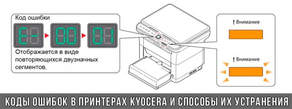
Коды ошибок принтеров и МФУ Kyocera, которые можно исправить самостоятельно
|
Код ошибки |
Значение ошибки |
Решение проблемы |
|
E-0001 (E1) |
Поврежден чип картриджа либо установлен неоригинальный картридж. |
Замените установленный картридж оригинальной версией изделия. Если хотите сэкономить, тогда купите и установите новый чип на картридж или перепрошейте принтер Kyocera. Однако предварительно не помешает попробовать сбросить ошибку соответствующей комбинацией клавиш (как это сделать, читайте в статье «Сброс ошибки установки неоригинального картриджа в принтерах Kyocera»). |
|
E-0002 (E2) |
Регион использования картриджа и принтера не совпадают. |
Замените чип или прошейте принтер Kyocera. |
|
E-0003 (E3) |
Заполнена память принтера или МФУ Kyocera. |
Отпечатайте ранее отсканированные листы или очистите очередь печати нажатием кнопки Стоп/Сброс (ранее отсканированные листы также удалятся из памяти принтера, даже если они еще не были распечатаны). |
|
E-0007 (E7) |
Тонер-картридж Kyocera израсходовал ресурс красящего вещества. |
Замените или заправьте картридж Kyocera (если используете совместимый или перезаправленный расходник, то после установки его в принтер не забудьте сбросить ошибку зажатием на 3-5 секунды кнопок [Ок] и [Сброс/Стоп]). |
|
E-0008 (E8) |
Открыта крышка принтера либо не работает датчик закрытия крышек устройства. |
Откройте и еще раз закройте переднюю и заднюю крышку принтера. Во время закрытия Вы должны услышать характерный щелчок. Если не помогло, то причина в неисправности датчика. |
|
E-0009 (E9) |
Лоток приема бумаги полон. |
Уберите все отпечатанные листы бумаги из выходящего лотка. Чтобы возобновить печать, нажмите кнопку [Старт]. |
|
E-0012 (E12) |
Ошибка памяти принтера Kyocera. |
Попробуйте уменьшить разрешение печати. Скорее всего, формат создаваемого отпечатка не соответствует возможностям принтера. |
|
E-0014 (E14) |
Установлен неверный формат бумаги (неподдерживаемый принтером Kyocera). |
Поменяйте бумагу на поддерживаемую принтером либо смените ее формат в настройках печати. Попробуйте обновить программное обеспечение. Возможно, это расширит поддерживаемые принтером Kyocera форматы. |
|
E-0015 (E15) |
Устройство не подключено к электрической сети либо на компьютере нет (не работает) драйвера принтера Kyocera. |
Проверьте подключение печатающего аппарата к электрической сети, а также целостность кабеля. Если ошибка не исчезает, скачайте драйвер принтера Kyocera и установите его на компьютер. |
|
E-0017 (E17) |
Ошибка передачи данных. |
Проверьте подключение принтера к компьютеру. Кабель не должен быть длиннее 5 метров, а также обязан поддерживать стандарт USB 2.0. Кроме того, переустановите драйвер принтера и утилиту Kyocera Client Tool. |
|
E-0018 (E18) |
Очередь печати заполнена. |
Очистите очередь печати нажатием кнопки [Сброс] либо через драйвер принтера. |
|
E-0019 (E19) |
Неверный формат печати. |
Отмените печать нажатием кнопки [Стоп/Сброс]. Выберите в настройках принтера соответствующий режим печати, а также установите в лоток поддерживаемый принтером формат бумаги. |
|
J-0000 (jam0000) |
Замятие бумаги за задней крышкой. |
Откройте крышку и извлеките бумагу. Проверьте надежность крепления бумаги в лотке, а также принтер на наличие посторонних предметов. Еще причина может быть в пружине выходного флажка. Если она растянулась, то может плохо работать фиксатор. Также проблема может быть из-за печки, сделайте ее ревизию, переборку и смазку. |
|
J-0501 (jam0501) |
Бумага застряла в принтере Kyocera |
Извлеките замятую бумагу. Проверьте надежность установки бумаги во входной лоток. Проверьте целостность роликов протяжки бумаги, а также принтер на наличие посторонних предметов. Если не помогло, стоит внимательно осмотреть ребра на направляющей пластине. На них могут образоваться сколы, трещины и заусенцы. Их можно слегка подчистить наждачной бумагой (нулевкой). |
|
J-0511 (jam0511) |
Принтер Kyocera замял бумагу. |
Извлеките замятую бумагу и повторите печать. Если проблема не исчезла, несите принтер в сервис. Скорее всего, изношен ролик протяжки бумаги. |
|
C7990 |
Бункер драм-картриджа (блока фотобарабана) заполнен отработанным тонером либо неисправен счетчик отработки красящего вещества. Еще проблема может быть в главной плате PWB. |
Осуществите чистку драм-картриджа (блока фотобарабана). Если проблема в датчике или плате, то нужно отнести принтер в СЦ на диагностику. |
|
F248 |
Ошибка обработки отпечатываемого материала. |
Перезагрузите принтер. Уберите неподдерживаемые спецсимволы из отпечатка. Обновите ПО принтера Kyocera. Смените режим работы принтера с PDL на GDI (Пуск -> Принтеры -> Свойства -> Параметры устройства). |
|
PF |
Отсутствует бумага в лотке подачи. |
Загрузите листы бумаги во входной лоток. Если принтер по-прежнему не печатает, значит нужно искать проблему в чем-то другом. |
|
1101 |
Ошибка сканирования через сеть из-за неправильного имени SMTP сервера. |
Пропишите DNS-адреса помимо прочих настроек печати по сети. |
|
1102 |
Некорректная настройка сканера для работы через сеть |
Зайдите в Web-панель управления принтером (нужно в адресную строку браузера ввести iP принтера Kyocera). Далее в зависимости от модели введите логин и пароль (Admin/Admin или просто admin00 без логина). Далее следуйте инструкции:
Логин и пароль нужны обязательно, если их нет, то следует создать. |
|
2101 |
Ошибка передачи данных при сканировании через сеть. |
Правильно настройте параметры (как для ошибки 1102), только предварительно отключите на ПК антивирус и брандмауэр. |
Если Вы испытали все способы, но не смогли убрать ошибку, то следует нести печатающее устройство в сервисный центр. Кроме того, есть ряд ошибок (высвечиваемых на дисплее принтера), которые нельзя устранить в домашних условиях. Соответствующие коды ошибок принтеров Kyocera представляем в очередной таблице.
Коды ошибок принтеров и МФУ Kyocera, которые нужно устранять в сервисном центре
|
Код ошибки |
Значение ошибки |
Решение проблемы |
|
0030 |
Неисправность платы управления факсом принтера. |
Замена платы. |
|
0100 |
Неисправность платы управления или флеш-памяти принтера. |
Замена платы. |
|
0120 |
Ошибка чтения mac-адреса из-за неисправности флеш-памяти принтера. |
Замена платы. |
|
0190 |
Неисправность платы управления или флеш-памяти принтера. |
Замена платы. |
|
0630 |
Неисправность платы управления принтера. |
Замена платы. |
|
1020 |
Неисправность мотора, привода или отсутствие контакта. |
Разборка принтера и замена изношенных частей. Проверка надежности подключений, замена разорванных (прогоревших) кабелей. Ремонт или замена привода мотора. |
|
1040 |
Неисправность мотора, привода или отсутствие контакта. |
Разборка принтера и замена изношенных частей. Проверка надежности подключений, замена разорванных (прогоревших) кабелей. Ремонт или замена привода мотора. |
|
2000 |
Неисправность главной платы управления, соединительного кабеля или привода принтера. |
Проверить ремни, шестерни и ролики привода. Смазать или заменить, если есть дефекты. Заменить привод или главную плату. |
|
3100 (C3100) |
Неисправность главной платы, привода сканера, датчика положения или нарушение целостности соединений. |
Проверить наличие разрывов и отсутствия контакта. Смазать или заменить изношенные элементы привода. Заменить привод, главную плату, датчик или соединительный кабель. Если Вам повезло, то возможно забыли отключить фиксатор блока сканера. |
|
3101 |
Сетевой кабель не подсоединен, или нарушена работа концентратора. Еще может быть из-за наличия вирусов в системе или неправильно заданным параметрам сервера SMTP. |
Проверить соединения, правильно настроить параметры сети. |
|
3300 |
Неисправность главной платы, датчика CIS или соединительного кабеля. |
Проверить контакты, заменить плату или датчик. |
|
3500 |
Неисправность главной платы или нарушение соединения контактов. |
Проверить контакты, заменить плату. |
|
4000 (C4000) |
Неисправность главной платы, привода сканера или нарушение соединений. Однако чаще всего ошибка лазера. |
Проверить контакты, заменить плату или привод блока сканера. Почистить лазер, смазать ось полигон-мотора, либо полностью заменить блок лазера. |
|
4200 |
Неисправность главной платы, блока сканера или датчика BD. |
Отключить питание принтера на 30 минут. Если не помогло, то следует заменить привод сканера или главную плату принтера. |
|
6000 (С6000) |
Неисправность главной платы, термостата, печки или нарушение соединения контактов. |
Проверить и поправить контакты. Заменить фьюзер. Ремонт или замена печки, термодатчика, термопредохранителя и т.д. |
|
6020 |
Сгорание термистора или главной платы. |
Замена термистора или главной платы. |
|
6030 |
Неисправность главной платы, термостата или термистора. Возможно, причина в отсутствии контакта. |
Проверить соединения. Заменить плату, термостат или термистор. |
|
6400 |
Неисправность главной платы, отсутствие питания или контакта. |
Заменить плату или источник питания. |
|
F000 |
Неисправность главной платы или отсутствие контакта. |
Проверить соединение ремня безопасности. Заменить ремень или плату управления. |
|
F020 |
Неисправность элементов памяти принтера. |
Перезагрузить принтер. Если ошибка не устранилась – заменить плату управления. |
|
F040 |
Неисправность главной платы принтера. |
Перезагрузить принтер. Если ошибка не устранилась – заменить плату управления. |
|
F05D |
Неисправность главной платы. Сбой программного оборудования привода. Проблемы с прошивкой принтера Kyocera. |
Перезагрузить принтер. Если ошибка не устранилась – заменить плату управления. Перепрошить принтер Kyocera. |
|
F245 F246 F247 F375 |
Принтер Kyocera заблокирован из-за проблемы, вызванной отказом источника питания. |
Нужно перепрошить принтер специальной сервисной микропрограммой. |
Обратите внимание: Если у печатающего устройства нет дисплея, то определить проблему можно по светодиодным индикаторам, встроенным в панель управления принтером. Например, у Kyocera Ecosys P2135D нужно сосчитать количество миганий индикаторов красного цвета и таким образом определить число, указывающее на ту или иную ошибку. В свою очередь, у модели Kyocera FS-1040 все зависит от темпа мигания светодиода с надписью «Внимание!» («Attention!»):
- Мигает медленно – указывает на отсутствие бумаги в лотке или тонера в картридже.
- Мигает быстро – оповещает о проблеме с памятью устройства, переполненном лотке или замятии бумаги, а также об использовании неоригинальных расходных материалов.
- Горит постоянно – говорит о проблемах с картриджем или фотобарабаном либо указывает на открытые крышки принтера.
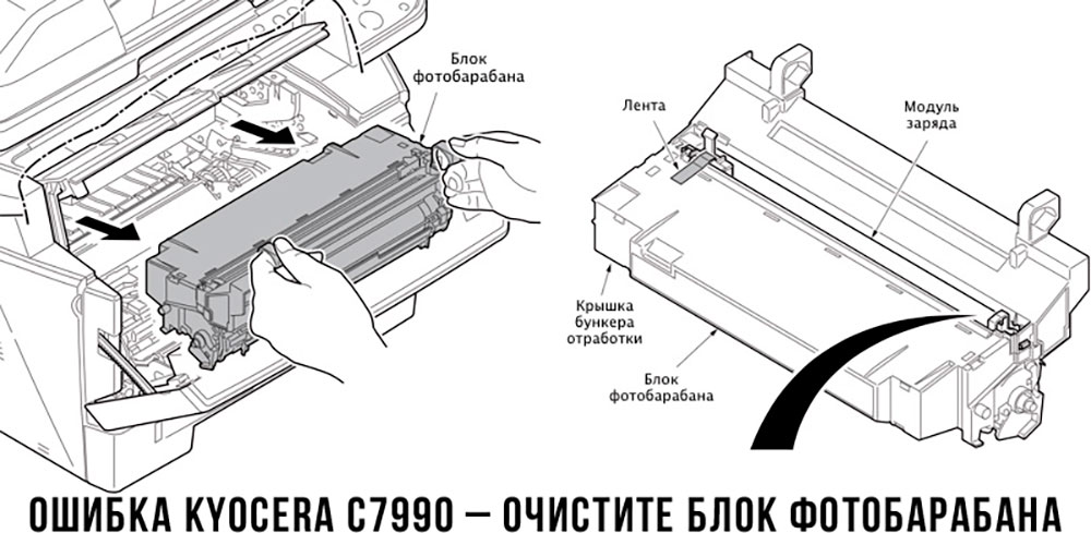
Чтобы потребитель мог наверняка определить проблему, рекомендуем использовать утилиту Kyocera Client Tool, которая идет в комплекте с драйверами принтера.
Ваше Имя:
Ваш вопрос:
Внимание: HTML не поддерживается! Используйте обычный текст.
Оценка:
Плохо
Хорошо
Введите код, указанный на картинке:
