PRESCRIBE Commands Command Reference Manual Rev 4.8 — Page 407
…G Graphics state, 228, 272 Gray pattern, 122 Grouping, 27
H Hard disk, 141, 246, 250, 256, 258
error codes, 136
I Image model, 299 International characters, 129
J Job, 136, 138, 140
printing a list of, 134 printing… copies by command, 145
K
KCGL
pen color, 297
KIR, 304 refinement level, 304
KPDL, 287 Kyocera Image Refinement, 304
L left, 307 Lightness, 155 Line, 73, 80, 82, 87
drawing by angle…
KM-NET for Direct Printing Operation Guide Rev-3.2 — Page 6
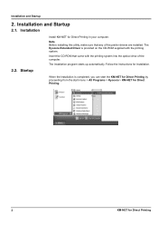
…Direct Printing by proceeding from the start menu > All Programs > Kyocera > KM-NET for Direct Printing.
2
KM-NET for Direct Printing
When the installation is provided on the CD-… that came with the printing system. Installation and Startup
2. Startup
Install KM-NET for installation. The installation program starts up automatically. Insert the CD-ROM that any of the computer.
PRESCRIBE Commands Technical Reference Manual — Rev. 4.7 — Page 215
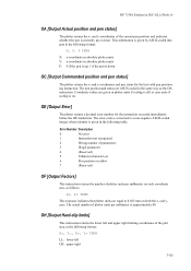
… whose identity is given in plotter units if scaling is off, or user units if scaling is approximately 40. The error code is given by ASCII-coded integers in the following format:
X, Y, P TERM
X: x-coordinate in absolute plotter units Y: y-coordinate in the following table. This information is converted to 0.025 mm on both …
PRESCRIBE Commands Technical Reference Manual — Rev. 4.7 — Page 251
… can be as follows:
setpagedevice
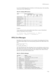
KPDL Error Messages
Depending on the computer screen.
Table 7.52. KPDL Error Messages
Code Error
Meaning
00
Cannot initiate KPDL
01 dictfull
Dictionary full; Table 7.51.
KPDL Error ## .. KPDL Operators
keys to the CollateDetails parameter should have the following error codes will appear if errors occur and doautocontinue is set to the…
KM-NET for Accounting Operation Guide Rev-1.4 — Page 7
… administrator is logged onto the domain,
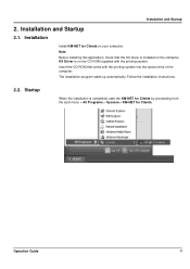
then a password is complete, you can start KM-NET for Accounting by clicking the start menu > All Programs > Kyocera > KM-NET for Accounting
5 Select the checkbox for Use Windows Domain authentication to login to install KM-NET for Accounting without entering the administrator password.
2 Click Next. 3 Register a database…
KM-NET for Clients Operation Guide Rev-3.7 — Page 7
…the CD-ROM that the KX driver is completed, start the KM-NET for Clients by proceeding from the start menu > All Programs > Kyocera > KM-NET for Clients on the computer. Operation Guide
3 KX Driver… program starts up automatically.
Installation and Startup
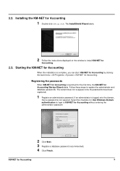
2.1. Installation
Install KM-NET for Clients. Follow the installation instructions.
2.2. Installation and Startup
2.
KX Driver User Guide Version 5.90 — Page 2
… U.S. Examples of this guide is prohibited.
Copyright © 2007 KYOCERA Corporation Copyright © 2007 Revised Edition KYOCERA MITA Corporation All rights reserved. The information in this guide is …C5030N FS-C8100DN KM-1820 KM-2540* KM-2560* KM-3040* KM—3050* KM-3060* KM-4050 * KM-5050 * KM-6030 KM-8030
KM-C2520 KM-C3225 KM-C3232 KM-C4008 KM-C4035E KM-C3232E KM-C3225E KM-C2525E FS-1010…
Fax System (M) Operation Guide Rev-2.0 — Page 4

…
10 About Network FAX What is Network FAX 10-2 Setup 10-4
11 Troubleshooting Indicators During Sending/Receiving Operation 11-2 Precautions When Turning Power OFF 11-3 Error Messages 11-4 Troubleshooting 11-6
Appendix Character Entry Method Appendix-2 Specifications Appendix-5 Menu List Appendix-6 Received FAX Sizes and Paper Priority (Inch Model Appendix-9 Received FAX…
Fax System (M) Operation Guide Rev-2.0 — Page 218

…on, or unplug the power cord and plug it in the report and refer to the Error Code List on page 15 of papers used up with document data. FAX Box capacity is …machine’s Advanced Operation Guide.
11-4
OPERATION GUIDE Call service.
If the message still appears, note the error code. Call your service representative. Refer to Send Result Reports on page 6-8 and FAX RX Result Reports…
Fax System (M) Operation Guide Rev-2.0 — Page 237

… line connection was stopped due to resend.
U01100 — U01400
Failed to cancel reception.
Ask the sender to establish connection with the recipient.
U00420 — U01199 Communication error occurred during V34 communication, the U in the error codes is recorded in a pulse line system. Send again. U00810 Page(s) not sent correctly. U00900 — Send again.
Send again…
Fax System (M) Operation Guide Rev-2.0 — Page 238

…-brand model and transmission restrictions were found set by the other party did not match the Local FAX ID on the receiving machine. Appendix-16
Error Code
Possible Cause/Action
U01600
Communication error occurred during reception of high-speed transmission.
Designated transmission speed may not be received because no data. U01800 — U01821
Communication…
Fax System (M) Operation Guide Rev-2.0 — Page 239

…. Check with a sub address box function, or the sub address does not match.
Check with the recipient.
Specified sub address box is not yet registered. Error Code U03500
U03600
U03700
U04000 U04100 U04200 U04300 U04400 U04401 U04500 U05100
U05200
Possible Cause/Action
Sub address bulletin board reception was attempted and the other…
Fax System (M) Operation Guide Rev-2.0 — Page 240

…this machine. Send again. Reception was stopped due to a data error occurring during transmission. Error Code U05300 U14000
U14100
U19000
U19100 U19200 U19300 U19400
Possible Cause/Action
Reception… the data stored in the memory of this machine. Transmission to a data error occurring during reception. Send again.
Transmission was stopped due to resend. Memory …
Fax System (M) Operation Guide Rev-2.0 — Page 241

… Encryption Key 5-59 Encryption Key No. 5-59 Operation at the Receiving System 5-63 Operation at the Sending System 5-61 Registering an Encryption Key 5-60 Error Code List Appendix-15 Error Messages 11-4
F
FAX Automatic Reception 3-11, 7-5 FAX Backup Kit 8-2 FAX Box Function 5-37
Checking 5-41 Deleting Originals from a FAX Box 5-40 FAX Box…
Scan System Operation Guide (Functions Edition) Rev-9 — Page 19

… Dialogue Box 3-137 Setting Up the PDF Keyword Assist Option 3-138 Supplemental: Making Settings related to the ‘Access according to sender name’ option 3-146
Appendix A Error Codes A-1
Appendix B Error messages B-1
Appendix C Specifications C-1
xviii
Scan System Operation Guide (Functions Edition) Rev-9 — Page 246

….
An attempt to use the Send E-mail function was made, but was unable to access the corresponding information in progress was canceled by the operator.
Error Code E001 E010
E011 E012
E020
Cause of your Operation Guide. Check to make sure that there are connected properly. The transmission log can be classified…
Scan System Operation Guide (Functions Edition) Rev-9 — Page 247

… already connected to another scanner.
• Check to find . Increase the available space on the destination computer ran out of Error
Procedure for Correction
The destination for SMTP Authentication are correct. Error Codes
Error Code E021
E022 E023 E024
E030
E031
E032
Cause of available space. The mail contained an e-mail address that Check to…
Scan System Operation Guide (Functions Edition) Rev-9 — Page 249

…, fix that problem. Verify the host name or the IP address of the FTP server is trouble in the information for Correction
The response received from the transmitting computer was not an appropriate one .
Check the computer of each group member as necessary and, if there is not set correctly. Error Codes
Error Code E039…
Scan System Operation Guide (Functions Edition) Rev-9 — Page 250

… FTP server matches the path setting registered in the FTP server. Check each error and fix the corresponding problem(s). E082 The storing path is permitted to login. Page A-6
Error Codes
Error Code
E081
Cause of unexpected response from the FTP server.
E101
An error has occurred while selecting multiple destinations. The storage folder is not found or…
3050/4050/5050 Operation Guide Rev-3 (Basic) — Page 22

… the seller, nor any other rights, which vary from whom the product was purchased.
For model KM—3050 — This warranty does not cover Maintenance Kits or the components of Maintenance Kits, which consist of the Authorized Kyocera Dealer in material and workmanship as «MFP»), and the new accessories installed with the initial installation…
Tech Support 24/7
Ask a Tech Specialist Online
Connect with the Expert via email, text or phone. Include photos, documents, and more. Get step-by-step instructions from verified Tech Support Specialists.

On this page, you will find more information about the most common causes and most relevant solutions for the Printer error ‘CFB30’. Do you need help straight away? Visit our support page.
Error information
What causes the CFB30 error?
The Kyocera documentation indicates that error code ‘CFB30’ is caused by the following problem: «Incompatible Level Of Firmware on Main EEPROM».
Do you think there is another cause for this error? Let others know in the comments.
How to solve Kyocera Printer error CFB30
We’ve created a list of solutions which you can follow if you want to solve this Printer problem yourself. Do you need more help? Visit our support page if you need professional support with Printer right away.
Tech Support 24/7
Ask a Tech Specialist Online
Connect with the Expert via email, text or phone. Include photos, documents, and more. Get step-by-step instructions from verified Tech Support Specialists.
Have you found a solution yourself, but it is not in the list? Share your solution in the comments below.
Need more help?
Do you need more help?
Tech experts are ready to answer your questions.
Ask a question
 Thanks: 0
 Likes: 0
 Dislikes: 0
-
09-14-2011
#1

Junior Member
- Rep Power
- 0
Error CFB30 on km-3060mfp
Hi
Got a km 3060 with non responsive touchscreen (board with dimm on it). got a replacement op panel (without dimm) and is getting a cfb30 error code on boot up. Suspect something to do with firmware but unable to locate latest firmware, any help would be appreciated.thanks
-
09-14-2011
#2
Senior Tech
100+ Posts
- Rep Power
- 33
Re: Error CFB30 on km-3060mfp
From Tech Bulletin 3 on the 3060:
When upgrading Firmware to MAIN/MMI2 Ver. 11.006 (2.05A Combined Firmware) on an MFP with the New Type Panel PWB installed, a Server Error message will display when the MAIN/MMI is Ver.10.029 or below. The MFP must be cycled OFF, wait at least five seconds, and then cycled ON again. The Firmware upgrade will start and the Firmware will be upgraded successfully. A Compact Flash must be used for this Upgrade. USB is not supported for this Update. Compact Flash or USB can be used for subsequent updates from Version 11.006 and above.If you try to downgrade Firmware below MAIN/MMI2 Ver. 10.029, on an MFP with a New Operation Panel 2 PWB, a CFB30 error will trigger. If this occurs, load MAIN/MMI2 Ver. 11.006 (2.05A Combined Firmware or above) to recover from the error.
The firmware should all be available on KMAconnect
-
09-15-2011
#3
Re: Error CFB30 on km-3060mfp
It might just be that the panel is not at a compatible level of firmware to talk to the main firmware. Whenever a board is changed a firmware upgrade is necessary. =^..^=
If you’d like a serious answer to your request:
1) demonstrate that you’ve read the manual
2) demonstrate that you made some attempt to fix it.
3) if you’re going to ask about jams include the jam code.
4) if you’re going to ask about an error code include the error code.
5) You are the person onsite. Only you can make observations.
blackcat: Master Of The Obvious =^..^=


Tags for this Thread
Bookmarks
Bookmarks
Posting Permissions

- You may not post new threads
- You may not post replies
- You may not post attachments
- You may not edit your posts
- BB code is On
- Smilies are On
- [IMG] code is On
- [VIDEO] code is On
- HTML code is Off
Forum Rules
- Code: 0030
- Description: FAX control PWB system error
Processing with the fax software was disabled due to a hardware problem. - Causes: Defective FAX control PWB.
- Remedy: Replace the fax control PWB and check for correct operation.
- Code: 0070
- Description: FAX control PWB incompatible detection error
Abnormal detection of FAX control PWB incompatibility In the initial communication with the FAX control PWB, any normal communication command is not transmitted. - Causes: Defective FAX software.
Defective FAX control PWB. - Remedy: Defective FAX software. Install the fax software.
Defective FAX control PWB. Replace the fax control PWB and check for correct operation.
- Code: 0100
- Description: Backup memory device error
- Causes: Defective flash memory.
Defective main PWB. - Remedy: Defective flash memory. Replace the main PWB and check for correct operation.
Defective main PWB. Replace the main PWB and check for correct operation.
- Code: 0120
- Description: MAC address data error
For data in which the MAC address is invalid. - Causes: Defective flash memory.
Defective engine PWB. - Remedy: Defective flash memory. Replace the main PWB and check for correct operation.
Defective engine PWB. Replace the engine PWB and check for correct operation.
- Code: 0150
- Description: Backup memory read/write error (engine PWB)
No response is issued from the device in reading/writing for 5 ms or more and this problem is repeated 5 times successively. Mismatch of reading data from 2 locations occurs 8 times successively. Mismatch between writing data and reading data occurs 8 times successively. - Causes: Improper installation EEPROM.
Device damage of EEPROM. - Remedy: Improper installation EEPROM. Check the installation of the EEPROM and remedy if necessary.
Defective engine PWB. Replace the engine PWB and check for correct operation.
Device damage of EEPROM. Contact the Service Administrative Division.
- Code: 0160
- Description: Backup memory data error
(engine PWB) Reading data from EEPROM is abnormal. - Causes: Data damage of EEPROM.
- Remedy: Contact the Service Administrative Division.
- Code: 0170
- Description: Billing counting error
A checksum error is detected in the main and engine backup memories for the billing counters. - Causes: Data damage of EEPROM.
Defective PWB. - Remedy: Data damage of EEPROM. Contact the Service Administrative Division.
Defective PWB. Replace the main PWB or the engine PWB and check for correct operation.
- Code: 0180
- Description: Machine number mismatch
Machine number of main and engine does not match. - Causes: Data damage of EEPROM.
- Remedy: Data damage of EEPROM. Contact the Service Administrative Division.
- Code: 0620
- Description: FAX image DIMM error
DIMM is not installed correctly. DIMM cannot be accessed. - Causes: DIMM installed incorrectly.
Defective main PWB. - Remedy: DIMM installed incorrectly. Check if the DIMM is inserted into the socket on the main PWB correctly.
Defective main PWB. Replace the main PWB and check for correct operation.
- Code: 0630
- Description: DMA error
DMA transmission of image data does not complete within the specified period of time. - Causes: Poor contact in the connector terminals.
Defective main PWB. - Remedy: Poor contact in the connector terminals. Check the connection the signal cable for CIS and the main PWB, and the continuity across the connector terminals. Repair or replace if necessary.
Defective main PWB. Replace the main PWB and check for correct operation.
- Code: 0640
- Description: Hard disk error
The hard disk cannot be accessed. - Causes: Defective hard disk.
Defective main PWB. - Remedy: Defective hard disk. Replace the hard disk and check for correct operation.
Defective main PWB. Replace the main PWB and check for correct operation.
- Code: 0650
- Description: FAX image DIMM check error
Improper DIMM is installed. - Causes: DIMM installed incorrectly.
Defective main PWB. - Remedy: DIMM installed incorrectly. Check if the DIMM is inserted into the socket on the main PWB correctly.
Defective main PWB. Replace the main PWB and check for correct operation.
- Code: 0800
- Description: Image processing error
JAM010X is detected twice. - Causes: Defective main PWB.
- Remedy: Replace the main PWB and check for correct operation.
- Code: 0830
- Description: FAX control PWB flash program area checksum error
A checksum error occurred with the program of the FAX control PWB. - Causes: Defective FAX software.
Defective FAX control PWB. - Remedy: Defective FAX software. Install the fax software.
Defective FAX control PWB. Replace the fax control PWB and check for correct operation.
- Code: 0840
- Description: Faults of RTC
The time is judged to go back based on the comparison of the RTC time and the current time or five years or more have passed. - Causes: The battery is disconnected from the main PWB.
Defective main PWB. - Remedy: The battery is disconnected from the main PWB. Check visually and remedy if necessary
Defective main PWB. Replace the main PWB and check for correct operation.
- Code: 0870
- Description: FAX control PWB to main PWB high capacity data transfer error
High-capacity data transfer between the FAX control PWB and the main PWB of the machine was not normally performed even if the data transfer was retried the specified times. - Causes: Improper installation FAX control PWB.
Defective FAX control PWB or main PWB. - Remedy: Improper installation FAX control PWB. Reinstall the FAX control PWB.
Defective FAX control PWB or main PWB. Replace the FAX control PWB or main PWB and check for correct operation.
- Code: 0900
- Description: FAX software incompatible detection error
Incompatible FAX control PWB is installed. - Causes: Defective FAX software.
Defective FAX control PWB. - Remedy: Defective FAX software. Install the fax software.
Defective FAX control PWB. Replace the fax control PWB and check for correct operation.
- Code: 0920
- Description: Fax file system error
The backup data is not retained for file system abnormality of flash memory of the FAX control PWB. - Causes: Defective FAX control PWB.
- Remedy: Replace the fax control PWB and check for correct operation.
- Code: 0970
- Description: 12 V power down detect
Power is disconnected during sleeping. - Causes: Defective power source PWB.
- Remedy: Replace the power source PWB and check for correct operation.
- Code: 0980
- Description: 24 V power down detect
24V disconnection signal is detected for 1 s and 12V disconnection signal is not detected. - Causes: Defective power source PWB.
- Remedy: Replace the power source PWB and check for correct operation.
- Code: 1000
- Description: MP lift motor error
After the MP lift motor is driven, the ON status of MP lift sensors 1 and 2 cannot be detected for 1.5 s. - Causes: Defective MP plate elevation mechanism.
Defective connector cable or poor contact in the connector.
Defective drive transmission system of motor.
Defective MP lift motor.
Defective engine PWB. - Remedy: Defective MP plate elevation mechanism. Check to see if the MP plate can move smoothly and repair it if any problem is found.
Defective connector cable or poor contact in the connector. Reinsert the connector. Also check for continuity within the connector cable. If none, replace the cable. MP lift motor and relay PWB (YC3) Relay PWB (YC12) and feed PWB 1 (YC17) Feed PWB 1 (YC1) and engine PWB (YC6)
Defective drive transmission system of motor. Check if the gears rotate smoothly. If not, grease the bushes and gears. Check for broken gears and replace if any.
Defective MP lift motor. Replace the MP lift motor.
Defective engine PWB. Replace the engine PWB and check for correct operation.
- Code: 1010
- Description: Lift motor 1 error
After cassette 1 is inserted, lift sensor 1 does not turn on within 12 s. This error is detected 4 times successively. The lock signal of the motor is detected continuously for 1 s. - Causes: Defective bottom plate elevation mechanism in the cassette.
Defective connector cable or poor contact in the connector.
Defective drive transmission system of motor
Defective lift motor 1.
Defective engine PWB. - Remedy: Defective bottom plate elevation mechanism in the cassette. Check to see if the bottom plate can move smoothly and repair it if any problem is found.
Defective connector cable or poor contact in the connector. Reinsert the connector. Also check for continuity within the connector cable. If none, replace the cable. Lift motor 1 and feed PWB 2 (YC3) Feed PWB 2 (YC1) and engine PWB (YC4)
Defective drive transmission system of motor. Check if the gears rotate smoothly. If not, grease the bushes and gears. Check for broken gears and replace if any.
Defective lift motor 1. Replace the lift motor 1.
Defective engine PWB. Replace the engine PWB and check for correct operation.
- Code: 1020
- Description: Lift motor 2 error
After cassette 2 is inserted, lift sensor 2 does not turn on within 12 s. This error is detected 4 times successively. The lock signal of the motor is detected continuously for 1 s. - Causes: Defective bottom plate elevation mechanism in the cassette.
Defective connector cable or poor contact in the connector.
Defective drive transmission system of motor.
Defective lift motor 2.
Defective engine PWB. - Remedy: Defective bottom plate elevation mechanism in the cassette. Check to see if the bottom plate can move smoothly and repair it if any problem is found.
Defective connector cable or poor contact in the connector. Reinsert the connector. Also check for continuity within the connector cable. If none, replace the cable. Lift motor 2 and feed PWB 2 (YC3) Feed PWB 2 (YC1) and engine PWB (YC4)
Defective drive transmission system of motor. Check if the gears rotate smoothly. If not, grease the bushes and gears. Check for broken gears and replace if any.
Defective lift motor 2. Replace the lift motor 2.
Defective engine PWB. Replace the engine PWB and check for correct operation.
- Code: 1030
- Description: PF lift motor 1 error (paper feeder)
After cassette 3 is inserted, PF lift sensor 1 does not turn on within 12 s. This error is detected 5 times successively. During driving the motor, the lift overcurrent protective monitor signal is detected for 1 s or more 5 times successively. However, the first 1 s after motor is turned on is excluded from detection. - Causes: Defective bottom plate elevation mechanism in the cassette.
Defective connector cable or poor contact in the connector.
Defective drive transmission system of motor.
Defective PF lift motor 1.
Defective PF main PWB. - Remedy: Defective bottom plate elevation mechanism in the cassette. Check to see if the bottom plate can move smoothly and repair it if any problem is found.
Defective connector cable or poor contact in the connector. Reinsert the connector. Also check for continuity within the connector cable. If none, replace the cable. PF lift motor 1 and PF main PWB (YC7)
Defective drive transmission system of motor. Check if the gears rotate smoothly. If not, grease the bushes and gears. Check for broken gears and replace if any.
Defective PF lift motor 1. Replace the PF lift motor 1.
Defective PF main PWB. Replace the PF main PWB (Refer to the service manual for the paper feeder).
- Code: 1040
- Description: PF lift motor 2 error (paper feeder)
After cassette 4 is inserted, PF lift sensor 2 does not turn on within 12 s. This error is detected 5 times successively. During driving the motor, the lift overcurrent protective monitor signal is detected for 1 s or more 5 times successively. However, the first 1 s after motor is turned on is excluded from detection. - Causes: Defective bottom plate elevation mechanism in the cassette.
Defective connector cable or poor contact in the connector.
Defective drive transmission system of motor.
Defective PF lift motor 2.
Defective PF main PWB. - Remedy: Defective bottom plate elevation mechanism in the cassette. Check to see if the bottom plate can move smoothly and repair it if any problem is found.
Defective connector cable or poor contact in the connector. Reinsert the connector. Also check for continuity within the connector cable. If none, replace the cable. PF lift motor 2 and PF main PWB (YC7)
Defective drive transmission system of motor. Check if the gears rotate smoothly. If not, grease the bushes and gears. Check for broken gears and replace if any.
Defective PF lift motor 2. Replace the PF lift motor 2.
Defective PF main PWB. Replace the PF main PWB (Refer to the service manual for the paper feeder).
- Code: 1050
- Description: SM lift motor error (side multi tray)
After cassette 5 is inserted, SM lift sensor does not turn on within 12 s. This error is detected 5 times successively. During driving the motor, the lift overcurrent protective monitor signal is detected for 1 s or more 5 times successively. However, the first 1 s after motor is turned on is excluded from detection. - Causes: Defective bottom plate elevation mechanism in the cassette.
Defective connector cable or poor contact in the connector.
Defective drive transmission system of motor.
Defective SM lift motor.
Defective SM main PWB. - Remedy: Defective bottom plate elevation mechanism in the cassette. Check to see if the bottom plate can move smoothly and repair it if any problem is found.
Defective connector cable or poor contact in the connector. Reinsert the connector. Also check for continuity within the connector cable. If none, replace the cable. SM lift motor and SM main PWB (YC5)
Defective drive transmission system of motor. Check if the gears rotate smoothly. If not, grease the bushes and gears. Check for broken gears and replace if any.
Defective SM lift motor. Replace the SM lift motor.
Defective SM main PWB. Replace the SM main PWB (Refer to the service manual for the paper feeder).
- Code: 1060
- Description: PF lift motor 1 error (side paper feeder)
After cassette 6 is inserted, PF lift sensor 1 does not turn on within 12 s. This error is detected 5 times successively. During driving the motor, the lift overcurrent protective monitor signal is detected for 1 s or more 5 times successively. However, the first 1 s after motor is turned on is excluded from detection. - Causes: Defective bottom plate elevation mechanism in the cassette.
Defective connector cable or poor contact in the connector.
Defective drive transmission system of motor.
Defective PF lift motor 1.
Defective PF main PWB. - Remedy: Defective bottom plate elevation mechanism in the cassette. Check to see if the bottom plate can move smoothly and repair it if any problem is found.
Defective connector cable or poor contact in the connector. Reinsert the connector. Also check for continuity within the connector cable. If none, replace the cable. PF lift motor 1 and PF main PWB (YC7)
Defective drive transmission system of motor. Check if the gears rotate smoothly. If not, grease the bushes and gears. Check for broken gears and replace if any.
Defective PF lift motor 1. Replace the PF lift motor 1.
Defective PF main PWB. Replace the PF main PWB (Refer to the service manual for the paper feeder).
- Code: 1070
- Description: PF lift motor 2 error (side paper feeder)
After cassette 7 is inserted, PF lift sensor 2 does not turn on within 12 s. This error is detected 5 times successively. During driving the motor, the lift overcurrent protective monitor signal is detected for 1 s or more 5 times successively. However, the first 1 s after motor is turned on is excluded from detection. - Causes: Defective bottom plate elevation mechanism in the cassette.
Defective connector cable or poor contact in the connector.
Defective drive transmission system of motor.
Defective PF lift motor 2.
Defective PF main PWB. - Remedy: Defective bottom plate elevation mechanism in the cassette. Check to see if the bottom plate can move smoothly and repair it if any problem is found.
Defective connector cable or poor contact in the connector. Reinsert the connector. Also check for continuity within the connector cable. If none, replace the cable. PF lift motor 2 and PF main PWB (YC7)
Defective drive transmission system of motor. Check if the gears rotate smoothly. If not, grease the bushes and gears. Check for broken gears and replace if any.
Defective PF lift motor 2. Replace the PF lift motor 2.
Defective PF main PWB. Replace the PF main PWB (Refer to the service manual for the paper feeder).
- Code: 1100
- Description: PF lift motor 1 error (large capacity feeder)
After cassette 3 is inserted, PF lift sensor 1 does not turn on within 12 s. This error is detected 2 times successively. During driving the motor, the lift overcurrent protective monitor signal is detected for 500 ms or more 2 times successively. However, the first 1 s after PF lift motor 1 is turned on is excluded from detection. - Causes: Defective connector cable or poor contact in the connector.
Defective drive transmission system of motor.
Defective PF lift motor 1.
Defective PF main PWB. - Remedy: Defective connector cable or poor contact in the connector. Reinsert the connector. Also check for continuity within the connector cable. If none, replace the cable. PF lift motor 1 and PF main PWB (YC7)
Defective drive transmission system of motor. Check if the gears rotate smoothly. If not, grease the bushes and gears. Check for broken gears and replace if any.
Defective PF lift motor 1. Replace the PF lift motor 1.
Defective PF main PWB. Replace the PF main PWB (Refer to the service manual for the paper feeder).
- Code: 1110
- Description: PF lift motor 2 error (large capacity feeder)
After cassette 4 is inserted, PF lift sensor 2 does not turn on within 12 s. This error is detected 2 times successively. During driving the motor, the lift overcurrent protective monitor signal is detected for 500 ms or more 2 times successively. However, the first 1 s after PF lift motor 2 is turned on is excluded from detection. - Causes: Defective connector cable or poor contact in the connector.
Defective drive transmission system of motor.
Defective PF lift motor 2.
Defective PF main PWB. - Remedy: Defective connector cable or poor contact in the connector. Reinsert the connector. Also check for continuity within the connector cable. If none, replace the cable. PF lift motor 2 and PF main PWB (YC7)
Defective drive transmission system of motor. Check if the gears rotate smoothly. If not, grease the bushes and gears. Check for broken gears and replace if any.
Defective PF lift motor 2. Replace the PF lift motor 2.
Defective PF main PWB. Replace the PF main PWB (Refer to the service manual for the paper feeder).
- Code: 1140
- Description: SD lift motor error (side deck)
After cassette 5 is inserted, SD lift sensor does not turn on within 30 s. The lock signal of the motor is detected continuously for 200 ms. - Causes: Defective connector cable or poor contact in the connector.
Defective drive transmission system of motor.
Defective SD lift motor.
Defective SD main PWB. - Remedy: Defective connector cable or poor contact in the connector. Reinsert the connector. Also check for continuity within the connector cable. If none, replace the cable. SD lift motor and SD main PWB (YC8)
Defective drive transmission system of motor. Check if the gears rotate smoothly. If not, grease the bushes and gears. Check for broken gears and replace if any.
Defective SD lift motor. Replace the SD lift motor.
Defective SD main PWB. Replace the SD main PWB (Refer to the service manual for the paper feeder).
- Code: 1250
- Description: SM multi feed sensor communication error (side multi tray)
A communication error is detected 3 times in succession. - Causes: Improper installation side multi tray.
Defective connector cable or poor contact in the connector.
Defective engine PWB.
Defective SM main PWB. - Remedy: Improper installation side multi tray. Follow installation instruction carefully again.
Defective connector cable or poor contact in the connector. Reinsert the connector. Also check for continuity within the connector cable. If none, replace the cable. SM main PWB (YC1) and engine PWB (YC19)
Defective engine PWB. Replace the engine PWB and check for correct operation.
Defective SM main PWB. Replace the SM main PWB (Refer to the service manual for the paper feeder).
- Code: 1350
- Description: SM multi feed sensor error (side multi tray)
The SM multi feed sensor has signaled the presence of paper for 10 ms continuously. - Causes: Defective connector cable or poor contact in the connector.
Defective SM multi feed sensor.
Defective SM main PWB. - Remedy: Defective connector cable or poor contact in the connector. Reinsert the connector. Also check for continuity within the connector cable. If none, replace the cable. SM multi feed sensor and SM main PWB (YC11)
Defective SM multi feed sensor. Replace the SM multi feed sensor.
Defective SM main PWB. Replace the SM main PWB (Refer to the service manual for the paper feeder).
- Code: 1450
- Description: SM multi feed sensor backup error (side multi tray)
When writing the data, read and write data does not match 3 times in succession. - Causes: Defective connector cable or poor contact in the connector.
Defective SM multi feed sensor.
Defective SM main PWB. - Remedy: Defective connector cable or poor contact in the connector. Reinsert the connector. Also check for continuity within the connector cable. If none, replace the cable. SM multi feed sensor and SM main PWB (YC11)
Defective SM multi feed sensor. Replace the SM multi feed sensor.
Defective SM main PWB. Replace the SM main PWB (Refer to the service manual for the paper feeder).
- Code: 1710
- Description: Side multi tray incompatible detection error
The side multi tray has been installed with a device to which it is incompatible. - Causes: The side multi tray is installed with a device to which it is incompatible.
- Remedy: The side multi tray must be installed with the devices to which it is compatible.
- Code: 1720
- Description: Paper feeder incompatible detection error
The paper feeder has been installed with a device to which it is incompatible. - Causes: The paper feeder is installed with a device to which it is incompatible.
- Remedy: The paper feeder must be installed with the devices to which it is compatible.
- Code: 1800
- Description: Paper feeder communication error
A communication error from paper feeder is detected 10 times in succession. - Causes: Improper installation paper feeder.
Defective connector cable or poor contact in the connector.
Defective engine PWB.
Defective PF main PWB. - Remedy: Improper installation paper feeder. Follow installation instruction carefully again.
Defective connector cable or poor contact in the connector. Reinsert the connector. Also check for continuity within the connector cable. If none, replace the cable. PF main PWB (YC13) and engine PWB (YC19)
Defective engine PWB. Replace the engine PWB and check for correct operation.
Defective PF main PWB. Replace the PF main PWB (Refer to the service manual for the paper feeder).
- Code: 1810
- Description: Side multi tray communication error
A communication error from paper feeder is detected 10 times in succession. - Causes: Improper installation side multi tray.
Defective connector cable or poor contact in the connector.
Defective engine PWB.
Defective SM main PWB. - Remedy: Improper installation side multi tray. Follow installation instruction carefully again.
Defective connector cable or poor contact in the connector. Reinsert the connector. Also check for continuity within the connector cable. If none, replace the cable. SM main PWB (YC1) and engine PWB (YC19)
Defective engine PWB. Replace the engine PWB and check for correct operation.
Defective SM main PWB. Replace the SM main PWB (Refer to the service manual for the paper feeder).
- Code: 1820
- Description: Side paper feeder communication error
A communication error from paper feeder is detected 10 times in succession. - Causes: Improper installation side paper feeder.
Defective connector cable or poor contact in the connector.
Defective engine PWB.
Defective SM main PWB.
Defective PF main PWB. - Remedy: Improper installation side paper feeder. Follow installation instruction carefully again.
Defective connector cable or poor contact in the connector. Reinsert the connector. Also check for continuity within the connector cable. If none, replace the cable. PF main PWB (YC13) and SM main PWB (YC4) SM main PWB (YC1) and engine PWB (YC19)
Defective engine PWB. Replace the engine PWB and check for correct operation.
Defective SM main PWB. Replace the SM main PWB (Refer to the service manual for the paper feeder).
Defective PF main PWB. Replace the PF main PWB (Refer to the service manual for the paper feeder).
- Code: 1900
- Description: Paper feeder EEPROM error
When writing the data, read and write data does not match 3 times in succession. - Causes: Defective PF main PWB.
Device damage of EEPROM. - Remedy: Defective PF main PWB. Replace the PF main PWB (Refer to the service manual for the paper feeder).
Device damage of EEPROM. Contact the Service Administrative Division.
- Code: 1910
- Description: Side multi tray EEPROM error
When writing the data, read and write data does not match 3 times in succession. - Causes: Defective SM main PWB.
Device damage of EEPROM. - Remedy: Defective SM main PWB. Replace the SM main PWB (Refer to the service manual for the paper feeder).
Device damage of EEPROM. Contact the Service Administrative Division.
- Code: 1920
- Description: Side paper feeder EEPROM error
When writing the data, read and write data does not match 3 times in succession. - Causes: Defective PF main PWB.
Device damage of EEPROM. - Remedy: Defective PF main PWB. Replace the PF main PWB (Refer to the service manual for the paper feeder).
Device damage of EEPROM. Contact the Service Administrative Division.
- Code: 1950
- Description: Transfer belt unit EEPROM error
No response is issued from the device in reading/writing for 5 ms or more and this problem is repeated 5 times successively. Mismatch of reading data from 2 locations occurs 8 times successively. Mismatch between writing data and reading data occurs 8 times successively. - Causes: Defective connector cable or poor contact in the connector.
Defective transfer belt unit. - Remedy: Defective connector cable or poor contact in the connector. Reinsert the connector. Also check for continuity within the connector cable. If none, replace the cable. Transfer belt unit and engine PWB (YC3)
Defective transfer belt unit. Replace the transfer belt unit and check for correct operation.
- Code: 2101
- Description: Developer motor K error
After developer motor K is driven, the ready signal does not turn to L within 5 s. After developer motor K is stabilized, the ready signal is at the H level for 5 s continuously. - Causes: Defective connector cable or poor contact in the connector.
Defective drive transmission system of motor.
Defective developer motor K.
Defective engine PWB. - Remedy: Defective connector cable or poor contact in the connector. Reinsert the connector. Also check for continuity within the connector cable. If none, replace the cable. Developer motor K and motor control PWB (YC7) Motor control PWB (YC3) and engine PWB (YC9)
Defective drive transmission system of motor. Check if the gears rotate smoothly. If not, grease the bushes and gears. Check for broken gears and replace if any.
Defective developer motor K. Replace the developer motor K.
Defective engine PWB. Replace the engine PWB and check for correct operation.
- Code: 2102
- Description: Developer motor MCY error
After developer motor MCY is driven, the ready signal does not turn to L within 5 s. After developer motor MCY is stabilized, the ready signal is at the H level for 5 s continuously. - Causes: Defective connector cable or poor contact in the connector.
Defective drive transmission system of motor.
Defective developer motor MCY.
Defective engine PWB. - Remedy: Defective connector cable or poor contact in the connector. Reinsert the connector. Also check for continuity within the connector cable. If none, replace the cable. Developer motor MCY and motor control PWB (YC7) Motor control PWB (YC3) and engine PWB (YC9)
Defective drive transmission system of motor. Check if the gears rotate smoothly. If not, grease the bushes and gears. Check for broken gears and replace if any.
Defective developer motor MCY. Replace the developer motor MCY.
Defective engine PWB. Replace the engine PWB and check for correct operation.
- Code: 2201
- Description: Drum motor K steady-state error
After drum motor K is stabilized, the ready signal is at the H level for 5 s continuously. - Causes: Defective connector cable or poor contact in the connector.
Defective drive transmission system of motor.
Defective drum motor K.
Defective engine PWB. - Remedy: Defective connector cable or poor contact in the connector. Reinsert the connector. Also check for continuity within the connector cable. If none, replace the cable. Drum motor K and motor control PWB (YC5) Motor control PWB (YC3) and engine PWB (YC9)
Defective drive transmission system of motor. Check if the gears rotate smoothly. If not, grease the bushes and gears. Check for broken gears and replace if any.
Defective drum motor K. Replace the drum motor K.
Defective engine PWB. Replace the engine PWB and check for correct operation.
- Code: 2202
- Description: Drum motor C steady-state error [45 ppm/55 ppm model]
After drum motor C is stabilized, the ready signal is at the H level for 5 s continuously. - Causes: Defective connector cable or poor contact in the connector.
Defective drive transmission system of motor.
Defective drum motor C.
Defective engine PWB. - Remedy: Defective connector cable or poor contact in the connector. Reinsert the connector. Also check for continuity within the connector cable. If none, replace the cable. Drum motor C and motor control PWB (YC4) Motor control PWB (YC3) and engine PWB (YC9)
Defective drive transmission system of motor. Check if the gears rotate smoothly. If not, grease the bushes and gears. Check for broken gears and replace if any.
Defective drum motor C. Replace the drum motor C.
Defective engine PWB. Replace the engine PWB and check for correct operation.
- Code: 2202
- Description: Drum motor MCY steady-state error [30 ppm/35 ppm model]
After drum motor MCY is stabilized, the ready signal is at the H level for 5 s continuously. - Causes: Defective connector cable or poor contact in the connector.
Defective drive transmission system of motor.
Defective drum motor MCY.
Defective engine PWB. - Remedy: Defective connector cable or poor contact in the connector. Reinsert the connector. Also check for continuity within the connector cable. If none, replace the cable. Drum motor MCY and motor control PWB (YC5) Motor control PWB (YC3) and engine PWB (YC9)
Defective drive transmission system of motor. Check if the gears rotate smoothly. If not, grease the bushes and gears. Check for broken gears and replace if any.
Defective drum motor MCY. Replace the drum motor MCY.
Defective engine PWB. Replace the engine PWB and check for correct operation.
- Code: 2203
- Description: Drum motor M steady-state error
After drum motor M is stabilized, the ready signal is at the H level for 5 s continuously. - Causes: Defective connector cable or poor contact in the connector.
Defective drive transmission system of motor.
Defective drum motor M.
Defective engine PWB. - Remedy: Defective connector cable or poor contact in the connector. Reinsert the connector. Also check for continuity within the connector cable. If none, replace the cable. Drum motor M and motor control PWB (YC5) Motor control PWB (YC3) and engine PWB (YC9)
Defective drive transmission system of motor. Check if the gears rotate smoothly. If not, grease the bushes and gears. Check for broken gears and replace if any.
Defective drum motor M. Replace the drum motor M.
Defective engine PWB. Replace the engine PWB and check for correct operation.
- Code: 2204
- Description: Drum motor Y steady-state error
After drum motor Y is stabilized, the ready signal is at the H level for 5 s continuously. - Causes: Defective connector cable or poor contact in the connector.
Defective drive transmission system of motor.
Defective drum motor Y.
Defective engine PWB. - Remedy: Defective connector cable or poor contact in the connector. Reinsert the connector. Also check for continuity within the connector cable. If none, replace the cable. Drum motor Y and motor control PWB (YC4) Motor control PWB (YC3) and engine PWB (YC9)
Defective drive transmission system of motor. Check if the gears rotate smoothly. If not, grease the bushes and gears. Check for broken gears and replace if any.
Defective drum motor Y. Replace the drum motor Y.
Defective engine PWB. Replace the engine PWB and check for correct operation.
- Code: 2211
- Description: Drum motor K startup error
Drum motor K is not stabilized within 5 s since the motor is activated. - Causes: Defective connector cable or poor contact in the connector.
Defective drive transmission system of motor.
Defective drum motor K.
Defective engine PWB. - Remedy: Defective connector cable or poor contact in the connector. Reinsert the connector. Also check for continuity within the connector cable. If none, replace the cable. Drum motor K and motor control PWB (YC5) Motor control PWB (YC3) and engine PWB (YC9)
Defective drive transmission system of motor. Check if the gears rotate smoothly. If not, grease the bushes and gears. Check for broken gears and replace if any.
Defective drum motor K. Replace the drum motor K.
Defective engine PWB. Replace the engine PWB and check for correct operation.
- Code: 2212
- Description: Drum motor C startup error
Drum motor C is not stabilized within 5 s since the motor is activated. - Causes: Defective connector cable or poor contact in the connector.
Defective drive transmission system of motor.
Defective drum motor C.
Defective engine PWB. - Remedy: Defective connector cable or poor contact in the connector. Reinsert the connector. Also check for continuity within the connector cable. If none, replace the cable. Drum motor C and motor control PWB (YC4) Motor control PWB (YC3) and engine PWB (YC9)
Defective drive transmission system of motor. Check if the gears rotate smoothly. If not, grease the bushes and gears. Check for broken gears and replace if any.
Defective drum motor C. Replace the drum motor C.
Defective engine PWB. Replace the engine PWB and check for correct operation.
- Code: 2213
- Description: Drum motor M startup error
Drum motor M is not stabilized within 5 s since the motor is activated. - Causes: Defective connector cable or poor contact in the connector.
Defective drive transmission system of motor.
Defective drum motor M.
Defective engine PWB. - Remedy: Defective connector cable or poor contact in the connector. Reinsert the connector. Also check for continuity within the connector cable. If none, replace the cable. Drum motor M and motor control PWB (YC5) Motor control PWB (YC3) and engine PWB (YC9)
Defective drive transmission system of motor. Check if the gears rotate smoothly. If not, grease the bushes and gears. Check for broken gears and replace if any.
Defective drum motor M. Replace the drum motor M.
Defective engine PWB. Replace the engine PWB and check for correct operation.
- Code: 2214
- Description: Drum motor Y startup error
Drum motor Y is not stabilized within 5 s since the motor is activated. - Causes: Defective connector cable or poor contact in the connector.
Defective drive transmission system of motor.
Defective drum motor Y.
Defective engine PWB. - Remedy: Defective connector cable or poor contact in the connector. Reinsert the connector. Also check for continuity within the connector cable. If none, replace the cable. Drum motor Y and motor control PWB (YC4) Motor control PWB (YC3) and engine PWB (YC9)
Defective drive transmission system of motor. Check if the gears rotate smoothly. If not, grease the bushes and gears. Check for broken gears and replace if any.
Defective drum motor Y. Replace the drum motor Y.
Defective engine PWB. Replace the engine PWB and check for correct operation.
- Code: 2300
- Description: Fuser motor error
After fuser motor is driven, the ready signal does not turn to L within 2 s. After fuser motor is stabilized, the ready signal is at the H level for 1 s continuously. - Causes: Defective connector cable or poor contact in the connector.
Defective drive transmission system of motor.
Defective fuser motor.
Defective engine PWB. - Remedy: Defective connector cable or poor contact in the connector. Reinsert the connector. Also check for continuity within the connector cable. If none, replace the cable. Fuser motor and feed PWB 1 (YC18) Feed PWB 1 (YC1) and engine PWB (YC6)
Defective drive transmission system of motor. Check if the gears rotate smoothly. If not, grease the bushes and gears. Check for broken gears and replace if any.
Defective fuser motor. Replace the fuser motor.
Defective engine PWB. Replace the engine PWB and check for correct operation.
- Code: 2550
- Description: Paper feed motor error
After paper feed motor is driven, the ready signal does not turn to L within 2 s. After paper feed motor is stabilized, the ready signal is at the H level for 1 s continuously. - Causes: Defective connector cable or poor contact in the connector.
Defective drive transmission system of motor.
Defective paper feed motor.
Defective engine PWB. - Remedy: Defective connector cable or poor contact in the connector. Reinsert the connector. Also check for continuity within the connector cable. If none, replace the cable. Paper feed motor and feed PWB 2 (YC2) Feed PWB 2 (YC1) and engine PWB (YC4)
Defective drive transmission system of motor. Check if the gears rotate smoothly. If not, grease the bushes and gears. Check for broken gears and replace if any.
Defective paper feed motor. Replace the paper feed motor.
Defective engine PWB. Replace the engine PWB and check for correct operation.
- Code: 2600
- Description: PF paper feed motor error (large capacity feeder)
After PF paper feed motor is driven, the ready signal does not turn to L within 2 s. - Causes: Defective connector cable or poor contact in the connector.
Defective drive transmission system of motor.
Defective PF paper feed motor
Defective PF main PWB. - Remedy: Defective connector cable or poor contact in the connector. Reinsert the connector. Also check for continuity within the connector cable. If none, replace the cable. PF paper feed motor and PF main PWB (YC16)
Defective drive transmission system of motor. Check if the gears rotate smoothly. If not, grease the bushes and gears. Check for broken gears and replace if any.
Defective PF paper feed motor. Replace the PF paper feed motor.
Defective PF main PWB. Replace the PF main PWB (Refer to the service manual for the paper feeder)
- Code: 2610
- Description: PF paper feed motor error (paper feeder)
After PF paper feed motor is driven, the ready signal does not turn to L within 2 s. - Causes: Defective connector cable or poor contact in the connector.
Defective drive transmission system of motor.
Defective PF paper feed motor
Defective PF main PWB. - Remedy: Defective connector cable or poor contact in the connector. Reinsert the connector. Also check for continuity within the connector cable. If none, replace the cable. PF paper feed motor and PF main PWB (YC16)
Defective drive transmission system of motor. Check if the gears rotate smoothly. If not, grease the bushes and gears. Check for broken gears and replace if any.
Defective PF paper feed motor. Replace the PF paper feed motor.
Defective PF main PWB. Replace the PF main PWB (Refer to the service manual for the paper feeder).
- Code: 2640
- Description: SD paper feed motor error (side deck)
After SD paper feed motor is driven, the ready signal does not turn to L within 2 s. - Causes: Defective connector cable or poor contact in the connector.
Defective drive transmission system of motor.
Defective SD paper feed motor
Defective SD main PWB. - Remedy: Defective connector cable or poor contact in the connector. Reinsert the connector. Also check for continuity within the connector cable. If none, replace the cable. SD paper feed motor and SD main PWB (YC16)
Defective drive transmission system of motor. Check if the gears rotate smoothly. If not, grease the bushes and gears. Check for broken gears and replace if any.
Defective SD paper feed motor. Replace the SD paper feed motor.
Defective SD main PWB. Replace the SD main PWB (Refer to the service manual for the paper feeder).
- Code: 2650
- Description: SM paper feed motor error (side multi tray)
After SM paper feed motor is driven, the ready signal does not turn to L within 2 s. - Causes: Defective connector cable or poor contact in the connector.
Defective drive transmission system of motor.
Defective SM paper feed motor.
Defective SM main PWB. - Remedy: Defective connector cable or poor contact in the connector. Reinsert the connector. Also check for continuity within the connector cable. If none, replace the cable. SM paper feed motor and SM main PWB (YC5)
Defective drive transmission system of motor. Check if the gears rotate smoothly. If not, grease the bushes and gears. Check for broken gears and replace if any.
Defective SM paper feed motor. Replace the SM paper feed motor.
Defective SM main PWB. Replace the SM main PWB (Refer to the service manual for the paper feeder).
- Code: 2660
- Description: PF paper feed motor error (side large capacity feeder)
After PF paper feed motor is driven, the ready signal does not turn to L within 2 s. - Causes: Defective connector cable or poor contact in the connector.
Defective drive transmission system of motor.
Defective PF paper feed motor.
Defective PF main PWB. - Remedy: Defective connector cable or poor contact in the connector. Reinsert the connector. Also check for continuity within the connector cable. If none, replace the cable. PF paper feed motor and PF main PWB (YC16)
Defective drive transmission system of motor. Check if the gears rotate smoothly. If not, grease the bushes and gears. Check for broken gears and replace if any.
Defective PF paper feed motor. Replace the PF paper feed motor.
Defective PF main PWB. Replace the PF main PWB (Refer to the service manual for the paper feeder).
- Code: 2670
- Description: PF paper feed motor error (side paper feeder)
After PF paper feed motor is driven, the ready signal does not turn to L within 2 s. - Causes: Defective connector cable or poor contact in the connector.
Defective drive transmission system of motor.
Defective PF paper feed motor.
Defective PF main PWB. - Remedy: Defective connector cable or poor contact in the connector. Reinsert the connector. Also check for continuity within the connector cable. If none, replace the cable. PF paper feed motor and PF main PWB (YC16)
Defective drive transmission system of motor. Check if the gears rotate smoothly. If not, grease the bushes and gears. Check for broken gears and replace if any.
Defective PF paper feed motor. Replace the PF paper feed motor.
Defective PF main PWB. Replace the PF main PWB (Refer to the service manual for the paper feeder).
- Code: 2700
- Description: Color release motor error
When the color release motor is driven, the color release sensor does not turn on/off for 1 s. - Causes: Defective connector cable or poor contact in the connector.
Defective drive transmission system of motor.
Defective color release motor.
Defective engine PWB. - Remedy: Defective connector cable or poor contact in the connector. Reinsert the connector. Also check for continuity within the connector cable. If none, replace the cable. Color release motor and engine PWB (YC3)
Defective drive transmission system of motor. Check if the gears rotate smoothly. If not, grease the bushes and gears. Check for broken gears and replace if any.
Defective color release motor. Replace the color release motor.
Defective engine PWB. Replace the engine PWB and check for correct operation.
- Code: 2730
- Description: Transfer release motor error
When the transfer release motor is driven, the transfer release sensor does not turn on/off for 1 s. - Causes: Defective connector cable or poor contact in the connector.
Defective drive transmission system of motor.
Defective transfer release motor.
Defective engine PWB. - Remedy: Defective connector cable or poor contact in the connector. Reinsert the connector. Also check for continuity within the connector cable. If none, replace the cable. Transfer release motor and relay PWB (YC14) Relay PWB (YC14) and feed PWB 1 (YC14) Feed PWB 1 (YC1) and engine PWB (YC6)
Defective drive transmission system of motor. Check if the gears rotate smoothly. If not, grease the bushes and gears. Check for broken gears and replace if any.
Defective transfer release motor. Replace the transfer release motor.
Defective engine PWB. Replace the engine PWB and check for correct operation.
- Code: 2760
- Description: Transfer motor startup error
Transfer motor is not stabilized within 5 s since the motor is activated. - Causes: Defective connector cable or poor contact in the connector.
Defective drive transmission system of motor
Defective transfer motor.
Defective engine PWB. - Remedy: Defective connector cable or poor contact in the connector. Reinsert the connector. Also check for continuity within the connector cable. If none, replace the cable. Transfer motor and feed PWB 1 (YC13) Feed PWB 1 (YC2) and engine PWB (YC5)
Defective drive transmission system of motor. Check if the gears rotate smoothly. If not, grease the bushes and gears. Check for broken gears and replace if any.
Defective transfer motor. Replace the transfer motor.
Defective engine PWB. Replace the engine PWB and check for correct operation.
- Code: 2770
- Description: Transfer skew error
An abnormal value is detected to transfer skew sensor. - Causes: Defective connector cable or poor contact in the connector.
Defective transfer skew sensor.
Defective engine PWB. - Remedy: Defective connector cable or poor contact in the connector. Reinsert the connector. Also check for continuity within the connector cable. If none, replace the cable. Transfer belt unit and engine PWB (YC3)
Defective transfer skew sensor. Replace the transfer skew sensor.
Defective engine PWB. Replace the engine PWB and check for correct operation.
- Code: 2780
- Description: Transfer skew sensor error
An abnormal value is detected to transfer skew sensor. - Causes: Defective connector cable or poor contact in the connector.
Defective transfer skew sensor.
Defective engine PWB. - Remedy: Defective connector cable or poor contact in the connector. Reinsert the connector. Also check for continuity within the connector cable. If none, replace the cable. Transfer belt unit and engine PWB (YC3)
Defective transfer skew sensor. Replace the transfer skew sensor.
Defective engine PWB. Replace the engine PWB and check for correct operation.
- Code: 2790
- Description: Transfer skew motor error
When the transfer skew motor is driven, timeouts were detected twice in a row. - Causes: Defective connector cable or poor contact in the connector.
Defective drive transmission system of motor.
Defective transfer skew motor.
Defective engine PWB. - Remedy: Defective connector cable or poor contact in the connector. Reinsert the connector. Also check for continuity within the connector cable. If none, replace the cable. Transfer skew motor and engine PWB (YC3)
Defective drive transmission system of motor. Check if the gears rotate smoothly. If not, grease the bushes and gears. Check for broken gears and replace if any.
Defective transfer skew motor. Replace the transfer skew motor.
Defective engine PWB. Replace the engine PWB and check for correct operation.
- Code: 2820
- Description: Transfer motor steady-state error
After transfer motor is stabilized, the ready signal is at the H level for 5 s continuously. - Causes: Defective connector cable or poor contact in the connector.
Defective drive transmission system of motor.
Defective transfer motor.
Defective engine PWB. - Remedy: Defective connector cable or poor contact in the connector. Reinsert the connector. Also check for continuity within the connector cable. If none, replace the cable. Transfer motor and feed PWB 1 (YC13) Feed PWB 1 (YC2) and engine PWB (YC5)
Defective drive transmission system of motor. Check if the gears rotate smoothly. If not, grease the bushes and gears. Check for broken gears and replace if any.
Defective transfer motor. Replace the transfer motor.
Defective engine PWB. Replace the engine PWB and check for correct operation.
- Code: 2840
- Description: Transfer cleaning motor error
After transfer cleaning motor is driven, the ready signal does not turn to L within 2 s.
After transfer cleaning motor is stabilized, the ready signal is at the H level for 1 s continuously. - Causes: Defective connector cable or poor contact in the connector.
Defective drive transmission system of motor.
Defective transfer cleaning motor.
Defective engine PWB. - Remedy: Defective connector cable or poor contact in the connector. Reinsert the connector. Also check for continuity within the connector cable. If none, replace the cable. Transfer cleaning motor and engine PWB (YC3)
Defective drive transmission system of motor. Check if the gears rotate smoothly. If not, grease the bushes and gears. Check for broken gears and replace if any.
Defective transfer cleaning motor. Replace the transfer cleaning motor.
Defective engine PWB. Replace the engine PWB and check for correct operation.
- Code: 2850
- Description: Transfer belt sensor error
The signal is not received for 100 ms in succession. - Causes: Defective connector cable or poor contact in the connector
Defective transfer belt sensor.
Defective engine PWB. - Remedy: Defective connector cable or poor contact in the connector. Reinsert the connector. Also check for continuity within the connector cable. If none, replace the cable. Transfer belt sensor and engine PWB (YC3)
Defective transfer belt sensor. Replace the transfer belt sensor.
Defective engine PWB. Replace the engine PWB and check for correct operation.
- Code: 2860
- Description: Transfer belt sensor error
The signal is not received for 100 ms in succession. - Causes: Defective connector cable or poor contact in the connector.
Defective transfer belt sensor.
Defective engine PWB. - Remedy: Defective connector cable or poor contact in the connector. Reinsert the connector. Also check for continuity within the connector cable. If none, replace the cable. Transfer belt sensor and engine PWB (YC3)
Defective transfer belt sensor. Replace the transfer belt sensor.
Defective engine PWB. Replace the engine PWB and check for correct operation.
- Code: 2950
- Description: Motor control PWB communication error
A communication error from the motor control PWB is detected 10 times in succession. - Causes: Defective connector cable or poor contact in the connector.
Defective motor control PWB.
Defective engine PWB. - Remedy: Defective connector cable or poor contact in the connector. Reinsert the connector. Also check for continuity within the connector cable. If none, replace the cable. Motor control PWB (YC3) and engine PWB (YC9)
Defective motor control PWB. Replace the motor control PWB and check for correct operation.
Defective engine PWB. Replace the engine PWB and check for correct operation.
- Code: 3100
- Description: Scanner carriage error
The home position is not correct when the power is turned on or at the start of copying using the table. - Causes: Defective connector cable or poor contact in the connector.
Defective home position sensor.
Defective scanner motor.
Defective ISC PWB.
Defective main PWB. - Remedy: Defective connector cable or poor contact in the connector. Reinsert the connector. Also check for continuity within the connector cable. If none, replace the cable. Home position sensor and ISC PWB (YC8) Scanner motor and ISC PWB (YC5) ISC PWB (YC3) and main PWB (YC11)
Defective home position sensor. Replace the home position sensor.
Defective scanner motor. Replace the scanner motor.
Defective ISC PWB. Replace the ISC PWB and check for correct operation.
Defective main PWB. Replace the main PWB and check for correct operation.
- Code: 3200
- Description: Exposure lamp error
When input value at the time of LED lamp PWB illumination does not exceed the threshold value between 5 s. - Causes: Defective connector cable or poor contact in the connector.
Defective LED lamp PWB.
Defective ISC PWB.
Defective main PWB. - Remedy: Defective connector cable or poor contact in the connector. Reinsert the connector. Also check for continuity within the connector cable. If none, replace the cable. LED lamp PWB and ISC PWB (YC6) ISC PWB (YC3) and main PWB (YC11)
Defective LED lamp PWB. Replace the LED lamp PWB and check for correct operation.
Defective ISC PWB. Replace the ISC PWB and check for correct operation.
Defective main PWB. Replace the main PWB and check for correct operation.
- Code: 3210
- Description: CIS lamp error
When input value at the time of CIS illumination does not exceed the threshold value between 5 s. - Causes: Defective connector cable or poor contact in the connector
Defective CIS.
Defective DPSHD PWB.
Defective DP relay PWB. - Remedy: Defective connector cable or poor contact in the connector. Reinsert the connector. Also check for continuity within the connector cable. If none, replace the cable. CIS and DPSHD PWB (YC2) DPSHD PWB (YC3) and DP relay PWB (YC2)
Defective CIS. Replace the CIS and check for correct operation.
Defective DPSHD PWB. Replace the DPSHD PWB and check for correct operation.
Defective DP relay PWB. Replace the DP relay PWB and check for correct operation.
- Code: 3300
- Description: Optical system (AGC) error
After AGC, correct input is not obtained at CCD. - Causes: Defective connector cable or poor contact in the connector.
Defective exposure lamp.
Defective CCD PWB.
Defective ISC PWB.
Defective main PWB. - Remedy: Defective connector cable or poor contact in the connector. Reinsert the connector. Also check for continuity within the connector cable. If none, replace the cable. CCD PWB (YC2) and ISC PWB (YC9) ISC PWB (YC3) and main PWB (YC11)
Defective exposure lamp. Replace the LED lamp PWB and check for correct operation.
Defective CCD PWB. Replace the CCD PWB and check for correct operation.
Defective ISC PWB. Replace the ISC PWB and check for correct operation.
Defective main PWB. Replace the main PWB and check for correct operation.
- Code: 3310
- Description: CIS AGC error
After AGC, correct input is not obtained at CIS. - Causes: Defective CIS.
Defective DPSHD PWB.
Defective DP relay PWB. - Remedy: Defective CIS. Replace the CIS and check for correct operation.
Defective DPSHD PWB. Replace the DPSHD PWB and check for correct operation.
Defective DP relay PWB. Replace the DP relay PWB and check for correct operation.
- Code: 3500
- Description: Communication error between scanner and ASIC An error code is detected.
- Causes: Defective connector cable or poor contact in the connector
Defective ISC PWB.
Defective main PWB. - Remedy: Defective connector cable or poor contact in the connector. Reinsert the connector. Also check for continuity within the connector cable. If none, replace the cable. ISC PWB (YC3) and main PWB (YC11)
Defective ISC PWB. Replace the ISC PWB and check for correct operation.
Defective main PWB. Replace the main PWB and check for correct operation.
- Code: 3600
- Description: Scanner sequence error
- Causes: Defective ISC PWB.
- Remedy: Replace the ISC PWB and check for correct operation.
- Code: 3700
- Description: Scanner device error
- Causes: CCD connector inserted incorrectly.
- Remedy: Reinsert the image scanner unit connector if necessary.
- Code: 3800
- Description: AFE error
When writing the data, read and write data does not match 3 times in succession. - Causes: Defective ISC PWB.
- Remedy: Replace the ISC PWB and check for correct operation.
- Code: 3900
- Description: Backup memory read/write error (ISC PWB)
Read and write data does not match. - Causes: Defective backup memory or PWB.
- Remedy: Replace the ISC PWB and check for correct operation.
- Code: 4001
- Description: Polygon motor K synchronization error
After polygon motor K is driven, the ready signal does not turn to L within 30 s. - Causes: Defective connector cable or poor contact in the connector.
Defective polygon motor K.
Defective engine PWB. - Remedy: Defective connector cable or poor contact in the connector. Reinsert the connector. Also check for continuity within the connector cable. If none, replace the cable. Polygon motor K and LSU relay PWB (YC4) LSU relay PWB (YC4) and engine PWB (YC12)
Defective polygon motor K. Replace the laser scanner unit.
Defective engine PWB. Replace the engine PWB and check for correct operation.
- Code: 4002
- Description: Polygon motor C synchronization error
After polygon motor C is driven, the ready signal does not turn to L within 30 s. - Causes: Defective connector cable or poor contact in the connector.
Defective polygon motor C.
Defective engine PWB. - Remedy: Defective connector cable or poor contact in the connector. Reinsert the connector. Also check for continuity within the connector cable. If none, replace the cable. Polygon motor C and LSU relay PWB (YC9) LSU relay PWB (YC3) and engine PWB (YC12)
Defective polygon motor C. Replace the laser scanner unit.
Defective engine PWB. Replace the engine PWB and check for correct operation.
- Code: 4003
- Description: Polygon motor M synchronization error
After polygon motor M is driven, the ready signal does not turn to L within 30 s. - Causes: Defective connector cable or poor contact in the connector.
Defective polygon motor M.
Defective engine PWB. - Remedy: Defective connector cable or poor contact in the connector. Reinsert the connector. Also check for continuity within the connector cable. If none, replace the cable. Polygon motor M and LSU relay PWB (YC7) LSU relay PWB (YC3) and engine PWB (YC12)
Defective polygon motor M. Replace the laser scanner unit.
Defective engine PWB. Replace the engine PWB and check for correct operation.
- Code: 4004
- Description: Polygon motor Y synchronization error
After polygon motor Y is driven, the ready signal does not turn to L within 30 s. - Causes: Defective connector cable or poor contact in the connector.
Defective polygon motor Y.
Defective engine PWB. - Remedy: Defective connector cable or poor contact in the connector. Reinsert the connector. Also check for continuity within the connector cable. If none, replace the cable. Polygon motor Y and LSU relay PWB (YC11) LSU relay PWB (YC3) and engine PWB (YC12)
Defective polygon motor Y. Replace the laser scanner unit.
Defective engine PWB. Replace the engine PWB and check for correct operation.
- Code: 4011
- Description: Polygon motor K steady-state error
After polygon motor K is stabilized, the ready signal is at the H level for 15 s continuously. - Causes: Defective connector cable or poor contact in the connector.
Defective polygon motor K.
Defective engine PWB. - Remedy: Defective connector cable or poor contact in the connector. Reinsert the connector. Also check for continuity within the connector cable. If none, replace the cable. Polygon motor K and LSU relay PWB (YC4) LSU relay PWB (YC4) and engine PWB (YC12)
Defective polygon motor K. Replace the laser scanner unit.
Defective engine PWB. Replace the engine PWB and check for correct operation.
- Code: 4012
- Description: Polygon motor C steady-state error
After polygon motor C is stabilized, the ready signal is at the H level for 15 s continuously. - Causes: Defective connector cable or poor contact in the connector.
Defective polygon motor C.
Defective engine PWB. - Remedy: Defective connector cable or poor contact in the connector. Reinsert the connector. Also check for continuity within the connector cable. If none, replace the cable. Polygon motor C and LSU relay PWB (YC9) LSU relay PWB (YC3) and engine PWB (YC12)
Defective polygon motor C. Replace the laser scanner unit.
Defective engine PWB. Replace the engine PWB and check for correct operation.
- Code: 4013
- Description: Polygon motor M steady-state error
After polygon motor M is stabilized, the ready signal is at the H level for 15 s continuously. - Causes: Defective connector cable or poor contact in the connector
Defective polygon motor M.
Defective engine PWB. - Remedy: Defective connector cable or poor contact in the connector. Reinsert the connector. Also check for continuity within the connector cable. If none, replace the cable. Polygon motor M and LSU relay PWB (YC7) LSU relay PWB (YC3) and engine PWB (YC12)
Defective polygon motor M. Replace the laser scanner unit.
Defective engine PWB. Replace the engine PWB and check for correct operation.
- Code: 4014
- Description: Polygon motor Y steady-state error
After polygon motor Y is stabilized, the ready signal is at the H level for 15 s continuously. - Causes: Defective connector cable or poor contact in the connector.
Defective polygon motor Y.
Defective engine PWB. - Remedy: Defective connector cable or poor contact in the connector. Reinsert the connector. Also check for continuity within the connector cable. If none, replace the cable. Polygon motor Y and LSU relay PWB (YC11) LSU relay PWB (YC3) and engine PWB (YC12)
Defective polygon motor Y. Replace the laser scanner unit.
Defective engine PWB. Replace the engine PWB and check for correct operation.
- Code: 4101
- Description: BD initialization error K
After polygon motor K is driven, ASIC detects a BD error for 1 s. - Causes: Defective connector cable or poor contact in the connector.
Defective PD PWB K.
Defective engine PWB. - Remedy: Defective connector cable or poor contact in the connector. Reinsert the connector. Also check for continuity within the connector cable. If none, replace the cable. Laser scanner unit and LSU relay PWB (YC5) LSU relay PWB (YC3) and engine PWB (YC12)
Defective PD PWB K. Replace the laser scanner unit.
Defective engine PWB. Replace the engine PWB and check for correct operation.
- Code: 4102
- Description: BD initialization error C
After polygon motor C is driven, ASIC detects a BD error for 1 s. - Causes: Defective connector cable or poor contact in the connector.
Defective PD PWB C.
Defective engine PWB. - Remedy: Defective connector cable or poor contact in the connector. Reinsert the connector. Also check for continuity within the connector cable. If none, replace the cable. Laser scanner unit and LSU relay PWB (YC10) LSU relay PWB (YC3) and engine PWB (YC12)
Defective PD PWB C. Replace the laser scanner unit.
Defective engine PWB. Replace the engine PWB and check for correct operation.
- Code: 4103
- Description: BD initialization error M
After polygon motor M is driven, ASIC detects a BD error for 1 s - Causes: Defective connector cable or poor contact in the connector.
Defective PD PWB M.
Defective engine PWB. - Remedy: Defective connector cable or poor contact in the connector. Reinsert the connector. Also check for continuity within the connector cable. If none, replace the cable. Laser scanner unit and LSU relay PWB (YC8) LSU relay PWB (YC3) and engine PWB (YC12)
Defective PD PWB M. Replace the laser scanner unit.
Defective engine PWB. Replace the engine PWB and check for correct operation.
- Code: 4104
- Description: BD initialization error Y
After polygon motor Y is driven, ASIC detects a BD error for 1 s. - Causes: Defective connector cable or poor contact in the connector.
Defective PD PWB Y.
Defective engine PWB. - Remedy: Defective connector cable or poor contact in the connector. Reinsert the connector. Also check for continuity within the connector cable. If none, replace the cable. Laser scanner unit and LSU relay PWB (YC12) LSU relay PWB (YC3) and engine PWB (YC12)
Defective PD PWB Y. Replace the laser scanner unit.
Defective engine PWB. Replace the engine PWB and check for correct operation.
- Code: 4201
- Description: BD steady-state error K
The BD signal is not detected. - Causes: Defective connector cable or poor contact in the connector.
Defective PD PWB K.
Defective engine PWB. - Remedy: Defective connector cable or poor contact in the connector. Reinsert the connector. Also check for continuity within the connector cable. If none, replace the cable. Laser scanner unit and LSU relay PWB (YC5) LSU relay PWB (YC3) and engine PWB (YC12)
Defective PD PWB K. Replace the laser scanner unit.
Defective engine PWB. Replace the engine PWB and check for correct operation.
- Code: 4202
- Description: BD steady-state error C
The BD signal is not detected. - Causes: Defective connector cable or poor contact in the connector.
Defective PD PWB C.
Defective engine PWB. - Remedy: Defective connector cable or poor contact in the connector. Reinsert the connector. Also check for continuity within the connector cable. If none, replace the cable. Laser scanner unit and LSU relay PWB (YC10) LSU relay PWB (YC3) and engine PWB (YC12)
Defective PD PWB C. Replace the laser scanner unit.
Defective engine PWB. Replace the engine PWB and check for correct operation.
- Code: 4203
- Description: BD steady-state error M
The BD signal is not detected. - Causes: Defective connector cable or poor contact in the connector.
Defective PD PWB M.
Defective engine PWB. - Remedy: Defective connector cable or poor contact in the connector. Reinsert the connector. Also check for continuity within the connector cable. If none, replace the cable. Laser scanner unit and LSU relay PWB (YC8) LSU relay PWB (YC3) and engine PWB (YC12)
Defective PD PWB M. Replace the laser scanner unit.
Defective engine PWB. Replace the engine PWB and check for correct operation.
- Code: 4204
- Description: BD steady-state error Y
The BD signal is not detected. - Causes: Defective connector cable or poor contact in the connector.
Defective PD PWB Y.
Defective engine PWB - Remedy: Defective connector cable or poor contact in the connector. Reinsert the connector. Also check for continuity within the connector cable. If none, replace the cable. Laser scanner unit and LSU relay PWB (YC12) LSU relay PWB (YC3) and engine PWB (YC12)
Defective PD PWB Y. Replace the laser scanner unit.
Defective engine PWB. Replace the engine PWB and check for correct operation.
- Code: 4300
- Description: Polygon motor phase error
ASIC won’t settle in completion of phase adjustment for 2 seconds after a BD signal is detected. - Causes: Defective laser scanner unit.
Defective engine PWB. - Remedy: Defective laser scanner unit. Replace the laser scanner unit.
Defective engine PWB. Replace the engine PWB and check for correct operation.
- Code: 4600
- Description: LSU cleaning motor error
After LSU cleaning motor is driven, the ready signal does not turn to L within 2 s. After LSU cleaning motor is stabilized, the ready signal is at the H level for 1 s continuously. - Causes: Defective connector cable or poor contact in the connector.
Defective drive transmission system of motor.
Defective LSU cleaning motor.
Defective engine PWB. - Remedy: Defective connector cable or poor contact in the connector. Reinsert the connector. Also check for continuity within the connector cable. If none, replace the cable. LSU cleaning motor and engine PWB (YC21)
Defective drive transmission system of motor. Check if the gears rotate smoothly. If not, grease the bushes and gears. Check for broken gears and replace if any.
Defective LSU cleaning motor. Replace the LSU cleaning motor.
Defective engine PWB. Replace the engine PWB and check for correct operation.
- Code: 5101
- Description: Main high-voltage error K
Abnormality of charger roller K is detected when Vpp adjustment. - Causes: Defective connector cable or poor contact in the connector.
Defective high voltage PWB 1.
Defective engine PWB. - Remedy: Defective connector cable or poor contact in the connector. Reinsert the connector. Also check for continuity within the connector cable. If none, replace the cable. High voltage PWB 1 (YC4) and engine PWB (YC17)
Defective high voltage PWB 1. Replace the high voltage PWB 1 and check for correct operation.
Defective engine PWB. Replace the engine PWB and check for correct operation.
- Code: 5102
- Description: Main high-voltage error C
Abnormality of charger roller C is detected when Vpp adjustment. - Causes: Defective connector cable or poor contact in the connector.
Defective high voltage PWB 1.
Defective engine PWB. - Remedy: Defective connector cable or poor contact in the connector. Reinsert the connector. Also check for continuity within the connector cable. If none, replace the cable. High voltage PWB 1 (YC2) and engine PWB (YC16)
Defective high voltage PWB 1. Replace the high voltage PWB 1 and check for correct operation.
Defective engine PWB. Replace the engine PWB and check for correct operation.
- Code: 5103
- Description: Main high-voltage error M
Abnormality of charger roller M is detected when Vpp adjustment. - Causes: Defective connector cable or poor contact in the connector.
Defective high voltage PWB 1.
Defective engine PWB. - Remedy: Defective connector cable or poor contact in the connector. Reinsert the connector. Also check for continuity within the connector cable. If none, replace the cable. High voltage PWB 1 (YC3) and engine PWB (YC17)
Defective high voltage PWB 1. Replace the high voltage PWB 1 and check for correct operation.
Defective engine PWB. Replace the engine PWB and check for correct operation.
- Code: 5104
- Description: Main high-voltage error Y
Abnormality of charger roller Y is detected when Vpp adjustment. - Causes: Defective connector cable or poor contact in the connector.
Defective high voltage PWB 1.
Defective engine PWB. - Remedy: Defective connector cable or poor contact in the connector. Reinsert the connector. Also check for continuity within the connector cable. If none, replace the cable. High voltage PWB 1 (YC1) and engine PWB (YC16)
Defective high voltage PWB 1. Replace the high voltage PWB 1 and check for correct operation.
Defective engine PWB. Replace the engine PWB and check for correct operation.
- Code: 6000
- Description: Broken fuser heater wire
Fuser thermistor 1 does not reach 100° C/212 °F even after 60 s during warming up. The detected temperature of fuser thermistor 1 does not reach the specified temperature (ready indication temperature) for 60 s in warming up after reached to 100° C/212 °F. - Causes: Defective connector cable or poor contact in the connector.
Deformed connector pin.
Defective triac.
Fuser thermostat triggered.
Defective fuser IH.
Defective engine PWB. - Remedy: Defective connector cable or poor contact in the connector. Reinsert the connector. Also check for continuity within the connector cable. If none, replace the cable. Power source PWB (YC3) and fuser IH PWB (YC1) Fuser IH PWB (YC4) and engine PWB (YC26)
Fuser thermostat triggered. Replace the fuser unit.
Defective fuser IH. Replace the fuser unit.
Defective engine PWB. Replace the engine PWB and check for correct operation.
- Code: 6020
- Description: Abnormally high fuser thermistor 1 temperature
Fuser thermistor 1 detects a temperature higher than 240°C/464°F for 1 s. - Causes: Deformed connector pin.
Defective triac.
Shorted fuser thermistor 1.
Defective engine PWB. - Remedy: Shorted fuser thermistor 1. Replace the fuser unit.
Defective engine PWB. Replace the engine PWB and check for correct operation.
- Code: 6030
- Description: Broken fuser thermistor 1 wire
Input from fuser thermistor 1 is 984 or more (A/D value) continuously for 1 s. - Causes: Defective connector cable or poor contact in the connector.
Deformed connector pin.
Defective triac.
Broken fuser thermistor 1 wire.
Fuser thermostat triggered.
Defective fuser IH.
Defective engine PWB. - Remedy: Defective connector cable or poor contact in the connector. Reinsert the connector. Also check for continuity within the connector cable. If none, replace the cable. Fuser unit and engine PWB (YC26)
Broken fuser thermistor 1 wire. Replace the fuser unit.
Fuser thermostat triggered. Replace the fuser unit.
Defective fuser IH. Replace the fuser unit.
Defective engine PWB. Replace the engine PWB and check for correct operation.
- Code: 6040
- Description: Fuser heater error
Input from fuser thermistor 1 is abnormal value continuously for 1 s. - Causes: Defective connector cable or poor contact in the connector.
Deformed connector pin.
Defective triac.
Broken fuser thermistor 1 wire
Defective fuser IH.
Defective engine PWB. - Remedy: Defective connector cable or poor contact in the connector. Reinsert the connector. Also check for continuity within the connector cable. If none, replace the cable. Fuser unit and engine PWB (YC26)
Broken fuser thermistor 1 wire. Replace the fuser unit.
Defective fuser IH. Replace the fuser unit.
Defective engine PWB. Replace the engine PWB and check for correct operation.
- Code: 6050
- Description: Abnormally low fuser thermistor 1 temperature
Fuser thermistor 1 detects a temperature lower than 100°C/212°F for 1 s after warming up. - Causes: Deformed connector pin.
Defective triac.
Defective fuser thermistor 1.
Defective fuser IH.
Defective engine PWB. - Remedy: Defective fuser thermistor 1. Replace the fuser unit.
Defective fuser IH. Replace the fuser unit.
Defective engine PWB. Replace the engine PWB and check for correct operation.
- Code: 6120
- Description: Abnormally high fuser thermistor 4 temperature
Fuser thermistor 1 detects a temperature higher than 190°C/374°F for 1 s. - Causes: Deformed connector pin.
Defective triac.
Shorted fuser thermistor 4.
Defective engine PWB. - Remedy: Shorted fuser thermistor 4. Replace the fuser unit.
Defective engine PWB. Replace the engine PWB and check for correct operation.
- Code: 6130
- Description: Broken fuser thermistor 4 wire
Input from fuser thermistor 4 is 992 or more (A/D value) continuously for 1 s. - Causes: Defective connector cable or poor contact in the connector.
Deformed connector pin.
Defective triac.
Broken fuser thermistor 4 wire.
Defective fuser IH.
Defective engine PWB. - Remedy: Defective connector cable or poor contact in the connector. Reinsert the connector. Also check for continuity within the connector cable. If none, replace the cable. Fuser unit and engine PWB (YC26)
Broken fuser thermistor 4 wire. Replace the fuser unit.
Defective fuser IH. Replace the fuser unit.
Defective engine PWB. Replace the engine PWB and check for correct operation.
- Code: 6150
- Description: Abnormally low fuser thermistor 4 temperature
Fuser thermistor 4 detects a temperature lower than 30°C/ 86°F for 1 s after warming up. - Causes: Deformed connector pin.
Defective triac.
Defective fuser thermistor 1.
Defective fuser IH.
Defective engine PWB. - Remedy: Defective fuser thermistor 1. Replace the fuser unit.
Defective fuser IH. Replace the fuser unit.
Defective engine PWB. Replace the engine PWB and check for correct operation.
- Code: 6200
- Description: Broken fuser edge heater wire
Fuser thermistor 2 does not reach 100° C/212 °F even after 60 s during warming up. The detected temperature of fuser thermistor 2 does not reach the specified temperature (ready indication temperature) for 60 s in warming up after reached to 100° C/212 °F. - Causes: Defective connector cable or poor contact in the connector.
Deformed connector pin.
Defective triac.
Fuser thermostat triggered.
Defective fuser IH.
Defective engine PWB. - Remedy: Defective connector cable or poor contact in the connector. Reinsert the connector. Also check for continuity within the connector cable. If none, replace the cable. Power source PWB (YC3) and fuser IH PWB (YC1) Fuser IH PWB (YC4) and engine PWB (YC26)
Fuser thermostat triggered. Replace the fuser unit.
Defective fuser IH. Replace the fuser unit.
Defective engine PWB. Replace the engine PWB and check for correct operation.
- Code: 6220
- Description: Abnormally high fuser thermistor 2 temperature
Fuser thermistor 2 detects a temperature higher than 250°C/482°F for 1 s. - Causes: Deformed connector pin.
Defective triac.
Shorted fuser thermistor 2.
Defective engine PWB. - Remedy: Shorted fuser thermistor 2. Replace the fuser unit.
Defective engine PWB. Replace the engine PWB and check for correct operation.
- Code: 6230
- Description: Broken fuser thermistor 2 wire
Input from fuser thermistor 2 is 992 or more (A/D value) continuously for 1 s. - Causes: Defective connector cable or poor contact in the connector.
Deformed connector pin.
Defective triac.
Broken fuser thermistor 2 wire.
Fuser thermostat triggered.
Defective fuser IH.
Defective engine PWB. - Remedy: Defective connector cable or poor contact in the connector. Reinsert the connector. Also check for continuity within the connector cable. If none, replace the cable. Fuser unit and engine PWB (YC26)
Broken fuser thermistor 2 wire. Replace the fuser unit.
Fuser thermostat triggered. Replace the fuser unit.
Defective fuser IH. Replace the fuser unit.
Defective engine PWB. Replace the engine PWB and check for correct operation.
- Code: 6250
- Description: Abnormally low fuser thermistor 2 temperature
Fuser thermistor 2 detects a temperature lower than 50°C/ 122°F for 1 s after warming up. - Causes: Deformed connector pin.
Defective triac.
Defective fuser thermistor 2.
Defective fuser IH.
Defective engine PWB. - Remedy: Defective fuser thermistor 2. Replace the fuser unit.
Defective fuser IH. Replace the fuser unit.
Defective engine PWB. Replace the engine PWB and check for correct operation.
- Code: 6320
- Description: Abnormally high fuser thermistor 3 temperature
Fuser thermistor 3 detects a temperature higher than 240°C/464°F for 1 s. - Causes: Deformed connector pin.
Defective triac.
Shorted fuser thermistor 3.
Defective engine PWB. - Remedy: Shorted fuser thermistor 3. Replace the fuser unit.
Defective engine PWB. Replace the engine PWB and check for correct operation.
- Code: 6330
- Description: Broken fuser thermistor 3 wire
Input from fuser thermistor 3 is 992 or more (A/D value) continuously for 1 s. - Causes: Defective connector cable or poor contact in the connector.
Deformed connector pin.
Defective triac.
Broken fuser thermistor 3 wire.
Fuser thermostat triggered.
Defective fuser IH.
Defective engine PWB. - Remedy: Defective connector cable or poor contact in the connector. Reinsert the connector. Also check for continuity within the connector cable. If none, replace the cable. Fuser unit and engine PWB (YC26)
Broken fuser thermistor 3 wire. Replace the fuser unit.
Fuser thermostat triggered. Replace the fuser unit.
Defective fuser IH. Replace the fuser unit.
Defective engine PWB. Replace the engine PWB and check for correct operation.
- Code: 6610
- Description: Fuser release motor error
When the fuser release motor is driven, the fuser release sensor does not turn on/off for 5 s. - Causes: Defective connector cable or poor contact in the connector.
Defective drive transmission system of motor.
Defective fuser release motor.
Defective engine PWB. - Remedy: Defective connector cable or poor contact in the connector. Reinsert the connector. Also check for continuity within the connector cable. If none, replace the cable. Fuser unit and engine PWB (YC26)
Defective drive transmission system of motor. Check if the gears rotate smoothly. If not, grease the bushes and gears. Check for broken gears and replace if any.
Defective fuser release motor. Replace the fuser release motor.
Defective engine PWB. Replace the engine PWB and check for correct operation.
- Code: 6710
- Description: Fuser IH PWB CPU reset error
Watch doc timer has been overflowed. - Causes: Defective connector cable or poor contact in the connector.
Defective fuser IH PWB
Defective engine PWB. - Remedy: Defective connector cable or poor contact in the connector. Reinsert the connector. Also check for continuity within the connector cable. If none, replace the cable. Fuser IH PWB (YC4) and engine PWB (YC26)
Defective fuser IH PWB. Replace the fuser IH PWB and check for correct operation.
Defective engine PWB. Replace the engine PWB and check for correct operation.
- Code: 6720
- Description: Fuser IH belt rotation error
A belt rotating pulse is not received for 1 second. - Causes: Defective connector cable or poor contact in the connector.
Defective fuser belt sensor.
Defective engine PWB - Remedy: Defective connector cable or poor contact in the connector. Reinsert the connector. Also check for continuity within the connector cable. If none, replace the cable. Fuser unit and engine PWB (YC26)
Defective fuser belt sensor. Replace the fuser belt sensor.
Defective engine PWB. Replace the engine PWB and check for correct operation.
- Code: 6730
- Description: Abnormally high fuser IH PWB temperature 1
The input detect temperature is greater than 105°C/221 °F. - Causes: Defective connector cable or poor contact in the connector.
Defective fuser IH PWB.
Defective engine PWB. - Remedy: Defective connector cable or poor contact in the connector. Reinsert the connector. Also check for continuity within the connector cable. If none, replace the cable. Fuser IH PWB (YC4) and engine PWB (YC26)
Defective fuser IH PWB. Replace the fuser IH PWB and check for correct operation.
Defective engine PWB. Replace the engine PWB and check for correct operation.
- Code: 6740
- Description: Abnormally high fuser IH PWB temperature 2
The input detect temperature is greater than 105°C/221 °F. - Causes: Defective connector cable or poor contact in the connector.
Defective fuser IH PWB.
Defective engine PWB. - Remedy: Defective connector cable or poor contact in the connector. Reinsert the connector. Also check for continuity within the connector cable. If none, replace the cable. Fuser IH PWB (YC4) and engine PWB (YC26)
Defective fuser IH PWB. Replace the fuser IH PWB and check for correct operation.
Defective engine PWB. Replace the engine PWB and check for correct operation.
- Code: 6750
- Description: Fuser IH output over-current error
The output current is greater than 75A for 10 ms in succession. - Causes: Defective connector cable or poor contact in the connector.
Defective fuser IH PWB.
Defective engine PWB. - Remedy: Defective connector cable or poor contact in the connector. Reinsert the connector. Also check for continuity within the connector cable. If none, replace the cable. Fuser IH PWB (YC4) and engine PWB (YC26)
Defective fuser IH PWB. Replace the fuser IH PWB and check for correct operation.
Defective engine PWB. Replace the engine PWB and check for correct operation.
- Code: 6760
- Description: Fuser IH input over-current error
The input current is greater than 20A for 100 ms in succession. - Causes: Defective connector cable or poor contact in the connector.
Defective fuser IH PWB.
Defective engine PWB. - Remedy: Defective connector cable or poor contact in the connector. Reinsert the connector. Also check for continuity within the connector cable. If none, replace the cable. Fuser IH PWB (YC4) and engine PWB (YC26)
Defective fuser IH PWB. Replace the fuser IH PWB and check for correct operation.
Defective engine PWB. Replace the engine PWB and check for correct operation.
- Code: 6770
- Description: Fuser IH low electric power error
The preset power is less than 0.6 times of it for 120 ms in succession. - Causes: Defective connector cable or poor contact in the connector.
Defective fuser IH PWB
Defective engine PWB. - Remedy: Defective connector cable or poor contact in the connector. Reinsert the connector. Also check for continuity within the connector cable. If none, replace the cable. Fuser IH PWB (YC4) and engine PWB (YC26)
Defective fuser IH PWB. Replace the fuser IH PWB and check for correct operation.
Defective engine PWB. Replace the engine PWB and check for correct operation.
- Code: 6780
- Description: Fuser IH input over-voltage error
The input voltage is greater than 140V for 200 ms in succession. - Causes: Defective connector cable or poor contact in the connector.
Defective fuser IH PWB.
Defective engine PWB. - Remedy: Defective connector cable or poor contact in the connector. Reinsert the connector. Also check for continuity within the connector cable. If none, replace the cable. Fuser IH PWB (YC4) and engine PWB (YC26)
Defective fuser IH PWB. Replace the fuser IH PWB and check for correct operation.
Defective engine PWB. Replace the engine PWB and check for correct operation.
- Code: 6900
- Description: Fuser front fan motor error
When the fuser front fan motor is driven, alarm signal is detected for 5 s continuously. - Causes: Defective connector cable or poor contact in the connector.
Defective fuser front fan motor.
Defective engine PWB - Remedy: Defective connector cable or poor contact in the connector. Reinsert the connector. Also check for continuity within the connector cable. If none, replace the cable. Fuser front fan motor and front PWB (YC4) Front PWB (YC3) and engine PWB (YC7)
Defective fuser front fan motor. Replace the fuser front fan motor.
Defective engine PWB. Replace the engine PWB and check for correct operation.
- Code: 6910
- Description: Fuser rear fan motor error
When the fuser rear fan motor is driven, alarm signal is detected for 5 s continuously. - Causes: Defective connector cable or poor contact in the connector.
Defective fuser rear fan motor.
Defective engine PWB. - Remedy: Defective connector cable or poor contact in the connector. Reinsert the connector. Also check for continuity within the connector cable. If none, replace the cable. Fuser rear fan motor and engine PWB (YC26)
Defective fuser rear fan motor. Replace the fuser rear fan motor.
Defective engine PWB. Replace the engine PWB and check for correct operation.
- Code: 6920
- Description: Fuser edge fan motor 1 error
When the fuser edge fan motor 1 is driven, alarm signal is detected for 5 s continuously. - Causes: Defective connector cable or poor contact in the connector.
Defective fuser edge fan motor 1.
Defective engine PWB. - Remedy: Defective connector cable or poor contact in the connector. Reinsert the connector. Also check for continuity within the connector cable. If none, replace the cable. Fuser edge fan motor and engine PWB (YC26)
Defective fuser edge fan motor 1. Replace fuser edge fan motor 1.
Defective engine PWB. Replace the engine PWB and check for correct operation.
- Code: 6930
- Description: Fuser edge fan motor 2 error
When the fuser edge fan motor 2 is driven, alarm signal is detected for 5 s continuously. - Causes: Defective connector cable or poor contact in the connector.
Defective fuser edge fan motor 2.
Defective engine PWB. - Remedy: Defective connector cable or poor contact in the connector. Reinsert the connector. Also check for continuity within the connector cable. If none, Fuser edge fan motor 2 and fuser PWB (YC2) Fuser PWB (YC1) and engine PWB (YC26)
Defective fuser edge fan motor 2. Replace fuser edge fan motor 2.
Defective engine PWB. Replace the engine PWB and check for correct operation.
- Code: 6940
- Description: IH fan motor error
When the IH fan motor is driven, the alarm signal is detected for 5 s continuously. - Causes: Defective connector cable or poor contact in the connector.
Defective IH fan motor.
Defective engine PWB. - Remedy: Defective connector cable or poor contact in the connector. Reinsert the connector. Also check for continuity within the connector cable. If none, replace the cable. IH fan motor and feed PWB 1 (YC11) Feed PWB 1 (YC2) and engine PWB (YC5)
Defective IH fan motor. Replace the IH fan motor.
Defective engine PWB. Replace the engine PWB and check for correct operation.
- Code: 6950
- Description: Fuser IH PWB communication error
No response is received in 30 ms since a command is sent to IHCPU. A checksum error is detected 10 times in succession. - Causes: Defective connector cable or poor contact in the connector.
Defective fuser IH PWB.
Defective engine PWB. - Remedy: Defective connector cable or poor contact in the connector. Reinsert the connector. Also check for continuity within the connector cable. If none, replace the cable. Fuser IH PWB (YC4) and engine PWB (YC26)
Defective fuser IH PWB. Replace the fuser IH PWB and check for correct operation.
Defective engine PWB. Replace the engine PWB and check for correct operation.
- Code: 6960
- Description: Current PWB error
Less than 1A is continuously observed for 5 seconds. - Causes: Defective current PWB.
- Remedy: Replace the current PWB and check for correct operation.
- Code: 6990
- Description: Fuser power supply incompatibility
Information won’t match between the engine backup and the fuser IH PWB. - Causes: Defective fuser IH PWB.
Defective engine PWB. - Remedy: Defective fuser IH PWB. Replace the fuser IH PWB and check for correct operation.
Defective engine PWB. Replace the engine PWB and check for correct operation.
- Code: 7001
- Description: Toner motor K error
When the toner motor K is driven, the pulse of screw sensor K is not detected. - Causes: Defective connector cable or poor contact in the connector.
Defective screw sensor K.
Defective toner motor K.
Defective engine PWB. - Remedy: Defective connector cable or poor contact in the connector. Reinsert the connector. Also check for continuity within the connector cable. If none, replace the cable. Toner motor K and engine PWB (YC27)
Defective screw sensor K. Replace the screw sensor K.
Defective toner motor K. Replace the toner motor K.
Defective engine PWB. Replace the engine PWB and check for correct operation.
- Code: 7002
- Description: Toner motor C error
When the toner motor C is driven, the pulse of screw sensor C is not detected. - Causes: Defective connector cable or poor contact in the connector.
Defective screw sensor C.
Defective toner motor C.
Defective engine PWB. - Remedy: Defective connector cable or poor contact in the connector. Reinsert the connector. Also check for continuity within the connector cable. If none, replace the cable. Toner motor C and engine PWB (YC27)
Defective screw sensor C. Replace the screw sensor C.
Defective toner motor C. Replace the toner motor C.
Defective engine PWB. Replace the engine PWB and check for correct operation.
- Code: 7003
- Description: Toner motor M error
When the toner motor M is driven, the pulse of screw sensor M is not detected. - Causes: Defective connector cable or poor contact in the connector.
Defective screw sensor M.
Defective toner motor M.
Defective engine PWB. - Remedy: Defective connector cable or poor contact in the connector. Reinsert the connector. Also check for continuity within the connector cable. If none, replace the cable. Toner motor M and engine PWB (YC27)
Defective screw sensor M. Replace the screw sensor M.
Defective toner motor M. Replace the toner motor M.
Defective engine PWB. Replace the engine PWB and check for correct operation.
- Code: 7004
- Description: Toner motor Y error
When the toner motor Y is driven, the pulse of screw sensor Y is not detected. - Causes: Defective connector cable or poor contact in the connector.
Defective screw sensor Y.
Defective toner motor Y.
Defective engine PWB. - Remedy: Defective connector cable or poor contact in the connector. Reinsert the connector. Also check for continuity within the connector cable. If none, replace the cable. Toner motor Y and engine PWB (YC27)
Defective screw sensor Y. Replace the screw sensor Y.
Defective toner motor Y. Replace the toner motor Y.
Defective engine PWB. Replace the engine PWB and check for correct operation.
- Code: 7101
- Description: Toner sensor K error
Sensor output value of 60 or less or 944 or more continued for 3 s. - Causes: Defective connector cable or poor contact in the connector.
Defective engine PWB. - Remedy: Defective connector cable or poor contact in the connector. Reinsert the connector. Also check for continuity within the connector cable. If none, replace the cable. Toner sensor K and front PWB (YC7) Front PWB (YC2) and engine PWB (YC10)
Defective engine PWB. Replace the engine PWB and check for correct operation.
- Code: 7102
- Description: Toner sensor C error
Sensor output value of 60 or less or 944 or more continued for 3 s. - Causes: Defective connector cable or poor contact in the connector.
Defective engine PWB. - Remedy: Defective connector cable or poor contact in the connector. Reinsert the connector. Also check for continuity within the connector cable. If none, replace the cable. Toner sensor C and front PWB (YC13) Front PWB (YC2) and engine PWB (YC10)
Defective engine PWB. Replace the engine PWB and check for correct operation.
- Code: 7103
- Description: Toner sensor M error
Sensor output value of 60 or less or 944 or more continued for 3 s. - Causes: Defective connector cable or poor contact in the connector.
Defective engine PWB. - Remedy: Defective connector cable or poor contact in the connector. Reinsert the connector. Also check for continuity within the connector cable. If none, replace the cable. Toner sensor M and front PWB (YC11) Front PWB (YC2) and engine PWB (YC10)
Defective engine PWB. Replace the engine PWB and check for correct operation.
- Code: 7104
- Description: Toner sensor Y error
Sensor output value of 60 or less or 944 or more continued for 3 s. - Causes: Defective connector cable or poor contact in the connector
Defective engine PWB. - Remedy: Defective connector cable or poor contact in the connector. Reinsert the connector. Also check for continuity within the connector cable. If none, replace the cable. Toner sensor Y and front PWB (YC15) Front PWB (YC2) and engine PWB (YC10)
Defective engine PWB. Replace the engine PWB and check for correct operation.
- Code: 7200
- Description: Broken outer temperature sensor 2 wire The sensor input sampling is greater than 230.
- Causes: Defective connector cable or poor contact in the connector.
Defective outer temperature sensor 2.
Defective engine PWB. - Remedy: Defective connector cable or poor contact in the connector. Reinsert the connector. Also check for continuity within the connector cable. If none, replace the cable. Outer temperature sensor 2 and front PWB (YC19) Front PWB (YC2) and engine PWB (YC10)
Defective outer temperature sensor 2. Replace outer temperature sensor 2.
Defective engine PWB. Replace the engine PWB and check for correct operation.
- Code: 7210
- Description: Short-circuited outer temperature sensor 2
The sensor input sampling is less than 69. - Causes: Defective connector cable or poor contact in the connector.
Defective outer temperature sensor 2.
Defective engine PWB. - Remedy: Defective connector cable or poor contact in the connector. Reinsert the connector. Also check for continuity within the connector cable. If none, replace the cable. Outer temperature sensor 2 and front PWB (YC19) Front PWB (YC2) and engine PWB (YC10)
Defective outer temperature sensor 2. Replace outer temperature sensor 2.
Defective engine PWB. Replace the engine PWB and check for correct operation.
- Code: 7221
- Description: Broken LSU thermistor K wire
The sensor input sampling is greater than 230. - Causes: Defective connector cable or poor contact in the connector
Defective LSU thermistor K.
Defective engine PWB. - Remedy: Defective connector cable or poor contact in the connector. Reinsert the connector. Also check for continuity within the connector cable. If none, replace the cable. Laser scanner unit and LSU relay PWB (YC5) LSU relay PWB (YC3) and engine PWB (YC12)
Defective LSU thermistor K. Replace the laser scanner unit.
Defective engine PWB. Replace the engine PWB and check for correct operation.
- Code: 7222
- Description: Broken LSU thermistor C wire
The sensor input sampling is greater than 230. - Causes: Defective connector cable or poor contact in the connector.
Defective LSU thermistor C.
Defective engine PWB. - Remedy: Defective connector cable or poor contact in the connector. Reinsert the connector. Also check for continuity within the connector cable. If none, replace the cable. Laser scanner unit and LSU relay PWB (YC10) LSU relay PWB (YC3) and engine PWB (YC12)
Defective LSU thermistor C. Replace the laser scanner unit.
Defective engine PWB. Replace the engine PWB and check for correct operation.
- Code: 7223
- Description: Broken LSU thermistor M wire
The sensor input sampling is greater than 230. - Causes: Defective connector cable or poor contact in the connector.
Defective LSU thermistor M.
Defective engine PWB. - Remedy: Defective connector cable or poor contact in the connector. Reinsert the connector. Also check for continuity within the connector cable. If none, replace the cable. Laser scanner unit and LSU relay PWB (YC8) LSU relay PWB (YC3) and engine PWB (YC12)
Defective LSU thermistor M. Replace the laser scanner unit.
Defective engine PWB. Replace the engine PWB and check for correct operation.
- Code: 7224
- Description: Broken LSU thermistor Y wire
The sensor input sampling is greater than 230. - Causes: Defective connector cable or poor contact in the connector.
Defective LSU thermistor Y.
Defective engine PWB. - Remedy: Defective connector cable or poor contact in the connector. Reinsert the connector. Also check for continuity within the connector cable. If none, replace the cable. Laser scanner unit and LSU relay PWB (YC12) LSU relay PWB (YC3) and engine PWB (YC12)
Defective LSU thermistor Y. Replace the laser scanner unit.
Defective engine PWB. Replace the engine PWB and check for correct operation.
- Code: 7231
- Description: Short-circuited LSU thermistor K
The sensor input sampling is less than 69. - Causes: Defective connector cable or poor contact in the connector.
Defective LSU thermistor K.
Defective engine PWB. - Remedy: Defective connector cable or poor contact in the connector. Reinsert the connector. Also check for continuity within the connector cable. If none, replace the cable. Laser scanner unit and LSU relay PWB (YC5) LSU relay PWB (YC3) and engine PWB (YC12)
Defective LSU thermistor K. Replace the laser scanner unit.
Defective engine PWB. Replace the engine PWB and check for correct operation.
- Code: 7232
- Description: Short-circuited LSU thermistor C
The sensor input sampling is less than 69. - Causes: Defective connector cable or poor contact in the connector.
Defective LSU thermistor C
Defective engine PWB. - Remedy: Defective connector cable or poor contact in the connector. Reinsert the connector. Also check for continuity within the connector cable. If none, replace the cable. Laser scanner unit and LSU relay PWB (YC10) LSU relay PWB (YC3) and engine PWB (YC12)
Defective LSU thermistor C. Replace the laser scanner unit.
Defective engine PWB. Replace the engine PWB and check for correct operation.
- Code: 7233
- Description: Short-circuited LSU thermistor M The sensor input sampling is less than 69.
- Causes: Defective connector cable or poor contact in the connector.
Defective LSU thermistor M.
Defective engine PWB. - Remedy: Defective connector cable or poor contact in the connector. Reinsert the connector. Also check for continuity within the connector cable. If none, replace the cable. Laser scanner unit and LSU relay PWB (YC8) LSU relay PWB (YC3) and engine PWB (YC12)
Defective LSU thermistor M. Replace the laser scanner unit.
Defective engine PWB. Replace the engine PWB and check for correct operation.
- Code: 7234
- Description: Short-circuited LSU thermistor Y
The sensor input sampling is less than 69. - Causes: Defective connector cable or poor contact in the connector.
Defective LSU thermistor Y.
Defective engine PWB. - Remedy: Defective connector cable or poor contact in the connector. Reinsert the connector. Also check for continuity within the connector cable. If none, replace the cable. Laser scanner unit and LSU relay PWB (YC12) LSU relay PWB (YC3) and engine PWB (YC12)
Defective LSU thermistor Y. Replace the laser scanner unit.
Defective engine PWB. Replace the engine PWB and check for correct operation.
- Code: 7241
- Description: Broken developer thermistor K wire
The sensor input sampling is greater than 230. - Causes: Defective connector cable or poor contact in the connector.
Defective developer thermistor K.
Defective engine PWB. - Remedy: Defective connector cable or poor contact in the connector. Reinsert the connector. Also check for continuity within the connector cable. If none, replace the cable. Developer unit K and front PWB (YC9) Front PWB (YC2) and engine PWB (YC10)
Defective developer thermistor K. Replace developer unit K.
Defective engine PWB. Replace the engine PWB and check for correct operation.
- Code: 7242
- Description: Broken developer thermistor C wire
The sensor input sampling is greater than 230. - Causes: Defective connector cable or poor contact in the connector
Defective developer thermistor C.
Defective engine PWB. - Remedy: Defective connector cable or poor contact in the connector. Reinsert the connector. Also check for continuity within the connector cable. If none, replace the cable. Developer unit C and front PWB (YC13) Front PWB (YC2) and engine PWB (YC10)
Defective developer thermistor C. Replace developer unit C.
Defective engine PWB. Replace the engine PWB and check for correct operation.
- Code: 7243
- Description: Broken developer thermistor M wire
The sensor input sampling is greater than 230. - Causes: Defective connector cable or poor contact in the connector.
Defective developer thermistor M.
Defective engine PWB. - Remedy: Defective connector cable or poor contact in the connector. Reinsert the connector. Also check for continuity within the connector cable. If none, replace the cable. Developer unit M and front PWB (YC11) Front PWB (YC2) and engine PWB (YC10)
Defective developer thermistor M. Replace developer unit M.
Defective engine PWB. Replace the engine PWB and check for correct operation.
- Code: 7244
- Description: Broken developer thermistor Y wire
The sensor input sampling is greater than 230. - Causes: Defective connector cable or poor contact in the connector.
Defective developer thermistor Y.
Defective engine PWB. - Remedy: Defective connector cable or poor contact in the connector. Reinsert the connector. Also check for continuity within the connector cable. If none, replace the cable. Developer unit Y and front PWB (YC15) Front PWB (YC2) and engine PWB (YC10)
Defective developer thermistor Y. Replace developer unit Y.
Defective engine PWB. Replace the engine PWB and check for correct operation.
- Code: 7251
- Description: Short-circuited developer thermistor K
The sensor input sampling is less than 69. - Causes: Defective connector cable or poor contact in the connector.
Defective developer thermistor K.
Defective engine PWB - Remedy: Defective connector cable or poor contact in the connector. Reinsert the connector. Also check for continuity within the connector cable. If none, replace the cable. Developer unit K and front PWB (YC9) Front PWB (YC2) and engine PWB (YC10)
Defective developer thermistor K. Replace developer unit K.
Defective engine PWB. Replace the engine PWB and check for correct operation.
- Code: 7252
- Description: Short-circuited developer thermistor C
The sensor input sampling is less than 69. - Causes: Defective connector cable or poor contact in the connector
Defective developer thermistor C.
Defective engine PWB. - Remedy: Defective connector cable or poor contact in the connector. Reinsert the connector. Also check for continuity within the connector cable. If none, replace the cable. Developer unit C and front PWB (YC13) Front PWB (YC2) and engine PWB (YC10)
Defective developer thermistor C. Replace developer unit C.
Defective engine PWB. Replace the engine PWB and check for correct operation.
- Code: 7253
- Description: Short-circuited developer thermistor M
The sensor input sampling is less than 69. - Causes: Defective connector cable or poor contact in the connector
Defective developer thermistor M.
Defective engine PWB - Remedy: Defective connector cable or poor contact in the connector. Reinsert the connector. Also check for continuity within the connector cable. If none, replace the cable. Developer unit M and front PWB (YC11) Front PWB (YC2) and engine PWB (YC10)
Defective developer thermistor M. Replace developer unit M.
Defective engine PWB. Replace the engine PWB and check for correct operation.
- Code: 7254
- Description: Short-circuited developer thermistor Y wire
The sensor input sampling is less than 69. - Causes: Defective connector cable or poor contact in the connector.
Defective developer thermistor Y.
Defective engine PWB. - Remedy: Defective connector cable or poor contact in the connector. Reinsert the connector. Also check for continuity within the connector cable. If none, replace the cable. Developer unit Y and front PWB (YC15) Front PWB (YC2) and engine PWB (YC10)
Defective developer thermistor Y. Replace developer unit Y.
Defective engine PWB. Replace the engine PWB and check for correct operation.
- Code: 7401
- Description: Developer unit K type mismatch error
Absence of the developer unit K is detected. - Causes: Defective connector cable or poor contact in the connector.
Different type of the developer unit is installed. - Remedy: Defective connector cable or poor contact in the connector. Reinsert the connector. Also check for continuity within the connector cable. If none, replace the cable. Developer unit K and front PWB (YC9) Front PWB (YC2) and engine PWB (YC10)
Different type of the developer unit is installed. Install the correct developer unit.
- Code: 7402
- Description: Developer unit C type mismatch error
Absence of the developer unit C is detected. - Causes: Defective connector cable or poor contact in the connector.
Different type of the developer unit is installed. - Remedy: Defective connector cable or poor contact in the connector. Reinsert the connector. Also check for continuity within the connector cable. If none, replace the cable. Developer unit C and front PWB (YC13) Front PWB (YC2) and engine PWB (YC10)
Different type of the developer unit is installed. Install the correct developer unit.
- Code: 7403
- Description: Developer unit M type mismatch error
Absence of the developer unit M is detected. - Causes: Defective connector cable or poor contact in the connector
Different type of the developer unit is installed - Remedy: Defective connector cable or poor contact in the connector. Reinsert the connector. Also check for continuity within the connector cable. If none, replace the cable. Developer unit M and front PWB (YC11) Front PWB (YC2) and engine PWB (YC10)
Different type of the developer unit is installed. Install the correct developer unit.
- Code: 7404
- Description: Developer unit Y type mismatch error
Absence of the developer unit Y is detected. - Causes: Defective connector cable or poor contact in the connector.
Different type of the developer unit is installed. - Remedy: Defective connector cable or poor contact in the connector. Reinsert the connector. Also check for continuity within the connector cable. If none, replace the cable. Developer unit Y and front PWB (YC15) Front PWB (YC2) and engine PWB (YC10)
Different type of the developer unit is installed. Install the correct developer unit.
- Code: 7601
- Description: ID sensor 1 error
An abnormal value is detected in the input data to ID sensor 1. - Causes: Defective connector cable or poor contact in the connector
Defective engine PWB. - Remedy: Defective connector cable or poor contact in the connector. Reinsert the connector. Also check for continuity within the connector cable. If none, replace the cable. ID sensor 1 and feed PWB 1 (YC10) Feed PWB 1 (YC1) and engine PWB (YC6)
Defective engine PWB. Replace the engine PWB and check for correct operation.
- Code: 7602
- Description: ID sensor 2 error
An abnormal value is detected in the input data to ID sensor 2. - Causes: Defective connector cable or poor contact in the connector.
Defective engine PWB. - Remedy: Defective connector cable or poor contact in the connector. Reinsert the connector. Also check for continuity within the connector cable. If none, replace the cable. ID sensor 2 and feed PWB 1 (YC10) Feed PWB 1 (YC1) and engine PWB (YC6)
Defective engine PWB. Replace the engine PWB and check for correct operation.
- Code: 7800
- Description: Broken outer temperature sensor 1 wire
The sensor input sampling is greater than 255. - Causes: Defective connector cable or poor contact in the connector.
Defective outer temperature sensor 1.
Defective engine PWB. - Remedy: Defective connector cable or poor contact in the connector. Reinsert the connector. Also check for continuity within the connector cable. If none, replace the cable. Outer temperature sensor 1 and front PWB (YC16) Front PWB (YC2) and engine PWB (YC10)
Defective outer temperature sensor 1. Replace outer temperature sensor 1.
Defective engine PWB. Replace the engine PWB and check for correct operation.
- Code: 7810
- Description: Short-circuited outer temperature sensor 1
The sensor input sampling is less than 0. - Causes: Defective connector cable or poor contact in the connector.
Defective outer temperature sensor 1.
Defective engine PWB. - Remedy: Defective connector cable or poor contact in the connector. Reinsert the connector. Also check for continuity within the connector cable. If none, replace the cable. Outer temperature sensor 1 and front PWB (YC16) Front PWB (YC2) and engine PWB (YC10)
Defective outer temperature sensor 1. Replace outer temperature sensor 1.
Defective engine PWB. Replace the engine PWB and check for correct operation.
- Code: 7901
- Description: Drum K EEPROM error
No response is issued from the device in reading/writing for 5 ms or more and this problem is repeated five times successively. Mismatch of reading data from two locations occurs 8 times successively. Mismatch between writing data and reading data occurs 8 times successively. - Causes: Defective connector cable or poor contact in the connector.
Defective drum PWB K. - Remedy: Defective connector cable or poor contact in the connector. Reinsert the connector. Also check for continuity within the connector cable. If none, replace the cable. Drum PWB K and front PWB (YC7) Front PWB (YC2) and engine PWB (YC10)
Defective drum PWB K. Replace the drum unit K.
- Code: 7902
- Description: Drum C EEPROM error
No response is issued from the device in reading/writing for 5 ms or more and this problem is repeated five times successively. Mismatch of reading data from two locations occurs 8 times successively. Mismatch between writing data and reading data occurs 8 times successively. - Causes: Defective connector cable or poor contact in the connector.
Defective drum PWB C. - Remedy: Defective connector cable or poor contact in the connector. Reinsert the connector. Also check for continuity within the connector cable. If none, replace the cable. Drum PWB C and front PWB (YC12) Front PWB (YC2) and engine PWB (YC10)
Defective drum PWB C. Replace the drum unit C.
- Code: 7903
- Description: Drum M EEPROM error
No response is issued from the device in reading/writing for 5 ms or more and this problem is repeated five times successively. Mismatch of reading data from two locations occurs 8 times successively. Mismatch between writing data and reading data occurs 8 times successively. - Causes: Defective connector cable or poor contact in the connector.
Defective drum PWB M. - Remedy: Defective connector cable or poor contact in the connector. Reinsert the connector. Also check for continuity within the connector cable. If none, replace the cable. Drum PWB M and front PWB (YC10) Front PWB (YC2) and engine PWB (YC10)
Defective drum PWB M. Replace the drum unit M.
- Code: 7904
- Description: Drum Y EEPROM error
No response is issued from the device in reading/writing for 5 ms or more and this problem is repeated five times successively. Mismatch of reading data from two locations occurs 8 times successively. Mismatch between writing data and reading data occurs 8 times successively. - Causes: Defective connector cable or poor contact in the connector.
Defective drum PWB Y. - Remedy: Defective connector cable or poor contact in the connector. Reinsert the connector. Also check for continuity within the connector cable. If none, replace the cable. Drum PWB Y and front PWB (YC14) Front PWB (YC2) and engine PWB (YC10)
Defective drum PWB Y. Replace the drum unit Y.
- Code: 7911
- Description: Developer unit K EEPROM error
No response is issued from the device in reading/writing for 5 ms or more and this problem is repeated five times successively. Mismatch of reading data from two locations occurs 8 times successively. Mismatch between writing data and reading data occurs 8 times successively. - Causes: Defective connector cable or poor contact in the connector.
Defective developer unit K. - Remedy: Defective connector cable or poor contact in the connector. Reinsert the connector. Also check for continuity within the connector cable. If none, replace the cable. Developer unit K and front PWB (YC9) Front PWB (YC2) and engine PWB (YC10)
Defective developer unit K. Replace the developer unit K.
- Code: 7912
- Description: Developer unit C EEPROM error
No response is issued from the device in reading/writing for 5 ms or more and this problem is repeated five times successively. Mismatch of reading data from two locations occurs 8 times successively. Mismatch between writing data and reading data occurs 8 times successively. - Causes: Defective connector cable or poor contact in the connector.
Defective developer unit C. - Remedy: Defective connector cable or poor contact in the connector. Reinsert the connector. Also check for continuity within the connector cable. If none, replace the cable. Developer unit C and front PWB (YC13) Front PWB (YC2) and engine PWB (YC10)
Defective developer unit C. Replace the developer unit C.
- Code: 7913
- Description: Developer unit M EEPROM error
No response is issued from the device in reading/writing for 5 ms or more and this problem is repeated five times successively. Mismatch of reading data from two locations occurs 8 times successively. Mismatch between writing data and reading data occurs 8 times successively. - Causes: Defective connector cable or poor contact in the connector.
Defective developer unit M. - Remedy: Defective connector cable or poor contact in the connector. Reinsert the connector. Also check for continuity within the connector cable. If none, replace the cable. Developer unit M and front PWB (YC11) Front PWB (YC2) and engine PWB (YC10)
Defective developer unit M. Replace the developer unit M.
- Code: 7914
- Description: Developer unit Y EEPROM error
No response is issued from the device in reading/writing for 5 ms or more and this problem is repeated five times successively. Mismatch of reading data from two locations occurs 8 times successively. Mismatch between writing data and reading data occurs 8 times successively. - Causes: Defective connector cable or poor contact in the connector.
Defective developer unit Y. - Remedy: Defective connector cable or poor contact in the connector. Reinsert the connector. Also check for continuity within the connector cable. If none, replace the cable. Developer unit Y and front PWB (YC15) Front PWB (YC2) and engine PWB (YC10)
Defective developer unit Y. Replace the developer unit Y.
- Code: 7941
- Description: Laser scanner unit K EEPROM error
Mismatch of reading data from two locations occurs 8 times successively. Mismatch between writing data and reading data occurs 8 times successively. - Causes: Defective connector cable or poor contact in the connector.
Defective APC PWB K. - Remedy: Defective connector cable or poor contact in the connector. Reinsert the connector. Also check for continuity within the connector cable. If none, replace the cable. APC PWB K and LSU relay PWB (YC5) LSU relay PWB (YC2) and engine PWB (YC11)
Defective APC PWB K. Replace the laser scanner unit.
- Code: 7942
- Description: Laser scanner unit C EEPROM error
Mismatch of reading data from two locations occurs 8 times successively. Mismatch between writing data and reading data occurs 8 times successively. - Causes: Defective connector cable or poor contact in the connector.
Defective APC PWB C. - Remedy: Defective connector cable or poor contact in the connector. Reinsert the connector. Also check for continuity within the connector cable. If none, replace the cable. APC PWB C and LSU relay PWB (YC10) LSU relay PWB (YC2) and engine PWB (YC11)
Defective APC PWB C. Replace the laser scanner unit.
- Code: 7943
- Description: Laser scanner unit M EEPROM error
Mismatch of reading data from two locations occurs 8 times successively. Mismatch between writing data and reading data occurs 8 times successively. - Causes: Defective connector cable or poor contact in the connector.
Defective APC PWB M. - Remedy: Defective connector cable or poor contact in the connector. Reinsert the connector. Also check for continuity within the connector cable. If none, replace the cable. APC PWB M and LSU relay PWB (YC8) LSU relay PWB (YC2) and engine PWB (YC11)
Defective APC PWB M. Replace the laser scanner unit.
- Code: 7944
- Description: Laser scanner unit Y EEPROM error
Mismatch of reading data from two locations occurs 8 times successively. Mismatch between writing data and reading data occurs 8 times successively. - Causes: Defective connector cable or poor contact in the connector.
Defective APC PWB Y. - Remedy: Defective connector cable or poor contact in the connector. Reinsert the connector. Also check for continuity within the connector cable. If none, replace the cable. APC PWB Y and LSU relay PWB (YC12) LSU relay PWB (YC2) and engine PWB (YC11)
Defective APC PWB Y. Replace the laser scanner unit.
- Code: 8010
- Description: Punch motor error 1
When the punch motor is driven, punch home position sensor does not turn on within 200 ms. - Causes: Defective connector cable or poor contact in the connector (4000-sheet finisher).
Defective connector cable or poor contact in the connector (1000-sheet finisher).
Defective punch home position sensor.
Defective punch motor.
Defective PWB. - Remedy: Defective connector cable or poor contact in the connector (4000-sheet finisher). Reinsert the connector. Also check for continuity within the connector cable. If none, replace the cable. Punch motor and punch PWB (YC4) Punch home position sensor and punch PWB (YC8) Punch PWB (YC1) and DF main PWB (YC7)
Defective connector cable or poor contact in the connector (1000-sheet finisher). Reinsert the connector. Also check for continuity within the connector cable. If none, replace the cable. Punch motor and punch PWB (YC4) Punch home position sensor and punch PWB (YC8) Punch PWB (YC1) and DF main PWB (YC8)
Defective punch home position sensor. Replace the punch home position sensor.
Defective punch motor. Replace the punch motor.
Defective PWB. Replace the punch PWB or DF main PWB and check for correct operation.
- Code: 8020
- Description: Punch motor error 2
Home position is not obtained in 3 seconds after home position is initialized or in standby. - Causes: Defective connector cable or poor contact in the connector (4000-sheet finisher).
Defective connector cable or poor contact in the connector (1000-sheet finisher).
Defective punch motor.
Defective PWB. - Remedy: Defective connector cable or poor contact in the connector (4000-sheet finisher). Reinsert the connector. Also check for continuity within the connector cable. If none, replace the cable. Punch motor and punch PWB (YC4) Punch PWB (YC1) and DF main PWB (YC7)
Defective connector cable or poor contact in the connector (1000-sheet finisher). Reinsert the connector. Also check for continuity within the connector cable. If none, replace the cable. Punch motor and punch PWB (YC4) Punch PWB (YC1) and DF main PWB (YC8)
Defective punch motor. Replace the punch motor.
Defective PWB. Replace the punch PWB or DF main PWB and check for correct operation.
- Code: 8030
- Description: Punch motor error 3
Home position does not turn from On to Off in 50 ms after home position has been initialized. - Causes: Defective connector cable or poor contact in the connector (4000-sheet finisher).
Defective connector cable or poor contact in the connector (1000-sheet finisher).
Defective punch motor.
Defective PWB. - Remedy: Defective connector cable or poor contact in the connector (4000-sheet finisher). Reinsert the connector. Also check for continuity within the connector cable. If none, replace the cable. Punch motor and punch PWB (YC4) Punch PWB (YC1) and DF main PWB (YC7)
Defective connector cable or poor contact in the connector (1000-sheet finisher). Reinsert the connector. Also check for continuity within the connector cable. If none, replace the cable. Punch motor and punch PWB (YC4) Punch PWB (YC1) and DF main PWB (YC8)
Defective punch motor. Replace the punch motor.
Defective PWB. Replace the punch PWB or DF main PWB and check for correct operation.
- Code: 8090
- Description: DF paddle motor error
When the DF paddle motor is driven, DF paddle sensor does not turn on within 1 s. - Causes: Defective connector cable or poor contact in the connector (4000-sheet finisher).
Defective connector cable or poor contact in the connector (1000-sheet finisher).
Defective DF paddle sensor
Defective DF paddle motor.
Defective DF main PWB. - Remedy: Defective connector cable or poor contact in the connector (4000-sheet finisher). Reinsert the connector. Also check for continuity within the connector cable. If none, replace the cable. DF paddle motor and DF main PWB (YC15) DF paddle sensor and DF main PWB (YC22)
Defective connector cable or poor contact in the connector (1000-sheet finisher). Reinsert the connector. Also check for continuity within the connector cable. If none, replace the cable. DF paddle motor and DF main PWB (YC11) DF paddle sensor and DF main PWB (YC20)
Defective DF paddle sensor. Replace the DF paddle sensor.
Defective DF paddle motor. Replace the DF paddle motor.
Defective DF main PWB. Replace the DF main PWB and check for correct operation.
- Code: 8100
- Description: DF eject release motor error
When the DF eject release motor is driven, DF bundle discharge sensor does not turn on within 1 s. - Causes: Defective connector cable or poor contact in the connector (4000-sheet finisher).
Defective connector cable or poor contact in the connector (1000-sheet finisher).
Defective DF bundle discharge sensor.
Defective DF eject release motor.
Defective DF main PWB. - Remedy: Defective connector cable or poor contact in the connector (4000-sheet finisher). Reinsert the connector. Also check for continuity within the connector cable. If none, replace the cable. DF eject release motor and DF main PWB (YC12) DF bundle discharge sensor and DF main PWB (YC22)
Defective connector cable or poor contact in the connector (1000-sheet finisher). Reinsert the connector. Also check for continuity within the connector cable. If none, replace the cable. DF eject release motor and DF main PWB (YC10) DF bundle discharge sensor and DF main PWB (YC20)
Defective DF bundle discharge sensor. Replace the DF bundle discharge sensor.
Defective DF eject release motor. Replace the DF eject release motor.
Defective DF main PWB. Replace the DF main PWB and check for correct operation.
- Code: 8110
- Description: DF shift motor 1 error
When the DF shift motor 1 is driven, DF shift sensor 1 does not turn on within 160 ms. - Causes: Defective connector cable or poor contact in the connector
Defective DF shift sensor 1.
Defective DF shift motor 1.
Defective DF main PWB. - Remedy: Defective connector cable or poor contact in the connector. Reinsert the connector. Also check for continuity within the connector cable. If none, replace the cable. DF shift motor 1 and DF main PWB (YC14) DF shift sensor 1 and DF main PWB (YC23)
Defective DF shift sensor 1. Replace the DF shift sensor 1.
Defective DF shift motor 1. Replace the DF shift motor 1.
Defective DF main PWB. Replace the DF main PWB and check for correct operation.
- Code: 8120
- Description: DF shift motor 2 error
When the DF shift motor 2 is driven, DF shift sensor 2 does not turn on within 160 ms. - Causes: Defective connector cable or poor contact in the connector.
Defective DF shift sensor 2.
Defective DF shift motor 2.
Defective DF main PWB. - Remedy: Defective connector cable or poor contact in the connector. Reinsert the connector. Also check for continuity within the connector cable. If none, replace the cable. DF shift motor 2 and DF main PWB (YC14) DF shift sensor 2 and DF main PWB (YC23)
Defective DF shift sensor 2. Replace the DF shift sensor 2.
Defective DF shift motor 2. Replace the DF shift motor 2.
Defective DF main PWB. Replace the DF main PWB and check for correct operation.
- Code: 8130
- Description: DF shift release motor error When the DF shift release motor is driven, DF shift release sensor does not turn on within 1 s.
- Causes: Defective connector cable or poor contact in the connector.
Defective DF shift release sensor.
Defective DF shift release motor.
Defective DF main PWB. - Remedy: Defective connector cable or poor contact in the connector. Reinsert the connector. Also check for continuity within the connector cable. If none, replace the cable. DF shift release motor and DF main PWB (YC14) DF shift release sensor and DF main PWB (YC23)
Defective DF shift release sensor. Replace the DF shift release sensor.
Defective DF shift release motor. Replace the DF shift release motor.
Defective DF main PWB. Replace the DF main PWB and check for correct operation.
- Code: 8140
- Description: DF tray motor error 1
When the main tray has started ascending, DF tray sensor 1 or DF tray upper surface sensor does not turn on within 20 s. - Causes: Defective connector cable or poor contact in the connector (4000-sheet finisher).
Defective connector cable or poor contact in the connector (1000-sheet finisher).
Defective sensor.
Defective DF tray motor.
Defective DF main PWB. - Remedy: Defective connector cable or poor contact in the connector (4000-sheet finisher). Reinsert the connector. Also check for continuity within the connector cable. If none, replace the cable. DF tray motor and DF main PWB (YC16) DF tray sensor 1 and DF main PWB (YC22) DF tray upper surface sensor and DF main PWB (YC21, YC13)
Defective connector cable or poor contact in the connector (1000-sheet finisher). Reinsert the connector. Also check for continuity within the connector cable. If none, replace the cable. DF tray motor and DF main PWB (YC14) DF tray sensor 1 and DF main PWB (YC20) DF tray upper surface sensor and DF main PWB (YC18)
Defective sensor. Replace DF tray sensor 1 or DF tray upper surface sensor.
Defective DF tray motor. Replace the DF tray motor.
Defective DF main PWB. Replace the DF main PWB and check for correct operation.
- Code: 8150
- Description: DF tray motor error 2
When the main tray has descended, DF tray sensor 1 or DF tray upper surface sensor does not turn off within 5s. - Causes: Defective connector cable or poor contact in the connector (4000-sheet finisher).
Defective connector cable or poor contact in the connector (1000-sheet finisher).
Defective sensor.
Defective DF tray motor.
Defective DF main PWB. - Remedy: Defective connector cable or poor contact in the connector (4000-sheet finisher). Reinsert the connector. Also check for continuity within the connector cable. If none, replace the cable. DF tray motor and DF main PWB (YC16) DF tray sensor 1 and DF main PWB (YC22) DF tray upper surface sensor and DF main PWB (YC21, YC13)
Defective connector cable or poor contact in the connector (1000-sheet finisher). Reinsert the connector. Also check for continuity within the connector cable. If none, replace the cable. DF tray motor and DF main PWB (YC14) DF tray sensor 1 and DF main PWB (YC20) DF tray upper surface sensor and DF main PWB (YC18)
Defective sensor. Replace DF tray sensor 1 or DF tray upper surface sensor.
Defective DF tray motor. Replace the DF tray motor.
Defective DF main PWB. Replace the DF main PWB and check for correct operation.
- Code: 8160
- Description: DF tray motor error 3
When the main tray has descended, DF tray sensor 3 does not turn on within 20 s. - Causes: Defective connector cable or poor contact in the connector (4000-sheet finisher).
Defective connector cable or poor contact in the connector (1000-sheet finisher).
Defective DF tray sensor 3.
Defective DF tray motor.
Defective DF main PWB. - Remedy: Defective connector cable or poor contact in the connector (4000-sheet finisher). Reinsert the connector. Also check for continuity within the connector cable. If none, replace the cable. DF tray motor and DF main PWB (YC16) DF tray sensor 3 and DF main PWB (YC23)
Defective connector cable or poor contact in the connector (1000-sheet finisher). Reinsert the connector. Also check for continuity within the connector cable. If none, replace the cable. DF tray motor and DF main PWB (YC14) DF tray sensor 3 and DF main PWB (YC20)
Defective DF tray sensor 3. Replace DF tray sensor 3.
Defective DF tray motor. Replace the DF tray motor.
Defective DF main PWB. Replace the DF main PWB and check for correct operation.
- Code: 8170
- Description: DF side registration motor 1 error 1
When initial operation, DF side registration sensor 1 does not turn on within 3 s. - Causes: Defective connector cable or poor contact in the connector (4000-sheet finisher).
Defective connector cable or poor contact in the connector (1000-sheet finisher).
Defective DF side registration sensor 1.
Defective DF side registration motor 1.
Defective DF main PWB. - Remedy: Defective connector cable or poor contact in the connector (4000-sheet finisher). Reinsert the connector. Also check for continuity within the connector cable. If none, replace the cable. DF side registration motor 1 and DF main PWB (YC15) DF side registration sensor 1 and DF main PWB (YC22)
Defective connector cable or poor contact in the connector (1000-sheet finisher). Reinsert the connector. Also check for continuity within the connector cable. If none, replace the cable. DF side registration motor 1 and DF main PWB (YC11) DF side registration sensor 1 and DF main PWB (YC20)
Defective DF side registration sensor 1. Replace DF side registration sensor 1.
Defective DF side registration motor 1. Replace DF side registration motor 1.
Defective DF main PWB. Replace the DF main PWB and check for correct operation.
- Code: 8180
- Description: DF side registration motor 1 error 2
JAM6810 is detected twice. - Causes: Defective connector cable or poor contact in the connector (4000-sheet finisher).
Defective connector cable or poor contact in the connector (1000-sheet finisher).
Defective DF side registration sensor 1.
Defective DF side registration motor 1.
Defective DF main PWB. - Remedy: Defective connector cable or poor contact in the connector (4000-sheet finisher). Reinsert the connector. Also check for continuity within the connector cable. If none, replace the cable. DF side registration motor 1 and DF main PWB (YC15) DF side registration sensor 1 and DF main PWB (YC22)
Defective connector cable or poor contact in the connector (1000-sheet finisher). Reinsert the connector. Also check for continuity within the connector cable. If none, replace the cable. DF side registration motor 1 and DF main PWB (YC11) DF side registration sensor 1 and DF main PWB (YC20)
Defective DF side registration sensor 1. Replace DF side registration sensor 1.
Defective DF side registration motor 1. Replace DF side registration motor 1.
Defective DF main PWB. Replace the DF main PWB and check for correct operation.
- Code: 8190
- Description: DF side registration motor 2 error 1
When initial operation, DF side registration sensor 2 does not turn on within 3 s. - Causes: Defective connector cable or poor contact in the connector (4000-sheet finisher).
Defective connector cable or poor contact in the connector (1000-sheet finisher).
Defective DF side registration sensor 2.
Defective DF side registration motor 2.
Defective DF main PWB. - Remedy: Defective connector cable or poor contact in the connector (4000-sheet finisher). Reinsert the connector. Also check for continuity within the connector cable. If none, replace the cable. DF side registration motor 2 and DF main PWB (YC15) DF side registration sensor 2 and DF main PWB (YC22)
Defective connector cable or poor contact in the connector (1000-sheet finisher). Reinsert the connector. Also check for continuity within the connector cable. If none, replace the cable. DF side registration motor 2 and DF main PWB (YC11) DF side registration sensor 2 and DF main PWB (YC20)
Defective DF side registration sensor 2. Replace DF side registration sensor 2.
Defective DF side registration motor 2. Replace DF side registration motor 2.
Defective DF main PWB. Replace the DF main PWB and check for correct operation.
- Code: 8200
- Description: DF side registration motor 2 error 2
JAM6910 is detected twice. - Causes: Defective connector cable or poor contact in the connector (4000-sheet finisher).
Defective connector cable or poor contact in the connector (1000-sheet finisher).
Defective DF side registration sensor 2.
Defective DF side registration motor 2.
Defective DF main PWB. - Remedy: Defective connector cable or poor contact in the connector (4000-sheet finisher). Reinsert the connector. Also check for continuity within the connector cable. If none, replace the cable. DF side registration motor 2 and DF main PWB (YC15) DF side registration sensor 2 and DF main PWB (YC22)
Defective connector cable or poor contact in the connector (1000-sheet finisher). Reinsert the connector. Also check for continuity within the connector cable. If none, replace the cable. DF side registration motor 2 and DF main PWB (YC11) DF side registration sensor 2 and DF main PWB (YC20)
Defective DF side registration sensor 2. Replace DF side registration sensor 2.
Defective DF side registration motor 2. Replace DF side registration motor 2.
Defective DF main PWB. Replace the DF main PWB and check for correct operation.
- Code: 8210
- Description: DF slide motor error
When initial operation, DF staple sensor does not turn on within 3 s. - Causes: Defective connector cable or poor contact in the connector (4000-sheet finisher).
Defective connector cable or poor contact in the connector (1000-sheet finisher).
Defective DF staple sensor.
Defective DF slide motor.
Defective DF main PWB. - Remedy: Defective connector cable or poor contact in the connector (4000-sheet finisher). Reinsert the connector. Also check for continuity within the connector cable. If none, replace the cable. DF slide motor and DF main PWB (YC12) DF staple sensor and DF main PWB (YC22)
Defective connector cable or poor contact in the connector (1000-sheet finisher). Reinsert the connector. Also check for continuity within the connector cable. If none, replace the cable. DF slide motor and DF main PWB (YC10) DF staple sensor and DF main PWB (YC20)
Defective DF staple sensor. Replace the DF staple sensor.
Defective DF slide motor. Replace the DF slide motor.
Defective DF main PWB. Replace the DF main PWB and check for correct operation.
- Code: 8230
- Description: DF staple motor error 1
JAM7000 is detected twice. - Causes: Defective connector cable or poor contact in the connector (4000-sheet finisher).
Defective connector cable or poor contact in the connector (1000-sheet finisher).
Defective DF staple sensor.
Defective DF staple motor.
Defective DF main PWB. - Remedy: Defective connector cable or poor contact in the connector (4000-sheet finisher). Reinsert the connector. Also check for continuity within the connector cable. If none, replace the cable. Staple unit and DF main PWB (YC17)
Defective connector cable or poor contact in the connector (1000-sheet finisher). Reinsert the connector. Also check for continuity within the connector cable. If none, replace the cable. Staple unit and DF main PWB (YC11)
Defective DF staple sensor. Defective DF staple motor. Replace the staple unit.
Defective DF main PWB. Replace the DF main PWB and check for correct operation.
- Code: 8240
- Description: DF staple motor error 2
The lock signal of the motor is detected continuously for 500 ms. - Causes: Defective connector cable or poor contact in the connector (4000-sheet finisher).
Defective connector cable or poor contact in the connector (1000-sheet finisher).
Defective DF staple motor.
Defective DF main PWB. - Remedy: Defective connector cable or poor contact in the connector (4000-sheet finisher). Reinsert the connector. Also check for continuity within the connector cable. If none, replace the cable. Staple unit and DF main PWB (YC17)
Defective connector cable or poor contact in the connector (1000-sheet finisher). Reinsert the connector. Also check for continuity within the connector cable. If none, replace the cable. Staple unit and DF main PWB (YC11)
Defective DF staple motor. Replace the staple unit.
Defective DF main PWB. Replace the DF main PWB and check for correct operation.
- Code: 8250
- Description: DF tray motor error 4
The lock signal of the motor is detected continuously for 500 ms. - Causes: Defective connector cable or poor contact in the connector (4000-sheet finisher).
Defective connector cable or poor contact in the connector (1000-sheet finisher).
Defective DF tray motor.
Defective DF main PWB. - Remedy: Defective connector cable or poor contact in the connector (4000-sheet finisher). Reinsert the connector. Also check for continuity within the connector cable. If none, replace the cable. DF tray motor and DF main PWB (YC16) DF tray sensor 3 and DF main PWB (YC23)
Defective connector cable or poor contact in the connector (1000-sheet finisher). Reinsert the connector. Also check for continuity within the connector cable. If none, replace the cable. DF tray motor and DF main PWB (YC14) DF tray sensor 3 and DF main PWB (YC20)
Defective DF tray motor. Replace the DF tray motor.
Defective DF main PWB. Replace the DF main PWB and check for correct operation.
- Code: 8300
- Description: Center-folding unit communication error
Communication with the center-folding unit is not possible. - Causes: Defective connector cable or poor contact in the connector.
Defective CF set sensor.
Defective PWB. - Remedy: Defective connector cable or poor contact in the connector. Reinsert the connector. Also check for continuity within the connector cable. If none, replace the cable. CF main PWB (YC7) and DF main PWB (YC9)
Defective CF set sensor. Replace the CF set sensor.
Defective PWB. Replace the CF main PWB or the DF main PWB and check for correct operation.
- Code: 8310
- Description: CF side registration motor 2 error
When initial operation, CF side registration sensor 2 does not turn on within 1 s. - Causes: Defective connector cable or poor contact in the connector.
Defective CF side registration sensor 2.
Defective CF side registration motor 2.
Defective CF main PWB. - Remedy: Defective connector cable or poor contact in the connector. Reinsert the connector. Also check for continuity within the connector cable. If none, replace the cable. CF side registration motor 2 and CF main PWB (YC10) CF side registration sensor 2 and CF main PWB (YC20)
Defective CF side registration sensor 2. Replace CF side registration sensor 2.
Defective CF side registration motor 2. Replace CF side registration motor 2.
Defective CF main PWB. Replace the CF main PWB and check for correct operation.
- Code: 8320
- Description: CF adjustment motor error
When initial operation, CF adjustment sensor does not turn on within 2.5 s. - Causes: Defective connector cable or poor contact in the connector.
Defective CF adjustment sensor 1, 2.
Defective CF adjustment motor 1, 2.
Defective CF main PWB. - Remedy: Defective connector cable or poor contact in the connector. Reinsert the connector. Also check for continuity within the connector cable. If none, replace the cable. CF adjustment motor 1, 2 and CF main PWB (YC10) CF adjustment sensor 1, 2 and CF main PWB (YC20)
Defective CF adjustment sensor 1, 2. Replace CF adjustment sensor 1, 2.
Defective CF adjustment motor 1, 2. Replace CF adjustment motor 1, 2.
Defective CF main PWB. Replace the CF main PWB and check for correct operation.
- Code: 8330
- Description: CF blade motor error
When initial operation, CF blade sensor does not turn on within 1.5 s. - Causes: Defective connector cable or poor contact in the connector.
Defective CF blade sensor.
Defective CF blade motor.
Defective CF main PWB. - Remedy: Defective connector cable or poor contact in the connector. Reinsert the connector. Also check for continuity within the connector cable. If none, replace the cable. CF blade motor and CF main PWB (YC15) CF blade sensor and CF main PWB (YC20)
Defective CF blade sensor. Replace the CF blade sensor.
Defective CF blade motor. Replace the CF blade motor.
Defective CF main PWB. Replace the CF main PWB and check for correct operation.
- Code: 8340
- Description: CF staple motor error 1
JAM7600 is detected twice. - Causes: Defective connector cable or poor contact in the connector.
Defective CF staple sensor.
Defective CF staple motor.
Defective CF main PWB. - Remedy: Defective connector cable or poor contact in the connector. Reinsert the connector. Also check for continuity within the connector cable. If none, replace the cable. CF staple unit and CF main PWB (YC13)
Defective CF staple sensor. Defective CF staple motor. Replace the CF staple unit.
Defective CF main PWB. Replace the CF main PWB and check for correct operation.
- Code: 8350
- Description: CF side registration motor 1 error
When initial operation, CF side registration sensor 1 does not turn on within 1 s. - Causes: Defective connector cable or poor contact in the connector.
Defective CF side registration sensor 1.
Defective CF side registration motor 1.
Defective CF main PWB. - Remedy: Defective connector cable or poor contact in the connector. Reinsert the connector. Also check for continuity within the connector cable. If none, replace the cable. CF side registration motor 1 and CF main PWB (YC10) CF side registration sensor 1 and CF main PWB (YC20)
Defective CF side registration sensor 1. Replace CF side registration sensor 1.
Defective CF side registration motor 1. Replace CF side registration motor 1.
Defective CF main PWB. Replace the CF main PWB and check for correct operation.
- Code: 8360
- Description: CF main motor error
During driving the motor, lock signal is detected for 1 s continuously. - Causes: Defective connector cable or poor contact in the connector.
Defective CF main motor
Defective CF main PWB. - Remedy: Defective connector cable or poor contact in the connector. Reinsert the connector. Also check for continuity within the connector cable. If none, replace the cable. CF main motor and CF main PWB (YC16)
Defective CF main motor. Replace the CF main motor.
Defective CF main PWB. Replace the CF main PWB and check for correct operation.
- Code: 8370
- Description: CF staple motor error 2
The lock signal of the motor is detected continuously for 500 ms. - Causes: Defective connector cable or poor contact in the connector.
Defective CF staple motor.
Defective CF main PWB. - Remedy: Defective connector cable or poor contact in the connector. Reinsert the connector. Also check for continuity within the connector cable. If none, replace the cable. CF staple unit and CF main PWB (YC13)
Defective CF staple motor. Replace the CF staple unit.
Defective CF main PWB. Replace the CF main PWB and check for correct operation.
- Code: 8410
- Description: Punch slide motor error 1
The punch slide sensor won’t turn On when home position has been moved by 30 mm. - Causes: Defective connector cable or poor contact in the connector (4000-sheet finisher).
Defective connector cable or poor contact in the connector (1000-sheet finisher).
Defective slide sensor.
Defective punch slide motor.
Defective PWB. - Remedy: Defective connector cable or poor contact in the connector (4000-sheet finisher). Reinsert the connector. Also check for continuity within the connector cable. If none, replace the cable. Punch slide motor and punch PWB (YC3) Punch slide sensor and punch PWB (YC6) Punch PWB (YC1) and DF main PWB (YC7)
Defective connector cable or poor contact in the connector (1000-sheet finisher). Reinsert the connector. Also check for continuity within the connector cable. If none, replace the cable. Punch slide motor and punch PWB (YC3) Punch slide sensor and punch PWB (YC6) Punch PWB (YC1) and DF main PWB (YC8)
Defective slide sensor. Replace the punch slide sensor.
Defective punch slide motor. Replace the punch slide motor.
Defective PWB. Replace the punch PWB or DF main PWB and check for correct operation.
- Code: 8420
- Description: Punch slide motor error 2
In detection of paper edges, the paper edge cannot be detected in 30 mm move. - Causes: Defective connector cable or poor contact in the connector (4000-sheet finisher).
Defective connector cable or poor contact in the connector (1000-sheet finisher).
Defective punch slide motor.
Defective PWB. - Remedy: Defective connector cable or poor contact in the connector (4000-sheet finisher). Reinsert the connector. Also check for continuity within the connector cable. If none, replace the cable. Punch slide motor and punch PWB (YC3) Punch PWB (YC1) and DF main PWB (YC7)
Defective connector cable or poor contact in the connector (1000-sheet finisher). Reinsert the connector. Also check for continuity within the connector cable. If none, replace the cable. Punch slide motor and punch PWB (YC3) Punch PWB (YC1) and DF main PWB (YC8)
Defective punch slide motor. Replace the punch slide motor.
Defective PWB. Replace the punch PWB or DF main PWB and check for correct operation.
- Code: 8430
- Description: Punch unit communication error
Communication with the punch unit is not possible. - Causes: Defective connector cable or poor contact in the connector (4000-sheet finisher).
Defective connector cable or poor contact in the connector (1000-sheet finisher).
Defective PWB. - Remedy: Defective connector cable or poor contact in the connector (4000-sheet finisher). Reinsert the connector. Also check for continuity within the connector cable. If none, replace the cable. Punch PWB (YC1) and DF main PWB (YC7)
Defective connector cable or poor contact in the connector (1000-sheet finisher). Reinsert the connector. Also check for continuity within the connector cable. If none, replace the cable. Punch PWB (YC1) and DF main PWB (YC8)
Defective PWB. Replace the punch PWB or the DF main PWB and check for correct operation.
- Code: 8500
- Description: Mailbox communication error
Communication with the mailbox is not possible. - Causes: Defective connector cable or poor contact in the connector.
Defective PWB. - Remedy: Defective connector cable or poor contact in the connector. Reinsert the connector. Also check for continuity within the connector cable. If none, replace the cable. MB main PWB (YC3) and DF main PWB (YC6)
Defective PWB. Replace the MB main PWB or the DF main PWB and check for correct operation.
- Code: 8510
- Description: MB conveying motor error 1
When initial operation, MB home position sensor does not turn on within 5 s. - Causes: Defective connector cable or poor contact in the connector.
Defective MB home position sensor.
Defective MB conveying motor.
Defective MB main PWB. - Remedy: Defective connector cable or poor contact in the connector. Reinsert the connector. Also check for continuity within the connector cable. If none, replace the cable. MB conveying motor and MB main PWB (YC5) MB home position sensor and MB main PWB (YC2)
Defective MB home position sensor. Replace the MB home position sensor.
Defective MB conveying motor. Replace the MB conveying motor.
Defective MB main PWB. Replace the MB main PWB and check for correct operation.
- Code: 8520
- Description: MB conveying motor error 2
When standby operation, MB home position sensor does not turn off within 1 s. - Causes: Defective connector cable or poor contact in the connector.
Defective MB home position sensor.
Defective MB conveying motor.
Defective MB main PWB. - Remedy: Defective connector cable or poor contact in the connector. Reinsert the connector. Also check for continuity within the connector cable. If none, replace the cable. MB conveying motor and MB main PWB (YC5) MB home position sensor and MB main PWB (YC2)
Defective MB home position sensor. Replace the MB home position sensor.
Defective MB conveying motor. Replace the MB conveying motor.
Defective MB main PWB. Replace the MB main PWB and check for correct operation.
- Code: 8800
- Description: Document finisher communication error
Communication with the document finisher is not possible. - Causes: Defective connector cable or poor contact in the connector (4000-sheet finisher).
Defective connector cable or poor contact in the connector (1000-sheet finisher).
Defective PWB. - Remedy: Defective connector cable or poor contact in the connector (4000-sheet finisher). Reinsert the connector. Also check for continuity within the connector cable. If none, replace the cable. DF main PWB (YC4) and engine PWB (YC18)
Defective connector cable or poor contact in the connector (1000-sheet finisher). Reinsert the connector. Also check for continuity within the connector cable. If none, replace the cable. DF main PWB (YC7) and engine PWB (YC18)
Defective PWB. Replace the DF main PWB or the engine PWB and check for correct operation.
- Code: 8900
- Description: Document finisher backup error
Read and write data does not match 3 times in succession. - Causes: Defective connector cable or poor contact in the connector (4000-sheet finisher).
Defective connector cable or poor contact in the connector (1000-sheet finisher).
Improper installation EEPROM.
Defective DF main PWB. - Remedy: Defective connector cable or poor contact in the connector (4000-sheet finisher). Reinsert the connector. Also check for continuity within the connector cable. If none, replace the cable. DF main PWB (YC4) and engine PWB (YC18)
Defective connector cable or poor contact in the connector (1000-sheet finisher). Reinsert the connector. Also check for continuity within the connector cable. If none, replace the cable. DF main PWB (YC7) and engine PWB (YC18)
Improper installation EEPROM. Check the installation of the EEPROM and remedy if necessary.
Defective DF main PWB. Replace the DF main PWB and check for correct operation.
- Code: 8930
- Description: Center-folding unit backup error
Read and write data does not match 3 times in succession. - Causes: Defective connector cable or poor contact in the connector.
Improper installation EEPROM
Defective CF main PWB. - Remedy: Defective connector cable or poor contact in the connector. Reinsert the connector. Also check for continuity within the connector cable. If none, replace the cable. CF main PWB (YC7) and DF main PWB (YC9)
Improper installation EEPROM. Check the installation of the EEPROM and remedy if necessary.
Defective CF main PWB. Replace the CF main PWB and check for correct operation.
- Code: 9000
- Description: Document processor communication error
Communication with the document processor is not possible. - Causes: Defective connector cable or poor contact in the connector
Defective PWB. - Remedy: Defective connector cable or poor contact in the connector. Reinsert the connector. Also check for continuity within the connector cable. If none, replace the cable. DP main PWB (YC1) and ISC PWB (YC12) ISC PWB (YC3) and main PWB (YC11)
Defective PWB. Replace the DP main PWB or the ISC PWB and check for correct operation.
- Code: 9010
- Description: Coin vender communication error
A communication error from coin vender is detected 10 times in succession. - Causes: Defective connector cable or poor contact in the connector.
Data setup failure.
Defective coin vender control PWB.
Defective PWB. - Remedy: Defective connector cable or poor contact in the connector. Reinsert the connector. Also check for continuity within the connector cable. If none, replace the cable.
Data setup failure. Set maintenance mode U206 to off when a coin vender is not installed.
Defective coin vender control PWB. Replace the coin vender control PWB.
Defective PWB. Replace the main PWB and check for correct operation.
- Code: 9040
- Description: DP lift motor going up error
When the DP lift motor is driven, DP lift sensor 1 does not turn on within 2 s. - Causes: Defective connector cable or poor contact in the connector
Defective DP lift sensor 1.
Defective DP lift motor.
Defective DP main PWB. - Remedy: Defective connector cable or poor contact in the connector. Reinsert the connector. Also check for continuity within the connector cable. If none, replace the cable. DP lift motor and DP main PWB (YC5) DP lift sensor 1 and DP main PWB (YC4)
Defective DP lift sensor 1. Replace the DP lift sensor 1.
Defective DP lift motor. Replace the DP lift motor.
Defective DP main PWB. Replace the DP main PWB and check for correct operation.
- Code: 9050
- Description: DP lift motor going down error
When the DP lift motor is driven, DP lift sensor 2 does not turn on within 2 s. - Causes: Defective connector cable or poor contact in the connector.
Defective DP lift sensor 2.
Defective DP lift motor.
Defective DP main PWB. - Remedy: Defective connector cable or poor contact in the connector. Reinsert the connector. Also check for continuity within the connector cable. If none, replace the cable. DP lift motor and DP main PWB (YC5) DP lift sensor 2 and DP main PWB (YC2)
Defective DP lift sensor 2. Replace the DP lift sensor 2.
Defective DP lift motor. Replace the DP lift motor.
Defective DP main PWB. Replace the DP main PWB and check for correct operation.
- Code: 9060
- Description: DP EEPROM error
Mismatch of reading data from two locations occurs 3 times successively. Mismatch between writing data and reading data occurs 3 times successively. - Causes: Defective DP main PWB.
Device damage of EEPROM. - Remedy: Defective DP main PWB. Replace the DP main PWB and check for correct operation.
Device damage of EEPROM. Contact the Service Administrative Division.
- Code: 9070
- Description: Communication error between DP and SHD
A communication error is detected. - Causes: Defective connector cable or poor contact in the connector.
Defective DPSHD PWB. - Remedy: Defective connector cable or poor contact in the connector. Reinsert the connector. Also check for continuity within the connector cable. If none, replace the cable. DPSHD PWB (YC1) and DP main PWB (YC10)
Defective DPSHD PWB. Replace the DPSHD PWB and check for correct operation.
- Code: 9080
- Description: LED fault detection
When the power supply is turned on, the peak value of LED is 80hex or less. - Causes: Defective connector cable or poor contact in the connector.
Defective CIS.
Defective DPSHD PWB. - Remedy: Defective connector cable or poor contact in the connector. Reinsert the connector. Also check for continuity within the connector cable. If none, replace the cable. CIS and DPSHD PWB (YC1) DPSHD PWB (YC1) and DP main PWB (YC10)
Defective CIS. Replace CIS and check for correct operation.
Defective DPSHD PWB. Replace the DPSHD PWB and check for correct operation.
- Code: 9100
- Description: Coin vender control PWB error
Communication error has been detected at the coin mec of the coin vender control PWB. - Causes: Defective coin vender control PWB.
- Remedy: Replace the coin mec.
- Code: 9110
- Description: Coin vender error
Communication error has been detected in connection with the coin mec and the rejector. - Causes: Rejector installed incorrectly.
Defective rejector. - Remedy: Rejector installed incorrectly. Check the rejector is properly installed and, if not, perform the corrective action.
Defective rejector. Replace the rejector.
- Code: 9120
- Description: Sensor error in coin vender change (Yen 10)
Change is empty despite change is enough. - Causes: Coin jam in the change tube
Poor contact in the connector.
Defective change empty sensor.
Defective coin vender control PWB. - Remedy: Coin jam in the change tube Check visually and remedy.
Poor contact in the connector. Check if the change empty sensor is intact.
Defective change empty sensor. Replace the coin mec.
Defective coin vender control PWB. Replace the coin mec.
- Code: 9130
- Description: Sensor error in coin vender change (Yen 50)
Change is empty despite change is enough. - Causes: Coin jam in the change tube
Poor contact in the connector.
Defective change empty sensor.
Defective coin vender control PWB - Remedy: Coin jam in the change tube Check visually and remedy.
Poor contact in the connector. Check if the change empty sensor is intact.
Defective change empty sensor. Replace the coin mec.
Defective coin vender control PWB. Replace the coin mec.
- Code: 9140
- Description: Sensor error in coin vender change (Yen 100)
Change is empty despite change is enough. - Causes: Coin jam in the change tube
Poor contact in the connector.
Defective change empty sensor.
Defective coin vender control PWB. - Remedy: Coin jam in the change tube Check visually and remedy.
Poor contact in the connector. Check if the change empty sensor is intact.
Defective change empty sensor. Replace the coin mec.
Defective coin vender control PWB. Replace the coin mec.
- Code: 9150
- Description: Sensor error in coin vender change (Yen 500)
Change is empty despite change is enough. - Causes: Coin jam in the change tube
Poor contact in the connector.
Defective change empty sensor.
Defective coin vender control PWB. - Remedy: Coin jam in the change tube Check visually and remedy.
Poor contact in the connector. Check if the change empty sensor is intact.
Defective change empty sensor. Replace the coin mec.
Defective coin vender control PWB. Replace the coin mec.
- Code: 9160
- Description: Coin vender pay-out error
Coin is paid out despite the pay-out motor is determined not active. - Causes: Defective pay-out motor.
- Remedy: Replace the coin mec.
- Code: 9170
- Description: Coin vender pay-out sensor error
Coin is paid out despite the pay-out motor is determined not active. - Causes: Change jam at the pay-out.
Defective pay-out motor.
Defective pay-out sensor. - Remedy: Change jam at the pay-out. Check visually and remedy.
Defective pay-out motor. Replace the coin mec.
Defective pay-out sensor. Replace the coin mec.
- Code: 9500 … 9550
- Description: Contact the Service Administrative Division.
- Causes:
- Remedy: Contact the Service Administrative Division.
- Code: F000
- Description: Communication error between main PWB and operation PWB
- Causes: Defective main PWB.
Defective operation PWB. - Remedy: Defective main PWB. Turn the main power switch off/on to restart the machine. If the error is not resolved, replace main PWB.
Defective operation PWB. Replace the operation PWB and check for correct operation.
- Code: F010
- Description: Main PWB checksum error
- Causes: Defective main PWB.
- Remedy: Turn the main power switch off/on to restart the machine. If the error is not resolved, replace main PWB.
- Code: F040
- Description: Communication error between main PWB and print engine
- Causes: Defective main PWB.
Defective engine PWB. - Remedy: Defective main PWB. Turn the main power switch off/on to restart the machine. If the error is not resolved, replace main PWB.
Defective engine PWB. Replace the engine PWB and check for correct operation.
- Code: F041
- Description: Communication error between main PWB and scanner engine
- Causes: Defective main PWB.
Defective ISC PWB. - Remedy: Defective main PWB. Turn the main power switch off/on to restart the machine. If the error is not resolved, replace main PWB.
Defective ISC PWB. Replace the ISC PWB and check for correct operation.
- Code: F050
- Description: Print engine ROM checksum error
- Causes: Defective engine PWB.
- Remedy: Turn the main power switch off/on to restart the machine. If the error is not resolved, replace engine PWB.
- Code: F051
- Description: Scanner engine ROM checksum error
- Causes: Defective ISC PWB.
- Remedy: Turn the main power switch off/on to restart the machine. If the error is not resolved, replace ISC PWB.
- Code: F278
- Description: Power supply in drive system error
- Causes: Main power switch was turned off without using the power key, or a power failure has occurred.
- Remedy: Turn on power. (To switch off power, first press the power key until the main power indicator goes off, then turn the main power switch off.)