Контакты
г. Москва, 1-й Нагатинский проезд, д. 2
Телефон: +7 (499) 406-00-60
PGlmcmFtZSBzcmM9Imh0dHBzOi8vd3d3Lmdvb2dsZS5jb20vbWFwcy9lbWJlZD9wYj0hMW0xOCExbTEyITFtMyExZDIyNDkuMzg3NTA2MTMwOTE2ITJkMzcuNjMwODk3MjE1NjY5MzMhM2Q1NS42ODIyNTAzODA1MzQ1MDUhMm0zITFmMCEyZjAhM2YwITNtMiExaTEwMjQhMmk3NjghNGYxMy4xITNtMyExbTIhMXMweDQxNGFiMzU2NzFjNWJhNmYlM0EweDMxZjc1Y2RiZGU0YzI4OWMhMnpNUzNRdVNEUW5kQ3cwTFBRc05HQzBMalF2ZEdCMExyUXVOQzVJTkNfMFlBdDBMUXNJRElzSU5DYzBMN1JnZEM2MExMUXNDd2dNVEUzTVRBMSE1ZTAhM20yITFzcnUhMnNydSE0djE0OTk4MjAxOTU4NjEiIHdpZHRoPSI2MDAiIGhlaWdodD0iNDUwIiBmcmFtZWJvcmRlcj0iMCIgc3R5bGU9ImJvcmRlcjowIiBhbGxvd2Z1bGxzY3JlZW4+PC9pZnJhbWU+
Спасибо. Мы свяжемся с вами как можно скорее.
- Manuals
- Brands
- Regin Manuals
- Controller
- OPTIGO OP5
- Manual
-
Contents
-
Table of Contents
-
Bookmarks
Quick Links
O P T I G O
R E G U L A T O R
–
R E A D Y — S T E A D Y — G O
Optigo OP5 Manual
©Copyright AB Regin, Sweden, 2007
Related Manuals for Regin Optigo OP5
Summary of Contents for Regin Optigo OP5
-
Page 1
O P T I G O R E G U L A T O R – R E A D Y — S T E A D Y — G O Optigo OP5 Manual ©Copyright AB Regin, Sweden, 2007… -
Page 2
DISCLAIMER The information in this manual has been carefully checked and is believed to be correct. Regin however, makes no warranties as regards the contents of this manual and users are requested to report errors, discrepancies or ambiguities to Regin, so that corrections may be made in future editions. -
Page 3: Table Of Contents
Table of contents Chapter 1 About this manual ………………….4 Terms …………………………….4 More information …………………………..4 Chapter 2 Introduction to Optigo………………….5 Optigo controllers ……………………….5 Chapter 3 Technical data ……………………7 Chapter 4 Installation and wiring…………………..8 Installation…………………………8 Wiring …………………………..8 Supply voltage…………………………..8 Inputs and outputs ………………………….9 Chapter 5 Control modes……………………10 Control mode 1, Temperature control ……………………10 Control mode 2, CO…
-
Page 4: Chapter 1 About This Manual
Factory setting, the parameter value set on delivery More information • More information on OP5 can be found in: • Optigo controllers – Sales brochure for Optigo controllers • Optigo product instruction The information can be downloaded from the Regin website, www.regin.se.
-
Page 5: Chapter 2 Introduction To Optigo
Chapter 2 Introduction to Optigo Optigo controllers Optigo is a new series of pre-programmed, configurable controllers that can be set to handle everything from temperature control or humidity control to CO control or pressure control. OP 5 och OP 10 The Optigo series comprises two different types, OP5 and OP10.
-
Page 6
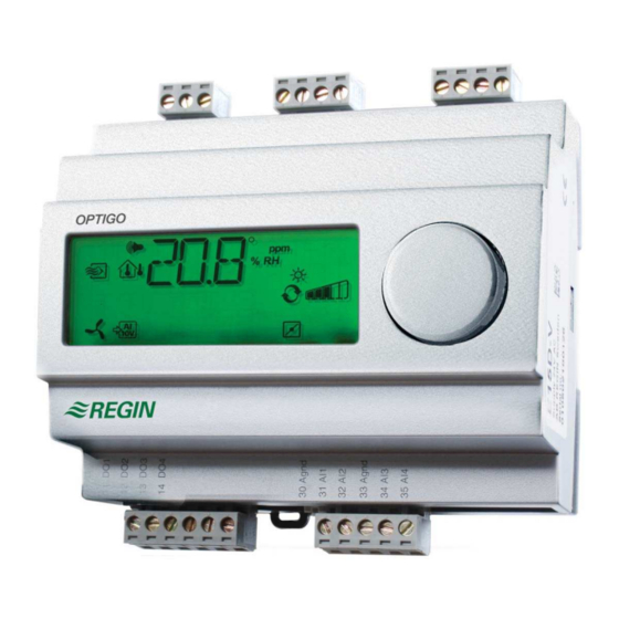
Optigo OP5 Optigo OP5 is a new pre-programmed, configurable controller. It has been designed with the main intention of replacing a number of Regin’s Aqualine controllers. All configuration and normal handling is done using the display and the knob on the front. -
Page 7: Chapter 3 Technical Data
External temperature sensors……….TG-R5/PT1000, TG-KH/PT1000 -sensor ……………….CO2RT, CO2RT-D, CO2DT Humidity sensor ………….HRT, HRT250, HDT3200, HDT2200 Pressure sensor …………. DMD, DTL-series, DTK-series, TTK-series The accessories are available from Regin. For more detailed information, see product sheets and instructions which are available at www.regin.se.
-
Page 8: Chapter 4 Installation And Wiring
Supply voltage 24 V AC ±15%, 50…60 Hz. 6 VA If the Optigo OP5 and active sensors and actuators connected to it share transformer, it is essential that the same transformer-pole is used as reference for all the equipment. Failure to…
-
Page 9: Inputs And Outputs
Analogue outputs must refer to a A terminal or directly to G0. If the Optigo OP5 and active sensors and actuators connected to it share transformer, it is essential that the same transformer-pole is used as reference for all the equipment. Failure to…
-
Page 10: Chapter 5 Control Modes
Chapter 5 Control modes Optigo can be configured to any one of the following control modes. 1. Temperature control. The temperature at the sensor is kept at the setpoint value by controlling the output signals on AO1 and AO2. A single PI control loop is used. 2.
-
Page 11
4. Heating Heating 5. Cooling / Cooling 6. Heating / Damper 7. Cooling / Damper 8. Change-over/ (Seasonal change-over between heating and cooling) DI1, Start signal Normal control will only be activated when this input is activated, closed. When the start signal is deactivated the controller will set the outputs to 0. -
Page 12: Control Mode 2, Co Control
Control mode 2, CO control The output signal will increase when the CO -value rises above the setpoint value. The CO -sensor must have a 0…10 V DC output for example: CO2RT, CO2RT-D Room sensors CO2DT Duct sensor The transmitter range cannot exceed 5000 ppm at 10 V DC output. DI1, Start signal Normal control will only be activated when this input is activated, closed.
-
Page 13: Control Mode 3, Humidity Control
Control mode 3, Humidity control RH max Humidification and dehumidification can be used simultaneously. A neutral zone can be set between humidification and dehumidification. The humidity transmitter must have an output signal of 0…10 V DC, for example: HRT, HRT250 or HRT350 Room humidity transmitters HDT2200 or HDT3200 Duct transmitters…
-
Page 14: Control Mode 4, Pressure Control
Control mode 4, Pressure control Pump f f / f f / The output signal will increase when the pressure signal falls below the setpoint value. The pressure transmitter must have an output signal of 0…10 V DC, for example: DTL-series DTK-series TTK-series…
-
Page 15: Control Mode 5, Pressure Control With Outdoor Temperature Compensation Of The Pressure Setpoint
Control mode 5, Pressure control with outdoor temperature compensation of the pressure setpoint. f f / The output signal will increase when the pressure signal falls below the setpoint value. The setpoint value follows a settable pressure-to-outdoor temperature relation. The pressure transmitter must have an output signal of 0…10 V DC, for example: DTL-series DTK-series TTK-series…
-
Page 16: Chapter 6 Display And Encoder
Chapter 6 Display and encoder All setting and configuration is done using the display and encoder. The menu information on the display is organised in a tree fashion. Using the encoder you can move between menus, set values etc. In any of the configuration menus, a press on the encoder will activate change mode. You can then rotate the encoder button to move between choices or set values.
-
Page 17: The 10-Second Level
The 10-second level This level is reached from the Base Display by depressing and holding the encoder button for 10 seconds. The 10-second level holds all the configuration menus. See chapter 8 Configuration. Note: The controller must displat the Base Display when pressing the encoder knob to reach the 10-second level.
-
Page 18: Chapter 7 Setpoint
Chapter 7 Setpoint The setpoint menu is normally accessed from the Base Display by a klicking on the encoder knob. If you wish to change the displayed value, klick on the knob again and the change indicators will start to flash to show that you are now in change mode. Twist the knob, clockwise to increase the value, counter-clockwise to decrease.
-
Page 19: Chapter 8 Configuration
Chapter 8 Configuration All the configuration menus lie in the 10-seconds level. This level is accessed from the Base Display by pressing and holding the encoder button for 10 seconds. There are numerous configuration menus covering all available options and combinations. In some cases, making a certain choice in one menu will mean that you will only see certain other menus.
-
Page 20: Menus X.2 Neutral Zone (Control Mode 1 And 3)
For each alternative the number representing it is shown along with a graphic symbolisation of the output signals and also a symbol next to the bar-graph for each output. Output signals, graphical Example, Menu 1.1 Control mode 1 menu 1 Temperature control with AO1 Heating output alternative 3…
-
Page 21: Menus X.4 I-Time
Menus X.4 I-time Here you set the Integration time (Reset time). If the I-time is set to 0 the integration function is disabled and the controller will act as a P-controller. Menu 1.5 Damper minimum position (Control mode 1 only) If you in menu 1.1 have configured output AO2 to be a damper, alternative 6 or 7, you can set a minimum value to the damper signal.
-
Page 22: Menus X.9 I/O
Menus X.9 I/O After the last configuration menu there is a menu where you can look at the actual values of all the inputs and outputs. This menu can also be accessed directly from the Base Display by twisting the encoder knob counter clockwise and then pressing. See chapter 6. Menu OK Last of the configuration level menus is the OK-menu.
-
Page 23: Chapter 9 Index
Chapter 9 Index I-time ……………….21 10 second level…………..17 LVD………………7 Analogue inputs …………..9 Analogue outputs …………..9 Menu Configuration …………..19 I/O …………….16, 22 OK……………….22 Setpoint …………..16, 18 Basic level …………….16 Mounting …………….5 Change-over ……………. 11 Reset time …………..See I-time Configuration …………..
-
Page 24
+ 46 (0)31-720 02 50 Websida: www.regin.se Försäljningskontor Frankrike Försäljningskontor Singapore Försäljningskontor Hong Kong Regin Control SARL Regin Controls Asia Pacific Pte Ltd Regin Controls Hong Kong Limited 5 Rue Regnault 66 Tannery Lane, 2901 EW International Tower FR-93500 Pantin, France…
-
Page 1
O P T I G O R E G U L A T O R – R E A D Y — S T E A D Y — G O Optigo OP5 Manual ©Copyright AB Regin, Sweden, 2007… -
Page 2
DISCLAIMER The information in this manual has been carefully checked and is believed to be correct. Regin however, makes no warranties as regards the contents of this manual and users are requested to report errors, discrepancies or ambiguities to Regin, so that corrections may be made in future editions. -
Page 3: Table Of Contents
Table of contents Chapter 1 About this manual ………………….4 Terms …………………………….4 More information …………………………..4 Chapter 2 Introduction to Optigo………………….5 Optigo controllers ……………………….5 Chapter 3 Technical data ……………………7 Chapter 4 Installation and wiring…………………..8 Installation…………………………8 Wiring …………………………..8 Supply voltage…………………………..8 Inputs and outputs ………………………….9 Chapter 5 Control modes……………………10 Control mode 1, Temperature control ……………………10 Control mode 2, CO…
-
Page 4: Chapter 1 About This Manual
Factory setting, the parameter value set on delivery More information • More information on OP5 can be found in: • Optigo controllers – Sales brochure for Optigo controllers • Optigo product instruction The information can be downloaded from the Regin website, www.regin.se.
-
Page 5: Chapter 2 Introduction To Optigo
Chapter 2 Introduction to Optigo Optigo controllers Optigo is a new series of pre-programmed, configurable controllers that can be set to handle everything from temperature control or humidity control to CO control or pressure control. OP 5 och OP 10 The Optigo series comprises two different types, OP5 and OP10.
-
Page 6
Optigo OP5 Optigo OP5 is a new pre-programmed, configurable controller. It has been designed with the main intention of replacing a number of Regin’s Aqualine controllers. All configuration and normal handling is done using the display and the knob on the front. -
Page 7: Chapter 3 Technical Data
External temperature sensors……….TG-R5/PT1000, TG-KH/PT1000 -sensor ……………….CO2RT, CO2RT-D, CO2DT Humidity sensor ………….HRT, HRT250, HDT3200, HDT2200 Pressure sensor …………. DMD, DTL-series, DTK-series, TTK-series The accessories are available from Regin. For more detailed information, see product sheets and instructions which are available at www.regin.se.
-
Page 8: Chapter 4 Installation And Wiring
Supply voltage 24 V AC ±15%, 50…60 Hz. 6 VA If the Optigo OP5 and active sensors and actuators connected to it share transformer, it is essential that the same transformer-pole is used as reference for all the equipment. Failure to…
-
Page 9: Inputs And Outputs
Analogue outputs must refer to a A terminal or directly to G0. If the Optigo OP5 and active sensors and actuators connected to it share transformer, it is essential that the same transformer-pole is used as reference for all the equipment. Failure to…
-
Page 10: Chapter 5 Control Modes
Chapter 5 Control modes Optigo can be configured to any one of the following control modes. 1. Temperature control. The temperature at the sensor is kept at the setpoint value by controlling the output signals on AO1 and AO2. A single PI control loop is used. 2.
-
Page 11
4. Heating Heating 5. Cooling / Cooling 6. Heating / Damper 7. Cooling / Damper 8. Change-over/ (Seasonal change-over between heating and cooling) DI1, Start signal Normal control will only be activated when this input is activated, closed. When the start signal is deactivated the controller will set the outputs to 0. -
Page 12: Control Mode 2, Co Control
Control mode 2, CO control The output signal will increase when the CO -value rises above the setpoint value. The CO -sensor must have a 0…10 V DC output for example: CO2RT, CO2RT-D Room sensors CO2DT Duct sensor The transmitter range cannot exceed 5000 ppm at 10 V DC output. DI1, Start signal Normal control will only be activated when this input is activated, closed.
-
Page 13: Control Mode 3, Humidity Control
Control mode 3, Humidity control RH max Humidification and dehumidification can be used simultaneously. A neutral zone can be set between humidification and dehumidification. The humidity transmitter must have an output signal of 0…10 V DC, for example: HRT, HRT250 or HRT350 Room humidity transmitters HDT2200 or HDT3200 Duct transmitters…
-
Page 14: Control Mode 4, Pressure Control
Control mode 4, Pressure control Pump f f / f f / The output signal will increase when the pressure signal falls below the setpoint value. The pressure transmitter must have an output signal of 0…10 V DC, for example: DTL-series DTK-series TTK-series…
-
Page 15: Control Mode 5, Pressure Control With Outdoor Temperature Compensation Of The Pressure Setpoint
Control mode 5, Pressure control with outdoor temperature compensation of the pressure setpoint. f f / The output signal will increase when the pressure signal falls below the setpoint value. The setpoint value follows a settable pressure-to-outdoor temperature relation. The pressure transmitter must have an output signal of 0…10 V DC, for example: DTL-series DTK-series TTK-series…
-
Page 16: Chapter 6 Display And Encoder
Chapter 6 Display and encoder All setting and configuration is done using the display and encoder. The menu information on the display is organised in a tree fashion. Using the encoder you can move between menus, set values etc. In any of the configuration menus, a press on the encoder will activate change mode. You can then rotate the encoder button to move between choices or set values.
-
Page 17: The 10-Second Level
The 10-second level This level is reached from the Base Display by depressing and holding the encoder button for 10 seconds. The 10-second level holds all the configuration menus. See chapter 8 Configuration. Note: The controller must displat the Base Display when pressing the encoder knob to reach the 10-second level.
-
Page 18: Chapter 7 Setpoint
Chapter 7 Setpoint The setpoint menu is normally accessed from the Base Display by a klicking on the encoder knob. If you wish to change the displayed value, klick on the knob again and the change indicators will start to flash to show that you are now in change mode. Twist the knob, clockwise to increase the value, counter-clockwise to decrease.
-
Page 19: Chapter 8 Configuration
Chapter 8 Configuration All the configuration menus lie in the 10-seconds level. This level is accessed from the Base Display by pressing and holding the encoder button for 10 seconds. There are numerous configuration menus covering all available options and combinations. In some cases, making a certain choice in one menu will mean that you will only see certain other menus.
-
Page 20: Menus X.2 Neutral Zone (Control Mode 1 And 3)
For each alternative the number representing it is shown along with a graphic symbolisation of the output signals and also a symbol next to the bar-graph for each output. Output signals, graphical Example, Menu 1.1 Control mode 1 menu 1 Temperature control with AO1 Heating output alternative 3…
-
Page 21: Menus X.4 I-Time
Menus X.4 I-time Here you set the Integration time (Reset time). If the I-time is set to 0 the integration function is disabled and the controller will act as a P-controller. Menu 1.5 Damper minimum position (Control mode 1 only) If you in menu 1.1 have configured output AO2 to be a damper, alternative 6 or 7, you can set a minimum value to the damper signal.
-
Page 22: Menus X.9 I/O
Menus X.9 I/O After the last configuration menu there is a menu where you can look at the actual values of all the inputs and outputs. This menu can also be accessed directly from the Base Display by twisting the encoder knob counter clockwise and then pressing. See chapter 6. Menu OK Last of the configuration level menus is the OK-menu.
-
Page 23: Chapter 9 Index
Chapter 9 Index I-time ……………….21 10 second level…………..17 LVD………………7 Analogue inputs …………..9 Analogue outputs …………..9 Menu Configuration …………..19 I/O …………….16, 22 OK……………….22 Setpoint …………..16, 18 Basic level …………….16 Mounting …………….5 Change-over ……………. 11 Reset time …………..See I-time Configuration …………..
-
Page 24
+ 46 (0)31-720 02 50 Websida: www.regin.se Försäljningskontor Frankrike Försäljningskontor Singapore Försäljningskontor Hong Kong Regin Control SARL Regin Controls Asia Pacific Pte Ltd Regin Controls Hong Kong Limited 5 Rue Regnault 66 Tannery Lane, 2901 EW International Tower FR-93500 Pantin, France…
Контакты
г. Москва, 1-й Нагатинский проезд, д. 2
Телефон: +7 (499) 406-00-60
PGlmcmFtZSBzcmM9Imh0dHBzOi8vd3d3Lmdvb2dsZS5jb20vbWFwcy9lbWJlZD9wYj0hMW0xOCExbTEyITFtMyExZDIyNDkuMzg3NTA2MTMwOTE2ITJkMzcuNjMwODk3MjE1NjY5MzMhM2Q1NS42ODIyNTAzODA1MzQ1MDUhMm0zITFmMCEyZjAhM2YwITNtMiExaTEwMjQhMmk3NjghNGYxMy4xITNtMyExbTIhMXMweDQxNGFiMzU2NzFjNWJhNmYlM0EweDMxZjc1Y2RiZGU0YzI4OWMhMnpNUzNRdVNEUW5kQ3cwTFBRc05HQzBMalF2ZEdCMExyUXVOQzVJTkNfMFlBdDBMUXNJRElzSU5DYzBMN1JnZEM2MExMUXNDd2dNVEUzTVRBMSE1ZTAhM20yITFzcnUhMnNydSE0djE0OTk4MjAxOTU4NjEiIHdpZHRoPSI2MDAiIGhlaWdodD0iNDUwIiBmcmFtZWJvcmRlcj0iMCIgc3R5bGU9ImJvcmRlcjowIiBhbGxvd2Z1bGxzY3JlZW4+PC9pZnJhbWU+
Спасибо. Мы свяжемся с вами как можно скорее.
-
Page 1
O P T I G O R E G U L A T O R – R E A D Y — S T E A D Y — G O Optigo OP5 Manual ©Copyright AB Regin, Sweden, 2007… -
Page 2
DISCLAIMER The information in this manual has been carefully checked and is believed to be correct. Regin however, makes no warranties as regards the contents of this manual and users are requested to report errors, discrepancies or ambiguities to Regin, so that corrections may be made in future editions. -
Page 3: Table Of Contents
Table of contents Chapter 1 About this manual ………………….4 Terms …………………………….4 More information …………………………..4 Chapter 2 Introduction to Optigo………………….5 Optigo controllers ……………………….5 Chapter 3 Technical data ……………………7 Chapter 4 Installation and wiring…………………..8 Installation…………………………8 Wiring …………………………..8 Supply voltage…………………………..8 Inputs and outputs ………………………….9 Chapter 5 Control modes……………………10 Control mode 1, Temperature control ……………………10 Control mode 2, CO…
-
Page 4: Chapter 1 About This Manual
Factory setting, the parameter value set on delivery More information • More information on OP5 can be found in: • Optigo controllers – Sales brochure for Optigo controllers • Optigo product instruction The information can be downloaded from the Regin website, www.regin.se.
-
Page 5: Chapter 2 Introduction To Optigo
Chapter 2 Introduction to Optigo Optigo controllers Optigo is a new series of pre-programmed, configurable controllers that can be set to handle everything from temperature control or humidity control to CO control or pressure control. OP 5 och OP 10 The Optigo series comprises two different types, OP5 and OP10.
-
Page 6
Optigo OP5 Optigo OP5 is a new pre-programmed, configurable controller. It has been designed with the main intention of replacing a number of Regin’s Aqualine controllers. All configuration and normal handling is done using the display and the knob on the front. -
Page 7: Chapter 3 Technical Data
External temperature sensors……….TG-R5/PT1000, TG-KH/PT1000 -sensor ……………….CO2RT, CO2RT-D, CO2DT Humidity sensor ………….HRT, HRT250, HDT3200, HDT2200 Pressure sensor …………. DMD, DTL-series, DTK-series, TTK-series The accessories are available from Regin. For more detailed information, see product sheets and instructions which are available at www.regin.se.
-
Page 8: Chapter 4 Installation And Wiring
Supply voltage 24 V AC ±15%, 50…60 Hz. 6 VA If the Optigo OP5 and active sensors and actuators connected to it share transformer, it is essential that the same transformer-pole is used as reference for all the equipment. Failure to…
-
Page 9: Inputs And Outputs
Analogue outputs must refer to a A terminal or directly to G0. If the Optigo OP5 and active sensors and actuators connected to it share transformer, it is essential that the same transformer-pole is used as reference for all the equipment. Failure to…
-
Page 10: Chapter 5 Control Modes
Chapter 5 Control modes Optigo can be configured to any one of the following control modes. 1. Temperature control. The temperature at the sensor is kept at the setpoint value by controlling the output signals on AO1 and AO2. A single PI control loop is used. 2.
-
Page 11
4. Heating Heating 5. Cooling / Cooling 6. Heating / Damper 7. Cooling / Damper 8. Change-over/ (Seasonal change-over between heating and cooling) DI1, Start signal Normal control will only be activated when this input is activated, closed. When the start signal is deactivated the controller will set the outputs to 0. -
Page 12: Control Mode 2, Co Control
Control mode 2, CO control The output signal will increase when the CO -value rises above the setpoint value. The CO -sensor must have a 0…10 V DC output for example: CO2RT, CO2RT-D Room sensors CO2DT Duct sensor The transmitter range cannot exceed 5000 ppm at 10 V DC output. DI1, Start signal Normal control will only be activated when this input is activated, closed.
-
Page 13: Control Mode 3, Humidity Control
Control mode 3, Humidity control RH max Humidification and dehumidification can be used simultaneously. A neutral zone can be set between humidification and dehumidification. The humidity transmitter must have an output signal of 0…10 V DC, for example: HRT, HRT250 or HRT350 Room humidity transmitters HDT2200 or HDT3200 Duct transmitters…
-
Page 14: Control Mode 4, Pressure Control
Control mode 4, Pressure control Pump f f / f f / The output signal will increase when the pressure signal falls below the setpoint value. The pressure transmitter must have an output signal of 0…10 V DC, for example: DTL-series DTK-series TTK-series…
-
Page 15: Control Mode 5, Pressure Control With Outdoor Temperature Compensation Of The Pressure Setpoint
Control mode 5, Pressure control with outdoor temperature compensation of the pressure setpoint. f f / The output signal will increase when the pressure signal falls below the setpoint value. The setpoint value follows a settable pressure-to-outdoor temperature relation. The pressure transmitter must have an output signal of 0…10 V DC, for example: DTL-series DTK-series TTK-series…
-
Page 16: Chapter 6 Display And Encoder
Chapter 6 Display and encoder All setting and configuration is done using the display and encoder. The menu information on the display is organised in a tree fashion. Using the encoder you can move between menus, set values etc. In any of the configuration menus, a press on the encoder will activate change mode. You can then rotate the encoder button to move between choices or set values.
-
Page 17: The 10-Second Level
The 10-second level This level is reached from the Base Display by depressing and holding the encoder button for 10 seconds. The 10-second level holds all the configuration menus. See chapter 8 Configuration. Note: The controller must displat the Base Display when pressing the encoder knob to reach the 10-second level.
-
Page 18: Chapter 7 Setpoint
Chapter 7 Setpoint The setpoint menu is normally accessed from the Base Display by a klicking on the encoder knob. If you wish to change the displayed value, klick on the knob again and the change indicators will start to flash to show that you are now in change mode. Twist the knob, clockwise to increase the value, counter-clockwise to decrease.
-
Page 19: Chapter 8 Configuration
Chapter 8 Configuration All the configuration menus lie in the 10-seconds level. This level is accessed from the Base Display by pressing and holding the encoder button for 10 seconds. There are numerous configuration menus covering all available options and combinations. In some cases, making a certain choice in one menu will mean that you will only see certain other menus.
-
Page 20: Menus X.2 Neutral Zone (Control Mode 1 And 3)
For each alternative the number representing it is shown along with a graphic symbolisation of the output signals and also a symbol next to the bar-graph for each output. Output signals, graphical Example, Menu 1.1 Control mode 1 menu 1 Temperature control with AO1 Heating output alternative 3…
-
Page 21: Menus X.4 I-Time
Menus X.4 I-time Here you set the Integration time (Reset time). If the I-time is set to 0 the integration function is disabled and the controller will act as a P-controller. Menu 1.5 Damper minimum position (Control mode 1 only) If you in menu 1.1 have configured output AO2 to be a damper, alternative 6 or 7, you can set a minimum value to the damper signal.
-
Page 22: Menus X.9 I/O
Menus X.9 I/O After the last configuration menu there is a menu where you can look at the actual values of all the inputs and outputs. This menu can also be accessed directly from the Base Display by twisting the encoder knob counter clockwise and then pressing. See chapter 6. Menu OK Last of the configuration level menus is the OK-menu.
-
Page 23: Chapter 9 Index
Chapter 9 Index I-time ……………….21 10 second level…………..17 LVD………………7 Analogue inputs …………..9 Analogue outputs …………..9 Menu Configuration …………..19 I/O …………….16, 22 OK……………….22 Setpoint …………..16, 18 Basic level …………….16 Mounting …………….5 Change-over ……………. 11 Reset time …………..See I-time Configuration …………..
-
Page 24
+ 46 (0)31-720 02 50 Websida: www.regin.se Försäljningskontor Frankrike Försäljningskontor Singapore Försäljningskontor Hong Kong Regin Control SARL Regin Controls Asia Pacific Pte Ltd Regin Controls Hong Kong Limited 5 Rue Regnault 66 Tannery Lane, 2901 EW International Tower FR-93500 Pantin, France…
Контакты
г. Москва, 1-й Нагатинский проезд, д. 2
Телефон: +7 (499) 406-00-60
PGlmcmFtZSBzcmM9Imh0dHBzOi8vd3d3Lmdvb2dsZS5jb20vbWFwcy9lbWJlZD9wYj0hMW0xOCExbTEyITFtMyExZDIyNDkuMzg3NTA2MTMwOTE2ITJkMzcuNjMwODk3MjE1NjY5MzMhM2Q1NS42ODIyNTAzODA1MzQ1MDUhMm0zITFmMCEyZjAhM2YwITNtMiExaTEwMjQhMmk3NjghNGYxMy4xITNtMyExbTIhMXMweDQxNGFiMzU2NzFjNWJhNmYlM0EweDMxZjc1Y2RiZGU0YzI4OWMhMnpNUzNRdVNEUW5kQ3cwTFBRc05HQzBMalF2ZEdCMExyUXVOQzVJTkNfMFlBdDBMUXNJRElzSU5DYzBMN1JnZEM2MExMUXNDd2dNVEUzTVRBMSE1ZTAhM20yITFzcnUhMnNydSE0djE0OTk4MjAxOTU4NjEiIHdpZHRoPSI2MDAiIGhlaWdodD0iNDUwIiBmcmFtZWJvcmRlcj0iMCIgc3R5bGU9ImJvcmRlcjowIiBhbGxvd2Z1bGxzY3JlZW4+PC9pZnJhbWU+
Спасибо. Мы свяжемся с вами как можно скорее.
- Manuals
- Brands
- Regin Manuals
- Controller
- OPTIGO OP5
- Manual
-
Contents
-
Table of Contents
-
Bookmarks
Quick Links
O P T I G O
R E G U L A T O R
–
R E A D Y — S T E A D Y — G O
Optigo OP5 Manual
©Copyright AB Regin, Sweden, 2007
Related Manuals for Regin Optigo OP5
Summary of Contents for Regin Optigo OP5
-
Page 1
O P T I G O R E G U L A T O R – R E A D Y — S T E A D Y — G O Optigo OP5 Manual ©Copyright AB Regin, Sweden, 2007… -
Page 2
DISCLAIMER The information in this manual has been carefully checked and is believed to be correct. Regin however, makes no warranties as regards the contents of this manual and users are requested to report errors, discrepancies or ambiguities to Regin, so that corrections may be made in future editions. -
Page 3: Table Of Contents
Table of contents Chapter 1 About this manual ………………….4 Terms …………………………….4 More information …………………………..4 Chapter 2 Introduction to Optigo………………….5 Optigo controllers ……………………….5 Chapter 3 Technical data ……………………7 Chapter 4 Installation and wiring…………………..8 Installation…………………………8 Wiring …………………………..8 Supply voltage…………………………..8 Inputs and outputs ………………………….9 Chapter 5 Control modes……………………10 Control mode 1, Temperature control ……………………10 Control mode 2, CO…
-
Page 4: Chapter 1 About This Manual
Factory setting, the parameter value set on delivery More information • More information on OP5 can be found in: • Optigo controllers – Sales brochure for Optigo controllers • Optigo product instruction The information can be downloaded from the Regin website, www.regin.se.
-
Page 5: Chapter 2 Introduction To Optigo
Chapter 2 Introduction to Optigo Optigo controllers Optigo is a new series of pre-programmed, configurable controllers that can be set to handle everything from temperature control or humidity control to CO control or pressure control. OP 5 och OP 10 The Optigo series comprises two different types, OP5 and OP10.
-
Page 6
Optigo OP5 Optigo OP5 is a new pre-programmed, configurable controller. It has been designed with the main intention of replacing a number of Regin’s Aqualine controllers. All configuration and normal handling is done using the display and the knob on the front. -
Page 7: Chapter 3 Technical Data
External temperature sensors……….TG-R5/PT1000, TG-KH/PT1000 -sensor ……………….CO2RT, CO2RT-D, CO2DT Humidity sensor ………….HRT, HRT250, HDT3200, HDT2200 Pressure sensor …………. DMD, DTL-series, DTK-series, TTK-series The accessories are available from Regin. For more detailed information, see product sheets and instructions which are available at www.regin.se.
-
Page 8: Chapter 4 Installation And Wiring
Supply voltage 24 V AC ±15%, 50…60 Hz. 6 VA If the Optigo OP5 and active sensors and actuators connected to it share transformer, it is essential that the same transformer-pole is used as reference for all the equipment. Failure to…
-
Page 9: Inputs And Outputs
Analogue outputs must refer to a A terminal or directly to G0. If the Optigo OP5 and active sensors and actuators connected to it share transformer, it is essential that the same transformer-pole is used as reference for all the equipment. Failure to…
-
Page 10: Chapter 5 Control Modes
Chapter 5 Control modes Optigo can be configured to any one of the following control modes. 1. Temperature control. The temperature at the sensor is kept at the setpoint value by controlling the output signals on AO1 and AO2. A single PI control loop is used. 2.
-
Page 11
4. Heating Heating 5. Cooling / Cooling 6. Heating / Damper 7. Cooling / Damper 8. Change-over/ (Seasonal change-over between heating and cooling) DI1, Start signal Normal control will only be activated when this input is activated, closed. When the start signal is deactivated the controller will set the outputs to 0. -
Page 12: Control Mode 2, Co Control
Control mode 2, CO control The output signal will increase when the CO -value rises above the setpoint value. The CO -sensor must have a 0…10 V DC output for example: CO2RT, CO2RT-D Room sensors CO2DT Duct sensor The transmitter range cannot exceed 5000 ppm at 10 V DC output. DI1, Start signal Normal control will only be activated when this input is activated, closed.
-
Page 13: Control Mode 3, Humidity Control
Control mode 3, Humidity control RH max Humidification and dehumidification can be used simultaneously. A neutral zone can be set between humidification and dehumidification. The humidity transmitter must have an output signal of 0…10 V DC, for example: HRT, HRT250 or HRT350 Room humidity transmitters HDT2200 or HDT3200 Duct transmitters…
-
Page 14: Control Mode 4, Pressure Control
Control mode 4, Pressure control Pump f f / f f / The output signal will increase when the pressure signal falls below the setpoint value. The pressure transmitter must have an output signal of 0…10 V DC, for example: DTL-series DTK-series TTK-series…
-
Page 15: Control Mode 5, Pressure Control With Outdoor Temperature Compensation Of The Pressure Setpoint
Control mode 5, Pressure control with outdoor temperature compensation of the pressure setpoint. f f / The output signal will increase when the pressure signal falls below the setpoint value. The setpoint value follows a settable pressure-to-outdoor temperature relation. The pressure transmitter must have an output signal of 0…10 V DC, for example: DTL-series DTK-series TTK-series…
-
Page 16: Chapter 6 Display And Encoder
Chapter 6 Display and encoder All setting and configuration is done using the display and encoder. The menu information on the display is organised in a tree fashion. Using the encoder you can move between menus, set values etc. In any of the configuration menus, a press on the encoder will activate change mode. You can then rotate the encoder button to move between choices or set values.
-
Page 17: The 10-Second Level
The 10-second level This level is reached from the Base Display by depressing and holding the encoder button for 10 seconds. The 10-second level holds all the configuration menus. See chapter 8 Configuration. Note: The controller must displat the Base Display when pressing the encoder knob to reach the 10-second level.
-
Page 18: Chapter 7 Setpoint
Chapter 7 Setpoint The setpoint menu is normally accessed from the Base Display by a klicking on the encoder knob. If you wish to change the displayed value, klick on the knob again and the change indicators will start to flash to show that you are now in change mode. Twist the knob, clockwise to increase the value, counter-clockwise to decrease.
-
Page 19: Chapter 8 Configuration
Chapter 8 Configuration All the configuration menus lie in the 10-seconds level. This level is accessed from the Base Display by pressing and holding the encoder button for 10 seconds. There are numerous configuration menus covering all available options and combinations. In some cases, making a certain choice in one menu will mean that you will only see certain other menus.
-
Page 20: Menus X.2 Neutral Zone (Control Mode 1 And 3)
For each alternative the number representing it is shown along with a graphic symbolisation of the output signals and also a symbol next to the bar-graph for each output. Output signals, graphical Example, Menu 1.1 Control mode 1 menu 1 Temperature control with AO1 Heating output alternative 3…
-
Page 21: Menus X.4 I-Time
Menus X.4 I-time Here you set the Integration time (Reset time). If the I-time is set to 0 the integration function is disabled and the controller will act as a P-controller. Menu 1.5 Damper minimum position (Control mode 1 only) If you in menu 1.1 have configured output AO2 to be a damper, alternative 6 or 7, you can set a minimum value to the damper signal.
-
Page 22: Menus X.9 I/O
Menus X.9 I/O After the last configuration menu there is a menu where you can look at the actual values of all the inputs and outputs. This menu can also be accessed directly from the Base Display by twisting the encoder knob counter clockwise and then pressing. See chapter 6. Menu OK Last of the configuration level menus is the OK-menu.
-
Page 23: Chapter 9 Index
Chapter 9 Index I-time ……………….21 10 second level…………..17 LVD………………7 Analogue inputs …………..9 Analogue outputs …………..9 Menu Configuration …………..19 I/O …………….16, 22 OK……………….22 Setpoint …………..16, 18 Basic level …………….16 Mounting …………….5 Change-over ……………. 11 Reset time …………..See I-time Configuration …………..
-
Page 24
+ 46 (0)31-720 02 50 Websida: www.regin.se Försäljningskontor Frankrike Försäljningskontor Singapore Försäljningskontor Hong Kong Regin Control SARL Regin Controls Asia Pacific Pte Ltd Regin Controls Hong Kong Limited 5 Rue Regnault 66 Tannery Lane, 2901 EW International Tower FR-93500 Pantin, France…
Добрый день. Объясните пожалуйста по пи регуляции, у меня Optigo op10:
Sp (уставка) — т.е. температура которая мне необходима
Р (зона пропорциональности) — т.е. если установлен параметр 1, при отклоненнии на 1 градус система будет запускаться (работать)
I время в течении которого необходимо изменять параметр, например, частотника
Все ли верно я понимаю?
Установки: sp-15, p-1, i-16, в помещении 23; система даже аврии по перегреву не выдает. Режим работы от 1датчика, охлаждение.