-
Bookmarks
Quick Links
Updated:
17/03/2010
CAREL ir33
Q u i c k r e f e r e n c e H a n d b o o k
Ver. 1.1
Pag.1/12
Eng
Related Manuals for Carel ir33
Summary of Contents for Carel ir33
-
Page 1
Updated: 17/03/2010 CAREL ir33 Q u i c k r e f e r e n c e H a n d b o o k Ver. 1.1 Pag.1/12… -
Page 2: Main Features Of The Instrument
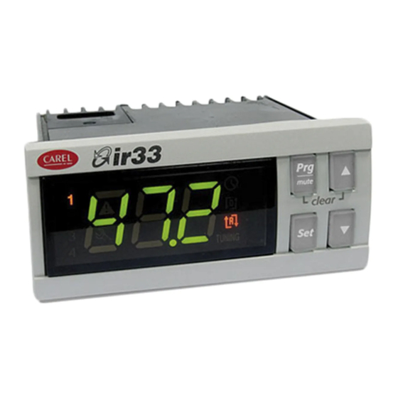
Updated: 17/03/2010 MAIN FEATURES OF THE INSTRUMENT USER INTERFACE ON/OFF switch button – UP button to increase temperature values DOWN button to decrease values — Activates/deactivates the manual defrost SET temperature button Prg/mute button Malfunctioning or failure warning icon High/Low temperature alarm icon icon is ON when defrost process starts icon is ON when compressor starts icon is ON when evaporator fans starts…
-
Page 3
“0” that indicates the password prompt Press UP button to set the password – CAREL thermoregulators are provided with password set to 11 (the code of the password allows access to the configuration parameters) -
Page 4
Updated: 17/03/2010 MANUAL Manual defrost is activated or deactivated if DEF/DOWN button is keep DEFROST pressed more than 5 seconds. When defrost starts display shows dFb (defrost begining) Defrost’s warning icon is ON when defrost is active Defrost can be interrupted simply by pressing again the DEF/DOWN button more than 5 seconds. -
Page 5
Updated: 17/03/2010 HOW TO CHECK To check current temperature measured by a single installed probe, CAVITY PROBE proceeds as follow: TEMPERATURE 1. refers to the previous step how to get in the configuration parameter session — type C parameter 2. scroll the configuration parameter list, by using UP/DOWN buttons, until display shows the parameter /C1 (calibration or offset for cavity probe) 3. -
Page 6
Updated: 17/03/2010 TABLE OF OPERATING PARAMETERS N° Code Range U.M. Description TEMPERATURE PROBE MANAGEMENT PARAMETERS 0…15 Measurement stability 0…15 Probe display response 0…100 Virtual probe Flag Selection °C or °F Flag Decimal point 1…6 Display on terminal 0…6 Display on external terminal 0…2 Type of probe 0…3… -
Page 7
Updated: 17/03/2010 N° Code Range U.M. Description 0…1 Flag Enable autostart function in PD 0…1 Flag Select Pump down by time or pressure 0…250 Seconds Second compressor delay DEFROST MANAGEMENT PARAMETERS 0…4 Flag Type of defrost 0…250 Hours Interval between defrosts -50…200 °C/°F End defrost temperature, evaporator… -
Page 8
Clean Alarm counter reset NOTE 1: Above operating parameters are available for all range of CAREL thermoregulators. Particularly all green highlighted parameters are available on new CAREL controller ir33 IRELF0HN245, currently installed on HD cabinets and counters NOTE 2: Blu highlighted operating parameters listed above are not influential for the functioning of the appliance. -
Page 9
Updated: 17/03/2010 SERVICE ALLARMS AND SIGNALS SERVICE ALARMS SERVICE ALARMS DUE TO MALFUNCTIONING OR FAILURE PRODUCE A WARNING SIGNALS ON THE DISPLAY BY MEAN OF THE SERVICE ICON CAVITY PROBE In case of cavity probe faulty or malfunctioning display shows the error FAULT signal rE and E0 (cavity probe S1 fault) alternately The appliance works however and compressor starts are controlled by… -
Page 10
Updated: 17/03/2010 TEMPERATURE ALARMS AND SIGNALS TEMPERATURE HIGH OR LOW TEMPERATURE ALARMS DUE TO MALFUNCTIONING OR ALARMS COMPONENTS FAILURE PRODUCE A WARNING SIGNALS ON THE DISPLAY BY MEAN OF THE ALARM ICON In case of low cavity temperature, referred to the cavity probe, the TEMPERATURE display shows a flashing error code LO. -
Page 11
Updated: 17/03/2010 CONNECTIONS Follows all electrical connections available on ir33 CAREL controller , currently used in production IRELC0HN215 (646R05100) installed on STD BEN and CL freezer counter and STD BEN cabinet provided with internal light IRELF0EN215 (646R04700) installed on all STD BEN refrigerated counters, 400Lt refrigerated cabinets and all STD BEN cabinets without light Ver. -
Page 12
Updated: 17/03/2010 IRELF0HN245 (646R09300) installed on HD counters and cabinets IRELF0EN225 installed on digital ROLL–IN IRELF0EHD15 installed on 400Lt FREEZER cabinet Ver. 1.1 Pag.12/12…
- Page 1
ir33 Universale electronic controller User manual… - Page 3
The technical specifi cations shown in the manual may be changed without prior warning. The liability of CAREL in relation to its products is specifi ed in the CAREL general contract conditions, available on the website www.carel.com and/or by specifi c agreements with customers; specifi cally, to the extent where allowed… -
Page 5: Table Of Contents
Content 1. INTRODUCTION 1.1 Models ……………………. 7 1.2 Functions and main characteristics ………….. 8 2. INSTALLATION 2.1 IR33: panel mounting and dimensions …………10 2.2 DN33: DIN rail mounting and dimensions ……….10 2.3 IR33 Universal wiring diagrams …………..11 2.4 DN33 Universal wiring diagrams …………..
-
Page 7: Introduction
1. INTRODUCTION IR33-DN33 Universal is a series of controllers designed for controlling the temperature in air-conditioning, refrigeration and heating units. The models diff er according to the type of power supply (115 to 230 Vac or 12 to 24 Vac, 12 to 30 Vdc) and the outputs, which based on the model may be one, two or four relays, one or four PWM outputs for controlling external solid state relays (SSR), one or two relays plus one or two 0 to 10 Vdc analogue outputs (AO) respectively.
-
Page 8: Functions And Main Characteristics
Below is a description of the accessories for the IR33/DN33 Universal: the testing phase. ComTool programming tool (downloadable from http://ksa.carel.com) With this useful tool, the controller can be programmed from any PC, saving the diff erent confi gurations to fi les that can be loaded during the…
- Page 9
Used to connect the DN33 via the RS485 serial network to the PlantVisor supervisory system. Fig. 1. d Analogue output module (code CONV0/10A0) Converts the PWM signal for solid state relays (SSR) to a standard 0 to 10 Vdc or 4 to 20 mA signal. For models IR/DN33A7**** and IR33D7**** only. -
Page 10: Installation
2. INSTALLATION 2.1 IR33: panel mounting and dimensions 2.2.1 DN33 optional connections 70.5 76.2 dima di foratura drilling template 71×29 mm 80.6 IROPZKEY**: IROPZ485S0: Fig. 2. a Chiave di Interfaccia scheda programmazione seriale RS485 Programming key intelligente Smart serial board interface RS485 Fig.
-
Page 11: Ir33 Universal Wiring Diagrams
2.3 IR33 Universal wiring diagrams The models with 115 to 230 Vac and 12 to 24 Vac power supply have the same wiring diagram. In the 230 Vac models, the line (L) is connected to terminal 6 and the neutral (N) to terminal 7. Relays IR33V7HR20 / IR33V7HB20/ IR33V7LR20 IR33W7HR20 / IR33W7HB20 / IR33W7LR20…
-
Page 12: Dn33 Universal Wiring Diagrams
2.4 DN33 Universal wiring diagrams For models with the same type of outputs, only the wiring diagram of the model with the most outputs has been shown (models : “Z”, “A”, “E”). DN33V7HR20 / DN33V7HB20 DN33V7LR20 / DN33W7LR20 / DN33Z7LR20 DN33W7HR20 / DN33W7HB20 Relays DN33Z7HR20 / DN33Z7HB20…
-
Page 13: Connection Diagrams
2.5 Connection diagrams 2.5.1 Connection to the CONV0/10A0 and CONVONOFF0 modules (accessories) The CONV0/10A0 and CONVONOFF0 modules convert a PWM output for SSR to a 0 to 10 Vdc analogue output and ON/OFF relay output respectively. Below is an example of an application that uses model DN33A7LR20.
-
Page 14: Installation
The parameters can only be copied between controllers with the same 2.6 Installation code. The UPLOAD operation can, however, always be performed. To install the controller, proceed as follows, with reference to the wiring diagrams: 2.7.1 Copying and downloading the parameters 1) connect the probes and power supply: the probes can be installed The following operations are used for the UPLOAD and/or DOWNLOAD up to a maximum distance of 100 m from the controller, using…
-
Page 15: User Interface
3. USER INTERFACE The front panel contains the display and the keypad, made up of 4 buttons, that, when pressed alone or combined with other buttons, are used to program the controller. IR33 Universal front panel Fig. 3. a 3.1 Display The display shows temperature in range -50 to +150°C.The temperature is displayed with resolution to the tenths between –19.9 and + 59.9 °C Alternatively, displays the value of one of the analogue or digital inputs…
-
Page 16: Keypad
3.2 Keypad Pressing the button alone: • If pressed for more than 5 seconds, accesses the menu for setting the type P parameters (frequent); • Mutes the audible alarm (buzzer) and deactivates the alarm relay; • When editing the parameters, pressed for 5 s, permanently saves the new values of the parameters; •…
- Page 17
3.3.3 Setting type P parameters Type P parameters (frequents) are indicated by a code beginning with the letter P, followed by one or two numbers. Press for more than 5 seconds (if an alarm is active, the buzzer is muted), the display shows the code of the fi rst modifi able type P parameter, P1;… -
Page 18: Example: Setting The Current Date/Time And The On/Off Times
All the modifi cations made to the parameters, temporarily stored in the RAM, can be cancelled, returning to the standard display by not pressing any button for 60 seconds. The values of the clock parameters, however, are saved when entered. If the controller is powered down before pressing , all the modifi cations made to the parameters will be lost…
- Page 19
3.4.3 Setting the default parameters To set the parameters to the default values: • Power down the controller; • Press • Power up the controller holding the button, until the message “Std” is shown on the display. This will cancel any changes made and restore the original values set by the manufacturer. -
Page 20: Using The Remote Control (Accessory)
3.4.10 Displaying the inputs • Press : the current input will be displayed, alternating with the value: b1 : probe 1; b2 : probe 2; di1 : digital input 1; di2 : digital input 2. • Press to select the input to be displayed; •…
- Page 21
3.5.2 Activating and deactivating the use of the remote control Button Immediate function Delayed function used to enable the remote control; each instrument displays its own enabling code ends operation using the remote control, cancelling all changes made to the parameters used to display the pressing and holding for 5s… -
Page 22: Commissioning
4. COMMISSIONING °C 4.1 Confi guration set point The confi guration parameters should be set when commissioning the process value controller, and involve: • serial address for the network connection; • enabling the keypad, buzzer and the remote control (accessory); •…
-
Page 23: Functions
5. FUNCTIONS 5.1 Probes (analogue inputs) Par. Description Def Min Max UoM St1 Set point 1 c21 c22 °C/°F The probe parameters are used to : St2 Set point 2 c23 c24 °C/°F • set the type of probe 1=direct •…
- Page 24
5.2.2 Reverse (parameter c0=2) 5.2.4 PWM (parameter c0=4) “Reverse” operation is similar to ”direct” operation, however the outputs The control logic in PWM mode uses the dead zone, with the outputs are activated when the value being controlled decreases, starting from activated based on pulse width modulation (PWM). - Page 25
St1/St2 Set point 1/2 Mod. V Mod. W “Direct” diff erential OUT1 (LOW ALARM) OUT1 OUT2 (HIGH ALARM) “Reverse” diff erential OUT1 Output 1 Probe 1 For models W & Z the activations of the outputs are equally distributed inside the diff erential set (P1/P2). Parameter c29 is not active in mode 6. -
Page 26: Validity Of Control Parameters (Parameters St1,St2,P1,P2,P3)
• 5.2.9 Direct/reverse with two set points (par. c0=9) Mode 6: does not consider the diff erential P3. The changeover of digital input 1 means the outputs consider set point 2 rather than In this mode, available only on the models with 2 or 4 outputs, half of the set point 1.
- Page 27
5.5.1 Dependence (parameters c34,c38,c42,c46) 5.5.3 Activation (parameters c36,c40,c44,c48) This the parameter that determines the specifi c function of each output. The parameter is active only if the output is the control output It links an output to a set point (control output) or a specifi c alarm (alarm (“dependence”=1,2,16,17) or TIMER (“dependence”=15). - Page 28
output, that is, for ON/OFF operation, the deactivation point of the output 5.5.6 Deactivation restriction (par. d35,d39,d43,d47) or, for PWM operation, the point where the output has the minimum value In normal operating conditions, the deactivation sequence should be as (ON time =0). -
Page 29: Additional Remarks On Special Operation
The following must also be set: The PWM (or analogue) outputs will follow the operation indicated in • “type of output “ =1, modulating output the fi gure. In practice, in the dead zone the output maintains the level of •…
-
Page 30: Outputs And Inputs
Modes 1 & 2 in diff erential operation (c19=1). In diff erential operation, St1 must compare against ‘B1-B2’ instead of B1. Time In special operation (c33=1) the outputs can be set with “dependence”=2: c6 & d1 are not operative for the PWM outputs. diff erential operation is therefore overridden and the outputs are linked to St2/P2 compared against B1.
- Page 31
c29=0 Input not active Par. Description Def Min Max UM c12 PWM cycle time 20 0.2 999 s c29=1 Immediate external alarm with automatic reset. The alarm condition relates to the contact being open. When the alarm Validity: c0=4; condition ceases (contact closes), normal control resumes and any alarm In special operation c12 is active in any mode if “type of output”=1 output is deactivated. -
Page 32: Control
6. CONTROL ON/OFF and PID control 6.3 Auto-Tuning (parameter c64) The controller leaves the factory with default settings of the PID The controller can operate with two types of control: parameters; these allow standard PID control, but are not optimised for the system that IR33 controls.
-
Page 33: Operating Cycle
procedure can be repeated to further tune the values. This is useful when Example 1: Heating cycle with infi nite temperature control the loads have changed since the fi rst procedure was performed, or to allow fi ner tuning. The controller in this case can manage the system using the PID parameters, and further Auto-Tuning will have the eff ect of improving control.
- Page 34
Example 1: T2< 8°C. To do this, simply connect OUT2 in series with OUT3 and OUT4, A refrigeration unit with 2 compressors must lower the temperature of then make OUT2 active only when B1 (T2) is greater than 8°C. the water by 5°C. Set c33=1: the changes to be made to the special parameters are: OUT2 OUT3… - Page 35
6.5.3 Compensation in cooling (parameter c19=2) from falling below 10°C, a minimum limit must be set for St1, with c21=10. The graph below shows the trend in St1. Compensation in cooling may either increase or decrease the value of St1, depending on whether c4 is positive or negative. St1_comp St1 only changes if the temperature B2 exceeds St2: c4=-0,5… - Page 36
6.5.5 Continuous compensation (parameter c19=4) ABILITAZIONE/ ENABLE The compensation of St1 is active for values of B2 other than St2: with C19=5 this value of c19, parameter P2 can be used to defi ne a dead zone around St2 in which compensation is not active, that is, when the value read by B2 is between St2-P2 and St2+P2, compensation is disabled and St1 is not changed: if B2 is greater than (St2+P2), eff ective St1 = St1+ [B2-(St2+P2)]*c4… -
Page 37: Table Of Parameters
7. TABLE OF PARAMETERS Par. Description Note Def Max UoM Type CAREL SVP ModBus® Icon Set point 1 °C/°F A Set point 2 °C/°F A Operating mode 1=direct 2=reverse 3=dead zone 4=PWM 5=alarm 6=direct/reverse from digital input1 7=direct: set point & diff erential from digital input 1 8=reverse: set point &…
- Page 38
Par. Description Note Def Max UoM Typ. CAREL SVP ModBus® Icon High temperature alarm threshold °C/°F if P29=0, P26=0 : threshold disabled if P29=1, P26=200 : threshold disabled Alarm diff erential °C/°F Alarm delay time Type of alarm threshold 0=relative; 1=absolute… - Page 39
Par. Description Note Def Min Max UoM Typ. CAREL SVP ModBus® Icon Activation of output 4 -100 -100 Diff erential/logic of output 4 -100 Activation restriction for output 4 Deactivation restriction for output 4 Minimum value of modulating output 4(*) -
Page 40: Variables Only Accessible Via Serial Connection
ModBus® : variable address with ModBus® protocol on 485 serial card. The selection between CAREL and ModBus® protocol is automatic. For both of them the speed is fi xed to 19200 bit/s. All the devices connected to the same network must feature the same serial parameters: — 8 data bit;…
-
Page 41: Alarms
8. ALARMS 8.1 Types of alarms There are two types of alarms available: • high temperature (E04) and low temperature (E05); • serious alarms, that is, all the others. The data memory alarms E07/E08 always cause the control to shutdown. “Alarm”…
-
Page 42: Table Of Alarms
8.4 Table of alarms Message Cause of the alarm Icon on display Alarm relay Buzzer Reset Code Control action Checks/solutions on display shown in alarm queue ALx_TYPE Probe B1 fault automatic Depends on Check probe connections fl ashing parameter c10 Probe B2 fault automatic If c19=1 &…
- Page 43
8.5.3 Status of the control outputs with alarm from Description digital input (parameter c31) Status of the control outputs with probe alarm Parameter c31 determines the action on the control outputs if an alarm 0=All outputs OFF from digital input E03 is active (see c29 and c30). When OFF is selected, 1= All outputs ON the controller shuts down immediately and the timers are ignored. -
Page 44: Technical Specifications And Product Codes
Note: in the installation, keep the power and load connections separate from the probe, digital inputs, repeater display and supervisor cables. Type of probe Std. CAREL NTC 10kΩ at 25°C, range from –50T90°C measurement error: 1°C in range from –50T50°C 3°C in range from +50T90°C…
-
Page 45: Cleaning The Controller
Device designed to be hand-held or integrated in hand-held devices Software class and structure Class A Front panel cleaning Only use neutral detergents and water Carel serial network interface External, available on all models Programming key Available on all models Type of connection Size…
-
Page 46: Software Revisions
9.4 Software revisions REVISION Description Functions active starting from software version higher than FUNCTION Parameter Soft start 0 to 10 V outputs c19=5,6 / c66, c67 d36, d40, d44, d48 d37, d41, d45, d49 ir33 universale +030220801 — rel. 1.0 — 16.04.2008…
- Page 48
CAREL is a registered trademark of CAREL S.p.A. in Italy and/or other countries. © CAREL S.p.A. 2008 all rights reserved CAREL reserves the right to modify the features of its products without prior notice. www.carel.com…
Подробнее устранение неисправностей описано в руководстве по эксплуатации каждой модели.
На нашем сайте представлены запасные части для оборудования Carel.
Для подбора запасных частей Carel сообщите нам полную маркировку блока и наименование запчасти любым удобным способом.
Коды ошибок управляющих блоков для систем вентиляции и кондиционирования Carel (PCOxs электро)
| Код | Описание ошибки |
|---|---|
| E01 | Поступил сигнал от пожарной сигнализации |
| E02 | Неисправен датчик наружной температуры |
| E03 | Неисправен датчик температуры в помещении |
| E04 | Неисправен датчик температуры приточного воздуха |
| E05 | Неисправен датчик температуры возвращаемого теплоносителя |
| E08 | Неисправен датчик температуры возвращаемого теплоносителя после нагревателя второго нагрева |
| E09 | Неисправен датчик влажности приточного воздуха |
| E10 | Неисправен датчик влажности воздуха в помещении |
| E12 | Неисправен датчик температуры насыщения |
| E13 | Один или несколько аналоговых входов под ручным управлением |
| E14 | Один или несколько аналоговых выходов под ручным управлением |
| E15 | Один или несколько дискретных входов под ручным управлением |
| E16 | Один или несколько дискретных выходов под ручным управлением |
| E17 | Нет сигнала статуса от приточного вентилятора |
| E18 | Нет сигнала статуса от вытяжного вентилятора |
| E19 | Нет сигнала статуса от вытяжного и (или) приточного вентилятора |
| E20 | Низкая наружная температура для использования режима «лето» |
| E21 | Запуск заблокирован. Низкая температура возвращаемого теплоносителя или клапан в контуре нагревателя открыт менее чем на 80% (или иное значения согласно St13) |
| E22 | Защита от замерзания водяного нагревателя. Предварительная тревога |
| E23 | Защита от замерзания водяного нагревателя. Основная тревога |
| E24 | Неисправен насос в контуре водяного нагревателя |
| E25 | Защита от замерзания водяного нагревателя второго нагрева. Предварительная тревога |
| E26 | Защита от замерзания водяного нагревателя второго нагрева. Основная тревога |
| E27 | Неисправен насос в контуре водяного нагревателя 2 |
| E28 | Перегрев электронагревателя |
| E29 | Активировано оттаивание рекуператора |
| E30 | Неисправен привод ротора рекуператора |
| E31 | Неисправен компрессорно-конденсаторный агрегат (ККА) |
| E32 | Фильтр на притоке загрязнен |
| E33 | Фильтр на вытяжке загрязнен |
| E34 | Фильтр загрязнен |
| E37 | Отсутствует связь с платой расширения |
| E39 | Получен внешний сигнал тревоги |
| E40 | Перезапуск после подачи питания |
| E41 | Термозащита приточного вентилятора |
| E42 | Термозащита вытяжного вентилятора |
| E43 | Термозащита вентиляторов |
-
Page 1
ir33 Universale electronic controller User manual… -
Page 3
The technical specifi cations shown in the manual may be changed without prior warning. The liability of CAREL in relation to its products is specifi ed in the CAREL general contract conditions, available on the website www.carel.com and/or by specifi c agreements with customers; specifi cally, to the extent where allowed… -
Page 5: Table Of Contents
Content 1. INTRODUCTION 1.1 Models ……………………. 7 1.2 Functions and main characteristics ………….. 8 2. INSTALLATION 2.1 IR33: panel mounting and dimensions …………10 2.2 DN33: DIN rail mounting and dimensions ……….10 2.3 IR33 Universal wiring diagrams …………..11 2.4 DN33 Universal wiring diagrams …………..
-
Page 7: Introduction
1. INTRODUCTION IR33-DN33 Universal is a series of controllers designed for controlling the temperature in air-conditioning, refrigeration and heating units. The models diff er according to the type of power supply (115 to 230 Vac or 12 to 24 Vac, 12 to 30 Vdc) and the outputs, which based on the model may be one, two or four relays, one or four PWM outputs for controlling external solid state relays (SSR), one or two relays plus one or two 0 to 10 Vdc analogue outputs (AO) respectively.
-
Page 8: Functions And Main Characteristics
Below is a description of the accessories for the IR33/DN33 Universal: the testing phase. ComTool programming tool (downloadable from http://ksa.carel.com) With this useful tool, the controller can be programmed from any PC, saving the diff erent confi gurations to fi les that can be loaded during the…
-
Page 9
Used to connect the DN33 via the RS485 serial network to the PlantVisor supervisory system. Fig. 1. d Analogue output module (code CONV0/10A0) Converts the PWM signal for solid state relays (SSR) to a standard 0 to 10 Vdc or 4 to 20 mA signal. For models IR/DN33A7**** and IR33D7**** only. -
Page 10: Installation
2. INSTALLATION 2.1 IR33: panel mounting and dimensions 2.2.1 DN33 optional connections 70.5 76.2 dima di foratura drilling template 71×29 mm 80.6 IROPZKEY**: IROPZ485S0: Fig. 2. a Chiave di Interfaccia scheda programmazione seriale RS485 Programming key intelligente Smart serial board interface RS485 Fig.
-
Page 11: Ir33 Universal Wiring Diagrams
2.3 IR33 Universal wiring diagrams The models with 115 to 230 Vac and 12 to 24 Vac power supply have the same wiring diagram. In the 230 Vac models, the line (L) is connected to terminal 6 and the neutral (N) to terminal 7. Relays IR33V7HR20 / IR33V7HB20/ IR33V7LR20 IR33W7HR20 / IR33W7HB20 / IR33W7LR20…
-
Page 12: Dn33 Universal Wiring Diagrams
2.4 DN33 Universal wiring diagrams For models with the same type of outputs, only the wiring diagram of the model with the most outputs has been shown (models : “Z”, “A”, “E”). DN33V7HR20 / DN33V7HB20 DN33V7LR20 / DN33W7LR20 / DN33Z7LR20 DN33W7HR20 / DN33W7HB20 Relays DN33Z7HR20 / DN33Z7HB20…
-
Page 13: Connection Diagrams
2.5 Connection diagrams 2.5.1 Connection to the CONV0/10A0 and CONVONOFF0 modules (accessories) The CONV0/10A0 and CONVONOFF0 modules convert a PWM output for SSR to a 0 to 10 Vdc analogue output and ON/OFF relay output respectively. Below is an example of an application that uses model DN33A7LR20.
-
Page 14: Installation
The parameters can only be copied between controllers with the same 2.6 Installation code. The UPLOAD operation can, however, always be performed. To install the controller, proceed as follows, with reference to the wiring diagrams: 2.7.1 Copying and downloading the parameters 1) connect the probes and power supply: the probes can be installed The following operations are used for the UPLOAD and/or DOWNLOAD up to a maximum distance of 100 m from the controller, using…
-
Page 15: User Interface
3. USER INTERFACE The front panel contains the display and the keypad, made up of 4 buttons, that, when pressed alone or combined with other buttons, are used to program the controller. IR33 Universal front panel Fig. 3. a 3.1 Display The display shows temperature in range -50 to +150°C.The temperature is displayed with resolution to the tenths between –19.9 and + 59.9 °C Alternatively, displays the value of one of the analogue or digital inputs…
-
Page 16: Keypad
3.2 Keypad Pressing the button alone: • If pressed for more than 5 seconds, accesses the menu for setting the type P parameters (frequent); • Mutes the audible alarm (buzzer) and deactivates the alarm relay; • When editing the parameters, pressed for 5 s, permanently saves the new values of the parameters; •…
-
Page 17
3.3.3 Setting type P parameters Type P parameters (frequents) are indicated by a code beginning with the letter P, followed by one or two numbers. Press for more than 5 seconds (if an alarm is active, the buzzer is muted), the display shows the code of the fi rst modifi able type P parameter, P1;… -
Page 18: Example: Setting The Current Date/Time And The On/Off Times
All the modifi cations made to the parameters, temporarily stored in the RAM, can be cancelled, returning to the standard display by not pressing any button for 60 seconds. The values of the clock parameters, however, are saved when entered. If the controller is powered down before pressing , all the modifi cations made to the parameters will be lost…
-
Page 19
3.4.3 Setting the default parameters To set the parameters to the default values: • Power down the controller; • Press • Power up the controller holding the button, until the message “Std” is shown on the display. This will cancel any changes made and restore the original values set by the manufacturer. -
Page 20: Using The Remote Control (Accessory)
3.4.10 Displaying the inputs • Press : the current input will be displayed, alternating with the value: b1 : probe 1; b2 : probe 2; di1 : digital input 1; di2 : digital input 2. • Press to select the input to be displayed; •…
-
Page 21
3.5.2 Activating and deactivating the use of the remote control Button Immediate function Delayed function used to enable the remote control; each instrument displays its own enabling code ends operation using the remote control, cancelling all changes made to the parameters used to display the pressing and holding for 5s… -
Page 22: Commissioning
4. COMMISSIONING °C 4.1 Confi guration set point The confi guration parameters should be set when commissioning the process value controller, and involve: • serial address for the network connection; • enabling the keypad, buzzer and the remote control (accessory); •…
-
Page 23: Functions
5. FUNCTIONS 5.1 Probes (analogue inputs) Par. Description Def Min Max UoM St1 Set point 1 c21 c22 °C/°F The probe parameters are used to : St2 Set point 2 c23 c24 °C/°F • set the type of probe 1=direct •…
-
Page 24
5.2.2 Reverse (parameter c0=2) 5.2.4 PWM (parameter c0=4) “Reverse” operation is similar to ”direct” operation, however the outputs The control logic in PWM mode uses the dead zone, with the outputs are activated when the value being controlled decreases, starting from activated based on pulse width modulation (PWM). -
Page 25
St1/St2 Set point 1/2 Mod. V Mod. W “Direct” diff erential OUT1 (LOW ALARM) OUT1 OUT2 (HIGH ALARM) “Reverse” diff erential OUT1 Output 1 Probe 1 For models W & Z the activations of the outputs are equally distributed inside the diff erential set (P1/P2). Parameter c29 is not active in mode 6. -
Page 26: Validity Of Control Parameters (Parameters St1,St2,P1,P2,P3)
• 5.2.9 Direct/reverse with two set points (par. c0=9) Mode 6: does not consider the diff erential P3. The changeover of digital input 1 means the outputs consider set point 2 rather than In this mode, available only on the models with 2 or 4 outputs, half of the set point 1.
-
Page 27
5.5.1 Dependence (parameters c34,c38,c42,c46) 5.5.3 Activation (parameters c36,c40,c44,c48) This the parameter that determines the specifi c function of each output. The parameter is active only if the output is the control output It links an output to a set point (control output) or a specifi c alarm (alarm (“dependence”=1,2,16,17) or TIMER (“dependence”=15). -
Page 28
output, that is, for ON/OFF operation, the deactivation point of the output 5.5.6 Deactivation restriction (par. d35,d39,d43,d47) or, for PWM operation, the point where the output has the minimum value In normal operating conditions, the deactivation sequence should be as (ON time =0). -
Page 29: Additional Remarks On Special Operation
The following must also be set: The PWM (or analogue) outputs will follow the operation indicated in • “type of output “ =1, modulating output the fi gure. In practice, in the dead zone the output maintains the level of •…
-
Page 30: Outputs And Inputs
Modes 1 & 2 in diff erential operation (c19=1). In diff erential operation, St1 must compare against ‘B1-B2’ instead of B1. Time In special operation (c33=1) the outputs can be set with “dependence”=2: c6 & d1 are not operative for the PWM outputs. diff erential operation is therefore overridden and the outputs are linked to St2/P2 compared against B1.
-
Page 31
c29=0 Input not active Par. Description Def Min Max UM c12 PWM cycle time 20 0.2 999 s c29=1 Immediate external alarm with automatic reset. The alarm condition relates to the contact being open. When the alarm Validity: c0=4; condition ceases (contact closes), normal control resumes and any alarm In special operation c12 is active in any mode if “type of output”=1 output is deactivated. -
Page 32: Control
6. CONTROL ON/OFF and PID control 6.3 Auto-Tuning (parameter c64) The controller leaves the factory with default settings of the PID The controller can operate with two types of control: parameters; these allow standard PID control, but are not optimised for the system that IR33 controls.
-
Page 33: Operating Cycle
procedure can be repeated to further tune the values. This is useful when Example 1: Heating cycle with infi nite temperature control the loads have changed since the fi rst procedure was performed, or to allow fi ner tuning. The controller in this case can manage the system using the PID parameters, and further Auto-Tuning will have the eff ect of improving control.
-
Page 34
Example 1: T2< 8°C. To do this, simply connect OUT2 in series with OUT3 and OUT4, A refrigeration unit with 2 compressors must lower the temperature of then make OUT2 active only when B1 (T2) is greater than 8°C. the water by 5°C. Set c33=1: the changes to be made to the special parameters are: OUT2 OUT3… -
Page 35
6.5.3 Compensation in cooling (parameter c19=2) from falling below 10°C, a minimum limit must be set for St1, with c21=10. The graph below shows the trend in St1. Compensation in cooling may either increase or decrease the value of St1, depending on whether c4 is positive or negative. St1_comp St1 only changes if the temperature B2 exceeds St2: c4=-0,5… -
Page 36
6.5.5 Continuous compensation (parameter c19=4) ABILITAZIONE/ ENABLE The compensation of St1 is active for values of B2 other than St2: with C19=5 this value of c19, parameter P2 can be used to defi ne a dead zone around St2 in which compensation is not active, that is, when the value read by B2 is between St2-P2 and St2+P2, compensation is disabled and St1 is not changed: if B2 is greater than (St2+P2), eff ective St1 = St1+ [B2-(St2+P2)]*c4… -
Page 37: Table Of Parameters
7. TABLE OF PARAMETERS Par. Description Note Def Max UoM Type CAREL SVP ModBus® Icon Set point 1 °C/°F A Set point 2 °C/°F A Operating mode 1=direct 2=reverse 3=dead zone 4=PWM 5=alarm 6=direct/reverse from digital input1 7=direct: set point & diff erential from digital input 1 8=reverse: set point &…
-
Page 38
Par. Description Note Def Max UoM Typ. CAREL SVP ModBus® Icon High temperature alarm threshold °C/°F if P29=0, P26=0 : threshold disabled if P29=1, P26=200 : threshold disabled Alarm diff erential °C/°F Alarm delay time Type of alarm threshold 0=relative; 1=absolute… -
Page 39
Par. Description Note Def Min Max UoM Typ. CAREL SVP ModBus® Icon Activation of output 4 -100 -100 Diff erential/logic of output 4 -100 Activation restriction for output 4 Deactivation restriction for output 4 Minimum value of modulating output 4(*) -
Page 40: Variables Only Accessible Via Serial Connection
ModBus® : variable address with ModBus® protocol on 485 serial card. The selection between CAREL and ModBus® protocol is automatic. For both of them the speed is fi xed to 19200 bit/s. All the devices connected to the same network must feature the same serial parameters: — 8 data bit;…
-
Page 41: Alarms
8. ALARMS 8.1 Types of alarms There are two types of alarms available: • high temperature (E04) and low temperature (E05); • serious alarms, that is, all the others. The data memory alarms E07/E08 always cause the control to shutdown. “Alarm”…
-
Page 42: Table Of Alarms
8.4 Table of alarms Message Cause of the alarm Icon on display Alarm relay Buzzer Reset Code Control action Checks/solutions on display shown in alarm queue ALx_TYPE Probe B1 fault automatic Depends on Check probe connections fl ashing parameter c10 Probe B2 fault automatic If c19=1 &…
-
Page 43
8.5.3 Status of the control outputs with alarm from Description digital input (parameter c31) Status of the control outputs with probe alarm Parameter c31 determines the action on the control outputs if an alarm 0=All outputs OFF from digital input E03 is active (see c29 and c30). When OFF is selected, 1= All outputs ON the controller shuts down immediately and the timers are ignored. -
Page 44: Technical Specifications And Product Codes
Note: in the installation, keep the power and load connections separate from the probe, digital inputs, repeater display and supervisor cables. Type of probe Std. CAREL NTC 10kΩ at 25°C, range from –50T90°C measurement error: 1°C in range from –50T50°C 3°C in range from +50T90°C…
-
Page 45: Cleaning The Controller
Device designed to be hand-held or integrated in hand-held devices Software class and structure Class A Front panel cleaning Only use neutral detergents and water Carel serial network interface External, available on all models Programming key Available on all models Type of connection Size…
-
Page 46: Software Revisions
9.4 Software revisions REVISION Description Functions active starting from software version higher than FUNCTION Parameter Soft start 0 to 10 V outputs c19=5,6 / c66, c67 d36, d40, d44, d48 d37, d41, d45, d49 ir33 universale +030220801 — rel. 1.0 — 16.04.2008…
-
Page 48
CAREL is a registered trademark of CAREL S.p.A. in Italy and/or other countries. © CAREL S.p.A. 2008 all rights reserved CAREL reserves the right to modify the features of its products without prior notice. www.carel.com…
Системы автоматического управления Carel ir33 широко применяются в различных сферах – от коммерческих и промышленных зданий до торговых площадей и холодильных камер. Однако даже в надежных и качественных устройствах бывают сбои, сопровождающиеся появлением кодов ошибок на дисплее.
Знание этих кодов и их расшифровка позволяют быстро выявить и устранить возникшие проблемы. Наиболее часто встречающиеся ошибки Carel ir33 связаны с проблемами в работе датчиков температуры, неправильной настройкой параметров управления, неисправным оборудованием или ошибках в программном обеспечении.
Чтобы найти и исправить ошибку, необходимо сначала понять, что означает тот или иной код. Для этого можно воспользоваться специальной таблицей, расшифровывающей все возможные ошибки Carel ir33. Затем нужно проверить соответствующие датчики и настройки, провести диагностику оборудования и решить проблему.
Примеры некоторых кодов ошибок Carel ir33:
Er01 – ошибка компрессора. Вероятные причины: перегруженность компрессора, неисправность клапана сброса или термостата, неправильная настройка параметров.
Er06 – ошибка связи с датчиком температуры. Вероятные причины: обрыв или короткое замыкание проводов, неисправность датчика, неправильная его установка.
Исправление ошибок Carel ir33 может потребовать различных мер, от перенастройки параметров до замены деталей или оборудования. В случае сомнений или сложностей рекомендуется обратиться к специалистам для диагностики и ремонта системы управления.
Содержание
- Что такое коды ошибок Carel ir33?
- Зачем нужно расшифровывать коды ошибок Carel ir33?
- Часто встречающиеся коды ошибок
- Ошибки с датчиками температуры
- Неполадки с системой управления
- Проблемы с электропитанием
- Исправление кодов ошибок Carel ir33
- Как исправить сбой системы датчиков
- Подключение и замена управляющего модуля
Что такое коды ошибок Carel ir33?
Коды ошибок Carel ir33 — это система сообщений, используемых для определения и исправления проблем, возникающих в системах контроля и управления Carel ir33. Эти сообщения позволяют операторам и техническим специалистам быстро определить причину возникшей ошибки и принять соответствующие меры.
Каждый код ошибки состоит из цифр и/или букв, которые представляют определенную проблему или условие. Обычно коды ошибок Carel ir33 представляются в числовом виде, например, E1, E2, E3 и т.д. В зависимости от конкретной модели устройства и его настроек может быть различное количество кодов ошибок.
Коды ошибок Carel ir33 могут указывать на различные проблемы, такие как высокая или низкая температура, неправильное подключение датчиков, неисправность оборудования и другие. Каждый код ошибки обычно сопровождается соответствующим текстовым сообщением, которое помогает оператору более точно определить причину проблемы.
Исправление ошибок Carel ir33 обычно включает в себя проверку системы на наличие проблемных ситуаций (например, неправильное подключение датчиков или оборудования) и их устранение. В случае, если оператор или технический специалист не может самостоятельно устранить проблему, рекомендуется обратиться за помощью к производителю или сервисному центру.
Использование кодов ошибок Carel ir33 помогает обеспечить более эффективное функционирование системы контроля и управления, а также упрощает и ускоряет процесс диагностики и исправления проблем.
Зачем нужно расшифровывать коды ошибок Carel ir33?
Коды ошибок Carel ir33 — это информационные сигналы, которые передаются контроллером данной системы. Расшифровка и исправление этих кодов ошибок является важным этапом для поддержания работоспособности системы и предотвращения возможных проблем и поломок.
Преимущества расшифровки кодов ошибок Carel ir33:
- Идентификация проблемы: Расшифровка кода ошибки помогает определить причину возникновения проблемы и устранить ее. Это позволяет быстро обнаружить неисправности и устранить их до того, как они приведут к серьезным последствиям.
- Повышение эффективности работы: Расшифровка кодов ошибок может помочь в определении оптимальных настроек и рекомендаций для оптимизации работы системы. Это может привести к повышению эффективности работы и снижению расходов на энергию.
- Экономия времени и ресурсов: Расшифровка кодов ошибок позволяет избежать ненужного обращения к специалистам или замены оборудования. Правильное расшифровывание кодов ошибок дает возможность быстро найти и устранить проблему, экономя время и деньги.
Расшифровка и исправление кодов ошибок Carel ir33 является важной частью обслуживания и эксплуатации данной системы. Это позволяет обеспечить стабильную и эффективную работу системы, а также предотвратить возможные поломки и неисправности.
Часто встречающиеся коды ошибок
Коды ошибок Carel ir33 – это специальные коды, которые могут появляться на дисплее контроллера ir33, указывающие на различные проблемы или неисправности в системе.
Ниже приведены некоторые из часто встречающихся кодов ошибок и их расшифровка:
-
E1 — Ошибка датчика температуры: указывает на проблемы с датчиками температуры в системе; требуется проверка и замена датчиков при необходимости.
-
E2 — Ошибка датчика влажности: указывает на проблемы с датчиком влажности в системе; требуется проверка и замена датчика при необходимости.
-
E3 — Ошибка вентилятора: указывает на проблемы с работой вентилятора в системе; требуется проверка и замена вентилятора при необходимости.
-
E4 — Ошибка компрессора: указывает на проблемы с работой компрессора в системе; требуется проверка и замена компрессора при необходимости.
-
E5 — Ошибка поддержания заданной температуры: указывает на проблемы с поддержанием заданной температуры в системе; требуется проверка и корректировка настроек контроллера.
Если вы столкнулись с одним из этих кодов ошибок, рекомендуется обратиться к специалисту или сервисному центру для профессиональной диагностики и исправления проблемы.
Ошибки с датчиками температуры
Ошибки с датчиками температуры в системе Carel ir33 могут возникать по разным причинам и могут указывать на различные неисправности.
Ниже приведены некоторые распространенные ошибки, связанные с датчиками температуры, которые могут возникнуть в системе Carel ir33:
- Ошибка E1: Эта ошибка указывает на проблемы с датчиком температуры. Возможно, датчик не соединен, поврежден или неправильно откалиброван. Для устранения этой ошибки нужно проверить соединение датчика и убедиться в его правильной работе.
- Ошибка E2: Эта ошибка может указывать на перегрев или переохлаждение системы. Проверьте, нет ли предметов, мешающих свободному циркулированию воздуха вокруг датчиков температуры и системы в целом.
- Ошибка E3: Эта ошибка может указывать на проблемы с проводами датчиков температуры или их неправильное подключение. Проверьте провода на наличие повреждений и убедитесь, что они правильно подключены.
- Ошибка E4: Эта ошибка указывает на неисправность самого датчика температуры. В этом случае, скорее всего, потребуется замена датчика.
Вышеперечисленные ошибки являются наиболее распространенными, однако существуют и другие возможные ошибки, связанные с датчиками температуры в системе Carel ir33. В каждом конкретном случае требуется проведение дополнительной диагностики и исправление проблемы в соответствии с инструкциями производителя.
Неполадки с системой управления
Система управления Carel ir33 является надежным решением для контроля и управления процессами в различных областях применения. Однако, иногда могут возникать неполадки, которые требуют вмешательства и решения проблемы.
Вот некоторые типичные неполадки, которые могут возникнуть с системой управления Carel ir33, и способы их исправления:
-
Отсутствие питания: Если система не работает, проверьте питание. Убедитесь, что питание включено и исправно. Если проблема не решается, возможно, проблема в кабелях или питающем блоке системы. Проверьте их на наличие повреждений и замените при необходимости.
-
Ошибка коммуникации: Если система не связывается с другими устройствами или сетью, проверьте настройки коммуникации. Убедитесь, что все настройки соответствуют требованиям системы и других устройств. Если проблема не решается, может потребоваться прописать новые настройки коммуникации или перезагрузить систему.
-
Ошибка датчика: Если система не правильно считывает данные с датчиков, проверьте сами датчики. Убедитесь, что они правильно установлены и функционируют исправно. Если проблема остается, возможно, проблема в самой системе управления. Проверьте настройки датчиков и, при необходимости, перекалибруйте их.
-
Перегрев системы: Если система перегревается, возможно, вентиляционные отверстия заблокированы или система установлена в неподходящем месте. Убедитесь, что система имеет достаточное пространство для обеспечения нормальной циркуляции воздуха. При необходимости, очистите вентиляционные отверстия или перенесите систему в другое место.
Если после проведения всех вышеуказанных действий проблема не устраняется, рекомендуется обратиться к специалистам по обслуживанию и ремонту системы управления Carel ir33.
Проблемы с электропитанием
Проблемы с электропитанием могут быть одной из причин возникновения кодов ошибок на контроллере Carel ir33. Ниже представлены некоторые типичные ошибки, связанные с электропитанием, и способы их исправления:
-
Ошибка E4: Напряжение в сети ниже минимально допустимого значения.
- Проверьте подключение к сети и убедитесь, что напряжение соответствует требованиям.
- Если напряжение в норме, возможно, неисправен блок питания контроллера – замените его.
-
Ошибка E5: Напряжение в сети выше максимально допустимого значения.
- Проверьте подключение к сети и убедитесь, что напряжение соответствует требованиям.
- Если напряжение в норме, возможно, неисправен блок питания контроллера – замените его.
-
Ошибка E6: Потеря фазы в сети.
- Проверьте подключение к сети и убедитесь, что все фазы присутствуют и нормально функционируют.
- Если проблема не в фазах, возможно, неисправен блок питания контроллера – замените его.
-
Ошибка E9: Нестабильность напряжения в сети.
- Проверьте подключение к сети и убедитесь, что нет перепадов напряжения или колебаний.
- Если проблема сохраняется, может потребоваться установка стабилизатора напряжения.
В случае возникновения любой ошибки, связанной с электропитанием, рекомендуется обратиться к квалифицированному специалисту для диагностики и решения проблемы. Подключение и настройка электропитания должны осуществляться с соблюдением всех соответствующих правил и требованиям к безопасности.
Исправление кодов ошибок Carel ir33
Коды ошибок Carel ir33 могут появляться по разным причинам, но в большинстве случаев они связаны с проблемами в работе оборудования или с нарушениями в настройках.
Для исправления кодов ошибок Carel ir33 рекомендуется следовать следующим шагам:
- Проверить соединения и кабели: убедитесь, что все соединения тщательно закреплены и не имеют видимых повреждений. При необходимости замените кабели.
- Проверить электропитание: убедитесь, что питающее напряжение соответствует требуемым параметрам. При необходимости проверьте работу и состояние электрических распределительных устройств.
- Проверить настройки: внимательно просмотрите настройки на приборе и убедитесь, что они правильно введены. При необходимости внесите соответствующие изменения.
- Перезагрузить прибор: выключите и включите прибор, чтобы перезагрузить его программное обеспечение.
- Сбросить настройки: если решение проблемы не удается найти, попробуйте сбросить настройки прибора в заводские значения. Убедитесь, что у вас есть копия текущих настроек, так как они будут утеряны.
Если после выполнения этих шагов коды ошибок Carel ir33 продолжают появляться, рекомендуется обратиться к специалистам для проведения диагностики и ремонта оборудования.
Помните, что без должного опыта и знаний самостоятельное вмешательство в работу оборудования может привести к ухудшению ситуации или даже к повреждению оборудования.
Как исправить сбой системы датчиков
Сбой системы датчиков является одной из распространенных проблем, с которыми можно столкнуться при использовании контроллеров Carel ir33. Возникновение этой ошибки может указывать на неправильное функционирование датчиков температуры, влажности или других параметров окружающей среды.
Чтобы исправить сбой системы датчиков, вам следует выполнить следующие действия:
- Проверьте подключение датчиков. Удостоверьтесь, что все датчики правильно подключены к контроллеру и сделайте проверку на наличие возможных повреждений кабелей.
- Проверьте настройки датчиков. Убедитесь, что все настройки датчиков, такие как тип датчика, диапазон измерений и калибровка, верны и соответствуют условиям эксплуатации.
- Очистите датчики. Иногда сбой системы датчиков может быть вызван проникновением пыли или грязи внутрь датчиков. В данном случае очистите их от возможных загрязнений.
- Проверьте наличие перегрева. Высокая температура окружающей среды может вызвать сбой работы датчиков. Если возможно, установите дополнительные меры для охлаждения окружающей среды.
Если после выполнения этих действий сбой системы датчиков все еще продолжается, рекомендуется обратиться за помощью к квалифицированному специалисту или технической поддержке производителя.
Подключение и замена управляющего модуля
Управляющий модуль Carel ir33 представляет собой компонент, который осуществляет контроль и управление функциями системы кондиционирования и охлаждения.
Для подключения управляющего модуля к системе необходимо выполнить следующие шаги:
- Выключите питание системы кондиционирования.
- Снимите панель с прибором и обнаружьте управляющий модуль.
- Отсоедините провода, подключенные к старому модулю.
- Установите новый управляющий модуль в точно такое же положение, как и старый модуль.
- Подключите провода к новому модулю.
- Установите обратно панель с прибором.
- Включите питание системы кондиционирования.
Если после замены управляющего модуля появляется ошибка кода, необходимо проверить правильность подключения и качество проводов. Также рекомендуется проверить всю систему кондиционирования на наличие других неисправностей или ошибок.
В случае появления сложностей или если не удается решить проблему самостоятельно, рекомендуется обратиться за помощью к квалифицированному специалисту или сервисному центру.