- Manuals
- Brands
- Yamaha Manuals
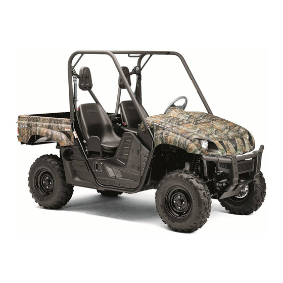
- Utility Vehicle
- Rhino 700 Fi
- Owner’s manual
-
Contents
-
Table of Contents
-
Troubleshooting
-
Bookmarks
Quick Links
READ THIS MANUAL CAREFULLY!
It contains important safety information.
OWNER’S MANUAL
YX70SD
YX70SHD
YX70SSD
1RB-F8199-71
Related Manuals for Yamaha Rhino 700 Fi
Summary of Contents for Yamaha Rhino 700 Fi
-
Page 1
READ THIS MANUAL CAREFULLY! It contains important safety information. OWNER’S MANUAL YX70SD YX70SHD YX70SSD 1RB-F8199-71… -
Page 2
Read this manual carefully before operating this vehicle. This manual should stay with this ve- hicle if it is sold. -
Page 3
Congratulations on your purchase of the Yamaha YX70SD / YX70SHD / YX70SSD. It represents the result of many years of Yamaha experience in the production of fine sporting, touring, and pace-setting racing vehicles. With the purchase of this Yamaha, you can now appreciate the high degree of craftsmanship and reliability that have made Yamaha a leader in these fields. -
Page 4: Important Manual Information
EVU00021 IMPORTANT MANUAL INFORMATION FAILURE TO FOLLOW THE WARNINGS CONTAINED IN THIS MANUAL CAN RESULT IN SE- RIOUS INJURY OR DEATH. Particularly important information is distinguished in this manual by the following notations: This is the safety alert symbol. It is used to alert you to potential personal injury hazards.
-
Page 5
This vehicle complies with almost all provinces off-highway noise level and spark ar- rester laws and regulations. YX70SD / YX70SHD / YX70SSD OWNER’S MANUAL ©2012 by Yamaha Motor Co., Ltd. 1st edition, March 2012 All rights reserved. Any reprinting or unauthorized use without the written permission of Yamaha Motor Co., Ltd. -
Page 6: Table Of Contents
EVU00050 Glove compartment …….4-19 CONTENTS Cup holders……..4-19 Cargo bed ……..4-20 LOCATION OF THE WARNING AND Adjusting the front and rear shock SPECIFICATION LABELS….1-1 absorber assemblies (YX70SD/YX70SHD) ….4-23 SAFETY INFORMATION….2-1 Adjusting the front shock absorber assemblies (YX70SSD) ….4-24 DESCRIPTION ……… 3-1 Adjusting the rear shock absorber assemblies (YX70SSD) ….4-30 INSTRUMENT AND CONTROL…
-
Page 7
Seat belts ……..5-7 Protective structure……7-6 Steering……….. 5-8 Seat belts……… 7-6 Fittings and fasteners…… 5-8 Doors ……….7-9 Instruments, lights and switches..5-8 Passenger handholds….7-10 Control cables ……… 5-8 Seat and hip restraints ….7-11 Tires ……….5-9 Floorboard …….. -
Page 8
Uphill……….7-21 Spark plug inspection ….8-24 Downhill ……… 7-22 Cleaning the air filter element ..8-27 Rough terrain……… 7-23 Drive select lever box check Pavement ……..7-23 hose ……….8-32 Water ……….7-23 V-belt cooling duct check hose..8-32 Loose terrain/slippery terrain..7-24 V-belt case drain plug ….8-33 Brush or wooded areas …. -
Page 9
Rear knuckle upper and lower CONSUMER INFORMATION ..11-1 pivot lubrication (left and right)..8-42 Identification number records..11-1 Steering shaft lubrication ….8-43 YAMAHA SIDE BY SIDE Wheel removal ……8-44 OFF-ROAD VEHICLE Tire replacement ……8-44 WARRANTY POLICY ….11-4 Wheel installation …… -
Page 10: Location Of The Warning And Specification Labels
EVU00060 L OCATION OF THE WARNING AND SPECIFICATION LABELS 6 7 8 9 0AB D E 43 2…
-
Page 11
Read and understand all of the labels on your vehicle. They contain important information for safe and proper operation of your vehicle. Never remove any labels from your vehicle. If a label becomes difficult to read or comes off, a re- placement label is available from your Yamaha dealer. 2YX70SSD… -
Page 12
If you think or feel YAMAHA certifies this ROV complies with the American that the vehicle National Standard for Recreational Off-Highway Vehicles, may tip or roll, ANSI/ROHVA-1-2010 Standard. -
Page 13
(ROPS). m=700 kg pour ISO 3471 m=700Kg for ISO3471 YAMAHA MOTOR DU CANADA LTÉE. YAMAHA MOTOR CANADA LTD. 480 Gordon Baker Road, Toronto (Ontario) M2H 3B4, Canada 480 Gordon Baker Road, Toronto, Ontario M2H 3B4, Canada… -
Page 14
BYX70SSD ARNING ny part of your body (arms, legs, or head) outside of the vehicle can be crushed by the cage/frame. If you think or feel that the vehicle may tip or roll, brace your feet on the floorboards, and keep your hands on the handholds. -
Page 15
YAMAHA certifie que ce véhicule hors route est conforme à la norme ANSI/ROHVA-1-2010 de l’ANSI, intitulée American National Standard for Recreational Off-Highway Vehicles. Date de fabrication xx/xx 1RB-F4161-10… -
Page 17
MAX 7.3 INCH (185MM) YAMAHA 5UG-F151J-00… -
Page 19
1-10… -
Page 20
1-11… -
Page 21: Safety Information
EVU00070 SAFETY INFORMATION Be a responsible owner As the vehicle’s owner, you are responsible for the safe and proper operation of your Rhino. While understanding all parts of this manual are important for vehicle ownership, be sure to read this chapter and the instructions in Chapter 7 before operating the Rhino.
-
Page 22
Before you operate the Rhino Prepare yourself and your passenger: ● • This vehicle is intended for use only by an operator 16 or older with a valid motor vehicle li- cense. DRIVER UNDER • This vehicle is designed to carry the driver and one passenger. Never carry passengers in the cargo bed. -
Page 23
Prepare your vehicle Perform the pre-operation checks each time you use the vehicle to make sure it is in safe operat- ing condition. Failure to inspect or maintain the vehicle properly increases the possibility of an ac- cident or equipment damage. See pages 5-1–5-2 for a list of pre-operation checks. Prepare your load or trailer Carrying loads, towing a trailer, or pulling objects can affect handling, stability, and cause the risk of overturns or other accidents. -
Page 24
While using the Rhino Keep your body completely inside the vehicle at all times. Keep both hands on the steering ● wheel. Be sure the passenger is seated, belted, and holding onto the handholds. Close doors before driving. Any part of your body (arms, legs, and head) outside the vehicle can be struck by objects your vehicle is passing or crushed by the vehicle cage/frame in a rollover accident. -
Page 25
● Avoid rollovers: • Use care when turning: • Turning the steering wheel too far or too fast can result in a rollover. • Avoid sideways sliding, skidding, or fishtailing, and never do donuts. • Slow down before entering a turn and avoid hard braking in a turn. •… -
Page 26
● If you think or feel that the vehicle may tip or roll, keep your body completely inside the protec- tive structure of the vehicle: • Brace yourself by pressing your feet firmly on the floorboards and keep a firm grip on the steering wheel or handholds. -
Page 27
Avoid carbon monoxide poisoning All engine exhaust contains carbon monoxide, a deadly gas. Breathing carbon monoxide can cause headaches, dizziness, drowsiness, nausea, confusion, and eventually death. Carbon monoxide is a colorless, odorless, tasteless gas which may be present even if you do not see or smell any engine exhaust. -
Page 28
Many companies with no connection to Yamaha manufacture parts and accessories or offer other modifications for Yamaha vehicles. Yamaha is not in a position to test the products that these af- termarket companies produce. Therefore, Yamaha can neither endorse nor recommend the use of accessories not sold by Yamaha or modifications not specifically recommended by Yamaha, even if sold and installed by a Yamaha dealer. -
Page 29
Aftermarket tires and rims The tires and rims that came with your Rhino were designed to match the performance capabili- ties and to provide the best combination of handling, braking, and comfort. Other tires, rims, sizes, and combinations may not be appropriate. Refer to pages 8-44–8-46 for tire specifications and more information on replacing your tires. -
Page 30: Description
EVU00080 D ESCRIPTION N M A 1. Headlights 14. Spark arrester 2. Front shock absorber assembly 15. Passenger seat belt 3. Brake fluid reservoir 16. Passenger seat 4. Air filter element 17. Passenger handholds 5. V-belt case 18. Engine oil dipstick 6.
-
Page 31
The vehicle you have purchased may differ slightly from those shown in the figures of this manual. 25. Light switch 26. Steering wheel 27. Main switch 28. On-Command four-wheel-drive and differential gear lock switches 29. Multi-function meter unit 30. Helmet/Seat belt indicator light 31. -
Page 32: Instrument And Control Functions
EVU00130 I NSTRUMENT AND CONTROL Functions of the respective switch positions FUNCTIONS are as follows: EVU00140 All electrical circuits are supplied with Main switch power. The helmet/seat belt indicator light comes on and stays on while the key is turned to “ON”. OFF: All electrical circuits are switched off.
-
Page 33: Indicator Lights And Warning Lights
EVU00150 EVU01140 Indicator lights and warning lights Low-range indicator light “L” This indicator light comes on when the drive select lever is in the “L” position. EVU01150 High-range indicator light “H” This indicator light comes on when the drive select lever is in the “H” position. 1.
-
Page 34
EVU00170 EBU29621 Neutral indicator light “N” On-Command four-wheel-drive indicator This indicator light comes on when the drive “ ”, On-Command differential gear lock select lever is in the “N” position. indicator “ ” and indicator light “DIFF. DIFF. LOCK LOCK” The On-Command four-wheel-drive indicator 5B410001 Reverse indicator light “R”… -
Page 35
“ON”, or if the warning light not completely locked or unlocked. In this remains on, have a Yamaha dealer check the case, start moving to allow time for the electrical circuit. -
Page 36
“ON”. If the warning light does not come on initially when the key is turned to “ON”, or if the warning light remains on, have a Yamaha dealer check the electrical circuit. -
Page 37: Multi-Function Meter Unit
The indicator light stays on even when the following: the seat belt is properly latched. a speedometer ● If the indicator light does not come on when an odometer ● the key is turned to “ON”, have a Yamaha dealer check the electrical circuit.
-
Page 38
two tripmeters (which show the distance Odometer and tripmeter modes ● traveled since they were last set to zero) ● a clock an hour meter (which shows the total time ● the engine has been running) a voltage display (which shows the battery ●… -
Page 39
To reset a tripmeter, select it by pushing the Clock, hour meter and voltage display “TRIP/ODO” button, and then hold the “TRIP/ modes ODO” button for at least three seconds. The tripmeters can be used to estimate the dis- tance that can be traveled with a full tank of fu- el. -
Page 40
To set the clock Voltage display mode 1. Set the display to the clock. 2. Push the “ ” button until the clock starts flashing. 3. Set the hours by pushing the “H” button. 4. Set the minutes by pushing the “M” but- ton. -
Page 41
If the voltage display indicates “LO” or “HI”, there may be trouble with the battery charging circuit or the battery may be faulty. If this occurs, have a Yamaha dealer check or repair the vehicle. 1. Fuel level warning indicator 2. -
Page 42
If a problem is detected in an elec- trical circuit, all the display segments and fuel level warning indicator start flashing. If this oc- curs, have a Yamaha dealer check the electri- cal circuit. 1. Engine trouble warning light “… -
Page 43
EVU00240 Light switch “OFF/ ” NOTICE If the multi-function display indicates an error code, the vehicle should be checked as soon as possible in order to avoid en- gine damage. 1. Light switch “OFF/ ” Set the switch to “ ”… -
Page 44
EVU01183 On-Command four-wheel-drive and differ- NOTICE ential gear lock switches Do not use the headlights with the engine turned off for an extended period of time. The battery may discharge to the point that the starter motor will not operate properly. -
Page 45: Accelerator Pedal
EVU00260 “4WD” (four-wheel drive): Power is sup- Accelerator pedal ● plied to the rear and front wheels. Press the accelerator pedal down to increase ● “LOCK” (four-wheel drive with the differen- engine speed. Spring tension returns the ped- tial gear locked): Power is supplied to the al to the rest position when released.
-
Page 46: Brake Pedal
EVU00270 EVU00280 Brake pedal Parking brake lever Press the brake pedal to slow or stop the ve- The parking brake lever is located at the right hicle. side of the driver’s seat. Setting the parking brake lever will help keep the vehicle from moving while parked.
-
Page 47: Drive Select Lever
EVU00290 EVU00300 Drive select lever Fuel tank cap The drive select lever is used to shift the vehi- cle into the low, high, neutral, and reverse po- sitions. (Refer to pages 6-4–6-5 for the drive select lever operation.) 1. Fuel tank cap To open Remove the fuel tank cap by turning it coun- terclockwise.
-
Page 48: Doors
EVU00330 Doors Seats To open a door, pull the latch outward. To To remove a seat, pull its seat lock lever up- close a door, push or pull the door inward until ward, lift the front of the seat, and then slide it is securely latched.
-
Page 49: Seat Belts
EVU00340 To install a seat, insert the projections on the Seat belts rear of the seat into the seat holders and push This vehicle is equipped with three-point seat down on the seat at the front. Make sure the belts for both the operator and the passenger. seats are securely latched.
-
Page 50: Glove Compartment
EVU01191 5B410005 Glove compartment Cup holders Be sure to tightly close the cap of any plastic NOTICE bottle before placing it in a cup holder. To protect from damage, do not put metal Some plastic bottles may not fit into the cup items, like tools, or sharply edged items holders depending on their size and shape.
-
Page 51: Cargo Bed
EVU00351 Cargo bed WARNING Do not exceed the specified maximum load limits. Heavier cargo could cause loss of control because of improper weight balance. 1. Storage/cup holder (× 1) 2. Cup holder (× 2) 1. Cargo bed 2. Tailgate 3. Cargo hook (× 4) Maximum load limit: 181 kg (400 lb) For additional loading information, see pages 6-9–6-11.
-
Page 52
Opening and closing the tailgate NOTICE The tailgate is not designed to hold heavy loads when open. The tailgate could col- lapse if you put heavy cargo or sit on it. 1. Tailgate 2. Latch (× 2) To open Unhook the latches, and then lower the tail- gate. -
Page 53
Lifting and lowering the cargo bed To lower With hands and fingers clear of pinch points, lower the cargo bed slowly to its original posi- tion and be sure it is locked into place. WARNING! Keep hands, body, and other people away from pinch points when low- ering bed. -
Page 54: Adjusting The Front And Rear Shock Absorber Assemblies (Yx70Sd/Yx70Shd)
5B410006 Adjusting the front and rear shock The rear wheels need to be removed to adjust absorber assemblies (YX70SD/YX70SHD) the rear shock absorber assemblies. (See pages 8-44–8-46 for wheel removal and in- WARNING stallation procedures.) Always adjust the shock absorbers on the Adjust the spring preload as follows: left and right sides to the same setting.
-
Page 55: Adjusting The Front Shock Absorber Assemblies (Yx70Ssd)
5UG1B001 Adjusting the front shock absorber A special wrench can be obtained at a assemblies (YX70SSD) Yamaha dealer to make this adjustment. WARNING These shock absorber assemblies contain Standard position: B highly pressurized nitrogen gas. Read and A- Minimum (soft)
-
Page 56
Take the shock absorber assem- 2. Turn the spring preload adjusting nut in direction a to increase the spring pre- bly to a Yamaha dealer for any service. load and thereby harden the suspension, and in direction b to decrease the spring… -
Page 57
Spring preload setting: ● A special wrench can be obtained at a Minimum (soft): Yamaha dealer to make this adjustment. Distance A = 62 mm (2.44 in) ● The spring preload setting is determined Standard: by measuring distance A, shown in the il- Distance A = 67 mm (2.64 in) -
Page 58
Rebound damping force Rebound damping setting: Turn the rebound damping force adjusting Minimum (soft): screw in direction a to increase the rebound 12 click(s) in direction b* damping force and thereby harden the damp- Standard: ing, and in direction b to decrease the re- 10 click(s) in direction b* bound damping force and thereby soften the Maximum (hard):… -
Page 59
Compression damping force Compression damping setting: Turn the compression damping force adjust- Minimum (soft): ing screw in direction a to increase the com- 12 click(s) in direction b* pression damping force and thereby harden Standard: the damping, and in direction b to decrease 10 click(s) in direction b* the compression damping force and thereby Maximum (hard):… -
Page 60
WARNING Although the total number of clicks of a damp- Suspension components become hot ● ing force adjusting mechanism may not exact- during operation. Never touch the ly match the above specifications due to small compression damping force adjusting differences in production, the actual number screw, the rebound damping force ad- of clicks always represents the entire adjust- justing screw or the oil reservoir with… -
Page 61: Adjusting The Rear Shock Absorber Assemblies (Yx70Ssd)
Read and self. Take the shock absorber assem- understand the following information be- bly to a Yamaha dealer for any fore handling the shock absorber assem- service. blies. The spring preload, rebound damping and Do not tamper with or attempt to open ●…
-
Page 62
Spring preload ● A special wrench can be obtained at a 1. Loosen the locknut. Yamaha dealer to make this adjustment. 2. Turn the spring preload adjusting nut in direction a to increase the spring pre- ● The spring preload setting is determined… -
Page 63
Rebound damping force Spring preload setting: Turn the rebound damping force adjusting Minimum (soft): screw in direction a to increase the rebound Distance A = 63.5 mm (2.50 in) damping force and thereby harden the damp- Standard: ing, and in direction b to decrease the re- Distance A = 63.5 mm (2.50 in) bound damping force and thereby soften the Maximum (hard):… -
Page 64
Compression damping force Rebound damping setting: Turn the compression damping force adjust- Minimum (soft): ing screw in direction a to increase the com- 20 click(s) in direction b* pression damping force and thereby harden Standard: the damping, and in direction b to decrease 12 click(s) in direction b* the compression damping force and thereby Maximum (hard):… -
Page 65
Compression damping setting: Although the total number of clicks of a damp- Minimum (soft): ing force adjusting mechanism may not exact- 12 click(s) in direction b* ly match the above specifications due to small Standard: differences in production, the actual number 7 click(s) in direction b* of clicks always represents the entire adjust- Maximum (hard):… -
Page 66: Trailer Hitch Bracket And Receiver
Never touch the dard trailer hitch. Trailer towing equipment compression damping force adjusting can be obtained at a Yamaha dealer. (See screw, the rebound damping force ad- pages 6-9–6-11 for precaution information.) justing screw or the oil reservoir with your bare hand or skin until suspen- sion components have cooled.
-
Page 67: Auxiliary Dc Jack
EVU00380 EVU00380 Auxiliary DC jack 4. Open the auxiliary DC jack cap, and then The auxiliary DC jack is located at the right insert the accessory power plug into the side of the front panel. The auxiliary DC jack jack. can be used for suitable work lights, radios, etc.
-
Page 68
NOTICE Do not use accessories requiring ● more than the maximum capacity stat- ed above. This may overload the cir- cuit and cause the fuse to blow. ● If accessories are used without the engine running, the battery may dis- charge. -
Page 69: For Your Safety — Pre-Operation Checks
Do not operate the vehicle if you find any problem. If a problem cannot be corrected by the procedures provided in this manual, have the vehicle inspect- ed by a Yamaha dealer. Before using this vehicle, check the following points:…
-
Page 70
ITEM ROUTINE PAGE Final gear oil/ • Check for leakage. 5-7, 8-15–8-21 Differential gear oil Accelerator pedal • Check for proper accelerator pedal operation. Seat belts • Check for proper operation and belt wear. 5-7–5-8 Steering • Check for proper operation. Fittings and fasteners •… -
Page 71: Front And Rear Brakes
Check that there is no free play in the brake ply the brakes firmly for one minute. If there is pedal. If there is free play, have a Yamaha any leakage, have the vehicle inspected by a dealer check the brake system. (See page Yamaha dealer.
-
Page 72: Fuel
Never refuel while smoking, or while in the vicinity of sparks, open flames, or oth- Your Yamaha engine has been designed to er sources of ignition such as the pilot use regular unleaded gasoline with a pump…
-
Page 73
Always place a portable fuel container on the Gasohol containing methanol is not recom- ground before filling it. Before removing the mended by Yamaha because it may cause container cap, touch the container with the fuel system damage or vehicle performance fuel dispenser nozzle. -
Page 74: Engine Oil
EVU00410 EVU00420 Engine oil Coolant Make sure the engine oil is at the specified Check the coolant level in the coolant reser- level. Add oil as necessary. (See pages 8-10– voir when the engine is cold (the coolant level 8-15.) will vary with engine temperature).
-
Page 75: Final Gear Oil
It must operate smoothly and 8-18 for details.) spring back to the idle position fully when re- leased. Have a Yamaha dealer repair as nec- Recommended oil: essary for proper operation. SAE 80 API GL-4 Hypoid gear oil…
-
Page 76: Steering
Yamaha dealer repair as necessary for proper operation. EVU00470 Fittings and fasteners Always check the tightness of chassis fittings and fasteners before a ride. Take the vehicle to a Yamaha dealer or refer to the Service Manual for correct tightening torque.
-
Page 77: Tires
EVU00500 Tires Set tire pressures to the following specifica- Check tire pressure regularly to make sure it tions: is at the recommended specifications. Also ACE-02E Recommended pressure Minimum check for wear and damage. 70 kPa 63 kPa Front EVU00510 (0.70 kgf/cm , 10 psi) (0.63 kgf/cm , 9 psi)
-
Page 78
EVU00520 Tire wear limit When the tire groove decreases to 3 mm (0.12 in) due to wear, replace the tire. 1. Tire pressure gauge a. Tire wear limit 5-10… -
Page 79: Operation
If there is a and 20 hours. control or function you do not understand, ask your Yamaha dealer. For this reason, we ask that you read the fol- lowing material carefully. Because the engine WARNING…
-
Page 80: Starting The Engine
The coolant temperature warning light and build-up of heat. If any abnormality is noticed engine trouble warning light should come during this period, consult a Yamaha dealer. on, then go off. If a warning light does not go off, see pag- 0–10 hours:…
-
Page 81
● The engine can be started in any gear For maximum engine life, never accelerate if the brake pedal is applied. However, hard when the engine is cold! it is recommended to shift into neutral before starting the engine. 4. With your foot off the accelerator pedal, start the engine by turning the key to “START”. -
Page 82: Drive Select Lever Operation And Reverse Driving
Drive select lever operation and reverse 2. Apply the brake pedal, then shift by mov- driving ing the drive select lever along the shift guide. Make sure that the drive select le- NOTICE ver is completely shifted into position. Do not shift without coming to a complete stop and waiting for the engine to return to normal idle speed.
-
Page 83
● If the light does not come on, ask a Yamaha dealer to inspect the reverse indicator light electrical circuit. -
Page 84: On-Command Four-Wheel-Drive Switch And Differential Gear Lock Switch
5B410009 On-Command four-wheel-drive switch and “2WD”/“4WD” differential gear lock switch To change from “2WD” to “4WD”, stop the ve- You may notice that the vehicle handles dif- hicle, and then set the switch to “4WD”. When ferently in “2WD”, “4WD”, and “LOCK”. For the vehicle is in four-wheel drive, the four- example, you should expect that the vehicle wheel-drive indicator “…
-
Page 85
On-Command differential gear lock switch To lock the differential gear in four-wheel “4WD”/“LOCK” drive, stop the vehicle, make sure the On- Command four-wheel-drive switch is set to “4WD”, move the differential gear lock lever to position a, and then set the switch to “LOCK”. -
Page 86: Parking
EVU01210 ● Driving before the differential gear is prop- Parking erly engaged or disengaged (e.g., when the When parking, stop the engine and shift the indicator and indicator light are flashing) will drive select lever into the neutral position. Ap- cause the engine speed to be limited until ply the parking brake to help prevent the vehi- the differential gear is completely engaged…
-
Page 87: Loading
EVU00630 Loading ● Do not exceed the maximum tongue Take extra precautions when driving with a weight. load or trailer. Follow these instructions and ● Make sure the load does not interfere always use common sense and good judg- with your control or ability to see ment when carrying cargo or towing a trailer.
-
Page 88
You can measure tongue weight with a bath- Operating when loaded with cargo or tow- room scale. Put the tongue of the loaded trail- ing a trailer er on the scale with the tongue at hitch height. Drive more slowly than you would without a Adjust the load in the trailer, if necessary, to load. -
Page 89
Pulling something other than a trailer Yamaha recommends that loads be transport- ed in the bed or in a trailer. If you need to move an object a short distance use a winch and follow the winch manufacturer’s instruc- tions. -
Page 90: Basic Guide For Safe Use
5B470010 BASIC GUIDE FOR SAFE KNOW YOUR VEHICLE This off-road vehicle will handle and maneu- ver differently from cars, ATVs, go-carts, golf- As a Rhino owner you are responsible for the cars and grounds-keeping vehicles. The safe and proper operation of this vehicle. Rhino has higher ground clearance and other Read this chapter and review the safety in- features to handle rugged terrain, and, as a…
-
Page 91
Doing things with a Rhino that some people do for thrills in other vehicles (such as side- ways sliding, skidding, fishtailing, or donuts) have led to side rollovers. These rollovers can result in crushed limbs and other serious inju- ries or death to drivers or passengers. As the owner/operator, it is your responsibility to protect yourself and your passenger from accidents, including rollovers. -
Page 92: Driver Requirements
Driver requirements Parents: ● This vehicle is intended for use only by an Many provinces have implemented new mo- operator 16 or older with a valid motor vehi- tor vehicle licensing requirements for young cle license. drivers. These requirements are in response to the disproportionately high rate of crashes involving youthful drivers.
-
Page 93: Passenger Requirements
Passenger requirements Occupant protection system This vehicle is designed for the operator and WARNING one passenger. Allowing passengers to ride Do not make changes to the occupant pro- improperly can lead to serious injury or death. tection system. If you install aftermarket As the operator, you are responsible for your products or have your vehicle modified, passenger.
-
Page 94
The Rhino comes with a variety of features to help reduce the risk of driver and passenger injury. These features work together, and when properly used, these features will help protect the occupants in the event of an acci- dent. If these features are not used properly, they can cause injury. -
Page 95: Protective Structure
Protective structure Seat belts The vehicle cage/frame provides a protective Seat belts should be worn by both driver and structure that helps limit intrusions by branch- passenger. Driver must be sure that the pas- es or other objects and may reduce your risk senger is belted before driving.
-
Page 96
An unbelted occupant may strike the interior of the vehicle, the protective structure, or oth- er objects in an accident or during operation. You may also fall completely out or be partial- ly ejected from the vehicle, which may lead to being crushed between the ground and the vehicle. -
Page 97
2. If the latch plate is not positioned in the correct location along the seat belt, squeeze the latch plate ends together along its long edges in order to more eas- ily adjust its location up or down along the length of the belt. -
Page 98: Doors
6. Check if the seat belt shoulder position Doors suits the size of the driver and passen- The doors are designed to reduce the likeli- ger. hood that you will stick your leg out to stop the To lower the belt, insert the belt into the vehicle from tipping over or for any other rea- seat belt height adjuster slot as shown.
-
Page 99: Passenger Handholds
Passenger handholds Handholds are provided to grip during opera- tion to maintain proper position and balance. Holding onto the handholds helps to reduce the likelihood that the passenger puts a hand outside the vehicle if the vehicle begins to tip. There are two handholds on the protective structure and two handholds on the passen- ger’s left side, for the right and left hands.
-
Page 100: Seat And Hip Restraints
Seat and hip restraints Floorboard The seat and hip restraints are designed to The floorboard allows you to brace your feet, help keep you in the vehicle. Do not hold onto which helps you keep your body in the vehicle hip restraint when the vehicle is moving.
-
Page 101: Steering Wheel
Steering wheel CORRECT GRIP EXAMPLE Keep both hands on the steering wheel. Do not hold the steering wheel with your thumbs inside the rim. Keep your palms on the out- side of the steering wheel. Similar to other off- road vehicles, if the Rhino hits a deep rut or large obstacle, the steering wheel could brief- ly jerk in one direction or back and forth as the tires and vehicle respond to the obstacle.
-
Page 102: Learning To Operate Your Vehicle
LEARNING TO OPERATE YOUR VEHICLE Both driver and passenger should wear the following to reduce risk of injury in an acci- Personal protective equipment dent: ● Approved motorcycle helmet that fits prop- erly Eye protection (goggles, helmet face ● shield, or protective eyewear) Over-the-ankle boots, gloves, long-sleeved ●…
-
Page 103: Practice For New Rhino Users
Wear eye protection when operating or riding the vehicle to reduce the risk of a serious ac- cident or injury. Eye protection, such as a face shield or goggles, may reduce the risk of for- eign material getting in your eyes and help prevent loss of vision.
-
Page 104: Getting Ready To Ride
Getting ready to ride Turning Perform the Pre-Operation Checks on pages Use care in turns – turning the steering wheel 5-1–5-10. Follow the instructions starting on too far or too fast can result in loss of control pages 6-2–6-3 to start the engine. or a rollover.
-
Page 105: Accelerating
If you think or feel that the vehicle may tip or Accelerating roll, keep your body completely inside the pro- With the engine idling in neutral and your foot tective structure of the vehicle: on the brake, shift the drive select lever into ●…
-
Page 106: Braking
Braking Engine braking When slowing down or stopping, take your Engine compression braking is designed to foot off the accelerator pedal and press the assist you when operating your Rhino off- brake pedal smoothly. Improper use of the road. With this feature, the engine helps slow brakes can cause the tires to lose traction, re- the vehicle down after you take your foot off ducing control of the vehicle and increasing…
-
Page 107: Leaving The Vehicle
Leaving the vehicle Parking on a flat area Do not get out of the vehicle while the engine When parking on a flat area, stop the engine is running and the drive select lever is in any and shift the drive select lever into the neutral gear.
-
Page 108: Loading
4. With the brake pedal applied, set the Operation on different surfaces and parking brake. terrains 5. Block the front and rear wheels with Go slowly and proceed with caution when op- rocks or other objects. erating on an unfamiliar surface or terrain. This vehicle may handle differently in certain Loading types of terrains or on certain surfaces.
-
Page 109: Hills
Hills Choose carefully which hills you attempt to climb or descend. Avoid hills with slippery sur- faces or those where you will not be able to see far enough ahead of you. Use common sense and remember that some hills are too steep for you to climb or descend.
-
Page 110: Uphill
Uphill Slow down when you reach the crest of the hill Do not attempt to climb hills until you have if you cannot see clearly what is on the other mastered basic maneuvers on flat ground. side – there could be another person, an ob- Drive straight up hills, and avoid crossing the stacle, or a sharp drop-off.
-
Page 111: Downhill
Downhill If you are sliding or skidding, try to steer in the Check the terrain carefully before going direction the vehicle is sliding, to regain con- downhill. When possible, choose a path that trol. For example, if you feel the back of the lets you drive your vehicle straight downhill.
-
Page 112: Rough Terrain
Rough terrain Water Operation over rough terrain should be done If you must cross shallow, slow-moving water with caution. up to the depth of the vehicle’s floorboards, ● Look for and avoid obstacles that could choose your path carefully to avoid sharp cause damage to the vehicle or could lead drop-offs, large rocks, or slippery surfaces to a rollover or accident.
-
Page 113: Loose Terrain/Slippery Terrain
Loose terrain/slippery terrain NOTICE When driving on slippery terrain, including After driving your vehicle in water, be sure wet, muddy, or icy conditions, as well as loose to drain the trapped water by removing the gravel, be aware that you could begin skid- check hoses at the bottom of the air filter ding or sliding.
-
Page 114: Brush Or Wooded Areas
Brush or wooded areas Encountering obstacles When operating in areas with brush or trees, If you cannot go around an obstacle, such as watch carefully on both sides and above the a fallen tree or a ditch, stop the vehicle where vehicle for obstacles such as branches that it is safe to do so.
-
Page 115: Periodic Maintenance And Adjustment
WARNING hicle. If you are not familiar with vehicle Brake discs, calipers, drums, and linings service, have a Yamaha dealer perform can become very hot during use. To avoid service. possible burns, let brake components cool…
-
Page 116: Owner’s Manual And Tool Kit
EVU00660 Owner’s manual and tool kit You are recommended to put this owner’s manual in the vinyl bag and always carry it un- derneath the driver seat as shown. Put the owner’s tool kit and tire pressure gauge in the space beside the battery.
-
Page 117
If you do not have a torque wrench available during a service operation requiring one, take your vehicle to a Yamaha dealer to check the torque settings and adjust them as necessary. -
Page 118: Periodic Maintenance Chart For The Emission Control System
However, keep in mind that if the vehicle isn’t used for a long period of time, the month maintenance intervals should be followed. Items marked with an asterisk should be performed by a Yamaha dealer as they require spe- ●…
-
Page 119: General Maintenance And Lubrication Chart
EVU01650 General maintenance and lubrication chart INITIAL EVERY month Whichever ITEM ROUTINE comes first 1200 2400 2400 4800 (mi) (200) (750) (1500) (1500) (3000) hours • Check coolant leakage. Cooling system* • Repair if necessary. • Replace coolant every 24 months. •…
-
Page 120
INITIAL EVERY month Whichever ITEM ROUTINE comes first 1200 2400 2400 4800 (mi) (200) (750) (1500) (1500) (3000) hours Drive shaft universal joint* • Lubricate with lithium-soap-based grease. • Check for cracks or damage. Engine mount* • Check bolt tightness. •… -
Page 121: Hood
EVU00680 Hood To open Unhook the hood latches, and then slowly tilt the hood up until it stops. 1. Hood 1. Hood latch (× 2)
-
Page 122
To close NOTICE Lower the hood slowly to its original position, Make sure that all cables and wires ● and then hook the hood latches. Secure pro- are in place when closing the hood. jections 1 on the rear of the hood into slots 2 ●… -
Page 123: Console
5B410011 Console To install 1. Place the console in its original position. To remove 2. Install the parking brake lever boot. 1. Remove the seats. (See pages 4-17– 3. Install the seats. 4-18 for seat removal and installation NOTICE procedures.) Be sure to position the seat belt buck- ●…
-
Page 124: Engine Oil And Oil Filter Cartridge
5B410012 Engine oil and oil filter cartridge Check engine oil level before each operation. In addition, change the oil and the oil filter car- tridge at the intervals specified in the periodic maintenance and lubrication chart. To check the engine oil level 1.
-
Page 125
5. Insert the dipstick completely into the oil 7. Insert the dipstick completely into the oil filler hole, and then remove it again to filler hole. check the oil level. 8. Install the console. The engine oil should be between the mini- mum and maximum level marks. -
Page 126
To change the engine oil (with or without oil filter cartridge replacement) 1. Park the vehicle on a level surface. 2. Remove the console. (See page 8-10 for console removal and installation proce- dures.) 3. Start the engine, warm it up for several minutes, and then turn it off. -
Page 127
If the O-ring remains attached to the crankcase, oil leakage may occur. An oil filter wrench is available from a Yamaha dealer. 1. O-ring 9. Install the new oil filter cartridge with an oil filter wrench, and then tighten it to the specified torque with a torque wrench. -
Page 128
12. Refill with the specified amount of recom- mended engine oil, and then insert the dipstick completely into the oil filler hole. Recommended engine oil: See pages 10-1–10-2. Oil quantity: Without oil filter cartridge replacement: 2.00 L (2.11 US qt, 1.76 Imp.qt) With oil filter cartridge replacement: 2.10 L (2.22 US qt, 1.85 Imp.qt) 1. -
Page 129: Final Gear Oil
5B410013 Final gear oil NOTICE In order to prevent clutch slippage ● Checking the final gear oil level (since the engine oil also lubricates 1. Park the vehicle on a level surface. the clutch), do not mix any chemical 2. Remove the final gear oil filler bolt and its additives with oil.
-
Page 130
3. If the oil is below the brim of the filler hole, Changing the final gear oil add sufficient oil of the recommended 1. Park the vehicle on a level surface. type to raise it to the correct level. 2. Remove the final gear case guard by re- NOTICE: Be sure no foreign material moving the bolts and the collars. -
Page 131
3. Place an oil pan under the final gear case 6. Refill with the recommended final gear oil to collect the used oil. up to the brim of the filler hole. NOTICE: 4. Remove the final gear oil filler bolt and its Be sure no foreign material enters the O-ring, the final gear oil drain bolt and its final gear case. -
Page 132: Differential Gear Oil
5B410014 9. Install the final gear case guard by install- Differential gear oil ing the bolts and the collars, and then tightening the bolts to the specified Checking the differential gear oil level torque. 1. Park the vehicle on a level surface. 2.
-
Page 133
4. Check the gasket for damage, and re- place it if necessary. 5. Install the differential gear oil filler bolt and its gasket, and then tighten the bolt to the specified torque. Tightening torque: Differential gear oil filler bolt: 23 Nm (2.3 m·kgf, 17 ft·lbf) 1. -
Page 134
Changing the differential gear oil 3. Place an oil pan under the differential 1. Park the vehicle on a level surface. gear case to collect the used oil. 2. Remove the differential gear case guard 4. Remove the differential gear oil filler bolt, by removing the bolts and the collars. -
Page 135
9. Check for oil leakage. If oil leakage is Tightening torque: found, check for the cause. Differential gear oil drain bolt: 10. Install the differential gear case guard by 9.8 Nm (0.98 m·kgf, 7.1 ft·lbf) installing the bolts and the collars, and then tightening the bolts to the specified 6. -
Page 136: Coolant
5B410015 Coolant The coolant level should be checked before each ride. Checking the coolant level 1. Park the vehicle on a level surface. 2. Check the coolant level in the coolant reservoir when the engine is cold as the coolant level varies with engine tempera- ture.
-
Page 137: Axle Boots
EVU00740 Changing the coolant Axle boots The coolant must be changed by a Yamaha Check the axle boots for holes or tears. dealer at the intervals specified in the periodic If any damage is found, have them replaced maintenance and lubrication chart.
-
Page 138: Spark Plug Inspection
EVU00750 Spark plug inspection Removal 1. Remove the console. (See page 8-9 for console removal and installation proce- dures.) 2. Remove the spark plug cap. 1. Rear axle boot (× 2 each side) 1. Spark plug cap 3. Use the spark plug wrench in the tool kit to remove the spark plug as shown.
-
Page 139
Inspection The spark plug is an important engine compo- nent and is easy to inspect. The condition of the spark plug can indicate the condition of the engine. The ideal color of the porcelain insulator around the center electrode is a medium-to- light tan for a vehicle that is being ridden nor- mally. -
Page 140
Measure the spark plug gap with a wire thick- 2. Install the spark plug and tighten it to the ness gauge and, if necessary, adjust the gap specified torque. If a torque wrench is not to specification. available when you are installing the spark plug, a good estimate of the correct torque is one-quarter to one-half turn past finger tight. -
Page 141: Cleaning The Air Filter Element
5B410016 Cleaning the air filter element There is a check hose at the bottom of the air filter case and at the bottom of the air duct un- der the case. If dust or water collects in a check hose, empty the hose and clean the air filter element and air filter case.
-
Page 142
1. Open the hood. (See pages 8-7–8-8 for 3. Remove the air filter case cover by un- hood opening and closing procedures.) hooking the holders. 2. Remove the air intake duct shroud by re- moving the quick fastener screws. 1. Air filter case cover holder (× 5) 2. -
Page 143
4. Remove the air filter element. 5. Remove the sponge material from the air filter frame. 1. Air filter element 1. Air filter frame 2. Sponge material 8-29… -
Page 144
NOTICE: Do not twist replace it if damaged. the sponge material when squeezing 11. Thoroughly apply Yamaha foam air filter oil or other quality liquid foam air filter oil (not spray type) to the sponge material. The sponge material should be wet but not dripping. -
Page 145
14. Insert the projections on the air filter case The air filter element should be cleaned every cover into the holders on the air filter 20–40 hours. It should be cleaned and lubri- case, and then install the air filter case cated more often if the vehicle is operated in cover by hooking the holders onto the extremely dusty areas. -
Page 146: Drive Select Lever Box Check Hose
2P512001 5B410017 Drive select lever box check hose V-belt cooling duct check hose The drive select lever box check hose is locat- The V-belt cooling duct check hose is located ed under the console. (See page 8-9 for con- under the cargo bed. If dust or water collects sole removal and installation procedures.) If in the V-belt cooling duct check hose, remove dust or water collects in the drive select lever…
-
Page 147: V-Belt Case Drain Plug
If water drains from the V-belt case after re- haust system. moving the drain plug, have a Yamaha dealer inspect the vehicle, as the water may affect 1. Remove the tailpipe bolts.
-
Page 148: Valve Clearance
To prevent this, the valve clear- ance must be adjusted regularly. This adjust- ment however, should be left to a professional Yamaha service technician. 1. Tailpipe 2. Spark arrester 3. Gasket 4.
-
Page 149: Brakes
To check the brake pad wear, check the wear indicator grooves. If a brake pad has worn to the point that the wear indica- tor grooves have almost disappeared, have a Yamaha dealer replace the brake pads as a set. 8-35…
-
Page 150: Checking The Parking Brake Pads
Check the pad has worn to a wear indicator groove, have brake fluid level with the top of the reservoir a Yamaha dealer replace the brake pads as a level. Replenish the brake fluid if necessary. set.
-
Page 151: Brake Fluid Replacement
Use only the specified brake fluid; oth- ● the brake system for leakage. If the brake fluid erwise, the rubber seals may deterio- level goes down suddenly, have a Yamaha rate, causing leakage. dealer check the cause before further riding. ●…
-
Page 152: Checking The Brake Pedal
EVU01220 EVU00870 Checking the brake pedal Parking brake lever free play adjustment Have a Yamaha dealer check the brakes at Periodically check the parking brake lever free the intervals specified in the periodic mainte- play and adjust it if necessary.
-
Page 153
a. Parking brake lever free play 1. Rubber cover 2. Locknut 3. Adjusting nut 8. Turn the adjusting nut in direction a to 5. Release the parking brake lever. increase the free play or in direction b to 6. Slide the rubber cover back on the park- ing brake cable. -
Page 154: Brake Light Switch Adjustment
EVU00880 Brake light switch adjustment The brake light switch, which is activated by the brake pedal, is properly adjusted when the brake light comes on just before braking takes effect. If necessary, adjust the brake light switch as follows. 1. Open the hood. (See pages 8-7–8-8 for hood opening and closing procedures.) 2.
-
Page 155: Cable Inspection And Lubrication
Cables can also become frayed or kinked. Lubricate the cable ends. If the cables do not operate smoothly, ask a Yamaha dealer to re- place them. Recommended lubricant: Lithium-soap-based grease…
-
Page 156: Rear Knuckle Upper And Lower Pivot Lubrication (Left And Right)
5B410021 Rear knuckle upper and lower pivot 2. Lubricate the knuckle upper and lower lubrication (left and right) pivots with a grease gun. 1. Remove the lower arm protector by re- moving the bolts. Recommended lubricant: 1. Bolt (× 3) 2.
-
Page 157: Steering Shaft Lubrication
EVU00920 3. Install the lower arm protector by install- Steering shaft lubrication ing the bolts and tightening them to the Lubricate the pivot points. specified torque. Recommended lubricant: Tightening torque: Lithium-soap-based grease Lower arm protector bolt: 7 Nm (0.7 m·kgf, 5.1 ft·lbf) 8-43…
-
Page 158: Wheel Removal
EVU00930 Wheel removal Tire replacement 1. Loosen the wheel nuts. Always use the same size and type of tires 2. Elevate the vehicle and place a suitable recommended in this owner’s manual. The stand under the frame. tires that came with your Rhino were de- 3.
-
Page 159: Wheel Installation
EVU00940 The tires listed below have been approved by Wheel installation Yamaha Motor Manufacturing Corporation of 1. Install the wheel and the nuts. America for this model. ● The arrow mark on the tire must point toward the rotating direction of…
-
Page 160
Wheel nut torque: Front: 55 Nm (5.5 m·kgf, 40 ft·lbf) Rear: 55 Nm (5.5 m·kgf, 40 ft·lbf) 1. Arrow mark 1. Tapered nut 8-46… -
Page 161: Battery
EVU00950 Battery WARNING The battery is located under the hood. (See Avoid battery contact with skin, eyes, or pages 8-7–8-8 for hood opening and closing clothing. Shield eyes when working near procedures.) batteries. Keep out of reach of children. This model is equipped with a VRLA (Valve You could be poisoned or severely burned Regulated Lead Acid) battery.
-
Page 162
NOTICE Do not try to remove the sealing caps of the battery cells. You may damage the bat- tery. To remove the battery 1. Turn the key to “OFF”. 2. Open the hood. (See pages 8-7–8-8 for hood opening and closing procedures.) 3. -
Page 163
To charge the battery Have a Yamaha dealer charge the battery as soon as possible if it seems to have dis- charged. Keep in mind that the battery tends to discharge more quickly if the vehicle is equipped with optional electrical accessories. -
Page 164
NOTICE Always keep the battery charged. Storing a discharged battery can cause permanent battery damage. To install the battery Be sure the battery is fully charged. 1. Place the battery in its compartment. 1. Positive battery lead (red) 2. Connect the positive battery lead first, 2. -
Page 165: Jump-Starting
5B410022 Jump-starting However, if the vehicle must be jump-started, Jump-starting the vehicle should be avoided. proceed as follows. The battery should be removed and charged 1. Turn the key to “OFF”. instead. 2. Open the hood. (See pages 8-7–8-8 for hood opening and closing procedures.) WARNING 3.
-
Page 166
1. Jumper cable positive lead 1. Jumper cable negative lead 6. Connect the negative lead of the jumper 7. Start the engine. (Refer to “Starting the cable to the negative terminal of the engine” on pages 6-2–6-3.) charged battery and the other end of the 8. -
Page 167: Fuse Replacement
5B410023 9. Install the console. Fuse replacement 10. Install the battery compartment cover. The main fuse, the fuel injection system fuse, 11. Close the hood. and the fuse box are located under the hood. If a fuse is blown, turn off the main switch and install a new fuse of the specified amperage.
-
Page 168
3. Remove the quick fastener screws. 1 2 3 4 56 4. Remove the battery compartment cover by lifting it up and pulling it out. 1. Fuel injection system spare fuse 2. Fuel injection system fuse 3. Main fuse 4. Headlight fuse “HEAD” 5. -
Page 169: Replacing A Headlight Bulb
6. Turn the key to “ON” and turn on the electrical circuit in question to check if the device operates. If the fuse blows again immediately, have a Yamaha dealer check the electrical system. 1. Cover at the rear of the headlight 7.
-
Page 170
3. Remove the headlight bulb holder cover 4. Remove the headlight bulb holder by by pulling it off. pushing it in and turning it counterclock- wise. 1. Headlight bulb holder cover 1. Headlight bulb holder 8-56… -
Page 171
5. Wait for the headlight bulb to cool before touching or removing it. Remove the bulb by pulling it out. 6. Insert a new headlight bulb into the bulb holder. NOTICE: Do not touch the glass part of the headlight bulb to keep it free from oil, otherwise the transparency of the glass, the lumi- nosity of the bulb, and the bulb life will… -
Page 172: Headlight Beam Adjustment
Tail/brake light bulb replacement If a tail/brake light bulb burns out, replace it as NOTICE follows: It is advisable to have a Yamaha dealer 1. Remove the quick fastener screws, nuts make this adjustment. and bolts from panel A (if replacing the…
-
Page 173
2. Lift the cargo bed up. (See page 4-22 for cargo bed lifting and lowering proce- dures.) 3. Remove the panel (panel A or B). 4. Remove the tail/brake light bulb holder (together with the bulb) by turning it coun- terclockwise. -
Page 174: Troubleshooting
If your vehicle Tightening torque: requires any repair, take it to a Yamaha deal- Panel nut: 7 Nm (0.7 m·kgf, 5.1 ft·lbf) The skilled technicians at a Yamaha dealer- ship have the tools, experience, and know- how to properly service your vehicle.
-
Page 175
WARNING When checking the fuel system, do not smoke and make sure there are no open flames or sparks in the area, including pi- lot lights from water heaters or furnaces. Gasoline or gasoline vapors can ignite or explode, causing severe injury or property damage. -
Page 176: Troubleshooting Charts
Engine turns over or replace the spark plug. Battery is good. quickly. Use the electric starter. Check the connections, and ask Engine turns over Ask a Yamaha dealer to a Yamaha dealer to charge the slowly. inspect. battery if necessary. 8-62…
-
Page 177
Restart the engine. If the engine overheats again, ask a Level is OK. Yamaha dealer to inspect and/or repair the cooling system. If it is difficult to get the recommended coolant, tap water can be used temporarily, provided that it is changed to the recommended coolant as soon as possible. -
Page 178: Cleaning And Storage
EVU01030 C LEANING AND STORAGE 3. Rinse the dirt and degreaser off with a garden hose. Use only enough pressure A. Cleaning to do the job. WARNING! Test the Frequent, thorough cleaning of your vehicle brakes after washing. Apply the will not only enhance its appearance but will brakes several times at slow speeds improve its general performance and extend…
-
Page 179: Storage
1. Fill the fuel tank with fresh fuel and add 6. Clean the seats with a vinyl upholstery the specified amount of Yamaha Fuel cleaner to keep the covers pliable and Stabilizer and Conditioner or equivalent glossy.
-
Page 180
4. Block up the frame to raise all wheels off nates the need to drain the fuel system. Con- the ground. sult a Yamaha dealer if the fuel system needs 5. Tie a plastic bag over the exhaust pipe to be drained. -
Page 181: Specifications
EBU25960 S PECIFICATIONS Dimensions: Starting system: Electric starter Overall length: Lubrication system: 2885 mm (113.6 in) Wet sump Overall width: Engine oil: 1438 mm (56.6 in) Overall height: Recommended brand: 1853 mm (73.0 in) YAMALUBE Seat height: Type: 818 mm (32.2 in) SAE 5W-30, 10W-30, 10W-40, 15W-40, 20W-40 or 20W- Wheelbase: 1910 mm (75.2 in)
-
Page 182
With oil filter cartridge replacement: Spark plug gap: 2.10 L (2.22 US qt, 1.85 Imp.qt) 0.8–0.9 mm (0.031–0.035 in) Final gear oil: Clutch: Type: Clutch type: SAE 80 API GL-4 Hypoid gear oil Wet, centrifugal automatic Quantity: Transmission: 0.25 L (0.26 US qt, 0.22 Imp.qt) Primary reduction system: Differential gear oil: V-belt… -
Page 183
Size: Rim size: 12 × 6.0AT 25 x 8-12NHS Manufacturer/model: Rear wheel: MAXXIS/M951Y Wheel type: Rear tire: YX70SD Panel wheel Type: YX70SHD Panel wheel Tubeless YX70SSD Cast wheel Size: Rim size: 12 × 7.5AT 25 x 10-12NHS Manufacturer/model: Front brake: MAXXIS/M952Y Type: Loading:… -
Page 184
Rear suspension: Coolant temperature warning light: Type: Engine trouble warning light: Double wishbone Spring/shock absorber type: Parking brake indicator light: YX70SD Coil spring/oil damper YX70SHD Coil spring/oil damper On-Command four-wheel-drive/differential gear lock indica- YX70SSD Coil spring/gas-oil damper tor: Wheel travel: 185 mm (7.3 in) High-range indicator light: Electrical system:… -
Page 185
Four-wheel-drive motor fuse: 10.0 A Radiator fan fuse: 25.0 A 10-5… -
Page 186: Consumer Information
Record the key identification number, vehicle identification number, and model label infor- mation in the spaces provided for assistance when ordering spare parts from a Yamaha 2. VEHICLE IDENTIFICATION NUMBER: dealer or for reference, in case the vehicle is ACA-02E stolen.
-
Page 187
EVU00100 EVU00110 Key identification number Vehicle identification number The key identification number is stamped on The vehicle identification number is stamped the key, as shown in the following illustration. into the frame. This number can be used for ordering a new key. -
Page 188
This label shows specifications related to ex- Yamaha dealer. haust emissions as required by federal law, state law and Environment Canada. 1. Model label 1. -
Page 189: Yamaha Side By Side Off-Road Vehicle Warranty Policy
The subsequent owner has the responsibility for ensuring CUSTOMER provide record MOTOR COMPANY, LTD. (‘MANUFACTURER’) under the that a change of registration is sent to YAMAHA at the maintenance having been performed trade name of Yamaha, distributed by YAMAHA MOTOR time of such transfer of ownership.
-
Page 190
Brakes warranty of performance, merchantability or fitness for a inspections; • Clutch particular purpose on the part of YAMAHA, and any other pre-delivery inspection and assembly; • Fluid Levels obligation or liability on behalf of YAMAHA, and the above SSV’s…
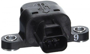
Grizzly 700, 2010г.в. Датчик положения заслонки


bars2
Данная тема может быть полезна, в случае если кто-то захочет разобрать датчик положения заслонки.
При нормальных значениях в режиме диагностики :Д01Угол газа
Полностью закрыт 15 – 20, проверять с полностью закрытым газом
Полностью открыт 95 – 100. проверять с полностью открытым.
При открывании газа значение стремится от меньшего к большему.
Grizzly 700, 2010г.в. Датчик положения заслонки, показывает значения в режиме диагностики, 9 в начале, при нажатии на курок газа 54. (Датчик раннее не снимался, положения не нарушались!)
При этом наблюдались следующие симптомы:
2) При нажатии резко на газ, мотор задыхался, не развивал положенных оборотов;
3) Ошибок на приборке не было;
4) Квадрик должным образом не ехал, дерганья, плавающие обороты и т.д.;
5) После того как, прочистили все контакты на заслонке, появилась ошибка 37, хотя регулятор холостого хода работал, сбросить ошибку так и не удалось.
Решил разобрать датчик положения заслонки. Надпилил его с боков и тут выяснилось, что он разборный! С виду было не определить. Думал, почищу контакты, дорожки и возможно этот датчик еще поработает.
При вскрытии стало видно, что верхняя крышка снимается, если сделать все аккуратно. В нутрии под крышкой есть прокладка, см. фото. В нутрии корпуса датчика были видны капли воды.
Специальным средством для контактов все промыл, протер, подогнул контакты. Запаял корпус датчика, поставил на место, режим диагностики показывал все прошлые ошибки и симптомы.
Не знаю, в чем было дело, но после того, как поставили заслонку от донора, все встало на свои места, у квадра появились силы и он стал работать, как прежде в нормальном режиме.
Источник
Grizzly 700, 2010г.в. Датчик положения заслонки

bars2
Данная тема может быть полезна, в случае если кто-то захочет разобрать датчик положения заслонки.
При нормальных значениях в режиме диагностики :Д01Угол газа
Полностью закрыт 15 – 20, проверять с полностью закрытым газом
Полностью открыт 95 – 100. проверять с полностью открытым.
При открывании газа значение стремится от меньшего к большему.
Grizzly 700, 2010г.в. Датчик положения заслонки, показывает значения в режиме диагностики, 9 в начале, при нажатии на курок газа 54. (Датчик раннее не снимался, положения не нарушались!)
При этом наблюдались следующие симптомы:
2) При нажатии резко на газ, мотор задыхался, не развивал положенных оборотов;
3) Ошибок на приборке не было;
4) Квадрик должным образом не ехал, дерганья, плавающие обороты и т.д.;
5) После того как, прочистили все контакты на заслонке, появилась ошибка 37, хотя регулятор холостого хода работал, сбросить ошибку так и не удалось.
Решил разобрать датчик положения заслонки. Надпилил его с боков и тут выяснилось, что он разборный! С виду было не определить. Думал, почищу контакты, дорожки и возможно этот датчик еще поработает.
При вскрытии стало видно, что верхняя крышка снимается, если сделать все аккуратно. В нутрии под крышкой есть прокладка, см. фото. В нутрии корпуса датчика были видны капли воды.
Специальным средством для контактов все промыл, протер, подогнул контакты. Запаял корпус датчика, поставил на место, режим диагностики показывал все прошлые ошибки и симптомы.
Не знаю, в чем было дело, но после того, как поставили заслонку от донора, все встало на свои места, у квадра появились силы и он стал работать, как прежде в нормальном режиме.
об ошибках Grizzly 700
Данная тема является сборной из двух — трех тем.
Постараюсь здесь описать все, что нашел на форуме и выяснил сам, пока боролся с ошибками на гризли.
Для начала диагностики необходимо войти в режим диагностики:
1. Выключить зажигание, двигстоп (левый пульт на руле, красный переключатель) перевести в положение выключено.
2. На приборке нажать одновременно и удерживать кнопки Select и Reset
3. Включить зажигание. Через 8 сек на дисплее загорится надпись DIAG
4. Нажать и удерживать те же кнопки еще раз на дисплее появится D1 и цифра 17 (норма)
если нужно только стереть ошибки:
5. С помощью нажатия на любую кнопку Select или Reset пролистать меню до D62
6. На дисплее если ошибок нет будет гореть «0» а если есть то они будут по очереди возникать на экране.
7. Что бы стереть ошибку надо выкл. и вкл. двигстоп и так
одну ошибку за другой.
8. Когда дисплей покажет «0» выключить зажигание ключем в замке.
Остальная предусмотренная диагностика:
Д01
Угол газа
Полностью закрыт 15 – 20, проверять с полностью закрытым газом
Полностью открыт 95 – 100. проверять с полностью открытым.
При открывании газа значение стремится от меньшего к большему.
Д03
Разница атмосферного давления и давления всасываемого воздуха
Кажет давление всасываемого воздуха (имеется ввиду в двигатель), при старте двигателя нажимайте и отпускайте газ, если значение изменится, с двиглом все акей.
Д05
Температура всасываемого воздуха.
Д06
Температура охлаждающей жидкости
Д07
Не понял ничего, но попробую перевести.
Пульс скорости квадрика (?) от 0 до 999, изменяется когда задние колеса крутятся. Число не обнуляется когда колеса останавливается.
Д08
Датчик угла наклона
Снимите датчик наклона и при положении прямо кажет 0.4, поверните его на 65 градусов покажет 1.4
Перевернутый показывает 3.7
как показала практика, нормальное значение для данного датчика 4.0
Д09
Вольтметр
Д21
тест лампочки нейтралки
Д60
История ошибок EEPROM
Нет истории 00
Есть история 01
Д61
Показывает коды ошибок от 12 – 50
Д62
Стирание истории ошибок
Может содержать до 16 ошибок, чтобы стереть выключите кнопкой (не ключом) и включите опять
Д70 контрольный номер
таблица ошибок: 
№ ошибки, деталь
Симптомы
Вероятная причина неисправности
cпособен/неспособен заводиться
cпособен/неспособен двигаться
————————————
12 датчик положения Коленчатого вала
Никакие нормальные сигналы не получены от датчика положения коленчатого вала
—-
Незамкнутая цепь или короткое замыкание в проводном жгуте.
• Дефектный датчик положения коленчатого вала.
• Сбой подхватывания сигнала ротора.
• Сбой в ECU.
• Ненадлежащим образом установленный датчик.
—
Неспособен
Неспособен
————————————
13 Датчик давления воздуха впуска
(незамкнутая цепь или короткое замыкание)
Датчик давления воздуха впуска: незамкнутая цепь или короткое замыкание
обнаружено.
—-
• Незамкнутая цепь или короткое замыкание в проводном жгуте.
• Дефектный датчик давления воздуха впуска.
• Сбой в ECU.
—-
Способен
Способен
———————————-
14 Датчик давления воздуха впуска
(линия шланга)
Датчик давления воздуха впуска: неисправность в системе шланга
(забитый или отделенный шланг).
—
• Шланг датчика давления воздуха впуска отделен, забит,
загнут, или зажат.
• Сбой в ECU.
—-
Способен
Способен
————————————
15 Датчик положения дросселя (открытый
или короткое замыкание)
Датчик положения дросселя: незамкнутая цепь или короткое замыкание
обнаружено.
——
• Незамкнутая цепь или короткое замыкание в проводе sub lead.
• Незамкнутая цепь или короткое замыкание в проводном жгуте.
• Дефектный датчик положения дросселя.
• Ненадлежащим образом установленный датчик положения дросселя.
• Сбой в ECU.
—-
Способен
Способен
————————————-
16 Датчик положения дросселя
Датчик положения дросселя заедает.
——
• Заедает датчик положения дросселя.
• Сбой в ECU.
—-
Способен
Способен
————————————
21 Датчик температуры ОЖ (охл. жидкость)
Датчик температуры ОЖ: незамкнутая цепь или короткое замыкание
обнаружено.
—
• Незамкнутая цепь или короткое замыкание в проводном жгуте.
• Дефектный датчик температуры ОЖ.
• Сбой в ECU.
• Ненадлежащим образом установленный датчик температуры ОЖ.
—-
Способен.
Способен.
————————————
22 Датчик температуры воздуха впуска
(незамкнутая цепь или короткое замыкание)
Датчик температуры воздуха впуска: незамкнутая цепь или короткое замыкание
обнаружено.
——
• Незамкнутая цепь или короткое замыкание в проводном жгуте.
• Дефектный датчик температуры воздуха впуска.
• Сбой в ECU.
• Ненадлежащим образом установленный датчик температуры воздуха впуска.
——
Способен
Способен
————————————
30 Датчик угла наклона (запирается обнаруженный. )
Транспортное средство опрокинулось.
—-
• Опрокинутый.
• Сбой в ECU.
—-
Неспособен
Неспособен
————————————
33 Катушка зажигания (дефектное зажигание)
Сбой обнаружен в первичном проводе зажигания
Спираль (обмотка?).
——
• Незамкнутая цепь или короткое замыкание в проводном жгуте.
• Сбой в катушке зажигания.
• Сбой в ECU.
• Сбой в компоненте системы цепи зажигания.
——-
Неспособен
Неспособен
————————————
37 Клапан частоты холостого хода
продается только в сборе с дросселем.
Ошибка редкая.
Информацию об ошибке предоставил Bsa17.
———————————
39 Инжектор (незамкнутая цепь)
Инжектор: незамкнутая цепь обнаружена.
——
• Незамкнутая цепь или короткое замыкание в проводном жгуте.
• Ненадлежащим образом установленный инжектор.
• Дефектный инжектор.
——
Неспособен
Неспособен
———————————-
41 Датчик угла наклона
Датчик угла наклона: незамкнутая цепь или короткое замыкание обнаружено.
——
• Незамкнутая цепь или короткое замыкание в проводном жгуте.
• Дефектный датчик угла наклона .
• Сбой в ECU.
——
Неспособен
Неспособен
———————————-
42 Датчика скорости
Никакие нормальные сигналы не получены от датчика скорости.
—-
• Незамкнутая цепь в проводном жгуте.
• Дефектный датчик скорости.
• обнаружен Cбой в датчике скорости транспортного средства .
• Сбой в машинной стороне нейтрального выключателя.
• Сбой в ECU.
—-
Способен
Способен
————————————
43 Напряжение топливной системы (контроль
напряжение)
ECU неспособно контролировать напряжение батареи (
незамкнутая цепь или короткое замыкание на линии к ECU).
——
• Незамкнутая цепь или короткое замыкание в проводном жгуте.
• Сбой в ECU.
——
Способен
Способен
————————————
44 Ошибка в написании количества
регулировки СО на ПЗУ
Ошибка обнаружена, читая или при письме на ПЗУ
(значение регулировки СО).
——
• Сбой в ECU. (значение регулировки СО не
должным образом написано или читается с внутренней памяти).
——
Способен
Способен
————————————
46 Электропитание системы транспортного средства
(Контролирующее напряжение)
Электропитание не нормально.
—-
• Сбой в системе зарядки.
——
Способен
Способен
————————————
50 ECU внутренний сбой
(ошибка проверки памяти)
Дефектная память ECU. (Когда этот сбой
обнаружен в ECU, номер кода неисправности не мог бы
появиться на метре).
——
• Сбой в ЭКЮ. (Программа и данные не
должным образом записаны или читаются с внутренней памяти.)
——
Неспособен
Неспособен
———————————-
Er-1 ECU внутренний сбой
(ошибка сигнала выхода)
Никакие сигналы не получены от ECU. Неспособен
Неспособен
———————————-
Er-2 ECU внутренний сбой
(ошибка сигнала выхода)
Никакие сигналы не получены от ECU в пределах указанной
продолжительности.
Неспособен
Неспособен
———————————-
Er-3 ECU внутренний сбой
(ошибка сигнала выхода)
Данные от ECU не могут быть получены правильно.
Неспособен
Неспособен
———————————-
Er-4 ECU внутренний сбой
(входная ошибка сигнала)
Незарегистрированные данные были получены от
Метр (приборка).
Неспособен
Неспособен
———————————-
Датчик переворота для квадроциклов Yamaha 3B4-82576-00-00
2007 GRIZZLY 700 (YFM7FGPW) — Electrical 1
2007 GRIZZLY 700 DUCKS (YFM7FGPDUW) — Electrical 1
2007 GRIZZLY 700 HUNTER (YFM7FGPHW) — Electrical 1
2007 GRIZZLY 700 OUTDOORSMAN EDITION (YFM7FGPOHW) — Electrical 1
2007 GRIZZLY 700 SPECIAL EDITION-SILVER (YFM7FGPSEW) — Electrical 1
2008 GRIZZLY 700 (YFM7FGXGR) — Electrical 1
2008 GRIZZLY 700 (YFM7FGXL) — Electrical 1
2008 GRIZZLY 700 (YFM7FGXR) — Electrical 1
2008 GRIZZLY 700 DUCKS UNLIMTED EDITION (YFM7FGPDUX) — Electrical 1
2008 GRIZZLY 700 EPS HUNTER (YFM7FGPHX) — Electrical 1
2008 GRIZZLY 700 POWER STEERING (YFM7FGPXGR) — Electrical 1
2008 GRIZZLY 700 POWER STEERING (YFM7FGPXL) — Electrical 1
2008 GRIZZLY 700 POWER STEERING (YFM7FGPXR) — Electrical 1
2008 GRIZZLY 700 SPECIAL EDITION (YFM7FGPSPX) — Electrical 1
2008 GRIZZLY FI 700 HUNTER (YFM7FGHX) — Electrical 1
2008 RHINO 700 FI (YXR70FXGR) — Electrical 2
2008 RHINO 700 FI DUCKS UNLIMTED (YXR70FDUX) — Electrical 2
2008 RHINO 700 FI HUNTER (YXR70FHX) — Electrical 2
2008 RHINO 700 FI SPECIAL EDITION I (YXR70FSEPX) — Electrical 2
2008 RHINO 700 FI SPECIAL EDITION II (YXR70FSP2X) — Electrical 2
2008 RHINO 700 FI SPORT EDITION (YXR70FSPX) — Electrical 2
2008 RHINO 700FI (YXR70FXR) — Electrical 2
2009 GRIZZLY 550 FI 4WD (YFM5FGYB) — Electrical 1
2009 GRIZZLY 550 FI 4WD (YFM5FGYGR) — Electrical 1
2009 GRIZZLY 550 FI 4WD (YFM5FGYL) — Electrical 1
2009 GRIZZLY 550 FI 4WD HUNTER (YFM5FGHY) — Electrical 1
2009 GRIZZLY 550 FI EPS 4WD (YFM5FGPYB) — Electrical 1
2009 GRIZZLY 550 FI EPS 4WD (YFM5FGPYGR) — Electrical 1
2009 GRIZZLY 550 FI EPS 4WD (YFM5FGPYL) — Electrical 1
2009 GRIZZLY 550 FI EPS 4WD HUNTER (YFM5FGPHY) — Electrical 1
2009 GRIZZLY 550 FI EPS 4WD SPECIAL EDITION (YFM5FGPSEY) — Electrical 1
2009 GRIZZLY 700 FI 4WD (YFM7FGYB) — Electrical 1
2009 GRIZZLY 700 FI 4WD (YFM7FGYGR) — Electrical 1
2009 GRIZZLY 700 FI 4WD (YFM7FGYL) — Electrical 1
2009 GRIZZLY 700 FI 4WD HUNTER (YFM7FGHY) — Electrical 1
2009 GRIZZLY 700 FI EPS 4WD (YFM7FGPYB) — Electrical 1
2009 GRIZZLY 700 FI EPS 4WD (YFM7FGPYGR) — Electrical 1
2009 GRIZZLY 700 FI EPS 4WD (YFM7FGPYL) — Electrical 1
2009 GRIZZLY 700 FI EPS 4WD HUNTER (YFM7FGPHY) — Electrical 1
2009 GRIZZLY 700 FI EPS DUCKS UNLIMITED (YFM7FGPDUY) — Electrical 1
2009 GRIZZLY 700 FI EPS SPECIAL EDITION (YFM7FGPSEY) — Electrical 1
2009 RHINO 700 FI (YXR7FYGR) — Electrical 2
2009 RHINO 700 FI (YXR7FYL) — Electrical 2
2009 RHINO 700 FI DUCKS UNLIMITED (YXR7FDUY) — Electrical 2
2009 RHINO 700 FI HUNTER (YXR7FHY) — Electrical 2
2009 RHINO 700 FI SPECIAL EDITION (YXR7FSEYB) — Electrical 2
2009 RHINO 700 FI SPECIAL EDITION (YXR7FSEYR) — Electrical 2
2009 RHINO 700 FI SPORT EDITION (YXR7FSPY) — Electrical 2
2009 RHINO 700 FI SPORT EDITION II (YXR7FSP2Y) — Electrical 2
2010 GRIZZLY 550 FI 4WD (YFM5FGZGR) — Electrical 1
2010 GRIZZLY 550 FI 4WD (YFM5FGZL) — Electrical 1
2010 GRIZZLY 550 FI 4WD HUNTER (YFM5FGHZ) — Electrical 1
2010 GRIZZLY 550 FI EPS 4WD (YFM5FGPZGR) — Electrical 1
2010 GRIZZLY 550 FI EPS 4WD (YFM5FGPZL) — Electrical 1
2010 GRIZZLY 550 FI EPS 4WD HUNTER (YFM5FGPHZ) — Electrical 1
2010 GRIZZLY 700 FI 4WD (YFM7FGZGR) — Electrical 1
2010 GRIZZLY 700 FI 4WD (YFM7FGZL) — Electrical 1
2010 GRIZZLY 700 FI 4WD HUNTER (YFM7FGHZ) — Electrical 1
2010 GRIZZLY 700 FI EPS 4WD (YFM7FGPZGR) — Electrical 1
2010 GRIZZLY 700 FI EPS 4WD (YFM7FGPZL) — Electrical 1
2010 GRIZZLY 700 FI EPS 4WD HUNTER (YFM7FGPHZ) — Electrical 1
2010 GRIZZLY 700 FI EPS 4WD SPECIAL EDITION (YFM7FGPSEZ) — Electrical 1
2011 GRIZZLY 550 4WD (YFM5FGAGR) — Electrical 1
2011 GRIZZLY 550 4WD (YFM5FGAL) — Electrical 1
2011 GRIZZLY 550 4WD HUNTER (YFM5FGHA) — Electrical 1
2011 GRIZZLY 550 EPS 4WD (YFM5FGPAGR) — Electrical 1
2011 GRIZZLY 550 EPS 4WD (YFM5FGPAL) — Electrical 1
2011 GRIZZLY 550 EPS 4WD HUNTER (YFM5FGPHA) — Electrical 1
2011 GRIZZLY 700 4WD (YFM7FGAGR) — Electrical 1
2011 GRIZZLY 700 4WD (YFM7FGAL) — Electrical 1
2011 GRIZZLY 700 EPS 4WD (YFM7FGPA) — Electrical 1
2011 GRIZZLY 700 EPS 4WD (YFM7FGPAGR) — Electrical 1
2011 GRIZZLY 700 EPS 4WD (YFM7FGPAL) — Electrical 1
2011 GRIZZLY 700 EPS 4WD HUNTER (YFM7FGPHA) — Electrical 1
2011 GRIZZLY 700 EPS 4WD SPECIAL (YFM7FGPSPA) — Electrical 1
2011 GRIZZLY 700 HUNTER (YFM7FGHA) — Electrical 1
2011 RHINO 700 (YXR7FAGR) — Electrical 2
2011 RHINO 700 (YXR7FAL) — Electrical 2
2011 RHINO 700 (YXR7FAR) — Electrical 2
2011 RHINO 700 HUNTER (YXR7FHA) — Electrical 2
2011 RHINO 700 SPORT (YXR7FSPA) — Electrical 2
2012 GRIZZLY 550 4WD (YFM5FGBGR) — Electrical 1
2012 GRIZZLY 550 4WD (YFM5FGBL) — Electrical 1
2012 GRIZZLY 550 4WD HUNTER (YFM5FGHB) — Electrical 1
2012 GRIZZLY 550 EPS 4WD (YFM5FGPBGR) — Electrical 1
2012 GRIZZLY 550 EPS 4WD (YFM5FGPBL) — Electrical 1
2012 GRIZZLY 550 EPS 4WD HUNTER (YFM5FGPHB) — Electrical 1
2012 GRIZZLY 700 4WD (YFM7FGBGR) — Electrical 1
2012 GRIZZLY 700 4WD (YFM7FGBL) — Electrical 1
2012 GRIZZLY 700 4WD HUNTER (YFM7FGHB) — Electrical 1
2012 GRIZZLY 700 EPS 4WD (YFM7FGPBGR) — Electrical 1
2012 GRIZZLY 700 EPS 4WD (YFM7FGPBL) — Electrical 1
2012 GRIZZLY 700 EPS 4WD HUNTER REALTREE (YFM7FGPHB) — Electrical 1
2012 GRIZZLY 700 EPS 4WD SPECIAL EDITION (YFM7FGPSEB) — Electrical 1
2012 RHINO 700 (YXR7FBGR) — Electrical 2
2012 RHINO 700 (YXR7FBL) — Electrical 2
2012 RHINO 700 HUNTER EDITION (YXR7FHB) — Electrical 2
2012 RHINO 700 SPORT EDITION (YXR7FSPB) — Electrical 2
2013 GRIZZLY 550 4WD (YFM5FGDGR) Pastel Deep Green — Electrical 1
2013 GRIZZLY 550 4WD (YFM5FGDL) Dark Purplish Blue Solid N — Electrical 1
2013 GRIZZLY 550 4WD HUNTER (YFM5FGHD) Yamaha Black (Camo) — Electrical 1
2013 GRIZZLY 550 EPS 4WD (YFM5FGPDGR) Pastel Deep Green — Electrical 1
2013 GRIZZLY 550 EPS 4WD (YFM5FGPDL) Deep Purplish Blue Solid N — Electrical 1
2013 GRIZZLY 550 EPS 4WD (YFM5FGPDR) — Electrical 1
2013 GRIZZLY 550 EPS 4WD HUNTER (YFM5FGPHD) Yamaha Black (Camo) — Electrical 1
2013 GRIZZLY 700 4WD (YFM7FGDGR) Pastel Deep Green — Electrical 1
2013 GRIZZLY 700 4WD (YFM7FGDL) Deep Purplish Blue Solid N — Electrical 1
2013 GRIZZLY 700 4WD HUNTER (YFM7FGHD) Yamaha Black (Camo) — Electrical 1
2013 GRIZZLY 700 EPS 4WD (YFM7FGPDGR) — Electrical 1
2013 GRIZZLY 700 EPS 4WD (YFM7FGPDGR) — Electrical 1
2013 GRIZZLY 700 EPS 4WD (YFM7FGPDL) — Electrical 1
2013 GRIZZLY 700 EPS 4WD (YFM7FGPDR) — Electrical 1
2013 GRIZZLY 700 EPS 4WD HUNTER (YFM7FGPHD) — Electrical 1
2013 GRIZZLY 700 EPS 4WD SPECIAL EDITION (YFM7FGPSED) Low Gloss Black — Electrical 1
2013 RHINO 700 (YXR7FDGR) Pastel Deep Green — Electrical 2
2013 RHINO 700 (YXR7FDR) Romantique Rouge — Electrical 2
2013 RHINO 700 HUNTER EDITION (YXR7FHD) Yamaha Black (Camo) — Electrical 2
2013 RHINO 700 SPORT EDITION (YXR7FSPD) Low Gloss Black — Electrical 2
2014 GRIZZLY 550 EPS HUNTING (YFM550PHEH) — Electrical 1
2014 GRIZZLY 550 FI (YFM550DEG) — Electrical 1
2014 GRIZZLY 550 FI (YFM550DEL) — Electrical 1
2014 GRIZZLY 550 FI EPS (YFM550PEG) — Electrical 1
2014 GRIZZLY 550 FI EPS (YFM550PEL) — Electrical 1
2014 GRIZZLY 550 FI EPS (YFM550PER) — Electrical 1
2014 GRIZZLY 550 FI HUNTING (YFM550DHEH) — Electrical 1
2014 GRIZZLY 700 FI 4WD (YFM700DEG) — Electrical 1
2014 GRIZZLY 700 FI 4WD (YFM700DEL) — Electrical 1
2014 GRIZZLY 700 FI EPS (YFM700PEG) — Electrical 1
2014 GRIZZLY 700 FI EPS (YFM700PEL) — Electrical 1
2014 GRIZZLY 700 FI EPS (YFM700PER) — Electrical 1
2014 GRIZZLY 700 FI EPS HUNTING (YFM700PHEH) — Electrical 1
2014 GRIZZLY 700 FI EPS SE (YFM700PSEB) — Electrical 1
2014 GRIZZLY 700 FI HUNT 4WD (YFM700DHEH) — Electrical 1
2014 VIKING 700 (YXM700DEG) — Electrical 1
2014 VIKING 700 (YXM700DEL) — Electrical 1
2014 VIKING 700 (YXM700DER) — Electrical 1
2014 VIKING 700 EPS (YXM700PEG) — Electrical 1
2014 VIKING 700 EPS (YXM700PEL) — Electrical 1
2014 VIKING 700 EPS (YXM700PER) — Electrical 1
2014 VIKING 700 EPS HUNTER (YXM700PHEH) — Electrical 1
2014 VIKING 700 EPS SE (YXM700PSEB) — Electrical 1
2014 VIKING 700 HUNTER (YXM700DHEH) — Electrical 1
2015 GRIZZLY 4WD HUNTER (YFM700DHFH) — Electrical 1
2015 GRIZZLY 700 4WD (YFM700DFG) — Electrical 1
2015 GRIZZLY 700 4WD (YFM700DFL) — Electrical 1
2015 GRIZZLY 700 EPS 4WD (YFM700PFG) — Electrical 1
2015 GRIZZLY 700 EPS 4WD (YFM700PFL) — Electrical 1
2015 GRIZZLY 700 EPS 4WD (YFM700PFR) — Electrical 1
2015 GRIZZLY 700 EPS HUNTER (YFM700PHFH) — Electrical 1
2015 GRIZZLY 700 FI EPS SE (YFM700PSFS) — Electrical 1
2015 VIKING (YXM700DFG) — Electrical 1
2015 VIKING (YXM700DFL) — Electrical 1
2015 VIKING (YXM700DFR) — Electrical 1
2015 VIKING EPS (YXM700PFG) — Electrical 1
2015 VIKING EPS (YXM700PFL) — Electrical 1
2015 VIKING EPS (YXM700PFR) — Electrical 1
2015 VIKING EPS HUNTER (YXM700PHFH) — Electrical 1
2015 VIKING EPS SE (YXM700PSF) — Electrical 1
2015 VIKING EPS SE (YXM700PSFS) — Electrical 1
2015 VIKING HUNTER (YXM700DHFH) — Electrical 1
2015 VIKING VI (YXC700DFG) — Electrical 1
2015 VIKING VI (YXC700DFL) — Electrical 1
2015 VIKING VI (YXC700DFR) — Electrical 1
2015 VIKING VI 700 EPS (YXC700PFG) — Electrical 1
2015 VIKING VI 700 EPS (YXC700PFL) — Electrical 1
2015 VIKING VI 700 EPS (YXC700PFR) — Electrical 1
2015 VIKING VI 700 EPS HUNTER (YXC700PHFH) — Electrical 1
2015 VIKING VI EPS SE (YXC700PSFS) — Electrical 1
2015 VIKING VI HUNTER (YXC700DHFH) — Electrical 1
2016 EPS SPECIAL EDITION (YXZ10YPSGY) — Electrical 3
2016 GRIZZLY 4WD (YFM70GDXGG) — Electrical 1
2016 GRIZZLY 4WD (YFM70GDXGR) — Electrical 1
2016 GRIZZLY 4WD HUNTER (YFM70GDHGH) — Electrical 1
2016 GRIZZLY 700 EPS 4WD (YFM70GPXGG) — Electrical 1
2016 GRIZZLY 700 EPS 4WD (YFM70GPXGL) — Electrical 1
2016 GRIZZLY 700 EPS 4WD (YFM70GPXGR) — Electrical 1
2016 GRIZZLY 700 EPS 4WD LTD EDITION (YFM70GPLGR) — Electrical 1
2016 GRIZZLY 700 EPS 4WD SE (YFM70GPSGB) — Electrical 1
2016 GRIZZLY EPS 4WD HUNTER (YFM70GPHGH) — Electrical 1
2016 KODIAK 700 4WD (YFM70KDXGG) — Electrical 1
2016 KODIAK 700 4WD (YFM70KDXGR) — Electrical 1
2016 KODIAK 700 4WD HUNTER (YFM70KDHGH) — Electrical 1
2016 KODIAK 700 EPS 4WD (YFM70KPXGG) — Electrical 1
2016 KODIAK 700 EPS 4WD (YFM70KPXGL) — Electrical 1
2016 KODIAK 700 EPS 4WD (YFM70KPXGR) — Electrical 1
2016 KODIAK 700 EPS 4WD HUNTER (YFM70KPHGH) — Electrical 1
2016 KODIAK 700 EPS 4WD SE (YFM70KPSGB) — Electrical 1
2016 VI EPS SPECIAL EDITION (YXC70VPSGB) — Electrical 1
2016 VIKING (YXM70VDXGG) — Electrical 1
2016 VIKING (YXM70VDXGR) — Electrical 1
2016 VIKING EPS (YXM70VPXGG) — Electrical 1
2016 VIKING EPS (YXM70VPXGL) — Electrical 1
2016 VIKING EPS (YXM70VPXGR) — Electrical 1
2016 VIKING EPS HUNTER (YXM70VPHGH) — Electrical 1
2016 VIKING EPS SPECIAL EDITION (YXM70VPSGB) — Electrical 1
2016 VIKING HUNTER (YXM70VDHGH) — Electrical 1
2016 VIKING VI (YXC70VDXGG) — Electrical 1
2016 VIKING VI (YXC70VDXGR) — Electrical 1
2016 VIKING VI EPS (YXC70VPXGG) — Electrical 1
2016 VIKING VI EPS (YXC70VPXGL) — Electrical 1
2016 VIKING VI EPS (YXC70VPXGR) — Electrical 1
2016 VIKING VI EPS HUNTER (YXC70VPHGH) — Electrical 1
2016 VIKING VI EPS RANCH EDITION (YXC70VPRGC) — Electrical 1
2016 VIKING VI HUNTER (YXC70VDHGH) — Electrical 1
2016 WOLVERINE (YXE70WDBGG) — Electrical 1
2016 WOLVERINE HUNTER (YXE70WDBGH) — Electrical 1
2016 WOLVERINE R-SPEC (YXE70WDXGG) — Electrical 1
2016 WOLVERINE R-SPEC (YXE70WDXGL) — Electrical 1
2016 WOLVERINE R-SPEC EPS (YXE70WPXGG) — Electrical 1
2016 WOLVERINE R-SPEC EPS (YXE70WPXGL) — Electrical 1
2016 WOLVERINE R-SPEC EPS HUNTER (YXE70WPHGH) — Electrical 1
2016 WOLVERINE R-SPEC EPS SE (YXE70WPSGB) — Electrical 1
2016 WOLVERINE R-SPEC HUNTER (YXE70WDHGH) — Electrical 1
2016 WOLVRINE R-SPEC EPS (YXE70WPAGW) — Electrical 1
2016 YXZ1000 EPS (YXZ10YPXGL) — Electrical 3
2016 YXZ1000 EPS (YXZ10YPXGO) — Electrical 3
2016 YXZ1000 EPS SPECIAL EDITION (YXZ10YPSGS) — Electrical 3
Производитель на свое усмотрение и без дополнительных уведомлений может менять комплектацию, внешний вид, страну производства и технические характеристики модели.
Наш магазин предоставляет услуги по доставке заказов по Москве и ближайшему подмосковью посредством собственных курьеров, а так же осуществляет отправки заказов по России, Белорусии и Казахстану с использованием услуг транспортных компаний и курьерских служб.
Подробную информацию можно изучить в меню справа. 

Основная информация о доставке представлена ниже. 

доставка по Москве (в пределах МКАД):
Курьерская доставка в пределах МКАД осуществляется на следующий день, либо в этот же день после оформления заказа, если товар есть в наличии и при условии наличия свободного курьера.
Курьерская доставка за пределы МКАД осуществляется на следующий день после оформления заказа, если товар есть в наличии.
При курьерской доставке экипировки двух вариантов товара с примеркой взимается дополнительная оплата в размере 500 рублей.
Внимание! Если сумма заказа менее 3000р — доставка 500р.
Доставка в центр города осуществляется только пешим курьером. Стоимость услуги 500 рублей.
Доставка осуществляется до подъезда. 
Въезд на территории с платной парковкой оплачивает клиент!
Доставка к определенному времени не осуществляется.
Доставка день в день, при условии наличия свободного курьера
Срочная доставка в течение 3-х часов внутри МКАД- 1000 рублей.
| Доставка заказа стоимостью от 3000 рублей до 7000 рублей — 290 рублей |
| Доставка заказа стоимостью более 7000 рублей — БЕСПЛАТНО. |
Доставка на автомобильные и железнодорожные вокзалы внутри МКАД- 500 рублей!
*В случае отказа от товара, доставленного до вас нашим курьером, клиент обязан оплатить полную стоимость доставки
Доставка для дилеров и оптовых клиентов — 500руб. в пределах МКАД.
Доставка за МКАД
Мы осуществляем курьерскую доставку за пределы МКАД по следующим тарифам:
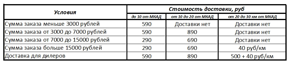
Доставка не осуществляется при удаленности пункта назначения более чем на 30 км от МКАД.
Самовывоз из магазина
Прежде чем приехать за товаром, обязательно уточняйте его наличие на складе!
Удобный , бесплатный и быстрый способ получения заказа.
Адрес розничного магазина: Москва , 1-ая Магистральная улица, 22к1 .
Самовывоз из пвз
ПВЗ- пункт выдачи заказов. В ПВЗ перемещаются только полностью предоплаченные заказы.
Стоимость услуги по перемещению в пункт выдачи заказов составляет 200 рублей.
Перемещение заказов осуществляется по пятницам.
Адрес пункта выдачи заказов: Московская обл., Одинцовский р-н, с. Каринское, 46К-1151. Автомойка Carwash.
Доставка в регионы
Обращаем ваше внимание на то, что отправки осуществляются по специальному графику. 
Транспортные компании:
Удобный и быстрый способ доставки в крупные города России. Посылка доставляется в офис транспортной компании в Вашем городе. Для получения необходимо предъявить паспорт и номер ТТН (товарно-транспортной накладной ( сообщит наш менеджер после отправки). Срок доставки и стоимость Вы можете рассчитать на сайтах компаний.
Обращаем ваше внимание на то, что по умолчанию в транспортных компаниях перевозка осуществляется автомобильным транспортом в случаях, когда это возможно. Если у вас есть предпочтения по виду перевозки, просим вас указывать нужный вид транспорта в комментариях при оформлении заказа на сайте или предупреждать менеджера по телефону!
ТК «Деловые линии»
Доставка до любой другой транспортной компании — 500руб.
Курьерские службы
EMS почта России
Отправка осуществляется исключительно с услугой страхования на полную стоимость товара.
Почта России
Отправка осуществляется исключительно с услугой страхования на полную стоимость товара.
Самый быстрый и удобный способ доставки во многие Подмосковные города, а так же крупные города Европейской части России.
Отправка осуществляется исключительно с услугой страхования на полную стоимость товара.
Подробнее об условиях отгрузки:
ОНЛАЙН оплата картой
К оплате принимаются карты (Visa, MasterCard, Maestro, а также по картам национальной платежной системы МИР). Банковская карта должна быть доступна для оплаты в Интернете (это определяется банком эмитентом).
После подтверждения заказа менеджером магазина будет доступна форма для осуществления оплаты.
Наличными курьеру
Вы можете оплатить заказ курьеру в рублях непосредственно в момент получения заказа. Курьерская доставка осуществляется по Москве и 
ближайшему подмосковью. Доставка осуществляется в день заказа или на следующий рабочий день, при условии наличия товара на складе магазина и наличия свободного курьера.
Просим вас стараться подготовливать оплату заказа и доставки заранее и без сдачи, для более быстрой и удобной работы нашего курьера.
Безналичная оплата (Только для юридических лиц)
Свяжитесь с менеджерами для получения счета на оплату. Наш телефон: 8(800)707-33-59; Наша почта: atvparts@mail.ru , zakaz@atv-parts.ru .
При оформлении заказа на сайте юридическим лицом карточку предприятия можно прикрепить в корзине на сайте.
Источник
Уважаемые клиенты данная таблица предоставлена только для общей информации. Консультации по поводу ошибок и прочих неисправностях мы не даем!
Уважаемые клиенты данная таблица предоставлена только для общей информации. Консультации по поводу ошибок и прочих неисправностях мы не даем!
Вот это подойдет? Это диагностика мотика R-1 !?
Для входа в режим диагностики и проверки существующих кодов ошибок в памяти системы необходимо проделать следующее:
1. Выключить зажигание, кнопку стоп-двигатель поставить в положение ВКЛ.
2. Отключить разъём бензонасоса.
3. Одновременно нажать кнопки SELECT + RESET на приборной панели и не отпускать.
4. Включить зажигание (кнопки всё ещё держим) и ждать ~8 секунд до появления на приборной панели надписи «dIAG».
5. Отпустить кнопки, кнопкой SELECT выбрать «dIAG» (для случая, если надпись на приборной панели появилась другая).
6. После того, как на экране отобразилась надпись dIAG нажать обе кнопки на приборной панели (SELECT + RESET) на ~2 секунды.
7. После того, как на приборной панели отобразится режим диагностики (d01) выключить кнопку стоп-двигателя.
8. Передвигаться по списку от d01 до d64 нужно используя кнопки SELECT (вверх по списку) или RESET (вниз по списку).
В диапазоне списка от d01 до d59 проводится процедура самодиагностики компонентов системы.
Включение некоторых компонентов осуществляется кнопкой стоп-двигатель.
Список самодиагностики (напротив номера меню списка расшифровка показаний + номинальное значение):
D:01 = датчик положения дроссельной заслонки
полностью закрыты, показатели от 12 до 21
полностью открыты, показатели от 96 до 106
D:02 = атмосферное давление, в процентах;
D:03 = абсолютное атмосферное давление во впускном контуре;
D:05 = температура воздуха во впускном контуре;
D:06 = температура охлаждающей жидкости;
D:07 = показания датчика скорости;
D:08 = положение датчика падения
нормальное положение, показатель 0,4 — 1,4
перевернутое положение, показатель 3,7 — 4,4
D:09 = напряжение бортовой сети
D:13 = датчик положения дроссельных заслонок 2
полностью. закрыты, показатель от 9 до 23
полностью открыты, показатель от 94 до 108
D:14 = датчик положения ручки газа 1
полностью закрыта, показатель от 12 до 22
полностью открыта, показатель от 97 до 107
D:15 = датчик положения ручки газа 2
полностью закрыта, показатель от 10 до 24
полностью открыта, показатель от 95 до 109
D:20 = датчик положения боковой подножки;
D:21 = датчик положения КПП (нейтрали)
D:60 = EEPROM, лист ошибок системы (00 = ошибок нет, 01-04 = коды ошибок по цилиндрам, если в памяти более одной ошибки, то они показываются поочерёдно)
D:61 = лист ошибок модуля зажигания по датчикам (00 = нет ошибок в памяти, 11-70 = коды ошибок по компонентам, если в памяти более одной ошибки, то они показываются поочерёдно)
D:62 = количество ошибок в модуле памяти (00 = ошибок нет, XX — количество ошибок, стирание ошибок производится включением кнопки «стоп-двигатель»);
D:63 = подразряд кода ошибки (только для ошибки 24, если более одного значения в памяти, то значение отображается поочерёдно)
Список самодиагностики по агрегатам (компонентам системы зажигания/электрики):
D:30 = диагностика катушки зажигания 1 цилиндра;
D:31 = диагностика катушки зажигания 2 цилиндра;
D:32 = диагностика катушки зажигания 3 цилиндра;
D:33 = диагностика катушки зажигания 4 цилиндра;
D:34 = диагностика клапана впускной системы;
D:36 = диагностика первичного инжектора, форсунка 1
D:37 = диагностика первичного инжектора, форсунка 2
D:38 = диагностика первичного инжектора, форсунка 3
D:39 = диагностика первичного инжектора, форсунка 4
D:40 = диагностика вторичного инжектора, форсунка 1
D:41 = диагностика вторичного инжектора, форсунка 2
D:42 = диагностика вторичного инжектора, форсунка 3
D:43 = диагностика вторичного инжектора, форсунка 4
D:47 = диагностика датчика рулевого демпфера;
D:48 = диагностика датчика клапана впускной системы;
D:50 = диагностика реле бензонасоса;
D:51 = диагностика реле мотора вентилятора охлаждения;
D:52 = диагностика реле ламп головного света;
Расшифровка кодов ошибок системы (для строки D:60 и D:61):
№ ошибки — расшифровка
11 — ошибка датчика положения цилиндров;
12 — ошибка датчика положения коленвала;
13 — ошибка датчика давления во впуске (показания датчика вне пределов требуемого диапазона) — диагностируется строкой самодиагностики D:03;
14 — ошибка датчика давления во впуске (датчик отсоединён или неисправен) — диагностируется строкой самодиагностики D:03 ;
15 — ошибка датчика положения дроссельных заслонок — диагностируется строкой самодиагностики D:01 + D:13;
19 — ошибка на ECU от входящего сигнала (короткое замыкание или отключён датчик боковой подножки) — — диагностируется строкой самодиагностики D:20;
20 — ошибка показаний датчиков атмосферного и абсолютного давления во впуске, не допустимые значения, — диагностируется строкой самодиагностики D:03, D:02;
21 — ошибка показаний датчика температуры ОЖ, — диагностируется строкой самодиагностики D:06;
22 — ошибка датчика температуры во впуске, — диагностируется строкой самодиагностики D:05;
23 — ошибка показаний датчика атмосферного давления, — диагностируется строкой самодиагностики D:02;
24 — ошибка датчика кислорода (O2 сенсор, лямбда-зонд);
30 — ошибка датчика падения (сработавший или неисправный датчик), — диагностируется строкой самодиагностики D:08;
33 — неисправность катушки зажигания 1 цилиндра, — диагностируется строкой самодиагностики D:30;
34 — неисправность катушки зажигания 2 цилиндра, — диагностируется строкой самодиагностики D:31;
35 — неисправность катушки зажигания 3 цилиндра, — диагностируется строкой самодиагностики D:32;
36 — неисправность катушки зажигания 4 цилиндра, — диагностируется строкой самодиагностики D:33;
39 — неисправность контура первичного инжектора, — диагностируется строкой самодиагностики D:36,37,38,39;
40 — неисправность контура вторичного инжектора, — диагностируется строкой самодиагностики D:40,41,42,43;
41 — неисправность или короткое замыкание в проводке датчика падения, диагностируется строкой самодиагностики D:08;
42 — нет сигнала или неисправен датчик скорости, — диагностируется строкой самодиагностики D:07 (датчик скорости),D:21(датчик КПП (нейтрали));
43 — ошибка значения напряжения в контуре бензонасоса, — диагностируется строкой самодиагностики D:50;
44 — ошибка значений/данных системы диагностики/зажигания, — диагностируется строкой самодиагностики D:60
— 00 обозначает нормальное состояние показаний EEP-ROM;
— 01 обозначает нарушение в смесеобразовании 01 цилиндра
— 02 обозначает нарушение в смесеобразовании 02 цилиндра
— 03 обозначает нарушение в смесеобразовании 03 цилиндра
— 04 обозначает нарушение в смесеобразовании 04 цилиндра
46 — ошибка показатеей напряжения на модуле зажигания;
50 — ошибка работы памяти модуля зажигания;
59 — рассоединение или короткое замыкание в контуре датчика положения ручки газа, — диагностируется строкой самодиагностики D:14,15;
60 — ошибка системы YCC-T;
66 — неисправность концевика рулевого демпфера, — диагностируется строкой самодиагностики D:47;
70 — ошибка организации холостого хода (как симптом: двигатель начинает глохнуть на холостых после 20 минут работы);
Er-1 — нет входящего сигнала от модуля зажигания;
Er-2 — нет исходящего сигнала с модуля зажигания;
Er-3 — невозможно считать показания с модуля зажигания;
Er-4 — ошибка обмена данными с приборной панелью;
Процесс входа в режим диагностики:
1. Выключить зажигание. Выключить кнопку Start/Stop Engine (красная на правом пульте).
2. Нажать обе кнопки на приборке и ДЕРЖАТЬ ИХ.
3. Включить зажигание, держать кнопки после включения зажигания около 8 секунд.
4. Дождаться надписи DIAG.
5. Отпустить и нажать ОБЕ кнопки ВМЕСТЕ на приборке ещё раз на 2 сек., и отпустить.
6. Отобразится [d01]. Это первый диагностический показатель, показывает положение дросселей.
7. Кнопкой Select (верхняя) добраться до строки с номером [d60]. Эта ячейка показывает номер СУЩЕСТВУЮЩЕЙ на данный момент ошибки.
8. Посмотреть номер, стоящий напротив d61. Это номер ошибки В ПАМЯТИ «мозгов». Если ошибок несколько, они показываются попеременно.
Все ячейки диагностики выше 60 — и есть строки диагностики каждого из компонентов в отдельности. Подробнее — смотри НИЖЕ.
Для стирания ошибки из памяти системы заходишь на строку d62 и включаешь кнопку стоп-двигателя на правом пульте.
Подробно:
При входе в режим диагностике на дисплее отображается ячейка [d01].
Нажимая кнопку Select (верхняя) нужно перейти к показателю [d60] (самодиагностика в реальном времени) и [d61] (память ошибок) и посмотреть число рядом. Число рядом и есть номер ошибки, которую запомнил «мозг».
А все остальные числа от [d01] и до [d60] — это показатели различных датчиков (например [d01] -это положение ручки газа в процентах на данный момент, покрути и всё поймёшь).
Показатели (тестирование по датчикам включением стоп-двигателя):
d01 = положение ручки газа (крутить ручку газа)
d02 = атмосферное давление (абсолютное, в процентах)
d03 = разряжение во впуске (датчик в корпусе воздушного фильтра, в процентах)
d05 = температура воздуха во впуске (датчик в корпусе воздушного фильтра, номинал в процентах я так понимаю)
d06 = температура охлаждающей жидкости на данный момент
d07 = датчик скорости (показатель)
d08 = датчик падения (угла наклона)
d09 = напряжение на бензонасосе (тестируется включением стоп-двигателя)
d20 = боковая подножка (on/off) — тестирование работает только при выключенной нейтрали
d21 = датчик нейтрали (on/off)
d30 = катушка на 1 цилиндре (при включении кнопки стоп-двигателя производится тестирование катушки по 5 импульсов, сопутствует характерный звук, с одновр. морганием лампы Check Engine)
d31 = катушка на 2 цилиндре (при включении кнопки стоп-двигателя производится тестирование катушки по 5 импульсов, сопутствует характерный звук, с одновр. морганием лампы Check Engine)
d32 = катушка на 3 цилиндре (при включении кнопки стоп-двигателя производится тестирование катушки по 5 импульсов, сопутствует характерный звук, с одновр. морганием лампы Check Engine)
d33 = катушка на 4 цилиндре (при включении кнопки стоп-двигателя производится тестирование катушки по 5 импульсов, сопутствует характерный звук, с одновр. морганием лампы Check Engine)
d36 = форсунка 1 цилиндра (при включении кнопки стоп-двигателя производится тестирование форсунки по 5 импульсов, сопутствует характерный звук, с одновр. морганием лампы Check Engine)
d37 = форсунка 2 цилиндра (при включении кнопки стоп-двигателя производится тестирование форсунки по 5 импульсов, сопутствует характерный звук, с одновр. морганием лампы Check Engine)
d38 = форсунка 3 цилиндра (при включении кнопки стоп-двигателя производится тестирование форсунки по 5 импульсов, сопутствует характерный звук, с одновр. морганием лампы Check Engine)
d39 = форсунка 4 цилиндра (при включении кнопки стоп-двигателя производится тестирование форсунки по 5 импульсов, сопутствует характерный звук, с одновр. морганием лампы Check Engine)
d48 = AI клапан. (при включении кнопки стоп-двигателя производится тестирование клапана, 5 импульсов, сопутствует характерный звук, с одновр. морганием лампы Check Engine)
d50 = силовое реле инжектора и системы зажигания (тестируется так же кнопкой стоп-двигатель)
d51 = реле включения вентилятора охлаждения (тестируется так же кнопкой стоп-двигатель)
d52 = реле головного света (фар) (тестируется так же кнопкой стоп-двигатель)
d53 = тестирование мотора сервопривода EXUP (тестируется так же кнопкой стоп-двигатель, показывает значение в углах)
d56 = сервопривод вторичных заслонок (тестируется так же кнопкой стоп-двигатель, показывает значение в углах)
d60 = ошибка работы коммутатора (коды отображаются поочерёдно, перечень кодов ошибок коммутатора ниже)
d61 = записанный в память код ошибки
d62 = стирание записанных в память кодов ошибок
d70 = отображает код работающей программы (0-255)
Расшифровка показателя строки d60 (найденные самодиагностикой нарушения в работе датчиков):
11 = нет сигнала с датчика определения цилиндра
12 = нет сигнала с датчика положения коленвала
13 = ошибочный сигнал с датчика разряжения (в корпусе воздушного фильтра)
14 = неверный сигнал с датчика абсолютного давления
15 = ошибка датчика полоджеия дроссельных заслонок
16 = зафиксирована ошибка заклинивания датчика положения дроссельных заслонок
17 = зафиксирована ошибка датчика положения сервопривода EXUP
18 = ошибка заклинивания сервопривода EXUP
19 = короткое замыкание на блоке управления двигателем при нажатии кнопки запуска
20 = при включении кнопки стоп-двигателя обнаружена ошибка напряжения (большая разница показателей) на датчиках абсолютного давления и разряжения
21 = неисправность датчика температуры двигателя
22 = неисправность датчика температуры во впуске
23 = неисправность (короткое замыкание) датчика абсолютного давления
30 = зафиксировано срабатывание датчика падения (мотоцикл падал)
33 = короткое замыкание на управляющем проводе катушки зажигания 1 цилиндра
34 = короткое замыкание на управляющем проводе катушки зажигания 2 цилиндра
35 = короткое замыкание на управляющем проводе катушки зажигания 3 цилиндра
36 = короткое замыкание на управляющем проводе катушки зажигания 4 цилиндра
41 = неисправность или короткое замыкание на датчике падения
42 = отсутствие или ошибочный сигнал с датчика скорости
43 = ошибка измерения напряжения бортовой сети (короткое замыкание в проводке)
44 = неисправность блока управления двигателем
46 = нет напряжения на блоке инжектора
47 = ошибка сервопривода вторичных заслонок (обнаружено короткое замыкание или неисправность датчика)
48 = заклинивание или короткое замыкание в сервоприводе вторичных заслонок дросселя
50 = ошибка блока управления двигателем, невозможно прочитать ошибку
Er1 = нет сигнала от блока управления двигателем
Er2 = нет ответа от блока управления двигателем
Er3 = ошибка сигнала от блока управления двигателем
Er4 = неизвестный сигнал от блока управления двигателем
5B410024
Starting problems or poor engine performance
1. Fuel
Check if there is fuel
in the fuel tank.
2. Compression
Use the electric
starter to see if
there is compression.
3. Ignition
Remove the
spark plug and
check the electrodes.
4. Battery
Use the electric starter.
There is fuel.
Check the compression.
Supply fuel.
No fuel.
There is compression.
Compression normal.
Ask a Yamaha dealer to
No compression.
inspect.
Wipe clean with dry cloth.
Wet
Attach spark plug cap and
Dry
ground to chassis.
Engine turns over
Battery is good.
quickly.
Check the connections, and ask
Engine turns over
a Yamaha dealer to charge the
slowly.
battery if necessary.
Restart the engine.
Use the
electric starter.
8-62
Ignition system is
Spark is good.
normal.
Spark is weak.
Adjust the spark plug gap
No spark.
or replace the spark plug.
Ask a Yamaha dealer to
inspect.