-
Page 1
OWNER’S MANUAL FJR1300AS 2D2-28199-E1… -
Page 2
EAU26943 DECLARATION of CONFORMITY Company: MORIC CO., LTD. Address: 1450-6 Mori Mori-Machi Shuchi-gun Shizuoka 437-0292 Japan Hereby declare that the product: Kind of equipment: IMMOBILIZER Type-designation: 5SL-00 is in compliance with following norm(s) or documents: R&TTE Directive(1999/5/EC) EN300 330-2 v1.1.1(2001-6), EN60950-1(2001) Two or Three-Wheel Motor Vehicles Directive(97/24/EC: Chapter 8, EMC) Place of issue: Shizuoka, Japan Date of issue: 1 Aug. -
Page 3
Yamaha a reputation for dependability. Please take the time to read this manual thoroughly, so as to enjoy all advantages of your FJR1300AS. The owner’s manual does not only instruct you in how to operate, inspect and maintain your motorcycle, but also in how to safeguard yourself and others from trouble and injury. -
Page 4: Important Manual Information
This manual should be considered a permanent part of this motorcycle and should remain with it even if the motorcycle is subsequently sold. Yamaha continually seeks advancements in product design and quality. Therefore, while this manual contains the most current product information available at the time of printing, there may be minor discrepancies between your motorcycle and this manual.
-
Page 5
IMPORTANT MANUAL INFORMATION EAU10200 FJR1300AS OWNER’S MANUAL ©2006 by Yamaha Motor Co., Ltd. 1st edition, November 2006 All rights reserved. Any reprinting or unauthorized use without the written permission of Yamaha Motor Co., Ltd. is expressly prohibited. Printed in Japan. -
Page 6: Table Of Contents
TABLE OF CONTENTS SAFETY INFORMATION ….1-1 Accessory box ……3-26 Removing and installing panels ..6-6 Adjusting the headlight beams ..3-26 Checking the spark plugs ….6-8 DESCRIPTION ……..2-1 Handlebar position ……. 3-27 Engine oil and oil filter cartridge ..6-9 Left view ……….2-1 Opening and closing the Final gear oil ……..
-
Page 7
TABLE OF CONTENTS Lubricating the swingarm pivots …6-24 Lubricating the rear suspension …6-24 Checking the front fork ….6-24 Checking the steering ….6-25 Checking the wheel bearings ..6-26 Battery ……….6-26 Replacing the fuses ……6-27 Headlight bulb ……6-29 Front turn signal light ….6-29 Replacing a rear turn signal light bulb or a tail/brake light bulb ..6-29 Replacing the license plate… -
Page 8: Safety Information
SAFETY INFORMATION EAU10281 AND/OR WHEN MADE NECES- • Ride where other motorists can SARY BY MECHANICAL CONDI- see you. Avoid riding in another MOTORCYCLES SINGLE TIONS. motorist’s blind spot. TRACK VEHICLES. THEIR SAFE USE Many accidents involve inexperi- AND OPERATION ARE DEPENDENT Safe riding enced operators.
-
Page 9
Modifications made to this motorcycle other motorists can see you. the single most critical factor in the pre- not approved by Yamaha, or the re- The posture of the operator and vention or reduction of head injuries. moval of original equipment, may ren- passenger is important for proper Always wear an approved helmet. -
Page 10
Maximum load: been specifically designed for use on create instability due to improper 208 kg (459 lb) this motorcycle. Since Yamaha cannot weight distribution or aerody- test all other accessories that may be namic changes. If accessories When loading within this weight limit,… -
Page 11
SAFETY INFORMATION tor and may limit control ability, Always turn the engine off before or clothing, immediately wash the therefore, such accessories are leaving the motorcycle unattended affected area with soap and water not recommended. and remove the key from the main and change your clothes. -
Page 12: Description
DESCRIPTION EAU10410 Left view 1. Accessory box (page 3-26) 9. YCC-S clutch fluid reservoir (page 6-20) 2. Front fork spring preload adjusting bolt (page 3-28) 10.Shock absorber assembly spring preload adjusting lever (page 3-30) 3. Front fork rebound damping force adjusting knob (page 3-28) 11.Air filter element (page 6-14) 4.
-
Page 13: Right View
DESCRIPTION EAU10420 Right view 1. Storage compartment (page 3-25) 9. Shock absorber assembly rebound damping force adjusting knob (page 3-30) 2. Fuel tank cap (page 3-19) 10.Rear brake fluid reservoir (page 6-20) 3. Fuse box (page 6-27) 4. Windshield (page 3-15) 5.
-
Page 14: Controls And Instruments
DESCRIPTION EAU10430 Controls and instruments 1. Rear view mirror (page 3-28) 9. Throttle grip (page 6-15) 2. Left handlebar switches (page 3-15) 10.Main switch/steering lock (page 3-3) 3. Tachometer (page 3-7) 11.Headlight beam adjusting knob (page 3-26) 4. Speedometer (page 3-7) 12.Grip warmer adjusting knob (page 3-31) 5.
-
Page 15: Instrument And Control Functions
Immobilizer system This is not an automatic transmission, This vehicle features the YCC-S only the clutch system is automatic. (Yamaha Chip Controlled-Shift) sys- The gears must be shifted by the rider. tem. The basic function of this system allows the rider to shift gears without the use of a clutch lever.
-
Page 16
Do not expose any key to exces- a Yamaha dealer to have them re-reg- sively high temperatures. istered. Do not use the key with the red Do not place any key close to bow for driving. -
Page 17: Main Switch/Steering Lock
INSTRUMENT AND CONTROL FUNCTIONS EAU10471 EAU26811 To lock the steering Main switch/steering lock All electrical circuits are supplied with power; the meter lighting, taillights, li- cense plate light and auxiliary lights come on, and the engine can be start- ed. The key cannot be removed. NOTE: The headlights come on automatically when the engine is started and stay on…
-
Page 18: Indicator And Warning Lights
INSTRUMENT AND CONTROL FUNCTIONS To unlock the steering EAU39460 EAU11003 (Parking) Indicator and warning lights The steering is locked, and the tail- lights, license plate light and auxiliary lights are on. The hazard lights and turn signal lights can be turned on, but all other electrical systems are off.
-
Page 19
Stop the vehicle when it is safe to do so, Even if the oil level is sufficient, the have a Yamaha dealer check the self- and park it away from traffic. Have a warning light may flicker when riding on diagnosis system. -
Page 20
ABS may be defective. Yamaha dealer check the electrical cir- then while rotating the rear wheel, push If this occurs, have a Yamaha dealer cuit. the shift pedal rod and pivot forward un- til the transmission is in the neutral po- check the system as soon as possible. -
Page 21: Speedometer
INSTRUMENT AND CONTROL FUNCTIONS EAU11601 EAU11872 EAU40532 Speedometer Tachometer Multi-function display 1. Tachometer 1. Tachometer 1. Multi-function display 2. Speedometer 2. Tachometer red zone 2. “SELECT” button 3. Multi-function display 3. “RESET” button The electric tachometer allows the rider The speedometer shows the riding EWA14430 to monitor the engine speed and keep it WARNING…
-
Page 22
INSTRUMENT AND CONTROL FUNCTIONS a fuel reserve tripmeter (which Odometer and tripmeter modes distance traveled from that point. In that shows the distance traveled on the case, pushing the “SELECT” button fuel reserve) switches the display between the vari- a clock ous tripmeter and odometer modes in a fuel meter the following order:… -
Page 23
INSTRUMENT AND CONTROL FUNCTIONS Clock Fuel meter will start flashing. If this occurs, have a Yamaha dealer check the electrical cir- cuit. Coolant temperature meter 1. Clock 1. Fuel meter 2. “SELECT” button The fuel meter indicates the amount of 3. -
Page 24
INSTRUMENT AND CONTROL FUNCTIONS ECA10020 Ambient temperature, instanta- Ambient temperature mode CAUTION: neous fuel consumption and aver- fuel consumption modes Do not operate the engine if it is (except for the UK) overheated. Transmission gear display 1. Ambient temperature This display shows the ambient tem- perature from –9 °C to 50 °C in 1 °C in- 1. -
Page 25
INSTRUMENT AND CONTROL FUNCTIONS The accuracy of the temperature When the display is set to “L/100 The average fuel consumption display reading may be affected when km”, the amount of fuel necessary can be set to either “AV_ _._ km/L” or riding slowly (approximately under to travel 100 km under the current “AV_ _._ L/100 km”. -
Page 26
50 °C will not be displayed. If there is a malfunction, “– –.–” will Air → MPG → AV_ _._ MPG → Air The accuracy of the temperature be displayed. Have a Yamaha dealer reading may be affected when check the vehicle. Ambient temperature mode riding slowly [approximately under 20 km/h (12.5 mi/h)] or when… -
Page 27
When the average fuel consumption such an error code, note the code num- mode is selected, the display flashes ber, and then have a Yamaha dealer for five seconds, and then “AV_ _._ check the vehicle. MPG” (average distance that can be traveled using 1.0 Imp.gal of fuel) is dis-… -
Page 28: Anti-Theft Alarm (Optional)
If the multi-function display indicates two-digit error code when the key is any error codes, note the code number, turned to “ON”. and then have a Yamaha dealer check the vehicle. NOTE: If the multi-function display indicates er- ror code 52, this could be caused by transponder interference.
-
Page 29: Handlebar Switches
INSTRUMENT AND CONTROL FUNCTIONS EAU12347 Right position. To cancel the turn signal Handlebar switches lights, push the switch in after it has re- turned to the center position. Left EAU12493 Windshield position adjusting switch “ ” To move the windshield up, push this switch in direction (a).
-
Page 30
INSTRUMENT AND CONTROL FUNCTIONS EAU12500 EAU12733 EAU40381 Horn switch “ ” Hazard switch “ ” Hand shift control switch Press this switch to sound the horn. With the key in the “ON” or “ ” posi- tion, use this switch to turn on the haz- EAU12660 ard lights (simultaneous flashing of all Engine stop switch “… -
Page 31: Shift Pedal
INSTRUMENT AND CONTROL FUNCTIONS and release this switch after start- EAU40492 Shift pedal ing the engine to enable hand shifting. 1. Shift pedal 2. Bolt 1. Shift pedal 3. Standard position This vehicle is equipped with a con- 2. Move the shift pedal to the desired stant-mesh 5-speed transmission.
-
Page 32: Hand Shift Lever
INSTRUMENT AND CONTROL FUNCTIONS EAU40481 EAU26822 EAU39540 Hand shift lever “ ”/“ ” Brake lever Brake pedal The brake lever is located at the right handlebar grip. To apply the front brake, pull the lever toward the handle- bar grip. 1.
-
Page 33: Abs
This ABS has a test mode which EAU13072 Fuel tank cap allows the owner to experience the The Yamaha ABS (Anti-lock Brake pulsating at the brake lever or System) features a dual electronic con- brake pedal when the ABS is oper- trol system, which acts on the front and ating.
-
Page 34: Fuel
Avoid spilling fuel on the hot en- Your Yamaha engine has been de- gine. signed to use regular unleaded gaso- line with a research octane number of 91 or higher.
-
Page 35: Fuel Tank Breather/Overflow Hose
INSTRUMENT AND CONTROL FUNCTIONS or premium unleaded fuel. Use of un- EAU39450 EAU13441 Fuel tank breather/overflow Catalytic converter leaded fuel will extend spark plug life hose This vehicle is equipped with catalytic and reduce maintenance costs. converters in the exhaust system. EWA10860 WARNING The exhaust system is hot after op-…
-
Page 36: Seats
INSTRUMENT AND CONTROL FUNCTIONS EAU39491 Seats Passenger seat To remove the passenger seat 1. Insert the key into the seat lock, and then turn it counterclockwise. 1. Projection 1. Rider seat lock lever 2. Seat holder 2. Rider seat 2. Remove the key. To install the rider seat 1.
-
Page 37: Adjusting The Rider Seat Height
INSTRUMENT AND CONTROL FUNCTIONS 2. Install the passenger seat. EAU39632 Adjusting the rider seat height NOTE: The rider seat height can be adjusted to Make sure that the seats are prop- one of two positions to suit the rider’s erly secured before riding. preference.
-
Page 38
INSTRUMENT AND CONTROL FUNCTIONS 6. Align the projection on the bottom of the rider seat with the “H” posi- tion slot, and then push the rear of the seat down to lock it in place as shown. 1. Rider seat height position adjuster 1. -
Page 39: Storage Compartment
208 kg (459 lb) for the ve- tion slot, and then push the rear of hicle. the seat down to lock it in place as shown. 1. Storage compartment 2. Yamaha CYCLELOK (optional) This storage compartment is designed 1. “L” position slot hold genuine Yamaha CYCLELOK.
-
Page 40: Accessory Box
INSTRUMENT AND CONTROL FUNCTIONS EAU39480 ECA11800 EAU39610 Accessory box Adjusting the headlight CAUTION: The accessory box is located beside beams Do not place heat-sensitive items in the meter panel. The headlight adjusting knobs are used the accessory box. The accessory to raise or lower the height of the head- box gets extremely hot especially To open the accessory box…
-
Page 41: Handlebar Position
The handlebars can be adjusted to one ings of three positions to suit the rider’s pref- The cowlings can be tilted back 30 mm erence. Have a Yamaha dealer adjust (1.18 in) for added ventilation to suit the the position of the handlebars. riding conditions.
-
Page 42: Rear View Mirrors
INSTRUMENT AND CONTROL FUNCTIONS EAU39671 EAU14731 Rear view mirrors Adjusting the front fork The rear view mirrors of this vehicle can This front fork is equipped with spring be folded forward or backward for park- preload adjusting bolts, rebound damp- ing in narrow spaces.
-
Page 43
INSTRUMENT AND CONTROL FUNCTIONS load thereby soften Rebound damping force Compression damping force suspension, turn the adjusting bolt on each fork leg in direction (b). NOTE: Align the appropriate groove on the ad- justing mechanism with the top of the front fork cap bolt. -
Page 44: Adjusting The Shock Absorber Assembly
INSTRUMENT AND CONTROL FUNCTIONS ECA10100 EAU14911 For riding solo, move the spring preload Adjusting the shock absorber CAUTION: adjusting lever in direction (b). For assembly riding with a passenger, move the Never attempt to turn an adjusting This shock absorber assembly is spring preload adjusting lever in direc- mechanism beyond the maximum or equipped with a spring preload adjust-…
-
Page 45: Grip Warmer Adjusting Knob
Standard: formance. the engine is running. 12 click(s) in direction (b)* Always have a Yamaha dealer Maximum (hard): Use the grip warmer adjusting knob, lo- service the shock absorber. 3 click(s) in direction (b)*…
-
Page 46: Sidestand
INSTRUMENT AND CONTROL FUNCTIONS EAU15301 below and have a Yamaha dealer re- NOTE: Sidestand pair it if it does not function proper- When the vehicle is stopped or travel- The sidestand is located on the left side ing at extremely low speeds (e.g., in of the frame.
-
Page 47: Ignition Circuit Cut-Off System
Periodically check the operation of the ignition circuit cut-off system according to the following procedure. EWA10260 WARNING The vehicle must be placed on the centerstand during this in- spection. If a malfunction is noted, have a Yamaha dealer check the sys- tem before riding. 3-33…
-
Page 48
The vehicle should not be ridden until With the engine still running: checked by a Yamaha dealer. 7. Move the sidestand up. 8. Keep the front or rear brake applied. 9. Shift the transmission into gear. -
Page 49: Auxiliary Dc Jack
INSTRUMENT AND CONTROL FUNCTIONS EAU39651 EWA14360 Auxiliary DC jack WARNING This vehicle is equipped with an auxilia- To prevent electrical shock or short- ry DC jack in the accessory box. circuiting, make sure that the cap is A 12-V accessory connected to the installed when the auxiliary DC jack auxiliary jack can be used when the key is not being used.
-
Page 50: Pre-Operation Checks
PRE-OPERATION CHECKS EAU15592 The condition of a vehicle is the owner’s responsibility. Vital components can start to deteriorate quickly and unexpectedly, even if the vehicle remains unused (for example, as a result of exposure to the elements). Any damage, fluid leakage or loss of tire air pressure could have serious consequences.
-
Page 51: Pre-Operation Check List
• If necessary, add recommended coolant to specified level. 6-13 • Check cooling system for leakage. • Check operation. • If soft or spongy, have Yamaha dealer bleed hydraulic system. • Check brake pads for wear. Front brake • Replace if necessary.
-
Page 52
• Make sure that operation is smooth. • Check cable free play. Throttle grip 6-15, 6-22 • If necessary, have Yamaha dealer adjust cable free play and lubricate cable and grip housing. • Make sure that operation is smooth. Control cables 6-22 •… -
Page 53: Operation And Important Riding Points
Yamaha dealer check the electrical cir- ground and distract the opera- Never ride with the sidestand cuit. tor, resulting in a possible loss down.
-
Page 54: Shifting
OPERATION AND IMPORTANT RIDING POINTS EAU40572 The gears can be shifted using either NOTE: Shifting the shift pedal or the hand shift lever. If the engine fails to start, release the The hand shift lever has to be enabled start switch, wait a few seconds, and by pressing the hand shift control then try again.
-
Page 55: Tips For Reducing Fuel Consumption
OPERATION AND IMPORTANT RIDING POINTS Always return the throttle to the EAU16810 EAU16841 Tips for reducing fuel con- Engine break-in closed position while changing sumption There is never a more important period gears to avoid damaging the en- in the life of your engine than the period Fuel consumption depends largely on gine, transmission, and drive between 0 and 1600 km (1000 mi).
-
Page 56: Parking
Yamaha dealer check the vehi- the main switch is still on, as the cle. clutch automatically disengag-…
-
Page 57: Periodic Maintenance And Minor Repair
If you are not familiar with mainte- certain maintenance work correctly. nance work, have a Yamaha dealer do it for you. NOTE: If you do not have the tools or experi- ence required for a particular job, have a Yamaha dealer perform it for you.
-
Page 58: Periodic Maintenance And Lubrication Chart
The annual checks must be performed every year, except if a kilometer-based maintenance is performed in- stead. From 50000 km, repeat the maintenance intervals starting from 10000 km. Items marked with an asterisk should be performed by a Yamaha dealer as they require special tools, data and technical skills. ODOMETER READING (× 1000 km)
-
Page 59
PERIODIC MAINTENANCE AND MINOR REPAIR ODOMETER READING (× 1000 km) ANNUAL ITEM CHECK OR MAINTENANCE JOB CHECK √ √ √ √ 9 * Wheels • Check runout and for damage. • Check tread depth and for damage. • Replace if necessary. √… -
Page 60
PERIODIC MAINTENANCE AND MINOR REPAIR ODOMETER READING (× 1000 km) ANNUAL ITEM CHECK OR MAINTENANCE JOB CHECK • Change. √ √ √ √ √ √ Engine oil • Check oil level and vehicle for oil leakage. Engine oil filter car- √… -
Page 61
PERIODIC MAINTENANCE AND MINOR REPAIR Hydraulic brake and YCC-S clutch service • Regularly check and, if necessary, correct the brake and YCC-S clutch fluid levels. • Every two years replace the internal components of the brake master cylinders and calipers as well as YCC-S clutch master and release cylinders, and change the brake and YCC-S clutch fluids. -
Page 62: Removing And Installing Panels
PERIODIC MAINTENANCE AND MINOR REPAIR EAU18771 Removing and installing pan- The panels shown need to be removed to perform some of the maintenance jobs described in this chapter. Refer to this section each time a panel needs to be removed and installed. 1.
-
Page 63
PERIODIC MAINTENANCE AND MINOR REPAIR EAU39601 Panel C To remove the panel 1. Remove the seats. (See page 3-22.) 2. Remove the bolt and the quick fas- tener screws, and then take the panel off. 1. Panel B 2. Install the seats. 2. -
Page 64: Checking The Spark Plugs
Do not attempt to diagnose 0.7–0.8 mm (0.028–0.031 in) such problems yourself. Instead, have a Yamaha dealer check the vehicle. Clean the surface of the spark plug If a spark plug shows signs of electrode gasket and its mating surface, and then…
-
Page 65: Engine Oil And Oil Filter Cartridge
PERIODIC MAINTENANCE AND MINOR REPAIR EAU19881 2. Place an oil pan under the engine Engine oil and oil filter car- NOTE: to collect the used oil. The engine oil should be between the tridge 3. Remove the engine oil filler cap minimum and maximum level marks.
-
Page 66
An oil filter wrench is available at a seated. 43 Nm (4.3 m·kgf, 31 ft·lbf) Yamaha dealer. 6. Install the new oil filter cartridge, 8. Add the specified amount of the 5. Apply a thin coat of engine oil to… -
Page 67: Final Gear Oil
If any page (since the engine oil also or remains on, immediately turn the leakage is found, have a Yamaha deal- lubricates the clutch), do not engine off and have a Yamaha dealer er check and repair the vehicle. In addi- mix any chemical additives.
-
Page 68
PERIODIC MAINTENANCE AND MINOR REPAIR 2. Remove the oil filler bolt, and then Tightening torque: Tightening torque: check the oil level in the final gear Final gear oil filler bolt: Final gear oil filler bolt: case. 23 Nm (2.3 m·kgf, 17 ft·lbf) 23 Nm (2.3 m·kgf, 17 ft·lbf) NOTE: 6. -
Page 69: Coolant
PERIODIC MAINTENANCE AND MINOR REPAIR EAU20070 Coolant NOTE: The coolant should be between the The coolant level should be checked minimum and maximum level marks. before each ride. In addition, the cool- ant must be changed at the intervals specified in the periodic maintenance and lubrication chart.
-
Page 70: Air Filter Element
Yamaha dealer change the coolant. in the periodic maintenance and lubri- coolant, have a Yamaha dealer cation chart. Have a Yamaha dealer check the antifreeze content of clean and replace the air filter element. the coolant as soon as possible, otherwise the effectiveness of the coolant will be reduced.
-
Page 71: Checking The Engine Idling Speed
To prevent this checked as follows and, if necessary, from occurring, the valve clearance adjusted by a Yamaha dealer at the in- must be adjusted by a Yamaha dealer tervals specified in the periodic mainte- at the intervals specified in the periodic nance and lubrication chart.
-
Page 72: Tires
PERIODIC MAINTENANCE AND MINOR REPAIR EAU21771 NEVER OVERLOAD Tire air pressure (measured on cold Tires MOTORCYCLE! Operation of an tires): To maximize the performance, durabil- overloaded motorcycle may re- 0–90 kg (0–198 lb): ity, and safe operation of your motor- Front: sult in tire damage, loss of con- cycle,…
-
Page 73
Tire information glass fragments in it, or if the sidewall is Use only the tire valves and cracked, have a Yamaha dealer re- valve cores listed below to place the tire immediately. avoid tire deflation during a high-speed ride. -
Page 74: Cast Wheels
Always adjust the tire air pres- 180/55 ZR17M/C (73W) fore each ride. If any damage is Manufacturer/model: sure according to the operating found, have a Yamaha dealer re- METZELER/Roadtec Z6C conditions. BRIDGESTONE/BT020R place the wheel. Do not attempt FRONT and REAR:…
-
Page 75: Ycc-S Clutch
If ified in the periodic maintenance and before each ride. If the YCC-S clutch necessary, have a Yamaha dealer ad- lubrication chart. plates wear out, shifting becomes just the brake light switch.
-
Page 76: Checking The Brake And Ycc-S Clutch Fluid Levels
PERIODIC MAINTENANCE AND MINOR REPAIR cator groove has almost disappeared, EAU40591 YCC-S clutch Checking the brake and have a Yamaha dealer replace the YCC-S clutch fluid levels brake pads as a set. Front brake EAU22500 Rear brake pads 1. Minimum level mark…
-
Page 77: Changing The Brake And Ycc-S Clutch Fluids
YCC-S clutch fluids 6-6.) stalling them. Have a Yamaha dealer change the Be careful that water or dust does Observe these precautions: brake and YCC-S clutch fluids at the in- not enter the brake and YCC-S…
-
Page 78: Checking And Lubricating The Cables
If a cable is damaged maintenance chart. or does not move smoothly, have a Yamaha dealer check or replace it. Recommended lubricant: Engine oil EWA10720 WARNING…
-
Page 79: Checking And Lubricating The Brake Lever
Recommended lubricant: EWA10740 Lithium-soap-based grease (all-pur- WARNING pose grease) If the centerstand or sidestand does not move up and down smoothly, have a Yamaha dealer check or re- pair it. Recommended lubricant: Lithium-soap-based grease (all-pur- pose grease) 6-23…
-
Page 80: Lubricating The Swingarm Pivots
PERIODIC MAINTENANCE AND MINOR REPAIR EAUM1650 EAU23250 EAU23271 Lubricating the swingarm piv- Lubricating the rear suspen- Checking the front fork sion The condition and operation of the front fork must be checked as follows at the intervals specified in the periodic main- tenance and lubrication chart.
-
Page 81: Checking The Steering
Securely support the vehicle so that fork does not operate smoothly, there is no danger of it falling over. have a Yamaha dealer check or re- pair it. 2. Hold the lower ends of the front fork legs and try to move them for- ward and backward.
-
Page 82: Checking The Wheel Bearings
Batteries produce explosive hy- To charge the battery drogen gas. Therefore, keep Have a Yamaha dealer charge the bat- sparks, flames, cigarettes, etc., tery as soon as possible if it seems to away from the battery and pro- have discharged.
-
Page 83: Replacing The Fuses
The main fuse, the fuse boxes and the CHILDREN. sealed-type (MF) battery charg- ABS motor fuse are located under pan- er, have a Yamaha dealer el A. (See page 6-6.) charge your battery. To store the battery 1. If the vehicle will not be used for…
-
Page 84
2. Right radiator fan fuse 10.0 A 4. If the fuse immediately blows Hazard fuse: 3. Left radiator fan fuse again, have a Yamaha dealer 10.0 A 4. Hazard fuse check the electrical system. Fuel injection system fuse: 5. Backup fuse (for odometer, clock and immo- 15.0 A… -
Page 85: Headlight Bulb
If a front turn signal light does not come light bulb or a tail/brake light Yamaha dealer check its electrical cir- on, have a Yamaha dealer check its bulb cuit or replace the bulb. electrical circuit or replace the bulb.
-
Page 86: Replacing The License Plate Light Bulb
PERIODIC MAINTENANCE AND MINOR REPAIR 6. Install the passenger seat. EAU24310 3. Remove the defective bulb by pull- Replacing the license plate ing it out. light bulb 4. Insert a new bulb into the socket. 1. Remove the license plate light unit 5.
-
Page 87: Auxiliary Light Bulb
The following troubleshooting charts represent quick and easy procedures for checking these vital systems your- self. However, should your motorcycle require any repair, take it to a Yamaha dealer, whose skilled technicians have the necessary tools, experience, and know-how to service the motorcycle properly.
-
Page 88: Troubleshooting Charts
Remove the spark plugs and check the electrodes. The engine does not start. Have a Yamaha dealer check the vehicle. Check the battery. 4. Battery The engine turns over The battery is good.
-
Page 89
Start the engine. If the engine overheats again, have a The coolant level Yamaha dealer check and repair the cooling system. is OK. NOTE: If coolant is not available, tap water can be temporarily used instead, provided that it is changed to the recommended coolant as soon as possible. -
Page 90: Motorcycle Care And Storage
Rust and corrosion can develop matte colored finished parts. Be ECA10770 even if high-quality components are sure to consult a Yamaha dealer for CAUTION: advice on what products to use be- used. A rusty exhaust pipe may go un- Avoid using strong acidic wheel fore cleaning the vehicle.
-
Page 91
MOTORCYCLE CARE AND STORAGE thinner, fuel (gasoline), rust re- After normal use ECA10790 CAUTION: movers or inhibitors, brake flu- Remove dirt with warm water, a mild id, antifreeze or electrolyte. detergent, and a soft, clean sponge, Do not use warm water since it in- Do not use high-pressure wash- and then rinse thoroughly with clean creases the corrosive action of the… -
Page 92: Storage
7. Let the motorcycle dry completely Always store your motorcycle in a cool, NOTE: before storing or covering it. dry place and, if necessary, protect it Consult a Yamaha dealer for advice on EWA11130 against dust with a porous cover. WARNING what products to use.
-
Page 93
MOTORCYCLE CARE AND STORAGE 3. Perform the following steps to pro- 4. Lubricate all control cables and the tect the cylinders, piston rings, etc. pivoting points of all levers and from corrosion. pedals as well as of the side- a. Remove the spark plug caps stand/centerstand. -
Page 94: Specifications
SPECIFICATIONS Dimensions: Engine oil: Fuel injector: Overall length: Type: Manufacturer: 2230 mm (87.8 in) SAE20W40 NIPPON INJECTOR Overall width: Recommended engine oil grade: Model/quantity: 750 mm (29.5 in) API service SG type or higher, JASO INP-151/4 Overall height: standard MA Spark plug (s): 1450 mm (57.1 in) Engine oil quantity:…
-
Page 95
SPECIFICATIONS 3rd: (Total weight of rider, passenger, cargo and Operation: 31/23 (1.348) accessories) Right hand operation 4th: Tire air pressure (measured on cold Recommended fluid: 28/26 (1.077) DOT 4 tires): 5th: Rear brake: Loading condition: 26/28 (0.929) Type: 0–90 kg (0–198 lb) Chassis: Single disc brake Front:… -
Page 96
SPECIFICATIONS Voltage, capacity: Fuses: 12 V, 12.0 Ah Main fuse: Headlight: 50.0 A Bulb type: Headlight fuse: Halogen bulb 25.0 A Bulb voltage, wattage × quantity: Signaling system fuse: 15.0 A Headlight: 12 V, 60 W/55.0 W × 2 Ignition fuse: 10.0 A Tail/brake light: 12 V, 5.0 W/21.0 W ×… -
Page 97: Consumer Information
Record the key identification number, vehicle identification number and mod- el label information in the spaces pro- vided below for assistance when ordering spare parts from a Yamaha dealer or for reference in case the vehi- cle is stolen. KEY IDENTIFICATION NUMBER: 1.
-
Page 98
The model label is affixed to the frame under the passenger seat. (See page 3-22.) Record the information on this la- bel in the space provided. This informa- tion will be needed when ordering spare parts from a Yamaha dealer. -
Page 99
INDEX Engine trouble/YCC-S indicators and warning light……….3-5 ABS …………3-19 License plate light bulb, replacing..6-30 ABS warning light ……..3-6 Accessory box ……..3-26 Final gear oil……….6-11 Main switch/steering lock……3-3 Air filter element……..6-14 Front and rear brake pads, checking ..6-19 Matte color, caution …….. -
Page 100
INDEX Starting the engine……..5-1 Start switch ……….. 3-16 Steering, checking …….. 6-25 Storage ……….. 7-3 Storage compartment ……3-25 Swingarm pivots, lubricating ….6-24 Tachometer……….3-7 Throttle cable free play, checking ..6-15 Throttle grip and cable, checking and lubricating ……..6-22 Tires ………… -
Page 102
YAMAHA MOTOR CO., LTD. PRINTED ON RECYCLED PAPER PRINTED IN JAPAN 2007.01-0.3×1 CR…
|
FAQ по мотоциклу |
||||||
|
||||||
|
||||||
|
||||||
|
||||||
|
||||||
|
||||||
|
||||||
|
||||||
|
||||||
|
||||||
|
||||||
|
||||||
|
||||||
|
||||||
|


 а то изза 2-х циферок пришлось целый мануал скачивать
 а то изза 2-х циферок пришлось целый мануал скачивать


|
|
-
Page 1
2003 FJR1300(R) FJR1300A(R) 5JW1-AE4 SUPPLEMENTARY SERVICE MANUAL… -
Page 3
FJR1300(N) 2001 SERVICE MANUAL: 5JW1-AE1 FJR1300(P) 2002 SUPPLEMENTARY SERVICE MANUAL: 5JW1-AE2 FJR1300(R)/FJR1300A(R) 2003 SUPPLEMENTARY SERVICE MANUAL © 2003 by Yamaha Motor Co., Ltd. First edition, February 2003 All rights reserved. Any reproduction or unauthorized use without the written permission of Yamaha Motor Co., Ltd. -
Page 4: Important Manual Information
EAS00002 NOTICE This manual was produced by the Yamaha Motor Company, Ltd. primarily for use by Yamaha deal- ers and their qualified mechanics. It is not possible to include all the knowledge of a mechanic in one manual. Therefore, anyone who uses this book to perform maintenance and repairs on Yamaha vehicles should have a basic understanding of mechanics and the techniques to repair these types of vehicles.
-
Page 5: How To Use This Manual
EAS00007 HOW TO USE THIS MANUAL This manual is intended as a handy, easy-to-read reference book for the mechanic. Comprehensive explanations of all installation, removal, disassembly, assembly, repair and check procedures are laid out with the individual steps in sequential order. 1 The manual is divided into chapters.
-
Page 6
EAS00008 SYMBOLS The following symbols are not relevant to SPEC every vehicle. INFO Symbols 1 to 9 indicate the subject of each chapter. 1 General information CHAS 2 Specifications 3 Periodic checks and adjustments 4 Chassis 5 Engine 6 Cooling system 7 Fuel injection system COOL 8 Electrical system… -
Page 7: Table Of Contents
CONTENTS GENERAL INFORMATION …………….1 SPECIAL TOOLS ………………1 SPECIFICATIONS ………………..2 GENERAL SPECIFICATIONS …………..2 ENGINE SPECIFICATIONS …………..3 CHASSIS SPECIFICATIONS …………..5 ELECTRICAL SPECIFICATIONS ………….8 TIGHTENING TORQUES ……………10 CHASSIS TIGHTENING TORQUES ……….10 CABLE ROUTING ……………….11 FJR1300 ………………..11 FJR1300A ……………….23 PERIODIC CHECKS AND ADJUSTMENTS ……….42 INTRODUCTION ………………42 PERIODIC MAINTENANCE AND LUBRICATION CHART …..42 SEATS AND FUEL TANK ……………44…
-
Page 8
ELECTRICAL ………………..131 ELECTRICAL COMPONENTS ………….131 CHECKING THE SWITCHES ……………133 IMMOBILIZER SYSTEM ……………135 CIRCUIT DIAGRAM …………….135 GENERAL INFORMATION ……………136 KEY CODES REGISTRATION METHOD……….137 SELF-DIAGNOSIS ERROR CODE INDICATION……140 TROUBLESHOOTING …………..141 CHECKING THE IMMOBILIZER SYSTEM ……..142 ACCESSORY BOX SYSTEM ……………145 CIRCUIT DIAGRAM …………….145 TROUBLESHOOTING …………..146 TROUBLESHOOTING ………………148 TROUBLESHOOTING WITH THE ABS WARNING LIGHT ….148… -
Page 9: General Information
SPECIAL TOOLS INFO GENERAL INFORMATION EB104000 SPECIAL TOOLS The following special tool is necessary for complete and accurate tune-up and assembly. Use only the appropriate special tool as this will help prevent damage caused by the use of inappro- priate tools or improvised techniques. When placing an order, refer to the list provided below to avoid any mistakes.
-
Page 10: Specifications
SPEC GENERAL SPECIFICATIONS SPECIFICATIONS GENERAL SPECIFICATIONS Item Standard Limit Model code FJR1300: 5JWA (for Europe) —- 5JWB (for F) —- 5JWC (for Oceania) —- FJR1300A: 5VS1 (for Europe) —- 5VS2 (for F) —- 5VS3 (for Oceania) —- Dimensions Overall length 2,195 mm —- Overall width…
-
Page 11: Engine Specifications
SPEC ENGINE SPECIFICATIONS ENGINE SPECIFICATIONS Item Standard Limit Engine Engine type Liquid-cooled, 4-stroke, DOHC —- Displacement 1,298 cm —- Cylinder arrangement Forward-inclined parallel 4-cylinder —- Bore × stroke 79.0 × 66.2 mm —- Compression ratio 10.8 : 1 —- Engine idling speed 1,000 ~ 1,100 r/min —- Vacuum pressure at engine idling…
-
Page 12
SPEC ENGINE SPECIFICATIONS Item Standard Limit Cooling system Radiator capacity (including all 3.2 L —- routes) Radiator capacity 1.03 L —- Radiator cap opening pressure 93.3 ~ 122.7 kPa —- (0.93 ~ 1.23 kg/cm 0.93 ~ 1.23 bar) Valve relief pressure 4.9 kPa (0.05 kg/cm 0.05 bar) —-… -
Page 13: Chassis Specifications
SPEC CHASSIS SPECIFICATIONS CHASSIS SPECIFICATIONS Item Standard Limit Front tire Tire type Tubeless —- Size 120/70 ZR17 M/C (58W) —- Model (manufacturer) MEZ4J FRONT (METZELER)/ —- BT020F N (BRIDGESTONE) Tire pressure (cold) 0 ~ 90 kg 250 kPa (2.5 kgf/cm , 2.5 bar) —- 90 ~ 201 kg (FJR1300)
-
Page 14
SPEC CHASSIS SPECIFICATIONS Item Standard Limit Front suspension Suspension type Telescopic fork —- Front fork type Coil spring/oil damper —- Front fork travel 135 mm —- Spring Free length 264 mm 259 mm Spacer length 149.5 mm —- Installed length 249 mm —- Spring rate (K1) -
Page 15
SPEC CHASSIS SPECIFICATIONS Item Standard Limit Rear suspension Suspension type Swingarm (link suspension) —- Rear shock absorber assembly type Coil spring/gas-oil damper —- Rear shock absorber assembly travel 60 mm —- Upper spring Free length 156 mm 152.88 mm Installed length 138.1 mm —- Lower spring… -
Page 16: Electrical Specifications
SPEC ELECTRICAL SPECIFICATIONS ELECTRICAL SPECIFICATIONS Item Standard Limit System voltage 12 V —- Ignition system Ignition system type Transistorized coil ignition (digital) —- Ignition timing 5° BTDC at 1,050 r/min —- Advancer type Electric —- 420.8 ~ 569.3 Ω/Gy–B Pickup coil resistance/color —- Transistorized coil ignition unit model F8T927 (MITSUBISHI)
-
Page 17
SPEC ELECTRICAL SPECIFICATIONS Item Standard Limit Coolant temperature sensor Model (manufacturer) 8CC (MITSUBISHI) —- Resistance 5.21 ~ 6.37 kΩ at 0 °C —- 0.290 ~ 0.354 kΩ at 80 °C —- Fuses (amperage × quantity) 50 A × 1 Main fuse —- Fuel injection system fuse 15 A… -
Page 18: Tightening Torques
SPEC TIGHTENING TORQUES TIGHTENING TORQUES CHASSIS TIGHTENING TORQUES Tightening Thread torque Part to be tightened Remarks size m·kg Fuel tank and frame Fuel tank and fuel tank bracket Front wheel sensor and sensor housing FJR1300A Front brake pipe (hydraulic unit to front brake caliper) and FJR1300A lower bracket Front brake hose (hydraulic unit to front brake caliper)
-
Page 19: Cable Routing
SPEC CABLE ROUTING CABLE ROUTING FJR1300 1 Throttle cable 9 Hazard switch 2 Brake hose 0 Rectifier/regulator 3 Clutch hose A Plate 4 Main switch lead/immobilizer lead B Plunger control unit hose 2 5 Headlight lead C Radiator 6 Fuse box D Radiator fan coupler 7 Thermostat assembly breather hose E Accessory box solenoid…
-
Page 20
SPEC CABLE ROUTING È Pass the right handlebar switch lead under the Ì After passing the coolant reservoir hose through handlebar. the two hose guides behind the plate, pass the É Pass the left handlebar switch lead under the hose through the right hole of the plate. Í… -
Page 21
SPEC CABLE ROUTING 1 Brake hose B Front turn signal extension-lead M Ignition coil leads #2 and #3 2 Right handlebar switch lead C Ignition coils #1 and #4 N Starter relay 3 Throttle cable D Coolant reservoir O Negative battery lead 4 Starter relay lead E Coolant reservoir breather hose 5 Battery… -
Page 22
SPEC CABLE ROUTING È Fasten the positive battery lead to the battery Í Pass the brake hose through the brake hose stay with a plastic locking tie. holder. É Fasten the positive battery lead and main fuse Î Pass the coolant reservoir hose through the hole lead with a plastic locking tie to the battery stay. -
Page 23
SPEC CABLE ROUTING Ñ Support the coolant reservoir hose and coolant Õ Pass the starter motor lead, negative battery reservoir breather hose with the hose holder lead, wire harness, and spark plug leads #2 and located under the coolant reservoir. #3 through the battery stay. -
Page 24
SPEC CABLE ROUTING 1 Immobilizer lead B Oil level switch lead 2 Main switch lead C Brake hose 3 Left handlebar switch lead D Coolant reservoir hose 4 Hazard switch E Thermostat assembly breather hose 5 Rectifier/regulator F Headlight lead 6 Clutch hose G Radiator fan lead 7 Fuel tank breather hose… -
Page 25
SPEC CABLE ROUTING È To the radiator fan Î Fasten the clutch hose with the hose holder É Pass the wire harness, stator coil lead, coolant attached to the frame. Ï Insert the harness holder into the hole at the rear reservoir hose, thermostat… -
Page 26
SPEC CABLE ROUTING 1 ECU É Fasten the wire harness to the Î Fasten the wire harness and 2 Tail/brake light wire harness (ECU) with the frame with a plastic locking tie. clamp attached to the clamp 3 Tail/brake light lead Ê… -
Page 27
SPEC CABLE ROUTING 1 Air cut-off valve B Spark plug lead #1 2 Clutch hose C Spark plug lead #4 3 Left handlebar switch lead D Cable guide 4 Headlight lead E Throttle position sensor 5 Main switch lead F Sidestand switch lead 6 Immobilizer lead 7 Throttle cable 8 Right handlebar switch lead… -
Page 28
SPEC CABLE ROUTING È Connect the wire harness and right handlebar Ì To the cylinder identification sensor Í To the fuel tank switch lead. É Pass the left handlebar switch lead, immobilizer Î Pass the cylinder identification sensor lead lead, main switch lead, headlight lead, and through the lead guide of throttle body. -
Page 29
SPEC CABLE ROUTING Ò Support the throttle cables with the T-bar located Ô To the left slit of the plate behind the cable guide. Ó Pass the throttle cables under spark plug leads #1, #2, #3, and #4, and the wire harness, head- light lead, main switch lead, immobilizer lead, right handlebar switch lead, and left handlebar switch lead. -
Page 30
SPEC CABLE ROUTING 1 Intake air temperature sensor È To the rear brake light switch 2 Lean angle circuit cut-off relay É Pass the rear brake light switch through the lead 3 Starting circuit cut-off relay guide attached to the frame. 4 Atmospheric pressure sensor Ê… -
Page 31: Fjr1300A
SPEC CABLE ROUTING FJR1300A 1 Throttle cable 0 Thermostat assembly breather hose 2 Brake hose (front brake master cylinder to A Coolant reservoir hose B Hazard switch hydraulic unit) 3 Clutch hose C Rectifier/regulator 4 Main switch/immobilizer lead D Plate 5 Front wheel sensor lead E Plunger control unit hose 2 6 Headlight lead…
-
Page 32
SPEC CABLE ROUTING È Pass the right handlebar switch lead under the Í Pass the wire harness, stator coil lead, coolant handlebar. reservoir hose, thermostat assembly É Pass the left handlebar switch lead under the breather hose through the left slit of the plate. Î… -
Page 33
SPEC CABLE ROUTING Ò Pass the radiator fan lead on the outside of the plate. Ó Fasten the brake hoses to the frame. Ô Tighten the brake hose joint bolt, union bolt, and brake hose holder bolt in the proper tightening sequence as shown. -
Page 34
SPEC CABLE ROUTING 1 Brake hose (front brake master A Spark plug lead #1 K Starter motor lead B Ignition coils #1 and #4 L Spark plug lead #2 cylinder to hydraulic unit) 2 Right handlebar switch lead C Front turn signal extension lead M Spark plug lead #3 3 Throttle cable N Ignition coils #2 and #3… -
Page 35
SPEC CABLE ROUTING È Fasten the positive battery lead Ë Install the connector so that Î Pass the coolant reservoir hose to the battery stay with a plastic ignition coil leads #1 and #4 can through the hole of the plate. Ï… -
Page 36
SPEC CABLE ROUTING Ñ Support the coolant reservoir hose and coolant Ô Pass the wire harness and spark plug leads #1, reservoir breather hose with the hose holder #2, #3, and #4 through the right slit of the plate. Õ Pass the starter motor lead, negative battery located under the coolant reservoir. -
Page 37
SPEC CABLE ROUTING 1 Tail/brake light lead È Pass the tail/brake light lead under the rear 2 Hydraulic unit wheel sensor lead. 3 Brake hose (front brake master cylinder to É Fasten the rear wheel sensor lead to the rear hydraulic unit) brake hose (hydraulic unit to rear brake caliper) 4 Brake hose (hydraulic unit to rear brake caliper) -
Page 38
SPEC CABLE ROUTING 1 Immobilizer lead B Oil level switch lead 2 Main switch lead C Front wheel sensor 3 Left handlebar switch lead D Brake hose (hydraulic unit to front brake caliper) 4 Hazard switch E Coolant reservoir hose 5 Rectifier/regulator F Thermostat assembly breather hose 6 Clutch hose… -
Page 39
SPEC CABLE ROUTING È Pass the wire harness, stator coil lead, coolant Î Pass the front wheel sensor lead through the reservoir hose, thermostat assembly holder. Ï Pass the front wheel sensor lead outside of the breather hose through the left slit of the plate. É… -
Page 40
SPEC CABLE ROUTING Ò Pass the brake hose (hydraulic unit to front Ø To the wire harness Ù Contact the clutch hose to the turn stopper. brake caliper) and front wheel sensor through the brake hose holder. Ó 60 ~ 70 mm Ô… -
Page 41
SPEC CABLE ROUTING 1 Air filter case breather hose È To the intake air temperature sensor 2 ECU (engine) É Fasten the wire harness to the frame with a plas- 3 ECU (ABS) tic locking tie. 4 Tail/brake light Ê To the inside of the U-lock storage box 5 Tail/brake light lead Ë… -
Page 42
SPEC CABLE ROUTING Î Fasten the wire harness and wire harness (ECU) with the clamp attached to the clamp bracket, which is attached to the seat lock bracket. Ï Pass the air filter case breather hose, fuel tank breather hose, and fuel tank over flow hose through the hose guide. -
Page 43
SPEC CABLE ROUTING 1 ECU (engine) 0 Hydraulic unit breather hose 2 Wire harness 3 ECU (ABS) È Be sure to install the ECU (ABS) so that the sub- 4 Sub-wire harness (ABS) wire harness (ABS) and leads do not get 5 Rear wheel sensor lead pinched between the ECU (ABS) and rear 6 Brake hose (rear brake master cylinder to… -
Page 44
SPEC CABLE ROUTING 1 Air cut-off valve A T-bar 2 Clutch hose B Spark plug lead #3 3 Front wheel sensor lead C Spark plug lead #2 4 Left handlebar switch lead D Spark plug lead #1 5 Headlight lead E Spark plug lead #4 6 Main switch lead F Cable guide… -
Page 45
SPEC CABLE ROUTING È Connect the wire harness and right handlebar Ì To the cylinder identification sensor Í To the fuel tank switch lead. É Pass the left handlebar switch lead, front wheel Î Pass the cylinder identification sensor lead sensor lead, immobilizer lead, main switch lead, through the lead guide of the throttle body. -
Page 46
SPEC CABLE ROUTING Ò Support the throttle cables with the T-bar located Ô To the left slit of the plate behind the cable guide. Ó Pass the throttle cables under spark plug leads #1, #2, #3, and #4, and the wire harness, head- light lead, main switch lead, immobilizer lead, right handlebar switch lead, and left handlebar switch lead. -
Page 47
SPEC CABLE ROUTING 1 Intake air temperature sensor A Seat lock cable 2 Rear brake light switch coupler 3 Brake hose (hydraulic unit to front brake caliper) È Fasten the brake hoses with the hose holder 4 Hydraulic unit attached to the frame. 5 Brake hose (front brake master cylinder to É… -
Page 48
SPEC CABLE ROUTING Í Pass the CYCLELOCK coupler through the inside of the storage box of the U-lock. Î Pass the CYCLELOCK coupler through the lead guide. Ï Pass the wire harnesses under the tray bracket. É Ê È È Ë… -
Page 49
SPEC CABLE ROUTING 1 Brake hose (front brake master 8 Sub-wire harness (ABS) Ì Contact the bracket claw to the 9 Hydraulic unit cylinder to hydraulic unit) hydraulic unit. 2 Brake hose (rear brake master 0 Hydraulic unit drain plug Í… -
Page 50: Periodic Checks And Adjustments
• From 50,000 km, repeat the maintenance intervals starting from 10,000 km. • Items marked with an asterisk should be performed by a Yamaha dealer as they require special tools, data and technical skills. ODOMETER READING (× 1,000 km)
-
Page 51: Periodic Maintenance And Lubrication Chart
PERIODIC MAINTENANCE AND LUBRICATION CHART ODOMETER READING (× 1,000 km) ANNUAL ITEM CHECK OR MAINTENANCE JOB CHECK • Make sure that all nuts, bolts and screws are √ √ √ √ √ 14 * Chassis fasteners properly tightened. Sidestand/center- • Check operation. √…
-
Page 52: Seats And Fuel Tank
SEATS AND FUEL TANK SEATS AND FUEL TANK EAS00040 FUEL TANK Order Job/Part Q’ty Remarks Removing the fuel tank Remove the parts in the order listed. Rider seat Refer to “SEATS AND FUEL TANK” in chapter 3. (Manual No.: 5JW1-AE1) Fuel Drain.
-
Page 53
SEATS AND FUEL TANK Order Job/Part Q’ty Remarks Bolt Fuel tank Refer to “REMOVING THE FUEL TANK” in chapter 3. (Manual No.: 5JW1-AE1) For installation, reverse the removal procedure. – 45 –… -
Page 54: Installing The Fuel Pump
SEATS AND FUEL TANK INSTALLING THE FUEL PUMP 1. Install: • fuel pump 4 Nm (0.4 m · kg) NOTE: • Do not damage the installation surfaces of the fuel tank when installing the fuel pump. • Always use a new fuel pump gasket. •…
-
Page 55: Cowlings And Covers
COWLINGS AND COVERS EAS00041 COWLINGS AND COVERS COWLINGS 10 Nm (1.0 m • Order Job/Part Q’ty Remarks Removing the cowlings Remove the parts in the order listed. Rider seat Refer to “SEATS AND FUEL TANK” in chapter 3. (Manual No.: 5JW1-AE1) Fuel tank Refer to “SEATS AND FUEL TANK”.
-
Page 56
COWLINGS AND COVERS 10 Nm (1.0 m • Order Job/Part Q’ty Remarks Front left inner panel (front cowling) Accessory box solenoid coupler Clamp Sub-wire harness coupler Front cowling assembly For installation, reverse the removal procedure. – 48 –… -
Page 57
COWLINGS AND COVERS ( 7 ) Order Job/Part Q’ty Remarks Disassembling the front cowling Remove the parts in the order listed. assembly Windshield outer bracket Windshield Grommet Windshield inner bracket Rear view mirror (left and right) Panel Front cowling Accessory box Accessory box lock assembly Auxiliary light coupler Headlight coupler… -
Page 58: Electrical System
ADJUSTING THE HEADLIGHT BEAMS ELECTRICAL SYSTEM EAS00185 ADJUSTING THE HEADLIGHT BEAMS The following procedure applies to both of the headlights. 1. Adjust: • headlight beam (vertically) M MMM M MMM M MMM M MMM M MMM a. Turn the adjusting knob 1 in direction a or Headlight beam is Direction a raised.
-
Page 59: Chassis
CHAS FRONT WHEEL AND BRAKE DISCS EAS00514 CHASSIS FRONT WHEEL AND BRAKE DISCS Order Job/Part Q’ty Remarks Removing the front wheel and brake Remove the parts in the order listed. discs NOTE: Place the motorcycle on a suitable stand so that the front wheel is elevated. Reflector For AUS only Brake caliper (left and right)
-
Page 60: Rear Wheel And Brake Disc
CHAS REAR WHEEL AND BRAKE DISC REAR WHEEL AND BRAKE DISC EAS00560 Order Job/Part Q’ty Remarks Disassembling the rear wheel Remove the parts in the order listed. Dust cover Rear wheel drive hub Dust seal Wheel bearing Rear wheel drive hub damper Oil seal Circlip Wheel bearing…
-
Page 61: Installing The Bearing
CHAS REAR WHEEL AND BRAKE DISC INSTALLING THE BEARING 1. Install: • bearing 1 a 3.5 ~ 4.5 mm b rear wheel – 53 –…
-
Page 62: Front And Rear Brakes
CHAS FRONT AND REAR BRAKES FRONT AND REAR BRAKES EAS00586 REAR BRAKE MASTER CYLINDER È FJR1300A Order Job/Part Q’ty Remarks Removing the rear brake master cyl- Remove the parts in the order listed. inder Side cover (right) Refer to “COWLINGS AND COVERS” in chapter 3.
-
Page 63
CHAS FRONT AND REAR BRAKES È FJR1300A Order Job/Part Q’ty Remarks Union bolt Refer to “DISASSEMBLING/ Copper washer ASSEMBLING THE Brake hose Disconnect. REAR BRAKE MASTER CYLINDER” in chapter 4. (Manual No.: 5JW1-AE1) Cotter pin Brake master cylinder For installation, reverse the removal procedure. -
Page 64
CHAS FRONT AND REAR BRAKES EAS00587 Order Job/Part Q’ty Remarks Disassembling the rear brake mas- Remove the parts in the order listed. ter cylinder Dust boot Circlip Push rod Brake master cylinder kit Brake master cylinder For assembly, reverse the disassembly procedure. -
Page 65: Handlebars
CHAS HANDLEBARS HANDLEBARS RIGHT HANDLEBAR Order Job/Part Q’ty Remarks Removing the right handlebar Remove the parts in the order listed. Front brake light switch connector Disconnect. Brake master cylinder holder Brake master cylinder Refer to “REMOVING/ Grip end INSTALLING THE Throttle cable housing HANDLEBARS”…
-
Page 66: Anti-Lock Brake System (Fjr1300A)
ABS OUTLINE Yamaha ABS features 1. The Yamaha ABS (Anti-Lock Brake System) features a dual electronic control system, which acts on the front and rear brakes independently. 2. The ABS features a compact and lightweight design to help maintain the basic maneuverability of the motorcycle.
-
Page 67
CHAS ANTI-LOCK BRAKE SYSTEM (FJR1300A) EAS00872 The operation of the Yamaha ABS brakes is the same as conventional motorcycles, with a brake lever for operating the front wheel brake and a brake pedal for operating the rear wheel brake. When wheel lockup is detected during emer- gency braking, hydraulic control is performed by the hydraulic system independently. -
Page 68
CHAS ANTI-LOCK BRAKE SYSTEM (FJR1300A) • Slip ratio: When the brakes are applied, slipping occurs between the tires and the road sur- face. This causes a difference between the wheel speed and the chassis speed. Slip ratio is the value that shows the rate of wheel slippage and is defined by the follow- ing formula. -
Page 69
CHAS ANTI-LOCK BRAKE SYSTEM (FJR1300A) EAS00875 Wheel slip and hydraulic control The ECU (ABS) calculates the wheel speed of each wheel according to the rotation signal Motorcycle speed received from the front and rear wheel sen- sors. In addition, the ECU (ABS) calculates the motorcycle chassis speed and the rate of speed reduction based on the wheel speed Wheel speed… -
Page 70
CHAS ANTI-LOCK BRAKE SYSTEM (FJR1300A) The higher the cornering force on a tire, the Brake force less traction there is available for braking. This is true whether the motorcycle is equipped with an ABS or not. Therefore, sudden braking while cornering is not recommended. Exces- Side force sive cornering force, which an ABS cannot pre- vent, could cause the tire to slip sideways. -
Page 71
CHAS ANTI-LOCK BRAKE SYSTEM (FJR1300A) EAS00877 Electronic ABS features The Yamaha ABS (Anti-lock Brake System) has been developed with the most advanced electronic technology. The ABS control is processed with good response providing various travel conditions for motorcy- cles. The ABS also includes a highly developed self-diagnostic function. The ABS detects any problem conditions and allows normal braking even if the ABS is not operating properly. -
Page 72
CHAS ANTI-LOCK BRAKE SYSTEM (FJR1300A) EAS00878 ABS component functions • Wheel sensors and sensor rotors Wheel sensors 1 detect the wheel rotation speed and transmit the wheel rotation signal to the ECU (ABS). Each wheel sensor is composed of a perma- nent magnet and a coil. -
Page 73
CHAS ANTI-LOCK BRAKE SYSTEM (FJR1300A) EAS00879 • Hydraulic unit The hydraulic unit 1 is composed of a hydrau- lic control valve (solenoid valve, flow control valve), a buffer chamber, and a hydraulic pump for each brake and an ABS motor. The hydraulic unit adjusts the front and rear wheel brake fluid pressure to control the wheel rota- tion speed according to signals transmitted… -
Page 74
CHAS ANTI-LOCK BRAKE SYSTEM (FJR1300A) • Hydraulic control valve The hydraulic control valve is composed of a flow control valve and solenoid valve. When the ABS is activated, the flow control valve regulates the flow of brake fluid to each brake and the solenoid valve decreases and increases the brake fluid pressure. -
Page 75
CHAS ANTI-LOCK BRAKE SYSTEM (FJR1300A) • Buffer chamber The buffer chamber accumulates the brake fluid that is depressurized while the ABS is operating. 1 Buffer chamber (pressurized) 2 Buffer chamber (depressurized) 3 Raised piston • Electronic control unit (ECU) The ECU (ABS) 1 controls the ABS and is installed under the tray bracket. -
Page 76
CHAS ANTI-LOCK BRAKE SYSTEM (FJR1300A) As shown in the block diagram below, the ECU (ABS) receives wheel sensor signals from the front and rear wheels and also receives signals from other monitor circuits. Both a main microcomputer and a sub microcomputer are installed in the ECU (ABS) to provide mutual monitoring. 1 Battery A Main switch K Meter assembly… -
Page 77
CHAS ANTI-LOCK BRAKE SYSTEM (FJR1300A) • ABS control operation The ABS control operation performed in the ECU (ABS) is divided into the following two parts. • Hydraulic control • Self-diagnosis These operations are performed once every 8/1,000 of a second. When a failure is detected in the ABS, a malfunction code is stored in the memory of the ECU (ABS) for easy problem identification and troubleshoot-… -
Page 78
CHAS ANTI-LOCK BRAKE SYSTEM (FJR1300A) • Fail-safe relay The fail-safe relay controls the power supply of the hydraulic unit and is located beside the hydraulic unit. 1 Fail-safe relay Composition and operation The fail-safe relay is composed of the solenoid relay 1 and ABS motor relay 2. The solenoid relay is activated (continuous) by signals transmitted from the ECU (ABS). -
Page 79
CHAS ANTI-LOCK BRAKE SYSTEM (FJR1300A) ABS operation The ABS hydraulic circuit consists of two systems: the front wheel and rear wheel. The following describes the front system only. • Normal braking (ABS not activated) When the ABS is not activated port D A of the solenoid valve is closed because a control signal has not been transmitted from the ECU (ABS) and port A 7 and port B 9 of the flow control valve are open. -
Page 80
CHAS ANTI-LOCK BRAKE SYSTEM (FJR1300A) • Emergency braking (ABS activated) 1) Depressurized state When the front wheel is about to lockup, port D A of the solenoid valve is opened by the “depres- surization” signal transmitted from the ECU (ABS). When this occurs, the spool of the flow control valve compresses the return spring to close port B 9. -
Page 81
CHAS ANTI-LOCK BRAKE SYSTEM (FJR1300A) 2) Pressurized state Port D A is closed by the “pressurization” signal transmitted from the ECU (ABS). Before this occurs, the spool of the flow control valve has compressed the return spring to close port B 9. Brake fluid that has entered through port A 7 is further restricted by the orifice 0 and the brake fluid is sent to the brake calipers via port A 7 and port C C. -
Page 82
CHAS ANTI-LOCK BRAKE SYSTEM (FJR1300A) EAS00880 Self-diagnosis function • ABS warning light The ABS warning light 1 comes on when a malfunction is detected by the ABS self-diag- nosis. It is located in the meter assembly. • Instances when the ABS warning light comes on 1) The ABS warning light comes on when the Main switch Main switch… -
Page 83
CHAS ANTI-LOCK BRAKE SYSTEM (FJR1300A) 4) The ABS warning light 4 flashes and mal- function code 3 is indicated on the multi- function display when a test coupler adaptor 2 is connected to the 4-pin test coupler 1 for troubleshooting the ABS. The 4-pin test coupler can be accessed by removing the right inner panel (front cowl- ing). -
Page 84
CHAS ANTI-LOCK BRAKE SYSTEM (FJR1300A) Cautions for operation ABS warning light: • When the main switch is set to “ON”, the ABS warning light comes on for 2 seconds, then goes off. • If the ABS warning light comes on while riding, stop the motorcycle, and then set the main switch to “OFF”, then set the main switch to “ON”. -
Page 85: Abs Components
CHAS ANTI-LOCK BRAKE SYSTEM (FJR1300A) EAS00882 ABS COMPONENTS 1 Front brake hose (front brake master cylinder to 8 Electronic control unit (ECU) 9 Rear brake hose (rear brake master cylinder to hydraulic unit) 2 ABS warning light hydraulic unit) 3 Fuse box 0 Fail-safe relay 4 Front brake hose (hydraulic unit to front brake A Hydraulic unit…
-
Page 86: Abs Couplers
CHAS ANTI-LOCK BRAKE SYSTEM (FJR1300A) EAS00883 ABS COUPLERS Gy W W1 B1 Wire har- ness end Front wheel sensor coupler Wire har- ness end B R/W Br/W B R/W Wire har- Wire harness end Wire har- ness end ness end Fail-safe relay cou- ABS test coupler Hydraulic unit coupler…
-
Page 87: Circuit Diagram
CHAS ANTI-LOCK BRAKE SYSTEM (FJR1300A) EAS00884 CIRCUIT DIAGRAM – 79 –…
-
Page 88
CHAS ANTI-LOCK BRAKE SYSTEM (FJR1300A) 2 Main switch 5 ABS fuse 7 Main fuse 8 ABS motor fuse 9 Battery [ Sub-wire harness (ABS) ECU (ABS) ] Rear wheel sensor _ Fail-safe relay a Hydraulic unit b ABS test coupler c Front wheel sensor k ABS warning light l Multifunction meter… -
Page 89: Troubleshooting
CHAS ANTI-LOCK BRAKE SYSTEM (FJR1300A) TROUBLESHOOTING EAS00881 ABS troubleshooting outline Use this section to troubleshoot the ABS. Read this service manual carefully and make sure you understand the information provided before repairing any malfunctions or performing service. The electronic control unit (ECU) has an ABS self-diagnostic function. When failures occur in the ABS, the ABS warning light on the meter assembly indicates a malfunction.
-
Page 90
CHAS ANTI-LOCK BRAKE SYSTEM (FJR1300A) ABS self-diagnosis by the ECU (ABS) The ECU (ABS) performs a static check on the ABS when the main switch is set to “ON”. The ECU (ABS) also monitors the ABS while riding the motorcycle and checks for malfunctions. If malfunctions occur, the malfunction codes are stored in the memory of the ECU (ABS). -
Page 91
CHAS ANTI-LOCK BRAKE SYSTEM (FJR1300A) EAS00886 Basic troubleshooting process Does not come on. Comes on for 2 seconds, then goes off. Check the ABS warning light. Flashing Remains on. [B-1] [B-3] [B-2] [B-5] [B-4] Warning light does Warning light Warning light Present Past not come on. -
Page 92
CHAS ANTI-LOCK BRAKE SYSTEM (FJR1300A) EAS00887 ABS troubleshooting • [A] ABS malfunction check using the ABS warning light Set the main switch to “ON”. (Do not start the engine.) → [B-1] 1) Warning light does not come on. → [B-2] 2) Warning light remains on. -
Page 93
CHAS ANTI-LOCK BRAKE SYSTEM (FJR1300A) • [B-4] ABS malfunction check using the ABS self-diagnosis (past malfunction) Remove the right inner panel (front cowling) and the front right inner panel (front cowling) to access the test coupler 1. Remove the protective cap and connect the test coupler adaptor 2 to the test coupler. -
Page 94
CHAS ANTI-LOCK BRAKE SYSTEM (FJR1300A) • [B-5] ABS malfunction check using the ABS self-diagnosis (present malfunction) NOTE: Before proceeding, read [B-3], “Function of the test coupler terminals”. Remove the right inner panel (front cowling) and the front right inner panel to access the test cou- pler. -
Page 95
CHAS ANTI-LOCK BRAKE SYSTEM (FJR1300A) • [C] Determining the cause and location of the malfunction • [C-1] Only the ABS warning light does not come on when the main switch is set to “ON” NOTE: Check following the steps in sequence. 1. -
Page 96
CHAS ANTI-LOCK BRAKE SYSTEM (FJR1300A) • [C-3] ABS warning light flashes With the engine off, check the front and rear brake switches. Check if the brake light comes on when the front or rear brake is applied. 1) The light does not come on for only one brake. →… -
Page 97
CHAS ANTI-LOCK BRAKE SYSTEM (FJR1300A) • [C-5] Diagnosis by the malfunction code Malfunction codes are used to determine the malfunctions that have occurred. (Refer to “[B-4] ABS malfunction check using the ABS self-diagnosis (past malfunction)” and “[B-5] ABS malfunction check using the ABS self-diagnosis (present malfunction)”.) The malfunction codes are explained in the following table. -
Page 98
CHAS ANTI-LOCK BRAKE SYSTEM (FJR1300A) Malfunction Problem Check point Reference code Defective operation of the ABS motor is • Fail-safe relay [C-5-9] Mal- detected. (ABS motor keeps running and will • ABS wire harness circuit function code not stop.) • ABS motor circuit 34 (page 94) Front wheel will not recover from the locking •… -
Page 99
CHAS ANTI-LOCK BRAKE SYSTEM (FJR1300A) • [C-5-1] Malfunction code 11 (Front wheel sensor signal is not received correctly.) Set the main switch to “OFF”, then back to “ON” after removing the test coupler adaptor. 1) ABS warning light remains on. →… -
Page 100
CHAS ANTI-LOCK BRAKE SYSTEM (FJR1300A) • [C-5-3] Malfunction codes 13 (front wheel) and 14 (rear wheel) (Incorrect signal is detected from either the front or rear wheel.) 1) The wheel sensors or sensor rotors are not properly installed. 1 Installation of the front or rear wheel sensor →… -
Page 101
CHAS ANTI-LOCK BRAKE SYSTEM (FJR1300A) • [C-5-6] Malfunction code 31 (Disconnection is detected between the fail-safe relay and the hydraulic unit solenoid.) Check the following: 1) ABS motor fuse • Check if the ABS motor fuse beside the battery is blown. 2) Hydraulic unit solenoid coupler •… -
Page 102
CHAS ANTI-LOCK BRAKE SYSTEM (FJR1300A) • [C-5-8] Malfunction code 33 (ABS motor operation malfunction is detected. [ABS motor stops and does not rotate.]) Check the following: 1) ABS motor fuse • Check if the ABS motor fuse beside the battery is blown. 2) Fail-safe relay →… -
Page 103
• Check the brake hose lines for kinks and deterioration. WARNING Only use genuine Yamaha parts. Using other brake pipes, hoses and union bolts may close the brake hose lines. • Check that the connections of the brake hose lines from the brake master cylinder to the hydrau- lic unit and to the front brake caliper from the hydraulic unit are correct. -
Page 104
• Check the brake hose lines for kinks and deterioration (particularly between the hydraulic unit and the rear brake caliper). WARNING Only use genuine Yamaha parts. Using other brake pipes, hoses and union bolts may close the brake hose lines. – 96 –… -
Page 105
CHAS ANTI-LOCK BRAKE SYSTEM (FJR1300A) • Check that the connections of the brake hose lines from the brake master cylinder to the hydrau- lic unit and to the rear brake caliper from the hydraulic unit are correct. WARNING The rear brake will not function properly if the connections are reversed. •… -
Page 106
CHAS ANTI-LOCK BRAKE SYSTEM (FJR1300A) • [C-5-12] Malfunction code 51 (Front wheel does not recover from the locking tendency even though the signal is continuously transmitted from the ECU (ABS) to release the hydraulic pressure [when the battery voltage is low].) Check the following: 1) Rotation of the front wheel Refer to “[C-5-10] Malfunction code 41”. -
Page 107
CHAS ANTI-LOCK BRAKE SYSTEM (FJR1300A) • [C-5-13] Malfunction code 52 (Rear wheel does not recover from the locking tendency even though the signal is continuously transmitted from the ECU (ABS) to release the hydraulic pressure [when the battery voltage is low].) Check the following: 1) Rotation of the rear wheel Refer to “[C-5-11] Malfunction code 42”. -
Page 108: Ecu (Abs) And Fail-Safe Relay
CHAS ANTI-LOCK BRAKE SYSTEM (FJR1300A) EAS00888 ECU (ABS) AND FAIL-SAFE RELAY Order Job/Part Q’ty Remarks Removing the ECU (ABS) and fail- Remove the parts in the order listed. safe relay Air filter case Refer to “AIR FILTER CASE” in chapter 3.
-
Page 109
CHAS ANTI-LOCK BRAKE SYSTEM (FJR1300A) [D-1] Maintenance of the ECU (ABS) • Removing the ECU (ABS) 1. Remove: • ECU (ABS) 1 NOTE: When removing the ECU (ABS), take care not to damage the ECU (ABS) or ECU (ABS) cou- plers. -
Page 110
CHAS ANTI-LOCK BRAKE SYSTEM (FJR1300A) • Checking the fail-safe relay 1. Check: • solenoid relay for continuity Connect the pocket tester (Ω × 1) to the ter- minals. Check for continuity between terminals 3 and 4 of the solenoid relay. Tester positive probe →… -
Page 111
CHAS ANTI-LOCK BRAKE SYSTEM (FJR1300A) 2. Check: • ABS motor relay for continuity Connect the pocket tester (Ω × 1) to the ter- minals of the ABS motor relay. Check for continuity between terminals 1 and 6 of the ABS motor relay. Tester positive probe →… -
Page 112: Front Wheel Sensor And Sensor Rotor
CHAS ANTI-LOCK BRAKE SYSTEM (FJR1300A) EAS00889 FRONT WHEEL SENSOR AND SENSOR ROTOR 72 Nm (7.2 m • 23 Nm (2.3 m • 7 Nm (0.7 m • 40 Nm (4.0 m • 30 Nm (3.0 m • Order Job/Part Q’ty Remarks Removing the front wheel sensor Remove the parts in the order listed.
-
Page 113
CHAS ANTI-LOCK BRAKE SYSTEM (FJR1300A) 72 Nm (7.2 m • 23 Nm (2.3 m • 7 Nm (0.7 m • 40 Nm (4.0 m • 30 Nm (3.0 m • Order Job/Part Q’ty Remarks Collar (right) Brake disc (left and right) For installation, reverse the removal procedure. -
Page 114
CHAS ANTI-LOCK BRAKE SYSTEM (FJR1300A) [D-3] Maintenance of the front wheel sensor and sensor rotor • ABS wheel sensor and sensor rotor CAUTION: • Handle the ABS components with care since they have been accurately adjusted. Keep them away from dirt and do not sub- ject them to shocks. -
Page 115
CHAS ANTI-LOCK BRAKE SYSTEM (FJR1300A) 2. Measure: • front wheel sensor resistance Connect the pocket tester (Ω × 1k) to the terminals of the front wheel sensor coupler. Tester positive probe → Terminal 1 Tester negative probe → Terminal 2 Regulated resistance 1.12 ~ 1.68 kΩ… -
Page 116
CHAS ANTI-LOCK BRAKE SYSTEM (FJR1300A) 2. Install: • front wheel sensor 1 30 Nm (3.0 m · kg) • front wheel sensor lead holder 2 • brake caliper 3 40 Nm (4.0 m · kg) • brake hose holder 4 NOTE: When installing the front wheel sensor, check the wheel sensor lead for twists and the sensor… -
Page 117: Rear Wheel Sensor And Sensor Rotor
CHAS ANTI-LOCK BRAKE SYSTEM (FJR1300A) EAS00890 REAR WHEEL SENSOR AND SENSOR ROTOR Order Job/Part Q’ty Remarks Removing the rear wheel sensor and Remove the parts in the order listed. sensor rotor NOTE: Place the motorcycle on a suitable stand so that the rear wheel is elevated. ECU (ABS) Refer to “ECU (ABS) AND FAIL-SAFE RELAY”.
-
Page 118
CHAS ANTI-LOCK BRAKE SYSTEM (FJR1300A) Order Job/Part Q’ty Remarks Sensor housing Brake disc For installation, reverse the removal procedure. – 110 –… -
Page 119
CHAS ANTI-LOCK BRAKE SYSTEM (FJR1300A) [D-4] Maintenance of the rear wheel sensor and sensor rotor CAUTION: • Be sure not to contact the sensor elec- trode to any metal part when removing the front wheel sensor from the sensor housing. •… -
Page 120
CHAS ANTI-LOCK BRAKE SYSTEM (FJR1300A) • Installing the rear wheel sensor 1. Install: • rear wheel NOTE: • Align the slot a of the sensor housing 1 with the projection b of the rear brake cali- per assembly 2, and then assemble them. •… -
Page 121: Hydraulic Unit
CHAS ANTI-LOCK BRAKE SYSTEM (FJR1300A) EAS00891 HYDRAULIC UNIT 30 Nm (3.0 m • 30 Nm (3.0 m • 16 Nm (1.6 m • 16 Nm (1.6 m • Order Job/Part Q’ty Remarks Removing the hydraulic unit Remove the parts in the order listed. Air filter case Refer to “AIR FILTER CASE”…
-
Page 122
CHAS ANTI-LOCK BRAKE SYSTEM (FJR1300A) 30 Nm (3.0 m • 30 Nm (3.0 m • 16 Nm (1.6 m • 16 Nm (1.6 m • Order Job/Part Q’ty Remarks Rear brake hose (rear brake master cylinder to hydraulic unit) Union bolt/copper washers Rear brake hose (hydraulic unit to rear brake caliper) Breather hose… -
Page 123
CHAS ANTI-LOCK BRAKE SYSTEM (FJR1300A) [D-5] Maintenance of the hydraulic unit CAUTION: Do not remove the hydraulic unit to check the resistance of the solenoid valves and the ABS motor for continuity. WARNING Refill with the same type of brake fluid that is already in the system. -
Page 124
CHAS ANTI-LOCK BRAKE SYSTEM (FJR1300A) • Checking the resistance of the solenoid valves and ABS motor for continuity CAUTION: When check the hydraulic unit solenoid relay and ABS motor, do not remove the brake hoses. 1. Measure: • resistance of the solenoid valve (front) Connect a pocket tester (Ω… -
Page 125
CHAS ANTI-LOCK BRAKE SYSTEM (FJR1300A) • Removing the hydraulic unit 1. Remove: • brake hose 1 (from the front brake master cylinder) • brake hose 2 (to the front brake caliper) • brake hose 3 (from the rear brake master cylinder) •… -
Page 126
CHAS ANTI-LOCK BRAKE SYSTEM (FJR1300A) • Installing the hydraulic unit Proceed in the reverse order of disassembly. Pay attention to the following items. 1. Install: • hydraulic unit bracket 1 1 16 Nm (1.6 m · kg) NOTE: Tighten the nuts in the proper sequence. 2. -
Page 127
CHAS ANTI-LOCK BRAKE SYSTEM (FJR1300A) 5. Fill: • brake master cylinder reservoirs Recommended brake fluid DOT 4 6. Bleed the brake system. 7. Check the operation of the hydraulic unit according to the brake lever and the brake pedal response. (Refer “[D-6-3-1] Hydraulic unit operation test 1”.) -
Page 128: Hydraulic Abs
CHAS ANTI-LOCK BRAKE SYSTEM (FJR1300A) HYDRAULIC ABS EAS00892 Bleeding the brake system (ABS) WARNING Always bleed the brake system when the brake related parts are removed. CAUTION: Bleed the brake system in the following order. 1st: Front brake caliper a 2nd: Rear brake caliper b •…
-
Page 129
CHAS ANTI-LOCK BRAKE SYSTEM (FJR1300A) Bleeding the ABS for FJR1300A 1 Hydraulic unit 4 Buffer chamber 7 Hydraulic pump pressure 2 Brake caliper 5 Hydraulic pump 3 Solenoid valve 6 Brake master cylinder pressure EAS00134 Bleeding the ABS brake WARNING Bleed the ABS whenever: •… -
Page 130
CHAS ANTI-LOCK BRAKE SYSTEM (FJR1300A) 1. Remove: • right side cover È Refer to “COWLINGS AND COVERS” in chapter 3. (Manual No.: 5JW1-AE1) 2. Bleed: • ABS M MMM M MMM M MMM M MMM M MMM a. Fill the brake fluid reservoir to the proper level with the recommended brake fluid. -
Page 131
CHAS ANTI-LOCK BRAKE SYSTEM (FJR1300A) l. Tighten the bleed screw to the specified torque. Bleed screw 6 Nm (0.6 m · kg) m. Fill the brake fluid reservoir to the proper level with the recommended brake fluid. Refer to “CHECKING THE BRAKE FLUID LEVEL”… -
Page 132
CHAS ANTI-LOCK BRAKE SYSTEM (FJR1300A) 2. Check: • installation of the wheel sensors to the sen- sor housings (Refer to “[D-3] Maintenance of the front wheel sensor and sensor rotor” and “[D-4] Maintenance of the rear wheel sensor and sensor rotor”.) Wheel sensor 30 Nm (3.0 m·kg) Hydraulic unit operation test… -
Page 133
CHAS ANTI-LOCK BRAKE SYSTEM (FJR1300A) 4. Check: • battery voltage Battery voltage Higher than 12.8 V Lower than 12.8 V → Charge or replace the battery. NOTE: • If the battery voltage is lower than 12.8 V, charge the battery and perform hydraulic unit operation test 1. -
Page 134
CHAS ANTI-LOCK BRAKE SYSTEM (FJR1300A) 9. After releasing the start switch, operate the brake lever and the brake pedal simulta- neously. NOTE: • A reaction-force pulsating action is gener- ated in the brake lever 1 0.5 second after the brake lever and the brake pedal are oper- ated simultaneously continues… -
Page 135
CHAS ANTI-LOCK BRAKE SYSTEM (FJR1300A) 12.Set the main switch to “OFF”. 13.Remove the test coupler adaptor from the test coupler. 14.Set the main switch to “ON”. 15.Set the engine stop switch to “ ”. • [D-6-3-2] Hydraulic unit operation test 2 WARNING Securely support the motorcycle so that there is no danger of it falling over. -
Page 136
CHAS ANTI-LOCK BRAKE SYSTEM (FJR1300A) 6. Set the main switch to “ON” while operating the brake lever and the brake pedal simulta- neously. CAUTION: When the main switch is set to “ON”, be sure to operate both the brake levers and the brake pedal simultaneously. -
Page 137
CHAS ANTI-LOCK BRAKE SYSTEM (FJR1300A) 3. Set the engine stop switch 1 to “ ”. CAUTION: Be sure to set the engine stop switch to “ ”. If the start switch is pushed without setting the engine stop switch to “ ”, the starter motor gears or other parts may be damaged. -
Page 138
CHAS ANTI-LOCK BRAKE SYSTEM (FJR1300A) • [D-6-6] Delete function test 1. Place the motorcycle on the centerstand. 2. Set the main switch to “OFF”. 3. Connect the test coupler adapter to the test coupler. 4. Set the main switch to “ON”. 5. -
Page 139: Electrical
– ELEC ELECTRICAL COMPONENTS EAS00729 ELECTRICAL ELECTRICAL COMPONENTS 1 Windshield drive unit 8 Radiator fan motor E Ignition coil 2 Battery 9 Wire harness F Main fuse 3 Starter relay 0 Neutral switch G ABS motor fuse (FJR1300A) 4 Fuel injection system fuse A Sidestand switch 5 Front brake switch B Oil level switch…
-
Page 140: Electrical Components
– ELEC ELECTRICAL COMPONENTS 1 Coolant temperature sensor 8 ECU (engine) E Accessory box solenoid 2 Intake air pressure sensor 9 ECU (ABS) (FJR1300A) F Headlight relay 1 3 Intake air temperature sensor 0 Starting circuit cut-off relay G Headlight relay 2 4 Atmospheric pressure sensor H Fuel injection system relay A Speed sensor…
-
Page 141: Checking The Switches
– ELEC CHECKING THE SWITCHES EAS00731 CHECKING THE SWITCHES Check each switch for damage or wear, proper connections, and also for continuity between the ter- minals. Refer to “CHECKING SWITCH CONTINUITY” in chapter 8. (Manual No.: 5JW1-AE1) Damage/wear → Repair or replace. Improperly connected →…
-
Page 142
– ELEC CHECKING THE SWITCHES 1 Main fuse 2 Main switch 3 Clutch switch 4 Pass switch 5 Dimmer switch 6 Horn switch 7 Windshield position switch 8 Turn signal switch 9 Front brake light switch 0 Engine stop switch A Start switch B Rear brake light switch C Neutral switch… -
Page 143: Immobilizer System
– ELEC IMMOBILIZER SYSTEM EB805000 IMMOBILIZER SYSTEM CIRCUIT DIAGRAM 1 Immobilizer unit 2 Main switch 6 Backup fuse 7 Main fuse 9 Battery T ECU (engine) h Immobilizer system indicator light æ Ignition fuse – 135 –…
-
Page 144
– ELEC IMMOBILIZER SYSTEM GENERAL INFORMATION This vehicle is equipped with an immobilizer system to help prevent theft by re-registering codes in the standard keys. This system consists of the following. • a code re-registering key (with a red bow) •… -
Page 145: Key Codes Registration Method
– ELEC IMMOBILIZER SYSTEM KEY CODES REGISTRATION METHOD In the course of use, you may encounter the following case where replace these parts and registra- tion of code re-registering/standard key is required. NOTE: Each standard key is registered during production, therefore re-registering at purchase is not neces- sary.
-
Page 146
– ELEC IMMOBILIZER SYSTEM Standard key registration: When you lose a standard key and need a new one. Or when the code re-registering key is re-reg- istered after the immobilizer unit or ECU, are replaced. NOTE: It is prohibited to start the engine with the standard key that is not registered. If the main switch is turned “ON”… -
Page 147
– ELEC IMMOBILIZER SYSTEM 6. Check that the engine can be started with the two registered standard keys. NOTE: The flashing stops when 5 seconds elapse and the registration mode is finished. In this case, the second standard key cannot be registered and only the first standard key is registered. Registration of the second unregis- less than 5.0 s… -
Page 148: Self-Diagnosis Error Code Indication
– ELEC IMMOBILIZER SYSTEM SELF-DIAGNOSIS ERROR CODE INDICATION When the system failure occurred, the error code number is indicated in the immobilizer system indicator light blinks at the same time. The pattern of blinking also shows the error code. Error code Detection Symptoms Trouble…
-
Page 149
– ELEC IMMOBILIZER SYSTEM EAS00781 EAS00739 TROUBLESHOOTING 2. Battery • Check the condition of the battery. The immobilizer system fails to operate. Refer to “CHECKING AND CHARGING (The immobilizer system indicator light THE BATTERY” in chapter 3. starts to blink in the self-diagnosis code (Manual No.: 5JW1-AE1) sequence.) Open-circuit voltage… -
Page 150: Checking The Immobilizer System
– ELEC IMMOBILIZER SYSTEM CHECKING THE IMMOBILIZER SYSTEM • Set the main switch to “ON”. 1. Immobilizer system indicator light does not • Measure the voltage (12 V) between red/ go on when the main switch is set to “ON”. green and black on the immobilizer unit coupler.
-
Page 151
– ELEC IMMOBILIZER SYSTEM 4. Voltage • Connect the pocket tester (DC 20 V) to the immobilizer unit coupler as shown. Tester positive probe → green/blue 1 Tester negative probe → black 2 B BB R/G B2 Y/L G/L R/W R/W Lg Y/L •… -
Page 152
– ELEC IMMOBILIZER SYSTEM 2. When the main switch is set to “ON”, the immobilizer system indicator light flashes after 1 sec- ond. • Check if metal or other immobilizer system keys exists near the immobilizer unit. If found, remove the metal or keys, and then check the condition again. -
Page 153: Accessory Box System
– ELEC ACCESSORY BOX SYSTEM ACCESSORY BOX SYSTEM CIRCUIT DIAGRAM 2 Main switch 7 Main fuse 9 Battery F Neutral switch H Accessory box solenoid I Accessory box relay ¡ Signaling system fuse – 145 –…
-
Page 154
– ELEC ACCESSORY BOX SYSTEM EAS00781 EAS00739 TROUBLESHOOTING 2. Battery • Check the condition of the battery. The accessory box system fails to oper- Refer to “CHECKING AND CHARGING ate. THE BATTERY” in chapter 3. (Manual No.: 5JW1-AE1) CAUTION: Before troubleshooting, make sure that the Minimum open-circuit voltage 12.8 V or more at 20 °C transmission is in neutral. -
Page 155
– ELEC ACCESSORY BOX SYSTEM EAS00759 5. Accessory box relay 6. Accessory box solenoid • Disconnect the accessory box relay from • Remove the accessory box solenoid cou- the wire harness. pler from the wire harness. • Connect the pocket tester (Ω × 1) and bat- •… -
Page 156
TRBL TROUBLESHOOTING WITH THE ABS WARNING LIGHT SHTG TROUBLESHOOTING TROUBLESHOOTING WITH THE ABS WARNING LIGHT When the main switch is set to “ON”. (Engine does not start.) ONLY THE ABS WARNING LIGHT DOES NOT COME ON • Blown, damaged, or incorrect fuse (ABS fuse) •… -
Page 157
FJR1300A WIRING DIAGRAM 1 Immobilizer unit § Tail/brake light 2 Main switch • Rear turn signal light (left) ¶ Rear turn signal light (right) 3 Rectifier/regulator 4 Generator ß Rear brake light switch 5 ABS fuse ® Turn signal relay 6 Backup fuse (odometer, clock and windshield) ©… -
Page 158
FJR1300 WIRING DIAGRAM 1 Immobilizer unit § Ignition fuse 2 Main switch • Headlight fuse ¶ Signaling system fuse 3 Rectifier/regulator 4 Generator ß Radiator fan motor fuse 5 Backup fuse (odometer, clock and windshield) ® Windshield motor fuse 6 Main fuse ©… -
Page 160
YAMAHA MOTOR CO., LTD. 2500 SHINGAI IWATA SHIZUOKA JAPAN… -
Page 161
FJR1300A WIRING DIAGRAM G/L R/W Br/L Br/W W/B Y Gy/G Gy/G Y W/B R/L R/B G/B G/B R/B R/L W Y/L Y/L W Sb/W Br/Y Br/Y Sb/W Y Lg Y/B Br/B Br/B B/L P/W L/B O/B L Br/W Br/G Sb Ch Br/G Br/W (BLACK) -
Page 162
FJR1300 WIRING DIAGRAM W/B Y Gy/G Gy/G Y W/B R/L R/B G/B G/B R/B R/L W Y/L Y/L W Sb/W Br/Y Br/Y Sb/W Y Lg Y/B Br/B Br/B Br/G Br/G B/L P/W L/B O/B L Sb Ch Br/W Br/G Br/G Br/W (BLACK) (BLACK)
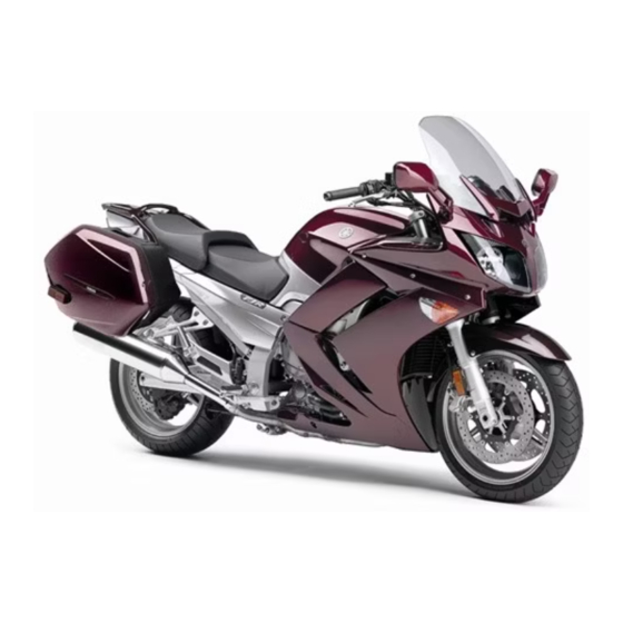
- Manuals
- Brands
- Yamaha Manuals
- Motorcycle
- FJR1300AS
- Owner’s manual
-
Contents
-
Table of Contents
-
Troubleshooting
-
Bookmarks
Quick Links
OWNER’S MANUAL
FJR1300AS
2D2-28199-E1
Related Manuals for Yamaha FJR1300AS
Summary of Contents for Yamaha FJR1300AS
-
Page 1
OWNER’S MANUAL FJR1300AS 2D2-28199-E1… -
Page 2
EAU26943 DECLARATION of CONFORMITY Company: MORIC CO., LTD. Address: 1450-6 Mori Mori-Machi Shuchi-gun Shizuoka 437-0292 Japan Hereby declare that the product: Kind of equipment: IMMOBILIZER Type-designation: 5SL-00 is in compliance with following norm(s) or documents: R&TTE Directive(1999/5/EC) EN300 330-2 v1.1.1(2001-6), EN60950-1(2001) Two or Three-Wheel Motor Vehicles Directive(97/24/EC: Chapter 8, EMC) Place of issue: Shizuoka, Japan Date of issue: 1 Aug. -
Page 3
Yamaha a reputation for dependability. Please take the time to read this manual thoroughly, so as to enjoy all advantages of your FJR1300AS. The owner’s manual does not only instruct you in how to operate, inspect and maintain your motorcycle, but also in how to safeguard yourself and others from trouble and injury. -
Page 4: Important Manual Information
This manual should be considered a permanent part of this motorcycle and should remain with it even if the motorcycle is subsequently sold. Yamaha continually seeks advancements in product design and quality. Therefore, while this manual contains the most current product information available at the time of printing, there may be minor discrepancies between your motorcycle and this manual.
-
Page 5
IMPORTANT MANUAL INFORMATION EAU10200 FJR1300AS OWNER’S MANUAL ©2006 by Yamaha Motor Co., Ltd. 1st edition, November 2006 All rights reserved. Any reprinting or unauthorized use without the written permission of Yamaha Motor Co., Ltd. is expressly prohibited. Printed in Japan. -
Page 6: Table Of Contents
TABLE OF CONTENTS SAFETY INFORMATION ….1-1 Accessory box ……3-26 Removing and installing panels ..6-6 Adjusting the headlight beams ..3-26 Checking the spark plugs ….6-8 DESCRIPTION ……..2-1 Handlebar position ……. 3-27 Engine oil and oil filter cartridge ..6-9 Left view ……….2-1 Opening and closing the Final gear oil ……..
-
Page 7
TABLE OF CONTENTS Lubricating the swingarm pivots …6-24 Lubricating the rear suspension …6-24 Checking the front fork ….6-24 Checking the steering ….6-25 Checking the wheel bearings ..6-26 Battery ……….6-26 Replacing the fuses ……6-27 Headlight bulb ……6-29 Front turn signal light ….6-29 Replacing a rear turn signal light bulb or a tail/brake light bulb ..6-29 Replacing the license plate… -
Page 8: Safety Information
SAFETY INFORMATION EAU10281 AND/OR WHEN MADE NECES- • Ride where other motorists can SARY BY MECHANICAL CONDI- see you. Avoid riding in another MOTORCYCLES SINGLE TIONS. motorist’s blind spot. TRACK VEHICLES. THEIR SAFE USE Many accidents involve inexperi- AND OPERATION ARE DEPENDENT Safe riding enced operators.
-
Page 9
Modifications made to this motorcycle other motorists can see you. the single most critical factor in the pre- not approved by Yamaha, or the re- The posture of the operator and vention or reduction of head injuries. moval of original equipment, may ren- passenger is important for proper Always wear an approved helmet. -
Page 10
Maximum load: been specifically designed for use on create instability due to improper 208 kg (459 lb) this motorcycle. Since Yamaha cannot weight distribution or aerody- test all other accessories that may be namic changes. If accessories When loading within this weight limit,… -
Page 11
SAFETY INFORMATION tor and may limit control ability, Always turn the engine off before or clothing, immediately wash the therefore, such accessories are leaving the motorcycle unattended affected area with soap and water not recommended. and remove the key from the main and change your clothes. -
Page 12: Description
DESCRIPTION EAU10410 Left view 1. Accessory box (page 3-26) 9. YCC-S clutch fluid reservoir (page 6-20) 2. Front fork spring preload adjusting bolt (page 3-28) 10.Shock absorber assembly spring preload adjusting lever (page 3-30) 3. Front fork rebound damping force adjusting knob (page 3-28) 11.Air filter element (page 6-14) 4.
-
Page 13: Right View
DESCRIPTION EAU10420 Right view 1. Storage compartment (page 3-25) 9. Shock absorber assembly rebound damping force adjusting knob (page 3-30) 2. Fuel tank cap (page 3-19) 10.Rear brake fluid reservoir (page 6-20) 3. Fuse box (page 6-27) 4. Windshield (page 3-15) 5.
-
Page 14: Controls And Instruments
DESCRIPTION EAU10430 Controls and instruments 1. Rear view mirror (page 3-28) 9. Throttle grip (page 6-15) 2. Left handlebar switches (page 3-15) 10.Main switch/steering lock (page 3-3) 3. Tachometer (page 3-7) 11.Headlight beam adjusting knob (page 3-26) 4. Speedometer (page 3-7) 12.Grip warmer adjusting knob (page 3-31) 5.
-
Page 15: Instrument And Control Functions
Immobilizer system This is not an automatic transmission, This vehicle features the YCC-S only the clutch system is automatic. (Yamaha Chip Controlled-Shift) sys- The gears must be shifted by the rider. tem. The basic function of this system allows the rider to shift gears without the use of a clutch lever.
-
Page 16
Do not expose any key to exces- a Yamaha dealer to have them re-reg- sively high temperatures. istered. Do not use the key with the red Do not place any key close to bow for driving. -
Page 17: Main Switch/Steering Lock
INSTRUMENT AND CONTROL FUNCTIONS EAU10471 EAU26811 To lock the steering Main switch/steering lock All electrical circuits are supplied with power; the meter lighting, taillights, li- cense plate light and auxiliary lights come on, and the engine can be start- ed. The key cannot be removed. NOTE: The headlights come on automatically when the engine is started and stay on…
-
Page 18: Indicator And Warning Lights
INSTRUMENT AND CONTROL FUNCTIONS To unlock the steering EAU39460 EAU11003 (Parking) Indicator and warning lights The steering is locked, and the tail- lights, license plate light and auxiliary lights are on. The hazard lights and turn signal lights can be turned on, but all other electrical systems are off.
-
Page 19
Stop the vehicle when it is safe to do so, Even if the oil level is sufficient, the have a Yamaha dealer check the self- and park it away from traffic. Have a warning light may flicker when riding on diagnosis system. -
Page 20
ABS may be defective. Yamaha dealer check the electrical cir- then while rotating the rear wheel, push If this occurs, have a Yamaha dealer cuit. the shift pedal rod and pivot forward un- til the transmission is in the neutral po- check the system as soon as possible. -
Page 21: Speedometer
INSTRUMENT AND CONTROL FUNCTIONS EAU11601 EAU11872 EAU40532 Speedometer Tachometer Multi-function display 1. Tachometer 1. Tachometer 1. Multi-function display 2. Speedometer 2. Tachometer red zone 2. “SELECT” button 3. Multi-function display 3. “RESET” button The electric tachometer allows the rider The speedometer shows the riding EWA14430 to monitor the engine speed and keep it WARNING…
-
Page 22
INSTRUMENT AND CONTROL FUNCTIONS a fuel reserve tripmeter (which Odometer and tripmeter modes distance traveled from that point. In that shows the distance traveled on the case, pushing the “SELECT” button fuel reserve) switches the display between the vari- a clock ous tripmeter and odometer modes in a fuel meter the following order:… -
Page 23
INSTRUMENT AND CONTROL FUNCTIONS Clock Fuel meter will start flashing. If this occurs, have a Yamaha dealer check the electrical cir- cuit. Coolant temperature meter 1. Clock 1. Fuel meter 2. “SELECT” button The fuel meter indicates the amount of 3. -
Page 24
INSTRUMENT AND CONTROL FUNCTIONS ECA10020 Ambient temperature, instanta- Ambient temperature mode CAUTION: neous fuel consumption and aver- fuel consumption modes Do not operate the engine if it is (except for the UK) overheated. Transmission gear display 1. Ambient temperature This display shows the ambient tem- perature from –9 °C to 50 °C in 1 °C in- 1. -
Page 25
INSTRUMENT AND CONTROL FUNCTIONS The accuracy of the temperature When the display is set to “L/100 The average fuel consumption display reading may be affected when km”, the amount of fuel necessary can be set to either “AV_ _._ km/L” or riding slowly (approximately under to travel 100 km under the current “AV_ _._ L/100 km”. -
Page 26
50 °C will not be displayed. If there is a malfunction, “– –.–” will Air → MPG → AV_ _._ MPG → Air The accuracy of the temperature be displayed. Have a Yamaha dealer reading may be affected when check the vehicle. Ambient temperature mode riding slowly [approximately under 20 km/h (12.5 mi/h)] or when… -
Page 27
When the average fuel consumption such an error code, note the code num- mode is selected, the display flashes ber, and then have a Yamaha dealer for five seconds, and then “AV_ _._ check the vehicle. MPG” (average distance that can be traveled using 1.0 Imp.gal of fuel) is dis-… -
Page 28: Anti-Theft Alarm (Optional)
If the multi-function display indicates two-digit error code when the key is any error codes, note the code number, turned to “ON”. and then have a Yamaha dealer check the vehicle. NOTE: If the multi-function display indicates er- ror code 52, this could be caused by transponder interference.
-
Page 29: Handlebar Switches
INSTRUMENT AND CONTROL FUNCTIONS EAU12347 Right position. To cancel the turn signal Handlebar switches lights, push the switch in after it has re- turned to the center position. Left EAU12493 Windshield position adjusting switch “ ” To move the windshield up, push this switch in direction (a).
-
Page 30
INSTRUMENT AND CONTROL FUNCTIONS EAU12500 EAU12733 EAU40381 Horn switch “ ” Hazard switch “ ” Hand shift control switch Press this switch to sound the horn. With the key in the “ON” or “ ” posi- tion, use this switch to turn on the haz- EAU12660 ard lights (simultaneous flashing of all Engine stop switch “… -
Page 31: Shift Pedal
INSTRUMENT AND CONTROL FUNCTIONS and release this switch after start- EAU40492 Shift pedal ing the engine to enable hand shifting. 1. Shift pedal 2. Bolt 1. Shift pedal 3. Standard position This vehicle is equipped with a con- 2. Move the shift pedal to the desired stant-mesh 5-speed transmission.
-
Page 32: Hand Shift Lever
INSTRUMENT AND CONTROL FUNCTIONS EAU40481 EAU26822 EAU39540 Hand shift lever “ ”/“ ” Brake lever Brake pedal The brake lever is located at the right handlebar grip. To apply the front brake, pull the lever toward the handle- bar grip. 1.
-
Page 33: Abs
This ABS has a test mode which EAU13072 Fuel tank cap allows the owner to experience the The Yamaha ABS (Anti-lock Brake pulsating at the brake lever or System) features a dual electronic con- brake pedal when the ABS is oper- trol system, which acts on the front and ating.
-
Page 34: Fuel
Avoid spilling fuel on the hot en- Your Yamaha engine has been de- gine. signed to use regular unleaded gaso- line with a research octane number of 91 or higher.
-
Page 35: Fuel Tank Breather/Overflow Hose
INSTRUMENT AND CONTROL FUNCTIONS or premium unleaded fuel. Use of un- EAU39450 EAU13441 Fuel tank breather/overflow Catalytic converter leaded fuel will extend spark plug life hose This vehicle is equipped with catalytic and reduce maintenance costs. converters in the exhaust system. EWA10860 WARNING The exhaust system is hot after op-…
-
Page 36: Seats
INSTRUMENT AND CONTROL FUNCTIONS EAU39491 Seats Passenger seat To remove the passenger seat 1. Insert the key into the seat lock, and then turn it counterclockwise. 1. Projection 1. Rider seat lock lever 2. Seat holder 2. Rider seat 2. Remove the key. To install the rider seat 1.
-
Page 37: Adjusting The Rider Seat Height
INSTRUMENT AND CONTROL FUNCTIONS 2. Install the passenger seat. EAU39632 Adjusting the rider seat height NOTE: The rider seat height can be adjusted to Make sure that the seats are prop- one of two positions to suit the rider’s erly secured before riding. preference.
-
Page 38
INSTRUMENT AND CONTROL FUNCTIONS 6. Align the projection on the bottom of the rider seat with the “H” posi- tion slot, and then push the rear of the seat down to lock it in place as shown. 1. Rider seat height position adjuster 1. -
Page 39: Storage Compartment
208 kg (459 lb) for the ve- tion slot, and then push the rear of hicle. the seat down to lock it in place as shown. 1. Storage compartment 2. Yamaha CYCLELOK (optional) This storage compartment is designed 1. “L” position slot hold genuine Yamaha CYCLELOK.
-
Page 40: Accessory Box
INSTRUMENT AND CONTROL FUNCTIONS EAU39480 ECA11800 EAU39610 Accessory box Adjusting the headlight CAUTION: The accessory box is located beside beams Do not place heat-sensitive items in the meter panel. The headlight adjusting knobs are used the accessory box. The accessory to raise or lower the height of the head- box gets extremely hot especially To open the accessory box…
-
Page 41: Handlebar Position
The handlebars can be adjusted to one ings of three positions to suit the rider’s pref- The cowlings can be tilted back 30 mm erence. Have a Yamaha dealer adjust (1.18 in) for added ventilation to suit the the position of the handlebars. riding conditions.
-
Page 42: Rear View Mirrors
INSTRUMENT AND CONTROL FUNCTIONS EAU39671 EAU14731 Rear view mirrors Adjusting the front fork The rear view mirrors of this vehicle can This front fork is equipped with spring be folded forward or backward for park- preload adjusting bolts, rebound damp- ing in narrow spaces.
-
Page 43
INSTRUMENT AND CONTROL FUNCTIONS load thereby soften Rebound damping force Compression damping force suspension, turn the adjusting bolt on each fork leg in direction (b). NOTE: Align the appropriate groove on the ad- justing mechanism with the top of the front fork cap bolt. -
Page 44: Adjusting The Shock Absorber Assembly
INSTRUMENT AND CONTROL FUNCTIONS ECA10100 EAU14911 For riding solo, move the spring preload Adjusting the shock absorber CAUTION: adjusting lever in direction (b). For assembly riding with a passenger, move the Never attempt to turn an adjusting This shock absorber assembly is spring preload adjusting lever in direc- mechanism beyond the maximum or equipped with a spring preload adjust-…
-
Page 45: Grip Warmer Adjusting Knob
Standard: formance. the engine is running. 12 click(s) in direction (b)* Always have a Yamaha dealer Maximum (hard): Use the grip warmer adjusting knob, lo- service the shock absorber. 3 click(s) in direction (b)*…
-
Page 46: Sidestand
INSTRUMENT AND CONTROL FUNCTIONS EAU15301 below and have a Yamaha dealer re- NOTE: Sidestand pair it if it does not function proper- When the vehicle is stopped or travel- The sidestand is located on the left side ing at extremely low speeds (e.g., in of the frame.
-
Page 47: Ignition Circuit Cut-Off System
Periodically check the operation of the ignition circuit cut-off system according to the following procedure. EWA10260 WARNING The vehicle must be placed on the centerstand during this in- spection. If a malfunction is noted, have a Yamaha dealer check the sys- tem before riding. 3-33…
-
Page 48
The vehicle should not be ridden until With the engine still running: checked by a Yamaha dealer. 7. Move the sidestand up. 8. Keep the front or rear brake applied. 9. Shift the transmission into gear. -
Page 49: Auxiliary Dc Jack
INSTRUMENT AND CONTROL FUNCTIONS EAU39651 EWA14360 Auxiliary DC jack WARNING This vehicle is equipped with an auxilia- To prevent electrical shock or short- ry DC jack in the accessory box. circuiting, make sure that the cap is A 12-V accessory connected to the installed when the auxiliary DC jack auxiliary jack can be used when the key is not being used.
-
Page 50: Pre-Operation Checks
PRE-OPERATION CHECKS EAU15592 The condition of a vehicle is the owner’s responsibility. Vital components can start to deteriorate quickly and unexpectedly, even if the vehicle remains unused (for example, as a result of exposure to the elements). Any damage, fluid leakage or loss of tire air pressure could have serious consequences.
-
Page 51: Pre-Operation Check List
• If necessary, add recommended coolant to specified level. 6-13 • Check cooling system for leakage. • Check operation. • If soft or spongy, have Yamaha dealer bleed hydraulic system. • Check brake pads for wear. Front brake • Replace if necessary.
-
Page 52
• Make sure that operation is smooth. • Check cable free play. Throttle grip 6-15, 6-22 • If necessary, have Yamaha dealer adjust cable free play and lubricate cable and grip housing. • Make sure that operation is smooth. Control cables 6-22 •… -
Page 53: Operation And Important Riding Points
Yamaha dealer check the electrical cir- ground and distract the opera- Never ride with the sidestand cuit. tor, resulting in a possible loss down.
-
Page 54: Shifting
OPERATION AND IMPORTANT RIDING POINTS EAU40572 The gears can be shifted using either NOTE: Shifting the shift pedal or the hand shift lever. If the engine fails to start, release the The hand shift lever has to be enabled start switch, wait a few seconds, and by pressing the hand shift control then try again.
-
Page 55: Tips For Reducing Fuel Consumption
OPERATION AND IMPORTANT RIDING POINTS Always return the throttle to the EAU16810 EAU16841 Tips for reducing fuel con- Engine break-in closed position while changing sumption There is never a more important period gears to avoid damaging the en- in the life of your engine than the period Fuel consumption depends largely on gine, transmission, and drive between 0 and 1600 km (1000 mi).
-
Page 56: Parking
Yamaha dealer check the vehi- the main switch is still on, as the cle. clutch automatically disengag-…
-
Page 57: Periodic Maintenance And Minor Repair
If you are not familiar with mainte- certain maintenance work correctly. nance work, have a Yamaha dealer do it for you. NOTE: If you do not have the tools or experi- ence required for a particular job, have a Yamaha dealer perform it for you.
-
Page 58: Periodic Maintenance And Lubrication Chart
The annual checks must be performed every year, except if a kilometer-based maintenance is performed in- stead. From 50000 km, repeat the maintenance intervals starting from 10000 km. Items marked with an asterisk should be performed by a Yamaha dealer as they require special tools, data and technical skills. ODOMETER READING (× 1000 km)
-
Page 59
PERIODIC MAINTENANCE AND MINOR REPAIR ODOMETER READING (× 1000 km) ANNUAL ITEM CHECK OR MAINTENANCE JOB CHECK √ √ √ √ 9 * Wheels • Check runout and for damage. • Check tread depth and for damage. • Replace if necessary. √… -
Page 60
PERIODIC MAINTENANCE AND MINOR REPAIR ODOMETER READING (× 1000 km) ANNUAL ITEM CHECK OR MAINTENANCE JOB CHECK • Change. √ √ √ √ √ √ Engine oil • Check oil level and vehicle for oil leakage. Engine oil filter car- √… -
Page 61
PERIODIC MAINTENANCE AND MINOR REPAIR Hydraulic brake and YCC-S clutch service • Regularly check and, if necessary, correct the brake and YCC-S clutch fluid levels. • Every two years replace the internal components of the brake master cylinders and calipers as well as YCC-S clutch master and release cylinders, and change the brake and YCC-S clutch fluids. -
Page 62: Removing And Installing Panels
PERIODIC MAINTENANCE AND MINOR REPAIR EAU18771 Removing and installing pan- The panels shown need to be removed to perform some of the maintenance jobs described in this chapter. Refer to this section each time a panel needs to be removed and installed. 1.
-
Page 63
PERIODIC MAINTENANCE AND MINOR REPAIR EAU39601 Panel C To remove the panel 1. Remove the seats. (See page 3-22.) 2. Remove the bolt and the quick fas- tener screws, and then take the panel off. 1. Panel B 2. Install the seats. 2. -
Page 64: Checking The Spark Plugs
Do not attempt to diagnose 0.7–0.8 mm (0.028–0.031 in) such problems yourself. Instead, have a Yamaha dealer check the vehicle. Clean the surface of the spark plug If a spark plug shows signs of electrode gasket and its mating surface, and then…
-
Page 65: Engine Oil And Oil Filter Cartridge
PERIODIC MAINTENANCE AND MINOR REPAIR EAU19881 2. Place an oil pan under the engine Engine oil and oil filter car- NOTE: to collect the used oil. The engine oil should be between the tridge 3. Remove the engine oil filler cap minimum and maximum level marks.
-
Page 66
An oil filter wrench is available at a seated. 43 Nm (4.3 m·kgf, 31 ft·lbf) Yamaha dealer. 6. Install the new oil filter cartridge, 8. Add the specified amount of the 5. Apply a thin coat of engine oil to… -
Page 67: Final Gear Oil
If any page (since the engine oil also or remains on, immediately turn the leakage is found, have a Yamaha deal- lubricates the clutch), do not engine off and have a Yamaha dealer er check and repair the vehicle. In addi- mix any chemical additives.
-
Page 68
PERIODIC MAINTENANCE AND MINOR REPAIR 2. Remove the oil filler bolt, and then Tightening torque: Tightening torque: check the oil level in the final gear Final gear oil filler bolt: Final gear oil filler bolt: case. 23 Nm (2.3 m·kgf, 17 ft·lbf) 23 Nm (2.3 m·kgf, 17 ft·lbf) NOTE: 6. -
Page 69: Coolant
PERIODIC MAINTENANCE AND MINOR REPAIR EAU20070 Coolant NOTE: The coolant should be between the The coolant level should be checked minimum and maximum level marks. before each ride. In addition, the cool- ant must be changed at the intervals specified in the periodic maintenance and lubrication chart.
-
Page 70: Air Filter Element
Yamaha dealer change the coolant. in the periodic maintenance and lubri- coolant, have a Yamaha dealer cation chart. Have a Yamaha dealer check the antifreeze content of clean and replace the air filter element. the coolant as soon as possible, otherwise the effectiveness of the coolant will be reduced.
-
Page 71: Checking The Engine Idling Speed
To prevent this checked as follows and, if necessary, from occurring, the valve clearance adjusted by a Yamaha dealer at the in- must be adjusted by a Yamaha dealer tervals specified in the periodic mainte- at the intervals specified in the periodic nance and lubrication chart.
-
Page 72: Tires
PERIODIC MAINTENANCE AND MINOR REPAIR EAU21771 NEVER OVERLOAD Tire air pressure (measured on cold Tires MOTORCYCLE! Operation of an tires): To maximize the performance, durabil- overloaded motorcycle may re- 0–90 kg (0–198 lb): ity, and safe operation of your motor- Front: sult in tire damage, loss of con- cycle,…
-
Page 73
Tire information glass fragments in it, or if the sidewall is Use only the tire valves and cracked, have a Yamaha dealer re- valve cores listed below to place the tire immediately. avoid tire deflation during a high-speed ride. -
Page 74: Cast Wheels
Always adjust the tire air pres- 180/55 ZR17M/C (73W) fore each ride. If any damage is Manufacturer/model: sure according to the operating found, have a Yamaha dealer re- METZELER/Roadtec Z6C conditions. BRIDGESTONE/BT020R place the wheel. Do not attempt FRONT and REAR:…
-
Page 75: Ycc-S Clutch
If ified in the periodic maintenance and before each ride. If the YCC-S clutch necessary, have a Yamaha dealer ad- lubrication chart. plates wear out, shifting becomes just the brake light switch.
-
Page 76: Checking The Brake And Ycc-S Clutch Fluid Levels
PERIODIC MAINTENANCE AND MINOR REPAIR cator groove has almost disappeared, EAU40591 YCC-S clutch Checking the brake and have a Yamaha dealer replace the YCC-S clutch fluid levels brake pads as a set. Front brake EAU22500 Rear brake pads 1. Minimum level mark…
-
Page 77: Changing The Brake And Ycc-S Clutch Fluids
YCC-S clutch fluids 6-6.) stalling them. Have a Yamaha dealer change the Be careful that water or dust does Observe these precautions: brake and YCC-S clutch fluids at the in- not enter the brake and YCC-S…
-
Page 78: Checking And Lubricating The Cables
If a cable is damaged maintenance chart. or does not move smoothly, have a Yamaha dealer check or replace it. Recommended lubricant: Engine oil EWA10720 WARNING…
-
Page 79: Checking And Lubricating The Brake Lever
Recommended lubricant: EWA10740 Lithium-soap-based grease (all-pur- WARNING pose grease) If the centerstand or sidestand does not move up and down smoothly, have a Yamaha dealer check or re- pair it. Recommended lubricant: Lithium-soap-based grease (all-pur- pose grease) 6-23…
-
Page 80: Lubricating The Swingarm Pivots
PERIODIC MAINTENANCE AND MINOR REPAIR EAUM1650 EAU23250 EAU23271 Lubricating the swingarm piv- Lubricating the rear suspen- Checking the front fork sion The condition and operation of the front fork must be checked as follows at the intervals specified in the periodic main- tenance and lubrication chart.
-
Page 81: Checking The Steering
Securely support the vehicle so that fork does not operate smoothly, there is no danger of it falling over. have a Yamaha dealer check or re- pair it. 2. Hold the lower ends of the front fork legs and try to move them for- ward and backward.
-
Page 82: Checking The Wheel Bearings
Batteries produce explosive hy- To charge the battery drogen gas. Therefore, keep Have a Yamaha dealer charge the bat- sparks, flames, cigarettes, etc., tery as soon as possible if it seems to away from the battery and pro- have discharged.
-
Page 83: Replacing The Fuses
The main fuse, the fuse boxes and the CHILDREN. sealed-type (MF) battery charg- ABS motor fuse are located under pan- er, have a Yamaha dealer el A. (See page 6-6.) charge your battery. To store the battery 1. If the vehicle will not be used for…
-
Page 84
2. Right radiator fan fuse 10.0 A 4. If the fuse immediately blows Hazard fuse: 3. Left radiator fan fuse again, have a Yamaha dealer 10.0 A 4. Hazard fuse check the electrical system. Fuel injection system fuse: 5. Backup fuse (for odometer, clock and immo- 15.0 A… -
Page 85: Headlight Bulb
If a front turn signal light does not come light bulb or a tail/brake light Yamaha dealer check its electrical cir- on, have a Yamaha dealer check its bulb cuit or replace the bulb. electrical circuit or replace the bulb.
-
Page 86: Replacing The License Plate Light Bulb
PERIODIC MAINTENANCE AND MINOR REPAIR 6. Install the passenger seat. EAU24310 3. Remove the defective bulb by pull- Replacing the license plate ing it out. light bulb 4. Insert a new bulb into the socket. 1. Remove the license plate light unit 5.
-
Page 87: Auxiliary Light Bulb
The following troubleshooting charts represent quick and easy procedures for checking these vital systems your- self. However, should your motorcycle require any repair, take it to a Yamaha dealer, whose skilled technicians have the necessary tools, experience, and know-how to service the motorcycle properly.
-
Page 88: Troubleshooting Charts
Remove the spark plugs and check the electrodes. The engine does not start. Have a Yamaha dealer check the vehicle. Check the battery. 4. Battery The engine turns over The battery is good.
-
Page 89
Start the engine. If the engine overheats again, have a The coolant level Yamaha dealer check and repair the cooling system. is OK. NOTE: If coolant is not available, tap water can be temporarily used instead, provided that it is changed to the recommended coolant as soon as possible. -
Page 90: Motorcycle Care And Storage
Rust and corrosion can develop matte colored finished parts. Be ECA10770 even if high-quality components are sure to consult a Yamaha dealer for CAUTION: advice on what products to use be- used. A rusty exhaust pipe may go un- Avoid using strong acidic wheel fore cleaning the vehicle.
-
Page 91
MOTORCYCLE CARE AND STORAGE thinner, fuel (gasoline), rust re- After normal use ECA10790 CAUTION: movers or inhibitors, brake flu- Remove dirt with warm water, a mild id, antifreeze or electrolyte. detergent, and a soft, clean sponge, Do not use warm water since it in- Do not use high-pressure wash- and then rinse thoroughly with clean creases the corrosive action of the… -
Page 92: Storage
7. Let the motorcycle dry completely Always store your motorcycle in a cool, NOTE: before storing or covering it. dry place and, if necessary, protect it Consult a Yamaha dealer for advice on EWA11130 against dust with a porous cover. WARNING what products to use.
-
Page 93
MOTORCYCLE CARE AND STORAGE 3. Perform the following steps to pro- 4. Lubricate all control cables and the tect the cylinders, piston rings, etc. pivoting points of all levers and from corrosion. pedals as well as of the side- a. Remove the spark plug caps stand/centerstand. -
Page 94: Specifications
SPECIFICATIONS Dimensions: Engine oil: Fuel injector: Overall length: Type: Manufacturer: 2230 mm (87.8 in) SAE20W40 NIPPON INJECTOR Overall width: Recommended engine oil grade: Model/quantity: 750 mm (29.5 in) API service SG type or higher, JASO INP-151/4 Overall height: standard MA Spark plug (s): 1450 mm (57.1 in) Engine oil quantity:…
-
Page 95
SPECIFICATIONS 3rd: (Total weight of rider, passenger, cargo and Operation: 31/23 (1.348) accessories) Right hand operation 4th: Tire air pressure (measured on cold Recommended fluid: 28/26 (1.077) DOT 4 tires): 5th: Rear brake: Loading condition: 26/28 (0.929) Type: 0–90 kg (0–198 lb) Chassis: Single disc brake Front:… -
Page 96
SPECIFICATIONS Voltage, capacity: Fuses: 12 V, 12.0 Ah Main fuse: Headlight: 50.0 A Bulb type: Headlight fuse: Halogen bulb 25.0 A Bulb voltage, wattage × quantity: Signaling system fuse: 15.0 A Headlight: 12 V, 60 W/55.0 W × 2 Ignition fuse: 10.0 A Tail/brake light: 12 V, 5.0 W/21.0 W ×… -
Page 97: Consumer Information
Record the key identification number, vehicle identification number and mod- el label information in the spaces pro- vided below for assistance when ordering spare parts from a Yamaha dealer or for reference in case the vehi- cle is stolen. KEY IDENTIFICATION NUMBER: 1.
-
Page 98
The model label is affixed to the frame under the passenger seat. (See page 3-22.) Record the information on this la- bel in the space provided. This informa- tion will be needed when ordering spare parts from a Yamaha dealer. -
Page 99
INDEX Engine trouble/YCC-S indicators and warning light……….3-5 ABS …………3-19 License plate light bulb, replacing..6-30 ABS warning light ……..3-6 Accessory box ……..3-26 Final gear oil……….6-11 Main switch/steering lock……3-3 Air filter element……..6-14 Front and rear brake pads, checking ..6-19 Matte color, caution …….. -
Page 100
INDEX Starting the engine……..5-1 Start switch ……….. 3-16 Steering, checking …….. 6-25 Storage ……….. 7-3 Storage compartment ……3-25 Swingarm pivots, lubricating ….6-24 Tachometer……….3-7 Throttle cable free play, checking ..6-15 Throttle grip and cable, checking and lubricating ……..6-22 Tires ………… -
Page 102
YAMAHA MOTOR CO., LTD. PRINTED ON RECYCLED PAPER PRINTED IN JAPAN 2007.01-0.3×1 CR…
- Вы не можете создать новую тему
- Вы не можете ответить в тему
#1

-
Группа:
Новые пользователи -
Сообщений:
2 -
Регистрация:
24 Апрель 07
Отправлено 24 Апрель 2007 — 07:43
Ребят, подскажите пожалуйста, кто знает где можно взять список кодов ошибок системы самодиагностики. Мотоцикл Ямаха FJR-1300. Загорелся значок «провертье двигатель» без причины, т.е. не бил, не ронял… купил совсем не давно. Да и вообще интересует какая-либо информация по ремонту данной техники. Даже покататься толком не успел  ((( Да и не СТО и каких либо магазинов у нас в Астане (Казахстан) нет. Что делать не знаю.
Заранее благодарен всем откликнувшимся!
0
- Наверх of the page up there ^
- Вы не можете создать новую тему
- Вы не можете ответить в тему
Другие ответы в этой теме
#2
ZSaint
-
Группа:
Новые пользователи -
Сообщений:
2 -
Регистрация:
24 Апрель 07
Отправлено 24 Апрель 2007 — 08:05
В мануале написано «при загорании лампочки «check engine» обратитесь к ближайшему официальному дилеру Ямаха» А на табло выходит сообщение типа F33 — т.е. код ошибки… или плохо искал или… ну в общем в инете пока ни чего не нашел. Посторонних звуков при работающем двигателе нет, масло поменял…
0
- Наверх of the page up there ^
#3
r2d2
-
Группа:
Новые пользователи -
Сообщений:
217 -
Регистрация:
04 Апрель 06
Отправлено 24 Апрель 2007 — 08:06
— вот тебе источник вдохновения 
0
- Наверх of the page up there ^
#4
ИГОРЬ (MOTOUA)
-
Группа:
администрация -
Сообщений:
2 256 -
Регистрация:
12 Март 06
Отправлено 24 Апрель 2007 — 08:09
0
- Наверх of the page up there ^
#5
Администратор
-
Группа:
Администрация -
Сообщений:
16 339 -
Регистрация:
03 Март 06
Отправлено 24 Апрель 2007 — 09:05
не может ли подобная надпись появиться при включенной кнопке блокировки работы двигателя?
либо по другой причине, блокирующей запуск двигателя (выставленная боковая подножка, если она глушит двигатель и т.п.)
0
- Наверх of the page up there ^
#6
кубинский партизан
-
Группа:
R.I.P. -
Сообщений:
65 -
Регистрация:
23 Май 06
Отправлено 24 Апрель 2007 — 15:56
Цитата
Загорелся значок «провертье двигатель» без причины
Стандартная фигня, которая случается у многих компьютеров самодиагностики двигателя. Чаще всего из-за плохой бензинки, но может быть тысяча других причин — ошибки в работе лямбда-зонда, сбой в системе зажигания и т.д.
Мой совет — если двигатель заводится и работает, не делай ничего, покатайся так.
После некоторого количества заводов двигателя (какое кол-во — зашито в компьютер) и исчезнувшей неисправности, лампочка «Check engine» должна погаснуть. Это при случайной ошибке в работе двигателя.
Дело в том, что компьютеры управления двигателем запрограммированы таким образом, чтобы блокировать неисправную цепь или датчик путем усреднения параметров при постоянно появляющейся неисправности. Другими словами — двигатель все равно работать будет, но не в оптимальном режиме, т.е. может увеличиться расход топлива, например.
Хотя во всех мануалах будет написано одинаково — при зажигании лампочки «Check engine» немедленно обратитесь в сервисный центр для диагностики двигателя
0
- Наверх of the page up there ^
#7
MR.Ru$$eL
-
Группа:
Пользователи -
Сообщений:
801 -
Регистрация:
09 Октябрь 06
Отправлено 24 Апрель 2007 — 16:22
У бати в машине (Mitsubishi Outlander) тоже как-то загорелась лампочка движка, оказалось что просто голимый бензин был, де то водичка попала. Потом опять загорелась, оказалось что датчик охлаждения движка сломался, тоесть охлаждение происходило даже тогда когда это не нужно было движку, решилось заменой датчика.
0
- Наверх of the page up there ^
#8
ASTARD
-
Группа:
Пользователи -
Сообщений:
183 -
Регистрация:
17 Апрель 07
Отправлено 24 Апрель 2007 — 16:35
а также мог умиреть датчик положения дросселной заслонки или холостого хода, также могли умереть свечи или в хутчем случае застратса форсунки. Также не мешало бы почистить дроссель но могу сказать с 100% увереностью это не поршен и не клапан такого рода ошибки это только ошибки инжектора и никакохо отношения к поршям колцам или коленвалу отношение не имеет.
0
- Наверх of the page up there ^
#9
кубинский партизан
-
Группа:
R.I.P. -
Сообщений:
65 -
Регистрация:
23 Май 06
Отправлено 25 Апрель 2007 — 11:19
Цитата
но могу сказать с 100% увереностью это не поршен и не клапан такого рода ошибки это только ошибки инжектора
Это не совсем верно, помимо инжектора может возникнуть ошибка на любом из датчиков в цепи обратной связи управления двигателем. Чаше всего на лямбда-зонде (на новой технике) и чаше всего из-за качества бензина. На поюзанной технике часто из-за износа сбоит TPS (trottle position sensor), в данном случае это маловероятно.
0
- Наверх of the page up there ^
#10
ASTARD
-
Группа:
Пользователи -
Сообщений:
183 -
Регистрация:
17 Апрель 07
Отправлено 25 Апрель 2007 — 11:52
TPS (trottle position sensor), это и есть датчик положения дроссельной заслонки просто по русски я написал )))
П.С. а также мог умиреть датчик положения дросселной заслонки или холостого хода
Сообщение отредактировал ASTARD: 25 Апрель 2007 — 12:04
0
- Наверх of the page up there ^
#11
кубинский партизан
-
Группа:
R.I.P. -
Сообщений:
65 -
Регистрация:
23 Май 06
Отправлено 25 Апрель 2007 — 12:38
Я знаю что такое TPS, а ты много видел новых машин у которых он вышел из строя ? 
0
- Наверх of the page up there ^
#12
ASTARD
-
Группа:
Пользователи -
Сообщений:
183 -
Регистрация:
17 Апрель 07
Отправлено 25 Апрель 2007 — 12:43
я понял что ты знаеш )
Видел на таврии например с завода шел мертвый этот датчик понятно что ТМАХ с таврией связывать нельзя но все же )))… а на иномарках скорее раньше выходит датчик холостого хода (там пластмассовый наконечник и через 20к километров от него остаеться очень мало)
0
- Наверх of the page up there ^
#13
кубинский партизан
-
Группа:
R.I.P. -
Сообщений:
65 -
Регистрация:
23 Май 06
Отправлено 25 Апрель 2007 — 13:30
Немного отвлеклись от темы. Говорили про новый FJR-1300.
Остаюсь при своем ИМХО, что самый вероятный глюк из-за датчика кислорода (из-за плохой бензинки).
Если есть другие мнения по диагностике и устранению — излагайте. Может чем-нибудь поможем человеку.
0
- Наверх of the page up there ^
#14
ЖОРИК
-
Группа:
Пользователи -
Сообщений:
25 -
Регистрация:
21 Июнь 07
![]()
Отправлено 23 Июнь 2007 — 13:49
Ребята, еслиб ето был датчик положения дроселя то тогда при розгоне былиб рывки, как при прошытых свечах!!!Ето ошыбка могла появитса даже изза датчика детонацыи который не влияет на роботу двигателя, так что причин маса.Хотя ето ошыбка может даже выскачить изза подсаженого акамулятора.В первую очередь посоветую тебе проверить свечи и заряд акума на прокрутке стартером, если до 9-ти вольт упадёт 90% что ето оно.
Я просто роботою на компьютерной автодиагностике инжекторных систем впырска так что знаю не по наслышке
0
- Наверх of the page up there ^
#15
ZlouDyx
-
Группа:
Заглохшие -
Сообщений:
102 -
Регистрация:
02 Март 07
![]()
Отправлено 19 Ноябрь 2007 — 22:04
chek engine загорается при неисправносятях систем которые свызаны с двигателем а так же необходимости замены масел и жидкостей, так же из мелочей это может быть из за свечей зажигания, забитого воздушного фильтра,отказа какогото датчика,ДАЖЕ МОЖЕТ загореться при севщем аккумуляторе,возможен вариант ( было такое при замене масла поставили масляный фильтр не для данного мотоцикла,может загореться если при работающем двигатьеле или включённом зажигании был отсоеденён какой либо разъём,также к загоранию лампочки может привести загрязнение топливной системы ( форсунок,фильтра…..)
способ по устранению(незнаю как на ямахах) обнулению ошибки — снять с аккумулятора клему на 5-10 минут а потом одеть обратно , если ошибка временная, то она пропадёт.
причин может быть очень много от самой мелочной до очень крупной .
0
- Наверх of the page up there ^
#16
ZlouDyx
-
Группа:
Заглохшие -
Сообщений:
102 -
Регистрация:
02 Март 07
![]()
Отправлено 19 Ноябрь 2007 — 22:08
 кубинский партизан (25.4.2007, 13:49) писал:
Немного отвлеклись от темы. Говорили про новый FJR-1300.
Остаюсь при своем ИМХО, что самый вероятный глюк из-за датчика кислорода (из-за плохой бензинки).
Если есть другие мнения по диагностике и устранению — излагайте. Может чем-нибудь поможем человеку.
если меняли датчик, то скорее всего не обнулили ошибку, если дело в датчике то это будет видно по расходу топлива( увеличиться до 2-х раз) и по динамике разгона мотоцикла, ну возможно что свечи будут чёрные из за неправельного (увеличенного количества смеси,) такой вариант там возможно два датчика — первичный и вторичный .
про датчик говорить рано, луче конечно где то наити сервис, чтоб не искать методом тыка.
0
- Наверх of the page up there ^
#17
ZlouDyx
-
Группа:
Заглохшие -
Сообщений:
102 -
Регистрация:
02 Март 07
![]()
Отправлено 19 Ноябрь 2007 — 22:10
ASTARD (24.4.2007, 16:54) писал:
а также мог умиреть датчик положения дросселной заслонки или холостого хода, также могли умереть свечи или в хутчем случае застратса форсунки. Также не мешало бы почистить дроссель но могу сказать с 100% увереностью это не поршен и не клапан такого рода ошибки это только ошибки инжектора и никакохо отношения к поршям колцам или коленвалу отношение не имеет.
если не дай бог вышло из строя что т осерьёздное,то это скажеться потом на ЦПГ
0
- Наверх of the page up there ^
#18
Frost
-
Группа:
Новые пользователи -
Сообщений:
17 -
Регистрация:
16 Август 07
Отправлено 20 Ноябрь 2007 — 11:54
Прошу прощения, что вмешиваюсь в битву Титанов, но не проще ли одновременно нажать кнопочки «Select» и «Reset», включть зажигание, и через благословенние 8 секунд зайти в систему самодиагностики, и считать кода неисправностей ,которые никакой проблемы нет расшифровать (в том же инете)., а не гадать на кофейной гуще 
0
- Наверх of the page up there ^
#19
Rustam
-
Группа:
Пользователи -
Сообщений:
3 -
Регистрация:
16 Ноябрь 09
Отправлено 20 Ноябрь 2009 — 01:46
если при загорании ломпочки чек мотор работает мормально то это скорее всего лядазонд желательно сделать диагностику т.к. ЭБУ может перейти в аварийный режим работы, т.е.при поломки других датчиков мотор жилбы своей жинью и работол бы неустойчево
0
- Наверх of the page up there ^
- ← Предыдущая тема
- РЕМОНТ, ЭКСПЛУАТАЦИЯ И ТЮНИНГ МОТОЦИКЛОВ
- Следующая тема →
- Вы не можете создать новую тему
- Вы не можете ответить в тему