
Phaser® 7800
Color Printer
Phaser® 7800
Service Manual
Xerox Internal-Use Only

Phaser 7800 Service Manual
Service Documentation
Phaser 7800 Service Manual
705P01307
BUS Update — 10/25/2011
November 2011
Xerox Corporation
Content Development and Language Services — North America
26600 Parkway — Bldg. 60
P.O. Box 1000, M/S 7060-776
Wilsonville, OR 97070-1000
NOTICE: All service documentation is supplied to Xerox external customers for informational purposes only. Xerox service documentation is intended for use by certified, product trained service personnel only. Xerox does not warrant or represent that such documentation is complete, nor does Xerox represent or warrant that it will notify or provide to such customer any future changes to this documentation. Customer performed service of equipment, or modules, components or parts of such equipment may affect the warranty offered by Xerox with respect to such equipment. You should consult the applicable warranty for its terms regarding customer or third party provided service. If the customer services such equipment, modules, components or parts thereof, the customer releases Xerox from any and all liability for the customer actions, and the customer agrees to indemnify, defend and hold Xerox harmless from any third party claims which arise directly or indirectly from such service.
© 2011 Xerox Corporation. All Rights Reserved. Unpublished rights reserved under the copyright laws of the United States. Contents of this publication may not be reproduced in any form without permission of Xerox Corporation.
Copyright protection claimed includes all forms of matters of copyrightable materials and information now allowed by statutory or judicial law or hereinafter granted, including without limitation, material generated from the software programs which are displayed on the screen such as styles, templates, icons, screen displays, looks, etc.
Xerox technical training materials and service manuals are intended for use by authorized Xerox service technicians and service partners only and are not for resale. These materials may not be distributed, copied or otherwise reproduced without prior written consent from Xerox Corporation.
XEROX® and XEROX and Design®, Phaser®, PhaserSMART®, PhaserMeter, CentreWare®, PrintingScout®, Walk-Up®, WorkCentre®, FreeFlow®, SMARTsend®, Scan to PC Desktop®, MeterAssistant®, SuppliesAssistant®, Xerox Secure Access Unified ID System®, Xerox Extensible Interface Platform®, ColorQube®, Global Print Driver®, and Mobile Express Driver® are trademarks of Xerox Corporation in the United States and/or other countries.
Adobe® Reader®, Adobe Type Manager®, ATM™, Flash®, Macromedia®, Photoshop®, and PostScript® are trademarks of Adobe Systems Incorporated in the United States and/or other countries.
Apple®, AppleTalk®, Bonjour®, EtherTalk®, Macintosh®, Mac OS®, and TrueType® are trademarks of Apple Computer, Inc. in the United States and/or other countries.
HP-GL®, HP-UX®, and PCL® are trademarks of Hewlett-Packard Corporation in the United States and/or other countries.
IBM® and AIX® are trademarks of International Business Machines Corporation in the United States and/or other countries.
Microsoft®, Windows Vista®, Windows®, and Windows Server® are trademarks of Microsoft Corporation in the United States and other countries.
Novell®, NetWare®, NDPS®, NDS®, IPX™, and Novell Distributed Print Services™ are trademarks of Novell, Inc. in the United States and other countries.
SGI® and IRIX® are trademarks of Silicon Graphics International Corp. or its subsidiaries in the United States and/or other countries.
Sun, Sun Microsystems, and Solaris are trademarks or registered trademarks of Oracle and/or its affiliates in the United States and other countries.
UNIX® is a trademark in the United States and other countries, licensed exclusively through X/ Open Company Limited.
As an ENERGY STAR® partner, Xerox Corporation has determined that this product meets the ENERGY STAR guidelines for energy efficiency. The ENERGY STAR name and logo are registered U.S. marks.
|
BUS Update 10/25/2011 — Xerox Internal Use Only |
November 2011 |
Phaser 7800 Service Manual

Introduction
|
About this Manual …………………………………………………………………………………………….. |
iii |
|
Organization…………………………………………………………………………………………………….. |
iii |
|
How to Use this Manual …………………………………………………………………………………….. |
iv |
|
Power Safety……………………………………………………………………………………………………. |
iv |
|
Service Safety Summary……………………………………………………………………………………. |
iv |
|
Moving the Printer …………………………………………………………………………………………….. |
vi |
|
Serial Number Format……………………………………………………………………………………….. |
vii |
|
Symbols Used on the Printer ……………………………………………………………………………… |
viii |
|
Electrostatic Discharge Precautions ……………………………………………………………………. |
x |
|
Regulatory Requirements ………………………………………………………………………………….. |
x |
|
Translation of Warnings …………………………………………………………………………………….. |
xii |
|
Phaser 7800 Overview………………………………………………………………………………………. |
xiii |
|
Printer Configurations ……………………………………………………………………………………….. |
xiii |
|
Parts of Phaser 7800 ………………………………………………………………………………………… |
xiv |
|
Phaser 7800 Options ………………………………………………………………………………………… |
xvi |
|
Control Panel Configurations ……………………………………………………………………………… |
xviii |
|
Routine Maintenance Items ……………………………………………………………………………….. |
xix |
|
Consumables …………………………………………………………………………………………………… |
xx |
|
Specifications …………………………………………………………………………………………………… |
xx |
|
Physical Dimensions and Clearances………………………………………………………………….. |
xxv |
|
Toner Cartridge Life ………………………………………………………………………………………….. |
xxvii |
|
Maintenance Function……………………………………………………………………………………….. |
xxvii |
|
Reference Pages and Troubleshooting Test Pages ………………………………………………. |
xxviii |
|
Acronyms and Abbreviations ……………………………………………………………………………… |
xxix |
|
BUS Update 10/25/2011 — Xerox Internal Use Only |
November 2011 |
Introduction |
|
Phaser 7800 Service Manual |
i |

About this Manual
The Phaser 7800 Service Manual is the primary document used for diagnosing, repairing, maintaining, and troubleshooting the printer. The Service Manual is the controlling publication for a service call. Information on using this document is found in the Introduction section. To ensure understanding of this product, complete the Xerox Service Training Program for this particular printer.
Service Manual Revision
Updates are issued as the printer changes or as corrections are identified.
Technical Support Information
For manual updates, Service Bulletins, knowledge base, and technical support, go to:
•Xerox Global Service Net — https://www.xrxgsn.com/secure/main.pl
For further technical support, contact your assigned Xerox Technical Support for this product.
Organization
The titles of the sections and a description of the information contained in each chapter are contained in the following paragraphs:
Introduction and General Information
This chapter contains documentation organization, symbology and nomenclature, translated warnings, safety symbols, regulatory requirements, and general information about the printer.
Chapter 1 Service Call Procedures
This chapter contains procedures to be taken during a service call and in what sequence they are to be completed. This is the entry level for all service calls.
Chapter 2 Status Indicator RAPs
This chapter contains descriptions of the diagnostic aids for troubleshooting that include Power On Self Test (POST), Fault Codes and Messages procedures.
Chapter 3 Image Quality
This chapter contains the diagnostic aids for troubleshooting image quality problems, as well as image quality specifications and image defect samples.
Chapter 4 Repairs/Adjustments
This chapter contains the removal, replacement, and adjustments procedures.
Repairs
Repairs include procedures for removal and replacement of spare parts listed in the Parts List. Use the repair procedures for the correct order of removal and replacement, for warnings, cautions, and notes.
Adjustments
Adjustments include procedures for adjusting the parts that must be within specification for the correct operation of the printer. Use the adjustment procedures for the correct sequence of operation for specifications, warnings, cautions and notes.
Chapter 5 Parts List
This chapter contains exploded views of the print engine and optional Field Replaceable Units (FRUs), as well as part numbers for orderable parts and illustrated Parts List.
Chapter 6 General Troubleshooting
This chapter contains details of the embedded Service Diagnostics test suite, as well as troubleshooting procedures for printer problems not related to a specific fault code.
Chapter 7 Wiring Data
This chapter contains drawings, lists of plug/jack locations, and diagrams of the power distribution wire networks in the printer.
Chapter 8 Theory of Operation
This chapter contains detailed functional information on the print engine components.
|
BUS Update 10/25/2011 — Xerox Internal Use Only |
November 2011 |
Introduction |
|
About this Manual, Organization |
||
|
Phaser 7800 Service Manual |
iii |

How to Use this Manual
Always start with the Service Call Procedures in Chapter 1. Perform Initial Actions and verify the problem, then follow the directions provided.
The power cord is attached to the printer as a plug-in device on the side of the printer. If it is necessary to disconnect all electrical power from the printer, disconnect the power cord from the electrical outlet.
Power Safety
Power Source
For 115 VAC printers, do not apply more than 135 volts RMS between the supply conductors or between either supply conductor and ground. For 230 VAC printers, do not apply more than 254 volts RMS between the supply conductors or between either supply conductor and ground. Use only the specified power cord and connector. This manual assumes that the reader is a qualified service technician.
Plug the three-wire power cord (with grounding prong) into a grounded AC outlet only. If necessary, contact a licensed electrician to install a properly grounded outlet. If the product loses its ground connection, contact with conductive parts may cause an electrical shock. A protective ground connection by way of the grounding conductor in the power cord is essential for safe operation.
Disconnecting Power
Disconnect the power cord in the following cases:
•if the power cord or plug is frayed or otherwise damaged,
•if any liquid or foreign material is spilled into the product,
•if the printer is exposed to any excess moisture,
•if the printer is dropped or damaged,
•if you suspect that the product needs servicing or repair,
•whenever you clean the product.
Service Safety Summary
General Safety
The printer and recommended supplies have been designed and tested to meet strict safety requirements. Attention to the following information will ensure the continued safe operation of the printer.
Electrical Safety
•Use the power cord supplied with the printer.
•Plug the power cord directly into a properly grounded electrical outlet.
•Do not use a ground adapter plug to connect the printer to an electrical outlet that does not have a ground connection terminal.
•Do not use an extension cord or power strip.
•Do not place the printer in an area where people might step on the power cord.
•Do not place objects on the power cord.
•Do not block the ventilation openings. These openings are provided to prevent overheating of the printer.
•Do not drop paper clips or staples into the printer.
WARNING
Switch off the electricity to the machine. Disconnect the power cord from the customer supply while performing tasks that do not need electricity. Electricity can cause death or injury. Moving parts can cause injury.
DANGER: Mettez la machine hors tension. Déconnectez le cordon d’alimentation de l’alimentation du client lorsque vous réalisez des tâches qui ne nécessitent pas d’électricité. L’électricité peut être à l’origine de blessures, voire d’un accident mortel. Les pièces amovibles peuvent être à l’origine de blessures.
AVVERTENZA: Spegnere la macchina. Scollegare il cavo di alimentazione dall’alimentatore quando si eseguono attività che non richiedono elettricità. L’elettricità può causare morte o lesioni personali. Le parti in movimento possono causare lesioni personali.
VORSICHT: Schalten Sie die Stromversorgung der Maschine ab. Ziehen Sie das Stromkabel ab, wenn Sie Aufgaben ausführen, für die keine Stromversorgung benötigt wird. Stromschläge können Todesfällen oder Verletzungen verursachen. Bewegliche Teile können zu Verletzungen führen.
AVISO: Apague la electricidad de la máquina. Desconecte el cable de alimentación eléctrica de la toma de pared mientras esté realizando tareas que no necesiten corriente. La electricidad puede causar daños o la muerte. Las partes móviles pueden causar daños.
WARNING
Do not switch on the electricity to the machine while a ground circuit is disconnected. Ground circuits ensure that the machine remains safe during a fault condition.
DANGER: Ne pas mettre la machine sous tension si un circuit de mise à la masse est déconnecté. Les circuits de mise à la masse permettent de garantir la sécurité de la machine lors d’un incident.
AVVERTENZA: Non accendere la macchina se uno dei conduttori di terra non è connesso. In caso di guasti elettrici, tali conduttori garantiscono la sicurezza del sistema.
VORSICHT: Stromzufuhr zum Gerät nicht einschalten, wenn keine Erdung gegeben ist.
AVISO: No encienda la máquina mientras esté deconectado algún circuito de tierra. Los circuitos de tierra mantienen la seguridad de la máquina en las situaciones de averías o errores.
Maintenance Safety
•Do not attempt any maintenance procedure that is not specifically described in the documentation supplied with the printer.
•Do not use aerosol cleaners. The use of supplies that are not approved may cause poor performance and could create a hazardous condition.
•Do not burn any consumables or routine maintenance items. For information on Xerox supplies recycling programs, go to www.xerox.com/gwa.
|
Introduction |
November 2011 |
BUS Update 10/25/2011 — Xerox Internal Use Only |
|
How to Use this Manual, Service Safety Summary |
||
|
iv |
Phaser 7800 Service Manual |

Operational Safety
The printer and supplies were designed and tested to meet strict safety requirements. These include safety agency examination, approval, and compliance with established environmental standards.
Pay attention to these safety guidelines to ensure the continued, safe operation of the printer.
•Use the supplies specifically designed for your printer. The use of unsuitable materials may cause poor performance and a possible safety hazard.
•Follow all warnings and instructions marked on, or supplied with, the printer, options and supplies.
WARNING
Use only Xerox materials and components. This product is safety certified using Xerox materials and components. The use of non Xerox materials and components may invalidate the safety certificate.
DANGER: N’utilisez que des matières premières et des composants Xerox. La sécurité du produit est assurée dans le cadre de son utilisation avec des matières premières et des composants Xerox. L’utilisation de matières premières et de composants autres que ceux de Xerox risque d’invalider le certificat de sécurité.
AVVERTENZA: Utilizzare solo materiali e componenti Xerox per avvalersi della certificazione di protezione. L’utilizzo di materiali e componenti non Xerox può rendere nulla la certificazione di protezione.
VORSICHT: Verwenden Sie nur Materialien und Komponenten von Xerox. Dieses Produkt besitzt die Sicherheitszertifizierung bei Verwendung von Xerox-Materialien und -Komponenten. Die Verwendung von Materialien und Komponenten anderer Hersteller setzt möglicherweise das Sicherheitszertifikat außer Kraft.
AVISO: Utilice solo los materiales y componentes Xerox. Este producto dispone de un certificado de seguridad si se utilizan los materiales y componentes Xerox. Este certificado de seguridad no será válido si se utilizan materiales y componentes que no sean de Xerox.
NOTE: The Total Satisfaction Guarantee is available in the United States and Canada. Coverage may vary outside these areas; please contact your local representative for details.
General Guidelines
For qualified service personnel only — Refer also to the preceding Power Safety Precautions.
Avoid servicing alone — Do not perform internal service or adjustment of this printer unless another person capable of rendering first aid or resuscitation is present.
Use care when servicing with power — Dangerous voltages may exist at several points in this printer. To avoid personal injury, do not touch exposed connections and components while power is on. Disconnect power before removing the power supply shield or replacing components.
Do not wear jewelry — Remove jewelry prior to servicing. Rings, necklaces and other metallic objects could come into contact with dangerous voltages and currents.
Warning Labels
Read and obey all posted warning labels. Throughout the printer, warning labels are displayed on potentially dangerous components. As you service the printer, check to make certain that all warning labels remain in place.
Safety Interlocks
Make sure all covers are in place and all interlock switches are functioning correctly after you have completed a printer service call. If you bypass an interlock switch during a service call, use extreme caution when working on or around the printer.
|
BUS Update 10/25/2011 — Xerox Internal Use Only |
November 2011 |
Introduction |
|
Service Safety Summary |
||
|
Phaser 7800 Service Manual |
v |

Moving the Printer |
Repacking Procedure |
||
|
• |
Use the power switch to turn Off the printer, and unplug all cables and cords. Do not turn |
1. |
Remove the Imaging Unit (Y/M/C/K) (REP 8.1). |
|
the printer Off by pulling the power cord or using a power-strip with an On/Off switch. |
2. |
Remove the Toner Cartridge (Y/M/C/K) (REP 5.1). |
|
|
• |
The printer is heavy and must be lifted by three people. |
3. |
Remove the Waste Cartridge (REP 8.9). |
|
4. |
Remove the IBT Belt Cleaner Assembly (REP 6.1). |
||
|
5. |
Remove the Front Cover Assembly and Inner Cover Assembly (REP 19.1). |
||
|
6. |
Remove the Top Cover (REP 19.2). |
||
|
7. |
Cut card board to 4 pieces at approximately 1 x 1.5 inch for each piece. |
||
|
8. |
Cover the toner ports with the card boards. |
Figure 1 Printer Lifting Technique
Repacking the Printer
When shipping the printer, repack the printer using the original packing material and boxes or a Xerox packaging kit. Instructions for repacking the printer are included in the kit. If you do not
have all the original packaging, or are unable to repackage the printer, contact your local Xerox
Figure 2 Covering the Toner Ports
service representative.
CAUTION
Failure to repackage the printer properly for shipment can result in damage to the printer. Damage to the printer caused by improper packaging is not covered by the Xerox warranty, service agreement, or Total Satisfaction Guarantee.
|
Introduction |
November 2011 |
BUS Update 10/25/2011 — Xerox Internal Use Only |
|
Moving the Printer |
||
|
vi |
Phaser 7800 Service Manual |

9.Use the tape from the Repack Kit and cut the tape to secure the Card Boards at the toner ports.
Figure 3 Securing the Card Boards
10. Reassemble the printer and follow the instructions included with the repair kit.
Serial Number Format
Changes to Xerox products are made to accommodate improved components. As improvements are made, part numbers may change from those appearing in this section. To get the latest part, provide the following information when ordering:
•Component’s part number
•Product type or configuration number
•Serial number of the printer
The nine-digit serial number has the following format:
•PPPRSSSSS
•PPP = Three digit alphanumeric product code
•R = Single digit numeric revision digit, 0-9. To be rolled when a major product change occurs and initiated with a change request.
|
Table 1 Product Code |
||
|
Product |
Product Code |
|
|
7800, 110V Engine |
AT0 |
|
|
7800V, 220V Engine |
AT1 |
|
NOTE: Not all of the serial number will be used. This is a buffer in case additional units are built by Fuji Xerox for each model of printer during pre-production.
Table 2 Serial Number
|
Product |
Starting Serial Number |
Ending Serial Number |
|
7800_DN, 110V Engine |
205601 |
224500 |
|
7800_YDN, 110V Engine |
224501 |
225500 |
|
7800V_DN, 220V Engine |
225601 |
250500 |
Serial numbers between 200601 — 205600 are reserved for XOG FIC sites if reserialization is needed. A serial number break or a new serial number range will be provided when a major product change occurs.
|
BUS Update 10/25/2011 — Xerox Internal Use Only |
November 2011 |
Introduction |
|
Moving the Printer, Serial Number Format |
||
|
Phaser 7800 Service Manual |
vii |

Examples
110V Engine
AT0220800
Product code for 110V printer = AT0 Serial number for 7800_DN = 220800
220V Engine
AT1227360
Product code for 220V printer = AT1 Serial number for 7800V_DN = 227360
Symbols Used on the Printer
Warnings, Cautions, and Notes
Be aware of all symbols and terms when they are used, and always read Note, Caution, and Warning statements.
A translated version of all warnings is in Translation of Warnings section.
Warnings, Cautions, and Notes can be found throughout the service manual. The words WARNING or CAUTION may be listed on an illustration when the specific component associated with the potential hazard is pointed out; however, the message of the WARNING or CAUTION is always located in the text. Their definitions are as follows:
Label Placement and Layout Example
The Serial Number Label will be applied inside the left door on the right side of the frame as shown in photo below:
WARNING
A warning is used whenever an operating or maintenance procedure, practice, condition or statement, if not strictly observed, could result in personal injury.
DANGER: Une note Danger est utilisée chaque fois qu’une procédure d’utilisation ou de maintenance peut être cause de blessure si elle n’est pas strictement respectée.
AVVERTENZA: Un segnale di avvertenza è utilizzato ogni volta che una procedura operativa o di manutenzione, una pratica, una condizione o un’istruzione, se non strettamente osservata, potrebbe causare lesioni personali.
VORSICHT: Weist darauf hin, dass ein Abweichen von den angeführten Arbeitsund Wartungsanweisungen gesundheitliche Schäden, möglicherweise sogar schwere Verletzungen zur Folge haben kann.
AVISO:Un aviso se utiliza siempre que un procedimiento de operación o mantenimiento, práctica o condición puede causar daños personales si no se respetan estrictamente.
CAUTION
A Caution is used whenever an operating or maintenance procedure, a practice, condition, or statement, if not strictly observed, could result in damage to the equipment.
NOTE: A Note is used whenever it is necessary to highlight an operating or maintenance procedure, practice, condition, or statement.
Figure 1 Serial Number Location
|
Introduction |
November 2011 |
BUS Update 10/25/2011 — Xerox Internal Use Only |
|
Serial Number Format, Symbols Used on the Printer |
||
|
viii |
Phaser 7800 Service Manual |

Printer Safety Icons |
Static Caution |
|
The following precautionary symbols may appear on the printer. |
|
|
This symbol indicates hot surface on or in the printer. Use caution to avoid personal injury. |
Figure 1 Hot Surface Symbol
Use caution (or draws attention to a particular component).
Figure 2 Use Caution Symbol
Danger, High Voltage
Figure 3 High Voltage Symbol
Fuser Temperature
Figure 4 Fuser Temperature
Figure 5 Static Caution Symbol
Do not touch the item.
Figure 6 Do Not Touch Item Symbol
Do not burn the item.
Figure 7 Do Not Burn Item Symbol
Recycle the item.
Figure 8 Recycling Item Symbol
Protective Ground (Earth) symbol.
Figure 9 Protective Ground (Earth) Symbol
|
BUS Update 10/25/2011 — Xerox Internal Use Only |
November 2011 |
Introduction |
|
Symbols Used on the Printer |
||
|
Phaser 7800 Service Manual |
ix |
![]()
Electrostatic Discharge Precautions
Some semiconductor components, and the respective sub-assemblies that contain them, are vulnerable to damage by Electrostatic Discharge (ESD). These components include Integrated Circuits (ICs), Large-Scale Integrated circuits (LSIs), field-effect transistors, and other semiconductor chip components. The following techniques will reduce the occurrence of component damage caused by static electricity.
Be sure the power is off to the chassis or the circuit board, and observe all other safety precautions.
•Immediately before handling any semiconductor components assemblies, drain the electrostatic charge from your body. This can be accomplished by touching an earth ground source or by wearing a wrist strap device connected to an earth ground source. Wearing a wrist strap will also prevent accumulation of additional bodily static charges. Be sure to remove the wrist strap before applying power to the unit under test to avoid potential shock.
•After removing a static sensitive assembly from its anti-static bag, place it on a grounded conductive surface. If the anti-static bag is conductive, you may ground the bag and use it as a conductive surface.
•Do not use freon-propelled chemicals. These can generate electrical charges sufficient to damage some devices.
•Do not remove a replacement component or electrical sub-assembly from its protective package until you are ready to install it.
•Immediately before removing the protective material from the leads of a replacement device, touch the protective material to the chassis or circuit assembly into which the device will be installed.
•Minimize body motions when handling unpacked replacement devices. Motion such as your clothes brushing together, or lifting a foot from a carpeted floor can generate enough static electricity to damage an electro-statically sensitive device.
•Handle IC’s and Erasable Programmable Read-Only Memories (EPROM’s) carefully to avoid bending the pins.
•Pay attention to the direction of parts when mounting or inserting them on the Printed Circuit Boards (PCB’s).
Regulatory Requirements
Xerox has tested this printer to electromagnetic emission and immunity standards. These standards are designed to mitigate interference caused or received by this printer in a typical office environment.
United States (FCC Regulations)
This equipment has been tested and found to comply with the limits for a Class A digital device, pursuant to Part 15 of the FCC Rules. These limits are designed to provide reasonable protection against harmful interference when the equipment is operated in a commercial environment. This equipment generates, uses, and can radiate radio frequency energy. If it is not installed and used in accordance with these instructions, it may cause harmful interference to radio communications. Operation of this equipment in a residential area is likely to cause harmful interference in which case the user will be required to correct the interference at his/her own expense.
If this equipment does cause harmful interference to radio or television reception, which can be determined by turning the equipment off and on, the user is encouraged to try to correct the interference by one or more of the following measures:
•Reorient or relocate the receiver.
•Increase the separation between the equipment and receiver.
•Connect the equipment into an outlet on a circuit different from that to which the receiver is connected.
•Consult the dealer or an experienced radio/television technician for help.
Any changes or modifications not expressly approved by Xerox could void the user’s authority to operate the equipment. To ensure compliance with Part 15 of the FCC rules, use shielded interface cables.
Canada (Regulations)
This Class A digital apparatus complies with Canadian ICES-003.
Cet appareil numérique de la classe A est conforme à la norme NMB-003 du Canada.
|
Introduction |
November 2011 |
BUS Update 10/25/2011 — Xerox Internal Use Only |
|
Electrostatic Discharge Precautions, Regulatory Re- |
||
|
x |
Phaser 7800 Service Manual |

European Union
The CE mark applied to this product symbolizes Xerox’s declaration of conformity with the following applicable Directives of the European Union as of the dates indicated:
Figure 1 CE Symbol
•December 12, 2006: Low Voltage Directive 2006/95/EC
•December 15, 2004: Electromagnetic Compatibility Directive 2004/108/EC
This product, if used properly in accordance with the user’s instructions, is neither dangerous for the consumer nor for the environment.
To ensure compliance with European Union regulations, use shielded interface cables.
A signed copy of the Declaration of Conformity for this product can be obtained from Xerox.
Ozone Release
During print operation, a small quantity of ozone is released. This amount is not large enough to harm anyone adversely. However, be sure the room where the printer is being used has adequate ventilation, especially if you are printing a high volume of materials, or if the printer is being used continuously over a long period.
|
BUS Update 10/25/2011 — Xerox Internal Use Only |
November 2011 |
Introduction |
|
Regulatory Requirements |
||
|
Phaser 7800 Service Manual |
xi |

Translation of Warnings
General Usage
WARNING
Use only Xerox materials and components. This product is safety certified using Xerox materials and components. The use of non Xerox materials and components may invalidate the safety certificate.
DANGER: N’utilisez que des matières premières et des composants Xerox. La sécurité du produit est assurée dans le cadre de son utilisation avec des matières premières et des composants Xerox. L’utilisation de matières premières et de composants autres que ceux de Xerox risque d’invalider le certificat de sécurité.
AVVERTENZA: Utilizzare solo materiali e componenti Xerox per avvalersi della certificazione di protezione. L’utilizzo di materiali e componenti non Xerox può rendere nulla la certificazione di protezione.
VORSICHT: Verwenden Sie nur Materialien und Komponenten von Xerox. Dieses Produkt besitzt die Sicherheitszertifizierung bei Verwendung von Xerox-Materialien und -Komponenten. Die Verwendung von Materialien und Komponenten anderer Hersteller setzt möglicherweise das Sicherheitszertifikat außer Kraft.
AVISO: Utilice solo los materiales y componentes Xerox. Este producto dispone de un certificado de seguridad si se utilizan los materiales y componentes Xerox. Este certificado de seguridad no será válido si se utilizan materiales y componentes que no sean de Xerox.
WARNING
Do not touch the fuser while it is hot.
DANGER: Ne pas toucher au four pendant qu’il est encore chaud.
AVVERTENZA: Non toccare il fonditore quando è caldo.
VORSICHT: Fixierbereich erst berühren, wenn dieser abgekühlt ist.
AVISO: No toque el fusor mientras está caliente.
WARNING
Do not work in a confined space. 1 m (39 inches) space is needed for safe working.
DANGER: Ne pas travailler dans un espace restreint. 1 mètre d’espace est nécessaire pour un dépannage en toute sécurité.
AVVERTENZA: Non lavorare in uno spazio limitato; è necessario uno spazio di almeno un metro attorno alla macchina per la sicurezza dell’operatore.
VORSICHT: Nur mit ausreichendem Bewegungsspielraum (1 m) arbeiten.
AVISO: No trabaje en un espacio reducido. Se necesita 1 metro de espacio para trabajar con seguridad.
WARNING
USA and Canada. Do not install this printer in a hallway or exit route that does not have 1.12 m (44 inches) of space additional to the normal space requirements in front of the machine. To conform with fire regulations this additional 1.12 m (44 inches) of space is needed in front of the printer in hallway and exit routes.
DANGER : États-Unis et Canada. Si cette machine est installée dans un couloir ou une voie de sortie, 1,12 m (44 pouces) d’espace supplémentaire à l’espace normal doit être disponible devant la machine conformément aux normes de sécurité d’incendie.
AVVERTENZA: N/A
VORSICHT: N/A
AVISO: Estados Unidos y Canadá. No instale esta máquina en un corredor o ruta de salida que no tenga 1.12 m (44 pulgadas) de ancho delante de la máquina, sin incluir el espacio que ocupe la máquina. Este espacio adicional de 1.12 m (44 pulgadas) delante de la máquina en corredores y rutas de salida es necesario para cumplir los requisitos
de las normas sobre incendios.
Electrical
WARNING
Do not perform repair activities with the power on or electrical power supplied to the machine. The machine could activate and cause serious personal injury when the power is on or electrical power is supplied.
DANGER: Ne pas effectuer de dépannage avec le contact principal activé ou avec l’alimentation électrique appliquée à la machine: celle-ci pourrait démarrer et causer de graves blessures.
AVVERTENZA: Non effettuare alcuna riparazione con la macchina accesa o con l’alimentazione elettrica inserita. La macchina potrebbe avviarsi all’improvviso e causare gravi ferite.
VORSICHT: Es dürfen keine Reparaturarbeiten durchgeführt werden, solange das Gerät eingeschalten oder mit der Stromquelle verbunden ist. Das Gerät kann u.U in den AktivZustand übergehen und somit erhebliche körperliche Schäden verursachen.
AVISO: No realice reparaciones con la máquina encendida o conectada a la corriente. La máquina podría activarse y ocasionar daños personales graves.
WARNING
Use extreme care when working near this power supply. High voltage is present on the power supply when the machine is in standby mode. Contact with electrical components or high voltage cables represents a shock potential that could result in serious personal injury.
DANGER: Faire très attention en intervenant près de ce module d’alimentation. Une haute tension y est présente lorsque la machine est en mode d’attente. Tout contact avec les éléments électriques ou les câbles haute tension représente un risque de choc et de graves blessures.
AVVERTENZA: Fare estrema attenzione quando si lavora vicino a questo gruppo statico. Il gruppo statico è caricato ad alta tensione quando la macchina è in modalità standby. Il contatto con componenti sotto tensione o cavi elettrici comportano un seriopericolo di scossa elettrica e gravi ferite.
VORSICHT: Bei der Verwendung unterbrechungsfreier Stromversorgung benutzt äußerste Vorsichtkeit. Während die Machine sich im Energiespar-Modus befindet, steht es unter Hochspannung. Beim Umgang mit elektrischen Bauteilen und Hochspannungsleitungen erhöht sich das Unfallrisiko. Äußerste Vorsicht ist geboten.
AVISO: Tenga mucho cuidado al trabajar en las proximidades de la fuente de alimentación. Hay voltaje muy alto en la fuente de alimentación cuando la máquina se encuentra en el modo de espera. El contacto con componentes eléctricos o cables de alto voltaje representa peligro de descarga eléctrica que puede ocasionar daños personales
graves.
|
Introduction |
November 2011 |
BUS Update 10/25/2011 — Xerox Internal Use Only |
|
Translation of Warnings |
||
|
xii |
Phaser 7800 Service Manual |

Finisher
WARNING
Do not connect the finisher power cord directly to the AC wall outlet. The finisher cannot operate without the machine. The machine controls the distribution of electricity to the finisher for correct power on the power off sequencing.
DANGER: Ne pas connecter le cordon d’alimentation du module de finition directement sur la prise murale. Le module ne peut pas fonctionner sans la machine. Celle-ci contrôle la distribution d’électricité vers le module de finition lors des séquences de mises hors tension.
AVVERTENZA: non connettere il cavo elettrico della stazione di finitura direttamente a una presa a muro. La macchina non è in grado di funzionare indipendentemente dalla stampante, la quale ne gestisce totalmente i cicli di accensione e spegnimento.
VORSICHT: Netzstecker des Finisher nicht direkt an eine Netzsteckdose anschließen. Der Finisher kann nicht ohne das Document Centre betrieben werden. Die Stromversorgung zum Finisher zur richtigen Abschaltsequenz wird vom Document Centre gesteuert.
AVISO: No conecte el cable de alimentación de la acabadora directamente a la toma de corriente alterna. La acabadora no funciona sin la máquina. La máquina controla la distribución de energía eléctrica a la acabadora para la secuencia correcta de encendido y apagado.
Phaser 7800 Overview
The Phaser 7800 uses single-pass LED print heads with an electrophotographic four-color (YMCK) tandem architecture and intermediate transfer printing process. The Phaser 7800 delivers color and mono print speed at 45/45-ppm, and resolutions up to 1200 x 2400 dots-per- inch (dpi). The Phaser 7800 supports Adobe PostScript 3, PCL5, PCL6, USB 2.0, and 10/100/ 1000 Base-TX Ethernet. Additional features include a 4.3” touch screen display and a Hard Disk Drive. A Finisher with stacking, stapling, punching, and booklet making features is available with the Phaser 7800 per selected model.
Input trays can support up to 5 trays with 1500-Sheet High-Capacity Feeder or 2500-Sheet High-Capacity Feeder. Tray 1 supports up to 100 sheets of specialty paper, card stock, and envelopes. The standard paper input is 500 sheets and the maximum input with an optional Trays 3, 4, and 5 is 2500 sheets. Two output trays are included with the Phaser 7800; each output tray holds 250 sheets face down.
Printer Configurations
The Phaser 7800 is available in three configurations.
Table 1 Phaser 7800 Configurations
|
Features |
7800 DN |
7800 GX |
7800 DX |
||||
|
Processor and Clock |
1.33 GHz |
1.33 GHz |
1.33 GHz |
||||
|
Speed |
|||||||
|
Memory Configuration* |
2 GB |
2 GB |
2 GB |
||||
|
Print Speed |
45/45 |
45/45 |
45/45 |
||||
|
Adobe Postscript 3 Fonts |
Standard |
Standard |
Standard |
||||
|
PCL5 Fonts |
Standard |
Standard |
Standard |
||||
|
PCL6 Fonts |
Standard |
Standard |
Standard |
||||
|
USB 2.0 |
Standard |
Standard |
Standard |
||||
|
Ethernet Interface |
10/100/1000 |
10/100/1000 |
10/100/1000 |
||||
|
Base-TX |
Base-TX |
Base-TX |
|||||
|
Tray 1 (100 Sheet) |
Standard |
Standard |
Standard |
||||
|
Tray 2 (500 Sheet) |
Standard |
Standard |
Standard |
||||
|
Tray 3/4/5 1500-Sheet |
Optional |
Standard |
N/A |
||||
|
Feeder |
|||||||
|
Tray 3/4/5 2500-Sheet |
Optional |
N/A |
Standard |
||||
|
Feeder |
|||||||
|
Auto-Duplexer |
Standard |
Standard |
Standard |
||||
|
Hard Disk Drive |
160 GB |
160 GB |
160 GB |
||||
|
Advanced Finisher |
N/A |
Optional |
Optional |
||||
|
Professional Finisher |
N/A |
Optional |
Optional |
||||
|
Wireless LAN |
Optional |
Optional |
Optional |
||||
|
Printer Resolution (dpi) |
|||||||
|
• |
Standard |
• |
1200×600 |
• |
1200×600 |
• |
1200×600 |
|
• |
Enhanced |
• |
1200×1200 |
• |
1200×1200 |
• |
1200×1200 |
|
• |
Photo |
• |
2400×1200 |
• |
2400×1200 |
• |
2400×1200 |
* All configurations have one memory slot supporting 2 GB DDR2 DIMMs.
|
BUS Update 10/25/2011 — Xerox Internal Use Only |
November 2011 |
Introduction |
|
Translation of Warnings, Printer Configurations |
||
|
Phaser 7800 Service Manual |
xiii |

Parts of Phaser 7800 |
Left Front View of 7800DX Printer (with 2500-Sheet Feeder) |
Left Front View of 7800GX Printer (with 1500-Sheet Feeder) |
Figure 2 Left Front View with 2500-Sheet Feeder
Figure 1 Left Front View with 1500-Sheet Feeder
1. Left Side Door C
1. Left Side Door C
2. Tray 1 with Extension Tray
2. Tray 1 with Extension Tray
3. Left Side Door B
3. Left Side Door B
4. Left Side Door A
4. Left Side Door A
5. Left Side Door D
5. Left Side Door D
6. Control Panel
6. Control Panel
7. Output Tray
7. Output Tray
8. Center Output Tray
8. Center Output Tray
9. Secondary Power Switch
9. Secondary Power Switch
10. Main Power Switch
10. Main Power Switch
11. Front Door
11. Front Door
12. Tray 2
12. Tray 2
13. 2500-Sheet Feeder (Trays 3-5)
13. 1500-Sheet Feeder (Trays 3-5)
|
Introduction |
November 2011 |
BUS Update 10/25/2011 — Xerox Internal Use Only |
|
Parts of Phaser 7800 |
||
|
xiv |
Phaser 7800 Service Manual |

Left and Rear Views |
Hard Disk Drive |
|
|
The Phaser 7800 supports an internal Hard Disk Drive. The Hard Disk Drive has a minimum |
||
|
160 GB capacity. Features include: |
||
|
• |
Secure Print |
|
|
• |
Personal Print |
|
|
• Personal or Shared Saved Print |
||
|
• |
Disk Collation |
Figure 4 Hard Disk Drive
Figure 3 Left and Rear Views
1.USB Connection
2.USB Memory Port (for service only)
3.Ethernet Connection
4.Power Connector for Finisher
5.Power Connector for Printer
|
BUS Update 10/25/2011 — Xerox Internal Use Only |
November 2011 |
Introduction |
|
Parts of Phaser 7800 |
||
|
Phaser 7800 Service Manual |
xv |

Phaser 7800 Options
The Phaser 7800 options include:
•Wireless Adapter
•Heavy Media Kit
•Optional 1500-Sheet Feeder (Trays 3, 4, 5)
•Optional 2500-Sheet Feeder (Trays 3, 4, 5)
Wireless Adapter
The Wireless Network Adapter enables the printer to connect to a wireless network.
Heavy Media Kit
The Heavy Media Kit allows the printer to feed media (duplex) up to 350gsm. Refer to Gate 1 Spring removal procedure (REP 17.5) for how to remove the Spring.
Optional 1500-Sheet Feeder (Trays 3, 4, 5)
The Optional 1500-Sheet Feeder increases the input capacity of the printer and can be attached to the printer underneath Tray 2. Each tray holds up to 500 sheets of media. The Optional 1500-Sheet Feeder is customer installable.
Figure 1 Optional 1500-Sheet Feeder
Optional 2500-Sheet Feeder (Trays 3, 4, 5)
The Optional 2500-Sheet Feeder increases the input capacity of the printer and can be attached to the printer underneath Tray 2. Tray 3 holds up to 500 sheets and Trays 4 and 5 hold up to 1,000 sheets each. The Optional 2500-Sheet Feeder is customer installable.
Figure 2 Optional 2500-Sheet Feeder
|
Introduction |
November 2011 |
BUS Update 10/25/2011 — Xerox Internal Use Only |
|
Phaser 7800 Options |
||
|
xvi |
Phaser 7800 Service Manual |

Finisher
The Finisher is a customer install option and available in two models: Advanced and Professional.
Advanced Finisher
The Advanced Finisher consists of a Horizontal Transport and SB Finisher. The SB Finisher can collate, stack, staple, add a booklet crimp, saddle staple, and hole punch sets of prints.
The Advanced Finisher can stack up to 2000 sheets or 200 sets of 90 gsm or 20 lb letter/A4 size paper. For paper sizes greater than A4 LTR, the maximum number of sets is limited to 100.
The SB Finisher handles a variety of standard paper sizes, ranging from A4 SEF/ 8.5 x 11” up to A3/ 11 x 17”. The Center Tray has a capacity of 200 sheets of A3/11 x 17” paper. The Stacker Tray has a capacity of 2000 sheets of A4/ 8.5 x 11” or 1000 sheets of A3/ 11 x 17” paper.
|
Figure 3 Advanced Finisher |
|||
|
1. |
Front Transport Cover |
8. |
Booklet Maker |
|
2. |
2/3 Hole Punch Kit or 2/4 Hole Punch Kit |
9. |
Right Tray |
|
3. |
Hole Punch Waste Container |
10. |
Right Tray Extension |
|
4. |
Horizontal Transport |
11. |
Creaser Unit |
|
5. |
Finisher Top Cover |
12. |
Staple Cartridge |
|
6. |
Booklet Staple Cartridge |
13. |
Finisher Front Door |
|
7. |
Side Cover for Booklet Unit |
14. |
Finisher Front Cover |
Professional Finisher
The Professional Finisher includes a Booklet Maker.
•Top Tray: 500 sheets
•Stacking Tray: Up to 3000 sheets
•Stapling:
–Single (Front/ Rear), dual, and quadruple* (A A4/ Letter)
–Auto stapling (50 sheets maximum) — 24 lb/90 gsm
–Booklet stapling
–Supports Letter, Legal, Tabloid, A3, A4, B4 and B5 size
|
Figure 4 Professional Finisher |
|||
|
1. |
Center Tray |
7. |
Right Middle Tray |
|
2. |
Hole Punch Unit |
8. |
Staple Cartridge |
|
3. |
Hole Punch Waste Container |
9. |
Booklet Tray |
|
4. |
Finisher Front Door |
10. |
Booklet Staple Assembly |
|
5. |
Right Top Tray |
11. |
Booklet Maker |
6.Exit Cover
|
BUS Update 10/25/2011 — Xerox Internal Use Only |
November 2011 |
Introduction |
|
Phaser 7800 Options |
||
|
Phaser 7800 Service Manual |
xvii |

Control Panel Configurations
The Control Panel consists of one LED, one 4.3 inch Wide Video Graphics Array (WVGA) touch screen display, and 2 functional buttons. The touch screen is used to navigate the menu system, perform functions, and select modes of operation for the printer. The Control Panel contains various features include:
•Displays the current operating status of the printer.
•Provides access to print features.
•Provides access to reference materials.
•Provides access to Tools and Setup menus.
•Provides access to Troubleshooting menus and videos.
•Prompts user to load paper, replace supplies, and clear jams.
•Displays errors and warnings.
•Plays event-driven videos.
|
Figure 1 Phaser 7800 Control Panel |
||
|
1. |
Touch Screen |
Displays information and provides access to the printer functions |
|
2. |
Power Saver |
Enters Sleep mode, and exists Low Power or Sleep mode. |
|
3. |
Cancel |
Temporarily stops the current print job, allowing user to cancel or |
|
resume the job. |
Control Panel Special Functions
Table 1 Service Control Panel
|
Function |
Buttons Presses |
|
|
Enter Service Diagnostics |
From Ready to Print, press and hold the Pause button for 5 |
|
|
seconds, then press and release the Power Saver button to |
||
|
display the Service Diagnostics login screen. |
||
|
Reset Touchscreen Parameters |
From Ready to Print, press and hold the Power Saver button |
|
|
for 5 seconds, then press and release the Pause button to |
||
|
reset the Touchscreen to factory defaults and display the |
||
|
Control Panel calibration screen (GP 10 — Control Panel |
||
|
Troubleshooting). |
||
|
Override locked Service Tools |
At the login screen: |
|
|
menu using Service credentials |
User Name: !$ecivreS |
|
|
Passcode: 2732 |
||
|
Resetting the System Admin |
1. |
Obtain the printer serial number and page count. |
|
(SA) Pass Code |
2. |
Call the Welcome Center for a temporary pass code. |
|
3. |
Enter reset (not case sensitive) and temporary pass |
|
|
code at the login screen. |
||
|
NOTE: SA login credentials return to default values |
||
|
(ADMIN/1111) after 100 pages. |
||
|
Access Code |
• |
From Control Panel |
|
Printer > Tools > Setup > Service Tools > Service Diag- |
||
|
nostics |
||
|
• |
Enter code 6789 |
|
LED Indicators
|
Table 2 LED Indicators |
|
|
LED State |
Printer State |
|
Flashing Green |
If no error condition exists and print engine is busy or a job is being |
|
processed. |
|
|
Green |
No error or warning condition exists. |
|
Red |
An error condition exists. |
|
Amber |
No error condition exists and a warning condition exists. |
|
Introduction |
November 2011 |
BUS Update 10/25/2011 — Xerox Internal Use Only |
|
Control Panel Configurations |
||
|
xviii |
Phaser 7800 Service Manual |

LUI (Control Panel) Lock
•LUI Lock is stored on the SD Card.
•LUI Lock factory default for all items: Off.
•System Administrator (SA) user name and passcode are stored on the SD Card.
•System Administrator (SA) user name and passcode factory defaults: «admin», 1111.
•Service username and passcode: Available from Service.
•Service Access is stored on the SD Card.
•Service Access: Enabled.
•If LUI Lock is Off or Service and the SA are not logged in, all buttons are displayed with no key icon.
•If LUI Lock is On and neither Service nor the SA is logged in, the buttons of each lockable item is displayed with a key icon.
•The lockable items are:
–Print Reference Materials
–Tray Management
–Language / Keyboard
–Date / Time
–System Timeout
–Startup Page
–Network & USB
–Reprint Jammed Pages
–Security
–Output Settings
–Energy Saver
–PostScript
–Service Tools
•If an LUI button has no key icon, selecting it displays the button’s menu.
•If an LUI button has a key icon, selecting the button displays the passcode entry screen.
•If the SA user name and passcode are entered, the SA is logged in.
•If Service Access is Enabled and the Service user name and passcode are entered, Service is logged in.
•If either Service or the SA is logged in, the item is displayed.
•Service or the SA is logged out when the System Timeout expires or the Logout button is selected from the Home Page.
Interactions
If the user name «reset» is entered in the passcode entry screen, a passcode generated from the serial number and Total Impressions by a proprietary algorithm is valid until Total Impressions plus 100 is reached.
•The above allows service to help users who have forgotten or lost their SA user name and/or passcode. The customer can call for assistance and must provide the printer serial number and current Total Impressions, which uses a Xerox app to generate the passcode. This passcode works while the printer’s Total Impressions are from up to and including Total Impressions + 99. Note that the «reset» user name and special passcode also work in CWIS.
Routine Maintenance Items
A maintenance item is a printer part or assembly that has a limited life, and requires periodic replacement. Routine maintenance items are typically customer replaceable.
The following listed items have limited life and require periodic replacement.
NOTE: Print life is based on “typical” office printing and 5% coverage per color on 24 lb. paper. The 1,500,000 life is not guaranteed and varies depending on usage habits.
Figure 1 Routine Maintenance Items
Table 1 Phaser 7800 Maintenance Items
|
Item |
Description |
Print Life |
||
|
1 |
Transfer Roller |
200,000 pages |
||
|
2 |
Fuser |
360,000 pages |
||
|
3 |
Transfer Belt Cleaner (IBT Cleaner) |
160,000 pages |
||
|
4 |
Waste Cartridge |
20,000 pages |
||
|
5 |
Imaging Units |
• |
5-page jobs: up to |
145,000 pages |
|
• |
3-page jobs: up to |
115,000 pages |
||
|
• |
1-page jobs: up to |
64,000 pages |
||
|
6 |
Tray 1 Feed Roller Kit |
100,000 pages |
||
|
7 |
Tray 2-5 Feed Roller Kit |
300,000 pages per tray |
||
|
8 |
Suction Filter |
120,000 pages |
||
|
BUS Update 10/25/2011 — Xerox Internal Use Only |
November 2011 |
Introduction |
|
Control Panel Configurations, Routine Mainte- |
||
|
Phaser 7800 Service Manual |
xix |
![]()
Table 1 Phaser 7800 Maintenance Items
|
Item |
Description |
Print Life |
|
9 |
Staple Cartridge (Booklet Maker, Advanced |
2,000 sets |
|
Finisher) |
||
|
Staple Cartridge (Booklet Maker, Professional |
5,000 sets |
|
|
Finisher) |
||
|
10 |
Staple Cartridge (Advanced Finisher, Profes- |
5,000 sets |
|
sional Finisher) |
||
Consumables
Consumable consist of 4 Toner Cartridges used in the printer.
Each Toner Cartridge has a CRUM (Customer Replaceable Unit Meter) to record new or used cartridge and usage information and identifies the type of Toner Cartridge (Standard or High capacity).
The CRUM contains a company ID, Region ID, and Xerox company name. A CRUM counts the amount of remaining toner. When toner empty is detected, Life End status will be sent to indicate toner empty.
Internal counters track Consumables and Maintenance Items life usage.
Life ratings are based on A-size sheets at 5% coverage.
|
Figure 1 Consumables |
|
|
Toner Cartridge |
Print Life |
|
Standard Capacity |
CMY: 6,000 pages |
|
High Capacity |
CMY: 17,200 pages |
|
K: 24,000 pages |
|
Specifications
Printer Specifications
|
Table 1 Printer Specifications |
||
|
Characteristic |
Specifications |
|
|
Printing Technology |
Recording System: Electrophotographic method that uses |
|
|
OPC Drum and Intermediate Transfer Belt |
||
|
Charging System: Includes contact charge (BCR) and roll |
||
|
type cleaner |
||
|
Development System: Dry type two-component magnet |
||
|
roller method that uses EA-HG toner, 5.8 microns in |
||
|
diameter (C, M, Y, K) |
||
|
Exposure System: LED Print Head |
||
|
Transfer System: Roller method using both primary and |
||
|
secondary transfers |
||
|
Fusing System: Induction Heating (IH) Fusing |
||
|
method |
||
|
Cleaning Method: |
||
|
• |
Imaging Unit: Cleaning Blade |
|
|
• |
IBT: Cleaning Blade |
|
|
Printer Life |
1,500,000 pages |
|
|
Maximum Duty Cycle |
Up to 175,000 pages/month* |
|
|
Recommended AMPV |
Up to 30,000 pages/month |
|
|
Color Medium |
Cyan, Magenta, Yellow, and Black Print Cartridges |
|
|
Print-Quality Mode (dpi) |
• |
Standard: 1200 x 600 |
|
• |
Enhanced: 1200 x 1200 |
|
|
• |
Photo: 2400 x 1200 |
|
|
Average Image Coverage |
• |
Color: 5% each CMY |
|
• |
Mono: 5% |
|
|
Average Job Size |
5 pages |
|
|
Maximum Image Coverage |
240% for all C, M, Y, K combined |
|
|
First Page Output Time |
As fast as 8 seconds |
|
|
Operating System |
• |
Windows: Vista and Windows 7 |
|
• |
Macintosh: OS 10.5 or higher, Intel Mac |
|
|
• |
Linux |
|
|
– Solaris 8, 9, 10 |
||
|
– HPUX 11.0 and 11iv2 |
||
|
– AIX 5I v5.3 |
||
|
– Linux Fedora Cora 1 and 5 |
||
|
– Redhat Enterprise Linux 4 |
||
|
– Suse Linux 10.0 and 11.x |
||
* Assumes a 30 day month of printing.
|
Introduction |
November 2011 |
BUS Update 10/25/2011 — Xerox Internal Use Only |
|
Consumables, Specifications |
||
|
xx |
Phaser 7800 Service Manual |

Memory Specifications
|
Table 2 Memory Specifications |
|
|
Characteristic |
Specifications |
|
Memory |
2.0 GB |
|
Supported RAM |
Supports 2.0 GB of DDR2 DIMM with one memory slot. |
Electrical Specifications
Table 3 Electrical Specifications
|
Characteristic |
Specifications |
|
|
Power Supply Voltage/ Frequency |
||
|
Line Voltage |
• |
110 — 127 V ± 10% |
|
• |
220 — 240 V ± 10% |
|
|
Frequency Range |
50/60 Hz ± 3 Hz0 |
|
Environmental Specifications
|
Table 4 Environmental Specifications |
|||
|
Characteristic |
Specifications |
||
|
Temperature |
|||
|
Operating |
10° to 32° C (50° to 90° F) |
||
|
Storage |
-20° to 48° C (-4° to 118° F) |
||
|
Humidity (% RH) |
|||
|
Operating |
15% to 85% RH |
||
|
Optimum |
20% to 70% RH |
||
|
Altitude |
|||
|
Operating |
0 to 3,200 meters (10,500 feet) |
||
|
Acoustic Noise |
Sound Power Level (Bels) |
Sound Pressure (Decibels) |
|
|
Operating (LWAd) |
6.81 B(A) |
52 dB(A) |
|
|
Idle (LWAd) |
3.8 B(A) |
21 dB(A) |
|
Energy Consumption
115 VAC, 60 Hz Operation
Table 5 Non-Printing Modes
|
Non-Printing |
Time |
Watt |
Watts/ |
|||
|
Modes |
(sec) |
Lpeak (A) |
Ppeak (W) |
Hours |
BTUs |
hour |
|
Power Off |
600 |
0.07 |
0.2 |
0.03 |
0.1 |
0.2 |
|
Warm Up |
181 |
10.4 |
1185.9 |
12.28 |
41.9 |
244.2 |
|
through Start Page |
||||||
|
Ready/ Standby |
3600 |
4.0 |
459.4 |
85.95 |
293.3 |
86.0 |
|
Mode |
||||||
|
Low Power Mode |
3600 |
4.0 |
457.5 |
53.28 |
181.8 |
53.3 |
|
Sleep Mode |
3600 |
0.1 |
5.4 |
5.33 |
18.2 |
5.3 |
|
1st Page from |
7 |
10.0 |
1138.6 |
2.02 |
6.9 |
1038.9 |
|
Ready Mode |
||||||
|
1st Page from Low |
9 |
10.0 |
1141.1 |
2.97 |
10.1 |
1188.0 |
|
Power |
||||||
|
1st Page from Sleep |
61 |
10.2 |
1162.5 |
7.88 |
26.9 |
465.0 |
Table 6 Printing Modes
|
Printing |
Time |
Watt |
BTUs/ |
Watts/ |
|||
|
Modes |
(sec) |
Images |
ipm |
Hours |
BTUs |
Image |
hour |
|
Printing Color |
260 |
190 |
43.8 |
61.0 |
208.1 |
1.1 |
844.1 |
|
Simplex |
|||||||
|
Printing Color |
276 |
197 |
42.8 |
58.7 |
200.4 |
1.0 |
765.9 |
|
Duplex |
|||||||
|
Printing |
206 |
150 |
43.7 |
39.6 |
135.0 |
0.9 |
691.2 |
|
Monochrome |
|||||||
|
Simplex |
|||||||
|
Printing |
299 |
213 |
42.7 |
54.0 |
184.2 |
0.9 |
649.8 |
|
Monochrome |
|||||||
|
Duplex |
|||||||
|
BUS Update 10/25/2011 — Xerox Internal Use Only |
November 2011 |
Introduction |
|
Specifications |
||
|
Phaser 7800 Service Manual |
xxi |

230 VAC, 50 Hz Operation
Table 7 Non-Printing Modes
|
Non-Printing |
Time |
Watt |
Watts/ |
|||
|
Modes |
(sec) |
Lpeak (A) |
Ppeak (W) |
Hours |
BTUs |
hour |
|
Power Off |
598 |
0 |
0.4 |
0.06 |
0.2 |
0.4 |
|
Warm Up |
150 |
5.2 |
1188.2 |
12.16 |
41.5 |
291.8 |
|
through Start Page |
||||||
|
Ready/ Standby |
3600 |
2.1 |
482.6 |
85.51 |
291.8 |
85.5 |
|
Mode |
||||||
|
Low Power Mode |
3600 |
2.3 |
519.5 |
55.54 |
189.6 |
55.5 |
|
Sleep Mode |
3600 |
0.2 |
17.5 |
6.32 |
21.6 |
6.3 |
|
1st Page from |
8 |
5.2 |
1196.7 |
1.83 |
6.2 |
823.5 |
|
Ready Mode |
||||||
|
1st Page from Low |
10 |
5.2 |
1192.6 |
3.26 |
11.1 |
1173.6 |
|
Power |
||||||
|
1st Page from Sleep |
33 |
5.1 |
1162.4 |
6.08 |
20.8 |
663.3 |
Table 8 Printing Modes
|
Printing |
Time |
Watt |
BTUs/ |
Watts/ |
|||
|
Modes |
(sec) |
Images |
ipm |
Hours |
BTUs |
Image |
hour |
|
Printing Color |
299 |
210 |
42.1 |
63.1 |
215.5 |
1.0 |
760.1 |
|
Simplex |
|||||||
|
Printing Color |
298 |
188 |
37.9 |
58.4 |
199.2 |
1.1 |
705.0 |
|
Duplex |
|||||||
|
Printing |
298 |
218 |
43.9 |
52.3 |
178.4 |
0.8 |
631.3 |
|
Monochrome |
|||||||
|
Simplex |
|||||||
|
Printing |
299 |
211 |
42.3 |
51.6 |
176.2 |
0.8 |
621.8 |
|
Monochrome |
|||||||
|
Duplex |
|||||||
Print Speed
Internal Tray
Table 9 Internal Tray
|
Continuous Print Speed |
||||||||
|
Color |
||||||||
|
Resolution |
Mode |
A4 |
A4 Duplex |
A3 |
A3 Duplex |
|||
|
Bond |
Color |
45 |
45 |
22 |
15 |
|||
|
Plain |
||||||||
|
B/W |
45 |
45 |
22 |
15 |
||||
|
Recycled |
||||||||
|
Plain Reload |
||||||||
|
Heavyweight 1* |
Color |
32 |
32 |
17 |
13 |
|||
|
Coated 1 (*1) |
||||||||
|
B/W |
32 |
32 |
17 |
13 |
||||
|
Labels (*1) |
||||||||
|
Heavyweight 2 (*1) |
Color |
22 |
22 |
13 |
9 |
|||
|
Coated 2 (*1) |
||||||||
|
B/W |
22 |
22 |
13 |
9 |
||||
|
Transparency |
Color |
22 |
N/A |
13 |
N/A |
|||
|
B/W |
22 |
N/A |
13 |
N/A |
||||
|
• |
(*1) Auto Duplex not available for Plain Reload, Heavyweight 1/2 Reload, Coated 1/2 |
|||||||
|
Reload, and Labels |
||||||||
|
• |
(*2) Tray 1 does not support paper of this size range. Trays 2 ~ 4 support up to 12×19” |
|||||||
|
SEF or SRA3. |
||||||||
Tray 1 |
||||||||
|
Table 10 Tray 1 |
||||||||
|
Continuous Print Speed |
||||||||
|
Color |
||||||||
|
Resolution |
Mode |
A4 |
A4 Duplex |
A3 |
A3 Duplex |
|||
|
Bond |
Color |
40 |
40 |
22 |
15 |
|||
|
Plain |
||||||||
|
B/W |
40 |
40 |
22 |
15 |
||||
|
Recycled |
||||||||
|
Plain Reload (*1) |
||||||||
|
Lightweight (*1) |
||||||||
|
Heavyweight 1 (*1) |
Color |
32 |
32 |
17 |
13 |
|||
|
Coated 1 (*1) |
||||||||
|
B/W |
32 |
32 |
17 |
13 |
||||
|
Labels (*1) |
||||||||
|
Heavyweight 2 (*1) |
Color |
22 |
22 |
13 |
9 |
|||
|
Coated 2 (*1) |
||||||||
|
B/W |
22 |
22 |
13 |
9 |
||||
|
Heavyweight 2 (*1) (*2) |
||||||||
|
Transparency |
Color |
22 |
N/A |
13 |
N/A |
|||
|
B/W |
22 |
N/A |
13 |
N/A |
||||
|
• |
(*1) Auto Duplex not available for Plain Reload, Lightweight, Heavyweight 1/2/3 Reload, |
|||||||
|
and Labels |
||||||||
|
• |
(*2) Heavyweight 3 is recognized as Heavyweight 2A in IOT. |
|||||||
|
Introduction |
November 2011 |
BUS Update 10/25/2011 — Xerox Internal Use Only |
|
Specifications |
||
|
xxii |
Phaser 7800 Service Manual |

First Print Output Time
First Print Output Time (FPOT) is defined as the time from when the engine receives a Start signal in Ready state, until a single page is printed and delivered to the output tray.
The following conditions are applied:
•The Controller does not keep the print engine waiting.
•The printer prints at Simplex mode.
•The printer is at Standby mode (ROS Motor Off, Fuser Ready).
•Paper is A4 size Long-Edge Feed (LEF).
Table 11 First Print Output Time
|
Condition |
FPOT (sec.) |
|
Mono FPOT from Warm |
9 sec. |
|
Color FPOT from Warm |
9 sec. |
|
FPOT from Sleep |
40 sec. |
|
FPOT from power Off (cold) |
100 sec. |
Media and Tray Specifications
The following tables list the recommended Xerox paper for the Phaser 7800. Print the Paper Tips Page from the printer for more details.
See also: Recommended Media List at www.xerox.com/paper
Supported Media Size
Table 12 Media Size
|
3TM |
TTM |
||||||
|
Trays |
Trays |
||||||
|
Media Type |
Size |
Tray 1 |
Tray 2 |
3, 4, 5 |
4, 5 |
||
|
Letter |
8.5 x 11 in. |
Yes |
Yes |
Yes |
Yes |
||
|
Legal |
8.5 x 14 in. |
Yes |
Yes |
Yes |
Yes |
||
|
Executive |
7.25 x 10.5 in. |
Yes |
Yes |
Yes |
Yes |
||
|
Statement |
5.5 x 8.5 in. |
Yes |
Yes |
Yes |
Yes |
||
|
A3 |
297 x 420 mm |
Yes |
Yes |
Yes |
Yes |
||
|
A4 |
210 x 297 mm |
Yes |
Yes |
Yes |
Yes |
||
|
A5 |
148 x 210 mm |
Yes |
Yes |
Yes |
Yes |
||
|
B4 |
JIS |
257 x 364 mm |
Yes |
Yes |
Yes |
Yes |
|
|
B5 |
JIS |
182 x 257 mm |
Yes |
Yes |
Yes |
Yes |
|
|
B5 |
ISO |
176 x 250 mm |
Yes |
Yes |
Yes |
Yes |
|
|
US Folio |
8.5 x 13 in. |
Yes |
Yes |
Yes |
Yes |
||
|
Tabloid |
11 x 17 in. |
Yes |
Yes |
Yes |
Yes |
||
|
Tabloid Extra |
12 x 18 in. |
Yes |
No |
Yes |
Yes |
||
|
SRA3 |
320 x 450 mm |
Yes |
Yes |
Yes |
Yes |
||
|
Custom |
• |
Width: 140 x 297 mm (5.5~11.7 |
Yes |
Yes |
Yes |
Yes |
|
|
in.) |
|||||||
|
• |
Length: 182 x 432 mm (7.2~17.0 |
||||||
|
in.) |
|||||||
|
Banner |
• |
Short Edge: 100 x 305 mm (3.94 x |
Yes |
No |
No |
No |
|
|
12.00 in.) |
|||||||
|
• |
Long Edge: 140 x 1219 mm (5.5 x |
||||||
|
48.0 in.) |
|||||||
NOTE: All trays support Custom sizes. Tray 1 supports a wider range of Custom size dimensions than trays 2 and 3.
|
BUS Update 10/25/2011 — Xerox Internal Use Only |
November 2011 |
Introduction |
|
Specifications |
||
|
Phaser 7800 Service Manual |
xxiii |

Supported Media Types and Weights
Table 13 Media Types and Weights
|
Auto-Duplex |
|||||||
|
3TM |
TTM |
Support |
|||||
|
Trays |
Trays |
Extra Heavy Duty |
|||||
|
Media Type |
Media Weight |
Tray 1 |
Tray 2 |
3, 4, 5 |
4, 5 |
Media Kit |
|
|
Plain Paper |
75-105g/m2 |
Yes |
Yes |
Yes |
Yes |
Auto- |
Auto- |
|
(20-28 lb. Bond) |
Duplex |
Duplex |
|||||
|
Lightweight Card- |
106-169 g/m2 |
Yes |
Yes |
Yes |
Yes |
Auto- |
Auto- |
|
stock |
(40-60 lb. Cover) |
Duplex |
Duplex |
||||
|
Card Stock |
170-256 g/m2 |
Yes |
Yes |
Yes |
Yes |
Auto- |
Auto- |
|
(65-98 lb. Cover) |
Duplex |
Duplex |
|||||
|
Heavy Card Stock |
257-300 g/m2 |
Yes |
No |
No |
No |
No Auto- |
Auto- |
|
(99-111 lb. Cover) |
Duplex |
Duplex |
|||||
|
Extra Heavy- |
301-350 g/m2 |
Yes |
No |
No |
No |
No Auto- |
No Auto- |
|
weight Card Stock |
(112-134 lb. Cover) |
Duplex |
Duplex |
||||
|
Lightweight |
106-169 g/m2 |
Yes |
Yes |
Yes |
Yes |
Auto- |
Auto- |
|
Glossy Cardstock |
(50-60 lb. Cover) |
Duplex |
Duplex |
||||
|
Glossy Cardstock |
170-256 g/m2 |
Yes |
Yes |
Yes |
Yes |
Auto- |
Auto- |
|
(65-98 lb. Cover) |
Duplex |
Duplex |
|||||
|
Heavyweight |
257-300 g/m2 |
Yes |
No |
No |
No |
No Auto- |
Auto- |
|
Glossy Cardstock |
(99-111 lb. Cover) |
Duplex |
Duplex |
||||
|
Extra Heavy- |
301-350 g/m2 |
Yes |
No |
No |
No |
No Auto- |
No Auto- |
|
weight Glossy |
(100 lb. Cover) |
Duplex |
Duplex |
||||
|
Cardstock |
|||||||
|
Labels |
Yes |
Yes |
Yes |
Yes |
No Auto- |
No Auto- |
|
|
Duplex |
Duplex |
||||||
|
Pre-printed |
Yes |
Yes |
Yes |
Yes |
Auto- |
Auto- |
|
|
Duplex |
Duplex |
||||||
|
Hole Punched |
Yes |
Yes |
Yes |
Yes |
Auto- |
Auto- |
|
|
Duplex |
Duplex |
||||||
|
Recycled |
Yes |
Yes |
Yes |
Yes |
Auto- |
Auto- |
|
|
Duplex |
Duplex |
||||||
|
Transparency |
Xerox Premium |
Yes |
Yes |
No |
No |
No Auto- |
No Auto- |
|
Transparency |
Duplex |
Duplex |
|||||
|
Letterhead |
Yes |
Yes |
Yes |
Yes |
Auto- |
Auto- |
|
|
Duplex |
Duplex |
||||||
|
Custom |
Yes |
Yes |
Yes |
Yes |
Auto- |
Auto- |
|
|
Duplex |
Duplex |
||||||
|
Envelope |
75-90 g/m2 |
Yes |
No |
No |
No |
No Auto- |
No Auto- |
|
(20-25 lb. Bond) |
Duplex |
Duplex |
|||||
Supported Envelopes
Table 14 Envelopes
|
Type |
Dimension |
Tray 1 |
Trays 2, 3, 4, 5 |
|
#10 Commercial Envelope |
4.12 x 9.5 in. |
Yes |
No |
|
Monarch Envelope |
3 7/8 x 7.5 in. |
Yes |
No |
|
DL Envelope |
110 x 220 mm |
Yes |
No |
|
C5 Envelope |
162 x 229 mm |
Yes |
No |
|
C6 Envelope |
114 x 162 mm |
Yes |
No |
|
C4 Envelope |
229 x 324 mm |
Yes |
No |
|
Custom Envelope |
Within range of min. — max |
Yes |
No |
|
standard media sizes |
|||
NOTE: Do not use envelopes with hot melt glue, windows, or metal clasps.
|
Introduction |
November 2011 |
BUS Update 10/25/2011 — Xerox Internal Use Only |
|
Specifications |
||
|
xxiv |
Phaser 7800 Service Manual |

Physical Dimensions and Clearances
Printer Dimensions
Table 1 Print Engine
|
Print Engine |
7800DN |
7800 GX |
7800 DX |
|
Width |
25.25 in. |
25.25 in. |
25.25 in. |
|
(641.4 mm) |
(641.4 mm) |
(641.4 mm) |
|
|
Depth |
27.5 in. |
27.5 in. |
27.5 in. |
|
(698.5 mm) |
(698.5 mm) |
(698.5 mm) |
|
|
Height |
22.75 in. |
37.5 in. |
37.5 in. |
|
(577.9 mm) |
(952.5 mm) |
(952.5 mm) |
|
|
Weight |
178.6 lb. |
255.7 lb. |
275.6 lb. |
|
(81.0 kg) |
(116.0 kg) |
(125.0 kg) |
|
|
Table 2 Options |
|
|
Options |
|
|
Optional 1500-Sheet Feeder (3TM) |
|
|
Width |
22.0 in. (640.0 mm) |
|
Depth |
26.2 in. (665.0 mm) |
|
Height |
14.6 in. (371.0 mm) |
|
Weight |
77.0 lb. (35.0 kg) |
|
Optional 2500-Sheet Feeder (TTM) |
|
|
Width |
22.0 in. (640.0 mm) |
|
Depth |
26.2 in. (665.0 mm) |
|
Height |
14.6 in. (371.0 mm) |
|
Weight |
97.0 lb. (44.0 kg) |
Clearance and Mounting Surface Specifications
These specifications apply to any printer used without a Lower Tray Assembly or Printer Stand.
1.In order to function properly, the printer must be placed on a flat surface with the following minimum clearances.
Figure 1 Clearance Specification for Printer
|
BUS Update 10/25/2011 — Xerox Internal Use Only |
November 2011 |
Introduction |
|
Physical Dimensions and Clearances |
||
|
Phaser 7800 Service Manual |
xxv |

Figure 3 Clearance Specification for with Professional Finisher
2.Mounting surface flatness must be within the specified range. The printer must not be tipped or tilted more than .2 inches.
Figure 2 Clearance Specification for Advanced Printer with Booklet Maker
Figure 4 Tilting Specification
|
Introduction |
November 2011 |
BUS Update 10/25/2011 — Xerox Internal Use Only |
|
Physical Dimensions and Clearances |
||
|
xxvi |
Phaser 7800 Service Manual |

Failure to adhere to the specified mounting specifications will void all guarantees of print-qual- ity and/or performance. Known problems that can occur as a result of exceeding the mounting surface specifications are:
•Color-to-Color mis-registration, primarily in the horizontal direction.
•A smear or line of toner approximately 40 mm from the trailing edge of the print.
Toner Cartridge Life
Table 1 Toner Cartridge Life Information
|
Toner Cartridge |
Control Panel Display |
Functionality |
|
|
Life Warning Error |
End of Life Error |
||
|
Xerox (Genuine |
X Toner Cartridge is |
Tone empty. Replace |
Can still print K if run black is |
|
Xerox) |
low. |
X Toner Cartridge. |
enable. |
|
Non-Xerox (com- |
X Toner Cartridge is |
Tone empty. Replace |
Can still print K if run black is |
|
patible) |
low. |
X Toner Cartridge. |
enable. |
|
Non-Xerox |
Non-Xerox Black |
Replace X Toner |
NOTE: If it is non-Xerox Toner |
|
(non-compatible) |
Toner in use. |
Cartridge. |
Cartridge is installed in the |
|
Non-Xerox Black |
printer, estimated remaining |
||
|
Toner Cartridge X |
pages will not be displayed. |
||
|
Toner is not genuine |
The gas gages are disabled. |
||
|
Xerox. |
|||
Maintenance Function
Firmware Update
The Image Processor Board firmware can be updated by customers and service technicians using Windows PC or Macintosh with dedicated utilities. Firmware updates are available at www.xerox.com/office/P7800support.
The Phaser 7800 updates Engine Controller, Network Controller (contained on the Hard Drives), and Finisher software.
Refer to GP 21 Firmware Update in Chapter 6, General Troubleshooting.
Diagnostics
Two types of diagnostic functions are available:
1.Power On Self Test: The controller board is checked at every Power On. The CPU, ROM, and RAM are verified by the boot loader for integrity before the POST firmware can be loaded to verify the Controller Board, but other system components are not required for POST to run.
2.Service Diagnostics: Only qualified service personnel can perform manual diagnostics using GP 3 (Service Diagnostics) in Chapter 6, General Troubleshooting.
|
BUS Update 10/25/2011 — Xerox Internal Use Only |
November 2011 |
Introduction |
|
Physical Dimensions and Clearances, Toner Car- |
||
|
Phaser 7800 Service Manual |
xxvii |

Reference Pages and Troubleshooting Test Pages
The following Reference and Troubleshooting Test Pages are available in the Phaser 7800 printer. The pages can be accessed using the printer’s Control Panel.
Reference Pages
|
Table 1 Reference Pages |
|
|
Reference Page |
Description |
|
Configuration Report |
Lists all information about the current configuration of the |
|
printer. |
|
|
Connection Setup |
Contains information about setting up the printer on a network, |
|
or connecting directly to a computer on a Windows or Macintosh. |
|
|
Office Demo |
Prints a page containing text. |
|
Graphics Demo |
Prints a page containing a graphic image. |
|
2-Sided Demo |
Prints two pages on one sheet containing a graphic image on one |
|
side, and text on the other side. Contains same images on |
|
|
Duplex sample, Office Sample and Graphics Sample. |
|
|
Paper Tips |
Lists supported paper and provides tips on setting up and loading |
|
paper trays. |
|
|
PostScript Font List |
Contains list of PostScript fonts available within the printer or |
|
installed on the printer’s Hard Drive, if the optional Hard Drive is |
|
|
installed. |
|
|
PCL Font List |
Contains list of PCL fonts available internally within the printer |
|
or installed on the printer’s Hard Drive, if the optional Hard |
|
|
Drive is installed. |
|
|
CMYK Sampler |
Prints spectrum of color rectangles with the values of each |
|
component color (Cyan, Magenta, Yellow, Black). |
|
|
RGB Sampler |
Prints spectrum of color rectangles with the values of each |
|
component color (Red, Green, Blue). |
|
|
Spot Color Sampler |
Prints 14 Pages of spot color samples. |
|
Supplies Usage |
Prints a page describing the status of the supplies used by the |
|
printer. |
|
|
Usage Profile |
Contains summary page of printer usage information. |
Accessing the Reference Pages
1.From the printer’s Control Panel, touch Printer.
2.Touch Print Reference Materials.
3.Select the appropriate reference page.
4.Touch Print to print the page(s).
Troubleshooting Test Pages
|
Table 2 Troubleshooting Test Pages |
|
|
Test Pages |
Description |
|
Cyan 50% Fill Test Page |
Prints 1 page consisting of 50% Cyan fills with alignment marks. |
|
Magenta 50% Fill Test |
Prints 1 page consisting of 50% Magenta fills with alignment |
|
Page |
marks. |
|
Yellow 50% Fill Test Page |
Prints 1 page consisting of 50% Yellow fills with alignment marks. |
|
Black 50% Fill Test Page |
|
|
Red 50% Fill Test Page |
Prints 1 page consisting of 50% Black fills with alignment marks. |
|
Green 50% Fill Test Page |
Prints 1 page consisting of 50% Green fills with alignment marks. |
|
Blue 50% Fill Test Page |
Prints 1 page consisting of 50% Blue fills with alignment marks. |
|
Repeating Defects |
Provides a measurement tool for using to match the spacing |
|
between repeated marks on the printed pages with the compo- |
|
|
nent that would cause such spacing to occur. |
|
Accessing the Troubleshooting Pages
1.From the printer’s Control Panel, touch Printer.
2.Touch Tools.
3.Touch Troubleshooting.
4.Touch Test Pages.
5.Select the appropriate test page to print.
6.Touch Print to print the page(s).
|
Introduction |
November 2011 |
BUS Update 10/25/2011 — Xerox Internal Use Only |
|
Reference Pages |
||
|
xxviii |
Phaser 7800 Service Manual |

Acronyms and Abbreviations
|
Table 1 Acronyms and Abbreviations |
|
|
Acronym |
Description |
|
3TM |
Three Tray Module |
|
A3 |
Paper size 297 millimeters (11.69 inches) x 420 millimeters (16.54 |
|
inches). |
|
|
A4 |
Paper size 210 millimeters (8.27 inches) x 297 millimeters (11.69 |
|
inches). |
|
|
A5 |
Paper size 148 millimeters (5.82 inches) x 210 millimeters (2.10 |
|
inches). |
|
|
AC |
Alternating Current is type of current available at power source for the |
|
printer |
|
|
AD |
Auto Duplex |
|
A/D |
Analog to Digital (refers to conversion of signal) |
|
ADC |
Automatic Density Control |
|
ADJ |
Adjustment Procedure |
|
AMPV |
Average Monthly Print Volume |
|
AOC |
Auto Offset Control, Automatic Offset Control |
|
A/P |
Advanced Professional (Finisher) |
|
ASIC |
Application Specific Integrated Circuit |
|
ASSY |
Assembly |
|
ATC |
Automatic Toner Concentration |
|
ATM |
Adobe Type Manager |
|
ATVC |
Auto Transfer Voltage Control |
|
BCR |
Bias Charge Roller |
|
BP |
Backplane |
|
BSD |
Block Schematic Diagram |
|
BTM |
Bottom |
|
BTR |
Bias Transfer Roller |
|
BUR |
Backup Roll |
|
C |
Degree Celsius |
|
CAM |
Cam Shaft |
|
CCD |
Charged Coupled Device (Photoelectric Converter) |
|
CCPM |
Color Pages Per Minute |
|
CCW |
Counterclock-Wise |
|
CD |
Circuit Diagram |
|
CD |
Compact Disc |
|
CLT |
Clutch |
|
CM |
Centimeter |
|
CMYK |
Toner colors for the printer: |
|
Y = yellow, C = cyan, M = magenta, K = black |
|
|
CPU |
Computer Processing Unit |
|
Table 1 Acronyms and Abbreviations |
|
|
Acronym |
Description |
|
CRD |
(PostScript) Color Rendering Dictionary |
|
CRU |
Customer Replaceable Unit |
|
CRUM |
Customer Replaceable Unit Meter/Memory |
|
CSE |
Customer Service Engineer |
|
CST |
Cassette |
|
CVT |
Constant Velocity Transport |
|
CW |
Clockwise |
|
CWIS |
CentreWare Internet Services |
|
dB |
Decibel |
|
DC |
Direct Current is type of power for printer components. |
|
Printer converts AC power from power source to DC |
|
|
power. |
|
|
DCN |
Disconnect |
|
DDNS |
Dynamic Domain Name System |
|
DDR2 DIMM |
Double Data Rate Dual In-Line Memory Module |
|
DEV |
Developer |
|
DHCP |
Dynamic Host Configuration Protocol |
|
DMM |
Digital Multimeter is generic name for meter that measures voltage, cur- |
|
rent, or electrical resistance. |
|
|
DMO |
Developing Markets Organization |
|
DMP |
Damper |
|
DNS |
Domain Name System |
|
DPI |
Dot Per Inch |
|
DRV |
Drive |
|
DUP |
Duplex (2-sided printing) |
|
EA-HG |
Emulsion Aggregate High Glass |
|
EC |
European Community |
|
ECM |
Error Correction Mode |
|
EDOC |
Electronic Documentation |
|
EEA |
European Economic Area |
|
EEC |
European Economic Community |
|
EEPROM |
Electronically Erasable Programmable Read-Only |
|
Memory |
|
|
EMI |
Electro Magnetic Induction |
|
EOL |
End of Life |
|
EOM |
End of Message |
|
EOP |
End of Procedure |
|
ER/ERR |
Error |
|
ESA |
Electrostatic Attachment |
|
ESD |
Electrostatic Discharge. A transfer of charge between |
|
bodies at different electrostactic potential. |
|
|
BUS Update 10/25/2011 — Xerox Internal Use Only |
November 2011 |
Introduction |
|
Acronyms and Abbreviations |
||
|
Phaser 7800 Service Manual |
xxix |
![]()
|
Table 1 Acronyms and Abbreviations |
|
|
Acronym |
Description |
|
ESS |
Printer Controller |
|
F |
Degrees Farenheit |
|
FCC |
Federal Communications Commission |
|
FDR |
Feeder |
|
FE |
Field Engineer |
|
FFC |
FFC Cable |
|
FIC |
Final Integration Center |
|
FIFO |
First In First Out |
|
FPOT |
First Print Output Time |
|
FR/FRNT |
Front |
|
FRU |
Field Replaceable Unit |
|
FT |
Foot |
|
FTP |
File Transfer Protocol |
|
FUNC |
Function |
|
G |
Gram |
|
GB |
Giga Byte |
|
GND |
Ground |
|
GSM/gsm |
Gram per Square Meter |
|
GUI |
Graphical User Interface |
|
HARN |
Harness |
|
HCF |
High Capacity Feeder |
|
HDD |
Hard Disk Drive |
|
HFSI |
High Frequency Service Item |
|
HGEA |
High-Grade Emulsion Aggregation (Toner) |
|
HSG |
Housing |
|
HTML |
Hyper Text Markup Language |
|
HTTP |
Hyper Text Transfer Protocol |
|
HUM |
Humidity |
|
HVPS |
High-Voltage Power Supply |
|
Hz |
Hertz (cycles per second) |
|
HW |
Hardware |
|
IBT |
Intermediate Belt Transfer |
|
IC |
Integrated Circuit |
|
ICDC |
Image Count Dispense Control |
|
IDT |
Intermediate Drum Transfer |
|
IEC |
International Electrotechnical Commission |
|
I/F |
Interface |
|
IGBT |
Insulated Gate Bipolar Transistor) |
|
IH |
Induction Heating |
|
IOT |
Image Output Terminal |
|
IP |
Image Processor |
|
Table 1 Acronyms and Abbreviations |
|
|
Acronym |
Description |
|
IP |
Internet Protocol |
|
IPA |
Isopropyl Alcohol |
|
IPM |
Impression Per Minutes |
|
IPP |
Internet Present Provider |
|
IPV4 |
Internet Protocol Version 4 |
|
IPV6 |
Internet Protocol Version 6 |
|
IPX |
Internet Protocol eXchange |
|
IPX |
Internetwork Packet Exchange |
|
IQ |
Image Quality |
|
IR |
InfraRed |
|
JBA |
Job-based Accounting |
|
KB |
Kilo Byte |
|
KG |
Kilogram |
|
LAN |
Local Area Network |
|
LBS |
Pounds |
|
LCD |
Liquid Crystal Display |
|
LE |
Leading Edge |
|
LED |
Light Emitting Diode |
|
LEF |
Long-Edge Feed |
|
L/H |
Left Hand |
|
LPH |
LED Print Head |
|
LTR |
Letter Size Paper (8.5 x 11 inches) |
|
LVPS |
Low-Voltage Power Supply |
|
mA |
Mili-amp |
|
MAC Address |
Media Access Control Address |
|
MB |
Mega Byte |
|
MCF |
Message Confirmation |
|
MCU |
Printer Control Unit (Engine Control Board) |
|
MD |
Motor Drive |
|
MHz |
Mega Hertz |
|
MIB |
Management Information Base |
|
MM |
Millimeters |
|
MOB |
Mark On Belt |
|
MOT |
Motor |
|
MP |
Media Path |
|
MPS |
Multi-Page Signal |
|
MPT |
Multi-Purpose Tray |
|
NA |
North America |
|
NCS |
Non-Contact Sensor |
|
NCU |
Network Control Unit |
|
NG |
No Go |
|
Introduction |
November 2011 |
BUS Update 10/25/2011 — Xerox Internal Use Only |
|
Acronyms and Abbreviations |
||
|
xxx |
Phaser 7800 Service Manual |

|
Table 1 Acronyms and Abbreviations |
|
|
Acronym |
Description |
|
NIC |
Network Interface Card |
|
NOHAD |
Noise Ozone Heat Altitude Dust |
|
NPP |
No Paper |
|
NSF |
Non-Standard Facilities |
|
NSS |
Non-Standard Set-up |
|
NVM |
Non-Volatile Memory |
|
NVRAM |
Non-Volatile Random Access Memory |
|
OEM |
Original Equipment Manufacturer |
|
OHP |
Overhead Print (Transparency) |
|
OPC |
Organic Photo Conductor |
|
OPT |
Optional |
|
OS |
Operating System |
|
PB |
Push Button |
|
PBX |
Private Branch Exchange |
|
PC |
Personal Computer |
|
PC |
Photo Conductor |
|
PCB |
Printed Circuit Board |
|
PCDC |
Pixel Count Dispense Control |
|
PCL |
Printer Command Language |
|
PDL |
Page Description Language |
|
PH |
Paper Handling |
|
P/J |
Plug Jack (electrical connections) |
|
PJL |
Printer Job Language |
|
PL |
Parts List |
|
P/N |
Part Number |
|
PO |
Part of (Assembly Name) |
|
POP3 |
Post Office Protocol version 3 |
|
POPO |
Power Off/ Power On |
|
POST |
Power On Self Test |
|
PPD |
PostScript Printer Description |
|
PPM |
Pages Per Minute |
|
PPR |
Partial Page Request |
|
PPS |
Pages |
|
PPS |
Pulses Per Second |
|
PQ |
Print Quality |
|
PS |
PostScript |
|
PU |
Print Unit |
|
PVM |
Print Volume Management |
|
PWB |
Printed Wiring Board |
|
PWBA |
Printed Wiring Board Assembly |
|
PWS |
Portable Work Station |
|
Table 1 Acronyms and Abbreviations |
|
|
Acronym |
Description |
|
RAM |
Random Access Memory |
|
RAP |
Repair Analysis Procedure for diagnosis of printer status codes and |
|
abnormal conditions |
|
|
REF |
Refer to |
|
RF |
Radio Frequency (RF Protective Shield) |
|
RegiCon |
Registration Control |
|
REP |
Repair Procedure for disassembly and re-assembly of component on |
|
printer |
|
|
RET |
Retard |
|
RGB |
Three primary colors of light — Red Green Blue |
|
RH |
Relative Humidity |
|
RLS |
Release |
|
RMS |
Root Mean Square Voltage |
|
ROM |
Read-Only Memory |
|
RTD |
Retard |
|
SA |
System Administrator |
|
SCP |
Service Call Procedure |
|
SCSI |
Small Computer System Interface |
|
SD |
Secure Digital |
|
SDTP |
Standard Digital Test Pattern |
|
SEF |
Short-Edge Feed |
|
SIMM |
Single Inline Memory Module used to increase printing capacity. |
|
Simplex |
Single sided |
|
SLED |
New LED Print Head |
|
SLP |
Service Location Protocol |
|
SNMP |
Simple Network Management Protocol |
|
SNR |
Sensor |
|
SOC |
Service Order Code |
|
SOL |
Solenoid |
|
sRGB |
A standard RGB color space created cooperatively by HP and Microsoft |
|
in for use on monitors, printers and the Internet. |
|
|
STM |
Single Tray Module |
|
STS |
Soft Touch Sensor |
|
SW |
Software |
|
SW |
Software |
|
SWOP |
Specifications for Web Offset Publications |
|
T/A |
Takeaway |
|
TAR |
Takeaway Roller |
|
TCP |
Transmission Control Protocol |
|
TDC |
Toner Density Control |
|
TE |
Trailing Edge |
|
BUS Update 10/25/2011 — Xerox Internal Use Only |
November 2011 |
Introduction |
|
Acronyms and Abbreviations |
||
|
Phaser 7800 Service Manual |
xxxi |

|
Table 1 Acronyms and Abbreviations |
|
|
Acronym |
Description |
|
TM |
Tray Module |
|
TNR |
Toner |
|
TP |
Test Point |
|
TRNS |
Transport |
|
UI |
User Interface |
|
UL |
Underwriters Laboratories |
|
UM |
Unscheduled Maintenance |
|
USB |
Universal Serial Bus |
|
VAC |
Volts Alternating Current |
|
VDC |
Volts of Direct Current |
|
VGA |
Video Graphics Array |
|
W |
Watt |
|
W/ |
With — indicates printer condition where specified condition is present |
|
W/O |
Without — indicates printer condition where specified condition is not |
|
present |
|
|
XE |
Xerox Europe |
|
ZIF |
Zero Insertion Force (ZIF connector) |
|
Introduction |
November 2011 |
BUS Update 10/25/2011 — Xerox Internal Use Only |
|
Acronyms and Abbreviations |
||
|
xxxii |
Phaser 7800 Service Manual |

1 Service Call Procedures
|
Service Call Procedures…………………………………………………………………………………….. |
1-3 |
|
Initial Actions ……………………………………………………………………………………………………. |
1-6 |
|
Routine Maintenance Activities …………………………………………………………………………… |
1-6 |
|
Cleaning Procedures…………………………………………………………………………………………. |
1-7 |
|
BUS Update 10/25/2011 — Xerox Internal Use Only |
November 2011 |
Service Call Procedures |
|
Phaser 7800 Service Manual |
1-1 |

Service Call Procedures
This chapter provides an overview of the steps a service technician should take to service the machine and attached options. The printer’s diagnostic routines report problems using fault messages and codes displayed on the Control Panel, logged in the Service Usage Profile, or by flashing LEDs. These error indications serve as the entry point into the troubleshooting process. System problems not directly indicated by or associated with an error message or fault code are covered in Chapter 6, General Troubleshooting. Print-quality problems are covered in Chapter 3, Image Quality.
The steps listed here are a guide for performing any service on this printer. If you choose not to use these steps, it is recommended that you start at the appropriate troubleshooting procedure and proceed from there. When servicing the printer, follow the safety measures detailed in the Introduction chapter, Service Safety Summary.
1.Identify the problem.
•Verify the reported problem does exist.
•Check for any fault codes and write them down.
•Print normal customer prints and service test prints.
•Make note of any print-quality problems in the test prints.
•Make note of any mechanical or electrical abnormalities present.
•Make note of any unusual noise or smell coming from the printer.
•Print a Service Usage Profile, if the printer is able to print.
•View the Engine Error and Jam Error Histories under the Service Tools menu.
•Verify the AC input from the wall outlet is within specifications.
2.Inspect and clean the printer.
•Follow the Cleaning Procedures in Chapter 1, Service Call Procedures.
•Verify that the power cord is in serviceable condition.
•Restart the printer to check if the error reoccurs.
3.Find the cause of the problem.
•Use the troubleshooting procedures to find the root cause of the problem.
•Use Service Diagnostics to check the printer and optional components.
•Use the Wiring Diagrams and Plug/Jack Locator in Chapter 7, Wiring Data to locate test points.
•Take voltage readings as instructed in the troubleshooting procedure.
4.Correct the problem.
•Use the Parts List in Chapter 5 to locate a part number.
•Use the Repair procedures in Chapter 4 to replace the part.
5.Final Checkout
•Test the printer to verify the problem is corrected and no new problems arose.
Accessing Fault History
NOTE: Definitions of the codes that appear in the Fault History (dc122 Fault History — Chapter 6, General Troubleshooting).
There are three ways to access the Fault History:
•Through the Customer Menu
•Through Service Diagnostics Menu, under Service Information
•Through Service Diagnostics Menu, under Maintenance
Accessing through the Customer Menu
1.From the printer’s Control Panel, touch Printer.
2.Touch Tools.
3.Touch Troubleshooting.
4.Touch Fault History.
5.The Fault History screen is displayed.
Figure 1 Fault History through Customer Menu
|
BUS Update 10/25/2011 — Xerox Internal Use Only |
November 2011 |
Service Call Procedures |
|
Service Call Procedures |
||
|
Phaser 7800 Service Manual |
1-3 |

Accessing through Service Diagnostics (Service Information)
1.Access the Service Diagnostics Menu — Entering Service Diagnostics.
2.Touch Service Information.
3.Touch dc122 Fault History.
4.The dc122 Fault History screen is displayed.
Figure 2 dc122 Fault History through Service Diagnostics (Service Information)
Accessing through Service Diagnostics (Maintenance)
1.Access the Service Diagnostics Menu — Entering Service Diagnostics.
2.Touch Maintenance.
3.Touch dc122 Fault History.
4.The dc122 Fault History screen is displayed.
Figure 3 dc122 Fault History through Service Diagnostics (Maintenance)
|
Service Call Procedures |
November 2011 |
BUS Update 10/25/2011 — Xerox Internal Use Only |
|
Service Call Procedures |
||
|
1-4 |
Phaser 7800 Service Manual |

Recommended Tool Kit
Table 1 lists required recommended and optional tools to service this and other similar prod-
ucts.
|
Table 1 Service Tools |
|
|
Description |
Detail |
|
Required Tools |
|
|
Nut Drivers |
5.5 mm or 7/32” |
|
Cleaners |
Multipurpose surface cleaner and Alcohol |
|
Driver Extension |
|
|
ESD Strap |
|
|
Ethernet Crossover Cable |
Tech tool to connect the printer directly to a laptop or computer |
|
without a hub or router. |
|
|
Flashlight |
|
|
Flathead Drivers |
5.0 x 75 mm, 3.0 x 75 mm |
|
Lint-Free Cloths |
|
|
Multimeter |
Volts, Ohms, Current |
|
Needle Nose Pliers |
Tech |
|
Phillips Drivers |
Posi Drive #1 |
|
Serial Adapter Cable |
600T80374 |
|
Small Channel Lock Pliers |
|
|
Torque Screw Driver |
|
|
Torx Driver Bits |
|
|
Wire Cutters |
|
|
Highly Recommended Tools |
|
|
Nut Driver |
5.5 mm (magnetic) — P/N 600T2123 |
|
Serial Adaptor Cable |
600T80374 |
|
To connect a computer’s serial port to the printer’s Service |
|
|
Only port to obtain BackChannel Trace information. Requires |
|
|
use of a RS-232 Null Modem cable. |
|
|
RS-232 Serial Null Modem |
P/N 600T80375 |
|
Cable |
|
|
Toner Vac |
Toner and general cleaning |
|
Optional Tools |
|
|
3 -Prong Claw Part-Retriever |
|
|
Thumb Drive and Training CD |
|
|
for Videos |
|
|
Canned Air |
|
|
Dental Mirror |
|
|
Electrical Tape |
|
|
Heat Shrink Tubing |
|
|
IC Chip Puller |
|
|
Jeweler’s Screwdriver Kit |
|
|
Table 1 Service Tools |
|
|
Description |
Detail |
|
Pointer with Magnetized Head |
|
|
Precision/ Hobby Tool Set |
Phillips, flathead, pliers, small torx drivers |
|
Screw Box |
|
|
Soldering Iron |
|
|
Tweezers |
|
|
Utility Knife |
|
|
BUS Update 10/25/2011 — Xerox Internal Use Only |
November 2011 |
Service Call Procedures |
|
Service Call Procedures |
||
|
Phaser 7800 Service Manual |
1-5 |

Initial Actions
Purpose
Use the following procedure to determine the reason for the service call and to identify and organize the actions which must be performed.
Procedure
1.Gather the information about the service call and the condition of the printer.
•Question the operator(s). Ask about the location of most recent paper jams. Ask about the image quality and the printer performance in general, including any unusual sounds or other indications.
•After informing the customer that the printer will not be available for printing, disconnect the printer from the customer’s network.
•If a new installation, be sure all packing material is removed.
•Check that the power cords are in good condition, directly plugged in to the power source, and free from defects. Repair or replace the power cords as required. Check that the circuit breaker, if present, is not tripped.
•If the printer appears is inoperative, go to AC Power RAP, +5VDC Power RAP, or +24VDC Power RAP and repair the problem, then continue below.
•Inspect any rejected copies. Inquire as to, or otherwise determine, the paper quality and weight. Print the Paper Tips page for specific media specifications. Look for any damage to the prints, oil marks, image quality defects, or other indications of an unreported problem.
NOTE: If a fault code is displayed while performing a diagnostics procedure, go to that fault code RAP and repair the fault. Return to Diagnostics and continue with the procedure that you were performing.
•Display and review the information in the Fault History, Jam History, and Service Usage Profile. Classify this information into categories:
–Information that is related to the problem that caused the service call.
–Information that is related to secondary problems.
–Information that does not require action, such as a single occurrence of a problem.
2.Perform any required routine maintenance activities. Refer to the Routine Maintenance Activities section.
3.Try to duplicate the problem by running the same jobs that the customer ran once repairs are complete to verify repairs are effective.
4.Go to Chapter 6 — General Troubleshooting to further investigate the problem.
Routine Maintenance Activities
Procedure
1.Clean the Pick Rollers on every call.
2.Use the Control Panel to check maintenance item counters.
3.Compare the counter values to those listed in Table 1.
4.Advise the customer of any routine maintenance items that are approaching or over the service limit.
Table 1 Phaser 7800 Maintenance Items
|
Item |
Description |
Print Life |
|
1 |
Transfer Roller |
200,000 pages |
|
2 |
Fuser |
360,000 pages |
|
3 |
Transfer Belt Cleaner (IBT Cleaner) |
160,000 pages |
|
4 |
Waste Cartridge |
20,000 pages |
|
5 |
Imaging Units |
CMYK: Up to 130,000 pages |
|
6 |
Tray 1 Feed Roller Kit |
100,000 pages |
|
7 |
Tray 2-5 Feed Roller Kit |
300,000 pages per tray |
|
8 |
Suction Filter |
120,000 pages |
|
9 |
Staple Cartridge (Professional Finisher) |
20,000 sets |
|
10 |
Staple Cartridge (Advanced Finisher) |
2,000 sets |
Inspection
Rollers
Replace the Rollers when you see any of the following defects:
•Flat spots
•Out of roundness
•Cracked rubber
•Loss of traction (tackiness) causing pick or feed failures
Gears
Replace Gears that show any signs of wear or damage. Look for these problems:
•Thinned gear teeth
•Bent or missing gear teeth; check especially where a metal gear drives a plastic gear.
•Fractured or cracked Gears (oil or incorrect grease on a plastic Gear can cause the Gear to crack).
|
Service Call Procedures |
November 2011 |
BUS Update 10/25/2011 — Xerox Internal Use Only |
|
Initial Actions, Routine Maintenance Activities |
||
|
1-6 |
Phaser 7800 Service Manual |

Cleaning Procedures
Cleaning is indicated if the printer is having print-quality or paper-feeding problems. Cleaning procedures, such as scrubbing the Paper Feed Rollers with a moistened lint-free wipe, must be done by the customers, but only if the Rollers are visibly dirty.
CAUTION
Never apply alcohol or other chemicals to any parts of the printer. Never use a damp cloth to clean up toner. If you remove the Toner Cartridges, place them in a light-protective bag or otherwise protect them as exposure to light can quickly degrade performance and result in early failure.
Perform the following general cleaning steps as indicated by the printer’s operating environment.
1.Record number of sheets printed.
2.Print several sheets of paper to check for problems or defects.
3.Turn the printer power Off and disconnect the power cord.
4.Remove the following components before cleaning.
•Toner Cartridges (REP 5.1).
•Imaging Units (REP REP 8.1)
•Waste Cartridge (REP 8.9)
•Fuser Assembly (REP 7.1)
5.Clean the Fans to remove excess dust.
6.Ensure that all cover vents are clean and free of obstructions.
7.Remove any debris from the Fuser, Imaging Units, Toner Cartridges, Duplex Unit, and inside of the printer.
8.Remove and clean the paper trays.
9.Clean all rubber rollers with a lint-free cloth slightly dampened with cold water.
Cleaning the Control Panel
CAUTION
Do not use any organic solvent, acid, or alkali solution.
1.Use a dry or soft cloth to wipe the Control Panel. Be sure there are no scratches on the Control Panel surface.
Figure 1 Cleaning the Control Panel
|
BUS Update 10/25/2011 — Xerox Internal Use Only |
November 2011 |
Service Call Procedures |
|
Cleaning Procedures |
||
|
Phaser 7800 Service Manual |
1-7 |

Cleaning the LED Assembly Window |
3. Open the Imaging Unit cover. |
1.Open the Front Door.
2.Rotate the Lever on the front left side to unlock it.
Figure 2 Rotating the Lever
Figure 3 Opening the Imaging Unit Cover
|
Service Call Procedures |
November 2011 |
BUS Update 10/25/2011 — Xerox Internal Use Only |
|
Cleaning Procedures |
||
|
1-8 |
Phaser 7800 Service Manual |
![]()
4.Pull the Cleaning Rod from the lower right corner of the Imaging Unit slot.
NOTE: Be sure to pull the cleaning rod out as far as it can come out. Also push the cleaning rod in as far as it will go. Do not use excessive force when pulling the cleaning rod.
5.Continue to pull the Cleaning Rod until it stops, and move it all the way in and out two to three times to clean the LED Scanner.
6.Repeat this step for all four Image Units.
Figure 4 Cleaning the LED Assembly Window
7.Close the Imagine Unit Cover.
|
BUS Update 10/25/2011 — Xerox Internal Use Only |
November 2011 |
Service Call Procedures |
|
Cleaning Procedures |
||
|
Phaser 7800 Service Manual |
1-9 |

|
Introduction ……………………………………………………………………………………………………… |
2-7 |
Chain 309
|
309.006.00 2nd BTR Unit (Transfer Roller) End Warning……………………………………….. |
2-9 |
|
|
309.607.00 IBT CLN Unit End Warning ……………………………………………………………….. |
2-9 |
|
|
309.608 |
1/2/3/4 Yellow/ Magenta/ Cyan/ Black Developer Housing/ Developer Beads End of |
|
|
Life …………………………………………………………………………………………………………………. |
2-10 |
|
|
309.609 |
Tray 1 (MPT)/ 2/ 3/ 4/ 5 Feed/ Retard/ Nudge Roll ……………………………………. |
2-10 |
|
309.612.00 Fuser EOL………………………………………………………………………………………. |
2-11 |
|
|
309.613.00 IBT Unit End Warning ………………………………………………………………………. |
2-11 |
|
|
309.670.00 Suction Filter EOL ……………………………………………………………………………. |
2-12 |
Chain 310 — Fusing
|
310.329 |
Fuser Cut Fail………………………………………………………………………………………. |
2-13 |
|
310.330 |
Fuser Motor Fault…………………………………………………………………………………. |
2-14 |
|
310.360 |
IH Driver Input High Voltage Fault ………………………………………………………….. |
2-14 |
|
310.361 |
IH Driver Input Low Voltage Fault …………………………………………………………… |
2-15 |
|
310.362 |
IH Driver Surge Fault ……………………………………………………………………………. |
2-15 |
|
310.363 |
IGBT Temperature High Fault………………………………………………………………… |
2-16 |
|
310.364 |
IGBT Temperature Sensor Fault…………………………………………………………….. |
2-16 |
|
310.367 |
Input Low Current Fault…………………………………………………………………………. |
2-17 |
|
310.368 |
Encoder Pulse Fault……………………………………………………………………………… |
2-17 |
|
310.369 |
IH Driver Communication Fault ………………………………………………………………. |
2-18 |
|
310.370 |
IH Driver Freeze Fault…………………………………………………………………………… |
2-18 |
|
310.371 |
Heat Belt STS Center Disconnection Fault ………………………………………………. |
2-19 |
|
310.372 |
Heat Roll STS Center Over Temperature Fault ………………………………………… |
2-19 |
|
310.373 |
Heat Belt STS Rear Disconnection Fault …………………………………………………. |
2-20 |
|
310.374 |
Heat Belt STS Rear Over Temperature Fault …………………………………………… |
2-20 |
|
310.375 |
Heat Belt STS Center Warm Up Time Fault …………………………………………….. |
2-21 |
|
310.376 |
Heat Belt STS Rear Warm Up Time Fault ……………………………………………….. |
2-21 |
|
310.377 |
Fuser On Time Fault …………………………………………………………………………….. |
2-22 |
|
310.378 |
Heat Belt Rotation Fault ………………………………………………………………………… |
2-22 |
|
310.379 |
Fuser Hot Not Ready Return Time Fault………………………………………………….. |
2-23 |
|
310.380 |
P/Roll Latch Motor Fault………………………………………………………………………… |
2-23 |
|
310.381 |
Fuser Assy Illegal Fault…………………………………………………………………………. |
2-24 |
|
310.382 |
Fuser Thermostat Fault…………………………………………………………………………. |
2-25 |
|
310.398 |
Fuser Fan Fault……………………………………………………………………………………. |
2-25 |
|
310.420 |
Fuser Assembly Near Life Warning ………………………………………………………… |
2-26 |
|
310.421 |
Fuser Assembly Life Over Warning ………………………………………………………… |
2-26 |
Chain 312 — Advanced Finisher
|
312.111 |
(SB) H-Transport Entrance Sensor Off Jam A ………………………………………….. |
2-27 |
|
312.112 |
(SB) H-Transport Entrance Sensor On Jam A ………………………………………….. |
2-27 |
|
312.132 |
(SB) Finisher Entrance Sensor On Jam…………………………………………………… |
2-28 |
|
312.151 |
(SB) Compiler Exit Sensor Off Jam…………………………………………………………. |
2-28 |
|
312.152 |
(SB) Compiler Exit Sensor On Jam…………………………………………………………. |
2-29 |
|
312.161 |
(SB) Finisher Set Eject Jam …………………………………………………………………… |
2-29 |
|
312.210 |
(SB) NVM Fail ……………………………………………………………………………………… |
2-30 |
|
312.211 |
(SB) Stacker Tray Fault…………………………………………………………………………. |
2-30 |
2 Status Indicator RAPs
|
312.212 |
(SB) Stacker Tray Upper Limit Fault ……………………………………………………….. |
2-31 |
|
312.213 |
(SB) Stacker Tray Lower Limit Fault ……………………………………………………….. |
2-32 |
|
312.221 |
(SB) Front Tamper Home Sensor On Fault………………………………………………. |
2-33 |
|
312.223 |
(SB) Front Tamper Home Sensor Off Fault………………………………………………. |
2-34 |
|
312.224 |
(SB) Rear Tamper Home Sensor Off Fault ………………………………………………. |
2-35 |
|
312.231 |
(SB) Punch Home Sensor On Fault ………………………………………………………… |
2-36 |
|
312.243 |
(SB) Booklet Folder Home Sensor On Fault …………………………………………….. |
2-37 |
|
312.249 |
(SB) Booklet Front Stapler Fault …………………………………………………………….. |
2-37 |
|
312.260 |
(SB) Eject Clamp Home Sensor On Fault………………………………………………… |
2-38 |
|
312.263 |
(SB) Rear Tamper Fault………………………………………………………………………… |
2-39 |
|
312.265 |
(SB) Booklet Folder Home Sensor Off Fault …………………………………………….. |
2-40 |
|
312.268 |
(SB) Booklet Rear Stapler Fault……………………………………………………………… |
2-40 |
|
312.269 |
(SB) Booklet Sub-CPU Communications Fault …………………………………………. |
2-41 |
|
312.282 |
(SB) Eject Clamp Home Sensor Off Fault………………………………………………… |
2-41 |
|
312.283 |
(SB) Set Clamp Home Sensor On Fault…………………………………………………… |
2-42 |
|
312.284 |
(SB) Set Clamp Home Sensor Off Fault…………………………………………………… |
2-43 |
|
312.291 |
(SB) Stapler Fault…………………………………………………………………………………. |
2-44 |
|
312.295 |
(SB) Stapler Move Position Sensor On Fault ……………………………………………. |
2-45 |
|
312.296 |
(SB) Staple Move Sensor Off Fault…………………………………………………………. |
2-45 |
|
312.300 |
(SB) Eject Cover Open………………………………………………………………………….. |
2-46 |
|
312.302 |
(SB) Finisher Front Cover Open……………………………………………………………… |
2-47 |
|
312.303 |
(SB) Finisher H-Transport Cover Open……………………………………………………. |
2-47 |
|
312.334 |
(SB) Download Mode Fault ……………………………………………………………………. |
2-48 |
|
312.700 |
(SB) Punch Box Nearly Full……………………………………………………………………. |
2-48 |
|
312.901 |
(SB) H-Transport Entrance Sensor Static Jam …………………………………………. |
2-49 |
|
312.903 |
(SB) Paper Remains at Compiler Exit Sensor…………………………………………… |
2-49 |
|
312.905 |
(SB) Compiler Tray No Paper Sensor Static Jam ……………………………………… |
2-50 |
|
312.911 |
(SB) Stacker Lower Safety Warning………………………………………………………… |
2-50 |
|
312.914 |
(SB) Stacker Tray Stapled Set Over Count………………………………………………. |
2-51 |
|
312.923 |
(SB) H-Transport Entrance Sensor Static Jam …………………………………………. |
2-51 |
|
312.935 |
(SB) Paper at Finisher Entrance Sensor ………………………………………………….. |
2-52 |
|
312.949 |
(SB) Punch Box Missing………………………………………………………………………… |
2-52 |
|
312.965 |
(SB) Stapler Near Empty……………………………………………………………………….. |
2-53 |
|
312.966 |
(SB) Scratch Sheet Compile ………………………………………………………………….. |
2-53 |
|
312.969 |
(SB) IOT Center Tray Full ……………………………………………………………………… |
2-54 |
Chain 312 — Professional Finisher
|
312.112 |
(C) H-Transport Entrance Sensor On Jam……………………………………………….. |
2-55 |
|
312.113 |
(C) Booklet In Sensor On Jam ……………………………………………………………….. |
2-55 |
|
312.114 |
(C) Booklet In Sensor Off Jam ……………………………………………………………….. |
2-56 |
|
312.115 |
(C) Booklet Folder Roll Exit Sensor On Jam …………………………………………….. |
2-56 |
|
312.123 |
(C) H-Transport Exit Sensor On Jam ………………………………………………………. |
2-57 |
|
312.124 |
(C) H-Transport Top Tray Exit Sensor Off Jam…………………………………………. |
2-57 |
|
312.125 |
(C) Gate Sensor On Jam……………………………………………………………………….. |
2-58 |
|
312.132 |
(C) Transport Entrance Sensor On Jam…………………………………………………… |
2-58 |
|
312.142 |
(C) Buffer Path Sensor On Jam ……………………………………………………………… |
2-59 |
|
312.151(C) Compiler Exit Sensor Off Jam ……………………………………………………………. |
2-59 |
|
|
312.152 |
(C) Compiler Exit Sensor On Jam …………………………………………………………… |
2-60 |
|
BUS Update 10/25/2011 — Xerox Internal Use Only |
November 2011 |
Status Indicator RAPs |
|
Phaser 7800 Service Manual |
2-1 |

|
312.161 |
(C) Set Eject Jam …………………………………………………………………………………. |
2-61 |
312.910 |
(C) Staple Ready Sensor Fault ………………………………………………………………. |
2-91 |
|
|
312.162 |
(C) H-Transport Exit Sensor On Jam ………………………………………………………. |
2-62 |
312.916 |
(C) Stapler NG……………………………………………………………………………………… |
2-92 |
|
|
312.171 |
(C) Top Tray Exit Sensor On Jam…………………………………………………………… |
2-62 |
312.920 |
(C) Paper at Gate Sensor (Top Tray Job) ………………………………………………… |
2-92 |
|
|
312.172 |
(C) Top Tray Exit Sensor Off Jam…………………………………………………………… |
2-63 |
312.921 |
(C) Paper at Gate Sensor (Compiler Path Job)…………………………………………. |
2-93 |
|
|
312.180 |
(C) Booklet Folder Roll Exit Sensor Off Jam…………………………………………….. |
2-64 |
312.922 |
(C) Paper at Gate Sensor (Buffer Path Job) …………………………………………….. |
2-93 |
|
|
312.211(C) Stacker Tray Fault……………………………………………………………………………. |
2-65 |
312.925 |
(C) Stacker Lower Safety Warning………………………………………………………….. |
2-94 |
||
|
312.212 |
(C) Stacker Upper Limit Fault…………………………………………………………………. |
2-65 |
312.932 |
(C) Paper Remain at Gate Sensor (Compiler Path Job) …………………………….. |
2-94 |
|
|
312.213 |
(C) Stacker Lower Limit Fault…………………………………………………………………. |
2-66 |
312.935 |
(C) Paper at Transport Entrance Sensor………………………………………………….. |
2-95 |
|
|
312.221 |
(C) Front Tamper Home Sensor On Fault………………………………………………… |
2-66 |
312.936 |
(C) Paper Remain In Booklet Sensor ………………………………………………………. |
2-95 |
|
|
312.223 |
(C) Front Tamper Home Sensor Off Fault………………………………………………… |
2-67 |
312.944 |
(C) Stacker Set Over Full ………………………………………………………………………. |
2-96 |
|
|
312.224 |
(C) Rear Tamper Home Sensor Off Fault ………………………………………………… |
2-67 |
312.945 |
(C) Low Staples……………………………………………………………………………………. |
2-96 |
|
|
312.225 |
(C) Booklet Tamper F Home Sensor On Fault………………………………………….. |
2-68 |
312.946 |
(C) Top Tray Full ………………………………………………………………………………….. |
2-97 |
|
|
312.226 |
(C) Booklet Tamper F Home Sensor Off Fault………………………………………….. |
2-68 |
312.948 |
(C) Puncher Waste Bin Nearly Full …………………………………………………………. |
2-97 |
|
|
312.227 |
(C) Booklet End Guide Home Sensor Off Fault ………………………………………… |
2-69 |
312.949 |
(C) Puncher Waste Bin Open…………………………………………………………………. |
2-98 |
|
|
312.228 |
(C) Booklet End Guide Home Sensor On Fault ………………………………………… |
2-69 |
312.959 |
(C) Full Stack Detected …………………………………………………………………………. |
2-98 |
|
|
312.229 |
(C) Booklet Tamper R Home Sensor On Fault …………………………………………. |
2-70 |
312.960 |
(C) Full Stack Detected …………………………………………………………………………. |
2-99 |
|
|
312.230 |
(C) Booklet Tamper R Home Sensor Off Fault …………………………………………. |
2-70 |
312.961 |
(C) Mix Stack Detected …………………………………………………………………………. |
2-99 |
|
|
312.231 |
(C) Puncher Home Sensor On Fault ……………………………………………………….. |
2-71 |
312.978 |
(C) Booklet Stapler NG………………………………………………………………………….. |
2-100 |
|
|
312.232 |
(C) Puncher Home Sensor Off Fault ……………………………………………………….. |
2-71 |
312.983 |
(C) Booklet Tray Full was Detected…………………………………………………………. |
2-101 |
|
|
312.233 |
(C) Puncher Move Home Sensor On Fault ………………………………………………. |
2-72 |
312.984 |
(C) Booklet Low Staple F ………………………………………………………………………. |
2-101 |
|
|
312.234 |
(C) Puncher Move Home Sensor Off Fault ………………………………………………. |
2-72 |
312.989 |
(C) Booklet Low Staple R ………………………………………………………………………. |
2-102 |
|
|
312.243 |
(C) Booklet Knife Home Sensor On Fault ………………………………………………… |
2-73 |
Chain 312 — Advanced Finisher |
|||
|
312.246 |
(C) Booklet Stapler Fault |
2-74 |
||||
|
313.210 |
(SB) Booklet Staple Move Home Sensor On |
2-103 |
||||
|
312.247 |
(C) Side Registration Sensor Off Fault |
2-75 |
||||
|
313.211 |
(SB) Booklet Staple Move Home Sensor Off |
2-104 |
||||
|
312.260 |
(C) Eject Clamp Home Sensor On Fault |
2-76 |
||||
|
313.212 |
(SB) Booklet Staple Move Position Sensor On Fault |
2-105 |
||||
|
312.261 |
(C) Booklet Knife Folding Sensor Fault |
2-76 |
||||
|
313.213 |
(SB) Booklet Staple Move Position Sensor Off Fault |
2-106 |
||||
|
312.263 |
(C) Rear Tamper Home Sensor On Fault |
2-77 |
||||
|
313.220 |
(SB) Booklet Creaser Detect Fault |
2-107 |
||||
|
312.264 |
(C) Booklet Drawer Broken Fault |
2-78 |
||||
|
313.306 |
(SB) Booklet Safety Switches Open |
2-107 |
||||
|
312.265 |
(C) Booklet Knife Home Sensor Off Fault |
2-78 |
||||
|
313.307 |
(SB) Booklet Cover Open |
2-108 |
||||
|
312.266 |
(C) Booklet Compiler No Paper Sensor Fault |
2-79 |
||||
|
312.269 |
(C) Booklet Sub-CPU Communications Fault …………………………………………… |
2-80 |
Chain 313 — Professional Finisher |
|||
|
312.282 |
(C) Eject Clamp Home Sensor Off Fault |
2-81 |
||||
|
313.902 |
(C) Paper Remains at Booklet Compiler No Paper Sensor |
2-109 |
||||
|
312.283 |
(C) Set Clamp Home Sensor On Fault |
2-81 |
||||
|
313.903 |
(C) Paper Remains at Booklet Folder Roll Exit Sensor |
2-109 |
||||
|
312.284 |
(C) Set Clamp Home Sensor Off Fault |
2-82 |
||||
|
312.286 |
(C) Decurler Cam Home Sensor On Fault ……………………………………………….. |
2-82 |
Chain 324 — Advanced Finisher |
|||
|
312.287 |
(C) Decurler Cam Home Sensor Off Fault ……………………………………………….. |
2-83 |
324.916 |
(SB) Mix Stack Full……………………………………………………………………………….. |
2-111 |
|
|
312.291 |
(C) Stapler Fault…………………………………………………………………………………… |
2-83 |
324.917 |
(SB) Stacker Tray Staple Set Over Limit………………………………………………….. |
2-111 |
|
|
312.295 |
(C) Stapler Move Position Sensor On Fault ……………………………………………… |
2-84 |
324.926 |
(SB) Punch Box Set Fail………………………………………………………………………… |
2-112 |
|
|
312.296 |
(C) Stapler Move Position Sensor Off Fault ……………………………………………… |
2-84 |
324.928 |
(SB) Scratch Sheet Compile ………………………………………………………………….. |
2-112 |
|
|
312.300 |
(C) Eject Cover Open……………………………………………………………………………. |
2-85 |
324.963 |
(SB) Punch Dust Box Full………………………………………………………………………. |
2-113 |
|
|
312.302 |
(C) Finisher Front Door Interlock Open……………………………………………………. |
2-85 |
324.976 |
(SB) Staple NG…………………………………………………………………………………….. |
2-113 |
|
|
312.303 |
(C) H-Transport Cover Open………………………………………………………………….. |
2-86 |
324.977 |
(SB) Stapler Feed Ready Fail ………………………………………………………………… |
2-114 |
|
|
312.307 |
(C) Booklet Drawer Set Fault …………………………………………………………………. |
2-86 |
324.978 |
(SB) Booklet Front Stapler or Rear Stapler NG…………………………………………. |
2-114 |
|
|
312.334 |
(C) Download Mode Failure …………………………………………………………………… |
2-87 |
324.979 |
(SB) Stapler Near Empty……………………………………………………………………….. |
2-115 |
|
|
312.350 |
(C) Finisher Communication ………………………………………………………………….. |
2-87 |
324.980 |
(SB) Stacker Tray Full Stack ………………………………………………………………….. |
2-115 |
|
|
312.900 |
(C) Paper at Buffer Path Sensor …………………………………………………………….. |
2-88 |
324.982 |
(SB) Stacker Lower Safety Warning………………………………………………………… |
2-116 |
|
|
312.901 |
(C) Paper at H-Transport Entrance Sensor………………………………………………. |
2-88 |
324.984 |
(SB) Booklet Low Staple F …………………………………………………………………….. |
2-116 |
|
|
312.902 |
(C) Paper at H-Transport Exit Sensor ……………………………………………………… |
2-89 |
324.989 |
(SB) Booklet Low Staple R…………………………………………………………………….. |
2-117 |
|
|
312.903 |
(C) Paper at Compiler Exit Sensor………………………………………………………….. |
2-89 |
Chain 341 — Electrical |
|||
|
312.905 |
(C) Paper at Compiler Tray No Paper Sensor ………………………………………….. |
2-90 |
||||
|
312.906 |
(C) Paper at H-Transport Exit Sensor ……………………………………………………… |
2-90 |
341.310 |
IM Logic Fault………………………………………………………………………………………. |
2-119 |
|
|
312.907 |
(C) Paper at Top Tray Exit Sensor………………………………………………………….. |
2-91 |
341.316 |
IH Driver Interface Fault ………………………………………………………………………… |
2-119 |
|
Status Indicator RAPs |
November 2011 |
BUS Update 10/25/2011 — Xerox Internal Use Only |
|
2-2 |
Phaser 7800 Service Manual |

|
341.317 MCU IH Interface Fault …………………………………………………………………………. |
2-120 |
|
341.325/ 341.330 MCU PWB F2 Open………………………………………………………………… |
2-120 |
|
341.326/ 341.331 MCU PWB F3 Open………………………………………………………………… |
2-121 |
|
341.327/ 341.332 MCU PWB F4 Open………………………………………………………………… |
2-121 |
|
341.328/ 341.333 MCU PWB F5 Open………………………………………………………………… |
2-122 |
|
341.340 MCU NVM (EEPROM) Data Fault ………………………………………………………….. |
2-122 |
|
341.341 MCU NVM (EEPROM) Access Fault ………………………………………………………. |
2-123 |
|
341.342 MCU NVM (EEPROM) Buffer Fault ………………………………………………………… |
2-123 |
|
341.345 MD PWB F2 Open ……………………………………………………………………………….. |
2-124 |
|
341.346 MD PWB F3 Open ……………………………………………………………………………….. |
2-124 |
|
341.347 Serial I/O Fault …………………………………………………………………………………….. |
2-125 |
|
341.348 MD PWB F4 Open ……………………………………………………………………………….. |
2-125 |
|
341.349 MD PWB F6 Open ……………………………………………………………………………….. |
2-126 |
|
341.350 MD PWB F7 Open ……………………………………………………………………………….. |
2-126 |
|
341.351 MD Detect Fault …………………………………………………………………………………… |
2-127 |
|
341.352 MD PWB F5 Open ……………………………………………………………………………….. |
2-127 |
|
341.353 MD PWB F8 Open ……………………………………………………………………………….. |
2-128 |
|
341.354 MD PWB F9 Open ……………………………………………………………………………….. |
2-128 |
|
341.355 MD PWB F10 Open ……………………………………………………………………………… |
2-129 |
|
341.356 MD PWB F11 Open ……………………………………………………………………………… |
2-129 |
|
341.357 MD PWB F12 Open ……………………………………………………………………………… |
2-130 |
|
341.358 MD PWB F13 Open ……………………………………………………………………………… |
2-130 |
|
341.359 MD PWB F14 Open ……………………………………………………………………………… |
2-131 |
|
341.360 MD PWB F15 Open ……………………………………………………………………………… |
2-131 |
|
341.361 MD PWB F16 Open ……………………………………………………………………………… |
2-132 |
|
341.368 MCU-SW Firmware Mismatch………………………………………………………………… |
2-132 |
|
341.369 MD Type Mismatch ………………………………………………………………………………. |
2-133 |
Chain 342 — NOHAD
|
342.320 |
Drum Y, M, C Motor Fail ……………………………………………………………………….. |
2-135 |
|
342.323 |
Drum K Motor Fail ………………………………………………………………………………… |
2-135 |
|
342.324 |
IBT Motor Fail………………………………………………………………………………………. |
2-136 |
|
342.325 |
Main Motor Fail ……………………………………………………………………………………. |
2-136 |
|
342.330 |
IH Exhaust Fan Fail………………………………………………………………………………. |
2-137 |
|
342.332 |
IH Intake Fan Fail…………………………………………………………………………………. |
2-138 |
|
342.334 |
IBT Fan Fail…………………………………………………………………………………………. |
2-138 |
|
342.335 |
Process 1 Fan Fail ……………………………………………………………………………….. |
2-139 |
|
342.336 |
Process 2 Fan Fail ……………………………………………………………………………….. |
2-139 |
|
342.338 |
LVPS Front Fan Fail……………………………………………………………………………… |
2-140 |
|
342.340 |
Cartridge Fan Fail ………………………………………………………………………………… |
2-140 |
|
342.341 |
M HVPS Fan Fail …………………………………………………………………………………. |
2-141 |
|
342.342 |
Suction Fan Fail …………………………………………………………………………………… |
2-141 |
|
342.343 |
Rear Bottom Fan Fail ……………………………………………………………………………. |
2-142 |
|
342.344 |
C Exit Fan Fail……………………………………………………………………………………… |
2-142 |
|
342.400 |
Deodorant Filter Life End ………………………………………………………………………. |
2-143 |
|
342.604 |
NOHAD Temperature Sensor Fail ………………………………………………………….. |
2-143 |
|
342.609 |
LH Fan Fail………………………………………………………………………………………….. |
2-144 |
Chain 345
|
345.310 Image Ready NG …………………………………………………………………………………. |
2-145 |
|
|
345.311 |
Controller Communication Fault……………………………………………………………… |
2-145 |
|
345.312 |
Drive Logic Fault ………………………………………………………………………………….. |
2-146 |
|
345.313 ENG_LOGIC_FAIL……………………………………………………………………………….. |
2-146 |
|
|
345.321 MK_Panel_NG …………………………………………………………………………………….. |
2-147 |
|
|
345.322 MK_Pitch_NG………………………………………………………………………………………. |
2-147 |
|
|
345.331 MK_MKIF_MSG_Reject………………………………………………………………………… |
2-148 |
|
|
345.332 MK_MMIF_MSG_Reject ……………………………………………………………………….. |
2-148 |
|
|
345.350 |
MK_Emergency_Over_Wait…………………………………………………………………… |
2-149 |
|
345.351 MK_Emergency_No_Timer ……………………………………………………………………. |
2-149 |
|
|
345.352 |
MK_Emergency_Enforced_Stop …………………………………………………………….. |
2-150 |
|
345.370 |
LPH Power On Fault Multi……………………………………………………………………… |
2-150 |
|
345.371 |
LPH Download Data Fault Multi ……………………………………………………………… |
2-151 |
|
345.372 |
LPH Mismatch Fault Multi ……………………………………………………………………… |
2-151 |
|
345.373 |
LPH Read Fault Multi ……………………………………………………………………………. |
2-152 |
|
345.374 |
LPH Write Fault Multi ……………………………………………………………………………. |
2-152 |
|
345.375 |
LPH Act Fault Multi……………………………………………………………………………….. |
2-153 |
|
345.376 |
LPH PLL Lock Fault Multi………………………………………………………………………. |
2-154 |
Chain 347
|
347.211 |
Exit 1 OCT Home Fault …………………………………………………………………………. |
2-155 |
|
347.212 |
Exit 2 OCT Home Fault …………………………………………………………………………. |
2-155 |
|
347.213 |
Finisher Kind Mismatch…………………………………………………………………………. |
2-156 |
|
347.216 |
Finisher Communication Fault………………………………………………………………… |
2-156 |
|
347.320 |
ALL Destination Tray Broken …………………………………………………………………. |
2-157 |
Chain 361 — LPH
|
361.350 |
LPH Power On Fault Y ………………………………………………………………………….. |
2-159 |
|
361.351 |
LPH Power On Fault M …………………………………………………………………………. |
2-159 |
|
361.352 |
LPH Power On Fault C………………………………………………………………………….. |
2-160 |
|
361.353 |
LPH Power On Fault K ………………………………………………………………………….. |
2-160 |
|
361.354 |
LPH Download Data Fault Y ………………………………………………………………….. |
2-161 |
|
361.355 |
LPH Download Data Fault M………………………………………………………………….. |
2-161 |
|
361.356 |
LPH Download Data Fault C ………………………………………………………………….. |
2-162 |
|
361.357 |
LPH Download Data Fault K ………………………………………………………………….. |
2-162 |
|
361.358 |
LPH Mismatch Fault Y…………………………………………………………………………… |
2-163 |
|
361.359 |
LPH Mismatch Fault M ………………………………………………………………………….. |
2-163 |
|
361.360 |
LPH Mismatch Fault C ………………………………………………………………………….. |
2-164 |
|
361.361 |
LPH Mismatch Fault K…………………………………………………………………………… |
2-164 |
|
361.362 |
LPH Read Fault Y ………………………………………………………………………………… |
2-165 |
|
361.363 |
LPH Read Fault M………………………………………………………………………………… |
2-165 |
|
361.364 |
LPH Read Fault C ………………………………………………………………………………… |
2-166 |
|
361.365 |
LPH Read Fault K ………………………………………………………………………………… |
2-166 |
|
361.366 |
LPH Write Fault Y…………………………………………………………………………………. |
2-167 |
|
361.367 |
LPH Write Fault M ………………………………………………………………………………… |
2-167 |
|
361.368 |
LPH Write Fault C ………………………………………………………………………………… |
2-168 |
|
361.369 |
LPH Write Fault K…………………………………………………………………………………. |
2-168 |
|
361.370 |
LPH Act Fault Y……………………………………………………………………………………. |
2-169 |
|
361.371 |
LPH Act Fault M …………………………………………………………………………………… |
2-169 |
|
361.372 |
LPH Act Fault C……………………………………………………………………………………. |
2-170 |
|
361.373 |
LPH Act Fault K……………………………………………………………………………………. |
2-170 |
|
361.374 |
LPH Chip Fault Y………………………………………………………………………………….. |
2-171 |
|
361.375 |
LPH Chip Fault M …………………………………………………………………………………. |
2-171 |
|
361.376 |
LPH Chip Fault C …………………………………………………………………………………. |
2-172 |
|
361.377 |
LPH Chip Fault K………………………………………………………………………………….. |
2-172 |
|
BUS Update 10/25/2011 — Xerox Internal Use Only |
November 2011 |
Status Indicator RAPs |
|
Phaser 7800 Service Manual |
2-3 |

|
361.378 |
LPH Ltrg Fault Y…………………………………………………………………………………… |
2-173 |
|
361.379 |
LPH Ltrg Fault M ………………………………………………………………………………….. |
2-173 |
|
361.384 |
LPH Ltrg Fault C ………………………………………………………………………………….. |
2-174 |
|
361.385 |
LPH Ltrg Fault K…………………………………………………………………………………… |
2-174 |
|
361.386 |
LPH PLL Lock Fault Y…………………………………………………………………………… |
2-175 |
|
361.387 |
LPH PLL Lock Fault M ………………………………………………………………………….. |
2-175 |
|
361.388 |
LPH PLL Lock Fault C…………………………………………………………………………… |
2-176 |
|
361.389 |
LPH PLL Lock Fault K…………………………………………………………………………… |
2-176 |
|
361.390 |
LPH FFC Connect Posi Fault Y ……………………………………………………………… |
2-177 |
|
361.391 |
LPH FFC Connect Posi Fault M……………………………………………………………… |
2-177 |
|
361.392 |
LPH FFC Connect Posi Fault C ……………………………………………………………… |
2-178 |
|
361.393 |
LPH FFC Connect Posi Fault K ……………………………………………………………… |
2-178 |
|
361.394 |
LPH FFC Connect Nega Fault Y…………………………………………………………….. |
2-179 |
|
361.395 LPH FFC Connect Nega Fault M ……………………………………………………………. |
2-179 |
|
|
361.396 |
LPH FFC Connect Nega Fault C…………………………………………………………….. |
2-180 |
|
361.397 |
LPH FFC Connect Nega Fault K…………………………………………………………….. |
2-180 |
|
361.398 |
BITZ1 Initialize Fault …………………………………………………………………………….. |
2-181 |
|
361.399 |
BITZ2 Initialize Fault …………………………………………………………………………….. |
2-181 |
|
361.610 |
Bitz1 CONTIF Fault………………………………………………………………………………. |
2-182 |
|
361.611 |
Bitz2 CONTIF Fault………………………………………………………………………………. |
2-182 |
Chain 371 — Tray 2
|
371.105 |
Reg Sensor On Jam (Tray2/3/4/5) ………………………………………………………….. |
2-183 |
|
|
371.210 |
Tray 2 |
Lift Up Fault……………………………………………………………………………….. |
2-183 |
|
371.212 |
Tray 2 Paper Size Sensor Broken…………………………………………………………… |
2-184 |
|
|
371.940 |
Tray 5 |
Lift Up NG …………………………………………………………………………………. |
2-184 |
Chain 372 — Tray 3
|
372.101 |
Tray 3 Miss Feed …………………………………………………………………………………. |
2-185 |
|
|
372.102 |
Feed Out Sensor 3 On Jam (Tray 3/4)…………………………………………………….. |
2-186 |
|
|
372.210 |
Tray 3 |
Lift Up Fault……………………………………………………………………………….. |
2-186 |
|
372.212 |
Tray 3 |
Paper Size Sensor Broken…………………………………………………………… |
2-187 |
|
372.900 |
Tray 3 |
Feed Out Sensor Static Jam………………………………………………………… |
2-188 |
|
372.940 |
Tray 3 |
Lift Up NG …………………………………………………………………………………. |
2-188 |
Chain 373 — Tray 4
|
373.101 |
Tray 4 Miss Feed …………………………………………………………………………………. |
2-189 |
|
|
373.102 |
Feed Out Sensor 3 On Jam (Tray 4)……………………………………………………….. |
2-190 |
|
|
373.210 |
Tray 4 |
Lift Up Fault……………………………………………………………………………….. |
2-190 |
|
373.212 |
Tray 4 |
Paper Size Sensor Broken…………………………………………………………… |
2-191 |
|
373.900 |
Tray 4 |
Feed Out Sensor Static Jam………………………………………………………… |
2-192 |
|
373.940 |
Tray 4 |
Lift Up NG …………………………………………………………………………………. |
2-192 |
Chain 374 — Tray 5
|
374.101 |
Tray 5 Miss Feed …………………………………………………………………………………. |
2-193 |
|
|
374.210 |
Tray 5 |
(3TM) Lift Up Fault ……………………………………………………………………… |
2-194 |
|
374.212 |
Tray 5 |
Paper Size Sensor Broken…………………………………………………………… |
2-195 |
|
374.900 |
Tray 5 |
Feed Out Sensor Static Jam………………………………………………………… |
2-196 |
|
374.940 |
Tray 5 |
Lift Up NG …………………………………………………………………………………. |
2-196 |
Chain 375 — Tray 1
|
375.100 |
Tray 1 |
Miss Feed …………………………………………………………………………………. |
2-197 |
|
375.103 |
Tray 1 |
Feed Out Sensor Off Jam ……………………………………………………………. |
2-198 |
|
375.135 |
Reg Sensor On Jam (Tray 1) …………………………………………………………………. |
2-198 |
|
375.212 |
Tray 1 Nudger Up Down Fault………………………………………………………………… |
2-199 |
Chain 377
|
377.101 |
Reg Sensor Off Jam……………………………………………………………………………… |
2-201 |
|
377.103 |
Exit Sensor 1 Off Jam …………………………………………………………………………… |
2-201 |
|
377.104 |
Exit Sensor 1 Off Jam (Too Short) ………………………………………………………….. |
2-202 |
|
377.105 |
Exit Sensor 2 Off Jam …………………………………………………………………………… |
2-202 |
|
377.106 |
Exit Sensor 1 On Jam …………………………………………………………………………… |
2-203 |
|
377.109 |
Exit Sensor 2 On Jam …………………………………………………………………………… |
2-203 |
|
377.110 POB Sensor On Jam…………………………………………………………………………….. |
2-204 |
|
|
377.130 |
Reg Sensor On Jam (Duplex Direct)……………………………………………………….. |
2-204 |
|
377.131 |
Duplex Wait Sensor On Jam ………………………………………………………………….. |
2-205 |
|
377.211 |
Tray Module Kind Mismatch…………………………………………………………………… |
2-205 |
|
377.212 |
Tray Module Reset Fault ……………………………………………………………………….. |
2-206 |
|
377.214 |
Tray Module Logic Fault………………………………………………………………………… |
2-206 |
|
377.215 |
Tray Module Communication Fault …………………………………………………………. |
2-207 |
|
377.300 |
Front Cover Interlock Open ……………………………………………………………………. |
2-207 |
|
377.301 |
L/H Cover Interlock Open………………………………………………………………………. |
2-208 |
|
377.305 |
Tray Module L/H Cover Open ………………………………………………………………… |
2-208 |
|
377.307 |
Duplex Cover Open………………………………………………………………………………. |
2-209 |
|
377.308 |
L/H High Cover Open ……………………………………………………………………………. |
2-209 |
|
377.314 |
P/H Module Logic Fault…………………………………………………………………………. |
2-210 |
|
377.320 |
All Feed Tray Broken…………………………………………………………………………….. |
2-210 |
|
377.602 |
Transparency Sensor Fault ……………………………………………………………………. |
2-211 |
|
377.900 |
Reg Sensor Static Jam………………………………………………………………………….. |
2-211 |
|
377.901 |
Exit Sensor 1 Static Jam ……………………………………………………………………….. |
2-212 |
|
377.902 |
Exit Sensor 2 Static Jam ……………………………………………………………………….. |
2-212 |
|
377.903 |
POB Sensor Static Jam…………………………………………………………………………. |
2-213 |
|
377.907 |
Duplex Wait Sensor Static Jam………………………………………………………………. |
2-213 |
Chain 378
|
378.210 |
Tray 4 (TTM) Lift Failure………………………………………………………………………… |
2-215 |
|
378.211 |
Tray 5 (TTM) Lift Failure………………………………………………………………………… |
2-216 |
|
378.945 |
TTM Tray 4 Lift NG……………………………………………………………………………….. |
2-217 |
|
378.946 |
TTM Tray 5 Lift NG……………………………………………………………………………….. |
2-217 |
Chain 389
|
389.600 |
RC Sample Lateral Fail-A1…………………………………………………………………….. |
2-219 |
|
389.601 |
RC Sample Block Fail-A1-In…………………………………………………………………… |
2-219 |
|
389.603 |
RC Sample Block Fail-A1-Out………………………………………………………………… |
2-220 |
|
389.604 |
RC Sample Block Fail-B-#1-In ……………………………………………………………….. |
2-220 |
|
389.606 |
RC Sample Block Fail-B-#1-Out……………………………………………………………… |
2-221 |
|
389.607 |
RC Sample Block Fail-B-#2-In ……………………………………………………………….. |
2-222 |
|
389.609 |
RC Sample Block Fail-B-#2-Out……………………………………………………………… |
2-223 |
|
389.610 |
RC Sample Block Fail-B-#3-In ……………………………………………………………….. |
2-224 |
|
389.612 |
RC Sample Block Fail-B-#3-Out……………………………………………………………… |
2-225 |
|
389.613 |
RC Sample Block Fail-B-#4-In ……………………………………………………………….. |
2-226 |
|
389.615 |
RC Sample Block Fail-B-#4-Out……………………………………………………………… |
2-227 |
|
389.616 |
RC Data Over Flow Fail ………………………………………………………………………… |
2-228 |
|
389.617 |
RC Lead Regi Over Range Fail………………………………………………………………. |
2-229 |
|
389.625 |
RC Data Linearity Fail Y………………………………………………………………………… |
2-230 |
|
Status Indicator RAPs |
November 2011 |
BUS Update 10/25/2011 — Xerox Internal Use Only |
|
2-4 |
Phaser 7800 Service Manual |
|
389.626 |
RC Data Linearity Fail M ……………………………………………………………………….. |
2-230 |
392.668 |
ATC Average Fault [K] ………………………………………………………………………….. |
2-257 |
|
|
389.627 |
RC Data Linearity Fail C ……………………………………………………………………….. |
2-231 |
392.670 |
ADC Patch Fault [Y] ……………………………………………………………………………… |
2-257 |
|
|
389.628 |
RC Data Linearity Fail K………………………………………………………………………… |
2-231 |
392.671 |
ADC Patch Fault [M]……………………………………………………………………………… |
2-258 |
|
|
Chain 391 |
392.672 |
ADC Patch Fault [C]……………………………………………………………………………… |
2-258 |
|||
|
392.673 |
ADC Patch Fault [K] |
2-259 |
||||
|
391.313 CRUM ASIC Communication Fault |
2-233 |
|||||
|
392.675 |
ADC Mini Setup Fault [Y] |
2-259 |
||||
|
391.400 |
Waste Toner Bottle Near Full |
2-233 |
||||
|
392.676 |
ADC Mini Setup Fault [M] |
2-260 |
||||
|
391.401 |
Drum Cartridge K Near Life |
2-234 |
||||
|
392.677 |
ADC Mini Setup Fault [C] |
2-260 |
||||
|
391.402 |
Drum Cartridge K Life Over |
2-234 |
||||
|
392.678 |
ADC Mini Setup Fault [K] |
2-261 |
||||
|
391.411 |
Drum Cartridge Y Near Life |
2-235 |
||||
|
Chain 393 |
||||||
|
391.421 |
Drum Cartridge M Near Life …………………………………………………………………… |
2-235 |
||||
|
391.431 |
Drum Cartridge C Near Life …………………………………………………………………… |
2-236 |
393.314 |
Y Disp Motor Fault………………………………………………………………………………… |
2-263 |
|
|
391.480 |
Drum Cartridge Y Life Over……………………………………………………………………. |
2-236 |
393.315 |
M Disp Motor Fault ……………………………………………………………………………….. |
2-263 |
|
|
391.481 |
Drum Cartridge M Life Over …………………………………………………………………… |
2-237 |
393.316 |
C Disp Motor Fault ……………………………………………………………………………….. |
2-264 |
|
|
391.482 |
Drum Cartridge C Life Over …………………………………………………………………… |
2-237 |
393.317 |
K Disp Motor Fault………………………………………………………………………………… |
2-264 |
|
|
391.910 |
Waste Toner Bottle Not In Position …………………………………………………………. |
2-238 |
393.324 |
Dev Y, M, C Motor Fault………………………………………………………………………… |
2-265 |
|
|
391.911 |
Waste Toner Bottle Full…………………………………………………………………………. |
2-238 |
393.400 |
Y Toner Cartridge Near Empty……………………………………………………………….. |
2-265 |
|
|
391.913 |
Drum Cartridge K Life End …………………………………………………………………….. |
2-239 |
393.423 |
M Toner Cartridge Near Empty ………………………………………………………………. |
2-266 |
|
|
391.914 |
Drum CRUM K Communication Fault ……………………………………………………… |
2-239 |
393.424 |
C Toner Cartridge Near Empty……………………………………………………………….. |
2-266 |
|
|
391.915 |
Drum CRUM K Data Broken ………………………………………………………………….. |
2-240 |
393.425 |
K Toner Cartridge Near Empty……………………………………………………………….. |
2-267 |
|
|
391.916 |
Drum CRUM K Data Mismatch ………………………………………………………………. |
2-240 |
393.912 |
K Toner Cartridge Empty……………………………………………………………………….. |
2-267 |
|
|
391.917 |
Drum CRUM Y Communication Fault ……………………………………………………… |
2-241 |
393.916 |
Toner K CRUM Not In Position ………………………………………………………………. |
2-268 |
|
|
391.918 |
Drum CRUM M Communication Fault……………………………………………………… |
2-241 |
393.924 |
Toner K CRUM Communication Fault……………………………………………………… |
2-268 |
|
|
391.919 |
Drum CRUM C Communication Fault ……………………………………………………… |
2-242 |
393.925 |
Toner K CRUM Data Broken Fault………………………………………………………….. |
2-269 |
|
|
391.921 |
Drum CRUM K Not In Position……………………………………………………………….. |
2-242 |
393.926 |
Toner K CRUM Data Mismatch Fault………………………………………………………. |
2-270 |
|
|
391.927 |
Drum CRUM Y Not In Position……………………………………………………………….. |
2-243 |
393.927 |
Toner Y CRUM Communication Fault……………………………………………………… |
2-271 |
|
|
391.928 |
Drum CRUM M Not In Position ………………………………………………………………. |
2-243 |
393.941 |
Toner M CRUM Communication Fault …………………………………………………….. |
2-271 |
|
|
391.929 |
Drum CRUM C Not In Position……………………………………………………………….. |
2-244 |
393.942 |
Toner C CRUM Communication Fault……………………………………………………… |
2-272 |
|
|
391.940 Drum CRUM Y Data Broken ………………………………………………………………….. |
2-244 |
393.943 |
Toner Y CRUM Communication Fault……………………………………………………… |
2-272 |
||
|
391.941 Drum CRUM C Data Broken ………………………………………………………………….. |
2-245 |
393.950 |
Toner Y CRUM Data Broken Fault………………………………………………………….. |
2-273 |
||
|
391.942 Drum CRUM C Data Broken ………………………………………………………………….. |
2-245 |
393.951 Toner M CRUM Data Broken Fault …………………………………………………………. |
2-273 |
|||
|
391.943 Drum CRUM Y Data Mismatch ………………………………………………………………. |
2-246 |
393.952 Toner C CRUM Data Broken Fault………………………………………………………….. |
2-274 |
|||
|
391.944 Drum CRUM M Data Mismatch………………………………………………………………. |
2-246 |
393.960 Toner Y CRUM Data Mismatch Fail………………………………………………………… |
2-274 |
|||
|
391.945 Drum CRUM C Data Mismatch ………………………………………………………………. |
2-247 |
393.961 Toner M CRUM Data Mismatch Fail ……………………………………………………….. |
2-275 |
|||
|
Chain 392 |
393.962 |
Toner C CRUM Data Mismatch Fail………………………………………………………… |
2-276 |
|||
|
393.970 |
Toner Y CRUM Not In Position |
2-277 |
||||
|
392.312 |
ATC Fault [Y] |
2-249 |
||||
|
393.971 |
Toner M CRUM Not In Position |
2-278 |
||||
|
392.313 |
ATC Fault [M] |
2-249 |
||||
|
393.972 |
Toner C CRUM Not In Position |
2-278 |
||||
|
392.314 |
ATC Fault [C] |
2-250 |
||||
|
Chain 394 |
||||||
|
392.315 |
ATC Fault [K]……………………………………………………………………………………….. |
2-250 |
||||
|
392.649 |
ADC Shutter Open Fault ……………………………………………………………………….. |
2-251 |
394.300 |
IBT Front Cover Open…………………………………………………………………………… |
2-279 |
|
|
392.650 |
ADC Shutter Close Fault……………………………………………………………………….. |
2-251 |
394.320 |
1st BTR Contact/Retract Fault ……………………………………………………………….. |
2-279 |
|
|
392.651 |
ADC Sensor Fault ………………………………………………………………………………… |
2-252 |
394.323 |
2nd BTR Contact/Retract Fault ………………………………………………………………. |
2-280 |
|
|
392.657 |
ATC Amplitude Fault [Y]………………………………………………………………………… |
2-252 |
394.324 |
Belt Home Fail Too Long……………………………………………………………………….. |
2-280 |
|
|
392.658 |
ATC Amplitude Fault [M] ……………………………………………………………………….. |
2-253 |
394.417 |
IBT Unit Near End Warning……………………………………………………………………. |
2-281 |
|
|
392.659 |
ATC Amplitude Fault [C] ……………………………………………………………………….. |
2-253 |
394.418 |
IBT CLN Unit Near End Warning…………………………………………………………….. |
2-281 |
|
|
392.660 |
ATC Amplitude Fault [K]………………………………………………………………………… |
2-254 |
394.419 |
2nd BTR Unit Near End Warning ……………………………………………………………. |
2-282 |
|
|
392.661 |
Temperature Sensor Fault …………………………………………………………………….. |
2-254 |
394.420 |
IBT Unit End Warning……………………………………………………………………………. |
2-282 |
|
|
392.662 |
Humidity Sensor Fault…………………………………………………………………………… |
2-255 |
Other Faults |
|||
|
392.665 |
ATC Average Fault [Y] |
2-255 |
||||
|
AC Power |
2-283 |
|||||
|
392.666 |
ATC Average Fault [M] |
2-256 |
||||
|
STBY +5VDC Power |
2-283 |
|||||
|
392.667 |
ATC Average Fault [C] |
2-256 |
||||
|
BUS Update 10/25/2011 — Xerox Internal Use Only |
November 2011 |
Status Indicator RAPs |
||||
|
Phaser 7800 Service Manual |
2-5 |

|
+5VDC Power ………………………………………………………………………………………………….. |
2-284 |
|
+24VDC Power ……………………………………………………………………………………………….. |
2-284 |
|
RAM Errors ……………………………………………………………………………………………………… |
2-285 |
|
LVPS Troubleshooting ………………………………………………………………………………………. |
2-286 |
|
Reflective Sensor ……………………………………………………………………………………………… |
2-286 |
|
Transmissive Sensor…………………………………………………………………………………………. |
2-287 |
|
Switch……………………………………………………………………………………………………………… |
2-288 |
|
Generic Solenoid/ Clutch …………………………………………………………………………………… |
2-289 |
|
Wire Motor Open………………………………………………………………………………………………. |
2-290 |
|
Wire Motor On………………………………………………………………………………………………….. |
2-290 |
|
LH Door (A) Open ……………………………………………………………………………………………. |
2-291 |
|
Set Gate Solenoid Open ……………………………………………………………………………………. |
2-291 |
|
Multiple Wire Motor …………………………………………………………………………………………… |
2-292 |
|
Status Indicator RAPs |
November 2011 |
BUS Update 10/25/2011 — Xerox Internal Use Only |
|
2-6 |
Phaser 7800 Service Manual |

Introduction
This chapter describes error messages and numeric codes displayed on the Control Panel or listed on the Error History page. These error indications serve as the entry point into the troubleshooting process.
Troubleshooting of problems not directly indicated by or associated with an error message or Chain Link code is covered in Chapter 6 — General Troubleshooting. Print quality problems are covered in Chapter 3 — Image Quality.
The printer tracks and reports errors in a number of ways. The two types of error reporting discussed in this section include:
•Error messages and Chain Link codes display on the Control Panel
•Engine (fatal) and Jam Error logs display on the Control Panel or listed on the Error History Report
|
BUS Update 10/25/2011 — Xerox Internal Use Only |
November 2011 |
|
Phaser 7800 Service Manual |
2-7 |
Status Indicator RAPs
Introduction

309.006.00 2nd BTR Unit (Transfer Roller) End Warning
The 2nd BTR must be replaced.
Procedure
NOTE: When turning the power Off, turn Off the Power Switch first and then the Main Power Switch.
1.Replace the 2nd BTR Assembly (REP 14.2).
2.Reset the Transfer Roller (Printer Control Panel menu > Printer > Tools > Setup > Service Tools > Reset HFSI Counters.
3.Select Transfer Roller.
4.Touch Reset Counter.
5.After the reset is complete, the display returns to the previous screen with new life counter information for the reset component.
6.Touch the Back Arrow to return to the Service Tools menu.
309.607.00 IBT CLN Unit End Warning
The IBT Cleaner needs to be replaced soon.
Procedure
NOTE: When turning the power Off, turn Off the Power Switch first and then the Main Power Switch.
1.Replace the IBT Belt Cleaner Assembly (REP 6.1).
2.Reset the Transfer Roller (Printer Control Panel menu > Printer > Tools > Setup > Service Tools > Reset HFSI Counters.
3.Select Belt Cleaner.
4.Touch Reset Counter.
5.After the reset is complete, the display returns to the previous screen with new life counter information for the reset component
6.Touch the Back Arrow to return to the Service Tools menu.
|
BUS Update 10/25/2011 — Xerox Internal Use Only |
November 2011 |
Status Indicator RAPs |
|
309.006.00, 309.607.00 |
||
|
Phaser 7800 Service Manual |
2-9 |

309.608 1/2/3/4 Yellow/ Magenta/ Cyan/ Black Developer Housing/ Developer Beads End of Life
The Yellow/ Magenta/ Cyan/ Black Developer Housing Developer Beads has reached the end of its life span.
Initial Actions
The rated life of the developer housing and beads is 480K prints. If this fault occurs at an unexpected time or if this fault does not occur at expected timing, check the following:
1.Check the HFSI counter for the developer or beads corresponding to the chain link displayed.
•From the Control Menu menu, select Printer > Tools > Setup > Service Tools >
Service Diagnostics > Maintenance > dc135 (dc135 CRU/HFSI Status and Reset).
•Select Reset HFSI > Developer X Counters.
If the message is premature, reset the Developer life counter, perform the following procedure.
Procedure
1.Replace the effected Developer (REP 5.7) and beads (REP 5.9). Reset the HFSI counter for the Developer(s) that was replaced in.
2.From the Control Menu, select Printer > Tools > Setup > Service Tools > Service Diagnostics > Maintenance > dc135 (dc135 CRU/HFSI Status and Reset).
NOTE: Check the remaining life on the other Developers. If they are also near the end of their life, all developers and beads near end of life should be replaced on the same service call.
309.609 Tray 1 (MPT)/ 2/ 3/ 4/ 5 Feed/ Retard/ Nudge Roll
The Tray 1/ 2/ 3/ 4/ 5 Feed/ Retard/ Nudge Roll has reached the end of life.
Procedure
If this fault occurs at an unexpected time or if this fault does not occur at expected timing, check steps 4 and 5 in the notes.
1.Replace the Feed/ Retard/ Nudge Rollers following the appropriate REP:
•309-609-1: Tray 1(MPT) (REP 13.6)
•309-609-2: Tray 2 (REP 9.7)
•309-609-3: Tray 3, 3TM (REP 10.6), TTM (REP 11.7)
•309-609-4: Tray 4, 3TM (REP 10.6), TTM (REP 11.7)
•309-609-5: Tray 5, 3TM (REP 10.6), TTM (REP 11.8)
2.Reset the HFSI counter for the tray the rollers were replaced in. From the Control Panel menu, select Printer > Tools > Setup > Service Tools > Reset HFSI > Feed Rollers X Counters.
3.HFSI counters can be accessed through Service Diagnostics in dc135 CRU/HFSI Status and Reset to determine life remaining.
NOTE: 1. If the retard roller is being replaced for multi-pick failures and the failures continue with the new retard roller, replace the friction clutch PL 9.5 item 19 or, for Tray 1/MPT, PL13.4 item 5.
2.If the Tray 1/MPT Pick Roller is replaced for pick failures and the failures continue with the new Roller, replace the Oneway Clutch (PL 13.3 Item 14 & PL 13.3 Item 15).
3.The Tray 1/MPT Feed/ Retard/ Nudge Rollers are a different part than the Feed/ Retard/ Nudge Rollers for Trays 2, 3, 4, 5. The surface texture is different because the Tray1/MPT Rollers rotate in a direction opposite that of the other trays.
4.Feed Roller life for Tray 1/MPT is 100K feeds. If this fault occurs before 100K feeds, just reset the HFSI counter.
5.Feed Roller life for Trays 2, 3, 4, 5 is 300K feeds. If this fault occurs before 300K feeds, just reset the HFSI counter.
|
Status Indicator RAPs |
November 2011 |
BUS Update 10/25/2011 — Xerox Internal Use Only |
|
309.608, 309.609 |
||
|
2-10 |
Phaser 7800 Service Manual |
 Loading…
Поиск и устр. неиспр.
Цветной принтер Phaser 7800 105
Руководство пользователя
Принтер часто перезагружается или отключается
Возможные причины
Решения
Шнур питания неправильно вставлен в
розетку.
Выключите принтер; убедитесь, что шнур питания правильно
вставлен в принтер и в розетку, затем снова включите принтер.
Подробности см. раздел
Включение и выключение принтера
на
Принтер подключен к источнику
бесперебойного питания (ИБП),
удлинителю или разветвителю.
Следует использовать удлинители, рассчитанные на рабочее
напряжение принтера.
Проблема с настройкой сети.
Отключите сетевой кабель. Если проблема не устранится,
обратитесь к системному администратору для настройки сети.
Произошла системная ошибка.
Обратитесь в представительство Xerox, указав код и сообщение
об ошибке. Проверьте журнал неисправностей панели
управления. Дополнительные сведения см. в разделе
Просмотр
сообщений об ошибках на панели управления
Печать занимает слишком много времени
Возможные причины
Решения
На принтере установлен медленный режим
печати, например для печати на плотной
бумаге или на прозрачной пленке.
Печать на некоторых типах материалов занимает больше
времени. Убедитесь, что в драйвере и на панели управления
принтера правильно указан тип бумаги.
Принтер находится в режиме
энергосбережения.
Подождите. При выходе из режима энергосбережения может
происходить задержка начала печати.
Возможно, причиной является способ
установки принтера в сети.
Возможно, программа буферизации печати или компьютер,
использующий принтер, помещают в буфер все работы печати, а
затем передают очередь на принтер. Буферизация может
снижать скорость печати. Для проверки скорости печати
выполните печать информационных страниц, например
обычной демонстрационной страницы. Если страницы не
печатаются с номинальной скоростью, причиной может быть
неполадка в сети или установке принтера.
Сложная работа печати.
Подождите. Никаких действий не требуется.
Документ печатается не из указанного лотка
Возможные причины
Решения
В приложении и драйвере печати заданы
разные лотки.
1. Проверьте, какой лоток выбран в драйвере печати.
2. Перейдите к настройкам макета страницы или параметрам
принтера в приложении, из которого выполняется печать.
3. Задайте источник бумаги, соответствующий лотку,
выбранному в драйвере печати, либо выберите настройку
«Автовыбор».
Примечание:
Для автоматического выбора используемого
лотка задайте для источника бумаги значение «Автовыбор
включен».
– Compatible Printer model: Xerox Phaser 7800
– Xerox Phaser 7800 Error Codes with quick guides:
- Code: 309.006.00
- Description: 2nd BTR Unit (Transfer Roller) End Warning The 2nd BTR must be replaced.
- Troubleshooting Guides: 1. Replace the 2nd BTR Assembly. 2. Reset the Transfer Roller (Printer Control Panel menu > Printer > Tools > Setup > Service Tools > Reset HFSI Counters. 3. Select Transfer Roller. 4. Touch Reset Counter. 5. After the reset is complete, the display returns to the previous screen with new life counter information for the reset component. 6. Touch the Back Arrow to return to the Service Tools menu.
- Code: 309.607.00
- Description: IBT CLN Unit End Warning The IBT Cleaner needs to be replaced soon.
- Troubleshooting Guides: 1. Replace the IBT Belt Cleaner Assembly. 2. Reset the Transfer Roller (Printer Control Panel menu > Printer > Tools > Setup > Service Tools > Reset HFSI Counters. 3. Select Belt Cleaner. 4. Touch Reset Counter. 5. After the reset is complete, the display returns to the previous screen with new life counter information for the reset component 6. Touch the Back Arrow to return to the Service Tools menu.
- Code: 309.608
- Description: 1/2/3/4 Yellow/ Magenta/ Cyan/ Black Developer Housing/ Developer Beads End of Life The Yellow/ Magenta/ Cyan/ Black Developer Housing Developer Beads has reached the end of its life span.
- Troubleshooting Guides: The rated life of the developer housing and beads is 480K prints. If this fault occurs at an unexpected time or if this fault does not occur at expected timing, check the following: 1. Check the HFSI counter for the developer or beads corresponding to the chain link displayed. • From the Control Menu menu, select Printer > Tools > Setup > Service Tools > Service Diagnostics > Maintenance > dc135 (dc135 CRU/HFSI Status and Reset). • Select Reset HFSI > Developer X Counters. If the message is premature, reset the Developer life counter, perform the following procedure.
1. Replace the effected Developer and beads. Reset the HFSI counter for the Developer(s) that was replaced in. 2. From the Control Menu, select Printer > Tools > Setup > Service Tools > Service Diagnostics > Maintenance > dc135 (dc135 CRU/HFSI Status and Reset). NOTE: Check the remaining life on the other Developers. If they are also near the end of their life, all developers and beads near end of life should be replaced on the same service call.
- Code: 309.609
- Description: Tray 1 (MPT)/ 2/ 3/ 4/ 5 Feed/ Retard/ Nudge Roll The Tray 1/ 2/ 3/ 4/ 5 Feed/ Retard/ Nudge Roll has reached the end of life.
- Troubleshooting Guides: If this fault occurs at an unexpected time or if this fault does not occur at expected timing, check steps 4 and 5 in the notes. 1. Replace the Feed/ Retard/ Nudge Rollers following the appropriate REP: • 309-609-1: Tray 1(MPT) • 309-609-2: Tray 2 • 309-609-3: Tray 3, 3TM, TTM • 309-609-4: Tray 4, 3TM, TTM • 309-609-5: Tray 5, 3TM, TTM 2. Reset the HFSI counter for the tray the rollers were replaced in. From the Control Panel menu, select Printer > Tools > Setup > Service Tools > Reset HFSI > Feed Rollers X Counters. 3. HFSI counters can be accessed through Service Diagnostics in dc135 CRU/HFSI Status and Reset to determine life remaining. NOTE: 1. If the retard roller is being replaced for multi-pick failures and the failures continue with the new retard roller, replace the friction clutch PL 9.5 item 19 or, for Tray 1/MPT, PL13.4 item 5. 2. If the Tray 1/MPT Pick Roller is replaced for pick failures and the failures continue with the new Roller, replace the Oneway Clutch (PL 13.3 Item 14 & PL 13.3 Item 15). 3. The Tray 1/MPT Feed/ Retard/ Nudge Rollers are a different part than the Feed/ Retard/ Nudge Rollers for Trays 2, 3, 4, 5. The surface texture is different because the Tray1/MPT Rollers rotate in a direction opposite that of the other trays. 4. Feed Roller life for Tray 1/MPT is 100K feeds. If this fault occurs before 100K feeds, just reset the HFSI counter. 5. Feed Roller life for Trays 2, 3, 4, 5 is 300K feeds. If this fault occurs before 300K feeds, just reset the HFSI counter.
- Code: 309.612.00
- Description: Fuser EOL The Fuser has reached the end of life.
- Troubleshooting Guides: The rated life of the fuser is 360K letter/A4 prints. If this fault occurs at an unexpected time or a replacement fuser does not reset the EOL message, check the following: Condition 1 – Existing Fuser 1. If this fault occurs prematurely, check the HFSI counter for the fuser corresponding to the status chain link displayed. • From the Control Panel menu, select Printer > Tools > Setup > Service Tools > Service Diagnostics > Maintenance > dc135 (dc135 CRU/HFSI Status and Reset). • Select Reset HFSI > Fuser Counters. If the message is premature, reset the fuser life counter, otherwise perform the following procedure. Condition 2 – New Fuser The customer could be trying to use a Fuser that was installed briefly in the printer for troubleshooting purposes. If this is the case the new Fuser fuse would have been blown and the printer can’t sense that the Fuser is a new replacement. 1. In this case the Fuser life can be reset: From the Control Panel menu, select Printer > Tools > Setup > Service Tools > Service Diagnostics > Maintenance > dc135 (dc135 CRU/HFSI Status and Reset). Select Reset HFSI > Fuser Counters.
- Code: 309.613.00
- Description: IBT Unit End Warning The IBT Assembly must be replaced.
- Troubleshooting Guides: 1. Replace the IBT Assembly. 2. Clear dc135 CRU/HFSI Status and Reset [954-820] (IBT Unit).
- Code: 309.670.00
- Description: Suction Filter EOL The Suction Filter has reached the end of life.
- Troubleshooting Guides: 1. Replace the Suction Filter.
- Code: 310.329
- Description: Fuser Cut Fail After the fuser is replaced with new one, the fuse (fuse1) did not change to Open state in 1 sec.
- Troubleshooting Guides: • Turn the power Off and check whether the Fuser Assembly is installed properly. Power back on and if the error has not cleared, follow the procedure.
Remove the Fuser Assembly and check the resistance between pins A1 and A2 on the Fuser Assembly. Is the readying ~0 ohms? Y↓ N→Check the wiring between DJ600-A10 and J431-2 on the MCU PWB. Is the resistance ~0 ohms? Y↓ N→Repair the wiring. Is the voltage between DJ600 A11 (+) and the GND (-) +3.3VDC? Y↓ N→Is the voltage between J431-1 (+) and the GND (-) +3.3VDC? Y↓ N→Repair the wiring Replace the MCU PWB. Replace the MCU PWB. Replace the MCU PWB.
- Code: 310.330
- Description: Fuser Motor Fault. The Fuser Drive Motor revolution failure was detected.
- Troubleshooting Guides: • Turn the power Off and check whether the Fuser Assembly is installed properly. • With the Fuser in closed state, rotate the Roller manually to check for loading.
Turn the power Off and remove the Rear Upper Cover. Disconnect the connector P592 of the MD PWB and open the Chassis Assembly. Turn the power On and enter Service Diagnostics Menu (Entering Service Diagnostics). Turn On dc330 Component Control [010-006] (Fuser Drive Motor). Does the Fuser Drive Motor rotate? Y↓ N→Is the voltage between the Fuser Drive Motor P/J242-1 (+) and the GND (-) +24VDC? Y↓ N→Go to +24VDC Power RAP. Is the voltage between the Fuser Drive Motor P/J243-1 (+) and the GND (-) +5VDC? Y↓ N→Go to +5VDC Power. Turn the power Off and check the connection between the MD PWB P/J525 and the Fuser Drive Motor P/J243 for open circuit, short circuit, and poor contact. If no problems are found, replace the following parts in sequence: • Fuser Drive Motor • MD PWB • MCU PWB Press the Stop button. Check the operation of dc330 Component Control [094-012] (1st BTR Contact) and dc330 Component Control [094-013] (1st BTR Retract) alternately. Does the Fuser Drive Motor rotate? Y↓ N→Turn the power Off and check the 1st BTR Contact/Retract Gear for blockage or damage. Turn the power Off and check the connection between the Fuser Drive Motor P/J243-8 and the MD PWB P/J525-A1 for open circuit, short circuit, and poor contact. If no problems are found, replace the following parts in sequence: • MD PWB • MCU PWB
- Code: 310.360
- Description: IH Driver Input High Voltage Fault. The input voltage of the IH Driver is high voltage (150VAC or higher). (Status code 0x1 is received)
- Troubleshooting Guides: Turn the power Off. Remove the Right Cover and remove the Front LVPS Fan. Turn the main power On (turn On the Main Power Switch). Is the voltage between the Main LVPS P/J6-1 and J6-3 100VAC? Y↓ N→Go to AC Power RAP. Turn the main power Off and replace the following parts in sequence: • IH Drive PWB • MCU PWB
- Code: 310.361
- Description: IH Driver Input Low Voltage Fault. The input voltage of the IH Driver is low voltage (80VAC or lower). (Status code 0x2 is received)
- Troubleshooting Guides: Turn the power Off. Remove the Right Cover and remove the Front LVPS Fan. Turn the main power On (turn On the Main Power Switch). Is the voltage between the Main LVPS P/J6-1 and P/J6-3 100VAC? Y↓ N→Go to AC Power RAP. Turn the main power Off and replace the following parts in sequence: • IH Driver PWB • MCU PWB
- Code: 310.362
- Description: IH Driver Surge Fault. The IH Driver detected surge. (Status code 0x3 is received)
- Troubleshooting Guides: 1. Turn the power Off and On. If the error does not clear, continue to step 2. 2. Check the voltage and voltage variation at customer’s outlet. If the problem was not resolved by turning the power Off then On and no problems were found after checking the voltage and voltage noise at the outlet, replace the IH Driver PWB.

Solve Xerox Phaser 7800 Error codes
- Code: 310.363
- Description: IGBT Temperature High Fault. The IGBT Temperature Sensor detected high temperature. (Status code 0x4 is received)
- Troubleshooting Guides: Turn the power Off and remove the Rear Upper Cover. Disconnect the connector P592 of the MD PWB and open the Chassis Assembly. Turn the power On and enter the Service Diagnostics Menu (Entering Service Diagnostics). Turn On dc330 Component Control [042-016] (IH Intake Fan). Is the IH Intake Fan rotating? Y↓ N→Proceed to the 342.332 RAP. Is the IH Exhaust Fan rotating? Y↓ N→Proceed to the 342.330 RAP. Press the Stop button. Turn the power Off and check the connection between the IH Driver P/J530 and the MCU PWB P/J414 for open circuit, short circuit, and poor contact. If no problems are found, replace the following parts in sequence: • IH Driver PWB • MCU PWB
- Code: 310.364
- Description: IGBT Temperature Sensor Fault. An open circuit, short circuit, or abnormal change in Sensor value was detected at the IGBT Temperature Sensor. (Status code 0x5 is received)
- Troubleshooting Guides: 1. Turn the power Off and On. If the error doesn’t clear, go to step 2. 2. Turn the power Off and check the connection between the IH Driver P/J530 and the MCU PWB P/J414 for open circuit, short circuit, and poor contact. 3. If no problems are found, replace the following parts in sequence: • IH Driver PWB • MCU PWB
- Code: 310.367
- Description: Input Low Current Fault. The input current was below the lower limit continuously for the specified time. (Status code 0x8 is received)
- Troubleshooting Guides: Turn the power Off and remove the Fuser Assembly. Inspect the Drawer Connector between the Fuser Assembly and the Main Unit ( DJ600) for broken/bent pins, foreign substances, burns, and etc.
• The relay connector P/J634 for poor contact • The connection between the IH Driver T60 and the Fuser Assembly DJ600-1 for short circuit and poor contact • The connection between the IH Driver T61 and the Fuser Assembly DJ600-3 for short circuit and poor contact If no problems are found, replace the following parts in sequence: • IH Driver PWB • Fuser Assembly • MCU PWB
- Code: 310.368
- Description: Encoder Pulse Fault. The level change of the Belt Speed Sensor was in less than 1 second. (Status code 0x9 is received)
- Troubleshooting Guides: • Turn the power Off and remove the Fuser Assembly. Inspect the Drawer Connector between the Fuser Assembly and the Main Unit ( DJ600) for broken/bent pins, foreign substances, burns, and etc. • Check whether the MCU PWB connector P/J431 is connected properly.
Check the following connections for short circuits and poor contacts. • Between MCU PWB P/J431-12 and Fuser Assembly DJ600-B7 • Between MCU PWB P/J431-13 and Fuser Assembly DJ600-B6 • Between MCU PWB P/J431-14 and Fuser Assembly DJ600-B5 If no problems are found, replace the following parts in sequence: • Fuser Assembly • MCU PWB
- Code: 310.369
- Description: IH Driver Communication Fault. Communication error between the IH Driver and the MCU PWB has occurred. (Status code 0xC is received. Or, communication error between the DD and the IH was detected)
- Troubleshooting Guides: 1. Turn the power Off and On. If the error doesn’t clear, go to step 2. 2. Turn the power Off and check the connection between the MCU PWB P/J414 and the IH Driver PWB P/J530 for open circuit, short circuit, and poor contact. 3. If no problems are found, replace the following parts in sequence: • IH Driver PWB • MCU PWB
- Code: 310.370
- Description: IH Driver Freeze Fault. The IH Driver Freeze port became Active (Low). (The CPU of the IH Driver has hanged.)
- Troubleshooting Guides: 1. Turn the power Off and On. If the error doesn’t clear, go to step 2. 2. Turn the power Off and check the connection between the MCU PWB P/J414 and the IH Driver PWB P/J530 for open circuit, short circuit, and poor contact. 3. If no problems are found, replace the following parts in sequence: • IH Driver PWB • MCU PWB
- Code: 310.371
- Description: Heat Belt STS Center Disconnection Fault. The open circuit AD value of the Center Thermistor was detected 3 times in a row.
- Troubleshooting Guides: • Turn the power Off and remove the Fuser Assembly. Inspect the Drawer Connector between the Fuser Assembly and the Main Unit ( DJ600) for broken/bent pins, foreign substances, burns, and etc. • Check whether the MCU PWB connector P/J431 is connected properly.
Measure the resistance between Fuser Assembly P600-A7 and P600-A8. Is the resistance infinite? Y↓ N→Check the following connections for open circuits, short circuits, and poor contacts. • Between DJ600-A5 and MCU PWB P/J431-7 • Between DJ600-A4 and MCU PWB P/J431-8 If no problems are found, replace the MCU PWB. Replace the Fuser Assembly.
- Code: 310.372
- Description: Heat Roll STS Center Over Temperature Fault. The AD value of the Center Thermistor was detected to be higher than the defined value 4 times in a row.
- Troubleshooting Guides: • Turn the power Off and remove the Fuser Assembly. Check whether foreign substances or paper is wound around the Heat Roll. • Inspect the Drawer Connector between the Fuser Assembly and the Main Unit ( DJ600) for broken/bent pins, foreign substances, burns, and etc. • Check whether the MCU PWB connector P/J431 is connected properly.
Check the following connections for short circuits and poor contacts. • Between DJ600-A5 and MCU PWB P/J431-7 • Between DJ600-A4 and MCU PWB P/J431-8 If no problems are found, replace the following parts in sequence: • Fuser Assembly • MCU PWB
- Code: 310.373
- Description: Heat Belt STS Rear Disconnection Fault. The open circuit AD value of the Rear Thermistor was detected 3 times in a row.
- Troubleshooting Guides: • Turn the power Off and remove the Fuser Assembly. Inspect the Drawer Connector between the Fuser Assembly and the Main Unit ( DJ600) for broken/bent pins, foreign substances, burns, and etc. • Check whether the MCU PWB connector P/J431 is connected properly.
Measure the resistance between Fuser Assembly P600-A9 and P600-A10. Is the resistance infinite? Y↓ N→Check the following connections for open circuits, short circuits, and poor contacts. • Between DJ600-A3 and MCU PWB P/J431-9 • Between DJ600-A2 and MCU PWB P/J431-10 If no problems are found, replace the MCU PWB. Replace the Fuser Assembly.
- Code: 310.374
- Description: Heat Belt STS Rear Over Temperature Fault. The AD value of the Rear Thermistor was detected to be higher than the defined value 4 times in a row.
- Troubleshooting Guides: • Turn the power Off and remove the Fuser Assembly. Check whether foreign substances or paper is wound around the Heat Roll. • Inspect the Drawer Connector between the Fuser Assembly and the Main Unit ( DJ600) for broken/bent pins, foreign substances, burns, and etc. • Check whether the MCU PWB connector P/J431 is connected properly.
Check the following connections for short circuits and poor contacts. • Between DJ600-A3 and MCU PWB P/J431-9 • Between DJ600-A2 and MCU PWB P/J431-10 If no problems are found, replace the following parts in sequence: • Fuser Assembly • MCU PWB
- Code: 310.375
- Description: Heat Belt STS Center Warm Up Time Fault. When transitioning from the Wait state, the specified Temperature is not reached within the specified time.
- Troubleshooting Guides: Enter dc122 Fault History. Check whether IH Driver Input Low Voltage Fault has occurred. Has Fault 310.361 occurred? Y↓ N→Turn the power Off and check the following: • Remove the Fuser Assembly. Inspect the Drawer Connector between the Fuser Assembly and the Main Unit ( DJ600) for broken/bent pins, foreign substances, burns, and etc. • The connection between the DJ600-A4/A5 and the MCU PWB P/J431-8/7 for open circuit, short circuit, and poor contact If no problems are found, replace the following parts in sequence: • Fuser Assembly • MCU PWB Proceed to the 310.361 RAP.
- Code: 310.376
- Description: Heat Belt STS Rear Warm Up Time Fault. When transitioning from the Wait state, the specified Temperature is not reached within the specified time.
- Troubleshooting Guides: 1. Turn the power Off and On. If the error does not clear, continue to step 2. 2. Turn the power Off and check the following: • Remove the Fuser Assembly. Inspect the Drawer Connector between the Fuser Assembly and the Main Unit ( DJ600) for broken/bent pins, foreign substances, burns, and etc. • The connection between the DJ600-A2/A3 and the MCU PWB P/J431-10/9 for open circuit, short circuit, and poor contact If no problems are found, replace the following parts in sequence: • Fuser Assembly • MCU PWB
- Code: 310.377
- Description: Fuser On Time Fault. When in Ready or Standby states, the temperature monitor value of the Rear Thermistor did not reach the specified temperature within the specified time after the IH power had turned On.
- Troubleshooting Guides: 1. Turn the power Off and On. 2. Turn the power Off and check the following: • Remove the Fuser Assembly. Inspect the Drawer Connector between the Fuser Assembly and the Main Unit ( DJ600) for broken/bent pins, foreign substances, burns, and etc. • The connection between the DJ600-A2/A3 and the MCU PWB P/J431-10/9 for open circuit, short circuit, and poor contact If no problems are found, replace the following parts in sequence: • Fuser Assembly • MCU PWB
- Code: 310.378
- Description: Heat Belt Rotation Fault. The Belt Speed Sensor output has not changed for 500ms or longer after the Fuser Motor On.
- Troubleshooting Guides: 1. Turn the power Off and On. If the error does not clear, continue to step 2. 2. Turn the power Off and check the following: • Remove the Fuser Assembly. Inspect the Drawer Connector between the Fuser Assembly and the Main Unit ( DJ600) for broken/bent pins, foreign substances, burns, and etc. • The connection between the DJ600-B7/B6/B5 and the MCU PWB P/J431-12/13/14 for open circuit, short circuit, and poor contact If no problems are found, replace the following parts in sequence: • Fuser Assembly • MCU PWB
- Code: 310.379
- Description: Fuser Hot Not Ready Return Time Fault. The time taken to recover from High Temperature Not Ready state has exceeded the specified time.
- Troubleshooting Guides: 1. Turn the power Off and On. If the error does not clear, continue to step 2. 2. Turn the power Off and check the following: • Remove the Fuser Assembly. Inspect the Drawer Connector between the Fuser Assembly and the Main Unit ( DJ600) for broken/bent pins, foreign substances, burns, and etc. • Inspect the connection between the Fuser Assembly DJ600 and the MCU PWB P/ J431 for open circuit, short circuit, and poor contact. If no problems are found, replace the following parts in sequence: • Fuser Assembly • MCU PWB
- Code: 310.380
- Description: P/Roll Latch Motor Fault. When in the P/Roll Contact/Retract operation, the Latch Position Sensor detected a Latch position error of the P/Roll.
- Troubleshooting Guides: • Turn the power Off and check whether the Fuser Assembly is installed properly. • Remove the Fuser Assembly and check the Drawer Connector between the Fuser Assembly and the Main Unit ( DJ600) for broken/bent pins, foreign substances, burns, and etc. • Check whether the MCU PWB connector P/J431 is connected properly.
Turn the power Off and remove the Rear Upper Cover. Disconnect the connector P592 of the MD PWB and open the Chassis Assembly. Turn the power On and enter Service Diagnostics (Entering Service Diagnostics). Turn On dc330 Component Control [010-009] (P/Roll Latch On) and DC330 [010-010] (P/Roll Latch Off) alternately. Does the Latch Motor rotate? Y↓ N→Is the voltage between the MD PWB P/J520-9 (+) and the GND +24VDC? Y↓ N→Go to +24VDC Power RAP. Turn the power Off, then measure the Latch Motor wire wound resistance. Disconnect the Latch Motor P/J254, then measure the following resistances. • Between Latch Motor P/J254 pin-2 and P/J254 pin-6 • Between Latch Motor P/J254 pin-1 and P/J254 pin-5 Is the resistance approx. 5.7 Ohm for each? (At 25° C / 77° F) Y↓ N→Replace the Fuser Assembly. Measure the resistance between the disconnected connector P/J254-1/2/5/6 and the Frame. Is the resistance infinite for all? Y↓ N→Check the wires of the pins with non-infinite resistance for peeled-off coatings and short circuits due to pinching. If no problems are found, replace the following parts in sequence: • MD PWB • MCU PWB Press the Stop button. Turn On dc330 Component Control [010-009] (P/Roll Latch On) and DC330 [010-202] (P/Roll Latch Sensor), as well as DC330 [010-010] (P/Roll Latch Off) and DC330 [010-202] (P/Roll Latch Sensor) alternately. Does the display change between Low/High? Y↓ N→Is the voltage between the MCU PWB P/J431-4 (+) and the GND +1.2VDC? Y↓ N→Press the Stop button and turn the power Off. Remove the Fuser Assembly and check the connection between the DJ600-A8/A7 and the MCU PWB P/J431-4/5 for open circuit, short circuit, and poor contact. If no problems are found, replace the following parts in sequence: • Fuser Assembly • MCU PWB Press the Stop button and turn the power Off. Remove the Fuser Assembly and check the connection between the DJ600-A6 and the MCU PWB P/J431-6 for open circuit, short circuit, and poor contact. If no problems are found, replace the following parts in sequence: • Fuser Assembly • MCU PWB Turn the power Off and check the Latch Motor Gear for wear or damage. If no problems are found, replace the following parts in sequence: • MCU PWB • MD PWB
- Code: 310.381
- Description: Fuser Assy Illegal Fault. A different type of Fuser Assembly (rapid heating/accumulative heating) was installed.
- Troubleshooting Guides: 1. Turn the power Off and On. If the error does not clear, continue to step 2. 2. Turn the power Off and replace with the correct Fuser Assembly.
- Code: 310.382
- Description: Fuser Thermostat Fault. The Fuser Assembly Thermostat is broken.
- Troubleshooting Guides: • Turn the power Off and remove the Fuser Assembly. Inspect the Drawer Connector between the Fuser Assembly and the Main Unit ( DJ600) for broken/bent pins, foreign substances, burns, and etc. • Check whether the MCU PWB connector P/J431 is connected properly.
Measure the resistance between P600 pin-A11 and P600 pin-B9. Is the resistance infinite? Y↓ N→Check the following connections for open circuits, short circuits, and poor contacts. • Between DJ600-A1 and MCU PWB P/J431-11 • Between DJ600-B1 and MCU PWB P/J431-18 If no problems are found, replace the MCU PWB. Replace the Fuser Assembly.
- Code: 310.398
- Description: Fuser Fan Fault. The Fuser Fan error was detected.
- Troubleshooting Guides: Rotate the Fuser Fan manually to check for loading.
Enter dc122 Fault History. Has 041-350 faults (MD PWB F7 Open) occurred? Y↓ N→Enter Service Diagnostics menu (Entering Service Diagnostics). Turn On dc330 Component Control [042-025] (NOHAD FAN Failure Detection). Is the Fuser Fan rotating and does the test return a fuser fan error? Y↓ N→Turn the power Off and check the connection between the Fuser Fan P/J230-4/3/1 and the MD PWB P/J524-10/11/13 for open circuit, short circuit, and poor contact. If no problems are found, replace the following parts in sequence: • Fuser Fan • MD PWB • MCU PWB Replace the Fuser Fan. Press the Stop button and turn the power Off. Check the connection between the Fuser Fan P/J230-2 and the MD PWB P/J524-12 for open circuit, short circuit, and poor contact. If no problems are found, replace the following parts in sequence: • MD PWB • MCU PWB Go to the 341.350 RAP.
- Code: 310.420
- Description: Fuser Assembly Near Life Warning The Fuser Assembly is near the end of its life span.
- Troubleshooting Guides: Replace the Fuser Assembly with a new one and clear dc135 CRU/HFSI Read & Reset [954-850]. If the problem persists, replace the MCU PWB.
- Code: 310.421
- Description: Fuser Assembly Life Over Warning. The Fuser Assembly has reached the end of its life span.
- Troubleshooting Guides: Replace the Fuser Assembly with a new one and clear dc135 CRU/HFSI Read & Reset [954-850]. If the problem persists, replace the MCU PWB.
- Code: 312.111
- Description: H-Transport Entrance Sensor Off Jam A. The H-Transport Entrance Sensor did not turn off within the specified time after it turned on.
- Troubleshooting Guides: Check the H-Transport Drive Rolls (PL 23.4) and Pinch Rolls (PL 23.3) for wear or contamination. Check for obstructions or damage in the paper path. The Paper Path is OK. Y↓ N→Clean or replace as required. Execute dc330 Component Control [012-190], H-Transport Entrance Sensor. Actuate the HTransport Entrance Sensor (PL 23.4). The display changes. Y↓ N→Check the wire between P/J8861 pin 2 and J8897 pin 6 for an open or short circuit, or a loose or damaged connector. The wire is OK. Y↓ N→Repair/reconnect as required. Measure the voltage between J8897, pins 4 and 5 on the Finisher PWB (Horizontal Paper Transportation). The voltage is approx. +5VDC. Y↓ N→Replace the Finisher PWB. Measure the voltage between J8897, pin 6 on the Finisher PWB and GND (Horizontal Paper Transportation). Actuate the H-Transport Entrance Sensor. The voltage changes. Y↓ N→Replace the H-Transport Entrance Sensor (PL 23.4). Replace the Finisher PWB. Power Off the printer. Open the H-Transport Top Cover. Cheat the H-Transport Interlock Sensor. Power On the printer. The H-Transport Belt rotates. Y↓ N→Check the wires between P/J8862 on the H-Transport Motor and J8897 on the Finisher PWB for an open or short circuit, or a loose or damaged connector. The wires are OK. Y↓ N→Repair/reconnect as required. Measure the resistance of the H-Transport Motor between each pin P/J8862-1/2/5/6 (Horizontal Paper Transportation). The resistance is approx. 20 Ohm. Y↓ N→Replace the H-Transport Motor. Replace the Finisher PWB. If the problem persists, replace the H-Transport Motor. Check the H-Transport Entrance Sensor and H-Transport Motor circuits for an intermittent condition. If the problem continues, replace the Finisher PWB.
- Code: 312.112
- Description: H-Transport Entrance Sensor On Jam A. After the Fuser Exit Sensor turned on, the H-Transport Entrance Sensor did not turn on within the specified time.
- Troubleshooting Guides: Check the H-Transport Drive Rolls (PL 23.4) and Pinch Rolls (PL 23.3) for wear or contamination. Check for obstructions or damage in the paper path. The Paper Path is OK. Y↓ N→Clean or replace as required. Execute dc330 Component Control [012-190], H-Transport Entrance Sensor. Actuate the HTransport Entrance Sensor (PL 23.4). The display changes. Y↓ N→Check the wire between P/J8861 pin 2 and P8987 pin 6 for an open or short circuit, or a loose or damaged connector. The wire is OK. Y↓ N→Repair/reconnect as required. Measure the voltage between P8987, pins 4 and 5 on the Finisher PWB (Horizontal Paper Transportation). The voltage is approx. +5VDC. Y↓ N→Replace the Finisher PWB. Measure the voltage between P8987, pin 6 on the Finisher PWB and GND (Horizontal Paper Transportation). Actuate the H-Transport Entrance Sensor. The voltage changes. Y↓ N→Replace the H-Transport Entrance Sensor (PL 23.4). Replace the Finisher PWB. Power Off the printer. Open the H-Transport Top Cover. Cheat the H-Transport Interlock Sensor. Power On the printer. The H-Transport Belt rotates. Y↓ N→Check the wires between P/J8862 on the H-Transport Motor and P8987 on the Finisher PWB for an open or short circuit, or a loose or damaged connector. The wires are OK. Y↓ N→Repair/reconnect as required. Measure the resistance of the H-Transport Motor between each pin P/J8862-1/2/5/6 (Horizontal Paper Transportation). The resistance is approx. 20 Ohm. Y↓ N→Replace the H-Transport Motor. Replace the Finisher PWB. If the problem persists, replace the H-Transport Motor. Check the H-Transport Entrance Sensor and H-Transport Motor circuits for an intermittent condition. If the problem continues, replace the Finisher PWB.
- Code: 312.112
- Description: H-Transport Entrance Sensor On Jam. H-Transport Entrance Sensor is not turned on within a specified time.
- Troubleshooting Guides: • Check for obstructions in the paper path. • Check the H-Transport Motor Belt for wear or damage. • Check the Guides on the H-Transport Cover for damage, wear or faulty installation.
Enter dc330 Component Control [012-190], H-Transport Entrance Sensor (PL 24.4 Item 12). Select Start. Open the H-Transport Cover and actuate the H-Transport Entrance Sensor. The display changes. Y↓ N→Go to Finisher Horizontal Transportation (1 of 2). Check the circuit of the HTransport Entrance Sensor. Refer to the Transmissive Sensor RAP for troubleshooting procedure. Select [012-090], H-Transport Motor (PL 24.6 Item 22). Select Start. The motor energizes. Y↓ N→Select Stop. Go to Finisher H-Transport Drives. Check the circuit of the HTransport Motor. Refer to the Transmissive Sensor for troubleshooting procedure. Select Stop. Close the H-Transport Cover. Select [012-086] or [012-087], Gate Solenoid (PL 24.41 Item 37). Select Start. The Gate Solenoid actuates. Y↓ N→Select Stop. Go to Finisher H-Transport Drives. Check the circuit of the Gate Solenoid. Refer to the Set Gate Solenoid Open RAP for troubleshooting procedure. Select Stop. Check the following: • Ensure that the connectors shown in the circuit diagrams are securely connected and that the wires are not damaged. • Check the H-Transport Motor and its associated gears and belts for damage, contamination or misalignment. If the above checks are OK, then replace the H-Transport Entrance Sensor (PL 24.4 Item 12). If the problem persists, replace the Finisher Main PWB.
- Code: 312.113
- Description: Booklet In Sensor On Jam. The Booklet In Sensor did not turn on within the specified time after Punch Out Sensor On.
- Troubleshooting Guides: • Check for obstructions in the paper path. • Check that the Finisher is dock correctly to ensure proper Transport Gate operation. • Check the Booklet In Sensor (PL 24.57 Item 5) for obstructions. • Check for transportation failure of non-standard paper. • Check the Booklet In Roll for wear or damage.
Enter dc330 Component Control [013-135], Booklet In Sensor (PL 24.57 Item 5). Select Start. Actuate the Booklet In Sensor. The display changes. Y↓ N→Go to Booklet Transportation. Check the circuit of the Booklet In Sensor. Refer to the Transmissive Sensor for troubleshooting procedure. Select [013-068] and/or [013-069], Booklet Gate Solenoid (PL 24.42 Item 9). Select Start. The Booklet Gate Solenoid actuates. Y↓ N→Select Stop. Go to Finisher Booklet/ Punch Transport. Check the circuit of the Booklet Gate Solenoid. Refer to the Set Gate Solenoid Open RAP for troubleshooting procedure. Select [012-001], Finisher Transport Motor (PL 24.41 Item 26). Select Start. The motor energizes. Y↓ N→Select Stop. Go to Finisher H-Transport Drives. Check the circuit of the Finisher Transport Motor. Refer to the Multiple Wire Motor RAP for troubleshooting procedure. Select Stop. Check the following: • Ensure that the connectors shown in the circuit diagrams are securely connected and that the wires are not damaged. • Check the H-Transport Motor and its associated gears and belts for damage, contamination or alignment. • Check the Finisher Transport Motor and its associated gears and belts for damage, contamination or alignment. If the above checks are OK, then replace the Booklet In Sensor (PL 24.57 Item 5). If the problem persists, replace the Finisher Main PWB.
- Code: 312.114
- Description: Booklet In Sensor Off Jam. The Booklet In Sensor did not turn off within the specified time.
- Troubleshooting Guides: • Check for obstructions in the paper path. • Check that the Finisher is dock correctly to ensure proper Transport Gate operation. • Check the Booklet In Sensor (PL 24.57 Item 5) for obstructions. • Check for transportation failure of non-standard paper. • Check the Booklet In Roll for wear or damage.
Enter dc330 Component Control [013-135], Booklet In Sensor (PL 24.57 Item 5). Select Start. Actuate the Booklet In Sensor. The display changes. Y↓ N→Go to Booklet Transportation. Check the circuit of the Booklet In Sensor. Refer to the Transmissive Sensor RAP for troubleshooting procedure. Select [013-068] and/or [013-069], Booklet Gate Solenoid (PL 24.42 Item 9). Select Start. The Booklet Gate Solenoid actuates. Y↓ N→Select Stop. Go to Finisher Booklet/ Punch Transport. Check the circuit of the Booklet Gate Solenoid. Refer to the Set Gate Solenoid Open RAP for troubleshooting procedure. Select [013-064], Booklet Paper Path Motor (PL 24.58 Item 4). Select Start. The motor energizes. Y↓ N→Select Stop. Go to Booklet Drive. Check the circuit of the Booklet Paper Path Motor. Refer to the Multiple Wire Motor RAP for troubleshooting procedure. Select Stop. Check the following: • Ensure that the connectors shown in the circuit diagrams are securely connected and that the wires are not damaged. • Check the H-Transport Motor and its associated gears and belts for damage, contamination or alignment. • Check the Booklet Paper Path Motor and its associated gears and belts for damage, contamination or alignment. If the above checks are OK, then replace the Booklet In Sensor (PL 24.57 Item 5). If the problem persists, replace the Finisher Main PWB.
- Code: 312.115
- Description: Booklet Folder Roll Exit Sensor On Jam. Booklet Folder Roll Exit Sensor is not turned off within a specified time.
- Troubleshooting Guides: • Check for obstructions in the paper path • Check that the Finisher is dock correctly to ensure proper Transport Gate operation. • Check the Booklet Folder Roll Exit Sensor (PL 24.57 Item 21) for obstructions. • Check for transportation failure of non-standard paper. • Check the Booklet Folding Roll for wear or damage. • Check the Booklet Eject Roll Drive rolls for wear or damage.
Enter dc330 Component Control [013-103], Booklet Folder Roll Exit Sensor (PL 24.57 Item 21). Select Start. Actuate the Booklet Folder Roll Exit Sensor. The display changes. Y↓ N→Go to Booklet Transportation. Check the circuit of the Booklet Folder Roll Exit Sensor. Refer to the Transmissive Sensor RAP for troubleshooting procedure. Select [013-064], Booklet Paper Path Motor (PL 24.58 Item 4). Select Start. The motor energizes. Y↓ N→Select Stop. Go to Booklet Drive. Check the circuit of the Booklet Paper Path Motor. Refer to the Multiple Wire Motor RAP for troubleshooting procedure. Select Stop. Select [013-008], Booklet Folder Roll Motor (PL 24.58 Item 2). Select Start. The motor energizes. Y↓ N→Select Stop. Go to Booklet Drive. Check the circuit of the Booklet Folder Roll Motor. Refer to the Multiple Wire Motor RAP for troubleshooting procedure. Check the following: • Ensure that the connectors shown in the circuit diagrams are securely connected and that the wires are not damaged. • Check the Booklet Paper Path Motor and its associated gears and belts for damage, contamination or alignment. • Check the Booklet Folder Roll Motor and its associated gears and belts for damage, contamination or alignment. If the above checks are OK, then replace the Booklet Folder Roll Exit Sensor (PL 24.57 Item 21). If the problem persists, replace the Finisher Main PWB.
- Code: 312.123
- Description: H-Transport Exit Sensor On Jam. H-Transport Exit Sensor is not turned on within a specified time.
- Troubleshooting Guides: • Check for obstructions in the paper path. • Check that the Finisher is dock correctly to ensure proper Transport Gate operation. • Check the H-Transport Motor Belt for wear or damage. • Check the Guides on the H-Transport Cover for damage, wear or faulty installation.
Enter dc330 Component Control [012-191], H-Transport Exit Sensor (PL 24.6 Item 8). Select Start. Open the H-Transport Cover and actuate the H-Transport Exit Sensor. The display changes. Y↓ N→Go to Finisher Horizontal Transportation (2 of 2). Check the circuit of the HTransport Exit Sensor. Refer to the Transmissive Sensor RAP for troubleshooting procedure. Select [012-090], H-Transport Motor (PL 24.6 Item 22). Select Start. The motor energizes. Y↓ N→Select Stop. Go to Finisher H-Transport Drives. Check the circuit of the HTransport Motor. Refer to the Multiple Wire Motor RAP for troubleshooting procedure. Select Stop. Close the H-Transport Cover. Select [012-086] or [012-087], H-Transport Gate Solenoid (PL 24.2). Select Start. The Gate Solenoid actuates. Y↓ N→Select Stop. Go to Finisher H-Transport Drives. Check the circuit of the Gate Solenoid. Refer to the Set Gate Solenoid Open RAP for troubleshooting procedure. Select Stop. Check the following: • Ensure that the connectors shown in the circuit diagrams are securely connected and that the wires are not damaged. • Check the H-Transport Motor and its associated gears and belts for damage, contamination or misalignment. If the above checks are OK, then replace the H-Transport Exit Sensor (PL 24.6 Item 8). If the problem persists, replace the Finisher Main PWB.
- Code: 312.124
- Description: H-Transport Top Tray Exit Sensor Off Jam. H-Transport Top Tray Exit Sensor is not turned off within a specified time.
- Troubleshooting Guides: • Check for obstructions in the paper path. • Check that the Finisher is dock correctly to ensure proper Transport Gate operation. • Check the H-Transport Motor Belt for wear or damage. • Check the Guides on the H-Transport Cover for damage, wear or faulty installation.
Enter dc330 Component Control [012-191], H-Transport Exit Sensor (PL 24.6 Item 8). Select Start. Open the H-Transport Cover and actuate the H-Transport Exit Sensor. The display changes. Y↓ N→Go to Finisher Horizontal Transportation (2 of 2). Check the circuit of the HTransport Exit Sensor. Refer to the Transmissive Sensor RAP for troubleshooting procedure. Select Stop. Select [012-090], H-Transport Motor (PL 24.6 Item 22). Select Start. The motor energizes. Y↓ N→Select Stop. Go to Finisher H-Transport Drives. Check the circuit of the HTransport Motor. Refer to the Multiple Wire Motor RAP for troubleshooting procedure. Select Stop. Close the H-Transport Cover. Select [012-086] or [012-087], H-Transport Gate Solenoid (PL 24.2). Select Start. The Gate Solenoid actuates. Y↓ N→Select Stop. Go to Finisher H-Transport Drives. Check the circuit of the Gate Solenoid. Refer to the Set Gate Solenoid Open RAP for troubleshooting procedure. Select Stop. Check the following: • Ensure that the connectors shown in the circuit diagrams are securely connected and that the wires are not damaged. • Check the H-Transport Motor and its associated gears and belts for damage, contamination or misalignment. If the above checks are OK, then replace the H-Transport Exit Sensor (PL 24.6 Item 8). If the problem persists, replace the Finisher Main PWB.
- Code: 312.125
- Description: Gate Sensor On Jam. Gate Sensor is not turned on within a specified time.
- Troubleshooting Guides: • Check for obstructions in the paper path. • Check the Finisher Drive Motor Gears and Drive rolls for wear or damage.
Enter dc330 Component Control [012-191], H-Transport Exit Sensor. Select Start. Open the H-Transport Cover and actuate the H-Transport Exit Sensor. The display changes. Y↓ N→Go to Finisher Horizontal Transportation (2 of 2). Check the circuit of the HTransport Exit Sensor. Refer to the Transmissive Sensor RAP for troubleshooting procedure. Enter dc330 Component Control [012-102], Gate Sensor (PL 24.43 Item 19). Select Start. Actuate the Gate Sensor. The display changes. Y↓ N→Go to Finisher Transport, Top Tray Gating. Check the circuit of the Gate Sensor. Refer to the Transmissive Sensor RAP for troubleshooting procedure. Select [012-001], Finisher Transport Motor 1 Speed (PL 24.41). Select Start. The motor energizes. Y↓ N→Select Stop. Go to Finisher Transport, Top Tray Gating. Check the circuit of the Finisher Transport Motor. Refer to the Multiple Wire Motor RAP for troubleshooting procedure. Select Stop. Check the following: • Ensure that the connectors shown in the circuit diagrams are securely connected and that the wires are not damaged. • Check the Finisher is docked properly. • Check the Finisher Transport Motor and its associated gears and belts for damage, contamination or misalignment. If the above checks are OK, then replace the Gate Sensor. If the problem persists, replace the Finisher Main PWB.
- Code: 312.132
- Description: Transport Entrance Sensor On Jam. Transport Entrance Sensor is not turned on within a specified time.
- Troubleshooting Guides: • Check for obstructions in the paper path. • Check that the Finisher is dock correctly to ensure proper Transport Gate operation.
Enter dc330 Component Control [012-100], Transport Entrance Sensor (PL 24.41 Item 19). Select Start. Actuate the Transport Entrance Sensor. The display changes. Y↓ N→Go to Finisher Transport, Top Tray Gating. Check the circuit of the Transport Entrance Sensor. Refer to the Transmissive Sensor RAP for troubleshooting procedure. Select [012-001], Finisher Transport Motor 1 Speed (PL 24.41). Select Start. The motor energizes. Y↓ N→Select Stop. Go to Finisher Drives. Check the circuit of the Finisher Transport Motor. Refer to the Multiple Wire Motor RAP for troubleshooting procedure. Select Stop. Check the following: • Ensure that the connectors shown in the circuit diagrams are securely connected and that the wires are not damaged. • Check the H-Transport Motor and its associated gears and belts for damage, contamination or alignment. • Check the Finisher Transport Motor and its associated gears and belts for damage, contamination or alignment. If the above checks are OK, then replace the Transport Entrance Sensor (PL 24.41 Item 19). If the problem persists, replace the Finisher Main PWB.
- Code: 312.142
- Description: Buffer Path Sensor On Jam. Buffer Path Sensor is not turned on within a specified time.
- Troubleshooting Guides: • Check for obstructions in the paper path. • Check the Finisher Transport Motor Belt, Gears and Drive Rolls for wear or damage.
Enter dc330 Component Control [012-101], Buffer Path Sensor (PL 24.41 Item 10). Select Start. Actuate the Buffer Path Sensor. The display changes. Y↓ N→Go to Finisher Buffer Transport. Check the circuit of the Buffer Path Sensor. Refer to the Transmissive Sensor RAP for troubleshooting procedure. Select [012-001], Finisher Transport Motor 1 Speed (PL 24.41). Select Start. The motor energizes. Y↓ N→Select Stop. Go to Finisher Drives. Check the circuit of the Finisher Transport Motor. Refer to the Multiple Wire Motor RAP for troubleshooting procedure. Select Stop. Select [012-015] and/or [012-016], Buffer Gate Solenoid. Select Start. The Gate Solenoid actuates. Y↓ N→Select Stop. Go to Finisher Buffer Transport. Check the circuit of the Buffer Gate Solenoid. Refer to the Set Gate Solenoid Open RAP for troubleshooting procedure. Select Stop. Check the following: • Ensure that the connectors shown in the circuit diagrams are securely connected and that the wires are not damaged. • Check the Buffer Rolls for obstructions. • Check the Finisher Transport Motor and its associated gears and belts for damage, contamination or misalignment. If the above checks are OK, then replace the Buffer Path Sensor (PL 24.41 Item 10). If the problem persists, replace the Finisher Main PWB.
- Code: 312.151
- Description: Compiler Exit Sensor Off Jam. After the Compiler Exit Sensor turned On, the Compiler Exit Sensor did not turn Off within the specified time.
- Troubleshooting Guides: Execute dc330 Component Control [012-150], Compiler Exit Sensor. Actuate the Compiler Exit Sensor (PL 23.14). The display changes. Y↓ N→Check the wire between J8869 pin 2 and P/J8988 pin 5 for an open or short circuit, or a loose or damaged connector. The wire is OK. Y↓ N→Repair/reconnect as required. Measure the voltage between P/J8988, pins 6 and 4 on the Finisher PWB (Finisher Paper Transportation). The voltage is approx. +5VDC. Y↓ N→Replace the Finisher PWB. Measure the voltage between P/J8988, pin 5 on the Finisher PWB and GND (Finisher Paper Transportation). Actuate the Compiler Exit Sensor. The voltage changes. Y↓ N→Replace the Compiler Exit Sensor (PL 23.14). Replace the Finisher PWB. Execute dc330 Component Control [012-038], Transport Motor. The Transport Motor rotates. Y↓ N→Check the wires between P/J8879 on the Transport Motor and P/J8893 on the Finisher PWB for an open or short circuit, or a loose or damaged connector. The wires are OK. Y↓ N→Repair/reconnect as required. Measure the resistance of the Transport Motor between each pin J8879-1/2/5/6 (Finisher Paper Transportation). The resistance is approx. 20 Ohm. Y↓ N→Replace the Transport Motor. Replace the Finisher PWB. If the problem persists, replace the Transport Motor. Check the Exit Roller, Paddle Shaft and Eject Belt for wear, damage or contamination (PL 23.13). Check the Compiler Exit Sensor and Transport Motor circuits for an intermittent condition. If the problem continues, replace the Finisher PWB.
- Code: 312.151
- Description: Compiler Exit Sensor Off Jam. The Compiler Exit Sensor did not turn Off within the specified time after Compiler Exit Sensor On.
- Troubleshooting Guides: • Check the Buffer Reverse Roll for wear or damage. • Check the Compile Exit Roll for wear or damage. • Check for paper transportation failure due to a foreign substance/burr on the paper path. • Check for transportation failure of non-standard paper.
Enter dc330 Component Control [012-150], Compiler Exit Sensor (PL 24.36 Item 3). Select Start. Actuate the Compiler Exit Sensor. The display changes. Y↓ N→Go to Finisher Compiling Check the circuit of the Compiler Exit Sensor. Refer to the Transmissive Sensor RAP for troubleshooting procedure. Select Stop. Select [012-011] or [012-012], Transport Gate Solenoid (PL 24.41 Item 37), and Select Start. The Transport Gate Solenoid actuates. Y↓ N→Select Stop. Go to Finisher Transport, Top Tray Gating. Check the circuit of the Transport Gate Solenoid. Refer to the Set Gate Solenoid Open RAP for troubleshooting procedure. Select Stop. Select [012-015] or [012-016], Buffer Gate Solenoid (PL 24.41 Item 39), and Select Start. The Buffer Gate Solenoid actuates. Y↓ N→Select Stop. Go to Finisher Buffer Transport. Check the circuit of the Buffer Gate Solenoid. Refer to the Set Gate Solenoid Open RAP for troubleshooting procedure. Select [012-007], Exit Motor (PL 24.43 Item 7). Select Start. The motor energizes. Y↓ N→Select Stop. Go to Finisher Drives. Check the circuit of the Exit Motor. Refer to the Multiple Wire Motor RAP for troubleshooting procedure. Select Stop. Check the following: • Ensure that the connectors shown in the circuit diagrams are securely connected and that the wires are not damaged • Check the Exit Motor and its associated gears and belts for damage, contamination or tension If the above checks are OK, then replace the Compiler Exit Sensor. If the problem persists, replace the Finisher Main PWB.
- Code: 312.152
- Description: Compiler Exit Sensor On Jam. After the H-Transport Exit Sensor turned On, the Compiler Exit Sensor did not turn On within the specified time.
- Troubleshooting Guides: Execute dc330 Component Control [012-150], Compiler Exit Sensor. Actuate the Compiler Exit Sensor (PL 23.14). The display changes. Y↓ N→Check the wire between J8869 pin 2 and P/J8988 pin 5 for an open or short circuit, or a loose or damaged connector. The wire is OK. Y↓ N→Repair/reconnect as required. Measure the voltage between P/J8988, pins 6 and 4 on the Finisher PWB (Finisher Paper Transportation). The voltage is approx. +5VDC. Y↓ N→Replace the Finisher PWB. Measure the voltage between P/J8988, pin 5 on the Finisher PWB and GND (Finisher Paper Transportation). Actuate the Compiler Exit Sensor. The voltage changes. Y↓ N→Replace the Compiler Exit Sensor (PL 23.14). Replace the Finisher PWB. Execute dc330 Component Control [012-038], Transport Motor. The Transport Motor rotates. Y↓ N→Check the wires between P/J8878 on the Transport Motor and P/J8893 on the Finisher PWB for an open or short circuit, or a loose or damaged connector. The wires are OK. Y↓ N→Repair/reconnect as required. Measure the resistance of the Transport Motor between each pin P/J8879-1/2/5/6 (Finisher Paper Transportation). The resistance is approx. 20 Ohm. Y↓ N→Replace the Transport Motor. Replace the Finisher PWB. If the problem persists, replace the Transport Motor. Check the Exit Roller, Entrance Roller, Paddle Shaft and Eject Belt for wear, damage or contamination (PL 23.13). Check the Compiler Exit Sensor and Transport Motor circuits for an intermittent condition. If the problem continues, replace the Finisher PWB.
- Code: 312.152
- Description: Compiler Exit Sensor On Jam. Not in the Punch mode: The Compiler Exit Sensor did not turn On within the specified time after Punch Out Sensor On. In Punch mode: The Compiler Exit Sensor did not turn On within the specified time after the punching operation had begun.
- Troubleshooting Guides: • Check the Buffer Roll for wear or damage. • Check the Compile Exit Roll for wear or damage. • Check for paper transportation failure due to a foreign substance/burr on the paper path. • Check for transportation failure of non-standard paper.
Enter dc330 Component Control [012-150], Compiler Exit Sensor (PL 24.36 Item 3). Select Start. Actuate the Compiler Exit Sensor. The display changes. Y↓ N→Go to Finisher Compiling. Check the circuit of the Compiler Exit Sensor. Refer to the Transmissive Sensor RAP for troubleshooting procedure. Select Stop. Select [012-015] or [012-016], Buffer Gate Solenoid (PL 24.41 Item 39), and Select Start. The Buffer Gate Solenoid actuates. Y↓ N→Select Stop. Go to Finisher Buffer Transport. Check the circuit of the Buffer Gate Solenoid. Refer to the Set Gate Solenoid Open RAP for troubleshooting procedure. Select Stop. Select [012-011] or [012-012], Transport Gate Solenoid (PL 24.41 Item 37). Select Start. The Transport Gate Solenoid actuates. Y↓ N→Select Stop. Go to Finisher Transport, Top Tray Gating. Check the circuit of the Transport Gate Solenoid. Refer to the Set Gate Solenoid Open RAP for troubleshooting procedure. Select [012-007], Exit Motor (PL 24.43 Item 7). Select Start. The motor energizes. Y↓ N→Select Stop. Go to Finisher Drives. Check the circuit of the Exit Motor. Refer to the Multiple Wire Motor RAP for troubleshooting procedure. Select Stop. Check the following: • Ensure that the connectors shown in the circuit diagrams are securely connected and that the wires are not damaged • Check the Exit Motor and its associated gears and belts for damage, contamination or tension If the above checks are OK, then replace the Compiler Exit Sensor. If the problem persists, replace the Finisher Main PWB.
- Code: 312.161
- Description: Finisher Set Eject Jam. After the Eject Motor turned On, the Compiler Tray No Paper Sensor did not turn Off within the specified time.
- Troubleshooting Guides: Enter dc330 Component Control [012-151], Compiler Tray No Paper Sensor. Select Start. Actuate the Compiler Tray No Paper Sensor. The display changes. Y↓ N→Check the wire between J8880 pin 2 and J8894 pin 2 on the Finisher PWB for an open or short circuit, or a loose or damaged connector. The wire is OK. Y↓ N→Repair/reconnect as required. Measure the voltage between J8894 pins 3 and 1 on the Finisher PWB (Set Eject Control (1 of 2)). The voltage is approx. +5VDC. Y↓ N→Replace the Finisher PWB. Measure the voltage between J8894 pin 2 on the Finisher PWB and GND (Tamping Control (2 of 2)). Actuate the Compiler Tray No Paper Sensor. The voltage changes. Y↓ N→Replace the Compiler Tray No Paper Sensor (PL 23.12). Replace the Finisher PWB. Alternately execute dc330 Component Control [012-054 Eject Motor FORWARD LO] and dc330 Component Control [012-055 Eject Motor FORWARD HI]. The Eject Motor starts up. Y↓ N→Check the wires between P/J8878 on the Eject Motor and P/J8893 on the Finisher PWB (Set Eject Control (1 of 2)) for an open or short circuit, or a loose or damaged connector. The wires are OK. Y↓ N→Repair/reconnect as required. Measure the resistance of the Eject Motor between each point of P/J8878-1/3/4/6 (Set Eject Control (1 of 2)). The resistance is approx. 20 Ohm. Y↓ N→Replace the Eject Motor. Replace the Eject Motor. If the problem persists, replace the Finisher PWB (PL 23.16). Check the Exit Roller, Entrance Roller, Paddle Shaft and Eject Belt for wear, damage or contamination (PL 23.13). Check the Compiler Tray No Paper Sensor and Eject Motor circuits for an intermittent condition. If the problem continues, replace the Finisher PWB.
- Code: 312.161
- Description: Set Eject Jam. The Compiler Exit Sensor did not turn off within the specified time after the Eject operation has begun.
- Troubleshooting Guides: • Check the Buffer Reverse Roll for wear or damage. • Check the Compile Exit Roll for wear or damage. • Check for paper transportation failure due to a foreign substance/burr on the paper path. • Check for transportation failure of non-standard paper.
Enter dc330 Component Control [012-150], Compiler Exit Sensor (PL 24.36 Item 3). Select Start. Actuate the Compiler Exit Sensor. The display changes. Y↓ N→Go to Finisher Compiling Check the circuit of the Compiler Exit Sensor. Refer to the Transmissive Sensor RAP for troubleshooting procedure. Select [012-007] Exit Motor (PL 24.43 Item 7). Select Start. The motor energizes. Y↓ N→Select Stop. Go to Finisher Drives. Check the circuit of the Exit Motor. Refer to the Multiple Wire Motor RAP for troubleshooting procedure. Select Stop. Select [012-011] or [012-012], Transport Gate Solenoid (PL 24.41 Item 37). Select Start. The Transport Gate Solenoid actuates. Y↓ N→Select Stop. Go to Finisher Transport, Top Tray Gating. Check the circuit of the Transport Gate Solenoid. Refer to the Set Gate Solenoid Open RAP for troubleshooting procedure. Select Stop. Check the following: • Ensure that the connectors shown in the circuit diagrams are securely connected and that the wires are not damaged. • Check the Exit Motor and its associated gears and belts for damage, contamination or tension. If the above checks are OK, then replace the Compiler Exit Sensor (PL 24.36 Item 3). If the problem persists, replace the Finisher Main PWB.
- Code: 312.162
- Description: H-Transport Exit Sensor On Jam. H-Transport Exit Sensor is not turned On within a specified time.
- Troubleshooting Guides: • Check for obstructions in the paper path. • Check that the Finisher is dock correctly to ensure proper Transport Gate operation. • Check the H-Transport Motor Belt for wear or damage. • Check the Guides on the H-Transport Cover for damage, wear or faulty installation. • Check the Fuser Exit Switch actuator for damage, installed properly, or actuator spring damaged or missing.
Enter dc330 Component Control [012-191], H-Transport Exit Sensor (PL 24.6 Item 8). Select Start. Open the H-Transport Cover and actuate the H-Transport Exit Sensor. The display changes. Y↓ N→Select Stop. Go to Finisher Horizontal Transportation (2 of 2). Check the circuit of the H-Transport Exit Sensor. Refer to the Transmissive Sensor RAP for troubleshooting procedure. Select [012-090], H-Transport Motor (PL 24.6 Item 21). Select Start. The motor energizes. Y↓ N→Select Stop. Go to Finisher H-Transport Drives. Check the circuit of the HTransport Motor. Refer to the Multiple Wire Motor RAP for troubleshooting procedure. Select Stop. Check the following: • Ensure that the connectors shown in the circuit diagrams are securely connected and that the wires are not damaged. • Check the H-Transport Motor and its associated gears and belts for damage, contamination or misalignment. If the above checks are OK, then replace the H-Transport Exit Sensor (PL 24.6 Item 8). If the problem persists, replace the Finisher Main PWB.
- Code: 312.171
- Description: Top Tray Exit Sensor On Jam. Not in the Punch mode: The Top Tray Exit Sensor did not turn on within the specified time after Punch Out Sensor on. In Punch mode: The Top Tray Exit Sensor did not turn on within the specified time after the punching operation had begun.
- Troubleshooting Guides: • Check Top Tray Exit for operation failure. • Check paper transportation failure due to a foreign substance/burr on the paper path. • Check transportation failure of non-standard paper.
Enter dc330 Component Control [012-115], Top Tray Exit Sensor (PL 24.36 Item 3). Select Start. Actuate the Top Tray Exit Sensor. The display changes. Y↓ N→Go to Finisher Top Tray Stacking Check the circuit of the Top Tray Exit Sensor. Refer to the Transmissive Sensor RAP for troubleshooting procedure. Select [012-007], Exit Motor (PL 24.43 Item 7). Select Start. The motor energizes. Y↓ N→Select Stop. Go to Finisher Drives Check the circuit of the Exit Motor. Refer to the Multiple Wire Motor RAP for troubleshooting procedure. Select Stop. Select [012-011] or [012-012], Transport Gate Solenoid (PL 24.41 Item 37). Select Start. The Transport Gate Solenoid actuates. Y↓ N→Select Stop. Go to Finisher Transport, Top Tray Gating. Check the circuit of the Transport Gate Solenoid. Refer to the Set Gate Solenoid Open RAP for troubleshooting procedure. Select [012-001], Finisher Transport Motor (PL 24.41 Item 26). Select Start. The motor energizes. Y↓ N→Select Stop. Go to Finisher Drives Check the circuit of the Finisher Transport Motor. Refer to the Multiple Wire Motor RAP for troubleshooting procedure. Select Stop. Check the following: • Ensure that the connectors shown in the circuit diagrams are securely connected and that the wires are not damaged. • Check the Exit Motor and its associated gears and belts for damage, contamination or misalignment. • Exit Drive Shaft for wear and a revolution failure • The Exit Pinch Rolls for wear and/or damage If the above checks are OK, then replace the Top Tray Exit Sensor. If the problem persists, replace the Finisher Main PWB.
- Code: 312.172
- Description: Top Tray Exit Sensor Off Jam. Top Tray Exit Sensor Off was not detected at the rear edge of paper within the specified time after Punch Out Sensor detected at the leading edge of the same paper. Top Tray Exit Sensor Off was not detected at the rear edge of paper within the specified time after the punching operation had begun.
- Troubleshooting Guides: • Check Top Tray Exit for operation failure. • Check paper transportation failure due to a foreign substance/burr on the paper path. • Check transportation failure of non-standard paper.
Enter dc330 Component Control [012-115], Top Tray Exit Sensor (PL 24.36 Item 3). Select Start. Actuate the Top Tray Exit Sensor. The display changes. Y↓ N→Go to Finisher Transport, Top Tray Gating. Check the circuit of the Top Tray Exit Sensor. Refer to the Transmissive Sensor RAP for troubleshooting procedure. Select [012-007], Exit Motor (PL 24.43 Item 7). Select Start. The motor energizes. Y↓ N→Select Stop. Go to Finisher Drives. Check the circuit of the Exit Motor. Refer to the Multiple Wire Motor RAP for troubleshooting procedure. Select Stop. Select [012-011] or [012-012], Transport Gate Solenoid (PL 24.41 Item 37). Select Start. The Transport Gate Solenoid actuates. Y↓ N→Select Stop. Go to Finisher Transport, Top Tray Gating. Check the circuit of the Transport Gate Solenoid. Refer to the Set Gate Solenoid Open RAP for troubleshooting procedure. Select [012-001], Finisher Transport Motor (PL 24.41 Item 26). Select Start. The motor energizes. Y↓ N→Select Stop. Go to Finisher H-Transport Drives. Check the circuit of the Finisher Transport Motor. Refer to the Multiple Wire Motor RAP for troubleshooting procedure. Select Stop. Check the following: • Ensure that the connectors shown in the circuit diagrams are securely connected and that the wires are not damaged. • Check the Exit Motor and its associated gears and belts for damage, contamination or misalignment. • Exit Drive Shaft for wear and a revolution failure • The Exit Pinch Rolls for wear and/or damage If the above checks are OK, then replace the top Tray Exit Sensor. If the problem persists, replace the Finisher Main PWB.
- Code: 312.180
- Description: Booklet Folder Roll Exit Sensor Off Jam. Booklet Folder Roll Exit Sensor is not turned off within a specified time.
- Troubleshooting Guides: • Check for obstructions in the paper path • Check the Booklet Folder Roll Exit Sensor (PL 24.57 Item 21) for obstructions. • Check for transportation failure of non-standard paper. • Check the Booklet Folding Roll for wear or damage. • Check the Booklet Eject Roll Drive rolls for wear or damage.
Enter dc330 Component Control [013-103], Booklet Folder Roll Exit Sensor (PL 24.57 Item 21). Select Start. Actuate the Booklet Folder Roll Exit Sensor. The display changes. Y↓ N→Go to Booklet Transportation. Check the circuit of the Booklet Folder Roll Exit Sensor. Refer to the Transmissive Sensor RAP for troubleshooting procedure. Select [013-064], Booklet Paper Path Motor (PL 24.58 Item 4). Select Start. The motor energizes. Y↓ N→Select Stop. Go to Booklet Drive. Check the circuit of the Booklet Paper Path Motor. Refer to the Multiple Wire Motor RAP for troubleshooting procedure. Select Stop. Select [013-008], Booklet Folder Roll Motor (PL 24.58 Item 4). Select Start. The motor energizes. Y↓ N→Select Stop. Go to Booklet Drive. Check the circuit of the Booklet Folder Roll Motor. Refer to the Multiple Wire Motor RAP for troubleshooting procedure. Check the following: • Ensure that the connectors shown in the circuit diagrams are securely connected and that the wires are not damaged. • Check the Booklet Paper Path Motor and its associated gears and belts for damage, contamination or alignment. • Check the Booklet Folder Roll Motor and its associated gears and belts for damage, contamination or alignment. If the above checks are OK, then replace the Booklet Folder Roll Exit Sensor (PL 24.57 Item 21). If the problem persists, replace the Finisher Main PWB.
- Code: 312.210
- Description: NVM Fail. NVM error has occurred.
- Troubleshooting Guides: Check any of the following cases. Check the continuity from J8889 pin 3 on the Finisher PWB to P/J590 pin 9 on the MD PWB. Is there continuity? Y↓ N→Repair or replace the wiring. Replace the finisher PWB.
- Code: 312.211
- Description: Stacker Tray Fault. Stack Height Sensor 1 is not On within the specified time after stacker tray starts elevating. While Stacker Tray is elevating or lowering, the state of the Encoder Sensor does not change within the specified time.
- Troubleshooting Guides: • Check for obstructions under the tray. • Check the operation of the Stacker Height Sensor 1 actuator. • Check the tray raise/lower mechanism for damage or contamination.
Execute dc330 Component Control [012-264], Stacker Height Sensor 1. Actuate the Stacker Height Sensor 1. The display changes. Y↓ N→Check the wire between J8873 pin 2 and P/J8988 pin 17 for an open or short circuit, or a loose or damaged connector. The wire is OK. Y↓ N→Repair/reconnect as required. Measure the voltage between P/J8988, pins 16 and 18 on the Finisher PWB (Stacker Tray Control). The voltage is approx. +5VDC. Y↓ N→Replace the Finisher PWB. Measure the voltage between P/J8988, pin 17 on the Finisher PWB and GND (Stacker Tray Control). Actuate the Stacker Height Sensor 1. The voltage changes. Y↓ N→Replace the Stacker Height Sensor 1. Replace the Finisher PWB. Execute dc330 Component Control [012-263], Stacker Encoder Sensor. Manually rotate the Encoder (PL 23.7) to block and unblock the sensor. The display changes. Y↓ N→Check the wire between J8874 pin 2 and P/J8988 pin 23 for an open or short circuit, or a loose or damaged connector. The wire is OK. Y↓ N→Repair/reconnect as required. Measure the voltage between P/J8988, pins 22 and 24 on the Finisher PWB (Stacker Tray Control). The voltage is approx. +5VDC. Y↓ N→Replace the Finisher PWB. Measure the voltage between P/J8988, pin 23 on the Finisher PWB and GND (Stacker Tray Control). Manually rotate the Encoder (PL 23.7) to block and unblock the Stacker Encoder Sensor. The voltage changes. Y↓ N→Replace the Stacker Encoder Sensor (PL 23.7). Replace the Finisher PWB. Alternately execute dc330 Component Control [012-060], Stacker Motor Up, and [012-061], Stacker Motor Down. The Stacker Motor (PL 23.7) Moves. Y↓ N→There is +24 VDC from P/J8986 pin 12 to GND (Stacker Tray Control) Y↓ N→Go to Finisher Interlock Switching and check the circuit of the Option Switch (PL 23.9). Repair/reconnect as required. Check the wires between P/J8986 pins 11 and 12, and the Stacker Motor for an open or short circuit, or a loose or damaged connector. The wires are OK. Y↓ N→Repair/reconnect as required. Replace the Stacker Elevator Motor. If the problem persists, replace the Finisher PWB. Replace the Finisher PWB.
- Code: 312.211
- Description: Stacker Tray Fault. The Stack Height Sensor did not turn Off in 500msec after the Stacker Tray started to drive down. The Tray Height Sensor Lower did not turn On in 5000msec after the Stacker Tray started lifting up.
- Troubleshooting Guides: • The Stack Height Sensor for improper installation. • The Stack Height Sensor connectors for connection failure. • The Tray Height Sensor Lower for improper installation. • The Tray Height Sensor Lower connectors for connection failure. • The Elevator Motor for operation failure. • The Elevator Motor connectors for connection failure. • The Elevator Gear for deformation.
Enter dc330 Component Control [012-061] Elevator Motor Down and [012-060] Elevator Motor Up (PL 24.31 Item 26), alternately. Select Start. The Elevator Motor runs. Y↓ N→Select Stop. Go to Finisher Stacker Drive. Check continuity between the Elevator Motor and Finisher PWB. The continuity check is OK. Y↓ N→Repair the open circuit or short circuit. Replace the Elevator Motor. If the problem continues, replace the Finisher Main PWB. Select Stop. If the problem continues, replace the Finisher Main PWB.
- Code: 312.212
- Description: Stacker Tray Upper Limit Fault. The stacker has continued to elevate after the defined period of time has passed since Stacker No Paper Sensor is ON during stacker elevation.
- Troubleshooting Guides: • Check for obstructions under the tray. • Check the operation of the Stacker Height Sensor actuators. • Check the tray raise/lower mechanism for damage or contamination.
Execute dc330 Component Control [012-264], Stacker Height Sensor 1. Actuate the Stacker Height Sensor 1. The display changes. Y↓ N→Check the wire between J8873 pin 2 and P/J8988 pin 17 for an open or short circuit, or a loose or damaged connector. The wire is OK. Y↓ N→Repair/reconnect as required. Measure the voltage between P/J8988, pins 16 and 18 on the Finisher PWB (Stacker Tray Control). The voltage is approx. +5VDC. Y↓ N→Replace the Finisher PWB. Measure the voltage between P/J8988, pin 17 on the Finisher PWB and GND (Stacker Tray Control). Actuate the Stacker Height Sensor 1. The voltage changes. Y↓ N→Replace the Stacker Height Sensor 1. Replace the Finisher PWB. Execute dc330 Component Control [012-265], Stacker Height Sensor 2. Block and unblock the Stacker Height Sensor 2. The display changes. Y↓ N→Check the wire between J8874 pin 2 and P/J8988 pin 20 for an open or short circuit, or a loose or damaged connector. The wire is OK. Y↓ N→Repair/reconnect as required. Measure the voltage between P/J8988, pins 19 and 21 on the Finisher PWB (Stacker Tray Control). The voltage is approx. +5VDC. Y↓ N→Replace the Finisher PWB. Measure the voltage between P/J8988, pin 20 on the Finisher PWB and GND (Stacker Tray Control).Actuate the Stacker Height Sensor 1. The voltage changes. Y↓ N→Replace the Stacker Height Sensor 2. Replace the Finisher PWB. Execute dc330 Component Control [012-263], Stacker Encoder Sensor. Manually rotate the Encoder (PL 23.7) to block and unblock the sensor. The display changes. Y↓ N→Check the wire between J8875 pin 2 and P/J8988 pin 23 for an open or short circuit, or a loose or damaged connector. The wire is OK. Y↓ N→Repair/reconnect as required. Measure the voltage between P/J8988, pins 22 and 24 on the Finisher PWB (Stacker Tray Control). The voltage is approx. +5VDC. Y↓ N→Replace the Finisher PWB. Measure the voltage between P/J8988, pin 3 on the Finisher PWB and GND (Stacker Tray Control). Manually rotate the Encoder (PL 23.7) to block and unblock the Stacker Encoder Sensor. The voltage changes. Y↓ N→Replace the Stacker Encoder Sensor (PL 23.7). Replace the Finisher PWB. Execute dc330 Component Control [012-262], Stacker No Paper Sensor. Block and unblock the Sensor (PL 23.7). The display changes. Y↓ N→Check the wire between J8872 pin 2 and P/J8988 pin 14 for an open or short circuit, or a loose or damaged connector. The wire is OK. Y↓ N→Repair/reconnect as required. Measure the voltage between P/J8988, pins 13 and 15 on the Finisher PWB (Stacker Tray Control). The voltage is approx. +5VDC. Y↓ N→Replace the Finisher PWB. Measure the voltage between P/J8988, pin 14 on the Finisher PWB and GND (Stacker Tray Control). Actuate the Stacker No Paper Sensor. The voltage changes. Y↓ N→Replace the Stacker No Paper Sensor (PL 23.7). Replace the Finisher PWB. Replace the Finisher PWB.
- Code: 312.212
- Description: Stacker Upper Limit Fault. When Stack Height Sensor 2 On was detected after the Stacker Tray had started lifting up.
- Troubleshooting Guides: • The Upper Limit SW for improper installation. • The Upper Limit SW connectors for connection failure. • The Elevator Motor for operation failure. • The Elevator Motor connectors for connection failure.
Enter dc330 Component Control [012-061] Elevator Motor Down and [012-060], Elevator Motor UP (PL 24.31 Item 24), alternately. Select Start. The Elevator Motor runs. Y↓ N→Select Stop. Go to Finisher Stacker Drive. Check continuity between the Elevator Motor and Finisher PWB. The continuity check is OK. Y↓ N→Repair the open circuit or short circuit. Replace the Elevator Motor. If the problem continues, replace the Finisher Main PWB. Select Stop. Select [012-262], Stacker No Paper Sensor (PL 23.7 Item 32). Select Start. Block/unblock the Stacker No Paper Sensor. The display changes. Y↓ N→Select Stop. Go to Finisher Stacker Drive. Check continuity between the Stacker No Paper Sensor and Finisher PWB. The continuity check is OK, Y↓ N→Repair the open circuit or short circuit. Replace the Stacker No Paper Sensor (PL 23.7 Item 32). If the problem continues, replace the Finisher Main PWB. Select [012-260], Upper Limit Sensor (PL 24.31 Item 17). Block/unblock the Upper Limit Sensor. Select Start. The display changes. Y↓ N→Select Stop. Go to Finisher Stacker Drive. Check continuity between the Upper Limit Sensor and Finisher PWB. The continuity check is OK, Y↓ N→Repair the open circuit or short circuit. Replace the Upper Limit Sensor. If the problem continues, replace the Finisher Main PWB. Select Stop. If the problem continues, replace the Finisher Main PWB.
- Code: 312.213
- Description: Stacker Tray Lower Limit Fault. Stacker descended lower than normal levels, below low limit height.
- Troubleshooting Guides: • Check for obstructions under the tray. • Check the operation of the Stacker Height Sensor actuators. • Check the tray raise/lower mechanism for damage or contamination.
Height Sensor 1. The display changes. Y↓ N→Check the wire between J8873 pin 2 and P/J8988 pin 17 for an open or short circuit, or a loose or damaged connector. The wire is OK. Y↓ N→Repair/reconnect as required. Measure the voltage between P/J8988, pins 16 and 18 on the Finisher PWB (Stacker Tray Control). The voltage is approx. +5VDC. Y↓ N→Replace the Finisher PWB. Measure the voltage between P/J8988, pin 17 on the Finisher PWB and GND (Stacker Tray Control).Actuate the Stacker Height Sensor 1. The voltage changes. Y↓ N→Replace the Stacker Height Sensor 1 (PL 23.11). Replace the Finisher PWB. Execute dc330 Component Control [012-265], Stacker Height Sensor 2. Block and unblock the Stacker Height Sensor 2. The display changes. Y↓ N→Check the wire between J8874 pin 2 and P/J8988 pin 20 for an open or short circuit, or a loose or damaged connector. The wire is OK. Y↓ N→Repair/reconnect as required. Measure the voltage between P/J8988, pins 19 and 21 on the Finisher PWB (Stacker Tray Control). The voltage is approx. +5VDC. Y↓ N→Replace the Finisher PWB. Measure the voltage between P/J8988, pin 20 on the Finisher PWB and GND (Stacker Tray Control). Actuate the Stacker Height Sensor 1. The voltage changes. Y↓ N→Replace the Stacker Height Sensor 2 (PL 23.11). Replace the Finisher PWB. Execute dc330 Component Control [012-263], Stacker Encoder Sensor. Manually rotate the Encoder (PL 23.7) to block and unblock the sensor. The display changes. Y↓ N→Check the wire between J8875 pin 2 and P/J8988 pin 23 for an open or short circuit, or a loose or damaged connector. The wire is OK. Y↓ N→Repair/reconnect as required. Measure the voltage between P/J8988, pins 22 and 24 on the Finisher PWB (Stacker Tray Control). The voltage is approx. +5VDC. Y↓ N→Replace the Finisher PWB. Measure the voltage between P/J8988, pin 23 on the Finisher PWB and GND (Stacker Tray Control). Manually rotate the Encoder (PL 23.7) to block and unblock the Stacker Encoder Sensor. The voltage changes. Y↓ N→Replace the Stacker Encoder Sensor (PL 23.7). Replace the Finisher PWB. Execute dc330 Component Control [012-262], Stacker No Paper Sensor. Block and unblock the Sensor (PL 23.7). The display changes. Y↓ N→Check the wire between J8872 pin 2 and P/J8988 pin 14 for an open or short circuit, or a loose or damaged connector. The wire is OK. Y↓ N→Repair/reconnect as required. Measure the voltage between P/J8988, pins 13 and 15 on the Finisher PWB (Stacker Tray Control). The voltage is approx. +5VDC. Y↓ N→Replace the Finisher PWB. Measure the voltage between P/J8988, pin 14 on the Finisher PWB and GND (Stacker Tray Control). Actuate the Stacker No Paper Sensor. The voltage changes. Y↓ N→Replace the Stacker No Paper Sensor (PL 23.7). Replace the Finisher PWB. Replace the Finisher PWB.
- Code: 312.213
- Description: Stacker Lower Limit Fault. When Lower Limit Sensor On was detected after the Stacker Tray had started driving down.
- Troubleshooting Guides: • The Upper Limit SW for improper installation • The Upper Limit SW connectors for connection failure • The Elevator Motor for operation failure • The Elevator Motor connectors for connection failure
Enter dc330 Component Control [012-061] Elevator Motor Down and [012-060] Elevator Motor Up (PL 24.31 Item 26), alternately. Select Start. The Elevator Motor runs. Y↓ N→Select Stop. Go to Finisher Stacker Drive. Check continuity between the Elevator Motor and Finisher PWB. The continuity check is OK. Y↓ N→Repair the open circuit or short circuit. Replace the Elevator Motor. If the problem continues, replace the Finisher Main PWB. Select Stop. If the problem continues, replace the Finisher Main PWB.
- Code: 312.221
- Description: Front Tamper Home Sensor On Fault. After the Front Tamper started moving to the home position, the Front Tamper Home Sensor did not turn On within 800ms.
- Troubleshooting Guides: Manually operate the Tamper mechanism. The Tamper mechanism moves smoothly. Y↓ N→Replace the parts that are interfering with operation. Execute dc330 Component Control [012-220], Front Tamper Home Sensor. Manually operate the Tamper mechanism to block and unblock the sensor. The display changes. Y↓ N→Check the wire between J8881 pin 2 and J8984 pin 5 for an open or short circuit, or a loose or damaged connector. The wire is OK. Y↓ N→Repair/reconnect as required. Measure the voltage between J8984, pins 6 and 4 on the Finisher PWB (Tamping Control (2 of 2)). The voltage is approx. +5VDC. Y↓ N→Replace the Finisher PWB. Measure the voltage between J8984, pin 5 on the Finisher PWB and GND (Tamping Control (2 of 2)). Manually operate the Tamper mechanism to block and unblock the Front Tamper Home Sensor. The voltage changes. Y↓ N→Replace the Front Tamper Home Sensor. Replace the Finisher PWB. Alternately execute dc330 Component Control [012-020], Front Tamper Motor Front and [012- 023], Front Tamper Motor Rear. The Front Tamper Motor moves. Y↓ N→There is +24 VDC from J8984 pin 19 on the Finisher PWB to GND Y↓ N→There is +24 VDC from J8982 pin 4 on the Finisher PWB to GND Y↓ N→Go to Finisher Interlock Switching and check the +24V circuit feeding pin 4. Repair/reconnect as required. Replace the Finisher PWB. Check the wires between J8984, pins 18 ~ 22 on the Finisher PWB, and the Front Tamper Motor J8984 for an open or short circuit, or a loose or damaged connector. The wires are OK. Repair/reconnect as required. Replace the front Tamper Motor. If the problem persists, replace the Finisher PWB. Replace the Finisher PWB.
- Code: 312.221
- Description: Front Tamper Home Sensor On Fault. The Front Tamper Home Sensor did not turn On within the specified time after the Tamper Motor had started running.
- Troubleshooting Guides: • The Front Tamper Actuator for deformation • The Front Tamper Home Sensor for proper installation • The Front Tamper Home Sensor connectors • The Front Tamper Motor for proper operation • The Front Tamper Motor connectors
Enter dc330 Component Control [012-020] and [012-023], Front Tamper Motor (PL 24.35 Item 6), alternately. Select Start. The Front Tamper Motor runs. Y↓ N→Select Stop. Go to Finisher Tamper Control. Check circuit of the Front Tamper Motor. Refer to Multiple Wire Motor RAP for troubleshooting procedure. Select Stop. Select [012-220], Front Tamper Home Sensor (PL 24.35 Item 2). Select Start. Actuate the sensor with a piece of paper. The display changes. Y↓ N→Select Stop. Go to Finisher Tamper Control. Check circuit of the Front Tamper Home Sensor. Refer to Transmissive Sensor RAP for troubleshooting procedure. Select Stop. If the problem continues, replace the Finisher Main PWB.
- Code: 312.223
- Description: Front Tamper Home Sensor Off Fault. After the Front Tamper started moving away from the home position, the Front Tamper Home Sensor did not turn Off within the specified time.
- Troubleshooting Guides: Manually operate the Tamper mechanism. The Tamper mechanism moves smoothly. Y↓ N→Replace the parts that are interfering with operation. Execute dc330 Component Control [012-220], Front Tamper Home Sensor. Manually operate the Tamper mechanism to block and unblock the sensor. The display changes. Y↓ N→Check the wire between J8881 pin 2 and J8984 pin 5 for an open or short circuit, or a loose or damaged connector. The wire is OK. Y↓ N→Repair/reconnect as required. Measure the voltage between J8984, pins 6 and 4 on the Finisher PWB (Tamping Control (1 of 2)). The voltage is approx. +5VDC. Y↓ N→Replace the Finisher PWB. Measure the voltage between J8984, pin 5 on the Finisher PWB and GND (Tamping Control (1 of 2). Manually operate the Tamper mechanism to block and unblock the Front Tamper Home Sensor. The voltage changes. Y↓ N→Replace the Front Tamper Home Sensor. Replace the Finisher PWB. Alternately execute dc330 Component Control [012-020], Front Tamper Motor Front and [012- 023], Front Tamper Motor Rear. The Front Tamper Motor moves. Y↓ N→There is +24 VDC from J8984 pin 19 on the Finisher PWB to GND Y↓ N→There is +24 VDC from J8984 pin 4 on the Finisher PWB to GND Y↓ N→Go to Finisher Interlock Switching and check the +24V circuit feeding pin 4. Repair/reconnect as required. Replace the Finisher PWB. Check the wires between J8984, pins 18 ~ 22 on the Finisher PWB, and the Front Tamper Motor J8984 for an open or short circuit, or a loose or damaged connector. The wires are OK. Repair/reconnect as required. Replace the Front Tamper Motor. If the problem persists, replace the Finisher PWB. Replace the Finisher PWB.
- Code: 312.223
- Description: Front Tamper Home Sensor Off Fault. Front Tamper Home Sensor is not turned off within a specified time. Front Tamper Home Sensor is not turned off after the stop following Front Tamper Home Sensor Off.
- Troubleshooting Guides: • The Front Tamper Actuator for deformation • The Front Tamper Home Sensor for proper installation • The Front Tamper Home Sensor connectors • The Front Tamper Motor for proper operation • The Front Tamper Motor connectors
Enter dc330 Component Control [012-020] and [012-023], Front Tamper Motor (PL 24.35 Item 6), alternately. Select Start. The Front Tamper Motor runs. Y↓ N→Select Stop. Go to Finisher Tamper Control. Check circuit of the Front Tamper Motor. Refer to Transmissive Sensor RAP for troubleshooting procedure. Select Stop. Select [012-220], Front Tamper Home Sensor (PL 24.35 Item 2). Select Start. Actuate the sensor with a piece of paper. The display changes. Y↓ N→Select Stop. Go to Finisher Tamper Control. Check circuit of the Front Tamper Home Sensor. Refer to Transmissive Sensor RAP for troubleshooting procedure. Select Stop. If the problem continues, replace the Finisher Main PWB.
- Code: 312.224
- Description: Rear Tamper Home Sensor Off Fault. After the Rear Tamper started moving away from the home position, the Rear Tamper Home Sensor did not turn Off within the specified time.
- Troubleshooting Guides: Manually operate the Tamper mechanism. The Tamper mechanism moves smoothly. Y↓ N→Replace the parts that are interfering with operation. Execute dc330 Component Control [012-221], Rear Tamper Home Sensor. Manually operate the Tamper mechanism to block and unblock the sensor. The display changes. Y↓ N→Check the wire between J8882 pin 2 and J8984 pin 8 for an open or short circuit, or a loose or damaged connector. The wire is OK. Y↓ N→Repair/reconnect as required. Measure the voltage between J8984, pins 9 and 7 on the Finisher PWB (Tamping Control (2 of 2)). The voltage is approx. +5VDC. Y↓ N→Replace the Finisher PWB. Measure the voltage between J8984, pin 8 on the Finisher PWB and GND (Tamping Control (2 of 2)). Manually operate the Tamper mechanism to block and unblock the Rear Tamper Home Sensor. The voltage changes. Y↓ N→Replace the Rear Tamper Home Sensor. Replace the Finisher PWB. Alternately execute dc330 Component Control [012-026], Rear Tamper Motor Front and [012- 029], Rear Tamper Motor Rear. The Rear Tamper Motor moves. Y↓ N→There is +24 VDC from J8984 pin 19 on the Finisher PWB to GND Y↓ N→There is +24 VDC from J8982 pin 4 on the Finisher PWB to GND Y↓ N→Go to Finisher Interlock Switching and check the +24V circuit feeding pin 4. Repair/reconnect as required. Replace the Finisher PWB. Check the wires between J8984, pins 13 ~ 17 on the Finisher PWB, and the Rear Tamper Motor P/J8883 for an open or short circuit, or a loose or damaged connector. The wires are OK. Repair/reconnect as required. Replace the Rear Tamper Motor. If the problem persists, replace the Finisher PWB. Replace the Finisher PWB.
- Code: 312.224
- Description: Rear Tamper Home Sensor Off Fault. Rear Tamper Home Sensor is not turned off within a specified time. Rear Tamper Home Sensor is not turned off after the stop following Rear Tamper Home Sensor Off.
- Troubleshooting Guides: • The Rear Tamper Actuator for deformation • The Rear Tamper Home Sensor for proper installation • The Rear Tamper Home Sensor connectors • The Rear Tamper Motor for proper operation • The Rear Tamper Motor connectors
Enter dc330 Component Control [012-026] and [012-029], Rear Tamper Motor (PL 24.35 Item 7), alternately. Select Start. The Rear Tamper Motor runs. Y↓ N→Select Stop. Go to Finisher Tamper Control. Check circuit of the Rear Tamper Motor. Refer to Transmissive Sensor RAP for troubleshooting procedure. Select Stop. Select [012-221], Rear Tamper Home Sensor (PL 24.35 Item 2). Select Start. Actuate the sensor with a piece of paper. The display changes. Y↓ N→Select Stop. Go to Finisher Tamper Control. Check circuit of the Rear Tamper Home Sensor. Refer to Transmissive Sensor RAP for troubleshooting procedure. Select Stop. If the problem continues, replace the Finisher Main PWB.
- Code: 312.225
- Description: Booklet Tamper F Home Sensor On Fault. Tamper Home Sensor Front is not turned on within 1000msec from motor On while Booklet Tamper Front is returning to Home.
- Troubleshooting Guides: • The Booklet Tamper Home Sensor Front for improper installation • The Booklet Tamper Home Sensor Front connectors for connection failure • The Booklet Tamper Motor Front connectors for connection failure • The Booklet Tamper Motor Front for improper installation • The gear part for wear or damage • The Booklet Tamper Front for deformation
Enter dc330 Component Control [013-048] Booklet Tamper Motor F Rear 1 and dc330 Component Control [013-052], Booklet Tamper Motor Front (PL 24.55 Item 10), alternately. Select Start. The Booklet Tamper Motor Front energizes. Y↓ N→Select Stop. Go to Booklet Tamper Control (1 of 2). Check continuity between the Booklet Tamper Motor Front and the Booklet PWB and the Booklet PWB and the Finisher PWB. The continuity check is OK. Y↓ N→Repair the open circuit or short circuit. Replace the Booklet Tamper Motor Front (PL 24.55 Item 10). If the problem continues, replace the Booklet PWB (PL 24.51 Item 1). If the problem persists, replace Finisher Main PWB. Select Stop. Select [013-134], Booklet Tamper Home Sensor Front (PL 24.55 Item 7). Select Start. Block/unblock the Booklet Tamper Home Sensor Front. The display changes. Y↓ N→Select Stop. Go to Booklet Tamper Control (2 of 2). Check continuity between the Booklet Tamper Home Sensor Front and the Booklet PWB and the Booklet PWB and the Finisher PWB. The continuity check is OK. Y↓ N→Repair the open circuit or short circuit. Replace the Booklet Tamper Home Sensor Front (PL 24.55 Item 7). If the problem continues, replace the Booklet PWB (PL 24.51 Item 1). If the problem persists, replace Finisher Main PWB. Select Stop. If the problem continues, replace the Finisher Main PWB.
- Code: 312.226
- Description: Booklet Tamper F Home Sensor Off Fault. Even when Booklet tamper Front motor outputs 75pulse, Tamper Front Home Sensor is not turned off.
- Troubleshooting Guides: • The Booklet Tamper Home Sensor Front for improper installation • The Booklet Tamper Home Sensor Front connectors for connection failure • The Booklet Tamper Motor Front connectors for connection failure • The Booklet Tamper Motor Front for improper installation • The gear part for wear or damage • The Booklet Tamper Front for deformation
Enter dc330 Component Control [013-048] Booklet Tamper Motor F Rear 1 and dc330 Component Control [013-052], Booklet Tamper Motor Front (PL 24.55 Item 10), alternately. Select Start. The Booklet Tamper Motor Front energizes. Y↓ N→Select Stop. Go to Booklet Tamper Control (1 of 2). Check continuity between the Booklet Tamper Motor Front and the Booklet PWB and the Booklet PWB and the Finisher PWB. The continuity check is OK. Y↓ N→Repair the open circuit or short circuit. Replace the Booklet Tamper Motor Front (PL 24.55 Item 10). If the problem continues, replace the Booklet PWB (PL 24.51 Item 1). If the problem persists, replace Finisher Main PWB. Select Stop. Select [013-134], Booklet Tamper Home Sensor Front (PL 24.55 Item 7). Select Start. Block/unblock the Booklet Tamper Home Sensor Front. The display changes. Y↓ N→Select Stop. Go to Booklet Tamper Control (2 of 2). Check continuity between the Booklet Tamper Home Sensor Front and the Booklet PWB and the Booklet PWB and the Finisher PWB. The continuity check is OK. Y↓ N→Repair the open circuit or short circuit. Replace the Booklet Tamper Home Sensor Front (PL 24.55 Item 7). If the problem continues, replace the Booklet PWB (PL 24.51 Item 1). If the problem persists, replace Finisher Main PWB. Select Stop. If the problem continues, replace the Finisher Main PWB.
- Code: 312.227
- Description: Booklet End Guide Home Sensor Off Fault. Even when Booklet End Guide motor outputs 200 pulse after the start, Booklet End Guide Home Sensor is not turned off.
- Troubleshooting Guides: • The Booklet End Guide Home Sensor for improper installation • The Booklet End Guide Home Sensor connectors for connection failure • The Booklet End Guide Motor connectors for connection failure • The Guide for deformation • The Guide for a foreign substance
Enter dc330 Component Control [013-013] and [013-016], Booklet End Guide Motor (PL 24.53 Item 2), alternately. Select Start. The Booklet End Guide Motor energizes. Y↓ N→Select Stop. Go to Booklet End Guide Control. Check continuity between the Booklet End Guide Motor and the Booklet PWB and the Booklet PWB and the Finisher PWB. The continuity check is OK. Y↓ N→Repair the open circuit or short circuit. Replace the Booklet End Guide Motor (PL 24.53 Item 2). If the problem continues, replace the Booklet PWB (PL 24.51 Item 1). If the problem persists, replace Finisher Main PWB. Select Stop. Select [013-137] Booklet End Guide Home Sensor. Block/unblock the Booklet End Guide Home Sensor to the light with paper strip. Select Start. The display changes. Y↓ N→Select Stop. Go to Booklet End Guide Control Check continuity between the Booklet End Guide Home Sensor and the Booklet PWB and the Booklet PWB and the Finisher PWB. The continuity check is OK. Y↓ N→Repair the open circuit or short circuit. Replace the Booklet End Guide Home Sensor (PL 24.53 Item 7). If the problem continues, replace the Booklet PWB (PL 24.51 Item 1). If the problem persists, replace Finisher Main PWB. Check the following: • The Booklet End Guide Motor for proper installation • Booklet End Guide Belt for proper tension • Booklet End Guide Belt for wear or damage If the above checks are OK, replace the Finisher Main PWB.
- Code: 312.228
- Description: Booklet End Guide Home Sensor On Fault. Booklet End Guide Home Sensor is not turned on within 2000ms from motor On while Booklet End Guide is returning to Home.
- Troubleshooting Guides: • The Booklet End Guide Home Sensor for improper installation • The Booklet End Guide Home Sensor connectors for connection failure • The Booklet End Guide Motor connectors for connection failure • The Guide for deformation • The Guide for a foreign substance
Enter dc330 Component Control [013-013] and [013-016], Booklet End Guide Motor (PL 24.53 Item 2), alternately. Select Start. The Booklet End Guide Motor energizes. Y↓ N→Select Stop. Go to Booklet End Guide Control. Check continuity between the Booklet End Guide Motor and the Booklet PWB and the Booklet PWB and the Finisher PWB. The continuity check is OK. Y↓ N→Repair the open circuit or short circuit. Replace the Booklet End Guide Motor (PL 24.53 Item 2). If the problem continues, replace the Booklet PWB (PL 24.51 Item 1). If the problem persists, replace Finisher Main PWB. Select Stop. Enter dc330 Component Control [013-137] Booklet End Guide Home Sensor. Select Start. Block/unblock the Booklet End Guide Home Sensor. The display changes. Y↓ N→Select Stop. Go to Booklet End Guide Control. Check continuity between the Booklet End Guide Home Sensor and the Booklet PWB and the Booklet PWB and the Finisher PWB. The continuity check is OK. Y↓ N→Repair the open circuit or short circuit. Replace the Booklet End Guide Home Sensor (PL 24.53 Item 7). If the problem continues, replace the Booklet PWB (PL 24.51 Item 1). If the problem persists, replace Finisher Main PWB. Check the following: • The Booklet End Guide Motor for proper installation • Booklet End Guide Belt for proper tension • Booklet End Guide Belt for wear or damage If the above checks are OK, replace the Finisher Main PWB.
- Code: 312.229
- Description: Booklet Tamper R Home Sensor On Fault. Tamper Home Sensor Rear is not turned on within 1000msec from motor On while Booklet Tamper Rear is returning to Home.
- Troubleshooting Guides: • The Booklet Tamper Home Sensor Rear for improper installation • The Booklet Tamper Home Sensor Rear connectors for connection failure • The Booklet Tamper Motor Rear connectors for connection failure • The Booklet Tamper Motor Rear for improper installation • The gear part for wear or damage • The Booklet Tamper Rear for deformation
Enter dc330 Component Control [013-056] and dc330 Component Control [013-060], Booklet Rear Tamper Motor (PL 24.55 Item 9), alternately. Select Start. The Booklet Tamper Motor Rear energizes. Y↓ N→Select Stop. Go to Booklet Tamper Control (1 of 2). Check continuity between the Booklet Rear Tamper Motor and the Booklet PWB and the Booklet PWB and the Finisher PWB. The continuity check is OK. Y↓ N→Repair the open circuit or short circuit. Replace the Booklet Rear Tamper Motor (PL 24.55 Item 9). If the problem continues, replace the Booklet PWB (PL 24.51 Item 1). If the problem persists, replace Finisher Main PWB. Select Stop. Select [013-136], Booklet Front Tamper Home Sensor (PL 24.55 Item 10). Select Start. Block/unblock the Booklet Tamper Home Sensor Front. The display changes. Y↓ N→Select Stop. Go to Booklet Tamper Control (2 of 2). Check continuity between the Booklet Rear Tamper Home Sensor and the Booklet PWB and the Booklet PWB and the Finisher PWB. The continuity check is OK. Y↓ N→Repair the open circuit or short circuit. Replace the Booklet Tamper Home Sensor Rear (PL 24.55 Item 7). If the problem continues, replace the Booklet PWB (PL 24.51 Item 1). If the problem persists, replace Finisher Main PWB. Select Stop. If the problem continues, replace the Finisher Main PWB.
- Code: 312.230
- Description: Booklet Tamper R Home Sensor Off Fault. Even when Booklet tamper Rear motor outputs 75pulse, Tamper Rear Home Sensor is not turned off.
- Troubleshooting Guides: • The Booklet Tamper Home Sensor Rear for improper installation • The Booklet Tamper Home Sensor Rear connectors for connection failure • The Booklet Tamper Motor Rear connectors for connection failure • The Booklet Tamper Motor Rear for improper installation • The gear part for wear or damage • The Booklet Tamper Rear for deformation
Enter dc330 Component Control [013-056] and [013-060], Booklet Rear Tamper Motor (PL 24.55 Item 9), alternately. Select Start. The Booklet Tamper Motor Rear energizes. Y↓ N→Select Stop. Go to Booklet Tamper Control (1 of 2). Check continuity between the Booklet Rear Tamper Motor and the Booklet PWB and the Booklet PWB and the Finisher PWB. The continuity check is OK. Y↓ N→Repair the open circuit or short circuit. Replace the Booklet Rear Tamper Motor (PL 24.55 Item 9). If the problem continues, replace the Booklet PWB (PL 24.51 Item 1). If the problem persists, replace Finisher Main PWB. Select Stop. Select [013-136], Booklet Tamper Home Sensor (PL 24.55 Item 10). Select Start. Block/unblock the Booklet Front Tamper Home Sensor. The display changes. Y↓ N→Select Stop. Go to Booklet Tamper Control (2 of 2). Check continuity between the Booklet Rear Tamper Home Sensor and the Booklet PWB and the Booklet PWB and the Finisher PWB. The continuity check is OK. Y↓ N→Repair the open circuit or short circuit. Replace the Booklet Rear Tamper Home Sensor (PL 24.55 Item 7). If the problem continues, replace the Booklet PWB (PL 24.51 Item 1). If the problem persists, replace Finisher Main PWB. Select Stop. If the problem continues, replace the Finisher Main PWB.
- Code: 312.231
- Description: Punch Home Sensor On Fault. The Punch Home Sensor did not turn ON within the specified time after the Punch Motor started running.
- Troubleshooting Guides: • Punch Home Actuator for deformation • Punch Home Sensor for proper installation • Punch Home Sensor connectors • Punch Motor for proper operation • Punch Motor connectors
Enter dc330 Component Control [12-074] and [12-078], Punch Motor (PL 23.5), alternately. Select Start. The Punch Motor runs. Y↓ N→Select Stop. Check circuit of the Punch Motor. Refer to (dc330 Component Control) to troubleshoot the Circuit. Select Stop. Select [12-271], Punch Home Sensor (PL 23.5). Select Start. Actuate the sensor with a piece of paper. The display changes. Y↓ N→Go to dc330 Component Control. Check circuit of the Punch Home Sensor. Select Stop. If the problem continues, replace the Finisher PWB.
- Code: 312.231
- Description: Puncher Home Sensor On Fault. The Puncher Home Sensor did not turn On within the specified time after the Puncher Motor started running.
- Troubleshooting Guides: • The Puncher Home Actuator for deformation • The Puncher Home Sensor for proper installation • The Puncher Home Sensor connectors • The Puncher Motor for proper operation • The Puncher Motor connectors
Enter dc330 Component Control [012-078] and [012-075], Puncher Move Motor (PL 24.32 Item 15), alternately. Select Start. The Puncher Motor runs. Y↓ N→Select Stop. Go to BSD 14 22 Finisher Punch Drive. Check circuit of the Punch Motor. Refer to Multiple Wire Motor RAP for troubleshooting procedure. Select Stop. Select [012-271], Puncher Move Home Sensor. Select Start. Actuate the sensor with a piece of paper. The display changes. Y↓ N→Go to Finisher Punch Hole Control. Check circuit of the Puncher Home Sensor. Refer to Transmissive Sensor RAP for troubleshooting procedure. Select Stop. If the problem continues, replace the Finisher Main PWB.
- Code: 312.232
- Description: Puncher Home Sensor Off Fault. The Puncher Home Sensor did not turn Off within 100 msec. after the Puncher Motor had started running.
- Troubleshooting Guides: • The Puncher Home Actuator for deformation • The Puncher Home Sensor for proper installation • The Puncher Home Sensor connectors • The Puncher Motor for proper operation • The Puncher Motor connectors
Enter dc330 Component Control [012-078] and [012-075], Puncher Move Motor (PL 24.32 Item 15), alternately. Select Start. The Puncher Motor runs. Y↓ N→Select Stop. Go to BSD 14 22 Finisher Punch Drive. Check circuit of the Punch Motor. Refer to Multiple Wire Motor RAP for troubleshooting procedure. Select Stop. Select [012-271], Puncher Move Home Sensor. Select Start. Actuate the sensor with a piece of paper. The display changes. Y↓ N→Select Stop. Go to Finisher Punch Hole Control. Check circuit of the Puncher Home Sensor. Refer to Transmissive Sensor RAP for troubleshooting procedure. Select Stop. If the problem continues, replace the Finisher Main PWB.
- Code: 312.233
- Description: Puncher Move Home Sensor On Fault. Puncher Move Home Sensor is not turned On after the lapse of 400(300*500**)msec from operation start. Puncher Move Home Sensor is not turned on after the stop following Puncher Move Home Sensor On.
- Troubleshooting Guides: • The Actuator for deformation • The Puncher Move Home Sensor for improper installation • The Puncher Move Home Sensor connectors for connection failure • The Puncher Move Motor connectors for connection failure
Enter dc330 Component Control [012-071] and [012-073], Puncher Move Motor (PL 24.32 Item 15), alternately. Select Start. The Puncher Move Motor energizes. Y↓ N→Select Stop. Go to BSD 14 22 Finisher Punch Drive. Check continuity between the Puncher Move Motor and Finisher PWB. The continuity check is OK. Y↓ N→Repair the open circuit or short circuit. Replace the Puncher Move Motor (PL 24.32 Item 15). If the problem continues, replace the Finisher Main PWB. Select Stop. Select [012-270], Puncher Move Home Sensor. Select Start. Block/ unblock the Puncher Move Home Sensor. The display changes. Y↓ N→Select Stop. Go to Finisher Punch Hole Control. Check continuity between the Puncher Move Home Sensor and Finisher PWB. The continuity check is OK. Y↓ N→Repair the open circuit or short circuit. Replace the Puncher Move Home Sensor. If the problem continues, replace the Finisher Main PWB. Select Stop. Check the following: • Puncher Move Motor rack and gear for binding, wear, or damage If the above check is OK, replace the Finisher Main PWB.
- Code: 312.234
- Description: Puncher Move Home Sensor Off Fault. Puncher Move Home Sensor not turned Off after the lapse of 1000 (100*) msec from operation start. Puncher Move Home Sensor is not turned off after the Stop following Puncher Move Home Sensor Off.
- Troubleshooting Guides: • The Actuator for deformation • The Puncher Move Home Sensor for improper installation. • The Puncher Move Home Sensor connectors for connecEnter dc330 Component Control [012-071] and [012-073], Puncher Move Motor (PL 24.32 Item 15), alternately. Select Start. The Puncher Move Motor run. Y↓ N→Select Stop. Go to BSD 14 22 Finisher Punch Drive. Check continuity between the Puncher Move Motor and Finisher PWB. The continuity check is OK. Y↓ N→Repair the open circuit or short circuit. Replace the Puncher Move Motor (PL 24.32 Item 15). If the problem continues, replace the Finisher Main PWB. Select Stop. Select [012-270], Puncher Move Home Sensor. Select Start. Block/ unblock the Puncher Move Home Sensor. The display changes. Y↓ N→Select Stop. Go to Finisher Punch Hole Control. Check continuity between the Puncher Move Home Sensor and Finisher PWB. The continuity check is OK. Y↓ N→Repair the open circuit or short circuit. Replace the Puncher Move Home Sensor. If the problem continues, replace the Finisher Main PWB. Select Stop. Check the following: • The Puncher Move Motor Belt for improper tension • The Puncher Move Motor Belt for disengagement If the above checks are OK, replace the Finisher Main PWB.tion failure • The Puncher Move Motor connectors for connection failure
- Code: 312.243
- Description: Booklet Folder Home Sensor On Fault. Folder Home Sensor is not turned on after the lapse of 500ms from Motor ON while Folder Knife is returning to Home.
- Troubleshooting Guides: • The Folder Home Sensor for improper installation • The Folder Home Sensor connectors for connection failure • The Folder Knife Motor connectors for connection failure • The Knife drive mechanism for a foreign substance
Enter dc330 Component Control [013-022], Folder Knife Motor FWD and [013-023], Folder Knife Motor REV alternately. Select Start. The Fold Knife Motor energizes. Y↓ N→Select Stop. Refer to Folder Control. Check continuity between the Booklet Folder Knife Motor ( P/J8905) and the Finisher PWB ( J8985), and between the Booklet PWB ( P/J8994) and the Finisher PWB ( J8985). The continuity check is OK. Y↓ N→Repair the open circuit or short circuit. Replace the Booklet Folder Knife Motor (PL 23.15 Item 15). If the problem continues, replace the Booklet PWB. Select Stop. Enter dc330 Component Control [13-101], Folder Home Sensor. Select Start. Block/unblock the Folder Home Sensor. The display changed. Y↓ N→Check the wire between J8904 pin 2 and P/J8990 pin 2 on the FInisher PWB for an open or short circuit, or a loose or damaged connector. The wire is OK. Y↓ N→Repair/reconnect as required. Measure the voltage between P/J8990, pins 3 and 1 on the Finisher PWB (Folder Control). The voltage is approx. +5VDC. Y↓ N→Replace the Finisher PWB. Measure the voltage between P/J8990, pin 2 on the Finisher PWB and GND (Folder Control). Block/unblock the Folder Home Sensor. The voltage changes. Y↓ N→Replace the Folder Home Sensor (PL 23.15 Item 16). Replace the Finisher PWB. If the problem continues, replace the Finisher PWB.
- Code: 312.243
- Description: Booklet Knife Home Sensor On Fault. Knife Home Sensor is not turned on after the lapse of 500ms from Clutch On while Booklet Knife is returning to Home.
- Troubleshooting Guides: Check the following: • The Knife Home Sensor for improper installation • The Knife Home Sensor connectors for connection failure • The Booklet Fold Motor connectors for connection failure • The Knife Clutch connectors for connection failure • The Knife Clutch for improper installation • The Knife drive mechanism for a foreign substance
Manually move the Booklet Tamper to both ends. Enter dc330 Component Control [013-008] and [013-009], Booklet Folder Roll Motor (PL 24.58 Item 2), alternately. Select Start. The Booklet Folder Roll Motor energizes. Y↓ N→Select Stop. Go to Booklet Drive. Check continuity between the Booklet Folder Roll Motor and the Booklet PWB and between the Booklet PWB and the Finisher PWB. The continuity check is OK. Y↓ N→Repair the open circuit or short circuit. Replace the Booklet Folder Roll Motor (PL 24.58 Item 2). If the problem continues, replace the Booklet PWB (PL 24.51 Item 1). If the problem persists, replace Finisher Main PWB. Select Stop. Select [013-010], Knife Solenoid, (PL 24.58 Item 10). Select Start. The Knife Solenoid actuates. Y↓ N→Select Stop. Go to Booklet Knife Control. Check continuity between the Knife Solenoid and the Booklet PWB and between the Booklet PWB and the Finisher PWB. The continuity check is OK. Y↓ N→Repair the open circuit or short circuit. Replace the Knife Solenoid (PL 24.58 Item 10). If the problem continues, replace the Booklet PWB (PL 24.51 Item 1). If the problem persists, replace Finisher Main PWB. Select Stop. Select [013-101], Booklet Knife Home Sensor (PL 24.54 Item 3). Select Start. Block/unblock the Knife Home Sensor. The display changed. Select Stop. Go to Booklet Knife Control. Check continuity between the Knife Home Sensor and the Booklet PWB and between the Booklet PWB and the Finisher PWB. The continuity check is OK. Y↓ N→Repair the open circuit or short circuit. Replace the Knife Home Sensor (PL 24.54 Item 3). If the problem continues, replace the Booklet PWB (PL 24.51 Item 1). If the problem persists, replace Finisher Main PWB. Select Stop. If the problem continues, replace the Finisher Main PWB.
- Code: 312.246
- Description: Booklet Stapler Fault. Error signal On and Ready signal Off output from the Booklet Stapler were detected after Booklet Stapling operation. The Stapler Ready signal did not turn to ‘Not Ready’ within the specified time after Booklet Stapler Start signal On. Error signal On and Ready signal Off output from the Booklet Stapler were detected after Stapler Power On check was performed at Power On or when the interlock was closed. Error signal On was detected just before the Booklet Stapling operation.
- Troubleshooting Guides: Check continuity between the Staple and Booklet PWB. The continuity check is OK. Y↓ N→Repair the open circuit or short circuit. Go to Figure 1. Check continuity between the Booklet PWB and Finisher PWB. The continuity check is OK. Y↓ N→Repair the open circuit or short circuit. Replace the Stapler. The problem is resolved. Y↓ N→Replace the Booklet PWB (PL 24.51 Item 1). If the problem continues, replace the Finisher Main PWB. If the problem continues, replace the Finisher Main PWB.
- Code: 312.247
- Description: Side Registration Sensor Off Fault. Side Registration Sensor not turned off after the lapse of 500msec from operation start. Side Registration Sensor is not turned off after the stop following Side Registration Sensor Off. Target Side Registration Sensor1 or Side Registration Sensor2 is not turned off at operation start.
- Troubleshooting Guides: • The Actuator for deformation • The Side Reg 1 and 2 Sensors for improper installation • The Side Reg 1 and 2 Sensors connectors for connection failure • The Puncher Move Motor connectors for connection failure
Enter dc330 Component Control [012-071] and [012-073], Puncher Move Motor (PL 24.32 Item 26), alternately. Select Start. The Puncher Move Motor run. Y↓ N→Select Stop. Go to BSD 14 22 Finisher Punch Drive. Check continuity between the Puncher Move Motor and Finisher PWB. The continuity check is OK. Y↓ N→Repair the open circuit or short circuit. Replace the Puncher Move Motor (PL 24.32 Item 26). If the problem continues, replace the Finisher Main PWB. Select Stop. Select [012-200], Side Registration 1 Sensor (PL 24.32 Item 10). Select Start. Block/unblock the Side Reg 1 Sensor. The display changes. Y↓ N→Select Stop. Go to Finisher Booklet/ Punch Transport. Check continuity between the Side Reg 1 Sensor and Finisher PWB. The continuity check is OK. Y↓ N→Repair the open circuit or short circuit. Replace the Side Reg 1 Sensor (PL 24.32 Item 10). If the problem continues, replace the Finisher Main PWB. Select [012-201], Side Reg 2 Sensor (PL 24.32 Item 10). Select Start. Block/unblock the Side Reg 2 Sensor. The display changes. Y↓ N→Select Stop. Go to Finisher Booklet/ Punch Transport. Check continuity between the Side Reg 2 Sensor and Finisher PWB. The continuity check is OK. Y↓ N→Repair the open circuit or short circuit. Replace the Side Reg 2 Sensor (PL 24.32 Item 10). If the problem continues, replace the Finisher Main PWB. Select Stop. Check the following: • The Puncher Move Motor Belt for improper tension • The Puncher Move Motor Belt for disengagement If the above checks are OK, replace the Finisher Main PWB.
- Code: 312.249
- Description: Booklet Front Stapler Fault. The Booklet Front Staple Home Switch is not On (does not return to home position) within the specified time after the Booklet Front Staple Motor starts to reverse.
- Troubleshooting Guides: Enter dc330 Component Control [12-024], Staple Motor FWD, and then [12-025], Staple Motor REV. The Front Booklet Stapler cycles normally. Y↓ N→There is +24 VDC from P/J8993 pin 5 on the Booklet PWB to GND. Y↓ N→Check the circuit from the Booklet PWB to the Booklet Stapler Cover Switch (Finisher Interlock Switching). Repair/replace as required (PL 23.21). Switch Off the power. Check the wires between P/J8994 on the Booklet PWB and P/ J8994 on the Front Booklet Stapler (Booklet Staple Control (1 of 2)) for a loose or damaged connector, or an open or short circuit. If the wires are OK, replace the Front Booklet Stapler Assembly. If the problem remains, replace the Booklet Maker PWB. Switch Off the power. Check the wire between P/J8995, pin 5 on the Booklet PWB and J8894 pin 3 on the Front Booklet Stapler (Booklet Staple Control (1 of 2)) for a loose or damaged connector, or an open or short circuit. If the wires are OK, replace the Front Booklet Stapler Assembly. If the problem remains, replace the Booklet Maker PWB.
- Code: 312.260
- Description: Eject Clamp Home Sensor On Fault. After the Eject Clamp started ascending, the Eject Clamp Home Sensor did not turn On within 500ms.
- Troubleshooting Guides: • Manually operate the Eject mechanism. Check for binding, a dirty sensor, or damage. • Check the actuator for the Eject Clamp Home Sensor b for damage
Execute dc330 Component Control [012-250], Eject Clamp Home Sensor. Block and unblock the Eject Clamp Home Sensor The display changes. Y↓ N→Check the wire between J8870 pin 2 on the Eject Clamp Home Sensor and P/J8988 pin 8 on the Finisher PWB for an open or short circuit, or loose or damaged connectors. The wire is OK. Y↓ N→Repair/replace as required. Measure the voltage between P/J8988, pins 9 and 7 on the Finisher PWB. The voltage is approx. +5VDC. Y↓ N→Replace the Finisher PWB. Measure the voltage between P/J8988 pin 8 on the Finisher PWB and GND. Actuate the Eject Clamp Home Sensor. The voltage changes. Y↓ N→Replace the Eject Clamp Home Sensor. Replace the Finisher PWB. Alternately execute dc330 Component Control [012-052], Eject Clamp Up and [012-053], Eject Clamp Down. The Eject Motor (PL 23.11) starts up. Y↓ N→Check the wires between P/J8878 pins 1~6 on the Eject Motor and P/J8983 pins 5~8 on the Finisher PWB for an open or short circuit, or loose or damaged connectors (Set Eject Control (1 of 2)). The wires are OK. Y↓ N→Repair/replace as required. Measure the resistance of the Eject Motor between each pin of P/J8878-1/3/4/6. The resistance is approx. 2Ohm. Y↓ N→Replace the Eject Motor. Replace the Finisher PWB. If the problem remains, replace the Eject Motor Go to Set Eject Control (1 of 2). Check for an intermittent circuit or intermittent mechanical problem. If the check is OK, replace the Finisher PWB.
- Code: 312.260
- Description: Eject Clamp Home Sensor On Fault. Eject Clamp Home Sensor is not turned On within a specified time.
- Troubleshooting Guides: • Check for obstructions in the Clamp area
Enter dc330 Component Control [012-250], Eject Clamp Home Sensor (PL 24.34 Item 12). Select Start. Actuate the Eject Clamp Home Sensor. The display changes. Y↓ N→Select Stop. Go to Finisher Eject Drive. Check the circuit of the Eject Clamp Home Sensor. Refer to the Transmissive Sensor RAP for troubleshooting procedure. Select [012-052], Eject Clamp Motor (PL 24.34 Item 10). Select Start. The Eject Clamp moves up. Y↓ N→The Eject Motor energized. Y↓ N→Select Stop. Go to Finisher Eject Drive. Check the circuit of the Eject Clamp Motor. Refer to the Multiple Wire Motor RAP for troubleshooting procedure. Check the Eject Clamp Motor and its associated gears, pulleys and belts for damage, contamination and misalignment. Select Stop. Check the following: • Ensure that the Eject Clamp Home Sensor connectors are securely connected and that the wires are not damaged. • Ensure that the Eject Clamp Motor connectors are securely connected and that the wires are not damaged. If the above checks are OK, replace the Eject Clamp Home Sensor. If the problem persists, replace the Finisher Main PWB.
- Code: 312.261
- Description: Booklet Knife Folding Sensor Fault. When the Booklet Knife performs folding operation, the Knife Folding Sensor did not turn On within 400 msec after Knife Solenoid On.
- Troubleshooting Guides: • The Knife Folding Sensor for improper installation • The Knife Folding Sensor connectors for connection failure • The Booklet Fold Motor connectors for connection failure • The Knife Solenoid connectors for connection failure • The Knife Solenoid for improper installation • The Knife drive mechanism for a foreign substance
Manually move the Booklet Tamper to both ends. Enter dc330 Component Control [013-008] and [013-009], Booklet Folder Roll Motor (PL 24.58 Item 2), alternately. Select Start. The Booklet Folder Roll Motor energizes. Y↓ N→Select Stop. Go to Booklet Drive. Check continuity between the Booklet Folder Roll Motor and the Booklet PWB and between the Booklet PWB and the Finisher PWB. The continuity check is OK. Y↓ N→Repair the open circuit or short circuit. Replace the Booklet Folder Roll Motor (PL 24.58 Item 2). If the problem continues, replace the Booklet PWB (PL 24.51 Item 1). If the problem persists, replace Finisher Main PWB. Select Stop. Select dc330 Component Control [013-010], Knife Solenoid, (PL 24.58 Item 10). Select Start. The Knife Solenoid actuates. Y↓ N→Select Stop. Go to Booklet Knife Control. Check continuity between the Knife Solenoid and the Booklet PWB and between the Booklet PWB and the Finisher PWB. The continuity check is OK. Y↓ N→Repair the open circuit or short circuit. Replace the Knife Solenoid (PL 24.58 Item 10). If the problem continues, replace the Booklet PWB (PL 24.51 Item 1). If the problem persists, replace Finisher Main PWB. Select Stop. Select dc330 Component Control [013-101], Booklet Knife Home Sensor (PL 24.54 Item 3). Select Start. Block/unblock the Knife Home Sensor. The display changed. Select Stop. Go to Booklet Knife Control. Check continuity between the Knife Home Sensor and the Booklet PWB and between the Booklet PWB and the Finisher PWB. The continuity check is OK. Y↓ N→Repair the open circuit or short circuit. Replace the Knife Home Sensor (PL 24.54 Item 3). If the problem continues, replace the Booklet PWB (PL 24.51 Item 1). If the problem persists, replace Finisher Main PWB. Select Stop. If the problem continues, replace the Finisher Main PWB.
- Code: 312.263
- Description: Rear Tamper Fault. After the Rear Tamper started moving to the home position, the Rear Tamper Home Sensor did not turn On within 800ms.
- Troubleshooting Guides: Manually operate the Tamper mechanism. The Tamper mechanism moves smoothly. Y↓ N→Replace the parts that are interfering with operation. Execute dc330 Component Control [012-221], Rear Tamper Home Sensor. Manually operate the Tamper mechanism to block and unblock the sensor. The display changes. Y↓ N→Check the wire between J8882 pin 2 and J8984 pin 8 for an open or short circuit, or a loose or damaged connector. The wire is OK. Y↓ N→Repair/reconnect as required. Measure the voltage between J8984, pins 9 and 7 on the Finisher PWB (Tamping Control (2 of 2)). The voltage is approx. +5VDC. Y↓ N→Replace the Finisher PWB. Measure the voltage between J8984, pin 8 on the Finisher PWB and GNN (Tamping Control (2 of 2)). Manually operate the Tamper mechanism to block and unblock the Rear Tamper Home Sensor. The voltage changes. Y↓ N→Replace the Rear Tamper Home Sensor. Replace the Finisher PWB. Alternately execute dc330 Component Control [012-026], Rear Tamper Motor Front and [012- 029], Rear Tamper Motor Rear. The Rear Tamper Motor moves. Y↓ N→There is +24 VDC from J8984 pin 19 on the Finisher PWB to GND Y↓ N→There is +24 VDC from J8982 pin 4 on the Finisher PWB to GND Y↓ N→Go to Finisher Interlock Switching and check the +24V circuit feeding pin 4. Repair/reconnect as required. Replace the Finisher PWB. Check the wires between J8984, pins 13 ~ 17 on the Finisher PWB, and the Rear Tamper Motor P/J8883 for an open or short circuit, or a loose or damaged connector. The wires are OK. Repair/reconnect as required. Replace the Rear Tamper Motor. If the problem persists, replace the Finisher PWB. Replace the Finisher PWB.
- Code: 312.263
- Description: Rear Tamper Home Sensor On Fault. The Rear Tamper Home Sensor did not turn On within the specified time after the Tamper Motor had started running.
- Troubleshooting Guides: • Rear Tamper Actuator for deformation • Rear Tamper Home Sensor for proper installation • Rear Tamper Home Sensor connectors • Rear Tamper Motor for proper operation • Rear Tamper Motor connectors
Enter dc330 Component Control [012-026] and [012-029], Rear Tamper Motor (PL 24.55 Item 9), alternately. Select Start. The Rear Tamper Motor runs. Y↓ N→Select Stop. Go to Finisher Tamper Control. Check circuit of the Rear Tamper Motor. Refer to Multiple Wire Motor RAP for troubleshooting procedure. Select Stop. Select [012-221], Rear Tamper Home Sensor (PL 24.55 Item 7). Select Start. Actuate the sensor with a piece of paper. The display changes. Y↓ N→Select Stop. Go to Finisher Tamper Control. Check circuit of the Rear Tamper Home Sensor. Refer to Transmissive Sensor RAP for troubleshooting procedure. Select Stop. If the problem continues, replace the Finisher Main PWB.
- Code: 312.264
- Description: Booklet Drawer Broken Fault. Booklet Drawer Set Sensor Open was detected when the Finisher Front Door Interlock was closed.
- Troubleshooting Guides: • The Booklet Drawer Set Sensor for improper installation • The Booklet Drawer Set Sensor connectors for connection failure • The Booklet Drawer Actuator part for a foreign substance and deformation • The Drawer mechanism for a foreign substance and deformation
Enter dc330 Component Control [013-104], Booklet Drawer Set Sensor (PL 24.51 Item 7). Select Start. Remove and insert the Booklet Drawer manually. The display changes. Y↓ N→Go to Booklet Drive. Check the circuit of the Booklet Drawer Set Sensor. Refer to the Transmissive Sensor RAP for troubleshooting procedure. Select Stop. If the problem continues, replace the Finisher Main PWB.
- Code: 312.265
- Description: Booklet Folder Home Sensor Off Fault. When the Booklet Home moves from Home position, the Folder Home Sensor did not turn OFF within the specified time.
- Troubleshooting Guides: • The Folder Home Sensor for improper installation • The Folder Home Sensor connectors for connection failure • The Booklet Fold Knife Motor connectors for connection failure • The Knife drive mechanism for a foreign substance
Enter dc330 Component Control [013-022], Folder Knife Motor FWD and [013-023], Folder Knife Motor REV alternately. Select Start. The Fold Knife Motor energizes. Y↓ N→Select Stop. Refer to Folder Control. Check continuity between the Folder Knife Motor ( P/J8905) and the Finisher PWB ( P8985), and between the Booklet PWB ( P/J8994) and the Finisher PWB ( P8985). The continuity check is OK. Y↓ N→Repair the open circuit or short circuit. Replace the Folder Knife Motor (PL 23.15). If the problem continues, replace the Booklet Maker PWB. Select Stop. Enter dc330 Component Control [13-101], Folder Home Sensor. Select Start. Block/unblock the Folder Home Sensor. The display changed. Y↓ N→Check the wire between J8904 pin 2 and P/J8990 pin 2 on the FInisher PWB for an open or short circuit, or a loose or damaged connector. The wire is OK. Y↓ N→Repair/reconnect as required. Measure the voltage between P/J8990, pins 3 and 1 on the Finisher PWB Folder Control. The voltage is approx. +5VDC. Y↓ N→Replace the Finisher PWB. Measure the voltage between P/J8990, pin 2 on the Finisher PWB and GND (Folder Control). Block/unblock the Folder Home Sensor. The voltage changes. Y↓ N→Replace the Folder Home Sensor (PL 23.15 Item 16). Replace the Finisher PWB. If the problem continues, replace the Finisher PWB.
- Code: 312.265
- Description: Booklet Knife Home Sensor Off Fault. When the Booklet Knife moves from Home position, the Knife Home Sensor did not turn Off within the specified time after Knife Solenoid On.
- Troubleshooting Guides: • The Knife Home Sensor for improper installation • The Knife Home Sensor connectors for connection failure • The Booklet Fold Motor connectors for connection failure • The Knife Solenoid connectors for connection failure • The Knife Solenoid for improper installation • The Knife drive mechanism for a foreign substance
Manually move the Booklet Tamper to both ends. Enter dc330 Component Control [013-008] and [013-009], Booklet Folder Roll Motor (PL 24.58 Item 2), alternately. Select Start. The Booklet Folder Roll Motor energizes. Y↓ N→Select Stop. Go to Booklet Drive. Check continuity between the Booklet Folder Roll Motor and the Booklet PWB and between the Booklet PWB and the Finisher PWB. The continuity check is OK. Y↓ N→Repair the open circuit or short circuit. Replace the Booklet Folder Roll Motor (PL 24.58 Item 2). If the problem continues, replace the Booklet PWB (PL 24.51 Item 1). If the problem persists, replace Finisher PWB. Select Stop. Select dc330 Component Control [013-010], Booklet Knife Solenoid, (PL 24.58 Item 10). Select Start. The Knife Solenoid actuates. Y↓ N→Select Stop. Go to Booklet Knife Control. Check continuity between the Knife Solenoid and the Booklet PWB and between the Booklet PWB and the Finisher PWB. The continuity check is OK. Y↓ N→Repair the open circuit or short circuit. Replace the Knife Solenoid (PL 24.58 Item 10). If the problem continues, replace the Booklet PWB (PL 24.51 Item 1). If the problem persists, replace Finisher Main PWB. Select Stop. Select dc330 Component Control [013-140], Booklet Knife Folding Sensor (PL 24.54 Item 3). Select Start. Block/unblock the Knife Folding Sensor. The display changed. Select Stop. Go to Booklet Knife Control. Check continuity between the Knife Folding Sensor and the Booklet PWB and between the Booklet PWB and the Finisher PWB. The continuity check is OK. Y↓ N→Repair the open circuit or short circuit. Replace the Knife Folding Sensor (PL 24.54 Item 3). If the problem continues, replace the Booklet PWB (PL 24.51 Item 1). If the problem persists, replace Finisher Main PWB. Select Stop. If the problem continues, replace the Finisher Main PWB.
- Code: 312.266
- Description: Booklet Compiler No Paper Sensor Fault. The Booklet Compile No Paper Sensor did not turn On within the specified time.
- Troubleshooting Guides: Enter dc330 Component Control [013-102], Booklet Compile No Paper Sensor (PL 24.54 Item 18). Select Start. Block/unblock the Booklet Compile No Paper Sensor. The display changed. Y↓ N→Select Stop. Go to Finisher Compiling. Check continuity between the Booklet Compile No Paper and the Booklet PWB and between the Booklet PWB and the Finisher PWB. The continuity check is OK. Y↓ N→Repair the open circuit or short circuit. Replace the Booklet Compile No Paper Sensor (PL 24.54 Item 18). If the problem continues, replace the Booklet PWB (PL 24.51 Item 1). If the problem persists, replace Finisher Main PWB. Select [013-064], Booklet Paper Path Motor (PL 24.58 Item 4). Select Start. The Motor energizes. Y↓ N→Select Stop. Go to Booklet Drive. Check continuity between the Booklet Paper Path Motor and the Booklet PWB and between the Booklet PWB and the Finisher PWB. The continuity check is OK. Y↓ N→Repair the open circuit or short circuit. Replace the Booklet Paper Path Motor (PL 24.58 Item 4). If the problem continues, replace the Booklet PWB (PL 24.51 Item 1). If the problem persists, replace Finisher Main PWB. Select Stop. If the problem persists, replace Finisher Main PWB.
- Code: 312.268
- Description: Booklet Rear Stapler Fault. The Booklet Rear Staple Home Switch is not On (does not return to home position) within the specified time after the Booklet Rear Staple Motor starts to reverse.
- Troubleshooting Guides: Enter dc330 Component Control [12-026], Staple Motor FWD. and then [12-027], Staple Motor REV. The Front Booklet Stapler cycles normally. Y↓ N→There is +24 VDC from P/J8993 pin 5 on the Booklet PWB to GND. Y↓ N→Check the circuit from the Booklet PWB to the Booklet Stapler Cover Switch (Booklet Interlock Switching). Repair/replace as required (PL 23.21). Switch Off the power. Check the wires between P/J8995 on the Booklet PWB and J8895 on the Rear Booklet Stapler (Booklet Staple Control (2 of 2)) for a loose or damaged connector, or an open or short circuit. If the wires are OK, replace the Rear Booklet Stapler Assembly. If the problem remains, replace the Booklet PWB (PL 23.21). Switch Off the power. Check the wire between P/J8995, pin 12 on the Booklet PWB and J8895 pin 3 on the Rear Booklet Stapler (Booklet Staple Control (2 of 2)) for a loose or damaged connector, or an open or short circuit. If the wires are OK, replace the Rear Booklet Stapler Assembly. If the problem remains, replace the Booklet Maker PWB.
- Code: 312.269
- Description: Booklet Sub-CPU Communications Fault. Communications between the Finisher PWB and the Booklet PWB Failed
- Troubleshooting Guides: • Check the connectors at the Finisher PWB and the Booklet PWB are connected or seated properly. • Check the wiring between the Finisher PWB and the Booklet PWB for damage.
Power Off and power On the printer. The problem is resolved. Y↓ N→Reload the software. The problem is resolved. Y↓ N→Replace the Finisher PWB. If the problem continues, replace the Booklet Maker PWB. Rerun the job. Rerun the job.
- Code: 312.269
- Description: Booklet Sub-CPU Communications Fault. Communications between the Finisher PWB and the Booklet PWB failed.
- Troubleshooting Guides: • Check the connectors at the Finisher PWB and the Booklet PWB are connected or seated properly. • Check the wiring between the Finisher PWB and the Booklet PWB for damage.
Power Off and Power On the Printer. The problem is resolved. Y↓ N→Reload the Software. The problem is resolved. Y↓ N→Replace the Finisher Main PWB. If the problem continues, replace the Booklet PWB (PL 24.51 Item 1). Rerun the job. Rerun the job.
- Code: 312.282
- Description: Eject Clamp Home Sensor Off Fault. BSD-ON: Set Eject Control (1 of 2) After the Eject Clamp started descending, the Eject Clamp Home Sensor did not turn Off within 200ms.
- Troubleshooting Guides: • Manually operate the Eject mechanism. Check for binding, a dirty sensor, or damage. • Check the Actuator for the Eject Clamp Home Sensor for damage.
Execute dc330 Component Control [012-250], Eject Clamp Home Sensor. Block and unblock the Eject Clamp Home Sensor The display changes. Y↓ N→Check the wire between J8870 pin 2 on the Eject Clamp Home Sensor and P/J8988 pin 8 on the Finisher PWB for an open or short circuit, or loose or damaged connectors. The wire is OK. Y↓ N→Repair/replace as required. Measure the voltage between P/J8988, pins 9 and 7 on the Finisher PWB. The voltage is approx. +5VDC. Y↓ N→Replace the Finisher PWB. Measure the voltage between P/J8988 pin 8 on the Finisher PWB and GND. Actuate the Eject Clamp Home Sensor. The voltage changes. Y↓ N→Replace the Eject Clamp Home Sensor (PL 23.11 Item 34). Replace the Finisher PWB. Alternately execute dc330 Component Control [012-052], Eject Clamp Up and [012-053], Eject Clamp Down. The Eject Motor starts. Y↓ N→Check the wires between P/J8878 pins 1~6 on the Eject Motor and P/J8893 pins 5~8 on the Finisher PWB for an open or short circuit, or loose or damaged connectors (Set Eject Control (1 of 2)). The wires are OK. Y↓ N→Repair/replace as required. Measure the resistance of the Eject Motor between each pin of P/J8878-1/3/4/6. The resistance is approx. 2Ohm. Y↓ N→Replace the Eject Motor. Replace the Finisher PWB. If the problem remains, replace the Eject Motor Go to Set Eject Control (1 of 2). Check for an intermittent circuit or intermittent mechanical problem. If the check is OK, replace the Finisher PWB.
- Code: 312.282
- Description: Eject Clamp Home Sensor Off Fault. Eject Clamp Home Sensor is not turned Off within a specified time.
- Troubleshooting Guides: • Check for obstructions in the Clamp area
Enter dc330 Component Control [012-250], Eject Clamp Home Sensor (PL 23.11 Item 16). Select Start. Actuate the Eject Clamp Home Sensor. The display changes. Y↓ N→Select Stop. Go to Finisher Eject Drive. Check the circuit of the Eject Clamp Home Sensor. Refer to the Transmissive Sensor RAP for troubleshooting procedure. Select [012-052], Eject Clamp Motor (PL 24.34 Item 10). Select Start. The Eject Clamp moves up. Y↓ N→The Eject Motor energized. Y↓ N→Select Stop. Go to Finisher Eject Drive. Check the circuit of the Eject Clamp Motor. Refer to the Multiple Wire Motor RAP for troubleshooting procedure. Check the Eject Clamp Motor (PL 24.34 Item 10) and its associated gears, pulleys and belts for damage, contamination and misalignment. Select Stop. Check the following: • Ensure that the Eject Clamp Home Sensor connectors are securely connected and that the wires are not damaged. • Ensure that the Eject Clamp Motor connectors are securely connected and that the wires are not damaged. If the above checks are OK, replace the Eject Clamp Home Sensor. If the problem persists, replace the Finisher Main PWB.
- Code: 312.283
- Description: Set Clamp Home Sensor On Fault. After the Set Clamp started, the Set Clamp Home Sensor did not turn On within 200ms.
- Troubleshooting Guides: • Manually operate the Eject mechanism. Check for binding, a dirty sensor, or damage. • Check the Actuator for the Set Clamp Home Sensor for damage.
Execute dc330 Component Control [012-251], Set Clamp Home Sensor. Actuate the Set Clamp Home Sensor. The display changes. Y↓ N→Check the wire between J8871 pin 2 on the Set Clamp Home Sensor and P/J8988 pin 11 on the Finisher PWB for an open or short circuit, or loose or damaged connectors. The wire is OK. Y↓ N→Repair/replace as required. Measure the voltage between J8871, pins 12 and 10 on the Finisher PWB. The voltage is approx. +5VDC. Y↓ N→Replace the Finisher PWB. Measure the voltage between the P/J8988 pin 11 on the Finisher PWB and GND). Actuate the Eject Clamp Home Sensor. The voltage changes. Y↓ N→Replace the Eject Clamp Home Sensor (PL 23.11 Item 34). Replace the Finisher PWB. Alternately execute dc330 Component Control [012-052], Eject Clamp Up and [012-053], Eject Clamp Down. The Eject Motor starts. Y↓ N→Check the wires between P/J8878 pins 1~6 on the Eject Motor and P/J8983 pins 5~8 on the Finisher PWB for an open or short circuit, or loose or damaged connectors (Set Eject Control (1 of 2)). The wires are OK. Y↓ N→Repair/replace as required. Measure the resistance of the Eject Motor between each pin of P/J8878-1/3/4/6. The resistance is approx. 2 Ohm. Y↓ N→Replace the Eject Motor. Replace the Finisher PWB. If the problem remains, replace the Eject Motor Execute dc330 Component Control [012-050 Set Clamp Clutch On]. The Set Clamp Clutch energizes. Y↓ N→Select Stop. Check the wires between P/J8877 pins 1 and 2 on the Set Clamp Clutch and P/J8983 pins 3 and 4 on the Finisher PWB for an open or short circuit, or loose or damaged connectors (Set Eject Control (2 of 2)). The wires are OK. Y↓ N→Repair/replace as required. Measure the voltage between the Finisher PWB P8983-4 (+) and GND (-). The voltage is approx. +24VDC. Y↓ N→Replace the Set Clamp Clutch (PL 23.11). If the problem persists, replace the Finisher PWB. Replace the Finisher PWB. Replace the Finisher PWB.
- Code: 312.283
- Description: Set Clamp Home Sensor On Fault. Set Clamp Home Sensor is not turned On within a specified time.
- Troubleshooting Guides: • Check for obstructions in the Clamp area
Enter dc330 Component Control [012-250], Eject Clamp Home Sensor (PL 24.34 Item 12). Select Start. Actuate the Eject Clamp Home Sensor. The display changes. Y↓ N→Select Stop. Go to Finisher Set Clamp Control. Check the circuit of the Eject Clamp Home Sensor. Refer to the Transmissive Sensor RAP for troubleshooting procedure. Select [012-052], Eject Motor (PL 24.35 Item 17). Select Start. The Eject moves up. Y↓ N→The Eject Motor energized. Y↓ N→Select Stop. Go to Finisher Eject Drive. Check the circuit of the Eject Motor. Refer to the Multiple Wire Motor RAP for troubleshooting procedure. Check the Eject Motor (PL 24.35 Item 17) and its associated gears, pulleys and belts for damage, contamination and misalignment. Select Stop. The following codes will be stacked. Select [012-052], Eject Motor (PL 24.35 Item 17). Select Start. Select [012-050], Set Clamp Clutch (PL 24.35 Item 15). Select Start. The Eject Roll Shaft rotates. Y↓ N→The Set Clamp Clutch energized. Y↓ N→Select Stop. Go to Finisher Set Clamp Control. Check the circuit of the Set Clamp Clutch. Refer to the Multiple Wire Motor RAP for troubleshooting procedure. Check the Set Clamp Clutch (PL 24.35 Item 15) and its associated gears, pulleys and belts for damage, contamination and misalignment. Select Stop. Check the following: • Ensure that the Eject Clamp Home Sensor connectors are securely connected and that the wires are not damaged. • Ensure that the Eject Motor connectors are securely connected and that the wires are not damaged. If the above checks are OK, replace the Eject Clamp Home Sensor. If the problem persists, replace the Finisher Main PWB.
- Code: 312.284
- Description: Set Clamp Home Sensor Off Fault. BSD-ON: Set Eject Control (2 of 2) After the Set Clamp completed operation, the Set Clamp Home Sensor did not turn Off within the specified time.
- Troubleshooting Guides: • Manually operate the Eject mechanism. Check for binding, a dirty sensor, or damage. • Check the Actuator for the Set Clamp Home Sensor for damage.
Execute dc330 Component Control [012-251], Set Clamp Home Sensor. Actuate the Set Clamp Home Sensor. The display changes. Y↓ N→Check the wire between J8881 pin 2 on the Set Clamp Home Sensor and P/J8988 pin 11 on the Finisher PWB for an open or short circuit, or loose or damaged connectors. The wire is OK. Y↓ N→Repair/replace as required. Measure the voltage between P/J8988, pins 12 and 10 on the Finisher PWB. The voltage is approx. +5VDC. Y↓ N→Replace the Finisher PWB. Measure the voltage between the pin 11 on the Finisher PWB and GND). Actuate the Eject Clamp Home Sensor. The voltage changes. Y↓ N→Replace the Eject Clamp Home Sensor (PL 23.11 Item 34). Replace the Finisher PWB. Alternately execute dc330 Component Control [012-052], Eject Clamp Up and [012-053], Eject Clamp Down. The Eject Motor starts. Y↓ N→Check the wires between P/J8878 pins 1~6 on the Eject Motor and P/J8983 pins 5~8 on the Finisher PWB for an open or short circuit, or loose or damaged connectors (Set Eject Control (1 of 2)). The wires are OK. Y↓ N→Repair/replace as required. Measure the resistance of the Eject Motor between each pin of P/J8878-1/3/4/6. The resistance is approx. 2Ohm. Y↓ N→Replace the Eject Motor. Replace the Finisher PWB. If the problem remains, replace the Eject Motor Execute dc330 Component Control [012-050 Set Clamp Clutch ON]. The Set Clamp Clutch energizes. Y↓ N→Select Stop. Check the wires between P/J8877 pins 1 and 2 on the Set Clamp Clutch and P/J8983 pins 3 and 4 on the Finisher PWB for an open or short circuit, or loose or damaged connectors (Set Eject Control (2 of 2)). The wires are OK. Y↓ N→Repair/replace as required. Measure the voltage between the Finisher PWB P8983-4 (+) and GND (-). The voltage is approx. +24VDC. Y↓ N→Replace the Set Clamp Clutch (PL 23.11 Item 12). If the problem persists, replace the Finisher PWB. Replace the Finisher PWB. Replace the Finisher PWB.
- Code: 312.284
- Description: Set Clamp Home Sensor Off Fault. Set Clamp Home Sensor is not turned Off within a specified time.
- Troubleshooting Guides: • Check for obstructions in the Clamp area
Enter dc330 Component Control [012-250], Eject Clamp Home Sensor (PL 24.34 Item 12). Select Start. Actuate the Eject Clamp Home Sensor. The display changes. Y↓ N→Select Stop. Go to Finisher Set Clamp Control. Check the circuit of the Eject Clamp Home Sensor. Refer to the Transmissive Sensor RAP for troubleshooting procedure. Select [012-052], Eject Motor (PL 24.35 Item 17). Select Start. The Eject moves up. Y↓ N→The Eject Motor energized. Y↓ N→Select Stop. Go to Finisher Eject Drive. Check the circuit of the Eject Motor. Refer to the Multiple Wire Motor RAP for troubleshooting procedure. Check the Eject Motor and its associated gears, pulleys and belts for damage, contamination and misalignment (PL 24.35 Item 17). Select Stop. Select [012-050], Set Clamp Clutch (PL 24.35 Item 15). Select Start. The Eject Roll Shaft rotates. Y↓ N→The Set Clamp Clutch energized. Y↓ N→Select Stop. Go to Finisher Set Clamp Control. Check the circuit of the Set Clamp Clutch. Refer to the Multiple Wire Motor RAP for troubleshooting procedure. Check the Set Clamp Clutch (PL 24.35 Item 15) and its associated gears, pulleys and belts for damage, contamination and misalignment. Select Stop. Check the following: • Ensure that the Eject Clamp Home Sensor connectors are securely connected and that the wires are not damaged. • Ensure that the Eject Motor connectors are securely connected and that the wires are not damaged. If the above checks are OK, replace the Eject Clamp Home Sensor. If the problem persists, replace the Finisher Main PWB.
- Code: 312.286
- Description: Decurler Cam Home Sensor On Fault. Decurler Cam Home Sensor is not turned on after the lapse of 1000msec from the detection of Decurler Cam Home Sensor Off.
- Troubleshooting Guides: • Check Enter dc330 Component Control [012-282], Decurler Cam Home Sensor (PL 24.5 Item 4). Select Start. Actuate the Decurler Cam Home Sensor. The display changes. Y↓ N→Select Stop. Go to Finisher Decurling. Check the circuit of the Decurler Cam Home Sensor. Refer to the Transmissive Sensor RAP for troubleshooting procedure. Select [012-099], Decurler Cam Clutch (PL 24.5 Item 7). Select Start. The Decurler Roll Shaft rotates. Y↓ N→The Decurler Cam Clutch energized. Y↓ N→Select Stop. Go to Finisher Decurling. Check the circuit of the Decurler Cam Clutch. Refer to the Multiple Wire Motor RAP for troubleshooting procedure. Check the Decurler Cam Clutch (PL 24.5 Item 7) and its associated gears, pulleys and belts for damage, contamination and misalignment. Select Stop. Check the following: • Ensure that the Decurler Cam Home Sensor connectors are securely connected and that the wires are not damaged. • Ensure that the Decurler Cam Clutch connectors are securely connected and that the wires are not damaged. • H-Transport Motor Drive belt for wear, damage, or loose • H-Transport Motor connections are securely connected and that the wires are not damaged. If the above checks are OK, replace the Decurler Cam Home Sensor (PL 24.5 Item 4). If the problem continues, replace the H-Transport PWB (PL 24.44 Item 19). If the problem persists, replace the Finisher Main PWB.for obstructions in the Decurler area
- Code: 312.287
- Description: Decurler Cam Home Sensor Off Fault. Decurler Move Home Sensor is not turned off after the lapse of 1000msec from the detection of Decurler Cam Home Sensor On.
- Troubleshooting Guides: • Check for obstructions in the Decurler area
Enter dc330 Component Control [012-282], Decurler Cam Home Sensor (PL 24.5 Item 4). Select Start. Actuate the Decurler Cam Home Sensor. The display changes. Y↓ N→Select Stop. Go to Finisher Decurling. Check the circuit of the Decurler Cam Home Sensor. Refer to the Transmissive Sensor RAP for troubleshooting procedure. Select Stop. Select [012-099], Decurler Cam Clutch (PL 24.5 Item 7). Select Start. The Decurler Roll Shaft rotates. Y↓ N→The Decurler Cam Clutch energized. Y↓ N→Select Stop. Go to Finisher Decurling. Check the circuit of the Decurler Cam Clutch. Refer to the Multiple Wire Motor RAP for troubleshooting procedure. Check the Decurler Cam Clutch (PL 24.5 Item 7) and its associated gears, pulleys and belts for damage, contamination and misalignment. Select Stop. Check the following: • Ensure that the Decurler Cam Home Sensor connectors are securely connected and that the wires are not damaged. • Ensure that the Decurler Cam Clutch connectors are securely connected and that the wires are not damaged. • H-Transport Motor Drive belt for wear, damage, or loose • H-Transport Motor connections are securely connected and that the wires are not damaged. If the above checks are OK, replace the Decurler Cam Home Sensor (PL 24.5 Item 4). If the problem continues, replace the H-Transport PWB (PL 24.44 Item 19). If the problem persists, replace the Finisher Main PWB.
- Code: 312.291
- Description: Stapler Fault. • After the Stapler Motor turned On (Forward rotation), the Staple Head Home Sensor did not switch from Off to On within the specified time. • After the Stapler Motor turned On (Reverse rotation), the Staple Head Home Sensor did not turn On within the specified time.
- Troubleshooting Guides: Execute dc330 Component Control [012-046], Staple Motor FWD, and [012-047], then Staple Motor REV. The Stapler cycles. Y↓ N→Check the wires between J8887, pins 1~4 on the Stapler Assembly and P/J8981 pins 9~11 on the Finisher PWB for an open or short circuit, or loose or damaged connectors. If the wires are OK, the Stapler Assembly. If the problem continues, replace the Finisher PWB (PL 23.16). Select Stop. Execute dc330 Component Control [012-244], Staple Home Switch. The display is “Low.” Y↓ N→There is +5 VDC from pin 5 to pin 1 of J8886 on the Stapler Assembly. Y↓ N→Check the wires from P/J8981, pins 4 and 8, to J8886 pins 5 and 1 for an open circuit. If the wires are OK, replace the Finisher PWB. Check the wire from J8886 pin 4 to P/J8981 pin 5 for an open circuit. If the wire is OK, replace the Stapler Assembly (PL 23.8). Go to Staple Control. Check for an intermittent connection. If the check is good, replace the Stapler Assembly. If the problem continues, replace the Finisher PWB. A
- Code: 312.291
- Description: Stapler Fault. The Staple Home Sensor has not switched from Off to On within the specified time after the Staple Motor had started rotating forward. The Staple Home Sensor did not turn On within the specified time after the Staple Motor had started rotating backward.
- Troubleshooting Guides: • Check the Stapler Head for obstructions
Enter dc330 Component Control [012-046] and [012-047], Staple Motor, (PL 24.33 Item 9), alternately. Select Start. The Staple Motor runs. Y↓ N→Select Stop. Go to Finisher Stapler Control. Check continuity between the Stapler Head and Finisher PWB. The continuity check is OK. Y↓ N→Repair the open circuit or short circuit. Replace the Stapler Unit. If the problem continues, replace the Finisher Main PWB. Select Stop. Select [012-244], Staple Home Sensor. Select [012-046] and [012-047], Staple Motor, (PL 24.33 Item 9), alternately. Select Start. The display changes Y↓ N→Select Stop. Go to Finisher Stapler Control. Check continuity between the Stapler Home Sensor and Finisher PWB. The continuity check is OK. Y↓ N→Repair the open circuit or short circuit. Replace the Stapler Unit. If the problem continues, replace the Finisher Main PWB. Select Stop. Check the following: • The wire between the Staple Head and the Finisher PWB for damage If the above checks are OK, replace the Finisher Main PWB.
- Code: 312.295
- Description: Stapler Move Position Sensor On Fault. • After the Stapler started moving to the staple position, the Stapler Move Position Sensor did not turn On within 2sec. • After the Stapler completed moving to the Staple Position, the Stapler Move Position Sensor did not turn On.
- Troubleshooting Guides: Check the Stapler, Base Frame, and Rail (PL 23.8) for freedom of movement.
Execute dc330 Component Control [012-241], Stapler Move Position Sensor. Move the Stapler by hand from the Home position to the staple position and back. The display changes. Y↓ N→Check the wire between J8885 pin 2 on the Stapler Move Position Sensor and P/J8981 pin 2 on the Finisher PWB for an open or short circuit, or loose or damaged connectors. The wire is OK. Y↓ N→Repair/replace as required. Measure the voltage between P/J8981, pins 3 and 1 on the Finisher PWB (Staple Positioning). The voltage is approx. +5VDC. Y↓ N→Replace the Finisher PWB (PL 23.16). Measure the voltage between P/J8981 pin 2 on the Finisher PWB and GND (Staple Positioning). Move the Stapler by hand from the Home position to the staple position and back. The voltage changes. Y↓ N→Replace the Stapler Move Position Sensor (PL 23.8 Item 8). Replace the Finisher PWB. Alternately execute dc330 Component Control [012-43], Staple Move Motor Rear and [012- 040], Staple Move Motor Front. The Stapler Move Motor moves. Y↓ N→Check the wires between P/J8981 pins 13~16 on the Finisher PWB and P/J8888 on the Stapler Move Motor (Staple Positioning) for an open or short circuit, or loose or damaged connectors. The wires are OK. Y↓ N→Repair/replace as required. Replace the Staple Move Motor. If the problem persists, replace the Finisher PWB (PL 23.16). Go to Staple Positioning. Check for an intermittent connection. If the check is good, replace the Stapler Assembly. If the problem continues, replace the Finisher PWB.
- Code: 312.295
- Description: Stapler Move Position Sensor On Fault. Stapler Move Position Sensor is not turned On within a specified time. Stapler Move Position Sensor not turned On when home operation is completed. Stapler Move Position Sensor is not turned On after the stop following Stapler Move Position Sensor On.
- Troubleshooting Guides: • Check Actuator for deformation • Check Stapler Move Position Sensor for improper installation • Check Stapler Move Position Sensor connectors for connection failure • Check Staple Move Motor connectors for connection failure • Check Staple Guide for deformation
Enter dc330 Component Control [012-046] and [012-047], Stapler Move Motor (PL 24.33 Item 9), alternately. Select Start. The Staple Move Motor energizes. Y↓ N→Select Stop. Go to Finisher Staple Positioning. Check continuity between the Stapler Move Motor and Finisher PWB. The continuity check is OK. Y↓ N→Repair the open circuit or short circuit. Replace the Staple Move Motor (PL 24.33 Item 9). If the problem continues, replace the Finisher Main PWB. Select Stop. Select dc330 Component Control [012-241], Stapler Move Position Sensor (PL 24.33 Item 5). Select Start. Block/unblock the Stapler Move Position Sensor. The display changed. Y↓ N→Select Stop. Go to Finisher Staple Positioning. Check continuity between the Stapler Move Position Sensor and Finisher PWB. The continuity check is OK. Y↓ N→Repair the open circuit or short circuit. Replace the Stapler Move Position Sensor (PL 24.33 Item 5). If the problem continues, replace the Finisher Main PWB. Select Stop. Check the following: • Obstructions on the Stapler Upper Rail • Stapler Move Motor Gear If the above checks are OK. replace the Finisher Main PWB.
- Code: 312.296
- Description: Staple Move Sensor Off Fault. • After the Stapler started moving to the Staple Position and the Staple Move Sensor turned Off, the Staple Move Sensor did not turn Off within 500ms. • After the Staple Position had been fixed, the Staple Move Sensor turned Off. • After the Staple Move Sensor turned On when paper passed through the Dual Staple 1 Position while moving to the Rear Staple Position, the Staple Move Sensor did not turn Off within 500ms.
- Troubleshooting Guides: Check the Stapler, Base Frame, and Rail (PL 23.8) for freedom of movement.
Execute dc330 Component Control [012-241], Stapler Move Position Sensor. Move the Stapler by hand from the Home position to the staple position and back. The display changes. Y↓ N→Check the wire between J8885 pin 2 on the Stapler Move Position Sensor and P/J8981 pin 2 on the Finisher PWB for an open or short circuit, or loose or damaged connectors. The wire is OK. Y↓ N→Repair/replace as required. Measure the voltage between P/J8981, pins 3 and 1 on the Finisher PWB (Staple Positioning. The voltage is approx. +5VDC. Y↓ N→Replace the Finisher PWB. Measure the voltage between P/J8981 pin 2 on the Finisher PWB and GND (Staple Positioning). Move the Stapler by hand from the Home position to the staple position and back. The voltage changes. Y↓ N→Replace the Stapler Move Position Sensor (PL 23.8 Item 8). Replace the Finisher PWB (PL 23.16). Alternately execute dc330 Component Control [012-43], Staple Move Motor Rear and [012- 040], Staple Move Motor Front. The Stapler Move Motor moves. Y↓ N→Check the wires between P/J8981 pins 13~16 on the Finisher PWB and P/J8888 on the Stapler Move Motor (Staple Positioning) for an open or short circuit, or loose or damaged connectors. The wires are OK. Y↓ N→Repair/replace as required. Replace the Staple Move Motor. If the problem persists, replace the Finisher PWB. Go to Staple Positioning. Check for an intermittent connection. If the check is good, replace the Stapler Assembly. If the problem continues, replace the Finisher PWB.
- Code: 312.296
- Description: Stapler Move Position Sensor Off Fault. Stapler Move Position Sensor is not turned Off within a specified time Stapler Move Position Sensor is not turned Off when home operation is completed. Stapler Move Position Sensor is not turned Off after the stop following Stapler Move Position Sensor Off.
- Troubleshooting Guides: • Check Actuator for deformation • Check Stapler Move Position Sensor for improper installation • Check Stapler Move Position Sensor connectors for connection failure • Check Staple Move Motor connectors for connection failure • Check Staple Guide for deformation
Enter dc330 Component Control [012-046] and [012-047], Stapler Move Motor (PL 24.33 Item 9), alternately. Select Start. The Staple Move Motor energizes. Y↓ N→Select Stop. Go to Finisher Staple Positioning. Check continuity between the Stapler Move Motor and Finisher PWB. The continuity check is OK. Y↓ N→Repair the open circuit or short circuit. Replace the Stapler Move Motor. If the problem continues, replace the Finisher Main PWB. Select Stop. Select dc330 Component Control [012-241], Stapler Move Position Sensor (PL 24.33 Item 5). Select Start. Block/unblock the Stapler Move Position Sensor. The display changed. Y↓ N→Select Stop. Go to Finisher Staple Positioning. Check continuity between the Stapler Move Position Sensor and Finisher PWB. The continuity check is OK. Y↓ N→Repair the open circuit or short circuit. Replace the Stapler Move Position Sensor (PL 24.33 Item 5). If the problem continues, replace the Finisher Main PWB. Select Stop. Check the following: • Obstructions on the Stapler Upper Rail • Stapler Move Motor Gear If the above checks are OK. replace the Finisher Main PWB.
- Code: 312.300
- Description: Eject Cover Open. Eject Cover Switch open was detected.
- Troubleshooting Guides: • Ensure that the Eject Cover is down. • Check Eject Cover Switch for improper installation. • Check Eject Cover Switch connectors for connection failure. • Check Actuator part for deformation
Enter dc330 Component Control [012-300], Eject Cover Switch (PL 23.11 Item 37). Select Start. Actuate the Eject Cover Switch. The display changes Y↓ N→Select Stop. Check continuity of the Eject Cover Switch ( J8889, pin 1 to pin 2). The continuity check is OK. Y↓ N→Replace the Eject Cover Switch (PL 23.11 Item 37). Check continuity between the Eject Cover Switch and the Finisher PWB ( J8982 pin 1 to. J8889 pin 1, and J8889 pin2 to J8889 pin 7. If the check is OK, replace the Finisher PWB (PL 23.16). Select Stop. If the problem continues, replace the Finisher PWB.
- Code: 312.300
- Description: Eject Cover Open. Eject Cover Switch open was detected.
- Troubleshooting Guides: • Ensure that the Eject Cover is down • Check Eject Cover Switch for improper installation • Check Eject Cover Switch connectors for connection failure • Check Actuator part for deformation
Enter dc330 Component Control [012-300], Eject Cover Switch (PL 24.34 Item 21). Select Start. Actuate the Eject Cover Switch. The display changes Y↓ N→Select Stop. Check continuity of the Eject Cover Switch. The continuity check is OK. Y↓ N→Replace the Eject Cover Switch. Go to Finisher Interlocks. Check continuity between the Eject Cover Switch and the Finisher PWB. If the check is OK, replace the Finisher Main PWB. Select Stop. If the problem continues, replace the Finisher Main PWB.
- Code: 312.302
- Description: Finisher Front Cover Open.
- Troubleshooting Guides: • Check the installation of the H-Transport Open Sensor • Opening/closing of the Finisher H-Transport Cover.
Execute dc330 Component Control [012-302], Front Door Interlock Switch. Open/close the Finisher Front Cover. The display changes. Y↓ N→Open the Front Door and cheat the Front Door Interlock Switch The display changes. Y↓ N→Check the wires between J8982 pin 3 and J8891 pin 2B, and from J8891 pin 2A to J8982 pin 3 for an open or short circuit, or a loose or damaged connector. The wires are OK. Y↓ N→Repair/reconnect as required. Remove the cheater. Measure the voltage between J8891 pin 2A on the Front Door Interlock Switch and GND (Finisher Interlock Switching). The voltage is approx. +5VDC. Y↓ N→Check the wire from J8891 pin 2A to J8982 pin 3 for an open or short circuit, or a loose or damaged connector. If the wires are OK, replace the Finisher PWB. Cheat the Interlock Switch. The voltage drops to 0 VDC. Y↓ N→Replace the Front Door Interlock Switch (PL 23.16). Replace the Finisher PWB. Check the actuator for damage or misalignment Check the Interlock circuit for an intermittent condition (Finisher Interlock Switching). If the problem continues, replace the Finisher PWB.
- Code: 312.302
- Description: Finisher Front Door Interlock Open. Finisher Front Door Switch Open was detected.
- Troubleshooting Guides: • Finisher Front Door Switch for proper installation • Finisher Front Door Switch connectors for connection failure • Actuator part for deformation • Ensure that the Eject Cover is in the closed/down position
Enter dc330 Component Control [012-302], Front Door Interlock Switch (PL 24.11 Item 2). Select Start. Open and close the Front Door. The display changes. Y↓ N→Go to Finisher Interlocks. Disconnect P8314 on the Finisher PWB. +5 VDC is measured between the Finisher PWB P8314-2 and P8314-3. Y↓ N→Replace the Finisher Main PWB. There is less than 5 ohms between P8314-3 and the finisher frame. Y↓ N→Replace the Finisher Main PWB. Go to Finisher Interlocks. Check the wires between the Finisher PWB, the Eject Cover Switch and the Finisher Front Door Switch for an open circuit or poor contact. If the wires are good, replace the Front Door Interlock Switch. Select Stop. Check the following: • Alignment between the Front Door and the Front Door Interlock Switch • Front Door and Front Cover for proper installation • Actuator for damage or bent • Magnet for proper mounting If the above checks are OK, replace the Finisher Main PWB.
- Code: 312.303
- Description: Finisher H-Transport Cover Open. The Finisher H-Transport Cover is open.
- Troubleshooting Guides: • Check the installation of the H-Transport Open Sensor. • Opening/closing of the Finisher H-Transport Cover.
Execute dc330 Component Control [012-303], H-Transport Open Sensor. Actuate the H-Transport Open Sensor (PL 23.4). The display changes. Y↓ N→Check the wire between P/J8860 pin 2 and J8987 pin 2 for an open or short circuit, or a loose or damaged connector. The wire is OK. Y↓ N→Repair/reconnect as required. Measure the voltage between J8987, pins 3 and 1 on the Finisher PWB (Horizontal Paper Transportation). The voltage is approx. +5VDC. Y↓ N→Replace the Finisher PWB. Measure the voltage between J8987, pin 2 on the Finisher PWB and GND (Horizontal Paper Transportation). Actuate the H-Transport Open Sensor. The voltage changes. Y↓ N→Replace the H-Transport Open Sensor (PL 23.4). Replace the Finisher PWB. If the problem continues, replace the Finisher PWB.
- Code: 312.303
- Description: H-Transport Cover Open. H-Transport Interlock Sensor-L Open was detected.
- Troubleshooting Guides: • The H-Transport Interlock Sensor-L for improper installation • Check for obstruction in between the H-Transport Cover and the H-Transport paper transport area • The H-Transport Cover Interlock Sensor connectors for connection failure • The Actuator for deformation
Select Start. Block and unblock the H-Transport Interlock Sensor-L. The display changes. Y↓ N→+5 VDC is measured between the H-Transport Interlock Sensor P/J8445–1 and -3. Y↓ N→Go to Finisher Horizontal Transportation (2 of 2). Disconnect J8310 on Finisher PWB. +5 VDC is measured between H Transport Interlock Sensor P/ P/ J8445-1 and -3. Y↓ N→Replace the H-Transport PWB (PL 24.44 Item 19). Check for an open circuit between H-Transport PWB P/J8396-3 and -1 and H-Transport Interlock Sensor P/J8445-1 and -3. +5 VDC is measured between Finisher PWB J8310-20 and ground. Y↓ N→Replace the Finisher Main PWB +5 VDC is measured at the H-Transport Interlock Sensor J8445-2 and ground. Y↓ N→Check for an open circuit between H-Transport Interlock Switch P/J8445-1 and HTransport Interlock Sensor P/J8445-2. Replace the H-Transport Interlock Sensor. Select Stop. Check the following: • Alignment between the H-Transport Cover and the H-Transport Interlock Sensor • The H-Transport Cover for proper installation • The Actuator for bending or alignment • The Magnets for proper mounting
- Code: 312.307
- Description: Booklet Drawer Set Fault. Booklet Drawer Set Sensor Open was detected.
- Troubleshooting Guides: • The Booklet Drawer Set Sensor for improper installation • The Booklet Drawer Set Sensor connectors for connection failure • The Actuator part for deformation
Enter dc330 Component Control [013-104], Booklet Drawer Set Sensor (PL 24.51 Item 7). Select Start. Remove and insert the Booklet Drawer manually. The display changes. Y↓ N→Select Stop. Go to Booklet Drive. Check continuity between the Booklet Drawer Set Sensor and Finisher PWB. The continuity check is OK. Y↓ N→Repair the open circuit or short circuit. Replace the Booklet Drawer Set Sensor (PL 24.51 Item 7). If the problem continues, replace the Finisher Main PWB. Select Stop. If the problem continues, replace the Finisher Main PWB.
- Code: 312.334
- Description: Download Mode Fault. Failure in previous download (abnormal termination during download); can only start in Download Mode upon turning power On.
- Troubleshooting Guides: Download defective; check the following: • Cable connection between Finisher and IOT is not connected or defective • Finisher power cable is plugged in properly
- Code: 312.334
- Description: Download Mode Failure. Failure in previous download (abnormal termination during download); can only start in Download Mode upon turning power on.
- Troubleshooting Guides: Download defective; check the following: • Cable connection between Finisher and IOT is not connected or defective. • The Finisher power cable is plugged in properly.
- Code: 312.350
- Description: Finisher Communication. Communication is not established between the MD PWB and the Finisher PWB in A/P Finisher.
- Troubleshooting Guides: Switch the machine power Off and On. The 012-350 is still present. Y↓ N→Return to Service Call Procedures. Check P/J8300 on the Finisher PWB and J590 on the MD PWB for a secure connection (Finisher Detection & Communication). Check the condition of the wires. Check the connections between the A/P Finisher and the IOT. If the connectors were recently disconnected and reconnected check for damaged pins. Check for less than 1 VDC at P/J590-1 on the MD PWB. Less than 1 VDC is measured. Y↓ N→Check the wire between P/J590-1 on the MD PWB and J8300-11 on the Finisher PWB for damage or a break. Repair as required. If the wire is good, replace the MD PWB. Replace the Finisher Main PWB.
- Code: 312.700
- Description: Punch Box Nearly Full. Punch Box nearly full.
- Troubleshooting Guides: Empty the Punch Box (PL 23.2 Item 11) and re-insert. If the fault remains, check the circuit of the Punch Box Set Sensor (Punch Control).
- Code: 312.900
- Description: Paper at Buffer Path Sensor. Control logic reports paper at the Buffer Path Sensor.
- Troubleshooting Guides: Check the following: • Paper on the Buffer Path Sensor • Obstructions in the paper path
Enter dc330 Component Control [012-101], Buffer Path Sensor (PL 24.41 Item 10). Select Start. Actuate the Buffer Path Sensor. The display changes. Y↓ N→Select Stop. Go to Finisher Buffer Transport. Check the circuit of the Buffer Path Sensor. Refer to the Transmissive Sensor RAP for troubleshooting procedure. Select Stop. Check the following: • Ensure that the connectors shown in the circuit diagrams are securely connected and that the wires are not damaged. • Finisher for a docking failure If the above checks are OK, then replace the Buffer Path Sensor. If the problem persists, replace the Finisher Main PWB.
- Code: 312.901
- Description: Paper at H-Transport Entrance Sensor. Control logic reports paper at the H-Transport Entrance Sensor.
- Troubleshooting Guides: • Paper on the H-Transport Entrance Sensor • Obstructions in the paper path • H-Transport Motor Belt for wear or damage • Guides on the H-Transport Cover for damage, wear or faulty installation
Enter dc330 Component Control [012-190], H-Transport Entrance Sensor (PL 24.4 Item 12). Select Start. Open the H-Transport Cover and actuate the H-Transport Entrance Sensor. The display changes. Y↓ N→Select Stop. Go to Finisher Horizontal Transportation (1 of 2). Check the circuit of the H-Transport Entrance Sensor. Refer to the Transmissive Sensor RAP for troubleshooting procedure. Select Stop. Check the following: • Ensure that the connectors shown in the circuit diagrams are securely connected and that the wires are not damaged. • H-Transport and Finisher for a docking failure • H-Transport Motor and its associated gears and belts for damage, contamination or misalignment If the above checks are OK, then replace the H-Transport Entrance Sensor (PL 24.4 Item 12). If the problem persists, replace the Finisher Main PWB.
- Code: 312.901
- Description: H-Transport Entrance Sensor Static Jam. Paper remains on the H-Transport Entrance Sensor.
- Troubleshooting Guides: Check the paper path. If no paper is found continue with this RAP. Clean the Sensor.
Execute dc330 Component Control [012-190], H-Transport Entrance Sensor. Actuate the HTransport Entrance Sensor (PL 23.4). The display changes. Y↓ N→Check the wire between P/J8861 pin 2 and J8987 pin 6 for an open or short circuit, or a loose or damaged connector. The wire is OK. Y↓ N→Repair/reconnect as required. Measure the voltage between J8987, pins 4 and 5 on the Finisher PWB (Horizontal Paper Transportation). The voltage is approx. +5VDC. Y↓ N→Replace the Finisher PWB. Measure the voltage between J8987, pin 6 on the Finisher PWB and GND (Horizontal Paper Transportation). Actuate the H-Transport Entrance Sensor. The voltage changes. Y↓ N→Replace the H-Transport Entrance Sensor (PL 23.4). Replace the Finisher PWB. If the problem continues, replace the Finisher PWB.
- Code: 312.902
- Description: Paper at H-Transport Exit Sensor. Control logic reports paper at the H-Transport Exit Sensor.
- Troubleshooting Guides: Check the following: • Paper on the H-Transport Exit Sensor • Obstructions in the paper path • H-Transport Motor Belt for wear or damage • Guides on the H-Transport Cover for damage, wear or faulty installation
Enter dc330 Component Control [012-191], H-Transport Exit Sensor (PL 24.6 Item 8). Select Start. Open the H-Transport Cover and actuate the H-Transport Exit Sensor. The display changes. Y↓ N→Select Stop. Go to Finisher Horizontal Transportation (2 of 2). Check the circuit of the H-Transport Exit Sensor. Refer to the Transmissive Sensor RAP for troubleshooting procedure. Select Stop. Check the following: • Ensure that the connectors shown in the circuit diagrams are securely connected and that the wires are not damaged. • H-Transport and Finisher for a docking failure • H-Transport Motor and its associated gears and belts for damage, contamination or misalignment If the above checks are OK, then replace the H-Transport Exit Sensor. If the problem persists, replace the Finisher Main PWB.
- Code: 312.903
- Description: Paper at Compiler Exit Sensor. Control logic reports paper at the Compiler Exit Sensor.
- Troubleshooting Guides: • Paper on the Compiler Exit Sensor • Obstructions in the paper path
Enter dc330 Component Control [012-150], Compiler Exit Sensor (PL 24.36 Item 3). Select Start. Open the H-Transport Cover and actuate the Compiler Exit Sensor. The display changes. Y↓ N→Select Stop. Go to Finisher Compiling. Check the circuit of the Compiler Exit Sensor. Refer to the Transmissive Sensor RAP for troubleshooting procedure. Select Stop. Check the following: • Ensure that the connectors shown in the circuit diagrams are securely connected and that the wires are not damaged • Exit Motor Belt for wear or damage • Exit Pinch Rollers 1 and 2 for damage • Lower Exit Roller for wear or damage • Synchronous Belt for wear or damage If the above checks are OK, then replace the Compiler Exit Sensor. If the problem continues, replace the Finisher Main PWB.
- Code: 312.903
- Description: Paper Remains at Compiler Exit Sensor. Paper remains on the Compiler Exit Sensor.
- Troubleshooting Guides: Check the paper path. If no paper is found continue with this RAP. Clean the Sensor.
Execute dc330 Component Control [012-150], Compiler Exit Sensor. Actuate the Compiler Exit Sensor (PL 23.14). The display changes. Y↓ N→Check the wire between J8869 pin 2 and P/J8988 pin 5 for an open or short circuit, or a loose or damaged connector. The wire is OK. Y↓ N→Repair/reconnect as required. Measure the voltage between P/J8988, pins 3 and 1 on the Finisher PWB (Finisher Paper Transportation). The voltage is approx. +5VDC. Y↓ N→Replace the Finisher PWB. Measure the voltage between P/J8988, pin 5 on the Finisher PWB and GND (Finisher Paper Transportation). Actuate the Compiler Exit Sensor. The voltage changes. Y↓ N→Replace the Compiler Exit Sensor (PL 23.14). Replace the Finisher PWB. If the problem continues, replace the Finisher PWB.
- Code: 312.905
- Description: Paper at Compiler Tray No Paper Sensor. Control logic reports paper at the Compiler Tray No Paper Sensor.
- Troubleshooting Guides: • Paper on the Compiler Tray Paper Sensor • Obstructions in the paper path
Enter dc330 Component Control [012-151], Compiler Tray No Paper Sensor (PL 24.35 Item 3). Select Start. Actuate the Compiler Tray No Paper Sensor. The display changes. Y↓ N→Select Stop. Go to Finisher Compiling Check the circuit of the Compiler Tray No Paper Sensor. Refer to the Transmissive Sensor RAP for troubleshooting procedure. Select Stop. Check the following: • Ensure that the connectors shown in the circuit diagrams are securely connected and that the wires are not damaged • Exit Motor Belt for wear or damage • Exit Pinch Rollers 1 and 2 for damage • Lower Exit Roller for wear or damage • Synchronous Belt for wear or damage If the above checks are OK, then replace the Compiler Tray No Paper Sensor. If the problem continues, replace the Finisher Main PWB.
- Code: 312.905
- Description: Compiler Tray No Paper Sensor Static Jam. Paper remains on the Compiler Tray No Paper Sensor.
- Troubleshooting Guides: Check the paper path. If no paper is found continue with this RAP.
Enter dc330 Component Control [012-151], Compiler Tray No Paper Sensor. Select Start. Actuate the Compiler Tray No Paper Sensor. The display changes. Y↓ N→Check the wire between J8880 pin 2 and J8984 pin 2 on the Finisher PWB for an open or short circuit, or a loose or damaged connector. The wire is OK. Y↓ N→Repair/reconnect as required. Measure the voltage between J8984 pins 3 and 1 on the Finisher PWB (Tamping Control (2 of 2)). The voltage is approx. +5VDC. Y↓ N→Replace the Finisher PWB. Measure the voltage between J8984 pin 2 on the Finisher PWB and GND (Tamping Control (2 of 2)). Actuate the Compiler Tray No Paper Sensor. The voltage changes. Y↓ N→Replace the Compiler Tray No Paper Sensor (PL 23.12). Replace the Finisher PWB. If the problem continues, replace the Finisher PWB.
- Code: 312.906
- Description: Paper at H-Transport Exit Sensor. Control logic reports paper at the H-Transport Exit Sensor.
- Troubleshooting Guides: Check the following: • Paper on the H-Transport Exit Sensor • Obstructions in the paper path • H-Transport Motor Belt for wear or damage • Guides on the H-Transport Cover for damage, wear or faulty installation
Enter dc330 Component Control [012-191], H-Transport Exit Sensor. Select Start. Open the H-Transport Cover and actuate the H-Transport Entrance Sensor. The display changes. Y↓ N→Select Stop. Go to Finisher Horizontal Transportation (2 of 2). Check the circuit of the H-Transport Entrance Sensor. Refer to the Transmissive Sensor RAP for troubleshooting procedure. Select Stop. Check the following: • Ensure that the connectors shown in the circuit diagrams are securely connected and that the wires are not damaged. • H-Transport and Finisher for a docking failure • H-Transport Motor and its associated gears and belts for damage, contamination or misalignment If the above checks are OK, then replace the H-Transport Entrance Sensor (PL 24.4 Item 12). If the problem persists, replace the Finisher Main PWB.
- Code: 312.907
- Description: Paper at Top Tray Exit Sensor. Control logic reports paper at the Top Tray Exit Sensor.
- Troubleshooting Guides: • Paper on the Top Tray Exit Sensor • Obstructions in the paper path
Enter dc330 Component Control [012-115], Top Tray Exit Sensor (PL 24.38 Item 11). Select Start. Actuate the Top Tray Exit Sensor. The display changes. Y↓ N→Select Stop. Go to Finisher Top Tray Stacking. Check the circuit of the Top Tray Exit Sensor. Refer to the Transmissive Sensor RAP for troubleshooting procedure. Select Stop. Check the following: • Ensure that the connectors shown in the circuit diagrams are securely connected and that the wires are not damaged • Exit Motor Belt for wear or damage • Exit Drive Shaft Rolls for wear or damage • Exit Pinch Rollers for wear or damage • Synchronous Belt for wear or damage If the above checks are OK, then replace the Top Tray Exit Sensor. If the problem continues, replace the Finisher Main PWB.
- Code: 312.910
- Description: Staple Ready Sensor Fault. Staple Ready Sensor is turned off at stapling start.
- Troubleshooting Guides: Enter dc330 Component Control [012-243], Stapler Ready Sensor, (part of Stapler Assembly) (PL 24.33 Item 2). Select Start. Block/unblock the Stapler Ready Sensor. The display changed. Y↓ N→Select Stop. Go to Finisher Stapler Control. Check continuity between the Stapler Ready Sensor and Finisher PWB. The continuity check is OK. Y↓ N→Repair the open circuit or short circuit. Replace the Stapler (PL 24.33 Item 2). If the problem continues, replace the Finisher Main PWB. Select Stop. Check the following: • Wiring between the Stapler and the Finisher PWB • Obstructions on the Stapler Upper Rail • Stapler Move Motor Gear If the above checks are OK. replace the Finisher Main PWB.
- Code: 312.911
- Description: Stacker Lower Safety Warning. The Height Alignment was not successful within 250msec when the Height Adjustment was performed for output paper to the Stacker Tray (Tray lowering down) in the middle of a job.
- Troubleshooting Guides: Remove all paper from the Stacker. If the problem continues, go to RAP 312.213 (SB).
- Code: 312.914
- Description: Stacker Tray Stapled Set Over Count. The Staple Set Count of the Stacker Tray has exceeded 50 sets during the Staple Set Eject operation
- Troubleshooting Guides: Remove all paper from the Stacker. If the problem continues, go to the RAP 312.161 (SB).
- Code: 312.916
- Description: Stapler NG. The Staple Home Sensor has not switched from Off to On within the specified time after the Staple Motor started rotating forward. The Staple Head Home Sensor turned On within xxx msec. after the Staple Motor reversed.
- Troubleshooting Guides: • The Actuator for deformation • The Staple Home Sensor for improper installation • The Staple Home Sensor connectors for connection failure • The Staple Guide for a foreign substance and deformation • The Staple Motor for operation failure • The Staple Motor connectors for connection failure
Enter dc330 Component Control [012-046] and [012-047], Staple Motor (PL 24.33 Item 9), alternately. Select Start. The Staple Motor energizes. Y↓ N→Select Stop. Go to Finisher Stapler Control. Check continuity between the Stapler Assembly and Finisher PWB. The continuity check is OK. Y↓ N→Repair the open circuit or short circuit. Replace the Stapler Assembly. If the problem continues, replace the Finisher Main PWB. Select Stop. Select [012-244], Staple Home Sensor, (part of Stapler Assembly) (PL 24.33). Select [012-046] and [012-047], Staple Motor (PL 24.33), alternately. Select Start. The display changes. Y↓ N→Select Stop. Go to Finisher Stapler Control. Check continuity between the Stapler and Finisher PWB. The continuity check is OK. Y↓ N→Repair the open circuit or short circuit. Replace the Stapler Assembly. If the problem continues, replace the Finisher Main PWB. Select Stop. If the problem continues, replace the Finisher Main PWB.
- Code: 312.920
- Description: Paper at Gate Sensor (Top Tray Job). Control logic reports paper at the Gate Sensor.
- Troubleshooting Guides: • Check for obstructions in the paper path • Check the Finisher Drive Motor Gears and Drive rolls for wear or damage
Enter dc330 Component Control [012-102], Gate Sensor (PL 24.43 Item 19). Select Start. Actuate the Gate Sensor. The display changes. Y↓ N→Select Stop. Go to Finisher Transport, Top Tray Gating. Check the circuit of the Gate Sensor. Refer to the Transmissive Sensor RAP for troubleshooting procedure. Select Stop. Check the following: • Ensure that the connectors shown in the circuit diagrams are securely connected and that the wires are not damaged. • Check the Finisher is docked properly • Check the Finisher Transport Motor and its associated gears and belts for damage, contamination or misalignment. If the above checks are OK, then replace the Gate Sensor. If the problem persists, replace the Finisher Main PWB.
- Code: 312.921
- Description: Paper at Gate Sensor (Compiler Path Job). Control logic reports paper at the Gate Sensor.
- Troubleshooting Guides: • Check for obstructions in the paper path • Check the Finisher Drive Motor Gears and Drive rolls for wear or damage
Enter dc330 Component Control [012-102], Gate Sensor (PL 24.43 Item 19). Select Start. Actuate the Gate Sensor. The display changes. Y↓ N→Select Stop. Go to Finisher Transport, Top Tray Gating Check the circuit of the Gate Sensor. Refer to the Transmissive Sensor RAP for troubleshooting procedure. Select Stop. Check the following: • Ensure that the connectors shown in the circuit diagrams are securely connected and that the wires are not damaged. • Check the Finisher is docked properly • Check the Finisher Transport Motor and its associated gears and belts for damage, contamination or misalignment. If the above checks are OK, then replace the Gate Sensor. If the problem persists, replace the Finisher Main PWB.
- Code: 312.922
- Description: Paper at Gate Sensor (Buffer Path Job). Control logic reports paper at the Gate Sensor.
- Troubleshooting Guides: • Check for obstructions in the paper path • Check the Finisher Drive Motor Gears and Drive rolls for wear or damage
Enter dc330 Component Control [012-102], Gate Sensor (PL 24.43 Item 19). Select Start. Actuate the Gate Sensor. The display changes. Y↓ N→Select Stop. Go to Finisher Transport, Top Tray Gating. Check the circuit of the Gate Sensor. Refer to the Transmissive Sensor RAP for troubleshooting procedure. Select Stop. Check the following: • Ensure that the connectors shown in the circuit diagrams are securely connected and that the wires are not damaged. • Check the Finisher is docked properly • Check the Finisher Transport Motor and its associated gears and belts for damage, contamination or misalignment. If the above checks are OK, then replace the Gate Sensor. If the problem persists, replace the Finisher Main PWB.
- Code: 312.923
- Description: H-Transport Entrance Sensor Static Jam. During standby, paper was detected by the H-Transport Entrance Sensor.
- Troubleshooting Guides: Check the paper path. If no paper is found continue with this RAP.
Execute dc330 Component Control [012-190], H-Transport Entrance Sensor. Actuate the HTransport Entrance Sensor (PL 23.4 Item 6). The display changes. Y↓ N→Check the wire between P/J8861 pin 2 and J8987 pin 6 for an open or short circuit, or a loose or damaged connector. The wire is OK. Y↓ N→Repair/reconnect as required. Measure the voltage between J8987, pins 4 and 5 on the Finisher PWB (Finisher Paper Transportation). The voltage is approx. +5VDC. Y↓ N→Replace the Finisher PWB (PL 23.16). Measure the voltage between J8987, pin 6 on the Finisher PWB and GND (Finisher Paper Transportation). Actuate the H-Transport Entrance Sensor. The voltage changes. Y↓ N→Replace the H-Transport Entrance Sensor (PL 23.4). Replace the Finisher PWB. If the problem continues, replace the Finisher PWB.
- Code: 312.925
- Description: Stacker Lower Safety Warning. Stack Height Sensor 1 Off is not detected 500ms after the stacker starts going down and this occurs three times.
- Troubleshooting Guides: Check for obstacles in the under the Stacker Tray. The problem is resolved. Y↓ N→Enter dc330 Component Control [012-264] Stacker Height Sensor 1. Select Start. Move the Stacker Tray manually. The display changes. Y↓ N→Go to Finisher Stack Height Detection. Check the circuit of Stack Height Sensor 1 (PL 24.31 Item 13). If the Sensor and wiring are OK, replace the Finisher Main PWB. Select Stop. Replace the Finisher Main PWB. If the problem continues, replace the Finisher Main PWB.
- Code: 312.932
- Description: Paper Remain at Gate Sensor (Compiler Path Job). Control logic reports paper at the Gate Sensor.
- Troubleshooting Guides: • Check for obstructions in the paper path. • Check the Finisher Drive Motor Gears and Drive rolls for wear or damage.
Enter dc330 Component Control [012-102], Gate Sensor (PL 24.43 Item 19). Select Start. Actuate the Gate Sensor. The display changes. Select Stop. Go to Finisher Transport, Top Tray Gating. Check the circuit of the Gate Sensor. Refer to the Transmissive Sensor RAP for troubleshooting procedure. Select Stop. Check the following: • Ensure that the connectors shown in the circuit diagrams are securely connected and that the wires are not damaged. • Check the Finisher is docked properly. • Check the Finisher Transport Motor and its associated gears and belts for damage, contamination or misalignment. If the above checks are OK, then replace the Gate Sensor. If the problem persists, replace the Finisher Main PWB.
- Code: 312.935
- Description: Paper at Transport Entrance Sensor. Control logic reports paper at the Transport Entrance Sensor.
- Troubleshooting Guides: • Check for obstructions in the paper path • Check that the Finisher is docked correctly to ensure proper Transport Gate operation
Enter dc330 Component Control [012-100], Transport Entrance Sensor (PL 24.41 Item 19). Select Start. Actuate the Transport Entrance Sensor. The display changes. Y↓ N→Select Stop. Go to Finisher Transport, Top Tray Gating. Check the circuit of the Transport Entrance Sensor. Refer to the Transmissive Sensor RAP for troubleshooting procedure. Select Stop. Check the following: • Ensure that the connectors shown in the circuit diagrams are securely connected and that the wires are not damaged. • Check the H-Transport Motor and its associated gears and belts for damage, contamination or alignment. • Check the Finisher Transport Motor and its associated gears and belts for damage, contamination or alignment. If the above checks are OK, then replace the Transport Entrance Sensor. If the problem persists, replace the Finisher Main PWB.
- Code: 312.935
- Description: Paper at Finisher Entrance Sensor. Control logic reports paper at the Finisher Entrance Sensor.
- Troubleshooting Guides: • Check for obstructions in the paper path • Check that the Finisher is docked correctly to ensure proper Transport Gate operation.
Enter dc330 Component Control [012-100], Finisher Entrance Sensor. Select Start. Actuate the Finisher Entrance Sensor. The display changes. Y↓ N→Check the wire between J8868 pin 2 and P/J8988 pin 2 for an open or short circuit, or a loose or damaged connector. The wire is OK. Y↓ N→Repair/reconnect as required. Measure the voltage between P/J8988 pins 3 and 1 on the Finisher PWB (Finisher Paper Transportation). The voltage is approx. +5VDC. Y↓ N→Replace the Finisher PWB. Measure the voltage between P/J8988 pin 2 on the Finisher PWB and GND (Finisher Paper Transportation). Actuate the Finisher Entrance Sensor. The voltage changes. Y↓ N→Replace the Finisher Entrance Sensor (PL 23.14 Item 10). Replace the Finisher PWB. Replace the Finisher PWB.
- Code: 312.936
- Description: Paper Remain In Booklet Sensor. The Booklet In Sensor detects paper present.
- Troubleshooting Guides: • Check for obstructions in the paper path. • Check that the Finisher is dock correctly to ensure proper Transport Gate operation. • Check the Booklet In Sensor (PL 24.57 Item 5) for obstructions. • Check for transportation failure of non-standard paper. • Check the Booklet In Roll for wear or damage.
Enter dc330 Component Control [013-135], Booklet In Sensor (PL 24.57 Item 5). Select Start. Actuate the Booklet In Sensor. The display changes. Y↓ N→Go to Booklet Transportation. Check the circuit of the Booklet In Sensor. Refer to the Transmissive Sensor RAP for troubleshooting procedure. Select [013-068] and/or [013-069], Booklet Gate Solenoid (PL 24.42 Item 9). Select Start. The Booklet Gate Solenoid actuates. Y↓ N→Select Stop. Go to Finisher Booklet/ Punch Transport. Check the circuit of the Booklet Gate Solenoid. Refer to the Set Gate Solenoid Open RAP for troubleshooting procedure. Select [013-064], Booklet Paper Path Motor (PL 24.58 Item 4). Select Start. The motor energizes. Y↓ N→Select Stop. Go to Booklet Drive. Check the circuit of the Booklet Paper Path Motor. Refer to the Multiple Wire Motor RAP for troubleshooting procedure. Select Stop. Check the following: • Ensure that the connectors shown in the circuit diagrams are securely connected and that the wires are not damaged. • Check the H-Transport Motor and its associated gears and belts for damage, contamination or alignment. • Check the Booklet Paper Path Motor and its associated gears and belts for damage, contamination or alignment. If the above checks are OK, then replace the Booklet In Sensor (PL 24.57 Item 5). If the problem persists, replace the Finisher Main PWB.
- Code: 312.944
- Description: Stacker Set Over Full The Staple Set Count exceeded the maximum number of sheets on the Stacker Tray during the Staple Set Eject operation.
- Troubleshooting Guides: Remove all paper from the Stacker. Perform the job again. The problem is resolved Y↓ N→Replace the Finisher Main PWB. Check the following: • Eject Motor Gears for wear or damage. • Paddle Shaft and Paddles for wear or damage.
- Code: 312.945
- Description: Low Staples. The Low Staple Sensor turned On just before the Staple Motor started running.
- Troubleshooting Guides: • Stapler Head connectors for connection failure • Staple remaining amount
Enter dc330 Component Control [012-242], Low Staple Sensor. Select Start. ‘LOW’ (staples available) is displayed. Y↓ N→Select Stop. Go to Finisher Stapler Control. Check continuity between the Stapler Head and Finisher PWB. The continuity check is OK. Y↓ N→Repair the open circuit or short circuit. Replace the Stapler Assembly. If the problem continues, replace the Finisher Main PWB. If the problem continues, replace the Finisher Main PWB.
- Code: 312.946
- Description: Top Tray Full. The Top Tray Full Sensor was turned On for 10sec continuously.
- Troubleshooting Guides: • The Top Tray Full Sensor for improper installation • The Top Tray Full Sensor connectors for connection failure • The Top Tray Full Sensor Actuator for deformation and operation failure
Enter dc330 Component Control [012-215], Top Tray Full Sensor, (PL 24.38 Item 9). Select Start. Actuate the Top Tray Full Sensor. The display changes. Y↓ N→Select Stop. Go to Finisher Top Tray Stacking Check continuity between the Top Tray Full Sensor and Finisher PWB. The continuity check is OK. Y↓ N→Repair the open circuit or short circuit. Replace the Top Tray Full Sensor. If the problem continues, replace the Finisher Main PWB. Select Stop. If the problem continues, replace the Finisher Main PWB.
- Code: 312.948
- Description: Puncher Waste Bin Nearly Full. Cumulative punching count reached the specified times (2-hole punching: 5000 times, 4-hole punching: 2500 times).
- Troubleshooting Guides: Remove the Puncher Waste Bin (PL 24.32 Item 29) and discard its dust. Install the Puncher Waste Bin. The problem is resolved. Y↓ N→Enter dc330 Component Control [012-275], Puncher Set Sensor (PL 24.32 Item 6). Select Start. Remove and insert the Puncher Waste Bin. The display changes. Y↓ N→Select Stop. Go to Finisher Booklet/ Punch Transport. Check continuity between the Puncher Box Set Sensor and Finisher PWB. The continuity check is OK. Y↓ N→Repair the open circuit or short circuit. Replace the Puncher Box Set Sensor. If the problem continues, replace the Finisher Main PWB. Select Stop. Replace the Finisher Main PWB. Ensure the Puncher Waste Bin is installed properly.
- Code: 312.949
- Description: Puncher Waste Bin Open. The Puncher Waste Bin Set Sensor detected Off (No Puncher Waste Bin).
- Troubleshooting Guides: • The Puncher Waste Bin Set Sensor for improper installation • The Puncher Waste Bin Set Sensor connectors for connection failure • The Puncher Waste Bin Actuator part for deformation and damage • The Guide for deformation • The Guide for a foreign substance
Enter dc330 Component Control [012-275], Puncher Box Set Sensor (PL 24.32 Item 6). Select Start. Remove and insert the Puncher Waste Bin (PL 24.32 Item 29) manually. The display changes. Y↓ N→Select Stop. Go to Finisher Booklet/ Punch Transport. Check continuity between the Puncher Box Set Sensor and Finisher PWB. The continuity check is OK. Y↓ N→Repair the open circuit or short circuit. Replace the Puncher Box Set Sensor. If the problem continues, replace the Finisher Main PWB. Check the Puncher Waste Box Actuator and Guide for deformation. The Puncher Waste Bin can be removed and inserted properly. Y↓ N→Repair or replace the Puncher Waste Bin (PL 24.32 Item 29). Select Stop. If the problem continues, replace the Finisher Main PWB.
- Code: 312.949
- Description: Punch Box Missing. Punch Box Set Sensor detected Punch Box to be missing.
- Troubleshooting Guides: • Ensure that the Punch Box (PL 23.2 Item 11) is present and installed properly
Enter dc330 Component Control [012-275], Punch Box Set Sensor (PL 23.5 Item 5). Select Start. Remove and insert the Punch Box manually. The display changes. Y↓ N→Select Stop. Check continuity between the Punch Box Set Sensor J8866, P8863, and the Finisher PWB J8987. The continuity check is OK. Y↓ N→Repair the open circuit or short circuit. Replace the Punch Box Set Sensor (PL 23.5 Item 5). If the problem continues, replace the Finisher PWB. Check the Punch Box Set Sensor Actuator and Punch Box Guide for deformation. The Punch Box can be removed and inserted properly. Y↓ N→Repair or replace the Punch Box (PL 23.2 Item 11). Select Stop. If the problem continues, replace the Finisher PWB.
- Code: 312.959
- Description: Full Stack Detected. Stacker No Paper Sensor On was detected during the Stacker Tray height adjusting operation.
- Troubleshooting Guides: • The Stacker No Paper Sensor for improper installation • The Stacker No Paper Sensor connectors for connection failure • The Elevator Motor for operation failure • The Elevator Motor connectors for connection failure
Enter dc330 Component Control [012-061] Elevator Motor Down and [012-060] Elevator Motor UP (PL 24.31), alternately. Select Start. The Elevator Motor energizes. Y↓ N→Select Stop. Go to Finisher Stacker Drive. Check continuity between the Elevator Motor and Finisher PWB. The continuity check is OK, Y↓ N→Repair the open circuit or short circuit. Replace the Elevator Motor (PL 24.31 Item 26). If the problem continues, replace the Finisher PWB Select Stop. Select [012-262], Stacker No Paper Sensor (PL 24.31 Item 32). Select Start. Block/unblock the Stacker No Paper Sensor. The display changes. Y↓ N→Select Stop. Go to Finisher Stacker Drive. Check continuity between the Stacker No Paper Sensor and Finisher PWB. The continuity check is OK, Y↓ N→Repair the open circuit or short circuit. Replace the Stacker No Paper Sensor. If the problem continues, replace the Finisher PWB Select [012-263], Stacker Encoder Sensor (PL 24.31 Item 32). Select Start. Block/unblock the Stacker Encoder Sensor. The display changes. Y↓ N→Select Stop. Go to Finisher Stacker Drive Check continuity between the Stacker Encoder Sensor and Finisher PWB. The continuity check is OK, Y↓ N→Repair the open circuit or short circuit. Replace the Stacker Encoder Sensor. If the problem continues, replace the Finisher PWB Select Stop. If the problem continues, replace the Finisher Main PWB.
- Code: 312.960
- Description: Full Stack Detected. Stacker No Paper Sensor On was detected during the Stacker Tray height adjusting operation.
- Troubleshooting Guides: • The Stacker No Paper Sensor for improper installation • The Stacker No Paper Sensor connectors for connection failure • The Elevator Motor for operation failure • The Elevator Motor connectors for connection failure
Enter dc330 Component Control [012-061] Elevator Motor Down and [012-060] Elevator Motor UP (PL 24.31 Item 26), alternately. Select Start. The Elevator Motor energizes. Y↓ N→Select Stop. Go to Finisher Stacker Drive. Check continuity between the Elevator Motor and Finisher PWB. The continuity check is OK, Y↓ N→Repair the open circuit or short circuit. Replace the Elevator Motor (PL 24.31 Item 26). If the problem continues, replace the Finisher PWB Select [012-263], Stacker Encoder Sensor (PL 24.31 Item 32). Select Start. Block/unblock the Stacker Encoder Sensor. The display changes. Y↓ N→Select Stop. Go to Finisher Stacker Drive Check continuity between the Stacker Encoder Sensor and Finisher PWB. The continuity check is OK, Y↓ N→Repair the open circuit or short circuit. Replace the Stacker Encoder Sensor. If the problem continues, replace the Finisher PWB Select Stop. Select [012-262], Stacker No Paper Sensor (PL 24.31 Item 32). Select Start. Block/unblock the Stacker No Paper Sensor. The display changes. Y↓ N→Select Stop. Go to Finisher Stacker Drive Check continuity between the Stacker No Paper Sensor and Finisher PWB. The continuity check is OK, Y↓ N→Repair the open circuit or short circuit. Replace the Stacker No Paper Sensor. If the problem continues, replace the Finisher PWB Select Stop. If the problem continues, replace the Finisher Main PWB.
- Code: 312.961
- Description: Mix Stack Detected.
- Troubleshooting Guides: • The Elevator Motor for operation failure • The Elevator Motor connectors for connection failure
Enter dc330 Component Control [012-061] Elevator Motor Down and [012-060] Elevator Motor Up (PL 24.31 Item 26), alternately. Select Start. The Elevator Motor energizes. Y↓ N→Select Stop. Go to Finisher Stacker Drive. Check continuity between the Elevator Motor and Finisher PWB. The continuity check is OK. Y↓ N→Repair the open circuit or short circuit. Replace the Elevator Motor (PL 24.31 Item 26). If the problem continues, replace the Finisher Main PWB. Select Stop. If the problem continues, replace the Finisher Main PWB.
- Code: 312.965
- Description: Stapler Near Empty • Low Staple Sensor On is detected during power On and Interlock Close • Low Staple Sensor On is detected right before the Staple Head Close operation
- Troubleshooting Guides: Check the Staple Cartridge. If the Staples are NOT low, go to the 312.291 (SB) RAP.
- Code: 312.966
- Description: Scratch Sheet Compile. Paper was detected that was either out of specification, in poor condition (wrinkled, curled) and was ejected to the compiler.
- Troubleshooting Guides: • Check that the Top Cover can be opened and closed. • Power Off/On.
Check the specifications of paper. The paper is in spec. Y↓ N→Replace the paper with new paper that is in spec. Check the condition of the paper. The paper is in normal condition without any problem that causes the paper to be bent (dog eared) or jam. Y↓ N→Resolve any problem that causes the paper to be bent or caught. Check for a Fault Code. Another Fault Code is displayed. Y↓ N→If the problem continues, replace the Finisher PWB. Go to the appropriate Fault Code.
- Code: 312.969
- Description: IOT Center Tray Full. The H-Transport Entrance Sensor is detected to be On for 10 successive seconds.
- Troubleshooting Guides: Check the H-Transport Drive Rolls (PL 23.4) and Pinch Rolls (PL 23.3 Item
 for wear or contamination. Check for obstructions or damage in the paper path. The Rolls and Paper Path are OK. Y↓ N→Clean or replace as required. Execute dc330 Component Control [012-190], H-Transport Entrance Sensor. Actuate the HTransport Entrance Sensor (PL 23.4 Item 6). The display changes. Y↓ N→Check the wire between P/J8861 pin 2 and J8987 pin 6 for an open or short circuit, or a loose or damaged connector. The wire is OK. Y↓ N→Repair/reconnect as required. Measure the voltage between J8987, pins 4 and 5 on the Finisher PWB (Horizontal Paper Transportation). The voltage is approx. +5VDC. Y↓ N→Replace the Finisher PWB. Measure the voltage between J8987, pin 6 on the Finisher PWB and GND (Horizontal Paper Transportation). Actuate the H-Transport Entrance Sensor. The voltage changes. Y↓ N→Replace the H-Transport Entrance Sensor (PL 23.4 Item 6). Replace the Finisher PWB. Power Off. Open the H-Transport Top Cover. Cheat the H-Transport Interlock Sensor. Power On. The H-Transport Belt rotates. Y↓ N→Check the wires between P/J8862 on the H-Transport Motor and J8987 on the Finisher PWB for an open or short circuit, or a loose or damaged connector. The wires are OK. Y↓ N→Repair/reconnect as required. Measure the resistance of the H-Transport Motor between each pin J8862-1/2/5/6 (Horizontal Paper Transportation). The resistance is approx. 20 Ohm. Y↓ N→Replace the H-Transport Motor. Replace the Finisher PWB. If the problem persists, replace the H-Transport Motor. Check the H-Transport Entrance Sensor and H-Transport Motor circuits for an intermittent condition. If the problem continues, replace the Finisher PWB.
 for wear or contamination. Check for obstructions or damage in the paper path. The Rolls and Paper Path are OK. Y↓ N→Clean or replace as required. Execute dc330 Component Control [012-190], H-Transport Entrance Sensor. Actuate the HTransport Entrance Sensor (PL 23.4 Item 6). The display changes. Y↓ N→Check the wire between P/J8861 pin 2 and J8987 pin 6 for an open or short circuit, or a loose or damaged connector. The wire is OK. Y↓ N→Repair/reconnect as required. Measure the voltage between J8987, pins 4 and 5 on the Finisher PWB (Horizontal Paper Transportation). The voltage is approx. +5VDC. Y↓ N→Replace the Finisher PWB. Measure the voltage between J8987, pin 6 on the Finisher PWB and GND (Horizontal Paper Transportation). Actuate the H-Transport Entrance Sensor. The voltage changes. Y↓ N→Replace the H-Transport Entrance Sensor (PL 23.4 Item 6). Replace the Finisher PWB. Power Off. Open the H-Transport Top Cover. Cheat the H-Transport Interlock Sensor. Power On. The H-Transport Belt rotates. Y↓ N→Check the wires between P/J8862 on the H-Transport Motor and J8987 on the Finisher PWB for an open or short circuit, or a loose or damaged connector. The wires are OK. Y↓ N→Repair/reconnect as required. Measure the resistance of the H-Transport Motor between each pin J8862-1/2/5/6 (Horizontal Paper Transportation). The resistance is approx. 20 Ohm. Y↓ N→Replace the H-Transport Motor. Replace the Finisher PWB. If the problem persists, replace the H-Transport Motor. Check the H-Transport Entrance Sensor and H-Transport Motor circuits for an intermittent condition. If the problem continues, replace the Finisher PWB.
- Code: 312.978
- Description: Booklet Stapler NG. Error signal On and Ready signal On output from the Staple were detected after Booklet Stapling operation.
- Troubleshooting Guides: Check continuity between the Booklet PWB and Finisher PWB. The continuity check is OK. Y↓ N→Repair the open circuit or short circuit. Replace the Staple. The problem resolved. Y↓ N→Replace the Booklet PWB (PL 24.51 Item 1). If the problem continues, replace the Finisher Main PWB. If the problem continues, replace the Finisher Main PWB.
- Code: 312.983
- Description: Booklet Tray Full was Detected. Booklet Tray Full was detected.
- Troubleshooting Guides: Remove all sets. Perform the job again. The problem is resolved. Y↓ N→Replace the Finisher Main PWB. If the problem continues, replace the Finisher Main PWB.
- Code: 312.984
- Description: Booklet Low Staple F. Booklet Stapler Low Staple Front signal was detected just before Stapling operation. Booklet Stapler Low Staple Front signal was detected at Power On, at initialization, or when the interlock was closed.
- Troubleshooting Guides: Supply the staples. The problem is resolved. Y↓ N→Enter dc330 Component Control [013-107], Booklet Low Staple Front. Select Start. ‘LOW’ (staples available) is displayed Y↓ N→Select Stop. Go to Booklet Staple Control. Check continuity between the Staple and Booklet PWB, and between the Booklet PWB and Finisher PWB. The continuity check is OK. Y↓ N→Repair the open circuit or short circuit. Replace the Booklet Stapler Low Staple Front (PL 24.52). If the problem continues, replace the Finisher Main PWB. Select Stop. Replace the Finisher Main PWB. If the problem continues, replace the Booklet PWB (PL 24.51 Item 1). If the problem continues, replace the Finisher Main PWB. If the problem persists, replace the Booklet PWB (PL 24.51 Item 1).
- Code: 312.989
- Description: Booklet Low Staple R. Booklet Stapler Low Staple Rear signal was detected just before Stapling operation. Booklet Stapler Low Staple Rear signal was detected at Power On, at initialization, or when the interlock was closed.
- Troubleshooting Guides: Supply the staples. The problem is resolved. Y↓ N→Enter dc330 Component Control [013-108], Booklet Low Staple Rear. Select Start. ‘LOW’ (staples available) is displayed Y↓ N→Select Stop. Go to Booklet Staple Control. Check continuity between the Staple and Booklet PWB, and between the Booklet PWB and Finisher PWB. The continuity check is OK. Y↓ N→Repair the open circuit or short circuit. Replace the Booklet Stapler Low Staple Rear (PL 24.52). If the problem continues, replace the Finisher Main PWB. Select Stop. Replace the Finisher Main PWB. If the problem continues, replace the Booklet PWB (PL 24.51 Item 1). If the problem continues, replace the Finisher Main PWB. If the problem persists, replace the Booklet PWB (PL 24.51 Item 1).
- Code: 313.210
- Description: Booklet Staple Move Home Sensor On
- Troubleshooting Guides: Execute dc330 Component Control [013-143], Booklet Staple Move Home Sensor. Move the Booklet Staplers to block and unblock the Sensor (PL 23.18 Item 13). The display changes. Y↓ N→Check the wire between J8897 pin 2 and P/J8991 pin 2 for an open or short circuit, or a loose or damaged connector. The wire is OK. Y↓ N→Repair/reconnect as required. Measure the voltage between P/J8991, pins 3 and 1 on the Booklet PWB (Booklet Staple Positioning). The voltage is approx. +5VDC. Y↓ N→Replace the Booklet PWB. Measure the voltage between P/J8991 pin 2 on the Booklet PWB and GND (Booklet Staple Positioning. Actuate the Booklet Staple Move Home Sensor. The voltage changes. Y↓ N→Replace the Booklet Staple Move Home Sensor (PL 23.18 Item 13). Replace the Booklet PWB. Alternately execute dc330 Component Control [013-028], Stapler Move Motor In and [013- 029], Stapler Move Motor Out. The Stapler Move Motor moves. Y↓ N→Check the wires between P/J8992 pins 1~6 on the Booklet PWB and P/J8906 on the Booklet Stapler Move Motor Booklet Staple Positioning for an open or short circuit, or loose or damaged connectors. The wires are OK. Y↓ N→Repair/replace as required. Monitor the voltage at P/J8994, pin 3 (Booklet Staple Positioning). Alternately execute dc330 Component Control [013-028], Stapler Move Motor In and [013-029], Stapler Move Motor Out. An AC clock pulse is detected. Y↓ N→Check the wire between P/J8994, pin 3 and P/J8995 pin 4. If the wire is OK, replace the Finisher PWB. Replace the Booklet Stapler Move Motor. If the problem persists, replace the Booklet PWB.
- Code: 313.211
- Description: Booklet Staple Move Home Sensor Off
- Troubleshooting Guides: Procedure Execute dc330 Component Control [013-143], Booklet Staple Move Home Sensor. Move the Booklet Staplers to block and unblock the Sensor (PL 23.18 Item 13). The display changes. Y↓ N→Check the wire between J8897 pin 2 and P/J8991 pin 2 for an open or short circuit, or a loose or damaged connector. The wire is OK. Y↓ N→Repair/reconnect as required. Measure the voltage between P/J8991, pins 3 and 1 on the Booklet PWB (Booklet Staple Positioning). The voltage is approx. +5VDC. Y↓ N→Replace the Booklet PWB. Measure the voltage between P/J8991 pin 2 on the Booklet PWB and GND (Booklet Staple Positioning). Actuate the Booklet Staple Move Home Sensor. The voltage changes. Y↓ N→Replace the Booklet Staple Move Home Sensor (PL 23.18 Item 13). Replace the Booklet PWB. Alternately execute dc330 Component Control [013-028], Stapler Move Motor In and [013- 029], Stapler Move Motor Out. The Stapler Move Motor moves. Y↓ N→Check the wires between P/J8992 pins 1~6 on the Booklet PWB and P/J8906 on the Booklet Stapler Move Motor (Booklet Staple Positioning) for an open or short circuit, or loose or damaged connectors. The wires are OK. Y↓ N→Repair/replace as required. Monitor the voltage at P/J8994, pin 3 (Booklet Staple Positioning). Alternately execute dc330 Component Control [013-028], Stapler Move Motor In and [013-029], Stapler Move Motor Out. An AC clock pulse is detected. Y↓ N→Check the wire between P/J8994, pin 3 and P/J8995 pin 4. If the wire is OK, replace the Finisher PWB. Replace the Booklet Stapler Move Motor. If the problem persists, replace the Booklet PWB. Go to Booklet Staple Positioning and check for an intermittent circuit.
- Code: 313.212
- Description: Booklet Staple Move Position Sensor On Fault
- Troubleshooting Guides: Execute dc330 Component Control [013-144], Booklet Staple Move Position Sensor. Move the Booklet Stapler to block and unblock the Sensor (PL 23.18 Item 13). The display changes. Y↓ N→Check the wire between J8898 pin 2 and P/J8991 pin 5; and the wire between J8894, pin 5 and P/J8995 pin 5 for an open or short circuit, or a loose or damaged connector. The wires are OK. Y↓ N→Repair/reconnect as required. Measure the voltage between P/J8991, pins 6 and 4 on the Booklet PWB (Booklet Staple Positioning). The voltage is approx. +5VDC. Y↓ N→Replace the Booklet PWB. Measure the voltage between P/J8991 pin 5 on the Booklet PWB and GND (Booklet Staple Positioning). Actuate the Booklet Staple Move Position Sensor. The voltage changes. Y↓ N→Replace the Booklet Staple Move Position Sensor (PL 23.18 Item 13). Measure the voltage between J8985 pin 5 on the Finisher PWB and GND (Booklet Staple Positioning). Actuate the Booklet Staple Move Position Sensor. The voltage changes. Y↓ N→Replace the Booklet PWB. If the problem persists, replace the Finisher PWB. Replace the Finisher PWB. Alternately execute dc330 Component Control [013-028], Stapler Move Motor In and [013- 029], Stapler Move Motor Out. The Stapler Move Motor moves. Y↓ N→Check the wires between P/J8992 pins 1~6 on the Booklet PWB and P/J8906 on the Booklet Stapler Move Motor (Booklet Staple Positioning) for an open or short circuit, or loose or damaged connectors. The wires are OK. Y↓ N→Repair/replace as required. Monitor the voltage at J8894, pin 3 (Booklet Staple Positioning). Alternately execute dc330 Component Control [013-028], Stapler Move Motor In and [013-029], Stapler Move Motor Out. An AC clock pulse is detected. Y↓ N→Check the wire between J8894, pin 3 and P/J8995 pin 4. If the wire is OK, replace the Finisher PWB. Replace the Booklet Stapler Move Motor. If the problem persists, replace the Booklet PWB. Go to Booklet Staple Positioning and check for an intermittent circuit.
– Get more error code list with quick guide to fix printer product, click here
- Code: 313.213
- Description: Booklet Staple Move Position Sensor Off Fault.
- Troubleshooting Guides: Execute dc330 Component Control [013-144], Booklet Staple Move Position Sensor. Move the Booklet Stapler to block and unblock the Sensor (PL 23.18 Item 13). The display changes. Y↓ N→Check the wire between J8898 pin 2 and P/J8991 pin 5; and the wire between P/J8994, pin 5 and J8985 pin 5 for an open or short circuit, or a loose or damaged connector. The wires are OK. Y↓ N→Repair/reconnect as required. Measure the voltage between P/J8991, pins 6 and 4 on the Booklet PWB (Booklet Staple Positioning). The voltage is approx. +5VDC. Y↓ N→Replace the Booklet PWB. Measure the voltage between P/J8991 pin 5 on the Booklet PWB and GND (Booklet Staple Positioning). Actuate the Booklet Staple Move Position Sensor. The voltage changes. Y↓ N→Replace the Booklet Staple Move Position Sensor (PL 23.18 Item 13). Measure the voltage between P8985 pin 5 on the Finisher PWB and GND (Booklet Staple Positioning). Actuate the Booklet Staple Move Position Sensor. The voltage changes. Y↓ N→Replace the Booklet PWB. If the problem persists, replace the Finisher PWB. Replace the Finisher PWB. Alternately execute dc330 Component Control [013-028], Stapler Move Motor In and [013- 029], Stapler Move Motor Out. The Stapler Move Motor moves. Y↓ N→Check the wires between P/J8992 pins 1~6 on the Booklet PWB and P/J8906 on the Booklet Stapler Move Motor (Booklet Staple Positioning) for an open or short circuit, or loose or damaged connectors. The wires are OK. Y↓ N→Repair/replace as required. Monitor the voltage at J8894, pin 3 (Booklet Staple Positioning). Alternately execute dc330 Component Control [013-028], Stapler Move Motor In and [013-029], Stapler Move Motor Out. An AC clock pulse is detected. Y↓ N→Check the wire between J8894, pin 3 and P8985 pin 4. If the wire is OK, replace the Finisher PWB. Replace the Booklet Stapler Move Motor. If the problem persists, replace the Booklet PWB. Go to Booklet Staple Positioning and check for an intermittent circuit.
- Code: 313.220
- Description: Booklet Creaser Detect Fault.
- Troubleshooting Guides: Execute dc330 Component Control [013-160], Creaser Detected. The display is ‘Low.’ Y↓ N→There is less than 1 VDC at P/J8990 pin 4. Y↓ N→Check the wires between P/J8990 pins 4 and 5. Make sure that P/J8903 is securely fastened. Replace the Finisher PWB. Go to Folder Control and check for an intermittent circuit.
- Code: 313.306
- Description: Booklet Safety Switches Open
- Troubleshooting Guides: There is +24 VDC between P/J8993 pin 3 on the Booklet PWB and GND. Y↓ N→There is +24 VDC between P/J8993 pin 6 on the Booklet PWB and GND. Y↓ N→Go to the 313.307 (SB) RAP. Go to Booklet Interlock Switching and check the circuit through the Booklet Safety Switches (PL 23.21). Replace the Booklet PWB.
- Code: 313.307
- Description: Booklet Cover Open.
- Troubleshooting Guides: There is +24 VDC between P/J8993 pin 5 on the Booklet PWB and GND. Y↓ N→Go to Booklet Interlock Switching and check the circuit from P/J8993 to and from J8899 on the Booklet Stapler Cover Switch (PL 23.21). Replace the Booklet PWB.
- Code: 313.902
- Description: Paper Remains at Booklet Compiler No Paper Sensor
- Troubleshooting Guides: Go to 312.266 (C) to troubleshoot the fault.
- Code: 313.903
- Description: Paper Remains at Booklet Folder Roll Exit Sensor
- Troubleshooting Guides: Go to 312.115 (C) and/or 312.180 (C) to troubleshoot the Fault.
- Code: 324.916
- Description: Mix Stack Full
- Troubleshooting Guides: The following conditions may cause this error to be generated. • The size (SEF and LEF) of the last sheet that was output in the previous job is ‘unknown.’ • The specified capacity of sheets/sets is loaded in the stacker tray in Booklet Staple job. • The specified capacity of sheets/sets is loaded in the stacker tray in Booklet Non-Staple job. • When one Booklet Staple/Non-Staple job is completed. • When a Booklet Staple/Non-Staple job is started while mixed-size sheets are stacked in the stacker tray. • When a Booklet Staple/Non-Staple job, after which mixed-size sheets are stacked in the stacker tray, is started. If this chain link code is generated in error, check the following: • Check for obstructions in the paper path. • Defective stacker no paper sensor. (Stacker Tray Control) • Stacker Encoder SNR defective. (Stacker Tray Control) • Stacker Motor or drive system action defective. (Stacker Tray Control) • ‘Defective Finisher PWB. (Stacker Tray Control)
- Code: 324.917
- Description: Stacker Tray Staple Set Over Limit
- Troubleshooting Guides: During detection of staple sheet count, if over 50 sheets are detected (Stapling limit), this error will be generated. If this chain link code is generated in error, check the following: • Check for a defective stacker no paper sensor. See Stacker Tray Control. Execute dc330 Component Control [012-262], Stacker No Paper Sensor and repair or replace as necessary. • Defective wiring, Check the continuity of the wiring as shown in PWBS Communication from J8989 on the Finisher PWB to P/J590 on the MD PWB. • Defective Finisher PWB.
- Code: 324.926
- Description: Punch Box Set Fail. Punch Box Set Sensor detected Punch Box to be missing.
- Troubleshooting Guides: • Ensure that the Punch Box is present and installed properly.
Enter dc330 Component Control [012-275], Punch Box Set Sensor (PL 23.5 Item 5). Select Start. Remove and insert the Punch Box manually. The display changes Y↓ N→Select Stop. Check continuity between the Punch Box Set Sensor J8866, J8863, and the Finisher PWB P8987. The continuity check is OK. Y↓ N→Repair the open circuit or short circuit. Replace the Punch Box Set Sensor (PL 23.5 Item 5). If the problem continues, replace the Finisher PWB. Check the Punch Box Set Sensor Actuator and Punch Box Guide for deformation. The Punch Box can be removed and inserted properly. Y↓ N→Repair or replace the Punch Box (PL 23.2 Item 11). Select Stop. If the problem continues, replace the Finisher PWB.
- Code: 324.928
- Description: Scratch Sheet Compile. Paper was detected that was either out of spec, in poor condition (wrinkled, curled) and was ejected to the compiler. NOTE: This Code is an operation message. If this fail code is frequently declared, perform the procedure below.
- Troubleshooting Guides: • Check that the Top Cover can be opened and closed. • Power Off/On.
Check the specifications of paper. The paper is in specification. Y↓ N→Replace the paper with new paper that is in the specification. Check the condition of the paper. The paper is in normal condition without any problem that causes the paper to be bent (dog eared) or jam. Y↓ N→Resolve any problem that causes the paper to be bent or caught. Check for a Fault Code. Another Fault Code is displayed. Y↓ N→If the problem continues, replace the Finisher PWB. Go to the appropriate Fault Code.
- Code: 324.963
- Description: Punch Dust Box Full
- Troubleshooting Guides: Empty the Punch Box (PL 23.2 Item 11) and re-insert. If the fault remains, check the circuit of the Punch Box Set Sensor (Punch Control).
- Code: 324.976
- Description: Staple NG
- Troubleshooting Guides: 1. Lack of stapler penetration force when media outside the spec is used. 2. Staple jam (staple remains in the staple cartridge). 3. Whether foreign matter is around the Stapler in the Compile Tray. 4. Stapler unit failure. 5. Harness or PWBA failure. NOTE: When the penetration force is not enough for the media desired, the maximum number of sheets in a set to be stapled can be reduced with NVM. (763-630)
- Code: 324.977
- Description: Stapler Feed Ready Fail. After a new cartridge is inserted, the stapler will make 13 attempts to feed staples before generating this error.
- Troubleshooting Guides: Check the following: 1. Whether a staple cartridge is mis-installed. 2. Stapler pin jam (staple pin remains in the staple cartridge). 3. Whether foreign matter is in the transport area of staple pins in the Stapler Unit. 4. Whether a staple cartridge is deformed or damaged. 5. Stapler Unit failure. 6. Harness or PWBA failure.
- Code: 324.978
- Description: Booklet Front Stapler or Rear Stapler NG
- Troubleshooting Guides: Check the followings: 1. Lack of penetration force of Booklet Stapler when media outside the spec is used. 2. The position of Booklet Front or Rear Stapler (upper) and that of Clincher (lower) do not match each other due to the deformation of Booklet Unit. 3. Staple pin jam (staple pin remains in the staple cartridge). 4. Whether foreign matter is around the Booklet Front or Rear Stapler in the Booklet Unit. 5. Booklet Front or Rear Stapler Unit failure. 6. Harness or PWBA failure. NOTE: When the penetration force is not enough, the maximum number of sheets in a set to be stapled should be reduced with NVM. (763-710)
- Code: 324.979
- Description: Stapler Near Empty
- Troubleshooting Guides: • Low Staple Sensor On is detected during power On and Interlock Close • Low Staple Sensor On is detected right before the Staple Head Close operation
Check the Staple Cartridge. If the Staples are NOT low, go to RAP 312.291 (SB).
- Code: 324.980
- Description: Stacker Tray Full Stack
- Troubleshooting Guides: Check any of the following cases: 1. At power-on, Stacker Height SNR detects stacking height and full-stack position. An erroneous detection could be the cause, see RAP 312.212 (SB) for troubleshooting procedure. 2. During height adjustment of stacker tray while printing (lowering) for small-size paper output, the full-stack position is detected. 3. During height adjustment of stacker tray while printing (lowering) for large-size paper output, the half-stack position (full-stack position for large-size paper) is detected. 4. When the half-stack position (full-stack position for large-size paper) has been already detected during printing with small size paper, paper with half-stack limitation (large-size paper) is attempted to be outputted.
- Code: 324.982
- Description: Stacker Lower Safety Warning. During the job, if the height of paper output to stacker tray cannot be adjusted (lowered) within the specified time within three tries, this error will be generated.
- Troubleshooting Guides: Check any of the following causes: 1. Whether an obstacle is under the Stacker Tray. 2. Whether excessive load is applied on the Stacker Tray since the obstacle is in contact with the Stacker Tray. 3. Whether excessive load is applied on the Stacker Tray since the obstacle is in contact with the Stacker Tray. 4. Whether Stacker Motor or its drive parts fail to operate normally. 5. Harness or PWBA failure.
- Code: 324.984
- Description: Booklet Low Staple F. When booklet cover is opened / closed, Booklet Low Staple Switch F detect whether staples are present or not.
- Troubleshooting Guides: If this fault occurs at an unexpected time or if this fault does not occur at expected timing, check the following: 1. Failure of Booklet Low Staple SW F in the Booklet Front Stapler Unit. 2. Whether a staple cartridge is deformed or damaged. 3. Whether a staple cartridge is deformed or damaged. 4. Harness or PWBA failure.
- Code: 324.989
- Description: Booklet Low Staple R. When booklet cover is opened/ closed, Booklet Low Staple Switch F detect whether staples are present or not.
- Troubleshooting Guides: If this fault occurs at an unexpected time or if this fault does not occur at expected timing, check the following: 1. Failure of Booklet Low Staple SW R in the Booklet Rear Stapler Unit. 2. Whether a staple cartridge is deformed or damaged. 3. Whether the storage area of staple cartridge in the Booklet Rear Stapler is deformed or damaged. 4. Harness or PWBA failure.
- Code: 341.310
- Description: IM Logic Fault. The IM software control error was detected.
- Troubleshooting Guides: 1. Turn the power Off and On. 2. Verify the current version and check for any updates. 3. Install the correct version of the IOT firmware. 4. Initialize the IOT NVM (includes writing back the adjustment NVM). If the problem persists, replace the MCU PWB.
- Code: 341.316
- Description: IH Driver Interface Fault. Interface error between the MCU PWB and the IH Driver has occurred (at the IH Driver).
- Troubleshooting Guides: 1. Turn the power Off and check the connection between the IH Driver P/J530 and the MCU PWB P/J414 for open circuit, short circuit, and poor contact. If no problems are found, replace the following parts in sequence: • IH Driver PWB • MCU PWB
- Code: 341.317
- Description: MCU IH Interface Fault. Interface error between the MCU PWB and the IH Driver has occurred (at the MCU).
- Troubleshooting Guides: 1. Turn the power Off and check the connection between the MCU PWB P/J414 and the IH Driver P/J530 for open circuit, short circuit, and poor contact. If no problems are found, replace the following parts in sequence: • MCU PWB • IH Driver PWB
- Code: 341.325, 341.330
- Description: MCU PWB F2 Open. Fuse 2 on the MCU PWB has blown.
- Troubleshooting Guides: 1. Check the following parts circuits for overcurrent and overvoltage, and then replace the faulty parts or repair the circuits. • Suction Fan • Bottom Fan • M Fan • 1st BTR Contact Retract Clutch (PL 3.2 Item 12) 2. Turn the power Off and replace the MCU PWB.
- Code: 341.326, 341.331
- Description: MCU PWB F3 Open. Fuse 3 on the MCU PWB has blown.
- Troubleshooting Guides: 1. Check the following parts circuits for overcurrent and overvoltage, and then replace the faulty parts or repair the circuits. • IH Exhaust Fan • Process 2 Fan • Erase Lamp Unit (C, M, Y, K) • MOB ADC Assembly 2. Turn the power Off and replace the MCU PWB.
- Code: 341.327, 341.332
- Description: MCU PWB F4 Open. Fuse 4 on the MCU PWB has blown.
- Troubleshooting Guides: 1. Check the C Fan circuits for overcurrent and overvoltage, and then replace the faulty part or repair the circuits. 2. Turn the power Off and replace the MCU PWB.
- Code: 341.328, 341.333
- Description: MCU PWB F5 Open. Fuse 5 on the MCU PWB has blown.
- Troubleshooting Guides: 1. Check the following parts circuits for overcurrent and overvoltage, and then replace the faulty parts or repair the circuits. • HVPS (1st/2nd/DTC) • HVPS (BCR) • HVPS (Dev) 2. Turn the power Off and replace the MCU PWB.
- Code: 341.340
- Description: MCU NVM (EEPROM) Data Fault. The specific values of the NVM (EEPROM) data are not in their specified addresses.
- Troubleshooting Guides: 1. Turn the power Off and On. 2. Install the correct version of the IOT firmware. 3. Initialize the IOT NVM (includes writing back the adjustment NVM). If the problem persists, replace the MCU PWB.
- Code: 341.341
- Description: MCU NVM (EEPROM) Access Fault. NVM (EEPROM) access error (The read values are different from those that were written, or there is I2C communication error).
- Troubleshooting Guides: 1. Turn the power Off and check whether there is poor connection between the EEPROM and the MCU PWB. If no problems are found, replace the MCU PWB.
- Code: 341.342
- Description: MCU NVM (EEPROM) Buffer Fault. NVM (EEPROM) buffer Fault (The write buffer has overflowed).
- Troubleshooting Guides: 1. Turn the power Off and check whether there is poor connection between the EEPROM and the MCU PWB. If no problems are found, replace the MCU PWB.
- Code: 341.345
- Description: MD PWB F2 Open. Fuse 2 on the MD PWB has blown.
- Troubleshooting Guides: 1. Check the following parts circuits for overcurrent and overvoltage, and then replace the faulty parts or repair the circuits. • LPH Unit (Y, M, C, K) • LPH Rear PWB (Y, M, C, K) 2. Turn the power Off and replace the MD PWB.
- Code: 341.346
- Description: MD PWB F3 Open. Fuse 3 on the MD PWB has blown.
- Troubleshooting Guides: 1. Check the following parts circuits for overcurrent and overvoltage, and then replace the faulty parts or repair the circuits. • Tray Module PWB (PL 10.9 Item 1) 2. Turn the power Off and replace the MD PWB.
- Code: 341.347
- Description: Serial I/O Fault.
- Troubleshooting Guides: 1. Turn the power Off and check the connector ( P/J452) between the MD PWB and the MCU PWB for poor connection. If no problems are found, replace the following parts in sequence: • MCU PWB • MD PWB
- Code: 341.348
- Description: MD PWB F4 Open. Fuse 4 on the MD PWB has blown.
- Troubleshooting Guides: 1. Check the following Tray Module PWB parts circuits for overcurrent and overvoltage, and then replace the faulty part or repair the circuits. 2. Turn the power Off and replace the MD PWB.
- Code: 341.349
- Description: MD PWB F6 Open. Fuse 6 on the MD PWB has blown.
- Troubleshooting Guides: 1. Check the following parts circuits for overcurrent and overvoltage, and then replace the faulty parts or repair the circuits. • Take Away Motor • Tray 2 Feed/Lift Up Motor (PL 9.4 Item 3) • P/R Latch Motor (PL 7.1 Item 4) • Agitator Motor 2. Turn the power Off and replace the MD PWB.
- Code: 341.350
- Description: MD PWB F7 Open.
- Troubleshooting Guides: 1. Check the following parts circuits for overcurrent and overvoltage, and then replace the faulty parts or repair the circuits. • Fuser Fan • Front LVPS Fan • IH Intake Fan • C Exit Fan • Process 1 Fan 2. Turn the power Off and replace the MD PWB.
- Code: 341.351
- Description: MD Detect Fault. The MD PWB is not installed.
- Troubleshooting Guides: 1. Turn the power Off and check the connector ( P/J452) between the MD PWB and the MCU PWB for poor connection. If no problems are found, replace the following parts in sequence: • MD PWB • MCU PWB
- Code: 341.352
- Description: MD PWB F5 Open. Fuse 5 on the MD PWB has blown.
- Troubleshooting Guides: 1. Check the Finisher circuit for overcurrent and overvoltage, and then replace the faulty parts or repair the circuits. 2. Turn the power Off and replace the MD PWB.
- Code: 341.353
- Description: MD PWB F8 Open. Fuse 8 on the MD PWB has blown.
- Troubleshooting Guides: 1. Check the following parts circuits for overcurrent and overvoltage, and then replace the faulty parts or repair the circuits. • Tray 1 Feed/Nudger Motor (PL 13.2 Item 6) • Exit 2 Drive Motor (PL 17.4 Item 5) • Duplex Motor 2. Turn the power Off and replace the MD PWB.
- Code: 341.354
- Description: MD PWB F9 Open. Fuse 9 on the MD PWB has blown.
- Troubleshooting Guides: 1. Check the following parts circuits for overcurrent and overvoltage, and then replace the faulty parts or repair the circuits. • Toner Dispense Motor (Y, M, C, K) (PL 5.1 Item 7) 2. Turn the power Off and replace the MD PWB.
- Code: 341.355
- Description: MD PWB F10 Open
- Troubleshooting Guides: 1. Check the following parts circuits for overcurrent and overvoltage, and then replace the faulty parts or repair the circuits. • 2nd BTR Contact Retract Motor • DC Heater (PL 14.3 Item 23) • LH Fan PWB or LH Fan 1/2/3 2. Turn the power Off and replace the MD PWB.
- Code: 341.356
- Description: MD PWB F11 Open
- Troubleshooting Guides: 1. Check the following parts circuits for overcurrent and overvoltage, and then replace the faulty parts or repair the circuits. • Fuser Drive Motor (PL 3.1 Item 10) • Main Drive Motor (PL 3.2 Item 26) 2. Turn the power Off and replace the MD PWB.
- Code: 341.357
- Description: MD PWB F12 Open
- Troubleshooting Guides: 1. Check the following parts circuits for overcurrent and overvoltage, and then replace the faulty parts or repair the circuits. • Drum/Dev Drive Motor (K) • IBT Drive Motor Assembly (PL 3.3 Item 4) 2. Turn the power Off and replace the MD PWB.
- Code: 341.358
- Description: MD PWB F13 Open
- Troubleshooting Guides: 1. Check the following parts circuits for overcurrent and overvoltage, and then replace the faulty parts or repair the circuits. • Drum Drive Motor (Y, M, C) • Dev Drive Motor (Y, M, C) 2. Turn the power Off and replace the MD PWB.
- Code: 341.359
- Description: MD PWB F14 Open
- Troubleshooting Guides: 1. Check the following parts circuits for overcurrent and overvoltage, and then replace the faulty parts or repair the circuits. • Face Up Gate Solenoid (PL 17.5 Item 2) • Exit 1 OCT Motor (PL 17.2 Item 4) 2. Turn the power Off and replace the MD PWB.
- Code: 341.360
- Description: MD PWB F15 Open
- Troubleshooting Guides: 1. Check the following parts circuits for overcurrent and overvoltage, and then replace the faulty parts or repair the circuits. • Exit 2 Gate Solenoid (PL 17.5 Item 10) • Exit 2 OCT Motor (PL 17.5 Item 11) 2. Turn the power Off and replace the MD PWB.
- Code: 341.361
- Description: MD PWB F16 Open
- Troubleshooting Guides: 1. Check the following parts circuits for overcurrent and overvoltage, and then replace the faulty parts or repair the circuits. • Registration Clutch 2. Turn the power Off and replace the MD PWB.
- Code: 341.368
- Description: MCU-SW Firmware Mismatch. The MCU software for the Phaser 7800 model is installed in the 7525/30/35 model. Or, the MCU software for the 7525/30/35 model is installed in the Phaser 7800 model.
- Troubleshooting Guides: 1. Turn the power Off and On. 2. Install the correct version of the IOT firmware. 3. Initialize the IOT NVM (includes writing back the adjustment NVM). If the problem persists, replace the MCU PWB.
- Code: 341.369
- Description: MD Type Mismatch. The MD PWD for the Phaser 7800 model is installed in the 7525/30/35 model. Or, the MD PWD for the 7525/30/35 model is installed in the Phaser 7800 mode
- Troubleshooting Guides: 1. Turn the power Off and replace with the correct MD PWB.
- Code: 342.320
- Description: Drum Y, M, C Motor Fail. The Drum Drive Motor (Y, M, C) revolution failure was detected.
- Troubleshooting Guides: Turn the power Off and open the Front Cover. Remove the Drum (Y, M, C) and close the Front Cover. Turn the power On and enter Service Diagnostics (Entering Service Diagnostics). Turn On dc330 Component Control [091-027] (Drum Drive Motor Y, M, C). Does the Drum Drive Motor (Y, M, C) rotate? Y↓ N→Turn the power Off and remove the Rear Upper Cover. Turn the power ON. Is the voltage between the MD PWB P/J526-3 (+) and the GND (-) +24VDC? Y↓ N→Go to +24VDC Power RAP. Is the voltage between the MD PWB P/J527-A16 (+) and the GND (-) +5VDC? Y↓ N→Go to +5VDC Power RAP. Turn the power Off and check the connections between the MD PWB P/J526 and the Drum Drive Motor (Y, M, C) P/J246, as well as between the MD PWB P/J527 and the Drum Drive Motor (Y, M, C) P/J247 for open circuits, short circuits, and poor contacts. If no problems are found, replace the following parts in sequence: • Drum Drive Motor (Y, M, C) • MD PWB • MCU PWB Press the Stop button and open the Front Cover. Install the Drum (Y, M, C) and close the Front Cover. Turn the power On and enter Service Diagnostics (Entering Service Diagnostics). Turn On dc330 Component Control [091-027] (Drum Drive Motor Y, M, C). Does the Drum Drive Motor (Y, M, C) rotate? Y↓ N→Check the Drum (Y, M, C) for loading. Press the Stop button and turn the power Off. Check the connection between the Drum Drive Motor (Y, M, C) P/J247-8 and the MD PWB P/J527-A9 for open circuit, short circuit, and poor contact. If no problems are found, replace the following parts in sequence: • MD PWB • MCU PWB
- Code: 342.323
- Description: Drum K Motor Fail. The Drum/Developer Drive Motor (K) revolution failure was detected.
- Troubleshooting Guides: Turn the power Off and remove the Front Cover. Remove the Drum (K) and the Developer (K) and cheat the Front Cover Interlock Switch. Turn the power On and enter Service Diagnostics (Entering Service Diagnostics). Turn On dc330 Component Control [091-033] (Drum/Developer Drive Motor K). Does the Drum/Developer Drive Motor (K) rotate? Y↓ N→Turn the power Off and remove the Rear Upper Cover. Turn the power ON. Is the voltage between the MD PWB P/J526-1 (+) and the GND (-) +24VDC? Y↓ N→Go to +24VDC Power RAP. Is the voltage between the MD PWB P/J527-A8 (+) and the GND (-) +5VDC? Y↓ N→Go to +5VDC Power RAP. Turn the power Off and check the connections between the MD PWB P/J526 and the Drum/Developer Drive Motor (K) P/J240, as well as between the MD PWB P/J527 and the Drum/Developer Drive Motor (K) P/J241 for open circuits, short circuits, and poor contacts. If no problems are found, replace the following parts in sequence: • Drum/Developer Drive Motor (K) • MD PWB • MCU PWB Press the Stop button and turn the power Off. Install the Drum (K), the Developer (K), and the Front Cover. Turn the power On and enter Service Diagnostics (Entering Service Diagnostics). Turn On dc330 Component Control [091-033] (Drum/Developer Drive Motor K). Does the Drum/Developer Drive Motor (K) rotate? Y↓ N→Check the Drum (K) and the Developer (K) for loading Press the Stop button and turn the power Off. Check the connection between the Drum/Developer Drive Motor (K) P/J241-8 and the MD PWB P/J527-A1 for open circuit, short circuit, and poor contact. If no problems are found, replace the following parts in sequence: • MD PWB • MCU PWB
- Code: 342.324
- Description: IBT Motor Fail. The IBT Drive Motor revolution failure was detected.
- Troubleshooting Guides: Turn the power Off. Remove the IBT Unit and cheat the L/H Cover Interlock Switch. Turn the power On and enter Service Diagnostics (Entering Service Diagnostics). Turn On dc330 Component Control [094-006] (IBT Drive Motor). Does the IBT Drive Motor rotate? Y↓ N→Turn the power Off and remove the Rear Upper Cover. Turn the power On. Is the voltage between the MD PWB P/J526-5 (+) and the GND (-) +24VDC? Y↓ N→Go to +24VDC Power RAP. Is the voltage between the MD PWB P/J527-B8 (+) and the GND (-) +5VDC? Y↓ N→Go to +5VDC Power RAP. Turn the power Off and check the connections between the MD PWB P/J526 and the IBT Drive Motor P/J248, as well as between the MD PWB P/J527 and the IBT Drive Motor P/ J249 for open circuits, short circuits, and poor contacts. If no problems are found, replace the following parts in sequence: • IBT Drive Motor • MD PWB • MCU PWB Press the Stop button and turn the power Off. Install the IBT Unit and close the L/H Cover. Turn the power On and enter Service Diagnostics (Entering Service Diagnostics). Turn On dc330 Component Control [094-006] (IBT Drive Motor). Does the IBT Drive Motor rotate? Y↓ N→Check the IBT Drive for loading. Also, check the IBT for loading due to blockage in the IBT Waste Toner Collection Auger Press the Stop button and turn the power Off. Check the connection between the IBT Drive Motor P/J249-8 and the MD PWB P/J527-B1 for open circuit, short circuit, and poor contact. If no problems are found, replace the MD PWB.
- Code: 342.325
- Description: Main Motor Fail.
- Troubleshooting Guides: Turn the power Off. Remove the IBT Unit and cheat the L/H Cover Interlock Switch. Turn the power On and enter Service Diagnostics (Entering Service Diagnostics). Turn On dc330 Component Control [042-002] (Main Drive Motor). Does the Main Drive Motor rotate? Y↓ N→Turn the power Off and remove the Rear Upper Cover. Turn the power On. Is the voltage between the MD PWB P/J535-1 (+) and the GND (-) +24VDC? Y↓ N→Go to +24VDC Power RAP. Is the voltage between the MD PWB P/J525-A16 (+) and the GND (-) +5VDC? Y↓ N→Go to +5VDC Power RAP. Turn the power Off and check the connections between the MD PWB P/J535 and the Main Drive Motor P/J244, as well as between the MD PWB P/J525 and the Main Drive Motor P/J245 for open circuits, short circuits, and poor contacts. If no problems are found, replace the following parts in sequence: • Main Drive Motor • MD PWB • MCU PWB Press the Stop button and turn the power Off. Install the IBT Unit and close the L/H Cover. Turn the power On and enter Service Diagnostics (Entering Service Diagnostics). Turn On dc330 Component Control [042-002] (Main Drive Motor). Does the Main Drive Motor rotate? Y↓ N→Check the 2nd BTR for loading and the Drive Gear for revolution failure or damage Press the Stop button. Turn On dc330 Component Control [042-002] (Main Drive Motor), then turn On dc330 Component Control [077-001] (Takeaway Clutch). Turn On DC330 [042-002] (Main Drive Motor), then turn On DC330 [077-050] (Takeaway Motor). Does the Main Drive Motor rotate? Y↓ N→Press the Stop button. Turn On dc330 Component Control [042-002] (Main Drive Motor), then turn On DC330 [077-002] (Registration Clutch). Does the Main Drive Motor rotate? Y↓ N→Check the Registration Roll for loading and the Drive Gear for revolution failure or damage Press the Stop button and turn the power Off. Check the connection between the Main Drive Motor P/J245-8 and the MD PWB P/J525-A9 for open circuit, short circuit, and poor contact. If no problems are found, replace the following parts in sequence: • MD PWB • MCU PWBCheck the Tray 1 Takeaway Roll and the Tray 1 Takeaway Roll for loading and the Drive Gear for revolution failure or damage
- Code: 342.330
- Description: IH Exhaust Fan Fail. The IH Exhaust Fan error was detected.
- Troubleshooting Guides: Enter dc122 Fault History. Has 341.326/ 341.331 faults (MCU PWB F3 Open) occurred? Y↓ N→Turn the power Off and remove the Rear Upper Cover. Disconnect the connector P592 of the MD PWB and open the Chassis Assembly. Rotate the IH Exhaust Fan manually to check for loading. Turn the power On and enter Service Diagnostics (Entering Service Diagnostics). Turn On dc330 Component Control [042-025] (NOHAD FAN Failure Detection). Is the IH Exhaust Fan rotating and does the test return an IH Exhaust Fan error? Y↓ N→When the Diag is turned On, is the voltage between the MCU PWB P/J414-B1 (+) and the GND (-) +24VDC? Y↓ N→Turn the power Off and replace the MCU PWB. Turn the power Off and check the connection between the IH Exhaust Fan P/J225 and the MCU PWB P/J414 for open circuit, short circuit, and poor contact. If no problems are found, replace the following parts in sequence: • IH Exhaust Fan • MCU PWB Replace the IH Exhaust Fan. Press the Stop button and turn the power Off. Check the connection between the IH Exhaust Fan P/J225-3 and the MCU PWB P/J414-B3 for open circuit, short circuit, and poor contact. If no problems are found, replace the MCU PWB. Go to the 341.326/ 341.331 RAP.
- Code: 342.332
- Description: IH Intake Fan Fail. The IH Intake Fan error was detected.
- Troubleshooting Guides: Enter dc122 Fault History. Has 341.350 faults (MD PWB F7 Open) occurred? Y↓ N→Turn the power Off and remove the Rear Upper Cover. Disconnect the connector P592 of the MD PWB and open the Chassis Assembly. Rotate the IH Intake Fan manually to check for loading. Turn the power On and enter Service Diagnostics (Entering Service Diagnostics). Turn On dc330 Component Control [042-025] (NOHAD FAN Failure Detection). Is the IH Intake Fan rotating and does the test return a IH Intake Fan error? Y↓ N→When the Diag is turned On, is the voltage between the MD PWB P/J529-B9 (+) and the GND (-) +24VDC? Y↓ N→Turn the power Off and replace the MD PWB. Turn the power Off and check the connection between the IH Intake Fan P/J226 and the MD PWB P/J529 for open circuit, short circuit, and poor contact. If no problems are found, replace the following parts in sequence: • IH Intake Fan (PL 4.1) • MD PWB • MCU PWB Replace the IH Intake Fan. Press the Stop button and turn the power Off. Check the connection between the IH Intake Fan J226-2 and the MD PWB P/J529-B11 for open circuit, short circuit, and poor contact. If no problems are found, replace the MD PWB. Go to the 341.350 RAP.
- Code: 342.334
- Description: IBT Fan Fail. The IBT Fan 1, 2 error was detected.
- Troubleshooting Guides: Enter dc122 Fault History. Has 341.327/ 341.332 faults (MCU PWB F4 Open) occurred? Y↓ N→Turn the power Off and remove the Rear Upper Cover. Open the Front Cover and cheat the Front Cover Interlock Switch. Turn the power On and enter Service Diagnostics (Entering Service Diagnostics). Turn On dc330 Component Control [042-019] (IBT Fan). Does the IBT Fan1, 2 rotate? Y↓ N→When the Diag is turned On, is the voltage between the MCU PWB P/J416-3/7 (+) and the GND (-) +24VDC? Y↓ N→Turn the power Off and replace the MCU PWB. Turn the power Off and check the connection between the IBT Fan 1 J232 and the MCU PWB P/J416, as well as between the IBT Fan 2 P/J236 and the MCU PWB P/ J416 for open circuits, short circuits, and poor contacts. If no problems are found, replace the following parts in sequence: • IBT Fan 1 • IBT Fan 2 • MCU PWB Press the Stop button and turn the power Off. Check the connection between the IBT Fan 1 J232-2 and the MCU PWB P/J416-5, as well as between the IBT Fan 2 P/J236-2 and the MCU PWB P/J416-9 for open circuits, short circuits, and poor contacts. If no problems are found, replace the MCU PWB. Go to the 341.327/ 341.332 RAP.
- Code: 342.335
- Description: Process 1 Fan Fail. The Process 1 Fan error was detected.
- Troubleshooting Guides: Enter dc122 Fault History. Has 341.350 faults (MD PWB F7 Open) occurred? Y↓ N→Turn the power Off and remove the Rear Upper Cover. Open the Front Cover and cheat the Front Cover Interlock Switch. Turn the power On and enter Service Diagnostics (Entering Service Diagnostics). Turn On dc330 Component Control [042-025] (NOHAD FAN Failure Detection). Is the Process 1 Fan rotating and does the test return a Process 1 Fan error? Y↓ N→When the Diag is turned On, is the voltage between the MD PWB P/J537-1 (+) and the GND (-) +24VDC? Y↓ N→Turn the power Off and replace the MD PWB. Turn the power Off and check the connection between the Process 1 Fan P/J228 and the MD PWB P/J537 for open circuit, short circuit, and poor contact. If no problems are found, replace the following parts in sequence: • Process 1 Fan • MD PWB Replace the Process 1 Fan. Press the Stop button and turn the power Off. Check the connection between the Process 1 Fan P/J228-2 and the MD PWB P/J537-3 for open circuit, short circuit, and poor contact. If no problems are found, replace the MD PWB. Go to the 341.350 RAP.
- Code: 342.336
- Description: Process 2 Fan Fail. The Process 2 Fan error was detected.
- Troubleshooting Guides: Y N Turn the power Off and remove the Rear Upper Cover. Open the Front Cover and cheat the Front Cover Interlock Switch. Turn the power On and enter Service Diagnostics (Entering Service Diagnostics). Turn On dc330 Component Control [042-025] (NOHAD FAN Failure Detection). Is the Process 2 Fan rotating and does the test return a Process 2 Fan error? Y↓ N→When the Diag is turned On, is the voltage between the MCU PWB P/J416-11 (+) and the GND (-) +24VDC? Y↓ N→Turn the power Off and replace the MCU PWB. Turn the power Off and check the connection between the Process 2 Fan P/J238 and the MCU PWB P/J416 for open circuit, short circuit, and poor contact. If no problems are found, replace the following parts in sequence: • Process 2 Fan • MCU PWB Replace the Process 2 Fan. Press the Stop button and turn the power OFF. Check the connection between the Process 2 Fan P/J238-2 and the MCU PWB P/J416-13 for open circuit, short circuit, and poor contact. If no problems are found, replace the MCU PWB. Go to the 341.326/ 341.331 RAP.
- Code: 342.338
- Description: LVPS Front Fan Fail. An abnormality was detected in the LVPS Front Fan.
- Troubleshooting Guides: Enter dc122 Fault History. Has 341.350 faults (MD PWB F7 Open) occurred? Y↓ N→Turn the power Off and remove the Right Cover and Rear Upper Cover. Disconnect and reconnect P/J239. Rotate the Front LVPS Fan manually to check for loading. Turn the power On and enter Service Diagnostics (Entering Service Diagnostics). Turn On dc330 Component Control [042-025] (NOHAD FAN Failure Detection). Is the Front LVPS Fan rotating and does the test return a LVPS Front Fan error? Y↓ N→When the Diag is turned On, is the voltage between the MD PWB P/J529-A13 (+) and the GND (-) +24VDC? Y↓ N→Turn the power Off and replace the MD PWB. Turn the power Off and check the connection between the Front LVPS Fan P/J239 and the MD PWB P/J529 for open circuit, short circuit, and poor contact. If no problems are found, replace the following parts in sequence: • Front LVPS Fan • MD PWB Replace the Front LVPS Fan. Press the Stop button and turn the power Off. Check the connection between the Front LVPS Fan P/J239-2 and the MD PWB P/J529-A14 for open circuit, short circuit, and poor contact. If no problems are found, replace the MD PWB. Go to the 341.350 RAP.
- Code: 342.340
- Description: Cartridge Fan Fail.
- Troubleshooting Guides: Enter dc122 Fault History. Has 341.327/ 341.332 faults (MCU PWB F4 Open) occurred? Y↓ N→Turn the power Off and remove the Rear Upper Cover. Open the Front Cover and cheat the Front Cover Interlock Switch. Turn the power On and enter Service Diagnostics (Entering Service Diagnostics). Turn On dc330 Component Control [042-025] (NOHAD FAN Failure Detection). Is the Cartridge Fan rotating and does the test return a Cartridge Fan error? Y↓ N→When the Diag is turned On, is the voltage between the MCU PWB P/J416-7 (+) and the GND (-) +24VDC? Y↓ N→Turn the power Off and replace the MCU PWB. Turn the power Off and check the connection between the Cartridge Fan P/J619 and the MCU PWB P/J416 for open circuit, short circuit, and poor contact. If no problems are found, replace the following parts in sequence: • Cartridge Fan • MCU PWB Replace the Cartridge Fan. Press the Stop button and turn the power Off. Check the connection between the Cartridge Fan P/J619-2 and the MCU PWB P/J416-9 for open circuit, short circuit, and poor contact. If no problems are found, replace the MCU PWB. Go to the 341.327/ 341.332 RAP.
- Code: 342.341
- Description: M HVPS Fan Fail. The M Fan error was detected.
- Troubleshooting Guides: Enter dc122 Fault History. Has 341.325/ 341.330 faults (MCU PWB F2 Open) occurred? Y↓ N→Turn the power Off and remove the Rear Upper Cover. Disconnect the connector P592 of the MD PWB and open the Chassis Assembly. Turn the power On and enter Service Diagnostics (Entering Service Diagnostics). Turn On dc330 Component Control [042-025] (NOHAD FAN Failure Detection). Is the HVPS Fan or the M Fan rotating and does the test return a M HVPS Fan error? Y↓ N→When the Diag is turned On, is the voltage between the MCU PWB P/J417-A10 (+) and the GND (-) +24VDC? Y↓ N→Turn the power Off and replace the MCU PWB. Turn the power Off and check the connection between the HVPS/M Fan P/J235 and the MCU PWB P/J417 for open circuit, short circuit, and poor contact. If no problems are found, replace the following parts in sequence: • M HVPS Fan • MCU PWB Replace the H HVPS Fan. Press the Stop button and turn the power Off. Check the connection between the HVPS/M Fan P/J235-3 and the MCU PWB P/J417- A12 for open circuit, short circuit, and poor contact. If no problems are found, replace the MCU PWB. Go to the 341.325/ 341.330 RAP.
- Code: 342.342
- Description: Suction Fan Fail. The Suction Fan error was detected.
- Troubleshooting Guides: Enter dc122 Fault History. Has 341.325/ 341.330 faults (MCU PWB F2 Open) occurred? Y↓ N→Turn the power Off and remove the Rear Upper Cover. Disconnect the connector P592 of the MD PWB and open the Chassis Assembly. Rotate the Suction Fan manually to check for loading. Turn the power On and enter Service Diagnostics (Entering Service Diagnostics). Turn On dc330 Component Control [042-025] (NOHAD FAN Failure Detection). Is the Suction Fan rotating and does the test return a Suction Fan error? Y↓ N→When the Diag is turned On, is the voltage between the MCU PWB P/J417-A1 (+) and the GND (-) +24VDC? Y↓ N→Turn the power Off and replace the MCU PWB. Turn the power Off and check the connection between the Suction Fan P/J231 and the MCU PWB P/J417 for open circuit, short circuit, and poor contact. If no problems are found, replace the following parts in sequence: • Suction Fan • MCU PWB Replace the Suction Fan. Press the Stop button and turn the power Off. Check the connection between the Suction Fan P/J231-2 and the MCU PWB P/J417-A3 for open circuit, short circuit, and poor contact. If no problems are found, replace the MCU PWB. Go to the 341.325/ 341.330 RAP.
- Code: 342.343
- Description: Rear Bottom Fan Fail. The Bottom Fan error was detected.
- Troubleshooting Guides: Enter dc122 Fault History. Has 341.325/ 341.330 faults (MCU PWB F2 Open) occurred? Y↓ N→Turn the power Off and remove the Rear Upper Cover. Disconnect the connector P592 of the MD PWB and open the Chassis Assembly. Rotate the Bottom Fan manually to check for loading. Turn the power On and enter Service Diagnostics (Entering Service Diagnostics). Turn On dc330 Component Control [042-025] (NOHAD FAN Failure Detection). Is the Bottom Fan rotating and does the test return a Rear Bottom Fan error? Y↓ N→When the Diag is turned On, is the voltage between the MCU PWB P/J417-B11 (+) and the GND (-) +24VDC? Y↓ N→Turn the power Off and replace the MCU PWB. Turn the power Off and check the connection between the Bottom Fan P/J234 and the MCU PWB P/J417 for open circuit, short circuit, and poor contact. If no problems are found, replace the following parts in sequence: • Bottom Fan • MCU PWB Replace the Bottom Fan. Press the Stop button and turn the power Off. Check the connection between the Bottom Fan P/J234-2 and the MCU PWB P/J417-B13 for open circuit, short circuit, and poor contact. If no problems are found, replace the MCU PWB. Go to the 341.325/ 341.330 RAP.
- Code: 342.344
- Description: C Exit Fan Fail. The C Exit Fan error was detected.
- Troubleshooting Guides: Enter dc122 Fault History. Has 341.350 faults (MD PWB F7 Open) occurred? Y↓ N→Turn the power Off and remove the Rear Upper Cover. Disconnect the connector P592 of the MD PWB and open the Chassis Assembly. Turn the power On and enter Service Diagnostics (Entering Service Diagnostics). Turn On dc330 Component Control [042–025] (NOHAD FAN Failure Detection). Is the C Exit Fan rotating and does the test return a C Exit Fan error? Y↓ N→When the Diag is turned On, is the voltage between the MD PWB P/J529-B13 (+) and the GND (-) +24VDC? Y↓ N→Turn the power Off and replace the MD PWB. Turn the power Off and check the connection between the C Exit Fan P/J227 and the MD PWB P/J529 for open circuit, short circuit, and poor contact. If no problems are found, replace the following parts in sequence: • C Exit Fan • MD PWB Replace the C Exit Fan. Press the Stop button and turn the power Off. Check the connection between the C Exit Fan P/J227-2 and the MD PWB P/J529-B15 for open circuit, short circuit, and poor contact. If no problems are found, replace the MD PWB. Go to the 341.350 RAP.
- Code: 342.400
- Description: Deodorant Filter Life End. The Deodorant Filter must be replaced.
- Troubleshooting Guides: Replace the Deodorant Filter and clear the dc135 CRU/HFSI Read & Reset [954-860].
- Code: 342.604
- Description: NOHAD Temperature Sensor Fail. The NOHAD Thermistor error was detected.
- Troubleshooting Guides: Turn the power Off and check the connection between the NOHAD Thermistor P/J130 and the MCU PWB P/J414 for open circuit, short circuit, and poor contact. Also check whether there is poor connection or foreign substances at the detection section of the NOHAD Thermistor. If no problems are found, replace the following parts in sequence: • NOHAD Thermistor • MCU PWB
- Code: 342.609
- Description: LH Fan Fail. The LH Fan 1-3 error was detected.
- Troubleshooting Guides: Enter dc122 Fault History. Has 041-355 faults (MD PWB F10 Open) occurred? Y↓ N→Turn the power Off. Open the L/H Cover and cheat the L/H Cover Interlock Switch. Disconnect and reconnect the LH Fan PWB P/J453, P/J454, LH Fan 2 P/J217, and LH Fan 3 P/J218. Rotate the LH Fan 1-3 manually to check for loading. Turn the power On and enter Service Diagnostics (Entering Service Diagnostics). Turn On dc330 Component Control [042-025] (NOHAD FAN Failure Detection). Are the LH Fan 1-3 rotating and does the test return a LH 1, 2, 3 Fan error? Y↓ N→Press the Stop button. Is the voltage between the LH Fan PWB J450-5 (+) and the GND (-) +24VDC? Y↓ N→Remove the Rear Upper Cover. Is the voltage between the MD PWB J523- B13 (+) and the GND (-) +24VDC? Y↓ N→Turn the power Off and replace the MD PWB. Turn the power Off and check the connection between the MD PWB P/J523 and the LH Fan PWB P/J450 for open circuit, short circuit, and poor contact. Turn On dc330 Component Control [042-026] (LH Fan) and measure the following voltages: • Between the LH Fan PWB P/J453-1 (+) and the GND (-) (LH Fan 1) • Between the LH Fan PWB P/J454-1 (+) and the GND (-) (LH Fan 2) • Between the LH Fan PWB P/J454-5 (+) and the GND (-) (LH Fan 3) Is the voltage +24VDC? Y↓ N→Turn the power Off and check the connection between the MD PWB P/J523 and the LH Fan PWB P/J450 for open circuit, short circuit, and poor contact. If no problems are found, replace the following parts in sequence: • LH Fan PWB • MD PWB • MCU PWB Press the Stop button and turn the power Off Check the following connectors for open circuits, short circuits, and poor contacts. • Between the LH Fan PWB P/J454 and the LH Fan 2 P/J217 • Between the LH Fan PWB P/J454 and the LH Fan 3 P/J218 If no problems are found, replace the appropriate LH Fan (1-3). Replace the LH Fan. Press the Stop button. Turn the power Off and check the following: • Check the connection between the LH Fan 2 P/J217-3 and the LH Fan PWB P/ J454-3 for open circuit, short circuit, and poor contact. • Check the connection between the LH Fan 3 P/J218-3 and the LH Fan PWB P/ J4544-7 for open circuit, short circuit, and poor contact. • Check the connection between the LH Fan PWB P/J450-2 and the MD PWB P/ J523-B16 for open circuit, short circuit, and poor contact. If no problems are found, replace the following parts in sequence: • LH Fan PWB • MD PWB Go to the 341.355 RAP.
- Code: 345.310
- Description: Image Ready NG. The Controller image preparation failure was detected.
- Troubleshooting Guides: 1. Turn the power Off and On. 2. Turn the power Off and check whether there is poor connection or foreign substances at the following connectors. • Between BP PWB and MCU PWB P/J451 • Between BP PWB J335 and I/P PWB P335 • Between BP PWB J309 and I/P PWB P309 If no problems are found, replace the following parts in sequence: • BP PWB • MCU PWB
- Code: 345.311
- Description: Controller Communication Fault. Communication error between I/P PWB and MCU PWB was detected.
- Troubleshooting Guides: 1. Turn the power Off and On. 2. Turn the power Off and check whether there is poor connection or foreign substances at the following connectors. • Between BP PWB and MCU PWB P/J451 • Between BP PWB J335 and I/P PWB P335 • Between BP PWB J309 and I/P PWB P309 If no problems are found, replace the following parts in sequence: • BP PWB • MCU PWB
- Code: 345.312
- Description: Drive Logic Fault A fatal error was detected in Drive control.
- Troubleshooting Guides: 1. Turn the power Off and On. 2. Install the correct version of the IOT firmware. 3. Initialize the IOT NVM (includes writing back the adjustment NVM). If the problem persists, replace the MCU PWB.
- Code: 345.313
- Description: ENG_LOGIC_FAIL Engine internal mismatch (control logic mismatch)
- Troubleshooting Guides: 1. Turn the power Off and On. 2. Install the correct version of the IOT firmware. 3. Initialize the IOT NVM (includes writing back the adjustment NVM). If the problem persists, replace the MCU PWB.
- Code: 345.321
- Description: MK_Panel_NG. Communication error between IM and MK (when receiving Pitch Check, the corresponding Panel Build is not received)
- Troubleshooting Guides: 1. Turn the power Off and On. 2. Install the correct version of the IOT firmware. 3. Initialize the IOT NVM (includes writing back the adjustment NVM). If the problem persists, replace the MCU PWB.
- Code: 345.322
- Description: MK_Pitch_NG. Communication error between IM and MK (when receiving Pitch Notify, the corresponding Pitch Check is not received)
- Troubleshooting Guides: 1. Turn the power Off and On. 2. Install the correct version of the IOT firmware. 3. Initialize the IOT NVM (includes writing back the adjustment NVM). If the problem persists, replace the MCU PWB.
- Code: 345.331
- Description: MK_MKIF_MSG_Reject. Communication error between IM and MK (the received message was rejected).
- Troubleshooting Guides: 1. Turn the power Off and On. 2. Install the correct version of the IOT firmware. 3. Initialize the IOT NVM (includes writing back the adjustment NVM). If the problem persists, replace the MCU PWB.
- Code: 345.332
- Description: MK_MMIF_MSG_Reject. Communication error between MM and Sub Module (the received message was rejected).
- Troubleshooting Guides: 1. Turn the power Off and On. 2. Install the correct version of the IOT firmware. 3. Initialize the IOT NVM (includes writing back the adjustment NVM). If the problem persists, replace the MCU PWB.
- Code: 345.350
- Description: MK_Emergency_Over_Wait. MK internal mismatch (panel creation is obstructed continuously over the predetermined time).
- Troubleshooting Guides: 1. Turn the power Off and On. 2. Install the correct version of the IOT firmware. 3. Initialize the IOT NVM (includes writing back the adjustment NVM). If the problem persists, replace the MCU PWB.
- Code: 345.351
- Description: MK_Emergency_No_Timer. MK internal mismatch (Call Back Timer has ran out and can’t be controlled).
- Troubleshooting Guides: 1. Turn the power Off and On. 2. Install the correct version of the IOT firmware. 3. Initialize the IOT NVM (includes writing back the adjustment NVM). If the problem persists, replace the MCU PWB.
- Code: 345.352
- Description: MK_Emergency_Enforced_Stop. MK internal mismatch (the MM has performed a forced stop process).
- Troubleshooting Guides: 1. Turn the power Off and On. 2. Install the correct version of the IOT firmware. 3. Initialize the IOT NVM (includes writing back the adjustment NVM). If the problem persists, replace the MCU PWB.
- Code: 345.370
- Description: LPH Power On Fault Multi. Power source error during LPH batch download complete verification or MCU error. (Fail has occurred in multiple LPHs.)
- Troubleshooting Guides: Turn the power Off and remove the Rear Upper Cover. Turn the power On. Is the voltage between the MD PWB P/J532-4/8/12/16 (+) and the GND (-) +5VDC? Y↓ N→Go to +5VDC Power RAP. Is the voltage between the MD PWB P/J532-2/6/10/14 (+) and the GND (-) +1.8VDC? Y↓ N→Turn the power Off and disconnect the MD PWB connector P/J532. Measure the resistance between the MD PWB P/J532-2/6/10/14 and the Frame. Is the resistance infinite for all? Y↓ N→Check the wires of the pins with non-infinite resistance for peeled-off coatings and short circuits due to pinching. Replace the MD PWB. Turn the power Off and check the following connectors for open circuit, short circuit, and poor connection. • Between MCU PWB P/J557 and LPH Rear PWB P/J561 • Between MCU PWB P/J556 and LPH Rear PWB P/J560 • Between MCU PWB P/J555 and LPH Rear PWB P/J559 • Between MCU PWB P/J554 and LPH Rear PWB P/J558 If no problems are found, replace the MCU PWB. If the problem persists, refer to dc131 NVM Read/Write [749-001] (LPH Fail Color) to go to the appropriate RAP. (1: Error has occurred at Y, 2: Error has occurred at M, 4: Error has occurred at C, 8: Error has occurred at K) • Y color: 361.350 RAP • M color: 361.351 RAP • C color: 361.352 RAP • K color: 361.353 RAP
- Code: 345.371
- Description: LPH Download Data Fault Multi. DELSOL register error during the LPH batch download complete verification or connector error. (Fail has occurred in multiple LPHs.)
- Troubleshooting Guides: Turn the power Off and remove the Rear Upper Cover. Turn the power ON. Is the voltage between the MD PWB P/J532-4/8/12/16 (+) and the GND (-) +5VDC? Y↓ N→Go to +5VDC Power RAP. Is the voltage between the MD PWB P/J532-2/6/10/14 (+) and the GND (-) +1.8VDC? Y↓ N→Turn the power Off and disconnect the MD PWB connector P/J532. Measure the resistance between the MD PWB P/J532-2/6/10/14 and the Frame. Is the resistance infinite for all? Y↓ N→Check the wires of the pins with non-infinite resistance for peeled-off coatings and short circuits due to pinching. Replace the MD PWB. Turn the power Off and check the following connectors for open circuit, short circuit, and poor connection. • Between MCU PWB P/J557 and LPH Rear PWB P/J561 • Between MCU PWB P/J556 and LPH Rear PWB P/J560 • Between MCU PWB P/J555 and LPH Rear PWB P/J559 • Between MCU PWB P/J554 and LPH Rear PWB P/J558 If no problems are found, replace the MCU PWB. If the problem persists, refer to dc131 NVM Read/Write [749-001] (LPH Fail Color) to go to the appropriate RAP. (1: Error has occurred at Y, 2: Error has occurred at M, 4: Error has occurred at C, 8: Error has occurred at K) • Y color: 361.354 RAP • M color: 361.355 RAP • C color: 361.356 RAP • K color: 361.357 RAP
- Code: 345.372
- Description: LPH Mismatch Fault Multi. The model numbers of multiple LPH Units do not match.
- Troubleshooting Guides: Turn the power Off and remove the Rear Upper Cover. Turn the power On. Is the voltage between the MD PWB P/J532-4/8/12/16 (+) and the GND (-) +5VDC? Y↓ N→Go to +5VDC Power RAP. Is the voltage between the MD PWB P/J532-2/6/10/14 (+) and the GND (-) +1.8VDC? Y↓ N→Turn the power Off and disconnect the MD PWB connector P/J532. Measure the resistance between the MD PWB P/J532-2/6/10/14 and the Frame. Is the resistance infinite for all? Y↓ N→Check the wires of the pins with non-infinite resistance for peeled-off coatings and short circuits due to pinching. Replace the MD PWB. Check that the values in dc131 NVM Read/Write [749-152 to 160] (LPH Specific Code) do not contain corruption, etc. If no problems are found, replace the following parts in sequence: • MCU PWB • LPH Unit (Y, M, C, K)
- Code: 345.373
- Description: LPH Read Fault Multi. Communication error between MCU and LPH Units (data read error from multiple LPHs).
- Troubleshooting Guides: Turn the power Off and remove the Rear Upper Cover. Turn the power On. Is the voltage between the MD PWB P/J532-4/8/12/16 (+) and the GND (-) +5VDC? Y↓ N→Go to +5VDC Power RAP. Is the voltage between the MD PWB P/J532-2/6/10/14 (+) and the GND (-) +1.8VDC? Y↓ N→Turn the power Off and disconnect the MD PWB connector P/J532. Measure the resistance between the MD PWB P/J532-2/6/10/14 and the Frame. Is the resistance infinite for all? Y↓ N→Check the wires of the pins with non-infinite resistance for peeled-off coatings and short circuits due to pinching. Replace the MD PWB. Turn the power Off and check the following connectors for open circuit, short circuit, and poor connection. • Between MCU PWB P/J557 and LPH Rear PWB P/J561 • Between MCU PWB P/J556 and LPH Rear PWB P/J560 • Between MCU PWB P/J555 and LPH Rear PWB P/J559 • Between MCU PWB P/J554 and LPH Rear PWB P/J558 If no problems are found, replace the MCU PWB. If the problem persists, refer to dc131 NVM Read/Write [749-001] (LPH Fail Color) to go to the appropriate RAP. (1: Error has occurred at Y, 2: Error has occurred at M, 4: Error has occurred at C, 8: Error has occurred at K) • Y color: 361.362 RAP • M color: 361.363 RAP • C color: 361.364 RAP • K color: 361.365 RAP
- Code: 345.374
- Description: LPH Write Fault Multi. Communication error between MCU and LPH Units (data write error to multiple LPHs).
- Troubleshooting Guides: Turn the power Off and remove the Rear Upper Cover. Turn the power On. Is the voltage between the MD PWB P/J532-4/8/12/16 (+) and the GND (-) +5VDC? Y↓ N→Go to +5VDC Power RAP. Is the voltage between the MD PWB P/J532-2/6/10/14 (+) and the GND (-) +1.8VDC? Y↓ N→Turn the power Off and disconnect the MD PWB connector P/J532. Measure the resistance between the MD PWB P/J532-2/6/10/14 and the Frame. Is the resistance infinite for all? Y↓ N→Check the wires of the pins with non-infinite resistance for peeled-off coatings and short circuits due to pinching. Replace the MD PWB. Turn the power Off and check the following connectors for open circuit, short circuit, and poor connection. • Between MCU PWB P/J557 and LPH Rear PWB P/J561 • Between MCU PWB P/J556 and LPH Rear PWB P/J560 • Between MCU PWB P/J555 and LPH Rear PWB P/J559 • Between MCU PWB P/J554 and LPH Rear PWB P/J558 If no problems are found, replace the MCU PWB. If the problem persists, refer to dc131 NVM Read/Write [749-001] (LPH Fail Color) to go to the appropriate RAP. (1: Error has occurred at Y, 2: Error has occurred at M, 4: Error has occurred at C, 8: Error has occurred at K) • Y color: 361.366 RAP • M color: 361.367 RAP • C color: 361.368 RAP • K color: 361.369 RAP
- Code: 345.375
- Description: LPH Act Fault Multi. Communication error between MCU and multiple LPH Units (error in the communication IC or cable).
- Troubleshooting Guides: Turn the power Off and remove the Rear Upper Cover. Turn the power On. Check the timing at when this Fail occurs. Does this Fail occur right after the power is turned ON? Y↓ N→If the Fail occurs when the Drum is rotating, it is very likely due to the noise caused by high voltage leak. Check the Drum (Y, M, C, K) for improper installation Is the voltage between the MD PWB P/J532-4/8/12/16 (+) and the GND (-) +5VDC? Y↓ N→Go to +5VDC Power RAP. Is the voltage between the MD PWB P/J532-2/6/10/14 (+) and the GND (-) +1.8VDC? Y↓ N→Turn the power Off and disconnect the MD PWB connector P/J532. Measure the resistance between the MD PWB P/J532-2/6/10/14 and the Frame. Is the resistance infinite for all? Y↓ N→Check the wires of the pins with non-infinite resistance for peeled-off coatings and short circuits due to pinching. Replace the MD PWB. Turn the power Off and check the following connectors for open circuit, short circuit, and poor connection. • Between MCU PWB P/J557 and LPH Rear PWB P/J561 • Between MCU PWB P/J556 and LPH Rear PWB P/J560 • Between MCU PWB P/J555 and LPH Rear PWB P/J559 • Between MCU PWB P/J554 and LPH Rear PWB P/J558 If no problems are found, replace the MCU PWB. If the problem persists, refer to dc131 NVM Read/Write [749-001] (LPH Fail Color) to go to the appropriate RAP. (1: Error has occurred at Y, 2: Error has occurred at M, 4: Error has occurred at C, 8: Error has occurred at K) • Y color: 361.370 RAP
- Code: 345.376
- Description: LPH PLL Lock Fault Multi. LPH PLL lock mechanism failure (clock failures in multiple LPHs).
- Troubleshooting Guides: Turn the power Off and remove the Rear Upper Cover. Turn the power ON. Is the voltage between the MD PWB P/J532 -4/8/12/16 (+) and the GND (-) +5VDC? Y↓ N→Go to +5VDC Power RAP. Is the voltage between the MD PWB P/J532 -2/6/10/14 (+) and the GND (-) +1.8VDC? Y↓ N→Turn the power Off and disconnect the MD PWB connector P/J532. Measure the resistance between the MD PWB P/J532 -2/6/10/14 and the Frame. Is the resistance infinite for all? Y↓ N→Check the wires of the pins with non-infinite resistance for peeled-off coatings and short circuits due to pinching. Replace the MD PWB. Turn the power Off and check the following connectors for open circuit, short circuit, and poor connection. • Between MCU PWB P/J557 and LPH Rear PWB P/J561 • Between MCU PWB P/J556 and LPH Rear PWB P/J560 • Between MCU PWB P/J555 and LPH Rear PWB P/J559 • Between MCU PWB P/J554 and LPH Rear PWB P/J558 If no problems are found, replace the MCU PWB. If the problem persists, refer to dc131 NVM Read/Write [749-001] (LPH Fail Color) to go to the appropriate RAP. (1: Error has occurred at Y, 2: Error has occurred at M, 4: Error has occurred at C, 8: Error has occurred at K) • Y color: 361.386 RAP • M color: 361.387 RAP • C color: 361.388 RAP • K color: 361.389 RAP
- Code: 347.211
- Description: Exit 1 OCT Home Fault. After the Exit 1 OCT Motor has ran for the specified operation time, the Exit 1 OCT Home Position Sensor does not turn On
- Troubleshooting Guides: Turn the power On and enter Service Diagnostics (Entering Service Diagnostics). Turn On dc330 Component Control [077-109]. Move the OCT Chute manually to block/clear the light path to the Exit 1 OCT Home Position Sensor. Does the display change between High/Low? Y↓ N→Use Reflective Sensor RAP to check the Exit 1 OCT Home Position Sensor. Press the Stop button. Turn On dc330 Component Control [077-040] and dc330 Component Control [077-041] alternately. Does the OCT 1 Chute move forward and backward? Y↓ N→Is the voltage between the MD PWB P/J524-3/4 (+) and the GND (-) +24VDC? Y↓ N→Go to +24VDC Power RAP. Turn the power Off and check the Exit 1 OCT Motor Gear for blockage and the OCT Chute for damage. Also, check the connection between the MD PWB P/J524 and the Exit 1 OCT Motor P/J271 for open circuit, short circuit, and poor contact. If no problems are found, replace the following parts in sequence: • Exit 1 OCT Motor (PL 17.2 Item 4) • MD PWB Press the Stop button and turn the power Off. Replace the MD PWB.
- Code: 347.212
- Description: Exit 2 OCT Home Fault. After the Exit 2 OCT Motor has ran for the specified operation time, the Exit 2 OCT Home Position Sensor does not turn On.
- Troubleshooting Guides: • Check the Exit 2 OCT Home Position Sensor for improper installation, contamination, and etc. • Check the Shielding Board, which blocks the detection section of the Exit 2 OCT Home Position Sensor, for damage and check the OCT 2 Chute for improper installation.
Turn the power On and enter Service Diagnostics (Entering Service Diagnostics). Turn On dc330 Component Control [077-110]. Move the OCT 2 Chute manually to block/clear the light path to the Exit 2 OCT Home Position Sensor. Does the display change between High/Low? Y↓ N→Use Transmissive Sensor RAP to check the Exit 2 OCT Home Position Sensor. Press the Stop button. Turn On dc330 Component Control [077-045] and dc330 Component Control [077-046] alternately. Does the OCT 2 Chute move forward and backward? Y↓ N→Is the voltage between the MD PWB P/J522-A3/A4 (+) and the GND (-) +24VDC? Y↓ N→Go to +24VDC Power RAP. Turn the power Off and check the Exit 2 OCT Motor Gear for blockage and the OCT 2 Chute for damage. Also, check the connection between the MD PWB P/J522 and the Exit 2 OCT Motor P/J266 for open circuit, short circuit, and poor contact. If no problems are found, replace the following parts in sequence: • Exit 2 OCT Motor (PL 17.5 Item 11) • MD PWB Press the Stop button and turn the power Off. Replace the MD PWB.
- Code: 347.213
- Description: Finisher Kind Mismatch. A Finisher other than the specified one is connected.
- Troubleshooting Guides: 1. Turn the power Off and On. 2. Turn the power Off and connect a Finisher that is supported by this machine.
- Code: 347.216
- Description: Finisher Communication Fault. Communication failure between the Finisher and the IOT was detected.
- Troubleshooting Guides: 1. Turn the power Off and On. 2. Turn the power Off and check the connection between the MD PWB P/J590/ and the Finisher PWB P/J591 for open circuit, short circuit, and poor contact. Also, check the power supply at the Finisher. If no problems are found, replace the following parts in sequence: • MD PWB • MCU PWB
- Code: 347.320
- Description: ALL Destination Tray Broken. All Trays connected to the IOT have become unusable.
- Troubleshooting Guides: Enter dc122 Fault History. Go to the RAP of the affected Output Tray.
- Code: 361.350
- Description: LPH Power On Fault Y. Power source system error during LPH batch download complete verification or poor connection of Flat Cable.
- Troubleshooting Guides: Check the following: • The connection between the MD PWB P/J532 and the LPH Rear PWB (Y) P/J553 for open circuit, short circuit, and poor contact • The connection between the LPH H PWB (Y) P/J565 and the LPH (Y) P/J573 for open circuit, short circuit, and poor contact (connection within the LPH Unit) • The Flat Cable between the MCU PWB P/J557 and the LPH Rear PWB (Y) P/J561 for open circuits, short circuits, and poor contacts (especially for short circuits between MCU PWB P/J557 pins-28/27 and LPH Rear PWB (Y) P/J561 pins-1/2) • The Flat Cable between the LPH H PWB (Y) P/J569 and the LPH (Y) P/J577 for open circuits, short circuits, and poor contacts (connection within the LPH Unit) • The connector P/J581 between the LPH Rear PWB (Y) and the LPH H PWB (Y) for damage and foreign substances • The LPH Unit (Y) for improper installation If no problems are found, replace the following parts in sequence: • LPH Unit (Y) • LPH Cable Assembly • LPH Rear PWB (Y) • MD PWB • MCU PWB
- Code: 361.351
- Description: LPH Power On Fault M. Power source system error during LPH batch download complete verification or poor connection of Flat Cable.
- Troubleshooting Guides: Check the following: • The connection between the MD PWB P/J532 and the LPH Rear PWB (M) P/J552 for open circuit, short circuit, and poor contact • The connection between the LPH H PWB (M) P/J564 and the LPH (M) P/J572 for open circuit, short circuit, and poor contact (connection within the LPH Unit) • The Flat Cable between the MCU PWB P/J556 and the LPH Rear PWB (M) P/J560 for open circuits, short circuits, and poor contacts (especially for short circuits between MCU PWB P/J556 pins-28/27 and LPH Rear PWB (M) P/J560 pins-1/2) • The Flat Cable between the LPH H PWB (M) P/J568 and the LPH (M) P/J576 for open circuits, short circuits, and poor contacts (connection within the LPH Unit) • The connector P/J580 between the LPH Rear PWB (M) and the LPH H PWB (M) for damage and foreign substances • The LPH Unit (M) for improper installation If no problems are found, replace the following parts in sequence: • LPH Unit (M) • LPH Cable Assembly • LPH Rear PWB (M) • MD PWB • MCU PWB
- Code: 361.352
- Description: LPH Power On Fault C. Power source system error during LPH batch download complete verification or poor connection of Flat Cable.
- Troubleshooting Guides: Check the following: • The connection between the MD PWB P/J532 and the LPH Rear PWB (C) P/J551 for open circuit, short circuit, and poor contact • The connection between the LPH H PWB (C) P/J563 and the LPH (C) P/J571 for open circuit, short circuit, and poor contact (connection within the LPH Unit) • The Flat Cable between the MCU PWB P/J555 and the LPH Rear PWB (C) P/J559 for open circuits, short circuits, and poor contacts (especially for short circuits between MCU PWB P/J555 pins-28/27 and LPH Rear PWB (C) P/J559 pins-1/2) • The Flat Cable between the LPH H PWB (C) P/J567 and the LPH (C) P/J575 for open circuits, short circuits, and poor contacts (connection within the LPH Unit) • The connector P/J579 between the LPH Rear PWB (C) and the LPH H PWB (C) for damage and foreign substances • The LPH Unit (C) for improper installation If no problems are found, replace the following parts in sequence: • LPH Unit (C) • LPH Cable Assembly • LPH Rear PWB (C) • MD PWB • MCU PWB
- Code: 361.353
- Description: LPH Power On Fault K. Power source system error during LPH batch download complete verification or poor connection of Flat Cable.
- Troubleshooting Guides: Check the following: • The connection between the MD PWB P/J532 and the LPH Rear PWB (K) P/J550 for open circuit, short circuit, and poor contact • The connection between the LPH H PWB (K) P/J562 and the LPH (K) P/J570 for open circuit, short circuit, and poor contact (connection within the LPH Unit) • The Flat Cable between the MCU PWB P/J554 and the LPH Rear PWB (K) P/J558 for open circuits, short circuits, and poor contacts (especially for short circuits between MCU PWB P/J554 pins-28/27 and LPH Rear PWB (K) P/J558 pins-1/2) • The Flat Cable between the LPH H PWB (K) P/J566 and the LPH (K) P/J574 for open circuits, short circuits, and poor contacts (connection within the LPH Unit) • The connector P/J578 between the LPH Rear PWB (K) and the LPH H PWB (K) for damage and foreign substances • The LPH Unit (K) for improper installation If no problems are found, replace the following parts in sequence: • LPH Unit (K) • LPH Cable Assembly • LPH Rear PWB (K) • MD PWB • MCU PWB
- Code: 361.354
- Description: LPH Download Data Fault Y. DELSOL register data error during the LPH batch download complete verification, download error, or connector error.
- Troubleshooting Guides: Check the following: • The Flat Cable between the MCU PWB P/J557 and the LPH Rear PWB (Y) P/J561 for open circuits, short circuits, and poor contacts • The Flat Cable between the LPH H PWB (Y) P/J569 and the LPH (Y) P/J577 for open circuits, short circuits, and poor contacts (connection within the LPH Unit) • The connector P/J581 between the LPH Rear PWB (Y) and the LPH H PWB (Y) for damage and foreign substances • The LPH Unit (Y) for improper installation If no problems are found, replace the following parts in sequence: • LPH Unit (Y) • LPH Cable Assembly • LPH Rear PWB (Y) • MCU PWB
- Code: 361.355
- Description: LPH Download Data Fault M. DELSOL register data error during the LPH batch download complete verification, download error, or connector error.
- Troubleshooting Guides: Check the following: • The Flat Cable between the MCU PWB P/J556 and the LPH Rear PWB (M) P/J560 for open circuits, short circuits, and poor contacts • The Flat Cable between the LPH H PWB (M) P/J568 and the LPH (M) P/J576 for open circuits, short circuits, and poor contacts (connection within the LPH Unit) • The connector P/J580 between the LPH Rear PWB (M) and the LPH H PWB (M) for damage and foreign substances • The LPH Unit (M) for improper installation If no problems are found, replace the following parts in sequence: • LPH Unit (M) • LPH Cable Assembly • LPH Rear PWB (M) • MCU PWB
- Code: 361.356
- Description: LPH Download Data Fault C. DELSOL register data error during the LPH batch download complete verification, download error, or connector error.
- Troubleshooting Guides: • The Flat Cable between the MCU PWB P/J555 and the LPH Rear PWB (C) P/J559 for open circuits, short circuits, and poor contacts • The Flat Cable between the LPH H PWB (C) P/J567 and the LPH (C) P/J575 for open circuits, short circuits, and poor contacts (connection within the LPH Unit) • The connector P/J579 between the LPH Rear PWB (C) and the LPH H PWB (C) for damage and foreign substances • The LPH Unit (C) for improper installation If no problems are found, replace the following parts in sequence: • Use Software Versions (dc108 Software Versions) to verify the most current software is installed. – If a software upgrade is necessary go to GP 21. • LPH Unit (C) • LPH Cable Assembly • LPH Rear PWB (C) • MCU PWB
- Code: 361.357
- Description: LPH Download Data Fault K. DELSOL register data error during the LPH batch download complete verification, download error, or connector error.
- Troubleshooting Guides: Check the following: • The Flat Cable between the MCU PWB P/J554 and the LPH Rear PWB (K) P/J558 for open circuits, short circuits, and poor contacts • The Flat Cable between the LPH H PWB (K) P/J566 and the LPH (K) P/J574 for open circuits, short circuits, and poor contacts (connection within the LPH Unit) • The connector P/J578 between the LPH Rear PWB (K) and the LPH H PWB (K) for damage and foreign substances • The LPH Unit (K) for improper installation If no problems are found, replace the following parts in sequence: • Use Software Versions (dc108 Software Versions) to verify the most current software is installed. – If a software upgrade is necessary go to GP 21. • LPH Unit (K) • LPH Cable Assembly • LPH Rear PWB (K) • MCU PWB
- Code: 361.358
- Description: LPH Mismatch Fault Y. The model number of the LPH Unit (Y) does not match.
- Troubleshooting Guides: Check the following: • Check that the values in dc131 NVM Read/Write [749-157] (LPH Specific Code 4Y) do not contain corruption, etc. • Use Software Versions (dc108 Software Versions) to verify the most current software is installed. – If a software upgrade is necessary go to GP 21. If no problems are found, replace the LPH Unit (Y).
- Code: 361.359
- Description: LPH Mismatch Fault M. The model number of the LPH Unit (M) does not match.
- Troubleshooting Guides: Check the following: • Check that the values in dc108 Software Versions [749-158] (LPH Specific Code 4M) do not contain corruption, etc. • Use Software Versions (dc108 Software Versions) to verify the most current software is installed. – If a software upgrade is necessary go to GP 21. If no problems are found, replace the LPH Unit (M).
- Code: 361.360
- Description: LPH Mismatch Fault C. The model number of the LPH Unit (C) does not match.
- Troubleshooting Guides: Check the following: • Check that the values in dc131 NVM Read/Write [749-159] (LPH Specific Code 4C) do not contain corruption, etc. • Use Software Versions (dc108 Software Versions) to verify the most current software is installed. – If a software upgrade is necessary go to GP 21. If no problems are found, replace the LPH Unit (C).
- Code: 361.361
- Description: LPH Mismatch Fault K. The model number of the LPH Unit (K) does not match.
- Troubleshooting Guides: Check the following: • Check that the values in dc131 NVM Read/Write [749-160] (LPH Specific Code 4K) do not contain corruption, etc. • Use Software Versions (dc108 Software Versions) to verify the most current software is installed. – If a software upgrade is necessary go to GP 21. If no problems are found, replace the LPH Unit (K).
- Code: 361.362
- Description: LPH Read Fault Y. Communication error between MCU and LPH Unit (Y) (data read error from LPH)
- Troubleshooting Guides: Check the following: • The Flat Cable between the MCU PWB P/J557 and the LPH Rear PWB (Y) P/J561 for open circuits, short circuits, and poor contacts • The Flat Cable between the LPH H PWB (Y) P/J569 and the LPH (Y) P/J577 for open circuits, short circuits, and poor contacts (connection within the LPH Unit) • The connector P/J581 between the LPH Rear PWB (Y) and the LPH H PWB (Y) for damage and foreign substances • The LPH Unit (Y) for improper installation • The Drum/Dev Drive Motor (Y, M, C) for improper installation (affected by the noises caused by improper installation) If no problems are found, replace the following parts in sequence: • LPH Unit (Y) • LPH Cable Assembly • LPH Rear PWB (Y) • MCU PWB
- Code: 361.363
- Description: LPH Read Fault M. Communication error between MCU and LPH Unit (M) (data read error from LPH)
- Troubleshooting Guides: Check the following: • The Flat Cable between the MCU PWB P/J556 and the LPH Rear PWB (M) P/J560 for open circuits, short circuits, and poor contacts • The Flat Cable between the LPH H PWB (M) P/J568 and the LPH (M) P/J576 for open circuits, short circuits, and poor contacts (connection within the LPH Unit) • The connector P/J580 between the LPH Rear PWB (M) and the LPH H PWB (M) for damage and foreign substances • The LPH Unit (M) for improper installation • The Drum/Dev Drive Motor (Y, M, C) for improper installation (affected by the noises caused by improper installation) If no problems are found, replace the following parts in sequence: • LPH Unit (M) • LPH Cable Assembly • LPH Rear PWB (M) • MCU PWB
- Code: 361.364
- Description: LPH Read Fault C. Communication error between MCU and LPH Unit (C) (data read error from LPH)
- Troubleshooting Guides: Check the following: • The Flat Cable between the MCU PWB P/J555 and the LPH Rear PWB (C) P/J559 for open circuits, short circuits, and poor contacts • The Flat Cable between the LPH H PWB (C) P/J567 and the LPH (C) P/J575 for open circuits, short circuits, and poor contacts (connection within the LPH Unit) • The connector P/J579 between the LPH Rear PWB (C) and the LPH H PWB (C) for damage and foreign substances • The LPH Unit (C) for improper installation • The Drum/Dev Drive Motor (Y, M, C) for improper installation (affected by the noises caused by improper installation) If no problems are found, replace the following parts in sequence: • LPH Unit (C) • LPH Cable Assembly • LPH Rear PWB (C) • MCU PWB
- Code: 361.365
- Description: LPH Read Fault K. Communication error between MCU and LPH Unit (K) (data read error from LPH)
- Troubleshooting Guides: Check the following: • The Flat Cable between the MCU PWB P/J554 and the LPH Rear PWB (K) P/J558 for open circuits, short circuits, and poor contacts • The Flat Cable between the LPH H PWB (K) P/J566 and the LPH (K) P/J574 for open circuits, short circuits, and poor contacts (connection within the LPH Unit) • The connector P/J578 between the LPH Rear PWB (K) and the LPH H PWB (K) for damage and foreign substances • The LPH Unit (K) for improper installation • The Drum/Dev Drive Motor (Y, M, C) for improper installation (affected by the noises caused by improper installation) If no problems are found, replace the following parts in sequence: • LPH Unit (K) • LPH Cable Assembly • LPH Rear PWB (K) • MCU PWB
- Code: 361.366
- Description: LPH Write Fault Y. Communication error between MCU and LPH Unit (Y) (data write error to LPH).
- Troubleshooting Guides: Procedure Refer to dc131 NVM Read/Write [749-046] (Write Retry Data Y). Is the value of dc131 NVM Read/Write [749-046] (Write Retry Data Y) ‘0’? Y↓ N→Check the following: • The Flat Cable between the MCU PWB P/J557 and the LPH Rear PWB (Y) P/J561 for open circuits, short circuits, and poor contacts • The Flat Cable between the LPH H PWB (Y) P/J569 and the LPH (Y) P/J577 for open circuits, short circuits, and poor contacts (connection within the LPH Unit) • The connector P/J581 between the LPH Rear PWB (Y) and the LPH H PWB (Y) for damage and foreign substances • The LPH Unit (Y) for improper installation • The Drum/Dev Drive Motor (Y, M, C) for improper installation (affected by the noises caused by improper installation) • The NVM value for corruption If no problems are found, replace the following parts in sequence: • LPH Unit (Y) • LPH Cable Assembly • LPH Rear PWB (Y) • MCU PWB Check the following: • The connection between the MD PWB P/J532 and the LPH Rear PWB (Y) P/J553 for open circuit, short circuit, and poor contact • The connection between the LPH H PWB (Y) P/J565 and the LPH (Y) P/J573 for open circuit, short circuit, and poor contact (connection within the LPH Unit) • The connector P/J581 between the LPH Rear PWB (Y) and the LPH H PWB (Y) for damage and foreign substances • The LPH Unit (Y) for improper installation If no problems are found, replace the following parts in sequence: • LPH Unit (Y) • LPH Cable Assembly • LPH Rear PWB (Y) • MD PWB • MCU PWB
- Code: 361.367
- Description: LPH Write Fault M. Communication error between MCU and LPH Unit (M) (data write error to LPH).
- Troubleshooting Guides: Refer to dc131 NVM Read/Write [749-047] (Write Retry Data M). Is the value of dc131 NVM Read/Write [749-047] (Write Retry Data M) ‘0’? Y↓ N→Check the following: • The Flat Cable between the MCU PWB P/J556 and the LPH Rear PWB (M) P/J560 for open circuits, short circuits, and poor contacts • The Flat Cable between the LPH H PWB (M) P/J568 and the LPH (M) P/J576 for open circuits, short circuits, and poor contacts (connection within the LPH Unit) • The connector P/J580 between the LPH Rear PWB (M) and the LPH H PWB (M) for damage and foreign substances • The LPH Unit (M) for improper installation • The Drum/Dev Drive Motor (Y, M, C) for improper installation (affected by the noises caused by improper installation) • The NVM value for corruption If no problems are found, replace the following parts in sequence: • LPH Unit (M) • LPH Cable Assembly • LPH Rear PWB (M) • MCU PWB Check the following: • The connection between the MD PWB P/J532 and the LPH Rear PWB (M) P/J552 for open circuit, short circuit, and poor contact • The connection between the LPH H PWB (M) P/J564 and the LPH (M) P/J572 for open circuit, short circuit, and poor contact (connection within the LPH Unit) • The connector P/J580 between the LPH Rear PWB (M) and the LPH H PWB (M) for damage and foreign substances • The LPH Unit (M) for improper installation If no problems are found, replace the following parts in sequence: • LPH Unit (M) • LPH Cable Assembly • LPH Rear PWB (M) • MD PWB • MCU PWB
- Code: 361.368
- Description: LPH Write Fault C. Communication error between MCU and LPH Unit (C) (data write error to LPH).
- Troubleshooting Guides: Refer to dc131 NVM Read/Write [749-048] (Write Retry Data C). Is the value of dc131 NVM Read/Write [749-048] (Write Retry Data C) ‘0’? Y↓ N→Check the following: • The Flat Cable between the MCU PWB P/J555 and the LPH Rear PWB (C) P/J559 for open circuits, short circuits, and poor contacts • The Flat Cable between the LPH H PWB (C) P/J567 and the LPH (C) P/J575 for open circuits, short circuits, and poor contacts (connection within the LPH Unit) • The connector P/J579 between the LPH Rear PWB (C) and the LPH H PWB (C) for damage and foreign substances • The LPH Unit (C) for improper installation • The Drum/Dev Drive Motor (Y, M, C) for improper installation (affected by the noises caused by improper installation) • The NVM value for corruption If no problems are found, replace the following parts in sequence: • LPH Unit (C) • LPH Cable Assembly • LPH Rear PWB (C) • MCU PWB Check the following: • The connection between the MD PWB P/J532 and the LPH Rear PWB (C) P/J551 for open circuit, short circuit, and poor contact • The connection between the LPH H PWB (C) P/J563 and the LPH (C) P/J571 for open circuit, short circuit, and poor contact (connection within the LPH Unit) • The connector P/J579 between the LPH Rear PWB (C) and the LPH H PWB (C) for damage and foreign substances • The LPH Unit (C) for improper installation If no problems are found, replace the following parts in sequence: • LPH Unit (C) • LPH Cable Assembly • LPH Rear PWB (C) • MD PWB • MCU PWB
- Code: 361.369
- Description: LPH Write Fault K. Communication error between MCU and LPH Unit (K) (data write error to LPH).
- Troubleshooting Guides: Refer to dc131 NVM Read/Write [749-049] (Write Retry Data K). Is the value of dc131 NVM Read/Write [749-049] (Write Retry Data K) ‘0’? Y↓ N→Check the following: • The Flat Cable between the MCU PWB P/J554 and the LPH Rear PWB (K) P/J558 for open circuits, short circuits, and poor contacts • The Flat Cable between the LPH H PWB (K) P/J566 and the LPH (K) P/J574 for open circuits, short circuits, and poor contacts (connection within the LPH Unit) • The connector P/J578 between the LPH Rear PWB (K) and the LPH H PWB (K) for damage and foreign substances • The LPH Unit (K) for improper installation • The Drum/Dev Drive Motor (Y, M, C) for improper installation (affected by the noises caused by improper installation) • The NVM value for corruption If no problems are found, replace the following parts in sequence: • LPH Unit (K) • LPH Cable Assembly • LPH Rear PWB (K) • MCU PWB Check the following: • The connection between the MD PWB P/J532 and the LPH Rear PWB (K) P/J550 for open circuit, short circuit, and poor contact • The connection between the LPH H PWB (K) P/J562 and the LPH (K) P/J570 for open circuit, short circuit, and poor contact (connection within the LPH Unit) • The connector P/J578 between the LPH Rear PWB (K) and the LPH H PWB (K) for damage and foreign substances • The LPH Unit (K) for improper installation If no problems are found, replace the following parts in sequence: • LPH Unit (K) • LPH Cable Assembly • LPH Rear PWB (K) • MD PWB • MCU PWB
- Code: 361.370
- Description: LPH Act Fault Y. Communication error between MCU and LPH Unit (Y) (error in the communication IC or cable).
- Troubleshooting Guides: Check the timing at when this Fail occurs. Does this Fail occur right after the power is turned On? Y↓ N→If the Fail occurs when the Drum is rotating, it is very likely due to the noise caused by high voltage leakCheck the Drum (Y, M, C, K) for improper installation Check the following: • The Flat Cable between the MCU PWB P/J557 and the LPH Rear PWB (Y) P/J561 for open circuits, short circuits, and poor contacts • The Flat Cable between the LPH H PWB (Y) P/J569 and the LPH (Y) P/J577 for open circuits, short circuits, and poor contacts (connection within the LPH Unit) • The connector P/J581 between the LPH Rear PWB (Y) and the LPH H PWB (Y) for damage and foreign substances • The LPH Unit (Y) for improper installation • The Drum/Dev Drive Motor (Y, M, C) for improper installation (affected by the noises caused by improper installation) If no problems are found, replace the following parts in sequence: • LPH Unit (Y) • LPH Cable Assembly • LPH Rear PWB (Y) • MCU PWB
- Code: 361.371
- Description: LPH Act Fault M. Communication error between MCU and LPH Unit (M) (error in the communication IC or cable).
- Troubleshooting Guides: Check the timing at when this Fail occurs. Does this Fail occur right after the power is turned On? Y↓ N→If the Fail occurs when the Drum is rotating, it is very likely due to the noise caused by high voltage leak. Check the Drum (Y, M, C, K) for improper installation Check the following: • The Flat Cable between the MCU PWB P/J556 and the LPH Rear PWB (M) P/J560 for open circuits, short circuits, and poor contacts • The Flat Cable between the LPH H PWB (M) P/J568 and the LPH (M) P/J576 for open circuits, short circuits, and poor contacts (connection within the LPH Unit) • The connector P/J580 between the LPH Rear PWB (M) and the LPH H PWB (M) for damage and foreign substances • The LPH Unit (M) for improper installation • The Drum/Dev Drive Motor (Y, M, C) for improper installation (affected by the noises caused by improper installation) If no problems are found, replace the following parts in sequence: • LPH Unit (M) • LPH Cable Assembly • LPH Rear PWB (M) • MCU PWB
- Code: 361.372
- Description: LPH Act Fault C. Communication error between MCU and LPH Unit (C) (error in the communication IC or cable).
- Troubleshooting Guides: Check the timing at when this Fail occurs. Does this Fail occur right after the power is turned On? Y↓ N→If the Fail occurs when the Drum is rotating, it is very likely due to the noise caused by high voltage leak. Check the Drum (Y, M, C, K) for improper installation Check the following: • The Flat Cable between the MCU PWB P/J555 and the LPH Rear PWB (C) P/J559 for open circuits, short circuits, and poor contacts • The Flat Cable between the LPH H PWB (C) P/J567 and the LPH (C) P/J575 for open circuits, short circuits, and poor contacts (connection within the LPH Unit) • The connector P/J579 between the LPH Rear PWB (C) and the LPH H PWB (C) for damage and foreign substances • The LPH Unit (C) for improper installation • The Drum/Dev Drive Motor (Y, M, C) for improper installation (affected by the noises caused by improper installation) If no problems are found, replace the following parts in sequence: • LPH Unit (C) • LPH Cable Assembly • LPH Rear PWB (C) • MCU PWB
- Code: 361.373
- Description: LPH Act Fault K. Communication error between MCU and LPH Unit (K) (error in the communication IC or cable).
- Troubleshooting Guides: Check the timing at when this Fail occurs. Does this Fail occur right after the power is turned On? Y↓ N→If the Fail occurs when the Drum is rotating, it is very likely due to the noise caused by high voltage leak. Check the Drum (Y, M, C, K) for improper installation Check the following: • The Flat Cable between the MCU PWB P/J554 and the LPH Rear PWB (K) P/J558 for open circuits, short circuits, and poor contacts • The Flat Cable between the LPH H PWB (K) P/J566 and the LPH (K) P/J574 for open circuits, short circuits, and poor contacts (connection within the LPH Unit) • The connector P/J578 between the LPH Rear PWB (K) and the LPH H PWB (K) for damage and foreign substances • The LPH Unit (K) for improper installation • The Drum/Dev Drive Motor (Y, M, C) for improper installation (affected by the noises caused by improper installation) If no problems are found, replace the following parts in sequence: • LPH Unit (K) • LPH Cable Assembly • LPH Rear PWB (K) • MCU PWB
- Code: 361.374
- Description: LPH Chip Fault Y. Open circuit detected in LPH Unit (Y) (open circuit between DELSOL and SLED).
- Troubleshooting Guides: Enter dc122 Fault History. Check whether any Fail related to connection failure of the Flat Cable between the MCU PWB P/J557 and the LPH Rear PWB (Y) P/J561 has occurred. Has any Chain No. 361 Fail (other than LPH Chip Fail) occurred? Y↓ N→Replace the LPH Unit (Y). Go to the appropriate RAP
- Code: 361.375
- Description: LPH Chip Fault M. Open circuit detected in LPH Unit (M) (open circuit between DELSOL and SLED).
- Troubleshooting Guides: Enter dc122 Fault History. Check whether any Fail related to connection failure of the Flat Cable between the MCU PWB P/J556 and the LPH Rear PWB (M) P/J560 has occurred. Has any Chain No. 361 Fail (other than LPH Chip Fail) occurred? Y↓ N→Replace the LPH Unit (M). Go to the appropriate RAP
- Code: 361.376
- Description: LPH Chip Fault C. Open circuit detected in LPH Unit (C) (open circuit between DELSOL and SLED).
- Troubleshooting Guides: Enter dc122 Fault History. Check whether any Fail related to connection failure of the Flat Cable between the MCU PWB P/J555 and the LPH Rear PWB (C) P/J559 has occurred. Has any Chain No. 361 Fail (other than LPH Chip Fail) occurred? Y↓ N→Replace the LPH Unit (C). Go to the appropriate RAP.
- Code: 361.377
- Description: LPH Chip Fault K. Open circuit detected in LPH Unit (K) (open circuit between DELSOL and SLED).
- Troubleshooting Guides: Enter dc122 Fault Historyy. Check whether any Fail related to connection failure of the Flat Cable between the MCU PWB P/J554 and the LPH Rear PWB (K) P/J558 has occurred. Has any Chain No. 361 Fail (other than LPH Chip Fail) occurred? Y↓ N→Replace the LPH Unit (K). Go to the appropriate RAP.
- Code: 361.378
- Description: LPH Ltrg Fault Y. The Ltrg signal (image synchronization signal) failure was detected.
- Troubleshooting Guides: Check the following: • The Flat Cable between the MCU PWB P/J557 and the LPH Rear PWB (Y) P/J561 for open circuits, short circuits, and poor contacts • The Flat Cable between the LPH H PWB (Y) P/J569 and the LPH (Y) P/J577 for open circuits, short circuits, and poor contacts (connection within the LPH Unit) • The connector P/J581 between the LPH Rear PWB (Y) and the LPH H PWB (Y) for damage and foreign substances • The LPH Unit (Y) for improper installation If no problems are found, replace the following parts in sequence: • LPH Unit (Y) • LPH Cable Assembly • LPH Rear PWB (Y) • MCU PWB
- Code: 361.379
- Description: LPH Ltrg Fault M. The Ltrg signal (image synchronization signal) failure was detected.
- Troubleshooting Guides: Check the following: • The Flat Cable between the MCU PWB P/J556 and the LPH Rear PWB (M) P/J560 for open circuits, short circuits, and poor contacts • The Flat Cable between the LPH H PWB (M) P/J568 and the LPH (M) P/J576 for open circuits, short circuits, and poor contacts (connection within the LPH Unit) • The connector P/J580 between the LPH Rear PWB (M) and the LPH H PWB (M) for damage and foreign substances • The LPH Unit (M) for improper installation If no problems are found, replace the following parts in sequence: • LPH Unit (M) • LPH Cable Assembly • LPH Rear PWB (M) • MCU PWB
- Code: 361.384
- Description: LPH Ltrg Fault C. The Ltrg signal (image synchronization signal) failure was detected.
- Troubleshooting Guides: Check the following: • The Flat Cable between the MCU PWB P/J555 and the LPH Rear PWB (C) P/J559 for open circuits, short circuits, and poor contacts • The Flat Cable between the LPH H PWB (C) P/J567 and the LPH (C) P/J575 for open circuits, short circuits, and poor contacts (connection within the LPH Unit) • The connector P/J579 between the LPH Rear PWB (C) and the LPH H PWB (C) for damage and foreign substances • The LPH Unit (C) for improper installation If no problems are found, replace the following parts in sequence: • LPH Unit (C) • LPH Cable Assembly • LPH Rear PWB (C) • MCU PWB
- Code: 361.385
- Description: LPH Ltrg Fault K. The Ltrg signal (image synchronization signal) failure was detected.
- Troubleshooting Guides: Check the following: • The Flat Cable between the MCU PWB P/J554 and the LPH Rear PWB (K) P/J558 for open circuits, short circuits, and poor contacts • The Flat Cable between the LPH H PWB (K) P/J566 and the LPH (K) P/J574 for open circuits, short circuits, and poor contacts (connection within the LPH Unit) • The connector P/J578 between the LPH Rear PWB (K) and the LPH H PWB (K) for damage and foreign substances • The LPH Unit (K) for improper installation If no problems are found, replace the following parts in sequence: • LPH Unit (K) • LPH Cable Assembly • LPH Rear PWB (K) • MCU PWB
- Code: 361.386
- Description: LPH PLL Lock Fault Y. LPH PLL lock mechanism failure (LPH clock failure).
- Troubleshooting Guides: Enter dc122 Fault History. Check whether 361.354 LPH Download Fail Y has occurred. Has Fail 361.354 occurred? Y↓ N→Replace the following parts in sequence: • LPH Unit (Y) • LPH Cable Assembly • LPH Rear PWB (Y) • MCU PWB Proceed to RAP 361.354.
- Code: 361.387
- Description: LPH PLL Lock Fault M. LPH PLL lock mechanism failure (LPH clock failure).
- Troubleshooting Guides: Enter dc122 Fault History. Check whether 361.355 LPH Download Fail M has occurred. Has Fail 361.355 occurred? Y↓ N→Replace the following parts in sequence: • LPH Unit (M) • LPH Cable Assembly • LPH Rear PWB (M) • MCU PWB Proceed to RAP 361.355.
- Code: 361.388
- Description: LPH PLL Lock Fault C. LPH PLL lock mechanism failure (LPH clock failure). NOTE: When turning the power Off, turn Off the Power
- Troubleshooting Guides: Enter dc122 Fault History. Check whether 361.356 LPH Download Fail C has occurred. Has Fail 361.356 occurred? Y↓ N→Replace the following parts in sequence: • LPH Unit (C) • LPH Cable Assembly • LPH Rear PWB (C) • MCU PWB Proceed to RAP 361.356.
- Code: 361.389
- Description: LPH PLL Lock Fault K. LPH PLL lock mechanism failure (LPH clock failure).
- Troubleshooting Guides: Enter dc122 Fault History. Check whether 361.357 LPH Download Fail K has occurred. Has Fail 361.357 occurred? Y↓ N→Replace the following parts in sequence: • LPH Unit (K) • LPH Cable Assembly • LPH Rear PWB (K) • MCU PWB Proceed to RAP 361.357.
- Code: 361.390
- Description: LPH FFC Connect Posi Fault Y. The image data (Y) cannot be received normally from the MCU.
- Troubleshooting Guides: Enter dc122 Fault History. Check whether 361.374 LPH Chip Fail Y has occurred. Has Fail 361.374 occurred? Y↓ N→Replace the following parts in sequence: • LPH Unit (Y) • LPH Cable Assembly • LPH Rear PWB (Y) • MCU PWB Proceed to RAP 361.374.
– About get help with reseting Epson inkpad or others, click here
- Code: 361.391
- Description: LPH FFC Connect Posi Fault M. The image data (M) cannot be received normally from the MCU.
- Troubleshooting Guides: Enter dc122 Fault History. Check whether 361.375 LPH Chip Fail M has occurred. Has Fail 361.375 occurred? Y↓ N→Replace the following parts in sequence: • LPH Unit (M) • LPH Cable Assembly • LPH Rear PWB (M) • MCU PWB Proceed to RAP 361.375.
- Code: 361.392
- Description: LPH FFC Connect Posi Fault C. The image data (C) cannot be received normally from the MCU.
- Troubleshooting Guides: Enter dc122 Fault History. Check whether 361.376 LPH Chip Fail C has occurred. Has Fail 361.376 occurred? Y↓ N→Replace the following parts in sequence: • LPH Unit (C) • LPH Cable Assembly • LPH Rear PWB (C) • MCU PWB Proceed to RAP 361.376.
- Code: 361.393
- Description: LPH FFC Connect Posi Fault K. The image data (K) cannot be received normally from the MCU.
- Troubleshooting Guides: Enter dc122 Fault History. Check whether 361.377 LPH Chip Fail K has occurred. Has Fail 361.377 occurred? Y↓ N→Replace the following parts in sequence: • LPH Unit (K) • LPH Cable Assembly • LPH Rear PWB (K) • MCU PWB Proceed to RAP 361.377.
- Code: 361.394
- Description: LPH FFC Connect Nega Fault Y. The image data (Y) cannot be received normally from the MCU.
- Troubleshooting Guides: Enter dc122 Fault History. Check whether 361.374 LPH Chip Fail Y has occurred. Has Fail 361.374 occurred? Y↓ N→Replace the following parts in sequence: • LPH Unit (Y) • LPH Cable Assembly • LPH Rear PWB (Y) • MCU PWB Proceed to RAP 361.374.
- Code: 361.395
- Description: LPH FFC Connect Nega Fault M. The image data (M) cannot be received normally from the MCU.
- Troubleshooting Guides: Enter dc122 Fault History. Check whether 361.375 LPH Chip Fail M has occurred. Has Fail 361.375 occurred? Y↓ N→Replace the following parts in sequence: • LPH Unit (M) • LPH Cable Assembly • LPH Rear PWB (M) • MCU PWB (7545/56) Proceed to RAP 361.375.
- Code: 361.396
- Description: LPH FFC Connect Nega Fault C. The image data (C) cannot be received normally from the MCU.
- Troubleshooting Guides: Enter dc122 Fault History. Check whether 361.376 LPH Chip Fail C has occurred. Has Fail 361.376 occurred? Y↓ N→Replace the following parts in sequence: • LPH Unit (C) • LPH Cable Assembly • LPH Rear PWB (C) • MCU PWB Proceed to RAP 361.376.
- Code: 361.397
- Description: LPH FFC Connect Nega Fault K. The image data (K) cannot be received normally from the MCU.
- Troubleshooting Guides: Enter dc122 Fault History. Check whether 361.377 LPH Chip Fail K has occurred. Has Fail 361.377 occurred? Y↓ N→Replace the following parts in sequence: • LPH Unit (K) • LPH Cable Assembly • LPH Rear PWB (K) • MCU PWB Proceed to RAP 361.377.
- Code: 361.398
- Description: BITZ1 Initialize Fault The Bitz1 initialization error was detected. This is an error where the CPU is unable to access the memory and the register of the ASIC BITZ (image processing chip for Y and M) that is installed on the MCU PWB.
- Troubleshooting Guides: Enter dc122 Fault History. Check whether an LPH-related Fail has occurred. Has any Chain No. 361 Fail occurred? Y↓ N→Replace the following parts in sequence: • LPH Cable Assembly • MCU PWB Go to the appropriate RAP.
- Code: 361.399
- Description: BITZ2 Initialize Fault The Bitz2 initialization error was detected. This is an error where the CPU is unable to access the memory and the register of the ASIC BITZ (image processing chip for C and K) that is installed on the MCU PWB.
- Troubleshooting Guides: Enter dc122 Fault History. Check whether an LPH-related Fail has occurred. Has any Chain No. 361 Fail occurred? Y↓ N→Replace the following parts in sequence: • LPH Cable Assembly • MCU PWB Go to the appropriate RAP.
- Code: 361.610
- Description: Bitz1 CONTIF Fault. An irregularity was detected in the Valid signal for Y or M color. The Valid signal, which is sent from the Controller to indicate the valid range of the fast scan, does not turn On at the given timing or turns On at an unscheduled timing. (This is a hidden failure. Data is only recorded in history.)
- Troubleshooting Guides: 1. Turn the power Off and On. 2. Check whether there is poor connection or foreign substances at the following connectors. • Between BP PWB and MCU PWB P/J451 • Between BP PWB J335 and I/P PWB P335 • Between BP PWB J309 and I/P PWB P309 If no problems are found, replace the following parts in sequence: • BP PWB • MCU PWB
- Code: 361.611
- Description: Bitz2 CONTIF Fault An irregularity was detected in the Valid signal for C or K color. The Valid signal, which is sent from the Controller to indicate the valid range of the fast scan, does not turn On at the given timing or turns On at an unscheduled timing. (This is a hidden failure. Data is only recorded in history.)
- Troubleshooting Guides: 1. Turn the power Off and On. 2. Check whether there is poor connection or foreign substances at the following connectors. • Between BP PWB and MCU PWB P/J451 • Between BP PWB J335 and I/P PWB P335 • Between BP PWB J309 and I/P PWB P309 If no problems are found, replace the following parts in sequence: • BP PWB • MCU PWB
- Code: 371.105
- Description: Reg Sensor On Jam (Tray2/3/4/5). The Reg Sensor does not turn On within the specified time after the Reg Clutch On after the Feed from the Tray has started.
- Troubleshooting Guides: Check the following: • A paper transportation failure due to a foreign substance/burr on the paper path • The Tray 2 Feed Roll, Retard Roll, and Nudger Roll for contamination, wear, and revolution failure (when the jam has occurred during Feed from Tray 2) • Each Takeaway Roll and Pinch Roll for contamination, wear, and revolution failure • Each Takeaway Roll Drive Gear for wear and damage • Use of paper out of spec (refer to Media and Tray Specifications). • The Reg Sensor for contamination, improper installation, and Actuator operation failure • The Reg Sensor for failure: dc330 Component Control [077-103] (PL 15.2) • The connection between the Reg Sensor P/J160 and the MD PWB P/J523 for open circuit, short circuit, and poor contact • The Main Drive Motor for revolution failure: dc330 Component Control [042-002] (PL 3.2) • The Tray 2 Feed/Lift Up Motor for revolution failure: dc330 Component Control [071-001] (PL 9.4) (when the jam has occurred during Feed from Tray 5) • The Takeaway Motor for revolution failure: dc330 Component Control [077-050] (PL 15.1) • The TM Takeaway Motor for revolution failure: dc330 Component Control [077-035] (PL 10.9) • The TM Takeaway Motor 2 for revolution failure): dc330 Component Control [077-037] (PL 10.9) If no problems are found, replace the following parts in sequence: • MD PWB • MCU PWB
- Code: 371.210
- Description: Tray 2 Lift Up Fault. Tray 2 Lift Up NG has occurred 3 times in a row.
- Troubleshooting Guides: Remove Tray 2. Turn the power On and enter the Diag mode. Turn On dc330 Component Control [071-001] (Tray 2 Feed/Lift Up Motor). Does the Tray 1 Feed/Lift Up Motor rotate? Y↓ N→Is the voltage between the MD PWB P/J520-9 (+) and the GND (-) +24VDC? Y↓ N→Go to +24VDC Power RAP. Turn the power Off, then measure the Tray 5 Feed/Lift Up Motor wire wound resistance. Remove the Rear Upper Cover, then measure the following resistances. • Between the MD PWB P/J528-B1 and the P/J528-B2 • Between the MD PWB P/J528-B3 and the P/J528-B4 Is the resistance approx. 4.0 Ohm for each? (At 25° C / 77° F) Y↓ N→Check the connection between the MD PWB P/J528 and the Tray 2 Feed/Lift Up Motor P/J268 for open circuit, short circuit, and poor contact. If there are no problems, replace the Tray 2 Feed/Lift Up Motor (PL 9.4). Measure the resistance between the MD PWB P/J528-B1/B2/B3/B4 and the Frame. Is the resistance infinite for all? Y↓ N→Check the wires of the pins with non-infinite resistance for peeled-off coatings and short circuits due to pinching. Replace the following parts in sequence: • MD PWB • MCU PWB Press the Stop button. Turn On dc330 Component Control [071-102] (Tray 2 Nudger Level Sensor). Use a sheet of paper, etc. to block/clear the light path to the Tray 2 Nudger Level Sensor. Does the display change between High/Low? Y↓ N→Use Permeable Sensor Failure RAP to check the Tray 1 Nudger Level Sensor. Press the Stop button and turn the power Off. Check the Tray Lift Up Gear for damage or the Tray Lift Up mechanism for mechanical load. If no problems are found, replace the following parts in sequence: • MD PWB • MCU PWB
- Code: 371.212
- Description: Tray 2 Paper Size Sensor Broken. Abnormal Analog voltage to Digital value from Tray 2 Size Sensor was detected.
- Troubleshooting Guides: Check the following: • Broken link and breakage at the bottom of the tray • The Actuator at the rear of the Tray for operation failure • The Tray 2 Paper Size Sensor for failure: dc140 Analog Monitor [071-200], dc330 Component Control [071-104] (PL 9.1) • The connection between the Tray 2 Paper Size Sensor P/J174 and the MCU PWB P/ J417 for open circuit, short circuit, and poor contact If no problems are found, replace the MCU PWB.
- Code: 371.940
- Description: Tray 5 Lift Up NG. After the Tray 5 Lift Up has started, the Tray 5 Nudger Level Sensor did not turn On within the specified time.
- Troubleshooting Guides: 1. Pull out and reinsert Tray 5 and check for improper loading of paper. 2. Enter dc122 Fault History. If this failure occurs frequently, go to RAP 371.210.
- Code: 372.101
- Description: Tray 3 Miss Feed. The Tray 3 Feed Out Sensor does not turn On within the specified time after the Feed from Tray 2 has started.
- Troubleshooting Guides: Remove the Rear Upper Cover and the Rear Cover. Check the connection between the MD PWB P592 and the Tray Module PWB P/J541 for open circuit, short circuit, and poor contact.
Turn the power On and enter the Diag mode (Entering Service Diagnostics). Turn On dc330 Component Control [072-001] (Tray 3 Feed/Lift Up Motor). Does the Tray 3 Feed/Lift Up Motor rotate? Y↓ N→Is the voltage between the Tray Module PWB P/J541-10 (+) and the GND (-) +24VDC? Y↓ N→Go to +24VDC Power RAP. Turn the power Off, then measure the Tray 3 Feed/Lift Up Motor wire wound resistance. Check the resistance of the following. • Between the Tray Module PWB P/J550-1 and P/J550-2 • Between the Tray Module PWB P/J550-3 and P/J550-4 Is the resistance approx. 4.0 Ohm for each? (At 25° C / 77° F) Y↓ N→Check the connection between the Tray Module PWB P/J550 and the Tray 3 Feed/ Lift Up Motor P/J221 for open circuit, short circuit, and poor contact. If there are no problems, replace the Tray 3 Feed/Lift Up Motor (PL 10.3 Item 3). Measure the resistance between the Tray Module PWB P/J550-1/2/3/4 and the Frame. Is the resistance infinite for all? Y↓ N→Check the wires of the pins with non-infinite resistance for peeled-off coatings and short circuits due to pinching. Replace the following parts in sequence: • Tray Module PWB • MD PWB • MCU PWB Press the Stop button. Turn On dc330 Component Control [077-035] (TM Takeaway Motor). Does the TM Takeaway Motor rotate? Y↓ N→Is the voltage between the TM Takeaway Motor P/J224-2/5 (+) and the GND (-) +24VDC? Y↓ N→Go to +24VDC Power RAP. Turn the power Off, disconnect the TM Takeaway Motor connector P/J224. Measure the TM Takeaway Motor wire wound resistance. • Between the TM Takeaway Motor P/J224-2 and P/J224-1 • Between the TM Takeaway Motor P/J224-2 and P/J224-3 • Between the TM Takeaway Motor P/J224-5 and P/J224-4 • Between the TM Takeaway Motor P/J224-5 and P/J224-6 Is the resistance approx. 0.85 Ohm for each? (At 25° C / 77° F) Y↓ N→Replace the TM Takeaway Motor. Measure the resistance between the disconnected TM Takeaway Motor connectors P/ J224-1/3/4/6 and the Frame. Is the resistance infinite for all? Y↓ N→Check the wires of the pins with non-infinite resistance for peeled-off coatings and short circuits due to pinching. Check the connection between the Tray Module PWB P/J551 and the TM Takeaway Motor P/J224 for open circuit, short circuit, and poor contact. If no problems are found, replace the following parts in sequence: • Tray Module PWB • MD PWB • MCU PWB Press the Stop button and open the L/H Cover. Turn On DC330 [072-103] (Tray 3 Feed Out Sensor). Move the Actuator manually to block/clear the light path to the Tray 3 Feed Out Sensor. Does the display change between High/Low? Y↓ N→Use Transmissive Sensor RAP to check the Tray 3 Feed Out Sensor. Press the Stop button and turn the power Off. Check the following: • A paper transportation failure due to a foreign substance/burr on the paper path • The Feed Roll, Retard Roll, and Nudger Roll for contamination, wear, and revolution failure • The TM Takeaway Roll and Pinch Roll for contamination, wear, and revolution failure • The Feed Roll, Retard Roll, and Nudger Roll Drive Gears for wear and damage • The TM Takeaway Roll Drive Gear for wear and damage • Use of paper out of spec (refer to the Media and Tray Specifications) If no problems are found, replace the following parts in sequence: • Tray Module PWB • MD PWB • MCU PWB
- Code: 372.102
- Description: Feed Out Sensor 3 On Jam (Tray 3/4).
- Troubleshooting Guides: The Tray 3/4 Feed Out Sensor does not turn On within the specified time after the Feed from Tray 3 or Tray 4 has started.
Check the following: • A paper transportation failure due to a foreign substance/burr on the paper path • The TM Takeaway Roll and Pinch Roll for contamination, wear, and revolution failure • The TM Takeaway Roll Drive Gear for wear and damage • Use of paper out of spec (Refer to the spec in Chapter 6 General) • The Tray 3/4 Feed Out Sensor for contamination, improper installation, and Actuator operation failure • The Tray 3/4 Feed Out Sensor for failure: dc330 Component Control [072-103] (PL 10.12) • The connection between the Tray 3 Feed Out Sensor P/J108 and the Tray Module PWB P/549 for open circuit, short circuit, and poor contact • The TM Takeaway Motor for revolution failure: dc330 Component Control [077-035] (PL 10.9) • The connection between the MD PWB P592 and the Tray Module PWB P/J541 for open circuit, short circuit, and poor contact If no problems are found, replace the following parts in sequence: • Tray Module PWB • MD PWB • MCU PWB
- Code: 372.210
- Description: Tray 3 Lift Up Fault. Tray 3 Lift Up NG has occurred 3 times in a row.
- Troubleshooting Guides: Remove Tray 3. Turn the power On and enter the Service Diag mode (Entering Service Diagnostics). Turn On dc330 Component Control [072-001] (Tray 3 Feed/Lift Up Motor). Does the Tray 3 Feed/Lift Up Motor rotate? Y↓ N→Is the voltage between the Tray Module PWB P/J541-10 (+) and the GND (-) +24VDC? Y↓ N→Go to +24VDC Power RAP. Turn the power Off, then measure the Tray 3 Feed/Lift Up Motor wire wound resistance. Remove the Rear Upper Cover, then measure the following resistances. • Between the Tray Module PWB P/J550-1 and P/J550-2 • Between the Tray Module PWB P/J550-3 and P/J550-4 Is the resistance approx. 4.0 Ohm for each? (At 25° C / 77° F) Y↓ N→Check the connection between the Tray Module PWB P/J550 and the Tray 3 Feed/ Lift Up Motor P/J221 for open circuit, short circuit, and poor contact. If there are no problems, replace the Tray 3 Feed/Lift Up Motor (PL 10.3). Measure the resistance between the Tray Module PWB P/J550-1/2/3/4 and the Frame. Is the resistance infinite for all? Y↓ N→Check the wires of the pins with non-infinite resistance for peeled-off coatings and short circuits due to pinching. Replace the following parts in sequence: • Tray Module PWB • MD PWB • MCU PWB Press the Stop button. Turn On DC330 [072-102] (Tray 3 Nudger Level Sensor). Use a sheet of paper, etc. to block/clear the light path to the Tray 3 Nudger Level Sensor. Does the display change between High/Low? Y↓ N→Use Transmissive Sensor RAP to check the Tray 3 Nudger Level Sensor. Press the Stop button and turn the power Off. Check the Tray Lift Up Gear for damage or the Tray Lift Up mechanism for mechanical load. If no problems are found, replace the following parts in sequence: • Tray Module PWB • MD PWB • MCU PWB
- Code: 372.212
- Description: Tray 3 Paper Size Sensor Broken. Abnormal Analog voltage to Digital value from Tray 3 Size Sensor was detected.
- Troubleshooting Guides: Check the following: • Broken link and breakage at the bottom of the tray • The Actuator at the rear of the Tray for operation failure • The Tray 3 Paper Size Sensor for failure: dc140 Analog Monitor [072-200], dc330 Component Control [072-104] (PL 10.1 Item • Check the connection between the Tray 3 Paper Size Sensor P/J101 and the Tray Module PWB P/549 for open circuit, short circuit, and poor contact If no problems are found, replace the following parts in sequence: • Tray Module PWB • MD PWB • MCU PWB
- Code: 372.900
- Description: Tray 3 Feed Out Sensor Static Jam. When the power was turned On, the M/C was stopped (Cycle Down/ Shut Down), or when the interlocks were closed (all interlocks including options), the Tray 3 Feed Out Sensor detected paper.
- Troubleshooting Guides: Check the following: • The Tray 3 Feed Out Sensor for remaining paper, contamination, Actuator return failure, or improper installation • The Tray 3 Feed Out Sensor for failure: dc330 Component Control [072-103] (PL 10.12) • The connection between the Tray 3 Feed Out Sensor P/J108-1 and the Tray Module PWB P/549-A3 for short circuit • The connection between the MD PWB P592-A6 and the Tray Module PWB P/J541-6 for short circuit If no problems are found, replace the following parts in sequence: • Tray Module PWB • MD PWB • MCU PWB
- Code: 372.940
- Description: Tray 3 Lift Up NG. After the Tray 3 Lift Up has started, the Tray 3 Nudger Level Sensor did not turn On within the specified time.
- Troubleshooting Guides: 1. Pull out and reinsert Tray 3 and check for improper loading of paper. 2. Enter dc122 Fault History. If this failure occurs frequently, go to RAP 372.210 .
- Code: 373.101
- Description: Tray 4 Miss Feed. The Tray 4 Feed Out Sensor does not turn On within the specified time after the Feed from Tray 3 has started.
- Troubleshooting Guides: Remove the Rear Upper Cover and the Rear Cover. Check the connection between the MD PWB J592 and the Tray Module PWB P/J541 for open circuit, short circuit, and poor contact.
Turn the power On and enter the Diag mode. Turn On dc330 Component Control [073-001] (Tray 4 Feed/Lift Up Motor). Does the Tray 4 Feed/Lift Up Motor rotate? Y↓ N→Is the voltage between the Tray Module PWB P/J541-10 (+) and the GND (-) +24VDC? Y↓ N→Go to +24VDC Power RAP. Turn the power Off, then measure the Tray 4 Feed/Lift Up Motor wire wound resistance. Check the resistance of the following. • Between the Tray Module PWB P/J550-5 and P/J550-6 • Between the Tray Module PWB P/J550-7 and P/J550-8 Is the resistance approx. 4.0 Ohm for each? (At 25° C / 77° F) Y↓ N→Check the connection between the Tray Module PWB P/J550 and the Tray 4 Feed/ Lift Up Motor P/J222 for open circuit, short circuit, and poor contact. If there are no problems, replace the Tray 4 Feed/Lift Up Motor (PL 10.3 Item 3). Measure the resistance between the Tray Module PWB P/J550-5/6/7/8 and the Frame. Is the resistance infinite for all? Y↓ N→Check the wires of the pins with non-infinite resistance for peeled-off coatings and short circuits due to pinching. Replace the following parts in sequence: • Tray Module PWB (PL 10.9) • MD PWB • MCU PWB Press the Stop button. Turn On DC330 [077-037] (TM Takeaway Motor 2). Does the TM Takeaway Motor 2 rotate? Y↓ N→Is the voltage between the TM Takeaway Motor 2 P/J226-2/5 (+) and the GND (-) +24VDC? Y↓ N→Go to +24VDC Power RAP. Turn the power Off, disconnect the TM Takeaway Motor 2 connector P/J226. Measure the TM Takeaway Motor 2 wire wound resistance. • Between the TM Takeaway Motor 2 P/J226-2 and P/J226-1 • Between the TM Takeaway Motor 2 P/J226-2 and P/J226-3 • Between the TM Takeaway Motor 2 P/J226-5 and P/J226-4 • Between the TM Takeaway Motor 2 P/J226-5 and P/J226-6 Is the resistance approx. 0.85 Ohm for each? (At 25° C / 77° F) Y↓ N→Replace the TM Takeaway Motor 2 (PL 10.9). Measure the resistance between the disconnected TM Takeaway Motor 2 connectors P/ J226-1/3/4/6 and the Frame. Is the resistance infinite for all? Y↓ N→Check the wires of the pins with non-infinite resistance for peeled-off coatings and short circuits due to pinching. Check the connection between the Tray Module PWB P/J552 and the TM Takeaway Motor 2 P/J226 for open circuit, short circuit, and poor contact. If no problems are found, replace the following parts in sequence: • Tray Module PWB (PL 10.9) • MD PWB • MCU PWB Press the Stop button and open the L/H Cover. Turn On DC330 [073-103] (Tray 4 Feed Out Sensor). Move the Actuator manually to block/clear the light path to the Tray 3 Feed Out Sensor. Does the display change between High/Low? Y↓ N→Use Transmissive Sensor RAP to check the Tray 4 Feed Out Sensor. Press the Stop button and turn the power Off. Check the following: • A paper transportation failure due to a foreign substance/burr on the paper path • The Feed Roll, Retard Roll, and Nudger Roll for contamination, wear, and revolution failure • The TM Takeaway Roll and Pinch Roll for contamination, wear, and revolution failure • The Feed Roll, Retard Roll, and Nudger Roll Drive Gears for wear and damage • The TM Takeaway Roll Drive Gear for wear and damage • Use of paper out of spec (refer to theMedia and Tray Specifications) If no problems are found, replace the following parts in sequence: • Tray Module PWB (PL 10.9) • MD PWB • MCU PWB
- Code: 373.102
- Description: Feed Out Sensor 3 On Jam (Tray 4). The Tray 4 Feed Out Sensor does not turn On within the specified time after the Feed from Tray 4 has started.
- Troubleshooting Guides: Check the following: • A paper transportation failure due to a foreign substance/burr on the paper path • The TM Takeaway Roll and Pinch Roll for contamination, wear, and revolution failure • The TM Takeaway Roll Drive Gear for wear and damage • Use of paper out of spec (refer to Media and Tray Specifications). • The Tray 4 Feed Out Sensor for contamination, improper installation, and Actuator operation failure • The Tray 4 Feed Out Sensor for failure: dc330 Component Control [073-103] (PL 10.12) • The connection between the Tray 4 Feed Out Sensor P/J112 and the Tray Module PWB P/J548 for open circuit, short circuit, and poor contact • The TM Takeaway Motor 2 for revolution failure: dc330 Component Control [077-037] (PL 10.9) • The connection between the MD PWB P592 and the Tray Module PWB P/J541 for open circuit, short circuit, and poor contact If no problems are found, replace the following parts in sequence: • Tray Module PWB (PL 10.9) • MD PWB • MCU PWB
- Code: 373.210
- Description: Tray 4 Lift Up Fault. Tray 4 Lift Up NG has occurred 3 times in a row.
- Troubleshooting Guides: Remove Tray 4. Turn the power On and enter the Service Diag mode (Entering Service Diagnostics). Turn On dc330 Component Control [073-001] (Tray 4 Feed/Lift Up Motor). Does the Tray 3 Feed/Lift Up Motor rotate? Y↓ N→Is the voltage between the Tray Module PWB P/J541-10 (+) and the GND (-) +24VDC? Y↓ N→Go to +24VDC Power RAP. Turn the power Off, then measure the Tray 4 Feed/Lift Up Motor wire wound resistance. Remove the Rear Upper Cover, then measure the following resistances. • Between the Tray Module PWB P/J550-5 and P/J550-6 • Between the Tray Module PWB P/J550-7 and P/J550-8 Is the resistance approx. 4.0 Ohm for each? (At 25° C / 77° F) Y↓ N→Check the connection between the Tray Module PWB P/J550 and the Tray 4 Feed/ Lift Up Motor P/J222 for open circuit, short circuit, and poor contact. If there are no problems, replace the Tray 4 Feed/Lift Up Motor (PL 10.3 Item 3). Measure the resistance between the Tray Module PWB P/J550-5/6/7/8 and the Frame. Is the resistance infinite for all? Y↓ N→Check the wires of the pins with non-infinite resistance for peeled-off coatings and short circuits due to pinching. Replace the following parts in sequence: • Tray Module PWB • MD PWB • MCU PWB Press the Stop button. Turn On DC330 [073-102] (Tray 4 Nudger Level Sensor). Use a sheet of paper, etc. to block/clear the light path to the Tray 4 Nudger Level Sensor. Does the display change between High/Low? Y↓ N→Use Transmissive Sensor RAP to check the Tray 4 Nudger Level Sensor. Press the Stop button and turn the power Off. Check the Tray Lift Up Gear for damage or the Tray Lift Up mechanism for mechanical load. If no problems are found, replace the following parts in sequence: • Tray Module PWB • MD PWB • MCU PWB
- Code: 373.212
- Description: Tray 4 Paper Size Sensor Broken. Abnormal Analog voltage to Digital value from Tray 4 Size Sensor was detected.
- Troubleshooting Guides: Check the following: • Broken link and breakage at the bottom of the tray • The Actuator at the rear of the Tray for operation failure • The Tray 4 Paper Size Sensor for failure: dc330 Component Control [073-104] (PL 10.1) • The connection between the Tray 4 Paper Size Sensor P/J102 and the Tray Module PWB P/549 for open circuit, short circuit, and poor contact If no problems are found, replace the following parts in sequence: • Tray Module PWB (PL 10.9) • MD PWB • MCU PWB
- Code: 373.900
- Description: Tray 4 Feed Out Sensor Static Jam. When the power was turned On, the M/C was stopped (Cycle Down/ Shut Down), or when the interlocks were closed (all interlocks including options), the Tray 4 Feed Out Sensor detected paper.
- Troubleshooting Guides: Check the following: • The Tray 4 Feed Out Sensor for remaining paper, contamination, Actuator return failure, or improper installation • The Tray 4 Feed Out Sensor for failure: dc330 Component Control [073-103] (PL 10.12) • The connection between the Tray 4 Feed Out Sensor P/J112-2 and the Tray Module PWB P/J548-11 for short circuit • The connection between the MD PWB J592-A7 and the Tray Module PWB P/J541-7 for short circuit If no problems are found, replace the following parts in sequence: • Tray Module PWB (PL 10.9) • MD PWB • MCU PWB
- Code: 373.940
- Description: Tray 4 Lift Up NG. After the Tray 4 Lift Up has started, the Tray 4 Nudger Level Sensor did not turn On within the specified time.
- Troubleshooting Guides: 1. Pull out and reinsert Tray 4 and check for improper loading of paper. 2. Enter dc122 Fault History. If this failure occurs frequently, go to RAP 372.210 .
- Code: 374.101
- Description: Tray 5 Miss Feed. The Tray 5 Feed Out Sensor does not turn On within the specified time after the Feed from Tray 4 has started
- Troubleshooting Guides: Remove the Rear Upper Cover and the Rear Cover. Check the connection between the MD PWB P592 and the Tray Module PWB P/J541 for open circuit, short circuit, and poor contact.
Turn the power On and enter Service Diag mode (Entering Service Diagnostics). Turn On dc330 Component Control [074-001] (Tray 5 Feed/Lift Up Motor). Does the Tray 5 Feed/Lift Up Motor rotate? Y↓ N→Is the voltage between the Tray Module PWB P/J541-10 (+) and the GND (-) +24VDC? Y↓ N→Go to +24VDC Power RAP. Turn the power Off, then measure the Tray 5 Feed/Lift Up Motor wire wound resistance. Check the resistance of the following. • Between the Tray Module PWB P/J550-9 and P/J550-10 • Between the Tray Module PWB P/J550-11 and P/J550-12 Is the resistance approx. 4.0 Ohm for each? (At 25° C / 77° F) Y↓ N→Check the connection between the Tray Module PWB P/J550 and the Tray 5 Feed/ Lift Up Motor P/J223 for open circuit, short circuit, and poor contact. If there are no problems, replace the Tray 5 Feed/Lift Up Motor (PL 10.3). Measure the resistance between the Tray Module PWB P/J550-9/10/11/12 and the Frame. Is the resistance infinite for all? Y↓ N→Check the wires of the pins with non-infinite resistance for peeled-off coatings and short circuits due to pinching. Replace the following parts in sequence: • Tray Module PWB (PL 10.9) • MD PWB • MCU PWB Press the Stop button. Turn On DC330 [077-037] (TM Takeaway Motor 2). Does the TM Takeaway Motor 2 rotate? Y↓ N→Is the voltage between the TM Takeaway Motor 2 P/J226-2/5 (+) and the GND (-) +24VDC? Y↓ N→Go to +24VDC Power RAP. Turn the power Off, disconnect the TM Takeaway Motor 2 connector P/J226. Measure the TM Takeaway Motor 2 wire wound resistance. • Between the TM Takeaway Motor 2 P/J226-2 and P/J226-1 • Between the TM Takeaway Motor 2 P/J226-2 and P/J226-3 • Between the TM Takeaway Motor 2 P/J226-5 and P/J226-4 • Between the TM Takeaway Motor 2 P/J226-5 and P/J226-6 Is the resistance approx. 0.85 Ohm for each? (At 25° C / 77° F) Y↓ N→Replace the TM Takeaway Motor 2 (PL 10.9). Measure the resistance between the disconnected TM Takeaway Motor 2 connectors P/ J226-1/3/4/6 and the Frame. Is the resistance infinite for all? Y↓ N→Check the wires of the pins with non-infinite resistance for peeled-off coatings and short circuits due to pinching. Check the connection between the Tray Module PWB P/J552 and the TM Takeaway Motor 2 P/J226 for open circuit, short circuit, and poor contact. If no problems are found, replace the following parts in sequence: • Tray Module PWB (PL 10.9) • MD PWB • MCU PWB Press the Stop button and open the L/H Cover. Turn On DC330 [074-103] (Tray 5 Feed Out Sensor). Move the Actuator manually to block/clear the light path to the Tray 5 Feed Out Sensor. Does the display change between High/Low? Y↓ N→Use Transmissive Sensor RAP to check the Tray 5 Feed Out Sensor. Check the following: • A paper transportation failure due to a foreign substance/burr on the paper path • The Feed Roll, Retard Roll, and Nudger Roll for contamination, wear, and revolution failure • The TM Takeaway Roll and Pinch Roll for contamination, wear, and revolution failure • The Feed Roll, Retard Roll, and Nudger Roll Drive Gears for wear and damage • The TM Takeaway Roll Drive Gear for wear and damage • Use of paper out of spec (refer to theMedia and Tray Specifications) If no problems are found, replace the following parts in sequence: • Tray Module PWB (PL 10.9) • MD PWB • MCU PWB
- Code: 374.210
- Description: Tray 5 (3TM) Lift Up Fault. Tray 5 Lift Up NG has occurred 3 times in a row.
- Troubleshooting Guides: Remove Tray 5. Turn the power On and enter the Diag mode (Entering Service Diagnostics). Turn On dc330 Component Control [074-001] (Tray 5 Feed/Lift Up Motor). Does the Tray 5 Feed/Lift Up Motor rotate? Y↓ N→Is the voltage between the Tray Module PWB P/J541-10 (+) and the GND (-) +24VDC? Y↓ N→Go to +24VDC Power RAP. Turn the power Off, then measure the Tray 5 Feed/Lift Up Motor wire wound resistance. Check the resistance of the following. • Between the Tray Module PWB P/J550-9 and P/J550-10 • Between the Tray Module PWB P/J550-11 and P/J550-12 Is the resistance approx. 4.0 Ohm for each? (At 25° C / 77° F) Y↓ N→Check the connection between the Tray Module PWB P/J550 and the Tray 5 Feed/ Lift Up Motor P/J223 for open circuit, short circuit, and poor contact. If there are no problems, replace the Tray 5 Feed/Lift Up Motor (PL 10.3). Measure the resistance between the Tray Module PWB P/J550-9/10/11/12 and the Frame. Is the resistance infinite for all? Y↓ N→Check the wires of the pins with non-infinite resistance for peeled-off coatings and short circuits due to pinching. Replace the following parts in sequence: • Tray Module PWB (PL 10.9) • MD PWB • MCU PWB Press the Stop button. Turn On DC330 [074-102] (Tray 5 Nudger Level Sensor). Use a sheet of paper, etc. to block/clear the light path to the Tray 5 Nudger Level Sensor. Does the display change between High/Low? Y↓ N→Use Transmissive Sensor RAP to check the Tray 5 Nudger Level Sensor. Press the Stop button and turn the power Off. Check the Tray Lift Up Gear for damage or the Tray Lift Up mechanism for mechanical load. If no problems are found, replace the following parts in sequence: • Tray Module PWB (PL 10.9) • MD PWB • MCU PWB
- Code: 374.212
- Description: Tray 5 Paper Size Sensor Broken. Abnormal output AD value from Tray 5 Size Sensor was detected.
- Troubleshooting Guides: Check the following: • Broken link and breakage at the bottom of the tray • The Actuator at the rear of the Tray for operation failure • The Tray 5 Paper Size Sensor for failure: dc140 Analog Monitor [072-200], dc330 Component Control [072-104] (PL 10.1) • The connection between the Tray 5 Paper Size Sensor P/J103 and the Tray Module PWB P/J549 for open circuit, short circuit, and poor contact If no problems are found, replace the following parts in sequence: • Tray Module PWB • MD PWB • MCU PWB
- Code: 374.900
- Description: Tray 5 Feed Out Sensor Static Jam. When the power was turned On, the M/C was stopped (Cycle Down/ Shut Down), or when the interlocks were closed (all interlocks including options), the Tray 5 Feed Out Sensor detected paper.
- Troubleshooting Guides: Check the following: • The Tray 5 Feed Out Sensor (PL 11.5 Item 6) for remaining paper, contamination, Actuator return failure, or improper installation • The Tray 5 Feed Out Sensor for failure: dc330 Component Control [074-103] • The connection between the Tray 5 Feed Out Sensor P/J116-2 and the Tray Module PWB P/J548-2 for short circuit • The connection between the MD PWB J592-B7 and the Tray Module PWB P/J541-8 for short circuit If no problems are found, replace the following parts in sequence: • Tray Module PWB • MD PWB • MCU PWB
- Code: 374.940
- Description: Tray 5 Lift Up NG. After the Tray 5 Lift Up has started, the Tray 5 Nudger Level Sensor did not turn On within the specified time.
- Troubleshooting Guides: 1. Pull out and reinsert Tray 5 and check for improper loading of paper. 2. Enter dc122 Fault History. If this failure occurs frequently, go to the 374.210 RAP.
- Code: 375.100
- Description: Tray 1 Miss Feed. The Tray 1 Feed Out Sensor does not turn On within the specified time after the Feed from Tray 5 has started.
- Troubleshooting Guides: Turn the power On and enter the Service Diag mode (Entering Service Diagnostics). Turn On dc330 Component Control [075-001] (Tray 1 Feed/Nudger Motor). Does the Tray 1 Feed/ Nudger Motor rotate? Y↓ N→Is the voltage between the MD PWB P/J520-1 (+) and the GND (-) +24VDC? Y↓ N→Go to +24VDC Power RAP. Turn the power Off, then measure the Tray 1 Feed/Nudger Motor wire wound resistance. Check the resistance of the following. • Between the MD PWB P/J525-B10 and the P/J525-B11 • Between the MD PWB P/J525-B12 and the P/J525-B13 Is the resistance approx. 4.0 Ohm for each? (At 25° C / 77° F) Y↓ N→Check the connection between the MD PWB P/J525 and Tray 1 Feed/Nudger Motor P/J269 for open circuit, short circuit, and poor contact. If no problems are found, replace the Tray 1 Feed/Nudger Motor (PL 13.2). Measure the resistance between the MD PWB P/J525-B10/B11/B12/B13 and the Frame. Is the resistance infinite for all? Y↓ N→Check the wires of the pins with non-infinite resistance for peeled-off coatings and short circuits due to pinching. Replace the following parts in sequence: • MD PWB • MCU PWB Press the Stop button. Turn On DC330 [077-104] (Tray 1 Feed Out Sensor). Activate the Actuator by using a sheet of paper, etc. to block/clear the light path to the Tray 1 Feed Out Sensor. Does the display change between High/Low? Y↓ N→Use Transmissive Sensor RAP to check the Tray 1 Feed Out Sensor. Press the Stop button and turn the power Off. Check the following: • A paper transportation failure due to a foreign substance/burr on the paper path • The Front Chute Floating Snap for disengagement • The Tray 1 Nudger Roll and Retard Spring for deformation and snags • The Tray 1 Feed Roll and Nudger Roll for contamination, wear, and revolution failure • The Tray 1 Feed Roll and Nudger Roll Drive Gears for wear and damage • Use of paper out of spec (refer to the Media and Tray Specifications). If no problems are found, replace the following parts in sequence: • MD PWB • MCU PWB
- Code: 375.103
- Description: Tray 1 Feed Out Sensor Off Jam. The Tray 1 Feed Out Sensor does not turn Off within the specified time after the Reg Clutch On.
- Troubleshooting Guides: Check the following: • A paper transportation failure due to foreign substances/burrs on the paper path and deformed paper guides • The Tray 1 Takeaway Roll and Pinch Roll for contamination, wear, and revolution failure • The Reg Roll and Pinch Roll for contamination, wear, and revolution failure • The 2nd BTR for contamination, wear, and revolution failure • The Tray 1 Takeaway Roll Drive Gear for wear and damage • The Reg Roll Drive Gear for wear and damage • The 2nd BTR Contact Retract Drive Gear for wear or damage • The Fuser Drive Gear for wear and damage • Use of paper out of spec (refer to the Media and Tray Specifications). • The Tray 1 Feed Out Sensor for contamination, improper installation, and Actuator operation failure • The Tray 1 Feed Out Sensor for failure: dc330 Component Control [077-104] (PL 13.4) • The connection between the Tray 1 Feed Out Sensor P/J179 and the MD PWB P/J525 for open circuit, short circuit, and poor contact • The Main Drive Motor for revolution failure: DC330 [042-002] (PL 3.2) • The 2nd BTR Contact Retract Motor for revolution failure: DC330 [094-003] (Contact), DC330 [094-004] (Retract) (PL 14.4) • The Fuser Drive Motor for revolution failure: DC330 [010-006] (PL 3.1) • The Takeaway Motor for revolution failure: DC330 [077-050] (PL 15.1) • The Reg Clutch for failure: DC330 [077-002] (PL 15.2) If no problems are found, replace the following parts in sequence: • MD PWB • MCU PWB
- Code: 375.135
- Description: Reg Sensor On Jam (Tray 1). The Reg Sensor does not turn On within the specified time after the Reg Clutch On after the Feed from the Tray 1 has started.
- Troubleshooting Guides: Check the following: • A paper transportation failure due to a foreign substance/burr on the paper path • The Tray 1 Takeaway Roll and Pinch Roll for contamination, wear, and revolution failure • The Tray 1 Takeaway Roll Drive Gear for wear and damage • Use of paper out of spec (Refer to the spec in Chapter 6 General) • The Reg Sensor for contamination, improper installation, and Actuator operation failure • The Reg Sensor for failure: dc330 Component Control [077-103] (PL 15.2) • The connection between the Reg Sensor P/J160 and the MD PWB P/J523 for open circuit, short circuit, and poor contact • The Main Drive Motor for revolution failure: DC330 [042-002] (PL 3.2) • The Takeaway Motor for revolution failure: DC330 [077-050] (PL 15.1) If no problems are found, replace the following parts in sequence: • MD PWB • MCU PWB
- Code: 375.212
- Description: Tray 1 Nudger Up Down Fault. The Tray 1 Nudger Position Sensor does not change within the specified time after the Tray 1 Nudger Up or Down operation has started.
- Troubleshooting Guides: Turn the power On and enter Service Diag mode (Entering Service Diagnostics). Turn On dc330 Component Control [075-002] (Tray 1 Feed/Nudger Motor). Does the Tray 5 Feed/ Nudger Motor rotate? Y↓ N→Is the voltage between the MD PWB P/J520-1 (+) and the GND (-) +24VDC? Y↓ N→Go to +24VDC Power RAP. Turn the power Off, then measure the Tray 1 Feed/Nudger Motor wire wound resistance. Check the resistance of the following. • Between the MD PWB P/J525-B10 and the P/J525-B11 • Between the MD PWB P/J525-B12 and the P/J525-B13 Is the resistance approx. 4.0 Ohm for each? (At 25° C / 77° F) Y↓ N→Check the connection between the MD PWB P/J525 and Tray 1 Feed/Nudger Motor P/J269 for open circuit, short circuit, and poor contact. If no problems are found, replace the Tray 1 Feed/Nudger Motor (PL 13.2 Item 6). Measure the resistance between the MD PWB P/J525-B10/B11/B12/B13 and the Frame. Is the resistance infinite for all? Y↓ N→Check the wires of the pins with non-infinite resistance for peeled-off coatings and short circuits due to pinching. Replace the following parts in sequence: • MD PWB • MCU PWB Press the Stop button. Turn On DC330 [075-102] (Tray 1 Nudger Position Sensor). Move the Shielding Board to block/clear the light path to the Tray 1 Nudger Position Sensor. Does the display change between High/Low? Y↓ N→Use Transmissive Sensor RAP to check the Tray 1 Nudger Position Sensor. Press the Stop button and turn the power Off. Check the Tray 1 Nudger Roll Up/Down mechanism for mechanical loading, the springs for deformation or snags. If no problems are found, replace the following parts in sequence: • MD PWB • MCU PWB
- Code: 377.101
- Description: Reg Sensor Off Jam. The Reg Sensor does not turn Off within the specified time after the Reg Clutch On.
- Troubleshooting Guides: Check the following: • A paper transportation failure due to a foreign substance/burr on the paper path • Each Takeaway Roll and Pinch Roll for contamination, wear, and revolution failure • The Reg Roll and Pinch Roll for contamination, wear, and revolution failure • The 2nd BTR for contamination, wear, and revolution failure • Each Exit Roll and Pinch Roll for contamination, wear, and revolution failure • Each Takeaway Roll Drive Gear for wear and damage • The Reg Roll Drive Gear for wear and damage • The 2nd BTR Contact Retract Drive Gear for wear or damage • The Fuser Drive Gear for wear and damage • Each Exit Roll Drive Gear for wear and damage • Use of paper out of spec (refer to theMedia and Tray Specifications). • The Reg Sensor for contamination, improper installation, and Actuator operation failure • The Reg Sensor for failure: dc330 Component Control [077-103] (PL 15.2) • The connection between the Reg Sensor P/J160 and the MD PWB P/J523 for open circuit, short circuit, and poor contact • The Main Drive Motor for revolution failure: DC330 [042-002] (PL 3.2) • The 2nd BTR Contact Retract Motor for revolution failure: DC330 [094-003] (Contact), DC330 [094-004] (Retract) (PL 14.4) • The Fuser Drive Motor for revolution failure: DC330 [010-006] (PL 3.1) • The Takeaway Motor for revolution failure: DC330 [077-050] (PL 15.1) • The Reg Clutch for failure: DC330 [077-002] (PL 15.2) If no problems are found, replace the following parts in sequence: • MD PWB • MCU PWB
- Code: 377.103
- Description: Exit Sensor 1 Off Jam. After the Fuser Exit Sensor turned On, the Fuser Exit Sensor did not turn Off within the specified time.
- Troubleshooting Guides: Check the following: • A paper transportation failure due to a foreign substance/burr on the paper path • The Fuser for wound up, stuck paper • Each Exit Roll and Pinch Roll for contamination, wear, and revolution failure • Each Exit Roll Drive Gear for wear and damage • The Exit 1 Gate for operation failure • The Exit 2 Gate for operation failure • Use of paper out of spec (refer to the Media and Tray Specifications). • The Fuser Exit Sensor for contamination, improper installation, and Actuator operation failure • The Fuser Exit Sensor for failure: dc330 Component Control [077-101] (PL 7.1) • The connection between the Fuser Assembly DJ600 and the MCU PWB P/J431 for open circuit, short circuit, and poor contact • The Fuser Drive Motor for revolution failure: DC330 [010-006] (PL 3.1) • The Exit 2 Drive Motor for revolution failure: DC330 [077-060] (PL 17.4) • The Exit 2 Gate Solenoid for failure: DC330 [077-003] (PL 17.5) • The Face Up Gate Solenoid for failure: DC330 [077-004] (PL 17.5) If no problems are found, replace the following parts in sequence: • MCU PWB • MD PWB
- Code: 377.104
- Description: Exit Sensor 1 Off Jam (Too Short). After the Fuser Exit Sensor turned On, the Fuser Exit Sensor turned Off before the specified time has passed.
- Troubleshooting Guides: Check the following: • A paper transportation failure due to a foreign substance/burr on the paper path • The Fuser for wound up, stuck paper • Each Exit Roll and Pinch Roll for contamination, wear, and revolution failure • Each Exit Roll Drive Gear for wear and damage • The Exit 1 Gate for operation failure • The Exit 2 Gate for operation failure • Use of paper out of spec (refer to the Media and Tray Specifications). • The Fuser Exit Sensor for contamination, improper installation, and Actuator operation failure • The Fuser Exit Sensor for failure: dc330 Component Control [077-101] (PL 7.1) • The connection between the Fuser Assembly DJ600 and the MCU PWB P/J431 for open circuit, short circuit, and poor contact • The Fuser Drive Motor for revolution failure: DC330 [010-006] (PL 3.1) • The Exit 2 Drive Motor for revolution failure: DC330 [077-060] (PL 17.4) • The Exit 2 Gate Solenoid for failure: DC330 [077-003] (PL 17.5) • The Face Up Gate Solenoid for failure: DC330 [077-004] (PL 17.5) If no problems are found, replace the following parts in sequence: • MCU PWB • MD PWB
- Code: 377.105
- Description: Exit Sensor 2 Off Jam. After the Exit 2 Sensor turned On, the Exit 2 Sensor did not turn Off within the specified time.
- Troubleshooting Guides: Check the following: • A paper transportation failure due to a foreign substance/burr on the paper path • The Exit 2 Roll and Pinch Roll for contamination, wear, and revolution failure • The Face Up Exit Roll and Pinch Roll for contamination, wear, and revolution failure • The Exit 2 Roll Drive Gear for wear and damage • The Exit 2 Gate for operation failure • The Face Up Exit Roll Drive Gear for wear and damage • Use of paper out of spec (refer to the Media and Tray Specifications). • The Exit 2 Sensor for contamination, improper installation, and Actuator operation failure • The Exit 2 Sensor for failure: dc330 Component Control [077-100] (PL 17.4) • The connection between the Exit 2 Sensor P/J164 and the MD PWB P/J522 for open circuit, short circuit, and poor contact • The Exit 2 Drive Motor for revolution failure: DC330 [077-060] (PL 17.4) • The Face Up Gate Solenoid for failure: DC330 [077-004] (PL 17.5) If no problems are found, replace the following parts in sequence: • MD PWB • MCU PWB
- Code: 377.106
- Description: Exit Sensor 1 On Jam. The Fuser Exit Sensor does not turn On within the specified time after the Reg Clutch On.
- Troubleshooting Guides: Check the following: • A paper transportation failure due to a foreign substance/burr on the paper path • Each Takeaway Roll and Pinch Roll for contamination, wear, and revolution failure • The Reg Roll and Pinch Roll for contamination, wear, and revolution failure • The 2nd BTR for contamination, wear, and revolution failure • The Fuser for wound up, stuck paper • Each Takeaway Roll Drive Gear for wear and damage • The Reg Roll Drive Gear for wear and damage • The 2nd BTR Contact Retract Drive Gear for wear or damage • The Fuser Drive Gear for wear and damage • Use of paper out of spec (refer to the Media and Tray Specifications). • The Fuser Exit Sensor for contamination, improper installation, and Actuator operation failure • The Fuser Exit Sensor for failure: dc330 Component Control [077-101] (PL 7.1) • The connection between the Fuser Assembly DJ600 and the MCU PWB P/J431 for open circuit, short circuit, and poor contact • The Main Drive Motor for revolution failure: DC330 [042-002] (PL 3.2) • The 2nd BTR Contact Retract Motor for revolution failure: DC330 [094-003] (Contact), DC330 [094-004] (Retract) (PL 14.4) • The Fuser Drive Motor for revolution failure: DC330 [010-006] (PL 3.1) • The Takeaway Motor for revolution failure: DC330 [077-050] (PL 15.1) • The Reg Clutch for failure: DC330 [077-002] (PL 15.2) If no problems are found, replace the following parts in sequence: • MCU PWB • MD PWB
- Code: 377.109
- Description: Exit Sensor 2 On Jam. After the Fuser Exit Sensor turned On, the Exit 2 Sensor did not turn ON within the specified time.
- Troubleshooting Guides: Check the following: • A paper transportation failure due to a foreign substance/burr on the paper path • Each Exit Roll and Pinch Roll for contamination, wear, and revolution failure • The Fuser for wound up, stuck paper • Each Exit Roll Drive Gear for wear and damage • The Exit 2 Gate for operation failure • Use of paper out of spec (refer to theMedia and Tray Specifications). • The Exit 2 Sensor for contamination, improper installation, and Actuator operation failure • The Exit 2 Sensor for failure: dc330 Component Control [077-100] (PL 17.4) • The connection between the Exit 2 Sensor P/J164 and the MD PWB P/J522 for open circuit, short circuit, and poor contact • The Fuser Drive Motor for revolution failure: DC330 [010-006] (PL 3.1) • The Exit 2 Drive Motor for revolution failure: DC330 [077-060] (PL 17.4) • The Exit 2 Gate Solenoid for failure: DC330 [077-003] (PL 17.5) If no problems are found, replace the following parts in sequence: • MD PWB • MCU PWB
- Code: 377.110
- Description: POB Sensor On Jam. The POB Sensor does not turn On within the specified time after the Reg Clutch On.
- Troubleshooting Guides: Check the following: • A paper transportation failure due to a foreign substance/burr on the paper path • Each Takeaway Roll and Pinch Roll for contamination, wear, and revolution failure • The Reg Roll and Pinch Roll for contamination, wear, and revolution failure • The 2nd BTR for contamination, wear, and revolution failure • The Transfer Belt for wound up, stuck paper • Each Takeaway Roll Drive Gear for wear and damage • The Reg Roll Drive Gear for wear and damage • The 2nd BTR Contact Retract Drive Gear for wear or damage • Use of paper out of spec (refer to the Media and Tray Specifications). • The POB Sensor for contamination and improper installation • The POB Sensor for failure: dc330 Component Control [077-102] (PL 14.4) • The connection between the POB Sensor P/J180 and the MD PWB P/J523 for open circuit, short circuit, and poor contact • The Main Drive Motor for revolution failure: DC330 [042-002] (PL 3.2) • The 2nd BTR Contact Retract Motor for revolution failure: DC330 [094-003] (Contact), DC330 [094-004] (Retract) (PL 14.4) • The Takeaway Motor for revolution failure): DC330 [077-050] (PL 15.1) • The Regret Clutch for failure: DC330 [077-002] (PL 15.2) If no problems are found, replace the following parts in sequence: • MD PWB • MCU PWB
- Code: 377.130
- Description: Reg Sensor On Jam (Duplex Direct). The Reg Sensor does not turn On within the specified time after the Reg Clutch On after the Feed has started in Duplex Direct mode.
- Troubleshooting Guides: Check the following: • A paper transportation failure due to a foreign substance/burr on the paper path • Each Duplex Roll and Pinch Roll for contamination, wear, and revolution failure • Each Duplex Roll Drive Gear for wear and damage • Use of paper out of spec (refer to the Media and Tray Specifications). • The Reg Sensor for contamination, improper installation, and Actuator operation failure • The Reg Sensor for failure: dc330 Component Control [077-103] (PL 15.2) • The connection between the Reg Sensor P/J160 and the MD PWB P/J523 for open circuit, short circuit, and poor contact • The Duplex Motor for revolution failure: DC330 [077-073] (PL 14.5) If no problems are found, replace the following parts in sequence: • MD PWB • MCU PWB
- Code: 377.131
- Description: Duplex Wait Sensor On Jam. The Duplex Wait Sensor does not turn On within the specified time after the Exit 2 Drive Motor has started rotating in the Duplex intake direction.
- Troubleshooting Guides: Check the following: • A paper transportation failure due to a foreign substance/burr on the paper path • Each Duplex Roll and Pinch Roll for contamination, wear, and revolution failure • Each Exit Roll and Pinch Roll for contamination, wear, and revolution failure • Each Duplex Roll Drive Gear for wear and damage • Each Exit Roll Drive Gear for wear and damage • The Exit 2 Gate for operation failure • Use of paper out of spec (refer to the Media and Tray Specifications). • The Duplex Wait Sensor for contamination, improper installation, and Actuator operation failure • The Duplex Wait Sensor for failure: dc330 Component Control [077-108] (PL 14.5) • The connection between the Duplex Wait Sensor P/J175 and the MD PWB P/J523 for open circuit, short circuit, and poor contact • The Duplex Motor for revolution failure: DC330 [077-073] (PL 14.5) • The Exit 2 Drive Motor for revolution failure: DC330 [077-062] (PL 17.4) • The Exit 2 Gate Solenoid for failure: DC330 [077-003] (PL 17.5) If no problems are found, replace the following parts in sequence: • MD PWB • MCU PWB
- Code: 377.211
- Description: Tray Module Kind Mismatch. A different type of Tray Module is connected.
- Troubleshooting Guides: 1. Turn the power Off and On. 2. Turn the power Off and check the following: • The DIP Switch settings on the Tray Module PWB
Tray Type SW1 SW2 SW3 SW4 3TM ON OFF OFF ON TTM OFF ON ON ON
• The connection between the MD PWB P592 and the Tray Module PWB P/J541 for open circuit, short circuit, and poor contact If no problems are found, replace the following parts in sequence: • Tray Module PWB • MD PWB • MCU PWB
- Code: 377.212
- Description: Tray Module Reset Fault. The Tray Module reset was detected.
- Troubleshooting Guides: 1. Turn the power Off and On. 2. Check whether the voltage between the Tray Module PWB P/J541-12 (+) and the GND (- ) is +5VDC and whether the voltage between the Tray Module PWB P/J541-10 (+) and the GND (-) is +24VDC. 3. Turn the power Off and check the connection between the MD PWB P592 and the Tray Module PWB P/J541 for open circuit, short circuit, and poor contact. If no problems are found, replace the following parts in sequence: • Tray Module PWB • MD PWB • MCU PWB
- Code: 377.214
- Description: Tray Module Logic Fault. I/F mismatch between the IOT and the Tray Module was detected.
- Troubleshooting Guides: 1. Turn the power Off and On. 2. Turn the power Off and check the connection between the MD PWB P592 and the Tray Module PWB P/J541 for open circuit, short circuit, and poor contact. If no problems are found, replace the following parts in sequence: • Tray Module PWB • MD PWB • MCU PWB
- Code: 377.215
- Description: Tray Module Communication Fault. Communication error between Tray Module PWB and MCU PWB was detected.
- Troubleshooting Guides: 1. Turn the power Off and On. 2. Turn the power Off and check the connection between the MD PWB P592 and the Tray Module PWB P/J541 for open circuit, short circuit, and poor contact. If no problems are found, replace the following parts in sequence: • Tray Module PWB (PL 10.9) • MD PWB • MCU PWB
- Code: 377.300
- Description: Front Cover Interlock Open. The Front Cover is open.
- Troubleshooting Guides: Check the following: • The Front Cover for damage or mismatch. • The Front Cover Interlock Switch for failure: dc330 Component Control [077-303] (PL 18.5) • The connection between the Front Cover Interlock Switch P/J101 and the MD PWB P/ J521 for open circuit, short circuit, and poor contact If no problems are found, replace the following parts in sequence: • MD PWB • MCU PWB
- Code: 377.301
- Description: L/H Cover Interlock Open. The L/H Cover is open.
- Troubleshooting Guides: Check the following: • The L/H Cover Unit for damage or mismatch • The L/H Cover Interlock Switch for failure: dc330 Component Control [077-300] (PL 14.1) • The connection between the L/H Cover Interlock Switch P/J100 and the MD PWB P/ J534 for open circuit, short circuit, and poor contact If no problems are found, replace the following parts in sequence: • MD PWB • MCU PWB
- Code: 377.305
- Description: Tray Module L/H Cover Open. The Tray Module L/H Cover is open.
- Troubleshooting Guides: 1. Turn the power Off and On. 2. Check the following: • The Tray Module L/H Cover for damage or mismatch • The Tray Module L/H Cover Switch for failure: dc330 Component Control [077-306] (PL 10.12) • The connection between the Tray Module L/H Cover Switch P/J104 and the Tray Module PWB P/J549 for open circuit, short circuit, and poor contact If no problems are found, replace the Tray Module PWB.
- Code: 377.307
- Description: Duplex Cover Open. The Duplex Cover is open.
- Troubleshooting Guides: Check the following: • The Duplex Cover for damage or mismatch. • The Duplex Cover Switch for failure: dc330 Component Control [077-305] (PL 14.5) • The connection between the Duplex Cover Switch P/J176 and the MD PWB P/J523 for open circuit, short circuit, and poor contact If no problems are found, replace the following parts in sequence: • MD PWB • MCU PWB
- Code: 377.308
- Description: L/H High Cover Open. The L/H High Cover is open.
- Troubleshooting Guides: Check the following: • The L/H High Cover Assembly for damage or mismatch • The L/H High Cover Switch for failure: dc330 Component Control [077-302] (PL 17.4) • The connection between the L/H High Cover Switch P/J168 and the MD PWB P/J522 for open circuit, short circuit, and poor contact If no problems are found, replace the following parts in sequence: • MD PWB • MCU PWB
- Code: 377.314
- Description: P/H Module Logic Fault. A fatal error was detected in the Tray Module.
- Troubleshooting Guides: 1. Turn the power Off and On. 2. Turn the power Off and check the connection between the MD PWB P/J542 and the Tray Module PWB P/J541 for open circuit, short circuit, and poor contact. If no problems are found, replace the following parts in sequence: • Tray Module PWB • MD PWB • MCU PWB
- Code: 377.320
- Description: All Feed Tray Broken. All the Feed Trays that are connected to the IOT were detected to have malfunctioned.
- Troubleshooting Guides: Enter dc122 Fault History. Go to the RAP of the affected Paper Tray.
- Code: 377.602
- Description: Transparency Sensor Fault. An abnormal value was detected from the Transparency Sensor. (This is a hidden failure. Data is only recorded in history.)
- Troubleshooting Guides: Check the following: • The Transparency Sensor and Reflective Prism for contamination and improper installation • Use of Transparency out of spec (refer to the Media and Tray Specifications). • The Transparency Sensor for failure: dc140 Analog Monitor [077-200] (PL 15.2) • The connection between the Transparency Sensor P/J161 and the MD PWB P/J523 for open circuit, short circuit, and poor contact • The connector ( P/J452) between the MD PWB and the MCU PWB for poor connection If no problems are found, replace the following parts in sequence: • MD PWB • MCU PWB
- Code: 377.900
- Description: Reg Sensor Static Jam. When the power was turned On, the M/C was stopped (Cycle Down/ Shut Down), or when the interlocks were closed (all interlocks including options), the Reg Sensor detected paper.
- Troubleshooting Guides: Check the following: • The Reg Sensor for remaining paper, contamination, Actuator return failure, or improper installation • The Reg Sensor for failure: dc330 Component Control [077-103] (PL 15.2) • The connection between the Reg Sensor P/J160 and the MD PWB P/J523 for short circuit If no problems are found, replace the following parts in sequence: • MD PWB • MCU PWB
- Code: 377.901
- Description: Exit Sensor 1 Static Jam. When the power was turned On, the M/C was stopped (Cycle Down/ Shut Down), or when the interlocks were closed (all interlocks including options), the Fuser Exit Sensor detected paper.
- Troubleshooting Guides: Check the following: • The Fuser Exit Sensor for remaining paper, contamination, Actuator return failure, or improper installation • The Fuser Exit Sensor for failure: dc330 Component Control [077-101] (PL 7.1) • The connection between the Fuser Assembly DJ600 and the MCU PWB P/J431 for short circuit If no problems are found, replace the MCU PWB.
- Code: 377.902
- Description: Exit Sensor 2 Static Jam. When the power was turned On, the M/C was stopped (Cycle Down/ Shut Down), or when the interlocks were closed (all interlocks including options), the Exit 2 Sensor detected paper.
- Troubleshooting Guides: Check the following: • The Exit 2 Sensor for remaining paper, contamination, Actuator return failure, or improper installation • The Exit 2 Sensor for failure: dc330 Component Control [077-100] (PL 17.4) • The connection between the Exit 2 Sensor P/J164 and the MD PWB P/J522 for short circuit • The L/H High Cover Assembly for damage or mismatch If no problems are found, replace the following parts in sequence: • MD PWB • MCU PWB
- Code: 377.903
- Description: POB Sensor Static Jam. When the power was turned On, the M/C was stopped (Cycle Down/ Shut Down), or when the interlocks were closed (all interlocks including options), the POB Sensor detected paper.
- Troubleshooting Guides: Check the following: • The POB Sensor for remaining paper, contamination, or improper installation • The POB Sensor for failure: dc330 Component Control [077-102] (PL 14.4) • The connection between the POB Sensor P/J180 and the MD PWB P/J523 for short circuit If no problems are found, replace the following parts in sequence: • MD PWB • MCU PWB
- Code: 377.907
- Description: Duplex Wait Sensor Static Jam. When the power was turned On, the M/C was stopped (Cycle Down/ Shut Down), or when the interlocks were closed (all interlocks including options), the Duplex Wait Sensor detected paper.
- Troubleshooting Guides: Check the following: • The Duplex Wait Sensor for remaining paper, contamination, Actuator return failure, or improper installation • The Duplex Wait Sensor for failure: dc330 Component Control [077-108] (PL 14.5) • The connection between the Duplex Wait Sensor P/J175 and the MD PWB P/J523 for short circuit If no problems are found, replace the following parts in sequence: • MD PWB • MCU PWB
- Code: 378.210
- Description: Tray 4 (TTM) Lift Failure. After the Tray 4 Lift/Feed Motor turned on, the Tray 4 Level Sensor did not turn on within the specified time.
- Troubleshooting Guides: • Reload paper in the tray correctly. • Remove foreign substances in the tray. • Power Off/On
Execute dc330 Component Control [073-004] Tray 4 Lift/Feed Motor On. The Tray 3 Lift/Feed Motor can be heard. Y↓ N→There is +24 VDC from P/J541 pin 10 on the Tray Module PWB to GND. Y↓ N→Refer to Option DC Power Distribution and the +24 VDC-4 Wirenet to troubleshoot the 24 VDC circuit. Turn Off the power. Remove the Tray 4 Lift/Feed Motor, then measure the following resistances. • Between P/J222 pin-1 and P/J222 pin-2 • Between P/J222 pin-3 and P/J222 pin-4 All resistances are approx. 4 Ohms at 25° C / 77° F. Y↓ N→Replace the Tray 4 Lift/Feed Motor (PL 11.9 Item 4). Check the wires between P/J222 on the Tray 4 Lift/Feed Motor and P/J550 on the Tray Module PWB for an open or shorted circuit, or a loose or damaged connector. The wires are OK. Y↓ N→Repair as required. Replace the Tray 4 Feed/Lift Motor (PL 11.9 Item 4). If the problem continues, replace the following in sequence: • Tray Module PWB • MD PWB • MCU PWB Check the installation of the Tray 4 Level Sensor (PL 11.9 Item 7) and the operation of the actuator. The Level Sensor is installed correctly and the actuator works. Y↓ N→Reinstall the Tray 4 Level Sensor (PL 11.9 Item 7). Execute DC330 [073-102], Tray 4 Level Sensor. Manually activate the Tray 4 Level Sensor (PL 11.9 Item 7). The display changes. Y↓ N→Check the wires between P/J111 on the Tray 4 Level Sensor and P/J548 on the Tray Module PWB for an open or shorted circuit, or a loose or damaged connector. The wires are OK. Y↓ N→Repair as required. Disconnect P/J548 on the Tray Module PWB. There is approx. +5VDC from P 548 pin 13 to GND. Y↓ N→Replace the Tray Module PWB. Reconnect P/J548. Monitor the voltage between P/J548-15 (+) and GND (-) while you activate the actuator of the Tray 4 Level Sensor. The voltage changes. Y↓ N→Replace the Tray 4 Level Sensor (PL 11.9 Item 7). Replace the following in sequence: • Tray Module PWB • MD PWB • MCU PWB Check the mechanical components of the lift mechanism for dirty or damaged gears, broken or out-of-place cables. If a problem is found replace the Tray 4 Assembly. If the check is good, replace the following in sequence: • Tray Module PWB • MD PWB • MCU PWB
- Code: 378.211
- Description: Tray 5 (TTM) Lift Failure. After the Tray 5 Lift/Feed Motor turned on, the Tray 5 Level Sensor did not turn on within the specified time.
- Troubleshooting Guides: Execute dc330 Component Control [074-004] Tray 5 Lift/Feed Motor On. The Tray 4 Lift/Feed Motor can be heard. Y↓ N→There is +24 VDC from – P/J541 pin 10 on the Tray Module PWB to GND. Y↓ N→Refer to Option DC Power Distribution and the +24 VDC-4 Wirenet to troubleshoot the 24 VDC circuit. Turn Off the power. Remove the Tray 5 Lift/Feed Motor, then measure the following resistances. • Between P/J223 pin-1 and P/J223 pin-2 • Between P/J223 pin-3 and P/J223 pin-4 All resistances are approx. 4 Ohms at 25° C / 77° F. Y↓ N→Replace the Tray 5 Lift/Feed Motor (PL 11.11 Item 4). Check the wires between P/J223 on the Tray 5 Lift/Feed Motor and P/J550 on the Tray Module PWB for an open or shorted circuit, or a loose or damaged connector. The wires are OK. Y↓ N→Repair as required. Replace the Tray 5 Feed/Lift Motor (PL 11.11 Item 4). If the problem continues, replace the following in sequence: • Tray Module PWB • MD PWB • MCU PWB Check the installation of the Tray 5 Level Sensor (PL 11.11 Item 7) and the operation of the actuator. The Level Sensor is installed correctly and the actuator works. Y↓ N→Reinstall the Tray 5 Level Sensor (PL 11.11 Item 7). Execute DC330 [074-102], Tray 5 Level Sensor. Manually activate the Tray 5 Level Sensor (PL 11.11 Item 7). The display changes. Y↓ N→Check the wires between P/J115 on the Tray 5 Level Sensor and P/J548 on the Tray Module PWB for an open or shorted circuit, or a loose or damaged connector. The wires are OK. Y↓ N→Repair as required. Disconnect P/J548 on the Tray Module PWB. There is approx. +5VDC from P 548 pin 4 to GND. Y↓ N→Replace the Tray Module PWB (PL 11.7). Reconnect P/J548. Monitor the voltage between P/J548-6 (+) and GND (-) while you activate the actuator of the Tray 5 Level Sensor. The voltage changes. Y↓ N→Replace the Tray 5 Level Sensor (PL 11.11 Item 7). Replace the following in sequence: • Tray Module PWB • MD PWB • MCU PWB Check the mechanical components of the lift mechanism for dirty or damaged gears, broken or out-of-place cables. If a problem is found replace the Tray 5 Assembly. If the check is good, replace the following in sequence: • Tray Module PWB (PL 11.7) • MD PWB • MCU PWB
- Code: 378.945
- Description: TTM Tray 4 Lift NG. There is a problem with the TTM Tray 4 Lift.
- Troubleshooting Guides: Go to the 389.617 RAP.
- Code: 378.946
- Description: TTM Tray 5 Lift NG There is a problem with the TTM Tray 5 Lift.
- Troubleshooting Guides: Go to the 389.617 RAP.
- Code: 389.600
- Description: RC Sample Lateral Fail-A1. There is an error with the Cyan fast scan position that is used as a reference during A1 (fine adjustment pattern) and C patch detection. (This is a hidden failure. The Color Regi Spec cannot be guaranteed and Data is only recorded in history.)
- Troubleshooting Guides: Check the installation status of the IBT Assembly. Is the IBT Assembly installed properly? Y↓ N→Install the IBT Assembly properly. Replace the IBT Assembly
- Code: 389.601
- Description: RC Sample Block Fail-A1-In. During the A1 (fine adjustment pattern) and C patch detection, the patch at the MOB Sensor In side did not satisfy the defined number of valid sample blocks. (This is a hidden failure. The Color Regi Spec cannot be guaranteed and Data is only recorded in history.)
- Troubleshooting Guides: 1. Check the detection section of the MOB Sensor for contamination, the connectors for disconnection, and the connections for open circuit, short circuit, and poor contact. If no problems are found, replace the MOB ADC Assembly.
- Code: 389.603
- Description: RC Sample Block Fail-A1-Out. During the A1 (fine adjustment pattern) and C patch detection, the patch at the MOB Sensor Out side did not satisfy the defined number of valid sample blocks. (This is a hidden failure. The Color Regi Spec cannot be guaranteed and Data is only recorded in history.)
- Troubleshooting Guides: 1. Check the detection section of the MOB Sensor for contamination, the connectors for disconnection, and the connections for open circuit, short circuit, and poor contact. If no problems are found, replace the MOB ADC Assembly.
- Code: 389.604
- Description: RC Sample Block Fail-B-#1-In. During the B (rough adjustment pattern) patch detection, the #1 (Yellow) patch at the MOB Sensor In side did not satisfy the defined number of valid sample blocks. (This is a hidden failure. The Color Regi Spec cannot be guaranteed and Data is only recorded in history.)
- Troubleshooting Guides: Check the density of Y color. Is the density of Y color normal? Y↓ N→Adjust to correct the density of Y color. Check the connection between the MOB Sensor In P/J150 and the MCU PWB P/J415 for connector disconnection, open circuit, short circuit, and poor contact. Is the connection normal? Y↓ N→Connect the MOB Sensor In P/J150 to the MCU PWB P/J415 properly. Check the Y Magnet Roll for contamination, scratches, and distortion. Is the Magnet Roll normal? Y↓ N→Replace the Developer (Y) (PL 5.2 Item 9). Check the Transfer Belt for contamination, scratches, and distortion. Is the Transfer Belt normal? Y↓ N→Replace the IBT Assembly. Check the Y Imaging Unit for contamination, scratches, and distortion. Is the Imaging Unit normal? Y↓ N→Replace the Imaging Unit (Y) Replace the MOB ADC Assembly. If the problem persists, replace the MCU PWB.
- Code: 389.606
- Description: RC Sample Block Fail-B-#1-Out. During the B (rough adjustment pattern) patch detection, the #1 (Yellow) patch at the MOB Sensor Out side did not satisfy the defined number of valid sample blocks. (This is a hidden failure. The Color Regi Spec cannot be guaranteed and Data is only recorded in history.)
- Troubleshooting Guides: Check the density of Y color. Is the density of Y color normal? Y↓ N→Adjust to correct the density of Y color. Check the connection between the MOB Sensor Out P/J151 and the MCU PWB P/J415 for connector disconnection, open circuit, short circuit, and poor contact. Is the connection normal? Y↓ N→Connect the MOB Sensor Out P/J151 to the MCU PWB P/J415 properly. Check the Y Magnet Roll for contamination, scratches, and distortion. Is the Magnet Roll normal? Y↓ N→Replace the Developer (Y) (PL 5.2 Item 9). Check the Transfer Belt for contamination, scratches, and distortion. Is the Transfer Belt normal? Y↓ N→Replace the IBT Assembly. Check the Y Imaging Unit for contamination, scratches, and distortion. Is the Imaging Unit normal? Y↓ N→Replace the Imaging Unit (Y). Replace the MOB ADC Assembly. If the problem persists, replace the MCU PWB.
- Code: 389.607
- Description: RC Sample Block Fail-B-#2-In. During the B (rough adjustment pattern) patch detection, the #2 (Magenta) patch at the MOB Sensor In side did not satisfy the defined number of valid sample blocks. (This is a hidden failure. The Color Regi Spec cannot be guaranteed and Data is only recorded in history.)
- Troubleshooting Guides: Check the density of M color. Is the density of M color normal? Y↓ N→Adjust to correct the density of M color. Check the connection between the MOB Sensor In P/J150 and the MCU PWB P/J415 for connector disconnection, open circuit, short circuit, and poor contact. Is the connection normal? Y↓ N→Connect the MOB Sensor In P/J150 to the MCU PWB P/J415 properly. Check the M Magnet Roll for contamination, scratches, and distortion. Is the Magnet Roll normal? Y↓ N→Replace the Developer (M) (PL 5.2 Item 8). Check the Transfer Belt for contamination, scratches, and distortion. Is the Transfer Belt normal? Y↓ N→Replace the IBT Assembly Check the M Imaging Unit for contamination, scratches, and distortion. Is the Imaging Unit normal? Y↓ N→Replace the Imaging Unit (M) Replace the MOB ADC Assembly. If the problem persists, replace the MCU PWB.
- Code: 389.609
- Description: RC Sample Block Fail-B-#2-Out. During the B (rough adjustment pattern) patch detection, the #2 (Magenta) patch at the MOB Sensor Out side did not satisfy the defined number of valid sample blocks. (This is a hidden failure. The Color Regi Spec cannot be guaranteed and Data is only recorded in history.)
- Troubleshooting Guides: Check the density of M color. Is the density of M color normal? Y↓ N→Adjust to correct the density of M color. Check the connection between the MOB Sensor In P/J151 and the MCU PWB P/J415 for connector disconnection, open circuit, short circuit, and poor contact. Is the connection normal? Y↓ N→Connect the MOB Sensor Out P/J151 to the MCU PWB P/J415 properly. Check the M Magnet Roll for contamination, scratches, and distortion. Is the Magnet Roll normal? Y↓ N→Replace the Developer (M) (PL 5.2 Item 8). Check the Transfer Belt for contamination, scratches, and distortion. Is the Transfer Belt normal? Y↓ N→Replace the IBT Assembly. Check the M Imaging Unit for contamination, scratches, and distortion. Is the Imaging Unit normal? Y↓ N→Replace the Imaging Unit (M) Replace the MOB ADC Assembly. If the problem persists, replace the MCU PWB.
- Code: 389.610
- Description: RC Sample Block Fail-B-#3-In. During the B (rough adjustment pattern) patch detection, the #3 (Cyan) patch at the MOB Sensor In side did not satisfy the defined number of valid sample blocks. (This is a hidden failure. The Color Regi Spec cannot be guaranteed and Data is only recorded in history.)
- Troubleshooting Guides: Check the density of C color. Is the density of C color normal? Y↓ N→Adjust to correct the density of C color. Check the connection between the MOB Sensor In P/J150 and the MCU PWB P/J415 for connector disconnection, open circuit, short circuit, and poor contact. Is the connection normal? Y↓ N→Connect the MOB Sensor In P/J150 to the MCU PWB P/J415 properly. Check the C Magnet Roll for contamination, scratches, and distortion. Is the Magnet Roll normal? Y↓ N→Replace the Developer (C) (PL 5.2 Item 7). Check the Transfer Belt for contamination, scratches, and distortion. Is the Transfer Belt normal? Y↓ N→Replace the IBT Assembly Check the C Imaging Unit for contamination, scratches, and distortion. Is the Imaging Unit normal? Y↓ N→Replace Imaging Unit (C). Replace the MOB ADC Assembly. If the problem persists, replace the MCU PWB.
- Code: 389.612
- Description: RC Sample Block Fail-B-#3-Out. During the B (rough adjustment pattern) patch detection, the #3 (Cyan) patch at the MOB Sensor Out side did not satisfy the defined number of valid sample blocks. (This is a hidden failure. The Color Regi Spec cannot be guaranteed and Data is only recorded in history.)
- Troubleshooting Guides: Check the density of C color. Is the density of C color normal? Y↓ N→Adjust to correct the density of C color. Check the connection between the MOB Sensor Out P/J151 and the MCU PWB P/J415 for connector disconnection, open circuit, short circuit, and poor contact. Is the connection normal? Y↓ N→Connect the MOB Sensor Out P/J151 to the MCU PWB P/J415 properly. Check the C Magnet Roll for contamination, scratches, and distortion. Is the Magnet Roll normal? Y↓ N→Replace the Developer (C) (PL 5.2 Item 7). Check the Transfer Belt for contamination, scratches, and distortion. Is the Transfer Belt normal? Y↓ N→Replace the IBT Assembly. Check the C Imaging Unit for contamination, scratches, and distortion. Is the Imaging Unit normal? Y↓ N→Replace Imaging Unit (C). Replace the MOB ADC Assembly. If the problem persists, replace the MCU PWB.
- Code: 389.613
- Description: RC Sample Block Fail-B-#4-In. During the B (rough adjustment pattern) patch detection, the #4 (Black) patch at the MOB Sensor In side did not satisfy the defined number of valid sample blocks. (This is a hidden failure. The Color Regi Spec cannot be guaranteed and Data is only recorded in history.)
- Troubleshooting Guides: Check the density of K color. Is the density of K color normal? Y↓ N→Adjust to correct the density of K color. Check the connection between the MOB Sensor In P/J150 and the MCU PWB P/J415 for connector disconnection, open circuit, short circuit, and poor contact. Is the connection normal? Y↓ N→Connect the MOB Sensor In P/J150 to the MCU PWB P/J415 properly. Check the K Magnet Roll for contamination, scratches, and distortion. Is the Magnet Roll normal? Y↓ N→Replace the Developer (K) (PL 5.2 Item 6). Check the Transfer Belt for contamination, scratches, and distortion. Is the Transfer Belt normal?Y N Replace the IBT Assembly. Check the K Imaging Unit for contamination, scratches, and distortion. Is the Imaging Unit normal? Y↓ N→Replace the Imaging Unit (K) Replace the MOB ADC Assembly. If the problem persists, replace the MCU PWB.
- Code: 389.615
- Description: RC Sample Block Fail-B-#4-Out. During the B (rough adjustment pattern) patch detection, the #4 (Black) patch at the MOB Sensor Out side did not satisfy the defined number of valid sample blocks. (This is a hidden failure. The Color Regi Spec cannot be guaranteed and Data is only recorded in history.)
- Troubleshooting Guides: Check the density of K color. Is the density of K color normal? Y↓ N→Adjust to correct the density of K color. Check the connection between the MOB Sensor Out P/J151 and the MCU PWB P/J415 for connector disconnection, open circuit, short circuit, and poor contact. Is the connection normal? Y↓ N→Connect the MOB Sensor Out P/J151 to the MCU PWB P/J415 properly. Check the K Magnet Roll for contamination, scratches, and distortion. Is the Magnet Roll normal? Y↓ N→Replace the Developer (K) (PL 5.2 Item 6). Check the Transfer Belt for contamination, scratches, and distortion. Is the Transfer Belt normal? Y↓ N→Replace the IBT Assembly(PL 6.1) Check the K Imaging Unit for contamination, scratches, and distortion. Is the Imaging Unit normal? Y↓ N→Replace the Imaging Unit (K). Replace the MOB ADC Assembly. If the problem persists, replace the MCU PWB.
- Code: 389.616
- Description: RC Data Over Flow Fail. The correction setting value of calculation result has exceeded the settable range. (This is a hidden failure. The Color Regi Spec cannot be guaranteed and Data is only recorded in history.)
- Troubleshooting Guides: Is the item that has reached the adjustment range (MIN or MAX), ‘Fast Scan Margin’ or ‘Slow Scan Margin’? Y↓ N→Check the following: • Check that the value of dc131 NVM Read/Write [760-024] is ‘0’. • The Imaging Unit (Y, M, C, K) for improper installation. If no problems are found, replace the following parts in sequence: • Imaging Unit (Y, M, C, K) • LPH Unit (Y, M, C, K) • Rear Holder Assembly Is the item that has reached the adjustment range (MIN or MAX) ‘Slow Scan Margin’? Y↓ N→Raise/lower the LPH (Y, M, C, K) 2 to 3 times to check the LPH lift up/down mechanism. If the problem persists, replace the LPH Unit (Y, M, C, K). Replace the MCU PWB.
- Code: 389.617
- Description: RC Lead Regi Over Range Fail. The result from adding the offset value to the color registration correction value has exceeded the settable range. (This is a hidden failure. The Alignment Lead Regi or Skew might have exceeded the adjustable range and Data is only recorded in history.)
- Troubleshooting Guides: 1. Check that the value of dc131 NVM Read/Write [760-063] is ‘0’. (Because this Fail occurs only when the NVM write data is incorrect or the NVM is corrupted, if the setting value is not ‘0’, reset it to ‘0’.) 2. Check that the value of DC131 [760-082] is between the values of DC131 [760-084] and DC131 [760-085]. (If it is not, set the value of DC131 [760-082] to be between the values of DC131 [760-084] and DC131 [760-085].) 3. Check that the value of DC131 [760-083] is between the values of DC131 [760-084] and DC131 [760-085]. (If it is not, set the value of DC131 [760-083] to be between the values of DC131 [760-084] and DC131 [760-085].)
- Code: 389.625
- Description: RC Data Linearity Fail Y. The result from adding the skew/bow correction value to the Y color linearity correction value has exceeded the settable range. (This is a hidden failure. The LPH Slow Scan linearity cannot be guaranteed and Data is only recorded in history.)
- Troubleshooting Guides: Check that the value stored in LPH (Y) EEPROM is correct. Has any Y color related Chain No. 061 Fail occurred? Y↓ N→Check the following: • Check that the value of dc131 NVM Read/Write [760-024] is ‘0’. • The Imaging Unit (Y) for improper installation. If no problems are found, replace the following parts in sequence: • Imaging Unit (Y) • LPH Unit (Y) • Rear Holder Assembly (Y) Replace the LPH Unit (Y). If the problem persists, replace the MCU PWB.
- Code: 389.626
- Description: RC Data Linearity Fail M. The result from adding the skew/bow correction value to the M color linearity correction value has exceeded the settable range. (This is a hidden failure. The LPH Slow Scan linearity cannot be guaranteed and Data is only recorded in history.)
- Troubleshooting Guides: Check that the value stored in LPH (M) EEPROM is correct. Has any M color related Chain No. 061 Fail occurred? Y↓ N→Check the following: • Check that the value of dc131 NVM Read/Write [760-024] is ‘0’. • The Imaging Unit (M) for improper installation. If no problems are found, replace the following parts in sequence: • Imaging (M) • LPH Unit (M) • Rear Holder Assembly (M) Replace the LPH Unit (M). If the problem persists, replace the MCU PWB.
- Code: 389.627
- Description: RC Data Linearity Fail C. The result from adding the skew/bow correction value to the C color linearity correction value has exceeded the settable range. (This is a hidden failure. The LPH Slow Scan linearity cannot be guaranteed and Data is only recorded in history.)
- Troubleshooting Guides: Check that the value stored in LPH (C) EEPROM is correct. Has any C color related Chain No. 061 Fail occurred? Y↓ N→Check the following: • Check that the value of dc131 NVM Read/Write [760-024] is ‘0’. • The Imaging Unit (C) for improper installation. If no problems are found, replace the following parts in sequence: • Imaging Unit (C) • LPH Unit (C) • Rear Holder Assembly (C) Replace the LPH Unit (C). If the problem persists, replace the MCU PWB.
- Code: 389.628
- Description: RC Data Linearity Fail K. The result from adding the skew/bow correction value to the K color linearity correction value has exceeded the settable range. (This is a hidden failure. The LPH Slow Scan linearity cannot be guaranteed and Data is only recorded in history.)
- Troubleshooting Guides: Check that the value stored in LPH (K) EEPROM is correct. Has any K color related Chain No. 061 Fail occurred? Y↓ N→Check the following: • Check that the value of dc131 NVM Read/Write [760-024] is ‘0’. • The Imaging Unit (K) for improper installation. If no problems are found, replace the following parts in sequence: • Imaging Unit (K) • LPH Unit (K) • Rear Holder Assembly (K) Replace the LPH Unit (K). If the problem persists, replace the MCU PWB.
- Code: 391.313
- Description: CRUM ASIC Communication Fault. Communication error between CPU of the MCU PWB and ASIC was detected.
- Troubleshooting Guides: 1. Turn the power Off and On. 2. Turn the power OFF and replace the MCU PWB.
- Code: 391.400
- Description: Waste Toner Bottle Near Full. The Waste Toner Bottle Full Sensor detected Near Full state.
- Troubleshooting Guides: The Waste Toner Bottle needs to be replaced soon. Replace the Waste Toner Bottle (PL 8.2) as required. If the problem persists, check the Waste Toner Bottle Full Sensor. Turn the power On and enter the Diag mode. Turn On dc330 Component Control [091-201]. Use a sheet of paper, etc. to block/clear the light path to the Waste Toner Bottle Full Sensor. Does the display change between High/Low? Y↓ N→Use Transmissive Sensor RAP to check the Waste Toner Bottle Full Sensor. Press the Stop button and turn the power Off. Replace the MCU PWB.
- Code: 391.401
- Description: Drum Cartridge K Near Life. It was detected that the replacement timing for the Imaging Unit (K) is closer than Pre Near.
- Troubleshooting Guides: The Imaging Unit (K) needs to be replaced soon. Replace the Imaging Unit (K) as required.
- Code: 391.402
- Description: Drum Cartridge K Life Over. Imaging Unit (K) has reached the end of its life span.
- Troubleshooting Guides: Replace the Imaging Unit (K).
- Code: 391.411
- Description: Drum Cartridge Y Near Life. It was detected that the replacement timing for the Imaging Unit (Y) is closer than Pre Near.
- Troubleshooting Guides: The Imaging Unit (Y) needs to be replaced soon. Replace the Imaging Unit (Y) as required.
- Code: 391.421
- Description: Drum Cartridge M Near Life. It was detected that the replacement timing for the Imaging Unit (M) is closer than Pre Near.
- Troubleshooting Guides: The Imaging Unit (M) needs to be replaced soon. Replace the Imaging Unit (M) as required.
- Code: 391.431
- Description: Drum Cartridge C Near Life. It was detected that the replacement timing for the Imaging Unit (C) is closer than Pre Near.
- Troubleshooting Guides: The Imaging Unit (C) needs to be replaced soon. Replace the Imaging Unit (C) as required.
- Code: 391.480
- Description: Drum Cartridge Y Life Over. Imaging Unit (Y) has reached the end of its life span.
- Troubleshooting Guides: Replace the Imaging Unit (Y).
- Code: 391.481
- Description: Drum Cartridge M Life Over. Imaging Unit (M) has reached the end of its life span.
- Troubleshooting Guides: Replace the Imaging Unit (M).
- Code: 391.482
- Description: Drum Cartridge C Life Over. Imaging Unit (C) has reached the end of its life span.
- Troubleshooting Guides: Replace the Imaging Unit (C).
- Code: 391.910
- Description: Waste Toner Bottle Not In Position. The Waste Toner Bottle is not in the proper position.
- Troubleshooting Guides: Check that the Bottle Guide Assembly at the machine side and the Waste Toner Bottle does not have any deformation or foreign substances, and that they are installed properly. Is the Waste Toner Bottle installed properly? Y↓ N→Install the Waste Toner Bottle properly. If there is any deformation, replace the Waste Toner Bottle (PL 8.2) and Bottle Guide Assembly (PL 8.2 Item 1). Check the Waste Toner Bottle Position Sensor. Turn the power On and enter Service Diag mode (Entering Service Diagnostics). Enter dc330 Component Control [091-200]. Use a sheet of paper, etc. to block/clear the light path to the Waste Toner Bottle Position Sensor. Does the display change between High/Low? Y↓ N→Use Transmissive Sensor RAP to check the Waste Toner Bottle Position Sensor. Press the Stop button and turn the power Off. Replace the MCU PWB.
- Code: 391.911
- Description: Waste Toner Bottle Full. After the Waste Toner Bottle Near Full has occurred, the PV exceeds the threshold value.
- Troubleshooting Guides: Replace the Waste Toner Bottle (PL 8.2). If the problem persists, check the Waste Toner Bottle Full Sensor. Enter dc330 Component Control [091-201]. Use a sheet of paper, etc. to block/ clear the light path to the Waste Toner Bottle Full Sensor. Does the display change between High/Low? Y↓ N→Use Transmissive Sensor RAP to check the Waste Toner Bottle Full Sensor. Press the Stop button and turn the power Off. Replace the MCU PWB.
- Code: 391.913
- Description: Drum Cartridge K Life End. Imaging Unit (K) has reached the end of its life span.
- Troubleshooting Guides: Replace the Imaging Unit (K).
- Code: 391.914
- Description: Drum CRUM K Communication Fault. Communication failure with the Imaging Unit (K) CRUM was detected.
- Troubleshooting Guides: 1. Turn the power Off and On. 2. Turn the power Off and check the following: • The connection between the MD PWB P/J528 and the Imaging Unit CRUM Coupler Assembly (K) P/J115 for open circuit, short circuit, and poor contact • The connection terminals between the Imaging Unit (K) CRUM PWB and the Imaging Unit CRUM Coupler Assembly (K) CRUM for damage and foreign substances • The Imaging Unit (K) CRUM PWB for contamination or disengagement • The Imaging Unit (K) for improper installation If no problems are found, replace the following parts in sequence: • Imaging Unit (K) • Imaging Unit CRUM Coupler Assembly (K) (PL 8.1) • MD PWB • MCU PWB
- Code: 391.915
- Description: Drum CRUM K Data Broken. The system detected that the data written to the Imaging Unit (K) CRUM and the data read from the Imaging Unit (K) CRUM do not match.
- Troubleshooting Guides: Remove and reinstall the Imaging Unit (K) and check for improper installation. If no problems are found, replace the Imaging Unit (K).
- Code: 391.916
- Description: Drum CRUM K Data Mismatch. Incorrect authentication area data was detected in Imaging Unit (K) CRUM.
- Troubleshooting Guides: Remove and reinstall the Imaging Unit (K) and check for improper installation. If no problems are found, replace it with the correct the Imaging Unit (K).
- Code: 391.917
- Description: Drum CRUM Y Communication Fault. Communication failure with the Imaging Unit (Y) CRUM was detected.
- Troubleshooting Guides: 1. Turn the power Off and On. 2. Turn the power Off and check the following: • The connection between the MD PWB P/J528 and the Imaging Unit CRUM Coupler Assembly (Y) P/J112 for open circuit, short circuit, and poor contact • The connection terminals between the Imaging Unit (Y) CRUM PWB and the Imaging Unit CRUM Coupler Assembly (Y) CRUM for damage and foreign substances • The Imaging Unit (Y) CRUM PWB for contamination or disengagement • The Imaging Unit (Y) for improper installation If no problems are found, replace the following parts in sequence: • Imaging Unit (Y) • Imaging Unit CRUM Coupler Assembly (Y) (PL 8.1) • MD PWB • MCU PWB
- Code: 391.918
- Description: Drum CRUM M Communication Fault. Communication failure with Imaging Unit (M) CRUM was detected.
- Troubleshooting Guides: 1. Turn the power Off and On. 2. Turn the power Off and check the following: • The connection between the MD PWB P/J528 and the Imaging Unit CRUM Coupler Assembly (M) P/J113 for open circuit, short circuit, and poor contact • The connection terminals between the Imaging Unit (M) CRUM PWB and the Imaging Unit CRUM Coupler Assembly (M) CRUM for damage and foreign substances • The Imaging Unit (M) CRUM PWB for contamination or disengagement • The Imaging Unit (M) for improper installation If no problems are found, replace the following parts in sequence: • Imaging Unit (M) • Imaging Unit CRUM Coupler Assembly (M) (PL 8.1) • MD PWB • MCU PWB
- Code: 391.919
- Description: Drum CRUM C Communication Fault. Communication failure with Imaging Unit (C) CRUM was detected.
- Troubleshooting Guides: 1. Turn the power Off and On. 2. Turn the power Off and check the following: • The connection between the MD PWB P/J528 and the Imaging Unit CRUM Coupler Assembly (C) P/J114 for open circuit, short circuit, and poor contact • The connection terminals between the Imaging Unit (C) CRUM PWB and the Imaging Unit CRUM Coupler Assembly (C) CRUM for damage and foreign substances • The Imaging Unit (C) CRUM PWB for contamination or disengagement • The Imaging Unit (C) for improper installation If no problems are found, replace the following parts in sequence: • Imaging Unit (C) • Imaging Unit CRUM Coupler Assembly (C) (PL 8.1) • MD PWB • MCU PWB
- Code: 391.921
- Description: Drum CRUM K Not In Position. The Imaging Unit (K) CRUM is not in the proper position (loose CRUM).
- Troubleshooting Guides: 1. Remove and reinstall the Imaging Unit (K). 2. Polish the connection terminals between the Imaging Unit (K) CRUM PWB and the Imaging Unit CRUM Coupler Assembly (K) CRUM with dry cloth. (When cleaning, do not use Imaging Unit cleaner, etc.) 3. Check the following: • The connection between the MD PWB P/J528 and the Imaging Unit CRUM Coupler Assembly (K) P/J115 for open circuit, short circuit, and poor contact • The connection terminals between the Imaging Unit (K) CRUM PWB and the Imaging Unit CRUM Coupler Assembly (K) CRUM for damage and foreign substances • The Imaging Unit (K) for improper installation If no problems are found, replace the following parts in sequence: • Imaging Unit (K) • Imaging Unit CRUM Coupler Assembly (K) (PL 8.1) • MD PWB • MCU PWB
- Code: 391.927
- Description: Drum CRUM Y Not In Position. The Imaging Unit (Y) CRUM is not in the proper position (loose CRUM).
- Troubleshooting Guides: 1. Remove and reinstall the Imaging Unit (Y). 2. Polish the connection terminals between the Imaging Unit (Y) CRUM PWB and the Imaging Unit CRUM Coupler Assembly (Y) CRUM with dry cloth. (When cleaning, do not use Imaging Unit cleaner, etc.) 3. Check the following: • The connection between the MD PWB P/J528 and the Imaging Unit CRUM Coupler Assembly (Y) P/J112 for open circuit, short circuit, and poor contact • The connection terminals between the Imaging Unit (Y) CRUM PWB and the Imaging Unit CRUM Coupler Assembly (Y) CRUM for damage and foreign substances • The Imaging Unit (Y) for improper installation If no problems are found, replace the following parts in sequence: • Imaging Unit (Y) • Imaging Unit CRUM Coupler Assembly (Y) (PL 8.1) • MD PWB • MCU PWB
- Code: 391.928
- Description: Drum CRUM M Not In Position. The Imaging Unit (M) CRUM is not in the proper position (loose CRUM).
- Troubleshooting Guides: 1. Remove and reinstall the Imaging Unit (M). 2. Polish the connection terminals between the Imaging Unit (M) CRUM PWB and the Imaging Unit CRUM Coupler Assembly (M) CRUM with dry cloth. (When cleaning, do not use Imaging Unit cleaner, etc.) 3. Check the following: • The connection between the MD PWB P/J528 and the Imaging Unit CRUM Coupler Assembly (M) P/J113 for open circuit, short circuit, and poor contact • The connection terminals between the Imaging Unit (M) CRUM PWB and the Imaging Unit CRUM Coupler Assembly (M) CRUM for damage and foreign substances • The Imaging Unit (M) for improper installation If no problems are found, replace the following parts in sequence: • Imaging Unit (M) • Imaging Unit CRUM Coupler Assembly (M) (PL 8.1) • MD PWB • MCU PWB
- Code: 391.929
- Description: Drum CRUM C Not In Position. The Imaging Unit (C) CRUM is not in the proper position (loose CRUM).
- Troubleshooting Guides: 1. Remove and reinstall the Imaging Unit (C). 2. Polish the connection terminals between the Imaging Unit (C) CRUM PWB and the Imaging Unit CRUM Coupler Assembly (C) CRUM with dry cloth. (When cleaning, do not use Imaging Unit cleaner, etc.) 3. Check the following: • The connection between the MD PWB P/J528 and the Imaging Unit CRUM Coupler Assembly (C) P/J14 for open circuit, short circuit, and poor contact • The connection terminals between the Imaging Unit (C) CRUM PWB and the Imaging Unit CRUM Coupler Assembly (C) CRUM for damage and foreign substances • The Imaging Unit (C) for improper installation If no problems are found, replace the following parts in sequence: • Imaging Unit (C) • Imaging Unit CRUM Coupler Assembly (C) (PL 8.1) • MD PWB • MCU PWB
- Code: 391.940
- Description: Drum CRUM Y Data Broken. The system detected that the data written to the Drum (Y) CRUM and the data read from the Imaging Unit (Y) CRUM do not match.
- Troubleshooting Guides: Remove and reinstall the Imaging Unit (Y) and check for improper installation. If no problems are found, replace the Imaging Unit (Y).
- Code: 391.941
- Description: Drum CRUM C Data Broken. The system detected that the data written to the Imaging Unit (M) CRUM and the data read from the Imaging Unit (M) CRUM do not match.
- Troubleshooting Guides: Remove and reinstall the Imaging Unit (M) and check for improper installation. If no problems are found, replace the Drum (M).
- Code: 391.942
- Description: Drum CRUM C Data Broken. The system detected that the data written to the Imaging Unit (C) CRUM and the data read from the Imaging Unit (C) CRUM do not match.
- Troubleshooting Guides: Remove and reinstall the Imaging Unit (C) and check for improper installation. If no problems are found, replace the Imaging Unit (C).
- Code: 391.943
- Description: Drum CRUM Y Data Mismatch. Incorrect authentication area data was detected in the Imaging Unit (Y) CRUM.
- Troubleshooting Guides: Remove and reinstall the Imaging Unit (Y) and check for improper installation. If no problems are found, replace it with the correct Imaging Unit (Y).
- Code: 391.944
- Description: Drum CRUM M Data Mismatch. Incorrect authentication area data was detected in the Imaging Unit (M) CRUM.
- Troubleshooting Guides: Remove and reinstall the Imaging Unit (M) and check for improper installation. If no problems are found, replace it with the correct Imaging Unit (M).
- Code: 391.945
- Description: Drum CRUM C Data Mismatch. Incorrect authentication area data was detected in the Imaging Unit (C) CRUM.
- Troubleshooting Guides: Remove and reinstall the Imaging Unit (C) and check for improper installation. If no problems are found, replace it with the correct Imaging Unit (C).
- Code: 392.312
- Description: ATC Fault [Y]. The frequency at which the ATC Average Fail [Y] or the ATC Amplitude Fail [Y] has been occurring has exceeded the threshold value.
- Troubleshooting Guides: Check the following: • The connection between the ATC Sensor (Y) and the ATC PWB P/J124 for open circuit, short circuit, and poor contact • The connection between the ATC PWB P/J633 and the MD PWB P/J528 for open circuit, short circuit, and poor contact • The Toner Dispense Motor (Y) (PL 5.1) for revolution failure: dc330 Component Control [093-001] • The Drum Drive Motor (Y, M, C) (PL 3.3) for revolution failure: DC330 [091-027] • The Dev Drive Motor (Y, M, C) (PL 3.3) for revolution failure: DC330 [093-022] • The path from Toner Cartridge (Y) to Developer (Y) for toner blockage • The Developer (Y) for internal toner blockage • The Toner Cartridge (Y) for internal toner blockage If no problems are found, replace the following parts in sequence: • ATC Sensor (Y) (PL 5.2 Item 4) • ATC PWB • MD PWB • MCU PWB
- Code: 392.313
- Description: ATC Fault [M]. The frequency at which the ATC Average Fail [M] or the ATC Amplitude Fail [M] has been occurring has exceeded the threshold value.
- Troubleshooting Guides: Check the following: • The connection between the ATC Sensor (M) and the ATC PWB P/J125 for open circuit, short circuit, and poor contact • The connection between the ATC PWB P/J633 and the MD PWB P/J528 for open circuit, short circuit, and poor contact • The Toner Dispense Motor (M) (PL 5.1) for revolution failure: dc330 Component Control [093-006] • The Drum Drive Motor (Y, M, C) (PL 3.3) for revolution failure: DC330 [091-027] • The Dev Drive Motor (Y, M, C) (PL 3.3) for revolution failure: DC330 [093-022] • The path from Toner Cartridge (M) to Developer (M) for toner blockage • The Developer (M) for internal toner blockage • The Toner Cartridge (M) for internal toner blockage If no problems are found, replace the following parts in sequence: • ATC Sensor (M) (PL 5.2 Item 4) • ATC PWB • MD PWB • MCU PWB
- Code: 392.314
- Description: ATC Fault [C]. The frequency at which the ATC Average Fail [C] or the ATC Amplitude Fail [C] has been occurring has exceeded the threshold value.
- Troubleshooting Guides: Check the following: • The connection between the ATC Sensor (C) and the ATC PWB P/J126 for open circuit, short circuit, and poor contact • The connection between the ATC PWB P/J633 and the MD PWB P/J528 for open circuit, short circuit, and poor contact • The Toner Dispense Motor (C) (PL 5.1) for revolution failure: dc330 Component Control [093-011] • The Drum Drive Motor (Y, M, C) (PL 3.3) for revolution failure: DC330 [091-027] • The Dev Drive Motor (Y, M, C) (PL 3.3) for revolution failure: DC330 [093-022] • The path from Toner Cartridge (C) to Developer (C) for toner blockage • The Developer (C) for internal toner blockage • The Toner Cartridge (C) for internal toner blockage If no problems are found, replace the following parts in sequence: • ATC Sensor (C) (PL 5.2 Item 4) • ATC PWB • MD PWB • MCU PWB
- Code: 392.315
- Description: ATC Fault [K]. The frequency at which the ATC Average Fail [K] or the ATC Amplitude Fail [K] has been occurring has exceeded the threshold value.
- Troubleshooting Guides: Check the following: • The connection between the ATC Sensor (K) and the ATC PWB P/J127 for open circuit, short circuit, and poor contact • The connection between the ATC PWB P/J633 and the MD PWB P/J528 for open circuit, short circuit, and poor contact • The Toner Dispense Motor (K) (PL 5.1) for revolution failure: dc330 Component Control [093-016] • The Drum/Dev Drive Motor (K) (PL 3.3) for revolution failure): DC330 [091-033] • The path from Toner Cartridge (K) (PL 3.3) to Developer (K) for toner blockage • The Developer (K) for internal toner blockage • The Toner Cartridge (K) for internal toner blockage If no problems are found, replace the following parts in sequence: • ATC Sensor (K) (PL 5.2 Item 4) • ATC PWB • MD PWB • MCU PWB
- Code: 392.649
- Description: ADC Shutter Open Fault. The ADC Sensor shutters is open (cannot be closed). (This is a hidden failure. Data is only recorded in history.)
- Troubleshooting Guides: Check the connection between the ADC Sensor (MOB ADC Assembly) P/J153 and the MCU PWB P/J415 for open circuit, short circuit, and poor contact. Also check whether there is opening/ closing failure due to foreign substances/burrs, etc. at the shutter section of the ADC Sensor. If no problems are found, replace the following parts in sequence: • MOB ADC Assembly • MCU PWB • MCU PWB
- Code: 392.650
- Description: ADC Shutter Close Fault. The ADC Sensor shutters is closed (cannot be opened). (This is a hidden failure. Data is only recorded in history.)
- Troubleshooting Guides: Check the connection between the ADC Sensor (MOB ADC Assembly) P/J153 and the MCU PWB P/J415 for open circuit, short circuit, and poor contact. Also check whether there is opening/ closing failure due to foreign substances/burrs, etc. at the shutter section of the ADC Sensor. If no problems are found, replace the following parts in sequence: • MOB ADC Assembly • MCU PWB • MCU PWB
- Code: 392.651
- Description: ADC Sensor Fault. The ADC Sensor read value of the density reference patch is abnormal. (This is a hidden failure. Data is only recorded in history.)
- Troubleshooting Guides: Check the connection between the ADC Sensor (MOB ADC Assembly) P/J153 and the MCU PWB P/J415 for open circuit, short circuit, and poor contact. Also check whether there is poor connection or foreign substances at the detection section of the ADC Sensor. If no problems are found, replace the following parts in sequence: • MOB ADC Assembly • IBT Assembly • MCU PWB • MCU PWB
- Code: 392.657
- Description: ATC Amplitude Fault [Y]. The difference between the maximum and minimum values in the ATC Sensor (Y) measurement set is lower than the threshold value. (This is a hidden failure. Data is only recorded in history.)
- Troubleshooting Guides: Check the following: • The connection between the ATC Sensor (Y) and the ATC PWB P/J124 for open circuit, short circuit, and poor contact • The connection between the ATC PWB P/J633 and the MD PWB P/J528 for open circuit, short circuit, and poor contact • The Toner Dispense Motor (Y) for revolution failure: dc330 Component Control [093-001] (PL 5.1) • The Drum Drive Motor (Y, M, C) for revolution failure: DC330 [091-027] (PL 3.3) • The Dev Drive Motor (Y, M, C) for revolution failure: DC330 [093-022] (PL 3.3) • The path from Toner Cartridge (Y) to Developer (Y) for toner blockage • The Developer (Y) for internal toner blockage • The Toner Cartridge (Y) for internal toner blockage If no problems are found, replace the following parts in sequence: • ATC Sensor (Y) (PL 5.2 Item 4) • ATC PWB • MD PWB • MCU PWB
- Code: 392.658
- Description: ATC Amplitude Fault [M]. The difference between the maximum and minimum values in the ATC Sensor (M) measurement set is lower than the threshold value. (This is a hidden failure. Data is only recorded in history.)
- Troubleshooting Guides: Check the following: • The connection between the ATC Sensor (M) and the ATC PWB P/J125 for open circuit, short circuit, and poor contact • The connection between the ATC PWB P/J633 and the MD PWB P/J528 for open circuit, short circuit, and poor contact • The Toner Dispense Motor (M) for revolution failure: dc330 Component Control0 [093- 006] (PL 5.1) • The Drum Drive Motor (Y, M, C) for revolution failure: DC330 [091-027] (PL 3.3) • The Dev Drive Motor (Y, M, C) for revolution failure): DC330 [093-022] (PL 3.3) • The path from Toner Cartridge (M) to Developer (M) for toner blockage • The Developer (M) for internal toner blockage • The Toner Cartridge (M) for internal toner blockage If no problems are found, replace the following parts in sequence: • ATC Sensor (M) (PL 5.2 Item 4) • ATC PWB • MD PWB • MCU PWB
- Code: 392.659
- Description: ATC Amplitude Fault [C]. The difference between the maximum and minimum values in the ATC Sensor (C) measurement set is lower than the threshold value. (This is a hidden failure. Data is only recorded in history.)
- Troubleshooting Guides: Check the following: • The connection between the ATC Sensor (C) and the ATC PWB P/J126 for open circuit, short circuit, and poor contact • The connection between the ATC PWB P/J633 and the MD PWB P/J528 for open circuit, short circuit, and poor contact • The Toner Dispense Motor (C) for revolution failure: dc330 Component Control [093-011] (PL 5.1) • The Drum Drive Motor (Y, M, C) for revolution failure: DC330 [091-027] (PL 3.3) • The Dev Drive Motor (Y, M, C) for revolution failure: DC330 [093-022] (PL 3.3) • The path from Toner Cartridge (C) to Developer (C) for toner blockage • The Developer (C) for internal toner blockage • The Toner Cartridge (C) for internal toner blockage If no problems are found, replace the following parts in sequence: • ATC Sensor (C) (PL 5.2 Item 4) • ATC PWB • MD PWB • MCU PWB
- Code: 392.660
- Description: ATC Amplitude Fault [K]. The difference between the maximum and minimum values in the ATC Sensor (K) measurement set is lower than the threshold value. (This is a hidden failure. Data is only recorded in history.)
- Troubleshooting Guides: Check the following: • The connection between the ATC Sensor (K) and the ATC PWB P/J127 for open circuit, short circuit, and poor contact • The connection between the ATC PWB P/J633 and the MD PWB P/J528 for open circuit, short circuit, and poor contact • The Toner Dispense Motor (K) for revolution failure: dc330 Component Control [093-016] (PL 5.1) • The Drum/Dev Drive Motor (K) for revolution failure: DC330 [091-033] (PL 3.3) • The path from Toner Cartridge (K) to Developer (K) for toner blockage • The Developer (K) for internal toner blockage • The Toner Cartridge (K) for internal toner blockage If no problems are found, replace the following parts in sequence: • ATC Sensor (K) (PL 5.2 Item 4) • ATC PWB • MD PWB • MCU PWB
- Code: 392.661
- Description: Temperature Sensor Fault. Abnormal value was detected by the Environment Sensor (Temperature). (This is a hidden failure. Data is only recorded in history.)
- Troubleshooting Guides: Check the connection between the Environment Sensor (MOB ADC Assembly) P/J154 and the MCU PWB P/J415 for open circuit, short circuit, and poor contact. Also check whether there is poor connection or foreign substances at the detection section of the Environment Sensor. If no problems are found, replace the following parts in sequence: • MOB ADC Assembly • MCU PWB
- Code: 392.662
- Description: Humidity Sensor Fault. Abnormal value was detected by the Environment Sensor (Humidity). (This is a hidden failure. Data is only recorded in history.)
- Troubleshooting Guides: Check the connection between the Environment Sensor (MOB ADC Assembly) P/J154 and the MCU PWB P/J415 for open circuit, short circuit, and poor contact. Also check whether there is poor connection or foreign substances at the detection section of the Environment Sensor. If no problems are found, replace the following parts in sequence: • MOB ADC Assembly • MCU PWB
- Code: 392.665
- Description: ATC Average Fault [Y]. The average measured value of ATC Sensor (Y) is out of the range of appropriate values. (This is a hidden failure. Data is only recorded in history.)
- Troubleshooting Guides: Check the following: • The connection between the ATC Sensor (Y) and the ATC PWB P/J124 for open circuit, short circuit, and poor contact • The connection between the ATC PWB P/J633 and the MD PWB P/J528 for open circuit, short circuit, and poor contact • The Toner Dispense Motor (Y) for revolution failure: dc330 Component Control [093-001] (PL 5.1) • The Drum Drive Motor (Y, M, C) for revolution failure: DC330 [091-027] (PL 3.3) • The Dev Drive Motor (Y, M, C) for revolution failure: DC330 [093-022] (PL 3.3) • The path from Toner Cartridge (Y) to Developer (Y) for toner blockage • The Developer (Y) for internal toner blockage • The Toner Cartridge (Y) for internal toner blockage If no problems are found, replace the following parts in sequence: • ATC Sensor (Y) (PL 5.2 Item 4) • ATC PWB • MD PWB • MCU PWB
- Code: 392.666
- Description: ATC Average Fault [M]. The average measured value of ATC Sensor (M) is out of the range of appropriate values. (This is a hidden failure. Data is only recorded in history.)
- Troubleshooting Guides: Check the following: • The connection between the ATC Sensor (M) and the ATC PWB P/J125 for open circuit, short circuit, and poor contact • The connection between the ATC PWB P/J633 and the MD PWB P/J528 for open circuit, short circuit, and poor contact • The Toner Dispense Motor (M) for revolution failure: dc330 Component Control [093-006] (PL 5.1) • The Drum Drive Motor (Y, M, C) for revolution failure: DC330 [091-027] (PL 3.3) • The Dev Drive Motor (Y, M, C) for revolution failure: DC330 [093-022] (PL 3.3) • The path from Toner Cartridge (M) to Developer (M) for toner blockage • The Developer (M) for internal toner blockage • The Toner Cartridge (M) for internal toner blockage If no problems are found, replace the following parts in sequence: • ATC Sensor (M) (PL 5.2 Item 4) • ATC PWB • MD PWB • MCU PWB
- Code: 392.667
- Description: ATC Average Fault [C]. The average measured value of ATC Sensor (C) is out of the range of appropriate values. (This is a hidden failure. Data is only recorded in history.)
- Troubleshooting Guides: Check the following: • The connection between the ATC Sensor (C) and the ATC PWB P/J126 for open circuit, short circuit, and poor contact • The connection between the ATC PWB P/J633 and the MD PWB P/J528 for open circuit, short circuit, and poor contact • The Toner Dispense Motor (C) for revolution failure: dc330 Component Control [093-011] (PL 5.1) • The Drum Drive Motor (Y, M, C) for revolution failure: DC330 [091-027] (PL 3.3) • The Dev Drive Motor (Y, M, C) for revolution failure: DC330 [093-022] (PL 3.3) • The path from Toner Cartridge (C) to Developer (C) for toner blockage • The Developer (C) for internal toner blockage • The Toner Cartridge (C) for internal toner blockage If no problems are found, replace the following parts in sequence: • ATC Sensor (C) (PL 5.2 Item 4) • ATC PWB • MD PWB • MCU PWB
- Code: 392.668
- Description: ATC Average Fault [K]. The average measured value of ATC Sensor (K) is out of the range of appropriate values. (This is a hidden failure. Data is only recorded in history.)
- Troubleshooting Guides: Check the following: • The connection between the ATC Sensor (K) and the ATC PWB P/J127 for open circuit, short circuit, and poor contact • The connection between the ATC PWB P/J633 and the MD PWB P/J528 for open circuit, short circuit, and poor contact • The Toner Dispense Motor (K) for revolution failure: dc330 Component Control [093-016] (PL 5.1) • The Drum/Dev Drive Motor (K) for revolution failure: DC330 [091-033] (PL 3.3) • The Drum/Dev Drive Motor (K) for revolution failure: DC330 [091-033] (PL 3.3) • The path from Toner Cartridge (K) to Developer (K) for toner blockage • The Developer (K) for internal toner blockage • The Toner Cartridge (K) for internal toner blockage If no problems are found, replace the following parts in sequence: • ATC Sensor (K) (PL 5.2 Item 4) • ATC PWB • MD PWB • MCU PWB
- Code: 392.670
- Description: ADC Patch Fault [Y]. The ADC patch of Y color is abnormally light. (This is a hidden failure. Data is only recorded in history.)
- Troubleshooting Guides: Enter dc122 Fault History. Check whether ADC Sensor Fail or ATC Fail [Y] has occurred. Has Fail 392.651 or 392.312 occurred? Y↓ N→Turn the power Off and check the following: • The Drum (Y) for contamination • The LPH (Y) for contamination • The 1st BTR (Y) for contamination • The Transfer Belt for contamination • The connection and board springs between the HVPS (1st/2nd/DTC) and the 1st BTR (Y) for open circuits, short circuits, and poor contacts • The connection and board springs between the HVPS (Dev) and the Magnet Roll (Y) for open circuits, short circuits, and poor contacts If no problems are found, replace the following parts in sequence: • Imaging Unit (Y) • LPH Assembly (Y) • HVPS (Dev) • HVPS (1st/2nd/DTC) • MCU PWB Go to the appropriate RAP.
- Code: 392.671
- Description: ADC Patch Fault [M]. The ADC patch of M color is abnormally light. (This is a hidden failure. Data is only recorded in history.)
- Troubleshooting Guides: Enter dc122 Fault History. Check whether ADC Sensor Fail or ATC Fail [M] has occurred. Has Fail 392.651 or 392.313 occurred? Y↓ N→Turn the power Off and check the following: • The Drum (M) for contamination • The LPH (M) for contamination • The 1st BTR (M) for contamination • The Transfer Belt for contamination • The connection and board springs between the HVPS (1st/2nd/DTC) and the 1st BTR (M) for open circuits, short circuits, and poor contacts • The connection and board springs between the HVPS (Dev) and the Magnet Roll (M) for open circuits, short circuits, and poor contacts If no problems are found, replace the following parts in sequence: • Imaging Unit (M) • LPH Assembly (M) • HVPS (Dev) • HVPS (1st/2nd/DTC) • MCU PWB Go to the appropriate RAP.
- Code: 392.672
- Description: ADC Patch Fault [C]. The ADC patch of C color is abnormally light. (This is a hidden failure. Data is only recorded in history.)
- Troubleshooting Guides: Enter dc122 Fault History. Check whether ADC Sensor Fail or ATC Fail [C] has occurred. Has Fail 392.651 or 392.314 occurred? Y↓ N→Turn the power Off and check the following: • The Drum (C) for contamination • The LPH (C) for contamination • The 1st BTR (C) for contamination • The Transfer Belt for contamination • The connection and board springs between the HVPS (1st/2nd/DTC) and the 1st BTR (C) for open circuits, short circuits, and poor contacts • The connection and board springs between the HVPS (Dev) and the Magnet Roll (C) for open circuits, short circuits, and poor contacts If no problems are found, replace the following parts in sequence: • Imaging Unit (C) • LPH Assembly (C) • HVPS (Dev) • HVPS (1st/2nd/DTC) • MCU PWB Go to the appropriate RAP.
- Code: 392.673
- Description: ADC Patch Fault [K]. The ADC patch of K color is abnormally light. (This is a hidden failure. Data is only recorded in history.)
- Troubleshooting Guides: Enter dc122 Fault History. Check whether ADC Sensor Fail or ATC Fail [K] has occurred. Has Fail 392.651 or 392.315 occurred? Y↓ N→Turn the power Off and check the following: • The Drum (K) for contamination • The LPH (K) for contamination • The 1st BTR (K) for contamination • The Transfer Belt for contamination • The connection and board springs between the HVPS (1st/2nd/DTC) and the 1st BTR (K) for open circuits, short circuits, and poor contacts • The connection and board springs between the HVPS (Dev) and the Magnet Roll (K) for open circuits, short circuits, and poor contacts If no problems are found, replace the following parts in sequence: • Imaging Unit (K) • LPH Assembly (K) • HVPS (Dev) • HVPS (1st/2nd/DTC) • MCU PWB Go to the appropriate RAP.
- Code: 392.675
- Description: ADC Mini Setup Fault [Y]. The difference in densities among the ADC patches of Y color is abnormal. (This is a hidden failure. Data is only recorded in history.)
- Troubleshooting Guides: Has Fail 392.651 or 392.312 occurred? Y↓ N→Turn the power Off and check the following: • The Drum (Y) for contamination • The 1st BTR (Y) for contamination • The Transfer Belt for contamination • The connection and board springs between the HVPS (1st/2nd/DTC) and the 1st BTR (Y) for open circuits, short circuits, and poor contacts • The connection and board springs between the HVPS (BCR) and the BCR (Y) for open circuits, short circuits, and poor contacts • The connection and board springs between the HVPS (Dev) and the Magnet Roll (Y) for open circuits, short circuits, and poor contacts If no problems are found, replace the following parts in sequence: • Imaging Unit (Y) • HVPS (BCR) • HVPS (Dev) • HVPS (1st/2nd/DTC) • MCU PWB Go to the appropriate RAP.
- Code: 392.676
- Description: ADC Mini Setup Fault [M]. The difference in densities among the ADC patches of M color is abnormal. (This is a hidden failure. (Data is only recorded in history.)
- Troubleshooting Guides: Enter dc122 Fault History. Check whether ADC Sensor Fail or ATC Fail [M] has occurred. Has Fail 392.651 or 392.313 occurred? Y↓ N→Turn the power Off and check the following: • The Drum (M) for contamination • The 1st BTR (M) for contamination • The Transfer Belt for contamination • The connection and board springs between the HVPS (1st/2nd/DTC) and the 1st BTR (M) for open circuits, short circuits, and poor contacts • The connection and board springs between the HVPS (BCR) and the BCR (M) for open circuits, short circuits, and poor contacts • The connection and board springs between the HVPS (Dev) and the Magnet Roll (M) for open circuits, short circuits, and poor contacts If no problems are found, replace the following parts in sequence: • Imaging Unit (M) • HVPS (BCR) • HVPS (Dev) • HVPS (1st/2nd/DTC) • MCU PWB Go to the appropriate RAP.
- Code: 392.677
- Description: ADC Mini Setup Fault [C]. The difference in densities among the ADC patches of C color is abnormal. (This is a hidden failure. Data is only recorded in history.)
- Troubleshooting Guides: Enter dc122 Fault History. Check whether ADC Sensor Fail or ATC Fail [C] has occurred. Has Fail 392.651 or 392.314 occurred? Y↓ N→Turn the power Off and check the following: • The Drum (C) for contamination • The 1st BTR (C) for contamination • The Transfer Belt for contamination • The connection and board springs between the HVPS (1st/2nd/DTC) and the 1st BTR (C) for open circuits, short circuits, and poor contacts • The connection and board springs between the HVPS (BCR) and the BCR (C) for open circuits, short circuits, and poor contacts • The connection and board springs between the HVPS (Dev) and the Magnet Roll (C) for open circuits, short circuits, and poor contacts If no problems are found, replace the following parts in sequence: • Imaging Unit (C) • HVPS (BCR) • HVPS (Dev) • HVPS (1st/2nd/DTC) • MCU PWB Go to the appropriate RAP.
- Code: 392.678
- Description: ADC Mini Setup Fault [K]. The difference in densities among the ADC patches of K color is abnormal. (This is a hidden failure. Data is only recorded in history.)
- Troubleshooting Guides: Enter dc122 Fault History. Check whether ADC Sensor Fail or ATC Fail [K] has occurred. Has Fail 392.651 or 392.315 occurred? Y↓ N→Turn the power Off and check the following: • The Drum (K) for contamination • The 1st BTR (K) for contamination • The Transfer Belt for contamination • The connection and board springs between the HVPS (1st/2nd/DTC) and the 1st BTR (K) for open circuits, short circuits, and poor contacts • The connection and board springs between the HVPS (BCR) and the BCR (K) for open circuits, short circuits, and poor contacts • The connection and board springs between the HVPS (Dev) and the Magnet Roll (K) for open circuits, short circuits, and poor contacts If no problems are found, replace the following parts in sequence: • Imaging Unit (K) • HVPS (BCR) • HVPS (Dev) • HVPS (1st/2nd/DTC) • MCU PWB Go to the appropriate RAP
- Code: 393.314
- Description: Y Disp Motor Fault. Regardless of low usage of toner from Y Toner Cartridge, it was detected to be empty.
- Troubleshooting Guides: 1. Turn the power Off and On. 2. Replace the Toner Cartridge (Y). If the problem persists, check the following: • The connectors of the MCU PWB P/J411 and the Toner CRUM Coupler (Y) P/J120 for damage, foreign substances, bent connector pins, burns, and improper soldering on the PWB • The connection between the MCU PWB P/J411 and the Toner CRUM Coupler (Y) P/J120 for open circuit, short circuit, and poor contact • The Toner Dispense Motor (Y) (PL 5.1): dc330 Component Control [093-001] • The drive transmission path in the Dispense Assembly • The MCU PWB for failure.
- Code: 393.315
- Description: M Disp Motor Fault. Regardless of low usage of toner from M Toner Cartridge, it was detected to be empty.
- Troubleshooting Guides: 1. Turn the power Off and On. 2. Replace the Toner Cartridge (M). If the problem persists, check the following: • The connectors of the MCU PWB P/J411 and the Toner CRUM Coupler (M) P/J121 for damage, foreign substances, bent connector pins, burns, and improper soldering on the PWB • The connection between the MCU PWB P/J411 and the Toner CRUM Coupler (M) P/J121 for open circuit, short circuit, and poor contact • The Toner Dispense Motor (M) (PL 5.1): dc330 Component Control [093-006] • The drive transmission path in the Dispense Assembly • The MCU PWB for failure.
- Code: 393.316
- Description: C Disp Motor Fault. Regardless of low usage of toner from C Toner Cartridge, it was detected to be empty.
- Troubleshooting Guides: 1. Turn the power Off and On. 2. Replace the Toner Cartridge (C). If the problem persists, check the following: • The connectors of the MCU PWB P/J411 and the Toner CRUM Coupler (C) P/J122 for damage, foreign substances, bent connector pins, burns, and improper soldering on the PWB • The connection between the MCU PWB P/J411 and the Toner CRUM Coupler (C) P/J122 for open circuit, short circuit, and poor contact • The Toner Dispense Motor (C) (PL 5.1): dc330 Component Control [093-011] • The drive transmission path in the Dispense Assembly • The MCU PWB for failure.
- Code: 393.317
- Description: K Disp Motor Fault. Regardless of low usage of toner from K Toner Cartridge, it was detected to be empty.
- Troubleshooting Guides: 1. Turn the power Off and On. 2. Replace the Toner Cartridge (K). If the problem persists, check the following: • The connectors of the MCU PWB P/J411 and the Toner CRUM Coupler (K) P/J123 for damage, foreign substances, bent connector pins, burns, and improper soldering on the PWB • The connection between the MCU PWB P/J411 and the Toner CRUM Coupler (K) P/J123 for open circuit, short circuit, and poor contact • The Toner Dispense Motor (K) (PL 5.1): dc330 Component Control [093-016] • The drive transmission path in the Dispense Assembly • The MCU PWB for failure.
- Code: 393.324
- Description: Dev Y, M, C Motor Fault. The Dev Motor (Y, M, C) revolution failure was detected.
- Troubleshooting Guides: Turn the power Off and remove the Front Cover. Remove the Imaging Unit (Y, M, C) and the Developer (Y, M, C) and cheat the Front Cover Interlock Switch. Turn the power On and enter Service Diag mode (Entering Service Diagnostics). Turn On dc330 Component Control [093-022] (Dev Drive Motor Y, M, C). Does the Dev Drive Motor (Y, M, C) rotate? Y↓ N→Turn the power Off and remove the Rear Upper Cover. Turn the power On. Is the voltage between the MD PWB P/J526-7 (+) and the GND (-) +24VDC? Y↓ N→Go to +24VDC Power RAP. Is the voltage between the MD PWB P/J527-B16 (+) and the GND (-) +5VDC? Y↓ N→Go to +5VDC Power RAP. Turn the power Off and check the connections between the MD PWB P/J526 and the Dev Drive Motor (Y, M, C) P/J251, as well as between the MD PWB P/J527 and the Dev Drive Motor (Y, M, C) P/J252 for open circuits, short circuits, and poor contacts. If no problems are found, replace the following parts in sequence: • Dev Drive Motor (Y, M, C) (PL 3.3) • MD PWB • MCU PWB Press the Stop button and turn the power Off. Install the Drum (Y, M, C), the Developer (Y, M, C), and the Front Cover. Turn the power On and enter Service Diag mode. Turn On dc330 Component Control [093- 022] (Dev Drive Motor Y, M, C). Does the Dev Drive Motor (Y, M, C) rotate? Y↓ N→Check the Developer (Y, M, C) for loading. Press the Stop button and turn the power Off. Check the connection between the Dev Drive Motor (Y, M, C) P/J252-8 and the MD PWB P/J527-B9 for open circuit, short circuit, and poor contact. If no problems are found, replace the following parts in sequence: • MD PWB • MCU PWB
- Code: 393.400
- Description: Y Toner Cartridge Near Empty. It was detected that the replacement timing for Toner Cartridge (Y) is closer than Pre Near.
- Troubleshooting Guides: The Toner Cartridge (Y) needs to be replaced soon. Replace the Toner Cartridge (Y) as required.
- Code: 393.423
- Description: M Toner Cartridge Near Empty. It was detected that the replacement timing for Toner Cartridge (M) is closer than Pre Near.
- Troubleshooting Guides: The Toner Cartridge (M) needs to be replaced soon. Replace the Toner Cartridge (M) as required.
- Code: 393.424
- Description: C Toner Cartridge Near Empty. It was detected that the replacement timing for Toner Cartridge (C) is closer than Pre Near.
- Troubleshooting Guides: The Toner Cartridge (C) needs to be replaced soon. Replace the Toner Cartridge (C) as required.
- Code: 393.425
- Description: K Toner Cartridge Near Empty. It was detected that the replacement timing for Toner Cartridge (K) is closer than Pre Near.
- Troubleshooting Guides: The Toner Cartridge (K) needs to be replaced soon. Replace the Toner Cartridge (K) as required.
- Code: 393.912
- Description: K Toner Cartridge Empty. The K Toner Cartridge Empty state was detected.
- Troubleshooting Guides: Replace the Toner Cartridge (K). No special action necessary.
- Code: 393.916
- Description: Toner K CRUM Not In Position. The Toner CRUM (K) is not in the proper position.
- Troubleshooting Guides: 1. Remove and reinstall the Toner Cartridge (K). 2. Polish the connection terminals between the Toner Cartridge (K) CRUM PWB and the Toner CRUM Coupler Assembly (K) CRUM with dry cloth. (When cleaning, do not use Drum cleaner, etc.) 3. Check the following: • The connection between the MCU PWB P/J411 and the Toner CRUM Coupler Assembly (K) P/J123 for open circuit, short circuit, and poor contact • The connection terminals between the Toner Cartridge (K) CRUM PWB and the Toner CRUM Coupler Assembly (K) CRUM for damage and foreign substances • The Toner Cartridge (K) for improper installation If no problems are found, replace the following parts in sequence: • Toner Cartridge (K) • Toner CRUM Coupler Assembly (K) (PL 5.1) • MCU PWB • Go to 393.926 Toner K CRUM Data Mismatch Fault.
- Code: 393.924
- Description: Toner K CRUM Communication Fault. Communication failure with Toner CRUM (K) was detected.
- Troubleshooting Guides: 1. Turn the power Off and On. 2. Check the connection between the MCU PWB P/J411 and the Toner CRUM Coupler Assembly (K) P/J123 for open circuit, short circuit, and poor contact. Also, remove and reinstall the Toner Cartridge (K) and check for improper installation. If no problems are found, replace the following parts in sequence: • Toner Cartridge (K) • Toner CRUM Coupler Assembly (K) (PL 5.1) • MCU PWB • Go to 393.926 Toner K CRUM Data Mismatch Fault
- Code: 393.925
- Description: Toner K CRUM Data Broken Fault. The system detected that the data written to the Toner CRUM (K) and the data read from the Toner CRUM (K) do not match.
- Troubleshooting Guides: An Error Message appears on the UI – Reinsert an improperly seated consumable or replace any consumables with Error. Press Machine Status button and select Supplies tab for details. Remove and reinstall the Black Toner Cartridge and check for improper installation. The problem continues Y↓ N→End Check the NVM locations
740-053 Geographic Setting 3 = North America/Europe 12 = DMO 15 = Worldwide 740-055 Contract Type 2 = Sold 3 = Metered 31 = Neutral
The NVM values match the expected customer configuration. Y↓ N→Determine correct Contract Type from customer. Contact Technical Support Center or your NTS for the CRUM conversion procedure. 1. Polish the connection terminals between the Toner Cartridge (K) CRUM PWB and the Toner CRUM Coupler Assembly (K) CRUM with dry cloth. (When cleaning, do not use Drum cleaner, etc.) 2. Check the following: • The connection between the MCU PWB P/J411 and the Toner CRUM Coupler Assembly (K) P/J123 for open circuit, short circuit, and poor contact • The connection terminals between the Toner Cartridge (K) CRUM PWB and the Toner CRUM Coupler Assembly (K) CRUM for damage and foreign substances • The Toner Cartridge (K) for improper installation If no problems are found, replace the following parts in sequence: • Toner Cartridge (M) • Toner CRUM Coupler Assembly (M) (PL 5.1) • MCU PWB
- Code: 393.926
- Description: Toner K CRUM Data Mismatch Fault. Incorrect authentication area data was detected in the Black Toner CRUM. This fault is displayed if different type of Toner cartridge is installed than what the printer is currently set to accept. The types of toner are: NA/XE, DMO, FX and Metered.
- Troubleshooting Guides: An Error Message appears on the UI – Reinsert an improperly seated consumable or replace any consumables with Error. Press Machine Status button and select Supplies tab for details. Remove and reinstall the Black Toner Cartridge and check for improper installation. The problem continues Y↓ N→End Contact second level support to obtain a secure snippet to reset the printer to the neutral configuration. You will need the printer’s serial number and current print count. The snippet will be effective if installed within 500 prints of the current print count. After sending the snippet, the next toner cartridge installed will set the region code so make sure that the cartridge installed is the correct one for the region. Is the issue still present after sending the secure snippet? Y↓ N→End. 1. Polish the connection terminals between the Toner Cartridge (K) CRUM PWB and the Toner CRUM Coupler Assembly (K) CRUM with dry cloth. (When cleaning, do not use Drum cleaner, etc.) 2. Check the following: • The connection between the MCU PWB P/J411 and the Toner CRUM Coupler Assembly (K) P/J123 for open circuit, short circuit, and poor contact • The connection terminals between the Toner Cartridge (K) CRUM PWB and the Toner CRUM Coupler Assembly (K) CRUM for damage and foreign substances • The Toner Cartridge (K) for improper installation If no problems are found, replace the following parts in sequence: • Toner Cartridge (M) • Toner CRUM Coupler Assembly (M) (PL 5.1)
- Code: 393.927
- Description: Toner Y CRUM Communication Fault. Communication failure with Toner CRUM (Y) was detected.
- Troubleshooting Guides: 1. Turn the power Off and On. 2. Check the connection between the MCU PWB P/J411 and the Toner CRUM Coupler Assembly (Y) P/J120 for open circuit, short circuit, and poor contact. Also, remove and reinstall the Toner Cartridge (Y) and check for improper installation. If no problems are found, replace the following parts in sequence: • Toner Cartridge (Y) • Toner CRUM Coupler Assembly (Y) (PL 5.1) • MCU PWB • Go to 393.960 Toner Y CRUM Data Mismatch Fault
- Code: 393.941
- Description: Toner M CRUM Communication Fault. Communication failure with Toner CRUM (M) was detected.
- Troubleshooting Guides: 1. Turn the power Off and On. 2. Check the connection between the MCU PWB P/J411 and the Toner CRUM Coupler Assembly (M) P/J121 for open circuit, short circuit, and poor contact. Also, remove and reinstall the Toner Cartridge (M) and check for improper installation. If no problems are found, replace the following parts in sequence: • Toner Cartridge (M) • Toner CRUM Coupler Assembly (M) (PL 5.1) • MCU PWB • Go to 393.961 Toner M CRUM Data Mismatch Fault
- Code: 393.942
- Description: Toner C CRUM Communication Fault. Communication failure with Toner CRUM (C) was detected.
- Troubleshooting Guides: 1. Turn the power Off and On. 2. Check the connection between the MCU PWB P/J411 and the Toner CRUM Coupler Assembly (C) P/J122 for open circuit, short circuit, and poor contact. Also, remove and reinstall the Toner Cartridge (C) and check for improper installation. If no problems are found, replace the following parts in sequence: • Toner Cartridge (C) • Toner CRUM Coupler Assembly (C) (PL 5.1) • MCU PWB • Go to 393.962 Toner C CRUM Data Mismatch Fault
- Code: 393.943
- Description: Toner Y CRUM Communication Fault. Communication failure with Toner CRUM (Y) was detected.
- Troubleshooting Guides: 1. Turn the power Off and On. 2. Check the connection between the MCU PWB P/J411 and the Toner CRUM Coupler Assembly (Y) P/J120 for open circuit, short circuit, and poor contact. Also, remove and reinstall the Toner Cartridge (Y) and check for improper installation. If no problems are found, replace the following parts in sequence: • Toner Cartridge (Y) • Toner CRUM Coupler Assembly (Y) (PL 5.1) • MCU PWB • Go to 393.960 Toner Y CRUM Data Mismatch Fault
- Code: 393.950
- Description: Toner Y CRUM Data Broken Fault. The system detected that the data written to the Toner CRUM (Y) and the data read from the Toner CRUM (Y) do not match.
- Troubleshooting Guides: Remove and reinstall the Toner Cartridge (Y) and check for improper installation. If no problems are found, replace the Toner Cartridge (Y). Go to 393.960 Toner Y CRUM Data Mismatch Fault.
- Code: 393.951
- Description: Toner M CRUM Data Broken Fault. The system detected that the data written to the Toner CRUM (M) and the data read from the Toner CRUM (M) do not match.
- Troubleshooting Guides: Remove and reinstall the Toner Cartridge (M) and check for improper installation. If no problems are found, replace the Toner Cartridge (M). Go to 393.961 Toner M CRUM Data Mismatch Fault
- Code: 393.952
- Description: Toner C CRUM Data Broken Fault. The system detected that the data written to the Toner CRUM (C) and the data read from the Toner CRUM (C) do not match.
- Troubleshooting Guides: Remove and reinstall the Toner Cartridge (C) and check for improper installation. If no problems are found, replace the Toner Cartridge (C). Go to 393.962 Toner C CRUM Data Mismatch Fault
- Code: 393.960
- Description: Toner Y CRUM Data Mismatch Fail. Incorrect authentication area data was detected in the Yellow Toner CRUM. This fault is displayed if a different type of Toner cartridge is installed than what the printer is currently set to accept. The types of toner are: NA/XE, DMO, FX and Metered.
- Troubleshooting Guides: An Error Message appears on the UI – Reinsert an improperly seated consumable or replace any consumables with Error. Press Machine Status button and select Supplies tab for details. Remove and reinstall the Yellow Toner Cartridge and check for improper installation. The problem continues. Y↓ N→End Contact second level support to obtain a secure snippet to reset the printer to the neutral configuration. You will need the printer’s serial number and current print count. The snippet will be effective if installed within 500 prints of the current print count. After sending the snippet, the next toner cartridge installed will set the region code so make sure that the cartridge installed is the correct one for the region. Is the issue still present after sending the secure snippet? Y↓ N→End. 1. Polish the connection terminals between the Toner Cartridge (Y) CRUM PWB and the Toner CRUM Coupler Assembly (Y) CRUM with dry cloth. (When cleaning, do not use Drum cleaner, etc.) 2. Check the following: • The connection between the MCU PWB P/J411 and the Toner CRUM Coupler Assembly (Y) P/J120 for open circuit, short circuit, and poor contact • The connection terminals between the Toner Cartridge (Y) CRUM PWB and the Toner CRUM Coupler Assembly (Y) CRUM for damage and foreign substances • The Toner Cartridge (Y) for improper installation If no problems are found, replace the following parts in sequence: • Toner Cartridge (M) • Toner CRUM Coupler Assembly (M) (PL 5.1) • MCU PWB
- Code: 393.961
- Description: Toner M CRUM Data Mismatch Fail. Incorrect authentication area data was detected in the Yellow Toner CRUM. This fault is displayed if a different type of Toner cartridge is installed than what the printer is currently set to accept. The types of toner are: NA/XE, DMO, FX and Metered.
- Troubleshooting Guides: An Error Message appears on the UI – Reinsert an improperly seated consumable or replace any consumables with Error. Press Machine Status button and select Supplies tab for details. Remove and reinstall the Magenta Toner Cartridge and check for improper installation. The problem continues. Y↓ N→End Contact second level support to obtain a secure snippet to reset the printer to the neutral configuration. You will need the printer’s serial number and current print count. The snippet will be effective if installed within 500 prints of the current print count. After sending the snippet, the next toner cartridge installed will set the region code so make sure that the cartridge installed is the correct one for the region. Is the issue still present after sending the secure snippet? Y↓ N→End. 1. Polish the connection terminals between the Toner Cartridge (M) CRUM PWB and the Toner CRUM Coupler Assembly (M) CRUM with dry cloth. (When cleaning, do not use Drum cleaner, etc.) 2. Check the following: • The connection between the MCU PWB P/J411 and the Toner CRUM Coupler Assembly (M) P/J121 for open circuit, short circuit, and poor contact • The connection terminals between the Toner Cartridge (M) CRUM PWB and the Toner CRUM Coupler Assembly (M) CRUM for damage and foreign substances • The Toner Cartridge (M) for improper installation If no problems are found, replace the following parts in sequence: • Toner Cartridge (M) • Toner CRUM Coupler Assembly (M) (PL 5.1) • MCU PWB
- Code: 393.962
- Description: Toner C CRUM Data Mismatch Fail. Incorrect authentication area data was detected in the Yellow Toner CRUM. This fault is displayed if a different type of Toner cartridge is installed than what the printer is currently set to accept. The types of toner are: NA/XE, DMO, FX and Metered.
- Troubleshooting Guides: An Error Message appears on the UI – Reinsert an improperly seated consumable or replace any consumables with Error. Press Machine Status button and select Supplies tab for details. Remove and reinstall the Cyan Toner Cartridge and check for improper installation. The problem continues Y↓ N→End Contact second level support to obtain a secure snippet to reset the printer to the neutral configuration. You will need the printer’s serial number and current print count. The snippet will be effective if installed within 500 prints of the current print count. After sending the snippet, the next toner cartridge installed will set the region code so make sure that the cartridge installed is the correct one for the region. Is the issue still present after sending the secure snippet? Y↓ N→End. 1. Polish the connection terminals between the Toner Cartridge (C) CRUM PWB and the Toner CRUM Coupler Assembly (C) CRUM with dry cloth. (When cleaning, do not use Drum cleaner, etc.) 2. Check the following: • The connection between the MCU PWB P/J411 and the Toner CRUM Coupler Assembly (C) P/J122 for open circuit, short circuit, and poor contact • The connection terminals between the Toner Cartridge (C) CRUM PWB and the Toner CRUM Coupler Assembly (C) CRUM for damage and foreign substances • The Toner Cartridge (C) for improper installation If no problems are found, replace the following parts in sequence: • Toner Cartridge (M) • Toner CRUM Coupler Assembly (M) (PL 5.1) • MCU PWB
- Code: 393.970
- Description: Toner Y CRUM Not In Position. The Toner CRUM (Y) is not in the proper position.
- Troubleshooting Guides: 1. Remove and reinstall the Toner Cartridge (Y). 2. Polish the connection terminals between the Toner Cartridge (Y) CRUM PWB and the Toner CRUM Coupler Assembly (Y) CRUM with dry cloth. (When cleaning, do not use Drum cleaner, etc.) 3. Check the following: • The connection between the MCU PWB P/J411 and the Toner CRUM Coupler Assembly (Y) P/J120 for open circuit, short circuit, and poor contact • The connection terminals between the Toner Cartridge (Y) CRUM PWB and the Toner CRUM Coupler Assembly (Y) CRUM for damage and foreign substances • The Toner Cartridge (Y) for improper installation If no problems are found, replace the following parts in sequence: • Toner Cartridge (Y) • Toner CRUM Coupler Assembly (Y) (PL 5.1) • MCU PWB • Go to 393.960 Toner Y CRUM Data Mismatch Fail
- Code: 393.971
- Description: Toner M CRUM Not In Position. The Toner CRUM (M) is not in the proper position.
- Troubleshooting Guides: 1. Remove and reinstall the Toner Cartridge (M). 2. Polish the connection terminals between the Toner Cartridge (M) CRUM PWB and the Toner CRUM Coupler Assembly (M) CRUM with dry cloth. (When cleaning, do not use Drum cleaner, etc.) 3. Check the following: • The connection between the MCU PWB P/J411 and the Toner CRUM Coupler Assembly (M) P/J121 for open circuit, short circuit, and poor contact • The connection terminals between the Toner Cartridge (M) CRUM PWB and the Toner CRUM Coupler Assembly (M) CRUM for damage and foreign substances • The Toner Cartridge (M) for improper installation If no problems are found, replace the following parts in sequence: • Toner Cartridge (M) • Toner CRUM Coupler Assembly (M) (PL 5.1) • MCU PWB • Go to 393.961 Toner M CRUM Data Mismatch Fail
- Code: 393.972
- Description: Toner C CRUM Not In Position. The Toner CRUM (C) is not in the proper position.
- Troubleshooting Guides: 1. Remove and reinstall the Toner Cartridge (C). 2. Polish the connection terminals between the Toner Cartridge (C) CRUM PWB and the Toner CRUM Coupler Assembly (C) CRUM with dry cloth. (When cleaning, do not use Drum cleaner, etc.) 3. Check the following: • The connection between the MCU PWB P/J411 and the Toner CRUM Coupler Assembly (C) P/J122 for open circuit, short circuit, and poor contact • The connection terminals between the Toner Cartridge (C) CRUM PWB and the Toner CRUM Coupler Assembly (C) CRUM for damage and foreign substances • The Toner Cartridge (C) for improper installation If no problems are found, replace the following parts in sequence: • Toner Cartridge (C) • Toner CRUM Coupler Assembly (C) (PL 5.1) • MCU PWB • Go to 393.962 Toner C CRUM Data Mismatch Fail
- Code: 394.300
- Description: IBT Front Cover Open. The Front Cover Open was detected by the IBT Front Cover Switch.
- Troubleshooting Guides: Check the following: • The Front Cover for damage or mismatch. • The IBT Front Cover Switch for failure: dc330 Component Control [077-307] (PL 18.5 Item 10) • The connection between the IBT Front Cover Switch P/J272 and the MCU PWB P/J416 for open circuit, short circuit, and poor contact If no problems are found, replace the MCU PWB.
- Code: 394.320
- Description: 1st BTR Contact/Retract Fault. After the 1st BTR Contact/Retract operation has started, it does not complete within the specified time.
- Troubleshooting Guides: Remove the 1st BTR Contact Retract Sensor Bracket. Turn the power On and enter Service Diag mode (Entering Service Diagnostics). Turn On dc330 Component Control [094-200]. Use a sheet of paper, etc. to block/clear the light path to the 1st BTR Contact Retract Sensor. Does the display change between High/Low? Y↓ N→Use Transmissive Sensor RAP to fix the 1st BTR Contact Retract Sensor. Press the Stop button and turn the power Off. Install the 1st BTR Contact Retract Sensor Bracket. Turn the power ON and enter Service Diag mode. Turn On dc330 Component Control [094- 012] (Contact) and DC330 [094-013] (Retract) alternately. Does it contact/retract? Y↓ N→Remove the IBT and check the following: • The IBT Assembly for mechanical loading or damage • The 1st BTR Contact Retract Gear for wear, damage, and operation failure • The 1st BTR Contact Retract Clutch for improper installation • The 1st BTR Contact Retract Sensor for improper installation • The connection between the 1st BTR Contact Retract Clutch P/J250 and the MCU PWB P/J417 for open circuit, short circuit, and poor contact If no problems are found, replace the 1st BTR Contact Retract Clutch (PL 3.2). Press the Stop button and turn the power Off. Replace the MCU PWB.
- Code: 394.323
- Description: 2nd BTR Contact/Retract Fault. After the 2nd BTR Contact/Retract operation has started, it does not complete within the specified time.
- Troubleshooting Guides: Turn the power On and enter the Diag mode. Turn On dc330 Component Control [094-201]. Move the Shielding Board of the 2nd BTR Contact Retract Sensor manually to block/clear the light path to the 2nd BTR Contact Retract Sensor. Does the display change between High/ Low? Y↓ N→Use Transmissive Sensor to fix the 2nd BTR Contact Retract Sensor. Press the Stop button. Turn On DC330 [094-003] (Contact) and DC330 [094-004] (Retract) alternately. Does it contact/retract? Y↓ N→Remove the IBT and check the following: • The 2nd BTR Contact Retract Gear for wear, damage, and revolution failure • The 2nd BTR Contact Retract Motor for improper installation • The 2nd BTR Contact Retract Sensor for improper installation • The connection between the 2nd BTR Contact Retract Motor P/J280 and the MD PWB P/J523 for open circuit, short circuit, and poor contact If no problems are found, replace the 2nd BTR Contact Retract Motor (PL 14.4). Press the Stop button and turn the power Off. Replace the following parts in sequence: • MD PWB • MCU PWB
- Code: 394.324
- Description: Belt Home Fail Too Long. 1. The engine senses that the IBT Belt Drive Motor is not turning. 2. Or, the MOB Sensor does not see RegiCon chevrons on the IBT Belt.
- Troubleshooting Guides: 1. Perform the following steps: • Check the IBT Belt Cleaner blade. If the blade is not adequately lubricated it can cause drag on the IBT Belt. The blade edge can be lubricated with waste toner from the Belt Cleaner assembly. • Check the IBT Belt Unit for mechanical loading and damage. • Perform the IBT Belt Motor test in Diagnostics. • If the belt is turning, perform a stall test while the printer is initializing and see if the RegiCon chevrons are printing on the belt. If the chevrons are printing and the IBT belt is moving. Examine the MOB Sensor for obstructions. • If the IBT Belt does not turn when the IBT Belt Motor test is performed in diagnostics, remove the IBT Belt Assembly and run the IBT Belt Motor test again in diagnostics. If the Motor does not turn, replace the following parts in sequence: – IBT Drive Motor Assembly – Motor Drive PWB • If the IBT Belt Motor runs when the IBT Belt Motor test is performed in diagnostics with the IBT Belt Assembly removed, diagnose and repair condition causing the belt assembly to bind. • Test the MOB shutter open/closed in diagnostics. If the shutter open/ closed test fails, replace the MOB ADC Assembly. NOTE: A temporary repair to allow the customer to use the printer if a MOB Sensor is not available and the shutter is not functioning correctly, is to remove the shutter from the MOB Assembly until a replacement assembly can be installed. 2. If no problems are found, replace the following parts in sequence: • IBT Belt Unit • MCU PWB
- Code: 394.417
- Description: IBT Unit Near End Warning. The IBT Assembly needs to be replaced soon.
- Troubleshooting Guides: Replace the IBT Assembly and clear dc135 CRU/HFSI Read & Reset [954-820] (IBT Unit).
- Code: 394.418
- Description: IBT CLN Unit Near End Warning. The IBT Cleaner needs to be replaced soon.
- Troubleshooting Guides: Replace the IBT Cleaner and clear dc135 CRU/HFSI Read & Reset [954-822] (IBT CLN Unit).
- Code: 394.419
- Description: 2nd BTR Unit Near End Warning. The 2nd BTR needs to be replaced soon.
- Troubleshooting Guides: Replace the 2nd BTR and clear dc135 CRU/HFSI Read & Reset [954-821] (2nd BTR Unit).
- Code: 394.420
- Description: IBT Unit End Warning. The IBT Assembly must be replaced.
- Troubleshooting Guides: Replace the IBT Assembly and clear dc135 CRU/HFSI Read & Reset [954-820] (IBT Unit).
– Get more information about Epson XP 15000 troubleshooting, click here
Xerox printer reset software introduction:
Notes before resetting Xerox printer:
– Identify accurate version, serial and crum of Xerox printer.
– How to get Xerox printer model info: Click Here
– Before you continue with the reprogramming of the firmware, please make sure that the device is installed on your computer.
– It is very important that under no circumstances should you remove the chip from the cartridge while reprogramming the firmware. After you have succesfully reprogrammed the printer, remove the chip from the cartridge and store it somewhere safely (the chip – a key). In all cartridges which you are going to use in the printer, the chip has to be either removed or sealed. If you have accidently inserted a new cartridge without removing the chip, the device will be blocked. In order to unblock it, you can use the stored chip as a key which help you to unblock the printer.
– And make sure that any other devices (except mouse and keyboard), which are connected to your computer via USB or LPT ports are disconnected. It’s preferable that the computer is connected to the “UPS” (uninterruptible power source) device, because if during the reprogramming process the electricity source has any interruptions, then the reprogramming will be carried out with an error, which makes the device unable to work.
– This firmware will be installed directly to your printer. Before opening firmare link make sure that printer is turned on and connected to your computer and printer drivers are installed correctly.
Be aware that with the reprogramming of the firmware the manufacturer’s warranty goes lost!!
How To Run Firmware Fix Xerox printer
1. Connect the printer to the computer and turn it on.
2. Wait until the printer is ready for work.
3. Drag and drop *.hd to usbprns2.exe file.

4. The reprogramming process starts automatically.
5. Wait until the printer reprograms (10-20 minute) and restarts.
6. After that the reprogramming process is finished, restart the printer.
– Fix Xerox B205 Toner Empty Error, click here
Contact us to get support with Xerox Phaser 7800 Error case
Telegram: https://t.me/hyperaktiv
Facebook: https://www.facebook.com/dngnm/
Or click here to get more ways.
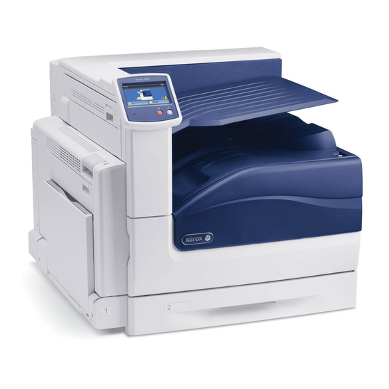
-
Contents
-
Table of Contents
-
Troubleshooting
-
Bookmarks
Quick Links
Xerox Phaser 7800
Color Printer
Imprimante couleur
Xerox
Phaser
7800
®
®
System Administrator Guide
Guide de l’administrateur système
Related Manuals for Xerox Phaser 7800
Summary of Contents for Xerox Phaser 7800
-
Page 1
Xerox Phaser 7800 Color Printer Imprimante couleur Xerox Phaser 7800 ® ® System Administrator Guide Guide de l’administrateur système… -
Page 2
© 2011 Xerox Corporation. All Rights Reserved. Unpublished rights reserved under the copyright laws of the United States. Contents of this publication may not be reproduced in any form without permission of Xerox Corporation. Copyright protection claimed includes all forms of matters of copyrightable materials and information now allowed by statutory or judicial law or hereinafter granted, including without limitation, material generated from the software programs which are displayed on the screen such as styles, templates, icons, screen displays, looks, and so on. -
Page 3: Table Of Contents
Configuring IP Settings in CentreWare Internet Services …………..22 SLP ……………………………….. 26 Configuring SLP …………………………26 SNMP ………………………………27 Enabling SNMP …………………………27 Configuring SNMPv1/v2c ……………………… 27 Configuring SNMPv3 ……………………….28 Configuring SNMP Advanced Settings ………………….29 Phaser 7800 Color Printer System Administrator Guide…
-
Page 4
Managing Host Groups ……………………….52 Managing Security Policies ……………………..53 Security Certificates …………………………54 Installing a Digital Certificate …………………….. 55 802.1X ………………………………58 Enabling and Configuring 802.1X in CentreWare Internet Services ……….58 Phaser 7800 Color Printer System Administrator Guide… -
Page 5
Enabling Banner Page Printing in CentreWare Internet Services …………66 Enabling Banner Page Printing in the Print Driver ………………66 UNIX, Linux, and AS/400 Printing …………………….. 67 Xerox® Services for UNIX Systems …………………… 67 Printing from a Linux Workstation ……………………. 68 Adding the Printer …………………………69 Printing with CUPS …………………………. -
Page 6
Printing Troubleshooting Guides and Test Pages or Viewing Fault History ……..87 Service Tools …………………………….. 88 Using Service Tools …………………………. 88 Customization and Expansion Driver Download Link …………………………90 Customizing or Hiding the Driver Download Link ………………90 Phaser 7800 Color Printer System Administrator Guide… -
Page 7: Introduction
Introduction This chapter includes: Overview ………………………………8 More Information …………………………..9 Phaser 7800 Color Printer System Administrator Guide…
-
Page 8: Overview
Configure Security. For details, see Security on page 41. Enable services in CentreWare Internet Services. For details, see Enabling Services. 10. Configure Accounting. For details, see Accounting. Note: Not all printer models support these features. Phaser 7800 Color Printer System Administrator Guide…
-
Page 9: More Information
A resource for tools and information, such as www.xerox.com/office/businessresourcecenter interactive tutorials, printing templates, helpful tips, and customized features to meet your individual needs. Local sales and support center www.xerox.com/office/worldcontacts Printer registration www.xerox.com/office/register ® Xerox Direct online store www.direct.xerox.com/ Phaser 7800 Color Printer System Administrator Guide…
-
Page 11: Initial Setup
This chapter includes: Physically Connecting the Printer ……………………..12 Initial Setup at the Control Panel ……………………..13 Initial Setup in CentreWare Internet Services …………………. 14 Physical Connection Settings ……………………….16 Phaser 7800 Color Printer System Administrator Guide…
-
Page 12: Physically Connecting The Printer
Connect one end of a Category 5 or better Ethernet cable to the Ethernet port on the back of the printer. Connect the other end of the cable to a correctly configured network port. Turn on the printer. Phaser 7800 Color Printer System Administrator Guide…
-
Page 13: Initial Setup At The Control Panel
Assigning a Network Address The printer automatically acquires a network address from a DHCP server by default. To assign a static IP address, configure DNS server settings, or configure other TCP/IP settings, see on page 21. Phaser 7800 Color Printer System Administrator Guide…
-
Page 14: Initial Setup In Centreware Internet Services
Restricted Access: Require users to log in as an administrator to access the listed tools and features on the control panel touch screen. To allow a Xerox representative to access restricted settings if the printer is being serviced, select Service Access.
-
Page 15: Configuration Report
In CentreWare Internet Services, click Properties > Description. Under Device Name, type a name for the printer. Under Location, type the location of the printer. Click Apply to save the new settings or Undo to retain the previous settings. Phaser 7800 Color Printer System Administrator Guide…
-
Page 16: Physical Connection Settings
Click USB Port. Under Connection, select Enabled to enable the USB port. Under Timeout, type the time in seconds that the printer waits inactive before disconnecting from a device connected to the port. Phaser 7800 Color Printer System Administrator Guide…
-
Page 17: Network Configuration
Microsoft Networking …………………………31 LPR/LPD ………………………………32 Raw TCP/IP Printing ………………………….. 33 SMTP Server …………………………….35 HTTP ………………………………. 36 Proxy Server …………………………….37 NTP ………………………………..38 WSD ……………………………….. 39 Phaser 7800 Color Printer System Administrator Guide…
-
Page 18: Appletalk
Under Zone Name, type a new zone name or use the default AppleTalk local zone. The default AppleTalk local zone is *. Click Apply to save the new settings or Undo to retain the previous settings. Click Default All to reset settings to default values. Phaser 7800 Color Printer System Administrator Guide…
-
Page 19: Netware
IPX internetwork. As servers start up and shut down, they can advertise and remove their services using SAP. Under Protocol, select Enabled. Under SAP Frequency, type the time in seconds between 15–300. The default time value is 60 seconds. Phaser 7800 Color Printer System Administrator Guide…
-
Page 20: Configuring Netware Bindery Settings
Type a name for the context. The default entry for this field is Xerox_DS_Context. If you are using bindery or bindery emulation, leave this field blank. Click Apply to save the new settings or Undo to retain the previous settings. Click Default All to reset settings to default values. Phaser 7800 Color Printer System Administrator Guide…
-
Page 21: Configuring Tcp/Ip Settings At The Control Panel
Select the Enable Manual IPv6 check box. To change the Prefix Length, touch Prefix Length and type the prefix length using the keypad. Touch OK. 10. Type the address using the keypad. 11. Touch OK. Phaser 7800 Color Printer System Administrator Guide…
-
Page 22: Configuring Ip Settings In Centreware Internet Services
IPv4 and IPv6 settings in CentreWare Internet Services, enable TCP/IP at the printer control panel. If you disable TCP/IP or change the IP address, any dependent protocols are disabled and the network controller restarts. Phaser 7800 Color Printer System Administrator Guide…
-
Page 23
IPv6. Options are: Use DHCP as directed by a router Always enable DHCP for address assignment and other configuration data Always enable DHCP for other configuration data only Never use DHCP Phaser 7800 Color Printer System Administrator Guide… -
Page 24
Under Remove this Device’s IPv6 DNS Registration at power down, select Enabled if necessary. This option allows the printer to release the current DCHP-assigned address and any DNS name when the printer is turned off. Phaser 7800 Color Printer System Administrator Guide… -
Page 25
12. Under Append Device Domain, select Enabled to add the domain of the printer to the Domain Name Search List. 13. Under Append Parent Domains, select Enabled to add the parent domains of the printer to the Domain Name Search List. 14. Click Apply. Phaser 7800 Color Printer System Administrator Guide… -
Page 26: Slp
The maximum MTU for IP over Ethernet is 1500 bytes. Click Apply to save the new settings or Undo to retain the previous settings. Click Default All to reset settings to default values. Phaser 7800 Color Printer System Administrator Guide…
-
Page 27: Snmp
Type a name up to 256 characters for the GET Community Name or use the default value of public. GET returns the password for the SNMP GET requests to the printer. Applications obtaining information from the printer using SNMP, such as CentreWare Internet Services, use this password. Phaser 7800 Color Printer System Administrator Guide…
-
Page 28: Configuring Snmpv3
The passphrase used to encrypt the data must match the passphrase on the Server. Note: The passwords must be at least 8 characters in length and can include any characters except control characters. Select the checkbox to save new password. Phaser 7800 Color Printer System Administrator Guide…
-
Page 29: Configuring Snmp Advanced Settings
Under Print Drivers/Remote Clients Account, click Account Enabled. To reset the default password, ® click Reset. This account allows Xerox clients and drivers limited access to objects on the printer. Click Save to apply the new settings or Undo to retain the previous settings.
-
Page 30: Ssdp
Under Time to Live, type a number between 1–60 router hops for discovery advertisement. The default number of hops is 4. Click Apply to save the new settings or Undo to retain the previous settings. Click Default All to reset settings to default values. Phaser 7800 Color Printer System Administrator Guide…
-
Page 31: Microsoft Networking
If desired, type an IP Address for a secondary server. Note: If DHCP is configured, WINS IP Addresses are overridden. Click Apply to save the new settings or Undo to retain the previous settings. Phaser 7800 Color Printer System Administrator Guide…
-
Page 32: Lpr/Lpd
This setting can cause jobs to print slowly but results in accurate banner page information. Click Apply to save the new settings or Undo to retain the previous settings. Phaser 7800 Color Printer System Administrator Guide…
-
Page 33: Raw Tcp/Ip Printing
Type the End of Job Timeout between 0–1800 seconds to specify the amount of time to pass before a job processes with an End of Job character. The default time is 300 seconds. Type 0 to disable end of job detection by timeout. Phaser 7800 Color Printer System Administrator Guide…
-
Page 34
Job data is not parsed when bidirectional communication and PDL switching are disabled. Click Apply to save the new settings or Undo to retain the previous settings. Click Default All to reset settings to default values. Phaser 7800 Color Printer System Administrator Guide… -
Page 35: Smtp Server
If you select System, type the Login Name and Password used to access the server. Enable Select to save new password to update the password for an existing Login Name. Click Apply to save the new settings or Undo to retain the previous settings. Phaser 7800 Color Printer System Administrator Guide…
-
Page 36: Http
If you are using the Default Xerox Device Certificate, you can install the Generic Xerox ® Trusted CA Certificate in your Web browser. Installing the Generic Xerox Trusted CA Certificate ensures that your browser trusts the printer. To download the certificate, click Download the Generic Xerox Trusted CA Certificate.
-
Page 37: Proxy Server
Select the Proxy Server address type. Options are IPv4 Address, IPv6 Address, or Host Name. Type the appropriately formatted address and port number. The default port number is 8080. Click Apply to save the new settings or Undo to retain the previous settings. Phaser 7800 Color Printer System Administrator Guide…
-
Page 38: Ntp
Address: Port. The default port number is 123. Click Apply to save the new settings or Undo to retain the previous settings. Note: Restart your printer for the new settings to take effect. Phaser 7800 Color Printer System Administrator Guide…
-
Page 39: Wsd
Click WSD (Web Services on Device). Under WSD Services, select Enabled. Select the check box next to the services that you want to enable. If necessary, type an alternate port number for each service to use. Click Apply. Phaser 7800 Color Printer System Administrator Guide…
-
Page 41: Security
Stored Data Encryption …………………………46 IP Filtering …………………………….47 IPsec ……………………………….. 49 Security Certificates ………………………….. 54 802.1X ………………………………58 Overwriting Image Data …………………………. 60 PostScript Passwords …………………………61 See also: www.xerox.com/security Phaser 7800 Color Printer System Administrator Guide…
-
Page 42: Setting Web Page Access Rights
For any pages that you want to lock, under State, select Locked. To lock all pages in CentreWare Internet Services, select the Lock icon. Click Apply. Click Yes to acknowledge the warning message. Phaser 7800 Color Printer System Administrator Guide…
-
Page 43: Secure Http (Ssl)
Ensure that the date and time configured on the printer is correct. The time that is set on the printer ® ® is used to set the start time for the Xerox Device Certificate. A Xerox Device Certificate is installed when you enable HTTP (SSL).
-
Page 44: Fips 140-2
Validates certificates for features where the printer is the client in the client-server relationship. CA certificates for LDAP, Xerox Extensible Interface Platform (EIP), and SMart eSolutions are examples. Validates certificates that are installed on the printer, but not used. Certificates for HTTPS, LDAP, or SNMPv3 are examples.
-
Page 45: Enabling Fips 140 Mode And Checking For Compliance
For each reason, a link is provided. Click the appropriate link to disable the protocol, replace the certificate, or allow the printer to use the non-compliant protocol. Note: When FIPS 140 Mode is enabled, only FIPS-compliant certificates can be installed on the printer. Phaser 7800 Color Printer System Administrator Guide…
-
Page 46: Stored Data Encryption
Click Apply to save the new settings or Undo to retain the previous settings. ® CAUTION: The printer restarts. This interrupts or deletes current jobs. Xerox recommends that you back up jobs and folders before enabling User Data Encryption. Phaser 7800 Color Printer…
-
Page 47: Ip Filtering
12. Restart your printer for the new settings to take effect. Editing an IP Filter Rule In CentreWare Internet Services, click Properties > Security. Click IP Filtering. Click an IP filter rule. Click Edit and edit the rule. Click Apply. Phaser 7800 Color Printer System Administrator Guide…
-
Page 48: Deleting An Ip Filter Rule
Arranging the Execution Order of IP Filter Rules In CentreWare Internet Services, click Properties > Security. Click IP Filtering. Click an IP filter rule. Under Move selected rule to position, select the position and click Move. Phaser 7800 Color Printer System Administrator Guide…
-
Page 49: Ipsec
Under Keying Method, select Manual Keying or Internet Key Exchange (IKE). Note: Select Manual Keying if client devices are not configured for or do not support IKE. If you selected IKE, under Pre-shared Key Passphrase, type the passphrase, then click Next. Phaser 7800 Color Printer System Administrator Guide…
-
Page 50
10. Type a 24-character ASCII key, or 48-character Hexadecimal key for the following: Encryption Key: IN Encryption Key: OUT 11. Click Save to apply the new settings or Undo to retain the previous settings. Phaser 7800 Color Printer System Administrator Guide… -
Page 51
10. Click Save to apply the new settings or Undo to retain the previous settings. Editing or Deleting an Action To edit or delete an action, select the action from the list, then click Edit or Delete. Phaser 7800 Color Printer System Administrator Guide… -
Page 52: Managing Protocol Groups
To continue to add addresses to the group, click Add. To delete addresses, next to any address, click Delete. Click Save to apply the new settings or Undo to retain the previous settings. Phaser 7800 Color Printer System Administrator Guide…
-
Page 53: Managing Security Policies
To prioritize policies, under Saved Policies, select the policy you want to move, then click the Promote or Demote buttons. Editing or Deleting a Security Policy To delete a policy, under Saved Policies, select the policy and click Delete. Phaser 7800 Color Printer System Administrator Guide…
-
Page 54: Security Certificates
Install a device certificate on the printer. ® Note: When you enable HTTPS, a Xerox Device Certificate is automatically created and installed on the printer. Install a copy of the CA certificate that was used to sign the device certificate of the printer on the other device.
-
Page 55: Installing A Digital Certificate
Creating a Xerox Device Certificate is less secure than creating a certificate signed by a ® trusted CA. If you do not have a server functioning as a Certificate Authority, install a Xerox Device ® Certificate on the printer. Then install the Generic Xerox Trusted CA Certificate on the other devices.
-
Page 56
Click Browse or Choose File, navigate to the signed certificate .crt file, then click Open or Choose. Click Next. Type a Friendly Name to help identify the certificate in the future. Click Next. The digital certificate appears in the list of Installed certificates. Phaser 7800 Color Printer System Administrator Guide… -
Page 57
To delete a certificate, select the check box next to the certificate name and click Delete. ® Note: You cannot delete the Default Xerox Device Certificate. ® Click Reset to Machine/Device Factory Defaults to delete all certificates except the Default Xerox Device Certificate. ® Installing the Generic Xerox Trusted CA Certificate ®… -
Page 58: 802.1X
EAP-MS-CHAPv2 EAP-TLS Note: When the printer is in FIPS 140 mode, EAP-TLS authentication is required. Under User Name (Device Name), type the user name required by your authentication switch and server. Phaser 7800 Color Printer System Administrator Guide…
-
Page 59
12. To save the new password, select the check box next to Select to save new password. A password is not required for EAP-TLS authentication. 13. Click Apply to save the new settings or Undo to retain the previous settings. Phaser 7800 Color Printer System Administrator Guide… -
Page 60: Overwriting Image Data
Under Type, select Full or Standard. CAUTION: If you select Full, the printer deletes all image data. Click Apply to save the new settings or Undo to retain the previous settings. Phaser 7800 Color Printer System Administrator Guide…
-
Page 61: Postscript Passwords
Under System Parameters Password, type a password. Retype the password to verify. Under Job Start Password, type a password. Retype the password to verify. Click Apply to save the new settings or Cancel to return to the previous screen. Phaser 7800 Color Printer System Administrator Guide…
-
Page 63: Printing
Printing This chapter includes: Saving and Reprinting Jobs ……………………….64 Managing Banner Page Printing Options ………………….. 66 UNIX, Linux, and AS/400 Printing ……………………..67 Phaser 7800 Color Printer System Administrator Guide…
-
Page 64: Saving And Reprinting Jobs
Deleting a Folder In CentreWare Internet Services, click Jobs > Saved Jobs. Click Manage Folders, then select a folder from the list. To delete a folder, select the folder and click Delete Folder. Phaser 7800 Color Printer System Administrator Guide…
-
Page 65: Saving And Printing Jobs
Under Printing, select the desired options for the job. Click Submit Job to print the document. Note: To ensure that the job was sent to the queue, wait for the job submission confirmation message to appear before you close this page. Phaser 7800 Color Printer System Administrator Guide…
-
Page 66: Managing Banner Page Printing Options
Click Banner Sheets, then click the down arrow and select Enabled or Disabled. Click OK. Note: If banner page printing is disabled in CentreWare Internet Services or at the control panel, setting the print driver to print banner pages is ignored. Phaser 7800 Color Printer System Administrator Guide…
-
Page 67: Unix, Linux, And As/400 Printing
NIS clients can then print to any of the queues listed on the server map without setting up local queues. For more information on how to set up NIS-based printing, see your UNIX or Linux operating system documentation. Phaser 7800 Color Printer System Administrator Guide…
-
Page 68: Printing From A Linux Workstation
Change to the directory created by the expansion of the Printer Definition .tgz file. Type ./setup then press Return or Enter. The installation creates a Xerox directory in /usr or /opt depending on your operating system. Launching XSUS To launch XSUS from a terminal window prompt as root, type xpadmin, then press Enter or Return.
-
Page 69: Adding The Printer
Xerox Support website. Copy the PPD into the CUPS ppd/Xerox folder on your workstation. If you are unsure of the location of the folder, use the Find command to locate the PPD files. Follow the instructions that are included with the PPD.
-
Page 71: Administrator Tools
Font Management Utility ……………………….. 81 Network Logs …………………………….82 Customizing Printer Contact Information ………………….83 Updating the Printer Software ………………………. 84 Calibration …………………………….86 Troubleshooting Tools…………………………87 Service Tools …………………………….88 Phaser 7800 Color Printer System Administrator Guide…
-
Page 72: Job Accounting
Enabling Job Accounting In CentreWare Internet Services, click Properties > Security. Click Job Accounting. Under Job Accounting Record, select Enabled. Click Apply. Phaser 7800 Color Printer System Administrator Guide…
-
Page 73: Monitoring Alerts And Status
The default time is 0 minutes. Click Apply to save the new settings or Undo to retain the previous settings. Phaser 7800 Color Printer System Administrator Guide…
-
Page 74
Click Apply to save the new settings or Undo to retain the previous settings. Notes: You can view the status on the Description & Alerts page under Status. To view current supplies status, click Status > Supplies. Phaser 7800 Color Printer System Administrator Guide… -
Page 75: Energy Saving Settings
To turn off the automatic transition, clear the Enable Energy Saver check box. The printer exits Energy Saver mode when it receives a print job, or when you press the Power Saver button. Phaser 7800 Color Printer System Administrator Guide…
-
Page 76: Modifying General Settings
Select the date and time format, and type the date and time in the appropriate fields. Select the Display 24 hour clock check box to show the time in 24 hour format. Under Time Zone, select your time zone from the drop-down menu. Click Apply. Phaser 7800 Color Printer System Administrator Guide…
-
Page 77: Restarting The Printer In Centreware Internet Services
If your printer is locked, type the system administrator user name and password to access the Properties tab. The administrator user name is admin and the default password is 1111. This procedure causes the printer to restart and be unavailable over the network for several minutes. Phaser 7800 Color Printer System Administrator Guide…
-
Page 78: Smart Esolutions And Billing Information
SMart eSolutions is not available in all countries. See your Xerox representative for details. Before you begin: Create an account on Xerox.com to receive your meter read information. To create an account, go to www.xerox.com/meterreads. Ensure that SNMP and TCP/IP are enabled.
-
Page 79: View Usage And Billing Information
The printer supply list appears with the current % Life Remaining of each supply. ® Note: If the % Life Remaining is zero, no data has been transmitted to Xerox View Usage and Billing Information Usage Counters The Usage Counters page displays the total number of pages printed or generated by the printer.
-
Page 80: Cloning
If View Feature Details is selected, the Install Clone File field does not appear. Click Hide Feature Details to see the Install Clone File field. Click Install. Note: This procedure causes the printer to restart and be unavailable over the network for several minutes. Phaser 7800 Color Printer System Administrator Guide…
-
Page 81: Font Management Utility
The CentreWare Font Management Utility allows you to manage fonts on one or more printers on your ® ® network. You can download the Xerox CentreWare Font Management Utility on the Xerox website at www.xerox.com/office/7800drivers. Use the utility to download soft fonts to your printer, such as your company branded fonts or unicode fonts to support multiple languages.
-
Page 82: Network Logs
Basic records a minimum list of network actions that have occurred on the printer. Enhanced records a detailed list of network actions that have occurred on the printer. Only use Enhanced logging when instructed to do so by a Xerox representative as it can cause increased job processing times. Touch OK.
-
Page 83: Customizing Printer Contact Information
You can customize this information to display your company contact information for printer users. To add your own custom information: In CentreWare Internet Services, click Support. Click Edit Settings. Update the fields with your information and click Save. Phaser 7800 Color Printer System Administrator Guide…
-
Page 84: Updating The Printer Software
Determine the current software version of your printer. ® Download the latest software update file in .dlm format from the Xerox support website at www.xerox.com/office/7800support. To determine the software version: In CentreWare Internet Services, click Properties > General Setup.
-
Page 85: Manually Updating The Software Using A Usb Flash Drive
Copy the software .dlm file to this directory. Insert the USB Flash Drive into the USB host port of the printer. The software upgrade process begins. When the software update completes, the printer restarts. Phaser 7800 Color Printer System Administrator Guide…
-
Page 86: Calibration
Color Calibration adjusts the printer to make corrections to color density and gray balance. Color Registration adjusts the printer to make corrections to blurry or hazy prints, or prints with color halos. Follow the onscreen instructions. Phaser 7800 Color Printer System Administrator Guide…
-
Page 87: Troubleshooting Tools
Resolve Problems allows you to select from a list of problems, and provides instructions to help you solve the problem. Test Pages allows you to print test pages for troubleshooting. Fault History lists recent errors that occurred on the printer. Phaser 7800 Color Printer System Administrator Guide…
-
Page 88: Service Tools
Service Tools are diagnostic, logging, and analysis tools, used primarily by a Xerox representative that services your printer. If you are troubleshooting a problem with a Xerox representative on the phone, you may be asked to use the Service Tools.
-
Page 89: Customization And Expansion
Customization and Expansion This chapter includes: Driver Download Link …………………………90 Phaser 7800 Color Printer System Administrator Guide…
-
Page 90: Driver Download Link
The driver installation link appears on the CentreWare Internet Services Welcome, Print, and Support pages. This link goes to the default driver and downloads page for your printer on the Xerox Support website. You can hide or customize this link to go to a location on your network where you post driver installation files for users.
-
11-19-2014
#1
Senior Tech
100+ Posts
- Rep Power
- 23
Xerox Phaser 7800DN error code? «389601 00»
had someone call us with a Phaser 7800DN and they say it has «389601 00» in the display.
is that some sort of «firmware» related type code maybe like on some of the HPs that goes away?
We looked at the same machine back in June for a problem recognizing one of the color toners. Ended up having a generic/aftermarket toner.
thanks.
looking on the regular Xerox customer website. I think it may have said 389.601.00
that looks like the format for some of the messages
-
11-20-2014
#2
Re: Xerox Phaser 7800DN error code? «389601 00»
It is a color calibration error. Clean the MOB sensor and check the transfer belt cleaning unit.
-
11-20-2014
#3
Senior Tech
100+ Posts
- Rep Power
- 23
Re: Xerox Phaser 7800DN error code? «389601 00»
thanks.
MOB- Mark On Belt sensor? for the transfer belt.
the Xerox customer website mentions upgrade the printer firmware and then they have some file that can be downloaded there. Does that go in to the machine directly like say the HP firmware does? Sort of loads automatically with prompts etc…
Last time we looked at this printer it had maybe 11,000 pages on it.
-
11-20-2014
#4
Re: Xerox Phaser 7800DN error code? «389601 00»
You can try a firmware upgrade. The latest general release does not address that error but it is something you can try that does not cost anything. The installation instructions are contained in the release notes that come with the firmware. If that does not work clean or replace the MOB sensor.


