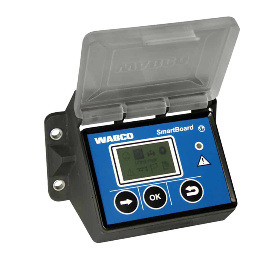
Отображение в SmartBoard.
Пример: код 002 05. 1-ый цифровой блок: компонент 002 — колесный датчик b. 2-ой цифровой блок: вид нарушения 05 — обрыв в питающем кабеле.
Коды сообщений.
Компонент: TEBS D.
Компонент: TEBS E (TEBS D/E).
Компонент IVTM.
Вид нарушения.
8
SmartBoard
8
8.1
Diagnostic messages
The messages always consist of four elements:
fig. 8-1:
Example for the «Messages» menu
1
The system that triggered the message
2
Current message: yes/no
3
The component concerned
4
The type of fault
In the example shown above, a message with the fol-
lowing content is displayed:
«Fault 05 (fault type: «Supply line interrupted») has oc-
curred at component 002 «Wheel sensor b») of TEBS E.
System Trailer EBS D: Component
Message Explanation
001
Wheel sensor a
002
Wheel sensor b
003
Wheel sensor c
004
Wheel sensor d
005
Wheel sensor e
006
Wheel sensor f
007/008
Trailer modulator
009
Trailer modulator / Solenoid control
010
EBS (ABS) Relay Valve
058/059
Trailer modulator
061
EBS relay valve
062
EBS relay valve / Pressure sensor
069
Axle load sensor
075
Wear sensor
076
No nominal value available
077
Desired-pressure sensor
078
Desired-pressure sensor external
081
Pneumatic control line
082
Pneumatic supply line
083
Supply pressure sensor
084
Electronic switch output 1
085
Electronic switch output 2
086
Electrical switch output 5 (IN/OUT 1)
088
Lateral acceleration sensor
50
Annex
Message Explanation
220
221
232
246
251
253
254
Table: 8-1: System Trailer EBS D, Messages Component
System Trailer EBS D: Type of fault
Message Explanation
00
01
02
03
04
05
05
07
08
09
11/12
13
14
15
Table: 8-2: System Trailer EBS D, Messages Fault Type
System Trailer EBS E: Component
Message Explanation
001
002
003
004
005
006
007
009
010
058
059
061
062
069
075
076
077
078
082
088
Data link towing vehicle/ Trailer
Trailer modulator / Sensor power supply 24V
Trailer modulator / Sensor power supply 5V
EBS-Trailer brake valve / Switch
Power supply
Parameter setting
Trailer modulator
Value too high
Value too low
Data is irregular or incorrect
Overvoltage / Short circuit to 24 V
Undervoltage/ Short circuit to ground
Permanent current consumption
Current too high
Air gap too big
Slip
Data reception fault
see failure note
Characteristic curve error
Special faults / See fault info
Residual pressure
Wheel sensor a
Wheel sensor b
Wheel sensor c
Wheel sensor d
Wheel sensor e
Wheel sensor f
EBS (ABS) relay valve / Solenoid control
Trailer modulator / Solenoid valve control H2
Trailer modulator/Solenoid valve control H1
EBS relay valve / Redundancy
EBS relay valve / Pressure sensor
Trailer modulator / Redundancy
Trailer modulator / Pressure sensors H1 / H2
Axle load sensor internal
Wear sensor
Failure of nominal value selection / Redundant
braking
Desired-pressure sensor internal
Desired-pressure sensor external
pneumatic supply line missing
Lateral acceleration sensor
-
Марат
- Сообщения: 6
- Зарегистрирован: Вс дек 06, 2009 3:59 pm
WABCO SMART BOARD
у меня тонар самосвал четырехосный пневмоподвеска управляется смарт боардом на экране исчез значок пневмоподвесла мигает сообщение код251 05 144 12 004 05 что означают эти коды я знаю но незнаю где находятся эти датчики и как устранить эти неполадки помогити если кто знает
-
KDAFSF33RUS
- Сообщения: 62
- Зарегистрирован: Вт сен 08, 2009 9:50 pm
- Откуда: Владимир
- Контактная информация:
Сообщение
KDAFSF33RUS »
Напиши расшифровку кода. Тогда будет ясно. Абс датчики там идут как: датчик колеса а-в-с-d. А это что за ошибки я не знаю. Нет распечатки кодов
-
Марат
- Сообщения: 6
- Зарегистрирован: Вс дек 06, 2009 3:59 pm
smartboard
Сообщение
Марат »
004 05 этот код колесного датчика 144 12 датчик питающего давления 251 05 напряжение питания а вот где находятся эти датчики я не знаю ![]()
-
Виталий
- Сообщения: 1085
- Зарегистрирован: Сб окт 18, 2008 10:47 pm
- Откуда: Киев
-
Контактная информация:
Re: wabco smart board
Сообщение
Виталий »
Марат писал(а):у меня тонар самосвал четырехосный пневмоподвеска управляется смарт боардом на экране исчез значок пневмоподвесла мигает сообщение код251 05 144 12 004 05 что означают эти коды я знаю но незнаю где находятся эти датчики и как устранить эти неполадки помогити если кто знает
Неплохо было б зайти на сайт тонара, там есть расшифровки всех кодов.
-

Рыба
- Сообщения: 106
- Зарегистрирован: Ср авг 13, 2008 7:57 pm
- Откуда: Украина г.Харьков

Сообщение
Рыба »
251-источник электропитания(Power supply),05-обрыв провода(Supply cable interruption).На выходе с тягача два плюса присутствуют?….Если всё нормально,проверяй кабель соединительный..A вообще,данные входного напряжения можно и в самом SmartBoardе найти,если в меню «покопаться»..В «Trailer info Display»….
-
Игорь.Кр
- Сообщения: 61
- Зарегистрирован: Чт сен 10, 2009 12:39 pm
- Откуда: Москва, Нагатино
- Контактная информация:

Сообщение
Игорь.Кр »
Доброго дня! нет ли у кого нибудь расшифровки кодов Smart Board Wabco, на сайте тонара не нашёл.
-
Игорь.Кр
- Сообщения: 61
- Зарегистрирован: Чт сен 10, 2009 12:39 pm
- Откуда: Москва, Нагатино
- Контактная информация:
Сообщение
Игорь.Кр »
Спасибо
-
Игорь.Кр
- Сообщения: 61
- Зарегистрирован: Чт сен 10, 2009 12:39 pm
- Откуда: Москва, Нагатино
- Контактная информация:
Сообщение
Игорь.Кр »
Приехал под вечер пятницы этот прицеп, разбираться буду в понедельник, ну а так на первый взгляд: подключен к американцу, через два запаралеленых преобразователя по 15а. на «доске» три ошибки:251 03,251 12, ну и 003 05,первые две настораживают, видимо к деньгам! ![]()
-
ROZEEN
- Сообщения: 18
- Зарегистрирован: Вс окт 28, 2012 9:01 pm
- Откуда: Краснодар
Re: WABCO SMART BOARD
Сообщение
ROZEEN »
Купил прицеп на котором установлен этот самый smart board. Есть функция контроля давления в шинах, но датчиков на колёсах нет. Тем не менее ругается, что одно колесо спущено. Как такое может быть?
И ещё вопрос: Можно ли стереть ошибки «висящие» в системе самостоятельно или нужен диагностический комп?
-
alek310
- Сообщения: 213
- Зарегистрирован: Ср апр 28, 2010 3:10 pm
- Откуда: россия,краснодар
- Контактная информация:
Re: WABCO SMART BOARD
Сообщение
alek310 »
Так перепрограммируйте блок,удалите датчики давления и в путь.
Вернуться в «Пневматическая подвеска»
Перейти
- WWW.TRUCK-DIAGNOST.COM
- ↳ ПОМОЩЬ ПЕРЕВОЗЧИКАМ. ТЕХНИЧЕСКИЕ КОНСУЛЬТАЦИИ
- ↳ ПОЛЕЗНАЯ ТЕХНИЧЕСКАЯ ИНФОРМАЦИЯ ДЛЯ ПЕРЕВОЗЧИКОВ
- ↳ Обучение диагностике грузовых автомобилей, автобусов, прицепов
- ↳ Техническая документация. Схемы.
- ↳ Оборудование для диагностики грузовиков, автобусов, прицепов
- ↳ Программное обеспечение для диагностики и чип-тюнинга
- ↳ Системы управления двигателями EDC — Electronic Diesel Control
- ↳ Топливные системы Common Rail
- ↳ Топливные системы с насос-форсунками PLD, PDE
- ↳ Топливные системы с ТНВД (рядными, ротационными)
- ↳ Системы снижения токсичности AdBlue, Denoxtronic, SCR, Bluetec, EAS и др.
- ↳ Система подготовки и подачи сжатого воздуха, ECAM, EAC, APM и др.
- ↳ Пневматическая тормозная система
- ↳ ABS/ASR — антиблокировочная и противобуксовочная системы
- ↳ EBS/EPB — электронно-пневматическая тормозная система
- ↳ Пневматическая подвеска
- ↳ ECAS/ELC — электронно-пневматическая подвеска
- ↳ Управление приводом сцепления
- ↳ Управление КПП: EPS, AS-Tronic, Opticruise, Optidriver, I-Shift и др.
- ↳ Бортовые компьютеры, координаторы: ZBR, VIC, FFR, COO и др.
- ↳ Электронные системы управления техническим обслуживанием
- ↳ Тахографы
- ↳ Автономные отопители WEBASTO, EBERSPACHER
- ↳ Диагностика и устранение неисправностей
- ↳ Ремонт электронных блоков управления
- ↳ Дополнительное оборудование
- ↳ Вопросы качества и гарантии
- ↳ Деловые контакты
- ↳ Вопросы, не подходящие к предложенным разделам
- ↳ Вопросы и предложения по работе форума WWW.TRUCK-DIAGNOST.COM
- ↳ Новости форума WWW.TRUCK-DIAGNOST.COM
Коды ошибок АБС Wabco. Чтение, стирание, диагностика по световым кодам
Диагностика системы АБС Wabco путем считывания кодов световых индикаторов неисправности АБС автомобилей ГАЗ.
- Схема АБС Wabco Валдай (ГАЗ-33104, ГАЗ-331041 и модификации).
- Схема АБС Wabco ГАЗ-3307-09 и ее модификации.
- Коды ошибок Wabco, отображаемые SmartBoard (трейлеры).
Точная идентификация и устранение неисправностей электрических компонентов тормоза с АБС требует, чтобы такие работы выполнялись специалистами, владеющими персональным компьютером, знанием основных концепций электротехники и пониманием простых электрических схем.
После поворота ключа системы запуска и переключателя приборов в положение «I» индикатор неисправности АБС должен загореться на некоторое время (2 — 5) с, а затем погаснуть, если блок управления не обнаружил ошибок тормоза АБС. При первом включении блока управления АБС индикатор неисправности АБС гаснет при достижении автомобилем скорости примерно 7 км/ч, если активных ошибок не обнаружено.
Если индикатор неисправности АБС не выключается, необходимо выполнить диагностику электрических компонентов тормоза АБС для выявления проблем. АБС не работает во время диагностики.
Для запуска режима диагностики поверните переключатель системы зажигания и приборов в положение «I». Нажмите диагностический переключатель ABS на 0,5-3 секунды.
После отпускания кнопки переключателя диагностики АБС индикатор неисправности АБС загорается на 0,5 секунды, указывая на то, что режим диагностики запущен. При этом, если блок управления АБС обнаруживает новую ошибку, появившуюся при считывании, или если диагностическая клавиша нажата более 6,3 секунд, система выходит из режима диагностики. При нажатии диагностического переключателя АБС более 15 секунд обнаруживается прерывание индикатора неисправности АБС.
Если при переводе переключателя системы зажигания и приборов в положение «I» была обнаружена только одна активная ошибка, блок управления АБС выдаст только эту ошибку. Если зарегистрировано несколько активных ошибок, блок управления ABS выдаст только последнюю зарегистрированную ошибку.
Если при переключении выключателя системы пуска и приборов не обнаружено активных ошибок, при включении режима диагностики будут отображаться ошибки, которых нет в системе в данный момент (пассивные ошибки). Пассивный режим вывода ошибок заканчивается после вывода последней ошибки, записанной в памяти электронного блока.
Ошибки отображаются на индикаторе неисправности АБС следующим образом:
Загорание индикатора неисправности АБС на 0,5 секунды: подтверждение запущенного режима диагностики.
- Пауза 1,5 секунды.
- первая часть кода ошибки.
- Пауза 1,5 секунды.
- 2-я часть кода ошибки.
- Пауза 4 секунды.
- первая часть кода ошибки.
- и т. д…
Для выхода из режима диагностики поверните выключатель системы зажигания и приборы в положение «0».
Автоматическая отладка.
Сохраненная ошибка автоматически удаляется из памяти, если в течение следующих 250 часов в этом компоненте системы не возникало ошибок.
Сброс ошибок с помощью диагностического переключателя ABS.
Сброс ошибок происходит только при отсутствии текущих (активных) ошибок.
Чтобы сбросить ошибки, сделайте следующее:
- Переведите переключатель приборов и системы зажигания в положение «I».
- Нажмите кнопку диагностического переключателя ABS на 3–6,3 секунды.
- Пауза 1,5 секунды.
- 8 быстрых вспышек диагностической лампы свидетельствуют об удалении ошибок из памяти блока управления АБС.
- Пауза 4 секунды.
- 3 мигания диагностической лампы указывают на правильную настройку ABS.
- Переведите переключатель приборов и системы зажигания в положение «0».
- Замените системный переключатель.
| Код первой ошибки | Второй код ошибки | Методы устранения неполадок |
| 1 — нет ошибок | 1 — нет ошибок | Система полностью функциональна |
| 2 — модулятор АБС | 1 — правый передний 2 — левый передний 3 — правый задний 4 — левый задний |
Проверьте провода к модулятору. В проводах к впускным, выпускным клапанам, либо в «общем» проводе постоянный или исчезающий обрыв, либо замыкание на «минус”. |
| 3 — датчик: увеличенный воздушный зазор | 1 — правый передний 2 — левый передний 3 — правый задний 4 — левый задний |
Проверьте биение ступичного подшипника. Переместите датчик к ротору. Проверьте кабель датчика и разъемы на наличие ослабленных контактов. |
| 4 — датчик: короткое замыкание/обрыв провода | 1 — правый передний 2 — левый передний 3 — правый задний 4 — левый задний |
Проверь провода к датчику. Обрыв или короткое замыкание на «минус» или «плюс» или между проводами датчика. |
| 5 — потеря сигнала / размер шин | 1 — правый передний 2 — левый передний 3 — правый задний 4 — левый задний |
Проверьте провода к датчику на отсутствие контакта. Проверьте ротор на наличие повреждений. Подключите другой датчик для проверки. Диаметры колес разные. |
| 6 — ротор | 1 — правый передний 2 — левый передний 3 — правый задний 4 — левый задний |
Проверьте ротор на наличие повреждений. Замените ротор. |
| 7 — функции системы | 4 — лампа АБС | Проверьте провода к индикатору неисправности АБС. Выключатель диагностики ABS был нажат более 16 секунд? |
| 8 — электронный блок | 1 — низкое напряжение питания | Проверьте предохранители АБС и силовые цепи. Пониженное напряжение питания |
| 8 — электронный блок | 2 — напряжение питания повышено | Проверьте аккумулятор и генератор. Повышенное напряжение питания |
| 8 — электронный блок | 3 — внутренняя ошибка | Замените блок управления ABS, если ошибка сохраняется |
| 8 — электронный блок | 4 — ошибка конфигурации | Электронный блок/неправильная параметризация |
| 8 — электронный блок | 5 — соединение с «минусом» аккумулятора | Проверить «массу» в блоке управления АБС и в модуляторах. |
- Manuals
- Brands
- WABCO Manuals
- Control Panel
- SMARTBOARD
- Manual
-
Contents
-
Table of Contents
-
Bookmarks
Quick Links
SmartBoard
System Description
Related Manuals for WABCO SmartBoard

Summary of Contents for WABCO SmartBoard
-
Page 1
SmartBoard System Description… -
Page 3
SmartBoard System Description Edition 3 This publication is not subject to any update service. You will find the latest version in INFORM www.wabco-auto.com © 2010 The right of amendment is reserved. Version 2/06.2010(en) 815 020 136 3… -
Page 4: Table Of Contents
SmartBoard Table of Contents 1 Important instructions and safety instructions Measures for avoiding electro-static charge and uncontrolled discharging (ESD) 2 Introduction SmartBoard for ADR (GGVS) vehicles 3 System Description System configuration System prerequisites 4 Operation and Functions Switching On / Off…
-
Page 5
Table of Contents SmartBoard 6.4.2 Updating the internal operating software of the SmartBoard 6.4.3 Download of the «Splash Image» 6.4.4 SmartBoard system plate 7 Workshop instructions Pin assignment EBS parameters «Battery almost empty» indication Replacing the battery Care and Cleaning… -
Page 6: Important Instructions And Safety Instructions
These safety instructions must be observed to avoid personal injury or material loss. WABCO only guarantees the safety, reliability and performance of its products and systems if all instructions, notes and safety instructions in this document are ob- served.
-
Page 7: Measures For Avoiding Electro-Static Charge And Uncontrolled Discharging (Esd)
– Use electrically conductive bolted connections when fastening the ECUs to the vehicle frame. – Use only cable conforming to WABCO specifications or WABCO original cable. – Run the cable in metallic casing if at all possible (e. g. inside the U-beam) or behind metallic and grounded protective plating, to minimize the influence of electro-magnetic fields.
-
Page 8: Introduction
Display of selected operating data (ODR) and the measured values of the brak- ing system It therefore serves as a universal information and control system for implementing efficient trailer vehicle operation. A SmartBoard can be used to replace the following separate display and control units: • Odometer Status •…
-
Page 9: Smartboard For Adr (Ggvs) Vehicles
Introduction SmartBoard The SmartBoard is designed to be mounted on the outside of the vehicle frame with a connection to Trailer EBS D or E. SmartBoard for ADR (GGVS) vehicles WABCO have developed a new SmartBoard version that allows trailers that carry dangerous goods to take advantage of SmartBoard functions.
-
Page 10: System Description
System Description System Description System configuration As standard, the SmartBoard is operated in combination with Trailer EBS and dis- plays the data transmitted by Trailer EBS. The SmartBoard is connected to Trailer EBS. The tyre pressure monitoring system IVTM and the BVA (brake lining wear indicator) are connected to Trailer EBS and so transmit their data to the SmartBoard via the Trailer EBS.
-
Page 11: System Prerequisites
SmartBoard is not available, the corresponding menu item or symbol is not displayed. The SmartBoard is used in combination with the Trailer EBS D or E as of genera- tion D Premium (480 102 014 0). The software version of the SmartBoard is shown in the menu <Tools> <System Info>…
-
Page 12
If Trailer EBS D Premium is used, the internal EBS connection (where the 7-pin ISO cable is not odometer of the SmartBoard can only be used plugged in), or with EBS connection for tamper- if an ABS sensor is also connected (see proof total distance indication. -
Page 13
Operating Data Recorder (ODR) data, support for TEBS modulator replacement, as well as SmartBoard settings. Since the display may be illegible under –20° C, WABCO recommends using the SmartBoard only in regions with temperatures ranging above –20° C. Trailer EBS E system description Open the WABCO website www.wabco-auto.com. -
Page 14: Operation And Functions
SmartBoard. Switching On / Off To be able to use the SmartBoard, it must be supplied with power via the 5-pin or 7-pin plug connection according to ISO 7638 or a battery supply connected on the Trailer EBS E modulator.
-
Page 15: Key Assignment
Operation and Functions SmartBoard Key assignment Individual keys have the same function throughout the entire menu structure. Function Selection of the next menu item (e.g. symbol or text) or the next option <Arrow right>: Confirmation and / or execution of the currently selected function <OK>…
-
Page 16
SmartBoard Operation and Functions fig. 4-2: Menu structure of main menu (1/2) fig. 4-3: Menu structure of main menu (2/2) -
Page 17: Functions
Operation and Functions SmartBoard Functions The SmartBoard provides a wide range of functions that can be accessed via sym- bols from the main menu. The chapters below describe the various functions. The following rules apply: • If a system is not available and no information can be retrieved from it, the cor- responding menu symbol is not displayed.
-
Page 18: Immobilizer
The PUK is reserved only for the end user. Handle the PUK with care and protect it from access to third-parties and unauthorized persons. Store the PUK in a safe location. WABCO will not be held responsible for the loss or misuse of the PUK. –…
-
Page 19
Operation and Functions SmartBoard Button <OK>: Selecting numbers 0 … 9 Button <Arrow right>: Jump to the next digit position. Button <Back>: Confirmation of input After entering the correct PIN, a confirmation window appears. If the vehicle was been locked, the window «Activated immobilizer» appears. The driver is also notified of the activated immobilizer by a continuous flashing of the yellow warning light in the tow vehicle (with ignition ON). -
Page 20: Brake Lining Wear Indication (Bva)
In addition, a message can also be shown in the display. The warning thresholds can be set in the SmartBoard. WABCO suggestion for a 3-axle semitrailer with 9 t axle load on each axle. • The initial warning threshold is to be set to a 8 t axle load: When there is an axle load of 8 t, the menu item «axle load»…
-
Page 21: Tyre-Pressure Monitoring
Operation and Functions SmartBoard Notation Size Configuration Total axle load Total of the separate axle Trailer EBS D/E Modula- loads. Axle 1 to axle n Axle loads of the separate Trailer EBS E Modulator axles. With drawbar trailers, the axle load information is only displayed if second pressure sensor is installed.
-
Page 22: Air Suspension
SmartBoard Operation and Functions Messages are only output via warning LEDs and flashing menu items if the «Event LED» functions is activated (see page 33). Current messages are displayed first, then the messages that are no longer cur- rent. When a current message is present, the menu item for this functional group flashes in the main menu and the warning LED also flashes.
-
Page 23
/ unloading by opera- for the time period set in the parameters. tion If the operator exits the SmartBoard air suspen- sion menu, stand-by operation is cancelled pre- maturely. 4.4.7.1 Manoeuvring aid, drawbar load reduction Manoeuvring aid OptiTurn™… -
Page 24
The menu for controlling the manoeuvring aid and the drawbar load reduction is called up via menu <Air Suspension>, menu point <Manoeuvring aid> Manual control The SmartBoard is used as a switch in manual control. The function is activated or deactivated with the <OK> button. Notation… -
Page 25: Relaxation Function
Controlling automatic functionality If automated functionality is activated in the Trailer EBS E1, the icon «Auto» will be shown in the <Manoeuvring aid> menu in SmartBoard: The «Automatic» mode is activated or deactivated with the <Right arrow> button. By pressing the <OK> button, the function can also be activated manually e. g. to actuate the OptiLoad function while the vehicle is at a standstill.
-
Page 26: Brake Release Function
V > 1.8 km/h. A TÜV certificate for the brake release function can be obtained from the product catalogue INFORM on the Internet at www.wabco-auto.com by entering the prod- uct number or the index words “SmartBoard“ or “certificate“. 4.4.10 Road Finisher Brake The road finisher brake serves to brake tipper body vehicles when operating be- hind road finishers.
-
Page 27: Vehicle Inclination
10 km/h, and the tipping body must be raised (limit switch or roller sensor on the tipping body). The function is deactivated again via the Smartboard (road finisher brake ON/OFF) or at a speed exceeding 10 km/h. A further setting in the Finisher brake menu per- mits setting the nominal braking pressure for the finisher brake by means of the +/- buttons.
-
Page 28: Language
4.4.13 Language The language for the SmartBoard is selected in this functional group. The SmartBoard is equipped with a language package. The language package can be changes in the Diagnostic Software (see chapter 6.4 «Diagnostic Software „SmartBoard“», page 45).
-
Page 29: Tools
Notation Description TEBS data Service information and functions such as measured values and ODR data. System Info System information about the SmartBoard and available systems. Settings Adjusting the SmartBoard settings. AutoConfig Automatic adjustment of the main menu to the system configuration.
-
Page 30
SmartBoard Operation and Functions Position Information Description Note Braking Braking pressure of the TEBS pressure c, modulator, axle c, d Braking Braking pressure of the EBS Only available in pressure e, relay valve. 4S /3M systems. Bellows Bellow pressure, axle e, f… -
Page 31
Write parameters Restoring previous Trailer This menu is activated when EBS parameters. the SmartBoard is connected to a new Trailer EBS modu- lator. 4.4.14.2 System Info System The key <Arrow right> is used to navigate through the different systems. -
Page 32
(not in the ADR version 446 192 111 0). Part no. WABCO part number SW-version ECU software version. 4.4.14.3 Settings System of units Press <OK> to activate. The currently applied system of units is marked by a ●. -
Page 33
The key <Arrow right> is used to switch between the different options. Press <OK> to apply the changes. The driven distance is counted and displayed by the SmartBoard. This information can also be retrieved with the «Auto Config» function from the Trailer EBS Modula- tor (see chapter 4.4.14.4 «Auto Config», page 36). -
Page 34
– Attach a clearly marked note on the steering wheel saying that work is being performed on the vehicle and that the brake must not be touched. The SmartBoard makes it possible to calibrate the pressure sensors for the axle load display of the Trailer EBS E (see chapter 4.4.4 «Axle load indication», page 20). -
Page 35
Prerequisites • Trailer EBS E1 with software version TE14013 • SmartBoard with software as of version SB010207 • With drawbar trailers, another pressure sensor must be installed on the axle that brakes via the 3rd modulator. While calibrating, the parking brake and the service brake must be released. -
Page 36
SmartBoard Operation and Functions If all lift axle(s) are lowered, the calibration is continued. – Select menu point <Front axle>. – Select menu point <Calibrate unladen> and enter the weight of the front axle of the unladen drawbar-trailer. Button <Arrow right>: Changes the digit position Button <OK>: Changing the value… -
Page 37: Output Of Messages
SmartBoard is fitted intro a different trailer or a system is not applicable. For further information see chapter 4.6.2 «Configuration of the main menu», page 39.
-
Page 38
SmartBoard Operation and Functions • Axle load indication Loading exceeds the set limit value. When the first limit value is exceeded, the menu item «Axle load» flashes in the display. When the second limit value is ex- ceeded, the menu item «Axle load» and the warning LED flashes (only in the case of 15) in the display. -
Page 39: Extended Settings
SmartBoard. This image is then displayed for one second when the software is started. A start screen template and a WABCO suggestion for editing the file is available for download at: www.wabco-auto.com <Service & Support> <Download-Center> <SmartBoard Splash Image Example>.
-
Page 40: Assembly And Installation
The workplace has to be dry, as well as sufficiently lit and ventilated. – Make sure that you install the ADR version (446 192 111 0) of the SmartBoard in ADR vehicles (see chapter 2.1 «SmartBoard for ADR (GGVS) vehicles», page 9).
-
Page 41
SmartBoard 446 192 110 0 Tyre pressure monitoring (IVTM) 446 220 014 0 Distribution box SmartBoard connection to Trailer EBS D (circuit diagram 841 802 155 0 / 159 0) The SmartBoard is connected to connection SUBSYSTEMS of the Trailer EBS E modulator. -
Page 42: Start-Up
ABS sensor connection to the SmartBoard (only required with Trailer EBS D) To operate the odometer counter of the SmartBoard in combination with Trailer EBS D, an ABS sensor must be wired to the SmartBoard using a Y-cable. Connect the cable ends in a junction box according to the diagram.
-
Page 43: Diagnosis
The diagnosis is performed via the diagnostic port of the Trailer EBS E or the ISO plug-in connection via CAN. For this purpose, the SmartBoard must be connected to the Trailer EBS and the vehicle must be supplied with power via the ABS socket.
-
Page 44: Hardware
Diagnostic Interface Set To set up the diagnosis, the WABCO Diagnostic Interface Set with order number 446 301 030 0 (USB connection) is required. The set contains the Diagnostic Inter- face and a USB connecting cable to the PC or laptop.
-
Page 45: Diagnostic Software «Smartboard
In the <Language> menu, the language package A or B can be selected (see chapter 4.4.13 «Language», page 28). • To save these settings in the SmartBoard, select the <Write to ECU> button. • The settings can also be saved in a parameter file on a PC.
-
Page 46: Updating The Internal Operating Software Of The Smartboard
Updating the internal operating software of the SmartBoard The menu item <Download Application> from the <System> menu can be used to update the operating software of the SmartBoard. The software is provided in the form of a file. This file can be selected using the button <Read from file>. The button <Write to ECU>…
-
Page 47: Workshop Instructions
<Read parameters>. The commissioning test must be performed after the parameter set has been read into a modulator. The vehicle must be taken to a WABCO Service Centre as soon as possible for this purpose.
-
Page 48: Battery Almost Empty» Indication
The SmartBoard has a replaceable battery. The battery status can be accessed via the menu <Extras> <System Info> <SmartBoard>. If the capacity of the battery is depleted, the SmartBoard can only be used if it is powered from a power supply provided in the towing vehicle.
-
Page 49: Electronic Media Durability
Workshop instructions SmartBoard Electronic media durability • Approved for exterior installation Class «Zd» • Electronic media durability according to prior consultation…
-
Page 50: Annex
SmartBoard Annex Message Explanation Annex Data link towing vehicle/ Trailer Trailer modulator / Sensor power supply 24V Diagnostic messages Trailer modulator / Sensor power supply 5V EBS-Trailer brake valve / Switch The messages always consist of four elements: Power supply…
-
Page 51
Annex SmartBoard Message Explanation Message Explanation Proximity switch Pneumatic control line Freely configurable function 8 Supply pressure sensor Freely configurable function 7 external ELM Freely configurable function 6 external ECAS Freely configurable function 5 internal ECAS / Calibration Freely configurable function 4… -
Page 52
SmartBoard Annex Message Explanation Message Explanation 3011 Pressure in tyre on axle 1, outer wheel left 3142 Leakage at tyre or valve on axle 4, inner wheel left 3012 Pressure in tyre on axle 1, inner wheel left 3143 Leakage at tyre or valve on axle 4, inner wheel… -
Page 53: Technical Data
Annex SmartBoard Technical data Property Value Protection class The SmartBoard complies with protection class IP6k9k according to DIN 40050-9 (1993-05) even when the cover is open. Certificates e1*72/245*2006/28*4968*00 Operating volt- 12–24 V DC Battery life approx. 5 years…
-
Page 54: Circuit Diagrams
SmartBoard Annex Circuit diagrams Circuit diagram 841 801 913 0: Trailer EBS D…
-
Page 55
Annex SmartBoard Circuit diagram 841 802 155 0: Trailer EBS E… -
Page 56: Drilling Template
SmartBoard Annex Drilling template…
-
Page 58
(NYSE: WBC) is a leading supplier of Belgium. For more information, visit www.wabco-auto.com safety and control systems for commer- cial vehicles. For over 140 years, WABCO has pio- neered breakthrough electronic, me- chanical and mechatronic technologies for braking, stability, and transmission automation systems supplied to the world’s leading commercial truck, trailer,…