Self diagnosis
Perkins electronic motors are capable of self-diagnosis. When the system registers an active problem, the diagnostic lamp is activated. In this case, the diagnostic codes will be stored in
read-only memory (ROM) of the electronic control module ECM. Diagnostic codes can be retrieved using the electronic service tool. For more information, see the chapter Troubleshooting, Electronic
Service Tools.
Some installations with electronic displays have the ability to directly read engine diagnostic codes. For more information on retrieving diagnostic codes, see the manual supplied by the OEM
(original equipment manufacturer), as well as the Troubleshooting chapter, “Warning Lights” section.
Active codes indicate problems that currently exist. These problems must be investigated first.
Registered codes display the following:
· Occasional malfunctions
· Registered Events
· History of operation
Problems can be fixed since the registration of the code. These codes do not indicate the need for repair, they are landmarks or signals when events occur. Also, these codes can be helpful in
solving troubleshooting problems.
After resolving the problem, it is necessary to clear the corresponding registered failure codes.
Diagnostic Lamps
The diagnostic lamp indicates the existence of an active failure. You can find more detailed information in the chapter Troubleshooting, section “Warning lights”. While resolving an existing
problem, the fault diagnosis code will remain active. This diagnostic code can be retrieved using the electronic service tool. You can find more detailed information in the Troubleshooting
chapter, Electronic Service Tools section.
Diagnostic Lamp
Use the Diagnostic lamp or electronic service tool to determine the diagnostic flashing code.
If the engine is equipped with a Diagnostic lamp, use the following algorithm to retrieve the blink code:
1. Change the position of the switch from on / off 2 times within 3 seconds.
The flashing yellow light indicates the digital engine code. The flashing sequence is a diagnostic message from the system. To determine the first digit of a blink code, count the number of
blinks in the first sequence. After a two second pause, the second flashing sequence determine the second digit of the flashing code. And finally, after a second pause, the third blink sequence
will determine the blink code.
Any additional codes will follow after a pause and displayed in the same way. Flashing code 551 means that since the ignition key was turned to the ON position, no faults were recorded.
111 Failure nozzle number 1
112 Nozzle Failure # 2
113 Failure nozzle number 3
114 Nozzle No.4 Failure
115 Failure nozzle number 5
116 Nozzle No.6 Failure
133 Failure of the air temperature sensor in the inlet pipe (5)
135 Failure boost pressure sensor in the inlet pipe
141 Failure of the main speed / motor timing sensor
142 Auxiliary engine speed / timing sensor failure
143 Engine Timing Calibration Failure
144 Engine Operation Mode Switch Failure
154 Throttle Position Sensor Failure
155 Auxiliary throttle position sensor failure
157 Engine oil pressure sensor failure
159 Fuel Rail Pressure Sensor Failure
162 Fuel Rail Pressure Valve Solenoid Failure
168 Engine Coolant Temperature Sensor Failure
177 Failure of the exhaust gas damper actuator (boost pressure regulator)
199 Spark Plug Trigger Failure
415 Software mismatch
422 ECM Power Outages
439 Ignition key failure
514 Data Link Damage SAE J1939
516 Sensor DC Power Failure
517 Sensor DC Power Failure (8 V)
527 System Parameter / User Parameter Error
![]()
Perkins
Product
Training
1300 Edi Series
Electronic Engine Training
|
Product Training Sept 2004 |
@Perkins |
|
Proprietary Information of Perkins Engines Company Limited 2004 — All Rights Reserved |

Please Note:
zThe Product Training information is distributed for informational purposes only. It is not to be construed as creating or becoming part of Perkins Engines contractual or warranty obligations.
zThe appropriate service literature and ‘Service Bulletins’ available on www.perkins.com should always be the final authority and source of information.
zElectrical Circuits, connections and termination points may change, make sure you have the correct drawings.
|
Product Training Sept 2004 |
@Perkins |
|
Proprietary Information of Perkins Engines Company Limited 2004 — All Rights Reserved |
‘Off Road’ Emissions Legislation
Tier 0
«A» rated engines can be used in regions without Emissions Legislation.
Tier 1
«B» rated engines are suitable for regions with Tier 1/Stage I Emissions Legislation
Tier 2
«C» rated engines are suitable for regions with Tier 2/Stage II Emissions Legislation.
Tier 3
«D» rated engines are suitable for regions with Tier 3/Stage III Emissions Legislation.
|
Product Training Sept 2004 |
@Perkins |
|
Proprietary Information of Perkins Engines Company Limited 2004 — All Rights Reserved |

‘Off Road’ Industrial — Ever Cleaner Engines
|
0.50 |
|||||||
|
0.45 |
|||||||
|
0.40 |
Tier 3: 56≤kW<75 |
||||||
|
1980’s |
|||||||
|
0.35 |
|||||||
|
PM |
0.30 |
Tier 3: 75≤kW<130 |
Particulate Matter |
||||
|
(g/kWh) |
(PM) 0.6g/kWh |
||||||
|
0.25 |
|||||||
|
0.20 |
Tier 3: 130≤kW<560 |
||||||
|
Nitrous Oxide |
|||||||
|
0.15 |
Tier 4B: 56≤kW<560 |
||||||
|
(NOx) 10.00g/kWh |
|||||||
|
0.10 |
Tier 4A: 56≤kW<130 |
||||||
|
Tier 4A: 130≤kW<560 |
|||||||
|
0.05 |
|||||||
|
0 |
|||||||
|
0 |
1 |
2 |
3 |
4 |
5 |
6 |
|
|
NOx; NOx + HC (g/kWh) |
|
Product Training Sept 2004 |
@Perkins |
|
Proprietary Information of Perkins Engines Company Limited 2004 — All Rights Reserved |

Electronic Engine Benefits
Electronic Engine Management system gives:
zImproved Specific Fuel Consumption (SFC) through precise control of Injection Timing and Duration.
zMachine protection under extreme operating conditions.
zEasy servicing and fault diagnostics, Electronic Service Tool, (EST)
zExceeds emissions legislation and has a lower noise level.
zBetter engine ‘responsiveness’.
zImproved reliability,engine monitoring and protection.
zFurther cost savings through integration into ‘Genset’ design (CAN)
zImproved torque, different torque curves available, torque ‘shaping’
zRating changes available, Base Load, Prime, Standby, 1500/1800
zConfiguration files, gives the customer flexibility, droop, etc
|
Product Training Sept 2004 |
@Perkins |
|
Proprietary Information of Perkins Engines Company Limited 2004 — All Rights Reserved |
|
Product Training Sept 2004 |
@Perkins |
|
Proprietary Information of Perkins Engines Company Limited 2004 — All Rights Reserved |
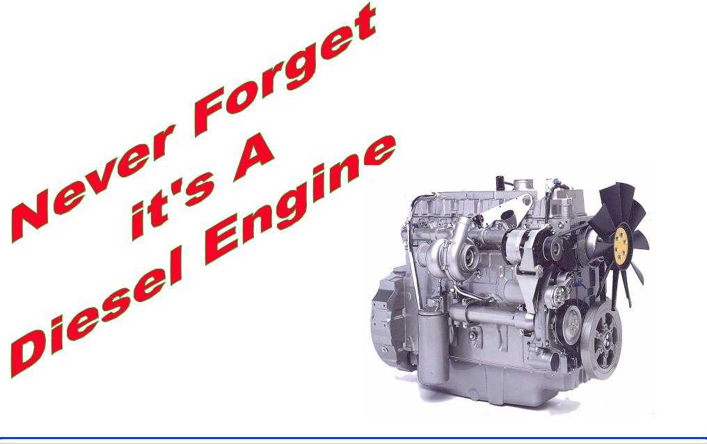
Electronics gives control! It needs a good flow of ; Clean Air and Fuel.
Also needs Compression!
|
Product Training Sept 2004 |
@Perkins |
|
Proprietary Information of Perkins Engines Company Limited 2004 — All Rights Reserved |
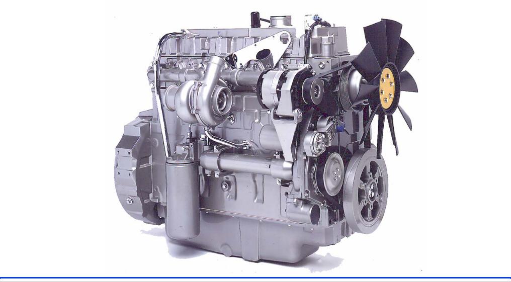
1300 Edi Series-Industrial Open Power Unit
|
Product Training Sept 2004 |
@Perkins |
|
Proprietary Information of Perkins Engines Company Limited 2004 — All Rights Reserved |
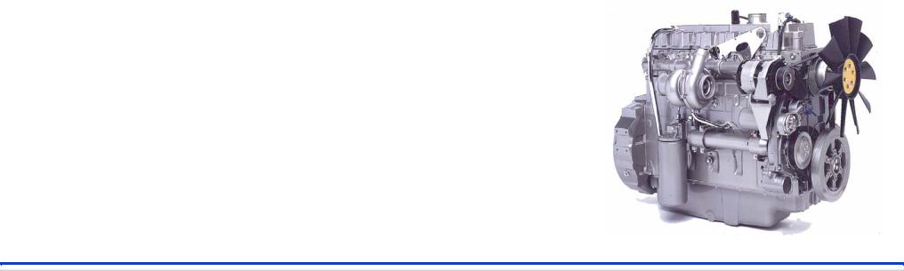
1300 Edi Series-Industrial Open Power Unit
zIOPU 1 -Variable Speed Droop, with analogue throttle and Idle validation switch. (mobile applications)
zIOPU 2 — Variable Speed Isochronous with analogue hand throttle, (no IVS — non Mobile Applications)
zIOPU 3 — Variable Set Speed Isochronous Control.
zIOPU 4 — With Pre-Set Speed Isochronous Control.
z12 Volt and 24 Volt ECM’s available.
If you are not sure of the voltage and markings have been removed check PIN 35 to ground 1.4K Ohms – 12 volts / 2.8K Ohms – 24 volts.
|
Product Training Sept 2004 |
@Perkins |
|
Proprietary Information of Perkins Engines Company Limited 2004 — All Rights Reserved |
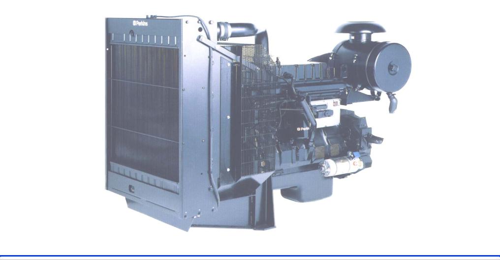
1300 Edi Series-Electropack
|
Product Training Sept 2004 |
@Perkins |
|
Proprietary Information of Perkins Engines Company Limited 2004 — All Rights Reserved |
![]()
1300 Edi Series-Electropack
z 1500/50 Hertz, can be wired 3 ways,
(auto or manual, (load share) or stand alone, (isochronous)
z 1800/60Hertz, can be wired 3 ways
(auto or manual, (load share) or stand alone, (isochronous)
z 1500/1800 Switchable, can be wired 2 ways
1500 or 1800, Isochronous Only
z 12 Volt and 24 Volt ECM’s available.
If you are not sure of the voltage and the markings have been removed check PIN 35 to ground 1.4K Ohms – 12 volts / 2.8K Ohms – 24 volts.
|
Product Training Sept 2004 |
@Perkins |
|
Proprietary Information of Perkins Engines Company Limited 2004 — All Rights Reserved |

2 Ratings
1306-E87T
1 Rating
6 Ratings
1306-E87TA
4 Ratings
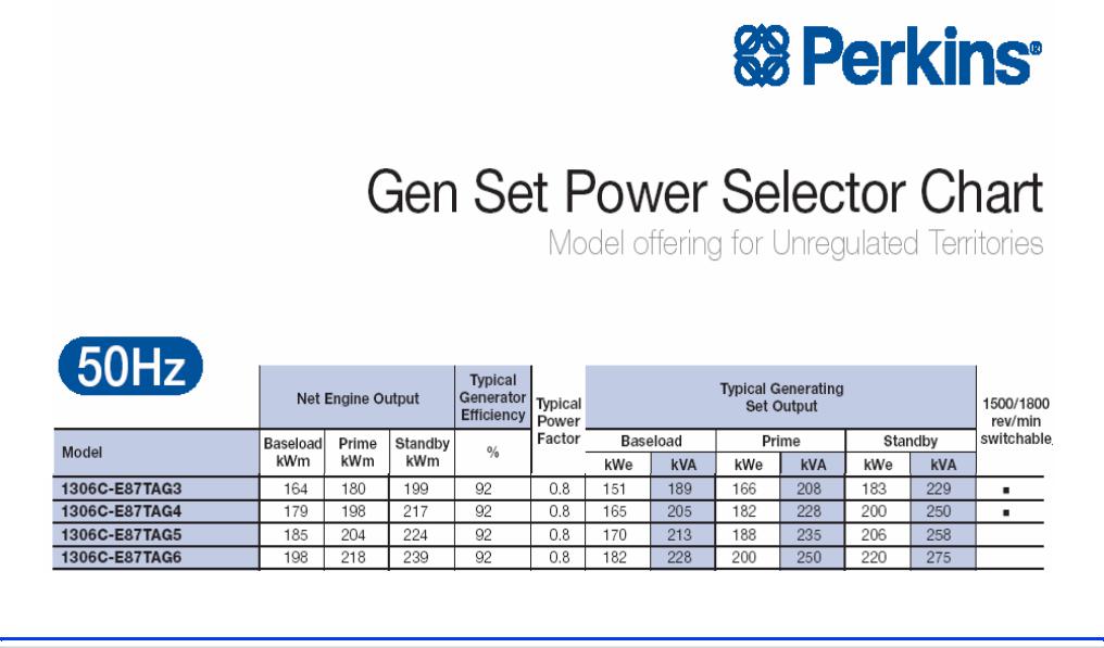
Gen Set Power Range
|
149.0 |
— 160.5 kW |
WR4410/WR4411 |
||||||
|
@ 1500 rev/min |
||||||||
|
171.5 kW |
WR4412 |
|||||||
|
@ |
1800 rev/min |
|||||||
172.0— 246 kW
@1500 rev/min
186.0— 242.5 kW @ 1800 rev/min
WS4413/WS4418
WS4419/WS4422
|
0 |
50 |
100 |
150 |
200 |
250 |
300 |
Max Gross Standby Ratings
|
Product Training Sept 2004 |
@Perkins |
|
Proprietary Information of Perkins Engines Company Limited 2004 — All Rights Reserved |
Engine Identification
zEngine Type
Engine Family
Build List Number
Country of Origin
W P 12345N 654321G
Serial Number
Year of Manufacture
|
Product Training Sept 2004 |
@Perkins |
|
Proprietary Information of Perkins Engines Company Limited 2004 — All Rights Reserved |
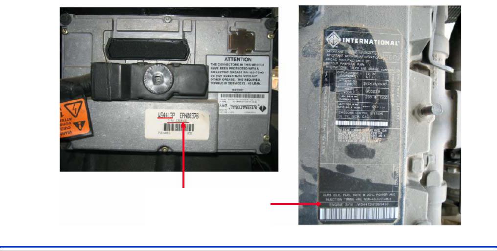
Engine Identification
Engine Serial Number
|
Product Training Sept 2004 |
@Perkins |
|
Proprietary Information of Perkins Engines Company Limited 2004 — All Rights Reserved |

Engine Identification
1306.E87TA
After cooled Turbo charged
8.7 Litre Electronic
6 Cylinder
1300 Series
|
Product Training Sept 2004 |
@Perkins |
|
Proprietary Information of Perkins Engines Company Limited 2004 — All Rights Reserved |

1300 Edi Engine Sensors
On Engine (Gray Connector)
zEngine Coolant Temperature. (ECT)
zEngine Oil Temperature. (EOT)
zManifold Absolute Pressure. (MAP)
zEngine Oil Pressure. (EOP)
zCamshaft Motion Pickup. (CMP)
zInjection Control Pressure (ICP)
z z
Off Engine (Black Connector)
Inlet Air Temperature. (IAT)
Barometric Pressure. (Baro)
|
Product Training Sept 2004 |
@Perkins |
|
Proprietary Information of Perkins Engines Company Limited 2004 — All Rights Reserved |
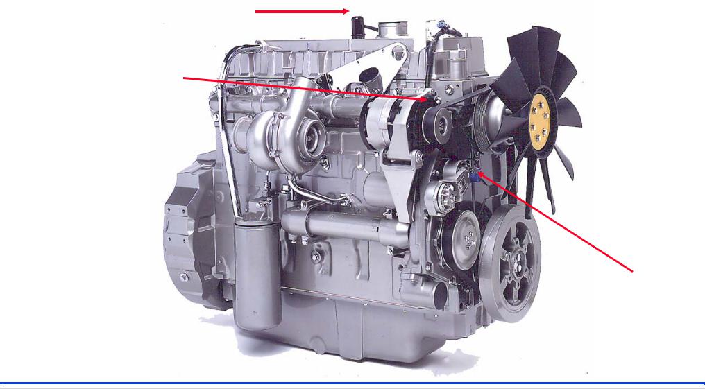
1300 Edi Series Sensor Layout
Manifold Absolute Pressure (MAP)
Engine Coolant
Temperature (ECT)
Camshaft Motion
Pickup (CMP)
|
Product Training Sept 2004 |
@Perkins |
|
Proprietary Information of Perkins Engines Company Limited 2004 — All Rights Reserved |

1300 Edi Series Sensor Layout
Injection Control Pressure
OEM/Customer
Connection
All On-Engine
Connections
|
Engine Oil Temperature |
Engine Oil |
|
|
Pressure |
||
|
Product Training Sept 2004 |
@Perkins |
|
Proprietary Information of Perkins Engines Company Limited 2004 — All Rights Reserved |
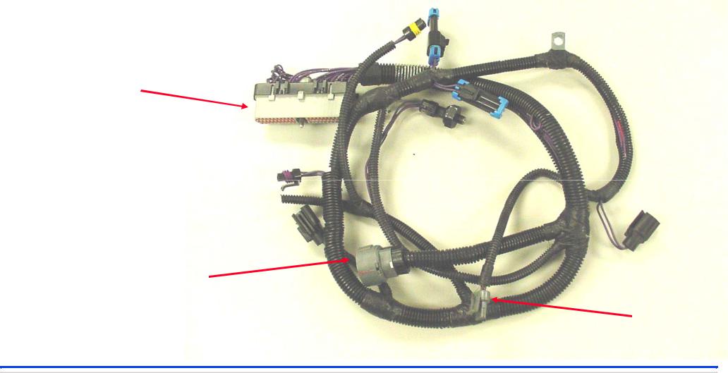
Typical 1300 Edi ‘On Engine’ Wiring Harness
Gray ECM Connector
‘Packard’ 20 pin Injector Plug
Camshaft Motion Pickup Plug
|
Product Training Sept 2004 |
@Perkins |
|
Proprietary Information of Perkins Engines Company Limited 2004 — All Rights Reserved |
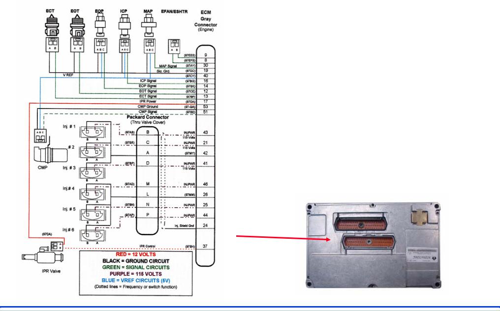
‘On Engine’ Connections
(Gray Connector)
zThe injector solenoids are controlled by a 110v DC.pulse.
(110 Volt DC is a dangerous voltage)
zPressure Sensors and Cam Motion Pickup require 5 volt dc.
zThe Injection Pressure Regulator Valve requires a Pulse Width Modulated (PWM) signal.
All ‘On Engine’
Connections
|
Product Training Sept 2004 |
@Perkins |
|
Proprietary Information of Perkins Engines Company Limited 2004 — All Rights Reserved |
![]()
1300 Edi Series ‘On Engine’ Wiring Harness
zThe Harness is protected by a plastic tubing.
zIt is mechanically fixed to the engine via clips, to keep the harness secure and away from potential damage.
zAll connectors are ‘keyed’ to ensure correct orientation.
zMake sure all seals are correctly positioned. Blanking plugs must be fitted on any unused pins, to prevent any liquid ingress.
(SPECIAL PowerPart grease is recommended for ECM Plug)
|
Product Training Sept 2004 |
@Perkins |
|
Proprietary Information of Perkins Engines Company Limited 2004 — All Rights Reserved |

1300 Edi Series ‘On Engine’ Wiring Harness
zWe have a very ‘Fault Tolerant’ extremely reliable system. Inevitably after many years service, faults may occur.
zTraditionally, if the problem is ‘Electrical’, wiring / connectors are most likely to be the cause.
zShorts / open circuits / high resistance connections, can be caused by any combination of corrosion / abrasion / burning / vibration / fatigue and ‘liquid ingress’.
|
Product Training Sept 2004 |
@Perkins |
|
Proprietary Information of Perkins Engines Company Limited 2004 — All Rights Reserved |

OEM/Customer Typical Connections
(Black Connector)
All OEM/Customer
Connections
|
Product Training Sept 2004 |
@Perkins |
|
|
Proprietary Information of Perkins Engines Company Limited 2004 — All Rights Reserved |

OEM/Customer side, Connections
zAll Battery Positive and Negative connections to the ECM, should be connected to prevent Voltage drop.
zIt is important that ECM power cables be connected directly to battery Positive and Negative –
zCorrect cable sizes and fuses, should be always be used.
zMake sure of the current rating of the power relay contacts.
zProtect against ‘back EMF’ by installing a diode across relay
zInstall 6 pin Deutsch Diagnostic Connector, for Communications.
zInstall warning lamps, Amber/Red and Diagnostics push button
|
Product Training Sept 2004 |
@Perkins |
|
Proprietary Information of Perkins Engines Company Limited 2004 — All Rights Reserved |
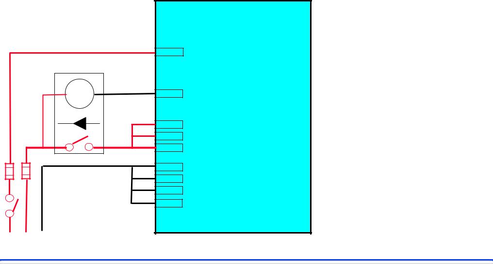
Minimum Connections, to run a 1300 Series
|
Customer Connections |
CONTROL |
||||||
|
E C M |
|||||||
+—
ECM Power Supply,
12/24 v
Note.
We do suggest that a connection is made to Service Tool to allow Communication with The ECM via the ATA
For Example 16 ATA + 17 ATA — + on pin C
— on pin E
Alternative:
SAE J1939. 18 CAN Screen
19 CAN High +
20 CAN Low –
(minimal information)
|
Product Training Sept 2004 |
@Perkins |
|
Proprietary Information of Perkins Engines Company Limited 2004 — All Rights Reserved |
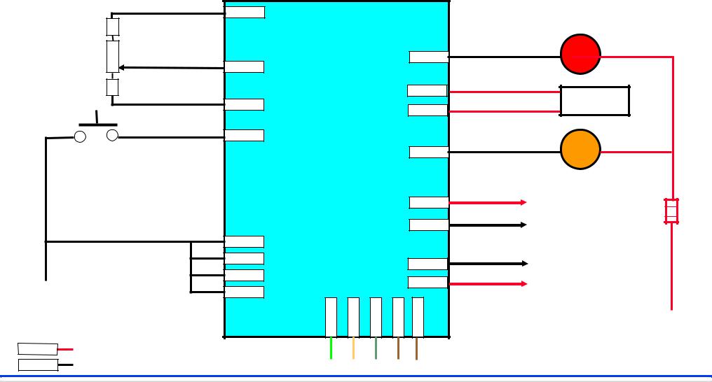
Some Typical Connections — 1300 Series ECM
|
INPUTS |
OUTPUTS |
||
|
CONTROL |
Red Lamp |
||
|
Analogue |
E C M |
||
|
Speed Adjust |
|||
|
Diagnostics |
IPR Valve |
||
|
Amber Lamp |
|||
|
+ |
5 volt Pressure |
||
|
— |
Sensors |
||
|
— |
— |
110 volt |
|
|
Injectors 3 |
|||
|
ECM Power Supply, |
+ |
||
|
12/24 v |
+ |
||
Communications Adapter
12/24 v
ATA J1939-CAN
|
Product Training Sept 2004 |
@Perkins |
|
Proprietary Information of Perkins Engines Company Limited 2004 — All Rights Reserved |

Connectors
zAlways use high quality connectors. (Gold/Nickel Plated)
zKeep connections to a minimum.
zMake sure all rubber seals are correctly fitted.
zRemember…
‘BAD’ CONNECTIONS CAUSE RESISTANCE!
RESISTANCE CAUSES VOLTAGE DROP!
|
Product Training Sept 2004 |
@Perkins |
|
Proprietary Information of Perkins Engines Company Limited 2004 — All Rights Reserved |

Effects of ‘Bad’ (Resistance) Connections
|
24v dc |
Possible ‘Bad’ Connections |
Lamp 24v dc |
Has the same effect as….Resistances in circuit
Don’t forget all connections!
|
24v dc |
Resistors |
Lamp 19.9v dc |
Don’t forget all connections!
|
Product Training Sept 2004 |
@Perkins |
|
Proprietary Information of Perkins Engines Company Limited 2004 — All Rights Reserved |

HYDRAULICALLY ACTUATED
ELECTRONICALLY CONTROLLED
UNIT
INJECTION
zHEUI is the fuel system used in place of the mechanical high pressure fuel injection pump and nozzles
zHydraulically actuated using High Pressure Engine lubrication oil as power medium
zInjection controlled by an 110 volt electrical solenoid
zSolenoid controlled by Electronic Control Module (ECM)
|
Product Training Sept 2004 |
@Perkins |
|
Proprietary Information of Perkins Engines Company Limited 2004 — All Rights Reserved |
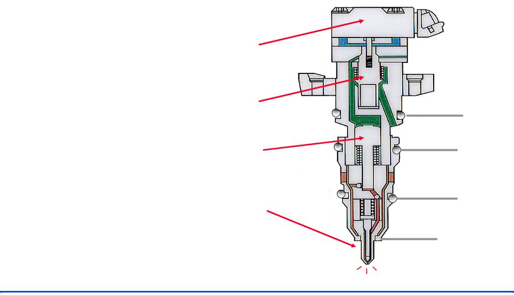
H.E.U.I. Injector
110 volt Solenoid
|
Enables control of: |
Poppet Valve |
||
|
z |
Injection Pressure |
High Pressure |
|
|
Engine Oil |
|||
|
z |
Injection Rate |
Intensifier Piston |
|
|
Fuel |
|||
|
z |
Injection Timing |
Injection Nozzle |
|
|
Coolant |
|||
|
Product Training Sept 2004 |
@Perkins |
|
Proprietary Information of Perkins Engines Company Limited 2004 — All Rights Reserved |
![]()
H.E.U.I. Oil System
Filter
Oil Cooler
To Engine Lubrication
System
High Pressure Oil Supply Pump Injection Pressure Regulator (IPR) valve
High Pressure Oil Rail (Manifold)
HEUI Injectors
|
Product Training Sept 2004 |
@Perkins |
|
Proprietary Information of Perkins Engines Company Limited 2004 — All Rights Reserved |

1300 Edi Oil Lubrication System
|
Product Training Sept 2004 |
@Perkins |
|||||
|
Proprietary Information of Perkins Engines Company Limited 2004 — All Rights Reserved |

|
1300 Edi Front View |
Engine Oil |
|
Reservoir |
|
|
Camshaft Speed/Position (CMP)Plate |
|
|
Engine Oil |
|
|
Temperature |
|
|
Sensor |
Feed to High
Pressure Pump
|
Product Training Sept 2004 |
@Perkins |
|
Proprietary Information of Perkins Engines Company Limited 2004 — All Rights Reserved |

H.E.U.I. Oil Supply and Pressure System
|
Product Training Sept 2004 |
@Perkins |
|
Proprietary Information of Perkins Engines Company Limited 2004 — All Rights Reserved |

Fuel System
Pressure
Relief Valve
Max 65 PSI
Min 20 PSI
X
HEUI Injectors
6 u Fuel Filter
Fuel Tank
250 u Fuel Strainer Lift Pump
|
Product Training Sept 2004 |
@Perkins |
|
Proprietary Information of Perkins Engines Company Limited 2004 — All Rights Reserved |

Oil Reservoir
High Pressure Oil Chamber
Coolant
Oil/Fuel Manifold
Pressure Pump Safety Valve
Pressure Outlet
|
Product Training Sept 2004 |
@Perkins |
|
Proprietary Information of Perkins Engines Company Limited 2004 — All Rights Reserved |

1300 Edi High Pressure Oil / Fuel Manifold
Fuel Supply
High Pressure Oil Supply
110 volt Injector Solenoid Supply
Fuel Pressure Relief Valve, 60/65 PSI
|
Product Training Sept 2004 |
@Perkins |
|
Proprietary Information of Perkins Engines Company Limited 2004 — All Rights Reserved |
 Loading…
Electronic Engine Fault Detection Flash Codes Perkins 1306-E87 electronic engines automatically record engine faults in the Electronic Control Module (ECM) to assist the operator or engineer in troubleshooting. The fault codes can be read using the red and amber lamps situated on the top of the relay box. The relay box can be found mounted on the alternator box below the AVR. The relevant codes can be identified using the fault-finding table below. ! Two types of codes may be observed: “active” and “inactive” codes. Active codes are new faults identified which must be rectified before the generating set is operated again. Inactive codes are all codes which have been previously logged. ! To operate the fault finding diagnostic codes, press and hold the red pushbutton. The lamps will flash in the following sequence: amber-red-amber-amber. Once this sequence has finished, while still holding the red button, press and release the green button. Observe the sequence of the flashing lamps. ! If there are no active codes retained in the memory of the ECM, the red lamp will flash once, then the amber lamp will flash three times. ! If there are any active codes retained in the memory of the ECM, the red lamp will flash once. The active codes will then flash on the amber lamp. If there is more than one code there will be a short delay between codes. ! When all of the active codes have been shown, the red lamp will flash twice. Then, if there are any inactive codes retained, the amber lamp will flash a code. If there is more then one code there will be a short delay between codes. ! When the test is complete, the red lamp will flash three times. ! Make a note of any codes that are shown. Active codes will become inactive if the test is done for a second time.
2
1
Flash code 111 112 113
114 115 121
3
Condition description
Comments
No errors found Electrical system voltage B+ out of range: high Electrical system voltage B+ out of range: low
ECM voltage is continuously more than 18V ECM voltage is continuously less than 6.5V. Cause of no start / misfire Defaults to 180°F (82°C). Signal voltage less than 0.127V Defaults to 180°F (82°C). Signal voltage greater than 4.6V Defaults to ECM setting. Low power. Slow acceleration. Signal voltage greater than 4.6V Defaults to ECM setting. Low power. Slow acceleration. Signal voltage greater than 4.6v Defaults to ECM setting. Low power. Slow acceleration Defaults to open-loop control. Underrun at low idle. Signal voltage less than 0.039V Defaults to open loop control Underrun at low idle. Signal voltage greater than 4.897V Signal voltage less than 0.152V. Engine at low idle only Signal voltage greater than 4.55V. Engine idle only Speed control position does not match the idle validation switch. Kept to 0% of Speed control position Kept to 0% of Speed control position Speed control position does not match the idle validation switch. Kept to 50% of Speed control position. Engine speed limited
Engine coolant temperature signal out of range: low Engine coolant temperature signal out of range: high Manifold air pressure signal out of range: high
122
Manifold air pressure signal out of range: low
123
Manifold air pressure fault: in range Injection control pressure signal out of range: low
124
125
Injection control pressure signal out of range: high
131
Speed control signal out of range: low Speed control signal out of range: high Speed control signal fault: in range
132 133
134* 135*
Speed control position does not match the idle validation switch. ECM low idle validation switch faulty.
1. 2. 3.
Red Lamp Amber Lamp Pushbuttons
Probable causes Charging system fault Low battery voltage. Loose connections. High resistance in circuit Short circuit to earth Open circuit. Sensor failure Sensor failure
Short circuit to earth. Sensor failure
Hose or sensor for manifold air pressure blocked Short circuit to low. Open circuit. Sensor failure Short circuit to high. Sensor failure
Short circuit to earth. Open circuit. Sensor failure. Short circuit to reference voltage or 12 volts. Sensor failure Speed control failure.
Speed control and idle validation switch failure Idle validation switch failure
141*
Vehicle speed signal out of range: low
142*
Vehicle speed signal out of range: high
143
Wrong number of pulses per revolution from the camshaft position sensor Interference found at the camshaft position sensor No signal from the camshaft position sensor but the injection control pressure has increased Barometric pressure signal out of range: high
144 145
151*
152*
Barometric pressure signal out of range: low
154
Intake air temperature signal out of range: low Intake air temperature signal out of range: high Engine oil pressure signal out of range: low Engine oil pressure signal out of range: high
155 211 212
213* 214*
221* 222*
ECM found excessive external inputs Found by the ECM
Interference. Injector unit voltage short circuit to earth Short circuit to earth. Open circuit. Sensor failure
Signal voltage greater than 4.9V for more than 1 second. Defaults to 101 kPa (14.7 lbf/in2) 1,0 kgf/cm2) Signal voltage less than 1.0V for more than 1 second. Defaults to 101 kPa (14.7 lb/in2) 1,0 kgf/cm2 Signal voltage less than 0.127V. Defaults to 170°F (77°C) Signal voltage greater than 4.6V. Defaults to 170°F (77°C) Signal voltage less than 0.039V
Short circuit high or open circuit. Sensor failure
Short circuit to reference voltage or 12 volts Poor connection or camshaft position sensor failure
Short circuit to earth low
Short circuit to earth Open circuit Short circuit to earth low Short circuit to earth high or open circuit
Remote speed control out of range: low Remote speed control out of range: high
Remote speed control signal less than 0.249V Remote speed control signal greater than 4.5V
Open circuit
Cruise / PTO (or remote PTO) switch fault Brake switch circuit fault
Signal voltage incorrect, does not match the switch position Voltage to pins 43 and 44 on the ECM are not the same Signal greater than 276 kPa (40 lbf/in2) 2,8 kgf/cm2 with the engine start key in the “ON” position. Engine protection disabled ATA link open or short circuit. VPM fault Output circuit test in engine-off test only
Short circuit or high resistance in the speed control circuit Switch or relay faulty or incorrectly adjusted Faulty circuit connection. Sensor failure
Sensor for engine oil pressure faulty: in range
231
ATA data link fault
236* 241
Engine coolant level switch fault Regulator for injection control pressure failed the output circuit test Engine data link failed open circuit test Open circuit test out of range: high Open circuit test out of range: low Engine oil temperature signal out of range: low
254 255 311
Sensor open circuit or short circuit to earth
Signal voltage greater than 4.9V
225
244
Speed sensor signal is less than 0.48V (0 Kmh/mph). Cruise control nor PTO not engaged. Engine speed limited Speed sensor signal is greater than 4.492V (0 Kmh/mph). Cruise control nor PTO not engaged Intermittent signal
Output circuit test in engine-off test only Signal voltage less greater 4.8v Defaults to 212°F (100°C) No fast idle Signal voltage less than 0.2v Defaults to 212°F (100°C) No fast idle Oil warning light on
312
Engine oil temperature signal out of range: high
313
Engine oil pressure below warning level
314
Engine oil pressure below critical level
Engine will stop, if this option is fitted
315*
Engine speed exceeded warning limit
ECM recorded an engine speed greater than 3000 rev/min
Short circuit to earth
ATA device earthed or overloaded Sort circuit to earth or open circuit Open circuit or short circuit to earth
Open circuit or short circuit to earth High voltage during open circuit test Low voltage during open circuit test Short circuit to earth Open circuit
No oil or low oil level. Faulty regulator. Suction pipe blocked or damaged. Worn main bearings. Worn oil pump. No oil or low oil level. Fault in regulator. Suction pipe blocked or damaged. Worn main bearings. Worn oil pump. Incorrect use of gears in automotive application
321
326
Engine coolant temperature above warning level Engine coolant temperature too high Engine coolant level below warning level Power reduced to match cooling system performance Gen Set speed control faults
331
Injection control pressure too high
332
Injection control pressure above specification with the engine off Injection control pressure below best value
322 323* 325
333
Coolant temperature greater than 224.6°F (107°C) Coolant temperature greater than 233.6°F (112.5°C) ECM finds low coolant level Engine power reduced Engine goes to idle on start up or no longer responds to a load/speed control Injection control pressure above 25 Mpa (3675 lbf/in2) 2250 kgf/cm2 Sensor signal voltage higher than expected with the engine off Pressure does not match the output signal for a long period of time
Cooling system fault Cooling system fault Coolant level low. Leakage of coolant High altitude or high ambient temperature Wiring loom fault or out of range speed control signal Short circuit to earth. Regulator valve stuck Short circuit to voltage. Sensor fault Incorrect specification lubricating oil. Air in the lubricating oil. Leakage at the ‘O’ ring for the injector unit. Regulator fault. Incorrect specification lubricating oil. Air in the lubricating oil. Leakage at the ‘O’ ring for the injector unit. Regulator fault.
334
Injection control pressure does not reach the correct pressure in the time allowed
Pressure does not match the output signal for a short period of time
335
Injection control pressure does not increase during engine Cranking Injection control pressure does not reach the correct pressure
Less than 5,1 Mpa (725 lbf/in2) 51 kgf/cm2 after 10 seconds of cranking —
Number 1 injector unit open circuit: high or low Number 2 injector unit open circuit: high or low Number 3 injector unit open circuit: high or low Number 4 injector unit open circuit: high or low Number 5 injector unit open circuit: high or low Number 6 injector unit open circuit: high or low Number 1 injector unit short circuit: high or low
Found by the ECM
Found by the ECM
Injector unit electrical wiring loom shorted high to low
Number 2 injector unit short circuit: high or low Number 3 injector unit short circuit: high or low Number 4 injector unit short circuit: high or low Number 5 injector unit short circuit: high or low Number 6 injector unit short circuit: high or low Number 1 injector unit short circuit to B+ or earth: high Number 2 injector unit short circuit to B+ or earth: high Number 3 injector unit short circuit to B+ or earth: high Number 4 injector unit short circuit to B+or earth: high Number 5 injector unit short circuit to B+ or earth: high Number 6 injector unit short circuit to B+ or earth: high Number 1 injector unit short circuit to earth Number 2 injector unit short circuit
Found by the ECM
Found by the ECM
Injector unit electrical wiring loom shorted high to low Injector unit electrical wiring loom shorted high to low Injector unit electrical wiring loom shorted high to low Injector unit electrical wiring loom shorted high to low Injector unit electrical wiring loom shorted high to low Injector unit electrical wiring loom shorted to earth: low Injector unit electrical wiring loom shorted to earth: low Injector unit electrical wiring loom shorted to earth: low Injector unit electrical wiring loom shorted to earth: low Injector unit electrical wiring loom shorted to earth: low Injector unit electrical wiring loom shorted to earth: low —
Found by the ECM
—
336
421 422 423 424 425 426 431 432 433 434 435 436 451 452 453 454 455 456 451 452
Found by the ECM Found by the ECM Found by the ECM Found by the ECM Found by the ECM
Found by the ECM Found by the ECM Found by the ECM Found by the ECM Found by the ECM Found by the ECM Found by the ECM Found by the ECM Found by the ECM Found by the ECM
Air in the lubricating oil. Fault in the high –pressure lubricating oil system A leakage of lubricating oil or fault in the high –pressure lubricating oil system Injector unit electrical wiring loom open circuit Injector unit electrical wiring loom open circuit Injector unit electrical wiring loom open circuit Injector unit electrical wiring loom open circuit Injector unit electrical wiring loom open circuit Injector unit wiring loom open circuit
453
454
to earth Number 3 injector unit short circuit to earth
513
Number 4 injector unit short circuit to earth Number 5 injector unit short circuit to earth Number 6 injector unit short circuit to earth Number 1 injector unit failed the contribution test Number 2 injector unit failed the contribution test Number 3 injector unit failed the contribution test Number 4 injector unit failed the contribution test Number 5 injector unit failed the contribution test Number 6 injector unit failed the contribution test Bank 1 open circuit: low
514
Bank 2 open circuit: low
515
621
Bank 1 short circuit to earth or B+: low Bank 2 short circuit to earth or B+: low Short circuit between bank 1 and bank 2 Injector unit driver circuit fault ECM unable to supply sufficient voltage to injector units Incorrect ECM installed for the camshaft timing plate Engine family rating code and ECM do not match Engine using default rating
622
Engine using field default rating
623
455 456 461 462 463 464 465 466
521 524 525
612
Found by the ECM
—
Found by the ECM
—
Found by the ECM
—
Found by the ECM
—
Found by the ECM
—
Found by the ECM
—
Found by the ECM
—
Found by the ECM
—
Found by the ECM
—
Found by the ECM
—
Injector units for cylinders 1,2 and 3 have an open circuit in the high voltage supply Injector units for cylinders 4, 5 and 6 have an open circuit in the high voltage supply Injector units for cylinders 1,2 and 3 have short circuit to earth or B+ Injector units for cylinders 4, 5 and 6 have short circuit to earth or B+ Short circuit between bank 1 and bank 2 Engine wiring loom fault.
Open circuit
Open circuit
Short circuit in wiring loom Short circuit in wiring loom Short circuit in wiring loom Injector unit wiring loom fault. ECM fault
No match between the ECM and the camshaft position sensor ECM programming fault
Incorrect ECM fitted
Engine operates AL25 HP, default
ECM installed but not programmed ECM installed but not programmed
Invalid engine rating code
Engine limited to 160 HP Options not available —
ECM not programmed correctly
624
Field default active
Programming problem
ECM fault
625 626 631
ECM fault Unexpected ECM reset fault ROM self test fault
ECM software fault Temporary ECM power failure ECM failure
Replace ECM Battery connection fault Internal ECM fault
632 655
RAM self test fault Programmable parameter list level incompatible RAM programmable parameter list corrupt Calibration level incompatible Programmable parameter memory content corrupt
ECM failure Programming problem. ECM memory problem Programming problem ECM memory problem Programming problem ECM failure
Internal ECM fault Programming fault
614
661 664 665
Components not compatible
Programming fault Programming problem Internal ECM fault
* These codes, if flashed, will not affect the operation of the engine in a generating set application: Note: The engine protection systems e.g. low oil pressure, high coolant temperature, are within the control of the generating set control panel. These sensors will shut the engine down before the ECM sensors.
277-978
10/99