A common problem with Kaeser air compressors is Kaeser compressor fault codes. This article will provide you with some useful information on compressor error codes, along with existing reader questions and responses about Kaeser compressor fault codes!
Table of Contents
- Reasons Kaeser Compressor Shows Fault Codes
- Additional Kaeser Pages
- Reader Questions & Responses
Reasons Kaeser Compressor Shows Fault Codes
In the event of a system fault, the Kaeser compressor will display a fault code in the user operational display menu. If there is more than one fault code active, each will be displayed as separate items in this operational display menu; they’re as simple as pressing up or down to view.
The fault codes displayed on the Kaeser air compressor should be separated into unit faults (ERR/ERROR), and system alarms (SYS/WARNING). When the compressor displays a system alarm warning, the conditions are automatically reset when the condition has been resolved and reset on the compressor.
When the compressor displays an error or shutdown, the conditions of the error will automatically reset once the condition has been resolved and the air compressor has restarted, working with no issues.
It’s common for the fault codes to be separated by some regarding a problem or error with the controller itself which prevents normal operation of the compressor, and system faults that occur externally from the controller and with the compressor.
The Kaeser compressor fault codes will likely show their errors in two different light patterns. The fault LED will flash slowly to indicate an alarm warning condition where the compressor is continuing with the normal operation but user attention is required still.
If the fault LED flashes fast it will indicate a trip condition where the controller will stop the operation of the compressor, until the conditions of the error are resolved.
Typically the fault codes are labeled with unique numeric codes which can then be understood from the user’s manual for the specific Kaeser compressor.
Additional Kaeser Pages
- Kaeser Air Compressor Troubleshooting Problems, Possible Causes & Solutions
Reader Questions & Responses
Kaeser Air Compressor Fault Codes – Kaeser Air Compressor Troubleshooting
Question

Response
Actually, thinking about it, I can’t see the number on the bottom line of the screen? What number or letter is it showing when you turn the power on?
Response
Hi again,
Thanks for the photo. Sorry, I may have misunderstood, it looks like, as you said, the backpressure fault is as soon as you turn the power on, not when you press the start button. I can see on the screen of your Sigma basic controller the bottom line is illuminated.
Does it let you reset this by pressing the reset button (the reset button is the red “Stop” button) if it doesn’t let you reset then I haven’t seen that before, are all the electrical connections in properly? The connection into your vent valve? (Brass component attached to the separator with a hose going to the air filter) if all these connections are ok then you may have a problem with the controller itself which could mean you may need an HPC engineer to come along to look at it to “K-load” it which means taking all software off and putting back on again. Or a new controller.
Let me know how you get on
Carl
Response
Hi,
I’m guessing you have a sigma 1 controller fitted and it has the words “backpressure” on the screen as opposed to a number on the bottom row of the screen as you would with a sigma basic controller?
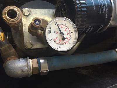
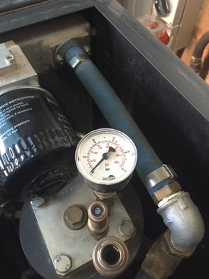
Either way, the backpressure error is indicating that you have pressure in the separator tank (where the oil is).
Do you have a pressure gauge on this tank? If so then it should read zero on startup.
Attached to the separator tank is a combination vent valve where you should find a little ball valve that is used for keeping pressure in this tank and firing out the oil when you have an oil change.
Check that this valve is open or you will get the back pressure error.
Secondly, inside that brass vent valve I mentioned is a rubber diaphragm, it has been known for this to inflate so will not let the separator vent, replace the diaphragm (it comes in an intermediate service kit along with an air filter, oil filter, and filter mat)
Finally, again with the vent valve, do you have an electrical connection to it? Make sure you have voltage going to it?
How old is your machine? If you could post a few photos of the machine and the vent valve/separator it would help a great deal.
Try all the above and reply to this post to let me know if it fixes it.
Many Thanks
Carl
Kaeser Compressor Critical Error – Kaeser Compressor Troubleshooting
Question
Critical error code 300A on Kaeser compressor.
What is this error code and what does it mean?
Response
Hi,
The Critical Error on the Kaeser’s Sigma controller means there is a software error on the actual controller, the compressor itself is all fine but your controller is no longer used which means it needs replacing.
Sometimes you can turn the machine off at the main isolator for 5 minutes then switch it back on again and it will work for anything between 5 minutes to a few weeks, but it will come back, so unfortunately it does need replacing.
Be warned, these are very expensive depending on which one you have (Sigma Basic is the cheapest, Sigma 1 most expensive) you’re looking at between £800-£2000 for replacement.
But check with your local HPC supplier. I’m in East Anglia in England. Whereabouts are you?
Sorry for the bad news but hope that helps
Carl
Question
Thanks for the information, Carl. I’m in Southern California. There is nothing else that can be done to fix the sigma control besides replacing it?
Thanks again,
Ron
Response
Hi Ron,
Your only last hope is getting what’s called “K-loaded” by the manufacturer, this means the software is totally wiped and put on again. I don’t know how much that costs but the critical error can still reappear at some point so it is a bit of a gamble. I get in touch with your nearest HPC distributor to see what they will do for you, obviously, they may just say buy a new one but ask about getting it K-loaded first. That really is your last option, unfortunately.
Having a critical error is really quite rare like I said but it can happen very randomly. One of the 3 I have seen in the 20 years of working on air compressors, happened whilst I was servicing it. Trying to explain to the customer that it wasn’t anything I had done was a nightmare! You are one of the unlucky ones I’m afraid to say.
Response
Just make sure when you get a new control module that it is actually set up to work when it is installed. I bought a new one from an authorized Kaeser distributor under the understanding that it was set up and ready to go. We installed it but not only was the display in German (which I changed) But it needs a level 5 password to get it up and running. Not much chance of that as they want to send their service tech out and charge me about Eight hours of travel time plus the service fee. In retrospect, I should have scrapped the compressor and replaced it with something more user-friendly.
Response
the sigma controllers are notorious for the error message. we have seen probably about 10 controllers with the same error, it is a small relay on the controller that creates the message, unfortunately, Kaeser in their wisdom does not have an error on their machines so we are told…
Response
by: Carl
Hi again
Just to clarify, it is ONLY Sigma 1 NOT Sigma Basic or the Signa 2 that has the Critical Error issue.
The Sigma 1 controller is no longer made so you will be lucky to actually get a new one from the manufacturer.
Yes, you do need the level 5 code to set it up but if you have ordered one and have had it delivered from a registered HPC/Kaeser distributor then you should have given the compressor’s details and it should have already been set up before delivery.
If it hasn’t been set up properly then HPC should have asked you to either send it back or they should send an engineer out free of charge to set it up. They wouldn’t/shouldn’t send a raw controller out that hasn’t been set up properly if they were a proper distributor
Response
I had the same situation myself where a Kaeser distributor sold me a controller that was not set up for the particular machine even though I had given the correct model, serial number, and part number.
It was an eight-hour round trip for this job so to say I was annoyed would be mildly put, especially when they said that they would need to send out the Kaeser technician to set it up and charge me for a whole days labor and travel for an item that I was assured was plug and play.
The other alternative was to return it but they said I would be charged a programming fee.
Needless to say, I did not go down that path and did some searching around until I eventually discovered the level 5 code and set it up myself.
It has now been working fine for a couple of years.
Response
Does anyone have the Pass desperate for it?
Response
11TTY or 3WW50 is level 7 in Australia it might work where you are.
Cheers.
Kaeser Compressor Fault Code – Kaeser Compressor Troubleshooting
Question
Hello, I have a Kaeser compressor mod. CS91 with SIGMA CONTROL and loading the update I get: CRITICAL ERROR
Please, do you get this error? Thank you very much.
Photo:
Response
I presume this error prevents compressor operation – Were there any symptoms prior to this?
Did anything happen to input power?
Are you trying to update the controller soft/firmware? If so, you’ll need to work it out with Kaeser, sorry.
Response
Hi,
Having a critical error on your Sigma isn’t good I’m afraid. I work for HPC (Kaeser.)
There are only 2 possible ways of getting rid of this, one being replacing the controller, and the other is getting it “K-loaded” which means getting Kaeser in to wipe the software and reinstall, even doing that isn’t a guaranteed fix as it could possibly do it again.
Temporarily it sometimes works by turning off the isolator, leaving it for 20 minutes, and turning it back on again. But again, it will possibly do it again either straight away or soon after.
This fault wouldn’t be because of your update, it can happen at any time, it isn’t often that this happens but when it does, unfortunately, it is expensive.
Question
Mr. Carl, please tell me what you mean by “Change controller”, Processor (intel KU80386EX25), or other components….?? please urgently answer me.
Response
The controller is the whole part where you turn the compressor on and off. The Sigma controller needs replacing. You need to contact Kaesar
Question
But Mr. Carl I am working on this, for repairing the PLC, I hope so I’ll succeed. I need your help to guide me about this error, according to this error which component is faulty, today I replaced the Intel processor, but fault still same, its mean processor was ok, on display result are like this: check RAM:—OK
Check F memory: —- OK, replace the controller, critical error, tell me according to this, is software faulty? or any component?
Guide me, I will repair and tell you after any changing. Thanks
Response
There is only one way to fix this, you need to replace the Sigma Controller itself.
You need to contact Kaesar (HPC) and tell them all the details of the compressor (Model, Serial number, pressure settings, etc).
There is nothing else you can do I’m afraid.
If you have any questions regarding Kaeser air compressor fault codes, please leave a comment below, with a photo if applicable, so that someone can help you!
-
Page 1
Service manual Controller SIGMA CONTROL 2 SCREW FLUID ≥1.2.4 9_9450 04 E Manufacturer: KAESER KOMPRESSOREN SE 96410 Coburg • PO Box 2143 • GERMANY • Tel. +49-(0)9561-6400 • Fax +49-(0)9561-640130 http://www.kaeser.com… -
Page 2
/KKW/SSC 2.04 en BA-SIGMA CONTROL FLUID /KKW/SSC 2.04 20140602 145709… -
Page 3
Quick user guide Controller SIGMA CONTROL 2 SCREW FLUID ≥1.2.4 9_9450 04 E Manufacturer: KAESER KOMPRESSOREN SE 96410 Coburg • PO Box 2143 • GERMANY • Tel. +49-(0)9561-6400 • Fax +49-(0)9561-640130 http://www.kaeser.com… -
Page 5: Table Of Contents
Checking the temperature sensor and overheating shut-down function ……Interpreting fault messages ………………..Interpreting warning messages ………………Interpreting operation messages ………………Interpreting diagnostic messages ………………Interpreting system messages ………………Quick user guide Controller 9_9450 04 E SIGMA CONTROL 2 SCREW FLUID ≥1.2.4…
-
Page 6
Contents Quick user guide Controller SIGMA CONTROL 2 SCREW FLUID ≥1.2.4 9_9450 04 E… -
Page 7: Important Settings
Setting and other work on the machine may only be carried out by the following persons: ■ persons trained on the machine/controller and persons instructed by and under the su‐ pervision of a specialist, ■ trained technicians, ■ authorised Service personnel. Quick user guide Controller 9_9450 04 E SIGMA CONTROL 2 SCREW FLUID ≥1.2.4…
-
Page 8: Setting The Contrast And The Brightness
3. Press «UP» or «DOWN» to adjust the contrast. 4. Press «Left» or «Right» to adjust the brightness. Result The settings for contrast and brightness have been adjusted. Quick user guide Controller SIGMA CONTROL 2 SCREW FLUID ≥1.2.4 9_9450 04 E…
-
Page 9: Setting The Display Language
4. Move to the required language with «UP» or «DOWN». 5. Press «Enter» to accept the setting. The display texts are now in the selected language. 6. Press «Escape» repeatedly to return to the main menu. Quick user guide Controller 9_9450 04 E SIGMA CONTROL 2 SCREW FLUID ≥1.2.4…
-
Page 10: Logging On With Equipment Card
5. Store this information at a suitable location. Log on with Equipment Card Use a supplied KAESER Equipment Card to log on at the controller. Two of them have been provided with the machine. Quick user guide Controller SIGMA CONTROL 2 SCREW FLUID ≥1.2.4 9_9450 04 E…
-
Page 11
2. Press «Enter» to confirm the log-on. The operating mode is displayed. Result You are logged on. Further information See chapter 7.2.6 for a manual log-on to the controller. Quick user guide Controller 9_9450 04 E SIGMA CONTROL 2 SCREW FLUID ≥1.2.4… -
Page 12: Adjusting The System Setpoint Pressure
10. If necessary, adjust the value for switching point pB in the same way. 11. Press «Escape» repeatedly to return to the main menu. Further information See chapter 7.4 for the adjustment of the machine’s pressure parameters. Quick user guide Controller SIGMA CONTROL 2 SCREW FLUID ≥1.2.4 9_9450 04 E…
-
Page 13: Activating The «Timer Control» Key
7. Press the «Right» key once. 00 : 00 flashes in the active line. Column time, hours display, 8. Use «UP» to specify the settings for the minutes. Quick user guide Controller 9_9450 04 E SIGMA CONTROL 2 SCREW FLUID ≥1.2.4…
-
Page 14
Proceed in the same manner to deactivate the «time control» key. ■ All defined switching points will be reset simultaneously if you activate the reset check box. Quick user guide Controller SIGMA CONTROL 2 SCREW FLUID ≥1.2.4 9_9450 04 E… -
Page 15
Activating the «timer control» key Activating time control ➤ Press the «Time control» key on the SIGMA CONTROL 2 operating panel to activate the time control. timer LED on the operating panel of SIGMA CONTROL 2 displays green continuous light to signal the successful timer operation. -
Page 16: Activating The «Remote Control» Key
Option to negate the switching logic Logic : + Active line with check box Key remote : ☐ 5. Press «UP». The activated check box is displayed. Quick user guide Controller SIGMA CONTROL 2 SCREW FLUID ≥1.2.4 9_9450 04 E…
-
Page 17
RC DI 1.09 ☐ ········· Active line with check box Key remote : ☐ Key idle : ☐ 5. Press «UP». The activated check box is displayed. Quick user guide Controller 9_9450 04 E SIGMA CONTROL 2 SCREW FLUID ≥1.2.4… -
Page 18
<Configuration ➙ Acknowledgement> <Communication> ■ Further information See chapter 7.5 for configuration of starting and stopping the machine. See chapter 7.9 for configuration of load changeover under master control. Quick user guide Controller SIGMA CONTROL 2 SCREW FLUID ≥1.2.4 9_9450 04 E… -
Page 19
The regulating mode DUAL has been switched to QUADRO. Further information See chapter 4.7 for the functions of the control modes. See chapter 7.6 for the parameters of the control modes. Quick user guide Controller 9_9450 04 E SIGMA CONTROL 2 SCREW FLUID ≥1.2.4… -
Page 20: Outputting Important Operational States Of The Machine
A message is now sent via the assigned output. 4. Press «Escape» repeatedly to return to the main menu. Further information See chapter 7.11 for the configuration and use of the controller’s inputs and outputs. Quick user guide Controller SIGMA CONTROL 2 SCREW FLUID ≥1.2.4 9_9450 04 E…
-
Page 21: 10 Resetting Maintenance Interval Counters
This ensures the timely procurement of re‐ quired replacement parts and operating fluids and other resources. When the current value of the maintenance counter reaches the lower limit vale, SIGMA CONTROL 2 generates a warning message. Term Definition…
-
Page 22
6000 h ¦ 3000 h Reset: ☐ ········· Further information See chapter 8.10 for setting the maintenance intervals. See chapter 10 for the maintenance of the controller. Quick user guide Controller SIGMA CONTROL 2 SCREW FLUID ≥1.2.4 9_9450 04 E… -
Page 23: 11 Checking The Pressure Relief Valve
3. Close the user’s shut-off valve between the machine and the pressure system. 4. Log on to SIGMA CONTROL 2 with access level 2 (see chapter 7.2.6). 5. In operating mode, switch to the main menu with the «Enter» key.
-
Page 24
8. If the internal pressure pi increases to more than 10% above the correct opening pressure of the pressure relief valve, shut down the machine with the «OFF» key and replace the pressure relief valve. Quick user guide Controller SIGMA CONTROL 2 SCREW FLUID ≥1.2.4 9_9450 04 E… -
Page 25
The machine is ready for operation. Resetting If the test is cancelled when opening the pressure relief valve, SIGMA CONTROL 2 will indicate the highest measured value as internal pressure. To reset the saved value, activate the «Reset» check box. -
Page 26: Checking The Temperature Sensor And Overheating Shut-Down Function
SIGMA CONTROL 2 will simulate a higher temperature for checking this function. For this purpose, SIGMA CONTROL 2 automatically determines an offset value to be displayed. During the test mode, this offset is added to the actual airend discharge temperature to cause the machine to shut down prematurely.
-
Page 27
The machine will switch off as soon as the airend discharge temperature attains a value of 108 °C . The machine does not shut down? ➤ Abort the test and contact KAESER Service as soon as possible. Quick user guide Controller 9_9450 04 E SIGMA CONTROL 2 SCREW FLUID ≥1.2.4… -
Page 28
4. Press «Escape» repeatedly to return to the main menu. Resetting SIGMA CONTROL 2 will display the highest measured value if the test for switching off at overtem‐ perature is aborted. Reset check box in order to reset the stored value. -
Page 29: 13 Interpreting Fault Messages
The message numbers are not numbered consecutively. Meanings of designation of fault messaged within this table with “%.2d”: If SIGMA CONTROL 2 generates this type of fault message, the I/O address having caused this fault message is attached. Messages 0081 to 0095 are customer-specific and may differ from the suggested values. Com‐…
-
Page 30
Contact KAESER Serv‐ Cabinet fan I ⇞ the control cabinet fan ice. motor. 0038 A Package discharge Contact KAESER Serv‐ PD temperature ⇟ (PD) temperature too ice. low. Quick user guide Controller SIGMA CONTROL 2 SCREW FLUID ≥1.2.4 9_9450 04 E… -
Page 31
Check the condensate Condensate drain drain and conduits. 0059 A Drive belt or coupling Drive belt: Back pressure run broken. Replace drive belt. Coupling: Contact KAESER Serv‐ ice. Quick user guide Controller 9_9450 04 E SIGMA CONTROL 2 SCREW FLUID ≥1.2.4… -
Page 32
0073 A 0074 A 0075 A 0076 A 0077 A 0078 A 0079 A 0080 A 0081 A 0082 A 0083 A 0084 A 0085 A Quick user guide Controller SIGMA CONTROL 2 SCREW FLUID ≥1.2.4 9_9450 04 E… -
Page 33
Contact KAESER Serv‐ Softstarter DI%.2d open? not deactivate. ice. 0108 A Run-up of the soft start Contact KAESER Serv‐ Softstarter DI%.2d closed? device is not comple‐ ice. ted. Quick user guide Controller 9_9450 04 E SIGMA CONTROL 2 SCREW FLUID ≥1.2.4… -
Page 34
0202 A Frequency converter Contact KAESER Serv‐ Compressor motor USS alarm fault ice. 0203 A Frequency converter Contact KAESER Serv‐ Compressor motor FC PKW failure P50.E50 fault ice. Quick user guide Controller SIGMA CONTROL 2 SCREW FLUID ≥1.2.4 9_9450 04 E… -
Page 35
USS bus communication error 50 ware driver. ice. 0243 A Fault message of the Contact KAESER Serv‐ Compressor motor FC Alarm 50 frequency converter ice. with message number (here: 50). Quick user guide Controller 9_9450 04 E SIGMA CONTROL 2 SCREW FLUID ≥1.2.4… -
Page 36
Contact KAESER Serv‐ USS bus communication error 50 ware driver. ice. 0305 A Fault caused by soft‐ Contact KAESER Serv‐ USS bus communication error 50 ware driver. ice. Quick user guide Controller SIGMA CONTROL 2 SCREW FLUID ≥1.2.4 9_9450 04 E… -
Page 37
Display and correct the IO parameterisation incorrect in module 50! been assigned more incorrect parameter in than once. the Address error menu. Tab. 5 Fault messages and remedies Quick user guide Controller 9_9450 04 E SIGMA CONTROL 2 SCREW FLUID ≥1.2.4… -
Page 38: 14 Interpreting Warning Messages
Change the cooling oil. Oil change h ⇞ Maintenance interval has elapsed. 0027 W Oil filter: Change the oil filter. Oil filter h ⇞ Maintenance interval has elapsed. Quick user guide Controller SIGMA CONTROL 2 SCREW FLUID ≥1.2.4 9_9450 04 E…
-
Page 39
Open the shut-off valve in reached. the venting line. 0041 W 1. Power failure: Check power supply. Mains voltage ↓ The machine is auto‐ Check the door interlock matically re-started. switch. Quick user guide Controller 9_9450 04 E SIGMA CONTROL 2 SCREW FLUID ≥1.2.4… -
Page 40
0060 W The airend temperature Keep ambient conditions Start temperature ↓ is too low (<+2 °C). within specified limits. Quick user guide Controller SIGMA CONTROL 2 SCREW FLUID ≥1.2.4 9_9450 04 E… -
Page 41
Refrigeration dryer: Check the condensate RD condensate drain Condensate drain faul‐ drain. 0073 W 0074 W 0075 W 0076 W 0077 W 0078 W 0079 W 0080 W Quick user guide Controller 9_9450 04 E SIGMA CONTROL 2 SCREW FLUID ≥1.2.4… -
Page 42
Temporarily fully disconnect Compressor motor FC test shut-off required quency converter since the machine from the power last shut-down too supply. (Required for the large. safety functions.) Quick user guide Controller SIGMA CONTROL 2 SCREW FLUID ≥1.2.4 9_9450 04 E… -
Page 43
Write protection activa‐ Deactivate the write protec‐ SD card write error ted? tion. Memory card defective. Use a new memory card. Tab. 6 Warning messages and remedies Quick user guide Controller 9_9450 04 E SIGMA CONTROL 2 SCREW FLUID ≥1.2.4… -
Page 44: 15 Interpreting Operation Messages
Machine report 0034 O No e-mail sending of machine information. E-mail send unsuccessful! 0073 O 0074 O 0075 O 0076 O 0077 O 0078 O 0079 O Quick user guide Controller SIGMA CONTROL 2 SCREW FLUID ≥1.2.4 9_9450 04 E…
-
Page 45
Slot2 (in the example 50 times) IOSlot2 Undervoltage error 50 0202 O The internal voltage monitoring reports undervoltage fault IO‐ Slot3 (in the example 50 times) IOSlot3 Undervoltage error 50 Quick user guide Controller 9_9450 04 E SIGMA CONTROL 2 SCREW FLUID ≥1.2.4… -
Page 46
IOSlot5 Undervoltage error 50 0205 O The internal voltage monitoring reports undervoltage fault IO‐ Slot6 (in the example 50 times) IOSlot6 Undervoltage error 50 Tab. 7 Operational Messages Quick user guide Controller SIGMA CONTROL 2 SCREW FLUID ≥1.2.4 9_9450 04 E… -
Page 47: 16 Interpreting Diagnostic Messages
Diagnostic messages are identified with the letter D . They provide information on the status of the controller, the connected input and output modules and support the KAESER service in trouble-shooting. Quick user guide Controller 9_9450 04 E SIGMA CONTROL 2 SCREW FLUID ≥1.2.4…
-
Page 48: 17 Interpreting System Messages
RAM out of memory 1000 Y System error Contact KAESER Service. RFID error: switch SIGMA CONTROL power supply OFF → ON! Tab. 8 System messages and remedies Quick user guide Controller SIGMA CONTROL 2 SCREW FLUID ≥1.2.4 9_9450 04 E…
-
Page 49
Initial Start-up Outline ……………………..Configuring the controller ………………..7.2.1 Selecting menu options ………………7.2.2 Changing the display language …………….7.2.3 Note the number of the KAESER Equipment Card ……….Service manual Controller 9_9450 04 E SIGMA CONTROL 2 SCREW FLUID ≥1.2.4… -
Page 50
Contents 7.2.4 Control access to SIGMA CONTROL 2 with the KAESER Equipment Card ..7.2.5 Generate password for SIGMA CONTROL 2 ………… 7.2.6 Control access to SIGMA CONTROL 2 via manual input ……..7.2.7 Generate password for KAESER CONNECT ………… -
Page 51
11.4 Displaying the version number, machine model, material number and serial number ..180 Decommissioning, Storage and Transport 12.1 De-commissioning ………………….182 12.2 Packing ……………………..12.3 Storage ……………………..182 Service manual Controller 9_9450 04 E SIGMA CONTROL 2 SCREW FLUID ≥1.2.4… -
Page 52
Contents 12.4 Transporting ……………………182 12.5 Disposal ……………………… Service manual Controller SIGMA CONTROL 2 SCREW FLUID ≥1.2.4 9_9450 04 E… -
Page 53
Insert the communication module………………..Fig. 28 Front plate of the PROFIBUS communication module …………… Fig. 29 Direct connection of two SIGMA CONTROL 2 …………….104 Fig. 30 LOAD remote contact ……………………. 109 Fig. 31 Wiring diagram for local/LOAD remote contact: …………….. 111 Fig. -
Page 54
List of Illustrations Service manual Controller SIGMA CONTROL 2 SCREW FLUID ≥1.2.4 9_9450 04 E… -
Page 55
Pressure conditions for IDLE ………………… Tab. 52 Example: activated output ………………….Tab. 53 Settings for machine start and stop……………….. Tab. 54 Example of a machine ON/OFF clock program …………….Service manual Controller 9_9450 04 E SIGMA CONTROL 2 SCREW FLUID ≥1.2.4… -
Page 56
Check box status ……………………158 Tab. 74 Fault messages and remedies ………………..164 Tab. 75 Warning messages and remedies ………………..173 Tab. 76 System messages and remedies ………………..178 Service manual Controller viii SIGMA CONTROL 2 SCREW FLUID ≥1.2.4 9_9450 04 E… -
Page 57: Regarding This Document Using This Document
The licenses can be also found under this address: http://www.gnu.org/licenses/gpl-2.0.txt http://www.gnu.org/licenses/gpl.txt Within three years from receipt of SIGMA CONTROL 2 , you may obtain the complete source code by sending a corresponding order to the following address: Technical Office Electrical Design…
-
Page 58: Displaying Additional Information
Regarding this document Displaying additional information Displaying additional information Depending on the used compressor type or options, SIGMA CONTROL 2 displays additional infor‐ mation. ■ Additional information in existing menus. ■ Additional information in optionally displayed menus. ➤ Note the compressor types and options.
-
Page 59: Potential Damage Warnings
Operating instructions with several steps are numbered in the sequence of the operating steps. Information referring to potential problems are identified by a question mark. The cause is named in the help text … ➤ … as is a solution. Service manual Controller 9_9450 04 E SIGMA CONTROL 2 SCREW FLUID ≥1.2.4…
-
Page 60
Regarding this document Symbols and labels This symbol identifies important information or measures regarding the protection of the envi‐ ronment. Further information Further subjects are introduced here. Service manual Controller SIGMA CONTROL 2 SCREW FLUID ≥1.2.4 9_9450 04 E… -
Page 61: Technical Specifications Sigma Control 2 Controller
Graphical display [px] 255 x 128 Width [mm] Height [mm] Maximum number of lines/characters 8/30 Colours Black/white with gray levels Lighting LED backlit px ≙ pixel Tab. 5 Display data Service manual Controller 9_9450 04 E SIGMA CONTROL 2 SCREW FLUID ≥1.2.4…
-
Page 62: Input/Output Modules
The positions of the interfaces X1–X5 are marked on the rear of the controller. Tab. 6 Interfaces Identification with RFID Equipment Card Feature Value Hardware on the SIGMA CONTROL 2 controller RFID write/read device Hardware (external) KAESER Equipment Card Recognition distance [m] Max. 0.05…
-
Page 63: Tab. 8 Sc2Iom-1
Power is provided by the power supply unit within the machine. Feature Value Rated power supply (stabilised) [V DC] Current consumption SIGMA CONTROL 2 with IOM 1 [A] Current consumption IOM 2 [A] IOM ≙ input/output module Service manual Controller 9_9450 04 E SIGMA CONTROL 2 SCREW FLUID ≥1.2.4…
-
Page 64: Sensors
2.1.3 Sensors Pressure transducer Feature Value Output signal [mA] 0/4–20 Connection Twin cable Tab. 15 Pressure transducer Resistance thermometer Feature Value Sensing resistance (to DIN IEC 751) PT100 Service manual Controller SIGMA CONTROL 2 SCREW FLUID ≥1.2.4 9_9450 04 E…
-
Page 65: Tab. 16 Resistance Thermometer
Technical Specifications SIGMA CONTROL 2 Controller Feature Value Connection Twin cable Tab. 16 Resistance thermometer Service manual Controller 9_9450 04 E SIGMA CONTROL 2 SCREW FLUID ≥1.2.4…
-
Page 66: Safety And Responsibility Basic Instructions
The safety regulations of the machine in which SIGMA CONTROL 2 is installed apply. Specified use SIGMA CONTROL 2 is solely intended for the control of machines in which SIGMA CONTROL 2 is factory-installed. Any other use is considered incorrect. The manufacturer is not liable for any dam‐…
-
Page 67: Design And Function
4 Design and Function The controller SIGMA CONTROL 2 controls, regulates, monitors, and protects the machine. All parameters needed to operate KAESER rotary screw compressors can be set and displayed using the controller. Various user-dependent password mechanisms protect the parameters.
-
Page 68: Operating Panel
Exits the edit mode and saves. «Down» Scrolls down the menu options. Reduces a parameter value. «Right» Jumps to the right. Moves the cursor position to the next right field. Service manual Controller SIGMA CONTROL 2 SCREW FLUID ≥1.2.4 9_9450 04 E…
-
Page 69: Changing The Control Mode
Flashes red to indicate a machine fault. Continuous red light after acknowledgement. Communications Continuous red light to indicate a faulty communication connec‐ error tion, or an external fault message without machine shut-down. Service manual Controller 9_9450 04 E SIGMA CONTROL 2 SCREW FLUID ≥1.2.4…
-
Page 70: Fig. 4 Rfid Reader
Placing a suitable transponder in front of the RFID reader of the controller will automatically acti‐ vate the communication between transponder and SIGMA CONTROL 2 . A suitable transponder is the KAESER RFID Equipment Card. Two of them have been provided with the machine.
-
Page 71: Display
The hours during which the machine was activated ■ The hours during which the machine ran in operating mode LOAD. ■ Remaining working hours of the machine before the next maintenance Service manual Controller 9_9450 04 E SIGMA CONTROL 2 SCREW FLUID ≥1.2.4…
-
Page 72: Main Menu
The «Enter» key affects only the active line. In some lines, you can change more than a single parameter. In this case, you must first select the specific parameter with the «Left» or «Right» keys. Service manual Controller SIGMA CONTROL 2 SCREW FLUID ≥1.2.4 9_9450 04 E…
-
Page 73: Activating Keys With Check Boxes
4.3.4 Activating keys with check boxes Certain keys of the SIGMA CONTROL 2 are locked by default. Activate the corresponding check boxes in the active line of the display to unlock these keys. First, press «Enter» to switch into setting mode. The check box will flash.
-
Page 74: Secure Storage Of The Rfid Equipment Cards
KAESER CONNECT does not require additional and expensive special software applications. KAESER CONNECT selectively visualises the current status of your controller in your country’s language. Fig. 5 KAESER CONNECT for SIGMA CONTROL 2 Language selection IO display System status…
-
Page 75: Menus — Overview
Machine designation Logout Read/write mode Contact KAESER Service Menus – overview 4.6.1 Operating mode When the machine is switched on, details of the software are displayed, for example, Service manual Controller 9_9450 04 E SIGMA CONTROL 2 SCREW FLUID ≥1.2.4…
-
Page 76: Menu Structure
In the main menu, you can: ■ Retrieve displayed information ■ Enter customer-specific settings Depending on the used compressor type and options, SIGMA CONTROL 2 displays addition‐ al menus. The menus shown require access level 2. Service manual Controller SIGMA CONTROL 2 SCREW FLUID ≥1.2.4…
-
Page 77
Load valve on ─ Hysteresis counter ■ Mains contactor on ─ Max. number of hysteresis ─ Hysteresis counter ─ Reset kWh counter ■ Active ■ Counting pulses ■ ■ Reset Service manual Controller 9_9450 04 E SIGMA CONTROL 2 SCREW FLUID ≥1.2.4… -
Page 78: Tab. 22 Menu Structure
9 Machine test ■ TÜV check 10 Components ■ Compressor motor ─ Power switching <Components> menu, see ta‐ For details of the ble 34 “Components menu”. Tab. 22 Menu structure Service manual Controller SIGMA CONTROL 2 SCREW FLUID ≥1.2.4 9_9450 04 E…
-
Page 79
1.3 Current pressure control ■ SIGMA CONTROL 2 ■ Cut-out pressure ■ Actual system pressure 1.4 Current operating mode ■ Compressor ON Load control ■ Regulating mode Idle time ■ Acknowledgement Service manual Controller 9_9450 04 E SIGMA CONTROL 2 SCREW FLUID ≥1.2.4… -
Page 80: Tab. 23 Status Menu
Serial number ─ Controller manufacturer: Material number Serial number Date of manufacture ■ Compressor ─ Equipment number ─ Material number ─ Serial number ■ IO modules ─ First IOM Service manual Controller SIGMA CONTROL 2 SCREW FLUID ≥1.2.4 9_9450 04 E…
-
Page 81: Tab. 24 Configuration Menu
DOR 1.03 5.9 Refrigeration dryer ■ Control mode ─ Compressor standby ─ Compressor clock/FK/FB off ■ Temperature high ■ Temperature low ■ Activate fault mode Tab. 24 Configuration menu Service manual Controller 9_9450 04 E SIGMA CONTROL 2 SCREW FLUID ≥1.2.4…
-
Page 82: Tab. 25 Pressure Control Menu
Remote operation Timer active ■ Timer contact (enter timing program) EMERGENCY-OFF 5.7.2 Analogue values Configure display of measured values ■ Analogue modules ■ Analogue inputs ■ Analogue outputs Service manual Controller SIGMA CONTROL 2 SCREW FLUID ≥1.2.4 9_9450 04 E…
-
Page 83: Tab. 26 I/O Periphery Menu
■ System pressure pNloc ■ Internal pressure pi ■ Airend discharge temperature (ADT) ■ Inlet temperature ■ Compressed air outlet temperature (PD) Tab. 26 I/O periphery menu Service manual Controller 9_9450 04 E SIGMA CONTROL 2 SCREW FLUID ≥1.2.4…
-
Page 84: Tab. 27 Communication Menu Option
Profibus Modbus Modbus TCP DeviceNet Profinet <Com modules> menu are Details regarding the provided in tables 28, 29, 30, 31, 32. Tab. 27 Communication menu option Service manual Controller SIGMA CONTROL 2 SCREW FLUID ≥1.2.4 9_9450 04 E…
-
Page 85: Tab. 28 Profibus
Status COM module start Reset Bus fault Start time Time-out Use P settings IP address Subnet mask Gateway DNS Server 1 DNS Server 2 Tab. 30 Modbus TCP Service manual Controller 9_9450 04 E SIGMA CONTROL 2 SCREW FLUID ≥1.2.4…
-
Page 86: Tab. 33 Connections Menu
─ Mode: Master/Slave Port ─ IP address of communication partner ─ Communication alarm ■ Control technology ─ JSON-RPC active ─ IP address ─ Port Tab. 33 Connections menu Service manual Controller SIGMA CONTROL 2 SCREW FLUID ≥1.2.4 9_9450 04 E…
-
Page 87: Tab. 34 Components Menu
High-voltage cell ─ SFC USS ─ Soft start <Power switching module> For details of the menu, see table 35 “Power switching module – menu”. Tab. 34 Components menu Service manual Controller 9_9450 04 E SIGMA CONTROL 2 SCREW FLUID ≥1.2.4…
-
Page 88: Additional Information
Mains contactor Tab. 35 Power switching module – menu 4.6.3 Additional information Depending on the used compressor model, SIGMA CONTROL 2 displays additional information in existing menus, such as the following: Menu Information 1.3 Current pressure control Switching points and switching differentials…
-
Page 89: Operating Modes And Control Modes
Design and Function Operating modes and control modes Depending on the used options, SIGMA CONTROL 2 displays additional menus. Example: Option: compressor with frequency converter: Menu Information 1.7 pN/n curve Nominal pressure/speed characteristic 10.1.1.5 Speed sensor Scaling of speed generator Tab.
-
Page 90: Control Modes
The control mode also rules the degree of energy efficiency of the machine. The machine-dependant venting phase between the LOAD and READY operating modes ensures load changes at minimum material stresses. The controller SIGMA CONTROL 2 can operate in the following modes: ■ DUAL ■…
-
Page 91: Frequency-Controlled Drive (Sfc)
The frequency converter runs the motor up to a speed at which air delivery matches the air de‐ mand. The inlet valve opens and the machine delivers compressed air. Service manual Controller 9_9450 04 E SIGMA CONTROL 2 SCREW FLUID ≥1.2.4…
-
Page 92: Modulating Control
The load and power consumption of the drive motor rises and falls with the air demand. To ensure optimal control on large compressors, the control air for the proportional controller is tak‐ en from an external air receiver. Service manual Controller SIGMA CONTROL 2 SCREW FLUID ≥1.2.4 9_9450 04 E…
-
Page 93: Installation And Operating Conditions
Direct sunlight (UV radiation) can destroy the display screen. ➤ Do not allow the display screen to be subjected to direct sunlight. ➤ See the machine’s operating manual for required conditions. Service manual Controller 9_9450 04 E SIGMA CONTROL 2 SCREW FLUID ≥1.2.4…
-
Page 94: Installation
Time control: Risk of injury caused by unexpected starting! ➤ Make sure the power supply disconnecting device is switched off before commencing any work on the machine. Tab. 40 Machine identification Service manual Controller SIGMA CONTROL 2 SCREW FLUID ≥1.2.4 9_9450 04 E…
-
Page 95: Initial Start-Up Outline
7 Initial Start-up Outline SIGMA CONTROL 2 was designed and developed for a number of applications. Potential settings are correspondingly varied. It is possible that only a few of these settings are needed for the initial start-up. This depends on the application.
-
Page 96: Changing The Display Language
4. Use the «DOWN» or «UP» keys to select the desired language. 5. Press «Enter» to accept the setting. 6. Press «Escape» repeatedly to return to the main menu. The display texts are now in the selected language. Service manual Controller SIGMA CONTROL 2 SCREW FLUID ≥1.2.4 9_9450 04 E…
-
Page 97: Note The Number Of The Kaeser Equipment Card
Note the number of the KAESER Equipment Card user name displayed on The number of your KAESER Equipment Card is identical with the SIGMA CONTROL 2 after you have successfully logged on using your KAESER Equipment Card. Fig. 7 Back of the KAESER Equipment Card…
-
Page 98
You have noted your user name and stored it at a suitable location. You now generate a password at the SIGMA CONTROL 2 . Note this generated password as well, and store it a suitable location. If your KAESER Equipment Card is damaged or lost, you can use these two data to manually log on to the SIGMA CONTROL 2 without an KAESER Equipment Card. -
Page 99: Control Access To Sigma Control 2 Via Manual Input
The KAESER Equipment Card is damaged or lost. User name (number of KAESER Equipment Card) must be known A password was generated at the SIGMA CONTROL 2 before the KAESER Equipment Card was damaged or lost. The display shows the operating mode.
-
Page 100
10. Repeatedly press «DOWN» or «UP» until the requested character is displayed. 11. Press the «Right» arrow. The cursor jumps to the next position. 12. Complete the remaining characters of the password. 13. Press «Enter» to accept the settings. Service manual Controller SIGMA CONTROL 2 SCREW FLUID ≥1.2.4 9_9450 04 E… -
Page 101: Generate Password For Kaeser Connect
15. Press «Enter» to accept the settings. Access level 2 is displayed. Result You are now logged on to SIGMA CONTROL 2 with access level 2, having manually input your user name and the generated password. 7.2.7 Generate password for KAESER CONNECT You also need a password to access KAESER CONNECT for the SIGMA CONTROL 2 .
-
Page 102
00: 00: 00 . The month display flashes. 5. Use «UP» or «DOWN» to change the month setting. 6. Press the «Right» arrow. 00: 00: 00 . The year display flashes. Service manual Controller SIGMA CONTROL 2 SCREW FLUID ≥1.2.4 9_9450 04 E… -
Page 103: Set Display Formats
5. Press «Escape» repeatedly to return to the main menu. Setting the time format Select your preferred format for the time display: Format Example hh:mm:ss 13:33:45 hh:mm 13:33 hh:mm:ssAM/PM 01:33:45PM hh:mmAM/PM 01:33PM Tab. 43 Time formats Service manual Controller 9_9450 04 E SIGMA CONTROL 2 SCREW FLUID ≥1.2.4…
-
Page 104: Tab. 44 Units Of Pressure
Time format hh:mm:ss ········· Current unit of pressure Pressure unit bar Temperature unit °C ········· Display lighting 2. Press «Enter» to switch into setting mode. bar parameter flashes. Service manual Controller SIGMA CONTROL 2 SCREW FLUID ≥1.2.4 9_9450 04 E…
-
Page 105: Tab. 45 Units Of Temperature
Tab. 46 Display illumination Precondition Password level 2 is activated, < Configuration > General > is selected (see 7.2.1). menu Display lighting is displayed. 1. Press «DOWN» repeatedly until Service manual Controller 9_9450 04 E SIGMA CONTROL 2 SCREW FLUID ≥1.2.4…
-
Page 106: Setting And Activating Summer/Winter Time
Thus, KAESER CONNECT provides an excellent option for an easy and quick check of the econo‐ my and energy efficiency of your compressors. The following functions are not available with KAESER CONNECT: ■ Remotely starting the machine ■ Remotely changing parameters Service manual Controller SIGMA CONTROL 2 SCREW FLUID ≥1.2.4 9_9450 04 E…
-
Page 107: Calling Up Kaeser Connect For Sigma Control 2
The password for KAESER CONNECT has already been generated, see chapter 7.2.7 The IP address of your controller is known. 1. Use an Ethernet cable to connect the PC and the SIGMA CONTROL 2 . 2. In the web browser, enter the controller’s IP address.
-
Page 108: Displaying The System Status
7. Select the required language KAESER CONNECT is displayed in the selected language. 7.3.2 Displaying the system status Precondition KAESER CONNECT for SIGMA CONTROL 2 is displayed. <System status> menu. 1. Select the The system displays the status information. Service manual Controller SIGMA CONTROL 2 SCREW FLUID ≥1.2.4…
-
Page 109: Fig. 11 Status Display
Using KAESER CONNECT Fig. 11 Status display <System status> menu Display SIGMA CONTROL 2 with status information 2. Check the status information. The entire local menu can be displayed at your PC. 1. Simply click in the display of the operating mode.
-
Page 110: Display Graphs
─ IDLE ─ LOAD ■ Speed Speed is implemented only for machines with frequency converter. The display of the Precondition KAESER CONNECT for SIGMA CONTROL 2 is displayed. Service manual Controller SIGMA CONTROL 2 SCREW FLUID ≥1.2.4 9_9450 04 E…
-
Page 111: Fig. 14 Pressure/Temperature Graphs
The selected area will be enlarged as soon as the mouse pointer is released. Fig. 15 Arrow keys Position Name Function «Start» Display of oldest data «Scroll left» Shift the display area by to the left «Zoom-out» Time range is enlarged Service manual Controller 9_9450 04 E SIGMA CONTROL 2 SCREW FLUID ≥1.2.4…
-
Page 112: Displaying Messages
The following messages are shown: ■ Current messages ■ Compressor messages ■ System messages ■ Diagnostic messages Precondition KAESER CONNECT for SIGMA CONTROL 2 is displayed. <messages> . 1. Open menu <messages> is displayed. Menu Fig. 16 Messages < Messages > Menu System messages…
-
Page 113: Calling Up The Io Display
User name: 6 to 16 characters, the second character must not be a number. ■ Password: 6 to 16 characters Precondition The generated password is available. KAESER CONNECT for SIGMA CONTROL 2 is displayed. <User administration> menu. 1. Select the <User administration> menu. The system displays the…
-
Page 114: Fig. 17 User Administration Menu
«Log on to write» window Log on to write window «OK» key User name «esc» key Password 3. Enter your own user name. 4. Enter your own password. 5. Click «OK». Service manual Controller SIGMA CONTROL 2 SCREW FLUID ≥1.2.4 9_9450 04 E…
-
Page 115: Fig. 19 Creating A New User
Similar to the creation of new user accounts, you can also update existing user accounts. ■ Changing the password ■ Changing the access level ■ Changing the status As an example, we show here how to change a password. Service manual Controller 9_9450 04 E SIGMA CONTROL 2 SCREW FLUID ≥1.2.4…
-
Page 116: Settings
<Settings> menu Unit of pressure Unit of temperature You want to convert your units to US values: Precondition KAESER CONNECT for SIGMA CONTROL 2 is displayed. <Settings> menu. 1. Select the <Settings> menu. The system displays the 2. Click the arrow key for the unit of pressure.
-
Page 117: Performing A Data Backup
Using KAESER CONNECT 7.3.8 Performing a data backup In order to use KAESER CONNECT to easily back up data from SIGMA CONTROL 2 to your own <Data backup> menu. PC, use the You can choose to either perform a full backup or partial backups.
-
Page 118: Adjusting The Pressure Parameters Of The Machine
➤ Click Logout. The logout message is displayed. Result You have closed KAESER CONNECT for SIGMA CONTROL 2 . Adjusting the pressure parameters of the machine This subchapter contains instructions for how to display and adjust the pressure parameters of the machine.
-
Page 119: Displaying Pressure Parameters
SP : 8.0 bar ¦ SD : — 0.5 bar pB SP : 7.5 bar ¦ SD : — 0.4 bar ········· System pressure low ☐ ↓ < 5.0 bar ¦ SD : 0.5 bar Service manual Controller 9_9450 04 E SIGMA CONTROL 2 SCREW FLUID ≥1.2.4…
-
Page 120: Configuring The Pressure Parameters For Compressors
SP : 7.5 bar ¦ SD : — 0.4 bar ········· System pressure low ☐ 3. Press «Enter» to switch into setting mode. 8.0 bar parameter flashes. Service manual Controller SIGMA CONTROL 2 SCREW FLUID ≥1.2.4 9_9450 04 E…
-
Page 121: Tab. 52 Example: Activated Output
The settings for the system set-point pressure pA and pB are adjusted. 7.4.2.2 Adjust value: System pressure low sys.press.low value, SIGMA CONTROL 2 will display a warning If the system pressure falls to the message for the system pressure being too low.
-
Page 122: Fig. 23 Pressure Rise In Frequency-Controlled Machines
System set-point pressure pA or pB Pressure rise dpFC System pressure band width 1. Select < Configuration ➙ Pressure control ➙ Pressure settings > (see Section 7.4.1) Service manual Controller SIGMA CONTROL 2 SCREW FLUID ≥1.2.4 9_9450 04 E…
-
Page 123: Activating/Deactivating The «Load/Idle» Key
7.4.3 Activating/deactivating the «LOAD/IDLE» key In order to prevent unauthorised users from switching the machine to IDLE, you can deactivate the «LOAD/IDLE» key on the operating panel SIGMA CONTROL 2 . Precondition Password level 2 is activated, < Configuration ➙ Pressure control ➙ Load control > menu is selected (see Section 7.2.1).
-
Page 124: Configuring Machine Start And Stop
Activating time control 7.5.1.1 Selecting the compressor clock menu Precondition Access level 2 is activated. The display shows the operating mode. 1. Press «Enter». The main menu is displayed. Service manual Controller SIGMA CONTROL 2 SCREW FLUID ≥1.2.4 9_9450 04 E…
-
Page 125: Tab. 54 Example Of A Machine On/Off Clock Program
Mon-Fri 06:30 Mon-Fri 12:00 Mon-Fri 13:00 Mon-Thu 17:00 15:00 Tab. 54 Example of a machine ON/OFF clock program Precondition Access level 2 is activated. <Timer_Compressor> menu is selected. Service manual Controller 9_9450 04 E SIGMA CONTROL 2 SCREW FLUID ≥1.2.4…
-
Page 126
Weekdays, time and the actions Compressor ON/Compressor OFF are set for all switching points. 7.5.1.3 Activate the «timer control» key Key clock is displayed as active line. 1. Press «UP» repeatedly until Service manual Controller SIGMA CONTROL 2 SCREW FLUID ≥1.2.4 9_9450 04 E… -
Page 127: Setting The Company Shut-Down
The activated key «Time control» can be used for activating the time control. 7.5.1.4 Activating time control ➤ Press the «Time control» key on the SIGMA CONTROL 2 operating panel to activate the time control. Time control LED on the operating panel of the SIGMA CONTROL 2 signalises with green continuous light that the machine is operated with activated time control.
-
Page 128: Starting The Machine Remotely From A Control Centre
ON/OFF at this point in time. Precondition The electrical connection has been made. Password level 2 is activated. The display shows the operating mode. Service manual Controller SIGMA CONTROL 2 SCREW FLUID ≥1.2.4 9_9450 04 E…
-
Page 129
The main menu is displayed. < Configuration ➙ Compressor start ➙ Compressor on > menu. 2. Select the Key remote is displayed as active line. 3. Press «DOWN» repeatedly until Service manual Controller 9_9450 04 E SIGMA CONTROL 2 SCREW FLUID ≥1.2.4… -
Page 130
Key remote : ☑ Key clock : ☐ 2. Press «Enter» to switch into setting mode. Input flashes. 3. Select another input with the «UP» or «DOWN» keys. Service manual Controller SIGMA CONTROL 2 SCREW FLUID ≥1.2.4 9_9450 04 E… -
Page 131: Activating/Deactivating The Idle Phase (Unloading Function)
End : 01.01.12 5. Press «Enter» to save the setting. The check box for the «Venting» function is activated. The function can be deactivated in the same manner. Service manual Controller 9_9450 04 E SIGMA CONTROL 2 SCREW FLUID ≥1.2.4…
-
Page 132: Activating/Deactivating And Adjusting The «Automatic Restart After A Power
8 0 ° C Menu 5.4 Compressor start Active line ▶1 Compressor on ▶2 Compressor off ········· Automatic restart activated. Autostart: : ☑ Target 10 s ¦ Actual 0 s ········· Service manual Controller SIGMA CONTROL 2 SCREW FLUID ≥1.2.4 9_9450 04 E…
-
Page 133
Set/expiring delay period. Target 10 s ¦ Actual 0 s ········· 2. Press «Enter» to switch into setting mode. Set point flashes. The display for the delay time Service manual Controller 9_9450 04 E SIGMA CONTROL 2 SCREW FLUID ≥1.2.4… -
Page 134: Activating And Adjusting The Control Modes
The machine-dependant venting phase between the LOAD and READY operating modes ensures load changes at minimum material stresses. Precondition Password level 2 is activated. The display shows the operating mode. 1. Press «Enter». The main menu is displayed. Service manual Controller SIGMA CONTROL 2 SCREW FLUID ≥1.2.4 9_9450 04 E…
-
Page 135: Adjust The Idle Time Of Dual Mode
The shorter the period, the more often the machine will switch from IDLE to READY. SIGMA CONTROL 2 will take into account the maximum motor switching capacity. Depending on the machine type, the machine’s motor may not fall below a minimum idling or standstill time.
-
Page 136: Adjusting The Minimum Running And Unloaded Period In Quadro Control
QUADRO control mode is selected. The display shows the operating mode. 1. Press «Enter». The main menu is displayed. < Configuration ➙ Control mode ➙ QUADRO > menu. 2. Select the Service manual Controller SIGMA CONTROL 2 SCREW FLUID ≥1.2.4 9_9450 04 E…
-
Page 137: Activating The Settings For The Refrigeration Dryer
Activate fault mode without refrigeration dryer ➤ It is mandatory to follow the procedures indicated according to the priorities established for the compressed air quality or compressed air quantity! Service manual Controller 9_9450 04 E SIGMA CONTROL 2 SCREW FLUID ≥1.2.4…
-
Page 138: Setting The Clock Mode
0 8 : 1 5 8 0 ° C Menu 5.9 Refrigeration dryer Control mode Compressor ready: Active line Continuous Compressor Clk/RC/RB off: ········· 5. Press «UP» once. Clock mode is displayed. Service manual Controller SIGMA CONTROL 2 SCREW FLUID ≥1.2.4 9_9450 04 E…
-
Page 139: Output Messages
DOR 1.05 ☐ ¦ Logic : + DOT 1.01 ☐ ¦ Logic : + Temperature ⇟ DOR 1.03 ☐ ¦ Logic : + DOT 2.01 ☐ ¦ Logic : + Service manual Controller 9_9450 04 E SIGMA CONTROL 2 SCREW FLUID ≥1.2.4…
-
Page 140: Fault In The Refrigeration Dryer — Call Service
7.7.3 Fault in the refrigeration dryer – call Service After a fault occurs in the refrigeration dryer, the SIGMA CONTROL 2 shut the machine down. No compressed air is delivered. Because compressed air quality is decisive factor (dried compressed air), you must call KAESER Service immediately.
-
Page 141
Activating the settings for the refrigeration dryer After a fault occurs in the refrigeration dryer, the SIGMA CONTROL 2 shut the machine down. In order to ensure compressed air delivery for a defined period of time, the operator can activate the «fault mode without refrigeration dryer»… -
Page 142: Configuring The Machine For Local Mode
If not activated, enter password for level 2 ■ Set the day of the week for the first switching point (delete any existing clock program). ■ Enter the time of the first switching point. Service manual Controller SIGMA CONTROL 2 SCREW FLUID ≥1.2.4 9_9450 04 E…
-
Page 143: Tab. 56 Example Of System Pressure Changeover Switching Points
01 n.a. 00 : 00 pA 02 n.a. 00 : 00 pA 03 n.a. 00 : 00 pA 04 n.a. 00 : 00 pA 05 n.a. 00 : 00 pA Service manual Controller 9_9450 04 E SIGMA CONTROL 2 SCREW FLUID ≥1.2.4…
-
Page 144
Active line Reset: ☐ ········· 01 Mon-Fri 06 : 30 pA 02 Mon-Fri 12 : 00 pB 03 Mon-Fri 13 : 00 pA 04 Mon-Thu 17 : 00 pB Service manual Controller SIGMA CONTROL 2 SCREW FLUID ≥1.2.4 9_9450 04 E… -
Page 145: Configure The System Pressure Setpoint Change-Over Using The Clock
1. Press «DOWN» repeatedly until the line. 2. Press «Enter» to switch into setting mode. pA flashes. 3. Press the «UP» repeatedly until the desired clock period is displayed as active line. Service manual Controller 9_9450 04 E SIGMA CONTROL 2 SCREW FLUID ≥1.2.4…
-
Page 146
Select local mode Precondition Access level 2 is activated. < Configuration ➙ Pressure control ➙ Load control > menu is selected. The clock program or timer is set up. Service manual Controller SIGMA CONTROL 2 SCREW FLUID ≥1.2.4 9_9450 04 E… -
Page 147: Configuring The Machine For Master Control
LOAD/IDLE signals. Master control of two compressors with The two SIGMA CONTROL 2 controllers oper‐ 7.9.4 SIGMA CONTROL 2 via Ethernet inter‐ ate as master and slave. The slave receive the…
-
Page 148: Configuring Profibus Mode (Sigma Air Manager Or Vesis)
Master control of compressors regulated On machines with the same FAD, 7.9.8.1 by pressure switch SIGMA CONTROL 2 controls the pressure switch via a floating relay output. There are two possibilities of linking to a machine regulated by pressure switch: On machines supplying an unequal FAD, the 7.9.8.2…
-
Page 149: Fig. 24 Profibus Plug Wiring
Initial Start-up Configuring the machine for master control Interface plug wiring Fig. 24 Profibus plug wiring Terminal 1A Terminal 2B Terminal 1B Slide switch, terminating resistor Terminal 2A Service manual Controller 9_9450 04 E SIGMA CONTROL 2 SCREW FLUID ≥1.2.4…
-
Page 150: Fig. 25 Electrical Diagram Example With Sigma Air Manager
Initial Start-up Configuring the machine for master control Wiring possibilities for master control (excerpt) Fig. 25 Electrical diagram example with SIGMA AIR MANAGER Service manual Controller SIGMA CONTROL 2 SCREW FLUID ≥1.2.4 9_9450 04 E…
-
Page 151
Set the remote operating mode pB . When automatic mode is changed to manual mode at the master controller, SIGMA CONTROL 2 changes into the set remote mode. In such a case it is preferable to set the operating mode to «remote mode pB «. -
Page 152: Fig. 26 Communication Interface
The plastic cover is removed. Fig. 27 Insert the communication module. Bay, interface X4 Cable connector, communication module Cable connector, interface X4 Communication module Guiding plate Front plate Recess, module bay Service manual Controller SIGMA CONTROL 2 SCREW FLUID ≥1.2.4 9_9450 04 E…
-
Page 153: Fig. 28 Front Plate Of The Profibus Communication Module
When connected to a SIGMA AIR MANAGER, the slave address is determined as follows: Compressor number used at SIGMA AIR MANAGER +102. 1. In operating mode, switch to the main menu with the «Enter» key. Service manual Controller 9_9450 04 E SIGMA CONTROL 2 SCREW FLUID ≥1.2.4…
-
Page 154
(as bus subscriber) after the expiry of a set time period (time-out). Time-out monitoring is activated. You may neither adjust nor deactivate time-out for SIGMA AIR MANAGER. Service manual Controller SIGMA CONTROL 2 SCREW FLUID ≥1.2.4 9_9450 04 E… -
Page 155
8 0 ° C Menu 8.2 Com-Module Status Counter 0 Com module not recognised ········· Type None Active line Com-Module Start : ☐ Reset: ☐ 3. Press «UP». Service manual Controller 9_9450 04 E SIGMA CONTROL 2 SCREW FLUID ≥1.2.4… -
Page 156
7. In order to activate the remote control, press «Remote control» on the operating panel of SIGMA CONTROL 2 . green LED of the «Remote control» key illuminates. Result Service manual Controller SIGMA CONTROL 2 SCREW FLUID ≥1.2.4 9_9450 04 E… -
Page 157: Configuring The Profibus Interface Without Sigma Air Manager Or Vesis
Initial Start-up Configuring the machine for master control The bus master can remotely control the SIGMA CONTROL 2 . 7.9.3 Configuring the Profibus interface without SIGMA AIR MANAGER or VESIS Contact KAESER Service for information on configuring the Profibus interface if Profibus is to be used.
-
Page 158: Configuring The Master Control Of Two Machines In Master/Slave Operation
Configuring the master control of two machines in master/slave operation (Ethernet interface) Two machines with SIGMA CONTROL 2 work as master/slave in the same air network. The mas‐ ter controls the machine configured as a slave and provides the signal for the system pressure set‐…
-
Page 159: Tab. 59 Master-Slave Configuration Procedure
During timer period 1, the master regulates to pA and signals the slave for pB . During timer period 2, the master regulates to pB and signals the slave to pA . If two machines SIGMA CONTROL 2 are to work in master-slave mode, their controllers must have the same software version.
-
Page 160: Fig. 29 Direct Connection Of Two Sigma Control 2
1. Insert the Ethernet cable into the machine and the machine’s control cabinet, using an EMC connection. 2. Lead the Ethernet cable through the cable ducts to SIGMA CONTROL 2 . Use the wiring path in the 24V range (blue wiring) of the ducts.
-
Page 161
3. Press «Enter» to switch into setting mode. The check box flashes. 4. Press «UP» key to deactivate the check box. 5. Press «Enter» to accept the setting. Setting the times SIGMA CONTROL 2 provides the following options for selecting times: ■ Clock program, or ■ Timer 1. -
Page 162
< Communication ➙ Ethernet ➙ IP configuration > . 2. Enter IP address for the slave. 3. Select < Communication ➙ Ethernet ➙ Connections ➙ SIGMA CONTROL 2 > . 4. Press «DOWN» twice. 5. Press «Enter» to switch into setting mode. -
Page 163
4. Use «UP» or «DOWN» to set the required value for pA/pB SC2 . 5. Press «Enter» to accept the setting. IP configuration If the controllers of both machines are linked directly, they must have different IP addresses. Service manual Controller 9_9450 04 E SIGMA CONTROL 2 SCREW FLUID ≥1.2.4… -
Page 164: Configuring Master Control Using The Load Remote Contact
< Communication ➙ Ethernet ➙ IP configuration > . 1. Select 2. Enter IP address for the master. < Communication ➙ Ethernet ➙ Connections ➙ SIGMA CONTROL 2 > . 3. Select 4. Press «DOWN» twice. 5. Press «Enter» to switch into setting mode.
-
Page 165: Fig. 30 Load Remote Contact
········· 3. Use «UP» to select the LOAD remote contact operating mode. 4. Press «Enter» to accept the setting. Result The remote LOAD contact operating mode is set. Service manual Controller 9_9450 04 E SIGMA CONTROL 2 SCREW FLUID ≥1.2.4…
-
Page 166
Load RC DI 1.13 ok ☑ Logic : + loc.-load RC DI 1.09 ☐ ········· Key remote : ☑ Key idle : ☑ 3. Use the «UP» key to activate the check box. Service manual Controller SIGMA CONTROL 2 SCREW FLUID ≥1.2.4 9_9450 04 E… -
Page 167: Configuring The Master Control With Local/Load Remote Contact
Configuring the machine for master control 4. Press «Enter» to accept the setting. The «remote control» key is activated and can be used now. 5. Press the «remote control» key on the SIGMA CONTROL 2 operating panel to activate the re‐ mote control. 7.9.6…
-
Page 168
Access level 2 is activated. < Configuration ➙ Pressure control ➙ Load control > menu is selected. Local mode is displayed as active line. 1. Press «UP» repeatedly until Service manual Controller SIGMA CONTROL 2 SCREW FLUID ≥1.2.4 9_9450 04 E… -
Page 169
3. Use the «UP» key to activate the check box. 4. Press «Enter» to accept the setting. The «Remote control» key is activated and can be used. 5. Press the «Remote control» key on the SIGMA CONTROL 2 operating panel to activate the remote control. Result The master control is fully configured. -
Page 170: Configuring Setpoint Pressure Pre-Selection Via Remote Contact
If there is a signal at the input then system pressure is regulated on set point pressure pB . Overview ■ Setting up remote contact mode pA/pB Service manual Controller SIGMA CONTROL 2 SCREW FLUID ≥1.2.4 9_9450 04 E…
-
Page 171
3. Use the «UP» key to select input pA/pB RC . 4. Press «Enter» to accept the setting. Result The input for remote contact has now been assigned. Service manual Controller 9_9450 04 E SIGMA CONTROL 2 SCREW FLUID ≥1.2.4… -
Page 172: Configuring Master Control Of Compressors Regulated By Pressure Switch
Configuring master control via floating relay contact Requirement: A machine with SIGMA CONTROL 2 (e.g. series BSD) and a conventional machine without SIGMA CONTROL 2 of the same capacity are to run in sequence as base load or peak load ma‐ chines. Proposal: ■…
-
Page 173: Fig. 32 Machine With Pressure Switch Regulation
■ Set local operating mode Establishing the electrical connection ■ Contact A open: SIGMA CONTROL 2 controls with system set point pressure pB ■ Contact A closed: SIGMA CONTROL 2 controls with system set point pressure pA ■ B 1.1: Pressure switch for system set point pressure pB ■…
-
Page 174
This output can now be used for the changeover between the two pressure switches. Set local mode Precondition Access level 2 is activated. < Configuration ➙ Pressure control ➙ Load control > menu. 1. Select the Service manual Controller SIGMA CONTROL 2 SCREW FLUID ≥1.2.4 9_9450 04 E… -
Page 175
Configuring the master control without an electrical connection Requirement: A high-capacity machine with SIGMA CONTROL 2 (e.g., BSD) is to work as base load machine. A second machine (e.g., SK) without SIGMA CONTROL 2 is to supply air in times of low demand. -
Page 176: Fig. 33 Function Diagram
< 5.0 bar ¦ SD : 0.5 bar 3. Press «Enter» to switch into setting mode. display for system setpoint pressure pA flashes. 4. Adjust the value with the «UP» or «DOWN» key. Service manual Controller SIGMA CONTROL 2 SCREW FLUID ≥1.2.4 9_9450 04 E…
-
Page 177: Tab. 61 Example Switching Points
3. If you want to delete an existing clock program, press «UP» until active line. 4. Press «Enter» to switch into setting mode. The check box will flash. Service manual Controller 9_9450 04 E SIGMA CONTROL 2 SCREW FLUID ≥1.2.4…
-
Page 178
5. Press the «Right» key once. 00 : 00 flashes in the active line. The column time, display for minutes, 6. Use «UP» to specify the settings for the minutes. Service manual Controller SIGMA CONTROL 2 SCREW FLUID ≥1.2.4 9_9450 04 E… -
Page 179
Set local mode Precondition Access level 2 is activated. < Configuration ➙ Pressure settings ➙ Load control > menu. 1. Select the Local mode mode is displayed as being active. Service manual Controller 9_9450 04 E SIGMA CONTROL 2 SCREW FLUID ≥1.2.4… -
Page 180: Examples Of Time Settings For Equal Overall Load
The setpoint pressure pA / pB is configured the same for both machines. ➤ The clock program is set up using the following switching points: Weekday Time System set-point pressure Mon-Sun 00:00 pA On Mon-Sun 06:00 pB On Service manual Controller SIGMA CONTROL 2 SCREW FLUID ≥1.2.4 9_9450 04 E…
-
Page 181: Configuring E-Mail
Example for a clock program for equal duty cycling during the week 7.10 Configuring e-mail SIGMA CONTROL 2 uses e-mail to send information (messages) to an e-mail address. For this purpose, an Ethernet connection with an SMTP server is required. Overview <…
-
Page 182
Language ■ Repeat lock time ■ Sender address ■ Sender’s name ■ Telephone number of contact person ■ Recipient address ■ SMTP server: ─ User name ─ Password Service manual Controller SIGMA CONTROL 2 SCREW FLUID ≥1.2.4 9_9450 04 E… -
Page 183: Configuring Input And Output Signals
This chapter deals with the various options in the following sections: ■ 7.11.1: Outputting important operational states of the machine ■ 7.11.2: Displaying analog input values ■ 7.11.3: Displaying additional binary input signals Service manual Controller 9_9450 04 E SIGMA CONTROL 2 SCREW FLUID ≥1.2.4…
-
Page 184: Outputting Important Operational States Of The Machine
Selecting the < Configuration ➙ I/O periphery > menu Precondition Access level 2 is activated. 1. In operating mode, switch to the main menu with the «Enter» key. Service manual Controller SIGMA CONTROL 2 SCREW FLUID ≥1.2.4 9_9450 04 E…
-
Page 185: Displaying Analog Input Values
Of these, two each are assigned to pressure and temperature transducers; two further inputs can be assigned to freely selectable sensor types. A list of standard analog data that can be displayed is found in chapter 8.7. Service manual Controller 9_9450 04 E SIGMA CONTROL 2 SCREW FLUID ≥1.2.4…
-
Page 186
5.7.2 Analogue values ▶1 AnMod Active line ▶2 AI ▶3 AO 3. Press «Enter». The menu for pressure transducers, temperature sensors, and freely selectable sensor types is displayed. Service manual Controller SIGMA CONTROL 2 SCREW FLUID ≥1.2.4 9_9450 04 E… -
Page 187
The line for sensor designation Volume flow 01. Unit of measure AII 1.02 ☐ 0 m3/h ········· 20mA : 16000 4mA : 0 8. Press «Enter» to accept the setting. Service manual Controller 9_9450 04 E SIGMA CONTROL 2 SCREW FLUID ≥1.2.4… -
Page 188
This value range has to be adapted to represent the measurement range of the sensor of 0 – 50 m 1. Press «DOWN» once until 20 mA is displayed as active line. Service manual Controller SIGMA CONTROL 2 SCREW FLUID ≥1.2.4 9_9450 04 E… -
Page 189: Displaying Additional Binary Input Signals
If an input signal is classified as fault, the controller goes into the alarm state and shuts down the machine. Overview < Configuration ➙ I/O periphery ➙ External messages > menu for the configura‐ Navigate to the tion. ■ Enter the message text Service manual Controller 9_9450 04 E SIGMA CONTROL 2 SCREW FLUID ≥1.2.4…
-
Page 190
: 0 s ¦ Logic + DOR 1.04 ☐ Message type (operational, alarm, warning) Warning ☑ 7.11.3.3 Assign and activate the input 1. Press «DOWN» repeatedly until «Input» is displayed as active line. Service manual Controller SIGMA CONTROL 2 SCREW FLUID ≥1.2.4 9_9450 04 E… -
Page 191
DOR 1.04 ☐ Alarm ☑ 3. Select the required delay time with the «UP» key. 4. Press «Enter» to accept the setting. Result The delay time is set. Service manual Controller 9_9450 04 E SIGMA CONTROL 2 SCREW FLUID ≥1.2.4… -
Page 192: Tab. 65 Logic
Alarm ☑ 5. Press the «Right» arrow. 6. Press «Enter» to switch into setting mode. The check box will flash. 7. Press «UP» to activate the check box. Service manual Controller SIGMA CONTROL 2 SCREW FLUID ≥1.2.4 9_9450 04 E…
-
Page 193: Activating Remote Acknowledgement
< Configuration ➙ Acknowledgement > menu. ■ Select the ■ Set the «Remote acknowledgement» function. ■ Activate the «remote control» key ■ Assigning an input ■ Press the «Remote control» key. Service manual Controller 9_9450 04 E SIGMA CONTROL 2 SCREW FLUID ≥1.2.4…
-
Page 194: Selecting The < Configuration ➙ Acknowledgement > Menu
3. Press «Enter» to accept the setting. Result The Remote acknowledgement function is set. 7.12.3 Activate the «remote control» key 1. Press «DOWN» three times. Key remote line is displayed as being active. Service manual Controller SIGMA CONTROL 2 SCREW FLUID ≥1.2.4 9_9450 04 E…
-
Page 195: Assigning An Input
The input has now been assigned. 5. Press the «Right» arrow. 6. Press «Enter» to switch into setting mode. The check box for input will flash. 7. Press «UP». Service manual Controller 9_9450 04 E SIGMA CONTROL 2 SCREW FLUID ≥1.2.4…
-
Page 196: Linking To An External Pressure Transducer
Pressure according to the assigned external transducer ■ The local system pressure transducer (pNloc) remains active. Overview Example: External pressure transducer is connected to SIGMA CONTROL 2 . ■ Enter access level 2. < Configuration ➙ Pressure control > menu.
-
Page 197: Selecting The < Configuration ➙ Pressure Control > Menu
6 . 1 b a r 0 8 : 1 5 8 0 ° C 5.2.4 Network actual pressure Active line (external sensor) AII 6.1 bar AII 1.01 ☐ 0.0 bar Service manual Controller 9_9450 04 E SIGMA CONTROL 2 SCREW FLUID ≥1.2.4…
-
Page 198: Starting The Machine
➤ Language correctly set? 7.2.2 ➤ Date and time correct? 7.2.8 ➤ Display format correctly set? 7.2.9 ➤ System pressure setpoint correctly set? Tab. 67 Checklist of installation conditions Service manual Controller SIGMA CONTROL 2 SCREW FLUID ≥1.2.4 9_9450 04 E…
-
Page 199
Key — off ¦ pA — off ········· Run 0 h Load 0 h Maintenance in 2000 h 2. Continue the commissioning process as described in chapter «Commissioning» of the ma‐ chine’s operating manual. Service manual Controller 9_9450 04 E SIGMA CONTROL 2 SCREW FLUID ≥1.2.4… -
Page 200: Operation
8.1.2 Switching off 1. Press the «OFF» key. IDLE LED flashes. The SIGMA CONTROL 2 displays The machine switches to IDLE and the Stopping . The ON LED extinguishes as soon as the automatic shut-off action is completed. 2. Switch off and lock out the power supply disconnecting device.
-
Page 201: Switching Off In An Emergency And Switching On Again
Messages are displayed on the «new value» principle: ■ Message coming: LED flashes ■ Message acknowledged: LED illuminates ■ Message going: LED off ■ Message coming: LED flashes Service manual Controller 9_9450 04 E SIGMA CONTROL 2 SCREW FLUID ≥1.2.4…
-
Page 202: Fig. 36 Acknowledging Messages
➤ Acknowledge the message with the «acknowledge» key. Warning LED extinguishes. Further information Please refer to the 9.3 operating manual for a list of possible warning messages during operation. Service manual Controller SIGMA CONTROL 2 SCREW FLUID ≥1.2.4 9_9450 04 E…
-
Page 203: Displaying Messages
Type of message Warning/service message Fault message Message status Message has come Message gone Message acknowledged (reset) 21.01.11 (example) Date Date Time 16:10:31 (example) Time Tab. 69 Message abbreviations Service manual Controller 9_9450 04 E SIGMA CONTROL 2 SCREW FLUID ≥1.2.4…
-
Page 204: Select Status Menu
0 8 : 1 5 8 0 ° C Menu 1.1.2 Message history Active line with Compressor messages submenu ▶1 Compressor messages Diagnostic messages ▶2 Diagnostic messages System messages ▶3 System messages Service manual Controller SIGMA CONTROL 2 SCREW FLUID ≥1.2.4 9_9450 04 E…
-
Page 205: Displaying The Current Operating Mode
0 8 : 1 5 8 0 ° C Menu 1 Status ▶1 Messages ▶2 Statistics ▶3 Current pressure control Active line ▶4 Current operating mode ▶5 DI/DO status Service manual Controller 9_9450 04 E SIGMA CONTROL 2 SCREW FLUID ≥1.2.4…
-
Page 206: Adjusting Working Pressure
Control mode Abbreviation of operating modes Segment Indication Meaning On/off switching via Key «ON» key on the operating panel of SIGMA CONTROL 2 Time control Remote contact (external LOAD signal) Remote bus (external bus signal) Holidays Holidays (see chapter 7.5.2)
-
Page 207
■ Differential pressure, oil separator cartridge ■ Start temperature, compressor motor ■ Temperature MCS ( SIGMA CONTROL 2 ) ■ Temperature, first IOM < Configuration ➙ Pressure control ➙ The data for the actual pressure can be displayed in Network actual pressure > . -
Page 208: Displaying Operating Data
Load Machine running time in LOAD mode ─ Compressor motor Running time of compressor motor (adjustable) ─ Airend Running time of airend (adjustable) ─ SIGMA CONTROL 2 : Controller running time <Switching cycles> ■ ─ Load valve on ─ Max. number of switching cycles/mains contactor switching cycle timer (adjustable) <kWh counter>…
-
Page 209: Checking The Switching Cycles
For the mains contactor, the usage time is defined by the maximum permissible number of switching cycles. The mains contactor switching cycle counter in SIGMA CONTROL 2 records the number of switching cycles and generates a warning message when the maximum permissible number of switching cycles is exceeded.
-
Page 210: Interpreting Operation Messages
Replacing the mains contactor If the displayed value of the mains contactor exceeds the maximum permissible number of 0024 Mains switching cycles, SIGMA CONTROL 2 generates the warning message contactor operations ⇞ . The mains contactor must be replaced. ➤ Have the mains contractor replaced by an authorised KAESER service representative.
-
Page 211
E-mail send unsuccessful! 0073 O 0074 O 0075 O 0076 O 0077 O 0078 O 0079 O 0080 O 0081 O 0082 O 0083 O 0084 O 0085 O Service manual Controller 9_9450 04 E SIGMA CONTROL 2 SCREW FLUID ≥1.2.4… -
Page 212: Displaying The Frequency Converter Settings
IOSlot6 Undervoltage error 50 Tab. 72 Operational Messages Displaying the frequency converter settings Precondition The machine is fitted with the frequency converter option (example). The display shows the operating mode. Service manual Controller SIGMA CONTROL 2 SCREW FLUID ≥1.2.4 9_9450 04 E…
-
Page 213: Setting The Maintenance Interval
Progressing damage to the machine up to functional incapacity. ➤ Observe the maintenance intervals of the manufacturer. Selecting menu maintenance 1. Press «Enter». The main menu is displayed. Service manual Controller 9_9450 04 E SIGMA CONTROL 2 SCREW FLUID ≥1.2.4…
-
Page 214: Checking The Pressure Relief Valve
The measured value of the internal pressure pi is used to describe the test below. Check box Status ☑ activated Service manual Controller SIGMA CONTROL 2 SCREW FLUID ≥1.2.4 9_9450 04 E…
-
Page 215: Tab. 73 Check Box Status
3. Close the user’s shut-off valve between the machine and the pressure system. 4. Log on to SIGMA CONTROL 2 with access level 2 (see chapter 7.2.6). 5. In operating mode, switch to the main menu with the «Enter» key.
-
Page 216
The test mode is de-activated and the test is completed. 4. Press «Escape» repeatedly to return to the main menu. 5. Open the shut-off valve from the machine. Result The machine is ready for operation. Service manual Controller SIGMA CONTROL 2 SCREW FLUID ≥1.2.4 9_9450 04 E… -
Page 217: Checking The Temperature Sensor And Overheating Shut-Down Function
Checking the temperature sensor and overheating shut-down function Resetting If the test is cancelled when opening the pressure relief valve, SIGMA CONTROL 2 will indicate the highest measured value as internal pressure. To reset the saved value, activate the «Reset» check box.
-
Page 218
The machine will switch off as soon as the airend discharge temperature attains a value of 108 °C . The machine does not shut down? ➤ Abort the test and contact KAESER Service as soon as possible. Service manual Controller SIGMA CONTROL 2 SCREW FLUID ≥1.2.4 9_9450 04 E… -
Page 219
4. Press «Escape» repeatedly to return to the main menu. Resetting SIGMA CONTROL 2 will display the highest measured value if the test for switching off at overtem‐ perature is aborted. Activate the Reset check box in order to reset the stored value. -
Page 220: Fault Recognition And Rectification
The message numbers are not numbered consecutively. Meanings of designation of fault messaged within this table with “%.2d”: If SIGMA CONTROL 2 generates this type of fault message, the I/O address having caused this fault message is attached. Messages 0073 to 0096 are customer-specific and may differ from the suggested values. Com‐…
-
Page 221
Maximum permissible Keep ambient conditions Safety shutdown ADT airend discharge tem‐ within specified limits. perature ( ADT ) ex‐ Clean the cooler. ceeded. Check the cooling oil lev‐ Service manual Controller 9_9450 04 E SIGMA CONTROL 2 SCREW FLUID ≥1.2.4… -
Page 222
0043 A The rate of rise of the Check the cooling oil lev‐ Airend discharge temperature ADT rise dT/dt⇞ airend discharge tem‐ perature ( ADT ) is too fast. Service manual Controller SIGMA CONTROL 2 SCREW FLUID ≥1.2.4 9_9450 04 E… -
Page 223
0067 A The electrical connec‐ Check the electrical con‐ SC2 <=> SC2 communication error tion is interrupted. nections. IP configuration incor‐ Check the IP configura‐ rect tion. Service manual Controller 9_9450 04 E SIGMA CONTROL 2 SCREW FLUID ≥1.2.4… -
Page 224
0085 A 0086 A 0087 A 0088 A 0089 A 0090 A 0092 A T-Switch inlet temperature 0093 A p-Switch pi 0094 A T-Switch ADT 0095 A p-Switch pN Service manual Controller SIGMA CONTROL 2 SCREW FLUID ≥1.2.4 9_9450 04 E… -
Page 225
0116 A Mains contactor of the Check mains contactor Oil-/air cooler fan Speed ↑ off? fan motor does not de‐ and wiring. activate. Service manual Controller 9_9450 04 E SIGMA CONTROL 2 SCREW FLUID ≥1.2.4… -
Page 226
Compressor motor FC Alarm 50 frequency converter ice. with message number (here: 50). 0212 A Speed sensor of the Contact KAESER Serv‐ Compressor motor FC AI2 error frequency converter ice. (here: AI2). Service manual Controller SIGMA CONTROL 2 SCREW FLUID ≥1.2.4 9_9450 04 E… -
Page 227
Contact KAESER Serv‐ USS bus communication error 50 software driver. ice. 0255 A Fault caused by the Contact KAESER Serv‐ USS bus communication error 50 software driver. ice. Service manual Controller 9_9450 04 E SIGMA CONTROL 2 SCREW FLUID ≥1.2.4… -
Page 228: Tab. 74 Fault Messages And Remedies
Display and correct the IO parameterisation incorrect in module 50! been assigned more incorrect parameter in than once. the Address error menu. Tab. 74 Fault messages and remedies Service manual Controller SIGMA CONTROL 2 SCREW FLUID ≥1.2.4 9_9450 04 E…
-
Page 229: Interpreting Warning Messages
KAESER service represen‐ ded. tative. 0025 W Oil separator cartridge: Changing the oil separator Oil separator h ⇞ Maintenance interval cartridge has elapsed. Service manual Controller 9_9450 04 E SIGMA CONTROL 2 SCREW FLUID ≥1.2.4…
-
Page 230
Increase the capacity of the exceeded in the last air receiver. 24 hours. Increase the cross-section of piping between compres‐ sor and air receiver. Service manual Controller SIGMA CONTROL 2 SCREW FLUID ≥1.2.4 9_9450 04 E… -
Page 231
0058 W The electrical connec‐ Check the electrical con‐ SC2 <=> SC2 communication error tion is interrupted. nections. IP configuration incor‐ Check the IP configuration. rect Service manual Controller 9_9450 04 E SIGMA CONTROL 2 SCREW FLUID ≥1.2.4… -
Page 232
Oil level ↓ low. 0072 W Refrigeration dryer: Check the condensate RD condensate drain Condensate drain faul‐ drain. 0073 W 0074 W 0075 W 0076 W 0077 W Service manual Controller SIGMA CONTROL 2 SCREW FLUID ≥1.2.4 9_9450 04 E… -
Page 233
T-Switch PDT 0097 W JSON-RPC communication error 0098 W Compressor T ↓↓ 0210 W Pressure transducer of Contact KAESER Service. Compressor motor FC AI1 error the frequency converter faulty Service manual Controller 9_9450 04 E SIGMA CONTROL 2 SCREW FLUID ≥1.2.4… -
Page 234: Interpreting Diagnostic Messages
Contact KAESER Service. RAM out of memory 1000 Y System error Contact KAESER Service. RFID error: switch SIGMA CONTROL power supply OFF → ON! Tab. 76 System messages and remedies Service manual Controller SIGMA CONTROL 2 SCREW FLUID ≥1.2.4 9_9450 04 E…
-
Page 235: 10 Maintenance
Maintenance 10.1 Maintenance Work 10 Maintenance 10.1 Maintenance Work The SIGMA CONTROL 2 and the I/O modules are maintenance-free. Service manual Controller 9_9450 04 E SIGMA CONTROL 2 SCREW FLUID ≥1.2.4…
-
Page 236: 11 Spares, Operating Materials, Service
6 . 1 b a r 0 8 : 1 5 8 0 ° C Menu 5.1.1 System information Active line ▶1 SIGMA CONTROL 2 MCS ▶2 Compressor ▶3 IO modules Service manual Controller SIGMA CONTROL 2 SCREW FLUID ≥1.2.4 9_9450 04 E…
-
Page 237
0 8 : 1 5 8 0 ° C Menu 5.1.1.1 SIGMA CONTROL 2 MCS x.xx.xx ········· Manufacturer Prodrive Material number 6309.1000.7900 Serial number 10.34.000,961 Manufacturing date MFGDT 2010/08 Service manual Controller 9_9450 04 E SIGMA CONTROL 2 SCREW FLUID ≥1.2.4… -
Page 238: 12 Decommissioning, Storage And Transport
➤ Follow the instructions in the machine’s service manual. 12.4 Transporting ➤ Follow the instructions in the machine’s service manual. 12.5 Disposal ➤ Follow the instructions in the machine’s service manual. Service manual Controller SIGMA CONTROL 2 SCREW FLUID ≥1.2.4 9_9450 04 E…
Tab. 95
10.4
160
10
Fault Recognition and Rectification
10.4
Message
Possible cause
0868 W
No continuity in line for ext. sensor
AII%d.0%d — open
at analogue input.
circuit
0869 W
Short circuit in line for ext. sensor at
AII%d.0%d — short-
analogue input.
circuit
0874 W
No continuity in line for ext. sensor
AII%d.0%d — open
at analogue input.
circuit
0875 W
Short circuit in line for ext. sensor at
AII%d.0%d — short-
analogue input.
circuit
0880 W
No continuity in line for ext. sensor
AII%d.0%d — open
at analogue input.
circuit
0881 W
Short circuit in line for ext. sensor at
AII%d.0%d — short-
analogue input.
circuit
1000 W
RFID reader fault
RFID error: switch
SIGMA CONTROL
power supply OFF →
ON!
Warning messages and remedies
Interpreting operation messages
The controller will automatically display operation messages, informing you about the current op‐
erational state of the machine.
Operational messages are identified with the letter O.
The message numbers are not numbered consecutively.
In this table, you will see «%d» for a variable value, e.g. a number, duration or I/O address.
Messages 0092-0096 are customer-specific.
1)
Complete possible causes and remedies for your defined message text (see chapter 8.8).
Message
0011 O
Waiting for cold start enabling
0012 O
Oil return started
0013 O
Oil deficiency
Please wait for oil return
Service Manual
Controller
SIGMA CONTROL 2 BLOWER ≥ 2.5.3
Remedy
Check cable runs and sensor con‐
nections.
Check cable runs and sensor con‐
nections.
Check cable runs and sensor con‐
nections.
Check cable runs and sensor con‐
nections.
Check cable runs and sensor con‐
nections.
Check cable runs and sensor con‐
nections.
Switch on the power supply and
subsequently off again.
Contact KAESER SERVICE if the
problem persists
Meaning
The optional heating has not yet heated the blower suffi‐
ciently
The solenoid valve for the gear ventilation has opened
Currently the oil level is low. Wait for oil return, this may
remedy the low oil level
No.: 901700 10 E
Коды ошибок на компрессоре и другие аварийные сообщения
Компрессоры, как и любая другая техника, при неправильном обращении можут выйти из строя или полностью сломаться. Для того чтобы компрессор вышел из строя, достаточно превысить температуру или вовремя не поменять масло.
Чтобы было легче контролировать рабочий процесс компрессорного оборудования и облегчить жизнь пользователей, разработчики стали устанавливать аварийные системы защиты в технику. Благодаря этой функции, вы сможете контролировать работу компрессора, вовремя выключить его и не допустить опасной ситуации.
Поэтому, когда вы будете покупать компрессор, обратите внимание на наличие аварийной системы защиты. Такой выбор сохранит вашу технику и поможет предотвратить аварии.
Обозначение первой буквы ошибки:
Коды ошибок, которые приведут к остановке работы двигателя:
- Er:0010E — аварийная остановка;
- Er:0040E — сигнал аварии частотного преобразователя;
- Er:0115E — неисправен датчик давления, обрыв провода, нарушение контакта;
- Er:0119E — превышение максимального давления;
- Er:0125E — неисправен датчик температуры, обрыв провода, нарушение контакта;
- Er:0129E — превышение максимальной температуры;
- Er:0821E — короткое замыкание, замыкание на корпус на аналоговом или цифровом входе.
Аварийные сообщения, которые не приводят к остановке работы двигателя:
- А:2118 — превышение максимального рабочего давления;
- А:2128 — превышение максимальной температуры масла;
- А:2816 — сбой в подаче электроэнергии;
- А:4804 — требуется сервисное обслуживание (время установленное до проведения сервисного обслуживания истекло).
Коды ошибок, которые предупреждают о возможности аварии:
- Er:2118А — предупреждение о превышении максимального давления;
- Er:2128А — предупреждение о превышении максимальной температуры;
- Er:2816А — сбой питания установки в рабочем режиме;
- Er:4804А — требуется техническое обслуживание (время до технического обслуживания истекло, требуется замена масла, масляного фильтра, сменного элемента маслоотделителя, воздушного фильтра).
Код ошибки, когда запрещено включать оборудование:
Er:3123R — низкая температура в рабочем помещении.
Аварийные сообщения, когда запрещено включать оборудование:
А:3423 —низкая температура в рабочем помещении.
Аварийные сигналы, при которых происходит экстренная остановка техники:
- Е:0010 — нажата кнопка «Аварийный стоп»;
- Е:0020 — сработало реле теплового токового электродвигателя;
- Е:0040 — неверное чередование фаз, перекос фаз более допустимого значения, обрыв фазы;
- Е:0115 — неисправность датчика давления, обрыв провода, плохой контакт;
- Е:0119 — аварийное рабочее давление;
- Е:0125 — неисправность датчика температуры, обрыв провода, плохой контакт;
- Е:0129 — аварийная температура масла.
Многие пользователи не обращают внимание на компрессорное оборудование, когда оно выдает код ошибки или аварийное сообщение. Специалисты компании А-Компр.ру беспокоятся о вас, и поэтому, при покупке компрессора, настоятельно рекомендуют внимательно изучить инструкцию по эксплуатации и коды ошибок.
Источник
Диагностика винтовых компрессоров Kaeser
В ходе производственного процесса нередко бывает так, что компрессор функционирует, но выявляются симптомы технических проблем: например, недостаточно либо долго набирается давление, возникают шумы, время от времени сигнализирует панель управления. Как раз в подобных случаях устройство нужно проверить целиком и полностью – для выявления причины, по которой техника начала давать сбой, и исключения аварии, ведущим к остановкам производственного цикла организации.
Эксплуатация винтовых компрессоров, практически всегда, осуществляется на постоянной основе. Но резерв, как правило, отсутствует. Так что ключевая цель – работа устройства без перебоев. Чтобы решить поставленную задачу, можно воспользоваться сразу двумя-тремя инструментами:
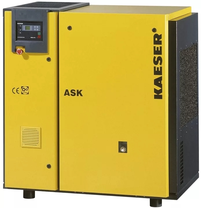
- Вовремя проводить техобслуживание. Разновидности услуг и требуемые расходники при конкретной наработке, как правило, зафиксированы в инструкции.
- Также важно регулярно проводить диагностику. Это ежедневный мониторинг, за который отвечает обслуживающий персонал: контроль рабочих характеристик, уровня масла, отражение показаний управляющей панели – включая ошибки.Также обслуживающий персонал отслеживают температуру в здании, вентиляцию (чтобы в ее работе не возникали сбои).
- Периодическую диагностику должны проводить сервисные инженеры. Ключевая составляющая обслуживания – гарант длительного и бесперебойного функционирования устройства.
БВА Сервис выполняет диагностику любых моделей винтовых электрических компрессоров Kaeser:
Aircenter 12, Aircenter 15, Aircenter 22, Aircenter 25, Aircenter 3, Aircenter 4, Aircenter 6, Aircenter 8, Aircenter 9, ASD 35, ASD 40, ASD 50, ASD 60, ASK 28, ASK 34, ASK 40, BSD 65, BSD 75, BSD 83, CSD5, CSD 125, CSD 85, CSDX 140, CSDX 165, CSG 120-2, CSG130-2, CSG 55-2, CSG 70-2, CSG 90-2, DSD 145, DSD 175, DSD 205, DSD 240, DSDX 245, DSDX 305, DSG 140-2, DSG 180-2, DSG 220-2, DSG 260-2, DSG 290-2, ESD 375, ESD 445, FSD 475, FSD 575, FSG 300-2, FSG 350-2, FSG 420-2, FSG 450-2, FSG 500-2, FSG 520-2, HSD 662, HSD 722, HSD 782, HSD 842, SK 22, SK 25, SM, SM 16, SX 3, SX 4, SX 6, SX 8, SXC 3, SXC 4, SXC 6, SXC 8.
БВА Сервис выполняет диагностику любых моделей винтовых дизельных компрессоров Kaeser:

M64, М100, М122, М123, М135, М17, М170, М20 РЕ, М200, М250, М27 РЕ, М31 РЕ, М350, М45, М50 РЕ, М57, М70, М80, М100 G, М13(РЕ), М135 G, М27Е, М36 G, М43 PE, М45 G, М46(РЕ) Е.
На периодичность, с которой диагностируют состояние винтового компрессора, влияют: интенсивность эксплуатации (24, 12, 8 часов), соответственно, 1 раз: в месяц, в два месяца и в три месяца.
Диагностика – одно из самых необходимых мероприятий для поддержания техники в рабочем состоянии
Она состоит из следующих этапов:
— режимов работы (загрузка, разгрузка, ожидание, холостой ход);
— клапанов (впускного, маслозапорного, обратного, термостатического, клапана минимального давления, дренажного);
— тока и напряжения в разных режимах работы;
— состояния шлангов и соединений (нет ли утечек);
— состояния приводных ремней и муфт;
— уровня масла, замер его расхода;
— вибрации подшипников винтового элемента и электродвигателя;
— системы сброса конденсата;
— состояния воздушных фильтров, при необходимости их очистка или замена.
- Продувки теплообменника (радиатора) – если это необходимо.
- Составления акта, где фиксируют рекомендации по плановым ремонтным работам.
Сотрудники нашей организации ежедневно видят разные ситуации, при которых компрессор выходит из строя. Время от времени инженеры нашей компании проходят обучающие курсы – с практическими занятиями. Мы детально исследуем любую аварийную ситуацию – наша база содержит огромное количество статистических данных по наработке и отказам узлов популярных компрессорных моделей. Наши мастера обладают специальным оборудованием и инструментами, благодаря которым выявляют и устраняют все возможные неполадки. Еще у нас имеются на складе все самые ходовые запчасти и расходники. Чтобы грамотно выявить, почему вышел из строя компрессор, советуем своевременно воспользоваться диагностикой устройства.
Вибродиагностика — метод диагностирования технических систем и оборудования. Берут в расчет параметры вибрации, издаваемой исследуемым компрессором. Если замерять этот показатель время от времени, можно оперативно увидеть изношенные детали. Так же вибродиагностика рекомендована после произведенного ремонта для оценки качества работ и правильности монтажа узлов оборудования.
Полноценный отчет о том, в каком состоянии находится Ваше устройство, нужно ли его ремонтировать, и во сколько обойдутся запчасти, Вы получите после диагностики. Как правило, речь идет о двух-трех днях!
Вероятные технические неполадки
Приведем краткий перечень неисправностей и причины их появления, на которые следует обратить внимание при диагностике промышленной компрессорной техники:
Неисправность:
— Компрессор начинает работать, но не переходит в режим загрузки.
— Неисправен электромагнит, залипло впускное устройство, порван шланг пневмоуправления, неисправен клапан минимального давления.
Неисправность:
— Не переходит в режим разгрузки, срабатывает предохранитель.
— Неисправен соленоид (электромагнит), не закрывается разгрузочный (впускной) устройство.
Неисправность:
— Выдает большое количество воды в сжатом воздухе.
— Сломан конденсатоотводчик, забит сливной шланг, не правильные условия эксплуатации компрессора.
Неисправность:
— Производительность или давление ниже нормы.
— Повреждено устройство разгрузки, загрязнен воздушный фильтр, поврежден соленоид, засорен маслоотделитель (маслосепаратор), разрушен винтовой блок, порван шланг пневматический, производительность компрессора ниже потребления воздуха.
Неисправность:
— Повышенное потребление масла / унос масла со сжатым воздухом в систему.
-Высокий уровень масла, неправильный тип масла, неисправен маслоотделитель или клапан минимального давления (работает при давлении менее 3,5 бар).
Неисправность:
— Температура сжатого воздуха на выходе из винтового элемента выше нормы
— Низкий уровень масла, засорен маслоотделитель, поврежден термостат, засорен радиатор охлаждения (воздухоохладитель), не работает вентилятор охлаждения, недостаточная подача притока воздуха в компрессорную, слишком высокая температура в компрессорной, неисправен винтовой элемент.
ВНИМАНИЕ! Если Вы заметили один, или несколько из этих признаков, немедленно обратитесь к специалистам!
- компрессор плохо включается или не перезапускается;
- отсутствие сжатого воздуха в выходном отверстии компрессора;
- низкая производительность;
- чрезмерный расход и утечка масла;
- непроизвольное открытие предохранительного клапана;
- отключение компрессора термостатом;
- повышенное давление;
- срабатывание прерывателя цепи.
По результатам диагностики наша компания может предложить следующие услуги
1. Техническое обслуживание, ремонт или замену:
— впускного (разгрузочного) клапана,
— маслозапорного клапана,
— обратного клапана,
— термостатического клапана,
— клапана минимального давления,
— дренажного клапана,
— винтового блока (элемент сжатия),
— электродвигателя,
— вентилятора,
— воздухоохладителя,
— блока управления,
— электрического щита и его компонентов,
— датчиков — давления, температуры, включения.
2. ТО компрессора согласно его наработке и состояния.
3. Провести выше обозначенные работы с системами подготавливающими сжатый воздух.
4. Пневмоаудит.
Это только основные услуги, при необходимости возможно оказание и дополнительных услуг, по договоренности с заказчиком.

Выезжаем в любой район Москвы и Московской области
Компания БВА Сервис предлагает качественную диагностику компрессоров в Москве и Московской области .
Мы производим диагностику как в нашем сервисном центре, так и на месте поломки, куда выезжает специалист сервисного центра.
Причины выбрать нас
Принимая решение о выборе исполнителя, важно проанализировать не только стоимость работ, но и спектр предоставляемых им услуг и отзывы клиентов!
Источник
РЕМОНТ КОМПРЕССОРОВ
Скорая техническая помощь +7 (812) 467-48-24
Что за код сообщения?
Что за код сообщения?
Сообщение Олег104 » 01 апр 2019, 18:27
Re: Что за код сообщения?
Сообщение engineger » 02 апр 2019, 09:47
Re: Что за код сообщения?
Сообщение Олег104 » 02 апр 2019, 12:38
Re: Что за код сообщения?
Сообщение engineger » 08 апр 2019, 08:24
Re: Что за код сообщения?
Сообщение engineger » 05 май 2019, 09:11
Re: Что за код сообщения?
Сообщение Lyaksey » 15 окт 2019, 15:27
Re: Что за код сообщения?
Сообщение engineger » 16 окт 2019, 12:17
Re: Что за код сообщения?
Сообщение Maxim » 15 ноя 2019, 17:02
CH3 — это пришло время заменить воздушный фильтр на компрессоре. После замены нужно обновить счетчик сервисного обслуживания.
Вот выдержка из инструкции CH1 Окончание срока работы масла.
Необходимо произвести замену масла.
CH2 Окончание срока работы масляного фильтра.
Необходимо произвести замену масляного фильтра.
CH3 Окончание срока работы воздушного фильтра.
Необходимо произвести замену воздушного фильтра.
CH4 Окончание срока работы маслобака сепаратора.
Необходимо произвести замену фильтра-сепаратора масла.
Если одновременно выявляются более одной сигнализации, то они визуализируются в последовательности.
Здравствуйте, не получается сбросить ошибку СН3.
Фильтр поменяли ошибка не сбрасывается.
Источник


- Ответить с цитатой
KAESER SK 22 T ошибка 3 (контроллер Sigma)
Часто сталкиваюсь с ошибкой 3 на данных компрессорах. Вопрос — кто ка эту ошибку скидывает.
- Ведущий специалист
- Сообщений: 161
- Зарегистрирован: 13 июл 2016, 14:34
- Откуда (город): Вельск
- Ответить с цитатой
Re: KAESER SK 22 T ошибка 3
![]() Sure_man » 28 мар 2018, 16:09
Sure_man » 28 мар 2018, 16:09
привет.
давай фото контроллера и ошибки — разбем проблему..
- Ведущий специалист
- Сообщений: 80
- Зарегистрирован: 24 фев 2015, 17:45
- Ответить с цитатой
Re: KAESER SK 22 T ошибка 3
![]() vasy01 » 30 мар 2018, 08:33
vasy01 » 30 мар 2018, 08:33
Проблему решил. Правда ни одна из причин её возникновения не совпадает с тем , что прописано в мануале.
- Вложения
-

- IMG_20170620_153406.jpg (40.15 KiB) Просмотров: 1516
- Ведущий специалист
- Сообщений: 161
- Зарегистрирован: 13 июл 2016, 14:34
- Откуда (город): Вельск
- Ответить с цитатой
Re: KAESER SK 22 T ошибка 3 (контроллер Sigma)
![]() Timur89 » 02 сен 2022, 12:03
Timur89 » 02 сен 2022, 12:03
Добрый день. Очень хотелось бы узнать в чем была проблема ошибка 3? У меня такая же проблема. Все способы проверки не дают результатов. Даже с перемычкой на клапане противодавления все равно появляется периодически ошибка 3. Пожалуйста помогите, в чем может быть проблема?
- Сообщений: 2
- Зарегистрирован: 02 сен 2022, 11:49
- Откуда (город): Shimkent
- Ответить с цитатой
Re: KAESER SK 22 T ошибка 3
![]() Timur89 » 02 сен 2022, 12:04
Timur89 » 02 сен 2022, 12:04
vasy01 писал(а):Проблему решил. Правда ни одна из причин её возникновения не совпадает с тем , что прописано в мануале.
Как решили?
- Сообщений: 2
- Зарегистрирован: 02 сен 2022, 11:49
- Откуда (город): Shimkent
Вернуться в Винтовые компрессорные установки
Перейти:
Кто сейчас на форуме:
Сейчас этот форум просматривают: нет зарегистрированных пользователей и гости: 1