Довольно часто встречается необходимость самодиагностики автомобиля Iveco,представляю вашему вниманию коды самодиагностики пользуйтесь:
Таблица кодов неисправностей блока управления EDC MS6.2 SW 5.X
Мигающий код Контрольная лампа EDC* Неисправность
АВТОМОБИЛЬ
1.1 СВЕТИТСЯ ПОСТОЯННО Сигнал скорости автомобиля
1.2 СВЕТИТСЯ ПОСТОЯННО Переключатель крутящего момента
1.3 ВЫКЛЮЧЕНА Круиз-контроль
1.4 СВЕТИТСЯ ПОСТОЯННО Педаль акселератора.
1.5 ВЫКЛЮЧЕНА Датчик нажатия сцепления
1.6 светится постоянно Правдоподобие сигнала датчиков педали тормоза
1.7 ВЫКЛЮЧЕНА Правдоподобие соотношения между педалями акселератора и тормоза
ДВИГАТЕЛЬ
2.1 ВЫКЛЮЧЕНА Датчик температуры охлаждающей ‘жидкости
2.2 ВЫКЛЮЧЕНА Датчик температуры воздуха
2.3 ВЫКЛЮЧЕНА Датчик температуры топлива
2.4 светится постоянно Датчик давления наддува
2.5 ВЫКЛЮЧЕНА Датчик атмосферного давления (внутри блока управления)
2.6 светится постоянно Сигнал датчика моторного тормоза
3.5 ВЫКЛЮЧЕНА Напряжение аккумулятора
ТУРБИНА
4.1 ВЫКЛЮЧЕНА Датчик давления в приводе турбины
4.2 светится постоянно Датчик частоты вращения турбины
4.3 светится постоянно Повышенная частота вращения турбины
4.4 светится постоянно Управление турбиной (механическая неисправность)
4.5 светится постоянно Электромагнитный клапан турбины с изменяемой геометрией
4.6 МИГАЕТ Электромагнитный клапан управления моторным тормозом
ФОРСУНКИ
5.1 светится постоянно Неисправность форсунки цилиндра 1
5.2 светится постоянно Неисправность форсунки цилиндра 2
5.3 светится постоянно Неисправность форсунки цилиндра 3
5.4 светится постоянно Неисправность форсунки цилиндра 4
5.5 светится постоянно Неисправность форсунки цилиндра 5
5.6 светится постоянно Неисправность форсунки цилиндра 6
ДАТЧИКИ ЧАСТОТЫ ВРАЩЕНИЯ ДВИГАТЕЛЯ
6.1 светится постоянно Датчик на маховике
6.2 светится постоянно Датчик на шестерне газораспределительного механизма
6.4 МИГАЕТ Повышенная частота вращения двигателя
ИНТЕРФЕЙС С ДРУГИМИ БЛОКАМИ УПРАВЛЕНИЯ
7.2 светится постоянно Линия CAN
7.3 светится постоянно Линия CAN (управление Eurotronic]
7.4 светится постоянно Линия CAN (управление EBS)
7.5 светится постоянно Линия CAN (управление intarder) .
7.6 светится постоянно Ошибка CAN (обмен данными с другими блоками управления)
77 светится постоянно Превышен лимит времени [обмен данными с другими блоками управления)
БЛОК УПРАВЛЕНИЯ
9.1 МИГАЕТ Неисправен блок управления
9.2 . светится постоянно Ошибочные данные в EPROM
9.3 МИГАЕТ Иммобилайзер
9.4 светится постоянно Пусковое реле
9.5 светится постоянно Ошибочная процедура остановки двигателя
9.6 светится постоянно В блоке управления записаны ошибочные данные
Контрольная лампа мигающего кода выключена
Контрольная лампа мигающего кода светится постоянно
Контрольная лампа мигающего кода мигает
Незначительная ошибка
Существенная ошибка
Серьезная ошибка
ЭЛЕКТРОННЫЙ БЛОК УПРАВЛЕНИЯ 0.49 ECAS 6X2 P / FP 6X2 C и 0.27 4X2 / 6X4
СЧИТЫВАНИЕ МИГАЮЩЕГО КОДА
1. Замкнуть на массу линию L системы диагностики приблизительно на 2 секунды.
2. Начнется индикация мигающего кода, состоящего из двух цифр.
Мигающий код состоит из медленных и быстрых вспышек.
Например, код 32 определяется так:.
3 (ДЕСЯТКИ) = МЕДЛЕННЫЕ ВСПЫШКИ (2 секунды)
2 (ЕДИНИЦЫ) = БЫСТРЫЕ ВСПЫШКИ (0,5 СЕКУНДЫ)
СТИРАНИЕ ПАМЯТИ НЕИСПРАВНОСТЕЙ
1. Замкнуть линию L на массу.
2. При выключенном зажигании подождать не менее 2 секунд
3. Включить зажигание и подождать не менее 2 секунд
После выполнения этих операций неисправности, записанные в электронном блоке управления, стираются.
ТАБЛИЦА МИГАЮЩИХ КОДОВ ЭЛЕКТРОННОГО БЛОКА УПРАВЛЕНИЯ 0.49 «ECAS «6X2 P / FP 6X2 C
ТИП НЕИСПРАВНОСТИ
ЭЛЕКТРОННЫЙ БЛОК УПРАВЛЕНИЯ КОД НЕИСПРАВНО-СТИ
Ошибки в памяти 01
Ошибка в параметрах калибровки датчиков уровня в памяти 02
Ошибка параметров в памяти 03
Ошибка в параметрах калибровки датчиков давления в памяти 07
Образцы значений для датчиков уровня в памяти 09
Неисправность памяти 04
Неисправность в электронном блоке управления 06 / 08 / 80
Сигнал скорости автомобиля (обрыв или замыкание на + постоянного тока) 81
Неисправность датчиков уровня: обрыв или короткое замыкание на + постоянного тока
Неисправность правого заднего датчика уровня 10
Неисправность левого заднего датчика уровня 11
Неисправность переднего датчика уровня 12
Неисправность датчиков давления: короткое замыкание на + постоянного тока
Неисправность правого заднего датчика давления 14
Неисправность левого заднего датчика давления 15
Неисправность правого датчика давления третьей оси / подъемной 16
Неисправность левого датчика давления третьей оси / подъемной 17
Неисправность датчиков уровня: короткое замыкание на массу
Неисправность правого заднего датчика уровня 20
Неисправность левого заднего датчика уровня 21
Неисправность переднего датчика уровня 22
Неисправность датчиков давления: разрыв / короткое замыкание на массу
Неисправность правого заднего датчика давления 24
Неисправность левого заднего датчика давления 25
Неисправность правого датчика давления третьей оси / подъемной 26
Неисправность левого датчика давления третьей оси / подъемной 27
ТАБЛИЦА МИГАЮЩИХ КОДОВ ЭЛЕКТРОННОГО БЛОКА УПРАВЛЕНИЯ 0.49 «ECAS «6X2 P / FP 6X2 C
Неисправность реле / электроклапанов: короткое замыкание на + постоянного тока
Неисправность впускного / выпускного электроклапана 30
Неисправность левого заднего электроклапана 31
Неисправность правого заднего электроклапана 32
Неисправность левого электроклапана третьей оси / подъемной 33
Неисправность правого электроклапана третьей оси / подъемной 34
Неисправность переднего клапана 36
Неисправность реле управления подъемом третьей оси 37
Неисправность реле управления гидронасосом 38
Неисправность реле / электроклапанов: короткое замыкание на массу Код Выход
Впускной / выпускной электроклапан 40 15
Неисправность левого заднего электроклапана 41 13
Неисправность правого заднего электроклапана 42 31
Неисправность левого электроклапана третьей оси / подъемной 43 12
Неисправность правого электроклапана третьей оси / подъемной 44 30
Передний электроклапан 46 11
Неисправность реле управления подъемом третьей оси 47 14
Неисправность реле управления гидронасосом 48 32
Несовместимость подъема рамы и наполнения подушек
Неисправность правого заднего датчика уровня 50 8
Неисправность левого заднего датчика уровня 51 25
Неисправность переднего датчика уровня 52 26
Неисправность правого датчика давления подъемной оси 56 23
Неисправность левого датчика давления подъемной оси 57 7
Несовместимость опускания рамы и стравливания воздуха из подушек
Неисправность правого заднего датчика уровня 60 8
Неисправность левого заднего датчика уровня 61 25
Неисправность переднего датчика уровня 62 26
Неисправность правого заднего датчика давления 64 23
Неисправность левого заднего датчика давления 65 7
Неисправность правого датчика давления третьей оси / подъемной 66 5
Неисправность левого датчика давления третьей оси / подъемной 67 6
ТАБЛИЦА МИГАЮЩИХ КОДОВ ЭЛЕКТРОННОГО БЛОКА УПРАВЛЕНИЯ 0.27 «ECAS «4X2 / 6X2»
ТИП НЕИСПРАВНОСТИ КОД НЕИСПРАВНО-СТИ
Ошибка параметров конфигурации электронного блока управления 01
Ошибка параметров калибровки 02
Неисправность внутренней памяти 03 / 04
Образцы значений для датчиков уровня 06
Правый задний датчик уровня
Обрыв / короткое замыкание на плюс 10
Короткое замыкание на массу 14
Несовместимость сигналов при подъеме рамы 40
Несовместимость сигналов при опускании рамы 44
Левый задний датчик уровня
Обрыв / короткое замыкание на плюс 11
Короткое замыкание на массу 15
Несовместимость сигналов при подъеме рамы 41
Несовместимость сигналов при опускании рамы 45
Передний датчик уровня
Обрыв / короткое замыкание на плюс 12
Короткое замыкание на массу 16
Несовместимость сигналов при подъеме рамы 42
Несовместимость сигналов при опускании рамы 46
Впускной / выпускной электроклапан
Обрыв / короткое замыкание на плюс 20
Короткое замыкание на массу 30
Передний электроклапан
Обрыв / короткое замыкание на плюс 23
Короткое замыкание на массу 33
Правый задний электроклапан
Обрыв / короткое замыкание на плюс 22
Короткое замыкание на массу 32
Левый задний электроклапан
Обрыв / короткое замыкание на плюс 21
Короткое замыкание на массу 31
СТИРАНИЕ ПАМЯТИ НЕИСПРАВНОСТЕЙ
1. Включить зажигание.
2. Приблизительно на 2 секунды одновременно нажать кнопку мигающего кода и выжать педаль тормоза.
3. Сигнальная лампочка системы EDC гаснет, если в системе нет неисправностей. не делай лишнего
Check Engine — диагностика легковых и грузовых автомобилей. www.trucksservice.narod.ru
Добавлять комментарии могут только зарегистрированные пользователи.
Регистрация | Вход
Во время диагностики своего транспортного средства компьютер в случае неисправностей получает код ошибки, которая может быть расшифрована специалистом. Здесь представлены некоторые варианты кодов ошибок и их значений.
Неисправности датчиков скорости и педалей, датчиков давления топлива, цепей управления форсунками, контроллеров, иммобилайзера и многого другого.
Приезжайте к нам для полной диагностики Вашего автомобиля Iveco по адресу: г. Минск, ул. Монтажников 51, корп. 1
✆ +375 29 186 00 59 ✆ +375 33 676 00 59
|
0111 |
Неисправность цепи датчика скорости автомобиля |
|
0112 |
Неисправность цепи датчика 1 положения педали ускорения |
|
0113 |
Несоответствие сигналов выключателей тормоза и датчиков педали ускорения |
|
0116 |
Неисправность цепи выключателя педали сцепления |
|
0117 |
Некорректный сигнал выключателей педали тормоза |
|
0119 |
Пропадание напряжения бортовой сети на контроллере от клеммы «15» |
|
0122 |
Неисправность цепи управления лампой MIL (Check Engine) |
|
0126 |
Напряжение бортовой сети вне рабочего диапазона контроллера |
|
0131 |
Неисправность цепи датчика температуры охлаждающей жидкости |
|
0132 |
Некорректный сигнал цепи датчика температуры охлаждающей жидкости |
|
0133 |
Неисправность цепи датчика температуры воздуха на впуске |
|
0134 |
Неисправность цепи датчика давления наддувочного воздуха |
|
0135 |
Неисправность цепи датчика температуры топлива |
|
0136 |
Неисправность цепи датчика давления топлива в рампе |
|
013A |
Неисправность цепи датчика температуры масла |
|
013E |
Низкий уровень сигнала в цепи датчика давления охлаждающей жидкости |
|
013F |
Некорректный сигнал в цепи давления охлаждающей жидкости |
|
0141 |
Неисправность или обрыв цепи датчика (частоты) положения коленчатого вала |
|
0143 |
Неисправность цепи датчика (фазы) положения распределительного вала |
|
0144 |
Несоответствие сигналов датчиков синхронизации (частоты и фазы) |
|
0145 |
Неисправность цепи управления реле электровентилятора 1 |
|
0149 |
Неисправность цепи нагревателя топлива |
|
014D |
Предельно-допустимая частота вращения коленчатого вала двигателя |
|
0151 |
Высокий уровень сигнала цепи датчика давления топлива в рампе |
|
0152 |
Повышенное давление топлива в рампе |
|
0153 |
Пониженное давление топлива в рампе |
|
0154 |
Давление топлива в рампе выше максимально допустимого |
|
0155 |
Давление топлива в рампе ниже минимально допустимого |
|
0159 |
Неисправность цепи топливного насоса высокого давления (ТНВД) |
|
015C |
Некорректное время впрыска топлива для форсунки цилиндра 1 |
|
015D |
Некорректное время впрыска топлива для форсунки цилиндра 3 |
|
015E |
Некорректное время впрыска топлива для форсунки цилиндра 5 |
|
015F |
Неисправность топливной системы, влияющая на токсичные выбросы |
|
0161 |
Неисправность цепи управления форсункой 1 |
|
0162 |
Неисправность цепи управления форсункой 2 |
|
0163 |
Неисправность цепи управления форсункой 3 |
|
0164 |
Неисправность цепи управления форсункой 4 |
|
0165 |
Неисправность цепи управления форсункой 5 |
|
0166 |
Неисправность цепи управления форсункой 6 |
|
0167 |
Обрыв или короткое замыкание на «массу» цепи управления форсункой 4 |
|
0168 |
Неисправность цепи управления форсункой 1 |
|
0169 |
Неисправность цепи управления форсункой 1 |
|
016A |
Неисправность цепи управления форсункой 1 |
|
016B |
Неисправность цепи управления форсункой 1 |
|
016C |
Предельное падение крутящего момента в цилиндре 1 |
|
016E |
Минимально необходимое количество впрысков не выполнено |
|
0171 |
Неисправность канала 1 управления форсунками |
|
0173 |
Неисправность канала 2 управления форсунками |
|
017C |
Контроллер: Неисправность канала (драйвера) 1 управления форсунками |
|
017D |
Общая неисправность системы сгорания топливовоздушной смеси |
|
017F |
Контроллер: некорректная запись или отсутствие записи IMA-кодов форсунок |
|
0182 |
Неисправность цепи датчика температуры воздуха на впуске (ДМРВ) |
|
0183 |
Низкий уровень сигнала в цепи датчика массового расхода воздуха |
|
0185 |
Высокий уровень сигнала в цепи датчика массового расхода воздуха |
|
0187 |
Повышенный расход воздуха через клапан рециркуляции ОГ |
|
0188 |
Пониженный расход воздуха через клапан рециркуляции ОГ |
|
0189 |
Короткое замыкание на бортовую сеть цепи управления клапаном рециркуляции |
|
018B |
КЗ на бортовую сеть цепи управления дросселем клапана рециркуляции ОГ |
|
018C |
Система топливоподачи слишком «бедная» при ее максимальном обогащении |
|
018D |
Токсичные выбросы окислов азота (NOx) выше первого порога |
|
0192 |
Короткое замыкание на бортовую сеть цепи управления турбокомпрессором |
|
0194 |
Повышенная производительность (мощность) турбокомпрессора |
|
0195 |
Пониженная производительность (мощность) турбокомпрессора |
|
019E |
Ограничение вращающего момента, вызванное неисправностями систем ДВС |
|
01A8 |
Предельно-допустимая температура дозирующего клапана мочевины |
|
01B1 |
Обрыв информационной CAN-линии «Н» |
|
01B3 |
Обрыв информационной CAN-линии «L» |
|
01B7 |
Информационная CAN-шина занята |
|
01BA |
CAN-шина: нет ответа от комбинации приборов автомобиля |
|
01C3 |
CAN-шина: нет ответа от тахографа |
|
01D1 |
Контроллер: неисправность SPI-канала |
|
01D2 |
Контроллер: неисправность EEPROM-памяти |
|
01D3 |
Контроллер: заблокирован для пуска двигателя |
|
01D4 |
Контроллер: неисправность микропрограммы перезагрузки |
|
01D5 |
Контроллер: ошибка программы инициализации |
|
01D6 |
Контроллер: ошибка внутренней синхронизации |
|
01D7 |
Контроллер: некорректный вариант калибровок управления двигателем |
|
01D8 |
Контроллер: неисправность микропрограммы перезагрузки |
|
01D9 |
Контроллер: неисправность аналого-цифрового преобразователя сигналов |
|
01DA |
Контроллер: неисправность флэш-ПЗУ (ошибка контрольной суммы) |
|
03D3 |
Контроллер: ошибка программы инициализации |
|
01E2 |
Иммобилайзер: неисправность блока или его цепей (топливоподача блокирована) |
|
01E3 |
Ошибка программы мониторинга систем двигателя |
|
01E4 |
Повышенная частота вращения коленчатого вала двигателя |
|
01E6 |
Контроллер: напряжение типа 1 для питания датчиков вне диапазона |
|
01E7 |
Контроллер: напряжение типа 2 для питания датчиков вне диапазона |
|
01E8 |
Контроллер: напряжение типа 3 для питания датчиков вне диапазона |
|
01E9 |
Контроллер: напряжение питания выше допустимого |
|
01EA |
Контроллер: напряжение питания ниже допустимого |
|
01EB |
Неисправность цепи датчика атмосферного (абсолютного) давления воздуха |
|
01F1 |
Неисправность цепи датчика засоренности сажевого фильтра |
|
01F2 |
Некорректный сигнал в цепи датчика засоренности сажевого фильтра |
|
01F3 |
Неисправность цепи датчика засоренности сажевого фильтра фильтра |
|
01F4 |
Низкий уровень сигнала в цепи датчика засоренности сажевого фильтра |
|
01F5 |
Высокий уровень сигнала цепи датчика засоренности сажевого фильтра |
|
01F6 |
Неисправность датчика температуры ОГ до нейтрализатора |
|
01F7 |
Неисправность цепи датчика температуры отработавших газов |
|
01F8 |
Некорректный сигнал в цепи датчика температуры отработавших газов |
|
01F9 |
Высокий уровень регенерации сажевого фильтра |
|
01FA |
Низкий уровень регенерации сажевого фильтра |
|
01FB |
Эффективность нейтрализатора ниже допустимой нормы |
|
01FC |
Медленный отклик на изменение температуры датчика до нейтрализатора |
|
0212 |
Неисправность цепи датчика 2 положения педали ускорения |
|
0215 |
Неустранимый отказ системы автоматического бортового контроля |
|
0225 |
Неисправность цепи управления главным реле |
|
022B |
Неисправность силовой цепи свечей накаливания |
|
022E |
Неисправность цепи управления реле подкачивающего электробензонасоса |
|
0232 |
Сигнал датчика температуры охлаждающей жидкости вне диапазона |
|
0236 |
Некорректный сигнал в цепи датчика давления топлива в рампе при останове ДВС |
|
023A |
Высокий уровень сигнала в цепи датчика температуры масла |
|
0251 |
Повышенное давление топлива в рампе |
|
0259 |
Короткое замыкание на бортовую сеть цепи управления ТНВД |
|
025C |
Некорректное время впрыска топлива для форсунки цилиндра 2 |
|
025D |
Некорректное время впрыска топлива для форсунки цилиндра 4 |
|
025E |
Некорректное время впрыска топлива для форсунки цилиндра 6 |
|
025F |
Неисправность системы впрыска топлива, влияющая на выбросы NOx |
|
0275 |
Некачественное сгорание топливовоздушной смеси в цилиндре 1 |
|
0276 |
Некачественное сгорание топливовоздушной смеси в цилиндре 2 |
|
0277 |
Некачественное сгорание топливовоздушной смеси в цилиндре 3 |
|
0278 |
Некачественное сгорание топливовоздушной смеси в цилиндре 4 |
|
0279 |
Некачественное сгорание топливовоздушной смеси в цилиндре 5 |
|
027A |
Некачественное сгорание топливовоздушной смеси в цилиндре 6 |
|
027C |
Контроллер: Неисправность канала (драйвера) 2 управления форсунками |
|
0281 |
Недостоверный расход воздуха через клапан рециркуляции ОГ |
|
0283 |
Предельно допустимое отклонение расхода воздуха на рабочем режиме |
|
0285 |
Предельно допустимое отклонение расхода воздуха на холостом ходу |
|
0286 |
Сигнал датчика массового расхода воздуха вне допустимого диапазона |
|
0287 |
Повышенный расход воздуха через клапан рециркуляции ОГ |
|
0288 |
Пониженный расход воздуха через клапан рециркуляции ОГ |
|
0289 |
Короткое замыкание на «массу» цепи управления клапаном рециркуляции ОГ |
|
028B |
КЗ на «массу» цепи управления дросселем клапана рециркуляции ОГ |
|
0292 |
Обрыв или КЗ на «массу» цепи управления турбокомпрессором |
|
02B4 |
CAN-шина: нет ответа от маршрутного компьютера или тестового оборудования |
|
02C9 |
CAN-шина: неверные данные от комбинации приборов или тахографа |
|
02F8 |
Некорректный сигнал в цепи датчика температуры отработавших газов |
|
02FF |
Критическое время впрыска для растворения масла в цилиндре двигателя |
|
0315 |
Устранимый отказ системы автоматического бортового контроля |
|
032B |
Неисправность цепи управления реле свечами накаливания |
|
0359 |
Короткое замыкание на «массу» цепи управления ТНВД |
|
035F |
Неисправность системы питания воздухом, влияющая на токсичные выбросы |
|
0385 |
Предельно допустимое отклонение расхода воздуха на нагрузочном режиме |
|
0386 |
Сигнал датчика массового расхода воздуха вне допустимого диапазона |
|
0389 |
Открытое состояние клапана рециркуляции или повышенная температура ОГ |
|
038B |
Открытое состояние дросселя КРЦ или повышенная температура ОГ |
|
0392 |
КЗ на бортовую сеть цепи управления турбокомпрессором и высокая температура |
|
039D |
Вероятное превышение норм токсичных выбросов (OBD) — богатая смесь |
|
039E |
Ограничение крутящего момента двигателя с целью защиты турбокомпрессора |
|
03C9 |
CAN-шина: высокая загрузка канала |
|
03F3 |
Некорректный сигнал в цепи датчика засоренности сажевого фильтра |
|
03F8 |
Неисправность цепи датчика температуры отработавших газов после фильтра |
|
03FA |
Низкий уровень 2 регенерации сажевого фильтра |
|
045F |
Неисправность лямбда-регулятора, влияющая на токсичные выбросы |
|
0486 |
Недостоверный сигнал в цепи датчика температуры впускного воздуха |
|
04FA |
Низкий уровень 3 регенерации сажевого фильтра |
|
055F |
Неисправность системы рециркуляции ОГ, влияющая на токсичные выбросы |
|
0601 |
Неисправность сигнальной цепи или потеря активности датчика кислорода 1 |
|
0602 |
Неисправность цепи нагревателя датчика кислорода 1 |
|
0603 |
Сигнал датчика кислорода 1 вне допустимого диапазона |
|
0604 |
Неисправность цепи нагревателя датчика кислорода 1 |
|
0605 |
Сигнал датчика кислорода 1 вне допустимого диапазона |
|
0606 |
Неисправность сигнальной цепи или потеря активности датчика кислорода 1 |
|
0607 |
Сигнал датчика кислорода 1 вне допустимого диапазона |
|
0609 |
Контроллер: недостоверный сигнал датчика кислорода 1 |
|
060A |
Контроллер: обрыв или КЗ на «массу» цепи нагревателя датчика кислорода 1 |
|
060C |
Обрыв или КЗ на «массу» цепи нагревателя датчика кислорода 1 |
|
060D |
Сигнал датчика кислорода 1 вне допустимого диапазона (полная нагрузка) |
|
060E |
Сигнал датчика кислорода 1 вне допустимого диапазона (частичная нагрузка) |
|
060F |
Сигнал датчика кислорода 1 вне допустимого диапазона (останов двигателя) |
|
069E |
Ограничение крутящего момента двигателя в связи с неисправностями впрыска |
Для поддержания автомобиля в рабочем состоянии необходимо периодически проводить диагностику и устанавливать на замену только качественные запчасти, которые будут служить долго и не подведут в ответственный момент.
Данные коды ошибок помогут прояснить картину того, что может работать не так и приступить к исправлению проблемы. Оказать качественные услуги ремонта может только профессионал. Наши сотрудники имеют 10-ти летний опыт в данной области.
Приезжайте к нам для полной диагностики Вашего автомобиля Iveco по адресу: г. Минск, ул. Монтажников 51, корп. 1
✆ +375 29 186 00 59 ✆ +375 33 676 00 59

29
E
URO
T
RAKKER
C
URSOR
13
ДВИГАТЕЛЬ
29
ИМ
П
У
ЛЬ
СНЫ
Й
КОД
ЛА
МПА
ED
C
ВО
З
М
О
Ж
НА
Я
П
РИЧ
ИН
А
ВО
З
М
О
Ж
НЫ
Е
П
О
СЛ
ЕД
СТ
ВИ
Я
ПО
РЯ
Д
О
К
ПР
ОВ
ЕР
К
И
,
РЕ
КОМ
ЕН
Д
ОВ
А
ННЫ
Е
ДЕ
Й
С
ТВ
ИЯ
П
РИМ
ЕЧ
А
Н
ИЯ
(4
.1
)
(4
.4
)
(Вы
êлю
че
на
)
(В
êлю
че
на
по
—
ст
оя
нн
о)
Сж
ат
ый
во
зд
óх
не
по
ст
óпа
ет
в
ê
ла
—
па
н
тó
рб
ин
ы
с
из
ме
няе
м
ой
ãео
м
ет
—
ри
ей
или
да
вл
ен
ие
во
зд
óха
не
до
ст
а-
точн
о.
Ни
зê
ая
мо
щ
но
ст
ь
при
низ
êой
ча
ст
от
е
вр
ащ
ен
ия
и
пр
и
ра
зã
он
е.
Возм
ож
но
сн
иж
ен
ие
эф
—
фе
êтив
нос
ти
мо
то
рн
оã
о
торм
оз
а.
Пр
ов
ер
êа
дви
ãателя
: а
êтив
на
я
диа
ãно
ст
иê
а
прив
од
а
тó
рби
ны
.
Пр
ов
ер
ьт
е,
по
ст
óпа
ет
ли
сж
ат
ый
во
зд
óх
в
ê
ам
ер
ó
тó
рб
ин
ы.
Пр
о-
ве
рь
те
р
абот
ос
пос
обн
ос
ть
эл
еê-
тр
ом
аã
нит
но
ãо
ê
ла
па
на
от
се
чê
и,
ра
сп
ол
ож
ен
но
ãо
на
ра
ме
ша
сси
.
Ес
ли
ê
ла
па
н
не
р
абот
ае
т,
пр
о-
ве
рь
те
ра
зъ
ем
ы,
эл
еê
тр
опр
ов
од
êó,
де
та
ли
и
ра
зъ
ем
на
пе
ре
ãор
од
êе
м
отоотс
еê
а.
Ес
ли
эл
еê
тр
ом
аã
нит
ны
й
êла
па
н
отс
еч
êи
р
абот
ает
, пр
о-
ве
рь
те
, ê
аê
пр
ол
ож
ен
ы
пн
ев
м
ати
че
—
сê
ие
тр
óб
êи
от
ê
ла
па
на
отс
еч
êи
ê
êам
ер
е
тó
рб
ин
ы
и ê
ре
пл
ен
ие
тр
óб
êи
ê ê
ам
ер
е.
Пр
ов
ер
ьт
е
ме
ха
ни
че
сê
ие
ха
ра
êтери
ст
иê
и
эл
еê
тр
ом
аã
ни
тно
ãо
êла
па
на
ó
пр
ав
ле
ни
я
тó
рб
ин
ы
с
из
—
ме
ня
ем
ой
ãеом
ет
ри
ей
.
(4
.1
)
(4
.4
)
(Вы
êлю
че
на
)
(В
êлю
че
на
по
ст
оя
нн
о)
Ме
ха
низ
м
т
óрб
ин
ы
с
из
ме
няе
м
ой
ãеом
ет
ри
ей
за
êли
нило
в
про
м
еж
óточн
ом
по
ло
ж
ен
ии
. Ни
зê
ая
мо
щ
но
ст
ь
при
низ
êой
и
ср
ед
не
й
ча
ст
от
е
вр
ащ
ен
ия
и
пр
и
ра
зã
он
е.
Возм
ож
но
сн
иж
ен
ие
эффе
êти
вн
ос
ти
мо
то
рн
оã
о
торм
оз
а.
Пр
ов
ер
êа
дви
ãателя
: т
óрб
ин
а
с
из
ме
няе
м
ой
ãеом
ет
ри
ей
, мо
то
рн
ый
торм
оз
. А
êти
вн
ая
ди
аã
но
ст
иê
а
прив
од
а
тó
рб
ин
ы.
Если
ме
ха
ни
зм
на
рó
жн
оã
о
ры
ча
ãа
óпр
ав
ле
ни
я
тó
рб
ин
ы
с
из
ме
няе
м
ой
ãео
м
етр
ие
й
ра
бо
та
ет
, и
пр
и
пров
ер
êе
тó
рб
ин
ы
вы
явл
яе
тс
я
ош
иб
êа
, не
ис
пр
ав
—
но
ст
ь
след
óет
ис
êать
в
ме
ха
ни
зме
пе
ре
ме
ще
ни
я
ло
па
ст
ей
в
тó
рб
ин
е.
4.5
Вê
лю
че
на
по
ст
оя
нн
о
Неи
сп
ра
вн
ос
ть
эл
еê
тр
ич
ес
êой
час
ти
эл
еê
тр
ом
аã
ни
тно
ãо
ê
ла
па
на
тó
рби
ны
с
из
ме
няе
м
ой
ãеом
етр
ие
й.
Зн
ач
ит
ел
ь-
но
е
сни
ж
ен
ие
мо
щ
но
ст
и
на
ни
зê
ой
ча
сто
те
вр
ащ
ен
ия
и
пр
и
ра
зã
он
е.
Сн
иж
ен
ие
эффе
êтив
нос
ти
мо
то
рн
оã
о
торм
оз
а.
Пр
ов
ер
êа
дви
ãателя
: пр
ов
ер
ьт
е
эл
еê
тр
опр
ов
од
êó
, ра
зъ
ем
ы
и
др
óã
ие
êо
м
по
не
нт
ы
эл
еê
тр
ооб
ор
óдо
ва
ни
я.
4.6
Ми
ãае
т
Э
ле
êтр
ом
аã
ни
тны
й ê
ла
па
н
óпр
ав
ле
ни
я
мо
то
рн
ым
то
рм
оз
ом
. Не
ра
бот
ае
т
мо
то
рн
ый
то
рм
оз
.
Пр
ов
ер
êа
дви
ãателя
: пр
ов
ер
ьт
е
эл
еê
тр
опр
ов
од
êó
, ра
зъ
ем
ы
и
др
óã
ие
êо
м
по
не
нт
ы
эл
еê
тр
ооб
ор
óдо
ва
ни
я.
Ес
ли
мо
то
рн
ый
торм
оз
не
б
óде
т
ра
бот
ат
ь
при
пр
ов
ер
êе
дви
ãат
ел
я,
зн
ач
ит
на
эл
еê
тр
ом
аã
ни
тны
й ê
ла
па
н
не
по
да
ет
ся
на
пр
яж
ен
ие
.
5.x
Вê
лю
че
на
по
ст
оя
нн
о
Не
ис
пр
ав
но
ст
ь
в
эл
еê
трич
ес
êой
це
пи
фо
рс
óн
êи
ци
ли
ндр
а X.
Сн
иж
ен
ие
ча
ст
оты
вр
ащ
ен
ия
ê
ол
ен
ча
то
ãо
ва
ла
,
ра
бот
аю
т
тол
ьê
о 5
ци
ли
нд
ро
в
дви
ãат
ел
я.
Пр
ов
ер
êа
дви
ãателя
(если
неи
сп
ра
вн
ост
ь
им
еет
ме
ст
о):
пр
ов
ер
ьте
эл
еê
тр
оп
ро
во
дêó,
ра
зъ
ем
ы
и
др
óã
ие
ê
ом
по
не
нт
ы
эл
еê
тр
ообор
óдо
ва
ни
я (
а
та
êже
ж
ãó
т
пр
ов
од
ов
, ид
óщи
й ê ã
ол
ов
êе
бл
оê
а
ци
ли
ндр
ов
).

30
ДВИГАТЕЛЬ
E
URO
T
RAKKER
C
URSOR
13
ИМ
П
У
ЛЬ
СНЫ
Й
КОД
ЛА
МПА
ED
C
ВО
З
М
О
Ж
НА
Я
П
РИЧ
ИН
А
ВО
З
М
О
Ж
НЫ
Е
П
О
СЛ
ЕД
СТ
ВИ
Я
ПО
РЯ
Д
О
К
ПР
ОВ
ЕР
К
И
,
РЕ
КОМ
ЕН
Д
ОВ
А
ННЫ
Е
ДЕ
Й
С
ТВ
ИЯ
П
РИМ
ЕЧ
А
Н
ИЯ
6.
1
Вê
лю
че
на
по
ст
оя
нн
о
Не
ис
пр
ав
ен
да
тч
иê
на
ма
хо
ви
êе
.
Сн
иж
ен
ие
ча
сто
ты
вр
ащ
ен
ия
и
мо
щ
но
ст
и
дви
ãат
ел
я.
П
óс
ê
дви
ãат
ел
я
за
ни
м
ает
бол
ьш
е
вр
ем
ен
и,
че
м
обыч
но
.
Пр
оч
ит
ай
те
в
ЗУ
за
пи
си
о
неи
сп
ра
вн
ост
ях
при
по
мо
щ
и
при
бор
а Mo
dus
. Пр
ов
ер
ьт
е
эл
еê
тр
опр
ов
од
êó
, ра
зъ
ем
ы
и
др
óã
ие
êо
м
по
не
нт
ы
эл
еê
тр
ооб
ор
óдо
ва
ни
я.
6.
2
Вê
лю
че
на
по
ст
оя
нн
о
Да
тч
иê
по
ло
ж
ен
ия
ра
сп
ре
де
ли
те
ль
но
ãо
ва
ла
. Сн
иж
ен
ие
ча
ст
оты
вр
ащ
ен
ия
и
мо
щ
но
ст
и
дви
ãат
ел
я.
П
óс
ê
дви
ãат
ел
я
за
ни
м
ает
бол
ьш
е
вр
ем
ен
и,
че
м
обыч
но
.
Пр
оч
ит
ай
те
в
ЗУ
за
пи
си
о
неи
сп
ра
вн
ост
ях
при
по
мо
щ
и
при
бор
а Mo
dus
. Пр
ов
ер
ьт
е
эл
еê
тр
опр
ов
од
êó
, ра
зъ
ем
ы
и
др
óã
ие
êо
м
по
не
нт
ы
эл
еê
тр
ооб
ор
óдо
ва
ни
я.
(6.1
-6
.2
)
(В
êлю
че
на
по
ст
оя
нн
о)
Зад
аю
щ
ее
ê
ол
ес
о
ра
сп
ре
де
ли
те
ль
но
ãо
ва
ла
пр
ов
ер
нó
ло
сь
из
-за
ос
ла
бш
их
бол
тов
ê
ре
пл
ен
ия
. Дв
иã
атель
не
за
во
ди
тс
я
ил
и ã
ло
хн
ет
и
по
вт
ор
но
не
за
во
ди
тс
я.
Сн
иж
ен
ие
мо
щ
но
ст
и
дви
ãат
ел
я (
по
сл
е
вы
по
лн
ен
ия
ре
êом
ен
дó
ем
ых
де
йс
тв
ий
,
пр
ив
ед
ен
ны
х
в
со
се
дн
ей
êол
он
êе
).
От
со
ед
ин
ит
е
ра
зъ
ем
да
тч
иê
а
ра
сп
ре
де
ли
те
ль
но
ãо
ва
ла
. Ес
ли
дви
ãат
ел
ь
за
пó
сê
ается
, но
п
óс
ê
за
ни
м
ает
бо
ль
ше
в
рем
ен
и,
за
да
ю
щ
ее
ê
ол
ес
о
см
ещ
ен
о.
6.
4
Ми
ãае
т
Ч
ас
то
та
вр
ащ
ен
ия
ê
ол
ен
ча
то
ãо
ва
ла
дви
ãат
ел
я
во
вр
ем
я
дви
ж
ен
ия
бе
з
ви
ди
мы
х
пр
ичин
по
вы
ша
ет
ся
до
38
00
об
/
мин
.
Пр
оч
ит
ай
те
в
ЗУ
за
пи
си
о
неи
сп
ра
вн
ост
ях
. Пр
оч
ит
ай
те
да
нн
ые
ре
ãист
ра
то
ра
дл
я
по
дт
ве
рж
де
ни
я
по
вы
ше
ни
я
ча
ст
от
ы
вр
ащ
ен
ия
ê
ол
ен
ча
то
ãо
ва
ла
.
7.
1
Вы
êл
ю
че
на
Н
еи
сп
ра
вно
ст
ь
пр
ов
од
ов
си
ст
ем
АБС
/A
SR
. Си
ст
ем
а AS
R
не
ра
бот
ае
т.
Пр
ов
ер
ьт
е
эл
еê
тр
опр
ов
од
êó
ав
то
м
оби
ля
.
7.
4
Вы
êлю
че
на
Д
ат
чи
ê ê
ор
об
êи
пе
ре
да
ч
на
шин
е
CA
N
. От
сó
тс
тв
óет
ó
пр
ав
ле
ни
е
êор
об
êой
пе
ре
да
ч
че
ре
з
шин
ó C
A
N
.
(9.1
)
(Ми
ãает
)
Не
ис
пр
ав
ен
бл
оê ó
пр
ав
ле
ни
я EDC
.
Дв
иã
ат
ел
ь ã
ло
хн
ет
или
не
за
во
дит
ся
.
Об
ра
ти
те
сь
в
Сл
óжб
ó
по
дд
ер
ж
êи
дл
я
за
м
ен
ы
бл
оê
а ó
пр
ав
ле
ни
я.
Ди
аã
но
ст
иê
а
не
во
зм
ож
на
. Зап
ис
ь
об
ош
иб
êе
мо
ж
ет
не
со
хр
ан
ит
ьс
я
в
ЗУ
,
это
за
ви
си
т
от
со
ст
оя
ни
я
бл
оê
а
óпр
ав
ле
ни
я.

31
E
URO
T
RAKKER
C
URSOR
13
ДВИГАТЕЛЬ
31
ИМ
П
У
ЛЬ
СНЫ
Й
КОД
ЛА
МПА
ED
C
ВО
З
М
О
Ж
НА
Я
П
РИЧ
ИН
А
ВО
З
М
О
Ж
НЫ
Е
П
О
СЛ
ЕД
СТ
ВИ
Я
ПО
РЯ
Д
О
К
ПР
ОВ
ЕР
К
И
,
РЕ
КОМ
ЕН
Д
ОВ
А
ННЫ
Е
ДЕ
Й
С
ТВ
ИЯ
П
РИМ
ЕЧ
А
Н
ИЯ
9.
2
Вê
лю
че
на
по
ст
оя
нн
о
Не
ис
пр
ав
ен
бл
оê ó
пр
ав
ле
ни
я
(ППЗ
У
).
Сн
иж
ен
ие
ча
ст
от
ы
вр
ащ
ен
ия
и
мо
щ
но
ст
и
дви
ãат
ел
я.
За
пи
си
об
оши
бê
ах
в
ЗУ
ст
ер
ты
, во
зм
ож
на
диа
ãно
ст
иê
а
тол
ьê
о
им
ею
щ
ей
ся
в
те
êó
щи
й
мо
ме
нт
не
ис
пр
ав
но
ст
и.
Пр
и
не
об
хо
ди
мо
ст
и
обр
ат
ит
ес
ь
в
Сл
óжб
ó
по
дд
ер
ж
êи
для
за
м
ен
ы
бл
оê
а ó
пр
ав
ле
ни
я.
9.
4
Вê
лю
че
на
по
ст
оя
нн
о
Гл
ав
ное
ре
ле
за
бл
оê
ир
ов
ан
о
или
Комментарии
See also:
- Iveco Stralis Fault Codes List
- Iveco Workshop Manuals PDF

Iveco Trakker
Iveco Trakker Euro 4/5 Fault Codes List
|
DTC |
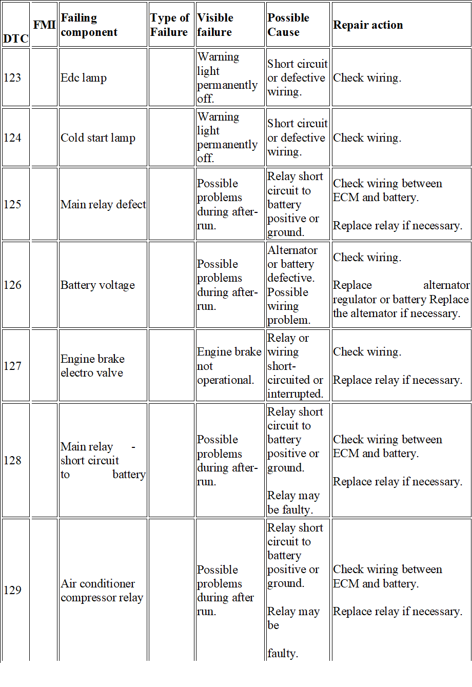
FMI | Failing component | Type of Failure | Visible failure | Possible Cause | Repair action |
| 123 | Edc lamp | Warning light permanently off. | Short circuit or defective wiring. | Check wiring. | ||
| 124 | Cold start lamp | Warning light permanently off. | Short circuit or defective wiring. | Check wiring. | ||
| 125 | Main relay defect | Possible problems during after-run. | Relay short circuit to battery positive or ground. | Check wiring between ECM and battery.
Replace relay if necessary. |
||
| 126 | Battery voltage | Possible problems during after-run. | Alternator or battery defective. Possible wiring problem. | Check wiring.
Replace alternator regulator or battery Replace the alternator if necessary. |
||
| 127 | Engine brake electro valve | Engine brake not operational. | Relay or wiring short-circuited or interrupted. | Check wiring.
Replace relay if necessary. |
||
| 128 | Main relay – short circuit to battery | Possible problems during after-run. | Relay short circuit to battery positive or ground.
Relay may be faulty. |
Check wiring between ECM and battery.
Replace relay if necessary. |
||
| 129 | Air conditioner compressor relay | Possible problems during after run. | Relay short circuit to battery positive or ground.
Relay may be faulty. |
Check wiring between ECM and battery.
Replace relay if necessary. |
|
DTC |
FMI |
Failing component | Type of Failure |
Visible failure |
Possible Cause |
Repair action |
| 113 | Accelerator pedal/ brake pedal suspect | Vehicle acceleration very slow. Engine idle speed: 500 rpm. | Accelerator pedal and brake pressed simultaneously (for too long); Accelerator pedal blocked or faulty;
Incorrect use of vehicle. |
Check the accelerator pedal signal and pedal mechanical movement. | ||
| 116 | Clutch signal suspect | The parameter reading shows that the clutch is pressed. | Clutch switch faulty or wiring problems in pedal. | Check clutch pedal switch and wiring. | ||
| 117 | Brake pedal signal error | Slight power re- duction | Main and secondary brake switch not synchronised. One of the two brake pedal switches may be stuck. | Check the synchronisation of both switches (signal) and wiring. | ||
| 119 | Plausibility + 15 | Possible mechanical problem (in pawl) or electrical problem. | Check wiring. | |||
| 121 | Speed limiter w / light | Warning light permanently off. | Short circuit or defective wiring. | Check wiring. | ||
| 122 | Warning light ODB | Warning light permanently off. | Short circuit or defective wiring. | Check wiring. |
|
DTC |
FMI |
Failing component | Type of Failure |
Visible failure |
Possible Cause |
Repair action |
| 12A | Relays for engine brake valve | Possible problems during after run. | Relay short circuit to battery positive or ground.
Relay may be faulty. |
Check wiring between ECM and battery.
Replace relay if necessary. |
||
| 12B | Thermostarter relay 1 (heater) | Heater not working. | Relay or wiring short circuited or interrupted. | Check wiring.
Replace relay if necessary. |
||
| 12C | Thermostarter relay 2 | Heater not working. | Relay or wiring short circuited or interrupted. | Check wiring.
Replace relay if necessary. |
||
| 12E | Management system pre/ post heating (active) | Grid heater permanently operating. | Grid heater short circuited to ground. | Check wiring and component. | ||
| 131 | Coolant temperature sensor | No reaction noticeable on behalf of the driver. | Sensor short -circuited or value implausible. | Check the wiring. Replace sensor if necessary. | ||
| 132 | Coolant temperature sensor (test) | Slight power reduction. | Operation in extreme environmental conditions or sensor inaccurate. | Ensure the engine is not working in extreme environmental conditions.
Check the wiring and the sensor accuracy. Replace sensor if necessary. |
|
DTC |
FMI | Failing component | Type of Failure | Visible failure | Possible Cause | Repair action |
| 133 | Air temperature sensor boost air | Slight power re- duction. | Sensor short circuited or value implausible. | Check the wiring. Re- place sensor if necessary. | ||
| 134 | Boost pressure sensor | No reaction perceivable by the driver.
Parameter recovery value: 2700 mbar. |
Sensor short circuited or difference between environmental pressure and turbo pressure implausible. | Check the wiring. Also check the environ- mental pressure sensor. Replace sensor if necessary. | ||
| 135 | Fuel temperature sensor | Slight power re- duction. | Sensor short-circuited or value implausible. | Check the wiring. Re- place sensor if necessary. | ||
| 138 | Oil pressure sensor | No reaction perceivable by the driver.
Parameter recovery value: 3000 mbar. |
Sensor short-circuited or value implausible. | Check the wiring and oil level.
Replace sensor if necessary. |
||
| 13A | Oil temperature sensor | No reaction perceivable by the driver.
Parameter recovery value: coolant temperature value (if intact) otherwise 120 C). |
Sensor short-circuited or value implausible. | Check the wiring. Replace sensor if necessary. | ||
| 13C | Atmospheric temperature sensor (humidtiy?) | No reaction perceivable by the driver.
Parameter recovery value: 40 C. |
Sensor short-circuited or value implausible. | Check the wiring. Replace sensor if necessary. |
|
DTC |
FMI |
Failing component | Type of Failure |
Visible failure |
Possible Cause |
Repair action |
| 141 | Crankshaft speed | No reaction noticeable on behalf of the driver. | Signal interrupted or wiring problem.
Sensor installation may not be correct. |
Check wiring and installation.
Replace sensor if necessary. |
||
| 142 | Engine working only
With camshaft sensor |
No reaction perceivable by the driver. | Signal interrupted or wiring problem.
Sensor installation may not be correct. |
Check wiring and installation.
Replace sensor if necessary. |
||
| 143 | Camshaft sensor | No reaction perceivable by the driver. | Signal interrupted or wiring problem.
Sensor installation may not be correct. |
Check wiring and installation.
Replace sensor if necessary. |
||
| 144 | Fault between fly-Wheel sensor and camshaft | No reaction noticeable on behalf of the driver. | Signal interrupted or wiring problem.
Flywheel and timing sensor installation may be incorrect. |
Check wiring and installation of both sensors. | ||
| 145 | Fan relay | No reaction perceivable by the driver.
Fan off. |
Short circuit or fan actuator faulty. | Check the wiring and the fan actuator.
Replace the actuator if necessary. |
||
| 148 | Air conditioner compressor relay | Air conditioner permanently off. | Wiring or relay short-circuited. | Check the wiring. Replace relay if necessary. |
|
DTC |
FMI | Failing component | Type of Failure | Visible failure | Possible Cause | Repair action |
| 149 | Preheating relay fuel
Filter |
Filter heater not working. | Wiring or filter heater short-circuited. | Check the wiring. Re- place the filter heater if necessary. | ||
| 151 | Injector cylinder 1 | The engine runs on 5 cylinders. | Injector no.1 electric trouble. | Check correct tightness to torque of the connectors on the solenoid valve of the injector (1.36 – 1.92 Nm). Check the integrity of the injector coil and replace the injector if defective. If the coil is integral, check the wiring between the solenoid valve and EDC -connector. | ||
| 152 | Injector cylinder 2 | The engine runs on 5 cylinders. | Injector no.2 electric trouble. | Check correct tightness to torque of the connectors on the solenoid valve of the injector (1.36 – 1.92 Nm). Check the integrity of the injector coil and replace the injector if defective. If the coil is integral, check the wiring between the solenoid valve and EDC connector. | ||
| 153 | Injector cylinder 3 | The engine runs on 5 cylinders. | Injector no.3 electric trouble | Check correct tightness to torque of the connectors on the solenoid valve of the injector (1.36 – 1.92 Nm). Check the integrity of the injector coil and replace the injector if defective. If the coil is integral, check the wiring between the solenoid valve and EDC connector. |
|
DTC |
FMI | Failing component | Type of Failure | Visible failure | Possible Cause | Repair action |
| 149 | Pre-heating relay fuel
Filter |
Filter heater not working. | Wiring or filter heater short-circuited. | Check the wiring. Replace the filter heater if necessary. | ||
| 151 | Injector cylinder 1 | The engine runs on 5 cylinders. | Injector no.1 electric trouble. | Check correct tightness to torque of the connectors on the solenoid valve of the injector (1.36 – 1.92 Nm). Check the integrity of the injector coil and replace the injector if defective. If the coil is integral, check the wiring between the solenoid valve and EDC- connector. | ||
| 152 | Injector cylinder 2 | The engine runs on 5 cylinders. | Injector no.2 electric trouble. | Check correct tightness to torque of the connectors on the solenoid valve of the injector (1.36 – 1.92 Nm). Check the integrity of the injector coil and replace the injector if defective. If the coil is integral, check the wiring be- tween the solenoid valve and EDC-connector. | ||
| 153 | Injector cylinder 3 | The engine runs on 5 cylinders. | Injector no.3 electric trouble | Check correct tightness to torque of the connectors on the solenoid valve of the injector (1.36 – 1.92 Nm). Check the integrity of the injector coil and replace the injector if defective. If the coil is integral, check the wiring between the solenoid valve and EDC-connector. |
|
DTC |
FMI |
Failing component | Type of Failure |
Visible failure |
Possible Cause |
Repair action |
| 154 | Injector Cylinder 4 | The engine runs
on 5 cylinders |
Injector no.4
electric trouble |
Check correct tightness to torque of the connectors on the solenoid valve of the injector (1.36 – 1.92 Nm). Check the integrity of the injector coil and replace the injector if defective. If the coil is integral, check the wiring between the solenoid valve and EDC connector. | ||
| 155 | Injector Cylinder 5 | The engine runs on 5 cylinders | Injector no.5 electric trouble | Check correct tightness to torque of the connectors on the solenoid valve of the injector (1.36 – 1.92 Nm). Check the integrity of the injector coil and replace the injector if defective. If the coil is integral, check the wiring between the solenoid valve and EDC connector. | ||
| 156 | Injector Cylinder 6 | The engine runs on 5 cylinders | Injector no.6 electric trouble | Check correct tightness to torque of the connectors on the solenoid valve of the injector (1.36 – 1.92 Nm). Check the integrity of the injector coil and replace the injector if defective. If the coil is integral, check the wiring between the solenoid valve and EDC connector. |
|
DTC |
FMI | Failing component | Type of Failure | Visible failure | Possible Cause | Repair action |
| 161 | Injector Cylinder 1 / short-Circuit | One or more injectors (bank 1 or bank 2) not operating. | Possible short-circuit in connections. Possible problem in
Injector coil . Possible problem in control unit. |
Check wiring. Possible internal problem also in ECM. Replace the injector if necessary. | ||
| 162 | Injector Cylinder 2 / short-Circuit | One or more injectors (bank 1 or bank 2) not operating. | Possible short-circuit in connections. Possible problem in injector coil . Possible problem in control unit. | Check wiring. Possible internal problem also in ECM. Replace the injector if necessary. | ||
| 163 | Injector Cylinder 3 / short-Circuit | One or more injectors (bank 1 or bank 2) not operating. | Possible short circuit in connections. Possible problem in injector coil . Possible problem in control unit. | Check wiring. Possible internal problem also in ECM. Replace the injector if necessary. | ||
| 164 | Injector Cylinder 4 / short-Circuit | One or more injectors (bank 1 or bank 2) not operating. | Possible short-circuit in connections. Possible problem in injector coil . Possible problem in control unit. | Check wiring. Possible internal problem also in ECM. Replace the injector if necessary. | ||
| 165 | Injector Cylinder 5 / short-Circuit | One or more injectors (bank 1 or bank 2) not operating. | Possible short circuit in connections. Possible problem in injector coil . Possible problem in control unit. | Check wiring. Possible internal problem also in ECM. Replace the injector if necessary. |
|
DTC |
FMI |
Failing component | Type of Failure |
Visible failure |
Possible Cause |
Repair action |
| 166 | Injector Cylinder 6 / short-Circuit | One or more injectors (bank 1 or bank 2) not operating. | Possible short-circuit in connections. Possible problem in injector coil. Possible problem in control unit. | Check wiring. Possible internal problem also in ECM. Replace the injector if necessary. | ||
| 167 | Injector Cylinder 1 / open circuit | One or more injectors (bank 1 orbank 2) not operating. | Possible injector
Connection problem (or disconnected internally). Possible problem in control unit (capacitor). |
Check wiring. Possible internal problem also in ECM. Replace the injector if necessary. | ||
| 168 | Injector
Cylinder 2 / open Circuit |
One or more injectors (bank 1 or bank 2) not operating. | Possible injector connection problem (or disconnected internally). Possible problem in control
unit (capacitor). |
Check wiring. Possible internal problem also in ECM. Replace the injector if necessary. | ||
| 169 | Injector
Cylinder 3 / open Circuit |
One or more injectors (bank 1 or bank 2) not operating. | Possible injector connection problem (or disconnected internally). Possible problem in control
unit (capacitor). |
Check wiring. Possible internal problem also in ECM. Replace the injector if necessary. |
|
DTC |
FMI | Failing component | Type of Failure | Visible failure | Possible Cause | Repair action |
| 16A | Injector cylinder 4 / open circuit | One or more injectors (bank 1 or bank 2) not operating. | Possible injector connection problem (or disconnected internally). Possible problem in control unit (capacitor). | Check wiring. Possible internal problem also in ECM. Replace the injector if necessary. | ||
| 16B | Injector cylinder 5 / open Circuit | One or more injectors (bank 1 or bank 2) not operating. | Possible injector connection problem (or disconnected internally). Possible problem in control unit (capacitor). | Check wiring. Possible internal problem also in ECM. Replace the injector if necessary. | ||
| 16C | Injector cylinder 6 / open circuit | One or more injectors (bank 1 or bank 2) not operating. | Possible injector connection problem (or disconnected internally). Possible problem in control unit (capacitor). | Check wiring. Possible internal problem also in ECM. Replace the injector if necessary. | ||
| 16D | Compression test in progress | Compression Test in progress. | After carrying out the compression test, turn the key OFF (after-run). |
|
DTC |
FMI |
Failing component | Type of Failure |
Visible failure |
Possible Cause |
Repair action |
| 16E | The minimum number of injections
Was not reached: stop the Engine |
More than 2 injectors not operating. | See individual faults in injectors. | |||
| 171 | Bench 1 cc | One or more injectors (bank 1 or bank 2) not operating. | Possible injector connection problem.
Injectors short-circuited. |
Check wiring. Possible internal problem also in ECM. Replace the injector if necessary. | ||
| 173 | Bench 2 cc | One or more injectors (bank 1 or bank 2) not operating. | Possible injector connection problem.
Injectors short-circuited. |
Check wiring. Possible internal problem also in ECM. Replace the injector if necessary. | ||
| 17C | Bench 1 injectors check (internal ecu) | One or more injectors (bank 1 or bank 2) may not be operating. | Fault in control unit. | Replace the engine control unit. | ||
| 189 | Egr power St. Short To batt. | No fault perceived by the driver. EGR not working. | Short circuit or EGR actuator faulty. | Check wiring.
Replace the EGR actuator if necessary. |
||
| 191 | Turbine actuator control
Electro-valve |
Poor performance | VGT actuator or wiring defective. | Check VGT wiring and actuator. |
|
DTC |
FMI | Failing component | Type of Failure | Visible failure | Possible Cause | Repair action |
| 192 | TURBINE
ACTUATOR CONTROL ELECTRO-VALVE SHORT-CIRCUIT TO POSITIVE |
Poor performance | VGT actuator or wiring defective. | Check VGT wiring and actuator. | ||
| 193 | TURBINE WHEEL REVS SENSOR | Poor performance | Air filter blocked or turbine rpm sensor signal implausible. | Check the air filter and check parameters linked with the turbine by performing a road test (parameter acquisition). | ||
| 198 | FAULT ON AT LEAST TWO OF THE FOLLOWING SENSORS: TURBINE SPEED, BOOT PRESSUR AND EXHAUST GAS PRESSURE | Poor performance | Sensor signal implausible. Sensor may be faulty. | Determine which turbine component caused the problem. | ||
| 199 | TURBO-CHARGER CONTRO BOOST PRESSURE FAILURE (PCR) | Poor performance | Turbo sensor or actuator may be faulty. Air filter may be blocked. | Check turbine sensors and actuator (parameter acquisition). Check whether air filter is blocked. |
|
DTC |
FMI |
Failing component | Type of Failure |
Visible failure |
Possible Cause |
Repair action |
| 19A | TURBINE SPEED EXCEEDING EVERY PERMITTED RANGE | Poor performance | Turbo sensor or actuator may be faulty. Air filter may be blocked. | Check turbine sensors and actuator (parameter acquisition). Check whether air filter is blocked. | ||
| 19B | TURBINE IN OVERSPEED (THE FAULT IS NOT DISPLAYED IF IT IS CAUSED BY A LOW ATMOSPERIC PRESSURE) | Poor performance | Air filter blocked or turbine rpm sensor signal implausible. | Check the air filter and check parameters linked with the turbine by performing a road test (parameter acquisition). | ||
| 19F | NOx SENSOR ERROR | No effect perceived by the driver. | Sensor signal implausible. Nox sensor may be faulty. | Check the Nox sensor. | ||
| 1A5 | TIMEOUT OF CAN MESSAGE
DM1DCU |
No effect perceived by the driver. | Problems in the Denoxtronic (on the CAN line). | Check wiring.
Check and correct any faults in the Denoxtronic control unit. |
||
| 1A6 | TIMEOUT OF CAN MESSAGE SCR1 | No effect perceived by the driver. | CAN configuration incorrect. CAN connection defective. Terminal resistance not suit-
able. |
Check CAN line wiring. Check Denoxtronic control unit wiring and operation. | ||
| 1AE | HUMIDITY SENSOR | No effect perceived by the driver. | Sensor short-circuited or faulty. | Check wiring Replace sensor if necessary. |
|
DTC |
FMI | Failing component | Type of Failure | Visible failure | Possible Cause | Repair action |
| 1AF | SERIOUSE OBD FAULT
FROM DENOXTRONIC (EOBD FLASHING LIGHT) |
No effect perceived by the driver. | Problems in AdBlue dosing system. | Check the faults in the Denoxtronic and consult the control unit troubleshooting guide. | ||
| 1B1 | ERROR ON CAN CONTROLLER A | No effect perceived by the driver. | CAN configuration incorrect. CAN connections defective. Terminal resistance not suitable. | Check CAN line wiring. Check terminal resistances. | ||
| 1B2 | ERROR ONCAN CONTROLLER B | No effect perceived by the driver. | CAN configuration incorrect. CAN connections defective. Terminal resistance not suitable. | Check CAN line wiring. Check terminal resistances. | ||
| 1B3 | ERROR ON CAN CONTROLLER C | No effect perceived by the driver. | CAN configuration incorrect. CAN connections defective. Terminal resistance not suitable. | Check CAN line wiring. Check terminal resistances. | ||
| 1B4 | TIMEOUT CAN MESSAGE BC2EDC1 | No effect perceived by the driver. | CAN configuration incorrect. CAN connections defective. Terminal resistance not suitable. | Check CAN line wiring. Check BC wiring and operation. |
|
DTC |
FMI |
Failing component | Type of Failure |
Visible failure |
Possible Cause |
Repair action |
| 1B5 | TIMEOUT CAN MESSAGE VM2EDC | No effect perceived by the driver. | CAN configuration incorrect. CAN connections defective. Terminal resistance not suitable. | Check CAN line wiring. Check VCM wiring and operation. | ||
| 1B7 | ERROR ON MESSAGES CAN IN TRANSMISSION | No effect perceived by the driver. | CAN configuration incorrect. CAN connections defective. Terminal resistance not suitable. | Check CAN line wiring. Check ECM wiring and operation. | ||
| 1B9 | ERROR ON THE EOBD LIGHT MANAGED BY THE CLUSTER) | No effect perceived by the driver. | MIL/Body Controller warning light defective. | Consult the Body Controller troubleshooting guide and check the CAN line. | ||
| 1BA | TIMEOUT CAN MESSAGE DASH DISPLAY | No effect perceived by the driver. | CAN messages from VCM inconsistent. | Consult the VCM troubleshooting guide and check the CAN line. | ||
| 1BC | TIMEOUT CAN MESSAGE AMBCOND | No effect perceived by the driver. | CAN messages from VCM in- consistent. | Consult the VCM troubleshooting guide and check the CAN line. | ||
| 1BD | TIMEOUT CAN MESSAGE CCVS | No effect perceived by the driver. | CAN messages from VCM or BC inconsistent. | Consult the VCM /BC troubleshooting guide and check the CAN line. |
|
DTC |
FMI | Failing component | Type of Failure | Visible failure | Possible Cause | Repair action |
| 1C2 | ERROR MESSAGE CAN ETC1 | No effect perceived by the driver. | CAN messages from ETC (gearbox) inconsistent. | Check the ETC connection with the CAN line. | ||
| 1C3 | TIMEOUT IN RECEIVING TC01 CAN MESSAGE | No effect perceived by the driver. | CAN messages from TCO in- consistent. | Check the TCO connection with the CAN line. | ||
| 1C6 | ERROR MESSAGE CAN TSC1PE | No effect perceived by the driver. | CAN messages from TCU (Transmission Control Unit) inconsistent. | Check the TCU connection with the CAN line. | ||
| 1C8 | ERROR MESSAGE CAN TSC1VE | No effect perceived by the driver. | CAN messages from TCU (Transmission Control Unit) inconsistent. | Check the TCU connection with the CAN line. | ||
| 1D1 | ECU OVERRUN MONITORING ERROR | No effect perceived by the driver. | Electrical interference or internal control unit problems. | If the error persists to replace ECU. | ||
| 1D2 | ECU OVERRUN MONITORING ERROR | No effect perceived by the driver. | Poor control unit programming/flash Possible internal fault. | Reprogram the central unit. If the error is repeated, replace the central unit, if needed. | ||
| 1D3 | ECU OVERRUN MONITORING ERROR | No effect perceived by the driver. | Poor control unit programming/flash Possible internal fault. | Reprogram the central unit. If the error is repeated, replace the central unit, if needed. |
|
DTC |
FMI |
Failing component | Type of Failure |
Visible failure |
Possible Cause |
Repair action |
| 1D4 | ECU OVERRUN MONITORING ERROR | No effect perceived by the driver. | Ecu internal failure. | If the error persists to replace ECU. | ||
| 1D5 | ECU OVERRUN MONI- TORING ERROR | No effect perceived by the driver. | Ecu internal failure. | If the error persists to replace ECU. | ||
| 1D6 | ECU INTERNAL ERROR (TPU) | Control unit deactivation. | Electronic interference or control unit faulty. | If the error persists to replace ECU. | ||
| 1D8 | ECU OVERRUN MONI TORING ERROR | No effect perceived by the driver. | Ecu internal failure. | If the error persists to replace ECU. | ||
| 1E2 | IMMOBILIZER | The engine fails to start. | Problem in CAN line or immobiliser control unit. | Check the Immobiliser control unit is correctly connected.
Enter the Immobiliser PIN code during the emergency procedure. |
||
| 1E3 | ERROR FOR ECU INTERNAL MONI TORING | No effect perceived by the driver. | Ecu internal failure. | If the error persists to replace ECU. | ||
| 1E4 | ERROR FOR ECU INTERNAL MONITORING | No effect perceived by the driver. | Ecu internal failure. | If the error persists to replace ECU. |
|
DTC |
FMI | Failing component | Type of Failure | Visible failure | Possible | Cause | Repair action |
| 1E5 | SENSORS POWER SUPPLY FAULT (12V) | No effect perceived by the driver. | Excessive/insufficient
Battery voltage or possible internal control unit problem. |
Check battery voltage or connections with the ECM. Replace the control unit if necessary. | |||
| 1E6 | SENSOR POWER SUPPLY 1 | No effect perceived by the driver. | Excessive/insufficient
Battery voltage or possible internal control unit problem |
Check battery voltage or connections with the ECM. Replace the control unit if necessary. | |||
| 1E7 | SENSOR POWER SUPPLY 2 | No effect perceived by the driver. | Excessive/insufficient
Battery voltage or possible internal control unit problem |
Check battery voltage or connections with the ECM. Check ECU, if required. | |||
| 1E8 | SENSOR POWER SUPPLY 3 | No effect perceived by the driver. | Excessive/insufficient
Battery voltage or possible internal control unit problem |
Check battery voltage or connections with the ECM. Replace the control unit if necessary. | |||
| 1E9 | ECU OVERRUN MONITORIN ERROR | No effect perceived by the driver. | Excessive/insufficient
Battery voltage or possible internal control unit problem |
Check battery voltage or connections with the ECM. Replace the control unit if necessary. | |||
| 1EA | ECU OVERRUN MONITORIN ERROR | No effect perceived by the driver. | Excessive/insufficient
Battery voltage or possible internal control unit problem |
Check battery voltage or connections with the ECM. Replace the control unit if necessary. | |||
| 1EB | ATMOSPHERIC PRESSURE SENSOR | No effect perceived by the driver. | Excessive/insufficient
Battery voltage or possible internal control unit problem |
Change ECU. |
|
DTC |
FMI |
Failing component | Type of Failure |
Visible failure |
Possible Cause |
Repair action |
| 1FA | TOO HIGH NUMBER OF REGENERATIONS DEMAND | No reaction perceivable by the driver. Too many filter regenerations carried out. | Particulate filter may be blocked. | Check filter. | ||
| 1FB | PERMANENT RIGENERATION ON TRAP PARTICLE | No reaction perceivable by the driver. | Catalytic converter not installed or damaged. | Check catalytic converter visually. | ||
| 1FC | FIRST SENSOR EXAUSTED GAS TEMPERATURE | No reaction perceivable by the driver. | Temperature sensors damaged or incorrectly fitted. | Check information and condition of sensors. | ||
| 21F | TOO HIGH EFFICIENCY OF CATALYST SYSTEM | No reaction noticeable on behalf of the driver. | Actuator coil faulty or not within specified tolerance limits. | Check actuator condition. | ||
| 225 | INTERRUPTED
AFTERRUN |
Slight power reduction. | The control unit is turned off by the general switch instead of by the key (k15). Possible problem in main relay or connections. | Check wiring and then replace the main relay. | ||
| 228 | MAIN RELAY – SHORT CIRCUIT TO GROUND | Slight power reduction. | Short circuit in main relay or relay faulty. | Check wiring between battery and ECM and then replace the main relay. |
|
DTC |
FMI | Failing component | Type of Failure | Visible failure | Possible Cause | Repair action |
| 232 | COOLANT TEMPERATURE SENSOR ABSOLUTE TEST | Slight power reduction | Extreme environmental conditions or sensor incorrectly adjusted. | Ensure the engine is working in non-critical conditions. Check the sensor connections and accuracy. Replace sensor if necessary. | ||
| 238 | OIL LOW PRESSURE | Slight power re- duction | Sensor incorrectly adjusted or faults in lubrication system. | Check the sensor connections and accuracy. Check the lubrication system. | ||
| 23A | OIL TEMPERATURE ABOVE NORMAL | Slight power reduction | Sensor incorrectly adjusted or faults in lubrication system. | Check the sensor connections and accuracy. Check the lubrication system. | ||
| 27C | BENCH 2 INJECTORS CHECK (INTERNAL ECU) | One or more injectors (bank 1 or bank 2) may not be operating | Fault in control unit. | Replace the engine control unit. | ||
| 292 | TURBINE ACTUATOR CONTROL
ELECTROVALVE SHORT CIRCUIT TO GROUND |
Poor performance | VGT actuator or wiring defective. | Check VGT wiring and actuator. | ||
| 2A6 | TIMEOUT OF CAN MESSAGE SCR2 | No effect perceived by the driver | Problem in the Denoxtronic
(on the CAN line). |
Check the faults in the Denoxtronic and consult the control unit troubleshooting guide. Check wiring. |
|
DTC |
FMI |
Failing component | Type of Failure |
Visible failure |
Possible Cause |
Repair action |
| 2AF | SERIOUS EOBD FAULT FROM DENOXTRONIC (EOBD FLASHING
LIGHT) |
No effect perceived by the driver. | Problems in AdBlue dosing system. | Check the faults in the Denoxtronic and consult the control unit troubleshooting guide. | ||
| 2B4 | TIMEOUT CAN MESSAGE BC2EDC2 | No effect perceived by the driver. | CAN configuration incorrect. CAN connections defective. Terminal resistance not suitable. | Check CAN line wiring. Check BC wiring and operation. | ||
| 2C6 | TIMEOUT OF CAN MESSAGE TSC1-PE PASSIVE | No effect perceived by the driver. | CAN messages from TCU (Transmission Control Unit) inconsistent. | Check the TCU connection with the CAN line. | ||
| 2C8 | ERROR MESSAGE CAN TSC1VR | No effect perceived by the driver. | CAN messages from TCU (Transmission Control Unit) inconsistent. | Check the TCU connection with the CAN line. | ||
| 2C9 | ERROR MESSAGE CAN TIMEDATE | No effect perceived by the driver. | CAN messages from TC (tachograph) inconsistent. | Check the tachograph connection with the CAN line. | ||
| 2D3 | ECU OVERRUN MONITORING ERROR | No effect perceived by the driver. | Poor control unit programming/flash Possible internal fault. | Reprogram the central unit. If the error is repeated, replace the central unit, if needed. |
|
DTC |
FMI | Failing component | Type of Failure | Visible failure | Possible Cause | Repair action |
| 2FF | ERROR CHECK OF CRITICAL TIME FOR OIL DILUTION | Slight power reduction | Oil overdiluted. | Change the engine oil . | ||
| 392 | TURBINE ACTUATOR
CONTROL ELECTRO-VALVE |
Poor performance | Connection damaged. Battery voltage excessive (ECU overheating). | Check VGT connection and actuator. | ||
| 3AF | SERIOUSE OBD FAULT FROM DENOXTRONIC (EOBD FLASHING LIGHT) | No effect perceived by the driver. | Problems in AdBlue dosing system. | Check the faults in the Denoxtronic and consult the control unit troubleshooting guide. | ||
| 3C8 | TIMEOUT OF CAN MESSAGE TSC1-VE PASSIVE | No effect perceived by the driver. | CAN messages from TCU (Transmission
Control Unit) inconsistent. |
Check the TCU connection with the CAN line. | ||
| 3C9 | ERROR MESSAGE CAN HRDV | No effect perceived by the driver. | CAN configuration incorrect. CAN connections defective. Terminal resistance not suitable. | Check CAN line wiring. Check BC wiring and operation. | ||
| 3D3 | ECU OVERRUN MONITORING ERROR | No effect perceived by the driver. | Poor control unit programming/flash Possible internal
fault. |
Reprogram the central unit. If the error is repeated, replace the central unit, if needed. |
|
DTC |
FMI |
Failing component | Type of Failure |
Visible failure |
Possible Cause |
Repair action |
| 3FA | REGENERATION DEMAND NUMBER 2 | No effect perceived by the driver. | Too many regenerations carried out. | Check particulate filter and faults in sensors. | ||
| 4AF | SERIOUSE OBD FAULT FROM DENOXTRONIC (EOBD FLASHING LIGHT) | No effect perceived by the driver. | Problems in AdBlue dosing system. | Check the faults in the Denoxtronic and consult the control unit troubleshooting guide. | ||
| 4C8 | TIMEOUT OF CAN MESSAGE TSC1-VR PASSIVE | No effect perceived by the driver. | CAN messages from TCU (Transmission Control Unit) inconsistent. | Check the TCU connection with the CAN line. | ||
| 4FA | REGENERATION DEMAND NUMBER 3 | No effect perceived by the driver. | Too many regenerations carried out. | Check particulate filter and faults in sensors. | ||
| 5AF | DM1DCU SPN5 MESSAGE | No effect perceived by the driver. | Problems in AdBlue dosing system. | Check the faults in the Denoxtronic and consult the control unit troubleshooting guide. |
Iveco Trakker Fault Codes in PDF free download
Iveco Trakker Euro 4-5 Fault Codes List
![]()
Error Tree IVECO — PDF manual.pdf
Adobe Acrobat Document
1.0 MB
![]()
Iveco truck OBD Error Codes Table.xls
Microsoft Excel Table
3.0 MB
![]()
Iveco Trakker Euro 4-5 Fault Codes List.
Portable Network Image Format
104.3 KB
![]()
Iveco LA Vehicles Error Codes — ET-TN-44
Adobe Acrobat Document
433.9 KB
Code Description
111 Malfunction in vehicle speed sensor circuit
112 Accelerator pedal position sensor circuit 1 malfunction
113 Mismatch of brake switch signals and accelerator pedal sensors
116 Clutch pedal switch circuit failure
117 Incorrect brake pedal switch signal
119 Loss of voltage on-board network on the controller from the terminal «15»
122 MIL (Check Engine) Lamp Control Circuit Malfunction
126 On-board network voltage outside the operating range of the controller
131 Coolant Temperature Sensor Circuit Malfunction
132 Incorrect coolant temperature sensor circuit signal
133 Intake air temperature sensor circuit malfunction
134 Malfunction of the circuit of the charge air pressure sensor
135 Fuel Temperature Sensor Circuit Malfunction
136 Rail Pressure Sensor Circuit Malfunction
013A Oil Temperature Sensor Circuit Malfunction
013E Low signal in the coolant pressure sensor circuit
013F Incorrect signal in the coolant pressure circuit
141 Malfunction or break in the sensor circuit (frequency) crankshaft position
143 Camshaft Position (Phase) Sensor Circuit Malfunction
144 Discrepancy of synchronization sensor signals (frequency and phase)
145 FAN relay 1 control circuit malfunction
149 Fuel heater circuit malfunction
014D Maximum allowable engine speed
151 High level fuel rail sensor circuit signal
152 Increased fuel rail pressure
153 Reduced fuel rail pressure
154 Fuel rail pressure above maximum allowed
155 Fuel rail pressure below the minimum
159 Malfunction of the high-pressure fuel pump circuit.
015C Incorrect fuel injection time for cylinder 1 injector
015D Incorrect fuel injection time for cylinder 3 nozzle
015E Incorrect fuel injection time for cylinder 5 injector
015F Fuel system malfunction affecting toxic emissions
161 Injector Control Circuit 1 Fault
162 Injector Control Circuit 2 Fault
163 Injector Control Circuit 3 Fault
164 Injector Control Circuit Malfunction 4
165 Injector Control Circuit 5 Fault
166 Injector Control Circuit Malfunction 6
167 Open or short to ground in the injector 4 control circuit
168 Injector Control Circuit 1 Fault
169 Injector Control Circuit 1 Fault
016A Injector Control Circuit 1 Fault
016B Injector Control Circuit 1 Fault
016C Ultimate torque drop in cylinder 1
016E The minimum required number of injections is not met.
171 Injector control channel 1 malfunction
173 Injector control channel 2 malfunction
017C Controller: Channel 1 Injector Control Fault (Driver)
017D General malfunction of the air-fuel mixture
017F Controller: incorrect entry or no entry of injector IMA-codes
182 Fault in the intake air temperature sensor circuit (DFID)
183 Low level signal in the air flow sensor circuit
185 High level signal in the air flow sensor circuit
187 Increased air flow through the exhaust gas recirculation valve
188 Reduced air flow through exhaust gas recirculation valve
189 Short circuit on the onboard network of the control circuit of the recirculation valve
018B short circuit on the onboard network of the control circuit of the throttle valve of the exhaust gas recirculation valve
018C Fuel delivery system too “poor” at its maximum enrichment
018D Toxic emissions of nitrogen oxides (NOx) above the first threshold
192 Short circuit on the on-board network of the control circuit of the turbocharger
194 Improved performance (power) of the turbocharger
195 Reduced performance (power) of the turbocharger
019E Torque limitation caused by malfunctions of ICE systems
01A8 Maximum allowable temperature of urea dosing valve
01B1 Break of CAN information line «H»
01B3 Break of CAN information line “L”
01B7 CAN Information Bus Busy
01BA CAN-bus: no response from the instrument cluster car
01C3 CAN-bus: no response from the tachograph
01D1 Controller: SPI channel malfunction
01D2 Controller: EEPROM Memory Fault
01D3 Controller: locked for engine start
01D4 Controller: firmware reset failure
01D5 Controller: initialization program error
01D6 Controller: internal synchronization error
01D7 Controller: incorrect engine control calibration option
01D8 Controller: firmware reset failure
01D9 Controller: A / D converter malfunction
01DA Controller: flash ROM malfunction (checksum error)
03D3 Controller: initialization program error
1.00E + 002 Immobilizer: malfunction of the unit or its chains (fuel supply is blocked)
1.00E + 003 Engine System Monitoring Program Error
1.00E + 004 Increased engine speed
1.00E + 006 Controller: Type 1 voltage to power sensors out of range
1.00E + 007 Controller: Type 2 voltage to power sensors out of range
1.00E + 008 Controller: Type 3 voltage to power sensors out of range
1.00E + 009 Controller: supply voltage higher than acceptable
01EA Controller: supply voltage below permissible
01EB Malfunction of the circuit of the atmospheric (absolute) air pressure sensor
01F1 Malfunction of the particulate filter contamination sensor circuit
01F2 Incorrect signal in the particulate filter debris sensor circuit
01F3 Malfunction of the diesel particulate filter blockage sensor circuit
01F4 Low level signal in the particulate filter debris sensor circuit
01F5 High signal level of the particulate filter debris sensor circuit
01F6 Malfunction of exhaust gas temperature sensor to neutralizer
01F7 Exhaust Temperature Sensor Circuit Malfunction
01F8 Incorrect signal in the exhaust gas temperature sensor circuit
01F9 High level of regeneration of the black filter
01FA Low level of regeneration of the black filter
01FB Neutralizer efficiency below acceptable standard
01FC Slow response to temperature change of the sensor to the neutralizer
212 Accelerator pedal position sensor circuit 2 malfunction
215 Fatal failure of automatic on-board control system
225 Main relay control circuit failure
022B Malfunction of the power circuit of the glow plugs
022E Malfunction of the control circuit of the pumping-up electric fuel pump
232 Coolant temperature sensor signal out of range
236 Incorrect signal in the rail pressure sensor circuit when the engine is stopped
023A High level signal in the circuit of the oil temperature sensor
251 Increased fuel rail pressure
259 Short circuit on the on-board network of the control circuit of the injection pump
025C Incorrect fuel injection time for cylinder 2 nozzle
025D Incorrect fuel injection time for cylinder 4 nozzle
025E Incorrect fuel injection time for cylinder 6 injector
025F Malfunctioning fuel injection system affecting NOx emissions
275 Poor combustion of the air-fuel mixture in cylinder 1
276 Poor combustion of the air-fuel mixture in cylinder 2
277 Poor combustion of the air-fuel mixture in cylinder 3
278 Poor combustion of the fuel-air mixture in the cylinder 4
279 Poor combustion of the fuel-air mixture in the cylinder 5
027A Poor combustion of the fuel-air mixture in the cylinder 6
027C Controller: Channel (driver) failure 2 injector controls
281 Invalid air flow through exhaust gas recirculation valve
283 Maximum allowable deviation of air flow in the operating mode
285 Maximum allowable deviation of air flow at idle
286 Mass air flow sensor signal out of range
287 Increased air flow through the exhaust gas recirculation valve
288 Reduced air flow through exhaust gas recirculation valve
289 Short to ground in the control circuit of the exhaust gas recirculation valve
028B short circuit to ground in the control circuit of the throttle valve of the exhaust gas recirculation valve
292 Open or short to ground of the turbocharger control circuit
02B4 CAN-bus: no response from the routing computer or test equipment
02C9 CAN-bus: incorrect data from the instrument cluster or tachograph
02F8 Incorrect signal in the exhaust gas temperature sensor circuit
02FF Critical injection time for dissolving oil in engine cylinder
315 Disposable automatic on-board control system failure
032B Malfunction of the glow plug control circuit
359 Short circuit to ground on the control circuit of the pump
035F Air supply malfunction affecting toxic emissions
385 Maximum allowable deviation of air flow in load mode
386 Mass air flow sensor signal out of range
389 Recirculation valve open or high exhaust gas temperature
038B Open state of the CRC throttle or increased exhaust gas temperature
392 short circuit to the onboard network of the turbocharger control circuit and high temperature
039D Probable excess of toxic emissions (OBD) — a rich mixture
039E Engine torque limit to protect the turbocharger
03C9 CAN-bus: high channel load
03F3 Incorrect signal in the particulate filter debris sensor circuit
03F8 Exhaust gas temperature sensor circuit malfunction after filter
03FA Low level 2 regeneration particulate filter
045F Lambda regulator malfunction affecting toxic emissions
486 Invalid signal in the intake air temperature sensor circuit
04FA Low level 3 regeneration particulate filter
055F Malfunction of the exhaust gas recirculation system, affecting toxic emissions
601 Malfunction of the signal circuit or loss of oxygen sensor activity 1
602 Oxygen Sensor Heater Circuit 1 Fault
603 Oxygen sensor 1 out of range
604 Oxygen Sensor Heater Circuit 1 Fault
605 Oxygen sensor 1 out of range
606 Malfunction of the signal circuit or loss of activity of the oxygen sensor 1
607 Oxygen sensor 1 out of range
609 Controller: Invalid Oxygen Sensor 1 Signal
060A Controller: open or short to ground on the oxygen sensor heater 1 circuit
060C Open or short to ground on the oxygen sensor heater 1 circuit
060D Oxygen sensor 1 signal out of range (full load)
060E Oxygen sensor 1 signal out of range (partial load)
060F Oxygen sensor 1 signal out of range (engine stop)
069E Engine Torque Limit due to Injection Malfunctions