|
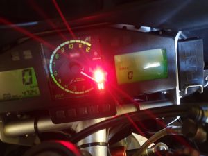
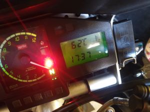
Горит надпись «SERVICE» |
||||||
|
||||||
|
||||||
|
||||||
|
||||||
|
||||||
|
||||||
|
||||||
|
||||||
|
||||||
|
||||||
|
||||||
|
||||||
|
||||||
|
||||||
|


|
|
| Клуб любителей мотоциклов Aprilia © 2023 |
|
Пятница, 22.09.2023, 04:53 |
||||||||||||||||||||||||||||||||||||||||||||||||||||||||||||||||||||||||||||||||||||||
|


-
03-26-2019, 04:33 PM
#1

apriliaforum expert
RSV4 /TuonoV4 error codes listing
Here I’m listing as much as I know the errorcodes. Keep listing clean, no questions about errors here please. It will take some time to fill up.
Code E4 Code E3 Description Detail (Symptom) Warning light status MIL light status Recovery Action to do P0105 P0105 Rear cylinder bank (electric) air pres. Sensor Short circuit to positive N F 1) Reconnect/repair connectors Short circuit to negative 2) Reconnect/repair wiring harness Open circuit 3) Replace sensor Signal not plausible 4) See detailed diagnosis in service station manual P0106 P0106 Rear cylinder bank (funct.) air pressure sensor Signal not plausible L F 1) Reconnect/repair connectors 2) Reconnect/repair wiring harness 3) Measure wiring harness resistance 4) Replace sensor 5) See detailed diagnosis in service station manual P0110 P0110 Air temperature sensor Short circuit to positive N F 1) Reconnect/repair connectors 2) Reconnect/repair wiring harness 3) Replace sensor or 4) Replace 7SM ECU 5) See detailed diagnosis in service station manual Short circuit to negative Open circuit P0115 P0115 Engine temperature sensor (electric) Short circuit to positive N F 1) Reconnect/repair connectors 2) Reconnect/repair wiring harness 3) Replace sensor or 4) Replace 7SM ECU 5) See detailed diagnosis in service station manual Short circuit to negative Open circuit P0116 P0116 Engine temperature sensor (functional) Signal not plausible N F None 1) Temperature variation too high 2) Reconnect/repair connectors 3) Reconnect/repair wiring harness 4) See detailed diagnosis in service station manual P0120 P0120 Rear cylinder bank throttle pos. potentiometer sensor Short circuit to positive L F 1) Check voltage (see details in service station manual) 2) Reconnect/repair connectors 3) Reconnect/repair wiring harness 4) Replace throttle body Short circuit to negative Open circuit P0121 P0121 Rear cylinder bank throttle posit. pot. Sensor Signal not plausible N F 1) Compare front and rear throttle body potentiometer voltages 2) Reconnect/repair connectors 3) Reconnect/repair wiring harness 4) Measure resistance between throttle body connector and ECU 5) Replace throttle body P0130 P0130 Rear cylinder bank lambda sensor Short circuit to positive N F 1) Measure voltage on ECU side connector 2) Reconnect/repair connectors 3) Reconnect/repair wiring harness 4) Replace sensor P0134 — Rear cylinder bank lambda sensor Not switching from rich state N F 1) Lambda probe or engine fault 2) With engine running, check if Lambda probe correction is close to zero during cut-off 3) Check that Lambda probe correction does not remain at maximum value (approx. 25%) for a prolonged period of time 4) Replace Lambda probe Not switching from lean state P0135 P0135 Rear cylinder bank lambda sensor heating Short circuit to positive N F 1) Measure sensor resistance 2) Reconnect/repair connectors 3) Reconnect/repair wiring harness 4) See detailed diagnosis in service station manual 5) Replace sensor Short circuit to negative Open circuit P0150 P0136 Front cylinder bank lambda sensor Short circuit to positive N F 1) Measure voltage on ECU side connector 2) Reconnect/repair connectors 3) Reconnect/repair wiring harness 4) Replace sensor P0154 — Front cylinder bank lambda sensor Not switching from rich state N F 1) Lambda probe or engine fault 2) With engine running, check if Lambda probe correction is close to zero during cut-off 3) Check that Lambda probe correction does not remain at maximum value (approx. 25%) for a prolonged period of time 4) Replace Lambda probe Not switching from lean state N: Lamp off F: Lamp on — lit steadily L: Lamp on — flashing Last edited by pauldayona; 03-26-2019 at 05:15 PM.
-
03-26-2019, 04:46 PM
#2
apriliaforum expert
Code E4 Code E3 Description Detail (Symptom) Warning light status MIL light status Recovery Action to do P0155 P0141 Front cylinder bank lambda sensor heating Short circuit to positive N F 1) Measure sensor resistance 2) Reconnect/repair connectors 3) Reconnect/repair wiring harness 4) See detailed diagnosis in service station manual 5) Replace sensor Short circuit to negative Open circuit P0201 P0201 Rear cylinder bank 1 cylinder lower injector Short circuit to positive N F None 1) Activate injector (see details in service station manual) 2) Reconnect/repair connectors 3) Reconnect/repair wiring harness 4) Replace sensor Short circuit to negative Open circuit P0202 P0202 Front cylinder bank 2 cylinder lower injector Short circuit to positive N F None 1) Activate injector (see details in service station manual) 2) Reconnect/repair connectors 3) Reconnect/repair wiring harness 4) Replace sensor Short circuit to negative Open circuit P0203 P0203 Rear cylinder bank 3 cylinder lower injector Short circuit to positive N F None 1) Activate injector (see details in service station manual) 2) Reconnect/repair connectors 3) Reconnect/repair wiring harness 4) Replace sensor Short circuit to negative Open circuit P0204 P0204 Front cylinder bank 4 cylinder lower injector Short circuit to positive N F None 1) Activate injector (see details in service station manual) 2) Reconnect/repair connectors 3) Reconnect/repair wiring harness 4) Replace sensor Short circuit to negative Open circuit P0205 P0205 Rear cylinder bank 1 cylinder upper injector Short circuit to positive N F None 1) Activate injector (see details in service station manual) 2) Reconnect/repair connectors 3) Reconnect/repair wiring harness 4) Replace sensor Short circuit to negative Open circuit P0206 P0206 Front cylinder bank 2 cylinder upper injector Short circuit to positive N F None 1) Activate injector (see details in service station manual) 2) Reconnect/repair connectors 3) Reconnect/repair wiring harness 4) Replace sensor Short circuit to negative Open circuit P0207 P0207 Rear cylinder bank 3 cylinder upper injector Short circuit to positive N F None 1) Activate injector (see details in service station manual) 2) Reconnect/repair connectors 3) Reconnect/repair wiring harness 4) Replace sensor Short circuit to negative Open circuit P0208 P0208 Front cylinder bank 4 cylinder upper injector Short circuit to positive N F None 1) Activate injector (see details in service station manual) 2) Reconnect/repair connectors 3) Reconnect/repair wiring harness 4) Replace sensor Short circuit to negative Open circuit P0220 P0125 Front cylinder bank throttle pos. potentiometer sensor Short circuit to positive L F 1) Check voltage (see details in service station manual) 2) Reconnect/repair connectors 3) Reconnect/repair wiring harness 4) Replace throttle body Short circuit to negative Open circuit P0221 P0126 Front cylinder bank throttle posit. pot. Sensor Signal not plausible N F 1) Compare front and rear throttle body potentiometer voltages 2) Reconnect/repair connectors 3) Reconnect/repair wiring harness 4) Measure resistance between throttle body connector and ECU 5) Replace throttle body P0225 P0150 Track A knob pos. Sensor Short circuit to positive L F 1) Reconnect/repair connectors 2) Reconnect/repair wiring harness 3) Replace throttle grip position sensor Short circuit to negative Open circuit P0230 P0230 Fuel pump relay control Short circuit to positive F N 1) Check electrical characteristics (see details in service station manual) 2) Reconnect/repair connectors 3) Reconnect/repair wiring harness 4) Replace relay Short circuit to negative Open circuit P0336 Engine rpm sensor Engine rpm sensor F N Engine OFF 1) Probable spurious contact in electric circuit 2) Check condition of electric circuit 3) Check cleanliness of fl ywheel teeth 4) Check that the sensor is fi tted in correct position in respective seat 5) Replace sensor
-
03-26-2019, 04:48 PM
#3
apriliaforum expert
Code E4 Code E3 Description Detail (Symptom) Warning light status MIL light status Recovery Action to do P0351 P0351 1 cylinder coil Short circuit to positive N F 1) Check voltage, activating from instrument 2) Reconnect/repair connectors 3) Reconnect/repair wiring harness 4) Replace coil Short circuit to negative Open circuit P0352 P0352 2 cylinder coil Short circuit to positive N F 1) Check voltage, activating from instrument 2) Reconnect/repair connectors 3) Reconnect/repair wiring harness 4) Replace coil Short circuit to negative Open circuit P0353 P0353 3 cylinder coil Short circuit to positive N F 1) Check voltage, activating from instrument 2) Reconnect/repair connectors 3) Reconnect/repair wiring harness 4) Replace coil Short circuit to negative Open circuit P0354 P0354 4 cylinder coil Short circuit to positive N F 1) Check voltage, activating from instrument 2) Reconnect/repair connectors 3) Reconnect/repair wiring harness 4) Replace coil Short circuit to negative Open circuit P0410 P0446 Secondary air valve control Short circuit to positive N F 1) Check voltage (see details in service station manual) 2) Reconnect/repair connectors 3) Reconnect/repair wiring harness 4) Replace component Short circuit to negative Open circuit P0480 P0480 Cooling fan control Short circuit to positive N N 1) Check electrical characteristics (see details in service station manual) 2) Reconnect/repair connectors 3) Reconnect/repair wiring harness 4) Replace relay Short circuit to negative Open circuit P0501 P0501 Front wheel speed sensor/signal Electrical fault N N Connect to the ABS control unit diagnostics Signal not valid Signal not plausible Plausibility signal not valid P0512 P0169 Starter button Signal not plausible N N None 1) Engine start button fault (button stuck) 2) Identify cause of button sticking and resolve P0560 P0560 Battery voltage Voltage too high N F 1) Measure resistance of voltage regulator wiring harness and check for corrosion 2) Reconnect/repair connectors 3) Reconnect/repair wiring harness Voltage too low P0564 Cruise ctrl/brake switch button Access instrument cluster diagnostic function F N Cruise control deactivated Access instrument cluster diagnostic function P0569 P0720 �-� control plausibility Contacts open N N Traction control deactivated 1) Check button activation with instrument 2) Reconnect/repair connectors 3) Reconnect/repair wiring harness Contacts closed P0570 P0721 �+� control plausibility Contacts open N N Traction control deactivated 1) Check button activation with instrument 2) Reconnect/repair connectors 3) Reconnect/repair wiring harness Contacts closed P0601 P0601 EEPROM error — Circuit failure N F Engine OFF 1) Replace 7SM ECU P0604 P0604 RAM error — Circuit failure N F Engine OFF 1) Replace 7SM ECU P0605 P0605 ROM error — Circuit failure N F Engine OFF 1) Replace 7SM ECU P060B P0607 A/D converter — Circuit failure L F Engine OFF 1) Replace 7SM ECU P0615 P0170 Starting relay Short circuit to positive F N None 1) Check voltage 2) Reconnect/repair connectors 3) Reconnect/repair wiring harness 4) Replace relay Short circuit to negative Open circuit P0638 P0167 Rear throttle pos. Error Misalignment between control and activation L F 1) Mechanical throttle valve control mechanism of may be damaged 2) Replace throttle body
-
03-26-2019, 04:50 PM
#4
apriliaforum expert
Code E4 Code E3 Description Detail (Symptom) Warning light status MIL light status Recovery Action to do P0639 P0187 Front throttle position errorEPOS error EPOS error L F 1) Mechanical throttle valve control mechanism of may be damaged 2) Replace throttle body P0704 — Clutch switch Signal not plausible F N Cruise control deactivated 1) Diagnose clutch lever activation with instrument 2) Reconnect/repair connectors 3) Reconnect/repair wiring harness 4) Replace switch P0914 P0461 Gear sensor Short circuit to positive N N 1) Check variation in resistance in response to rotation of desmodromic drum 2) Reconnect/repair connectors 3) Reconnect/repair wiring harness 4) Replace sensor Short circuit to negative Open circuit Signal not plausible P1105 Front cylinder bank air pressure sensor Short circuit to positive N F 1) Reconnect/repair connectors 2) Reconnect/repair wiring harness 3) Replace sensor 4) See detailed diagnosis in service station manual Short circuit to negative Signal not plausible Open circuit P1106 P0108 Exhaust valve DC Motor Error Signal not plausible L F 1) Reconnect/repair connectors 2) Reconnect/repair wiring harness 3) Measure wiring harness resistance 4) Replace sensor 5) See detailed diagnosis in service station manual P1119 P0186 Front throttle control circuit Short circuit to positive L F 1) Reconnect/repair connectors 2) Reconnect/repair wiring harness 3) Check for excessive current consumption or overheating of 7SM ECU 4) Replace throttle body 5) See detailed diagnosis in service station manual Short circuit to negative Open circuit Overcurrent, high internal temperature P1227 P0154 Blue connector handgrip posit. sensor (tracks A-B) Signal not congruent L F 1) Check Throttle Grip Position Sensor track A and track B parameters 2) Reconnect/repair connectors 3) Reconnect/repair wiring harness 4) Replace complete throttle grip sensor P1301 P0610 Stop light relay error Short circuit to positive F N 1) Check voltage 2) Reconnect/repair connectors 3) Reconnect/repair wiring harness 4) Replace relay Short circuit to negative Open circuit P1401 P0168 Rear throttle mechanical (opening) springs self-learning Test failed N F 1) Throttle valve return time not within specifi ed limit 2) Deteriorated spring performance or excessive throttle valve friction 3) Check cleanliness of throttle body and of intake duc 4) Replace throttle body P1402 P0162 Rear throttle minimum mechanical position self-learning Test failed N F 1) Throttle valve end stop position not within correct range 2) Check cleanliness of throttle body and of intake duct 3) Replace throttle body P1403 P0163 Rear (AIRt, WATERt) throttle recovery condition detection — ice N F 1) Check cleanliness of throttle body and check that there is no ice or condensation in intake duct 2) Replace throttle body P1404 P0164 Rear throttle supply voltage during self-learning Low voltage N F 1) Throttle valve power feed voltage too low to perform self-acquisition test correctly 2) Resolve any errors impeding throttle valve self-acquisition P1405 Rear throttle mechanical (return) springs self-learning Test failed L F 1) Throttle valve return time to position maintained by springs not within correct range 2) Check cleanliness of throttle body and intake duct 3) Replace throttle body if necessary 4) See detailed diagnosis in service station manual
-
03-26-2019, 04:52 PM
#5
apriliaforum expert
Code E4 Code E3 Description Detail (Symptom) Warning light status MIL light status Recovery Action to do P1406 P0180 Front throttle body Limp Home self-acquisition Test failed N F 1) Position of throttle valve maintained by springs not within correct range 2) Check cleanliness of throttle body and of intake duct 3) Replace throttle body P1407 P0188 Front throttle mechanical (opening) springs self-learning Test failed N F 1) Throttle valve return time not within specifi ed limit 2) Deteriorated spring performance or excessive throttle valve friction 3) Check cleanliness of throttle body and of intake duc 4) Replace throttle body P1408 P0182 Front throttle minimum mechanical position self-learning — test failed Test failed N F 1) Throttle valve end stop position not within correct range 2) Check cleanliness of throttle body and of intake duct 3) Replace throttle body P1409 P0183 Front throttle recovery condition detection (AIRt, WATERt) — ice N F 1) Check cleanliness of throttle body and check that there is no ice or condensation in intake duct 2) Replace throttle body P1410 P0184 Front throttle supply voltage during self-learning Low voltage N F 1) Throttle valve power feed voltage too low to perform self-acquisition test correctly 2) Resolve any errors impeding throttle valve self-acquisition P1411 P0181 Front throttle mechanical (return) springs self-learning failed Test failed L F 1) Throttle valve return time to position maintained by springs not within correct range 2) Check cleanliness of throttle body and intake duct 3) Replace throttle body if necessary 4) See detailed diagnosis in service station manual P1500 P0190 Exhaust valve position EPOS error L F 1) Position indicated by potentiometer does not correspond to position implemented by ECU 2) Mechanically check exhaust bypass valve motor 3) Reconnect/repair connectors 4) Reconnect/repair wiring harness 5) Replace exhaust bypass valve motor P1501 P0191 Exhaust valve end of stroke detection Potentiometer signal above threshold F N None 1) Perform �Exhaust bypass valve� self-acquisition cycle with instrument 2) Check that correct rotation of valve is not impeded 3) Reconnect/repair wiring harness 4) Replace exhaust bypass valve motor Potentiometer signal below threshold Time out sick Search not performed P1502 P0192 Exhaust valve DC Motor Error Short circuit to positive L F 1) In case of thermal overload protection alarm: replace instrument cluster 2) Reconnect/repair connectors 3) Reconnect/repair wiring harness 4) Replace exhaust bypass valve or replace instrument cluster Short circuit to negative Open circuit Thermal overload protection P1503 P0193 Exhaust valve feedback pot. Short circuit to positive N F 1) Reconnect/repair connectors 2) Reconnect/repair wiring harness 3) Replace exhaust bypass valve or replace instrument cluster Short circuit to negative Open circuit P1504 — Exhaust valve Hang-Up L F 1) Check that correct rotation of valve is not impeded 2) Mechanically check exhaust bypass valve motor 3) Reconnect/repair wiring harness 4) Replace exhaust bypass valve motor N: Lamp off F: Lamp on — lit steadily L: Lamp on — flashing Last edited by pauldayona; 03-26-2019 at 05:17 PM.
-
03-26-2019, 04:53 PM
#6
apriliaforum expert
Code E4 Code E3 Description Detail (Symptom) Warning light status MIL light status Recovery Action to do P1560 P0701 Low battery voltage Low voltage F N Cruise Control deactivated Traction Control deactivated 1) Check that alternator is working correctly 2) Reconnect/repair connectors 3) Reconnect/repair wiring harness P1600 P0210 Unexp. air leak error in rear cylinder manifold Signal not plausible L F 1) Small diff erence between estimated pressure and measured pressure 2) Check air system between pressure sensor and throttle valve pressure reading port 3) Check state of intake manifold and check cleanliness of pressure reading port P1601 P0211 Unexp. air leak error in front cylinder manifold Signal not plausible L F 1) Small diff erence between estimated pressure and measured pressure 2) Check air system between pressure sensor and throttle valve pressure reading port 3) Check state of intake manifold and check cleanliness of pressure reading port P1602 P0215 Rear cylinder bank intake manifold pressure estim. Error Pressure too high L F 1) Large diff erence between estimated pressure and measured pressure 2) Check air system between pressure sensor and throttle valve pressure reading port Pressure too low P1603 P0216 Front cylinder bank intake manifold press. Estimation Pressure too high L F 1) Large diff erence between estimated pressure and measured pressure 2) Check air system between pressure sensor and throttle valve pressure reading port Pressure too low P1604 P0217 Rear cylinder bank too low pressure error Signal not plausible L F 1) Small diff erence between estimated pressure and measured pressure 2) Check air system between pressure sensor and throttle valve pressure reading port 3) Check state of intake manifold and check cleanliness of pressure reading port P1605 P0218 Front cylinder bank too low pressure error Signal not plausible L F 1) Small diff erence between estimated pressure and measured pressure 2) Check air system between pressure sensor and throttle valve pressure reading port 3) Check state of intake manifold and check cleanliness of pressure reading port P1606 P0606 Hardware and software are incompatible F N Engine OFF Starter motor deactivated 1) Incorrect engine control ECU map 2) Contact Aprilia Technical Support Service P1607 P0611 Stored data file (for safety) Filled N F Traction control deactivated 1) ECU has disabled a-PRC system after detecting severe fault 2) Contact Aprilia Technical Support Service Scheduling error CKSUM Flash error CANVBTHR voltage error P1608 P0700 A-PRC functional error Scheduling error N F Traction control deactivated 1) ECU has disabled a-PRC system after detecting severe fault 2) Contact Aprilia Technical Support Service CKSUM Flash error CANVBTHR voltage error P160C P0608 2 level safety reset — circuit not working N N 1) Follow diagnostic procedures for any other errors noted P1650 P0490 Engine event confi g.checksum calc. error Signal not plausible F N 1) Incorrect engine control ECU calibration 2) Contact Aprilia Technical Support Service
-
03-26-2019, 04:55 PM
#7
apriliaforum expert
Code E4 Code E3 Description Detail (Symptom) Warning light status MIL light status Recovery Action to do P1800 P0510 Rear wheel radius learningCAN error during learning CAN error during acquisition N F Traction control deactivated 1) Procedure cannot be completed due to communication problem on CAN line 2) Transcription error from EEPROM memory to RAM memory 3) Contact Aprilia Technical Support Service Signal not plausible P1850 — Side stand (functional) diagnosis Signal not plausible N N None 1) Check if signal is interrupted 2) Reconnect/repair connectors 3) Reconnect/repair wiring harness 4) Replace side stand sensor P1900 P0462 Quick Shift sensor Short circuit to negative N N 1) Reconnect/repair connectors 2) Reconnect/repair wiring harness 3) Replace Quick Shift sensor Signal not plausible P1906 — Quick Shift (functional) sensor Signal stuck in up state N N 1) Signal stuck in UP state: Sensor voltage 1600 mV for excessively long period 2) Signal stuck in DOWN state: Sensor voltage 3250 mV for excessively long period 3) Signal not plausible: Sensor state stuck in UP or DOWN state 4) Replace QuickShift sensor Signal stuck in down state Signal not plausible P1901 P0710 Ax acceleration sensor plausibility Sensor not OK N N Traction control deactivated 1) Engine ECI incorrectly confi gured 2) Reconfigure 7SM ECU with instrument Signal Failure P1902 P0711 Ay acceleration sensor plausibility Sensor not OK N N Traction control deactivated 1) Engine ECI incorrectly confi gured 2) Reconfigure 7SM ECU with instrument Signal Failure P1903 P0712 Yaw sensor plausibility Sensor not OK N N Traction control deactivated 1) Engine ECI incorrectly confi gured 2) Reconfigure 7SM ECU with instrument Signal Failure P1904 P0713 Roll sensor plausibility Sensor not OK N N Traction control deactivated 1) Engine ECI incorrectly confi gured 2) Reconfigure 7SM ECU with instrument Signal Failure P1905 P0730 Wheelie error Time-out error N N Traction control deactivated 1) Fasten Sensor Box correctly, box may be loosened 2) Check speed sensors P2119 P0166 Rear throttle body drive circuit Short circuit to positive L F 1) Reconnect/repair connectors 2) Reconnect/repair wiring harness 3) Check for excessive current consumption or overheating of 7SM ECU 4) Replace throttle body 5) See detailed diagnosis in service station manual Short circuit to negative Open circuit Overcurrent, high internal temperature P2120 P0122 CF2 rear throttle pos. potentiometer sensor Short circuit to positive L F 1) Check voltage (see details in service station manual) 2) Reconnect/repair connectors 3) Reconnect/repair wiring harness 4) Replace throttle body Short circuit to negative Open circuit P2121 P0123 CF2 rear throttle potentiometer Signal not plausible N F 1) Compare front and rear throttle body potentiometer voltages 2) Reconnect/repair connectors 3) Reconnect/repair wiring harness 4) Measure resistance between throttle body connector and ECU 5) Replace throttle body P2125 P0127 CF2 front throttle pos. potentiometer sensor Short circuit to positive L F 1) Check voltage (see details in service station manual) 2) Reconnect/repair connectors 3) Reconnect/repair wiring harness 4) Replace throttle body Short circuit to negative Open circuit P2126 P0128 CF2 front throttle potentiometer Signal not plausible N F 1) Compare front and rear throttle body potentiometer voltages 2) Reconnect/repair connectors 3) Reconnect/repair wiring harness 4) Measure resistance between throttle body connector and ECU 5) Replace throttle body Last edited by pauldayona; 11-20-2019 at 05:29 AM.
-
03-26-2019, 04:56 PM
#8
apriliaforum expert
Code E4 Code E3 Description Detail (Symptom) Warning light status MIL light status Recovery Action to do P2130 P0151 Track B knob pos. Sensor Short circuit to positive L F 1) Reconnect/repair connectors 2) Reconnect/repair wiring harness 3) Replace throttle grip position sensor Short circuit to negative Open circuit P2135 P0124 Throttle potentiometers Signal not congruent L F 1) Reconnect/repair connectors 2) Reconnect/repair wiring harness 3) Measure resistance between throttle body connector and ECU 4) See detailed diagnosis in service station manual 5) Replace throttle body P2138 P0129 CF2 throttle position sensors Signal not congruent L F 1) Malfunction of one of the two resistance sensors, fault in one of the two circuits 2) Reconnect/repair connectors 3) Reconnect/repair wiring harness 4) Measure resistance between throttle body connector and ECU 5) Replace throttle body P2158 P0502 Rear wheel speed sensor/signalConnect to ABS diagnosis Sensor faulty N N 1) Access ABS ECU diagnostic function 2) Defective sensor or signal interference: check tone wheel, sensor, wheel bearings or tyre. Replace if necessary Electric signal not valid Signal not plausible Plausibility signal not valid P2162 P0503 Wheel speed plausibility — front axle Front axle N N None 1) ABS system malfunction 2) Access ABS ECU diagnostic function Rear axle U0001 U1602 No CAN signal — bus off Bus Off N F Cruise Control deactivated Traction Control deactivated 1) Reconnect/repair connectors 2) Reconnect/repair wiring harness 3) Replace 7SM ECU U0002 U1601 CAN line�Mute Node� — Mute Node Mute Node F N Cruise Control deactivated Traction Control deactivated 1) Reconnect/repair connectors 2) Reconnect/repair wiring harness 3) Replace 7SM ECU U0121 U1711 CAN line to ABS control unit Signal not plausible N F Cruise Control deactivated Traction Control deactivated 1) Reconnect/repair connectors 2) Reconnect/repair wiring harness 3) Check 7SM ECU confi guration 4) Replace ABS ECU Signal absent Confi g. error U0125 U1721 Sensor box CAN line diagnosis Signal absent F N Traction control deactivated 1) Reconnect/repair connectors 2) Reconnect/repair wiring harness 3) Check 7SM ECU confi guration 4) See detailed diagnosis in service station manual Signal not plausible U0140 U1701 CAN to instrument panel communication Signal absent F N Cruise Control deactivated Traction Control deactivated 1) Reconnect/repair connectors 2) Reconnect/repair wiring harness 3) Replace instrument cluster U0426 U1600 Immobilizer Signal not plausible N N Engine cannot start 1) Instrument cluster does not recognise key: Perform key acquisition procedure 2) Check if software is correct 3) Check immobilizer antenna wiring harness and condition of ignition switch barrel U1121 U1711 CAN line to ABS control unit Signal absent N F Cruise Control deactivated Traction Control deactivated 1) Reconnect/repair connectors 2) Reconnect/repair wiring harness 3) Replace ABS ECU U1125 U1722 Package Counter Sensor Box CAN line diagnosis Signal absent N N Traction control deactivated 1) Reconnect/repair connectors 2) Reconnect/repair wiring harness 3) See detailed diagnosis in service station manual U1129 — LH handlebar CAN line diagnosis Signal absent F N Cruise control deactivated 1) Reconnect/repair connectors 2) Reconnect/repair wiring harness U1130 — Package Counter �LH handlebar� CAN line diagnosis Signal absent N N Cruise control deactivated
-
03-26-2019, 04:57 PM
#9
apriliaforum expert
Code E4 Code E3 Description Detail (Symptom) ABS light status Recovery Action to do C1033 C1033 Front wheel speed sens.: electr.diagn. Short circuit to positive F ABS disabled 1) Reconnect/repair connectors 2) Reconnect/repair wiring harness 3) Replace speed sensor Short circuit to negative Open circuit C1034 C1034 Front wheel speed sens.: funct.diagn. Signal not plausible F ABS disabled 1) Check state and cleanliness of tone wheel 2) Check number of tone wheel teeth 3) Check that tone wheel and sensor are positioned correctly 4) Check that the tyre size is correct 5) Replace speed sensor C1031 C1031 Rear wheel speed sens.: electr.diagn. Short circuit to positive F ABS disabled 1) Reconnect/repair connectors 2) Reconnect/repair wiring harness 3) Replace speed sensor Short circuit to negative Open circuit C1032 C1032 Rear wheel speed sens.: funct.diagn. Signal not plausible F ABS disabled 1) Check state and cleanliness of tone wheel 2) Check number of tone wheel teeth 3) Check that tone wheel and sensor are positioned correctly 4) Check that the tyre size is correct 5) Replace speed sensor C1024 C1024 Speed comparison between front and rear wheels: difference too high Excessive diff erence F ABS disabled 1) Check type and size of tyres fi tted 2) Check type and size of tone wheels installed C1054 C1054 Internal error: front circuit input solenoid valve fault Front circuit inlet solenoid valve failure F ABS disabled 1) Replace ABS ECU C1049 C1049 Internal error: front circuit output solenoid valve fault Front circuit outlet solenoid valve failure F ABS disabled 1) Replace ABS ECU C1052 C1052 Internal error: rear circuit input solenoid valve fault Rear circuit input solenoid valve failure F ABS disabled 1) Replace ABS ECU C1048 C1048 Internal error: rear circuit output solenoid valve fault Rear circuit output solenoid valve failure F ABS disabled 1) Replace ABS ECU C1015 C1015 Internal error: recirculation pump fault Recirculation pump failure F ABS disabled 1) Replace ABS ECU C1014 C1014 Internal error: solenoid valve relay fault Solenoid valve relay failure F ABS disabled 1) Replace ABS ECU C1021 C1021 Internal error: control unit fault Control unit failure F ABS disabled 1) Replace ABS ECU C1058 C1058 Input voltage � low F ABS disabled 1) Check that the voltage regulator is working correctly 2) Check battery C1059 C1059 Input voltage � high F ABS disabled 1) Check that the voltage regulator is working correctly 2) Check battery C1089 C1089 Coding error — ABS disabled 1) Check ECU map 2) Reset vehicle confi guration U2921 U2921 CAN error: controller error Controller error — Cornering ABS function disabled 1) Communication problem on CAN line: probable contact 2) Reconnect/repair connectors 3) Reconnect/repair wiring harness U2922 U2922 CAN error: line fault (busoff ) Line failure (busoff ) — Cornering ABS function disabled 1) Communication problem on CAN line: probable contact 2) Reconnect/repair connectors 3) Reconnect/repair wiring harness U2924 U2924 CAN error: no data received from cockpit Failed reception from instrument panel N — 1) Check instrument cluster side CAN line wiring harness 2) Reconnect/repair connectors 3) Reconnect/repair wiring harness 4) Replace wiring harness U2925 U2925 CAN error: no data received from injection control unit Failed reception from injection ECU F ABS disabled 1) Check 7SM ECU side CAN line wiring harness 2) Reconnect/repair connectors 3) Reconnect/repair wiring harness 4) Replace wiring harness U2926 U2926 Key + (connect to injection control unit diagnosis) Access 7SM ECU diagnostic function N — 1) Check continuity between switch contacts in open and closed states U2927 U2927 Key — (connect to injection control unit diagnosis) Access 7SM ECU diagnostic function N — 1) Check continuity between switch contacts in open and closed states
-
03-26-2019, 04:59 PM
#10
apriliaforum expert
Code E4 Code E3 Description ABS light status Recovery Action to do C1331 C1331 Internal error: pressure sensor fault Pressure sensor failure F ABS active only during check cycle, then disabled 1) Replace ABS ECU C1332 C1332 Internal error: pressure sensor fault (off set) Pressure sensor failure (Off set) F ABS active only during check cycle, then disabled 1) Replace ABS ECU C1333 C1333 Internal error: pressure sensor fault (supply) Pressure sensor failure (Power supply) F ABS active only during check cycle, then disabled 1) Replace ABS ECU C1077 — Internal error: pressure sensor fault Pressure sensor failure (plausibility) F ABS active only during check cycle, then disabled 1) Replace ABS ECU U2930 — Net under voltage L Cornering ABS function disabled 1) CAN line voltage below minimum threshold 2) Check battery 3) Check if voltage regulator is working correctly U2931 — Net over voltage L Cornering ABS function disabled 1) CAN line voltage above maximum threshold 2) Check battery 3) Check if voltage regulator is working correctly U2932 — CAN message error/timeout N — 1) Check ABS ECU side CAN line wiring harness 2) Reconnect/repair connectors 3) Reconnect/repair wiring harness 4) Replace wiring harness U2933 — CAN message error/DLC/Alive counter N — 1) ABS ECU does not recognise CAN line from 7SM ECU 2) Reconnect/repair connectors 3) Reconnect/repair wiring harness 4) Replace wiring harness U2934 — CAN message error/timeout N — 1) ABS ECU does not recognise CAN line from 7SM ECU 2) Reconnect/repair connectors 3) Reconnect/repair wiring harness 4) Replace wiring harness U2935 — CAN message signal error N — 1) ABS ECU does not recognise CAN line from 7SM ECU 2) Reconnect/repair connectors 3) Reconnect/repair wiring harness 4) Replace wiring harness U2928 — CAN MM5 frame failure L — 1) Reconnect/repair connectors 2) Reconnect/repair wiring harness 3) Connection error between ABS ECU and inertial platform 4) Internal error — replace ABS ECU U2929 — CAN MM5 signal L — 1) Reconnect/repair connectors 2) Reconnect/repair wiring harness 3) Connection error between ABS ECU and inertial platform 4) Internal error — replace ABS ECU C1092 — MM5 wrong mounting failure L Cornering ABS function disabled 1) Problem probably due to vibration caused by loose fasteners 2) Check fasteners 3) Internal error — replace ABS ECU C1094 — MM5 model monitoring L Cornering ABS function disabled 1) Problem probably due to vibration caused by loose fasteners 2) Check fasteners 3) Internal error — replace ABS ECU B0001 B0001 Oil sensor fault F N ALARM OIL SENSOR B0002 B0002 Oil pressure fault L N ALARM OIL PRESSURE B0003 B0003 Immobilizer — Key code read but not acknowledged F N ALARM IMMO B0003 B0004 B0004 Immobilizer — Key code reading error Key code read error F N ALARM IMMO B0004 B0005 B0005 Immobilizer — antenna electric fault Short circuit to positive F N ALARM IMMO B0005 Open circuit B0006 B0006 Immobilizer — internal error F N ALARM IMMO B0006 B0007 B0007 Immobilizer — insuffi cient number of stored keys Number of stored keys too low F N ALARM 1 KEY STORED B0008 B0008 CAN line reception error F N ALARM CAN ECU DISC. B0009 B0009 CAN line transmission error F N ALARM CAN BUS OFF B0300 — Handlebar loss of CAN Reception F N ALARM CAN CMD DISC. B0201 — BrakeRear Fault NC active -BrakeRear open Short circuit to negative see 7SM N — B0202 — BrakeRear Fault NO active -BrakeRear short Open circuit or short circuit to positive see 7SM N — B0200 — Pressure sensor fault see 7SM N — B0203 — Command UP fault NC Short circuit to negative N N — B0204 — Command UP fault NO Open circuit or short circuit to positive N N — B0205 — Command DOWN fault NC Short circuit to negative N N — B0206 — Command DOWN fault NO Open circuit or short circuit to positive N N — N: Lamp off F: Lamp on — lit steadily L: Lamp on — flashing Keep this topic clean, questions about errors in your own topic.
Last edited by pauldayona; 03-26-2019 at 05:19 PM.
-
01-04-2022, 07:00 AM
#11
apriliaforum Member
-
10-29-2022, 06:50 PM
#12
apriliaforum prov-nov
Do I look at E3 or E4 column? I have a race flash ecu on 2014 rsv4 factory
-
11-01-2022, 11:43 AM
#13
apriliaforum Junkie

APRILIA Motorcycle Fault Codes DTC
To display fault codes:
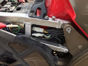
1) Remove right side panel (the piece that covers the rear subframe and lower gas tank) by removing the two 4mm button-head Allen bolts. Be
careful of the plastic tabs on the backside of the panels.
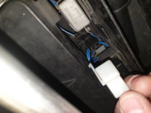
2) You will find two unconnected wires near a big harness clip near the side of the battery. You cannot miss these wires. They are the only 2
unconnected wires in there.
3) Connect the two wires together.
4) Turn key switch to «ON/RUN».
5) DO NOT start or attempt to start engine.
6) The message «DIAG» should appear on left LCD screen along with a number indicating the Fault Code.
7) If your bike is still under warranty, let your Aprilia dealer do all of this.
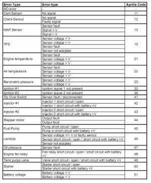
| Component | Fault Code DTC | Possible Cause |
| Camshaft position sensor | 11 |
Sensor not connected.
Sensor broken. Wiring faulty. |
| Crankshaft position sensor | 12 | |
| Intake pressure sensor | 13 | |
| Intake pressure sensor | 14 | Excessive pressure difference between two pressure sensors |
| Throttle position sensor | 15 |
Sensor not connected.
Sensor broken. Wiring faulty. |
| Coolant temperature sensor | 21 | |
| Air temperature sensor | 22 | |
| Atmospheric pressure sensor (inside ECU) | 23 | Sensor faulty |
| Ignition coil 1, Front cylinder | 33 | Ignition coil faulty or wiring not connected |
| Ignition coil 2, Front cylinder | 34 | |
| Ignition coils 1 and 2, Front cylinder | 33,34 | |
| Ignition coil 1, Rear cylinder | 35 | |
| Ignition coil 2, Rear cylinder | 36 | |
| Ignition coils 1 and 2, Rear cylinder | 35,36 | |
| Fall Sensor (tip-over sensor) | 41 |
Sensor not connected.
Sensor broken. Wiring faulty. |
PERIODIC MAINTENANCE
Engine overheat
Pick-up sensor failure
Wrong signal from throttle position sensors
Wrong signal from throttle position sensor 1
Wrong signal from throttle position sensor 2
Throttle position sensor 1 malfunction
Throttle position sensor 2 malfunction
Throttle position sensors malfunction
Incorrect charging voltage
Oil pump malfunction
Air injector malfunction
Fuel injector malfunction
Ignition circuit malfunction
Fuel pump malfunction
Engine rpm limiter tripped
Error in ECU power supply
Rpm limiter tripped while starting
Engine temperature sensor malfunction
Error on ECU – throttle sensor connection
Atmospheric pressure sensor malfunction
INSTRUMENT PANEL ERRORS: This menu allows you to
view any current errors (active) or stored (memo) as
detected by the instrument panel.
The presence of an error is indicated by «x».
To identify the error, please refer to the «instrument panel
error codes» table.
Immobilizer failure: Key code read but not acknowledged
Immobilizer failure: Key code not read (key not available or
transponder broken)
Immobilizer failure: Broken antenna (open or short-circuited)
Immobilizer failure: Inner controller failure
Fuel sensor failure
2 — 14
ERROR DESCRIPTION
ERROR DESCRIPTION
ECU ERROR CODE
ECU 01
ECU 02
ECU 03
ECU 04
ECU 05
ECU 06
ECU 07
ECU 08
ECU 09
ECU 10
ECU 11
ECU 12
ECU 13
ECU 14
ECU 15
ECU 16
ECU 17
ECU 18
ECU 22
ECU 23
INSTRUMENT PANEL
ERROR CODE
DSB 01
DSB 02
DSB 03
DSB 04
DSB 05
SR 50