
![]()
Jungheinrich System Error Codes list.pdf
Adobe Acrobat Document
168.2 KB
![]()
Jungheinrich Fault Codes.pdf
Adobe Acrobat Document
720.8 KB
![]()
Jungheinrich Error Codes List PDF.pdf
Adobe Acrobat Document
191.8 KB
![]()
Jungheinrich EJC112 & E1202 Event Messag
Adobe Acrobat Document
582.8 KB
Event Messages
Z This display units shows a four-digit event message for every
event. Trucks that only use one luminous display (e.g. LED) show
the event through a flashing code (see «Display System”).
Each event message is also stored in the master logbook. The
master logbook describes the event in more detail through the sub
index behind the event message (FEXX).
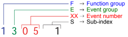
Event numbering display
F E XX S
F Function group; E Event group
XX Event number S Sub index
The first two characters “F, E” refer to the category. The middle
two digits “XX” refer to the event. From these two digits the range:
• 1 to 50 describes standard events (uniform basic events)
which can occur in any function group.
• 51 to 99 describes specific events.
The event is described in further detail through the last characters
“S” (single digit / multi-digit).
This process ensures that a unique number is assigned to each
event. Example:
0 Fault reset or
no fault
1 General fault / additional functions
Example:
Logic error, e.g. both directions selected simultaneously
2 Current
(input interface, device-internal, output interface)
3 Voltage
(input interface, device-internal, output interface)
4 Temperature
5 Hardware
Example: Output transformer short circuit, EEPROM not
responding, …
6 Software
(internal software, application software, data record /
parameters)
Example: EEPROM data error
7 Additional modules
8 CAN monitoring
9 External fault
Example: ISM
See also: Jungheinrich Service Repair Manuals PDF
Jungheinrich Error Codes Manual PDF
Password: https://truckmanualshub.com/
| Title | File Size | Download Links |
| Jungheinrich EJC112 / E1202 Event Messages Codes List PDF [PDF] | 616.6kb | Download |
| Jungheinrich Error Codes List PDF [PDF] | 198.4kb | Download |
| Jungheinrich Fault Codes [PDF] | 769kb | Download |
| Jungheinrich LISTADO ERRORES [PDF] | 198.4kb | Download |
| Jungheinrich System Error Codes list [PDF] | 162.3kb | Download |
Jungheinrich system error table
| Error | Description | Component | Display text | Cause / Action | Effect |
| 1 | Low voltage during system start | F, H, L,
F-AC, H-AC |
Low voltage ELECTRICAL SYSTEM | Check battery voltage, charge battery; Check wire connection to controller; check main current fuse; check main contactor; replace control part; Replace component;
(Limit VN = 80V: VBatt < 64V or VCap. < 56V Limit VN = 48V: VBatt < 34V or VCap. < 34V Limit VN = 24V: VBatt <17V) |
Travel is inhibited.
Reduced power for travel and lifting. Warning symbol flashing (Else-Check). |
| 2 | Over voltage | F, H, L,
F-AC, H-AC |
Over voltage BATTERY CONTROLLER | Check battery voltage; replace controller part; replace component; (Limit VN = 80V: VBatt > 92 V
Limit VN = 48V: VBatt > 62 V Limit VN = 24V: VBatt > 28 V) |
No travel or hydraulic functions Warning symbol
flashing (Else-Check). |
| 3 | Temperature limit for controllers
> 80°C (>70°C MP1510C) or ACS only: Info at > 85°C Err at > 115°C Err at < -20°C |
F, H, L,
F-AC, H-AC |
TEMPERATURE CONTROLLER | Check sensor and wire connections Allow controllers to cool down; check fan operation, improve cooling.
Warm up the controller and operate at reduced level until the controller has warmed up. |
Reduced power for travel and lifting.
Warning symbol flashing (Else-Check). |
| 4 | Emergency Disconnect applied during travel | F | POWER SUPPLY | Warning
(V < 20V MP1510C) |
Brake applies, travel inhibited |
| Error | Description | Component | Display text | Cause / Action | Effect |
| 1 | Low voltage during system start | F, H, L,
F-AC, H-AC |
Low voltage ELECTRICAL SYSTEM | Check battery voltage, chargebattery; Checkwireconnectiontocontroller; check main current fuse; check main contactor; replace control part; Replacecomponent;
(Limit VN = 80V: VBatt < 64V or VCap. < 56V Limit VN = 48V: VBatt < 34V or VCap. < 34V Limit VN = 24V: VBatt <17V) |
Travel is inhibited.
Reduced power for travel and lifting. Warning symbol flashing (Else-Check). |
| 2 | Overvoltage | F, H, L,
F-AC, H-AC |
Overvoltage BATTERY CONTROLLER | Check battery voltage; replace controllerpart; replace component; (Limit VN = 80V: VBatt > 92 V
Limit VN = 48V: VBatt > 62 V Limit VN = 24V: VBatt > 28 V) |
No travel or hydraulic functions Warning symbol
flashing (Else-Check). |
| 3 | Temperature limit for controllers
> 80°C (>70°C MP1510C) or ACS only: Info at > 85°C Err at > 115°C Err at < -20°C |
F, H, L,
F-AC, H-AC |
TEMPERATURE CONTROLLER | Check sensor and wire connections Allow controllers to cool down; check fan operation, improve cooling.
Warm up the controller and operate at reduced level until the controller has warmed up. |
Reduced power for travel and lifting.
Warning symbol flashing (Else-Check). |
| 4 | Emergency Disconnect applied during travel | F | POWER SUPPLY | Warning
(V < 20V MP1510C) |
Brake applies, travel inhibited |
| Error | Description | Component | Display text | Cause / Action | Effect |
| 5 | Over voltage | F, F-AC, H-AC | ELECTRICAL SYSTEM | Check wire connection to battery, check Battery, replace controller part; Replace component;
(Limit for Retrak: VBatt > 62 V Limit for MP1510C: V > 32 V) |
Brake applies, travel inhibited |
| 6 | Wire breakage:
– Travel set point device |
C, I2, I3, I4, I5,
Travel switch |
TRAVEL SWITCH | Check wire connection; Replace travel set point device; Replace Canion/ Interface; | Travel stop. “Warning” symbol flashes (Else-Check). Hydraulic functions possible |
| 7 | Key switch applied during travel | F,F-AC,H-AC | KEY SWITCH | Warning
(V < 13V for 200ms MP1510C) |
Brake applies, travel inhibited |
| 8 | 2 travel directions applied simultaneously | F-AC, H-AC, C,
MP, S, I2, I3, I5, FS |
ELECTRICAL SYSTEM | Warning, replace travel direction switch, replace Interface 7 Canion; replace Multi-pilot / Solo-pilot
For twin pedal, check the electrical system. |
Travel stop. “Warning” symbol flashing (Else-Check).
Hydraulic functions possible |
| 9 | Operator protection switch faulty | I2, FS | ELECTRICAL SYSTEM | Check switch, check wire connections | |
| 10 | V Cap. <> V Batt; (main
contactor jammed or not open) |
F, H,
F-AC, H-AC L |
MAIN CONTACTOR | Check main contactor, check wire connection; check output pin 2 (ACS) of traction controller; replace component | No travel, hydraulics Warning symbol
Flashing warning (Else-Check). |
| 11 | Offset error armature / field current (DC) Stator current (AC); Current measurement
point |
F, H, L,
F-AC, H-AC |
CONTROLLER | Check main current wire, replace component | Travel no function |
| 12 | Disable driver field rheostat faulty for DC Disable driver power stage faulty (for AC) | F, H
F-AC, H-AC L |
CONTROLLER | Replace component;
for AC: Check flat belt wire connection; replace power part |
No travel, hydraulics Warning symbol
Flashing warning (Else-Check). |
| Error | Description | Component | Display text | Cause / Action | Effect |
| 13 | Disable Watchdog field faulty | F, H | CONTROLLER | Replace components | Travel no function |
| 14 | – Main contactor not closed
– Field power stage cannot be switched on (DC) |
F, H,
F-AC, H-AC |
CONTROLLER/ MAIN CONTACTOR | Check wire connection; check main contactor; check charging connection, Check field supply fuse,
Replace component. |
No travel, hydraulics Warning symbol
Flashing warning (Else-Check). |
| 15 | Disable field faulty; Illegal address (for AC) | F, H,
F-AC, H-AC L |
CONTROLLER | Replace control part; replace component | Travel no function |
| 16 | Disable driver armature
actuator faulty; Software reset (for AC) |
F, H,
F-AC, H-AC |
CONTROLLER | Replace control part (AC); replace component | Travel no function |
| 17 | Disable Watchdog armature faulty | F, H | CONTROLLER | Replace components | Travel no function |
| 18 | DC: Armature power stage cannot be switched on
AC: one of the 3 phases cannot be switched on |
F, H, F-AC, H-AC L | CONTROLLER | Check armature wire connection; replace power part; replace component | Travel no function |
| Error | Description | Component | Display text | Cause / Action | Effect |
| 19 | Disable armature faulty; Power stage short circuit (for AC)
The error may be triggered by the faulty speed sensor in connection with AS4814Plus controllers. Sensor wheel wobbles (elliptical) or the sensor- sensor wheel gap is too big. In this case the component is not faulty. A short circuit cannot be resolved by switching the truck off/on. |
F, H, F-AC ,H- AC,
L-AC |
CONTROLLER | Replace power part; Replace component.
Can occur in connection with error 70, in this case: check power supply behind the main contactor contact, in the event of an error the voltage will be much lower here than the rated operating voltage. Disconnect the positive supply from the components to target the error cause. The exception here is the F1 traction controller which must remain connected. One component overloads the testing voltage due to internal short circuit. The testing voltage arises by charging the internal capacitor batteries via a resistor to the level of the control voltage supply. |
Travel no function |
| Check sensor, replace sensor and / or sensor wheel. | |||||
| 20 | Armature incorrectly connected | F, H | ELECTRICAL SYSTEM | Check armature main current wire connection | Travel no function |
| 21 | Armature over voltage (short circuit / high side faulty) | F, H, F-AC, H-AC L | CONTROLLER/ ELECTR | Check main current wire to armature; check settings(for AC);
A Armature > 360A for 250ms (MP1510); Replace component. |
| Error | Description | Component | Display text | Cause / Action | Effect |
| 22 | Watchdog error; Watchdog does not run out | F, H, L, M, S, A, I2, I3, I4, C,
F-AC, H-AC, FS |
CONTROLLER/ CANION | Truck reset,
Replace controlpart; replace component |
No travel, hydraulics Warning symbol
Flashing warning (Else-Check). |
| 23 | – Computer overload
– Permanent interrupt – “ACS” timeout on CAN connection |
F, H, L, M, S, A, I2, I3, I4, C,
F-AC, H-AC, FS |
CONTROLLER / CAN | Check CAN bus connection; Check CANION connector and component;
Replace component |
No travel, hydraulics Warning symbol
Flashing warning (Else-Check). |
| 24 | EEPROM cannot be contacted / parameters not plausible / parameter set to default
Faulty checksum |
F, H, L, I2, I3, I4, C,
F-AC, H-AC MFC brake MFC hydr. , travel switch |
CONTROLLER/ CANION | Check battery cable; check VBatt; set trucktype, set default parameters; replace control part; replace component
Delete logbook, change parameters, set hourmeter, replace component |
Flashing warning symbol (Else- Check). |
| 25 | No telegrams:
– no logon from interface – no telegrams from Can-Bus travel switch |
F, H, I4, I8
F-AC, H-AC L |
INTERFACE / CAN | Check CANBus connection, check wire connection between proportional valve
– modulation; check fuse 1F8; replace iInterface (I2, I4, I8) ; replace lift potentiometer, Multipilot, Solopilot or interface; MP1510C: Voltage collapses, controller logs on again, interface does not, controller remains blocked and waits for interface. Check battery voltage (with load!); charge or replace battery if necessary; AS2409K: no “live” telegram received from CAN Bus travel switch for more than 300 ms; replace travel switch |
| Error | Description | Component | Display text | Cause / Action | Effect |
| 26 | Wire breakage:
– Lift potentiometer |
M, S, I2, I3 | MULTIPILOT / SOLOPILOT / LIFT POTENTIOMETER | Check wire connection | Lift stop. “Warning” symbol flashes (Else-Check), travel enabled |
| 27 | Wire breakage:
– Steering setpoint device; à Reach truck: for 45° steering bolster movement no flank from proximity switch. à Canion: “Steer angle acquire active” parameter has incorrect value à Juniors PM2402L: “Operating mode” parameter incorrectly set |
C, L, I3, I4 | STEER ACTUAL ANGLE | Check wire connection; Replace steer angle sensor / potentiometer;
Replace Canion / Interface; Replace steering; PM2402L from software version 1.60: set parameter P511 “operating mode” correctly à 1 = analog sensor (potentiometer), 2 = digital sensor on steer motor |
Crawl speed,
Flashing warning symbol (Else- Check), hydraulic functions enabled. This error produces an emergency stop on the reach truck and the Juniors. |
| 28 | Wire breakage:
– Steering sensor |
C, L, I3, I4 | STEER NOMINAL ANGLE | Check wire connection, replace steering wheel sensor;replace Canion / interface; replace steering | Crawl speed,
Flashing warning symbol (Else- Check), hydraulic functions enabled. This error produces an emergency stop on the reach truck |
| 29 | Wire breakage:
– Traverse potentiometer |
M | Traverse nominal value MULTIPILOT | Replace Multipilot | |
| 30 | Wire breakage:
– Tilt potentiometer |
M | Tilt nominal value MULTIPILOT | Replace Multipilot,
Teach Multipilot (Hall sensor 2003 only) |
|
| 31 | Wire breakage:
– ZH1 setpoint device – Initial lift / lower Setpoint device |
M, S
Travel switch |
Sideshift nominal value MULTIPILOT / SOLOPILOT | Replace Multipilot / Solopilot, Teach Multipilot (Hall sensor 2003 only);
Travel switch: Check / replace switch |
Hydraulic functions stop, “Warning” symbol flashes (Else-Check), travel enabled |
| Error | Description | Component | Display text | Cause / Action | Effect |
| 32 | Wire breakage:
– ZH2 setpoint device |
M, S | MULTIPILOT / SOLOPILOT | Replace Multipilot / Solopilot,
Teach Multipilot (Hall sensor 2003 only) |
Hydraulic functions stop, “Warning” symbol flashes (Else-Check), travel enabled |
| 33 | Wire breakage:
– ZH3 setpoint device |
M, I8 | MULTIPILOT | Replace Multipilot | |
| 34 | CANBus damaged | F, H, L, M, S, A,
I2, I3, I4, I5, C, F- AC, H-AC Travel switch |
CAN-BUS | Check CAN bus connection; replace faulty component; Check terminal resistances | No travel, hydraulics Warning symbol
Flashing warning (Else-Check). Only stored in logbook (from 2004). |
| 35 | No travel zero position Deadman and accelerator pedal applied when truck switched on | I2, I3, I4, C
Travel switch |
TRAVEL ZERO POSITION | Warning, check travel switch; Intermittent contact in interface power supply (12 volts)
Check Canion, for twin pedal check electrical system |
Travel stop,
Flashing warning symbol (Else- Check), hydraulic functions enabled. |
| 36 | No lift zero position | M, I2, I3,FS | LIFT ZERO POSITION | Warning, check lift setpoint device. | Hydraulic functions stop, “Warning” symbol flashes (Else-Check), travel enabled |
| 37 | No steering angle nominal value | L | CONTROLLER / CAN | Check steering setpoint device;Check CANBus connection; check “steer type” parameter; Replace component (I5) | |
| 38 | Component does not log on, self test not concluded. | F, H, L, I2, I3, I4,
C, A, M, S, F-AC, H-AC |
CONTROLLER / CAN | Check CAN-Bus connection and voltage; check DIL switch 7 encoding (MP1510); steering controller monitoring activated? (AS2412F); check ACS encoding; replace component | No travel, lifting Warning symbol
Flashing warning (Else-Check). |
| Error | Description | Component | Display text | Cause / Action | Effect |
| 39 | Implausible truck type
1. Discovered during the self test phase that at least one component has a different truck type as a parameter. A different truck type was discovered in operating mode. Caused by intermittent contacts in the power supply connections |
F, H, L, I2, I3, I4, I5, A, M,
F-AC, H-AC |
TRUCK TYPE | For 1. Set truck type;
For 2. Examine and if necessary replace switch (key switch) or rectify intermittent contact in power supply plug connections. Set truck type. |
|
| 40 | Motor overtemperature Traction motor overtemperature in operating mode.> 150°C And travel speed < 1km/h For ACS:
Info > 145°C Err > 165°C |
L, F, H
F-AC, H-AC |
TEMPERATURE MOTOR | Warning; check motor sensor system and wire connections;
Check motor; traction motor brake open? |
Reduced power for travel and lifting.
Warning symbol flashing (Else-Check). For steering only warning symbol flashing. |
| 41 | Brake magnet potentiometer Potentiometer voltage less than 0.3 volts or greater than 2.7 volts for more than 500ms. | L | BRAKE MAGNETPOTENTIOM ETER | Check potentiometer; check potentiometer attachment; check wire connection |
| Error | Description | Component | Display text | Cause / Action | Effect |
| 42 | – Short circuit between the output and battery positive. (EJC, ELE)
-Brake magnet control, below minimum difference on potentiometer for 500ms when magnet applied. (150mV ) No brake pressure during initialization. Brake pressure after the Emergency Stop magnet has applied; |
L,F | BRAKE MAGNET | Check wire connection, check brake
magnet; replace component |
|
| 43 | Adjust brake | L | ADJUST BRAKE | Adjust brake; check potentiometer | |
| 44 | -Brake not connected or connection wire short circuit
-Brake cable torn Only for steer category_3: Internal driver of fail safe brake cannot connect the relay Or short circuit bypass (contact jams) on the output during power up test |
L,F | BRAKE FAULTY | -Check brake wiring, replace brake if necessary
-Replace brake cable, check potentiometer; Check potentiometer attachment; Only for steer category_3: -Check brake driver output, check switch contact plausibility, Replace steer component. |
No release |
| Error | Description | Component | Display text | Cause / Action | Effect |
| 45 | Too many pulses from steering set point device Intermittent contact or perturbing radiation.
More than 255 pulses identified within 100ms |
L,I5 | STEERING WHEEL | Check wire connection, replace sensor bearing; replace component | |
| 46 | Steering set point device wrongly connected AS4803L: More than 3 pulses identified in one direction and more than 3 pulses in another within 100ms. | L,I5 | STEERING WHEEL | Check sensor bearing connection; check wire connection AS4803L: Check steering wheel recognition input. | |
| 47 | No pulses from steer set point device ETVQ steering wheel no pulses from 1st sensor bearing. More than 10 pulses were obtained from the stepper motor but fewer than 3 pulses were counted within 200ms from the sensor bearing. | L,I5 | STEERING WHEEL | Check wire connection, replace sensor bearing; replace component | No release |
| Error | Description | Component | Display text | Cause / Action | Effect |
| 48 | Does not match the “Steering type” parameter ETVQ steering wheel no pulses from stepper motor or 2nd sensor bearing.
More than 10 pulses were obtained from the sensor bearing but fewer than 2 pulses were counted within 200ms from the stepper motor sensor bearing. |
L | STEERING TYPE | Set steering type correctly
ETVQ: Check stepper motor coupling, tighten grub screw. Test both setpoint device branches, set defaults and truck type Otherwise faulty, replace component. |
|
| 49 | CAN supply interrupted; Supply above 14 volts or less than 10 volts, Can or sensor bearing incorrectly
supplied |
AS 2412 F,H-AC | Can Bus CAN supply | Suply on CAN connector greater than 14 volts (electrical system short circuit, component) | Travel disabled |
| 50 | NRG Multipilot wire breakage Horizontal tilt | M | Setpoint device horizontal | Check Multipilot wire connection Parameter 540 set to 1 by mistake | Travel and lifting disabled. |
| 51 | Teach-In: steering actual value potentiometer | L | Incorrect setting SETTING | Repeat calibration, check wire connection;check potentiometer;replace component | |
| 52 | Teach-In: Brake magnet potentiometer | L | Incorrect setting SETTING | Repeat calibration, check wire connection;check potentiometer;replace component | |
| 53 | Teach-In: Steering setpoint potentiometer | L | Incorrect setting SETTING | Repeat calibration, check wire connection;check potentiometer;replace component |
| Error | Description | Component | Display text | Cause / Action | Effect |
| 54 | Motor wire breakage during power-up test ETVQ: Temperature voltage level less than 0.3 volts or greater than 2.7
volts |
L, F, H | MOTOR WIRE BREAKAGE | Check wire connection;
Check temperature sensor lines; replace component; replace motor |
|
| 55 | Motor short circuit; Current not ok; Power stage faulty | L, F-AC, H-AC | SHORT CIRCUIT MOTOR | Check wire connection; Replace motor; Replace component | Traction motor stops, Hydraulic motor stops Warning symbol
flashing (Else-Check). |
| 56 | Motor or actual value transmitter incorrectly connected | L,F.H | MOTOR REVERSE POLARITY | Check motor connection; check actual value transmitter potentiometer; AC: Phases L1,L2 or L3 swapped on motor; | |
| 57 | No actual value change Motor turns despite control signal | L,F,H | Steering controller ACTUAL VALUE TRANSMITTER | Check motor; check actual angle potentiometer; rectify mechanical wheel block;
AS4803L: Check incremental bearings; replace component; AC: Check actual value transmitter wire breakage signals PM2402L check operating mode |
|
| 58 | Steering angle actual value fluctuates
ETVQ: Reference mark 0° could not be started within 5 seconds or no valid segment reached. Steer motor does not turn |
L | STEER ACTUAL ANGLE | Check actual value transmitter (on steer motor)
Check steer motor, fuse and incremental bearing, rectify mechanical wheel block; Check proximity switch distance. |
| Error | Description | Component | Display text | Cause / Action | Effect |
| 59 | Steering angle nominal value fluctuates | L | Steer angle setpoint device
TILLER POTENTIOMETER |
Check setpoint device potentiometer (on tiller) | |
| 60 | Swivelling bolster does not follow steering wheel directions
Deviation of > 15° for 100ms The wheel turns more than 5°without change of nominal value on steering wheel, less than 2°/sec after reaching the nominal position. Tyres over-tensioned, the actual value cannot follow the nominal value. |
L | STEERING CONTROL | Check steering bolster mechanics; check chain and chain tension; check motor; check actual value transmitter attachment;
Check tyres, replace wheel if necessary. |
|
| 61 | Power stage error | L | CONTROLLER | Replace controller | |
| 62 | Power stage error | L | CONTROLLER | Replace controller | |
| 63 | Sensor power supply out of range
AS4803L: < 10V oder >16V |
L,F-AC,H-AC | CONTROLLER | The 12 volt supply not in valid range. Monitoring of 12 volt sensor supply greater than 15 volts and less than 11 volts.
Switch controller off and on, replace fuse and controller if necessary. |
|
| 64 | Software version differs | L | CONTROLLER | Different software versions in the AS4803Ls in the ETV-Q. Update software to same level. |
| Error | Description | Component | Display text | Cause / Action | Effect |
| 65 | NRG Multipilot wire breakage centre shifter | M | Centre switch MP centre shifter | Check Multipilot wire connection Parameter 540 set to 1 by mistake | Travel and lifting disabled. |
| 66 | NRG Multipilot wire breakage
180° / 360° steering toggle |
M | 180-360 switch
MP toggle switch 180°/ 360° |
Check Multipilot wire connection Parameter 543 set to 1 by mistake | Travel and lifting disabled. |
| 67 | NRG-Multipilot setpoint device travel direction switch jams on MP when system starts | M | Travel direction MP setpoint device | Check Multipilot switch, values in Judit MP teach window, recalibrate values | Travel and lifting disabled. |
| 68 | Safety switch wire breakage | I2, I3, I4, I5 | DEADMAN | Check wire connection to safety switch (deadman, seat switch); replace safety switch | |
| 69 | Both lift and lower requested simultaneously | I2, I5, FS | LIFT/LOWERSWITCH | Check wire connection; check switch | |
| 70 | Component fails to respond orresponds incorrectly to self test | F-AC, H-AC, M, S, A,
I2, C |
SELF TEST | Check displays on basic component (LED); note other error messages on basic card; Check wireconnectionsandcheck connector; check power supply behind the main contactor contact, in the event of an error the voltage will be much lower here than the rated operating voltage. Disconnect the positive supply from the components to target the error cause. One component overloads the testing voltage due to internal short circuit.
The testing voltage arises by charging the internal capacitor batteries via a resistor to the level of the control voltage supply. |
No travel, hydraulics Warning symbol
Flashing warning (Else-Check). |
| Error | Description | Component | Display text | Cause / Action | Effect |
| 71 | Lower potentiometer wire breakage | I2, FS | LOWER POTENTIOMETER | Check wire connection; replace lower potentiometer; replace Multipilot; replace interface | |
| 72 | No lowering zero position | I2, FS | LOWER RESTPOSITION | Warning, check lower setpoint device | |
| 73 | Valve output interface faulty | I2 | VALVE OUTPUT | Warning, check valve outputs | |
| 74 | Interface valve output faulty | I2 | INTERFACE FAULTY | Replace interface | |
| 75 | Proportional valve does not draw any current Correct Multipilot ?? | I2,I4,C | PROP. VALVE | Check wire connection, replace proportional valve;replace Canion / interface; replace proportional valve | Flashing warning symbol (Else- Check). |
| 76 | Proportional valve short circuit | I2, I4C | PROP. VALVE | Check wire connection, replace proportional valve;replace Canion / interface; replace proportional valve | Flashing warning symbol (Else- Check). |
| 77 | Button wire breakage | I2, | BUTTON WIRE BREAKAGE | Check wire connection; replace button; replace interface | |
| 78 | Button and travel switch pressed simultaneously | I2 | BUTTON / TRAVEL SWITCH | Warning: Check wire connection; replace button; replace interface | |
| 79 | Switch and deadman switch pressed simultaneously | I2 | BUTTON / DEADMAN | Warning: Check wire connection; replace button; replace interface | |
| 80 | 2 travel directions simultaneously | I2 | ELECTRICAL SYSTEM | Check wire connection; replace button; replace interface | |
| 81 | Different parameters for the two traction controllers | F, F-AC | MOTORS | reset parameters (EFG traction controllers) | Travel inhibited |
| 82 | Sensor wire breakage | I2 | ELECTRICAL SYSTEM | Safety height: Check wire connection; replace button; replace interface |
| Error | Description | Component | Display text | Cause / Action | Effect |
| 83 | 2 of the same components report on the truck
e.g. AS4803L: Key switch voltage cannot be assigned to components Elle_1,Elle_2 or Elle_3 |
F, H, I4, F-AC L-AC | ELECTRICAL SYSTEM | Check component encoding; check wire connection; replace component; | Travel inhibited |
| 84 | Faulty speed sensor:
à AS4803L: – Speed changes by 50% within 4ms; – Reference speed less than half the rated speed; – Steer transmission blocked; – Tear identification: a valid sensor reading is reduced to zero within 4ms and remains at this level for 50ms without producing a new valid reading. à PM2402L/2 from V1.60: – Too many pulses on encoder 3 on steer motor |
F,H,L-AC | SPEED SENSOR | Check speed sensor; Sensor bearing drift; Check wire connection; Replace speed sensor; Replace component;
Check wire routing, do not route together with motor supply wires! |
Travel stop, Lift stop,
Flashing warning symbol (Else- Check), hydraulic functions enabled. |
| 85 | Power release low voltage Travel/Steer:
Capacitor voltage drops to 30V (48V) for 0.5 seconds |
F,H-AC L-AC | ELECTRICAL SYSTEM TRAVEL | Switch truck on and off; check battery; check battery cable connections; check fuse;
Check power connections; replace component |
Travel, hydraulics no function, warning symbol
Flashing warning (Else-Check). |
| Error | Description | Component | Display text | Cause / Action | Effect |
| 86 | Improbable speed, sudden change:
à AS4803L: 2 sensor systems differ from each other. à PM2402L/2 from V1.60: Encoders 3 and 4 supply different sensor signalse |
F,H-AC L-AC | SPEED IMPLAUS | Check wire connection; Replace speed sensor; Replace component;
Pulse counts correct: 8 or 64 pulses/ revolution? Check wiring and plug connections, check wire routing, do not route together with motor supply wires! |
|
| 87 | Sensor line interrupted AS4803L: no voltage drop on a 100 Ohm internal measurement resistor MFC brake: load wheel
speed sensing |
F-AC L-AC
MFC brake |
Electrics DISCONNECTION SENSOR BEARING | Sensor wire disconnected, motor consumes maximum current and makes buzzing noise. Check sensor wires. | |
| 88 | Hydraulic speed sensor faulty on AS4814H | H (AS4814H) | SPEED SENSOR H | Check speed sensor;
Check wire connection; replace speed sensor; replace component; |
Hydraulics stop,
Flashing warning symbol (Else- Check), travel enabled. |
| 89 | Hydraulics power release low voltage | H | ELECTRICS- HYDRAULICS | Check battery, check battery wire connection;
Check fuse; replace component |
Reduced power for travel and lifting.
Warning symbol flashing (Else-Check). |
| 90 | Travel with handbrake on | C | ELECTRICAL SYSTEM | Check magnetic brake switch | Flashing warning symbol (Else- Check). |
| 91 | 24 volts out of range Info at <17 V
Err at <15 V |
C | ELECTRICAL SYSTEM | Check power supply; check wire connection | For a warning, only the warning symbol flashes (Else-Check).
For an error, the truck stops. |
| Error | Description | Component | Display text | Cause / Action | Effect |
| 92 | Wrong component reporting on Canion | M, S, A | ELECTRICAL SYSTEM | Check Master/Solopilot; check display; replace component
Check jumper in XB 27 and XB 44 from pin 2 to pin 6, |
Travel, lifting
function, warning symbol flashes (Else-Check). |
| 93 | ACS capacitors not charged | F, H, C | ELECTRICAL SYSTEM | Check charging connection, main contactor
does not apply, check bus voltage, check transformer, fuses and cable set, Replace component |
Travel, lifting no function, warning symbol flashes (Else-Check). |
| 94 | SDO error | F, H, C | SDO ERROR | Software incompatible check software version
Reload software. Check jumper in XB 41 from pin 12 to pin 13. |
Travel, lifting no function, warning symbol flashes (Else-Check). |
| 95 | Pin code error | C | PIN CODE ERROR | Component pin codes not identical | Travel, lifting no function, warning symbol flashes (Else-Check). |
| 96 | No zero position for hydraulics Masterpilot, Solopilot, | M,S | Hydraulics zero position MP/SOLOPILOT | Check Master/Solopilot; lift, lower, tilt, ZH1, ZH2, ZH3, horn switch not in zero position
Replace component |
Hydraulic functions stop, “Warning” symbol flashes (Else-Check), travel enabled |
| 97 | Segment beyond tolerance limits
à PM2402L/2 from V1.60: Referencing error on power up, no switch signal from proximity switch (NS) or time interval exceeded |
L | FAULTY SEGMENT | Segment on swivelling bolster not within tolerance level.
Check wiring and proximity switch, check distance from switch to trip cam on swivelling bolster |
| Error | Description | Component | Display text | Cause / Action | Effect |
| 98 | The position of the sensor bearing and proximity switch (segment) deviate by more than 1.1 degrees. When the truck starts up, the direction of rotation from the steering wheel sensor system to the motor power connection or the steer motor sensor system is inversed.
à PM2402L/2 from V1.60: Referencing error during operation, unexpected switch signal from proximity switch. |
L | POSITION DEVIATION | Check wiring.
Check wiring and proximity switch, check distance from switch to trip cam on swivelling bolster |
|
| 99 | CANBus damaged; CANBus driver temporarily deactivated | F,H,M,S,A, I3, I4, C | CAN-BUS | Check wire connection, check terminal resistors, install truck anti- interferencemeasures; | Travel, hydraulics no function, warning symbol flashes (Else-Check). |
| 100 | NRG software versions of internal component parts
implausible |
M | Multipilot software | Replace component part with corresponding component, as flashing currently not possible in the
field. |
| Error | Description | Component | Display text | Cause / Action | Effect |
| 101 | Input / output error | JUBES | Jubes input/output | Check I/Oa, rectify contact error, check operating voltage, replace external transmitter
Index info in display: a— Sensor 1 supplies values, but not defined. Check parameters 11-17 b— Sensor 2 supplies values, but not defined. Check parameters 20-26 c— Sensor 3 supplies values, but not defined. Check parameters 29-35 Or a sensor 1-3 supplies a voltage outside the range of 0.5V – 9.5V. |
Shown in the driver’s display with error 101 |
| 102 | Internal error | JUBES | Jubes internal | Check operating voltage. Index info in display:
a — Communication between access module and data recording faulty, check connection e — Radio module faulty f — Radio channel number is “0”, should be >0, check parameter 100 g — Radio transmitting power is “0”, Check parameter 101 h — Lock number is invalid, replace access module i — Impact sensor faulty, replace data recorder |
Shown in the driver’s display with error 102 |
| Error | Description | Component | Display text | Cause / Action | Effect |
| 103 | Parameter error | JUBES | Jubes parameters | Set parameters Index info in display:
a — Parameter 5 greater than parameter 6, should be smaller. b — Differential value of parameter 11 is greater than the differential values of the various stages of parameters 12-17 c — Differential value of parameter 20 is greater than the differential values of the various stages of parameters 21-26 d — Differential value of parameter 29 is greater than the differential values of the various stages of parameters 30-35 e — the stages of parameters 12-17 … f — the stages of parameters 21-26 … g — the stages of parameters 30-35 … h — Impact stages of parameters 47-49 … i — Impact stages of parameters 50-52 … …are not in increasing order |
Shown in the driver’s display with error 103 |
| 104 | Sensor bearing provides
no pulses on system start up |
F,H | (SENSOR BEARING) | Check sensor bearing and wire, replace sensor bearing or
controller |
|
| 105 | Motor temperature gauge
provides incorrect values Sensor line wire breakage |
F,H,L | Temp.Motor | Check sensor connection and lines, if
possible replace sensor, otherwise replace the entire motor… |
|
| 106 | Controller temperature gauge provides incorrect
values |
F,H,L | Temp. controller | Internal error, replace controller. |
| Error | Description | Component | Display text | Cause / Action | Effect |
| 107 | Key switch voltage out of range
Hardware encoding incorrect |
F,H,L
MFC hydr. MFC brake |
Electrics | Error in controller connection (Saab connector) on component | No travel No lifting No steering
Main contactor open |
| 108 | Calibration reading incorrect | F,H | (CONTROLLER
internal) |
Internal error, replace controller. | |
| 109 | Brake pedal faulty | MFC brake | BRAKE PEDAL | Brake pedal signals implausible | |
| 110 | Current output faulty | MFC brake MFC hydr. MFC option | CONTROLLER | Check outputs for short circuits | MFC_Hydr.: no lifting MFC_Brake: crawl speed only |
| 111 | Steering controller is monitored by traction controller for signs of life telegrams
Traction controller does not receive these telegrams. The Can Bus is overloaded. |
F | Steering controller | Check steering controller | Travel inhibited Main contactor open |
| 112 | Steering controller_2 is monitored by traction controller_1 for signs of life telegrams
The Can Bus is overloaded. |
F | Traction controller | Check Can Bus, measure terminal resistor 60Ohm | |
| 113 | Lift controller does not send lift telegrams | H | LIFT CONTROLLER | ||
| 114 | No traverse distance reference on power up | MFC hydr. | Info 32
Traverse reference |
None | Reduced traverse speed until both stops have been reached once. |
| Error | Description | Component | Display text | Cause / Action | Effect |
| 115 | Main contactor improbable,
contacts not closed. Wire connection interrupted, faulty main contactor driver on traction controller |
F,H,L
?? |
Main contactor improbable | Check wire connection.
If error 19 is also present, disconnect the shorted power stage Disconnect the power positive. Check driver voltage (switched against negative). If reading OK, check contactor coil and mechanics. |
No truck functions |
| 116 | After software flashing (field operation), the item number of the software is implausible and parameters may also be implausible. | F,H,
MFC brake MFC prop |
Info 54
SET TRUCK TYPE |
Set truck type and switch truck off / on (wait approx. 35 seconds).
On request, automatically: all parameters are set to default, the software item number is set to plausible, the log book is deleted, the hourmeter set to zero and entry 116 made in the log book. |
In the log book only error 116 stands as a marker for this process and all parameters can be at default. |
| 117 | Cab position implausible, rotary potentiometer value does not match 180
degree switch |
CANION | Cab position | Check rotary potentiometer, re-adjust if necessary, check 180 degree switch | No TRAVEL release |
| 118 | Steering controller reports error | L | Steering controller | Check display on steering controller | TRAVEL inhibited, EMERGENCY STOP activated |
| 119 | Weigher button faulty | MFC brake | Button faulty | Check wire and button | Weighing interrupted |
| 120 | Weigher pressure sensor faulty | MFC hydraulics | Sensor faulty | Check wire and sensor | Weighing interrupted |
| 121 | Battery incorrectly locked | F-AC | Battery lock | Locking strips stuck. Check proximity switch | No truck functions |
| 201 | Optical sensor faulty | Rack height select | sensor |
| Error | Description | Component | Display text | Cause / Action | Effect |
| 202 | Too many reference points during calibration | Rack height select | Calibration wrong | ||
| 203 | Sensor evaluation improbable | Rack height select | sensor | ||
| 204 | Error when reading EEPROM | Rack height select | Controller | All settings set to default | |
| 205 | No Multipilot in truck | Rack height select | MP missing | ||
| 240 | Internal process interrupted | Rack height select | Controller | ||
| 250 | No height actual value on job input | Rack height select | The height is invalid for the warehouse level entered | ||
| 252 | Rack height select incorrect | Rack height select | |||
| 253 | Rotary field implausible –
transmission overloaded, excess load on incline |
F | Controller | None, switch truck off/on | Main contactor opened |
| 254 | Diagnostics piratry | Judit Box | None | Create authorisation | No diagnosis possible |
Components
| A | C = 064 | Display / Operation (LISA / JULIA) |
| C = 065 | Display / Operation (Else-Check) | |
| C = 066 | Display/Operation (CANCode) | |
| C = 067 | Display (CANDis) | |
| C = 068 | Display/Operation (on board computer) | |
| C = 3 | Comfort display [CANopen] | |
| C | Canion (Atlas Copco) [CANopen] | |
| C = 1 | – Master | |
| C = 11 | – Slave | |
| F | C = 016 | Travel (MP1510C / AS2405F / AS2409K / AS2412F) |
| C = 016 | Travel 1 (MP1514F / AS4814Fplus) | |
| C = 017 | Travel 2 (MP1514F / AS4814Fplus) | |
| F-AC | C = 016 | Travel (AS4812/14F) |
| C = 8 | ACS Traction (Atlas Copco AC 8011/18, Inmotion) [CANopen] | |
| Travel switch | C = 096 | Can-Bus travel switch |
| H | C = 032 | Lift (MP1514H / AS4814Hplus) |
| H-AC | C = 032 | Lift (AS4814H) |
| C = 7 | ACS Pump (Atlas Copco AC 8011/18, Inmotion) [CANopen] | |
| Rack height select | C = 128 | Rack Select |
| I | C = 21 | I/O-Board 1 [CANopen] |
| C = 22 | I/O-Board 2 [CANopen] | |
| C = 23 | I/O-Board 3 [CANopen] | |
| C = 24 | I/O-Board 4 [CANopen] |
| I2 | C = 146 | Interface 2 |
| C = 155 | Interface 21 | |
| C = 156 | Interface 71 | |
| I3 | C = 147 | Interface 3 |
| I4 | C = 148 | Interface 4 = MFC_brake |
| I5 | C = 149 | Interface 5 |
| I6 | C = 150 | Interface 6 = MFC_Prop |
| I7 | C = 151 | Interface 7 |
| I8 | C = 152 | Interface 8 = MFC_Option |
| Jubes | C = 069 | ISM Access Module |
| C = 29 | ISM Access Module [CANopen] | |
| C = 070 | ISM-Data recorder | |
| C = 071 | ISM-radio module | |
| L | C = 048 | Steer (MP1502L / PM2402L / AS4803L) |
| C = 048 | Steer 1 (AS4803L) | |
| C = 049 | Steer 2 (AS4803L) | |
| C = 050 | Steer 3 (AS4803L) | |
| C = 4 | Steer computer [CANopen] | |
| M | C = 096 | Multipilot / Masterpilot |
| C = 2 | Multipilot / Solopilot [CANopen] | |
| S | C = 112 | Solopilot / Hand lever |
Travel setpoint device: travel potentiometer, accelerator pedal
Steering actual value transmitter: steer potentiometer, proximity switch (on steered wheel)
ONLY in 1st generation!
All messages numbered above 100 come from the interface and correspond to messages 1- xx -99!
| Warning / Information Messages | |||||
| INFO 01 | SEAT SWITCH_OPEN | ||||
| INFO 02 | NO_TRAVEL DIRECTION | ||||
| INFO 03 | NO_TRAVEL RELEASE | ||||
| INFO 04 | NO_NOMINAL VALUE | ||||
| INFO 05 | LIFTING OFF | ||||
| INFO 06 | DEADMAN KEY OPEN | ||||
| INFO 07 | START_INCORRECT | ||||
| INFO 08 | PARKING BRAKE | ||||
| INFO 09 | SLOW SPEED | ||||
| INFO 10 | TEMPERATURE DRIVE MOTOR | ||||
| INFO 11 | TEMP_LIFT_MOTOR | ||||
| INFO 12 | TEMP_STEER_MOTOR | ||||
| INFO 13 | BRUSH WEAR OUT_DRIVE_MOTOR | ||||
| INFO 14 | BRUSH WEAR OUT_LIFT_MOTOR | ||||
| INFO 15 | BRUSH WEAR OUT_STEER_MOTOR | ||||
| INFO 16 | DRIVING DISABLE | ||||
| INFO 17 | LIFT END DIS. | ||||
| INFO 18 | SECURITY HEIGHT | ||||
| INFO 19 | DOOR OPEN | ||||
| INFO 20 | AISLE MODE | ||||
| INFO 21 | RESCUE STEERING | ||||
| INFO 22 | STEERING MISSING | ||||
| INFO 23 | DIAGNOSTIC_MODE | ||||
| INFO 24 | SWITCH POWER OFF | ||||
| INFO 25 | TEMP_TRAVEL | ||||
| INFO 26 | TEMP_LIFT | ||||
| INFO 27 | TEMP_STEER | ||||
| INFO 28 | SPARE_1 | ||||
| INFO 29 | DISPLAY SWITCHES THE EXTERNAL
BUZZER |
| INFO 30 | TWIN PEDAL BOTH APPLIED | ||||
| INFO 31 | NO ZERO POSITION | ||||
| INFO 32 | NO TRAVERSE REFERENCE ON POWER UP | ||||
| INFO 33 | ONLY CRAWL SPEED POSSIBLE AS
BATTERY NOT LOCKED |
||||
| INFO 34 | ONLY CRAWL SPEED POSSIBLE, AS INFO
FROM STEERING CONTROLLER |
||||
| INFO 35 | LOW VOLTAGE TRAVEL | ||||
| INFO 36 | LOW VOLTAGE LIFT | ||||
| INFO 37 | LOW VOLTAGE STEER | ||||
| INFO 40 | CHECK MOTOR SENSOR SYSTEM | ||||
| INFO 48 | IMPACT EVENT VERTICAL FORCE 1 | ||||
| INFO 49 | IMPACT EVENT VERTICAL FORCE 2 | ||||
| INFO 50 | IMPACT EVENT VERTICAL FORCE 3 | ||||
| INFO 51 | IMPACT EVENT HORIZONTAL
FORCE 1 |
||||
| INFO 52 | IMPACT EVENT HORIZONTAL
FORCE 2 |
||||
| INFO 53 | IMPACT EVENT HORIZONTAL
FORCE 3 |
||||
| INFO 54 | SET TRUCK TYPE | ||||
| INFO 73 | CHECK VALVE OUTPUTS |
![]()
Jungheinrich System Error Codes list.pdf
Adobe Acrobat Document
168.2 KB
![]()
Jungheinrich Fault Codes.pdf
Adobe Acrobat Document
720.8 KB
![]()
Jungheinrich Error Codes List PDF.pdf
Adobe Acrobat Document
191.8 KB
![]()
Jungheinrich EJC112 & E1202 Event Messag
Adobe Acrobat Document
582.8 KB
Event Messages
Z This display units shows a four-digit event message for every
event. Trucks that only use one luminous display (e.g. LED) show
the event through a flashing code (see «Display System”).
Each event message is also stored in the master logbook. The
master logbook describes the event in more detail through the sub
index behind the event message (FEXX).
Event numbering display
F E XX S
F Function group; E Event group
XX Event number S Sub index
The first two characters “F, E” refer to the category. The middle
two digits “XX” refer to the event. From these two digits the range:
• 1 to 50 describes standard events (uniform basic events)
which can occur in any function group.
• 51 to 99 describes specific events.
The event is described in further detail through the last characters
“S” (single digit / multi-digit).
This process ensures that a unique number is assigned to each
event. Example:
0 Fault reset or
no fault
1 General fault / additional functions
Example:
Logic error, e.g. both directions selected simultaneously
2 Current
(input interface, device-internal, output interface)
3 Voltage
(input interface, device-internal, output interface)
4 Temperature
5 Hardware
Example: Output transformer short circuit, EEPROM not
responding, …
6 Software
(internal software, application software, data record /
parameters)
Example: EEPROM data error
7 Additional modules
8 CAN monitoring
9 External fault
Example: ISM
Password: https://www.pdfmanual4trucks.com/
|
Title |
File Size |
Download Links |
|
Jungheinrich EJC112 / E1202 Event Messages Codes List PDF |
619.4kb |
Download |
|
Jungheinrich Error Codes List PDF [PDF] |
199kb |
Download |
|
Jungheinrich Fault Codes [PDF] |
769kb |
Download |
|
Jungheinrich LISTADO ERRORES [PDF] |
199kb |
Download |
|
Jungheinrich System Error Codes list [PDF] |
162.7kb |
Download |
|
Display error code |
Cause |
Action |
|
1901 |
During system start-up, the accelerator pedal zero position could not |
Do not press the accelerator pedal during system start-up. |
|
1904 |
Accelerator pedal pressed, but no travel direction selected. |
Take your foot off the accelerator pedal, select a travel direction and set off. |
|
1909 |
Accelerator pedal pressed and parking brake not released via parking |
Release the parking brake by pressing the parking brake button. |
|
1917 |
Accelerator and brake pedals pressed simultaneously. |
Press one pedal at a time only. |
|
2951 |
Lift function activated on multi-/ solo PILOT during system start- up. |
Do not apply the multi-/ solo PILOT during system start- up. – – – |
|
1952 |
Travel direction switch pressed during system start-up. |
Do not press the travel direction switch during system start-up |
|
9961 |
ISM (option) has detected a shock event in the vertical |
Obtain acknowledgement from authorized person (warehouse manager) and |
|
9962 |
ISM (option) has detected a shock event in the horizontal |
Obtain acknowledgement from authorized person (warehouse manager) and |
|
5990 |
The electrolyte level sensor check (battery-management option) on the |
Add electrolyte. |
|
5992 |
After switching on the truck, no radio network could be established |
– – – – |
|
5408/ 5409 |
Lithium-ion battery overtemperature |
Stop work. |
|
5413 |
Lithium-ion battery low temperature |
Move truck to warm environment. |
For all other warning messages switch the truck off and on again. If the warning message appears again call the service department.
The code lock enables an operator or a group of operators to be assigned an individual user code. The user code is configured with a master code and is outlined in the following sections of this
chapter.
When you have entered the valid user code the truck will be operational. The truck will be able to perform travel, steering and hydraulic operations.
When you have entered the valid master code the truck will be switched on. Travel operations are inhibited. The truck will be able to perform steering and hydraulic operations. The code lock is
in programming mode. When you enter one of the following parameters the settings in the code lock can be changed.
|
Parameters |
Description |
|
0-0-0 |
– To change the master code |
|
0-0-1 |
– To add user codes |
|
0-0-2 |
– To change a user code |
|
0-0-3 |
– To clear a user code |
|
0-0-4 |
– To clear all user codes |
|
0-1-0 |
– To set the automatic cutout of the truck |
Newly supplied trucks have the code indicated on a sticker. When using the truck for the first time change the master and user codes and remove the sticker.
- User code factory setting: 2-5-8-0
- Master code factory setting: 7-2-9-5
German-made Jungheinrich loading equipment is distinguished by excellent durability and
performance. Benefit from consistently high handling speeds with maximum comfort. This European-quality equipment perfectly adapts to various operating conditions, meets strict safety standards,
is distinguished by high working and driving qualities for moving and storing goods for work both in an open area and inside a closed warehouse or a freight railway container.
Jungheinrich LPG trucks, like trucks from other brands of this type, have a number of advantages. This is a universal warehouse
equipment, which is very economical if, when buying it, you correctly calculate the basic requirements for the height of lifting of loads, carrying capacity, speed of movement, weight of the
machine, its dimensions and, of course, the types of cargo with which the machine has to deal. If the calculation is carried out carefully, and the optimal model is chosen, the costs for it,
given the low price of gas, will pay off in a few months. And due to its high ecological class, it can work on a shift all day long with practically different cargoes that require specific
transportation conditions. The peculiarity of gas forklifts is that you can start them in any weather without any problems, which can not be said about diesel or gasoline ones.
Jungheinrich electric forklift EFG 115
The EFG 115 is the most compact electric forklift from the German concern Jungheinrich. It can be used in the smallest rooms,
including wagons and wagons. It has the following technical characteristics:
The distribution of weight to the front axle is 3805/1270.
Carrying capacity — 1500 kg.
Total weight 2870 kg.
Engine:
running — 4 kW;
lifting — 6 kW.
The maximum speed is 12.5 km / h.
Clearance — 100 mm.
The wheelbase is 1200 mm.
The center of gravity of the load on the forks is 500 mm.
Mast tilt (a / b) in degrees — 5/6.
Mast — 2000-3550 mm.
Working corridor width:
across — 3114 mm;
along — 3236 mm.
The total width is 990 mm.
The total length is 2935 mm.
The service brake is hydraulic.
The maximum lifting height is 3000 mm.
The maximum climb is 16 degrees.
Fork dimensions (LxWxH) — 1150x100x35 mm.
Lifting speed with / without load — 240/500 mm / s.
Lowering speed with / without load — 580/600 mm / s.
It is worth noting that it is quite difficult to find a new Jungheinrich EFG 115 loader in the domestic market. However, these
forklifts are quite widely used, and here the price depends on the condition of the machine. In general, the cost can vary from 3,000 to 10,000 euros. The new EFG 115 will cost about 18,500
euros.
Electric forklift Jungheinrich EFG 215
The second series of EFG loaders differs from the first in a large set of technical options. All this could not but affect the cost, which will be
slightly higher than the 115 model. However, first, let’s look at the technical specifications:
The distribution of weight to the front axle is 3870/1310.
Carrying capacity — 1500 kg.
Total weight 2978 kg.
Engine:
running — 4.6 kW;
lifting — 11.5 kW.
Storage battery (voltage V / capacity kW * h) — 48/500.
The maximum speed is 16 km / h.
Clearance — 100 mm.
The wheelbase is 1249 mm.
The center of gravity of the load on the forks is 500 mm.
Mast tilt (a / b) in degrees — 7/7.
Mast — 2000-3560 mm.
Working corridor width:
across — 3104 mm;
Along — 3226 mm.
The total width is 1060 mm.
The total length is 2924 mm.
The service brake is electromechanical.
The maximum lifting height is 3000 mm.
The maximum climb is 35 degrees.
Turning radius — 1440 mm.
Fork dimensions (LxWxH) — 1150x100x35 mm.
Lifting speed with / without load — 460/600 mm / s.
Lowering speed with / without load — 550/550 mm / s.
As you can see from the technical characteristics, this car has almost the same dimensions as the previous model, but with more powerful motors and
improved other indicators.

Jungheinrich Service Manual
Jungheinrich DFG/TFG
660-690 Operating Instructions
Models: DFG 670; DFG
680; DFG 690; DFG S80; DFG S90; TFG 660; TFG 670; TFG 680; TFG 690; TFG S80; TFG S90; DFG S90.
Jungheinrich DFG S80
Service Manual
Models: TFG 680; DFG 670; DFG 660; DFG 680; DFG 690; DFG S80; DFG S90; TFG 660; TFG 670; TFG 690; TFG S80; TFG S90.
Jungheinrich DFG TFG
316-435 Operating Instructions
Models: TFG 430; DFG 320; DFG 425; DFG 430; DFG 435; TFG 316; TFG 320; TFG 425; TFG 435.
Jungheinrich EFG-Vac 22-30/ 25L/S/SL Service Manual Download
Jungheinrich ECE 225 (90309857) Spare Parts Catalogue Download
Jungheinrich EJC 110/112 Operating instructions Download
Jungheinrich DFG/TFG 16 — 50 A/B/C-K Operating instructions Download
Jungheinrich DFG 660 Service Manual Download
Jungheinrich DFG 670 Service Manual Download
Jungheinrich DFG S80 Service Manual Download
Jungheinrich DFG_TFG 316-435 Operating Instructions Download
Jungheinrich ECE 225 Spare Parts Catalogue Download
Jungheinrich EFG 213-320 Operating Manual Download
Jungheinrich EFG-Vac 22 Service Manual Download
Jungheinrich EFG-Vac 25L Service Manual Download
Jungheinrich EFG-Vac 30 Service Manual Download
Jungheinrich EJD 220 Service Manual Download
Jungheinrich ERE 120 Service Manual Download
Jungheinrich ETM 214 Service Manual Download
Jungheinrich ETM 216 Service Manual Download
Jungheinrich ETM 325 Service Manual Download
Jungheinrich ETV 214 Service Manual Download
Jungheinrich ETV 216 Service Manual Download
Jungheinrich ETV 318Service Manual Download
Jungheinrich ETV 320 Service Manual Download
Jungheinrich ETV 325 Service Manual Download
Jungheinrich EZS 330 XL Operating Instructions Manual Download
Jungheinrich EZS 350 XL Operating Instructions Manual Download
Jungheinrich SLH 200 Service Manual Download
Jungheinrich TFG 660 Service Manual Download
Jungheinrich Fault Codes
Jungheinrich Fault Codes Download
Jungheinrich EJC112 & E1202 Event Messages Codes List Download
Jungheinrich Error Codes List Download
Jungheinrich Fault Codes Download
Jungheinrich LISTADO ERRORES Download
Jungheinrich System Error Codes list Download
Jungheinrich System Error Codes list Download
Jungheinrich System Error Codes list Download
Jungheinrich forklifts
The manufacturer of forklifts is Jungheinrich, which is a leader in the production and sale of industrial, warehouse and material handling equipment. The company began its journey from 1953, when
a small loader company was founded, and by 2011 the company had several factories at its disposal.
Purpose
Forklifts are mainly used to work in warehouses, but without them they are very rarely managed in large-scale industries. They carry loads that are placed on pallets. Due to the version with a
closed cabin, they are able to work even in places with unfavorable external environment, namely, with wind, dust, sparks, sawdust, steam, and so on.
Electric
Electric loaders are represented by 5 series, which differ in load capacity, low unloading height, technology, maneuverability, as well as convenience of the operator’s workplace.
1 series EFG 110/113/115. The letters mean that this is an electric forklift, the first number indicates the series, and the second two are the maximum carrying
capacity in hundreds of kilograms. These are lightweight and compact loaders that have just one rear wheel. Thanks to these parameters, they have excellent maneuverability and can move even
inside the truck body. However, these «kids» are able to work with a weight of from 1 to 1.5 tons and lift the load to a height of 6.5 meters. AC control electronics may be updated.
EFG 213/215 / 216k / 216 / 218k / 218/220. The index k near some models indicates that the model has a smaller battery, a shorter base and a shorter fork body. This series has
the same dimensions and related benefits. However, the maximum load capacity is increased, as well as equipped with a large number of technologies. In the loader, an electric power steering was
added, the ability to independently configure 5 work programs, replace batteries, a more thoughtful security system, an automatic parking brake, smart electronics, and a maintenance-free brake
system and electric motor. The case in these loaders is integral, which provides greater stability when maneuvering.
EFG 316 / 316k / 318 / 318k / 320. The main differences between these trucks from previous models is that they have 4 wheels and a fully enclosed cab with front and rear window
cleaner. The control system is now electro-hydraulic, which provides better handling. Cab stances were enhanced, and the lighting system and battery compartment received additional protection.
EFG 540k / 540 / 545k / 545/550 / S40 / S30. These are the most powerful and big electric lift trucks. The maximum unloading height has also been increased, but only to 7.18
meters. You can use various packages of additional functions that determine the operation of the loader. In this series, more attention is paid to operator safety, as well as comfort and
ergonomics of the workplace.
Some JUNGHEINRICH Forklift Trucks Error Codes
Sub-division of function group F
0 Dystem: Overlappingfunction that cannot be assigned to any other function group
1 Travel
2 Hydraulics (load handling)
3 Steering and travel
4 Displays / controls, interface
5 Charger (either on-board or external charger)
6 Reserved
7 Reserved
8 Reserved
9 Special Functions
Sub-division of event group E
0 Fault reset or no fault
1 General fault /additional functions
2 Current
3 Voltage
4 Temperature
5 Hardware
6 Software
7 CAN motitoring
8 External fault
![]()
Jungheinrich System Error Codes list.pdf
Adobe Acrobat Document
168.2 KB
![]()
Jungheinrich Fault Codes.pdf
Adobe Acrobat Document
720.8 KB
![]()
Jungheinrich Error Codes List PDF.pdf
Adobe Acrobat Document
191.8 KB
![]()
Jungheinrich EJC112 & E1202 Event Messag
Adobe Acrobat Document
582.8 KB
Event Messages
Z This display units shows a four-digit event message for every
event. Trucks that only use one luminous display (e.g. LED) show
the event through a flashing code (see «Display System”).
Each event message is also stored in the master logbook. The
master logbook describes the event in more detail through the sub
index behind the event message (FEXX).
Event numbering display
F E XX S
F Function group; E Event group
XX Event number S Sub index
The first two characters “F, E” refer to the category. The middle
two digits “XX” refer to the event. From these two digits the range:
• 1 to 50 describes standard events (uniform basic events)
which can occur in any function group.
• 51 to 99 describes specific events.
The event is described in further detail through the last characters
“S” (single digit / multi-digit).
This process ensures that a unique number is assigned to each
event. Example:
0 Fault reset or
no fault
1 General fault / additional functions
Example:
Logic error, e.g. both directions selected simultaneously
2 Current
(input interface, device-internal, output interface)
3 Voltage
(input interface, device-internal, output interface)
4 Temperature
5 Hardware
Example: Output transformer short circuit, EEPROM not
responding, …
6 Software
(internal software, application software, data record /
parameters)
Example: EEPROM data error
7 Additional modules
8 CAN monitoring
9 External fault
Example: ISM
Password: https://www.pdfmanual4trucks.com/
|
Title |
File Size |
Download Links |
|
Jungheinrich EJC112 / E1202 Event Messages Codes List PDF |
619.4kb |
Download |
|
Jungheinrich Error Codes List PDF [PDF] |
199kb |
Download |
|
Jungheinrich Fault Codes [PDF] |
769kb |
Download |
|
Jungheinrich LISTADO ERRORES [PDF] |
199kb |
Download |
|
Jungheinrich System Error Codes list [PDF] |
162.7kb |
Download |
|
Display error code |
Cause |
Action |
|
1901 |
During system start-up, the accelerator pedal zero position could not |
Do not press the accelerator pedal during system start-up. |
|
1904 |
Accelerator pedal pressed, but no travel direction selected. |
Take your foot off the accelerator pedal, select a travel direction and set off. |
|
1909 |
Accelerator pedal pressed and parking brake not released via parking |
Release the parking brake by pressing the parking brake button. |
|
1917 |
Accelerator and brake pedals pressed simultaneously. |
Press one pedal at a time only. |
|
2951 |
Lift function activated on multi-/ solo PILOT during system start- up. |
Do not apply the multi-/ solo PILOT during system start- up.
–
–
– |
|
1952 |
Travel direction switch pressed during system start-up. |
Do not press the travel direction switch during system start-up |
|
9961 |
ISM (option) has detected a shock event in the vertical |
Obtain acknowledgement from authorized person (warehouse manager) and |
|
9962 |
ISM (option) has detected a shock event in the horizontal |
Obtain acknowledgement from authorized person (warehouse manager) and |
|
5990 |
The electrolyte level sensor check (battery-management option) on the |
Add electrolyte. |
|
5992 |
After switching on the truck, no radio network could be established |
–
–
–
– |
|
5408/ 5409 |
Lithium-ion battery overtemperature |
Stop work. |
|
5413 |
Lithium-ion battery low temperature |
Move truck to warm environment. |
For all other warning messages switch the truck off and on again. If the warning message appears again call the service department.
The code lock enables an operator or a group of operators to be assigned an individual user code. The user code is configured with a master code and is outlined in the following sections of this
chapter.
When you have entered the valid user code the truck will be operational. The truck will be able to perform travel, steering and hydraulic operations.
When you have entered the valid master code the truck will be switched on. Travel operations are inhibited. The truck will be able to perform steering and hydraulic operations. The code lock is
in programming mode. When you enter one of the following parameters the settings in the code lock can be changed.
|
Parameters |
Description |
|
0-0-0 |
– To change the master code |
|
0-0-1 |
– To add user codes |
|
0-0-2 |
– To change a user code |
|
0-0-3 |
– To clear a user code |
|
0-0-4 |
– To clear all user codes |
|
0-1-0 |
– To set the automatic cutout of the truck |
Newly supplied trucks have the code indicated on a sticker. When using the truck for the first time change the master and user codes and remove the sticker.
- User code factory setting: 2-5-8-0
- Master code factory setting: 7-2-9-5
Service technicians have no problem recognising breakdowns and carrying out machine diagnostics, Jungheinrich System Error Codes list, plus they are familiar with equipment from a variety of manufacturers.
 Jungheinrich AG is a German company active in the material handling equipment, warehousing and material flow engineering sectors. In these segments, the company is ranked in second place in Europe, and third in the world. Friedrich Jungheinrich founded H. Jungheinrich & Co. Maschinenfabrik on 7 August 1953 in Hamburg. The first foreign branch was opened in Austria in 1956. In 1958, the company headquarters opened with a plant in Hamburg-Wandsbek. On 11 July 1960 Jungheinrich AG was founded as a Swiss subsidiary under the name “Ameise GmbH”, headquartered in Aarau. The product range is divided into four pillars: industrial trucks such as forklift trucks, high-bay stackers and tractors. The best-known product is the ‘Ameise’ (Ant). It is a registered trademark of Jungheinrich Profishop and is frequently used as a synonym for manual or electric pallet trucks.
Jungheinrich Diagnostic Fault Codes
| Error | Description | Component | Display text | Cause / Action | Effect |
| 1 | Low voltage during system start | F, H, L, F-AC, H-AC | Low voltage ELECTRICAL SYSTEM | Check battery voltage, chargebattery; Checkwireconnectiontocontroller; check main current fuse; check main contactor; replace control part; Replacecomponent; (Limit VN = 80V: VBatt < 64V or VCap. < 56V Limit VN = 48V: VBatt < 34V or VCap. < 34V Limit VN = 24V: VBatt <17V) | Travel is inhibited. Reduced power for travel and lifting. Warning symbol flashing (Else-Check). |
| 2 | Overvoltage | F, H, L, F-AC, H-AC | Overvoltage BATTERY CONTROLLER | Check battery voltage; replace controllerpart; replace component; (Limit VN = 80V: VBatt > 92 V Limit VN = 48V: VBatt > 62 V Limit VN = 24V: VBatt > 28 V) | No travel or hydraulic functions Warning symbol flashing (Else-Check). |
| 3 | Temperature limit for controllers > 80°C (>70°C MP1510C) or ACS only: Info at > 85°C Err at > 115°C Err at < -20°C | F, H, L, F-AC, H-AC | TEMPERATURE CONTROLLER | Check sensor and wire connections Allow controllers to cool down; check fan operation, improve cooling. Warm up the controller and operate at reduced level until the controller has warmed up. | Reduced power for travel and lifting. Warning symbol flashing (Else-Check). |
| 4 | Emergency Disconnect applied during travel | F | POWER SUPPLY | Warning (V < 20V MP1510C) | Brake applies, travel inhibited |
| Error | Description | Component | Display text | Cause / Action | Effect |
| 5 | Overvoltage | F, F-AC, H-AC | ELECTRICAL SYSTEM | Check wire connection to battery, checkBattery, replacecontroller part; Replace component; (Limit for Retrak: VBatt > 62 V Limit for MP1510C: V > 32 V) | Brake applies, travel inhibited |
| 6 | Wire breakage: – Travel setpoint device | C, I2, I3, I4, I5, Travel switch | TRAVEL SWITCH | Check wire connection; Replace travel setpoint device; Replace Canion/ Interface; | Travel stop. “Warning” symbol flashes (Else-Check). Hydraulic functions possible |
| 7 | Key switch applied duringtravel | F,F-AC,H-AC | KEY SWITCH | Warning (V < 13V for 200ms MP1510C) | Brake applies, travel inhibited |
| 8 | 2 travel directions applied simultaneously | F-AC, H-AC, C, MP, S, I2, I3, I5, FS | ELECTRICAL SYSTEM | Warning, replace travel direction switch, replace Interface 7 Canion; replace Multipilot / Solopilot For twin pedal, check the electrical system. | Travel stop. “Warning” symbol flashing (Else-Check). Hydraulic functions possible |
| 9 | Operator protection switch faulty | I2, FS | ELECTRICAL SYSTEM | Check switch, check wire connections | |
| 10 | V Cap. <> V Batt; (main contactor jammed or not open) | F, H, F-AC, H-AC L | MAIN CONTACTOR | Check main contactor, check wire connection; check output pin 2 (ACS) of traction controller; replace component | No travel, hydraulics Warning symbol Flashing warning (Else-Check). |
| 11 | Offset error armature / field current (DC) Stator current (AC); Current measurement point | F, H, L, F-AC, H-AC | CONTROLLER | Check main current wire, replace component | Travel no function |
| 12 | Disable driver field rheostat faulty for DC Disable driver power stage faulty (forAC) | F, H F-AC, H-AC L | CONTROLLER | Replace component; for AC: Check flat belt wire connection; replace power part | No travel, hydraulics Warning symbol Flashing warning (Else-Check). |
| Error | Description | Component | Display text | Cause / Action | Effect |
| 13 | Disable Watchdog field faulty | F, H | CONTROLLER | Replace components | Travel no function |
| 14 | – Main contactor notclosed – Field power stage cannot be switched on (DC) | F, H, F-AC, H-AC | CONTROLLER/ MAIN CONTACTOR | Check wire connection; check main contactor; check charging connection, Check field supply fuse, Replace component. | No travel, hydraulics Warning symbol Flashing warning (Else-Check). |
| 15 | Disable field faulty; Illegal address (for AC) | F, H, F-AC, H-AC L | CONTROLLER | Replace controlpart; replace component | Travel no function |
| 16 | Disable driver armature actuator faulty; Software reset (for AC) | F, H, F-AC, H-AC | CONTROLLER | Replace controlpart (AC); replace component | Travel no function |
| 17 | Disable Watchdog armature faulty | F, H | CONTROLLER | Replace components | Travel no function |
| 18 | DC: Armature power stage cannot be switched on AC: one of the 3 phases cannot be switched on | F, H, F-AC, H-AC L | CONTROLLER | Check armature wire connection; replace power part; replace component | Travel no function |
| Error | Description | Component | Display text | Cause / Action | Effect |
| 19 | Disable armature faulty; Power stage short circuit (for AC) The error may be triggered by the faulty speed sensor in connection with AS4814Plus controllers. Sensor wheel wobbles (elliptical) or the sensor- sensor wheel gap is too big. In this case the component is not faulty. A short circuit cannot be resolved by switching the truck off/on. | F, H, F-AC ,H- AC, L-AC | CONTROLLER | Replace power part; Replace component. Can occur in connection with error 70, in this case: check power supply behind the main contactor contact, in the event of an error the voltage will be much lower here than the rated operating voltage. Disconnect the positive supply from the components to target the error cause. The exception here is the F1 traction controller which must remain connected. One component overloads the testing voltage due to internal short circuit. The testing voltage arises by charging the internal capacitor batteries via a resistor to the level of the control voltage supply. | Travel no function |
| Check sensor, replace sensor and / or sensor wheel. | |||||
| 20 | Armature incorrectly connected | F, H | ELECTRICAL SYSTEM | Check armature main current wire connection | Travel no function |
| 21 | Armature overvoltage (short circuit / high side faulty) | F, H, F-AC, H-AC L | CONTROLLER/ ELECTR | Check main current wire to armature; check settings(for AC); AArmature > 360A for 250ms (MP1510); Replace component. |
| Error | Description | Component | Display text | Cause / Action | Effect |
| 22 | Watchdog error; Watchdog does not run out | F, H, L, M, S, A, I2, I3, I4, C, F-AC, H-AC, FS | CONTROLLER/ CANION | Truck reset, Replace controlpart; replace component | No travel, hydraulics Warning symbol Flashing warning (Else-Check). |
| 23 | – Computer overload – Permanent interrupt – “ACS” timeout on CAN connection | F, H, L, M, S, A, I2, I3, I4, C, F-AC, H-AC, FS | CONTROLLER / CAN | Check CAN bus connection; Check CANION connector and component; Replace component | No travel, hydraulics Warning symbol Flashing warning (Else-Check). |
| 24 | EEPROM cannot be contacted / parameters not plausible / parameter set to default Faulty checksum | F, H, L, I2, I3, I4, C, F-AC, H-AC MFC brake MFC hydr. , travel switch | CONTROLLER/ CANION | Check battery cable; check VBatt; set trucktype, set default parameters; replace control part; replace component Delete logbook, change parameters, set hourmeter, replace component | Flashing warning symbol (Else- Check). |
| 25 | No telegrams: – no logon from interface – no telegrams from Can-Bus travel switch | F, H, I4, I8 F-AC, H-AC L | INTERFACE / CAN | Check CANBus connection, check wire connection between proportional valve – modulation; check fuse 1F8; replace iInterface (I2, I4, I8) ; replace lift potentiometer, Multipilot, Solopilot or interface; MP1510C: Voltage collapses, controller logs on again, interface does not, controller remains blocked and waits for interface. Check battery voltage (with load!); charge or replace battery if necessary; AS2409K: no “live” telegram received from CAN Bus travel switch for more than 300 ms; replace travel switch |
| Error | Description | Component | Display text | Cause / Action | Effect |
| 26 | Wire breakage: – Lift potentiometer | M, S, I2, I3 | MULTIPILOT / SOLOPILOT / LIFT POTENTIOMETER | Check wire connection | Lift stop. “Warning” symbol flashes (Else-Check), travel enabled |
| 27 | Wire breakage: – Steering setpoint device; ◊ Reach truck: for 45° steering bolster movement no flank from proximity switch. ◊ Canion: “Steer angle acquire active” parameter has incorrect value ◊ Juniors PM2402L: “Operating mode” parameter incorrectly set | C, L, I3, I4 | STEER ACTUAL ANGLE | Check wire connection; Replace steer angle sensor / potentiometer; Replace Canion / Interface; Replace steering; PM2402L from software version 1.60: set parameter P511 “operating mode” correctly ◊ 1 = analog sensor (potentiometer), 2 = digital sensor on steer motor | Crawl speed, Flashing warning symbol (Else- Check), hydraulic functions enabled. This error produces an emergency stop on the reach truck and the Juniors. |
| 28 | Wire breakage: – Steering sensor | C, L, I3, I4 | STEER NOMINAL ANGLE | Check wire connection, replace steering wheel sensor;replace Canion / interface; replace steering | Crawl speed, Flashing warning symbol (Else- Check), hydraulic functions enabled. This error produces an emergency stop on the reach truck |
| 29 | Wire breakage: – Traverse potentiometer | M | Traverse nominal value MULTIPILOT | Replace Multipilot | |
| 30 | Wire breakage: – Tilt potentiometer | M | Tilt nominal value MULTIPILOT | Replace Multipilot, Teach Multipilot (Hall sensor 2003 only) | |
| 31 | Wire breakage: – ZH1 setpoint device – Initial lift / lower Setpoint device | M, S Travel switch | Sideshift nominal value MULTIPILOT / SOLOPILOT | Replace Multipilot / Solopilot, Teach Multipilot (Hall sensor 2003 only); Travel switch: Check / replace switch | Hydraulic functions stop, “Warning” symbol flashes (Else-Check), travel enabled |
| Error | Description | Component | Display text | Cause / Action | Effect |
| 32 | Wire breakage: – ZH2 setpoint device | M, S | MULTIPILOT / SOLOPILOT | Replace Multipilot / Solopilot, Teach Multipilot (Hall sensor 2003 only) | Hydraulic functions stop, “Warning” symbol flashes (Else-Check), travel enabled |
| 33 | Wire breakage: – ZH3 setpoint device | M, I8 | MULTIPILOT | Replace Multipilot | |
| 34 | CANBus damaged | F, H, L, M, S, A, I2, I3, I4, I5, C, F- AC, H-AC Travel switch | CAN-BUS | Check CAN bus connection; replace faulty component; Check terminal resistances | No travel, hydraulics Warning symbol Flashing warning (Else-Check). Only stored in logbook (from 2004). |
| 35 | No travel zero position Deadman and accelerator pedal applied when truck switched on | I2, I3, I4, C Travel switch | TRAVEL ZERO POSITION | Warning, check travel switch; Intermittent contact in interface power supply (12 volts) Check Canion, for twin pedal check electrical system | Travel stop, Flashing warning symbol (Else- Check), hydraulic functions enabled. |
| 36 | No lift zero position | M, I2, I3,FS | LIFT ZERO POSITION | Warning, check lift setpoint device. | Hydraulic functions stop, “Warning” symbol flashes (Else-Check), travel enabled |
| 37 | No steering angle nominal value | L | CONTROLLER / CAN | Check steering setpoint device;Check CANBus connection; check “steer type” parameter; Replace component (I5) | |
| 38 | Component does not log on, self test not concluded. | F, H, L, I2, I3, I4, C, A, M, S, F-AC, H-AC | CONTROLLER / CAN | Check CAN-Bus connection and voltage; check DIL switch 7 encoding (MP1510); steering controller monitoring activated? (AS2412F); check ACS encoding; replace component | No travel, lifting Warning symbol Flashing warning (Else-Check). |
| Error | Description | Component | Display text | Cause / Action | Effect |
| 39 | Implausible truck type 1. Discovered during the self test phase that at least one component has a different truck type as a parameter. A different truck type was discovered in operating mode. Caused by intermittent contacts in the power supply connections | F, H, L, I2, I3, I4, I5, A, M, F-AC, H-AC | TRUCK TYPE | For 1. Set truck type; For 2. Examine and if necessary replace switch (key switch) or rectify intermittent contact in power supply plug connections. Set truck type. | |
| 40 | Motor overtemperature Traction motor overtemperature in operating mode.> 150°C And travel speed < 1km/h For ACS: Info > 145°C Err > 165°C | L, F, H F-AC, H-AC | TEMPERATURE MOTOR | Warning; check motor sensor system and wire connections; Check motor; traction motor brake open? | Reduced power for travel and lifting. Warning symbol flashing (Else-Check). For steering only warning symbol flashing. |
| 41 | Brake magnet potentiometer Potentiometer voltage less than 0.3 volts or greater than 2.7 volts for more than 500ms. | L | BRAKE MAGNETPOTENTIOM ETER | Check potentiometer; check potentiometer attachment; check wire connection |
| Error | Description | Component | Display text | Cause / Action | Effect |
| 42 | – Short circuit between | L,F | BRAKE MAGNET | Check wire connection, check brake | |
| the output and battery | magnet; replace component | ||||
| positive.(EJC, ELE) | |||||
| -Brake magnet control, | |||||
| below minimum difference | |||||
| on potentiometer for 500 | |||||
| ms when magnet applied. | |||||
| (150mV ) | |||||
| No brake pressure during | |||||
| initialization. | |||||
| Brake pressure after the | |||||
| Emergency Stop magnet | |||||
| has applied; | |||||
| 43 | Adjust brake | L | ADJUST BRAKE | Adjust brake; check potentiometer | |
| 44 | -Brake not connected or connection wire short circuit -Brake cable torn Only for steer category_3: Internal driver of failsafe brake cannot connect the relay Or short circuit bypass (contact jams) on the output during power up test | L,F | BRAKE FAULTY | -Check brake wiring, replace brake if necessary -Replace brake cable, check potentiometer; Check potentiometer attachment; Only for steer category_3: -Check brake driver output, check switch contact plausibility, Replace steer component. | No release |
| Error | Description | Component | Display text | Cause / Action | Effect |
| 45 | Too many pulses from steering setpointdevice Intermittent contact or perturbing radiation. More than 255 pulses identified within 100ms | L,I5 | STEERING WHEEL | Check wire connection, replace sensor bearing; replace component | |
| 46 | Steering setpoint devicewrongly connected AS4803L: More than 3 pulses identified in one direction and more than 3 pulses in another within 100ms. | L,I5 | STEERING WHEEL | Check sensor bearing connection; check wireconnectio AS4803L: Check steering wheel recognition input. | |
| 47 | No pulses from steer | L,I5 | STEERING WHEEL | Check wire connection, replace sensor | No release |
| setpointdevice | bearing; replace component | ||||
| ETVQ steering wheel no | |||||
| pulses from 1st sensor | |||||
| bearing. | |||||
| More than 10 pulses were | |||||
| obtained from the stepper | |||||
| motor but fewer than 3 | |||||
| pulses were counted | |||||
| within 200ms from the | |||||
| sensor bearing. |
| Error | Description | Component | Display text | Cause / Action | Effect |
| 48 | Does not match the “Steering type” parameter ETVQ steering wheel no pulses from stepper motor or 2nd sensor bearing. More than 10 pulses were obtained from the sensor bearing but fewer than 2 pulses were counted within 200ms from the stepper motor sensor bearing. | L | STEERING TYPE | Set steering type correctly ETVQ: Check stepper motor coupling, tighten grub screw. Test both setpoint device branches, set defaults and truck type Otherwise faulty, replace component. | |
| 49 | CAN supply interrupted; Supply above 14 volts or less than 10 volts, Can or sensor bearing incorrectly supplied | AS 2412 F,H-AC | Can Bus CAN supply | Suply on CAN connector greater than 14 volts (electrical system short circuit, component) | Travel disabled |
| 50 | NRG Multipilot wire breakage Horizontal tilt | M | Setpoint device horizontal | Check Multipilot wire connection Parameter 540 set to 1 by mistake | Travel and lifting disabled. |
| 51 | Teach-In: steering actual value potentiometer | L | Incorrect setting SETTING | Repeat calibration, check wire connection;check potentiometer;replace component | |
| 52 | Teach-In: Brake magnet potentiometer | L | Incorrect setting SETTING | Repeat calibration, check wire connection;check potentiometer;replace component | |
| 53 | Teach-In: Steering setpoint potentiometer | L | Incorrect setting SETTING | Repeat calibration, check wire connection;check potentiometer;replace component |
| Error | Description | Component | Display text | Cause / Action | Effect |
| 54 | Motor wire breakage during power-up test ETVQ: Temperature voltage level less than 0.3 volts or greater than 2.7 volts | L, F, H | MOTOR WIRE BREAKAGE | Check wire connection; Check temperature sensor lines; replace component; replace motor | |
| 55 | Motor short circuit; Current not ok; Power stage faulty | L, F-AC, H-AC | SHORT CIRCUIT MOTOR | Check wire connection; Replace motor; Replace component | Traction motor stops, Hydraulic motor stops Warning symbol flashing (Else-Check). |
| 56 | Motor or actual value transmitter incorrectly connected | L,F.H | MOTOR REVERSE POLARITY | Check motor connection; check actual value transmitter potentiometer; AC: Phases L1,L2 or L3 swapped on motor; | |
| 57 | No actual value change Motor turns despite control signal | L,F,H | Steering controller ACTUAL VALUE TRANSMITTER | Check motor; check actual angle potentiometer; rectify mechanical wheel block; AS4803L: Check incremental bearings; replace component; AC: Check actual value transmitter wire breakage signals PM2402L check operating mode | |
| 58 | Steering angle actual value fluctuates ETVQ: Reference mark 0° could not be started within 5 seconds or no valid segment reached. Steer motor does not turn | L | STEER ACTUAL ANGLE | Check actual value transmitter (on steer motor) Check steer motor, fuse and incremental bearing, rectify mechanical wheel block; Check proximity switch distance. |
| Error | Description | Component | Display text | Cause / Action | Effect |
| 59 | Steering angle nominal value fluctuates | L | Steer angle setpoint device TILLER POTENTIOMETER | Check setpoint device potentiometer (on tiller) | |
| 60 | Swivelling bolster does not follow steering wheel directions Deviation of > 15° for 100ms The wheel turns more than 5°without change of nominal value on steering wheel, less than 2°/sec after reaching the nominal position. Tyres over-tensioned, the actual value cannot follow the nominal value. | L | STEERING CONTROL | Check steering bolster mechanics; check chain and chain tension; check motor; check actual value transmitter attachment; Check tyres, replace wheel if necessary. | |
| 61 | Power stage error | L | CONTROLLER | Replace controller | |
| 62 | Power stage error | L | CONTROLLER | Replace controller | |
| 63 | Sensor power supply out of range AS4803L: < 10V oder >16V | L,F-AC,H-AC | CONTROLLER | The 12 volt supply not in valid range. Monitoring of 12 volt sensor supply greater than 15 volts and less than 11 volts. Switch controller off and on, replace fuse and controller if necessary. | |
| 64 | Software version differs | L | CONTROLLER | Different software versions in the AS4803Ls in the ETV-Q. Update software to same level. |
| Error | Description | Component | Display text | Cause / Action | Effect |
| 65 | NRG Multipilot wire breakage centre shifter | M | Centre switch MP centre shifter | Check Multipilot wire connection Parameter 540 set to 1 by mistake | Travel and lifting disabled. |
| 66 | NRG Multipilot wire breakage 180° / 360° steering toggle | M | 180-360 switch MP toggle switch 180°/ 360° | Check Multipilot wire connection Parameter 543 set to 1 by mistake | Travel and lifting disabled. |
| 67 | NRG-Multipilot setpoint device travel direction switch jams on MP when system starts | M | Travel direction MP setpoint device | Check Multipilot switch, values in Judit MP teach window, recalibrate values | Travel and lifting disabled. |
| 68 | Safety switch wire breakage | I2, I3, I4, I5 | DEADMAN | Check wire connection to safety switch (deadman, seat switch); replace safety switch | |
| 69 | Both lift and lower requested simultaneously | I2, I5, FS | LIFT/LOWERSWITCH | Check wire connection; check switch | |
| 70 | Component fails to respond orresponds incorrectly to self test | F-AC, H-AC, M, S, A, I2, C | SELF TEST | Check displays on basic component (LED); note other error messages on basic card; Check wireconnectionsandcheck connector; check power supply behind the main contactor contact, in the event of an error the voltage will be much lower here than the rated operating voltage. Disconnect the positive supply from the components to target the error cause. One component overloads the testing voltage due to internal short circuit. The testing voltage arises by charging the internal capacitor batteries via a resistor to the level of the control voltage supply. | No travel, hydraulics Warning symbol Flashing warning (Else-Check). |
| Error | Description | Component | Display text | Cause / Action | Effect |
| 71 | Lower potentiometer wire breakage | I2, FS | LOWER POTENTIOMETER | Check wire connection; replace lower potentiometer; replace Multipilot; replace interface | |
| 72 | No lowering zero position | I2, FS | LOWER RESTPOSITION | Warning, check lower setpoint device | |
| 73 | Valve output interface faulty | I2 | VALVE OUTPUT | Warning, check valve outputs | |
| 74 | Interface valve output faulty | I2 | INTERFACE FAULTY | Replace interface | |
| 75 | Proportional valve does not draw any current Correct Multipilot ?? | I2,I4,C | PROP. VALVE | Check wire connection, replace proportional valve;replace Canion / interface; replace proportional valve | Flashing warning symbol (Else- Check). |
| 76 | Proportional valve short circuit | I2, I4C | PROP. VALVE | Check wire connection, replace proportional valve;replace Canion / interface; replace proportional valve | Flashing warning symbol (Else- Check). |
| 77 | Button wire breakage | I2, | BUTTON WIRE BREAKAGE | Check wire connection; replace button; replace interface | |
| 78 | Button and travel switch pressed simultaneously | I2 | BUTTON / TRAVEL SWITCH | Warning: Check wire connection; replace button; replace interface | |
| 79 | Switch and deadman switch pressed simultaneously | I2 | BUTTON / DEADMAN | Warning: Check wire connection; replace button; replace interface | |
| 80 | 2 travel directions simultaneously | I2 | ELECTRICAL SYSTEM | Check wire connection; replace button; replace interface | |
| 81 | Different parameters for the two traction controllers | F, F-AC | MOTORS | reset parameters (EFG traction controllers) | Travel inhibited |
| 82 | Sensor wire breakage | I2 | ELECTRICAL SYSTEM | Safety height: Check wire connection; replace button; replace interface |
| Error | Description | Component | Display text | Cause / Action | Effect |
| 83 | 2 of the same components report on thetruck e.g. AS4803L: Key switch voltage cannot be assigned to components Elle_1,Elle_2 or Elle_3 | F, H, I4, F-AC L-AC | ELECTRICAL SYSTEM | Check component encoding; check wire connection; replace component; | Travel inhibited |
| 84 | Faulty speed sensor: ◊ AS4803L: – Speed changes by 50% within 4ms; – Reference speed less than half the rated speed; – Steer transmission blocked; – Tear identification: a valid sensor reading is reduced to zero within 4ms and remains at this level for 50ms without producing a new valid reading. ◊ PM2402L/2 from V1.60: – Too many pulses on encoder 3 on steer motor | F,H,L-AC | SPEED SENSOR | Check speed sensor; Sensor bearing drift; Check wire connection; Replace speed sensor; Replace component; Check wire routing, do not route together with motor supply wires! | Travel stop, Lift stop, Flashing warning symbol (Else- Check), hydraulic functions enabled. |
| 85 | Power release low voltage Travel/Steer: Capacitor voltage drops to 30V (48V) for 0.5 seconds | F,H-AC L-AC | ELECTRICAL SYSTEM TRAVEL | Switch truck on and off; check battery; check battery cable connections; check fuse; Check power connections; replace component | Travel, hydraulics no function, warning symbol Flashing warning (Else-Check). |
| Error | Description | Component | Display text | Cause / Action | Effect |
| 86 | Improbable speed, sudden change: ◊ AS4803L: 2 sensor systems differ from each other. ◊ PM2402L/2 from V1.60: Encoders 3 and 4 supply different sensor signalse | F,H-AC L-AC | SPEED IMPLAUS | Check wire connection; Replace speed sensor; Replace component; Pulse counts correct: 8 or 64 pulses/ revolution? Check wiring and plug connections, check wire routing, do not route together with motor supply wires! | |
| 87 | Sensor line interrupted AS4803L: no voltage drop on a 100 Ohm internal measurement resistor MFC brake: load wheel speed sensing | F-AC L-AC MFC brake | Electrics DISCONNECTION SENSOR BEARING | Sensor wire disconnected, motor consumes maximum current and makes buzzing noise. Check sensor wires. | |
| 88 | Hydraulic speed sensor faulty on AS4814H | H (AS4814H) | SPEED SENSOR H | Check speed sensor; Check wire connection; replace speed sensor; replace component; | Hydraulics stop, Flashing warning symbol (Else- Check), travel enabled. |
| 89 | Hydraulics power release low voltage | H | ELECTRICS- HYDRAULICS | Check battery, check battery wire connection; Check fuse; replace component | Reduced power for travel and lifting. Warning symbol flashing (Else-Check). |
| 90 | Travel with handbrake on | C | ELECTRICAL SYSTEM | Check magnetic brake switch | Flashing warning symbol (Else- Check). |
| 91 | 24 volts out of range Info at <17 V Err at <15 V | C | ELECTRICAL SYSTEM | Check power supply; check wire connection | For a warning, only the warning symbol flashes (Else-Check). For an error, the truck stops. |
| Error | Description | Component | Display text | Cause / Action | Effect |
| 92 | Wrong component reporting on Canion | M, S, A | ELECTRICAL SYSTEM | Check Master/Solopilot; check display; replace component Check jumper in XB 27 and XB 44 from pin 2 to pin 6, | Travel, lifting function, warning symbol flashes (Else-Check). |
| 93 | ACS capacitors not charged | F, H, C | ELECTRICAL SYSTEM | Check charging connection, main contactor does not apply, check bus voltage, check transformer, fuses and cable set, Replace component | Travel, lifting no function, warning symbol flashes (Else-Check). |
| 94 | SDO error | F, H, C | SDO ERROR | Software incompatible check software version Reload software. Check jumper in XB 41 from pin 12 to pin 13. | Travel, lifting no function, warning symbol flashes (Else-Check). |
| 95 | Pin code error | C | PIN CODE ERROR | Component pin codes not identical | Travel, lifting no function, warning symbol flashes (Else-Check). |
| 96 | No zero position for hydraulics Masterpilot, Solopilot, | M,S | Hydraulics zero position MP/SOLOPILOT | Check Master/Solopilot; lift, lower, tilt, ZH1, ZH2, ZH3, horn switch not in zero position Replace component | Hydraulic functions stop, “Warning” symbol flashes (Else-Check), travel enabled |
| 97 | Segment beyond tolerance limits ◊ PM2402L/2 from V1.60: Referencing error on power up, no switch signal from proximity switch (NS) or time interval exceeded | L | FAULTY SEGMENT | Segment on swivelling bolster not within tolerance level. Check wiring and proximity switch, check distance from switch to trip cam on swivelling bolster |
| Error | Description | Component | Display text | Cause / Action | Effect |
| 98 | The position of the sensor bearing and proximity switch (segment) deviate by more than 1.1 degrees. When the truck starts up, the direction of rotation from the steering wheel sensor system to the motor power connection or the steer motor sensor system is inversed. ◊ PM2402L/2 from V1.60: Referencing error during operation, unexpected switch signal from proximity switch. | L | POSITION DEVIATION | Check wiring. Check wiring and proximity switch, check distance from switch to trip cam on swivelling bolster | |
| 99 | CANBus damaged; CANBus driver temporarily deactivated | F,H,M,S,A, I3, I4, C | CAN-BUS | Check wire connection, check terminal resistors, install truck anti- interferencemeasures; | Travel, hydraulics no function, warning symbol flashes (Else-Check). |
| 100 | NRG software versions of internal component parts implausible | M | Multipilot software | Replace component part with corresponding component, as flashing currently not possible in the field. |
| Error | Description | Component | Display text | Cause / Action | Effect |
| 101 | Input / output error | JUBES | Jubes input/output | Check I/Oa, rectify contact error, check operating voltage, replace external transmitter Index info in display: a— Sensor 1 supplies values, but not defined. Check parameters 11-17 b— Sensor 2 supplies values, but not defined. Check parameters 20-26 c— Sensor 3 supplies values, but not defined. Check parameters 29-35 Or a sensor 1-3 supplies a voltage outside the range of 0.5V – 9.5V. | Shown in the driver’s display with error 101 |
| 102 | Internal error | JUBES | Jubes internal | Check operating voltage. Index info in display: a — Communication between access module and data recording faulty, check connection e — Radio module faulty f — Radio channel number is “0”, should be >0, check parameter 100 g — Radio transmitting power is “0”, Check parameter 101 h — Lock number is invalid, replace access module i — Impact sensor faulty, replace data recorder | Shown in the driver’s display with error 102 |
| Error | Description | Component | Display text | Cause / Action | Effect |
| 103 | Parameter error | JUBES | Jubes parameters | Set parameters Index info in display: a — Parameter 5 greater than parameter 6, should be smaller. b — Differential value of parameter 11 is greater than the differential values of the various stages of parameters 12-17 c — Differential value of parameter 20 is greater than the differential values of the various stages of parameters 21-26 d — Differential value of parameter 29 is greater than the differential values of the various stages of parameters 30-35 e — the stages of parameters 12-17 … f — the stages of parameters 21-26 … g — the stages of parameters 30-35 … h — Impact stages of parameters 47-49 … i — Impact stages of parameters 50-52 … …are not in increasing order | Shown in the driver’s display with error 103 |
| 104 | Sensor bearing provides no pulses on system start up | F,H | (SENSOR BEARING) | Check sensor bearing and wire, replace sensor bearing or controller | |
| 105 | Motor temperature gauge provides incorrect values Sensor line wire breakage | F,H,L | Temp.Motor | Check sensor connection and lines, if possible replace sensor, otherwise replace the entire motor… | |
| 106 | Controller temperature gauge provides incorrect values | F,H,L | Temp. controller | Internal error, replace controller. |
| Error | Description | Component | Display text | Cause / Action | Effect |
| 107 | Key switch voltage out of range Hardware encoding incorrect | F,H,L MFC hydr. MFC brake | Electrics | Error in controller connection (Saab connector) on component | No travel No lifting No steering Main contactor open |
| 108 | Calibration reading incorrect | F,H | (CONTROLLER internal) | Internal error, replace controller. | |
| 109 | Brake pedal faulty | MFC brake | BRAKE PEDAL | Brake pedal signals implausible | |
| 110 | Current output faulty | MFC brake MFC hydr. MFC option | CONTROLLER | Check outputs for short circuits | MFC_Hydr.: no lifting MFC_Brake: crawl speed only |
| 111 | Steering controller is monitored by traction controller for signs of life telegrams Traction controller does not receive these telegrams. The Can Bus is overloaded. | F | Steering controller | Check steering controller | Travel inhibited Main contactor open |
| 112 | Steering controller_2 is monitored by traction controller_1 for signs of life telegrams The Can Bus is overloaded. | F | Traction controller | Check Can Bus, measure terminal resistor 60Ohm | |
| 113 | Lift controller does not send lift telegrams | H | LIFT CONTROLLER | ||
| 114 | No traverse distance reference on power up | MFC hydr. | Info 32 Traverse reference | None | Reduced traverse speed until both stops have been reached once. |
| Error | Description | Component | Display text | Cause / Action | Effect |
| 115 | Main contactor improbable, contacts not closed. Wire connection interrupted, faulty main contactor driver on traction controller | F,H,L ?? | Main contactor improbable | Check wire connection. If error 19 is also present, disconnect the shorted power stage Disconnect the power positive. Check driver voltage (switched against negative). If reading OK, check contactor coil and mechanics. | No truck functions |
| 116 | After software flashing (field operation), the item number of the software is implausible and parameters may also be implausible. | F,H, MFC brake MFC prop | Info 54 SET TRUCK TYPE | Set truck type and switch truck off / on (wait approx. 35 seconds). On request, automatically: all parameters are set to default, the software item number is set to plausible, the log book is deleted, the hourmeter set to zero and entry 116 made in the log book. | In the log book only error 116 stands as a marker for this process and all parameters can be at default. |
| 117 | Cab position implausible, rotary potentiometer value does not match 180 degree switch | CANION | Cab position | Check rotary potentiometer, re-adjust if necessary, check 180 degree switch | No TRAVEL release |
| 118 | Steering controller reports error | L | Steering controller | Check display on steering controller | TRAVEL inhibited, EMERGENCY STOP activated |
| 119 | Weigher button faulty | MFC brake | Button faulty | Check wire and button | Weighing interrupted |
| 120 | Weigher pressure sensor faulty | MFC hydraulics | Sensor faulty | Check wire and sensor | Weighing interrupted |
| 121 | Battery incorrectly locked | F-AC | Battery lock | Locking strips stuck. Check proximity switch | No truck functions |
| 201 | Optical sensor faulty | Rack height select | sensor |
| Error | Description | Component | Display text | Cause / Action | Effect |
| 202 | Too many reference points during calibration | Rack height select | Calibration wrong | ||
| 203 | Sensor evaluation improbable | Rack height select | sensor | ||
| 204 | Error when reading EEPROM | Rack height select | Controller | All settings set to default | |
| 205 | No Multipilot in truck | Rack height select | MP missing | ||
| 240 | Internal process interrupted | Rack height select | Controller | ||
| 250 | No height actual value on job input | Rack height select | The height is invalid for the warehouse level entered | ||
| 252 | Rack height select incorrect | Rack height select | |||
| 253 | Rotary field implausible – transmission overloaded, excess load on incline | F | Controller | None, switch truck off/on | Main contactor opened |
| 254 | Diagnostics piratry | Judit Box | None | Create authorisation | No diagnosis possible |
Components:
| A | C = 064 | Display / Operation (LISA / JULIA) |
| C = 065 | Display / Operation (Else-Check) | |
| C = 066 | Display/Operation (CANCode) | |
| C = 067 | Display (CANDis) | |
| C = 068 | Display/Operation (on board computer) | |
| C = 3 | Comfort display [CANopen] | |
| C | Canion (Atlas Copco) [CANopen] | |
| C = 1 | – Master | |
| C = 11 | – Slave | |
| F | C = 016 | Travel (MP1510C / AS2405F / AS2409K / AS2412F) |
| C = 016 | Travel 1 (MP1514F / AS4814Fplus) | |
| C = 017 | Travel 2 (MP1514F / AS4814Fplus) | |
| F-AC | C = 016 | Travel (AS4812/14F) |
| C = 8 | ACS Traction (Atlas Copco AC 8011/18, Inmotion) [CANopen] | |
| Travel switch | C = 096 | Can-Bus travel switch |
| H | C = 032 | Lift (MP1514H / AS4814Hplus) |
| H-AC | C = 032 | Lift (AS4814H) |
| C = 7 | ACS Pump (Atlas Copco AC 8011/18, Inmotion) [CANopen] | |
| Rack height select | C = 128 | Rack Select |
| I | C = 21 | I/O-Board 1 [CANopen] |
| C = 22 | I/O-Board 2 [CANopen] | |
| C = 23 | I/O-Board 3 [CANopen] | |
| C = 24 | I/O-Board 4 [CANopen] |
| I2 | C = 146 | Interface 2 |
| C = 155 | Interface 21 | |
| C = 156 | Interface 71 | |
| I3 | C = 147 | Interface 3 |
| I4 | C = 148 | Interface 4 = MFC_brake |
| I5 | C = 149 | Interface 5 |
| I6 | C = 150 | Interface 6 = MFC_Prop |
| I7 | C = 151 | Interface 7 |
| I8 | C = 152 | Interface 8 = MFC_Option |
| Jubes | C = 069 | ISM Access Module |
| C = 29 | ISM Access Module [CANopen] | |
| C = 070 | ISM-Data recorder | |
| C = 071 | ISM-radio module | |
| L | C = 048 | Steer (MP1502L / PM2402L / AS4803L) |
| C = 048 | Steer 1 (AS4803L) | |
| C = 049 | Steer 2 (AS4803L) | |
| C = 050 | Steer 3 (AS4803L) | |
| C = 4 | Steer computer [CANopen] | |
| M | C = 096 | Multipilot / Masterpilot |
| C = 2 | Multipilot / Solopilot [CANopen] | |
| S | C = 112 | Solopilot / Hand lever |
Travel setpoint device: travel potentiometer, accelerator pedal Steering actual value transmitter: steer potentiometer, proximity switch (on steered wheel)
ONLY in 1st generation!
All messages numbered above 100 come from the interface and correspond to messages 1- xx -99!
| Error | Description/Cause | Component | Display text | Action | Effect |
| Warning / Information Messages | |||||
| INFO 01 | SEAT SWITCH_OPEN | ||||
| INFO 02 | NO_TRAVEL DIRECTION | ||||
| INFO 03 | NO_TRAVEL RELEASE | ||||
| INFO 04 | NO_NOMINAL VALUE | ||||
| INFO 05 | LIFTING OFF | ||||
| INFO 06 | DEADMAN KEY OPEN | ||||
| INFO 07 | START_INCORRECT | ||||
| INFO 08 | PARKING BRAKE | ||||
| INFO 09 | SLOW SPEED | ||||
| INFO 10 | TEMPERATURE DRIVE MOTOR | ||||
| INFO 11 | TEMP_LIFT_MOTOR | ||||
| INFO 12 | TEMP_STEER_MOTOR | ||||
| INFO 13 | BRUSH WEAR OUT_DRIVE_MOTOR | ||||
| INFO 14 | BRUSH WEAR OUT_LIFT_MOTOR | ||||
| INFO 15 | BRUSH WEAR OUT_STEER_MOTOR | ||||
| INFO 16 | DRIVING DISABLE | ||||
| INFO 17 | LIFT END DIS. | ||||
| INFO 18 | SECURITY HEIGHT | ||||
| INFO 19 | DOOR OPEN | ||||
| INFO 20 | AISLE MODE | ||||
| INFO 21 | RESCUE STEERING | ||||
| INFO 22 | STEERING MISSING | ||||
| INFO 23 | DIAGNOSTIC_MODE | ||||
| INFO 24 | SWITCH POWER OFF | ||||
| INFO 25 | TEMP_TRAVEL | ||||
| INFO 26 | TEMP_LIFT | ||||
| INFO 27 | TEMP_STEER | ||||
| INFO 28 | SPARE_1 | ||||
| INFO 29 | DISPLAY SWITCHES THE EXTERNAL BUZZER |
| INFO 30 | TWIN PEDAL BOTH APPLIED | ||||
| INFO 31 | NO ZERO POSITION | ||||
| INFO 32 | NO TRAVERSE REFERENCE ON POWER UP | ||||
| INFO 33 | ONLY CRAWL SPEED POSSIBLE AS BATTERY NOT LOCKED | ||||
| INFO 34 | ONLY CRAWL SPEED POSSIBLE, AS INFO FROM STEERING CONTROLLER | ||||
| INFO 35 | LOW VOLTAGE TRAVEL | ||||
| INFO 36 | LOW VOLTAGE LIFT | ||||
| INFO 37 | LOW VOLTAGE STEER | ||||
| INFO 40 | CHECK MOTOR SENSOR SYSTEM | ||||
| INFO 48 | IMPACT EVENT VERTICAL FORCE 1 | ||||
| INFO 49 | IMPACT EVENT VERTICAL FORCE 2 | ||||
| INFO 50 | IMPACT EVENT VERTICAL FORCE 3 | ||||
| INFO 51 | IMPACT EVENT HORIZONTAL FORCE 1 | ||||
| INFO 52 | IMPACT EVENT HORIZONTAL FORCE 2 | ||||
| INFO 53 | IMPACT EVENT HORIZONTAL FORCE 3 | ||||
| INFO 54 | SET TRUCK TYPE | ||||
| INFO 73 | CHECK VALVE OUTPUTS |
ble>
The diagnosis tool Jungheinrich System Error Codes list for trucks provides different possibilities such as information on the use and location of the connectors, detection and description of errors, activation of the fan, compression test and other components, system data information and more.
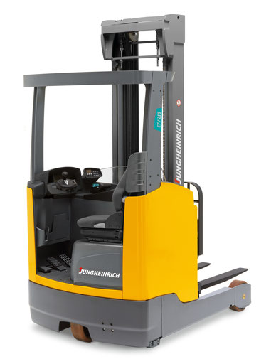
Warehouse equipment malfunctions and their diagnostics

Progress does not stand still, adding all new units to the device of technology, therefore, the design of special machines only becomes more complicated every year. However, the more complex the
technique, the more difficult it is to maintain and diagnose.
Fortunately, to facilitate the work and quickly analyze breakdowns and emergency situations, special sensors were invented that provide servicemen with information about specific breakdown
points. Such a system has been operating in the automotive industry for a long time and has proven itself to be the best.
The requirement for loading equipment is no exception, since its downtime can cost a business a lump sum. It is important that timely and fast diagnostics and troubleshooting become top
priorities.
To make it easier for the maintenance service of warehouse equipment (reach truck, forklift and electric stacker) to work, special error and error codes have been invented, which indicate the
exact problems that have arisen with the equipment. Such a system not only speeds up the repair work, but also eliminates the human factor.
What codes are there
Codes are divided into errors and malfunctions. All of them can be easily diagnosed and corrected in a short time.
The most common problems and errors that can be diagnosed using codes
- Wrong learning operation warning
- Short circuit top and bottom FET
- Upper side short circuit
- Bottom side short
- Phase U wire damage
- Phase V wire damage
- Phase W wire damage
- Temperature increase
- Temperature is abnormal
- Short circuit of load circuits
- Pump motor (Temperature rise)
- Pump motor (Temperature abnormal)
- External controller input signal is out of regulatory range
- Faulty temperature sensor of the controller of loading and unloading operations
- Malfunction of the temperature sensor of the pump motor
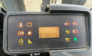
Also, special icons on the instrument panel can signal the need for maintenance, replacement of technical fluids, or the change and selection of a new battery. The main thing to remember is that,
despite the seeming simplicity of warehouse equipment, in no case should you try to correct mistakes yourself. To avoid costly costs, it is always best to contact a qualified after-sales service.
She will promptly and efficiently fix all the problems, and you will not have to worry about anything. Moreover, in the case of self-repair, you may lose the warranty on your equipment. Since
only after service repairs, the percentage of repeated breakdowns will be minimized.
An electronic diagnostic system enables technicians to efficiently troubleshoot faults. Optimum equipment of the service vehicle and all the necessary spare parts for the fastest possible
troubleshooting and minimizes downtime.

This diagnostic device allows proactive diagnostics and parameterization of the widest range of Jungheinrich specialist equipment.
Jungheinrich forklifts are diagnosed with an adapter.
DFG-320
ETV-12
EJE-220r
ESD-120
EFG-215
EFG-320
ETV-216
ETV-325
EFG-425
ETV-214
EJC-12
ECE-118
EFG-216k
AM-22
DFG-20
EKS-210
ETV-114
EJE-120
EFG-216
DFG-316
ESD-220
ETV-112
EFG-113
EJC-112
Jungheinrich Diagnostic Dispaly Fault Codes List. Free Download PDF Fault Codes
Jungheinrich Fault Codes Download
Jungheinrich EJC112 & E1202 Event Messages Codes List Download
Jungheinrich Error Codes List Download
Jungheinrich Fault Codes Download
Jungheinrich LISTADO ERRORES Download
Jungheinrich System Error Codes list Download
Jungheinrich System Error Codes list Download
Jungheinrich System Error Codes list Download
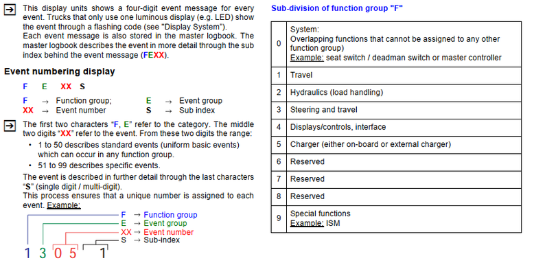
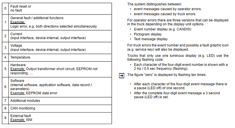
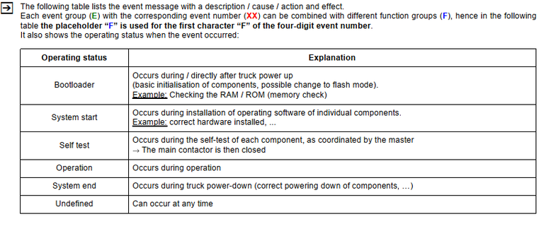
|
F |
E |
XX |
S |
Operational |
Description |
Cause / Triggering Event |
Action |
|
_ |
1 |
01 |
1 |
System start |
Supply via unexpected key |
Evaluation of three key switch inputs. Possible |
— Check key switch input connection against the |
|
_ |
1 |
02 |
1 |
Self test |
Contact closed instead of |
On power-up the capacitor voltage should be one volt |
— Test the main contactor output of the controller; |
|
_ |
1 |
2 |
Self test |
Contact open instead of |
When the main contactor has switched on the capacitor |
— Test the main contactor output of the controller; |
|
|
_ |
1 |
3 |
Self test |
Main contactor permanently |
An attempt is being made to open the main contactor. |
— Replace controller; |
|
|
_ |
1 |
4 |
Self test |
Main contactor feedback |
Feedback signal from main contactor status implausible |
— Test the main contactor output of the controller; |
|
|
_ |
1 |
03 |
1 |
Self test |
Output transformer faulty |
The semi-jumpers 1, 2 and 3 are controlled in turned for |
— Replace controller; |
|
2 |
Self test |
Output transformer faulty |
|||||
|
3 |
Self test |
Output transformer faulty |
|
_ |
1 |
04 |
1 |
Self test |
Output transformer faulty |
Semi-jumpers 1, 2 and 3 are controlled in turn for |
— Replace controller; |
|
2 |
Self test |
Output transformer faulty |
|||||
|
3 |
Self test |
Output transformer faulty |
|||||
|
_ |
1 |
04 |
4 |
Operation |
Error bit set for power |
«Error, power stage ID : The power card of the power |
— Replace controller; |
|
_ |
1 |
05 |
1 |
Self test |
Motor cutout |
Semi-jumpers 1, 2 and 3 are controlled in turn for |
— Check motor connection wire (wire breakage); |
|
_ |
1 |
05 |
2 |
Self test |
«Combi controller behaviour |
Semi-jumpers 1, 2 and 3 of a combi controller power |
— Switch the truck off and on again; |
|
F |
E |
XX |
S |
Operational |
Description |
Cause / Triggering Event |
Action |
|
_ |
1 |
06 |
1 |
Operation |
Safety switch inputs |
The safety switch consists of a NC and a NO contact. |
— Check safety switch wire connection; |
|
_ |
1 |
06 |
2 |
Operation |
Deadman switch inputs |
During operation combinations 0/0 and 1/1 trigger the |
— Check wiring with multimeter; |
|
_ |
1 |
06 |
3 |
Operation |
Slack-chain switch inputs |
During operation combinations 0/0 and 1/1 trigger the |
— Check wiring with multimeter; |
|
_ |
1 |
06 |
4 |
Operation |
Cabin gate inputs |
During operation combinations 0/0 and 1/1 trigger the |
— Check wiring with multimeter; |
|
_ |
1 |
06 |
5 |
Operation |
Optional cabin gate inputs |
During operation combinations 0/0 and 1/1 trigger the |
— Check wiring with multimeter; |
|
F |
E |
XX |
S |
Operational |
Description |
Cause / Triggering Event |
Action |
|
_ |
1 |
06 |
6 |
Operation |
Sideshift index inputs |
During operation combinations 0/0 and 1/1 trigger the |
— Check wiring with multimeter; |
|
_ |
1 |
06 |
7 |
Operation |
Aisle recognition right inputs |
During operation combinations 0/1 and 1/0 trigger the |
— Check wiring with multimeter; |
|
_ |
1 |
06 |
8 |
Operation |
Aisle recognition left inputs |
During operation combinations 0/1 and 1/0 trigger the |
— Check wiring with multimeter; |
|
_ |
1 |
06 |
9 |
Operation |
Load handling inputs: no |
During operation combinations 0/0 and 1/1 trigger the |
— Check wiring with multimeter; |
|
_ |
1 |
06 |
10 |
Operation |
Load sensing inputs: no |
If the weight display > 300 kg the load sensors must be |
— Check wiring with multimeter; |
|
_ |
1 |
06 |
11 |
Operation |
Logic test: signal at working |
During operation combinations 0/0 and 1/1 trigger the |
— Check wiring with multimeter; |
|
F |
E |
XX |
S |
Operational |
Description |
Cause / Triggering Event |
Action |
|
_ |
1 |
06 |
12 |
Operation |
Logic test: signal at left/right |
During operation combinations 0/1 and 1/0 trigger the |
— Check wiring with multimeter; |
|
_ |
1 |
06 |
13 |
Operation |
Logic test: No signal for gate |
During operation no feedback triggers the message |
— Check wiring with multimeter; |
|
_ |
1 |
06 |
14 |
Operation |
Logic test: Signal for gate |
During operation a feedback triggers the message |
— Check wiring with multimeter; |
|
_ |
1 |
06 |
15 |
Operation |
Logic test: No signal for gate |
During operation no feedback triggers the message |
— Check wiring with multimeter; |
|
_ |
1 |
07 |
1 |
Operation |
Operator protection switch |
The body protection switch consists of a NC and a NO |
— Check wire connections; |
|
F |
E |
XX |
S |
Operational |
Description |
Cause / Triggering Event |
Action |
|
_ |
1 |
07 |
2 |
Operation |
Acknowledge button inputs |
During operation combinations 0/0 and 1/1 (500 msec.) |
— Check wire connections; |
|
_ |
1 |
08 |
1 |
Operation |
Touch mode switch inputs |
The touch mode button consists of a NC and a NO |
— Check wire connection; |
|
_ |
1 |
08 |
2 |
Operation |
«Crawl speed redundant |
The «inching» button consists of a NC and a NO contact. |
— Check wire connections; |
|
_ |
1 |
08 |
3 |
Operation |
“Stop» button redundant |
The «Stop» button consists of an NC and an NO contact. |
— Check parameter reading (side pedestrian mode |
|
F |
E |
XX |
S |
Operational |
Description |
Cause / Triggering Event |
Action |
|
_ |
1 |
08 |
4 |
Self test |
“Handbrake lever redundant |
The «handbrake lever» switch consists of a NC and a NO |
— Check wire connections; |
|
_ |
1 |
08 |
5 |
Self test |
“Parking brake switch |
The «parking brake» switch consists of a NC and a NO |
— Check wire connections; |
|
_ |
1 |
09 |
1 |
Operation |
Weigher button inputs |
The weigher button consists of a NC and a NO contact. |
— Check wire connection; |
|
F |
E |
XX |
S |
Operational |
Description |
Cause / Triggering Event |
Action |
|
_ |
1 |
10 |
1 |
Operation |
Lift/lower digital setpoints |
During operation the combination 1/1 for both buttons |
— Check wire connection; |
|
_ |
1 |
10 |
2 |
Operation |
Lift/lower analog setpoints |
During operation the limits for 1/1 [both buttons pressed |
— Check wire connection; |
|
_ |
1 |
11 |
1 |
Operation |
Braking setpoint and release |
The event message is triggered if the following applies |
— Check wire connection; |
|
_ |
1 |
11 |
2 |
Operation |
Braking setpoint and release |
The event message is triggered if the following applies |
— Check wire connection; |
|
_ |
1 |
11 |
3 |
Operation |
Braking setpoint and full |
The event message is triggered if the following applies |
— Check wire connection; |
|
_ |
1 |
11 |
4 |
Operation |
Braking setpoint and full |
The event message is triggered if the following applies |
— Check wire connection; |
|
F |
E |
XX |
S |
Operational |
Description |
Cause / Triggering Event |
Action |
|
_ |
1 |
11 |
5 |
Operation |
Combination «brake |
The event message is triggered |
— Check brake fluid level; |
|
_ |
1 |
11 |
6 |
Operation |
Combination «brake |
The event message is triggered |
— Check brake fluid level; |
|
_ |
1 |
11 |
7 |
Operation |
Sum of the voltages |
The event message is triggered |
— Check the cable connection; |
|
_ |
1 |
12 |
1 |
Operation |
Travel setpoint and release |
The event message is triggered if the following applies |
— Check wire connection; |
|
_ |
1 |
12 |
2 |
Operation |
Travel setpoint and release |
The event message is triggered if the following applies |
— Check wire connection; |
|
_ |
1 |
12 |
3 |
Operation |
Total voltage «Travel1 |
The event message is triggered |
— Check wire connection; |
|
F |
E |
XX |
S |
Operational |
Description |
Cause / Triggering Event |
Action |
|
_ |
1 |
13 |
1 |
Operation |
Travel direction 1 and travel |
During operation the combination 1/1 [both travel |
— Check wire connection; |
|
_ |
1 |
13 |
2 |
Operation |
Direction setting signal |
If more than one direction sensor is installed: |
— Check parameter settings; |
|
_ |
1 |
14 |
1 |
Self test |
Motor speed signal |
Logic test: after a short period of motor control, the |
— Rectify mechanical blockage of drive system; |
|
_ |
1 |
15 |
1 |
Operation |
Motor powers without |
Motor powered for 500 msec without setpoint. |
— Check motor connections; |
|
_ |
1 |
15 |
2 |
Operation |
Motor powers without |
Convergence problem in monitor for the motor speed |
— Check motor connections; |
|
_ |
1 |
16 |
1 |
Operation |
Irregular speed signal |
Jump from n_motor > 10% to n_motor < 1% and for |
— Check speed sensor power supply; |
|
F |
E |
XX |
S |
Operational |
Description |
Cause / Triggering Event |
Action |
Jungheinrich Fault Codes Download
|
Error |
Descripción |
Componentes |
Texto de mensaje |
Causa / medidas |
Efectos |
|
1 |
Subtensión durante el arranque |
F, H, L, |
Subtensión |
Controlar la tensión de la batería; cargar |
No es posible conducir. |
|
2 |
Sobretensión |
F, H, L, |
Sobretensión |
Controlar tensión de la batería; cambiar |
Ninguna función de marcha |
|
3 |
Límite de temperatura de los |
F, H, L, |
MANDO DE |
Controlar el sensor y las conexiones de |
Reducción de la potencia |
|
4 |
Parada de emergencia activada |
F |
ALIMENT. TENSIÓN |
Aviso de advertencia |
El freno se activa, imposible |
|
5 |
Sobretensión |
F, F-AC, H-AC |
INST. ELÉCTRICA |
Comprobar conexión de cables hacia la |
El freno se activa, no es |
|
5 |
Sobretensión |
F, F-AC, H-AC |
INST. ELÉCTRICA |
Comprobar conexión de cables hacia la |
El freno se activa, no es |
|
6 |
Rotura de cable: |
C, I2, I3, I4, I5, |
CONTROLER |
Controlar tensión de la batería; cambiar |
Marcha interrumpida, sím |
|
7 |
Interruptor de llave |
F,F-AC,H-AC |
INTERRUPT. LLAVE |
Aviso de advertencia |
El freno se activa, imposible |
|
8 |
2 direcciones de marcha al mis |
F-AC, H-AC, C, |
INST. ELÉCTRICA |
Aviso de advertencia; cambiar inversor |
Marcha interrumpida, sím |
|
9 |
Interruptor de protección por in |
I2, FS |
INST. ELÉCTRICA |
Comprobar el interruptor, controlar las |
|
|
10 |
Ucond <> Ubat ; |
F, H, |
CONTACTOR PRINC. |
Comprobar el contactor principal; com |
Marcha, hidráulica sin fun |
|
11 |
Fallo de offset corriente de induci |
F, H, L, |
MANDO |
Comprobar el cable de corriente princi |
Marcha sin función |
|
12 |
Campo ’Disable Driver’ defectuo |
F, H |
MANDO |
Cambiar componente; |
Marcha, hidráulica sin fun |
|
13 |
Campo ‘Disable Watchdog’ |
F, H |
MANDO |
Cambiar el componente |
Marcha sin función |
|
Error |
Descripción |
Componentes |
Texto de mensaje |
Causa / medidas |
Efectos |
|
14 |
— Contactor principal no cerrado |
F, H, |
MANDO / CONTAC |
Controlar conexión de cables; controlar |
Marcha, hidráulica sin fun |
|
15 |
Campo ‘Disable’ |
F, H, |
MANDO |
Cambiar parte de mando; cambiar |
Marcha sin función |
|
16 |
Regulador de inducido ’Disable |
F, H, |
MANDO |
Cambiar parte de mando (AC); cambiar |
Marcha sin función |
|
17 |
Inducido ‘Disable Watchdog’ |
F, H |
MANDO |
Cambiar componente |
Marcha sin función |
|
18 |
DC: la etapa final del inducido no |
F, H, F-AC, H |
MANDO |
Comproar conexión de cables hacia el |
Marcha sin función |
|
19 |
Inducido „Disable“ defectuoso; |
F, H, F-AC ,H |
MANDO |
Cambiar parte de potencia; cambiar el |
Marcha sin función |
|
20 |
Inducido mal conectado |
F, H |
INST. ELÉCTRICA |
Comprobar cable de corriente principal |
Marcha sin función |
|
21 |
Sobrecorriente inducido (cortocir |
F, H, F-AC, H |
MANDO/ELÉCTRICA |
Comprobar el cable de corriente princi |
|
26 |
Rotura de cable: |
M, S, I2, I3 |
MULTIPILOTO / |
Comprobar conexión de cables |
Elevación se interrumpe, |
|
27 |
Rotura de cable: |
C, L, I3, I4 |
SENSOR ÁNG. DIR. |
Comprobar conexión de cables; cambiar |
Conducir en marcha lenta, |
|
28 |
Rotura de cable: |
C, L, I3, I4 |
SENS. ÁNG. PRE. |
Comprobar conexión de cables; cambiar |
Conducir en marcha lenta, |
|
29 |
Rotura de cable: |
M |
Valor prescrito de em |
Cambiar el Multipiloto |
|
|
Error |
Descripción |
Componentes |
Texto de mensaje |
Causa / medidas |
Efectos |
|
36 |
Ninguna pos. cero de elevación |
M, I2, I3,FS |
POS. REPOSO ELEV. |
Aviso de advertencia; comprobar el en |
Funciones hidráulicas se in |
|
37 |
Ningún valor prescrito (teórico) |
L |
MANDO / CAN |
Comprobar encoder de valores prescri |
|
|
38 |
Componente no responde, los |
F, H, L, I2, I3, I4, |
MANDO / CAN |
Controlar la conexión y la tensión del |
Marcha, elevación sin fun |
|
39 |
Tipo de máquina no es |
F, H, L, I2, I3, I4, |
TIPO DE MÁQUINA |
Ref. a 1. Ajustar el tipo de máquina |
|
40 |
Sobretemperatura del motor |
L, F, H |
TEMPERAT. MOTOR |
Aviso de advertencia; controlar sistema |
Reducción de la potencia |
|
41 |
Potenciómetro en el imán de |
L |
POT. IMÁN FRENO |
Comprobar potenciómetro; controlar fija |
|
|
42 |
— Cortocircuito entre la salida y el |
L,F |
IMÁN DE FRENO |
Comprobar la conexión de cables; com |
|
|
43 |
Reajustar el freno |
L |
AJUSTE DE FRENO |
Reajustar el freno; comprobar el |
|
44 |
— Freno no conectado o línea de |
L,F |
DEFECTO FRENO |
— Comprobar el cableado del freno, |
Ninguna liberación |
|
45 |
Demasiados impulsos del encod |
L,I5 |
VOLANTE |
Comprobar conexión de cables; cambiar |
|
|
46 |
Encoder de valores prescritos de |
L,I5 |
VOLANTE |
Comprobar conexión del soporte del |
|
|
47 |
Ningún impulso del encoder de |
L,I5 |
VOLANTE |
Comprobar conexión de cables; cambiar |
Ninguna liberación |
|
48 |
Incompatibilidad con el parámetro |
L |
TIPO DIRECCIÓN |
Ajustar tipo de dirección correctamente |
|
|
49 |
Alimentación CAN defectuosa; |
AS 2412 |
Can Bus |
Tensión en el enchufe CAN es superior |
¡No es posible conducir la |
|
50 |
Multipiloto NRG rotura de cable |
M |
Encoder de valores |
Verificar el cableado del Multipiloto, |
No es posible conducir la |
|
51 |
Teach-In: potenciómetro de val |
L |
Ajuste erróneo |
Repetir el Teachin; comprobar conexión |
|
|
52 |
Teach-In: potenciómetro del imán |
L |
Ajuste erróneo |
Repetir el Teachin; comprobar conexión |
|
|
53 |
Teach-In: potenciómetro de val |
L |
Ajuste erróneo |
Repetir el Teachin; comprobar conexión |
Jungheinrich Error Codes List Download
Jungheinrich Forklift Error Codes
- 0915.2 — Industrial truck not ready for operation — battery door opened.
- 0938.1 — Battery discharged (0%).
- 1901.1 — Drive pedal activated during startup.
- 1904.1 — No travel direction present with drive pedal activated.
- 1908.1 — Seat belt or belt lock not closed when the pedal is pressed.
- 1909.1 — Activation of drive pedal when the parking brake is not released.
- 1917.1 — Drive pedal and brake pedal both activated at the same time.
- 1918.1 — Industrial truck ready for operation, but cab door opened.
- 2908.1 — Seat belt or belt lock not closed when hydraulic function is activated.
- 2937.3 — Simulatneous activiation of several hydraulic functions that can only be operated as individual functions.
- 2951.1 — Hydraulic function activated during startup.
- 5409.1 — Battery temperature too high
- 5393.1 — Battery cell faulty