
Jungheinrich Service Manual
Jungheinrich DFG/TFG
660-690 Operating Instructions
Models: DFG 670; DFG
680; DFG 690; DFG S80; DFG S90; TFG 660; TFG 670; TFG 680; TFG 690; TFG S80; TFG S90; DFG S90.
Jungheinrich DFG S80
Service Manual
Models: TFG 680; DFG 670; DFG 660; DFG 680; DFG 690; DFG S80; DFG S90; TFG 660; TFG 670; TFG 690; TFG S80; TFG S90.
Jungheinrich DFG TFG
316-435 Operating Instructions
Models: TFG 430; DFG 320; DFG 425; DFG 430; DFG 435; TFG 316; TFG 320; TFG 425; TFG 435.
Jungheinrich EFG-Vac 22-30/ 25L/S/SL Service Manual Download
Jungheinrich ECE 225 (90309857) Spare Parts Catalogue Download
Jungheinrich EJC 110/112 Operating instructions Download
Jungheinrich DFG/TFG 16 — 50 A/B/C-K Operating instructions Download
Jungheinrich DFG 660 Service Manual Download
Jungheinrich DFG 670 Service Manual Download
Jungheinrich DFG S80 Service Manual Download
Jungheinrich DFG_TFG 316-435 Operating Instructions Download
Jungheinrich ECE 225 Spare Parts Catalogue Download
Jungheinrich EFG 213-320 Operating Manual Download
Jungheinrich EFG-Vac 22 Service Manual Download
Jungheinrich EFG-Vac 25L Service Manual Download
Jungheinrich EFG-Vac 30 Service Manual Download
Jungheinrich EJD 220 Service Manual Download
Jungheinrich ERE 120 Service Manual Download
Jungheinrich ETM 214 Service Manual Download
Jungheinrich ETM 216 Service Manual Download
Jungheinrich ETM 325 Service Manual Download
Jungheinrich ETV 214 Service Manual Download
Jungheinrich ETV 216 Service Manual Download
Jungheinrich ETV 318Service Manual Download
Jungheinrich ETV 320 Service Manual Download
Jungheinrich ETV 325 Service Manual Download
Jungheinrich EZS 330 XL Operating Instructions Manual Download
Jungheinrich EZS 350 XL Operating Instructions Manual Download
Jungheinrich SLH 200 Service Manual Download
Jungheinrich TFG 660 Service Manual Download
Jungheinrich Fault Codes
Jungheinrich Fault Codes Download
Jungheinrich EJC112 & E1202 Event Messages Codes List Download
Jungheinrich Error Codes List Download
Jungheinrich Fault Codes Download
Jungheinrich LISTADO ERRORES Download
Jungheinrich System Error Codes list Download
Jungheinrich System Error Codes list Download
Jungheinrich System Error Codes list Download
Jungheinrich forklifts
The manufacturer of forklifts is Jungheinrich, which is a leader in the production and sale of industrial, warehouse and material handling equipment. The company began its journey from 1953, when
a small loader company was founded, and by 2011 the company had several factories at its disposal.
Purpose
Forklifts are mainly used to work in warehouses, but without them they are very rarely managed in large-scale industries. They carry loads that are placed on pallets. Due to the version with a
closed cabin, they are able to work even in places with unfavorable external environment, namely, with wind, dust, sparks, sawdust, steam, and so on.
Electric
Electric loaders are represented by 5 series, which differ in load capacity, low unloading height, technology, maneuverability, as well as convenience of the operator’s workplace.
1 series EFG 110/113/115. The letters mean that this is an electric forklift, the first number indicates the series, and the second two are the maximum carrying
capacity in hundreds of kilograms. These are lightweight and compact loaders that have just one rear wheel. Thanks to these parameters, they have excellent maneuverability and can move even
inside the truck body. However, these «kids» are able to work with a weight of from 1 to 1.5 tons and lift the load to a height of 6.5 meters. AC control electronics may be updated.
EFG 213/215 / 216k / 216 / 218k / 218/220. The index k near some models indicates that the model has a smaller battery, a shorter base and a shorter fork body. This series has
the same dimensions and related benefits. However, the maximum load capacity is increased, as well as equipped with a large number of technologies. In the loader, an electric power steering was
added, the ability to independently configure 5 work programs, replace batteries, a more thoughtful security system, an automatic parking brake, smart electronics, and a maintenance-free brake
system and electric motor. The case in these loaders is integral, which provides greater stability when maneuvering.
EFG 316 / 316k / 318 / 318k / 320. The main differences between these trucks from previous models is that they have 4 wheels and a fully enclosed cab with front and rear window
cleaner. The control system is now electro-hydraulic, which provides better handling. Cab stances were enhanced, and the lighting system and battery compartment received additional protection.
EFG 540k / 540 / 545k / 545/550 / S40 / S30. These are the most powerful and big electric lift trucks. The maximum unloading height has also been increased, but only to 7.18
meters. You can use various packages of additional functions that determine the operation of the loader. In this series, more attention is paid to operator safety, as well as comfort and
ergonomics of the workplace.

![]()
Jungheinrich System Error Codes list.pdf
Adobe Acrobat Document
168.2 KB
![]()
Jungheinrich Fault Codes.pdf
Adobe Acrobat Document
720.8 KB
![]()
Jungheinrich Error Codes List PDF.pdf
Adobe Acrobat Document
191.8 KB
![]()
Jungheinrich EJC112 & E1202 Event Messag
Adobe Acrobat Document
582.8 KB
Event Messages
Z This display units shows a four-digit event message for every
event. Trucks that only use one luminous display (e.g. LED) show
the event through a flashing code (see «Display System”).
Each event message is also stored in the master logbook. The
master logbook describes the event in more detail through the sub
index behind the event message (FEXX).
Event numbering display
F E XX S
F Function group; E Event group
XX Event number S Sub index
The first two characters “F, E” refer to the category. The middle
two digits “XX” refer to the event. From these two digits the range:
• 1 to 50 describes standard events (uniform basic events)
which can occur in any function group.
• 51 to 99 describes specific events.
The event is described in further detail through the last characters
“S” (single digit / multi-digit).
This process ensures that a unique number is assigned to each
event. Example:
0 Fault reset or
no fault
1 General fault / additional functions
Example:
Logic error, e.g. both directions selected simultaneously
2 Current
(input interface, device-internal, output interface)
3 Voltage
(input interface, device-internal, output interface)
4 Temperature
5 Hardware
Example: Output transformer short circuit, EEPROM not
responding, …
6 Software
(internal software, application software, data record /
parameters)
Example: EEPROM data error
7 Additional modules
8 CAN monitoring
9 External fault
Example: ISM
![]()
Jungheinrich System Error Codes list.pdf
Adobe Acrobat Document
168.2 KB
![]()
Jungheinrich Fault Codes.pdf
Adobe Acrobat Document
720.8 KB
![]()
Jungheinrich Error Codes List PDF.pdf
Adobe Acrobat Document
191.8 KB
![]()
Jungheinrich EJC112 & E1202 Event Messag
Adobe Acrobat Document
582.8 KB
Event Messages
Z This display units shows a four-digit event message for every
event. Trucks that only use one luminous display (e.g. LED) show
the event through a flashing code (see «Display System”).
Each event message is also stored in the master logbook. The
master logbook describes the event in more detail through the sub
index behind the event message (FEXX).
Event numbering display
F E XX S
F Function group; E Event group
XX Event number S Sub index
The first two characters “F, E” refer to the category. The middle
two digits “XX” refer to the event. From these two digits the range:
• 1 to 50 describes standard events (uniform basic events)
which can occur in any function group.
• 51 to 99 describes specific events.
The event is described in further detail through the last characters
“S” (single digit / multi-digit).
This process ensures that a unique number is assigned to each
event. Example:
0 Fault reset or
no fault
1 General fault / additional functions
Example:
Logic error, e.g. both directions selected simultaneously
2 Current
(input interface, device-internal, output interface)
3 Voltage
(input interface, device-internal, output interface)
4 Temperature
5 Hardware
Example: Output transformer short circuit, EEPROM not
responding, …
6 Software
(internal software, application software, data record /
parameters)
Example: EEPROM data error
7 Additional modules
8 CAN monitoring
9 External fault
Example: ISM
Автор ForkliftMan, 20 апреля 2021, 17:38:17
Заказчик привёз в ремонт блок управления 51462020 AS4824iS/F/H/Plus от нового погрузчика Jungheinrich EFG второй серии, выпускаемого с 2016 года.
Сделали несколько фото. Весьма интересный контроллер. Инженеры Jungheinrich впихнули в него всё что можно.
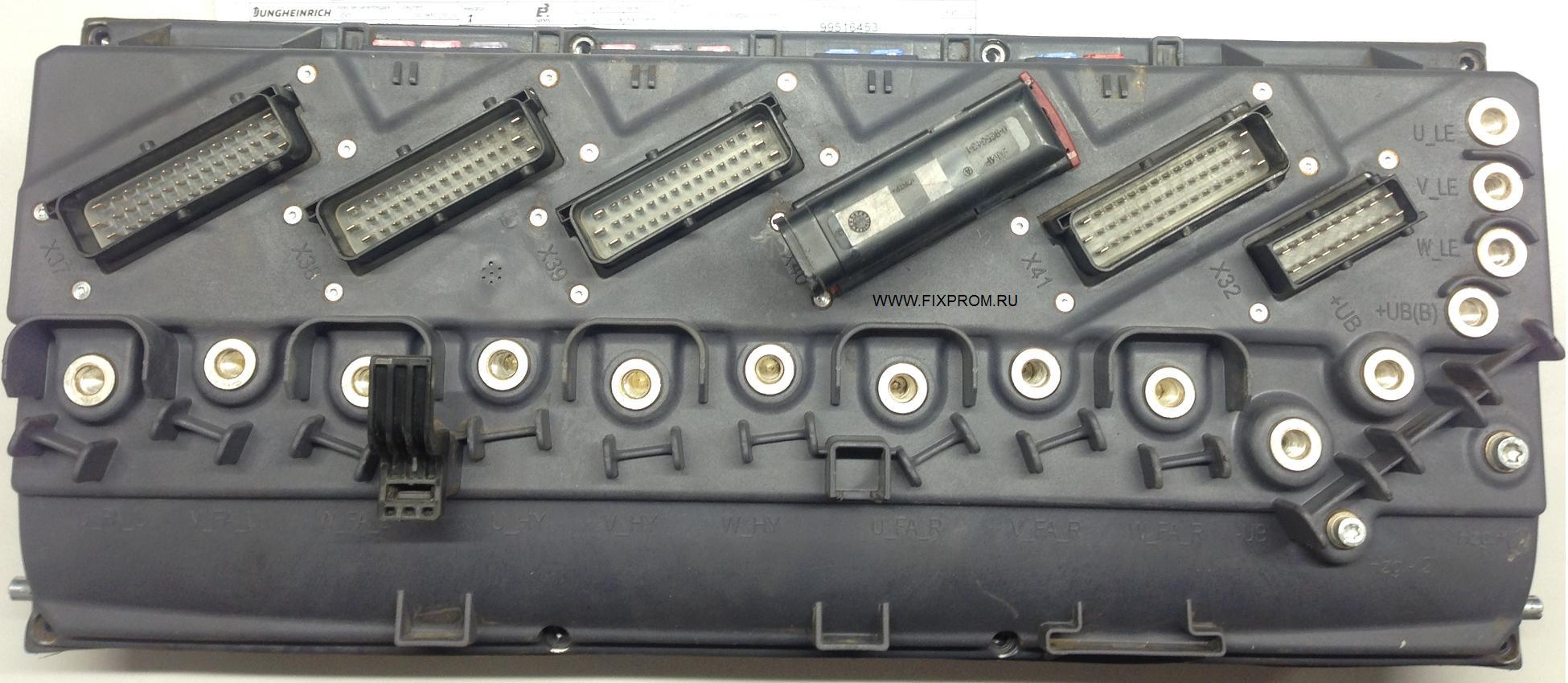
Контроллер отвечает буквально за всё в погрузчике, и любая его неисправность приводит к тому, что клиент попадает на дорогостоящий ремонт.
К слову блок этот очень дорогой и сложный.
По сравнению с ним контроллер JXP-DPI от узкопроходчика EKX 515 или комплектовщика EKS 312 покажется «детским садом».
Предыдущее поколение контроллеров для тяжелой серии EFG, выпускаемых с 2014 года, тоже однозначно попроще будет.
И так, под пластиковой крышкой находится плата управления…
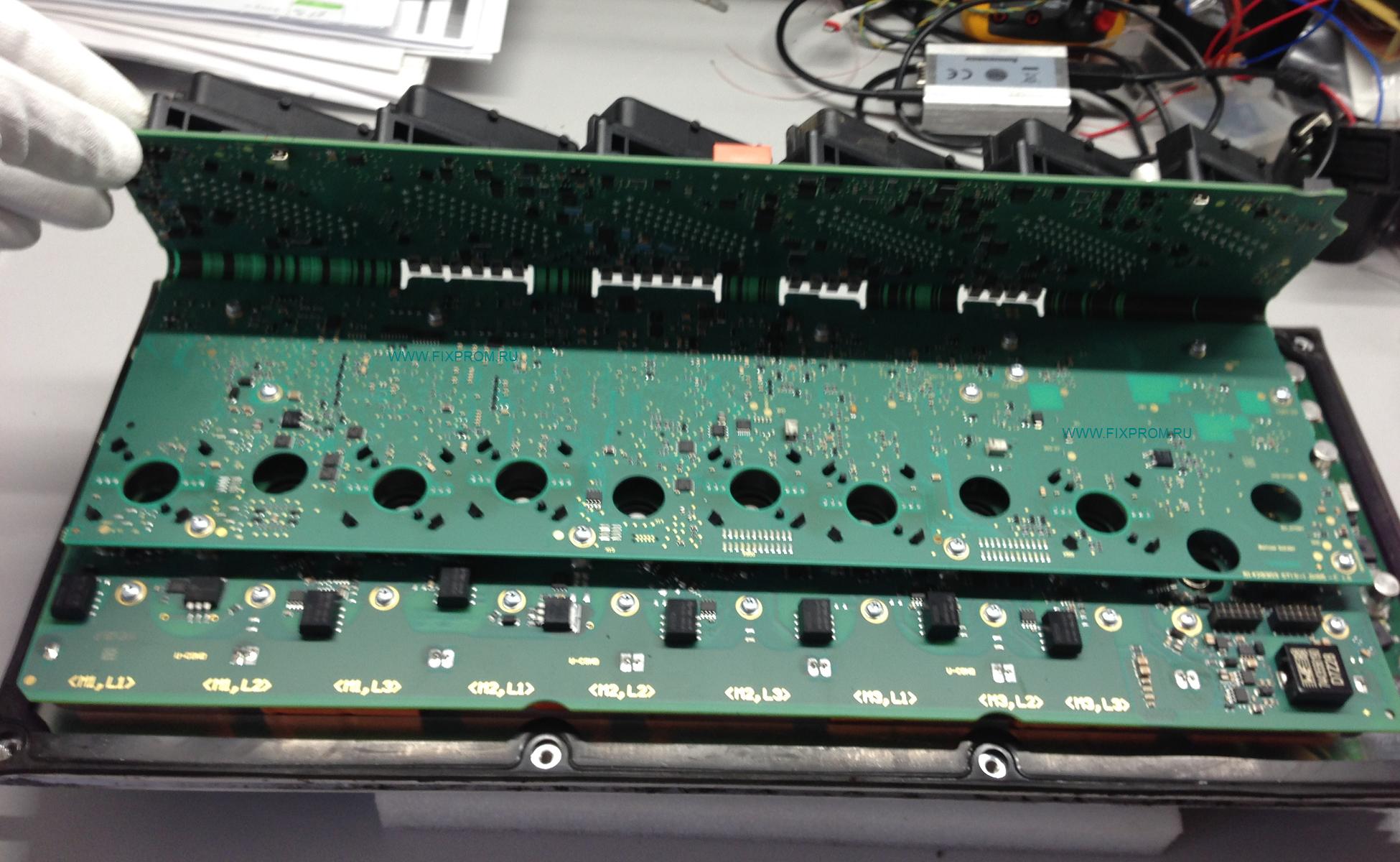
Плата выполнена по гибко-жесткой технологии, весьма сложна в ремонте и требует большой аккуратности в обращении с ней.
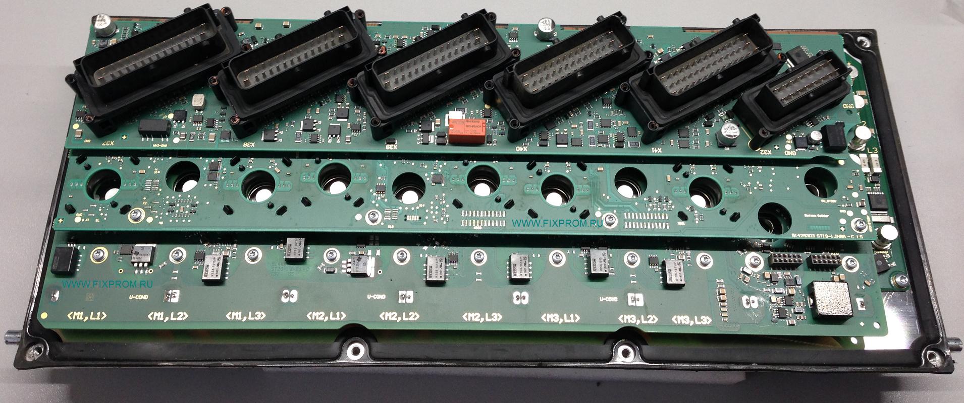
Далее на следующем этаже живёт плата управления силовыми MOSFET-ключами.
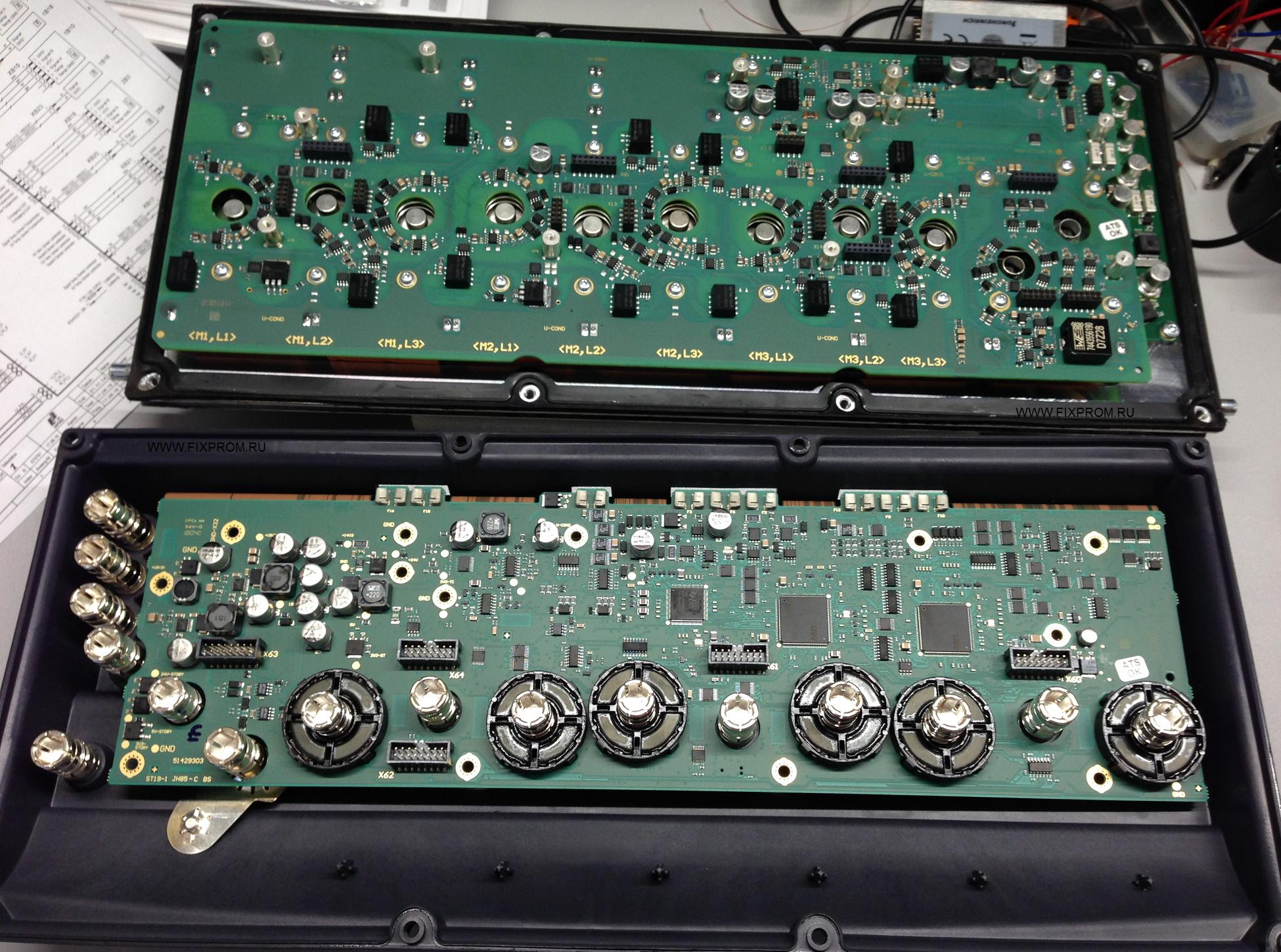
На ней расположились яркие рыжие конденсаторы Epcos.
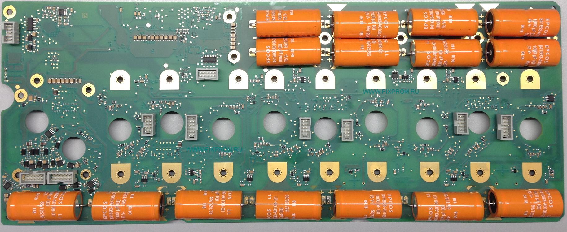
Прослеживается явная экономия места. Конденсаторы через теплопроводящие подложки упираются в радиатор,
на котором расположена силовая часть блока (MOSFET-ключи и вторичный источник питания на 24 вольта).
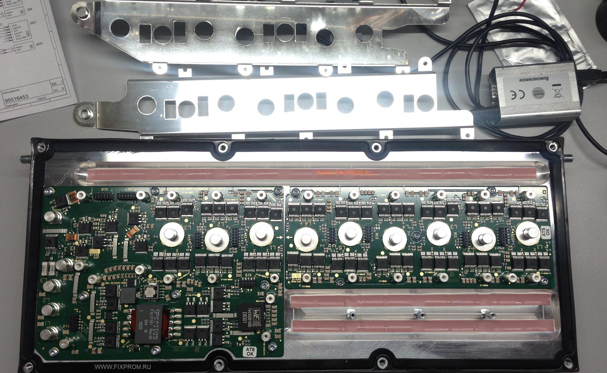
Радиатор обдувается парой вентиляторов. Нашему взору предстала вот такая картина.
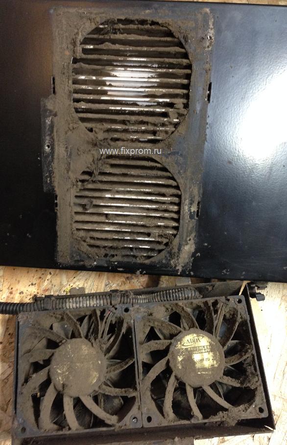
Оба вентилятора были заклинившие огромным количеством грязи и не вращались.
Силовым компонентам в блоке и так тяжело приходится, а тут с охлаждением вообще беда.
Делайте регулярные ТО и чистку от пыли грязи, иначе техника может в любой момент приподнести неприятный сюрприз.
Ещё красивые фото
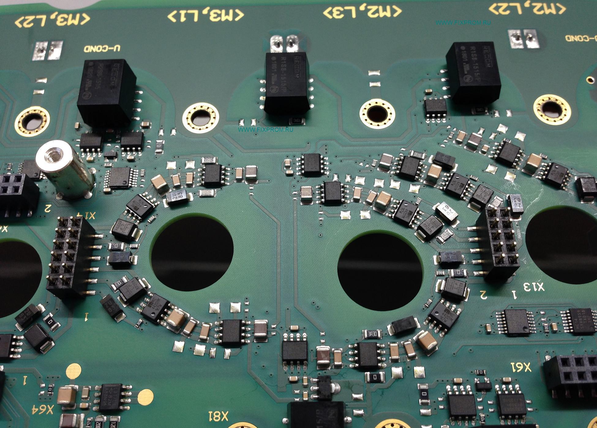
фигурная компоновка драйверов
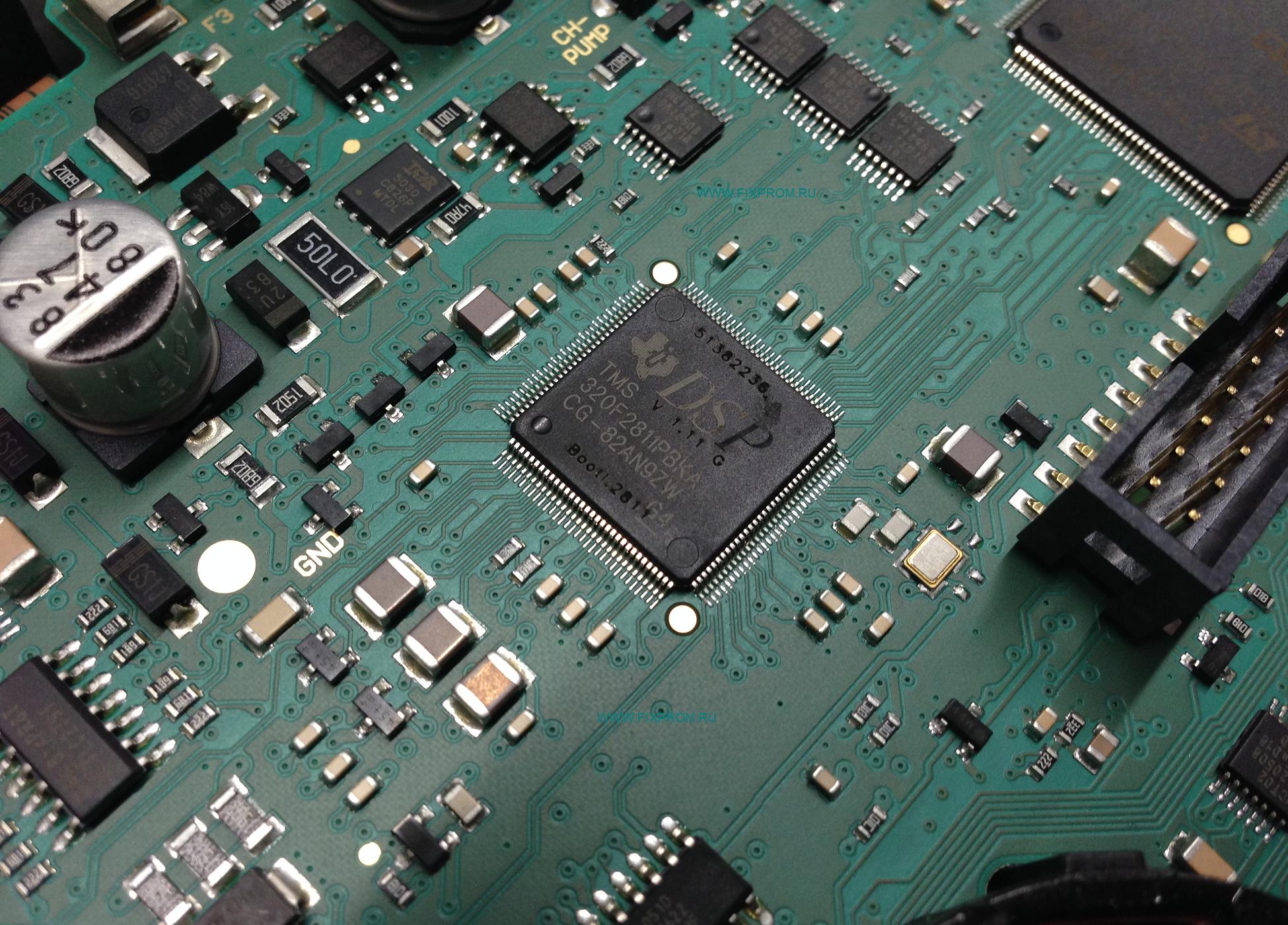
микроконтроллер Texas Instruments, что предназначен крутить трёхфазные двигатели
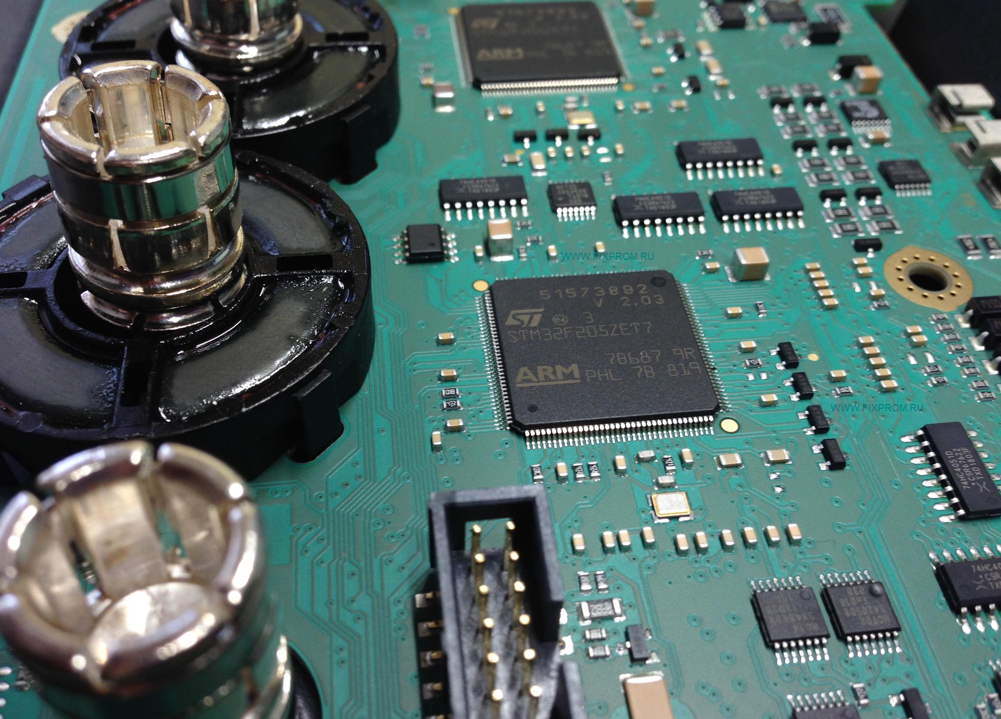
и новые процы от ST
У клиента погрузчик Jungheinrich EFG 215 2018 года выпуска, перестал проходить самотестирование
и встал с ошибками 0181.1 0304.1 0132.3
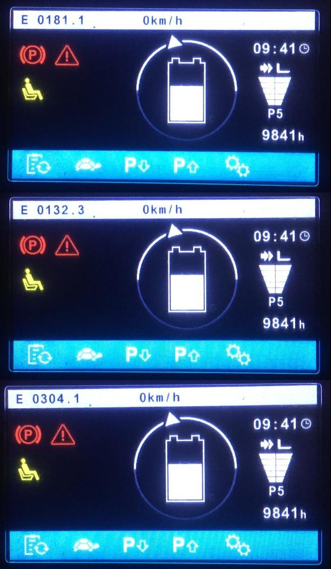
Опираясь на опыт ремонта аналогичных комбинированных блоков с ричтраков Jungheinrich ETV,
удалось решить проблему и отремонтировать блок EFG за пару дней.
Благо запчасти имелись в наличии на складе.
Погрузчик снова в строю!
И что же было причиной таки?
Инженерный просчёт, или «задумка» такая от разработчиков.
Ещё с 2011 года ничего сильно не изменилось в схемном решении и софте, работает на пределе, вот и мрут блоки периодически.
На ричтраках Jungheinrich чаще, может просто их больше, чем погрузчиков. Бывают плавающие дефекты, то проявляются, то нет.
Здравствуйте. Парни есть клиент для вас с данным вариатором, дайте контакты для связи.
- Технический форум: Ремонт промышленной электроники и спецтехники
-
►
Ремонт электроники -
►
Jungheinrich -
►
Jungheinrich AS4824iS 51617861 51617924 51414511 комбинированный контроллер EFG
Password: https://www.pdfmanual4trucks.com/
|
Title |
File Size |
Download Links |
|
Jungheinrich EJC112 / E1202 Event Messages Codes List PDF |
619.4kb |
Download |
|
Jungheinrich Error Codes List PDF [PDF] |
199kb |
Download |
|
Jungheinrich Fault Codes [PDF] |
769kb |
Download |
|
Jungheinrich LISTADO ERRORES [PDF] |
199kb |
Download |
|
Jungheinrich System Error Codes list [PDF] |
162.7kb |
Download |
|
Display error code |
Cause |
Action |
|
1901 |
During system start-up, the accelerator pedal zero position could not |
Do not press the accelerator pedal during system start-up. |
|
1904 |
Accelerator pedal pressed, but no travel direction selected. |
Take your foot off the accelerator pedal, select a travel direction and set off. |
|
1909 |
Accelerator pedal pressed and parking brake not released via parking |
Release the parking brake by pressing the parking brake button. |
|
1917 |
Accelerator and brake pedals pressed simultaneously. |
Press one pedal at a time only. |
|
2951 |
Lift function activated on multi-/ solo PILOT during system start- up. |
Do not apply the multi-/ solo PILOT during system start- up.
–
–
– |
|
1952 |
Travel direction switch pressed during system start-up. |
Do not press the travel direction switch during system start-up |
|
9961 |
ISM (option) has detected a shock event in the vertical |
Obtain acknowledgement from authorized person (warehouse manager) and |
|
9962 |
ISM (option) has detected a shock event in the horizontal |
Obtain acknowledgement from authorized person (warehouse manager) and |
|
5990 |
The electrolyte level sensor check (battery-management option) on the |
Add electrolyte. |
|
5992 |
After switching on the truck, no radio network could be established |
–
–
–
– |
|
5408/ 5409 |
Lithium-ion battery overtemperature |
Stop work. |
|
5413 |
Lithium-ion battery low temperature |
Move truck to warm environment. |
For all other warning messages switch the truck off and on again. If the warning message appears again call the service department.
The code lock enables an operator or a group of operators to be assigned an individual user code. The user code is configured with a master code and is outlined in the following sections of this
chapter.
When you have entered the valid user code the truck will be operational. The truck will be able to perform travel, steering and hydraulic operations.
When you have entered the valid master code the truck will be switched on. Travel operations are inhibited. The truck will be able to perform steering and hydraulic operations. The code lock is
in programming mode. When you enter one of the following parameters the settings in the code lock can be changed.
|
Parameters |
Description |
|
0-0-0 |
– To change the master code |
|
0-0-1 |
– To add user codes |
|
0-0-2 |
– To change a user code |
|
0-0-3 |
– To clear a user code |
|
0-0-4 |
– To clear all user codes |
|
0-1-0 |
– To set the automatic cutout of the truck |
Newly supplied trucks have the code indicated on a sticker. When using the truck for the first time change the master and user codes and remove the sticker.
- User code factory setting: 2-5-8-0
- Master code factory setting: 7-2-9-5
Посмотреть инструкция для Jungheinrich EFG 220 бесплатно. Руководство относится к категории Электропогрузчики, 2 человек(а) дали ему среднюю оценку 6.9. Руководство доступно на следующих языках: английский. У вас есть вопрос о Jungheinrich EFG 220 или вам нужна помощь? Задайте свой вопрос здесь
Не можете найти ответ на свой вопрос в руководстве? Вы можете найти ответ на свой вопрос ниже, в разделе часто задаваемых вопросов о Jungheinrich EFG 220.
Инструкция Jungheinrich EFG 220 доступно в русский?
Не нашли свой вопрос? Задайте свой вопрос здесь
- Home
- Forums
- Technical Troubleshooting
- Jungheinrich
- EJE C20
Jungheinrich EJE C20:
Fails e0305.1/ e1504.52/ e2504.52/e0331.1
hello. I have a c20 axis machine with errors e0305.1/ e1504.52/ e2504.52/e0331.1. I have checked electrobrake and connectors and nothing still works.
- Posted
22 Sep 2022 21:57 - Discussion started by
Letujxano - Zaragoza, Spain
Still fm14
Showing items 1 — 2 of 2 results.
Sort messages by:
No brushes there. It’s an AC motor / controller…..
- Posted
21 Nov 2022 18:57 - Reply by
Fittermax - Denmark
Thank’s for helping. Contact d-b-a@mail.com
P i s s Work, gone fishing
Please check the steering motor brushes.
- Posted
18 Nov 2022 03:53 - Reply by
Tanel_M - Estonia
Having trouble using the Discussion Forums? Contact us for help.
Forkliftaction.com accepts no responsibility for forum content and requires forum participants to adhere to the rules. Click here for more information.
![]()
Jungheinrich System Error Codes list.pdf
Adobe Acrobat Document
168.2 KB
![]()
Jungheinrich Fault Codes.pdf
Adobe Acrobat Document
720.8 KB
![]()
Jungheinrich Error Codes List PDF.pdf
Adobe Acrobat Document
191.8 KB
![]()
Jungheinrich EJC112 & E1202 Event Messag
Adobe Acrobat Document
582.8 KB
Event Messages
Z This display units shows a four-digit event message for every
event. Trucks that only use one luminous display (e.g. LED) show
the event through a flashing code (see «Display System”).
Each event message is also stored in the master logbook. The
master logbook describes the event in more detail through the sub
index behind the event message (FEXX).
Event numbering display
F E XX S
F Function group; E Event group
XX Event number S Sub index
The first two characters “F, E” refer to the category. The middle
two digits “XX” refer to the event. From these two digits the range:
• 1 to 50 describes standard events (uniform basic events)
which can occur in any function group.
• 51 to 99 describes specific events.
The event is described in further detail through the last characters
“S” (single digit / multi-digit).
This process ensures that a unique number is assigned to each
event. Example:
0 Fault reset or
no fault
1 General fault / additional functions
Example:
Logic error, e.g. both directions selected simultaneously
2 Current
(input interface, device-internal, output interface)
3 Voltage
(input interface, device-internal, output interface)
4 Temperature
5 Hardware
Example: Output transformer short circuit, EEPROM not
responding, …
6 Software
(internal software, application software, data record /
parameters)
Example: EEPROM data error
7 Additional modules
8 CAN monitoring
9 External fault
Example: ISM
Password: https://www.pdfmanual4trucks.com/
|
Title |
File Size |
Download Links |
|
Jungheinrich EJC112 / E1202 Event Messages Codes List PDF |
619.4kb |
Download |
|
Jungheinrich Error Codes List PDF [PDF] |
199kb |
Download |
|
Jungheinrich Fault Codes [PDF] |
769kb |
Download |
|
Jungheinrich LISTADO ERRORES [PDF] |
199kb |
Download |
|
Jungheinrich System Error Codes list [PDF] |
162.7kb |
Download |
|
Display error code |
Cause |
Action |
|
1901 |
During system start-up, the accelerator pedal zero position could not |
Do not press the accelerator pedal during system start-up. |
|
1904 |
Accelerator pedal pressed, but no travel direction selected. |
Take your foot off the accelerator pedal, select a travel direction and set off. |
|
1909 |
Accelerator pedal pressed and parking brake not released via parking |
Release the parking brake by pressing the parking brake button. |
|
1917 |
Accelerator and brake pedals pressed simultaneously. |
Press one pedal at a time only. |
|
2951 |
Lift function activated on multi-/ solo PILOT during system start- up. |
Do not apply the multi-/ solo PILOT during system start- up.
–
–
– |
|
1952 |
Travel direction switch pressed during system start-up. |
Do not press the travel direction switch during system start-up |
|
9961 |
ISM (option) has detected a shock event in the vertical |
Obtain acknowledgement from authorized person (warehouse manager) and |
|
9962 |
ISM (option) has detected a shock event in the horizontal |
Obtain acknowledgement from authorized person (warehouse manager) and |
|
5990 |
The electrolyte level sensor check (battery-management option) on the |
Add electrolyte. |
|
5992 |
After switching on the truck, no radio network could be established |
–
–
–
– |
|
5408/ 5409 |
Lithium-ion battery overtemperature |
Stop work. |
|
5413 |
Lithium-ion battery low temperature |
Move truck to warm environment. |
For all other warning messages switch the truck off and on again. If the warning message appears again call the service department.
The code lock enables an operator or a group of operators to be assigned an individual user code. The user code is configured with a master code and is outlined in the following sections of this
chapter.
When you have entered the valid user code the truck will be operational. The truck will be able to perform travel, steering and hydraulic operations.
When you have entered the valid master code the truck will be switched on. Travel operations are inhibited. The truck will be able to perform steering and hydraulic operations. The code lock is
in programming mode. When you enter one of the following parameters the settings in the code lock can be changed.
|
Parameters |
Description |
|
0-0-0 |
– To change the master code |
|
0-0-1 |
– To add user codes |
|
0-0-2 |
– To change a user code |
|
0-0-3 |
– To clear a user code |
|
0-0-4 |
– To clear all user codes |
|
0-1-0 |
– To set the automatic cutout of the truck |
Newly supplied trucks have the code indicated on a sticker. When using the truck for the first time change the master and user codes and remove the sticker.
- User code factory setting: 2-5-8-0
- Master code factory setting: 7-2-9-5

Jungheinrich EJC112 & E1202 Event Messages Codes List Download
Jungheinrich Error Codes List Download
Jungheinrich Fault Codes Download
Jungheinrich LISTADO ERRORES Download
Jungheinrich System Error Codes list Download
Jungheinrich System Error Codes list Download
|
Error |
Description |
Component |
Display text |
Cause / Action |
Effect |
|
1 |
Low voltage during system start |
F, H, L, F-AC, H-AC |
Low voltage ELECTRICAL SYSTEM |
Check battery voltage, charge battery; Check wire connection to controller; check main current fuse; check main contactor; replace control part; Replace component; (Limit VN = 80V: VBatt < 64V or VCap. < 56V Limit VN = 48V: VBatt < 34V or VCap. < 34V Limit VN = 24V: VBatt <17V) |
Travel is inhibited. Reduced power for travel and lifting. Warning symbol flashing (Else-Check). |
|
2 |
Overvoltage |
F, H, L, F-AC, H-AC |
Overvoltage BATTERY CONTROLLER |
Check battery voltage; replace controllerpart; replace component; (Limit VN = 80V: VBatt > 92 V Limit VN = 48V: VBatt > 62 V Limit VN = 24V: VBatt > 28 V) |
No travel or hydraulic functions Warning symbol flashing (Else-Check). |
|
3 |
Temperature limit for controllers > 80°C (>70°C MP1510C) or ACS only: Info at > 85°C Err at > 115°C Err at < -20°C |
F, H, L, F-AC, H-AC |
TEMPERATURE CONTROLLER |
Check sensor and wire connections Allow controllers to cool down; check fan operation, improve cooling. Warm up the controller and operate at reduced level until the controller has warmed up. |
Reduced power for travel and lifting. Warning symbol flashing (Else-Check). |
|
4 |
Emergency Disconnect applied during travel |
F |
POWER SUPPLY |
Warning (V < 20V MP1510C) |
Brake applies, travel inhibited |
|
5 |
Overvoltage |
F, F-AC, H-AC |
ELECTRICAL SYSTEM |
Check wire connection to battery, checkBattery, replacecontroller part; Replace component; (Limit for Retrak: VBatt > 62 V Limit for MP1510C: V > 32 V) |
Brake applies, travel inhibited |
|
6 |
Wire breakage: — Travel setpoint device |
C, I2, I3, I4, I5, Travel switch |
TRAVEL SWITCH |
Check wire connection; Replace travel setpoint device; Replace Canion/ Interface; |
Travel stop. “Warning” symbol flashes (Else-Check). Hydraulic functions possible |
|
7 |
Key switch applied duringtravel |
F,F-AC,H-AC |
KEY SWITCH |
Warning (V < 13V for 200ms MP1510C) |
Brake applies, travel inhibited |
|
8 |
2 travel directions applied simultaneously |
F-AC, H-AC, C, MP, S, I2, I3, I5, FS |
ELECTRICAL SYSTEM |
Warning, replace travel direction switch, replace Interface 7 Canion; replace Multipilot / Solopilot For twin pedal, check the electrical system. |
Travel stop. “Warning” symbol flashing (Else-Check). Hydraulic functions possible |
|
9 |
Operator protection switch faulty |
I2, FS |
ELECTRICAL SYSTEM |
Check switch, check wire connections |
|
|
10 |
V Cap. <> V Batt; (main contactor jammed or not open) |
F, H, F-AC, H-AC L |
MAIN CONTACTOR |
Check main contactor, check wire connection; check output pin 2 (ACS) of traction controller; replace component |
No travel, hydraulics Warning symbol Flashing warning (Else-Check). |
|
11 |
Offset error armature / field current (DC) Stator current (AC); Current measurement point |
F, H, L, F-AC, H-AC |
CONTROLLER |
Check main current wire, replace component |
Travel no function |
|
12 |
Disable driver field rheostat faulty for DC Disable driver power stage faulty (forAC) |
F, H F-AC, H-AC L |
CONTROLLER |
Replace component; for AC: Check flat belt wire connection; replace power part |
No travel, hydraulics Warning symbol Flashing warning (Else-Check). |
|
13 |
Disable Watchdog field faulty |
F, H |
CONTROLLER |
Replace components |
Travel no function |
|
14 |
—
— |
F, H, F-AC, H-AC |
CONTROLLER/ MAIN CONTACTOR |
Check wire connection; check main contactor; check charging connection, Check field supply fuse, Replace component. |
No travel, hydraulics Warning symbol Flashing warning (Else-Check). |
|
15 |
Disable field faulty; Illegal address (for AC) |
F, H, F-AC, H-AC L |
CONTROLLER |
Replace controlpart; replace component |
Travel no function |
|
16 |
Disable driver armature actuator faulty; Software reset (for AC) |
F, H, F-AC, H-AC |
CONTROLLER |
Replace controlpart (AC); replace component |
Travel no function |
|
17 |
Disable Watchdog armature faulty |
F, H |
CONTROLLER |
Replace components |
Travel no function |
|
18 |
DC: Armature power stage cannot be switched on AC: one of the 3 phases cannot be switched on |
F, H, F-AC, H-AC L |
CONTROLLER |
Check armature wire connection; replace power part; replace component |
Travel no function |
|
19 |
Disable armature faulty; Power stage short circuit (for AC)
The error may be triggered by the faulty speed sensor in connection with AS4814Plus controllers. Sensor wheel wobbles (elliptical) or the sensor- sensor wheel gap is too big. In |
F, H, F-AC ,H- AC, L-AC |
CONTROLLER |
Replace power part; Replace component. Can occur in connection with error 70, in this case:
check power supply behind the main contactor contact, in the event of an error the voltage will be much lower here than the rated operating voltage. Disconnect the positive supply The testing voltage arises by charging the internal capacitor batteries via a resistor to the level of the control voltage supply. |
Travel no function |
|
Check sensor, replace sensor and / or sensor wheel. |
|||||
|
20 |
Armature incorrectly connected |
F, H |
ELECTRICAL SYSTEM |
Check armature main current wire connection |
Travel no function |
|
21 |
Armature overvoltage (short circuit / high side faulty) |
F, H, F-AC, H-AC L |
CONTROLLER/ ELECTR |
Check main current wire to armature; check settings(for AC); AArmature > 360A for 250ms (MP1510); Replace component. |
|
22 |
Watchdog error; Watchdog does not run out |
F, H, L, M, S, A, I2, I3, I4, C, F-AC, H-AC, FS |
CONTROLLER/ CANION |
Truck reset, Replace controlpart; replace component |
No travel, hydraulics Warning symbol Flashing warning (Else-Check). |
|
23 |
—
—
— |
F, H, L, M, S, A, I2, I3, I4, C, F-AC, H-AC, FS |
CONTROLLER / CAN |
Check CAN bus connection; Check CANION connector and component; Replace component |
No travel, hydraulics Warning symbol Flashing warning (Else-Check). |
|
24 |
EEPROM cannot be contacted / parameters not plausible / parameter set to default Faulty checksum |
F, H, L, I2, I3, I4, C, F-AC, H-AC MFC brake MFC hydr. , travel switch |
CONTROLLER/ CANION |
Check battery cable; check VBatt; set trucktype, set default parameters; replace control part; replace component Delete logbook, change parameters, set hourmeter, replace component |
Flashing warning symbol (Else- Check). |
|
26 |
Wire breakage: — Lift potentiometer |
M, S, I2, I3 |
MULTIPILOT / SOLOPILOT / LIFT POTENTIOMETER |
Check wire connection |
Lift stop. “Warning” symbol flashes (Else-Check), travel enabled |
|
27 |
Wire breakage: — Steering setpoint device;
à
à
à “Operating mode” parameter incorrectly set |
C, L, I3, I4 |
STEER ACTUAL ANGLE |
Check wire connection; Replace steer angle sensor / potentiometer; Replace Canion / Interface; Replace steering; PM2402L from software version 1.60: set parameter P511 “operating mode” correctly 1 = analog sensor (potentiometer), 2 = digital sensor on steer motor |
Crawl speed, Flashing warning symbol (Else- Check), hydraulic functions enabled. This error produces an emergency stop on the reach truck and the Juniors. |
|
28 |
Wire breakage: — Steering sensor |
C, L, I3, I4 |
STEER NOMINAL ANGLE |
Check wire connection, replace steering wheel sensor;replace Canion / interface; replace steering |
Crawl speed, Flashing warning symbol (Else- Check), hydraulic functions enabled. This error produces an emergency stop on the reach truck |
|
29 |
Wire breakage: — Traverse potentiometer |
M |
Traverse nominal value MULTIPILOT |
Replace Multipilot |
|
|
30 |
Wire breakage: — Tilt potentiometer |
M |
Tilt nominal value MULTIPILOT |
Replace Multipilot, Teach Multipilot (Hall sensor 2003 only) |
|
|
31 |
Wire breakage:
—
— |
M, S Travel switch |
Sideshift nominal value MULTIPILOT / SOLOPILOT |
Replace Multipilot / Solopilot, Teach Multipilot (Hall sensor 2003 only); Travel switch: Check / replace switch |
Hydraulic functions stop, “Warning” symbol flashes (Else-Check), travel enabled |
|
32 |
Wire breakage: — ZH2 setpoint device |
M, S |
MULTIPILOT / SOLOPILOT |
Replace Multipilot / Solopilot, Teach Multipilot (Hall sensor 2003 only) |
Hydraulic functions stop, “Warning” symbol flashes (Else-Check), travel enabled |
|
33 |
Wire breakage: — ZH3 setpoint device |
M, I8 |
MULTIPILOT |
Replace Multipilot |
|
|
34 |
CANBus damaged |
F, H, L, M, S, A, I2, I3, I4, I5, C, F- AC, H-AC Travel switch |
CAN-BUS |
Check CAN bus connection; replace faulty component; Check terminal resistances |
No travel, hydraulics Warning symbol Flashing warning (Else-Check). Only stored in logbook (from 2004). |
|
35 |
No travel zero position Deadman and accelerator pedal applied when truck switched on |
I2, I3, I4, C Travel switch |
TRAVEL ZERO POSITION |
Warning, check travel switch; Intermittent contact in interface power supply (12 volts) Check Canion, for twin pedal check electrical system |
Travel stop, Flashing warning symbol (Else- Check), hydraulic functions enabled. |
|
36 |
No lift zero position |
M, I2, I3,FS |
LIFT ZERO POSITION |
Warning, check lift setpoint device. |
Hydraulic functions stop, “Warning” symbol flashes (Else-Check), travel enabled |
|
37 |
No steering angle nominal value |
L |
CONTROLLER / CAN |
Check steering setpoint device;Check CANBus connection; check “steer type” parameter; Replace component (I5) |
|
|
38 |
Component does not log on, self test not concluded. |
F, H, L, I2, I3, I4, C, A, M, S, F-AC, H-AC |
CONTROLLER / CAN |
Check CAN-Bus connection and voltage; check DIL switch 7 encoding (MP1510); steering controller monitoring activated? (AS2412F); check ACS encoding; replace component |
No travel, lifting Warning symbol Flashing warning (Else-Check). |
|
39 |
Implausible truck type 1. Discovered during the self test phase that at least one component has a different truck type as a parameter. A different truck type was discovered in operating mode. Caused by intermittent contacts in the power supply connections |
F, H, L, I2, I3, I4, I5, A, M, F-AC, H-AC |
TRUCK TYPE |
For 1. Set truck type; For 2. Examine and if necessary replace switch (key switch) or rectify intermittent contact in power supply plug connections. Set truck type. |
|
|
40 |
Motor overtemperature Traction motor overtemperature in operating mode.> 150°C And travel speed < 1km/h For ACS: Info > 145°C Err > 165°C |
L, F, H F-AC, H-AC |
TEMPERATURE MOTOR |
Warning; check motor sensor system and wire connections; Check motor; traction motor brake open? |
Reduced power for travel and lifting. Warning symbol flashing (Else-Check). For steering only warning symbol flashing. |
|
41 |
Brake magnet potentiometer Potentiometer voltage less than 0.3 volts or greater than 2.7 volts for more than 500ms. |
L |
BRAKE MAGNETPOTENTIOM ETER |
Check potentiometer; check potentiometer attachment; check wire connection |
|
42 |
— Short circuit between |
L,F |
BRAKE MAGNET |
Check wire connection, check brake |
|
|
the output and battery |
magnet; replace component |
||||
|
positive.(EJC, ELE) |
|||||
|
-Brake magnet control, |
|||||
|
below minimum difference |
|||||
|
on potentiometer for 500 |
|||||
|
ms when magnet applied. |
|||||
|
(150mV ) |
|||||
|
No brake pressure during |
|||||
|
initialization. |
|||||
|
Brake pressure after the |
|||||
|
Emergency Stop magnet |
|||||
|
has applied; |
|||||
|
43 |
Adjust brake |
L |
ADJUST BRAKE |
Adjust brake; check potentiometer |
|
|
44 |
-Brake not connected or connection wire short circuit -Brake cable torn Only for steer category_3: Internal driver of failsafe brake cannot connect the relay Or short circuit bypass (contact jams) on the output during power up test |
L,F |
BRAKE FAULTY |
-Check brake wiring, replace brake if necessary -Replace brake cable, check potentiometer; Check potentiometer attachment; Only for steer category_3: -Check brake driver output, check switch contact plausibility, Replace steer component. |
No release |
|
48 |
Does not match the «Steering type» parameter ETVQ steering wheel no pulses from stepper motor or 2nd sensor bearing. More than 10 pulses were obtained from the sensor bearing but fewer than 2 pulses were counted within 200ms from the stepper motor sensor bearing. |
L |
STEERING TYPE |
Set steering type correctly ETVQ: Check stepper motor coupling, tighten grub screw. Test both setpoint device branches, set defaults and truck type Otherwise faulty, replace component. |
|
|
49 |
CAN supply interrupted; Supply above 14 volts or less than 10 volts, Can or sensor bearing incorrectly supplied |
AS 2412 F,H-AC |
Can Bus CAN supply |
Suply on CAN connector greater than 14 volts (electrical system short circuit, component) |
Travel disabled |
|
50 |
NRG Multipilot wire breakage Horizontal tilt |
M |
Setpoint device horizontal |
Check Multipilot wire connection Parameter 540 set to 1 by mistake |
Travel and lifting disabled. |
|
51 |
Teach-In: steering actual value potentiometer |
L |
Incorrect setting SETTING |
Repeat calibration, check wire connection;check potentiometer;replace component |
|
|
52 |
Teach-In: Brake magnet potentiometer |
L |
Incorrect setting SETTING |
Repeat calibration, check wire connection;check potentiometer;replace component |
|
|
53 |
Teach-In: Steering setpoint potentiometer |
L |
Incorrect setting SETTING |
Repeat calibration, check wire connection;check potentiometer;replace component |
|
Error |
Description |
Component |
Display text |
Cause / Action |
Effect |
|
54 |
Motor wire breakage during power-up test ETVQ: Temperature voltage level less than 0.3 volts or greater than 2.7 volts |
L, F, H |
MOTOR WIRE BREAKAGE |
Check wire connection; Check temperature sensor lines; replace component; replace motor |
|
|
55 |
Motor short circuit; Current not ok; Power stage faulty |
L, F-AC, H-AC |
SHORT CIRCUIT MOTOR |
Check wire connection; Replace motor; Replace component |
Traction motor stops, Hydraulic motor stops Warning symbol flashing (Else-Check). |
|
56 |
Motor or actual value transmitter incorrectly connected |
L,F.H |
MOTOR REVERSE POLARITY |
Check motor connection; check actual value transmitter potentiometer; AC: Phases L1,L2 or L3 swapped on motor; |
|
|
57 |
No actual value change Motor turns despite control signal |
L,F,H |
Steering controller ACTUAL VALUE TRANSMITTER |
Check motor; check actual angle potentiometer; rectify mechanical wheel block; AS4803L: Check incremental bearings; replace component; AC: Check actual value transmitter wire breakage signals PM2402L check operating mode |
|
|
58 |
Steering angle actual value fluctuates ETVQ: Reference mark 0° could not be started within 5 seconds or no valid segment reached. Steer motor does not turn |
L |
STEER ACTUAL ANGLE |
Check actual value transmitter (on steer motor) Check steer motor, fuse and incremental bearing, rectify mechanical wheel block; Check proximity switch distance. |
|
59 |
Steering angle nominal value fluctuates |
L |
Steer angle setpoint device TILLER POTENTIOMETER |
Check setpoint device potentiometer (on tiller) |
|
|
60 |
Swivelling bolster does not follow steering wheel directions Deviation of > 15° for 100ms The wheel turns more than 5°without change of nominal value on steering wheel, less than 2°/sec after reaching the nominal position. Tyres over-tensioned, the actual value cannot follow the nominal value. |
L |
STEERING CONTROL |
Check steering bolster mechanics; check chain and chain tension; check motor; check actual value transmitter attachment; Check tyres, replace wheel if necessary. |
|
|
61 |
Power stage error |
L |
CONTROLLER |
Replace controller |
|
|
62 |
Power stage error |
L |
CONTROLLER |
Replace controller |
|
|
63 |
Sensor power supply out of range AS4803L: < 10V oder >16V |
L,F-AC,H-AC |
CONTROLLER |
The 12 volt supply not in valid range. Monitoring of 12 volt sensor supply greater than 15 volts and less than 11 volts. Switch controller off and on, replace fuse and controller if necessary. |
|
|
64 |
Software version differs |
L |
CONTROLLER |
Different software versions in the AS4803Ls in the ETV-Q. Update software to same level. |
|
65 |
NRG Multipilot wire breakage centre shifter |
M |
Centre switch MP centre shifter |
Check Multipilot wire connection Parameter 540 set to 1 by mistake |
Travel and lifting disabled. |
|
66 |
NRG Multipilot wire breakage 180° / 360° steering toggle |
M |
180-360 switch MP toggle switch 180°/ 360° |
Check Multipilot wire connection Parameter 543 set to 1 by mistake |
Travel and lifting disabled. |
|
67 |
NRG-Multipilot setpoint device travel direction switch jams on MP when system starts |
M |
Travel direction MP setpoint device |
Check Multipilot switch, values in Judit MP teach window, recalibrate values |
Travel and lifting disabled. |
|
68 |
Safety switch wire breakage |
I2, I3, I4, I5 |
DEADMAN |
Check wire connection to safety switch (deadman, seat switch); replace safety switch |
|
|
69 |
Both lift and lower requested simultaneously |
I2, I5, FS |
LIFT/LOWERSWITCH |
Check wire connection; check switch |
|
|
70 |
Component fails to respond orresponds incorrectly to self test |
F-AC, H-AC, M, S, A, I2, C |
SELF TEST |
Check displays on basic component (LED); note other error messages on basic card; Check wireconnectionsandcheck connector; check power supply behind the main contactor contact, in The testing voltage arises by charging the internal capacitor batteries via a resistor to the level of the control voltage supply. |
No travel, hydraulics Warning symbol Flashing warning (Else-Check). |
|
71 |
Lower potentiometer wire breakage |
I2, FS |
LOWER POTENTIOMETER |
Check wire connection; replace lower potentiometer; replace Multipilot; replace interface |
|
|
72 |
No lowering zero position |
I2, FS |
LOWER RESTPOSITION |
Warning, check lower setpoint device |
|
|
73 |
Valve output interface faulty |
I2 |
VALVE OUTPUT |
Warning, check valve outputs |
|
|
74 |
Interface valve output faulty |
I2 |
INTERFACE FAULTY |
Replace interface |
|
|
75 |
Proportional valve does not draw any current Correct Multipilot ?? |
I2,I4,C |
PROP. VALVE |
Check wire connection, replace proportional valve;replace Canion / interface; replace proportional valve |
Flashing warning symbol (Else- Check). |
|
76 |
Proportional valve short circuit |
I2, I4C |
PROP. VALVE |
Check wire connection, replace proportional valve;replace Canion / interface; replace proportional valve |
Flashing warning symbol (Else- Check). |
|
77 |
Button wire breakage |
I2, |
BUTTON WIRE BREAKAGE |
Check wire connection; replace button; replace interface |
|
|
78 |
Button and travel switch pressed simultaneously |
I2 |
BUTTON / TRAVEL SWITCH |
Warning: Check wire connection; replace button; replace interface |
|
|
79 |
Switch and deadman switch pressed simultaneously |
I2 |
BUTTON / DEADMAN |
Warning: Check wire connection; replace button; replace interface |
|
|
80 |
2 travel directions simultaneously |
I2 |
ELECTRICAL SYSTEM |
Check wire connection; replace button; replace interface |
|
|
81 |
Different parameters for the two traction controllers |
F, F-AC |
MOTORS |
reset parameters (EFG traction controllers) |
Travel inhibited |
|
82 |
Sensor wire breakage |
I2 |
ELECTRICAL SYSTEM |
Safety height: Check wire connection; replace button; replace interface |
|
Error |
Description |
Component |
Display text |
Cause / Action |
Effect |
|
83 |
2 of the same components report on thetruck e.g. AS4803L: Key switch voltage cannot be assigned to components Elle_1,Elle_2 or Elle_3 |
F, H, I4, F-AC L-AC |
ELECTRICAL SYSTEM |
Check component encoding; check wire connection; replace component; |
Travel inhibited |
|
84 |
Faulty speed sensor:
à
—
—
—
—
à — Too many pulses on encoder 3 on steer motor |
F,H,L-AC |
SPEED SENSOR |
Check speed sensor; Sensor bearing drift; Check wire connection; Replace speed sensor; Replace component; Check wire routing, do not route together with motor supply wires! |
Travel stop, Lift stop, Flashing warning symbol (Else- Check), hydraulic functions enabled. |
|
85 |
Power release low voltage Travel/Steer: Capacitor voltage drops to 30V (48V) for 0.5 seconds |
F,H-AC L-AC |
ELECTRICAL SYSTEM TRAVEL |
Switch truck on and off; check battery; check battery cable connections; check fuse; Check power connections; replace component |
Travel, hydraulics no function, warning symbol Flashing warning (Else-Check). |
|
86 |
Improbable speed, sudden change:
à
à |
F,H-AC L-AC |
SPEED IMPLAUS |
Check wire connection; Replace speed sensor; Replace component; Pulse counts correct: 8 or 64 pulses/ revolution? Check wiring and plug connections, check wire routing, do not route together with motor supply wires! |
|
|
87 |
Sensor line interrupted AS4803L: no voltage drop on a 100 Ohm internal measurement resistor MFC brake: load wheel speed sensing |
F-AC L-AC MFC brake |
Electrics DISCONNECTION SENSOR BEARING |
Sensor wire disconnected, motor consumes maximum current and makes buzzing noise. Check sensor wires. |
|
|
88 |
Hydraulic speed sensor faulty on AS4814H |
H (AS4814H) |
SPEED SENSOR H |
Check speed sensor; Check wire connection; replace speed sensor; replace component; |
Hydraulics stop, Flashing warning symbol (Else- Check), travel enabled. |
|
89 |
Hydraulics power release low voltage |
H |
ELECTRICS- HYDRAULICS |
Check battery, check battery wire connection; Check fuse; replace component |
Reduced power for travel and lifting. Warning symbol flashing (Else-Check). |
|
90 |
Travel with handbrake on |
C |
ELECTRICAL SYSTEM |
Check magnetic brake switch |
Flashing warning symbol (Else- Check). |
|
91 |
24 volts out of range Info at <17 V Err at <15 V |
C |
ELECTRICAL SYSTEM |
Check power supply; check wire connection |
For a warning, only the warning symbol flashes (Else-Check). For an error, the truck stops. |
|
92 |
Wrong component reporting on Canion |
M, S, A |
ELECTRICAL SYSTEM |
Check Master/Solopilot; check display; replace component Check jumper in XB 27 and XB 44 from pin 2 to pin 6, |
Travel, lifting function, warning symbol flashes (Else-Check). |
|
93 |
ACS capacitors not charged |
F, H, C |
ELECTRICAL SYSTEM |
Check charging connection, main contactor does not apply, check bus voltage, check transformer, fuses and cable set, Replace component |
Travel, lifting no function, warning symbol flashes (Else-Check). |
|
94 |
SDO error |
F, H, C |
SDO ERROR |
Software incompatible check software version Reload software. Check jumper in XB 41 from pin 12 to pin 13. |
Travel, lifting no function, warning symbol flashes (Else-Check). |
|
95 |
Pin code error |
C |
PIN CODE ERROR |
Component pin codes not identical |
Travel, lifting no function, warning symbol flashes (Else-Check). |
|
96 |
No zero position for hydraulics Masterpilot, Solopilot, |
M,S |
Hydraulics zero position MP/SOLOPILOT |
Check Master/Solopilot; lift, lower, tilt, ZH1, ZH2, ZH3, horn switch not in zero position Replace component |
Hydraulic functions stop, “Warning” symbol flashes (Else-Check), travel enabled |
|
97 |
Segment beyond tolerance limits
à Referencing error on power up, no switch signal from proximity switch (NS) or time interval exceeded |
L |
FAULTY SEGMENT |
Segment on swivelling bolster not within tolerance level. Check wiring and proximity switch, check distance from switch to trip cam on swivelling bolster |
|
98 |
The position of the sensor bearing and proximity switch (segment) deviate by more than 1.1 degrees. When the truck starts up, the direction of rotation from the steering wheel
à signal from proximity switch. |
L |
POSITION DEVIATION |
Check wiring. Check wiring and proximity switch, check distance from switch to trip cam on swivelling bolster |
|
|
99 |
CAN Bus damaged; CAN Bus driver temporarily deactivated |
F,H,M,S,A, I3, I4, C |
CAN-BUS |
Check wire connection, check terminal resistors, install truck anti- interference measures; |
Travel, hydraulics no function, warning symbol flashes (Else-Check). |
|
100 |
NRG software versions of internal component parts implausible |
M |
Multi pilot software |
Replace component part with corresponding component, as flashing currently not possible in the field. |
|
101 |
Input / output error |
JUBES |
Jubes input/output |
Check I/Oa, rectify contact error, check operating voltage, replace external transmitter Index info in display: a— Sensor 1 supplies values, but not defined. Check parameters 11-17 b— Sensor 2 supplies values, but not defined. Check parameters 20-26 c— Sensor 3 supplies values, but not defined. Check parameters 29-35 Or a sensor 1-3 supplies a voltage outside the range of 0.5V – 9.5V. |
Shown in the driver’s display with error 101 |
|
102 |
Internal error |
JUBES |
Jubes internal |
Check operating voltage. Index info in display: a — Communication between access module and data recording faulty, check connection e — Radio module faulty f — Radio channel number is “0”, should be >0, check parameter 100 g — Radio transmitting power is “0”, Check parameter 101 h — Lock number is invalid, replace access module i — Impact sensor faulty, replace data recorder |
Shown in the driver’s display with error 102 |
|
103 |
Parameter error |
JUBES |
Jubes parameters |
Set parameters Index info in display: a — Parameter 5 greater than parameter 6, should be smaller.
b — Differential value of parameter 11 is greater than the differential values of the various stages of parameters 12-17 c — Differential value of parameter 20 is greater than … i — Impact stages of parameters 50-52 … …are not in increasing order |
Shown in the driver’s display with error 103 |
|
104 |
Sensor bearing provides no pulses on system start up |
F,H |
(SENSOR BEARING) |
Check sensor bearing and wire, replace sensor bearing or controller |
|
|
105 |
Motor temperature gauge provides incorrect values Sensor line wire breakage |
F,H,L |
Temp.Motor |
Check sensor connection and lines, if possible replace sensor, otherwise replace the entire motor… |
|
|
106 |
Controller temperature gauge provides incorrect values |
F,H,L |
Temp. controller |
Internal error, replace controller. |
|
107 |
Key switch voltage out of range Hardware encoding incorrect |
F,H,L MFC hydr. MFC brake |
Electrics |
Error in controller connection (Saab connector) on component |
No travel No lifting No steering Main contactor open |
|
108 |
Calibration reading incorrect |
F,H |
(CONTROLLER internal) |
Internal error, replace controller. |
|
|
109 |
Brake pedal faulty |
MFC brake |
BRAKE PEDAL |
Brake pedal signals implausible |
|
|
110 |
Current output faulty |
MFC brake MFC hydr. MFC option |
CONTROLLER |
Check outputs for short circuits |
MFC_Hydr.: no lifting MFC_Brake: crawl speed only |
|
111 |
Steering controller is monitored by traction controller for signs of life telegrams Traction controller does not receive these telegrams. The Can Bus is overloaded. |
F |
Steering controller |
Check steering controller |
Travel inhibited Main contactor open |
|
112 |
Steering controller_2 is monitored by traction controller_1 for signs of life telegrams The Can Bus is overloaded. |
F |
Traction controller |
Check Can Bus, measure terminal resistor 60Ohm |
|
|
113 |
Lift controller does not send lift telegrams |
H |
LIFT CONTROLLER |
||
|
114 |
No traverse distance reference on power up |
MFC hydr. |
Info 32 Traverse reference |
None |
Reduced traverse speed until both stops have been reached once. |
|
115 |
Main contactor improbable, contacts not closed. Wire connection interrupted, faulty main contactor driver on traction controller |
F,H,L ?? |
Main contactor improbable |
Check wire connection. If error 19 is also present, disconnect the shorted power stage Disconnect the power positive. Check driver voltage (switched against negative). If reading OK, check contactor coil and mechanics. |
No truck functions |
|
116 |
After software flashing (field operation), the item number of the software is implausible and parameters may also be implausible. |
F,H, MFC brake MFC prop |
Info 54 SET TRUCK TYPE |
Set truck type and switch truck off / on (wait approx. 35 seconds). On request, automatically: all parameters are set to default, the software item number is set to plausible, the log book is deleted, the hourmeter set to zero and entry 116 made in the log book. |
In the log book only error 116 stands as a marker for this process and all parameters can be at default. |
|
117 |
Cab position implausible, rotary potentiometer value does not match 180 degree switch |
CANION |
Cab position |
Check rotary potentiometer, re-adjust if necessary, check 180 degree switch |
No TRAVEL release |
|
118 |
Steering controller reports error |
L |
Steering controller |
Check display on steering controller |
TRAVEL inhibited, EMERGENCY STOP activated |
|
119 |
Weigher button faulty |
MFC brake |
Button faulty |
Check wire and button |
Weighing interrupted |
|
120 |
Weigher pressure sensor faulty |
MFC hydraulics |
Sensor faulty |
Check wire and sensor |
Weighing interrupted |
|
121 |
Battery incorrectly locked |
F-AC |
Battery lock |
Locking strips stuck. Check proximity switch |
No truck functions |
|
201 |
Optical sensor faulty |
Rack height select |
sensor |
Components:
|
A |
C = 064 |
Display / Operation (LISA / JULIA) |
|
C = 065 |
Display / Operation (Else-Check) |
|
|
C = 066 |
Display/Operation (CANCode) |
|
|
C = 067 |
Display (CANDis) |
|
|
C = 068 |
Display/Operation (on board computer) |
|
|
C = 3 |
Comfort display [CANopen] |
|
|
C |
Canion (Atlas Copco) [CANopen] |
|
|
C = 1 |
— Master |
|
|
C = 11 |
— Slave |
|
|
F |
C = 016 |
Travel (MP1510C / AS2405F / AS2409K / AS2412F) |
|
C = 016 |
Travel 1 (MP1514F / AS4814Fplus) |
|
|
C = 017 |
Travel 2 (MP1514F / AS4814Fplus) |
|
|
F-AC |
C = 016 |
Travel (AS4812/14F) |
|
C = 8 |
ACS Traction (Atlas Copco AC 8011/18, Inmotion) [CANopen] |
|
|
Travel switch |
C = 096 |
Can-Bus travel switch |
|
H |
C = 032 |
Lift (MP1514H / AS4814Hplus) |
|
H-AC |
C = 032 |
Lift (AS4814H) |
|
C = 7 |
ACS Pump (Atlas Copco AC 8011/18, Inmotion) [CANopen] |
|
|
Rack height select |
C = 128 |
Rack Select |
|
I |
C = 21 |
I/O-Board 1 [CANopen] |
|
C = 22 |
I/O-Board 2 [CANopen] |
|
|
C = 23 |
I/O-Board 3 [CANopen] |
|
|
C = 24 |
I/O-Board 4 [CANopen] |
|
I2 |
C = 146 |
Interface 2 |
|
C = 155 |
Interface 21 |
|
|
C = 156 |
Interface 71 |
|
|
I3 |
C = 147 |
Interface 3 |
|
I4 |
C = 148 |
Interface 4 = MFC_brake |
|
I5 |
C = 149 |
Interface 5 |
|
I6 |
C = 150 |
Interface 6 = MFC_Prop |
|
I7 |
C = 151 |
Interface 7 |
|
I8 |
C = 152 |
Interface 8 = MFC_Option |
|
Jubes |
C = 069 |
ISM Access Module |
|
C = 29 |
ISM Access Module [CANopen] |
|
|
C = 070 |
ISM-Data recorder |
|
|
C = 071 |
ISM-radio module |
|
|
L |
C = 048 |
Steer (MP1502L / PM2402L / AS4803L) |
|
C = 048 |
Steer 1 (AS4803L) |
|
|
C = 049 |
Steer 2 (AS4803L) |
|
|
C = 050 |
Steer 3 (AS4803L) |
|
|
C = 4 |
Steer computer [CANopen] |
|
|
M |
C = 096 |
Multipilot / Masterpilot |
|
C = 2 |
Multipilot / Solopilot [CANopen] |
|
|
S |
C = 112 |
Solopilot / Hand lever |
Travel set point device: travel potentiometer, accelerator pedal
Steering actual value transmitter: steer potentiometer, proximity switch (on steered wheel)
ONLY in 1st generation!
All messages numbered above 100 come from the interface and correspond to messages 1- xx -99!
|
Warning |
Information Messages |
|
INFO 01 |
SEAT SWITCH_OPEN |
|
INFO 02 |
NO_TRAVEL DIRECTION |
|
INFO 03 |
NO_TRAVEL RELEASE |
|
INFO 04 |
NO_NOMINAL VALUE |
|
INFO 05 |
LIFTING OFF |
|
INFO 06 |
DEADMAN KEY OPEN |
|
INFO 07 |
START_INCORRECT |
|
INFO 08 |
PARKING BRAKE |
|
INFO 09 |
SLOW SPEED |
|
INFO 10 |
TEMPERATURE DRIVE MOTOR |
|
INFO 11 |
TEMP_LIFT_MOTOR |
|
INFO 12 |
TEMP_STEER_MOTOR |
|
INFO 13 |
BRUSH WEAR OUT_DRIVE_MOTOR |
|
INFO 14 |
BRUSH WEAR OUT_LIFT_MOTOR |
|
INFO 15 |
BRUSH WEAR OUT_STEER_MOTOR |
|
INFO 16 |
DRIVING DISABLE |
|
INFO 17 |
LIFT END DIS. |
|
INFO 18 |
SECURITY HEIGHT |
|
INFO 19 |
DOOR OPEN |
|
INFO 20 |
AISLE MODE |
|
INFO 21 |
RESCUE STEERING |
|
INFO 22 |
STEERING MISSING |
|
INFO 23 |
DIAGNOSTIC_MODE |
|
INFO 24 |
SWITCH POWER OFF |
|
INFO 25 |
TEMP_TRAVEL |
|
INFO 26 |
TEMP_LIFT |
|
INFO 27 |
TEMP_STEER |
|
INFO 28 |
SPARE_1 |
|
INFO 29 |
DISPLAY SWITCHES THE EXTERNAL BUZZER |
|
INFO 30 |
TWIN PEDAL BOTH APPLIED |
|
INFO 31 |
NO ZERO POSITION |
|
INFO 32 |
NO TRAVERSE REFERENCE ON POWER UP |
|
INFO 33 |
ONLY CRAWL SPEED POSSIBLE AS BATTERY NOT LOCKED |
|
INFO 34 |
ONLY CRAWL SPEED POSSIBLE, AS INFO FROM STEERING CONTROLLER |
|
INFO 35 |
LOW VOLTAGE TRAVEL |
|
INFO 36 |
LOW VOLTAGE LIFT |
|
INFO 37 |
LOW VOLTAGE STEER |
|
INFO 40 |
CHECK MOTOR SENSOR SYSTEM |
|
INFO 48 |
IMPACT EVENT VERTICAL FORCE 1 |
|
INFO 49 |
IMPACT EVENT VERTICAL FORCE 2 |
|
INFO 50 |
IMPACT EVENT VERTICAL FORCE 3 |
|
INFO 51 |
IMPACT EVENT HORIZONTAL FORCE 1 |
|
INFO 52 |
IMPACT EVENT HORIZONTAL FORCE 2 |
|
INFO 53 |
IMPACT EVENT HORIZONTAL FORCE 3 |
|
INFO 54 |
SET TRUCK TYPE |
|
INFO 73 |
CHECK VALVE OUTPUTS |