Password: https://www.pdfmanual4trucks.com/
|
Title |
File Size |
Download Links |
|
Jungheinrich EJC112 / E1202 Event Messages Codes List PDF |
619.4kb |
Download |
|
Jungheinrich Error Codes List PDF [PDF] |
199kb |
Download |
|
Jungheinrich Fault Codes [PDF] |
769kb |
Download |
|
Jungheinrich LISTADO ERRORES [PDF] |
199kb |
Download |
|
Jungheinrich System Error Codes list [PDF] |
162.7kb |
Download |
|
Display error code |
Cause |
Action |
|
1901 |
During system start-up, the accelerator pedal zero position could not |
Do not press the accelerator pedal during system start-up. |
|
1904 |
Accelerator pedal pressed, but no travel direction selected. |
Take your foot off the accelerator pedal, select a travel direction and set off. |
|
1909 |
Accelerator pedal pressed and parking brake not released via parking |
Release the parking brake by pressing the parking brake button. |
|
1917 |
Accelerator and brake pedals pressed simultaneously. |
Press one pedal at a time only. |
|
2951 |
Lift function activated on multi-/ solo PILOT during system start- up. |
Do not apply the multi-/ solo PILOT during system start- up.
–
–
– |
|
1952 |
Travel direction switch pressed during system start-up. |
Do not press the travel direction switch during system start-up |
|
9961 |
ISM (option) has detected a shock event in the vertical |
Obtain acknowledgement from authorized person (warehouse manager) and |
|
9962 |
ISM (option) has detected a shock event in the horizontal |
Obtain acknowledgement from authorized person (warehouse manager) and |
|
5990 |
The electrolyte level sensor check (battery-management option) on the |
Add electrolyte. |
|
5992 |
After switching on the truck, no radio network could be established |
–
–
–
– |
|
5408/ 5409 |
Lithium-ion battery overtemperature |
Stop work. |
|
5413 |
Lithium-ion battery low temperature |
Move truck to warm environment. |
For all other warning messages switch the truck off and on again. If the warning message appears again call the service department.
The code lock enables an operator or a group of operators to be assigned an individual user code. The user code is configured with a master code and is outlined in the following sections of this
chapter.
When you have entered the valid user code the truck will be operational. The truck will be able to perform travel, steering and hydraulic operations.
When you have entered the valid master code the truck will be switched on. Travel operations are inhibited. The truck will be able to perform steering and hydraulic operations. The code lock is
in programming mode. When you enter one of the following parameters the settings in the code lock can be changed.
|
Parameters |
Description |
|
0-0-0 |
– To change the master code |
|
0-0-1 |
– To add user codes |
|
0-0-2 |
– To change a user code |
|
0-0-3 |
– To clear a user code |
|
0-0-4 |
– To clear all user codes |
|
0-1-0 |
– To set the automatic cutout of the truck |
Newly supplied trucks have the code indicated on a sticker. When using the truck for the first time change the master and user codes and remove the sticker.
- User code factory setting: 2-5-8-0
- Master code factory setting: 7-2-9-5
See also: Jungheinrich Service Repair Manuals PDF
Jungheinrich Error Codes Manual PDF
Password: https://truckmanualshub.com/
| Title | File Size | Download Links |
| Jungheinrich EJC112 / E1202 Event Messages Codes List PDF [PDF] | 616.6kb | Download |
| Jungheinrich Error Codes List PDF [PDF] | 198.4kb | Download |
| Jungheinrich Fault Codes [PDF] | 769kb | Download |
| Jungheinrich LISTADO ERRORES [PDF] | 198.4kb | Download |
| Jungheinrich System Error Codes list [PDF] | 162.3kb | Download |
Jungheinrich system error table
| Error | Description | Component | Display text | Cause / Action | Effect |
| 1 | Low voltage during system start | F, H, L,
F-AC, H-AC |
Low voltage ELECTRICAL SYSTEM | Check battery voltage, charge battery; Check wire connection to controller; check main current fuse; check main contactor; replace control part; Replace component;
(Limit VN = 80V: VBatt < 64V or VCap. < 56V Limit VN = 48V: VBatt < 34V or VCap. < 34V Limit VN = 24V: VBatt <17V) |
Travel is inhibited.
Reduced power for travel and lifting. Warning symbol flashing (Else-Check). |
| 2 | Over voltage | F, H, L,
F-AC, H-AC |
Over voltage BATTERY CONTROLLER | Check battery voltage; replace controller part; replace component; (Limit VN = 80V: VBatt > 92 V
Limit VN = 48V: VBatt > 62 V Limit VN = 24V: VBatt > 28 V) |
No travel or hydraulic functions Warning symbol
flashing (Else-Check). |
| 3 | Temperature limit for controllers
> 80°C (>70°C MP1510C) or ACS only: Info at > 85°C Err at > 115°C Err at < -20°C |
F, H, L,
F-AC, H-AC |
TEMPERATURE CONTROLLER | Check sensor and wire connections Allow controllers to cool down; check fan operation, improve cooling.
Warm up the controller and operate at reduced level until the controller has warmed up. |
Reduced power for travel and lifting.
Warning symbol flashing (Else-Check). |
| 4 | Emergency Disconnect applied during travel | F | POWER SUPPLY | Warning
(V < 20V MP1510C) |
Brake applies, travel inhibited |
| Error | Description | Component | Display text | Cause / Action | Effect |
| 1 | Low voltage during system start | F, H, L,
F-AC, H-AC |
Low voltage ELECTRICAL SYSTEM | Check battery voltage, chargebattery; Checkwireconnectiontocontroller; check main current fuse; check main contactor; replace control part; Replacecomponent;
(Limit VN = 80V: VBatt < 64V or VCap. < 56V Limit VN = 48V: VBatt < 34V or VCap. < 34V Limit VN = 24V: VBatt <17V) |
Travel is inhibited.
Reduced power for travel and lifting. Warning symbol flashing (Else-Check). |
| 2 | Overvoltage | F, H, L,
F-AC, H-AC |
Overvoltage BATTERY CONTROLLER | Check battery voltage; replace controllerpart; replace component; (Limit VN = 80V: VBatt > 92 V
Limit VN = 48V: VBatt > 62 V Limit VN = 24V: VBatt > 28 V) |
No travel or hydraulic functions Warning symbol
flashing (Else-Check). |
| 3 | Temperature limit for controllers
> 80°C (>70°C MP1510C) or ACS only: Info at > 85°C Err at > 115°C Err at < -20°C |
F, H, L,
F-AC, H-AC |
TEMPERATURE CONTROLLER | Check sensor and wire connections Allow controllers to cool down; check fan operation, improve cooling.
Warm up the controller and operate at reduced level until the controller has warmed up. |
Reduced power for travel and lifting.
Warning symbol flashing (Else-Check). |
| 4 | Emergency Disconnect applied during travel | F | POWER SUPPLY | Warning
(V < 20V MP1510C) |
Brake applies, travel inhibited |
| Error | Description | Component | Display text | Cause / Action | Effect |
| 5 | Over voltage | F, F-AC, H-AC | ELECTRICAL SYSTEM | Check wire connection to battery, check Battery, replace controller part; Replace component;
(Limit for Retrak: VBatt > 62 V Limit for MP1510C: V > 32 V) |
Brake applies, travel inhibited |
| 6 | Wire breakage:
– Travel set point device |
C, I2, I3, I4, I5,
Travel switch |
TRAVEL SWITCH | Check wire connection; Replace travel set point device; Replace Canion/ Interface; | Travel stop. “Warning” symbol flashes (Else-Check). Hydraulic functions possible |
| 7 | Key switch applied during travel | F,F-AC,H-AC | KEY SWITCH | Warning
(V < 13V for 200ms MP1510C) |
Brake applies, travel inhibited |
| 8 | 2 travel directions applied simultaneously | F-AC, H-AC, C,
MP, S, I2, I3, I5, FS |
ELECTRICAL SYSTEM | Warning, replace travel direction switch, replace Interface 7 Canion; replace Multi-pilot / Solo-pilot
For twin pedal, check the electrical system. |
Travel stop. “Warning” symbol flashing (Else-Check).
Hydraulic functions possible |
| 9 | Operator protection switch faulty | I2, FS | ELECTRICAL SYSTEM | Check switch, check wire connections | |
| 10 | V Cap. <> V Batt; (main
contactor jammed or not open) |
F, H,
F-AC, H-AC L |
MAIN CONTACTOR | Check main contactor, check wire connection; check output pin 2 (ACS) of traction controller; replace component | No travel, hydraulics Warning symbol
Flashing warning (Else-Check). |
| 11 | Offset error armature / field current (DC) Stator current (AC); Current measurement
point |
F, H, L,
F-AC, H-AC |
CONTROLLER | Check main current wire, replace component | Travel no function |
| 12 | Disable driver field rheostat faulty for DC Disable driver power stage faulty (for AC) | F, H
F-AC, H-AC L |
CONTROLLER | Replace component;
for AC: Check flat belt wire connection; replace power part |
No travel, hydraulics Warning symbol
Flashing warning (Else-Check). |
| Error | Description | Component | Display text | Cause / Action | Effect |
| 13 | Disable Watchdog field faulty | F, H | CONTROLLER | Replace components | Travel no function |
| 14 | – Main contactor not closed
– Field power stage cannot be switched on (DC) |
F, H,
F-AC, H-AC |
CONTROLLER/ MAIN CONTACTOR | Check wire connection; check main contactor; check charging connection, Check field supply fuse,
Replace component. |
No travel, hydraulics Warning symbol
Flashing warning (Else-Check). |
| 15 | Disable field faulty; Illegal address (for AC) | F, H,
F-AC, H-AC L |
CONTROLLER | Replace control part; replace component | Travel no function |
| 16 | Disable driver armature
actuator faulty; Software reset (for AC) |
F, H,
F-AC, H-AC |
CONTROLLER | Replace control part (AC); replace component | Travel no function |
| 17 | Disable Watchdog armature faulty | F, H | CONTROLLER | Replace components | Travel no function |
| 18 | DC: Armature power stage cannot be switched on
AC: one of the 3 phases cannot be switched on |
F, H, F-AC, H-AC L | CONTROLLER | Check armature wire connection; replace power part; replace component | Travel no function |
| Error | Description | Component | Display text | Cause / Action | Effect |
| 19 | Disable armature faulty; Power stage short circuit (for AC)
The error may be triggered by the faulty speed sensor in connection with AS4814Plus controllers. Sensor wheel wobbles (elliptical) or the sensor- sensor wheel gap is too big. In this case the component is not faulty. A short circuit cannot be resolved by switching the truck off/on. |
F, H, F-AC ,H- AC,
L-AC |
CONTROLLER | Replace power part; Replace component.
Can occur in connection with error 70, in this case: check power supply behind the main contactor contact, in the event of an error the voltage will be much lower here than the rated operating voltage. Disconnect the positive supply from the components to target the error cause. The exception here is the F1 traction controller which must remain connected. One component overloads the testing voltage due to internal short circuit. The testing voltage arises by charging the internal capacitor batteries via a resistor to the level of the control voltage supply. |
Travel no function |
| Check sensor, replace sensor and / or sensor wheel. | |||||
| 20 | Armature incorrectly connected | F, H | ELECTRICAL SYSTEM | Check armature main current wire connection | Travel no function |
| 21 | Armature over voltage (short circuit / high side faulty) | F, H, F-AC, H-AC L | CONTROLLER/ ELECTR | Check main current wire to armature; check settings(for AC);
A Armature > 360A for 250ms (MP1510); Replace component. |
| Error | Description | Component | Display text | Cause / Action | Effect |
| 22 | Watchdog error; Watchdog does not run out | F, H, L, M, S, A, I2, I3, I4, C,
F-AC, H-AC, FS |
CONTROLLER/ CANION | Truck reset,
Replace controlpart; replace component |
No travel, hydraulics Warning symbol
Flashing warning (Else-Check). |
| 23 | – Computer overload
– Permanent interrupt – “ACS” timeout on CAN connection |
F, H, L, M, S, A, I2, I3, I4, C,
F-AC, H-AC, FS |
CONTROLLER / CAN | Check CAN bus connection; Check CANION connector and component;
Replace component |
No travel, hydraulics Warning symbol
Flashing warning (Else-Check). |
| 24 | EEPROM cannot be contacted / parameters not plausible / parameter set to default
Faulty checksum |
F, H, L, I2, I3, I4, C,
F-AC, H-AC MFC brake MFC hydr. , travel switch |
CONTROLLER/ CANION | Check battery cable; check VBatt; set trucktype, set default parameters; replace control part; replace component
Delete logbook, change parameters, set hourmeter, replace component |
Flashing warning symbol (Else- Check). |
| 25 | No telegrams:
– no logon from interface – no telegrams from Can-Bus travel switch |
F, H, I4, I8
F-AC, H-AC L |
INTERFACE / CAN | Check CANBus connection, check wire connection between proportional valve
– modulation; check fuse 1F8; replace iInterface (I2, I4, I8) ; replace lift potentiometer, Multipilot, Solopilot or interface; MP1510C: Voltage collapses, controller logs on again, interface does not, controller remains blocked and waits for interface. Check battery voltage (with load!); charge or replace battery if necessary; AS2409K: no “live” telegram received from CAN Bus travel switch for more than 300 ms; replace travel switch |
| Error | Description | Component | Display text | Cause / Action | Effect |
| 26 | Wire breakage:
– Lift potentiometer |
M, S, I2, I3 | MULTIPILOT / SOLOPILOT / LIFT POTENTIOMETER | Check wire connection | Lift stop. “Warning” symbol flashes (Else-Check), travel enabled |
| 27 | Wire breakage:
– Steering setpoint device; à Reach truck: for 45° steering bolster movement no flank from proximity switch. à Canion: “Steer angle acquire active” parameter has incorrect value à Juniors PM2402L: “Operating mode” parameter incorrectly set |
C, L, I3, I4 | STEER ACTUAL ANGLE | Check wire connection; Replace steer angle sensor / potentiometer;
Replace Canion / Interface; Replace steering; PM2402L from software version 1.60: set parameter P511 “operating mode” correctly à 1 = analog sensor (potentiometer), 2 = digital sensor on steer motor |
Crawl speed,
Flashing warning symbol (Else- Check), hydraulic functions enabled. This error produces an emergency stop on the reach truck and the Juniors. |
| 28 | Wire breakage:
– Steering sensor |
C, L, I3, I4 | STEER NOMINAL ANGLE | Check wire connection, replace steering wheel sensor;replace Canion / interface; replace steering | Crawl speed,
Flashing warning symbol (Else- Check), hydraulic functions enabled. This error produces an emergency stop on the reach truck |
| 29 | Wire breakage:
– Traverse potentiometer |
M | Traverse nominal value MULTIPILOT | Replace Multipilot | |
| 30 | Wire breakage:
– Tilt potentiometer |
M | Tilt nominal value MULTIPILOT | Replace Multipilot,
Teach Multipilot (Hall sensor 2003 only) |
|
| 31 | Wire breakage:
– ZH1 setpoint device – Initial lift / lower Setpoint device |
M, S
Travel switch |
Sideshift nominal value MULTIPILOT / SOLOPILOT | Replace Multipilot / Solopilot, Teach Multipilot (Hall sensor 2003 only);
Travel switch: Check / replace switch |
Hydraulic functions stop, “Warning” symbol flashes (Else-Check), travel enabled |
| Error | Description | Component | Display text | Cause / Action | Effect |
| 32 | Wire breakage:
– ZH2 setpoint device |
M, S | MULTIPILOT / SOLOPILOT | Replace Multipilot / Solopilot,
Teach Multipilot (Hall sensor 2003 only) |
Hydraulic functions stop, “Warning” symbol flashes (Else-Check), travel enabled |
| 33 | Wire breakage:
– ZH3 setpoint device |
M, I8 | MULTIPILOT | Replace Multipilot | |
| 34 | CANBus damaged | F, H, L, M, S, A,
I2, I3, I4, I5, C, F- AC, H-AC Travel switch |
CAN-BUS | Check CAN bus connection; replace faulty component; Check terminal resistances | No travel, hydraulics Warning symbol
Flashing warning (Else-Check). Only stored in logbook (from 2004). |
| 35 | No travel zero position Deadman and accelerator pedal applied when truck switched on | I2, I3, I4, C
Travel switch |
TRAVEL ZERO POSITION | Warning, check travel switch; Intermittent contact in interface power supply (12 volts)
Check Canion, for twin pedal check electrical system |
Travel stop,
Flashing warning symbol (Else- Check), hydraulic functions enabled. |
| 36 | No lift zero position | M, I2, I3,FS | LIFT ZERO POSITION | Warning, check lift setpoint device. | Hydraulic functions stop, “Warning” symbol flashes (Else-Check), travel enabled |
| 37 | No steering angle nominal value | L | CONTROLLER / CAN | Check steering setpoint device;Check CANBus connection; check “steer type” parameter; Replace component (I5) | |
| 38 | Component does not log on, self test not concluded. | F, H, L, I2, I3, I4,
C, A, M, S, F-AC, H-AC |
CONTROLLER / CAN | Check CAN-Bus connection and voltage; check DIL switch 7 encoding (MP1510); steering controller monitoring activated? (AS2412F); check ACS encoding; replace component | No travel, lifting Warning symbol
Flashing warning (Else-Check). |
| Error | Description | Component | Display text | Cause / Action | Effect |
| 39 | Implausible truck type
1. Discovered during the self test phase that at least one component has a different truck type as a parameter. A different truck type was discovered in operating mode. Caused by intermittent contacts in the power supply connections |
F, H, L, I2, I3, I4, I5, A, M,
F-AC, H-AC |
TRUCK TYPE | For 1. Set truck type;
For 2. Examine and if necessary replace switch (key switch) or rectify intermittent contact in power supply plug connections. Set truck type. |
|
| 40 | Motor overtemperature Traction motor overtemperature in operating mode.> 150°C And travel speed < 1km/h For ACS:
Info > 145°C Err > 165°C |
L, F, H
F-AC, H-AC |
TEMPERATURE MOTOR | Warning; check motor sensor system and wire connections;
Check motor; traction motor brake open? |
Reduced power for travel and lifting.
Warning symbol flashing (Else-Check). For steering only warning symbol flashing. |
| 41 | Brake magnet potentiometer Potentiometer voltage less than 0.3 volts or greater than 2.7 volts for more than 500ms. | L | BRAKE MAGNETPOTENTIOM ETER | Check potentiometer; check potentiometer attachment; check wire connection |
| Error | Description | Component | Display text | Cause / Action | Effect |
| 42 | – Short circuit between the output and battery positive. (EJC, ELE)
-Brake magnet control, below minimum difference on potentiometer for 500ms when magnet applied. (150mV ) No brake pressure during initialization. Brake pressure after the Emergency Stop magnet has applied; |
L,F | BRAKE MAGNET | Check wire connection, check brake
magnet; replace component |
|
| 43 | Adjust brake | L | ADJUST BRAKE | Adjust brake; check potentiometer | |
| 44 | -Brake not connected or connection wire short circuit
-Brake cable torn Only for steer category_3: Internal driver of fail safe brake cannot connect the relay Or short circuit bypass (contact jams) on the output during power up test |
L,F | BRAKE FAULTY | -Check brake wiring, replace brake if necessary
-Replace brake cable, check potentiometer; Check potentiometer attachment; Only for steer category_3: -Check brake driver output, check switch contact plausibility, Replace steer component. |
No release |
| Error | Description | Component | Display text | Cause / Action | Effect |
| 45 | Too many pulses from steering set point device Intermittent contact or perturbing radiation.
More than 255 pulses identified within 100ms |
L,I5 | STEERING WHEEL | Check wire connection, replace sensor bearing; replace component | |
| 46 | Steering set point device wrongly connected AS4803L: More than 3 pulses identified in one direction and more than 3 pulses in another within 100ms. | L,I5 | STEERING WHEEL | Check sensor bearing connection; check wire connection AS4803L: Check steering wheel recognition input. | |
| 47 | No pulses from steer set point device ETVQ steering wheel no pulses from 1st sensor bearing. More than 10 pulses were obtained from the stepper motor but fewer than 3 pulses were counted within 200ms from the sensor bearing. | L,I5 | STEERING WHEEL | Check wire connection, replace sensor bearing; replace component | No release |
| Error | Description | Component | Display text | Cause / Action | Effect |
| 48 | Does not match the “Steering type” parameter ETVQ steering wheel no pulses from stepper motor or 2nd sensor bearing.
More than 10 pulses were obtained from the sensor bearing but fewer than 2 pulses were counted within 200ms from the stepper motor sensor bearing. |
L | STEERING TYPE | Set steering type correctly
ETVQ: Check stepper motor coupling, tighten grub screw. Test both setpoint device branches, set defaults and truck type Otherwise faulty, replace component. |
|
| 49 | CAN supply interrupted; Supply above 14 volts or less than 10 volts, Can or sensor bearing incorrectly
supplied |
AS 2412 F,H-AC | Can Bus CAN supply | Suply on CAN connector greater than 14 volts (electrical system short circuit, component) | Travel disabled |
| 50 | NRG Multipilot wire breakage Horizontal tilt | M | Setpoint device horizontal | Check Multipilot wire connection Parameter 540 set to 1 by mistake | Travel and lifting disabled. |
| 51 | Teach-In: steering actual value potentiometer | L | Incorrect setting SETTING | Repeat calibration, check wire connection;check potentiometer;replace component | |
| 52 | Teach-In: Brake magnet potentiometer | L | Incorrect setting SETTING | Repeat calibration, check wire connection;check potentiometer;replace component | |
| 53 | Teach-In: Steering setpoint potentiometer | L | Incorrect setting SETTING | Repeat calibration, check wire connection;check potentiometer;replace component |
| Error | Description | Component | Display text | Cause / Action | Effect |
| 54 | Motor wire breakage during power-up test ETVQ: Temperature voltage level less than 0.3 volts or greater than 2.7
volts |
L, F, H | MOTOR WIRE BREAKAGE | Check wire connection;
Check temperature sensor lines; replace component; replace motor |
|
| 55 | Motor short circuit; Current not ok; Power stage faulty | L, F-AC, H-AC | SHORT CIRCUIT MOTOR | Check wire connection; Replace motor; Replace component | Traction motor stops, Hydraulic motor stops Warning symbol
flashing (Else-Check). |
| 56 | Motor or actual value transmitter incorrectly connected | L,F.H | MOTOR REVERSE POLARITY | Check motor connection; check actual value transmitter potentiometer; AC: Phases L1,L2 or L3 swapped on motor; | |
| 57 | No actual value change Motor turns despite control signal | L,F,H | Steering controller ACTUAL VALUE TRANSMITTER | Check motor; check actual angle potentiometer; rectify mechanical wheel block;
AS4803L: Check incremental bearings; replace component; AC: Check actual value transmitter wire breakage signals PM2402L check operating mode |
|
| 58 | Steering angle actual value fluctuates
ETVQ: Reference mark 0° could not be started within 5 seconds or no valid segment reached. Steer motor does not turn |
L | STEER ACTUAL ANGLE | Check actual value transmitter (on steer motor)
Check steer motor, fuse and incremental bearing, rectify mechanical wheel block; Check proximity switch distance. |
| Error | Description | Component | Display text | Cause / Action | Effect |
| 59 | Steering angle nominal value fluctuates | L | Steer angle setpoint device
TILLER POTENTIOMETER |
Check setpoint device potentiometer (on tiller) | |
| 60 | Swivelling bolster does not follow steering wheel directions
Deviation of > 15° for 100ms The wheel turns more than 5°without change of nominal value on steering wheel, less than 2°/sec after reaching the nominal position. Tyres over-tensioned, the actual value cannot follow the nominal value. |
L | STEERING CONTROL | Check steering bolster mechanics; check chain and chain tension; check motor; check actual value transmitter attachment;
Check tyres, replace wheel if necessary. |
|
| 61 | Power stage error | L | CONTROLLER | Replace controller | |
| 62 | Power stage error | L | CONTROLLER | Replace controller | |
| 63 | Sensor power supply out of range
AS4803L: < 10V oder >16V |
L,F-AC,H-AC | CONTROLLER | The 12 volt supply not in valid range. Monitoring of 12 volt sensor supply greater than 15 volts and less than 11 volts.
Switch controller off and on, replace fuse and controller if necessary. |
|
| 64 | Software version differs | L | CONTROLLER | Different software versions in the AS4803Ls in the ETV-Q. Update software to same level. |
| Error | Description | Component | Display text | Cause / Action | Effect |
| 65 | NRG Multipilot wire breakage centre shifter | M | Centre switch MP centre shifter | Check Multipilot wire connection Parameter 540 set to 1 by mistake | Travel and lifting disabled. |
| 66 | NRG Multipilot wire breakage
180° / 360° steering toggle |
M | 180-360 switch
MP toggle switch 180°/ 360° |
Check Multipilot wire connection Parameter 543 set to 1 by mistake | Travel and lifting disabled. |
| 67 | NRG-Multipilot setpoint device travel direction switch jams on MP when system starts | M | Travel direction MP setpoint device | Check Multipilot switch, values in Judit MP teach window, recalibrate values | Travel and lifting disabled. |
| 68 | Safety switch wire breakage | I2, I3, I4, I5 | DEADMAN | Check wire connection to safety switch (deadman, seat switch); replace safety switch | |
| 69 | Both lift and lower requested simultaneously | I2, I5, FS | LIFT/LOWERSWITCH | Check wire connection; check switch | |
| 70 | Component fails to respond orresponds incorrectly to self test | F-AC, H-AC, M, S, A,
I2, C |
SELF TEST | Check displays on basic component (LED); note other error messages on basic card; Check wireconnectionsandcheck connector; check power supply behind the main contactor contact, in the event of an error the voltage will be much lower here than the rated operating voltage. Disconnect the positive supply from the components to target the error cause. One component overloads the testing voltage due to internal short circuit.
The testing voltage arises by charging the internal capacitor batteries via a resistor to the level of the control voltage supply. |
No travel, hydraulics Warning symbol
Flashing warning (Else-Check). |
| Error | Description | Component | Display text | Cause / Action | Effect |
| 71 | Lower potentiometer wire breakage | I2, FS | LOWER POTENTIOMETER | Check wire connection; replace lower potentiometer; replace Multipilot; replace interface | |
| 72 | No lowering zero position | I2, FS | LOWER RESTPOSITION | Warning, check lower setpoint device | |
| 73 | Valve output interface faulty | I2 | VALVE OUTPUT | Warning, check valve outputs | |
| 74 | Interface valve output faulty | I2 | INTERFACE FAULTY | Replace interface | |
| 75 | Proportional valve does not draw any current Correct Multipilot ?? | I2,I4,C | PROP. VALVE | Check wire connection, replace proportional valve;replace Canion / interface; replace proportional valve | Flashing warning symbol (Else- Check). |
| 76 | Proportional valve short circuit | I2, I4C | PROP. VALVE | Check wire connection, replace proportional valve;replace Canion / interface; replace proportional valve | Flashing warning symbol (Else- Check). |
| 77 | Button wire breakage | I2, | BUTTON WIRE BREAKAGE | Check wire connection; replace button; replace interface | |
| 78 | Button and travel switch pressed simultaneously | I2 | BUTTON / TRAVEL SWITCH | Warning: Check wire connection; replace button; replace interface | |
| 79 | Switch and deadman switch pressed simultaneously | I2 | BUTTON / DEADMAN | Warning: Check wire connection; replace button; replace interface | |
| 80 | 2 travel directions simultaneously | I2 | ELECTRICAL SYSTEM | Check wire connection; replace button; replace interface | |
| 81 | Different parameters for the two traction controllers | F, F-AC | MOTORS | reset parameters (EFG traction controllers) | Travel inhibited |
| 82 | Sensor wire breakage | I2 | ELECTRICAL SYSTEM | Safety height: Check wire connection; replace button; replace interface |
| Error | Description | Component | Display text | Cause / Action | Effect |
| 83 | 2 of the same components report on the truck
e.g. AS4803L: Key switch voltage cannot be assigned to components Elle_1,Elle_2 or Elle_3 |
F, H, I4, F-AC L-AC | ELECTRICAL SYSTEM | Check component encoding; check wire connection; replace component; | Travel inhibited |
| 84 | Faulty speed sensor:
à AS4803L: – Speed changes by 50% within 4ms; – Reference speed less than half the rated speed; – Steer transmission blocked; – Tear identification: a valid sensor reading is reduced to zero within 4ms and remains at this level for 50ms without producing a new valid reading. à PM2402L/2 from V1.60: – Too many pulses on encoder 3 on steer motor |
F,H,L-AC | SPEED SENSOR | Check speed sensor; Sensor bearing drift; Check wire connection; Replace speed sensor; Replace component;
Check wire routing, do not route together with motor supply wires! |
Travel stop, Lift stop,
Flashing warning symbol (Else- Check), hydraulic functions enabled. |
| 85 | Power release low voltage Travel/Steer:
Capacitor voltage drops to 30V (48V) for 0.5 seconds |
F,H-AC L-AC | ELECTRICAL SYSTEM TRAVEL | Switch truck on and off; check battery; check battery cable connections; check fuse;
Check power connections; replace component |
Travel, hydraulics no function, warning symbol
Flashing warning (Else-Check). |
| Error | Description | Component | Display text | Cause / Action | Effect |
| 86 | Improbable speed, sudden change:
à AS4803L: 2 sensor systems differ from each other. à PM2402L/2 from V1.60: Encoders 3 and 4 supply different sensor signalse |
F,H-AC L-AC | SPEED IMPLAUS | Check wire connection; Replace speed sensor; Replace component;
Pulse counts correct: 8 or 64 pulses/ revolution? Check wiring and plug connections, check wire routing, do not route together with motor supply wires! |
|
| 87 | Sensor line interrupted AS4803L: no voltage drop on a 100 Ohm internal measurement resistor MFC brake: load wheel
speed sensing |
F-AC L-AC
MFC brake |
Electrics DISCONNECTION SENSOR BEARING | Sensor wire disconnected, motor consumes maximum current and makes buzzing noise. Check sensor wires. | |
| 88 | Hydraulic speed sensor faulty on AS4814H | H (AS4814H) | SPEED SENSOR H | Check speed sensor;
Check wire connection; replace speed sensor; replace component; |
Hydraulics stop,
Flashing warning symbol (Else- Check), travel enabled. |
| 89 | Hydraulics power release low voltage | H | ELECTRICS- HYDRAULICS | Check battery, check battery wire connection;
Check fuse; replace component |
Reduced power for travel and lifting.
Warning symbol flashing (Else-Check). |
| 90 | Travel with handbrake on | C | ELECTRICAL SYSTEM | Check magnetic brake switch | Flashing warning symbol (Else- Check). |
| 91 | 24 volts out of range Info at <17 V
Err at <15 V |
C | ELECTRICAL SYSTEM | Check power supply; check wire connection | For a warning, only the warning symbol flashes (Else-Check).
For an error, the truck stops. |
| Error | Description | Component | Display text | Cause / Action | Effect |
| 92 | Wrong component reporting on Canion | M, S, A | ELECTRICAL SYSTEM | Check Master/Solopilot; check display; replace component
Check jumper in XB 27 and XB 44 from pin 2 to pin 6, |
Travel, lifting
function, warning symbol flashes (Else-Check). |
| 93 | ACS capacitors not charged | F, H, C | ELECTRICAL SYSTEM | Check charging connection, main contactor
does not apply, check bus voltage, check transformer, fuses and cable set, Replace component |
Travel, lifting no function, warning symbol flashes (Else-Check). |
| 94 | SDO error | F, H, C | SDO ERROR | Software incompatible check software version
Reload software. Check jumper in XB 41 from pin 12 to pin 13. |
Travel, lifting no function, warning symbol flashes (Else-Check). |
| 95 | Pin code error | C | PIN CODE ERROR | Component pin codes not identical | Travel, lifting no function, warning symbol flashes (Else-Check). |
| 96 | No zero position for hydraulics Masterpilot, Solopilot, | M,S | Hydraulics zero position MP/SOLOPILOT | Check Master/Solopilot; lift, lower, tilt, ZH1, ZH2, ZH3, horn switch not in zero position
Replace component |
Hydraulic functions stop, “Warning” symbol flashes (Else-Check), travel enabled |
| 97 | Segment beyond tolerance limits
à PM2402L/2 from V1.60: Referencing error on power up, no switch signal from proximity switch (NS) or time interval exceeded |
L | FAULTY SEGMENT | Segment on swivelling bolster not within tolerance level.
Check wiring and proximity switch, check distance from switch to trip cam on swivelling bolster |
| Error | Description | Component | Display text | Cause / Action | Effect |
| 98 | The position of the sensor bearing and proximity switch (segment) deviate by more than 1.1 degrees. When the truck starts up, the direction of rotation from the steering wheel sensor system to the motor power connection or the steer motor sensor system is inversed.
à PM2402L/2 from V1.60: Referencing error during operation, unexpected switch signal from proximity switch. |
L | POSITION DEVIATION | Check wiring.
Check wiring and proximity switch, check distance from switch to trip cam on swivelling bolster |
|
| 99 | CANBus damaged; CANBus driver temporarily deactivated | F,H,M,S,A, I3, I4, C | CAN-BUS | Check wire connection, check terminal resistors, install truck anti- interferencemeasures; | Travel, hydraulics no function, warning symbol flashes (Else-Check). |
| 100 | NRG software versions of internal component parts
implausible |
M | Multipilot software | Replace component part with corresponding component, as flashing currently not possible in the
field. |
| Error | Description | Component | Display text | Cause / Action | Effect |
| 101 | Input / output error | JUBES | Jubes input/output | Check I/Oa, rectify contact error, check operating voltage, replace external transmitter
Index info in display: a— Sensor 1 supplies values, but not defined. Check parameters 11-17 b— Sensor 2 supplies values, but not defined. Check parameters 20-26 c— Sensor 3 supplies values, but not defined. Check parameters 29-35 Or a sensor 1-3 supplies a voltage outside the range of 0.5V – 9.5V. |
Shown in the driver’s display with error 101 |
| 102 | Internal error | JUBES | Jubes internal | Check operating voltage. Index info in display:
a — Communication between access module and data recording faulty, check connection e — Radio module faulty f — Radio channel number is “0”, should be >0, check parameter 100 g — Radio transmitting power is “0”, Check parameter 101 h — Lock number is invalid, replace access module i — Impact sensor faulty, replace data recorder |
Shown in the driver’s display with error 102 |
| Error | Description | Component | Display text | Cause / Action | Effect |
| 103 | Parameter error | JUBES | Jubes parameters | Set parameters Index info in display:
a — Parameter 5 greater than parameter 6, should be smaller. b — Differential value of parameter 11 is greater than the differential values of the various stages of parameters 12-17 c — Differential value of parameter 20 is greater than the differential values of the various stages of parameters 21-26 d — Differential value of parameter 29 is greater than the differential values of the various stages of parameters 30-35 e — the stages of parameters 12-17 … f — the stages of parameters 21-26 … g — the stages of parameters 30-35 … h — Impact stages of parameters 47-49 … i — Impact stages of parameters 50-52 … …are not in increasing order |
Shown in the driver’s display with error 103 |
| 104 | Sensor bearing provides
no pulses on system start up |
F,H | (SENSOR BEARING) | Check sensor bearing and wire, replace sensor bearing or
controller |
|
| 105 | Motor temperature gauge
provides incorrect values Sensor line wire breakage |
F,H,L | Temp.Motor | Check sensor connection and lines, if
possible replace sensor, otherwise replace the entire motor… |
|
| 106 | Controller temperature gauge provides incorrect
values |
F,H,L | Temp. controller | Internal error, replace controller. |
| Error | Description | Component | Display text | Cause / Action | Effect |
| 107 | Key switch voltage out of range
Hardware encoding incorrect |
F,H,L
MFC hydr. MFC brake |
Electrics | Error in controller connection (Saab connector) on component | No travel No lifting No steering
Main contactor open |
| 108 | Calibration reading incorrect | F,H | (CONTROLLER
internal) |
Internal error, replace controller. | |
| 109 | Brake pedal faulty | MFC brake | BRAKE PEDAL | Brake pedal signals implausible | |
| 110 | Current output faulty | MFC brake MFC hydr. MFC option | CONTROLLER | Check outputs for short circuits | MFC_Hydr.: no lifting MFC_Brake: crawl speed only |
| 111 | Steering controller is monitored by traction controller for signs of life telegrams
Traction controller does not receive these telegrams. The Can Bus is overloaded. |
F | Steering controller | Check steering controller | Travel inhibited Main contactor open |
| 112 | Steering controller_2 is monitored by traction controller_1 for signs of life telegrams
The Can Bus is overloaded. |
F | Traction controller | Check Can Bus, measure terminal resistor 60Ohm | |
| 113 | Lift controller does not send lift telegrams | H | LIFT CONTROLLER | ||
| 114 | No traverse distance reference on power up | MFC hydr. | Info 32
Traverse reference |
None | Reduced traverse speed until both stops have been reached once. |
| Error | Description | Component | Display text | Cause / Action | Effect |
| 115 | Main contactor improbable,
contacts not closed. Wire connection interrupted, faulty main contactor driver on traction controller |
F,H,L
?? |
Main contactor improbable | Check wire connection.
If error 19 is also present, disconnect the shorted power stage Disconnect the power positive. Check driver voltage (switched against negative). If reading OK, check contactor coil and mechanics. |
No truck functions |
| 116 | After software flashing (field operation), the item number of the software is implausible and parameters may also be implausible. | F,H,
MFC brake MFC prop |
Info 54
SET TRUCK TYPE |
Set truck type and switch truck off / on (wait approx. 35 seconds).
On request, automatically: all parameters are set to default, the software item number is set to plausible, the log book is deleted, the hourmeter set to zero and entry 116 made in the log book. |
In the log book only error 116 stands as a marker for this process and all parameters can be at default. |
| 117 | Cab position implausible, rotary potentiometer value does not match 180
degree switch |
CANION | Cab position | Check rotary potentiometer, re-adjust if necessary, check 180 degree switch | No TRAVEL release |
| 118 | Steering controller reports error | L | Steering controller | Check display on steering controller | TRAVEL inhibited, EMERGENCY STOP activated |
| 119 | Weigher button faulty | MFC brake | Button faulty | Check wire and button | Weighing interrupted |
| 120 | Weigher pressure sensor faulty | MFC hydraulics | Sensor faulty | Check wire and sensor | Weighing interrupted |
| 121 | Battery incorrectly locked | F-AC | Battery lock | Locking strips stuck. Check proximity switch | No truck functions |
| 201 | Optical sensor faulty | Rack height select | sensor |
| Error | Description | Component | Display text | Cause / Action | Effect |
| 202 | Too many reference points during calibration | Rack height select | Calibration wrong | ||
| 203 | Sensor evaluation improbable | Rack height select | sensor | ||
| 204 | Error when reading EEPROM | Rack height select | Controller | All settings set to default | |
| 205 | No Multipilot in truck | Rack height select | MP missing | ||
| 240 | Internal process interrupted | Rack height select | Controller | ||
| 250 | No height actual value on job input | Rack height select | The height is invalid for the warehouse level entered | ||
| 252 | Rack height select incorrect | Rack height select | |||
| 253 | Rotary field implausible –
transmission overloaded, excess load on incline |
F | Controller | None, switch truck off/on | Main contactor opened |
| 254 | Diagnostics piratry | Judit Box | None | Create authorisation | No diagnosis possible |
Components
| A | C = 064 | Display / Operation (LISA / JULIA) |
| C = 065 | Display / Operation (Else-Check) | |
| C = 066 | Display/Operation (CANCode) | |
| C = 067 | Display (CANDis) | |
| C = 068 | Display/Operation (on board computer) | |
| C = 3 | Comfort display [CANopen] | |
| C | Canion (Atlas Copco) [CANopen] | |
| C = 1 | – Master | |
| C = 11 | – Slave | |
| F | C = 016 | Travel (MP1510C / AS2405F / AS2409K / AS2412F) |
| C = 016 | Travel 1 (MP1514F / AS4814Fplus) | |
| C = 017 | Travel 2 (MP1514F / AS4814Fplus) | |
| F-AC | C = 016 | Travel (AS4812/14F) |
| C = 8 | ACS Traction (Atlas Copco AC 8011/18, Inmotion) [CANopen] | |
| Travel switch | C = 096 | Can-Bus travel switch |
| H | C = 032 | Lift (MP1514H / AS4814Hplus) |
| H-AC | C = 032 | Lift (AS4814H) |
| C = 7 | ACS Pump (Atlas Copco AC 8011/18, Inmotion) [CANopen] | |
| Rack height select | C = 128 | Rack Select |
| I | C = 21 | I/O-Board 1 [CANopen] |
| C = 22 | I/O-Board 2 [CANopen] | |
| C = 23 | I/O-Board 3 [CANopen] | |
| C = 24 | I/O-Board 4 [CANopen] |
| I2 | C = 146 | Interface 2 |
| C = 155 | Interface 21 | |
| C = 156 | Interface 71 | |
| I3 | C = 147 | Interface 3 |
| I4 | C = 148 | Interface 4 = MFC_brake |
| I5 | C = 149 | Interface 5 |
| I6 | C = 150 | Interface 6 = MFC_Prop |
| I7 | C = 151 | Interface 7 |
| I8 | C = 152 | Interface 8 = MFC_Option |
| Jubes | C = 069 | ISM Access Module |
| C = 29 | ISM Access Module [CANopen] | |
| C = 070 | ISM-Data recorder | |
| C = 071 | ISM-radio module | |
| L | C = 048 | Steer (MP1502L / PM2402L / AS4803L) |
| C = 048 | Steer 1 (AS4803L) | |
| C = 049 | Steer 2 (AS4803L) | |
| C = 050 | Steer 3 (AS4803L) | |
| C = 4 | Steer computer [CANopen] | |
| M | C = 096 | Multipilot / Masterpilot |
| C = 2 | Multipilot / Solopilot [CANopen] | |
| S | C = 112 | Solopilot / Hand lever |
Travel setpoint device: travel potentiometer, accelerator pedal
Steering actual value transmitter: steer potentiometer, proximity switch (on steered wheel)
ONLY in 1st generation!
All messages numbered above 100 come from the interface and correspond to messages 1- xx -99!
| Warning / Information Messages | |||||
| INFO 01 | SEAT SWITCH_OPEN | ||||
| INFO 02 | NO_TRAVEL DIRECTION | ||||
| INFO 03 | NO_TRAVEL RELEASE | ||||
| INFO 04 | NO_NOMINAL VALUE | ||||
| INFO 05 | LIFTING OFF | ||||
| INFO 06 | DEADMAN KEY OPEN | ||||
| INFO 07 | START_INCORRECT | ||||
| INFO 08 | PARKING BRAKE | ||||
| INFO 09 | SLOW SPEED | ||||
| INFO 10 | TEMPERATURE DRIVE MOTOR | ||||
| INFO 11 | TEMP_LIFT_MOTOR | ||||
| INFO 12 | TEMP_STEER_MOTOR | ||||
| INFO 13 | BRUSH WEAR OUT_DRIVE_MOTOR | ||||
| INFO 14 | BRUSH WEAR OUT_LIFT_MOTOR | ||||
| INFO 15 | BRUSH WEAR OUT_STEER_MOTOR | ||||
| INFO 16 | DRIVING DISABLE | ||||
| INFO 17 | LIFT END DIS. | ||||
| INFO 18 | SECURITY HEIGHT | ||||
| INFO 19 | DOOR OPEN | ||||
| INFO 20 | AISLE MODE | ||||
| INFO 21 | RESCUE STEERING | ||||
| INFO 22 | STEERING MISSING | ||||
| INFO 23 | DIAGNOSTIC_MODE | ||||
| INFO 24 | SWITCH POWER OFF | ||||
| INFO 25 | TEMP_TRAVEL | ||||
| INFO 26 | TEMP_LIFT | ||||
| INFO 27 | TEMP_STEER | ||||
| INFO 28 | SPARE_1 | ||||
| INFO 29 | DISPLAY SWITCHES THE EXTERNAL
BUZZER |
| INFO 30 | TWIN PEDAL BOTH APPLIED | ||||
| INFO 31 | NO ZERO POSITION | ||||
| INFO 32 | NO TRAVERSE REFERENCE ON POWER UP | ||||
| INFO 33 | ONLY CRAWL SPEED POSSIBLE AS
BATTERY NOT LOCKED |
||||
| INFO 34 | ONLY CRAWL SPEED POSSIBLE, AS INFO
FROM STEERING CONTROLLER |
||||
| INFO 35 | LOW VOLTAGE TRAVEL | ||||
| INFO 36 | LOW VOLTAGE LIFT | ||||
| INFO 37 | LOW VOLTAGE STEER | ||||
| INFO 40 | CHECK MOTOR SENSOR SYSTEM | ||||
| INFO 48 | IMPACT EVENT VERTICAL FORCE 1 | ||||
| INFO 49 | IMPACT EVENT VERTICAL FORCE 2 | ||||
| INFO 50 | IMPACT EVENT VERTICAL FORCE 3 | ||||
| INFO 51 | IMPACT EVENT HORIZONTAL
FORCE 1 |
||||
| INFO 52 | IMPACT EVENT HORIZONTAL
FORCE 2 |
||||
| INFO 53 | IMPACT EVENT HORIZONTAL
FORCE 3 |
||||
| INFO 54 | SET TRUCK TYPE | ||||
| INFO 73 | CHECK VALVE OUTPUTS |
Колеса/ролики Stellana на EJC 212/214/216 (6,08- г.)

Гарантия 100% применимости! Обратитесь к нашим менеджерам по бесплатному многоканальному телефону 8 (800) 444-16-13 или по эл. почте managers@pogruzrf. com, и в кротчайшие сроки получите коммерческое предложение на приобретение нужных Вам колес/роликов для штабелёра EJC 212/214/216 (6,08- г.)!

На виллу ставиться 2 ролика


Набор колес/роликов

На виллу ставиться 2 ролика
На виллу ставиться 1 ролик


Набор колес/роликов


Набор колес/роликов


Набор колес/роликов


Набор колес/роликов

На виллу ставиться 2 ролика
На виллу ставиться 1 ролик


Набор колес/роликов


Набор колес/роликов


Набор колес/роликов


Набор колес/роликов


Набор колес/роликов
В наличии колеса/ролики Stellana для:
Если вы не нашли на нашем сайте свою модель техники, то это не означает что у нас для неё нет колес/роликов, обращайтесь к нашим менеджерам по указанным на сайте контактам и они быстро произведут подбор необходимых позиций под вашу технику.
—>
VULKOLLAN® является зарегистрированным товарным знаком Covestro Group
Обращаем Ваше внимание на то что данный сайт носит исключительно информационных характер,
и ни при каких условиях не является публичной офертой, определяемой положениями Статьи 437(2) ГК РФ.
—> Политика конфиденциальности
Доступ к OnLine ценам на колеса/ролики для всех зарегистрированных пользователей на сайте
Пройдите быструю регистрацию на сайте и получите неограниченный доступ ко всем ценам каталога, а также к бонусным программам и акциям
Изменение адреса
Новый адрес
Политика конфенденциальности
Соглашение об обработке персональных данных
Данное соглашение об обработке персональных данных разработано в соответствии с Федеральным законом Российской Федерации от 27.07.2006 г. № 152-ФЗ «О персональных данных» Все лица заполнившие сведения составляющие персональные данные на данном сайте, а также разместившие иную информацию обозначенными действиями подтверждают свое согласие на обработку персональных данных и их передачу оператору обработки персональных данных.
Под персональными данными Гражданина понимается нижеуказанная общая информация: Имя, Телефон, E-mail, Адрес возможного проживания или работы, Файлы cookie.
Пользователи, принимая настоящее Соглашение, выражают свою заинтересованность и полное согласие, что обработка их персональных данных может включать в себя следующие действия: сбор, систематизацию, накопление, хранение, уточнение (обновление, изменение), использование, уничтожение.
Пользователь гарантирует: информация, им предоставленная, является полной, точной и достоверной; при предоставлении информации не нарушается действующее законодательство Российской Федерации, законные права и интересы третьих лиц; вся предоставленная информация заполнена Пользователем в отношении себя лично.
Источники:
https://stellana. ru/poliuretanovye_kolyesa_i_roliki/shtabelyer/jungheinrich_sht/jungheinrich-ejc-212-214-216/
See also: Jungheinrich Service Repair Manuals PDF
Jungheinrich Error Codes Manual PDF
Password: https://truckmanualshub.com/
| Title | File Size | Download Links |
| Jungheinrich EJC112 / E1202 Event Messages Codes List PDF [PDF] | 616.6kb | Download |
| Jungheinrich Error Codes List PDF [PDF] | 198.4kb | Download |
| Jungheinrich Fault Codes [PDF] | 769kb | Download |
| Jungheinrich LISTADO ERRORES [PDF] | 198.4kb | Download |
| Jungheinrich System Error Codes list [PDF] | 162.3kb | Download |
Jungheinrich system error table
| Error | Description | Component | Display text | Cause / Action | Effect |
| 1 | Low voltage during system start | F, H, L,
F-AC, H-AC |
Low voltage ELECTRICAL SYSTEM | Check battery voltage, charge battery; Check wire connection to controller; check main current fuse; check main contactor; replace control part; Replace component;
(Limit VN = 80V: VBatt < 64V or VCap. < 56V Limit VN = 48V: VBatt < 34V or VCap. < 34V Limit VN = 24V: VBatt <17V) |
Travel is inhibited.
Reduced power for travel and lifting. Warning symbol flashing (Else-Check). |
| 2 | Over voltage | F, H, L,
F-AC, H-AC |
Over voltage BATTERY CONTROLLER | Check battery voltage; replace controller part; replace component; (Limit VN = 80V: VBatt > 92 V
Limit VN = 48V: VBatt > 62 V Limit VN = 24V: VBatt > 28 V) |
No travel or hydraulic functions Warning symbol
flashing (Else-Check). |
| 3 | Temperature limit for controllers
> 80°C (>70°C MP1510C) or ACS only: Info at > 85°C Err at > 115°C Err at < -20°C |
F, H, L,
F-AC, H-AC |
TEMPERATURE CONTROLLER | Check sensor and wire connections Allow controllers to cool down; check fan operation, improve cooling.
Warm up the controller and operate at reduced level until the controller has warmed up. |
Reduced power for travel and lifting.
Warning symbol flashing (Else-Check). |
| 4 | Emergency Disconnect applied during travel | F | POWER SUPPLY | Warning
(V < 20V MP1510C) |
Brake applies, travel inhibited |
| Error | Description | Component | Display text | Cause / Action | Effect |
| 1 | Low voltage during system start | F, H, L,
F-AC, H-AC |
Low voltage ELECTRICAL SYSTEM | Check battery voltage, chargebattery; Checkwireconnectiontocontroller; check main current fuse; check main contactor; replace control part; Replacecomponent;
(Limit VN = 80V: VBatt < 64V or VCap. < 56V Limit VN = 48V: VBatt < 34V or VCap. < 34V Limit VN = 24V: VBatt <17V) |
Travel is inhibited.
Reduced power for travel and lifting. Warning symbol flashing (Else-Check). |
| 2 | Overvoltage | F, H, L,
F-AC, H-AC |
Overvoltage BATTERY CONTROLLER | Check battery voltage; replace controllerpart; replace component; (Limit VN = 80V: VBatt > 92 V
Limit VN = 48V: VBatt > 62 V Limit VN = 24V: VBatt > 28 V) |
No travel or hydraulic functions Warning symbol
flashing (Else-Check). |
| 3 | Temperature limit for controllers
> 80°C (>70°C MP1510C) or ACS only: Info at > 85°C Err at > 115°C Err at < -20°C |
F, H, L,
F-AC, H-AC |
TEMPERATURE CONTROLLER | Check sensor and wire connections Allow controllers to cool down; check fan operation, improve cooling.
Warm up the controller and operate at reduced level until the controller has warmed up. |
Reduced power for travel and lifting.
Warning symbol flashing (Else-Check). |
| 4 | Emergency Disconnect applied during travel | F | POWER SUPPLY | Warning
(V < 20V MP1510C) |
Brake applies, travel inhibited |
| Error | Description | Component | Display text | Cause / Action | Effect |
| 5 | Over voltage | F, F-AC, H-AC | ELECTRICAL SYSTEM | Check wire connection to battery, check Battery, replace controller part; Replace component;
(Limit for Retrak: VBatt > 62 V Limit for MP1510C: V > 32 V) |
Brake applies, travel inhibited |
| 6 | Wire breakage:
– Travel set point device |
C, I2, I3, I4, I5,
Travel switch |
TRAVEL SWITCH | Check wire connection; Replace travel set point device; Replace Canion/ Interface; | Travel stop. “Warning” symbol flashes (Else-Check). Hydraulic functions possible |
| 7 | Key switch applied during travel | F,F-AC,H-AC | KEY SWITCH | Warning
(V < 13V for 200ms MP1510C) |
Brake applies, travel inhibited |
| 8 | 2 travel directions applied simultaneously | F-AC, H-AC, C,
MP, S, I2, I3, I5, FS |
ELECTRICAL SYSTEM | Warning, replace travel direction switch, replace Interface 7 Canion; replace Multi-pilot / Solo-pilot
For twin pedal, check the electrical system. |
Travel stop. “Warning” symbol flashing (Else-Check).
Hydraulic functions possible |
| 9 | Operator protection switch faulty | I2, FS | ELECTRICAL SYSTEM | Check switch, check wire connections | |
| 10 | V Cap. <> V Batt; (main
contactor jammed or not open) |
F, H,
F-AC, H-AC L |
MAIN CONTACTOR | Check main contactor, check wire connection; check output pin 2 (ACS) of traction controller; replace component | No travel, hydraulics Warning symbol
Flashing warning (Else-Check). |
| 11 | Offset error armature / field current (DC) Stator current (AC); Current measurement
point |
F, H, L,
F-AC, H-AC |
CONTROLLER | Check main current wire, replace component | Travel no function |
| 12 | Disable driver field rheostat faulty for DC Disable driver power stage faulty (for AC) | F, H
F-AC, H-AC L |
CONTROLLER | Replace component;
for AC: Check flat belt wire connection; replace power part |
No travel, hydraulics Warning symbol
Flashing warning (Else-Check). |
| Error | Description | Component | Display text | Cause / Action | Effect |
| 13 | Disable Watchdog field faulty | F, H | CONTROLLER | Replace components | Travel no function |
| 14 | – Main contactor not closed
– Field power stage cannot be switched on (DC) |
F, H,
F-AC, H-AC |
CONTROLLER/ MAIN CONTACTOR | Check wire connection; check main contactor; check charging connection, Check field supply fuse,
Replace component. |
No travel, hydraulics Warning symbol
Flashing warning (Else-Check). |
| 15 | Disable field faulty; Illegal address (for AC) | F, H,
F-AC, H-AC L |
CONTROLLER | Replace control part; replace component | Travel no function |
| 16 | Disable driver armature
actuator faulty; Software reset (for AC) |
F, H,
F-AC, H-AC |
CONTROLLER | Replace control part (AC); replace component | Travel no function |
| 17 | Disable Watchdog armature faulty | F, H | CONTROLLER | Replace components | Travel no function |
| 18 | DC: Armature power stage cannot be switched on
AC: one of the 3 phases cannot be switched on |
F, H, F-AC, H-AC L | CONTROLLER | Check armature wire connection; replace power part; replace component | Travel no function |
| Error | Description | Component | Display text | Cause / Action | Effect |
| 19 | Disable armature faulty; Power stage short circuit (for AC)
The error may be triggered by the faulty speed sensor in connection with AS4814Plus controllers. Sensor wheel wobbles (elliptical) or the sensor- sensor wheel gap is too big. In this case the component is not faulty. A short circuit cannot be resolved by switching the truck off/on. |
F, H, F-AC ,H- AC,
L-AC |
CONTROLLER | Replace power part; Replace component.
Can occur in connection with error 70, in this case: check power supply behind the main contactor contact, in the event of an error the voltage will be much lower here than the rated operating voltage. Disconnect the positive supply from the components to target the error cause. The exception here is the F1 traction controller which must remain connected. One component overloads the testing voltage due to internal short circuit. The testing voltage arises by charging the internal capacitor batteries via a resistor to the level of the control voltage supply. |
Travel no function |
| Check sensor, replace sensor and / or sensor wheel. | |||||
| 20 | Armature incorrectly connected | F, H | ELECTRICAL SYSTEM | Check armature main current wire connection | Travel no function |
| 21 | Armature over voltage (short circuit / high side faulty) | F, H, F-AC, H-AC L | CONTROLLER/ ELECTR | Check main current wire to armature; check settings(for AC);
A Armature > 360A for 250ms (MP1510); Replace component. |
| Error | Description | Component | Display text | Cause / Action | Effect |
| 22 | Watchdog error; Watchdog does not run out | F, H, L, M, S, A, I2, I3, I4, C,
F-AC, H-AC, FS |
CONTROLLER/ CANION | Truck reset,
Replace controlpart; replace component |
No travel, hydraulics Warning symbol
Flashing warning (Else-Check). |
| 23 | – Computer overload
– Permanent interrupt – “ACS” timeout on CAN connection |
F, H, L, M, S, A, I2, I3, I4, C,
F-AC, H-AC, FS |
CONTROLLER / CAN | Check CAN bus connection; Check CANION connector and component;
Replace component |
No travel, hydraulics Warning symbol
Flashing warning (Else-Check). |
| 24 | EEPROM cannot be contacted / parameters not plausible / parameter set to default
Faulty checksum |
F, H, L, I2, I3, I4, C,
F-AC, H-AC MFC brake MFC hydr. , travel switch |
CONTROLLER/ CANION | Check battery cable; check VBatt; set trucktype, set default parameters; replace control part; replace component
Delete logbook, change parameters, set hourmeter, replace component |
Flashing warning symbol (Else- Check). |
| 25 | No telegrams:
– no logon from interface – no telegrams from Can-Bus travel switch |
F, H, I4, I8
F-AC, H-AC L |
INTERFACE / CAN | Check CANBus connection, check wire connection between proportional valve
– modulation; check fuse 1F8; replace iInterface (I2, I4, I8) ; replace lift potentiometer, Multipilot, Solopilot or interface; MP1510C: Voltage collapses, controller logs on again, interface does not, controller remains blocked and waits for interface. Check battery voltage (with load!); charge or replace battery if necessary; AS2409K: no “live” telegram received from CAN Bus travel switch for more than 300 ms; replace travel switch |
| Error | Description | Component | Display text | Cause / Action | Effect |
| 26 | Wire breakage:
– Lift potentiometer |
M, S, I2, I3 | MULTIPILOT / SOLOPILOT / LIFT POTENTIOMETER | Check wire connection | Lift stop. “Warning” symbol flashes (Else-Check), travel enabled |
| 27 | Wire breakage:
– Steering setpoint device; à Reach truck: for 45° steering bolster movement no flank from proximity switch. à Canion: “Steer angle acquire active” parameter has incorrect value à Juniors PM2402L: “Operating mode” parameter incorrectly set |
C, L, I3, I4 | STEER ACTUAL ANGLE | Check wire connection; Replace steer angle sensor / potentiometer;
Replace Canion / Interface; Replace steering; PM2402L from software version 1.60: set parameter P511 “operating mode” correctly à 1 = analog sensor (potentiometer), 2 = digital sensor on steer motor |
Crawl speed,
Flashing warning symbol (Else- Check), hydraulic functions enabled. This error produces an emergency stop on the reach truck and the Juniors. |
| 28 | Wire breakage:
– Steering sensor |
C, L, I3, I4 | STEER NOMINAL ANGLE | Check wire connection, replace steering wheel sensor;replace Canion / interface; replace steering | Crawl speed,
Flashing warning symbol (Else- Check), hydraulic functions enabled. This error produces an emergency stop on the reach truck |
| 29 | Wire breakage:
– Traverse potentiometer |
M | Traverse nominal value MULTIPILOT | Replace Multipilot | |
| 30 | Wire breakage:
– Tilt potentiometer |
M | Tilt nominal value MULTIPILOT | Replace Multipilot,
Teach Multipilot (Hall sensor 2003 only) |
|
| 31 | Wire breakage:
– ZH1 setpoint device – Initial lift / lower Setpoint device |
M, S
Travel switch |
Sideshift nominal value MULTIPILOT / SOLOPILOT | Replace Multipilot / Solopilot, Teach Multipilot (Hall sensor 2003 only);
Travel switch: Check / replace switch |
Hydraulic functions stop, “Warning” symbol flashes (Else-Check), travel enabled |
| Error | Description | Component | Display text | Cause / Action | Effect |
| 32 | Wire breakage:
– ZH2 setpoint device |
M, S | MULTIPILOT / SOLOPILOT | Replace Multipilot / Solopilot,
Teach Multipilot (Hall sensor 2003 only) |
Hydraulic functions stop, “Warning” symbol flashes (Else-Check), travel enabled |
| 33 | Wire breakage:
– ZH3 setpoint device |
M, I8 | MULTIPILOT | Replace Multipilot | |
| 34 | CANBus damaged | F, H, L, M, S, A,
I2, I3, I4, I5, C, F- AC, H-AC Travel switch |
CAN-BUS | Check CAN bus connection; replace faulty component; Check terminal resistances | No travel, hydraulics Warning symbol
Flashing warning (Else-Check). Only stored in logbook (from 2004). |
| 35 | No travel zero position Deadman and accelerator pedal applied when truck switched on | I2, I3, I4, C
Travel switch |
TRAVEL ZERO POSITION | Warning, check travel switch; Intermittent contact in interface power supply (12 volts)
Check Canion, for twin pedal check electrical system |
Travel stop,
Flashing warning symbol (Else- Check), hydraulic functions enabled. |
| 36 | No lift zero position | M, I2, I3,FS | LIFT ZERO POSITION | Warning, check lift setpoint device. | Hydraulic functions stop, “Warning” symbol flashes (Else-Check), travel enabled |
| 37 | No steering angle nominal value | L | CONTROLLER / CAN | Check steering setpoint device;Check CANBus connection; check “steer type” parameter; Replace component (I5) | |
| 38 | Component does not log on, self test not concluded. | F, H, L, I2, I3, I4,
C, A, M, S, F-AC, H-AC |
CONTROLLER / CAN | Check CAN-Bus connection and voltage; check DIL switch 7 encoding (MP1510); steering controller monitoring activated? (AS2412F); check ACS encoding; replace component | No travel, lifting Warning symbol
Flashing warning (Else-Check). |
| Error | Description | Component | Display text | Cause / Action | Effect |
| 39 | Implausible truck type
1. Discovered during the self test phase that at least one component has a different truck type as a parameter. A different truck type was discovered in operating mode. Caused by intermittent contacts in the power supply connections |
F, H, L, I2, I3, I4, I5, A, M,
F-AC, H-AC |
TRUCK TYPE | For 1. Set truck type;
For 2. Examine and if necessary replace switch (key switch) or rectify intermittent contact in power supply plug connections. Set truck type. |
|
| 40 | Motor overtemperature Traction motor overtemperature in operating mode.> 150°C And travel speed < 1km/h For ACS:
Info > 145°C Err > 165°C |
L, F, H
F-AC, H-AC |
TEMPERATURE MOTOR | Warning; check motor sensor system and wire connections;
Check motor; traction motor brake open? |
Reduced power for travel and lifting.
Warning symbol flashing (Else-Check). For steering only warning symbol flashing. |
| 41 | Brake magnet potentiometer Potentiometer voltage less than 0.3 volts or greater than 2.7 volts for more than 500ms. | L | BRAKE MAGNETPOTENTIOM ETER | Check potentiometer; check potentiometer attachment; check wire connection |
| Error | Description | Component | Display text | Cause / Action | Effect |
| 42 | – Short circuit between the output and battery positive. (EJC, ELE)
-Brake magnet control, below minimum difference on potentiometer for 500ms when magnet applied. (150mV ) No brake pressure during initialization. Brake pressure after the Emergency Stop magnet has applied; |
L,F | BRAKE MAGNET | Check wire connection, check brake
magnet; replace component |
|
| 43 | Adjust brake | L | ADJUST BRAKE | Adjust brake; check potentiometer | |
| 44 | -Brake not connected or connection wire short circuit
-Brake cable torn Only for steer category_3: Internal driver of fail safe brake cannot connect the relay Or short circuit bypass (contact jams) on the output during power up test |
L,F | BRAKE FAULTY | -Check brake wiring, replace brake if necessary
-Replace brake cable, check potentiometer; Check potentiometer attachment; Only for steer category_3: -Check brake driver output, check switch contact plausibility, Replace steer component. |
No release |
| Error | Description | Component | Display text | Cause / Action | Effect |
| 45 | Too many pulses from steering set point device Intermittent contact or perturbing radiation.
More than 255 pulses identified within 100ms |
L,I5 | STEERING WHEEL | Check wire connection, replace sensor bearing; replace component | |
| 46 | Steering set point device wrongly connected AS4803L: More than 3 pulses identified in one direction and more than 3 pulses in another within 100ms. | L,I5 | STEERING WHEEL | Check sensor bearing connection; check wire connection AS4803L: Check steering wheel recognition input. | |
| 47 | No pulses from steer set point device ETVQ steering wheel no pulses from 1st sensor bearing. More than 10 pulses were obtained from the stepper motor but fewer than 3 pulses were counted within 200ms from the sensor bearing. | L,I5 | STEERING WHEEL | Check wire connection, replace sensor bearing; replace component | No release |
| Error | Description | Component | Display text | Cause / Action | Effect |
| 48 | Does not match the “Steering type” parameter ETVQ steering wheel no pulses from stepper motor or 2nd sensor bearing.
More than 10 pulses were obtained from the sensor bearing but fewer than 2 pulses were counted within 200ms from the stepper motor sensor bearing. |
L | STEERING TYPE | Set steering type correctly
ETVQ: Check stepper motor coupling, tighten grub screw. Test both setpoint device branches, set defaults and truck type Otherwise faulty, replace component. |
|
| 49 | CAN supply interrupted; Supply above 14 volts or less than 10 volts, Can or sensor bearing incorrectly
supplied |
AS 2412 F,H-AC | Can Bus CAN supply | Suply on CAN connector greater than 14 volts (electrical system short circuit, component) | Travel disabled |
| 50 | NRG Multipilot wire breakage Horizontal tilt | M | Setpoint device horizontal | Check Multipilot wire connection Parameter 540 set to 1 by mistake | Travel and lifting disabled. |
| 51 | Teach-In: steering actual value potentiometer | L | Incorrect setting SETTING | Repeat calibration, check wire connection;check potentiometer;replace component | |
| 52 | Teach-In: Brake magnet potentiometer | L | Incorrect setting SETTING | Repeat calibration, check wire connection;check potentiometer;replace component | |
| 53 | Teach-In: Steering setpoint potentiometer | L | Incorrect setting SETTING | Repeat calibration, check wire connection;check potentiometer;replace component |
| Error | Description | Component | Display text | Cause / Action | Effect |
| 54 | Motor wire breakage during power-up test ETVQ: Temperature voltage level less than 0.3 volts or greater than 2.7
volts |
L, F, H | MOTOR WIRE BREAKAGE | Check wire connection;
Check temperature sensor lines; replace component; replace motor |
|
| 55 | Motor short circuit; Current not ok; Power stage faulty | L, F-AC, H-AC | SHORT CIRCUIT MOTOR | Check wire connection; Replace motor; Replace component | Traction motor stops, Hydraulic motor stops Warning symbol
flashing (Else-Check). |
| 56 | Motor or actual value transmitter incorrectly connected | L,F.H | MOTOR REVERSE POLARITY | Check motor connection; check actual value transmitter potentiometer; AC: Phases L1,L2 or L3 swapped on motor; | |
| 57 | No actual value change Motor turns despite control signal | L,F,H | Steering controller ACTUAL VALUE TRANSMITTER | Check motor; check actual angle potentiometer; rectify mechanical wheel block;
AS4803L: Check incremental bearings; replace component; AC: Check actual value transmitter wire breakage signals PM2402L check operating mode |
|
| 58 | Steering angle actual value fluctuates
ETVQ: Reference mark 0° could not be started within 5 seconds or no valid segment reached. Steer motor does not turn |
L | STEER ACTUAL ANGLE | Check actual value transmitter (on steer motor)
Check steer motor, fuse and incremental bearing, rectify mechanical wheel block; Check proximity switch distance. |
| Error | Description | Component | Display text | Cause / Action | Effect |
| 59 | Steering angle nominal value fluctuates | L | Steer angle setpoint device
TILLER POTENTIOMETER |
Check setpoint device potentiometer (on tiller) | |
| 60 | Swivelling bolster does not follow steering wheel directions
Deviation of > 15° for 100ms The wheel turns more than 5°without change of nominal value on steering wheel, less than 2°/sec after reaching the nominal position. Tyres over-tensioned, the actual value cannot follow the nominal value. |
L | STEERING CONTROL | Check steering bolster mechanics; check chain and chain tension; check motor; check actual value transmitter attachment;
Check tyres, replace wheel if necessary. |
|
| 61 | Power stage error | L | CONTROLLER | Replace controller | |
| 62 | Power stage error | L | CONTROLLER | Replace controller | |
| 63 | Sensor power supply out of range
AS4803L: < 10V oder >16V |
L,F-AC,H-AC | CONTROLLER | The 12 volt supply not in valid range. Monitoring of 12 volt sensor supply greater than 15 volts and less than 11 volts.
Switch controller off and on, replace fuse and controller if necessary. |
|
| 64 | Software version differs | L | CONTROLLER | Different software versions in the AS4803Ls in the ETV-Q. Update software to same level. |
| Error | Description | Component | Display text | Cause / Action | Effect |
| 65 | NRG Multipilot wire breakage centre shifter | M | Centre switch MP centre shifter | Check Multipilot wire connection Parameter 540 set to 1 by mistake | Travel and lifting disabled. |
| 66 | NRG Multipilot wire breakage
180° / 360° steering toggle |
M | 180-360 switch
MP toggle switch 180°/ 360° |
Check Multipilot wire connection Parameter 543 set to 1 by mistake | Travel and lifting disabled. |
| 67 | NRG-Multipilot setpoint device travel direction switch jams on MP when system starts | M | Travel direction MP setpoint device | Check Multipilot switch, values in Judit MP teach window, recalibrate values | Travel and lifting disabled. |
| 68 | Safety switch wire breakage | I2, I3, I4, I5 | DEADMAN | Check wire connection to safety switch (deadman, seat switch); replace safety switch | |
| 69 | Both lift and lower requested simultaneously | I2, I5, FS | LIFT/LOWERSWITCH | Check wire connection; check switch | |
| 70 | Component fails to respond orresponds incorrectly to self test | F-AC, H-AC, M, S, A,
I2, C |
SELF TEST | Check displays on basic component (LED); note other error messages on basic card; Check wireconnectionsandcheck connector; check power supply behind the main contactor contact, in the event of an error the voltage will be much lower here than the rated operating voltage. Disconnect the positive supply from the components to target the error cause. One component overloads the testing voltage due to internal short circuit.
The testing voltage arises by charging the internal capacitor batteries via a resistor to the level of the control voltage supply. |
No travel, hydraulics Warning symbol
Flashing warning (Else-Check). |
| Error | Description | Component | Display text | Cause / Action | Effect |
| 71 | Lower potentiometer wire breakage | I2, FS | LOWER POTENTIOMETER | Check wire connection; replace lower potentiometer; replace Multipilot; replace interface | |
| 72 | No lowering zero position | I2, FS | LOWER RESTPOSITION | Warning, check lower setpoint device | |
| 73 | Valve output interface faulty | I2 | VALVE OUTPUT | Warning, check valve outputs | |
| 74 | Interface valve output faulty | I2 | INTERFACE FAULTY | Replace interface | |
| 75 | Proportional valve does not draw any current Correct Multipilot ?? | I2,I4,C | PROP. VALVE | Check wire connection, replace proportional valve;replace Canion / interface; replace proportional valve | Flashing warning symbol (Else- Check). |
| 76 | Proportional valve short circuit | I2, I4C | PROP. VALVE | Check wire connection, replace proportional valve;replace Canion / interface; replace proportional valve | Flashing warning symbol (Else- Check). |
| 77 | Button wire breakage | I2, | BUTTON WIRE BREAKAGE | Check wire connection; replace button; replace interface | |
| 78 | Button and travel switch pressed simultaneously | I2 | BUTTON / TRAVEL SWITCH | Warning: Check wire connection; replace button; replace interface | |
| 79 | Switch and deadman switch pressed simultaneously | I2 | BUTTON / DEADMAN | Warning: Check wire connection; replace button; replace interface | |
| 80 | 2 travel directions simultaneously | I2 | ELECTRICAL SYSTEM | Check wire connection; replace button; replace interface | |
| 81 | Different parameters for the two traction controllers | F, F-AC | MOTORS | reset parameters (EFG traction controllers) | Travel inhibited |
| 82 | Sensor wire breakage | I2 | ELECTRICAL SYSTEM | Safety height: Check wire connection; replace button; replace interface |
| Error | Description | Component | Display text | Cause / Action | Effect |
| 83 | 2 of the same components report on the truck
e.g. AS4803L: Key switch voltage cannot be assigned to components Elle_1,Elle_2 or Elle_3 |
F, H, I4, F-AC L-AC | ELECTRICAL SYSTEM | Check component encoding; check wire connection; replace component; | Travel inhibited |
| 84 | Faulty speed sensor:
à AS4803L: – Speed changes by 50% within 4ms; – Reference speed less than half the rated speed; – Steer transmission blocked; – Tear identification: a valid sensor reading is reduced to zero within 4ms and remains at this level for 50ms without producing a new valid reading. à PM2402L/2 from V1.60: – Too many pulses on encoder 3 on steer motor |
F,H,L-AC | SPEED SENSOR | Check speed sensor; Sensor bearing drift; Check wire connection; Replace speed sensor; Replace component;
Check wire routing, do not route together with motor supply wires! |
Travel stop, Lift stop,
Flashing warning symbol (Else- Check), hydraulic functions enabled. |
| 85 | Power release low voltage Travel/Steer:
Capacitor voltage drops to 30V (48V) for 0.5 seconds |
F,H-AC L-AC | ELECTRICAL SYSTEM TRAVEL | Switch truck on and off; check battery; check battery cable connections; check fuse;
Check power connections; replace component |
Travel, hydraulics no function, warning symbol
Flashing warning (Else-Check). |
| Error | Description | Component | Display text | Cause / Action | Effect |
| 86 | Improbable speed, sudden change:
à AS4803L: 2 sensor systems differ from each other. à PM2402L/2 from V1.60: Encoders 3 and 4 supply different sensor signalse |
F,H-AC L-AC | SPEED IMPLAUS | Check wire connection; Replace speed sensor; Replace component;
Pulse counts correct: 8 or 64 pulses/ revolution? Check wiring and plug connections, check wire routing, do not route together with motor supply wires! |
|
| 87 | Sensor line interrupted AS4803L: no voltage drop on a 100 Ohm internal measurement resistor MFC brake: load wheel
speed sensing |
F-AC L-AC
MFC brake |
Electrics DISCONNECTION SENSOR BEARING | Sensor wire disconnected, motor consumes maximum current and makes buzzing noise. Check sensor wires. | |
| 88 | Hydraulic speed sensor faulty on AS4814H | H (AS4814H) | SPEED SENSOR H | Check speed sensor;
Check wire connection; replace speed sensor; replace component; |
Hydraulics stop,
Flashing warning symbol (Else- Check), travel enabled. |
| 89 | Hydraulics power release low voltage | H | ELECTRICS- HYDRAULICS | Check battery, check battery wire connection;
Check fuse; replace component |
Reduced power for travel and lifting.
Warning symbol flashing (Else-Check). |
| 90 | Travel with handbrake on | C | ELECTRICAL SYSTEM | Check magnetic brake switch | Flashing warning symbol (Else- Check). |
| 91 | 24 volts out of range Info at <17 V
Err at <15 V |
C | ELECTRICAL SYSTEM | Check power supply; check wire connection | For a warning, only the warning symbol flashes (Else-Check).
For an error, the truck stops. |
| Error | Description | Component | Display text | Cause / Action | Effect |
| 92 | Wrong component reporting on Canion | M, S, A | ELECTRICAL SYSTEM | Check Master/Solopilot; check display; replace component
Check jumper in XB 27 and XB 44 from pin 2 to pin 6, |
Travel, lifting
function, warning symbol flashes (Else-Check). |
| 93 | ACS capacitors not charged | F, H, C | ELECTRICAL SYSTEM | Check charging connection, main contactor
does not apply, check bus voltage, check transformer, fuses and cable set, Replace component |
Travel, lifting no function, warning symbol flashes (Else-Check). |
| 94 | SDO error | F, H, C | SDO ERROR | Software incompatible check software version
Reload software. Check jumper in XB 41 from pin 12 to pin 13. |
Travel, lifting no function, warning symbol flashes (Else-Check). |
| 95 | Pin code error | C | PIN CODE ERROR | Component pin codes not identical | Travel, lifting no function, warning symbol flashes (Else-Check). |
| 96 | No zero position for hydraulics Masterpilot, Solopilot, | M,S | Hydraulics zero position MP/SOLOPILOT | Check Master/Solopilot; lift, lower, tilt, ZH1, ZH2, ZH3, horn switch not in zero position
Replace component |
Hydraulic functions stop, “Warning” symbol flashes (Else-Check), travel enabled |
| 97 | Segment beyond tolerance limits
à PM2402L/2 from V1.60: Referencing error on power up, no switch signal from proximity switch (NS) or time interval exceeded |
L | FAULTY SEGMENT | Segment on swivelling bolster not within tolerance level.
Check wiring and proximity switch, check distance from switch to trip cam on swivelling bolster |
| Error | Description | Component | Display text | Cause / Action | Effect |
| 98 | The position of the sensor bearing and proximity switch (segment) deviate by more than 1.1 degrees. When the truck starts up, the direction of rotation from the steering wheel sensor system to the motor power connection or the steer motor sensor system is inversed.
à PM2402L/2 from V1.60: Referencing error during operation, unexpected switch signal from proximity switch. |
L | POSITION DEVIATION | Check wiring.
Check wiring and proximity switch, check distance from switch to trip cam on swivelling bolster |
|
| 99 | CANBus damaged; CANBus driver temporarily deactivated | F,H,M,S,A, I3, I4, C | CAN-BUS | Check wire connection, check terminal resistors, install truck anti- interferencemeasures; | Travel, hydraulics no function, warning symbol flashes (Else-Check). |
| 100 | NRG software versions of internal component parts
implausible |
M | Multipilot software | Replace component part with corresponding component, as flashing currently not possible in the
field. |
| Error | Description | Component | Display text | Cause / Action | Effect |
| 101 | Input / output error | JUBES | Jubes input/output | Check I/Oa, rectify contact error, check operating voltage, replace external transmitter
Index info in display: a— Sensor 1 supplies values, but not defined. Check parameters 11-17 b— Sensor 2 supplies values, but not defined. Check parameters 20-26 c— Sensor 3 supplies values, but not defined. Check parameters 29-35 Or a sensor 1-3 supplies a voltage outside the range of 0.5V – 9.5V. |
Shown in the driver’s display with error 101 |
| 102 | Internal error | JUBES | Jubes internal | Check operating voltage. Index info in display:
a — Communication between access module and data recording faulty, check connection e — Radio module faulty f — Radio channel number is “0”, should be >0, check parameter 100 g — Radio transmitting power is “0”, Check parameter 101 h — Lock number is invalid, replace access module i — Impact sensor faulty, replace data recorder |
Shown in the driver’s display with error 102 |
| Error | Description | Component | Display text | Cause / Action | Effect |
| 103 | Parameter error | JUBES | Jubes parameters | Set parameters Index info in display:
a — Parameter 5 greater than parameter 6, should be smaller. b — Differential value of parameter 11 is greater than the differential values of the various stages of parameters 12-17 c — Differential value of parameter 20 is greater than the differential values of the various stages of parameters 21-26 d — Differential value of parameter 29 is greater than the differential values of the various stages of parameters 30-35 e — the stages of parameters 12-17 … f — the stages of parameters 21-26 … g — the stages of parameters 30-35 … h — Impact stages of parameters 47-49 … i — Impact stages of parameters 50-52 … …are not in increasing order |
Shown in the driver’s display with error 103 |
| 104 | Sensor bearing provides
no pulses on system start up |
F,H | (SENSOR BEARING) | Check sensor bearing and wire, replace sensor bearing or
controller |
|
| 105 | Motor temperature gauge
provides incorrect values Sensor line wire breakage |
F,H,L | Temp.Motor | Check sensor connection and lines, if
possible replace sensor, otherwise replace the entire motor… |
|
| 106 | Controller temperature gauge provides incorrect
values |
F,H,L | Temp. controller | Internal error, replace controller. |
| Error | Description | Component | Display text | Cause / Action | Effect |
| 107 | Key switch voltage out of range
Hardware encoding incorrect |
F,H,L
MFC hydr. MFC brake |
Electrics | Error in controller connection (Saab connector) on component | No travel No lifting No steering
Main contactor open |
| 108 | Calibration reading incorrect | F,H | (CONTROLLER
internal) |
Internal error, replace controller. | |
| 109 | Brake pedal faulty | MFC brake | BRAKE PEDAL | Brake pedal signals implausible | |
| 110 | Current output faulty | MFC brake MFC hydr. MFC option | CONTROLLER | Check outputs for short circuits | MFC_Hydr.: no lifting MFC_Brake: crawl speed only |
| 111 | Steering controller is monitored by traction controller for signs of life telegrams
Traction controller does not receive these telegrams. The Can Bus is overloaded. |
F | Steering controller | Check steering controller | Travel inhibited Main contactor open |
| 112 | Steering controller_2 is monitored by traction controller_1 for signs of life telegrams
The Can Bus is overloaded. |
F | Traction controller | Check Can Bus, measure terminal resistor 60Ohm | |
| 113 | Lift controller does not send lift telegrams | H | LIFT CONTROLLER | ||
| 114 | No traverse distance reference on power up | MFC hydr. | Info 32
Traverse reference |
None | Reduced traverse speed until both stops have been reached once. |
| Error | Description | Component | Display text | Cause / Action | Effect |
| 115 | Main contactor improbable,
contacts not closed. Wire connection interrupted, faulty main contactor driver on traction controller |
F,H,L
?? |
Main contactor improbable | Check wire connection.
If error 19 is also present, disconnect the shorted power stage Disconnect the power positive. Check driver voltage (switched against negative). If reading OK, check contactor coil and mechanics. |
No truck functions |
| 116 | After software flashing (field operation), the item number of the software is implausible and parameters may also be implausible. | F,H,
MFC brake MFC prop |
Info 54
SET TRUCK TYPE |
Set truck type and switch truck off / on (wait approx. 35 seconds).
On request, automatically: all parameters are set to default, the software item number is set to plausible, the log book is deleted, the hourmeter set to zero and entry 116 made in the log book. |
In the log book only error 116 stands as a marker for this process and all parameters can be at default. |
| 117 | Cab position implausible, rotary potentiometer value does not match 180
degree switch |
CANION | Cab position | Check rotary potentiometer, re-adjust if necessary, check 180 degree switch | No TRAVEL release |
| 118 | Steering controller reports error | L | Steering controller | Check display on steering controller | TRAVEL inhibited, EMERGENCY STOP activated |
| 119 | Weigher button faulty | MFC brake | Button faulty | Check wire and button | Weighing interrupted |
| 120 | Weigher pressure sensor faulty | MFC hydraulics | Sensor faulty | Check wire and sensor | Weighing interrupted |
| 121 | Battery incorrectly locked | F-AC | Battery lock | Locking strips stuck. Check proximity switch | No truck functions |
| 201 | Optical sensor faulty | Rack height select | sensor |
| Error | Description | Component | Display text | Cause / Action | Effect |
| 202 | Too many reference points during calibration | Rack height select | Calibration wrong | ||
| 203 | Sensor evaluation improbable | Rack height select | sensor | ||
| 204 | Error when reading EEPROM | Rack height select | Controller | All settings set to default | |
| 205 | No Multipilot in truck | Rack height select | MP missing | ||
| 240 | Internal process interrupted | Rack height select | Controller | ||
| 250 | No height actual value on job input | Rack height select | The height is invalid for the warehouse level entered | ||
| 252 | Rack height select incorrect | Rack height select | |||
| 253 | Rotary field implausible –
transmission overloaded, excess load on incline |
F | Controller | None, switch truck off/on | Main contactor opened |
| 254 | Diagnostics piratry | Judit Box | None | Create authorisation | No diagnosis possible |
Components
| A | C = 064 | Display / Operation (LISA / JULIA) |
| C = 065 | Display / Operation (Else-Check) | |
| C = 066 | Display/Operation (CANCode) | |
| C = 067 | Display (CANDis) | |
| C = 068 | Display/Operation (on board computer) | |
| C = 3 | Comfort display [CANopen] | |
| C | Canion (Atlas Copco) [CANopen] | |
| C = 1 | – Master | |
| C = 11 | – Slave | |
| F | C = 016 | Travel (MP1510C / AS2405F / AS2409K / AS2412F) |
| C = 016 | Travel 1 (MP1514F / AS4814Fplus) | |
| C = 017 | Travel 2 (MP1514F / AS4814Fplus) | |
| F-AC | C = 016 | Travel (AS4812/14F) |
| C = 8 | ACS Traction (Atlas Copco AC 8011/18, Inmotion) [CANopen] | |
| Travel switch | C = 096 | Can-Bus travel switch |
| H | C = 032 | Lift (MP1514H / AS4814Hplus) |
| H-AC | C = 032 | Lift (AS4814H) |
| C = 7 | ACS Pump (Atlas Copco AC 8011/18, Inmotion) [CANopen] | |
| Rack height select | C = 128 | Rack Select |
| I | C = 21 | I/O-Board 1 [CANopen] |
| C = 22 | I/O-Board 2 [CANopen] | |
| C = 23 | I/O-Board 3 [CANopen] | |
| C = 24 | I/O-Board 4 [CANopen] |
| I2 | C = 146 | Interface 2 |
| C = 155 | Interface 21 | |
| C = 156 | Interface 71 | |
| I3 | C = 147 | Interface 3 |
| I4 | C = 148 | Interface 4 = MFC_brake |
| I5 | C = 149 | Interface 5 |
| I6 | C = 150 | Interface 6 = MFC_Prop |
| I7 | C = 151 | Interface 7 |
| I8 | C = 152 | Interface 8 = MFC_Option |
| Jubes | C = 069 | ISM Access Module |
| C = 29 | ISM Access Module [CANopen] | |
| C = 070 | ISM-Data recorder | |
| C = 071 | ISM-radio module | |
| L | C = 048 | Steer (MP1502L / PM2402L / AS4803L) |
| C = 048 | Steer 1 (AS4803L) | |
| C = 049 | Steer 2 (AS4803L) | |
| C = 050 | Steer 3 (AS4803L) | |
| C = 4 | Steer computer [CANopen] | |
| M | C = 096 | Multipilot / Masterpilot |
| C = 2 | Multipilot / Solopilot [CANopen] | |
| S | C = 112 | Solopilot / Hand lever |
Travel setpoint device: travel potentiometer, accelerator pedal
Steering actual value transmitter: steer potentiometer, proximity switch (on steered wheel)
ONLY in 1st generation!
All messages numbered above 100 come from the interface and correspond to messages 1- xx -99!
| Warning / Information Messages | |||||
| INFO 01 | SEAT SWITCH_OPEN | ||||
| INFO 02 | NO_TRAVEL DIRECTION | ||||
| INFO 03 | NO_TRAVEL RELEASE | ||||
| INFO 04 | NO_NOMINAL VALUE | ||||
| INFO 05 | LIFTING OFF | ||||
| INFO 06 | DEADMAN KEY OPEN | ||||
| INFO 07 | START_INCORRECT | ||||
| INFO 08 | PARKING BRAKE | ||||
| INFO 09 | SLOW SPEED | ||||
| INFO 10 | TEMPERATURE DRIVE MOTOR | ||||
| INFO 11 | TEMP_LIFT_MOTOR | ||||
| INFO 12 | TEMP_STEER_MOTOR | ||||
| INFO 13 | BRUSH WEAR OUT_DRIVE_MOTOR | ||||
| INFO 14 | BRUSH WEAR OUT_LIFT_MOTOR | ||||
| INFO 15 | BRUSH WEAR OUT_STEER_MOTOR | ||||
| INFO 16 | DRIVING DISABLE | ||||
| INFO 17 | LIFT END DIS. | ||||
| INFO 18 | SECURITY HEIGHT | ||||
| INFO 19 | DOOR OPEN | ||||
| INFO 20 | AISLE MODE | ||||
| INFO 21 | RESCUE STEERING | ||||
| INFO 22 | STEERING MISSING | ||||
| INFO 23 | DIAGNOSTIC_MODE | ||||
| INFO 24 | SWITCH POWER OFF | ||||
| INFO 25 | TEMP_TRAVEL | ||||
| INFO 26 | TEMP_LIFT | ||||
| INFO 27 | TEMP_STEER | ||||
| INFO 28 | SPARE_1 | ||||
| INFO 29 | DISPLAY SWITCHES THE EXTERNAL
BUZZER |
| INFO 30 | TWIN PEDAL BOTH APPLIED | ||||
| INFO 31 | NO ZERO POSITION | ||||
| INFO 32 | NO TRAVERSE REFERENCE ON POWER UP | ||||
| INFO 33 | ONLY CRAWL SPEED POSSIBLE AS
BATTERY NOT LOCKED |
||||
| INFO 34 | ONLY CRAWL SPEED POSSIBLE, AS INFO
FROM STEERING CONTROLLER |
||||
| INFO 35 | LOW VOLTAGE TRAVEL | ||||
| INFO 36 | LOW VOLTAGE LIFT | ||||
| INFO 37 | LOW VOLTAGE STEER | ||||
| INFO 40 | CHECK MOTOR SENSOR SYSTEM | ||||
| INFO 48 | IMPACT EVENT VERTICAL FORCE 1 | ||||
| INFO 49 | IMPACT EVENT VERTICAL FORCE 2 | ||||
| INFO 50 | IMPACT EVENT VERTICAL FORCE 3 | ||||
| INFO 51 | IMPACT EVENT HORIZONTAL
FORCE 1 |
||||
| INFO 52 | IMPACT EVENT HORIZONTAL
FORCE 2 |
||||
| INFO 53 | IMPACT EVENT HORIZONTAL
FORCE 3 |
||||
| INFO 54 | SET TRUCK TYPE | ||||
| INFO 73 | CHECK VALVE OUTPUTS |

![]()
Jungheinrich System Error Codes list.pdf
Adobe Acrobat Document
168.2 KB
![]()
Jungheinrich Fault Codes.pdf
Adobe Acrobat Document
720.8 KB
![]()
Jungheinrich Error Codes List PDF.pdf
Adobe Acrobat Document
191.8 KB
![]()
Jungheinrich EJC112 & E1202 Event Messag
Adobe Acrobat Document
582.8 KB
Event Messages
Z This display units shows a four-digit event message for every
event. Trucks that only use one luminous display (e.g. LED) show
the event through a flashing code (see «Display System”).
Each event message is also stored in the master logbook. The
master logbook describes the event in more detail through the sub
index behind the event message (FEXX).
Event numbering display
F E XX S
F Function group; E Event group
XX Event number S Sub index
The first two characters “F, E” refer to the category. The middle
two digits “XX” refer to the event. From these two digits the range:
• 1 to 50 describes standard events (uniform basic events)
which can occur in any function group.
• 51 to 99 describes specific events.
The event is described in further detail through the last characters
“S” (single digit / multi-digit).
This process ensures that a unique number is assigned to each
event. Example:
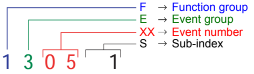
0 Fault reset or
no fault
1 General fault / additional functions
Example:
Logic error, e.g. both directions selected simultaneously
2 Current
(input interface, device-internal, output interface)
3 Voltage
(input interface, device-internal, output interface)
4 Temperature
5 Hardware
Example: Output transformer short circuit, EEPROM not
responding, …
6 Software
(internal software, application software, data record /
parameters)
Example: EEPROM data error
7 Additional modules
8 CAN monitoring
9 External fault
Example: ISM

Jungheinrich Service Manual
Jungheinrich DFG/TFG
660-690 Operating Instructions
Models: DFG 670; DFG
680; DFG 690; DFG S80; DFG S90; TFG 660; TFG 670; TFG 680; TFG 690; TFG S80; TFG S90; DFG S90.
Jungheinrich DFG S80
Service Manual
Models: TFG 680; DFG 670; DFG 660; DFG 680; DFG 690; DFG S80; DFG S90; TFG 660; TFG 670; TFG 690; TFG S80; TFG S90.
Jungheinrich DFG TFG
316-435 Operating Instructions
Models: TFG 430; DFG 320; DFG 425; DFG 430; DFG 435; TFG 316; TFG 320; TFG 425; TFG 435.
Jungheinrich EFG-Vac 22-30/ 25L/S/SL Service Manual Download
Jungheinrich ECE 225 (90309857) Spare Parts Catalogue Download
Jungheinrich EJC 110/112 Operating instructions Download
Jungheinrich DFG/TFG 16 — 50 A/B/C-K Operating instructions Download
Jungheinrich DFG 660 Service Manual Download
Jungheinrich DFG 670 Service Manual Download
Jungheinrich DFG S80 Service Manual Download
Jungheinrich DFG_TFG 316-435 Operating Instructions Download
Jungheinrich ECE 225 Spare Parts Catalogue Download
Jungheinrich EFG 213-320 Operating Manual Download
Jungheinrich EFG-Vac 22 Service Manual Download
Jungheinrich EFG-Vac 25L Service Manual Download
Jungheinrich EFG-Vac 30 Service Manual Download
Jungheinrich EJD 220 Service Manual Download
Jungheinrich ERE 120 Service Manual Download
Jungheinrich ETM 214 Service Manual Download
Jungheinrich ETM 216 Service Manual Download
Jungheinrich ETM 325 Service Manual Download
Jungheinrich ETV 214 Service Manual Download
Jungheinrich ETV 216 Service Manual Download
Jungheinrich ETV 318Service Manual Download
Jungheinrich ETV 320 Service Manual Download
Jungheinrich ETV 325 Service Manual Download
Jungheinrich EZS 330 XL Operating Instructions Manual Download
Jungheinrich EZS 350 XL Operating Instructions Manual Download
Jungheinrich SLH 200 Service Manual Download
Jungheinrich TFG 660 Service Manual Download
Jungheinrich Fault Codes
Jungheinrich Fault Codes Download
Jungheinrich EJC112 & E1202 Event Messages Codes List Download
Jungheinrich Error Codes List Download
Jungheinrich Fault Codes Download
Jungheinrich LISTADO ERRORES Download
Jungheinrich System Error Codes list Download
Jungheinrich System Error Codes list Download
Jungheinrich System Error Codes list Download
Jungheinrich forklifts
The manufacturer of forklifts is Jungheinrich, which is a leader in the production and sale of industrial, warehouse and material handling equipment. The company began its journey from 1953, when
a small loader company was founded, and by 2011 the company had several factories at its disposal.
Purpose
Forklifts are mainly used to work in warehouses, but without them they are very rarely managed in large-scale industries. They carry loads that are placed on pallets. Due to the version with a
closed cabin, they are able to work even in places with unfavorable external environment, namely, with wind, dust, sparks, sawdust, steam, and so on.
Electric
Electric loaders are represented by 5 series, which differ in load capacity, low unloading height, technology, maneuverability, as well as convenience of the operator’s workplace.
1 series EFG 110/113/115. The letters mean that this is an electric forklift, the first number indicates the series, and the second two are the maximum carrying
capacity in hundreds of kilograms. These are lightweight and compact loaders that have just one rear wheel. Thanks to these parameters, they have excellent maneuverability and can move even
inside the truck body. However, these «kids» are able to work with a weight of from 1 to 1.5 tons and lift the load to a height of 6.5 meters. AC control electronics may be updated.
EFG 213/215 / 216k / 216 / 218k / 218/220. The index k near some models indicates that the model has a smaller battery, a shorter base and a shorter fork body. This series has
the same dimensions and related benefits. However, the maximum load capacity is increased, as well as equipped with a large number of technologies. In the loader, an electric power steering was
added, the ability to independently configure 5 work programs, replace batteries, a more thoughtful security system, an automatic parking brake, smart electronics, and a maintenance-free brake
system and electric motor. The case in these loaders is integral, which provides greater stability when maneuvering.
EFG 316 / 316k / 318 / 318k / 320. The main differences between these trucks from previous models is that they have 4 wheels and a fully enclosed cab with front and rear window
cleaner. The control system is now electro-hydraulic, which provides better handling. Cab stances were enhanced, and the lighting system and battery compartment received additional protection.
EFG 540k / 540 / 545k / 545/550 / S40 / S30. These are the most powerful and big electric lift trucks. The maximum unloading height has also been increased, but only to 7.18
meters. You can use various packages of additional functions that determine the operation of the loader. In this series, more attention is paid to operator safety, as well as comfort and
ergonomics of the workplace.
Password: https://www.pdfmanual4trucks.com/
|
Title |
File Size |
Download Links |
|
Jungheinrich EJC112 / E1202 Event Messages Codes List PDF |
619.4kb |
Download |
|
Jungheinrich Error Codes List PDF [PDF] |
199kb |
Download |
|
Jungheinrich Fault Codes [PDF] |
769kb |
Download |
|
Jungheinrich LISTADO ERRORES [PDF] |
199kb |
Download |
|
Jungheinrich System Error Codes list [PDF] |
162.7kb |
Download |
|
Display error code |
Cause |
Action |
|
1901 |
During system start-up, the accelerator pedal zero position could not |
Do not press the accelerator pedal during system start-up. |
|
1904 |
Accelerator pedal pressed, but no travel direction selected. |
Take your foot off the accelerator pedal, select a travel direction and set off. |
|
1909 |
Accelerator pedal pressed and parking brake not released via parking |
Release the parking brake by pressing the parking brake button. |
|
1917 |
Accelerator and brake pedals pressed simultaneously. |
Press one pedal at a time only. |
|
2951 |
Lift function activated on multi-/ solo PILOT during system start- up. |
Do not apply the multi-/ solo PILOT during system start- up. – – – |
|
1952 |
Travel direction switch pressed during system start-up. |
Do not press the travel direction switch during system start-up |
|
9961 |
ISM (option) has detected a shock event in the vertical |
Obtain acknowledgement from authorized person (warehouse manager) and |
|
9962 |
ISM (option) has detected a shock event in the horizontal |
Obtain acknowledgement from authorized person (warehouse manager) and |
|
5990 |
The electrolyte level sensor check (battery-management option) on the |
Add electrolyte. |
|
5992 |
After switching on the truck, no radio network could be established |
– – – – |
|
5408/ 5409 |
Lithium-ion battery overtemperature |
Stop work. |
|
5413 |
Lithium-ion battery low temperature |
Move truck to warm environment. |
For all other warning messages switch the truck off and on again. If the warning message appears again call the service department.
The code lock enables an operator or a group of operators to be assigned an individual user code. The user code is configured with a master code and is outlined in the following sections of this
chapter.
When you have entered the valid user code the truck will be operational. The truck will be able to perform travel, steering and hydraulic operations.
When you have entered the valid master code the truck will be switched on. Travel operations are inhibited. The truck will be able to perform steering and hydraulic operations. The code lock is
in programming mode. When you enter one of the following parameters the settings in the code lock can be changed.
|
Parameters |
Description |
|
0-0-0 |
– To change the master code |
|
0-0-1 |
– To add user codes |
|
0-0-2 |
– To change a user code |
|
0-0-3 |
– To clear a user code |
|
0-0-4 |
– To clear all user codes |
|
0-1-0 |
– To set the automatic cutout of the truck |
Newly supplied trucks have the code indicated on a sticker. When using the truck for the first time change the master and user codes and remove the sticker.
- User code factory setting: 2-5-8-0
- Master code factory setting: 7-2-9-5
German-made Jungheinrich loading equipment is distinguished by excellent durability and
performance. Benefit from consistently high handling speeds with maximum comfort. This European-quality equipment perfectly adapts to various operating conditions, meets strict safety standards,
is distinguished by high working and driving qualities for moving and storing goods for work both in an open area and inside a closed warehouse or a freight railway container.
Jungheinrich LPG trucks, like trucks from other brands of this type, have a number of advantages. This is a universal warehouse
equipment, which is very economical if, when buying it, you correctly calculate the basic requirements for the height of lifting of loads, carrying capacity, speed of movement, weight of the
machine, its dimensions and, of course, the types of cargo with which the machine has to deal. If the calculation is carried out carefully, and the optimal model is chosen, the costs for it,
given the low price of gas, will pay off in a few months. And due to its high ecological class, it can work on a shift all day long with practically different cargoes that require specific
transportation conditions. The peculiarity of gas forklifts is that you can start them in any weather without any problems, which can not be said about diesel or gasoline ones.
Jungheinrich electric forklift EFG 115
The EFG 115 is the most compact electric forklift from the German concern Jungheinrich. It can be used in the smallest rooms,
including wagons and wagons. It has the following technical characteristics:
The distribution of weight to the front axle is 3805/1270.
Carrying capacity — 1500 kg.
Total weight 2870 kg.
Engine:
running — 4 kW;
lifting — 6 kW.
The maximum speed is 12.5 km / h.
Clearance — 100 mm.
The wheelbase is 1200 mm.
The center of gravity of the load on the forks is 500 mm.
Mast tilt (a / b) in degrees — 5/6.
Mast — 2000-3550 mm.
Working corridor width:
across — 3114 mm;
along — 3236 mm.
The total width is 990 mm.
The total length is 2935 mm.
The service brake is hydraulic.
The maximum lifting height is 3000 mm.
The maximum climb is 16 degrees.
Fork dimensions (LxWxH) — 1150x100x35 mm.
Lifting speed with / without load — 240/500 mm / s.
Lowering speed with / without load — 580/600 mm / s.
It is worth noting that it is quite difficult to find a new Jungheinrich EFG 115 loader in the domestic market. However, these
forklifts are quite widely used, and here the price depends on the condition of the machine. In general, the cost can vary from 3,000 to 10,000 euros. The new EFG 115 will cost about 18,500
euros.
Electric forklift Jungheinrich EFG 215
The second series of EFG loaders differs from the first in a large set of technical options. All this could not but affect the cost, which will be
slightly higher than the 115 model. However, first, let’s look at the technical specifications:
The distribution of weight to the front axle is 3870/1310.
Carrying capacity — 1500 kg.
Total weight 2978 kg.
Engine:
running — 4.6 kW;
lifting — 11.5 kW.
Storage battery (voltage V / capacity kW * h) — 48/500.
The maximum speed is 16 km / h.
Clearance — 100 mm.
The wheelbase is 1249 mm.
The center of gravity of the load on the forks is 500 mm.
Mast tilt (a / b) in degrees — 7/7.
Mast — 2000-3560 mm.
Working corridor width:
across — 3104 mm;
Along — 3226 mm.
The total width is 1060 mm.
The total length is 2924 mm.
The service brake is electromechanical.
The maximum lifting height is 3000 mm.
The maximum climb is 35 degrees.
Turning radius — 1440 mm.
Fork dimensions (LxWxH) — 1150x100x35 mm.
Lifting speed with / without load — 460/600 mm / s.
Lowering speed with / without load — 550/550 mm / s.
As you can see from the technical characteristics, this car has almost the same dimensions as the previous model, but with more powerful motors and
improved other indicators.
 Loading…

|
õUNGHEINRICH |
System Messages |
08.06 |
1 |
G |
|||||||
|
Error |
Description |
Component |
Display text |
Cause / Action |
Effect |
||||||
|
1 |
Low voltage during |
F, H, L, |
Low voltage |
Check battery voltage, chargebattery; |
Travel is inhibited. |
||||||
|
system start |
F-AC, H-AC |
Checkwireconnectiontocontroller; |
|||||||||
|
ELECTRICAL SYSTEM |
check main current fuse; check main |
Reduced power for |
|||||||||
|
contactor; replace control part; |
travel and lifting. |
||||||||||
|
Replacecomponent; |
Warning symbol |
||||||||||
|
(Limit VN = 80V: VBatt < 64V or |
flashing (Else-Check). |
||||||||||
|
VCap. < 56V |
|||||||||||
|
Limit VN = 48V: VBatt < 34V or |
|||||||||||
|
VCap. < 34V |
|||||||||||
|
Limit VN = 24V: VBatt <17V) |
|||||||||||
|
2 |
Overvoltage |
F, H, L, |
Overvoltage |
Check battery voltage; replace |
No travel or hydraulic functions |
||||||
|
F-AC, H-AC |
BATTERY |
controllerpart; replace component; |
Warning symbol |
||||||||
|
CONTROLLER |
(Limit VN = 80V: VBatt > 92 V |
flashing (Else-Check). |
|||||||||
|
Limit VN = 48V: VBatt > 62 V |
|||||||||||
|
Limit VN = 24V: VBatt > 28 V) |
|||||||||||
|
3 |
Temperature limit for |
F, H, L, |
TEMPERATURE |
Check sensor and wire connections |
Reduced power for |
||||||
|
controllers |
F-AC, H-AC |
CONTROLLER |
Allow controllers to cool down; check |
travel and lifting. |
|||||||
|
> 80°C (>70°C MP1510C) |
fan operation, improve cooling. |
Warning symbol |
|||||||||
|
or |
Warm up the controller and operate at |
flashing (Else-Check). |
|||||||||
|
ACS only: |
reduced level until the controller has |
||||||||||
|
Info at > 85°C |
warmed up. |
||||||||||
|
Err at > 115°C |
|||||||||||
|
Err at < -20°C |
|||||||||||
|
4 |
Emergency Disconnect |
F |
POWER SUPPLY |
Warning |
Brake applies, travel inhibited |
||||||
|
applied during travel |
(V < 20V MP1510C) |
|
õUNGHEINRICH |
System Messages |
08.06 |
2 |
G |
|||||||
|
Error |
Description |
Component |
Display text |
Cause / Action |
Effect |
||||||
|
5 |
Overvoltage |
F, F-AC, H-AC |
ELECTRICAL SYSTEM |
Check wire connection to battery, |
Brake applies, travel inhibited |
||||||
|
checkBattery, replacecontroller part; |
|||||||||||
|
Replace component; |
|||||||||||
|
(Limit for Retrak: VBatt > 62 V |
|||||||||||
|
Limit for MP1510C: V > 32 V) |
|||||||||||
|
6 |
Wire breakage: |
C, I2, I3, I4, I5, |
TRAVEL SWITCH |
Check wire connection; |
Travel stop. “Warning” symbol flashes |
||||||
|
— Travel setpoint device |
Travel switch |
Replace travel setpoint device; |
(Else-Check). Hydraulic functions |
||||||||
|
Replace Canion/ Interface; |
possible |
||||||||||
|
7 |
Key switch applied |
F,F-AC,H-AC |
KEY SWITCH |
Warning |
Brake applies, travel inhibited |
||||||
|
duringtravel |
(V < 13V for 200ms MP1510C) |
||||||||||
|
8 |
2 travel directions applied |
F-AC, H-AC, C, |
ELECTRICAL SYSTEM |
Warning, replace travel direction |
Travel stop. “Warning” symbol |
||||||
|
simultaneously |
MP, S, I2, I3, I5, |
switch, replace Interface 7 Canion; |
flashing (Else-Check). |
||||||||
|
FS |
replace Multipilot / Solopilot |
Hydraulic functions possible |
|||||||||
|
For twin pedal, check the electrical |
|||||||||||
|
system. |
|||||||||||
|
9 |
Operator protection switch |
I2, FS |
ELECTRICAL SYSTEM |
Check switch, check wire connections |
|||||||
|
faulty |
|||||||||||
|
10 |
V Cap. <> V Batt; (main |
F, H, |
MAIN CONTACTOR |
Check main contactor, check wire |
No travel, hydraulics |
||||||
|
contactor jammed or not |
F-AC, H-AC |
connection; check output pin 2 (ACS) of |
Warning symbol |
||||||||
|
open) |
L |
traction controller; replace component |
Flashing warning (Else-Check). |
||||||||
|
11 |
Offset error armature / |
F, H, L, |
CONTROLLER |
Check main current wire, replace |
Travel no function |
||||||
|
field current (DC) |
F-AC, H-AC |
component |
|||||||||
|
Stator current (AC); |
|||||||||||
|
Current measurement |
|||||||||||
|
point |
|||||||||||
|
12 |
Disable driver field |
F, H |
CONTROLLER |
Replace component; |
No travel, hydraulics |
||||||
|
rheostat faulty for DC |
F-AC, H-AC |
for AC: Check flat belt wire connection; |
Warning symbol |
||||||||
|
Disable driver power |
L |
replace power part |
Flashing warning (Else-Check). |
||||||||
|
stage faulty (forAC) |
|||||||||||

|
õUNGHEINRICH |
System Messages |
08.06 |
3 |
G |
|||||||
|
Error |
Description |
Component |
Display text |
Cause / Action |
Effect |
||||||
|
13 |
Disable Watchdog field |
F, H |
CONTROLLER |
Replace components |
Travel no function |
||||||
|
faulty |
|||||||||||
|
14 |
— Main contactor notclosed |
F, H, |
CONTROLLER/ |
Check wire connection; check main |
No travel, hydraulics |
||||||
|
— Field power stage cannot |
F-AC, H-AC |
MAIN CONTACTOR |
contactor; check charging connection, |
Warning symbol |
|||||||
|
be switched on (DC) |
Check field supply fuse, |
Flashing warning (Else-Check). |
|||||||||
|
Replace component. |
|||||||||||
|
15 |
Disable field faulty; |
F, H, |
CONTROLLER |
Replace controlpart; replace |
Travel no function |
||||||
|
Illegal address (for AC) |
F-AC, H-AC |
component |
|||||||||
|
L |
|||||||||||
|
16 |
Disable driver armature |
F, H, |
CONTROLLER |
Replace controlpart (AC); replace |
Travel no function |
||||||
|
actuator faulty; |
F-AC, H-AC |
component |
|||||||||
|
Software reset (for AC) |
|||||||||||
|
17 |
Disable Watchdog |
F, H |
CONTROLLER |
Replace components |
Travel no function |
||||||
|
armature faulty |
|||||||||||
|
18 |
DC: Armature power |
F, H, F-AC, H-AC |
CONTROLLER |
Check armature wire connection; |
Travel no function |
||||||
|
stage cannot be switched |
L |
replace power part; replace component |
|||||||||
|
on |
|||||||||||
|
AC: one of the 3 phases |
|||||||||||
|
cannot be switched on |
|
õUNGHEINRICH |
System Messages |
08.06 |
4 |
G |
||||||
|
Error |
Description |
Component |
Display text |
Cause / Action |
Effect |
|||||
|
19 |
Disable armature faulty; |
F, H, F-AC ,H- |
CONTROLLER |
Replace power part; Replace |
Travel no function |
|||||
|
Power stage short circuit |
AC, |
component. |
||||||||
|
(for AC) |
L-AC |
Can occur in connection with error 70, |
||||||||
|
The error may be |
in this case: |
|||||||||
|
triggered by the faulty |
check power supply behind the main |
|||||||||
|
speed sensor in |
contactor contact, in the event of an |
|||||||||
|
connection with |
error the voltage will be much lower |
|||||||||
|
AS4814Plus controllers. |
here than the rated operating voltage. |
|||||||||
|
Sensor wheel wobbles |
Disconnect the positive supply from the |
|||||||||
|
(elliptical) or the sensor- |
components to target the error cause. |
|||||||||
|
sensor wheel gap is too |
The exception here is the F1 traction |
|||||||||
|
big. In this case the |
controller which must remain |
|||||||||
|
component is not faulty. |
connected. One component overloads |
|||||||||
|
A short circuit cannot be |
the testing voltage due to internal short |
|||||||||
|
resolved by switching the |
circuit. |
|||||||||
|
truck off/on. |
The testing voltage arises by charging |
|||||||||
|
the internal capacitor batteries via a |
||||||||||
|
resistor to the level of the control |
||||||||||
|
voltage supply. |
||||||||||
|
Check sensor, replace sensor and / or |
||||||||||
|
sensor wheel. |
||||||||||
|
20 |
Armature incorrectly |
F, H |
ELECTRICAL SYSTEM |
Check armature main current wire |
Travel no function |
|||||
|
connected |
connection |
|||||||||
|
21 |
Armature overvoltage |
F, H, F-AC, H-AC |
CONTROLLER/ |
Check main current wire to armature; |
||||||
|
(short circuit / high side |
L |
ELECTR |
check settings(for AC); |
|||||||
|
faulty) |
AArmature > 360A for 250ms (MP1510); |
|||||||||
|
Replace component. |
||||||||||

|
õUNGHEINRICH |
System Messages |
08.06 |
5 |
G |
|||||||
|
Error |
Description |
Component |
Display text |
Cause / Action |
Effect |
||||||
|
22 |
Watchdog error; |
F, H, L, M, S, A, |
CONTROLLER/ |
Truck reset, |
No travel, hydraulics |
||||||
|
Watchdog does not run |
I2, I3, I4, C, |
CANION |
Replace controlpart; replace |
Warning symbol |
|||||||
|
out |
F-AC, H-AC, FS |
component |
Flashing warning (Else-Check). |
||||||||
|
23 |
— Computer overload |
F, H, L, M, S, A, |
CONTROLLER / CAN |
Check CAN bus connection; |
No travel, hydraulics |
||||||
|
— Permanent interrupt |
I2, I3, I4, C, |
Check CANION connector and |
Warning symbol |
||||||||
|
— “ACS” timeout on |
F-AC, H-AC, FS |
component; |
Flashing warning (Else-Check). |
||||||||
|
CAN connection |
Replace component |
||||||||||
|
24 |
EEPROM cannot be |
F, H, L, I2, I3, I4, |
CONTROLLER/ |
Check battery cable; check VBatt; set |
Flashing warning symbol (Else- |
||||||
|
contacted / parameters |
C, |
CANION |
trucktype, set default parameters; |
Check). |
|||||||
|
not plausible / parameter |
F-AC, H-AC |
replace control part; replace |
|||||||||
|
set to default |
MFC brake |
component |
|||||||||
|
Faulty checksum |
MFC hydr. , travel |
Delete logbook, change parameters, |
|||||||||
|
switch |
set hourmeter, replace component |
||||||||||
|
25 |
No telegrams: |
F, H, I4, I8 |
INTERFACE / CAN |
Check CANBus connection, check wire |
|||||||
|
— no logon from |
F-AC, H-AC |
connection between proportional valve |
|||||||||
|
interface |
L |
– modulation; check fuse 1F8; replace |
|||||||||
|
iInterface (I2, I4, I8) ; replace lift |
|||||||||||
|
potentiometer, Multipilot, Solopilot or |
|||||||||||
|
interface; |
|||||||||||
|
MP1510C: Voltage collapses, controller |
|||||||||||
|
logs on again, interface does not, |
|||||||||||
|
controller remains blocked and waits for |
|||||||||||
|
interface. |
|||||||||||
|
Check battery voltage (with load!); |
|||||||||||
|
charge or replace battery if necessary; |
|||||||||||
|
— no telegrams from |
AS2409K: no “live” telegram received |
||||||||||
|
from CAN Bus travel switch for more |
|||||||||||
|
Can-Bus travel switch |
than 300 ms; replace travel switch |
|
õUNGHEINRICH |
System Messages |
08.06 |
6 |
G |
|||||||
|
Error |
Description |
Component |
Display text |
Cause / Action |
Effect |
||||||
|
26 |
Wire breakage: |
M, S, I2, I3 |
MULTIPILOT / |
Check wire connection |
Lift stop. “Warning” symbol flashes |
||||||
|
— Lift potentiometer |
SOLOPILOT / LIFT |
(Else-Check), travel enabled |
|||||||||
|
POTENTIOMETER |
|||||||||||
|
27 |
Wire breakage: |
C, L, I3, I4 |
STEER ACTUAL |
Check wire connection; |
Crawl speed, |
||||||
|
— Steering setpoint device; |
ANGLE |
Replace steer angle sensor / |
Flashing warning symbol (Else- |
||||||||
|
◊ Reach truck: for 45° |
potentiometer; |
Check), hydraulic functions enabled. |
|||||||||
|
steering bolster movement |
Replace Canion / Interface; |
This error produces an emergency |
|||||||||
|
no flank from proximity |
Replace steering; |
stop on the reach truck and the |
|||||||||
|
switch. |
PM2402L from software version 1.60: |
Juniors. |
|||||||||
|
◊ Canion: “Steer angle |
|||||||||||
|
acquire active” parameter |
set parameter P511 “operating mode” |
||||||||||
|
has incorrect value |
correctly ◊ 1 = analog sensor |
||||||||||
|
◊ Juniors PM2402L: |
(potentiometer), |
||||||||||
|
“Operating mode” |
2 = digital sensor on steer motor |
||||||||||
|
parameter incorrectly set |
|||||||||||
|
28 |
Wire breakage: |
C, L, I3, I4 |
STEER NOMINAL |
Check wire connection, replace |
Crawl speed, |
||||||
|
— Steering sensor |
ANGLE |
steering wheel sensor;replace Canion / |
Flashing warning symbol (Else- |
||||||||
|
interface; replace steering |
Check), hydraulic functions enabled. |
||||||||||
|
This error produces an emergency |
|||||||||||
|
stop on the reach |
truck |
||||||||||
|
29 |
Wire breakage: |
M |
Traverse nominal value |
Replace Multipilot |
|||||||
|
— Traverse potentiometer |
MULTIPILOT |
||||||||||
|
30 |
Wire breakage: |
M |
Tilt nominal value |
Replace Multipilot, |
|||||||
|
— Tilt potentiometer |
MULTIPILOT |
Teach Multipilot (Hall sensor 2003 only) |
|||||||||
|
31 |
Wire breakage: |
M, S |
Sideshift nominal value |
Replace Multipilot / Solopilot, |
Hydraulic functions stop, “Warning” |
||||||
|
— ZH1 setpoint device |
MULTIPILOT / |
Teach Multipilot (Hall sensor 2003 |
symbol flashes (Else-Check), travel |
||||||||
|
SOLOPILOT |
only); |
enabled |
|||||||||
|
— Initial lift / lower |
Travel switch |
Travel switch: Check / replace switch |
|||||||||
|
Setpoint device |
|||||||||||

|
õUNGHEINRICH |
System Messages |
08.06 |
7 |
G |
|||||||
|
Error |
Description |
Component |
Display text |
Cause / Action |
Effect |
||||||
|
32 |
Wire breakage: |
M, S |
MULTIPILOT / |
Replace Multipilot / Solopilot, |
Hydraulic functions stop, “Warning” |
||||||
|
— ZH2 setpoint device |
SOLOPILOT |
Teach Multipilot (Hall sensor 2003 only) |
symbol flashes (Else-Check), travel |
||||||||
|
enabled |
|||||||||||
|
33 |
Wire breakage: |
M, I8 |
MULTIPILOT |
Replace Multipilot |
|||||||
|
— ZH3 setpoint device |
|||||||||||
|
34 |
CANBus damaged |
F, H, L, M, S, A, |
CAN-BUS |
Check CAN bus connection; |
No travel, hydraulics |
||||||
|
I2, I3, I4, I5, C, F- |
replace faulty component; |
Warning symbol |
|||||||||
|
AC, H-AC |
Check terminal resistances |
Flashing warning (Else-Check). Only |
|||||||||
|
Travel switch |
stored in logbook (from 2004). |
||||||||||
|
35 |
No travel zero position |
I2, I3, I4, C |
TRAVEL ZERO |
Warning, check travel switch; |
Travel stop, |
||||||
|
Deadman and accelerator |
Travel switch |
POSITION |
Intermittent contact in interface power |
Flashing warning symbol (Else- |
|||||||
|
pedal applied when truck |
supply (12 volts) |
Check), hydraulic functions enabled. |
|||||||||
|
switched on |
Check Canion, for twin pedal check |
||||||||||
|
electrical system |
|||||||||||
|
36 |
No lift zero position |
M, I2, I3,FS |
LIFT ZERO POSITION |
Warning, check lift setpoint device. |
Hydraulic functions stop, “Warning” |
||||||
|
symbol flashes (Else-Check), travel |
|||||||||||
|
enabled |
|||||||||||
|
37 |
No steering angle nominal |
L |
CONTROLLER / CAN |
Check steering setpoint device;Check |
|||||||
|
value |
CANBus connection; check “steer type” |
||||||||||
|
parameter; Replace component (I5) |
|||||||||||
|
38 |
Component does not log |
F, H, L, I2, I3, I4, |
CONTROLLER / CAN |
Check CAN-Bus connection and |
No travel, lifting |
||||||
|
on, self test not |
C, A, M, S, F-AC, |
voltage; check DIL switch 7 encoding |
Warning symbol |
||||||||
|
concluded. |
H-AC |
(MP1510); steering controller |
Flashing warning (Else-Check). |
||||||||
|
monitoring activated? (AS2412F); |
|||||||||||
|
check ACS encoding; replace |
|||||||||||
|
component |

|
õUNGHEINRICH |
System Messages |
08.06 |
8 |
G |
||||||
|
Error |
Description |
Component |
Display text |
Cause / Action |
Effect |
|||||
|
39 |
Implausible truck type |
F, H, L, I2, I3, I4, |
TRUCK TYPE |
For 1. Set truck type; |
||||||
|
1. Discovered during the |
I5, A, M, |
For 2. Examine and if necessary |
||||||||
|
self test phase that at |
F-AC, H-AC |
replace switch (key switch) or rectify |
||||||||
|
least one component |
intermittent contact in power supply |
|||||||||
|
has a different truck |
plug connections. |
|||||||||
|
type as a parameter. |
Set truck type. |
|||||||||
|
A different truck type was |
||||||||||
|
discovered in operating |
||||||||||
|
mode. Caused by |
||||||||||
|
intermittent contacts in the |
||||||||||
|
power supply connections |
||||||||||
|
40 |
Motor overtemperature |
L, F, H |
TEMPERATURE |
Warning; check motor sensor system |
Reduced power for |
|||||
|
Traction motor |
F-AC, H-AC |
MOTOR |
and wire connections; |
travel and lifting. |
||||||
|
overtemperature in |
Check motor; traction motor brake |
Warning symbol |
||||||||
|
operating mode.> 150°C |
open? |
flashing (Else-Check). For steering |
||||||||
|
And travel speed < 1km/h |
only |
|||||||||
|
For ACS: |
warning symbol flashing. |
|||||||||
|
Info > 145°C |
||||||||||
|
Err > 165°C |
||||||||||
|
41 |
Brake magnet |
L |
BRAKE |
Check potentiometer; check |
||||||
|
potentiometer |
MAGNETPOTENTIOM |
potentiometer attachment; check wire |
||||||||
|
Potentiometer voltage less |
ETER |
connection |
||||||||
|
than 0.3 volts or greater |
||||||||||
|
than 2.7 volts for more |
||||||||||
|
than 500ms. |

|
õUNGHEINRICH |
System Messages |
08.06 |
9 |
G |
|||||
|
Error |
Description |
Component |
Display text |
Cause / Action |
Effect |
||||
|
42 |
— Short circuit between |
L,F |
BRAKE MAGNET |
Check wire connection, check brake |
|||||
|
the output and battery |
magnet; replace component |
||||||||
|
positive.(EJC, ELE) |
|||||||||
|
-Brake magnet control, |
|||||||||
|
below minimum difference |
|||||||||
|
on potentiometer for 500 |
|||||||||
|
ms when magnet applied. |
|||||||||
|
(150mV ) |
|||||||||
|
No brake pressure during |
|||||||||
|
initialization. |
|||||||||
|
Brake pressure after the |
|||||||||
|
Emergency Stop magnet |
|||||||||
|
has applied; |
|||||||||
|
43 |
Adjust brake |
L |
ADJUST BRAKE |
Adjust brake; check potentiometer |
|||||
|
44 |
—Brake not connected or |
L,F |
BRAKE FAULTY |
-Check brake wiring, replace brake if |
No release |
||||
|
connection wire short |
necessary |
||||||||
|
circuit |
-Replace brake cable, check |
||||||||
|
potentiometer; Check potentiometer |
|||||||||
|
-Brake cable torn |
attachment; |
||||||||
|
Only for steer category_3: |
Only for steer category_3: |
||||||||
|
Internal driver of failsafe |
|||||||||
|
brake cannot connect the |
-Check brake driver output, check |
||||||||
|
relay |
switch contact plausibility, |
||||||||
|
Or short circuit bypass |
Replace steer component. |
||||||||
|
(contact jams) on the |
|||||||||
|
output during power up |
|||||||||
|
test |
![]()
Jungheinrich System Error Codes list.pdf
Adobe Acrobat Document
168.2 KB
![]()
Jungheinrich Fault Codes.pdf
Adobe Acrobat Document
720.8 KB
![]()
Jungheinrich Error Codes List PDF.pdf
Adobe Acrobat Document
191.8 KB
![]()
Jungheinrich EJC112 & E1202 Event Messag
Adobe Acrobat Document
582.8 KB
Event Messages
Z This display units shows a four-digit event message for every
event. Trucks that only use one luminous display (e.g. LED) show
the event through a flashing code (see «Display System”).
Each event message is also stored in the master logbook. The
master logbook describes the event in more detail through the sub
index behind the event message (FEXX).
Event numbering display
F E XX S
F Function group; E Event group
XX Event number S Sub index
The first two characters “F, E” refer to the category. The middle
two digits “XX” refer to the event. From these two digits the range:
• 1 to 50 describes standard events (uniform basic events)
which can occur in any function group.
• 51 to 99 describes specific events.
The event is described in further detail through the last characters
“S” (single digit / multi-digit).
This process ensures that a unique number is assigned to each
event. Example:
0 Fault reset or
no fault
1 General fault / additional functions
Example:
Logic error, e.g. both directions selected simultaneously
2 Current
(input interface, device-internal, output interface)
3 Voltage
(input interface, device-internal, output interface)
4 Temperature
5 Hardware
Example: Output transformer short circuit, EEPROM not
responding, …
6 Software
(internal software, application software, data record /
parameters)
Example: EEPROM data error
7 Additional modules
8 CAN monitoring
9 External fault
Example: ISM
German-made Jungheinrich loading equipment is distinguished by excellent durability and
performance. Benefit from consistently high handling speeds with maximum comfort. This European-quality equipment perfectly adapts to various operating conditions, meets strict safety standards,
is distinguished by high working and driving qualities for moving and storing goods for work both in an open area and inside a closed warehouse or a freight railway container.
Jungheinrich LPG trucks, like trucks from other brands of this type, have a number of advantages. This is a universal warehouse
equipment, which is very economical if, when buying it, you correctly calculate the basic requirements for the height of lifting of loads, carrying capacity, speed of movement, weight of the
machine, its dimensions and, of course, the types of cargo with which the machine has to deal. If the calculation is carried out carefully, and the optimal model is chosen, the costs for it,
given the low price of gas, will pay off in a few months. And due to its high ecological class, it can work on a shift all day long with practically different cargoes that require specific
transportation conditions. The peculiarity of gas forklifts is that you can start them in any weather without any problems, which can not be said about diesel or gasoline ones.
Jungheinrich electric forklift EFG 115
The EFG 115 is the most compact electric forklift from the German concern Jungheinrich. It can be used in the smallest rooms,
including wagons and wagons. It has the following technical characteristics:
The distribution of weight to the front axle is 3805/1270.
Carrying capacity — 1500 kg.
Total weight 2870 kg.
Engine:
running — 4 kW;
lifting — 6 kW.
The maximum speed is 12.5 km / h.
Clearance — 100 mm.
The wheelbase is 1200 mm.
The center of gravity of the load on the forks is 500 mm.
Mast tilt (a / b) in degrees — 5/6.
Mast — 2000-3550 mm.
Working corridor width:
across — 3114 mm;
along — 3236 mm.
The total width is 990 mm.
The total length is 2935 mm.
The service brake is hydraulic.
The maximum lifting height is 3000 mm.
The maximum climb is 16 degrees.
Fork dimensions (LxWxH) — 1150x100x35 mm.
Lifting speed with / without load — 240/500 mm / s.
Lowering speed with / without load — 580/600 mm / s.
It is worth noting that it is quite difficult to find a new Jungheinrich EFG 115 loader in the domestic market. However, these
forklifts are quite widely used, and here the price depends on the condition of the machine. In general, the cost can vary from 3,000 to 10,000 euros. The new EFG 115 will cost about 18,500
euros.
Electric forklift Jungheinrich EFG 215
The second series of EFG loaders differs from the first in a large set of technical options. All this could not but affect the cost, which will be
slightly higher than the 115 model. However, first, let’s look at the technical specifications:
The distribution of weight to the front axle is 3870/1310.
Carrying capacity — 1500 kg.
Total weight 2978 kg.
Engine:
running — 4.6 kW;
lifting — 11.5 kW.
Storage battery (voltage V / capacity kW * h) — 48/500.
The maximum speed is 16 km / h.
Clearance — 100 mm.
The wheelbase is 1249 mm.
The center of gravity of the load on the forks is 500 mm.
Mast tilt (a / b) in degrees — 7/7.
Mast — 2000-3560 mm.
Working corridor width:
across — 3104 mm;
Along — 3226 mm.
The total width is 1060 mm.
The total length is 2924 mm.
The service brake is electromechanical.
The maximum lifting height is 3000 mm.
The maximum climb is 35 degrees.
Turning radius — 1440 mm.
Fork dimensions (LxWxH) — 1150x100x35 mm.
Lifting speed with / without load — 460/600 mm / s.
Lowering speed with / without load — 550/550 mm / s.
As you can see from the technical characteristics, this car has almost the same dimensions as the previous model, but with more powerful motors and
improved other indicators.
Jungheinrich Service Manual
Jungheinrich DFG/TFG
660-690 Operating Instructions
Models: DFG 670; DFG
680; DFG 690; DFG S80; DFG S90; TFG 660; TFG 670; TFG 680; TFG 690; TFG S80; TFG S90; DFG S90.
Jungheinrich DFG S80
Service Manual
Models: TFG 680; DFG 670; DFG 660; DFG 680; DFG 690; DFG S80; DFG S90; TFG 660; TFG 670; TFG 690; TFG S80; TFG S90.
Jungheinrich DFG TFG
316-435 Operating Instructions
Models: TFG 430; DFG 320; DFG 425; DFG 430; DFG 435; TFG 316; TFG 320; TFG 425; TFG 435.
Jungheinrich EFG-Vac 22-30/ 25L/S/SL Service Manual Download
Jungheinrich ECE 225 (90309857) Spare Parts Catalogue Download
Jungheinrich EJC 110/112 Operating instructions Download
Jungheinrich DFG/TFG 16 — 50 A/B/C-K Operating instructions Download
Jungheinrich DFG 660 Service Manual Download
Jungheinrich DFG 670 Service Manual Download
Jungheinrich DFG S80 Service Manual Download
Jungheinrich DFG_TFG 316-435 Operating Instructions Download
Jungheinrich ECE 225 Spare Parts Catalogue Download
Jungheinrich EFG 213-320 Operating Manual Download
Jungheinrich EFG-Vac 22 Service Manual Download
Jungheinrich EFG-Vac 25L Service Manual Download
Jungheinrich EFG-Vac 30 Service Manual Download
Jungheinrich EJD 220 Service Manual Download
Jungheinrich ERE 120 Service Manual Download
Jungheinrich ETM 214 Service Manual Download
Jungheinrich ETM 216 Service Manual Download
Jungheinrich ETM 325 Service Manual Download
Jungheinrich ETV 214 Service Manual Download
Jungheinrich ETV 216 Service Manual Download
Jungheinrich ETV 318Service Manual Download
Jungheinrich ETV 320 Service Manual Download
Jungheinrich ETV 325 Service Manual Download
Jungheinrich EZS 330 XL Operating Instructions Manual Download
Jungheinrich EZS 350 XL Operating Instructions Manual Download
Jungheinrich SLH 200 Service Manual Download
Jungheinrich TFG 660 Service Manual Download
Jungheinrich Fault Codes
Jungheinrich Fault Codes Download
Jungheinrich EJC112 & E1202 Event Messages Codes List Download
Jungheinrich Error Codes List Download
Jungheinrich Fault Codes Download
Jungheinrich LISTADO ERRORES Download
Jungheinrich System Error Codes list Download
Jungheinrich System Error Codes list Download
Jungheinrich System Error Codes list Download
Jungheinrich forklifts
The manufacturer of forklifts is Jungheinrich, which is a leader in the production and sale of industrial, warehouse and material handling equipment. The company began its journey from 1953, when
a small loader company was founded, and by 2011 the company had several factories at its disposal.
Purpose
Forklifts are mainly used to work in warehouses, but without them they are very rarely managed in large-scale industries. They carry loads that are placed on pallets. Due to the version with a
closed cabin, they are able to work even in places with unfavorable external environment, namely, with wind, dust, sparks, sawdust, steam, and so on.
Electric
Electric loaders are represented by 5 series, which differ in load capacity, low unloading height, technology, maneuverability, as well as convenience of the operator’s workplace.
1 series EFG 110/113/115. The letters mean that this is an electric forklift, the first number indicates the series, and the second two are the maximum carrying
capacity in hundreds of kilograms. These are lightweight and compact loaders that have just one rear wheel. Thanks to these parameters, they have excellent maneuverability and can move even
inside the truck body. However, these «kids» are able to work with a weight of from 1 to 1.5 tons and lift the load to a height of 6.5 meters. AC control electronics may be updated.
EFG 213/215 / 216k / 216 / 218k / 218/220. The index k near some models indicates that the model has a smaller battery, a shorter base and a shorter fork body. This series has
the same dimensions and related benefits. However, the maximum load capacity is increased, as well as equipped with a large number of technologies. In the loader, an electric power steering was
added, the ability to independently configure 5 work programs, replace batteries, a more thoughtful security system, an automatic parking brake, smart electronics, and a maintenance-free brake
system and electric motor. The case in these loaders is integral, which provides greater stability when maneuvering.
EFG 316 / 316k / 318 / 318k / 320. The main differences between these trucks from previous models is that they have 4 wheels and a fully enclosed cab with front and rear window
cleaner. The control system is now electro-hydraulic, which provides better handling. Cab stances were enhanced, and the lighting system and battery compartment received additional protection.
EFG 540k / 540 / 545k / 545/550 / S40 / S30. These are the most powerful and big electric lift trucks. The maximum unloading height has also been increased, but only to 7.18
meters. You can use various packages of additional functions that determine the operation of the loader. In this series, more attention is paid to operator safety, as well as comfort and
ergonomics of the workplace.
- Page 1
EJC 214-220 / EJC 212z-220z 11.10 Operating instructions en-GB 51141056 04.19 EJC 212z EJC 214z EJC 216z EJC 220z EJC 214 EJC 216 EJC 220… - Page 3
Declaration of Conformity Manufacturer Jungheinrich AG, 22039 Hamburg, Germany Description Industrial truck Type Option Serial no. Year of manufacture EJC 212z EJC 214z EJC 216z EJC 220z EJC 214 EJC 216 EJC 220 On behalf of Date EU DECLARATION OF CONFORMITY… - Page 5
Foreword Notes on the operating instructions The present ORIGINAL OPERATING INSTRUCTIONS are designed to provide sufficient instruction for the safe operation of the industrial truck. The information is provided clearly and concisely. The chapters are arranged by letter and the pages are numbered continuously. - Page 6
Copyright Copyright of these operating instructions remains with JUNGHEINRICH AG. Jungheinrich Aktiengesellschaft Friedrich-Ebert-Damm 129 22047 Hamburg — Germany Tel: +49 (0) 40/6948-0 www.jungheinrich.com… -
Page 7: Table Of Contents
Contents Correct Use and Application General Correct application Lifting Passengers Approved application conditions Internal Operation Combined with Brief External or Cold Store Operation (t) Internal Operation in Cold Stores with Cold Store Equipment (o) Proprietor responsibilities Adding attachments and/or optional equipment Truck Description Application Truck models and rated capacity…
- Page 8
Load cannot be lifted Operating the truck without its own drive system Release and activate the drive wheel brake Load handler emergency lowering EJC 214/216/220 EJC 212z / 214z / 216z / 220z Optional equipment Emergency operation with service key GF60… - Page 9
Safety tests to be performed at intervals and after unusual incidents Final de-commissioning, disposal Human vibration measurement Maintenance, Inspection and Changing of Maintenance Parts Requiring Replacement Maintenance Contents EJC 212z/214z/216z Owner Customer Service Maintenance Contents EJC 214/216 Owner Customer Service… - Page 11
Appendix JH Traction Battery Operating Instructions These operating instructions apply only to Jungheinrich battery models. If using another brand, refer to the manufacturer’s operating instructions. -
Page 13: A Correct Use And Application
A Correct Use and Application General The truck must be used, operated and serviced in accordance with the present instructions. All other types of use are beyond its scope of application and may result in damage to personnel, the industrial truck or property. Correct application NOTICE The maximum load and load distance are indicated on the capacity plate and must…
-
Page 14: Approved Application Conditions
Approved application conditions – Operation in industrial and commercial environments. – Operation only on secure, level surfaces with sufficient capacity. – Do not exceed the permissible surface and spot load limits on the travel routes. – Operation only on routes that are visible and approved by the operating company. –…
-
Page 15: Internal Operation Combined With Brief External Or Cold Store Operation (T)
Internal Operation Combined with Brief External or Cold Store Operation (t) In addition to the permissible application conditions in industrial and commercial environments, the truck may also be used in outdoor environments, cold stores and fresh food areas. Secure parking is only permissible indoors or in a cold store environment.
-
Page 16: Proprietor Responsibilities
Proprietor responsibilities For the purposes of the present operating instructions the “operating company” is defined as any natural or legal person who either uses the industrial truck himself, or on whose behalf it is used. In special cases (e.g. leasing or renting) the proprietor is considered the person who, in accordance with existing contractual agreements between the owner and user of the industrial truck, is charged with operational duties.
-
Page 17: B Truck Description
The rated capacity depends on the model. The rated capacity can be derived from the model name. EJC 214 / 216 / 220 / EJC 212z / 214z / 216z / 220z EJC 214 / 216 / 220 EJC 212z / 214z / 216z /…
-
Page 18: Travel Direction Definition
Travel direction definition The following determinations have been made for travel direction specification: Item Travel direction Left Drive direction Load direction Right…
-
Page 19: Assemblies And Functional Description
Assemblies and Functional Description Assembly Overview…
- Page 20
Item Description Item Description t Travel switch 14 t Charge status indicator t Collision safety switch o CanDis o Display unit (2-inch display) t Mast 15 t Key switch t Protective screen panel o CanCode o ISM access module o Keypad Protective grille (for cold store application) o Transponder reader… -
Page 21: Functional Description
Functional Description Safety mechanisms An enclosed, smooth truck geometry with rounded edges ensures safe handling of the truck. The wheels are surrounded by a solid skirt. The long tiller provides a maximum safety distance to the truck. When it is released and in hazardous situations, a gas strut forces the tiller up into the brake position.
- Page 22
Hydraulic System Lifting and lowering are activated via the lift and lower buttons. Pressing the lifting button starts the pump unit, supplying hydraulic oil from the oil reservoir to the lift cylinder. With the two-stage Duplex mast (ZZ) (o) or three-stage telescopic mast (DZ) (o) a short, centre-mounted free lift cylinder initially lifts the load handler (free lift) without changing the overall height of the truck. - Page 23
Mast The maximum strength steel sections are narrow, allowing for outstanding load handler visibility in particular with the three-stage mast. The lift rails and the fork carriage run on permanently-lubricated and hence maintenance-free angled rollers. Load backrest (o) A load backrest is recommended as an additional protective mechanism to move low or small item loads above the mast protection frame or grille (o). -
Page 24: Technical Specifications
Technical Specifications The technical specifications comply with the German «Industrial Truck Data Sheet» Guidelines. Technical modifications and additions reserved. Performance data Model EJC 214 EJC 214 Rated capacity 1400 1400 Load centre distance Travel speed with/without load 6.0 / 6.0 6.0 / 6.0…
- Page 25
Description EJC 212z EJC 214z Rated capacity 1200 1400 1200 1400 Capacity for mast lift Capacity for support arm lift 2000 2000 Load centre distance 6.0 / 6.0 6.0 / 6.0 km/h Travel speed Lift speed 0.04/0.05 0.04/0.05 Initial lift 0.08/0.06 0.08/0.06 Lowering speed… -
Page 26: Dimensions
Dimensions EJC 214 / 216 / 220 max. min. h1 3 b1 b10 b1 1 b5 b1 2 (Ast)
- Page 27
EJC 212z / 214z / 216z / 220z… - Page 28
EJC 214 EJC 214 Component Height 1950 1950 Free lift Lift 2900 2900 Mast height extended 3375 3375 h13 Forks lowered Control handle height in travel 850 / 1305 850 / 1305 position Load distance Wheelbase 1277 1357 Truck length… - Page 29
EJC 216 EJC 216 EJC 220 Component h1 Height 1950 1950 2100 h2 Free lift h3 Lift 2800 2800 2800 h4 Mast height extended 3325 3325 3465 h13 Forks lowered Control handle height in travel 850 / 1305 850 / 1305 850 / 1305 position Load distance… - Page 30
Component EJC 212z EJC 214z Height 1950 1950 Free lift Lift 2900 2900 Mast height extended 3375 3375 Initial lift h13 Forks lowered Control handle height in travel 850 / 1305 850 / 1305 position Load distance raised 3)9) 3)9) Wheel base raised 1571 1592… - Page 31
Component EJC 216z EJC 220z Height 1950 1950 Free lift Lift 2800 2800 Mast height extended 3325 3325 Initial lift h13 Forks lowered Control handle height in travel 850 / 1305 850 / 1305 position Load distance raised 3)9) 3)9) Wheel base raised 1592 1592… -
Page 32: Weights
Weights EJC 214 EJC 214 Net weight incl. battery 1039 1120 Axle load, w. load front / rear + battery 794/ 1645 850 / 1670 Axle load, w. load front / rear + battery 721 / 318 762 / 358…
-
Page 33: Tyre Type
Tyre type EJC 214 (M) / 214 (L) / EJC 220 216 (M) / 216 (L) Tyre size, drive 230 x 70 230 x 70 Load section tyre size Ø 85 x 110 / Ø 85 x 85 — / Ø 85 x 85…
-
Page 34: Norms
EN norms Continuous sound pressure level – EJC 214-220 / EJC 212z-220z: 63 dB(A) in accordance with EN 12053 as harmonised with ISO 4871. The continuous sound pressure level is calculated according to standard procedures and takes into account the sound pressure level when travelling, lifting and idling.
-
Page 35: Specifications According To Red Guideline (Radio Equipment Directive) For Radio Units
Specifications according to RED guideline (Radio Equipment Directive) for radio units The table contains any components installed according to the European Directive 2014/53/EU. The table shows the affected frequency range and the emitted transmission power for each component. Component Frequency range Transmission power Transponder reader 13,56 MHz…
-
Page 36: Identification Points And Data Plates
Identification Points and Data Plates Warnings and notices such as capacity charts, strap points and data plates must be legible at all times. Replace if necessary. Indication Points…
-
Page 37: Data Plate
Item Description Attachment points for lifting by crane (with ZZ mast in the middle) Prohibition plate: “Do not step under the load handler” Prohibition plate: «Do not reach through the mast» Truck capacity plate Serial number Truck data plate Capacity plate for stacking and transport operations or stacking, double- deck and transport operations (o) Prohibition plate: “No passengers”…
- Page 38
Data plate Item Model Item Model Type Load centre distance (mm) Serial number Drive output Rated capacity (kg) Min./max. battery weight (kg) Battery voltage (V) Manufacturer Net weight w/o battery (kg) QR code Option Manufacturer’s logo Year of manufacture For queries regarding the truck or ordering spare parts, always quote the truck serial number (35). - Page 39
Truck capacity plate Previous capacity plate Current capacity plate The capacity plate (25) indicates the maximum capacity Q (in kg) for a given load centre distance D (in mm) and corresponding lift height H (in mm) for the truck when raising a load. - Page 40
Load centre distance The load centre distance D of the load handler is specified as the horizontal distance from the front face and the vertical distance from the upper edge of the load handler. The capacity plate for standard load handlers specifies valid load centre distances of 500 mm, 600 mm and 700 mm. - Page 41
5.3.1 Example of Use of Capacity Plate (575 mm) 1150 mm SERIAL NO. 3600 3200 1050 1050 2900 1200 1200 Example load (palletised): – several cardboard boxes of the same size and same weight – Load height: 800 mm – Load length: 1150 mm –… -
Page 42: Wind Loads
Wind loads Wind forces can affect the stability of a truck when lifting, lowering and transporting loads with large surface areas. Light loads must be especially secured when they are subjected to wind forces. This will prevent the load from sliding or falling. Stop the truck in both cases.
-
Page 43: Capacity Plate For Stacking, Transport And Double-Deck Operations
Capacity Plate for Stacking, Transport and Double-Deck Operations EJC 212z / 214z / 216z / 220z only For double decker option only CAUTION! Risk to operational stability In order not to jeopardize the operational stability, pay attention to the weight when transporting two pallets so that the truck does not tip over.
- Page 44
Current capacity plate The capacity plate for stacking, transport and double-deck operations (28) specifies the truck’s capacity Q (in kg) during stacking, transport and double-deck operations: Stacking operations (storing and retrieving loads): During high-level lift (mast lift) observe the capacity depending on the lift height, see page 37. -
Page 45: C Transport And Commissioning
C Transport and Commissioning Lifting by crane WARNING! All persons involved in loading by crane must be trained Incorrect crane loading procedures due to untrained personnel can cause the truck to fall. There is a risk of injury to personnel and a risk of material damage to the truck.
- Page 46
Lifting the truck by crane Requirements – Park truck securely, page 84. Tools and Material Required – Lifting gear – Crane lifting gear Procedure • Secure the crane lifting gear to the strap points (22). The truck can now be lifted by crane. -
Page 47: Transport
Transport WARNING! Accidental movement during transport Improper fastening of the truck and mast during transport can result in serious accidents. uLoading must only be performed by specialist personnel trained for this purpose. The specialist personnel must be instructed in securing loads on road vehicles and handling load securing devices.
- Page 48
Securing the truck for transport Requirements – Load the truck. – Truck parked securely, see page 84. Tools and Material Required – Lashing straps – Edge protectors – Wooden beam or pallet Procedure • Position the wooden beam or pallet between the front of the transport vehicle and the load handler to ensure a positive fit between the front of the transport vehicle and the load handler. -
Page 49: Using The Truck For The First Time
Using the Truck for the First Time WARNING! The use of unsuitable energy sources can be hazardous Rectified AC current will damage the assemblies (controllers, sensors, motors etc.) of the electronic system. Unsuitable cable connections (too long, insufficient wire cross-section) to the battery (tow cables) can overheat, setting the truck and battery on fire.
-
Page 51: D Battery — Servicing, Recharging, Replacement
D Battery — Servicing, Recharging, Replacement Safety Regulations Governing the Handling of Lead-Acid Batteries Maintenance personnel Batteries may only be charged, serviced or replaced by trained personnel. These operating instructions and the manufacturer’s instructions concerning batteries and charging stations must be observed when carrying out the work. Fire Protection Do not smoke and avoid naked flames when handling batteries.
- Page 52
The use of unsuitable batteries that have not been approved for the truck by Jungheinrich, can lead to a deterioration of the braking characteristics of the truck during energy recovery, causing considerable damage to the electric controller and resulting in serious danger to the health and safety of individuals. -
Page 53: Battery Types
Battery types Depending on the model, the truck will be supplied with different battery types. The following table shows which combinations are included as standard: EJC 214/216 Battery type Capacity (Ah) Min. weight Max. dimensions (kg) (mm) LxWxH 24-volt battery…
- Page 54
EJC 220 Battery type Capacity (Ah) Min. weight Max. dimensions (kg) (mm) LxWxH 24-volt battery XFC 316 624X284X628 24-volt battery 3 PzV 300 624X284X628 24-volt battery 3 PzV 330 624X284X628 24-volt battery 3 PzS 375 624X284X628 24-volt battery 3 PzS 375 Lib. 624X284X628 Silver 24-volt battery… - Page 55
EJC 212z/214z/216z/220z Battery type Capacity (Ah) Min. weight Max. dimensions (kg) (mm) LxWxH 24-volt battery 2 PzS 250 792X212X635 24-volt battery 2 PzQ 276 792X212X635 24-volt battery XFC 177 792X212X635 24-volt battery 3 PzV 300 792X212X635 24-volt battery 3 PzV 330 792X212X635 24-volt battery 3 PzS 375… -
Page 56: Exposing The Battery
Exposing the battery WARNING! An unsecured truck can cause accidents Parking the truck on an incline or with a raised load handler is dangerous and is strictly prohibited. uPark the truck on a level surface. In special cases the truck may need to be secured with wedges.
-
Page 57: Charging The Battery
Charging the battery WARNING! The gases produced during charging can cause explosions The battery gives off a mixture of oxygen and hydrogen (electrolytic gas) during charging. Gassing is a chemical process. This gas mixture is highly explosive and must not be ignited. uSwitch the charging station and truck off first before connecting/disconnecting the charging cable of the battery charging station to/from the battery connector.
-
Page 58: Charging The Battery With A Stationary Charger
Charging the battery with a stationary charger Charging the battery Requirements – Expose the battery, see page 54. Procedure • Disconnect the battery connector (50) from the truck connector. • Connect the battery connector (50) to the charging cable (51) of the stationary charger.
-
Page 59: Charging The Battery With An On-Board Charger (O)
The on-board charger consisting of a battery charger and battery controller must not be opened. If faulty, contact the manufacturer’s customer service department. uThe charger must only be used for batteries supplied by Jungheinrich or other approved batteries provided it has been adapted by the manufacturer’s customer service department.
- Page 60
4.2.1 Setting the charging characteristics (ELG 2430) For trucks built up to March/April 2014 The factory setting for trucks without a battery is the 0 position. A battery discharge indicator, a charge/discharge indicator, a CanDis or a bipolar LED can be attached to the connector (53). - Page 61
400 Ah Wet cell battery: PzS with pulse characteristic 200 — 414 Ah Jungheinrich 100 — 300 Ah NOTICE uAll other switch positions (52) block the charger, and the battery is not charged. uFor PzM batteries with a capacity of less than 180 Ah set characteristic 1, beyond 180 Ah set characteristic 5. - Page 62
4.2.2 Setting the charging characteristics (ELH 2415 / 2425 / 2435) For trucks built from April/May 2014 The charging characteristics (ELH 2415 / 2425 / 2435) are set via parameter 1388 of the truck software, see page 147. The CanCode and CanDis option is necessary to set the charging characteristics. Otherwise, the setting may only be performed by the manufacturer’s customer service department. - Page 63
NOTICE uIf parameter 1388 is incorrectly set, the charger will be inhibited and the battery will not charge. uWith PzS 200-300 Ah wet-cell batteries, both characteristic curve 1 and characteristic curve 2 can be used. uIf a characteristic curve is set on the ELH 2415 / 2425 that is not supported by the charger, the charge display is lit a steady red. - Page 64
4.2.3 Charging the battery Starting charging with the on-board battery charger ELH mains connection Mains supply: 230 /115 V (+15/-10%) Mains frequency: 50 /60 Hz The mains cable and mains connector (17) of the charger are contained in the front panel or the battery compartment (54). - Page 65
Completing battery charging, restoring the truck to operation NOTICE If charging has been interrupted, the full battery capacity will not be available. Requirements – The battery is fully charged. Procedure • Remove the mains connector (17) from the mains socket and store it along with the cable in the storage compartment (54). - Page 66
LED display (55) Green LED (charge status) Charging complete, battery full. (Charge interval, float or compensation charge). Flashes slowly Charging. Rapid flash Display at beginning of charge or after setting a new characteristic curve. Number of flash pulses corresponds to the characteristic curve set. Red LED (fault) Overtemperature. -
Page 67: Battery Removal And Installation
Battery removal and installation WARNING! Accident risk during battery removal and installation Due to the battery weight and acid there is a risk of trapping or scalding when the battery is removed and installed. uNote the «Safety regulations for handling acid batteries» section in this chapter. uWear safety shoes when removing and installing the battery.
-
Page 68: Changing The Battery From The Top
Changing the battery from the top EJC 214/216/220 Removing the battery Requirements – Park the truck securely, see page 84. – Expose the battery, see page 54. Tools and Material Required – Crane lifting gear Procedure • Disconnect the battery connector from the truck connector.
- Page 69
Battery installation Requirements – Park the truck securely, see page 84. Procedure Installation is the reverse order. When reinstalling the batteries, make sure they are installed in the correct position and properly connected. Place the battery cable on the tray so that it cannot be severed when the battery is inserted. -
Page 70: Removing The Battery From The Side
Removing the battery from the side EJC 214/216/220 Lateral battery removal is an option only. CAUTION! Trapping hazard Trapping hazard when removing and installing the battery. uWhen removing and installing the battery do not put your hands between the battery and the chassis.
- Page 71
Battery removal Requirements – Park the truck securely, see page 84. – Expose the battery, see page 54. Tools and Material Required – Battery replacement station / trolley Procedure • Disconnect the battery connector from the truck connector. Place the battery cable on the tray so that it cannot be severed when the battery is pulled out. - Page 72
CAUTION! Trapping hazard Trapping hazard when removing and installing the battery. uWhen removing and installing the battery do not put your hands between the battery and the chassis. Battery removal Requirements – Park the truck securely, see page 84. – Expose the battery, see page 54. Tools and Material Required –… - Page 73
Battery installation Requirements – Park the truck securely, see page 84. Procedure Installation is in the reverse order. When reinstalling the battery, note the proper installation position and make sure the battery is connected correctly. Place the battery cable on the tray so that it cannot be severed when the battery is inserted. -
Page 75: E Operation
E Operation Safety Regulations for the Operation of Forklift Trucks Driver authorisation The truck may only be used by suitably trained personnel, who have demonstrated to the proprietor or his representative that they can drive and handle loads and have been authorised to operate the truck by the proprietor or his representative.
- Page 76
Hazardous area WARNING! Risk of accidents/injury in the hazardous area of the truck A hazardous area is defined as the area in which people are at risk due to travel or lifting operations of the truck, its load handler or the load. This also includes the area within reach of falling loads or lowering/falling operating equipment. -
Page 77: Displays And Controls
Displays and Controls EJC 212z / 214z / 216z / 220z…
- Page 78
EJC 214 / 216 / 220… - Page 79
Control/display Function t – Travel direction and speed Travel switch t Safety feature, drive direction travel only Collision safety switch – When applied, the truck travels for approx. 3 seconds in the load direction. The parking brake is then applied. The truck remains switched off until the travel switch is set to neutral. - Page 80
Control/display Function t – Activates the truck by switching on the 15 Key switch control voltage – Removing the key prevents the truck from being switched on by unauthorised personnel. o – Brake release to move the truck when non- Key switch with second switch stage operational. -
Page 81: Battery Discharge Monitor
Battery discharge monitor The standard setting for the battery discharge indicator / discharge monitor is based on standard batteries. When using maintenance-free or special batteries, the display and cut-out points of the battery discharge monitor must be set by manufacturer’s service department.
-
Page 82: Battery Discharge Indicator
Battery discharge indicator When the truck has been released via the key switch, CanCode or ISM, the battery charge status is displayed. The LED colours (68) represent the following conditions: LED colour Charge status Green 40–100% Orange 30–40% Green/orange 20–30% flashes at 1 Hz 0–20% If the LED is red, the load can no longer be lifted.
-
Page 83: Preparing The Truck For Operation
Preparing the Truck for Operation Checks and Operations to Be Performed Before Starting Daily Work WARNING! Damage and other truck or attachment (optional equipment) defects can result in accidents. If damage or other truck or attachment (optional equipment) defects are discovered during the following checks, the truck must be taken out of service until it has been repaired.
- Page 84
Preparing the truck for operation Switching on the truck Requirements – Checks and operations to be performed before starting daily work, see page 81. Procedure • Pull the emergency disconnect switch (9) to unlock it. • To switch on the truck: •… -
Page 85: Checks And Operations To Be Carried Out When The Truck Is Operational
Checks and operations to be carried out when the truck is operational WARNING! Risk of accident due to damage to or other defects in the truck and optional features If damage or other truck or attachment (optional equipment) defects are discovered during the following checks, the truck must be taken out of service until it has been repaired.
-
Page 86: Parking The Truck Securely
Parking the truck securely WARNING! An unsecured truck can cause accidents Do not leave an unsecured truck. uPark the truck securely when leaving it. uException: If the operator intends to remain in the immediate vicinity and is leaving the truck for only a short while, the applied parking brake is sufficient to hold the truck, see page 96.
-
Page 87: Industrial Truck Operation
Industrial Truck Operation Safety regulations for truck operation Travel routes and work areas Only use lanes and routes specifically designated for truck traffic. Unauthorised third parties must stay away from work areas. Loads must only be stored in places specially designated for this purpose. The truck must only be operated in work areas with sufficient lighting to avoid danger to personnel and materials.
- Page 88
Negotiating slopes and inclines Negotiating slopes and inclines up to 16% is only permitted when they are recognised lanes. The slopes and inclines must be clean, have a non-slip surface, and negotiating them safely must be within the technical specifications of the truck. The truck must always be driven with the load facing uphill. -
Page 89: Emergency Disconnect
Emergency Disconnect CAUTION! Applying maximum braking can result in accidents Applying the Emergency Disconnect switch during travel will cause the truck to decelerate to a halt at maximum force. This may cause the load to slide off the load handler. There is a higher risk of accidents and injury. uDo not use the Emergency Disconnect switch as a service brake.
- Page 90
Press the Emergency Disconnect switch Procedure • Press the Emergency Disconnect (9). All electrical functions are deactivated. The truck brakes to a halt. Press the Emergency Disconnect switch on in emergencies. Releasing the Emergency Disconnect switch Procedure • Pull the Emergency Disconnect switch (9) to unlock it. All electrical functions are enabled and the truck is operational again (provided the truck was operational before the Emergency Disconnect was pressed). -
Page 91: Automatic Braking
Automatic braking When the tiller is released, it returns automatically to the upper brake zone (B) and the brakes are applied automatically. WARNING! Risk of collision due to a defective tiller Operating the truck with a defective tiller can lead to collisions with persons or objects.
-
Page 92: Travel
Travel WARNING! Collision hazard when operating the truck Collisions with personnel and equipment can result if the truck is operated with open panels. uDo not operate the truck unless the panels and covers are closed and properly locked. uWhen travelling through swing doors etc. make sure that the doors do not activate the collision safety button.
- Page 93
oReduced speed when the load handler is fully lowered (EJC 212z/214z/216z/ 220z only) When the load handler is fully lowered, the truck can only travel at reduced speed. The load handler must be raised in order to use the maximum available speed. - Page 94
4.4.1 Changing direction during travel CAUTION! Danger when changing direction during travel Changing direction during travel causes the truck to decelerate sharply. When the truck changes direction, it can start travelling at high speed in the opposite direction unless the travel switch is released in time. uAfter setting off in the opposite direction, apply the travel switch gently or not at all. -
Page 95: Slow Travel
Slow travel CAUTION! Risk of accident if the service brake is deactivated Particular care and attention is required by the operator during slow travel. The service brake is deactivated during slow travel and is only reactivated after the «slow travel» button is released. uIn hazardous situations brake by immediately releasing the «slow travel»…
-
Page 96: Steering
Steering Procedure • Move the tiller (13) to the left or right. The truck is steered in the required direction. Electric steering (o) is easier to operate due to less activation force required. Brakes WARNING! Accident risk while braking The truck’s braking response depends largely on the floor condition and the type of surface.
- Page 97
When braking regeneratively, energy is returned to the battery, ensuring a longer service time. - Page 98
4.7.2 Braking with the coasting brake Procedure • If the travel switch (5) is set to (0), the truck automatically brakes regeneratively. The truck brakes to a halt regeneratively via the coasting brake. When braking regeneratively, energy is returned to the battery, ensuring a longer service time. -
Page 99: Load Handler Raise/Lower
Load handler raise/lower WARNING! Accident risk when lifting and lowering Other people can be injured in the truck’s hazardous area. The hazardous area is defined as the area in which people are at risk from the movement of the truck including the load handler, etc. This also includes areas which can be reached by falling loads, operating equipment, etc.
- Page 100
4.8.1 Raising the load handler Requirements – Prepare the truck for operation, see page 82. Procedure Press the “Raise load handler” button (63) until you reach the desired lift height. NOTICE Risk of material damage to the hydraulic unit When you have reached the mechanical stops of the load handler, do not press the «Raise load handler»… - Page 101
Use as an elevated work table The raised load handler can be used as an elevated work table when the truck is switched off, see page 108. 4.8.2 Lowering the load handler Requirements – Prepare the truck for operation, see page 82. Procedure •… -
Page 102: Lifting, Transporting And Depositing Loads
Lifting, transporting and depositing loads WARNING! Risk of accident when the centre of gravity of the load is outside of the load centre distance If the centre of gravity G of a raised load lies outside the load centre distance D specified for the load handler in the horizontal or vertical planes, under unfavourable conditions the raised load and also the truck can tip over while working.
- Page 103
WARNING! Unsecured and incorrectly positioned loads can cause accidents. Before lifting a load unit, the driver must make sure that it has been correctly palletised and does not exceed the truck’s capacity. uInstruct other people to move out of the hazardous area of the truck. Stop working with the truck if people do not leave the hazardous area. - Page 104
4.9.1 Raising a load Requirements – Load correctly palletised. – Load weight matches the truck’s capacity. – Load handler evenly loaded for heavy loads. Procedure • Drive the truck carefully up to the pallet. • Drive the load handler slowly into the pallet until the pallet is against the back of the load handler (see graphic to the right). - Page 105
4.9.2 Transporting a load Requirements – Load raised correctly. – Mast lowered for proper transport (approx. 150 — 500 mm above the ground). Do not travel with a raised load (>500 mm). In double decker mode (o): Load handler lowered as far as possible but without touching the lower load, see page 106. - Page 106
4.9.3 Depositing a load CAUTION! Loads must not be set down on transport or escape routes, in front of safety installations or factory equipment that must be accessible at all times. Requirements – Storage location suitable for storing the load. Procedure •… - Page 107
4.9.4 Lifting two palletised loads EJC 212z/214z/216z/220z only For double decker option only CAUTION! Risk to operational stability In order not to jeopardize the operational stability, pay attention to the weight when transporting two pallets so that the truck does not tip over. uIn order not to jeopardize the operational stability, the heavier pallet should always be transported underneath. - Page 108
4.9.5 Transporting two palletised loads above each other EJC 212z/214z/216z/220z only For double decker option only CAUTION! Risk to operational stability In order not to jeopardize the operational stability, pay attention to the weight when transporting two pallets so that the truck does not tip over. uIn order not to jeopardize the operational stability, the heavier pallet should always be transported underneath. - Page 109
4.9.6 Lowering two palletised loads in turn EJC 212z/214z/216z/220z only For double decker option only CAUTION! Loads must not be deposited on travel or escape routes, in front of safety mechanisms or plant equipment that must be accessible at all times. Requirements –… -
Page 110: Use As A Lift Work Table
4.10 Use as a Lift Work Table The load handler can remain in a raised position to be used as a lift work table when the truck is switched off, provided the operator is close to the truck. Immediate vicinity of the truck is when the operator is able to respond to malfunctions or attempts to use the truck by unauthorised persons immediately.
-
Page 111: Troubleshooting
Troubleshooting This chapter enables the operator to localize and rectify basic faults or the results of incorrect operation himself. When trying to locate a fault, proceed in the order shown in the remedy table. If, after carrying out the following remedial action, the truck cannot be restored to operation or if a fault in the electronics system is displayed with a corresponding error code, contact the manufacturer’s service department.
-
Page 112: Truck Does Not Start
Truck does not start Possible cause Actions Battery connector not plugged in Check the battery connector and connect if necessary Emergency disconnect switch pressed Release the emergency disconnect switch, see page 87 Key switch in position «O» Set the key switch to position «I» Battery charge too low Check battery charge and charge the battery if necessary…
- Page 113
Possible cause Actions Tiller not in brake position when truck Set the tiller to the top or bottom brake zone, see page 90 switched on (for CanDis (o) or the display unit (2-inch display) (o), event message E0914 appears) Travel switch actuated for more than Follow the operating sequence: 0.5 seconds with the tiller folded up, 1st Swivel the tiller into the travel zone (F) -
Page 114: Load Cannot Be Lifted
Load cannot be lifted Possible cause Actions Truck not operational Carry out all actions listed under «Truck does not start» Hydraulic oil level too low Check the hydraulic oil level, see page 190 Battery discharge monitor has Charge the battery, see page 55 switched off Faulty fuse Check the fuses, see page 194…
-
Page 115: Operating The Truck Without Its Own Drive System
Operating the truck without its own drive system With the right optional equipment (o) it is possible to switch the truck to emergency operation via the GF60 service key: The brakes are released electrically and the truck can move without its own drive system, see page 117. Release and activate the drive wheel brake WARNING! Accidental truck movement…
- Page 116
Activating the brake Procedure • Use wedges to prevent the truck from moving. • Remove the two M5x35 screws (73) from the brake (74). CAUTION! Open covers can cause injury and accidents uThe covers (battery cover, side panels, drive compartment cover etc.) must be closed during operation. -
Page 117: Load Handler Emergency Lowering
Load handler emergency lowering Requirements – Load handler is not in the rack. Tools and Material Required – Fork wrench SW 8 (EJC 214/216/220) Procedure • Set the key switch (15) to “0”. • Depress the Emergency Disconnect switch (9), see page 87.
-
Page 118: Ejc 212Z / 214Z / 216Z / 220Z
EJC 212z / 214z / 216z / 220z Load handler emergency lowering Requirements – Load handler is not in the rack. Tools and Material Required – Key (SW8) – Torque wrench setting range 1-4 Nm Procedure • Park the truck securely, see page 84. •…
-
Page 119: Optional Equipment
Optional equipment Emergency operation with service key GF60 WARNING! Accidental truck movement When the brakes are de-activated the truck must be parked on a level surface, since the brakes are no longer effective. uDo not release the brake on slopes or inclines. uDo not park the truck with the brake released.
- Page 120
Parking the truck Procedure • Turn the service key to the 0 position and remove the key. After switching back from level 2 to level 1, the lock bar returns to its original position. The brake is now activated again. WARNING! Only return the truck to service when you have identified and rectified the fault. -
Page 121: Cancode Keypad (O)
CanCode Keypad (o) 8.2.1 Code lock The code lock allows a user or group of users to assign an individual user code. Travel programs can also be assigned to the individual user codes. The user code is configured with a master code and is described in the following sections in this chapter.
- Page 122
The keypad consists of 10 digit keys, a Set key (80) and a o key (82). Digit keys The digit keys are used to enter the user or master code and select the travel program. The green LEDs of the digit keys 1, 2 and 3 (77, 78, 79) show the travel program setting. - Page 123
8.2.2 Preparing the truck for operation with the keypad (CanCode) Preparing the truck for operation by entering a valid operator code Procedure • Pull the Emergency Disconnect to unlock it, see page 87. The LED (81) lights up red. • Enter the operator code with the digit keys. When you have entered a valid operator code the LED (81) lights up green, the travel program selected is indicated by the corresponding LEDs (77,78,79) and the truck is switched on. - Page 124
8.2.4 Changing the master code To change the length of the master code you must follow the procedure in «Choose length of the new master code (4-6 digit) and add user codes», see page 131. If there are still user codes stored in the code lock, the master code to be changed must be the same length as the saved user codes. - Page 125
Error displays changing the master code For the following events the LED (81) flashes red: Cause Remedy – Switch off the truck, see page 121. – Choose a different master code, see page 122. – New master code is already –… - Page 126
8.2.5 Add operator code Requirements – To prepare the truck for operation, see page 121. Procedure • Press the O key (82). • Enter the valid master code with the digit keys. When you enter the valid master code the LED (81) flashes green. - Page 127
Error displays adding a user code For the following events the LED (81) flashes red: Cause Remedy – The user code entered is – Switch off the truck, see page 121. not the same length as the – Repeat the entry, making sure that the master master code code is the same length as the user code. - Page 128
8.2.6 Change operator code Requirements – To prepare the truck for operation, see page 121. Procedure • Press the O key (82). • Enter the valid master code with the digit keys. When you enter the valid master code the LED (81) flashes green. - Page 129
Error displays changing a user code For the following events the LED (81) flashes red: Cause Remedy – The user code entered is – Switch off the truck, see page 121. not the same length as the – Repeat the entry, making sure that the master master code code is the same length as the user code. - Page 130
8.2.7 Delete individual user codes Requirements – To prepare the truck for operation, see page 121. Procedure • Press the O key (82). • Enter the valid master code with the digit keys. When you enter the valid master code the LED (81) flashes green. - Page 131
Error displays deleting individual user codes For the following events the LED (81) flashes red: Cause Remedy – The user code entered is – Switch off the truck, see page 121. not the same length as the – Repeat the entry, making sure that the master master code code is the same length as the user code. - Page 132
8.2.8 Delete all user codes, Requirements – To prepare the truck for operation, see page 121. Procedure • Press the O key (82). • Enter the valid master code with the digit keys. When you enter the valid master code the LED (81) flashes green. - Page 133
8.2.9 Choose length of the new master code (4-6 digit) and add user codes The master code is factory set to a four-digit entry: If necessary, the four-digit master code can be changed to a five or six-digit entry. Before the master code length can be changed, all user codes must be deleted. - Page 134
8.2.10 Setting the automatic truck cutout (timeframe) Requirements – To prepare the truck for operation, see page 121. Procedure • Press the O key (82). • Enter the valid master code with the digit keys. When you enter the correct master code the LED (81) flashes green. - Page 135
This setting can be changed if required. - Page 136
8.2.11 Assigning the travel program The travel programs are fixed to the user code and can be released or blocked with a configuration code. The configuration code can also be used to assign a starting travel program to each user code. The starting travel program is the travel program that is activated when the truck is switched on and is displayed by the (77,78,79) LEDs. - Page 137
Specifying a configuration code: Setting Description – Travel program 1 is blocked for the user code selected 1st digit – Travel program 1 is enabled for the user code selected – Travel program 2 is blocked for the user code selected 2nd digit –… - Page 138
Adapting the travel program configuration to the user code Procedure • Press the O key (82). • Enter the valid master code with the digit keys. When you enter the valid master code the green LED (81) flashes green. • Enter the parameters 0-2-4 with the digit keys. •… - Page 139
Error displays configuring the travel programs For the following events the LED (81) flashes red: Cause Remedy – Blocked travel program – Switch off the truck, see page 121. defined as start travel – Try again, making sure the configuration code is program entered correctly. -
Page 140: Setting The Truck Parameters With Cancode
Setting the truck parameters with CanCode CAUTION! Faulty entry Without CanDis only CanCode internal parameters can be changed. Traction controller parameters can only be changed with CanDis, without CanDis the settings must be performed by the manufacturer’s service department. CAUTION! Altering settings for the travel, steering and hydraulic functions can result in accidents Increasing or decreasing the settings for travel, steering and hydraulic functions can…
- Page 141
The truck is now in travel mode and can be checked. To continue setting, confirm with the Set key (80) again. Saving travel parameters Requirements – Enter all parameters. Procedure • Run «SaveParameters» by pressing 1-2-3-Set. • Confirm with the O key (82). -
Page 142: Parameters
Parameters These parameters can be adjusted by the manufacturer’s customer service department. Travel program 1 Function Setting Standard range setting 20 — 200 Acceleration (0.2 — 2.0 m/s (0.4 m/s 20 — 330 Coasting brake (0.2 — 3.3 m/s (0.8 m/s 20 — 160 Reversing brake (0.2 — 1.6 m/s…
- Page 143
Travel program 3 Function Setting Standard range setting 20 — 200 Acceleration (0.2 — 2.0 m/s (1.3 m/s 20 — 330 Coasting brake (0.2 — 3.3 m/s (1.0 m/s Maximum speed in drive direction via 0 — 60 travel switch (0 — 6.0 km/h) (6.0 km/h) Maximum speed in load direction via… - Page 144
Battery parameters Function Range Standard Comments setting 1377 Battery type 0 – 5 0 = Normal (wet-cell) (normal / high- 1 = High performance performance / dry-cell) (wet-cell) 2 = Dry (maintenance- free) 3 = US «Flat Plate» type 4 = US «Pallet Pro» type 5 = US «Tubular Plate»… - Page 145
Hydraulic function lock settings 3 , 4 Function Range Standard Comments setting 2338 Lift Lower 0 — 15 0 = Lifting and lowering always released 1 = Lifting only with authorisation 2 = Lifting only when stationary 3 = Lifting only with authorisation and only when stationary 4 = Lowering only when stationary 5 = Lifting and lowering only with… - Page 146
5 , 6 Function Range Standard Comments setting 2338 Lift Lower 0 — 15 13 = Lifting and lowering only with authorisation, lowering only when stationary 14 = Lifting and lowering only when stationary, lowering only with authorisation 15 = Lifting and lowering only with authorisation and only when stationary 5) With authorisation = with tiller in travel range (F) or with «slow travel»… -
Page 147: Setting The Battery Parameters With Cancode
Setting the Battery Parameters with CanCode WARNING! Altering parameters can cause accidents uAltering the settings can cause accidents. uThis requires greater attention on the part of the operator The following example shows the parameter setting for the battery type (parameter 1377) to «dry — maintenance-free».
- Page 148
The parameter is now saved. Testing an altered parameter Requirements – The parameter is now saved. Procedure • Press the O key (82). • Enter the master code. • Enter the four-digit parameter number «1377» and confirm with the Set key. •… -
Page 149: Set Elh 2415 / 2425 / 2435 Charger Characteristics With Cancode
Set ELH 2415 / 2425 / 2435 Charger Characteristics with CanCode Parameter setting example The following example shows the charging characteristics parameter setting for a maintenance-free battery with 201 — 300 Ah. Requirements – CanCode and CanDis are available. Procedure •…
- Page 150
• Enter sub index «2» and confirm with the Set key. The parameter with sub index are displayed alternately with the current reading. E.g. (1388-2<->0000-5) corresponds to the charging characteristics for the maintenance-free battery with 201 — 300 Ah. • Press the O key. The parameter has now been checked. -
Page 151: Candis Display Instrument (O)
CanDis Display Instrument (o) The instrument indicates: Battery charge display (on board charger only) LED bars for battery charge status «Warning» symbol (yellow), Battery charge recommended «Stop» symbol (red); lift cut-off, Battery charge essential No symbol when battery type set to normal or enhanced performance wet cell battery «T»…
- Page 152
8.7.1 Discharge monitor function The discharge limit has been reached when the «Stop» symbol (86) lights up. When the discharge monitor function is activated lifting operations are disabled. Travel and lowering are still possible. Lifting is only enabled again when the battery is 70% charged. -
Page 153: Display Unit (2 Inch Display)
Display unit (2 inch display) Item Control or Function display Information line Display of event messages, speed and remaining run time Battery capacity display Battery discharge status Symbol field Displays the symbols, see page 154. Battery type Displays the set battery type or set battery (characteristics) characteristic curve 1 = Maintenance-free gel/dry-cell battery…
- Page 154
8.8.1 Button allocation of the display Key allocation in main menu Symbol Meaning Travel program down: To switch the travel program down Travel program up: To switch the travel program up Settings (o): To change to the menu to administer the codes or transponders Switch off (o): Allows the truck to be switched off Switch off is only available in the display if the truck is switched on with… - Page 155
Key allocation in menu for managing codes or transponders (o) Symbol Meaning Change Set-Up Code: To change the set-up code and to activate the keypad or the transponder reader. Edit access code / transponder: To add or delete access codes and transponders. Up selection: To select access codes or transponders. - Page 156
8.8.2 Symbols in the display Any number of pictograms can be displayed in the pictogram field (91). Which pictograms are shown in the pictogram field depends on the operating and truck status. Symbol Meaning Colour Function Stop notice Functions deactivated due to truck malfunction Warning yellow… - Page 157
Symbol Meaning Colour Function Support arm lift yellow Illuminates if «Lift support arms» button lifting limit pressed if the support arm lift lifting limit has been reached. Support arm lift yellow Illuminates if «Lower support arms» button lowering limit pressed if the support arm lift lowering limit has been reached. -
Page 158: Keyless Access System
Keyless Access System The keyless access systems serve as a replacement for the key switch to release the truck. The keyless access system allows an individual code to be allocated to each operator or group of operators. Item Description Display unit (EasyAccess Softkey): –…
-
Page 159: General Information About The Use Of Keyless Access Systems
8.10 General Information about the Use of Keyless Access Systems The default code is to be found on a sticker. When using for the first time, change the set-up code and remove the sticker! – Default code: 1-2-3-4 – Factory set-up code: 2-4-1-2 When allocating the codes, ensure the rider trucks are given a different code than pedestrian trucks.
- Page 160
8.11.1 Activating the keypad Procedure • Release the emergency disconnect switch, see page 87. • Enter the default code 1-2-3-4 using the keys below the display unit (97). The truck is switched on. • Press the key below the «Settings» symbol (100). - Page 161
8.11.2 Activating the transponder reader Procedure • Release the emergency disconnect switch, see page 87. • Enter the default code 1-2-3-4 using the keys below the display unit (97). The truck is switched on. • Press the key below the «Settings» symbol (100). -
Page 162: Using The Display
8.12 Using the Display: 8.12.1 Switch on the truck with the access code. Procedure • Release the emergency disconnect switch, see page 87. • Enter the access code with the buttons below the display (97). The truck is switched on. 8.12.2 Switching off the truck Procedure…
- Page 163
8.12.3 Changing the Set-up Code Requirements – The truck is switched on, see page 165. Procedure • Press the key below the «Settings» symbol (100). • Press the key below the «Change set- up code» symbol (101). • Enter the set-up code using the keys below the display unit (97). - Page 164
8.12.4 Adding a new access code Requirements – The truck is switched on, see page 165. Procedure • Press the key below the «Settings» symbol (100). • Press the key below the «Edit access code» symbol (106). The set-up code is requested. •… - Page 165
8.12.5 Deleting an access code Requirements – The truck is switched on, see page 165. Procedure • Press the key below the «Settings» symbol (100). • Press the key below the «Edit access code» symbol (106). The set-up code is requested. •… - Page 166
8.12.6 Displaying the Log-in Process The use of the last different access codes is displayed during the log-in process. The last log-in is displayed first. If multiple access codes are logged as being displayable simultaneously, the display area can be moved by scrolling forward or back. Requirements –… -
Page 167: Using The Keypad
8.13 Using the Keypad 8.13.1 Switch on the truck with the access code. Procedure • Release the emergency disconnect switch, see page 87. • Enter the access code with the keypad (98). The truck is switched on. Procedure • Press the key under the «Switch off» symbol (105) in the display unit. •…
- Page 168
8.13.3 Changing the Set-up Code Requirements – The truck is switched on, see page 165. Procedure • Press the key below the «Settings» symbol (100). • Press the key below the «Change set- up code» symbol (101). • Enter the set-up code using the keypad (98). - Page 169
8.13.4 Adding a new access code Requirements – The truck is switched on, see page 165. Procedure • Press the key below the «Settings» symbol (100). • Press the key below the «Edit access code» symbol (106). The set-up code is requested. •… - Page 170
8.13.5 Deleting an access code Requirements – The truck is switched on, see page 165. Procedure • Press the key below the «Settings» symbol (100). • Press the key below the «Edit access code» symbol (106). The set-up code is requested. •… - Page 171
8.13.6 Displaying the Log-in Process The use of the last different access codes is displayed during the log-in process. The last log-in is displayed first. If multiple access codes are logged as being displayable simultaneously, the display area can be moved by scrolling forward or back. Requirements –… -
Page 172: Operating The Transponder Reader
8.14 Operating the transponder reader NOTICE Take care not to damage the transponder. If the transponder is damaged, the truck cannot be switched on. 8.14.1 Switching on the truck with the transponder Procedure • Release the Emergency Disconnect switch, see page 87. •…
- Page 173
8.14.3 Changing the Set-up Transponder Requirements – The truck is switched on, see page 170. Procedure • Press the key below the «Settings» symbol (100). • Press the key below the «Change set-up code» symbol (101). • Place the set-up transponder on the transponder reader (99). - Page 174
8.14.4 Adding a new transponder Requirements – The truck is switched on, see page 170. Procedure • Press the key below the «Settings» symbol (100). • Press below «Edit transponder» symbol (106). The set-up transponder is requested. • Place the set-up transponder on the transponder reader (99). - Page 175
8.14.5 Deleting transponders Requirements – The truck is switched on, see page 170. Procedure • Press the key below the «Settings» symbol (100). • Press the key below the «Edit transponder» symbol (106). set-up transponder requested. • Place the set-up transponder on the transponder reader (99). -
Page 176: Ism Access Module (O)
8.14.6 Displaying the Log-in Process The use of the last different transponders is displayed during the log-in process. The last log-in is displayed first. If multiple transponders are logged as being displayable simultaneously, the display area can be moved by scrolling forward or back. Requirements –…
-
Page 177: F Industrial Truck Maintenance
F Industrial Truck Maintenance Operational Safety and Environmental Protection The inspections and maintenance tasks listed in chapter «Maintenance, Inspection and Changing of Maintenance Parts Requiring Replacement» must be performed according to the defined service intervals (see page 199). The manufacturer recommends the replacement of the maintenance parts also listed in chapter «Maintenance, Inspection and Changing of Maintenance Parts Requiring Replacement»…
-
Page 178: Maintenance Safety Regulations
Maintenance Safety Regulations Maintenance and repair personnel The manufacturer has a customer service department specially trained for these tasks. A maintenance contract with the manufacturer will support trouble-free operation. Truck maintenance, repair work and changing of parts requiring replacement must only be carried out by specialist personnel.
-
Page 179: Working On The Electrical System
Working on the electrical system WARNING! Electrical current can cause accidents Ensure the electrical system is de-energised before starting work. The capacitors in the control must be completely discharged. The capacitors are fully discharged approx. 10 minutes after disconnecting the electrical system from the battery. Before starting maintenance on the electrical system: uOnly suitably trained electricians may work on the truck’s electrical system.
-
Page 180: Hydraulic System
Hydraulic system WARNING! Leaky hydraulic systems can result in accidents Hydraulic oil can escape from leaky and faulty hydraulic systems. uReport any defects immediately to your supervisor. uMark defective truck and take out of service. uDo not return the industrial truck to service until you have identified and rectified the fault.
-
Page 181: Lift Chains
Lift Chains WARNING! Non-lubricated and incorrectly cleaned lift chains can cause accidents Lift chains are safety-critical parts. They must not contain any serious contamination. Lift chains and pivot pins must always be clean and well lubricated. uLift chains should only be cleaned with paraffin derivatives e.g. petroleum or diesel fuels.
-
Page 182: Lubricants And Lubrication Schedule
Lubricants and Lubrication Schedule Handling consumables safely Handling consumables Consumables must always be handled correctly. Follow the manufacturer’s instructions. WARNING! Improper handling is hazardous to health, life and the environment Consumables can be flammable. uKeep consumables away from hot components and naked flames. uAlways keep consumables in prescribed containers.
- Page 183
WARNING! Improper handling of oils can be hazardous Oils (chain spray / hydraulic oil) are flammable and poisonous. uDispose of used oils in accordance with regulations. Store used oil safely until it can be disposed of in accordance with regulations. uDo not spill oil. -
Page 184: Lubrication Schedule
Lubrication Schedule A + C g Contact surfaces a Transmission oil drain plug Grease nipple Cold-store application b Transmission oil filler neck Hydraulic-oil filler plug Lifting kinematics of initial lift (EJC 212z / 214z / 216z / 220z only) Mixture ratio for cold-store usage 1:1 Transmission oil is a guideline.
-
Page 185: Consumables
The Jungheinrich hydraulic oil may be mixed with one of the named alternative hydraulic oils. For cold store operations the Jungheinrich hydraulic oil and the cold store hydraulic oil must be mixed in a 1:1 ratio.
-
Page 186: Maintenance And Repairs
Maintenance and repairs Preparing the truck for maintenance and repairs All necessary safety measures must be taken to avoid accidents when carrying out maintenance and repairs. The following preparations must be made: Procedure • Park the truck securely, see page 84. •…
-
Page 187: Front Cover Disassembly
Front cover disassembly Front panel disassembly Requirements – Prepare the truck for maintenance and repair work, see page 184. Tools and Material Required – Allen key opening 5 Procedure • Turn or slightly tilt tiller towards the edge of the truck. •…
-
Page 188: Lifting And Jacking Up The Truck Safely
Lifting and jacking up the truck safely WARNING! Lifting and jacking up the truck safely In order to raise the truck, the lifting gear must only be secured to the points specially provided for this purpose. You may only work under a raised load handler if it has been secured with a sufficiently strong chain or the fastening bolt.
-
Page 189: Cleaning
Cleaning 4.4.1 Cleaning the truck The truck may only be cleaned in the designated locations, which adhere to the stipulations of the country of use. CAUTION! Fire hazard Do not use flammable liquids to clean the industrial truck. uDisconnect the battery before starting cleaning work. uCarry out all necessary safety measures to prevent sparking before cleaning (e.g.
- Page 190
Cleaning the truck Requirements – Prepare the truck for maintenance and repairs (see page 184). Tools and Material Required – Water-based solvents – Sponge or cloth Procedure • Clean the surface of the truck with water-based solvents and water. Use a sponge or cloth to clean. - Page 191
4.4.2 Cleaning the electrical system assemblies CAUTION! Risk of electrical system damage Cleaning the assemblies (controllers, sensors, motors etc.) of the electronic system with water can damage the electrical system. uDo not clean the electrical system with water. uClean the electrical system with weak suction or compressed air (use a compressor with a water trap) and not a conductive, anti-static brush. -
Page 192: Checking The Hydraulic Oil Level
If a leak is discovered in the hydraulics (cylinder; unions, lines), the truck must be decommissioned and repaired by specialist personnel. Marking Litres Lift heights (h approx. 8.3 approx. 7.5 EJC 214-220 approx. 6.5 EJC 214-220 EJC 214-220 Marking Litres Lift heights (h approx.
- Page 193
After adding hydraulic oil tighten the lock to 10 Nm. M=10Nm… -
Page 194: Check Wheel Attachment And Wear
Check wheel attachment and wear Replace the wheels if the wear limit (112) has been reached. The wheel nuts on the drive wheel must be retightened in accordance with the maintenance intervals indicated in the maintenance checklist, see page 199. Tightening the wheel nuts Requirements –…
-
Page 196: Checking Electrical Fuses
Checking electrical fuses Checking fuses Requirements – Truck prepared for maintenance and repairs, see page 184. – Front panel removed, see page 185. Procedure • Check the fuse ratings against the table and replace if necessary. The fuses have been checked. Item Description To protect Rating (A)
-
Page 197: Restoring The Truck To Service After Maintenance And Repairs
Restoring the truck to service after maintenance and repairs Procedure • Thoroughly clean the truck, see page 187. • Lubricate the truck according to the lubrication diagram, see page 182. • Clean the battery, grease the terminals and connect the battery. •…
-
Page 198: Decommissioning The Industrial Truck
Decommissioning the Industrial Truck If the truck is to be out of service for more than a month, it must be stored in a frost- free and dry room. All necessary measures must be taken before, during and after decommissioning as described hereafter. When the truck is out of service it must be jacked up so that all the wheels are clear of the ground.
-
Page 199: Restoring The Truck To Service After Decommissioning
Restoring the truck to service after decommissioning Procedure • Thoroughly clean the truck, see page 187. • Lubricate the truck according to the lubrication schedule, see page 182. • Clean the battery, grease the terminal screws and connect the battery. •…
-
Page 200: Safety Tests To Be Performed At Intervals And After Unusual Incidents
Safety tests to be performed at intervals and after unusual incidents The truck must be inspected at least annually (refer to national regulations) or after any unusual event by a qualified inspector. The manufacturer offers a safety inspection service which is performed by personnel specifically trained for this purpose.
-
Page 201: Maintenance, Inspection And Changing Of Maintenance Parts Requiring Replacement
G Maintenance, Inspection and Changing of Maintenance Parts Requiring Replacement WARNING! Lack of maintenance can result in accidents Failure to perform regular maintenance and inspections can lead to truck failure and poses a potential hazard to personnel and equipment. uThorough and expert maintenance and inspections are among the most important requirements for the safe operation of the industrial truck.
-
Page 202: Maintenance Contents Ejc 212Z/214Z/216Z
Maintenance Contents EJC 212z/214z/216z Issued on: 2019-04-24 12:00 Owner To be performed every 50 service hours, but at least once a week. 1.1.1 Maintenance contents 1.1.1.1 Standard equipment Brakes Test the function of the brakes Hydraulic operations Lubricate the load chains. Correct the hydraulic oil level.
- Page 203
1.1.1.2 Optional equipment Lead-acid battery, international Power supply Correct the battery acid level using demineralised water. Lead-acid battery Power supply Correct the battery acid level using demineralised water. - Page 204
1.1.2 Inspection contents 1.1.2.1 Standard equipment The following points must be checked: Electrical system Warning and safety devices are in accordance with the operating instructions Function of display and controls The function of the emergency disconnect and for damage Power supply The function and secure seating of the battery connector and for damage Travel The function of the collision safety switch and for damage… - Page 205
1.1.2.2 Optional equipment The following points must be checked: Standard on-board charger Battery charger The mains plug and mains cable for damage Aquamatik Power supply The function of the Aquamatik plug, hose connections and float and for leaks The function of the flow indicator and for leaks Lead-acid battery, international Power supply Battery and battery components for damage… -
Page 206: Customer Service
Customer Service 1.2.1 Maintenance contents In accordance with the EJC 212z/214z/216z service interval, to be performed every 1000 service hours, but at least once a year. 1.2.1.1 Standard equipment Brakes Test the brake with the tiller in the maximum vertical and horizontal positions. Measure the air gap of the magnetic brake.
- Page 207
1.2.1.2 Optional equipment Standard on-board charger Battery charger Test the immobiliser on trucks with on-board chargers. Carry out a potential measurement on the chassis while charging is in progress. Data radio System components Clean the scanner and terminal. Lead-acid battery, international Power supply Clean and grease the battery terminals. - Page 208
1.2.2 Inspection contents The following points must be checked: 1.2.2.1 Standard equipment Electrical system Cables and engine are secure and for damage Warning and safety devices are in accordance with the operating instructions Function of display and controls The function of the emergency disconnect and for damage Note: Pedestrian mode: 701;… - Page 209
Hydraulic operations The function of the hydraulic system The secure seating of the hydraulic connections, hoses and pipes and for leaks and damage The forks or load handler for wear and damage Mast and fork carriage stops are present and secure Tie/plunger rods are uniformly adjusted and for wear and damage The secure seating of the hoses, pipes and connections and for wear, leaks, damage, blisters and kinks… - Page 210
1.2.2.2 Optional equipment Standard on-board charger Battery charger The mains plug and mains cable for damage The secure seating of the cables and electrical connections and for damage Electrolyte circulation Power supply The function of the hose connections and pump Aquamatik Power supply The function of the Aquamatik plug, hose connections and float and for leaks… - Page 211
Lead-acid battery Power supply The secure seating of the battery, battery cables and cell connectors and for damage… - Page 212
1.2.3 Maintenance parts The manufacturer recommends the replacement of the following maintenance parts at the specified intervals. 1.2.3.1 Standard equipment maintenance part service hours months Hydraulic oil 2000 Hydraulic system — breather filter 2000 Hydraulic oil filter 2000 Transmission oil 10000 1.2.3.2 Optional equipment… -
Page 213: Maintenance Contents Ejc
Maintenance Contents EJC 214/216 Issued on: 2019-04-24 12:00 Owner To be performed every 50 service hours, but at least once a week. 2.1.1 Maintenance contents 2.1.1.1 Standard equipment Brakes Test the function of the brakes Hydraulic operations Lubricate the load chains.
- Page 214
2.1.1.2 Optional equipment Lead-acid battery, international Power supply Correct the battery acid level using demineralised water. Lead-acid battery Power supply Correct the battery acid level using demineralised water. - Page 215
2.1.2 Inspection contents 2.1.2.1 Standard equipment The following points must be checked: Electrical system Warning and safety devices are in accordance with the operating instructions Function of display and controls The function of the emergency disconnect and for damage Power supply Battery and battery components for damage The function and secure seating of the battery connector and for damage Travel… - Page 216
2.1.2.2 Optional equipment The following points must be checked: Standard on-board charger Battery charger The mains plug and mains cable for damage Lead-acid battery, international Power supply Battery and battery components for damage Battery cable connections are secure Lead-acid battery Power supply Battery cable connections are secure… -
Page 217: Customer Service
Customer Service 2.2.1 Maintenance contents In accordance with the EJC 214/216 service interval, to be performed every 1000 service hours, but at least once a year. 2.2.1.1 Standard equipment Brakes Test the brake with the tiller in the maximum vertical and horizontal positions.
- Page 218
2.2.1.2 Optional equipment Standard on-board charger Battery charger Test the immobiliser on trucks with on-board chargers. Carry out a potential measurement on the chassis while charging is in progress. Data radio System components Clean the scanner and terminal. Lead-acid battery, international Power supply Clean and grease the battery terminals. - Page 219
2.2.2 Inspection contents The following points must be checked: 2.2.2.1 Standard equipment Electrical system Cables and engine are secure and for damage Warning and safety devices are in accordance with the operating instructions Function of display and controls The function of the emergency disconnect and for damage Note: Pedestrian mode: 701;… - Page 220
Hydraulic operations Mast rollers and their running surfaces for wear and damage The function of the hydraulic system Mast and fork carriage stops are present and secure The secure seating of the hoses, pipes and connections and for wear, leaks, damage, blisters and kinks Steering Lateral play of the tiller… - Page 221
2.2.2.2 Optional equipment Standard on-board charger Battery charger The mains plug and mains cable for damage The secure seating of the cables and electrical connections and for damage Electrolyte circulation Power supply The function of the hose connections and pump Aquamatik Power supply The function of the Aquamatik plug, hose connections and float and for leaks… - Page 222
2.2.3 Maintenance parts The manufacturer recommends the replacement of the following maintenance parts at the specified intervals. 2.2.3.1 Standard equipment maintenance part service hours months Hydraulic oil 2000 Hydraulic system — breather filter 2000 Hydraulic oil filter 2000 Transmission oil 10000 2.2.3.2 Optional equipment… - Page 223
Foreword Notes to the operating instructions The present ORIGINAL OPERATING INSTRUCTIONS are designed to provide sufficient instruction for the safe operation of the traction battery. The information is presented in a precise and clear manner. The chapters are arranged by letter and the pages are numbered continuously. - Page 224
Copyright Copyright of these operating instructions remains with JUNGHEINRICH AG. Jungheinrich Aktiengesellschaft Friedrich-Ebert-Damm 129 22047 Hamburg — Germany Tel: +49 (0) 40/6948-0 www.jungheinrich.com… - Page 225
Contents Traction battery …………… Correct Use and Application…………..Data plate ………………..Safety Instructions, Warning Indications and other Notes ……. Lead acid batteries with armour plated cells and liquid electrolyte..Description………………..Operation………………..Servicing lead-acid batteries with armour plated cells……PzV and PzV-BS lead-acid batteries with sealed armour plated cells..Description……………….. -
Page 227: A Traction Battery
A Traction battery Correct Use and Application This appendix does not apply to trucks with lithium-ion batteries. Further documentation for lithium-ion batteries can be obtained from the supplied documents. Failure to observe the operating instructions, carrying out repairs with non-original spare parts, tampering with the battery or using electrolyte additives will invalidate the warranty.
- Page 228
Safety instructions and warning information… -
Page 229: Safety Instructions, Warning Indications And Other Notes
Safety Instructions, Warning Indications and other Notes Used batteries must be treated as hazardous waste. These batteries are marked with the recycling symbol and the sign showing a crossed-out rubbish bin, and should not be disposed of with ordinary household waste. Buy-back terms and type of recycling are to be agreed with the manufacturer as described in §…
-
Page 230: Lead Acid Batteries With Armour Plated Cells And Liquid Electrolyte
Lead acid batteries with armour plated cells and liquid electrolyte Description Jungheinrich traction batteries are lead acid batteries with armour plated cells and liquid electrolyte. The names of the traction batteries are PzS, PzB, PzS Lib and PzM. Name Explanation –…
- Page 231
4.1.1 Battery nominal data Product Traction battery Nominal voltage 2.0 V x number of cells Rated capacity C5 See data plate Discharge current C5/5h Nominal electrolyte density 1.29 kg/l Nominal temperature 30 °C System rated electrolyte level up to «Max» electrolyte level marking Limit temperature 55 °C 1. -
Page 232: Operation
Operation 4.2.1 Commissioning unfilled batteries The operations required must be carried out by the manufacturer’s customer service department or a customer service organisation authorised by the manufacturer. 4.2.2 Commissioning filled and charged batteries Battery cell cross section Top view of a battery cell Checks and operations to be performed before starting daily work Procedure •…
- Page 233
4.2.3 Discharging the battery To achieve an optimum useful life avoid operational discharge of more than 80% of nominal capacity (full discharge). This corresponds to a minimum electrolyte density of 1.13 kg/l at the end of the discharge. Fully or partially discharged batteries must be re-charged immediately and not left unattended. - Page 234
The electrolyte temperature rises by approx. 10°C during charging. Charging should therefore only begin when the electrolyte temperature is below 45°C. The electrolyte temperature of batteries must be at least +10°C before charging. Otherwise the battery will not charge correctly. Below 10°C the battery is insufficiently charged with standard charging systems. -
Page 235: Servicing Lead-Acid Batteries With Armour Plated Cells
Servicing lead-acid batteries with armour plated cells 4.3.1 Quality of Water for Adding Electrolyte The quality of the water used to add electrolyte must correspond to purified or distilled water. Purified water can be produced through distillation or ion exchangers and is then suitable for the production of electrolyte. 4.3.2 Daily Battery cell cross section Top view of a battery cell…
- Page 236
4.3.3 Weekly – After re-charging, carry out a visual inspection for dirt and physical damage. – If the battery is charged regularly according to the IU characteristic, carry out a compensation charge. 4.3.4 Monthly – Towards the end of the charging process measure and record the voltages of all the cells with the charger switched on. -
Page 237: Pzv And Pzv-Bs Lead-Acid Batteries With Sealed Armour Plated Cells
PzV and PzV-BS lead-acid batteries with sealed armour plated cells Description PzV batteries are sealed batteries with fixed electrolytes, to which no water can be added over the entire lifespan of the battery. Relief valves are used as plugs which are destroyed when opened.
-
Page 238: Operation
Operation 5.2.1 Commissioning Checks and operations to be performed before starting daily work Procedure • Make sure the battery is in physically good condition. • Make sure the terminals are correct (positive to positive and negative to negative) and check that contacts on the battery terminal conducting system are secure. •…
- Page 239
NOTE Charging the battery incorrectly can result in material damage. Incorrect battery charging can result in overloading of the electric wires and contacts, hazardous gas formation and electrolyte leakage from the battery cell. Always charge the battery with DC current. All DIN 41773 charging procedures are permitted in the format approved by the manufacturer. - Page 240
Charging the battery Requirements – Electrolyte temperature between +15°C and +35°C Procedure • Open or take off the tray lid or covers from the battery compartment. • Connect the battery to the switched off charger, ensuring the terminals are connect (positive to positive and negative to negative). -
Page 241: Servicing Pzv And Pzv-Bs Lead-Acid Batteries With Sealed Armour Plated Cells
Servicing PzV and PzV-BS lead-acid batteries with sealed armour plated cells Do not add water! 5.3.1 Daily – Charge the battery after each discharge. 5.3.2 Weekly – Visually inspect for dirt and physical damage. 5.3.3 Every three months – Measure and record the overall voltage. –…
-
Page 242: Aquamatik Water Replenishment System
Aquamatik water replenishment system Water replenishment system design > 3 m Water container Tap connection with ball cock Flow indicator Shut-off cock Locking coupling Battery lock connector…
-
Page 243: Functional Description
Functional Description The Aquamatik water replenishment system is used to adjust the rated electrolyte level automatically on traction batteries for industrial trucks. The battery cells are interconnected through hoses and are attached to the water supply (e.g. water container) through a plug connection. When the shut-off cock is opened all the cells are filled with water.
-
Page 244: Filling Time
Filling time The filling time for a battery depends on the electrolyte level, the ambient temperature and the filling pressure. Filling ends automatically. The water supply line must be disconnected from the battery when the water has been filled. Water quality The quality of the water used to fill up electrolyte must correspond to purified or distilled water.
-
Page 245: Electrolyte Circulation
Electrolyte circulation Functional Description Electrolyte circulation ensures the supply of air during charging to mix the electrolyte, thereby preventing any acid layer, shortening the charge time (charge factor approx. 1.07) and reducing the formation of gas during charging. The charger must be suitable for the battery and electrolyte circulation.
- Page 246
NOTE If an installed electrolyte circulation system is seldom used or not used at all, or if the battery is subjected to severe temperature fluctuations, the electrolyte may flow back into the hose system. Attach a separate coupling system to the air inlet line, such as: locking coupling to the battery side and through-coupling to the air supply side. -
Page 247: Cleaning Batteries
Cleaning batteries Batteries and trays must be cleaned in order to – Maintain cell insulation and protect cells from ground or external conductive parts. – Avoid damage from corrosion and stray currents. – Avoid excessive and varying automatic discharge of the individual cells or block batteries due to stray currents.
- Page 248
Cleaning the battery with a high pressure cleaner Requirements – Cell connectors tight, plugged in securely – Cell plugs closed Procedure • Follow the high pressure cleaner’s user instructions. • Do not use any cleaning additives. • Observe the permissible cleaning device temperature setting of 140°C. This generally ensures that the temperature does not exceed 60°C at a distance of 30cm behind the outlet nozzle. -
Page 249: Storing The Battery
Storing the battery NOTE The battery should not be stored for longer than 3 months without charging as otherwise it will no longer be functional. If the battery is to be taken out of service for a long period, it should be stored fully charged in a dry room protected from frost.
See also: Jungheinrich Service Repair Manuals PDF
Jungheinrich Error Codes Manual PDF
Password: https://truckmanualshub.com/
| Title | File Size | Download Links |
| Jungheinrich EJC112 / E1202 Event Messages Codes List PDF [PDF] | 616.6kb | Download |
| Jungheinrich Error Codes List PDF [PDF] | 198.4kb | Download |
| Jungheinrich Fault Codes [PDF] | 769kb | Download |
| Jungheinrich LISTADO ERRORES [PDF] | 198.4kb | Download |
| Jungheinrich System Error Codes list [PDF] | 162.3kb | Download |
Jungheinrich system error table
| Error | Description | Component | Display text | Cause / Action | Effect |
| 1 | Low voltage during system start | F, H, L,
F-AC, H-AC |
Low voltage ELECTRICAL SYSTEM | Check battery voltage, charge battery; Check wire connection to controller; check main current fuse; check main contactor; replace control part; Replace component;
(Limit VN = 80V: VBatt < 64V or VCap. < 56V Limit VN = 48V: VBatt < 34V or VCap. < 34V Limit VN = 24V: VBatt <17V) |
Travel is inhibited.
Reduced power for travel and lifting. Warning symbol flashing (Else-Check). |
| 2 | Over voltage | F, H, L,
F-AC, H-AC |
Over voltage BATTERY CONTROLLER | Check battery voltage; replace controller part; replace component; (Limit VN = 80V: VBatt > 92 V
Limit VN = 48V: VBatt > 62 V Limit VN = 24V: VBatt > 28 V) |
No travel or hydraulic functions Warning symbol
flashing (Else-Check). |
| 3 | Temperature limit for controllers
> 80°C (>70°C MP1510C) or ACS only: Info at > 85°C Err at > 115°C Err at < -20°C |
F, H, L,
F-AC, H-AC |
TEMPERATURE CONTROLLER | Check sensor and wire connections Allow controllers to cool down; check fan operation, improve cooling.
Warm up the controller and operate at reduced level until the controller has warmed up. |
Reduced power for travel and lifting.
Warning symbol flashing (Else-Check). |
| 4 | Emergency Disconnect applied during travel | F | POWER SUPPLY | Warning
(V < 20V MP1510C) |
Brake applies, travel inhibited |
| Error | Description | Component | Display text | Cause / Action | Effect |
| 1 | Low voltage during system start | F, H, L,
F-AC, H-AC |
Low voltage ELECTRICAL SYSTEM | Check battery voltage, chargebattery; Checkwireconnectiontocontroller; check main current fuse; check main contactor; replace control part; Replacecomponent;
(Limit VN = 80V: VBatt < 64V or VCap. < 56V Limit VN = 48V: VBatt < 34V or VCap. < 34V Limit VN = 24V: VBatt <17V) |
Travel is inhibited.
Reduced power for travel and lifting. Warning symbol flashing (Else-Check). |
| 2 | Overvoltage | F, H, L,
F-AC, H-AC |
Overvoltage BATTERY CONTROLLER | Check battery voltage; replace controllerpart; replace component; (Limit VN = 80V: VBatt > 92 V
Limit VN = 48V: VBatt > 62 V Limit VN = 24V: VBatt > 28 V) |
No travel or hydraulic functions Warning symbol
flashing (Else-Check). |
| 3 | Temperature limit for controllers
> 80°C (>70°C MP1510C) or ACS only: Info at > 85°C Err at > 115°C Err at < -20°C |
F, H, L,
F-AC, H-AC |
TEMPERATURE CONTROLLER | Check sensor and wire connections Allow controllers to cool down; check fan operation, improve cooling.
Warm up the controller and operate at reduced level until the controller has warmed up. |
Reduced power for travel and lifting.
Warning symbol flashing (Else-Check). |
| 4 | Emergency Disconnect applied during travel | F | POWER SUPPLY | Warning
(V < 20V MP1510C) |
Brake applies, travel inhibited |
| Error | Description | Component | Display text | Cause / Action | Effect |
| 5 | Over voltage | F, F-AC, H-AC | ELECTRICAL SYSTEM | Check wire connection to battery, check Battery, replace controller part; Replace component;
(Limit for Retrak: VBatt > 62 V Limit for MP1510C: V > 32 V) |
Brake applies, travel inhibited |
| 6 | Wire breakage:
– Travel set point device |
C, I2, I3, I4, I5,
Travel switch |
TRAVEL SWITCH | Check wire connection; Replace travel set point device; Replace Canion/ Interface; | Travel stop. “Warning” symbol flashes (Else-Check). Hydraulic functions possible |
| 7 | Key switch applied during travel | F,F-AC,H-AC | KEY SWITCH | Warning
(V < 13V for 200ms MP1510C) |
Brake applies, travel inhibited |
| 8 | 2 travel directions applied simultaneously | F-AC, H-AC, C,
MP, S, I2, I3, I5, FS |
ELECTRICAL SYSTEM | Warning, replace travel direction switch, replace Interface 7 Canion; replace Multi-pilot / Solo-pilot
For twin pedal, check the electrical system. |
Travel stop. “Warning” symbol flashing (Else-Check).
Hydraulic functions possible |
| 9 | Operator protection switch faulty | I2, FS | ELECTRICAL SYSTEM | Check switch, check wire connections | |
| 10 | V Cap. <> V Batt; (main
contactor jammed or not open) |
F, H,
F-AC, H-AC L |
MAIN CONTACTOR | Check main contactor, check wire connection; check output pin 2 (ACS) of traction controller; replace component | No travel, hydraulics Warning symbol
Flashing warning (Else-Check). |
| 11 | Offset error armature / field current (DC) Stator current (AC); Current measurement
point |
F, H, L,
F-AC, H-AC |
CONTROLLER | Check main current wire, replace component | Travel no function |
| 12 | Disable driver field rheostat faulty for DC Disable driver power stage faulty (for AC) | F, H
F-AC, H-AC L |
CONTROLLER | Replace component;
for AC: Check flat belt wire connection; replace power part |
No travel, hydraulics Warning symbol
Flashing warning (Else-Check). |
| Error | Description | Component | Display text | Cause / Action | Effect |
| 13 | Disable Watchdog field faulty | F, H | CONTROLLER | Replace components | Travel no function |
| 14 | – Main contactor not closed
– Field power stage cannot be switched on (DC) |
F, H,
F-AC, H-AC |
CONTROLLER/ MAIN CONTACTOR | Check wire connection; check main contactor; check charging connection, Check field supply fuse,
Replace component. |
No travel, hydraulics Warning symbol
Flashing warning (Else-Check). |
| 15 | Disable field faulty; Illegal address (for AC) | F, H,
F-AC, H-AC L |
CONTROLLER | Replace control part; replace component | Travel no function |
| 16 | Disable driver armature
actuator faulty; Software reset (for AC) |
F, H,
F-AC, H-AC |
CONTROLLER | Replace control part (AC); replace component | Travel no function |
| 17 | Disable Watchdog armature faulty | F, H | CONTROLLER | Replace components | Travel no function |
| 18 | DC: Armature power stage cannot be switched on
AC: one of the 3 phases cannot be switched on |
F, H, F-AC, H-AC L | CONTROLLER | Check armature wire connection; replace power part; replace component | Travel no function |
| Error | Description | Component | Display text | Cause / Action | Effect |
| 19 | Disable armature faulty; Power stage short circuit (for AC)
The error may be triggered by the faulty speed sensor in connection with AS4814Plus controllers. Sensor wheel wobbles (elliptical) or the sensor- sensor wheel gap is too big. In this case the component is not faulty. A short circuit cannot be resolved by switching the truck off/on. |
F, H, F-AC ,H- AC,
L-AC |
CONTROLLER | Replace power part; Replace component.
Can occur in connection with error 70, in this case: check power supply behind the main contactor contact, in the event of an error the voltage will be much lower here than the rated operating voltage. Disconnect the positive supply from the components to target the error cause. The exception here is the F1 traction controller which must remain connected. One component overloads the testing voltage due to internal short circuit. The testing voltage arises by charging the internal capacitor batteries via a resistor to the level of the control voltage supply. |
Travel no function |
| Check sensor, replace sensor and / or sensor wheel. | |||||
| 20 | Armature incorrectly connected | F, H | ELECTRICAL SYSTEM | Check armature main current wire connection | Travel no function |
| 21 | Armature over voltage (short circuit / high side faulty) | F, H, F-AC, H-AC L | CONTROLLER/ ELECTR | Check main current wire to armature; check settings(for AC);
A Armature > 360A for 250ms (MP1510); Replace component. |
| Error | Description | Component | Display text | Cause / Action | Effect |
| 22 | Watchdog error; Watchdog does not run out | F, H, L, M, S, A, I2, I3, I4, C,
F-AC, H-AC, FS |
CONTROLLER/ CANION | Truck reset,
Replace controlpart; replace component |
No travel, hydraulics Warning symbol
Flashing warning (Else-Check). |
| 23 | – Computer overload
– Permanent interrupt – “ACS” timeout on CAN connection |
F, H, L, M, S, A, I2, I3, I4, C,
F-AC, H-AC, FS |
CONTROLLER / CAN | Check CAN bus connection; Check CANION connector and component;
Replace component |
No travel, hydraulics Warning symbol
Flashing warning (Else-Check). |
| 24 | EEPROM cannot be contacted / parameters not plausible / parameter set to default
Faulty checksum |
F, H, L, I2, I3, I4, C,
F-AC, H-AC MFC brake MFC hydr. , travel switch |
CONTROLLER/ CANION | Check battery cable; check VBatt; set trucktype, set default parameters; replace control part; replace component
Delete logbook, change parameters, set hourmeter, replace component |
Flashing warning symbol (Else- Check). |
| 25 | No telegrams:
– no logon from interface – no telegrams from Can-Bus travel switch |
F, H, I4, I8
F-AC, H-AC L |
INTERFACE / CAN | Check CANBus connection, check wire connection between proportional valve
– modulation; check fuse 1F8; replace iInterface (I2, I4, I8) ; replace lift potentiometer, Multipilot, Solopilot or interface; MP1510C: Voltage collapses, controller logs on again, interface does not, controller remains blocked and waits for interface. Check battery voltage (with load!); charge or replace battery if necessary; AS2409K: no “live” telegram received from CAN Bus travel switch for more than 300 ms; replace travel switch |
| Error | Description | Component | Display text | Cause / Action | Effect |
| 26 | Wire breakage:
– Lift potentiometer |
M, S, I2, I3 | MULTIPILOT / SOLOPILOT / LIFT POTENTIOMETER | Check wire connection | Lift stop. “Warning” symbol flashes (Else-Check), travel enabled |
| 27 | Wire breakage:
– Steering setpoint device; à Reach truck: for 45° steering bolster movement no flank from proximity switch. à Canion: “Steer angle acquire active” parameter has incorrect value à Juniors PM2402L: “Operating mode” parameter incorrectly set |
C, L, I3, I4 | STEER ACTUAL ANGLE | Check wire connection; Replace steer angle sensor / potentiometer;
Replace Canion / Interface; Replace steering; PM2402L from software version 1.60: set parameter P511 “operating mode” correctly à 1 = analog sensor (potentiometer), 2 = digital sensor on steer motor |
Crawl speed,
Flashing warning symbol (Else- Check), hydraulic functions enabled. This error produces an emergency stop on the reach truck and the Juniors. |
| 28 | Wire breakage:
– Steering sensor |
C, L, I3, I4 | STEER NOMINAL ANGLE | Check wire connection, replace steering wheel sensor;replace Canion / interface; replace steering | Crawl speed,
Flashing warning symbol (Else- Check), hydraulic functions enabled. This error produces an emergency stop on the reach truck |
| 29 | Wire breakage:
– Traverse potentiometer |
M | Traverse nominal value MULTIPILOT | Replace Multipilot | |
| 30 | Wire breakage:
– Tilt potentiometer |
M | Tilt nominal value MULTIPILOT | Replace Multipilot,
Teach Multipilot (Hall sensor 2003 only) |
|
| 31 | Wire breakage:
– ZH1 setpoint device – Initial lift / lower Setpoint device |
M, S
Travel switch |
Sideshift nominal value MULTIPILOT / SOLOPILOT | Replace Multipilot / Solopilot, Teach Multipilot (Hall sensor 2003 only);
Travel switch: Check / replace switch |
Hydraulic functions stop, “Warning” symbol flashes (Else-Check), travel enabled |
| Error | Description | Component | Display text | Cause / Action | Effect |
| 32 | Wire breakage:
– ZH2 setpoint device |
M, S | MULTIPILOT / SOLOPILOT | Replace Multipilot / Solopilot,
Teach Multipilot (Hall sensor 2003 only) |
Hydraulic functions stop, “Warning” symbol flashes (Else-Check), travel enabled |
| 33 | Wire breakage:
– ZH3 setpoint device |
M, I8 | MULTIPILOT | Replace Multipilot | |
| 34 | CANBus damaged | F, H, L, M, S, A,
I2, I3, I4, I5, C, F- AC, H-AC Travel switch |
CAN-BUS | Check CAN bus connection; replace faulty component; Check terminal resistances | No travel, hydraulics Warning symbol
Flashing warning (Else-Check). Only stored in logbook (from 2004). |
| 35 | No travel zero position Deadman and accelerator pedal applied when truck switched on | I2, I3, I4, C
Travel switch |
TRAVEL ZERO POSITION | Warning, check travel switch; Intermittent contact in interface power supply (12 volts)
Check Canion, for twin pedal check electrical system |
Travel stop,
Flashing warning symbol (Else- Check), hydraulic functions enabled. |
| 36 | No lift zero position | M, I2, I3,FS | LIFT ZERO POSITION | Warning, check lift setpoint device. | Hydraulic functions stop, “Warning” symbol flashes (Else-Check), travel enabled |
| 37 | No steering angle nominal value | L | CONTROLLER / CAN | Check steering setpoint device;Check CANBus connection; check “steer type” parameter; Replace component (I5) | |
| 38 | Component does not log on, self test not concluded. | F, H, L, I2, I3, I4,
C, A, M, S, F-AC, H-AC |
CONTROLLER / CAN | Check CAN-Bus connection and voltage; check DIL switch 7 encoding (MP1510); steering controller monitoring activated? (AS2412F); check ACS encoding; replace component | No travel, lifting Warning symbol
Flashing warning (Else-Check). |
| Error | Description | Component | Display text | Cause / Action | Effect |
| 39 | Implausible truck type
1. Discovered during the self test phase that at least one component has a different truck type as a parameter. A different truck type was discovered in operating mode. Caused by intermittent contacts in the power supply connections |
F, H, L, I2, I3, I4, I5, A, M,
F-AC, H-AC |
TRUCK TYPE | For 1. Set truck type;
For 2. Examine and if necessary replace switch (key switch) or rectify intermittent contact in power supply plug connections. Set truck type. |
|
| 40 | Motor overtemperature Traction motor overtemperature in operating mode.> 150°C And travel speed < 1km/h For ACS:
Info > 145°C Err > 165°C |
L, F, H
F-AC, H-AC |
TEMPERATURE MOTOR | Warning; check motor sensor system and wire connections;
Check motor; traction motor brake open? |
Reduced power for travel and lifting.
Warning symbol flashing (Else-Check). For steering only warning symbol flashing. |
| 41 | Brake magnet potentiometer Potentiometer voltage less than 0.3 volts or greater than 2.7 volts for more than 500ms. | L | BRAKE MAGNETPOTENTIOM ETER | Check potentiometer; check potentiometer attachment; check wire connection |
| Error | Description | Component | Display text | Cause / Action | Effect |
| 42 | – Short circuit between the output and battery positive. (EJC, ELE)
-Brake magnet control, below minimum difference on potentiometer for 500ms when magnet applied. (150mV ) No brake pressure during initialization. Brake pressure after the Emergency Stop magnet has applied; |
L,F | BRAKE MAGNET | Check wire connection, check brake
magnet; replace component |
|
| 43 | Adjust brake | L | ADJUST BRAKE | Adjust brake; check potentiometer | |
| 44 | -Brake not connected or connection wire short circuit
-Brake cable torn Only for steer category_3: Internal driver of fail safe brake cannot connect the relay Or short circuit bypass (contact jams) on the output during power up test |
L,F | BRAKE FAULTY | -Check brake wiring, replace brake if necessary
-Replace brake cable, check potentiometer; Check potentiometer attachment; Only for steer category_3: -Check brake driver output, check switch contact plausibility, Replace steer component. |
No release |
| Error | Description | Component | Display text | Cause / Action | Effect |
| 45 | Too many pulses from steering set point device Intermittent contact or perturbing radiation.
More than 255 pulses identified within 100ms |
L,I5 | STEERING WHEEL | Check wire connection, replace sensor bearing; replace component | |
| 46 | Steering set point device wrongly connected AS4803L: More than 3 pulses identified in one direction and more than 3 pulses in another within 100ms. | L,I5 | STEERING WHEEL | Check sensor bearing connection; check wire connection AS4803L: Check steering wheel recognition input. | |
| 47 | No pulses from steer set point device ETVQ steering wheel no pulses from 1st sensor bearing. More than 10 pulses were obtained from the stepper motor but fewer than 3 pulses were counted within 200ms from the sensor bearing. | L,I5 | STEERING WHEEL | Check wire connection, replace sensor bearing; replace component | No release |
| Error | Description | Component | Display text | Cause / Action | Effect |
| 48 | Does not match the “Steering type” parameter ETVQ steering wheel no pulses from stepper motor or 2nd sensor bearing.
More than 10 pulses were obtained from the sensor bearing but fewer than 2 pulses were counted within 200ms from the stepper motor sensor bearing. |
L | STEERING TYPE | Set steering type correctly
ETVQ: Check stepper motor coupling, tighten grub screw. Test both setpoint device branches, set defaults and truck type Otherwise faulty, replace component. |
|
| 49 | CAN supply interrupted; Supply above 14 volts or less than 10 volts, Can or sensor bearing incorrectly
supplied |
AS 2412 F,H-AC | Can Bus CAN supply | Suply on CAN connector greater than 14 volts (electrical system short circuit, component) | Travel disabled |
| 50 | NRG Multipilot wire breakage Horizontal tilt | M | Setpoint device horizontal | Check Multipilot wire connection Parameter 540 set to 1 by mistake | Travel and lifting disabled. |
| 51 | Teach-In: steering actual value potentiometer | L | Incorrect setting SETTING | Repeat calibration, check wire connection;check potentiometer;replace component | |
| 52 | Teach-In: Brake magnet potentiometer | L | Incorrect setting SETTING | Repeat calibration, check wire connection;check potentiometer;replace component | |
| 53 | Teach-In: Steering setpoint potentiometer | L | Incorrect setting SETTING | Repeat calibration, check wire connection;check potentiometer;replace component |
| Error | Description | Component | Display text | Cause / Action | Effect |
| 54 | Motor wire breakage during power-up test ETVQ: Temperature voltage level less than 0.3 volts or greater than 2.7
volts |
L, F, H | MOTOR WIRE BREAKAGE | Check wire connection;
Check temperature sensor lines; replace component; replace motor |
|
| 55 | Motor short circuit; Current not ok; Power stage faulty | L, F-AC, H-AC | SHORT CIRCUIT MOTOR | Check wire connection; Replace motor; Replace component | Traction motor stops, Hydraulic motor stops Warning symbol
flashing (Else-Check). |
| 56 | Motor or actual value transmitter incorrectly connected | L,F.H | MOTOR REVERSE POLARITY | Check motor connection; check actual value transmitter potentiometer; AC: Phases L1,L2 or L3 swapped on motor; | |
| 57 | No actual value change Motor turns despite control signal | L,F,H | Steering controller ACTUAL VALUE TRANSMITTER | Check motor; check actual angle potentiometer; rectify mechanical wheel block;
AS4803L: Check incremental bearings; replace component; AC: Check actual value transmitter wire breakage signals PM2402L check operating mode |
|
| 58 | Steering angle actual value fluctuates
ETVQ: Reference mark 0° could not be started within 5 seconds or no valid segment reached. Steer motor does not turn |
L | STEER ACTUAL ANGLE | Check actual value transmitter (on steer motor)
Check steer motor, fuse and incremental bearing, rectify mechanical wheel block; Check proximity switch distance. |
| Error | Description | Component | Display text | Cause / Action | Effect |
| 59 | Steering angle nominal value fluctuates | L | Steer angle setpoint device
TILLER POTENTIOMETER |
Check setpoint device potentiometer (on tiller) | |
| 60 | Swivelling bolster does not follow steering wheel directions
Deviation of > 15° for 100ms The wheel turns more than 5°without change of nominal value on steering wheel, less than 2°/sec after reaching the nominal position. Tyres over-tensioned, the actual value cannot follow the nominal value. |
L | STEERING CONTROL | Check steering bolster mechanics; check chain and chain tension; check motor; check actual value transmitter attachment;
Check tyres, replace wheel if necessary. |
|
| 61 | Power stage error | L | CONTROLLER | Replace controller | |
| 62 | Power stage error | L | CONTROLLER | Replace controller | |
| 63 | Sensor power supply out of range
AS4803L: < 10V oder >16V |
L,F-AC,H-AC | CONTROLLER | The 12 volt supply not in valid range. Monitoring of 12 volt sensor supply greater than 15 volts and less than 11 volts.
Switch controller off and on, replace fuse and controller if necessary. |
|
| 64 | Software version differs | L | CONTROLLER | Different software versions in the AS4803Ls in the ETV-Q. Update software to same level. |
| Error | Description | Component | Display text | Cause / Action | Effect |
| 65 | NRG Multipilot wire breakage centre shifter | M | Centre switch MP centre shifter | Check Multipilot wire connection Parameter 540 set to 1 by mistake | Travel and lifting disabled. |
| 66 | NRG Multipilot wire breakage
180° / 360° steering toggle |
M | 180-360 switch
MP toggle switch 180°/ 360° |
Check Multipilot wire connection Parameter 543 set to 1 by mistake | Travel and lifting disabled. |
| 67 | NRG-Multipilot setpoint device travel direction switch jams on MP when system starts | M | Travel direction MP setpoint device | Check Multipilot switch, values in Judit MP teach window, recalibrate values | Travel and lifting disabled. |
| 68 | Safety switch wire breakage | I2, I3, I4, I5 | DEADMAN | Check wire connection to safety switch (deadman, seat switch); replace safety switch | |
| 69 | Both lift and lower requested simultaneously | I2, I5, FS | LIFT/LOWERSWITCH | Check wire connection; check switch | |
| 70 | Component fails to respond orresponds incorrectly to self test | F-AC, H-AC, M, S, A,
I2, C |
SELF TEST | Check displays on basic component (LED); note other error messages on basic card; Check wireconnectionsandcheck connector; check power supply behind the main contactor contact, in the event of an error the voltage will be much lower here than the rated operating voltage. Disconnect the positive supply from the components to target the error cause. One component overloads the testing voltage due to internal short circuit.
The testing voltage arises by charging the internal capacitor batteries via a resistor to the level of the control voltage supply. |
No travel, hydraulics Warning symbol
Flashing warning (Else-Check). |
| Error | Description | Component | Display text | Cause / Action | Effect |
| 71 | Lower potentiometer wire breakage | I2, FS | LOWER POTENTIOMETER | Check wire connection; replace lower potentiometer; replace Multipilot; replace interface | |
| 72 | No lowering zero position | I2, FS | LOWER RESTPOSITION | Warning, check lower setpoint device | |
| 73 | Valve output interface faulty | I2 | VALVE OUTPUT | Warning, check valve outputs | |
| 74 | Interface valve output faulty | I2 | INTERFACE FAULTY | Replace interface | |
| 75 | Proportional valve does not draw any current Correct Multipilot ?? | I2,I4,C | PROP. VALVE | Check wire connection, replace proportional valve;replace Canion / interface; replace proportional valve | Flashing warning symbol (Else- Check). |
| 76 | Proportional valve short circuit | I2, I4C | PROP. VALVE | Check wire connection, replace proportional valve;replace Canion / interface; replace proportional valve | Flashing warning symbol (Else- Check). |
| 77 | Button wire breakage | I2, | BUTTON WIRE BREAKAGE | Check wire connection; replace button; replace interface | |
| 78 | Button and travel switch pressed simultaneously | I2 | BUTTON / TRAVEL SWITCH | Warning: Check wire connection; replace button; replace interface | |
| 79 | Switch and deadman switch pressed simultaneously | I2 | BUTTON / DEADMAN | Warning: Check wire connection; replace button; replace interface | |
| 80 | 2 travel directions simultaneously | I2 | ELECTRICAL SYSTEM | Check wire connection; replace button; replace interface | |
| 81 | Different parameters for the two traction controllers | F, F-AC | MOTORS | reset parameters (EFG traction controllers) | Travel inhibited |
| 82 | Sensor wire breakage | I2 | ELECTRICAL SYSTEM | Safety height: Check wire connection; replace button; replace interface |
| Error | Description | Component | Display text | Cause / Action | Effect |
| 83 | 2 of the same components report on the truck
e.g. AS4803L: Key switch voltage cannot be assigned to components Elle_1,Elle_2 or Elle_3 |
F, H, I4, F-AC L-AC | ELECTRICAL SYSTEM | Check component encoding; check wire connection; replace component; | Travel inhibited |
| 84 | Faulty speed sensor:
à AS4803L: – Speed changes by 50% within 4ms; – Reference speed less than half the rated speed; – Steer transmission blocked; – Tear identification: a valid sensor reading is reduced to zero within 4ms and remains at this level for 50ms without producing a new valid reading. à PM2402L/2 from V1.60: – Too many pulses on encoder 3 on steer motor |
F,H,L-AC | SPEED SENSOR | Check speed sensor; Sensor bearing drift; Check wire connection; Replace speed sensor; Replace component;
Check wire routing, do not route together with motor supply wires! |
Travel stop, Lift stop,
Flashing warning symbol (Else- Check), hydraulic functions enabled. |
| 85 | Power release low voltage Travel/Steer:
Capacitor voltage drops to 30V (48V) for 0.5 seconds |
F,H-AC L-AC | ELECTRICAL SYSTEM TRAVEL | Switch truck on and off; check battery; check battery cable connections; check fuse;
Check power connections; replace component |
Travel, hydraulics no function, warning symbol
Flashing warning (Else-Check). |
| Error | Description | Component | Display text | Cause / Action | Effect |
| 86 | Improbable speed, sudden change:
à AS4803L: 2 sensor systems differ from each other. à PM2402L/2 from V1.60: Encoders 3 and 4 supply different sensor signalse |
F,H-AC L-AC | SPEED IMPLAUS | Check wire connection; Replace speed sensor; Replace component;
Pulse counts correct: 8 or 64 pulses/ revolution? Check wiring and plug connections, check wire routing, do not route together with motor supply wires! |
|
| 87 | Sensor line interrupted AS4803L: no voltage drop on a 100 Ohm internal measurement resistor MFC brake: load wheel
speed sensing |
F-AC L-AC
MFC brake |
Electrics DISCONNECTION SENSOR BEARING | Sensor wire disconnected, motor consumes maximum current and makes buzzing noise. Check sensor wires. | |
| 88 | Hydraulic speed sensor faulty on AS4814H | H (AS4814H) | SPEED SENSOR H | Check speed sensor;
Check wire connection; replace speed sensor; replace component; |
Hydraulics stop,
Flashing warning symbol (Else- Check), travel enabled. |
| 89 | Hydraulics power release low voltage | H | ELECTRICS- HYDRAULICS | Check battery, check battery wire connection;
Check fuse; replace component |
Reduced power for travel and lifting.
Warning symbol flashing (Else-Check). |
| 90 | Travel with handbrake on | C | ELECTRICAL SYSTEM | Check magnetic brake switch | Flashing warning symbol (Else- Check). |
| 91 | 24 volts out of range Info at <17 V
Err at <15 V |
C | ELECTRICAL SYSTEM | Check power supply; check wire connection | For a warning, only the warning symbol flashes (Else-Check).
For an error, the truck stops. |
| Error | Description | Component | Display text | Cause / Action | Effect |
| 92 | Wrong component reporting on Canion | M, S, A | ELECTRICAL SYSTEM | Check Master/Solopilot; check display; replace component
Check jumper in XB 27 and XB 44 from pin 2 to pin 6, |
Travel, lifting
function, warning symbol flashes (Else-Check). |
| 93 | ACS capacitors not charged | F, H, C | ELECTRICAL SYSTEM | Check charging connection, main contactor
does not apply, check bus voltage, check transformer, fuses and cable set, Replace component |
Travel, lifting no function, warning symbol flashes (Else-Check). |
| 94 | SDO error | F, H, C | SDO ERROR | Software incompatible check software version
Reload software. Check jumper in XB 41 from pin 12 to pin 13. |
Travel, lifting no function, warning symbol flashes (Else-Check). |
| 95 | Pin code error | C | PIN CODE ERROR | Component pin codes not identical | Travel, lifting no function, warning symbol flashes (Else-Check). |
| 96 | No zero position for hydraulics Masterpilot, Solopilot, | M,S | Hydraulics zero position MP/SOLOPILOT | Check Master/Solopilot; lift, lower, tilt, ZH1, ZH2, ZH3, horn switch not in zero position
Replace component |
Hydraulic functions stop, “Warning” symbol flashes (Else-Check), travel enabled |
| 97 | Segment beyond tolerance limits
à PM2402L/2 from V1.60: Referencing error on power up, no switch signal from proximity switch (NS) or time interval exceeded |
L | FAULTY SEGMENT | Segment on swivelling bolster not within tolerance level.
Check wiring and proximity switch, check distance from switch to trip cam on swivelling bolster |
| Error | Description | Component | Display text | Cause / Action | Effect |
| 98 | The position of the sensor bearing and proximity switch (segment) deviate by more than 1.1 degrees. When the truck starts up, the direction of rotation from the steering wheel sensor system to the motor power connection or the steer motor sensor system is inversed.
à PM2402L/2 from V1.60: Referencing error during operation, unexpected switch signal from proximity switch. |
L | POSITION DEVIATION | Check wiring.
Check wiring and proximity switch, check distance from switch to trip cam on swivelling bolster |
|
| 99 | CANBus damaged; CANBus driver temporarily deactivated | F,H,M,S,A, I3, I4, C | CAN-BUS | Check wire connection, check terminal resistors, install truck anti- interferencemeasures; | Travel, hydraulics no function, warning symbol flashes (Else-Check). |
| 100 | NRG software versions of internal component parts
implausible |
M | Multipilot software | Replace component part with corresponding component, as flashing currently not possible in the
field. |
| Error | Description | Component | Display text | Cause / Action | Effect |
| 101 | Input / output error | JUBES | Jubes input/output | Check I/Oa, rectify contact error, check operating voltage, replace external transmitter
Index info in display: a— Sensor 1 supplies values, but not defined. Check parameters 11-17 b— Sensor 2 supplies values, but not defined. Check parameters 20-26 c— Sensor 3 supplies values, but not defined. Check parameters 29-35 Or a sensor 1-3 supplies a voltage outside the range of 0.5V – 9.5V. |
Shown in the driver’s display with error 101 |
| 102 | Internal error | JUBES | Jubes internal | Check operating voltage. Index info in display:
a — Communication between access module and data recording faulty, check connection e — Radio module faulty f — Radio channel number is “0”, should be >0, check parameter 100 g — Radio transmitting power is “0”, Check parameter 101 h — Lock number is invalid, replace access module i — Impact sensor faulty, replace data recorder |
Shown in the driver’s display with error 102 |
| Error | Description | Component | Display text | Cause / Action | Effect |
| 103 | Parameter error | JUBES | Jubes parameters | Set parameters Index info in display:
a — Parameter 5 greater than parameter 6, should be smaller. b — Differential value of parameter 11 is greater than the differential values of the various stages of parameters 12-17 c — Differential value of parameter 20 is greater than the differential values of the various stages of parameters 21-26 d — Differential value of parameter 29 is greater than the differential values of the various stages of parameters 30-35 e — the stages of parameters 12-17 … f — the stages of parameters 21-26 … g — the stages of parameters 30-35 … h — Impact stages of parameters 47-49 … i — Impact stages of parameters 50-52 … …are not in increasing order |
Shown in the driver’s display with error 103 |
| 104 | Sensor bearing provides
no pulses on system start up |
F,H | (SENSOR BEARING) | Check sensor bearing and wire, replace sensor bearing or
controller |
|
| 105 | Motor temperature gauge
provides incorrect values Sensor line wire breakage |
F,H,L | Temp.Motor | Check sensor connection and lines, if
possible replace sensor, otherwise replace the entire motor… |
|
| 106 | Controller temperature gauge provides incorrect
values |
F,H,L | Temp. controller | Internal error, replace controller. |
| Error | Description | Component | Display text | Cause / Action | Effect |
| 107 | Key switch voltage out of range
Hardware encoding incorrect |
F,H,L
MFC hydr. MFC brake |
Electrics | Error in controller connection (Saab connector) on component | No travel No lifting No steering
Main contactor open |
| 108 | Calibration reading incorrect | F,H | (CONTROLLER
internal) |
Internal error, replace controller. | |
| 109 | Brake pedal faulty | MFC brake | BRAKE PEDAL | Brake pedal signals implausible | |
| 110 | Current output faulty | MFC brake MFC hydr. MFC option | CONTROLLER | Check outputs for short circuits | MFC_Hydr.: no lifting MFC_Brake: crawl speed only |
| 111 | Steering controller is monitored by traction controller for signs of life telegrams
Traction controller does not receive these telegrams. The Can Bus is overloaded. |
F | Steering controller | Check steering controller | Travel inhibited Main contactor open |
| 112 | Steering controller_2 is monitored by traction controller_1 for signs of life telegrams
The Can Bus is overloaded. |
F | Traction controller | Check Can Bus, measure terminal resistor 60Ohm | |
| 113 | Lift controller does not send lift telegrams | H | LIFT CONTROLLER | ||
| 114 | No traverse distance reference on power up | MFC hydr. | Info 32
Traverse reference |
None | Reduced traverse speed until both stops have been reached once. |
| Error | Description | Component | Display text | Cause / Action | Effect |
| 115 | Main contactor improbable,
contacts not closed. Wire connection interrupted, faulty main contactor driver on traction controller |
F,H,L
?? |
Main contactor improbable | Check wire connection.
If error 19 is also present, disconnect the shorted power stage Disconnect the power positive. Check driver voltage (switched against negative). If reading OK, check contactor coil and mechanics. |
No truck functions |
| 116 | After software flashing (field operation), the item number of the software is implausible and parameters may also be implausible. | F,H,
MFC brake MFC prop |
Info 54
SET TRUCK TYPE |
Set truck type and switch truck off / on (wait approx. 35 seconds).
On request, automatically: all parameters are set to default, the software item number is set to plausible, the log book is deleted, the hourmeter set to zero and entry 116 made in the log book. |
In the log book only error 116 stands as a marker for this process and all parameters can be at default. |
| 117 | Cab position implausible, rotary potentiometer value does not match 180
degree switch |
CANION | Cab position | Check rotary potentiometer, re-adjust if necessary, check 180 degree switch | No TRAVEL release |
| 118 | Steering controller reports error | L | Steering controller | Check display on steering controller | TRAVEL inhibited, EMERGENCY STOP activated |
| 119 | Weigher button faulty | MFC brake | Button faulty | Check wire and button | Weighing interrupted |
| 120 | Weigher pressure sensor faulty | MFC hydraulics | Sensor faulty | Check wire and sensor | Weighing interrupted |
| 121 | Battery incorrectly locked | F-AC | Battery lock | Locking strips stuck. Check proximity switch | No truck functions |
| 201 | Optical sensor faulty | Rack height select | sensor |
| Error | Description | Component | Display text | Cause / Action | Effect |
| 202 | Too many reference points during calibration | Rack height select | Calibration wrong | ||
| 203 | Sensor evaluation improbable | Rack height select | sensor | ||
| 204 | Error when reading EEPROM | Rack height select | Controller | All settings set to default | |
| 205 | No Multipilot in truck | Rack height select | MP missing | ||
| 240 | Internal process interrupted | Rack height select | Controller | ||
| 250 | No height actual value on job input | Rack height select | The height is invalid for the warehouse level entered | ||
| 252 | Rack height select incorrect | Rack height select | |||
| 253 | Rotary field implausible –
transmission overloaded, excess load on incline |
F | Controller | None, switch truck off/on | Main contactor opened |
| 254 | Diagnostics piratry | Judit Box | None | Create authorisation | No diagnosis possible |
Components
| A | C = 064 | Display / Operation (LISA / JULIA) |
| C = 065 | Display / Operation (Else-Check) | |
| C = 066 | Display/Operation (CANCode) | |
| C = 067 | Display (CANDis) | |
| C = 068 | Display/Operation (on board computer) | |
| C = 3 | Comfort display [CANopen] | |
| C | Canion (Atlas Copco) [CANopen] | |
| C = 1 | – Master | |
| C = 11 | – Slave | |
| F | C = 016 | Travel (MP1510C / AS2405F / AS2409K / AS2412F) |
| C = 016 | Travel 1 (MP1514F / AS4814Fplus) | |
| C = 017 | Travel 2 (MP1514F / AS4814Fplus) | |
| F-AC | C = 016 | Travel (AS4812/14F) |
| C = 8 | ACS Traction (Atlas Copco AC 8011/18, Inmotion) [CANopen] | |
| Travel switch | C = 096 | Can-Bus travel switch |
| H | C = 032 | Lift (MP1514H / AS4814Hplus) |
| H-AC | C = 032 | Lift (AS4814H) |
| C = 7 | ACS Pump (Atlas Copco AC 8011/18, Inmotion) [CANopen] | |
| Rack height select | C = 128 | Rack Select |
| I | C = 21 | I/O-Board 1 [CANopen] |
| C = 22 | I/O-Board 2 [CANopen] | |
| C = 23 | I/O-Board 3 [CANopen] | |
| C = 24 | I/O-Board 4 [CANopen] |
| I2 | C = 146 | Interface 2 |
| C = 155 | Interface 21 | |
| C = 156 | Interface 71 | |
| I3 | C = 147 | Interface 3 |
| I4 | C = 148 | Interface 4 = MFC_brake |
| I5 | C = 149 | Interface 5 |
| I6 | C = 150 | Interface 6 = MFC_Prop |
| I7 | C = 151 | Interface 7 |
| I8 | C = 152 | Interface 8 = MFC_Option |
| Jubes | C = 069 | ISM Access Module |
| C = 29 | ISM Access Module [CANopen] | |
| C = 070 | ISM-Data recorder | |
| C = 071 | ISM-radio module | |
| L | C = 048 | Steer (MP1502L / PM2402L / AS4803L) |
| C = 048 | Steer 1 (AS4803L) | |
| C = 049 | Steer 2 (AS4803L) | |
| C = 050 | Steer 3 (AS4803L) | |
| C = 4 | Steer computer [CANopen] | |
| M | C = 096 | Multipilot / Masterpilot |
| C = 2 | Multipilot / Solopilot [CANopen] | |
| S | C = 112 | Solopilot / Hand lever |
Travel setpoint device: travel potentiometer, accelerator pedal
Steering actual value transmitter: steer potentiometer, proximity switch (on steered wheel)
ONLY in 1st generation!
All messages numbered above 100 come from the interface and correspond to messages 1- xx -99!
| Warning / Information Messages | |||||
| INFO 01 | SEAT SWITCH_OPEN | ||||
| INFO 02 | NO_TRAVEL DIRECTION | ||||
| INFO 03 | NO_TRAVEL RELEASE | ||||
| INFO 04 | NO_NOMINAL VALUE | ||||
| INFO 05 | LIFTING OFF | ||||
| INFO 06 | DEADMAN KEY OPEN | ||||
| INFO 07 | START_INCORRECT | ||||
| INFO 08 | PARKING BRAKE | ||||
| INFO 09 | SLOW SPEED | ||||
| INFO 10 | TEMPERATURE DRIVE MOTOR | ||||
| INFO 11 | TEMP_LIFT_MOTOR | ||||
| INFO 12 | TEMP_STEER_MOTOR | ||||
| INFO 13 | BRUSH WEAR OUT_DRIVE_MOTOR | ||||
| INFO 14 | BRUSH WEAR OUT_LIFT_MOTOR | ||||
| INFO 15 | BRUSH WEAR OUT_STEER_MOTOR | ||||
| INFO 16 | DRIVING DISABLE | ||||
| INFO 17 | LIFT END DIS. | ||||
| INFO 18 | SECURITY HEIGHT | ||||
| INFO 19 | DOOR OPEN | ||||
| INFO 20 | AISLE MODE | ||||
| INFO 21 | RESCUE STEERING | ||||
| INFO 22 | STEERING MISSING | ||||
| INFO 23 | DIAGNOSTIC_MODE | ||||
| INFO 24 | SWITCH POWER OFF | ||||
| INFO 25 | TEMP_TRAVEL | ||||
| INFO 26 | TEMP_LIFT | ||||
| INFO 27 | TEMP_STEER | ||||
| INFO 28 | SPARE_1 | ||||
| INFO 29 | DISPLAY SWITCHES THE EXTERNAL
BUZZER |
| INFO 30 | TWIN PEDAL BOTH APPLIED | ||||
| INFO 31 | NO ZERO POSITION | ||||
| INFO 32 | NO TRAVERSE REFERENCE ON POWER UP | ||||
| INFO 33 | ONLY CRAWL SPEED POSSIBLE AS
BATTERY NOT LOCKED |
||||
| INFO 34 | ONLY CRAWL SPEED POSSIBLE, AS INFO
FROM STEERING CONTROLLER |
||||
| INFO 35 | LOW VOLTAGE TRAVEL | ||||
| INFO 36 | LOW VOLTAGE LIFT | ||||
| INFO 37 | LOW VOLTAGE STEER | ||||
| INFO 40 | CHECK MOTOR SENSOR SYSTEM | ||||
| INFO 48 | IMPACT EVENT VERTICAL FORCE 1 | ||||
| INFO 49 | IMPACT EVENT VERTICAL FORCE 2 | ||||
| INFO 50 | IMPACT EVENT VERTICAL FORCE 3 | ||||
| INFO 51 | IMPACT EVENT HORIZONTAL
FORCE 1 |
||||
| INFO 52 | IMPACT EVENT HORIZONTAL
FORCE 2 |
||||
| INFO 53 | IMPACT EVENT HORIZONTAL
FORCE 3 |
||||
| INFO 54 | SET TRUCK TYPE | ||||
| INFO 73 | CHECK VALVE OUTPUTS |
Showing items 1 — 15 of 16 results.
Sort messages by:
Tiller head. First check wiring to tiller head.
Regards.
Having error E4690 in EJC216 anyone can help?
Thanks!
my email iyu5 at yahoo dot com
As my post before, there’s text after I turn on the key.
‘Alarm pump 41’
prop. hydraulic
and then
‘Alarm tract 0’
I assume that number «41» and «0» as error code. Or it isn’t? I will check the potentiometer in a lever. Thank you for your advice.
Hydraulic.
There is a potenciometer in a lever, Is possible potenciometer, calibrate with INCADO Box.
But Code 41 is not for hydraulic. Is real code 41 or other.
Dear Joram,
I finally find the potentiometer. Is it near the main motor ? I already check and the voltage is around 1.5 V.
btw the problem of my truck is the hydraulic. I can not move the fork. But the truck can run normally.
Is there any more advice for me? The alarm is alarm pump and alarm tract.
Thank you
Thank’s Joram s for advice. I will check it.
41: Brake magnet
potentiometer
Potentiometer voltage
less than 0.3 volts or
greater than 2.7 volts for
more than 500ms.
Check potentiometer; check
potentiometer attachment; check wire
connection.
¿ 0 ?. I don´t know.
Thank you Jorams for the answer. I got another alarm. When I turn on the key the screen show
Alarm pump 41
prop. hydraulic
and then
Alarm tract 0
Is the alaram tract 0 means battery low ?
and how about alarm pump 41 ?
Thank you
40 Temp motor.
ETV 14 G-902DZ
Preop Is possible inverter AS2405. Check Fuses.
Dear Sir, I have Jungheinrich type ETV 14 G-902DZ. Now have problem with the hydraulic. I can not move the load and there is text in screen prop hydraulic error 40. Can you send me the error code and what to do with that error.
Thank you.
Megatron, any idea what error code PrEoP is? This even has the German boys stumped
hi, megatron. i m also servicing some walkie pallets having the jungheinrich inverter AS2405f (multithon brand).
will you be so kindly to send me the codes for troubleshooting. i ‘ll appreciate any help.
regards
Forkliftaction.com accepts no responsibility for forum content and requires forum participants to adhere to the rules. Click here for more information.
See also: Jungheinrich Service Repair Manuals PDF
Jungheinrich Error Codes Manual PDF
Password: https://truckmanualshub.com/
| Title | File Size | Download Links |
| Jungheinrich EJC112 / E1202 Event Messages Codes List PDF [PDF] | 616.6kb | Download |
| Jungheinrich Error Codes List PDF [PDF] | 198.4kb | Download |
| Jungheinrich Fault Codes [PDF] | 769kb | Download |
| Jungheinrich LISTADO ERRORES [PDF] | 198.4kb | Download |
| Jungheinrich System Error Codes list [PDF] | 162.3kb | Download |
Jungheinrich system error table
| Error | Description | Component | Display text | Cause / Action | Effect |
| 1 | Low voltage during system start | F, H, L,
F-AC, H-AC |
Low voltage ELECTRICAL SYSTEM | Check battery voltage, charge battery; Check wire connection to controller; check main current fuse; check main contactor; replace control part; Replace component;
(Limit VN = 80V: VBatt < 64V or VCap. < 56V Limit VN = 48V: VBatt < 34V or VCap. < 34V Limit VN = 24V: VBatt <17V) |
Travel is inhibited.
Reduced power for travel and lifting. Warning symbol flashing (Else-Check). |
| 2 | Over voltage | F, H, L,
F-AC, H-AC |
Over voltage BATTERY CONTROLLER | Check battery voltage; replace controller part; replace component; (Limit VN = 80V: VBatt > 92 V
Limit VN = 48V: VBatt > 62 V Limit VN = 24V: VBatt > 28 V) |
No travel or hydraulic functions Warning symbol
flashing (Else-Check). |
| 3 | Temperature limit for controllers
> 80°C (>70°C MP1510C) or ACS only: Info at > 85°C Err at > 115°C Err at < -20°C |
F, H, L,
F-AC, H-AC |
TEMPERATURE CONTROLLER | Check sensor and wire connections Allow controllers to cool down; check fan operation, improve cooling.
Warm up the controller and operate at reduced level until the controller has warmed up. |
Reduced power for travel and lifting.
Warning symbol flashing (Else-Check). |
| 4 | Emergency Disconnect applied during travel | F | POWER SUPPLY | Warning
(V < 20V MP1510C) |
Brake applies, travel inhibited |
| Error | Description | Component | Display text | Cause / Action | Effect |
| 1 | Low voltage during system start | F, H, L,
F-AC, H-AC |
Low voltage ELECTRICAL SYSTEM | Check battery voltage, chargebattery; Checkwireconnectiontocontroller; check main current fuse; check main contactor; replace control part; Replacecomponent;
(Limit VN = 80V: VBatt < 64V or VCap. < 56V Limit VN = 48V: VBatt < 34V or VCap. < 34V Limit VN = 24V: VBatt <17V) |
Travel is inhibited.
Reduced power for travel and lifting. Warning symbol flashing (Else-Check). |
| 2 | Overvoltage | F, H, L,
F-AC, H-AC |
Overvoltage BATTERY CONTROLLER | Check battery voltage; replace controllerpart; replace component; (Limit VN = 80V: VBatt > 92 V
Limit VN = 48V: VBatt > 62 V Limit VN = 24V: VBatt > 28 V) |
No travel or hydraulic functions Warning symbol
flashing (Else-Check). |
| 3 | Temperature limit for controllers
> 80°C (>70°C MP1510C) or ACS only: Info at > 85°C Err at > 115°C Err at < -20°C |
F, H, L,
F-AC, H-AC |
TEMPERATURE CONTROLLER | Check sensor and wire connections Allow controllers to cool down; check fan operation, improve cooling.
Warm up the controller and operate at reduced level until the controller has warmed up. |
Reduced power for travel and lifting.
Warning symbol flashing (Else-Check). |
| 4 | Emergency Disconnect applied during travel | F | POWER SUPPLY | Warning
(V < 20V MP1510C) |
Brake applies, travel inhibited |
| Error | Description | Component | Display text | Cause / Action | Effect |
| 5 | Over voltage | F, F-AC, H-AC | ELECTRICAL SYSTEM | Check wire connection to battery, check Battery, replace controller part; Replace component;
(Limit for Retrak: VBatt > 62 V Limit for MP1510C: V > 32 V) |
Brake applies, travel inhibited |
| 6 | Wire breakage:
– Travel set point device |
C, I2, I3, I4, I5,
Travel switch |
TRAVEL SWITCH | Check wire connection; Replace travel set point device; Replace Canion/ Interface; | Travel stop. “Warning” symbol flashes (Else-Check). Hydraulic functions possible |
| 7 | Key switch applied during travel | F,F-AC,H-AC | KEY SWITCH | Warning
(V < 13V for 200ms MP1510C) |
Brake applies, travel inhibited |
| 8 | 2 travel directions applied simultaneously | F-AC, H-AC, C,
MP, S, I2, I3, I5, FS |
ELECTRICAL SYSTEM | Warning, replace travel direction switch, replace Interface 7 Canion; replace Multi-pilot / Solo-pilot
For twin pedal, check the electrical system. |
Travel stop. “Warning” symbol flashing (Else-Check).
Hydraulic functions possible |
| 9 | Operator protection switch faulty | I2, FS | ELECTRICAL SYSTEM | Check switch, check wire connections | |
| 10 | V Cap. <> V Batt; (main
contactor jammed or not open) |
F, H,
F-AC, H-AC L |
MAIN CONTACTOR | Check main contactor, check wire connection; check output pin 2 (ACS) of traction controller; replace component | No travel, hydraulics Warning symbol
Flashing warning (Else-Check). |
| 11 | Offset error armature / field current (DC) Stator current (AC); Current measurement
point |
F, H, L,
F-AC, H-AC |
CONTROLLER | Check main current wire, replace component | Travel no function |
| 12 | Disable driver field rheostat faulty for DC Disable driver power stage faulty (for AC) | F, H
F-AC, H-AC L |
CONTROLLER | Replace component;
for AC: Check flat belt wire connection; replace power part |
No travel, hydraulics Warning symbol
Flashing warning (Else-Check). |
| Error | Description | Component | Display text | Cause / Action | Effect |
| 13 | Disable Watchdog field faulty | F, H | CONTROLLER | Replace components | Travel no function |
| 14 | – Main contactor not closed
– Field power stage cannot be switched on (DC) |
F, H,
F-AC, H-AC |
CONTROLLER/ MAIN CONTACTOR | Check wire connection; check main contactor; check charging connection, Check field supply fuse,
Replace component. |
No travel, hydraulics Warning symbol
Flashing warning (Else-Check). |
| 15 | Disable field faulty; Illegal address (for AC) | F, H,
F-AC, H-AC L |
CONTROLLER | Replace control part; replace component | Travel no function |
| 16 | Disable driver armature
actuator faulty; Software reset (for AC) |
F, H,
F-AC, H-AC |
CONTROLLER | Replace control part (AC); replace component | Travel no function |
| 17 | Disable Watchdog armature faulty | F, H | CONTROLLER | Replace components | Travel no function |
| 18 | DC: Armature power stage cannot be switched on
AC: one of the 3 phases cannot be switched on |
F, H, F-AC, H-AC L | CONTROLLER | Check armature wire connection; replace power part; replace component | Travel no function |
| Error | Description | Component | Display text | Cause / Action | Effect |
| 19 | Disable armature faulty; Power stage short circuit (for AC)
The error may be triggered by the faulty speed sensor in connection with AS4814Plus controllers. Sensor wheel wobbles (elliptical) or the sensor- sensor wheel gap is too big. In this case the component is not faulty. A short circuit cannot be resolved by switching the truck off/on. |
F, H, F-AC ,H- AC,
L-AC |
CONTROLLER | Replace power part; Replace component.
Can occur in connection with error 70, in this case: check power supply behind the main contactor contact, in the event of an error the voltage will be much lower here than the rated operating voltage. Disconnect the positive supply from the components to target the error cause. The exception here is the F1 traction controller which must remain connected. One component overloads the testing voltage due to internal short circuit. The testing voltage arises by charging the internal capacitor batteries via a resistor to the level of the control voltage supply. |
Travel no function |
| Check sensor, replace sensor and / or sensor wheel. | |||||
| 20 | Armature incorrectly connected | F, H | ELECTRICAL SYSTEM | Check armature main current wire connection | Travel no function |
| 21 | Armature over voltage (short circuit / high side faulty) | F, H, F-AC, H-AC L | CONTROLLER/ ELECTR | Check main current wire to armature; check settings(for AC);
A Armature > 360A for 250ms (MP1510); Replace component. |
| Error | Description | Component | Display text | Cause / Action | Effect |
| 22 | Watchdog error; Watchdog does not run out | F, H, L, M, S, A, I2, I3, I4, C,
F-AC, H-AC, FS |
CONTROLLER/ CANION | Truck reset,
Replace controlpart; replace component |
No travel, hydraulics Warning symbol
Flashing warning (Else-Check). |
| 23 | – Computer overload
– Permanent interrupt – “ACS” timeout on CAN connection |
F, H, L, M, S, A, I2, I3, I4, C,
F-AC, H-AC, FS |
CONTROLLER / CAN | Check CAN bus connection; Check CANION connector and component;
Replace component |
No travel, hydraulics Warning symbol
Flashing warning (Else-Check). |
| 24 | EEPROM cannot be contacted / parameters not plausible / parameter set to default
Faulty checksum |
F, H, L, I2, I3, I4, C,
F-AC, H-AC MFC brake MFC hydr. , travel switch |
CONTROLLER/ CANION | Check battery cable; check VBatt; set trucktype, set default parameters; replace control part; replace component
Delete logbook, change parameters, set hourmeter, replace component |
Flashing warning symbol (Else- Check). |
| 25 | No telegrams:
– no logon from interface – no telegrams from Can-Bus travel switch |
F, H, I4, I8
F-AC, H-AC L |
INTERFACE / CAN | Check CANBus connection, check wire connection between proportional valve
– modulation; check fuse 1F8; replace iInterface (I2, I4, I8) ; replace lift potentiometer, Multipilot, Solopilot or interface; MP1510C: Voltage collapses, controller logs on again, interface does not, controller remains blocked and waits for interface. Check battery voltage (with load!); charge or replace battery if necessary; AS2409K: no “live” telegram received from CAN Bus travel switch for more than 300 ms; replace travel switch |
| Error | Description | Component | Display text | Cause / Action | Effect |
| 26 | Wire breakage:
– Lift potentiometer |
M, S, I2, I3 | MULTIPILOT / SOLOPILOT / LIFT POTENTIOMETER | Check wire connection | Lift stop. “Warning” symbol flashes (Else-Check), travel enabled |
| 27 | Wire breakage:
– Steering setpoint device; à Reach truck: for 45° steering bolster movement no flank from proximity switch. à Canion: “Steer angle acquire active” parameter has incorrect value à Juniors PM2402L: “Operating mode” parameter incorrectly set |
C, L, I3, I4 | STEER ACTUAL ANGLE | Check wire connection; Replace steer angle sensor / potentiometer;
Replace Canion / Interface; Replace steering; PM2402L from software version 1.60: set parameter P511 “operating mode” correctly à 1 = analog sensor (potentiometer), 2 = digital sensor on steer motor |
Crawl speed,
Flashing warning symbol (Else- Check), hydraulic functions enabled. This error produces an emergency stop on the reach truck and the Juniors. |
| 28 | Wire breakage:
– Steering sensor |
C, L, I3, I4 | STEER NOMINAL ANGLE | Check wire connection, replace steering wheel sensor;replace Canion / interface; replace steering | Crawl speed,
Flashing warning symbol (Else- Check), hydraulic functions enabled. This error produces an emergency stop on the reach truck |
| 29 | Wire breakage:
– Traverse potentiometer |
M | Traverse nominal value MULTIPILOT | Replace Multipilot | |
| 30 | Wire breakage:
– Tilt potentiometer |
M | Tilt nominal value MULTIPILOT | Replace Multipilot,
Teach Multipilot (Hall sensor 2003 only) |
|
| 31 | Wire breakage:
– ZH1 setpoint device – Initial lift / lower Setpoint device |
M, S
Travel switch |
Sideshift nominal value MULTIPILOT / SOLOPILOT | Replace Multipilot / Solopilot, Teach Multipilot (Hall sensor 2003 only);
Travel switch: Check / replace switch |
Hydraulic functions stop, “Warning” symbol flashes (Else-Check), travel enabled |
| Error | Description | Component | Display text | Cause / Action | Effect |
| 32 | Wire breakage:
– ZH2 setpoint device |
M, S | MULTIPILOT / SOLOPILOT | Replace Multipilot / Solopilot,
Teach Multipilot (Hall sensor 2003 only) |
Hydraulic functions stop, “Warning” symbol flashes (Else-Check), travel enabled |
| 33 | Wire breakage:
– ZH3 setpoint device |
M, I8 | MULTIPILOT | Replace Multipilot | |
| 34 | CANBus damaged | F, H, L, M, S, A,
I2, I3, I4, I5, C, F- AC, H-AC Travel switch |
CAN-BUS | Check CAN bus connection; replace faulty component; Check terminal resistances | No travel, hydraulics Warning symbol
Flashing warning (Else-Check). Only stored in logbook (from 2004). |
| 35 | No travel zero position Deadman and accelerator pedal applied when truck switched on | I2, I3, I4, C
Travel switch |
TRAVEL ZERO POSITION | Warning, check travel switch; Intermittent contact in interface power supply (12 volts)
Check Canion, for twin pedal check electrical system |
Travel stop,
Flashing warning symbol (Else- Check), hydraulic functions enabled. |
| 36 | No lift zero position | M, I2, I3,FS | LIFT ZERO POSITION | Warning, check lift setpoint device. | Hydraulic functions stop, “Warning” symbol flashes (Else-Check), travel enabled |
| 37 | No steering angle nominal value | L | CONTROLLER / CAN | Check steering setpoint device;Check CANBus connection; check “steer type” parameter; Replace component (I5) | |
| 38 | Component does not log on, self test not concluded. | F, H, L, I2, I3, I4,
C, A, M, S, F-AC, H-AC |
CONTROLLER / CAN | Check CAN-Bus connection and voltage; check DIL switch 7 encoding (MP1510); steering controller monitoring activated? (AS2412F); check ACS encoding; replace component | No travel, lifting Warning symbol
Flashing warning (Else-Check). |
| Error | Description | Component | Display text | Cause / Action | Effect |
| 39 | Implausible truck type
1. Discovered during the self test phase that at least one component has a different truck type as a parameter. A different truck type was discovered in operating mode. Caused by intermittent contacts in the power supply connections |
F, H, L, I2, I3, I4, I5, A, M,
F-AC, H-AC |
TRUCK TYPE | For 1. Set truck type;
For 2. Examine and if necessary replace switch (key switch) or rectify intermittent contact in power supply plug connections. Set truck type. |
|
| 40 | Motor overtemperature Traction motor overtemperature in operating mode.> 150°C And travel speed < 1km/h For ACS:
Info > 145°C Err > 165°C |
L, F, H
F-AC, H-AC |
TEMPERATURE MOTOR | Warning; check motor sensor system and wire connections;
Check motor; traction motor brake open? |
Reduced power for travel and lifting.
Warning symbol flashing (Else-Check). For steering only warning symbol flashing. |
| 41 | Brake magnet potentiometer Potentiometer voltage less than 0.3 volts or greater than 2.7 volts for more than 500ms. | L | BRAKE MAGNETPOTENTIOM ETER | Check potentiometer; check potentiometer attachment; check wire connection |
| Error | Description | Component | Display text | Cause / Action | Effect |
| 42 | – Short circuit between the output and battery positive. (EJC, ELE)
-Brake magnet control, below minimum difference on potentiometer for 500ms when magnet applied. (150mV ) No brake pressure during initialization. Brake pressure after the Emergency Stop magnet has applied; |
L,F | BRAKE MAGNET | Check wire connection, check brake
magnet; replace component |
|
| 43 | Adjust brake | L | ADJUST BRAKE | Adjust brake; check potentiometer | |
| 44 | -Brake not connected or connection wire short circuit
-Brake cable torn Only for steer category_3: Internal driver of fail safe brake cannot connect the relay Or short circuit bypass (contact jams) on the output during power up test |
L,F | BRAKE FAULTY | -Check brake wiring, replace brake if necessary
-Replace brake cable, check potentiometer; Check potentiometer attachment; Only for steer category_3: -Check brake driver output, check switch contact plausibility, Replace steer component. |
No release |
| Error | Description | Component | Display text | Cause / Action | Effect |
| 45 | Too many pulses from steering set point device Intermittent contact or perturbing radiation.
More than 255 pulses identified within 100ms |
L,I5 | STEERING WHEEL | Check wire connection, replace sensor bearing; replace component | |
| 46 | Steering set point device wrongly connected AS4803L: More than 3 pulses identified in one direction and more than 3 pulses in another within 100ms. | L,I5 | STEERING WHEEL | Check sensor bearing connection; check wire connection AS4803L: Check steering wheel recognition input. | |
| 47 | No pulses from steer set point device ETVQ steering wheel no pulses from 1st sensor bearing. More than 10 pulses were obtained from the stepper motor but fewer than 3 pulses were counted within 200ms from the sensor bearing. | L,I5 | STEERING WHEEL | Check wire connection, replace sensor bearing; replace component | No release |
| Error | Description | Component | Display text | Cause / Action | Effect |
| 48 | Does not match the “Steering type” parameter ETVQ steering wheel no pulses from stepper motor or 2nd sensor bearing.
More than 10 pulses were obtained from the sensor bearing but fewer than 2 pulses were counted within 200ms from the stepper motor sensor bearing. |
L | STEERING TYPE | Set steering type correctly
ETVQ: Check stepper motor coupling, tighten grub screw. Test both setpoint device branches, set defaults and truck type Otherwise faulty, replace component. |
|
| 49 | CAN supply interrupted; Supply above 14 volts or less than 10 volts, Can or sensor bearing incorrectly
supplied |
AS 2412 F,H-AC | Can Bus CAN supply | Suply on CAN connector greater than 14 volts (electrical system short circuit, component) | Travel disabled |
| 50 | NRG Multipilot wire breakage Horizontal tilt | M | Setpoint device horizontal | Check Multipilot wire connection Parameter 540 set to 1 by mistake | Travel and lifting disabled. |
| 51 | Teach-In: steering actual value potentiometer | L | Incorrect setting SETTING | Repeat calibration, check wire connection;check potentiometer;replace component | |
| 52 | Teach-In: Brake magnet potentiometer | L | Incorrect setting SETTING | Repeat calibration, check wire connection;check potentiometer;replace component | |
| 53 | Teach-In: Steering setpoint potentiometer | L | Incorrect setting SETTING | Repeat calibration, check wire connection;check potentiometer;replace component |
| Error | Description | Component | Display text | Cause / Action | Effect |
| 54 | Motor wire breakage during power-up test ETVQ: Temperature voltage level less than 0.3 volts or greater than 2.7
volts |
L, F, H | MOTOR WIRE BREAKAGE | Check wire connection;
Check temperature sensor lines; replace component; replace motor |
|
| 55 | Motor short circuit; Current not ok; Power stage faulty | L, F-AC, H-AC | SHORT CIRCUIT MOTOR | Check wire connection; Replace motor; Replace component | Traction motor stops, Hydraulic motor stops Warning symbol
flashing (Else-Check). |
| 56 | Motor or actual value transmitter incorrectly connected | L,F.H | MOTOR REVERSE POLARITY | Check motor connection; check actual value transmitter potentiometer; AC: Phases L1,L2 or L3 swapped on motor; | |
| 57 | No actual value change Motor turns despite control signal | L,F,H | Steering controller ACTUAL VALUE TRANSMITTER | Check motor; check actual angle potentiometer; rectify mechanical wheel block;
AS4803L: Check incremental bearings; replace component; AC: Check actual value transmitter wire breakage signals PM2402L check operating mode |
|
| 58 | Steering angle actual value fluctuates
ETVQ: Reference mark 0° could not be started within 5 seconds or no valid segment reached. Steer motor does not turn |
L | STEER ACTUAL ANGLE | Check actual value transmitter (on steer motor)
Check steer motor, fuse and incremental bearing, rectify mechanical wheel block; Check proximity switch distance. |
| Error | Description | Component | Display text | Cause / Action | Effect |
| 59 | Steering angle nominal value fluctuates | L | Steer angle setpoint device
TILLER POTENTIOMETER |
Check setpoint device potentiometer (on tiller) | |
| 60 | Swivelling bolster does not follow steering wheel directions
Deviation of > 15° for 100ms The wheel turns more than 5°without change of nominal value on steering wheel, less than 2°/sec after reaching the nominal position. Tyres over-tensioned, the actual value cannot follow the nominal value. |
L | STEERING CONTROL | Check steering bolster mechanics; check chain and chain tension; check motor; check actual value transmitter attachment;
Check tyres, replace wheel if necessary. |
|
| 61 | Power stage error | L | CONTROLLER | Replace controller | |
| 62 | Power stage error | L | CONTROLLER | Replace controller | |
| 63 | Sensor power supply out of range
AS4803L: < 10V oder >16V |
L,F-AC,H-AC | CONTROLLER | The 12 volt supply not in valid range. Monitoring of 12 volt sensor supply greater than 15 volts and less than 11 volts.
Switch controller off and on, replace fuse and controller if necessary. |
|
| 64 | Software version differs | L | CONTROLLER | Different software versions in the AS4803Ls in the ETV-Q. Update software to same level. |
| Error | Description | Component | Display text | Cause / Action | Effect |
| 65 | NRG Multipilot wire breakage centre shifter | M | Centre switch MP centre shifter | Check Multipilot wire connection Parameter 540 set to 1 by mistake | Travel and lifting disabled. |
| 66 | NRG Multipilot wire breakage
180° / 360° steering toggle |
M | 180-360 switch
MP toggle switch 180°/ 360° |
Check Multipilot wire connection Parameter 543 set to 1 by mistake | Travel and lifting disabled. |
| 67 | NRG-Multipilot setpoint device travel direction switch jams on MP when system starts | M | Travel direction MP setpoint device | Check Multipilot switch, values in Judit MP teach window, recalibrate values | Travel and lifting disabled. |
| 68 | Safety switch wire breakage | I2, I3, I4, I5 | DEADMAN | Check wire connection to safety switch (deadman, seat switch); replace safety switch | |
| 69 | Both lift and lower requested simultaneously | I2, I5, FS | LIFT/LOWERSWITCH | Check wire connection; check switch | |
| 70 | Component fails to respond orresponds incorrectly to self test | F-AC, H-AC, M, S, A,
I2, C |
SELF TEST | Check displays on basic component (LED); note other error messages on basic card; Check wireconnectionsandcheck connector; check power supply behind the main contactor contact, in the event of an error the voltage will be much lower here than the rated operating voltage. Disconnect the positive supply from the components to target the error cause. One component overloads the testing voltage due to internal short circuit.
The testing voltage arises by charging the internal capacitor batteries via a resistor to the level of the control voltage supply. |
No travel, hydraulics Warning symbol
Flashing warning (Else-Check). |
| Error | Description | Component | Display text | Cause / Action | Effect |
| 71 | Lower potentiometer wire breakage | I2, FS | LOWER POTENTIOMETER | Check wire connection; replace lower potentiometer; replace Multipilot; replace interface | |
| 72 | No lowering zero position | I2, FS | LOWER RESTPOSITION | Warning, check lower setpoint device | |
| 73 | Valve output interface faulty | I2 | VALVE OUTPUT | Warning, check valve outputs | |
| 74 | Interface valve output faulty | I2 | INTERFACE FAULTY | Replace interface | |
| 75 | Proportional valve does not draw any current Correct Multipilot ?? | I2,I4,C | PROP. VALVE | Check wire connection, replace proportional valve;replace Canion / interface; replace proportional valve | Flashing warning symbol (Else- Check). |
| 76 | Proportional valve short circuit | I2, I4C | PROP. VALVE | Check wire connection, replace proportional valve;replace Canion / interface; replace proportional valve | Flashing warning symbol (Else- Check). |
| 77 | Button wire breakage | I2, | BUTTON WIRE BREAKAGE | Check wire connection; replace button; replace interface | |
| 78 | Button and travel switch pressed simultaneously | I2 | BUTTON / TRAVEL SWITCH | Warning: Check wire connection; replace button; replace interface | |
| 79 | Switch and deadman switch pressed simultaneously | I2 | BUTTON / DEADMAN | Warning: Check wire connection; replace button; replace interface | |
| 80 | 2 travel directions simultaneously | I2 | ELECTRICAL SYSTEM | Check wire connection; replace button; replace interface | |
| 81 | Different parameters for the two traction controllers | F, F-AC | MOTORS | reset parameters (EFG traction controllers) | Travel inhibited |
| 82 | Sensor wire breakage | I2 | ELECTRICAL SYSTEM | Safety height: Check wire connection; replace button; replace interface |
| Error | Description | Component | Display text | Cause / Action | Effect |
| 83 | 2 of the same components report on the truck
e.g. AS4803L: Key switch voltage cannot be assigned to components Elle_1,Elle_2 or Elle_3 |
F, H, I4, F-AC L-AC | ELECTRICAL SYSTEM | Check component encoding; check wire connection; replace component; | Travel inhibited |
| 84 | Faulty speed sensor:
à AS4803L: – Speed changes by 50% within 4ms; – Reference speed less than half the rated speed; – Steer transmission blocked; – Tear identification: a valid sensor reading is reduced to zero within 4ms and remains at this level for 50ms without producing a new valid reading. à PM2402L/2 from V1.60: – Too many pulses on encoder 3 on steer motor |
F,H,L-AC | SPEED SENSOR | Check speed sensor; Sensor bearing drift; Check wire connection; Replace speed sensor; Replace component;
Check wire routing, do not route together with motor supply wires! |
Travel stop, Lift stop,
Flashing warning symbol (Else- Check), hydraulic functions enabled. |
| 85 | Power release low voltage Travel/Steer:
Capacitor voltage drops to 30V (48V) for 0.5 seconds |
F,H-AC L-AC | ELECTRICAL SYSTEM TRAVEL | Switch truck on and off; check battery; check battery cable connections; check fuse;
Check power connections; replace component |
Travel, hydraulics no function, warning symbol
Flashing warning (Else-Check). |
| Error | Description | Component | Display text | Cause / Action | Effect |
| 86 | Improbable speed, sudden change:
à AS4803L: 2 sensor systems differ from each other. à PM2402L/2 from V1.60: Encoders 3 and 4 supply different sensor signalse |
F,H-AC L-AC | SPEED IMPLAUS | Check wire connection; Replace speed sensor; Replace component;
Pulse counts correct: 8 or 64 pulses/ revolution? Check wiring and plug connections, check wire routing, do not route together with motor supply wires! |
|
| 87 | Sensor line interrupted AS4803L: no voltage drop on a 100 Ohm internal measurement resistor MFC brake: load wheel
speed sensing |
F-AC L-AC
MFC brake |
Electrics DISCONNECTION SENSOR BEARING | Sensor wire disconnected, motor consumes maximum current and makes buzzing noise. Check sensor wires. | |
| 88 | Hydraulic speed sensor faulty on AS4814H | H (AS4814H) | SPEED SENSOR H | Check speed sensor;
Check wire connection; replace speed sensor; replace component; |
Hydraulics stop,
Flashing warning symbol (Else- Check), travel enabled. |
| 89 | Hydraulics power release low voltage | H | ELECTRICS- HYDRAULICS | Check battery, check battery wire connection;
Check fuse; replace component |
Reduced power for travel and lifting.
Warning symbol flashing (Else-Check). |
| 90 | Travel with handbrake on | C | ELECTRICAL SYSTEM | Check magnetic brake switch | Flashing warning symbol (Else- Check). |
| 91 | 24 volts out of range Info at <17 V
Err at <15 V |
C | ELECTRICAL SYSTEM | Check power supply; check wire connection | For a warning, only the warning symbol flashes (Else-Check).
For an error, the truck stops. |
| Error | Description | Component | Display text | Cause / Action | Effect |
| 92 | Wrong component reporting on Canion | M, S, A | ELECTRICAL SYSTEM | Check Master/Solopilot; check display; replace component
Check jumper in XB 27 and XB 44 from pin 2 to pin 6, |
Travel, lifting
function, warning symbol flashes (Else-Check). |
| 93 | ACS capacitors not charged | F, H, C | ELECTRICAL SYSTEM | Check charging connection, main contactor
does not apply, check bus voltage, check transformer, fuses and cable set, Replace component |
Travel, lifting no function, warning symbol flashes (Else-Check). |
| 94 | SDO error | F, H, C | SDO ERROR | Software incompatible check software version
Reload software. Check jumper in XB 41 from pin 12 to pin 13. |
Travel, lifting no function, warning symbol flashes (Else-Check). |
| 95 | Pin code error | C | PIN CODE ERROR | Component pin codes not identical | Travel, lifting no function, warning symbol flashes (Else-Check). |
| 96 | No zero position for hydraulics Masterpilot, Solopilot, | M,S | Hydraulics zero position MP/SOLOPILOT | Check Master/Solopilot; lift, lower, tilt, ZH1, ZH2, ZH3, horn switch not in zero position
Replace component |
Hydraulic functions stop, “Warning” symbol flashes (Else-Check), travel enabled |
| 97 | Segment beyond tolerance limits
à PM2402L/2 from V1.60: Referencing error on power up, no switch signal from proximity switch (NS) or time interval exceeded |
L | FAULTY SEGMENT | Segment on swivelling bolster not within tolerance level.
Check wiring and proximity switch, check distance from switch to trip cam on swivelling bolster |
| Error | Description | Component | Display text | Cause / Action | Effect |
| 98 | The position of the sensor bearing and proximity switch (segment) deviate by more than 1.1 degrees. When the truck starts up, the direction of rotation from the steering wheel sensor system to the motor power connection or the steer motor sensor system is inversed.
à PM2402L/2 from V1.60: Referencing error during operation, unexpected switch signal from proximity switch. |
L | POSITION DEVIATION | Check wiring.
Check wiring and proximity switch, check distance from switch to trip cam on swivelling bolster |
|
| 99 | CANBus damaged; CANBus driver temporarily deactivated | F,H,M,S,A, I3, I4, C | CAN-BUS | Check wire connection, check terminal resistors, install truck anti- interferencemeasures; | Travel, hydraulics no function, warning symbol flashes (Else-Check). |
| 100 | NRG software versions of internal component parts
implausible |
M | Multipilot software | Replace component part with corresponding component, as flashing currently not possible in the
field. |
| Error | Description | Component | Display text | Cause / Action | Effect |
| 101 | Input / output error | JUBES | Jubes input/output | Check I/Oa, rectify contact error, check operating voltage, replace external transmitter
Index info in display: a— Sensor 1 supplies values, but not defined. Check parameters 11-17 b— Sensor 2 supplies values, but not defined. Check parameters 20-26 c— Sensor 3 supplies values, but not defined. Check parameters 29-35 Or a sensor 1-3 supplies a voltage outside the range of 0.5V – 9.5V. |
Shown in the driver’s display with error 101 |
| 102 | Internal error | JUBES | Jubes internal | Check operating voltage. Index info in display:
a — Communication between access module and data recording faulty, check connection e — Radio module faulty f — Radio channel number is “0”, should be >0, check parameter 100 g — Radio transmitting power is “0”, Check parameter 101 h — Lock number is invalid, replace access module i — Impact sensor faulty, replace data recorder |
Shown in the driver’s display with error 102 |
| Error | Description | Component | Display text | Cause / Action | Effect |
| 103 | Parameter error | JUBES | Jubes parameters | Set parameters Index info in display:
a — Parameter 5 greater than parameter 6, should be smaller. b — Differential value of parameter 11 is greater than the differential values of the various stages of parameters 12-17 c — Differential value of parameter 20 is greater than the differential values of the various stages of parameters 21-26 d — Differential value of parameter 29 is greater than the differential values of the various stages of parameters 30-35 e — the stages of parameters 12-17 … f — the stages of parameters 21-26 … g — the stages of parameters 30-35 … h — Impact stages of parameters 47-49 … i — Impact stages of parameters 50-52 … …are not in increasing order |
Shown in the driver’s display with error 103 |
| 104 | Sensor bearing provides
no pulses on system start up |
F,H | (SENSOR BEARING) | Check sensor bearing and wire, replace sensor bearing or
controller |
|
| 105 | Motor temperature gauge
provides incorrect values Sensor line wire breakage |
F,H,L | Temp.Motor | Check sensor connection and lines, if
possible replace sensor, otherwise replace the entire motor… |
|
| 106 | Controller temperature gauge provides incorrect
values |
F,H,L | Temp. controller | Internal error, replace controller. |
| Error | Description | Component | Display text | Cause / Action | Effect |
| 107 | Key switch voltage out of range
Hardware encoding incorrect |
F,H,L
MFC hydr. MFC brake |
Electrics | Error in controller connection (Saab connector) on component | No travel No lifting No steering
Main contactor open |
| 108 | Calibration reading incorrect | F,H | (CONTROLLER
internal) |
Internal error, replace controller. | |
| 109 | Brake pedal faulty | MFC brake | BRAKE PEDAL | Brake pedal signals implausible | |
| 110 | Current output faulty | MFC brake MFC hydr. MFC option | CONTROLLER | Check outputs for short circuits | MFC_Hydr.: no lifting MFC_Brake: crawl speed only |
| 111 | Steering controller is monitored by traction controller for signs of life telegrams
Traction controller does not receive these telegrams. The Can Bus is overloaded. |
F | Steering controller | Check steering controller | Travel inhibited Main contactor open |
| 112 | Steering controller_2 is monitored by traction controller_1 for signs of life telegrams
The Can Bus is overloaded. |
F | Traction controller | Check Can Bus, measure terminal resistor 60Ohm | |
| 113 | Lift controller does not send lift telegrams | H | LIFT CONTROLLER | ||
| 114 | No traverse distance reference on power up | MFC hydr. | Info 32
Traverse reference |
None | Reduced traverse speed until both stops have been reached once. |
| Error | Description | Component | Display text | Cause / Action | Effect |
| 115 | Main contactor improbable,
contacts not closed. Wire connection interrupted, faulty main contactor driver on traction controller |
F,H,L
?? |
Main contactor improbable | Check wire connection.
If error 19 is also present, disconnect the shorted power stage Disconnect the power positive. Check driver voltage (switched against negative). If reading OK, check contactor coil and mechanics. |
No truck functions |
| 116 | After software flashing (field operation), the item number of the software is implausible and parameters may also be implausible. | F,H,
MFC brake MFC prop |
Info 54
SET TRUCK TYPE |
Set truck type and switch truck off / on (wait approx. 35 seconds).
On request, automatically: all parameters are set to default, the software item number is set to plausible, the log book is deleted, the hourmeter set to zero and entry 116 made in the log book. |
In the log book only error 116 stands as a marker for this process and all parameters can be at default. |
| 117 | Cab position implausible, rotary potentiometer value does not match 180
degree switch |
CANION | Cab position | Check rotary potentiometer, re-adjust if necessary, check 180 degree switch | No TRAVEL release |
| 118 | Steering controller reports error | L | Steering controller | Check display on steering controller | TRAVEL inhibited, EMERGENCY STOP activated |
| 119 | Weigher button faulty | MFC brake | Button faulty | Check wire and button | Weighing interrupted |
| 120 | Weigher pressure sensor faulty | MFC hydraulics | Sensor faulty | Check wire and sensor | Weighing interrupted |
| 121 | Battery incorrectly locked | F-AC | Battery lock | Locking strips stuck. Check proximity switch | No truck functions |
| 201 | Optical sensor faulty | Rack height select | sensor |
| Error | Description | Component | Display text | Cause / Action | Effect |
| 202 | Too many reference points during calibration | Rack height select | Calibration wrong | ||
| 203 | Sensor evaluation improbable | Rack height select | sensor | ||
| 204 | Error when reading EEPROM | Rack height select | Controller | All settings set to default | |
| 205 | No Multipilot in truck | Rack height select | MP missing | ||
| 240 | Internal process interrupted | Rack height select | Controller | ||
| 250 | No height actual value on job input | Rack height select | The height is invalid for the warehouse level entered | ||
| 252 | Rack height select incorrect | Rack height select | |||
| 253 | Rotary field implausible –
transmission overloaded, excess load on incline |
F | Controller | None, switch truck off/on | Main contactor opened |
| 254 | Diagnostics piratry | Judit Box | None | Create authorisation | No diagnosis possible |
Components
| A | C = 064 | Display / Operation (LISA / JULIA) |
| C = 065 | Display / Operation (Else-Check) | |
| C = 066 | Display/Operation (CANCode) | |
| C = 067 | Display (CANDis) | |
| C = 068 | Display/Operation (on board computer) | |
| C = 3 | Comfort display [CANopen] | |
| C | Canion (Atlas Copco) [CANopen] | |
| C = 1 | – Master | |
| C = 11 | – Slave | |
| F | C = 016 | Travel (MP1510C / AS2405F / AS2409K / AS2412F) |
| C = 016 | Travel 1 (MP1514F / AS4814Fplus) | |
| C = 017 | Travel 2 (MP1514F / AS4814Fplus) | |
| F-AC | C = 016 | Travel (AS4812/14F) |
| C = 8 | ACS Traction (Atlas Copco AC 8011/18, Inmotion) [CANopen] | |
| Travel switch | C = 096 | Can-Bus travel switch |
| H | C = 032 | Lift (MP1514H / AS4814Hplus) |
| H-AC | C = 032 | Lift (AS4814H) |
| C = 7 | ACS Pump (Atlas Copco AC 8011/18, Inmotion) [CANopen] | |
| Rack height select | C = 128 | Rack Select |
| I | C = 21 | I/O-Board 1 [CANopen] |
| C = 22 | I/O-Board 2 [CANopen] | |
| C = 23 | I/O-Board 3 [CANopen] | |
| C = 24 | I/O-Board 4 [CANopen] |
| I2 | C = 146 | Interface 2 |
| C = 155 | Interface 21 | |
| C = 156 | Interface 71 | |
| I3 | C = 147 | Interface 3 |
| I4 | C = 148 | Interface 4 = MFC_brake |
| I5 | C = 149 | Interface 5 |
| I6 | C = 150 | Interface 6 = MFC_Prop |
| I7 | C = 151 | Interface 7 |
| I8 | C = 152 | Interface 8 = MFC_Option |
| Jubes | C = 069 | ISM Access Module |
| C = 29 | ISM Access Module [CANopen] | |
| C = 070 | ISM-Data recorder | |
| C = 071 | ISM-radio module | |
| L | C = 048 | Steer (MP1502L / PM2402L / AS4803L) |
| C = 048 | Steer 1 (AS4803L) | |
| C = 049 | Steer 2 (AS4803L) | |
| C = 050 | Steer 3 (AS4803L) | |
| C = 4 | Steer computer [CANopen] | |
| M | C = 096 | Multipilot / Masterpilot |
| C = 2 | Multipilot / Solopilot [CANopen] | |
| S | C = 112 | Solopilot / Hand lever |
Travel setpoint device: travel potentiometer, accelerator pedal
Steering actual value transmitter: steer potentiometer, proximity switch (on steered wheel)
ONLY in 1st generation!
All messages numbered above 100 come from the interface and correspond to messages 1- xx -99!
| Warning / Information Messages | |||||
| INFO 01 | SEAT SWITCH_OPEN | ||||
| INFO 02 | NO_TRAVEL DIRECTION | ||||
| INFO 03 | NO_TRAVEL RELEASE | ||||
| INFO 04 | NO_NOMINAL VALUE | ||||
| INFO 05 | LIFTING OFF | ||||
| INFO 06 | DEADMAN KEY OPEN | ||||
| INFO 07 | START_INCORRECT | ||||
| INFO 08 | PARKING BRAKE | ||||
| INFO 09 | SLOW SPEED | ||||
| INFO 10 | TEMPERATURE DRIVE MOTOR | ||||
| INFO 11 | TEMP_LIFT_MOTOR | ||||
| INFO 12 | TEMP_STEER_MOTOR | ||||
| INFO 13 | BRUSH WEAR OUT_DRIVE_MOTOR | ||||
| INFO 14 | BRUSH WEAR OUT_LIFT_MOTOR | ||||
| INFO 15 | BRUSH WEAR OUT_STEER_MOTOR | ||||
| INFO 16 | DRIVING DISABLE | ||||
| INFO 17 | LIFT END DIS. | ||||
| INFO 18 | SECURITY HEIGHT | ||||
| INFO 19 | DOOR OPEN | ||||
| INFO 20 | AISLE MODE | ||||
| INFO 21 | RESCUE STEERING | ||||
| INFO 22 | STEERING MISSING | ||||
| INFO 23 | DIAGNOSTIC_MODE | ||||
| INFO 24 | SWITCH POWER OFF | ||||
| INFO 25 | TEMP_TRAVEL | ||||
| INFO 26 | TEMP_LIFT | ||||
| INFO 27 | TEMP_STEER | ||||
| INFO 28 | SPARE_1 | ||||
| INFO 29 | DISPLAY SWITCHES THE EXTERNAL
BUZZER |
| INFO 30 | TWIN PEDAL BOTH APPLIED | ||||
| INFO 31 | NO ZERO POSITION | ||||
| INFO 32 | NO TRAVERSE REFERENCE ON POWER UP | ||||
| INFO 33 | ONLY CRAWL SPEED POSSIBLE AS
BATTERY NOT LOCKED |
||||
| INFO 34 | ONLY CRAWL SPEED POSSIBLE, AS INFO
FROM STEERING CONTROLLER |
||||
| INFO 35 | LOW VOLTAGE TRAVEL | ||||
| INFO 36 | LOW VOLTAGE LIFT | ||||
| INFO 37 | LOW VOLTAGE STEER | ||||
| INFO 40 | CHECK MOTOR SENSOR SYSTEM | ||||
| INFO 48 | IMPACT EVENT VERTICAL FORCE 1 | ||||
| INFO 49 | IMPACT EVENT VERTICAL FORCE 2 | ||||
| INFO 50 | IMPACT EVENT VERTICAL FORCE 3 | ||||
| INFO 51 | IMPACT EVENT HORIZONTAL
FORCE 1 |
||||
| INFO 52 | IMPACT EVENT HORIZONTAL
FORCE 2 |
||||
| INFO 53 | IMPACT EVENT HORIZONTAL
FORCE 3 |
||||
| INFO 54 | SET TRUCK TYPE | ||||
| INFO 73 | CHECK VALVE OUTPUTS |
![]()
Jungheinrich System Error Codes list.pdf
Adobe Acrobat Document
168.2 KB
![]()
Jungheinrich Fault Codes.pdf
Adobe Acrobat Document
720.8 KB
![]()
Jungheinrich Error Codes List PDF.pdf
Adobe Acrobat Document
191.8 KB
![]()
Jungheinrich EJC112 & E1202 Event Messag
Adobe Acrobat Document
582.8 KB
Event Messages
Z This display units shows a four-digit event message for every
event. Trucks that only use one luminous display (e.g. LED) show
the event through a flashing code (see «Display System”).
Each event message is also stored in the master logbook. The
master logbook describes the event in more detail through the sub
index behind the event message (FEXX).
Event numbering display
F E XX S
F Function group; E Event group
XX Event number S Sub index
The first two characters “F, E” refer to the category. The middle
two digits “XX” refer to the event. From these two digits the range:
• 1 to 50 describes standard events (uniform basic events)
which can occur in any function group.
• 51 to 99 describes specific events.
The event is described in further detail through the last characters
“S” (single digit / multi-digit).
This process ensures that a unique number is assigned to each
event. Example:
0 Fault reset or
no fault
1 General fault / additional functions
Example:
Logic error, e.g. both directions selected simultaneously
2 Current
(input interface, device-internal, output interface)
3 Voltage
(input interface, device-internal, output interface)
4 Temperature
5 Hardware
Example: Output transformer short circuit, EEPROM not
responding, …
6 Software
(internal software, application software, data record /
parameters)
Example: EEPROM data error
7 Additional modules
8 CAN monitoring
9 External fault
Example: ISM
![]()
Jungheinrich System Error Codes list.pdf
Adobe Acrobat Document
168.2 KB
![]()
Jungheinrich Fault Codes.pdf
Adobe Acrobat Document
720.8 KB
![]()
Jungheinrich Error Codes List PDF.pdf
Adobe Acrobat Document
191.8 KB
![]()
Jungheinrich EJC112 & E1202 Event Messag
Adobe Acrobat Document
582.8 KB
Event Messages
Z This display units shows a four-digit event message for every
event. Trucks that only use one luminous display (e.g. LED) show
the event through a flashing code (see «Display System”).
Each event message is also stored in the master logbook. The
master logbook describes the event in more detail through the sub
index behind the event message (FEXX).
Event numbering display
F E XX S
F Function group; E Event group
XX Event number S Sub index
The first two characters “F, E” refer to the category. The middle
two digits “XX” refer to the event. From these two digits the range:
• 1 to 50 describes standard events (uniform basic events)
which can occur in any function group.
• 51 to 99 describes specific events.
The event is described in further detail through the last characters
“S” (single digit / multi-digit).
This process ensures that a unique number is assigned to each
event. Example:
0 Fault reset or
no fault
1 General fault / additional functions
Example:
Logic error, e.g. both directions selected simultaneously
2 Current
(input interface, device-internal, output interface)
3 Voltage
(input interface, device-internal, output interface)
4 Temperature
5 Hardware
Example: Output transformer short circuit, EEPROM not
responding, …
6 Software
(internal software, application software, data record /
parameters)
Example: EEPROM data error
7 Additional modules
8 CAN monitoring
9 External fault
Example: ISM
Jungheinrich Service Manual
Jungheinrich DFG/TFG
660-690 Operating Instructions
Models: DFG 670; DFG
680; DFG 690; DFG S80; DFG S90; TFG 660; TFG 670; TFG 680; TFG 690; TFG S80; TFG S90; DFG S90.
Jungheinrich DFG S80
Service Manual
Models: TFG 680; DFG 670; DFG 660; DFG 680; DFG 690; DFG S80; DFG S90; TFG 660; TFG 670; TFG 690; TFG S80; TFG S90.
Jungheinrich DFG TFG
316-435 Operating Instructions
Models: TFG 430; DFG 320; DFG 425; DFG 430; DFG 435; TFG 316; TFG 320; TFG 425; TFG 435.
Jungheinrich EFG-Vac 22-30/ 25L/S/SL Service Manual Download
Jungheinrich ECE 225 (90309857) Spare Parts Catalogue Download
Jungheinrich EJC 110/112 Operating instructions Download
Jungheinrich DFG/TFG 16 — 50 A/B/C-K Operating instructions Download
Jungheinrich DFG 660 Service Manual Download
Jungheinrich DFG 670 Service Manual Download
Jungheinrich DFG S80 Service Manual Download
Jungheinrich DFG_TFG 316-435 Operating Instructions Download
Jungheinrich ECE 225 Spare Parts Catalogue Download
Jungheinrich EFG 213-320 Operating Manual Download
Jungheinrich EFG-Vac 22 Service Manual Download
Jungheinrich EFG-Vac 25L Service Manual Download
Jungheinrich EFG-Vac 30 Service Manual Download
Jungheinrich EJD 220 Service Manual Download
Jungheinrich ERE 120 Service Manual Download
Jungheinrich ETM 214 Service Manual Download
Jungheinrich ETM 216 Service Manual Download
Jungheinrich ETM 325 Service Manual Download
Jungheinrich ETV 214 Service Manual Download
Jungheinrich ETV 216 Service Manual Download
Jungheinrich ETV 318Service Manual Download
Jungheinrich ETV 320 Service Manual Download
Jungheinrich ETV 325 Service Manual Download
Jungheinrich EZS 330 XL Operating Instructions Manual Download
Jungheinrich EZS 350 XL Operating Instructions Manual Download
Jungheinrich SLH 200 Service Manual Download
Jungheinrich TFG 660 Service Manual Download
Jungheinrich Fault Codes
Jungheinrich Fault Codes Download
Jungheinrich EJC112 & E1202 Event Messages Codes List Download
Jungheinrich Error Codes List Download
Jungheinrich Fault Codes Download
Jungheinrich LISTADO ERRORES Download
Jungheinrich System Error Codes list Download
Jungheinrich System Error Codes list Download
Jungheinrich System Error Codes list Download
Jungheinrich forklifts
The manufacturer of forklifts is Jungheinrich, which is a leader in the production and sale of industrial, warehouse and material handling equipment. The company began its journey from 1953, when
a small loader company was founded, and by 2011 the company had several factories at its disposal.
Purpose
Forklifts are mainly used to work in warehouses, but without them they are very rarely managed in large-scale industries. They carry loads that are placed on pallets. Due to the version with a
closed cabin, they are able to work even in places with unfavorable external environment, namely, with wind, dust, sparks, sawdust, steam, and so on.
Electric
Electric loaders are represented by 5 series, which differ in load capacity, low unloading height, technology, maneuverability, as well as convenience of the operator’s workplace.
1 series EFG 110/113/115. The letters mean that this is an electric forklift, the first number indicates the series, and the second two are the maximum carrying
capacity in hundreds of kilograms. These are lightweight and compact loaders that have just one rear wheel. Thanks to these parameters, they have excellent maneuverability and can move even
inside the truck body. However, these «kids» are able to work with a weight of from 1 to 1.5 tons and lift the load to a height of 6.5 meters. AC control electronics may be updated.
EFG 213/215 / 216k / 216 / 218k / 218/220. The index k near some models indicates that the model has a smaller battery, a shorter base and a shorter fork body. This series has
the same dimensions and related benefits. However, the maximum load capacity is increased, as well as equipped with a large number of technologies. In the loader, an electric power steering was
added, the ability to independently configure 5 work programs, replace batteries, a more thoughtful security system, an automatic parking brake, smart electronics, and a maintenance-free brake
system and electric motor. The case in these loaders is integral, which provides greater stability when maneuvering.
EFG 316 / 316k / 318 / 318k / 320. The main differences between these trucks from previous models is that they have 4 wheels and a fully enclosed cab with front and rear window
cleaner. The control system is now electro-hydraulic, which provides better handling. Cab stances were enhanced, and the lighting system and battery compartment received additional protection.
EFG 540k / 540 / 545k / 545/550 / S40 / S30. These are the most powerful and big electric lift trucks. The maximum unloading height has also been increased, but only to 7.18
meters. You can use various packages of additional functions that determine the operation of the loader. In this series, more attention is paid to operator safety, as well as comfort and
ergonomics of the workplace.
Password: https://www.pdfmanual4trucks.com/
|
Title |
File Size |
Download Links |
|
Jungheinrich EJC112 / E1202 Event Messages Codes List PDF |
619.4kb |
Download |
|
Jungheinrich Error Codes List PDF [PDF] |
199kb |
Download |
|
Jungheinrich Fault Codes [PDF] |
769kb |
Download |
|
Jungheinrich LISTADO ERRORES [PDF] |
199kb |
Download |
|
Jungheinrich System Error Codes list [PDF] |
162.7kb |
Download |
|
Display error code |
Cause |
Action |
|
1901 |
During system start-up, the accelerator pedal zero position could not |
Do not press the accelerator pedal during system start-up. |
|
1904 |
Accelerator pedal pressed, but no travel direction selected. |
Take your foot off the accelerator pedal, select a travel direction and set off. |
|
1909 |
Accelerator pedal pressed and parking brake not released via parking |
Release the parking brake by pressing the parking brake button. |
|
1917 |
Accelerator and brake pedals pressed simultaneously. |
Press one pedal at a time only. |
|
2951 |
Lift function activated on multi-/ solo PILOT during system start- up. |
Do not apply the multi-/ solo PILOT during system start- up.
–
–
– |
|
1952 |
Travel direction switch pressed during system start-up. |
Do not press the travel direction switch during system start-up |
|
9961 |
ISM (option) has detected a shock event in the vertical |
Obtain acknowledgement from authorized person (warehouse manager) and |
|
9962 |
ISM (option) has detected a shock event in the horizontal |
Obtain acknowledgement from authorized person (warehouse manager) and |
|
5990 |
The electrolyte level sensor check (battery-management option) on the |
Add electrolyte. |
|
5992 |
After switching on the truck, no radio network could be established |
–
–
–
– |
|
5408/ 5409 |
Lithium-ion battery overtemperature |
Stop work. |
|
5413 |
Lithium-ion battery low temperature |
Move truck to warm environment. |
For all other warning messages switch the truck off and on again. If the warning message appears again call the service department.
The code lock enables an operator or a group of operators to be assigned an individual user code. The user code is configured with a master code and is outlined in the following sections of this
chapter.
When you have entered the valid user code the truck will be operational. The truck will be able to perform travel, steering and hydraulic operations.
When you have entered the valid master code the truck will be switched on. Travel operations are inhibited. The truck will be able to perform steering and hydraulic operations. The code lock is
in programming mode. When you enter one of the following parameters the settings in the code lock can be changed.
|
Parameters |
Description |
|
0-0-0 |
– To change the master code |
|
0-0-1 |
– To add user codes |
|
0-0-2 |
– To change a user code |
|
0-0-3 |
– To clear a user code |
|
0-0-4 |
– To clear all user codes |
|
0-1-0 |
– To set the automatic cutout of the truck |
Newly supplied trucks have the code indicated on a sticker. When using the truck for the first time change the master and user codes and remove the sticker.
- User code factory setting: 2-5-8-0
- Master code factory setting: 7-2-9-5
German-made Jungheinrich loading equipment is distinguished by excellent durability and
performance. Benefit from consistently high handling speeds with maximum comfort. This European-quality equipment perfectly adapts to various operating conditions, meets strict safety standards,
is distinguished by high working and driving qualities for moving and storing goods for work both in an open area and inside a closed warehouse or a freight railway container.
Jungheinrich LPG trucks, like trucks from other brands of this type, have a number of advantages. This is a universal warehouse
equipment, which is very economical if, when buying it, you correctly calculate the basic requirements for the height of lifting of loads, carrying capacity, speed of movement, weight of the
machine, its dimensions and, of course, the types of cargo with which the machine has to deal. If the calculation is carried out carefully, and the optimal model is chosen, the costs for it,
given the low price of gas, will pay off in a few months. And due to its high ecological class, it can work on a shift all day long with practically different cargoes that require specific
transportation conditions. The peculiarity of gas forklifts is that you can start them in any weather without any problems, which can not be said about diesel or gasoline ones.
Jungheinrich electric forklift EFG 115
The EFG 115 is the most compact electric forklift from the German concern Jungheinrich. It can be used in the smallest rooms,
including wagons and wagons. It has the following technical characteristics:
The distribution of weight to the front axle is 3805/1270.
Carrying capacity — 1500 kg.
Total weight 2870 kg.
Engine:
running — 4 kW;
lifting — 6 kW.
The maximum speed is 12.5 km / h.
Clearance — 100 mm.
The wheelbase is 1200 mm.
The center of gravity of the load on the forks is 500 mm.
Mast tilt (a / b) in degrees — 5/6.
Mast — 2000-3550 mm.
Working corridor width:
across — 3114 mm;
along — 3236 mm.
The total width is 990 mm.
The total length is 2935 mm.
The service brake is hydraulic.
The maximum lifting height is 3000 mm.
The maximum climb is 16 degrees.
Fork dimensions (LxWxH) — 1150x100x35 mm.
Lifting speed with / without load — 240/500 mm / s.
Lowering speed with / without load — 580/600 mm / s.
It is worth noting that it is quite difficult to find a new Jungheinrich EFG 115 loader in the domestic market. However, these
forklifts are quite widely used, and here the price depends on the condition of the machine. In general, the cost can vary from 3,000 to 10,000 euros. The new EFG 115 will cost about 18,500
euros.
Electric forklift Jungheinrich EFG 215
The second series of EFG loaders differs from the first in a large set of technical options. All this could not but affect the cost, which will be
slightly higher than the 115 model. However, first, let’s look at the technical specifications:
The distribution of weight to the front axle is 3870/1310.
Carrying capacity — 1500 kg.
Total weight 2978 kg.
Engine:
running — 4.6 kW;
lifting — 11.5 kW.
Storage battery (voltage V / capacity kW * h) — 48/500.
The maximum speed is 16 km / h.
Clearance — 100 mm.
The wheelbase is 1249 mm.
The center of gravity of the load on the forks is 500 mm.
Mast tilt (a / b) in degrees — 7/7.
Mast — 2000-3560 mm.
Working corridor width:
across — 3104 mm;
Along — 3226 mm.
The total width is 1060 mm.
The total length is 2924 mm.
The service brake is electromechanical.
The maximum lifting height is 3000 mm.
The maximum climb is 35 degrees.
Turning radius — 1440 mm.
Fork dimensions (LxWxH) — 1150x100x35 mm.
Lifting speed with / without load — 460/600 mm / s.
Lowering speed with / without load — 550/550 mm / s.
As you can see from the technical characteristics, this car has almost the same dimensions as the previous model, but with more powerful motors and
improved other indicators.
Неполадки складской техники и их диагностика

Прогресс не стоит на месте, добавляя в устройство техники все новые агрегаты, поэтому конструкция специальных машин с каждым годом только усложняется. Однако, чем сложнее техника, тем сложнее ее обслуживание и диагностика.
К счастью, для облегчения работы и быстрого анализа поломок и внештатных ситуаций были придуманы специальные датчики, которые снабжают сервисменов информацией о конкретных точках поломки. Такая система уже давно работает в автомобильной промышленности и зарекомендовала себя с лучшей стороны.
Требование к погрузочной технике не является исключением, так как ее простой может обойтись бизнесу в круглую сумму. Важно, чтобы своевременная и быстрая диагностика, а также устранение неисправностей стали главными задачами.
Чтобы облегчить сервису по обслуживанию складской техники (ричтрак, вилочный погрузчик и электроштабелер) работу, были придуманы специальные коды ошибок и неполадок, которые указывают на точные проблемы, возникшие с техникой. Такая система не только ускоряет работу по ремонту, но и исключает человеческий фактор.
Какие коды существуют
Коды делятся на ошибки и неисправности. Их все можно с легкостью диагностировать и исправить в короткие сроки.
Самые часто встречающиеся неполадки и ошибки, которые можно диагностировать с помощью кодов

- Предупреждение о неправильной операции обучения
- Короткое замыкание верхних и нижних FET
- Короткое замыкание верхней стороны
- Короткое замыкание нижней стороны
- Повреждение провода фазы U
- Повреждение провода фазы V
- Повреждение провода фазы W
- Повышение температуры
- Температура не соответствует норме
- Короткое замыкание цепей нагрузки
- Мотор насоса (Повышение температуры)
- Мотор насоса (Температура не соответствует норме)
- Входной сигнал внешнего контролера выходит за пределы нормативного диапазона
- Неисправность датчика температуры контроллера погрузочно-разгрузочных операций
- Неисправность датчика температуры мотора насоса

Также спецзначки на панели приборов могут сигнализировать о необходимости технического обслуживания, замене технических жидкостей или о смене и подборе новой АКБ. Главное помнить, что, несмотря на кажущуюся простоту складской техники, ни в коем случае нельзя самому пытаться исправить ошибки. Чтобы избежать дорогостоящих расходов, всегда лучше обратиться в квалифицированную сервисную службу. Она своевременно и качественно починит все неполадки, и вам не придется ни о чем беспокоиться. Более того, в случае самостоятельного ремонта вы можете потерять гарантию на свою технику. Так как только после сервисного ремонта процент повторной поломки сведется к минимуму.