


 Добрый день,может у кого- было подобное,возникает следующая ситуация с аппаратом, замятие бумаги в автоподатчике в районе регистрации, либо на выходе,когда лист почти весь вышел, Jam 9000,9110,либо 9410.При этом ролики захвата,подхвата, тормозной поменяны,прочищен тракт прохождения бумаги, проверены датчики, заменил клатчи захвата и регистрации,были загнуты в узле регистрации майларки,выправил их.Иногда автоподатчик может отработать без заминов, особенно при включении.Затем периодически возникают замины. Счетчик 136625 страниц
-

Alex12
- Увидел чернила
-

- Сайт

![]()
![]() Alex12 » Вт июл 28, 2020 12:34 pm
Alex12 » Вт июл 28, 2020 12:34 pm
Goldwater писал(а):Есть два варианта решения проблемы: японский подороже но побыстрее и русский подешевле но подольше.
Оба начинаются с обязательного обновления прошивки.
Вам который?
Прошивка не помогла, рассмотрю оба варианта.
-
Alex12
- Увидел чернила
-
- Сайт
![]()
-
-
Kyocera 1035 «бледная» печать
srMax в форуме Принтеры, МФУ, факсы, копиры формата A4
- 2
- 14198
srMax

Пт янв 23, 2015 2:49 pm
-
Kyocera 1035 «бледная» печать
-
-
Kyocera FS-1120d индикатор «Нет бумаги»
vs-dos в форуме Принтеры, МФУ, факсы, копиры формата A4
- 11
- 15414
СТРОНЦИЙ
Вт ноя 02, 2021 2:24 pm
-
Kyocera FS-1120d индикатор «Нет бумаги»
-
-
[SCANNER ERROR] Lamp Error Kyocera FS-1016
мастерчип в форуме Принтеры, МФУ, факсы, копиры формата A4
- 3
- 6735
Усатый Полосатый
Вс окт 28, 2018 11:08 pm
-
[SCANNER ERROR] Lamp Error Kyocera FS-1016
-
-
Kyocera Ecosys M2635dn «поворот» изображения
Искатель в форуме Принтеры, МФУ, факсы, копиры формата A4
- 10
- 6309
MatrixAgent
Ср апр 08, 2020 5:18 am
-
Kyocera Ecosys M2635dn «поворот» изображения
-
-
Стирание вала ведущей шестерни в «печке» Kyocera M2035dn
Грецкий орех в форуме Принтеры, МФУ, факсы, копиры формата A4
- 12
- 3777
СТРОНЦИЙ
Пн дек 13, 2021 3:35 pm
-
Стирание вала ведущей шестерни в «печке» Kyocera M2035dn
Вернуться в Принтеры, МФУ, копиры формата A3
Кто сейчас на форуме
Сейчас этот форум просматривают: нет зарегистрированных пользователей и гости: 12
 Thanks: 0
 Dislikes: 0
-
06-26-2020
#1

Field Service Engineer
50+ Posts
- Rep Power
- 25
Kyocera M2640idw — Failing to detect paper in ADF
Hi All,
I’m a Sharp service agent and have had some experience with various other models. I was wondering if someone could give a few tips to help point me in the right direction.
Kyocera M2640idw, fails to pick up paper when loaded in the ADF. It will automatically scan from the glass with no attempt at taking the paper. I’m thinking it maybe a paper detect sensor. Is there are mode to check sensors in the ADF. So far my search efforts have been fruitless.
Or if anyone else has had a similar experience, I would love to hear your remedy.
Thanks you.
-
06-26-2020
#2
Technician
- Rep Power
- 14
Re: Kyocera M2640idw — Failing to detect paper in ADF
Couple questions, when you open the adf or lift the cover does the feeder go through its reset procedure? i.e. rollers turn and reset? Can you run maintenance mode 203?
If it doesnt go through its reset, I believe it will be more than the paper (stock) switch. There are very few test modes in this machine.
-
06-26-2020
#3
Re: Kyocera M2640idw — Failing to detect paper in ADF
So it never tries to pick up? Does it home the pickup mechanism when open/closed?
Or do you get 9110, 9400 jams from multiple feeds?=^..^=
If you’d like a serious answer to your request:
1) demonstrate that you’ve read the manual
2) demonstrate that you made some attempt to fix it.
3) if you’re going to ask about jams include the jam code.
4) if you’re going to ask about an error code include the error code.
5) You are the person onsite. Only you can make observations.
blackcat: Master Of The Obvious =^..^=
-
06-26-2020
#4
Multibrands Tech
250+ Posts
- Rep Power
- 26
Re: Kyocera M2640idw — Failing to detect paper in ADF
Try to disconnect/reconecct the ADF connector in the machine first (with the machine OFF).
-
06-27-2020
#5
Re: Kyocera M2640idw — Failing to detect paper in ADF
Originally Posted by rapidocument
Try to disconnect/reconecct the ADF connector in the machine first (with the machine OFF).
This is not so easy on this DP. It’s a ribbon cable and a small wire harness that routes down through the top cover. I’m assuming it would terminate at the main PWB. =^..^=
If you’d like a serious answer to your request:
1) demonstrate that you’ve read the manual
2) demonstrate that you made some attempt to fix it.
3) if you’re going to ask about jams include the jam code.
4) if you’re going to ask about an error code include the error code.
5) You are the person onsite. Only you can make observations.
blackcat: Master Of The Obvious =^..^=
-
06-27-2020
#6
Field Service Engineer
50+ Posts
- Rep Power
- 25
Re: Kyocera M2640idw — Failing to detect paper in ADF
So with my limited experience with these models, here is what I have done so far. Apologies for not detailing this first.
— Set paper in ADF
— Automatically scans from glass/platen
— Power cycled m/c
— Rollers etc. actuated in ADF
— Power to ADF confirmed
— Place paper in ADF
— No recognition on display that paper is there. (Not sure if it’s supposed to give confirmation)
— Had a fiddle with the paper detect actuator, no result.
— Guy walks up «Know what you’re doing there»?
— «To be honest mate, not really. We don’t deal with alot of these».
— Had another piss fart around
— «I’m gunna have to come back mate after I do a bit of research.And here we are
In reply to
mtcchuck:
No, when the top cover is opened, no recognition on display or mechanics after closing that cover has been opened,
-
06-27-2020
#7
Re: Kyocera M2640idw — Failing to detect paper in ADF
If you’d like a serious answer to your request:
1) demonstrate that you’ve read the manual
2) demonstrate that you made some attempt to fix it.
3) if you’re going to ask about jams include the jam code.
4) if you’re going to ask about an error code include the error code.
5) You are the person onsite. Only you can make observations.
blackcat: Master Of The Obvious =^..^=


Tags for this Thread
Bookmarks
Bookmarks
Posting Permissions

- You may not post new threads
- You may not post replies
- You may not post attachments
- You may not edit your posts
- BB code is On
- Smilies are On
- [IMG] code is On
- [VIDEO] code is On
- HTML code is Off
Forum Rules
ECOSYS M2135dn ECOSYS M2635dn ECOSYS M2635dw ECOSYS M2735dw ECOSYS M2040dn ECOSYS M2540dn ECOSYS M2540dw ECOSYS M2640idw PF-1100 SERVICE MANUAL Published in October 2017 2S0SM064 Rev.4
CAUTION RISK OF EXPLOSION IF BATTERY IS REPLACED BY AN INCORRECT TYPE. DISPOSE OF USED BATTERIES ACCORDING TO THE INSTRUCTIONS. It may be illegal to dispose of this battery into the municipal waste stream. Check with your local solid waste officials for details in your area for proper disposal.
ATTENTION IL Y A UN RISQUE D’EXPLOSION SI LA BATTERIE EST REMPLACEE PAR UN MODELE DE TYPE INCORRECT. METTRE AU REBUT LES BATTERIES UTILISEES SELON LES INSTRUCTIONS DONNEES. Il peut être illégal de jeter les batteries dans des eaux d’égout municipales. Vérifiez avec les fonctionnaires municipaux de votre région pour les détails concernant des déchets solides et une mise au rebut appropriée.
Notation of products in the manual For the purpose of this service manual, products are identified by print speed.
Product name
Manual classification
ECOSYS M2135dn ECOSYS M2635dn ECOSYS M2635dw
35 ppm Wi-Fi
ECOSYS M2735dw ECOSYS M2040dn ECOSYS M2540dn ECOSYS M2540dw ECOSYS M2640idw
LCD
—
FAX
—
TSI LCD
40 ppm Wi-Fi
ADF
FAX TSI
DADF HyPAS
KDJ
KDA
KDE
KDAU
×
○
○
×
×
×
○
○
×
○
×
×
×
×
○
○
×
○
○
○
×
×
○
○
○
○
×
×
○
○
○
○
Revision history Revision
Date
1
2 November 2016
2
3
Pages CONTENTS
Chenge: Page number
1-4, 1-5
Added: FAX functions
2-4
Added: Name of parts number 7
2-9
Correction: Description of «IMPORTANT»
3-2
Correction: Item name of 3-2/3-2(1) Added: 4. Fuser pressure release motor
3-11
Correction: Description of the thermopile
4-3, 4-4 6-9, 6-10
Correction: Maintenance kits
4-36 to 38
Correction: Correction: Procedure of detaching and rettaching the laser scanner unit
4-75
Deleted: Procedure of detaching the front cover
4-95 to 99
Added: Procedure of detaching the Wi-Fi PWB
6-68
Deleted: Destination code (22)
7-2
Correction: rear cover → cover Deleted: (1-1)Step2 to 4
7-9, 7-10
Added: J4002 to J4018
7-15 to 83
Added: 7-2 Self diagnostic, 7-3 Image formation failure 7-4 Electric failure, 7-5 Mechanical failure
28 December 2016 1-5
30 January 2017
Revised contents
Added: (Dual Scan / Simplex ADF)
3-11
Correction: Description of 7 (right → front)
4-101 6-37
Deleted: 5.(1) *:When using the SSFC card, … Added: U222 Description of SSFC
6-10
Correction: Description of Toner Log
6-40
Correction: Initial setting : DBL(Folio)
4-101 6-53, 6-54 6-63 9-12
Correction: Chart no.(7505000106→302NM94330)
4-100 6-53 to 55 6-58, 6-62 9-12
Correction: Chart no.(7505000107→302NM94340)
6-105
Added: U964 Contents (Description of transfer files)
Revision
Date
4
16 October 2017
Pages
Revised contents
CONTENTS
Chenged: Chapter 7
1-2
Correction: Memory size (512→256MB)
4-115
Added: Caution statement
7-1 to 211
Changed: Chapter 7 All
8-1
Chenged: PWB photograph
8-5
Correction: Pin Assignment of YC 19
This page is intentionally left blank.
Safety precautions
This booklet provides safety warnings and precautions for our service personnel to ensure the safety of their customers, their machines as well as themselves during maintenance activities. Service personnel are advised to read this booklet carefully to familiarize themselves with the warnings and precautions described here before engaging in maintenance activities.
Safety warnings and precautions
Various symbols are used to protect our service personnel and customers from physical danger and to prevent damage to their property. These symbols are described below:
DANGER: High risk of serious bodily injury or death may result from insufficient attention to or incorrect compliance with warning messages using this symbol. WARNING: Serious bodily injury or death may result from insufficient attention to or incorrect compliance with warning messages using this symbol. CAUTION: Bodily injury or damage to property may result from insufficient attention to or incorrect compliance with warning messages using this symbol.
Symbols The triangle (
) symbol indicates a warning including danger and caution. The specific point of attention is
shown inside the symbol.
General warning.
Warning of risk of electric shock.
Warning of high temperature.
indicates a prohibited action. The specific prohibition is shown inside the symbol.
General prohibited action.
Disassembly prohibited.
indicates that action is required. The specific action required is shown inside the symbol.
General action required.
Always ground the copier.
Remove the power plug from the wall outlet.
1. Installation Precautions WARNING • Do not use a power supply with a voltage other than that specified. Avoid multiple connections to one outlet: they may cause fire or electric shock. When using an extension cable, always check that it is adequate for the rated current. ……………………………………………………………………………………….. • Connect the ground wire to a suitable grounding point. Not grounding the copier may cause fire or electric shock. Connecting the earth wire to an object not approved for the purpose may cause explosion or electric shock. Never connect the ground cable to any of the following: gas pipes, lightning rods, ground cables for telephone lines and water pipes or faucets not approved by the proper authorities. …………………………………………………………………………………………………………………………
CAUTION:
• Do not place the copier on an infirm or angled surface: the copier may tip over, causing injury. ………
• Do not install the copier in a humid or dusty place. This may cause fire or electric shock. …………….. • Do not install the copier near a radiator, heater, other heat source or near flammable material. This may cause fire. ………………………………………………………………………………………………………………….. • Allow sufficient space around the copier to allow the ventilation grills to keep the machine as cool as possible. Insufficient ventilation may cause heat buildup and poor copying performance. …………
• Always handle the machine by the correct locations when moving it. …………………………………………. • Always use anti-toppling and locking devices on copiers so equipped. Failure to do this may cause the copier to move unexpectedly or topple, leading to injury. …………………………………………………….. • Avoid inhaling toner or developer excessively. Protect the eyes. If toner or developer is accidentally ingested, drink a lot of water to dilute it in the stomach and obtain medical attention immediately. If it gets into the eyes, rinse immediately with copious amounts of water and obtain medical attention. ………………………………………………………………………………………………………………………………….. • Advice customers that they must always follow the safety warnings and precautions in the copier’s instruction handbook. ………………………………………………………………………………………………………….
2. Precautions for Maintenance WARNING
• Always remove the power plug from the wall outlet before starting machine disassembly. ……………. • Always follow the procedures for maintenance described in the service manual and other related brochures. ………………………………………………………………………………………………………………………… • Under no circumstances attempt to bypass or disable safety features including safety mechanisms and protective circuits. …………………………………………………………………………………………………………
• Always use parts having the correct specifications. …………………………………………………………………. • Always use the thermostat or thermal fuse specified in the service manual or other related brochure when replacing them. Using a piece of wire, for example, could lead to fire or other serious accident. …………………………………………………………………………………………………………………………………
• When the service manual or other serious brochure specifies a distance or gap for installation of a part, always use the correct scale and measure carefully. …………………………………………………………
• Always check that the copier is correctly connected to an outlet with a ground connection. …………… • Check that the power cable covering is free of damage. Check that the power plug is dust-free. If it is dirty, clean it to remove the risk of fire or electric shock. ……………………………………………………….. • Never attempt to disassemble the optical unit in machines using lasers. Leaking laser light may damage eyesight. ………………………………………………………………………………………………………………. • Handle the charger sections with care. They are charged to high potentials and may cause electric shock if handled improperly. …………………………………………………………………………………………………
CAUTION • Wear safe clothing. If wearing loose clothing or accessories such as ties, make sure they are safely secured so they will not be caught in rotating sections. …………………………………………………………….
• Use utmost caution when working on a powered machine. Keep away from chains and belts. ……….
• Handle the fixing section with care to avoid burns as it can be extremely hot. ……………………………. • Check that the fixing unit thermistor, heat and press rollers are clean. Dirt on them can cause abnormally high temperatures. ……………………………………………………………………………………………..
• Do not remove the ozone filter, if any, from the copier except for routine replacement. …………………. • Do not pull on the AC power cord or connector wires on high-voltage components when removing them; always hold the plug itself. ………………………………………………………………………………………….. • Do not route the power cable where it may be stood on or trapped. If necessary, protect it with a cable cover or other appropriate item. ……………………………………………………………………………………
• Treat the ends of the wire carefully when installing a new charger wire to avoid electric leaks. ……….
• Remove toner completely from electronic components. ……………………………………………………………
• Run wire harnesses carefully so that wires will not be trapped or damaged. ……………………………….. • After maintenance, always check that all the parts, screws, connectors and wires that were removed, have been refitted correctly. Special attention should be paid to any forgotten connector, trapped wire and missing screws. …………………………………………………………………………………………. • Check that all the caution labels that should be present on the machine according to the instruction handbook are clean and not peeling. Replace with new ones if necessary. …………………………………
• Handle greases and solvents with care by following the instructions below: ……………………………….. · Use only a small amount of solvent at a time, being careful not to spill. Wipe spills off completely. · Ventilate the room well while using grease or solvents. · Allow applied solvents to evaporate completely before refitting the covers or turning the power switch on. · Always wash hands afterwards. • Never dispose of toner or toner bottles in fire. Toner may cause sparks when exposed directly to fire in a furnace, etc. …………………………………………………………………………………………………………… • Should smoke be seen coming from the copier, remove the power plug from the wall outlet immediately. …………………………………………………………………………………………………………………………………
3. Miscellaneous WARNING • Never attempt to heat the drum or expose it to any organic solvents such as alcohol, other than the specified refiner; it may generate toxic gas. ……………………………………………………………………………. • Keep the machine away from flammable liquids, gases, and aerosols. A fire or an electric shock might occur. ……………………………………………………………………………………………………………………….
This page is intentionally left blank.
2S0/2S1/2S2/2S3/2S4/2S5/2SG/2SH/3RA-1
CONTENTS 1
Specifications 1-1 Specifications …………………………………………………………………………………………………………… 1-1 (1) Common function …………………………………………………………………………………………………. 1-1 (2) Copy Functions…………………………………………………………………………………………………….. 1-3 (3) Printer Functions ………………………………………………………………………………………………….. 1-3 (4) Scanner Functions………………………………………………………………………………………………… 1-4 (5) FAX Functions ……………………………………………………………………………………………………… 1-4 (6) Document Processor (Dual Scan / Simplex ADF) ……………………………………………………. 1-5 (7) Paper Feeder (PF-1100)(Option) ……………………………………………………………………………. 1-6 1-2 Part Names………………………………………………………………………………………………………………. 1-7 (1) Machine Exterior…………………………………………………………………………………………………… 1-7 (2) Connectors/Interior ……………………………………………………………………………………………….. 1-8 (3) With Optional Equipments Attached………………………………………………………………………… 1-9 (4) Operation Panel (TSI)………………………………………………………………………………………….. 1-10 (5) Operation Panel Keys (LCD) ………………………………………………………………………………… 1-11 1-3 Overview of Optional Equipment ……………………………………………………………………………….. 1-13 (1) Expansion Memory……………………………………………………………………………………………… 1-14 (2) PF-1100 «Paper Feeder» ……………………………………………………………………………………… 1-15 (3) Card Authentication Kit(B) «Card Authentication Kit»………………………………………………… 1-15 (4) UG-33 «ThinPrint Option» …………………………………………………………………………………….. 1-15 (5) SD/SDHC Memory Card………………………………………………………………………………………. 1-15
2
Installation 2-1 Environment …………………………………………………………………………………………………………….. 2-1 2-2 Installing the main unit ……………………………………………………………………………………………….. 2-2 (1) Unpacking and checking bundled items …………………………………………………………………… 2-3 (1-1) Main unit……………………………………………………………………………………………………… 2-3 (1-2) Paper Feeder (Option) ………………………………………………………………………………….. 2-4 (2) Installing the optional equipment …………………………………………………………………………….. 2-5 (3) Connecting to other device…………………………………………………………………………………….. 2-5 (4) Connecting to the cable…………………………………………………………………………………………. 2-6 (4-1) LAN Cable …………………………………………………………………………………………………… 2-6 (4-2) USB cable …………………………………………………………………………………………………… 2-6 (5) Loading Paper ……………………………………………………………………………………………………… 2-7 (6) Power-up …………………………………………………………………………………………………………….. 2-9 (7) Default (TSI model) …………………………………………………………………………………………….. 2-10 (7-1) Setting Date and Time…………………………………………………………………………………. 2-10 (7-2) Network Settings ………………………………………………………………………………………… 2-11 (7-3) Altitude Adjustment Setting ………………………………………………………………………….. 2-12 (7) Default (LCD model)……………………………………………………………………………………………. 2-13 (7-1) Setting Date and Time…………………………………………………………………………………. 2-13 (7-2) Network Settings ………………………………………………………………………………………… 2-14 (7-3) Altitude Adjustment Setting ………………………………………………………………………….. 2-16 (8) Installing Software ………………………………………………………………………………………………. 2-17 (9) Output Maintenance Report (Executing Maintenance mode U000) (For Service) ………… 2-18 (10) Clearing the counts (Executing Maintenance Mode U927) (For service) …………………….. 2-18 (11) Terminating the maintenance mode (For service)……………………………………………………. 2-18 (12) Installing the main unit is complete………………………………………………………………………… 2-18
2S0/2S1/2S2/2S3/2S4/2S5/2SG/2SH/3RA-1
3
Machine Design 3-1 Cross-section view ……………………………………………………………………………………………………. 3-1 (1) Main unit + Document processor + Paper feeder (option)…………………………………………… 3-1 3-2 The configuration of the electrical components ……………………………………………………………… 3-2 (1) Electric parts………………………………………………………………………………………………………… 3-2 (1-1) Machine left side ………………………………………………………………………………………….. 3-2 (1-2) Machine right side ………………………………………………………………………………………… 3-3 (1-3) Document processor …………………………………………………………………………………….. 3-4 (1-4) Paper feeder (option) ……………………………………………………………………………………. 3-4 (2) Descriptions about the major PWBs………………………………………………………………………… 3-5 (2-1) Main/Engine PWB ………………………………………………………………………………………… 3-5 (2-2) High-voltage PWB ………………………………………………………………………………………… 3-5 (2-3) Power source PWB ………………………………………………………………………………………. 3-5 (2-4) Operation panel PWB (TSI)……………………………………………………………………………. 3-6 (2-5) Operation panel PWB (LCD) ………………………………………………………………………….. 3-6 (3) Electric parts layout ………………………………………………………………………………………………. 3-7 (3-1) PWBs …………………………………………………………………………………………………………. 3-7 (3-2) Sensors and Switches…………………………………………………………………………………. 3-10 (3-3) Motors ………………………………………………………………………………………………………. 3-13 (3-4) Others……………………………………………………………………………………………………….. 3-15 3-3 Drive system …………………………………………………………………………………………………………… 3-17 (1) Drive system for the paper conveying ……………………………………………………………………. 3-17 (2) Each section drive ………………………………………………………………………………………………. 3-18 (2-1) Primary paper feed drive ……………………………………………………………………………… 3-18 (2-2) Drum drive…………………………………………………………………………………………………. 3-18 (2-3) Developer drive ………………………………………………………………………………………….. 3-19 (2-4) Fuser unit drive…………………………………………………………………………………………… 3-19 3-4 Mechanical construction …………………………………………………………………………………………… 3-20 (1) Paper feed section………………………………………………………………………………………………. 3-20 (1-1) Cassette paper feed section…………………………………………………………………………. 3-20 (1-2) MP tray paper feed section ………………………………………………………………………….. 3-22 (2) Optical section ……………………………………………………………………………………………………. 3-24 (2-1) Image scanner unit……………………………………………………………………………………… 3-24 (2-2) Laser scanner unit………………………………………………………………………………………. 3-26 (3) Developer section……………………………………………………………………………………………….. 3-28 (3-1) Developer unit ……………………………………………………………………………………………. 3-28 (4) Drum section ……………………………………………………………………………………………………… 3-30 (4-1) Main charger unit………………………………………………………………………………………… 3-30 (4-2) Cleaning ……………………………………………………………………………………………………. 3-30 (5) Conveying/Transfer and Separation section …………………………………………………………… 3-32 (6) Fuser section ……………………………………………………………………………………………………… 3-34 (7) Eject and feedshift section……………………………………………………………………………………. 3-36 (8) Duplex conveying section…………………………………………………………………………………….. 3-38 (9) Document processor …………………………………………………………………………………………… 3-40 (10) Paper feeder (option)…………………………………………………………………………………………… 3-42
4
Maintenance 4-1 Precautions for the maintenance …………………………………………………………………………………. 4-1 (1) Precautions………………………………………………………………………………………………………….. 4-1 (2) Storage and handling of the drum …………………………………………………………………………… 4-1 (3) Storage of the toner container ………………………………………………………………………………… 4-1
2S0/2S1/2S2/2S3/2S4/2S5/2SG/2SH/3RA-1 (4) Screening of the toner container …………………………………………………………………………….. 4-2 4-2 Maintenance parts …………………………………………………………………………………………………….. 4-3 (1) Maintenance kits…………………………………………………………………………………………………… 4-3 (2) Executing the maintenance mode after replacing the maintenance kit ………………………. 4-3 (3) Maintenance parts list……………………………………………………………………………………………. 4-3 (4) Periodic maintenance Procedures…………………………………………………………………………… 4-4 4-3 Maintenance parts replacement procedures …………………………………………………………………. 4-5 (1) Cassette paper feed section…………………………………………………………………………………… 4-5 (1-1) Detaching and reattaching the Paper feed roller……………………………………………….. 4-5 (1-2) Detaching and reattaching the retard roller ………………………………………………………. 4-6 (1-3) Detaching and reattaching the MP paper feed pulley ………………………………………… 4-8 (2) Developer section……………………………………………………………………………………………….. 4-10 (2-1) Detaching and reattaching the developer unit…………………………………………………. 4-10 (3) Drum section ……………………………………………………………………………………………………… 4-11 (3-1) Detaching and reattaching the drum unit ……………………………………………………….. 4-11 (3-2) Detaching and reattaching the main charger unit…………………………………………….. 4-13 (4) Transfer section………………………………………………………………………………………………….. 4-14 (4-1) Detaching and reattaching the transfer roller unit ……………………………………………. 4-14 (5) Fuser section ……………………………………………………………………………………………………… 4-17 (5-1) Detaching and reattaching the fuser unit………………………………………………………… 4-17 4-4 Disassembly and Reassembly ………………………………………………………………………………….. 4-21 (1) Outer covers ………………………………………………………………………………………………………. 4-21 (1-1) Detaching and reattaching the left rear cover …………………………………………………. 4-21 (1-2) Detaching and reattaching the ISU rear cover ………………………………………………… 4-21 (1-3) Detaching and reattaching the ISU left cover………………………………………………….. 4-22 (1-4) Detaching and reattaching the ISU right cover………………………………………………… 4-22 (1-5) Detaching and reattaching the left cover………………………………………………………… 4-23 (1-6) Detaching and reattaching the right cover………………………………………………………. 4-24 (1-7) Detaching and reattaching the front cover ……………………………………………………… 4-26 (1-8) Detaching and reattaching the rear cover ………………………………………………………. 4-27 (2) Optical section ……………………………………………………………………………………………………. 4-28 (2-1) Detaching and reattaching the laser scanner unit (LSU)…………………………………… 4-28 (2-2) Detaching and reattaching the image scanner unit (ISU)………………………………….. 4-39 (2-3) Detaching and reattaching the operation panel (TSI model)……………………………… 4-45 (2-4) Detaching and reattaching the operation panel (LCD model) ……………………………. 4-47 (2-5) Detaching and reattaching the ISU top frame …………………………………………………. 4-48 (2-6) Detaching and reattaching the scanner carriage assembly ………………………………. 4-48 (3) Drive section………………………………………………………………………………………………………. 4-49 (3-1) Detaching and reattaching the main motor …………………………………………………….. 4-49 (3-2) Detaching and reattaching the fuser pressure release drive unit ……………………….. 4-54 (3-3) Detaching and reattaching the MP solenoid (front side) …………………………………… 4-60 (3-4) Detaching reattaching the clutch. ………………………………………………………………….. 4-64 (3-5) Detaching and reattaching the eject solenoid …………………………………………………. 4-70 (4) Others……………………………………………………………………………………………………………….. 4-83 (4-1) Detaching and reattaching the speaker………………………………………………………….. 4-83 (4-2) Detaching and reattaching the eraser ……………………………………………………………. 4-89 (4-3) Replacing the language sheet (TSI model) …………………………………………………….. 4-91 (4-4) Replacing the language sheet (LCD model) …………………………………………………… 4-92 (4-5) Fan motor attachment direction…………………………………………………………………….. 4-93 (5) PWBs………………………………………………………………………………………………………………… 4-94 (5-1) Detaching and reattaching the main/engine PWB……………………………………………. 4-94
2S0/2S1/2S2/2S3/2S4/2S5/2SG/2SH/3RA-1 (5-2) Detaching and reattaching the high voltage PWB………………………………………….. 4-102 (5-3) Detaching and reattaching the low voltage power source PWB……………………….. 4-110 (5-4) Detaching and reattaching the FAX PWB …………………………………………………….. 4-116 (5-5) Detaching and reattaching the Wi-Fi PWB……………………………………………………. 4-124 (5-6) Detaching and reattaching the USB PWB…………………………………………………….. 4-126 (5-7) Detaching and reattaching the operation panel PWB (TSI model)……………………. 4-138 (5-8) Detaching and reattaching the operation panel PWB (LCD model) ………………….. 4-141 (6) Detaching and reattaching the document processor ………………………………………………. 4-143 (6-1) Detaching and reattaching the DP pick up pulley, DP paper feed roller and DP separation pad ………………………………………………… 4-143 (6-2) Detaching and reattaching the DP front cover ………………………………………………. 4-145 (6-3) Detaching and reattaching the DP rear cover ……………………………………………….. 4-146 (6-4) Detaching and reattaching the DP main motor ……………………………………………… 4-146 4-5 Maintenance parts replacement procedures (option) ………………………………………………….. 4-148 (1) Paper feeder…………………………………………………………………………………………………….. 4-148 (1-1) Detaching and reattaching the PF main PWB……………………………………………….. 4-148 (1-2) Detaching and reattaching PF conveying motor. …………………………………………… 4-149 (1-3) Detaching and reattaching the PF clutch. …………………………………………………….. 4-152
5
Firmware 5-1 Firmware update (TSI model) ……………………………………………………………………………………… 5-1 5-2 Firmware update (LCD model) ……………………………………………………………………………………. 5-6
6
Maintenance mode 6-1 Maintenance mode ……………………………………………………………………………………………………. 6-1 (1) Executing the maintenance mode …………………………………………………………………………… 6-1 (2) Maintenance modes list ………………………………………………………………………………………… 6-2 (2-1) Content of the maintenance mode ………………………………………………………………….. 6-5 6-2 Service modes ………………………………………………………………………………………………………. 6-107 (1) TSI model ………………………………………………………………………………………………………… 6-107 (1-1) Executing the service mode ……………………………………………………………………….. 6-107 (1-2) Descriptions of service modes ……………………………………………………………………. 6-109 (2) LCD model……………………………………………………………………………………………………….. 6-113 (2-1) Executing the service mode ……………………………………………………………………….. 6-113 (2-2) Descriptions of service modes ……………………………………………………………………. 6-115
7
Troubleshooting 7-1 Image formation failure ………………………………………………………………………………………………. 7-1 (1) Scanner Factors (When scanning the front side through the DP) ………………………………… 7-2 (1-1) Abnormal image …………………………………………………………………………………………… 7-4 (1-2) Background is colored…………………………………………………………………………………… 7-5 (1-3) Black dots / color dots …………………………………………………………………………………… 7-5 (1-4) Horizontal black streaks ………………………………………………………………………………… 7-6 (1-5) Vertical streaks or bands (black/color) …………………………………………………………….. 7-7 (1-6) Vertical streaks or bands (white) …………………………………………………………………….. 7-7 (1-7) Center of the original and output image is inconsistent………………………………………. 7-8 (1-8) Regular difference in the leading image between the original and output……………… 7-8 (1-9) Moire ………………………………………………………………………………………………………….. 7-9 (1-10) Entire blank image (white/black) …………………………………………………………………….. 7-9 (1-11) Part of the image is not copied……………………………………………………………………… 7-10
2S0/2S1/2S2/2S3/2S4/2S5/2SG/2SH/3RA-1 (1-12) A part of the image is dark or light…………………………………………………………………. 7-10 (1-13) The entire image is light ………………………………………………………………………………. 7-11 (1-14) Blurred image …………………………………………………………………………………………….. 7-12 (1-15) Blurred characters ………………………………………………………………………………………. 7-12 (1-16) Color shift ………………………………………………………………………………………………….. 7-13 (1-17) Skewed image……………………………………………………………………………………………. 7-13 (2) Scanner Factors (When scanning the back side through the DP)………………………………. 7-14 (2-1) Abnormal image …………………………………………………………………………………………. 7-16 (2-2) Background is colored…………………………………………………………………………………. 7-17 (2-3) Black dots / color dots …………………………………………………………………………………. 7-17 (2-4) Horizontal black streaks ………………………………………………………………………………. 7-18 (2-5) Vertical streaks or bands (black/color) …………………………………………………………… 7-18 (2-6) Vertical streaks or bands (white) …………………………………………………………………… 7-19 (2-7) Center of the original and output image is inconsistent…………………………………….. 7-19 (2-8) Regular difference in the leading image between the original and output……………. 7-19 (2-9) Moire ………………………………………………………………………………………………………… 7-20 (2-10) Entire blank image (white/black) …………………………………………………………………… 7-20 (2-11) Part of the image is not copied……………………………………………………………………… 7-20 (2-12) A part of the image is dark or light…………………………………………………………………. 7-21 (2-13) The entire image is light ………………………………………………………………………………. 7-21 (2-14) Blurred image …………………………………………………………………………………………….. 7-22 (2-15) Blurred characters ………………………………………………………………………………………. 7-23 (2-16) Color shift ………………………………………………………………………………………………….. 7-23 (2-17) Skewed image……………………………………………………………………………………………. 7-23 (3) Scanner Factors (when scanning on the contact glass)……………………………………………. 7-24 (3-1) Abnormal image …………………………………………………………………………………………. 7-26 (3-2) Background is colored…………………………………………………………………………………. 7-27 (3-3) Black dots / color dots …………………………………………………………………………………. 7-28 (3-4) Horizontal black streaks ………………………………………………………………………………. 7-28 (3-5) Vertical streaks or bands (black/color) …………………………………………………………… 7-29 (3-6) Vertical streaks or bands (white) …………………………………………………………………… 7-29 (3-7) Center of the original and output image is inconsistent…………………………………….. 7-30 (3-8) Regular difference in the leading image between the original and output……………. 7-30 (3-9) Moire ………………………………………………………………………………………………………… 7-31 (3-10) Entire blank image (white/black) …………………………………………………………………… 7-31 (3-11) Part of the image is not copied……………………………………………………………………… 7-32 (3-12) A part of the image is dark or light…………………………………………………………………. 7-33 (3-13) The entire image is light ………………………………………………………………………………. 7-34 (3-14) Blurred image …………………………………………………………………………………………….. 7-35 (3-15) Blurred characters / Color Shift …………………………………………………………………….. 7-35 (3-16) Skewed image……………………………………………………………………………………………. 7-35 (4) Engine Factors (Paper conveying cause: Transfer, Fuser and Separation)…………………. 7-36 (4-1) spots…………………………………………………………………………………………………………. 7-39 (4-2) Horizontal streaks or bands………………………………………………………………………….. 7-39 (4-3) Vertical streaks or bands (white) …………………………………………………………………… 7-39 (4-4) Vertical streaks or bands……………………………………………………………………………… 7-40 (4-5) Center of the original and output image is inconsistent…………………………………….. 7-40 (4-6) Irregular error in the leading edge between original and output image (variation in the paper leading edge timing) ………………………….. 7-40 (4-7) Blank image……………………………………………………………………………………………….. 7-41
2S0/2S1/2S2/2S3/2S4/2S5/2SG/2SH/3RA-1 (4-8) The image is not partly printed (blank or white spots) ……………………………………… 7-41 (4-9) The entire image is light ………………………………………………………………………………. 7-41 (4-10) Blurred image …………………………………………………………………………………………….. 7-42 (4-11) Blurred characters ………………………………………………………………………………………. 7-42 (4-12) Color shift in the main scanning direction……………………………………………………….. 7-42 (4-13) Color shift in the sub scanning direction…………………………………………………………. 7-42 (4-14) Toner smudge at the paper edge ………………………………………………………………….. 7-43 (4-15) Dirty reverse side ……………………………………………………………………………………….. 7-43 (4-16) Offset image ………………………………………………………………………………………………. 7-43 (4-17) Color reproduction is poor ……………………………………………………………………………. 7-44 (4-18) Fusing failure……………………………………………………………………………………………… 7-44 (4-19) Paper skew………………………………………………………………………………………………… 7-45 (4-20) Uneven transfer………………………………………………………………………………………….. 7-45 (4-21) Paper creases ……………………………………………………………………………………………. 7-46 (5) Engine Factors (Image forming cause) ………………………………………………………………….. 7-47 (5-1) Background is colored…………………………………………………………………………………. 7-49 (5-2) Black dots………………………………………………………………………………………………….. 7-50 (5-3) Horizontal streaks or bands (white/black) ………………………………………………………. 7-51 (5-4) Irregular horizontal streaks and bands (black) ………………………………………………… 7-52 (5-5) Vertical streaks or bands (white) …………………………………………………………………… 7-52 (5-6) Vertical streaks and bands (black) ………………………………………………………………… 7-53 (5-7) Blank image……………………………………………………………………………………………….. 7-53 (5-8) Entire blank image (black)……………………………………………………………………………. 7-54 (5-9) Part of the image is not copied……………………………………………………………………… 7-54 (5-10) The entire image is light ………………………………………………………………………………. 7-55 (5-11) Blurred image …………………………………………………………………………………………….. 7-56 (5-12) Offset image ………………………………………………………………………………………………. 7-56 (5-13) Horizontal uneven density ……………………………………………………………………………. 7-57 (5-14) Vertical uneven density ……………………………………………………………………………….. 7-57 7-2 Conveying failures …………………………………………………………………………………………………… 7-58 (1) Prior standard check items …………………………………………………………………………………… 7-58 (1-1) Paper jam due to the cover-open detection ……………………………………………………. 7-58 (1-2) Paper jam due to the wave or curl in the fuser section of the damp paper ………….. 7-59 (1-3) Paper jam due to dog-ear, skew, crease. fusing failure, curl, etc……………………….. 7-59 (1-4) Paper jam due to the guide factor …………………………………………………………………. 7-59 (1-5) Paper jam due to paper loading failure at the paper source ……………………………… 7-60 (1-6) Paper jam due to the inferior paper……………………………………………………………….. 7-60 (1-7) Paper jam caused by conveying rollers and pulleys ………………………………………… 7-61 (1-8) Paper jam due to the sensor ………………………………………………………………………… 7-61 (1-9) Paper jam due to setting failure or detection failure …………………………………………. 7-62 (1-10) Paper jam due to the static electricity…………………………………………………………….. 7-62 (1-11) Paper jam due to paper storage environment (high humidity) …………………………… 7-62 (2) Paper jam indication ……………………………………………………………………………………………. 7-63 (3) Paper jam detection condition ………………………………………………………………………………. 7-64 (4) Jam Codes ………………………………………………………………………………………………………… 7-66 7-3 Self diagnostic ………………………………………………………………………………………………………. 7-113 (1) Self diagnostic function………………………………………………………………………………………. 7-113 (2) Self diagnostic codes…………………………………………………………………………………………. 7-113 (2-1) Error codes list …………………………………………………………………………………………. 7-113 (2-2) Content of Self Diagnostic………………………………………………………………………….. 7-115
2S0/2S1/2S2/2S3/2S4/2S5/2SG/2SH/3RA (3) System Error (Fxxxx) Outline ……………………………………………………………………………… 7-140 (3-1) System Error code list ……………………………………………………………………………….. 7-140 (3-2) Content of System Error (Fxxxx) Outline………………………………………………………. 7-140 (4) System Error (Fxxxx) Outline ……………………………………………………………………………… 7-143 7-4 FAX Related Errors ………………………………………………………………………………………………. 7-148 (1) FAX Related Errors ………………………………………………………………………………………….. 7-148 (1-1) C0030: FAX PWB system error…………………………………………………………………… 7-148 (1-2) C0070: FAX PWB compatibility error …………………………………………………………… 7-148 (1-3) C0830: FAX flash program area checksum error…………………………………………… 7-149 (1-4) C0870: FAX PWB large capacity data transfer error………………………………………. 7-149 (1-5) C0920: FAX file system error ……………………………………………………………………… 7-150 (1-6) FAX cannot be sent…………………………………………………………………………………… 7-150 (2) Error codes ………………………………………………………………………………………………………. 7-152 7-5 Send Related Errors ………………………………………………………………………………………………. 7-177 (1) Send Related Errors ………………………………………………………………………………………….. 7-177 (1-1) The sending error 2101 does not disappear even if changing the host name or the security software settings…………………………….. 7-177 (1-2) Sending error 2203 does not disappear. ………………………………………………………. 7-177 (1-3) Scanned data from the contact glass is automatically sent……………………………… 7-177 (2) Sending Errors (Error Codes)……………………………………………………………………………… 7-178 (2-1) Scan to E-mail Error Codes………………………………………………………………………… 7-178 (2-2) Scan to FTP Error Codes …………………………………………………………………………… 7-182 (2-3) Scan to SMB Error Codes ………………………………………………………………………….. 7-187 7-6 Print Errors …………………………………………………………………………………………………………… 7-190 (1) The paper loading message appears …………………………………………………………………… 7-191 (2) The paper direction is incorrect …………………………………………………………………………… 7-192 (3) Paper is fed from the MP tray……………………………………………………………………………… 7-192 (4) Garbled characters ……………………………………………………………………………………………. 7-193 (5) Data is output in monochrome…………………………………………………………………………….. 7-193 (6) Paper is not fed from the MP tray………………………………………………………………………… 7-194 (7) The same data is printed out endlessly ………………………………………………………………… 7-194 (8) [Print Job Error] or [Printing Queue] is displayed on the PC screen and [Printer Unavailable] on the printer properties. ………………………………………………… 7-194 (9) Printer Pending message is displayed but [Processing] or [Memory] lamp turns on on the operation panel…………………………………………………. 7-195 (10) Output is unavailable in sleep mode due to the main unit startup failure …………………… 7-195 (11) [Processing] or [Memory] lamp turns on on the operation panel. …………………………….. 7-195 (12) Print stops and operation lock after printing several pages. No error is displayed and if directing print, it is on hold. ………………………………………….. 7-195 (13) Print out is not available from the network factor (1) ………………………………………………. 7-196 (14) Print out is not available from the network factor (2) ………………………………………………. 7-196 (15) Print out is not available from the network factor (3) ………………………………………………. 7-197 (16) Print out is not available from the network factor (4) ………………………………………………. 7-197 (17) Print out is not available from the network factor (5) ………………………………………………. 7-198 (18) Print out is not available from the network factor (6) ………………………………………………. 7-198 (19) Print out is not available from the network factor (7) ………………………………………………. 7-199 (20) Print out is not available from the printer driver setting factor (1) ……………………………… 7-200 (21) Print out is not available from the printer driver setting factor (2) ……………………………… 7-200 (22) Print out is not available from the printer driver setting factor (3) ……………………………… 7-200 (23) Print out is not available from the printer driver setting factor (4) ……………………………… 7-201 (24) Print out is not available from the printer driver setting factor (5) ……………………………… 7-201 (25) Print out is not available from the printer driver setting factor (6) ……………………………… 7-201
2S0/2S1/2S2/2S3/2S4/2S5/2SG/2SH/3RA (26) A part of the image is missing …………………………………………………………………………….. 7-202 (27) «Paper Mismatch Error» appears …………………………………………………………………………. 7-202 7-7 Error Messages …………………………………………………………………………………………………….. 7-203 (1) The [Add Paper] message appears while the paper is loaded on the MP tray……………. 7-203 7-8 Abnormal Noise …………………………………………………………………………………………………….. 7-204 (1) Abnormal sound (basic treatment) ………………………………………………………………………. 7-204 (2) Abnormal sounds from the paper conveying section………………………………………………. 7-205 (3) Abnormal sound from the developer section …………………………………………………………. 7-205 (4) Abnormal sound from the document processor……………………………………………………… 7-205 (5) Abnormal sound from the exit section ………………………………………………………………….. 7-205 (6) Abnormal sound from the primary paper feed section…………………………………………….. 7-206 (7) Abnormal sound from the machine front side………………………………………………………… 7-206 (8) Abnormal sound from the lower side than the fuser exit section ………………………………. 7-207 (9) Abnormal sound from the upper side of the fuser exit section …………………………………. 7-207 (10) Abnormal sound from the fuser section………………………………………………………………… 7-207 (11) Abnormal sound from inside the machine …………………………………………………………….. 7-207 (12) Abnormal sound from inside the machine …………………………………………………………….. 7-208 (13) Abnormal sound from inside the machine …………………………………………………………….. 7-208 (14) The driving sound is noisy during printing …………………………………………………………….. 7-209 (15) The rotation sound of the fan is noisy…………………………………………………………………… 7-209 7-9 Malfunction …………………………………………………………………………………………………………… 7-210 (1) The main unit does not operate at all even if the power switch is turned on ………………. 7-210 (2) Toner drops over the paper conveying section. …………………………………………………….. 7-210 (3) The login fails with other than the ID card …………………………………………………………….. 7-211
8
PWBs 8-1 Description for PWB ………………………………………………………………………………………………….. 8-1 (1) Main/Engine PWB ………………………………………………………………………………………………… 8-1 (2) High voltage PWB ………………………………………………………………………………………………. 8-10 (3) Low voltage power supply PWB ……………………………………………………………………………. 8-12 (4) Operation panel PWB (TSI)………………………………………………………………………………….. 8-14 (5) Operation panel PWB (LCD) ………………………………………………………………………………… 8-19 (6) PF main PWB (option)…………………………………………………………………………………………. 8-21
9
Appendixes 9-1 Appendixes ………………………………………………………………………………………………………………. 9-1 (1) Repetitive defects gauge ……………………………………………………………………………………….. 9-1 (2) Firmware environment commands ………………………………………………………………………….. 9-2 (3) Chart of image adjustment procedures ………………………………………………………………….. 9-10 (4) Wiring diagram …………………………………………………………………………………………………… 9-13 (4-1) Standard……………………………………………………………………………………………………. 9-13 (4-2) PF-1100 (Options)………………………………………………………………………………………. 9-17
Installation Guide PF-1100(250 sheets × 1 Paper Feeder)
2S0/2S1/2S2/2S3/2S4/2S5/2SG/2SH/3RA
1 Specifications
1-1 Specifications (1) Common function Item
Description 40 ppm model
M2640idw
M2540dw
M2540dn
M2040dn
35 ppm model
M2735dw
M2635dw
M2635dn
M2135dn
Type
Desktop
Printing Method
Electrophotography by semiconductor laser
Paper Weight
Paper Type
Paper Size
Cassette
60 to 163 g/m2
Multi Purpose Tray
60 to 220 g/m², 209g/m² (Hagaki)
Cassette
Plain, Rough, Recycled, Preprinted, Bond, Color, Prepunched, Letterhead, Thick, High Quality, Custom 1 to 8 (Duplex: Same as Simplex)
Multi Purpose Tray
Plain, Transparency (OHP film), Rough, Vellum, Labels, Recycled, Preprinted, Cardstock, Coated, Color, Prepunched, Letterhead, Envelope, Thick, High Quality, Custom 1 to 8
Cassette
A4, A5-R, A5, A6, B5, Letter, Legal, Folio, 216 × 340 mm, Statement, Executive, Oficio II, 16K, B5(ISO), Custom (105 x 148 to 216 x 356 mm)
Multi Purpose Tray
A4, A5-R, A5, A6, B5, B6, Letter, Legal, Folio, 216 × 340 mm, Statement-R,Executive, Oficio II, 16K, B5(ISO), Envelope #10, Envelope #9, Envelope #6 3/4, Envelope Monarch, Envelope DL, Envelope C5, Hagaki (Cardstock), Oufukuhagaki (Return postcard), youkei 4, youkei 2, Custom (70 x 148 to 216 x 356 mm)
Printable Area
Print margin for top, bottom and both sides is 4.2 mm.
Warm-up Time (23°C/ 73.4°F, 60%)
Power on
20 seconds or 17 seconds or less less
Sleep
10 seconds or less
Paper Capacity
Cassette
300 Sheets (64 g/m2)*1
Output Tray Capacity
250 Sheets (80 g/m2) *1 Multi Purpose Tray
120 sheets (A4/Letter or smaller) (64 g/m2) 100 sheets (A4/Letter or smaller) (80 g/m2)
Inner tray
150 sheets (80 g/m²)
Image Write System
Semiconductor laser and electrophotography (twin beams)
Scanning light source
3-color LED light source
Scanning method
Flat-face scanning method with the CIS contact image sensor
Photoconductor
OPC drum (diameter 30 mm)
Charging system
Positive charge scorotron system
1-1
2S0/2S1/2S2/2S3/2S4/2S5/2SG/2SH/3RA-4 Item
Description 40 ppm model
M2640idw
M2540dw
M2540dn
M2040dn
35 ppm model
M2735dw
M2635dw
M2635dn
M2135dn
Developer system
Magnetic mono-component developing system Toner: magnetic toner Toner feed system: leveled toner feed
Transfer system
Transfer roller method
Separation system
Curvature separation + discharger needle (grounded) : except 100 V model Curvature separation + discharger needle (DC voltage impressed) : 100 V model only
Cleaning system
Counter blade
Charge erasing system
Exposure by cleaning lamp (LED)
Fusing system
Sliding belt + foam press roller system Heat source: halogen heater Abnormal temperature preventing device: 2 thermocat
Operation Panel
4.3inch TSI
Memory
256 MB
Interface
USB Interface Connector: 1 (Hi-Speed USB)
5-line LCD
Network interface: 1 (10 BASE-T/100 BASE-TX/1000 BASE-T) USB Port: 1 (Hi-Speed USB)
Operating Environment
Fax
Fax: 1
Fax: 1
Fax: 1
—
Wireless LAN
Wireless LAN support Only
Wireless LAN support Only
—
—
Temperature
10 to 32.5°C/50 to 90.5°F
Humidity
10 to 80%
Altitude
3,500 m/11,482 ft maximum
Brightness
1,500 lux maximum
Dimension (W × D × H)
16.42″ × 16.23″ × 17.21″417 × 412 × 437 mm (Metric Model) 18.71″ × 16.23″ × 17.21″475 × 412 × 437 mm (Inch Model)
Weight
(without toner container) Approx. 41.9 lb/Approx. 19 kg
Space Required (W × D)
(Using multi purpose tray) 14.77″ × 28.47″375 × 723 mm (Metric Model) (Using multi purpose tray) 14.77″ × 28.47″375 × 723 mm (Inch Model)
Power Source
AC100 V, 50/60 Hz, 9.7 A AC120 V, 60 Hz, 8.7A AC220 to 240V, 50 Hz, 4.4 A
*1 Up to upper limit height line in the cassette.
1-2
2S0/2S1/2S2/2S3/2S4/2S5/2SG/2SH/3RA
(2) Copy Functions Item
Description 40 ppm model
35 ppm model
Copy Speed
A4/A5 Letter Legal B5 A5-R A6 16K
First Copy Time (A4, place on the platen, feed from Cassette)
6.4 seconds or less
Zoom Level
Manual mode: 25 to 400%, 1% increments Auto mode:Preset Zoom
Continuous Copying
1 to 999 sheets
Resolution
600 × 600 dpi
Supported Original Types
Sheet, Book, 3-dimensional objects (maximum original size: Legal/Folio)
Original Feed System
Fixed
40 sheets/min 42 sheets/min 34 sheets/min 27 sheets/min 19 sheets/min 19 sheets/min 22 sheets/min
A4/A5 Letter Legal B5 A5-R A6 16K
35 sheets/min 37 sheets/min 30 sheets/min 24 sheets/min 17 sheets/min 17 sheets/min 20 sheets/min
6.9 seconds or less
(3) Printer Functions Item
Description 40 ppm model
35 ppm model
Printing Speed
Same as Copying Speed.
First Print Time (A4, feed from Cassette)
6.4 seconds or less
Resolution
300 dpi × 300 dpi, 600 dpi × 600 dpi, 1200 dpi equivalent × 1200 dpi equivalent, 1800 dpi equivalent × 600 dpi
Operating System
Windows XP, Windows Server 2003, Windows Vista, Windows 7, Windows 8, Windows 8.1, Windows 10, Windows Server 2008/R2, Windows Server 2012/R2, Mac OS X v10.5 or later
Interface
USB Interface Connector: 1 (Hi-Speed USB) Network interface: 1 (10 BASE-T/100 BASE-TX/1000 BASE-T) Wireless LAN support Only
Page Description Language
PRESCRIBE
Emulations
PCL6(PCL-XL, PCL5c) KPDL3, (PostScript3 compatible), PDF, XPS, OpenXPS
1-3
6.8 seconds or less
2S0/2S1/2S2/2S3/2S4/2S5/2SG/2SH/3RA-1
(4) Scanner Functions Item
Description
Resolution
300 × 300 dpi, 200 × 200 dpi, 200 × 100 dpi, 600 × 600 dpi*1, 400 × 400 dpi*1, 200 × 400 dpi*1
File Format
TIFF (MMR/JPEG compression), JPEG, PDF (MMR/JPEG compression), High compressive PDF, XPS, OPEN XPS, Encrypted PDF, PDF/A-1
Scanning Speed*2
(A4 landscape, 300 dpi × 300 dpi, Image quality: Text/Photo original) 1-sided B/W: 40 images/min, Color: 23 images/min 2-sided B/W: 32 images/min, Color: 16 images/min*3
Interface
Ethernet (10 BASE-T/100 BASE-TX/1000 BASE-T), USB
Transmission System
SMBv3, SMTP, FTP, FTP over SSL, USB, TWAIN*4, WIA*5, WSD
*1 *2 *3 *4
One-sided scanning When using the document processor (except TWAIN and WIA scanning) Simultaneous duplex scan: 40ppm model only Available Operating System: Windows XP/Windows Vista/Windows Server 2003/Windows Server 2008/ Windows Server 2008 R2/Windows 7/Windows 8/Windows 8.1/Windows 10/Windows Server 2012/Windows Server 2012 R2 *5 Available Operating System: Windows Vista/Windows Server 2008/Windows Server 2008 R2/Windows 7/ Windows 8/ Windows 8.1/Windows Server 2012/Windows Server 2012 R2/Windows 10
(5) FAX Functions FAX Function Item
Description
Compatibility
G3
Communication Line
Subscriber telephone line
Transmission Time
Less than 3 seconds (33600 bps, JBIG, ITU-T A4-R #1 chart)
Transmission Speed
33600/31200/28800/26400/24000/21600/19200/16800/14400/ 12000/9600/7200/4800/2400 bps
Coding Scheme
JBIG/MMR/MR/MH
Error Correction
ECM
Original Size
Max. width: 8 1/2″/216 mm, Max. length: 14 1/32″/356 mm
Automatic Document Feed
Max. 50 sheets (with document processor)
Resolution
Scan: 200 × 100 dpi Normal (8 dot/mm × 3.85 line/mm) 200 × 200 dpi Fine (8 dot/mm × 7.7 line/mm) 200 × 400 dpi Super (Super Fine) (8 dot/mm × 15.4 line/mm) 400 × 400 dpi Ultra (Ultra Fine) (16 dot/mm × 15.4 line/mm) Print: 600 dpi
Gradations
256 shades (Error diffusion)
One Touch Key
100 keys *1, 22 keys *2
Multi-Station Transmission
Max. 100 destinations
1-4
2S0/2S1/2S2/2S3/2S4/2S5/2SG/2SH/3RA-2 Item
Description
Substitute Memory Reception
256 sheets or more (when using ITU-T A4 #1)
Image Memory Capacity
3.5 MB (standard)(For fax transmission and reception)
Report Output
Send result report, FAX RX result report, Activity report, Status page
*1 TSI model *2 LCD model Network FAX Function Item
Description
Hardware
IBM PC-AT compatible computer
Interface
10BASE-T, 100BASE-TX, 1000BASE-T, Wireless LAN support*1
Operating system
Windows XP, Windows Server 2003, Windows Vista, Windows 7,
Windows 8, Windows 8.1, Windows 10, Windows Server 2008/R2,Windows Server 2012/R2 Transmission Resolution
200 × 100 dpi Normal (8 dot/mm × 3.85 line/mm) 200 × 200 dpi Fine (8 dot/mm × 7.7 line/mm) 400 × 400 dpi Ultra (Ultra Fine) (16 dot/mm × 15.4 line/mm)
Document Size
Letter, Legal, Statement, A4, A5, Folio, B5(JIS)
FAX Delayed Transmit
Based on settings in the Network FAX Driver (setting is possible to any 1 minute increment within the subsequent 24 hour period)
Transmit and Print
Fax transmission and print out at the machine is available
Broadcast Transmission
Max. 100 destinations
Job Accounting
Requires the input of a Login User Name and Password in the Network FAX Driver when User Login, is turn ON in the fax machine. Requires the input of an Account ID in the Network FAX Driver when Job Accounting, is turned ON in the fax machine.
Cover Page
A format can be selected using the Network FAX Driver or a template can be created.
*1 Wi-Fi model only
(6) Document Processor (Dual Scan / Simplex ADF) Item
Description
Supported Original Types
Sheet originals
Paper Size
Maximum: Folio/Legal Minimum: Statement/A6
Paper Weight
50 to 160 g/m2
Loading Capacity
50 sheets (50 to 80 g/m²) maximum*1 Thick (120 g/m²) : 25 sheets
*1 Up to upper limit height line in the document processor
1-5
2S0/2S1/2S2/2S3/2S4/2S5/2SG/2SH/3RA
(7) Paper Feeder (PF-1100)(Option) Item
Description
Paper Supply Method
Friction roller feeder (No. Sheets: 250, 80 g/m2, 1 cassette)
Paper Size
A4, A5-R, A5, B5, A6, Letter, Legal, Folio, 216 × 340 mm, Statement, Executive, Oficio II, 16K, B5(ISO), Custom (105 x 148 to 216 x 356 mm)
Supported Paper
Paper weight: 60 to 163 g/m² Media types: Plain, Recycled, Material
Dimensions (W) × (D) × (H)
14.77″ × 15.48″ × 3.94″ 375 × 393 × 100 mm
Weight
Approx. 6.4 lb/Approx. 2.9 kg
1-6
2S0/2S1/2S2/2S3/2S4/2S5/2SG/2SH/3RA
1-2 Part Names (1) Machine Exterior
14 10
9 11 8
1 13 2 7 3
12
6
4 5
15
1 Document Processor
9 Original Tray
2 Inner Tray
10 Original Width Guides
3 Eject Stopper
11 Slit Glass
4 Cassette 1
12 Operation Panel
5 Power Switch
13 Contact glass
6 Front Cover Open Button
14 Original Size Indicator Plates
7 Original Eject Table
15 Rear cover
8 Original Stopper
1-7
2S0/2S1/2S2/2S3/2S4/2S5/2SG/2SH/3RA
(2) Connectors/Interior
1
2
3 4 12
5
11
6 8
9 10
7
1. TEL Connector 2. LINE Connector 3. USB Interface Connector 4. Network Interface Connector 5. Feed Cover 6. Paper Length Guide
7. Paper Width Guides 8. USB Memory Slot 9. Multi Purpose Tray 10. Sub Tray 11. Paper Guides 12. Fuser Cover
1-8
2S0/2S1/2S2/2S3/2S4/2S5/2SG/2SH/3RA
14 13
13. Toner Container Release Button 14. Toner Container
(3) With Optional Equipments Attached
1 2
1. Cassette 2 2. Cassette 3
1-9
2S0/2S1/2S2/2S3/2S4/2S5/2SG/2SH/3RA
(4) Operation Panel (TSI)
1
17
Select the function. Home
3
15
7
8
14
13
10:10 Admin
Copy
Send
Job Box
Removable Memory
Status
2
16
FAX
Sub Address Box Task Screen
4
5
6
9
10
11 12
1. [Home] key: Displays the Home screen. 2. [Status/Job Cancel] key: Displays the Status/Job Cancel screen. 3. [System Menu/Counter] key: Displays the System Menu/Counter screen. 4. Touch panel: Displays icons for configuring machine settings. 5. [Processing] indicator: Blinks while printing or sending/receiving. 6. [Memory] indicator: Blinks while the machine is accessing the machine memory or fax memory. 7. [Attention] indicator: Lights or blinks when an error occurs and a job is stopped. 8. [Enter] key: Finalizes numeric key entry, and finalizes details during setting of functions. Operates linked with the onscreen [OK]. 9. [Start] key: Starts copying and scanning operations and processing for setting operations. 10. [Stop] key: Cancels or pauses the job in progress. 11. [Quiet Mode] key: Lower print and scan speed for quiet processing. 12. [Authentication/Logout] key: Authenticates user switching, and exits the operation for the current user (i.e. log out). 13. [Energy Saver] key: Puts the machine into Sleep Mode. Recovers from Sleep if in Sleep Mode. 14. [Reset] key: Returns settings to their default states. 15. [Clear] key: Clears entered numbers and characters. 16. [Quick No. Search] key: Specifies registered information such as address numbers and user IDs by number. 17. Numeric keys: Enter numbers and symbols.
1-10
2S0/2S1/2S2/2S3/2S4/2S5/2SG/2SH/3RA
(5) Operation Panel Keys (LCD)
1
2
17
3
4
5
16
15
14
13
6
12
7
11
8
9
10
1. [Status/Job Cancel] key: Displays the Status/Job Cancel screen. 2. [Document Box/USB] key: Displays the Document Box/USB screen. 3. [System Menu/Counter] key: Displays the System Menu/Counter screen. 4. [FAX] key: Displays the FAX screen. 5. [Send] key: Displays the screen for sending. You can change it to display the Address Book screen. 6. One Touch keys: Recalls the destination registered for One Touch Keys. 7. [Wi-Fi] indicator : Blinks during Wi-Fi connection. 8. Select keys: Selects the menu displayed at the bottom of the message display. 9. [Processing] indicator: Blinks while printing or sending/receiving. 10. [Memory] indicator: Blinks while the machine is accessing the machine memory or fax memory. 11. Message display: Displays the setting menu, machine status, and error messages. 12. [Wi-Fi Direct] key: Set Wi-Fi Direct, and show information necessary for connection and the connection status. 13. [On Hook] key: Switches between on-hook and off-hook when manually sending a FAX. 14. [Confirm/Add Destination] key: Confirms the destination or adds a destination. 15. [Address Recall/Pause] key: Calls the previous destination. Also used to enter a pause when entering a FAX number. 16. [Address Book] key: Displays the Address Book screen. 17. [Copy] key: Displays the Copy screen.
1-11
2S0/2S1/2S2/2S3/2S4/2S5/2SG/2SH/3RA
18
19
20
21, 22
31
23
24
30
25
28
29
26
27
18. [Function Menu] key: Displays the function menu screen. 19. [Back] key: Returns to the previous display. 20. [Attention] indicator: Lights or blinks when an error occurs and a job is stopped. 21. Arrow keys: Increments or decrements numbers, or selects menu in the message display. In addition, moves the cursor when entering the characters. 22. [OK] key: Finalizes a function or menu, and numbers that have been entered. 23. Numeric keys: Enter numbers and symbols. 24. [Stop] key: Cancels or pauses the job in progress. 25. [Start] key: Starts copying and scanning operations and processing for setting operations. 26. [Quiet Mode] key: Lower print and scan speed for quiet processing. 27. [Authentication/Logout] key: Authenticates user switching, and exits the operation for the current user (i.e. log out). 28. [Energy Saver] key: Puts the machine into Sleep Mode. Recovers from Sleep if in Sleep Mode. 29. Program keys: Used to register or recall programs. 30. [Reset] key: Returns settings to their default states. 31. [Clear] key: Clears entered numbers and characters.
1-12
2S0/2S1/2S2/2S3/2S4/2S5/2SG/2SH/3RA
1-3 Overview of Optional Equipment The following optional equipment is available for the machine.
(1) Expansion Memory
(2) PF-1100
Software option
(3) Card Authentication Kit (B)
(4) UG-33
(5) SD/SDHC Memory Card (6) USB Keyboad
1-13
2S0/2S1/2S2/2S3/2S4/2S5/2SG/2SH/3RA
(1) Expansion Memory The machine can perform the more multiple jobs simultaneously by adding more memories. You can increase the machine’s memory up to 1,536 MB by plugging in the optional memory modules. Precautions for Handling the Memory Modules
To protect electronic parts, discharge static electricity from your body by wearing an antistatic wrist strap, if possible, when you install the memory modules. If you do not have a wristband, touch a metal object to discharge static electricity before inserting the memory. Installing the Memory Modules 1. Turn off the machine and disconnect the power cord and interface cable. 2. Remove the cover.
3. Remove the memory module from its package. 4. With the memory connection terminal pointing toward the socket, align the cut-out part with the socket terminal and insert directly in at an angle.
5. Carefully press the inserted memory down and into the machine. 6. Replace the covers.
1-14
2S0/2S1/2S2/2S3/2S4/2S5/2SG/2SH/3RA
(2) PF-1100 «Paper Feeder» Maximum two 250-sheet paper feeder can be installed.
(3) Card Authentication Kit(B) «Card Authentication Kit» User login administration can be performed using ID cards. To do so, it is necessary to register ID card information on the previously registered local user list.
(4) UG-33 «ThinPrint Option» This application allows print data to be printed directly without a print driver.
(5) SD/SDHC Memory Card SD/SDHC memory card is a micro chip card that can save optional fonts, macros, forms. The machine is equipped with a slot for an SDHC memory card with a maximum size of 32 GB, and an SD memory card with a maximum size of 2 GB. Installing the Memory Modules 1. Turn off the machine and disconnect the power cord and interface cable. 2. Remove the cover.
3. Insert the SD/SDHC memory card into the SD/SDHC memory card slot.
4. Replace the covers.
1-15
2S0/2S1/2S2/2S3/2S4/2S5/2SG/2SH/3RA
2 Installation 2-1 Environment Installation environment 1. Temperature: 50 to 90.5°F (10 to 32.5°C) (But humidity should be 70% or less when the temperature is 90.5°F (32.5°C).) 2. Humidity: 10 to 80%(But the temperature should be 86°F (30°C) or less when humidity is 80%.) 3. Power AC100V 50/60Hz 9.7A or more AC120V 60Hz 8.7A or more AC220 to 240V 50HzA 4.4A or more 4. Frequency fluctuation: 50Hz+/-2% or 60Hz+/-2% Installation location The operative environmental conditions are as follows: Adverse environmental conditions may affect the image quality. It is recommended to use the machine as follows: Humidity: 36 to 65% Temperature: 60.8 to 80.6°F or less (16 to 27°C). Avoid the following locations when selecting a site for the machine. Avoid locations near a window or with exposure to direct sunlight Avoid locations with vibrations Avoid locations with rapid temperature fluctuations Avoid locations with direct exposure to hot or cold air Avoid poorly ventilated locations If the floor is delicate, when this machine is moved after installation, the floor material may be damaged by the casters. During operation, some ozone is released, but the amount does not cause any ill effect to one’s health. If, however, the machine is used over a long period of time in a poorly ventilated room or when making an extremely large number of copies, the smell may become unpleasant. To maintain the appropriate environment for copy work, it is suggested that the room be properly ventilated. Installation space
400mm or more
300mm or more
300mm or more
300mm or more
500mm or more
Figure 2-1
2-1
2S0/2S1/2S2/2S3/2S4/2S5/2SG/2SH/3RA
2-2 Installing the main unit Installation procedures
START
Unpacking and checking bundled items
Optional unit installation
Connecting the Other Dvices
Connecting the Interface Cable
Default Setting
Loading Paper
Installing Software
Turn the power on
Output a report (Maintenance mode U000) Maintenance report User status report
Clearing the counts (maintenance mode U927)
Exiting from the Maintenance mode
Output a Status report
Completion of installing the main unit
IMPORTANT Default setting will take about 10 minutes for the toner installation. Do not execute the maintenance mode during the initial setting drive.
2-2
2S0/2S1/2S2/2S3/2S4/2S5/2SG/2SH/3RA
(1) Unpacking and checking bundled items (1-1) Main unit Take out the main unit and accessories from the packing case. Remove the tape and cushioning materials for packing from the main unit.
3 1
2 5 8
4
6 7
9 12
11
13 14
10
Figure 2-2 8. Documents 9. Left bottom pad 10. Front bottom pad 11. Lower right pad 12. Lower left pad 13. inner frame 14. Outer box
1. Right upper pad 2. Left upper pad 3. AC power cord 4. Product storage bag 5. Main unit 6. Front upper pad 7. Accessories box
Note: Make sure to install the main unit on a level surface.
2-3
2S0/2S1/2S2/2S3/2S4/2S5/2SG/2SH/3RA-1
(1-2) Paper Feeder (Option) Take the paper feeder out of the packing case. Remove the packing tape from the paper feeder.
7
1 4 3
5
2
6
Figure 2-3 5. Main unit storage bag 6. Outer box 7. Cassette spacer
1. Left pad 2. Right pad 3. Main unit protective sheet 4. Paper Feeder
2-4
2S0/2S1/2S2/2S3/2S4/2S5/2SG/2SH/3RA
(2) Installing the optional equipment Install the necessary optional equipment in the main unit by referring to the installation procedures.
(3) Connecting to other device Prepare the cables necessary to suit the environment and purpose of the machine use. When Connecting the Machine to the PC via USB USB
When Connecting the Machine to the PC on the Network Network
Network
NOTE When using wireless LAN, it is not necessary to connect the network cable. It is necessary to change the initial setting of the machine unit from System Menu to use the wireless LAN. Cables that Can Be Used Connection environment
Function
Necessary Cable
Connect a LAN cable to the machine.
Printer/Scanner/Network FAX
LAN cable (10BASE-T, 100BASE-TX, 1000BASE-T)
Connect a USB cable to the machine.
Printer/Scanner (TWAIN/WIA)
USB2.0 compatible cable (Hi-Speed USB compliant, Max. 5.0m or less. with shield)
IMPORTANT When not using the USB2.0 compatible cable, it causes a failure.
2-5
2S0/2S1/2S2/2S3/2S4/2S5/2SG/2SH/3RA
(4) Connecting to the cable (4-1) LAN Cable 1. Connect the LAN cable to the network interface connector. 2. Connect the other end of the cable to the hub or the PC. 3. Power on the machine and set the network.
(4-2)USB cable 1. Connect the USB cable to the USB interface connector. 2. Connect the other end of the cable to the PC. 3. Turn the power switch of the main unit on.
2-6
2S0/2S1/2S2/2S3/2S4/2S5/2SG/2SH/3RA
(5) Loading Paper 1. Pull the cassette out of the main unit.
NOTE When the bottom plate is lifted, push it until locked.
2. Adjust the paper length guide of the cassette.
2-7
2S0/2S1/2S2/2S3/2S4/2S5/2SG/2SH/3RA NOTE In case of using Folio, Oficio ?or Legal
3. Adjust the paper width guides of the cassette
4. Load paper.
5. Insert the cassette slowly into the main unit as far as it goes. 6. Set the paper size and the paper type from the system menu. IMPORTANT Load it with the printing side facing down Before loading paper in the cassette, fan the paper taken from a new package to separate it. Before loading the paper, be sure that it is not curled or folded. Such paper may cause paper jams. Load paper below the maximum paper level. If the paper is loaded without adjusting the paper length guide and the paper width guides, it causes the skew paper feeding and the paper jam.
2-8
2S0/2S1/2S2/2S3/2S4/2S5/2SG/2SH/3RA-1
Precaution for Loading Paper Separate the paper taken out of the package in the following procedures before loading it in the cassette.
Separate paper and align the edge of the paper in a flat place. In addition, note the following. In case of paper fold or curl, stretch it in a straight line. Such paper may cause a jam. If paper is left in the high humidity environment after taking the paper out of the package, it causes a trouble with moisture. Keep paper remaining paper in the cassette into the sealed paper storage bag. Also, keep paper left on the MP tray into the sealed paper storage bag. If the machine is not used for a prolonged period, keep paper out of the cassette in the sealed storage bag in order to protect it from humidity.
(6) Power-up 1. Turn the power switch on.
IMPORTANT Initial Setup will take up to 10min to complete toner installation. Do not execute maintenance mode during this period.
2-9
2S0/2S1/2S2/2S3/2S4/2S5/2SG/2SH/3RA
(7) Default (TSI model) Before using this machine, configure such settings as date and time, network configuration, and energy saving functions as needed. The Machine Setup Wizard is launched when the equipment is turned on for the first time after being installed. Also, configure the following settings if necessary. NOTE The default settings of the machine can be changed in System Menu. Refer to the operation guide of the main unit about the items which can set from the system menu.
(7-1) Setting Date and Time Follow the steps below to set the local date and time at the place of installation. When you send an E-mail using the transmission function, the date and time as set here will be printed in the header of the E-mail message. Set the date, time and time difference from GMT of the region where the machine is used. NOTE The correct time can be periodically set by obtaining the time from the network time server. See page Command Center RX User Guide. 1. Displays the screen. [System menu / counter] key > [Date/Timer/Energy Saver] 2. Configure the settings. Select [Time Zone] > [Date/Time] > [Date Format] in this order for settings. Item
Descriptions
Time Zone
Set the time difference from GMT. Choose the nearest listed location from the list. If you select a region that utilizes summer time, configure settings for summer time.
Date/Time
Set the date and time for the location where you use the machine. If you perform Send as E-mail, the date and time set here will be displayed on the header. Value: Year (2000 to 2037), Month (1 to 12), Day (1 to 31), Hour (00 to 23), Minute (00 to 59), Second (00 to 59)
Date Format
Select the display format of year, month, and date. The year is displayed in Western notation. Value: Month/Day/Year, Day/Month/Year, Year/Month/Day
2-10
2S0/2S1/2S2/2S3/2S4/2S5/2SG/2SH/3RA
(7-2)Network Settings Wired network setting The machine is equipped with network interface, which is compatible with network protocols such as TCP/IP (IPv4), TCP/IP (IPv6), NetBEUI, and IPSec. It enables network printing on the Windows, Macintosh, UNIX and other platforms. Set up TCP/IP (IPv4) to connect to the Windows network. Be sure to connect the network cable before configuring the settings. If the user administration is effective, this can be changed by logging in with administrator privileges. If the user login administration is not effective, the user authentication screen appears. Enter a login user name and password, and select [Login]. The default login user name and login password at the factory shipment is set as below. Login User Name: 4000 or 3500 Login Password: 4000 or 3500 TCP/IP (IPv4) Settings 1. Displays the screen. [System menu / counter] key > [System/Network] > [Network] > [Wired Network Settings] > [TCP/IP Setting] > [IPv4] [Wired setting] > [TCP/IP setting] > [IPv4 setting] 2. Configure the settings. When using DHCP server [DHCP]: Set to [On] When setting the static IP address [DHCP]: Set to [Off]. [IP Address]: Enter the address. [Subnet Mask]: Enter the subnet mask in decimal representation (0 to 255). [Default Gateway]: Enter the address. In case of using Auto-IP Set 0.0.0.0. in the IP address. IMPORTANT After changing the setting, restart the network from System Menu, or turn the machine OFF and then ON. NOTE Ask your network administrator for the IP address in advance, and have it ready when you configure this setting. In the following cases, set the IP address of DNS server on the Command Center RX. In case of using the host name with «DHCP» set to [Off] When using the DNS server other than the DNS server, IP address of which is assigned by the DHCP automatically, Regarding to setting the IP Address of the DNS Server, refer to Command Center RX User Guide.
2-11
2S0/2S1/2S2/2S3/2S4/2S5/2SG/2SH/3RA Wireless network setting When the wireless network function is available on the machine and the connection settings are configured, it is possible to print or send in a wireless network (wireless LAN) environment. The configuration methods are as follows: Configuration Method
Descriptions
Configuring the Connection from the Operation Panel on This Machine
Use Quick Setup Wizard when configuring the network in a wizard-style screen, without setting individually in System menu.
Setting the Connection by Using the Wi-Fi Setup Tool
This is the tool included in the Product Library. You can configure the connection according to the instructions provided by the wizard.
Configuring Connections on the Web Page
It can be set from the Command Center RX.
Use Wi-Fi Settings or Wireless Network to configure the network in details from System menu.
NOTE On a model with a Wi-Fi function, change the settings in «Primary Network (Client)» appropriately if you switch to other than a wired network interface.
(7-3)Altitude Adjustment Setting Execute [Altitude Adjustment] from the System Menu when setting up at a high altitude place. When the usage environment is at altitudes of sea level 1,000m or more and the printing quality is declined, set the altitude adjustment mode and you can recover the print quality.
1. Select [System Menu/Counter] key > [Adjustment/Maintenance] > [Service Setting] > [Altitude Adjustment] 2. Select the either of [Standard], [1,001 to 2,000m], [2,001 to 3,000m], [3,001 to 3,500m], and press the [OK] key. *: Standard: Use at altitude 0 to 1,000m
2-12
2S0/2S1/2S2/2S3/2S4/2S5/2SG/2SH/3RA
(7) Default (LCD model) Before using this machine, configure such settings as date and time, network configuration, and energy saving functions as needed. NOTE The default settings of the machine can be changed in System Menu. Refer to the operation guide of the main unit about the items which can set from the system menu.
(7-1) Setting Date and Time Follow the steps below to set the local date and time at the place of installation. When you send an E-mail using the transmission function, the date and time as set here will be printed in the header of the E-mail message. Set the date, time and time difference from GMT of the region where the machine is used. If the user administration is effective, this can be changed by logging in with administrator privileges. If the user login administration is not effective, the user authentication screen appears. Enter a login user name and password, and select [Login]. The default login user name and login password at the factory shipment is set as below. Login User Name: 4000 or 3500 Login Password: 4000 or 3500 Before setting date/time, make sure to set the time difference. The correct time can be periodically set by obtaining the time from the network time server. 1. Displays the screen. [System menu / counter] key > [▲][▼] key > [Common Setting] > [OK] key > [▲][▼] key > [Day and Time setting] > [OK] key 2. Configure the settings. [▲][▼] key > [Time difference] > [OK] key > Select the time difference > [OK] key > [▲][▼] key > [Date/Time] > [OK] key > Set day and time > [OK] key > [▲][▼] key > [Date format] > [OK] key > Select the date format > [OK] key
Item
Descriptions
Time Zone
Set the time difference from GMT. Choose the nearest listed location from the list. If you select a region that utilizes summer time, configure settings for summer time.
Date/Time
Set the date and time for the location where you use the machine. If you perform Send as E-mail, the date and time set here will be displayed on the header. Value: Year (2000 to 2037), Month (1 to 12), Day (1 to 31), hour (00 to 23), Minute (00 to 59), Second (00 to 59)
Date Format
Select the display format of year, month, and date. The year is displayed in Western notation. Value: Month/Day/Year, Day/Month/Year, Year/Month/Day
NOTE Select [▲] or [▼] key, and enter the numerical values. If you select [◄] or [►] key, the entering position moves left and right and the highlight is displayed.
2-13
2S0/2S1/2S2/2S3/2S4/2S5/2SG/2SH/3RA
(7-2)Network Settings Configuring the Wired Network The machine is equipped with network interface, which is compatible with network protocols such as TCP/IP (IPv4), TCP/IP (IPv6), NetBEUI, and IPSec. It enables network printing on the Windows, Macintosh, UNIX and other platforms. Set up the network connection via TCP/IP (IPv4). Be sure to connect the network cable before configuring the settings. For other network settings, refer to the following: NOTE If the user administration is effective, this can be changed by logging in with administrator privileges. If the user login administration is not effective, the user authentication screen appears. Enter a login user name and password, and select [Login]. The default login user name and login password at the factory shipment is set as below. Login User Name: 4000 or 3500 Login Password: 4000 or 3500 TCP/IP (IPv4) Settings 1. Displays the screen. [System Menu/Counter] key > [▲][▼] key > [System/Network] > [OK] key > [▲][▼] key > [Network setting] > [OK] key > [▲][▼] key > [Wired network setting] > [▲][▼] key > [TCP/IP setting] > [OK] key > [▲][▼] key > [IPv4 setting] > [OK] key 2. Set When setting the static IP address 1.[▲][▼] key > [DHCP] > [OK] key > [▲][▼] key > [Not set] > [OK] key 2.[▲][▼] key > [IP address] > [OK] key 3.Enter the IP address. NOTE The IP address which can be entered is as follows. IP Address: 000 to 255. Use the numeric keypad, or select [▲] or [▼] key and enter the numerical values. If you select [◄] or [►] key, the entering position moves left and right and the highlight is displayed. 4.Select [OK] key. 5.[▲][▼] key > [Subnet Mask] > [OK] key 6.Enter Subnet Mask NOTE The subnet mask which can be entered is as follows. Subnet Mask: 000 to 255 Use the numeric keypad, or select [▲] or [▼] key and enter the numerical values. If you select [◄] or [►] key, the entering position moves left and right and the highlight is displayed. 7.Select [OK] key. 8.[▲][▼] key > [Default gateway] > [OK] key 9.Enter Default Gateway.
NOTE The default gateway which can be entered is as follows. Default Gateway: 000 to 255 Use the numeric keypad, or select [▲] or [▼] key and enter the numerical values. If you select [◄] or [►] key, the entering position moves left and right and the highlight is displayed. 10.Select [OK] key. 11.[▲][▼] key > [Auto-IP] > [OK] key 12.[Off] > [OK] key IMPORTANT After changing the setting, restart the network from System Menu, or turn the machine OFF and then ON. 2-14
2S0/2S1/2S2/2S3/2S4/2S5/2SG/2SH/3RA
NOTE Ask your network administrator for the IP address in advance, and have it ready when you configure this setting. In the following cases, set the IP address of DNS server by using Command Center RX. When using the host name with the «DHCP» set to [Off] When using the DNS server other than the DNS server, IP address of which is assigned by the DHCP automatically, With regard to the IP address setting of the DNS server, refer to Command Center RX operating procedures.
Wireless network setting When setting up the connection of the model equipped with the Wi-Fi function, printing and sending are available in a wireless network (wireless LAN) environment. The configuration methods are as follows:
Configuration Method
Descriptions
Configuring the Connection from the Operation Panel on This Machine
When setting the connection from the system menu, use Wi-Fi settings or Wireless Network.
Setting the Connection by Using the Wi-Fi Setup Tool
This is the tool included in the Product Library. You can configure the connection according to the instructions provided by the wizard.
Configuring Connections on the Web Page
It can be set from the Command Center RX.
NOTE If you switch other network interface than wired, change to the appropriate setting value in [Primary Network].
2-15
2S0/2S1/2S2/2S3/2S4/2S5/2SG/2SH/3RA
(7-3)Altitude Adjustment Setting Execute [Altitude Adjustment] from the System Menu when setting up at a high altitude place. When the usage environment is at altitudes of sea level 1,000m or more and the printing quality is declined, set the altitude adjustment mode and you can recover the print quality. 1. Press the [System Menu/Counter] key 2. Press [▲] or [▼] key, select [Adjustment/ Maintenance] and press the [OK] key. 3. Press [▲] or [▼] key, select [Service setting] and Press the [OK] key. 4. Press [▲] or [▼] key, select [High Altitude Adjustment] and press the [OK] key. 5. Press [▲] or [▼] key, select the either of [Standard], [1,001 to 2,000m], [2,001 to 3,000m], [3,001 to 3,500m], and press the [OK] key. *: Standard: Use at altitude 0 to 1,000m
2-16
2S0/2S1/2S2/2S3/2S4/2S5/2SG/2SH/3RA
(8) Installing Software In case of using the printer function, TWAIN / WIA connection and Network FAX function in the machine, install necessary software from the DVD (Product Library) Software on DVD (Windows) You can use either [Express Install] or [Custom Install] can be selected for the installation method. [Express Install] is the standard installation method. To install components that cannot be installed by [Express Install], use [Custom Install]. Software
Description
Express Install
KX DRIVER
This driver enables files on a computer to be printed by the machine. Multiple page description languages (PCL XL, KPDL, etc.) are supported by a single driver. This printer driver allows you to take full advantage of the features of the machine. Use this driver to create PDF files.
○
KX XPS DRIVER
This printer driver supports the XPS (XML Paper Specification) format developed by Microsoft Corporation.
—
KPDL mini-driver/PCL mini-driver This is a Microsoft MiniDriver that supports PCL and KPDL. There are some restrictions on the machine features and option features that can be used with this driver.
—
FAX Driver
This makes it possible to send a document created in a computer software application as a fax via the machine.
—
Kyocera TWAIN Driver
This driver enables scanning on the machine using a TWAINcompliant software application.
○
Kyocera WIA Driver
WIA (Windows Imaging Acquisition) is a function of Windows that enables reciprocal communication between an imaging device such as a scanner and an image processing software application. An image can be acquired using a WIA-compliant software application, which is convenient when a TWAIN-compliant software application is not installed in the computer.
—
KYOCERA Net Viewer
This is a utility that enables monitoring of the machine on the network.
—
Status Monitor
This is a utility that monitors the printer status and provides an ongoing reporting function.
○
File Management Utility
This makes it possible to send and save a scanned document to a specified network folder.
—
KYOCERA Net Direct Print
This makes it possible to print a PDF file without starting Adobe Acrobat/Reader.
—
FONTS
These are display fonts that enable the machine’s built-in fonts to be used in a software application.
○
NOTE Installation on Windows must be done by a user logged on with administrator privileges. WIA Driver and cannot be installed on Windows XP.
2-17
2S0/2S1/2S2/2S3/2S4/2S5/2SG/2SH/3RA
(9) Output Maintenance Report (Executing Maintenance mode U000) (For Service) 1. Input «10871087» using the numeric keys to enter the maintenance mode. 2. Enter «000» by using the numeric keys and press the [Start] key. 3. Select [Maintenance] and press the [Start] key to output the status report. 4. Select ?User Status?and press the [Start] key to output the user status page. 5. Press the [Stop] key.
(10)Clearing the counts (Executing Maintenance Mode U927) (For service) 1. Input «927» using the numeric keys and press the [Start] key. 2. Select [Execute]. 3. Press the [Start] key to clear the counter value. 4. Press the [Stop] key.
(11)Terminating the maintenance mode (For service) 1. Input «001» using the numeric keys and press the [Start] key. *: The maintenance mode is exited.
(12)Installing the main unit is complete. 1. Turn the power switch off.
*: When the «Processing» indicator or «Memory» indicator is lit up or blinking, the main unit is operating. If you turn the power switch off while the main unit is operating, it may cause malfunctions. NOTE The confirmation message for power supply off is displayed when [Show Power Off Message] is set to [On]. It takes approximately 3 minutes for power off. IMPORTANT Note that turning the machine off at the power switch disables fax transmission and reception. Remove paper from the cassettes and seal it in the paper storage bag to protect it from humidity.
2-18
2S0/2S1/2S2/2S3/2S4/2S5/2SG/2SH/3RA
3 Machine Design 3-1
Cross-section view
(1) Main unit + Document processor + Paper feeder (option)
11
3
6 4
9
5
8 2 10 7 1
12
Original path
/
Paper path
Optical path
/
Paper path (Option) Figure 3-1 7. Conveying/Transfer section 8. Fuser section 9. Feedshift and eject section 10. Duplex conveying section 11. Document processor 12. Paper feeder (option)
1. Cassette paper feed 2. MP paper feed section 3. Image scanner unit 4. Laser scanner unit 5. Developer unit 6. Drum unit
3-1
2S0/2S1/2S2/2S3/2S4/2S5/2SG/2SH/3RA-1
3-2
The configuration of the electrical components
(1) Electric parts (1-1) Machine left side
2
1 4 3
Figure 3-2 1. Left side fan motor 2. Scanner motor 3. Temp/Humid sensor 4. Fuser pressure release motor
3-2
2S0/2S1/2S2/2S3/2S4/2S5/2SG/2SH/3RA
(1-2) Machine right side
C
A
5 6 7 3
4
B
2 1
Figure 3-3 A. Main/Engine PWB B. Power source PWB C. Wi-Fi PWB
1. Paper feed motor 2. Paper feed clutch 3. Registration clutch 4. Developer clutch 5. Right side fan motor 6. MP solenoid 7. Power switch
3-3
2S0/2S1/2S2/2S3/2S4/2S5/2SG/2SH/3RA
(1-3) Document processor
2
1
Figure 3-4
1. PF main PWB 2. PF paper feed clutch
3. PF conveying clutch
(1-4) Paper feeder (option)
3
2 1
Figure 3-5
1. PF paper feed motor 2. PF paper feed clutch
3. PF feed clutch
??
3-4
2S0/2S1/2S2/2S3/2S4/2S5/2SG/2SH/3RA
(2) Descriptions about the major PWBs (2-1) Main/Engine PWB It controls the software for interface, image data processing, etc. and hardware for the image scanner, operation unit, high voltage/ bias output, paper conveying mechanism, etc.
Figure 3-6
(2-2) High-voltage PWB Output the main charger high-voltage, the developer bias, the transfer bias, separation bias and the transfer cleaning bias.
Figure 3-7
(2-3) Power source PWB The input voltage (AC) from the AC power supply is changed and output to DC such as DC24V. It also controls the fuser heater.
Figure 3-8
3-5
2S0/2S1/2S2/2S3/2S4/2S5/2SG/2SH/3RA
(2-4) Operation panel PWB (TSI) It consists of the relay wiring circuit for the main/engine PWB, the operation key PWB(L/R) and the touch panel.
Figure 3-9
(2-5) Operation panel PWB (LCD) It consists of the LCD, LED indicators, the key switches.
Figure 3-10
3-6
2S0/2S1/2S2/2S3/2S4/2S5/2SG/2SH/3RA
(3) Electric parts layout (3-1) PWBs
Laser scanner unit
12 13
Fuser unit
10 9 1
8
2
Main body
11 Drum unit
3
4
7
Developer unit
6
5
Paper feeder
14
Machine left side /
Machine inside / Figure 3-11
3-7
Machine right side
2S0/2S1/2S2/2S3/2S4/2S5/2SG/2SH/3RA 1. FAX PWB *1 ………………………………….. Modulate/demodulate of image data, compress/decompress, change resolution and smoothing 2. Main/Engine PWB ………………………….. It controls the software for the interface and image data processing, and controls the hardware such as the image scanner unit, operation section, high voltage/bias output, paper conveying mechanism, etc. 3. Wi-Fi PWB *2 ………………………………… It communicates wireless data. 4. Lower voltage power source PWB ……. The input voltage (AC) from the AC power supply is changed and output to DC such as DC24V. It also controls the fuser heater. 5. Eraser PWB ………………………………….. Removing the remaining electric charge on the drum. 6. USB PWB …………………………………….. Distribution of USB connector 7. High voltage PWB ………………………….. Output the main charger high-voltage and the developer bias, the transfer bias, separation bias and the transfer cleaning bias. 8. Left key PWB (L) *3 ……………………….. It consists of the LED indicator and the key switches. 9. Operation panel PWB *3 …………………. It consists of main/engine PWB, left and right key and the LCD relay wiring circuit. 10. Operation key PWB (R) *3 ………………. It consists of the LED indicator and the key switches. 11. Grid PWB ……………………………………… Controlling the grid currency 12. APC PWB …………………………………….. Emitting and controlling the laser beam. 13. Operation panel PWB *4 …………………. It consists of LCD, LED indicators and key switches. 14. PF main PWB ……………………………….. Controlling the drive of each electric parts in the PF. *1: FAX model only, *2: WiFi model only, *3: TSI model only, *4: LCD model only
3-8
2S0/2S1/2S2/2S3/2S4/2S5/2SG/2SH/3RA Part name table No.
Name used in service manual
1
Name used in parts list
Part. No.
FAX PWB*1
PARTS FAX UNIT E SP PARTS FAX UNIT U SP PARTS FAX UNIT J SP
303PA94011 302R794340 302R794330
Main/Engine PWB
PARTS PWB MAIN ENGINE ASSY SP PARTS PWB MAIN ENGINE ASSY EU SP PARTS PWB MAIN ENGINE ASSY SP PARTS PWB MAIN ENGINE ASSY EU SP PARTS PWB MAIN ENGINE ASSY SP PARTS PWB MAIN ENGINE ASSY SP PARTS PWB MAIN ENGINE ASSY EU SP PARTS PWB MAIN ENGINE ASSY SP PARTS PWB MAIN ENGINE ASSY EU SP PARTS PWB MAIN ENGINE ASSY EU SP PARTS PWB MAIN ENGINE ASSY SP PARTS PWB MAIN ENGINE ASSY SP PARTS PWB MAIN ENGINE ASSY EU SP
302S094060 302S094070 302S194020 302S194030 302S294020 302SG94010 302SG94020 302S394020 302S394030 302SH94010 302S494010 302S594020 302S594030
Wi-Fi PWB *2
PARTS WIFI UNIT SP
302R794010
Power source PWB
PARTS UNIT LOW VOLTAGE 100V SP PARTS UNIT LOW VOLTAGE 230V SP
302S094090 302S094100
5
Eraser PWB
PARTS PWB ERASER ASSY SP
302RV94110
6
USB PWB
PARTS PWB FRONT PWB ASSY SP
302RV94120
High-voltage PWB
PARTS UNIT HIGH VOLTAGE SP PARTS UNIT HIGH VOLTAGE J SP
302RV94190 302RV94200
Left key PWB *3
PARTS PWB KEY LEFT ASSY SP (PARTS OPERATION ASSY SP)
302R794250 (302S594010)
Operation panel PWB *3
PARTS PWB PANEL MAIN ASSY SP (PARTS OPERATION ASSY SP)
302S594040 (302S594010)
Right key PWB *3
PARTS PWB KEY RIGHT ASSY SP (PARTS OPERATION ASSY SP)
302R794220 (302S594010)
11
Grid PWB
(DK-1150)
(302RV93010)
12
APC PWB
(LK-1150)
(302RV93070)
Operation panel PWB *4
PARTS PWB M PANEL ASSY SP (PARTS OPERATION ASSY SP) (PARTS OPERATION ASSY SP) (PARTS OPERATION ASSY SP)
302S094080 (302S294010) (302S194010) (302S094040)
PF main PWB
PARTS PWB PF CONT ASSY SP
303RA94010
2
3 4
7 8 9 10
13
14
*1: FAX model only, *2: WiFi model only, *3: TSI model only, *4: LCD model only
3-9
2S0/2S1/2S2/2S3/2S4/2S5/2SG/2SH/3RA
(3-2) Sensors and Switches
18
20
21 22
Document processer
Laser scanner unit
16
17
Fuser unit 15
19 12 13
11 Main body
14 10 9
Drum unit
8 7
6 Developer unit
5 4
32 1
Paper feeder
24 23
Machine left side /
Machine inside /
3-10
Machine right side
2S0/2S1/2S2/2S3/2S4/2S5/2SG/2SH/3RA-2 1. Power switch …………………………………. Switching on and off the main/engine PWB and the operation panel PWB, etc. 2. Paper sensor …………………………………. Detecting the presence of paper on the cassette. 3. Registration sensor ………………………… Controlling the timing to start the secondary paper feeding. 4. Toner sensor ………………………………… Detecting the toner amount inside the developer unit. 5. MP paper sensor ……………………………. Detecting the presence of paper on the MP tray. 6. Temp/Humid sensor ……………………….. Detecting the external temperature and humidity 7. Interlock switch ……………………………… Shutting off the 24V power line when the front cover is opened. 8. Thermopile ……………………………………. Detecting a surface temperature of the fuser belt. 9. In-machine temperature sensor ……….. Detecting in-machine temperature. 10. Waste toner sensor ………………………… Detecting the toner amount inside the waste toner box. 11. Home position sensor …………………….. Detecting the position of the image scanner unit. 12. CIS ………………………………………………. Scanning the frontside original data. 13. Eject sensor ………………………………….. Detecting the paper jam at the fuser section. 14. Press-release sensor ……………………… Detecting the mode of the fuser pressure. 15. Fuser edge thermistor …………………….. Detecting the heat roller temperature (Edge). 16. Rotation detecting sensor ……………….. Detecting the fuser rotation position 17. DPCIS *1 ………………………………………. Scanning the backside original data. 18. DP front side timing sensor ……………… Detecting the conveying timing of original front side. 19. DP back side timing sensor *1 …………. Detecting the conveying timing of original back side. 20. DP paper feed sensor …………………….. Detecting the original paper feed timing. 21. DP open/close sensor …………………….. Detecting the opening and closing of the document processor. 22. DP original sensor ………………………….. Detecting the presence of the original in the document processor. 23. Paper sensor …………………………………. Detecting the presence of paper on the PF cassette. 24. PF feed sensor ………………………………. Detecting the conveying timing of PF paper *1: 40 ppm model only
3-11
2S0/2S1/2S2/2S3/2S4/2S5/2SG/2SH/3RA Conveying cover switchPart name table No.
Name used in service manual
Name used in parts list
Part. No.
1
Power switch
PARTS PWB SWITCH ASSY SP
302RV94130
2
Paper sensor
PARTS SENSOR OPT. SP
302P794010
Registration sensor
PARTS UNIT HIGH VOLTAGE SP PARTS UNIT HIGH VOLTAGE J SP
302RV94190 302RV94200
Toner sensor
PARTS PWB ASSY EMPTY SENSOR SP
302RV94170
5
MP paper sensor
PARTS SENSOR OPT. SP
302P794010
6
Temp/Humid sensor
P.W.BOARD ASSY THERMISTOR
3V2M201100
7
Interlock switch
SW.MICRO
7SM010104+++H01
8
Thermopile
PARTS THERMOPILE ASSY SP
302RH94110
9
In-machine temperature sensor
PARTS PWB THERMISTOR ASSY SP
302RV94150
10
Waste toner sensor
PARTS PWB ASSY FULL SENSOR SP 302RV94140
Home position sensor
SENSOR OPT.
7NXSG2A241+++H0 1
12
CIS
PARTS SENSOR A4 CIS SP
302R794320
13
Eject sensor
14
Fuser pressure release sensor
15
Fuser edge thermistor
(FK-1150) (FK-1152) (FK-1151)
(302RV93050) (302RV93060) (302RY93020)
16
Rotation detecting sensor
17
DPCIS *1
PARTS SENSOR A4 CIS SP
302R794320
18
DP front side timing sensor
PARTS SENSOR OPT. SP
302P794010
19
DP backside timing sensor *1
PARTS SENSOR OPT. SP
302P794010
20
DP paper feed sensor
PARTS SENSOR OPT. SP
302P794010
21
DP open/close sensor
PARTS SENSOR OPT. SP
302P794010
22
DP original sensor
PARTS SENSOR OPT. SP
302P794010
23
PF paper sensor
PARTS PWB PF CONT ASSY SP
303RA94010
24
PF feed sensor
PARTS SENSOR OPT. SP
302P794010
3 4
11
*1: 40 ppm model only
3-12
2S0/2S1/2S2/2S3/2S4/2S5/2SG/2SH/3RA
(3-3) Motors
7 Document processer
Laser scanner unit
6
Fuser unit
3 Main body
Drum unit
2
4
5 Developer unit
1 Paper feeder
8
Machine left side /
Machine inside /
3-13
Machine right side
2S0/2S1/2S2/2S3/2S4/2S5/2SG/2SH/3RA 1. Main motor ……………………………………. The paper feed and conveying mechanism drive 2. Fuser pressure release motor ………….. Fuser pressure release drive 3. Scanner motor ………………………………. Driving the optical section. 4. Rght side fan …………………………………. Cooling inside the machine (right side) 5. Left side fan motor …………………………. Cooling inside the machine (left side) 6. Polygon motor ……………………………….. Drive for polygon mirror. 7. DP feed motor ……………………………….. Drive for the DP paper conveying mechanism 8. PF paper feed motor ………………………. The paper feed drive of PF paper
Part name table No. 1
Name used in service manual
Name used in parts list
Part. No.
Main motor
PARTS MOTOR-BL W40 SP
302LC94283
Fuser pressure release sensor
PARTS DC MOTOR ASSY SP (PARTS DRIVE PRESS RELEASE ASSY SP)
302RV94180 (302RV94030)
Scanner motor
PARTS MOTOR ISU SP
302R794380
Right side fan motor
PARTS,FAN COOLING CONVEYING SP
302FZ94420
5
Left side fan motor
PARTS FAN MOTOR SP
302NG94220
6
Polygon motor
(LK-1150)
(302RV93070)
7
DP feed motor
PARTS MOTOR-PM DP SP
302S094010
8
PF paper feed motor
PARTS MOTOR-BL W10 SP
302LC94292
2
3 4
3-14
2S0/2S1/2S2/2S3/2S4/2S5/2SG/2SH/3RA
(3-4) Others
10 Document processer
Laser scanner unit
Fuser unit
6
7 8 Main body
5 9
Drum unit
4 3 Developer unit
2 Paper feeder
12
Machine left side /
Machine inside /
3-15
11
Machine right side
1
2S0/2S1/2S2/2S3/2S4/2S5/2SG/2SH/3RA 1. Developer clutch ……………………………. Controlling the drive to developer unit. 2. Registration clutch …………………………. Registration roller drive control 3. Paper feed clutch …………………………… Controlling the drive of cassette paper feed 4. MP solenoid ………………………………….. Controlling the drive of MP lift guide 5. Eject solenoid ………………………………… Switching the reverse guide 6. Fuser heater ………………………………….. Heating the fuser belt 7. Thermal cut (center) ……………………….. Shutting off the fuser heater power supply when the heat roller is abnormally high (edge). 8. Thermal cut (edge) …………………………. Shutting off the fuser heater power supply when the heat roller is abnormally high (edge). 9. Speaker ………………………………………… Generating the operation panel touch sound and error sound 10. DP paper feed clutch ……………………… Controlling the conveying drive of document processor 11. PF paper feed clutch ………………………. Controlling the drive of PF cassette paper feed 12. PF feed clutch ……………………………….. Controlling the conveying drive of PF paper
Part name table No.
Name used in service manual
Name used in parts list
Part. No.
1
Developer clutch
PARTS CLUTCH 35 Z35R SP
302NR94010
2
Registration clutch
PARTS CLUTCH 35 Z35R SP
302NR94010
3
Paper feed clutch
PARTS CLUTCH 35 Z35R SP
302NR94010
4
MP solenoid
SOLENOID MPF
302HN44160
5
Eject solenoid
SOLENOID FD ASSY SP
302HN94140
6
Fuser heater
7
Thermal cut (center)
8
Thermal cut (edge)
(FK-1150) (FK-1152) (FK-1151)
(302RV93050) (302RV93060) (302RY93020)
9
SPEKER
PARTS SPEAKER SP
302ND94790
10
DP feed clutch
PARTS CLUTCH 35 Z35R SP
302NR94010
11
PF paper feed clutch
PARTS CLUTCH 35 Z35R SP
302NR94010
12
PF feed roller
PARTS CLUTCH 35 Z35R SP
302NR94010
3-16
2S0/2S1/2S2/2S3/2S4/2S5/2SG/2SH/3RA
3-3
Drive system
(1) Drive system for the paper conveying
D
8
C B 6 7
2 4 3
5
A
1 9
11
10
Figure 3-12 A. Primary paper feed 1. Paper feed roller B. Developer unit 2. Developer roller 3. Screw roller a 4. Screw roller b
8. Eject roller 9. Main motor 10. PF paper feed roller 11. PF conveying motor
C. Drum unit 5. Drum D. Fuser unit 6. Press roller 7. Belt roller
3-17
2S0/2S1/2S2/2S3/2S4/2S5/2SG/2SH/3RA
(2) Each section drive (2-1) Primary paper feed drive
Main motor
Middle roller Paper feed clutch Paper feed roller
Figure 3-13
(2-2) Drum drive
Cleaning roller
Main motor
Drum
Figure 3-14
3-18
2S0/2S1/2S2/2S3/2S4/2S5/2SG/2SH/3RA
(2-3) Developer drive Developer screw A
Developer roller
Developer screw B
Developer clutch
Main motor Figure 3-15
(2-4) Fuser unit drive Fuser belt
Main motor
Figure 3-16
3-19
Lower eject roller
2S0/2S1/2S2/2S3/2S4/2S5/2SG/2SH/3RA
3-4
Mechanical construction
(1) Paper feed section The paper feed section consists of the cassette feed section which feeds from the paper cassette and the MP tray feed section which feeds from the MP tray.
(1-1) Cassette paper feed section The cassette can 300 sheets paper (64g/m2) or 250 sheets paper (80g/m2). As for the paper feed from the cassette, paper is pulled out by the pickup roller rotation and conveyed to the paper conveying section by the feed roller rotation. Multi-feeding is also prevented by the effect of the retard roller. The fed paper is conveyed by the middle roller to the position where it turns the registration sensor on. Components parts 1. Pickup roller 2. Paper feed roller 3. Retard roller 4. Cassette bottom plate 5. Friction pad 6. Paper width guides 7. Paper length guide 8. Middle roller 9. Middle pulley 10. Actuator (Paper sensor ) 11. Cassette base 12. Extension tray button 13. Extension tray
2 1 9 8
5 4
3
7
6
10
11
Figure 3-17
13 7
6
12 11
4 9
1
8
10
6
2
Figure 3-18
3-20
2S0/2S1/2S2/2S3/2S4/2S5/2SG/2SH/3RA Block diagram
Main/ Engine PWB
Paper sensor
CASPAPSE MAIMOTDIR MAIMOTRDYN
Main motor
MAIMOTCLKN MAIMOTREN
Paper feed clutch
Figure 3-19
3-21
FEEDCLURE
YC6-3 YC9-1 YC9-2 YC9-3 YC9-4
YC10-4
2S0/2S1/2S2/2S3/2S4/2S5/2SG/2SH/3RA
(1-2) MP tray paper feed section The MP tray can load 60 sheets paper (64 g/m2) or 50 sheets (80 g/m2). The paper on the MP tray is fed by rotating the MP paper feed roller while lifting up the MP bottom plate by the MP solenoid. Multi-feeding is also prevented by the effect of the MP separation pad. The fed paper is conveyed by the MP feed roller to the position where it turns the registration sensor on. Components parts 1. MP paper feed roller 2. MP separation pad 3. MP friction plate 4. MP bottom plate 5. MP paper width guides 6. MP tray 7. MP tray sub 8. MP actuator (MP paper sensor )
6
7
5
4
8
1
3
2
Figure 3-20
8
5 4
3 1
2 7
6 5
Figure 3-21
3-22
2S0/2S1/2S2/2S3/2S4/2S5/2SG/2SH/3RA Block diagram
Main/ Engine PWB
MP paper sensor
MP solenoid
MPFPAPSE
MPFSOLRE
MAIMOTDIR MAIMOTRDYN
Main motor
MAIMOTCLKN MAIMOTREN
Figure 3-22
3-23
YC6-6
YC21-4
YC9-1 YC9-2 YC9-3 YC9-4
2S0/2S1/2S2/2S3/2S4/2S5/2SG/2SH/3RA
(2) Optical section The optical section consists of the image scanner section for scanning the original and the laser scanner section to write the image.
(2-1) Image scanner unit The original image is exposed by the exposure lamp (LED) and the reflection light is scanned by the CIS image sensor and converted to the electric signal. When using the document processor, the image scanner unit stops at the original scanning position (slit glass) and scans the image from the original conveyed in the document processor.
Components parts 1. CIS 2. Scanner carriage 3. Slit glass 4. Contact glass 5. ISU top flame 6. Scanner drive gear 7. Scanner drive belt 8. ISU bottom flame
5
3
1
2
4
7
8
6
Figure 3-23
6 5
2 3
1
7 3
8 4
Figure 3-24
3-24
2S0/2S1/2S2/2S3/2S4/2S5/2SG/2SH/3RA Block diagram
Main/ Engine PWB
Home position sensor
ISUHPSE
ISUMOTA1 ISUMOTA2
Scanner motor
ISUMOTB2 ISUMOTB1
SAAVO0 SAAVO1 SAAVO2 SAASP
CIS
SAACLK SAALEDA SAALEDB SAALEDG SAALEDR
Figure 3-25
3-25
YC31-3
YC31-4 YC31-5 YC31-6 YC31-7 YC506-1 YC506-3 YC506-5 YC506-8 YC506-10 YC506-11 YC506-12 YC506-13 YC506-14
2S0/2S1/2S2/2S3/2S4/2S5/2SG/2SH/3RA
(2-2) Laser scanner unit The charged drum surface is scanned by the laser emitted from the laser scanner units. The laser reflects to the polygon mirrors by rotating the polygon motor so that the laser scans horizontally to the image. The laser scanner unit has some lenses and mirrors, that adjust the diameter of the laser to focus the laser to the drum surface.
3
Components parts 1. Polygon motor 2. fθ lens 3. Mirror 4. Laser scanner frame 5. Collimate lens 6. Cylindrical lens 7. Laser bracket 8. Drum
2
1
4
8 Figure 3-26
2
8
1
3
Figure 3-27
3-26
4
6
5
7
2S0/2S1/2S2/2S3/2S4/2S5/2SG/2SH/3RA Block diagram
Main/ Engine PWB
PMOTREM
Polygon motor
PMOTRDYN PMOTCLKN
VDATA2N VDATA2P VDATA1N VDATA1P
APC PWB
SAMPLE2 SAMPLE1 LSUENAN VCONT PDN
Figure 3-28
3-27
YC3-3 YC3-4 YC3-5
YC505-1 YC505-2 YC505-3 YC505-4 YC505-5 YC505-6 YC505-7 YC505-9 YC505-10
2S0/2S1/2S2/2S3/2S4/2S5/2SG/2SH/3RA
(3) Developer section (3-1) Developer unit The developer section consists of the developer roller forming the magnetic brush, the developer blade forming the thin layer by moving the toner, and the developer screw mixing up the toner. The toner density is adjusted by impressing the bias to the developer roller. The toner amount inside the developer unit is also detected by the toner sensor. Components parts 1. Developer roller 2. Developer blade 3. Blade magnet 4. Developer screw A 5. Developer screw B 6. Developer case 7. Toner container release button 8. Toner sensor 9. Developer shutter 10. Drum 11. Toner container
11
8
6
5
4
Figure 3-29
5 4 3 2 1 10
6 8 9 7 Figure 3-30
3-28
1
2S0/2S1/2S2/2S3/2S4/2S5/2SG/2SH/3RA Block diagram
REGPAPSE MHVCNT
Gr M D T S
Developer
High voltage PWB
HVCLK RTHVREM GHVCNT DHVCNT THVCNT SHVCNT
YC16-4 YC16-5 YC16-6 YC16-7 YC16-8 YC16-9 YC16-10 YC16-12
Main/ Engine PWB
Developer clutch
DLPCLURE
MAIMOTDIR MAIMOTRDYN
Main motor
MAIMOTCLKN MAIMOTREN
Toner sensor
Figure 3-31
3-29
ITOEMPSE
YC10-6
YC9-1 YC9-2 YC9-3 YC9-4 YC14-2
2S0/2S1/2S2/2S3/2S4/2S5/2SG/2SH/3RA
(4) Drum section The drum section consists of the drum, the main charger roller unit, and the cleaning blade, etc. The drum surface is evenly charged to prepare forming the electrostatic latent image by emitting the laser beams.
(4-1) Main charger unit The drum surface is evenly charged by the shield grid attached to the bottom of the unit.
(4-2) Cleaning Remaining toner on the drum surface after transferring is removed by the cleaning blade, and collected to the toner container by the collecting roller. The eraser PWB consists of LED lamp, and it removes the remaining electric charge on the drum before the main charge.
7
[Components parts] 1. Drum 2. Main charger unit 3. Shield grid 4. Collecting roller 5. Cleaning blade 6. Cleaning roller 7. Eraser PWB 8. Flicker plate 9. Drum unit frame
2 3
5
1
6
4
Figure 3-32
6
4 8 5 2
3
1
Figure 3-33
3-30
9
2S0/2S1/2S2/2S3/2S4/2S5/2SG/2SH/3RA Block diagram
REGPAPSE
Grid PWB
MHVCNT
Gr M D T S
High voltage PWB
HVCLK RTHVREM GHVCNT DHVCNT THVCNT SHVCNT
YC16-4 YC16-5 YC16-6 YC16-7 YC16-8 YC16-9 YC16-10 YC16-12
Main/ Engine PWB
MAIMOTDIR MAIMOTRDYN
Mai motor
MAIMOTCLKN MAIMOTREN
Figure 3-34
3-31
YC9-1 YC9-2 YC9-3 YC9-4
2S0/2S1/2S2/2S3/2S4/2S5/2SG/2SH/3RA
(5) Conveying/Transfer and Separation section Conveying section conveys paper to the transfer and separation section after adjusting the paper position at the registration rollers. The transfer and separation section consists of the transfer roller and separation needles attached to the paper conveying unit. The DC bias is impressed to the transfer roller by the high-voltage PWB (HVPWB), and the toner image formed on the drum is transferred to the paper by the potential gap. Then, the paper is separated by the drum curvature separation. and discharged by the grounded separation brush *1 *1: 100V model applies DC voltage. Components parts 1. registration roller 2. Registration pulley 3. Actuator (registration sensor) 4. Transfer front guide 5. Transfer roller 6. Separation brush 7. Conveying guide 8. Drum
1
3
8
2
4
Figure 3-35
8 7
1 2 3
Figure 3-36
3-32
6
5
4
7
5 6
2S0/2S1/2S2/2S3/2S4/2S5/2SG/2SH/3RA Block diagram
REGPAPSE MHVCNT
Gr
Transfer Separate
M D T S
High voltage PWB
HVCLK RTHVREM GHVCNT DHVCNT THVCNT SHVCNT
YC16-4 YC16-5 YC16-6 YC16-7 YC16-8 YC16-9 YC16-10 YC16-12
Main/ Engine PWB Registration clutch
REGCLURE
MAIMOTDIR MAIMOTRDYN
Main motor
MAIMOTCLKN MAIMOTREN
Figure 3-37
3-33
YC10-2
YC9-1 YC9-2 YC9-3 YC9-4
2S0/2S1/2S2/2S3/2S4/2S5/2SG/2SH/3RA
(6) Fuser section Paper from the transfer and separation section is pinched between the fuser belt and the press roller. The fuser belt is heated by the fuser heater and pressed by the press roller pressed by the fuser pressure spring. The toner is fused on the paper with heat and pressure. The surface temperature of the heat roller is detected by the fuser thermistor and controlled by the main/ engine PWB. If the fuser section has abnormal high temperature, the power supply line is shut off by switching the fuser thermostat and the fuser heater is turned off forcibly. Components parts 1. Fuser front guide 2. Fuser heater 3. Fuser belt 4. Fuser press roller 5. Thermopile 6. Fuser thermistor 7. Thermal cut-off 8. Actuator (Eject sensor) 9. Lower eject roller 10. Lower eject pulley
7 2
3
8
10 9
1
4
Figure 3-38
6 7
5
8
3
10
9 4 7
1
Figure 3-39
3-34
2
2S0/2S1/2S2/2S3/2S4/2S5/2SG/2SH/3RA Block diagram
Fuser edge thermistor
FUSTMPSE2
Rotation detect sensor
FUSROTSE
YC19-3
FUSTMPSE10
YC2-5 YC2-8 YC2-9 YC2-10
FUSTMPSE1A
Thermo pile
TPSDA TPSCL
Thermocut
YC102-2 YC102-1
Heater
Low voltage power source PWB
ZCROSS HEAT STANDBYN RELAY
YC19-10
YC20-7 YC20-8 YC20-9 YC20-10
Main/ Engine PWB
Eject sensor
EXIPAPSE PREMOTRE-
Press-release motor Fuser pressure release sensor
PREMOTRE+ PREMOTPOSSE
MAIMOTDIR MAIMOTRDYN
Main motor
MAIMOTCLKN MAIMOTREN
Figure 3-40
3-35
YC19-6 YC1-3 YC1-4 YC19-9
YC9-1 YC9-2 YC9-3 YC9-4
2S0/2S1/2S2/2S3/2S4/2S5/2SG/2SH/3RA
(7) Eject and feedshift section The eject and feedshift section consists of the paper path from the fuser section to the inner tray or the duplex conveying section. Components parts 1. Upper eject roller 2. Upper eject pulley 3. Eraser brush 4. FD guide 5. Eject lever 6. Lower eject roller 7. Feedshift pulley 8. Rear cover
2 5 1
6 7 Figure 3-41
4 1
2 3 5
5
3 8
6
7 Figure 3-42
3-36
2S0/2S1/2S2/2S3/2S4/2S5/2SG/2SH/3RA Block diagram
Main/ Engine PWB
Eject solenoid
EXISOLRE
MAIMOTDIR MAIMOTRDYN
Main motor
MAIMOTCLKN MAIMOTREN
Figure 3-43
3-37
YC1-2
YC9-1 YC9-2 YC9-3 YC9-4
2S0/2S1/2S2/2S3/2S4/2S5/2SG/2SH/3RA
(8) Duplex conveying section The duplex conveying section consists of the paper conveying path to forward the paper from the eject and feedshift section in the duplex print to the paper conveying section.
Components parts 1. Lower eject roller 2. Feedshift pulley 3. Actuator (Eject sensor) 4. DU conveying roller A 5. DU conveying pulley A 6. DU conveying roller B 7. DU conveying upper guide 8. DU conveying lower guide 9. DU conveying lever 10. Rear cover
6
1
7
8
4
3
5
Figure 3-44
1
2
3 6
4
10 5 9 8
Figure 3-45
3-38
2
10
2S0/2S1/2S2/2S3/2S4/2S5/2SG/2SH/3RA Block diagram
Main/ Engine PWB
Eject sensor
EXIPAPSE
MAIMOTDIR MAIMOTRDYN
Main motor
MAIMOTCLKN MAIMOTREN
Figure 3-46
3-39
YC19-6
YC9-1 YC9-2 YC9-3 YC9-4
2S0/2S1/2S2/2S3/2S4/2S5/2SG/2SH/3RA
(9) Document processor The original feed section consisting of the parts in the figure, feeds and conveys the original on the original tray to the original conveying section by the rotation of the DP forwarding pulley and DP feed roller. The 2nd side of the conveyed original is scanned *1 when passing the CIS and the 1st side at the optical section (CIS) in the main unit when passing the DP slit glass. The original already scanned is ejected to the original eject table by the eject roller.
14 12 10 7 5 3 13 11 8 9 2 1 4
16
17 15 18
19 20
6
21
22
23 Figure 3-47
Components parts 1. DP pickup pulley 2. DP feed roller 3. DP feed folder 4. DP friction pad 5. DP separation pad 6. DP actuator (DP original sensor ) 7. DP registration roller 8. DP registration pulley 9. DP actuator (DP front side timing sensor) 10. DP actuator *1 (DP backside timing sensor) 11. DP CIS contact glass 12. DPCIS *1
13. DP conveying roller A 14. DP conveying pulley A 15. DP conveying roller B 16. DP conveying pulley B 17. DP actuator (DP paper feed sensor) 18. DP scanning guide 19. DP eject roller 20. DP eject pulley 21. DP original width guide 22. DP original tray 23. DP eject tray
*1: 40 ppm model only
8 14
13 12 16 15
7
2
5 6 17
11
18
1 3
21
22 4
9 23 19
21 Figure 3-48
3-40
2S0/2S1/2S2/2S3/2S4/2S5/2SG/2SH/3RA Block diagram
Main/ Engine PWB
DP open/close sensor
DPCOVER DPMOTA1 DPMOTA2
DP paper feed motor
DPMOTB2 DPMOTB1
DP paper feed clutch DP original detect sensor DP paper feed sensor
DPREGCLURE
ORGSETSE DPFEEPAPSE ADFVO0 ADFVO1 ADFVO2 ADFSP
CIS *1
ADFCLK ADFLEDA ADFLEDB ADFLEDG ADFLEDR
DP backside timing sensor *1 DP timing sensor
*1: 40 ppm model only, *2: 35 ppm model only Figure 3-49
3-41
DPREGPAPSE1 DPREGPAPSE
YC34-15 *1 YC34-12 *1 YC33-1 YC33-2 YC33-3 YC33-4
YC33-6 YC34-12 *1 YC34-9 *2 YC34-9 *1 YC34-6 *2 YC509-1 YC509-3 YC509-5 YC509-8 YC509-10 YC509-11 YC509-12 YC509-13 YC509-14 YC34-6 YC34-3
2S0/2S1/2S2/2S3/2S4/2S5/2SG/2SH/3RA
(10)Paper feeder (option) The cassette can 300 sheets paper (64 g/m2) or 250 sheets paper (80 g/m2). Paper fed from the cassette is picked up by the rotation of the pickup roller and is conveyed to the main unit by the rotation of the paper feed roller and conveying roller. Multi-feeding is also prevented by the effect of the retard roller.
Components parts 1. PF paper feed roller 2. PF pickup roller 3. PF pickup holder 4. PF retard roller 5. PF conveying roller 6. PF conveying pulley 7. PF cassette bottom plate 8. PF friction pad 9. PF paper width guides 10. PF actuator (PF paper sensor) 11. PF paper length guide 12. PF cassette base 13. PF actuator (PF feed sensor)
13 1 3
6
4 5
10
7
9
12
2 8
Figure 3-50
6 5
1 13 2
9
10 9 8 7
12
Figure 3-51
3-42
11
11
2S0/2S1/2S2/2S3/2S4/2S5/2SG/2SH/3RA Block diagram
Main/ Engine PWB
PF feed sensor
PFEED
YC7-3
PF main PWB PF paper sensor
NC-1
TMOTRDYN TMOTCLK
PF conveying motor
PF paper feed clutch PF conveying clutch
Figure 3-52
3-43
TMOTDRVN
FEEDCLN TRNSCLN
YC4-1 YC4-2 YC4-3
YC2-2 YC2-4
2S0/2S1/2S2/2S3/2S4/2S5/2SG/2SH/3RA
4 Maintenance 4-1 Precautions for the maintenance (1) Precautions Before disassembling the main unit, press the main power switch to turn the power off. Make sure that the power lamp on the operation panel is off and unplug the power cord from the wall outlet. Then, start the disassembly. When handling the PWBs (printed wiring boards), do not touch parts with bare hands. Make sure not to damage the PWB. If ICs are mounted on the PWB, do not touch them by hand or something charged with electrostatic. Make sure to release the hook before disconnecting the connector with the hook. Take care not to pinch up the wire and cable. Use the original screws when reassembling the parts once disassembled. If the types and the sizes of screws are not sure, refer to the parts list.
(2) Storage and handling of the drum Note the following when handling and storing the drum. When detaching the drum unit, never expose the drum surface to strong direct light. Store in the place of ambient temperature of -20 to 40 degree C and ambient humidity of 85% RH or less. Avoid storing the drum unit in the place where the temperature and humidity may suddenly change even if these changes are within the tolerable range. Avoid exposure to any substance which is harmful or may affect the quality of the drum. Do not touch the drum surface with any object. Make sure not to touch the drum surface with bare hands or gloves. If the drum is touched by hands or stained with oil, clean it.
(3) Storage of the toner container Store the toner container in a cool, dark place. Do not place the toner container under direct sunshine or in a damp environment.
4-1
2S0/2S1/2S2/2S3/2S4/2S5/2SG/2SH/3RA
(4) Screening of the toner container Look at the screening film on the brand protection seal affixed to the toner container through the windows of the validation viewer. Look at the screening film through two windows to check the genuineness. A black-colored band when seen through the the anti-counterfeit film portion left side window ( mark). A shiny or gold-colored band when seen through the anti-counterfeit film portion right side window (
mark).
When seen as the above, it is genuine. Otherwise (e.g. both seen in gold), it is a counterfeit.
( marking)
( marking) Validation viewer
Validation viewer
Brand protection seal
Brand protection seal
A black-colored band when seen through the left side window
A shiny or gold-colored band when seen through the right side window Figure 4-1
The anti-counterfeiting film portion has three slits as the figure below and it can not reused.
Three cut parts at the red circle section
Figure 4-2
4-2
2S0/2S1/2S2/2S3/2S4/2S5/2SG/2SH/3RA-1
4-2 Maintenance parts (1) Maintenance kits Maintenance part name Name used in service manual
Name used in parts list
1702RV0NL0 1702RV0JP0 1702RV0US0 1702RV0AS0
MK-1150/MAINTENANCE KIT MK-1151/MAINTENANCE KIT MK-1152/MAINTENANCE KIT MK-1154/MAINTENANCE KIT DRUM UNIT Developer unit
MK-1150 MK-1151 MK-1152 MK-1154 (100,000 image)
(2) Executing the maintenance mode after replacing the
Part No.
maintenance kit
Execute the following maintenance modes after replacing the above maintenance kit. Section
No.
Maintenance mode
Replacing settings
U130
Developer powder initial setting *1
Maintenance
U251
Maintenance counter clear
*1 Only when replacing the developer unit with the new one
(3) Maintenance parts list Maintenance part name Name used in service manual
Name used in parts list
Part No.
Pick up roller Paper feed roller (Paper feed roller assembly)
PULLEY PICKUP ASSY PULLEY FEED ASSY (PARTS HOLDER FEED ASSY SP)
MP paper feed roller
ROLLER M/P ASSY
302HS0826_
CONTACT GLASS
PARTS ISU TOP SP
—
Slit glass (ISU upper frame(A4)) (ISU upper frame(Legal))
PARTS ISU TOP SP (PARTS FRAME ISU TOP A ASSY SP) (PARTS FRAME ISU TOP L ASSY SP)
4-3
302HN0608_ 302F90623_ (302RV9407_)
302S01713_ (302S09403_) (302S39401_)
2S0/2S1/2S2/2S3/2S4/2S5/2SG/2SH/3RA-1
(4) Periodic maintenance Procedures Check the maintenance counts by the maintenance mode U901. CH:Check / CL:Clean / AD:Adjust / LU:Lubrication / RE:Replace Parts name
1
IMAGE QUALITY
2
MK-1150 MK-1151 MK-1152 MK-1154
3
INSIDE OF MACHINE
4
Parts No.
—
PM maintenance (x1000 counts) Set UP
User Call
100
CH
CH
CH
AD
AD
AD
1702RV0NL0 1702RV0JP0 1702RV0US0 1702RV0AS0
Remark Please do not use spray containing flamable gas for air-blow or air-brush purposes.
RE
Drum unit, Developer unit
—
CL
CL
Vacuum: In particular, remove toner and paper dust around imaging and conveying section.
PULLEY PICKUP ASSY PULLEY FEED ASSY
302HN06080 302F906230
CL
CL
Alcohol or dry cloth if no replacement.
5
ROLLER M/P ASSY
302HS08260
CL
CL
Alcohol or dry cloth if no replacement.
6
CONTACT GLASS
—
CL
CL
Dry cloth wiping or Alcohol cleaning.
302S017130
CL
CL
CONTACT-GLASS DP
4-4
2S0/2S1/2S2/2S3/2S4/2S5/2SG/2SH/3RA
4-3Maintenance parts replacement procedures When it is necessary to replace parts is needed due to malfunction, etc., replace the service parts in the following procedures.
(1) Cassette paper feed section (1-1)Detaching and reattaching the Paper feed roller Procedures 1. Pull out the cassette (a) from the main unit (b) in the direction of the arrow, and detach it.
b
a Figure 4-1
2. Pull the lever (b) of the paper feed roller assembly (a) toward you and release the lock. 3. Slide the paper feeder roller assembly (a) while settingg it upright and detach it from the paper feeder roller shaft (c). 4. Detach the paper feeder roller assembly (a) toward you.
c
a b Figure 4-2
4-5
2S0/2S1/2S2/2S3/2S4/2S5/2SG/2SH/3RA
5. Check or replace the paper feeder roller assembly (a) (paper feed roller, pick up roller), and then reattach the parts in the original position.
b
a
Attention: When reattaching to the paper feed roller assembly (a), make sure to align the head (c) of the feed shaft (b) to the oval (d) of the paper feed roller assembly.
a
b
d c Figure 4-3
(1-2)Detaching and reattaching the retard roller Procedures 1. Detach the cassette (a). 2. Release two hooks (b) from the back side of the cassette and detach the retard roller assembly (c).
c
b
b
a
b
Figure 4-4
4-6
2S0/2S1/2S2/2S3/2S4/2S5/2SG/2SH/3RA
3. Detach the retard roller (b) from the retard roller assembly (a).
b
a
Figure 4-5
a
4. Check or replace the retard roller, reattach the detached parts in the original position. Attention: When attaching the retard roller assembly (a), make sure to attach the spring (c) to the protrusion (b) of the retard roller assembly.
b
c
Figure 4-6
4-7
2S0/2S1/2S2/2S3/2S4/2S5/2SG/2SH/3RA
(1-3)Detaching and reattaching the MP paper feed pulley Procedures 1. Detach the cassette 2. Open the front cover (a) and detach the strap by using pliers. 3. Remove the stop ring (c).
a
1
c 2
b
Figure 4-7
4. Open the front cover (a) to the bottom and detach the left side of cover fulcrum from the fulcrum shaft (b). 5. Release the right side of fulcrum portion (c) and detach the front cover (a).
b a 1
a
c 2
Figure 4-8
4-8
2S0/2S1/2S2/2S3/2S4/2S5/2SG/2SH/3RA
6. Remove four screws(M3x8S tight)(a), detach MP below frame(b).
a
b Figure 4-9
7. Pull the lock lever and the slide the paper feed roller shaft (b) to the right. 8. Detach the paper feed pulley (c). 9. Check or replace the paper feed pulley (c), and then reattach the parts which are detached in the original position.
a
b
c
Figure 4-10
*: When attaching the paper feed pulley, locate it so that the cross notch lies at the right side viewed from front.
Figure 4-11
4-9
2S0/2S1/2S2/2S3/2S4/2S5/2SG/2SH/3RA
(2) Developer section (2-1)Detaching and reattaching the developer unit Procedures 1. Open the front cover (a). 2. Push down the developer release lever (b).
b
a Figure 4-12
3. Detach the developer unit (a). 4. Check or replace the developer unit (a), and then reattach the parts which are detached in the original position. Execute the following maintenance mode when replacing with the new developer unit. U130 Developer powder initial setting U158 Clear the developer counter
a
Attention: Execute the following maintenance modes when replacing the maintenance kit. U130 Developer powder initial setting U251 Clear the maintenance counter
Figure 4-13
4-10
2S0/2S1/2S2/2S3/2S4/2S5/2SG/2SH/3RA
(3) Drum section (3-1)Detaching and reattaching the drum unit Procedures 1. Open the front cover (a). 2. Push down the developer release lever (b).
b
a Figure 4-14
3. Detach the developer unit (a).
a
Figure 4-15
4-11
2S0/2S1/2S2/2S3/2S4/2S5/2SG/2SH/3RA
4. Detach the drum unit (a). 5. Check or replace the drum unit (a), and then reattach the parts which are detached in the original position.
a When replacing with the new drum unit, execute the following maintenance mode. U110 Clear the drum counter U120?Clear the drum drive distance counter
Attention: Execute the following maintenance modes when replacing the maintenance kit. U251 Clear the maintenance counter
Figure 4-16
4-12
2S0/2S1/2S2/2S3/2S4/2S5/2SG/2SH/3RA
(3-2)Detaching and reattaching the main charger unit Procedures 1. Remove the tape (b) from the drum unit (a). 2. Open the eraser cover (c)
b
a
c
Figure 4-17
3. Slide the edge (a) of the main charger unit. 4. Pull up the edge (a) of the main charger unit and detach it. 5. Check or replace the main charger unit (b), and then reattach the parts which are detached in the original position.
a
b
Figure 4-18
4-13
2S0/2S1/2S2/2S3/2S4/2S5/2SG/2SH/3RA
(4) Transfer section (4-1)Detaching and reattaching the transfer roller unit Procedures 1. Open the front cover (a). 2. Push down the developer release lever (b).
b
a Figure 4-19
3. Detach the developer unit (a).
a
Figure 4-20
4-14
2S0/2S1/2S2/2S3/2S4/2S5/2SG/2SH/3RA
4. Detach the drum unit (b).
a
Figure 4-21
5. Slide the transfer front guide (b) while pressing the release lever (a) and release the hook (c). 6. Remove the transfer front guide (b).
b
a
a
b
c
c
c
Figure 4-22
4-15
c
2S0/2S1/2S2/2S3/2S4/2S5/2SG/2SH/3RA
7. Remove the shaft (b) of transfer roller (a) from two transfer bushings (c). 8. Remove the gear Z17 (d) from the transfer roller (a). 9. Check or replace the transfer roller (a), and then reattach the parts which are detached in the original position.
b a b
a d
Figure 4-23
4-16
2S0/2S1/2S2/2S3/2S4/2S5/2SG/2SH/3RA
(5) Fuser section (5-1)Detaching and reattaching the fuser unit Procedures 1. Slightly pull out the cassette 2. Open the rear cover (a). 3. Open the cassette cover (c) and release the hook (d) of the left rear cover (b) in the direction of the arrow. 4. Twist the rear left cover (b) to release the hook (e) and detach it.
b b
e e d d
Attention: The direction of hook (d) or (e) is reverse. Pay attention to the damage when detaching.
a a
d d
c c Figure 4-24
5. Open the rear cover (a) to align it to the position of the shaft (b) and detach it from the fulcrum (c) in the direction of the arrow.
c
a
b
Figure 4-25
4-17
2S0/2S1/2S2/2S3/2S4/2S5/2SG/2SH/3RA
6. After twisting the DIMM cover(a), remove it while sliding it
1 2
a
Figure 4-26
7. Twist the right rear cover(a) and detach it while sliding it.
a
2
1
Figure 4-27
4-18
2S0/2S1/2S2/2S3/2S4/2S5/2SG/2SH/3RA
8. Remove two screws (a)(M3x8P tight) and detach the fuser wire cover (b).
b
a
Figure 4-28
9. Disconnect the connector(a) from the low voltage power source PWB. 10. Disconnect the connector (b) from the main/ engine PWB.
b
a
Figure 4-29
4-19
2S0/2S1/2S2/2S3/2S4/2S5/2SG/2SH/3RA
11. Remove four screws (a) (M3×8S tight).
a
a
Figure 4-30
12. Pull out the fuser unit (a) while holding the both ends of it. 13. Check or replace the fuser unit (a), and then reattach the parts which are detached in the original position.
a
Attention: When detaching and reattaching, pay attention not to burn by touching the hot section.
Figure 4-31
4-20
2S0/2S1/2S2/2S3/2S4/2S5/2SG/2SH/3RA
4-4Disassembly and Reassembly (1) Outer covers (1-1)Detaching and reattaching the left rear cover Procedures 1. Slightly pull out the cassette 2. Open the rear cover (a). 3. Open the cassette cover (c) and release the hook (d) of the left rear cover (b) in the direction of the arrow. 4. Twist the rear left cover (b) to release the hook (e) and detach it.
b
e d
Attention: The direction of hook (d) or (e) is reverse. Pay attention to the damage when detaching.
a
c Figure 4-32
(1-2)Detaching and reattaching the ISU rear cover Procedures 1. Remove the screw(M3×10TP)(b). 2. Detach ISU rear cover (a) by holding the lower left portion of it.
a 1
b
2
Figure 4-33
4-21
d
2S0/2S1/2S2/2S3/2S4/2S5/2SG/2SH/3RA
(1-3)Detaching and reattaching the ISU left cover Procedures 1. Remove the screw(M3×10TP)(b). 2. While twisting the ISU left cover (a), release two hooks (c) in the direction of the arrow. 3. Release the protrusion (d) of the ISU left cover (a) in the direction of the arrow and detach it.
d
b
1 2
c
a
Figure 4-34
(1-4)Detaching and reattaching the ISU right cover Procedures 1. Twist the ISU right cover (a) and release two hooks (b) in the direction of the arrow. 2. Release the protrusion (c) of ISU left cover (a) in the direction of the arrow and detach it.
c
b
2
1
a
Figure 4-35
4-22
2S0/2S1/2S2/2S3/2S4/2S5/2SG/2SH/3RA
(1-5)Detaching and reattaching the left cover Procedures 1. Detach the cassette 2. Open the front cover (a). 3. Release four hooks (b) at the front side of the left cover(a).
a
b
b
Figure 4-36
4. Release two hooks (b) at the rear side of the left cover (a). 5. While tilting the left cover (a), detach it in the direction of the arrow.
a b
Figure 4-37
4-23
2S0/2S1/2S2/2S3/2S4/2S5/2SG/2SH/3RA
(1-6)Detaching and reattaching the right cover Procedures 1. After twisting the DIMM cover(a), remove it while sliding it
1 2
a
Figure 4-38
2. Twist the right rear cover(a) and detach it while sliding it.
a
2
1
Figure 4-39
4-24
2S0/2S1/2S2/2S3/2S4/2S5/2SG/2SH/3RA
3. Detach two hooks(b) at the front side of the right cover (a).
b a Figure 4-40
4. Release three hooks (b) at the rear side of the right cover (a). 5. Tilt the right cover (a) and detach it.
a b
Figure 4-41
4-25
2S0/2S1/2S2/2S3/2S4/2S5/2SG/2SH/3RA
(1-7)Detaching and reattaching the front cover Procedures 1. Open the front cover (a) and detach the strap by using pliers. 2. Remove the stop ring (c).
a
1
c 2
b
Figure 4-42
3. Open the front cover (a) to the bottom and detach the left side of cover fulcrum from the fulcrum shaft (b). 4. Release the right side of fulcrum portion (c) and detach the front cover (a).
b a 1
a
c 2
Figure 4-43
4-26
2S0/2S1/2S2/2S3/2S4/2S5/2SG/2SH/3RA
(1-8)Detaching and reattaching the rear cover Procedures 1. Open the rear cover (a) to align it to the position of the shaft (b) and detach it from the fulcrum (c) in the direction of the arrow.
c
a
b
Figure 4-44
4-27
2S0/2S1/2S2/2S3/2S4/2S5/2SG/2SH/3RA
(2) Optical section (2-1)Detaching and reattaching the laser scanner unit (LSU). Procedures 1. Slightly pull out the cassette 2. Open the rear cover (a). 3. Open the cassette cover (c) and release the hook (d) of the left rear cover (b) in the direction of the arrow. 4. Twist the rear left cover (b) to release the hook (e) and detach it.
b
e d
Attention: The direction of hook (d) or (e) is reverse. Pay attention to the damage when detaching.
a
c Figure 4-45
5. Remove the screw(M3×10TP)(b). 6. Detach ISU rear cover (a) by holding the lower left portion of it.
a 1
b
2
Figure 4-46
4-28
d
2S0/2S1/2S2/2S3/2S4/2S5/2SG/2SH/3RA
7. Remove the screw(M3×10TP)(b). 8. While twisting the ISU left cover (a), release two hooks (c) in the direction of the arrow. 9. Release the protrusion (d) of the ISU left cover (a) in the direction of the arrow and detach it.
d
b
1 2
c
a
Figure 4-47
10. Twist the ISU right cover (a) and release two hooks (b) in the direction of the arrow. 11. Release the protrusion (c) of ISU right cover (a) in the direction of the arrow and detach it.
c
b
2
1
a
Figure 4-48
4-29
2S0/2S1/2S2/2S3/2S4/2S5/2SG/2SH/3RA
12. After twisting the DIMM cover(a), remove it while sliding it.
1 2
a
Figure 4-49
13. Twist the right rear cover (a) and detach it while sliding it.
a
2
1
Figure 4-50
4-30
2S0/2S1/2S2/2S3/2S4/2S5/2SG/2SH/3RA
14. Detach the cassette 15. Open the front cover (a). 16. Detach two hooks (b) at the front side of the right cover (a).
b a Figure 4-51
17. Release three hooks (b) at the rear side of the right cover (a). 18. Tilt the right cover (a) and detach it.
a b
Figure 4-52
4-31
2S0/2S1/2S2/2S3/2S4/2S5/2SG/2SH/3RA
19. Remove the screw(M3×8S tight)(a), remove the ground terminal.
b
a
Figure 4-53
20. Disconnect six connectors (b), the connector (c)*1, USB connector (d)*1, FFC (e) and FFC (f)*2 from the main/engine PWB (a). *1: TSI model only *2: 40 ppm model only
c
a
b
Figure 4-54
4-32
d
e
f
2S0/2S1/2S2/2S3/2S4/2S5/2SG/2SH/3RA
21. TSI model: remove the screw (M3×8B). 22. Remove two screws (b)(M4x12). 23. Align the image scanner unit(c) and document processor (d) in the direction of the arrow to release the hooks and detach them.
a
d c
b Figure 4-55
a
24. Remove two screws(M3x8S tight)(a), detach ISU left holder(b).
b
Figure 4-56
4-33
2S0/2S1/2S2/2S3/2S4/2S5/2SG/2SH/3RA
25. Disconnect the relay connector (a) of the speaker. 26. Disconnect the connector (c) from the main/engine PWB (b).
a
b
c
Figure 4-57
c
27. Remove two screws (a)(M3x8S tight) and detach the FAX PWB assembly(b). 28. Lift up the hook (d) of FAX PWB lower cover (c) and detach it while sliding it in the direction of the arrow.
c
b
a Figure 4-58
4-34
2S0/2S1/2S2/2S3/2S4/2S5/2SG/2SH/3RA
a
29. Remove the screw(M3x8P tight)(a), detach the speaker holder(b).
b
Figure 4-59
30. Remove three screws(M3x8S tight)(a), detach ISU right holder(b).
a
b
Figure 4-60
4-35
2S0/2S1/2S2/2S3/2S4/2S5/2SG/2SH/3RA-1
31. Detach the Wi-Fi PWB (a). 32. Remove the wire from the wire guide (b). 33. Slid the wire guide (b), release the hook (c) and remove it.
a 2 1
b c
Figure 4-61
34. Open the top cover (a). 35. Remove the stop ring(b) and detach the upper cover rack (c) from the upper cover (a).
2
a 1
b
c
c
Figure 4-62
4-36
2S0/2S1/2S2/2S3/2S4/2S5/2SG/2SH/3RA-1
a
36. Remove two screws(M3×8TP)(a) and remove the eject tray (b) in the upper direction.
b
Figure 4-63
37. Disconnect the connector (b) and the FFC (c) from the main/engine PWB (a). 38. Detach the wire from the clamp (d).
a
b d
c
Figure 4-64
4-37
2S0/2S1/2S2/2S3/2S4/2S5/2SG/2SH/3RA-1
b
39. Remove four screws (M3×6TP)(b) from the laser scanner unit (a). 40. Check or replace the laser scanner unit (a), and then reattach the parts which are detached in the original position.
a
Figure 4-65
IMPORTANT When securing the laser scanner unit with screws, execute it in the order of the figure to the right.
Figure 4-66
4-38
2S0/2S1/2S2/2S3/2S4/2S5/2SG/2SH/3RA
(2-2)Detaching and reattaching the image scanner unit (ISU) Procedures 1. Slightly pull out the cassette 2. Open the rear cover (a). 3. Open the cassette cover (c) and release the hook (d) of the left rear cover (b) in the direction of the arrow. 4. Twist the rear left cover (b) to release the hook (e) and detach it.
b
e d
Attention: The direction of hook (d) or (e) is reverse. Pay attention to the damage when detaching.
a
c Figure 4-67
5. Remove the screw(M3×10TP)(b). 6. Detach ISU rear cover (a) by holding the lower left portion of it.
a 1
b
2
Figure 4-68
4-39
d
2S0/2S1/2S2/2S3/2S4/2S5/2SG/2SH/3RA
7. Remove the screw(M3×10TP)(b). 8. While twisting the ISU left cover (a), release two hooks (c) in the direction of the arrow. 9. Release the protrusion (d) of the ISU left cover (a) in the direction of the arrow and detach it.
d
b
1 2
c
a
Figure 4-69
10. Twist the ISU right cover (a) and release two hooks (b) in the direction of the arrow. 11. Release the protrusion (c) of ISU right cover (a) in the direction of the arrow and detach it.
c
b
2
1
a
Figure 4-70
4-40
2S0/2S1/2S2/2S3/2S4/2S5/2SG/2SH/3RA
12. After twisting the DIMM cover(a), remove it while sliding it
1 2
a
Figure 4-71
13. Twist the right rear cover (a) and detach it while sliding it.
a
2
1
Figure 4-72
4-41
2S0/2S1/2S2/2S3/2S4/2S5/2SG/2SH/3RA
14. Detach the cassette 15. Open the front cover (a). 16. Detach two hooks (b) at the front side of the right cover (a).
b a Figure 4-73
17. Release three hooks (b) at the rear side of the right cover (a). 18. Tilt the right cover (a) and detach it.
a b
Figure 4-74
4-42
2S0/2S1/2S2/2S3/2S4/2S5/2SG/2SH/3RA
19. Remove the screw(M3×8S tight)(a), remove the ground terminal.
b
a
Figure 4-75
20. Disconnect six connectors (b), the connector (c)*1, USB connector (d)*1, FFC (e) and FFC (f)*2 from the main/engine PWB (a). *1: TSI model only *2: 40 ppm model only
c
a
b
Figure 4-76
4-43
d
e
f
2S0/2S1/2S2/2S3/2S4/2S5/2SG/2SH/3RA
21. Open the document processor (a). 22. Lift up the document processor (a) in the direction of the arrow and detach the hinge (b) from the main unit.
a
b
Figure 4-77
23. TSI model: remove the screw (M3×8B). 24. Remove two screws (b)(M4x12). 25. Align the image scanner unit (c) in the direction of the arrow and detach it by releasing the hook. 26. Check the image scanner unit(c), and clean or replace it . 27. Reattach the parts in the original position.
a
c
b
Figure 4-78
4-44
2S0/2S1/2S2/2S3/2S4/2S5/2SG/2SH/3RA
(2-3)Detaching and reattaching the operation panel (TSI model) Procedures 1. Open the document processor. 2. While lifting up the leading edge, slide two points of the operation covers (b) in the direction of the arrow. 3. Detach the operation panel cover (b) from the operational section (a).
b
b
a
Figure 4-79
b
4. Detach the clear panel (b) and (c) from the operation panel (a). 5. Next detach the operation panel sheet (d) and (e).
d c
e
a
Figure 4-80
4-45
2S0/2S1/2S2/2S3/2S4/2S5/2SG/2SH/3RA
c
6. Remove two screws (c) (M3×8S tight). 7. Release two hooks (b) by using a flathead screwdriver (d). 8. Open the operational cover (a) while lifting up the front side of it.
c
b
a b
d
d Figure 4-81
9. Turn over the operation cover (a). 10. Disconnects two connectors (c), the USB connector (d) and the grounding terminal (e) of operational cover PWB (b). 11. Detach the operating section.
a
b
c e
d
Figure 4-82
4-46
2S0/2S1/2S2/2S3/2S4/2S5/2SG/2SH/3RA
(2-4)Detaching and reattaching the operation panel (LCD model) Procedures 1. Open the document processor. 2. Release two hooks (b) by using a flathead screwdriver (c). 3. Open the operational cover (a) while lifting up the front side of it.
b
a b
c
c Figure 4-83
4. Turn over the operation cover (a). 5. Disconnects the connector (c) of operational cover PWB (b). 6. Detach the operating section.
b a
c
Figure 4-84
4-47
2S0/2S1/2S2/2S3/2S4/2S5/2SG/2SH/3RA
(2-5)Detaching and reattaching the ISU top frame Procedures 1. Remove two screws(c). 2. Release five protrusions (d) of the ISU upper frame in the direction of arrow. 3. Release three hooks (f) of the ISU upper frame from the fixed section (e) of the ISU lower frame while lifting up the rear side of ISU upper frame. 4. Detach the ISU upper frame (b) from the ISU lower frame (a).
c d b
d
d
c d
IMPORTANT When detaching the ISU upper frame, pay attention not to touch the contact glass. Also wipe it with a dry cloth when it is dirty.
d
a f e
Figure 4-85
(2-6)Detaching and reattaching the scanner carriage assembly Procedures 1. Disconnect FFC (d) from the connector (c) of the ISU carriage. 2. Detach the drive belt (f) from the ISU carriage fixed section (e). 3. Detach the ISU carriage(b) from ISU lower frame (a).
c
d
b
a e
f Figure 4-86
4-48
2S0/2S1/2S2/2S3/2S4/2S5/2SG/2SH/3RA
(3) Drive section (3-1)Detaching and reattaching the main motor Procedures 1. Slightly pull out the cassette 2. Open the rear cover (a). 3. Open the cassette cover (c) and release the hook (d) of the left rear cover (b) in the direction of the arrow. 4. Twist the rear left cover (b) to release the hook (e) and detach it.
b
e d
Attention: The direction of hook (d) or (e) is reverse. Pay attention to the damage when detaching.
a
c Figure 4-87
5. Remove the screw(M3×10TP)(b). 6. Detach ISU rear cover (a) by holding the lower left portion of it.
a 1
b
2
Figure 4-88
4-49
d
2S0/2S1/2S2/2S3/2S4/2S5/2SG/2SH/3RA
7. Twist the ISU right cover (a) and release two hooks (b) in the direction of the arrow. 8. Release the protrusion (c) of ISU right cover (a) in the direction of the arrow and detach it.
c
1
2
b
a
Figure 4-89
9. After twisting the DIMM cover(a), remove it while sliding it
1 2
a
Figure 4-90
4-50
2S0/2S1/2S2/2S3/2S4/2S5/2SG/2SH/3RA
10. Twist the right rear cover (a) and detach it while sliding it.
a
2
1
Figure 4-91
11. Detach the cassette 12. Open the front cover (a). 13. Detach two hooks (b) at the front side of the right cover (a).
b a Figure 4-92
4-51
2S0/2S1/2S2/2S3/2S4/2S5/2SG/2SH/3RA
14. Release three hooks (b) at the rear side of the right cover (a). 15. Tilt the right cover (a) and detach it.
a b
Figure 4-93
16. Remove the screw(M3×8Ptight) (b) and three screws(M3×8Stight)(c) securing the low voltage power source PWB cover (a) . 17. Remove the low voltage power source PWB cover (a). Attention: When detaching the low voltage power source PWB, the lower voltage power source PWB protection plate (d) may fall.
d
b a c Figure 4-94
4-52
2S0/2S1/2S2/2S3/2S4/2S5/2SG/2SH/3RA
18. Disconnect the connector (a). 19. Remove three screws(M3×8Stight)(b), detach the main motor(c). 20. Check or replace the main motor(c), and then reattach the parts which are detached in the original position.
c
b
a Figure 4-95
4-53
2S0/2S1/2S2/2S3/2S4/2S5/2SG/2SH/3RA
(3-2)Detaching and reattaching the fuser pressure release drive unit Procedures 1. Slightly pull out the cassette 2. Open the rear cover (a). 3. Open the cassette cover (c) and release the hook (d) of the left rear cover (b) in the direction of the arrow. 4. Twist the rear left cover (b) to release the hook (e) and detach it.
b
e d
Attention: The direction of hook (d) or (e) is reverse. Pay attention to the damage when detaching.
a
c Figure 4-96
5. Remove the screw(M3×10TP)(b). 6. Detach ISU rear cover (a) by holding the lower left portion of it.
a 1
b
2
Figure 4-97
4-54
d
2S0/2S1/2S2/2S3/2S4/2S5/2SG/2SH/3RA
7. Remove the screw(M3×10TP)(b). 8. While twisting the ISU left cover (a), release two hooks (c) in the direction of the arrow. 9. Release the protrusion (d) of the ISU left cover (a) in the direction of the arrow and detach it.
d
b
1 2
a
Figure 4-98
10. Detach the cassette 11. Open the front cover (a). 12. Release four hooks (b) at the front side of the left cover (a).
a
b
b
Figure 4-99
4-55
c
2S0/2S1/2S2/2S3/2S4/2S5/2SG/2SH/3RA
13. Release two hooks (b) at the rear side of the left cover (a). 14. While tilting the left cover (a), detach it in the direction of the arrow.
a b
Figure 4-100
15. Disconnect the connector (a).
a Figure 4-101
4-56
2S0/2S1/2S2/2S3/2S4/2S5/2SG/2SH/3RA
16. Open the front cover (a). 17. Push down the developer release lever (b).
b
a Figure 4-102
18. Detach the developer unit (a).
a
Figure 4-103
4-57
2S0/2S1/2S2/2S3/2S4/2S5/2SG/2SH/3RA
19. Detach the drum unit (b).
a
Figure 4-104
20. Stand the main unit so that you can see the bottom side. 21. Remove four screws(M3x8P tight)(a) and remove the front stay(b).
b a
Figure 4-105
4-58
2S0/2S1/2S2/2S3/2S4/2S5/2SG/2SH/3RA
22. Tilt the DU assembly (a) and detach two stoppers(b) while pushing them inside. 23. Lift down the DU assembly(a) to the bottom and pull it toward you to detach it.
1
b
1 2
a
b
3
Figure 4-106
24. Remove two screws (a)(M3x8S tight). 25. Release the hook(b) and detach the fuser pressure release drive unit(c). 26. Check the fuser pressure release drive unit(c) and clean, or change it. 27. Reattach the parts in the original position.
b
c
a Figure 4-107
4-59
2S0/2S1/2S2/2S3/2S4/2S5/2SG/2SH/3RA
(3-3)Detaching and reattaching the MP solenoid (front side) Procedures 1. Slightly pull out the cassette 2. Open the rear cover (a). 3. Open the cassette cover (c) and release the hook (d) of the left rear cover (b) in the direction of the arrow. 4. Twist the rear left cover (b) to release the hook (e) and detach it.
b
e d
Attention: The direction of hook (d) or (e) is reverse. Pay attention to the damage when detaching.
a
c Figure 4-108
5. Remove the screw(M3×10TP)(b). 6. Detach ISU rear cover (a) by holding the lower left portion of it.
a 1
b
2
Figure 4-109
4-60
d
2S0/2S1/2S2/2S3/2S4/2S5/2SG/2SH/3RA
7. Twist the ISU right cover (a) and release two hooks (b) in the direction of the arrow. 8. Release the protrusion (c) of ISU right cover (a) in the direction of the arrow and detach it.
c
1
2
b
a
Figure 4-110
9. After twisting the DIMM cover(a), remove it while sliding it
1 2
a
Figure 4-111
4-61
2S0/2S1/2S2/2S3/2S4/2S5/2SG/2SH/3RA
10. Twist the right rear cover (a) and detach it while sliding it.
a
2
1
Figure 4-112
11. Detach the cassette 12. Open the front cover (a). 13. Detach two hooks (b) at the front side of the right cover (a).
b a Figure 4-113
4-62
2S0/2S1/2S2/2S3/2S4/2S5/2SG/2SH/3RA
14. Release three hooks (b) at the rear side of the right cover (a). 15. Tilt the right cover (a) and detach it.
a b
Figure 4-114
16. Disconnect the connector (a), and detach one screw (M3x8S tight)(b). 17. Detach the MP solenoid (c). 18. Check the MP solenoid (c), and clean or replace it. 19. Reattach the parts in the original position.
c a
b
Figure 4-115
4-63
2S0/2S1/2S2/2S3/2S4/2S5/2SG/2SH/3RA
(3-4)Detaching reattaching the clutch. Procedures 1. Slightly pull out the cassette 2. Open the rear cover (a). 3. Open the cassette cover (c) and release the hook (d) of the left rear cover (b) in the direction of the arrow. 4. Twist the rear left cover (b) to release the hook (e) and detach it.
b
e d
Attention: The direction of hook (d) or (e) is reverse. Pay attention to the damage when detaching.
a
c Figure 4-116
5. Remove the screw(M3×10TP)(b). 6. Detach ISU rear cover (a) by holding the lower left portion of it.
a 1
b
2
Figure 4-117
4-64
d
2S0/2S1/2S2/2S3/2S4/2S5/2SG/2SH/3RA
7. Twist the ISU right cover (a) and release two hooks (b) in the direction of the arrow. 8. Release the protrusion (c) of ISU right cover (a) in the direction of the arrow and detach it.
c
1
2
b
a
Figure 4-118
9. After twisting the DIMM cover(a), remove it while sliding it
1 2
a
Figure 4-119
4-65
2S0/2S1/2S2/2S3/2S4/2S5/2SG/2SH/3RA
10. Twist the right rear cover (a) and detach it while sliding it.
a
2
1
Figure 4-120
11. Detach the cassette 12. Open the front cover (a). 13. Detach two hooks (b) at the front side of the right cover (a).
b a Figure 4-121
4-66
2S0/2S1/2S2/2S3/2S4/2S5/2SG/2SH/3RA
14. Release three hooks (b) at the rear side of the right cover (a). 15. Tilt the right cover (a) and detach it.
a b
Figure 4-122
16. Disconnect three connector(a) of each clutch.
a a
Figure 4-123
4-67
2S0/2S1/2S2/2S3/2S4/2S5/2SG/2SH/3RA
17. Remove two screws(M3x8S tight)(a), detach the clutch cover(b). 18. Detach the developer clutch (c) and registration clutch (d).
d b
c
a
Figure 4-124
19. Remove the screw(M3x8P tight)(a) and deatch the power switch(b).
a
b
Figure 4-125
4-68
2S0/2S1/2S2/2S3/2S4/2S5/2SG/2SH/3RA
20. Remove three screws(M3x8S tight)(a) and remove the cover (b). 21. Detach the paper feed clutch (c). 22. Check or replace the clutch, and reattach the parts which are detached in the original position.
c
a
b
Figure 4-126
*: Attach the developer clutch (a) and the registration clutch (b) with the notches (c) facing down, and attach the cover.
b
c
Figure 4-127
4-69
a
2S0/2S1/2S2/2S3/2S4/2S5/2SG/2SH/3RA
(3-5)Detaching and reattaching the eject solenoid Procedures 1. Slightly pull out the cassette 2. Open the rear cover (a). 3. Open the cassette cover (c) and release the hook (d) of the left rear cover (b) in the direction of the arrow. 4. Twist the rear left cover (b) to release the hook (e) and detach it.
b
e d
Attention: The direction of hook (d) or (e) is reverse. Pay attention to the damage when detaching.
a
c Figure 4-128
5. Remove the screw(M3×10TP)(b). 6. Detach ISU rear cover (a) by holding the lower left portion of it.
a 1
b
2
Figure 4-129
4-70
d
2S0/2S1/2S2/2S3/2S4/2S5/2SG/2SH/3RA
7. Remove the screw(M3×10TP)(b). 8. While twisting the ISU left cover (a), release two hooks (c) in the direction of the arrow. 9. Release the protrusion (d) of the ISU left cover (a) in the direction of the arrow and detach it.
d
b
1 2
c
a
Figure 4-130
10. Twist the ISU right cover (a) and release two hooks (b) in the direction of the arrow. 11. Release the protrusion (c) of ISU right cover (a) in the direction of the arrow and detach it.
c
b
2
1
a
Figure 4-131
4-71
2S0/2S1/2S2/2S3/2S4/2S5/2SG/2SH/3RA
12. Detach the cassette 13. Open the front cover (a). 14. Release four hooks (b) at the front side of the left cover (a).
a
b
b
Figure 4-132
15. Release two hooks (b) at the rear side of the left cover (a). 16. While tilting the left cover (a), detach it in the direction of the arrow.
a b
Figure 4-133
4-72
2S0/2S1/2S2/2S3/2S4/2S5/2SG/2SH/3RA
17. After twisting the DIMM cover(a), remove it while sliding it
1 2
a
Figure 4-134
18. Twist the right rear cover (a) and detach it while sliding it.
a
2
1
Figure 4-135
4-73
2S0/2S1/2S2/2S3/2S4/2S5/2SG/2SH/3RA
19. Detach two hooks (b) at the front side of the right cover (a).
b a Figure 4-136
20. Release three hooks (b) at the rear side of the right cover (a). 21. Tilt the right cover (a) and detach it.
a b
Figure 4-137
4-74
2S0/2S1/2S2/2S3/2S4/2S5/2SG/2SH/3RA-1
22. Open the rear cover (a) to align it to the position of the shaft (b) and detach it from the fulcrum (c) in the direction of the arrow.
c
a
b
Figure 4-138
23. Remove the screw(M3×8S tight)(a), remove the ground terminal.
b
Figure 4-139
4-75
a
2S0/2S1/2S2/2S3/2S4/2S5/2SG/2SH/3RA
24. Disconnect six connectors (b), the connector (c)*1, USB connector (d)*1, FFC (e) and FFC (f)*2 from the main/engine PWB (a). *1: TSI model only *2: 40 ppm model only
d
e
c
a
b
f
Figure 4-140
25. TSI model: remove the screw (M3×8B). 26. Remove two screws (b)(M4x12). 27. Align the image scanner unit(c) and document processor (d) in the direction of the arrow to release the hooks and detach them.
a
d c
b Figure 4-141
4-76
2S0/2S1/2S2/2S3/2S4/2S5/2SG/2SH/3RA
a
28. Remove two screws(M3x8S tight)(a), detach ISU left holder(b).
b
Figure 4-142
29. Disconnect the relay connector (a) of the speaker. 30. Disconnect the connector (c) from the main/engine PWB (b).
a
b
c
Figure 4-143
4-77
2S0/2S1/2S2/2S3/2S4/2S5/2SG/2SH/3RA
c
31. Remove two screws (a)(M3x8S tight) and detach the FAX PWB assembly(b). 32. Lift up the hook (d) of FAX PWB lower cover (c) and detach it while sliding it in the direction of the arrow.
c
b
a Figure 4-144
a
33. Remove the screw(M3x8P tight)(a), detach the speaker holder (b).
b
Figure 4-145
4-78
2S0/2S1/2S2/2S3/2S4/2S5/2SG/2SH/3RA
34. Remove three screws(M3x8S tight)(a), detach ISU right holder(b).
a
b
Figure 4-146
35. Open the top cover (a). 36. ?Remove the stop ring (b), ?remove the upper cover rack (c) from the upper cover (a).
2
a 1
b
c
c
Figure 4-147
4-79
2S0/2S1/2S2/2S3/2S4/2S5/2SG/2SH/3RA
a
37. Remove two screws(M3×8TP)(a) and remove the eject tray (b) in the upper direction.
b
Figure 4-148
38. Remove four screws(M3x8S tight)(a) and remove the back side of metallic plate (b).
a b
a
Figure 4-149
4-80
a
2S0/2S1/2S2/2S3/2S4/2S5/2SG/2SH/3RA
39. Disconnect the connector (a).
a
Figure 4-150
40. Remove the screw(M3×8S tight)(a). 41. Remove the screw(M3×8P tight)(b).
b a
Figure 4-151
4-81
2S0/2S1/2S2/2S3/2S4/2S5/2SG/2SH/3RA
42. Detach the eject unit (a) in the direction of the arrow.
a
Figure 4-152
43. Release two hooks(b) and detach the eject unit cover (a). 44. Remove the screw (c) (M3×4P tight). 45. Remove the eject solenoid (d). 46. Check or replace the eject unit(d), and reattach the parts which are detached in the original position.
d b
c
a
Figure 4-153
4-82
2S0/2S1/2S2/2S3/2S4/2S5/2SG/2SH/3RA
(4) Others (4-1)Detaching and reattaching the speaker Procedures 1. Slightly pull out the cassette 2. Open the rear cover (a). 3. Open the cassette cover (c) and release the hook (d) of the left rear cover (b) in the direction of the arrow. 4. Twist the rear left cover (b) to release the hook (e) and detach it.
b
e d
Attention: The direction of hook (d) or (e) is reverse. Pay attention to the damage when detaching.
a
c Figure 4-154
5. Remove the screw(M3×10TP)(b). 6. Detach ISU rear cover (a) by holding the lower left portion of it.
a 1
b
2
Figure 4-155
4-83
d
2S0/2S1/2S2/2S3/2S4/2S5/2SG/2SH/3RA
7. Remove the screw(M3×10TP)(b). 8. While twisting the ISU left cover (a), release two hooks (c) in the direction of the arrow. 9. Release the protrusion (d) of the ISU left cover (a) in the direction of the arrow and detach it.
d
b
1 2
c
a
Figure 4-156
10. Twist the ISU right cover (a) and release two hooks (b) in the direction of the arrow. 11. Release the protrusion (c) of ISU right cover (a) in the direction of the arrow and detach it.
c
b
2
1
a
Figure 4-157
4-84
2S0/2S1/2S2/2S3/2S4/2S5/2SG/2SH/3RA
12. After twisting the DIMM cover(a), remove it while sliding it
1 2
a
Figure 4-158
13. Twist the right rear cover (a) and detach it while sliding it.
a
2
1
Figure 4-159
4-85
2S0/2S1/2S2/2S3/2S4/2S5/2SG/2SH/3RA
14. Detach the cassette 15. Open the front cover (a). 16. Detach two hooks (b) at the front side of the right cover (a).
b a Figure 4-160
17. Release three hooks (b) at the rear side of the right cover (a). 18. Tilt the right cover (a) and detach it.
a b
Figure 4-161
4-86
2S0/2S1/2S2/2S3/2S4/2S5/2SG/2SH/3RA
19. Remove the screw(M3×8S tight)(a), remove the ground terminal.
b
a
Figure 4-162
20. Disconnect six connectors (b), the connector (c)*1, USB connector (d)*1, FFC (e) and FFC (f)*2 from the main/engine PWB (a). *1: TSI model only *2: 40 ppm model only
c
a
b
Figure 4-163
4-87
d
e
f
2S0/2S1/2S2/2S3/2S4/2S5/2SG/2SH/3RA
21. TSI model: remove the screw (M3×8B). 22. Remove two screws (b)(M4x12). 23. Align the image scanner unit(c) and document processor (d) in the direction of the arrow to release the hooks and detach them.
a
d c
b Figure 4-164
a
24. Remove the screw(M3x8P tight)(a), detach the speaker holder (b). 25. Check the speaker(b), and clean or replace it. 26. Reattach the parts in the original position.
b
Figure 4-165
4-88
2S0/2S1/2S2/2S3/2S4/2S5/2SG/2SH/3RA
(4-2)Detaching and reattaching the eraser Procedures 1. Open the front cover (a). 2. Push down the developer release lever (b).
b
a Figure 4-166
3. Detach the developer unit (a).
a
Figure 4-167
4-89
2S0/2S1/2S2/2S3/2S4/2S5/2SG/2SH/3RA
4. Detach the drum unit (b).
a
Figure 4-168
5. While taking care of both side of springs, remove the eraser assembly (a). 6. Check the eraser PWB, and clean or replace it. 7. Reattach the parts in the original position.
a
*: Attach the spring by hooking on the protrusion at the main unit. *: When reattaching the eraser assembly, hook it the protrusion of the main unit.
Figure 4-169
4-90
2S0/2S1/2S2/2S3/2S4/2S5/2SG/2SH/3RA
(4-3)Replacing the language sheet (TSI model) Procedures 1. Open the document processor. 2. While lifting up the leading edge, slide two points of the operation covers (b) in the direction of the arrow. 3. Detach the operation panel cover (b) from the operational section (a).
b
b
a
Figure 4-170
b
4. Detach the clear panel (b) and (c) from the operation panel (a). 5. Next detach the operation panel sheet (d) and (e). 6. Replace the operation panel sheet of the applicable language. 7. Reattach the parts in the original position.
d c
e
a
Figure 4-171
4-91
2S0/2S1/2S2/2S3/2S4/2S5/2SG/2SH/3RA
(4-4)Replacing the language sheet (LCD model) Procedures 1. Open the document processor. 2. While lifting up the leading edge, slide three points of the operation covers (b) in the direction of the arrow. 3. Detach the operation panel cover (b) from the operational section (a).
b
b
b a
Figure 4-172
4. Detach the clear panel (b) from the operation panel (a). 5. Next detach the operation panel sheet (c). 6. Replace the operation panel sheet of the applicable language. 7. Reattach the parts in the original position.
b
c
a
Figure 4-173
4-92
2S0/2S1/2S2/2S3/2S4/2S5/2SG/2SH/3RA
(4-5)Fan motor attachment direction Detaching and attaching are available by detaching the outer covers. *: When reattaching the fan motor (a), be aware of the attachment direction (intake/exhaust).
2
1
Figure 4-174
1. Right side fan motor : Intake (Rating label inside) 2. Left side fan motor : Intake (Rating label inside)
4-93
2S0/2S1/2S2/2S3/2S4/2S5/2SG/2SH/3RA
(5) PWBs (5-1)Detaching and reattaching the main/engine PWB Procedures 1. Slightly pull out the cassette 2. Open the rear cover (a). 3. Open the cassette cover (c) and release the hook (d) of the left rear cover (b) in the direction of the arrow. 4. Twist the rear left cover (b) to release the hook (e) and detach it.
b
e d
Attention: The direction of hook (d) or (e) is reverse. Pay attention to the damage when detaching.
a
c Figure 4-175
5. Remove the screw(M3×10TP)(b). 6. Detach ISU rear cover (a) by holding the lower left portion of it.
a 1
b
2
Figure 4-176
4-94
d
2S0/2S1/2S2/2S3/2S4/2S5/2SG/2SH/3RA-1
7. Twist the ISU right cover (a) and release two hooks (b) in the direction of the arrow. 8. Release the protrusion (c) of ISU right cover (a) in the direction of the arrow and detach it.
c
b
2
1
a
Figure 4-177
9. Detach the Wi-Fi PWB (a).
a
Figure 4-178
4-95
2S0/2S1/2S2/2S3/2S4/2S5/2SG/2SH/3RA-1
10. After twisting the DIMM cover(a), remove it while sliding it
1 2
a
Figure 4-179
11. Twist the right rear cover (a) and detach it while sliding it.
a
2
1
Figure 4-180
4-96
2S0/2S1/2S2/2S3/2S4/2S5/2SG/2SH/3RA-1
12. Detach two hooks (b) at the front side of the right cover (a).
b a Figure 4-181
13. Release three hooks (b) at the rear side of the right cover (a). 14. Tilt the right cover (a) and detach it.
a b
Figure 4-182
4-97
2S0/2S1/2S2/2S3/2S4/2S5/2SG/2SH/3RA-1
15. Remove two screws(M3x8S tight)(a) and detach the USB earth plate (b).
b
a
Figure 4-183
16. Disconnect all the connectors and FFCs from the main/engine PWB (a). 17. Release the wire from the wire guide (b) and remove it.
a b
Figure 4-184
4-98
2S0/2S1/2S2/2S3/2S4/2S5/2SG/2SH/3RA-1
18. Remove seven screws(M3×8S tight)(a). 19. Detach the main/ engine PWB (b).
a
a b a a a Figure 4-185
20. Check or replace the main/engine PWB (a), and then reattach the parts which are detached in the original position.
b
Attention: When replacing the main/engine PWB(a), remove EEPROM (YS1)(b) from it and reattach it to the new main/engine PWB(a).
a
Figure 4-186
4-99
2S0/2S1/2S2/2S3/2S4/2S5/2SG/2SH/3RA-3
Note when replacing the main/engine PWB When replacing the main/engine PWB, remove EEPROM (YS1) on the old PWB and make sure to place it on the new PWB.
a
Figure 4-187
Note when replacing the main/engine PWB *: When replacing the main/engine PWB, in order to take over user information, insert the USB memory before replacing the main/engine PWB, execute U917, and export the data. (See page P.6-101) *: Check the network setting since the MAC address is changed. Example: when the printer name is registered with the IP address, reconfigure the IP address. *: Make sure to attach the Wi-Fi PWB on the old PWB of the Wi-Fi model to the new PWB. After replacing the main/engine PWB, execute the following setting. 1. Machine No. (maintenance mode U004) *:If the C0180 error occurs, execute U004 to match the serial numbers in the PWBs. (1)Input «004» using the numeric keys and press the [Start] key. (2)Select [Execute] and press the [Start] key. (3)Turn the power switch off then on. Wait more than 5 seconds between the power off and on. 2. Firmware update (See page P.5-1) *:Check the latest firmware and upgrade it. 3. Adjusting the scanner automatically (maintenance mode U411) Adjusting the table scanning automatically (1)Set the specified original (P/N: 302NM94340) on the table. (2)Enter maintenance item U411. (3)Select [Target]. (4)Press [Left/Right] cursor key or [#], [*] key and select [Auto]. (5)Press the [Up/Down] cursor key and select [Table(ChartA)]. (6)Press the [Start] key to read the barcode of the original chart and to start the automatic adjustment. (7)When automatic adjustment has normally completed, [OK] is displayed.
4-100
2S0/2S1/2S2/2S3/2S4/2S5/2SG/2SH/3RA-3 DP 1st side scanning auto adjustment (1)Set the specified original (P/N: 302NM94330) face-up on the DP. (2)Enter maintenance item U411. (3)Select [DP FU(ChartB)]. (4)Press the [Start] key to start Auto adjustment. (5)When automatic adjustment has normally completed, [OK] is displayed. *: If there is a problem with the 2nd side timing after adjusting the scanner, execute [DP FD(ChartB)]. Also, if there is a problem with the DP 1st side color, execute [DP FU(ChartA)]. 4. Insert the USB memory and execute U917 to import data. 5. Reactivating the license Reactivate the license when equipping the license of the optional product. (1)Card Authentication Kit (B) (2)UG-33 (ThinPrint) (3)Data Security Kit (E) *:Re-entering 4-digit encryption codes entered at setup is necessary. 6. Resetting the initial settings Reset the user default setting and FAX default setting (e.g. the local FAX information) from the System Menu or Command Center. 7. Resetting the maintenance mode Reset the following maintenance mode if necessary. No.
Maintenance mode relating to the main unit
No.
Maintenance mode relating to the main unit
U250
Maintenance counter preset
U603
User data 1
U251
Maintenance counter clear
U604
User data 2
U253
Double/single count switch
U610
System 1
U260
Feed/eject counter switch
U611
System 2
U345
Maintenance timing pre-caution setting
U612
System 3
U402
Print margin adjustment
U625
Communication Setting
U403
Scanning margin adjustment (table)
U695
FAX function customization
U404
Scanning margin adjustment (DP)
U425
Target adjustment
8. Exiting from the maintenance mode Input «001» using the numeric keys and press the [Start] key.
4-101
2S0/2S1/2S2/2S3/2S4/2S5/2SG/2SH/3RA
(5-2)Detaching and reattaching the high voltage PWB Procedures 1. Open the front cover (a). 2. Push down the developer release lever (b).
b
a Figure 4-188
3. Detach the developer unit (a).
a
Figure 4-189
4-102
2S0/2S1/2S2/2S3/2S4/2S5/2SG/2SH/3RA
4. Detach the drum unit (b).
a
Figure 4-190
5. Slightly pull out the cassette 6. Open the rear cover (a). 7. Open the cassette cover (c) and release the hook (d) of the left rear cover (b) in the direction of the arrow. 8. Twist the rear left cover (b) to release the hook (e) and detach it.
b
e d
Attention: The direction of hook (d) or (e) is reverse. Pay attention to the damage when detaching.
a
c Figure 4-191
4-103
d
2S0/2S1/2S2/2S3/2S4/2S5/2SG/2SH/3RA
9. Remove the screw(M3×10TP)(b). 10. Detach ISU rear cover (a) by holding the lower left portion of it.
a 1
b
2
Figure 4-192
11. Twist the ISU right cover (a) and release two hooks (b) in the direction of the arrow. 12. Release the protrusion (c) of ISU right cover (a) in the direction of the arrow and detach it.
c
b
2
1
a
Figure 4-193
4-104
2S0/2S1/2S2/2S3/2S4/2S5/2SG/2SH/3RA
13. After twisting the DIMM cover(a), remove it while sliding it
1 2
a
Figure 4-194
14. Twist the right rear cover (a) and detach it while sliding it.
a
2
1
Figure 4-195
4-105
2S0/2S1/2S2/2S3/2S4/2S5/2SG/2SH/3RA
15. Detach the cassette 16. Detach two hooks (b) at the front side of the right cover (a).
b a Figure 4-196
17. Release three hooks (b) at the rear side of the right cover (a). 18. Tilt the right cover (a) and detach it.
a b
Figure 4-197
4-106
2S0/2S1/2S2/2S3/2S4/2S5/2SG/2SH/3RA
19. Stand the main unit so that you can see the bottom side. 20. Remove four screws(M3x8S tight)(a) and detach the front stay(b).
a b a
Figure 4-198
21. Tilt the DU assembly (a) and detach two stoppers(b) while pushing them inside. 22. Lift down the DU assembly(a) to the bottom and pull it toward you to detach it.
a b
b
Figure 4-199
4-107
2S0/2S1/2S2/2S3/2S4/2S5/2SG/2SH/3RA
23. Remove three screws(M4×12P tight)(a). 24. Lift up the lower base cover (b) and detach it. 25. Disconnect the connector (c).
1 2
c
a
b Figure 4-200
e
26. Remove the screw(M3×8Ptight) (b) and three screws(M3×8Stight)(c) securing the low voltage power source PWB cover (a) . 27. Remove the low voltage power source PWB cover (a).
d
Attention: When detaching the low voltage power source PWB, the lower voltage power source PWB protection plate (d) may fall.
c 28. Disconnect the connector (d) from the main/engine PWB and release the wire from the hook (e).
c c a Figure 4-201
4-108
b
2S0/2S1/2S2/2S3/2S4/2S5/2SG/2SH/3RA
29. Remove the screw(M4x12P?tight)(a), release the board support. 30. Detach the high voltage PWB (b). 31. Check or replace the high voltage PWB (b), and then reattach the parts which are detached in the original position.
c
a
b
Figure 4-202
4-109
2S0/2S1/2S2/2S3/2S4/2S5/2SG/2SH/3RA
(5-3)Detaching and reattaching the low voltage power source PWB Procedures 1. Slightly pull out the cassette 2. Open the rear cover (a). 3. Open the cassette cover (c) and release the hook (d) of the left rear cover (b) in the direction of the arrow. 4. Twist the rear left cover (b) to release the hook (e) and detach it.
b
e d
Attention: The direction of hook (d) or (e) is reverse. Pay attention to the damage when detaching.
a
c Figure 4-203
5. Remove the screw(M3×10TP)(b). 6. Detach ISU rear cover (a) by holding the lower left portion of it.
a 1
b
2
Figure 4-204
4-110
d
2S0/2S1/2S2/2S3/2S4/2S5/2SG/2SH/3RA
7. Twist the ISU right cover (a) and release two hooks (b) in the direction of the arrow. 8. Release the protrusion (c) of ISU right cover (a) in the direction of the arrow and detach it.
c
1
2
b
a
Figure 4-205
9. After twisting the DIMM cover(a), remove it while sliding it
1 2
a
Figure 4-206
4-111
2S0/2S1/2S2/2S3/2S4/2S5/2SG/2SH/3RA
10. Twist the right rear cover (a) and detach it while sliding it.
a
2
1
Figure 4-207
11. Detach the cassette 12. Open the front cover (a). 13. Detach two hooks (b) at the front side of the right cover (a).
b a Figure 4-208
4-112
2S0/2S1/2S2/2S3/2S4/2S5/2SG/2SH/3RA
14. Release three hooks (b) at the rear side of the right cover (a). 15. Tilt the right cover (a) and detach it.
a b
Figure 4-209
16. Remove the screw(M3×8Ptight) (b) and three screws(M3×8Stight)(c) securing the low voltage power source PWB cover (a) . 17. Remove the low voltage power source PWB cover (a). Attention: When detaching the low voltage power source PWB, the lower voltage power source PWB protection plate (d) may fall.
d
b a c Figure 4-210
4-113
2S0/2S1/2S2/2S3/2S4/2S5/2SG/2SH/3RA
18. Remove three screws(M3x8S tight)(a), detach the inlet mounting plate(b).
b
a Figure 4-211
19. Disconnect two connectors (a). 20. Remove the screw(M4×8S tight)(b), remove the ground wire(c).
a
b c Figure 4-212
4-114
2S0/2S1/2S2/2S3/2S4/2S5/2SG/2SH/3RA-4
21. Remove three screws(a)(M3x8S tight), detach the low voltage power source PWB (b). 22. Check or replace the low voltage power source PWB (b), and then reattach the parts which are detached in the original position.
*: Even if the power switch of the main unit is turned off and the power cord is unplugged, the electric charge may remain in the capacitors on the low voltage PWB, so that please be careful not to touch the mounted parts to protect you from electric shock.
b
a Figure 4-213
4-115
2S0/2S1/2S2/2S3/2S4/2S5/2SG/2SH/3RA
(5-4)Detaching and reattaching the FAX PWB Procedures 1. Slightly pull out the cassette 2. Open the rear cover (a). 3. Open the cassette cover (c) and release the hook (d) of the left rear cover (b) in the direction of the arrow. 4. Twist the rear left cover (b) to release the hook (e) and detach it.
b b
e e d d
Attention: The direction of hook (d) or (e) is reverse. Pay attention to the damage when detaching.
a a
c c Figure 4-214
5. Remove the screw(M3×10TP)(b). 6. Detach ISU rear cover (a) by holding the lower left portion of it.
a 1
b
2
Figure 4-215
4-116
d d
2S0/2S1/2S2/2S3/2S4/2S5/2SG/2SH/3RA
7. Remove the screw(M3×10TP)(b). 8. While twisting the ISU left cover (a), release two hooks (c) in the direction of the arrow. 9. Release the protrusion (d) of the ISU left cover (a) in the direction of the arrow and detach it.
d
b
1 2
c
a
Figure 4-216
10. Twist the ISU right cover (a) and release two hooks (b) in the direction of the arrow. 11. Release the protrusion (c) of ISU right cover (a) in the direction of the arrow and detach it.
c
b
2
1
a
Figure 4-217
4-117
2S0/2S1/2S2/2S3/2S4/2S5/2SG/2SH/3RA
12. After twisting the DIMM cover(a), remove it while sliding it
1 2
a
Figure 4-218
13. Twist the right rear cover (a) and detach it while sliding it.
a
2
1
Figure 4-219
4-118
2S0/2S1/2S2/2S3/2S4/2S5/2SG/2SH/3RA
14. Detach the cassette 15. Open the front cover (a). 16. Detach two hooks (b) at the front side of the right cover (a).
b a Figure 4-220
17. Release three hooks (b) at the rear side of the right cover (a). 18. Tilt the right cover (a) and detach it.
a b
Figure 4-221
4-119
2S0/2S1/2S2/2S3/2S4/2S5/2SG/2SH/3RA
19. Remove the screw(M3×8S tight)(a), remove the ground terminal(b).
b
a
Figure 4-222
20. Disconnect six connectors (b), the connector (c)*1, USB connector (d)*1, FFC (e) and FFC (f)*2 from the main/engine PWB (a). *1: TSI model only *2: 40 ppm model only
c
a
b
Figure 4-223
4-120
d
e
f
2S0/2S1/2S2/2S3/2S4/2S5/2SG/2SH/3RA
21. TSI model: remove the screw (M3×8B)(a). 22. Remove two screws (M4x12)(b). 23. Align the image scanner unit(c) and document processor (d) in the direction of the arrow to release the hooks and detach them.
a
d c
b Figure 4-224
24. Disconnect the relay connector (a) of the speaker. 25. Disconnect the connector (c) from the main/engine PWB (b).
a
b
c
Figure 4-225
4-121
2S0/2S1/2S2/2S3/2S4/2S5/2SG/2SH/3RA
26. Remove two screws (a)(M3x8S tight) and detach the FAX PWB assembly(b).
b
a
Figure 4-226
4-122
2S0/2S1/2S2/2S3/2S4/2S5/2SG/2SH/3RA
27. Remove three screws(M3x8S tight)(a), detach the cover(b). 28. Check or replace the FAX PWB (c), and then reattach the parts which are removed in the original position.
a
b
a
c
Figure 4-227
4-123
2S0/2S1/2S2/2S3/2S4/2S5/2SG/2SH/3RA
(5-5)Detaching and reattaching the Wi-Fi PWB. Procedures 1. Slightly pull out the cassette 2. Open the rear cover (a). 3. Open the cassette cover (c) and release the hook (d) of the left rear cover (b) in the direction of the arrow. 4. Twist the rear left cover (b) to release the hook (e) and detach it.
b
e d
Attention: The direction of hook (d) or (e) is reverse. Pay attention to the damage when detaching.
a
c Figure 4-228
5. Remove the screw(M3×10TP)(b). 6. Detach ISU rear cover (a) by holding the lower left portion of it.
a 1
b
2
Figure 4-229
4-124
d
2S0/2S1/2S2/2S3/2S4/2S5/2SG/2SH/3RA
7. Twist the ISU right cover (a) and release two hooks (b) in the direction of the arrow. 8. Release the protrusion (c) of ISU right cover (a) in the direction of the arrow and detach it.
c
b
2
1
a
Figure 4-230
9. Detach the Wi-Fi PWB (a). 10. Check or replace the Wi-Fi PWB (a), and then reattach the parts which are detached in the original position.
a
Figure 4-231
4-125
2S0/2S1/2S2/2S3/2S4/2S5/2SG/2SH/3RA
(5-6)Detaching and reattaching the USB PWB. Procedures 1. Slightly pull out the cassette 2. Open the rear cover (a). 3. Open the cassette cover (c) and release the hook (d) of the left rear cover (b) in the direction of the arrow. 4. Twist the rear left cover (b) to release the hook (e) and detach it.
b
e d
Attention: The direction of hook (d) or (e) is reverse. Pay attention to the damage when detaching.
a
c Figure 4-232
5. Remove the screw(M3×10TP)(b). 6. Detach ISU rear cover (a) by holding the lower left portion of it.
a 1
b
2
Figure 4-233
4-126
d
2S0/2S1/2S2/2S3/2S4/2S5/2SG/2SH/3RA
7. Remove the screw(M3×10TP)(b). 8. While twisting the ISU left cover (a), release two hooks (c) in the direction of the arrow. 9. Release the protrusion (d) of the ISU left cover (a) in the direction of the arrow and detach it.
d
b
1 2
c
a
Figure 4-234
10. Twist the ISU right cover (a) and release two hooks (b) in the direction of the arrow. 11. Release the protrusion (c) of ISU right cover (a) in the direction of the arrow and detach it.
c
b
2
1
a
Figure 4-235
4-127
2S0/2S1/2S2/2S3/2S4/2S5/2SG/2SH/3RA
12. Detach the cassette 13. Open the front cover (a). 14. Release four hooks (b) at the front side of the left cover (a).
a
b
b
Figure 4-236
15. Release two hooks (b) at the rear side of the left cover (a). 16. While tilting the left cover (a), detach it in the direction of the arrow.
a b
Figure 4-237
4-128
2S0/2S1/2S2/2S3/2S4/2S5/2SG/2SH/3RA
17. After twisting the DIMM cover(a), remove it while sliding it
1 2
a
Figure 4-238
18. Twist the right rear cover (a) and detach it while sliding it.
a
2
1
Figure 4-239
4-129
2S0/2S1/2S2/2S3/2S4/2S5/2SG/2SH/3RA
19. Detach two hooks (b) at the front side of the right cover (a).
b a Figure 4-240
20. Release three hooks (b) at the rear side of the right cover (a). 21. Tilt the right cover (a) and detach it.
a b
Figure 4-241
4-130
2S0/2S1/2S2/2S3/2S4/2S5/2SG/2SH/3RA
22. Open the front cover (a) and detach the strap (b) by using pliers. 23. Remove the stop ring (c).
a
1
c 2
b
Figure 4-242
24. Open the front cover (a) to the bottom and detach the left side of cover fulcrum from the fulcrum shaft (b). 25. Release the right side of fulcrum portion (c) and detach the front cover (a).
b a 1
a
c 2
Figure 4-243
4-131
2S0/2S1/2S2/2S3/2S4/2S5/2SG/2SH/3RA
26. Open the rear cover (a) to align it to the position of the shaft (b) and detach it from the fulcrum (c) in the direction of the arrow.
c
a
b
Figure 4-244
27. Remove the screw(M3×8S tight)(a), remove the ground terminal.
b
Figure 4-245
4-132
a
2S0/2S1/2S2/2S3/2S4/2S5/2SG/2SH/3RA
28. Disconnect six connectors (b), the connector (c)*1, USB connector (d)*1, FFC (e) and FFC (f)*2 from the main/engine PWB (a). *1: TSI model only *2: 40 ppm model only
d
e
c
a
b
f
Figure 4-246
29. TSI model: remove the screw (M3×8B). 30. Remove two screws (b)(M4x12). 31. Align the image scanner unit(c) and document processor (d) in the direction of the arrow to release the hooks and detach them.
a
d c
b Figure 4-247
4-133
2S0/2S1/2S2/2S3/2S4/2S5/2SG/2SH/3RA
a
32. Remove two screws(M3x8S tight)(a), detach ISU left holder(b).
b
Figure 4-248
33. Disconnect the relay connector (a) of the speaker. 34. Disconnect the connector (c) from the main/engine PWB (b).
a
b
c
Figure 4-249
4-134
2S0/2S1/2S2/2S3/2S4/2S5/2SG/2SH/3RA
c
35. Remove two screws (a)(M3x8S tight) and detach the FAX PWB assembly (b). 36. Lift up the hook (d) of FAX PWB lower cover (c) and detach it while sliding it in the direction of the arrow.
c
b
a Figure 4-250
a
37. Remove the screw(M3x8P tight)(a), detach the speaker holder (b).
b
Figure 4-251
4-135
2S0/2S1/2S2/2S3/2S4/2S5/2SG/2SH/3RA
38. Remove three screws(M3x8S tight)(a), detach ISU right holder(b).
a
b
Figure 4-252
39. Open the top cover (a). 40. Remove the stop ring(b) and detach the upper cover rack (c) from the upper cover (a).
2
a 1
b
c
c
Figure 4-253
4-136
2S0/2S1/2S2/2S3/2S4/2S5/2SG/2SH/3RA
a
41. Remove two screws(M3×8TP)(a) and remove the eject tray (b) in the upper direction.
b
Figure 4-254
42. Remove two screws (M3×8P tight)(b) from the eject tray(a). 43. Detach the USB PWB assembly (c). 44. Check or replace the USB PWB (c), and then reattach the parts which are detached in the original position.
a
b
d
c
Figure 4-255
4-137
b
2S0/2S1/2S2/2S3/2S4/2S5/2SG/2SH/3RA
(5-7)Detaching and reattaching the operation panel PWB (TSI model) Procedures 1. Open the document processor. 2. While lifting up the leading edge, slide two points of the operation covers (b) in the direction of the arrow. 3. Detach the operation panel cover (b) from the operational section (a).
b
b
a
Figure 4-256
b
4. Detach the clear panel (b) and (c) from the operation panel (a). 5. Next detach the operation panel sheet (d) and (e).
d c
e
a
Figure 4-257
4-138
2S0/2S1/2S2/2S3/2S4/2S5/2SG/2SH/3RA
6. Remove two screws (c) (M3×8S tight). 7. Lift up the front side of operation cover (a) and release four hooks (b).
c
c
b
a b
Figure 4-258
8. Turn over the operation cover (a). 9. Disconnects two connectors (c), the USB connector (d) and the grounding terminal (e) of operational cover PWB (b).
a
b
c e
d
Figure 4-259
4-139
2S0/2S1/2S2/2S3/2S4/2S5/2SG/2SH/3RA
10. Disconnect all the connectors and FFC from the operational panel PWB (a). 11. Remove four screws(M3x8S tight)(c), detach the operational panel PWB (b) from the operational cover (a). 12. Check the status of the operation panel PWB (b) and if necessary clean or replace it. 13. Reattach the parts in the original position.
c b c
c
c
a
Figure 4-260
4-140
2S0/2S1/2S2/2S3/2S4/2S5/2SG/2SH/3RA
(5-8)Detaching and reattaching the operation panel PWB (LCD model) Procedures 1. Open the document processor. 2. Release two hooks (b) by using a flathead screwdriver (c). 3. Open the operational cover (a) while lifting up the front side of it.
b
a b
c
c Figure 4-261
4. Turn over the operation cover (a). 5. Disconnects the connector (c) of operational cover PWB (b).
b a
c
Figure 4-262
4-141
2S0/2S1/2S2/2S3/2S4/2S5/2SG/2SH/3RA
6. Remove ten screws(M3x8P tight)(c), detach the operational panel PWB(b) from the operational cover(a). 7. Check the status of the operation panel PWB (b) and if necessary clean or replace it. 8. Reattach the parts in the original position.
c
c c c c
c c c
c
b c
a
Figure 4-263
4-142
2S0/2S1/2S2/2S3/2S4/2S5/2SG/2SH/3RA
(6) Detaching and reattaching the document processor (6-1)Detaching and reattaching the DP pick up pulley, DP paper feed roller and DP separation pad Procedures 1. Open the DP upper cover (a). 2. Twist two hooks (c) of the DP front cover to release them and detach the DP front cover (b).
a
c c
b
Figure 4-264
3. Twist two hooks (b) of the DP rear cover to release them and detach the DP rear cover (a).
b b
a
Figure 4-265
4-143
2S0/2S1/2S2/2S3/2S4/2S5/2SG/2SH/3RA
4. Detach two guides (b) from the DP paper feed roller shaft (a). 5. Detach the stop ring(c) and the bearing(d) from DP paper feed roller shaft(a).
b
b a
c
d
Figure 4-266
6. Remove two stop rings(d) and the clutch(e) and the bearing(f) from the paper feed roller shaft(c). 7. Slide the DP paper feed roller shaft (c) in the direction of the arrow and detach the DP paper feed roller assembly (a) from the document processor (b).
b
c a
d
f e Figure 4-267
4-144
2S0/2S1/2S2/2S3/2S4/2S5/2SG/2SH/3RA
8. Push both side hooks (b) of DP separate pad assembly (a) inside and detach it from the document processor (c). 9. Check the pickup pulley, DP paper feed roller and DP separate pad assembly (a) and clean or replace it. 10. Reattach the parts in the original position.
c
b a b
IMPORTANT When replacing with new DP paper feed roller assembly or DP separation pad assembly, pay attention not to touch the roller surface.
Figure 4-268
(6-2)Detaching and reattaching the DP front cover Procedures 1. Open the DP upper cover (a). 2. Twist two hooks (c) of the DP front cover to release them and detach the DP front cover (b).
a
c c
b
Figure 4-269
4-145
2S0/2S1/2S2/2S3/2S4/2S5/2SG/2SH/3RA
(6-3)Detaching and reattaching the DP rear cover Procedures 1. Open the DP upper cover (a). 2. Twist two hooks (c) of the DP rear cover to release them and detach the DP rear cover (b).
a
c c
b
Figure 4-270
(6-4)Detaching and reattaching the DP main motor Procedures 1. Open the DP upper cover (a). 2. Twist two hooks (c) of the DP rear cover to release them and detach the DP rear cover (b).
a
c c
b
Figure 4-271
4-146
2S0/2S1/2S2/2S3/2S4/2S5/2SG/2SH/3RA
3. Disconnect the connector (c). 4. Remove two screws(M3×8)(b), detach the DP main motor (a). 5. Check the main motor (a) and clean or replace it. 6. Reattach the parts in the original position.
a
c
b b
Figure 4-272
4-147
2S0/2S1/2S2/2S3/2S4/2S5/2SG/2SH/3RA
4-5Maintenance parts replacement procedures (option) (1) Paper feeder (1-1)Detaching and reattaching the PF main PWB Procedures 1. Remove two screws(M3×8P tight)(a). 2. Release two hooks (b) of the upper cover (c) and detach it.
a b a c
Figure 4-273
b
3. Disconnect all the connectors (a) from the PF main PWB(c). 4. Remove three screws(M3×8P tight)(b). 5. Detach the PF main PWB (c). 6. Check the status of the PF main PWB (c), clean or replace it as needed. 7. Reattach the parts in the original position.
b
c
a
Figure 4-274
4-148
2S0/2S1/2S2/2S3/2S4/2S5/2SG/2SH/3RA
(1-2)Detaching and reattaching PF conveying motor. Procedures 1. Remove two screws(M3×8P tight)(a). 2. Release two hooks (b) of the upper cover (c) and detach it.
a b a c
Figure 4-275
a
3. Remove the screw(M3x8P tight)(a) and detach the frame assembly(b).
b
Figure 4-276
4-149
2S0/2S1/2S2/2S3/2S4/2S5/2SG/2SH/3RA
4. Disconnect three connectors (b) from the PF main PWB (a). 5. Remove the sheet(c) and open the wire saddle(d). 6. Remove the fixed screws(M3x8TP)(e) of the earth spring(f).
e
f
a
b d c Figure 4-277
7. Disconnect two clutch connectors (a) and the motor connector (b). 8. Remove six screws(M3x8S tight)(a) and two ground terminals(d). 9. Detach the drawer support part (d).
e
a
c
c
d b c
Figure 4-278
4-150
2S0/2S1/2S2/2S3/2S4/2S5/2SG/2SH/3RA
10. Remove two screws (M3x8S tight)(a). 11. Remove three screws (M3x8P tight)(b). 12. Detach the PF conveying motor assembly (c).
b c
a b
Figure 4-279
a
13. Detach the gear (a). 14. Remove three screws (b) (M3x4). 15. Detach the PF conveying motor (c) from the motor mounting plate (d). 16. Check the status of the PF conveying motor, clean or replace it if necessary. 17. Reattach the parts in the original position.
d 1
b
2
c Figure 4-280
4-151
2S0/2S1/2S2/2S3/2S4/2S5/2SG/2SH/3RA
(1-3)Detaching and reattaching the PF clutch. Procedures 1. Remove two screws(M3×8P tight)(a). 2. Release two hooks (b) of the upper cover (c) and detach it.
a b a c
Figure 4-281
a
3. Remove the screw(M3x8P tight)(a) and detach the frame assembly (b).
b
Figure 4-282
4-152
2S0/2S1/2S2/2S3/2S4/2S5/2SG/2SH/3RA
4. Disconnect three connectors (b) from the PF main PWB (a). 5. Remove the sheet(c) and open the wire saddle(d). 6. Remove the fixed screws(M3x8TP)(e) of the earth spring(f).
e
f
a
b d c Figure 4-283
7. Disconnect two clutch connectors (a). 8. Remove six screws(M3x8S tight)(b) and two ground terminals(c). 9. Detach the drawer support part (d).
d
a
b
b
c
b
Figure 4-284
4-153
2S0/2S1/2S2/2S3/2S4/2S5/2SG/2SH/3RA
10. Detach the PF paper feed clutch(a). 11. Detach the PF feed clutch(b). 12. Check the status of the clutch, clean or replace it if necessary. 13. Reattach the parts in the original position.
b
a
Figure 4-285
4-154
2S0/2S1/2S2/2S3/2S4/2S5/2SG/2SH/3RA
5 Firmware 5-1
Firmware update (TSI model)
Execute the following to update the firmware below. *: The processing time is reduced with simultaneous processing by group. [GROUP1 UPDATE] Update order
Target
Master file name
Message
1
Controller firmware
DL_CTRL.2S5
CTRL
2
Optional language data 1(for controller)
DL_OPT_xx.2S5*1
OPT1
3
Optional language data 2(for controller)
DL_OPT_xx.2S5*1
OPT2
4
Optional language data 3(for controller)
DL_OPT_xx.2S5*1
OPT3
5
Optional language data 4(for controller)
DL_OPT_xx.2S5*1
OPT4
6
Optional language data 5(for controller)
DL_OPT_xx.2S5*1
OPT5
*1: 01 to 99 of a different number for each language is inserted in «xx». [GROUP2 UPDATE]: No applicable firmware is available. [GROUP3 UPDATE] Update order 1
Target
Master file name
Engine firmware
DL_ENGN.2S0
Message ENGN
[GROUP4 UPDATE]: No applicable firmware is available. [GROUP5 UPDATE] Update order
Target
Master file name
Message
1
Optional language data 1 (for operation panel)
DL_OPT_xx.2S5*1
OPT1
2
Optional language data 2
DL_OPT_xx.2S5*1
OPT2
3
Optional language data 3
DL_OPT_xx.2S5*1
OPT3
4
Optional language data 4
DL_OPT_xx.2S5*1
OPT4
5
Optional language data 5
DL_OPT_xx.2S5*1
OPT5
6
Dictionary data
DL_DIC.2ND
DIC
7
Browser data
DL_BRWS.2R4 *2
BRWS
8
Panel firmware
DL_PANL.2S5
PNL
*1: 01 to 99 of a different number for each language is inserted in «xx». *2: TSI 40 ppm model only.
5-1
2S0/2S1/2S2/2S3/2S4/2S5/2SG/2SH/3RA Verify the signature at firmware update Verify the signature of the update file to prevent the firmware update with illegally falsified data. File names of the signature and firmware certificate Target
Signature file name
Firmware certificate file name
Controller data
2S5_CTRL_sign.bin
2R7_CTRL_cert.pem
Panel data
2R5_PANL_sign.bin
2R7_PANL_cert.pem
Dictionary data
2ND_DIC_sign.bin
2ND_DIC_cert.pem
Browser data
2R4_BRWS_sign.bin
2R4_BRWS_cert.pem
Optional language data *1
2S5_OPT_xx_sign.bin
2S5_OPT_xx_cert.pem
Engine PWB
2S0_ENGN_sign.bin
2S0_ENGN_cert.pem
Data for optional language deletion
2S5_OPT_ER_sign.bin
2S5_OPT_ER_cert_pem
*1: 01 to 99 of a different number for each language is inserted in «xx». Preparations Unzip the file containing the downloaded firmware and then copy the firmware and high-speed master file (skip files: ES_SKIP.ON) in the root folder of the USB memory. *: If the high-speed master file exists, the same version firmware update is skipped.
Procedures 1. After turning the power switch (a) on and the screen is properly displayed, turn the power switch (a) off. 2. Insert the USB memory (b) with the firmware into the USB memory slot. 3. Turn the power switch (a) on.
a
c b
Figure 5-1
5-2
2S0/2S1/2S2/2S3/2S4/2S5/2SG/2SH/3RA
4. [FW-UPDATE] and the progress indicator are displayed. *: Several kinds of firmware updates are processed simultaneously.
FW-U P D A T E CTRL
100%
ENGN OPT1
100%
OPT2 OPT3
80%
OPT4 OPT5 DIC BRWS PANEL
20%
Figure 5-2 5. When [Completed] is displayed, the firmware update is completed. 6. Check if the new firmware versions are displayed.
FW-U P D A T E CTRL
2S5_2000.001.003
ENGN
No Change
OPT1
2R7_G000.001.001*
OPT2
2R7_G100.001.001*
OPT 3
No Change
OPT 4
No Change
OPT 5
No Change
DIC
No Change
BRWS
No Change
PANL
2S0_1000.001.005
C om pleted
Figure 5-3 *: When there is no corresponding master file, «No Change» is displayed. * is displayed after the firmware version update that has been skipped. *: ———-is displayed when the FAX PWB, the option equipment, etc. is not installed.
In case of the error completion. In case of occurring an error during the firmware update, the process is immediately interrupted and the error message and error code are displayed.
FW-U P D A T E CTRL
2S5_2000.001.003
ENGN
No Change
OPT1
No Change
OPT2
No Change
OPT 3
No Change
OPT 4
No Change
OPT 5
No Change
DIC
No Change
BRWS
No Change
PANL
Error 0801
E rror
Figure 5-4 Error code Code
Error contents
Code
Error contents
0000
Others
S000
Other signature verification error *1
0100
There is no master file.
S001
Official signature verification file is short.
0200
Master file version discrepancy
N001
Unable to connect the network *2 (There is no target to update.)
N002
Can not connect to the network *3 (There is the target to update.)
03xx*4
There is no download file (No.xx).
04xx*4
File (No.xx) check sum discrepancy
05xx*4
File (No.xx) preparation failure
5-3
2S0/2S1/2S2/2S3/2S4/2S5/2SG/2SH/3RA Code
Error contents
06xx*4
File(No.xx) size excess
08xx*4
File (No.xx) writing failure
Code
Error contents
*1: The expiration of the FM certification is also included. *2: Since the normal start-up is available next time, it is restarted automatically and starts up normally. *3: As there is a possibility that normal start-up is impossible next time, without restarting automatically, and move to USB update mode. *4: The identifier applicable to the code XX is as follows. Update target Controller data
Code
Identifier
01
BOOT
02
KERNEL
03
FDTBIN
04
ROOTFS
05
APPL1
01
BOOT
02
KERNEL
03
INTRD
04
LOGO
05
APPLI
06
T.B.D
07
DIC
08
BRWS
01
M_OPT_ALL
02
P_OPT_MSG
Dictionary data
01
DIC
Browser
01
BRWS
Engine PWB
01
ENGN
Panel data
Optional language data
Each master file code is «00». *: TSI 40 ppm model only, The signature verification result display Official signature verification file
Indicate the result
Both certificate and signature files exist and verification is successful.
Version number
Both certificate and signature files exist but verification is unsuccessful.
S000
Neither certificate nor signature files exist. Or either of them does not exist.
S001
7. Unplug the power cord and disconnect the USB memory. 8. Plug in the power cord and turn the power switch (a) on. 9. Check that the «Home» screen is displayed and then turn the power switch (a) off. Precautions Never turn the power switch (a) off or disconnect the USB memory (b) during the firmware update.
5-4
2S0/2S1/2S2/2S3/2S4/2S5/2SG/2SH/3RA
Safe-Update When the firmware update was interrupted by power shut-off or disconnecting the USB memory during the firmware update, the firmware update is retried at the next power-on. Turn the main power on again while the USB memory is installed. *: The firmware update that was already completed before power shut-down is skipped.
5-5
2S0/2S1/2S2/2S3/2S4/2S5/2SG/2SH/3RA
5-2
Firmware update (LCD model)
Execute the following to update the firmware below. *: The processing time is reduced with simultaneous processing by group. [GROUP1 UPDATE] FAX model Update order
Target
Master file name
Message
1
Controller firmware
DL_CTRL.2S1
CTRL
2
Optional language data 1
DL_OPT_xx.2S0*1
OPT1
3
Optional language data 2
DL_OPT_xx.2S0*1
OPT2
4
Optional language data 3
DL_OPT_xx.2S0*1
OPT3
5
Optional language data 4
DL_OPT_xx.2S0*1
OPT4
6
Optional language data 5
DL_OPT_xx.2S0*1
OPT5
Without FAX Update order
Target
Master file name
Message
1
Controller firmware
DL_CTRL.2S0
CTRL
2
Optional language data 1
DL_OPT_xx.2S0*1
OPT1
3
Optional language data 2
DL_OPT_xx.2S0*1
OPT2
4
Optional language data 3
DL_OPT_xx.2S0*1
OPT3
5
Optional language data 4
DL_OPT_xx.2S0*1
OPT4
6
Optional language data 5
DL_OPT_xx.2S0*1
OPT5
*1: 01 to 99 of a different number for each language is inserted in «xx». [GROUP2 UPDATE]: No applicable firmware is available. [GROUP3 UPDATE] Update order 1
Target
Master file name
Engine firmware
DL_ENGN.2S0
[GROUP4 UPDATE]: No applicable firmware is available. [GROUP5 UPDATE]: No applicable firmware is available.
5-6
Message ENGN
2S0/2S1/2S2/2S3/2S4/2S5/2SG/2SH/3RA Verify the signature at firmware update Verify the signature of the update file to prevent the firmware update with illegally falsified data. File names of the signature and firmware certificate FAX model Target
Signature file name
Firmware certificate file name
Controller data
2S1_CTRL_sign.bin
2S1_CTRL_cert.pem
Optional language data *1
2S0_OPT_xx_sign.bin
2S0_OPT_xx_cert.pem
Engine PWB
2S0_ENGN_sign.bin
2S0_ENGN_cert.pem
Data for optional language deletion
2S0_OPT_ER_sign.bin
2S0_OPT_ER_cert_pem
Without FAX Target
Signature file name
Firmware certificate file name
Controller data
2S0_CTRL_sign.bin
2S0_CTRL_cert.pem
Optional language data *1
2S0_OPT_xx_sign.bin
2S0_OPT_xx_cert.pem
Engine PWB
2S0_ENGN_sign.bin
2S0_ENGN_cert.pem
Data for optional language deletion
2S0_OPT_ER_sign.bin
2S0_OPT_ER_cert_pem
*1: 01 to 99 of a different number for each language is inserted in «xx». Preparations Unzip the file containing the downloaded firmware and then copy the firmware and high-speed master file (skip files: ES_SKIP.ON) in the root folder of the USB memory. *: If the high-speed master file exists, the same version firmware update is skipped.
Procedures 1. After turning the power switch (a) on and the screen is properly displayed, turn the power switch (a) off. 2. Insert the USB memory (b) with the firmware into the USB memory slot. 3. Turn the power switch (a) on. 4. [FW-UPDATE] is displayed and the upgrade is started. *: Several kinds of firmware updates are processed simultaneously.
a
c b
Figure 5-5
5-7
2S0/2S1/2S2/2S3/2S4/2S5/2SG/2SH/3RA 5. The target name is displayed with the progress by the progress bar during the firmware update. (Display example) The first line: «FW-Update» is displayed The second line: The progress bar displaying the update progress.
FW-Update
6. When the firmware update complete normally, the completion message is displayed on the first page and the character string of the update target and updated version are displayed on the second and subsequent pages. (The first page) FW-Update 1/10 The first line: «FW-Update» Completed Page number/total page number and upper and lower key icon are displayed. The second line: «Completed» (Completion message) (The second and subsequent pages) The first line: «CTRL», (the character string applicable to the update target) Page number/total page number and upper and lower key icon are displayed. The second line: (Updated version) *: When there is no applicable master file, «No Change» is displayed.
*: «*» is displayed after the update target name when it has been skipped.
[CTRL] 2/10 2RB_2000.001.005
[ENGN] No Change
9/10
[CTRL] 2/10 2S1_2000.001.005
7. Check if the new firmware versions are displayed. 8. Unplug the power cord and disconnect the USB memory. 9. Connect the power cord and turn the power switch off after checking that «Ready to copy» is displayed. In case of any error (the error which can not read a file), the process is interrupted immediately and the completion is displayed without executing the subsequent firmware update. (The first page) The first line: «FW-Update» Page number/total page number and upper and lower key icon are displayed. The second line: «Error» (The second and subsequent pages) The first line: «ENGN», (the character string applicable to the update target) Display page number/total page number, upper and lower key icon The second line: «Error», error code
5-8
FW-Update Error
1/10
[ENGN] Error
10/10 0100
2S0/2S1/2S2/2S3/2S4/2S5/2SG/2SH/3RA Error code Code
Error contents
Code
Error contents
0000
Others
S000
Other signature verification error *1
0100
There is no master file.
S001
The signature verification file is insufficient.
0200
Master file version mismatch.
N001
Unable to connect the network *2 (There is no target under the update.)
N002
can not connect to the network *3 (There is the target to update.)
03xx*4
There is no download file (No.xx).
04xx*4
File (No.xx) check sum discrepancy
05xx*4
File (No.xx) preparation failure
06xx*4
File(No.xx) size excess
08xx*4
File (No.xx) writing failure
*1: The expiration of the FM certification is also included. *2: Since the normal start-up is available next time, it is restarted automatically and starts up normally. *3: Since the normal start-up is not available next time, it is not restarted automatically but moved to the USB update mode. *4: The identifier applicable to the code XX is as follows. Update target Controller data
Code
Identifier
01
BOOT
02
KERNEL
03
FDTBIN
04
ROOTFS
05
APPLI
Optional language data
01
M_OPT_ALL
Engine PWB
01
ENGN
The signature verification result display Official signature verification file
Indicate the result
Both certificate and signature files exist and verification is successful.
Version number
Both certificate and signature files exist but verification is unsuccessful.
S000
Neither certificate nor signature files exist. Or either of them does not exist.
S001
10. Unplug the power cord and disconnect the USB memory. 11. Plug in the power cord and turn the power switch (a) on. 12. Check that the «Home» screen is displayed and then turn the power switch (a) off. Precautions Never turn the power switch (a) off or disconnect the USB memory (b) during the firmware update. Safe-Update When the firmware update was interrupted by power shut-off or disconnecting the USB memory during the firmware update, the firmware update is retried at the next power-on. Turn the main power on again while the USB memory is installed. *: The firmware update that was already completed before power shut-down is skipped.
5-9
2S0/2S1/2S2/2S3/2S4/2S5/2SG/2SH/3RA
6 Maintenance mode 6-1 Maintenance mode The machine is equipped with a maintenance function which can be used to maintain and service the machine.
(1) Executing the maintenance mode Start
Enter “10871087” using the numeric keys.
Maintenance mode is entered.
Enter the maintenance item number using the [▲] [▼] keys or numeric keys.
The maintenance item is selected.
Press the start key.
The selected maintenance item is run.
Press the stop key.
Yes
Repeat the same maintenance item?
No Yes
Run another maintenance item? No Enter 001 using the [▲] [▼] keys or numeric keys and press the start key.
Maintenance mode is exited.
End Operational caution There is a difference of a way of selecting each item by operational section type(TSI or LCD mode). Read «Select xxx item» in each procedure as follows. TSI model: Touching the item on the screen and select it. LCD model: Using the [▲] or [▼] key, select the item. (In order to move to the adjustment screen, Press the [OK] key or [START] key.)
6-1
2S0/2S1/2S2/2S3/2S4/2S5/2SG/2SH/3RA
(2) Maintenance modes list Section General
No.
Maintenance item
Outline
U000 Printing Maintenance Report
Printing the reports and exporting them to a USB memory
U001 Exiting the maintenance mode
Exiting from the maintenance mode
U002 Set Factory Default
Initializing to the factory-default setting
U004 Machine number
Display of the machine serial number and setting
U010 Setting the maintenance mode ID
Setting the maintenance mode ID
U019 Firmware Version
Displays the firmware version of the PWB
U021 Initializes Memory
Initializing the backup RAM
U025 Firmware update (S)
Updates the firmware
Drive Paper feed Conveying Cooling
U034 Paper timing adjustment
Adjusting the leading edge timing and the center line
Optical
U065 Adjusting the magnification for table scanning
Adjusting the magnification for table scanning
U066 Adjusting the table scanning timing
Adjusting the leading edge timing for table scanning
U067 Adjusting the table scanning center line
Adjusting the center line for table scanning
U068 DP scanning position adjustment
Adjusting the starting position for DP scanning
U070 DP magnification adjustment
Adjusting the magnification for DP scanning
U071 Adjusting the DP leading edge Timing
Adjusting the DP scanning timing
U072 Adjusting the DP original center
Adjusting the center line for DP scanning
U110 Drum counter
Displays/cleas the drum counter
U120 Drum counter
Displays/clears the drum driveing distance counter
Developer system
U130 Developer initial setting
Set the toner install mode on or off.
U158 Developer counter
Displays/sets the developer counter
Operation section / Support equipment
U201 Initializing the touch panel
Correct the X and Y axis position of the touch panel
U222 Setting the IC card type
Sets the ID card type
Initialization
High voltage system
6-2
2S0/2S1/2S2/2S3/2S4/2S5/2SG/2SH/3RA Section Mode Setting
Mode Setting Image processing
Image processing
FAX
No.
Maintenance item
Outline
U250 Changing the preset maintenance counter value
Display or set the maintenance counter preset value.
U251 Clearing/checking the maintenance counter
Display, set or clear the maintenance counter.
U252 Destination
Sets the machine operation and indication depending on the specification of the destination
U253 Switching the double/single counts
Sets the counter by color mode
U260 Select Copy Count
Setting the count-up timing
U285 Set Service Status Page
Setting the print coverage report output
U287 Set Auto Reset Function
Enable/disable the auto recovery after error
U290 Setting the drive to save the HyPAS application
Sets the drive to save the HyPAS application
U332 Adjusting the black coverage coefficient
Setting the coefficient of the custom size
U345 Set Service Status Page
Setting the counter to display close to time for maintenance
U346 Selecting Sleep Mode
Setting the BAM related sleep mode
U402 Adjusting the printing margins
Adjusts the scan image margins
U403 Adjusting margins for scanning an original on the contact glass
Adjusts the margin for scanning originals
U404 Adjusting margins for scanning an original from the document processor
Adjusts the margin for scanning originals
U407 Adjusting the writing timing (Duplex/ Reversal)
Adjusting the writing timing when duplex printing
U411 Scanner auto adjustment
Adjusting the scanner and DP automatically
U425 Set Target
Inputs the Lab value printed on an adjustment original
U520 TDRS setting
Checking/setting the TDRS
U600 Initialize: All Data
Initializes all data and image memory.
U601 Initialize: Keep data
Initializing the software switches of other than the machine data
U603 User data 1
Makes user settings to enable the use as a FAX
U604 User data 2
Makes user settings to enable the use as a FAX
U605 Data clear
Initializing the FAX communication data
U610 System 1
Set the number of lines to be ignored when receiving a FAX at 100% magnification and in the auto reduction mode.
U611 System 2
Number of adjustment lines for automatic reduction.
6-3
2S0/2S1/2S2/2S3/2S4/2S5/2SG/2SH/3RA Section FAX
Others
Others
No.
Maintenance item
Outline
U612 System 3
Setting regarding the FAX communication operation
U620 FAX system
Sets the signal detection method for remote switching
U625 Communication settings
Sets the auto redialing interval and the number of times of auto redialing
U630 Communication control procedures 1
Setting the FAX communication
U631 Communication control procedures 2
Sets the FAX communication
U632 Communication control procedures 3
Setting the FAX communication
U633 Communication control procedures 4
Setting the FAX communication
U634 Communication control procedures 5
Set the acceptable error when judging the received TCF signal
U640 Communication time setting 1
Setting the detection time by remote switching mode
U641 Communication time setting 2
Sets the time-out time for the fax communication
U650 Modem 1
Sets the G3 transmission cable equalizer
U651 Modem 2
Sets the modem output level
U660 Ring setting
Setting the NCU (network control unit)
U670 List output
Outputting the list of the fax communication data
U695 FAX function customization
FAX batch transmission is set up.
U699 Software switch: Set
Sets the software switches individually
U910 Black rate data
Clearing the print coverage data and its period
U917 Read/Write Backup Data
Reading/writing the backup data to a USB memory
U920 Billing counter
Displays the billing count
U927 Clearing all the billing/life counters
Clearing the billing count and machine life count
U928 Machine life counter
Displays the machine life count
U964 Log check
Transfer the log files to a USB memory
U977 Setting the data capture mode
Stores the data sent to the main unit into a USB memory
6-4
2S0/2S1/2S2/2S3/2S4/2S5/2SG/2SH/3RA
(2-1) Content of the maintenance mode U000
Printing Maintenance Report (Message: Mainte Report) Contents Prints the list of the current settings of the maintenance items, paper jam and service call error occurrences. Output the event log and service status page. Also, sends output data to a USB memory. Purpose Checks the current settings of the maintenance items, paper jam and service call error occurrences. Before initializing or replacing the backup memory, print the list of the current settings of the maintenance items to reenter the settings after initialization or replacement. Method 1.Press the [Start] key. 2.Select the item to output. Items
Output list
Maintenance
Maintenance mode setting list
User Status
Output User Status Page
Svc Status
Output Service Status Page
Event
Output the event log report
NW Status
Output Network Status Page
All
All reports output
3.Press the [Start] key to output the list. * :If A4 paper is available, it is output with this size. If A4 paper is unavailable, select the paper cassette. Output status is displayed. Method: when sending output data to a USB memory 1.Press the [Start] key. 2.Insert a USB memory into the USB memory slot. 3.Select the item to send. 4.Select [USB(Text)] or [USB(HTML)]. Items
Output list
A report is printed.
USB(Text)
Destination: send to USB memory (text format)
USB(HTML)
Destination: send to USB memory (HTML format)
5.Press the [Start] key. * :The output data is sent to the USB memory. Completion Press the [Stop] key. * :The screen for selecting a maintenance item No. is displayed.
6-5
2S0/2S1/2S2/2S3/2S4/2S5/2SG/2SH/3RA Detail of event log (1)
Event Log MFP
XXXXXXXXXXXXXXXX
(2) 2014/10/19 15:15
ECOSYS M2640idw
(1) Firmware version 2S5_2000.000.000 2014.09.19
[XXXXXXXX] [XXXXXXXX] [XXXXXXXX]
(4)
(3) (6) Machine No.:Z7T0000000
(7) Life Count:100000
(8) Paper Jam Log # 16 15 14 13 12 11 10 9 8 7 6 5 4 3 2 1
Count. 9999999 8888888 9999999 9999999 9999999 9999999 9999999 9999999 9999999 (a) 9999999 9999999 9999999 9999999 9999999 9999999 9999999
# 8 7 6 5 4 3 2 1
(10) Maintenance Log
Event Descriptions Date and Time 4003.01.00.00.00 2014/09/22 10:00 0501.01.00.00.00 2014/09/20 09:22 4201.01.00.00.00 2014/09/11 10:00 4003.01.00.00.00 2014/09/11 10:00 4003.01.00.00.00 2014/09/11 10:00 4003.01.00.00.00 2014/09/03 10:00 4003.01.00.00.00 2014/08/15 10:00 4003.01.00.00.00 2014/08/11 10:00 4003.01.00.00.00 2014/07/05 10:00 (b) (c) (d) 2014/07/04 (e) 4003.01.00.00.00 10:00 4003.00.00.00.00 2014/06/26 10:00 4003.00.00.00.00 2014/05/01 10:00 4003.00.00.00.00 2014/04/05 10:00 4003.00.00.00.00 2014/02/21 10:00 4003.00.00.00.00 2013/11/3010:00 4003.00.00.00.00 2013/11/24 10:00
# 8 7 6 5 4 3 2 1
4003.01.00.00.00
(9) Service Call Log Count. 9999999 9999999 9999999 9999999 9999999 9999999 9999999 9999999
(5)
Count. 9999999 9999999 9999999 9999999 9999999 9999999 9999999 9999999
Item 02.01 02.00 02.01 02.02 02.03 02.01 02.00 02.02
Date and Time 2014/07/05 10:00 2014/07/04 10:00 2014/06/26 10:00 2014/05/01 10:00 2014/04/05 10:00 2014/02/21 10:00 2013/11/30 10:00 2013/11/24 10:00
(11) Toner Log
Service Code Date and Time 01.00.0100 2014/07/05 10:00 02.01.0100 2014/07/04 10:00 01.01.0000 2014/06/26 10:00 01.00.0000 2014/05/01 10:00 01.01.0000 2014/04/05 10:00 02.00.0000 2014/02/21 10:00 02.00.0000 2013/11/30 10:00 01.00.0000 2013/11/24 10:00
# 5 4 3 2 1
Count. 9999999 9999999 9999999 9999999 9999999
Item 01.00 01.00 01.00 01.00 01.00
1
Figure 6-1
6-6
Serial Number 0123456789ABCDEF 0123456789ABCDEF 0123456789ABCDEF 0123456789ABCDEF 0123456789ABCDEF
Date and Time 2014/05/01 10:00 2014/04/05 10:00 2014/02/21 10:00 2013/11/30 10:00 2013/11/24 10:00
2S0/2S1/2S2/2S3/2S4/2S5/2SG/2SH/3RA Detail of event log (2)
Event Log MFP
XXXXXXXXXXXXXXXX
ECOSYS M2640idw
(2) 2014/10/19 15:15
(1) Firmware version 2S5_2000.000.000 2014.09.19
[XXXXXXXX] [XXXXXXXX] [XXXXXXXX]
(3) (6) Machine No.:Z7T0000000
(7) Life Count:100000
(12) Counter Log (f) J0000 :
1 J0001 : 2 J0002 : 3 J0003 : 4 J0004 : 5 J0005 : 6 J0006 : 7 J0007 : 8 J0008 : 9 J0009 : 10 J0010 : 20 J0011 : 30 J0012 : 40 J0013 : 50 J0014 : 60 J0015 : 70 J0016 : 80 J0017 : 90 J0018 : 100 J0019 : 110 J0020 : 120 J0021 : 130 J0022 : 140 J0023 : 150 J0024 : 160 J0025 : 170 J0026 : 180 J0027 : 190 J0028 : 200 J0029 : 300 J0030 : 400 J0031 : 500 J0032 : 600 J0033 : 700 J0034 : 800 J0035 : 900
J0035 : 999 J0036 : 999 J0037 : 999 J0038 : 999 J0039 : 999 J0040 : 999 (g) C0001 : 1 C0002 : 2 C0003 : 3 C0004 : 4 C0005 : 5 C0006 : 6 C0007 : 7 C0008 : 8 C0009 : 9 C0010 : 10 C0011 : 11 C0012 : 12 C0013 : 13 C0014 : 14 C0015 : 15 C0016 : 16 C0017 : 17 C0018 : 18 C0019 : 19 C0020 : 20 CF245: 21 ( 0) CF248: 22 ( 11) CF345: 222 ( 111) (h) T00 : 10 T01 : 20 T02 : 30 T03 : 40 M00 : 50 M01 : 60 M02 : 70 M03 : 80 M04 : 90
2
Figure 6-2
6-7
(4)
(5)
2S0/2S1/2S2/2S3/2S4/2S5/2SG/2SH/3RA Description of event log No.
Items
Contents
(1)
System version
(2)
System date
(3)
Engine firmware version
(4)
Engine boot version
(5)
Operation panel firmware version
(6)
Machine serial number
(7)
Life counter
(8)
Paper Jam # Log Remembers 1 to 16 of occurrence. If the past paper jam occurrence is less than 16, all of them are indicated. The oldest log is deleted when exceeding 16 events.
Count.
Event
The total page count at the time of a paper jam.
Log code ( 5 types in hexadecimal) (a) Cause of paper jam (b) Paper source (c) Paper size (d) Paper type (e) Paper eject
(a)Detail of Cause of paper jam (Hexadecimal) :Refer to «17-1 Paper Misfeed Detection» (See page ),for the detail of Cause of paper jam. (7-64) (b) Detail of paper source (Hexadecimal) 00: MP tray 01: Cassette 1 02: Cassette 2 (paper feeder) 03 to 09: Reserved
(c) Detail of paper size (Hexadecimal) 00: Not specified 01: Monarch 02: Business 03: International DL 04: International C5 05: Executive 06: Letter-R 86: Letter-E 07: Legal 08: A4R 88: A4E 09: B5R 89: B5E 0A: A3
0B: B4 0C: Ledger 0D: A5R 0E: A6 0F: B6 10: Commercial #9 11: Commercial #6 12: ISO B5 13: Custom size 1E: C4 1F: Hagaki 20: Oufuku Hagaki 21: Oficio II
6-8
22: Special 1 23: Special 2 24: A3 Wide 25: Ledger Wide 26: Full bleed paper (12 x  27: 8K 28: 16K-R A8: 16K-E 32: Statement-R B2: Statement-E 33: Folio 34: Youkei type 2 35: Youkei type 4
2S0/2S1/2S2/2S3/2S4/2S5/2SG/2SH/3RA-1 No. (8) cont.
(9)
(10)
Items
Contents
Paper Jam (d) Detail of paper type (Hexadecimal) Log 0A: Color 01: Plain 0B: Prepunched 02: Transparency 0C: Envelope 03: Preprinted 0D: Cardstock 04: Labels 0E: Coated 05: Bond 0F: 2nd side 06: Recycled 10: Media 16 07: Vellum 11: High quality 08: Rough 09: Letterhead Service Call Log
Maintenance Log
#
Count.
15: Custom 1 16: Custom 2 17: Custom 3 18: Custom 4 19: Custom 5 1A: Custom 6 1B: Custom 7 1C: Custom 8
Service Code
The total page count at the Remembers 1 to 8 th of occurrence of self diagnos- time of the self diagnostic error. tics error. If the occurrence of the previous self-diagnostic error is 8 or less, all of the diagnostics errors are logged.
Self diagnostic error code (See page 7-113)
#
Count.
item
Remembers 1 to 8 of occurrence of unknown toner detection. If the occurrence of the previous unknown toner detection is less than 8, all of the unknown toner detection are logged.
Total page count at the time of the replacement of the maintenance item.
Maintenance item code (1byte value to indicate 2 items)
The toner replacement log is triggered by toner empty. This record may contain such a reference as the toner container is inserted twice or a used toner container is inserted.
Example: 01.6000 Self diagnostic error6000: Self diagnostic error code number
First byte (Replacing item) 01: Toner container Second 1 byte (replacement item type) 00: Black First byte (Replacing item) 02: Maintenance kit Second 1 byte (replacement item type) 01: MK-1150 MK-1151 MK-1152 MK-1154
6-9
2S0/2S1/2S2/2S3/2S4/2S5/2SG/2SH/3RA-2 No.
Items
(11)
Toner Log
(12)
Counter Log Consist of three log counters of paper jams, self diagnostics errors, and maintenance replacement items.
Contents #
Count.
item
Remembers 1 to 32 of occurrence of unknown toner detection. If the occurrence of the previous unknown toner detection is less than 32, all of the unknown toner detection are logged.
The total page count at the time of the request of toner container replacement.
Unknown toner log code (1 byte, 2 categories)
(f) Paper jam
(g) Self diagnostic error
(h) Replacement for maintenance Items
Indicates the log counter of paper jams depending on location. Refer to Paper Jam Log.
Indicates the log counter of self diagnostics errors depending on cause.
Indicates the log counter depending on the maintenance replacing item.
Example: C6000: 004 Self diagnostic error 6000 has happened four times.
T: Toner container 00: Black
All instances including those not having occurred are displayed.
First byte (Replacing item) 01: Toner container (Fixed to 01) Second byte (Type of replacing item) 00: Black
M: Maintenance kit 01: MK-1150 MK-1151 MK-1152 MK-1154 Example: T00: 1 The toner container (Black) has been replaced once. The toner replacement log is triggered by toner empty. This record may contain such a reference as the toner container is inserted twice or a used toner container is inserted.
6-10
2S0/2S1/2S2/2S3/2S4/2S5/2SG/2SH/3RA Detail of service status page (1)
(6)
Service Status Page
[XXXXXXXXXX]
MFP ECOSYS M2640idw
(2) 2014/10/30 15:15 (4) (5)
(3)
(1) Firmware Version 2S5_2000.000.000 2014.10.30
[XXXXXXXX] [XXXXXXXX] [XXXXXXXX]
Controller Information Memory status Standard Size Option Slot (7) Total Size
(28) FRPO Status 1.0 GB 1.0 GB 2.0 GB
User Top Margin User Left Margin . . . . . . . . . . . . . . . . . . .
Time
(8) Local Time Zone (9) Date and Time (10) Time Server
+01:00 _Tokyo 10/30/2014 02:33 10.183.53.13
((11) Paper Feeder2 (12) SD Card (13) Card Authentication Kit (B) (14) UG-33 (15) USB Keyboard (16) USB Keyboard Type (17) Print Coverage Average(%)
Installed Not Installed Installed Installed Installed US-English
/Usage Page(A4/Letter Conversion)
(18) Total K: 1.10
/ 1111111.11
e-MPS error contro
(19) Copy K: 1.10
/ 1111111.11 RP Code
(29) 1234 5678 9012 (30) 5678 9012 3456 (31) 9012 3456 7890 (32) 3456 7890 1234
(20) Printer K: 1.10
/ 1111111.11
(21) FAX K: 1.10
(22) Period (23) Last Page K(%)
/ 1111111.11 (27/10/2010 — 03/11/2010 08:40) 1.00
FAX Information
(24) Rings (Normal) (25) Rings (FAX/TEL) (26) Rings (TAD) (27) Option DIMM Size
3 3 3 —
1
Figure 6-3
6-11
A1+A2/100 A3+A4/100
Y6
0.0 0.0
0
2S0/2S1/2S2/2S3/2S4/2S5/2SG/2SH/3RA Detail of service status page (2)
Service Status Page
[ZE76100020]
MFP ECOSYS M2640idw Firmware Version 2S5_2000.001.123 2016.02.18
2016/03/09 19:45 [2S5_1000.001.083] [2S5_1100.001.002] [2S5_4000.002.123]
Controller Information (33) (34)
(35) (36)
(43) (44) (45) (46)
(65) (66) (67) (68) (69) (70) (71) (72) (73) (74) (75) (76) (77) (78) (79)
(80) (81) (84)
(85)
Print Settings MP Tray Priority Altitude Adjustment Status Send Information Date and Time Address
Engine Information (37) NVRAM Version (38) FAX Slot1 FAX BOOT Version FAX APL Version FAX IPL Version (39) MAC Address
MP Tray Priority Normal 14/03/05 15:30 [email protected]
_CR05A19_CR05A19 2NM_1200.001.089 2NM_5000.001.006 2NM_5100.004.001 2NM_5200.001.006 00:17:C8:3B:41:7E
1/4 (40) (41) 644/600 (42) -10/0/0/0/ 0/0/-49/0 0/50/0/50/ 0000064/0000000/0000064/0000000/0000064/0000000/ 0000063/0000063/0000063/0000063/ F00/U00/0/1/0/0/1/25/27/30/0/0/25/25//5/1/0/ (47) (48) (49) (50) (51) (52) (53) (54) (55) (56) (57) (58) (59) (60) (61) (62) (63) (64) 1010/9000/2010/4000/3010/1010/4000/2010/1010/1010/5000/6000/3010/ 5010/1010/1010/1010/1010/1010/1010/1010/1010/1010/ 6A00/F000/9901/4302/E102/9903/E803/E803/7100/F200/8601/3D02/D902/9503/E803/E803/ 7500/F500/8701/3A02/EA02/9103/E803/E803/7400/0001/A901/4E02/F602/7C03/C403/CE03/ 0000000000000000/0000000000000000/0000000000000000/0000000000000000/0000000000000000/0000000000000000/000000000000/ 0000000000000000/0000000000000000/0000000000000000/0000000000000000/0000000000 0000000000000000/0000000000000000/0000000000000000/ 0000000000000000/0000000000000000/0000000000000000/0000000000000000/0000000000000000/0000000000000000/ 0000000000000000/0000000000000000/0000000000000000/0000000000000000/0000000000000000/0000000000000000/000000000000/ 0000000000000000/0000000000000000/0000000000000000/0000000000000000/0000000000000000/0000000000000000/000000000000/ 0000000000000000/0000000000000000/0000000000000000/0000000000000000/0000000000000000/0000000000000000/000000000000/ 0000000000000000/0000000000000000/0000000000000000/ 0000000000000000/0000000000000000/0000000000000000/0000000000000000/0000000000000000/0000000000000000/ 0000000000000000/0000000000000000/0000000000000000/0000000000000000/0000000000000000/0000000000000000/000000000000/ 0000000000000000/0000000000000000/0000000000000000/0000000000000000/0000000000000000/0000000000000000/000000000000/ 0000000000000000/0000000000000000/0000000000000000/0000000000000000/0000000000000000/0000000000000000/000000000000/ 0300A000/00000000/544B2D353234314B5300000000000000/36313246303335580000000000000000/0078/00/00 0300A000/00000000/544B2D35323431435300000000000000/36313246303136570000000000000000/0078/00/00 0300A000/00000000/544B2D353234314B5300000000000000/363132453236325A0000000000000000/0078/00/00 0300A000/00000000/544B2D35323431595300000000000000/36313245323931420000000000000000/0078/00/00 / [2R7_81BR.001.008] [ ] [ ] [ ] [ ] [ ] [ ] (82) (83) 0284F60000/0258000000/00CF060005/000000FF00/5A00410022/0000003F00/00003F0000/003F000000/3F00001861/0000186100/ 0018610000/1861000000/3F0000003F/0000000029/0028002300/2200900090/0028000002/0000EE02EE/02EE025203/0000002500/ 0000250000/0025000000/310000002C/0000002C00/00002C0000/003F3C6E78/8CAA000186/A00000003D/00000101B0/0438048403/ 8403840375/030302EF01/CC01EA0160/676D700105/0EFF39FEC7/004D00BCFE/DC01DE0159/FEA103EDFF/02FF1BFF0A/005800E5FF/ 320082FE60/FE1BFF1500/2800D8FF54/FFA5FF5700/2100310000/000040 4/ 1/0/5.0/12.0/ (86) (87) (88) (89) 0/5/ (90) (91) 0/0/15:47/0/ (92) (93) (94) (95)
2
Figure 6-4
6-12
2S0/2S1/2S2/2S3/2S4/2S5/2SG/2SH/3RA
No.
Items
Contents
(1)
Firmware Version
—
(2)
System date
—
(3)
Engine firmware version
—
(4)
Engine boot version
—
(5)
Operation panel firmware version
—
(6)
Machine serial number
—
(7)
Total memory size
—
(8)
Local time zone
—
(9)
Report output date
Day/Month/Year hour : minute
(10)
NTP server name
—
(11)
Availability of the paper feeder 2
Installed/Not Installed
(12)
Availability of the SD memory card
Installed/Not Installed
(13)
Availability of the ID Card Authentication Kit
Introduced/ before introduction/trial
(14)
Availability of UG-33
Introduced/ before introduction/trial
(15)
USB keyboard connection status
Connected/Not connected
(16)
Type of the USB keyboard
US-English/US-English with Euro symbol/German France
(17)
Page count converted to the A4/Letter size
Print Coverage provides a close-matching reference of toner consumption and will not match the actual toner consumption.
(18)
Entire average coverage
Black
(19)
Average coverage for copy
Black
(20)
Average printer coverage
Black
(21)
Average coverage for FAX
Black
(22)
Cleared date and output date
—
(23)
Coverage on the last output page
—
(24)
Number of rings
0 to 15
(25)
Number of rings before automatic switching
0 to 15
(26)
Number of rings before connecting to the answering machine
0 to 15
(27)
Optional DIMM size
—
(28)
FRPO setting
—
(29)
RP code
Coding the engine firmware version and the date of the previous update.
(30)
RP code
Code the main software version and the date of the latest update.
(31)
RP code
Coding the engine firmware version and the date of the previous update.
6-13
2S0/2S1/2S2/2S3/2S4/2S5/2SG/2SH/3RA No.
Items
Contents
(32)
RP code
Code the main software version and the date of the previous update.
(33)
MP tray priority setting
Off/Auto/Always
(34)
High altitude adjustment set data
Normal/1001-2000m/2001-3000m/3001-3500m
(35)
The last sent date and time
—
(36)
Transmission address
—
(37)
NVRAM version
_ 1F3 1225 _ 1F3 1225 (a)(b)(c)(d)(e)(f) (a) Consistency of the current firmware version and the database _ (underscore): OK * (Asterisk): NG (b) Database version (c) The oldest time stamp of database version (d) Consistency of the present software version and the ME firmware version _ (underscore): OK * (Asterisk): NG (e) ME firmware version (f) The oldest time stamp of the ME firmware version Normal if (a) and (d) are underscored, and (b) and (e) are identical with (c) and (f).
(38)
FAX firmware version
—
(39)
Mac address
—
(40)
Destination information
—
(41)
Area information
—
(42)
Margin setting
Top margin/Left margin
(43)
Top offset setting by paper source
MP tray top offest / Paper feeder 2 top offset / Duplex top offset / Top offset for rotated output
(44)
Left offset setting by paper source
MP tray left offset / Paper feeder 2 left offset / Duplex left offset / Left offset for rotated output
(45)
L parameters
Top margin integer part/Top margin decimal part/Left margin integer part /Left margin decimal part
(46)
Life counter (cassette 1)
Machine life/MP tray/Cassette/Paper feeder 1/Paper feeder 2/Duplex
Life counter (cassette 2)
Drum unit K/Transfer unit/Developer Unit K Fuser unit
(47)
Panel lock information
F00: OFF F01: Partial lock1 F02: Partial lock2 F03: Partial lock3 F04: Full lock
(48)
USB information
U00: Not Connected U01: Full speed U02: Hi speed
6-14
2S0/2S1/2S2/2S3/2S4/2S5/2SG/2SH/3RA No.
Items
Contents
(49)
Paper handling information
0: Paper source select 1: Paper source fixed
(50)
Auto cassette change
0: OFF 1: ON (Default)
(51)
Color printing double count mode
0: All single counts 3: Folio (Less than 330 mm length), Single counts
(52)
Black and white printing double count mode
0: All single counts 3: Folio (Less than 330 mm length), Single counts
(53)
Billing counts timing
0: When secondary paper feed starts 1: When the paper is ejected
(54)
Temperature (machine inside)
—
(55)
Temperature (machine outside)
—
(56)
Relative humidity (machine outside)
—
(57)
Absolute humidity (machine outside)
—
(58)
LSU humidity information
—
(59)
LSU 2 humidity information
—
(60)
DRT information
—
(61)
Asset Number
—
(62)
Job end judgment time-out time
—
(63)
Job end detection mode
0: Detects as one job, even if contained multiple jobs 1: Detects as individual job, dividing multiple jobs at a break in job
(64)
Prescribe environment reset
0: Off 1: On
(65)
Media type attributes 1 to 28 (Not used: 18, 19, 20)
Weight settings Fuser settings 0: Light 0: High 1: Normal 1 1: Middle 2: Normal 2 2: Low 3: Normal 3 3: Vellum 4: Heavy 1 5: Heavy 2 Duplex settings 6: Heavy 3 0: Disable 7: Extra Heavy 1: Enable
*: For details on settings, refer to MDAT command in «Prescribe Commands Reference Manual».
(66)
IO Calibration information
—
(67)
Bias Calibration information
—
(68)
Calibration information
—
(69)
Sensor initial information
—
(70)
Calibration information
—
(71)
Calibration information
—
(72)
Calibration information
—
(73)
Calibration information
—
(74)
Paper loop correction shift amount
—
(75)
Paper loop correction interval
—
6-15
2S0/2S1/2S2/2S3/2S4/2S5/2SG/2SH/3RA No.
Items
Contents
(76)
Paper loop correction patch amount
—
(77)
Calibration information
—
(78)
Calibration information
—
(79)
RFID information (K,C,M,Y)
—
(80)
RFID reader/writer version
—
(81)
Optional paper feeder firmware version
—
(82)
Color table version
—
(83)
Color table 2 version
—
(84)
Maintenance information
—
(85)
MC correction
1 to 7
(86)
Automatic judgment of the color conversion process
0: Off 1: On
(87)
Configuring the toner coverage counters
0: Full-color count display 1: Color coverage count display
(88)
Low coverage setting
0.1 to 100.0
(89)
Middle coverage setting
0.1 to 100.0
(90)
Toner low setting
0: Disabled 1: Enabled
(91)
Toner low detection level
0 to 100 (%)
(92)
Full-page print mode
0: Normal mode (Factory setting) 1: Full-page mode
(93)
Wake-up mode
0: Off (Don’t wake up) 1: On (Do wake up)
(94)
Wake-up timer
Displays the wake-up time
(95)
BAM conformity mode setting
0: Non-conformity mode 1: Conformity Mode
6-16
2S0/2S1/2S2/2S3/2S4/2S5/2SG/2SH/3RA
U001
Exiting the maintenance mode (Message: Exit Mainte) Contents Exits the maintenance mode and returns to the normal copy mode. Purpose Exit the maintenance mode. Method 1.Press the [Start] key. 2.The normal copy mode is entered.
U002
Set Factory Default (Message: Set Factory Def) Contents Sets the machine initial setting values to the factory default. Purpose Executes the machine initial settings when shipping from factory. Method 1.Press the [Start] key. 2.Select [Mode1(All)]. 3.Press the [Start] key. Items
Contents
(No Action) *1
Malfunction preventing item
Mode1(All)
Sets the machine initial setting values to the factory default.
*1: LCD model only 4.Turn the power switch off. * :An error code is displayed in case of the initialization error. When errors occur, turn the power switch off then on, and execute initialization using maintenance mode U002. Wait more than 5 seconds between the power off and on. Error codes Codes
Contents
0001
Controller (Entity error)
0002
Controller (Counter error)
0003
Controller (OS error)
0020
Engine error
6-17
2S0/2S1/2S2/2S3/2S4/2S5/2SG/2SH/3RA
U004
Machine number (Message: Machine No.) Contents Sets or displays the machine serial number. Purpose Checks the machine serial number After the main/engine PWB replacement, execute if the «C0180 machine number mismatch» occurs. Method 1.Press the [Start] key. When the machine serial number in the engine PWB matches the one in the main PWB, Items Machine No.
Contents Displays the machine serial number.
When the machine serial number in the engine PWB does not match the one in the main PWB, Items
Contents
Machine No.(Main)
Displays the machine serial number in the main PWB.
Machine No.(Eng)
Displays the machine serial number in the engine PWB.
Setting Execute if the serial numbers do not match. 1.Select [Execute]. 2.Press the [Start] key. * :The serial number writing starts. 3.Turn the power switch off then on. Wait more than 5 seconds between the power off and on. Completion Press the [Stop] key. * :The screen for selecting a maintenance item No. is displayed.
6-18
2S0/2S1/2S2/2S3/2S4/2S5/2SG/2SH/3RA
U010
Setting the maintenance mode ID (Message: Set Mainte ID) Contents Change the maintenance mode ID for service. Purpose Modify maintenance mode ID for service for more security. Method 1.Press the [Start] key. 2.Select the item to set. * :The screen for setting is displayed. Items
Contents
Change
Change the maintenance mode ID for service.
Initialize
Initializes the maintenance mode ID for service.
Setting: Change 1.Select [New ID]. Items
Contents
New ID
Enter a new 8-digit maintenance ID
New ID(Reconfirm)
Enter a new 8-digit maintenance ID (to confirm)
Execute
Change the maintenance mode ID for service.
2.Press ten keys (0–9, *, #) to enter a new 8-digit ID. * :Either [*] or [#] must be included. 3.Press the [Start] key to set the setting value. 4.Select [New ID(Reconfirm)]. 5.Press ten keys (0–9, *, #) to re-enter the new 8-digit ID. 6.Select [Execute]. 7.Press the [Start] key to set the setting value. Method: Initialize 1.Select [Execute]. Items Execute
Contents Initializes the maintenance mode ID for service.
2.Press the [Start] key to initialize the maintenance mode ID. Completion Press the [Stop] key. * :The screen for selecting a maintenance item No. is displayed. Error codes Codes
Contents
0001
Do not include «#» or «*» in the ID.
0002
ID does not match.
0003
8-digit ID is not input
6-19
2S0/2S1/2S2/2S3/2S4/2S5/2SG/2SH/3RA
U019
Firmware Version (Message: Firm Version) Contents Displays the firmware version installed in each PWB. Purpose Check the firmware version installed in each PWB Method 1.Press the [Start] key. * :The firmware version is displayed. 2.Change the screen using the [Up/Down cursor] key. Items
Contents
Main
Main firmware
MMI
Operation firmware
Browser *1
Panel Boot
Engine
Engine firmware
Engine Boot
Engine boot
Dictionary *1
Dictionary firmware
Option Language 1
Optional language firmware 1
Option Language 2
Optional language firmware 2
Option Language 3
Optional language firmware 3
Option Language 4
Optional language firmware 4
Option Language 5
Optional language firmware 5
Cass2
Cass2 firmware
Cass3
Cass3 firmware
HyPAS EMB API *1
HyPAS EMB API firmware
Application Name1-16 Color table 1-16 *1 * :*1: TSI model only Completion Press the [Stop] key. * :The screen for selecting a maintenance item No. is displayed.
6-20
2S0/2S1/2S2/2S3/2S4/2S5/2SG/2SH/3RA
U021
Initializes Memory (Message: Init Memory) Contents Initializes all settings, except those pertinent to the type of machine, namely each counter, service call error history and mode setting. Also, initializes the backup RAM according to the area specification selected in the maintenance mode U252 (Setting the destination). Purpose Initialize the backup data except machine settings to the factory default in the field Method 1.Press the [Start] key. 2.Select [Execute]. Items
Contents
(No Action) *1
Malfunction preventing item
Execute
Initialize data according to the destination information.
*1: LCD model only 3.Press the [Start] key. * :All data other than for adjustments is initialized by the destination setting. 4.Turn the power switch off then on. Wait more than 5 seconds between the power off and on. * :An error code is displayed in case of the initialization error. When errors occur, turn the power switch off then on, and execute initialization using maintenance mode U021. Error codes Items
Contents
0001
Controller (Entity error)
0002
Controller (Counter error)
0020
Engine error
0040
Scanner error
Completion Press the [Stop] key. * :The screen for selecting a maintenance item No. is displayed.
6-21
2S0/2S1/2S2/2S3/2S4/2S5/2SG/2SH/3RA
U025
Firmware update (S) (Message: Firm Update(S)) Contents Executes Firmware-Update from the USB memory while «Very High» is selected in the Security Level settings under the System Menu. Supplement Initiate the firmware upgrade by a service person by executing U025 while a USB memory is inserted Method 1.Press the [Start] key. 2.Select [Execute]. Items
Contents
(No Action) *1
Malfunction preventing item
Execute
Updates the firmware
*1: LCD model only 3.Press the [Start] key. * :This is not executable when a USB memory is not installed. 4.After normal completion, turn the power switch off then on. Wait more than 5 seconds between the power off and on. Completion Press the [Stop] key. * :The screen for selecting a maintenance item No. is displayed.
6-22
2S0/2S1/2S2/2S3/2S4/2S5/2SG/2SH/3RA
U034
Paper timing adjustment (Message: Adj Paper Timing) Contents Adjust the leading edge registration or center line. Purpose Executed if there is a regular error between the leading edges of the copy image and original. Adjusted if there is a regular error between the center lines of the copy image and original. Method 1.Press the [Start] key. 2.Select the item to adjust. * :The screen for adjusting is displayed. Items
Contents
LSU Out Top
Leading edge registration.
LSU Out Left
Adjusts the center line
Adjustment: LSU Out Top 1.Select the item to adjust. 2.Press the [System Menu] key. 3.Press the [Start] key to output a test pattern. 4.Press the [System Menu] key. Items
Contents
Setting range
Initial setting
Data variation
Top
Adjust the reference value of the leadingedge timing.
0 to 1180
600
0.1mm
MPT
Adjust the leading-edge timing for the MP tray
-70 to 70
0
0.1mm
Cass
Adjust the leading-edge timing for cassette feed
-70 to 70
0
0.1mm
Dup
Adjust the leading-edge timing when copying in duplex.
-70 to 70
0
0.1mm
5.Press the [◄] [►] keys or the numeric keys to change the counter value. For the test pattern 1, increase the setting value. For the test pattern 2, decrease the setting value. * :When the setting value is increased, the image moves backward, and it moves forward when the setting value is decreased.
A
A
A
Center line (within ± 1.0 mm)
Output example 1
Correct image
Figure 6-5
6-23
Output example 2
2S0/2S1/2S2/2S3/2S4/2S5/2SG/2SH/3RA 6.Press the [Start] key to set the setting value. Precautions Check the copy image after the adjustment. If the image is still incorrect, adjust the following in the maintenance mode. U034 > U066(6-26) > U071(6-30) Adjustment: LSU Out Left 1.Select the item to adjust. 2.Press the [System Menu] key. 3.Press the [Start] key to output a test pattern. 4.Press the [System Menu] key. Items
Contents
Setting range
Initial setting
Data variation
Left
Adjust the reference value of the center line
0 to 1180
600
0.1mm
MPT
Adjust the center line for the MP tray
-70 to 70
0
0.1mm
Cass1
Adjust the center line for cassette 1 feed
-70 to 70
0
0.1mm
Cass2
Adjust the center line for cassette 2 (Optional unit) feed
-70 to 70
0
0.1mm
Dup
Adjusting the center line when duplex copying (Back page)
-70 to 70
0
0.1mm
5.Press the [◄] [►] keys or the numeric keys to change the counter value. For the test pattern 1, increase the value. For the test pattern 2, decrease the value. * :When the setting value is increased, the image moves to right, and it moves to left when the setting value is decreased. Center line (within ± 2.0 mm)
A
Correct image
A
Output example 1
A
Output example 2
Figure 6-6 6.Press the [Start] key to set the setting value. Precautions Check the copy image after the adjustment. If the image is still incorrect, adjust the following in the maintenance mode. U034 < U067(6-27) < U072(6-32) Completion Press the [Stop] key. * :The screen for selecting a maintenance item No. is displayed.
6-24
2S0/2S1/2S2/2S3/2S4/2S5/2SG/2SH/3RA
U065
Adjusting the magnification for table scanning (Message: Adj Scn) Contents Adjust the magnification in the sub scanning direction of the table scanning. Purpose Adjusts the magnification in the sub scanning direction of the table scanning if the above incorrect. Method 1.Press the [Start] key. 2.Press the [System Menu] key. 3.Place an original and press the [Start] key to make a test copy. 4.Press the [System Menu] key. 5.Select [Sub Scan]. Items
Sub Scan
Contents
Setting range
Adjusts scanner magnification in the subscanning direction
-25 to 25
Initial setting 0
Data variation 0.1%
6.Press the [◄] [►] keys or the numeric keys to change the counter value. In the case of the copy example 1, raise the setting value. In the case of the copy example 2, lower the setting value. * :When the setting value is increased, the image get longer, and it shortens when the setting value is decreased.
Original
Copy example 1
Copy example 2
Figure 6-7 7.Press the [Start] key to set the setting value. Completion Press the [Stop] key. * :The screen for selecting a maintenance item No. is displayed.
6-25
2S0/2S1/2S2/2S3/2S4/2S5/2SG/2SH/3RA
U066
Adjusting the table scanning timing (Message: Table Timing) Contents Adjusts the leading edge timing for the table scanning. Purpose Executed if there is a regular error between the leading edges of the copy image and original. Adjustment 1.Press the [Start] key. 2.Press the [System Menu] key. 3.Place an original and press the [Start] key to make a test copy. 4.Press the [System Menu] key. 5.Select the item to adjust. Items Front
Contents
Setting range
Adjusts the scanner leading edge margin. -45 to 45
Initial setting 0
Data variation 0.085 mm
6.Press the [◄] [►] keys or the numeric keys to change the counter value. In the case of the copy example 1, raise the setting value. In the case of the copy example 2, lower the setting value. * :When the setting value is increased, the image moves forward, and it moves backward when the setting value is decreased. Leading edge registration of the copy image (+1.0/-1.5 mm or less)
Original
Copy example 1
Copy example 2
Figure 6-8 7.Press the [Start] key to set the setting value. Precautions Check the copy image after the adjustment. If the image is still incorrect, adjust the following in the maintenance mode. U034(6-23) > U065(6-25) > U066 Completion Press the [Stop] key. * :The screen for selecting a maintenance item No. is displayed.
6-26
2S0/2S1/2S2/2S3/2S4/2S5/2SG/2SH/3RA
U067
Adjusting the table scanning center line (Message: Table Center) Contents Adjusts the center line for the table scanning. Purpose Adjusted if there is a regular error between the center lines of the copy image and original. Adjustment 1.Press the [Start] key. 2.Press the [System Menu] key. 3.Place an original and press the [Start] key to make a test copy. 4.Press the [System Menu] key. Items Front
Contents Adjusts the scanner center line
Setting range -40 to 40
Initial setting 0
Data variation 0.085 mm
1.Press the [◄] [►] keys or the numeric keys to change the counter value. In the case of the copy example 1, raise the setting value. In the case of the copy example 2, lower the setting value. * :When the setting value is increased, the image moves to right, and it moves to left when the setting value is decreased. Center line of the copy image (within ± 2.0 mm)
Original
Copy example 1
Copy example 2
Figure 6-9 2.Press the [Start] key to set the setting value. Precautions Check the copy image after the adjustment. If the image is still incorrect, adjust the following in the maintenance mode. U034(6-23) > U065(6-25) > U067 Completion Press the [Stop] key. * :The screen for selecting a maintenance item No. is displayed.
6-27
2S0/2S1/2S2/2S3/2S4/2S5/2SG/2SH/3RA
U068
DP scanning position adjustment (Message: DP Scn Start Pos) Contents Adjusts the starting position for scanning originals from the DP. Execute test copy at the four scanning positions after adjustment. Purpose Adjust if the image fogging occurs because the scanning position is not proper when the DP is used * :Execute U071 to adjust the timing of the DP leading edge when the scanning position is changed. Method 1.Press the [Start] key. 2.Select the item to adjust. Items
Contents
Setting range
Initial setting
Data variation
DP Read
Adjusts the starting position for scanning originals.
-33 to 33
0
0.085 mm
Black Line
Adjusts the scanning position for the test copy originals.
0 to 3
0
—
Adjustment: DP Read 1.Select [DP Read]. 2.Press the [◄] or [►] keys or the numeric keys to change the setting value. * :When the setting value is increased, the image moves backward, and it moves forward when the setting value is decreased. 3.Press the [Start] key to set the setting value. Adjustment: Black Line 1.Select [Black Line]. 2.Press the [◄] or [►] keys or the numeric keys to change the setting value. 3.Press the [Start] key to set the setting value. 4.Set the original (the one of which density is known) in the DP and press the [System Menu] key. 5.Press the [Start] key to execute the test copy. 6.Perform the test copy at each scanning position with the setting value from 0 to 3 and check that no black line appears and the image is normally scanned. Completion Press the [Stop] key. * :The screen for selecting a maintenance item No. is displayed.
6-28
2S0/2S1/2S2/2S3/2S4/2S5/2SG/2SH/3RA
U070
DP magnification adjustment (Message: Adj DP Motor) Contents Adjusting the magnification for DP scanning. Purpose Adjusted if the magnification is incorrect in the auxiliary scanning direction when the DP is used Adjustment 1.Press the [Start] key. 2.Press the [System Menu] key. 3.Place an original on the DP and press the [Start] key to make a test copy. * :Check the duplex scanning by setting [Duplex] when test copying. 4.Press the [System Menu] key. 5.Select the item to adjust. Items
Sub Scan (F)
Contents
Setting range
Adjusts the 1st side magnification in the subscanning direction when scanning in simplex
-25 to 25
Initial setting 0
Data variation 0.1%
6.Press the [◄] [►] keys or the numeric keys to change the counter value. In the case of the copy example 1, raise the setting value. In the case of the copy example 2, lower the setting value. * :When the setting value is increased, the image get longer, and it shortens when the setting value is decreased.
Original
Copy example 1
Copy example 2
Figure 6-10 7.Press the [Start] key to set the setting value. Completion Press the [Stop] key. * :The screen for selecting a maintenance item No. is displayed.
6-29
2S0/2S1/2S2/2S3/2S4/2S5/2SG/2SH/3RA
U071
Adjusting the DP leading edge Timing (Message: DP Timing) Contents Adjusts the DP original scanning timing. Purpose Adjusted if there is a regular error between the leading or trailing edges of the original and the copy image when the DP is used Method 1.Press the [Start] key. 2.Press the [System Menu] key. 3.Place an original on the DP and press the [Start] key to make a test copy. * :Check the duplex scanning by setting [Duplex] when test copying. 4.Press the [System Menu] key. 5.Select the item to adjust. Items
Contents
Setting range
Initial setting
Data variation
Front Head
Leading edge registration. (Front page)
-32 to 32
0
0.195 (mm)
Front Tail
Trailing edge registration. (Front page)
-32 to 32
0
0.195 (mm)
Back Head *1
Leading edge registration. (Back page)
-32 to 32
0
0.195 (mm)
Back Tail *1
Trailing edge registration. (Back page)
-32 to 32
0
0.195 (mm)
*1: 40 ppm model only
6-30
2S0/2S1/2S2/2S3/2S4/2S5/2SG/2SH/3RA Adjustment: Front Head/Back Head 1.Press the [◄] [►] keys or the numeric keys to change the counter value. In the case of the copy example 1, raise the setting value. In the case of the copy example 2, lower the setting value. * :When the setting value is increased, the image moves forward, and it moves backward when the setting value is decreased.
Original
Copy example 1
Copy example 2
Figure 6-11 2.Press the [Start] key to set the setting value. Precautions Check the 2nd side after adjusting the 1st side. Adjust if necessary. Check the copy image after the adjustment. If the image is still incorrect, adjust the following in the maintenance mode. U034(6-23) > U071 Adjustment: Front Tail/Back Tail 1.Press the [◄] [►] keys or the numeric keys to change the counter value. In the case of the copy example 1, raise the setting value. In the case of the copy example 2, lower the setting value. * :When the setting value is increased, the image get longer, and it shortens when the setting value is decreased.
Original Copy Copy example 1 example 2
Figure 6-12 2.Press the [Start] key to set the setting value. Completion Press the [Stop] key. * :The screen for selecting a maintenance item No. is displayed.
6-31
2S0/2S1/2S2/2S3/2S4/2S5/2SG/2SH/3RA
U072
Adjusting the DP original center (Message: DP Center) Contents Adjusts the DP original center line. Purpose Adjusted if there is a regular error between the center lines of the original and the copy image when the DP is used Adjustment 1.Press the [Start] key. 2.Press the [System Menu] key. 3.Place an original on the DP and press the [Start] key to make a test copy. * :Check the duplex scanning by setting [Duplex] when test copying. 4.Press the [System Menu] key. 5.Select the item to adjust. Items
Contents
Setting range
Initial setting
Data variation
Front
DP center line. (Front page)
-40 to 40
0
0.085 mm
Back *1
DP center line. (Back page)
-40 to 40
0
0.085 mm
*1: 40ppm model only 6.Press the [◄] [►] keys or the numeric keys to change the counter value. In the case of the copy example 1, lower the setting value. In the case of the copy example 2, raise the setting value. * :When the setting value is increased, the image moves to left, and it moves to right when the setting value is decreased.
Original
Copy example 1
Copy example 2
Figure 6-13 7.Press the [Start] key to set the setting value. Precautions Check the 2nd side after adjusting the 1st side. Adjust if necessary. Check the copy image after the adjustment. If the image is still incorrect, adjust the following in the maintenance mode. U034(6-23) > U065(6-25) > U067(6-27) > U072 Completion Press the [Stop] key. * :The screen for selecting a maintenance item No. is displayed.
6-32
2S0/2S1/2S2/2S3/2S4/2S5/2SG/2SH/3RA
U110
Drum counter (Message: Drum Cnt) Contents Displays the drum counter values. Purpose Execute to check the drum usage status. Method 1.Press the [Start] key. * :The drum counter is displayed. Items
Contents
K
Display the drum counter value.
Clear
Clear the drum counter values.
Method 1.Press the [Clear] key. 2.Press the [Start] key. * :The drum counter value is cleared. Completion Press the [Stop] key. * :The screen for selecting a maintenance item No. is displayed.
U120
Drum counter (Message: Drum Cnt) Contents Displays the drum driveing distance counter values. Purpose Execute to check the drum usage status. Method 1.Press the [Start] key. * :The drum counter is displayed. Items
Contents
K
Display the drum driveing distance counter value.
Clear
Clear the drum driveing distance counter values.
Method 1.Press the [Clear] key. 2.Press the [Start] key. * :The drum driveing distance counter value is cleared. Completion Press the [Stop] key. * :The screen for selecting a maintenance item No. is displayed.
6-33
2S0/2S1/2S2/2S3/2S4/2S5/2SG/2SH/3RA
U130
Developer initial setting (Message: Set Toner Install) Contents Set the toner install mode on or off. Purpose Execute the toner installation when setting up the machine. Method 1.Press the [Start] key. 2.Select [Mode]. Items Mode
Contents Set the toner install mode
* :If setting On (1), the toner installation is executed when turning the power on next time. Completion Press the [Stop] key. * :The screen for selecting a maintenance item No. is displayed.
U158
Developer counter (Message: Dev Cnt) Contents Displays the developer counter Purpose Execute to check the developer unit usage status. Method 1.Press the [Start] key. * :The developer count is displayed. Items
Contents
K
Displaying the developer counter value
Clear
Clear the developer counter values.
Method 1.Press the [Clear] key. 2.Press the [Start] key. * :The developer counter value is cleared. Completion Press the [Stop] key. * :The screen for selecting a maintenance item No. is displayed.
6-34
2S0/2S1/2S2/2S3/2S4/2S5/2SG/2SH/3RA
U201
Initializing the touch panel (Message: Init Touch Panel)
*: TSI model only
Contents Adjusts touch panel detecting positions. Purpose Correct and confirm the touch panel detecting positions, when the panel PWB or the operation panel is replaced or if the detecting positions are not aligned. Method 1.Press the [Start] key. 2.Select the item to execute. 3.Press the [Start] key. * :The screen for executing is displayed. Items
Contents
Initialize
Automatically corrects the touch panel display position
Check
Checks the touch panel display position
Method: Initialize 1.Press the center of «+».
+
2.Press the center of «+».
+
6-35
2S0/2S1/2S2/2S3/2S4/2S5/2SG/2SH/3RA
3.Press the center of «+». 4.The touch panel is automatically corrected after setting. 5.After finishing setting, the [Check] screen is automatically displayed.
Method: Check 1.Press the indicated three «+», and then check the display position. 2.Check that the gap of the X and Y axis of the displayed coordinate is 6 or less.
+
+ Initialize
* :If out of the specified value, select [Initialize] and press the [Start] key to return to Step.1.
+ +
Completion Press the [Stop] key. * :The screen for selecting a maintenance item No. is displayed.
6-36
2S0/2S1/2S2/2S3/2S4/2S5/2SG/2SH/3RA-2
U222
Setting the IC card type (Message: Set IC Card Type)
*: Only when the ID card is installed
Contents Sets the ID card type Purpose Change the type of ID card Setting 1.Press the [Start] key. 2.Select the item to set. Items
Contents
Other
Select when the ID card type is other than SSFC.
SSFC
Select when the ID card type is SSFC.
* :Initial setting: Other * :SSFC: Shared Security Formats Cooperation 3.Press the [Start] key to set the setting value. Completion Press the [Stop] key. * :The screen for selecting a maintenance item No. is displayed.
U250
Changing the preset maintenance counter value (Message: Mnt Cnt Pre-set) Contents Display/set the maintenance counter preset value which decides the time to display the message which promotes to replace the maintenance kit. Purpose Used to check or change the maintenance counter preset Setting 1.Press the [Start] key. 2.Select [M.Cnt A]. Items
Contents
M.Cnt A
Display the preset value of maintenance counter (A).
Clear
Clear the preset value of maintenance counter (A).
3.Press the [Start] key and display the preset value. Method 1.Press the [Clear] key. 2.Press the [Start] key. * :Clear the preset value of maintenance counter (A). Completion Press the [Stop] key. * :The screen for selecting a maintenance item No. is displayed.
6-37
2S0/2S1/2S2/2S3/2S4/2S5/2SG/2SH/3RA
U251
Clearing/checking the maintenance counter (Message: Clr Mnt Cnt) Contents Display, set or clear the maintenance counter. Purpose Used to check, change and reset the maintenance counter Setting 1.Press the [Start] key. 2.Select [M.Cnt A]. Items
Contents
M.Cnt A
Display the maintenance counter (A) value.
Clear
Clear all the maintenance counter (A) values.
3.Press the [Start] key to display the counter value. Method 1.Press the [Clear] key. 2.Press the [Start] key. * :The maintenance counter (A) value is cleared. Completion Press the [Stop] key. * :The screen for selecting a maintenance item No. is displayed.
6-38
2S0/2S1/2S2/2S3/2S4/2S5/2SG/2SH/3RA
U252
Destination (Message: Set Dest) Contents Switch the operations and screens of the main unit according to the destination. Purpose Execute after initializing the backup RAM, in order to return the setting to the value before replacement or initialization Method 1.Press the [Start] key. 2.Select the item to set. Items
Contents
(No Action) *3
Malfunction preventing item
Europe Metric *2
Europe Metric
Inch *2
Inch
Asia Pacific *2
Asia Pacific
Japan Metric *1
Japan metric
Australia *2
Australia
China *2
China
Korea *2
Korea
*1: 100V model only, *2: Except 100V model, *3: LCD model only * :Initial setting: Destination 3.Press the [Start] key. * :Initializes according to the destination. 4.Turn the power switch off then on. Wait more than 5 seconds between the power off and on. * :An error code is displayed when an error occurs. When errors occur, turn the power switch off then on, and execute initialization using maintenance mode U252. Error codes Items
Contents
0001
Controller (Entity Error)
0002
Controller error
0020
Engine error
0040
Scanner error
6-39
2S0/2S1/2S2/2S3/2S4/2S5/2SG/2SH/3RA-3
U253
Switching the double/single counts (Message: Set D/S Count) Contents Switches the count timing for the total counter and other counters by color mode. (Single/Double Count) Purpose Select, according to user’s request (copy service provider), if the maximum size paper is to be counted as one sheet (single count) or two sheets (double count) Setting 1.Press the [Start] key. 2.Select [B/W]. Items
Contents
Color
Switch the counter for full color mode
B/W
Switch the counter for B/W mode
3.Select [SGL(All)] or [DBL(Folio)]. Items
Contents
SGL(All)
Sets single count for all the paper sizes
DBL(Folio)
Set double count for Folio size or larger
* :Initial setting: DBL(Folio) 4.Press the [Start] key to set the setting value. Completion Press the [Stop] key. * :The screen for selecting a maintenance item No. is displayed.
6-40
2S0/2S1/2S2/2S3/2S4/2S5/2SG/2SH/3RA
U260
Select Copy Count (Message: Set Count Mode) Contents Switches the count timing for the total counter and other counters between paper feed and eject. Purpose Change the count timing according to the user’s request Setting 1.Press the [Start] key. 2.Selects the copy count timing. Items
Contents
Feed
When secondary paper feed starts.
Eject
Selects the paper eject timing
* :Initial setting: Eject 3.Press the [Start] key to set the setting value. Completion Press the [Stop] key. * :The screen for selecting a maintenance item No. is displayed.
U285
Set Service Status Page (Message: Set Svc Sts Page) Contents Determines whether to display the digital dot coverage report on the report print. Purpose Change the setting according to the user’s request Setting 1.Press the [Start] key. 2.Select the item to set. Items
Contents
On
Displays the digital dot coverage.
Off
Not to display the digital dot coverage.
* :Initial setting: On 3.Press the [Start] key. Set the setting value. Completion 4.Press the [Stop] key. * :The screen for selecting a maintenance item No. is displayed.
6-41
2S0/2S1/2S2/2S3/2S4/2S5/2SG/2SH/3RA
U287
Set Auto Reset Function (Message: Set Reset Func) Contents Enables/disables the auto recovery function after service call error or system error. Purpose Sets to enable/disable the auto recovery function after service call error or system error. Setting 1.Press the [Start] key. 2.Select the item to set. Items
Contents
C0XXX
ENABLE/DISABLE THE AUTO RECOVERY AFTER ERROR
C1XXX
Enables/disables the auto recovery function after C1xxx error
C2XXX
Enables/disables the auto recovery function after C2xxx error
C3XXX
Enables/disables the auto recovery function after C3xxx error
C4XXX
Enables/disables the auto recovery function after C4xxx error
C5XXX
Enables/disables the auto recovery function after C5xxx error
C6XXX
Enables/disables the auto recovery function after C6xxx error
C7XXX
Enables/disables the auto recovery function after C7xxx error
C8XXX
Enables/disables the auto recovery function after C8xxx error
C9XXX
Enables/disables the auto recovery function after C9xxx error
CFXXX
Enable/disable the auto recovery after CF error
3.Press the [Start] key. Set the setting value. Completion 4.Press the [Stop] key. * :The screen for selecting a maintenance item No. is displayed.
6-42
2S0/2S1/2S2/2S3/2S4/2S5/2SG/2SH/3RA
U290
Setting the drive to save the HyPAS application (Message: Set Drive App)
*: Tsi 40 ppm model only *: Only when the SD card or SSD is installed
Contents Sets the drive to save the HyPAS application * :Indicated when the HyPAS application is not installed in the SD card and SSD. Purpose Sets to save to the SD card or optional SSD. Setting 1.Press the [Start] key. 2.Select the item to set. Items
Contents
SD Card
Set in the SD card
SSD
Set in the SSD * :Initial setting: SD card (0)
3.Press the [Start] key. Set the setting value. 4.Turn the power switch off then on. Wait more than 5 seconds between the power off and on. Completion Press the [Stop] key. * :The screen for selecting a maintenance item No. is displayed.
6-43
2S0/2S1/2S2/2S3/2S4/2S5/2SG/2SH/3RA
U332
Adjusting the black coverage coefficient (Message: Adj Calc Rate) Contents Sets the coefficient of custom size with A4/Letter size. The coefficient set here is used to convert the black ratio in relation to the A4/Letter size and to display the result in the service status page. Setting the display of the coverage counter and the coverage threshold for color copy and color print. Purpose Set the coefficient for converting the black ratio for custom sizes in relation to the A4/Letter size Setting 1.Press the [Start] key. 2.Select the item to set. 3.Press the [◄] or [►] keys or the numeric keys to change the setting value. Items
Contents
Setting range
Initial setting
Rate
Set the coefficient for converting the black ratio for custom sizes in relation to the A4/Letter size.
0.1 to 3.0
1.0
Mode
Switching the full-color count display and color coverage counter display
0: Full color 1: Color coverage
1.0
Level1
Low coverage threshold value
0.1 to 99.8
10 Display: 1.0
Level2
Middle coverage threshold value
0.1 to 99.8
2.5 Display: 2.5
4.Press the [Start] key to set the setting value. Completion Press the [Stop] key. * :The screen for selecting a maintenance item No. is displayed.
6-44
2S0/2S1/2S2/2S3/2S4/2S5/2SG/2SH/3RA
U345
Set Service Status Page (Message: Set Mnt Time Disp) Contents Setting the counter to display close to time for maintenance Displays the maintenance count has reached at the count deducting this setting value from the maintenance cycle count. Purpose If the maintenance counter value becomes the preset value or more, the message «Time for maintenance is soon» is displayed and promotes replacing the maintenance kit. Setting 1.Press the [Start] key. 2.Select [Cnt]. 3.Press the [◄] [►] keys or the numeric keys to change the counter value. Items
Contents
Cnt
Setting the counter to display close to time for maintenance
Clear
Clearing the counter
4.Press the [Start] key. Set the setting value. Method 1.Select [Clear]. 2.Press the [Start] key to clear the counter value. Completion 3.Press the [Stop] key. * :The screen for selecting a maintenance item No. is displayed.
6-45
2S0/2S1/2S2/2S3/2S4/2S5/2SG/2SH/3RA
U346
Selecting Sleep Mode (Message: Slct Sleep Mode) Contents Changes the sleep mode settings. Purpose Changes the sleep mode settings. Method 1.Press the [Start] key. 2.Select the item to set. * :The screen for setting is displayed. Items
Contents
Timer/Sleep Level
BAM conformity country setting
Auto sleep
Switches AutoSleep function setting
Setting: Timer/Sleep Level 1.Select the item to set. Items
Contents
More Energy Save
BAM conformity setting On Sleep mode is disabled (Quick Recovery setting is disabled)
Less Energy Save
BAM conformity setting Off Sets Sleep Level (Quick Recovery or Energy Saver)
* :Initial setting: More Energy Save 2.Press the [Start] key. Set the setting value. 3.Turn the power switch off then on. Wait more than 5 seconds between the power off and on. Setting: Auto sleep 1.Select the item to set. Items
Contents
On
The sleep mode is enabled from the system menu.
Off
The sleep mode is disabled from the system menu. * :Initial setting: On
2.Press the [Start] key to set the setting value. Completion Press the [Stop] key. * :The screen for selecting a maintenance item No. is displayed.
6-46
2S0/2S1/2S2/2S3/2S4/2S5/2SG/2SH/3RA
U402
Adjusting the printing margins (Message: Print Margin) Contents Adjusts the scan image margins. Purpose Make the adjustment if margins are incorrect * :If the leading edge margin is less than the specified value, it may cause jam at the fuser. * :If there is no bottom margin, when continuously printing, it may cause an image smudge on the second page. Adjustment 1.Press the [Start] key. 2.Press the [System Menu] key. 3.Press the [Start] key to output a test pattern. 4.Press the [System Menu] key. 5.Select the item to set. Items
Contents
Setting range
Initial setting
Data variation
Lead
Adjusts the printer leading edge margin
0.0 to 10.0
4.0
0.1 mm
A Margin
Printer left margin
0.0 to 10.0
3.0
0.1 mm
C Margin
Printer right margin
0.0 to 10.0
3.0
0.1 mm
Trail
Printer trailing edge margin
0.0 to 10.0
3.9
0.1 mm
6.Press the [◄] [►] keys or the numeric keys to change the counter value. * :When the setting value is increased, the margin widens, and it narrows when the setting value is decreased. Leading edge margin (4.0 +1.5/-0mm)
A Left margin (Within 4.0mm)
Right margin (Within 4.0mm)
Trailing edge margin (Within 4.0mm)
Figure 6-14 7.Press the [Start] key to set the setting value. Precautions Appropriate margins are not obtained after this adjustment, execute the following maintenance mode. U034(6-23) > U402 Completion Press the [Stop] key. * :The screen for selecting a maintenance item No. is displayed.
6-47
2S0/2S1/2S2/2S3/2S4/2S5/2SG/2SH/3RA
U403
Adjusting margins for scanning an original on the contact glass (Message: Adjust Scanning Margin(Table)) Contents Adjusts the margins for the table scanning. Purpose Make the adjustment if margins are incorrect Adjustment 1.Press the [Start] key. 2.Press the [System Menu] key. 3.Place an original and press the [Start] key to make a test copy. 4.Press the [System Menu] key. 5.Select the item to adjust. Items
Contents
Setting range
Initial setting
Data variation
A Margin
Adjusts the scanner left margin
0.0 to 10.0
2.0
0.5mm
B Margin
Adjusts the scanner leading edge margin. 0.0 to 10.0
2.0
0.5mm
C Margin
Adjusts the scanner right margin
0.0 to 10.0
2.0
0.5mm
D Margin
Adjusts the scanner trailing edge margin
0.0 to 10.0
2.0
0.5mm
6.Press the [◄] [►] keys or the numeric keys to change the counter value. * :When the setting value is increased, the margin widens, and it narrows when the setting value is decreased. Leading edge margin (4.0 +1.5/-0mm)
A Left margin (Within 4.0mm)
Right margin (Within 4.0mm)
Trailing edge margin (Within 4.0mm)
Figure 6-15 7.Press the [Start] key to set the setting value. Precautions Check the copy image after the adjustment. If the image is still incorrect, adjust the following in the maintenance mode. U034(6-23) > U402(6-47) > U403 Completion Press the [Stop] key. * :The screen for selecting a maintenance item No. is displayed.
6-48
2S0/2S1/2S2/2S3/2S4/2S5/2SG/2SH/3RA
U404
Adjusting margins for scanning an original from the document processor (Message: Scan Margin DP) Contents Adjusts the margins for DP scanning. Purpose Make the adjustment if margins are incorrect Adjustment 1.Press the [Start] key. 2.Press the [System Menu] key. 3.Place an original on the DP and press the [Start] key to make a test copy. 4.Press the [System Menu] key. 5.Select the item to adjust. Items
Contents
Setting range
Initial setting
Data variation
A Margin
Adjusts the DP left margin
0.0 to 10.0
3.0
0.5mm
B Margin
Adjusts the DP leading edge margin
0.0 to 10.0
2.5
0.5mm
C Margin
Sets the DP right margin
0.0 to 10.0
3.0
0.5mm
D Margin
Adjusts the DP trailing edge margin
0.0 to 10.0
4.0
0.5mm
A Margin(B) *1
Adjusts the DP left margin (2nd side)
0.0 to 10.0
3.0
0.5mm
B Margin(B) *1
Adjusts the DP leading edge margin (2nd side)
0.0 to 10.0
2.5
0.5mm
C Margin(B) *1
Adjusts the DP right margin (2nd side)
0.0 to 10.0
3.0
0.5mm
D Margin(B) *1
Adjusts the DP trailing edge margin (2nd side)
0.0 to 10.0
4.0
0.5mm
*1: 40ppm model only 6.Press the [◄] [►] keys or the numeric keys to change the counter value. * :When the setting value is increased, the margin widens, and it narrows when the setting value is decreased. Leading edge margin (4.0 +1.5/-0mm)
A Left margin (Within 4.0mm)
Right margin (Within 4.0mm)
Trailing edge margin (Within 4.0mm)
Figure 6-16 7.Press the [Start] key to set the setting value.
6-49
2S0/2S1/2S2/2S3/2S4/2S5/2SG/2SH/3RA Precautions Check the copy image after the adjustment. If the image is still incorrect, adjust the following in the maintenance mode. U034(6-23) > U402(6-47) > U403(6-48) > U404 Completion Press the [Stop] key. * :The screen for selecting a maintenance item No. is displayed.
6-50
2S0/2S1/2S2/2S3/2S4/2S5/2SG/2SH/3RA
U407
Adjusting the writing timing (Duplex/Reversal) (Message: WR DR Timing) Contents Adjusts the writing timing when duplex printing. Purpose Adjusted when the back page image of duplex copying is printed in rotated 180 degrees from the scanner reading image (image on the memory) Precautions Adjust this after finishing the following maintenance modes. U034(6-23) > U402(6-47) > U66(6-26)> U403(6-48) > U71(6-30) > U404(6-49) > U407 Adjustment 1.Press the [Start] key. 2.Press the [System Menu] key. 3.Place an original on the DP and press the [Start] key to make a test copy. 4.Press the [System Menu] key. 5.Select [Adj Data]. Items
Adj Data
Contents
Setting range
Adjusts the leading edge timing when writing the image in the memory
-47 to 47
Initial setting 0
Data variation 1dot
6.Press the [◄] or [►] keys or the numeric keys to change the setting value. In the case of the copy example 1, raise the setting value. In the case of the copy example 2, lower the setting value. * :When the setting value is increased, the image moves forward, and it moves backward when the setting value is decreased. Leading edge registration of the copy image (+1.0/-1.5 mm or less)
Original
Copy example 1
Copy example 2
Figure 6-17 7.Press the [Start] key to set the setting value. Completion Press the [Stop] key. * :The screen for selecting a maintenance item No. is displayed.
6-51
2S0/2S1/2S2/2S3/2S4/2S5/2SG/2SH/3RA Error codes Codes
S001
Occurrence position
Continuing the adjustment
Original reference patch is not detected
Available
S002
Original deviation is in excess in the main scanning direction
Available
S003
Original deviation is in excess in the sub-scanning direction
Available
S004
Original skew is in excess
Available
S005
Original type error
Available
SFFF
Other scanner error
Unavailable
Engine status error
Unavailable
E002
Adjustment result error
Unavailable
EFFF
Other engine error
Unavailable
Pause status
Unavailable
C002
Adjustment result error
Unavailable
C110
Adjustment value (increase amount) value error (black)
Unavailable
C120
Adjustment value (increase amount) value error (cyan)
Unavailable
C140
Adjustment value (increase amount) value error (magenta)
Unavailable
C180
Adjustment value (increase amount) value error (yellow)
Unavailable
C210
Adjustment value (increase rate) error (black)
Unavailable
C220
Adjustment value (increase rate) value error (cyan)
Unavailable
C240
Adjustment value (increase rate) value error (magenta)
Unavailable
C280
Adjustment value (increase rate) value error (yellow)
Unavailable
CFFF
Other controller error
Unavailable
E001
C001
Scanner
Contents
Engine
Controller
Completion Press the [Stop] key. * :The screen for selecting a maintenance item No. is displayed.
6-52
2S0/2S1/2S2/2S3/2S4/2S5/2SG/2SH/3RA-3
U411
Scanner auto adjustment (Message: Auto Adj Scn) Contents Uses the specified originals and automatically adjusts the following items in the scanner and the DP scanning sections. Scanner section:Original size magnification, leading edge timing, center line, chromatic aberration in main/sub scanning direction, MTF correction, color/monochrome input gamma, color correction matrix automatic adjustment DP scanning section: Original size magnification, leading edge timing and center line, MTF correction, Input gamma, automatic adjustment of color correction matrix Purpose Automatically adjusts the scanner and the DP scanning sections. Items Table (Chart A)
Contents Automatically adjusts the table scanning.
Original for adjustment (P/N) 302NM94340
Scanning timing ( Leading edge timing / Center line / Sub-scanning direction ) Input gamma correction coefficient for color Color correction matrix coefficient Black line detection correction value LED light intensity adjustment Tentative white reference correction coefficiency DP FU(ChartA)
Execute the 1st side automatic adjustment in the DP scanning section. Input gamma correction coefficient for color Color correction matrix coefficient Input gamma correction coefficient for monochrome
DP FD(ChartA)
Execute the 2nd side automatic adjustment in the DP scanning section. Input gamma correction coefficient for color Color correction matrix coefficient
DP FU(ChartB) DP FD(ChartB)
Execute the 1st side automatic adjustment in the DP scanning section. Execute the 2nd side automatic adjustment in the DP scanning section.
302NM94330
Magnification in the sub-scanning direction Leading edge timing Center line Trailing edge timing Target
Set-up for obtaining the target value
6-53
302NM94340
2S0/2S1/2S2/2S3/2S4/2S5/2SG/2SH/3RA-3
65
80
*: Cut the trailing edge of the DP adjustment original (ChartB) as shown below.
Method: Table (Chart A) Automatic input of the target value * :Usually, it adjusts here. 1.Set the specified original (P/N: 302NM94340) on the table. 2.Enter maintenance item U411. 3.Select [Target]. 4.Select [Auto]. 5.Press the [Start] key. 6.Select [Table(ChartA)]. 7.When pressing the [Start] key, the bar code of the original chart is read and the automatic adjustment is started. 8.When automatic adjustment has normally completed, [OK] is displayed. *: When the error code «1e» or «1f» is displayed during the automatic adjustment in the table scanning and the barcode is not read, adjust the following after manually inputting the target value. Manual input of the target value 1.Enter the target values which are shown on the lower part of the front page of the adjustment original (P/N: 302NM94340) by executing the maintenance mode U425. 2.Set the specified original (P/N: 302NM94340) on the table. 3.Enter maintenance item U411. 4.Select [Target]. 5.Select [U425]. 6.Press the [Start] key. 7.Select [Table(ChartA)]. 8.Press the [Start] key to start Auto adjustment. 9.When automatic adjustment has normally completed, [OK] is displayed. If the image position is shifted largely at the DP adjustment below, an error might occur when adjusting it with ChartA. First, use ChartB (image position) to adjust it and then use ChartA (color). Method: DP FU (Chart B) * :Adjusting the first side of the DP duplex scanning 1.Set the specified original (P/N: 302NM94330) face-up on the DP. 2.Enter maintenance item U411. 3.Select [DP FU(ChartB)]. 4.Press the [Start] key to start Auto adjustment. 5.When automatic adjustment has normally completed, [OK] is displayed. Method: DP FD (Chart B) * :Adjusting the second side of the DP duplex scanning 1.Set the specified original (P/N: 302NM94330) face-down on the DP. 2.Enter maintenance item U411. 3.Select [DP FD(ChartB)]. 4.Press the [Start] key to start Auto adjustment. 5.When automatic adjustment has normally completed, [OK] is displayed.
6-54
2S0/2S1/2S2/2S3/2S4/2S5/2SG/2SH/3RA-3 Method: DP FU (Chart A) Automatic input of the target value 1.Set the specified original (P/N: 302NM94340) face-up on the DP. 2.Enter maintenance item U411. 3.Select [Target]. 4.Select [Auto]. 5.Press the [Start] key. 6.Select [DP FU(ChartA)]. 7.Press the [Start] key to read the barcode of the original chart and to start the automatic adjustment. 8.When automatic adjustment has normally completed, [OK] is displayed. *: When the error code «1e» or «1f» is displayed during the automatic adjustment in the DP scanning and the barcode is not read, adjust the following after manually inputting the target value. Manual input of the target value 1.Enter the target values which are shown on the lower part of the front page of the adjustment original (P/N: 302NM94340) by executing the maintenance mode U425. 2.Set the specified original (P/N: 302NM94340) face-up on the DP. 3.Enter maintenance item U411. 4.Select [Target]. 5.Select [U425]. 6.Press the [Start] key. 7.Select [DP FU(ChartA)]. 8.Press the [Start] key to start Auto adjustment. 9.When automatic adjustment has normally completed, [OK] is displayed. Method: DP FD (Chart A) Automatic input of the target value 1.Set the specified original (P/N: 302NM94340) face-up on the DP. 2.Enter maintenance item U411. 3.Select [Target]. 4.Select [Auto]. 5.Press the [Start] key. 6.Select [DP FD(ChartA)]. 7.Press the [Start] key to read the barcode of the original chart and to start the automatic adjustment. 8.When automatic adjustment has normally completed, [OK] is displayed. *: When the error code «1e» or «1f» is displayed during the automatic adjustment in the DP scanning and the barcode is not read, adjust the following after manually inputting the target value. Manual input of the target value 1.Enter the target values which are shown on the lower part of the front page of the adjustment original (P/N: 302NM94340) by executing the maintenance mode U425. 2.Set the specified original (P/N: 302NM94340) face-up on the DP. 3.Enter maintenance item U411. 4.Select [Target]. 5.Select [U425]. 6.Press the [Start] key. 7.Select [DP FD(ChartA)]. 8.Press the [Start] key to start Auto adjustment. 9.When automatic adjustment has normally completed, [OK] is displayed.
* :When automatic adjustment has normally completed, [OK] is displayed. If an error occurs during auto adjustment, error code «NGXX» is displayed and operation stops. In this case, check the error and execute the automatic adjustment again.
6-55
2S0/2S1/2S2/2S3/2S4/2S5/2SG/2SH/3RA Error codes Codes
Contents
00
Automatic adjustment success
01
Black band detection error (Table scanning leading edge skew in the sub-scanning direction)
04
Black band is not detected (Table leading edge in the sub-scanning direction)
05
Black band is not detected (Table far end in the main scanning direction)
06
Black band is not detected (Table near end in the main scanning direction)
07
Black band is not detected (Table trailing edge in the sub-scanning direction)
08
Black band is not detected (DP far end in the main scanning direction)
09
Black band is not detected (DP near end in the main scanning direction)
0a
Black band is not detected (DP leading edge in the sub-scanning direction)
0b
Black band is not detected (Original check of DP leading edge in the sub-scanning direction)
0c
Black band is not detected (DP trailing edge in the sub-scanning direction)
0d
White band is not detected (DP trailing edge in the sub-scanning direction)
0e
DMA time out
0f
Magnification error in the sub-scanning direction
10
Leading edge error in the sub-scanning direction
11
Trailing edge error in the sub-scanning direction
12
DP skew error in the sub-scanning direction
13
Maintenance request error
14
Center line error in the main scanning direction
15
DP skew error in the main scanning direction
16
Magnification error in the main scanning direction
Corrective action 1. Set the original correctly and execute the adjustment again. 2. Check lighting of the lamp or replace it.
1. Check the attachment position of DP. 2. Check lighting of the lamp or replace it. 3. Check the back and front of the adjustment original.
Turn the power switch off then on, and execute again.
6-56
1. Turn the power switch off then on, and execute again. 2. Adjust manually. (U065 to U067, U070 to U072)
Turn the power switch off then on, and execute again. 1. Turn the power off and on, and execute again. 2. Adjust manually. (U065 to U067, U070 to U072)
2S0/2S1/2S2/2S3/2S4/2S5/2SG/2SH/3RA Codes
Contents
Corrective action
17
Service call error
Turn the power off and on, and execute again.
18
DP paper jam error
Set the original correctly and execute it again.
19
PWB replacement error
—
1a
Original error
1b
Input gamma adjustment original error
1c
Matrix adjustment original error
1d
Original for the white reference correction coefficient error
1e
Lab value detection error
Check the following and execute it again. Is the bar code dirty? Is the original position correct? Is the bar code position correct?
1f
Lab value comparison error
Check the following and execute it again. Is the acquired bar code the same? Is the original position correct? Is the bar code position correct?
20
Input gamma correction coefficient error
21
Color correction matrix coefficient error
Set the original correctly and execute it again.
30
Chromatic aberration adjustment original error
50
White reference correction ratio error
Set the original correctly and execute it again.
63
Completed to obtain the test RAW
—
1. Clean the contact glass and slit glass. 2. Exchange the adjustment original. Set the original correctly and execute it again.
Completion Press the [Stop] key. * :The screen for selecting a maintenance item No. is displayed.
6-57
2S0/2S1/2S2/2S3/2S4/2S5/2SG/2SH/3RA-3
U425
Set Target (Message: Set Target Adjustment Value) Contents Enter the lab values which are shown on the back page of the adjustment original (P/N: 302NM94340). Purpose Enter data in order to correct for differences in originals during the automatic adjustment Method 1.Press the [Start] key. 2.Select the item to set. Items
Contents
ChartA
Setting the adjustment value of the table scanning
ChartB
Sets the adjustment value of the DP scanning
Method: ChartA 1.Press the [Start] key. 2.Select the item to set. Items
Contents
White
Setting the white patch for the adjustment original
Black
Setting the black patch for the adjustment original
Gray1
Setting the Gray1 patch for the adjustment original
Gray2
Setting the Gray2 patch for the adjustment original
Gray3
Setting the Gray3 patch for the adjustment original
C
Setting the cyan patch for the adjustment original
M
Setting the magenta patch for the adjustment original
Y
Setting the yellow patch for the adjustment original
R
Setting the red patch for the adjustment original
G
Setting the green patch for the adjustment original
B
Setting the blue patch for the adjustment original
Adjust Original
Setting the main scanning and sub-scanning directions
Setting: White 1.Select the item to set. 2.By using [Left/Right cursor] keys or the numeric keys, enter the values which are shown on the back page of the adjustment original. Items
Contents
Setting range
Initial setting
Data variation
L
L parameter setting
0.0 to 100
93.6
—
a
A value setting
-200 to 200
0.9
—
b
B value setting
-200 to 200
-0.4
—
3.Press the [Start] key to set the setting value.
6-58
2S0/2S1/2S2/2S3/2S4/2S5/2SG/2SH/3RA Setting: Black 1.Select the item to set. 2.By using [Left/Right cursor] keys or the numeric keys, enter the values which are shown on the back page of the adjustment original. Items
Contents
Setting range
Initial setting
Data variation
L
L parameter setting
0.0 to 100
10.6
—
a
A value setting
-200 to 200
-0.2
—
b
B value setting
-200 to 200
-0.7
—
3.Press the [Start] key to set the setting value. Setting: Gray1 1.Select the item to set. 2.By using [Left/Right cursor] keys or the numeric keys, enter the values which are shown on the back page of the adjustment original. Items
Contents
Setting range
Initial setting
Data variation
L
L parameter setting
0.0 to 100
76.2
—
a
A value setting
-200 to 200
-0.2
—
b
B value setting
-200 to 200
1.2
—
3.Press the [Start] key to set the setting value. Setting: Gray2 1.Select the item to set. 2.By using [Left/Right cursor] keys or the numeric keys, enter the values which are shown on the back page of the adjustment original. Items
Contents
Setting range
Initial setting
Data variation
L
L parameter setting
0.0 to 100
25.2
—
a
A value setting
-200 to 200
-0.2
—
b
B value setting
-200 to 200
-0.2
—
3.Press the [Start] key to set the setting value. Setting: Gray3 1.Select the item to set. 2.By using [Left/Right cursor] keys or the numeric keys, enter the values which are shown on the back page of the adjustment original. Items
Contents
Setting range
Initial setting
Data variation
L
L parameter setting
0.0 to 100
51.3
—
a
A value setting
-200 to 200
-0.3
—
b
B value setting
-200 to 200
0.3
—
3.Press the [Start] key to set the setting value.
6-59
2S0/2S1/2S2/2S3/2S4/2S5/2SG/2SH/3RA Setting: C 1.Select the item to set. 2.By using [Left/Right cursor] keys or the numeric keys, enter the values which are shown on the back page of the adjustment original. Items
Contents
Setting range
Initial setting
Data variation
L
L parameter setting
0.0 to 100
72.6
—
a
A value setting
-200 to 200
-32.8
—
b
B value setting
-200 to 200
-11.5
—
3.Press the [Start] key to set the setting value. Setting: M 1.Select the item to set. 2.By using [Left/Right cursor] keys or the numeric keys, enter the values which are shown on the back page of the adjustment original. Items
Contents
Setting range
Initial setting
Data variation
L
L parameter setting
0.0 to 100
48.1
—
a
A value setting
-200 to 200
69.9
—
b
B value setting
-200 to 200
-6.1
—
3.Press the [Start] key to set the setting value. Setting: Y 1.Select the item to set. 2.By using [Left/Right cursor] keys or the numeric keys, enter the values which are shown on the back page of the adjustment original. Items
Contents
Setting range
Initial setting
Data variation
L
L parameter setting
0.0 to 100
86.2
—
a
A value setting
-200 to 200
-18.6
—
b
B value setting
-200 to 200
81.7
—
3.Press the [Start] key to set the setting value. Setting: R 1.Select the item to set. 2.By using [Left/Right cursor] keys or the numeric keys, enter the values which are shown on the back page of the adjustment original. Items
Contents
Setting range
Initial setting
Data variation
L
L parameter setting
0.0 to 100
46.7
—
a
A value setting
-200 to 200
54.2
—
b
B value setting
-200 to 200
38.6
—
3.Press the [Start] key to set the setting value.
6-60
2S0/2S1/2S2/2S3/2S4/2S5/2SG/2SH/3RA Setting: G 1.Select the item to set. 2.By using [Left/Right cursor] keys or the numeric keys, enter the values which are shown on the back page of the adjustment original. Items
Contents
Setting range
Initial setting
Data variation
L
L parameter setting
0.0 to 100
67.8
—
a
A value setting
-200 to 200
-51.3
—
b
B value setting
-200 to 200
48.9
—
3.Press the [Start] key to set the setting value. Setting: B 1.Select the item to set. 2.By using [Left/Right cursor] keys or the numeric keys, enter the values which are shown on the back page of the adjustment original. Items
Contents
Setting range
Initial setting
Data variation
L
L parameter setting
0.0 to 100
38.8
—
a
A value setting
-200 to 200
25.3
—
b
B value setting
-200 to 200
-22.8
—
3.Press the [Start] key to set the setting value.
Setting: Adjust Original * :This setting is usually unnecessary. Items
Contents
Setting range
Initial setting
Data variation
Lead
Set the adjustment value of the leading edge.
4.0 to 6.0
5.0
0.1mm
Main Scan
Sets the adjustment value of the left edge.
9.0 to 11.0
10.0
0.1mm
Sub Scan
Set the adjustment value of the trailing edge.
265.0 to 267.0
266.0
0.1mm
1.Measure the distances «A», «B» and «C» from the upper edge of black belt 1 to the lower edge of black belt 3 of the adjustment original. Measurement procedure 1) Measure the distance «A», «B» and «C» between two points as follows. (A: 30mm from the left edge, B: 105mm from the left edge, C: 180mm from the left edge) ?Measure the distance from the leading edge to the top edge of black belt 1. 2) Apply the following formula for the values obtained: ((A+B+C)/3) 2.Enter the value solved in «Lead» using the [◄] [►] keys keys. 3.Press the [Start] key to set the setting value. 4.Measure the distance «F» from the left edge to the right edge of black belt 2 on the adjustment original. Measurement procedure Measure the distance «F» from the left edge at 21mm from the top edge of black belt 1to the right edge of black belt 2. 5.Enter the values measured in «Main Scan» using the [◄] [►] keys. 6.Press the [Start] key to set the setting value.
6-61
2S0/2S1/2S2/2S3/2S4/2S5/2SG/2SH/3RA-3 7.Measure the distance «D» and «E» from the top edge of black belt 1 to the bottom edge of black belt 3 on the adjustment original at two positions. Measurement procedure 1) Measure the distance «D» and «E» between two points as follows. (D: Measure the distance from the leading edge to the trailing edge of black belt 3 on the adjustment original at 30mm of the left edge and deduct A. E: Measure the distance from the leading edge to the trailing edge of black belt 3 on the adjustment original at 180mm of the left edge and deduct C.) 2) Apply the following formula for the values obtained: (D/2+E/2) 8.Enter the value solved in «Sub Scan» using the [◄] [►] keys keys. 9.Press the [Start] key to set the setting value. 30mm 21mm
A
105mm
180mm
B
C
Black belt 1 Leading edge
F
D
E
Left edge
Black belt 2
[Dist1] = (A+B+C)/3 [Dist2] = F [Dist3] = D/2+E/2 Original for adjustment (P/N: 302NM94340)
Figure 6-18
6-62
Black belt 3
2S0/2S1/2S2/2S3/2S4/2S5/2SG/2SH/3RA-3 Setting: DP(ChartB) * :This setting is usually unnecessary. Items
Contents
Setting range
Initial setting
Data variation
Lead
Set the adjustment value of the leading edge.
14.0 to 16.0
15.0
0.1mm
Main Scan
Sets the adjustment value of the left edge.
14.0 to 16.0
15.0
0.1mm
Sub Scan
Set the adjustment value of the trailing edge.
265.0 to 269.0
267.0
0.1mm
1.Measure the distance «A» from the leading edge to the black belt (inside) on the adjustment original. 2.Enter the values measured in «Lead» using the [◄] [►] keys. 3.Measure the distance «B» from the left edge to the black belt (inside) on the adjustment original. 4.Enter the values measured in «Main Scan» using the [◄] [►] keys. 5.Measure the distance «C» from the leading black belt (inside) to the trailing black belt (inside) on the adjustment original. 6.Enter the values measured in «Sub Scan» using the [◄] [►] keys. 7.Press the [Start] key to set the setting value. B A
C
Original for adjustment (P/N: 302NM94330)
Figure 6-19 Completion Press the [Stop] key. * :The screen for selecting a maintenance item No. is displayed.
6-63
2S0/2S1/2S2/2S3/2S4/2S5/2SG/2SH/3RA
U520
TDRS setting (Message: Set TDRS) Contents Checks/sets the TDRS Purpose Execute to check/set the TDRS Method 1.Press the [Start] key. 2.Select the item to set. Items
Contents
Registration *1
Changes to the TDRS Manager registration dialog
Information *1
Transition to the Device Agent description dialog
On/Off Config
Changes to the TDRS features setting dialog
*1: displayed only when TDRS function is enabled. Setting: Registration 1.Select the item to set. Items
Contents
TDRS User
Registering process for user and password
Access Code
Registers Access Code
Setting: TDRS User 1.Select the item to set. Items
Contents
Regist
Registers in the TDRS Manager
TDRS Server
Sets the TDRS server URL
TDRS User
Sets the TDRS Username
Proxy Server
Sets the TDRS proxy server URL
Proxy Port
Sets the TDRS proxy port number
Proxy User
Sets the TDRS proxy username
Text
Sets the TDRS description
6-64
2S0/2S1/2S2/2S3/2S4/2S5/2SG/2SH/3RA Setting: Access Code 1.Select the item to set. Items
Contents
Regist
Registers in the TDRS Manager
TDRS Server
Sets the TDRS server URL
Access Code
Sets the TDRS access code
Proxy Server
Sets the TDRS proxy server URL
Proxy Port
Sets the TDRS proxy port number
Proxy User
Sets the TDRS proxy username
Text
Sets the TDRS description * :[Regist] is not executable if a USB memory is not installed. * :When the USB memory is inserted, TDRS information is automatically retrieved and displayed. After obtaining the TDRS information, select [Regist] and then register the TDRS information by pressing the [OK] or [Start] key. * :After the normal completion, [Complete] is indicated in the status information of the item that was performed. When an error occurs, the following numbers are indicated in the status information of the item that has been operated. * :If [User/Processing Registration using a Password] is selected in the previous dialog, the «TDRS User» will be indicated. If [Processing Registration using an Access Code] is selected, the «Access Code» will be indicated.
Error codes Items
Contents
Items
Contents
e0001
HDD is unavailable.
t0001
Fatal error
e0002
The USB memory is unavailable.
t0002
Error in processing the network
e0003
The file to import does not exist in the USB memory.
t0003
An illegal parameter error
e0004
Reading from the USB memory has failed.
t0004
Insufficient resource
e0005
Unmounting the USB memory has failed.
t0005
Communication error
e0006
Moving or renaming the file has failed.
t0006
Error in processing communication.
e0007
Opening the file has failed.
t0007
Login error
e0008
Closing the file has failed.
t0008
External error
e0009
Error in reading the file
t0009
Authentication error
e000A
Copying the file has failed.
t000A
HTTP error: Request error
e000B
Opening the directory has failed.
t000B
HTTP error: Error due to the server
e000C
Creating the working directory has failed.
t000C
HTTP error: Error due to the client.
e000D
Deleting the working file has failed.
6-65
2S0/2S1/2S2/2S3/2S4/2S5/2SG/2SH/3RA Setting: Information 1.Displays the set contents. Items
Contents
Agent ID
Agent ID
Agent Type
Agent Type
Model
Displays the model name.
Serial No
Display of the machine serial number
Offline
Display of the TDRS connection state
Setting: On/Off Config 1.Select the item to set. Items
Contents
On
Enables TDRS
Off
Disables TDRS
* :Initial setting: Off 2.Press the [Start] key to set the setting value. 3.Turn the power switch off then on. Wait more than 5 seconds between the power off and on. Completion Press the [Stop] key. * :The screen for selecting a maintenance item No. is displayed.
6-66
2S0/2S1/2S2/2S3/2S4/2S5/2SG/2SH/3RA
U600
Initialize: All Data (Message: Initialize: All Data) Contents Initializes software switches, and all data and image memory in the backup data on the FAX PWB according to the destination and OEM setting. Initializes the file system and then initializes the communication record and the registered contents if the file system is checked and an error is detected there. Purpose Initialize the FAX PWB Method 1.Press the [Start] key. 2.Select [Execute]. * :The screen for entering the destination code and OEM code is displayed. Items Execute
Contents Executing data initialization
3.Select [Country Code] and enter a destination code using the numeric keys. * :Refer to the following destination code list. Items
Contents
Country Code
Setting Destination code
OEM Code
Sets the OEM code
* :No need to change the default value of [OEM Code]. 4.Press the [Start] key to set the setting value. * :Data initialization starts. Press the [Stop] key to cancel the data initialization. 5.The firmware version is displayed after the data initialization. The firmware version of 3 types of application, boot and IPL is displayed. * :When initialization is successful, «Completed» is displayed for one second. * :Where an irregular value is input, when it initializes, the following errors are displayed. Kind of error Unknown Country (When Country Code is unknown) Unknown OEM (When OEM Code is unknown) Unknown Country (When both are unknown)
6-67
2S0/2S1/2S2/2S3/2S4/2S5/2SG/2SH/3RA-1 Destination code list Destination code
Destination
Destination code 253
Destination
000
Japan
007
Argentina
↑
Italy
009
Australia
↑
Germany
↑
Spain
CTR21 (European nations)
038
China
↑
U.K.
080
Hong Kong
↑
Netherlands
084
Indonesia
↑
Sweden
088
Israel
↑
France
097
Korea
↑
Austria
181
U.S.A.
↑
Switzerland
250
Russia
↑
Belgium
108
Malaysia
↑
Denmark
115
Mexico
↑
Finland
126
New Zealand
↑
Portugal
136
Peru
↑
Ireland
137
Philippines
↑
Norway
152
Middle East
254
156
Singapore
159
South Africa
169
Thailand
6-68
Taiwan
2S0/2S1/2S2/2S3/2S4/2S5/2SG/2SH/3RA
U601
Initialize: Keep data (Message: Initialize: Keep Data) Contents Initializes software switches other than the machine data on the FAX PWB according to the destination and OEM setting. Purpose Initialize the FAX PWB without changing the user registration data and the factory defaults Method 1.Press the [Start] key. 2.Select [Execute]. * :The screen for entering the destination code and OEM code is displayed. Items Execute
Contents Executing data initialization
3.Select [Country Code]. 4.Press the [◄] or [►] keys or the numeric keys to change the setting value. * :Refer to the destination code list. (See page 6-67) Items
Contents
Country Code
Setting Destination code
OEM Code
Sets the OEM code
* :No need to change the default value of [OEM Code]. 5.Press the [Start] key to set the setting value. * :Data initialization starts. Press the [Stop] key to cancel the data initialization. 6.The firmware version is displayed after the data initialization. The firmware version of 3 types of application, boot and IPL is displayed. * :When initialization is successful, «Completed» is displayed for one second.
6-69
2S0/2S1/2S2/2S3/2S4/2S5/2SG/2SH/3RA
U603
User data 1 (Message: User Data 1) Contents Sets the line type for FAX use Purpose Execute as required Method 1.Press the [Start] key. 2.Select [Line Type]. Items Line Type
Contents Line Type
3.Select the item to set. Items
Contents
DTMF
DTMF
10PPS
10PPS
20PPS
20PPS
4.Press the [Start] key to set the setting value. * :»Completed» is displayed. Completion Press the [Stop] key. * :The screen for selecting a maintenance item No. is displayed.
6-70
2S0/2S1/2S2/2S3/2S4/2S5/2SG/2SH/3RA
U604
User data 2 (Message: User Data 2) Contents Sets the number of rings for the automatic FAX/telephone switching for FAX use Purpose Adjust the number of rings to longer or shorter at the automaric FAX/telephoe switching Method 1.Press the [Start] key. 2.Select [Rings(F/T)]. 3.Press the [◄] or [►] keys or the numeric keys to change the setting value. Items Rings (F/T)
Contents Number of fax/telephone rings
Setting range
Initial setting
0 to 15
—
* :If the default is set to «0», the main unit will start FAX reception without any ringing. 4.Press the [Start] key to set the setting value. * :»Completed» is displayed. Completion Press the [Stop] key. * :The screen for selecting a maintenance item No. is displayed.
U605
Data clear (Message: Clear Data) Contents Initializes data related to the fax transmission such as transmission history or various ID. Purpose Clear the communication history Method 1.Press the [Start] key. 2.Select [Clear Com.Rec.]. Items
Contents
(No Action) *1
Malfunction preventing item
Clear Com.Rec.
Delete data of communication history and protocol list of displayed port
*1: LCD model only 3.Press the [Start] key. * :When initialization is successful, «Completed» is displayed for one second. Completion Press the [Stop] key. * :The screen for selecting a maintenance item No. is displayed.
6-71
2S0/2S1/2S2/2S3/2S4/2S5/2SG/2SH/3RA
U610
System 1 (Message: System Setting 1) Contents Set the number of lines to be ignored when receiving a fax at 100% magnification and in the auto reduction mode. Method 1.Press the [Start] key. 2.Select the item to set. Items
Contents
Cut Line: A4
Set the number of lines to be ignored when receiving a fax (A4R/LetterR) in the auto reduction mode.
Cut Line: 100%
Set the number of lines to be ignored when receiving a fax at 100% magnification.
Cut Line: Auto
Number of lines to be ignored when receiving in the auto reduction mode.
Setting: Cut Line: A4 Set the maximum number of lines to be ignored if the received data volume exceeds the recording capacity when the data is recorded in the auto reduction mode onto A4R or Letter R paper. If the number of excess lines is below the setting, those lines are ignored. If over the setting, the entire data on a page is further reduced so that it can be recorded on the same page. 1.Press the [◄] [►] keys or the numeric keys to change the counter value. Contents
Number of lines to be ignored when receiving in the A4R auto reduction mode.
Setting range
Initial setting
Data variation
0 to 22
0
—
* :Increase the setting value if a page received in the reduction mode is reduced too much with the trailing edge margin. Decrease the value if there is dropout in received image. 2.Press the [Start] key to set the setting value. Setting: Cut Line(100%) Sets the maximum number of lines to be ignored if the received data volume exceeds the recording capacity when recording the data at 100% magnification. If the number of excess lines is below the setting, those lines are ignored. If it is over the setting, they are recorded on the next page. 1.Press the [◄] [►] keys or the numeric keys to change the counter value. Contents
Set the number of lines to be ignored when receiving a fax at 100% magnification.
Setting range
Initial setting
Data variation
0 to 22
3
—
* :Increase the setting value if a blank second page is output in the full magnification reception. Decrease the value if there is dropout in received image. 2.Press the [Start] key to set the setting value.
6-72
2S0/2S1/2S2/2S3/2S4/2S5/2SG/2SH/3RA Setting: Cut Line: Auto Set the maximum number of lines to be ignored if the received data volume exceeds the recording capacity when the data is recorded in the auto reduction mode. If the number of excess lines is below the setting, those lines are ignored. If over the setting, the entire data on a page is further reduced so that it can be recorded on the same page. 1.Press the [◄] [►] keys or the numeric keys to change the counter value. Contents
Number of lines to be ignored when receiving in the auto reduction mode.
Setting range
Initial setting
Data variation
0 to 22
0
—
* :Increase the setting value if a page received in the reduction mode is reduced too much with the trailing edge margin. Decrease the value if there is dropout in received image. 2.Press the [Start] key to set the setting value. Completion Press the [Stop] key. * :The screen for selecting a maintenance item No. is displayed.
6-73
2S0/2S1/2S2/2S3/2S4/2S5/2SG/2SH/3RA
U611
System 2 (Message: System Setting 2) Contents Sets the number of adjustment lines for automatic reduction. Purpose Sets the number of adjustment lines for automatic reduction. Method 1.Press the [Start] key. 2.Select the item to set. Items
Contents
Adj lines
Sets the number of adjustment lines for automatic reduction.
Adj lines(A4)
Number of adjustment lines for automatic reduction when A4 paper is set.
Adj lines(LT)
Number of adjustment lines for automatic reduction when letter size paper is set.
Setting: Adj lines Sets the number of adjustment lines for automatic reduction. 1.Press the [◄] [►] keys or the numeric keys to change the counter value. Contents
Setting range
Number of adjustment lines for automatic reduction.
0 to 22
Initial setting 7
Data variation —
2.Press the [Start] key to set the setting value. * :»Completed» is displayed. Setting: Adj lines(A4) Sets the number of adjustment lines for automatic reduction. 1.Press the [◄] [►] keys or the numeric keys to change the counter value. Contents
Setting range
Number of adjustment lines for automatic reduction when A4 paper is set. 2.Press the [Start] key to set the setting value. * :»Completed» is displayed.
6-74
0 to 22
Initial setting 22
Data variation —
2S0/2S1/2S2/2S3/2S4/2S5/2SG/2SH/3RA
Setting: Adj lines(LT) Sets the number of adjustment lines for automatic reduction when letter size paper is set. 1.Press the [◄] [►] keys or the numeric keys to change the counter value. Contents
Setting range
Number of adjustment lines for automatic reduction when letter size paper is set.
0 to 22
2.Press the [Start] key to set the setting value. * :»Completed» is displayed. Completion Press the [Stop] key. * :The screen for selecting a maintenance item No. is displayed.
6-75
Initial setting 26
Data variation —
2S0/2S1/2S2/2S3/2S4/2S5/2SG/2SH/3RA
U612
System 3 (Message: System Setting 3) Contents Sets the FAX operation and automatic printing of the protocol list. Method 1.Press the [Start] key. 2.Select the item to set. * :The screen for setting is displayed. Items
Contents
Auto reduct
Selects auto reduction in the sub-scanning direction
Protocol List
Sets the automatic protocol list printing.
Setting: Auto Reduct Sets whether to receive a long document by automatically reducing it in the sub-scanning direction or at 100% magnification. 1.Select the item to set. Items
Contents
On
Auto reduction is executed if the received document is longer than the FAX paper.
Off
Auto reduction is not performed. * :Initial setting: On
2.Press the [Start] key to set the setting value. * :»Completed» is displayed. Setting: Protocol List Sets the automatic protocol list printing. 1.Select the item to set. Items
Contents
Off
The protocol list is not printed out automatically.
Err
Automatically printed if a communication error occurs.
On
Automatically printed out after communication. * :Initial setting: Off
2.Press the [Start] key to set the setting value. * :»Completed» is displayed. Completion Press the [Stop] key. * :The screen for selecting a maintenance item No. is displayed.
6-76
2S0/2S1/2S2/2S3/2S4/2S5/2SG/2SH/3RA
U620
FAX system (Message: FAX System) Contents Sets the signal detection method for remote switching. Change the setting according to the type of telephone connected to the main unit. Purpose Sets the remote switching conditions according to the user’s telephone type, preference, etc. Setting 1.Press the [Start] key. 2.Select [Remote Mode] and press the [Start] key. Items Remote Mode
Contents Setting the remote switching mode
3.Select the item to set. Items
Contents
One
Sets the one-shot type detection
Cont
Sets the continuous type detection
* :Initial setting: One 4.Press the [Start] key to set the setting value. Completion Press the [Stop] key. * :The screen for selecting a maintenance item No. is displayed.
6-77
2S0/2S1/2S2/2S3/2S4/2S5/2SG/2SH/3RA
U625
Communication settings (Message: Set Communication) Contents Sets the auto redialing interval and the number of times of auto redialing. Purpose FAX transmission may not be available if redialing interval is short. If long, it takes much time to complete transmission. Changes the setting to prevent the following problems. Method 1.Press the [Start] key. 2.Select the item to set. Items
Contents
Interval
Sets the auto redialing interval
Times
Sets the number of times of auto redialing
Setting: Interval 1.Press the [◄] [►] keys or the numeric keys to change the counter value. Contents
Setting range
Sets the redialing interval
Initial setting
1 to 9 minutes 3 minutes
Data variation —
2.Press the [Start] key to set the setting value. * :»Completed» is displayed. Setting: Times 1.Press the [◄] [►] keys or the numeric keys to change the counter value. Contents
Setting range
Sets the number of times of redialing
0 to 15 times
2.Press the [Start] key to set the setting value. * :»Completed» is displayed. Completion Press the [Stop] key. * :The screen for selecting a maintenance item No. is displayed.
6-78
Initial setting 3 times
Data variation —
2S0/2S1/2S2/2S3/2S4/2S5/2SG/2SH/3RA
U630
Communication control procedures 1 (Message: Communication Control 1) Contents Sets the FAX communication. Purpose Sets the following to correspond to field claims Reducing the transmission time to improve the accuracy of reception when using a low quality line Improving the accuracy of communication during the international communication Method 1.Press the [Start] key. 2.Select the item to set. * :The screen for setting is displayed. Items
Contents
TX Speed
Sets the communication starting speed.
RX Speed
Sets the reception speed.
TX Echo
Sets the waiting period to prevent echo problems at the sender.
RX Echo
Sets the reception speed.
Setting: TX Speed Sets the transmission speed of the sender. When the destination unit has the V.34 capability, V.34 is selected for transmission regardless of this setting. 1.Select the communication speed. Items
Contents
14400bps/V17
V.17 14400bps
9600bps/V29
V.29 9600bps
4800bps/V27ter
V.27ter 4800bps
2400bps/V27ter
V.27ter 2400bps
* :Initial setting: 14400bps/V17 2.Press the [Start] key to set the setting value. * :»Completed» is displayed. Setting: RX Speed Sets the reception capacity to advise the transmitter by the DIS/NSF signal. When the destination unit has the V.34 capability, V.34 is selected for transmission regardless of this setting. 1.Select the reception speed. Items
Contents
14400bps
V.17, V.33, V.29, V.27ter
9600bps
V.29, V.27ter
4800bps
V.27ter
2400bps
V.27ter (fallback only)
* :Initial setting: 14400bps 2.Press the [Start] key to set the setting value.
6-79
2S0/2S1/2S2/2S3/2S4/2S5/2SG/2SH/3RA * :»Completed» is displayed. Setting: TX Echo Sets the time to send the DCS signal after the DIS signal is received. Execute when an error occurs with echo at the transmitter side. 1.Select the item to set. Items
Contents
500
Sends the DCS 500 ms after receiving a DIS.
300
Sends the DCS 300 ms after receiving a DIS.
* :Initial setting: 300 2.Press the [Start] key to set the setting value. * :»Completed» is displayed. Setting: RX Echo Sets the time to send the NSF, CSI or DIS signal after the CED signal is received. Execute when an error occurs with echo at the receiver side. 1.Select the item to set. Items
Contents
500
Sends the NSF, CSI or DIS 500ms after receiving the CED.
75
Sends the NSF, CSI or DIS 75ms after receiving the CED.
* :Initial setting: 75 2.Press the [Start] key to set the setting value. * :»Completed» is displayed. Completion Press the [Stop] key. * :The screen for selecting a maintenance item No. is displayed.
6-80
2S0/2S1/2S2/2S3/2S4/2S5/2SG/2SH/3RA
U631
Communication control procedures 2 (Message: Communication Control 2) Contents Sets the FAX communication. Purpose Sets the transmission and reception of ECM Sets the CED frequency Method 1.Press the [Start] key. 2.Select the item to set. * :The screen for setting is displayed. Items
Contents
ECM TX
Sets ECM transmission.
ECM RX
Sets ECM reception.
CED Freq
The frequency of CED is set up.
Setting: ECM TX Set to OFF when the reduction of transmission costs is of higher priority than image quality. * :Do not set it to Off when connecting to the IP telephone line. 1.Select the item to set. Items
Contents
On
ECM transmission is enabled.
Off
ECM transmission is disabled.
* :Initial setting: On 2.Press the [Start] key. Set the setting value. * :Completed is displayed. Setting: ECM RX Set to OFF when the reduction of transmission costs is of higher priority than image quality. * :Do not set it to OFF when connecting to the IP (Internet Protocol) telephone line. 1.Select the item to set. Items
Contents
On
ECM reception is enabled.
Off
ECM reception is disabled.
* :Initial setting: On 2.Press the [Start] key to set the setting value. * :»Completed» is displayed.
6-81
2S0/2S1/2S2/2S3/2S4/2S5/2SG/2SH/3RA Setting: CED Freq Sets the CED frequency. Execute it as one of the communication accuracy improvement measures for the international communication. 1.Select the item to set. Items
Contents
2100
2100Hz
1100
1100Hz
* :Initial setting: 2100 2.Press the [Start] key to set the setting value. * :»Completed» is displayed. Completion Press the [Stop] key. * :The screen for selecting a maintenance item No. is displayed.
6-82
2S0/2S1/2S2/2S3/2S4/2S5/2SG/2SH/3RA
U632
Communication control procedures 3 (Message: Communication Control 3) Contents Sets the FAX communication. Purpose Reducing the error communication when using a low quality line Corresponds to field claims when automatic FAX/telephone switching Method 1.Press the [Start] key. 1.Select the item to set. * :The screen for setting is displayed. Items
Contents
DIS 4Byte
Sets the DIS signal to 4 bytes.
Num OF CNG(F/T)
Sets the number of the CNG detection in the automatic FAX/telephone switching mode.
Setting: DIS 4Byte Sets whether to send bit 33 and later bits of the DIS/DTC signal. 1.Select the item to set. Items
Contents
On
Bit 33 and later bits of the DIS/DTC signal are not sent.
Off
Bit 33 and later bits of the DIS/DTC signal are sent.
* :Initial setting: Off 2.Press the [Start] key to set the setting value. * :»Completed» is displayed. Setting: Num OF CNG(F/T) Sets the CNG detection times in the automatic FAX/telephone switching mode. 1.Select the item to set. Items
Contents
1Time
Detects CNG once.
2Time
Detects CNG twice.
* :Initial setting: 1Time (100 V model)/2Time (Others) 2.Press the [Start] key to set the setting value. * :»Completed» is displayed. Completion Press the [Stop] key. * :The screen for selecting a maintenance item No. is displayed.
6-83
2S0/2S1/2S2/2S3/2S4/2S5/2SG/2SH/3RA
U633
Communication control procedures 4 (Message: Communication Control 4) Contents Sets the FAX communication. Purpose Reducing the error communication when using a low quality line Method 1.Press the [Start] key. 2.Select the item to set. * :The screen for setting is displayed. Items
Contents
V.34
Enables or disables the V.34 communication.
V.34-3429Hz
Sets the V.34 symbol speed (3429 Hz).
DIS 2Res
Sets the number of times of DIS signal reception.
RTN Check
Sets the reference for the RTN signal output.
Setting: V.34 Sets whether to enable/disable the V.34 communication individually for transmission and reception. 1.Select the item to set. Items
Contents
On
V.34 communication is enabled for both transmission and reception.
TX
V.34 communication is enabled for transmission only.
RX
V.34 communication is enabled for reception only.
Off
V.34 communication is disabled for both transmission and reception.
* :Initial setting: On 2.Press the [Start] key to set the setting value. * :»Completed» is displayed. Setting: V.34-3429Hz Sets if the V.34 symbol speed 3429 Hz is used. 1.Select the item to set. Items
Contents
On
V.34 symbol speed 3429 Hz is used.
Off
V.34 symbol speed 3429 Hz is not used.
* :Initial setting: On 2.Press the [Start] key to set the setting value. * :»Completed» is displayed.
6-84
2S0/2S1/2S2/2S3/2S4/2S5/2SG/2SH/3RA Setting: DIS 2Res Sets the number of times to receive the DIS signal to once or twice. Execute it as one of the corrective measures for transmission errors and other problems. 1.Select the item to set. Items
Contents
Once
Responds to the first signal.
Twice
Responds to the second signal.
* :Initial setting: Once 1.Press the [Start] key to set the setting value. * :»Completed» is displayed. Setting: RTN Check Sets the error line rate to be a reference to the RTN signal transmission. If transmission errors occur frequently due to the line quality, lower this setting to reduce them. 1.Select the item to set. Items
Contents
5%
Error line rate of 5%
10%
Error line rate of 10%
15%
Error line rate of 15%
20%
Error line rate of 20%
* :Initial setting: 15% 2.Press the [Start] key to set the setting value. * :»Completed» is displayed. Completion Press the [Stop] key. * :The screen for selecting a maintenance item No. is displayed.
6-85
2S0/2S1/2S2/2S3/2S4/2S5/2SG/2SH/3RA
U634
Communication control procedures 5 (Message: Communication Control 5) Contents Sets the maximum number of error bytes judged acceptable when receiving a TCF signal. Execute it as one of measures to ease transmission conditions if transmission errors occur. Purpose * :Relax the communication conditions Setting 1.Press the [Start] key. 2.Select [TCF Check]. 3.Press the [◄] or [►] keys or the numeric keys to change the setting value. Items TCF Check
Contents Sets the allowed error bytes when detecting the TCF signal
4.Press the [Start] key to set the setting value. * :»Completed» is displayed. Completion Press the [Stop] key. * :The screen for selecting a maintenance item No. is displayed.
6-86
Setting range 1 to 255
Initial setting 0
2S0/2S1/2S2/2S3/2S4/2S5/2SG/2SH/3RA
U640
Communication time setting 1 (Message: Communication Time 1) Contents Sets the detection time when one-shot detection is selected for remote switching. Sets the detection time when continuous detection is selected for remote switching. Purpose Sets the remote switching conditions according to the user’s telephone type, preference, etc. Method 1.Press the [Start] key. 2.Select the item to set. 3.Press the [◄] [►] keys or the numeric keys to change the counter value. Items
Contents
Setting range
Initial setting
Time(One)
Sets the one-shot detection time for remote switching.
0 to 255
7 1 (New Zealand)
Time (Cont)
Sets the continuous detection time for remote switching.
0 to 255
80
4.Press the [Start] key to set the setting value. * :»Completed» is displayed. Completion Press the [Stop] key. * :The screen for selecting a maintenance item No. is displayed.
6-87
2S0/2S1/2S2/2S3/2S4/2S5/2SG/2SH/3RA
U641
Communication time setting 2 (Message: Communication Time 2) Contents Sets the time-out time for the fax communication. Purpose Mainly, executed to improve the accuracy of communication for international communication Method 1.Press the [Start] key. 1.Select the item to set. Items
Contents
T0 TIME OUT
Sets the T0 time-out time.
T1 TIME OUT
Sets the T1 time-out time.
T2 TIME OUT
Sets the T2 time-out time.
Ta TIME OUT
Sets the Ta time-out time.
Tb1 TIME OUT
Sets the Tb1 time-out time.
Tb2 TIME OUT
Sets the Tb2 time-out time.
Tc TIME OUT
Sets the Tc time-out time.
Td TIME OUT
Sets the Td time-out time.
Setting: T0 Time Out Sets the time before detecting a CED or DIS signal after a dialing signal is sent. Sets to prevent disconnection of a line that occurs depending on the quality of the exchange, or when the destination unit sets the auto switching function. 1.Press the [◄] [►] keys or the numeric keys to change the counter value. Contents
Setting range
Sets the T0 time-out time.
30 to 90 s
Initial setting 56 58 (100 V model)
2.Press the [Start] key to set the setting value. * :»Completed» is displayed. Setting: T1 Time Out Sets the time before receiving the correct signal after call reception. *This setting is usually unnecessary. 1.Press the [◄] [►] keys or the numeric keys to change the counter value. Contents
Setting range
Sets the T1 time-out time.
30 to 90 s
2.Press the [Start] key to set the setting value. * :»Completed» is displayed.
6-88
Initial setting 36 38 (100 V model)
2S0/2S1/2S2/2S3/2S4/2S5/2SG/2SH/3RA Setting: T2 Time Out The T2 time-out time is specified as follows. From CFR signal output to image data reception From image data reception to the next signal reception In ECM, from RNR signal detection to the next signal reception 1.Press the [◄] [►] keys or the numeric keys to change the counter value. Contents
Setting range
Sets the T2 time-out time.
1 to 255
Initial setting 69
2.Press the [Start] key to set the setting value. * :»Completed» is displayed. Setting: Ta Time Out Sets the time to start ringing for an operator through the external telephone after receiving a call in the FAX/telephone automatic switching mode. (See figure 1-3-18). If either receiving a FAX signal within this time or passing this time, the mode automatically switches to the FAX reception mode. Execute when a reception error occurs when in the automatic FAX/telephone switching. 1.Press the [◄] or [►] keys or the numeric keys to change the setting value. Contents
Setting range
Sets the Ta time-out time.
1 to 255 s
Initial setting 30
Ta
Start of fax reception
Rings
Tb1
Ring back tone send start
Line connection as a fax machine
Ring detection
2.Press the [Start] key to set the setting value. * :»Completed» is displayed.
Tb2
Figure 6-20 Ta/Tb1/Tb2 time-out time Setting: Tb1 Time Out Sets the time to start sending the ring back tone after receiving a call as a fax machine in the FAX/telephone automatic switching mode, (See figure 1-3-18). Execute when a reception error occurs when in the automatic FAX/telephone switching. 1.Press the [◄] [►] keys or the numeric keys to change the counter value. Contents
Setting range
Sets the Tb1 time-out time.
1 to 255
2.Press the [Start] key to set the setting value. * :»Completed» is displayed.
6-89
Initial setting 20
2S0/2S1/2S2/2S3/2S4/2S5/2SG/2SH/3RA Setting: Tb2 Time Out Sets the time to start ringing for an operator through the external telephone after receiving a call in the FAX/telephone automatic switching mode. (See figure 1-3-27). Execute when a reception error occurs when in the automatic FAX/telephone switching. 1.Press the [◄] [►] keys or the numeric keys to change the counter value. Contents
Setting range
Sets the Tb2 time-out time.
1 to 255
Initial setting 80
2.Press the [Start] key to set the setting value. * :»Completed» is displayed. Setting: Tc Time Out In the TAD mode, set the time to check if there are any triggers for shifting to FAX reception after a connected handset receives a call. Unless switched to FAX reception during this period, operated as a normal phone after this. In the TAD mode, change the setting when fax reception is unsuccessful or a telephone fails to receive a call. 1.Press the [◄] [►] keys or the numeric keys to change the counter value. Contents
Setting range
Sets the Tc time-out time.
1 to 255 s
Initial setting 60
2.Press the [Start] key to set the setting value. * :»Completed» is displayed. Setting: Td Time Out Sets the length of time to determine silent status, one of the triggers for Tc time check. In the TAD mode, change the setting when fax reception is unsuccessful or a telephone fails to receive a call. Be sure not to set too short, otherwise the mode may be switched to fax while the unit is being used as a telephone. 1.Press the [◄] [►] keys or the numeric keys to change the counter value. Contents
Setting range
Sets the Td time-out time.
1 to 255
2.Press the [Start] key to set the setting value. * :»Completed» is displayed.
Completion Press the [Stop] key. * :The screen for selecting a maintenance item No. is displayed.
6-90
Initial setting 6 30 (100 V model) 9 (120V model)
2S0/2S1/2S2/2S3/2S4/2S5/2SG/2SH/3RA
U650
Modem 1 (Message: Modem 1) Contents Sets the G3 cable equalizer. Sets the modem detection level. Purpose Adjusts the equalizer to be compatible with the line characteristics Set to Improve the accuracy of communication when using a low quality line Method 1.Press the [Start] key. 2.Select the item to set. Items
Contents
Reg G3 TX Eqr
Sets the G3 transmission cable equalizer.
Reg G3 RX Eqr
Sets the G3 reception cable equalizer.
RX Mdm Level
Sets the modem detection level.
Setting: Reg G3 TX Eqr 1.Select [0dB], [4dB], [8dB] or [12dB]. * :Initial setting: 0dB 2.Press the [Start] key to set the setting value. * :»Completed» is displayed. Setting: Reg G3 RX Eqr 1.Select [0dB], [4dB], [8dB] or [12dB]. * :Initial setting: 0dB 2.Press the [Start] key to set the setting value. * :»Completed» is displayed. Setting: RX Mdm Level 1.Select [-33dBm], [-38dBm], [-43dBm] or [-48dBm]. * :Initial setting: -43dBm 2.Press the [Start] key to set the setting value. * :»Completed» is displayed. Completion Press the [Stop] key. * :The screen for selecting a maintenance item No. is displayed.
6-91
2S0/2S1/2S2/2S3/2S4/2S5/2SG/2SH/3RA
U651
Modem 2 (Message: Modem 2) Contents Sets the modem output level. Purpose Adjust to make the equalizer compatible with the line characteristics when installing the main unit Setting 1.Press the [Start] key. 2.Select the item to set. 3.Press the [◄] [►] keys or the numeric keys to change the counter value. Items
Contents
Setting range
Initial setting
Sgl LVL Modem
Sets the modem output level
-15 to 0
11 10 (100 V model) 12 (Australia)
DTMF LEV (Cent)
DTMF output level (center value)
-15.0 to 0.0
-8 -9 (100 V model) -7 (Australia) -6 (120V model)
0 to 5.5
2 1.5 (Australia) 1 (New Zealand)
DTMF LEV (Diff) Sets the DTMF output level (level difference) 4.Press the [Start] key to set the setting value. * :»Completed» is displayed.
Completion Press the [Stop] key. * :The screen for selecting a maintenance item No. is displayed.
6-92
2S0/2S1/2S2/2S3/2S4/2S5/2SG/2SH/3RA
U660
Ring setting (Message: Set Calls) Contents Sets the NCU (network control unit). Purpose Execute as required Method 1.Press the [Start] key. 2.Select the item to set. * :The screen for setting is displayed. Items
Contents
Exchange
Setting the PBX/PSTN connection
Dial Tone
Sets the PSTN dial tone detection.
Busy Tone
Sets the busy tone detection.
PBX Setting
Setting the PBX connection
DC Loop
Sets the loop current detection before dialing.
Setting: Exchange Selects if the FAX is connected to either a PBX or public switched telephone network. 1.Select the item to set. Items
Contents
PSTN
Connected to the public switched telephone network.
PBX
Connecting to the PBX
* :Initial setting: PSTN 2.Press the [Start] key to set the setting value. * :»Completed» is displayed. Setting: Dial Tone Selects whether or not to check for a dial tone to check if the telephone is off the hook when a fax is connected to a public switched telephone network. 1.Select the item to set. Items
Contents
On
The dial tone is detected.
Off
The dial tone is not detected.
* :Initial setting: On 2.Press the [Start] key to set the setting value. * :»Completed» is displayed.
6-93
2S0/2S1/2S2/2S3/2S4/2S5/2SG/2SH/3RA Setting: Busy Tone Sets whether the line is disconnected immediately after a busy tone is detected, or the busy tone is not detected and the line remains connected until T0 time-out time, when a FAX signal is sent FAX transmission may fail due to incorrect busy tone detection. When setting it to OFF, this problem may be improved. However, the line is not disconnected within the T0 time-out time even if the destination line is busy. 1.Select the item to set. Items
Contents
On
Detects the busy tone.
Off
Does not detect the busy tone.
* :Initial setting: On/Off (Australia) 2.Press the [Start] key to set the setting value. * :»Completed» is displayed. Setting: PBX Setting Selects the mode to connect an outside call when connected to a PBX. *According to the type of the PBX connected, select the mode to connect an outside call. 1.Select the item to set. Items
Contents
Flash
Flashing mode
Loop
Code number mode
* :Initial setting: Loop 2.Press the [Start] key to set the setting value. * :»Completed» is displayed. Setting: DC Loop Sets if the loop current is detected before dialing. 1.Select the item to set. Items
Contents
On
Detects the loop current before dialing.
Off
Detects the loop current before dialing.
* :Initial setting: On 2.Press the [Start] key to set the setting value. * :»Completed» is displayed. Completion Press the [Stop] key. * :The screen for selecting a maintenance item No. is displayed.
6-94
2S0/2S1/2S2/2S3/2S4/2S5/2SG/2SH/3RA
U670
List output (Message: Output List) Contents Outputs the list of fax communication data. * :Printing a list is disabled either when a job is remaining in the buffer or when [Pause All Print Jobs] is pressed to halt printing. Purpose Check conditions of use, settings and transmission procedures of the FAX. Method 1.Press the [Start] key. 2.Select the item to execute. 3.Press the [Start] key. 4.Output selected list. Items
Contents
Sys Conf Report
Prints the list of software switches, local telephone number, confidential boxes, firmware versions and other information.
Action List
Prints the list of the error logs and communication lines.
Self Sts Report
Prints the list of FAX communication settings only in the maintenance mode (self-status report).
Protocol List
Outputs a list of communication procedures.
Error List
Output the error list.
Addr List(No.)
Outputs address book in the IDs order
Addr List(Idx)
Outputs address book in the order of names.
One-touch List
Outputs a list of one-touch.
Group List
Outputs the group list.
Completion Press the [Stop] key. * :The screen for selecting a maintenance item No. is displayed.
6-95
2S0/2S1/2S2/2S3/2S4/2S5/2SG/2SH/3RA
U695
FAX function customization (Message: Customize FAX Function) Contents FAX package transmission is set up. Changes print size priority when receiving small size. Purpose Execute as required Method 1.Select the item to set. Items
Contents
FAX Bulk TX
FAX batch transmission is set up.
A5 Pt Pri Chg
Change of print size priority at the time of small size reception.
Setting: FAX Bulk TX 1.By using [◄] [►] keys, select [On] or [Off]. Items
Contents
On
FAX batch transmission is enabled.
Off
FAX batch transmission is disabled.
* :Initial setting: On 2.Press the [Start] key to set the setting value. * :»Completed» is displayed. Setting: A5 Pt Pri Chg 1.By using [◄] [►] keys, select [On] or [Off]. Items
Contents
On
At the time of A5 size reception: A5 >B5 >A4 >B4 >A3
Off
At the time of A5 size reception: A5 >A4 >B5 >A3 >B4
2.Initial setting: Off 3.Press the [Start] key to set the setting value. * :»Completed» is displayed. Completion Press the [Stop] key. * :The screen for selecting a maintenance item No. is displayed.
6-96
2S0/2S1/2S2/2S3/2S4/2S5/2SG/2SH/3RA
U699
Software switch: Set (Message: Set: Soft SW) Contents Sets the software switches on the FAX PWB individually. Purpose Change the setting when a problem such as split output of received originals occurs * :Since the communication performance is largely affected, normally this setting need not be changed. Method 1.Press the [Start] key. 2.Select [SW No.]. 3.Enter the desired software switch number (3 digits) using the numeric keys and press the [Start] key. Items SW No.
Contents Specifies the software switch number (2 to 3 digits)
4.Press the keys of bit 0 to 7 to switch each bit between 0 and 1. Items Bit
Contents Set the software switch bit (8bit).
5.Press the [Start] key to set the setting value. * :»Completed» is displayed. Completion Press the [Stop] key. * :The screen for selecting a maintenance item No. is displayed. List of software switches which can be configured Communication control procedures No.
Bit
36
7654
Coding format in transmission
3210
Coding format in reception
37
38
Contents
5
33600bps/V34
4
31200bps/V34
3
28800bps/V34
2
26400bps/V34
1
24000bps/V34
0
21600bps/V34
7
19200bps/V34
6
16800bps/V34
5
14400bps/V34
4
12000bps/V34
3
9600bps/V34
2
7200bps/V34
1
4800bps/V34
0
2400bps/V34
6-97
2S0/2S1/2S2/2S3/2S4/2S5/2SG/2SH/3RA No.
Bit
Contents
41
3
FSK detection in V.8
42
4
4800 bps transmission when low-speed setting is active
2
FIF length when transmitting DIS/DTC signal 4 times or more
Communication time setting No.
Bit
Contents
53
76543210
T3 timeout setting
54
76543210
T4 timeout setting (auto transmission)
55
76543210
T5 timeout setting
60
76543210
Time before transmission of CNG (1100 Hz) signal
63
76543210
T0 timeout setting (manual transmission)
64
7
66
76543210
Timeout 1 in countermeasures against echo
68
76543210
Timeout for FSK detection start in V.8
Phase C timeout in ECM reception
Modem setting No.
Bit
89
76543
Contents RX gain adjust
NCU setting No.
Bit
Contents
121
7654
Dial tone/busy tone detection pattern
122
7654
Busy tone detection pattern
1
Busy tone detection in FAX/TEL automatic switching
125
76543210
Registering the access code for connection to PSTN
126
7654
Ringback tone ON/OFF cycle for the automatic FAX/ telephone switching
68
76543210
Timeout for FSK detection start in V.8
Calling time setting No.
Bit
Contents
133
76543210
DTMF signal transmission time
134
76543210
DTMF signal pause time
141
76543210
Ringer detection cycle (minimum)
142
76543210
Ringer detection cycle (maximum)
143
76543210
Ringer ON time detection
144
76543210
Ringer OFF time detection
145
76543210
Ringer OFF time undetected
147
76543210
Dial tone detection time (continuous tone)
148
76543210
Allowable dial tone interruption time
6-98
2S0/2S1/2S2/2S3/2S4/2S5/2SG/2SH/3RA No.
Bit
Contents
149
76543210
Time for transmitting selection signal after closing the DC circuit
151
76543210
Ringer frequency detection invalid time
6-99
2S0/2S1/2S2/2S3/2S4/2S5/2SG/2SH/3RA
U910
Black rate data (Message: Clr Coverage Dat) Contents Clears the accumulated data for the print coverage per A4 size paper and its period of time (as shown on the service status page). Purpose Clears data as required at the time such as maintenance Method 1.Press the [Start] key. 2.Select [Execute]. Items
Contents
(No Action) *1
Malfunction preventing item
Execute
Clears the print coverage data.
*1: LCD model only 3.Press the [Start] key to clear the print coverage data. Completion Press the [Stop] key. * :The screen for selecting a maintenance item No. is displayed.
6-100
2S0/2S1/2S2/2S3/2S4/2S5/2SG/2SH/3RA
U917
Read/Write Backup Data (Message: R/W Bkup Data) Contents Retrieves the backup data to a USB memory from the main unit, or writes the data from the USB memory to the main unit. Purpose Makes a back up of the main unit information, and import or export to restore the main unit information Setting 1.Turn the power switch off. 2.Insert a USB memory into the USB memory slot. 3.Turn the power switch on. * :Wait for about 10 seconds until the main unit recognizes a USB memory. 4.Press the [Start] key. 5.Select the item to set. Items
Contents
Import
Imports data from the USB memory to the main unit.
Export
Retrieving data from the main unit to the USB memory.
Method: Import/Export 1.Select the item to execute. Items
Contents
Depending data*
Address
Address book information
—
Job Accnt
Job accounting information
—
One Touch
One-touch key informa- Address book information tion
User
User management information
Document
Document box informa- Job accounting, User information tion
Shortcut *2
Short-cut information
Job accounting, User, Document Box information
Fax Fwd *1
FAX forward information
Job accounting, User, Document Box information
System
System setting informa- tion
Network
Network setting information
—
Job Set
Job setting information
—
Printer
Printer setting information
—
Fax Set *1
FAX setting information
—
Program
Program information
Information of Address book, Job accounting, User management, Document box, FAX transfer and FAX setting
Job accounting information
6-101
2S0/2S1/2S2/2S3/2S4/2S5/2SG/2SH/3RA Items Panel Set
Contents
Depending data*
Panel setting information
Information of Address book, Job accounting, User management, Document box, FAX transfer, FAX setting and Program
*1: Only when FAX is attached, *2: TSI model only * :Since data are dependent with each other, data other than selected are also retrieved or written. 2.Press the [Start] key. Starts reading or writing. * :The progress of selected item is displayed in %. * :When an error occurs, the operation is canceled and an error code appears. 3.[Finish] appears after normal completion. 4.When selecting [Import], turn the power switch off then on, after completing writing. Wait more than 5 seconds between the power off and on. Error codes Codes
Contents
e000
Unspecified error
e0001
Parameter error
e0002
Generating a dummy file has failed.
e0003
The XML file to import does not exist
e0004
The exported file does not exist
e0100 to e01ff
Error in handling addressbook
e0200 to e02ff
Error in handling One-touch
e0300 to e03ff
Error in handling user management
e0400 to e04ff
Error in handling panel program data
e0500 to e05ff
Error in handling forwarding FAX data
e0600 to e06ff
Error in handling the system configuration
e0700 to e07ff
Error in handling network parameters
e0800 to e08ff
Error in handling job accounting
e0900 to e09ff
Error in handling short-cuts
e0a00 to e0aff
Error in handling job information
e0b00 to e0bff
Error in handling FAX data
e0c00: toe0cff
Error in handling printer data
e0d00 to e0dff
Error in handling panel data
e0e00 to e0eff
Error in handling document boxes
e1000 to e1fff
Error in the device-related process
e2000 to e2fff
Error in handling SOAP IF
e3000 to e3fff
Error in handling KM-WSDL IF
e4000 to e4fff
Error in process for import (e4002) A file mandatory for importing is missing (e4008) Invalid file header
e5000 to e5fff
Error in the SOAP data rewriting process
Completion Press the [Stop] key. * :The screen for selecting a maintenance item No. is displayed.
6-102
2S0/2S1/2S2/2S3/2S4/2S5/2SG/2SH/3RA
U920
Billing counter (Message: Chg Cnt) Contents Displays the billing count. Purpose Execute to check the current billing counts Method 1.Press the [Start] key. 2.Select the item to display. * :Switched to each display screen. Items
Contents
Col Copy H
Color copy counts (Coverage: High)
Col Copy M
Color copy counts (Coverage: Middle)
Col Copy L
Color copy counts (Coverage: Low)
B/W Copy
B/W copy count is displayed.
Col Prn H
Color print counts (Coverage: High)
Col Prn M
Color print counts (Coverage: Middle)
Col Prn L
Color print counts (Coverage: Low)
B/W Prn
B/W print count is displayed
B/W FAX
FAX count
Simplex
Simplex print count is displayed
Duplex
Duplex print count is displayed
Comb(Off)
Combine print counts (Off) is displayed
Comb(2in1)
Combine print counts (2in1) is displayed
Comb(4in1)
Combine print counts (4in1) is displayed
Completion Press the [Stop] key. * :The screen for selecting a maintenance item No. is displayed.
6-103
2S0/2S1/2S2/2S3/2S4/2S5/2SG/2SH/3RA
U927
Clearing all the billing/life counters (Message: Clear All Charge/Life Counter (one time only)) Contents Clears all charge counts and machine life counts. Supplement The total charge counts and the machine life counts can be cleared only once if all count values are 1000 or less. Method 1.Press the [Start] key. 2.Select [Execute]. Items
Contents
(No Action) *1
Malfunction preventing item
Execute
Initializes the billing count and machine life count.
*1: LCD model only 3.Press the [Start] key. * :Clears all charge counts and machine life counts. Completion Press the [Stop] key. * :The screen for selecting a maintenance item No. is displayed.
U928
Machine life counter (Message: Machine Life Counter) Contents The current machine life counts is displayed. Purpose Executed to check the machine life count Method 1.Press the [Start] key. * :The current machine life counts is displayed. Items Cnt
Contents Displays the machine life count
Completion Press the [Stop] key. * :The screen for selecting a maintenance item No. is displayed.
6-104
2S0/2S1/2S2/2S3/2S4/2S5/2SG/2SH/3RA-3
U964
Log check Contents Transfer the log files save in the HDD to a USB memory. *: Transfer screenshots at log and log acquisition. Purpose Transfer the log file saved in the HDD to a USB memory for investigation when a failure occurs. Method 1.Check the LED display is off and turn the power switch off. 2.Insert a USB memory into the USB memory slot. 3.Turn the power switch on. 4.Enter maintenance item U952. 5.Select [Execute]. Items
Contents
(No Action) *1
Malfunction preventing item
Execute
Transfer the log file.
*1: LCD model only 6.Press the [Start] key. * :Starts transferring the log files saved in the HDD to a USB memory. [Processing] is displayed. (About 3 to 5 minutes) 7.[Completed] appears after normal completion. 8.Turn the power switch off then on. Wait more than 5 seconds between the power off and on. * :An error code appears when there is an error. Supplement How to retrieve the log when the operation panel freezes Log retrieving starts when pressing four keys on the operation panel (*, 8, 6, Clear) for 3 to 6 seconds. The memory lamp is blinking during retrieving and turns off when completed. The log retrieved this way can be saved in a USB memory. Error codes Display
Contents
No USB Storage
The USB memory is not installed
No File
No file
Mount Error
USB memory mount error
File Delete Error
Failed to delete existing files in the USB memory
Copy Error
HDD to USB memory copy failure
Unmount Error
USB memory unmount error
Other Error
Other error
Completion Press the [Stop] key. * :The screen for selecting a maintenance item No. is displayed.
6-105
2S0/2S1/2S2/2S3/2S4/2S5/2SG/2SH/3RA
U977
Setting the data capture mode (Message: Set Data Capture) Contents Stores the data sent to the main unit into a USB memory. Purpose Store the data sent to the main unit into a USB memory to check it. Method 1.Press the [Start] key. 2.Select [Execute]. Items
Contents
(No Action) *1
Malfunction preventing item
Execute
Stores data in a USB memory.
*1: LCD model only 3.Press the [Start] key. * :When the operation is completed abnormally, an error code is displayed. Error codes Items
Contents
1
USB memory is broken. USB memory was disconnected during data processing or is write-protected.
4
USB memory is full.
50
Other error occurs
Completion Press the [Stop] key. * :The screen for selecting a maintenance item No. is displayed.
6-106
2S0/2S1/2S2/2S3/2S4/2S5/2SG/2SH/3RA
6-2 Service modes The machine is equipped with a maintenance function which can be used to maintain and service the machine.
(1) TSI model (1-1) Executing the service mode [Message Display] Ready to copy
1. Press the System Menu Key. System Menu: Easy Set Up Language Report Counter Cassette/MP Tray Settings Common Setting Home Copy Send Document Box FAX Application Address Book/One Touch User Login/Job Accounting Printer System/Network Date/Timer/Energy Saver Adjustment/Maintenance
2.Select [Adjustment/Maintenance] using the [▲] [▼] keys.
3. Select [Service Setting] using the [▲] [▼] keys. Adjustment/Maintenance: Density Adjustment Contrast Adjustment Background Density Adj. Print Density Auto Color Correction Correcting Black Line Display Brightness Drum Refresh Service Setting
4. Select the item to be set using the [▲] [▼] keys. Service Setting: Test Page New Developer FAX Country Code Alititude Adj. MC Memory diagnosis
6-107
2S0/2S1/2S2/2S3/2S4/2S5/2SG/2SH/3RA Service settings Items
Contents
page
Test Page
Outputs the test page formed in halftone
6-109
Developer
Enforce to supply toner when replacing the developer unit.
6-110
FAX Country Code
Initializes all data and image memory.
6-111
Altitude Adjustment
Sets the altitude adjustment mode.
6-112
MC
Sets the main charger output.
6-112
Memory diagnosis
Memory Diagnosis at power-up is executed to check whether read/write are executable.
6-112
6-108
2S0/2S1/2S2/2S3/2S4/2S5/2SG/2SH/3RA
(1-2) Descriptions of service modes Test Page Contents Outputs the test page in 16-level halftone. Purpose Outputs the test page to judge the cause is at the engine or scanner when an image failure occurs. Method 1.Enter the Service Setting menu. 2.Select [Test Page]. 3.Press [OK]. * :Outputs the test page.
Gray scale (16 levels)
Figure 6-21
Completion Press the [System Menu/Counter] key.
6-109
2S0/2S1/2S2/2S3/2S4/2S5/2SG/2SH/3RA
Developer Contents When replacing with the new developer unit, it needs to supply toner as it is not included in the developer unit. Though the toner is supplied automatically to the developer unit without the specific operation, it takes a long time to supply the toner inside the developer unit to the level so that it is possible to print in the case of the new developer unit which does not contain the toner at all. (About 200gram toner needs to reside.) In case of replacing the developer unit, it is possible to supply toner temporally at a high speed in this mode. Purpose Enforce to supply the toner when replacing the developer unit. Method 1.Enter the Service Setting menu. 2.Select [Developer]. 3.Press the [Start] key. 4.[Received] is displayed. 5.After turning the power switch off and on, the toner installation mode is executed. Completion Press the [Menu] key.
6-110
2S0/2S1/2S2/2S3/2S4/2S5/2SG/2SH/3RA
FAX Country Code Contents Initializes software switches, and all data and image memory in the backup data on the FAX PWB according to the destination and OEM setting.
Purpose To initialize the FAX PWB. Method 1.Enter the Service Setting menu. 2.Select [FAX Country Code]. 3.Enter the destination code by using the numeric keys. 4.Press the [OK] key to set the setting value. * :Data initialization starts. Destination code list Destination code
Destination
Destination code 253
Destination
000
Japan
007
Argentina
↑
?Italy
009
Australia
↑
?Germany
022
Brazil
↑
?Spain
038
China
↑
?U.K.
080
Hong Kong
↑
?Netherlands
084
Indonesia
↑
?Sweden
088
Israel
↑
?France
097
Korea
↑
?Austria
181
U.S.A.
↑
?Switzerland
250
Russia
↑
?Belgium
108
Malaysia
↑
?Denmark
115
Mexico
↑
?Finland
126
New Zealand
↑
?Portugal
136
Peru
↑
?Ireland
137
Philippines
↑
?Norway
152
Middle East
254
156
Singapore
159
South Africa
169
Thailand
Completion Press the [System Menu/Counter] key.
6-111
CTR21 (European nations)
Taiwan
2S0/2S1/2S2/2S3/2S4/2S5/2SG/2SH/3RA
Altitude Adj. Description Sets the altitude adjustment mode. Purpose Execute when print quality deteriorates in the installation at the altitude of 1,001 meters or higher Method 1.Enter the Service Setting menu. 2.Select [Altitude adjustment]. 3.Select [Normal], [1001 — 2000m], [2001 — 3000m] or [3001 — 3500m] and confirm the setting value. Completion Press the [System Menu/Counter] key.
MC Contents Sets the main charger output. Purpose Execute it when the image density deterioration, background image or offset image has occurred. Method 1.Enter the Service Setting menu. 2.Select [MC]. 3.Using the [▲] or [▼] key, select the setting «1» to «7» and set the setting value. Completion Press the [System Menu/Counter] key.
Memory diagnostics Contents Diagnose memory at power-up (whether reading and writing are executable). Purpose Check if the memory device is defective that may cause an unresolvable F-code error, locking or abnormal images. Checks the memory failure.
Method 1.Enter the Service Setting menu. 2.Select [Memory diagnosis]. 3.Press [Start]. 4.Turn the power switch off then on. Wait more than 5 seconds between the power off and on. Completion Press the [System Menu/Counter] key.
6-112
2S0/2S1/2S2/2S3/2S4/2S5/2SG/2SH/3RA
(2) LCD model (2-1) Executing the service mode [Message Display] Ready to copy
1. Press the System Menu Key. Report Counter System/Network User Login/Job Accounting Common Setting Copy Counter Send FAX Document Box Application Edit Distination Adjustment/Maint.
2.Select [Adjustment/Maintenance] using the [▲] [▼] keys.
3. Select [Service Setting] using the [▲] [▼] keys. Adjustment/Maint.: Copy Denst. Adj. Send/Box Density Contrast Color Calibration Color Regist. Correct. Bk Line Service Setting
4. Select the item to be set using the [▲] [▼] keys. Service Status Network Status Test Page New Developer Drum Refresh Alutitude Adj. MC FAX Country Code Remote Diag.Set. Remote Diag. ID Memory Diagnostics
6-113
2S0/2S1/2S2/2S3/2S4/2S5/2SG/2SH/3RA Service settings Items
Contents
page
Service Status
Outputs the service status page.
6-115
Network Status
Outputs the network status page.
6-115
Test Page
Outputs the test page formed in halftone
6-116
New Developer
Enforce to supply toner when replacing the developer unit.
6-117
Drum Refresh
Cleans the drum surface.
6-117
Altitude Adj.
Sets the altitude adjustment mode.
6-118
MC
Sets the main charger output.
6-118
FAX Country Code
Initializes all data and image memory.
6-119
Remote Diag.Set.
Sets the remote diagnostics
6-120
Remote Diag. ID
Sets the remote diagnosis ID
6-120
Mem.Diagnostics
Memory Diagnosis at power-up is executed to check whether read/write are executable.
6-120
6-114
2S0/2S1/2S2/2S3/2S4/2S5/2SG/2SH/3RA
(2-2) Descriptions of service modes Service Status Contents Output the service status page. Purpose Use to retrieve the information of the environmental setting and service data. Method 1.Enter the Service Setting menu. 2.Using the [▲] [▼] key, select [Service Status]. 3.Press the [OK] key. 4.Select [Yes] by the [Left select] key. Output the service status page. * :Refer to maintenance mode U000 for detailed contents. (See page 6-23) Completion Select [Exit] by the [Right select] key.
Network Status Contents Outputs the network status page. Purpose Acquires the network setting information. Method 1.Enter the Service Setting menu. 2.Using the [▲] [▼] key, select [Network Status]. 3.Press the [OK] key. 4.Select [Yes] by the [Left select] key. Outputs the network status page. Completion Select [Exit] by the [Right select] key.
6-115
2S0/2S1/2S2/2S3/2S4/2S5/2SG/2SH/3RA
Test Page Contents Outputs the test page in 16-level halftone. Purpose Outputs the test page to judge the cause is at the engine or scanner when an image failure occurs. Method 1.Enter the Service Setting menu. 2.Using the [▲] [▼] key, select [Test Page]. 3.Press the [OK] key. 4.Select [Yes] by the [Left select] key. Outputs the test page.
Gray scale (16 levels)
Figure 6-22 Completion Select [Exit] by the [Right select] key.
6-116
2S0/2S1/2S2/2S3/2S4/2S5/2SG/2SH/3RA
New Developer Contents When replacing with the new developer unit, it needs to supply toner as it is not included in the developer unit. Though the toner is supplied automatically to the developer unit without the specific operation, it takes a long time to supply the toner inside the developer unit to the level so that it is possible to print in the case of the new developer unit which does not contain the toner at all. (About 200gram toner needs to reside.) In case of replacing the developer unit, it is possible to supply toner temporally at a high speed in this mode. Purpose Enforce to supply the toner when replacing the developer unit. Method 1.Enter the Service Setting menu. 2.Select [Developer]. 3.Press the [Start] key. 4.[Received] is displayed. 5.After turning the power switch off and on, the toner installation mode is executed. Completion Press the [Menu] key.
Drum Refresh Contents Toner is thinly spread to the entire drum and it is rotated about 2 minutes. The cleaning blade inside the drum unit scrapes off toner to clean the drum surface. Purpose Cleans the drum surface if an image failure occurs from the drum factor. Effective to execute when condensation occurs on the drum. Method 1.Enter the Service Setting menu. 2.Using the [▲] [▼] key, select [Drum Refresh]. 3.Press the [OK] key. 4.Select [Yes] by the [Left select] key. Execute Drum refreshing.
Completion Select [Exit] by the [Right select] key.
6-117
2S0/2S1/2S2/2S3/2S4/2S5/2SG/2SH/3RA
Altitude Adj. Description Sets the altitude adjustment mode. Purpose Execute when print quality deteriorates in the installation at the altitude of 1,500 meters or higher Method 1.Enter the Service Setting menu. 2.Using the [▲] or [▼] key, select [Altitude Adjustment]. 3.Press the [OK] key. 4.Using the [▲] or [▼] keys, select [Normal], [1001 — 2000m], [2001 — 3000m] or [3001 — 3500m]. 5.Press the [OK] key to set the setting value. Completion Select [Exit] by the [Right select] key.
MC Contents Sets the main charger output. Purpose Execute it when the image density deterioration, background image or offset image has occurred. Method 1.Enter the Service Setting menu. 2.Using the [▲] or [▼] key, select [MC]. 3.Press the [OK] key. 4.Using the [▲] or [▼] key, select the setting «1» to «7». 5.Press the [OK] key to set the setting value. Completion Select [Exit] by the [Right select] key.
6-118
2S0/2S1/2S2/2S3/2S4/2S5/2SG/2SH/3RA
FAX Country Code Contents Initializes software switches, and all data and image memory in the backup data on the FAX PWB according to the destination and OEM setting.
Purpose To initialize the FAX PWB. Method 1.Enter the Service Setting menu. 2.Using the [▲] [▼] key, select [FAX Country Code]. 3.Press the [OK] key. 4.Enter the destination code by using the numeric keys. 5.Press the [OK] key to set the setting value. 6.Press the [OK] key. Data initialization starts. Destination code list Destination code
Destination
Destination code 253
Destination
000
Japan
007
Argentina
↑
?Italy
009
Australia
↑
?Germany
022
Brazil
↑
?Spain
038
China
↑
?U.K.
080
Hong Kong
↑
?Netherlands
084
Indonesia
↑
?Sweden
088
Israel
↑
?France
097
Korea
↑
?Austria
181
U.S.A.
↑
?Switzerland
250
Russia
↑
?Belgium
108
Malaysia
↑
?Denmark
115
Mexico
↑
?Finland
126
New Zealand
↑
?Portugal
136
Peru
↑
?Ireland
137
Philippines
↑
?Norway
152
Middle East
254
156
Singapore
159
South Africa
169
Thailand
Completion Select [Exit] by the [Right select] key.
6-119
CTR21 (European nations)
Taiwan
2S0/2S1/2S2/2S3/2S4/2S5/2SG/2SH/3RA
Remote Diag.Set. Contents Sets the remote diagnostics Purpose Executed to remotely diagnose the main unit from the service center when a problem arises. Method 1.Enter the Service Setting menu. 2.Using the [▲] [▼] key, select [Remote Diag.Set.]. 3.Press the [OK] key. 4.Select [On]. 5.Press the [OK] key to set the setting value. Completion Select [Exit] by the [Right select] key. Remote Diag. ID Contents Sets the remote diagnostics ID Purpose An ID is registered to diagnose the main unit by using the communication from the service center when a problem arises. Method 1.Enter the Service Setting menu. 2.Using the [▲] [▼] key, select [Remote Diag. ID]. 3.Press the numeric keys to input the pre-designated remote diagnostic ID (0000-9999). 4.Press the [OK] key to set the setting value. Completion Select [Exit] by the [Right select] key. Mem.Diagnostics Contents Diagnose memory at power-up (whether reading and writing are executable). Purpose The defective memory device may be regarded as one of an unresolvable factor when F-code error, lock-up or abnormal images occurs. Checks the memory failure. Method 1.Enter the Service Setting menu. 2.Using the [▲] [▼] key, select [Mem. Diagnostic]. 3.Press the [OK] key. 4.Select [Start] by the [Left] key. 5.Turn the power switch off then on. Wait more than 5 seconds between the power off and on. Completion Select [Exit] by the [Right select] key.
6-120
2S0/2S1/2S2/2S3/2S4/2S5/2SG/2SH/3RA-4
7 Troubleshooting 7-1 Image formation failure Isolate the place of the image failure occurrence.
Print Test Page to check an image failure. [System Menu] > [Adjustment/Maintenance] > [Service Setting] Yes: Engine factor No: Scanner factor Check if image failure is enlarged or reduced in the zoom mode. Yes: Scanner factor 1. Scanner factor: Refer to [Image failure at Copy or Send](see page7-2). (LED lamp for originals on the contact glass —> CIS failure at scanning factor) Isolate with the original scanning position. a. DP surface, on the contact glass (scan by the main unit CIS) b. DP back side (scan by DPCIS) (40 ppm model only) 2. Refer to image failure with engine factor (see page 7-36). (Main charge —> Drum —> LSU —> Developer —> Transfer image formation process failure)
Copying : LED lamp
CIS
Main/Engine PWB
APC PWB (LSU)
CIS
Main/Engine PWB
PC
Main/Engine PWB
APC PWB (LSU)
Sending : LED lamp
Printing data from PC : Printer driver
7-1
2S0/2S1/2S2/2S3/2S4/2S5/2SG/2SH/3RA-4
(1) Scanner Factors (When scanning the front side through the DP) No.
Contents
Image sample
(2-1)
Abnormal image
(2-2)
Background is colored
(2-3)
Black dots / color dots
(2-4)
Horizontal black streaks
(2-5)
Vertical streaks or bands (black/color)
(2-6)
Vertical streaks or bands (white)
(2-7)
Center of the original and output image is inconsistent
7-2
2S0/2S1/2S2/2S3/2S4/2S5/2SG/2SH/3RA-4 No.
Contents
Image sample
(2-8)
Regular difference in the leading image between the original and output
(2-9)
Moire
(2-10)
Entire blank image (white/black)
(2-11)
Part of the image is not copied
(2-12)
A part of the image is dark or light
(2-13)
The entire image is light
(2-14)
Blurred image
7-3
2S0/2S1/2S2/2S3/2S4/2S5/2SG/2SH/3RA-4 No.
Contents
(2-15)
Blurred characters
(2-16)
Color shift
(2-17)
Skewed image
Image sample
Content of Scanner Factors (When scanning the front side through the DP) (1-1) Abnormal image (When scanning the front side through the DP) Step
Check description
Assumed cause The FFC is not properly connected or faulty.
Measures
1
Checking the connection
2
Replacing the scanner car- The CIS is faulty. riage
Replace the scanner carriage and execute U411 [Table(ChartA)] and [DP FU(ChartA)].
3
Replacing the main/engine PWB
Replace the main/engine PWB.
The main/engine PWB is faulty.
7-4
Reconnect the FFC. If the FFC terminal is peel, deformed or broken, replace it. • CIS — Main/engine PWB (YC506)
Reference
2S0/2S1/2S2/2S3/2S4/2S5/2SG/2SH/3RA-4
(1-2) Background is colored (When scanning the front side through the DP) Step
Check description
Assumed cause
Measures
1
Changing the settings
The original background density is dark. The background density adjustment is dark.
Select [Manual] for [Background Density Adjustment] in the system menu and adjust the background image density.
2
Reloading the original
The original is raised at scanning.
Set the original during pressing.
3
Cleaning the shading plate The shading plate is dirty.
Clean the shading plate at the backside of the contact glass.
4
Executing U411
The automatic scanner adjustment is not executed.
When the same phenomenon occurs at the table scanning too, execute U411 [Table(chartA)].
5
Reattaching the home position sensor
The home position sensor is not properly attached.
Reattach the home position sensor.
6
Checking the connection
The FFC is not properly connected or faulty.
Reconnect the FFC. If the FFC terminal is peel, deformed or broken, replace it. • CIS — Main/engine PWB (YC506)
7
Cleaning / reattaching the slit glass
The slit glass is dirty or not properly attached.
Reattach or clean the slit glass.
8
Replacing the DP
The DP frame is deformed or the DP hinge is faulty.
Replace the document processor.
9
Replacing the scanner car- The LED or CIS is faulty. riage
Replace the scanner carriage and execute U411 [Table(ChartA)] and [DP FU(ChartA)].
10
Replacing the main/engine PWB
Replace the main/engine PWB.
The main/engine PWB is faulty.
Reference
(1-3) Black dots / color dots Condition: Color dots at transmission only (When scanning the front side through the DP) Step
Check description
Assumed cause
Measures
1
Replacing the original
The original is dirty.
Replace the original.
2
Cleaning the slit glass
The slit glass is dirty.
Clean the slit glass.
3
Cleaning the scanner cartridge
Dust adheres on the scanner carriage.
Clean the scanner carriage.
7-5
Reference
2S0/2S1/2S2/2S3/2S4/2S5/2SG/2SH/3RA-4 Step 4
Check description
Assumed cause
Measures
Checking the main/engine PWB
The connector and FFC are not connected properly or the wire, FFC or PWB is faulty.
Reconnect the connector and FFC that are connected to the main/engine PWB. If the wire is pinched or scratched, or the FFC terminal is peel or deformed, correct or replace it. If not repaired, replace the main/engine PWB.
Reference
(1-4) Horizontal black streaks (When scanning the front side through the DP) Step
Check description
Assumed cause
Measures
1
Replacing the original
The original is dirty.
Replace the original.
2
Cleaning the slit glass
The slit glass is dirty.
Clean the slit glass.
3
Executing U072
The center line is not adjusted properly.
Adjust the center line in U072 [Front].
4
Executing U411
Image backside the size indication plate is scanned (Adjustment value of U411 [Table(ChartA)] is not proper).
Execute U411 [Table(ChartA)].
5
Checking the connection
The FFC is not properly connected or faulty.
Reconnect the FFC. If the FFC terminal is peel, deformed or broken, replace it. • CIS — Main/engine PWB (YC506)
6
Replacing the scanner car- The CIS is faulty. riage
Replace the scanner carriage and execute U411 [Table(ChartA)] and [DP FU(ChartA)].
7
Checking the main/engine PWB
Reconnect the connector and FFC that are connected to the main/engine PWB. If the wire is pinched or scratched, or the FFC terminal is peel or deformed, correct or replace it. If not repaired, replace the main/engine PWB.
The connector and FFC are not connected properly or the wire, FFC or PWB is faulty.
7-6
Reference
2S0/2S1/2S2/2S3/2S4/2S5/2SG/2SH/3RA-4
(1-5) Vertical streaks or bands (black/color) Condition: Color streaks or bands at transmission only (When scanning the front side through the DP) Step
Check description
Assumed cause
Measures
1
Cleaning the slit glass
The slit glass is dirty.
Clean the slit glass and DP original conveying guide.
2
Cleaning the contact glass
The contact glass or the shading plate is dirty.
Clean the contact glass and shading plate at the backside.
3
Cleaning the scanner cartridge
Dust adheres on the scanner carriage.
Clean the scanner carriage.
4
Replacing the original
The original is dirty.
Replace the original.
5
Setting the original size
Actual original size and detected original size are mismatched.
Set the original paper size.
6
Cleaning the original mat
The original mat is dirty.
Clean the original mat.
7
Executing U072
Center line is not adjusted properly (streaks or bands appear out of the original area).
Adjust the center line in U072 [Front].
8
Executing U411
Leading edge is not adjusted properly (streaks or bands appear out of the original area).
Execute U411 [DP FU(Chart B)].
9
Executing U068
DP original scanning start position is not adjusted properly.
Adjust the DP original scanning position in U068 [DP Read].
10
Replacing the scanner car- The CIS is faulty. riage
Replace the scanner carriage and execute U411 [Table(ChartA)] and [DP FU(ChartA)].
11
Checking the main/engine PWB
Reconnect the connector and FFC that are connected to the main/engine PWB. If the wire is pinched or scratched, or the FFC terminal is peel or deformed, correct or replace it. If not repaired, replace the main/engine PWB.
The connector and FFC are not connected properly or the wire, FFC or PWB is faulty.
Reference
(1-6) Vertical streaks or bands (white) (When scanning the front side through the DP) Step
Check description
Assumed cause
Measures
1
Replacing the original
The original is dirty.
Replace the original.
2
Cleaning the scanner cartridge
Dust adheres on the scanner carriage.
Remove dust in the laser path of the scanner carriage.
7-7
Reference
2S0/2S1/2S2/2S3/2S4/2S5/2SG/2SH/3RA-4 Step
Check description
Assumed cause
Measures
3
Replacing the scanner car- The CIS is faulty. riage
Replace the scanner carriage and execute U411 [Table(ChartA)] and [DP FU(ChartA)].
4
Cleaning the slit glass
The slit glass is dirty.
Clean the slit glass and DP original conveying guide.
5
Checking the main/engine PWB
The connector and FFC are not connected properly or the wire, FFC or PWB is faulty.
Reconnect the connector and FFC that are connected to the main/engine PWB. If the wire is pinched or scratched, or the FFC terminal is peel or deformed, correct or replace it. If not repaired, replace the main/engine PWB.
Reference
(1-7) Center of the original and output image is inconsistent (When scanning the front side through the DP) Step
Check description
Assumed cause
Measures
1
Reloading the original
The originals are not prop- Reset the originals. erly set on the original tray.
2
Executing U072
The center line is not adjusted properly.
Adjust the center line in U072 [Front].
3
Executing U411
The automatic scanner adjustment is not executed.
Execute U411 [DP FU(Chart B)].
Reference
(1-8) Regular difference in the leading image between the original and output (When scanning the front side through the DP) Step
Check description
Assumed cause
Measures
1
Executing U071
The leading edge timing is not properly adjusted.
Adjust original leading edge scanning timing in U071 [Front Head].
2
Executing U411
The automatic scanner adjustment is not executed.
Execute U411 [DP FU(Chart B)].
3
Cleaning the DP conveying roller A, B
The DP conveying roller A, Clean the DP conveying B or the bushings are dirty. roller A, B and the bushings.
4
Replacing the DP conveying roller A and B
The DP conveying roller A, B are worn down.
Replace the DP conveying roller A and B.
5
Applying the grease
Excessive load is applied to the drive gear as the DP feed motor rotates irregularly.
Apply the grease to the DP drive gears.
7-8
Reference
2S0/2S1/2S2/2S3/2S4/2S5/2SG/2SH/3RA-4 Step 6
Check description Checking the DP feed motor
Assumed cause The DP feed motor does not operate properly.
Measures
Reference
Reattach the DP feed motor and reconnect the connector. If not repaired, replace it.
(1-9) Moire (When scanning the front side through the DP) Step
Check description
Assumed cause
Measures
1
Changing the settings
The original image quality is not adjusted properly (Moire changes by image quality mode).
Set the original image quality in the system menu.
2
Reloading the original
The original is not properly set. (Moire appears in the original scanning direction.)
Rotate the originals in 90 degrees and reset them.
Reference
(1-10) Entire blank image (white/black) (When scanning the front side through the DP) Step
Check description
Assumed cause
Measures
1
Reloading the original
The originals were set upside down.
Reset the original to correct the front and back direction.
2
Reattaching the slit glass
The slit glass is not properly attached.
Reattach the slit glass.
3
Executing U068
DP original scanning start position is not adjusted properly.
Adjust the DP original scanning position in U068 [DP Read].
4
Reattaching the home position sensor
The home position sensor is not properly attached.
Reattach the home position sensor.
5
Checking the connection
The FFC is not properly connected or faulty.
Reconnect the FFC. If the FFC terminal is peel, deformed or broken, replace it. • CIS — Main/engine PWB (YC506)
6
Reattaching the scanner drive belt
The scanner drive belt comes off.
Reattach the scanner drive belt.
7
Reattaching the scanner drive gear
The scanner drive gear is not properly attached.
Reattach the scanner drive gear.
8
Replacing the scanner car- The CIS is faulty. riage
7-9
Replace the scanner carriage and execute U411 [Table(ChartA)] and [DP FU(ChartA)].
Reference
2S0/2S1/2S2/2S3/2S4/2S5/2SG/2SH/3RA-4 Step 9
Check description
Assumed cause
Measures
Checking the main/engine PWB
The connector and FFC are not connected properly or the wire, FFC or PWB is faulty.
Reconnect the connector and FFC that are connected to the main/engine PWB. If the wire is pinched or scratched, or the FFC terminal is peel or deformed, correct or replace it. If not repaired, replace the main/engine PWB.
Reference
(1-11) Part of the image is not copied (When scanning the front side through the DP) Step
Check description
Assumed cause
Measures
1
Reloading the original
The original is not set properly.
Reset the originals.
2
Checking the settings
Original size and paper size are unmatched on the operation panel display.
Set the original size manually.
3
Cleaning the slit glass
The slit glass is dirty.
Clean the slit glass.
4
Reattaching the slit glass
The slit glass is not properly attached.
Reattach the slit glass.
5
Checking the connection
The FFC is not properly connected or faulty.
Reconnect the FFC. If the FFC terminal is peel, deformed or broken, replace it. • CIS — Main/engine PWB (YC506)
6
Replacing the main/engine PWB
The main/engine PWB is faulty.
Replace the main/engine PWB.
Reference
(1-12) A part of the image is dark or light (When scanning the front side through the DP) Step
Check description
Assumed cause
Measures
1
Measures when scanning on the table
The table scanning proExecute the treatment for the cess for the front side origi- abnormal image at table nal is faulty. scanning.
2
Cleaning the slit glass
The slit glass is dirty.
Clean the slit glass.
3
Reattaching the slit glass
The slit glass is bent.
Reattach the slit glass.
4
Reattaching the DP scanning guide
The DP scanning guide is not attached properly.
Reattach the DP scanning guide.
7-10
Reference
2S0/2S1/2S2/2S3/2S4/2S5/2SG/2SH/3RA-4
(1-13) The entire image is light (When scanning the front side through the DP) Step
Check description
Assumed cause
Measures
1
Executing U068
DP original scanning start position is not adjusted properly.
Adjust the DP original scanning position in U068 [DP Read].
2
Cleaning the slit glass
The slit glass is dirty.
Clean the slit glass and DP original conveying guide.
3
Reattaching the slit glass
The slit glass is not properly attached.
Reattach the slit glass.
4
Changing the settings
Image density is not adjusted properly (original type and image quality are unmatched).
Set the original image quality in the system menu.
5
Changing the settings
Image density is not adjusted properly (EcoPrint is set to [On]).
Change [EcoPrint] to [Off] in [System Menu/Counter] > [Common Settings] > [Function Defaults].
6
Changing the settings
Image density is not adjusted properly (Image density setting is light).
Increase the density in [System Menu/Counter] key > [Adjustment/Maintenance].
7
Changing the settings
Image density is not adjusted properly (Background density adjustment setting is [Off]) .
Select [Manual] for [Background Density Adjustment] in the system menu and adjust the background image density.
8
Executing U411
The automatic scanner adjustment is not executed.
Execute U411 [DP FU(ChartA)].
9
Checking the connection
The FFC is not properly connected or faulty.
Reconnect the FFC. If the FFC terminal is peel, deformed or broken, replace it. • CIS — Main/engine PWB (YC506)
10
Replacing the scanner car- The LED or CIS is faulty. riage
Replace the scanner carriage and execute U411 [Table(ChartA)] and [DP FU(ChartA)].
11
Checking the main/engine PWB
Reconnect the connector and FFC that are connected to the main/engine PWB. If the wire is pinched or scratched, or the FFC terminal is peel or deformed, correct or replace it. If not repaired, replace the main/engine PWB.
The connector and FFC are not connected properly or the wire, FFC or PWB is faulty.
7-11
Reference
2S0/2S1/2S2/2S3/2S4/2S5/2SG/2SH/3RA-4
(1-14) Blurred image (When scanning the front side through the DP) Step
Check description
Assumed cause
Measures
1
Correcting / replacing the original
The original is wavy.
Make the originals flat, or replace it if possible.
2
Checking the slit glass
The slit glass has condensation.
Remove condensation on the slit glass.
3
Checking the scanner carriage
The lens has condensation.
Remove condensation on the lens of the scanner carriage.
4
Executing U411
The automatic scanner adjustment is not executed.
Execute U411 [DP FU(Chart B)].
5
Checking the main/engine PWB
The connector and FFC are not connected properly or the wire, FFC or PWB is faulty.
Reconnect the connector and FFC that are connected to the main/engine PWB. If the wire is pinched or scratched, or the FFC terminal is peel or deformed, correct or replace it. If not repaired, replace the main/engine PWB.
Reference
(1-15) Blurred characters (When scanning the front side through the DP) Step
Check description
Assumed cause
Measures
1
Checking the original
Original out of specification is used (Thick, thin, slippery).
Explain users to use the original within the specifications.
2
Correcting the original
The leading edge of the original is bent.
Stretch the bending or the paper creases of the original.
3
Cleaning the DP conveying roller A, B
The DP conveying roller A, Clean the DP conveying B or the bushings are dirty. roller A, B and the bushings.
4
Reattaching the DP conveying pulley A and B
The DP conveying pulley A Reattach the DP conveying and B do not rotate propPulley A, B, and press spring. erly.
5
Reattaching the DP drive parts
The DP drive parts are not properly attached.
Reattach the DP drive parts.
6
Checking the DP scanning guide
The DP scanning guide is deformed.
Replace the DP scanning guide.
7
Checking the DP
The document processor is not properly installed on the main unit.
Check the positioning of the document processor and tighten the screws again.
7-12
Reference
2S0/2S1/2S2/2S3/2S4/2S5/2SG/2SH/3RA-4
(1-16) Color shift Condition: At transmission only (When scanning the front side through the DP) Step
Check description
Assumed cause
Measures
1
Checking the original
Original out of specification is used (Thick, thin, slippery).
Explain users to use the original within the specifications.
2
Correcting the original
The leading edge of the original is bent.
Stretch the bending or the paper creases of the original.
3
Cleaning the DP conveying roller A, B
The DP conveying roller A, Clean the DP conveying B or the bushings are dirty. roller A, B and the bushings.
4
Reattaching the DP conveying pulley A and B
The DP conveying pulley A Reattach the DP conveying and B do not rotate propPulley A, B, and press spring. erly.
5
Checking the DP drive parts
The DP drive parts are not properly attached.
Reattach the DP drive parts.
6
Replacing the DP scanning guide
The DP scanning guide is deformed.
Replace the DP scanning guide.
7
Checking the DP
The document processor is not properly installed on the main unit.
Check the positioning of the document processor and tighten the screws again.
8
Replacing the DP hinge
The DP hinge is faulty (Vertical DP hinge movement is not smooth and DP opening state cannot be held to cause horizontally warped image).
Replace the DP hinges.
Reference
(1-17) Skewed image (When scanning the front side through the DP) Step
Check description
Assumed cause
Measures
1
Correcting the original
The original is bent or creased.
Stretch the bending or the paper creases of the original.
2
Re-setting the DP original guide
The original skews.
Relocate the DP original width guides.
3
Cleaning the DP feed roller The DP feed roller is dirty. (It can be removed by cleaning.)
Clean the DP feed roller.
4
Replacing the DP feed roller
The DP feed roller is dirty. (It cannot be removed by cleaning.)
Replace the DP feed roller.
5
Cleaning the DP conveying roller A, B
The DP conveying roller A, B are dirty.
Clean the DP conveying roller A, B.
7-13
Reference
2S0/2S1/2S2/2S3/2S4/2S5/2SG/2SH/3RA-4
(2) Scanner Factors (When scanning the back side through the DP)
No.
Contents
Image sample
(3-1)
Abnormal image
(3-2)
Background is colored
(3-3)
Black dots / color dots
(3-4)
Horizontal black streaks
(3-5)
Vertical streaks or bands (black/color)
(3-6)
Vertical streaks or bands (white)
(3-7)
Center of the original and output image is inconsistent
7-14
2S0/2S1/2S2/2S3/2S4/2S5/2SG/2SH/3RA-4 No.
Contents
Image sample
(3-8)
Regular difference in the leading image between the original and output
(3-9)
Moire
(3-10)
Entire blank image (white/black)
(3-11)
Part of the image is not copied
(3-12)
A part of the image is dark or light
(3-13)
The entire image is light
(3-14)
Blurred image
7-15
2S0/2S1/2S2/2S3/2S4/2S5/2SG/2SH/3RA-4 No.
Contents
(3-15)
Blurred characters
(3-16)
Color shift
(3-17)
Skewed image
Image sample
Content of Scanner Factors (When scanning the back side through the DP) (2-1) Abnormal image Target: 40ppm model (When scanning the back side through the DP) Step
Check description
Assumed cause
Measures
1
Checking the connection
The FFC is not properly connected or faulty.
Reconnect the FFC. If the FFC terminal is peel, deformed or broken, replace it. • DPCIS — Main/engine PWB (YC509)
2
Replacing the DPCIS
The DPCIS is faulty.
Replace the DPCIS, and then execute U411 [DP FD(ChartA)].
3
Replacing the main/engine PWB
The main/engine PWB is faulty.
Replace the main/engine PWB.
7-16
Reference
2S0/2S1/2S2/2S3/2S4/2S5/2SG/2SH/3RA-4
(2-2) Background is colored Target: 40ppm model (When scanning the back side through the DP) Step
Check description
Assumed cause
Measures
1
Changing the settings
The original background density is dark. The background density adjustment is dark.
Select [Manual] for [Background Density Adjustment] in the system menu and adjust the background image density.
2
Executing U411
The automatic scanner adjustment is not executed.
Execute U411 [DP FD(ChartA)].
3
Cleaning the DP conveying roller A
The DP conveying roller A is dirty.
Clean the DP conveying roller A.
4
Reattaching the DP conveying roller A drive section
The DP conveying roller A does not properly rotate.
Reattach the DP conveying roller A drive section.
5
Replacing the DPCIS
The DPCIS is faulty.
Replace the DPCIS, and then execute U411 [DP FD(ChartA)].
6
Checking the main/engine PWB
The connector and FFC are not connected properly or the wire, FFC or PWB is faulty.
Reconnect the connector and FFC that are connected to the main/engine PWB. If the wire is pinched or scratched, or the FFC terminal is peel or deformed, correct or replace it. If not repaired, replace the main/engine PWB.
Reference
(2-3) Black dots / color dots Target: 40ppm model Condition: Color dots at transmission only (When scanning the back side through the DP) Step
Check description
Assumed cause
Measures
1
Replacing the original
The original is dirty.
Replace the original.
2
Replacing the DPCIS
The DPCIS is faulty.
Replace the DPCIS, and then execute U411 [DP FD(ChartA)].
3
Replacing the main/engine PWB
The main/engine PWB is faulty.
Replace the main/engine PWB.
7-17
Reference
2S0/2S1/2S2/2S3/2S4/2S5/2SG/2SH/3RA-4
(2-4) Horizontal black streaks Target: 40ppm model (When scanning the back side through the DP) Step
Check description
Assumed cause
Measures
1
Replacing the original
The original is dirty.
Replace the original.
2
Cleaning the DPCIS contact glass
The DPCIS contact glass is dirty.
Clean the DPCIS contact glass and DP original conveying guide.
3
Replacing the DPCIS
The DPCIS is faulty.
Replace the DPCIS, and then execute U411 [DP FD(ChartA)].
4
Replacing the main/engine PWB
The main/engine PWB is faulty.
Replace the main/engine PWB.
Reference
(2-5) Vertical streaks or bands (black/color) Target: 40ppm model Condition: Color streaks or bands at transmission only (When scanning the back side through the DP) Step
Check description
Assumed cause
Measures
1
Executing U072
The center line is not adjusted properly (streaks or bands appear outside the original).
Adjust the DP back side center line in U072 [Back].
2
Executing U411
The leading edge is not adjusted properly (streaks or bands appear outside the original).
Execute U411 [DP FD(ChartB)].
3
Cleaning the DPCIS contact glass
The DPCIS contact glass is dirty.
Clean the DPCIS contact glass.
4
Cleaning the DP conveying guide
The DP conveying guide is dirty.
Clean the DP conveying guide.
5
Cleaning the DP conveying roller A
The DP conveying roller A is dirty.
Clean the DP conveying roller A.
6
Replacing the DPCIS
The DPCIS is faulty.
Replace the DPCIS, and then execute U411 [DP FD(ChartA)].
7
Replacing the main/engine PWB
The main/engine PWB is faulty.
Replace the main/engine PWB.
7-18
Reference
2S0/2S1/2S2/2S3/2S4/2S5/2SG/2SH/3RA-4
(2-6) Vertical streaks or bands (white) Target: 40ppm model (When scanning the back side through the DP) Step
Check description
Assumed cause
Measures
1
Cleaning the DP conveying roller A
The DP conveying roller A is dirty.
Clean the DP conveying roller A.
2
Checking the DPCIS contact glass
The DPCIS contact glass is dirty.
Clean the DPCIS contact glass and DP original conveying guide.
3
Replacing the DPCIS
The DPCIS is faulty.
Replace the DPCIS, and then execute U411 [DP FD(ChartA)].
4
Replacing the main/engine PWB
The main/engine PWB is faulty.
Replace the main/engine PWB.
Reference
(2-7) Center of the original and output image is inconsistent Target: 40ppm model (When scanning the back side through the DP) Step
Check description
Assumed cause
Measures
1
Reloading the original
The originals are not prop- Reload the original properly. erly set on the original tray.
2
Executing U072
The DP rear side center line is not adjusted properly.
Adjust the DP back side center line in U072 [Back].
3
Executing U411
The automatic scanner adjustment is not executed.
Execute U411 [DP FD(ChartB)].
Reference
(2-8) Regular difference in the leading image between the original and output Target: 40ppm model (When scanning the back side through the DP) Step
Check description
Assumed cause
Measures
1
Executing U072
The DP rear side center line is not adjusted properly.
Adjust the DP back side center line in U072 [Back].
2
Executing U411
The automatic scanner adjustment is not executed.
Execute U411 [DP FD(ChartB)].
7-19
Reference
2S0/2S1/2S2/2S3/2S4/2S5/2SG/2SH/3RA-4
(2-9) Moire Target: 40ppm model (When scanning the back side through the DP) Step
Check description
Assumed cause
Measures
1
Changing the settings
The original image quality is not adjusted properly (Moire changes by image quality mode).
Set the original image quality in the system menu.
2
Reloading the original
The original is not properly set. (Moire appears in the original scanning direction.)
Rotate the originals in 90 degrees and reset them.
3
Executing U411
The automatic scanner adjustment is not executed.
Execute U411 [DP FD(ChartA)].
Reference
(2-10) Entire blank image (white/black) Target: 40ppm model (When scanning the back side through the DP) Step
Check description
Assumed cause
Measures
1
Replacing the DPCIS
The DPCIS is faulty.
Replace the DPCIS, and then execute U411 [DP FD(ChartA)].
2
Checking the main/engine PWB
The connector and FFC are not connected properly or the wire, FFC or PWB is faulty.
Reconnect the connector and FFC that are connected to the main/engine PWB. If the wire is pinched or scratched, or the FFC terminal is peel or deformed, correct or replace it. If not repaired, replace the main/engine PWB.
Reference
(2-11) Part of the image is not copied Target: 40ppm model (When scanning the back side through the DP) Step
Check description
Assumed cause
Measures
1
Reloading the original
The originals are not prop- Reload the original properly. erly set on the original tray.
2
Setting the original size
Actual original size and detected original size are mismatched.
Set the original size manually.
3
Replacing the DPCIS
The DPCIS is faulty.
Replace the DPCIS, and then execute U411 [DP FD(ChartA)].
7-20
Reference
2S0/2S1/2S2/2S3/2S4/2S5/2SG/2SH/3RA-4 Step 4
Check description
Assumed cause
Measures
Checking the main/engine PWB
The connector and FFC are not connected properly or the wire, FFC or PWB is faulty.
Reconnect the connector and FFC that are connected to the main/engine PWB. If the wire is pinched or scratched, or the FFC terminal is peel or deformed, correct or replace it. If not repaired, replace the main/engine PWB.
Reference
(2-12) A part of the image is dark or light Target: 40ppm model (When scanning the back side through the DP) Step
Check description
Assumed cause
Measures
1
Changing the settings
The original image quality is not adjusted properly (original type and image quality unmatched).
Set the original image quality in the system menu.
2
Replacing the original
The original is dirty.
Replace the original.
3
Correcting the original
The original is bent or creased.
Stretch the bending or the paper creases of the original.
4
Reattaching the DP conveying roller A drive section
The DP conveying roller A does not properly rotate.
Reattach the DP conveying roller A drive section.
5
Cleaning the DPCIS contact glass
The DPCIS contact glass is dirty.
Clean the DPCIS contact glass and DP original conveying guide.
6
Replacing the DPCIS
The DPCIS is faulty.
Replace the DPCIS, and then execute U411 [DP FD(ChartA)].
7
Replacing the main/engine PWB
The main/engine PWB is faulty.
Replace the main/engine PWB.
Reference
(2-13) The entire image is light Target: 40ppm model (When scanning the back side through the DP) Step
Check description
Assumed cause
Measures
1
Measures when scanning on the table
The table scanning proExecute the treatment for the cess for the front side origi- abnormal image at table nal is faulty. scanning.
2
Executing U411
The automatic scanner adjustment is not executed.
Execute U411 [DP FD(ChartA)].
3
Cleaning the DP conveying roller A, B
The DP conveying roller A, B are dirty.
Clean the DP conveying roller A, B.
7-21
Reference
2S0/2S1/2S2/2S3/2S4/2S5/2SG/2SH/3RA-4 Step
Check description
Assumed cause
Measures
4
Reattaching the DP conveying roller A and B drive section
The DP conveying roller A, B do not properly rotate.
Reattach the DP conveying roller A, B drive section.
5
Reattaching the DPCIS
The DPCIS is not properly attached.
Reattach the DPCIS.
6
Replacing the DPCIS
The DPCIS is faulty.
Replace the DPCIS, and then execute U411 [DP FD(ChartA)].
7
Checking the connection
The FFC is not properly connected or faulty.
Reconnect the FFC. If the FFC terminal is peel, deformed or broken, replace it. • DPCIS — Main/engine PWB (YC509)
8
Replacing the main/engine PWB
The main/engine PWB is faulty.
Replace the main/engine PWB.
Reference
(2-14) Blurred image Target: 40ppm model (When scanning the back side through the DP) Step
Check description
Assumed cause
Measures
1
Checking the DPCIS contact glass
The DPCIS contact glass has condensation.
Remove condensation on the DPCIS contact glass.
2
Cleaning the DPCIS contact glass
The DPCIS contact glass is dirty.
Clean the DPCIS contact glass and DP original conveying guide.
3
Reattaching the DPCIS contact glass
The DPCIS contact glass is bent.
Reattach the DPCIS contact glass.
4
Replacing the DPCIS contact glass
The DPCIS contact glass has some scratches.
Replace the DPCIS contact glass.
5
Reattaching the DP conveying roller A and B drive section
The DP conveying roller A, B do not properly rotate.
Reattach the DP conveying roller A, B drive section.
6
Executing U411
The automatic scanner adjustment is not executed.
Execute U411 [DP FD(ChartA)].
7
Reattaching the DPCIS
The DPCIS is not properly attached.
Reattach the DPCIS.
8
Replacing the DPCIS
The DPCIS is faulty.
Replace the DPCIS, and then execute U411 [DP FD(ChartA)].
7-22
Reference
2S0/2S1/2S2/2S3/2S4/2S5/2SG/2SH/3RA-4
(2-15) Blurred characters Target: 40ppm model (When scanning the back side through the DP) Step
Check description
Assumed cause
Measures
1
Measures when scanning the front side through DP
The DP scanning process for the front side original is faulty.
Execute the treatment for the abnormal image at DP 1st side (font side) scanning.
2
Reattaching the DP conveying roller A and B
The originals are conveyed without contacting the DP conveying roller A, B.
Reattach the DP conveying roller A, B.
3
Reattaching the DPCIS
The originals are away from the DPCIS contact glass.
Reattach the DPCIS.
Reference
(2-16) Color shift Target: 40ppm model (When scanning the back side through the DP) Step
Check description
Assumed cause
Measures
1
Measures when scanning the front side through DP
The DP scanning process for the front side original is faulty.
Execute the treatment for the abnormal image at DP 1st side (font side) scanning.
2
Reattaching the DP conveying roller A and B
The originals are conveyed without contacting the DP conveying roller A, B.
Reattach the DP conveying roller A, B.
3
Reattaching the DPCIS
The originals are away from the DPCIS contact glass.
Reattach the DPCIS.
Reference
(2-17) Skewed image Target: 40ppm model (When scanning the back side through the DP) Step
Check description
Assumed cause
Measures
1
Measures when scanning the front side through DP
The DP scanning process for the front side original is faulty.
Execute the treatment for the abnormal image at DP 1st side (font side) scanning.
2
Reattaching the DPCIS
The DPCIS is not properly attached.
Reattach the DPCIS.
7-23
Reference
2S0/2S1/2S2/2S3/2S4/2S5/2SG/2SH/3RA-4
(3) Scanner Factors (when scanning on the contact glass)
No.
Contents
Image sample
(3-1)
Abnormal image
(3-2)
Background is colored
(3-3)
Black dots / color dots
(3-4)
Horizontal black streaks
(3-5)
Vertical streaks or bands (black/color)
(3-6)
Vertical streaks or bands (white)
(3-7)
Center of the original and output image is inconsistent
7-24
2S0/2S1/2S2/2S3/2S4/2S5/2SG/2SH/3RA-4 No.
Contents
Image sample
(3-8)
Regular difference in the leading image between the original and output
(3-9)
Moire
(3-10)
Entire blank image (white/black)
(3-11)
Part of the image is not copied
(3-12)
A part of the image is dark or light
(3-13)
The entire image is light
(3-14)
Blurred image
7-25
2S0/2S1/2S2/2S3/2S4/2S5/2SG/2SH/3RA-4 No.
Contents
Image sample
(3-15)
Blurred characters / Color Shift
(3-16)
Skewed image
Content of Scanner Factors (when scanning on the contact glass) (3-1) Abnormal image Step
Check description
Assumed cause The FFC is not properly connected or faulty.
Measures
1
Checking the connection
2
Replacing the scanner car- The CIS is faulty. riage
Replace the scanner carriage and execute U411 [Table(ChartA)] and [DP FU(ChartA)].
3
Replacing the main/engine PWB
Replace the main/engine PWB.
The main/engine PWB is faulty.
7-26
Reconnect the FFC. If the FFC terminal is peel, deformed or broken, replace it. • CIS — Main/engine PWB (YC506)
Reference
2S0/2S1/2S2/2S3/2S4/2S5/2SG/2SH/3RA-4
(3-2) Background is colored Step
Check description
Assumed cause
Measures
1
Changing the settings
The original background density is dark. The background density adjustment is dark.
Select [Manual] for [Background Density Adjustment] in the system menu and adjust the background image density.
2
Reloading the original
The original is raised at scanning.
Set the original during pressing.
3
Cleaning the shading plate The shading plate is dirty.
Clean the shading plate at the backside of the contact glass.
4
Executing U411
The automatic scanner adjustment is not executed.
Execute U411 [Table(ChartA)].
5
Reattaching the home position sensor
The home position sensor is not properly attached.
Reattach the home position sensor.
6
Checking the connection
The FFC is not properly connected or faulty.
Reconnect the FFC. If the FFC terminal is peel, deformed or broken, replace it. • CIS — Main/engine PWB (YC506)
7
Replacing the main/engine PWB
The main/engine PWB is faulty.
Replace the main/engine PWB.
7-27
Reference
2S0/2S1/2S2/2S3/2S4/2S5/2SG/2SH/3RA-4
(3-3) Black dots / color dots Step
Check description
Assumed cause
Measures
1
Replacing the original
The original is dirty.
Replace the original.
2
Cleaning the contact glass
The contact glass is dirty.
Clean the contact glass.
3
Checking the connection
The FFC is not properly connected or faulty.
Reconnect the FFC. If the FFC terminal is peel, deformed or broken, replace it. • CIS — Main/engine PWB (YC506)
4
Replacing the scanner car- The CIS is faulty. riage
Replace the scanner carriage and execute U411 [Table(ChartA)] and [DP FU(ChartA)].
5
Checking the main/engine PWB
Reconnect the connector and FFC that are connected to the main/engine PWB. If the wire is pinched or scratched, or the FFC terminal is peel or deformed, correct or replace it. If not repaired, replace the main/engine PWB.
The connector and FFC are not connected properly or the wire, FFC or PWB is faulty.
Reference
(3-4) Horizontal black streaks Step
Check description
Assumed cause
Measures
1
Replacing the original
The original is dirty.
Replace the original.
2
Cleaning the contact glass
The contact glass is dirty.
Clean the contact glass.
3
Executing U066
The image backside of the size indication plate is scanned (U066 [Front] adjustment is not proper).
Adjust the leading edge timing in U066 [Front].
4
Executing U411
Image backside the size indication plate is scanned (Adjustment value of U411 [Table(ChartA)] is not proper).
Execute U411 [Table(ChartA)].
5
Checking the connection
The FFC is not properly connected or faulty.
Reconnect the FFC. If the FFC terminal is peel, deformed or broken, replace it. • CIS — Main/engine PWB (YC506)
6
Replacing the main/engine PWB
The main/engine PWB is faulty.
Replace the main/engine PWB.
7-28
Reference
2S0/2S1/2S2/2S3/2S4/2S5/2SG/2SH/3RA-4
(3-5) Vertical streaks or bands (black/color) Step
Check description
Assumed cause
Measures
1
Replacing the original
The original is dirty.
Replace the original.
2
Changing the settings
Actual original size and detected original size are mismatched.
Set the original paper size.
3
Cleaning the original mat
The original mat is dirty.
Clean the original mat.
4
Executing U067
Center line is not adjusted properly (streaks or bands appear out of the original area).
Adjust the center line at U067 [Front].
5
Executing U411
Scanner automatic adjustment is not executed (streaks or bands appear outside the original).
Execute U411 [Table(ChartA)].
6
Cleaning the contact glass
The contact glass or the shading plate is dirty.
Clean the contact glass and shading plate at the backside.
7
Replacing the scanner car- The CIS is faulty. riage
Replace the scanner carriage and execute U411 [Table(ChartA)] and [DP FU(ChartA)].
8
Replacing the main/engine PWB
Replace the main/engine PWB.
The main/engine PWB is faulty.
Reference
(3-6) Vertical streaks or bands (white) Step
Check description
Assumed cause
Measures
1
Replacing the original
The original is dirty.
Replace the original.
2
Checking the scanner carriage
Dust adheres on the scanner carriage.
Remove dust in the laser path of the scanner carriage.
3
Cleaning the scanner cartridge
The scanner carriage is dirty.
Clean the scanner carriage.
4
Replacing the scanner car- The CIS is faulty. riage
Replace the scanner carriage and execute U411 [Table(ChartA)] and [DP FU(ChartA)].
5
Replacing the main/engine PWB
Replace the main/engine PWB.
The main/engine PWB is faulty.
7-29
Reference
2S0/2S1/2S2/2S3/2S4/2S5/2SG/2SH/3RA-4
(3-7) Center of the original and output image is inconsistent Step
Check description
Assumed cause
Measures
1
Reloading the original
The original is not properly set on the contact glass.
Reset the originals.
2
Reattaching the contact glass
The contact glass is not properly attached.
Reattach the contact glass.
3
Executing U067
The center line is not adjusted properly.
Adjust the center line at U067 [Front].
4
Executing U411
The automatic scanner adjustment is not executed.
Execute U411 [Table(ChartA)].
Reference
(3-8) Regular difference in the leading image between the original and output Step
Check description
Assumed cause
Measures
1
Reloading the original
The original is not properly placed. (The original leading edge is not aligned to the contact glass properly.)
Reset the originals.
2
Executing U066
The leading edge timing is not properly adjusted.
Adjust the leading edge timing in U066 [Front].
3
Executing U411
The automatic scanner adjustment is not executed.
Execute U411 [Table(ChartA)].
4
Reattaching the home position sensor
The home position sensor is not properly attached.
Reattach the home position sensor.
5
Reattaching the scanner drive belt
The scanner drive belt is loose.
Reattach the scanner drive belt.
6
Reattaching the scanner drive gear
The attachment of the scanner drive gear is loose.
Retighten the screw of the scanner drive gear.
7-30
Reference
2S0/2S1/2S2/2S3/2S4/2S5/2SG/2SH/3RA-4
(3-9) Moire Step
Check description
Assumed cause
Measures
1
Changing the settings
The original image quality is not adjusted properly (Moire changes by image quality mode).
Set the original image quality in the system menu.
2
Reloading the original
The original is not properly set. (Moire appears in the original scanning direction.)
Rotate the originals in 90 degrees and reset them.
3
Executing U411
The automatic scanner adjustment is not executed.
Execute U411 [Table(ChartA)].
Reference
(3-10) Entire blank image (white/black) Step
Check description
Assumed cause
Measures
1
Reloading the original
The originals were set upside down.
Reset the original to correct the front and back direction.
2
Checking the connection
The FFC is not properly connected or faulty.
Reconnect the FFC. If the FFC terminal is peel, deformed or broken, replace it. • CIS — Main/engine PWB (YC506)
3
Reattaching the home position sensor
The home position sensor is not properly attached.
Reattach the home position sensor.
4
Reattaching the scanner drive belt
The scanner drive belt comes off.
Reattach the scanner drive belt.
5
Reattaching the scanner drive gear
The scanner drive gear is not properly attached.
Reattach the scanner drive gear.
6
Replacing the scanner car- The CIS is faulty. riage
Replace the scanner carriage and execute U411 [Table(ChartA)] and [DP FU(ChartA)].
7
Replacing the main/engine PWB
Replace the main/engine PWB.
The main/engine PWB is faulty.
7-31
Reference
2S0/2S1/2S2/2S3/2S4/2S5/2SG/2SH/3RA-4
(3-11) Part of the image is not copied Step
Check description
Assumed cause
Measures
1
Changing the settings
Marked part by highlighter pen on the original cannot be scanned.
Set the original image quality in the system menu.
2
Correcting the original
A part of the original is not printed out where the light is reflected.
Scan the original excluding the section where light is reflected.
3
Reloading the original
The original is not set properly.
Reset the originals.
4
Changing the settings
Original size and paper size are unmatched on the operation panel display.
Set the original size manually.
5
Cleaning the contact glass
The original scanning side Clean the original scanning of the contact glass is dirty. side of the contact glass.
6
Reattaching the contact glass
The contact glass is not properly attached.
Reattach the contact glass.
7
Checking the connection
The FFC is not properly connected or faulty.
Reconnect the FFC. If the FFC terminal is peel, deformed or broken, replace it. • CIS — Main/engine PWB (YC506)
8
Reattaching the scanner carriage
The scanner carriage is not properly attached.
Reattach the scanner carriage.
9
Replacing the DP original detection sensor
The original size and paper size are unmatched on the operation panel display (The DP original detection sensor mis-detects).
Replace the DP original detection sensor.
10
Replacing the scanner car- The CIS is faulty. riage
Replace the scanner carriage and execute U411 [Table(ChartA)] and [DP FU(ChartA)].
11
Replacing the main/engine PWB
Replace the main/engine PWB.
The main/engine PWB is faulty.
7-32
Reference
2S0/2S1/2S2/2S3/2S4/2S5/2SG/2SH/3RA-4
(3-12) A part of the image is dark or light Step
Check description
Assumed cause
Measures
1
Changing the settings
The original image quality is not adjusted properly (original type and image quality unmatched).
Set the original image quality in the system menu.
2
Replacing the original
The original is dirty.
Replace the original.
3
Correcting the original
The original is bent or creased.
Stretch the bending or the paper creases of the original.
4
Reattaching the original mat
The original mat shifts.
Reattach the original mat.
5
Cleaning the contact glass
The contact glass is dirty.
Clean the contact glass.
6
Reattaching the contact glass
The contact glass is not properly attached.
Reattach the contact glass.
7
Re-setting the book original
Original is scanned on the bent contact glass.
Set the booklet original while not bending the contact glass.
8
Replacing the scanner car- Part of LEDs do not turn riage on. The scanner carriage ISU shaft contact is deformed. The CIS is faulty.
Replace the scanner carriage and execute U411 [Table(ChartA)] and [DP FU(ChartA)].
9
Replacing the main/engine PWB
Replace the main/engine PWB.
The main/engine PWB is faulty.
7-33
Reference
2S0/2S1/2S2/2S3/2S4/2S5/2SG/2SH/3RA-4
(3-13) The entire image is light Step
Check description
Assumed cause
Measures
1
Changing the settings
Image density is not adjusted properly (image quality is not consistent to original type).
Set the original image quality in the system menu.
2
Changing the settings
Image density is not adjusted properly (EcoPrint is set to [On]).
Change [EcoPrint] to [Off] in [System Menu/Counter] > [Common Settings] > [Function Defaults].
3
Changing the settings
Image density is not adjusted properly (Image density setting is light).
Increase the density in [System Menu/Counter] key > [Adjustment/Maintenance].
4
Changing the settings
Image density is not adjusted properly (Background density adjustment setting is [Off]) .
Select [Manual] for [Background Density Adjustment] in the system menu and adjust the background image density.
5
Executing U411
The automatic scanner adjustment is not executed.
Execute U411 [Table(ChartA)].
6
Reattaching the home position sensor
The home position sensor is not properly attached.
Reattach the home position sensor.
7
Checking the connection
The FFC is not properly connected or faulty.
Reconnect the FFC. If the FFC terminal is peel, deformed or broken, replace it. • CIS — Main/engine PWB (YC506)
8
Replacing the scanner car- The LED or CIS is faulty. riage
Replace the scanner carriage and execute U411 [Table(ChartA)] and [DP FU(ChartA)].
9
Checking the main/engine PWB
Reconnect the connector and FFC that are connected to the main/engine PWB. If the wire is pinched or scratched, or the FFC terminal is peel or deformed, correct or replace it. If not repaired, replace the main/engine PWB.
The connector and FFC are not connected properly or the wire, FFC or PWB is faulty.
7-34
Reference
2S0/2S1/2S2/2S3/2S4/2S5/2SG/2SH/3RA-4
(3-14) Blurred image Step
Check description
Assumed cause The original is wavy.
Measures
1
Correcting / replacing the original
2
Checking the contact glass The contact glass has con- Remove the condensation on densation. the contact glass.
3
Checking the scanner carriage
The scanner carriage has condensation.
Remove condensation on the scanner carriage.
4
Executing U411
The automatic scanner adjustment is not executed.
Execute U411 [Table(ChartA)].
5
Replacing the scanner car- The CIS is faulty. riage
Replace the scanner carriage and execute U411 [Table(ChartA)] and [DP FU(ChartA)].
6
Replacing the main/engine PWB
Replace the main/engine PWB.
The main/engine PWB is faulty.
Reference
Make the originals flat, or replace it if possible.
(3-15) Blurred characters / Color Shift Step
Check description
Assumed cause
Measures
1
Cleaning the ISU shaft
Foreign objects adhere to Remove foreign material on the ISU shaft. the ISU shaft and load is applied to the scanner carriage when moving.
2
Reattaching the scanner carriage
The scanner carriage is not attached properly and load is applied when moving.
Reattach the scanner carriage.
3
Reattaching the scanner drive belt
The scanner drive belt is loose.
Reattach the scanner drive belt.
Reference
(3-16) Skewed image Step
Check description
Assumed cause
Measures
1
Reloading the original
The original is not properly set. (The original is skewed.)
Reset the originals.
2
Reattaching the scanner carriage
The scanner carriage is not properly attached.
Reattach the scanner carriage.
7-35
Reference
2S0/2S1/2S2/2S3/2S4/2S5/2SG/2SH/3RA-4
(4) Engine Factors (Paper conveying cause: Transfer, Fuser and Separation)
No.
Contents
Image sample
(4-1)
spots
(4-2)
Horizontal streaks or bands
(4-3)
Vertical streaks or bands (white)
(4-4)
Vertical streaks or bands
(4-5)
Center of the original and output image is inconsistent
(4-6)
Irregular error in the leading edge between original and output image (variation in the paper leading edge timing)
(4-7)
Blank image
7-36
2S0/2S1/2S2/2S3/2S4/2S5/2SG/2SH/3RA-4 No.
Contents
Image sample
(4-8)
The image is not partly printed (blank or white spots)
(4-9)
The entire image is light
(4-10)
Blurred image
(4-11)
Blurred characters
(4-12)
Color shift in the main scanning direction
(4-13)
Color shift in the sub scanning direction
(4-14)
Toner smudge at the paper edge
7-37
2S0/2S1/2S2/2S3/2S4/2S5/2SG/2SH/3RA-4 No.
Contents
(4-15)
Dirty reverse side
(4-16)
Offset image
(4-17)
Color reproduction is poor
(4-18)
Fusing failure
(4-19)
Paper skew
(4-20)
Uneven transfer
(4-21)
Paper creases
Image sample
7-38
2S0/2S1/2S2/2S3/2S4/2S5/2SG/2SH/3RA-4
Content of Engine Factors (Paper conveying cause: Transfer, Fuser and Separation) (4-1) spots Step
Check description
Assumed cause
Measures
1
Checking the transfer roller The transfer roller is dirty or scratched.
Clean the transfer roller if the image failure appears in the circumference interval. If not repaired, replace the transfer roller.
2
Checking the fuser unit
Clean the fuser belt if the image failure appears in the circumference interval. If not repaired, replace the fuser unit.
The fuser belt is dirty or scratched.
Reference
(4-2) Horizontal streaks or bands Step
Check description
Assumed cause
1
Cleaning the fuser belt
The fuser belt is dirty.
2
Checking the transfer roller The press spring is not attached properly or deformed.
Measures
Reference
Clean the fuser belt if the image failure appears in the circumference interval. Reattach the press spring. If not repaired, replace the transfer roller.
(4-3) Vertical streaks or bands (white) Step
Check description
Assumed cause
Measures
1
Checking the transfer roller The transfer roller is dirty or scratched.
Clean the transfer roller if the image failure appears in the circumference interval. If not repaired, replace the transfer roller.
2
Reattaching the FD guide
Check the paper warpage at output and reattach the FD guide.
The FD guide contacts the paper too stiffly.
7-39
Reference
2S0/2S1/2S2/2S3/2S4/2S5/2SG/2SH/3RA-4
(4-4) Vertical streaks or bands Step
Check description
Assumed cause
Measures
1
Changing the settings
The media type is not properly set.
2
Cleaning the FD guide
The FD guide is dirty with Clean the FD guide. toner or toner adheres to it.
3
Cleaning the separation needle
The separation needles are dirty with paper dust or toner.
4
Checking the transfer roller The transfer roller is dirty, deformed or worn down.
Reference
Select the proper media type in the system menu.
Clean the separation needle at the transfer/separation section with a cleaning blush. Clean the transfer roller if the image failure appears in the circumference interval. If not repaired, replace the transfer roller.
(4-5) Center of the original and output image is inconsistent Step
Check description
Assumed cause
Measures
1
Re-setting the guide
The guide is not aligned to the paper size.
Align the paper width guide, paper guide (MP tray) or PF paper width guide (paper feeder) to the paper size and re-load paper.
2
Executing U034
The center line is not adjusted properly.
Adjust the center line in U034 [LSU Out Left].
Reference
(4-6) Irregular error in the leading edge between original and output image (variation in the paper leading edge timing) Step
Check description
Assumed cause
Measures
1
Executing U034
The leading edge timing is not properly adjusted.
Adjust the leading edge timing at U034 [LSU Out Top].
2
Checking the feed clutch and registration clutch
The feed clutch and registration clutch operation is faulty.
Reattach the feed clutch and registration clutch and reconnect the connectors. If not repaired replace them.
7-40
Reference
2S0/2S1/2S2/2S3/2S4/2S5/2SG/2SH/3RA-4
(4-7) Blank image Step
Check description
Assumed cause
Measures
1
Replacing the main/engine PWB
The transfer high voltage on signal (5V -> 0V) is not generated from the main/ engine PWB.
Replace the main/engine PWB.
2
Replacing the high voltage PWB
The transfer bias output from the high voltage PWB is faulty.
Replace the high voltage PWB.
Reference
(4-8) The image is not partly printed (blank or white spots) Step
Check description
Assumed cause
Measures
1
Replacing the paper
The paper is damp.
Replace with the dry paper.
2
Checking the paper storage place
Paper is stored in the high humidity environment.
Ask users to store paper in a dry place. Put the dry paper into the plastic bag and seal the bag to prevent moisture from getting in.
3
Changing the settings
The media type is not properly set.
• TSI model: Set proper media type at [System Menu/ Counter] key > [Common Setting] > [Paper Settings] > [Cassette1-3] or [MP Tray] • LCD model: Set proper media type at [System Menu/ Counter] key > [Common Setting] > [Orig./Paper Set.] > [Cassette1-3] or [MP Tray]
4
Checking the transfer roller The transfer roller is dirty or scratched.
Reference
Clean the transfer roller if the image failure appears in the circumference interval. If not repaired, replace the transfer roller.
(4-9) The entire image is light Step
Check description
Assumed cause
Measures
1
Replacing the paper
The paper is damp.
Replace the paper.
2
Checking the paper storage place
Paper is stored in the high humidity environment.
Ask users to store paper in a dry place. Put the dry paper into the plastic bag and seal the bag to prevent moisture from getting in.
3
Replacing the high voltage PWB
The transfer bias output from the high voltage PWB is faulty.
Replace the high voltage PWB.
7-41
Reference
2S0/2S1/2S2/2S3/2S4/2S5/2SG/2SH/3RA-4
(4-10) Blurred image Step
Check description
Assumed cause
Measures
1
Replacing the paper
The paper is damp.
Replace with the new dry paper.
2
Checking the paper storage place
Paper is stored in the high humidity environment.
Ask users to store paper in a dry place. Put the dry paper into the plastic bag and seal the bag to prevent moisture from getting in.
Assumed cause
Measures
Reference
(4-11) Blurred characters Step
Check description
1
Replacing the paper
Unspecified papers are used.
Replace with the paper within the specification.
2
Changing the settings
The media type is not properly set.
Select the proper media type in the system menu.
3
Applying the grease
The main motor drive is not transmitted smoothly.
Apply grease to the drive gears.
4
Replacing the conveying guide
The conveying guide is deformed.
Replace the conveying guide.
5
Replacing the fuser unit
The fuser front guide is deformed or the fuser pressure is uneven.
Replace the fuser unit.
Reference
(4-12) Color shift in the main scanning direction Step 1
Check description Replacing the LSU
Assumed cause The LSU is faulty.
Measures
Reference
Replace the LSU.
(4-13) Color shift in the sub scanning direction Step 1
Check description
Assumed cause
Measures
Checking the main/engine PWB
The connector and FFC are not connected properly or the wire, FFC or PWB is faulty.
Reconnect the connector and FFC that are connected to the main/engine PWB. If the wire is pinched or scratched, or the FFC terminal is peel or deformed, correct or replace it. If not repaired, replace the main/engine PWB.
7-42
Reference
2S0/2S1/2S2/2S3/2S4/2S5/2SG/2SH/3RA-4
(4-14) Toner smudge at the paper edge Step 1
Check description Cleaning the conveying guide
Assumed cause The conveying guide is dirty with toner.
Measures
Reference
Clean the conveying guide, developer unit and developer duct.
(4-15) Dirty reverse side Step
Check description
Assumed cause
Measures
1
Checking the transfer roller The transfer roller is dirty or scratched.
Clean the transfer roller if the image failure appears in the circumference interval. If not repaired, replace the transfer roller.
2
Cleaning the fuser press roller
The fuser press roller is dirty depending on media type selection.
Clean the fuser press roller. Next, select the proper media type in the system menu.
3
Checking the conveying guide and the developer unit
The conveying guide or developer unit is dirty.
Clean the conveying guide and developer unit.
Reference
(4-16) Offset image Step
Check description
Assumed cause
Measures
1
Checking the paper
Unspecified papers are used.
Replace with paper within specification or set media type to the closest one.
2
Changing the settings
The media type is not properly set.
Change the setting depending on the paper type and weight.
3
Cleaning the transfer roller The transfer roller is dirty.
Clean the transfer roller if the image failure appears in the circumference interval.
4
Cleaning the fuser belt
The fuser belt is dirty.
Clean the fuser belt if the image failure appears in the circumference interval.
5
Replacing the high voltage PWB
The high voltage PWB is faulty.
Replace the high voltage PWB.
6
Replacing the fuser unit
The fuser belt surface is scratched.
Replace the fuser unit.
7-43
Reference
2S0/2S1/2S2/2S3/2S4/2S5/2SG/2SH/3RA-4
(4-17) Color reproduction is poor Step
Check description
Assumed cause
Measures
1
Replacing the paper
The paper is damp.
Replace the paper.
2
Checking the paper storage place
Paper is stored in the high humidity environment.
Ask users to store paper in a dry place. Put the dry paper into the plastic bag and seal the bag to prevent moisture from getting in.
3
Checking the paper
Rough paper for monochrome print is used.
Use the color paper with smooth surface that fits for color print.
4
Changing the settings
Installation environment is high altitude.
Execute [Altitude Adjustment] at [System Menu/Counter] key > [Adjustment/Maintenance] > [Service Settings] to set the proper mode.
5
Checking the developer unit
Toner in the developer unit is degraded.
Consume degraded toner in the developer unit with test prints and replenish the toner.
6
Reinstalling the main char- The main charger unit or ger unit and drum unit drum unit is not attached properly.
Reference
Reattach the main charger unit and drum unit.
(4-18) Fusing failure Step
Check description
Assumed cause
Measures
1
Replacing the paper
Unspecified papers are used.
Replace with the proper paper.
2
Changing the settings
The media type is not properly set.
Select the proper media type in the system menu.
3
Firmware upgrade
The firmware is not the lat- Upgrade the firmware to the est version. latest version.
4
Replacing the fuser unit
Replace the fuser unit. The nipped pressure (width) to the solid image is low and fuser pressure setting (spring) is too weak.
7-44
Reference
2S0/2S1/2S2/2S3/2S4/2S5/2SG/2SH/3RA-4
(4-19) Paper skew Step
Check description
Assumed cause
Measures
1
Re-setting the guide
The guide is not aligned to the paper size.
Align the paper width guide, paper guide (MP tray) or PF paper width guide (paper feeder) to the paper size and re-load paper.
2
Checking the guide
The guide is not attached properly or faulty.
Reattach the paper width guide, paper guide (MP tray) or PF paper width guide (paper feeder). If not repaired, replace it.
Reference
(4-20) Uneven transfer Step
Check description
Assumed cause
Measures
1
Cleaning the transfer roller The transfer roller is dirty.
Clean the transfer roller if the image failure appears in the circumference interval.
2
Replacing the transfer roller
The transfer roller is faulty or not attached properly.
Correct the deformation of the press spring. If not repaired, replace the transfer roller.
3
Replacing the high voltage PWB
The high voltage contact on the high voltage PWB is deformed or broken.
Replace the high voltage PWB.
4
Replacing the fuser unit
The roller, drive section or fuser pressure release mechanism is deformed or worn down.
Replace the fuser unit.
7-45
Reference
2S0/2S1/2S2/2S3/2S4/2S5/2SG/2SH/3RA-4
(4-21) Paper creases Step
Check description
Assumed cause
Measures
1
Re-setting the guide
The guide is not aligned to the paper size.
Align the paper width guide, paper guide (MP tray) or PF paper width guide (paper feeder) to the paper size and re-load paper.
2
Replacing the paper
The paper is curled or wavy.
Replace the paper.
3
Checking the paper storage place
Paper is stored in the high humidity environment.
Ask users to store paper in a dry place. Put the dry paper into the plastic bag and seal the bag to prevent moisture from getting in.
4
Checking the pressure spring
The pressure springs are not attached properly at both ends of the registration roller, so the pressure balance is uneven.
Reattach the pressure springs at both sides of the registration roller.
5
Replacing the fuser unit
The pressure springs at the machine front and rear ends of the fuser unit are not properly attached.
Check the pressure balance of both ends of the fuser unit by checking the nipped pressure on the solid image. If the balance is uneven, replace the fuser unit.
7-46
Reference
2S0/2S1/2S2/2S3/2S4/2S5/2SG/2SH/3RA-4
(5) Engine Factors (Image forming cause)
No.
Contents
Image sample
(5-1)
Background is colored
(5-2)
Black dots
(5-3)
Horizontal streaks or bands (white/black)
(5-4)
Irregular horizontal streaks and bands (black)
(5-5)
Vertical streaks or bands (white)
(5-6)
Vertical streaks and bands (black)
(5-7)
Blank image
7-47
2S0/2S1/2S2/2S3/2S4/2S5/2SG/2SH/3RA-4 No.
Contents
(5-8)
Entire blank image (black)
(5-9)
Part of the image is not copied
(5-10)
The entire image is light
(5-11)
Blurred image
(5-12)
Offset image
(5-13)
Horizontal uneven density
(5-14)
Vertical uneven density
Image sample
7-48
2S0/2S1/2S2/2S3/2S4/2S5/2SG/2SH/3RA-4
Content of Engine Factors (Image forming cause) (5-1) Background is colored Step
Check description
Assumed cause
Measures
1
Checking the developer bias contact
The developer bias contact is dirty or deformed.
Clean the developer bias contact or correct it to secure ground.
2
Checking the temperature inside the main unit
Temperature is low in the installation environment.
When the in-machine temperature is 16°C / 60.8°F or less, request the user to change the installation environment where the room temperature is warmer than 16°C / 60.8°F.
3
Reinstalling the drum unit
The drum unit does not ground.
Reattach the main charger unit to the drum unit and reattach the drum unit to the main unit so that it is securely grounded.
4
Cleaning the main charger wire
The main charger wire sur- Clean the main charger wire face is dirty. surface. If not repaired, replace the main charger unit.
5
Checking the connection
The connector is not properly connected or the wire is faulty.
Clean the terminal of the following wire connectors and reconnect the connectors. If there is no continuity, replace the wire. • High voltage PWB — Main/ engine PWB (YC16)
6
Replacing the high voltage PWB
The high voltage contact on the high voltage PWB is deformed or broken.
Replace the high voltage PWB.
7
Replacing the main/engine PWB
The main/engine PWB is faulty.
Replace the main/engine PWB.
7-49
Reference
2S0/2S1/2S2/2S3/2S4/2S5/2SG/2SH/3RA-4
(5-2) Black dots Step
Check description
Assumed cause
Measures
1
Executing Drum refresh
The drum surface is dirty.
Execute Drum refresh.
2
Replacing the drum unit
There are some scratches on the drum surface.
Replace the drum unit.
3
Cleaning the main charger wire
The main charger wire sur- Clean the main charger wire face is dirty. surface. If not repaired, replace the main charger unit.
4
Changing the settings
Developer bias leaks.
Execute [Altitude Adjustment] at [System Menu/Counter] key > [Adjustment/Maintenance] > [Service Settings] to set the proper mode.
5
Checking the developer unit
The developer roller and magnet roller are dirty or faulty.
Clean the developer roller. If not repaired, replace the developer unit.
7-50
Reference
2S0/2S1/2S2/2S3/2S4/2S5/2SG/2SH/3RA-4
(5-3) Horizontal streaks or bands (white/black) Step
Check description
Assumed cause
Measures
1
Checking the developer unit
Both ends of the developer roller are dirty and it causes the developer bias leakage.
Clean both ends of the developer roller and main charger contact.
2
Replacing the developer unit
Both ends of the developer roller and the developer bias contact are deteriorated and it causes the developer bias leakage.
Replace the developer unit.
3
Executing Drum refresh
The drum surface is dirty.
Execute Drum refresh.
4
Replacing the drum unit
There are some scratches on the drum surface.
Replace the drum unit.
5
Cleaning the main charger wire
The main charger wire sur- Clean the main charger wire face is dirty. surface. If not repaired, replace the main charger unit.
6
Changing the settings
The electric charge remains on the drum surface due to insufficient discharging.
Execute [MC] at [System Menu/Counter] key > [Adjustment/Maintenance] > [Service Settings] to reduce the main charger output value.
7
Checking the connection
The connector is not properly connected or the wire is faulty.
Clean the terminal of the following wire connectors and reconnect the connectors. If there is no continuity, replace the wire. • High voltage PWB — Main/ engine PWB (YC16)
8
Replacing the high voltage PWB
The bias voltage is generated unevenly from the high voltage PWB since the PWB is faulty.
Replace the high voltage PWB.
9
Replacing the main/engine PWB
The main/engine PWB is faulty.
Replace the main/engine PWB.
7-51
Reference
2S0/2S1/2S2/2S3/2S4/2S5/2SG/2SH/3RA-4
(5-4) Irregular horizontal streaks and bands (black) Step
Check description
Assumed cause
Measures
1
Changing the settings
The settings do not match the installation environment (High altitude exceeding 1,500m above sea-level).
Execute [Altitude Adjustment] at [System Menu/Counter] key > [Adjustment/Maintenance] > [Service Settings] to set the proper mode.
2
Correcting the main charger contact
The main charger contact is not grounded.
Correct the main charger contact for secure ground.
3
Reinstalling the drum unit
The drum unit is not properly installed, so it does not ground the drum drive shaft.
Reattach the drum unit.
4
Replacing the paper
Paper with the high surface resistance is used.
Replace with the recommended paper.
Reference
(5-5) Vertical streaks or bands (white) Step
Check description
Assumed cause
Measures
1
Executing Drum refresh
The drum surface is dirty.
Execute Drum refresh.
2
Cleaning the LSU glass
The LSU glass is dirty.
Clean the LSU glass.
3
Checking the laser path
There are foreign objects on the laser path of the LSU.
Remove foreign objects on the frame or sealing material between the developer unit and the drum unit.
4
Replacing the developer unit
Foreign objects are in the developer unit.
Replace the developer unit.
5
Cleaning the main charger wire
The main charger wire sur- Clean the main charger wire face is dirty. surface. If not repaired, replace the main charger unit.
6
Replacing the drum unit
There are some scratches on the drum surface.
7-52
Replace the drum unit.
Reference
2S0/2S1/2S2/2S3/2S4/2S5/2SG/2SH/3RA-4
(5-6) Vertical streaks and bands (black) Step
Check description
Assumed cause
Measures
1
Executing Drum refresh
The drum surface is dirty.
Execute Drum refresh.
2
Replacing the drum unit
The drum surface is worn down.
Replace the drum unit.
3
Cleaning the main charger wire
Streaky dirt adhere to the Clean the main charger wire main charger wire surface. surface.
4
Replacing the main charger unit
The main charger wire sur- Replace the main charger face is altered. unit.
5
Checking the developer unit
Foreign objects are on the developer roller surface.
Reference
Clean the developer roller. If not repaired, replace the developer unit.
(5-7) Blank image Step
Check description
Assumed cause
Measures
1
Checking the developer bias contact
The developer bias contact is dirty or deformed.
Clean the developer bias contact, or correct its shape so that it grounds securely.
2
Replacing the developer unit
The developer unit side gear is faulty.
Replace the developer unit.
3
Checking the connection
The FFC is not properly connected or faulty.
Reconnect the FFC. If the FFC terminal is peel, deformed or broken, replace it. • LSU (APC PWB) — Main/ engine PWB (YC505)
4
Checking the connection
The connector is not properly connected or the wire is faulty.
Clean the terminal of the following wire connectors and reconnect the connectors. If there is no continuity, replace the wire. • High voltage PWB — Main/ engine PWB (YC16)
5
Checking the developer clutch
The developer clutch or drive parts do noto operate properly.
Reattach the developer clutch and reconnect the connector. If not repaired, replace it.
6
Replacing the high voltage PWB
The high voltage PWB is faulty.
Replace the high voltage PWB.
7
Replacing the LSU
The APC PWB in the LSU is faulty.
Replace the LSU.
8
Replacing the main/engine PWB
The main/engine PWB is faulty.
Replace the main/engine PWB.
7-53
Reference
2S0/2S1/2S2/2S3/2S4/2S5/2SG/2SH/3RA-4
(5-8) Entire blank image (black) Step
Check description
Assumed cause
Measures
1
Reinstalling the drum unit
The drum unit or main charger unit is not attached properly.
Reattach the main charger unit to the drum unit and reattach the drum unit to the main unit so that it is securely grounded.
2
Checking the main charger contact
The main charger contact is dirty or deformed.
Clean the main charger contact and correct it for secure grounding.
3
Checking the developer bias contact
The developer bias contact is dirty or deformed.
Clean the developer bias contact or correct it to secure ground.
4
Checking the connection
The FFC is not properly connected or faulty.
Reconnect the FFC. If the FFC terminal is peel, deformed or broken, replace it. • LSU (APC PWB) — Main/ engine PWB (YC505)
5
Checking the connection
The connector is not properly connected or the wire is faulty.
Clean the terminal of the following wire connectors and reconnect the connectors. If there is no continuity, replace the wire. • High voltage PWB — Main/ engine PWB (YC16)
6
Replacing the high voltage PWB
The high voltage PWB is faulty.
Replace the high voltage PWB.
7
Replacing the LSU
The LSU is dirty or faulty.
Replace the LSU.
8
Replacing the main/engine PWB
The main/engine PWB is faulty.
Replace the main/engine PWB.
Reference
(5-9) Part of the image is not copied Step
Check description
Assumed cause
Measures
1
Executing Drum refresh
The drum surface is dirty.
Execute Drum refresh.
2
Cleaning / replacing the transfer roller
The transfer roller is dirty or deformed.
Clean the transfer roller. If not repaired, replace the transfer roller.
7-54
Reference
2S0/2S1/2S2/2S3/2S4/2S5/2SG/2SH/3RA-4
(5-10) The entire image is light Step
Check description
Assumed cause
Measures
1
Reinstalling the toner container
Toner is collected on one side.
2
Executing Drum refresh
The drum surface has con- Execute Drum refresh. densation.
3
Replacing the toner container
The toner supply opening does not open.
Replace the toner container.
3
Replenishing toner in the developer unit
Toner in the developer unit is degraded due to many low coverage prints.
Consume degraded toner in the developer unit with test prints and replenish the toner.
4
Reinstalling the drum unit and developer unit
The drum unit or the devel- Reinstall the drum unit and developer unit. oper unit is not properly attached, so that the developer roller does not contact the drum.
5
Correcting the developer bias contact
The developer bias contact is deformed.
Correct the developer bias contact so that it surely grounds.
6
Cleaning the DS pulley
The DS pulleys are dirty.
Clean the DS pulleys at both ends of the developer unit.
7
Replacing the developer unit
The DS pulleys are faulty.
Replace the developer unit.
8
Replacing the drum unit
The drum surface is worn down.
Replace the drum unit.
9
Correcting the main charger contact
The voltage impressed to the main charger contact is high.
Correct the main charger contact for secure ground.
10
Checking the connection
The FFC is not properly connected or faulty.
Reconnect the FFC. If the FFC terminal is peel, deformed or broken, replace it. • LSU (APC PWB) — Main/ engine PWB (YC505)
11
Checking the connection
The connector is not properly connected or the wire is faulty.
Clean the terminal of the following wire connectors and reconnect the connectors. If there is no continuity, replace the wire. • High voltage PWB — Main/ engine PWB (YC16)
12
Replacing the high voltage PWB
The high voltage PWB is faulty.
Replace the high voltage PWB.
13
Replacing the LSU
The LSU is dirty or faulty.
Replace the LSU.
14
Replacing the main/engine PWB
The main/engine PWB is faulty.
Replace the main/engine PWB.
7-55
Sufficiently shake the toner container and reinstall it to the main unit.
Reference
2S0/2S1/2S2/2S3/2S4/2S5/2SG/2SH/3RA-4
(5-11) Blurred image Step
Check description
Assumed cause
Measures
1
Executing Drum refresh
The drum surface has con- Execute Drum refresh. densation.
2
Cleaning the LSU glass
The LSU glass is dirty.
Clean the LSU glass.
3
Replacing the LSU
The LSU glass is deteriorated.
Replace the LSU.
Reference
(5-12) Offset image Step
Check description
Assumed cause
Measures
1
Executing Drum refresh
The drum surface is dirty.
Execute Drum refresh.
2
Replacing the drum unit
The drum surface is worn down or scratched.
Replace the drum unit.
3
Cleaning the developer roller
The developer roller is dirty Clean the developer roller.
4
Replacing the developer unit
The developer roller surface is worn down or scratched.
7-56
Replace the developer unit.
Reference
2S0/2S1/2S2/2S3/2S4/2S5/2SG/2SH/3RA-4
(5-13) Horizontal uneven density Step
Check description
Assumed cause
Measures
1
Cleaning the DS pulley
The DS pulleys are dirty.
Clean the DS pulleys at both ends of the developer unit.
2
Replacing the developer unit
The DS pulleys are faulty.
Replace the developer unit.
3
Checking the developer bias contact
The conduction is not stabilized due to the dirty developer bias contact.
Clean the developer bias contact.
4
Replenishing toner in the developer unit
Toner in the developer unit is degraded.
Consume degraded toner in the developer unit with test prints and replenish the toner.
5
Executing Drum refresh
Toner smudges in the shape of a streak are on both ends of the drum surface.
Execute Drum refresh.
6
Changing the settings
The electric charge remains on the drum surface due to insufficient discharging.
Execute [MC] at [System Menu/Counter] key > [Adjustment/Maintenance] > [Service Settings] to reduce the main charger output value.
7
Replacing the drum unit
The drum surface is worn down.
Replace the drum unit.
8
Replacing the LSU
The laser emission is uneven.
Replace the LSU.
Reference
(5-14) Vertical uneven density Step
Check description
Assumed cause
Measures
1
Executing Drum refresh
The drum surface has con- Execute Drum refresh. densation.
2
Replacing the LSU
The laser is not evenly emitted from the LSU (The internal mirror comes off).
Replace the LSU.
3
Cleaning the main charger wire
Dirt adheres to the main charger wire.
Clean the main charger wire surface. If not repaired, replace the main charger unit.
4
Replacing the drum unit
The drum surface is worn down.
Replace the drum unit.
5
Replacing the developer unit
The toner layer on the developer roller is uneven.
Replace the developer unit.
7-57
Reference
2S0/2S1/2S2/2S3/2S4/2S5/2SG/2SH/3RA-4
7-2 Conveying failures (1) Prior standard check items
No.
Contents
(1-1)
Paper jam due to the cover-open detection
(1-2)
Paper jam due to the wave or curl in the fuser section of the damp paper
(1-3)
Paper jam due to the dog-ear, paper skew, paper creases, fusing failure or the paper curl
(1-4)
Paper jam caused by the conveying guide, paper entry guide or the feedshift guide
(1-5)
Paper jam caused by incorrectly loaded paper in the cassette or the paper deck
(1-6)
Paper jam due to the inferior paper
(1-7)
Paper jam caused by the conveying rollers or the paper feed pulleys
(1-8)
Paper jam due to the sensor
(1-9)
Paper jam due to the setting / detection failure
(1-10)
Paper jam due to the static electricity
(1-11)
Paper jam caused by installation in the environment where paper inside the cassette is always moist.
Content of Feeding/Conveying Failures (1-1) Paper jam due to the cover-open detection Step
Check description
Assumed cause
Measures
1
Opening / closing the front cover
The front cover is not engaged.
Open/close the front cover.
2
Re-loading / replacing paper
The paper fanning is not enough or the cutting edge of loaded paper is damaged.
Fan the paper well and reload paper after switching top and bottom ends. If the paper is folded, correct or replace it.
3
Re-loading paper
The paper is wavy.
Correct or replace paper. If difficult to replace, re-load paper by switching top and bottom ends or turning it over.
4
Checking the paper
Paper out of specification is used or foreign objects adhere to paper.
Ask a user to use the specified paper type. Or, remove the paper with foreign objects.
5
Re-loading paper
The paper is not properly loaded.
Reload paper in the cassette.
7-58
Reference
2S0/2S1/2S2/2S3/2S4/2S5/2SG/2SH/3RA-4
(1-2) Paper jam due to the wave or curl in the fuser section of the damp paper Step
Check description
Assumed cause
Measures
1
Re-loading paper
The paper curls.
Reload paper upside down.
2
Re-loading paper
The paper fanning is not enough.
Fan the paper well and load it by reversing the paper direction
3
Replacing the paper
The paper is damp.
Replace the paper.
Reference
(1-3) Paper jam due to dog-ear, skew, crease. fusing failure, curl, etc. Step
Check description
Assumed cause
Measures
1
Checking the paper path and the paper
Paper is caught up by a piece of paper or paper leading edge is bent.
2
Changing the settings
Media type is not set prop- Select the proper media type erly. in the system menu.
Reference
If there is a piece of paper, foreign object or burr on the part on the conveying path, remove them. If the paper leading edge is bent, remove the paper.
(1-4) Paper jam due to the guide factor Step
Check description
Assumed cause
Measures
1
Checking the paper path
The paper is caught with a piece of paper, etc.
If there is a piece of paper, foreign object or burr on the part on the conveying path, remove them.
2
Cleaning the guide and separation needle
The guide and separation needle are dirty.
If the guide or separation needle is dirty with toner or paper dust, clean it with a cleaning cloth or brush.
3
Reattaching / replacing the guide
The guide does not properly operate due to the incorrect attachment or a fault.
If the guide does not smoothly move manually, reattach it. If not repaired, replace it.
4
Checking the solenoid
The solenoid does not operate properly.
Test print and check the guide operation with the operation sound. If the guide does not operate or it is not smooth, reattach the guide. If not repaired, replace the solenoid.
7-59
Reference
2S0/2S1/2S2/2S3/2S4/2S5/2SG/2SH/3RA-4
(1-5) Paper jam due to paper loading failure at the paper source Step
Check description
Assumed cause
Measures
1
(When skewing, creasing, paper jam occurs) Re-setting the guide.
The guide is not aligned to the paper size.
Align the paper width guide, paper guide (MP tray) or PF paper width guide (paper feeder) to the paper size and re-load paper.
2
Re-loading paper
The paper fanning is not enough.
Fan paper and reload it in the paper source. If a part of the paper is bent, remove it.
Reference
(1-6) Paper jam due to the inferior paper Step 1
Check description Replacing the paper
Assumed cause Unspecified papers are used.
7-60
Measures Explain to the user to use the paper within the specifications.
Reference
2S0/2S1/2S2/2S3/2S4/2S5/2SG/2SH/3RA-4
(1-7) Paper jam caused by conveying rollers and pulleys Step
Check description
Assumed cause
Measures
1
Cleaning / replacing the roller and pulley
The roller and pulley are dirty.
If paper dust, toner or foreign object adheres to the roller or pulley, clean it. If there is variation in the external diameter or wear, replace it.
2
Operation check
The clutch does not operate properly.
Test print and check the related motor operation with the operation sound. Check the clutch operation. If the clutch does not operate, go to the next step. (If the motor operation is faulty, execute the treatment by jam code.)
3
Checking the clutch
The clutch is not attached properly, connector is not connected properly or foreign objects adhere to the clutch.
Reattach the clutch and reconnect the connector. If foreign objects adhere to the clutch, clean it to remove.
4
Replacing the clutch
The clutch is faulty.
Replace the clutch (individual clutch or unit including the clutch).
5
Cleaning the roller shaft and bushing
The roller shaft or bushing is dirty.
If more load is applied to the conveying rollers due to dirt on the roller shaft and bushing, clean there.
6
Reattaching the spring
The spring comes off.
Check if the spring came off, or if it adequately presses the roller or the pulley, and reattach it if necessary.
Reference
(1-8) Paper jam due to the sensor Step
Check description
Assumed cause
Measures
1
Checking the actuator and the spring
The actuator or spring does not operate properly.
If the sensor actuator is caught up or comes off, reattach the actuator or spring. If deformed, replace them.
2
Cleaning the sensor
The sensor is dirty.
If the sensor surface is dirty, clean it.
3
Reattaching / replacing the sensor
The sensor is faulty.
Reattach and reconnect the sensor. If not repaired, replace it.
7-61
Reference
2S0/2S1/2S2/2S3/2S4/2S5/2SG/2SH/3RA-4
(1-9) Paper jam due to setting failure or detection failure Step
Check description
Assumed cause
Measures
1
Checking the paper leading edge margin
The leading edge margin is not enough.
When there is no margin from the paper leading edge to 4.0mm(+1.5/-0.0mm), and, when the fuser jam occurs while there is no check line on 20mm(+/-1mm) from the paper leading edge of the test pattern that is output at U034, adjust the leading margin by executing [Lead] at U402.
2
Re-setting the guide
The paper size is misdetected.
Align the paper width guide, paper guide (MP tray) or PF paper width guide (paper feeder) to the paper size and re-load paper (multi feed jam factor).
3
Changing the settings
Media type is not set prop- In case the media type seterly. ting mismatch against the actual paper thickness (jam by separation failure), set the proper media type in the system menu.
Reference
(1-10) Paper jam due to the static electricity Step 1
Check description Checking the ground
Assumed cause
Measures
The static electricity accumulates.
When the main unit is installed in the low humidity environment where the static electricity easily accumulates on the conveying guide during the continuous printing, check if the discharge sheet in the exit section and the metal guide in the transfer section are grounded securely. If necessary, reattach the parts.
Reference
(1-11) Paper jam due to paper storage environment (high humidity) Step 1
Check description Checking the paper storage place
Assumed cause Papers have been stored in the improper place.
7-62
Measures Ask users to store paper in a dry place.
Reference
2S0/2S1/2S2/2S3/2S4/2S5/2SG/2SH/3RA-4
(2) Paper jam indication When a paper jam occurs, the machine immediately stops the operation and displays the paper jam message on the operation panel. Remove paper by way of pulling out the cassette, opening the front cover and rear cover when a paper jam has occurred inside the machine. *: The location and clearing method are displayed on the operation panel when a paper jam has occurred. Jam location indication
(TSI model)
1
1 Shows the location of a paper jam. 2 Shows the previous step. 3 Shows the next step. 4 Shows the removal procedure.
4
Paper jam.
Clear the paper jammed in Cassette 1. Press [Next >] to follow the instructions.
3 2
< Back
Next >
5 Selecting [Status/Job Cancel] key displays [Hold]. Selecting [Hold] displays status screen, and the status of jobs can be checked. 6 Select [Display Error] to return to the paper jam guidance.
Status/Job Cancel. Status Print Job Status Send Job Status Store Job Status Scheduled Job Display Error
6
Pause All Print Jobs
Close
G (LCD model)
1 2
Paper jammed in Cassette 1. JAM**** Help
F E D A B
Attention
C
1 Shows the location of a paper jam. 2 Displays the Help screen. Figure 7-1 E. Paper jam inside machine F. Paper jam inside the rear cover G. Paper jam in document processor
A. Paper jam in the cassette 1 B. Paper jam in the cassette 2 C. Paper jam in the cassette 3 D. MP tray paper jam
7-63
2S0/2S1/2S2/2S3/2S4/2S5/2SG/2SH/3RA-4
(3) Paper jam detection condition Main unit + document processor + paper feeder (option)
G
5
6
7
8
F D
2 3
E
4
1 A
10
9 B
12
11 C Figure 7-2
[Paper jam location] A. Paper jam in the cassette 1 B. Paper jam in the cassette 2 C. Paper jam in the cassette 3 D. MP tray paper jam E. Paper jam inside machine F. Paper jam inside the rear cover G. Paper jam in document processor
*1: 40 ppm models only
[sensor(paper conveying)] 1. Paper sensor 2. MP paper sensor 3. Registration sensor 4. Eject sensor 5. DP original sensor 6. DP feed sensor 7. DP backside timing sensor *1 8. DP front side timing sensor 9. PF paper sensor 1 10. PF feed sensor 1 11. PF paper sensor 2 12. PF feed sensor 2
7-64
2S0/2S1/2S2/2S3/2S4/2S5/2SG/2SH/3RA-4 Jam code contents Error Code
JAM Position*
Error Code
JAM Position*
Error Code
JAM Position*
Error Code
JAM Position*
J0000
—
J0509
D
J4012
E
J4218
F
J0101
—
J0511
E
J4013
E
J4219
F
J0104
—
J0512
E
J4018
E
J9000
G
J0105
—
J0513
B
J4201
E
J9002
—
J0106
—
J0518
E
J4202
E
J9010
—
J0107
—
J0519
E
J4203
E
J9061
—
J0110
—
J1403
C
J4208
E
J9110
G
J0501
A
J1413
B
J4209
E
J9300
G
J0502
B
J4002
A
J4211
F
J9310
G
J0503
C
J4003
A
J4212
F
J9400
G
J0508
E
J4008
A
J4213
F
J9410
G
* Refer to figure 7-2 for the paper JAM indication (see page 7-64).
7-65
2S0/2S1/2S2/2S3/2S4/2S5/2SG/2SH/3RA-4
(4) Jam Codes
Error code
Contents
note
J0000
Power ON jam
J0101/J0104/J0105/ J0106
Paper jam caused by the software factor
J0107
Fuser temperature stabilization time-out
J0110
Right cover open detection
J0501/J0502/J0503/ J0508/J0509
No feed
Note: Prior check point at no feed
J0501/J0502/J0503
Cassette no feed
Condition: No mark of paper feed at the paper leading edge and the cassette bottom plate does not rise.
J0501
Cassette no feed
Condition: No mark of paper feed at the paper leading edge and, the cassette bottom plate is rising but the paper feed drive does not start.
J0502/J0503
Cassette no feed
Condition: No mark of paper feed at the paper leading edge and, the cassette bottom plate is rising but the paper feed drive does not start.
J0501/J0502/J0503
Cassette no feed
Condition: Mark of paper feed slippage at the paper leading edge (the pickup roller cannot convey paper.)
J0501/J0502/J0503
Cassette no feed
Condition: A part other than the center part of the leading edge of the paper is broken. (Paper jam occurs as paper is caught up before entering the retard roller)
J0501/J0502/J0503
Cassette no feed
Condition: The center part of the paper leading edge is folded or torn (It does not reach to the retard roller or retard roller does not rotate).
J0501
Cassette no feed
Condition: The paper conveying force is lowered and paper slips.
J0502/J0503
Cassette no feed
Condition: The paper conveying force is lowered and paper slips.
J0501
Cassette no feed
Condition: The paper conveying force is lowered and paper slips or the roller does not rotate.
J0502/J0503
Cassette no feed
Condition: The paper conveying force is lowered and paper slips or the roller does not rotate.
J0501
Cassette no feed
Condition: The sensor detection is unstable.
J0502/J0503
Cassette no feed
Condition: The sensor detection is unstable.
J0508
No paper feed from the duplex section
Condition: Paper is damaged (Paper is caught up, the paper conveying force is lowered or paper slips).
J0508
No paper feed from the duplex section
Condition: Paper is not damaged (The duplex conveying drive does not rotate).
7-66
2S0/2S1/2S2/2S3/2S4/2S5/2SG/2SH/3RA-4 Error code
Contents
note
J0509
No paper feed from the MP tray
Condition: Paper is damaged (Paper is caught up, the paper conveying force is lowered or paper slips).
J0509
No paper feed from the MP tray
Condition: Paper is not damaged (The MP bottom plate does not ascend or feed drive does not start).
J0511
Multi feed jam
J0512/J0513
Multi feed jam
J0518
Multi-feeding from the duplex section
J0519
Multi-feeding from the MP tray
J1403
PF feed sensor non-arrival jam
Target: Paper feeder 2 Condition: Paper is not damaged (Paper feed does not start or the PF conveying clutch does not operate properly).
J1403
PF feed sensor non-arrival jam
Target: Paper feeder 2 Condition: Paper is damaged (Paper is caught up, the paper conveying force is lowered or paper slips).
J1413
PF feed sensor stay jam
Target: Paper feeder 2
J4002/J4003
Registration sensor nonarrival jam
Condition: Paper is damaged.
J4002/J4003
Registration sensor nonarrival jam
Condition: Paper is not damaged. (The PF conveying roller does not rotate properly. The PF conveying clutch does not operate properly.)
J4008
Registration sensor nonarrival jam
J4012/J4013/J4018
Registration sensor stay jam
J4201/J4202/J4203/ J4208/J4209
Exit sensor non-arrival jam
Condition: Paper jam before the fuser section
J4201/J4202/J4203/ J4208/J4209
Exit sensor non-arrival jam
Condition: Paper jam in the fuser section
J4201/J4202/J4203/ J4208/J4209
Exit sensor non-arrival jam
Condition: Paper rolled up on the fuser roller (leading edge margin less than 4.0mm)
J4201/J4202/J4203/ J4208/J4209
Exit sensor non-arrival jam
Condition: Paper rolled up on the fuser roller (leading edge margin 4.0mm or more)
J4201/J4202/J4203/ J4208/J4209
Exit sensor non-arrival jam
Condition: Paper jam after passing the lower exit roller
J4211/J4212/J4213/ J4218/J4219
Exit sensor stay jam
Condition: Paper jam in the fuser section
J4211/J4212/J4213/ J4218/J4219
Exit sensor stay jam
Condition: Paper jam in the exit unit
J4211/J4212/J4213/ J4218/J4219
Exit sensor stay jam
Condition: Paper jam at FD guide
J9000
No original feed from the DP
7-67
2S0/2S1/2S2/2S3/2S4/2S5/2SG/2SH/3RA-4 Error code
Contents
note
J9002
Paper jam detected when starting the paper conveying
J9009
DP original jam caused by the image scanning
J9010
Document processor open detection
J9061
DP feed motor rotation error
J9110
DP feed sensor multi-feeding jam
J9300
DP backside timing sensor non-arrival jam
Target: 40ppm model
J9310
DP backside timing sensor stay jam
Target: 40ppm model
J9400
DP timing sensor non-arrival jam
J9410
DP timing sensor stay jam
Content of Jam Code J0000: Power ON jam The power was turned on while the unspecified conveying sensor turns on. Step
Check description
Assumed cause
Measures
1
Checking the paper path
The paper is caught with a piece of paper, etc.
If there is a paper piece, foreign object or burr on the part such as guide and actuator on the conveying path, remove it.
2
Cleaning the sensor
The sensor is dirty.
Clean the registration sensor or exit sensor.
3
Checking the connection
The sensor is not properly connected.
Reconnect the connector to the registration sensor or exit sensor.
4
Replacing the sensor
The sensor is faulty.
Replace the high voltage PWB (including the registration sensor) or fuser unit (including the exit sensor).
7-68
Reference
2S0/2S1/2S2/2S3/2S4/2S5/2SG/2SH/3RA-4
J0101/J0104/J0105/J0106: Paper jam caused by the software factor The firmware does not properly activate. Step
Check description
Assumed cause
Measures
1
Resetting the main power
The controller does not activate properly.
Turn off the power switch and unplug the power cord. After 5s passes, reconnect the power cord and turn on the power switch.
2
Firmware upgrade
The firmware does not properly activate.
Upgrade the firmware to the latest version.
Reference
J0107: Fuser temperature stabilization time-out The fuser temperature does not achieve to the paper feed-able temperature within the specified time. Step
Check description
Assumed cause
Measures
1
Resetting the main power
The controller does not activate properly.
Turn off the power switch and unplug the power cord. After 5s passes, reconnect the power cord and turn on the power switch.
2
Changing the external power source
The electric power supply fluctuates or the electric voltage reduces.
Plug the power cord into another wall outlet.
3
Changing the settings
The actual paper and the paper settings (media type, paper size) do not match.
Select the proper media type in the system menu.
4
Firmware upgrade
The firmware does not properly activate.
Upgrade the firmware to the latest version.
5
Checking the fuser unit
The fuser heater is faulty.
Replace the fuser unit.
Reference
J0110: Right cover open detection Right cover open was detected during printing. Step
Check description
Assumed cause
Measures
1
Checking the right cover
The right cover is not engaged.
Check if the right cover is securely closed and reattach it if necessary. If deformed, repair or replace it.
2
Checking the interlock switch
The interlock switch does not operate properly.
Reattach the interlock switch and reconnect the connector. If not repaired, replace it.
7-69
Reference
2S0/2S1/2S2/2S3/2S4/2S5/2SG/2SH/3RA-4
J0501/J0502/J0503/J0508/J0509: No feed Note: Prior check point at no feed During paper feed, the next sensor does not turn on even passing a certain time (paper factor). Step
Check description
Assumed cause
Measures
1
Checking the paper
The cut-end of the paper is crushed.
Fan the paper well and load it by reversing the paper direction
2
Checking the paper
The paper leading edge is bent.
Remove the bent paper.
3
Checking the paper
Paper is curled downward or wavy.
Correct or replace paper. If difficult to replace, re-load paper by switching top and bottom ends or turning it over.
4
Checking the paper
Unspecified papers are used.
Explain to the user to use the paper within the specifications.
5
Checking the paper
foreign objects are on the paper.
Remove the paper with foreign objects.
Reference
J0501/J0502/J0503: Cassette no feed Condition: No mark of paper feed at the paper leading edge and the cassette bottom plate does not rise. During paper feed from cassette 1-3, the leading edge does not come out from the cassette (no mark of paper feed at the leading edge). Step
Check description
Assumed cause
Measures
1
Checking the spring
The spring is deformed and cannot lift up the cassette bottom plate.
Correct the spring if deformed. If not repaired, replace it.
2
Replacing the cassette bottom plate
The cassette bottom plate is deformed or broken and cannot be lifted up.
Replace the cassette bottom plate.
7-70
Reference
2S0/2S1/2S2/2S3/2S4/2S5/2SG/2SH/3RA-4
J0501: Cassette no feed Condition: No mark of paper feed at the paper leading edge and, the cassette bottom plate is rising but the paper feed drive does not start. During paper feed from cassette 1, the leading edge does not come out from the cassette (no mark of paper feed at the leading edge). Step
Check description
Assumed cause
Measures
1
Checking the connection
The connector is not properly connected or the wire is faulty.
Clean the terminal of the following wire connectors and reconnect the connectors. If there is no continuity, replace the wire. • Feed clutch — Main/engine PWB (YC10) • Main motor — Main/engine PWB (YC9)
2
Checking the paper feed shaft
The feed roller shaft or pin is not attached properly and feed roller does not rotate.
Reattach the feed shaft and feed pin. If deformed, replace them.
3
Checking the driving parts
The main motor drive is not properly transmitted.
Check if the feed roller smoothly rotates manually and clean the drive parts and reattach them if necessary. If not repaired, replace them.
4
Checking the paper feed clutch
The paper feed clutch is not connected, so the paper feed roller does not rotate.
Reattach the feed clutch and reconnect the connector. If not repaired, replace it.
5
Checking the main motor
The main motor does not operate properly.
Reattach the main motor and reconnect the connector. If not repaired, replace it.
6
Replacing the main/engine PWB
The main/engine PWB is faulty.
Replace the main/engine PWB.
7-71
Reference
2S0/2S1/2S2/2S3/2S4/2S5/2SG/2SH/3RA-4
J0502/J0503: Cassette no feed Condition: No mark of paper feed at the paper leading edge and, the cassette bottom plate is rising but the paper feed drive does not start. During paper feed from cassette 2,3, the leading edge does not come out from the cassette (no mark of paper feed at the leading edge). Step
Check description
Assumed cause
Measures
1
Checking the connection
The connector is not properly connected or the wire is faulty.
Clean the terminal of the following wire connectors and reconnect the connectors. If there is no continuity, replace the wire. • PF feed clutch — PF main PWB (YC2) • PF feed motor — PF main PWB (YC4) • PF main PWB (YC5)(PF2) Drawer connector (at J0503 jam) • Drawer connector — PF main PWB (YC6)(PF1) (at J0503 jam) • PF main PWB (YC5)(PF1) Drawer connector • Drawer connector — Main/ engine PWB (YC17)
2
Checking the paper feed shaft
The PF feed roller shaft or pin is not attached properly and PF feed roller does not rotate.
Reattach the feed shaft and feed pin. If deformed, replace them.
3
Checking the driving parts
The PF feed motor drive is not transmitted properly.
Check if the PF feed roller smoothly rotates manually and clean the drive parts and reattach them if necessary. If not repaired, replace them.
4
Checking the PF feed clutch
The PF feed clutch is not linked and the PF feed roller does not rotate.
Reattach the PF feed clutch and reconnect the connector. If not repaired, replace it.
5
Checking the PF feed motor
The PF feed motor does not operate properly.
Reattach the PF feed motor and reconnect the connector. If not repaired, replace it.
6
Replacing the PF main PWB
The PF main PWB is faulty.
Replace the PF main PWB.
7
Replacing the main/engine PWB
The main/engine PWB is faulty.
Replace the main/engine PWB.
7-72
Reference
2S0/2S1/2S2/2S3/2S4/2S5/2SG/2SH/3RA-4
J0501/J0502/J0503: Cassette no feed Condition: Mark of paper feed slippage at the paper leading edge (the pickup roller cannot convey paper.) When feeding from cassette 1-3, paper stops at the pickup roller and the next sensor does not turn on after the feed clutch or PF feed clutch turns on. Step
Check description
Assumed cause
Measures
1
Relocating the paper width guides
The locations of the paper width guides do not fit with the paper size.
Relocate the paper width guides to fit them with the paper size.
2
Checking the pickup roller
The conveying function of the pickup roller is not enough.
Clean the pickup roller surface. If worn down, replace it.
3
Checking the paper feed roller
The conveying function of the paper feed roller is not enough.
Clean the feed roller surface. If worn down, replace it.
Reference
J0501/J0502/J0503: Cassette no feed Condition: A part other than the center part of the leading edge of the paper is broken. (Paper jam occurs as paper is caught up before entering the retard roller) When feeding from cassette 1-3, paper stops at the feed roller and the next sensor does not turn on after the feed clutch or PF feed clutch turns on. Step
Check description
Assumed cause
Measures
1
Checking the paper
Paper curls downward.
Correct or replace paper. If difficult to replace, re-load paper by switching top and bottom ends or turning it over.
2
(In case paper is bent or conveyed in skew) Checking the conveying path
Paper is caught up by the conveying guide or paper piece.
If there is a paper piece or foreign object on the conveying side or a burr on the conveying side of the conveying guide or on the parts such as actuator, remove it or replace it. If there is a scratch, deformation or floating on the sheet or film, correct or replace it.
Reference
J0501/J0502/J0503: Cassette no feed Condition: The center part of the paper leading edge is folded or torn (It does not reach to the retard roller or retard roller does not rotate). When feeding from cassette 1-3, paper stops at the retard roller and the next sensor does not turn on after the feed clutch or PF feed clutch turns on. Step 1
Check description Checking the retard roller
Assumed cause The retard roller conveying force is not enough.
7-73
Measures Clean the retard roller surface. If worn down, replace it.
Reference
2S0/2S1/2S2/2S3/2S4/2S5/2SG/2SH/3RA-4 Step
Check description
Assumed cause
Measures
2
Reattaching the retard spring
The retard spring comes off.
Reattach the retard spring.
3
(In case paper is bent or conveyed in skew) Checking the conveying path
Paper is caught up by the conveying guide or paper piece.
If there is a paper piece or foreign object on the conveying side or a burr on the conveying side of the conveying guide or on the parts such as actuator, remove it or replace it. If there is a scratch, deformation or floating on the sheet or film, correct or replace it.
Reference
J0501: Cassette no feed Condition: The paper conveying force is lowered and paper slips. When feeding from cassette1, the paper leading edge gets out of cassette but does not reach the middle roller after the feed clutch turns on. Step
Check description
Assumed cause The conveying performance is lowered due to the retard roller rotation failure.
Measures
Reference
Clean the retard roller surface. If worn down, replace it.
1
Checking the retard roller
2
Checking the retard holder The load increases since the retard holder is caught up.
Reattach the retard holder. If not repaired, replace it.
3
Checking the paper feed roller
The conveying function of the paper feed roller is not enough.
Clean the paper feed roller surface. If worn down, replace it.
4
(When the paper skew occurs) Relocating the paper width guides
The locations of the paper width guides do not fit with the paper size.
Relocate the paper width guides to fit them with the paper size.
5
(In case paper is conveyed in skew) Checking the paper stacking level
Paper is loaded above the highest level.
Reload paper up to the paper stack limit label level.
J0502/J0503: Cassette no feed Condition: The paper conveying force is lowered and paper slips. When feeding from cassette 2,3, the paper leading edge gets out of cassette but does not reach the PF conveying roller after the PF feed clutch turns on. Step 1
Check description Checking the retard roller
Assumed cause The conveying performance is lowered due to the retard roller rotation failure.
7-74
Measures Clean the retard roller surface. If worn down, replace it.
Reference
2S0/2S1/2S2/2S3/2S4/2S5/2SG/2SH/3RA-4 Step
Check description
Assumed cause
Measures
2
Checking the retard holder The load increases since the retard holder is caught up.
Reattach the retard holder. If not repaired, replace it.
3
Checking the paper feed roller
The conveying function of the paper feed roller is not enough.
Clean the paper feed roller surface. If worn down, replace it.
4
Checking the connection
The connector is not properly connected or the wire is faulty.
Clean the terminal of the following wire connectors and reconnect the connectors. If there is no continuity, replace the wire. • PF conveying clutch — PF main PWB(YC2) • PF main PWB (YC5)(PF2) Drawer connector (at J0503 jam) • Drawer connector — PF main PWB (YC6)(PF1) (at J0503 jam) • PF main PWB (YC5)(PF1) Drawer connector • Drawer connector — Main/ engine PWB (YC17)
5
Checking the PF conveying clutch
The PF conveying clutch does not operate properly.
Reattach the PF feed clutch and reconnect the connector. If not repaired, replace it.
6
Replacing the PF main PWB
The PF main PWB is faulty.
Replace the PF main PWB.
7
Replacing the main/engine PWB
The main/engine PWB is faulty.
Replace the main/engine PWB.
Reference
J0501: Cassette no feed Condition: The paper conveying force is lowered and paper slips or the roller does not rotate. When feeding from cassette 1, the paper leading edge gets out of cassette but stops at the middle roller after the feed clutch turns on. Step
Check description
Assumed cause
Measures
1
Checking the paper feed roller
The conveying function of the paper feed roller is not enough.
Clean the paper feed roller surface. If worn down, replace it.
2
Checking the middle roller and middle pulley
The middle roller conveying force is not enough.
Clean the middle roller and middle pulley on their surface. If the spring and bushing come off, reattach them. If the roller and pulley are deformed or worn down, replace them.
7-75
Reference
2S0/2S1/2S2/2S3/2S4/2S5/2SG/2SH/3RA-4 Step
Check description
Assumed cause
Measures
3
Checking the driving parts
The main motor drive is not properly transmitted.
Check if the middle roller smoothly rotate manually, clean the drive parts and reattach them if necessary. If not repaired, replace them.
4
(When the paper skew occurs) Relocating the paper width guides
The locations of the paper width guides do not fit with the paper size.
Relocate the paper width guides to fit them with the paper size.
5
(In case paper is conveyed in skew) Checking the paper stacking level
Paper is loaded above the highest level.
Reload paper within the upper limit label level.
6
(In case paper is bent or conveyed in skew) Checking the conveying path
Paper is caught up by the conveying guide or paper piece.
If there is a paper piece or foreign object on the conveying side or a burr on the conveying side of the conveying guide or on the parts such as actuator, remove it or replace it. If there is a scratch, deformation or floating on the sheet or film, correct or replace it.
7
Checking the connection
The connector is not properly connected or the wire is faulty.
Clean the terminal of the following wire connectors and reconnect the connectors. If there is no continuity, replace the wire. • Main motor — Main/engine PWB (YC9)
8
Checking the main motor
The main motor does not operate properly.
Reattach the main motor and reconnect the connector. If not repaired, replace it.
9
Replacing the main/engine PWB
The main/engine PWB is faulty.
Replace the main/engine PWB.
Reference
J0502/J0503: Cassette no feed Condition: The paper conveying force is lowered and paper slips or the roller does not rotate. When feeding from cassette 2,3, the paper leading edge gets out of cassette but stops at the PF conveying roller after the PF feed clutch turns on. Step 1
Check description Checking the paper feed roller
Assumed cause The conveying function of the paper feed roller is not enough.
7-76
Measures Clean the paper feed roller surface. If worn down, replace it.
Reference
2S0/2S1/2S2/2S3/2S4/2S5/2SG/2SH/3RA-4 Step
Check description
Assumed cause
Measures
2
Checking the PF conveying roller and PF conveying pulley
The PF conveying roller conveying force is not enough.
Clean the PF conveying roller and PF conveying pulley on their surface. If the spring and bushing come off, reattach them. If the roller and pulley are deformed or worn down, replace them.
3
Checking the driving parts
The PF feed motor drive is not transmitted properly.
Check if the PF conveying roller smoothly rotates manually. Clean the drive parts and reattach them if necessary. If not repaired, replace them.
4
(When the paper skew occurs) Relocating the paper width guides
The locations of the paper width guides do not fit with the paper size.
Relocate the paper width guides to fit them with the paper size.
5
(In case paper is conveyed in skew) Checking the paper stacking level
Paper is loaded above the highest level.
Reload paper within the upper limit label level.
6
(In case paper is bent or conveyed in skew) Checking the conveying path
Paper is caught up by the conveying guide or paper piece.
If there is a paper piece or foreign object on the conveying side or a burr on the conveying side of the conveying guide or on the parts such as actuator, remove it or replace it. If there is a scratch, deformation or floating on the sheet or film, correct or replace it.
7
Checking the connection
The connector is not properly connected or the wire is faulty.
Clean the terminal of the following wire connectors and reconnect the connectors. If there is no continuity, replace the wire. • PF conveying clutch — PF main PWB(YC2) • PF main PWB (YC5)(PF2) Drawer connector (at J0503 jam) • Drawer connector — PF main PWB (YC6)(PF1) (at J0503 jam) • PF main PWB (YC5)(PF1) Drawer connector • Drawer connector — Main/ engine PWB (YC17)
8
Checking the PF conveying clutch
The PF conveying clutch does not operate properly.
Reattach the PF feed clutch and reconnect the connector. If not repaired, replace it.
9
Checking the PF feed motor
The PF feed motor does not operate properly.
Reattach the PF feed motor and reconnect the connector. If not repaired, replace it.
7-77
Reference
2S0/2S1/2S2/2S3/2S4/2S5/2SG/2SH/3RA-4 Step
Check description
Assumed cause
Measures
10
Replacing the PF main PWB
The PF main PWB is faulty.
Replace the PF main PWB.
11
Replacing the main/engine PWB
The main/engine PWB is faulty.
Replace the main/engine PWB.
Reference
J0501: Cassette no feed Condition: The sensor detection is unstable. When feeding from cassette 1, the paper leading edge reaches the registration sensor but it does not turn on after the feed clutch turns on. Step
Check description
Assumed cause
Measures
1
Checking the connection
The connector is not properly connected or the wire is faulty.
Clean the terminal of the following wire connectors and reconnect the connectors. If there is no continuity, replace the wire. • Registration sensor (on the high voltage PWB) — Main/ engine PWB (YC16)
2
Checking the registration sensor
The registration sensor does not operate properly.
Clean the registration sensor and reconnect the connector. If not repaired, replace the high voltage PWB (including the registration sensor).
3
Replacing the main/engine PWB
The main/engine PWB is faulty.
Replace the main/engine PWB.
7-78
Reference
2S0/2S1/2S2/2S3/2S4/2S5/2SG/2SH/3RA-4
J0502/J0503: Cassette no feed Condition: The sensor detection is unstable. When feeding from cassette 2,3, the paper leading edge reaches the PF feed sensor but it does not turn on after the PF feed clutch turns on. Step
Check description
Assumed cause
Measures
The connector is not properly connected or the wire is faulty.
Clean the terminal of the following wire connectors and reconnect the connectors. If there is no continuity, replace the wire. • PF feed sensor — PF main PWB (YC7) • PF main PWB (YC5)(PF2) Drawer connector (at J0503 jam) • Drawer connector — PF main PWB (YC6)(PF1) (at J0503 jam) • PF main PWB (YC5)(PF1) Drawer connector • Drawer connector — Main/ engine PWB (YC17)
1
Checking the connection
2
Checking the PF feed sen- The PF feed sensor does sor not operate properly.
Reattach the PF feed sensor and reconnect the connector. If not repaired, replace it.
3
Replacing the PF main PWB
The PF main PWB is faulty.
Replace the PF main PWB.
4
Replacing the main/engine PWB
The main/engine PWB is faulty.
Replace the main/engine PWB.
Reference
J0508: No paper feed from the duplex section Condition: Paper is damaged (Paper is caught up, the paper conveying force is lowered or paper slips). When feeding from duplex section, the registration sensor does not turn on after the exit solenoid turns on (after paper switches back). Step 1
Check description Performing the prior standard check items
Assumed cause There is a mechanical cause such as the dirty guide, etc.
7-79
Measures Perform the prior standard check items.
Reference
2S0/2S1/2S2/2S3/2S4/2S5/2SG/2SH/3RA-4 Step
Check description
Assumed cause
Measures
Reference
If there is a paper piece or foreign object on the conveying side or a burr on the conveying side of the conveying guide or on the parts such as actuator, remove it or replace it. If there is a scratch, deformation or floating on the sheet or film, correct or replace it.
2
(In case paper is bent or conveyed in skew) Checking the conveying path
Paper is caught up by the conveying guide or paper piece.
3
(In case paper leading edge is bent) Checking paper
The paper curls or is wavy. Replace the paper if it is damp.
4
(In case paper slips and stops at the DU conveying roller) Checking paper
Unspecified papers are used.
Explain to the user to use the paper within the specifications.
5
(In case paper stops at the DU conveying roller) Checking the DU conveying roller and pulley
The conveying performance is lowered or slippage occurs (rotation not smooth).
Clean the DU conveying roller and DU conveying pulley on their surface. Check the pressure to the roller and pulley and if the spring and bushing come off, reattach them. If the roller and pulley are deformed or worn down, replace them. If foreign objects adhere to the drive gear, remove them. If damaged, replace it.
6
Checking the actuator and the spring
The actuator does not operate properly.
Reattach the actuator and spring for the registration sensor. If not operating properly due to deformation, correct or replace it.
J0508: No paper feed from the duplex section Condition: Paper is not damaged (The duplex conveying drive does not rotate). When feeding from duplex section, the registration sensor does not turn on after the exit solenoid turns on (after paper switches back). Step 1
Check description (In case paper stops at the DU conveying roller) Checking the drive parts
Assumed cause The main motor drive is not properly transmitted.
7-80
Measures Check if the DU conveying roller A, B smoothly rotate manually, clean the drive parts and reattach them if necessary. If not repaired, replace them.
Reference
2S0/2S1/2S2/2S3/2S4/2S5/2SG/2SH/3RA-4 Step
Check description
Assumed cause
Measures
2
Checking the connection
The connector is not properly connected or the wire is faulty.
Clean the terminal of the following wire connectors and reconnect the connectors. If there is no continuity, replace the wire. • Registration sensor (on the high voltage PWB) — Main/ engine PWB (YC16) • Main motor — Main/engine PWB (YC9)
3
Checking the registration sensor
The registration sensor does not operate properly.
Clean the registration sensor and reconnect the connector. If not repaired, replace the high voltage PWB (including the registration sensor).
4
Checking the main motor
The main motor does not operate properly.
Reattach the main motor and reconnect the connector. If not repaired, replace it.
5
Replacing the main/engine PWB
The main/engine PWB is faulty.
Replace the main/engine PWB.
Reference
J0509: No paper feed from the MP tray Condition: Paper is damaged (Paper is caught up, the paper conveying force is lowered or paper slips). The registration sensor does not turn on during paper feed from the MP tray. Step
Check description
Assumed cause
Measures
1
(In case paper leading edge is bent) Checking paper
The paper leading edge is bent.
Remove the bent paper.
2
(In case paper leading edge is bent) Checking paper
Paper is curled downward or wavy.
Correct or replace paper. If difficult to replace, re-load paper by switching top and bottom ends or turning it over.
3
(In case paper leading edge is bent) Checking paper
foreign objects are on the paper.
Remove the paper with foreign objects.
4
(In case paper is bent or conveyed in skew) Checking the conveying path
Paper is caught up by the conveying guide or paper piece.
If there is a paper piece or foreign object on the conveying side or a burr on the conveying side of the conveying guide or on the parts such as actuator, remove it or replace it. If there is a scratch, deformation or floating on the sheet or film, correct or replace it.
7-81
Reference
2S0/2S1/2S2/2S3/2S4/2S5/2SG/2SH/3RA-4 Step
Check description
Assumed cause
Measures
5
(In case paper stops at the MP feed roller) Checking paper
The cut-end of the paper is crushed.
Fan the paper well and load it by reversing the paper direction
6
(In case paper stops at the MP feed roller) Checking paper
Unspecified papers are used.
Explain to the user to use the paper within the specifications.
7
(In case paper stops at the MP feed roller) Checking the MP feed roller
The paper conveying performance of the MP feed roller is not enough.
Clean the MP paper feed roller surface. If worn down, replace it.
8
Checking the actuator and the spring
The actuator does not operate properly.
Correct and reattach the registration sensor actuator if does not operate properly due to deformation, etc. If not repaired, replace it.
Reference
J0509: No paper feed from the MP tray Condition: Paper is not damaged (The MP bottom plate does not ascend or feed drive does not start). The registration sensor does not turn on during paper feed from the MP tray. Step
Check description
Assumed cause
Measures
1
(In case the MP bottom plate does not ascend) Checking the cam
The cam to lift up the MP bottom plate does not operate properly.
Align the MP bottom plate elevation cam and reattach it.
2
(In case the MP bottom plate does not ascend) Checking the MP bottom plate
The MP bottom plate is not properly attached.
Reattach the MP bottom plate.
3
(In case the MP bottom plate does not ascend) Checking the MP solenoid
The MP solenoid does not operate properly.
Reattach the MP solenoid and reconnect the connector. If not repaired, replace it.
4
(In case paper stops at the MP feed roller) Checking the drive parts
The main motor drive is not properly transmitted.
Check if the MP feed roller smoothly rotates manually and clean and reattach the drive parts if necessary. If not repaired, replace it.
5
Checking the actuator and the spring
The actuator does not operate properly.
Correct and reattach the registration sensor actuator if does not operate properly due to deformation, etc. If not repaired, replace it.
7-82
Reference
2S0/2S1/2S2/2S3/2S4/2S5/2SG/2SH/3RA-4 Step
Check description
Assumed cause
Measures
6
Checking the connection
The connector is not properly connected or the wire is faulty.
Clean the terminal of the following wire connectors and reconnect the connectors. If there is no continuity, replace the wire. • Registration sensor (on the high voltage PWB) — Main/ engine PWB (YC16) • Main motor — Main/engine PWB (YC9)
7
Checking the registration sensor
The registration sensor does not operate properly.
Clean the registration sensor and reconnect the connector. If not repaired, replace the high voltage PWB (including the registration sensor).
8
Checking the main motor
The main motor does not operate properly.
Reattach the main motor and reconnect the connector. If not repaired, replace it.
9
Replacing the main/engine PWB
The main/engine PWB is faulty.
Replace the main/engine PWB.
Reference
J0511: Multi feed jam When feeding cassette 1, the registration sensor does not turn on even passing certain time after the registration clutch turns on. Step
Check description
Assumed cause
Measures
1
Checking the paper
The cut-end of the paper is crushed.
Fan the paper well and load it by reversing the paper direction
2
Checking the paper
The paper leading edge is bent.
Remove the bent paper.
3
Checking the paper
foreign objects are on the paper.
Remove the paper with foreign objects.
4
Replacing the paper
The paper is damp.
Replace the paper.
5
Checking the retard roller
The paper separation force Clean the retard roller surof the retard roller is not face. If worn down, replace it. enough.
6
Checking the retard holder The retard holder comes off.
Reattach the retard holder.
7
Checking the retard spring
Reattach the retard spring.
The retard spring comes off.
7-83
Reference
2S0/2S1/2S2/2S3/2S4/2S5/2SG/2SH/3RA-4 Step
Check description
Assumed cause
Measures
8
Checking the connection
The connector is not properly connected or the wire is faulty.
Clean the terminal of the following wire connectors and reconnect the connectors. If there is no continuity, replace the wire. • Registration clutch — Main/ engine PWB (YC10) • Registration sensor (on the high voltage PWB) — Main/ engine PWB (YC16) • Feed clutch — Main/engine PWB (YC10)
9
(In case of no mark of paper loop) Checking the registration clutch
The registration clutch continues linkage and the registration roller rotation does not stop.
Reattach the registration clutch and reconnect the connector. If not repaired, replace it.
10
Checking the registration sensor
The registration sensor does not operate properly.
Clean the registration sensor and reconnect the connector. If not repaired, replace the high voltage PWB (including the registration sensor).
11
Checking the paper feed clutch
The feed clutch does not operate properly.
Reattach the feed clutch and reconnect the connector. If not repaired, replace it.
12
Replacing the main/engine PWB
The main/engine PWB is faulty.
Replace the main/engine PWB.
Reference
J0512/J0513: Multi feed jam When feeding from cassette 2,3, the PF feed sensor does not turn off even passing certain time after the PF feed sensor turns on. Step
Check description
Assumed cause
Measures
1
Checking the paper
The cut-end of the paper is crushed.
Fan the paper well and load it by reversing the paper direction
2
Checking the paper
The paper leading edge is bent.
Remove the bent paper.
3
Checking the paper
foreign objects are on the paper.
Remove the paper with foreign objects.
4
Replacing the paper
The paper is damp.
Replace the paper.
5
Checking the retard roller
The paper separation force Clean the retard roller surface. If worn down, replace it. of the retard roller is not enough.
6
Checking the retard holder The retard holder comes off.
Reattach the retard holder.
7
Checking the retard spring
Reattach the retard spring.
The retard spring comes off.
7-84
Reference
2S0/2S1/2S2/2S3/2S4/2S5/2SG/2SH/3RA-4 Step
Check description
Assumed cause
Measures
8
Checking the connection
The connector is not properly connected or the wire is faulty.
Clean the terminal of the following wire connectors and reconnect the connectors. If there is no continuity, replace the wire. • PF conveying clutch — PF main PWB (YC2) • PF feed sensor — PF main PWB (YC7) • PF feed clutch — PF main PWB (YC2) • PF main PWB (YC5)(PF2) Drawer connector (at J0513 jam) • Drawer connector — PF main PWB (YC6) (PF1) (at J0513) • PF main PWB (YC5)(PF1) Drawer connector • Drawer connector — Main/ engine PWB (YC17)
9
(In case of no mark of paper loop) Checking the PF conveying clutch
The PF conveying clutch continues linkage and the PF conveying roller rotation does not stop.
Reattach the PF feed clutch and reconnect the connector. If not repaired, replace it.
10
Checking the PF feed sen- The PF feed sensor does sor not operate properly.
Reattach the PF feed sensor and reconnect the connector. If not repaired, replace it.
11
Checking the PF feed clutch
The PF conveying clutch does not operate properly.
Reattach the PF feed clutch and reconnect the connector. If not repaired, replace it.
12
Replacing the PF main PWB
The PF main PWB is faulty.
Replace the PF main PWB.
13
Replacing the main/engine PWB
The main/engine PWB is faulty.
Replace the main/engine PWB.
Reference
J0518: Multi-feeding from the duplex section When feeding from duplex, the registration sensor does not turn off even passing certain time after the registration clutch turns on. Step
Check description
Assumed cause
Measures
1
Checking the paper
The cut-end of the paper is crushed.
Fan the paper well and load it by reversing the paper direction
2
Checking the paper
The paper leading edge is bent.
Remove the bent paper.
3
Checking the paper
foreign objects are on the paper.
Remove the paper with foreign objects.
7-85
Reference
2S0/2S1/2S2/2S3/2S4/2S5/2SG/2SH/3RA-4 Step
Check description
Assumed cause
Measures
4
Checking the paper
Paper is wavy with moisture or curled.
Correct or replace paper. If difficult to replace, re-load paper by switching top and bottom ends or turning it over.
5
Checking the connection
The connector is not properly connected or the wire is faulty.
Clean the terminal of the following wire connectors and reconnect the connectors. If there is no continuity, replace the wire. • Registration clutch — Main/ engine PWB (YC10) • Registration sensor (on the high voltage PWB) — Main/ engine PWB (YC16)
6
(In case paper reached the registration roller but no mark of paper loop) Checking the registration clutch
The registration clutch continues linkage and the registration roller rotation does not stop.
Reattach the registration clutch and reconnect the connector. If not repaired, replace it.
7
Checking the registration sensor
The registration sensor does not operate properly.
Clean the registration sensor and reconnect the connector. If not repaired, replace the high voltage PWB (including the registration sensor).
8
Replacing the main/engine PWB
The main/engine PWB is faulty.
Replace the main/engine PWB.
Reference
J0519: Multi-feeding from the MP tray When feeding from MP tray, the registration sensor does not turn off even passing certain time after the registration clutch turns on. Step
Check description
Assumed cause
Measures
1
Checking the paper
The cut-end of the paper is crushed.
Fan the paper well and load it by reversing the paper direction
2
Checking the paper
The paper leading edge is bent.
Remove the bent paper.
3
Checking the paper
foreign objects are on the paper.
Remove the paper with foreign objects.
4
Checking the paper
The paper is curled or wavy.
Correct or replace paper. If difficult to replace, re-load paper by switching top and bottom ends or turning it over.
5
Checking the MP feed roller and the MP separation pad
The paper separation force of the MP separation pad is insufficient.
Clean the MP feed roller and MP separation pad on their surface or replace them.
7-86
Reference
2S0/2S1/2S2/2S3/2S4/2S5/2SG/2SH/3RA-4 Step
Check description
Assumed cause
Measures
6
Checking the actuator and the spring
The actuator does not operate properly.
Correct and reattach the registration sensor actuator if does not operate properly due to deformation, etc. If not repaired, replace it.
7
Checking the connection
The connector is not properly connected or the wire is faulty.
Clean the terminal of the following wire connectors and reconnect the connectors. If there is no continuity, replace the wire. • Registration sensor (on the high voltage PWB) — Main/ engine PWB (YC16) • Registration clutch — Main/ engine PWB (YC10)
8
(In case paper reached the registration roller but no mark of paper loop) Checking the registration clutch
The registration clutch continues linkage and the registration roller rotation does not stop.
Reattach the registration clutch and reconnect the connector. If not repaired, replace it.
9
Checking the registration sensor
The registration sensor does not operate properly.
Clean the registration sensor and reconnect the connector. If not repaired, replace the high voltage PWB (including the registration sensor).
10
Replacing the main/engine PWB
The main/engine PWB is faulty.
Replace the main/engine PWB.
Reference
J1403: PF feed sensor non-arrival jam Target: Paper feeder 2 Condition: Paper is not damaged (Paper feed does not start or the PF conveying clutch does not operate properly). The PF feed sensor (PF1) does not turn on even passing certain tie after the PF feed sensor (PF2) turns on. Step 1
Check description
Assumed cause
Measures
(In case the leading edge of paper stops at the paper feeder 1 PF conveying roller) Checking the drive parts
The PF feed motor drive is not transmitted properly.
Check if the PF conveying roller smoothly rotates manually. Clean the drive parts and reattach them if necessary. If not repaired, replace them.
7-87
Reference
2S0/2S1/2S2/2S3/2S4/2S5/2SG/2SH/3RA-4 Step
Check description
Assumed cause
Measures
The connector is not properly connected or the wire is faulty.
Clean the terminal of the following wire connectors and reconnect the connectors. If there is no continuity, replace the wire. • PF feed sensor (PF1) — PF main PWB (YC7) • PF conveying clutch (PF1) PF main PWB (YC2) • PF feed motor (PF1) — PF main PWB (YC4) • PF main PWB (YC5)(PF1) Drawer connector • Drawer connector — Main/ engine PWB (YC17)
2
Checking the connection
3
Checking the PF feed sen- The PF feed sensor does sor not operate properly.
Clean the PF feed sensor, reattach it and reconnect the connector. If not repaired, replace it. (Paper feeder 1)
4
Checking the PF conveying clutch
The PF conveying clutch does not operate properly.
Clean the PF feed clutch, reattach it and reconnect the connector. If not repaired, replace it. (Paper feeder 1)
5
Checking the PF feed motor
The PF feed motor does not operate properly.
Clean the PF feed motor, reattach it and reconnect the connector. If not repaired, replace it. (Paper feeder 1)
6
Replacing the PF main PWB
The PF main PWB is faulty.
Replace the PF main PWB. (Paper feeder 1)
7
Replacing the main/engine PWB
The main/engine PWB is faulty.
Replace the main/engine PWB.
Reference
J1403: PF feed sensor non-arrival jam Target: Paper feeder 2 Condition: Paper is damaged (Paper is caught up, the paper conveying force is lowered or paper slips). The PF feed sensor (PF1) does not turn on even passing certain tie after the PF feed sensor (PF2) turns on. Step 1
Check description (In case paper is bent or conveyed in skew) Checking the conveying path
Assumed cause Paper is caught up by the conveying guide or paper piece.
7-88
Measures If there is a paper piece or foreign object on the conveying side or a burr on the conveying side of the conveying guide or on the parts such as actuator, remove it or replace it. If there is a scratch, deformation or floating on the sheet or film, correct or replace it.
Reference
2S0/2S1/2S2/2S3/2S4/2S5/2SG/2SH/3RA-4 Step
Check description
Assumed cause
Measures
Reference
Relocate the paper width guides to fit them with the paper size.
2
(When the paper skew occurs) Relocating the paper width guides
The locations of the paper width guides do not fit with the paper size.
3
(In case paper is conveyed in skew) Checking the press spring
The PF feed roller presReattach the PF feed roller sure balance is not proper. press spring. If deformed, correct or replace it.
4
(In case paper is conveyed in skew or in delay) Checking the PF feed roller and conveying gear
The conveying performance is lowered or slippage occurs (rotation not smooth).
Clean the PF feed roller surface. If worn down, replace it. If foreign objects adhere to the drive gear, remove it. If damaged, replace it.
5
Checking the paper
The cut-end of the paper is crushed.
Fan the paper well and load it by reversing the paper direction
6
Checking the paper
The paper leading edge is bent.
Remove the bent paper.
7
Checking the paper
Paper is curled downward or wavy.
Correct or replace paper. If difficult to replace, re-load paper by switching top and bottom ends or turning it over.
8
Checking the paper
foreign objects are on the paper.
Remove the paper with foreign objects.
9
(In case paper slips) Checking paper
Unspecified papers are used.
Explain to the user to use the paper within the specifications.
J1413: PF feed sensor stay jam Target: Paper feeder 2 The PF feed sensor (PF1) does not turn off even passing certain tie after the PF feed sensor (PF2) turns off. Step
Check description
Assumed cause
Measures
1
(In case paper is bent or conveyed in skew) Checking the conveying path
Paper is caught up by the conveying guide or paper piece.
If there is a paper piece or foreign object on the conveying side or a burr on the conveying side of the conveying guide or on the parts such as actuator, remove it or replace it. If there is a scratch, deformation or floating on the sheet or film, correct or replace it.
2
(When the paper skew occurs) Relocating the paper width guides
The locations of the paper width guides do not fit with the paper size.
Relocate the paper width guides to fit them with the paper size.
3
(In case paper is conveyed in skew) Checking the paper stacking level
Paper is loaded above the highest level.
Reload paper within the upper limit label level.
7-89
Reference
2S0/2S1/2S2/2S3/2S4/2S5/2SG/2SH/3RA-4 Step
Check description
Assumed cause
Measures
4
(In case paper is conveyed in skew) Checking the press spring
The front/rear PF feed roller pressure balance is not proper.
Reattach the PF feed roller press spring. If deformed, correct or replace it.
5
(In case paper skews) Checking the conveying guide
The paper is caught with the conveying guide.
Reattach the conveying guide. If there is a burr on the conveying side of the conveying guide, remove it or replace the conveying guide.
6
Checking the PF feed roller and drive gear
The conveying performance is lowered or slippage occurs (rotation not smooth).
Clean the PF feed roller surface. If worn down, replace it. If foreign objects adhere to the drive gear, remove them and if damaged, replace it.
7
Checking the PF cover
The PF cover is deformed. Check if the PF cover is closed securely. If not closed due to deformation, replace it.
8
Checking the paper
The cut-end of the paper is crushed.
Fan the paper well and load it by reversing the paper direction
9
Checking the paper
The paper leading edge is bent.
Remove the bent paper.
10
Checking the paper
Paper is curled downward or wavy.
Correct or replace paper. If difficult to replace, re-load paper by switching top and bottom ends or turning it over.
11
Checking the paper
Unspecified papers are used.
Explain to the user to use the paper within the specifications.
12
Checking the paper
foreign objects are on the paper.
Remove the paper with foreign objects.
13
Checking the connection
The connector is not properly connected or the wire is faulty.
Clean the terminal of the following wire connectors and reconnect the connectors. If there is no continuity, replace the wire. • PF feed sensor (PF1) — PF main PWB (YC7) • PF main PWB (YC5)(PF1) Drawer connector • Drawer connector — Main/ engine PWB (YC17)
14
Checking the PF feed sen- The PF feed sensor does sor not operate properly.
Clean the PF feed sensor, reattach it and reconnect the connector. If not repaired, replace it. (Paper feeder 1)
15
Replacing the PF main PWB
Replace the PF main PWB. (Paper feeder 1)
The PF main PWB is faulty.
7-90
Reference
2S0/2S1/2S2/2S3/2S4/2S5/2SG/2SH/3RA-4 Step 16
Check description Replacing the main/engine PWB
Assumed cause The main/engine PWB is faulty.
Measures
Reference
Replace the main/engine PWB.
J4002/J4003: Registration sensor non-arrival jam Condition: Paper is damaged. The registration sensor does not turn on when feed from cassette 2, 3. Step
Check description
Assumed cause
Measures
1
(There is a mark of paper caught up or paper is conveyed in skew) Checking the paper path
Paper is caught up at the foreign objects, hole, burr, etc. on the conveying side of the conveying guide.
If there is a foreign object or burr on the conveying side of the conveying guide, remove it or replace it. If there is a scratch, deformation or floating, on the sheet guide material correct or replace it.
2
(In case of Z-folded paper) Checking the paper conveying path
The conveying path is filled with foreign objects such as paper piece.
If there is a burr or foreign object on the conveying side of the conveying guide, remove it. If broken, replace the conveying guide.
3
(Paper is conveyed in skew or paper has a Zfold) Checking the PF conveying roller and drive gear
The conveying performance is lowered or slippage occurs (rotation not smooth).
Clean the PF conveying roller surface. If worn down, replace it. If foreign objects adhere to the drive gear, remove them and if damaged, replace it.
4
(When the paper skew occurs) Relocating the paper width guides
The locations of the paper width guides do not fit with the paper size.
Relocate the paper width guides to fit them with the paper size.
5
(In case paper is conveyed in skew) Checking the paper stacking level
Paper is loaded above the highest level.
Reload paper within the upper limit label level.
6
(In case paper is conveyed in skew) Checking the press spring
Pressure balance of the PF conveying pulley is not proper.
Reattach the PF conveying pulley press spring. If deformed, correct or replace it.
7
(In case paper conveying delays) Checking the PF cover
The PF cover is deformed. Check if the PF cover is closed securely. If not closed due to deformation, replace it.
8
(In case paper leading edge is bent) Checking paper
The paper leading edge is bent.
Remove the bent paper.
9
(In case paper leading edge is bent) Checking paper
Paper is curled downward or wavy.
Correct or replace paper. If difficult to replace, re-load paper by switching top and bottom ends or turning it over.
7-91
Reference
2S0/2S1/2S2/2S3/2S4/2S5/2SG/2SH/3RA-4 Step
Check description
Assumed cause
Measures
10
(In case paper leading edge is bent) Checking paper
foreign objects are on the paper.
Remove the paper with foreign objects.
11
Checking the connection
The connector is not properly connected or the wire is faulty.
Clean the terminal of the following wire connectors and reconnect the connectors. If there is no continuity, replace the wire. • Registration sensor (on the high voltage PWB) — Main/ engine PWB (YC16)
12
Checking the registration sensor
The registration sensor does not operate properly.
Clean the registration sensor and reconnect the connector. If not repaired, replace the high voltage PWB (including the registration sensor).
13
Replacing the main/engine PWB
The main/engine PWB is faulty.
Replace the main/engine PWB.
Reference
J4002/J4003: Registration sensor non-arrival jam Condition: Paper is not damaged. (The PF conveying roller does not rotate properly. The PF conveying clutch does not operate properly.) The registration sensor does not turn on when feed from cassette 2, 3. Step 1
Check description
Assumed cause
Measures
(In case paper stops at the PF conveying roller) Checking the drive parts
The PF feed motor drive is not transmitted properly.
Check if the PF conveying roller smoothly rotates manually. Clean the drive parts and reattach them if necessary. If not repaired, replace them.
7-92
Reference
2S0/2S1/2S2/2S3/2S4/2S5/2SG/2SH/3RA-4 Step
Check description
Assumed cause
Measures
2
Checking the connection
The connector is not properly connected or the wire is faulty.
Clean the terminal of the following wire connectors and reconnect the connectors. If there is no continuity, replace the wire. • Registration sensor (on the high voltage PWB) — Main/ engine PWB (YC16) • PF conveying clutch — PF main PWB (YC2) • PF feed motor — PF main PWB (YC4) • PF main PWB (YC5)(PF2) Drawer connector (at J4003 jam) • Drawer connector — PF main PWB (YC6)(PF1) (at J4003 jam) • PF main PWB (YC5)(PF1) Drawer connector • Drawer connector — Main/ engine PWB (YC17)
3
Checking the PF conveying clutch
The PF conveying clutch does not operate properly.
Reattach the PF feed clutch and reconnect the connector. If not repaired, replace it.
4
Checking the PF feed motor
The PF feed motor does not operate properly.
Reattach the PF feed motor and reconnect the connector. If not repaired, replace it.
5
Checking the registration sensor
The registration sensor does not operate properly.
Clean the registration sensor and reconnect the connector. If not repaired, replace the high voltage PWB (including the registration sensor).
6
Replacing the PF main PWB
The PF main PWB is faulty.
Replace the PF main PWB.
7
Replacing the main/engine PWB
The main/engine PWB is faulty.
Replace the main/engine PWB.
Reference
J4008: Registration sensor non-arrival jam The registration sensor does not turn on when feed from the duplex section. Step
Check description
Assumed cause
Measures
1
Checking the paper
The cut-end of the paper is crushed.
Fan the paper well and load it by reversing the paper direction
2
Checking the paper
The paper leading edge is bent.
Remove the bent paper.
3
Checking the paper
foreign objects are on the paper.
Remove the paper with foreign objects.
7-93
Reference
2S0/2S1/2S2/2S3/2S4/2S5/2SG/2SH/3RA-4 Step
Check description
Assumed cause
Measures
4
Checking the paper
Paper is wavy with moisture or curled.
Correct or replace paper. If difficult to replace, re-load paper by switching top and bottom ends or turning it over.
5
Checking the DU conveying roller and DU conveying pulley
The conveying performance is lowered or slippage occurs (rotation not smooth).
Clean the DU conveying roller A,B and DU conveying pulley A,B on their surface. If worn don, replace them. If the press spring is deformed, correct and reattach it. If not repaired, replace it.
6
Checking the driving parts
The main motor drive is not properly transmitted.
Check if the DU conveying roller A, B smoothly rotate manually, clean the drive parts and reattach them if necessary. If not repaired, replace them.
7
Checking the connection
The connector is not properly connected or the wire is faulty.
Clean the terminal of the following wire connectors and reconnect the connectors. If there is no continuity, replace the wire. • Registration sensor (on the high voltage PWB) — Main/ engine PWB (YC16) • Main motor — Main/engine PWB (YC9)
8
Checking the registration sensor
The registration sensor does not operate properly.
Clean the registration sensor and reconnect the connector. If not repaired, replace the high voltage PWB (including the registration sensor).
9
Checking the main motor
The main motor does not operate properly.
Reattach the main motor and reconnect the connector. If not repaired, replace it.
10
Replacing the main/engine PWB
The main/engine PWB is faulty.
Replace the main/engine PWB.
7-94
Reference
2S0/2S1/2S2/2S3/2S4/2S5/2SG/2SH/3RA-4
J4012/J4013/J4018: Registration sensor stay jam • When feeding from cassette 2,3, the registration sensor does not turn off even passing the specified time after the PF feed sensor is turned off. • When feeding from duplex, the registration sensor does not turn off even passing the specified time after the registration sensor is turned on. Step
Check description
Assumed cause
Measures
1
(In case paper is bent or conveyed in skew) Checking the conveying path
Paper is caught up by the conveying guide or paper piece.
If there is a paper piece or foreign object on the conveying side or a burr on the conveying side of the conveying guide or on the parts such as actuator, remove it or replace it. If there is a scratch, deformation or floating on the sheet or film, correct or replace it.
2
(When the paper skew occurs) Relocating the paper width guides
The locations of the paper width guides do not fit with the paper size.
Relocate the paper width guides to fit them with the paper size.
3
(In case paper is conveyed in skew) Checking the paper stacking level
Paper is loaded above the highest level.
Reload paper within the upper limit label level.
4
(In case paper is conveyed in skew) Checking the press spring
Pressure balance of the PF conveying pulley is not proper.
Reattach the PF conveying pulley press spring. If deformed, correct or replace it.
5
(In case multiple paper is fed) Reloading paper
The cut-end of the paper is crushed.
Fan the paper well and load it by reversing the paper direction
6
(In case multiple paper is fed) Checking the feed roller and retard roller
The paper fanning is not enough.
Clean the feed roller and retard roller. If worn down, replace them.
7
Checking the PF conveying roller and PF conveying pulley
The PF conveying roller conveying force is not enough.
Clean the PF conveying roller and PF conveying pulley on their surface. If worn down, replace them.
8
Checking the paper
The paper leading edge is bent.
Remove the bent paper.
9
Checking the paper
Paper is curled downward or wavy.
Correct or replace paper. If difficult to replace, re-load paper by switching top and bottom ends or turning it over.
10
Checking the paper
Unspecified papers are used.
Explain to the user to use the paper within the specifications.
11
Checking the paper
foreign objects are on the paper.
Remove the paper with foreign objects.
7-95
Reference
2S0/2S1/2S2/2S3/2S4/2S5/2SG/2SH/3RA-4 Step
Check description
Assumed cause
Measures
12
Checking the connection
The connector is not properly connected or the wire is faulty.
Clean the terminal of the following wire connectors and reconnect the connectors. If there is no continuity, replace the wire. • Registration sensor (on the high voltage PWB) — Main/ engine PWB (YC16) • Registration clutch — Main/ engine PWB (YC10)
13
Checking the registration sensor
The registration sensor does not operate properly.
Clean the registration sensor and reconnect the connector. If not repaired, replace the high voltage PWB (including the registration sensor).
14
Checking the registration clutch
The registration clutch does not operate properly.
Reattach the registration clutch and reconnect the connector. If not repaired, replace it.
15
Replacing the main/engine PWB
The main/engine PWB is faulty.
Replace the main/engine PWB.
Reference
J4201/J4202/J4203/J4208/J4209: Exit sensor non-arrival jam Condition: Paper jam before the fuser section When feeding from cassette 1-3, duplex or MP tray, the exit sensor does not turn of when passing the specified time after the secondary feed is started. Step
Check description
Assumed cause
Measures
1
(In case paper is bent or conveyed in skew) Checking the conveying path
Paper is caught up at the fuser entry guide or paper piece.
If there is a paper piece or foreign object on the conveying side or a foreign object or burr on the conveying side of the fuser entry, remove it or replace the fuser entry guide. If the sheet or film comes off, correct or replace it.
2
(When the paper skew occurs) Relocating the paper width guides
The locations of the paper width guides do not fit with the paper size.
Relocate the paper width guides to fit them with the paper size.
3
Checking the fuser roller and drive parts
The fuser roller does not drive properly.
Attach the fuser unit so that the main motor drive is transmitted to the fuser roller. If the fuser roller drive gear is damaged or the busing is worn down, replace them.
7-96
Reference
2S0/2S1/2S2/2S3/2S4/2S5/2SG/2SH/3RA-4
J4201/J4202/J4203/J4208/J4209: Exit sensor non-arrival jam Condition: Paper jam in the fuser section When feeding from cassette 1-3, duplex or MP tray, paper jams in the fuser section and the exit sensor does not turn on. Step
Check description
Assumed cause
Measures
1
(In case of accordion jam) Checking the actuator and spring
The actuator does not operate properly.
Reattach the exit sensor actuator and spring. If not operating properly due to deformation, correct or replace them.
2
Checking the fuser exit guide
Paper is caught up at the conveying side of the fuser exit guide.
If there is a burr or fused toner on the conveying side of the fuser exit guide, remove it or replace the fuser unit.
3
Changing the settings
The actual paper and the paper settings (media type, paper size) do not match.
Select the proper media type in the system menu.
4
Replacing the paper
The paper curls.
Replace with long grain paper.
5
Checking the paper
The paper leading edge is bent.
Remove the bent paper.
6
Checking the paper
The paper is wavy.
Correct or replace paper. If difficult to replace, re-load paper by switching top and bottom ends or turning it over.
7
Checking the paper
Unspecified papers are used.
Explain to the user to use the paper within the specifications.
8
Checking the paper
foreign objects are on the paper.
Remove the paper with foreign objects.
9
Checking the press roller and fuser belt
Foreign objects adhere to the press roller or fuser belt.
Clean the press roller and fuser belt. Or replace the fuser unit.
Reference
J4201/J4202/J4203/J4208/J4209: Exit sensor non-arrival jam Condition: Paper rolled up on the fuser roller (leading edge margin less than 4.0mm) When feeding from cassette 1-3, duplex or MP tray, paper is rolled up along the fuser roller and the exit sensor does not turn on. Step 1
Check description Adjusting the paper leading edge timing
Assumed cause The margin at the paper leading edge is incorrect.
7-97
Measures If each margin shift is regular, execute U034 to adjust the leading edge timing .
Reference
2S0/2S1/2S2/2S3/2S4/2S5/2SG/2SH/3RA-4 Step
Check description
Assumed cause
Measures
2
(When the paper skew occurs) Relocating the paper width guides
The locations of the paper width guides do not fit with the paper size.
Relocate the paper width guides to fit them with the paper size.
3
Replacing the paper
The paper curls.
Replace with long grain paper.
4
Checking the paper
The paper leading edge is bent.
Remove the bent paper.
5
Checking the paper
The paper is wavy.
Correct or replace paper. If difficult to replace, re-load paper by switching top and bottom ends or turning it over.
6
Checking the paper
Unspecified papers are used.
Explain to the user to use the paper within the specifications.
7
Checking the paper
foreign objects are on the paper.
Remove the paper with foreign objects.
8
Checking the press roller and fuser belt
Foreign objects adhere to the press roller or fuser belt.
Clean the press roller and fuser belt. Or replace the fuser unit.
Reference
J4201/J4202/J4203/J4208/J4209: Exit sensor non-arrival jam Condition: Paper rolled up on the fuser roller (leading edge margin 4.0mm or more) When feeding from cassette 1-3, duplex or MP tray, paper is rolled up along the fuser roller and the exit sensor does not turn on. Step 1
Check description Checking the press roller and fuser belt
Assumed cause Foreign objects adhere to the press roller or fuser belt.
Measures
Reference
Clean the press roller or replace the fuser unit.
J4201/J4202/J4203/J4208/J4209: Exit sensor non-arrival jam Condition: Paper jam after passing the lower exit roller When feeding from cassette 1-3, duplex or MP tray, paper jams after passing through the lower exit roller and the exit sensor does not turn on. Step
Check description
Assumed cause
1
(When the paper skew The actuator does not occurs) Checking the actu- operate properly. ator and the spring
2
(In case paper is conveyed in skew) Checking the fuser exit guide
The fuser exit guide is deformed.
7-98
Measures Reattach the exit sensor actuator and spring. If not operating properly due to deformation, correct or replace them. Reattach the fuser exit guide. If the conveying side of the fuser exit guide is warped, correct it. If not repaired, replace the fuser unit.
Reference
2S0/2S1/2S2/2S3/2S4/2S5/2SG/2SH/3RA-4 Step
Check description
Assumed cause
Measures
3
(In case paper skews) Checking the lower exit roller
The lower exit roller conClean the lower exit roller and veying force is not enough. lower exit pulley on their surface. If the surface is won down, replace the fuser unit.
4
Checking the paper
The paper leading edge is bent.
Remove the bent paper.
5
Checking the paper
The paper is wavy.
Correct or replace paper. If difficult to replace, re-load paper by switching top and bottom ends or turning it over.
6
Checking the paper
Unspecified papers are used.
Explain to the user to use the paper within the specifications.
7
Checking the paper
foreign objects are on the paper.
Remove the paper with foreign objects.
8
Checking the connection
The connector is not properly connected or the wire is faulty.
Clean the terminal of the following wire connectors and reconnect the connectors. If there is no continuity, replace the wire. • Exit sensor — Main/engine PWB (YC19)
9
Checking the exit sensor
The exit sensor does not properly operate.
Clean the exit sensor, reattach it and reconnect the connector. If not repaired, replace the fuser unit (including the exit sensor).
10
Replacing the fuser unit
The load is applied to the fuser belt.
Replace the fuser unit.
11
Replacing the main/engine PWB
The main/engine PWB is faulty.
Replace the main/engine PWB.
Reference
J4211/J4212/J4213/J4218/J4219: Exit sensor stay jam Condition: Paper jam in the fuser section Paper jams before entering into the upper exit roller and the exit sensor does not turn on. Step
Check description
Assumed cause
Measures
1
Checking the paper
The paper curls.
Replace with long grain paper.
2
Checking the exit guide
Paper is caught up at the exit guide, a piece of paper, etc..
If there is a paper piece or foreign object on the conveying side or a burr on the conveying side of the exit guide or on the parts such as actuator, remove it. If not repaired, replace it.
3
Checking the exit guide
Toner is fused on the exit guide.
Clean the conveying side of the exit guide.
7-99
Reference
2S0/2S1/2S2/2S3/2S4/2S5/2SG/2SH/3RA-4 Step
Check description
Assumed cause
Measures
4
Checking the actuator
The actuator is not attached properly.
Reattach the exit sensor actuator.
5
Checking the connection
The connector is not properly connected or the wire is faulty.
Clean the terminal of the following wire connectors and reconnect the connectors. If there is no continuity, replace the wire. • Exit sensor — Main/engine PWB (YC19) • Main motor — Main/engine PWB (YC9)
6
Checking the lower exit roller and drive parts
The lower exit roller and drive parts do not operate properly.
Reattach the fuser unit so that the main motor drive is transmitted to the lower exit roller. If the drive gear is damaged or bushing is worn down, replace the fuser unit.
7
Checking the exit sensor
The exit sensor does not properly operate.
Clean the exit sensor, reattach it and reconnect the connector. If not repaired, replace the fuser unit (including the exit sensor).
8
Checking the main motor
The main motor does not operate properly.
Reattach the main motor and reconnect the connector. If not repaired, replace it.
9
Replacing the main/engine PWB
The main/engine PWB is faulty.
Replace the main/engine PWB.
Reference
J4211/J4212/J4213/J4218/J4219: Exit sensor stay jam Condition: Paper jam in the exit unit When feeding from cassette 1-3, duplex or MP tray, paper jam occurs at the exit section and the exit sensor does not turn off. Step
Check description
Assumed cause
Measures
1
Checking the paper tray
There is an obstacle on the tray.
Remove an obstacle.
2
Checking the paper tray
The paper stopper on the tray is not stored.
Store the paper stopper.
3
(When the paper skew occurs) Relocating the paper width guides
The locations of the paper width guides do not fit with the paper size.
Relocate the paper width guides to fit them with the paper size.
4
(In case paper skews) Checking the exit guide
Foreign objects such as toner, etc. adhere to the exit guide and paper is caught up there.
Clean and reattach the exit guide. If there is a burr on the conveying side of the exit guide, remove it. If not repaired, replace the exit unit.
7-100
Reference
2S0/2S1/2S2/2S3/2S4/2S5/2SG/2SH/3RA-4 Step
Check description
Assumed cause
Measures
5
Checking the upper exit roller and upper exit pulley
The upper exit roller conClean the surface of the veying force is not enough. upper exit roller and upper exit pulley. If worn down, replace them.
6
Checking the driving parts
The exit roller does not rotate.
In case the drive gear is deformed, torque limiter is faulty or bushing is worn down, replace the exit unit.
7
(In case the sensor does not turn on with paper) Reattaching the fuser unit or exit unit
The fuser unit or exit unit is not attached properly.
Reattach the fuser unit and exit unit, and reconnect the exit unit connector.
8
Checking the connection
The connector is not properly connected or the wire is faulty.
Clean the terminal of the following wire connectors and reconnect the connectors. If there is no continuity, replace the wire. • Main motor — Main/engine PWB (YC9) • Exit sensor — Main/engine PWB (YC19)
9
Checking the main motor
The main motor does not operate properly.
Reattach the main motor and reconnect the connector. If not repaired, replace it.
10
Checking the actuator and the spring
The actuator does not operate properly.
Reattach the actuator and spring for the exit sensor. If faulty due to deformation, etc., correct it. If not repaired, replace the fuser unit.
11
Checking the exit sensor
The exit sensor does not properly operate.
Clean the exit sensor, reattach it and reconnect the connector. If not repaired, replace the fuser unit (including the exit sensor).
12
Replacing the main/engine PWB
The main/engine PWB is faulty.
Replace the main/engine PWB.
Reference
J4211/J4212/J4213/J4218/J4219: Exit sensor stay jam Condition: Paper jam at FD guide When feeding from cassette 1-3, duplex or MP tray, paper jam occurs at the feed-shift section and the exit sensor does not turn off. Step 1
Check description Checking the paper
Assumed cause Unspecified papers are used.
7-101
Measures Explain to the user to use the paper within the specifications.
Reference
2S0/2S1/2S2/2S3/2S4/2S5/2SG/2SH/3RA-4 Step
Check description
Assumed cause
Measures
2
Checking the paper
foreign objects are on the paper.
Remove the paper with foreign objects.
3
Checking the paper
The paper leading edge is bent.
Remove the bent paper.
4
Checking the paper
The paper is wavy.
Correct or replace paper. If difficult to replace, re-load paper by switching top and bottom ends or turning it over.
5
(In case paper hits the FD guide and jams) Cleaning the FD guide
Toner is fused on the FD guide.
Clean the conveying side of the FD guide.
6
(In case paper jam occurs at the FD guide) Replacing paper
The paper curls.
Replace with long grain paper.
7
(In case paper jam occurs at the FD guide) Replacing paper
Paper stiffness is lowered with moisture.
Replace the paper.
8
(In case paper jam occurs at the FD guide) Checking paper
The actual paper and the paper settings (media type, paper size) do not match.
Select the proper media type in the system menu.
9
(In case paper hits the FD guide and jams) Checking the conveying path
Paper is caught up at the FD guide or paper piece.
If there is a paper piece or foreign object on the conveying side or a burr on the conveying side of the FD guide or on the parts such as actuator, remove it. If not repaired, replace it.
10
(In case paper hits the FD guide and jams) Checking the FD guide
The FD guide does not operate properly.
Reattach the FD guide and reconnect the exit unit connector.
11
(In case paper hits the FD guide and jams) Checking connection
The connector is not properly connected or the wire is faulty.
Clean the terminal of the following wire connectors and reconnect the connectors. If there is no continuity, replace the wire. • Exit solenoid — Main/engine PWB (YC1)
12
(In case paper hits the FD guide and jams) Checking the exit solenoid
The exit solenoid does not operate properly.
Reattach the exit solenoid and reconnect the connector. If not repaired, replace it.
13
(In case paper hits the FD guide and jams) Replacing the main/engine PWB
The main/engine PWB is faulty.
Replace the main/engine PWB.
7-102
Reference
2S0/2S1/2S2/2S3/2S4/2S5/2SG/2SH/3RA-4
J9000: No original feed from the DP The DP feed sensor does not turn on even after trying to feed again. Step
Check description
Assumed cause
Measures
1
Checking the original
The leading edge of the original is bent.
Remove the folded original.
2
Checking the original
The original is curled downward or wavy.
Correct or replace the original. if difficult to replace, switch the top and bottom end and reload it.
3
Checking the original
The original out of specification is used.
Explain users to use the original within the specifications.
4
Checking the original
Foreign objects adhere on the original.
Remove the original with the foreign objects.
5
Checking the paper path
The original is caught up by a piece of paper.
If there is a paper piece, foreign object or burr on the part such as guide and actuator on the conveying path, remove it.
6
Checking the DP feed roller
The paper conveying force of the DP feed roller is insufficient.
Clean the DP feed roller surface. If worn down, replace it.
7
Checking the actuator and the spring
The actuator does not operate properly.
If the DP feed sensor does not operate properly due to deformed actuator or spring, correct and reattach it. If not repaired, replace it.
8
Checking the connection
The connector is not properly connected or the wire is faulty.
Clean the terminal of the following wire connectors and reconnect the connectors. If there is no continuity, replace the wire. • DP feed sensor — Main/ engine PWB (YC34) • DP feed clutch — Main/ engine PWB (YC33) • DP feed motor — Main/ engine PWB (YC33)
9
Checking the driving parts
The DP feed motor drive is not transmitted properly.
Check if the DP feed roller smoothly rotate manually. Clean the drive parts and reattach them if necessary. If not repaired, replace it.
10
Checking the DP feed sen- The DP feed clutch does sor not operate properly.
Clean the DP feed sensor and reattach it and reconnect the connector. If not repaired, replace it.
11
Checking the DP feed clutch
Reattach the DP feed clutch and reconnect the connector. If not repaired, replace it.
The DP feed clutch does not operate properly.
7-103
Reference
2S0/2S1/2S2/2S3/2S4/2S5/2SG/2SH/3RA-4 Step
Check description
Assumed cause
Measures
12
Checking the DP feed motor
The DP feed motor does not operate properly.
Reattach the DP feed motor and reconnect the connector. If not repaired, replace it.
13
Replacing the main/engine PWB
The main/engine PWB is faulty.
Replace the main/engine PWB.
Reference
J9002: Paper jam detected when starting the paper conveying The unspecific conveying sensor turns on when starting the paper conveying. Step
Check description
Assumed cause
Measures
1
Checking the paper path
The foreign objects such as a piece of paper are on the paper path.
If there is a paper piece, foreign object or burr on the part such as guide and actuator on the conveying path, remove it.
2
Checking the connection
The connector is not properly connected or the wire is faulty.
Clean the terminal of the following wire connectors and reconnect the connectors. If there is no continuity, replace the wire. • DP feed sensor — Main/ engine PWB (YC34) • DP timing sensor — Main/ engine PWB (YC34) • DP back side timing sensor — Main/engine PWB (YC34)(40 ppm model)
3
Checking the sensor
The sensor does not operate properly.
Clean the DP conveying sensors on the conveying path, reattach them and reconnect the connectors. If not repaired, replace them. • 35ppm model: DP feed sensor, DP timing sensor • 40ppm model: DP feed sensor, DP timing sensor, DP backside timing sensor
4
Replacing the main/engine PWB
The main/engine PWB is faulty.
Replace the main/engine PWB.
7-104
Reference
2S0/2S1/2S2/2S3/2S4/2S5/2SG/2SH/3RA-4
J9009: DP original jam caused by the image scanning The next original is in standby during the image scanning. Step
Check description
Assumed cause
Measures
1
Resetting the main power
The controller does not activate properly.
Remove the originals and check the sensors. Then, turn the power switch and unplug the power cord. After 5s passes, reconnect the power cord and turn the power switch on.
2
Firmware upgrade
The firmware does not properly activate.
Upgrade the firmware to the latest version.
3
Executing [Memory Diagnostics]
The memory on the main/ engine PWB is faulty.
Execute [Memory Diagnostics] at [System Menu/Counter] key > [Adjustment/ Maintenance] > [Service Settings].
Reference
J9010: Document processor open detection The document processor open is detected during the original conveying. Step
Check description
Assumed cause
Measures
1
Checking the DP
The DP is not attached properly or faulty.
Check if the DP can be securely closed and reattach it if necessary. If the cover is deformed, correct or replace it.
2
Checking the connection
The connector is not properly connected or the wire is faulty.
Clean the terminal of the following wire connectors and reconnect the connectors. If there is no continuity, replace the wire. • DP open/close sensor Main/engine PWB (YC34)
3
Checking the DP opening/ closing sensor
The DP opening/closing sensor does not operate properly.
Clean the DP open/close sensor, reattach it and reconnect the connector. If not repaired, replace it.
4
Replacing the main/engine PWB
The main/engine PWB is faulty.
Replace the main/engine PWB.
7-105
Reference
2S0/2S1/2S2/2S3/2S4/2S5/2SG/2SH/3RA-4
J9061: DP feed motor rotation error The DP feed motor keeps rotating. Or, the firmware does not properly operate. Step
Check description
Assumed cause
Measures
1
Resetting the main power
The controller does not activate properly.
Remove a piece of paper from the conveying section and check the sensors. Then, turn off the power switch and unplug the power cord. When 5s passes, reconnect the power cord and turn the power switch on.
2
Firmware upgrade
The firmware does not properly activate.
Upgrade the firmware to the latest version.
Reference
J9110: DP feed sensor multi-feeding jam The DP feed sensor does not turn off. Step
Check description
Assumed cause
Measures
1
Checking the original
The leading edge of the original is bent.
Remove the folded original.
2
Checking the original
The original is curled downward or wavy.
Correct or replace the original. if difficult to replace, switch the top and bottom end and reload it.
3
Checking the original
The original out of specification is used.
Explain users to use the original within the specifications.
4
Checking the original
Foreign objects adhere on the original.
Remove the original with the foreign objects.
5
(When the original is skewed) Checking the DP feed roller
The paper conveying force of the DP feed roller is insufficient.
Clean the DP feed roller surface. If worn down, replace it.
6
(When the original is skewed) Relocating the DP original width guides
The position of the DP original width guides does not match to the original size.
Align the DP original width guides to the original size.
7
(When the original is skewed) Checking the DP feed belt
The original is hooked with the DP feed guide.
Reattach the DP feed guide. If there is a burr on the conveying side of the DP feed guide, remove it. If not repaired, replace it.
8
Checking the actuator and the spring
The actuator does not operate properly.
If the DP feed sensor does not operate properly due to deformed actuator or spring, correct and reattach it. If not repaired, replace it.
7-106
Reference
2S0/2S1/2S2/2S3/2S4/2S5/2SG/2SH/3RA-4 Step
Check description
Assumed cause
Measures
9
Checking the connection
The connector is not properly connected or the wire is faulty.
Clean the terminal of the following wire connectors and reconnect the connectors. If there is no continuity, replace the wire. • DP feed sensor — Main/ engine PWB (YC34) • DP feed clutch — Main/ engine PWB (YC33) • DP feed motor — Main/ engine PWB (YC33)
10
Checking the driving parts
The DP feed motor drive is not transmitted properly.
Check if the DP feed roller smoothly rotate manually. Clean the drive parts and reattach them if necessary. If not repaired, replace it.
11
Checking the DP feed sen- The DP feed clutch does sor not operate properly.
Clean the DP feed sensor and reattach it and reconnect the connector. If not repaired, replace it.
12
Checking the DP feed clutch
The DP feed clutch does not operate properly.
Reattach the DP feed clutch and reconnect the connector. If not repaired, replace it.
13
Checking the DP feed motor
The DP feed motor does not operate properly.
Reattach the DP feed motor and reconnect the connector. If not repaired, replace it.
14
Replacing the main/engine PWB
The main/engine PWB is faulty.
Replace the main/engine PWB.
Reference
J9300: DP backside timing sensor non-arrival jam Target: 40ppm model The DP backside timing sensor does not turn on even passing certain pulses after the DP feed sensor turns on. Step
Check description
Assumed cause
Measures
1
Checking the paper path
The original is caught up by a piece of paper.
If there is a paper piece, foreign object or burr on the part such as guide and actuator on the conveying path, remove it.
2
(When the original is skewed) Checking the DP feed roller
The paper conveying force of the DP feed roller is insufficient.
Clean the DP feed roller surface. If worn down, replace it.
3
(When the original is skewed) Relocating the DP original width guides
The position of the DP original width guides does not match to the original size.
Align the DP original width guides to the original size.
7-107
Reference
2S0/2S1/2S2/2S3/2S4/2S5/2SG/2SH/3RA-4 Step
Check description
Assumed cause The original is caught up with the DP original conveying guide.
Measures Reattach the DP original conveying guide. If there is a burr on the conveying side of the guide, remove it. If not repaired, replace the guide.
4
(When the original is skewed) Checking the DP original conveying guide
5
(When the original convey- The original conveying ing delays) Checking the force of the DP conveying DP conveying roller A roller A is not enough.
Clean the DP conveying roller A surface. If worn down, replace it.
6
(When the original convey- The DP top cover is deformed. ing delays) Checking the DP top cover
Check if the DP top cover is securely closed. If it cannot be closed due to the deformation, replace it.
7
Checking the original
The leading edge of the original is bent.
Remove the folded original.
8
Checking the original
The original is curled downward or wavy.
Correct or replace the original. If difficult to replace, switch the top and bottom end and reload it. In case of duplex scanning, turn over the original and reload it.
9
Checking the original
The original out of specification is used.
Explain users to use the original within the specifications.
10
Checking the original
Foreign objects adhere on the original.
Remove the original with the foreign objects.
11
Checking the connection
The connector is not properly connected or the wire is faulty.
Clean the terminal of the following wire connectors and reconnect the connectors. If there is no continuity, replace the wire. • DP back side timing sensor — Main/engine PWB (YC34) • DP feed motor — Main/ engine PWB (YC33)
12
Checking the DP backside timing sensor
The DP back side timing sensor does not operate properly.
Clean the DP back side timing sensor and reattach it and reconnect the connector. If not repaired, replace it.
13
Checking the DP feed motor
The DP feed motor does not operate properly.
Reattach the DP feed motor and reconnect the connector. If not repaired, replace it.
14
Replacing the main/engine PWB
The main/engine PWB is faulty.
Replace the main/engine PWB.
7-108
Reference
2S0/2S1/2S2/2S3/2S4/2S5/2SG/2SH/3RA-4
J9310: DP backside timing sensor stay jam Target: 40ppm model The DP backside timing sensor does not turn off after passing the certain pulse since the DP feed sensor turned off. Step
Check description
Assumed cause
Measures
1
Checking the paper path
The original is caught up by a piece of paper.
If there is a paper piece, foreign object or burr on the part such as guide and actuator on the conveying path, remove it.
2
(When the original is skewed) Relocating the DP original width guides
The position of the DP original width guides does not match to the original size.
Align the DP original width guides to the original size.
3
(When the original is skewed) Checking the DP original conveying guide
The original is caught up with the DP original conveying guide.
Reattach the DP original conveying guide. If there is a burr on the conveying side of the guide, remove it. If not repaired, replace the guide.
4
(When the original convey- The original conveying force of the DP conveying ing delays) Checking the roller A, B is not enough. DP conveying roller A, B
Clean the DP conveying roller A, B surface. If worn down, replace them.
5
(When the original convey- The DP top cover is ing delays) Checking the deformed. DP top cover
Check if the DP top cover is securely closed. If it cannot be closed due to the deformation, replace it.
6
Checking the original
The leading edge of the original is bent.
Remove the folded original.
7
Checking the original
The original is curled downward or wavy.
Correct or replace the original. If difficult to replace, switch the top and bottom end and reload it. In case of duplex scanning, turn over the original and reload it.
8
Checking the original
The original out of specification is used.
Explain users to use the original within the specifications.
9
Checking the original
Foreign objects adhere on the original.
Remove the original with the foreign objects.
10
Checking the connection
The connector is not properly connected or the wire is faulty.
Clean the terminal of the following wire connectors and reconnect the connectors. If there is no continuity, replace the wire. • DP back side timing sensor — Main/engine PWB (YC34) • DP feed motor — Main/ engine PWB (YC33)
7-109
Reference
2S0/2S1/2S2/2S3/2S4/2S5/2SG/2SH/3RA-4 Step
Check description
Assumed cause
Measures
11
Checking the DP backside timing sensor
The DP back side timing sensor does not operate properly.
Clean the DP back side timing sensor and reattach it and reconnect the connector. If not repaired, replace it.
12
Checking the DP feed motor
The DP feed motor does not operate properly.
Reattach the DP feed motor and reconnect the connector. If not repaired, replace it.
13
Replacing the main/engine PWB
The main/engine PWB is faulty.
Replace the main/engine PWB.
Reference
J9400: DP timing sensor non-arrival jam The DP timing sensor does not turn on even passing certain pulses after the DP feed sensor turns on. Step
Check description
Assumed cause
Measures
1
Checking the paper path
The original is caught up by a piece of paper.
If there is a paper piece, foreign object or burr on the part such as guide and actuator on the conveying path, remove it.
2
(When the original is skewed) Checking the DP feed roller
The paper conveying force of the DP feed roller is insufficient.
Clean the DP feed roller surface. If worn down, replace it.
3
(When the original is skewed) Relocating the DP original width guides
The position of the DP original width guides does not match to the original size.
Align the DP original width guides to the original size.
4
(When the original is skewed) Checking the DP original conveying guide
The original is caught up with the DP original conveying guide.
Reattach the DP original conveying guide. If there is a burr on the conveying side of the guide, remove it. If not repaired, replace the guide.
5
(When the original convey- The original conveying ing delays) Checking the force of the DP conveying DP conveying roller A roller A is not enough.
Clean the DP conveying roller A surface. If worn down, replace it.
6
(When the original convey- The DP top cover is ing delays) Checking the deformed. DP top cover
Check if the DP top cover is securely closed. If it cannot be closed due to the deformation, replace it.
7
Checking the original
The leading edge of the original is bent.
Remove the folded original.
8
Checking the original
The original is curled downward or wavy.
Correct or replace the original. If difficult to replace, switch the top and bottom end and reload it. In case of duplex scanning, turn over the original and reload it.
9
Checking the original
The original out of specification is used.
Explain users to use the original within the specifications.
7-110
Reference
2S0/2S1/2S2/2S3/2S4/2S5/2SG/2SH/3RA-4 Step
Check description
Assumed cause
Measures
10
Checking the original
Foreign objects adhere on the original.
Remove the original with the foreign objects.
11
Checking the connection
The connector is not properly connected or the wire is faulty.
Clean the following wire connector terminal and reconnect it. If there is no continuity, replace the wire. • DP timing sensor — Main/ engine PWB (YC34) • DP feed motor — Main/ engine PWB (YC33)
12
Checking the DP timing sensor
The DP timing sensor does not operate properly.
Clean the DP timing sensor and reconnect the connector. If not repaired, replace it.
13
Checking the DP feed motor
The DP feed motor does not operate properly.
Reattach the DP feed motor and reconnect the connector. If not repaired, replace it.
14
Replacing the main/engine PWB
The main/engine PWB is faulty.
Replace the main/engine PWB.
Reference
J9410: DP timing sensor stay jam The DP timing sensor does not turn off when passing the certain pulse since the DP feed sensor turned off. Step
Check description
Assumed cause
Measures
1
Checking the original
The leading edge of the original is bent.
Remove the folded original.
2
Checking the original
The original is curled downward or wavy.
Correct or replace the original. If difficult to replace, switch the top and bottom end and reload it. In case of duplex scanning, turn over the original and reload it.
3
Checking the original
The original out of specification is used.
Explain users to use the original within the specifications.
4
Checking the original
Foreign objects adhere on the original.
Remove the original with the foreign objects.
5
Checking the paper path
The original is caught up by a piece of paper.
If there is a paper piece, foreign object or burr on the part such as guide and actuator on the conveying path, remove it.
6
(When the original is skewed) Checking the DP feed roller
The paper conveying force of the DP feed roller is insufficient.
Clean the DP feed roller surface. If worn down, replace it.
7
(When the original is skewed) Relocating the DP original width guides
The position of the DP original width guides does not match to the original size.
Align the DP original width guides to the original size.
7-111
Reference
2S0/2S1/2S2/2S3/2S4/2S5/2SG/2SH/3RA-4 Step
Check description
Assumed cause The original is caught up with the DP original conveying guide.
Measures Reattach the DP original conveying guide. If there is a burr on the conveying side of the guide, remove it. If not repaired, replace the guide.
8
(When the original is skewed) Checking the DP original conveying guide
9
(When the original convey- The original conveying ing delays) Checking the force of the DP conveying DP conveying roller A, B roller A, B is not enough.
Clean the DP conveying roller A, B surface. If worn down, replace them.
10
(When the original convey- The DP top cover is deformed. ing delays) Checking the DP top cover
Check if the DP top cover is securely closed. If it cannot be closed due to the deformation, replace it.
11
Checking the connection
The connector is not properly connected or the wire is faulty.
Clean the following wire connector terminal and reconnect it. If there is no continuity, replace the wire. • DP timing sensor — Main/ engine PWB (YC34) • DP feed motor — Main/ engine PWB (YC33)
12
Checking the DP timing sensor
The DP timing sensor does not operate properly.
Clean the DP timing sensor and reconnect the connector. If not repaired, replace it.
13
Checking the DP feed motor
The DP feed motor does not operate properly.
Reattach the DP feed motor and reconnect the connector. If not repaired, replace it.
14
Replacing the main/engine PWB
The main/engine PWB is faulty.
Replace the main/engine PWB.
7-112
Reference
2S0/2S1/2S2/2S3/2S4/2S5/2SG/2SH/3RA-4
7-3Self diagnostic (1) Self diagnostic function This machine is equipped with a self-diagnostic function. When a problem is detected, the machine stops operating and displays an error message on the operation panel. An error message consists of a message prompting a contact to service personnel and a four-digit error code indicating the type of error.
(2) Self diagnostic codes If the parts of the failure cause is not supplied, replace the unit that includes it. Before attempting to check the fuser unit and the low voltage power supply PWB, be sure to turn the power switch off and unplug the machine from power. (Allow at least 5 s before starting to conduct service until the capacitors on the circuit boards have been completely discharged.)
(2-1) Error codes list Error code
Contents
C0030
FAX PWB system error
C0070
FAX PWB compatibility error
C0100
Backup memory device error
C0120
MAC address data error
C0130
Backup memory reading/writing error
C0140
Backup memory data error
C0150
Engine EEPROM data error
C0160
Engine EEPROM data error
C0170
Charger count error
C0180
Machine serial number mismatch
C0190
Backup memory device error (Engine)
C0500
Drive lock detection by the engine firmware
C0510
High voltage remote control error
C0530
Backup task error
C0540
Engine firmware unexpected control detection
C0800
Print sequence error
C0830
FAX flash program area checksum error
C0840
RTC error («Time for maintenance T» appears)
C0870
FAX PWB large capacity data transfer error
C0920
FAX file system error
C0970
Power interruption detection
C1810
Paper feeder communication error (PF1)
C1820
Paper feeder communication error (PF2)
C2000
Main motor steady state error
C2010
Main motor startup error
C2600
PF feed motor error (PF1)
C2610
PF feed motor error (PF2)
7-113
2S0/2S1/2S2/2S3/2S4/2S5/2SG/2SH/3RA-4 Error code
Contents
C3100
Carriage error
C3200
CIS lamp error
C3210
DPCIS lamp error
C3300
CIS AGC error
C3310
DPCIS AGC error
C3500
Communication error between the scanner and the ASIC
C4000
Polygon motor startup error
C4010
Polygon motor steady-state error
C4201
Laser error
C6000
Broken fuser heater
C6020
Thermopile high temperature error
C6030
Broken thermopile
C6050
Thermopile low temperature error
C6200
Fuser edge thermistor error
C6220
Fuser edge thermistor high temperature error
C6230
Broken fuser edge thermistor
C6250
Fuser edge thermistor low temperature error
C6400
Zero-cross signal error
C6600
Fuser rotation error
C6610
Fuser press-release sensor error
C6650
Thermopile EEPROM error
C7220
Broken in-machine thermistor
C7800
Outer thermistor broken
C7990
Waste toner full
7-114
2S0/2S1/2S2/2S3/2S4/2S5/2SG/2SH/3RA-4
(2-2) Content of Self Diagnostic C0030: FAX PWB system error The FAX PWB does not operate properly. Step
Check description
Assumed cause
Measures
1
Checking the connection
The connector is not properly connected or the wire is faulty.
Clean the terminal of the following wire connectors and reconnect the connectors. If there is no continuity, replace the wire. • Main/engine PWB (YC508) — FAX PWB
2
Reinstalling the FAX PWB
The FAX PWB does not operate properly.
Turn off the power switch and pull out the power plug. After passing 5s, reattach the FAX PWB and reinsert the power plug. Then, turn on the power switch.
3
Replacing the FAX PWB
The FAX PWB is faulty.
Replace the FAX PWB.
4
Replacing the main/engine PWB
The main/engine PWB is faulty.
Replace the main/engine PWB.
Reference
C0070: FAX PWB compatibility error The FAX and the controller mismatch. Step
Check description
Assumed cause
Measures
1
Checking the connection
The connector is not properly connected or the wire is faulty.
Clean the terminal of the following wire connectors and reconnect the connectors. If there is no continuity, replace the wire. • Main/engine PWB (YC508) — FAX PWB
2
Checking the FAX PWB
The incompatible FAX PWB is installed.
Install the FAX PWB for the applicable model.
3
Replacing the FAX PWB
The FAX PWB is faulty.
Replace the FAX PWB.
Reference
C0100: Backup memory device error An abnormal status is output from the flash memory. Step
Check description
Assumed cause
Measures
1
Resetting the main power
The EEPROM does not operate properly.
Turn off the power switch and unplug the power cord. After 5s passes, reconnect the power cord and turn on the power switch.
2
Reinstalling the EEPROM
The EEPROM is not properly attached.
Reattach the EEPROM on the main/engine PWB.
7-115
Reference
2S0/2S1/2S2/2S3/2S4/2S5/2SG/2SH/3RA-4 Step
Check description
Assumed cause
Measures
3
Replacing the EEPROM
The EEPROM is faulty.
Replace the EEPROM on the main/engine PWB. After replacement, C0180 appears and execute U004.
4
Checking the main/engine PWB
The connector is not connected properly or the wire or main/engine PWB is faulty.
Reconnect the connector of the main/engine PWB. If the wire is pinched or scratched, repair or replace it. If not repaired, replace the main/ engine PWB.
Reference
C0120: MAC address data error MAC address data was incorrect data. Step
Check description
Assumed cause
Measures
1
Resetting the main power
The flash memory does not operate properly.
2
Checking the MAC address
The MAC address is incor- Replace the main/engine rect. PWB when the MAC address is not indicated on the network status page.
Reference
Turn off the power switch and unplug the power cord. After 5s passes, reconnect the power cord and turn on the power switch.
C0130: Backup memory reading/writing error The reading or writing into the flash memory is unavailable. Step
Check description
Assumed cause
Measures
1
Resetting the main power
The flash memory does not operate properly.
Turn off the power switch and unplug the power cord. After 5s passes, reconnect the power cord and turn on the power switch.
2
Checking the main/engine PWB
The connector is not connected properly or the wire or main/engine PWB is faulty.
Reconnect the connector of the main/engine PWB. If the wire is pinched or scratched, repair or replace it. If not repaired, replace the main/ engine PWB.
7-116
Reference
2S0/2S1/2S2/2S3/2S4/2S5/2SG/2SH/3RA-4
C0140: Backup memory data error The data read from the flash memory is judged as abnormal at the startup. Step
Check description
Assumed cause
Measures
1
Resetting the main power
The flash memory does not operate properly.
Turn off the power switch and unplug the power cord. After 5s passes, reconnect the power cord and turn on the power switch.
2
Executing U021
The flash memory does not operate properly.
Execute U021.
3
Checking the main/engine PWB
The connector is not connected properly or the wire or main/engine PWB is faulty.
Reconnect the connector of the main/engine PWB. If the wire is pinched or scratched, repair or replace it. If not repaired, replace the main/ engine PWB.
Reference
C0150: Engine EEPROM data error 1. After writing in the EEPROM, written value and readout value after writing mismatched 8 times consecutively. 2. After reading from the EEPROM, readout value from the same location mismatched 8 times consecutively. Step
Check description
Assumed cause
Measures
1
Resetting the main power
The EEPROM does not operate properly.
Turn off the power switch and unplug the power cord. After 5s passes, reconnect the power cord and turn on the power switch.
2
Reinstalling the EEPROM
The EEPROM is not properly attached.
Reattach the EEPROM on the main/engine PWB.
3
Replacing the EEPROM
The EEPROM is faulty.
Replace the EEPROM on the main/engine PWB and execute U004.
4
Checking the main/engine PWB
The connector is not connected properly or the wire or main/engine PWB is faulty.
Reconnect the connector of the main/engine PWB. If the wire is pinched or scratched, repair or replace it. If not repaired, replace the main/ engine PWB.
Reference
C0160: Engine EEPROM data error The data read from the EEPROM is judged as abnormal. Step 1
Check description Resetting the main power
Assumed cause The EEPROM does not operate properly.
7-117
Measures Turn off the power switch and unplug the power cord. After 5s passes, reconnect the power cord and turn on the power switch.
Reference
2S0/2S1/2S2/2S3/2S4/2S5/2SG/2SH/3RA-4 Step
Check description
Assumed cause
Measures
2
Executing U021
The data saved in the EEPROM is faulty.
Execute U021.
3
Replacing the EEPROM
The EEPROM is faulty.
Replace the EEPROM on the main/engine PWB and execute U004.
Reference
C0170: Charger count error The values in one of the billing counters, life counter or the scanner counter mismatch between the main side and the engine side. Step
Check description
Assumed cause
Measures
1
Checking the machine serial number in the EEPROM on the main/ engine PWB
The main/engine PWB for the different main unit is installed.
Check the main and engine machine serial number in U004 and if the main number is different, attach the correct main/engine PWB.
2
Checking the machine serial number in the EEPROM on the main/ engine PWB
The EEPROM for the different main unit is installed.
Check the main and engine machine serial number in U004 and if the engine number is different, install the correct EEPROM in the main/ engine PWB.
3
Replacing the main/engine PWB
The main/engine PWB is faulty.
Check the main and engine machine serial number in U004 and if the main number is different, replace the main/ engine PWB and execute U004.
4
Checking the EEPROM
The EEPROM is faulty.
Check the main and engine machine serial number in U004 and if the engine number is different, reinstall the EEPROM in the main/engine PWB. If not repaired, replace the EEPROM and execute U004. Note: Do not execute U004 (selecting [Execute] and pressing the [Start] key). A different machine serial number is overwritten.
4
Replacing the main/engine PWB
The main/engine PWB is faulty.
Replace the main/engine PWB.
7-118
Reference
2S0/2S1/2S2/2S3/2S4/2S5/2SG/2SH/3RA-4
C0180: Machine serial number mismatch Machine serial number mismatch between the main and engine side when turning the power on. Step
Check description
Assumed cause
Measures
1
Checking the machine serial number in the EEPROM on the main/ engine PWB
The main/engine PWB for the different main unit is installed.
Check the main and engine machine serial number in U004 and if the main number is different, attach the correct main/engine PWB.
2
Checking the machine serial number in the EEPROM on the main/ engine PWB
The EEPROM for the different main unit is installed.
Check the main and engine machine serial number in U004 and if the engine number is different, install the correct EEPROM in the main/ engine PWB.
3
Replacing the main/engine PWB
The main/engine PWB is faulty.
Check the main and engine machine serial number in U004 and if the main number is different, replace the main/ engine PWB and execute U004.
4
Checking the EEPROM
The EEPROM is faulty.
Check the main and engine machine serial number in U004 and if the engine number is different, reinstall the EEPROM in the main/engine PWB. If not repaired, replace the EEPROM and execute U004. Note: Do not execute U004 (selecting [Execute] and pressing the [Start] key). A different machine serial number is overwritten.
5
Replacing the main/engine PWB
The main/engine PWB is faulty.
Replace the main/engine PWB.
Reference
C0190: Backup memory device error (Engine) The data is not read from the EEPROM when turning the power on. (3 retries) Step 1
Check description Resetting the main power
Assumed cause
Measures
The EEPROM is not properly read.
Turn off the power switch and unplug the power cord. After 5s passes, reconnect the power cord and turn on the power switch.
7-119
Reference
2S0/2S1/2S2/2S3/2S4/2S5/2SG/2SH/3RA-4 Step
Check description
Assumed cause
Measures
2
Checking the main/engine PWB
The connector is not connected properly or the wire or main/engine PWB is faulty.
Reconnect the connector of the main/engine PWB. If the wire is pinched or scratched, repair or replace it. If not repaired, replace the main/ engine PWB.
3
Replacing the EEPROM
The data is not properly read since the EEPROM is faulty.
Contact the service support to acquire the new EEPROM, and install it on the main/ engine PWB.
Reference
C0500: Drive lock detection by the engine firmware The main motor continuously rotates. Step
Check description
Assumed cause
Measures
1
Resetting the main power
The main/engine PWB Turn off the power switch and does not correctly operate. unplug the power cord. After 5s passes, reconnect the power cord and turn on the power switch.
2
Checking the main/engine PWB
The connector is not connected properly or the wire or main/engine PWB is faulty.
Reference
Reconnect the connector of the main/engine PWB. If the wire is pinched or scratched, repair or replace it. If not repaired, replace the main/ engine PWB.
C0510: High voltage remote control error Only the high voltage PWB remote signal turns on while the drum unit is not driven. Step
Check description
Assumed cause
Measures
1
Resetting the main power
The main/engine PWB Turn off the power switch and does not correctly operate. unplug the power cord. After 5s passes, reconnect the power cord and turn on the power switch.
2
Checking the main/engine PWB
The connector and FFC are not connected properly or the wire, FFC or PWB is faulty.
7-120
Reconnect the connector of the main/engine PWB. If the wire is pinched or scratched, repair or replace it. If not repaired, replace the main/ engine PWB.
Reference
2S0/2S1/2S2/2S3/2S4/2S5/2SG/2SH/3RA-4
C0530: Backup task error The backup task does not operate for 30s or more. Step
Check description
Assumed cause
Measures
1
Resetting the main power
The main/engine PWB Turn off the power switch and does not correctly operate. unplug the power cord. After 5s passes, reconnect the power cord and turn on the power switch.
2
Checking the main/engine PWB
The connector is not connected properly or the wire or main/engine PWB is faulty.
Reference
Reconnect the connector of the main/engine PWB. If the wire is pinched or scratched, repair or replace it. If not repaired, replace the main/ engine PWB.
C0540: Engine firmware unexpected control detection The solenoid turns on over the certain time. Step
Check description
Assumed cause
Measures
1
Resetting the main power
The main/engine PWB Turn off the power switch and does not correctly operate. unplug the power cord. After 5s passes, reconnect the power cord and turn on the power switch.
2
Checking the main/engine PWB
The connector is not connected properly or the wire or main/engine PWB is faulty.
Reference
Reconnect the connector of the main/engine PWB. If the wire is pinched or scratched, repair or replace it. If not repaired, replace the main/ engine PWB.
C0800: Print sequence error Print sequence jam (J010x) occurred twice consecutively. Step
Check description
Assumed cause
Measures
1
Resetting the main power
The main/engine PWB Turn off the power switch and does not correctly operate. unplug the power cord. After 5s passes, reconnect the power cord and turn on the power switch.
2
Checking the main/engine PWB
The connector is not connected properly or the wire or main/engine PWB is faulty.
7-121
Reconnect the connector of the main/engine PWB. If the wire is pinched or scratched, repair or replace it. If not repaired, replace the main/ engine PWB.
Reference
2S0/2S1/2S2/2S3/2S4/2S5/2SG/2SH/3RA-4
C0830: FAX flash program area checksum error The FAX program saved in the flash memory is broken. Step
Check description
Assumed cause
Measures
1
Reinstalling the FAX PWB
The FAX PWB does not operate properly.
Turn off the power switch and pull out the power plug. After passing 5s, reattach the FAX PWB and reinsert the power plug. Then, turn on the power switch.
2
Checking the connection
The connector is not properly connected or the wire is faulty.
Clean the terminal of the following wire connectors and reconnect the connectors. If there is no continuity, replace the wire. • Main/engine PWB (YC508) — FAX PWB
3
Initializing the fax
The data in the FAX PWB is faulty.
Execute U600 to initialize the FAX.
4
Replacing the FAX PWB
The FAX PWB is faulty.
Replace the FAX PWB.
5
Replacing the main/engine PWB
The main/engine PWB is faulty.
Replace the main/engine PWB.
Reference
C0840: RTC error («Time for maintenance T» appears)
• RTC value has returned to the past • No power was supplied for 5 years or more • RTC setting value is older than 2000/01/01 • RTC has returned to the past than the previous check • After C0840 was detected and the main power was reset for partial operation, [Time for Maintenance T] is displayed Step
Check description
Assumed cause
Measures
1
Setting the RTC
RTC is not properly set.
Set the RTC in the System Menu.
2
Reattaching the main/ engine PWB
The main/engine PWB is not correctly attached.
Retighten the screws for the main/engine PWB.
3
Checking the main/engine PWB
The connector is not connected properly or the wire or main/engine PWB is faulty.
Reconnect the connector of the main/engine PWB. If the wire is pinched or scratched, repair or replace it. If not repaired, replace the main/ engine PWB.
7-122
Reference
2S0/2S1/2S2/2S3/2S4/2S5/2SG/2SH/3RA-4
C0870: FAX PWB large capacity data transfer error The DMA transfer failed between the controller and FAX PWB. Step
Check description
Assumed cause
Measures
1
Reinstalling the FAX PWB
The FAX PWB does not operate properly.
Turn off the power switch and pull out the power plug. After passing 5s, reattach the FAX PWB and reinsert the power plug. Then, turn on the power switch.
2
Checking the connection
The connector is not properly connected or the wire is faulty.
Clean the terminal of the following wire connectors and reconnect the connectors. If there is no continuity, replace the wire. • Main/engine PWB (YC508) — FAX PWB
2
Replacing the FAX PWB
The FAX PWB is faulty.
Replace the FAX PWB.
3
Replacing the main/engine PWB
The main/engine PWB is faulty.
Replace the main/engine PWB.
Reference
C0920: FAX file system error The file system in the FAX PWB flash memory is broken. Step
Check description
Assumed cause
Measures
1
Reinstalling the FAX PWB
The FAX PWB does not operate properly.
Turn off the power switch and pull out the power plug. After passing 5s, reattach the FAX PWB and reinsert the power plug. Then, turn on the power switch.
2
Checking the connection
The connector is not properly connected or the wire is faulty.
Clean the terminal of the following wire connectors and reconnect the connectors. If there is no continuity, replace the wire. • Main/engine PWB (YC508) — FAX PWB
3
Initializing the fax
FAX control values are incorrect
Execute U600 to initialize the FAX.
4
Replacing the FAX PWB
The FAX PWB is faulty.
Replace the FAX PWB.
5
Replacing the main/engine PWB
The main/engine PWB is faulty.
Replace the main/engine PWB.
7-123
Reference
2S0/2S1/2S2/2S3/2S4/2S5/2SG/2SH/3RA-4
C0970: Power interruption detection Step
Check description
Assumed cause
Measures
1
Checking the interlock switch
The interlock switch does not turn on.
2
Resetting the main power
The main/engine PWB Turn off the power switch and does not correctly operate. unplug the power cord. After 5s passes, reconnect the power cord and turn on the power switch.
3
Checking the connection
The connector is not properly connected or the wire is faulty.
Clean the terminal of the following wire connectors and reconnect the connectors. If there is no continuity, replace the wire. • Low voltage PWB (YC103) — Main/engine PWB (YC20)
4
Replacing the low voltage PWB.
The low voltage PWB is faulty.
Replace the low voltage PWB.
5
Replacing the main/engine PWB
The main/engine PWB is faulty.
Replace the main/engine PWB.
Reference
Check if the interlock switch turns on by opening/closing the right cover. If not, reattach the interlock switch.
C1810: Paper feeder communication error (PF1) Target: Paper feeder 1 No paper feeder is detected after the paper feeder installation is detected when turning the power on. Step
Check description
Assumed cause
Measures
1
Reinstalling the paper feeder
The drawer connector between the main unit and paper feeder 1 is not connected properly.
Place the main unit on the paper feeder 1 so that the drawer connector is securely connected.
2
Checking the connection
The connector is not connected properly or, the wire or drawer connector is faulty.
Check and clean the terminal of the following wire connectors or, repair and reconnect the connectors. If there is no continuity or the drawer connector is faulty, replace the wire. • PF main PWB (YC5) Drawer connector • Drawer connector — Main/ engine PWB (YC17)
3
Replacing the PF main PWB
The PF main PWB is faulty.
Replace the PF main PWB.
4
Replacing the main/engine PWB
The main/engine PWB is faulty.
Replace the main/engine PWB.
7-124
Reference
2S0/2S1/2S2/2S3/2S4/2S5/2SG/2SH/3RA-4
C1820: Paper feeder communication error (PF2) Target: Paper feeder 2 No paper feeder is detected after the paper feeder installation is detected when turning the power on. Step
Check description
Assumed cause
Measures
1
Reinstalling the paper feeder
The drawer connector between the paper feeder 1 and the paper feeder 2 is not connected properly.
Place the main unit and the paper feeder 1 on the paper feeder 2 so that the drawer connectors are securely connected.
2
Checking the connection
The connector is not connected properly or, the wire or drawer connector is faulty.
Check and clean the terminal of the following wire connectors or, repair and reconnect the connectors. If there is no continuity or the drawer connector is faulty, replace the wire. • PF main PWB (YC5)(PF2) Drawer connector • Drawer connector — PF main PWB (YC6)(PF1) • PF main PWB (YC5)(PF1) Drawer connector • Drawer connector — Main/ engine PWB (YC17)
3
Replacing the PF main PWB
The PF main PWB is faulty.
Replace the PF main PWB.
4
Replacing the main/engine PWB
The main/engine PWB is faulty.
Replace the main/engine PWB.
Reference
C2000: Main motor steady state error Ready signal turns off for 1s consecutively after the motor becomes stable. Step
Check description
Assumed cause
Measures
1
Checking the drum unit and the developer unit
More load is applied to the main motor drive caused by the drum unit lockup.
Check if the drum smoothly rotates manually and if locked, replace the drum unit.
2
Checking the connection
The connector is not properly connected or the wire is faulty.
Clean the terminal of the following wire connectors and reconnect the connectors. If there is no continuity, replace the wire. • Main motor — Main/engine PWB (YC9)
7-125
Reference
2S0/2S1/2S2/2S3/2S4/2S5/2SG/2SH/3RA-4 Step
Check description
Assumed cause
Measures
3
Checking the driving parts
The main motor drive parts do not properly operate.
If the coupling and gear in the main motor drive section do not rotate smoothly, clean the gear and apply grease to it. If the coupling or gear is broken, replace it.
4
Replacing the main motor
The main motor is faulty.
Replace the main motor.
5
Replacing the main/engine PWB
The main/engine PWB is faulty.
Replace the main/engine PWB.
Reference
C2010: Main motor startup error Ready signal does not turn on even passing 2s after the main motor starts up. Step
Check description
Assumed cause
Measures
1
Checking the drum unit and the developer unit
More load is applied to the main motor drive caused by the drum unit lockup.
Check if the drum smoothly rotates manually and if locked, replace the drum unit.
2
Checking the connection
The connector is not properly connected or the wire is faulty.
Clean the terminal of the following wire connectors and reconnect the connectors. If there is no continuity, replace the wire. • Main motor — Main/engine PWB (YC9)
3
Checking the driving parts
The main motor drive parts do not properly operate.
If the coupling and gear in the main motor drive section do not rotate smoothly, clean the gear and apply grease to it. If the coupling or gear is broken, replace it.
4
Replacing the main motor
The main motor is faulty.
Replace the main motor.
5
Replacing the main/engine PWB
The main/engine PWB is faulty.
Replace the main/engine PWB.
7-126
Reference
2S0/2S1/2S2/2S3/2S4/2S5/2SG/2SH/3RA-4
C2600: PF feed motor error (PF1) Target: Paper feeder 1 Ready signal does not turn on even passing 2s after the PF feed motor starts up. Step
Check description
Assumed cause
Measures
1
Checking the connection
The connector is not properly connected or the wire is faulty.
Clean the terminal of the following wire connectors and reconnect the connectors. If there is no continuity, replace the wire. • PF feed motor — PF main PWB (YC4) • PF main PWB (YC5) Drawer connector • Drawer connector — Main/ engine PWB (YC17)
2
Checking the driving parts
The PF feed motor drive parts do not operate properly.
If the coupling and gear in the PF feed motor drive section do not rotate smoothly, clean the gear and apply grease to it. If the coupling or gear is broken, replace it.
3
Replacing the PF feed motor
The PF feed motor is faulty.
Replace the PF feed motor
4
Replacing the main/engine PWB
The main/engine PWB is faulty.
Replace the main/engine PWB.
Reference
C2610: PF feed motor error (PF2) Target: Paper feeder 2 Ready signal does not turn on even passing 2s after the PF feed motor starts up. Step
Check description
Assumed cause
Measures
1
Checking the connection
The connector is not properly connected or the wire is faulty.
Clean the terminal of the following wire connectors and reconnect the connectors. If there is no continuity, replace the wire. • PF feed motor — PF main PWB (YC4)(PF2) • PF main PWB (YC5)(PF2) Drawer connector • Drawer connector — PF main PWB (YC6)(PF1) • PF main PWB (YC5)(PF1) Drawer connector • Drawer connector — Main/ engine PWB (YC17)
7-127
Reference
2S0/2S1/2S2/2S3/2S4/2S5/2SG/2SH/3RA-4 Step
Check description
Assumed cause
Measures
2
Checking the driving parts
The PF feed motor drive parts do not operate properly.
If the coupling and gear in the PF feed motor drive section do not rotate smoothly, clean the gear and apply grease to it. If the coupling or gear is broken, replace it.
4
Replacing the PF feed motor
The PF feed motor is faulty.
Replace the PF feed motor
5
Replacing the main/engine PWB
The main/engine PWB is faulty.
Replace the main/engine PWB.
Reference
C3100: Carriage error The position of the home position sensor (turning on / off) mismatches when turning the main power on or finishing the original scan by the scanner. Step
Check description
Assumed cause
Measures
1
Checking the scanner movement
A load is applied to the scanner movement.
If there is an excessive load to the scanner movement when manually shifting the scanner carriage, check if foreign material is on the scanner drive belt. Then, clean the scanner drive belt and apply the grease to the ISU shaft.
2
Checking the tension of the drive belt
A load is applied to the scanner movement since the drive belt tension is improper.
Adjust the drive belt tension properly.
3
Checking the connection
The connector and FFC Reconnect the connector and are not connected properly the FFC. If there is no contior the wire or FFC is faulty. nuity, replace the wire. If the FFC terminal is peeled, deformed or broken, replace it. • Home position sensor Main/engine PWB (YC31) • Scanner motor — Main/ engine PWB (YC31) • CIS — Main/engine PWB (YC506)
4
Checking the home position sensor
The home position sensor is not attached properly or faulty.
Reattach the home position sensor and reconnect the connector. If not repaired, replace it.
5
Checking the scanner motor
The scanner motor is not attached properly or faulty.
Reattach the scanner motor and reconnect the connector. If not repaired, replace it.
7-128
Reference
2S0/2S1/2S2/2S3/2S4/2S5/2SG/2SH/3RA-4 Step
Check description
Assumed cause
Measures
6
Replacing the scanner car- The CIS is faulty. riage
Replace the scanner carriage and execute U411 [Table(ChartA)] and [DP FU(ChartA)].
7
Firmware upgrade
The firmware is faulty.
Upgrade the engine firmware to the latest version
8
Replacing the main/engine PWB
The main/engine PWB is faulty.
Replace the main/engine PWB.
Reference
C3200: CIS lamp error The white reference data obtained by turning the CIS lamp on at initialization was less than the specified value. Step
Check description
Assumed cause
Measures
1
Checking the connection
The FFC terminal is not properly connected or faulty.
Reconnect the following FFC. If the FFC terminal is peeled, deformed or broken, replace it. • CIS — Main/engine PWB (YC506)
2
Replacing the scanner car- The CIS is faulty. riage
Replace the scanner carriage and execute U411 [Table(ChartA)] and [DP FU(ChartA)].
3
Replacing the main/engine PWB
Replace the main/engine PWB.
The main/engine PWB is faulty.
Reference
C3210: DPCIS lamp error Target: 40ppm model The white reference data obtained by turning the DPCIS lamp on at initialization was less than the specified value. Step
Check description
Assumed cause
Measures
1
Checking the connection
The FFC terminal is not properly connected or faulty.
Reconnect the following FFC. If the FFC terminal is peeled, deformed or broken, replace it. • DPCIS — Main/engine PWB (YC509)
2
Replacing the DPCIS
The DPCIS is faulty.
Replace the DPCIS, and then execute U411 [DP FD(ChartA)].
3
Replacing the main/engine PWB
The main/engine PWB is faulty.
Replace the main/engine PWB.
7-129
Reference
2S0/2S1/2S2/2S3/2S4/2S5/2SG/2SH/3RA-4
C3300: CIS AGC error The DPCIS could not acquire the correct white reference value while AGC process was executed. Step
Check description
Assumed cause
Measures
1
Checking the connection
The FFC terminal is not properly connected or faulty.
Reconnect the following FFC. If the FFC terminal is peeled, deformed or broken, replace it. • CIS — Main/engine PWB (YC506)
2
Replacing the scanner car- The CIS is faulty. riage
Replace the scanner carriage and execute U411 [Table(ChartA)] and [DP FU(ChartA)].
3
Replacing the main/engine PWB
Replace the main/engine PWB.
The main/engine PWB is faulty.
Reference
C3310: DPCIS AGC error Target: 40ppm model Proper white reference value was not obtained from the DPCIS after AGC. Step
Check description
Assumed cause
Measures
1
Checking the connection
The FFC terminal is not properly connected or faulty.
Reconnect the following FFC. If the FFC terminal is peeled, deformed or broken, replace it. • DPCIS — Main/engine PWB (YC509)
2
Replacing the DPCIS
The DPCIS is faulty.
Replace the DPCIS, and then execute U411 [DP FD(ChartA)].
3
Replacing the main/engine PWB
The main/engine PWB is faulty.
Replace the main/engine PWB.
Reference
C3500: Communication error between the scanner and the ASIC The communication error was detected during the communication between the scanner ASIC and the engine CPU. Step
Check description
Assumed cause
Measures
1
Checking the connection
The FFC terminal is not properly connected or faulty.
Reconnect the following FFC. If the FFC terminal is peeled, deformed or broken, replace it. • CIS — Main/engine PWB (YC506)
2
Replacing the scanner car- The scanner carriage is riage faulty.
Replace the scanner carriage and execute U411 [Table(ChartA)] and [DP FU(ChartA)].
7-130
Reference
2S0/2S1/2S2/2S3/2S4/2S5/2SG/2SH/3RA-4 Step
Check description
Assumed cause
Measures
3
Replacing the main/engine PWB
The main/engine PWB is faulty.
Replace the main/engine PWB.
Reference
C4000: Polygon motor startup error Ready signal does not turn on even passing 10s after the polygon motor starts up. Step
Check description
Assumed cause
Measures
1
Checking the connection
The connector is not properly connected or the wire is faulty.
Clean and reattach the wire connector terminal as follows. If there is no continuity, replace the wire. • LSU (polygon motor) Main/engine PWB (YC3)
2
Checking the LSU
The polygon motor does not rotate properly.
Check the polygon motor rotation sound. If not rotating properly, reattach the LSU. If not repaired, replace it.
3
Replacing the main/engine PWB
The main/engine PWB is faulty.
Replace the main/engine PWB.
Reference
C4010: Polygon motor steady-state error Ready signal turns off for 1s consecutively after the polygon motor becomes stable. Step
Check description
Assumed cause
Measures
1
Checking the connection
The connector is not properly connected or the wire is faulty.
Clean and reattach the wire connector terminal as follows. If there is no continuity, replace the wire. • LSU (polygon motor) Main/engine PWB (YC3)
2
Checking the LSU
The polygon motor does not rotate properly.
Check the polygon motor rotation sound. If not rotating properly, reattach the LSU. If not repaired, replace it.
3
Replacing the main/engine PWB
The main/engine PWB is faulty.
Replace the main/engine PWB.
Reference
C4201: Laser error Laser cannot be received for 1s after starting laser emission. Step
Check description
Assumed cause
Measures
1
Checking the connection
The FFC terminal is not properly connected or faulty.
Reconnect the following FFC. If the FFC terminal is peeled, deformed or broken, replace it. • LSU (APC PWB) — Main/ engine PWB (YC505)
7-131
Reference
2S0/2S1/2S2/2S3/2S4/2S5/2SG/2SH/3RA-4 Step
Check description
Assumed cause
Measures
2
Checking the LSU
The laser diode is faulty.
Reattach the LSU while taking care of static electricity. If not repaired, replace it.
3
Replacing the main/engine PWB
The main/engine PWB is faulty.
Replace the main/engine PWB.
Reference
C6000: Broken fuser heater 1. During warm-up, the temperature detected by the thermopile does not reach 100°C/212°F even if the fuser heater is turned on for 10s consecutively. 2. During warm-up, the temperature detected by the thermopile does not reach Ready temperature even passing 30s after the temperature detected by the thermopile reached 60°C/140°F. Step
Check description
Assumed cause
Measures
1
Removing a piece of paper A piece of paper resides in the fuser unit and the thermopile cannot detect temperature properly.
Remove a piece of paper remaining in the fuser unit.
2
Checking the connection
The connector is not properly connected or the wire is faulty.
Clean the terminal of the following wire connectors and reconnect the connectors. If there is no continuity, replace the wire. • Fuser unit — Main/engine PWB (YC19) • Low voltage PWB (YC103) — Main/engine PWB (YC20)
3
Replacing the fuser unit
The fuser heater is broken. Replace the fuser unit.
4
Replacing the low voltage PWB.
The low voltage PWB is faulty.
Replace the low voltage PWB.
5
Replacing the main/engine PWB
The main/engine PWB is faulty.
Replace the main/engine PWB.
Reference
C6020: Thermopile high temperature error 1. The thermopile detected 200°C/392°F or more for 5s. 2. The thermopile detected 200°C/392°F or more for 0.5s when passing 1s or more after the drive stopped. (however, at the emergency stop, the relay circuit is used and this detection is not done.) Step
Check description
Assumed cause
Measures
1
Checking the connection
The connector is not properly connected or the wire is faulty.
Clean the terminal of the following wire connectors and reconnect the connectors. If there is no continuity, replace the wire. • Thermopile — Main/engine PWB (YC2)
2
Replacing the thermopile
The thermopile is faulty.
Replace the thermopile.
3
Replacing the main/engine PWB
The main/engine PWB is faulty.
Replace the main/engine PWB.
7-132
Reference
2S0/2S1/2S2/2S3/2S4/2S5/2SG/2SH/3RA-4
C6030: Broken thermopile The thermopile AD value is abnormal. Step
Check description
Assumed cause
Measures
1
Removing a piece of paper A piece of paper resides in the fuser unit and the thermopile cannot detect temperature properly.
Remove a piece of paper.
2
Checking the connection
The connector is not properly connected or the wire is faulty.
Clean the terminal of the following wire connectors and reconnect the connectors. If there is no continuity, replace the wire. • Thermopile — Main/engine PWB (YC2)
3
Replacing the thermopile
The thermopile is faulty.
Replace the thermopile.
4
Replacing the main/engine PWB
The main/engine PWB is faulty.
Replace the main/engine PWB.
Reference
C6050: Thermopile low temperature error During stand-by or printing, the thermopile detected less than 100°C/212°F for 3s consecutively. Step
Check description
Assumed cause
Measures
1
Changing the external power source
The power supply voltage reduces.
Connect the power cord to a different wall outlet if the power supply voltage descends by 10% or more of the rated voltage, or multiple devices use the same outlet.
2
Removing a piece of paper A piece of paper resides in the fuser unit and the thermopile cannot detect temperature properly.
Remove a piece of paper remaining in the fuser unit.
3
Checking the connection
The connector is not properly connected or the wire is faulty.
Clean the terminal of the following wire connectors and reconnect the connectors. If there is no continuity, replace the wire. • Thermopile — Main/engine PWB (YC2)
4
Replacing the thermopile
The thermopile is faulty.
Replace the thermopile.
5
Replacing the main/engine PWB
The main/engine PWB is faulty.
Replace the main/engine PWB.
Reference
C6200: Fuser edge thermistor error 1. During warm-up, the temperature detected by the edge thermistor does not reach 60°C/140°F when turning the heater on for 30s consecutively.
7-133
2S0/2S1/2S2/2S3/2S4/2S5/2SG/2SH/3RA-4 2. During warm-up, the temperature detected by the edge thermistor does not reach Ready temperature when passing 20s after the temperature detected by the edge thermistor reached 60°C/140°F. Step
Check description
Assumed cause
Measures
1
Reinstalling the fuser unit
The fuser unit drawer con- Reinstall the fuser unit so that nector is not inserted com- the drawer connector is conpletely. nected securely.
2
Checking the connection
The connector is not properly connected or the wire is faulty.
Clean the terminal of the following wire connectors and reconnect the connectors. If there is no continuity, replace the wire. • Fuser unit — Main/engine PWB (YC19)
3
Replacing the fuser unit
The fuser edge thermistor is faulty and cannot detect correct temperature.
Replace the fuser unit.
4
Checking the connection
The connector is not properly connected or the wire is faulty.
Clean the terminal of the following wire connectors and reconnect the connectors. If there is no continuity, replace the wire. • Low voltage PWB (YC103) — Main/engine PWB (YC20)
5
Replacing the low voltage PWB.
The low voltage PWB is faulty.
Replace the low voltage PWB.
6
Replacing the main/engine PWB
The main/engine PWB is faulty.
Replace the main/engine PWB.
Reference
C6220: Fuser edge thermistor high temperature error 1. While drive is stopped, the fuser edge thermistor detected 240°C/464°F or more. 2. During drive, the fuser edge thermistor detected 255°C/491°F or more. Step
Check description
Assumed cause
1
Reinstalling the fuser unit
The fuser unit drawer con- Reinstall the fuser unit so that nector is not inserted com- the drawer connector is conpletely. nected securely.
2
Checking the connection
The connector is not properly connected or the wire is faulty.
Clean the terminal of the following wire connectors and reconnect the connectors. If there is no continuity, replace the wire. • Fuser unit — Main/engine PWB (YC19)
3
Replacing the fuser unit
The fuser edge thermistor is faulty and cannot detect correct temperature.
Replace the fuser unit.
7-134
Measures
Reference
2S0/2S1/2S2/2S3/2S4/2S5/2SG/2SH/3RA-4 Step
Check description
Assumed cause
Measures
4
Checking the connection
The connector is not properly connected or the wire is faulty.
Clean the terminal of the following wire connectors and reconnect the connectors. If there is no continuity, replace the wire. • Low voltage PWB (YC103) — Main/engine PWB (YC20)
5
Replacing the low voltage PWB.
The low voltage PWB is faulty.
Replace the low voltage PWB.
6
Replacing the main/engine PWB
The main/engine PWB is faulty.
Replace the main/engine PWB.
Reference
C6230: Broken fuser edge thermistor The fuser thermistor AD value is abnormal. Step
Check description
Assumed cause
Measures
1
Reinstalling the fuser unit
The fuser unit drawer con- Reinstall the fuser unit so that nector is not inserted com- the drawer connector is connected securely. pletely.
2
Checking the connection
The connector is not properly connected or the wire is faulty.
Clean the terminal of the following wire connectors and reconnect the connectors. If there is no continuity, replace the wire. • Fuser unit — Main/engine PWB (YC19)
3
Replacing the fuser unit
The fuser edge thermistor is faulty and cannot detect correct temperature.
Replace the fuser unit.
4
Checking the connection
The connector is not properly connected or the wire is faulty.
Clean the terminal of the following wire connectors and reconnect the connectors. If there is no continuity, replace the wire. • Low voltage PWB (YC103) — Main/engine PWB (YC20)
5
Replacing the low voltage PWB.
The low voltage PWB is faulty.
Replace the low voltage PWB.
6
Replacing the main/engine PWB
The main/engine PWB is faulty.
Replace the main/engine PWB.
Reference
C6250: Fuser edge thermistor low temperature error During printing, the fuser edge thermistor detected less than 60°C/140°F for consecutive 3s or more. Step
Check description
Assumed cause
1
Reinstalling the fuser unit
The fuser unit drawer con- Reinstall the fuser unit so that nector is not inserted com- the drawer connector is conpletely. nected securely.
7-135
Measures
Reference
2S0/2S1/2S2/2S3/2S4/2S5/2SG/2SH/3RA-4 Step
Check description
Assumed cause
Measures
2
Checking the connection
The connector is not properly connected or the wire is faulty.
Clean the terminal of the following wire connectors and reconnect the connectors. If there is no continuity, replace the wire. • Fuser unit — Main/engine PWB (YC19)
3
Replacing the fuser unit
The fuser edge thermistor is faulty and cannot detect correct temperature.
Replace the fuser unit.
4
Checking the connection
The connector is not properly connected or the wire is faulty.
Clean the terminal of the following wire connectors and reconnect the connectors. If there is no continuity, replace the wire. • Low voltage PWB (YC103) — Main/engine PWB (YC20)
5
Replacing the low voltage PWB.
The low voltage PWB is faulty.
Replace the low voltage PWB.
6
Replacing the main/engine PWB
The main/engine PWB is faulty.
Replace the main/engine PWB.
Reference
C6400: Zero-cross signal error During the fuser heater on, the zero cross signal is not input for 1s consecutively. Step
Check description
Assumed cause
Measures
1
Checking the connection
The connector is not properly connected or the wire is faulty.
Clean the terminal of the following wire connectors and reconnect the connectors. If there is no continuity, replace the wire. • Low voltage PWB (YC103) — Main/engine PWB (YC20)
2
Replacing the low voltage PWB.
The low voltage PWB is faulty.
Replace the low voltage PWB.
3
Replacing the main/engine PWB
The main/engine PWB is faulty.
Replace the main/engine PWB.
Reference
C6600: Fuser rotation error Despite the motor stable signal input, the fuser roller rotation detection signal is not input for 2s consecutively. Step
Check description
Assumed cause
1
Removing a piece of paper A piece of paper resides in the fuser unit and the fuser pressure release does not operate properly.
7-136
Measures Remove a piece of paper remaining in the fuser unit.
Reference
2S0/2S1/2S2/2S3/2S4/2S5/2SG/2SH/3RA-4 Step
Check description
Assumed cause
Measures
2
Checking the connection
The connector is not properly connected or the wire is faulty.
Clean the terminal of the following wire connectors and reconnect the connectors. If there is no continuity, replace the wire. • Fuser unit — Main/engine PWB (YC19)
3
Replacing the fuser unit
The fuser unit is faulty.
Replace the fuser unit.
4
Replacing the main/engine PWB
The main/engine PWB is faulty.
Replace the main/engine PWB.
Reference
C6610: Fuser press-release sensor error 1. The fuser pressure release sensor does not turn on even passing 10s after starting the fuser pressure increase. 2. The fuser pressure release sensor does not turn off even passing 10s after starting the fuser pressure decrease. Step
Check description
Assumed cause
1
Removing a piece of paper A piece of paper resides in the fuser unit and the fuser pressure release does not operate properly.
Remove a piece of paper remaining in the fuser unit.
2
Checking the fuser pressure release operation
The fuser press-release does not operate properly.
Manually reverse-rotate the fuser gear to check if the fuser pressure is decreased. If not, replace the fuser unit.
3
Reattaching the fuser pressure release sensor
The fuser press-release sensor is not properly attached.
Check the fuser pressure release sensor is photo-interrupted by the actuator when decreasing the pressure. If not, reattach the fuser pressure release sensor.
4
Checking the connection
The connector is not properly connected or the wire is faulty.
Clean the terminal of the following wire connectors and reconnect the connectors. If there is no continuity, replace the wire. • Fuser unit (Fuser pressure release sensor) — Main/ engine PWB (YC19) • Fuser pressure release motor — Main/engine PWB (YC1)
5
Replacing the fuser pressure release motor
The fuser pressure release motor does not operate properly.
Replace the fuser pressure release motor.
6
Replacing the fuser unit
The internal parts of the fuser unit such as the fuser press-release sensor are faulty.
Replace the fuser unit.
7-137
Measures
Reference
2S0/2S1/2S2/2S3/2S4/2S5/2SG/2SH/3RA-4 Step
Check description
Assumed cause
Measures
7
Replacing the main/engine PWB
The main/engine PWB is faulty.
Replace the main/engine PWB.
Reference
C6650: Thermopile EEPROM error The thermopile EEPROM cannot be accessed. Step
Check description
Assumed cause
Measures
1
Changing the external power source
The power supply voltage reduces.
If the supply power voltage drops exceeding 10% of rated voltage or multiple tap is used, change the power supply.
2
Checking the connection
The connector is not properly connected or the wire is faulty.
Clean the terminal of the following wire connectors and reconnect the connectors. If there is no continuity, replace the wire. • Thermopile — Main/engine PWB (YC2)
3
Replacing the thermopile
The thermopile is faulty.
Replace the thermopile.
4
Replacing the main/engine PWB
The main/engine PWB is faulty.
Replace the main/engine PWB.
Reference
C7220: Broken in-machine thermistor The in-machine thermistor input sampling value exceeds the reference value. Step
Check description
Assumed cause
Measures
1
Checking the connection
The connector is not properly connected or the wire is faulty.
Clean the terminal of the following wire connectors and reconnect the connectors. If there is no continuity, replace the wire. • In-machine temperature sensor — Main/engine PWB (YC1)
2
Replacing thein-machine temperature sensor
The in-machine temperature sensor is faulty.
Replace the in-machine temperature sensor.
3
Replacing the main/engine PWB
The main/engine PWB is faulty.
Replace the main/engine PWB.
7-138
Reference
2S0/2S1/2S2/2S3/2S4/2S5/2SG/2SH/3RA-4
C7800: Outer thermistor broken The temperature/humidity sensor (external thermistor) input sampling value exceeds the reference value. Step
Check description
Assumed cause
Measures
1
Checking the connection
The connector is not properly connected or the wire is faulty.
Clean the terminal of the following wire connectors and reconnect the connectors. If there is no continuity, replace the wire. • Temperature/humidity sensor — Main/engine PWB (YC2)
2
Replacing the temperature/humidity sensor
Temperature/humidity sen- Replace the temperature/ sor is faulty. humidity sensor.
3
Replacing the main/engine PWB
The main/engine PWB is faulty.
Reference
Replace the main/engine PWB.
C7990: Waste toner full The waste toner sensor detected the waste toner box in the drum unit full. Step
Check description
Assumed cause
Measures
1
Replacing the drum unit
The waste toner reservoir in the drum unit is full.
Replace the drum unit if not recovered after turning the power off and on.
2
Checking the connection
The connector is not properly connected or the wire is faulty.
Clean the terminal of the following wire connectors and reconnect the connectors. If there is no continuity, replace the wire. • Waste toner sensor — Main/ engine PWB (YC2)
3
Replacing the waste toner sensor
The waste toner sensor is faulty.
Replace the waste toner sensor.
4
Replacing the main/engine PWB
The main/engine PWB is faulty.
Replace the main/engine PWB.
7-139
Reference
2S0/2S1/2S2/2S3/2S4/2S5/2SG/2SH/3RA-4
(3) System Error (Fxxxx) Outline (3-1) System Error code list Error code
Contents
F000
Communication error between the main unit and CPU
F010
Program read error
F020
RAM read / write error
F040
Communication error between the main unit and CPU (Communication error between the controller and the print engine)
F050
Engine main program error
(3-2) Content of System Error (Fxxxx) Outline F000: Communication error between the main unit and CPU The panel cannot be detected since the CPU communication between the main/engine PWB and the operation panel PWB is unavailable. Step
Check description
Assumed cause
Measures
1
Resetting the main power
The controller does not activate properly.
Turn off the power switch and unplug the power cord. After 5s passes, reconnect the power cord and turn on the power switch.
2
Checking the connection
The connector is not properly connected or the wire is faulty.
Clean the terminal of the following wire connectors and reconnect the connectors. If there is no continuity, replace the wire. • TSI model: Operation panel PWB (YC6) — Main/engine PWB (YC507) • LCD model: Operation panel PWB (YC2) — Main/ engine PWB (YC507)
3
Checking the expansion memory
The expansion memory is not properly connected.
Clean the expansion memory and reconnect it to the main/engine PWB
4
Executing U021
The backup RAM data is faulty.
Execute U021 to initialize the backup RAM data.
5
Replacing the main/engine PWB
The main/engine PWB is faulty.
Replace the main/engine PWB.
6
Replacing the operation panel PWB
The operation panel PWB is faulty.
Replace the operation panel PWB.
7-140
Reference
2S0/2S1/2S2/2S3/2S4/2S5/2SG/2SH/3RA-4
F010: Program read error The garbled 2bit data was detected during the program read from the flash memory. Step
Check description
Assumed cause
Measures
1
Resetting the main power
The program does not start up properly.
Turn off the power switch and unplug the power cord. After 5s passes, reconnect the power cord and turn on the power switch.
2
Executing U021
The backup RAM data is faulty.
Execute U021 to initialize the backup RAM data.
3
Replacing the main/engine PWB
The main/engine PWB is faulty.
Replace the main/engine PWB.
Reference
F020: RAM read / write error The error appears during the reading/writing check of the RAM for the CPU when the main unit starts up. Step
Check description
Assumed cause
Measures
1
Resetting the main power
The program does not start up properly.
Turn off the power switch and unplug the power cord. After 5s passes, reconnect the power cord and turn on the power switch.
2
Executing U021
The backup RAM data is faulty.
Execute U021 to initialize the backup RAM data.
3
Replacing the main/engine PWB
The main/engine PWB is faulty.
Replace the main/engine PWB.
Reference
F040: Communication error between the main unit and CPU (Communication error between the controller and the print engine) The communication between the controller and the print engine is faulty. Step
Check description
Assumed cause
Measures Turn off the power switch and unplug the power cord. After 5s passes, reconnect the power cord and turn on the power switch.
1
Resetting the main power
The communication between the controller and the print engine is faulty.
2
Firmware upgrade
The firmware is not the lat- Upgrade the main firmware est version. and the engine firmware to the latest version.
3
Replacing the main/engine PWB
The main/engine PWB is faulty.
7-141
Replace the main/engine PWB.
Reference
2S0/2S1/2S2/2S3/2S4/2S5/2SG/2SH/3RA-4
F050: Engine main program error The engine program cannot start up. Step
Check description
Assumed cause
Measures
1
Resetting the main power
The print engine ROM checksum is faulty.
2
Firmware upgrade
The firmware is not the lat- Upgrade the engine firmware est version. to the latest version
3
Reinstalling the EEPROM
The EEPROM is not properly attached.
Reattach the EEPROM to the main/engine PWB.
4
Replacing the main/engine PWB
The main/engine PWB is faulty.
Replace the main/engine PWB.
7-142
Turn off the power switch and unplug the power cord. After 5s passes, reconnect the power cord and turn on the power switch.
Reference
2S0/2S1/2S2/2S3/2S4/2S5/2SG/2SH/3RA-4
(4) System Error (Fxxxx) Outline The document is described for the outline of the factors of the Fxxx errors that are not described in the self-diagnosis error code list. Please utilize it as the measures when the system is not recovered after power off/on or it frequently occurs. *: Please initially check the following when the error (Fxxx) is indicated. — Check the DIMM (DDR memory) and neighboring parts: Check the contact on the control PWB by releasing and reinserting the DIMM. If the error repeats after that, replace the DIMM. *: Power is partially supplied to this machine when the power is turned off. Unplug the power plug and check if the F-code error is not released when passing one minute or more after turning the power off and then on. Number
Contents
Verification procedure & check point
Remarks
—
It locks on a Welcome screen.It locks on a starting logo (Taskalfa/Ecosys) screen.(Even if time passes for a definite period of time in more than * notes, a screen does not change)
(1) Check the harness of the connection state of a connector between Panel<=>Main/Engine PWBs, and perform an operation check. (2) Check contact of a DDR memory (extracting) and perform an operation check. If exchangeable, it will exchange and will perform an operation check. (3) U021 Controller backup initialization is carried out and an operation check is performed. (4) Exchange a Panel PWB and perform an operation check. (5) Exchange a Main/Engine PWB and perform an operation check. (6) It will get, if USBLOG is obtainable, and contact service headquarters.
*Note 70 [s] or immediately displayed [Main<=>Panel I/F] Main/Engine PWB: YC507, YC511, YC514 Panel PWB: YC4, YC6, YC17
*Note 60 [s] [Main<=>Panel I/F] Main/Engine PWB: YC507 Panel PWB: YC2
F000
CF000 will be displayed if * notes progress is carried out for a definite period of time with a Welcome screen.The communication fault between Panel-Main/Engine PWBsCommunication fault between Panel Core-Main Core
(1) Check the harness of the connection state of a connector between Panel<=>Main/Engine PWBs, and perform an operation check. (2) Check contact of a DDR memory (extracting) and perform an operation check. If exchangeable, it will exchange and will perform an operation check. (3) U021 Controller backup initialization is carried out and an operation check is performed. (4) Exchange a Main/Engine PWB and perform an operation check. (5) Exchange a Panel PWB and perform an operation check. (6) It will get, if USBLOG is obtainable, and contact service headquarters.
[Main<=>Panel I/F] Main/Engine PWB: YC507, YC511, YC514 Panel PWB: YC4, YC6, YC17
[Main<=>Panel I/F] Main/Engine PWB: YC507 Panel PWB: YC2
F12X
Abnormality detecting in a Scan control section
(1) Check the harness between Scan/DP<=>Main/Engine PWBs, and the connection state of a connector, and perform an operation check. (2) U021 Controller backup initialization is carried out and an operation check is performed. (3) Exchange a Scan/DP board and perform an operation check. (4) Exchange a Main/Engine PWB and perform an operation check. (5) Get USBLOG and contact service headquarters.
[Main<=>Scan] Main/Engine PWB: YC506, YC31 ISU side: CIS, sensor, motor [Main<=>DP] Main/Engine PWB: YC509, YC33, YC34 DP side: cis. sensor, motor
[Main<=>Scan] Main/Engine PWB: YC506, YC31 ISU side: CIS, sensor, motor [Main<=>DP] Main/Engine PWB: YC509, YC33, YC34 DP side: cis. sensor, motor
7-143
TSI model
LCD model
2S0/2S1/2S2/2S3/2S4/2S5/2SG/2SH/3RA-4 Number
Contents
Verification procedure & check point
Remarks
TSI model
LCD model
F14X
Abnormality detecting in a FAX control part
(1) Check the harness between FAX<=>Main/Engine PWBs, and the connection state of a connector, and perform an operation check. (2) U021 Controller backup initialization is carried out and an operation check is performed. (3) Perform a deed operation check for DIMM Clear by U671. * Notes(Since it disappears when received data remain, cautions are required.) (4) Exchange a FAX board and perform an operation check. (5) Exchange a Main/Engine PWB and perform an operation check. (6) Get USBLOG and contact service headquarters.
[Checking FAX connector connection] I/F dedicate to FAX (Not eKUIO) [Main<=>FAX] Main/Engine PWB: YC508 FAX PWB: CN4
[Checking FAX connector connection] I/F dedicate to FAX (Not eKUIO) [Main<=>FAX] Main/Engine PWB: YC508 FAX PWB: CN4
F15X
Abnormality detecting in an authentication device control section
Authentication device: IC card reader (1) Check the harness between authentication device <=>Main/ etc. Engine PWBs, and the connection situation of a connector, and perform an operation check. (2) Carry out U021 Main backup initialization and perform an operation check. (3) Exchange a Main/Engine PWB and perform an operation check. (4) Get USBLOG and contact service headquarters.
[Main unit<=>Authentication device] USB Host connector [Main/Engine PWB<=>USB connector] Main/Engine PWB: YC510
[Main unit<=>Authentication device] USB Host connector [Main/Engine PWB<=>USB connector] Main/Engine PWB: YC510
F18X
Abnormality detecting in a Video control section (1) Check the harness between Engine<=>Main/Engine PWBs, and the connection state of a connector, and perform an operation check. (2) U021 Controller backup initialization is carried out and an operation check is performed. (3) Exchange a Main/Engine PWB and perform an operation check. (4) Get USBLOG and contact service headquarters.
[Main/Engine PWB<=>Video device] Main/Engine PWB: YC1, YC2, YC3, YC5, YC6, YC7, YC9, YC10, YC14, YC21, YC23
[Main/Engine PWB<=>Video device] Main/Engine PWB: YC1, YC2, YC3, YC5, YC6, YC7, YC9, YC10, YC14, YC21, YC23
F1DX
Abnormality detecting of the image memory Management Department
(1) Carry out U021 Main backup initialization and perform an opera- * Poor arrangement of F1D4:Random Access Memory tion check. (2) Exchange a Main/Engine PWB and perform an operation check. (1) Initialization of a set point (U021) (3) Get USBLOG and contact service headquarters.
[Main/Engine PWB<=>Option DIMM] YS500
[Main/Engine PWB<=>Option DIMM] YS500
F21X, F22X, F23X
Abnormality detecting in an image-processing part
(1) Check contact of a DDR memory and perform an operation check. (2) Carry out U021 Main backup initialization and perform an operation check. (3) Exchange a Main/Engine PWB and perform an operation check. (4) Get USBLOG and contact service headquarters.
[Main/Engine PWB<=>Option DIMM] YS500
[Main/Engine PWB<=>Option DIMM] YS500
F24X
Abnormality detecting in the system Management Department
(1) Check contact of a DDR memory and perform an operation check. (2) Carry out U021 Main backup initialization and perform an operation check. (3) Exchange a Main/Engine PWB and perform an operation check. (4) Get USBLOG and contact service headquarters.
Support [Controller failure] Cleared by turning power off and on only USB log is required for investigation [Main/Engine PWB<=>Option DIMM]YS500
Support [Controller failure] Cleared by turning power off and on only USB log is required for investigation [Main/Engine PWB<=>Option DIMM] YS500
F25X
Abnormality detecting in a network management department
(1) Carry out U021 Main backup initialization and perform an opera- * It may occur according to a visitor’s network environment. tion check. (2) Exchange a Main/Engine PWB and perform an operation check. (3) Get USBLOG and packet capture and contact service headquarters.
[Main unit<=>Outside network] Ethernet connector
[Main unit<=>Outside network] Ethernet connector
7-144
* F248 is the abnormalities of a printer process.In recurring by specific printer data, please give me cooperation at acquisition of capture data and USBLOG.
2S0/2S1/2S2/2S3/2S4/2S5/2SG/2SH/3RA-4 Number
Contents
Verification procedure & check point
Remarks
TSI model
LCD model
F26X, F27X, F28X, F29X, F2AX
Abnormality detecting in the system Management Department
(1) Carry out U021 Main backup initialization and perform an operation check. (2) Exchange a Main/Engine PWB and perform an operation check. (3) Get USBLOG and contact service headquarters.
(SSM:F26X) [Main/Engine PWB<=>Option DIMM] YS500
(SSM:F26X) [Main/Engine PWB<=>Option DIMM] YS500
F2BX, F2CX, F2DX, F2EX, F2FX, F30X, F31X, F32X
Abnormality detecting in a network control part
(1) Carry out U021 Main backup initialization and perform an operation check. (2) Exchange a Main/Engine PWB and perform an operation check. (3) Get USBLOG and contact service headquarters.(Depending on an analysis result, it is packet capture acquisition)
[Main unit<=>Outside network] Ethernet connector
[Main unit<=>Outside network] Ethernet connector
F33X
Abnormality detecting in the Scan Management Department
(1) Check the harness between Scan/DP<=>Main/Engine PWBs, and the connection state of a connector, and perform an operation check. (2) U021 Controller backup initialization is carried out and an operation check is performed. (3) Exchange a Scan/DP board and perform an operation check. (4) Exchange a Main/Engine PWB and perform an operation check. (5) Get USBLOG and contact service headquarters.
[Main<=>Scan] Main/Engine PWB: YC506, YC31 ISU side: CIS, sensor, motor [Main<=>DP] Main/Engine PWB: YC509, YC33, YC34 DP side: cis. sensor, motor
[Main<=>Scan] Main/Engine PWB: YC506, YC31 ISU side: CIS, sensor, motor [Main<=>DP] Main/Engine PWB: YC509, YC33, YC34 DP side: cis. sensor, motor
F34X
Abnormality detecting in the Panel Management Department
(1) Check the harness between Panel<=>Main/Engine PWBs, and the connection state of a connector, and perform an operation check. * Notes (2) U021 Controller backup initialization is carried out and an operation check is performed. (3) Exchange a Panel board and perform an operation check. (4) Exchange a Main/Engine PWB and perform an operation check. (5) Get USBLOG and contact service headquarters.
Error in panel process (Command response timeout, etc.) Regarding hardware factor, PanelMain/Engine PWB harness connector disconnection can be considered [Main<=>Panel I/F] Main/Engine PWB: YC507, YC511, YC514Panel PWB: YC4, YC6, YC17
Error in panel process (command response timeout, etc.) Not occurring with hardware factor [Main<=>Panel I/F] Main/Engine PWB: YC507, YC511, YC514 Panel PWB: YC4, YC6, YC17
F35X
Abnormality detecting in the printing controlling Management Department
(1) Carry out U021 Main backup initialization and perform an operation check. (2) Exchange a Main/Engine PWB and perform an operation check. (3) Get USBLOG and contact service headquarters.
*Combined PWB of Main and Engine [Main/Engine PWB<=>Video device] Main/Engine PWB: YC1, YC2, YC3, YC5, YC6, YC7, YC9, YC10, YC14, YC21, YC23
*Combined PWB of Main and Engine [Main/Engine PWB<=>Video device] Main/Engine PWB: YC1, YC2, YC3, YC5, YC6, YC7, YC9, YC10, YC14, YC21, YC23
F37X
Abnormality detecting in the FAX Management Department
(1) Carry out U021 Main backup initialization and perform an operation check. (2) Exchange a Main/Engine PWB and perform an operation check. (3) Get USBLOG and contact service headquarters.
No flash memory for FAX data [Main<=>FAX] Main/Engine PWB: YC508 FAX PWB: CN4
No flash memory for FAX data [Main<=>FAX] Main/Engine PWB: YC508 FAX PWB: CN4
F38X
Abnormality detecting in the authentication authorized Management Department
(1) Carry out U021 Main backup initialization and perform an operation check. (2) Exchange a Main/Engine PWB and perform an operation check. (3) Get USBLOG and contact service headquarters.
[Main unit<=>Authentication device] USB Host connector [Main/Engine PWB<=>USB connector] Main/Engine PWB: YC510
[Main unit<=>Authentication device] USB Host connector [Main/Engine PWB<=>USB connector] Main/Engine PWB: YC510
7-145
2S0/2S1/2S2/2S3/2S4/2S5/2SG/2SH/3RA-4 Number
Contents
F3AX, F3BX, F3CX, F3DX, F3EX, F3FX, F40X, F41X, F42X, F43X, F44X, F45X
Abnormality detecting in the Entity Management Department
F46X
Verification procedure & check point
Remarks
TSI model
LCD model
[Main/Engine PWB<=>Option DIMM] YS500
[Main/Engine PWB<=>Option DIMM] YS500
Abnormality detecting of a printer rendering part (1) Exchange a Main/Engine PWB and perform an operation check. * F46F is the abnormalities of a printer (2) the acquisition wish of USBLOG — carry out process.In recurring by specific printer (Depending on the (2) case, it is print capture data acquisition) data, please give me cooperation at acquisition of capture data and USBLOG.
[Main/Engine PWB<=>Option DIMM] YS500
[Main/Engine PWB<=>Option DIMM] YS500
F47X, F48X, F49X
Abnormality detecting of an image editing processing part
(1) Carry out U021 Main backup initialization and perform an operation check. (2) Exchange a Main/Engine PWB and perform an operation check. (3) Get USBLOG and contact service headquarters.
Not Support(F49X) [Main/Engine PWB<=>Option DIMM] YS500
Not Support(F49X) [Main/Engine PWB<=>Option DIMM] YS500
F4DX, F4EX
Abnormality detecting in the Entity Management Department
(1) Carry out U021 Main backup initialization and perform an operation check. (2) Exchange a Main/Engine PWB and perform an operation check. (3) Get USBLOG and contact service headquarters.
[Main/Engine PWB<=>Option DIMM] YS500
[Main/Engine PWB<=>Option DIMM] YS500
F4FX
Abnormality detecting in the JOB Management Department
(1) Carry out U021 Main backup initialization and perform an operation check. (2) Exchange a Main/Engine PWB and perform an operation check. (3) Get USBLOG and contact service headquarters.
Since the USB log immediately after occurrence is needed for analysis, please give me cooperation of acquisition.
[Main/Engine PWB<=>Option DIMM] YS500
[Main/Engine PWB<=>Option DIMM] YS500
F50X
Abnormality detecting in the FAX Management Department
(1) Carry out U021 Main backup initialization and perform an operation check. (2) Exchange a Main/Engine PWB and perform an operation check. (3) Get USBLOG and contact service headquarters.
Since the USB log immediately after occurrence is needed for analysis, please give me cooperation of acquisition.
No flash memory for FAX data HDD non-standard [Main<=>FAX] Main/Engine PWB: YC508 FAX PWB: CN4
No flash memory for FAX data HDD non-standard [Main<=>FAX] Main/Engine PWB: YC508 FAX PWB: CN4
F51X, F52X, F53X, F55X, F56X, F57X
Abnormality detecting in a JOB execution part
(1) Carry out U021 Main backup initialization and perform an operation check. (2) Exchange a Main/Engine PWB and perform an operation check. (3) Get USBLOG and contact service headquarters.
Since the USB log immediately after occurrence is needed for analysis, please give me cooperation of acquisition.
[Main/Engine PWB<=>Option DIMM] YS500
[Main/Engine PWB<=>Option DIMM] YS500
F58X, F59X, F5AX, F5BX, F5CX, F5DX, F5EX
Abnormality detecting in the various-services Management Department
(1) Carry out U021 Main backup initialization and perform an opera- Since the USB log at the time of occurrence is needed for analysis, please tion check. (2) Exchange a Main/Engine PWB and perform an operation check. give me cooperation of acquisition. (3) Get USBLOG and contact service headquarters.
F5DX (especially X is 9, A, B, C or D) occurs at Fax reception or URDS related process. Check transmission data from PC [Main/Engine PWB<=>Option DIMM] YS500
F5DX (especially X is 9, A, B, C or D) occurs at Fax reception or URDS related process. Check transmission data from PC [Main/Engine PWB<=>Option DIMM] YS500
(1) Carry out U021 Main backup initialization and perform an operation check. (2) Exchange a Main/Engine PWB and perform an operation check. (3) Get USBLOG and contact service headquarters.
7-146
2S0/2S1/2S2/2S3/2S4/2S5/2SG/2SH/3RA-4 Number
Contents
Verification procedure & check point
Remarks Since the USB log immediately after occurrence is needed for analysis, please give me cooperation of acquisition.
F5FX
Abnormality detecting in a service execution part
(1) Carry out U021 Main backup initialization and perform an operation check. (2) Exchange a Main/Engine PWB and perform an operation check. (3) Get USBLOG and contact service headquarters.
F62X
Abnormality detecting in a service execution part
F63X
F69X, F6AX, F6BX, F6CX,
TSI model
LCD model
[Main/Engine PWB<=>Option DIMM] YS500
[Main/Engine PWB<=>Option DIMM] YS500
(1) Carry out U021 Main backup initialization and perform an opera- Since the USB log at the time of occurrence is needed for analysis, please tion check. (2) Exchange a Main/Engine PWB and perform an operation check. give me cooperation of acquisition. (3) Get USBLOG and contact service headquarters.
Please cooperate to retrieve USB log that is necessary for analysis [Main/Engine PWB<=>Option DIMM] YS500
Please cooperate to retrieve USB log that is necessary for analysis [Main/Engine PWB<=>Option DIMM] YS500
Abnormality detecting in a device control section
(1) Carry out U021 Main backup initialization and perform an operation check. (2) Exchange a Main/Engine PWB and perform an operation check. (3) Get USBLOG and contact service headquarters.
[Main/Engine PWB<=>Option DIMM] YS500
[Main/Engine PWB<=>Option DIMM] YS500
Abnormality detecting in a HyPAS-E part
(1) Carry out U021 Main backup initialization and perform an operation check. (2) Exchange a Main/Engine PWB and perform an operation check. (3) Get USBLOG and contact service headquarters.
[Main/Engine PWB<=>Option DIMM] YS500 TSI model only
7-147
2S0/2S1/2S2/2S3/2S4/2S5/2SG/2SH/3RA-4
7-4 FAX Related Errors (1) FAX Related Errors
No.
Contents
(1)
C0030: FAX PWB system error
(2)
C0070: FAX PWB compatibility error
(3)
C0830: FAX flash program area checksum error
(4)
C0870: FAX PWB large capacity data transfer error
(5)
C0920: FAX file system error
(6)
FAX cannot be sent
Content of FAX Related Errors (1-1) C0030: FAX PWB system error The FAX PWB does not operate properly. Step
Check description
Assumed cause
Measures
1
Checking the connection
The connector is not properly connected or the wire is faulty.
Clean the terminal of the following wire connectors and reconnect the connectors. If there is no continuity, replace the wire. • Main/engine PWB (YC508) — FAX PWB
2
Reinstalling the FAX PWB
The FAX PWB does not operate properly.
Turn off the power switch and pull out the power plug. After passing 5s, reattach the FAX PWB and reinsert the power plug. Then, turn on the power switch.
3
Replacing the FAX PWB
The FAX PWB is faulty.
Replace the FAX PWB.
4
Replacing the main/engine PWB
The main/engine PWB is faulty.
Replace the main/engine PWB.
Reference
(1-2) C0070: FAX PWB compatibility error The FAX and the controller mismatch. Step 1
Check description Checking the connection
Assumed cause
Measures
The connector is not properly connected or the wire is faulty.
Clean the terminal of the following wire connectors and reconnect the connectors. If there is no continuity, replace the wire. • Main/engine PWB (YC508) — FAX PWB
7-148
Reference
2S0/2S1/2S2/2S3/2S4/2S5/2SG/2SH/3RA-4 Step
Check description
Assumed cause
Measures
2
Checking the FAX PWB
The incompatible FAX PWB is installed.
Install the FAX PWB for the applicable model.
3
Replacing the FAX PWB
The FAX PWB is faulty.
Replace the FAX PWB.
Reference
(1-3) C0830: FAX flash program area checksum error The FAX program saved in the flash memory is broken. Step
Check description
Assumed cause
Measures
1
Reinstalling the FAX PWB
The FAX PWB does not operate properly.
Turn off the power switch and pull out the power plug. After passing 5s, reattach the FAX PWB and reinsert the power plug. Then, turn on the power switch.
2
Checking the connection
The connector is not properly connected or the wire is faulty.
Clean the terminal of the following wire connectors and reconnect the connectors. If there is no continuity, replace the wire. • Main/engine PWB (YC508) — FAX PWB
3
Initializing the fax
The data in the FAX PWB is faulty.
Execute U600 to initialize the FAX.
4
Replacing the FAX PWB
The FAX PWB is faulty.
Replace the FAX PWB.
5
Replacing the main/engine PWB
The main/engine PWB is faulty.
Replace the main/engine PWB.
Reference
(1-4) C0870: FAX PWB large capacity data transfer error The DMA transfer failed between the controller and FAX PWB. Step
Check description
Assumed cause
Measures
1
Reinstalling the FAX PWB
The FAX PWB does not operate properly.
Turn off the power switch and pull out the power plug. After passing 5s, reattach the FAX PWB and reinsert the power plug. Then, turn on the power switch.
2
Checking the connection
The connector is not properly connected or the wire is faulty.
Clean the terminal of the following wire connectors and reconnect the connectors. If there is no continuity, replace the wire. • Main/engine PWB (YC508) — FAX PWB
2
Replacing the FAX PWB
The FAX PWB is faulty.
Replace the FAX PWB.
3
Replacing the main/engine PWB
The main/engine PWB is faulty.
Replace the main/engine PWB.
7-149
Reference
2S0/2S1/2S2/2S3/2S4/2S5/2SG/2SH/3RA-4
(1-5) C0920: FAX file system error The file system in the FAX PWB flash memory is broken. Step
Check description
Assumed cause
Measures
1
Reinstalling the FAX PWB
The FAX PWB does not operate properly.
Turn off the power switch and pull out the power plug. After passing 5s, reattach the FAX PWB and reinsert the power plug. Then, turn on the power switch.
2
Checking the connection
The connector is not properly connected or the wire is faulty.
Clean the terminal of the following wire connectors and reconnect the connectors. If there is no continuity, replace the wire. • Main/engine PWB (YC508) — FAX PWB
3
Initializing the fax
FAX control values are incorrect
Execute U600 to initialize the FAX.
4
Replacing the FAX PWB
The FAX PWB is faulty.
Replace the FAX PWB.
5
Replacing the main/engine PWB
The main/engine PWB is faulty.
Replace the main/engine PWB.
Reference
(1-6) FAX cannot be sent Step
Check description
Assumed cause
Measures
1
Checking the connection
The modular cable discon- Reconnect the modular nects. cable.
2
Changing the connection
If the adapter and the switching device or the like is connected to the telephone line, it is affected.
3
Changing the settings
The line settings are incor- Correct the line settings. rect. (Reduce the transmission speed, etc.)
4
Checking the destination unit
The destination unit is busy.
Wait a while and then redial the number if busy tones are heard.
5
(In case calling but not answered by the destination machine) Request to the destination machine
The modular cable of the destination machine comes off.
Request the destination unit to reconnect the modular cable.
6
(In case calling but not answered by the destination machine) Request to the destination machine
The manual reception is set at the destination machine.
Ask the destination unit to change the reception settings.
7-150
Directly connect the main unit to the telephone line.
Reference
2S0/2S1/2S2/2S3/2S4/2S5/2SG/2SH/3RA-4 Step 7
Check description
Assumed cause
Measures
Correcting the destination machine FAX number
When transmitting the data to the other country, the communication line is automatically cut.
Input a pause at the last of the destination FAX number.
7-151
Reference
2S0/2S1/2S2/2S3/2S4/2S5/2SG/2SH/3RA-4
(2) Error codes Error codes are listed on the communication reports, activity report, etc. The codes consist of an error code indication U followed by a 5-digit number. (The V.34 error is indicated with E of the error code and 5digit number) Regarding the 5-digit number, upper 3 digits indicate error and large classification of cause, lower 2 digits small classification of cause. The lower 2 digits are 00 for the item not requiring the category.
Error code EXXXXX UXXXXX
Detailed classification of error code General classification of error code Error code indication
Figure 7-1
Communication Errors Error code
Contents
U00000/E00000
No response or busy after the set times of redials.
U00100/E00100
Transmission was interrupted by a press of the stop/clear key.
U00200/E00200
Reception was interrupted by a press of the [Stop] key.
U00300/E00300
Recording paper on the destination unit has run out during transmission.
U00430/E00430
Communication was canceled with the permission number mismatch at the polling request (occurred at the sender side) or at the sub address bulletin board transmission request (occurred at the sender side).
U00431/E00431
An sub address bulletin board transmission was interrupted because the specified sub address password was not registered.
U00432/E00432
A sub address bulletin board transmission was interrupted because the sub address password did not match.
U00433/E00433
A sub address bulletin board transmission request was received but data was not present in the sub address box.
U00440/E00440
Sub address confidential reception was interrupted because the specified sub address password was not registered.
U00450/E00450
The reception was interrupted because the permitted ID and FAX number did not match in the restricted transmission (password check transmission) in the destination unit.
U00460/E00460
The encryption reception was interrupted because the specified encryption box number was not registered.
7-152
2S0/2S1/2S2/2S3/2S4/2S5/2SG/2SH/3RA-4 Error code
Contents
U00462/E00462
Encrypted reception was interrupted because the encryption key for the specified encryption box was not registered.
U00601/E00601
1. The original feed jam occurs. 2. The original length exceeds the maximum allowed.
U00613/E00613
Image writing section error
U00656/E00656
The data was not transmitted due to an error in the modem.
U00690/E00690
System error
U00800/E00800
A page transmission error occurred because of the reception of an RTN or PIN signal.
U00811/E00811
A page reception error remained after retry of transmission in the ECM mode.
U00900/E00900
An RTN or PIN signal was transmitted because of a page reception error.
U01000/E01000
An FTT signal was received for a set number of times after TCF signal transmission at 2400 bps. Or, an RTN signal was received in response to a Q signal (excluding EOP) after transmission at 2400 bps.
U01001/E01001
Function as indicated by DIS signal is not consistent with the one of own machine.
U01016/E01016
T1 timeout occurs since MBF signal is received but DIS signal is not after sending EOM signal.
U01019/E01019
Command send retrial times exceeds since significant signal is not received after sending CNC signal. (between own machines)
U01020/E01020
Command send retrial times exceeds since significant signal is not received after sending CTC signal. (ECM)
U01021/E01021
Command send retry time has exceeded since message signal is not received after sending EOR•Q signal. (ECM)
U01022/E01022
Command send retrial times exceeds since significant signal is not received after sending RR signal. (ECM)
U01028/E01028
T5 timeout is detected when sending in ECM (ECM)
U01052/E01052
DCN signal is received after sending RR signal (ECM)
U01080/E01080
PIP signal is received after sending PPS and NULL signals.
U01092/E01092
Communication is stopped since there are impossible combination of symbol speed and communication speed at V.34 sending.
U01093/E01093
A DCN or other inappropriate signal was received during phase B of transmission.
U01094/E01094
DCS/NSS signal send retrial time is exceeded at phase B during transmission.
U01095/E01095
Command send retrial time is exceeded since significant signal is not received after sending (PPS) Q signal at phase D during transmission.
U01096/E01096
DCN signal or invalid command is received at phase D during transmission.
U01097/E01097
The preset number of command retransfers was exceeded after transmission of an RR signal or no response.
U01100/E01100
Function indicated by DCS signal is not consistent with the one of own machine.
U01101/E01101
Function indicated by NSS signal except communication type is not consistent with the one of own machine.
U01102/E01102
DTC (NSC) signal is received while own machine has no transmission data.
U01110/E01110
No response is received after sending DIS signal.
U01111/E01111
No response is received after sending DTC (NSC) signal.
U01113/E01113
No response after transmitting an FTT signal.
7-153
2S0/2S1/2S2/2S3/2S4/2S5/2SG/2SH/3RA-4 Error code
Contents
U01125/E01125
No response after transmitting a CNS signal. (Between the units of our make)
U01129/E01129
No response after transmitting an SPA signal. (Short protocol)
U01141/E01141
DCN signal is received after sending DTC signal.
U01143/E01143
DCN signal is received after sending FTT signal.
U01155/E01155
DCN signal is received after sending SPA signal. (simplified protocol)
U01160/E01160
Maximum transmission time per line is exceeded while receiving message.
U01162/E01162
Reception was aborted due to a modem malfunction during message reception.
U01191/E01191
Communication is stopped with error during image data receipt sequence at V.34.
U01193/E01193
No response, DCN signal or invalid command is received at phase C/D during reception.
U01194/E01194
DCN signal is received at phase B during reception.
U01195/E01195
No message is received at phase C during reception.
U01196/E01196
Error line control overflow and decoding error occurred in messages during reception.
U01400/E01400
An invalid one-touch key was specified during communication.
U01500/E01500
A communication error occurred when calling in V.8 mode.
U01600/E01600
A communication error occurred when called in V.8 mode.
U01700/E01700
A communication error occurred in phase 2 (line probing).
U01720/E01720
The communication error appears at phase 4 (replacing the modem parameter).
U01721/E01721
The communication was interrupted because there is no communication speed commonly used with the destination unit.
U01800/E01800
A communication error occurred in phase 2 (line probing).
U01810/E01810
A communication error occurred in phase 3 (primary channel equivalent device training).
U01820/E01820
The communication error appears at phase 4 (replacing the modem parameter).
U01821/E01821
The communication was interrupted because there is no communication speed commonly used with the destination unit.
U03000/E03000
No document was present in the destination unit when polling reception started.
U03200/E03200
In interoffice sub address bulletin board reception, the data was not stored in the box specified by the destination unit.
U03300/E03300
Communication was canceled with the permission ID and permitted phone number mismatch at the polling reception (destination is own machine) or at the sub address bulletin board reception.
U03400/E03400
Polling reception was interrupted because of a mismatch in individual numbers (destination unit is either of our make or by another manufacturer).
U03500/E03500
In interoffice sub address bulletin board reception, the specified sub address password was not registered in the destination unit.
U03600/E03600
An interoffice sub address bulletin board reception was interrupted because of a mismatch in the specified sub address password.
U03700/E03700
Destination machine did not have the sub address bulletin board transmission function at the sub address bulletin board reception, or no data was accumulated in any of the destination machine sub address confidential box.
U04000/E04000
In interoffice sub address transmission mode, the specified sub address password was not registered in the destination unit.
7-154
2S0/2S1/2S2/2S3/2S4/2S5/2SG/2SH/3RA-4 Error code
Contents
U04100/E04100
The destination unit had no sub address reception capability while the sub address transmission was executed.
U04200/E04200
In encrypted transmission, the specified encryption box was not registered in the destination unit.
U04300/E04300
The encryption transmission was carried out, but there is no encryption function at the other machine.
U04400/E04400
Encrypted transmission was interrupted because encryption keys did not agree.
U04500/E04500
Encrypted reception was interrupted because of a mismatch in encryption keys.
U05100/E05100
The transmission was interrupted because the permitted ID and FAX number did not match in the restricted transmission (password check transmission).
U05200/E05200
Communication was canceled since the permitted FAX and ID number mismatched or matched the denied FAX number at the restricted reception (password check reception) or the destination machine did not notify the own phone number.
U05300/E05300
Communication was canceled since the destination machine restricted reception with password check and the permission FAX and ID number mismatched or matched the denied FAX number, or own machine did not notify the own phone number.
U14000/E14000
Memory overflowed during the sub address confidential reception.
U14100/E14100
In interoffice sub address transmission, memory overflowed in the destination unit.
U19000/E19000
Memory overflowed during memory reception.
U19100/E19100
Memory overflowed in the destination unit while transmitting the data.
U19300/E19300
Transmission failed because an error appeared during JBIG encoding.
Content of Communication Errors U00000/E00000 Step 1
Check description Resending
Assumed cause The status is Busy.
Measures
Reference
Check if the destination unit can receive the data and resend the data if there is no particular problem.
U00100/E00100 Step 1
Check description Resending
Assumed cause Transmission was interrupted by a press of the stop/clear key.
7-155
Measures Resend.
Reference
2S0/2S1/2S2/2S3/2S4/2S5/2SG/2SH/3RA-4
U00200/E00200 Step 1
Check description
Assumed cause
Measures
Request to the destination unit
Reception was interrupted by a press of the [Stop] key.
Suspend resending from the destination unit or request the destination unit to resend the data.
Check description
Assumed cause
Measures
Request to the destination unit
Recording paper on the destination unit has run out during transmission.
Reference
U00300/E00300 Step 1
Reference
Request the destination unit to set the recording papers.
U00430/E00430 Step 1
Check description Checking the permitted number
Assumed cause
Measures
Reference
Polling or sub address bul- Register a valid permitted number letin board transmission were requested, but the communication was interrupted because the permitted ID did not match. (It occurs in the transmitting unit.)
U00431/E00431 Step 1
Check description Request to the destination unit
Assumed cause An sub address bulletin board transmission was interrupted because the specified sub address password was not registered.
Measures
Reference
Request the sub address password registration to the destination machine.
U00432/E00432 Step 1
Check description
Assumed cause
Measures
Checking the sub address password
A sub address bulletin board transmission was interrupted because the sub address password did not match.
Send by using correct the sub address password.
7-156
Reference
2S0/2S1/2S2/2S3/2S4/2S5/2SG/2SH/3RA-4
U00433/E00433 Step 1
Check description
Assumed cause
Checking the sub address box
A sub address bulletin board transmission request was received but data was not present in the sub address box.
Measures
Reference
Set data in the sub address box.
U00440/E00440 Step 1
Check description
Assumed cause
Checking the sub address password
Sub address confidential reception was interrupted because the specified sub address password was not registered.
Measures
Reference
Register the sub address password.
U00450/E00450 Step 1
Check description Checking the permitted number
Assumed cause
Measures
Reference
Register the permitted numThe reception was interrupted because the permit- ber to be consistent at own ted ID and FAX number did machine side. not match in the restricted transmission (password check transmission) in the destination unit.
U00460/E00460 Step 1
Check description Checking the encryption key
Assumed cause
Measures
Reference
Register an encrypted box The encryption reception number. was interrupted because the specified encryption box number was not registered.
U00462/E00462 Step 1
Check description Checking the encryption key
Assumed cause Encrypted reception was interrupted because the encryption key for the specified encryption box was not registered.
7-157
Measures Register an encryption key.
Reference
2S0/2S1/2S2/2S3/2S4/2S5/2SG/2SH/3RA-4
U00601/E00601 Step
Check description
Assumed cause
Measures
1
Clearing the paper jam
Original jam
Clear original feed jam and resend.
2
Checking the original
The original length exceeds the maximum allowed.
Check if the original length does not exceed 1.6 meter and resend.
Reference
U00613/E00613 Step 1
Check description Checking the service call error record
Assumed cause
Measures
Reference
Image writing section error Check the service call error record and perform the corrective actions.
U00656/E00656 Step
Check description
Assumed cause
Measures
1
Resending
Transmission was interrupted because there was an error in the modem.
Resend.
2
Reinstalling the FAX PWB
Transmission was interrupted because there was an error in the modem.
Turn off the power switch and pull out the power plug. After passing 5s, reattach the FAX PWB and reinsert the power plug. Then, turn on the power switch.
3
Firmware upgrade
The firmware is not the lat- Upgrade the fax firmware to est version. the latest version.
4
Initializing the fax
The FAX initial value was changed.
Execute U600 to initialize the FAX.
5
Replacing the FAX PWB
The FAX PWB is faulty.
Replace the FAX PWB.
Reference
U00690/E00690 Step
Check description
Assumed cause
Measures
1
Resetting the main power
System error
Turn off the power switch and unplug the power cord. After 5s passes, reconnect the power cord and turn on the power switch.
2
Measures for the system error
System error in the main unit
Perform the corrective actions for the system error in the main unit.
7-158
Reference
2S0/2S1/2S2/2S3/2S4/2S5/2SG/2SH/3RA-4
U00800/E00800 Step 1
Check description
Assumed cause
Measures
Checking the transmit start speed
A page was not correctly transmitted because of the receiving an RTN or PIN signal during communication.
In case pages are not properly sent and resending does not solve it, reduce transmit start speed and resend the data.
Assumed cause
Measures
Reference
U00811/E00811 Step 1
Check description Resending
A page reception error remained after retry of transmission in the ECM mode.
Reference
In case pages are not properly sent and resending does not solve it, reduce transmit start speed and resend the data.
U00900/E00900 Step 1
Check description Resending
Assumed cause
Measures
An RTN or PIN signal was transmitted because of a page reception error.
Resend the page if there is a page not transmitted properly.
Assumed cause
Measures
Reference
U01000/E01000 Step
Check description
1
Resending
An FTT signal was received for a set number of times after TCF signal transmission at 2400 bps. Or, an RTN signal was received in response to a Q signal (excluding EOP) after transmission at 2400 bps.
Resend.
2
Checking the transmit start speed
Line condition is poor. (Destination unit)
Reduce transmit start speed by executing [TX Speed] at U630, and then resend the data.
3
Changing the initial value
Line condition is poor. (Own machine)
Change the transmit start speed by executing U630 [TX Speed].
7-159
Reference
2S0/2S1/2S2/2S3/2S4/2S5/2SG/2SH/3RA-4
U01001/E01001 Step
Check description
Assumed cause
Measures
1
Resending
Function as indicated by DIS signal is not consistent with the one of own machine.
Resend.
2
Checking the transmit start speed
Line condition is poor. (Destination unit)
Reduce transmit start speed by executing [TX Speed] at U630, and then resend the data.
3
Changing the initial value
Line condition is poor. (Own machine)
Change the transmit start speed by executing U630 [TX Speed].
Reference
U01016/E01016 Step
Check description
Assumed cause
Measures
1
Resending
T1 timeout occurs since MBF signal is received but DIS signal is not after sending EOM signal.
Resend.
2
Checking the transmit start speed
Line condition is poor. (Destination unit)
Reduce transmit start speed by executing [TX Speed] at U630, and then resend the data.
3
Changing the initial value
Line condition is poor. (Own machine)
Change the transmit start speed by executing U630 [TX Speed].
Reference
U01019/E01019 Step
Check description
Assumed cause
Measures
1
Resending
Resend. Command send retrial times exceeds since significant signal is not received after sending CNC signal. (between own machines)
2
Checking the transmit start speed
Line condition is poor. (Destination unit)
Reduce transmit start speed by executing [TX Speed] at U630, and then resend the data.
3
Changing the initial value
Line condition is poor. (Own machine)
Change the transmit start speed by executing U630 [TX Speed].
7-160
Reference
2S0/2S1/2S2/2S3/2S4/2S5/2SG/2SH/3RA-4
U01020/E01020 Step
Check description
Assumed cause
Measures
1
Resending
Resend. Command send retrial times exceeds since significant signal is not received after sending CTC signal. (ECM)
2
Checking the transmit start speed
Line condition is poor. (Destination unit)
Reduce transmit start speed by executing [TX Speed] at U630, and then resend the data.
3
Changing the initial value
Line condition is poor. (Own machine)
Change the transmit start speed by executing U630 [TX Speed].
Reference
U01021/E01021 Step
Check description
Assumed cause
Measures
1
Resending
Command send retry time has exceeded since message signal is not received after sending EOR•Q signal. (ECM)
Resend.
2
Checking the transmit start speed
Line condition is poor. (Destination unit)
Reduce transmit start speed by executing [TX Speed] at U630, and then resend the data.
3
Changing the initial value
Line condition is poor. (Own machine)
Change the transmit start speed by executing U630 [TX Speed].
Reference
U01022/E01022 Step
Check description
Assumed cause
Measures
1
Resending
Resend. Command send retrial times exceeds since significant signal is not received after sending RR signal. (ECM)
2
Checking the transmit start speed
Line condition is poor. (Destination unit)
Reduce transmit start speed by executing [TX Speed] at U630, and then resend the data.
3
Changing the initial value
Line condition is poor. (Own machine)
Change the transmit start speed by executing U630 [TX Speed].
7-161
Reference
2S0/2S1/2S2/2S3/2S4/2S5/2SG/2SH/3RA-4
U01028/E01028 Step
Check description
Assumed cause
Measures
1
Resending
T5 timeout is detected when sending in ECM (ECM)
Resend.
2
Checking the transmit start speed
Line condition is poor. (Destination unit)
Reduce transmit start speed by executing [TX Speed] at U630, and then resend the data.
3
Changing the initial value
Line condition is poor. (Own machine)
Change the transmit start speed by executing U630 [TX Speed].
Reference
U01052/E01052 Step
Check description
Assumed cause
Measures
1
Resending
DCN signal is received after sending RR signal (ECM)
Resend.
2
Checking the transmit start speed
Line condition is poor. (Destination unit)
Reduce transmit start speed by executing [TX Speed] at U630, and then resend the data.
3
Changing the initial value
Line condition is poor. (Own machine)
Change the transmit start speed by executing U630 [TX Speed].
Reference
U01080/E01080 Step
Check description
Assumed cause
Measures
1
Resending
PIP signal is received after sending PPS and NULL signals.
Resend.
2
Checking the transmit start speed
Line condition is poor. (Destination unit)
Reduce transmit start speed by executing [TX Speed] at U630, and then resend the data.
3
Changing the initial value
Line condition is poor. (Own machine)
Change the transmit start speed by executing U630 [TX Speed].
7-162
Reference
2S0/2S1/2S2/2S3/2S4/2S5/2SG/2SH/3RA-4
U01092/E01092 Step
Check description
Assumed cause
Measures
1
Resending
Communication is stopped since there are impossible combination of symbol speed and communication speed at V.34 sending.
Resend.
2
Checking the transmit start speed
Line condition is poor. (Destination unit)
Reduce transmit start speed by executing [TX Speed] at U630, and then resend the data.
3
Changing the initial value
Line condition is poor. (Own machine)
Change the transmit start speed by executing U630 [TX Speed].
Reference
U01093/E01093 Step
Check description
Assumed cause
Measures
1
Checking the settings
The modem is not detected since the received signal is attenuated with its frequency response.
Set the modem detection level at U650 [RX Mdm Level]. (Initial setting: 43dBm)
2
Checking the settings
The modem is not detected since the received signal is attenuated with its frequency response.
Set the G3 reception cable equalizer by executing U650 [Reg G3 RX Eqr]. (Initial value: 0dBm)
Reference
U01094/E01094 Step
Check description
Assumed cause
Measures
1
Resending
DCS/NSS signal send retrial time is exceeded at phase B during transmission.
Resend.
2
Checking the transmit start speed
Line condition is poor. (Destination unit)
Reduce transmit start speed by executing [TX Speed] at U630, and then resend the data.
3
Changing the initial value
Line condition is poor. (Own machine)
Change the transmit start speed by executing U630 [TX Speed].
7-163
Reference
2S0/2S1/2S2/2S3/2S4/2S5/2SG/2SH/3RA-4
U01095/E01095 Step
Check description
Assumed cause
Measures
1
Resending
Command send retrial time is exceeded since significant signal is not received after sending (PPS) Q signal at phase D during transmission.
Resend.
2
Checking the transmit start speed
Line condition is poor. (Destination unit)
Reduce transmit start speed by executing [TX Speed] at U630, and then resend the data.
3
Changing the initial value
Line condition is poor. (Own machine)
Change the transmit start speed by executing U630 [TX Speed].
Reference
U01096/E01096 Step
Check description
Assumed cause
Measures
1
Resending
DCN signal or invalid com- Resend. mand is received at phase D during transmission.
2
Checking the transmit start speed
Line condition is poor. (Destination unit)
Reduce transmit start speed by executing [TX Speed] at U630, and then resend the data.
3
Changing the initial value
Line condition is poor. (Own machine)
Change the transmit start speed by executing U630 [TX Speed].
Reference
U01097/E01097 Step
Check description
Assumed cause
Measures
1
Resending
The preset number of com- Resend. mand retransfers was exceeded after transmission of an RR signal or no response.
2
Checking the transmit start speed
Line condition is poor. (Destination unit)
Reduce transmit start speed by executing [TX Speed] at U630, and then resend the data.
3
Changing the initial value
Line condition is poor. (Own machine)
Change the transmit start speed by executing U630 [TX Speed].
7-164
Reference
2S0/2S1/2S2/2S3/2S4/2S5/2SG/2SH/3RA-4
U01100/E01100 Step
Check description
Assumed cause
Measures
1
Request for resending
Function indicated by DCS signal is not consistent with the one of own machine.
Request resending.
2
Changing the initial value
Line condition is poor. (Own machine)
Change the reception speed by executing U630 [RX Speed].
Reference
U01101/E01101 Step
Check description
Assumed cause
Measures
1
Request for resending
Function indicated by NSS signal except communication type is not consistent with the one of own machine.
Request resending.
2
Changing the initial value
Line condition is poor. (Own machine)
Change the reception speed by executing U630 [RX Speed].
Reference
U01102/E01102 Step
Check description
Assumed cause
Measures
1
Request for resending
DTC (NSC) signal is received while own machine has no transmission data.
Request resending.
2
Changing the initial value
Line condition is poor. (Own machine)
Change the reception speed by executing U630 [RX Speed].
Reference
U01110/E01110 Step
Check description
Assumed cause
Measures
1
Request for resending
No response is received after sending DIS signal.
Request resending.
2
Changing the initial value
Line condition is poor. (Own machine)
Change the reception speed by executing U630 [RX Speed].
7-165
Reference
2S0/2S1/2S2/2S3/2S4/2S5/2SG/2SH/3RA-4
U01111/E01111 Step
Check description
Assumed cause
Measures
1
Request for resending
No response is received after sending DTC (NSC) signal.
Request resending.
2
Changing the initial value
Line condition is poor. (Own machine)
Change the reception speed by executing U630 [RX Speed].
Reference
U01113/E01113 Step
Check description
Assumed cause
Measures
1
Checking the settings
The modem is not detected since the received signal is attenuated with its frequency response.
Set the modem detection level at U650 [RX Mdm Level]. (Initial setting: 43dBm)
2
Checking the settings
The modem is not detected since the received signal is attenuated with its frequency response.
Set the G3 reception cable equalizer by executing U650 [Reg G3 RX Eqr]. (Initial value: 0dBm)
Reference
U01125/E01125 Step
Check description
Assumed cause
Measures
1
Request for resending
No response after transmitting a CNS signal. (Between the units of our make)
Request resending.
2
Changing the initial value
Line condition is poor. (Own machine)
Change the reception speed by executing U630 [RX Speed].
Reference
U01129/E01129 Step
Check description
Assumed cause
Measures
1
Request for resending
No response after transmitting an SPA signal. (Short protocol)
Request resending.
2
Changing the initial value
Line condition is poor. (Own machine)
Change the reception speed by executing U630 [RX Speed].
7-166
Reference
2S0/2S1/2S2/2S3/2S4/2S5/2SG/2SH/3RA-4
U01141/E01141 Step
Check description
Assumed cause
Measures
1
Request for resending
DCN signal is received after sending DTC signal.
Request resending.
2
Changing the initial value
Line condition is poor. (Own machine)
Change the reception speed by executing U630 [RX Speed].
Reference
U01143/E01143 Step 1
Check description Checking the settings
Assumed cause DCN signal is received after sending FTT signal.
Measures
Reference
Set the G3 reception cable equalizer by executing U650 [Reg G3 RX Eqr]. (Initial value: 0dBm)
U01155/E01155 Step
Check description
Assumed cause
Measures
1
Request for resending
DCN signal is received after sending SPA signal. (simplified protocol)
Request resending.
2
Changing the initial value
Line condition is poor. (Own machine)
Change the reception speed by executing U630 [RX Speed].
Reference
U01160/E01160 Step
Check description
Assumed cause
Measures
1
Request for resending
Maximum transmission time per line is exceeded while receiving message.
Request resending.
2
Changing the initial value
Line condition is poor. (Own machine)
Change the reception speed by executing U630 [RX Speed].
Reference
U01162/E01162 Step
Check description
Assumed cause
Measures
1
Request for resending
Maximum transmission time per line is exceeded while receiving message.
Request resending.
2
Changing the initial value
Line condition is poor. (Own machine)
Change the reception speed by executing U630 [RX Speed].
7-167
Reference
2S0/2S1/2S2/2S3/2S4/2S5/2SG/2SH/3RA-4
U01191/E01191 Step
Check description
Assumed cause
Measures
1
Request for resending
Communication is stopped with error during image data receipt sequence at V.34.
Request resending.
2
Changing the initial value
Line condition is poor. (Own machine)
Change the reception speed by executing U630 [RX Speed].
Reference
U01193/E01193 Step
Check description
Assumed cause
Measures
1
Checking the settings
No response, DCN signal or invalid command is received at phase C/D during reception.
Extend T2 time-out time at U641 [T2 Time Out]. (Change from the initial setting 69 to 150.)
2
Checking the settings
Line condition is poor.
Set the corrective measures for echoes at the reception in U630 [RX Echo]. (Initial setting: 75)
3
Changing the transmit start timing
Line condition is poor.
Change the reception starting speed to «9600bps» or less.
Reference
U01194/E01194 Step
Check description
Assumed cause
Measures
1
Request for resending
DCN signal is received at phase B during reception.
Request resending.
2
Changing the initial value
Line condition is poor. (Own machine)
Change the reception speed by executing U630 [RX Speed].
Reference
U01195/E01195 Step
Check description
Assumed cause
Measures
1
Checking the settings
No message is received at phase C during reception.
Extend T2 time-out time at U641 [T2 Time Out]. (Change from the initial setting 69 to 150.)
2
Checking the settings
Line condition is poor.
Set the corrective measures for echoes at the reception in U630 [RX Echo]. (Initial setting: 75)
3
Changing the transmit start timing
Line condition is poor.
Change the reception starting speed to «9600bps» or less.
7-168
Reference
2S0/2S1/2S2/2S3/2S4/2S5/2SG/2SH/3RA-4
U01196/E01196 Step
Check description
Assumed cause
Measures
1
Resending
Error line control overflow Resend. and decoding error occurred in messages during reception.
2
Changing the initial value
Line condition is poor. (Own machine)
Reference
Change the reception speed by executing U630 [RX Speed].
U01400/E01400 Step
Assumed cause
Measures
«#» exists in advance of «x» on the phone numbers of the destination unit, so it is processed as the invalid dial line.
Delete «#» from the registered numbers if «#» exists in advance of «x» on the phone numbers of the destination unit.
Check description
Assumed cause
Measures
1
Checking the transmit start speed
The communication line is the poor condition.
Reduce transmit start speed by executing [TX Speed] at U630, and then resend the data.
2
Checking the transmit start speed
The communication line condition is poor and an error frequently occurs.
Change the transmit start speed by executing U630 [TX Speed].
1
Check description Checking the telephone number
Reference
U01500/E01500 Step
Reference
U01600/E01600 Step
Check description
Assumed cause
1
Request to the destination unit
The communication line is the poor condition.
Request the destination unit to resend the data after reducing the transmit start speed.
2
Changing the transmit start timing
The communication line condition is poor and an error frequently occurs.
Request the destination machine re-transmission after executing U630 [RX Speed] to lower the reception speed.
7-169
Measures
Reference
2S0/2S1/2S2/2S3/2S4/2S5/2SG/2SH/3RA-4
U01700/E01700 Step
Check description
Assumed cause
Measures
1
Resending
A communication error occurred in phase 2 (line probing).
Resend.
2
Checking the transmit start speed
Line condition is poor. (Destination unit)
Reduce transmit start speed by executing [TX Speed] at U630, and then resend the data.
3
Changing the initial value
Line condition is poor. (Own machine)
Change the transmit start speed by executing U630 [TX Speed].
Reference
U01720/E01720 Step
Check description
Assumed cause
Measures
1
Resending
The communication error appears at phase 4 (replacing the modem parameter).
Resend.
2
Checking the transmit start speed
Line condition is poor. (Destination unit)
Reduce transmit start speed by executing [TX Speed] at U630, and then resend the data.
3
Changing the initial value
Line condition is poor. (Own machine)
Change the transmit start speed by executing U630 [TX Speed].
Reference
U01721/E01721 Step
Check description
Assumed cause
Measures
1
Resending
The communication was interrupted because there is no communication speed commonly used with the destination unit.
Resend.
2
Checking the transmit start speed
Line condition is poor. (Destination unit)
Reduce transmit start speed by executing [TX Speed] at U630, and then resend the data.
3
Changing the initial value
Line condition is poor. (Own machine)
Change the transmit start speed by executing U630 [TX Speed].
7-170
Reference
2S0/2S1/2S2/2S3/2S4/2S5/2SG/2SH/3RA-4
U01800/E01800 Step
Check description
Assumed cause
Measures
1
Request to the destination unit
A communication error occurred in phase 2 (line probing).
Request the destination unit to resend the data after reducing the transmit start speed.
2
Changing the initial value
Line condition is poor. (Own machine)
Change the reception speed by executing U630 [RX Speed].
Reference
U01810/E01810 Step
Check description
Assumed cause
Measures
1
Request to the destination unit
A communication error occurred in phase 3 (primary channel equivalent device training).
Request the destination unit to resend the data after reducing the transmit start speed.
2
Changing the initial value
Line condition is poor. (Own machine)
Change the reception speed by executing U630 [RX Speed].
Reference
U01820/E01820 Step
Check description
Assumed cause
Measures
1
Request to the destination unit
A communication error occurred in phase 3 (primary channel equivalent device training).
Request the destination unit to resend the data after reducing the transmit start speed.
2
Changing the initial value
Line condition is poor. (Own machine)
Change the reception speed by executing U630 [RX Speed].
Reference
U01821/E01821 Step
Check description
Assumed cause
1
Request to the destination unit
The communication was interrupted because there is no communication speed commonly used with the destination unit.
Request the destination unit to resend the data after reducing the transmit start speed.
2
Changing the initial value
Line condition is poor. (Own machine)
Change the reception speed by executing U630 [RX Speed].
7-171
Measures
Reference
2S0/2S1/2S2/2S3/2S4/2S5/2SG/2SH/3RA-4
U03000/E03000 Step 1
Check description
Assumed cause
Request to the destination unit
No document was present in the destination unit when polling reception started.
Measures
Reference
Request the destination unit to set the originals.
U03200/E03200 Step 1
Check description
Assumed cause
Request to the destination unit
There is no data in the sub address box in the main unit that are specified from the destination unit.
Measures
Reference
Request the destination unit to store the original data in the sub address box.
U03300/E03300 Step 1
Check description
Assumed cause
Measures
Request to the destination unit
The permitted ID and FAX number registered in the destination unit are incorrect.
Request the destination unit to register the own ID and the own FAX number as the permitted ID and the permitted FAX number.
Assumed cause
Measures
In polling reception, the operation was interrupted because the password input in the destination unit and the own FAX number in the receiver did not match.
Revise it so that the password input at the destination machine is consistent with the receiver’s own FAX ID to receive again.
Reference
U03400/E03400 Step 1
Check description Checking the destination unit
Reference
U03500/E03500 Step 1
Check description Checking the destination unit
7-172
Reference
2S0/2S1/2S2/2S3/2S4/2S5/2SG/2SH/3RA-4
U03600/E03600 Step 1
Check description Resending
Assumed cause
Measures
Reception was canceled since the sub address password was unmatched that was specified at the sub address bulletin board reception.
Input the sub address password registered by the destination machine and retransmit.
Assumed cause
Measures
Reference
U03700/E03700 Step 1
Check description Checking the functions
Destination machine has no sub address bulletin board communication function or no originals are stored in any original delivery box (sub address box).
Reference
Check if the destination unit has a sub address bulletin board communication function. If available, request the destination unit to save the original data in the sub address box.
U04000/E04000 Step
Check description
Assumed cause
Measures
1
Request to the destination unit
The original was transmitted to the sub address box, but the specified box was not registered in the destination unit that is our own model.
Request the sub address password registration to the destination machine.
2
Checking the sub address of the FAX transmission condition
The original was transmitted to the sub address box in the destination unit that is our own model, but the sub address of the transmission condition did not match.
Match the sub address in the FAX forward condition
Assumed cause
Measures
Reference
U04100/E04100 Step 1
Check description Resending
The destination unit had no sub address reception capability while the sub address transmission was executed.
7-173
Transmit the data according to the reception function in the destination unit.
Reference
2S0/2S1/2S2/2S3/2S4/2S5/2SG/2SH/3RA-4
U04200/E04200 Step 1
Check description
Assumed cause
Measures
Request to the destination unit
In encrypted transmission, the specified encryption box was not registered in the destination unit.
Request the destination unit to register the encrypted box.
Assumed cause
Measures
Reference
U04300/E04300 Step 1
Check description Resending
Reference
Transmit the data according The encryption transmisto the reception function in sion was carried out, but there is no encryption func- the destination unit. tion at the other machine.
U04400/E04400 Step 1
Check description Checking the encryption key
Assumed cause Encrypted transmission was interrupted because encryption keys did not agree.
Measures
Reference
Request resending after checking the encryption key registered in the receiving and sending machines.
U04500/E04500 Step 1
Check description Checking the encryption key
Assumed cause Encrypted transmission was interrupted because encryption keys did not agree.
Measures
Reference
Request resending after checking the encryption key registered in the receiving and sending machines.
U05100/E05100 Step 1
Check description Checking the permitted number
Assumed cause
Measures
Resend after confirming the The transmission was authorization number that interrupted because the has been registered. permitted ID and FAX number did not match in the restricted transmission (password check transmission).
7-174
Reference
2S0/2S1/2S2/2S3/2S4/2S5/2SG/2SH/3RA-4
U05200/E05200 Step
Check description
Assumed cause
Measures
1
Checking the settings
The number does not match a permitted FAX number / ID, or it matches a rejected FAX number.
Change the restricted reception settings.
2
Request to the destination unit
The own telephone number is not informed from the destination unit.
Request the destination unit to register the own telephone number.
Reference
U05300/E05300 Step
Check description
Assumed cause
Measures
1
Request to the destination unit
The number does not match a permitted FAX number / ID, or it matches a rejected FAX number.
Ask the destination unit to change the restricted reception settings.
2
Request to the destination unit
The main unit did not acknowledge its phone number in question .
Request the destination unit to register the own telephone number.
Reference
U14000/E14000 Step 1
Check description Checking the memory
Assumed cause The reception to the FAX box was interrupted due to memory overflow in its unit.
Measures
Reference
Print the document saved in the memory and free up the memory. Or cancel the FAX box reception.
U14100/E14100 Step 1
Check description
Assumed cause
Request to the destination unit
Transmission was interrupted due to the memory overflow in the destination unit when transmitting into the sub address box.
Measures
Reference
Request the destination unit to release memory.
U19000/E19000 Step 1
Check description Checking the memory
Assumed cause The reception was interrupted due to the memory overflow in the main unit during memory reception.
7-175
Measures Release memory by printing originals stored in memory.
Reference
2S0/2S1/2S2/2S3/2S4/2S5/2SG/2SH/3RA-4
U19100/E19100 Step
Check description
Assumed cause
Measures
1
Resending
The transmission was interrupted because there is an error in the data during transmission.
Resend.
2
Reinstalling the FAX PWB
The transmission was interrupted because there is an error in the data during transmission.
Turn off the power switch and pull out the power plug. After passing 5s, reattach the FAX PWB and reinsert the power plug. Then, turn on the power switch.
Assumed cause
Measures
Reference
U19300/E19300 Step
Check description
1
Resending
The transmission was interrupted because there is an error in the data during transmission.
Resend.
2
Reinstalling the FAX PWB
The transmission was interrupted because there is an error in the data during transmission.
Turn off the power switch and pull out the power plug. After passing 5s, reattach the FAX PWB and reinsert the power plug. Then, turn on the power switch.
3
Firmware upgrade
The firmware is not the lat- Upgrade the fax firmware to est version. the latest version.
4
Initializing the fax
The FAX initial value was changed.
Execute U600 to initialize the FAX.
5
Replacing the FAX PWB
The FAX PWB is faulty.
Replace the FAX PWB.
7-176
Reference
2S0/2S1/2S2/2S3/2S4/2S5/2SG/2SH/3RA-4
7-5 Send Related Errors (1) Send Related Errors
No.
Contents
(1)
The sending error 2101 does not disappear even if changing the host name or the security software settings
(2)
Sending error 2203 does not disappear.
(3)
Scanned data from the contact glass is automatically sent
Content of Send Related Errors (1-1) The sending error 2101 does not disappear even if changing the host name or the security software settings Step 1
Check description Changing the settings
Assumed cause The incorrect port number has been set.
Measures
Reference
Change the SMB port number from «139» to «445».
(1-2) Sending error 2203 does not disappear. Step 1
Check description Changing the settings
Assumed cause The Windows Fire Wall is not properly set. (Windows Vista / 7 /
Measures
Reference
Open [Control Panel] > [System&Security] >[Windows Firewall] and select [Allow programs or functions via Windows Firewall]. Next, check [File and Printer Sharing] and check the checkbox to the right.
(1-3) Scanned data from the contact glass is automatically sent Step 1
Check description Changing the settings
Assumed cause Continuous Scan is not enabled.
7-177
Measures • TSI model: [System Menu/ Counter] key > [Common Setting] > [Function Defaults] > [Continuous Scan (Send/ Store)] > [On] • LCD model: [System Menu/ Counter] key > [Common Setting] > [Function Defaults] > [Continuous Scan-Other] > Select [On]
Reference
2S0/2S1/2S2/2S3/2S4/2S5/2SG/2SH/3RA-4
(2) Sending Errors (Error Codes) (2-1) Scan to E-mail Error Codes
Error code
Contents
1101
SMTP/POP3 server does not exist on the network.
1102
Login to the SMTP/POP3 server has failed.
1104
Destination address domain is restricted and transmission is denied.
1105
Invalid SMTP protocol
1106
The sender address is not set.
2101
Connection to the SMTP/POP3 server has failed.
2102
Connection to the SMTP/POP3 server has failed. (Connection timeout)
2103
The server cannot establish communication.
2201
Communication to the SMTP/POP3 server has failed.
2202
Communication to the SMTP/POP3 server has failed. (Connection timeout)
2204
The size of scanning exceeded its limit.
3101
SMTP/POP3 server responded with an error.
3201
No SMTP authentication is found.
4803
Failed to establish the SSL session.
Content of Scan to E-mail Error Codes Scan to E-mail error code : 1101 SMTP/POP3 server does not exist on the network. Step
Check description
Assumed cause
Measures
1
Checking the SMTP/POP3 server name
SMTP / POP3 server name is incorrect.
Correct the SMTP / POP3 server name at [Function Settings] > [E-mail] via the command center.
2
Checking the settings
The network settings are incorrect.
Correct the settings in the Network Settings via the Command Center.
3
Checking the settings
The network settings that the main unit is connected to are incorrect.
Correct the network settings that the main unit is connected to.
Reference
Scan to E-mail error code : 1102 Login to the SMTP/POP3 server has failed. Step 1
Check description Checking the SMTP/POP3 server name
Assumed cause The user name or the password is incorrect.
7-178
Measures Correct the SMTP / POP3 user name or password at [Function Settings] > [E-mail] via the command center.
Reference
2S0/2S1/2S2/2S3/2S4/2S5/2SG/2SH/3RA-4 Step 2
Check description Checking the SMTP/POP3 server
Assumed cause The SMTP/POP3 server settings are incorrect.
Measures
Reference
Correct the protocol in the Network Settings via the Command Center.
Scan to E-mail error code : 1104 Destination address domain is restricted and transmission is denied. Step 1
Check description Checking the settings
Assumed cause Destination address domain is restricted and transmission is denied.
Measures
Reference
Correct the settings in the Network Settings via the Command Center.
Scan to E-mail error code : 1105 Invalid SMTP protocol Step 1
Check description Checking the settings
Assumed cause Invalid SMTP protocol
Measures
Reference
Correct the protocol in the Network Settings via the Command Center.
Scan to E-mail error code : 1106 The sender address is not set. Step 1
Check description Checking the settings
Assumed cause The sender address is not set.
Measures
Reference
Correct the protocol in the Network Settings via the Command Center.
Scan to E-mail error code : 2101 Connection to the SMTP/POP3 server has failed. Step
Check description
Assumed cause
Measures
1
Checking the SMTP/POP3 server name
SMTP / POP3 server name is incorrect.
Correct the SMTP / POP3 server name at [Function Settings] > [E-mail] via the command center.
2
Checking the LAN cable
The LAN cable is not connected to the main unit.
Connect the LAN cable to the main unit.
3
Checking the SMTP/POP3 port No.
The port number is incorrect.
Correct the SMTP/POP3 port number.
4
Checking the settings
The network settings are incorrect.
Correct the settings in the Network Settings via the Command Center.
7-179
Reference
2S0/2S1/2S2/2S3/2S4/2S5/2SG/2SH/3RA-4 Step
Check description
Assumed cause
Measures
5
Checking the settings
The network settings that the main unit is connected to are incorrect.
Correct the network settings that the main unit is connected to.
6
Checking the settings
The SMTP/POP3 server settings are incorrect.
Correct the protocol in the Network Settings via the Command Center.
Reference
Scan to E-mail error code : 2102 Connection to the SMTP/POP3 server has failed. (Connection timeout) Step
Check description
Assumed cause
Measures
1
Checking the SMTP/POP3 server name
SMTP / POP3 server name is incorrect.
Correct the SMTP / POP3 server name at [Function Settings] > [E-mail] via the command center.
2
Checking the SMTP/POP3 port No.
The port number is incorrect.
Correct the SMTP/POP3 port number.
3
Checking the settings
The network settings are incorrect.
Correct the settings in the Network Settings via the Command Center.
4
Checking the settings
The network settings that the main unit is connected to are incorrect.
Correct the network settings that the main unit is connected to.
5
Checking the settings
The SMTP/POP3 server settings are incorrect.
Correct the protocol in the Network Settings via the Command Center.
Reference
Scan to E-mail error code : 2103 The server cannot establish communication. Step
Check description
Assumed cause
Measures
1
Checking the SMTP/POP3 server name
SMTP / POP3 server name is incorrect.
Correct the SMTP / POP3 server name at [Function Settings] > [E-mail] via the command center.
2
Checking the SMTP/POP3 port No.
The port number is incorrect.
Correct the SMTP/POP3 port number.
3
Checking the settings
The network settings are incorrect.
Correct the settings in the Network Settings via the Command Center.
4
Checking the settings
The network settings that the main unit is connected to are incorrect.
Correct the network settings that the main unit is connected to.
5
Checking the settings
The SMTP/POP3 server settings are incorrect.
Correct the protocol in the Network Settings via the Command Center.
7-180
Reference
2S0/2S1/2S2/2S3/2S4/2S5/2SG/2SH/3RA-4
Scan to E-mail error code : 2201 Communication to the SMTP/POP3 server has failed. Step
Check description
Assumed cause
Measures
1
Checking the settings
The network settings are incorrect.
Correct the settings in the Network Settings via the Command Center.
2
Checking the settings
The network settings that the main unit is connected to are incorrect.
Correct the network settings that the main unit is connected to.
Reference
Scan to E-mail error code : 2202 Communication to the SMTP/POP3 server has failed. (Connection timeout) Step
Check description
Assumed cause
Measures
1
Checking the settings
The network settings are incorrect.
Correct the settings in the Network Settings via the Command Center.
2
Checking the settings
The network settings that the main unit is connected to are incorrect.
Correct the network settings that the main unit is connected to.
Reference
Scan to E-mail error code : 2204 The size of scanning exceeded its limit. Step 1
Check description Checking the settings
Assumed cause The network settings are incorrect.
Measures
Reference
Correct the settings in the Network Settings via the Command Center.
Scan to E-mail error code : 3101 SMTP/POP3 server responded with an error. Step
Check description
Assumed cause
Measures
1
Checking the settings
The network settings are incorrect.
Correct the settings in the Network Settings via the Command Center.
2
Checking the settings
The network settings that the main unit is connected to are incorrect.
Correct the network settings that the main unit is connected to.
3
Checking the settings
The SMTP/POP3 server settings are incorrect.
Correct the protocol in the Network Settings via the Command Center.
7-181
Reference
2S0/2S1/2S2/2S3/2S4/2S5/2SG/2SH/3RA-4
Scan to E-mail error code : 3201 No SMTP authentication is found. Step 1
Check description Checking the settings
Assumed cause
Measures
The SMTP server settings are incorrect.
Set the correct SMTP Authentication Protocol at [Function Settings] > [E-mail] via the command center.
Reference
Scan to E-mail error code : 4803 Failed to establish the SSL session. Step
Check description
Assumed cause
Measures
1
Checking the self-signed certificate
The self-signed certificate of the device is incorrect.
Correct the certificates in the Security Settings via the Command Center.
2
Checking the settings
The service certificate settings are incorrect.
Correct the certificates in the Security Settings via the Command Center.
3
Checking the settings
The SMTP/POP3 settings are incorrect.
Correct the protocol in the Network Settings via the Command Center.
(2-2) Scan to FTP Error Codes
Error code
Contents
1101
FTP server does not exist on the network.
1102
Login to the FTP server has failed.
1105
FTP protocol is not enabled.
1131
Initializing TLS has failed.
1132
TLS negotiation has failed.
2101
Connection to the FTP server has failed.
2102
Connection with the FTP server has failed. (Timeout)
2103
The server cannot establish communication.
2201
Communication with the FTP server has failed.
2202
Communication with the FTP server has failed. (Timeout)
2203
No response from the server during a certain period of time.
2231
Communication with the FTP server has failed. (FTPS communication)
3101
FTP server responded with an error.
7-182
Reference
2S0/2S1/2S2/2S3/2S4/2S5/2SG/2SH/3RA-4
Content of Scan to FTP Error Codes Scan to FTP error code : 1101 FTP server does not exist on the network. Step
Check description
Assumed cause
Measures
1
Checking the FTP host name
The FTP host name is incorrect.
Correct the FTP host name via the Command Center.
2
Checking the settings
The network settings are incorrect.
Correct the settings in the Network Settings via the Command Center.
3
Checking the settings
The network settings that the main unit is connected to are incorrect.
Correct the network settings that the main unit is connected to.
Reference
Scan to FTP error code : 1102 Login to the FTP server has failed. Step
Check description
Assumed cause
Measures
1
Checking the FTP host name
The user name or the password is incorrect.
Correct the user name and the password.
2
Checking the FTP server
FTP server is improper.
Correct the protocol in the Network Settings via the Command Center.
Reference
Scan to FTP error code : 1105 FTP protocol is not enabled. Step 1
Check description Checking the settings
Assumed cause FTP protocol is not enabled.
Measures
Reference
Correct the protocol in the Network Settings via the Command Center.
Scan to FTP error code : 1131 Initializing TLS has failed. Step 1
Check description Checking the settings
Assumed cause The security settings of the device are incorrect.
7-183
Measures Correct the settings in the Security Settings via the Command Center.
Reference
2S0/2S1/2S2/2S3/2S4/2S5/2SG/2SH/3RA-4
Scan to FTP error code : 1132 TLS negotiation has failed. Step
Check description
Assumed cause
Measures
1
Checking the settings
The security settings of the device are incorrect.
Correct the settings in the Security Settings via the Command Center.
2
Checking the settings
The FTP server settings are incorrect.
Correct the protocol in the Network Settings via the Command Center.
Reference
Scan to FTP error code : 2101 Connection to the FTP server has failed. Step
Check description
Assumed cause
Measures
1
Checking the FTP host name
The FTP host name is incorrect.
Correct the FTP host name via the Command Center.
2
Checking the LAN cable
The LAN cable is not connected to the main unit.
Connect the LAN cable to the main unit.
3
Checking the FTP port number
The port number is incorrect.
Correct the FTP port number.
4
Checking the settings
The network settings are incorrect.
Correct the settings in the Network Settings via the Command Center.
5
Checking the settings
The FTP server settings are incorrect.
Correct the protocol in the Network Settings via the Command Center.
Reference
Scan to FTP error code : 2102 Connection with the FTP server has failed. (Timeout) Step
Check description
Assumed cause
1
Checking the FTP host name
The FTP host name is incorrect.
Correct the FTP host name via the Command Center.
2
Checking the FTP port number
The port number is incorrect.
Correct the FTP port number.
3
Checking the settings
The network settings are incorrect.
Correct the settings in the Network Settings via the Command Center.
4
Checking the settings
The network settings that the main unit is connected to are incorrect.
Correct the network settings that the main unit is connected to.
5
Checking the settings
The FTP server settings are incorrect.
Correct the protocol in the Network Settings via the Command Center.
7-184
Measures
Reference
2S0/2S1/2S2/2S3/2S4/2S5/2SG/2SH/3RA-4
Scan to FTP error code : 2103 The server cannot establish communication. Step
Check description
Assumed cause
Measures
1
Checking the FTP host name
The FTP host name is incorrect.
Correct the FTP host name via the Command Center.
2
Checking the FTP port number
The port number is incorrect.
Correct the FTP port number.
3
Checking the settings
The network settings are incorrect.
Correct the settings in the Network Settings via the Command Center.
4
Checking the settings
The network settings that the main unit is connected to are incorrect.
Correct the network settings that the main unit is connected to.
5
Checking the settings
The FTP server settings are incorrect.
Correct the protocol in the Network Settings via the Command Center.
Reference
Scan to FTP error code : 2201 Communication with the FTP server has failed. Step
Check description
Assumed cause
Measures
1
Checking the settings
The network settings are incorrect.
Correct the settings in the Network Settings via the Command Center.
2
Checking the settings
The network settings that the main unit is connected to are incorrect.
Correct the network settings that the main unit is connected to.
3
Checking the destination folder name
The destination folder name is incorrect.
Set the correct destination folder.
4
Checking the settings
The FTP server settings are incorrect.
Correct the protocol in the Network Settings via the Command Center.
Reference
Scan to FTP error code : 2202 Communication with the FTP server has failed. (Timeout) Step
Check description
Assumed cause
Measures
1
Checking the settings
The network settings are incorrect.
Correct the settings in the Network Settings via the Command Center.
2
Checking the settings
The network settings that the main unit is connected to are incorrect.
Correct the network settings that the main unit is connected to.
7-185
Reference
2S0/2S1/2S2/2S3/2S4/2S5/2SG/2SH/3RA-4
Scan to FTP error code : 2203 No response from the server during a certain period of time. Step
Check description
Assumed cause
Measures
1
Checking the settings
The network settings are incorrect.
Correct the settings in the Network Settings via the Command Center.
2
Checking the settings
The network settings that the main unit is connected to are incorrect.
Correct the network settings that the main unit is connected to.
Reference
Scan to FTP error code : 2231 Communication with the FTP server has failed. (FTPS communication) Step
Check description
Assumed cause
Measures
1
Checking the settings
The network settings are incorrect.
Correct the settings in the Network Settings via the Command Center.
2
Checking the settings
The network settings that the main unit is connected to are incorrect.
Correct the network settings that the main unit is connected to.
Reference
Scan to FTP error code : 3101 FTP server responded with an error. Step
Check description
Assumed cause
Measures
1
Checking the settings
The network settings are incorrect.
Correct the settings in the Network Settings via the Command Center.
2
Checking the settings
The network settings that the main unit is connected to are incorrect.
Correct the network settings that the main unit is connected to.
3
Checking the settings
The FTP server settings are incorrect.
Correct the protocol in the Network Settings via the Command Center.
7-186
Reference
2S0/2S1/2S2/2S3/2S4/2S5/2SG/2SH/3RA-4
(2-3) Scan to SMB Error Codes
Error code
Contents
1101
Destination host does not exist on the network.
1102
Login to the host has failed.
1103
Destination host, folder, and/or file names are invalid.
1105
SMB protocol is not enabled.
2101
Login to the host has failed.
2201
Writing scanned data has failed.
2203
No response from the host during a certain period of time.
Content of Scan to SMB Error Codes Scan to SMB error code : 1101 Destination host does not exist on the network. Step
Check description
Assumed cause
Measures
1
Checking the destination host name
The destination host name is incorrect.
Correct the destination host name.
2
Checking the settings
The network settings are incorrect.
Correct the settings in the Network Settings via the Command Center.
3
Checking the settings
The network settings that the main unit is connected to are incorrect.
Correct the network settings that the main unit is connected to.
Reference
Scan to SMB error code : 1102 Login to the host has failed. Step
Check description
Assumed cause
Measures
1
Checking the user name and the password
The user name or the password is incorrect.
Correct the user name and the password.
2
Checking the settings
The network settings are incorrect.
Correct the settings in the Network Settings via the Command Center.
3
Checking the settings
The sharing settings of the destination host / folder are incorrect.
Correct the sharing settings of the destination host / folder.
7-187
Reference
2S0/2S1/2S2/2S3/2S4/2S5/2SG/2SH/3RA-4
Scan to SMB error code : 1103 Destination host, folder, and/or file names are invalid. Step
Check description
Assumed cause
Measures
1
Checking the host name, destination folder name and the file name
The host name, destination folder name, or the file name contains the invalid character.
Revise invalid characters in destination host name, destination folder name and file name properly.
2
Checking the destination folder name and the file name
The destination folder name or the file name is incorrect.
Revise the destination folder and file name according to the naming rules.
3
Checking the destination host and the destination folder
The destination host name or the destination folder name is incorrect.
Revise the destination host and destination folder properly.
Reference
Scan to SMB error code : 1105 SMB protocol is not enabled. Step 1
Check description Checking the settings
Assumed cause The settings of the SMP protocol are incorrect.
Measures
Reference
Correct the protocol in the Network Settings via the Command Center.
Scan to SMB error code : 2101 Login to the host has failed. Step
Check description
Assumed cause
Measures
1
Checking the destination host name
The destination host name is incorrect.
Correct the destination host name.
2
Checking the LAN cable
The LAN cable is not connected to the main unit in the transmission (Scan to SMB).
Connect the LAN cable to the main unit.
3
Checking the SMB port No.
The port number is incorrect.
Correct the SMB port number.
4
Checking the settings
The network settings are incorrect.
Correct the settings in the Network Settings via the Command Center.
5
Checking the settings
The network settings that the main unit is connected to are incorrect.
Correct the network settings that the main unit is connected to.
7-188
Reference
2S0/2S1/2S2/2S3/2S4/2S5/2SG/2SH/3RA-4
Scan to SMB error code : 2201 Writing scanned data has failed. Step
Check description
Assumed cause
Measures
1
Checking the scanning file name
The sending file name is incorrect.
Correct the scanning file name.
2
Checking the settings
The network settings are incorrect.
Correct the settings in the Network Settings via the Command Center.
3
Checking the settings
The network settings that the main unit is connected to are incorrect.
Correct the network settings that the main unit is connected to.
Reference
Scan to SMB error code : 2203 No response from the host during a certain period of time. Step
Check description
Assumed cause
Measures
1
Checking the settings
The network settings are incorrect.
Correct the settings in the Network Settings via the Command Center.
2
Checking the settings
The network settings that the main unit is connected to are incorrect.
Correct the network settings that the main unit is connected to.
3
Checking the LAN cable
The LAN cable is not connected to the main unit in the transmission (Scan to SMB).
Connect the LAN cable to the main unit.
7-189
Reference
2S0/2S1/2S2/2S3/2S4/2S5/2SG/2SH/3RA-4
7-6 Print Errors No.
Contents
Condition
(1)
The paper loading message appears
(2)
The paper direction is incorrect
(3)
Paper is fed from the MP tray
(4)
Garbled characters
The printer driver was not properly installed.
(5)
Data is output in monochrome
Photos printed from a PC are monochrome instead of color. (Print from Windows Photo Viewer)
(6)
Paper is not fed from the MP tray
MP tray setting is unmatched between the main unit side and PC side.
(7)
The same data is printed out endlessly
A PC (spooler) does not properly operate.
(8)
[Print Job Error] or [Printing Queue] is displayed on the PC screen and [Printer Unavailable] on the printer properties.
The main unit is not ready to print
(9)
Printer Pending message is displayed but [Pro- The main unit locks up. cessing] or [Memory] lamp turns on on the operation panel.
(10)
Output is unavailable in sleep mode due to the main unit startup failure [Processing] or [Memory] lamp turns on on the operation panel.
(11)
Print stops and operation lock after printing sev- The entire machine is locked up since image eral pages. No error is displayed and if directing processing is unavailable from memory shortprint, it is on hold. age.
(12)
Print out is not available from the network factor (1)
There is trouble in network or network setting is not proper.
(13)
Print out is not available from the network factor (2)
The cable between the main unit and the PC is not properly connected.
(14)
Print out is not available from the network factor (3)
The access point (router or hub) in the network does not operate properly.
(15)
Print out is not available from the network factor (4)
The router is faulty or the router setting is not proper.
(16)
Print out is not available from the network factor (5)
«Offline» appears and the print function is unavailable.
(17)
Print out is not available from the network factor (6)
Only one among installed PCs is unable to print. No error is displayed and if directing print, it is on hold.
(18)
Print out is not available from the network factor (7)
The main unit IP address is changed.
(19)
Print out is not available from the printer driver setting factor (1)
[Not connected] is displayed on the PC and a print job cannot be executed by error. Or [Preparing] is displayed at the main unit and jobs reside without output.
7-190
The main unit locks up.
2S0/2S1/2S2/2S3/2S4/2S5/2SG/2SH/3RA-4 No.
Contents
Condition
(20)
Print out is not available from the printer driver setting factor (2)
A PC does not recognize the main unit.
(21)
Print out is not available from the printer driver setting factor (3)
PC operation does not stabilize.
(22)
Print out is not available from the printer driver setting factor (4)
Printer port supporting the network print is not selected or not set up properly.
(23)
Print out is not available from the printer driver setting factor (5)
The incorrect printer driver was selected.
(24)
Print out is not available from the printer driver setting factor (6)
Installed printer driver shows «Deleting» and it remains when reinstalling it
(25)
A part of the image is missing
The image data processing with a certain application (Excel, PDF, etc.) is faulty.
(26)
«Paper Mismatch Error» appears
The paper size is not detected properly.
Content of Print Errors (1) The paper loading message appears Step
Check description
Assumed cause
Measures
1
Changing paper
Paper size is unmatched between the PC side output size and cassette side paper size.
Load the paper in the paper source of the size which is set at [Output Size] in [Printer Setting] > [Basis Setting] at the PC.
2
Changing the settings
Paper size displayed on the operation panel unmatched the size sent in the cassette.
Check if the paper size displayed on the operation panel matches the size of paper loaded in the paper source. If not, change the paper size in the system menu.
3
Re-setting the guide
The guide is not aligned to the paper size.
Align the paper width guide, paper guide (MP tray) or PF paper width guide (paper feeder) to the paper size and re-load paper.
4
Checking the actuator and the spring
The paper sensor does not operate properly.
The actuator or spring for the paper sensor, MP paper sensor or PF paper sensor is deformed or does not operate properly, replace it.
5
Checking the situation
The print data generated by a certain application (Word, etc.) is faulty.
Check if the print data not generated by a certain application (Word, etc.) is output properly. And then, change the application setting if necessary.
7-191
Reference
2S0/2S1/2S2/2S3/2S4/2S5/2SG/2SH/3RA-4 Step
Check description
Assumed cause
6
Changing the settings
[Orientation] is not set properly.
7
(When feeding from the Paper size and media type MP tray) Changing the set- at the main unit side ting unmatched the output size and media type set at the PC side.
Measures
Reference
Check the orientation with the preview before print and change the orientation at [Orientation] in the page layout setting of the certain application (Word, etc.). If [Paper Size] and [Media Type] for the MP tray set the main unit unmatched [Output Size] and [Media Type] respectively set at [Printer Properties] > [Preferences] of the PC setting [Paper Source: MP tray], change the main unit setting to match the PC.
(2) The paper direction is incorrect Step
Check description
Assumed cause
Measures
1
Resetting the main power
There is a communication error.
Check if there is no job in process in the PC and main unit. Next, turn the main unit power off and disconnect the power cord. After 5s, reconnect the power cord and turn the power on.
2
Checking the font list
Font for special data is not resident.
After confirming Excel or Word output is normal, output Font List to check fonts for special data are resident.
3
Selecting the bitmap font
The bitmap font (default setting) is unselected.
Select the bitmap font (default setting) and print the data.
4
Reinstalling the printer driver
The printer driver is faulty.
Uninstall and reinstall the printer driver.
Reference
(3) Paper is fed from the MP tray Step 1
Check description (TSI model) Changing the setting
Assumed cause [Auto Cassette] is set to [On].
7-192
Measures To prevent paper feed in case no paper is available in the cassette selected, change [Auto Cassette Switching] to [Off].
Reference
2S0/2S1/2S2/2S3/2S4/2S5/2SG/2SH/3RA-4 Step
Check description
Assumed cause
Measures
2
(LCD model) Changing the setting
[Auto Cassette] is set to [On].
To prevent paper feed in case no paper is available in the cassette selected, change [Auto Cassette Switching] to [Off].
3
Changing the settings
[Media type] at the PC side is different from the one at the main unit.
Check the media type setting of the main unit cassette and MP tray. Next, change [Media Type] at the PC side in [Printer Properties] > [Preferences] to match the main unit setting.
4
Changing the settings
[Media type] setting of the main unit cassette and MP tray is same.
Set the different media types for the cassette and the MP tray at the main unit.
Reference
(4) Garbled characters The printer driver was not properly installed. Step
Check description
Assumed cause
Measures
1
Resetting the main power
There is a communication error.
Check if there is no job in process in the PC and main unit. Next, turn the main unit power off and disconnect the power cord. After 5s, reconnect the power cord and turn the power on.
2
Checking the font list
Font for special data is not resident.
After confirming Excel or Word output is normal, output Font List to check fonts for special data are resident.
3
Selecting the bitmap font
The bitmap font (default setting) is unselected.
Select the bitmap font (default setting) and print the data.
4
Reinstalling the printer driver
The printer driver is faulty.
Uninstall and reinstall the printer driver.
Reference
(5) Data is output in monochrome Photos printed from a PC are monochrome instead of color. (Print from Windows Photo Viewer) Step 1
Check description Checking the settings
Assumed cause
Measures
The [Color Mode] setting in the [Imaging] tab in the print settings at the PC is incorrect.
Check the color mode in the [Imaging tab] in the print settings at the PC and change to «Full color» if the color mode was set to «Black».
7-193
Reference
2S0/2S1/2S2/2S3/2S4/2S5/2SG/2SH/3RA-4 Step
Check description
Assumed cause
Measures
2
Checking the settings
The option or printer properties are not properly set up
Change [Color Mode] to [Full Color] from Page Setting of special application, Excel, etc.
3
Changing the printing method
The application is incompatible.
Directly print JPEG data instead of pasting it on Excel, etc.
Reference
(6) Paper is not fed from the MP tray MP tray setting is unmatched between the main unit side and PC side. Step 1
Check description Changing the settings
Assumed cause
Measures
Paper size and media type at the main unit side unmatched the output size and media type set at the PC side.
If [Paper Size] and [Media Type] for the MP tray set the main unit unmatched [Output Size] and [Media Type] respectively set at [Printer Properties] > [Preferences] of the PC setting [Paper Source: MP tray], change the main unit setting to match the PC.
Reference
(7) The same data is printed out endlessly A PC (spooler) does not properly operate. Step 1
Check description Cancelling the job
Assumed cause The generated data is faulty.
Measures
Reference
Cancel print jobs spooled by PC and reprint them.
(8) [Print Job Error] or [Printing Queue] is displayed on the PC screen and [Printer Unavailable] on the printer properties. The main unit is not ready to print Step 1
Check description Clearing the error
Assumed cause
Measures
The main unit is not ready to print
Check if an error is displayed on the operation panel or [Attention] lamp turns on and clear the error if necessary.
7-194
Reference
2S0/2S1/2S2/2S3/2S4/2S5/2SG/2SH/3RA-4
(9) Printer Pending message is displayed but [Processing] or [Memory] lamp turns on on the operation panel. The main unit locks up. Step 1
Check description Resetting the main power
Assumed cause
Measures
The main unit is not ready to print
After confirming no error is displayed on the operation panel, cancel print jobs from all the PCs. Next, turn the power off and disconnect the power cord. When passing 5s, reconnect the power cord and turn the power on.
Reference
(10)Output is unavailable in sleep mode due to the main unit startup failure (11) [Processing] or [Memory] lamp turns on on the operation panel. The main unit locks up. Step
Check description
Assumed cause
Measures
1
Firmware upgrade
The firmware is not the lat- Upgrade the firmware to the est version. latest version.
2
Changing the settings
The sleep level is not set to Quick Recovery mode.
Reference
Turn off the power switch and unplug the power cord. After 5s passes, reconnect the power cord and turn on the power switch. After that, set the Sleep Level to Quick Recovery.
(12)Print stops and operation lock after printing several pages. No error is displayed and if directing print, it is on hold. The entire machine is locked up since image processing is unavailable from memory shortage. Step
Check description
Assumed cause
Measures
1
Resetting the main power
The main unit locks up.
If the operation panel or the buttons are not active, turn off the power switch and unplug the power cord. After passing 5s, reconnect the power cord and turn on the power switch.
2
Checking the situation
The data processing in a certain PC is faulty.
Check if it occurs with print from other PC in the network. If it only occurs at the certain PC, print from other PC.
7-195
Reference
2S0/2S1/2S2/2S3/2S4/2S5/2SG/2SH/3RA-4 Step
Check description
Assumed cause
Measures
3
Changing the settings
The application is not prop- Check if it occurs with the erly set. certain application or file (large size file such as CAD data) and change the setting of the application or refer to Help of the application.
4
Firmware upgrade
The firmware is not the lat- Upgrade the main firmware to est version. the latest version.
5
Cancelling the job
Processing fails.
Reference
Cancel the job in process in the main unit job status and reprint it.
(13)Print out is not available from the network factor (1) There is trouble in network or network setting is not proper. Step
Check description
Assumed cause
Measures
1
Cancelling the job
There is trouble in the network.
Check if the [Memory] lamp on the operation panel of the main unit is blinking. If not, cancel the job in process and reprint it.
2
Executing the error correc- There is trouble in the nettion work.
If a print error is displayed on the operation panel or PC screen, clear the error such as toner related and paper jam.
3
Re-setting the network
There is trouble in the network.
Check the main unit IP address with the user status page, etc. and check if Command Center can be opened with the IP address. If not, reconfigure the network.
4
Checking the network
There is trouble in the network.
Check if the internet connection is available. If not, repair the network connection.
5
Restarting up
There is trouble in the network.
Reconnect the network cable and restart the router or hub (concentrator).
6
Restarting up
The PC or the main unit locks up.
Restart the PC or main unit to reprint.
Reference
(14)Print out is not available from the network factor (2) The cable between the main unit and the PC is not properly connected. Step 1
Check description Checking the connection
Assumed cause The network cable is not connected properly.
7-196
Measures Reconnect the network cable in between the main unit and PC.
Reference
2S0/2S1/2S2/2S3/2S4/2S5/2SG/2SH/3RA-4 Step
Check description
Assumed cause
Measures
2
Restarting up
The main unit or the PC does not properly start up.
Restart the main unit and then restart the PC.
3
Replacing the Ethernet cable
The Ethernet cable is faulty.
Replace the Ethernet cable.
4
Changing the connection
Another network is faulty.
Directly connect the main unit to the PC with the cross cable, and then check if the same data can be printed out.
Reference
(15)Print out is not available from the network factor (3) The access point (router or hub) in the network does not operate properly. Step
Check description
Assumed cause
Measures
1
Restarting up
The router or the hub does not properly activate.
Check if the link lamp of the router or hub (concentrator) turns on and restart it.
2
Reconnecting the Ethernet cable
The Ethernet cable is not connected properly.
If the link lamp turns off, disconnect and reconnect the Ethernet cable to the router and check if it turns on.
3
Replacing the Ethernet cable
The Ethernet cable is faulty.
Replace the Ethernet cable.
4
Restarting up
The router, hub, PC or the main unit do not start up properly.
If the link lamp turns on but network connection is unavailable, restart the router or hub (concentrator), and restart the PC and main unit.
Reference
(16)Print out is not available from the network factor (4) The router is faulty or the router setting is not proper. Step
Check description
Assumed cause
Measures
1
Correcting the IP address
The IP address is not prop- Check if the main unit IP erly set. address displayed on the status page and system menu matches the one at the [Port] tab of [Printer Properties] of the PC. If not, correct the IP address at the PC.
2
Correcting the printer host name
The printer host name is not properly set.
7-197
In case of the server environment, check the printer hostname. Next, check the hostname at the [Port] tab of [Printer Properties]. If different, correct the PC side.
Reference
2S0/2S1/2S2/2S3/2S4/2S5/2SG/2SH/3RA-4
(17)Print out is not available from the network factor (5) «Offline» appears and the print function is unavailable. Step
Check description
Assumed cause
Measures
1
Repairing the network con- There is trouble in the netnection work.
Check if the internet is available. Improve the network connection if not available.
2
Restarting up
The PC malfunctions.
When «Offline» appears on the printer driver, check if it is used in the pause or offline. Then, restart up the PC.
3
Changing the settings
The application is not prop- Check if the other data such erly set. as Excel, Word, etc. can be output and change the setting of the application.
4
Correcting the IP address
The IP address is not prop- Check if the main unit IP erly set. address displayed on the status page and system menu matches the one at the [Port] tab of [Printer Properties] of the PC. If not, correct the IP address at the PC.
5
Correcting the IP address
The IP address is not prop- Check if Command Center or erly set. communication via PING is available with the IP address set up. Then, correct the IP address if necessary and restart the main unit.
6
Changing the settings
The port settings in the printer properties at the PC are incorrect.
Uncheck [Bidirectional Support] and [SNMP Status} at the [Port] tab of [Printer Properties] of the PC, and restart the main unit and PC.
7
Restarting up
The main unit does not start up properly.
Check if test print is available after the printer becomes Ready and restart the main unit.
Reference
(18)Print out is not available from the network factor (6) [Condition] • PC OS: Windows7 • Print file: Test Page • Connection: Wireless LAN Only one among installed PCs is unable to print. No error is displayed and if directing print, it is on hold. Step 1
Check description Restarting up
Assumed cause The main unit or PC does not start up properly.
7-198
Measures Restart the main unit or PC.
Reference
2S0/2S1/2S2/2S3/2S4/2S5/2SG/2SH/3RA-4 Step
Check description
Assumed cause
Measures
2
Checking the connection
The network cable is not connected properly.
3
Correcting the IP address
The IP address is not prop- Check if the main unit IP erly set. address displayed on the status page and system menu matches the one at the [Port] tab of [Printer Properties] of the PC. If not, correct the IP address at the PC.
4
Checking the router / hub
There is trouble in the network.
Check if access via command center or PING is available and then check the hub or router.
5
Checking the settings
The printer port IP address, the SNMP of the printer driver, or the bidirectional support is not properly set.
Correct the IP address at the [Port] tab of [Printer Properties] of the PC, disable [SNMP Status] and [Bidirectional Support] and restart.
6
Checking the security soft- The restriction of the secu- Check if printing is available ware rity software causes the by uninstalling the security phenomenon. software or set [Exception].
Reference
Re-connect the network cable.
(19)Print out is not available from the network factor (7) The main unit IP address is changed. Step
Check description
Assumed cause
Measures
1
Restarting up
There is trouble in the network.
If occurring in all the PC in the network, restart the router or hub (concentrator).
2
Checking the connection
The network cable is not connected properly.
Re-connect the network cable.
3
Resetting the main power
The main unit does not start up properly.
Turn off the power switch and unplug the power cord. After 5s passes, reconnect the power cord and turn on the power switch.
4
Correcting the IP address
IP address was changed.
Check if the main unit IP address displayed on the status page and system menu matches the one at the [Port] tab of [Printer Properties] of the PC. If not, correct the IP address at the PC.
5
Changing the settings
The main unit network is not set to the static IP address.
Set the network to static IP address in the system menu.
7-199
Reference
2S0/2S1/2S2/2S3/2S4/2S5/2SG/2SH/3RA-4
(20)Print out is not available from the printer driver setting factor (1) [Condition] • PC OS: Windows7 • Print file: Test Page • Connection: Wireless LAN [Not connected] is displayed on the PC and a print job cannot be executed by error. Or [Preparing] is displayed at the main unit and jobs reside without output. Step 1
Check description Cancelling the job
Assumed cause Faulty print jobs remain.
Measures
Reference
Cancel print jobs residing in the printer driver.
(21)Print out is not available from the printer driver setting factor (2) A PC does not recognize the main unit. Step
Check description
Assumed cause
Measures
1
Checking the settings
The printer driver is not properly set.
Check if the printer icon of the PC is [Ready] (Execute Troubleshooting by rightclicking the printer icon).
2
Installing the printer driver
The printer driver is faulty.
Uninstall and reinstall the printer driver.
3
Restarting up
The PC does not start up properly.
Restart up the PC.
4
Upgrading the printer driver
The printer driver is not the latest version.
Upgrade the printer driver.
Reference
(22)Print out is not available from the printer driver setting factor (3) PC operation does not stabilize. Step 1
Check description Restarting the PC
Assumed cause Multiple application softwares are started up or available PC memory is short.
7-200
Measures Restart up the PC.
Reference
2S0/2S1/2S2/2S3/2S4/2S5/2SG/2SH/3RA-4
(23)Print out is not available from the printer driver setting factor (4) Printer port supporting the network print is not selected or not set up properly. Step 1
Check description Correcting the IP address
Assumed cause
Measures
Reference
The IP address is not prop- Check if the main unit IP erly set. address displayed on the status page and system menu matches the one at the [Port] tab of [Printer Properties] of the PC. If not, correct the IP address at the PC.
(24)Print out is not available from the printer driver setting factor (5) The incorrect printer driver was selected. Step 1
Check description
Assumed cause
Measures
Installing the printer driver
The incorrect printer driver is selected.
Select the proper printer driver. If there is no proper it on the PC, install the printer driver which supports the main unit of the destination of outputting the data.
Reference
(25)Print out is not available from the printer driver setting factor (6) Installed printer driver shows «Deleting» and it remains when reinstalling it Step
Check description
Assumed cause
Measures
1
Cancelling the job
The print jobs remain in the spool inside the printer driver.
Cancel all the print jobs spooled in the printer driver.
2
Uninstalling the printer driver
There is the unused printer driver.
Delete the unused printer driver.
3
Restarting the print
The system is pausing.
Right click the pausing printer icon and select [Print resuming]. Then, check the ready port.
4
Correcting the IP address
The IP address is not prop- If local network is connected, erly set. check the main unit IP address with status page. next, correct the IP address at the [Port] tab of [Printer Properties] of the PC.
5
Adding the Standard TCP/ IP port
No Standard TCP/IP port is Add the main unit IP address available for the main unit in Standard TCP/IP port and print Test Page IP address.
7-201
Reference
2S0/2S1/2S2/2S3/2S4/2S5/2SG/2SH/3RA-4
(26)A part of the image is missing The image data processing with a certain application (Excel, PDF, etc.) is faulty. Step
Check description
Assumed cause
Measures
1
Referring to Help
The image data processing with a certain application (Excel, PDF, etc.) is faulty.
When the phenomenon occurs with a certain file only, check if there is an abnormality in the image data.
2
Referring to Help
The data processing with a certain application (Excel, PDF, etc.) is faulty.
Check if the image does not drop out on the print preview, and refer to the Help in the application if necessary.
3
Changing the settings
The PDL settings is incorrect.
Select «GDI compatible mode» at [PDL settings] in the print settings at the PC.
4
Firmware upgrade
The firmware is not the lat- Upgrade the main firmware to est version. the latest version.
Reference
(27)»Paper Mismatch Error» appears The paper size is not detected properly. Step
Check description
Assumed cause
Measures
1
The paper size for the MP (When feeding from the MP tray) Changing the set- tray is not properly set. ting
2
(When feeding from the MP tray) Re-setting the paper guide
3
(When feeding from the Paper size is not set propMP tray) Changing the set- erly. ting
Set the MP tray paper size from the system menu.
4
Changing the settings
Set to [Continue] at [Paper Mismatch].
The paper guide is not aligned to the paper size.
«Paper Mismatch Error» is set to [Display Error].
7-202
Select [MP tray] in [Printer Properties] > [Preferences] > [Source] and set [Print size] at the PC side. Align the paper guide to the paper size and reload paper.
Reference
2S0/2S1/2S2/2S3/2S4/2S5/2SG/2SH/3RA-4
7-7 Error Messages No. (1)
Contents The [Add Paper] message appears while the paper is loaded on the MP tray
Content of Error Messages (1) The [Add Paper] message appears while the paper is loaded on the MP tray Step
Check description
Assumed cause
Measures
1
Checking the connection
The connector is not properly connected or the wire is faulty.
Clean the terminal of the following wire connectors and reconnect the connectors. If there is no continuity, replace the wire. • MP paper sensor — Main/ engine PWB (YC6)
2
Replacing the actuator
The actuator is deformed.
Replace the MP paper sensor actuator.
3
Checking the MP paper sensor
The MP paper sensor is not properly connected or faulty.
Reattach the MP paper sensor. If not repaired, replace it.
4
Checking the main/engine PWB
The connector and FFC are not connected properly or the wire, FFC or PWB is faulty.
Reconnect the connector and FFC that are connected to the main/engine PWB. If the wire is pinched or scratched, or the FFC terminal is peel or deformed, correct or replace it. If not repaired, replace the main/engine PWB.
7-203
Reference
2S0/2S1/2S2/2S3/2S4/2S5/2SG/2SH/3RA-4
7-8 Abnormal Noise No.
Contents
Condition
(1)
Abnormal sound (basic treatment)
(2)
Abnormal sounds from the paper conveying section
The conveying rollers, pulleys and gears are worn down, dirty or foreign objects adhere to them
(3)
Abnormal sound from the developer section
Caused by the developer unit.
(4)
Abnormal sound from the document processor
The DP conveying section is worn down, dirty, not attached properly or foreign objects adhere to it
(5)
Abnormal sound from the exit section
The exit section is dirty or foreign objects adhere to it
(6)
Abnormal sound from the primary paper feed section
The primary feed section is worn down, dirty, not attached properly or foreign objects adhere to it
(7)
Abnormal sound from the machine front side
The MP feed section is worn down, dirty, not attached properly or foreign objects adhere to it
(8)
Abnormal sound from the lower side than the fuser exit section
Friction sound between the lower exit roller bushing and stop ring due to adhesion of dirt and foreign objects
(9)
Abnormal sound from the upper side of the fuser exit section
Friction sound between the lower exit pulley and shaft due to adhesion of dirt and foreign objects
(10)
Abnormal sound from the fuser section
Dirt at the fuser section, foreign object adhesion, contact of parts
(11)
Abnormal sound from inside the machine
Toner shutter open/close failure of the toner container, toner quantity lack, or toner aggregation
(12)
Abnormal sound from inside the machine
Dirt at the developer section, Foreign object adhesion or toner aggregation
(13)
Abnormal sound from inside the machine
Worn, dirt, foreign object adhesion or waste toner clogging at the drum section
(14)
The driving sound is noisy during printing
(15)
The rotation sound of the fan is noisy
Content of Abnormal Noise (1) Abnormal sound (basic treatment) Step
Check description
Assumed cause
Measures
1
Applying the grease
Grease to each gear and bushing is not enough.
Check the rotation of the roller, pulley and gear. If not rotating smoothly, apply grease to them.
2
Checking the gear and the bushing
The parts such as each gear or bushing are not properly attached.
Reattach the gear or bushing, and apply grease.
7-204
Reference
2S0/2S1/2S2/2S3/2S4/2S5/2SG/2SH/3RA-4
(2) Abnormal sounds from the paper conveying section The conveying rollers, pulleys and gears are worn down, dirty or foreign objects adhere to them Step
Check description
Assumed cause
Measures
1
Cleaning and applying the grease
The bushing or the gear is dirty or foreign objects are on them.
Clean conveying roller shafts and gears, and apply grease.
2
Replacing the bushing
The bushing is worn down. Replace the conveying roller shafts.
2
Cleaning and applying the grease
The drive gear is dirty or Clean the main motor drive foreign objects adhere to it. gear and apply grease to it.
Reference
(3) Abnormal sound from the developer section Caused by the developer unit. Step
Check description
Assumed cause
Measures
1
Checking the developer unit
The developer unit drive is faulty.
Check the following and correct the developer unit if necessary.
• Developer power leaks from the developer unit
2
Replacing the developer unit
The developer unit is faulty.
Replace the developer unit.
Reference
(4) Abnormal sound from the document processor The DP conveying section is worn down, dirty, not attached properly or foreign objects adhere to it Step
Check description
Assumed cause
Measures
1
Cleaning and applying the grease
The bushing or the gear is dirty or foreign objects are on them.
2
Replacing the bushing
The bushing is worn down. Replace the bushing.
3
Cleaning and applying the grease
The drive gear is dirty or Clean the drive gear of the foreign objects adhere to it. DP feed motor, and apply grease to it.
Reference
Clean the bushings and the shafts of the DP conveying roller A, B, and then apply grease to them.
(5) Abnormal sound from the exit section The exit section is dirty or foreign objects adhere to it Step 1
Check description
Assumed cause
Cleaning and applying the grease
The bushing or the gear is dirty or foreign objects are on them.
7-205
Measures Clean the upper exit pulley shaft and gear and apply grease to it.
Reference
2S0/2S1/2S2/2S3/2S4/2S5/2SG/2SH/3RA-4 Step
Check description
Assumed cause
Measures
2
Cleaning and applying the grease
The shaft is dirty or foreign objects adhere to it.
Clean the upper exit pulley and apply grease to it.
3
Cleaning and applying the grease
The FD guide shaft is dirty or foreign objects adhere to it.
Clean the FD guide shaft and apply grease to it.
Reference
(6) Abnormal sound from the primary paper feed section The primary feed section is worn down, dirty, not attached properly or foreign objects adhere to it Step
Check description
Assumed cause
Measures
1
Checking the gear and the clutch
The parts such as the gear or the clutch are not properly attached.
Reattach the primary paper feed drive parts such as the gear or the clutch if they are not properly attached.
2
Cleaning and applying the grease
The gear, bushing, etc. are dirty or foreign objects adhere to them.
Clean the primary paper feed drive parts such as the gear or the bushing and apply the grease to them.
3
Cleaning and applying the grease
The shaft or the bushing is dirty or foreign objects adhere on them.
Clean the shaft and the bushing of the paper feed roller and apply grease to them.
Reference
(7) Abnormal sound from the machine front side The MP feed section is worn down, dirty, not attached properly or foreign objects adhere to it Step
Check description
Assumed cause
Measures
1
Checking the gear and the clutch
The parts such as the gear or the clutch are not properly attached.
When the gears or the clutch in the MP paper feed drive section are not properly attached, reattach them.
2
Cleaning and applying the grease
The shaft or the bushing is dirty or foreign objects adhere on them.
Clean the shaft and the bushing of the MP paper feed roller and apply the grease to them.
3
Checking the MP separation pad
The MP separation pad surface is dirty or worn down.
Clean the MP separation pad. Then, replace it if necessary.
4
Checking the MP bottom plate
The MP bottom plate is not properly attached.
Reattach the MP bottom plate.
7-206
Reference
2S0/2S1/2S2/2S3/2S4/2S5/2SG/2SH/3RA-4
(8) Abnormal sound from the lower side than the fuser exit section Friction sound between the lower exit roller bushing and stop ring due to adhesion of dirt and foreign objects Step
Check description
Assumed cause
Measures
1
Cleaning and applying the grease
The lower exit roller, bushing, stop ring, etc. are dirty or foreign objects adhere to them.
Clean the lower exit roller, bushing, stop ring, etc. and apply heat-resistant grease.
2
Replacing the fuser unit
The fuser unit is faulty.
Replace the fuser unit.
Reference
(9) Abnormal sound from the upper side of the fuser exit section Friction sound between the lower exit pulley and shaft due to adhesion of dirt and foreign objects Step
Check description
Assumed cause
Measures
1
Cleaning and applying the grease
The pulley or the shaft is dirty, or foreign objects adhere on them.
Clean the lower exit roller and shaft, and apply heat-resistant grease.
2
Replacing the fuser unit
The fuser unit is faulty.
Replace the fuser unit.
Reference
(10)Abnormal sound from the fuser section Dirt at the fuser section, foreign object adhesion, contact of parts Step
Check description
Assumed cause
Measures
1
Cleaning and applying the grease
The bushing or the gear is dirty or foreign objects are on them.
Clean the fuser belt, fuser press roller bushing and gear and apply grease.
2
Cleaning and applying the grease
The shaft is dirty or foreign objects adhere to it.
Clean the lower exit roller and shaft,etc., and apply heatresistant grease.
3
Cleaning and applying the grease
The gear is dirty or foreign objects adhere to it.
Clean the fuser drive gear and apply the grease to it.
4
Applying the grease
The grease is not enough.
Apply the grease to the pressure release cam and the frame.
5
Replacing the fuser unit
The fuser front guide is warped and contacts the fuser press roller.
Replace the fuser unit.
Reference
(11)Abnormal sound from inside the machine Toner shutter open/close failure of the toner container, toner quantity lack, or toner aggregation Step 1
Check description
Assumed cause
Checking the toner supply opening
The spring to open/close the toner shutter is caught up or deformed.
7-207
Measures Open and close the toner supply opening manually to fix the operation.
Reference
2S0/2S1/2S2/2S3/2S4/2S5/2SG/2SH/3RA-4 Step
Check description
Assumed cause
Measures
2
Checking the toner remaining amount
The agitating paddle in the toner container is warped or toner amount is low.
Check the toner remaining amount and replace the toner container if necessary.
3
Reinstalling / replacing the toner container
The torque increases due to the toner condensation.
Shake the toner container enough and reinstall it. Or, replace it.
Reference
(12)Abnormal sound from inside the machine Dirt at the developer section, Foreign object adhesion or toner aggregation Step
Check description
Assumed cause
Measures
1
Checking the toner supply opening
The spring for opening and closing of the toner supply opening is hooked with the other parts, or deformed.
Open and close the toner supply opening manually to fix the operation.
2
Cleaning the developer unit
The shaft or the bushing of the developer roller is dirty or foreign objects are on them.
Check if the developer roller rotates. If not rotating smoothly, clean the shaft or the bushing of the developer roller.
3
Replacing the developer unit
Replace the developer unit. The torque inside the developer unit increased due to the toner condensation, etc.
Reference
(13)Abnormal sound from inside the machine Worn, dirt, foreign object adhesion or waste toner clogging at the drum section Step
Check description
Assumed cause
Measures
1
Executing Drum refresh
Toner is not enough on the drum.
Execute Drum refresh.
2
Checking the drum unit and the developer unit
The drum screw does not properly rotate.
Check if the drum screw rotates manually. Clean it if not smoothly rotated. If it is locked, replace the drum unit.
3
Cleaning and applying the grease
Foreign objects adhere to the drum drive gear cogs or grease is in shortage.
Clean the tooth of the drum drive gear and apply the grease to them.
4
Replacing the drum unit
The torque inside the drum unit increased due to the waste toner clogging, etc.
Replace the drum unit.
7-208
Reference
2S0/2S1/2S2/2S3/2S4/2S5/2SG/2SH/3RA-4
(14)The driving sound is noisy during printing Step 1
Check description Changing the settings
Assumed cause The Quiet Mode is off.
Measures
Reference
Press [Quiet] key to set quiet mode.
(15)The rotation sound of the fan is noisy Step
Check description
Assumed cause
Measures
1
Cleaning the fan motor
The blades of the fan motor are dirty.
Isolate the fan motor with the noisy sounds and clean the fans.
2
Reattaching / replacing the fan motor
The fan motor is faulty.
Reattach the fan motor and reconnect the connector. If not repaired, replace the fan motor.
7-209
Reference
2S0/2S1/2S2/2S3/2S4/2S5/2SG/2SH/3RA-4
7-9 Malfunction No.
Contents
Condition
(1)
The main unit does not operate at all even if the power switch is turned on
(2)
Toner drops over the paper conveying section.
(3)
The login fails with other than the ID card
(Final phenomenon: Toner adheres on the paper leading edge)
Content of Malfunction (1) The main unit does not operate at all even if the power switch is turned on Step
Check description
Assumed cause
Measures
1
Measuring the input voltage
The power cord has no continuity.
Plug the power cord into another wall outlet.
2
Checking the power cord
The power cord is faulty.
Check the continuity in the power cord, and replace the power cord if there is no continuity.
3
Checking the power switch The power switch is faulty.
Check the continuity between the contacts of the power switch. Then, replace the power switch if there is no continuity.
4
Checking the connection
The connector is not properly connected or the wire is faulty.
Clean the terminal of the following wire connectors and reconnect the connectors. If there is no continuity, replace the wire. • Low voltage PWB (YC103) Main/engine PWB (YC20)
5
Replacing the low voltage PWB.
The low voltage PWB is faulty.
Replace the low voltage PWB.
6
Replacing the main/engine PWB
The main/engine PWB is faulty.
Replace the main/engine PWB.
Reference
(2) Toner drops over the paper conveying section. (Final phenomenon: Toner adheres on the paper leading edge) Step
Check description
Assumed cause
Measures
1
Cleaning the developer unit and drum unit
The developer unit or drum unit is dirty.
Clean the developer unit and drum unit.
2
Replacing the developer unit
The toner is deteriorated.
Replace the developer unit.
7-210
Reference
2S0/2S1/2S2/2S3/2S4/2S5/2SG/2SH/3RA-4
(3) The login fails with other than the ID card Step 1
Check description Changing the settings
Assumed cause [User/Job Account] is valid while the card authentication kit is not installed.
7-211
Measures • TSI model: Set [Card Setting] > [Keyboard Login] to [On] in the system menu. • LCD model: Set [Card Setting] > [Ten Key Login] to [On]in the system menu.
Reference
2S0/2S1/2S2/2S3/2S4/2S5/2SG/2SH/3RA-4
8 PWBs 8-1
Description for PWB
(1) Main/Engine PWB Connector position 10
YC504
1 20
11
YC31
7
1
1
YC508
13
YC511
1
10
YC507
4
14
YC506
1
1
YC514 5 1
1
YC510
5 13
YC509 YC33
6
1
1
YC34
15
1
5
YC522 1 5
7
1 5
YC1
YC521 YC5 1
1
1 13
2
YC501
YS1
2 3 R1 L1
YC21
1
4
YC6
1
9
2 1
1
YC7
4
1
1
11
3
1
YC2
YC505
2 1
1
YC3
YC502
YC23
R10
1
YC10
L4
7
YC14
YC503
1 6
YC16 12
YC9
1
1
2
YC8 1
YC17
1
11
13
10
1
YC20
5
1
YC526
Figure 8-1 PWB photograph
Figure 8-2
8-1
YC19
12
2S0/2S1/2S2/2S3/2S4/2S5/2SG/2SH/3RA Connector access point YC1: In-machine temperature sensor, Fuser pressure release motor, In-machine fan motor, Eject solenoid YC2: Temperature humidity sensor, Waste toner sensor, Thermopile YC3: Polygon motor YC5: Eraser YC6: MP paper sensor, Paper sensor, Container relay PWB YC7: Eject fan motor YC8: Inter lock switch YC9: Main motor YC10: Developer clutch, Feed clutch, Registration clutch YC14: Toner sensor YC16: Registration sensor, High voltage PWB YC17: PF-1100 YC:19 Fuser pressure release sensor, Rotation detection sensor, Eject sensor, Fuser terminal thermistor YC20: Low voltage power supply PWB YC21: MP solenoid YC23: Power switch YC31: Home position sensor, Scanner motor YC33: DP conveying motor, DP feed clutch YC34: DP opening and closing sensor, DP paper feed sensor, DP front side timing sensor, DP original detection sensor (35 ppm model only) YC34: DP opening and closing sensor, DP paper feed sensor, DP front side timing sensor, DP original detection sensor, DP back side timing sensor (40 ppm model only) YC501: USB YC502: EtherNet YC503: SD YC504: Wi-Fi YC505: APC PWB YC506: CIS YC507: Operation panel PWB(LCD model only) YC507: Operation panel PWB(TSI model only) YC508: FAX PWB (FAX model only) YC509: DPCIS (40 ppm model only) YC510: USB PWB YC511: Operation panel PWB(TSI model only) YC514: Operation panel PWB(TSI model only) YS1: EEPROM Connector
Pin
Signal
I/O
Voltage
YC1
1
+24V6FA
—
24 V DC
24 V DC power source
2
EXISOLRE
I
0/24 V DC
Eject solenoid drive
3
PREMOTRE-
I/O
0/24 V DC
Pressure release motor drive
4
PREMOTRE+
I/O
0/24 V DC
Pressure release motor drive
5
FAN1MOTRE
I
0/24 V DC/ about12V
Left side fan drive
6
+24V6FA(FAN)
—
24 V DC
24 V DC power (When fan stops, the output is turned off)
7
GND
—
0 V DC
Ground
8
INTTMP
I
Analog
In-machine temperature sensor output
8-2
Description
2S0/2S1/2S2/2S3/2S4/2S5/2SG/2SH/3RA Connector
Pin
YC2
1
HUMCLK
O
0/3.3 V DC(pulse) Outside machine humidity sensor clock
2
HUMDATA_
I
0/3.3 V DC(pulse) Outside machine humidity sensor clock signal
3
TMPDATA
I
Analog
Outside temperature sensor clock signal
4
GND
—
0 V DC
Ground
5
FUSTMPSE1O
I
Analog
Thermopile output 0
6
GND
—
0 V DC
Ground
7
+3.3V4LS
—
3.3 V DC
3.3 V DC power supply
8
FUSTMPSE1A
I
Analog
Thermopile output A
9
TPSDA
I/O
0/3.3 V DC(pulse) Thermopile I2C communication data
10
TPSCL
O
0/3.3 V DC(pulse) Thermopile I2C communication clock
11
GND
—
0 V DC
Ground
12
WTOFULSE
I
0/3.3 V DC
Toner full detection signal
13
+3.3V4LS
—
3.3 V DC
3.3 V DC power supply
1
+24V6FA
—
24 V DC
24 V DC power source
2
GND
—
0 V DC
Ground
3
PMOTREN
O
0/5 V DC
Polygon motor drive signal
4
PMOTRDYN
I
0/3.3 V DC
Polygon motor rotation stability signal
5
PMOTCLKN
O
0/5 V DC(pulse)
Polygon motor clock
1
GND
—
0 V DC
Ground
2
+24V6ILFERA
—
24 V DC
24 V DC power (When the eraser is off, the output is turned off.)
1
+3.3V2LED
—
about1.2 V DC
Power for PI
2
GND
—
0 V DC
Ground
3
CASPAPSE
I
0/3.3 V DC
Cassette paper detection
4
+3.3V2LED
—
about1.2 V DC
Power for PI
5
GND
—
0 V DC
Ground
6
MPFPAPSE
I
0/3.3 V DC
MPF paper detection
7
GND
—
0 V DC
Ground
8
CMDATA
0/3.3 V DC
Container communication
9
—
—
—
Not used
1
+24V6FA
—
24 V DC
24 V DC power source
2
FAN2MOTRE
I
0/24 V DC
Right side fan drive
1
+24V0IL
—
24 V DC
24 V DC power (When the cover is opened, the output is turned off.)
2
+24V0
—
24 V DC
24 V DC power source
YC3
YC5
YC6
YC7 YC8
Signal
I/O
I/O
Voltage
8-3
Description
2S0/2S1/2S2/2S3/2S4/2S5/2SG/2SH/3RA Connector
Pin
YC9
YC10
YC14
YC16
Signal
I/O
Voltage
1
MAIMOTDIR
O
0/5 V DC
Main motor rotaion’s direction control signal
2
MAIMOTRDYN
I
0/3.3 V DC
Main motor rotation stability signal
3
MAIMOTCLKN
O
0/5 V DC(pulse)
Main motor clock
4
MAIMOTREN
O
0/5 V DC
Main motor drive signal
5
GND
—
0 V DC
Ground
6
+24V6IL
—
24 V DC
24 V DC power (When the cover is opened, the output is turned off.)
1
+24V6FA
—
24 V DC
24 V DC power source
2
REGCLURE
I
0/24 V DC
Registration clutch drive
3
+24V6FA
—
24 V DC
24 V DC power source
4
FEEDCLURE
I
0/24 V DC
Paper feed clutch drive
5
+24V6FA
—
24 V DC
24 V DC power source
6
DLPCLURE
I
0/24 V DC
Developer clutch drive
7
—
—
—
Not used
1
+3.3V4LS
—
3.3 V DC
3.3 V DC power supply
2
ITOEMPSE
I
0/3.3 V DC
Toner empty detection signal
3
GND
—
0 V DC
Ground
1
PGND
—
0 V DC
Ground
2
SGND
—
0 V DC
Ground
3
+3.3V4LS
—
3.3 V DC
3.3 V DC power supply
4
REGPAPSE
I
0/3.3 V DC
Registration sensor output
5
MHVCNT
O
0/5 V DC(pulse)
High voltage(M) output 310uA/155uA switch
6
HVCLK
O
0/5 V DC(pulse)
High voltage(D) output pulse
7
RTHVREM
O
0/5 V DC
High voltage(M,T) output off/on
8
GHVCNT
O
0/5 V DC(pulse)
High voltage (M) output constant voltage/ constant current switch, G terminal voltage adjustment
9
DHVCNT
O
0/5 V DC(pulse)
High voltage (D) output DC voltage adjustment
10
THVCNT
O
0/5 V DC(pulse)
High voltage (T) output constant current off/on (output adjustment)
11
+24V6ILF
—
24 V DC
24 V DC power (When the cover is opened, the output is turned off.)
12
SHVCNT
O
Analog
High voltage (S) output off/on (output adjustment) : Japanese specification only
8-4
Description
2S0/2S1/2S2/2S3/2S4/2S5/2SG/2SH/3RA-4 Connector
Pin
YC17
1
GND
—
0 V DC
Ground
2
+3.3V4LSF
—
3.3 V DC
3.3 V DC power supply
3
+3.3V2
—
3.3 V DC
3.3 V DC power supply
4
PFINT
I
0/3.3 V DC
PF recovery factor detection
5
PFRDY
I
0/3.3 V DC
PF ready signal
6
PFSEL0
O
0/3.3 V DC
PF select 1 signal
7
PFSEL1
O
0/3.3 V DC
PF select 2 signal
8
PFCLK
O
0/3.3 V DC(pulse) PF clock
9
PFTXD
O
0/3.3 V DC(pulse) PF data sending signal
10
PFRXD
I
0/3.3 V DC(pulse) PF data receiving signal
11
+24V6FB
—
24 V DC
24 V DC power source
12
+24V6FB
—
24 V DC
24 V DC power source
13
GND
—
0 V DC
Ground
1
+3.3V4LED
—
about1.2 V DC
Power for PI
2
GND
—
0 V DC
Ground
3
FUSROTSE
I
0/3.3 V DC(pulse) Fuser rotation’s detection signal
4
+3.3V4LED
—
about1.2 V DC
Power for PI
5
GND
—
0 V DC
Ground
6
EXIPAPSE
I
0/3.3 V DC
Eject sensor signal
7
+3.3V4LED
—
about1.2 V DC
Power for PI
8
GND
—
0 V DC
Ground
9
PREMOTPOSSE
I
0/3.3 V DC
Pressure release detection signal
10
FUSTMPSE2
I
Analog
Fuser terminal thermistor signal
11
GND
—
0 V DC
Ground
1
+24V0
—
24 V DC
24 V DC power source
2
+24V0
—
24 V DC
24 V DC power source
3
+24V0
—
24 V DC
24 V DC power source
4
GND
—
0 V DC
Ground
5
GND
—
0 V DC
Ground
6
GND
—
0 V DC
Ground
7
ZCROSS
I
0/3.3 V DC
Zero cross signal
8
HEAT
O
0/3.3 V DC
Heater lighting signal
9
STANDBYN
O
0/3.3 V DC
Sleep control signal
10
RELAY
O
0/3.3 V DC
Relay control signal
1
—
—
—
Not used
2
—
—
—
Not used
3
+24V6FA
—
24 V DC
24 V DC power source
4
MPFSOLRE
I
0/24 V DC
MPF solenoid drive
YC19
YC20
YC21
Signal
I/O
Voltage
8-5
Description
2S0/2S1/2S2/2S3/2S4/2S5/2SG/2SH/3RA Connector
Pin
YC23
1
POWERSW
I
0/3.3 V DC
Power source switch signal
2
GND
—
0 V DC
Ground
1
+3.3V4LED
—
about1.2 V DC
Power for PI
2
SGND
—
0 V DC
Ground
3
ISUHPSE
I
0/3.3 V DC
HP detection signal
4
ISUMOTA1
O
0/24 V DC
ISU motor A phase voltage
5
ISUMOTA2
O
0/24 V DC
ISU motor A phase voltage
6
ISUMOTB2
O
0/24 V DC
ISU motor B phase voltage
7
ISUMOTB1
O
0/24 V DC
ISU motor B phase voltage
1
DPMOTA1
O
0/24 V DC
DP motor A phase voltage
2
DPMOTA2
O
0/24 V DC
DP motor A phase voltage
3
DPMOTB2
O
0/24 V DC
DP motor B phase voltage
4
DPMOTB1
O
0/24 V DC
DP motor B phase voltage
5
+24V6FA
—
24 V DC
24 V DC power source
6
DPREGCLURE
O
0/24 V DC
DP Registration clutch drive
YC34
1
+3.3V4LED
—
about1.2 V DC
Power for PI
35 ppm model
2
GND
—
0 V DC
Ground
3
DPREGPAPSE
I
0/3.3 V DC
DP registration 2 sensor signal
4
+3.3V4LED
—
about1.2 V DC
Power for PI
5
GND
—
0 V DC
Ground
6
DPFEEPAPSE
I
0/3.3 V DC
DP paper feed sensor signal
7
+3.3V4LED
—
about1.2 V DC
Power for PI
8
GND
—
0 V DC
Ground
9
ORGSETSE
I
0/3.3 V DC
DP document detection sensor signal
10
+3.3V4LED
—
about1.2 V DC
Power for PI
11
GND
—
0 V DC
Ground
12
DPCOVER
I
0/3.3 V DC
DP cover opening and closing detection signal
YC34
1
+3.3V4LED
—
about1.2 V DC
Power for PI
40 ppm model
2
GND
—
0 V DC
Ground
3
DPREGPAPSE
I
0/3.3 V DC
DP registration 2 sensor signal
4
+3.3V4LED
—
about1.2 V DC
Power for PI
5
GND
—
0 V DC
Ground
6
DPREGPAPSE1
I
0/3.3 V DC
DP registration 1 sensor signal
7
+3.3V4LED
—
about1.2 V DC
Power for PI
8
GND
—
0 V DC
Ground
9
DPFEEPAPSE
I
0/3.3 V DC
DP paper feed sensor signal
YC31
YC33
Signal
I/O
Voltage
8-6
Description
2S0/2S1/2S2/2S3/2S4/2S5/2SG/2SH/3RA Connector
Pin
YC34 40 ppm model
10
+3.3V4LED
—
about1.2 V DC
Power for PI
11
GND
—
0 V DC
Ground
12
ORGSETSE
I
0/3.3 V DC
DP document detection sensor signal
13
+3.3V4LED
—
about1.2 V DC
Power for PI
14
GND
—
0 V DC
Ground
15
DPCOVER
I
0/3.3 V DC
DP cover opening and closing detection signal
1
VDATA2N
O
LVDS
Image data signal
2
VDATA2P
O
LVDS
Image data signal
3
VDATA1N
O
LVDS
Image data signal
4
VDATA1P
O
LVDS
Image data signal
5
SAMPLE2
O
0/5 V DC
Sample signal
6
SAMPLE1
O
0/5 V DC
Sample signal
7
LSUENAN
O
0/5 V DC
Laser lighting signal
8
SGND
—
0 V DC
Ground
9
VCONT
O
Analog
Standard voltage
10
PDN
I
0/5 V DC
Main scanning synchronization signal
11
+5.0V4_F
—
5 V DC
5 V DC power
1
SAAVO0
I
Analog
CIS signal out 1
2
SGND
—
0 V DC
Ground
3
SAAVO1
I
Analog
CIS signal out 2
4
SGND
—
0 V DC
Ground
5
SAAVO2
I
Analog
CIS signal out 3
6
SGND
—
0 V DC
Ground
7
+3.3V5
—
3.3 V DC
3.3 V DC power supply
8
SAASP
O
0/3.3 V DC
Main scanning synchronization signal
9
SGND
—
0 V DC
Ground
10
SAACLK
O
0/3.3 V DC(pulse) CIS clock
11
SAALEDA
O
0/about18 V DC
Power source for CISLED
12
SAALEDB
I
0 V DC
CISLED cathode BLUE
13
SAALEDG
I
0 V DC
CISLED cathode GREEN
14
SAALEDR
I
0 V DC
CISLED cathode RED
YC505
YC506
Signal
I/O
Voltage
8-7
Description
2S0/2S1/2S2/2S3/2S4/2S5/2SG/2SH/3RA Connector
Pin
Signal
I/O
Voltage
YC507
1
GND
—
0 V DC
Ground
LCD model
2
P2C_SDAT
I
0/3.3 V DC
Panel communication data receiving signal
3
INT_ENERGYSA EKEY_N
I
0/3.3 V DC
ESAVERKEY detection signal
4
C2P_PRSTN
O
0/3.3 V DC
Panel reset signal
5
INT_ANYKEY
I
0/3.3 V DC
INT_ANYKEY detection signal
6
C2P_SDAT
O
0/3.3 V DC
Panel communication data sending signal
7
+5V2
—
5 V DC
5 V DC power
8
+3.3V2
—
3.3 V DC
3.3 V DC power supply
YC507
1
GND
—
0 V DC
Ground
TSI model
2
PANEL_STATUS
—
—
There is no function in Libra.
3
INT_ENERGYSA EKEY
I
0/3.3 V DC
ESAVERKEY detection signal
4
FPRSTN
O
0/3.3 V DC
Panel reset signal
5
LCDCON
O
0/3.3 V DC
LCD control signal
6
24VSHUTDOWN
O
0/3.3 V DC
Sleep control signal
7
LED_PROCESSI NG_N
I
0/5 V DC
LED control processing
8
LED_ATTENTION _N
I
0/5 V DC
LED control attention
9
LED_MEMORY_N
I
0/5 V DC
LED control memory
10
PANEL_WAKEUP
O
0/3.3 V DC
Panel recovery signal
11
BUZERCON
O
0/3.3 V DC
Buzzer control
YC508
1
+24V4
—
24 V DC
24 V DC power source
FAX model
2
GND
—
0 V DC
Ground
3
+3.3V2
—
3.3 V DC
3.3 V DC power supply
4
RESB
O
0/3.3 V DC
Reset signal
5
GND
—
0 V DC
Ground
6
HSCLK
O
0/3.3 V DC(pulse) SPI clock
7
HSD
I
0/3.3 V DC
SPI data input
8
GND
—
0 V DC
Ground
9
HSAD
O
0/3.3 V DC
SPI data, address output
10
HSCCSB
O
0/3.3 V DC
SPI chip select
11
GND
—
0 V DC
Ground
12
HINT
I
0/3.3 V DC
Interruption signal
13
—
—
—
Not used
8-8
Description
2S0/2S1/2S2/2S3/2S4/2S5/2SG/2SH/3RA Connector
Pin
YC509
1
ADFVO0
I
Analog
CIS signal out 1
40 ppm model
2
SGND
—
0 V DC
Ground
3
ADFVO1
I
Analog
CIS signal out 2
4
SGND
—
0 V DC
Ground
5
ADFVO2
I
Analog
CIS signal out 3
6
SGND
—
0 V DC
Ground
7
+3.3V5
—
3.3 V DC
3.3 V DC power supply
8
ADFSP
O
0/3.3 V DC
Main scanning synchronization signal
9
SGND
—
0 V DC
Ground
10
ADFCLK
O
0/3.3 V DC(pulse) CIS clock
11
ADFLEDA
O
0 V DC/about18V
Power source for CISLED
12
ADFLEDB
I
0 V DC
CISLED cathode BLUE
13
ADFLEDG
I
0 V DC
CISLED cathode GREEN
14
ADFLEDR
I
0 V DC
CISLED cathode RED
1
GND
—
0 V DC
Ground
2
DATAP
I/O
LVDS
USB data signal
3
DATAN
I/O
LVDS
USB data signal
4
VBUS(+5.0V4)
—
5 V DC
5 V DC power
5
FGND
—
0 V DC
Ground
YC511
1
GND
—
0 V DC
Ground
TSI model
2
GND
—
0 V DC
Ground
3
+5V2
—
5 V DC
5 V DC power
4
+5V2
—
5 V DC
5 V DC power
YC514
1
VBUS(+5V4)
—
5 V DC
5 V DC power
TSI model
2
DN
I/O
LVDS
Panel data signal
3
DP
I/O
LVDS
Panel data signal
4
—
—
—
Not used
5
GND
—
0 V DC
Ground
S
SHELL
YC510
Signal
I/O
Voltage
8-9
Description
2S0/2S1/2S2/2S3/2S4/2S5/2SG/2SH/3RA
(2) High voltage PWB Connector position
CN2
Gr
M
S
PGND2
T PGND1 CN1
YC201 1
D
Figure 8-3 PWB photograph
Figure 8-4
8-10
2S0/2S1/2S2/2S3/2S4/2S5/2SG/2SH/3RA Connector access point YC201: Main/Engine PWB Connector
Pin
Signal
I/O
Voltage
YC201
1
SHVCNT
I
0 to 3.3 V DC(Analog)
High voltage (S) output off/on (output adjustment) : Japanese specification only
2
+24V6ILF
—
24 V DC
Power source for high voltage
3
THVCNT
I
0/5 V DC(pulse)
High voltage (T) output constant current off/on (output adjustment)
4
DHVCNT
I
0/5 V DC(pulse)
High voltage (D) output DC voltage adjustment
5
GHVCNT
I
0/5 V DC(pulse)
High voltage (M) output constant voltage/ constant current switch, G terminal voltage adjustment
6
RTHVREM
I
0/5 V DC
High voltage(M,T) output off/on
7
HVCLK
I
0/5 V DC
High voltage(D) output pulse
8
MHVCNT
I
0/5 V DC
High voltage(M) output 310uA/155uA switch
9
REGPAPSE
O
0/3.3 V DC
Registration paper detection
10
+3.3V4LS
—
3.3 V DC
Power for registration paper detection
11
SGND
—
—
Ground for registration paper detection
12
PGND
—
—
Ground for high voltage
8-11
Description
2S0/2S1/2S2/2S3/2S4/2S5/2SG/2SH/3RA
(3) Low voltage power supply PWB Connector position
YC102
YC103 1
1
YC101 2 1
Figure 8-5 PWB photograph
Figure 8-6
8-12
2S0/2S1/2S2/2S3/2S4/2S5/2SG/2SH/3RA Connector access point YC101: Inlet YC102: Fuser heater, thermal cut-off YC103: Main/Engine PWB Connector
Pin
YC101
1
L
—
AC power voltage Commercial power connection
2
N
—
AC power voltage Commercial power connection
1
HEATERCOM
—
AC power voltage Heater live side
2
HEATERLIVE
—
AC power voltage Heater neutral side
1
RELAY
I
0/3.3 V DC
Relay control signal
2
STANDBYN
I
0/3.3 V DC
Sleep control signal
3
HEAT
I
0/3.3 V DC
Heater lighting signal
4
ZCROSS
O
0/3.3 V DC
Zero cross signal
5
GND
—
0 V DC
Ground
6
GND
—
0 V DC
Ground
7
GND
—
0 V DC
Ground
8
+24V0
—
8/24 V DC
24 V DC power (8V in off-mode)
9
+24V0
—
8/24 V DC
24 V DC power (8V in off-mode)
10
+24V0
—
8/24 V DC
24 V DC power (8V in off-mode)
YC102 YC103
Signal
I/O
Voltage
8-13
Description
2S0/2S1/2S2/2S3/2S4/2S5/2SG/2SH/3RA
(4) Operation panel PWB (TSI) Connector position
YC4 5
1
YC6
8
1
YC14
12
YC17 1 4
1
5
1
YC8 1
YC7 1
YC12
18
5
YC2 1
Figure 8-7 PWB photograph
Figure 8-8
8-14
67
2S0/2S1/2S2/2S3/2S4/2S5/2SG/2SH/3RA Connector access point YC2: LCD YC4: Main/Engine PWB YC6: Main/Engine PWB YC7: Right key PWB YC8: Left key PWB YC17: Main/Engine PWB Connector
Pin
Signal
I/O
Voltage
YC2
1/2
LED_C(-)/ LED_A(+)
-/-
(0/5 V DC)/(5 V DC/24V)
LED power input (Low)/LED power input (High)
3/4
DGND1/X1(R)
-/I
-/(0/2.5V DC)
Digital ground/Touch panel terminal (Right)
5/6
Y2(B)/X2(L)
I/I
(0/1.5V DC)/(0/ 2.5V DC)
Touch panel terminal (Low)/Touch panel terminal (Left)
7/8
Y1(T)/AGND1
I/-
(0/1.5V DC)/-
Touch panel terminal (Upper)/Analog ground
9/10
VGH/C11P
-/-
(0/14V DC)/(3/6V DC(pulse))
11/12 C11N/C12P
-/-
(0/3 V DC(pulse)/ (3/6 V DC(pulse)
13/14 C12N/VGL
-/-
(0/3 V DC(pulse))(DC11 V/0V)
15/16 C13P/C13N
-/-
(0/3 V DC(pulse)/ (DC-3V/ 0V(pulse))
17/18 AGND2/DDVDH
-/-
-/(0/6V DC)
19/20 C14P/C14N
-/-
(0/4V DC(pulse)/ (-4/0 V DC(pulse)
21/22 VCC/NC
-/-
(0/3.3 V DC)/-
Input voltage terminal for boosting voltage/unconnection
23/24 AGND3/VCL2
-/-
-/(-4/0 V DC)
Analog ground/
25/26 C21P/C21N
-/-
(0/14 V DC (pulse)/(-5/14V DC (pulse)
27/28 IOVCC/RESB
-/0
(0/3.3 V DC)/(0/3/ Power input for logic I/O/reset terminal 3V DC)
29/30 DGND2/IOVCC
-/-
-/(0/3.3 V DC)
Digital ground/Power input for logic I/O
31/32 VDD/DGND3
-/-
(0/1.5V DC/-
/Digital ground
33/34 SHUT/CSB
O/ O
(0/3.3 V DC)/(0/3/ Sleep mode control terminal/Chip select 3V DC) terminal
35/36 SDI/SCK
O/ O
(0/3.3 V DC)/(0/3/ Data input terminal/clock input terminal 3V DC(pulse))
37/38 AGND4/DEN
-/0
-/(0/3.3 V DC(pulse)
8-15
Description
Analog ground/
Analog ground/Enable signal
2S0/2S1/2S2/2S3/2S4/2S5/2SG/2SH/3RA Connector YC2
YC4
Pin
Signal
I/O
Voltage
Description
39/40 B5/B4
O/ O
(0/3.3 V DC(pulse)/(0/3.3 V DC(pulse)
Blue data signal(MSB)/Blue data signal
41/42 B3/B2
O/ O
(0/3.3 V DC(pulse)/(0/3.3 V DC(pulse)
Blue data signal/Blue data signal
43/44 B1/B0
O/ O
(0/3.3 V DC(pulse)/(0/3.3 V DC(pulse)
Blue data signal/Blue data signal(LSB)
45/46 G5/G4
O/ O
(0/3.3 V DC(pulse)/(0/3.3 V DC(pulse)
Green data signal(MSB)/Green data signal
47/48 G3/G2
O/ O
(0/3.3 V DC(pulse)/(0/3.3 V DC(pulse)
Green data signal/Green data signal
49/50 G1/G0
O/ O
(0/3.3 V DC(pulse)/(0/3.3 V DC(pulse)
Green data signal/Green data signal(LSB)
51/52 R5/R4
O/ O
(0/3.3 V DC(pulse)/(0/3.3 V DC(pulse)
Red data signal(MSB)/Red data signal
53/54 R3/R2
O/ O
(0/3.3 V DC(pulse)/(0/3.3 V DC(pulse)
Red data signal/Red data signal
55/56 R1/R0
O/ O
(0/3.3 V DC(pulse)/(0/3.3 V DC(pulse)
Red data signal/Red data signal(LSB)
57/58 VSYNC/HSYNC
O/ O
(0/3.3 V DC(pulse)/(0/3.3 V DC(pulse)
Vertical synchronizing signal/Horizontal synchronizing signal
59/60 DOTCLK/VCI1
O/- (0/3.3 V DC (pulse))(0/3.3 V DC)
Clock signal/
61/62 DGND4/VREG
-/-
-/(0/4.6V DC)
Digital ground/
63/64 VCOMH/VCOML
-/-
(0/3.3 V DC)/(-2/0 V DC)
65/66 DGND5/C22P
-/-
-(-5.5/9 V DC (pulse))
Digital ground/
67
C22N
—
DC3V/-11V
1
VBUS(+5V4)
—
5 V DC
VBUS signal
2
DN
I/O
0/3.3 V DC
Highspeed
3
DP
I/O
0/3.3 V DC
Highspeed
4
—
—
—
Not used
5
GND
—
—
Ground
S
SHELL
—
—
Ground
8-16
2S0/2S1/2S2/2S3/2S4/2S5/2SG/2SH/3RA Connector
Pin
YC6
1
GND
—
—
Ground
2
BUZERCON
I
0/3.3 V DC
Notification sound rumbling signal when recovering from sleep
3
PANEL_WAKEUP
I
0/3.3 V DC
Stop mode recovery signal
4
LED_MEMORY_N
I
0/5 V DC
Memory LED light signal
5
LED_ATTENTION _N
I
0/5 V DC
Attention LED light signal
6
LED_PROCESSI NG_N
I
0/5 V DC
Processing LED light signal
7
24VSHUTDOWN
I
0/3 V DC
LCD power off signal
8
LCDCON
I
0/3.3 V DC
LCD display control signal when recovering from sleep
9
FPRSTN
I
0/3.3 V DC
Software reset signal
10
INT_ENERGYSA EKEY
O
0/3.3 V DC
Power source key interruption signal
11
PANEL_STATUS
O
0/3.3 V DC
Panel status notification signal
12
GND
—
—
Ground
1
KEY0
I
0/3.15 V DC
Key input signal 0
2
SCAN2
O
0/3.15 V DC
Key scan signal 2
3
SCAN3
O
0/3.15 V DC
Key scan signal 3
4
KEY1
I
0/3.15 V DC
Key input signal 2
5
ESAVEKEY
I
0/3.3 V DC
Energy Saver key input signal
6
SCAN1
O
0/3.15 V DC
Key scan signal 1
7
SCAN4
O
0/3.15 V DC
Key scan signal 4
8
LED0
O
0/5 V DC(pulse)
LED lghting signal 0
9
ESAVELED
O
0/5 V DC
Energy Saver LED light signal
10
KEY2
I
0/3.15 V DC
Key input signal 2
11
PROCESSING
O
0/5 V DC(pulse)
Processing LED light signal
12
SCAN0
O
0/3.15 V DC
Key scan signal 0
13
MEMORY
O
0/5 V DC(pulse)
Memory LED light signal
14
LED1
O
0/5 V DC(pulse)
LED lghting signal 1
15
ATTENTION
O
0/5 V DC(pulse)
Attention LED light signal
16
BUZZER
O
0/5 V DC(pulse)
Buzzer control signal
17
GND
—
—
Ground
18
KEY3
I
0/3.15 V DC
Key input signal 3
YC7
Signal
I/O
Voltage
8-17
Description
2S0/2S1/2S2/2S3/2S4/2S5/2SG/2SH/3RA Connector
Pin
YC8
1
SCAN2
O
0/3.15 V DC
Key scan signal 2
2
LED2
O
0/5 V DC(pulse)
LED lghting signal 2
3
KEY4
O
0/3.15 V DC
Key input signal 4
4
SCAN1
I
0/3.15 V DC
Key scan signal 1
5
SCAN0
O
0/3.15 V DC
Key scan signal 0
1
+5V2
—
5 V DC
5 V DC power
2
+5V2
—
5 V DC
5 V DC power
3
GND
—
—
Ground
4
GND
—
—
Ground
YC17
Signal
I/O
Voltage
8-18
Description
2S0/2S1/2S2/2S3/2S4/2S5/2SG/2SH/3RA
(5) Operation panel PWB (LCD) Connector position YC3 2
1
Figure 8-9 PWB photograph
Figure 8-10
8-19
1
YC2 YC1 8
8
1
2S0/2S1/2S2/2S3/2S4/2S5/2SG/2SH/3RA Connector access point YC2: Main/Engine PWB Connector
Pin
Signal
I/O
Voltage
Description
YC2
1
+3.3V2
—
0/3.3 V DC
3.3 V DC power supply
2
+5V2
—
0/5 V DC
5 V DC power
3
C2P_SDAT
I
0/3.3 V DC(pulse) Panel communication data receiving signal
4
INT_ANYKEY
O
0/3.3 V DC
Key input signal at sleep
5
C2P_PRSTN
I
0/3.3 V DC
Software reset signal
6
INT_ENERGYSA EKEY_N
O
0/3.3 V DC
Energy Saver key input signal
7
P2C_SDAT
O
0/3.3 V DC(pulse) Panel communication data sending signal
8
GND
—
—
Ground
8-20
2S0/2S1/2S2/2S3/2S4/2S5/2SG/2SH/3RA
(6) PF main PWB (option) Connector position
YC7 NC1
NC2
1
3
1
YC5
13
YC2
YC6 1
14
Figure 8-11 PWB photograph
Figure 8-12
8-21
1
YC4 4
5
1
2S0/2S1/2S2/2S3/2S4/2S5/2SG/2SH/3RA Connector access point YC2: PF paper feed clutch, PF conveying clutch YC4: PF conveying motor YC5: Main/Engine PWB YC6: PF main PWB (Lower cassette) YC7: PF feed sensor Connector
Pin
YC2
1
+24V6FB
O
24 V DC
24 V DC power output
2
FEEDCLN
O
0/24 V DC
Paper feed clutch signal
3
+24V6FB
O
24 V DC
24 V DC power output
4
TRNSCLN
O
0/24 V DC
Conveying clutch signal
1
TMOTRDYN
I
0/3.3 V DC
Motor rotation stability signal
2
TMOTCLK
O
0/5 V DC(pulse)
motor rotation standard clock
3
TMOTDRVN
O
0/5 V DC
motor rotation start/stop signal
4
GND
O
—
Ground
5
+24V6
O
24 V DC
24 V DC power output
1
GND
I
—
Ground
2
+3.3V4
I
3.3 V DC
3.3 V DC power input
3
+3.3V2
I
3.3 V DC
3.3 V DC power input
4
PFINT
O
0/3.3 V DC
Recovery factor signal
5
PFRDY
O
0/3.3 V DC
Main PFRDY
6
PFSEL0
I
0/3.3 V DC
PF select signal
7
PFSEL1
I
0/3.3 V DC
PF select signal
8
PFCLK
I
0/3.3 V DC(pulse) Main PFCLK
9
PFTXD
I
0/3.3 V DC
10
PFRXD
O
0/3.3 V DC(pulse) PF receiving data
11
+24V6FB
I
24 V DC
24 V DC power input
12
+24V6FB
I
24 V DC
24 V DC power input
13
GND
I
—
Ground
1
GND
O
—
Ground
2
+3.3V4
O
3.3 V DC
3.3 V DC power output
3
+3.3V2
O
3.3 V DC
3.3 V DC power output
4
PFINT
I
0/3.3 V DC
Recovery factor signal
5
PFRDY
I
0/3.3 V DC
Main PFRDY
6
PFSEL0
O
0/3.3 V DC
PF select signal
7
PFSEL1
O
0/3.3 V DC
PF select signal
8
PFCLK
O
0/3.3 V DC(pulse) Main PFCLK
9
PFTXD
O
0/3.3 V DC
10
PFRXD
I
0/3.3 V DC(pulse) PF receiving data
YC4
YC5
YC6
Signal
I/O
Voltage
8-22
Description
PF receiving data
PF receiving data
2S0/2S1/2S2/2S3/2S4/2S5/2SG/2SH/3RA Connector
Pin
YC6
11
+24V6FB
O
24 V DC
24 V DC power output
12
+24V6FB
O
24 V DC
24 V DC power output
13
GND
O
—
Ground
14
NC
—
—
Not used
1
+3.3V4
O
3.3 V DC
3.3 V DC power output
2
GND
O
—
Ground
3
PFEED
I
0/3.3 V DC
Conveying paper timing sensor
YC7
Signal
I/O
Voltage
8-23
Description
2S0/2S1/2S2/2S3/2S4/2S5/2SG/2SH/3RA
9 Appendixes 9-1
Appendixes
(1) Repetitive defects gauge
First occurrence of defect
40.0 mm / 1 9/16” Sleeve roller 48.0 mm / 1 7/8” Transfer roller
93.0 mm / 3 11/16” Press roller 94.0 mm / 3 11/16” Drum / Fuser belt
*: The repetitive marks interval may vary depending on operating conditions.
9-1
2S0/2S1/2S2/2S3/2S4/2S5/2SG/2SH/3RA
(2) Firmware environment commands The printer maintains a number of printing parameters in its memory. These parameters may be changed permanently with the FRPO (Firmware RePrOgram) commands. This section provides information on how to use the FRPO command and its parameters using examples.
Using FRPO commands for reprogramming the firmware The current settings of the FRPO parameters are listed as the optional values on the service status page. Note: Before changing any FRPO parameters, print out a service status page, so you will know the parametervalues before the changes are made. To return FRPO parameters to their factory default values, send theFRPO INIT (FRPO-INITialize) command. (!R! FRPO INIT; EXIT;) The FRPO command is sent to the printer in the following sequence: !R! FRPO parameter, value; EXIT; Example: Changing emulation mode to PC-PR201/65A !R! FRPO P1, 6; EXIT; FRPO parameters Items
FRPO
Setting value
Factory setting
Message language selection at power-up (LCD model except 100V only)
B7
0: Entering into the language selection menu 1: Not entering the language selection menu
1
Default pattern resolution
B8
0: 300 dpi 1: 600 dpi
0
Number of copies at start-up
C0
1 to 999
1
Page orientation
C1
0: Portrait 1: Landscape
0
Default font*
C2
Middle two digits of power-up font
0
C3
Last two digits of power-up font
0
C5
First two digits of power-up font
0
PCL font switching
C8
0:HP compatible mode 32:Compatibility mode
0
Total host buffer size
H8
0 to 99 in units of the size defined by FRPO S5
5
Form feed time-out value
H9
Value in units of 5 seconds (0 to 99).
Reduction (100 V model only)
J0
0: 100% 5: 70 % 6: 81 % 7: 86 % 8: 94 % 9: 98 %
0
Auto linefeed mode (100 V model only) (Japanese emulation only)
J7
0: Auto linefeed 1: No auto linefeed
0
9-2
6 1: 100V
2S0/2S1/2S2/2S3/2S4/2S5/2SG/2SH/3RA Items
FRPO
Setting value
Factory setting
Horizontal offset (100 V model only) *
K0
-7 to +7 (Integer), unit: cm
0
K1
-99 to +99 (Decimal), unit: 1/100 cm
0
Vertical offset (100 V model only)*
K2
-7 to +7 (Integer), unit: cm
0
K3
-99 to +99 (Decimal), unit: 1/100 cm
0
Kanji font number setting (100 V model only)
K4
0: Same as V7 1: Mincho 40 dots 2: Gothic 40 dots 5: Mincho 48 dots 6: Gothic 48 dots
0
New/old JIS code switching (100 V model only)
K6
0: JIS X 0208: 1990 1: JIS X 0208: 1978 8: JIS X 0213: 2004
0
Duplex printing mode selection
N4
0: OFF 1: Long-edge mode (long-edge bind) 2: Short-edge mode (Short-edge bind)
0
Sleep timer time-out time
N5
1 to 240 minutes
1
Ecoprint level
N6
0: OFF 2: ON
0
Default emulation mode
P1
6 : PCL6 9 : KPDL
Carriage-return action
P2
0: Ignores 1: CR 2: CR+LF?
1
Linefeed action
P3
0: Ignores 1: LF 2: CR+LF?
1
KPDL auto switching
P4
0: None 1: Auto switching
AES option Page eject command and action when automatic emulation switching (AES) is triggered
P7
If the data is neither applicable to KPDL nor alternate emulation after the AES is started, it is processed in the alternate emulation . 0: All page eject commands 1: None 2: All page eject commands and Prescribe EXIT command 3: Prescribe EXIT command only 4: ^L command only 6: Prescribe EXIT command and ^L command If the data is neither applicable to KPDL nor alternate emulation after the AES is started, it is processed in KPDL. 10: Data other than KPDL print data is printed in the alternate emulation.
Command recognition character
P9
ASCII code of 33 to 126
9-3
6 9: 120V
0 1(120V model) 10 11: 120V
82(R)
2S0/2S1/2S2/2S3/2S4/2S5/2SG/2SH/3RA Items
FRPO
Setting value
Factory setting
Paper size(start-up)
R2
0: Size of the default paper cassette (See R4.) 1: Envelope Monarch 2: Envelope #10 3: Envelope DL 4: Envelope C5 5: Executive 6: Letter 7: Legal 8: ISO A4 9: JIS B5 13: ISO A5 14: ISO A6 15: JIS B6 16: Envelope #9 17: Envelope #6-3/4 18: ISO B5 19: Custom 20: B4 to A4(100 V model only) 21: A3 to A4(100 V model only) 22: A4 to A4[98%](100 V model only) 23: STK to A4(100 V model only) 31: Hagaki 32: Oufuku Hagaki 33: Oficio II 40: 16K 42: 8.5×13.5 50: Statement 51: Folio 52: Youkei type 2 53: Youkei type 4
0
Default paper source
R4
0: MP paper feed section 1: Cassette 1
1
9-4
2S0/2S1/2S2/2S3/2S4/2S5/2SG/2SH/3RA Items
FRPO
Setting value
Factory setting
MP tray size
R7
1: Envelope Monarch 2: Envelope #10 3: Envelope DL 4: Envelope C5 5: Executive 6: Letter 7: Legal 8: ISO A4 9: JIS B5 13: ISO A5 14: ISO A6 15: JIS B6 16: Envelope #9 17: Envelope #6-3/4 18: ISO B5 19: Custom 31: Hagaki 32: Oufuku Hagaki 33: Oficio II 40: 16K 42: 8.5×13.5 50: Statement 51: Folio 52: Youkei type 2 53: Youkei type 4
8 6(120V)
A4/Letter override
S4
0: OFF 1: ON
1 0 (100V)
Host buffer size rate (H8 value and integration)
S5
0: 10KB 1: 100KB 2: 1MB
1
RAM disk size
S6
1 to 1024
400
RAM disk size
S7
0: RAM disk mode OFF 1: RAM disk mode ON
Tray1 size
T1
5: Executive 6: Letter 7: Legal 8: ISO A4 9: JIS B5 13: ISO A5 14: ISO A6 15: JIS B6 18: ISO B5 19: Custom 33: Oficio II 40: 16K 42: 8.5×13.5 50: Statement 51: Folio
9-5
1 8 6(120V)
2S0/2S1/2S2/2S3/2S4/2S5/2SG/2SH/3RA Items
FRPO
Setting value
Factory setting 8 6(120V)
Tray2 size
T2
5: Executive 6: Letter 7: Legal 8: ISO A4 9: JIS B5 13: ISO A5 14: ISO A6 15: JIS B6 18: ISO B5 19: Custom 33: Oficio II 40: 16K 42: 8.5×13.5 50: Statement 51: Folio
Wide A4
T6
0: OFF 1: ON
0
Line spacing
U0
Lines per inch (integer value)
6
U1
Lines per inch (fraction value)
0
U2
Characters per inch (integer value)
10
U3
Characters per inch (fraction value)
0
Country code of the resident fonts
U6
0: US 1: France 2: Germany 3: U.K. 4: Denmark 5: Sweden 6: Italy 7: Spain 8: Japan 9: US legal 10: IBM PC-850 (Multi-lingual) 11: IBM PC-860 (Portuguese) 12: IBM PC-863 (Canadian French) 13: IBM PC-865 (Norwegian) 14: Norway 15: Denmark 2 16: Spain 2 17: Latin America
41 0 (100V)
Supported symbol sets
U7
0: Same as the default emulation mode (P1) 1: IBM 6: PCL
53 0 (100V)
Default font pitch*
U8
Default font pitch/integer
10
U9
Default font pitch/decimal
0
Character spacing
9-6
2S0/2S1/2S2/2S3/2S4/2S5/2SG/2SH/3RA Items
FRPO
Setting value
Factory setting
V0
Integer value of ANK outline font size at powerup Upper 2-digit/valid value: 00 to 09
0
V1
Integer value of ANK outline font size at powerup Lower 2-digit/valid value: 00 to 99
12
V2
Decimal value of ANK outline font size at power-up Valid value: 00, 25, 50, 75
0
ANK outline font name at start-up*
V3
ANK outline font name at power-up
Initial Kanji outline font side at start-up (100 V model only)*
V4
Upper 2-digit integer value of Kanji outline font size at start-up Valid value range: 00 to 09
0
V5
2-digit integer value of the Kanji outline font size at start-up Valid value range: 00 to 99
10
V6
2-digit decimal value of the Kanji outline font size at start-up Valid value: 00, 25, 50, 75
0
Initial Kanji outline font name (100 V model only)*
V7
Kanji outline font name at start-up
Default weight(courier and letter Gothic)
V9
0: Courier = darkness Letter Gothic = darkness 1: Courier = regular Letter Gothic = darkness 4: Courier = darkness Letter Gothic = regular 5: Courier = regular Letter Gothic = regular
5
Color mode
W1
0: BW 1: Color (CMYK color)
1
Gloss mode
W6
0: OFF 1: ON
0
ANK outline font size at start-up*
9-7
Courier
MTHSMINCHO-W3
2S0/2S1/2S2/2S3/2S4/2S5/2SG/2SH/3RA Items
FRPO
Setting value
Factory setting
Paper type for the MP tray
X0
1: Plain 2: Transparency 3: Preprinted 4: Labels 5: Bond 6: Recycled 7: Vellum 8: Rough (except 100 V model) 9: Letterhead 10: Color 11: Prepunched 12: Envelope 13: Hagaki 14: Coated 16: Thick 17: High quality 21 to 28 : Custom 1 to Custom 8
1
Paper type (Paper cassettes 1)
X1
1: Plain 3: Preprinted 5: Bond 6: Recycled 8: Rough (except 100 V model) 9: Letterhead 10: Color 11: Prepunched 16: Thick 17: High quality 21 to 28 : Custom 1 to Custom 8
1
Paper type (Option paper cassette 2 to 5)
X2
1: Plain 3: Preprinted 5: Bond 6: Recycled 8: Rough (except 100 V model) 9: Letterhead 10: Color 11: Prepunched 16: Thick 17: High quality 21 to 28 : Custom 1 to Custom 8
1
Cassette selection mode (PCL)
X9
0: Paper selection depending on an escape sequence compatible with HP-LJ5Si 2: Paper selection depending on an escape sequence compatible with HP-LJ8000
0
Auto error clear at an error
Y0
0: OFF 1: ON
0
Auto error clear timeout time
Y1
Value in units of 5 seconds (0 to 99).
6
9-8
2S0/2S1/2S2/2S3/2S4/2S5/2SG/2SH/3RA Items
FRPO
Setting value
Factory setting
Paper error detection at duplex printing Paper size and type error detection at fixed paper source
Y3
0: Not detected 33: Detected
33
Forced duplex printing setting (Media type is Preprinted, Prepunched and Letterhead only)
Y4
0: OFF 1: ON
0
PDF direct printing
Y5
0: Zoom depending on paper size 1: Loads paper which is the same size as the image 2: Loads Letter, A4 size paper depending on the image sizeEnlarges or reduces the image to fit in the current paper size 3: Loads Letter, A4 size paper depending on the image size 8: Printed in full magnification 9: Loads Letter, A4 size paper depending on the image size 10: Loads Letter, A4 size paper depending on the image sizeEnlarges or reduces the image to fit in the current paper size 13 to 99: Same action as default value(0)
0
Job box error control
Y6
0: No error control 1: Output the error list 2: Displays the error 3: Displays the error and prints the error report
3
*: Ignored depending on emulation
9-9
2S0/2S1/2S2/2S3/2S4/2S5/2SG/2SH/3RA
(3) Chart of image adjustment procedures Adjusting order
Item Adjusting the center line of the MP tray (printing adjustment)
Image
Maintenance mode Item No. U034
Mode LSU Out Left
P.6-23
A
1 Adjusting the LSU print start timing.
Adjusting the center line of the cassettes (printing adjustment)
(Original: test pattern)
U034
LSU Out Left
P.6-23
A
2 Adjusting the LSU print start timing.
Adjusting the leading edge registration of the MP tray (printing adjustment)
(Original: test pattern)
U034 A
LSU Out Top Full
P.6-23
3 Changes the secondary feed timing.
Adjusting the leading edge registration of the cassette (printing adjustment)
(Original: test pattern) U034 A
LSU Out Top Full
P.6-23
4 Changes the secondary feed timing.
Adjusting the leading edge margin (printing adjustment) 5
(Original: test pattern) U402
Lead
P.6-47
A
Changes the LSU illumination start timing.
Setting procedure
Page
(Original: test pattern)
Method 1. Press the [Start] key. 2. Select [Lsu Out Left]. 3. Press the [System Menu] key. 4. Press the [Start] key. (output a test pattern) 5. Press the [System Menu] key. 6. Select [MPT]. 1. Press the [Start] key. 2. Select [Lsu Out Left]. 3. Press the [System Menu] key. 4. Press the [Start] key. (output a test pattern) 5. Press the [System Menu] key. 6. Select?[Cass1] to [Cass3]. 1. Press the [Start] key. 2. Select [Lsu Out Top Full]. 3. Press the [System Menu] key. 4. Press the [Start] key. (output a test pattern) 5. Press the [System Menu] key. 6. Select [MPT]. 1. Press the [Start] key. 2. Select [Lsu Out Top Full]. 3. Press the [System Menu] key. 4. Press the [Start] key. (output a test pattern) 5. Press the [System Menu] key. 6. Select [Cass]. 1. Press the [Start] key. 2. Press the [System Menu] key. 3. Press the [Start] key. (output a test pattern) 4. Press the [System Menu] key. 5. Select [Lead].
Setting 1. Press the [◄] [►] keys or the numeric keys to change the counter value. 2. Press the [Start] key to set the setting value.
Remarks *When the setting value is increased, the image moves leftward. *Adjustment selects [Duplex] at the time of duplex mode.
Press the [Stop] key. 1. Press the [◄] [►] keys or the numeric keys to change the counter value. 2. Press the [Start] key to set the setting value.
*When the setting value is increased, the image moves leftward. *Adjustment selects [Duplex] at the time of duplex mode.
Press the [Stop] key. 1. Press the [◄] [►] keys or the numeric keys to change the counter value. 2. Press the [Start] key to set the setting value.
*When the setting value is increased, the image moves downward. *Adjustment selects [Duplex] at the time of duplex mode.
Press the [Stop] key. 1. Press the [◄] [►] keys or the numeric keys to change the counter value. 2. Press the [Start] key to set the setting value.
*When the setting value is increased, the image moves downward. *Adjustment selects [Duplex] at the time of duplex mode.
Press the [Stop] key. 1. Press the [◄] [►] keys or the numeric keys to change the counter value. 2. Press the [Start] key to set the setting value.
*When the setting value is increased, the margin widens.
Press the [Stop] key. Adjusting the trailing edge margin (printing adjustment) 6
Changes the LSU illumination end timing.
U402
Trail
A
(Original: test pattern)
P.6-47
1. Press the [Start] key. 2. Press the [System Menu] key. 3. Press the [Start] key. (output a test pattern) 4. Press the [System Menu] key. 5. Select [Trail].
1. Press the [◄] [►] keys or the numeric keys to change the counter value. 2. Press the [Start] key to set the setting value. Press the [Stop] key.
9-10
*When the setting value is increased, the margin widens.
2S0/2S1/2S2/2S3/2S4/2S5/2SG/2SH/3RA
Adjusting order
Item Adjusting the left and right margins (printing adjustment)
7
Changes the LSU illumination start/end timing.
Image
Maintenance mode Item No. U402
A
Mode A Margin C Margin
Setting procedure
Page P.6-47
(Original: test pattern)
Method 1. Press the [Start] key. 2. Press the [System Menu] key. 3. Press the [Start] key. (output a test pattern) 4. Press the [System Menu] key. 5. Select [A Margin] or [C Margin].
Setting 1. Press the [◄] [►] keys or the numeric keys to change the counter value. 2. Press the [Start] key to set the setting value.
Remarks *When the setting value is increased, the margin widens.
Press the [Stop] key. Adjusting magnification of the scanner in the main scanning direction
U065
Main Scan
P.6-25
8 Processes data. (Original: test copy)
1. Press the [Start] key. 2. Press the [System Menu] key. 3. Place an original and press the [Start] key. (Test copy output) 4. Press the [System Menu] key. 5. Select [Main Scan].
1. Press the [◄] [►] keys or the numeric keys to change the counter value. 2. Press the [Start] key to set the setting value.
U065: When using on the contact glass *When the setting value is increased, the imagewidens.
Press the [Stop] key. Adjusting magnification of the scanner in the sub scanning direction (scanning adjustment) 9
Changes the original scanning speed.
U065
Sub Scan
P.6-25
U070
Sub Scan(F) Sub Scan(B) Sub Scan(CIS)
P.6-29
(Original: test copy)
Adjusting the center line (scanning adjustment)
U067
Front Rotate
P.6-27
Scan data is processed.
U072
Front Back CIS
P.6-32
10
(Original: test copy)
Adjusting the leading edge registration (scanning adjustment)
11
Changes the original scan start timing.
U066
Front Rotate
P.6-26
U071
Front Head Back Head
P.6-30
(Original: test copy)
1. Press the [Start] key. 2. Press the [System Menu] key. 3. Place an original and press the [Start] key. (Test copy output) 4. Press the [System Menu] key. 5. Select the item to be adjusted. U065: [Sub Scan] or [Rotate] U070: [Sub Scan(F)], [Sub Scan(B)] or [Sub Scan(CIS)] 1. Press the [Start] key. 2. Press the [System Menu] key. 3. Place an original and press the [Start] key. (Test copy output) 4. Press the [System Menu] key. 5. Select the item to be adjusted. U067: [Front] or [Rotate] U072: [Front], [Back] or [CIS]
1. Press the [Start] key. 2. Press the [System Menu] key. 3. Place an original and press the [Start] key. (Test copy output) 4. Press the [System Menu] key. 5. Select the item to be adjusted. U066: [Front] or [Rotate] U071: [Front Head] or [Back Head]
9-11
1. Press the [◄] [►] keys or the numeric keys to change the counter value. 2. Press the [Start] key to set the setting value. Press the [Stop] key.
1. Press the [◄] [►] keys or the numeric keys to change the counter value. 2. Press the [Start] key to set the setting value. Press the [Stop] key.
1. Press the [◄] [►] keys or the numeric keys to change the counter value. 2. Press the [Start] key to set the setting value. Press the [Stop] key.
U065: When using on the contact glass *When the setting value is increased, the imagewidens. U070: When using document processor *When the setting value is increased, the image get longer.
U067: When using on the contact glass *Adjustment at the time of rotate copy, select[Rotate]. *When the setting value is increased, the image moves leftward. U072: When copying from the document processor *Back adjustment selects [Back] at the time of duplex mode. *When the setting value is increased, the image moves rightward. U066: When using on the contact glass *Adjustment at the time of rotate copy, select[Rotate]. *When the setting value is increased, the imagemoves forward. U071: When using document processor *Back adjustment selects [Back Head] at the time of duplex mode. *When the setting value is increased, the imagemoves forward.
2S0/2S1/2S2/2S3/2S4/2S5/2SG/2SH/3RA-3
When maintenance item U411 (Automatic adjustment in the scanner) is run using the specified original (P/N 302NM94340), the following adjustments are automatically made: Scanner magnification adjustment in the sub scanning direction (U065) Adjusts the scanner leading edge registration (U066) Adjusting the scanner center line (U067) Chromatic aberration in the main scanning direction Chromatic aberration in the sub scanning direction MTF correction Input gamma correction coefficient for color Color correction matrix coefficient Input gamma correction coefficient for monochrome
When maintenance item U411 (Automatic adjustment in the scanner) is run using the specified original (P/N 302NM94330), the following adjustments are automatically made: *:When running this test chart, you first must clean the feed rollers with alcohol and ensure the DP width guides are correctly positioned against the original.
Adjusting the DP magnification (U070) Adjusting the DP leading edge registration (U071) Adjusting the DP center line (U072)
9-12
Image quality Items
Specifications
100% magnification
Printer: ±0.8% Copy: ±1.5% Using DP: ±2.0%
Magnificaiton
Copy: ±2.0% Using DP: ±2.5%
Lateral squareness
Copy: ±2.0mm/200mm Using DP: ±2.5mm/200mm
Leading edge timing
Print: 2.0 mm or less Copy: 2.0mm or less Using DP: 2.5mm or less
Skewed paper feed (left-right difference)
Print: 1.0mm / 10.0mm or less Copy: 1.0mm / 10.0mm or less (table) 1.5 mm / 10.0mm or less (DP)
Lateral image shifting
Print: ±2.0mm or less (cassette) ±3.0mm or less (MP tray) Copy: ±2.0mm or less(cassette) ±3.0mm or less (MP tray) Using DP: ±2.0mm or less(cassette) ±3.0mm or less (MP tray)
2S0/2S1/2S2/2S3/2S4/2S5/2SG/2SH/3RA
(4) Wiring diagram (4-1)Standard YC9 1 2 3 4 5 6
4 1 YC21 3 2
2 Relay 1 2 1
MP solenoid
Registration clutch
Paper feed clutch
WE 2 2 WE 1 1
+24V6FA REGCLURE
GN 2 2 GN 1 1
+24V6FA FEEDCLURE
+24V6FA DLPCLURE
YW 2 2 YW 1 1
Developer clutch
+24V6FA MPFSOLRE
1 2 3 4 5 6
MAIMOTDIR MAIMOTRDYN MAIMOTCLKN MAIMOTREN GND +24V6IL
6 5 4 3 2 1
6 5 4 3 2 1
Main motor
Main/Engine PWB (1/4)
2 3 1 4
1 1 YC10 2 2
YC6
3 3 4 4
1 1 2 2 3 3
4 4 5 5 6 6
+3.3V2LED GND CASPAPSE
+3.3V2LED GND MPFPAPSE
3 1 2 Relay 2 1 3
3 3 2 2 1 1
Paper sensor
3 1 2 Relay 2 1 3
3 3 2 2 1 1
MP paper sensor
5 5 6 6 7 7
+24V6FA FAN2MOTRE
Right side fan motor
1 2 Relay 2 1
Eject solenoid
Fuser pressure release motor
Inside temperature sensor
Polygon motor
Toner sensor
Power source switch
PREMOTRE —
1 3 2 2 3 1
PREMOTRE+
2 Relay 2 1 1
Left side fan motor
2 2 1 1
5 4 3 2 1
5 4 3 2 1
+24V6FA EXISOLRE
FAN1MOTRE +24V6FA(FAN)
GND INTTMP
+24V6FA GND PMOTREN PMOTRDYN POTCLKN
BK 3 WT 2 RD 1
GND ITOEMPSE +3.3V4LS
2 RD
POWERSW
1 BK
GND
7 7 8 8
2 1 YC7 1 2
9 9
1 1 YC1 2 2 YC5 1 1 2 2
3 3
BK RD
GND +24V6ILFERA
1 2 3
Eraser PWB Temperature sensor
4 4 YC2
5 5 6 6
1 2 3 4
1 2 3 4
7 7 8 8
1 2 3 4 5
1 2 3 4 5
3 3 2 2 1 1
HUMCLK HUMDATA_ TMPDATA_ GND
FUSTMPSE1O GND +3.3V4LS FUSTMPSE1A TPSDA TPSCL
YC3
5 5 6 6 7 7 8 8 9 9 10 10
YC14
GND 11 11 WTOFULSE 12 12 +3.3V4LS 13 13
1 1 YC23 2 2
9-13
1 3 2 Relay 2 3 1
4 3 2 1
1 2 3 4
7 6 5 4 3 2 1
7 6 5 4 3 2 1
Thermo pile
3 2 1
Waste toner sensor
BK WE RD
Temp/Humid sensor
2S0/2S1/2S2/2S3/2S4/2S5/2SG/2SH/3RA
Grid PWB
Gr
High voltage
Grid
Main charge
M
Developer
D
Transfer
T
Separate
S R
YC201 12 12 11 11 10 10 9 9 8 8 PWB 7 7 6 6 5 5 4 4 3 3 2 2 1 1
PGND SGND +3.3V4LS REGPAPSE MHVCNT HVCLK RTHVREM GHVCNT DHVCNT THVCNT +24V6ILF SHVCNT
Registration sensor
1 1 YC16 2 2 3 3 4 4 5 5 6 6 7 7 8 8 9 9 10 10 11 11 12 12
Main/Engine PWB (2/4)
YC17 13 13 12 12 11 11 10 10 9 9 8 8 7 7 6 6 5 5 4 4 3 3 2 2 1 1
YS1 EEPROM
100MΩ
+24V0
10 1 YC20 9 2 8 3 7 4 6 5 5 6 4 7 3 8 2 9 1 10
+3.3V4LED 7 7 GND 8 8 PREMOTPOSSE 9 9 WE 3 3 WE 2 2 WE 1 1
Thermo stat
Fuser pressure release sensor
1 Relay 2 2 1
Thermo stat
Eject sensor
YC102 HEATERCOM 1 1 2 HEATERLIVE 3 2
2
+3.3V4LED 4 4 GND 5 5 EXIPAPSE 6 6
AC inlet
N
1 L
L L E E N N
WE 3 3 WE 2 2 WE 1 1
(E) 250V/10A (U) 250V/15A
YC101
YC19 FUSTMPSE2 10 10 GND 11 11
(E) 250V/2.5A (U) 250V/4.0A
+3.3V4LED 1 1 GND 2 2 FUSROTSE 3 3
+24V0 +24V0 +24V0 GND GND GND ZCROSS HEAT STANDBYN RELAY
Fuser edge thermistor
Low voltage power souce
YC103 10 1 9 2 8 3 7 4 6 5 PWB 5 6 4 7 3 8 2 9 1 10
3 2 YC8 2 +24V0IL 1 1
GY 3 3 GY Rotation detect sensor 2 2 GY 1 1
Inter lock switch
Fuser unit
9-14
GND +24V6FB +24V6FB PFRXD PFTXD PFCLK PFSEL1 PFSEL0 PFRDY PFINT +3.3V2 +3.3V4LSF GND
1 1 2 2 3 3 4 4 5 5 6 6 7 7 8 8 9 9 10 10 11 11 12 12 13 13 14 14
P F-1100
2S0/2S1/2S2/2S3/2S4/2S5/2SG/2SH/3RA
LC D model
Main/Engine PWB (3/4)
USB PWB USB (A)
5 4 3 2 1
5 4 3 2 1
FGND VBUS(+5.0V4) DATAN DATAP GND
5 4 3 2 1
YC507
5 YC510 4 3 2 1
1 2 3 4 5 6 7 8
1 2 3 4 5 6 7 8
GND P2C_SDAT INT_ENERGYSAEKEY_N C2P_PRSTN INT_ANYKEY C2P_SDAT +5V2 +3.3V2
8 7 6 5 4 3 2 1
8 YC2 7 6 Operation 5 PWB 4 3 2 LCD 1
panel
YC502
T S I model 1000base-T
APC PWB
1 2 3 4 5 6 7 8 9 10 11
+5.0V4 PDN VCONT SGND LSUENAN SAMPLE1 SAMPLE2 VDATA1P VDATA1N VDATA2P VDATA2N
11 YC505 10 9 8 7 6 5 4 3 2 1
YC511 1 2 3 4
YC501
USB (B)
4 3 2 1
GND GND +5V2 +5V2
1 2 2 4
4 YC17 3 2 1
YC503
SDHC
YC 507 1 1 2 2 3 3 4 4 5 5 6 6 7 7 8 8 9 9 10 10 11 11
YC504
WiFi
LSU
YC514 1 2 3 4 5 S
Right key
9-15
1 2 3 4 5 S
GND 12 12 YC6 PANEL_STASUS 11 11 INT_ENERGYSAEKEY 10 10 FPRSTN 9 9 LCDCON 8 8 24VSHUTDOWN 7 7 LED_PROCESSING_N 6 6 LED_ATTENTION_N 5 5 LED_MEMORY_N 4 4 PANEL_WAKEUP 3 3 BUZERCON 2 2 1 1
VBUS(+5V4) DN DP GND SHELL
YC1 1 2 3 4 5 6 7 8 9 PWB 10 11 12 13 14 15 16 17 18
KEY0 SCAN2 SCAN3 KEY1 ESAVEKEY SCAN1 SCAN4 LED0 ESAVELED KEY2 PROCESSING SCAN0 MEMORY LED1 ATTENTION BUZZER GND KEY3
1 2 3 4 5 S
1 YC4 2 3 4 5 S
1 YC7 2 3 4 5 6 Operation 7 PWB 8 9 10 11 12 13 14 15 16 17 18
YC2 1/2 3/4 5/6 7/8 9/10 11/12 13/14 15/16 17/18 19/20 21/22 23/24 25/26 27/28 29/30 31/32 33/34 35/36 37/38 39/40 41/42 43/44 45/46 47/48 49/50 51/52 53/54 55/56 57/58 59/60 61/62 63/64 65/66 67
LED_C(-)/LED_A(+) DGND1/X1(R) Y2(B)/X2(L) Y1(T)/AGND1 VGH/C11P C11N/C12P C12N/VGL C13P/C13N AGND2/DDVDH C14P/C14N VCC/NC AGND3/VCL2 C21P/C21N IOVCC/RESB DGND2/IOVCC VDD/DGND3 SHUT/CSB SDI/SCK AGND4/DEN B5/B4 B3/B2 B1/B0 G5/G4 G3/G2 G1/G0 R5/R4 R3/R2 R1/R0 VSYNC/HSYNC DOTCLK/VCI1 DGND4/VREG VCOMH/VCOML DGND5/C22P C22N
1/2 3/4 5/6 7/8 9/10 11/12 13/14 15/16 17/18 19/20 21/22 23/24 25/26 27/28 29/30 31/32 33/34 35/36 37/38 39/40 41/42 43/44 45/46 47/48 49/50 51/52 53/54 55/56 57/58 59/60 61/62 63/64 65/66 67
LC D
panel YC8 1 2 3 4 5
SCAN2 LED2 KEY4 SCAN1 SCAN0
Left key PWB
DPCIS
(40 ppm model only)
9-16 (40 ppm model only)
D P timing sensor
+24V4 GND +3.3V2 RESB GND HSCLK HSD GND HSAD HSCCSB GND HINT
1 2 3 4 5 6 7 8 9 10 11 12 13
1 2 3 4 5 6 7 8 9 10 11 12 13
Main/Engine PWB (4/4)
YC34 (40 ppm model)
DP
SAAVO0 SGND SAAVO1 SGND SAAVO2 SGND +3.3V5 SAASP SGND SAACLK SAALEDA SAALEDB SAALEDG SAALEDR
1 2 3 4 5
1 2 3 4 5
1 2 3 4 5
1 2 3 4 5 6 7 8 9
4 5 6 7
4 3 2 1
1 2 3 4
3 3 2 2 1 1
1 2 3 4 5 6 7 8 9 10 11 12 13 14
CN4
LINE
PMIC debugger I/F
Main JTAG I/F
Main debugger DS I/F
Main debugger FP I/F
Main flash I/F
ISUMOTA1 4 ISUMOTA2 5 ISUMOTB2 6 ISUMOTB1 7
+3.3V4LED 1 1 SGND 2 2 ISUHPSE 3 3
1 2 3 4 5 6 7 8 9 10 11 12 13 14
1 2 3 4 5 6 7 8 9 10 11 12
YC522
1 2 2 Relay 1
12 12 11 11 10 10 9 9 8 8 7 7 6 6 5 5 4 4 3 3 2 2 1 1
3 3 2 2 1 1
6 6 5 5 4 4
9 9 8 8 7 7
YC521
P N
P 1 1 N 2 2
DPREGPAPSE 3 3 GND 2 2 +3.3V4LED 1 1
DPREGPAPSE1 6 6 GND 5 5 +3.3V1LED 4 4
DPFEEPAPSE 9 9 GND 8 8 +3.3V4LED 7 7
ORGSETSE 1 2 12 GND 11 11 +3.3V4LED 10 10
YC520
1 1 2 2 3 3
1 1 2 2 3 3
1 1 2 2 3 3
1 1 2 2 3 3
12 12 11 11 10 10
C31
D P backside timing sensor
D P paper feed sensor
D P original detect sensor
D P open close sensor
DPCOVER 15 15 GND 14 14 +3.3V4LED 13 13
YC33
1 1 2 2 3 3
+24V6FA 5 5 DPREGCLURE 6 6
DPMOTA1 1 1 DPMOTA2 2 2 DPMOTB2 3 3 DPMOTB1 4 4
YC506
2 2 1 1
4 3 2 1
1 2 3 4 5 6 7 8 9 10 11 12 13 14
Scanner motor
Home position sensor
CIS
D P paper feed clutch
1 2 3 4
ADFVO0 SGND ADFVO1 SGND ADFVO2 SGND +3.3V5 ADFSP SGND ADFCLK ADFLEDA ADFLEDB ADFLEDG ADFLEDR YC509
D P paper feed motor
1 2 3 4 5 6 7 8 9 10 11 12 13 14
2S0/2S1/2S2/2S3/2S4/2S5/2SG/2SH/3RA
YC523 YC526
YS500 DDR3 DIMM
YC34 (35 ppm model)
YC508
FAX PWB
CN3 TEL
speaker
(FAX model only)
2S0/2S1/2S2/2S3/2S4/2S5/2SG/2SH/3RA
(4-2)PF-1100 (Options)
Main/Engine PWB
14 14 14 14 13 13 13 13 12 12 12 12 11 11 11 11 10 10 10 10 9 9 9 9 8 8 8 8 7 7 7 7 6 6 6 6 5 5 5 5 4 4 4 4 3 3 3 3 2 2 2 2 1 1 1 1
GND +3.3V4 +3.3V2 PFINT PFRDY PFSEL0 PFSEL1 PFCLK PFTXD PFRXD +24V6FB +24V6FB GND
1 2 3 4 5 6 7 8 9 10 11 12 13
1 2 3 4 5 6 7 YC5 8 9 10 11 12 13
1 1 2 2
Grounging plate
14 13 12 11 10 9 8 7 6 5 4 3 2 1
GND +3.3V4 +3.3V2 PFINT PFRDY PFSEL0 PFSEL1 PFCLK PFTXD PFRXD +24V6FB +24V6FB GND NC
1 2 3 4 5 6 7 8 9 10 11 12 13 14
1 2 3 4 5 6 7 8 YC6 9 10 11 12 13 14
3 3 4 4
3 3 YC7 2 2 1 1
PF paper sensor
NC1
PF cassette detect sensor
PF conveying motor
6 5 4 3 2 1
1 2 3 4 5 6
TMOTRDYN TMOTCLK TMOTDRVN GND +24V6
5 4 3 2 1
1 2 3 4 5
2 2 1 1
PF paper feed clutch
2 2 1 1
PF conveying clutch
YC2
PF main PWB 14 13 12 11 10 9 8 7 6 5 4 3 2 1
+24V6FB FEEDCLN
NC2 YC4
9-17
+24V6FB TRNSCLN
PFEED GND +3.3V4
1 1 2 2 3 3
PF feed sensor
Installation Guide
PF-1100 (250 sheets × 1 Paper Feeder)
Installation Guide
PF-1100 安裝手冊 ㉘㾌㙼⇨㉐
Руководство по установке
PF-1100 PF-1100 PF-1100
1
PF-1100 PF-1100 Установка PF-1100
安裝PF-1100 㻼㻲㻙㻝㻝㻜㻜㉘㾌 ㉘㾌 㻼㻲㻙㻝㻝㻜㻜䛾タ⨨
2
3
1
2
Загрузка бумаги
1
3
裝入紙張 㟝㫴G㤵㣠
Folio Oficio II Legal
2
4
5
For Canada: CAN ICES-3B/NMB-3B
2016.6 303RA5614001
KYOCERA Document Solutions America, Inc. Headquarters 225 Sand Road, Fairfield, New Jersey 07004-0008, USA Phone: +1-973-808-8444 Fax: +1-973-882-6000
Latin America 8240 NW 52nd Terrace Dawson Building, Suite 100 Miami, Florida 33166, USA Phone: +1-305-421-6640 Fax: +1-305-421-6666
KYOCERA Document Solutions Asia Limited Unit 3 & 5, 16/F.,Mita Centre, 552-566, Castle Peak Road Tsuen Wan, New Territories, Hong Kong Phone: +852-2496-5678 Fax: +852-2610-2063
KYOCERA Document Solutions (China) Corporation 8F, No. 288 Nanjing Road West, Huangpu District, Shanghai,200003, China Phone: +86-21-5301-1777 Fax: +86-21-5302-8300
KYOCERA Document Solutions Canada, Ltd. 6120 Kestrel Rd., Mississauga, ON L5T 1S8, Canada Phone: +1-905-670-4425 Fax: +1-905-670-8116
KYOCERA Document Solutions Mexico, S.A. de C.V. Calle Arquimedes No. 130, 4 Piso, Colonia Polanco Chapultepec, Delegacion Miguel Hidalgo, Distrito Federal, C.P. 11560, México Phone: +52-555-383-2741 Fax: +52-555-383-7804
KYOCERA Document Solutions Brazil, Ltda. Alameda África, 545, Pólo Empresarial Consbrás, Tamboré, Santana de Parnaíba, State of São Paulo, CEP 06543-306, Brazil Phone: +55-11-2424-5353 Fax: +55-11-2424-5304
KYOCERA Document Solutions (Thailand) Corp., Ltd. 335 Ratchadapisek Road, Wongsawang, Bangsue, Bangkok 10800, Thailand Phone: +66-2-586-0333 Fax: +66-2-586-0278
KYOCERA Document Solutions Singapore Pte. Ltd. 12 Tai Seng Street #04-01A, Luxasia Building, Singapore 534118 Phone: +65-6741-8733 Fax: +65-6748-3788
KYOCERA Document Solutions Hong Kong Limited
KYOCERA Document Solutions Chile SpA
Unit 1,2,4,6,8 & 10, 16/F.,Mita Centre, 552-566, Castle Peak Road Tsuen Wan, New Territories, Hong Kong Phone: +852-3582-4000 Fax: +852-3185-1399
Jose Ananias 505, Macul. Santiago, Chile Phone: +562-2350-7000 Fax: +562-2350-7150
KYOCERA Document Solutions Taiwan Corporation
KYOCERA Document Solutions Australia Pty. Ltd. Level 3, 6-10 Talavera Road North Ryde N.S.W, 2113, Australia Phone: +61-2-9888-9999 Fax: +61-2-9888-9588
KYOCERA Document Solutions New Zealand Ltd. Ground Floor, 19 Byron Avenue, Takapuna, Auckland, New Zealand Phone: +64-9-415-4517 Fax: +64-9-415-4597
6F., No.37, Sec. 3, Minquan E. Rd., Zhongshan Dist., Taipei 104, Taiwan R.O.C. Phone: +886-2-2507-6709 Fax: +886-2-2507-8432
KYOCERA Document Solutions Korea Co., Ltd. #10F Daewoo Foundation Bldg 18, Toegye-ro, Jung-gu, Seoul, Korea Phone: +822-6933-4050 Fax: +822-747-0084
KYOCERA Document Solutions India Private Limited Second Floor, Centrum Plaza, Golf Course Road, Sector-53, Gurgaon, Haryana 122002, India Phone: +91-0124-4671000 Fax: +91-0124-4671001
KYOCERA Document Solutions Europe B.V. Bloemlaan 4, 2132 NP Hoofddorp, The Netherlands Phone: +31-20-654-0000 Fax: +31-20-653-1256
KYOCERA Document Solutions Nederland B.V. Beechavenue 25, 1119 RA Schiphol-Rijk, The Netherlands Phone: +31-20-5877200 Fax: +31-20-5877260
KYOCERA Document Solutions (U.K.) Limited Eldon Court, 75-77 London Road, Reading, Berkshire RG1 5BS, United Kingdom Phone: +44-118-931-1500 Fax: +44-118-931-1108
KYOCERA Document Solutions Italia S.p.A. Via Monfalcone 15, 20132, Milano, Italy, Phone: +39-02-921791 Fax: +39-02-92179-600
KYOCERA Document Solutions Belgium N.V. Sint-Martinusweg 199-201 1930 Zaventem, Belgium Phone: +32-2-7209270 Fax: +32-2-7208748
KYOCERA Document Solutions France S.A.S. Espace Technologique de St Aubin Route de I’Orme 91195 Gif-sur-Yvette CEDEX, France Phone: +33-1-69852600 Fax: +33-1-69853409
KYOCERA Document Solutions Deutschland GmbH Otto-Hahn-Strasse 12, 40670 Meerbusch, Germany Phone: +49-2159-9180 Fax: +49-2159-918100
KYOCERA Document Solutions Austria GmbH Altmannsdorferstraße 91, Stiege 1, 2. OG, Top 1, 1120, Wien, Austria Phone: +43-1-863380 Fax: +43-1-86338-400
KYOCERA Document Solutions Nordic AB Esbogatan 16B 164 75 Kista, Sweden Phone: +46-8-546-550-00 Fax: +46-8-546-550-10
KYOCERA Document Solutions Norge Nuf Olaf Helsetsv. 6, 0619 Oslo, Norway Phone: +47-22-62-73-00 Fax: +47-22-62-72-00
KYOCERA Document Solutions Danmark A/S Ejby Industrivej 60, DK-2600 Glostrup, Denmark Phone: +45-70223880 Fax: +45-45765850
KYOCERA Document Solutions Portugal Lda. Rua do Centro Cultural, 41 (Alvalade) 1700-106 Lisboa, Portugal Phone: +351-21-843-6780 Fax: +351-21-849-3312
KYOCERA Document Solutions Espana, S.A.
KYOCERA Document Solutions South Africa (Pty) Ltd.
Edificio Kyocera, Avda. de Manacor No.2, 28290 Las Matas (Madrid), Spain Phone: +34-91-6318392 Fax: +34-91-6318219
KYOCERA House, Hertford Office Park, 90 Bekker Road (Cnr. Allandale), Midrand, South Africa Phone: +27-11-540-2600 Fax: +27-11-466-3050
KYOCERA Document Solutions Finland Oy
KYOCERA Document Solutions Russia LLC.
Atomitie 5C, 00370 Helsinki, Finland Phone: +358-9-47805200 Fax: +358-9-47805390
Building 2, 51/4, Schepkina St., 129110, Moscow, Russia Phone: +7(495)741-0004 Fax: +7(495)741-0018
KYOCERA Document Solutions Europe B.V., Amsterdam (NL) Zürich Branch
KYOCERA Document Solutions Middle East
Hohlstrasse 614, 8048 Zürich, Switzerland Phone: +41-44-9084949 Fax: +41-44-9084950
KYOCERA Bilgitas Document Solutions Turkey A.S. Gülbahar Mahallesi Otello Kamil Sk. No:6 Mecidiyeköy 34394 Şişli İstanbul, Turkey Phone: +90-212-356-7000 Fax: +90-212-356-6725 © 2017 KYOCERA Document Solutions Inc. is a trademark of KYOCERA Corporation
Dubai Internet City, Bldg. 17, Office 157 P.O. Box 500817, Dubai, United Arab Emirates Phone: +971-04-433-0412
KYOCERA Document Solutions Inc. 2-28, 1-chome, Tamatsukuri, Chuo-ku Osaka 540-8585, Japan Phone: +81-6-6764-3555 http://www.kyoceradocumentsolutions.com
Ошибки Kyocera ECOSYS M2030dn
Ошибки Kyocera ECOSYS M2030pn
Ошибки Kyocera ECOSYS M2035dn
Ошибки Kyocera ECOSYS M2040dn
Ошибки Kyocera ECOSYS M2135dn
Ошибки Kyocera ECOSYS M2530dn
Ошибки Kyocera ECOSYS M2535dn
Ошибки Kyocera ECOSYS M2540dn
Ошибки Kyocera ECOSYS M2540dw
Ошибки Kyocera ECOSYS M2635dn
Ошибки Kyocera ECOSYS M2635dw
Ошибки Kyocera ECOSYS M2640idw
Ошибки Kyocera ECOSYS M3040dn
Ошибки Kyocera ECOSYS M3040idn
Ошибки Kyocera ECOSYS M3145dn
Ошибки Kyocera ECOSYS M3145idn
Ошибки Kyocera ECOSYS M2735dw
Ошибки Kyocera ECOSYS M3540dn
Ошибки Kyocera ECOSYS M3540idn
Ошибки Kyocera ECOSYS M3550idn
Ошибки Kyocera ECOSYS M3560idn
Ошибки Kyocera ECOSYS M3645dn
Ошибки Kyocera ECOSYS M3645idn
Ошибки Kyocera ECOSYS M3655idn
Ошибки Kyocera ECOSYS M3660idn
Ошибки Kyocera ECOSYS M3860idn
Ошибки Kyocera ECOSYS M3860idn
Ошибки Kyocera ECOSYS M4125idn
Ошибки Kyocera ECOSYS M4132idn
Ошибки Kyocera ECOSYS M5521cdn
Ошибки Kyocera ECOSYS M5521cdw
Ошибки Kyocera ECOSYS M5526cdn
Ошибки Kyocera ECOSYS M5526cdw
Ошибки Kyocera ECOSYS M6026cdn
Ошибки Kyocera ECOSYS M6026cidn
Ошибки Kyocera ECOSYS M6030cdn
Ошибки Kyocera ECOSYS M6035cidn
Ошибки Kyocera ECOSYS M6230cidn
Ошибки Kyocera ECOSYS M6235cidn
Ошибки Kyocera ECOSYS M6526cdn
Ошибки Kyocera ECOSYS M6526cidn
Ошибки Kyocera ECOSYS M6530cdn
Ошибки Kyocera ECOSYS M6535cidn
Ошибки Kyocera ECOSYS M6630cidn
Ошибки Kyocera ECOSYS M6635cidn
Ошибки Kyocera ECOSYS M8124cidn
Ошибки Kyocera ECOSYS M8130cidn
Ошибки Kyocera ECOSYS P2035d
Ошибки Kyocera ECOSYS P2040dn
Ошибки Kyocera ECOSYS P2040dw
Ошибки Kyocera ECOSYS P2135d
Ошибки Kyocera ECOSYS P2135dn
Ошибки Kyocera ECOSYS P2235dn
Ошибки Kyocera ECOSYS P2235dw
Ошибки Kyocera ECOSYS P3045dn
Ошибки Kyocera ECOSYS P3050dn
Ошибки Kyocera ECOSYS P3055dn
Ошибки Kyocera ECOSYS P3060dn
Ошибки Kyocera ECOSYS P3145dn
Ошибки Kyocera ECOSYS P3150dn
Ошибки Kyocera ECOSYS P3155dn
Ошибки Kyocera ECOSYS P3160dn
Ошибки Kyocera ECOSYS P3260dn
Ошибки Kyocera ECOSYS P4035dn
Ошибки Kyocera ECOSYS P4040dn
Ошибки Kyocera ECOSYS P5021cdn
Ошибки Kyocera ECOSYS P5021cdw
Ошибки Kyocera ECOSYS P5026cdn
Ошибки Kyocera ECOSYS P5026cdw
Ошибки Kyocera ECOSYS P6021cdn
Ошибки Kyocera ECOSYS P6026cdn
Ошибки Kyocera ECOSYS P6030cdn
Ошибки Kyocera ECOSYS P6035cdn
Ошибки Kyocera ECOSYS P6130cdn
Ошибки Kyocera ECOSYS P6230cdn
Ошибки Kyocera ECOSYS P6235cdn
Ошибки Kyocera ECOSYS P7035cdn
Ошибки Kyocera ECOSYS P7040cdn
Ошибки Kyocera ECOSYS P7240cdn
Ошибки Kyocera ECOSYS P8060cdn
Ошибки Kyocera FS-C8600DN
Ошибки Kyocera FS-C8650DN
Ошибки Kyocera FS1016MFP
Ошибки Kyocera FS1018MFP
Ошибки Kyocera FS1020MFP
Ошибки Kyocera FS1024MFP
Ошибки Kyocera FS1025MFP
Ошибки Kyocera FS1028MFP
Ошибки Kyocera FS1030MFP
Ошибки Kyocera FS1035MFP
Ошибки Kyocera FS1040
Ошибки Kyocera FS1050
Ошибки Kyocera FS1060DN
Ошибки Kyocera FS1100
Ошибки Kyocera FS1110
Ошибки Kyocera FS1116MFP
Ошибки Kyocera FS1118MFP
Ошибки Kyocera FS1120
Ошибки Kyocera FS1120MFP
Ошибки Kyocera FS1124MFP
Ошибки Kyocera FS1125MFP
Ошибки Kyocera FS1128MFP
Ошибки Kyocera FS1130MFP
Ошибки Kyocera FS1135MFP
Ошибки Kyocera FS1200
Ошибки Kyocera FS1220MFP
Ошибки Kyocera FS1300D
Ошибки Kyocera FS1320D
Ошибки Kyocera FS1320MFP
Ошибки Kyocera FS1325MFP
Ошибки Kyocera FS1350DN
Ошибки Kyocera FS1370DN
Ошибки Kyocera FS1500
Ошибки Kyocera FS6020
Ошибки Kyocera FS6025MFP
Ошибки Kyocera FS6025MFPB
Ошибки Kyocera FS6030MFP
Ошибки Kyocera FS6500
Ошибки Kyocera FS6525MFP
Ошибки Kyocera FS6530MFP
Ошибки Kyocera FS6700
Ошибки Kyocera FS6900
Ошибки Kyocera FS6950DN
Ошибки Kyocera FS8000CD
Ошибки Kyocera FS8000CN
Ошибки Kyocera FS8100DN
Ошибки Kyocera TASKalfa 180
Ошибки Kyocera TASKalfa 1800
Ошибки Kyocera TASKalfa 1801
Ошибки Kyocera TASKalfa 181
Ошибки Kyocera TASKalfa 205c
Ошибки Kyocera TASKalfa 220
Ошибки Kyocera TASKalfa 2200
Ошибки Kyocera TASKalfa 2201
Ошибки Kyocera TASKalfa 221
Ошибки Kyocera TASKalfa 2420w
Ошибки Kyocera TASKalfa 2460ci
Ошибки Kyocera TASKalfa 2470ci
Ошибки Kyocera TASKalfa 250ci
Ошибки Kyocera TASKalfa 2510i
Ошибки Kyocera TASKalfa 2520i
Ошибки Kyocera TASKalfa 255
Ошибки Kyocera TASKalfa 2550ci
Ошибки Kyocera TASKalfa 2551ci
Ошибки Kyocera TASKalfa 2552ci
Ошибки Kyocera TASKalfa 2553ci
Ошибки Kyocera TASKalfa 255b
Ошибки Kyocera TASKalfa 255c
Ошибки Kyocera TASKalfa 265ci
Ошибки Kyocera TASKalfa 300ci
Ошибки Kyocera TASKalfa 300i
Ошибки Kyocera TASKalfa 3010i
Ошибки Kyocera TASKalfa 3011i
Ошибки Kyocera TASKalfa 305
Ошибки Kyocera TASKalfa 3050ci
Ошибки Kyocera TASKalfa 3051ci
Ошибки Kyocera TASKalfa 306ci
Ошибки Kyocera TASKalfa 307ci
Ошибки Kyocera TASKalfa 308ci
Ошибки Kyocera TASKalfa 3212i
Ошибки Kyocera TASKalfa 3252ci
Ошибки Kyocera TASKalfa 3253ci
Ошибки Kyocera TASKalfa 3500i
Ошибки Kyocera TASKalfa 3501i
Ошибки Kyocera TASKalfa 350ci
Ошибки Kyocera TASKalfa 3510i
Ошибки Kyocera TASKalfa 3511i
Ошибки Kyocera TASKalfa 3550ci
Ошибки Kyocera TASKalfa 3551ci
Ошибки Kyocera TASKalfa 3552ci
Ошибки Kyocera TASKalfa 3553ci
Ошибки Kyocera TASKalfa 356ci
Ошибки Kyocera TASKalfa 358ci
Ошибки Kyocera TASKalfa 4002i
Ошибки Kyocera TASKalfa 4003i
Ошибки Kyocera TASKalfa 400ci
Ошибки Kyocera TASKalfa 4012i
Ошибки Kyocera TASKalfa 4052ci
Ошибки Kyocera TASKalfa 4053ci
Ошибки Kyocera TASKalfa 406ci
Ошибки Kyocera TASKalfa 408ci
Ошибки Kyocera TASKalfa 420i
Ошибки Kyocera TASKalfa 4500i
Ошибки Kyocera TASKalfa 4501i
Ошибки Kyocera TASKalfa 4550ci
Ошибки Kyocera TASKalfa 4551ci
Ошибки Kyocera TASKalfa 4820w
Ошибки Kyocera TASKalfa 5002i
Ошибки Kyocera TASKalfa 5003i
Ошибки Kyocera TASKalfa 500ci
Ошибки Kyocera TASKalfa 5052ci
Ошибки Kyocera TASKalfa 5053ci
Ошибки Kyocera TASKalfa 508ci
Ошибки Kyocera TASKalfa 520i
Ошибки Kyocera TASKalfa 5500i
Ошибки Kyocera TASKalfa 5501i
Ошибки Kyocera TASKalfa 550c
Ошибки Kyocera TASKalfa 552ci
Ошибки Kyocera TASKalfa 5550ci
Ошибки Kyocera TASKalfa 5551ci
Ошибки Kyocera TASKalfa 6002i
Ошибки Kyocera TASKalfa 6003i
Ошибки Kyocera TASKalfa 6052ci
Ошибки Kyocera TASKalfa 6053ci
Ошибки Kyocera TASKalfa 620
Ошибки Kyocera TASKalfa 6500i
Ошибки Kyocera TASKalfa 6501i
Ошибки Kyocera TASKalfa 650c
Ошибки Kyocera TASKalfa 6550ci
Ошибки Kyocera TASKalfa 6551ci
Ошибки Kyocera TASKalfa 7002i
Ошибки Kyocera TASKalfa 7003i
Ошибки Kyocera TASKalfa 7052ci
Ошибки Kyocera TASKalfa 7353ci
Ошибки Kyocera TASKalfa 750c
Ошибки Kyocera TASKalfa 7550ci
Ошибки Kyocera TASKalfa 7551ci
Ошибки Kyocera TASKalfa 8000i
Ошибки Kyocera TASKalfa 8001i
Ошибки Kyocera TASKalfa 8002i
Ошибки Kyocera TASKalfa 8003i
Ошибки Kyocera TASKalfa 8052ci
Ошибки Kyocera TASKalfa 820
Ошибки Kyocera TASKalfa 8353ci
Ошибки Kyocera TASKalfa 9002i
Ошибки Kyocera TASKalfa 9003i
Добрый день,может у кого- было подобное,возникает следующая ситуация с аппаратом, замятие бумаги в автоподатчике в районе регистрации, либо на выходе,когда лист почти весь вышел, Jam 9000,9110,либо 9410.При этом ролики захвата,подхвата, тормозной поменяны,прочищен тракт прохождения бумаги, проверены датчики, заменил клатчи захвата и регистрации,были загнуты в узле регистрации майларки,выправил их.Иногда автоподатчик может отработать без заминов, особенно при включении.Затем периодически возникают замины. Счетчик 136625 страниц
-
Alex12
- Увидел чернила
-
- Сайт
![]()
![]() Alex12 » Вт июл 28, 2020 12:34 pm
Alex12 » Вт июл 28, 2020 12:34 pm
Goldwater писал(а):Есть два варианта решения проблемы: японский подороже но побыстрее и русский подешевле но подольше.
Оба начинаются с обязательного обновления прошивки.
Вам который?
Прошивка не помогла, рассмотрю оба варианта.
-
Alex12
- Увидел чернила
-
- Сайт
![]()
-
-
Kyocera 1035 «бледная» печать
srMax в форуме Принтеры, МФУ, факсы, копиры формата A4
- 2
- 13946
srMax
Пт янв 23, 2015 2:49 pm
-
Kyocera 1035 «бледная» печать
-
-
Kyocera FS-1120d индикатор «Нет бумаги»
vs-dos в форуме Принтеры, МФУ, факсы, копиры формата A4
- 11
- 15138
СТРОНЦИЙ
Вт ноя 02, 2021 2:24 pm
-
Kyocera FS-1120d индикатор «Нет бумаги»
-
-
[SCANNER ERROR] Lamp Error Kyocera FS-1016
мастерчип в форуме Принтеры, МФУ, факсы, копиры формата A4
- 3
- 6641
Усатый Полосатый
Вс окт 28, 2018 11:08 pm
-
[SCANNER ERROR] Lamp Error Kyocera FS-1016
-
-
Kyocera Ecosys M2635dn «поворот» изображения
Искатель в форуме Принтеры, МФУ, факсы, копиры формата A4
- 10
- 6099
MatrixAgent
Ср апр 08, 2020 5:18 am
-
Kyocera Ecosys M2635dn «поворот» изображения
-
-
Kyocera taskalfa 3501 «открыта крышка основного блока»
Юрий Яраскин в форуме Принтеры, МФУ, копиры формата A3
- 3
- 2889
Goldwater
Пт сен 10, 2021 1:31 pm
-
Kyocera taskalfa 3501 «открыта крышка основного блока»
Вернуться в Принтеры, МФУ, копиры формата A3
Кто сейчас на форуме
Сейчас этот форум просматривают: нет зарегистрированных пользователей и гости: 24
Thanks: 0
Dislikes: 0
-
06-26-2020
#1
Field Service Engineer
50+ Posts
- Rep Power
- 24
Kyocera M2640idw — Failing to detect paper in ADF
Hi All,
I’m a Sharp service agent and have had some experience with various other models. I was wondering if someone could give a few tips to help point me in the right direction.
Kyocera M2640idw, fails to pick up paper when loaded in the ADF. It will automatically scan from the glass with no attempt at taking the paper. I’m thinking it maybe a paper detect sensor. Is there are mode to check sensors in the ADF. So far my search efforts have been fruitless.
Or if anyone else has had a similar experience, I would love to hear your remedy.
Thanks you.
-
06-26-2020
#2
Technician
- Rep Power
- 14
Re: Kyocera M2640idw — Failing to detect paper in ADF
Couple questions, when you open the adf or lift the cover does the feeder go through its reset procedure? i.e. rollers turn and reset? Can you run maintenance mode 203?
If it doesnt go through its reset, I believe it will be more than the paper (stock) switch. There are very few test modes in this machine.
-
06-26-2020
#3
Re: Kyocera M2640idw — Failing to detect paper in ADF
So it never tries to pick up? Does it home the pickup mechanism when open/closed?
Or do you get 9110, 9400 jams from multiple feeds?=^..^=
If you’d like a serious answer to your request:
1) demonstrate that you’ve read the manual
2) demonstrate that you made some attempt to fix it.
3) if you’re going to ask about jams include the jam code.
4) if you’re going to ask about an error code include the error code.
5) You are the person onsite. Only you can make observations.
blackcat: Master Of The Obvious =^..^=
-
06-26-2020
#4
Multibrands Tech
250+ Posts
- Rep Power
- 26
Re: Kyocera M2640idw — Failing to detect paper in ADF
Try to disconnect/reconecct the ADF connector in the machine first (with the machine OFF).
-
06-27-2020
#5
Re: Kyocera M2640idw — Failing to detect paper in ADF
Originally Posted by rapidocument
Try to disconnect/reconecct the ADF connector in the machine first (with the machine OFF).
This is not so easy on this DP. It’s a ribbon cable and a small wire harness that routes down through the top cover. I’m assuming it would terminate at the main PWB. =^..^=
If you’d like a serious answer to your request:
1) demonstrate that you’ve read the manual
2) demonstrate that you made some attempt to fix it.
3) if you’re going to ask about jams include the jam code.
4) if you’re going to ask about an error code include the error code.
5) You are the person onsite. Only you can make observations.
blackcat: Master Of The Obvious =^..^=
-
06-27-2020
#6
Field Service Engineer
50+ Posts
- Rep Power
- 24
Re: Kyocera M2640idw — Failing to detect paper in ADF
So with my limited experience with these models, here is what I have done so far. Apologies for not detailing this first.
— Set paper in ADF
— Automatically scans from glass/platen
— Power cycled m/c
— Rollers etc. actuated in ADF
— Power to ADF confirmed
— Place paper in ADF
— No recognition on display that paper is there. (Not sure if it’s supposed to give confirmation)
— Had a fiddle with the paper detect actuator, no result.
— Guy walks up «Know what you’re doing there»?
— «To be honest mate, not really. We don’t deal with alot of these».
— Had another piss fart around
— «I’m gunna have to come back mate after I do a bit of research.And here we are
In reply to
mtcchuck:
No, when the top cover is opened, no recognition on display or mechanics after closing that cover has been opened,
-
06-27-2020
#7
Re: Kyocera M2640idw — Failing to detect paper in ADF
If you’d like a serious answer to your request:
1) demonstrate that you’ve read the manual
2) demonstrate that you made some attempt to fix it.
3) if you’re going to ask about jams include the jam code.
4) if you’re going to ask about an error code include the error code.
5) You are the person onsite. Only you can make observations.
blackcat: Master Of The Obvious =^..^=

Tags for this Thread
Bookmarks
Bookmarks
Posting Permissions
- You may not post new threads
- You may not post replies
- You may not post attachments
- You may not edit your posts
- BB code is On
- Smilies are On
- [IMG] code is On
- [VIDEO] code is On
- HTML code is Off
Forum Rules
Японская компания Kyocera производит высококачественные лазерные принтеры и МФУ для офисной печати. Их продукция одна из самых востребованных на сегодняшний день. Ведь печатающие устройства Kyocera характеризуются высокой надежностью, износостойкостью и большим сроком эксплуатации. Однако даже их изделия не являются вечными. Со временем принтеры Kyocera начинают сбоить.
К счастью, оргтехника Kyocera оснащена системой самодиагностики (так же, как и струйные принтеры Canon). Поэтому, в случае возникновения проблемы, устройство самостоятельно выявит уязвимое место и сообщит Вам об этом миганием соответствующего индикатора на панели управления либо кодом ошибки, выведенным на дисплей принтера.
Если Вы не являетесь мастером по обслуживанию принтеров и МФУ Kyocera, то, чтобы понять, о чем сообщает печатающее устройство, Вам потребуется расшифровать указанный им код. Для этого мы добавили в статью таблицу кодов ошибок лазерных принтеров Kyocera серии FS и не только.
|
Код ошибки |
Значение ошибки |
Решение проблемы |
|
E-0001 (E1) |
Поврежден чип картриджа либо установлен неоригинальный картридж. |
Замените установленный картридж оригинальной версией изделия. Если хотите сэкономить, тогда купите и установите новый чип на картридж или перепрошейте принтер Kyocera. Однако предварительно не помешает попробовать сбросить ошибку соответствующей комбинацией клавиш (как это сделать, читайте в статье «Сброс ошибки установки неоригинального картриджа в принтерах Kyocera»). |
|
E-0002 (E2) |
Регион использования картриджа и принтера не совпадают. |
Замените чип или прошейте принтер Kyocera. |
|
E-0003 (E3) |
Заполнена память принтера или МФУ Kyocera. |
Отпечатайте ранее отсканированные листы или очистите очередь печати нажатием кнопки Стоп/Сброс (ранее отсканированные листы также удалятся из памяти принтера, даже если они еще не были распечатаны). |
|
E-0007 (E7) |
Тонер-картридж Kyocera израсходовал ресурс красящего вещества. |
Замените или заправьте картридж Kyocera (если используете совместимый или перезаправленный расходник, то после установки его в принтер не забудьте сбросить ошибку зажатием на 3-5 секунды кнопок [Ок] и [Сброс/Стоп]). |
|
E-0008 (E8) |
Открыта крышка принтера либо не работает датчик закрытия крышек устройства. |
Откройте и еще раз закройте переднюю и заднюю крышку принтера. Во время закрытия Вы должны услышать характерный щелчок. Если не помогло, то причина в неисправности датчика. |
|
E-0009 (E9) |
Лоток приема бумаги полон. |
Уберите все отпечатанные листы бумаги из выходящего лотка. Чтобы возобновить печать, нажмите кнопку [Старт]. |
|
E-0012 (E12) |
Ошибка памяти принтера Kyocera. |
Попробуйте уменьшить разрешение печати. Скорее всего, формат создаваемого отпечатка не соответствует возможностям принтера. |
|
E-0014 (E14) |
Установлен неверный формат бумаги (неподдерживаемый принтером Kyocera). |
Поменяйте бумагу на поддерживаемую принтером либо смените ее формат в настройках печати. Попробуйте обновить программное обеспечение. Возможно, это расширит поддерживаемые принтером Kyocera форматы. |
|
E-0015 (E15) |
Устройство не подключено к электрической сети либо на компьютере нет (не работает) драйвера принтера Kyocera. |
Проверьте подключение печатающего аппарата к электрической сети, а также целостность кабеля. Если ошибка не исчезает, скачайте драйвер принтера Kyocera и установите его на компьютер. |
|
E-0017 (E17) |
Ошибка передачи данных. |
Проверьте подключение принтера к компьютеру. Кабель не должен быть длиннее 5 метров, а также обязан поддерживать стандарт USB 2.0. Кроме того, переустановите драйвер принтера и утилиту Kyocera Client Tool. |
|
E-0018 (E18) |
Очередь печати заполнена. |
Очистите очередь печати нажатием кнопки [Сброс] либо через драйвер принтера. |
|
E-0019 (E19) |
Неверный формат печати. |
Отмените печать нажатием кнопки [Стоп/Сброс]. Выберите в настройках принтера соответствующий режим печати, а также установите в лоток поддерживаемый принтером формат бумаги. |
|
J-0000 (jam0000) |
Замятие бумаги за задней крышкой. |
Откройте крышку и извлеките бумагу. Проверьте надежность крепления бумаги в лотке, а также принтер на наличие посторонних предметов. Еще причина может быть в пружине выходного флажка. Если она растянулась, то может плохо работать фиксатор. Также проблема может быть из-за печки, сделайте ее ревизию, переборку и смазку. |
|
J-0501 (jam0501) |
Бумага застряла в принтере Kyocera |
Извлеките замятую бумагу. Проверьте надежность установки бумаги во входной лоток. Проверьте целостность роликов протяжки бумаги, а также принтер на наличие посторонних предметов. Если не помогло, стоит внимательно осмотреть ребра на направляющей пластине. На них могут образоваться сколы, трещины и заусенцы. Их можно слегка подчистить наждачной бумагой (нулевкой). |
|
J-0511 (jam0511) |
Принтер Kyocera замял бумагу. |
Извлеките замятую бумагу и повторите печать. Если проблема не исчезла, несите принтер в сервис. Скорее всего, изношен ролик протяжки бумаги. |
|
C7990 |
Бункер драм-картриджа (блока фотобарабана) заполнен отработанным тонером либо неисправен счетчик отработки красящего вещества. Еще проблема может быть в главной плате PWB. |
Осуществите чистку драм-картриджа (блока фотобарабана). Если проблема в датчике или плате, то нужно отнести принтер в СЦ на диагностику. |
|
F248 |
Ошибка обработки отпечатываемого материала. |
Перезагрузите принтер. Уберите неподдерживаемые спецсимволы из отпечатка. Обновите ПО принтера Kyocera. Смените режим работы принтера с PDL на GDI (Пуск -> Принтеры -> Свойства -> Параметры устройства). |
|
PF |
Отсутствует бумага в лотке подачи. |
Загрузите листы бумаги во входной лоток. Если принтер по-прежнему не печатает, значит нужно искать проблему в чем-то другом. |
|
1101 |
Ошибка сканирования через сеть из-за неправильного имени SMTP сервера. |
Пропишите DNS-адреса помимо прочих настроек печати по сети. |
|
1102 |
Некорректная настройка сканера для работы через сеть |
Зайдите в Web-панель управления принтером (нужно в адресную строку браузера ввести iP принтера Kyocera). Далее в зависимости от модели введите логин и пароль (Admin/Admin или просто admin00 без логина). Далее следуйте инструкции:
Логин и пароль нужны обязательно, если их нет, то следует создать. |
|
2101 |
Ошибка передачи данных при сканировании через сеть. |
Правильно настройте параметры (как для ошибки 1102), только предварительно отключите на ПК антивирус и брандмауэр. |
Если Вы испытали все способы, но не смогли убрать ошибку, то следует нести печатающее устройство в сервисный центр. Кроме того, есть ряд ошибок (высвечиваемых на дисплее принтера), которые нельзя устранить в домашних условиях. Соответствующие коды ошибок принтеров Kyocera представляем в очередной таблице.
Коды ошибок принтеров и МФУ Kyocera, которые нужно устранять в сервисном центре
|
Код ошибки |
Значение ошибки |
Решение проблемы |
|
0030 |
Неисправность платы управления факсом принтера. |
Замена платы. |
|
0100 |
Неисправность платы управления или флеш-памяти принтера. |
Замена платы. |
|
0120 |
Ошибка чтения mac-адреса из-за неисправности флеш-памяти принтера. |
Замена платы. |
|
0190 |
Неисправность платы управления или флеш-памяти принтера. |
Замена платы. |
|
0630 |
Неисправность платы управления принтера. |
Замена платы. |
|
1020 |
Неисправность мотора, привода или отсутствие контакта. |
Разборка принтера и замена изношенных частей. Проверка надежности подключений, замена разорванных (прогоревших) кабелей. Ремонт или замена привода мотора. |
|
1040 |
Неисправность мотора, привода или отсутствие контакта. |
Разборка принтера и замена изношенных частей. Проверка надежности подключений, замена разорванных (прогоревших) кабелей. Ремонт или замена привода мотора. |
|
2000 |
Неисправность главной платы управления, соединительного кабеля или привода принтера. |
Проверить ремни, шестерни и ролики привода. Смазать или заменить, если есть дефекты. Заменить привод или главную плату. |
|
3100 (C3100) |
Неисправность главной платы, привода сканера, датчика положения или нарушение целостности соединений. |
Проверить наличие разрывов и отсутствия контакта. Смазать или заменить изношенные элементы привода. Заменить привод, главную плату, датчик или соединительный кабель. Если Вам повезло, то возможно забыли отключить фиксатор блока сканера. |
|
3101 |
Сетевой кабель не подсоединен, или нарушена работа концентратора. Еще может быть из-за наличия вирусов в системе или неправильно заданным параметрам сервера SMTP. |
Проверить соединения, правильно настроить параметры сети. |
|
3300 |
Неисправность главной платы, датчика CIS или соединительного кабеля. |
Проверить контакты, заменить плату или датчик. |
|
3500 |
Неисправность главной платы или нарушение соединения контактов. |
Проверить контакты, заменить плату. |
|
4000 (C4000) |
Неисправность главной платы, привода сканера или нарушение соединений. Однако чаще всего ошибка лазера. |
Проверить контакты, заменить плату или привод блока сканера. Почистить лазер, смазать ось полигон-мотора, либо полностью заменить блок лазера. |
|
4200 |
Неисправность главной платы, блока сканера или датчика BD. |
Отключить питание принтера на 30 минут. Если не помогло, то следует заменить привод сканера или главную плату принтера. |
|
6000 (С6000) |
Неисправность главной платы, термостата, печки или нарушение соединения контактов. |
Проверить и поправить контакты. Заменить фьюзер. Ремонт или замена печки, термодатчика, термопредохранителя и т.д. |
|
6020 |
Сгорание термистора или главной платы. |
Замена термистора или главной платы. |
|
6030 |
Неисправность главной платы, термостата или термистора. Возможно, причина в отсутствии контакта. |
Проверить соединения. Заменить плату, термостат или термистор. |
|
6400 |
Неисправность главной платы, отсутствие питания или контакта. |
Заменить плату или источник питания. |
|
F000 |
Неисправность главной платы или отсутствие контакта. |
Проверить соединение ремня безопасности. Заменить ремень или плату управления. |
|
F020 |
Неисправность элементов памяти принтера. |
Перезагрузить принтер. Если ошибка не устранилась – заменить плату управления. |
|
F040 |
Неисправность главной платы принтера. |
Перезагрузить принтер. Если ошибка не устранилась – заменить плату управления. |
|
F05D |
Неисправность главной платы. Сбой программного оборудования привода. Проблемы с прошивкой принтера Kyocera. |
Перезагрузить принтер. Если ошибка не устранилась – заменить плату управления. Перепрошить принтер Kyocera. |
|
F245 F246 F247 F375 |
Принтер Kyocera заблокирован из-за проблемы, вызванной отказом источника питания. |
Нужно перепрошить принтер специальной сервисной микропрограммой. |
Обратите внимание: Если у печатающего устройства нет дисплея, то определить проблему можно по светодиодным индикаторам, встроенным в панель управления принтером. Например, у Kyocera Ecosys P2135D нужно сосчитать количество миганий индикаторов красного цвета и таким образом определить число, указывающее на ту или иную ошибку. В свою очередь, у модели Kyocera FS-1040 все зависит от темпа мигания светодиода с надписью «Внимание!» («Attention!»):
- Мигает медленно – указывает на отсутствие бумаги в лотке или тонера в картридже.
- Мигает быстро – оповещает о проблеме с памятью устройства, переполненном лотке или замятии бумаги, а также об использовании неоригинальных расходных материалов.
- Горит постоянно – говорит о проблемах с картриджем или фотобарабаном либо указывает на открытые крышки принтера.
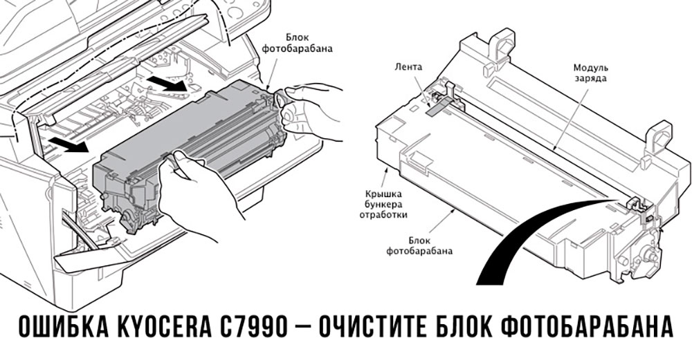
Чтобы потребитель мог наверняка определить проблему, рекомендуем использовать утилиту Kyocera Client Tool, которая идет в комплекте с драйверами принтера.
Ваше Имя:
Ваш вопрос:
Внимание: HTML не поддерживается! Используйте обычный текст.
Оценка:
Плохо
Хорошо
Введите код, указанный на картинке:

- Code: C0030
- Description: FAX PWB system error
- Causes: The FAX processing cannot be continued due to the FAX firmware error.
- Remedy: 1 Checking the FAX PWB The FAX PWB does not operate properly. Turn off the power switch and the main power switch. After 5s passes, reinstall the FAX PWB, and then turn on the main power switch and the power switch. FAX Installation Guide 2 Firmware upgrade The firmware is faulty. Reinstall the FAX firmware. Firmware Upgrade 3 Replacing the FAX PWB The FAX PWB is faulty. Replace the FAX PWB. FAX Installation Guide
- Code: C0070
- Description: FAX PWB incompatible detection error
- Causes: Abnormal detection of FAX control PWB incompatibility in the initial communication with the FAX control PWB, any normal communication command is not transmitted.
- Remedy: 1 Checking the FAX PWB The incompatible FAX PWB is installed. Install the FAX PWB for the applicable model. Related Product List 2 Checking the firmware The FAX firmware is faulty. Reinstall the FAX firmware. Firmware Upgrade 3 Replacing the main PWB The main PWB is faulty. Replace the main PWB. Main PWB Replacement
- Code: C0080
- Description: Optional Printing System device error Object: Printing System 15 (for 120V, 230V and 240V)
- Causes: The FPGA version of the interface PWB to control Fiery cannot be read. (FPGA failure)
- Remedy: 1 Resetting the main power The EEPROM does not operate properly. Turn the power switch and the main power switch off . After 5s passes, turn the main power switch and the power switch on. 2 Checking the interface PWB The interface PWB for other models is installed. Replace with the interface PWB for the applicable models. Printing System Installation Guide 3 Firmware upgrade The main firmware version does not support the interface PWB. Upgrade the main firmware to the latest version. Firmware Upgrade 4 Checking the interface PWB The interface PWB is not properly connected, or it is faulty. Reconnect the connectors on the interface PWB. Then, fix or replace the wires if they are pinched by the other part or if they have any damage. When the issue is not resolved, replace the interface PWB. Printing System Installation Guide 5 Checking the main PWB The main PWB is not properly connected, or it is faulty. Reconnect the wire connectors between the main PWB and the interface PWB. Then, fix or replace the wires if they are pinched by the other part or if they have any damage. When the issue is not resolved, replace the main PWB. Main PWB Replacement
- Code: C0100
- Description: Backup memory device error
- Causes: An abnormal status is output from the flash memory.
- Remedy: 1 Resetting the main power The flash memory does not operate properly. Turn the power switch and the main power switch off . After 5s passes, turn the main power switch and the power switch on. 2 Checking the main PWB The main PWB is faulty. Reconnect the connectors on the main PWB. Then, fix or replace the wires if they are pinched by the other part or if they have any damage. When the issue is not resolved, replace the main PWB. Main PWB Replacement
- Code: C0120
- Description: MAC address data error
- Causes: The MAC address data is incorrect.
- Remedy: 1 Resetting the main power The flash memory does not operate properly. Turn the power switch and the main power switch off . After 5s passes, turn the main power switch and the power switch on. 2 Checking the MAC address The MAC address is incorrect. Replace the main PWB when the MAC address is not indicated on the network status page. Main PWB Replacement
- Code: C0130
- Description: Backup memory reading/writing error
- Causes: The reading or writing into the flash memory is unavailable.
- Remedy: 1 Resetting the main power The flash memory does not operate properly. Turn the power switch and the main power switch off . After 5s passes, turn the main power switch and the power switch on. 2 Checking the main PWB The main PWB is faulty. Reconnect the connectors on the main PWB. Then, fix or replace the wires if they are pinched by the other part or if they have any damage. When the issue is not resolved, replace the main PWB. Main PWB Replacement
- Code: C0150
- Description: Engine EEPROM reading / writing error
- Causes: 1. No response from the device is detected for 5s or more 5 times continuously when reading / writing the data.2. The reading data of 2 points mismatches 8 times continuously.3. The reading data and the writing data mismatch 8 times continuously.
- Remedy: 1 Resetting the main power The EEPROM on the engine PWB does not operate properly. Turn the power switch and the main power switch off . After 5s passes, turn the main power switch and the power switch on. 2 Checking the EEPROM on the engine PWB The EEPROM is not properly attached. Reattach the EEPROM on the engine PWB. EEPROM Replacement 3 Checking the EEPROM on the engine PWB The EEPROM is faulty. Replace the EEPROM on the engine PWB and execute U004. EEPROM Replacement 4 Replacing the engine PWB The engine PWB is faulty. Replace the engine PWB. Engine PWB Replacement
- Code: C0160
- Description: EEPROM data error
- Causes: The data read from the EEPROM is judged as abnormal.
- Remedy: 1 Resetting the main power The EEPROM on the engine PWB does not operate properly. Turn the power switch and the main power switch off . After 5s passes, turn the main power switch and the power switch on. 2 Executing U021 The storage data in the EEPROM on the engine PWB is faulty. Execute U021. U021 Execution 3 Replacing the EEPROM The EEPROM is faulty. Replace the EEPROM on the engine PWB and execute U004. EEPROM Replacement
- Code: C0170
- Description: Charger count error
- Causes: The values in one of the billing counters, life counter or the scanner counter mismatch between the main side and the engine side.
- Remedy: 1 Checking the machine serial No. of the main PWB The main unit for the different main unit is installed. Check the machine serial Nos of MAIN and ENGINE at U004, and install the correct main PWB if the MAIN No. differs. U004 Execution 2 Checking the machine serial No. in the EEPROM on the engine PWB The EEPROM for the different main unit is installed. Check the machine serial Nos of MAIN and ENGINE at U004, and install the correct EEPROM on the engine PWB if the ENGINE machine serial No. differs. U004 Execution 3 Checking the main PWB The main PWB is faulty. When the MAIN machine serial No. differs at U004, replace the main PWB and execute U004. U004 Execution 4 Checking the EEPROM on the engine PWB The EEPROM is faulty. When the machine serial No.in the engine PWB differs at U004, reattach the EEPROM on the engine PWB. If not repaired, replace the EEPROM and execute U004. Note: Be sure not to execute U004 if the machine serial No. differs from the machine serial No. indicated on the main unit to prevent the different machine serial No. from overwritten. (Dontselect[ Execute]andpressthe[ Start]key.)’ U004 Execution 5 Replacing the engine PWB The engine PWB is faulty. Replace the engine PWB. Engine PWB Replacement
- Code: C0180
- Description: Machine serial number mismatch
- Causes: The machine serial Nos. in the main PWB and the EEPROM on the engine PWB mismatch when turning the power on.
- Remedy: 1 Checking the machine serial No. of the main PWB The main unit for the different main unit is installed. Check the machine serial Nos of MAIN and ENGINE at U004, and install the correct main PWB if the MAIN No. differs. U004 Execution 2 Checking the machine serial No. in the EEPROM on the engine PWB The EEPROM for the different main unit is installed. Check the machine serial Nos of MAIN and ENGINE at U004, and install the correct EEPROM on the engine PWB if the ENGINE machine serial No. differs. U004 Execution 3 Replacing the main PWB The main PWB is faulty. When the MAIN machine serial No. differs at U004, replace the main PWB and execute U004. U004 Execution 4 Checking the EEPROM on the engine PWB The EEPROM is faulty. When the machine serial No.in the engine PWB differs at U004, reattach the EEPROM on the engine PWB. If not repaired, replace the EEPROM and execute U004. Note: Be sure not to execute U004 if the machine serial No. differs from the machine serial No. indicated on the main unit to prevent the different machine serial No. from overwritten. (Dontselect[ Execute]andpressthe[ Start]key.)’ U004 Execution 5 Replacing the engine PWB The engine PWB is faulty. Replace the engine PWB. Engine PWB Replacement
- Code: C0350
- Description: Panel PWB communication error (Electronic volume I2C communication error)
- Causes: Since NACK was received during the I2C communication, the retry was repeated 5 times and the initial command was transmitted, and then the retry was repeated 5 times again. After that, NACK was also received.
- Remedy: 1 Resetting the main power The operation of the operation panel main PWB is faulty. Turn the power switch and the main power switch off . After 5s passes, turn the main power switch and the power switch on. 2 Checking the wire The wire is not properly connected to the operation panel main PWB. Reinsert the following wire connectors.• Operation panel PWB — Main PWB• Operation panel PWB — NFC PWB Electrical Diagram of PWBs 3 Replacing the wire The wire connecting to the operation panel main PWB is faulty. Replace the following wires if they are broken, short-circuited or have a ground fault.• Operation main PWB — Main PWB• Operation main PWB — NFC PWB Electrical Diagram of PWBs 4 Replacing the operation panel main PWB The operation panel main PWB is faulty. Replace the panel main PWB. Operation Panel Main PWB Replacement 5 Replacing the main PWB The main PWB is faulty. Replace the main PWB. Main PWB Replacement 6 Replacing the NFC PWB The NFC PWB is faulty. Replace the NFC PWB.
- Code: C0361
- Description: Communication error between the engine CPU and the feed ASIC
- Causes: The communication with the feed ASIC failed 10 times continuously.
- Remedy: 1 Resetting the main power The engine PWB does not operate properly. Turn the power switch and the main power switch off . After 5s passes, turn the main power switch and the power switch on. 2 Firmware upgrade The firmware is not the latest version. Upgrade the engine firmware to the latest version Firmware Upgrade 3 Checking the feed drive PWB The feed drive PWB is faulty. Reconnect the wire connectors between the feed drive PWB and the engine PWB. Then, fix or replace the wires if they are pinched by the other part or if they have any damage. When the issue is not resolved, replace the feed drive PWB. Electrical Diagram of PWBs 4 Replacing the engine PWB The engine PWB is faulty. Replace the engine PWB. Engine PWB Replacement
- Code: C0362
- Description: Communication error between the engine CPU and the feed ASIC
- Causes: The communication with the feed ASIC failed 10 times continuously.
- Remedy: 1 Resetting the main power The engine PWB does not operate properly. Turn the power switch and the main power switch off . After 5s passes, turn the main power switch and the power switch on. 2 Firmware upgrade The firmware is not the latest version. Upgrade the engine firmware to the latest version Firmware Upgrade 3 Checking the feed image PWB The feed image PWB is faulty. Reconnect the wire connectors between the feed image PWB and the engine PWB. If the wires are pinched or it have any damage, fix or replace them. Electrical Diagram of PWBs 4 Replacing the engine PWB The engine PWB is faulty. Replace the engine PWB. Engine PWB Replacement
- Code: C0640
- Description: Hard Disk error
- Causes: The HDD cannot be accessed properly.
- Remedy: 1 (For the main unit without the HDD) Replacing the SSD When installing the 8GB HDD mistakenly, it tries to access the HDD. At that time, the error appears if the HDD is not installed in the main units . Replace with the correct 32GB SSD. SSD Replacement 2 (When abnormal sounds occur) Replacing the HDD The HDD is faulty. Replace the HDD when the abnormal sounds are from the HDD. HDD Replacement 3 Checking the SATA cable and the wire The SATA cable between the HDD and the main PWB is not properly connected. Reconnect the SATA cable and the wire between the HDD and the main PWB. HDD Replacement 4 Replacing the SATA cable and the wire The SATA cable between the HDD and the main PWB is faulty. Replace the SATA cable and the wire between the HDD and the main PWB. HDD Replacement 5 Initializing the HDD The HDD storage data is faulty. Execute U024 [FULL] (HDD Format). U024 Execution 6 Replacing the HDD The HDD is faulty. Replace the HDD. HDD Replacement 7 Replacing the main PWB The main PWB is faulty. Replace the main PWB. Main PWB Replacement
- Code: C0660
- Description: Hard Disk encryption key error
- Causes: 1. The encryption password input when replacing the main PWB was incorrect.2. The SSD used in the other main unit was installed.
- Remedy: 1 (When the issue occurs after replacing the main PWB) Executing U004 The encryption key after replacing the main PWB is faulty. Execute U004 when this issue occurs after replacing the main PWB. U004 Execution 2 Replacing the HDD (abnormal sounds) The HDD is faulty. Replace the HDD when the abnormal sounds are from the HDD. HDD Replacement 3 Checking the SATA cable and the wire The SATA cable between the HDD and the main PWB is not properly connected. Reconnect the SATA cable and the wire between the HDD and the main PWB. HDD Replacement 4 Replacing the SATA cable and the wire The SATA cable between the HDD and the main PWB is faulty. Replace the SATA cable and the wire between the HDD and the main PWB. HDD Replacement 5 Initializing the HDD The HDD storage data is faulty. Execute U024 [FULL] (HDD Format). U024 Execution 6 Replacing the HDD The HDD is faulty. Replace the HDD. HDD Replacement 7 Replacing the main PWB The main PWB is faulty. Replace the main PWB. Main PWB Replacement
- Code: C0670
- Description: Hard Disk overwriting error
- Causes: The area that cannot be properly overwritten exists in a part of the HDD.
- Remedy: 1 Replacing the HDD (abnormal sounds) The HDD is faulty. Replace the HDD when the abnormal sounds are from the HDD. HDD Replacement 2 Checking the SATA cable and the wire The SATA cable between the HDD and the main PWB is not properly connected. Reconnect the SATA cable and the wire between the HDD and the main PWB. HDD Replacement 3 Replacing the SATA cable and the wire The SATA cable between the HDD and the main PWB is faulty. Replace the SATA cable and the wire between the HDD and the main PWB. HDD Replacement 4 Initializing the HDD The HDD storage data is faulty. Execute U024 [FULL] (HDD Format). U024 Execution 5 Replacing the HDD The HDD is faulty. Replace the HDD. HDD Replacement 6 Replacing the main PWB The main PWB is faulty. Replace the main PWB. Main PWB Replacement
- Code: C0680
- Description: SSD error
- Causes: The SSD cannot be accessed, or the error occurs when accessing to the SSD.
- Remedy: 1 Checking the SSD (if lit after replacing the SSD) An SSD out of specification is installed. Install the SSD matching the memory capacity specification. 2 Resetting the main power The SSD is faulty. Turn the power switch and the main power switch off . After 5s passes, turn the main power switch and the power switch on. 3 Reinstalling the SSD The connection with the main PWB is faulty. Reinstall the SSD on the main PWB. SSD Replacement 4 Initializing the SSD The data stored in the SSD is faulty. Retrieve the SSD storage data at U026, and then initialize the SSD at U024. U026 / U024 Execution 5 Replacing the SSD The SSD is faulty. Retrieve the SSD storage data at U026, and then replace the SSD. U026 Execution / SSD Replacement 6 Replacing the main PWB The main PWB is faulty. Replace the main PWB. Main PWB Replacement
- Code: C0800
- Description: Image processing error
- Causes: The print sequence jam (J010x) was detected 2 times continuously.
- Remedy: 1 Checking the image data The image data is faulty. When this issue occurs only when handling the certain image data, check if the image data is faulty. 2 Checking the situation The printing operation of the certain file is faulty. Acquire the jobslogifthephenomenoncanbereproducedbyspecifyingthejobwhentheer rorwasdetected.’ Checking Job & Job Operation 3 Checking the main PWB The main PWB is faulty. Reconnect the connectors on the main PWB. Then, fix or replace the wires if they are pinched by the other part or if they have any damage. When the issue is not resolved, replace the main PWB. Main PWB Replacement
- Code: C0840
- Description: RTC error («Time for maintenance T» appears)
- Causes: [Check at start-up]• RTC values are old.• Power has not been turned on for over 5 years.• RTC value is older than 2000/1/1 00:01.[Periodic check per 5 minutes after start-up]• RTC values are older than the ones at the last check.• Partial operation by power reset after C840 error and «Time for Maintenance T» is indicated.
- Remedy: 1 Executing U906 The backup battery on the main PWB is faulty, and so, the RTC settings are erased after unplugging the power cord. Execute U906 to reset the indication «Maintenance T». After that, set the data (RTC) via the System Menu.(This treatment needs to be performed when unplugging and reconnecting the power cord.) Date/ Timer/ Energy Saver (System Menu) 2 Replacing the main PWB The main PWB is faulty, or the backup battery runs out. The user call regarding C0840 is frequent even if performing the previous treatment, replace the main PWB. Main PWB Replacement
- Code: C0980
- Description: 24V power interruption detection
- Causes: 1. The 24V power interruption signal was detected for 1s continuously.2. After passing 100ms since the 24V power interruption signal was detected, the other service call error appeared. Then, the 24V power supply recovered.
- Remedy: 1 Resetting the main power The printing process is not properly executed. Turn the power switch and the main power switch off . After 5s passes, turn the main power switch and the power switch on. 2 Checking the wire The wire is not properly connected, or it has a ground fault. Reconnect the wire connectors between the LVU and the engine PWB. If the wire is pinched or has any damage, fix or replace the wire. Electrical Diagram of PWBs 3 Replacing the LVU The LVU is faulty. When the +24V generation from the LVU is not stable, and it lowers, replace the LVU. LVU Replacement 4 Replacing the engine PWB The engine PWB is faulty. Replace the engine PWB. Engine PWB Replacement
- Code: C1000
- Description: MP lift motor error
- Causes: 1. The MP position switch does not turn on within 1850ms when rotating the MP lift motor in the descend direction.2. The MP position switch does not turn off within 1600ms when rotating the MP lift motor in the ascend direction.
- Remedy: 1 Checking the MP bottom plate The MP bottom plate does not operate properly. If the MP bottom plate of the MP tray does not move vertically, fix or replace the lift base. 2 Checking the lift lever The lift lever is not properly attached. Check if the lift lever is vertically shifted by the lift motor cam, or if it has the excessive load. Then, reattach the MP tray. Then, replace the MP tray if it is not fixed. 3 Checking the drive gear The drive gear does not rotate properly. Check if the MP bottom plate lift-up drive gears rotate smoothly or have no excessive load. And apply the grease to the frictional parts and fix the related parts so that they can rotate smoothly. 4 Checking the wire The wire is not properly connected. Reinsert the following wire connectors, and replace the wires when they have no continuity.• MP position switch — Relay connector — Feed drive PWB • Feed drive PWB — Engine PWB Electrical Diagram of PWBs 5 Replacing the MP lift motor The MP lift motor does not operate properly. Replace the MP lift motor. 6 Checking the MP positioning switch The MP positioning switch is not properly attached. Reattach the MP positioning switch. 7 Replacing the MP positioning switch The MP positioning switch is faulty. Replace the MP positioning switch. 8 Replacing the feed drive PWB The feed drive PWB is faulty. Replace the feed drive PWB. 9 Firmware upgrade The firmware is not the latest version. Upgrade the engine firmware to the latest version Firmware Upgrade 10 Replacing the engine PWB The engine PWB is faulty. Replace the engine PWB. Engine PWB Replacement
- Code: C1010
- Description: Lift motor 1 error
- Causes: Either of the following was detected 5 times continuously.1. Lift upper limit sensor 1 does not turn on after passing 16s since cassette 1 was inserted.2. The lock-up signal is not released for 300ms after turning on of lift motor 1.3. Since lift upper limit sensor 1 turned off during printing, lift upper limit sensor 1 does not turn on after passing 1s from the ascend control
- Remedy: 1 Checking the cassette base The cassette base does not operate properly. Repair or replace the cassette base if it cannot move vertically. 2 Checking the drive gear The drive gear to lift up the cassette base does not rotate properly. Check if the lift motor drive gears to lift up the cassette base rotate smoothly or have no excessive load. And apply the grease to the frictional parts and repair the related parts so that they can rotate smoothly. 3 Checking the wire The wire is not properly connected. Reinsert the following wire connectors, and replace the wires if there is no continuity.• Lift motor 1 — Feed drive PWB• Feed drive PWB — Engine PWB Electrical Diagram of PWBs 4 Checking lift motor 1 Lift motor 1 is faulty. Check the operation of lift motor 1, and replace it if necessary. Lift Motor Replacement 5 Checking the wire The wire is not properly connected. Reinsert the following wire connectors, and replace the wires if there is no continuity.• Lift upper limit sensor 1 — Feed drive PWB• Feed drive PWB — Engine PWB Electrical Diagram of PWBs 6 Checking lift sensor 1 Lift upper limit sensor 1 is not properly attached, or it is faulty. Reattach lift upper limit sensor 1. Replace it if it is not fixed. 7 Replacing the feed drive PWB The feed drive PWB is faulty. Replace the feed drive PWB. 8 Firmware upgrade The firmware is not the latest version. Upgrade the engine firmware to the latest version Firmware Upgrade 9 Replacing the engine PWB The engine PWB is faulty. Replace the engine PWB. Engine PWB Replacement
- Code: C1020
- Description: Lift motor 2 error
- Causes: Either of the following was detected 5 times continuously.1. PF lift sensor 2 does not turn on after passing 16s since cassette 2 was inserted.2. The lock-up signal is not released for 300ms after turning on of lift motor 2.3. Since lift sensor 2 turned off during printing, lift sensor 2 does not turn on after passing 1s from the ascend control.
- Remedy: 1 Checking the cassette base The cassette base does not operate properly. Repair or replace the cassette base if it cannot move vertically. 2 Checking the drive gear The drive gear does not rotate properly. Check if the lift motor drive gears to lift up the cassette base rotate smoothly or have no excessive load. And apply the grease to the frictional parts and repair the related parts so that they can rotate smoothly. 3 Checking the wire The wire is not properly connected. Reinsert the following wire connectors, and replace the wires when they have no continuity.• Lift motor 2 — Feed drive PWB• Feed drive PWB — Engine PWB Electrical Diagram of PWBs 4 Checking lift motor 2 Lift motor 2 is faulty. Check the operation of lift motor 2, and replace it if necessary. Lift Motor Replacement 5 Checking the wire The wire is not properly connected. Reinsert the following wire connectors, and replace the wires when they have no continuity.• Lift upper limit sensor 2 — Feed drive PWB• Feed drive PWB — Engine PWB Electrical Diagram of PWBs 6 Checking lift sensor 2 Lift upper limit sensor 2 is not properly attached, or it is faulty. Reattach lift upper limit sensor 2. Then, replace it if it is not fixed. 7 Replacing the feed drive PWB The feed drive PWB is faulty. Replace the feed drive PWB. 8 Firmware upgrade The firmware is not the latest version. Upgrade the engine firmware to the latest version Firmware Upgrade 9 Replacing the engine PWB The engine PWB is faulty. Replace the engine PWB. Engine PWB Replacement
- Code: C1030
- Description: PF lift motor 1 error (Paper Feeder)
- Causes: [PF-7100 (Paper Feeder)]1. PF lift upper limit sensor 1 does not turn on after passing 16s since cassette 3 was inserted.2. The lock-up signal is not released for 300ms after turning on of PF lift motor 1.3. Since PF lift sensor 1 turned off during printing, PF lift upper limit sensor 1 does not turn on after passing 1s from the ascend control.[PF-7110 (Paper Deck)]1. PF lift upper limit sensor 1 does not turn on after passing 24s since cassette 3 was inserted.2. PF lift upper limit sensor 1 does not turn on after passing 3s from the ascend control when starting printing.
- Remedy: 1 Checking the cassette base The cassette base does not operate properly. Repair or replace the cassette base if it cannot move vertically. 2 Checking the drive gear The drive gear does not rotate properly. Check if the drive gears to lift up the cassette base rotate smoothly or have no excessive load. And apply the grease to the frictional parts and repair the related parts so that they can rotate smoothly. 3 Checking the wire The wire is not properly connected. Reinsert the following wire connectors, and replace the wire when it has no continuity.• PF lift motor 1 — PF main PWB Electrical Diagram of PWBs 4 Checking PF lift motor 1 PF lift motor 1 is faulty. Replace PF lift motor 1. 5 Checking the wire The wire is not properly connected. Reinsert the following wire connectors, and replace the wire when it has no continuity.• PF lift sensor 1 — PF main PWB Electrical Diagram of PWBs 6 Checking PF lift sensor 1 PF lift upper limit sensor 1 is not properly attached, or it is faulty. Reattach PF lift upper limit sensor 1. Then, replace it if it is not fixed. 7 Replacing the PF main PWB The PF main PWB is faulty. Replace the PF main PWB. PF Main PWB Replacement
- Code: C1040
- Description: PF lift motor 2 error (Paper Feeder)
- Causes: [PF-7100 (Paper Feeder)]1. PF lift upper limit sensor 2 does not turn on after passing 16s since cassette 4 is inserted.2. The lock-up signal is not released for 300ms after turning on of PF lift motor 2.3. Since PF lift sensor 2 turned off during printing, PF lift upper limit sensor 2 does not turn on after passing 1s from the ascend control.[PF-7110 (Paper Deck)]1. PF lift upper limit sensor 2 does not turn on after passing 24s since cassette 4 is inserted.2. PF lift upper limit sensor 2 does not turn on after passing 3s from the ascend control when starting printing.
- Remedy: 1 Checking the cassette base The cassette base does not operate properly. Repair or replace the cassette base if it cannot move vertically. 2 Checking the drive gear The drive gear to lift up the cassette base does not rotate properly. Check if the lift motor drive gears to lift up the cassette base rotate smoothly or have no excessive load. And apply the grease to the frictional parts and repair the related parts so that they can rotate smoothly. 3 Checking the wire The wire is not properly connected. Reinsert the following wire connectors, and replace the wire when it has no continuity.• PF lift motor 2 — PF main PWB Electrical Diagram of PWBs 4 Replacing PF lift motor 2 PF lift motor 2 is faulty. Replace PF lift motor 2. 5 Checking the wire The wire is not properly connected. Reinsert the following wire connectors, and replace the wire when it has no continuity.• PF lift upper limit sensor 2 — PF main PWB Electrical Diagram of PWBs 6 Checking PF lift sensor 2 PF lift upper limit sensor 2 is not properly attached, or it is faulty. Reattach PF lift upper limit sensor 2. Then, replace it if it is not fixed. 7 Replacing the PF main PWB The PF main PWB is faulty. Replace the PF main PWB. PF Main PWB Replacement
- Code: C1140
- Description: PF lift motor error (Side Feeder)
- Causes: 1. The PF lift upper limit sensor does not turn on after passing 30s since cassette 5 was inserted.2. The lock signal is detected for 200ms continuously while the PF lift motor is operating.3. The PF lift upper limit sensor does not turn on for passing 2s from the ascending control during the printing.
- Remedy: 1 Checking the bottom plate The bottom plate does not operate properly. Repair or replace the bottom plate when it does not move vertically. ISU Replacement 2 Checking the drive gear The drive gear to lift up the bottom plate does not rotate properly. Check if the drive gears to lift up the bottom plate rotate smoothly or have no excessive load. And apply the grease to the frictional parts and fix the related parts so that they can rotate smoothly. ISU Replacement 3 Checking the wire The wire is not properly connected. Reinsert the following wire connectors, and replace the wire when it has no continuity.• PF lift motor — PF main PWB Electrical Diagram of PWBs 4 Checking the PF lift motor The PF lift motor is faulty. Replace the PF lift motor. 5 Checking the wire The wire is not properly connected. Reinsert the following wire connectors, and replace the wire when it has no continuity.• PF lift upper limit sensor — PF main PWB Electrical Diagram of PWBs 6 Checking the PF lift upper limit sensor The PF lift upper limit sensor is not properly attached, or it is faulty. Reattach the PF lift upper limit sensor. Then, replace it if it is not fixed. 7 Checking the PF main PWB The PF main PWB is faulty. Replace the PF main PWB. PF Main PWB Replacement
- Code: C1800
- Description: Paper Feeder communication error
- Causes: The communication error was detected 10 times continuously.
- Remedy: 1 Checking the connection The cable is not properly connected to the main unit. Reconnect the cable into the main unit. 2 Checking the wire The wire is not properly connected. Reinsert the following wire connectors, and replace the wire when it has no continuity.• PF main PWB — Engine PWB Electrical Diagram of PWBs 3 Firmware upgrade The firmware is not the latest version. Upgrade the engine firmware to the latest version Firmware Upgrade 4 Replacing the PF main PWB The PF main PWB is faulty. Replace the PF main PWB. PF Main PWB Replacement 5 Replacing the engine PWB The engine PWB is faulty. Replace the engine PWB. Engine PWB Replacement
- Code: C1820
- Description: Paper Feeder communication error (Side Feeder)
- Causes: The communication error was detected 10 times continuously.
- Remedy: 1 Checking the connection It is not properly connected to the main unit. Reconnect to the main unit. 2 Checking the wire The wire is not properly connected. Reinsert the following wire connectors• PF main PWB — PF main PWB for the side feeder Electrical Diagram of PWBs 3 Firmware upgrade The firmware is not the latest version. Upgrade the engine firmware to the latest version Firmware Upgrade 4 Checking the PF main PWB (Side Feeder) The PF main PWB (Side Feeder) is faulty. Replace the PF main PWB (Side Feeder). PF Main PWB Replacement (Side Feeder) 5 Replacing the PF main PWB The PF main PWB is faulty. Replace the PF main PWB. PF Main PWB Replacement 6 Replacing the engine PWB The engine PWB is faulty. Replace the engine PWB. Engine PWB Replacement
- Code: C1900
- Description: Paper Feeder EEPROM error
- Causes: The writing data and the reading data mismatch 3 times continuously when writing.
- Remedy: 1 Checking the connection It is not properly connected to the main unit. Reconnect the paper feeder into the main unit. Also, reconnect the wire connectors between the engine PWB and the PF main PWB. Electrical Diagram of PWBs 2 Checking the wire and the PF main PWB The wire or the PF main PWB is faulty. If the wires on the PF main PWB are pinched or have any damage, fix or replace the wires. When the issue is not resolved, replace the PF main PWB. PF Main PWB Replacement 3 Replacing the engine PWB The engine PWB is faulty. Replace the engine PWB. Engine PWB Replacement
- Code: C1920
- Description: Paper Feeder EEPROM error (Side Feeder)
- Causes: The writing data and the reading data mismatch 3 times continuously when writing.
- Remedy: 1 Checking the connection It is not properly connected to the main unit. Reconnect the side feeder into the main unit. Also, reconnect the wire connectors between the engine PWB and the PF main PWB for the side feeder. Electrical Diagram of PWBs 2 Checking the wire The wire is not properly connected. If the wires on the PF main PWB for the side feeder are pinched or have any damage, fix or replace the wires. When the issue is not resolved, replace the PF main PWB for the side feeder. PF Main PWB Replacement (Side Feeder) 3 Checking the PF main PWB The PF main PWB is faulty. Replace the PF main PWB (Side Feeder). PF Main PWB Replacement (Side Feeder)
- Code: C1950
- Description: Primary transfer unit EEPROM error
- Causes: 1. No response from the device is detected for 5s or more 5 times continuously when reading / writing the data.2. The reading data of 2 points mismatches 8 times continuously.3. The reading data and the writing data mismatch 8 times continuously.
- Remedy: 1 Reinstalling the primary transfer unit The primary transfer unit is not properly installed. Reinstall the primary transfer unit. Primary Transfer Unit Replacement 2 Checking the wire The wire is not properly connected. Reinsert the following wire connectors, and replace the wires when they have no continuity.• Primary transfer unit — Transfer PWB• Transfer PWB — Feed image PWB• Feed image PWB — Engine PWB Electrical Diagram of PWBs 3 Primary transfer unit replacement The primary transfer unit is faulty. Replace the primary transfer unit. Primary Transfer Unit Replacement 4 Replacing the feed image PWB The feed image PWB is faulty. Replace the feed image PWB. 5 Replacing the engine PWB The engine PWB is faulty. Replace the engine PWB. Engine PWB Replacement
- Code: C2102
- Description: Developer motor Y/C error Object: 35ppm or faster color models
- Causes: 1. The ready signal is at the L level after passing 2s since developer motor Y/C drive started.2. The ready signal is at the H level for 2s continuously after developer motor Y/C becomes stable.
- Remedy: 1 Checking the developer drive section The developer drive section is faulty. Replace the developer unit drive gear if it is faulty. Developer Unit Replacement 2 Checking the developer roller The developer roller is faulty. Check if the developer roller rotates, and replace the developer unit if not rotating. Developer Unit Replacement 3 Checking developer motor Y/C The developer motor Y/C drive is faulty. Execute U030 [DLP(CMY)] to check the developer motor Y/ C operation.Check if the drive gears rotate smoothly or have no excessive load. And apply the grease to the frictional parts and fix the related parts so that they can rotate smoothly. U030 Execution 4 Checking the wire The wire is not properly connected. Reinsert the following wire connectors, and replace the wires when they have no continuity.• Developer motors Y/ C — Feed image PWB• Feed image PWB — Engine PWB Electrical Diagram of PWBs 5 Checking developer motor Y/C Developer motor Y/C is faulty. Reattach developer motor Y/ C. Then, replace it if it is not fixed. Main Drive Unit Replacement 6 Replacing the feed image PWB The feed image PWB is faulty. Replace the feed image PWB. 7 Firmware upgrade The firmware is not the latest version. Upgrade the engine firmware to the latest version Firmware Upgrade 8 Replacing the engine PWB The engine PWB is faulty. Replace the engine PWB. Engine PWB Replacement
- Code: C2103
- Description: Developer motor COL/M error Object: Color models (Developer motor COL: 32/25ppm models, Developer motor M: 35ppm or faster models)
- Causes: 1. The ready signal is not at the L level for passing 2s since developer motor COL/M drive was started.2. The ready signal is at the H level for 2s continuously after developer motor COL/M was stable.
- Remedy: 1 Checking the developer drive section The developer drive section is faulty. Replace the developer unit drive gear if it is faulty. Developer Unit Replacement 2 Checking the developer roller The developer roller is faulty. Check if the developer roller rotates, and replace the developer unit if not rotating. Developer Unit Replacement 3 Checking developer motor Y/C Developer motor COL/M does not properly operate. Execute U030 [DLP(CMY)] to check the developer motor COL/M operation.Check if the drive gears rotate smoothly or have no excessive load. And apply the grease to the frictional parts and fix the related parts so that they can rotate smoothly. U030 Execution 4 Checking the wire The wire is not properly connected. Reinsert the following wire connectors, and replace the wires when they have no continuity.• Developer motors COL / M — Feed image PWB• Feed image PWB — Engine PWB Electrical Diagram of PWBs 5 Checking developer motor Y/C Developer motor COL/M is faulty. Reattach the developer motors COL / M. Then, replace it if it is not fixed. Main Drive Unit Replacement 6 Replacing the feed image PWB The feed image PWB is faulty. Replace the feed image PWB. 7 Firmware upgrade The firmware is not the latest version. Upgrade the engine firmware to the latest version Firmware Upgrade 8 Replacing the engine PWB The engine PWB is faulty. Replace the engine PWB. Engine PWB Replacement
- Code: C2201
- Description: Drum motor BK steady-state error
- Causes: The ready signal is at the H level for 2s continuously after drum motor BK becomes stable
- Remedy: 1 Checking drum motor BK The drive of drum motor BK is faulty. Execute U030 [Drum K] to check the drum motor BK operation.Check if the drive gears rotate smoothly or have no excessive load. And apply the grease to the frictional parts and fix the related parts so that they can rotate smoothly. U030 Execution 2 Checking the wire The wire is not properly connected. Reinsert the following wire connectors, and replace the wires when they have no continuity.• Drum motor BK — Feed image PWB• Feed image PWB — Engine PWB Electrical Diagram of PWBs 3 Checking drum unit BK The drum unit is faulty. Check if the drum or the drum screw is rotated manually, and replace the drum unit if not rotated. Drum Unit Replacement 4 Checking drum motor BK Drum motor BK is faulty. Replace drum motor BK. Main Drive Unit Replacement 5 Replacing the feed image PWB The feed image PWB is faulty. Replace the feed image PWB. 6 Firmware upgrade The firmware is not the latest version. Upgrade the engine firmware to the latest version Firmware Upgrade 7 Replacing the engine PWB The engine PWB is faulty. Replace the engine PWB. Engine PWB Replacement
- Code: C2203
- Description: Drum motor COL steady-state error Object: Color models
- Causes: The ready signal is at the H level for 2s continuously after drum motor COL becomes stable.
- Remedy: 1 Checking drum motor COL The drive of drum motor COL is faulty. Execute U030 [Drum COL] to check the drum motor COL operation.Check if the drive gears rotate smoothly or have no excessive load. And apply the grease to the frictional parts and fix the related parts so that they can rotate smoothly. U030 Execution 2 Checking the wire The wire is not properly connected or is faulty. Reinsert the following wire connectors, and replace the wires when they have no continuity.• Drum motor COL — Feed image PWB• Feed image PWB — Engine PWB Electrical Diagram of PWBs 3 Replacing drum motor COL Drum motor COL is faulty. Replace drum motor COL. Main Drive Unit Replacement 4 Checking the drum unit and the developer unit The drum unit is faulty. Check if the drum or the drum screw is rotated manually, and replace the drum unit if not rotated. Drum Unit Replacement 5 Replacing the feed image PWB The feed image PWB is faulty. Replace the feed image PWB. 6 Firmware upgrade The firmware is not the latest version. Upgrade the engine firmware to the latest version Firmware Upgrade 7 Replacing the engine PWB The engine PWB is faulty. Replace the engine PWB. Engine PWB Replacement
- Code: C2300
- Description: Fuser motor error
- Causes: The ready signal is at the H level for 1.5s continuously during the fuser motor drive.
- Remedy: 1 Checking the fuser motor The fuser motor operation is faulty. Execute U030 [Fuser] to check the fuser motor operation. Check if the drive gears rotate smoothly or have no excessive load. And apply the grease to the frictional parts and fix the related parts so that they can rotate smoothly. U030 Execution 2 Checking the wire The wire is not properly connected or is faulty. Reinsert the following wire connectors, and replace the wires when they have no continuity.• Fuser motor — Feed drive PWB• Feed drive PWB — Engine PWB Electrical Diagram of PWBs 3 Replacing the fuser unit The fuser unit is faulty. Replace the fuser unit. Fuser Unit Replacement 4 Replacing the fuser drive unit The fuser drive unit is faulty. Replace the fuser drive unit. Fuser Drive Unit Replacement 5 Replacing the fuser motor The fuser motor is faulty. Replace the fuser motor. Fuser Drive Unit Replacement 6 Replacing the feed drive PWB The feed drive PWB is faulty. Replace the feed drive PWB. 7 Firmware upgrade The firmware is not the latest version. Upgrade the engine firmware to the latest version Firmware Upgrade 8 Replacing the engine PWB The engine PWB is faulty. Replace the engine PWB. Engine PWB Replacement
- Code: C2500
- Description: Paper feed motor error
- Causes: The ready signal is not at the L level after passing 2s since the paper feed motor drive was started.
- Remedy: 1 Checking the paper feed motor The operation of the paper feed motor is faulty. Execute [Feed] at U030 to check the paper feed motor operation.Check if paper feed roller and the drive gears rotate smoothly or have no excessive load. And apply the grease to the frictional parts and fix the related parts so that they can rotate smoothly. U030 Execution 2 Checking the wire The wire is not properly connected. Reinsert the following wire connectors, and replace the wires when they have no continuity.• Feed motor — Feed drive PWB• Feed drive PWB — Engine PWB Electrical Diagram of PWBs 3 Replacing the paper feed motor The paper feed motor is faulty. Replace the paper feed motor. 4 Replacing the paper feed drive unit The paper feed drive unit is faulty. Replace the paper feed drive unit. Feed Drive Unit Replacement 5 Replacing the feed drive PWB The feed drive PWB is faulty. Replace the feed drive PWB. 6 Firmware upgrade The firmware is faulty. Upgrade the engine firmware to the latest version Firmware Upgrade 7 Replacing the engine PWB The engine PWB is faulty. Replace the engine PWB. Engine PWB Replacement
- Code: C2600
- Description: PF feed motor error
- Causes: The ready signal is not at the L level (stable rotation) after passing 1s since the PF feed motor drive started.
- Remedy: 1 Checking the PF feed motor The PF feed motor is not properly connected, or it is faulty. Check the paper feed operation by executing [2PF] or [LCF] at U247 and [Motor On].if it is faulty, reinsert the connector of the paper feed motor.Check if the PF paper feed roller and the drive gears rotate smoothly or have no excessive load. And apply the grease to the frictional parts and fix the related parts so that they can rotate smoothly. U247 Execution 2 Checking the wire The wire is not properly connected or is faulty. Reinsert the following wire connectors, and replace the wire when it has no continuity.• PF paper feed motor — PF main PWB Electrical Diagram of PWBs 3 Checking the connection The connection between the PF main PWB and the main PWB is incorrect. Check the following wire connection, and correct the terminals and reinsert the connectors all the way.If the connection parts are deformed or damaged, replace them.• PF main PWB — Engine PWB (Drawer connector between the paper feeder and the main unit) Electrical Diagram of PWBs 4 Replacing the PF feed motor The PF feed motor is faulty. Replace the PF feed motor. PF Drive Unit Replacement 5 Firmware upgrade The engine firmware or the PF firmware is faulty. Upgrade the engine firmware and the PF firmware to the latest version. Firmware Upgrade 6 Replacing the PF main PWB The PF main PWB is faulty. Replace the PF main PWB. PF Main PWB Replacement 7 Replacing the engine PWB The engine PWB is faulty. Replace the engine PWB. Engine PWB Replacement
- Code: C2700
- Description: Primary / secondary transfer release error
- Causes: The release or pressure state of the belt release motor continued for 2.3s after driving the motor in the release or pressure direction.
- Remedy: 1 Checking the drive components The belt release motor drive transmission is faulty. Execute U030 [Belt Lift].Repair the drive components when the motor drive is not transmitted. U030 Execution 2 Checking the wire The wire is not properly connected. Reinsert the following wire connectors.• Belt release motor — Feed image PWB• Belt release sensor — Feed image PWB• Feed image PWB — Engine PWB Electrical Diagram of PWBs 3 Checking the belt release sensor The belt release sensor comes off. Reattach or replace the belt release sensor. 4 Checking the belt release motor The belt release motor does not operate properly. Reattach or replace the belt release motor. 5 Primary transfer unit replacement The primary transfer roller lift-up drive section is faulty. Replace the primary transfer unit. Primary Transfer Unit Replacement 6 Replacing the feed image PWB The feed image PWB is faulty. Replace the feed image PWB. 7 Firmware upgrade The engine firmware is faulty. Upgrade the engine firmware to the latest version Firmware Upgrade 8 Replacing the engine PWB The engine PWB is faulty. Replace the engine PWB. Engine PWB Replacement
- Code: C2760
- Description: Developer BK/belt motor startup error
- Causes: 1. The motor FG pulse of is not input for 2s continuously during the motor operation.2. The FG pulse exceeding 4000rpm was detected 10 times continuously.3. The motor speed was out of the target speed (+/- 6.25%), and the condition was continued for 2s
- Remedy: 1 Checking the developer BK/belt motor drive components The developer BK/belt motor drive transmission is faulty. Execute U030 [DLP(K)] to check the excessive load is not applied to the drive gears, roller and the belt by rotating them. After that, clean the drive section of the primary transfer unit. U030 Execution 2 Checking the wire The wire is not properly connected or is faulty. Reinsert the following wire connectors, and replace the wires when they have no continuity.• Developer BK/belt motor — Feed image PWB• Feed image PWB — Engine PWB Electrical Diagram of PWBs 3 Checking the developer BK/belt motor The developer BK/belt motor is faulty. Reattach the developer BK/ belt motor and reconnect the wire. Replace it if it is not fixed. Main Drive Unit Replacement 4 Firmware upgrade The firmware is faulty. Upgrade the engine firmware to the latest version Firmware Upgrade 5 Checking the feed image PWB The feed image PWB is faulty. Reconnect the connectors on the feed image PWB. Then, fix or replace the wires if they are pinched by the other part or if they have any damage. When the issue is not resolved, replace the feed image PWB. 6 Checking the engine PWB The engine PWB is faulty. Reconnect the connectors on the engine PWB. Then, fix or replace the wires if they are pinched by the other part or if they have any damage. When the issue is not resolved after that, replace the engine PWB. Engine PWB Replacement
- Code: C2810
- Description: Waste toner motor error
- Causes: The lock detection signal reaches the L level while the waste toner motor is driving (3 retries of successive 0.5s per 2ms).2. The lock detection signal does not reach L level within 50ms since the REM signal switched from L to H (3 retry per 500ms).
- Remedy: 1 Checking the waste toner box The waste toner box is not properly installed. Reinstall the waste toner box. Waste Toner Box Replacement 2 Checking the waste toner motor The waste toner motor does not operate properly. Execute U030 [Toner Recovery] to check if the excessive load is not applied to the waste toner motor. Then, repair the part if necessary. U030 Execution 3 Checking the drive gear The drive gear does not rotate properly. Check if the excessive load is not applied to the drive gears by rotating the gears, and clean the drive gears and the bushing, etc. 4 Replacing the waste toner box The waste toner box is faulty. Replace the waste toner box. Waste Toner Box Replacement 5 Checking the waste toner motor The waste toner motor is not properly connected. Reinsert the connector into the waste toner motor. 6 Checking the wire The wire is not properly connected. Reinsert the following wire connectors, and replace the wire when it has no continuity.• Waste toner motor — Engine PWB Electrical Diagram of PWBs 7 Firmware upgrade The engine firmware is faulty. Upgrade the engine firmware to the latest version Firmware Upgrade 8 Replacing the engine PWB The engine PWB is faulty. Replace the engine PWB. Engine PWB Replacement
- Code: C2840
- Description: Belt cleaning motor error
- Causes: 1. The motor FG pulse of is not input for 2s continuously during the motor operation.2. The FG pulse exceeding 4000rpm was detected 10 times continuously.3. The motor speed was out of the target speed (+/- 6.25%), and the condition was continued for 2s.
- Remedy: 1 Checking the primary transfer unit The primary transfer unit is not properly installed. Reinstall the primary transfer unit. Primary Transfer Unit Replacement 2 Cleaning the primary transfer cleaning section The roller in the primary transfer cleaning section does not rotate properly. Remove the waste toner remaining in the primary transfer cleaning section. 3 Checking the wire The wire is not properly connected. Reinsert the following wire connectors, and replace the wires when they have no continuity.• Belt cleaning motor — Transfer PWB• Transfer PWB — Transfer connection PWB• Transfer connection PWB — Feed image PWB Electrical Diagram of PWBs 4 Checking the wire The wire is not properly connected. Reconnect the wire connectors between the feed image PWB and the engine PWB. If the wires are pinched or it have any damage, fix or replace them. Electrical Diagram of PWBs 5 Checking the belt cleaning motor The belt cleaning motor is not properly attached, or it is faulty. Reattach or replace the belt cleaning motor. 6 Primary transfer unit replacement The cleaning drive section in the primary transfer unit is faulty. Replace the primary transfer unit. Primary Transfer Unit Replacement 7 Replacing the feed image PWB The feed image PWB is faulty. Replace the feed image PWB. 8 Firmware upgrade The engine firmware is faulty. Upgrade the engine firmware to the latest version Firmware Upgrade 9 Replacing the engine PWB The engine PWB is faulty. Replace the engine PWB. Engine PWB Replacement
- Code: C3100
- Description: Carriage error
- Causes: The position of the home position sensor (turning on / off) mismatches when turning the main power on or finishing the original scan by the scanner.
- Remedy: 1 Unlocking the primary mirror unit The primary mirror unit is not unlocked. Unlock the primary mirror unit. Unlocking Primary Mirror Unit 2 Checking the scanner movement A load is applied to the scanner movement. Check the mirror unit operation by executing U073 or shifting it manually. If it has the excessive load, check if there is the foreign objects are on the scanner wires or the wire drums, and clean them. After that, apply the grease to the scanner rails. Optical Wires Replacement 3 Checking the scanner wires The scanner wires are dirty or come off. Clean and reattach the scanner wires. Optical Wires Replacement 4 Checking the scanner motor The scanner motor is faulty. Reattach the scanner motor and reconnect the wire. Replace it if it is not fixed. 5 Checking the belt tension of the scanner motor A load is applied to the scanner movement since the belt tension is improper. Adjust the scanner motor belt tension properly. 6 Checking the wire The wire is not properly connected or is faulty. Reinsert the following wire connectors, and replace the wire if there is no continuity.• Scanner motor — Engine PWB Electrical Diagram of PWBs 7 Checking the home position sensor The home position sensor is not properly attached. Reattach the home position sensor. 8 Checking the wire The wire is not properly connected or is faulty. Reinsert the following wire connectors, and replace the wire if there is no continuity.• Home position motor — Engine PWB Electrical Diagram of PWBs 9 Checking the home position sensor The home position sensor is faulty. Replace the home position sensor. 10 Firmware upgrade The firmware is faulty. Upgrade the engine firmware to the latest version Firmware Upgrade 11 Checking the engine PWB The engine PWB is faulty. Reconnect the connectors on the engine PWB. Then, fix or replace the wires if they are pinched by the other part or if they have any damage. When the issue is not resolved after that, replace the engine PWB. Engine PWB Replacement
- Code: C3200
- Description: LED lamp startup error
- Causes: The white reference data acquired by lighting the lamp at the initial operation is at the specified value or less. (Over 2 LED lamps do not light.)
- Remedy: 1 Checking the LED lamp The LED lamp does not light. Check if the LED lamp lights by executing U061 [CCD]. If it does not light, replace the lamp unit and execute U411 [Table(ChartA)]. Lamp Unit Replacement 2 Checking the FFC The FFC is not properly connected, or it is faulty. Reconnect the following FFC. When the FFC terminals are peeled off or deformed or the FFC is broken, replace the FFC.• CCD PWB — Engine PWB• LED PWB — CCD PWB Electrical Diagram of PWBs 3 Replacing the ISU The CCD PWB is faulty. Replace the ISU and then execute U411. ISU Replacement 4 Firmware upgrade The firmware is faulty. Upgrade the engine firmware to the latest version Firmware Upgrade 5 Checking the engine PWB The engine PWB is faulty. Reconnect the connectors on the engine PWB. Then, fix or replace the wires if they are pinched by the other part or if they have any damage. When the issue is not resolved after that, replace the engine PWB. Engine PWB Replacement
- Code: C3210
- Description: CIS lamp error Object: Dual scan DP
- Causes: The input data did not exceed threshold for 5s when lighting the CIS lamp.
- Remedy: 1 Releasing the partial operation The partial operation is executed. Execute resetting the partial operation at U906. U906 Execution 2 Checking the DPCIS The CIS lamp does not light. Check if the CIS lamp lights by executing U061 [CIS]. If it does not light, replace the DPCIS and execute U091 and U411. DP CIS Replacement 3 Cleaning the CIS glass and the CIS roller The CIS glass or the CIS roller is dirty. Clean the CIS glass and the CIS roller. 4 Checking the DPSHD PWB The DPSHD PWB is not properly connected. Reconnect the DPSHD PWB to the DPCIS. 5 Checking the wire The wire is not properly connected or is faulty. Reinsert the following wire connectors, and replace the wires when they have no continuity.• DPSHD PWB — DP main PWB• DP main PWB — Engine PWB Electrical Diagram of PWBs 6 Firmware upgrade The firmware is faulty. Upgrade the engine firmware to the latest version Firmware Upgrade 7 Replacing the DPSHD PWB The DPSHD PWB is faulty. Replace the DPSHD PWB. 8 Replacing the DP main PWB The DP main PWB is faulty. Replace the DP main PWB. DP Main PWB Replacement 9 Replacing the engine PWB The engine PWB is faulty. Replace the engine PWB. Engine PWB Replacement
- Code: C3300
- Description: CCD AGC error
- Causes: The brightness of the LED lamps is darker (1 LED lamp does not turn on) or brighter than anticipated when executing the AGC process for the CCD lamp.
- Remedy: 1 Checking the LED lamp The LED lamp is broken. Check if the LED lamp lights by executing U061 [CCD]. If it does not light, replace the lamp unit and execute U411 [Table(ChartA)]. Lamp Unit Replacement 2 Cleaning the backside of the contact glass The white reference sheet is dirty. Clean the white reference sheet at the backside of the contact glass. Contact Glass Detachment 3 Checking the FFC The FFC is not properly connected, or it is faulty. Reconnect the following FFC. When the FFC terminals are peeled off or deformed or the FFC is broken, replace the FFC.• LED PWB — CCD PWB• CCD PWB -Engine PWB Electrical Diagram of PWBs 4 Firmware upgrade The firmware is faulty. Upgrade the engine firmware to the latest version Firmware Upgrade 5 Replacing the ISU The CCD PWB is faulty. Replace the ISU and then execute U411. ISU Replacement 6 Replacing the engine PWB The engine PWB is faulty. Replace the engine PWB. Engine PWB Replacement
- Code: C3310
- Description: CIS AGC error Object: Dual scan DP
- Causes: The DPCIS could not acquire the correct white reference value while AGC process was executed.
- Remedy: 1 Releasing the partial operation The partial operation is executed. Execute resetting the partial operation at U906. U906 Execution 2 Cleaning the CIS glass and the CIS roller The CIS glass or the CIS roller is dirty. Clean the CIS glass and the CIS roller. 3 Firmware upgrade The firmware is faulty. Upgrade the engine firmware to the latest version Firmware Upgrade 4 Checking the DPSHD PWB The DPSHD PWB is not properly connected. Reconnect the DPSHD PWB to the DPCIS. 5 Replacing the DPSHD PWB The DPSHD PWB is faulty. Replace the DPSHD PWB. 6 Replacing the DPCIS The DPCIS is faulty. Replace the DPCIS, and then execute U091 and U411. DP CIS Replacement 7 Replacing the DP main PWB The DP main PWB is faulty. Replace the DP main PWB. DP Main PWB Replacement 8 Replacing the engine PWB The engine PWB is faulty. Replace the engine PWB. Engine PWB Replacement
- Code: C3500
- Description: Communication error between the scanner and the ASIC
- Causes: The communication error was detected during the communication between the scanner ASIC and the engine CPU.
- Remedy: 1 Replacing the engine PWB The engine PWB is faulty. Replace the engine PWB. Engine PWB Replacement
- Code: C3600
- Description: Scanner sequence error
- Causes: The program internal processing error of the scanner sequence occurs.
- Remedy: 1 Executing U021 The memory operation is faulty. Execute U021. U021 Execution 2 Replacing the engine PWB The engine PWB is faulty. Replace the engine PWB. Engine PWB Replacement
- Code: C3800
- Description: AFE error
- Causes: The writing data and the reading data mismatch 3 times continuously when writing.The response from AFE is not returned for 100ms.
- Remedy: 1 Checking the FFC The FFC is not properly connected, or it is faulty. Reconnect the following FFC. When the FFC terminals are peeled off or deformed or the FFC is broken, replace the FFC.• CCD PWB — Engine PWB Electrical Diagram of PWBs 2 Replacing the ISU The CCD PWB is faulty. Replace the ISU and then execute U411. ISU Replacement 3 Replacing the engine PWB The engine PWB is faulty. Replace the engine PWB. Engine PWB Replacement
- Code: C4001
- Description: Polygon motor synchronization error
- Causes: The ready signal is not at the L level after passing 15s since the polygon motor drive was started.
- Remedy: 1 Checking the wire and the FFC The wire or the FFC is not properly connected, or they are faulty. Reinsert the following wire connectors and reconnect the FFC. Replace the wire If there is no continuity. Then, replace the FFC if the FFC terminals are deformed or the FFC is broken.• LSU cleaning motor — APC PWB (LSU)• APC PWB (LSU) — Engine PWB Electrical Diagram of PWBs 2 Checking the polygon motor The polygon motor does not rotate properly. Check the rotation sound of the polygon motor, and reattach or replace the LSU if it does not rotate properly. LSU Replacement 3 Firmware upgrade The engine firmware is faulty. Upgrade the engine firmware to the latest version Firmware Upgrade 4 Replacing the engine PWB The engine PWB is faulty. Replace the engine PWB. Engine PWB Replacement
- Code: C4011
- Description: Polygon motor steady-state error
- Causes: The ready signal is at the H level for 15s continuously after the polygon motor drive becomes stable.
- Remedy: 1 Checking the wire and the FFC The wire or the FFC is not properly connected, or they are faulty. Reinsert the following wire connectors and reconnect the FFC. Replace the wire If there is no continuity. Then, replace the FFC if the FFC terminals are deformed or the FFC is broken.• LSU cleaning motor — APC PWB (LSU)• APC PWB (LSU) — Engine PWB Electrical Diagram of PWBs 2 Checking the polygon motor The polygon motor does not rotate properly. Check the rotation sound of the polygon motor, and reattach or replace the LSU if it does not rotate properly. LSU Replacement 3 Firmware upgrade The engine firmware is faulty. Upgrade the engine firmware to the latest version Firmware Upgrade 4 Replacing the engine PWB The engine PWB is faulty. Replace the engine PWB. Engine PWB Replacement
- Code: C4101
- Description: BD initialization error
- Causes: The BD signal was not detected for 1s after driving the polygon motor.
- Remedy: 1 Checking the FFC The FFC is not properly connected, or it is faulty. Reconnect the following FFC. When the FFC terminals are peeled off or deformed or the FFC is broken, replace the FFC.• APC PWB (LSU) — Engine PWB Electrical Diagram of PWBs 2 Checking the LSU The BD sensor or the laser diode is faulty. Reinstall or replace the LSU while paying attention to the static electricity. LSU Replacement 3 Firmware upgrade The engine firmware is faulty. Upgrade the engine firmware to the latest version Firmware Upgrade 4 Replacing the engine PWB The engine PWB is faulty. Replace the engine PWB. Engine PWB Replacement
- Code: C4201
- Description: BD steady-state error
- Causes: The BD signal is not detected during the laser lighting.
- Remedy: 1 Checking the FFC The FFC is not properly connected, or it is faulty. Reconnect the following FFC. When the FFC terminals are peeled off or deformed or the FFC is broken, replace the FFC.• APC PWB (LSU) — Engine PWB Electrical Diagram of PWBs 2 Checking the LSU The BD sensor or the laser diode is faulty. Reinstall or replace the LSU while paying attention to the static electricity. LSU Replacement 3 Firmware upgrade The engine firmware is faulty. Upgrade the engine firmware to the latest version Firmware Upgrade 4 Replacing the engine PWB The engine PWB is faulty. Replace the engine PWB. Engine PWB Replacement
- Code: C4600
- Description: LSU cleaning motor error
- Causes: The LSU cleaning motor lock-up was detected, or the motor continued to be shifted in the same direction for 8s or more.
- Remedy: 1 Executing the Laser Scanner Cleaning The LSU cleaning drive gear and the cleaning pad have the load and so they are not shifted smoothly. Execute Laser Scanner Cleaning. Adjustment/ Maintenance Menu 2 Cleaning the LSU cleaning drive gear and the cleaning pad The LSU cleaning drive gear and the cleaning pad have the load and so they are not shifted smoothly. Clean the LSU cleaning drive gear and the cleaning pad. 3 LSU replacement The LSU cleaning drive gear, cleaning wire or the cleaning pad are deformed, or they are faulty. Replace the LSU. LSU Replacement 4 Checking the wire and the FFC The wire or the FFC is not properly connected, or they are faulty. Reinsert the following wire connectors and reconnect the FFC. Replace the wire If there is no continuity. Then, replace the FFC if the FFC terminals are deformed or the FFC is broken.• LSU cleaning motor — APC PWB (LSU)• APC PWB (LSU) — Engine PWB Electrical Diagram of PWBs 5 Checking the LSU cleaning motor The LSU cleaning motor is not properly attached, or it is faulty. Reattach the LSU cleaning motor and reconnect the connector. Then, replace it if it is not fixed. 6 Firmware upgrade The firmware is not the latest version. Upgrade the engine firmware to the latest version Firmware Upgrade 7 Replacing the engine PWB The engine PWB is faulty. Replace the engine PWB. Engine PWB Replacement
- Code: C4701
- Description: VIDEO ASIC device error 1
- Causes: The communication with VIDEO ASIC failed 10 times continuously.(This is the value mismatching error by trying to read the data from the same address after writing the data to VIDEO ASIC.)
- Remedy: 1 Resetting the main power The ASIC operation on the engine is faulty. Turn the power switch and the main power switch off . After 5s passes, turn the main power switch and the power switch on. 2 Firmware upgrade The firmware is not the latest version. Upgrade the main firmware and the engine firmware to the latest version. Firmware Upgrade 3 Replacing the engine PWB The engine PWB is faulty. Replace the engine PWB. Engine PWB Replacement
- Code: C4702
- Description: VIDEO ASIC device error 2 Object: 35ppm or faster color models
- Causes: The communication with VIDEO ASIC (2) failed 10 times continuously.(This is the value mismatching error by trying to read the data from the same address after writing the data to VIDEO ASIC.)
- Remedy: 1 Resetting the main power The ASIC operation on the engine is faulty. Turn the power switch and the main power switch off . After 5s passes, turn the main power switch and the power switch on. 2 Firmware upgrade The firmware is not the latest version. Upgrade the main firmware and the engine firmware to the latest version. Firmware Upgrade 3 Replacing the engine PWB The engine PWB is faulty. Replace the engine PWB. Engine PWB Replacement
- Code: C4801
- Description: LSU type mismatch error
- Causes: The LSU mismatches with the main unit.
- Remedy: 1 Checking the LSU The different type LSU is installed. Install the correct LSU. LSU Replacement 2 Checking the FFC The FFC is not properly connected, or it is faulty. Reconnect the following FFC. When the FFC terminals are peeled off or deformed or the FFC is broken, replace the FFC.• APC PWB (LSU) — Engine PWB Electrical Diagram of PWBs 3 LSU replacement The APC PWB is faulty. Replace the LSU. LSU Replacement
- Code: C5101
- Description: Main high-voltage error BK Object: 35ppm or faster color models and the monochrome models
- Causes: 1. When measuring the inflow electric currents changing Vpp to 3 steps during the Vpp adjustment, the gap between the 0 electric current value and the 2nd electric current value is at the reference value or less.2. The detected ldc is poor even if applying Vpp[C]. (5ìA or less)
- Remedy: 1 Reinstalling the main highvoltage PWB The main charger roller contacts of the main highvoltage PWB are not properly contacted, and so, the proper voltage is not applied. Reinstall the main high-voltage PWB. Main Highvoltage PWB Replacement 2 Checking the drum unit and the developer unit The drum or the drum screw is not rotated properly due to the excessive load. Check if the drum or the drum screw is rotated manually, and replace the drum unit if not rotated. Drum Unit Replacement 3 Replacing drum motor BK Drum motor BK is faulty. Replace drum motor BK. Main Drive Unit Replacement 4 Checking the main charger unit The proper voltage is not applied since the foreign objects adhered on the high-voltage contact of the main charger unit. Clean the high-voltage contact of the main charger unit, and apply conductive grease to the roller shaft. Main Charger Unit Replacement 5 Main charger unit replacement The proper voltage is not applied since the high-voltage contact of the main charger unit is deformed or damaged. Replace the main charger unit and execute U930. Main Charger Unit Replacement 6 Checking the wire The wire is not properly connected or is faulty. Reinsert the following wire connectors, and replace the wire when it has no continuity.• Main high-voltage PWB — Engine PWB Electrical Diagram of PWBs 7 Replacing the main highvoltage PWB The main high-voltage PWB is faulty. Replace the main high-voltage PWB. Main Highvoltage PWB Replacement 8 Firmware upgrade The firmware is not the latest version. Upgrade the engine firmware to the latest version Firmware Upgrade 9 Replacing the engine PWB The engine PWB is faulty. Replace the engine PWB. Engine PWB Replacement
- Code: C5102
- Description: Main high-voltage error C Object: 35ppm or faster color models
- Causes: When measuring the inflow electric current changing Vpp to 3 steps during the Vpp adjustment, the gap between the 0 electric current value and the 2nd electric current value is the standard value or less.
- Remedy: 1 Reinstalling the main highvoltage PWB The main charger roller contacts of the main highvoltage PWB are not properly contacted, and so, the proper voltage is not applied. Reinstall the main high-voltage PWB. Main Highvoltage PWB Replacement 2 Checking the drum unit and the developer unit The drum or the drum screw is not rotated properly due to the excessive load. Check if the drum or the drum screw is rotated manually, and replace the drum unit if not rotated. Drum Unit Replacement 3 Checking drum motor COL Drum motor COL is not rotated properly due to an excessive load. Replace drum motor COL. Main Drive Unit Replacement 4 Checking the main charger unit The proper voltage is not applied since the foreign objects adhered on the high-voltage contact of the main charger unit. Clean the high-voltage contact of the main charger unit, and apply conductive grease to the roller shaft. Main Charger Unit Replacement 5 Main charger unit replacement The proper voltage is not applied since the high-voltage contact of the main charger unit is deformed or damaged. Replace the main charger unit and execute U930. Main Charger Unit Replacement 6 Checking the wire The wire is not properly connected or is faulty. Reinsert the following wire connectors, and replace the wire when it has no continuity.• Main high-voltage PWB — Engine PWB Electrical Diagram of PWBs 7 Replacing the main highvoltage PWB The main high-voltage PWB is faulty. Replace the main high-voltage PWB. Main Highvoltage PWB Replacement 8 Firmware upgrade The firmware is not the latest version. Upgrade the engine firmware to the latest version Firmware Upgrade 9 Replacing the engine PWB The engine PWB is faulty. Replace the engine PWB. Engine PWB Replacement
- Code: C5103
- Description: Main high-voltage error M Object: 35ppm or faster color models
- Causes: When measuring the inflow electric current changing Vpp to 3 steps during the Vpp adjustment, the gap between the 0 electric current value and the 2nd electric current value is the standard value or less.
- Remedy: 1 Reinstalling the main highvoltage PWB The main charger roller contacts of the main highvoltage PWB are not properly contacted, and so, the proper voltage is not applied. Reinstall the main high-voltage PWB. Main Highvoltage PWB Replacement 2 Checking the drum unit and the developer unit The drum or the drum screw is not rotated properly due to the excessive load. Check if the drum or the drum screw is rotated manually, and replace the drum unit if not rotated. Drum Unit Replacement 3 Checking drum motor COL Drum motor COL is not rotated properly due to an excessive load. Replace drum motor COL. Main Drive Unit Replacement 4 Checking the main charger unit The proper voltage is not applied since the foreign objects adhered on the high-voltage contact of the main charger unit. Clean the high-voltage contact of the main charger unit, and apply conductive grease to the roller shaft. Main Charger Unit Replacement 5 Main charger unit replacement The proper voltage is not applied since the high-voltage contact of the main charger unit is deformed or damaged. Replace the main charger unit and execute U930. Main Charger Unit Replacement 6 Checking the wire The wire is not properly connected or is faulty. Reinsert the following wire connectors, and replace the wire when it has no continuity.• Main high-voltage PWB — Engine PWB Electrical Diagram of PWBs 7 Replacing the main highvoltage PWB The main high-voltage PWB is faulty. Replace the main high-voltage PWB. Main Highvoltage PWB Replacement 8 Firmware upgrade The firmware is not the latest version. Upgrade the engine firmware to the latest version Firmware Upgrade 9 Replacing the engine PWB The engine PWB is faulty. Replace the engine PWB. Engine PWB Replacement
- Code: C5104
- Description: Main high-voltage error Y Object: 35ppm or faster color models
- Causes: When measuring the inflow electric current changing Vpp to 3 steps during the Vpp adjustment, the gap between the 0 electric current value and the 2nd electric current value is the standard value or less.
- Remedy: 1 Reinstalling the main highvoltage PWB The main charger roller contacts of the main highvoltage PWB are not properly contacted, and so, the proper voltage is not applied. Reinstall the main high-voltage PWB. Main Highvoltage PWB Replacement 2 Checking the drum unit and the developer unit The drum or the drum screw is not rotated properly due to the excessive load. Check if the drum or the drum screw is rotated manually, and replace the drum unit if not rotated. Drum Unit Replacement 3 Checking drum motor COL Drum motor COL is not rotated properly due to an excessive load. Replace drum motor COL. Main Drive Unit Replacement 4 Checking the main charger unit The proper voltage is not applied since the foreign objects adhered on the high-voltage contact of the main charger unit. Clean the high-voltage contact of the main charger unit, and apply conductive grease to the roller shaft. Main Charger Unit Replacement 5 Main charger unit replacement The proper voltage is not applied since the high-voltage contact of the main charger unit is deformed or damaged. Replace the main charger unit and execute U930. Main Charger Unit Replacement 6 Checking the wire The wire is not properly connected or is faulty. Reinsert the following wire connectors, and replace the wire when it has no continuity.• Main high-voltage PWB — Engine PWB Electrical Diagram of PWBs 7 Replacing the main highvoltage PWB The main high-voltage PWB is faulty. Replace the main high-voltage PWB. Main Highvoltage PWB Replacement 8 Firmware upgrade The firmware is not the latest version. Upgrade the engine firmware to the latest version Firmware Upgrade 9 Replacing the engine PWB The engine PWB is faulty. Replace the engine PWB. Engine PWB Replacement
- Code: C5130
- Description: Primary transfer high-voltage error Object: Monochrome models
- Causes: When adjusting the feedback, the detected electric current value exceeds the upper limit or is less than the lower limit, or the adjustment result is 300V or less or is 2,900V or more.
- Remedy: 1 Reinstalling the primary transfer unit The primary transfer unit is not properly installed. Reinstall the primary transfer unit so that the connector firmly connects. Primary Transfer Unit Replacement 2 Checking the high-voltage contact Foreign material adheres on the high-voltage contacts of the primary transfer roller, and so, the proper voltage is not applied. Clean the high-voltage contact of the primary transfer roller, and apply conductive grease to the roller shaft. 3 Reinstalling the transfer high-voltage PWB The high-voltage contacts on the transfer high-voltage PWB are faulty, and so, the proper voltage is not applied. Reinstall the transfer highvoltage PWB. Transfer High-voltage PWB Replacement 4 Checking the wire The wire is not properly connected or is faulty. Reinsert the following wire connectors, and replace the wires if there is no continuity.• Transfer high-voltage PWB — Engine PWB• Transfer highvoltage PWB — Feed image PWB Electrical Diagram of PWBs 5 Replacing the transfer high-voltage PWB The transfer high-voltage PWB is faulty. Replace the transfer highvoltage PWB. Transfer High-voltage PWB Replacement 6 Firmware upgrade The firmware is not the latest version. Upgrade the engine firmware to the latest version Firmware Upgrade 7 Replacing the feed image PWB The feed image PWB is faulty. Replace the feed image PWB. 8 Replacing the engine PWB The engine PWB is faulty. Replace the engine PWB. Engine PWB Replacement
- Code: C5131
- Description: Primary transfer high-voltage error K Object: Color models
- Causes: When adjusting the feedback, the detected electric current value exceeds the upper limit or is less than the lower limit, or the adjustment result is 300V or less or is 2,900V or more.
- Remedy: 1 Checking the developer BK/belt motor The developer BK/belt motor is faulty. Execute U030 [DLP(K)] to check the developer BK/belt motor operation.If it does not properly operate, reattach the developer BK/belt motor and reconnect the connector. When it is not fixed, replace the motor. U030 Execution 2 Reinstalling the primary transfer unit The primary transfer unit is not properly installed. Reinstall the primary transfer unit so that the high-voltage contacts of the primary transfer roller firmly connect. Primary Transfer Unit Replacement 3 Primary transfer unit replacement The primary transfer belt does not properly rotate. Replace the primary transfer unit when the primary transfer belt does not rotate manually. Primary Transfer Unit Replacement 4 Checking the high-voltage contact Foreign material adheres on the high-voltage contacts of the primary transfer roller, and so, the proper voltage is not applied. Clean the high-voltage contact of the primary transfer roller, and apply conductive grease to the roller shaft. 5 Reinstalling the transfer high-voltage PWB The high-voltage contacts on the transfer high-voltage PWB are faulty, and so, the proper voltage is not applied. Reinstall the transfer highvoltage PWB. Transfer High-voltage PWB Replacement 6 Checking the wire The wire is not properly connected or is faulty. Reinsert the following wire connectors, and replace the wires if there is no continuity.• Transfer high-voltage PWB — Engine PWB• Transfer highvoltage PWB — Feed image PWB Electrical Diagram of PWBs 7 Replacing the transfer high-voltage PWB The transfer high-voltage PWB is faulty. Replace the transfer highvoltage PWB. Transfer High-voltage PWB Replacement 8 Firmware upgrade The firmware is not the latest version. Upgrade the engine firmware to the latest version Firmware Upgrade 9 Replacing the feed image PWB The feed image PWB is faulty. Replace the feed image PWB. 10 Replacing the engine PWB The engine PWB is faulty. Replace the engine PWB. Engine PWB Replacement
- Code: C5132
- Description: Primary transfer high-voltage error C Object: Color models
- Causes: When adjusting the feedback, the detected electric current value exceeds the upper limit or is less than the lower limit, or the adjustment result is 300V or less or is 2,900V or more.
- Remedy: 1 Checking the developer BK/belt motor The developer BK/belt motor is faulty. Execute U030 [DLP(K)] to check the developer BK/belt motor operation.If it does not properly operate, reattach the developer BK/belt motor and reconnect the connector. When it is not fixed, replace the motor. U030 Execution 2 Reinstalling the primary transfer unit The primary transfer unit is not properly installed. Reinstall the primary transfer unit so that the high-voltage contacts of the primary transfer roller firmly connect. Primary Transfer Unit Replacement 3 Primary transfer unit replacement The primary transfer belt does not properly rotate. Replace the primary transfer unit when the primary transfer belt does not rotate manually. Primary Transfer Unit Replacement 4 Checking the high-voltage contact Foreign material adheres on the high-voltage contacts of the primary transfer roller, and so, the proper voltage is not applied. Clean the high-voltage contact of the primary transfer roller, and apply conductive grease to the roller shaft. 5 Reinstalling the transfer high-voltage PWB The high-voltage contacts on the transfer high-voltage PWB are faulty, and so, the proper voltage is not applied. Reinstall the transfer highvoltage PWB. Transfer High-voltage PWB Replacement 6 Checking the wire The wire is not properly connected or is faulty. Reinsert the following wire connectors, and replace the wires if there is no continuity.• Transfer high-voltage PWB — Engine PWB• Transfer highvoltage PWB — Feed image PWB Electrical Diagram of PWBs 7 Replacing the transfer high-voltage PWB The transfer high-voltage PWB is faulty. Replace the transfer highvoltage PWB. Transfer High-voltage PWB Replacement 8 Firmware upgrade The firmware is not the latest version. Upgrade the engine firmware to the latest version Firmware Upgrade 9 Replacing the feed image PWB The feed image PWB is faulty. Replace the feed image PWB. 10 Replacing the engine PWB The engine PWB is faulty. Replace the engine PWB. Engine PWB Replacement
- Code: C5133
- Description: Primary transfer high-voltage error M Object: Color models
- Causes: When adjusting the feedback, the detected electric current value exceeds the upper limit or is less than the lower limit, or the adjustment result is 300V or less or is 2,900V or more
- Remedy: 1 Checking the developer BK/belt motor The developer BK/belt motor is faulty. Execute U030 [DLP(K)] to check the developer BK/belt motor operation.If it does not properly operate, reattach the developer BK/belt motor and reconnect the connector. When it is not fixed, replace the motor. U030 Execution 2 Reinstalling the primary transfer unit The primary transfer unit is not properly installed. Reinstall the primary transfer unit so that the high-voltage contacts of the primary transfer roller firmly connect. Primary Transfer Unit Replacement 3 Primary transfer unit replacement The primary transfer belt does not properly rotate. Replace the primary transfer unit when the primary transfer belt does not rotate manually. Primary Transfer Unit Replacement 4 Checking the high-voltage contact Foreign material adheres on the high-voltage contacts of the primary transfer roller, and so, the proper voltage is not applied. Clean the high-voltage contact of the primary transfer roller, and apply conductive grease to the roller shaft. 5 Reinstalling the transfer high-voltage PWB The high-voltage contacts on the transfer high-voltage PWB are faulty, and so, the proper voltage is not applied. Reinstall the transfer highvoltage PWB. Transfer High-voltage PWB Replacement 6 Checking the wire The wire is not properly connected or is faulty. Reinsert the following wire connectors, and replace the wires if there is no continuity.• Transfer high-voltage PWB — Engine PWB• Transfer highvoltage PWB — Feed image PWB Electrical Diagram of PWBs 7 Replacing the transfer high-voltage PWB The transfer high-voltage PWB is faulty. Replace the transfer highvoltage PWB. Transfer High-voltage PWB Replacement 8 Firmware upgrade The firmware is not the latest version. Upgrade the engine firmware to the latest version Firmware Upgrade 9 Replacing the feed image PWB The feed image PWB is faulty. Replace the feed image PWB. 10 Replacing the engine PWB The engine PWB is faulty. Replace the engine PWB. Engine PWB Replacement
- Code: C5134
- Description: Primary transfer high-voltage error Y Object: Color models
- Causes: When adjusting the feedback, the detected electric current value exceeds the upper limit or is less than the lower limit, or the adjustment result is 300V or less or is 2,900V or more.
- Remedy: 1 Checking the developer BK/belt motor The developer BK/belt motor is faulty. Execute U030 [DLP(K)] to check the developer BK/belt motor operation.If it does not properly operate, reattach the developer BK/belt motor and reconnect the connector. When it is not fixed, replace the motor. U030 Execution 2 Reinstalling the primary transfer unit The primary transfer unit is not properly installed. Reinstall the primary transfer unit so that the high-voltage contacts of the primary transfer roller firmly connect. Primary Transfer Unit Replacement 3 Primary transfer unit replacement The primary transfer belt does not properly rotate. Replace the primary transfer unit when the primary transfer belt does not rotate manually. Primary Transfer Unit Replacement 4 Checking the high-voltage contact Foreign material adheres on the high-voltage contacts of the primary transfer roller, and so, the proper voltage is not applied. Clean the high-voltage contact of the primary transfer roller, and apply conductive grease to the roller shaft. 5 Reinstalling the transfer high-voltage PWB The high-voltage contacts on the transfer high-voltage PWB are faulty, and so, the proper voltage is not applied. Reinstall the transfer highvoltage PWB. Transfer High-voltage PWB Replacement 6 Checking the wire The wire is not properly connected or is faulty. Reinsert the following wire connectors, and replace the wires if there is no continuity.• Transfer high-voltage PWB — Engine PWB• Transfer highvoltage PWB — Feed image PWB Electrical Diagram of PWBs 7 Replacing the transfer high-voltage PWB The transfer high-voltage PWB is faulty. Replace the transfer highvoltage PWB. Transfer High-voltage PWB Replacement 8 Firmware upgrade The firmware is not the latest version. Upgrade the engine firmware to the latest version Firmware Upgrade 9 Replacing the feed image PWB The feed image PWB is faulty. Replace the feed image PWB. 10 Replacing the engine PWB The engine PWB is faulty. Replace the engine PWB. Engine PWB Replacement
- Code: C6000
- Description: IH heating error 1
- Causes: 1. The center thermistor does not detect 100°C / 212°F or more after passing 60s during the warm-up.2. The center thermistor does not detect the specified temperature (ready indication temperature) after it detected 100°C / 212°F during the warm-up.
- Remedy: 1 Executing U169 The IH setting mismatches the power supply specification. Set the destination same as the voltage of the IH PWB at U169. U169 Execution 2 Removing foreign material There is foreign material between the fuser unit and the fuser IH unit. Or, foreign material adheres on the heat roller. Remove foreign material if it is on between the fuser unit and the fuser IH unit, or on the heat roller. Then, reinstall the fuser unit. Fuser Unit Replacement 3 Reinstalling the fuser unit The drawer connector of the fuser unit is not properly inserted. Check if the pins of the drawer connector of the fuser unit do not bend. If it bend, replace the fuser unit. When the pins are proper, reinstall the fuser unit so that the drawer connector firmly connects. Fuser Unit Replacement 4 Firmware upgrade The firmware is not the latest version. Upgrade the engine firmware to the latest version Firmware Upgrade 5 Checking the wire The wire is not properly connected or is faulty. Reinsert the following wire connectors, and replace the wires if there is no continuity.• Drawer connector of the fuser unit — Feed image PWB• Feed image PWB — Engine PWB• Fuser IH unit — IH PWB• IH PWB — Engine PWB Electrical Diagram of PWBs 6 Replacing the fuser unit The temperature cannot be detected properly due to the broken thermostat or the thermistor error. Replace the fuser unit. Fuser Unit Replacement 7 Replacing the engine PWB The engine PWB is faulty. Replace the engine PWB. Engine PWB Replacement 8 Replacing the feed image PWB The feed image PWB is faulty. Replace the feed image PWB. 9 Checking the wire The wire is not properly connected or is faulty. Reinsert the following wire connectors, and replace the wires if there is no continuity.• Fuser IH unit — IH PWB• IH PWB — Engine PWB Electrical Diagram of PWBs 10 Replacing the IH PWB The IH PWB is faulty. Replace the IH PWB. IH PWB Replacement
- Code: C6020
- Description: Center thermistor high temperature error
- Causes: The center thermistor detects 245°C / 473°F or more for 1s.
- Remedy: 1 Reinstalling the fuser unit The drawer connector of the fuser unit is not properly inserted. Check if the pins of the drawer connector of the fuser unit do not bend. If it bend, replace the fuser unit. When the pins are proper, reinstall the fuser unit so that the drawer connector firmly connects. Fuser Unit Replacement 2 Firmware upgrade The firmware is not the latest version. Upgrade the engine firmware to the latest version Firmware Upgrade 3 Checking the wire The wire is not properly connected or is faulty. Reinsert the following wire connectors, and replace the wires when they have no continuity.• Drawer connector of the fuser unit — Feed image PWB• Feed image PWB — Engine PWB Electrical Diagram of PWBs 4 Replacing the fuser unit The temperature cannot be detected properly due to the thermistor error, etc. Replace the fuser unit. Fuser Unit Replacement 5 Replacing the engine PWB The engine PWB is faulty. Replace the engine PWB. Engine PWB Replacement 6 Replacing the feed image PWB The feed image PWB is faulty. Replace the feed image PWB.
- Code: C6030
- Description: Center thermistor broken
- Causes: The center thermistor temperature is detected at less than 41°C / 104°F for 1s when the edge thermistor detects 100°C / 212°F or more during the warm-up.
- Remedy: 1 Removing foreign material There is foreign material between the fuser unit and the fuser IH unit. Or, foreign material adheres on the heat roller. Remove foreign material if it is on between the fuser unit and the fuser IH unit, or on the heat roller. Then, reinstall the fuser unit. Fuser Unit Replacement 2 Reinstalling the fuser unit The drawer connector of the fuser unit is not properly inserted. Check if the pins of the drawer connector of the fuser unit do not bend. If it bend, replace the fuser unit. When the pins are proper, reinstall the fuser unit so that the drawer connector firmly connects. Fuser Unit Replacement 3 Firmware upgrade The firmware is not the latest version. Upgrade the engine firmware to the latest version Firmware Upgrade 4 Checking the wire The wire is not properly connected or is faulty. Reinsert the following wire connectors, and replace the wires when they have no continuity.• Drawer connector of the fuser unit — Feed image PWB• Feed image PWB — Engine PWB Electrical Diagram of PWBs 5 Replacing the fuser unit The temperature is not properly detected due to the broken wire or the thermistor error in the fuser unit. Replace the fuser unit. Fuser Unit Replacement 6 Replacing the engine PWB The engine PWB is faulty. Replace the engine PWB. Engine PWB Replacement 7 Replacing the feed image PWB The feed image PWB is faulty. Replace the feed image PWB.
- Code: C6050
- Description: Center thermistor low temperature error
- Causes: The center thermistor detected less than 80°C / 176°F for 1s during printing.
- Remedy: 1 Changing the wall outlet The power voltage descends by 10% or more of the rated voltage when printing. Connect the power cord to a different wall outlet if the power supply voltage descends by 10% or more of the rated voltage. 2 Removing foreign material There is foreign material between the fuser unit and the fuser IH unit. Or, foreign material adheres on the heat roller. Remove foreign material if it is on between the fuser unit and the fuser IH unit, or on the heat roller. Then, reinstall the fuser unit. Fuser Unit Replacement 3 Reinstalling the fuser unit The drawer connector of the fuser unit is not properly inserted. Check if the pins of the drawer connector of the fuser unit do not bend. If it bend, replace the fuser unit. When the pins are proper, reinstall the fuser unit so that the drawer connector firmly connects. Fuser Unit Replacement 4 Firmware upgrade The firmware is not the latest version. Upgrade the engine firmware to the latest version Firmware Upgrade 5 Checking the wire The wire is not properly connected or is faulty. Reinsert the following wire connectors, and replace the wires when they have no continuity.• Drawer connector of the fuser unit — Feed image PWB• Feed image PWB — Engine PWB Electrical Diagram of PWBs 6 Replacing the fuser unit The temperature is not properly detected due to the broken wire or the thermistor error in the fuser unit. Replace the fuser unit. Fuser Unit Replacement 7 Replacing the engine PWB The engine PWB is faulty. Replace the engine PWB. Engine PWB Replacement 8 Replacing the feed image PWB The feed image PWB is faulty. Replace the feed image PWB. 9 Checking the wire The wire is not properly connected or is faulty. Reinsert the following wire connectors, and replace the wire when it has no continuity.• IH PWB — Engine PWB Electrical Diagram of PWBs 10 Replacing the IH PWB The IH PWB is faulty. Replace the IH PWB. IH PWB Replacement 11 Checking the wire The wire is not properly connected or is faulty. Reinsert the following wire connectors, and replace the wire when it has no continuity.• Fuser IH unit — IH PWB Electrical Diagram of PWBs 12 Replacing the fuser IH unit The fuser IH unit is faulty. Replace the fuser IH unit. Fuser IH Unit Replacement
- Code: C6120
- Description: Press thermistor high temperature error
- Causes: C6120: Press thermistor high temperature error The press thermistor detected 210°C / 410°F or more for 1s.
- Remedy: 1 Reinstalling the fuser unit The drawer connector of the fuser unit is not properly inserted. Check if the pins of the drawer connector of the fuser unit do not bend. If it bend, replace the fuser unit. When the pins are proper, reinstall the fuser unit so that the drawer connector firmly connects. Fuser Unit Replacement 2 Firmware upgrade The firmware is not the latest version. Upgrade the engine firmware to the latest version Firmware Upgrade 3 Checking the wire The wire is not properly connected or is faulty. Reinsert the following wire connectors, and replace the wires when they have no continuity.• Drawer connector of the fuser unit — Feed image PWB• Feed image PWB — Engine PWB Electrical Diagram of PWBs 4 Replacing the fuser unit The temperature cannot be detected properly due to the thermistor error, etc. Replace the fuser unit. Fuser Unit Replacement 5 Replacing the engine PWB The engine PWB is faulty. Replace the engine PWB. Engine PWB Replacement 6 Replacing the feed image PWB The feed image PWB is faulty. Replace the feed image PWB.
- Code: C6130
- Description: Press thermistor broken
- Causes: 1. The press thermistor detected less than 35°C / 95°F for 60s continuously during the warm-up.2. The press thermistor detected less than 35°C / 95°F for 1s continuously after finishing the warm-up.
- Remedy: 1 Removing foreign material There is foreign material between the fuser unit and the fuser IH unit. Or, foreign material adheres on the heat roller. Remove foreign material if it is on between the fuser unit and the fuser IH unit, or on the heat roller. Then, reinstall the fuser unit. Fuser Unit Replacement 2 Reinstalling the fuser unit The drawer connector of the fuser unit is not properly inserted. Check if the pins of the drawer connector of the fuser unit do not bend. If it bend, replace the fuser unit. When the pins are proper, reinstall the fuser unit so that the drawer connector firmly connects. Fuser Unit Replacement 3 Firmware upgrade The firmware is not the latest version. Upgrade the engine firmware to the latest version Firmware Upgrade 4 Checking the wire The wire is not properly connected or is faulty. Reinsert the following wire connectors, and replace the wires when they have no continuity.• Drawer connector of the fuser unit — Feed image PWB• Feed image PWB — Engine PWB Electrical Diagram of PWBs 5 Replacing the fuser unit The temperature is not properly detected due to the broken wire or the thermistor error in the fuser unit. Replace the fuser unit. Fuser Unit Replacement 6 Replacing the engine PWB The engine PWB is faulty. Replace the engine PWB. Engine PWB Replacement 7 Replacing the feed image PWB The feed image PWB is faulty. Replace the feed image PWB.
- Code: C6200
- Description: IH heating error 2
- Causes: 1. The edge thermistor does not detect 80°C / 176°F or more within 60s since starting the warm-up.2. The edge thermistor does not detect the specified temperature (ready indication temperature) within 420s after it detected 100°C / 212°F during the warm-up.
- Remedy: 1 Removing foreign material There is foreign material between the fuser unit and the fuser IH unit. Or, foreign material adheres on the heat roller. Remove foreign material if it is on between the fuser unit and the fuser IH unit, or on the heat roller. Then, reinstall the fuser unit. Fuser Unit Replacement 2 Reinstalling the fuser unit The drawer connector of the fuser unit is not properly inserted. Check if the pins of the drawer connector of the fuser unit do not bend. If it bend, replace the fuser unit. When the pins are proper, reinstall the fuser unit so that the drawer connector firmly connects. Fuser Unit Replacement 3 Firmware upgrade The firmware is not the latest version. Upgrade the engine firmware to the latest version Firmware Upgrade 4 Checking the wire The wire is not properly connected or is faulty. Reinsert the following wire connectors, and replace the wires when they have no continuity.• Drawer connector of the fuser unit — Feed image PWB• Feed image PWB — Engine PWB Electrical Diagram of PWBs 5 Replacing the fuser unit The temperature is not properly detected due to the broken wire or the thermistor error in the fuser unit. Replace the fuser unit. Fuser Unit Replacement 6 Replacing the engine PWB The engine PWB is faulty. Replace the engine PWB. Engine PWB Replacement 7 Replacing the feed image PWB The feed image PWB is faulty. Replace the feed image PWB. 8 Checking the wire The wire is not properly connected or is faulty. Reinsert the following wire connectors, and replace the wire when it has no continuity.• IH PWB — Engine PWB Electrical Diagram of PWBs 9 Replacing the IH PWB The IH PWB is faulty. Replace the IH PWB. IH PWB Replacement 10 Checking the wire The wire is not properly connected or is faulty. Reinsert the following wire connectors, and replace the wire when it has no continuity.• Fuser IH unit — IH PWB Electrical Diagram of PWBs 11 Replacing the fuser IH unit The fuser IH unit is faulty. Replace the fuser IH unit. Fuser IH Unit Replacement
- Code: C6220
- Description: Edge thermistor high temperature error
- Causes: The edge thermistor detected 245°C / 473°F or more for 1s.
- Remedy: 1 Reinstalling the fuser unit The drawer connector of the fuser unit is not properly inserted. Check if the pins of the drawer connector of the fuser unit do not bend. If it bend, replace the fuser unit. When the pins are proper, reinstall the fuser unit so that the drawer connector firmly connects. Fuser Unit Replacement 2 Firmware upgrade The firmware is not the latest version. Upgrade the engine firmware to the latest version Firmware Upgrade 3 Checking the wire The wire is not properly connected or is faulty. Reinsert the following wire connectors, and replace the wires when they have no continuity.• Drawer connector of the fuser unit — Feed image PWB• Feed image PWB — Engine PWB Electrical Diagram of PWBs 4 Replacing the fuser unit The temperature is not properly detected due to the broken wire or the thermistor error in the fuser unit. Replace the fuser unit. Fuser Unit Replacement 5 Replacing the engine PWB The engine PWB is faulty. Replace the engine PWB. Engine PWB Replacement 6 Replacing the feed image PWB The feed image PWB is faulty. Replace the feed image PWB. 7 Replacing the fuser IH unit The fuser IH unit is faulty. Replace the fuser IH unit. Fuser IH Unit Replacement 8 Reattaching the edge fan motor The edge fan motor is not properly attached. Reattach the edge fan motor. Fan Motors Attachable Direction
- Code: C6230
- Description: Edge thermistor broken
- Causes: C6230: Edge thermistor broken The edge thermistor detects less than 41°C / 105.8°F for 1s continuously when the center thermistor detected 100°C / 212°F or more during the warm-up
- Remedy: 1 Removing foreign material There is foreign material between the fuser unit and the fuser IH unit. Or, foreign material adheres on the heat roller. Remove foreign material if it is on between the fuser unit and the fuser IH unit, or on the heat roller. Then, reinstall the fuser unit. Fuser Unit Replacement 2 Reinstalling the fuser unit The drawer connector of the fuser unit is not properly inserted. Check if the pins of the drawer connector of the fuser unit do not bend. If it bend, replace the fuser unit. When the pins are proper, reinstall the fuser unit so that the drawer connector firmly connects. Fuser Unit Replacement 3 Firmware upgrade The firmware is not the latest version. Upgrade the engine firmware to the latest version Firmware Upgrade 4 Checking the wire The wire is not properly connected or is faulty. Reinsert the following wire connectors, and replace the wires when they have no continuity.• Drawer connector of the fuser unit — Feed image PWB• Feed image PWB — Engine PWB Electrical Diagram of PWBs 5 Replacing the fuser unit The temperature cannot be detected properly due to the heater broken or the thermistor error. Replace the fuser unit. Fuser Unit Replacement 6 Replacing the engine PWB The engine PWB is faulty. Replace the engine PWB. Engine PWB Replacement 7 Replacing the feed image PWB The feed image PWB is faulty. Replace the feed image PWB.
- Code: C6250
- Description: Edge thermistor low temperature error
- Causes: The edge thermistor detected less than 80°C / 176°F for 1s during printing.
- Remedy: 1 Removing foreign material There is foreign material between the fuser unit and the fuser IH unit. Or, foreign material adheres on the heat roller. Remove foreign material if it is on between the fuser unit and the fuser IH unit, or on the heat roller. Then, reinstall the fuser unit. Fuser Unit Replacement 2 Reinstalling the fuser unit The drawer connector of the fuser unit is not properly inserted. Check if the pins of the drawer connector of the fuser unit do not bend. If it bend, replace the fuser unit. When the pins are proper, reinstall the fuser unit so that the drawer connector firmly connects. Fuser Unit Replacement 3 Firmware upgrade The firmware is not the latest version. Upgrade the engine firmware to the latest version Firmware Upgrade 4 Checking the wire The wire is not properly connected or is faulty. Reinsert the following wire connectors, and replace the wires when they have no continuity.• Drawer connector of the fuser unit — Feed image PWB• Feed image PWB — Engine PWB Electrical Diagram of PWBs 5 Replacing the fuser unit The temperature cannot be detected properly due to the heater broken or the thermistor error. Replace the fuser unit. Fuser Unit Replacement 6 Replacing the engine PWB The engine PWB is faulty. Replace the engine PWB. Engine PWB Replacement 7 Replacing the feed image PWB The feed image PWB is faulty. Replace the feed image PWB. 8 Checking the wire The wire is not properly connected or is faulty. Reinsert the following wire connectors, and replace the wire when it has no continuity.• IH PWB — Engine PWB Electrical Diagram of PWBs 9 Replacing the IH PWB The IH PWB is faulty. Replace the IH PWB. IH PWB Replacement 10 Checking the wire The wire is not properly connected or is faulty. Reinsert the following wire connectors, and replace the wire when it has no continuity.• Fuser IH unit — IH PWB Electrical Diagram of PWBs 11 Replacing the fuser IH unit The fuser IH unit is faulty. Replace the fuser IH unit. Fuser IH Unit Replacement
- Code: C6320
- Description: Middle thermistor high temperature error
- Causes: The middle thermistor detected 245°C / 473°F or more for 1s.
- Remedy: 1 Reinstalling the fuser unit The drawer connector of the fuser unit is not properly inserted. Check if the pins of the drawer connector of the fuser unit do not bend. If it bend, replace the fuser unit. When the pins are proper, reinstall the fuser unit so that the drawer connector firmly connects. Fuser Unit Replacement 2 Firmware upgrade The firmware is not the latest version. Upgrade the engine firmware to the latest version Firmware Upgrade 3 Checking the wire The wire is not properly connected or is faulty. Reinsert the following wire connectors, and replace the wires when they have no continuity.• Drawer connector of the fuser unit — Feed image PWB• Feed image PWB — Engine PWB Electrical Diagram of PWBs 4 Replacing the fuser unit The temperature is not properly detected due to the wire short-circuit or the thermistor error in the fuser unit. Replace the fuser unit. Fuser Unit Replacement 5 Replacing the engine PWB The engine PWB is faulty. Replace the engine PWB. Engine PWB Replacement 6 Replacing the feed image PWB The feed image PWB is faulty. Replace the feed image PWB. 7 Replacing the fuser IH unit The fuser IH unit is faulty. Replace the fuser IH unit. Fuser IH Unit Replacement 8 Reattaching the edge fan motor The edge fan motor is not properly attached. Reattach the edge fan motor. Fan Motors Attachable Direction
- Code: C6330
- Description: Middle thermistor broken
- Causes: The middle thermistor detects less than 41°C / 105.8°F for 1s continuously when the center thermistor or the edge thermistor detects 100°C / 212°F or more during the warm-up.
- Remedy: 1 Reinstalling the fuser unit The drawer connector of the fuser unit is not properly inserted. Check if the pins of the drawer connector of the fuser unit do not bend. If it bend, replace the fuser unit. When the pins are proper, reinstall the fuser unit so that the drawer connector firmly connects. Fuser Unit Replacement 2 Firmware upgrade The firmware is not the latest version. Upgrade the engine firmware to the latest version Firmware Upgrade 3 Checking the wire The wire is not properly connected or is faulty. Reinsert the following wire connectors, and replace the wires when they have no continuity.• Drawer connector of the fuser unit — Feed image PWB• Feed image PWB — Engine PWB Electrical Diagram of PWBs 4 Replacing the fuser unit The temperature cannot be detected properly due to the heater broken or the thermistor error. Replace the fuser unit. Fuser Unit Replacement 5 Replacing the engine PWB The engine PWB is faulty. Replace the engine PWB. Engine PWB Replacement 6 Replacing the feed image PWB The feed image PWB is faulty. Replace the feed image PWB. 7 Replacing the fuser IH unit The fuser IH unit is faulty. Replace the fuser IH unit. Fuser IH Unit Replacement
- Code: C6410
- Description: Uninstalled fuser unit
- Causes: The unit identification code is mismatched. The unit for other models is installed.
- Remedy: 1 Replacing the fuser unit The fuser unit for other models is installed. Install the fuser unit for the applicable models. Fuser Unit Replacement 2 Reinstalling the fuser unit The drawer connector of the fuser unit is not properly inserted. Check if the pins of the drawer connector of the fuser unit do not bend. If it bend, replace the fuser unit. When the pins are proper, reinstall the fuser unit so that the drawer connector firmly connects. Fuser Unit Replacement 3 Firmware upgrade The firmware is faulty. Reinstall the engine firmware. Firmware Upgrade 4 Checking the wire The wire is not properly connected or is faulty. Reinsert the following wire connectors, and replace the wires when they have no continuity.• Drawer connector of the fuser unit — Feed image PWB• Feed image PWB — Engine PWB Electrical Diagram of PWBs 5 Replacing the fuser unit The fuser unit is faulty. Replace the fuser unit. Fuser Unit Replacement 6 Replacing the engine PWB The engine PWB is faulty. Replace the engine PWB. Engine PWB Replacement 7 Replacing the feed image PWB The feed image PWB is faulty. Replace the feed image PWB.
- Code: C6600
- Description: Fuser belt rotation error
- Causes: The belt rotation pulse is not input for 1.8s continuously.
- Remedy: 1 Reinstalling the fuser unit The drawer connector of the fuser unit is not properly inserted. Check if the pins of the drawer connector of the fuser unit do not bend. If it bend, replace the fuser unit. When the pins are proper, reinstall the fuser unit so that the drawer connector firmly connects. Fuser Unit Replacement 2 Replacing the fuser unit The fuser unit parts such as the fuser belt, the belt rotation detecting system, or the belt rotation sensor are faulty Replace the fuser unit. Fuser Unit Replacement 3 Applying the grease The load increases due to the lack of grease on the bushing or the gears for the fuser motor. Check the fuser motor operation by executing U030 [Fuser], and apply the grease to the bushing or the gear if it does not rotate smoothly. U030 Execution 4 Checking the wire The wire is not properly connected or is faulty. Reinsert the following wire connectors, and replace the wires if there is no continuity.• Fuser motor — Feed drive PWB• Feed drive PWB — Engine PWB• Feed image PWB — Engine PWB Electrical Diagram of PWBs 5 Firmware upgrade The firmware is not the latest version. Upgrade the engine firmware to the latest version Firmware Upgrade 6 Replacing the engine PWB The engine PWB is faulty. Replace the engine PWB. Engine PWB Replacement 7 Replacing the feed drive PWB The feed drive PWB is faulty. Replace the feed drive PWB. 8 Replacing the feed image PWB The feed image PWB is faulty. Replace the feed image PWB. 9 Replacing the fuser drive gear The fuser drive gear is faulty. Replace the fuser drive gear.
- Code: C6610
- Description: Fuser pressure release sensor error
- Causes: 1. The fuser pressure release sensor does not turn off after passing 3s from the instruction to reduce the fuser pressure by the fuser release motor, or to relocate the paper jam processing position.2. The fuser pressure release sensor does not turn on after passing 6s from the instruction to increase the fuser pressure by the fuser release motor.3. The lock-up signal of the fuser release motor is low for 200ms. (However, when shifting to the paper jam processing mode, the fuser release motor is stopped but the service call error does not appear if it is in between the stop position and the position in front of the stop position by 500ms.)
- Remedy: 1 Reinstalling the fuser unit The drawer connector of the fuser unit is not properly inserted. Check if the pins of the drawer connector of the fuser unit do not bend. If it bend, replace the fuser unit. When the pins are proper, reinstall the fuser unit so that the drawer connector firmly connects. Fuser Unit Replacement 2 Checking the wire The wire is not properly connected or is faulty. Execute U030 [Fuser Release] to check the fuser release motor operation. If it does not operate properly, reinsert the following wire connectors. Then, replace the wires if there is no continuity.• Fuser release motor (in the fuser unit) — Feed drive PWB• Feed drive PWB — Engine PWB• Drawer connector of the fuser unit — Feed image PWB• Feed image PWB — Engine PWB Electrical Diagram of PWBs 3 Replacing the fuser unit The fuser unit is faulty at the fuser pressure release mechanism or the fuser pressure release sensor . Replace the fuser unit. Fuser Unit Replacement 4 Firmware upgrade The firmware is not the latest version. Upgrade the engine firmware to the latest version Firmware Upgrade 5 Replacing the feed drive PWB The feed drive PWB is faulty. Replace the feed drive PWB. 6 Replacing the engine PWB The engine PWB is faulty. Replace the engine PWB. Engine PWB Replacement 7 Replacing the feed image PWB The feed image PWB is faulty. Replace the feed image PWB. 8 Replacing the fuser release motor The fuser release motor is faulty. Replace the fuser release motor. Fuser Drive Unit Replacement 9 Replacing the gear in the fuser pressure releasing system at the main unit The gear of the fuser pressure releasing mechanism at the main unit is faulty. Replace the gears in the fuser pressure releasing mechanism at the main unit.
- Code: C6620
- Description: IH core motor rotation error Object: 35ppm or faster color models, and the monochrome models
- Causes: 1. Turning on of the IH position sensor is not detected within 5s after the IH core motor drives while the IH position sensor is off at the home position detecting operation.2. Turning off/on of the IH position sensor is not detected within 5s after the IH core motor drives while the IH position sensor is on at the home position detecting operation.3. Turning off of the IH position sensor is not detected within the specified pulse after the IH core motor drives while the IH position sensor is on when shifting to the small size paper position.
- Remedy: 1 Checking the fuser IH unit The connector of the fuser IH unit is not properly connected. Check if the connector pins of the fuser IH unit do not bend. If the pins bend, fix them.Next, reinstall the fuser IH unit so that the connector firmly connects. 2 Checking the IH positioning sensor The IH positioning sensor is not properly attached. Reattach the IH positioning sensor. 3 Cleaning the IH positioning sensor The IH positioning sensor cannot detect properly since it is dirty. Clean the IH positioning sensor. 4 Checking the wire The wire is not properly connected or is faulty. Reinsert the following wire connectors, and replace the wires when they have no continuity.• IH core motor (Fuser IH unit) — Feed drive PWB• Feed drive PWB — Engine PWB Electrical Diagram of PWBs 5 Replacing the fuser IH unit The IH positioning sensor or the IH core motor is faulty. Replace the fuser IH unit. Fuser IH Unit Replacement 6 Firmware upgrade The firmware is not the latest version. Upgrade the engine firmware to the latest version Firmware Upgrade 7 Replacing the feed image PWB The feed image PWB is faulty. Replace the feed image PWB. 8 Replacing the engine PWB The engine PWB is faulty. Replace the engine PWB. Engine PWB Replacement
- Code: C6740
- Description: IH PWB high temperature error (IGBT2)
- Causes: The IGBT temperature acquired from the power microprocessor detected is 115°C / 239°F or more for 1s continuously.
- Remedy: 1 Checking the IH PWB fan motor The connection of the IH PWB fan motor, or the IH PWB fan motor is faulty. Execute U037 [IH PWB] and check the IH PWB fan motor operation.If it does not properly operate, go to step 2 «Connecting the IH PWB fan motor». If it properly operates, go to step 3 «Replacing the IH PWB fan motor». U037 Execution 2 Connecting the IH PWB fan motor The connector of the IH PWB fan motor wire is not inserted securely. Reinsert the connector of the IH PWB fan motor. 3 Replacing the IH PWB fan motor The IH PWB fan motor is faulty. Replace the IH PWB fan motor. Fan Motors Attachable Direction 4 Checking the wire The wire is not properly connected or is faulty. Reinsert the following wire connectors, and replace the wire when it has no continuity.• IH PWB — Engine PWB Electrical Diagram of PWBs 5 Replacing the IH PWB The IH PWB is faulty. Replace the IH PWB. IH PWB Replacement 6 Firmware upgrade The firmware is not the latest version. Upgrade the engine firmware to the latest version Firmware Upgrade 7 Replacing the engine PWB The engine PWB is faulty. Replace the engine PWB. Engine PWB Replacement
- Code: C6760
- Description: Fuser IH input excessive electric current error
- Causes: The input current acquired from the power microprocessor continued at 20A or more (for 120V), or 10A or more (for 220-240V) for 200ms.
- Remedy: 1 Checking the fuser unit The fuser belt is faulty. Detach the fuser unit and check if the fuser belt is not faulty. If there is any damage, replace the fuser unit. Fuser Unit Replacement 2 Checking the wire The wire is not properly connected or is faulty. Reinsert the following wire connectors, and replace the wire when it has no continuity.• IH PWB — Engine PWB Electrical Diagram of PWBs 3 Firmware upgrade The firmware is not the latest version. Upgrade the engine firmware to the latest version Firmware Upgrade 4 Replacing the IH PWB The IH PWB is faulty. Replace the IH PWB. IH PWB Replacement 5 Replacing the fuser unit The fuser unit is faulty. Replace the fuser unit. Fuser Unit Replacement 6 Replacing the engine PWB The engine PWB is faulty. Replace the engine PWB. Engine PWB Replacement
- Code: C6770
- Description: IH low power error
- Causes: The IH PWB detects 30% or less of the setting power value for the certain time after the fuser heating is started.
- Remedy: 1 Checking the wire The wire is not properly connected or is faulty. Reinsert the following wire connectors, and replace the wires when they have no continuity.• Fuser IH unit — IH PWB• IH PWB — Engine PWB Electrical Diagram of PWBs 2 Replacing the IH PWB The IH PWB is faulty. Replace the IH PWB. IH PWB Replacement 3 Firmware upgrade The firmware is not the latest version. Upgrade the engine firmware to the latest version Firmware Upgrade 4 Replacing the engine PWB The engine PWB is faulty. Replace the engine PWB. Engine PWB Replacement 5 Replacing the feed image PWB The feed image PWB is faulty. Replace the feed image PWB. 6 Checking the cause depending on the input power The input power is improper. Change the input power. 7 Replacing the fuser IH unit The fuser IH unit is faulty. (The coil is broken.) Replace the fuser IH unit. Fuser IH Unit Replacement
- Code: C6900
- Description: Edge fan motor error
- Causes: The lock-up was detected for 20s continuously when driving the fan motor.
- Remedy: 1 Checking the edge fan motor The wire is not properly connected or is faulty. Execute U037 [Fuser Edge], and reinsert the connector of the paper conveying unit (edge fan motor) into the relay connector at the main unit side if the edge fan motor does not operate properly. U037 Execution 2 Checking the wire The wire is not properly connected or is faulty. Reinsert the following wire connectors, and replace the wires when they have no continuity.• Edge fan motor — Feed drive PWB• Feed drive PWB — Engine PWB Electrical Diagram of PWBs 3 Replacing the edge fan motor The edge fan motor is faulty. Replace the edge fan motor. Fan Motors Attachable Direction 4 Firmware upgrade The firmware is not the latest version. Upgrade the engine firmware to the latest version Firmware Upgrade 5 Replacing the feed drive PWB The feed drive PWB is faulty. Replace the feed drive PWB. 6 Replacing the engine PWB The engine PWB is faulty. Replace the engine PWB. Engine PWB Replacement
- Code: C6910
- Description: Engine firmware unexpected error
- Causes: 1. The engine stabilization control was continued for 1 hour.2. The paper feed motor does not drive after passing 3s or more when driving the drum motor or the developer BK/belt motor.3. Only the high-voltage remote signal turned on while the drum was stopped.4. The main charger bias turned off while the developer bias was on.
- Remedy: 1 Resetting the main power The power startup delays. Turn the power switch and the main power switch off . After 5s passes, turn the main power switch and the power switch on. 2 Firmware upgrade The firmware is not the latest version. Upgrade the engine firmware to the latest version Firmware Upgrade 3 Checking the engine PWB The engine PWB is not properly attached or connected. Retighten the screws securing the engine PWB so that it can ground securely, and reinsert the connectors all the way. Engine PWB Replacement 4 Replacing the engine PWB The engine PWB is faulty. Replace the engine PWB. Engine PWB Replacement
- Code: C6920
- Description: Eject/IH fan motor error
- Causes: The lock-up was detected for 20s continuously when driving the fan motor.
- Remedy: 1 Checking the wire The wire is not properly connected or is faulty. Execute U037 to check the operation of the eject/IH fan motors. If they do not operate properly, reconnect the following wire connectors. If there is no continuity, replace the wires.• Front/Middle/Rear eject IH fan motors — Feed image PWB• Feed image PWB — Engine PWB Electrical Diagram of PWBs 2 Checking the eject/IH fan motors The eject/IH fan motors do not properly operate. Clean the following fan motors, and remove foreign material if it adheres on the fan motors. Then, replace the fan motors if they are not fixed.• Front eject/IH fan motor• Middle eject/IH fan motor• Rear eject/IH fan motor 3 Firmware upgrade The firmware is not the latest version. Upgrade the engine firmware to the latest version Firmware Upgrade 4 Replacing the feed image PWB The feed image PWB is faulty. Replace the feed image PWB. 5 Replacing the engine PWB The engine PWB is faulty. Replace the engine PWB. Engine PWB Replacement
- Code: C6950
- Description: IH PWB communication error
- Causes: 1. The communication between the IH PWB and the engine PWB does not succeed at the initial communication. (The retry is executed 10 times in 150ms intervals.)2. The communication between the IH PWB and the engine PWB does not succeed for 500ms after the initial communication success.
- Remedy: 1 Resetting the main power The power startup delays. Turn the power switch and the main power switch off . After 5s passes, turn the main power switch and the power switch on. 2 Checking the wire The wire is not properly connected or is faulty. Reinsert the following wire connectors, and replace the wire when it has no continuity.• IH PWB — Engine PWB Electrical Diagram of PWBs 3 Checking the wire The wire is not properly connected or is faulty. Reinsert the following wire connectors, and replace the wire when it has no continuity.• LVU — IH PWB Electrical Diagram of PWBs 4 Checking the power supply voltage The abnormal electric noise is mixed in the power supply voltage. Plug the power cord into another wall outlet. 5 Checking the LVU The fuse on the LVU is broken. Check the continuity of the fuse (F002) on the LVU. Then, replace the LVU if there is no continuity. LVU Replacement 6 Replacing the IH PWB The IH PWB is faulty. Replace the IH PWB. IH PWB Replacement 7 Firmware upgrade The firmware is not the latest version. Upgrade the engine firmware to the latest version Firmware Upgrade 8 Replacing the engine PWB The engine PWB is faulty. Replace the engine PWB. Engine PWB Replacement
- Code: C6980
- Description: Fuser unit EEPROM error
- Causes: The EEPROM in the fuser unit cannot be accessed since the machine condition matches to either of the following. 1. No response from the device is detected for 5s or more 5 times continuously when reading / writing the data.2. The reading data of 2 points mismatches 8 times continuously.3. The reading data and the writing data mismatch 8 times continuously.
- Remedy: 1 Reinstalling the fuser unit The drawer connector of the fuser unit is not properly inserted. Check if the pins of the drawer connector of the fuser unit do not bend. If it bend, replace the fuser unit. When the pins are proper, reinstall the fuser unit so that the drawer connector firmly connects. Fuser Unit Replacement 2 Replacing the fuser unit The fuser unit is faulty. Replace the fuser unit. Fuser Unit Replacement 3 Replacing the engine PWB The engine PWB is faulty. Replace the engine PWB. Engine PWB Replacement 4 Replacing the feed image PWB The feed image PWB is faulty. Replace the feed image PWB.
- Code: C6990
- Description: Fuser power source destination error
- Causes: The information mismatches between the engine backup and the IH PWB.
- Remedy: 1 Executing U169 The voltage setting at U169 mismatches the voltage of the IH PWB. Set the destination same as the voltage of the IH PWB at U169. U169 Execution 2 Firmware upgrade The firmware is not the latest version. Upgrade the engine firmware to the latest version Firmware Upgrade 3 Replacing the engine PWB The engine PWB is faulty. Replace the engine PWB. Engine PWB Replacement
- Code: C7001
- Description: Container motor error
- Causes: 1. The ready signal does not turn on after passing 2s since the container motor was started up.2. The ready signal is off for 2s continuously after the container motor was stabilized.
- Remedy: Replacing the toner container The toner container locks up and is not rotated. Replace the toner container. Toner Container Replacement 2 Checking the toner container drive components The toner container drive components are not operated properly, or the excessive load is applied to it. Check the container motor operation by executing U030 [Container Mix]. If it does not operate properly, clean the drive gears and the couplings in the container drive unit and apply the grease to them. U030 Execution 3 Checking the wire The wire is not properly connected or is faulty. Reinsert the following wire connectors, and replace the wire when it has no continuity.• Container motor — Feed image PWB Electrical Diagram of PWBs 4 Checking the toner container motor The toner container motor is faulty. Reattach the container motor and reconnect the wire. Replace it if it is not fixed. Container Motor Replacement 5 Firmware upgrade The firmware is not the latest version. Upgrade the engine firmware to the latest version Firmware Upgrade 6 Replacing the feed image PWB The feed image PWB is faulty. Replace the feed image PWB.
- Code: C7101
- Description: T/C sensor BK error
- Causes: For the specified value of the initial toner stored in the EEPROM of the developer unit, the output value of the T/C sensor is out of the range between +100 (undetection toner) and -1000 (Coming off of the sensor connector). And that status was detected 3 times continuously.
- Remedy: 1 Reinstalling the developer unit The developer unit is not properly installed. Reinstall developer unit BK so that the connector firmly connects. Developer Unit Replacement 2 Checking the wire The wire is not properly connected or is faulty. Reinsert the following wire connectors, and replace the wires when they have no continuity.• Drum/developer relay PWB — Feed image PWB• Feed image PWB — Engine PWB Electrical Diagram of PWBs 3 Replacing the drive gear The drive gear for developer unit BK is damaged. (The spiral is not rotated.) Replace the drive gear for developer unit BK. 4 Developer unit replacement Developer unit BK (T/C sensor BK) is faulty. Replace the developer unit BK. Developer Unit Replacement 5 Firmware upgrade The firmware is not the latest version. Upgrade the engine firmware to the latest version Firmware Upgrade 6 Replacing the drum/developer relay PWB The drum/developer relay PWB is faulty. Replace the drum/developer relay PWB. Drum/ Developer Relay PWB Replacement 7 Replacing the feed image PWB The feed image PWB is faulty. Replace the feed image PWB. 8 Replacing the engine PWB The engine PWB is faulty. Replace the engine PWB. Engine PWB Replacement
- Code: C7102
- Description: T/C sensor C error Object: Color models
- Causes: For the specified value of the initial toner stored in the EEPROM of the developer unit, the output value of the T/C sensor is out of the range between +100 (undetection toner) and -1000 (Coming off of the sensor connector). And that status was detected 3 times continuously
- Remedy: 1 Reinstalling the developer unit The developer unit is not properly installed. Reinstall developer unit C so that the connector firmly connects. Developer Unit Replacement 2 Checking the wire The wire is not properly connected or is faulty. Reinsert the following wire connectors, and replace the wires when they have no continuity.• Drum/developer relay PWB — Feed image PWB• Feed image PWB — Engine PWB Electrical Diagram of PWBs 3 Replacing the drive gear The drive gear for developer unit C is damaged. (The spiral is not rotated.) Replace the drive gear for developer unit C. 4 Developer unit replacement Developer unit C (T/C sensor C) is faulty. Replace the developer unit C. Developer Unit Replacement 5 Firmware upgrade The firmware is not the latest version. Upgrade the engine firmware to the latest version Firmware Upgrade 6 Replacing the drum/developer relay PWB The drum/developer relay PWB is faulty. Replace the drum/developer relay PWB. Drum/ Developer Relay PWB Replacement 7 Replacing the feed image PWB The feed image PWB is faulty. Replace the feed image PWB. 8 Replacing the engine PWB The engine PWB is faulty. Replace the engine PWB. Engine PWB Replacement
- Code: C7103
- Description: T/C sensor M error Object: Color models
- Causes: For the specified value of the initial toner stored in the EEPROM of the developer unit, the output value of the T/C sensor is out of the range between +100 (undetection toner) and -1000 (Coming off of the sensor connector). And that status was detected 3 times continuously.
- Remedy: 1 Reinstalling the developer unit The developer unit is not properly installed. Reinstall developer unit M so that the connector firmly connects. Developer Unit Replacement 2 Checking the wire The wire is not properly connected or is faulty. Reinsert the following wire connectors, and replace the wires when they have no continuity.• Drum/developer relay PWB — Feed image PWB• Feed image PWB — Engine PWB Electrical Diagram of PWBs 3 Replacing the drive gear The drive gear for developer unit M is damaged. (The spiral is not rotated.) Replace the drive gear for developer unit M. 4 Developer unit replacement Developer unit M (T/C sensor M) is faulty. Replace the developer unit M. Developer Unit Replacement 5 Firmware upgrade The firmware is not the latest version. Upgrade the engine firmware to the latest version Firmware Upgrade 6 Replacing the drum/developer relay PWB The drum/developer relay PWB is faulty. Replace the drum/developer relay PWB. Drum/ Developer Relay PWB Replacement 7 Replacing the feed image PWB The feed image PWB is faulty. Replace the feed image PWB. 8 Replacing the engine PWB The engine PWB is faulty. Replace the engine PWB. Engine PWB Replacement
- Code: C7104
- Description: T/C sensor Y error Object: Color models
- Causes: For the specified value of the initial toner stored in the EEPROM of the developer unit, the output value of the T/C sensor is out of the range between +100 (undetection toner) and -1000 (Coming off of the sensor connector). And that status was detected 3 times continuously.
- Remedy: 1 Reinstalling the developer unit The developer unit is not properly installed. Reinstall developer unit Y so that the connector firmly connects. Developer Unit Replacement 2 Checking the wire The wire is not properly connected or is faulty. Reinsert the following wire connectors, and replace the wires when they have no continuity.• Drum/developer relay PWB — Feed image PWB• Feed image PWB — Engine PWB Electrical Diagram of PWBs 3 Replacing the drive gear The drive gear for developer unit Y is damaged. (The spiral is not rotated.) Replace the drive gear for developer unit Y. 4 Developer unit replacement Developer unit Y (T/C sensor Y) is faulty. Replace the developer unit Y. Developer Unit Replacement 5 Firmware upgrade The firmware is not the latest version. Upgrade the engine firmware to the latest version Firmware Upgrade 6 Replacing the drum/developer relay PWB The drum/developer relay PWB is faulty. Replace the drum/developer relay PWB. Drum/ Developer Relay PWB Replacement 7 Replacing the feed image PWB The feed image PWB is faulty. Replace the feed image PWB. 8 Replacing the engine PWB The engine PWB is faulty. Replace the engine PWB. Engine PWB Replacement
- Code: C7200
- Description: Inner thermistor broken (developer)
- Causes: The input sampling value of T/C sensor BK (inner thermistor) is at the reference value or more.
- Remedy: 1 Reinstalling the developer unit The developer unit is not properly installed. Reinstall developer unit BK so that the connector firmly connects. Developer Unit Replacement 2 Checking the wire The wire is not properly connected or is faulty. Reinsert the following wire connectors, and replace the wires when they have no continuity.• Drum/developer relay PWB — Feed image PWB• Feed image PWB — Engine PWB Electrical Diagram of PWBs 3 Developer unit replacement Developer unit BK (T/C sensor BK) is faulty. Replace the developer unit BK. Developer Unit Replacement 4 Firmware upgrade The firmware is not the latest version. Upgrade the engine firmware to the latest version Firmware Upgrade 5 Replacing the drum/developer relay PWB The drum/developer relay PWB is faulty. Replace the drum/developer relay PWB. Drum/ Developer Relay PWB Replacement 6 Replacing the feed image PWB The feed image PWB is faulty. Replace the feed image PWB.
- Code: C7210
- Description: Inner thermistor short-circuited (developer)
- Causes: The input sampling value of T/C sensor BK (inner thermistor) is the reference value or less.
- Remedy: 1 Reinstalling the developer unit The developer unit is not properly installed. Reinstall developer unit BK so that the connector firmly connects. Developer Unit Replacement 2 Checking the wire The wire is not properly connected or is faulty. Reinsert the following wire connectors, and replace the wires when they have no continuity.• Drum/developer relay PWB — Feed image PWB• Feed image PWB — Engine PWB Electrical Diagram of PWBs 3 Developer unit replacement Developer unit BK (T/C sensor BK) is faulty. Replace the developer unit BK. Developer Unit Replacement 4 Firmware upgrade The firmware is not the latest version. Upgrade the engine firmware to the latest version Firmware Upgrade 5 Replacing the drum/developer relay PWB The drum/developer relay PWB is faulty. Replace the drum/developer relay PWB. Drum/ Developer Relay PWB Replacement 6 Replacing the feed image PWB The feed image PWB is faulty. Replace the feed image PWB
- Code: C7221
- Description: LSU thermistor broken
- Causes: The input sampling value of the LSU thermistor is at the reference value or more.
- Remedy: Checking the FFC The FFC is not properly connected, or it is faulty. Reconnect the following FFC. When the FFC terminals are peeled off or deformed or the FFC is broken, replace the FFC.• LSU — Engine PWB Electrical Diagram of PWBs 2 LSU replacement The LSU (LSU thermistor) is faulty. Replace the LSU. LSU Replacement 3 Firmware upgrade The firmware is not the latest version. Upgrade the engine firmware to the latest version Firmware Upgrade 4 Replacing the engine PWB The engine PWB is faulty. Replace the engine PWB. Engine PWB Replacement
- Code: C7231
- Description: LSU thermistor short-circuited
- Causes: The input sampling value of the LSU thermistor is at the reference value or less.
- Remedy: 1 Checking the FFC The FFC is not properly connected, or it is faulty. Reconnect the following FFC. When the FFC terminals are peeled off or deformed or the FFC is broken, replace the FFC.• LSU — Engine PWB Electrical Diagram of PWBs 2 LSU replacement The LSU (LSU thermistor) is faulty. Replace the LSU. LSU Replacement 3 Firmware upgrade The firmware is not the latest version. Upgrade the engine firmware to the latest version Firmware Upgrade 4 Replacing the engine PWB The engine PWB is faulty. Replace the engine PWB. Engine PWB Replacement
- Code: C7241
- Description: Belt thermistor broken
- Causes: The input sampling value of the belt thermistor is at the reference value or more.
- Remedy: 1 Reinstalling the primary transfer unit The primary transfer unit is not properly installed. Reinstall the primary transfer unit so that the connector firmly connects. Primary Transfer Unit Replacement 2 Checking the wire The wire is not properly connected or is faulty. Reinsert the following wire connectors, and replace the wires when they have no continuity.• Transfer PWB — Transfer connection PWB• Transfer connection PWB — Feed image PWB Electrical Diagram of PWBs 3 Primary transfer unit replacement The primary transfer unit is faulty. Replace the primary transfer unit. Primary Transfer Unit Replacement 4 Firmware upgrade The firmware is not the latest version. Upgrade the engine firmware to the latest version Firmware Upgrade 5 Replacing the transfer connection PWB The transfer connection PWB is faulty. Replace the transfer connection PWB. 6 Replacing the feed image PWB The feed image PWB is faulty. Replace the feed image PWB.
- Code: C7251
- Description: Belt thermistor short-circuited
- Causes: The input sampling value of the belt thermistor is at the reference value or less.
- Remedy: 1 Reinstalling the primary transfer unit The primary transfer unit is not properly installed. Reinstall the primary transfer unit so that the connector firmly connects. Primary Transfer Unit Replacement 2 Checking the wire The wire is not properly connected or is faulty. Reinsert the following wire connectors, and replace the wires when they have no continuity.• Transfer PWB — Transfer connection PWB• Transfer connection PWB — Feed image PWB Electrical Diagram of PWBs 3 Primary transfer unit replacement The primary transfer unit is faulty. Replace the primary transfer unit. Primary Transfer Unit Replacement 4 Firmware upgrade The firmware is not the latest version. Upgrade the engine firmware to the latest version Firmware Upgrade 5 Replacing the transfer connection PWB The transfer connection PWB is faulty. Replace the transfer connection PWB. 6 Replacing the feed image PWB The feed image PWB is faulty. Replace the feed image PWB.
- Code: C7301
- Description: Toner motor BK error
- Causes: The toner supply motor drive stopped and waited for 0.1s when the pulse plate of the toner supply screw could not detect the pulse for 2s during the toner supply motor operation. Even if these operations repeated 3 times continuously, the pulse could not be detected.
- Remedy: 1 Checking the toner supply drive unit The toner supply screw is not rotated properly due to the excessive load. (The pulse plate is not rotated.) Check if the toner is not clogged inside the toner supply drive unit by rotating the toner supply screw manually. Then, clean the unit if necessary. 2 Checking the wire The wire is not properly connected or is faulty. Reinsert the following wire connectors, and replace the wire if there is no continuity.• Toner motor BK — Feed image PWB Electrical Diagram of PWBs 3 Replacing the toner supply drive unit The toner supply drive unit (toner motor BK or toner level sensor BK) is faulty. Replace the toner supply drive unit. Toner Supply Drive Unit Replacement 4 Firmware upgrade The firmware is not the latest version. Upgrade the engine firmware to the latest version Firmware Upgrade 5 Replacing the feed image PWB The feed image PWB is faulty. Replace the feed image PWB.
- Code: C7302
- Description: Toner motor C error Object: Color models
- Causes: The toner supply motor drive stopped and waited for 0.1s when the pulse plate of the toner supply screw could not detect the pulse for 2s during the toner supply motor operation. Even if these operations repeated 3 times continuously, the pulse could not be detected.
- Remedy: 1 Checking the toner supply drive unit The toner supply screw is not rotated properly due to the excessive load. (The pulse plate is not rotated.) Check if the toner is not clogged inside the toner supply drive unit by rotating the toner supply screw manually. Then, clean the unit if necessary. 2 Checking the wire The wire is not properly connected or is faulty. Reinsert the following wire connectors, and replace the wire if there is no continuity.• Toner motor C — Feed image PWB Electrical Diagram of PWBs 3 Replacing the toner supply drive unit The toner supply drive unit (toner motor C or toner remaining amount sensor C) is faulty. Replace the toner supply drive unit. Toner Supply Drive Unit Replacement 4 Firmware upgrade The firmware is not the latest version. Upgrade the engine firmware to the latest version Firmware Upgrade 5 Replacing the feed image PWB The feed image PWB is faulty. Replace the feed image PWB.
- Code: C7303
- Description: Toner motor M error Object: Color models
- Causes: The toner supply motor drive stopped and waited for 0.1s when the pulse plate of the toner supply screw could not detect the pulse for 2s during the toner supply motor operation. Even if these operations repeated 3 times continuously, the pulse could not be detected.
- Remedy: 1 Checking the toner supply drive unit The toner supply screw is not rotated properly due to the excessive load. (The pulse plate is not rotated.) Check if the toner is not clogged inside the toner supply drive unit by rotating the toner supply screw manually. Then, clean the unit if necessary. 2 Checking the wire The wire is not properly connected or is faulty. Reinsert the following wire connectors, and replace the wire when it has no continuity.• Toner motor M — Feed image PWB Electrical Diagram of PWBs 3 Replacing the toner supply drive unit The toner supply drive unit (toner motor M or toner level sensor M) is faulty. Replace the toner supply drive unit. Toner Supply Drive Unit Replacement 4 Firmware upgrade The firmware is not the latest version. Upgrade the engine firmware to the latest version Firmware Upgrade 5 Replacing the feed image PWB The feed image PWB is faulty. Replace the feed image PWB
- Code: C7304
- Description: Toner motor Y error Object: Color models
- Causes: The toner supply motor drive stopped and waited for 0.1s when the pulse plate of the toner supply screw could not detect the pulse for 2s during the toner supply motor operation. Even if these operations repeated 3 times continuously, the pulse could not be detected.
- Remedy: 1 Checking the toner supply drive unit The toner supply screw is not rotated properly due to the excessive load. (The pulse plate is not rotated.) Check if the toner is not clogged inside the toner supply drive unit by rotating the toner supply screw manually. Then, clean the unit if necessary. 2 Checking the wire The wire is not properly connected or is faulty. Reinsert the following wire connectors, and replace the wire if there is no continuity.• Toner motor Y — Feed image PWB Electrical Diagram of PWBs 3 Replacing the toner supply drive unit The toner supply drive unit (toner motor Y or toner level sensor Y) is faulty. Replace the toner supply drive unit. Toner Supply Drive Unit Replacement 4 Firmware upgrade The firmware is not the latest version. Upgrade the engine firmware to the latest version Firmware Upgrade 5 Replacing the feed image PWB The feed image PWB is faulty. Replace the feed image PWB.
- Code: C7320
- Description: Toner container detection connector error
- Causes: Disconnection of the toner container detection connector was detected when closing the toner container cover.
- Remedy: 1 Checking the wire The wire is not properly connected or is faulty. Reinsert the following wire connectors, and replace the wire when it has no continuity.• Container drive unit — Feed image PWB Electrical Diagram of PWBs 2 Checking the container drive unit The wire is not properly connected or is faulty. Reconnect the connectors in the container drive unit if they are disconnected. Then, replace the container drive unit when the issue is not resolved. Container Drive Unit Replacement 3 Firmware upgrade The firmware is not the latest version. Upgrade the engine firmware to the latest version Firmware Upgrade 4 Replacing the feed image PWB The feed image PWB is faulty. Replace the feed image PWB
- Code: C7611
- Description: Bias calibration read value error (Black)
- Causes: The ID sensors cannot properly read the patch density on the primary transfer belt when executing Calibration or Color Registration.
- Remedy: 1 Resetting the main power The ID sensor does not operate properly. Turn the power switch and the main power switch off . After 5s passes, turn the main power switch and the power switch on. 2 Cleaning the ID sensor The ID sensor is dirty. Clean the ID sensor surface. 3 Executing Calibration The last calibration failed. Execute U464 [Calib]. U464 Execution 4 Checking the ID sensor shutter The ID sensor shutter does not operate properly. If the ID sensor shutter does not operate properly when executing U033 [ID Sensor], reattach the cleaning solenoid. U033 Execution 5 Checking the primary transfer unit The primary transfer belt surface is dirty. Clean the surface of the primary transfer belt, or replace the primary transfer unit. Primary Transfer Unit Replacement 6 Checking the ID sensor The ID sensor is not properly attached, or the wire is not properly connected. Reattach the ID sensor and reconnect the wire. 7 (When the image is too light) Checking the main high-voltage PWB and the transfer high-voltage PWB The contacts of the main high-voltage PWB and the transfer high-voltage PWB are faulty, and so, the proper voltage is not applied. Reinstall the main high-voltage PWB and the transfer high-voltage PWB. Main Highvoltage PWB / Transfer High-voltage PWB Replacement 8 (When the print is too light) Cleaning or replacing the drum unit / developer unit / LSU The parts in the drum unit, developer unit or the LSU are dirty or worn down. Clean or replace the drum unit, developer unit and the LSU if the output image is too light. Drum Unit / Developer Unit / LSU Replacement 9 Firmware upgrade The firmware is not the latest version. Upgrade the firmware to the latest version. Firmware Upgrade 10 Checking the feed drive PWB The feed drive PWB is faulty. Reconnect the connectors on the feed drive PWB wires. Then, fix or replace the wires if they are pinched by the other part or if they have any damage. When the issue is not resolved, replace the feed drive PWB. Electrical Diagram of PWBs 11 Checking the engine PWB The engine PWB is faulty. Reconnect the connectors on the engine PWB. Then, fix or replace the wires if they are pinched by the other part or if they have any damage. When the issue is not resolved after that, replace the engine PWB. Engine PWB Replacement
- Code: C7612
- Description: Bias calibration read value error (Cyan) Object: Color models
- Causes: The ID sensors cannot properly read the patch density on the primary transfer belt when executing Calibration or Color Registration.
- Remedy: 1 Resetting the main power The ID sensor does not operate properly. Turn the power switch and the main power switch off . After 5s passes, turn the main power switch and the power switch on. 2 Cleaning the ID sensor The ID sensor is dirty. Clean the ID sensor surface. 3 Executing Calibration The last calibration failed. Execute U464 [Calib]. U464 Execution 4 Checking the ID sensor shutter The ID sensor shutter does not operate properly. If the ID sensor shutter does not operate properly when executing U033 [ID Sensor], reattach the cleaning solenoid. U033 Execution 5 Checking the primary transfer unit The primary transfer belt surface is dirty. Clean the surface of the primary transfer belt, or replace the primary transfer unit. Primary Transfer Unit Replacement 6 Checking the ID sensor The ID sensor is not properly attached, or the wire is not properly connected. Reattach the ID sensor and reconnect the wire. 7 (When the image is too light) Checking the main high-voltage PWB and the transfer high-voltage PWB The contacts of the main high-voltage PWB and the transfer high-voltage PWB are faulty, and so, the proper voltage is not applied. Reinstall the main high-voltage PWB and the transfer high-voltage PWB. Main Highvoltage PWB / Transfer High-voltage PWB Replacement 8 (When the print is too light) Cleaning or replacing the drum unit / developer unit / LSU The parts in the drum unit, developer unit or the LSU are dirty or worn down. Clean or replace the drum unit, developer unit and the LSU if the output image is too light. Drum Unit / Developer Unit / LSU Replacement 9 Firmware upgrade The firmware is not the latest version. Upgrade the firmware to the latest version. Firmware Upgrade 10 Checking the feed drive PWB The feed drive PWB is faulty. Reconnect the connectors on the feed drive PWB wires. Then, fix or replace the wires if they are pinched by the other part or if they have any damage. When the issue is not resolved, replace the feed drive PWB. Electrical Diagram of PWBs 11 Checking the engine PWB The engine PWB is faulty. Reconnect the connectors on the engine PWB. Then, fix or replace the wires if they are pinched by the other part or if they have any damage. When the issue is not resolved after that, replace the engine PWB. Engine PWB Replacement
- Code: C7613
- Description: Bias calibration read value error (Magenta) Object: Color models
- Causes: The ID sensors cannot properly read the patch density on the primary transfer belt when executing Calibration or Color Registration.
- Remedy: 1 Resetting the main power The ID sensor does not operate properly. Turn the power switch and the main power switch off . After 5s passes, turn the main power switch and the power switch on. 2 Cleaning the ID sensor The ID sensor is dirty. Clean the ID sensor surface. 3 Executing Calibration The last calibration failed. Execute U464 [Calib]. U464 Execution 4 Checking the ID sensor shutter The ID sensor shutter does not operate properly. If the ID sensor shutter does not operate properly when executing U033 [ID Sensor], reattach the cleaning solenoid. U033 Execution 5 Checking the primary transfer unit The primary transfer belt surface is dirty. Clean the surface of the primary transfer belt, or replace the primary transfer unit. Primary Transfer Unit Replacement 6 Checking the ID sensor The ID sensor is not properly attached, or the wire is not properly connected. Reattach the ID sensor and reconnect the wire. 7 (When the image is too light) Checking the main high-voltage PWB and the transfer high-voltage PWB The contacts of the main high-voltage PWB and the transfer high-voltage PWB are faulty, and so, the proper voltage is not applied. Reinstall the main high-voltage PWB and the transfer high-voltage PWB. Main Highvoltage PWB / Transfer High-voltage PWB Replacement 8 (When the print is too light) Cleaning or replacing the drum unit / developer unit / LSU The parts in the drum unit, developer unit or the LSU are dirty or worn down. Clean or replace the drum unit, developer unit and the LSU if the output image is too light. Drum Unit / Developer Unit / LSU Replacement 9 Firmware upgrade The firmware is not the latest version. Upgrade the firmware to the latest version. Firmware Upgrade 10 Checking the feed drive PWB The feed drive PWB is faulty. Reconnect the connectors on the feed drive PWB wires. Then, fix or replace the wires if they are pinched by the other part or if they have any damage. When the issue is not resolved, replace the feed drive PWB. Electrical Diagram of PWBs 11 Checking the engine PWB The engine PWB is faulty. Reconnect the connectors on the engine PWB. Then, fix or replace the wires if they are pinched by the other part or if they have any damage. When the issue is not resolved after that, replace the engine PWB. Engine PWB Replacement
- Code: C7614
- Description: Bias calibration read value error (Yellow) Object: Color models
- Causes: The ID sensors cannot properly read the patch density on the primary transfer belt when executing Calibration or Color Registration
- Remedy: 1 Resetting the main power The ID sensor does not operate properly. Turn the power switch and the main power switch off . After 5s passes, turn the main power switch and the power switch on. 2 Cleaning the ID sensor The ID sensor is dirty. Clean the ID sensor surface. 3 Executing Calibration The last calibration failed. Execute U464 [Calib]. U464 Execution 4 Checking the ID sensor shutter The ID sensor shutter does not operate properly. If the ID sensor shutter does not operate properly when executing U033 [ID Sensor], reattach the cleaning solenoid. U033 Execution 5 Checking the primary transfer unit The primary transfer belt surface is dirty. Clean the surface of the primary transfer belt, or replace the primary transfer unit. Primary Transfer Unit Replacement 6 Checking the ID sensor The ID sensor is not properly attached, or the wire is not properly connected. Reattach the ID sensor and reconnect the wire. 7 (When the image is too light) Checking the main high-voltage PWB and the transfer high-voltage PWB The contacts of the main high-voltage PWB and the transfer high-voltage PWB are faulty, and so, the proper voltage is not applied. Reinstall the main high-voltage PWB and the transfer high-voltage PWB. Main Highvoltage PWB / Transfer High-voltage PWB Replacement 8 (When the print is too light) Cleaning or replacing the drum unit / developer unit / LSU The parts in the drum unit, developer unit or the LSU are dirty or worn down. Clean or replace the drum unit, developer unit and the LSU if the output image is too light. Drum Unit / Developer Unit / LSU Replacement 9 Firmware upgrade The firmware is not the latest version. Upgrade the firmware to the latest version. Firmware Upgrade 10 Checking the feed drive PWB The feed drive PWB is faulty. Reconnect the connectors on the feed drive PWB wires. Then, fix or replace the wires if they are pinched by the other part or if they have any damage. When the issue is not resolved, replace the feed drive PWB. Electrical Diagram of PWBs 11 Checking the engine PWB The engine PWB is faulty. Reconnect the connectors on the engine PWB. Then, fix or replace the wires if they are pinched by the other part or if they have any damage. When the issue is not resolved after that, replace the engine PWB. Engine PWB Replacement
- Code: C7620
- Description: Automatic color registration error Object: Color models
- Causes: 1. The patch print position on the primary transfer belt is not within the readable area by the ID sensor.2. The primary transfer belt surface is dirty, or the patch print density is too light.
- Remedy: 1 Resetting the main power The ID sensor does not operate properly. Turn the power switch and the main power switch off . After 5s passes, turn the main power switch and the power switch on. 2 Cleaning the ID sensor The ID sensor is dirty. Clean the ID sensor surface. 3 Executing Calibration The last calibration failed. Execute U464 [Calib]. U464 Execution 4 Checking the ID sensor shutter The ID sensor shutter does not operate properly. If the ID sensor shutter does not operate properly when executing U033 [ID Sensor], reattach the cleaning solenoid. U033 Execution 5 Checking the primary transfer unit The primary transfer belt surface is dirty. Clean the surface of the primary transfer belt, or replace the primary transfer unit. Primary Transfer Unit Replacement 6 (When the image is too light) Checking the main high-voltage PWB and the transfer high-voltage PWB The contacts of the main high-voltage PWB and the transfer high-voltage PWB are faulty, and so, the proper voltage is not applied. Reinstall the main high-voltage PWB and the transfer high-voltage PWB. Main Highvoltage PWB / Transfer High-voltage PWB Replacement 7 (When the print is too light) Cleaning or replacing the drum unit / developer unit / LSU The parts in the drum unit, developer unit or the LSU are dirty or worn down. Clean or replace the drum unit, developer unit and the LSU if the output image is too light. Drum Unit / Developer Unit / LSU Replacement 8 (When color registration is shifted) Reinstalling or replacing the LSU and the drum unit The LSU or the drum unit is not installed in the correct position, or the LSU is faulty. Reinstall the LSU and the drum unit to the correct positions when the color registration is shifted. If the issue is not resolved, replace the LSU. 9 Checking the ID sensor The ID sensor is not properly attached, or the wire is not properly connected. Reattach the ID sensor and reconnect the wire. 10 Firmware upgrade The firmware is not the latest version. Upgrade the firmware to the latest version. Firmware Upgrade 11 Checking the feed drive PWB The feed drive PWB is faulty. Reconnect the connectors on the feed drive PWB wires. Then, fix or replace the wires if they are pinched by the other part or if they have any damage. When the issue is not resolved, replace the feed drive PWB. Electrical Diagram of PWBs 12 Checking the engine PWB The engine PWB is faulty. Reconnect the connectors on the engine PWB. Then, fix or replace the wires if they are pinched by the other part or if they have any damage. When the issue is not resolved after that, replace the engine PWB. Engine PWB Replacement
- Code: C7800
- Description: Outer thermistor broken
- Causes: The input sampling value of the temperature/humidity sensor (outer thermistor) is at the reference value or more
- Remedy: 1 Checking the wire The wire is not properly connected or is faulty. Reinsert the following wire connectors, and replace the wire when it has no continuity.• Temperature/humidity sensor — Engine PWB Electrical Diagram of PWBs 2 Replacing the temperature/ humidity sensor The temperature/humidity sensor is faulty. Replace the temperature/ humidity sensor. 3 Firmware upgrade The firmware is not the latest version. Upgrade the engine firmware to the latest version Firmware Upgrade 4 Replacing the engine PWB The engine PWB is faulty. Replace the engine PWB. Engine PWB Replacement
- Code: C7810
- Description: Outer thermistor short-circuited
- Causes: The input sampling value of the temperature/humidity sensor (outer thermistor) is at the reference value or less
- Remedy: 1 Checking the wire The wire is not properly connected or is faulty. Reinsert the following wire connectors, and replace the wire when it has no continuity.• Temperature/humidity sensor — Engine PWB Electrical Diagram of PWBs 2 Replacing the temperature/ humidity sensor The temperature/humidity sensor is faulty. Replace the temperature/ humidity sensor. 3 Firmware upgrade The firmware is not the latest version. Upgrade the engine firmware to the latest version Firmware Upgrade 4 Replacing the engine PWB The engine PWB is faulty. Replace the engine PWB. Engine PWB Replacement
- Code: C7901
- Description: Drum unit BK EEPROM error
- Causes: 1. No response from the device is detected for 5s or more 5 times continuously when reading / writing the data.2. The reading data of 2 points mismatches 8 times continuously.3. The reading data and the writing data mismatch 8 times continuously.
- Remedy: 1 Resetting the main power The data stored in the EEPROM in the drum unit is faulty. Turn the power switch and the main power switch off . After 5s passes, turn the main power switch and the power switch on. 2 Reinstalling the drum unit The drum unit is not properly installed. Reinstall drum unit BK so that the connector firmly connects. Drum Unit Replacement 3 Checking the wire The wire is not properly connected or is faulty. Reinsert the following wire connectors, and replace the wires when they have no continuity.• Drum/developer relay PWB — Feed image PWB• Feed image PWB — Engine PWB Electrical Diagram of PWBs 4 Drum unit replacement The EEPROM in the drum unit is faulty. Replace drum unit BK. Drum Unit Replacement 5 Replacing the drum/developer relay PWB The drum/developer relay PWB is faulty. Replace the drum/developer relay PWB. Drum/ Developer Relay PWB Replacement 6 Firmware upgrade The firmware is not the latest version. Upgrade the engine firmware to the latest version Firmware Upgrade 7 Replacing the feed image PWB The feed image PWB is faulty. Replace the feed image PWB.
- Code: C7902
- Description: Drum unit C EEPROM error Object: Color models
- Causes: 1. No response from the device is detected for 5s or more 5 times continuously when reading / writing the data.2. The reading data of 2 points mismatches 8 times continuously.3. The reading data and the writing data mismatch 8 times continuously.
- Remedy: 1 Resetting the main power The data stored in the EEPROM in the drum unit is faulty. Turn the power switch and the main power switch off . After 5s passes, turn the main power switch and the power switch on. 2 Reinstalling the drum unit The drum unit is not properly installed. Reinstall drum unit C so that the connector firmly connects. Drum Unit Replacement 3 Checking the wire The wire is not properly connected or is faulty. Reinsert the following wire connectors, and replace the wires when they have no continuity.• Drum/developer relay PWB — Feed image PWB• Feed image PWB — Engine PWB Electrical Diagram of PWBs 4 Drum unit replacement The EEPROM in the drum unit is faulty. Replace drum unit C. Drum Unit Replacement 5 Replacing the drum/developer relay PWB The drum/developer relay PWB is faulty. Replace the drum/developer relay PWB. Drum/ Developer Relay PWB Replacement 6 Firmware upgrade The firmware is not the latest version. Upgrade the engine firmware to the latest version Firmware Upgrade 7 Replacing the feed image PWB The feed image PWB is faulty. Replace the feed image PWB.
- Code: C7903
- Description: Drum unit M EEPROM error Object: Color models
- Causes: 1. No response from the device is detected for 5s or more 5 times continuously when reading / writing the data.2. The reading data of 2 points mismatches 8 times continuously.3. The reading data and the writing data mismatch 8 times continuously.
- Remedy: 1 Resetting the main power The data stored in the EEPROM in the drum unit is faulty. Turn the power switch and the main power switch off . After 5s passes, turn the main power switch and the power switch on. 2 Reinstalling the drum unit The drum unit is not properly installed. Reinstall drum unit M so that the connector firmly connects. Drum Unit Replacement 3 Checking the wire The wire is not properly connected or is faulty. Reinsert the following wire connectors, and replace the wires when they have no continuity.• Drum/developer relay PWB — Feed image PWB• Feed image PWB — Engine PWB Electrical Diagram of PWBs 4 Drum unit replacement The EEPROM in the drum unit is faulty. Replace drum unit M. Drum Unit Replacement 5 Replacing the drum/developer relay PWB The drum/developer relay PWB is faulty. Replace the drum/developer relay PWB. Drum/ Developer Relay PWB Replacement 6 Firmware upgrade The firmware is not the latest version. Upgrade the engine firmware to the latest version Firmware Upgrade 7 Replacing the feed image PWB The feed image PWB is faulty. Replace the feed image PWB.
- Code: C7904
- Description: Drum unit Y EEPROM error Object: Color models
- Causes: 1. No response from the device is detected for 5s or more 5 times continuously when reading / writing the data.2. The reading data of 2 points mismatches 8 times continuously.3. The reading data and the writing data mismatch 8 times continuously.
- Remedy: 1 Resetting the main power The data stored in the EEPROM in the drum unit is faulty. Turn the power switch and the main power switch off . After 5s passes, turn the main power switch and the power switch on. 2 Reinstalling the drum unit The drum unit is not properly installed. Reinstall drum unit Y so that the connector firmly connects. Drum Unit Replacement 3 Checking the wire The wire is not properly connected or is faulty. Reinsert the following wire connectors, and replace the wires when they have no continuity.• Drum/developer relay PWB — Feed image PWB• Feed image PWB — Engine PWB Electrical Diagram of PWBs 4 Drum unit replacement The EEPROM in the drum unit is faulty. Replace drum unit Y. Drum Unit Replacement 5 Replacing the drum/developer relay PWB The drum/developer relay PWB is faulty. Replace the drum/developer relay PWB. Drum/ Developer Relay PWB Replacement 6 Firmware upgrade The firmware is not the latest version. Upgrade the engine firmware to the latest version Firmware Upgrade 7 Replacing the feed image PWB The feed image PWB is faulty. Replace the feed image PWB.
- Code: C7911
- Description: Developer unit BK EEPROM error
- Causes: 1. No response from the device is detected for 5s or more 5 times continuously when reading / writing the data.2. The reading data of 2 points mismatches 8 times continuously.3. The reading data and the writing data mismatch 8 times continuously.
- Remedy: 1 Resetting the main power The data stored in the EEPROM in the developer unit is faulty. Turn the power switch and the main power switch off . After 5s passes, turn the main power switch and the power switch on. 2 Reinstalling the developer unit The developer unit is not properly installed. Reinstall developer unit BK so that the connector firmly connects. Drum Unit Replacement 3 Checking the wire The wire is not properly connected or is faulty. Reinsert the following wire connectors, and replace the wires when they have no continuity.• Drum/developer relay PWB — Feed image PWB• Feed image PWB — Engine PWB Electrical Diagram of PWBs 4 Developer unit replacement The EEPROM in the developer unit is faulty. Replace the developer unit BK. Developer Unit Replacement 5 Firmware upgrade The firmware is not the latest version. Upgrade the engine firmware to the latest version Firmware Upgrade 6 Replacing the drum/developer relay PWB The drum/developer relay PWB is faulty. Replace the drum/developer relay PWB. Drum/ Developer Relay PWB Replacement 7 Checking the feed image PWB The feed image PWB is faulty. Replace the feed image PWB.
- Code: C7912
- Description: Developer unit C EEPROM error Object: Color models
- Causes: 1. No response from the device is detected for 5s or more 5 times continuously when reading / writing the data.2. The reading data of 2 points mismatches 8 times continuously.3. The reading data and the writing data mismatch 8 times continuously
- Remedy: 1 Resetting the main power The data stored in the EEPROM in the developer unit is faulty. Turn the power switch and the main power switch off . After 5s passes, turn the main power switch and the power switch on. 2 Reinstalling the developer unit The developer unit is not properly installed. Reinstall developer unit C so that the connector firmly connects. Developer Unit Replacement 3 Checking the wire The wire is not properly connected or is faulty. Reinsert the following wire connectors, and replace the wires when they have no continuity.• Drum/developer relay PWB — Feed image PWB• Feed image PWB — Engine PWB Electrical Diagram of PWBs 4 Developer unit replacement The EEPROM in the developer unit is faulty. Replace the developer unit C. Developer Unit Replacement 5 Firmware upgrade The firmware is not the latest version. Upgrade the engine firmware to the latest version Firmware Upgrade 6 Replacing the drum/developer relay PWB The drum/developer relay PWB is faulty. Replace the drum/developer relay PWB. Drum/ Developer Relay PWB Replacement 7 Checking the feed image PWB The feed image PWB is faulty. Replace the feed image PWB.
- Code: C7913
- Description: Developer unit M EEPROM error Object: Color models
- Causes: 1. No response from the device is detected for 5s or more 5 times continuously when reading / writing the data.2. The reading data of 2 points mismatches 8 times continuously.3. The reading data and the writing data mismatch 8 times continuously.
- Remedy: 1 Resetting the main power The data stored in the EEPROM in the developer unit is faulty. Turn the power switch and the main power switch off . After 5s passes, turn the main power switch and the power switch on. 2 Reinstalling the developer unit The developer unit is not properly installed. Reinstall developer unit M so that the connector firmly connects. Developer Unit Replacement 3 Checking the wire The wire is not properly connected or is faulty. Reinsert the following wire connectors, and replace the wires when they have no continuity.• Drum/developer relay PWB — Feed image PWB• Feed image PWB — Engine PWB Electrical Diagram of PWBs 4 Developer unit replacement The EEPROM in the developer unit is faulty. Replace the developer unit M. Developer Unit Replacement 5 Firmware upgrade The firmware is not the latest version. Upgrade the engine firmware to the latest version Firmware Upgrade 6 Replacing the drum/developer relay PWB The drum/developer relay PWB is faulty. Replace the drum/developer relay PWB. Drum/ Developer Relay PWB Replacement 7 Checking the feed image PWB The feed image PWB is faulty. Replace the feed image PWB.
- Code: C7914
- Description: Developer unit Y EEPROM error Object: Color models
- Causes: 1. No response from the device is detected for 5s or more 5 times continuously when reading / writing the data.2. The reading data of 2 points mismatches 8 times continuously.3. The reading data and the writing data mismatch 8 times continuously.
- Remedy: 1 Resetting the main power The data stored in the EEPROM in the developer unit is faulty. Turn the power switch and the main power switch off . After 5s passes, turn the main power switch and the power switch on. 2 Reinstalling the developer unit The developer unit is not properly installed. Reinstall developer unit Y so that the connector firmly connects. Developer Unit Replacement 3 Checking the wire The wire is not properly connected or is faulty. Reinsert the following wire connectors, and replace the wires when they have no continuity.• Drum/developer relay PWB — Feed image PWB• Feed image PWB — Engine PWB Electrical Diagram of PWBs 4 Developer unit replacement The EEPROM in the developer unit is faulty. Replace the developer unit Y. Developer Unit Replacement 5 Firmware upgrade The firmware is not the latest version. Upgrade the engine firmware to the latest version Firmware Upgrade 6 Replacing the drum/developer relay PWB The drum/developer relay PWB is faulty. Replace the drum/developer relay PWB. Drum/ Developer Relay PWB Replacement 7 Checking the feed image PWB The feed image PWB is faulty. Replace the feed image PWB.
- Code: C7941
- Description: LSU EEPROM error For the 35 ppm or faster color models, this is the LSU EEPROM error when the access to Cyan or Yellow is faulty
- Causes: 1. The reading data of 2 points mismatches 8 times continuously.2. The reading data and the writing data mismatch 8 times continuously.
- Remedy: 1 Resetting the main power The EEPROM data in the LSU is faulty. Turn the power switch and the main power switch off . After 5s passes, turn the main power switch and the power switch on. 2 Checking the FFC The FFC is not properly connected, or it is faulty. Reconnect the following FFC. When the FFC terminals are peeled off or deformed or the FFC is broken, replace the FFC.• APC PWB (LSU) — Engine PWB Electrical Diagram of PWBs 3 LSU replacement The APC PWB (LSU) is faulty. Replace the LSU. LSU Replacement 4 Firmware upgrade The firmware is not the latest version. Upgrade the engine firmware to the latest version Firmware Upgrade
- Code: C7942
- Description: LSU EEPROM error 2 Object: 35ppm or faster color models
- Causes: 1. The reading data of 2 points mismatches 8 times continuously.2. The reading data and the writing data mismatch 8 times continuously
- Remedy: 1 Resetting the main power The EEPROM data in the LSU is faulty. Turn the power switch and the main power switch off . After 5s passes, turn the main power switch and the power switch on. 2 Checking the FFC The FFC is not properly connected, or it is faulty. Reconnect the following FFC. When the FFC terminals are peeled off or deformed or the FFC is broken, replace the FFC.• APC PWB (LSU) — Engine PWB Electrical Diagram of PWBs 3 LSU replacement The APC PWB (LSU) is faulty. Replace the LSU. LSU Replacement 4 Firmware upgrade The firmware is not the latest version. Upgrade the engine firmware to the latest version Firmware Upgrade
- Code: C7970
- Description: Weight detection sensor error
- Causes: The sensor output value was at the specified value (54) or less and that state continued for 500ms.
- Remedy: 1 Reinstalling the waste toner box The waste toner box is not properly installed. Reinstall the waste toner box into the main unit slowly, and then check if it moves vertically. Waste Toner Box Replacement 2 Checking the wire The relay connector which connects between the engine PWB and the waste toner motor / weight detection sensor is loose or disconnected since the wire of the relay connector was stretched excessively at the backside of the waste toner box unit during the maintenance work. Rearrange the wire alignment so that the wire of the relay connector at the waste toner box unit backside is not excessively stretched. Then, reconnect the relay connector. Connection of Relay Connector of Waste Toner Box Unit 3 Checking the weight detection sensor and the actuator The weight detection sensor is not properly connected, or the actuator is not properly attached. Reconnect the weight detection sensor, or correct the position of the actuator. 4 Checking the weight detection spring The weight detection spring is not properly attached. Reattach the weight detection spring. 5 Cleaning the weight detection sensor and the neighboring parts The weight detection sensor and the neighboring parts are dirty. Clean the weight detection sensor and the neighboring parts with an air-blower. 6 Executing U155 The calibration of the weight detection sensor was not executed properly. Execute the waste toner calibration at U155. U155 Execution 7 Replacing the waste toner box The waste toner box is faulty. Replace the waste toner box. Waste Toner Box Replacement 8 Firmware upgrade The engine firmware is faulty. Upgrade the engine firmware to the latest version Firmware Upgrade 9 Replacing the engine PWB The engine PWB is faulty. Replace the engine PWB. Engine PWB Replacement
- Code: C8010
- Description: PH motor error 1 Object: 4000-sheet finisher or 1000-sheet finisher with the punch unit
- Causes: 1. The PH home position sensor does not turn on after passing 200ms when driving the PH motor.2. The pulse plate does not count the specified pulse after passing 300ms since the punch operation was started.
- Remedy: 1 Checking the punch unit The punch unit is not assembled properly. If the punch unit is not shifted manually, repair the part that restricts the operation. 2 Checking the punch cam drive components The punch cam drive components are not properly attached, or they are faulty. Reattach the punch cam drive components. Then, replace them if they are not fixed. 3 Checking the wire The wire is not properly connected or is faulty. Reinsert the following wire connectors, and replace the wires when they have no continuity.• PH motor — PH main PWB• PH main PWB — DF main PWB Electrical Diagram of PWBs 4 Replacing the PH motor The PH motor is faulty. Replace the PH motor if it does not operate properly when checking the operation at U240. U240 Execution 5 Checking the PH home position sensor The PH home position sensor is not properly attached, or it is faulty. Execute U241 to check the PH home position sensor operation. If it does not operate properly, reattach it.When it is not fixed, replace the PH home position sensor. U241 Execution 6 Firmware upgrade The firmware is not the latest version. Upgrade the PH firmware to the latest version. Firmware Upgrade 7 Replacing the PH main PWB The PH main PWB is faulty. Replace the PH main PWB. 8 Replacing the DF main PWB The DF main PWB is faulty. Replace the DF main PWB. DF Main PWB Replacement
- Code: C8020
- Description: PH motor error 2 Object: 4000-sheet finisher or 1000-sheet finisher with the punch unit
- Causes: The positioning alignment of the home position is not completed within 3s when initializing or waiting the home position
- Remedy: 1 Checking the punch unit The punch unit is not assembled properly. If the punch unit is not shifted manually, repair the part that restricts the operation. 2 Checking the punch cam drive components The punch cam drive components are not properly attached, or they are faulty. Reattach the punch cam drive components. Then, replace them if they are not fixed. 3 Checking the wire The wire is not properly connected or is faulty. Reinsert the following wire connectors, and replace the wires when they have no continuity.• PH motor — PH main PWB• PH main PWB — DF main PWB Electrical Diagram of PWBs 4 Replacing the PH motor The PH motor is faulty. Replace the PH motor if it does not operate properly when checking the operation at U240. U240 Execution 5 Firmware upgrade The firmware is not the latest version. Upgrade the PH firmware to the latest version. Firmware Upgrade 6 Replacing the PH main PWB The PH main PWB is faulty. Replace the PH main PWB. 7 Replacing the DF main PWB The DF main PWB is faulty. Replace the DF main PWB. DF Main PWB Replacement
- Code: C8030
- Description: PH motor error 3 Object: 4000-sheet finisher or 1000-sheet finisher with the punch unit
- Causes: The home position detection does not turn off within 50ms when initializing the home position.
- Remedy: 1 Checking the punch unit The punch unit is not assembled properly. If the punch unit is not shifted manually, repair the part that restricts the operation. 2 Checking the punch cam drive components The punch cam drive components are not properly attached, or they are faulty. Reattach the punch cam drive components. Then, replace them if they are not fixed. 3 Checking the wire The wire is not properly connected or is faulty. Reinsert the following wire connectors, and replace the wires when they have no continuity.• PH motor — PH main PWB• PH main PWB — DF main PWB Electrical Diagram of PWBs 4 Replacing the PH motor The PH motor is faulty. Replace the PH motor if it does not operate properly when checking the operation at U240. U240 Execution 5 Firmware upgrade The firmware is not the latest version. Upgrade the PH firmware to the latest version. Firmware Upgrade 6 Replacing the PH main PWB The PH main PWB is faulty. Replace the PH main PWB. 7 Replacing the DF main PWB The DF main PWB is faulty. Replace the DF main PWB. DF Main PWB Replacement
- Code: C8090
- Description: DF paddle motor error
- Causes: 1. The DF paddle sensor does not turn on after passing 1s when driving the DF paddle motor.2. The DF paddle sensor does not turn off when driving the DF paddle motor for 1s.
- Remedy: 1 Checking the DF paddle drive components The DF paddle drive components are not properly attached, or it is faulty. Reattach the DF paddle drive components. Then, replace them if they are not fixed. 2 Checking the wire The wire is not properly connected or is faulty. Reinsert the following wire connectors, and replace the wires when they have no continuity.• DF paddle motor — DF main PWB• DF paddle sensor — DF main PWB Electrical Diagram of PWBs 3 Replacing the DF paddle motor The DF paddle motor is faulty. Replace the DF paddle motor if it does not operate properly when checking the operation at U240. U240 Execution 4 Replacing the DF paddle sensor The DF paddle sensor is faulty. Replace the DF paddle sensor if it does not operate properly when checking the operation at U241. U241 Execution 5 Replacing the DF main PWB The DF main PWB is faulty. Replace the DF main PWB. DF Main PWB Replacement
- Code: C8100
- Description: DF eject release motor error
- Causes: 1. The DF paper stack eject switch does not turn on after passing 1s when driving the DF eject release motor.2. The DF paper stack eject switch does not turn off when driving the DF eject release motor for 1s.
- Remedy: 1 Checking the DF paper stack eject unit The eject guide in the DF paper stack eject unit is deformed. Correct the DF paper stack eject unit. 2 Checking the DF paper stack eject unit drive components The DF paper stack eject unit drive components are not properly attached, or they are faulty. Reattach the DF paper stack eject unit drive components. Then, replace them if they are not fixed. 3 Checking the wire The wire is not properly connected or is faulty. Reinsert the following wire connectors, and replace the wires when they have no continuity.• DF eject release motor — DF main PWB• DF paper stack eject switch — DF main PWB Electrical Diagram of PWBs 4 Replacing the DF eject release motor The DF eject release motor is faulty. Replace the DF eject release motor if it does not operate properly when checking the operation at U240. U240 Execution 5 Checking the DF paper stack eject switch The DF paper stack eject switch is not properly attached, or it is faulty. Reattach the DF paper stack eject switch and execute U241 to check the operation. If it does not properly operate, replace the switch. U241 Execution 6 Replacing the DF main PWB The DF main PWB is faulty. Replace the DF main PWB. DF Main PWB Replacement
- Code: C8110
- Description: DF shift motor 1 error Object: 4000-sheet finisher
- Causes: DF shift sensor 1 does not turn on even if shifting 160mm when driving DF shift motor 1.
- Remedy: 1 Checking the front shift guide The front shift guide is not assembled properly. If the front shift guide is not shifted manually, repair the part that restricts the operation. 2 Checking the front shift guide drive components The front shift guide drive components are not properly attached, or they are faulty. Reattach the front shift guide drive components. Then, replace them if they are not fixed. 3 Checking the wire The wire is not properly connected or is faulty. Reinsert the following wire connectors, and replace the wires when they have no continuity.• DF shift motor 1 — DF main PWB• DF shift sensor 1 — DF main PWB Electrical Diagram of PWBs 4 Replacing DF shift motor 1 DF shift motor 1 is faulty. Replace DF shift motor 1 if it does not operate properly when checking the operation at U240. U240 Execution 5 Checking DF shift sensor 1 DF shift sensor 1 is not properly attached, or it is faulty. Reattach DF shift sensor 1 and execute U241 to check the operation. If it does not properly operate, replace the sensor. U241 Execution 6 Replacing the DF main PWB The DF main PWB is faulty. Replace the DF main PWB. DF Main PWB Replacement
- Code: C8120
- Description: DF shift motor 2 error Object: 4000-sheet finisher
- Causes: DF shift sensor 2 does not turn on even if shifting 160mm when driving DF shift motor 2.
- Remedy: 1 Checking the rear shift guide The rear shift guide is not assembled properly. If the rear shift guide is not shifted manually, repair the part that restricts the operation. 2 Checking the rear shift guide drive components The rear shift guide drive components are not properly attached, or they are faulty. Reattach the rear shift guide drive components. Then, replace them if they are not fixed 3 Checking the wire The wire is not properly connected or is faulty. Reinsert the following wire connectors, and replace the wires if there is no continuity.• DF shift motor 2 — DF main PWB• DF shift sensor 2 — DF main PWB Electrical Diagram of PWBs 4 Checking DF shift motor 2 DF shift motor 2 is faulty. Replace DF shift motor 2 if it does not operate properly when checking the operation at U240. U240 Execution 5 Checking DF shift sensor 2 DF shift sensor 2 is not properly attached, or it is faulty. Reattach DF shift sensor 2. Then, execute U241 to check the operation. If it does not properly operate, replace the sensor. U241 Execution 6 Replacing the DF main PWB The DF main PWB is faulty. Replace the DF main PWB. DF Main PWB Replacement
- Code: C8130
- Description: DF shift release motor error Object: 4000-sheet finisher
- Causes: 1. The DF shift release sensor does not turn on for passing 1s when the DF shift release motor is driving.2. The DF shift release sensor does not turn on even if the DF shift release motor drives for 3s toward the direction where the home position is detected.3. The DF shift release sensor does not turn off even if it drives for 3s toward the direction where the home position is not detected.
- Remedy: 1 Checking the rear shift guide The rear shift guide is not assembled properly. If the rear shift guide is not shifted manually, repair the part that restricts the operation. 2 Checking the rear shift guide drive components The rear shift guide drive components are not properly attached, or they are faulty. Reattach the rear shift guide drive components. Then, replace them if they are not fixed. 3 Checking the wire The wire is not properly connected or is faulty. Reinsert the following wire connectors, and replace the wires if there is no continuity.• DF shift release motor — DF main PWB• DF shift release sensor — DF main PWB Electrical Diagram of PWBs 4 Checking the DF shift release motor The DF shift release motor is faulty. Replace the DF shift release motor if it does not operate properly when checking the operation at U240. U240 Execution 5 Checking the DF shift release sensor The DF shift release sensor is not properly attached, or it is faulty. Reattach the DF shift release sensor. Then, execute U241 to check the operation. If it does not operate properly, replace the sensor. U241 Execution 6 Replacing the DF main PWB The DF main PWB is faulty. Replace the DF main PWB. DF Main PWB Replacement
- Code: C8140
- Description: DF tray motor error 1 Object: 4000-sheet finisher or 1000-sheet finisher
- Causes: The DF tray sensor or the DF tray upper side sensor does not turn on after passing 30s when ascending the DF main tray or the DF tray.
- Remedy: 1 Checking the DF main tray / DF tray The DF main tray / DF tray is not assembled properly. If the DF main tray/DF tray is not shifted manually vertically, repair the part that restricts the operation. 2 Checking the DF main tray / DF tray drive components The DF main tray / DF tray drive components are not properly attached, or they are faulty. Reattach the DF main tray / DF tray drive components. Then, replace them if they are not fixed. 3 Checking the wire The wire is not properly connected or is faulty. Reinsert the following wire connectors, and replace the wires there is no continuity.• DF tray motor — DF main PWB• DF tray sensor 4 — DF main PWBOr, • DF tray sensor 5 (with the folding unit) — DF main PWB Electrical Diagram of PWBs 4 Replacing the DF tray motor The DF tray motor is faulty. Replace the DF tray motor if it does not operate properly when checking the operation at U240. U240 Execution 5 (When installing the 1000- sheet finisher) Checking the wire The wire is not properly connected or is faulty. Reinsert the following wire connectors, and replace the wires when they have no continuity.• DF tray sensor 1 — DF main PWB• DF tray sensor 2 — DF main PWB Electrical Diagram of PWBs 6 (When installing the 4000- sheet finisher) Checking the wire The wire is not properly connected or is faulty. Reinsert the following wire connectors, and replace the wires when they have no continuity.• DF tray sensor 1 — DF main PWB• DF tray sensor 2 — DF main PWB Electrical Diagram of PWBs 7 Checking the wire The wire is not properly connected or is faulty. Reinsert the following wire connectors, and replace the wires when they have no continuity.• DF tray upper side sensor 1 — DF main PWB• DF tray upper side sensor 2 — DF main PWB Electrical Diagram of PWBs 8 Checking the wire The wire is not properly connected or is faulty. Reinsert the following wire connectors, and replace the wires when they have no continuity.• DF tray upper side sensor 1 — DF main PWB• DF tray upper side sensor 2 — DF main PWB Electrical Diagram of PWBs 9 (When installing the 1000- sheet finisher) Checking DF tray sensor 1 DF tray sensor 1 is not properly attached, or it is faulty. Reattach DF tray sensor 1 and execute U241 to check the operation. If it does not properly operate, replace the sensor. U241 Execution 10 (When installing the 4000- sheet finisher) Checking DF tray sensor 1, 2 DF tray sensors 1, 2 are not properly attached, or they are faulty. Reattach DF tray sensors 1, 2 and execute U241 to check the operation.If they do not properly operate, replace the sensors. U241 Execution 11 Checking DF tray upper side sensors 1, 2 DF tray upper surface sensors 1, 2 are not properly attached, or they are faulty. Reattach DF tray upper surface sensors 1, 2 and execute U241 to check the operation.If they do not properly operate, replace the sensors. U241 Execution 12 Replacing the DF main PWB The DF main PWB is faulty. Replace the DF main PWB. DF Main PWB Replacement
- Code: C8140
- Description: DF tray motor error 1 Object: Inner finisher
- Causes: Turning on/off of DF paper holding sensors 1, 2 could not be detected after passing 4s when ascending the DF tray.
- Remedy: 1 Checking the DF tray The DF tray is not assembled properly. If the DF tray is not shifted manually vertically, repair the part that restricts the operation. 2 Checking the DF tray drive components The DF tray drive components are not properly attached, or they are faulty. Reattach the DF tray drive components. Replace them if they are not fixed. 3 Checking the wire The wire is not properly connected or is faulty. Reinsert the following wire connectors, and replace the wires there is no continuity.• DF tray motor — DF main PWB• DF tray sensor 4 — DF main PWBOr, • DF tray sensor 5 (with the folding unit) — DF main PWB Electrical Diagram of PWBs 4 Replacing the DF tray motor The DF tray motor is faulty. Replace the DF tray motor if it does not operate properly when checking the operation at U240. U240 Execution 5 Checking DF paper holding sensors 1, 2 DF paper holding sensors 1, 2 are not properly attached, or they are faulty. Reattach DF paper holding sensors 1, 2 and execute U241 to check the operation. If they do not properly operate, replace the sensors. U241 Execution 6 Replacing the DF main PWB The DF main PWB is faulty. Replace the DF main PWB. DF Main PWB Replacement
- Code: C8150
- Description: DF tray motor error 2 Object: 1000-sheet finisher
- Causes: Turning on and off of DF tray sensor 1 or DF tray upper side sensors 1, 2 could not be detected after passing 5s when descending the DF tray.
- Remedy: 1 Checking the DF tray The DF tray is not assembled properly. If the DF tray is not shifted manually vertically, repair the part that restricts the operation. 2 Checking the DF tray drive components The DF tray drive components are not properly attached, or they are faulty. Reattach the DF tray drive components. Replace them if they are not fixed. 3 Checking the wire The wire is not properly connected or is faulty. Reinsert the following wire connectors, and replace the wires there is no continuity.• DF tray motor — DF main PWB• DF tray sensor 4 — DF main PWBOr, • DF tray sensor 5 (with the folding unit) — DF main PWB Electrical Diagram of PWBs 4 Replacing the DF tray motor The DF tray motor is faulty. Replace the DF tray motor if it does not operate properly when checking the operation at U240. U240 Execution 5 Checking DF tray sensor 1 DF tray sensor 1 is not properly attached. Reattach DF tray sensor 1 and execute U241 to check the operation. If it does not properly operate, replace the sensor. U241 Execution 6 Checking DF tray upper side sensors 1, 2 DF tray upper side sensors 1, 2 are not properly attached. Reattach DF tray upper surface sensors 1, 2 and execute U241 to check the operation.If they do not properly operate, replace the sensors. U241 Execution 7 Replacing the DF main PWB The DF main PWB is faulty. Replace the DF main PWB. DF Main PWB Replacement
- Code: C8150
- Description: DF tray motor error 2 Object: 4000-sheet finisher
- Causes: Turning on and off of DF tray sensors 1, 2 or DF tray upper side sensors 1, 2 could not be detected after passing 5s when descending the DF main tray.
- Remedy: 1 Checking the DF main tray The DF main tray is not assembled properly. If the DF main tray is not shifted manually vertically, repair the part that restricts the operation. 2 Checking the DF main tray drive components The DF main tray drive components are not properly attached, or they are faulty. Reattach the DF main tray drive components. Then, replace them if they are not fixed. 3 Checking the wire The wire is not properly connected or is faulty. Reinsert the following wire connectors, and replace the wires there is no continuity.• DF tray motor — DF main PWB• DF tray sensor 4 — DF main PWBOr, • DF tray sensor 5 (with the folding unit) — DF main PWB Electrical Diagram of PWBs 4 Replacing the DF tray motor The DF tray motor is faulty. Replace the DF tray motor if it does not operate properly when checking the operation at U240. U240 Execution 5 Checking DF tray sensors 1, 2 DF tray sensors 1, 2 are not properly attached, or they are faulty. Reattach DF tray sensors 1, 2 and execute U241 to check the operation.If they do not properly operate, replace the sensors. U241 Execution 6 Checking DF tray upper side sensors 1, 2 DF tray upper surface sensors 1, 2 are not properly attached, or they are faulty. Reattach DF tray upper surface sensors 1, 2 and execute U241 to check the operation.If they do not properly operate, replace the sensors. U241 Execution 7 Replacing the DF main PWB The DF main PWB is faulty. Replace the DF main PWB. DF Main PWB Replacement
- Code: C8160
- Description: DF tray motor error (3) Object: 1000-sheet finisher
- Causes: DF tray sensor 3 does not turn on after passing 30s when descending the DF tray.
- Remedy: 1 Checking the DF tray The DF tray is not assembled properly. If the DF tray is not shifted manually vertically, repair the part that restricts the operation. 2 Checking the DF tray drive components The DF tray drive components are not properly attached, or they are faulty. Reattach the DF tray drive components. Replace them if they are not fixed. 3 Checking the wire The wire is not properly connected or is faulty. Reinsert the following wire connectors, and replace the wires there is no continuity.• DF tray motor — DF main PWB• DF tray sensor 4 — DF main PWBOr, • DF tray sensor 5 (with the folding unit) — DF main PWB Electrical Diagram of PWBs 4 Checking the DF tray motor The DF tray motor is faulty. Replace the DF tray motor if it does not operate properly when checking the operation at U240. U240 Execution 5 Checking DF tray sensor 3 DF tray sensor 3 is not properly attached, or it is faulty. Reattach DF tray sensor 3 and execute U241 to check the operation.If it does not operate properly, replace the sensor. U241 Execution 6 Replacing the DF main PWB The DF main PWB is faulty. Replace the DF main PWB. DF Main PWB Replacement
- Code: C8160
- Description: DF tray motor error (3) Object: 4000-sheet finisher
- Causes: DF tray sensors 4, 5 does not turn on after passing 60s when descending the DF main tray.
- Remedy: 1 Checking the DF main tray The DF main tray is not assembled properly. If the DF main tray is not shifted manually vertically, repair the part that restricts the operation. 2 Checking the DF main tray drive components The DF main tray drive components are not properly attached, or they are faulty. Reattach the DF main tray drive components. Then, replace them if they are not fixed. 3 Checking the wire The wire is not properly connected or is faulty. Reinsert the following wire connectors, and replace the wires there is no continuity.• DF tray motor — DF main PWB• DF tray sensor 4 — DF main PWBOr, • DF tray sensor 5 (with the folding unit) — DF main PWB Electrical Diagram of PWBs 4 Checking the DF tray motor The DF tray motor is faulty. Replace the DF tray motor if it does not operate properly when checking the operation at U240. U240 Execution 5 Checking DF tray sensors 4, 5 DF tray sensors 4, 5 are not properly attached, or they are faulty. Reattach DF tray sensor 4, or DF tray sensor 5 (when equipping the folding unit).Next, execute U241 to the operation check. If it does not operate properly, replace each sensor. U241 Execution 6 Replacing the DF main PWB The DF main PWB is faulty. Replace the DF main PWB. DF Main PWB Replacement
- Code: C8160
- Description: DF tray motor error (3) Object: Inner finisher
- Causes: The DF tray sensor does not turn on after passing 4s when descending the DF tray.
- Remedy: 1 Checking the DF tray The DF tray is not assembled properly. If the DF tray is not shifted manually vertically, repair the part that restricts the operation. 2 Checking the DF tray drive components The DF tray drive components are not properly attached, or they are faulty. Reattach the DF tray drive components. Replace them if they are not fixed. 3 Checking the wire The wire is not properly connected or is faulty. Reinsert the following wire connectors, and replace the wires there is no continuity.• DF tray motor — DF main PWB• DF tray sensor 4 — DF main PWBOr, • DF tray sensor 5 (with the folding unit) — DF main PWB Electrical Diagram of PWBs 4 Checking the DF tray motor The DF tray motor is faulty. Replace the DF tray motor if it does not operate properly when checking the operation at U240. U240 Execution 5 Checking the DF tray sensor The DF tray sensor is not properly attached, or it is faulty. Reattach DF tray sensor 4 and execute U241 to check the operation. If it does not properly operate, replace the sensor. U241 Execution 6 Replacing the DF main PWB The DF main PWB is faulty. Replace the DF main PWB. DF Main PWB Replacement
- Code: C8170
- Description: DF side registration motor 1 error 1
- Causes: The home position cannot be detected after passing 3s when relocating to the home position.
- Remedy: 1 Checking the front DF side registration guide The front DF side registration guide is not assembled properly. If the front DF side registration guide is not shifted manually, repair the part that restricts the operation. 2 Checking the front DF side registration guide drive components The DF side registration front guide drive components are not properly attached, or they are faulty. Reattach the DF side registration front guide drive components. Then, replace them if they are not fixed. 3 Checking the wire The wire is not properly connected or is faulty. Reinsert the following wire connectors, and replace the wires if there is no continuity.• DF side registration motor 1 — DF main PWB• DF side registration sensor 1 — DF main PWB Electrical Diagram of PWBs 4 Replacing DF side registration motor 1 DF side registration motor 1 is faulty. Replace DF side registration motor 1 if it does not operate properly when checking the operation at U240. U240 Execution 5 Checking DF side registration sensor 1 DF side registration sensor 1 is not properly attached, or it is faulty. Reattach DF side registration sensor 1 and execute U241 to check the operation. If it does not properly operate, replace the sensor. U241 Execution 6 Replacing the DF main PWB The DF main PWB is faulty. Replace the DF main PWB. DF Main PWB Replacement
- Code: C8180
- Description: DF side registration motor 1 error 2
- Causes: J6810/J6811/J6812 (Front DF side registration jam) was detected 2 times continuously.
- Remedy: 1 Checking the front DF side registration guide The front side registration guide is not assembled properly. If the front DF side registration guide is not shifted manually, repair the part that restricts the operation. 2 Checking the front DF side registration guide drive components The DF side registration front guide drive components are not properly attached, or they are faulty. Reattach the front DF side registration guide drive components. 3 Replacing the front DF side registration guide drive components The front DF side registration guide drive components are faulty. Replace the front DF side registration guide drive components. 4 Checking the wire The wire is not properly connected or is faulty. Reinsert the following wire connectors, and replace the wires if there is no continuity.• DF side registration motor 1 — DF main PWB• DF side registration sensor 1 — DF main PWB Electrical Diagram of PWBs 5 Checking DF side registration motor 1 DF side registration motor 1 is faulty. Replace DF side registration motor 1 if it does not operate properly when checking the operation at U240. U240 Execution 6 Checking DF side registration sensor 1 DF side registration sensor 1 is not properly attached, or it is faulty. Reattach DF side registration sensor 1 and execute U241 to check the operation. If it does not properly operate, replace the sensor. U241 Execution 7 Replacing the DF main PWB The DF main PWB is faulty. Replace the DF main PWB. DF Main PWB Replacement
- Code: C8190
- Description: DF side registration motor 2 error 1
- Causes: The home position cannot be detected after passing 3s when relocating to the home position.
- Remedy: 1 Checking the rear DF side registration guide The rear DF side registration guide is not assembled properly. If the rear DF side registration guide is not shifted manually, repair the part that restricts the operation. 2 Checking the rear DF side registration guide drive components The DF side registration rear guide drive components are not properly attached, or they are faulty. Reattach the DF side registration rear guide drive components. Then, replace them if they are not fixed. 3 Checking the wire The wire is not properly connected or is faulty. Reinsert the following wire connectors, and replace the wires if there is no continuity.• DF side registration motor 2 — DF main PWB• DF side registration sensor 2 — DF main PWB Electrical Diagram of PWBs 4 Replacing DF side registration motor 2 DF side registration motor 2 is faulty. Replace DF side registration motor 2 if it does not operate properly when checking the operation at U240. U240 Execution 5 Checking DF side registration sensor 2 DF side registration sensor 2 is not properly attached, or it is faulty. Reattach DF side registration sensor 2 and execute U241 to check the operation. If it does not properly operate, replace the sensor. U241 Execution 6 Replacing the DF main PWB The DF main PWB is faulty. Replace the DF main PWB. DF Main PWB Replacement
- Code: C8200
- Description: DF side registration motor 2 error 2
- Causes: J6910/J6911/J6912 (Rear DF side registration jam) was detected 2 times continuously.
- Remedy: 1 Checking the rear DF side registration guide The rear DF side registration guide is not assembled properly. If the rear DF side registration guide is not shifted manually, repair the part that restricts the operation. 2 Checking the rear DF side registration guide drive components The side registration rear guide drive components are not properly attached, or they are faulty. Reattach the DF side registration rear guide drive components. Then, replace them if they are not fixed. 3 Checking the wire The wire is not properly connected or is faulty. Reinsert the following wire connectors, and replace the wires if there is no continuity.• DF side registration motor 2 — DF main PWB• DF side registration sensor 2 — DF main PWB Electrical Diagram of PWBs 4 Checking DF side registration motor 2 DF side registration motor 2 is faulty. Replace DF side registration motor 2 if it does not operate properly when checking the operation at U240. U240 Execution 5 Checking DF side registration sensor 2 DF side registration sensor 2 is not properly attached. Reattach DF side registration sensor 2 and execute U241 to check the operation. If it does not properly operate, replace the sensor. U241 Execution 6 Replacing the DF main PWB The DF main PWB is faulty. Replace the DF main PWB. DF Main PWB Replacement
- Code: C8210
- Description: DF staple motor front/rear error
- Causes: The home position could not be detected after passing 3s when replacing to the home position at the initial operation.
- Remedy: 1 Checking the DF staple unit The DF staple unit is not assembled properly. If the DF staple unit is not shifted manually back and forth, repair the part that restricts the operation. 2 Checking the DF staple unit drive components The DF staple unit drive components are not properly attached, or they are faulty. Reattach the DF staple unit drive components. Then, replace them if they are not fixed. 3 Checking the wire The wire is not properly connected or is faulty. Reinsert the following wire connectors, and replace the wires when they have no continuity.• DF staple motor — DF main PWB• DF staple sensor — DF main PWB Electrical Diagram of PWBs 4 Replacing the DF staple motor The DF staple motor is faulty. Replace the DF staple unit if the DF staple motor does not operate properly when checking the operation at U240. DF Staple Unit Replacement 5 Checking the DF staple sensor The DF staple motor is not properly attached, or it is faulty. Reattach the DF staple sensor. Then, replace the DF staple unit if the sensor is not fixed. DF Staple Unit Replacement 6 Replacing the DF main PWB The DF main PWB is faulty. Replace the DF main PWB. DF Main PWB Replacement
- Code: C8230
- Description: DF staple motor error 1
- Causes: The DF staple jam was detected 2 times continuously.(Detection condition of 2nd paper jam: The home position cannot be detected after passing 600ms since starting up the motor.)
- Remedy: 1 Checking the DF staple unit The DF staple unit is not assembled properly. If the DF staple cannot operate manually without paper jam, repair the part that restricts the DF staple. 2 Checking the wire The wire is not properly connected or is faulty. Reinsert the following wire connectors, and replace the wire when it has no continuity.• DF staple unit — DF main PWB Electrical Diagram of PWBs 3 Replacing the DF staple unit The DF staple unit is faulty. Replace the DF staple unit. DF Staple Unit Replacement 4 Replacing the DF main PWB The DF main PWB is faulty. Replace the DF main PWB. DF Main PWB Replacement
- Code: C8250
- Description: DF main tray error 4 Object: 1000-sheet finisher
- Causes: The lock-up signal was 0.7V or less for 10s continuously during the DF tray motor operation.
- Remedy: 1 Checking the DF tray The DF tray is not assembled properly. If the DF tray is not shifted manually vertically, repair the part that restricts the operation. 2 Checking the DF tray drive components The DF tray drive components are not properly attached, or they are faulty. Reattach the DF tray drive components. Replace them if they are not fixed. 3 Checking the wire The wire is not properly connected or is faulty. Reinsert the following wire connectors, and replace the wires there is no continuity.• DF tray motor — DF main PWB• DF tray sensor 4 — DF main PWBOr, • DF tray sensor 5 (with the folding unit) — DF main PWB Electrical Diagram of PWBs 4 Replacing the DF tray motor The DF tray motor is faulty. Replace the DF tray motor if it does not operate properly when checking the operation at U240. U240 Execution 5 Replacing the DF main PWB The DF main PWB is faulty. Replace the DF main PWB. DF Main PWB Replacement
- Code: C8260
- Description: DF middle motor HP detection error
- Causes: J790X (Middle paddle jam) was detected 2 times continuously.
- Remedy: 1 Checking the DF paddle drive components The DF paddle drive components are not properly attached, or it is faulty. Reattach or replace the DF paddle drive components. 2 Checking the wire The wire is not properly connected or is faulty. Reinsert the following wire connectors, and replace the wires if there is no continuity.• DF middle motor — DF main PWB• DF paddle sensor — DF main PWB Electrical Diagram of PWBs 3 Replacing the DF middle motor The DF middle motor is faulty. Replace the DF middle motor if it does not operate properly when checking the operation at U240. U240 Execution 4 Checking the DF paddle sensor The DF paddle sensor is not properly attached, or it is faulty. Reattach the DF paddle sensor and execute U241 to check the operation.If it does not operate properly, replace the sensor. U241 Execution 5 Replacing the DF main PWB The DF main PWB is faulty. Replace the DF main PWB. DF Main PWB Replacement
- Code: C8300
- Description: Main program error / BF unit communication error Object: 4000-sheet finisher with the folding unit
- Causes: The communication could not succeed after confirming the connection with the BF unit.
- Remedy: 1 Checking the BF set switch The BF set switch is not properly attached. Reattach the BF set switch. 2 Checking the wire The wire is not properly connected or is faulty. Reinsert the following wire connectors, and replace the wire when it has no continuity.• BF main PWB — DF main PWB Electrical Diagram of PWBs 3 Replacing the BF set switch The BF set switch is faulty. Replace the BF set switch if it does not operate properly when checking the operation at U241. U241 Execution 4 Replacing the BF main PWB The BF main PWB is faulty. Replace the BF main PWB. 5 Replacing the DF main PWB The DF main PWB is faulty. Replace the DF main PWB. DF Main PWB Replacement
- Code: C8310
- Description: BF side registration motor 2 error Object: 4000-sheet finisher with the folding unit
- Causes: BF side registration sensor 2 does not turn on after passing 1s during the initial operation.
- Remedy: 1 Checking the upper BF side registration guide The upper BF side registration guide is not assembled properly. If the upper BF side registration guide is not shifted manually back and forth, repair the part that restricts the operation. 2 Checking the upper BF side registration guide drive components The BF side registration upper guide drive components are not properly attached, or they are faulty. Reattach the upper BF side registration guide drive components. Then, replace them if they are not fixed. 3 Checking the wire The wire is not properly connected or is faulty. Reinsert the following wire connectors, and replace the wires if there is no continuity.• BF side registration motor 2 — BF main PWB• BF side registration sensor 2 — BF main PWB Electrical Diagram of PWBs 4 Replacing BF side registration motor 2 BF side registration motor 2 is faulty. Replace BF side registration motor 2 if it does not operate properly when checking the operation at U240. U240 Execution 5 Checking BF side registration sensor 2 BF side registration sensor 2 is not properly attached, or it is faulty. Reattach BF side registration sensor 2 and execute U241 to check the operation.If it does not operate properly, replace the sensor. U241 Execution 6 Replacing the BF main PWB The BF main PWB is faulty. Replace the BF main PWB.
- Code: C8320
- Description: BF adjustment motor error Object: 4000-sheet finisher with the folding unit
- Causes: At the initialization, turning on of the BF adjustment sensor is not detected after 2.5s passes.
- Remedy: 1 Checking the BF shift belt The BF shift belt is not assembled properly. If the BF shift belt is not operated manually, repair the part that restricts the operation. 2 Checking the BF shift belt drive components The BF shift belt drive components are not properly attached, or they are faulty. Reattach the BF shift belt drive components. If the belt comes off, reattach it.When they are not fixed, replace them if they are not fixed. 3 Checking the wire The wire is not properly connected or is faulty. Reinsert the following wire connectors, and replace the wires when they have no continuity.• BF adjustment motors 1, 2 — BF main PWB• BF adjustment sensors 1, 2 — BF main PWB Electrical Diagram of PWBs 4 Replacing BF adjustment motors 1, 2 BF adjustment motors 1, 2 are faulty. Replace BF adjustment motors 1, 2 if they do not operate properly when checking the operation at U240. U240 Execution 5 Checking BF adjustment sensors 1, 2 BF adjustment sensors 1, 2 are not properly attached, or they are faulty. Reattach BF adjustment sensors 1, 2 and execute U241 to check the operation. If they do not properly operate, replace the sensors. U241 Execution 6 Replacing the BF main PWB The BF main PWB is faulty. Replace the BF main PWB.
- Code: C8330
- Description: BF blade motor error Object: 4000-sheet finisher with the folding unit
- Causes: The BF blade sensor does not turn on after passing 3s during the initial operation.
- Remedy: 1 Checking the BF blade The BF blade is not assembled properly. If the BF blade is not operated manually, repair the part that restricts the operation. 2 Checking the BF blade drive components The BF blade drive components are not properly attached, or they are faulty. Reattach the BF blade drive components.Then, replace them if they are not fixed. 3 Checking the wire The wire is not properly connected or is faulty. Reinsert the following wire connectors, and replace the wires there is no continuity.• BF blade motor — BF main PWB• BF blade sensor — BF main PWB Electrical Diagram of PWBs 4 Replacing the BF blade motor The BF blade motor is faulty. Replace the BF blade motor if it does not operate properly when checking the operation at U240. U240 Execution 5 Checking the BF blade sensor The BF blade sensor is not properly attached. Reattach the BF blade sensor and execute U241 to check the operation.Then, replace the BF blade sensor if it does not operate properly. U241 Execution 6 Replacing the BF main PWB The BF main PWB is faulty. Replace the BF main PWB.
- Code: C8340
- Description: BF staple motor error 1 Object: 4000-sheet finisher with the folding unit
- Causes: The BF staple jam was detected 2 times continuously.(Detection condition of 2nd paper jam: The home position cannot be detected after passing 600ms since starting up the motor.)
- Remedy: 1 Checking the BF staple unit The BF staple unit is not assembled properly. If the BF staple unit is not operated manually, repair the part that restricts the operation. 2 Checking the BF staple unit drive components The BF staple unit drive components are not properly attached, or they are faulty. Reattach the BF staple unit drive components. Then, replace them if they are not fixed. 3 Checking the wire The wire is not properly connected or is faulty. Reinsert the following wire connectors, and replace the wire when it has no continuity.• BF staple unit — BF main PWB Electrical Diagram of PWBs 4 Replacing the BF staple motor The BF staple motor is faulty. Replace the BF staple motor if it does not operate properly when checking the operation at U240. U240 Execution 5 Replacing the BF staple unit The BF staple unit is faulty. Replace the BF staple unit. 6 Replacing the BF main PWB The BF main PWB is faulty. Replace the BF main PWB.
- Code: C8350
- Description: BF side registration motor 1 error Object: 4000-sheet finisher with the folding unit
- Causes: BF side registration sensor 1 does not turn on after passing 1s during the initial operation.
- Remedy: 1 Checking the lower BF side registration guide The lower BF side registration guide is not assembled properly. If the lower BF side registration guide is not operated manually, repair the part that restricts the operation. 2 Checking the lower BF side registration guide drive components The BF side registration lower guide drive components are not properly attached, or they are faulty. Reattach the BF side registration lower guide drive components. Then, replace them if they are not fixed. 3 Checking the wire The wire is not properly connected or is faulty. Reinsert the following wire connectors, and replace the wire when it has no continuity.• BF side registration motor 1 — BF main PWB• BF side registration sensor 1 — BF main PWB Electrical Diagram of PWBs 4 Replacing BF side registration motor 1 BF side registration motor 1 is faulty. Replace BF side registration motor 1 if it does not operate properly when checking the operation at U240. U240 Execution 5 Checking BF side registration sensor 1 BF side registration sensor 1 is not properly attached, or it is faulty. Reattach BF side registration sensor 1 and execute U241 to check the operation.If it does not operate properly, replace the sensor. U241 Execution 6 Replacing the BF main PWB The BF main PWB is faulty. Replace the BF main PWB.
- Code: C8360
- Description: BF main motor error Object: 4000-sheet finisher with the folding unit
- Causes: The lock-up signal was detected for 1s continuously during the motor operation.
- Remedy: 1 Checking the BF conveying roller The BF conveying roller is not assembled properly. If the BF conveying roller is not rotated manually, repair the part that restricts the operation. 2 Checking the BF conveying roller drive components The BF conveying roller drive components are not properly attached, or they are faulty. Reattach the BF conveying roller drive components. Then, replace them if they are not fixed. 3 Checking the wire The wire is not properly connected or is faulty. Reinsert the following wire connectors, and replace the wire when it has no continuity.• BF main motor — BF main PWB Electrical Diagram of PWBs 4 Replacing the BF main motor The BF main motor is faulty. Replace the BF main motor if it does not operate properly when checking the operation at U240. U240 Execution 5 Replacing the BF main PWB The BF main PWB is faulty. Replace the BF main PWB.
- Code: C8370
- Description: BF staple motor error 2 Object: 4000-sheet finisher with the folding unit
- Causes: The BF staple jam was detected 2 times continuously.(Detection condition of 2nd paper jam: The lock-up signal was generated for 500ms continuously during the motor operation.)
- Remedy: 1 Checking the BF staple unit The BF staple unit is not assembled properly. If the BF staple unit is not operated manually, repair the part that restricts the operation. 2 Checking the BF staple unit drive components The BF staple unit drive components are not properly attached, or they are faulty. Reattach the BF staple unit drive components. Then, replace them if they are not fixed. 3 Checking the wire The wire is not properly connected or is faulty. Reinsert the following wire connectors, and replace the wire when it has no continuity.• BF staple unit — BF main PWB Electrical Diagram of PWBs 4 Replacing the BF staple motor The BF staple motor is faulty. Replace the BF staple motor if it does not operate properly when checking the operation at U240. U240 Execution 5 Replacing the BF staple unit The BF staple unit is faulty. Replace the BF staple unit. 6 Replacing the BF main PWB The BF main PWB is faulty. Replace the BF main PWB.
- Code: C8410
- Description: PH slide motor error 1 Object: 4000-sheet finisher or 1000-sheet finisher with the punch unit
- Causes: The PH slide sensor does not turn on after shifting 30mm when relocating to the home position.
- Remedy: 1 Checking the punch unit The punch unit is not assembled properly. If the punch slide section is not shifted manually forwardbackward, repair the part that restricts the operation. 2 Checking the punch drive components The punch drive components are not properly attached, or they are faulty. Reattach the punch drive components. Then, replace them if they are not fixed. 3 Checking the wire The wire is not properly connected or is faulty. Reinsert the following wire connectors, and replace the wires when they have no continuity.• PH slide motor — PH main PWB• PH slide sensor — PH main PWB• PH main PWB — DF main PWB Electrical Diagram of PWBs 4 Replacing the PH slide motor The PH slide motor is faulty. Replace the PH slide motor if it does not operate properly when checking the operation at U240. U240 Execution 5 Checking the PH slide sensor The PH slide sensor is not properly attached, or it is faulty. Reattach the PH slide sensor and execute U241 to check the operation. If it does not properly operate, replace the sensor. U241 Execution 6 Replacing the PH main PWB The PH main PWB is faulty. Replace the PH main PWB. 7 Replacing the DF main PWB The DF main PWB is faulty. Replace the DF main PWB. DF Main PWB Replacement
- Code: C8420
- Description: PH slide motor error 2 Object: 4000-sheet finisher or 1000-sheet finisher with the punch unit
- Causes: The paper edge cannot be detected even if shifting 30mm when detecting the paper edge.
- Remedy: 1 Checking the punch unit The punch unit is not assembled properly. If the punch slide section is not shifted manually forwardbackward, repair the part that restricts the operation. 2 Checking the punch drive components The punch drive components are not properly attached, or they are faulty. Reattach the punch drive components. Then, replace them if they are not fixed. 3 Checking the wire The wire is not properly connected or is faulty. Reinsert the following wire connectors, and replace the wires when they have no continuity.• PH slide motor — PH main PWB• PH slide sensor — PH main PWB• PH main PWB — DF main PWB Electrical Diagram of PWBs 4 Replacing the PH slide motor The PH slide motor is faulty. Replace the PH slide motor if it does not operate properly when checking the operation at U240. U240 Execution 5 Checking the PH paper edge sensors 1, 2 PH paper edge sensors 1, 2 are not properly attached, or they are faulty. Reattach PH paper edge sensors 1, 2. Then, execute U241 to check the operation. If it does not operate properly, replace the sensors. U241 Execution 6 Replacing the PH main PWB The PH main PWB is faulty. Replace the PH main PWB. 7 Replacing the DF main PWB The DF main PWB is faulty. Replace the DF main PWB. DF Main PWB Replacement
- Code: C8430
- Description: Main program error / Punch unit communication error
- Causes: The communication could not succeed after confirming the connection with the punch unit.
- Remedy: 1 Checking the wire The wire is not properly connected or is faulty. Reinsert the following wire connectors, and replace the wire when it has no continuity.• PH main PWB — DF main PWB Electrical Diagram of PWBs 2 Replacing the PH main PWB The PH main PWB is faulty. Replace the PH main PWB. 3 Replacing the DF main PWB The DF main PWB is faulty. Replace the DF main PWB. DF Main PWB Replacement
- Code: C8500
- Description: Main program error / Mail Box communication error Object: 4000-sheet finisher with the mail box
- Causes: The communication failed after confirming the connection with the mail box.
- Remedy: 1 Resetting the main power The PWB malfunctions. Turn the power switch and the main power switch off . After 5s passes, turn the main power switch and the power switch on. 2 Checking the wire The wire is not properly connected or is faulty. Reinsert the following wire connectors, and replace the wire when it has no continuity.• MB main PWB — DF main PWB Electrical Diagram of PWBs 3 Replacing the MB main PWB The MB main PWB is faulty. Replace the MB main PWB. 4 Replacing the DF main PWB The DF main PWB is faulty. Replace the DF main PWB. DF Main PWB Replacement
- Code: C8510
- Description: MB conveying motor error 1 Object: 4000-sheet finisher with the mail box
- Causes: The MB home position sensor does not turn on after passing 5s during the initial operation.
- Remedy: 1 Checking the MB conveying roller The MB conveying roller is not assembled properly. If the MB conveying roller is not rotated manually, repair the part that restricts the operation. 2 Checking the wire The wire is not properly connected or is faulty. Reinsert the following wire connectors, and replace the wires if there is no continuity.• MB conveying motor — MB main PWB• MB home position sensor — MB main PWB Electrical Diagram of PWBs 3 Replacing the MB conveying motor The MB conveying motor is faulty. Replace the MB conveying motor if it does not operate properly when checking the operation at U240. U240 Execution 4 Checking the MB home position sensor The MB home position is not properly attached, or it is faulty. Reattach the MB home position sensor and execute U241 to check the operation. If it does not operate properly, replace the sensor. U241 Execution 5 Replacing the MB main PWB The MB main PWB is faulty. Replace the MB main PWB.
- Code: C8520
- Description: MB conveying motor error 2 Object: 4000-sheet finisher with the mail box
- Causes: The MB home position sensor does not turn off after passing 1s during the standby operation.
- Remedy: 1 Checking the MB conveying roller The MB conveying roller is not assembled properly. If the MB conveying roller is not rotated manually, repair the part that restricts the operation. 2 Checking the MB conveying roller drive components The MB conveying roller drive components are not properly attached, or they are faulty. Reattach the MB conveying roller drive components. 3 Replacing the MB conveying roller drive components The MB conveying roller drive components are faulty. Replace the MB conveying roller drive components. 4 Checking the wire The wire is not properly connected or is faulty. Reinsert the following wire connectors, and replace the wires if there is no continuity.• MB conveying motor — MB main PWB• MB home position sensor — MB main PWB Electrical Diagram of PWBs 5 Replacing the MB conveying motor The MB conveying motor is faulty. Replace the MB conveying motor if it does not operate properly when checking the operation at U240. U240 Execution 6 Checking the MB home position sensor The MB home position is not properly attached, or it is faulty. Reattach the MB home position sensor and execute U241 to check the operation. If it does not operate properly, replace the sensor. U241 Execution 7 Replacing the MB main PWB The MB main PWB is faulty. Replace the MB main PWB.
- Code: C8800
- Description: Main program error / Engine — DF communication error (DF)
- Causes: 1. The main program is faulty when turning the power on.2. The communication error between the engine and the DF was detected 10 times continuously.
- Remedy: 1 Resetting the main power The program does not start up properly. Turn the power switch and the main power switch off . After 5s passes, turn the main power switch and the power switch on. 2 Firmware upgrade The firmware is not the latest version. Upgrade the DP firmware to the latest version. Firmware Upgrade 3 Checking the wire The wire is not properly connected or is faulty. Reinsert the following wire connectors, and replace the wire when it has no continuity.• DF main PWB — Engine PWB Electrical Diagram of PWBs 4 Replacing the DF main PWB The DF main PWB is faulty. Replace the DF main PWB. DF Main PWB Replacement 5 Firmware upgrade The firmware is not the latest version. Upgrade the engine firmware to the latest version Firmware Upgrade 6 Replacing the engine PWB The engine PWB is faulty. Replace the engine PWB. Engine PWB Replacement
- Code: C8900
- Description: DF backup error
- Causes: The writing data and the reading data mismatch 3 times continuously.
- Remedy: 1 Checking the wire The wire is not properly connected or is faulty. Reinsert the following wire connectors, and replace the wire when it has no continuity.• DF main PWB — Engine PWB Electrical Diagram of PWBs 2 Replacing the DF main PWB The DF main PWB is faulty. Replace the DF main PWB. DF Main PWB Replacement
- Code: C8930
- Description: BF unit backup error Object: 4000-sheet finisher
- Causes: The writing data and the reading data mismatch 3 times continuously.
- Remedy: 1 Checking the wire The wire is not properly connected or is faulty. Reinsert the following wire connectors, and replace the wire when it has no continuity.• BF main PWB — DF main PWB Electrical Diagram of PWBs 2 Replacing the BF main PWB The BF main PWB is faulty. Replace the BF main PWB.
- Code: C9000
- Description: Main program error / DP communication error
- Causes: The document processor cannot be communicated.
- Remedy: 1 Firmware upgrade The firmware version between the main unit and the document processor mismatches. Upgrade the firmware for the main unit and the document processor to the latest version. Firmware Upgrade 2 Checking the wire The wire is not properly connected or is faulty. Reinsert the following wire connectors, and replace the wire when it has no continuity.• DP main PWB — Engine PWB Electrical Diagram of PWBs 3 Replacing the DP main PWB The DP main PWB is faulty. Replace the DP main PWB. DP Main PWB Replacement 4 Replacing the engine PWB The engine PWB is faulty. Replace the engine PWB. Engine PWB Replacement
- Code: C9040
- Description: DP lift motor ascend error Object: Dual scan DP and automatic duplex DP with the DP feed belt
- Causes: Turning on of the DP lift upper limit sensor could not be detected after passing 3000 pulses during the DP lift motor ascend drive. That status was continued 5 times or more.
- Remedy: 1 Checking the original lift plate The DP original lift plate is not properly attached. If the original lift plate is not shifted manually vertically, repair the part that restricts the operation. 2 Checking the wire The wire is not properly connected or is faulty. Reinsert the following wire connectors, and replace the wires when they have no continuity.• DP lift motor — DP main PWB• DP lift upper limit sensor — DP main PWB Electrical Diagram of PWBs 3 Replacing the DP lift motor The DP lift motor is faulty. Replace the DP lift motor if it does not operate properly when checking the operation at U243. U243 Execution 4 Checking the DP lift upper limit sensor The DP lift upper limit sensor is not properly attached, or it is faulty. Reattach the DP lift upper limit sensor and execute U241 to check the operation. If it does not operate properly, replace the sensor. U244 Execution 5 Replacing the DP main PWB The DP main PWB is faulty. Replace the DP main PWB. DP Main PWB Replacement
- Code: C9050
- Description: DP lift motor descend error Object: Dual scan DP and automatic duplex DP with the DP feed belt
- Causes: Turning on of the DP lift lower limit sensor could not be detected after passing 3000 pulses during the DP lift motor descend drive. (The recovery is 3 times.)
- Remedy: 1 Checking the original lift plate The DP original lift plate is not properly attached. If the original lift plate is not shifted manually vertically, repair the part that restricts the operation. 2 Checking the wire The wire is not properly connected or is faulty. Reinsert the following wire connectors, and replace the wires when they have no continuity.• DP lift motor — DP main PWB• DP lift upper limit sensor — DP main PWB Electrical Diagram of PWBs 3 Replacing the DP lift motor The DP lift motor is faulty. Replace the DP lift motor if it does not operate properly when checking the operation at U243. U243 Execution 4 Checking the DP lift lower limit sensor The DP lift lower limit sensor is not properly attached, or it is faulty. Reattach the DP lift lower limit sensor and execute U241 to check the operation. If it does not operate properly, replace the sensor. U244 Execution 5 Replacing the DP main PWB The DP main PWB is faulty. Replace the DP main PWB. DP Main PWB Replacement
- Code: C9060
- Description: DP EEPROM error
- Causes: The writing data and the reading data into the EEPROM mismatch.
- Remedy: 1 Checking the EEPROM The EEPROM is not properly installed. Reattach the EEPROM on the DP main PWB. 2 Replacing the DP main PWB The DP main PWB is faulty. Replace the DP main PWB. DP Main PWB Replacement 3 Replacing the EEPROM The EEPROM is faulty. Replace the EEPROM on the DP main PWB and execute U411. U411 Execution
- Code: C9070
- Description: DP — SHD communication error Object: Dual scan DP
- Causes: The communication error between the DP main PWB and the DPSHD PWB was detected during communication.
- Remedy: 1 Checking the wire The wire is not properly connected or is faulty. Reinsert the following wire connectors, and replace the wire when it has no continuity.• DPSHD PWB — DP main PWB Electrical Diagram of PWBs 2 Replacing the DPSHD PWB The DPSHD PWB is faulty. Replace the DPSHD PWB. 3 Replacing the DP main PWB The DP main PWB is faulty. Replace the DP main PWB. DP Main PWB Replacement
- Code: C9080
- Description: LED failure detection Object: Dual scan DP
- Causes: After 4 blocks of the LED lamps of the DPCIS are lit when turning on the power, the acquired peak value of some blocks is the reference value or less.
- Remedy: 1 Checking the LED lamp The LED lamp of the DPCIS does not light. Execute U203 to confirm that the LED lamp of the DPCIS does not light. Go to the next step. U203 Execution 2 Checking the DPSHD PWB The DPSHD PWB is not properly connected. Reconnect the DPSHD PWB to the DPCIS. 3 Checking the wire The wire is not properly connected or is faulty. Reinsert the following wire connectors, and replace the wire when it has no continuity.• DPSHD PWB — DP main PWB Electrical Diagram of PWBs 4 Executing U411 DP scanning is not properly adjusted. Execute U411 [DP FD(ChartB)] and [DP FD(ChartA)]. U411 Execution 5 Replacing the DPCIS The DPCIS is faulty. Replace the DPCIS, and then execute U091 and U411. DP CIS Replacement 6 Replacing the DPSHD PWB The DPSHD PWB is faulty. Replace the DPSHD PWB.
- Code: C9180
- Description: DP reverse motor error Object: Automatic duplex DP with the DP feed belt
- Causes: The home position cannot be detected even if executing the retry of the home position detection 3 times continuously. [Note]Home position detection: When shifting the DP reverse motor to the home position, the retry will be executed if the home position could not be detected after driving the DP reverse motor 1-round.
- Remedy: 1 Resetting the main power The DP reverse motor is not controlled properly. Turn the power switch and the main power switch off . After 5s passes, turn the main power switch and the power switch on. 2 Checking the DP reverse motor The DP reverse motor does not rotate properly or the excessive load is applied to it. Remove the DP reverse motor and fix it by rotating the drive components manually. Then, reattach it. 3 Checking the wire The wire is not properly connected or is faulty. Reinsert the following wire connectors, and replace the wires if there is no continuity.• DF reverse motor — DP main PWB• DP timing sensor — DP main PWB Electrical Diagram of PWBs 4 Firmware upgrade The firmware is not the latest version. Upgrade the engine firmware to the latest version Firmware Upgrade 5 Checking the DP reverse motor The DP reverse motor is faulty. Reconnect the DP reverse motor. Replace it if it is not fixed. 6 Checking the DP timing sensor The DP timing sensor is not properly attached, or it is faulty. Reattach the DP timing sensor. Replace it if it is not fixed. 7 Checking the DP main PWB The connectors on the DP main PWB are not properly connected, or the wires are faulty. Reconnect the connectors on the DP main PWB. Then, fix or replace them if they are pinched by the other part or if they have any damage. When the issue is not resolved, replace the DP main PWB. DP Main PWB Replacement
- Code: C9500
- Description: Image processing PWB error (Scanner)
- Causes: Scanner
- Remedy: 1 Checking the FFC The FFC is not properly connected, or it is faulty. Reconnect the following FFC. When the FFC terminals are peeled off or deformed or the FFC is broken, replace the FFC.• Engine PWB — Main PWB Electrical Diagram of PWBs 2 Replacing the main PWB The main PWB is faulty. Replace the main PWB. Main PWB Replacement 3 Replacing the engine PWB The engine PWB is faulty. Replace the engine PWB. Engine PWB Replacement
- Code: C9510
- Description: Image processing circuit error (DP)
- Causes: DP
- Remedy: 1 Checking the DP relay PWB The DP relay PWB is not properly attached. Reattach the DP relay PWB. 2 Checking the SATA cable The SATA cable is not properly connected, or it is faulty. Reinsert the connectors of the SATA cable between the DPSHD PWB and the DP relay PWB. If the issue is not resolved, check the continuity, and replace the SATA cable if there is no continuity. Electrical Diagram of PWBs 3 Replacing the DPSHD PWB The DPSHD PWB is faulty. Replace the DPSHD PWB. 4 Replacing the DP relay PWB The DP relay PWB is faulty. Replace the DP relay PWB. 5 Replacing the main PWB The main PWB is faulty. Replace the main PWB. Main PWB Replacement
- Code: C9540
- Description: Backup data error
- Causes: When multiple parts are replaced at the same time, the internal data is changed and it interferes with the machine operation. Consequently, the main unit cannot recover.
- Remedy: 1 Checking the PWB Multiple PWBs were replaced at the same time. Recover to the original, if 2 or more of the following related parts were replaced at the same time.• Related parts: Memory, each PWB 2 Checking the unit Multiple units were replaced at the same time. Be sure not to perform the following works at the same time when the memory or each PWB is replaced.• Replacing the drum unit or the developer unit• Relocating the drum units to other colorspositioninsideamainunit’
- Code: F000
- Description: CF000 will be displayed if * notes progress is carried out for a definite period of time with a Welcome screen.The communication fault between Panel-Main boardsCommunication fault between Panel Core-Main Core Notes 2
- Causes:
- Remedy: (1) Check the harness of * (between Main board <=>HDD), and the connection state of a connector between Panel<=>Main boards, and perform an operation check. (2) Check contact of a DDR memory (extracting) and perform an operation check. If exchangeable, it will exchange and will perform an operation check. (3) Initialize HDD and perform an operation check. (FULL of U024) * ( 4) U021 Controller backup initialization is carried out and an operation check is performed. (5) Exchange a Main board and perform an operation check. (6) Exchange a PanelMain board and perform an operation check. (7) It will get, if USBLOG is obtainable, and contact service headquarters. * : only HDD standard model * Note 2 : Only Dual Core CPU model
- Code: F12X
- Description: Abnormality detecting in a Scan control section
- Causes:
- Remedy: (1) Check the harness between Scan/DP<=>Main boards, and the connection state of a connector, and perform an operation check. (2) Initialize HDD and perform an operation check. (FULL of U024) * ( 3) U021 Controller backup initialization is carried out and an operation check is performed. (4) Exchange a Scan/DP board and perform an operation check. (5) Exchange a Main board and perform an operation check. (6) Get USBLOG and contact service headquarters. * Only HDD standard model
- Code: F14X
- Description: Abnormality detecting in a FAX control part
- Causes:
- Remedy: (1) Check the harness between FAX<=>Main boards, and the connection state of a connector, and perform an operation check. (2) Initialize HDD and perform an operation check. (FULL of U024) * ( 3) U021 Controller backup initialization is carried out and an operation check is performed. (4) Perform a deed operation check for DIMM Clear by U671. * Notes(Since it disappears when received data remain, cautions are required.) (5) Exchange FAX_DIMM and perform an operation check. * Notes (6) Exchange a FAX board and perform an operation check. (7) Exchange a Main board and perform an operation check. (8) Get USBLOG and contact service headquarters. * Only HDD standard model * Note Only model which has Flash for FAX data in a Main board
- Code: F15X
- Description: Abnormality detecting in an authentication device control section
- Causes:
- Remedy: (1) Check the harness between authentication device <=>Main boards, and the connection situation of a connector, and perform an operation check. (2) Initialize HDD and perform an operation check. (FULL of U024) * ( 3) Carry out U021 Main backup initialization and perform an operation check. (4) Exchange a Main board and perform an operation check. (5) Exchange HDD and perform an operation check. * (6) Get USBLOG and contact service headquarters. * Only HDD standard model
- Code: F18X
- Description: Abnormality detecting in a Video control section
- Causes:
- Remedy: (1) Check the harness between Engine<=>Main boards, and the connection state of a connector, and perform an operation check. (2) Initialize HDD and perform an operation check. (FULL of U024) * ( 3) U021 Controller backup initialization is carried out and an operation check is performed. (3) Exchange an Engine board and perform an operation check. (4) Exchange a Main board and perform an operation check. (5) Get USBLOG and contact service headquarters. * Only HDD standard model
- Code: F1DX
- Description: Abnormality detecting of the image memory Management Department
- Causes:
- Remedy: (1) Initialize HDD and perform an operation check. (FULL of U024) * ( 2) Carry out U021 Main backup initialization and perform an operation check. (3) Exchange a Main board and perform an operation check. (4) Exchange HDD and perform an operation check. * (5) Get USBLOG and contact service headquarters. * Only HDD standard model
- Code: F21X, F22X, F23X
- Description: Abnormality detecting in an image-processing part
- Causes:
- Remedy: (1) Check contact of a DDR memory and perform an operation check. (2) Initialize HDD and perform an operation check. (FULL of U024) * ( 3) Carry out U021 Main backup initialization and perform an operation check. (4) Exchange a Main board and perform an operation check. (5) Exchange HDD and perform an operation check. * (6) Get USBLOG and contact service headquarters. * Only HDD standard model
- Code: F24X
- Description: Abnormality detecting in the system Management Department
- Causes:
- Remedy: (1) Check contact of a DDR memory and perform an operation check. (2) Initialize HDD and perform an operation check. (FULL of U024) * ( 3) Carry out U021 Main backup initialization and perform an operation check. (4) Exchange a Main board and perform an operation check. (5) Exchange HDD and perform an operation check. * (6) Get USBLOG and contact service headquarters. * Only HDD standard model
- Code: F25X
- Description: Abnormality detecting in a network management department
- Causes:
- Remedy: (1) Initialize HDD and perform an operation check. (FULL of U024) * ( 2) Carry out U021 Main backup initialization and perform an operation check. (3) Exchange a Main board and perform an operation check. (4) Get USBLOG and packet capture and contact service headquarters. * Only HDD standard model
- Code: F26X, F27X, F28X
- Description: Abnormality detecting in the system Management Department
- Causes:
- Remedy: (1) Initialize HDD and perform an operation check. (FULL of U024) * ( 2) Carry out U021 Main backup initialization and perform an operation check. (3) Exchange a Main board and perform an operation check. (4) Exchange HDD and perform an operation check. * (5) Get USBLOG and contact service headquarters. * Only HDD standard model
- Code: F29X, F2AX
- Description: Abnormality detecting in the system Management Department
- Causes:
- Remedy: (1) Initialize HDD and perform an operation check. (FULL of U024) * ( 2) Carry out U021 Main backup initialization and perform an operation check. (3) Exchange a Main board and perform an operation check. (4) Exchange HDD and perform an operation check. * (5) Get USBLOG and contact service headquarters. * Only HDD standard model
- Code: F2BX, F2CX, F2DX
- Description: Abnormality detecting in a network control part
- Causes:
- Remedy: (1) Initialize HDD and perform an operation check. (FULL of U024) * ( 2) Carry out U021 Main backup initialization and perform an operation check. (3) Exchange a Main board and perform an operation check. (4) Get USBLOG and contact service headquarters. (Depending on an analysis result, it is packet capture acquisition) * Only HDD standard model
- Code: F2EX, F2FX, F30X
- Description: Abnormality detecting in a network control part
- Causes:
- Remedy: (1) Initialize HDD and perform an operation check. (FULL of U024) * ( 2) Carry out U021 Main backup initialization and perform an operation check. (3) Exchange a Main board and perform an operation check. (4) Get USBLOG and contact service headquarters. (Depending on an analysis result, it is packet capture acquisition) * Only HDD standard model
- Code: F31X, F32X
- Description: Abnormality detecting in a network control part
- Causes:
- Remedy: (1) Initialize HDD and perform an operation check. (FULL of U024) * ( 2) Carry out U021 Main backup initialization and perform an operation check. (3) Exchange a Main board and perform an operation check. (4) Get USBLOG and contact service headquarters. (Depending on an analysis result, it is packet capture acquisition) * Only HDD standard model
- Code: F33X
- Description: Abnormality detecting in the Scan Management Department
- Causes:
- Remedy: (1) Check the harness between Scan/DP<=>Main boards, and the connection state of a connector, and perform an operation check. (2) Initialize HDD and perform an operation check. (FULL of U024) * ( 3) U021 Controller backup initialization is carried out and an operation check is performed. (4) Exchange a Scan/DP board and perform an operation check. (5) Exchange a Main board and perform an operation check. (6) Get USBLOG and contact service headquarters. * Only HDD standard model
- Code: F34X
- Description: Abnormality detecting in the Panel Management Department
- Causes:
- Remedy: (1) Check the harness between Panel<=>Main boards, and the connection state of a connector, and perform an operation check. * Notes (2) Initialize HDD and perform an operation check. (FULL of U024) * ( 3) U021 Controller backup initialization is carried out and an operation check is performed. (4) Exchange a Panel board and perform an operation check. * Notes (5) Exchange a Main board and perform an operation check. (6) Get USBLOG and contact service headquarters. * Only HDD standard model * Note : A Dual Core CPU model and HyPAS model
- Code: F35X
- Description: Abnormality detecting in the printing controlling Management Department
- Causes:
- Remedy: (1) Initialize HDD and perform an operation check. (FULL of U024) * ( 2) Carry out U021 Main backup initialization and perform an operation check. (3) Exchange a Main board and perform an operation check. (4) Exchange HDD and perform an operation check. * (5) Get USBLOG and contact service headquarters. * Only HDD standard model
- Code: F37X
- Description: Abnormality detecting in the FAX Management Department
- Causes:
- Remedy: (1) Initialize HDD and perform an operation check. (FULL of U024) * ( 2) Carry out U021 Main backup initialization and perform an operation check. (3) Perform a deed operation check for DIMM Clear by U671.(Since it disappears when received data remain, cautions are required.) * notes (4) Exchange FAX_DIMM and perform an operation check. * Notes (5) Exchange a Main board and perform an operation check. (6) Exchange HDD and perform an operation check. * (7) Get USBLOG and contact service headquarters. * Only HDD standard model * Note Only model which has Flash for FAX data in a Main board
- Code: F38X
- Description: Abnormality detecting in the authentication authorized Management Department
- Causes:
- Remedy: (1) Initialize HDD and perform an operation check. (FULL of U024) * ( 2) Carry out U021 Main backup initialization and perform an operation check. (3) Exchange a Main board and perform an operation check. (4) Exchange HDD and perform an operation check. * (5) Get USBLOG and contact service headquarters. * Only HDD standard model
- Code: F3AX, F3BX, F3CX
- Description: Abnormality detecting in the Entity Management Department
- Causes:
- Remedy: (1) Initialize HDD and perform an operation check. (FULL of U024) * ( 2) Carry out U021 Main backup initialization and perform an operation check. (3) Exchange a Main board and perform an operation check. (4) Exchange HDD and perform an operation check. * (5) Get USBLOG and contact service headquarters. * Only HDD standard model
- Code: F3DX, F3EX, F3FX
- Description: Abnormality detecting in the Entity Management Department
- Causes:
- Remedy: (1) Initialize HDD and perform an operation check. (FULL of U024) * ( 2) Carry out U021 Main backup initialization and perform an operation check. (3) Exchange a Main board and perform an operation check. (4) Exchange HDD and perform an operation check. * (5) Get USBLOG and contact service headquarters. * Only HDD standard model
- Code: F40X, F41X, F42X
- Description: Abnormality detecting in the Entity Management Department
- Causes:
- Remedy: (1) Initialize HDD and perform an operation check. (FULL of U024) * ( 2) Carry out U021 Main backup initialization and perform an operation check. (3) Exchange a Main board and perform an operation check. (4) Exchange HDD and perform an operation check. * (5) Get USBLOG and contact service headquarters. * Only HDD standard model
- Code: F43X, F44X, F45X
- Description: Abnormality detecting in the Entity Management Department
- Causes:
- Remedy: (1) Initialize HDD and perform an operation check. (FULL of U024) * ( 2) Carry out U021 Main backup initialization and perform an operation check. (3) Exchange a Main board and perform an operation check. (4) Exchange HDD and perform an operation check. * (5) Get USBLOG and contact service headquarters. * Only HDD standard model
- Code: F46X
- Description: Abnormality detecting of a printer rendering part
- Causes:
- Remedy: (1) Exchange boards and perform an operation check. (2) the acquisition wish of USBLOG — carry out (Depending on the (2) case, it is print capture data acquisition) * Only HDD standard model
- Code: F47X, F48X
- Description: Abnormality detecting of an image editing processing part
- Causes:
- Remedy: (1) Initialize HDD and perform an operation check. (FULL of U024) * ( 2) Carry out U021 Main backup initialization and perform an operation check. (3) Exchange a Main board and perform an operation check. (4) Exchange HDD and perform an operation check. * (5) Get USBLOG and contact service headquarters. * Only HDD standard model
- Code: F4DX, F4EX
- Description: Abnormality detecting in the Entity Management Department
- Causes:
- Remedy: (1) Initialize HDD and perform an operation check. (FULL of U024) * ( 2) Carry out U021 Main backup initialization and perform an operation check. (3) Exchange a Main board and perform an operation check. (4) Exchange HDD and perform an operation check. * (5) Get USBLOG and contact service headquarters. * Only HDD standard model
- Code: F4FX
- Description: Abnormality detecting in the JOB Management Department
- Causes:
- Remedy: (1) Initialize HDD and perform an operation check. (FULL of U024) * ( 2) Carry out U021 Main backup initialization and perform an operation check. (3) Exchange a Main board and perform an operation check. (4) Exchange HDD and perform an operation check. * (5) Get USBLOG and contact service headquarters. * Only HDD standard model
- Code: F50X
- Description: Abnormality detecting in the FAX Management Department
- Causes:
- Remedy: (1) Initialize HDD and perform an operation check. (FULL of U024) * ( 2) Carry out U021 Main backup initialization and perform an operation check. (3) Exchange a Main board and perform an operation check. (4) Exchange HDD and perform an operation check. * (5) Get USBLOG and contact service headquarters. * Only HDD standard model
- Code: F51X, F52X, F53X
- Description: Abnormality detecting in a JOB execution part
- Causes:
- Remedy: (1) Initialize HDD and perform an operation check. (FULL of U024) * ( 2) Carry out U021 Main backup initialization and perform an operation check. (3) Exchange a Main board and perform an operation check. (4) Exchange HDD and perform an operation check. * (5) Get USBLOG and contact service headquarters. * Only HDD standard model
- Code: F55X, F56X, F57X
- Description: Abnormality detecting in a JOB execution part
- Causes:
- Remedy: (1) Initialize HDD and perform an operation check. (FULL of U024) * ( 2) Carry out U021 Main backup initialization and perform an operation check. (3) Exchange a Main board and perform an operation check. (4) Exchange HDD and perform an operation check. * (5) Get USBLOG and contact service headquarters. * Only HDD standard model
- Code: F58X, F59X, F5AX
- Description: Abnormality detecting in the various-services Management Department
- Causes:
- Remedy: (1) Initialize HDD and perform an operation check. (FULL of U024) * ( 2) Carry out U021 Main backup initialization and perform an operation check. (3) Exchange a Main board and perform an operation check. (4) Exchange HDD and perform an operation check. * (5) Get USBLOG and contact service headquarters. * Only HDD standard model
- Code: F5BX, F5CX
- Description: Abnormality detecting in the various-services Management Department
- Causes:
- Remedy: (1) Initialize HDD and perform an operation check. (FULL of U024) * ( 2) Carry out U021 Main backup initialization and perform an operation check. (3) Exchange a Main board and perform an operation check. (4) Exchange HDD and perform an operation check. * (5) Get USBLOG and contact service headquarters. * Only HDD standard model
- Code: F5DX, F5EX
- Description: Abnormality detecting in the various-services Management Department
- Causes:
- Remedy: (1) Initialize HDD and perform an operation check. (FULL of U024) * ( 2) Carry out U021 Main backup initialization and perform an operation check. (3) Exchange a Main board and perform an operation check. (4) Exchange HDD and perform an operation check. * (5) Get USBLOG and contact service headquarters. * Only HDD standard model
- Code: F5FX
- Description: Abnormality detecting in a service execution part
- Causes:
- Remedy: (1) Initialize HDD and perform an operation check. (FULL of U024) * ( 2) Carry out U021 Main backup initialization and perform an operation check. (3) Exchange a Main board and perform an operation check. (4) Exchange HDD and perform an operation check. * (5) Get USBLOG and contact service headquarters. * Only HDD standard model
- Code: F62X
- Description: Abnormality detecting in a service execution part
- Causes:
- Remedy: (1) Initialize HDD and perform an operation check. (FULL of U024) * ( 2) Carry out U021 Main backup initialization and perform an operation check. (3) Exchange a Main board and perform an operation check. (4) Exchange HDD and perform an operation check. * (5) Get USBLOG and contact service headquarters. * Only HDD standard model
- Code: F63X
- Description: Abnormality detecting in a device control section
- Causes:
- Remedy: (1) Initialize HDD and perform an operation check. (FULL of U024) * ( 2) Carry out U021 Main backup initialization and perform an operation check. (3) Exchange a Main board and perform an operation check. (4) Exchange HDD and perform an operation check. * (5) Get USBLOG and contact service headquarters. * Only HDD standard model
Японский производитель оргтехники Kyocera выпускает одни из самых качественных печатающих устройств на рынке, которые, в первую очередь, пользуются высоким спросом у бизнеса. А это уже говорит о многом!
На заметку! В отличие от частных покупателей, сильно подверженных рекламе и маркетинговым уловкам, большинство предпринимателей предпочитают вкладывать средства рационально.
Тем не менее, даже самая качественная оргтехника может давать сбои. Особенно, если за ней не следить!
Поэтому сегодня мы рассмотрим наиболее распространенные коды ошибок у популярных принтеров Kyocera FS-1020MFP, FS-1025MFP, FS-1030MFP, FS-1120MFP, FS-1125MFP, FS-1220MFP и прочих моделей, чтобы разобраться, какие неполадки можно устранить своими руками, а в каких случаях необходимо воспользоваться помощью специалистов.
- Сброс ошибок у принтеров Kyocera своими руками
- Устранение ошибок у принтеров Kyocera в сервисном центре
Под сбросом ошибок у принтеров Kyocera нужно понимать комплекс мероприятий, которые потенциально может осуществить опытный пользователь, чтобы восстановить работоспособность печатающих устройств без обращения в сервисный центр.
|
Ошибка № |
Причина |
Решение проблемы |
|
E-0001 |
В принтере установлен совместимый картридж или чип расходника был поврежден. | Проблема решается несколькими способами:
1. установка оригинального картриджа; 2. замена поврежденного чипа; 3. прошивка принтера – затем в печатающее устройство можно будет установить любой картридж неограниченное количество раз; 4. сброс ошибки – зажмите на несколько секунд кнопки «Режим» и «Сброс». |
|
E-0002 |
Регион используемого картриджа не соответствует характеристикам принтера. | Проблема решается несколькими способами:
1. установка соответствующего региону принтера картриджа; 2. замена чипа; 3. прошивка принтера. |
|
E-0003 |
Память печатающего устройства заполнена. | Распечатайте уже отсканированные документы или сбросьте операцию соответствующей кнопкой. |
|
E-0007 |
В картридже закончился тонер. | Замените картридж на новый оригинальный, совместимый или заправьте расходник. |
|
E-0008 |
Одна из крышек принтера не закрыта. | Захлопните заднюю и переднюю крышки принтера, ощутив характерный щелчок. |
|
E-0009 |
Лоток с отпечатками переполнен. | Извлеките распечатанные листы с бумагой, а затем возобновите печать кнопкой «Старт». |
|
E-0012 |
Память принтера заполнена. | Измените разрешение печати в меньшую сторону – до 600 dpi. |
|
E-0014 |
Установлена бумага такого формата, который принтер не поддерживает. | Замените бумагу листами совместимого формата.
Иногда функционал принтера может быть ограничен на софтверном уровне. Чтобы расширить диапазон форматов, мы рекомендуем обновить ПО печатающего устройства. |
|
E-0015 |
1. У принтера отсутствует питание.
2. Сетевой кабель не подключен. 3. На персональном компьютере отсутствует драйвер. |
Проверьте целостность сетевого кабеля.
Включите принтер. При необходимости установите драйвер. |
|
E-0018 |
Выбранный файл отсутствует в очереди на печать. | Сбросьте операцию, нажав на кнопку «Сброс». Затем выберите новый файл и продолжите печать. |
|
E-0019 |
Формат печати не поддерживается принтером. | Сбросьте операцию, нажав на кнопку «Сброс». |
|
J-0511 |
Бумагу зажевало. | Аккуратно извлеките остатки бумаги из корпуса принтера. |
|
PF |
Отсутствует бумага во входном лотке. | Установите бумагу во входной лоток и возобновите печать, нажав на кнопку «Старт». |
Устранение ошибок у принтеров Kyocera в сервисном центре
| Ошибка № |
Возможная причина |
|
0030 |
Неисправна PWB-плата. |
|
0100 |
Неисправна Flash-память или плата PWB. |
|
0120 |
Неисправна Flash-память. |
|
0190 |
Неисправна Flash-память или плата PWB. |
|
0630 |
Неисправна PWB-плата. |
|
2000 |
1. Неисправна PWB-плата;
2. неисправен соединительный кабель или нарушена целостность соединения контактов; 3. неисправен привод или его отдельные узлы. |
|
3100 |
1. Неисправен соединительный кабель или нарушена целостность соединения контактов;
2. неисправен датчик положения; 3. неисправен привод сканера; 4. неисправна PWB-плата. |
|
3300 |
1. Неисправен соединительный кабель или нарушена целостность соединения контактов;
2. неисправен датчик CIS; 3. неисправна PWB-плата. |
|
3500 |
Неисправна PWB-плата. |
|
4000 |
1. Неисправен соединительный кабель или нарушена целостность соединения контактов;
2. неисправен привод; 3. неисправна PWB-плата. |
|
4200 |
1. Неисправен соединительный кабель или нарушена целостность соединения контактов;
2. неисправна PWB-плата и отдельные компоненты. |
|
6000 |
1. Неисправен соединительный кабель или нарушена целостность соединения контактов;
2. неисправен термостат; 3. неисправен нагреватель фьюзера; 4. неисправна PWB-плата и отдельные компоненты. |
|
6020 |
1. Неисправна PWB-плата и отдельные компоненты;
2. выявлен дефект у термистора. |
|
6030 |
1. Неисправен соединительный кабель или нарушена целостность соединения контактов;
2. выявлен дефект у термистора; 3. неисправен термостат; 4. неисправна PWB-плата и отдельные компоненты. |
|
6400 |
1. Неисправен соединительный кабель или нарушена целостность соединения контактов;
2. неисправна PWB-плата и отдельные компоненты. |
|
F000 |
Неисправна PWB-плата и отдельные компоненты. |
|
F020 |
Неисправна PWB-плата. |
|
F040 |
Неисправна PWB-плата. |
|
F05D |
1. Неисправно программное обеспечение привода;
2. неисправна PWB-плата и отдельные компоненты. |
Попытались самостоятельно устранить ошибку на принтере Kyocera, но проблемы с печатью остались нерешенными? Сервисный центр МосТонер – круглосуточный бесплатный выезд мастера в пределах МКАД. Вы платите только за результат!