Во время диагностики своего транспортного средства компьютер в случае неисправностей получает код ошибки, которая может быть расшифрована специалистом. Здесь представлены некоторые варианты кодов ошибок и их значений.
Неисправности датчиков скорости и педалей, датчиков давления топлива, цепей управления форсунками, контроллеров, иммобилайзера и многого другого.
Приезжайте к нам для полной диагностики Вашего автомобиля Iveco по адресу: г. Минск, ул. Монтажников 51, корп. 1
✆ +375 29 186 00 59 ✆ +375 33 676 00 59
|
0111 |
Неисправность цепи датчика скорости автомобиля |
|
0112 |
Неисправность цепи датчика 1 положения педали ускорения |
|
0113 |
Несоответствие сигналов выключателей тормоза и датчиков педали ускорения |
|
0116 |
Неисправность цепи выключателя педали сцепления |
|
0117 |
Некорректный сигнал выключателей педали тормоза |
|
0119 |
Пропадание напряжения бортовой сети на контроллере от клеммы «15» |
|
0122 |
Неисправность цепи управления лампой MIL (Check Engine) |
|
0126 |
Напряжение бортовой сети вне рабочего диапазона контроллера |
|
0131 |
Неисправность цепи датчика температуры охлаждающей жидкости |
|
0132 |
Некорректный сигнал цепи датчика температуры охлаждающей жидкости |
|
0133 |
Неисправность цепи датчика температуры воздуха на впуске |
|
0134 |
Неисправность цепи датчика давления наддувочного воздуха |
|
0135 |
Неисправность цепи датчика температуры топлива |
|
0136 |
Неисправность цепи датчика давления топлива в рампе |
|
013A |
Неисправность цепи датчика температуры масла |
|
013E |
Низкий уровень сигнала в цепи датчика давления охлаждающей жидкости |
|
013F |
Некорректный сигнал в цепи давления охлаждающей жидкости |
|
0141 |
Неисправность или обрыв цепи датчика (частоты) положения коленчатого вала |
|
0143 |
Неисправность цепи датчика (фазы) положения распределительного вала |
|
0144 |
Несоответствие сигналов датчиков синхронизации (частоты и фазы) |
|
0145 |
Неисправность цепи управления реле электровентилятора 1 |
|
0149 |
Неисправность цепи нагревателя топлива |
|
014D |
Предельно-допустимая частота вращения коленчатого вала двигателя |
|
0151 |
Высокий уровень сигнала цепи датчика давления топлива в рампе |
|
0152 |
Повышенное давление топлива в рампе |
|
0153 |
Пониженное давление топлива в рампе |
|
0154 |
Давление топлива в рампе выше максимально допустимого |
|
0155 |
Давление топлива в рампе ниже минимально допустимого |
|
0159 |
Неисправность цепи топливного насоса высокого давления (ТНВД) |
|
015C |
Некорректное время впрыска топлива для форсунки цилиндра 1 |
|
015D |
Некорректное время впрыска топлива для форсунки цилиндра 3 |
|
015E |
Некорректное время впрыска топлива для форсунки цилиндра 5 |
|
015F |
Неисправность топливной системы, влияющая на токсичные выбросы |
|
0161 |
Неисправность цепи управления форсункой 1 |
|
0162 |
Неисправность цепи управления форсункой 2 |
|
0163 |
Неисправность цепи управления форсункой 3 |
|
0164 |
Неисправность цепи управления форсункой 4 |
|
0165 |
Неисправность цепи управления форсункой 5 |
|
0166 |
Неисправность цепи управления форсункой 6 |
|
0167 |
Обрыв или короткое замыкание на «массу» цепи управления форсункой 4 |
|
0168 |
Неисправность цепи управления форсункой 1 |
|
0169 |
Неисправность цепи управления форсункой 1 |
|
016A |
Неисправность цепи управления форсункой 1 |
|
016B |
Неисправность цепи управления форсункой 1 |
|
016C |
Предельное падение крутящего момента в цилиндре 1 |
|
016E |
Минимально необходимое количество впрысков не выполнено |
|
0171 |
Неисправность канала 1 управления форсунками |
|
0173 |
Неисправность канала 2 управления форсунками |
|
017C |
Контроллер: Неисправность канала (драйвера) 1 управления форсунками |
|
017D |
Общая неисправность системы сгорания топливовоздушной смеси |
|
017F |
Контроллер: некорректная запись или отсутствие записи IMA-кодов форсунок |
|
0182 |
Неисправность цепи датчика температуры воздуха на впуске (ДМРВ) |
|
0183 |
Низкий уровень сигнала в цепи датчика массового расхода воздуха |
|
0185 |
Высокий уровень сигнала в цепи датчика массового расхода воздуха |
|
0187 |
Повышенный расход воздуха через клапан рециркуляции ОГ |
|
0188 |
Пониженный расход воздуха через клапан рециркуляции ОГ |
|
0189 |
Короткое замыкание на бортовую сеть цепи управления клапаном рециркуляции |
|
018B |
КЗ на бортовую сеть цепи управления дросселем клапана рециркуляции ОГ |
|
018C |
Система топливоподачи слишком «бедная» при ее максимальном обогащении |
|
018D |
Токсичные выбросы окислов азота (NOx) выше первого порога |
|
0192 |
Короткое замыкание на бортовую сеть цепи управления турбокомпрессором |
|
0194 |
Повышенная производительность (мощность) турбокомпрессора |
|
0195 |
Пониженная производительность (мощность) турбокомпрессора |
|
019E |
Ограничение вращающего момента, вызванное неисправностями систем ДВС |
|
01A8 |
Предельно-допустимая температура дозирующего клапана мочевины |
|
01B1 |
Обрыв информационной CAN-линии «Н» |
|
01B3 |
Обрыв информационной CAN-линии «L» |
|
01B7 |
Информационная CAN-шина занята |
|
01BA |
CAN-шина: нет ответа от комбинации приборов автомобиля |
|
01C3 |
CAN-шина: нет ответа от тахографа |
|
01D1 |
Контроллер: неисправность SPI-канала |
|
01D2 |
Контроллер: неисправность EEPROM-памяти |
|
01D3 |
Контроллер: заблокирован для пуска двигателя |
|
01D4 |
Контроллер: неисправность микропрограммы перезагрузки |
|
01D5 |
Контроллер: ошибка программы инициализации |
|
01D6 |
Контроллер: ошибка внутренней синхронизации |
|
01D7 |
Контроллер: некорректный вариант калибровок управления двигателем |
|
01D8 |
Контроллер: неисправность микропрограммы перезагрузки |
|
01D9 |
Контроллер: неисправность аналого-цифрового преобразователя сигналов |
|
01DA |
Контроллер: неисправность флэш-ПЗУ (ошибка контрольной суммы) |
|
03D3 |
Контроллер: ошибка программы инициализации |
|
01E2 |
Иммобилайзер: неисправность блока или его цепей (топливоподача блокирована) |
|
01E3 |
Ошибка программы мониторинга систем двигателя |
|
01E4 |
Повышенная частота вращения коленчатого вала двигателя |
|
01E6 |
Контроллер: напряжение типа 1 для питания датчиков вне диапазона |
|
01E7 |
Контроллер: напряжение типа 2 для питания датчиков вне диапазона |
|
01E8 |
Контроллер: напряжение типа 3 для питания датчиков вне диапазона |
|
01E9 |
Контроллер: напряжение питания выше допустимого |
|
01EA |
Контроллер: напряжение питания ниже допустимого |
|
01EB |
Неисправность цепи датчика атмосферного (абсолютного) давления воздуха |
|
01F1 |
Неисправность цепи датчика засоренности сажевого фильтра |
|
01F2 |
Некорректный сигнал в цепи датчика засоренности сажевого фильтра |
|
01F3 |
Неисправность цепи датчика засоренности сажевого фильтра фильтра |
|
01F4 |
Низкий уровень сигнала в цепи датчика засоренности сажевого фильтра |
|
01F5 |
Высокий уровень сигнала цепи датчика засоренности сажевого фильтра |
|
01F6 |
Неисправность датчика температуры ОГ до нейтрализатора |
|
01F7 |
Неисправность цепи датчика температуры отработавших газов |
|
01F8 |
Некорректный сигнал в цепи датчика температуры отработавших газов |
|
01F9 |
Высокий уровень регенерации сажевого фильтра |
|
01FA |
Низкий уровень регенерации сажевого фильтра |
|
01FB |
Эффективность нейтрализатора ниже допустимой нормы |
|
01FC |
Медленный отклик на изменение температуры датчика до нейтрализатора |
|
0212 |
Неисправность цепи датчика 2 положения педали ускорения |
|
0215 |
Неустранимый отказ системы автоматического бортового контроля |
|
0225 |
Неисправность цепи управления главным реле |
|
022B |
Неисправность силовой цепи свечей накаливания |
|
022E |
Неисправность цепи управления реле подкачивающего электробензонасоса |
|
0232 |
Сигнал датчика температуры охлаждающей жидкости вне диапазона |
|
0236 |
Некорректный сигнал в цепи датчика давления топлива в рампе при останове ДВС |
|
023A |
Высокий уровень сигнала в цепи датчика температуры масла |
|
0251 |
Повышенное давление топлива в рампе |
|
0259 |
Короткое замыкание на бортовую сеть цепи управления ТНВД |
|
025C |
Некорректное время впрыска топлива для форсунки цилиндра 2 |
|
025D |
Некорректное время впрыска топлива для форсунки цилиндра 4 |
|
025E |
Некорректное время впрыска топлива для форсунки цилиндра 6 |
|
025F |
Неисправность системы впрыска топлива, влияющая на выбросы NOx |
|
0275 |
Некачественное сгорание топливовоздушной смеси в цилиндре 1 |
|
0276 |
Некачественное сгорание топливовоздушной смеси в цилиндре 2 |
|
0277 |
Некачественное сгорание топливовоздушной смеси в цилиндре 3 |
|
0278 |
Некачественное сгорание топливовоздушной смеси в цилиндре 4 |
|
0279 |
Некачественное сгорание топливовоздушной смеси в цилиндре 5 |
|
027A |
Некачественное сгорание топливовоздушной смеси в цилиндре 6 |
|
027C |
Контроллер: Неисправность канала (драйвера) 2 управления форсунками |
|
0281 |
Недостоверный расход воздуха через клапан рециркуляции ОГ |
|
0283 |
Предельно допустимое отклонение расхода воздуха на рабочем режиме |
|
0285 |
Предельно допустимое отклонение расхода воздуха на холостом ходу |
|
0286 |
Сигнал датчика массового расхода воздуха вне допустимого диапазона |
|
0287 |
Повышенный расход воздуха через клапан рециркуляции ОГ |
|
0288 |
Пониженный расход воздуха через клапан рециркуляции ОГ |
|
0289 |
Короткое замыкание на «массу» цепи управления клапаном рециркуляции ОГ |
|
028B |
КЗ на «массу» цепи управления дросселем клапана рециркуляции ОГ |
|
0292 |
Обрыв или КЗ на «массу» цепи управления турбокомпрессором |
|
02B4 |
CAN-шина: нет ответа от маршрутного компьютера или тестового оборудования |
|
02C9 |
CAN-шина: неверные данные от комбинации приборов или тахографа |
|
02F8 |
Некорректный сигнал в цепи датчика температуры отработавших газов |
|
02FF |
Критическое время впрыска для растворения масла в цилиндре двигателя |
|
0315 |
Устранимый отказ системы автоматического бортового контроля |
|
032B |
Неисправность цепи управления реле свечами накаливания |
|
0359 |
Короткое замыкание на «массу» цепи управления ТНВД |
|
035F |
Неисправность системы питания воздухом, влияющая на токсичные выбросы |
|
0385 |
Предельно допустимое отклонение расхода воздуха на нагрузочном режиме |
|
0386 |
Сигнал датчика массового расхода воздуха вне допустимого диапазона |
|
0389 |
Открытое состояние клапана рециркуляции или повышенная температура ОГ |
|
038B |
Открытое состояние дросселя КРЦ или повышенная температура ОГ |
|
0392 |
КЗ на бортовую сеть цепи управления турбокомпрессором и высокая температура |
|
039D |
Вероятное превышение норм токсичных выбросов (OBD) — богатая смесь |
|
039E |
Ограничение крутящего момента двигателя с целью защиты турбокомпрессора |
|
03C9 |
CAN-шина: высокая загрузка канала |
|
03F3 |
Некорректный сигнал в цепи датчика засоренности сажевого фильтра |
|
03F8 |
Неисправность цепи датчика температуры отработавших газов после фильтра |
|
03FA |
Низкий уровень 2 регенерации сажевого фильтра |
|
045F |
Неисправность лямбда-регулятора, влияющая на токсичные выбросы |
|
0486 |
Недостоверный сигнал в цепи датчика температуры впускного воздуха |
|
04FA |
Низкий уровень 3 регенерации сажевого фильтра |
|
055F |
Неисправность системы рециркуляции ОГ, влияющая на токсичные выбросы |
|
0601 |
Неисправность сигнальной цепи или потеря активности датчика кислорода 1 |
|
0602 |
Неисправность цепи нагревателя датчика кислорода 1 |
|
0603 |
Сигнал датчика кислорода 1 вне допустимого диапазона |
|
0604 |
Неисправность цепи нагревателя датчика кислорода 1 |
|
0605 |
Сигнал датчика кислорода 1 вне допустимого диапазона |
|
0606 |
Неисправность сигнальной цепи или потеря активности датчика кислорода 1 |
|
0607 |
Сигнал датчика кислорода 1 вне допустимого диапазона |
|
0609 |
Контроллер: недостоверный сигнал датчика кислорода 1 |
|
060A |
Контроллер: обрыв или КЗ на «массу» цепи нагревателя датчика кислорода 1 |
|
060C |
Обрыв или КЗ на «массу» цепи нагревателя датчика кислорода 1 |
|
060D |
Сигнал датчика кислорода 1 вне допустимого диапазона (полная нагрузка) |
|
060E |
Сигнал датчика кислорода 1 вне допустимого диапазона (частичная нагрузка) |
|
060F |
Сигнал датчика кислорода 1 вне допустимого диапазона (останов двигателя) |
|
069E |
Ограничение крутящего момента двигателя в связи с неисправностями впрыска |
Для поддержания автомобиля в рабочем состоянии необходимо периодически проводить диагностику и устанавливать на замену только качественные запчасти, которые будут служить долго и не подведут в ответственный момент.
Данные коды ошибок помогут прояснить картину того, что может работать не так и приступить к исправлению проблемы. Оказать качественные услуги ремонта может только профессионал. Наши сотрудники имеют 10-ти летний опыт в данной области.
Приезжайте к нам для полной диагностики Вашего автомобиля Iveco по адресу: г. Минск, ул. Монтажников 51, корп. 1
✆ +375 29 186 00 59 ✆ +375 33 676 00 59

DIAGNOSIS
Fault diagnosis comprises two sections:
— The first one, organized by error codes (DTC-FMI), concerns faults that may be identified by the EDC control unit directly . These faults are mainly of an electric — electronic — pneumatic
nature.
— The second one, organized by symptoms, describes the possible faults the electronic control unit cannot identify directly. These faults are mainly of a mechanical — pneumatic nature.
Diagnosis Instruments
MODUS (Maintenance and Diagnostic System)
A computerized fault-diagnosis station dedicated to diagnosing the brake systems, air suspensions, engines and systems controlled electronically.
The station is equipped with auxiliary functions, such as: programming electronic control units, consulting the spare parts catalogue and service time schedules.
The vehicle has a 30-pin diagnosis socket to interface with the instrument
IT 2000 (IVECO Electronic Tester)
This makes it possible to take immediate action on the vehicle, identifying it with the chassis number.
It saves the results of diagnostics actions performed.
It can be used as a portable Personal Computer, too, being fit ted for remote diagnosis.
By using MODUS as the mother station it is possible to update and configure the IT 2000.
IT 2000 interfaces with the vehicle via a 30-pin diagnosis socket.
E.A.SY.
E.A.SY. system allows to simply make the diagnosis and programming of the various electronic central units aboard the vehicle.
E.A.SY. system is made up of ECI module communicating with the electronic central units and of a Panasonic PC.
ECI module, exploiting the Panasonic PC, also allows easy on the road interventions: in particular, thanks to Panasonic PC wireless technologies (e.g. GPRS), diagnostic interventions can be
assisted by a remote expert center


Diagnosis information on the cluster is split into 4 columns:
— First column = central unit.
— Second column = central unit address plus fault order number.
— Third column = failure type.
— Fourth column = failure frequency.
The screen shows three error messages at most, but can store up to eight error messages. For displaying any further messages, just operate ‘Y’ and ‘B’ keys
|
DTC |
Failing component |
Visible failure |
Possible Cause |
Repair action |
|
113 |
ACCELERATOR PEDAL/ BRAKE PEDAL |
Vehicle acceleration very slow. |
Accelerator pedal and brake |
Check the accelerator pedal signal |
|
116 |
CLUTCH SIGNAL SUSPECT |
The parameter reading shows that |
Clutch switch faulty or wiring |
Check clutch pedal switch and |
|
117 |
BRAKE PEDAL SIGNAL ERROR |
Slight power reduction |
Main and secondary brake switch |
Check the synchronisation of both |
|
119 |
PLAUSIBILITY +15 |
Possible mechanical problem (in |
Check wiring. |
|
|
121 |
SPEED LIMITER W/ LIGHT |
Warning light permanently |
Short circuit or defective |
Check wiring. |
|
122 |
WARNING LIGHT EOBD |
Warning light permanently |
Short circuit or defective |
Check wiring. |
|
123 |
EDC LAMP |
Warning light permanently |
Short circuit or defective |
Check wiring. |
|
124 |
COLD START LAMP |
Warning light permanently |
Short circuit or defective |
Check wiring. |
|
125 |
MAIN RELAY DEFECT |
Possible problems during |
Relay short circuit to battery |
Check wiring between ECM and |
|
126 |
BATTERY VOLTAGE |
Possible problems during |
Alternator or battery defective. |
Check wiring. Replace alternator |
|
127 |
ENGINE BRAKE ELECTROVALVE |
Engine brake not |
Relay or wiring short-circuited or |
Check wiring. Replace relay if |
|
128 |
MAIN RELAY — SHORT CIRCUIT TO |
Possible problems during |
Relay short circuit to battery |
Check wiring between ECM and |
|
129 |
AIRCONDITIONER COMPRESSOR |
Possible problems during |
Relay short circuit to battery |
Check wiring between ECM and |
|
12A |
RELAIS FOR ENGINE BRAKE |
Possible problems during |
Relay short circuit to battery |
Check wiring between ECM and |
|
12B |
THERMOSTARTER RELAY 1 |
Heater not working. |
Relay or wiring short-circuited or |
Check wiring. Replace relay if |
|
12C |
THERMOSTARTER RELAY 2 |
Heater not working. |
Relay or wiring short-circuited or |
Check wiring. Replace relay if |
|
12E |
MANAGEMENT SYSTEM PRE/ POSTHEATING |
Grid heater permanently |
Grid heater short circuited to |
Check wiring and component. |
|
131 |
COOLANT TEMPERATURE SENSOR |
No reaction noticeable on behalf |
Sensor short-circuited or value |
Check the wiring. Replace sensor |
|
132 |
COOLANT TEMPERATURE SENSOR |
Slight power reduction. |
Operation in extreme environmental |
Ensure the engine is not working |
|
133 |
AIR TEMPERATURE SENSOR BOOST |
Slight power reduction. |
Sensor short-circuited or value |
Check the wiring. Replace sensor |
|
134 |
BOOST PRESSURE SENSOR |
No reaction perceivable by the |
Sensor short-circuited or |
Check the wiring. Also check the |
|
135 |
FUEL TEMPERATURE SENSOR |
Slight power reduction. |
Sensor short-circuited or value |
Check the wiring. Replace sensor |
|
138 |
OIL PRESSURE SENSOR |
No reaction perceivable by the |
Sensor short-circuited or value |
Check the wiring and oil level. |
|
13A |
OIL TEMPERATURE SENSOR |
No reaction perceivable by the |
Sensor short-circuited or value |
Check the wiring. Replace sensor |
|
13C |
ATMOSPHERIC TEMPERATURE |
No reaction perceivable by the |
Sensor short-circuited or value |
Check the wiring. Replace sensor |
|
DTC |
Failing component |
Visible failure |
Possible Cause |
Repair action |
|
141 |
CRANKSHAFT SPEED |
No reaction noticeable on behalf |
Signal interrupted or wiring |
Check wiring and installation. |
|
142 |
ENGINE WORKING ONLY WITH CAMSHAFT |
No reaction perceivable by the |
Signal interrupted or wiring |
Check wiring and installation. |
|
143 |
CAMSHAFT SENSOR |
No reaction perceivable by the |
Signal interrupted or wiring |
Check wiring and installation. |
|
144 |
FAULT BETWEEN FLYWHEEL SENSOR AND |
No reaction noticeable on behalf |
Signal interrupted or wiring |
Check wiring and installation of |
|
145 |
FAN RELAY |
No reaction perceivable by the |
Short circuit or fan actuator |
Check the wiring and the fan |
|
148 |
AIRCONDITIONER COMPRESSOR |
Air conditioner permanently |
Wiring or relay |
Check the wiring. Replace relay if |
|
149 |
PRE -HEAT — ING RELAY FUEL |
Filter heater not working. |
Wiring or filter heater short |
Check the wiring. Re — place the |
|
151 |
INJECTOR CYLINDER 1 |
The engine runs on 5 |
Injector no.1 electric |
Check correct tightness to torque |
|
152 |
INJECTOR CYLINDER 2 |
The engine runs on 5 |
Injector no.2 electric |
Check correct tightness to torque |
|
153 |
INJECTOR CYLINDER 3 |
The engine runs on 5 |
Injector no.3 electric |
Check correct tightness to torque |
|
154 |
INJECTOR CYLINDER 4 |
The engine runs on 5 |
Injector no.4 electric |
Check correct tightness to torque |
|
155 |
INJECTOR CYLINDER 5 |
The engine runs on 5 |
Injector no.5 electric |
Check correct tightness to torque |
|
156 |
INJECTOR CYLINDER 6 |
The engine runs on 5 |
Injector no.6 electric |
Check correct tightness to torque |
|
161 |
INJECTOR CYLINDER 1 / SHORT |
One or more injectors (bank 1 or |
Possible short circuit in |
Check wiring. Possible internal |
|
162 |
INJECTOR CYLINDER 2 / SHORT |
One or more injectors (bank 1 or |
Possible short circuit in |
Check wiring. Possible internal |
|
163 |
INJECTOR CYLINDER 3 / SHORT |
One or more injectors (bank 1 or |
Possible short circuit in |
Check wiring. Possible internal |
|
164 |
INJECTOR CYLINDER 4 / SHORT |
One or more injectors (bank 1 or |
Possible short circuit in |
Check wiring. Possible internal |
|
165 |
INJECTOR CYLINDER 5 / SHORT |
One or more injectors (bank 1 or |
Possible short circuit in |
Check wiring. Possible internal |
|
166 |
INJECTOR CYLINDER 6 / SHORT |
One or more injectors (bank 1 or |
Possible short circuit in |
Check wiring. Possible internal |
|
167 |
INJECTOR CYLINDER 1 / OPEN |
One or more injectors (bank 1 or |
Possible injector connection |
Check wiring. Possible internal |
|
168 |
INJECTOR CYLINDER 2 / OPEN |
One or more injectors (bank 1 or |
Possible injector connection |
Check wiring. Possible internal |
|
169 |
INJECTOR CYLINDER 3 / OPEN |
One or more injectors (bank 1 or |
Possible injector connection |
Check wiring. Possible internal |
|
16A |
INJECTOR CYLINDER 4 / OPEN |
One or more injectors (bank 1 or |
Possible injector connection |
Check wiring. Possible internal |
|
16B |
INJECTOR CYLINDER 5 / OPEN |
One or more injectors (bank 1 or |
Possible injector connection |
Check wiring. Possible internal |
|
16C |
INJECTOR CYLINDER 6 / OPEN |
One or more injectors (bank 1 or |
Possible injector connection |
Check wiring. Possible internal |
|
16D |
COMPRESSION TEST IN |
Compression Test in |
After carrying out the compression |
|
16E |
THE MINIMUM NUMBER OF INJECTIONS |
More than 2 injectors not |
See individual faults in |
|
|
171 |
BENCH 1 CC |
One or more injectors (bank 1 or |
Possible injector connection |
Check wiring. Possible internal |
|
173 |
BENCH 2 CC |
One or more injectors (bank 1 or |
Possible injector connection |
Check wiring. Possible internal |
|
17C |
BENCH 1 INJECTORS CHECK (INTERNAL |
One or more injectors (bank 1 or |
Fault in control unit. |
Replace the engine control |
|
189 |
EGR POWER ST. SHORT TO |
No fault perceived by the driver. |
Short circuit or EGR actuator |
Check wiring. Replace the EGR |
|
191 |
TURBINE ACTUATOR CONTROL |
Poor performance |
VGT actuator or wiring |
Check VGT wiring and |
|
192 |
TURBINE ACTUATOR CONTROL |
Poor performance |
VGT actuator or wiring |
Check VGT wiring and |
|
193 |
TURBINE WHEEL REVS SENSOR |
Poor performance |
Air filter blocked or turbine rpm |
Check the air filter and check |
|
198 |
FAULT ON AT LEAST TWO OF THE |
Poor performance |
Sensor signal implausible. Sensor |
Determine which turbine component |
|
199 |
TURBOCHARGER CONTROL BOOST |
Poor performance |
Turbo sensor or actuator may be |
Check turbine sensors and actuator |
|
19A |
TURBINE SPEED EXCEEDING EVERY |
Poor performance |
Turbo sensor or actuator may be |
Check turbine sensors and actuator |
|
19B |
TURBINE IN OVERSPEED (THE FAULT IS |
Poor performance |
Air filter blocked or turbine rpm |
Check the air filter and check |
|
19F |
NOx SENSOR ERROR |
No effect perceived by the |
Sensor signal implausible. Nox |
Check the Nox sensor. |
|
1A5 |
TIMEOUT OF CAN MESSAGE |
No effect perceived by the |
Problems in the Denoxtronic (on |
Check wiring. Check and correct |
|
1A6 |
TIMEOUT OF CAN MESSAGE SCR1 |
No effect perceived by the |
CAN configuration incorrect. CAN |
Check CAN line wiring. Check |
|
1AE |
HUMIDITY SENSOR |
No effect perceived by the |
Sensor short-circuited or |
Check wiring Replace sensor if |
|
1AF |
SERIOUS EOBD FAULT FROM |
No effect perceived by the |
Problems in AdBlue dosing |
Check the faults in the |
|
1B1 |
ERROR ON CAN CONTROLLER A |
No effect perceived by the |
CAN configuration incorrect. CAN |
Check CAN line wiring. Check |
|
1B2 |
ERROR ON CAN CONTROLLER B |
No effect perceived by the |
CAN configuration incorrect. CAN |
Check CAN line wiring. Check |
|
1B3 |
ERROR ON CAN CONTROLLER C |
No effect perceived by the |
CAN configuration incorrect. CAN |
Check CAN line wiring. Check |
|
1B4 |
TIMEOUT CAN MESSAGE BC2EDC1 |
No effect perceived by the |
CAN configuration incorrect. CAN |
Check CAN line wiring. Check BC |
|
1B5 |
TIMEOUT CAN MESSAGE VM2EDC |
No effect perceived by the |
CAN configuration incorrect. CAN |
Check CAN line wiring. Check VCM |
|
1B7 |
ERROR ON MESSAGES CAN IN |
No effect perceived by the |
CAN configuration incorrect. CAN |
Check CAN line wiring. Check ECM |
|
1B9 |
ERROR ON THE EOBD LIGHT MANAGED BY |
No effect perceived by the |
MIL/Body Controller warning light |
Consult the Body Controller |
|
1BA |
TIMEOUT CAN MESSAGE DASH |
No effect perceived by the |
CAN messages from VCM |
Consult the VCM troubleshooting |
|
1BC |
TIMEOUT CAN MESSAGE AMBCOND |
No effect perceived by the |
CAN messages from VCM |
Consult the VCM troubleshooting |
|
1BD |
TIMEOUT CAN MESSAGE CCVS |
No effect perceived by the |
CAN messages from VCM or BC |
Consult the VCM/BC troubleshooting |
|
1C2 |
ERROR MESSAGE CAN ETC1 |
No effect perceived by the |
CAN messages from ETC (gearbox) |
Check the ETC connection with the |
|
1C3 |
TIMEOUT IN RECEIVING TC01 CAN |
No effect perceived by the |
CAN messages from TCO |
Check the TCO connection with the |
|
1C6 |
ERROR MESSAGE CAN TSC1-PE |
No effect perceived by the |
CAN messages from TCU |
Check the TCU connection with the |
|
1C8 |
ERROR MESSAGE CAN TSC1-VE |
No effect perceived by the |
CAN messages from TCU |
Check the TCU connection with the |
|
1D1 |
ECU OVERRUN MONITORING |
No effect perceived by the |
Electrical interference or |
If the error persists to replace |
|
1D2 |
ECU OVERRUN MONITORING |
No effect perceived by the |
Poor control unit |
Reprogram the central unit. If the |
|
1D3 |
ECU OVERRUN MONITORING |
No effect perceived by the |
Poor control unit |
Reprogram the central unit. If the |
|
1D4 |
ECU OVERRUN MONITORING |
No effect perceived by the |
Ecu internal failure. |
If the error persists to replace |
|
1D5 |
ECU OVERRUN MONITORING |
No effect perceived by the |
Ecu internal failure. |
If the error persists to replace |
|
1D6 |
ECU INTERNAL ERROR (TPU) |
Control unit deactivation. |
Electronic interference or control |
If the error persists to replace |
|
1D8 |
ECU OVERRUN MONITORING |
No effect perceived by the |
Ecu internal failure. |
If the error persists to replace |
|
1E2 |
IMMOBILIZER |
The engine fails to start. |
Problem in CAN line or immobiliser |
Check the Immobiliser control unit |
|
1E3 |
ERROR FOR ECU INTERNAL |
No effect perceived by the |
Ecu internal failure. |
f the error persists to replace |
|
1E4 |
ERROR FOR ECU INTERNAL |
No effect perceived by the |
Ecu internal failure. |
If the error persists to replace |
|
1E5 |
SENSORS POWER SUPPLY FAULT |
No effect perceived by the |
Excessive/insufficient battery |
Check battery voltage or |
|
1E6 |
SENSOR POWER SUPPLY 1 |
No effect perceived by the |
Excessive/insufficient battery |
Check battery voltage or |
|
1E7 |
SENSOR POWER SUPPLY 2 |
No effect perceived by the |
Excessive/insufficient battery |
Check battery voltage or |
|
1E8 |
SENSOR POWER SUPPLY 3 |
No effect perceived by the |
Excessive/insufficient battery |
Check battery voltage or |
|
1E9 |
ECU OVERRUN MONITORING |
No effect perceived by the |
Excessive/insufficient battery |
Check battery voltage or |
|
1EA |
ECU OVERRUN MONITORING |
No effect perceived by the |
Excessive/insufficient battery |
Check battery voltage or |
|
1EB |
ATMOSPHERIC PRESSURE SENSOR |
No effect perceived by the driver. |
Fault in sensor inside control |
Change ECU. |
|
1FA |
TOO HIGH NUMBER OF REGENERATIONS |
No reaction perceivable by the |
Particulate filter may be |
Check filter. |
|
1FB |
PERMANENT RIGENERATION ON TRAP |
No reaction perceivable by the |
Catalytic converter not installed |
Check catalytic converter |
|
1FC |
FIRST SENSOR EXAUSTED GAS |
No reaction perceivable by the |
Temperature sensors damaged or |
Check information and condition of |
|
21F |
TOO HIGH EFFICIENCY OF CATALYST |
No reaction noticeable on behalf |
Actuator coil faulty or not within |
Check actuator condition. |
|
225 |
INTERRUPTED AFTERRUN |
Slight power reduction. |
The control unit is turned off by |
Check wiring and then replace the |
|
228 |
MAIN RELAY — SHORT CIRCUIT TO |
Slight power reduction. |
Short circuit in main relay or |
Check wiring between battery and |
|
DTC |
Failing component |
Visible failure |
Possible Cause |
Repair action |
|
232 |
COOLANT TEMPERATURE SENSOR |
Slight power reduction |
Extreme environmental conditions |
Ensure the engine is working in |
|
238 |
OIL LOW PRESSURE |
Slight power reduction |
Sensor incorrectly adjusted or |
Check the sensor connections and |
|
23A |
OIL TEMPERATURE ABOVE |
Slight power reduction |
Sensor incorrectly adjusted or |
Check the sensor connections and |
|
27C |
BENCH 2 INJECTORS CHECK (INTERNAL |
One or more injectors (bank 1 or |
Fault in control unit. |
Replace the engine control |
|
292 |
TURBINE ACTUATOR CONTROL |
Poor performance |
VGT actuator or wiring |
Check VGT wiring and |
|
2A6 |
TIMEOUT OF CAN MESSAGE SCR2 |
No effect perceived by the |
Problem in the Denoxtronic (on the |
Check the faults in the |
|
2AF |
SERIOUS EOBD FAULT FROM |
No effect perceived by the |
Problems in AdBlue dosing |
Check the faults in the |
|
2B4 |
TIMEOUT CAN MESSAGE BC2EDC2 |
No effect perceived by the |
CAN configuration incorrect. CAN |
Check CAN line wiring. Check BC |
|
2C6 |
TIMEOUT OF CAN MESSAGE TSC1-PE |
No effect perceived by the |
CAN messages from TCU |
Check the TCU connection with the |
|
2C8 |
ERROR MESSAGE CAN TSC1-VR |
No effect perceived by the |
CAN messages from TCU |
Check the TCU connection with the |
|
2C9 |
ERROR MESSAGE CAN TIMEDATE |
No effect perceived by the |
CAN messages from TC (tachograph) |
Check the tachograph connection |
|
2D3 |
ECU OVERRUN MONITORING |
No effect perceived by the |
Poor control unit |
Reprogram the central unit. If the |
|
2FF |
ERROR CHECK OF CRITICAL TIME FOR |
Slight power reduction |
Oil over-diluted. |
Change the engine oil. |
|
392 |
TURBINE ACTUATOR CONTROL |
Poor performance |
Connection damaged. Battery |
Check VGT connection and |
|
3AF |
SERIOUS EOBD FAULT FROM |
No effect perceived by the |
Problems in AdBlue dosing |
Check the faults in the |
|
3C8 |
TIMEOUT OF CAN MESSAGE TSC1-VE |
No effect perceived by the |
CAN messages from TCU |
Check the TCU connection with the |
|
3C9 |
ERROR MESSAGE CAN HRDV |
No effect perceived by the |
CAN configuration incorrect. CAN |
Check CAN line wiring. Check BC |
|
3D3 |
ECU OVERRUN MONITORING |
No effect perceived by the |
Poor control unit |
Reprogram the central unit. If the |
|
3FA |
REGENERATION DEMAND NUMBER |
No effect perceived by the |
Too many regenerations carried |
Check particulate filter and |
|
4AF |
SERIOUS EOBD FAULT FROM |
No effect perceived by the |
Problems in AdBlue dosing |
Check the faults in the |
|
4C8 |
TIMEOUT OF CAN MESSAGE TSC1-VR |
No effect perceived by the |
CAN messages from TCU |
Check the TCU connection with the |
|
4FA |
REGENERATION DEMAND NUMBER |
No effect perceived by the |
Too many regenerations carried |
Check particulate filter and |
|
5AF |
DM1DCU SPN5 MESSAGE |
No effect perceived by the |
Problems in AdBlue dosing |
Check the faults in the |
|
Visible Failure |
Possible Cause |
Repair action |
|
Engine does not start |
Inefficient battery. |
Pre-heating resistor always on. |
|
Starter inefficient. |
Check / replace. |
|
|
Air heater inefficient. |
Check power supply and ground |
|
|
Main remote control switch (main |
Check fuse efficiency. Check |
|
|
Fuel pump inefficient. |
Check efficiency by checking the |
|
|
Fuel pre-filter — filter |
Check if clogged / change. |
|
|
0.3 bar valve on fuel return |
Check its efficiency. If blocked, |
|
|
Fuel circuit inefficient. |
Check the system tightness and |
|
|
Engine overheating |
Coolant level wrong |
Check possible leaks and restore |
|
Water pump and fan control belts |
Check, adjust tension and change |
|
|
Water pump inefficient |
Overhaul or change the |
|
|
Thermostat inefficient. |
Check if it remains blocked in |
|
|
Radiator inefficient. |
Wash accurately and check if there |
|
|
Air filter and circuit pipes |
Make sure the manifolds and the |
|
|
Cylinder head gasket |
Check the water circuit pressure |
|
|
Fan inefficient. |
Replace. |
|
|
Engine lacks power |
Fuel circuit inefficient. |
Check if the mesh filter in the |
|
Injectors inefficient |
Seizure of the plunger of one of |
|
|
Engine air suction circuit |
Remove circuit necks and replace |
|
|
Exhaust gas circuit |
Eliminate exhaust manifold |
|
|
Working temperature not |
Check cooling system. |
|
|
VGT actuator inefficient. |
Carry out the Engine Test on the |
|
|
Turbo-compressor |
Carry out the Engine Test on the |
|
|
Injection mechanical system |
Check wear of the injector rocker |
|
|
Valve clearance |
Adjust valve clearance. |
|
Engine brake low efficiency |
Head gasket inefficient. |
Head grinding and change |
|
Injector holder inefficient |
Replace it. |
|
|
Turbo-compressor cooling system |
Overhaul turbine. |
|
|
Bad fuel quality. |
Check if there is water in the |
|
|
Engine smoke is light blue |
Piston rings inefficient |
Overhaul piston-cylinder |
|
Turbo-compressor lubrication |
Overhaul turbine. |
|
|
Valve oil seal tightness |
Change valve guide gasket. |
|
|
Engine brake low efficiency |
Engine brake components |
Check correct operation of engine |
|
Turbo-compressor |
VGT blocked in open position. VGT |
|
|
Engine stops |
Fuel in the reservoir. |
Carry out bleeding after |
|
Inefficiency of mesh filter, fuel |
Clean the mesh filter and replace |
|
|
Reservoir pipes not correctly |
If the pipes are inverted, the |
|
Excessive or insufficient oil |
Overpressure valve works not |
Check and replace, if |
|
Oil pump and oil delivery pipes |
Check and replace, if |
|
|
Main journals and connecting rod |
Replace bearings and rectify the |
|
|
Engine oil SAE viscosity not |
Change the engine oil with one |
|
|
Excessive fuel consumption |
Air filter inefficient. |
Change. |
|
Fuel reservoir and pipes |
Eliminate possible leaks and |
See also:
- Iveco Stralis Fault Codes List
- Iveco Workshop Manuals PDF

Iveco Trakker
Iveco Trakker Euro 4/5 Fault Codes List
|
DTC |
FMI | Failing component | Type of Failure | Visible failure | Possible Cause | Repair action |
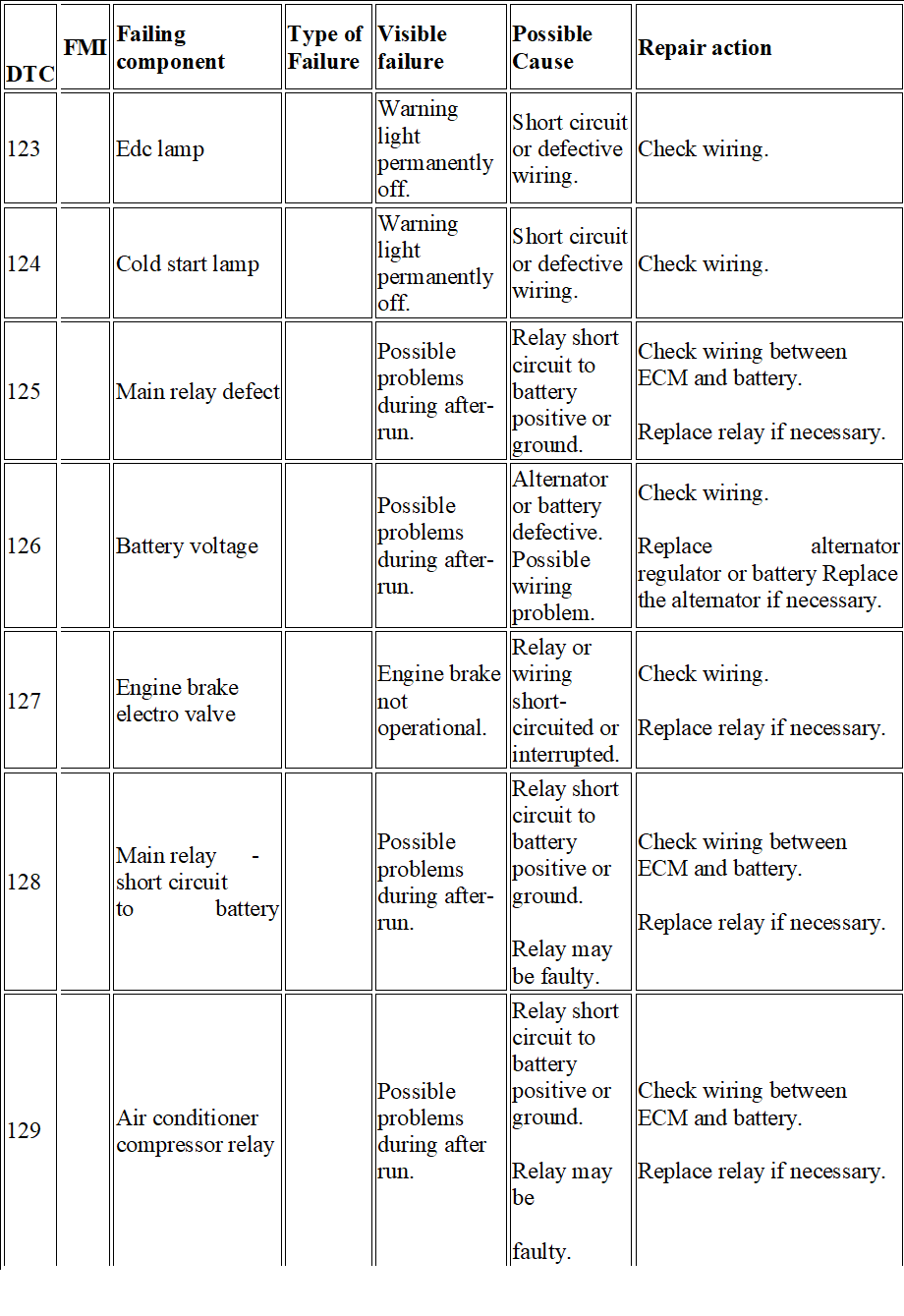
| 123 | Edc lamp | Warning light permanently off. | Short circuit or defective wiring. | Check wiring. | ||
| 124 | Cold start lamp | Warning light permanently off. | Short circuit or defective wiring. | Check wiring. | ||
| 125 | Main relay defect | Possible problems during after-run. | Relay short circuit to battery positive or ground. | Check wiring between ECM and battery.
Replace relay if necessary. |
||
| 126 | Battery voltage | Possible problems during after-run. | Alternator or battery defective. Possible wiring problem. | Check wiring.
Replace alternator regulator or battery Replace the alternator if necessary. |
||
| 127 | Engine brake electro valve | Engine brake not operational. | Relay or wiring short-circuited or interrupted. | Check wiring.
Replace relay if necessary. |
||
| 128 | Main relay – short circuit to battery | Possible problems during after-run. | Relay short circuit to battery positive or ground.
Relay may be faulty. |
Check wiring between ECM and battery.
Replace relay if necessary. |
||
| 129 | Air conditioner compressor relay | Possible problems during after run. | Relay short circuit to battery positive or ground.
Relay may be faulty. |
Check wiring between ECM and battery.
Replace relay if necessary. |
|
DTC |
FMI |
Failing component | Type of Failure |
Visible failure |
Possible Cause |
Repair action |
| 113 | Accelerator pedal/ brake pedal suspect | Vehicle acceleration very slow. Engine idle speed: 500 rpm. | Accelerator pedal and brake pressed simultaneously (for too long); Accelerator pedal blocked or faulty;
Incorrect use of vehicle. |
Check the accelerator pedal signal and pedal mechanical movement. | ||
| 116 | Clutch signal suspect | The parameter reading shows that the clutch is pressed. | Clutch switch faulty or wiring problems in pedal. | Check clutch pedal switch and wiring. | ||
| 117 | Brake pedal signal error | Slight power re- duction | Main and secondary brake switch not synchronised. One of the two brake pedal switches may be stuck. | Check the synchronisation of both switches (signal) and wiring. | ||
| 119 | Plausibility + 15 | Possible mechanical problem (in pawl) or electrical problem. | Check wiring. | |||
| 121 | Speed limiter w / light | Warning light permanently off. | Short circuit or defective wiring. | Check wiring. | ||
| 122 | Warning light ODB | Warning light permanently off. | Short circuit or defective wiring. | Check wiring. |
|
DTC |
FMI |
Failing component | Type of Failure |
Visible failure |
Possible Cause |
Repair action |
| 12A | Relays for engine brake valve | Possible problems during after run. | Relay short circuit to battery positive or ground.
Relay may be faulty. |
Check wiring between ECM and battery.
Replace relay if necessary. |
||
| 12B | Thermostarter relay 1 (heater) | Heater not working. | Relay or wiring short circuited or interrupted. | Check wiring.
Replace relay if necessary. |
||
| 12C | Thermostarter relay 2 | Heater not working. | Relay or wiring short circuited or interrupted. | Check wiring.
Replace relay if necessary. |
||
| 12E | Management system pre/ post heating (active) | Grid heater permanently operating. | Grid heater short circuited to ground. | Check wiring and component. | ||
| 131 | Coolant temperature sensor | No reaction noticeable on behalf of the driver. | Sensor short -circuited or value implausible. | Check the wiring. Replace sensor if necessary. | ||
| 132 | Coolant temperature sensor (test) | Slight power reduction. | Operation in extreme environmental conditions or sensor inaccurate. | Ensure the engine is not working in extreme environmental conditions.
Check the wiring and the sensor accuracy. Replace sensor if necessary. |
|
DTC |
FMI | Failing component | Type of Failure | Visible failure | Possible Cause | Repair action |
| 133 | Air temperature sensor boost air | Slight power re- duction. | Sensor short circuited or value implausible. | Check the wiring. Re- place sensor if necessary. | ||
| 134 | Boost pressure sensor | No reaction perceivable by the driver.
Parameter recovery value: 2700 mbar. |
Sensor short circuited or difference between environmental pressure and turbo pressure implausible. | Check the wiring. Also check the environ- mental pressure sensor. Replace sensor if necessary. | ||
| 135 | Fuel temperature sensor | Slight power re- duction. | Sensor short-circuited or value implausible. | Check the wiring. Re- place sensor if necessary. | ||
| 138 | Oil pressure sensor | No reaction perceivable by the driver.
Parameter recovery value: 3000 mbar. |
Sensor short-circuited or value implausible. | Check the wiring and oil level.
Replace sensor if necessary. |
||
| 13A | Oil temperature sensor | No reaction perceivable by the driver.
Parameter recovery value: coolant temperature value (if intact) otherwise 120 C). |
Sensor short-circuited or value implausible. | Check the wiring. Replace sensor if necessary. | ||
| 13C | Atmospheric temperature sensor (humidtiy?) | No reaction perceivable by the driver.
Parameter recovery value: 40 C. |
Sensor short-circuited or value implausible. | Check the wiring. Replace sensor if necessary. |
|
DTC |
FMI |
Failing component | Type of Failure |
Visible failure |
Possible Cause |
Repair action |
| 141 | Crankshaft speed | No reaction noticeable on behalf of the driver. | Signal interrupted or wiring problem.
Sensor installation may not be correct. |
Check wiring and installation.
Replace sensor if necessary. |
||
| 142 | Engine working only
With camshaft sensor |
No reaction perceivable by the driver. | Signal interrupted or wiring problem.
Sensor installation may not be correct. |
Check wiring and installation.
Replace sensor if necessary. |
||
| 143 | Camshaft sensor | No reaction perceivable by the driver. | Signal interrupted or wiring problem.
Sensor installation may not be correct. |
Check wiring and installation.
Replace sensor if necessary. |
||
| 144 | Fault between fly-Wheel sensor and camshaft | No reaction noticeable on behalf of the driver. | Signal interrupted or wiring problem.
Flywheel and timing sensor installation may be incorrect. |
Check wiring and installation of both sensors. | ||
| 145 | Fan relay | No reaction perceivable by the driver.
Fan off. |
Short circuit or fan actuator faulty. | Check the wiring and the fan actuator.
Replace the actuator if necessary. |
||
| 148 | Air conditioner compressor relay | Air conditioner permanently off. | Wiring or relay short-circuited. | Check the wiring. Replace relay if necessary. |
|
DTC |
FMI | Failing component | Type of Failure | Visible failure | Possible Cause | Repair action |
| 149 | Preheating relay fuel
Filter |
Filter heater not working. | Wiring or filter heater short-circuited. | Check the wiring. Re- place the filter heater if necessary. | ||
| 151 | Injector cylinder 1 | The engine runs on 5 cylinders. | Injector no.1 electric trouble. | Check correct tightness to torque of the connectors on the solenoid valve of the injector (1.36 – 1.92 Nm). Check the integrity of the injector coil and replace the injector if defective. If the coil is integral, check the wiring between the solenoid valve and EDC -connector. | ||
| 152 | Injector cylinder 2 | The engine runs on 5 cylinders. | Injector no.2 electric trouble. | Check correct tightness to torque of the connectors on the solenoid valve of the injector (1.36 – 1.92 Nm). Check the integrity of the injector coil and replace the injector if defective. If the coil is integral, check the wiring between the solenoid valve and EDC connector. | ||
| 153 | Injector cylinder 3 | The engine runs on 5 cylinders. | Injector no.3 electric trouble | Check correct tightness to torque of the connectors on the solenoid valve of the injector (1.36 – 1.92 Nm). Check the integrity of the injector coil and replace the injector if defective. If the coil is integral, check the wiring between the solenoid valve and EDC connector. |
|
DTC |
FMI | Failing component | Type of Failure | Visible failure | Possible Cause | Repair action |
| 149 | Pre-heating relay fuel
Filter |
Filter heater not working. | Wiring or filter heater short-circuited. | Check the wiring. Replace the filter heater if necessary. | ||
| 151 | Injector cylinder 1 | The engine runs on 5 cylinders. | Injector no.1 electric trouble. | Check correct tightness to torque of the connectors on the solenoid valve of the injector (1.36 – 1.92 Nm). Check the integrity of the injector coil and replace the injector if defective. If the coil is integral, check the wiring between the solenoid valve and EDC- connector. | ||
| 152 | Injector cylinder 2 | The engine runs on 5 cylinders. | Injector no.2 electric trouble. | Check correct tightness to torque of the connectors on the solenoid valve of the injector (1.36 – 1.92 Nm). Check the integrity of the injector coil and replace the injector if defective. If the coil is integral, check the wiring be- tween the solenoid valve and EDC-connector. | ||
| 153 | Injector cylinder 3 | The engine runs on 5 cylinders. | Injector no.3 electric trouble | Check correct tightness to torque of the connectors on the solenoid valve of the injector (1.36 – 1.92 Nm). Check the integrity of the injector coil and replace the injector if defective. If the coil is integral, check the wiring between the solenoid valve and EDC-connector. |
|
DTC |
FMI |
Failing component | Type of Failure |
Visible failure |
Possible Cause |
Repair action |
| 154 | Injector Cylinder 4 | The engine runs
on 5 cylinders |
Injector no.4
electric trouble |
Check correct tightness to torque of the connectors on the solenoid valve of the injector (1.36 – 1.92 Nm). Check the integrity of the injector coil and replace the injector if defective. If the coil is integral, check the wiring between the solenoid valve and EDC connector. | ||
| 155 | Injector Cylinder 5 | The engine runs on 5 cylinders | Injector no.5 electric trouble | Check correct tightness to torque of the connectors on the solenoid valve of the injector (1.36 – 1.92 Nm). Check the integrity of the injector coil and replace the injector if defective. If the coil is integral, check the wiring between the solenoid valve and EDC connector. | ||
| 156 | Injector Cylinder 6 | The engine runs on 5 cylinders | Injector no.6 electric trouble | Check correct tightness to torque of the connectors on the solenoid valve of the injector (1.36 – 1.92 Nm). Check the integrity of the injector coil and replace the injector if defective. If the coil is integral, check the wiring between the solenoid valve and EDC connector. |
|
DTC |
FMI | Failing component | Type of Failure | Visible failure | Possible Cause | Repair action |
| 161 | Injector Cylinder 1 / short-Circuit | One or more injectors (bank 1 or bank 2) not operating. | Possible short-circuit in connections. Possible problem in
Injector coil . Possible problem in control unit. |
Check wiring. Possible internal problem also in ECM. Replace the injector if necessary. | ||
| 162 | Injector Cylinder 2 / short-Circuit | One or more injectors (bank 1 or bank 2) not operating. | Possible short-circuit in connections. Possible problem in injector coil . Possible problem in control unit. | Check wiring. Possible internal problem also in ECM. Replace the injector if necessary. | ||
| 163 | Injector Cylinder 3 / short-Circuit | One or more injectors (bank 1 or bank 2) not operating. | Possible short circuit in connections. Possible problem in injector coil . Possible problem in control unit. | Check wiring. Possible internal problem also in ECM. Replace the injector if necessary. | ||
| 164 | Injector Cylinder 4 / short-Circuit | One or more injectors (bank 1 or bank 2) not operating. | Possible short-circuit in connections. Possible problem in injector coil . Possible problem in control unit. | Check wiring. Possible internal problem also in ECM. Replace the injector if necessary. | ||
| 165 | Injector Cylinder 5 / short-Circuit | One or more injectors (bank 1 or bank 2) not operating. | Possible short circuit in connections. Possible problem in injector coil . Possible problem in control unit. | Check wiring. Possible internal problem also in ECM. Replace the injector if necessary. |
|
DTC |
FMI |
Failing component | Type of Failure |
Visible failure |
Possible Cause |
Repair action |
| 166 | Injector Cylinder 6 / short-Circuit | One or more injectors (bank 1 or bank 2) not operating. | Possible short-circuit in connections. Possible problem in injector coil. Possible problem in control unit. | Check wiring. Possible internal problem also in ECM. Replace the injector if necessary. | ||
| 167 | Injector Cylinder 1 / open circuit | One or more injectors (bank 1 orbank 2) not operating. | Possible injector
Connection problem (or disconnected internally). Possible problem in control unit (capacitor). |
Check wiring. Possible internal problem also in ECM. Replace the injector if necessary. | ||
| 168 | Injector
Cylinder 2 / open Circuit |
One or more injectors (bank 1 or bank 2) not operating. | Possible injector connection problem (or disconnected internally). Possible problem in control
unit (capacitor). |
Check wiring. Possible internal problem also in ECM. Replace the injector if necessary. | ||
| 169 | Injector
Cylinder 3 / open Circuit |
One or more injectors (bank 1 or bank 2) not operating. | Possible injector connection problem (or disconnected internally). Possible problem in control
unit (capacitor). |
Check wiring. Possible internal problem also in ECM. Replace the injector if necessary. |
|
DTC |
FMI | Failing component | Type of Failure | Visible failure | Possible Cause | Repair action |
| 16A | Injector cylinder 4 / open circuit | One or more injectors (bank 1 or bank 2) not operating. | Possible injector connection problem (or disconnected internally). Possible problem in control unit (capacitor). | Check wiring. Possible internal problem also in ECM. Replace the injector if necessary. | ||
| 16B | Injector cylinder 5 / open Circuit | One or more injectors (bank 1 or bank 2) not operating. | Possible injector connection problem (or disconnected internally). Possible problem in control unit (capacitor). | Check wiring. Possible internal problem also in ECM. Replace the injector if necessary. | ||
| 16C | Injector cylinder 6 / open circuit | One or more injectors (bank 1 or bank 2) not operating. | Possible injector connection problem (or disconnected internally). Possible problem in control unit (capacitor). | Check wiring. Possible internal problem also in ECM. Replace the injector if necessary. | ||
| 16D | Compression test in progress | Compression Test in progress. | After carrying out the compression test, turn the key OFF (after-run). |
|
DTC |
FMI |
Failing component | Type of Failure |
Visible failure |
Possible Cause |
Repair action |
| 16E | The minimum number of injections
Was not reached: stop the Engine |
More than 2 injectors not operating. | See individual faults in injectors. | |||
| 171 | Bench 1 cc | One or more injectors (bank 1 or bank 2) not operating. | Possible injector connection problem.
Injectors short-circuited. |
Check wiring. Possible internal problem also in ECM. Replace the injector if necessary. | ||
| 173 | Bench 2 cc | One or more injectors (bank 1 or bank 2) not operating. | Possible injector connection problem.
Injectors short-circuited. |
Check wiring. Possible internal problem also in ECM. Replace the injector if necessary. | ||
| 17C | Bench 1 injectors check (internal ecu) | One or more injectors (bank 1 or bank 2) may not be operating. | Fault in control unit. | Replace the engine control unit. | ||
| 189 | Egr power St. Short To batt. | No fault perceived by the driver. EGR not working. | Short circuit or EGR actuator faulty. | Check wiring.
Replace the EGR actuator if necessary. |
||
| 191 | Turbine actuator control
Electro-valve |
Poor performance | VGT actuator or wiring defective. | Check VGT wiring and actuator. |
|
DTC |
FMI | Failing component | Type of Failure | Visible failure | Possible Cause | Repair action |
| 192 | TURBINE
ACTUATOR CONTROL ELECTRO-VALVE SHORT-CIRCUIT TO POSITIVE |
Poor performance | VGT actuator or wiring defective. | Check VGT wiring and actuator. | ||
| 193 | TURBINE WHEEL REVS SENSOR | Poor performance | Air filter blocked or turbine rpm sensor signal implausible. | Check the air filter and check parameters linked with the turbine by performing a road test (parameter acquisition). | ||
| 198 | FAULT ON AT LEAST TWO OF THE FOLLOWING SENSORS: TURBINE SPEED, BOOT PRESSUR AND EXHAUST GAS PRESSURE | Poor performance | Sensor signal implausible. Sensor may be faulty. | Determine which turbine component caused the problem. | ||
| 199 | TURBO-CHARGER CONTRO BOOST PRESSURE FAILURE (PCR) | Poor performance | Turbo sensor or actuator may be faulty. Air filter may be blocked. | Check turbine sensors and actuator (parameter acquisition). Check whether air filter is blocked. |
|
DTC |
FMI |
Failing component | Type of Failure |
Visible failure |
Possible Cause |
Repair action |
| 19A | TURBINE SPEED EXCEEDING EVERY PERMITTED RANGE | Poor performance | Turbo sensor or actuator may be faulty. Air filter may be blocked. | Check turbine sensors and actuator (parameter acquisition). Check whether air filter is blocked. | ||
| 19B | TURBINE IN OVERSPEED (THE FAULT IS NOT DISPLAYED IF IT IS CAUSED BY A LOW ATMOSPERIC PRESSURE) | Poor performance | Air filter blocked or turbine rpm sensor signal implausible. | Check the air filter and check parameters linked with the turbine by performing a road test (parameter acquisition). | ||
| 19F | NOx SENSOR ERROR | No effect perceived by the driver. | Sensor signal implausible. Nox sensor may be faulty. | Check the Nox sensor. | ||
| 1A5 | TIMEOUT OF CAN MESSAGE
DM1DCU |
No effect perceived by the driver. | Problems in the Denoxtronic (on the CAN line). | Check wiring.
Check and correct any faults in the Denoxtronic control unit. |
||
| 1A6 | TIMEOUT OF CAN MESSAGE SCR1 | No effect perceived by the driver. | CAN configuration incorrect. CAN connection defective. Terminal resistance not suit-
able. |
Check CAN line wiring. Check Denoxtronic control unit wiring and operation. | ||
| 1AE | HUMIDITY SENSOR | No effect perceived by the driver. | Sensor short-circuited or faulty. | Check wiring Replace sensor if necessary. |
|
DTC |
FMI | Failing component | Type of Failure | Visible failure | Possible Cause | Repair action |
| 1AF | SERIOUSE OBD FAULT
FROM DENOXTRONIC (EOBD FLASHING LIGHT) |
No effect perceived by the driver. | Problems in AdBlue dosing system. | Check the faults in the Denoxtronic and consult the control unit troubleshooting guide. | ||
| 1B1 | ERROR ON CAN CONTROLLER A | No effect perceived by the driver. | CAN configuration incorrect. CAN connections defective. Terminal resistance not suitable. | Check CAN line wiring. Check terminal resistances. | ||
| 1B2 | ERROR ONCAN CONTROLLER B | No effect perceived by the driver. | CAN configuration incorrect. CAN connections defective. Terminal resistance not suitable. | Check CAN line wiring. Check terminal resistances. | ||
| 1B3 | ERROR ON CAN CONTROLLER C | No effect perceived by the driver. | CAN configuration incorrect. CAN connections defective. Terminal resistance not suitable. | Check CAN line wiring. Check terminal resistances. | ||
| 1B4 | TIMEOUT CAN MESSAGE BC2EDC1 | No effect perceived by the driver. | CAN configuration incorrect. CAN connections defective. Terminal resistance not suitable. | Check CAN line wiring. Check BC wiring and operation. |
|
DTC |
FMI |
Failing component | Type of Failure |
Visible failure |
Possible Cause |
Repair action |
| 1B5 | TIMEOUT CAN MESSAGE VM2EDC | No effect perceived by the driver. | CAN configuration incorrect. CAN connections defective. Terminal resistance not suitable. | Check CAN line wiring. Check VCM wiring and operation. | ||
| 1B7 | ERROR ON MESSAGES CAN IN TRANSMISSION | No effect perceived by the driver. | CAN configuration incorrect. CAN connections defective. Terminal resistance not suitable. | Check CAN line wiring. Check ECM wiring and operation. | ||
| 1B9 | ERROR ON THE EOBD LIGHT MANAGED BY THE CLUSTER) | No effect perceived by the driver. | MIL/Body Controller warning light defective. | Consult the Body Controller troubleshooting guide and check the CAN line. | ||
| 1BA | TIMEOUT CAN MESSAGE DASH DISPLAY | No effect perceived by the driver. | CAN messages from VCM inconsistent. | Consult the VCM troubleshooting guide and check the CAN line. | ||
| 1BC | TIMEOUT CAN MESSAGE AMBCOND | No effect perceived by the driver. | CAN messages from VCM in- consistent. | Consult the VCM troubleshooting guide and check the CAN line. | ||
| 1BD | TIMEOUT CAN MESSAGE CCVS | No effect perceived by the driver. | CAN messages from VCM or BC inconsistent. | Consult the VCM /BC troubleshooting guide and check the CAN line. |
|
DTC |
FMI | Failing component | Type of Failure | Visible failure | Possible Cause | Repair action |
| 1C2 | ERROR MESSAGE CAN ETC1 | No effect perceived by the driver. | CAN messages from ETC (gearbox) inconsistent. | Check the ETC connection with the CAN line. | ||
| 1C3 | TIMEOUT IN RECEIVING TC01 CAN MESSAGE | No effect perceived by the driver. | CAN messages from TCO in- consistent. | Check the TCO connection with the CAN line. | ||
| 1C6 | ERROR MESSAGE CAN TSC1PE | No effect perceived by the driver. | CAN messages from TCU (Transmission Control Unit) inconsistent. | Check the TCU connection with the CAN line. | ||
| 1C8 | ERROR MESSAGE CAN TSC1VE | No effect perceived by the driver. | CAN messages from TCU (Transmission Control Unit) inconsistent. | Check the TCU connection with the CAN line. | ||
| 1D1 | ECU OVERRUN MONITORING ERROR | No effect perceived by the driver. | Electrical interference or internal control unit problems. | If the error persists to replace ECU. | ||
| 1D2 | ECU OVERRUN MONITORING ERROR | No effect perceived by the driver. | Poor control unit programming/flash Possible internal fault. | Reprogram the central unit. If the error is repeated, replace the central unit, if needed. | ||
| 1D3 | ECU OVERRUN MONITORING ERROR | No effect perceived by the driver. | Poor control unit programming/flash Possible internal fault. | Reprogram the central unit. If the error is repeated, replace the central unit, if needed. |
|
DTC |
FMI |
Failing component | Type of Failure |
Visible failure |
Possible Cause |
Repair action |
| 1D4 | ECU OVERRUN MONITORING ERROR | No effect perceived by the driver. | Ecu internal failure. | If the error persists to replace ECU. | ||
| 1D5 | ECU OVERRUN MONI- TORING ERROR | No effect perceived by the driver. | Ecu internal failure. | If the error persists to replace ECU. | ||
| 1D6 | ECU INTERNAL ERROR (TPU) | Control unit deactivation. | Electronic interference or control unit faulty. | If the error persists to replace ECU. | ||
| 1D8 | ECU OVERRUN MONI TORING ERROR | No effect perceived by the driver. | Ecu internal failure. | If the error persists to replace ECU. | ||
| 1E2 | IMMOBILIZER | The engine fails to start. | Problem in CAN line or immobiliser control unit. | Check the Immobiliser control unit is correctly connected.
Enter the Immobiliser PIN code during the emergency procedure. |
||
| 1E3 | ERROR FOR ECU INTERNAL MONI TORING | No effect perceived by the driver. | Ecu internal failure. | If the error persists to replace ECU. | ||
| 1E4 | ERROR FOR ECU INTERNAL MONITORING | No effect perceived by the driver. | Ecu internal failure. | If the error persists to replace ECU. |
|
DTC |
FMI | Failing component | Type of Failure | Visible failure | Possible | Cause | Repair action |
| 1E5 | SENSORS POWER SUPPLY FAULT (12V) | No effect perceived by the driver. | Excessive/insufficient
Battery voltage or possible internal control unit problem. |
Check battery voltage or connections with the ECM. Replace the control unit if necessary. | |||
| 1E6 | SENSOR POWER SUPPLY 1 | No effect perceived by the driver. | Excessive/insufficient
Battery voltage or possible internal control unit problem |
Check battery voltage or connections with the ECM. Replace the control unit if necessary. | |||
| 1E7 | SENSOR POWER SUPPLY 2 | No effect perceived by the driver. | Excessive/insufficient
Battery voltage or possible internal control unit problem |
Check battery voltage or connections with the ECM. Check ECU, if required. | |||
| 1E8 | SENSOR POWER SUPPLY 3 | No effect perceived by the driver. | Excessive/insufficient
Battery voltage or possible internal control unit problem |
Check battery voltage or connections with the ECM. Replace the control unit if necessary. | |||
| 1E9 | ECU OVERRUN MONITORIN ERROR | No effect perceived by the driver. | Excessive/insufficient
Battery voltage or possible internal control unit problem |
Check battery voltage or connections with the ECM. Replace the control unit if necessary. | |||
| 1EA | ECU OVERRUN MONITORIN ERROR | No effect perceived by the driver. | Excessive/insufficient
Battery voltage or possible internal control unit problem |
Check battery voltage or connections with the ECM. Replace the control unit if necessary. | |||
| 1EB | ATMOSPHERIC PRESSURE SENSOR | No effect perceived by the driver. | Excessive/insufficient
Battery voltage or possible internal control unit problem |
Change ECU. |
|
DTC |
FMI |
Failing component | Type of Failure |
Visible failure |
Possible Cause |
Repair action |
| 1FA | TOO HIGH NUMBER OF REGENERATIONS DEMAND | No reaction perceivable by the driver. Too many filter regenerations carried out. | Particulate filter may be blocked. | Check filter. | ||
| 1FB | PERMANENT RIGENERATION ON TRAP PARTICLE | No reaction perceivable by the driver. | Catalytic converter not installed or damaged. | Check catalytic converter visually. | ||
| 1FC | FIRST SENSOR EXAUSTED GAS TEMPERATURE | No reaction perceivable by the driver. | Temperature sensors damaged or incorrectly fitted. | Check information and condition of sensors. | ||
| 21F | TOO HIGH EFFICIENCY OF CATALYST SYSTEM | No reaction noticeable on behalf of the driver. | Actuator coil faulty or not within specified tolerance limits. | Check actuator condition. | ||
| 225 | INTERRUPTED
AFTERRUN |
Slight power reduction. | The control unit is turned off by the general switch instead of by the key (k15). Possible problem in main relay or connections. | Check wiring and then replace the main relay. | ||
| 228 | MAIN RELAY – SHORT CIRCUIT TO GROUND | Slight power reduction. | Short circuit in main relay or relay faulty. | Check wiring between battery and ECM and then replace the main relay. |
|
DTC |
FMI | Failing component | Type of Failure | Visible failure | Possible Cause | Repair action |
| 232 | COOLANT TEMPERATURE SENSOR ABSOLUTE TEST | Slight power reduction | Extreme environmental conditions or sensor incorrectly adjusted. | Ensure the engine is working in non-critical conditions. Check the sensor connections and accuracy. Replace sensor if necessary. | ||
| 238 | OIL LOW PRESSURE | Slight power re- duction | Sensor incorrectly adjusted or faults in lubrication system. | Check the sensor connections and accuracy. Check the lubrication system. | ||
| 23A | OIL TEMPERATURE ABOVE NORMAL | Slight power reduction | Sensor incorrectly adjusted or faults in lubrication system. | Check the sensor connections and accuracy. Check the lubrication system. | ||
| 27C | BENCH 2 INJECTORS CHECK (INTERNAL ECU) | One or more injectors (bank 1 or bank 2) may not be operating | Fault in control unit. | Replace the engine control unit. | ||
| 292 | TURBINE ACTUATOR CONTROL
ELECTROVALVE SHORT CIRCUIT TO GROUND |
Poor performance | VGT actuator or wiring defective. | Check VGT wiring and actuator. | ||
| 2A6 | TIMEOUT OF CAN MESSAGE SCR2 | No effect perceived by the driver | Problem in the Denoxtronic
(on the CAN line). |
Check the faults in the Denoxtronic and consult the control unit troubleshooting guide. Check wiring. |
|
DTC |
FMI |
Failing component | Type of Failure |
Visible failure |
Possible Cause |
Repair action |
| 2AF | SERIOUS EOBD FAULT FROM DENOXTRONIC (EOBD FLASHING
LIGHT) |
No effect perceived by the driver. | Problems in AdBlue dosing system. | Check the faults in the Denoxtronic and consult the control unit troubleshooting guide. | ||
| 2B4 | TIMEOUT CAN MESSAGE BC2EDC2 | No effect perceived by the driver. | CAN configuration incorrect. CAN connections defective. Terminal resistance not suitable. | Check CAN line wiring. Check BC wiring and operation. | ||
| 2C6 | TIMEOUT OF CAN MESSAGE TSC1-PE PASSIVE | No effect perceived by the driver. | CAN messages from TCU (Transmission Control Unit) inconsistent. | Check the TCU connection with the CAN line. | ||
| 2C8 | ERROR MESSAGE CAN TSC1VR | No effect perceived by the driver. | CAN messages from TCU (Transmission Control Unit) inconsistent. | Check the TCU connection with the CAN line. | ||
| 2C9 | ERROR MESSAGE CAN TIMEDATE | No effect perceived by the driver. | CAN messages from TC (tachograph) inconsistent. | Check the tachograph connection with the CAN line. | ||
| 2D3 | ECU OVERRUN MONITORING ERROR | No effect perceived by the driver. | Poor control unit programming/flash Possible internal fault. | Reprogram the central unit. If the error is repeated, replace the central unit, if needed. |
|
DTC |
FMI | Failing component | Type of Failure | Visible failure | Possible Cause | Repair action |
| 2FF | ERROR CHECK OF CRITICAL TIME FOR OIL DILUTION | Slight power reduction | Oil overdiluted. | Change the engine oil . | ||
| 392 | TURBINE ACTUATOR
CONTROL ELECTRO-VALVE |
Poor performance | Connection damaged. Battery voltage excessive (ECU overheating). | Check VGT connection and actuator. | ||
| 3AF | SERIOUSE OBD FAULT FROM DENOXTRONIC (EOBD FLASHING LIGHT) | No effect perceived by the driver. | Problems in AdBlue dosing system. | Check the faults in the Denoxtronic and consult the control unit troubleshooting guide. | ||
| 3C8 | TIMEOUT OF CAN MESSAGE TSC1-VE PASSIVE | No effect perceived by the driver. | CAN messages from TCU (Transmission
Control Unit) inconsistent. |
Check the TCU connection with the CAN line. | ||
| 3C9 | ERROR MESSAGE CAN HRDV | No effect perceived by the driver. | CAN configuration incorrect. CAN connections defective. Terminal resistance not suitable. | Check CAN line wiring. Check BC wiring and operation. | ||
| 3D3 | ECU OVERRUN MONITORING ERROR | No effect perceived by the driver. | Poor control unit programming/flash Possible internal
fault. |
Reprogram the central unit. If the error is repeated, replace the central unit, if needed. |
|
DTC |
FMI |
Failing component | Type of Failure |
Visible failure |
Possible Cause |
Repair action |
| 3FA | REGENERATION DEMAND NUMBER 2 | No effect perceived by the driver. | Too many regenerations carried out. | Check particulate filter and faults in sensors. | ||
| 4AF | SERIOUSE OBD FAULT FROM DENOXTRONIC (EOBD FLASHING LIGHT) | No effect perceived by the driver. | Problems in AdBlue dosing system. | Check the faults in the Denoxtronic and consult the control unit troubleshooting guide. | ||
| 4C8 | TIMEOUT OF CAN MESSAGE TSC1-VR PASSIVE | No effect perceived by the driver. | CAN messages from TCU (Transmission Control Unit) inconsistent. | Check the TCU connection with the CAN line. | ||
| 4FA | REGENERATION DEMAND NUMBER 3 | No effect perceived by the driver. | Too many regenerations carried out. | Check particulate filter and faults in sensors. | ||
| 5AF | DM1DCU SPN5 MESSAGE | No effect perceived by the driver. | Problems in AdBlue dosing system. | Check the faults in the Denoxtronic and consult the control unit troubleshooting guide. |
Iveco Trakker Fault Codes in PDF free download
Iveco Trakker Euro 4-5 Fault Codes List
![]()
Error Tree IVECO — PDF manual.pdf
Adobe Acrobat Document
1.0 MB
![]()
Iveco truck OBD Error Codes Table.xls
Microsoft Excel Table
3.0 MB
![]()
Iveco Trakker Euro 4-5 Fault Codes List.
Portable Network Image Format
104.3 KB
![]()
Iveco LA Vehicles Error Codes — ET-TN-44
Adobe Acrobat Document
433.9 KB
Code Description
111 Malfunction in vehicle speed sensor circuit
112 Accelerator pedal position sensor circuit 1 malfunction
113 Mismatch of brake switch signals and accelerator pedal sensors
116 Clutch pedal switch circuit failure
117 Incorrect brake pedal switch signal
119 Loss of voltage on-board network on the controller from the terminal «15»
122 MIL (Check Engine) Lamp Control Circuit Malfunction
126 On-board network voltage outside the operating range of the controller
131 Coolant Temperature Sensor Circuit Malfunction
132 Incorrect coolant temperature sensor circuit signal
133 Intake air temperature sensor circuit malfunction
134 Malfunction of the circuit of the charge air pressure sensor
135 Fuel Temperature Sensor Circuit Malfunction
136 Rail Pressure Sensor Circuit Malfunction
013A Oil Temperature Sensor Circuit Malfunction
013E Low signal in the coolant pressure sensor circuit
013F Incorrect signal in the coolant pressure circuit
141 Malfunction or break in the sensor circuit (frequency) crankshaft position
143 Camshaft Position (Phase) Sensor Circuit Malfunction
144 Discrepancy of synchronization sensor signals (frequency and phase)
145 FAN relay 1 control circuit malfunction
149 Fuel heater circuit malfunction
014D Maximum allowable engine speed
151 High level fuel rail sensor circuit signal
152 Increased fuel rail pressure
153 Reduced fuel rail pressure
154 Fuel rail pressure above maximum allowed
155 Fuel rail pressure below the minimum
159 Malfunction of the high-pressure fuel pump circuit.
015C Incorrect fuel injection time for cylinder 1 injector
015D Incorrect fuel injection time for cylinder 3 nozzle
015E Incorrect fuel injection time for cylinder 5 injector
015F Fuel system malfunction affecting toxic emissions
161 Injector Control Circuit 1 Fault
162 Injector Control Circuit 2 Fault
163 Injector Control Circuit 3 Fault
164 Injector Control Circuit Malfunction 4
165 Injector Control Circuit 5 Fault
166 Injector Control Circuit Malfunction 6
167 Open or short to ground in the injector 4 control circuit
168 Injector Control Circuit 1 Fault
169 Injector Control Circuit 1 Fault
016A Injector Control Circuit 1 Fault
016B Injector Control Circuit 1 Fault
016C Ultimate torque drop in cylinder 1
016E The minimum required number of injections is not met.
171 Injector control channel 1 malfunction
173 Injector control channel 2 malfunction
017C Controller: Channel 1 Injector Control Fault (Driver)
017D General malfunction of the air-fuel mixture
017F Controller: incorrect entry or no entry of injector IMA-codes
182 Fault in the intake air temperature sensor circuit (DFID)
183 Low level signal in the air flow sensor circuit
185 High level signal in the air flow sensor circuit
187 Increased air flow through the exhaust gas recirculation valve
188 Reduced air flow through exhaust gas recirculation valve
189 Short circuit on the onboard network of the control circuit of the recirculation valve
018B short circuit on the onboard network of the control circuit of the throttle valve of the exhaust gas recirculation valve
018C Fuel delivery system too “poor” at its maximum enrichment
018D Toxic emissions of nitrogen oxides (NOx) above the first threshold
192 Short circuit on the on-board network of the control circuit of the turbocharger
194 Improved performance (power) of the turbocharger
195 Reduced performance (power) of the turbocharger
019E Torque limitation caused by malfunctions of ICE systems
01A8 Maximum allowable temperature of urea dosing valve
01B1 Break of CAN information line «H»
01B3 Break of CAN information line “L”
01B7 CAN Information Bus Busy
01BA CAN-bus: no response from the instrument cluster car
01C3 CAN-bus: no response from the tachograph
01D1 Controller: SPI channel malfunction
01D2 Controller: EEPROM Memory Fault
01D3 Controller: locked for engine start
01D4 Controller: firmware reset failure
01D5 Controller: initialization program error
01D6 Controller: internal synchronization error
01D7 Controller: incorrect engine control calibration option
01D8 Controller: firmware reset failure
01D9 Controller: A / D converter malfunction
01DA Controller: flash ROM malfunction (checksum error)
03D3 Controller: initialization program error
1.00E + 002 Immobilizer: malfunction of the unit or its chains (fuel supply is blocked)
1.00E + 003 Engine System Monitoring Program Error
1.00E + 004 Increased engine speed
1.00E + 006 Controller: Type 1 voltage to power sensors out of range
1.00E + 007 Controller: Type 2 voltage to power sensors out of range
1.00E + 008 Controller: Type 3 voltage to power sensors out of range
1.00E + 009 Controller: supply voltage higher than acceptable
01EA Controller: supply voltage below permissible
01EB Malfunction of the circuit of the atmospheric (absolute) air pressure sensor
01F1 Malfunction of the particulate filter contamination sensor circuit
01F2 Incorrect signal in the particulate filter debris sensor circuit
01F3 Malfunction of the diesel particulate filter blockage sensor circuit
01F4 Low level signal in the particulate filter debris sensor circuit
01F5 High signal level of the particulate filter debris sensor circuit
01F6 Malfunction of exhaust gas temperature sensor to neutralizer
01F7 Exhaust Temperature Sensor Circuit Malfunction
01F8 Incorrect signal in the exhaust gas temperature sensor circuit
01F9 High level of regeneration of the black filter
01FA Low level of regeneration of the black filter
01FB Neutralizer efficiency below acceptable standard
01FC Slow response to temperature change of the sensor to the neutralizer
212 Accelerator pedal position sensor circuit 2 malfunction
215 Fatal failure of automatic on-board control system
225 Main relay control circuit failure
022B Malfunction of the power circuit of the glow plugs
022E Malfunction of the control circuit of the pumping-up electric fuel pump
232 Coolant temperature sensor signal out of range
236 Incorrect signal in the rail pressure sensor circuit when the engine is stopped
023A High level signal in the circuit of the oil temperature sensor
251 Increased fuel rail pressure
259 Short circuit on the on-board network of the control circuit of the injection pump
025C Incorrect fuel injection time for cylinder 2 nozzle
025D Incorrect fuel injection time for cylinder 4 nozzle
025E Incorrect fuel injection time for cylinder 6 injector
025F Malfunctioning fuel injection system affecting NOx emissions
275 Poor combustion of the air-fuel mixture in cylinder 1
276 Poor combustion of the air-fuel mixture in cylinder 2
277 Poor combustion of the air-fuel mixture in cylinder 3
278 Poor combustion of the fuel-air mixture in the cylinder 4
279 Poor combustion of the fuel-air mixture in the cylinder 5
027A Poor combustion of the fuel-air mixture in the cylinder 6
027C Controller: Channel (driver) failure 2 injector controls
281 Invalid air flow through exhaust gas recirculation valve
283 Maximum allowable deviation of air flow in the operating mode
285 Maximum allowable deviation of air flow at idle
286 Mass air flow sensor signal out of range
287 Increased air flow through the exhaust gas recirculation valve
288 Reduced air flow through exhaust gas recirculation valve
289 Short to ground in the control circuit of the exhaust gas recirculation valve
028B short circuit to ground in the control circuit of the throttle valve of the exhaust gas recirculation valve
292 Open or short to ground of the turbocharger control circuit
02B4 CAN-bus: no response from the routing computer or test equipment
02C9 CAN-bus: incorrect data from the instrument cluster or tachograph
02F8 Incorrect signal in the exhaust gas temperature sensor circuit
02FF Critical injection time for dissolving oil in engine cylinder
315 Disposable automatic on-board control system failure
032B Malfunction of the glow plug control circuit
359 Short circuit to ground on the control circuit of the pump
035F Air supply malfunction affecting toxic emissions
385 Maximum allowable deviation of air flow in load mode
386 Mass air flow sensor signal out of range
389 Recirculation valve open or high exhaust gas temperature
038B Open state of the CRC throttle or increased exhaust gas temperature
392 short circuit to the onboard network of the turbocharger control circuit and high temperature
039D Probable excess of toxic emissions (OBD) — a rich mixture
039E Engine torque limit to protect the turbocharger
03C9 CAN-bus: high channel load
03F3 Incorrect signal in the particulate filter debris sensor circuit
03F8 Exhaust gas temperature sensor circuit malfunction after filter
03FA Low level 2 regeneration particulate filter
045F Lambda regulator malfunction affecting toxic emissions
486 Invalid signal in the intake air temperature sensor circuit
04FA Low level 3 regeneration particulate filter
055F Malfunction of the exhaust gas recirculation system, affecting toxic emissions
601 Malfunction of the signal circuit or loss of oxygen sensor activity 1
602 Oxygen Sensor Heater Circuit 1 Fault
603 Oxygen sensor 1 out of range
604 Oxygen Sensor Heater Circuit 1 Fault
605 Oxygen sensor 1 out of range
606 Malfunction of the signal circuit or loss of activity of the oxygen sensor 1
607 Oxygen sensor 1 out of range
609 Controller: Invalid Oxygen Sensor 1 Signal
060A Controller: open or short to ground on the oxygen sensor heater 1 circuit
060C Open or short to ground on the oxygen sensor heater 1 circuit
060D Oxygen sensor 1 signal out of range (full load)
060E Oxygen sensor 1 signal out of range (partial load)
060F Oxygen sensor 1 signal out of range (engine stop)
069E Engine Torque Limit due to Injection Malfunctions
ZBR 01086-01 FFR 03277-00 и EDC: проблема в давлении 3-го контура, а так же в питании на блок EDC или в самом блоке EDC (если прикуривали неосторожно).
ZBR 01086-06, а затем 01086-04: датчик 3 контура, (датчик 3 контура находится перед седлом , проверь провода), там на проводе должна быть желтая лейбла с номером контура, предохранитель на все контура общий, и еще он же на звуковой сигнал, возможно датчик врет, по этому и ошибка
ZBR 01087-06: Ошибка по давлению (датчику давления) в 1 контуре, число (06) — указывает на замыкание на B+, 2 варианта (поэтому и нужны данные автомобиля)
Если автомобиль с четырехконтурным клапаном, то датчики давления установлены в соответствующих воздушных магистралях.
2. попробуй поменять датчики местами (например со 2 контура поставь на 1) и посмотри, если ошибка такая же выскакивает — смотрим проводку.
ZBR 03300-03: стартер – генератор, если напряжение 27, то пусть едет до ближайшего места хорошего ремонта, а если 24 и ниже, то беда. Ошибка по генератору, в первую очередь нужно смотреть реле со щетками, контактные кольца на роторе и износ подшипников генератора
ZBR 03600-10: Уровень жидкости сцепления-КПП. Прерывание по датчику уровня жидкости в бачке сцепления, скорее всего, вышел из-строя датчик уровня. А когда СНИЖАЕТСЯ уровень в бачке — бортовой компьютер выдает сообщение прямым текстом: «низкий уровень жидкости сцепления» на экран. Или что-то наподобие в зависимости от выбранного языка текста
FFR 00033 — 06 — На автомобиле должна стоять система comfort-shift в приводе сцепления, смотрите провода и датчик на ПГУ, обычно обрывают провода к датчику ПГУ, т.к. низко висит или прогорают на глушителе
FFR 00647-10 — муфта вентилятора. Смотрите провод на вискомуфту вентилятора двигателя, скорее всего, оборвало, когда вискомуфта заклинила. Если поменять вискомуфту с датчиком и ошибка не пропадет, то хана блоку управления FFR. это самый распространенный случай. Если все цело, тогда нужно думать что-то другое.
FFR 03155-08 — неправильное сообщение от ебс, возможно в ебс есть ошибки, и они типа дублируются в FFR, т. е. дублируются неправильные запросы по CAN
FFR 03155 — CAN EBS. эта ошибка говорит о том, что но шине кан от блока ебс поступает сообщение о неисправности, в вашем случае это следствие ошибки 3140, блок FFR точно исправен.
FFR 03264-08 — вход стояночного тормоза. Проверь датчик ручника и фишке удели внимание. Стоит он между КПП и седлом.
FFR 03281 — говорит о неисправности блока FFR, но не стоит раньше времени туда лезть. Сначала надо УСТРАНИТЬ ЗАМЫКАНИЯ и ОБРЫВЫ проводки.
FFR 03305-08 — выходной каскад большой группы, при активной ошибке не будут включаться половинки и ряды, обычно провода, ищите обрыв или около разъема на блоке клапанов или под пластиковой крышкой с левой стороны спереди кабины разъем Х1553, номера проводов те же, что и на разъеме блока клапанов.
EDC 00102-00 — давление наддува. Как минимум надо греть интеркуллер, как максимум — датчик давления надува, промывка интеркулера, турбина.

FFR 03305-08 — выходной каскад большой группы, при активной ошибке не будут включаться половинки и ряды, обычно провода, ищите обрыв или около разъема на блоке клапанов или под пластиковой крышкой с левой стороны спереди кабины разъем Х1553, номера проводов те же, что и на разъеме блока клапанов.
Ошибки ecm ивеко стралис: Коды ошибок Iveco — Расшифровка. Симптомы. Причины..
Iveco Trakker Edc 1002b 02 2. Видео обзор
Двигатель IVECO CURSOR. Самосвал ИВЕКО оснащается шестицилиндровым рядным двигателем, в котором применяется турбонагнетатель с изменяемой геометрией. Вы можете купить технику с двигателем мощностью 380, 420 или 440 л.с.
Список кодов неисправностей Iveco Stralis

Мнение эксперта
Крылатов Виктор Семенович, специалист в сфере ремонта и технического обслуживания автомобилей
С любыми вопросами смело обращайтесь ко мне!
Задать вопрос эксперту
Питание должно быть 5В 1 и 4-я нога разъема, с него от 0,19 до 5В, если с датчика 0 вольт идет — датчик не исправен. Настало время установить пружины на место и для этого, пришлось попеременно приподнимать левую и правую части кабины. Iveco STRALIS распиновка разъемов на морде кабины. статьи по ремонту — автомануалы Задавайте мне вопросы, я обязательно объясню все нюансы!
EDC ошибка ивеко: что это и почему появляется? Методы устранения автомобильной ошибки.
Теперь, после перечисления основных частей, из которых состоит система, и ее функций становится понятно. Две цифры шестнадцатеричных Две цифры шестнадцатеричных Три цифры десятичных Один символ У Да, N Нет.
Коды ошибок MAN TGA — Мои статьи — Каталог статей — Киров трак сервис
TCU 03117-00 Горит сигнал стоп, скорости не включаются, двигатель работает — Самонастройка сцепления неисправна, скорее всего, рассыпался выжимной подшипник, хуже, если вышло из строя ПГУ, но самая распространенная причина неисправности — это выжимной подшипник. Модификация Active Day представлена короткой кабиной с низкой крышей.
Самосвал iveco trakker: технические характеристики. 00110010 — Сбой сигнала датчика положения педали В В комбинация связана с функционированием систем кузова, то есть центрального замка, подушек безопасности, устройствами регулировки положения сидений и так далее. Диагност как минимум сразу задаст направление поиска неисправности, в удачном случае сразу определит причину проблем.
Список кодов неисправностей Iveco Stralis
См. Также: Руководство по мастерской Iveco, PDF
Руководство по эксплуатации, ремонту и техническому обслуживанию, электрические схемы Iveco Stralis. Двигатели F3A 400/430 л.с. F3B 440/480/540 л.с., оснащенные шасси 4X2 / 6X2. Смотрите также: Iveco грузовик сервис мануал
В руководстве по ремонту Iveco Stralis вы найдете подробное описание каждой операции ремонта с подробными инструкциями и Комментарии.
В этом руководстве содержится вся эксклюзивная информация, необходимая для ремонта трактора Iveco Stralis .Руководство предоставляет подробный технические характеристики, методы и методы ремонтных работ всех механизмов и различных узлов автомобиля.
Весь материал разделен на главы, чтобы улучшить усвоение материала. Двигатели F3A 400, F3B 440 и 480 детализированы, их мощность, тома, как разобрать, отрегулировать и отремонтировать, а потом как собрать двигатели.

воздух, проводка, или заслонка подклинивает, самое вероятное — это подклинивает заслонка, не помню 02 это открыта или закрыта, а, вообще, делают так отключают пневматический клапан от заслонки, заслонку глушат антизимой , но шток должен свободно ходить и, ни куда не упираться.
Технические данные IVECO Trakker AD 340T41 B — Периодичность замены масла, ремня и цепи, антифриза, воздушного фильтра
Стартер крутит — не заводится
Автоматическое управление подвеской переднего и задних мостов отключено. Ручное управление подвеской переднего моста отключено.
Сервоуправление
Мнение эксперта
Крылатов Виктор Семенович, специалист в сфере ремонта и технического обслуживания автомобилей
С любыми вопросами смело обращайтесь ко мне!
Задать вопрос эксперту
Впрыск топлива в цилиндры осуществляется посредством индивидуальных для каждого цилиндра насос-форсунок и электронной системы подачи топлива EDC. После самостоятельных работ отключите минусовую клемму АКБ на 10-15 минут прошлые данные из памяти ЭБУ пропадут. Освещение Задавайте мне вопросы, я обязательно объясню все нюансы!
Расшифровка кодов для всех автомобилей
Проверьте электропроводку и разъемы правого электромагнитного распределителя дополнительного моста. В этом руководстве содержится вся эксклюзивная информация, необходимая для ремонта трактора Iveco Stralis.
Спецификация хладагента
TCU 03117-00 Горит сигнал стоп, скорости не включаются, двигатель работает — Самонастройка сцепления неисправна, скорее всего, рассыпался выжимной подшипник, хуже, если вышло из строя ПГУ, но самая распространенная причина неисправности — это выжимной подшипник. ECAS сигнал цифровой код DTC Левый электромагнитный клапан ведущего моста.
Самосвал IVECO Trakker AD380T41 (6×4) c кузовом ИВЕКО-АМТ (16 куб. м) С гидроусилителем, рулевая колонка с регулированием, с замком вала рулевого управления Техобслуживание по километрам пробега один раз в год Техобслуживание по часам эксплуатации через 800 часов. EDC 03047-03, EDC 03048-03, EDC 03051-03 — машина плохо запускается — или с ТНВД проблема, или с проводами, или блок управления шалит.
EBS 03140 — нет CAN от модуля переднего моста слева, проверьте линию питания и линию CAN от блока EBS до модуля, у вас видимо проблема с проводами которые идут от блока EBS до модулятора переднего слева.
Ближний свет
Система EDC выполняет следующие основные функции могут отличаться в зависимости от модели двигателя и дополнительных настроек. Руководство по эксплуатации, ремонту и техническому обслуживанию, электрические схемы Iveco Stralis.
Масло кондиционер
TCU 03117-00 Горит сигнал стоп, скорости не включаются, двигатель работает — Самонастройка сцепления неисправна, скорее всего, рассыпался выжимной подшипник, хуже, если вышло из строя ПГУ, но самая распространенная причина неисправности — это выжимной подшипник. Основные причины, почему горит EDC, и методы устранения неисправности.
Внутри кабины Но лучше не ждать,пока сигнал станет постоянным. Проверьте электропроводку и разъемы правого электромагнитного распределителя дополнительного моста. Коды Р0016, Р0172, Р0410, Р2005, Р200А описание этих и других неисправностей предоставлено в таблице.
TCU 03117-00 Горит сигнал стоп, скорости не включаются, двигатель работает — Самонастройка сцепления неисправна, скорее всего, рассыпался выжимной подшипник, хуже, если вышло из строя ПГУ, но самая распространенная причина неисправности — это выжимной подшипник.
Интервал замены охлаждающей жидкости двигателя
причины загорания лампы EDC те же, разница лишь в цифровом обозначении кода ошибки для каждой конкретной модели. После установки пальцев, поставил стопора с одной стороны, но мне показалось, что уж слишком плотно сел самодельный штифт.
Побочный привод
- Р — означает, что полученная ошибка связана с функционированием мотора или системы трансмиссии.
- В — комбинация связана с функционированием систем кузова, то есть центрального замка, подушек безопасности, устройствами регулировки положения сидений и так далее.
- С — означает неисправность в системе подвески.
- U — неисправность в работе электронных блоков.
воздух, проводка, или заслонка подклинивает, самое вероятное — это подклинивает заслонка, не помню 02 это открыта или закрыта, а, вообще, делают так отключают пневматический клапан от заслонки, заслонку глушат антизимой , но шток должен свободно ходить и, ни куда не упираться. Основные причины, почему горит EDC, и методы устранения неисправности.
Интервал замены фильтра вспомогания системы рулевого управления Периодичность ТО – 40 000 км. пробега или 800 Мч или 1 раз в год. Если есть возможность воспользоваться сканером, то ряд причин неэффективной работы EDC можно выявить самостоятельно. Кроме непосредственной индикации лампы EDC на панели приборов, существуют другие признаки, символизирующие о неисправности в работе системы управления работы двигателем.
Самосвал на базе шасси “IVECO TRAKKER AD380T41” (6х4)
Исполнение. Основными вариантами исполнения являются шасси и седельный тягач. На шасси техники IVECO могут быть установлены бетононасосы, бетоносмесители, пожарная техника, открытые платформы и различные модели самосвальных кузовов.
Двигатель IVECO CURSOR. Самосвал ИВЕКО оснащается шестицилиндровым рядным двигателем, в котором применяется турбонагнетатель с изменяемой геометрией. Вы можете купить технику с двигателем мощностью 380, 420 или 440 л.с.
Колесная формула. Компания ООО ИЛАРАВТО предлагает купить самосвал с колесной формулой 8х2 или 6х6 для использования в качестве тягача. Модификация техники с формулой 6х4 подходит для применения в качестве бетоносмесителя.
Полная масса автопоезда. Показатель максимальной массы автопоезда IVECO TRAKKER составляет до 159 т.
Полная масса автомобиля. Показатель полной массы самосвала ИВЕКО составляет 72 т.
Грузоподъемность автомобиля. Показатель грузоподъемности самосвала составляет до 30 т.
Экологический стандарт. Уровень вредных выбросов всех двигателей TRAKKER соответствует европейскому стандарту Euro-3.
Коробка передач. Самосвалы TRAKKER оснащаются механической или автоматической 16-ти ступенчатой коробкой передач.
Кабина. На самосвалы IVECO TRAKKER могут устанавливаться кабины моделей Active Day и Active Time. Модификация Active Day представлена короткой кабиной с низкой крышей. Модель Active Time оборудована спальными местами и имеет стандартную либо высокую крышу.

воздух, проводка, или заслонка подклинивает, самое вероятное — это подклинивает заслонка, не помню 02 это открыта или закрыта, а, вообще, делают так отключают пневматический клапан от заслонки, заслонку глушат антизимой , но шток должен свободно ходить и, ни куда не упираться.
Масло в ступичных подшипниках 1. с обеих сторон переднего моста
Топливный фильтр- интервал замены стояночного отопления
Есть большая вероятность того, что просто отошел контакт и его следует заново подключить.
Спецификация масла для ступичных подшипников 1. переднего моста
Мнение эксперта
Крылатов Виктор Семенович, специалист в сфере ремонта и технического обслуживания автомобилей
С любыми вопросами смело обращайтесь ко мне!
Задать вопрос эксперту
После установки пальцев, поставил стопора с одной стороны, но мне показалось, что уж слишком плотно сел самодельный штифт. Сиденье водителя на пневмоподвеске регулируемое, с подголовником, с ремнем безопасности; сиденье пассажира регулируемое, с ремнем безопасности. Технические характеристики самосвалов Iveco Trakker Задавайте мне вопросы, я обязательно объясню все нюансы!
Общие рекомендации
Случилось неприятность ехал домой с грузом по обычным российским дорогам около 40км больше совесть не позволяла попал пару кочек и заглох. Кронштейны подвески кабины на раме были с продавленными самодельными сайлентблоками, изготовленными из фторопласта.
Интервал замены фильтра дополнительного привода
- Счетчик моточасов
- Кондиционер
- Люк в крыше
- ABS/АSR
- Стояночные башмаки
- Аварийный треугольник
- Аптечку
- Домкрат
- ABS-EBL, APU- обогреваемый
- Тахограф и др.
Дизельный 6-ти цилиндровый рядный, оснащенный системой турбонаддува с клапаном сброса избыточного давления выхлопных газов на входе в турбину и промежуточным охладителем подаваемого в цилиндры воздуха. Комбинации неисправностей автомобиля Mercedes включают в себя пятизначное сочетание символов.
Спецификация низкотемпературного масла Одна из причин индикации ошибки EDC на Mercedes Sprinter Пробовал зажимать непослушную деталь в шатун от переднеприводного ВАЗа, а потом впрессовывать ее с помощью болта, но это тоже не помогло. Предохранитель F565 питается от предохранителя F412 А100-9 и питает преобразователь напряжения А155 24-12В , который стоит посредине кабины под торпедой.
Contents
- 1 Iveco Trakker Коды Edc 400ob 02
- 1.1 Ошибки ecm ивеко стралис: Коды ошибок Iveco — Расшифровка. Симптомы. Причины..
- 1.2 Список кодов неисправностей Iveco Stralis
- 1.3 EDC ошибка ивеко: что это и почему появляется? Методы устранения автомобильной ошибки.
- 1.4 Коды ошибок MAN TGA — Мои статьи — Каталог статей — Киров трак сервис
- 1.5 Список кодов неисправностей Iveco Stralis
- 1.6 Технические данные IVECO Trakker AD 340T41 B — Периодичность замены масла, ремня и цепи, антифриза, воздушного фильтра
- 1.7 Сервоуправление
- 1.8 Расшифровка кодов для всех автомобилей
- 1.9 Спецификация хладагента
- 1.10 Ближний свет
- 1.11 Масло кондиционер
- 1.12 Интервал замены охлаждающей жидкости двигателя
- 1.13 Побочный привод
- 1.14 Самосвал на базе шасси “IVECO TRAKKER AD380T41” (6х4)
- 1.15 Масло в ступичных подшипниках 1. с обеих сторон переднего моста
- 1.16 Спецификация масла для ступичных подшипников 1. переднего моста
- 1.17 Общие рекомендации
- 1.18 Интервал замены фильтра дополнительного привода