Clearing the error logs
To clear the error logs, complete the following steps.
Note: The POST error log is automatically cleared each time the server is
restarted.
1. Turn on the server.
2. When the prompt <F1> Setup is displayed, press F1. If you have set both a
3. Use one of the following procedures:
The following table describes the POST error codes and suggested actions to
correct the detected problems. These errors can appear as severe, warning, or
informational.
Table 5. Methods for viewing event logs (continued)
Condition
The server is not hung and the integrated
management module (IMM) is connected to
a network.
The server is hung.
power-on password and an administrator password, you must type the
administrator password to view the error logs.
v To clear the IMM system-event log, select System Event Logs —> System
Event Log. Select Clear System Event Log; then, press Enter twice.
Action
In a Web browser, type the IP address for
the IMM and go to the Event Log page. For
more information, see «Obtaining the IP
address for the IMM» on page 267 and
«Logging on to the Web interface» on page
268.
Restart the server and press F2 to start DSA
Preboot and view the diagnostic event log
(see «Running the diagnostic programs» on
page 116 for more information).
Alternatively, you can restart the server and
press F1 to start the Setup utility and view
the POST event log or system-event log. For
more information, see «Viewing event logs
from the Setup utility» on page 25.
Chapter 3. Diagnostics
27
-
Page 1
IBM System x3550 M3 Types 4254 and 7944 Problem Determination and Service Guide… -
Page 3
IBM System x3550 M3 Types 4254 and 7944 Problem Determination and Service Guide… -
Page 4
Note: Before using this information and the product it supports, read the information in Appendix B, “Notices,” on page 283, the IBM Safety Information and Environmental Notices and User Guide documents on the IBM Documentation CD, and the Warranty Information document. -
Page 5: Table Of Contents
Software problems ….. . 100 Universal Serial Bus (USB) port problems … . . 101 © Copyright IBM Corp. 2010…
-
Page 6
Installing an optional ServeRAID adapter advanced feature key ..207 Removing a USB embedded hypervisor flash device ..208 IBM System x3550 M3 Types 4254 and 7944: Problem Determination and Service Guide… -
Page 7
Using the LSI Configuration Utility program … . . 269 IBM Advanced Settings Utility program….271… -
Page 8
Hardware service and support ….282 IBM Taiwan product service ….282 Appendix B. -
Page 9: Safety
Les sikkerhetsinformasjonen (Safety Information) før du installerer dette produktet. Antes de instalar este produto, leia as Informações sobre Segurança. Antes de instalar este producto, lea la información de seguridad. Läs säkerhetsinformationen innan du installerar den här produkten. © Copyright IBM Corp. 2010…
-
Page 10: Guidelines For Trained Service Technicians
Use the information in this section to help you identify potential unsafe conditions in an IBM product that you are working on. Each IBM product, as it was designed and manufactured, has required safety items to protect users and service technicians from injury.
-
Page 11
v Do not touch the reflective surface of a dental mirror to a live electrical circuit. The surface is conductive and can cause personal injury or equipment damage if it touches a live electrical circuit. v Some rubber floor mats contain small conductive fibers to decrease electrostatic discharge. -
Page 12: Safety Statements
Read any additional safety information that comes with the server or optional device before you install the device. Attention: Use No. 26 AWG or larger UL-listed or CSA certified telecommunication line cord. IBM System x3550 M3 Types 4254 and 7944: Problem Determination and Service Guide…
-
Page 13
Statement 1: DANGER Electrical current from power, telephone, and communication cables is hazardous. To avoid a shock hazard: v Do not connect or disconnect any cables or perform installation, maintenance, or reconfiguration of this product during an electrical storm. v Connect all power cords to a properly wired and grounded electrical outlet. -
Page 14
Statement 2: CAUTION: When replacing the lithium battery, use only IBM Part Number 33F8354 or an equivalent type battery recommended by the manufacturer. If your system has a module containing a lithium battery, replace it only with the same module type made by the same manufacturer. -
Page 15
Statement 3: CAUTION: When laser products (such as CD-ROMs, DVD drives, fiber optic devices, or transmitters) are installed, note the following: v Do not remove the covers. Removing the covers of the laser product could result in exposure to hazardous laser radiation. There are no serviceable parts inside the device. -
Page 16
To remove all electrical current from the device, ensure that all power cords are disconnected from the power source. IBM System x3550 M3 Types 4254 and 7944: Problem Determination and Service Guide… -
Page 17
Statement 8: CAUTION: Never remove the cover on a power supply or any part that has the following label attached. Hazardous voltage, current, and energy levels are present inside any component that has this label attached. There are no serviceable parts inside these components. -
Page 18
IBM System x3550 M3 Types 4254 and 7944: Problem Determination and Service Guide… -
Page 19: Chapter 1. Start Here
You can solve many problems without outside assistance by following the troubleshooting procedures in this Problem Determination and Service Guide and on the IBM Web site. This document describes the diagnostic tests that you can perform, troubleshooting procedures, and explanations of error messages and error codes.
-
Page 20
You might be able to solve the problem by turning off the server, reconnecting cables, reseating adapters, and turning the server back on. For information about performing the checkout IBM System x3550 M3 Types 4254 and 7944: Problem Determination and Service Guide… -
Page 21
Problem determination information is available for many devices such as RAID and network adapters. For problems with operating systems or IBM software or devices, complete the following steps. Note: Changes are made periodically to the IBM Web site. The actual procedure might vary slightly from what is described in this document. -
Page 22: Undocumented Problems
If you have completed the diagnostic procedure and the problem remains, the problem might not have been previously identified by IBM. After you have verified that all code is at the latest level, all hardware and software configurations are valid, and no light path diagnostics LEDs or log entries indicate a hardware component failure, contact IBM or an approved warranty service provider for assistance.
-
Page 23: Chapter 2. Introduction
163. v Tier 1 customer replaceable unit (CRU): Replacement of Tier 1 CRUs is your responsibility. If IBM installs a Tier 1 CRU at your request, you will be charged for the installation. v Tier 2 customer replaceable unit: You may install a Tier 2 CRU yourself or request IBM to install it, at no additional charge, under the type of warranty service that is designated for your server.
-
Page 24: Notices And Statements In This Document
Environmental Notices and User Guide This document is in PDF format on the IBM System x Documentation CD. It contains translated environmental notices. Depending on the server model, additional documentation might be included on the IBM System x Documentation CD.
-
Page 25: Features And Specifications
(PCI Express Gen2 x16 or (10000 ft) v For a list of supported microprocessors, PCI-X 1.0a 64-bit/133 MHz). – Shipment: -40°C to 60°C see http://www.ibm.com/servers/eserver/ (-40°F to 140°F); maximum altitude: Video controller (integrated into IMM): serverproven/compat/us/. 3048 m (10000 ft)
-
Page 26
Weight: approximately 15.9 kg (35.1 lb) when fully configured Acoustical noise emissions: v Sound power, idling: 6.1 bels maximum v Sound power, operating: 6.1 bels maximum IBM System x3550 M3 Types 4254 and 7944: Problem Determination and Service Guide… -
Page 27: Server Controls, Leds, And Power
When this LED is lit, it indicates that the drive has failed. If an optional IBM ServeRAID controller is installed in the server, when this LED is flashing slowly (one flash per second), it indicates that the drive is being rebuilt.
-
Page 28: Operator Information Panel
This LED is also used as a presence detection button. You can use IBM Systems Director to light this LED remotely. This LED is controlled by the IMM. When you press the System-locator button, the LED will blink and it will continue to blink until you press it again to turn it off.
-
Page 29: Light Path Diagnostics Panel
Notes: 1. For a SAS drive, a hard disk drive activity LED is shown in two places: on the hard disk drive and on the operator information panel. 2. For a SATA drive, hard disk drive activity is indicated only by the hard disk drive activity LED on the operator information panel.
-
Page 30: Rear View
Serial over LAN (SOL). v USB connectors: Connect a USB device, such as a USB mouse or keyboard to any of these connectors. IBM System x3550 M3 Types 4254 and 7944: Problem Determination and Service Guide…
-
Page 31
v Systems-management Ethernet connector: Use this connector to connect the server to a network for full systems-management information control. v Ethernet connectors: Use either of these connectors to connect the server to a network. When you use the Ethernet 1 connector, the network can be shared with the IMM through a single network cable. -
Page 32: Server Power Features
Note: When 4 GB or more of memory (physical or logical) is installed, some memory is reserved for various system resources and is unavailable to the IBM System x3550 M3 Types 4254 and 7944: Problem Determination and Service Guide…
-
Page 33: Turning Off The Server
operating system. The amount of memory that is reserved for system resources depends on the operating system, the configuration of the server, and the configured PCI options. Turning off the server When you turn off the server and leave it connected to power, the server can respond to requests from the service processor, such as a remote request to turn on the server.
-
Page 34: Internal Leds, Connectors, And Jumpers
The illustrations in this section show the connectors, LEDs, and jumpers on the internal boards. The illustrations might differ slightly from your hardware. System-board internal connectors The following illustration shows the internal connectors on the system board. IBM System x3550 M3 Types 4254 and 7944: Problem Determination and Service Guide…
-
Page 35: System-Board External Connectors
System-board external connectors The following illustration shows the external connectors on the system board: Chapter 2. Introduction…
-
Page 36: System-Board Switches And Jumpers
Pins 1 and 2: Normal (default) Loads the primary IMM firmware ROM page. v Pins 2 and 3: Loads the secondary (backup) IMM firmware ROM page. IBM System x3550 M3 Types 4254 and 7944: Problem Determination and Service Guide…
-
Page 37
Table 2. System board jumpers (continued) Jumper number Jumper name Jumper setting Notes: 1. If no jumper is present, the server responds as if the pins are set to 1 and 2. 2. Changing the position of the UEFI boot recovery jumper from pins 1 and 2 to pins 2 and 3 before the server is turned on alters which flash ROM page is loaded. -
Page 38
169, and “Turning off the server” on page 15. 2. Any system-board switch or jumper blocks that are not shown in the illustrations in this document are reserved. IBM System x3550 M3 Types 4254 and 7944: Problem Determination and Service Guide… -
Page 39: System-Board Leds
System-board LEDs The following illustration shows the light-emitting diodes (LEDs) on the system board. Chapter 2. Introduction…
-
Page 40: System-Board Optional Device Connectors
System-board optional device connectors The following illustration shows the connectors for user-installable options: IBM System x3550 M3 Types 4254 and 7944: Problem Determination and Service Guide…
-
Page 41: Chapter 3. Diagnostics
— PCI slot information The diagnostic programs create a merged log that includes events from all collected logs. The information is collected into a file that you can send to IBM service and support. Additionally, you can view the server information locally through a generated text report file.
-
Page 42: Post
POST to run. If POST detects a problem an error message is displayed. See “POST error codes” on page 27 for more information. IBM System x3550 M3 Types 4254 and 7944: Problem Determination and Service Guide…
-
Page 43: Error Logs
Error logs Error codes and messages are displayed in the following types of event logs. Some of the error codes and messages in the logs are abbreviated. When you are troubleshooting PCI-X slots, note that the event logs report the PCI-X buses numerically.
-
Page 44
&brandind=5000008 or complete the following steps. Note: Changes are made periodically to the IBM Web site. The actual procedure might vary slightly from what is described in this document. 1. Go to http://www.ibm.com/systems/support/. 2. Under Product support, click System x. -
Page 45: Post Error Codes
Table 5. Methods for viewing event logs (continued) Condition Action The server is not hung and the integrated In a Web browser, type the IP address for management module (IMM) is connected to the IMM and go to the Event Log page. For a network.
-
Page 46
If an action step is preceded by “(Trained service technician only),” that step must be performed only by a trained service technician. v Go to the IBM support Web site at http://www.ibm.com/systems/support/ to check for technical information, hints, tips, and new device drivers or to submit a request for information. -
Page 47
If an action step is preceded by “(Trained service technician only),” that step must be performed only by a trained service technician. v Go to the IBM support Web site at http://www.ibm.com/systems/support/ to check for technical information, hints, tips, and new device drivers or to submit a request for information. -
Page 48
If an action step is preceded by “(Trained service technician only),” that step must be performed only by a trained service technician. v Go to the IBM support Web site at http://www.ibm.com/systems/support/ to check for technical information, hints, tips, and new device drivers or to submit a request for information. -
Page 49
If an action step is preceded by “(Trained service technician only),” that step must be performed only by a trained service technician. v Go to the IBM support Web site at http://www.ibm.com/systems/support/ to check for technical information, hints, tips, and new device drivers or to submit a request for information. -
Page 50
If an action step is preceded by “(Trained service technician only),” that step must be performed only by a trained service technician. v Go to the IBM support Web site at http://www.ibm.com/systems/support/ to check for technical information, hints, tips, and new device drivers or to submit a request for information. -
Page 51
If an action step is preceded by “(Trained service technician only),” that step must be performed only by a trained service technician. v Go to the IBM support Web site at http://www.ibm.com/systems/support/ to check for technical information, hints, tips, and new device drivers or to submit a request for information. -
Page 52
If an action step is preceded by “(Trained service technician only),” that step must be performed only by a trained service technician. v Go to the IBM support Web site at http://www.ibm.com/systems/support/ to check for technical information, hints, tips, and new device drivers or to submit a request for information. -
Page 53
If an action step is preceded by “(Trained service technician only),” that step must be performed only by a trained service technician. v Go to the IBM support Web site at http://www.ibm.com/systems/support/ to check for technical information, hints, tips, and new device drivers or to submit a request for information. -
Page 54
If an action step is preceded by “(Trained service technician only),” that step must be performed only by a trained service technician. v Go to the IBM support Web site at http://www.ibm.com/systems/support/ to check for technical information, hints, tips, and new device drivers or to submit a request for information. -
Page 55
If an action step is preceded by “(Trained service technician only),” that step must be performed only by a trained service technician. v Go to the IBM support Web site at http://www.ibm.com/systems/support/ to check for technical information, hints, tips, and new device drivers or to submit a request for information. -
Page 56: System Event Log
If an action step is preceded by “(Trained service technician only),” that step must be performed only by a trained service technician. v Go to the IBM support Web site at http://www.ibm.com/systems/support/ to check for technical information, hints, tips, and new device drivers or to submit a request for information.
-
Page 57
Table 6. IMM error messages v Follow the suggested actions in the order in which they are listed in the Action column until the problem is solved. v See Chapter 4, “Parts listing, System x3550 M3 Types 4254 and 7944,” on page 159 to determine which components are customer replaceable units (CRU) and which components are field replaceable units (FRU). -
Page 58
(n = fan number) The connector System board has Error An interconnect Reseat the front video encountered a configuration error. configuration error has cable on the system occurred. board. IBM System x3550 M3 Types 4254 and 7944: Problem Determination and Service Guide… -
Page 59
Table 6. IMM error messages (continued) v Follow the suggested actions in the order in which they are listed in the Action column until the problem is solved. v See Chapter 4, “Parts listing, System x3550 M3 Types 4254 and 7944,” on page 159 to determine which components are customer replaceable units (CRU) and which components are field replaceable units (FRU). -
Page 60
2. Make sure that the heat sink for microprocessor nis installed correctly. 3. (Trained service technician only) Replace microprocessor n. (n = microprocessor number) IBM System x3550 M3 Types 4254 and 7944: Problem Determination and Service Guide… -
Page 61
Table 6. IMM error messages (continued) v Follow the suggested actions in the order in which they are listed in the Action column until the problem is solved. v See Chapter 4, “Parts listing, System x3550 M3 Types 4254 and 7944,” on page 159 to determine which components are customer replaceable units (CRU) and which components are field replaceable units (FRU). -
Page 62
2. Update the server firmware to the latest level (see “Updating the firmware” on page 255). 3. (Trained service technician only) Replace the incompatible microprocessor. IBM System x3550 M3 Types 4254 and 7944: Problem Determination and Service Guide… -
Page 63
Table 6. IMM error messages (continued) v Follow the suggested actions in the order in which they are listed in the Action column until the problem is solved. v See Chapter 4, “Parts listing, System x3550 M3 Types 4254 and 7944,” on page 159 to determine which components are customer replaceable units (CRU) and which components are field replaceable units (FRU). -
Page 64
2. Make sure that the heat sink for microprocessor n is installed correctly. 3. (Trained service technician only) Replace microprocessor n. (n = microprocessor number) IBM System x3550 M3 Types 4254 and 7944: Problem Determination and Service Guide… -
Page 65
Table 6. IMM error messages (continued) v Follow the suggested actions in the order in which they are listed in the Action column until the problem is solved. v See Chapter 4, “Parts listing, System x3550 M3 Types 4254 and 7944,” on page 159 to determine which components are customer replaceable units (CRU) and which components are field replaceable units (FRU). -
Page 66
3. Make sure that the heat sink for microprocessor nis installed correctly. 4. (Trained service technician only) Replace microprocessor n. (n = microprocessor number) IBM System x3550 M3 Types 4254 and 7944: Problem Determination and Service Guide… -
Page 67
Table 6. IMM error messages (continued) v Follow the suggested actions in the order in which they are listed in the Action column until the problem is solved. v See Chapter 4, “Parts listing, System x3550 M3 Types 4254 and 7944,” on page 159 to determine which components are customer replaceable units (CRU) and which components are field replaceable units (FRU). -
Page 68
2. Reinstall the device CIM_ComputerSystem.ElementName) driver. 3. Update all device drives to the latest level. 4. Update the firmware (UEFI and IMM) (see “Updating the firmware” on page 255). IBM System x3550 M3 Types 4254 and 7944: Problem Determination and Service Guide… -
Page 69
Table 6. IMM error messages (continued) v Follow the suggested actions in the order in which they are listed in the Action column until the problem is solved. v See Chapter 4, “Parts listing, System x3550 M3 Types 4254 and 7944,” on page 159 to determine which components are customer replaceable units (CRU) and which components are field replaceable units (FRU). -
Page 70
3. (Trained service technician only) Replace the system board. IBM System x3550 M3 Types 4254 and 7944: Problem Determination and Service Guide… -
Page 71
Table 6. IMM error messages (continued) v Follow the suggested actions in the order in which they are listed in the Action column until the problem is solved. v See Chapter 4, “Parts listing, System x3550 M3 Types 4254 and 7944,” on page 159 to determine which components are customer replaceable units (CRU) and which components are field replaceable units (FRU). -
Page 72
5. Make sure that the two microprocessors are matching. 6. (Trained service technician only) Replace the system board. IBM System x3550 M3 Types 4254 and 7944: Problem Determination and Service Guide… -
Page 73
Table 6. IMM error messages (continued) v Follow the suggested actions in the order in which they are listed in the Action column until the problem is solved. v See Chapter 4, “Parts listing, System x3550 M3 Types 4254 and 7944,” on page 159 to determine which components are customer replaceable units (CRU) and which components are field replaceable units (FRU). -
Page 74
If the error recurs, replace the component that you just reinstalled. 2. Reseat power supply 3. Replace power supply (n = power supply number) IBM System x3550 M3 Types 4254 and 7944: Problem Determination and Service Guide… -
Page 75
Table 6. IMM error messages (continued) v Follow the suggested actions in the order in which they are listed in the Action column until the problem is solved. v See Chapter 4, “Parts listing, System x3550 M3 Types 4254 and 7944,” on page 159 to determine which components are customer replaceable units (CRU) and which components are field replaceable units (FRU). -
Page 76
4. Replace the failing device. 5. (Trained service technician only) Replace the system board. IBM System x3550 M3 Types 4254 and 7944: Problem Determination and Service Guide… -
Page 77
Table 6. IMM error messages (continued) v Follow the suggested actions in the order in which they are listed in the Action column until the problem is solved. v See Chapter 4, “Parts listing, System x3550 M3 Types 4254 and 7944,” on page 159 to determine which components are customer replaceable units (CRU) and which components are field replaceable units (FRU). -
Page 78
RAID controller system management software event logs. 2. Reseat the hard disk drive for which the status LED is lit. 3. Replace the defective hard disk drive. IBM System x3550 M3 Types 4254 and 7944: Problem Determination and Service Guide… -
Page 79
Table 6. IMM error messages (continued) v Follow the suggested actions in the order in which they are listed in the Action column until the problem is solved. v See Chapter 4, “Parts listing, System x3550 M3 Types 4254 and 7944,” on page 159 to determine which components are customer replaceable units (CRU) and which components are field replaceable units (FRU). -
Page 80
LED. Note: You do not have to replace DIMMs by pairs. 3. Run the Setup utility to enable all the DIMMs. 4. Run the DSA memory test. IBM System x3550 M3 Types 4254 and 7944: Problem Determination and Service Guide… -
Page 81
Table 6. IMM error messages (continued) v Follow the suggested actions in the order in which they are listed in the Action column until the problem is solved. v See Chapter 4, “Parts listing, System x3550 M3 Types 4254 and 7944,” on page 159 to determine which components are customer replaceable units (CRU) and which components are field replaceable units (FRU). -
Page 82
DIMMs by pairs. 3. Run the Setup utility to enable all the DIMMs. 4. Run the DSA memory test. 5. (Trained service technician only) Replace the system board. IBM System x3550 M3 Types 4254 and 7944: Problem Determination and Service Guide… -
Page 83
Table 6. IMM error messages (continued) v Follow the suggested actions in the order in which they are listed in the Action column until the problem is solved. v See Chapter 4, “Parts listing, System x3550 M3 Types 4254 and 7944,” on page 159 to determine which components are customer replaceable units (CRU) and which components are field replaceable units (FRU). -
Page 84
4. Remove both adapters. 5. Replace the riser cards. 6. (Trained service technicians only) Replace the system board. IBM System x3550 M3 Types 4254 and 7944: Problem Determination and Service Guide… -
Page 85
Table 6. IMM error messages (continued) v Follow the suggested actions in the order in which they are listed in the Action column until the problem is solved. v See Chapter 4, “Parts listing, System x3550 M3 Types 4254 and 7944,” on page 159 to determine which components are customer replaceable units (CRU) and which components are field replaceable units (FRU). -
Page 86
4. Make sure that the adapter is on the serverproven list. 5. Remove both adapters. 6. Replace the PCIe adapter. 7. Replace the riser card. IBM System x3550 M3 Types 4254 and 7944: Problem Determination and Service Guide… -
Page 87
Table 6. IMM error messages (continued) v Follow the suggested actions in the order in which they are listed in the Action column until the problem is solved. v See Chapter 4, “Parts listing, System x3550 M3 Types 4254 and 7944,” on page 159 to determine which components are customer replaceable units (CRU) and which components are field replaceable units (FRU). -
Page 88
5. Remove the adapter from slot n. 6. Replace the PCIe adapter. 7. Replace riser card n. (n = PCI slot number) IBM System x3550 M3 Types 4254 and 7944: Problem Determination and Service Guide… -
Page 89
Table 6. IMM error messages (continued) v Follow the suggested actions in the order in which they are listed in the Action column until the problem is solved. v See Chapter 4, “Parts listing, System x3550 M3 Types 4254 and 7944,” on page 159 to determine which components are customer replaceable units (CRU) and which components are field replaceable units (FRU). -
Page 90
5. Remove both adapters. 6. Replace the PCIe adapter. 7. Replace the riser card. 8. (Trained service technician only) Replace the system board. IBM System x3550 M3 Types 4254 and 7944: Problem Determination and Service Guide… -
Page 91
Table 6. IMM error messages (continued) v Follow the suggested actions in the order in which they are listed in the Action column until the problem is solved. v See Chapter 4, “Parts listing, System x3550 M3 Types 4254 and 7944,” on page 159 to determine which components are customer replaceable units (CRU) and which components are field replaceable units (FRU). -
Page 92
Hostname set to %1 by user %2. Info A user has modified the No action; information only. (%1 = host name of the IMM. CIM_DNSProtocolEndpoint.Hostname; %2 = user ID) IBM System x3550 M3 Types 4254 and 7944: Problem Determination and Service Guide… -
Page 93
Table 6. IMM error messages (continued) v Follow the suggested actions in the order in which they are listed in the Action column until the problem is solved. v See Chapter 4, “Parts listing, System x3550 M3 Types 4254 and 7944,” on page 159 to determine which components are customer replaceable units (CRU) and which components are field replaceable units (FRU). -
Page 94
%2 = user ID) IMM reset was initiated by user %1. Info A user has initiated a reset No action; information only. (%1 = user ID) of the IMM. IBM System x3550 M3 Types 4254 and 7944: Problem Determination and Service Guide… -
Page 95
Table 6. IMM error messages (continued) v Follow the suggested actions in the order in which they are listed in the Action column until the problem is solved. v See Chapter 4, “Parts listing, System x3550 M3 Types 4254 and 7944,” on page 159 to determine which components are customer replaceable units (CRU) and which components are field replaceable units (FRU). -
Page 96
If the device is part of a cluster solution, verify that the latest level of code is supported for the cluster solution before you update the code. IBM System x3550 M3 Types 4254 and 7944: Problem Determination and Service Guide… -
Page 97
Table 6. IMM error messages (continued) v Follow the suggested actions in the order in which they are listed in the Action column until the problem is solved. v See Chapter 4, “Parts listing, System x3550 M3 Types 4254 and 7944,” on page 159 to determine which components are customer replaceable units (CRU) and which components are field replaceable units (FRU). -
Page 98
USB interface is enabled. 3. Reinstall the RNDIS or cdc_ether device driver for the operating system. 4. Disable the watchdog. 5. Check the integrity of the installed operating system. IBM System x3550 M3 Types 4254 and 7944: Problem Determination and Service Guide… -
Page 99
Table 6. IMM error messages (continued) v Follow the suggested actions in the order in which they are listed in the Action column until the problem is solved. v See Chapter 4, “Parts listing, System x3550 M3 Types 4254 and 7944,” on page 159 to determine which components are customer replaceable units (CRU) and which components are field replaceable units (FRU). -
Page 100: Checkout Procedure
“Diagnostic programs and messages” on page 115. Performing the checkout procedure To perform the checkout procedure, complete the following steps: 1. Is the server part of a cluster? IBM System x3550 M3 Types 4254 and 7944: Problem Determination and Service Guide…
-
Page 101
Check the power supply LEDs (see “Power-supply LEDs” on page 110). b. Turn off the server and all external devices. c. Check all internal and external devices for compatibility at http://www.ibm.com/servers/eserver/serverproven/compat/us/. d. Check all cables and power cords. e. Set all display controls to the middle positions. -
Page 102: Troubleshooting Tables
If an action step is preceded by “(Trained service technician only),” that step must be performed only by a Trained service technician. v Go to the IBM support Web site at http://www.ibm.com/systems/support/ to check for technical information, hints, tips, and new device drivers or to submit a request for information.
-
Page 103: General Problems
If an action step is preceded by “(Trained service technician only),” that step must be performed only by a Trained service technician. v Go to the IBM support Web site at http://www.ibm.com/systems/support/ to check for technical information, hints, tips, and new device drivers or to submit a request for information.
-
Page 104
If an action step is preceded by “(Trained service technician only),” that step must be performed only by a Trained service technician. v Go to the IBM support Web site at http://www.ibm.com/systems/support/ to check for technical information, hints, tips, and new device drivers or to submit a request for information. -
Page 105: Hypervisor Problems
If an action step is preceded by “(Trained service technician only),” that step must be performed only by a Trained service technician. v Go to the IBM support Web site at http://www.ibm.com/systems/support/ to check for technical information, hints, tips, and new device drivers or to submit a request for information.
-
Page 106: Intermittent Problems
If an action step is preceded by “(Trained service technician only),” that step must be performed only by a Trained service technician. v Go to the IBM support Web site at http://www.ibm.com/systems/support/ to check for technical information, hints, tips, and new device drivers or to submit a request for information.
-
Page 107: Keyboard, Mouse, Or Pointing-Device Problems
If an action step is preceded by “(Trained service technician only),” that step must be performed only by a Trained service technician. v Go to the IBM support Web site at http://www.ibm.com/systems/support/ to check for technical information, hints, tips, and new device drivers or to submit a request for information.
-
Page 108: Memory Problems
If an action step is preceded by “(Trained service technician only),” that step must be performed only by a Trained service technician. v Go to the IBM support Web site at http://www.ibm.com/systems/support/ to check for technical information, hints, tips, and new device drivers or to submit a request for information.
-
Page 109
If an action step is preceded by “(Trained service technician only),” that step must be performed only by a Trained service technician. v Go to the IBM support Web site at http://www.ibm.com/systems/support/ to check for technical information, hints, tips, and new device drivers or to submit a request for information. -
Page 110: Microprocessor Problems
If an action step is preceded by “(Trained service technician only),” that step must be performed only by a Trained service technician. v Go to the IBM support Web site at http://www.ibm.com/systems/support/ to check for technical information, hints, tips, and new device drivers or to submit a request for information.
-
Page 111: Monitor And Video Problems
Monitor and video problems Some IBM monitors have their own self-tests. If you suspect a problem with your monitor, see the documentation that comes with the monitor for instructions for testing and adjusting the monitor. If you cannot diagnose the problem, call for service.
-
Page 112
If an action step is preceded by “(Trained service technician only),” that step must be performed only by a Trained service technician. v Go to the IBM support Web site at http://www.ibm.com/systems/support/ to check for technical information, hints, tips, and new device drivers or to submit a request for information. -
Page 113: Optional-Device Problems
If an action step is preceded by “(Trained service technician only),” that step must be performed only by a Trained service technician. v Go to the IBM support Web site at http://www.ibm.com/systems/support/ to check for technical information, hints, tips, and new device drivers or to submit a request for information.
-
Page 114: Power Problems
If an action step is preceded by “(Trained service technician only),” that step must be performed only by a Trained service technician. v Go to the IBM support Web site at http://www.ibm.com/systems/support/ to check for technical information, hints, tips, and new device drivers or to submit a request for information.
-
Page 115
If an action step is preceded by “(Trained service technician only),” that step must be performed only by a Trained service technician. v Go to the IBM support Web site at http://www.ibm.com/systems/support/ to check for technical information, hints, tips, and new device drivers or to submit a request for information. -
Page 116
If an action step is preceded by “(Trained service technician only),” that step must be performed only by a Trained service technician. v Go to the IBM support Web site at http://www.ibm.com/systems/support/ to check for technical information, hints, tips, and new device drivers or to submit a request for information. -
Page 117: Serial-Device Problems
If an action step is preceded by “(Trained service technician only),” that step must be performed only by a Trained service technician. v Go to the IBM support Web site at http://www.ibm.com/systems/support/ to check for technical information, hints, tips, and new device drivers or to submit a request for information.
-
Page 118: Software Problems
If an action step is preceded by “(Trained service technician only),” that step must be performed only by a Trained service technician. v Go to the IBM support Web site at http://www.ibm.com/systems/support/ to check for technical information, hints, tips, and new device drivers or to submit a request for information.
-
Page 119: Universal Serial Bus (Usb) Port Problems
If an action step is preceded by “(Trained service technician only),” that step must be performed only by a Trained service technician. v Go to the IBM support Web site at http://www.ibm.com/systems/support/ to check for technical information, hints, tips, and new device drivers or to submit a request for information.
-
Page 120
LEDs that are lit to indicate the location of a problem. The following illustration shows the LEDs and connectors on the system board. IBM System x3550 M3 Types 4254 and 7944: Problem Determination and Service Guide… -
Page 121
It allows you to blue screen the server and take a memory dump (use this button only when directed by the IBM service support). v Checkpoint code display: This display provides a checkpoint code that indicates the point at which the system stopped during the boot block and POST. -
Page 122: Light Path Diagnostics Leds
5. Replace any failing device. 6. (Trained service technician only) Replace the system board. (Continued on the next page) IBM System x3550 M3 Types 4254 and 7944: Problem Determination and Service Guide…
-
Page 123
Table 7. Light path diagnostics panel LEDs (continued) v Follow the suggested actions in the order in which they are listed in the Action column until the problem is solved. v See Chapter 4, “Parts listing, System x3550 M3 Types 4254 and 7944,” on page 159 to determine which components are customer replaceable units (CRU) and which components are field replaceable units (FRU). -
Page 124
2. Make sure that the power supplies are seated correctly. 3. Remove one of the power supplies to isolate the failed power supply. 4. Replace the failed power supply. IBM System x3550 M3 Types 4254 and 7944: Problem Determination and Service Guide… -
Page 125
PCI riser card v (Trained service technician only) Replace the system board. 5. For more information, go to http://www.ibm.com/systems/ support/supportsite.wss/docdisplay?brandind=5000008 &lndocid=SERV-CALL. A service processor error has 1. Shut down the system and remove the power cords from been detected. -
Page 126
Make sure that the DIMM configuration is supported (see “Installing a memory module” on page 195 for DIMM requirements and installation sequence information). b. Replace the DIMMs with a supported configuration. IBM System x3550 M3 Types 4254 and 7944: Problem Determination and Service Guide… -
Page 127
LED on the system board, is installed correctly. See “Installing a microprocessor and heat sink” on page 245 for information about installation and requirements. b. For more information, go to http://www.ibm.com/ systems/support/supportsite.wss/ docdisplay?brandind=5000008&lndocid=SERV-CALL. Reserved. Chapter 3. Diagnostics… -
Page 128: Power-Supply Leds
The following minimum configuration is required for the server to start: v One microprocessor in microprocessor socket 1 v One 2 GB DIMM on the system board v One power supply v Power cord IBM System x3550 M3 Types 4254 and 7944: Problem Determination and Service Guide…
-
Page 129
v Five cooling fans (two, two, one for each thermal zone) v One PCI riser-card assembly in PCI riser connector 2 The following illustration shows the locations of the power-supply LEDs on the ac power supply. The following table describes the problems that are indicated by various combinations of the power-supply LEDs on an ac power supply and suggested actions to correct the detected problems. -
Page 130
Replace the power supply. power-supply Power-supply is Replace the power supply. faulty but still operational The following illustration shows the locations of the power-supply LEDs on the dc power supply. IBM System x3550 M3 Types 4254 and 7944: Problem Determination and Service Guide… -
Page 131
Power input LED Power output LED Power error LED -48V -48V return Ground The following table describes the problems that are indicated by various combinations of the power-supply LEDs on a dc power supply and suggested actions to correct the detected problems. Chapter 3. -
Page 132
(trained service technician only) replace the system board. Faulty Replace the power supply. power-supply Power-supply is Replace the power supply. faulty but still operational IBM System x3550 M3 Types 4254 and 7944: Problem Determination and Service Guide… -
Page 133: System Pulse Leds
System pulse LEDs The following LEDs are on the system board and monitors the system power-on and power-off sequencing and boot progress (see “System-board LEDs” on page 21 for the location of these LEDs): Table 8. System pulse LEDs Description Action Enclosure management heartbeat power-on and power-off sequencing.
-
Page 134: Running The Diagnostic Programs
2. Under Product support, click System x. 3. Under Popular links, click Software and device drivers. 4. Click IBM System x3550 M3 to display the matrix of downloadable files for the server. Utilities are available to reset and update the diagnostics code on the integrated USB flash device, if the diagnostic partition becomes damaged and does not start the diagnostic programs.
-
Page 135: Diagnostic Text Messages
If the server stops during testing and you cannot continue, restart the server and try running the diagnostic programs again. If the problem remains, replace the component that was being tested when the server stopped. Diagnostic text messages Diagnostic text messages are displayed while the tests are running. A diagnostic text message contains one of the following results: Passed: The test was completed without any errors.
-
Page 136
If an action step is preceded by “(Trained service technician only),” that step must be performed only by a Trained service technician. v Go to the IBM support Web site at http://www.ibm.com/systems/support/ to check for technical information, hints, tips, and new device drivers or to submit a request for information. -
Page 137
If an action step is preceded by “(Trained service technician only),” that step must be performed only by a Trained service technician. v Go to the IBM support Web site at http://www.ibm.com/systems/support/ to check for technical information, hints, tips, and new device drivers or to submit a request for information. -
Page 138
If an action step is preceded by “(Trained service technician only),” that step must be performed only by a Trained service technician. v Go to the IBM support Web site at http://www.ibm.com/systems/support/ to check for technical information, hints, tips, and new device drivers or to submit a request for information. -
Page 139
If an action step is preceded by “(Trained service technician only),” that step must be performed only by a Trained service technician. v Go to the IBM support Web site at http://www.ibm.com/systems/support/ to check for technical information, hints, tips, and new device drivers or to submit a request for information. -
Page 140
If an action step is preceded by “(Trained service technician only),” that step must be performed only by a Trained service technician. v Go to the IBM support Web site at http://www.ibm.com/systems/support/ to check for technical information, hints, tips, and new device drivers or to submit a request for information. -
Page 141
If an action step is preceded by “(Trained service technician only),” that step must be performed only by a Trained service technician. v Go to the IBM support Web site at http://www.ibm.com/systems/support/ to check for technical information, hints, tips, and new device drivers or to submit a request for information. -
Page 142
If an action step is preceded by “(Trained service technician only),” that step must be performed only by a Trained service technician. v Go to the IBM support Web site at http://www.ibm.com/systems/support/ to check for technical information, hints, tips, and new device drivers or to submit a request for information. -
Page 143
If an action step is preceded by “(Trained service technician only),” that step must be performed only by a Trained service technician. v Go to the IBM support Web site at http://www.ibm.com/systems/support/ to check for technical information, hints, tips, and new device drivers or to submit a request for information. -
Page 144
If an action step is preceded by “(Trained service technician only),” that step must be performed only by a Trained service technician. v Go to the IBM support Web site at http://www.ibm.com/systems/support/ to check for technical information, hints, tips, and new device drivers or to submit a request for information. -
Page 145
If an action step is preceded by “(Trained service technician only),” that step must be performed only by a Trained service technician. v Go to the IBM support Web site at http://www.ibm.com/systems/support/ to check for technical information, hints, tips, and new device drivers or to submit a request for information. -
Page 146
If an action step is preceded by “(Trained service technician only),” that step must be performed only by a Trained service technician. v Go to the IBM support Web site at http://www.ibm.com/systems/support/ to check for technical information, hints, tips, and new device drivers or to submit a request for information. -
Page 147
If an action step is preceded by “(Trained service technician only),” that step must be performed only by a Trained service technician. v Go to the IBM support Web site at http://www.ibm.com/systems/support/ to check for technical information, hints, tips, and new device drivers or to submit a request for information. -
Page 148
If an action step is preceded by “(Trained service technician only),” that step must be performed only by a Trained service technician. v Go to the IBM support Web site at http://www.ibm.com/systems/support/ to check for technical information, hints, tips, and new device drivers or to submit a request for information. -
Page 149
If an action step is preceded by “(Trained service technician only),” that step must be performed only by a Trained service technician. v Go to the IBM support Web site at http://www.ibm.com/systems/support/ to check for technical information, hints, tips, and new device drivers or to submit a request for information. -
Page 150
If an action step is preceded by “(Trained service technician only),” that step must be performed only by a Trained service technician. v Go to the IBM support Web site at http://www.ibm.com/systems/support/ to check for technical information, hints, tips, and new device drivers or to submit a request for information. -
Page 151
If an action step is preceded by “(Trained service technician only),” that step must be performed only by a Trained service technician. v Go to the IBM support Web site at http://www.ibm.com/systems/support/ to check for technical information, hints, tips, and new device drivers or to submit a request for information. -
Page 152
If an action step is preceded by “(Trained service technician only),” that step must be performed only by a Trained service technician. v Go to the IBM support Web site at http://www.ibm.com/systems/support/ to check for technical information, hints, tips, and new device drivers or to submit a request for information. -
Page 153
If an action step is preceded by “(Trained service technician only),” that step must be performed only by a Trained service technician. v Go to the IBM support Web site at http://www.ibm.com/systems/support/ to check for technical information, hints, tips, and new device drivers or to submit a request for information. -
Page 154
If an action step is preceded by “(Trained service technician only),” that step must be performed only by a Trained service technician. v Go to the IBM support Web site at http://www.ibm.com/systems/support/ to check for technical information, hints, tips, and new device drivers or to submit a request for information. -
Page 155
If an action step is preceded by “(Trained service technician only),” that step must be performed only by a Trained service technician. v Go to the IBM support Web site at http://www.ibm.com/systems/support/ to check for technical information, hints, tips, and new device drivers or to submit a request for information. -
Page 156
If an action step is preceded by “(Trained service technician only),” that step must be performed only by a Trained service technician. v Go to the IBM support Web site at http://www.ibm.com/systems/support/ to check for technical information, hints, tips, and new device drivers or to submit a request for information. -
Page 157
If an action step is preceded by “(Trained service technician only),” that step must be performed only by a Trained service technician. v Go to the IBM support Web site at http://www.ibm.com/systems/support/ to check for technical information, hints, tips, and new device drivers or to submit a request for information. -
Page 158
If an action step is preceded by “(Trained service technician only),” that step must be performed only by a Trained service technician. v Go to the IBM support Web site at http://www.ibm.com/systems/support/ to check for technical information, hints, tips, and new device drivers or to submit a request for information. -
Page 159
If an action step is preceded by “(Trained service technician only),” that step must be performed only by a Trained service technician. v Go to the IBM support Web site at http://www.ibm.com/systems/support/ to check for technical information, hints, tips, and new device drivers or to submit a request for information. -
Page 160
If an action step is preceded by “(Trained service technician only),” that step must be performed only by a Trained service technician. v Go to the IBM support Web site at http://www.ibm.com/systems/support/ to check for technical information, hints, tips, and new device drivers or to submit a request for information. -
Page 161
If an action step is preceded by “(Trained service technician only),” that step must be performed only by a Trained service technician. v Go to the IBM support Web site at http://www.ibm.com/systems/support/ to check for technical information, hints, tips, and new device drivers or to submit a request for information. -
Page 162
If an action step is preceded by “(Trained service technician only),” that step must be performed only by a Trained service technician. v Go to the IBM support Web site at http://www.ibm.com/systems/support/ to check for technical information, hints, tips, and new device drivers or to submit a request for information. -
Page 163
If an action step is preceded by “(Trained service technician only),” that step must be performed only by a Trained service technician. v Go to the IBM support Web site at http://www.ibm.com/systems/support/ to check for technical information, hints, tips, and new device drivers or to submit a request for information. -
Page 164
If an action step is preceded by “(Trained service technician only),” that step must be performed only by a Trained service technician. v Go to the IBM support Web site at http://www.ibm.com/systems/support/ to check for technical information, hints, tips, and new device drivers or to submit a request for information. -
Page 165
If an action step is preceded by “(Trained service technician only),” that step must be performed only by a Trained service technician. v Go to the IBM support Web site at http://www.ibm.com/systems/support/ to check for technical information, hints, tips, and new device drivers or to submit a request for information. -
Page 166
If an action step is preceded by “(Trained service technician only),” that step must be performed only by a Trained service technician. v Go to the IBM support Web site at http://www.ibm.com/systems/support/ to check for technical information, hints, tips, and new device drivers or to submit a request for information. -
Page 167
If an action step is preceded by “(Trained service technician only),” that step must be performed only by a Trained service technician. v Go to the IBM support Web site at http://www.ibm.com/systems/support/ to check for technical information, hints, tips, and new device drivers or to submit a request for information. -
Page 168
If an action step is preceded by “(Trained service technician only),” that step must be performed only by a Trained service technician. v Go to the IBM support Web site at http://www.ibm.com/systems/support/ to check for technical information, hints, tips, and new device drivers or to submit a request for information. -
Page 169
If an action step is preceded by “(Trained service technician only),” that step must be performed only by a Trained service technician. v Go to the IBM support Web site at http://www.ibm.com/systems/support/ to check for technical information, hints, tips, and new device drivers or to submit a request for information. -
Page 170: Recovering The Server Firmware
To download the server firmware update package from the World Wide Web, complete the following steps. Note: Changes are made periodically to the IBM Web site. The actual procedure might vary slightly from what is described in this document. 1. Go to http://www.ibm.com/systems/support/.
-
Page 171
4. Move the jumper from pins 1 and 2 to pins 2 and 3 to enable the UEFI recovery mode. 5. Reinstall the server cover; then, reconnect all power cords. 6. Restart the server. The power-on self-test (POST) starts. 7. Boot the server to an operating system that is supported by the firmware update package that you downloaded. -
Page 172: Automated Boot Recovery (Abr)
(see “Power-supply LEDs” on page 110 for the minimum configuration). IBM System x3550 M3 Types 4254 and 7944: Problem Determination and Service Guide…
-
Page 173: Solving Ethernet Controller Problems
5. Reconnect all ac power cords and turn on the server. If the server starts successfully, reseat the adapters and devices one at a time until the problem is isolated. If the server does not start from the minimum configuration, see “Power-supply LEDs”…
-
Page 174: Problem Determination Tips
Failure symptom – Does the server fail the diagnostic tests? – What occurs? When? Where? – Does the failure occur on a single server or on multiple servers? IBM System x3550 M3 Types 4254 and 7944: Problem Determination and Service Guide…
-
Page 175
Software versions and levels v Diagnostic program type and version level v Configuration option settings v Operating-system control-file setup See Appendix A, “Getting help and technical assistance,” on page 281 for information about calling IBM for service. Chapter 3. Diagnostics… -
Page 176
IBM System x3550 M3 Types 4254 and 7944: Problem Determination and Service Guide… -
Page 177: Chapter 4. Parts Listing, System X3550 M3 Types 4254 And 7944
Tier 1 customer replaceable unit (CRU): Replacement of Tier 1 CRUs is your responsibility. If IBM installs a Tier 1 CRU at your request, you will be charged for the installation. v Tier 2 customer replaceable unit: You may install a Tier 2 CRU yourself or request IBM to install it, at no additional charge, under the type of warranty service that is designated for your server.
-
Page 178
The following illustration shows the major components in the server. The illustrations in this document might differ slightly from your hardware. IBM System x3550 M3 Types 4254 and 7944: Problem Determination and Service Guide… -
Page 179
The following table lists the part numbers for the server components. Table 10. Parts listing, Types 4254 and 7944 CRU part CRU part number number FRU part Index Description (Tier 1) (Tier 2) number Top cover 59Y3927 Filler, PCI 59Y3969 PCI-X riser card 69Y4570 PCI Express riser card, x16, assembly… -
Page 180
Cable, line cord (models A2x, B2x, C2x, D2x, F2x, G2x, 39M5377 H2x, J2x, M2x, and N2x) Cage, hard disk drive 59Y3968 Cage, optical drive 59Y3924 Safety cover 49Y4823 IBM System x3550 M3 Types 4254 and 7944: Problem Determination and Service Guide… -
Page 181: Consumable Parts
Alcohol wipes 59P4739 Consumable parts Consumable parts are not covered by the IBM Statement of Limited Warranty. The following consumable parts are available for purchase from the retail store. Chapter 4. Parts listing, System x3550 M3 Types 4254 and 7944…
-
Page 182
If you need help with your order, call the toll-free number that is listed on the retail parts page, or contact your local IBM representative for assistance. IBM System x3550 M3 Types 4254 and 7944: Problem Determination and Service Guide… -
Page 183: Power Cords
Power cords For your safety, IBM provides a power cord with a grounded attachment plug to use with this IBM product. To avoid electrical shock, always use the power cord and plug with a properly grounded outlet. IBM power cords used in the United States and Canada are listed by Underwriter’s Laboratories (UL) and certified by the Canadian Standards Association (CSA).
-
Page 184
Panama, Peru, Philippines, Saudi Arabia, Thailand, Taiwan, United States of America, Venezuela 39M5219 Korea (Democratic People’s Republic of), Korea (Republic of) 39M5199 Japan 39M5068 Argentina, Paraguay, Uruguay 39M5226 India 39M5233 Brazil IBM System x3550 M3 Types 4254 and 7944: Problem Determination and Service Guide… -
Page 185: Chapter 5. Removing And Replacing Server Components
Tier 1 customer replaceable unit (CRU): Replacement of Tier 1 CRUs is your responsibility. If IBM installs a Tier 1 CRU at your request, you will be charged for the installation. v Tier 2 customer replaceable unit: You may install a Tier 2 CRU yourself or request IBM to install it, at no additional charge, under the type of warranty service that is designated for your server.
-
Page 186: System Reliability Guidelines
When you are finished working on the server, reinstall all safety shields, guards, labels, and ground wires. v For a list of supported optional devices for the server, see http://www.ibm.com/ servers/eserver/serverproven/compat/us/. System reliability guidelines…
-
Page 187: Working Inside The Server With The Power On
You have kept the preinstalled air deflector in place unless directed to remove it in this publication or by IBM Service. See “Removing the microprocessor 2 air baffle” on page 175 for the location of the air deflector in the server.
-
Page 188: Returning A Device Or Component
To disconnect the optional optical drive cable, you must first press the connector release tab, and then disconnect the cable from the connector on the system board. Do not disconnect the cable by using excessive force. IBM System x3550 M3 Types 4254 and 7944: Problem Determination and Service Guide…
-
Page 189
Chapter 5. Removing and replacing server components… -
Page 190
Note: The USB cable is routed under the video cable and then both the USB and video cables are routed under the cable retention tab and the top cover latch receptacle. IBM System x3550 M3 Types 4254 and 7944: Problem Determination and Service Guide… -
Page 191
The following illustration shows the internal routing for the SATA power cable and signal cable. Chapter 5. Removing and replacing server components… -
Page 192: Removing And Replacing Consumable Parts And Tier 1 Crus
Removing and replacing consumable parts and Tier 1 CRUs Replacement of consumable parts and Tier 1 CRUs is your responsibility. If IBM installs a consumable part or Tier 1 CRU at your request, you will be charged for the installation.
-
Page 193: Removing The Microprocessor 2 Air Baffle
Important: Before you slide the cover forward, make sure that all the tabs on both the front, rear, and side of the cover engage the chassis correctly. If all the tabs do not engage the chassis correctly, it will be very difficult to remove the cover later.
-
Page 194: Installing The Microprocessor 2 Air Baffle
4. Slide the server into the rack. 5. Reconnect the power cords and any cables that you removed. 6. Turn on the peripheral devices and the server. IBM System x3550 M3 Types 4254 and 7944: Problem Determination and Service Guide…
-
Page 195: Removing The Dimm Air Baffle
Removing the DIMM air baffle To remove the DIMM air baffle, complete the following steps: 1. Read the safety information that begins on page vii and “Installation guidelines” on page 167. 2. Turn off the server and peripheral devices and disconnect all power cords and external cables if necessary.
-
Page 196: Installing The Dimm Air Baffle
Attention: For proper cooling and airflow, replace the air baffle before turning on the server. Operating the server with an air baffle removed might damage server components. IBM System x3550 M3 Types 4254 and 7944: Problem Determination and Service Guide…
-
Page 197: Removing An Adapter
Removing an adapter To remove an adapter, complete the following steps: 1. Read the safety information that begins on page vii and “Installation guidelines” on page 167. 2. Turn off the server and peripheral devices and disconnect all power cords; then, remove the cover (see “Removing the cover”…
-
Page 198: Installing An Adapter
You must install a PCI riser-card assembly in slot 2 even if you do not install an adapter. The following table lists the supported configurations for the PCI rise-cardr slots. IBM System x3550 M3 Types 4254 and 7944: Problem Determination and Service Guide…
-
Page 199
Table 12. PCI riser slots supported configurations PCI riser-card slot number Configuration 1 Configuration 2 Configuration 3 Configuration 4 Slot 1 PCI Express PCI Express PCI-X 1.0a PCI-X 1.0a Gen 2 (x16) card Gen 2 (x16) card 64-bit/133 MHz 64-bit/133 MHz with a PCI with a PCI care with a… -
Page 200: Removing The Sas/Sata Raid Riser-Card Assembly
5. Remove the flash device from the SAS/SATA RAID riser card, if one is installed (see “Removing a USB embedded hypervisor flash device” on page 208). IBM System x3550 M3 Types 4254 and 7944: Problem Determination and Service Guide…
-
Page 201: Installing The Sas/Sata Raid Riser-Card Assembly
Release tab 6. If you are instructed to return the SAS/SATA RAID riser-card assembly, follow all packaging instructions, and use any packaging materials for shipping that are supplied to you. Installing the SAS/SATA RAID riser-card assembly To install the SAS/SATA RAID riser-card assembly, complete the following steps: 1.
-
Page 202: Removing A Hot-Swap Hard Disk Drive
2. Make sure you save the data on your drive, especially if it is part of a RAID array, before you remove it from the server. 3. Slide the release latch (orange) gently to the left to unlock the drive handle. IBM System x3550 M3 Types 4254 and 7944: Problem Determination and Service Guide…
-
Page 203: Installing A Hot-Swap Hard Disk Drive
The following notes describe the type of hard disk drives that the server supports and other information that you must consider when you install a hard disk drive. For a list of supported hard disk drives, see http://www.ibm.com/servers/eserver/ serverproven/compat/us/. v Locate the documentation that comes with the hard disk drive and follow those instructions in addition to the instructions in this chapter.
-
Page 204: Removing A Simple-Swap Hard Disk Drive
To avoid damage to the hard disk drive connectors, make sure that the server cover is in place and fully closed whenever you install or remove a hard disk drive. IBM System x3550 M3 Types 4254 and 7944: Problem Determination and Service Guide…
-
Page 205: Installing A Simple-Swap Hard Disk Drive
Before you install a simple-swap SATA hard disk drive, read the following information. For a list of supported hard disk drives, see http://www.ibm.com/servers/eserver/serverproven/ compat/us/. v Locate the documentation that comes with the hard disk drive and follow those instructions in addition to the instructions in this chapter.
-
Page 206
The following illustration shows the location of the IDs of the hard disk drives. The ID numbers and the drive bay numbers are the same. IBM System x3550 M3 Types 4254 and 7944: Problem Determination and Service Guide… -
Page 207: Removing An Optional Dvd Drive
Removing an optional DVD drive To remove an optional DVD drive, complete the following steps: 1. Read the safety information that begins on page “Safety” on page vii and “Installation guidelines” on page 167. 2. Turn off the server and peripheral devices and disconnect all power cords. 3.
-
Page 208: Installing An Optional Dvd Drive
6. Remove the DVD drive filler panel if it is installed. locate the blue release tab on the rear of the DVD drive filler panel; then, while you press the tab, push the DVD drive filler panel out of the drive bay. IBM System x3550 M3 Types 4254 and 7944: Problem Determination and Service Guide…
-
Page 209
Release tab DVD drive filler panel 7. Remove the retention clip from the side of the DVD drive filler panel. Save the DVD drive filler panel for future use. Note: If you are installing an optical drive that contains a laser, observe the following safety precaution. -
Page 210
DVD drive. 11. Align the DVD drive in the drive bay and slide the DVD drive into the optical drive bay until the DVD drive clicks into place. IBM System x3550 M3 Types 4254 and 7944: Problem Determination and Service Guide… -
Page 211
12. Connect the DVD drive cable (see “Installing the DVD cable” on page 230). The following illustration shows the cable routing for the DVD drive: Note: The DVD cable should go on the top of the operation information panel cable (in the middle) and the Video/USB cable (on the bottom) when all three cables are installed in the server. -
Page 212: Removing A Memory Module
6. If you are instructed to return the DIMM, follow all packaging instructions, and use any packaging materials for shipping that are supplied to you. IBM System x3550 M3 Types 4254 and 7944: Problem Determination and Service Guide…
-
Page 213: Installing A Memory Module
1066, or 1333 MHz, PC3-10600R-999, registered or unbuffered, synchronous dynamic random-access memory (SDRAM) dual inline memory modules (DIMMs) with error correcting code (ECC). See http://www.ibm.com/servers/eserver/ serverproven/compat/us/ for a list of supported memory modules for the server. – The specifications of a DDR3 DIMM are on a label on the DIMM, in the following format.
-
Page 214
When you install one quad-rank RDIMM in a channel, install it in the DIMM connector furthest away from the microprocessor. IBM System x3550 M3 Types 4254 and 7944: Problem Determination and Service Guide… -
Page 215: Dimm Installation Sequence
v Do not install one quad-rank RDIMM in one channel and three RDIMMs in another channel. v Do not install 1.5V DIMMs and 1.35V DIMMs in the same server. The following illustration shows the location of the DIMM connectors on the system board.
-
Page 216
DIMM pairs. For example, the first DIMM pair (indicated within the boxes by ones (1)) should be installed in DIMM connectors 1 and 2, which is associated with microprocessor 1 (CPU1). IBM System x3550 M3 Types 4254 and 7944: Problem Determination and Service Guide… -
Page 217
Note: You can install DIMMs for microprocessor 2 as soon as you install microprocessor 2; you do not have to wait until all of the DIMM slots for microprocessor 1 are filled. CPU2 17 18 CPU1 Figure 2. Memory connectors associated with each microprocessor for memory mirroring The following table shows the installation sequence for installing DIMMs in memory-mirroring mode: Table 16. -
Page 218: Installing A Dimm
9. Reconnect the power cord and any cables that you removed. 10. Replace the cover (see “Installing the cover” on page 174). 11. Turn on the peripheral devices and the server. IBM System x3550 M3 Types 4254 and 7944: Problem Determination and Service Guide…
-
Page 219: Removing A Serveraid Sas/Sata Controller From The Sas/Sata Raid Riser Card
ServeRAID-M1015, ServeRAID-M5014, or a ServeRAID-M5015 SAS/SATA adapter installed. You can replace the ServeRAID controller with another supported ServeRAID controller. For a list of supported ServeRAID controllers, see http://www.ibm.com/ servers/eserver/serverproven/compat/us/. Note: For brevity, in this documentation the ServeRAID SAS/SATA controller is often referred to as the SAS/SATA adapter or the ServeRAID adapter.
-
Page 220: Installing A Serveraid Sas/Sata Controller On The Sas/Sata Raid Riser Card
6. Insert the SAS/SATA adapter into the connector on the SAS/SATA RAID riser card until it is firmly seated. Attention: Incomplete insertion might cause damage to the server or the adapter. IBM System x3550 M3 Types 4254 and 7944: Problem Determination and Service Guide…
-
Page 221
7. Install the SAS/SATA RAID riser-card assembly (see “Installing the SAS/SATA RAID riser-card assembly” on page 183). 8. Route the signal cables from the drive backplane over the blue adapter retention bracket. 9. Connect the signal cables to the SAS/SATA adapter: v ServeRAID-BR10il v2 adapter: Take the signal cable that is attached to the drive backplane for drive bays 0 through 3 and connect it to the SAS/SATA connector on the ServeRAID adapter. -
Page 222
Connect the other signal cable so that is attached to the drive backplane for drive bays 4 and 7 and connect it to the other connector on the adapter. IBM System x3550 M3 Types 4254 and 7944: Problem Determination and Service Guide… -
Page 223: Removing An Optional Serveraid Adapter Advanced Feature Key
10. Reconnect the power cord and any cables that you removed. 11. Replace the cover (see “Installing the cover” on page 174). 12. Turn on the peripheral devices and the server. Note: When you restart the server, you are prompted to import the existing RAID configuration to the new SAS/SATA adapter.
-
Page 224
5. If you are instructed to return the feature key, follow all packaging instructions, and use any packaging materials for shipping that are supplied to you. IBM System x3550 M3 Types 4254 and 7944: Problem Determination and Service Guide… -
Page 225: Installing An Optional Serveraid Adapter Advanced Feature Key
Installing an optional ServeRAID adapter advanced feature key To install an optional ServeRAID adapter advanced feature key, complete the following steps: 1. Read the safety information that begins on page vii and “Installation guidelines” on page 167. 2. Turn off the server and peripheral devices and disconnect the power cords. 3.
-
Page 226: Removing A Usb Embedded Hypervisor Flash Device
4. Grasp the flash device blue lockbar (shown in the following illustration) and slide it toward the SAS/SATA riser-card assembly to the unlock position and remove it from the connector. IBM System x3550 M3 Types 4254 and 7944: Problem Determination and Service Guide…
-
Page 227: Installing A Usb Embedded Hypervisor Flash Device
5. If you are instructed to return the flash device, follow all packaging instructions, and use any packaging materials for shipping that are supplied to you. Installing a USB embedded hypervisor flash device To install a hypervisor flash device, complete the following steps: 1.
-
Page 228: Removing A Hot-Swap Ac Power Supply
There are no serviceable parts inside these components. If you suspect a problem with one of these parts, contact a service technician. IBM System x3550 M3 Types 4254 and 7944: Problem Determination and Service Guide…
-
Page 229
Note: The procedure below describes how to remove a hot-swap ac power supply, for instructions on how to remove a hot-swap dc power supply, refer to the documentation that comes with the dc power supply. To remove a hot-swap ac power supply, complete the following steps: 1. -
Page 230: Installing A Hot-Swap Ac Power Supply
There are no serviceable parts inside these components. If you suspect a problem with one of these parts, contact a service technician. IBM System x3550 M3 Types 4254 and 7944: Problem Determination and Service Guide…
-
Page 231: Removing A Hot-Swap Fan Assembly
To install a hot-swap ac power supply, complete the following steps: 1. Read the safety information that begins vii and “Installation guidelines” on page 167. 2. Touch the static-protective package that contains the hot-swap power supply to any unpainted metal surface on the server; then, remove the power supply from the package and place it on a static-protective surface.
-
Page 232
4. If you are instructed to return the fan, follow all of the packaging instructions, and use any packaging materials for shipping that are supplied to you. IBM System x3550 M3 Types 4254 and 7944: Problem Determination and Service Guide… -
Page 233: Installing A Hot-Swap Fan Assembly
Installing a hot-swap fan assembly The server comes standard with five dual-motor hot-swap cooling fans. Attention: To ensure proper operation, replace a failed hot-swap fan within 30 seconds. To install an additional hot-swap fan, complete the following steps: 1. Read the safety information that begins on page vii and “Installation guidelines” on page 167.
-
Page 234: Removing The Virtual Media Key
3. Align the virtual media key with the mounting tab and slide it down the tab onto the connector on the system board. Press the virtual media key down into the connector until it is firmly seated on the system board. IBM System x3550 M3 Types 4254 and 7944: Problem Determination and Service Guide…
-
Page 235: Removing The Optional Two-Port Ethernet Adapter
4. Replace the cover (see “Installing the cover” on page 174). 5. Slide the server into the rack. 6. Reconnect the power cord and any cables that you removed. 7. Turn on the peripheral devices and the server. Removing the optional two-port Ethernet adapter To remove the Ethernet adapter, complete the following steps: 1.
-
Page 236: Installing The Optional Two-Port Ethernet Adapter
5. Install the two standoffs on the system board. 6. Insert the bottom tabs of the metal clip into the port openings from outside the chassis. IBM System x3550 M3 Types 4254 and 7944: Problem Determination and Service Guide…
-
Page 237: Removing A Remotely Installed Raid Adapter Battery
7. While pressing the top of the metal clip, rotate the metal clip toward the front of the server until the metal clip clicks into place. Make sure the metal clip is securely engaged on the chassis. 8. Touch the static-protective package that contains the new Ethernet adapter to any unpainted metal surface on the server.
-
Page 238
If you are instructed to return the RAID adapter battery, follow all packaging instructions, and use any packaging materials for shipping that are supplied to you. IBM System x3550 M3 Types 4254 and 7944: Problem Determination and Service Guide… -
Page 239: Installing A Raid Adapter Battery Remotely In The Server
Installing a RAID adapter battery remotely in the server When you install any RAID adapters that come with a batteries in the PCI slot 1 and PCI slot 2, it is sometimes necessary to install the batteries in another location in the server to prevent the batteries from overheating.
-
Page 240
6. Install the cover. 7. Slide the server into the rack. 8. Reconnect the power cords and all external cables, and turn on the server and peripheral devices. IBM System x3550 M3 Types 4254 and 7944: Problem Determination and Service Guide… -
Page 241: Removing The System Battery
The following notes describe information that you must consider when replacing the battery: v IBM has designed this product with your safety in mind. The lithium battery must be handled correctly to avoid possible danger. If you replace the battery, you must adhere to the following instructions.
-
Page 242
(see “Removing the cover” on page 174). 3. If necessary, lift the riser-card assembly out of the way (see “Removing an adapter” on page 179). IBM System x3550 M3 Types 4254 and 7944: Problem Determination and Service Guide… -
Page 243: Installing The System Battery
Use your thumb and index finger to lift the battery from the socket. 5. Dispose of the battery as required by local ordinances or regulations. See the IBM Environmental Notices and User’s Guide on the IBM System x Documentation CD for more information.
-
Page 244
Statement 2: CAUTION: When replacing the lithium battery, use only IBM Part Number 33F8354 or an equivalent type battery recommended by the manufacturer. If your system has a module containing a lithium battery, replace it only with the same module type made by the same manufacturer. -
Page 245: Removing And Replacing Tier 2 Crus
Removing and replacing Tier 2 CRUs You may install a Tier 2 CRU yourself or request IBM to install it, at no additional charge, under the type of warranty service that is designated for your server. The illustrations in this document might differ slightly from your hardware.
-
Page 246: Removing An Optional Optical Drive Cage
Bezel Installing an optional optical drive cage The IBM System x3550 M3 DVD enablement kit is used to install an optical drive cage in a server with less than four hard disk drives. The optional optical drive cage is installed in the bays for hot-swap hard disk drives 5 to 8.
-
Page 247: Removing The Dvd Cable
v One optical drive bay filler panel v One SATA cable v One retention bracket v Four screws v One bezel To install an optical drive cage, complete the following steps: 1. Read the safety information that begins on page vii and the “Installation guidelines”…
-
Page 248: Installing The Dvd Cable
9. If you are instructed to return the DVD drive, follow all packaging instructions, and use any packaging materials for shipping that are supplied to you. Installing the DVD cable To install the DVD cable, complete the following cable: IBM System x3550 M3 Types 4254 and 7944: Problem Determination and Service Guide…
-
Page 249
1. Read the safety information that begins on page vii and “Installation guidelines” on page 167. 2. Turn off the server and peripheral devices and disconnect the power cords and all external cables. 3. Align the cable connector with the connector on the rear of the optical drive cage and press the cable connector into the optical drive cage connector until it is firmly seated. -
Page 250: Removing A Sas/Sata 4 Pac Hdd Option
Bezel Installing a SAS/SATA 4 Pac HDD option You can install an IBM System x3550 M3 Hot-swap SAS/SATA 4 Pac HDD option to add four additional 2.5-inch hot-swap hard disk drives in the server. See http://www.ibm.com/servers/eserver/serverproven/compat/us/ for a list of supported optional devices.
-
Page 251: Removing A Pci Riser-Card Assembly
2. Turn off the server and peripheral devices and disconnect the power cords and all external cables. 3. Remove the cover (see “Removing the cover” on page 174). 4. Remove the bezel (see “Removing the bezel” on page 227). 5. Slide the hot-swap hard disk drive cage forward into the server until the screw holes on the drive cage align with the screw holes on the chassis.
-
Page 252
2 PCI riser connector 1 6. Remove the adapter, if one is present, from the PCI riser-card assembly. 7. Set the adapter and PCI riser-card assembly aside. IBM System x3550 M3 Types 4254 and 7944: Problem Determination and Service Guide… -
Page 253: Installing A Pci Riser-Card Assembly
Installing a PCI riser-card assembly Note: A PCI riser-card assembly must be installed in slot 2 even if you do not install an adapter. To install a PCI riser-card assembly, complete the following steps: 1. Read the safety information that begins on page vii and the “Installation guidelines”…
-
Page 254: Installing The Pci Riser-Card Bracket To The Riser Card
9. Slide the server into the rack. 10. Reconnect the power cords and any cables that you removed. 11. Turn on the peripheral devices and the server. IBM System x3550 M3 Types 4254 and 7944: Problem Determination and Service Guide…
-
Page 255: Removing The Hot-Swap Sas/Sata Hard Disk Drive Backplane
Removing the hot-swap SAS/SATA hard disk drive backplane To remove the hot-swap SAS/SATA hard disk drive backplane, complete the following steps: 1. Read the safety information that begins on page vii and “Installation guidelines” on page 167. 2. Turn off the server and peripheral devices and disconnect all power cords. 3.
-
Page 256: Removing The Simple-Swap Sata Hard Disk Drive Backplate Assembly
6. Lift the hard disk drive backplate up to disengage the backplate assembly from the backplane bracket and remove it from the server. IBM System x3550 M3 Types 4254 and 7944: Problem Determination and Service Guide…
-
Page 257: Installing The Simple-Swap Sata Hard Disk Drive Backplate Assembly
7. If you are instructed to return the hard disk drive backplate assembly, follow all packaging instructions, and use any packaging materials for shipping that are supplied to you. Installing the simple-swap SATA hard disk drive backplate assembly To install the replacement simple-swap SATA hard disk drive backplate assembly, complete the following steps: 1.
-
Page 258: Removing The Operator Information Panel Assembly
4. Use an object to push down on the release tab; hold down the release tab and push the blue push point on the rear of the panel to the front of the server. IBM System x3550 M3 Types 4254 and 7944: Problem Determination and Service Guide…
-
Page 259: Installing The Operator Information Panel Assembly
Release tab Operator information panel 5. From the front of the server, carefully pull the assembly out of the server while you move it slightly from side to side. 6. If you are instructed to return the operator information panel assembly, follow all packaging instructions, and use any packaging materials for shipping that are supplied to you.
-
Page 260: Removing And Replacing Frus
(see “Removing the cover” on page 174). 3. Remove the SAS/SATA riser-card assembly (see “Removing a PCI riser-card assembly” on page 233). 4. Remove the screw from the safety cover. IBM System x3550 M3 Types 4254 and 7944: Problem Determination and Service Guide…
-
Page 261: Installing The 240 Va Safety Cover
Screw Safety cover Alignment tabs 5. Disconnect the hard disk drive backplane cables from the connector on the front of the safety cover. 6. Slide the safety cover forward to disengage it from the system board, then lift it out of the server. 7.
-
Page 262: Removing A Microprocessor And Heat Sink
2. Turn off the server and peripheral devices and disconnect all power cords; then, remove the cover (see “Removing the cover” on page 174). 3. Disconnect any cables that impede access to the heat sink and microprocessor. IBM System x3550 M3 Types 4254 and 7944: Problem Determination and Service Guide…
-
Page 263: Installing A Microprocessor And Heat Sink
Microprocessors are to be installed only by trained service technicians. ® v The server supports up to two Intel Xeon multi-core microprocessors. See http://www.ibm.com/servers/eserver/serverproven/compat/us/ for a list of supported microprocessors. Chapter 5. Removing and replacing server components…
-
Page 264
2. Under Product support, click System x. 3. Under Popular links, click Software and device drivers. 4. Click IBM System x3550 M3 to display the matrix of downloadable files for the server. v The microprocessor speeds are automatically set for this server; therefore, you do not have to set any microprocessor frequency-selection jumpers or switches. -
Page 265
Attention: When you handle static-sensitive devices, take precautions to avoid damage from static electricity. For details about handling these devices, see “Handling static-sensitive devices” on page 169. 1. Read the safety information that begins on page vii and “Installation guidelines” on page 167. -
Page 266: Thermal Grease
4. Use a clean area of the cleaning pad to wipe the thermal grease from the microprocessor; then, dispose of the cleaning pad after all of the thermal grease IBM System x3550 M3 Types 4254 and 7944: Problem Determination and Service Guide…
-
Page 267: Removing The Heat Sink Retention Module
is removed. 0.02 mL of thermal grease Microprocessor 5. Use the thermal-grease syringe to place 9 uniformly spaced dots of 0.02 mL each on the top of the microprocessor. The outermost dots must be within approximately 5 mm of the edge of the microprocessor; this is to ensure uniform distribution of the grease.
-
Page 268: Installing A Heat Sink Retention Module
CD image. Make sure that you have the latest firmware or a copy of the pre-existing firmware before you proceed. IBM System x3550 M3 Types 4254 and 7944: Problem Determination and Service Guide…
-
Page 269
4. Remove all PCI riser-card assemblies and adapters (see “Removing a PCI riser-card assembly” on page 233 and “Removing an adapter” on page 179). 5. Remove the SAS/SATA RAID riser-card assembly (see “Removing the SAS/SATA RAID riser-card assembly” on page 182). 6. -
Page 270: Installing The System Board
2. Align the system board with the chassis; then, lower the system board into the chassis and slide the system board toward the rear of the server until the system board is seated firmly into the locator pins on the chassis. IBM System x3550 M3 Types 4254 and 7944: Problem Determination and Service Guide…
-
Page 271
3. Grasp the fan assembly brackets and rotate them down toward the chassis. 4. Reinstall the hot-swap fans (see “Installing a hot-swap fan assembly” on page 215). 5. (Trained service technician only) Reinstall the microprocessor and heat sink (see “Installing a microprocessor and heat sink” on page 245). 6. -
Page 272
Update the UUID (see “Updating the Universal Unique Identifier (UUID)” on page 274). v Update the DMI/SMBIOS (see “Updating the DMI/SMBIOS data” on page 276). IBM System x3550 M3 Types 4254 and 7944: Problem Determination and Service Guide… -
Page 273: Chapter 6. Configuration Information And Instructions
The firmware for the server is periodically updated and is available for download on the IBM Web site. To check for the latest level of firmware, such as the server firmware, vital product data (VPD) code, device drivers, and service processor firmware complete the following steps.
-
Page 274
Web interface without the Virtual Media Key. You can order the optional IBM Virtual Media Key, if one did not come with your server. For more information about how to enable the remote presence function, see “Using the remote presence capability and blue-screen… -
Page 275: Using The Serverguide Setup And Installation Cd
Device drivers that are provided for your server model and detected hardware v Operating-system partition size and file-system type that are selectable during setup Note: Changes are made periodically to the IBM Web site. The actual procedure might vary slightly from what is described in this document. ServerGuide features Features and functions can vary slightly with different versions of the ServerGuide program.
-
Page 276: Setup And Configuration Overview
When you use the ServerGuide Setup and Installation CD, you do not need setup diskettes. You can use the CD to configure any supported IBM server model. The setup program provides a list of tasks that are required to set up your server model.
-
Page 277: Using The Setup Utility
ServerGuide program to install your operating system, complete the following steps to download the latest operating-system installation instructions from the IBM Web site. Note: Changes are made periodically to the IBM Web site. The actual procedure might vary slightly from what is described in this document. 1. Go to http://www.ibm.com/systems/support/.
-
Page 278: Setup Utility Menu Choices
— Rehook INT 19h Select this choice to enable or disable devices from taking control of the boot process. The default is Disable. — Legacy Thunk Support IBM System x3550 M3 Types 4254 and 7944: Problem Determination and Service Guide…
-
Page 279
Select this choice to enable or disable UEFI to interact with PCI mass storage devices that are non-UEFI compliant. – Integrated Management Module Select this choice to view or change the settings for the integrated management module. — POST Watchdog Timer Select this choice to view or enable the POST watchdog timer. -
Page 280
Select this choice to clear an administrator password. For more information, see “Administrator password” on page 264. v Save Settings Select this choice to save the changes that you have made in the settings. IBM System x3550 M3 Types 4254 and 7944: Problem Determination and Service Guide… -
Page 281
v Restore Settings Select this choice to cancel the changes that you have made in the settings and restore the previous settings. v Load Default Settings Select this choice to cancel the changes that you have made in the settings and restore the factory settings. -
Page 282
Attention: If you set an administrator password and then forget it, there is no way to change, override, or remove it. You must replace the system board. IBM System x3550 M3 Types 4254 and 7944: Problem Determination and Service Guide… -
Page 283: Using The Boot Manager Program
Using the Boot Manager program The Boot Manager program is a built-in, menu-driven configuration utility program that you can use to temporarily redefine the first startup device without changing settings in the Setup utility. To use the Boot Manager program, complete the following steps: 1.
-
Page 284: Using The Remote Presence Capability And Blue-Screen Capture
After the virtual media key is installed in the server, it is authenticated to determine whether it is valid. If the key is not valid, you receive a message from the Web IBM System x3550 M3 Types 4254 and 7944: Problem Determination and Service Guide…
-
Page 285: Enabling The Remote Presence Feature
interface (when you attempt to start the remote presence feature) indicating that the hardware key is required to use the remote presence feature. The virtual media key has an LED. When this LED is lit and green, it indicates that the key is installed and functioning correctly.
-
Page 286: Using The Embedded Hypervisor
2. When the prompt <F1> Setup is displayed, press F1. 3. From the Setup utility main menu, select Boot Manager. 4. Select Add Boot Option; then, select Embedded Hypervisor. Press Enter, and then select Esc. IBM System x3550 M3 Types 4254 and 7944: Problem Determination and Service Guide…
-
Page 287: Enabling The Broadcom Gigabit Ethernet Utility Program
3. Under Popular links, click Software and device drivers. 4. From the Product family menu, select System x3550 M3 and click Go. Note: Changes are made periodically to the IBM Web site. The actual procedure might vary slightly from what is described in this document.
-
Page 288: Starting The Lsi Configuration Utility Program
3. Select System Settings → Adapters and UEFI drivers. 4. Select Please refresh this page on the first visit and press Enter. IBM System x3550 M3 Types 4254 and 7944: Problem Determination and Service Guide…
-
Page 289: Ibm Advanced Settings Utility Program
7. Select Apply changes and exit menu to create the array. IBM Advanced Settings Utility program The IBM Advanced Settings Utility (ASU) program is an alternative to the Setup utility for modifying UEFI settings. Use the ASU program online or out of band to modify UEFI settings from the command line without the need to restart the system to access the Setup utility.
-
Page 290: Activating 1333 Mhz Operation In Two-Dimm-Per-Channel Configuration
Check the system information displayed on the monitor during POST v Press F1 to start the Setup utility and select System Information→ Memory Speed v DMIDECODE/pDSA tool IBM System x3550 M3 Types 4254 and 7944: Problem Determination and Service Guide…
-
Page 291: Updating Ibm Systems Director
Updating IBM Systems Director If you plan to use IBM Systems Director to manage the server, you must check for the latest applicable IBM Systems Director updates and interim fixes. Note: Changes are made periodically to the IBM Web site. The actual procedure might vary slightly from what is described in this document.
-
Page 292: Updating The Universal Unique Identifier (Uuid)
The ASU is an online tool that supports several operating systems. Make sure that you download the version for your operating system. You can download the ASU from the IBM Web site. To download the ASU and update the UUID, complete the following steps.
-
Page 293
See the Advanced Settings Utility Users Guide for more details. You can access the ASU Users Guide from the IBM Web site. Note: Changes are made periodically to the IBM Web site. The actual procedure might vary slightly from what is described in this document. -
Page 294: Updating The Dmi/Smbios Data
The ASU is an online tool that supports several operating systems. Make sure that you download the version for your operating system. You can download the ASU from the IBM Web site. To download the ASU and update the DMI, complete the following steps.
-
Page 295
v Bootable media containing ASU (LAN or KCS, depending upon the bootable media) 3. Copy and unpack the ASU package, which also includes other required files, to the server. Make sure that you unpack the ASU and the required files to the same directory. -
Page 296
Examples that do not use the userid and password default values: asu set SYSTEM_PROD_DATA.SYsInfoProdName <m/t_model> —host <imm_ip> —user <imm_user_id> —password <imm_password> asu set SYSTEM_PROD_DATA.SYsInfoSerialNum <s/n> —host <imm_ip> —user <imm_user_id> —password <imm_password> asu set SYSTEM_PROD_DATA.SYsEncloseAssetTag <asset_tag> —host <imm_ip> IBM System x3550 M3 Types 4254 and 7944: Problem Determination and Service Guide… -
Page 297
You can also build a bootable media using the applications available through the Tools Center Web site at http://publib.boulder.ibm.com/infocenter/toolsctr/ v1r0/index.jsp. From the left pane, click IBM System x and BladeCenter Tools Center, then click Tool reference for the available tools. -
Page 298
IBM System x3550 M3 Types 4254 and 7944: Problem Determination and Service Guide… -
Page 299: Appendix A. Getting Help And Technical Assistance
If you need help, service, or technical assistance or just want more information about IBM products, you will find a wide variety of sources available from IBM to assist you. This section contains information about where to go for additional information about IBM and IBM products, what to do if you experience a problem with your system, and whom to call for service, if it is necessary.
-
Page 300: Software Service And Support
You can find service information for IBM systems and optional devices at http://www.ibm.com/systems/support/. Software service and support Through IBM Support Line, you can get telephone assistance, for a fee, with usage, configuration, and software problems with System x and xSeries servers, BladeCenter products, IntelliStation workstations, and appliances. For information about which products are supported by Support Line in your country or region, see http://www.ibm.com/services/sl/products/.
-
Page 301: Appendix B. Notices
Web sites. The materials at those Web sites are not part of the materials for this IBM product, and use of those Web sites is at your own risk. IBM may use or distribute any of the information you supply in any way it believes appropriate without incurring any obligation to you.
-
Page 302: Important Notes
IBM makes no representations or warranties with respect to non-IBM products. Support (if any) for the non-IBM products is provided by the third party, not IBM. IBM System x3550 M3 Types 4254 and 7944: Problem Determination and Service Guide…
-
Page 303: Particulate Contamination
If IBM determines that the levels of particulates or gases in your environment have caused damage to the server, IBM may condition provision of repair or replacement of servers or parts on implementation of appropriate remedial measures to mitigate such environmental contamination.
-
Page 304: Electronic Emission Notices
In the request, be sure to include the publication part number and title. When you send information to IBM, you grant IBM a nonexclusive right to use or distribute the information in any way it believes appropriate without incurring any obligation to you.
-
Page 305: European Union Emc Directive Conformance Statement
EU-Mitgliedsstaaten und hält die Grenzwerte der EN 55022 Klasse A ein. Um dieses sicherzustellen, sind die Geräte wie in den Handbüchern beschrieben zu installieren und zu betreiben. Des Weiteren dürfen auch nur von der IBM empfohlene Kabel angeschlossen werden. IBM übernimmt keine Verantwortung für die Einhaltung der Schutzanforderungen, wenn das Produkt ohne Zustimmung der IBM verändert bzw.
-
Page 306: Japan Vcci Class A Statement
(JEITA) statement Japanese Electronics and Information Technology Industries Association (JEITA) Confirmed Harmonics Guideline (products less than or equal to 20 A per phase) Korea Communications Commission (KCC) statement IBM System x3550 M3 Types 4254 and 7944: Problem Determination and Service Guide…
-
Page 307: Russia Electromagnetic Interference (Emi) Class A Statement
Please note that this equipment has obtained EMC registration for commercial use. In the event that it has been mistakenly sold or purchased, please exchange it for equipment certified for home use. Russia Electromagnetic Interference (EMI) Class A statement People’s Republic of China Class A electronic emission statement Taiwan Class A compliance statement Appendix B.
-
Page 308
IBM System x3550 M3 Types 4254 and 7944: Problem Determination and Service Guide… -
Page 309: Index
(CRUs) 159 cabling danger statements 6 internal routing 170 dc good LED 112 caution statements 6 dc power LED 13 checkout procedure 82 dc power supply LED errors 112 deassertion event, system-event log 25 © Copyright IBM Corp. 2010…
-
Page 310
SATA 184 intermittent 88 problems 85 keyboard, non-USB 89 SAS 184 memory 90 SCSI microprocessor 92 See SAS monitor 93 simple-swap SATA 186 mouse, non-USB 89 IBM System x3550 M3 Types 4254 and 7944: Problem Determination and Service Guide… -
Page 311
IPMI, overview 26 hypervisor flash device IPMItool 26 installing 209 problems 87 jumper UEFI boot recovery 152 IBM Advanced Settings Utility program jumpers and switches overview 271 on the system board 18 IBM Support Line 282 IBM Systems Director updating 273… -
Page 312
2 12 microprocessor PCI expansion slots 7 installing 245 PCI riser card bracket problems 92 installing 236 specifications 7 PCI riser slots mirroring mode 197 installation configurations 180 IBM System x3550 M3 Types 4254 and 7944: Problem Determination and Service Guide… -
Page 313
PCI riser slots (continued) remote battery, RAID adapter supported configurations 180 installing 221 POST removing 219 error codes 27 remote presence feature error log 25 using 266 POST event log 25 Remote presence support 256 power removing power-control button 10 a hot-swap fan 213 power-on LED 14 a RAID adapter remote battery 219… -
Page 314
19 embedded hypervisor 268 switches and jumpers IMM 265 on the system board 18 the integrated management module 265 the LSI Configuration Utility program 269 IBM System x3550 M3 Types 4254 and 7944: Problem Determination and Service Guide… -
Page 315
(continued) the remote presence feature 266 the Setup utility 259 utility Setup 259 Utility program IBM Advanced Settings 271 utility, Setup 255 video connector front 10 rear 12 video controller, integrated specifications 7 video problems 93 viewing event logs 25… -
Page 316
IBM System x3550 M3 Types 4254 and 7944: Problem Determination and Service Guide… -
Page 318
Part Number: 69Y4056 Printed in USA (1P) P/N: 69Y4056…
-
Contents
-
Table of Contents
-
Troubleshooting
-
Bookmarks
Quick Links
IBM System x3550 Type 7978 and 1913
Problem Determination and Service Guide
Related Manuals for IBM x3550
Summary of Contents for IBM x3550
-
Page 1
IBM System x3550 Type 7978 and 1913 Problem Determination and Service Guide… -
Page 3
IBM System x3550 Type 7978 and 1913 Problem Determination and Service Guide… -
Page 4
Note: Before using this information and the product it supports, read the general information in Appendix B, “Notices,” on page 171 and the Warranty and Support Information document on the IBM System x Documentation CD. 24th Edition (October 2009) © Copyright International Business Machines Corporation 2006, 2007. -
Page 5: Table Of Contents
Removing a hard disk drive ….47 Installing a hard disk drive….49 © Copyright IBM Corp. 2006, 2007…
-
Page 6
Installing the system-board battery….68 IBM System x3550 dc power supply 670 W … . . 69 Removing and replacing Tier 2 CRUs . -
Page 7
Hardware service and support ….170 IBM Taiwan product service ….170 Appendix B. -
Page 8
IBM System x3550 Type 7978 and 1913: Problem Determination and Service Guide… -
Page 9: Safety
Les sikkerhetsinformasjonen (Safety Information) før du installerer dette produktet. Antes de instalar este produto, leia as Informações sobre Segurança. Antes de instalar este producto, lea la información de seguridad. Läs säkerhetsinformationen innan du installerar den här produkten. © Copyright IBM Corp. 2006, 2007…
-
Page 10: Guidelines For Trained Service Technicians
Use the information in this section to help you identify potential unsafe conditions in an IBM product that you are working on. Each IBM product, as it was designed and manufactured, has required safety items to protect users and service technicians from injury.
-
Page 11
v Do not touch the reflective surface of a dental mirror to a live electrical circuit. The surface is conductive and can cause personal injury or equipment damage if it touches a live electrical circuit. v Some rubber floor mats contain small conductive fibers to decrease electrostatic discharge. -
Page 12: Safety Statements
Be sure to read all caution and danger statements in this documentation before performing the instructions. Read any additional safety information that comes with your server or optional device before you install the device. IBM System x3550 Type 7978 and 1913: Problem Determination and Service Guide…
-
Page 13
Statement 1: DANGER Electrical current from power, telephone, and communication cables is hazardous. To avoid a shock hazard: v Do not connect or disconnect any cables or perform installation, maintenance, or reconfiguration of this product during an electrical storm. v Connect all power cords to a properly wired and grounded electrical outlet. -
Page 14
Statement 2: CAUTION: When replacing the lithium battery, use only IBM Part Number 33F8354 or an equivalent type battery recommended by the manufacturer. If your system has a module containing a lithium battery, replace it only with the same module type made by the same manufacturer. -
Page 15
Statement 3: CAUTION: When laser products (such as CD-ROMs, DVD drives, fiber optic devices, or transmitters) are installed, note the following: v Do not remove the covers. Removing the covers of the laser product could result in exposure to hazardous laser radiation. There are no serviceable parts inside the device. -
Page 16
The device also might have more than one power cord. To remove all electrical current from the device, ensure that all power cords are disconnected from the power source. IBM System x3550 Type 7978 and 1913: Problem Determination and Service Guide… -
Page 17
Statement 8: CAUTION: Never remove the cover on a power supply or any part that has the following label attached. Hazardous voltage, current, and energy levels are present inside any component that has this label attached. There are no serviceable parts inside these components. -
Page 18
IBM System x3550 Type 7978 and 1913: Problem Determination and Service Guide… -
Page 19: Chapter 1. Introduction
Replaceable components are of three types: v Tier 1 customer replaceable unit (CRU): Replacement of Tier 1 CRUs is your responsibility. If IBM installs a Tier 1 CRU at your request, you will be charged for the installation. v Tier 2 customer replaceable unit: You may install a Tier 2 CRU yourself or request IBM to install it, at no additional charge, under the type of warranty service that is designated for your server.
-
Page 20: Notices And Statements In This Document
These updates are available from the IBM Web site. To check for updated documentation and technical updates, complete the following steps.
-
Page 21: Features And Specifications
Features and specifications The following information is a summary of the features and specifications of the server. Depending on the server model, some features might not be available, or some specifications might not apply. Chapter 1. Introduction…
-
Page 22
PCI Expansion slots: – Server off: 8% to 80% will operate. v One PCI Express x8 (half length) v One PCI Express x8 (half length) or PCI-X (half length) IBM System x3550 Type 7978 and 1913: Problem Determination and Service Guide… -
Page 23: Server Controls, Leds, And Connectors
Server controls, LEDs, and connectors This section describes the controls, light-emitting diodes (LEDs), and connectors on the front and rear of the server. Front view The following illustration shows the controls, LEDs, and connectors on the front of the server. This configuration supports up to four 2.5-inch hot-swappable hard disk drives.
-
Page 24
Hard disk drive status LED: This LED is used on SAS hard disk drives. When this LED is lit, it indicates that the drive has failed. If an optional IBM ServeRAID controller is installed in the server, when this LED is flashing slowly (one flash per second), it indicates that the drive is being rebuilt. -
Page 25: Light Path Diagnostics Panel
(POST). You might have to use a pen or the end of a straightened paper clip to press the button. The reset button is to the right of the remind button. For information about light path diagnostics, see the System x3550 Problem Determination and Service Guide on the IBM System x Documentation CD.
-
Page 26: Rear View
This connector is active only if you have installed a Remote Supervisor Adapter II SlimLine, and it is used only by the Remote Supervisor Adapter II SlimLine. IBM System x3550 Type 7978 and 1913: Problem Determination and Service Guide…
-
Page 27: Internal Leds, Connectors, And Jumpers
v Ethernet activity LEDs: When these LEDs are lit, they indicate that the server is transmitting to or receiving signals from the Ethernet LAN that is connected to the Ethernet port. v Ethernet speed LED: When these LEDs are lit, they indicate that there is an active link connection on the 10BASE-T, 100BASE-TX, or 1000BASE-TX interface for the Ethernet port.
-
Page 28: System-Board Internal Connectors
Operator information Video front panel connector panel connector connector (USB3 and USB4) Power backplane card internal connectors The following illustration shows the internal connectors on the power backplane card. IBM System x3550 Type 7978 and 1913: Problem Determination and Service Guide…
-
Page 29: System-Board Switches And Jumpers
Power-supply connectors System-board connector Hard disk drive power connector System-board switches and jumpers The following illustration shows the switches and jumpers on the system board. Note: If a clear protective sticker is present on top of the SW2 switch block, you must remove and discard it in order to access the switches.
-
Page 30
NMI (SW1) Boot block recovery jumper (J14) 8 7 6 5 4 3 2 1 System board switch block (SW2) IBM System x3550 Type 7978 and 1913: Problem Determination and Service Guide… -
Page 31
Changing the position of this switch does not affect the administrator password check if an administrator password is set. See the User’s Guide on the IBM System x Documentation CD for additional information about the power-on password. BMC update switch… -
Page 32: System-Board External Connectors
The following illustration shows the external connectors on the system board. Ethernet connector USB 1 connector Systems- management USB 2 connector Ethernet 2 connector Serial connector Ethernet 1 connector Video connector IBM System x3550 Type 7978 and 1913: Problem Determination and Service Guide…
-
Page 33: System-Board Leds
System-board LEDs The following illustration shows the light-emitting diodes (LEDs) on the system board. Power-on LED System-board battery Location LED error LED System-error LED PCI slot 1 error LED DIMM 5 error LED DIMM 6 error LED DIMM 7 error LED PCI slot 2 error LED DIMM 8 error LED Light path diagnostics…
-
Page 34
When this LED is lit, it indicates that a system error has occurred. An LED on the light path diagnostics panel is also lit to help isolate the error. IBM System x3550 Type 7978 and 1913: Problem Determination and Service Guide… -
Page 35: System-Board Option Connectors
System-board option connectors The following illustration shows the connectors for user-installable options. PCI Express or PCI-X riser-card connector slot 2 (J12) PCI-Express riser card connector slot 1 (J34) RAID controller connector (J3) (some models) Remote Supervisor Adapter II SlimLine DIMM 5 connector connector (J60) DIMM 6 connector DIMM 7 connector…
-
Page 36
IBM System x3550 Type 7978 and 1913: Problem Determination and Service Guide… -
Page 37: Chapter 2. Configuration Information And Instructions
Configuring the server The ServerGuide Setup and Installation CD provides software setup tools and installation tools that are specifically designed for your IBM server. Use this CD during the initial installation of the server to configure basic hardware features and to simplify the operating-system installation.
-
Page 38: Serverguide Features
When you use the ServerGuide Setup and Installation CD, you do not need setup diskettes. You can use the CD to configure any supported IBM server model. The setup program provides a list of tasks that are required to set up your server model.
-
Page 39: Using The Configuration/Setup Utility Program
ServerGuide program to install your operating system, complete the following steps to download the latest operating-system installation instructions from the IBM Web site. Note: Changes are made periodically to the IBM Web site. The actual procedure might vary slightly from what is described in this document. 1. Go to http://www.ibm.com/systems/support/.
-
Page 40: Configuring The Ethernet Controller
Configuration/Setup Utility menu. 3. Follow the instructions on the screen. See the User’s Guide on the IBM System x Documentation CD for more detailed information about the Configuration/Setup Utility program. Configuring the Ethernet controller The Ethernet controller is integrated on the system board.
-
Page 41: Using The Ibm Serveraid Configuration Utility Program
Do not include SAS and SATA drives in the same array. v To update the firmware and BIOS code for an optional ServeRAID controller, you must use the IBM ServeRAID Support CD that comes with the ServeRAID option. Using the IBM ServeRAID Configuration Utility program…
-
Page 42
5. Click the (Add selected drives) icon to add the drives to the array. 6. If you want to configure a hot-spare drive, complete the following steps: a. Click the Spares tab. IBM System x3550 Type 7978 and 1913: Problem Determination and Service Guide… -
Page 43: Configuring Simple-Swap Sata Raid
For additional information about using the Adaptec RAID Configuration Utility program, see the documentation on the Adaptec HostRAID Support CD. If this CD did not come with the server, you can download it from http://www.ibm.com/ support/. Chapter 2. Configuration information and instructions…
-
Page 44: Updating The Uuid
1. Copy the DMI/SMBIOS utility (extrmdmi.exe) from the BIOS flash diskette to a DOS bootable diskette. 2. Insert the diskette into a diskette drive that is connected to the server. IBM System x3550 Type 7978 and 1913: Problem Determination and Service Guide…
-
Page 45
3. Restart the server from the diskette. 4. At the a:\ prompt, type extrmdmi.exe, and press Enter. 5. To change the machine type and model number, type mtm xxxxyyy where xxxx is the model type and yyy is the model number; then, press Enter. 6. -
Page 46
IBM System x3550 Type 7978 and 1913: Problem Determination and Service Guide… -
Page 47: Chapter 3. Parts Listing, Type 7978 And 1913 Server
Chapter 3. Parts listing, Type 7978 and 1913 server The following replaceable components are available for the System x3550 Type 7978 and 1913 servers. To check for an updated parts listing on the Web, complete the following steps: 1. Go to http://www.ibm.com/servers/eserver/support/xseries/index.html 2.
-
Page 48: Replaceable Server Components
Replaceable components are of three types: v Tier 1 customer replaceable unit (CRU): Replacement of Tier 1 CRUs is your responsibility. If IBM installs a Tier 1 CRU at your request, you will be charged for the installation. v Tier 2 customer replaceable unit: You may install a Tier 2 CRU yourself or request IBM to install it, at no additional charge, under the type of warranty service that is designated for your server.
-
Page 49
Table 4. Parts listing, Type 7978 and 1913 (continued) CRU part CRU part number number FRU part Index Description (Tier 1) (Tier 2) number AC Power supply, 670 W 39Y7189 DC Power supply, -48 V (optional) 39Y7186 AC Power supply, 450 W (optional) 39Y7196 Power supply filler panel 39Y9420… -
Page 50
Microprocessor, 3.73 GHz with heat sink (models 45x, 46x, 42C3998 4Sx) Microprocessor, E5335 2.0 GHz with heat sink (model A2x) 42D3801 Microprocessor, E5345 2.33 GHz with heat sink (models 42D3800 C2x, CBx) IBM System x3550 Type 7978 and 1913: Problem Determination and Service Guide… -
Page 51
Table 4. Parts listing, Type 7978 and 1913 (continued) CRU part CRU part number number FRU part Index Description (Tier 1) (Tier 2) number Microprocessor, X5355 2.66 GHz with heat sink (models 42D3802 C3x, CCx) Microprocessor, 2.00 GHz/1333 MHz, 12MB 80W, without 44R5644 heat sink (models B1x, BAx) Microprocessor, 2.50 GHz/1333 MHz, 12MB, 80W, without… -
Page 52: Product Recovery Cds
46M1154 card (optional) Y jumper cord (optional) 39M5450 Consumable parts are not covered by the IBM Statement of Limited Warranty. The following consumable part for MT 7233 is available for purchase from the retail store. Table 5. Consumable parts Description Part number Battery, 3.0 volt…
-
Page 53
Table 6. Product recovery CDs (continued) Description CRU part number Microsoft Windows Server 2003 R2 w/SP2 32 bit Standard 44W4047 Edition 1-4 microprocessors, French Microsoft Windows Server 2003 R2 w/SP2 32 bit Standard 44W4048 Edition 1-4 microprocessors, Italy Microsoft Windows Server 2003 R2 w/SP2 32 bit Standard 44W4049 Edition 1-4 microprocessors, German Microsoft Windows Server 2003 R2 w/SP2 32 bit Standard… -
Page 54
Microsoft Windows Server 2008 Enterprise Edition 32/64 bit 1-8 49Y0897 microprocessors, Traditional Chinese Microsoft Windows HPC Server 2008, English 68Y9455 Microsoft Windows HPC Server 2008, Japanese 68Y9456 Microsoft Windows HPC Server 2008, Simplified Chinese 68Y9457 IBM System x3550 Type 7978 and 1913: Problem Determination and Service Guide… -
Page 55: Power Cords
Power cords For your safety, IBM provides a power cord with a grounded attachment plug to use with this IBM product. To avoid electrical shock, always use the power cord and plug with a properly grounded outlet. IBM power cords used in the United States and Canada are listed by Underwriter’s Laboratories (UL) and certified by the Canadian Standards Association (CSA).
-
Page 56
Colombia, Costa Rica, Cuba, Dominican Republic, Ecuador, El Salvador, Guam, Guatemala, Haiti, Honduras, Jamaica, Mexico, Micronesia (Federal States of), Netherlands Antilles, Nicaragua, Panama, Peru, Philippines, Saudi Arabia, Thailand, Taiwan, United States of America, Venezuela IBM System x3550 Type 7978 and 1913: Problem Determination and Service Guide… -
Page 57: Chapter 4. Removing And Replacing Server Components
Replaceable components are of three types: v Tier 1 customer replaceable unit (CRU): Replacement of Tier 1 CRUs is your responsibility. If IBM installs a Tier 1 CRU at your request, you will be charged for the installation. v Tier 2 customer replaceable unit: You may install a Tier 2 CRU yourself or request IBM to install it, at no additional charge, under the type of warranty service that is designated for your server.
-
Page 58: System Reliability Guidelines
You have kept the preinstalled air deflector in place unless directed to remove it in this publication or by IBM Service. See “Removing the air baffle” on page 43 for the location of the air deflector in the server.
-
Page 59: Returning A Device Or Component
To reduce the possibility of damage from electrostatic discharge, observe the following precautions: v Limit your movement. Movement can cause static electricity to build up around you. v The use of a grounding system is recommended. For example, wear an electrostatic-discharge wrist strap, if one is available.
-
Page 60: Removing And Replacing Tier 1 Crus
Removing and replacing Tier 1 CRUs Replacement of Tier 1 CRUs is your responsibility. If IBM installs a Tier 1 CRU at your request, you will be charged for the installation. The illustrations in this document might differ slightly from your hardware.
-
Page 61: Removing The Air Baffle
Thumbscrew Fan door 4. Close the fan door. 5. Slide the server all the way into the rack until it latches. Removing the air baffle When working with some options, such as DIMMs, you must first remove the air baffle to access certain components or connectors on the system board. The following illustration shows how to remove the air baffle.
-
Page 62
Attention: For proper cooling and airflow, replace the air baffle before turning on the server. Operating the server with the air baffle removed might damage server components. IBM System x3550 Type 7978 and 1913: Problem Determination and Service Guide… -
Page 63: Installing The Air Baffle
Installing the air baffle To install the air baffle, complete the following steps. Air baffle Air baffle with cable guide 1. Read the safety information that begins on page vii and “Installation guidelines” on page 39. 2. Put the baffle into place from the top of the server and slide it forward to engage the bulkhead.
-
Page 64: Removing An Adapter
7. If you are instructed to return the adapter, follow all packaging instructions, and use any packaging materials for shipping that are supplied to you. IBM System x3550 Type 7978 and 1913: Problem Determination and Service Guide…
-
Page 65: Installing An Adapter
Installing an adapter To install an adapter, complete the following steps. Expansion slot cover PCI Express Adapter Adapter support bracket Expansion Riser-card slot 1 assembly Riser card connector 1. Remove the adapter from the static-protective package and set any jumpers or switches on the adapter as directed by the adapter manufacturer.
-
Page 66
1. Read the safety information that begins on page vii and “Installation guidelines” on page 39. 2. Move the handle on the drive to the open position (perpendicular to the drive). 3. Pull the hot-swap drive assembly from the bay. IBM System x3550 Type 7978 and 1913: Problem Determination and Service Guide… -
Page 67: Installing A Hard Disk Drive
Note: If the server has a RAID controller or adapter installed, you might have to reconfigure the disk arrays after installing hard disk drives. See the RAID documentation on the IBM System x Documentation CD for information about RAID adapters.
-
Page 68
Note: If you have a RAID configuration you might have to reconfigure the disk arrays after installing hard disk drives. See the RAID documentation on the IBM System x Documentation CD for information about RAID adapters. Installing a 3.5-inch hot-swap hard disk drive To install a 3.5-inch hot-swap hard disk drive, complete the following steps. -
Page 69: Removing And Installing The Internal Cd-Rw/Dvd Drive
Removing and installing the internal CD-RW/DVD drive Removing the CD-RW/DVD drive To remove the CD-RW/DVD drive, complete the following steps. Release button CD/DVD drive 1. If you are replacing a removed drive with a new drive, make sure that: v You have all the cables and other equipment that is specified in the documentation that comes with the new drive.
-
Page 70
Release button CD/DVD drive 4. Press and hold the release button as you push the drive from the rear to slide it out of the bay. IBM System x3550 Type 7978 and 1913: Problem Determination and Service Guide… -
Page 71
Drive-retention clip Alignment pins 5. Slide the drive-retention clip to remove it from the drive. 6. If you are instructed to return the CD-RW/DVD drive, follow all packaging instructions, and use any packaging materials for shipping that are supplied to you. -
Page 72: Removing A Memory Module (Dimm)
DIMMs at a time, in the order shown in the following table, to maintain performance. Table 7. DIMM installation sequence Pair DIMM connectors 1 and 3 5 and 7 2 and 4 IBM System x3550 Type 7978 and 1913: Problem Determination and Service Guide…
-
Page 73
Table 7. DIMM installation sequence (continued) Pair DIMM connectors 6 and 8 Channel 2 Figure 1. DIMM connectors, channels, and branches Channel 3 DIMM 5 connector DIMM 6 connector Branch 1 DIMM 7 connector DIMM 8 connector DIMM 1 connector DIMM 2 connector DIMM 3 connector DIMM 4 connector… -
Page 74
To avoid breaking the retaining clips or damaging the DIMM connectors, open and close the clips gently. 4. Open the retaining clip on each end of the DIMM connector. IBM System x3550 Type 7978 and 1913: Problem Determination and Service Guide… -
Page 75: Removing The Remote Supervisor Adapter Ii Slimline
5. Touch the static-protective package that contains the DIMM to any unpainted metal surface on the outside of the server. Then, remove the DIMM from the package. 6. Turn the DIMM so that the DIMM keys align correctly with the slot. 7.
-
Page 76: Installing The Remote Supervisor Adapter Ii Slimline
5. Install the cover (see “Installing the cover” on page 42). 6. Slide the server into the rack. IBM System x3550 Type 7978 and 1913: Problem Determination and Service Guide…
-
Page 77: Removing The Raid Controller
7. Reconnect the power cords and any cables that were removed. 8. Turn on the peripheral devices and the server. Removing the RAID controller To remove the RAID controller (some models) from the system board, complete the following steps: 1. Read the safety information that begins on page vii and “Installation guidelines” on page 39.
-
Page 78
RAID controller board. 5. Open the retaining clip on each end of the RAID controller board connector. 6. Slide the RAID controller board out of the connector. IBM System x3550 Type 7978 and 1913: Problem Determination and Service Guide… -
Page 79: Installing The Raid Controller
Installing the RAID controller To install the RAID controller on the system board, complete the following steps. Battery mounting tabs Battery Battery cable Battery mounting clips Battery cable connector RAID controller 1. Read the safety information that begins on page vii and “Installation guidelines” on page 39.
-
Page 80: Removing The Raid-Controller Battery
The battery is a lithium ion battery. To avoid possible explosion, do not burn the battery. Exchange it only with the IBM-approved part. Recycle or discard the battery as instructed by local regulations. In the United States, IBM has a process for collection of this battery. For information, call 1-800-426-4333.
-
Page 81: Installing The Raid-Controller Battery
The battery is a lithium ion battery. To avoid possible explosion, do not burn the battery. Exchange it only with the IBM-approved part. Recycle or discard the battery as instructed by local regulations. In the United States, IBM has a process for collection of this battery. For information, call 1-800-426-4333.
-
Page 82: Removing A Power Supply
4. Press and hold the orange release tab down and pull the power supply out of the server. IBM System x3550 Type 7978 and 1913: Problem Determination and Service Guide…
-
Page 83: Installing A Power Supply
Installing a power supply Statement 8: CAUTION: Never remove the cover on a power supply or any part that has the following label attached. Hazardous voltage, current, and energy levels are present inside any component that has this label attached. There are no serviceable parts inside these components.
-
Page 84: Removing A Hot-Swap Fan Assembly
4. Disconnect the cable of the failing fan from the connector. 5. Pull up on the orange tab to lift the fan out of the server. IBM System x3550 Type 7978 and 1913: Problem Determination and Service Guide…
-
Page 85: Installing A Hot-Swap Fan Assembly
Installing a hot-swap fan assembly Fan 1 A IR Air baffle Fan 3 Fan 4 Fan 5 Fan 2 Fan 6 Attention: To ensure proper server operation, replace a failed fan within two minutes. To replace a hot-swap-fan, complete the following steps: 1.
-
Page 86: Installing The System-Board Battery
After you replace the system-board battery, you must reconfigure the server and reset the system date and time. v To avoid possible danger, read and follow the following safety statement. IBM System x3550 Type 7978 and 1913: Problem Determination and Service Guide…
-
Page 87: Ibm System X3550 Dc Power Supply 670 W
Statement 2: CAUTION: When replacing the lithium battery, use only IBM Part Number 33F8354 or an equivalent type battery recommended by the manufacturer. If your system has a module containing a lithium battery, replace it only with the same module type made by the same manufacturer.
-
Page 88
If you are using terminal screws, see the documentation that came with the terminal for the torque requirements. Use this document with the documentation that comes with the IBM System x3550 server. The information in this document replaces the instructions in the server documentation for connecting and disconnecting the power cable from the rear of the server. -
Page 89
Statement 19: CAUTION: The power-control button on the device does not turn off the electrical current supplied to the device. The device also might have more than one connection to dc power. To remove all electrical current from the device, ensure that all connections to dc power are disconnected at the dc power input terminals. -
Page 90
4. Slide the power supply into the bay until it clicks into place. Make sure that you have pushed the power supply far enough forward that it connects firmly to the power-supply backplane. Power supply release tab DC power supply Power supply handle IBM System x3550 Type 7978 and 1913: Problem Determination and Service Guide… -
Page 91
5. Insert the dc power cords into the power supplies. a. Line up the triangular key on the dc power-cord connector with the triangular notch on the power-supply connector. b. Push the power-cord connector into the power-supply connector until it is well seated. -
Page 92: Removing And Replacing Tier 2 Crus
Store this document with the server for future use. Removing and replacing Tier 2 CRUs You may install a Tier 2 CRU yourself or request IBM to install it, at no additional charge, under the type of warranty service that is designated for your server.
-
Page 93: Removing A Riser Card Assembly
Removing a riser card assembly To remove a riser assembly, complete the following steps. Expansion slot cover PCI Express Adapter Adapter support bracket Expansion Riser-card slot 1 assembly Riser card connector Expansion slot cover Adapter support PCI adapter bracket Expansion slot 2 Riser-card assembly Riser-card…
-
Page 94: Installing A Riser Card Assembly
4. Install the cover (see “Installing the cover” on page 42). 5. Slide the server into the rack. 6. Reconnect the power cords and any cables that were removed. 7. Turn on the peripheral devices and the server. IBM System x3550 Type 7978 and 1913: Problem Determination and Service Guide…
-
Page 95: Removing A Disk Drive Cage Assembly
Removing a disk drive cage assembly Removing a 3.5-inch disk drive cage assembly To remove a 3.5-inch SAS disk drive cage assembly, complete the following steps. Mounting screws 3.5-inch drive cage 1. Read the safety information that begins on page vii and “Installation guidelines” on page 39.
-
Page 96
4. Remove the three drive cage mounting screws; then, slide the drive cage assembly forward out of the server. 5. Remove the SAS backplane. (See “Removing the hot swap backplane or simple swap backplate” on page 80). IBM System x3550 Type 7978 and 1913: Problem Determination and Service Guide… -
Page 97: Installing A Disk Drive Cage Assembly
Installing a disk drive cage assembly Installing a 3.5-inch disk drive cage assembly To install a 3.5-inch disk drive cage assembly, complete the following steps. Mounting screws 3.5-inch drive cage 1. Read the safety information that begins on page vii and “Installation guidelines” on page 39.
-
Page 98: Removing The Hot Swap Backplane Or Simple Swap Backplate
Removing the 3.5-inch backplane or backplate To remove the 3.5-inch SAS backplane or simple-swap SATA backplate, complete the following steps. Note: The following illustration shows removing the 3.5-inch hot-swap SAS backplane. IBM System x3550 Type 7978 and 1913: Problem Determination and Service Guide…
-
Page 99
Mounting channel Locking tab Mounting channel 1. Read the safety information that begins on page vii and “Installation guidelines” on page 39. 2. Turn off the server and peripheral devices and disconnect all power cords. 3. Remove the cover (see “Removing the cover” on page 42). 4. -
Page 100: Installing The Hot Swap Backplane Or Simple Swap Backplate
2. Connect the power cable to the replacement backplane or backplate. 3. Slide the backplane or backplate into the card guides, making sure not to trap or pinch any nearby wires or cables. IBM System x3550 Type 7978 and 1913: Problem Determination and Service Guide…
-
Page 101
4. Press firmly until the backplane or backplate is fully seated and the locking tab snaps into place. 5. Reconnect the backplane or backplate cables. v If the server is a hot-swap model, reconnect the two cables to the backplane. v If the server is a simple-swap model, reconnect the two blue signal cables to the system board and reconnect the power cable to the power supply backplane card. -
Page 102: Removing The Power-Supply Backplane
4. Disconnect the cable connected to the power-supply backplane. 5. Slide the power-supply backplane to the left, disconnecting it from the system board. 6. Lift the power-supply backplane to remove it from the server. IBM System x3550 Type 7978 and 1913: Problem Determination and Service Guide…
-
Page 103: Installing The Power-Supply Backplane
Installing the power-supply backplane To install the power-supply backplane, complete the following steps. 1. Read the safety information that begins on page vii and “Installation guidelines” on page 39. 2. Align the keyhole slots in the power-supply backplane with the mounting pins in the server.
-
Page 104: Removing And Replacing Frus
(this helps to break the bond between the heat sink and the microprocessor). After the captive screws are loosened, remove the heat sink. IBM System x3550 Type 7978 and 1913: Problem Determination and Service Guide…
-
Page 105: Installing A Microprocessor
Microprocessor orientation indicator Microprocessor Microprocessor- release lever Microprocessor orientation indicator Microprocessor connector 4. Open the microprocessor release lever to the fully-open position. 5. Open the microprocessor bracket frame. 6. If you are instructed to return the microprocessor, follow all packaging instructions, and use any packaging materials for shipping that are supplied to you.
-
Page 106
Do not use excessive force when inserting the microprocessor into the socket. Note: The microprocessor fits only one way on the socket. 3. Carefully close the release lever to secure the microprocessor in the socket. IBM System x3550 Type 7978 and 1913: Problem Determination and Service Guide… -
Page 107: Thermal Grease
Heat sink Heat-sink Thermal grease installation label Microprocessor 4. If the new heat sink did not come with thermal grease, you must apply thermal grease on the microprocessor before you install the heat sink (see “Thermal grease”). 5. Install the heat sink on top of the microprocessor, and tighten the captive screws.
-
Page 108: Removing The Operator Information Panel Assembly
(see “Removing the cover” on page 42). 3. Open the fan door. 4. Remove the CD-RW/DVD drive (see “Removing the CD-RW/DVD drive” on page 51). IBM System x3550 Type 7978 and 1913: Problem Determination and Service Guide…
-
Page 109
CD-RW cable connector Video cable connector Air baffle USB cable connector Lightpath cable connector CD-RW cable retainer Fan 3 Interposer card Lightpath cable CD-RW cable Video cable USB cable 5. Slide the CD-RW cable retainer away from the interposer card. Interposer card CD/DVD drive 6. -
Page 110
10. Press the release button on the front of the operator information panel and slide the assembly out of the server. Ribbon cable Operator information panel Release buttons IBM System x3550 Type 7978 and 1913: Problem Determination and Service Guide… -
Page 111: Installing The Operator Information Panel Assembly
11. Press the release buttons on the top of the server and slide the operator information panel assembly rails out of the server as far as it will go. 12. Pull the panel away from the rails and carefully pull the attached lightpath ribbon cable out of the server.
-
Page 112
11. Install the cover (see “Installing the cover” on page 42). 12. Slide the server into the rack. 13. Reconnect the power cords and any cables that were removed. 14. Turn on the peripheral devices and the server. IBM System x3550 Type 7978 and 1913: Problem Determination and Service Guide… -
Page 113: Removing The System Board
Removing the system board To remove the system board, complete the following steps. 1. Read the safety information that begins on page vii and “Installation guidelines” on page 39. 2. Turn off the server and any attached devices. Note: When replacing the system board, you must either update the server with the latest firmware or restore the pre-existing firmware that the customer provides on a diskette or CD image.
-
Page 114: Installing The System Board
Note: When reassembling the components in the server, be sure to route all cables carefully so that they are not exposed to excessive pressure. To reinstall the system board, complete the following steps. IBM System x3550 Type 7978 and 1913: Problem Determination and Service Guide…
-
Page 115
1. Read the safety information that begins on page vii and “Installation guidelines” on page 39. 2. Align the system board with the chassis and replace the six screws that you removed. 3. Replace the microprocessor and microprocessor heat sink (see “Installing a microprocessor”… -
Page 116
CD image. v Update the UUID (see “Updating the UUID” on page 26). v Update the DMI/SMBIOS (see “Updating the DMI/SMBIOS data” on page 26). IBM System x3550 Type 7978 and 1913: Problem Determination and Service Guide… -
Page 117: Chapter 5. Diagnostics
A single problem might cause more than one error message. When this occurs, correct the cause of the first error message. The other error messages usually will not occur the next time POST runs. © Copyright IBM Corp. 2006, 2007…
-
Page 118
RAM refresh verification failed. 1. Reseat the DIMMs. 2. Replace the following components, one at a time, in the order shown: a. DIMMs b. (Trained service technician only) System board IBM System x3550 Type 7978 and 1913: Problem Determination and Service Guide… -
Page 119
v Follow the suggested actions in the order in which they are listed in the Action column until the problem is solved. v See Chapter 3, “Parts listing, Type 7978 and 1913 server,” on page 29 to determine which components are CRUs and which components are FRUs. -
Page 120
1. Reseat the DIMMs. 2. Replace the following components one at a time, in the order shown, restarting the server each time: a. DIMMs b. (Trained service technician only) System board IBM System x3550 Type 7978 and 1913: Problem Determination and Service Guide… -
Page 121
v Follow the suggested actions in the order in which they are listed in the Action column until the problem is solved. v See Chapter 3, “Parts listing, Type 7978 and 1913 server,” on page 29 to determine which components are CRUs and which components are FRUs. -
Page 122
PCI-X/PCI Express adapter (if present) e. DIMMs f. Hard disk drives g. Hard disk drive backplane h. Hard disk drive power cable i. Hard disk drive signal cable (only for SAS drive) IBM System x3550 Type 7978 and 1913: Problem Determination and Service Guide… -
Page 123
v Follow the suggested actions in the order in which they are listed in the Action column until the problem is solved. v See Chapter 3, “Parts listing, Type 7978 and 1913 server,” on page 29 to determine which components are CRUs and which components are FRUs. -
Page 124
(Trained service technician only) Replace the LED is off) system board. See ″Information panel system error LED.″ No beep No beep and no video (system Attention LED is on) IBM System x3550 Type 7978 and 1913: Problem Determination and Service Guide… -
Page 125: Error Logs
Configuration/Setup Utility program (the menu choices are described in the User’s Guide on the IBM System x Documentation CD). When you are troubleshooting an error, be sure to clear both the logs so that you can find current errors more easily.
-
Page 126: Post Error Codes
Replace the following components, one at a time, in the order shown, restarting the server each time: 1. Adapter (if present) 2. DIMMs 3. (Trained service technician only) System board IBM System x3550 Type 7978 and 1913: Problem Determination and Service Guide…
-
Page 127
v Follow the suggested actions in the order in which they are listed in the Action column until the problem is solved. v See Chapter 3, “Parts listing, Type 7978 and 1913 server,” on page 29 to determine which components are customer replaceable units (CRU) and which components are field replaceable units (FRU). -
Page 128
DIMMs b. (Trained service technician only) System board Service processor failure. (Trained service technician only) Replace the system board. IBM System x3550 Type 7978 and 1913: Problem Determination and Service Guide… -
Page 129
v Follow the suggested actions in the order in which they are listed in the Action column until the problem is solved. v See Chapter 3, “Parts listing, Type 7978 and 1913 server,” on page 29 to determine which components are customer replaceable units (CRU) and which components are field replaceable units (FRU). -
Page 130
2. Make sure that the DIMM is installed correctly (see “Installing a memory module” on page 54). 3. Reseat the DIMM. 4. Replace the DIMM. 5. (Trained service technician only) Replace the system board. IBM System x3550 Type 7978 and 1913: Problem Determination and Service Guide… -
Page 131
v Follow the suggested actions in the order in which they are listed in the Action column until the problem is solved. v See Chapter 3, “Parts listing, Type 7978 and 1913 server,” on page 29 to determine which components are customer replaceable units (CRU) and which components are field replaceable units (FRU). -
Page 132
4. Replace the following components one at a time, in the order shown, restarting the server each time: a. Hard disk drive b. Hard disk drive backplate c. (Trained service technician only) System board IBM System x3550 Type 7978 and 1913: Problem Determination and Service Guide… -
Page 133
v Follow the suggested actions in the order in which they are listed in the Action column until the problem is solved. v See Chapter 3, “Parts listing, Type 7978 and 1913 server,” on page 29 to determine which components are customer replaceable units (CRU) and which components are field replaceable units (FRU). -
Page 134
2. If you are using an external USB hub, disconnect the pointing device from the hub and connect it directly to the server. 3. Replace the pointing device. 4. (Trained service technician only) Replace the system board. IBM System x3550 Type 7978 and 1913: Problem Determination and Service Guide… -
Page 135
v Follow the suggested actions in the order in which they are listed in the Action column until the problem is solved. v See Chapter 3, “Parts listing, Type 7978 and 1913 server,” on page 29 to determine which components are customer replaceable units (CRU) and which components are field replaceable units (FRU). -
Page 136
2. Reseat each installed PCI adapter and riser card. 3. (Trained service technician only) Replace the system board. 4. Replace each installed PCI adapter, restarting the server each time. IBM System x3550 Type 7978 and 1913: Problem Determination and Service Guide… -
Page 137
v Follow the suggested actions in the order in which they are listed in the Action column until the problem is solved. v See Chapter 3, “Parts listing, Type 7978 and 1913 server,” on page 29 to determine which components are customer replaceable units (CRU) and which components are field replaceable units (FRU). -
Page 138
If an action step is preceded by “(Trained service technician only),” that step must be performed only by a trained service technician. Error code Description Action I9990650 AC power has been restored. 1. Check the power cables. 2. Check for interruption of the ac power supply. IBM System x3550 Type 7978 and 1913: Problem Determination and Service Guide… -
Page 139: Checkout Procedure
Checkout procedure The checkout procedure is the sequence of tasks that you must follow to diagnose a problem in the server. About the checkout procedure Before performing the checkout procedure for diagnosing hardware problems, review the following information: v Read the safety information that begins on page vii. v The diagnostic programs provide the primary methods of testing the major components of the server, such as the system board, Ethernet controller, keyboard, mouse (pointing device), serial ports, and hard disk drives.
-
Page 140
“Solving undetermined problems” on page 166. v Yes: Find the beep code in “POST beep codes” on page 99; if necessary, see “Solving undetermined problems” on page 166. IBM System x3550 Type 7978 and 1913: Problem Determination and Service Guide… -
Page 141: Troubleshooting Tables
Troubleshooting tables Use the troubleshooting tables to find solutions to problems that have identifiable symptoms. If you cannot find the problem in these tables, see “Running the diagnostic programs” on page 142 for information about testing the server. If you have just added new software or a new optional device and the server is not working, complete the following steps before using the troubleshooting tables: 1.
-
Page 142: General Problems
RAID device errors (see “Error logs” on page 107) and use the RAID device utilities to confirm correct disk drive setup (“Using the Configuration/Setup Utility program” on page 21). IBM System x3550 Type 7978 and 1913: Problem Determination and Service Guide…
-
Page 143: Intermittent Problems
“Diagnostic programs, messages, and error codes” on page 141. 2. If the reset occurs after the operating system starts, disable any automatic server restart (ASR) utilities, such as the IBM Automatic Server Restart IPMI Application for Windows, or ASR devices that may be installed.
-
Page 144: Usb Keyboard, Mouse, Or Pointing-Device Problems
4. Replace the following components one at a time, in the order shown, restarting the server each time: a. Mouse or pointing device b. (Trained service technician only) System board IBM System x3550 Type 7978 and 1913: Problem Determination and Service Guide…
-
Page 145: Memory Problems
Memory problems v Follow the suggested actions in the order in which they are listed in the Action column until the problem is solved. v See Chapter 3, “Parts listing, Type 7978 and 1913 server,” on page 29 to determine which components are customer replaceable units (CRU) and which components are field replaceable units (FRU).
-
Page 146: Microprocessor Problems
2 in the connector for microprocessor 1; then, restart the server. If no beep code occurs, microprocessor 1 might have failed; replace the microprocessor. 5. (Trained service technician only) Replace the microprocessor. IBM System x3550 Type 7978 and 1913: Problem Determination and Service Guide…
-
Page 147: Monitor Problems
Monitor problems Some IBM monitors have their own self-tests. If you suspect a problem with your monitor, see the documentation that comes with the monitor for instructions for testing and adjusting the monitor. If you cannot diagnose the problem, call for service.
-
Page 148
2. Reseat the monitor cable. 3. Replace the following components one at a time, in the order shown, restarting the server each time: a. Monitor b. (Trained service technician only) System board IBM System x3550 Type 7978 and 1913: Problem Determination and Service Guide… -
Page 149: Optional-Device Problems
An IBM optional device that was 1. Make sure that: just installed does not work. v The device is designed for the server (see http://www.ibm.com/servers/ eserver/serverproven/compat/us/). v You followed the installation instructions that came with the device and the device is installed correctly.
-
Page 150: Power Problems
DIMMs b. Power supply c. (Trained service technician only) Power backplane d. (Trained service technician only) System board 6. See “Solving undetermined problems” on page 166. IBM System x3550 Type 7978 and 1913: Problem Determination and Service Guide…
-
Page 151
v Follow the suggested actions in the order in which they are listed in the Action column until the problem is solved. v See Chapter 3, “Parts listing, Type 7978 and 1913 server,” on page 29 to determine which components are customer replaceable units (CRU) and which components are field replaceable units (FRU). -
Page 152: Serial Port Problems
2. Make sure that the hard disk drive is connected correctly. operating system cannot be 3. Make sure that the hard disk drive cables are securely connected. installed. IBM System x3550 Type 7978 and 1913: Problem Determination and Service Guide…
-
Page 153: Software Problems
v Follow the suggested actions in the order in which they are listed in the Action column until the problem is solved. v See Chapter 3, “Parts listing, Type 7978 and 1913 server,” on page 29 to determine which components are customer replaceable units (CRU) and which components are field replaceable units (FRU).
-
Page 154: Universal Serial Bus (Usb) Port Problems
If the system-error LED is lit, it indicates that an error has occurred; go to step 2 on page 137. The following illustration shows the operator information panel. IBM System x3550 Type 7978 and 1913: Problem Determination and Service Guide…
-
Page 155
2. To view the light path diagnostics panel, slide the latch to the left on the front of the light path diagnostics drawer. This reveals the light path diagnostics panel. Lit LEDs on this panel indicate the type of error that has occurred. The following illustration shows the light path diagnostics panel. -
Page 156: Remind Button
The following table describes the LEDs on the light path diagnostics panel and suggested actions to correct the detected problems. Note: Check the system-error log or BMC log for additional information before replacing a FRU. IBM System x3550 Type 7978 and 1913: Problem Determination and Service Guide…
-
Page 157
v Follow the suggested actions in the order in which they are listed in the Action column until the problem is solved. v See Chapter 3, “Parts listing, Type 7978 and 1913 server,” on page 29 to determine which components are customer replaceable units (CRU) and which components are field replaceable units (FRU). -
Page 158: Power-Supply Leds
One power supply v Power backplane v Power cord v Five cooling fans v ServeRAID adapter (SR 8k or 8k-l) The following illustration shows the locations of the power-supply LEDs. IBM System x3550 Type 7978 and 1913: Problem Determination and Service Guide…
-
Page 159: Diagnostic Programs, Messages, And Error Codes
Power connector PCI slot 1 PCI slot 2 AC power DC power Ethernet 1 Video Power-on LED connector System-locator LED USB 2 System-error LED Ethernet 2 USB 1 Systems- Serial management Ethernet connector connector The following table describes the problems that are indicated by various combinations of the power-supply LEDs and the power-on LED on the operator information panel and suggested actions to correct the detected problems.
-
Page 160: Running The Diagnostic Programs
If the diagnostic programs do not detect any hardware errors but the problem remains during normal server operations, a software error might be the cause. If you suspect a software problem, see the information that comes with your software. IBM System x3550 Type 7978 and 1913: Problem Determination and Service Guide…
-
Page 161: Diagnostic Text Messages
A single problem might cause more than one error message. When this happens, correct the cause of the first error message. The other error messages usually will not occur the next time you run the diagnostic programs. Exception: If there are multiple error codes or diagnostics LEDs that indicate a microprocessor error, the error might be in a microprocessor or in a microprocessor socket.
-
Page 162: Diagnostic Error Codes
011-xxx-000 Failed COM1 serial port test. 1. Check the loopback plug that is connected to the serial port. 2. (Trained service technician only) Replace the system board. IBM System x3550 Type 7978 and 1913: Problem Determination and Service Guide…
-
Page 163
v Follow the suggested actions in the order in which they are listed in the Action column until the problem is solved. v See Chapter 3, “Parts listing, Type 7978 and 1913 server,” on page 29 to determine which components are customer replaceable units (CRU) and which components are field replaceable units (FRU). -
Page 164
ASM busy. Refer to the error log and diagnostic panel. 3. Disconnect all server and option power cords from the server, wait 30 seconds, reconnect, and retry. 4. (Trained service technician only) Replace the system board. IBM System x3550 Type 7978 and 1913: Problem Determination and Service Guide… -
Page 165
v Follow the suggested actions in the order in which they are listed in the Action column until the problem is solved. v See Chapter 3, “Parts listing, Type 7978 and 1913 server,” on page 29 to determine which components are customer replaceable units (CRU) and which components are field replaceable units (FRU). -
Page 166
3. Disconnect all server and option power cords from the server, wait 30 seconds, reconnect, and retry. 4. Remote Supervisor Adapter II SlimLine, if installed. 5. (Trained service technician only) Replace the system board. IBM System x3550 Type 7978 and 1913: Problem Determination and Service Guide… -
Page 167
v Follow the suggested actions in the order in which they are listed in the Action column until the problem is solved. v See Chapter 3, “Parts listing, Type 7978 and 1913 server,” on page 29 to determine which components are customer replaceable units (CRU) and which components are field replaceable units (FRU). -
Page 168
2. Reflash or update the firmware for the BMC. 3. Reseat the power backplane 4. Replace the power backplane. 5. (Trained service technician only) Replace the system board. IBM System x3550 Type 7978 and 1913: Problem Determination and Service Guide… -
Page 169
v Follow the suggested actions in the order in which they are listed in the Action column until the problem is solved. v See Chapter 3, “Parts listing, Type 7978 and 1913 server,” on page 29 to determine which components are customer replaceable units (CRU) and which components are field replaceable units (FRU). -
Page 170
Failed diagnostics LED panel test. Trained service technician only: 1. Disconnect the server power cords and reseat the operator information panel cable. Restart the server. 2. Replace the operator information panel. IBM System x3550 Type 7978 and 1913: Problem Determination and Service Guide… -
Page 171
v Follow the suggested actions in the order in which they are listed in the Action column until the problem is solved. v See Chapter 3, “Parts listing, Type 7978 and 1913 server,” on page 29 to determine which components are customer replaceable units (CRU) and which components are field replaceable units (FRU). -
Page 172
1. Adapter in PCI slot n 2. (Trained service technician only) System board IBM System x3550 Type 7978 and 1913: Problem Determination and Service Guide… -
Page 173
v Follow the suggested actions in the order in which they are listed in the Action column until the problem is solved. v See Chapter 3, “Parts listing, Type 7978 and 1913 server,” on page 29 to determine which components are customer replaceable units (CRU) and which components are field replaceable units (FRU). -
Page 174: Recovering The Bios Code
1. Go to http://www.ibm.com/systems/support/. 2. Under Product support, click System x. 3. Under Popular links, click Software and device drivers. 4. Click IBM System x3550 to display the matrix of downloadable files for the server. 5. Download the latest BIOS code update.
-
Page 175
NMI (SW1) Boot block recovery jumper (J14) 8 7 6 5 4 3 2 1 System board switch block (SW2) 4. Move the jumper from pins 1 and 2 to pins 2 and 3 to enable the BIOS recovery mode. 5. -
Page 176: System-Error Log Messages
(see “Installing a microprocessor” on page 87). Attention: If the layer of thermal grease is disturbed, the microprocessor could overheat and be damaged. IBM System x3550 Type 7978 and 1913: Problem Determination and Service Guide…
-
Page 177
v Follow the suggested actions in the order in which they are listed in the Action column until the problem is solved. v See Chapter 3, “Parts listing, Type 7978 and 1913 server,” on page 29 to determine which components are customer replaceable units (CRU) and which components are field replaceable units (FRU). -
Page 178
Information only +1.8v critical over voltage fault Information only +1.8v critical under voltage fault Information only The system real time clock battery is no longer Replace the battery. reliable. IBM System x3550 Type 7978 and 1913: Problem Determination and Service Guide… -
Page 179
v Follow the suggested actions in the order in which they are listed in the Action column until the problem is solved. v See Chapter 3, “Parts listing, Type 7978 and 1913 server,” on page 29 to determine which components are customer replaceable units (CRU) and which components are field replaceable units (FRU). -
Page 180
1. Make sure that there are no obstructions, such as bundled n = the power supply number cables, to the airflow on the power-supply fan. 2. Replace power supply n. IBM System x3550 Type 7978 and 1913: Problem Determination and Service Guide… -
Page 181
v Follow the suggested actions in the order in which they are listed in the Action column until the problem is solved. v See Chapter 3, “Parts listing, Type 7978 and 1913 server,” on page 29 to determine which components are customer replaceable units (CRU) and which components are field replaceable units (FRU). -
Page 182: Solving Power Problems
3. Check for loose cables in the power subsystem. Also check for short circuits, for example, if a loose screw is causing a short circuit on a circuit board. IBM System x3550 Type 7978 and 1913: Problem Determination and Service Guide…
-
Page 183: Solving Ethernet Controller Problems
4. Remove the adapters and disconnect the cables and power cords to all internal and external devices until the server is at the minimum configuration that is required for the server to start (see “Solving undetermined problems” on page 166 for the minimum configuration). 5.
-
Page 184: Solving Undetermined Problems
– If it has been working, what changes were made prior to it failing? – Is this the original reported failure? v Diagnostics version – Type and version level IBM System x3550 Type 7978 and 1913: Problem Determination and Service Guide…
-
Page 185: Calling Ibm For Service
“non-working” systems will often lead to problem resolution. Calling IBM for service See Appendix A, “Getting help and technical assistance,” on page 169 for information about calling IBM for service. When you call for service, have as much of the following information available as possible:…
-
Page 186
Address jumpers, terminators, and cabling v Software versions and levels v Diagnostic program type and version level v Configuration option settings v Operating-system control-file setup IBM System x3550 Type 7978 and 1913: Problem Determination and Service Guide… -
Page 187: Appendix A. Getting Help And Technical Assistance
If you need help, service, or technical assistance or just want more information about IBM products, you will find a wide variety of sources available from IBM to assist you. This section contains information about where to go for additional information about IBM and IBM products, what to do if you experience a problem with your system, and whom to call for service, if it is necessary.
-
Page 188: Software Service And Support
You can find service information for IBM systems and optional devices at http://www.ibm.com/systems/support/. Software service and support Through IBM Support Line, you can get telephone assistance, for a fee, with usage, configuration, and software problems with System x and xSeries servers, BladeCenter products, IntelliStation workstations, and appliances. For information about which products are supported by Support Line in your country or region, see http://www.ibm.com/services/sl/products/.
-
Page 189: Appendix B. Notices
Web sites. The materials at those Web sites are not part of the materials for this IBM product, and use of those Web sites is at your own risk. IBM may use or distribute any of the information you supply in any way it believes appropriate without incurring any obligation to you.
-
Page 190: Important Notes
Maximum internal hard disk drive capacities assume the replacement of any standard hard disk drives and population of all hard disk drive bays with the largest currently supported drives that are available from IBM. IBM System x3550 Type 7978 and 1913: Problem Determination and Service Guide…
-
Page 191: Product Recycling And Disposal
IBM makes no representations or warranties with respect to non-IBM products. Support (if any) for the non-IBM products is provided by the third party, not IBM. Some software might differ from its retail version (if available) and might not include user manuals or all program functionality.
-
Page 192: Battery Return Program
United States, go to http://www.ibm.com/ibm/environment/ products/index.shtml or contact your local waste disposal facility. In the United States, IBM has established a return process for reuse, recycling, or proper disposal of used IBM sealed lead acid, nickel cadmium, nickel metal hydride, and battery packs from IBM equipment.
-
Page 193
For proper collection and treatment, contact your local IBM representative. For California: Perchlorate material – special handling may apply. See http://www.dtsc.ca.gov/ hazardouswaste/perchlorate/. -
Page 194: Electronic Emission Notices
Properly shielded and grounded cables and connectors must be used in order to meet FCC emission limits. IBM is not responsible for any radio or television interference caused by using other than recommended cables and connectors or by unauthorized changes or modifications to this equipment.
-
Page 195: Taiwanese Class A Warning Statement
This is a Class A product. In a domestic environment this product may cause radio interference in which case the user may be required to take adequate measures. European Community contact: IBM Technical Regulations Pascalstr. 100, Stuttgart, Germany 70569 Telephone: 0049 (0)711 785 1176 Fax: 0049 (0)711 785 1283 E-mail: tjahn@de.ibm.com…
-
Page 196: Korean Class A Warning Statement
Korean Class A warning statement IBM System x3550 Type 7978 and 1913: Problem Determination and Service Guide…
-
Page 197: Index
Ethernet 9 POST/BIOS 108 Ethernet systems-management 8 system error 158 power supply 8 error logs 107 serial 8 clearing 107 USB 6, 8 POST 107 video system error 107 front 6 viewing 107 rear 8 © Copyright IBM Corp. 2006, 2007…
-
Page 198
89 ac power 8 CD-RW/DVD drive activity 6 hard disk drive dc power 8 diagnostic tests, types of 142 Ethernet activity 9 hot-swap SATA 48 Ethernet-link status 9 IBM System x3550 Type 7978 and 1913: Problem Determination and Service Guide… -
Page 199
LED (continued) hard disk drive activity 6 slot 1 8 hard disk drive status 6 slot 2 8 hard drive activity 6 PCI expansion slots 4 location 5 pointing device problems 126 power-on 5 POST rear 8 beep codes 99 system information 6 error codes 108 system locator 6… -
Page 200
3 rear 8 starting video controller Array Configuration Utility 26 specifications 4 statements and notices 2 viewing the configuration support, web site 169 Serial ATA controller 26 IBM System x3550 Type 7978 and 1913: Problem Determination and Service Guide… -
Page 201
viewing the configuration (continued) ServeRAID Manager 25 web site publication ordering 169 support 169 support line, telephone numbers 170 Index… -
Page 202
IBM System x3550 Type 7978 and 1913: Problem Determination and Service Guide… -
Page 204
Part Number: 49Y0122 Printed in USA (1P) P/N: 49Y0122…
Resolving The Problem
The following sections list the error codes and messages that
are generated when a problem is detected:
- POST error
codes - IMM2 error
messages - DSA
messages
POST error codes
Follow the suggested actions in the order in which they are
listed in the Action column until the problem is solved.
- If an action step is preceded by “(Trained technician
only),” that step must be performed only by a trained
technician. - Go to the IBM support website at http://www.ibm.com/supportportal/
to check for technical information, hints, tips, and new device
drivers or to submit a request for information.
Diagnostic code: I.11002
Message: [I.11002] A processor mismatch has
been detected between one or more processors in the system.
Description: One or More Mismatched Processors
Detected.
Action:
- Make sure that the microprocessor is on the ServerProven
website at
http://www.ibm.com/systems/info/x86servers/serverprovencompat/us. - Check the IBM support website for an applicable retain tip or
firmware update that applies to this problem. - (Trained technician only) Remove and replace the affected
microprocessor (error LED is lit) with a supported type
Diagnostic code: W.11004
Message: [W.11004] A processor within the
system has failed the BIST.
Description: Processor Self Test Failure
Detected.
Action:
- Check the IBM support website for an applicable retain tip or
firmware update that applies to this problem. - (Trained technician only) If there are more than one
microprocessor installed, swap the microprocessors. If the problem
follows the affected microprocessor or there is only one
microprocessor installed, replace the affected microprocessor. - (Trained technician only) Replace the system board.
Diagnostic code: S.1100C
Message: [S.1100C] An uncorrectable error has
been detected on processor %.
Description: Processors have mismatched number
of cores.
Action:
- Check the IBM support website for an applicable retain tip or
firmware update that applies to this error. - Restart the server.
- Contact your IBM service representative for support.
(% = microprocessor number).
Diagnostic code: I.18005
Message: [I.18005] A discrepancy has been
detected in the number of cores reported by one or more processor
packages within the system.
Description: Processors have mismatched number
of cores.
Action:
- Make sure that the microprocessor is on the ServerProven
website at
http://www.ibm.com/systems/info/x86servers/serverproven/compat/us/
. - Check the IBM support website for an applicable retain tip or
firmware update that applies to this problem. - (Trained technician only) Remove and replace the affected
microprocessor (error LED is lit) with a supported type.
Diagnostic code: I.18006
Message: [I.18006] A mismatch between the
maximum allowed QPI link speed has been detected for one or more
processor packages.
Description:Processors have mismatched QPI
Speed.
Action:
- Make sure that the microprocessor is on the ServerProven
website at
http://www.ibm.com/systems/info/x86servers/serverproven/compat/us/
. - Check the IBM support website for an applicable retain tip or
firmware update that applies to this problem. - (Trained technician only) Remove and replace the affected
microprocessor (error LED is lit) with a supported type
Diagnostic code: I.18007
Message: [I.18007] A power segment mismatch has
been detected for one or more processor packages..
Description: Processors have mismatched Power
Segments.
Action:
- Make sure that the microprocessor is on the ServerProven
website at
http://www.ibm.com/systems/info/x86servers/serverproven/compat/us/
. - Check the IBM support website for an applicable retain tip or
firmware update that applies to this problem. - (Trained technician only) Remove and replace the affected
microprocessor (error LED is lit) with a supported type
Diagnostic code: I.18008
Message: [I.18008] Currently, there is no
additional information for this event.
Description: Processors have mismatched
Internal DDR3 Frequency.
Action:
- Make sure that the microprocessor is on the ServerProven
website at
http://www.ibm.com/systems/info/x86servers/serverproven/compat/us/
. - Check the IBM support website for an applicable retain tip or
firmware update that applies to this problem. - (Trained technician only) Remove and replace the affected
microprocessor (error LED is lit) with a supported type.
Diagnostic code: I.18009
Message: [I.18009] A core speed mismatch has
been detected for one or more processor packages.
Description: Processors have mismatched Core
Speed.
Action:
- Make sure that the microprocessor is on the ServerProven
website at
http://www.ibm.com/systems/info/x86servers/serverproven/compat/us/
. - Check the IBM support website for an applicable retain tip or
firmware update that applies to this problem. - (Trained technician only) Remove and replace the affected
microprocessor (error LED is lit) with a supported type.
Diagnostic code: I.1800A
Message: [I.1800A] A mismatch has been detected
between the speed at which a QPI link has trained between two or
more processor packages.
Description: Processors have mismatched Bus
Speed.
Action:
- Make sure that the microprocessor is on the ServerProven
website at
http://www.ibm.com/systems/info/x86servers/serverproven/compat/us/
. - Check the IBM support website for an applicable retain tip or
firmware update that applies to this problem. - (Trained technician only) Remove and replace the affected
microprocessor (error LED is lit) with a supported type.
Diagnostic code: I.1800B
Message: [I.1800B] A cache size mismatch has
been detected for one or more processor packages.
Description: Processors have one or more cache
levels with mismatched size.
Action:
- Make sure that the microprocessor is on the ServerProven
website at
http://www.ibm.com/systems/info/x86servers/serverproven/compat/us/
. - Check the IBM support website for an applicable retain tip or
firmware update that applies to this problem. - (Trained technician only) Remove and replace the affected
microprocessor (error LED is lit) with a supported type.
Diagnostic code: I.1800C
Message: [I.1800C] A cache type mismatch has
been detected for one or more processor packages.
Description: Processors have one or more cache
levels with mismatched type.
Action:
- Make sure that the microprocessor is on the ServerProven
website at
http://www.ibm.com/systems/info/x86servers/serverproven/compat/us/
. - Check the IBM support website for an applicable retain tip or
firmware update that applies to this problem. - (Trained technician only) Remove and replace the affected
microprocessor (error LED is lit) with a supported type.
Diagnostic code: I.1800D
Message: [I.1800D] A cache associativity
mismatch has been detected for one or more processor packages.
Description: Processors have one or more cache
levels with mismatched associativity.
Action:
- Make sure that the microprocessor is on the ServerProven
website at
http://www.ibm.com/systems/info/x86servers/serverproven/compat/us/
. - Check the IBM support website for an applicable retain tip or
firmware update that applies to this problem. - (Trained technician only) Remove and replace the affected
microprocessor (error LED is lit) with a supported type.
Diagnostic code: I.1800E
Message: [I.1800E] A processor model mismatch
has been detected for one or more processor packages.
Description: Processors have mismatched Model
Number.
Action:
- Make sure that the microprocessor is on the ServerProven
website at
http://www.ibm.com/systems/info/x86servers/serverproven/compat/us/
. - Check the IBM support website for an applicable retain tip or
firmware update that applies to this problem. - (Trained technician only) Remove and replace the affected
microprocessor (error LED is lit) with a supported type.
Diagnostic code: I.1800F
Message: [I.1800F] A processor family mismatch
has been detected for one or more processor packages.
Description: Processors have mismatched
Family.
Action:
- Make sure that the microprocessor is on the ServerProven
website at
http://www.ibm.com/systems/info/x86servers/serverproven/compat/us/
. - Check the IBM support website for an applicable retain tip or
firmware update that applies to this problem. - (Trained technician only) Remove and replace the affected
microprocessor (error LED is lit) with a supported type.
Diagnostic code: I.18010
Message: [I.18010] A processor stepping
mismatch has been detected for one or more processor packages.
Description: Processors of the same model have
mismatched Stepping ID.
Action:
- Make sure that the microprocessor is on the ServerProven
website at
http://www.ibm.com/systems/info/x86servers/serverproven/compat/us/
. - Check the IBM support website for an applicable retain tip or
firmware update that applies to this problem. - (Trained technician only) Remove and replace the affected
microprocessor (error LED is lit) with a supported type.
Diagnostic code: W.50001
Message: [W.50001] A DIMM has been disabled due
to an error detected during POST.
Description: DIMM Disabled.
Action:
Note: Each time you install or remove a DIMM, you must
disconnect the server from the power source; then, wait 10 seconds
before restarting the server.
- Make sure the DIMM is installed correctly.
- If the DIMM was disabled because of a memory fault, follow the
suggested actions for that error event. - If no memory fault is recorded in the logs and no DIMM
connector error LED is lit, you can re-enable the DIMM through the
Setup utility or the Advanced Settings Utility (ASU).
Diagnostic code: S.51003
Message:
[S.51003] An uncorrectable memory error was detected in DIMM
slot % on rank %.
[S.51003] An uncorrectable memory error was detected on processor
% channel %. The failing DIMM within the channel could not be
determined.
[S.51003] An uncorrectable memory error has been detected during
POST.
Description: Fatal Memory Error Occurred.
Action:
- Check the IBM support website for an applicable retain tip or
firmware update that applies to this problem. - If the problem remains, replace the affected DIMMs.
- (Trained technician only) If the problem occurs on the same
DIMM connector, check the DIMM connector. If the connector contains
any foreign material or is damaged, replace the system board. - (Trained technician only) Remove the affected microprocessor
and check the microprocessor socket pins for any damaged pins. If a
damage is found, replace the system board. - (Trained technician only) Replace the affected
microprocessor.
Diagnostic code: S.51006
Message: [S.51006] A memory mismatch has been
detected. Please verify that the memory configuration is valid.
Description: One or More Mismatched DIMMs
Detected.
Action:
Note: Each time you install or remove a DIMM, you must
disconnect the server from the power source; then, wait 10 seconds
before restarting the server.Make sure that the DIMMs match and are
installed in the correct sequence
Diagnostic code: S.51009
Message: [S.51009] No system memory has been
detected.
Description: One or More Mismatched DIMMs
Detected.
Action:
- Make sure that there is at least one DIMM installed in the
server. - If there are no memory fault recorded in the logs and no DIMM
connector error LEDs are lit, make sure that all DIMM connectors
are enabled by using the Setup utility or the Advance Settings
Utility (ASU). - Reinstall all DIMMs in the correct population sequence.
Diagnostic code: W.58001
Message: [W.58001] The PFA Threshold limit
(correctable error logging limit) has been exceeded on DIMM number
% at address %. MC5 Status contains % and MC5 Misc contains %.
Description: DIMM PFA Threshold Exceeded.
Action:
Note: Each time you install or remove a DIMM,
you must disconnect the server from the power source; then, wait 10
seconds before restarting the server.
- Check the IBM support website for an applicable retain tip or
firmware update that applies to this memory error. - Swap the affected DIMMs (as indicated by the error LEDs on the
system board or the event logs) to a different memory channel. - If the error still occurs on the same DIMM, replace the
affected DIMM. - If the problem occurs on the same DIMM connector, swap other
DIMMs (in the same memory channel) to a different memory channel or
microprocessor . If the problem follows a
moved DIMM to a different memory channel, replace the affected
DIMM. - (Trained technician only) If the problem occurs on the same
DIMM connector, check the DIMM connector. Remove any foreign
material on the DIMM connector, if found. If the connector is
damaged, replace the system board. - (Trained technician only) Remove the affected microprocessor
and check the microprocessor socket pins for any damaged pins. If a
damage is found or the microprocessor is an upgrade part, replace
the system board. - (Trained technician only) Replace the affected
microprocessor. - (Trained technician only) Replace the system board.
Diagnostic code: W.58007
Message: [W.58007] Invalid memory configuration
(Unsupported DIMM Population) detected. Please verify memory
configuration is valid.
Description: Unsupported DIMM Population.
Action:
Note: Each time you install or remove a DIMM,
you must disconnect the server from the power source; then, wait 10
seconds before restarting the server.
- Reseat the DIMMs, and then restart the server.
- Make sure that the DIMMs are installed in the proper
sequence
Diagnostic code: S.58008
Message: [S.58008] A DIMM has failed the POST
memory test.
Description: DIMM Failed Memory Test.
Action:
Note: Each time you install or remove a DIMM,
you must disconnect the server from the power source; then, wait 10
seconds before restarting the server.
- Check the IBM support website for an applicable retain tip or
firmware update that applies to this memory error. - Make sure that the DIMMs are firmly seated and no foreign
material is found in the DIMM connector. Then, retry with the same
DIMM. - If the problem is related to a DIMM, replace the failing DIMM
indicated by the error LEDs - If the problem occurs on the same DIMM connector, swap the
affected DIMMs (as indicated by the error LEDs on the system board
or the event logs) to a different memory channel or
microprocessor. - (Trained technician only) If the problem occurs on the same
DIMM connector, check the DIMM connector. If the connector contains
any foreign material or is damaged, replace the system board. - (Trained technician only) Remove the affected microprocessor
and check the microprocessor socket pins for any damaged pins. If a
damage is found, replace the system board. - (Trained technician only) Swap the affected microprocessor, if
there are more than one microprocessor installed. If the problem
follows the microprocessor, replace the affected
microprocessor. - (Trained technician only) Replace the system board.
Diagnostic code: W.580A1
Message: [W.580A1] Invalid memory configuration
for Mirror Mode. Please correct memory configuration.
Description: Unsupported DIMM Population for
Mirror Mode.
Action:
- If a DIMM connector error LED is lit on the system board, check
the event logs and follow the procedure for that event and restart
the server. - Make sure that the DIMMs have been installed in the correct
sequence for mirrored channel mode.
Diagnostic code: W.580A2
Message: [W.580A2] Invalid memory configuration
for Sparing Mode. Please correct memory configuration.
Description: Unsupported DIMM Population for
Spare Mode.
Action:
Make sure that the DIMMs have been installed in the correct
sequence for rank sparing mode.
Diagnostic code: I.580A4
Message: [W.580A2] Invalid memory configuration
for Sparing Mode. Please correct memory configuration.
Description: DIMM Population Change
Detected.
Action:
Information only. Memory has been added, moved, or changed.
Diagnostic code: I.580A5
Message: [I.580A5] Mirror Fail-over complete.
DIMM number % has failed over to to the mirrored copy.
Description: DIMM Mirror Fail-over
Detected.
Action:
Information only. Memory redundancy has been lost. Check the
event log for uncorrected DIMM failure events.
Diagnostic code: I.580A6
Message: [I.580A6] Memory spare copy has
completed successfully.
Description: Spare Copy Complete.
Action:
Information only. Memory redundancy or spare rank has been lost.
Check the event log for uncorrected DIMM failure events.
Diagnostic code: I.58015
Message: [I.58015] Memory spare copy
initiated.
Description: Spare Copy Started.
Action:
No action; information only.
Diagnostic code: W.68002
Message: [W.68002] A CMOS battery error has
been detected.
Description: CMOS Battery Fault.
Action:
- Check the IBM support website for an applicable retain tip or
firmware update that applies to this memory error. - Replace the CMOS battery.
- (Trained technician only) Replace the system board.
Diagnostic code: S.68005
Message: [S.68005] An error has been detected
by the IIO core logic on Bus %. The Global Fatal Error Status
register contains %. The Global Non-Fatal Error Status register
contains %. Please check error logs for the presence of additional
downstream device error data.
Description: Critical IOH-PCI Error.
Action:
- Check the IBM support website for an applicable retain tip or
firmware update that applies to this memory error. - Replace the following components one at a time in the order
shown, restarting the server each time:- PCI express adapter.
- (Trained technician only) System board.
Diagnostic code: S.680B8
Message: [S.680B8] Internal QPI Link Failure
Detected.
Description: Internal QPI Link Failure
Detected.
Action:
- Check the IBM support website for an applicable retain tip or
firmware update that applies to this error. - Inspect the microprocessor socket for foreign material, if the
microprocessor socket contains any foreign material, remove the
foreign material. If it is found damaged, (trained technician only)
replace the system board.
Diagnostic code: S.680B9
Message: [S.680B9] External QPI Link Failure
Detected.
Description: External QPI Link Failure
Detected.
Action:
- Check the IBM support website for an applicable retain tip or
firmware update that applies to this error. - Inspect the microprocessor socket for foreign material, if the
microprocessor socket contains any foreign material, remove the
foreign material. If it is found damaged, (trained technician only)
replace the system board.
Diagnostic code: S.2011001
Message: [S.2011001] An Uncorrected PCIe Error
has Occurred at Bus % Device % Function %. The Vendor ID for the
device is % and the Device ID is %.
Description: PCI SERR Detected.
Action:
- Check the PCI riser slot LEDs on the system board.
- Reseat all affected adapters and PCI-X riser-card
assembly. - Update the adapter firmware.
- Replace the affected adapters and riser cards.
- (Trained technician only) Replace the system board.
Diagnostic code: S.2018001
Message: [S.2018001] An Uncorrected PCIe Error
has Occurred at Bus % Device % Function %. The Vendor ID for the
device is % and the Device ID is %.
Description: PCIe Uncorrected Error
Detected.
Action:
- Check the PCI riser slot LEDs on the system board.
- Reseat all affected adapters and PCI-X riser-card
assembly. - Update the adapter firmware.
- Replace the affected adapters and riser cards.
- (Trained technician only) Replace the system board.
Diagnostic code: I.2018002
Message: [I.2018002] The device found at Bus %
Device % Function % could not be configured due to resource
constraints. The Vendor ID for the device is % and the Device ID is
%.
Description: OUT_OF_RESOURCE (PCI Option
ROM)
Action:
- Run the Setup utility. Select Startup Options from the menu and
modify the boot sequence to change the load order of the
optional-device ROM code. - Informational message that some devices might not be
initialized. - See RETAIN tip H197144 for more
information.
Diagnostic code: I.2018003
Message: [I.2018003] A bad option ROM checksum
was detected for the device found at Bus % Device % Function %. The
Vendor ID for the device is % and the Device ID is %.
Description: ROM CHECKSUM ERROR.
Action:
- Check the riser-card LEDs.
- Reseat all affected adapters and riser cards.
- Move the affected adapter to a different slot.
- Update the PCI adapter firmware.
- Replace the affected adapters and riser cards.
Diagnostic code: S.3020007
Message: [S.3020007] A firmware fault has been
detected in the UEFI image.
Description: Internal UEFI Firmware Fault
Detected, System halted.
Action:
- Check the IBM support website for an applicable retain tip or
firmware update that applies to this error. - Recover the server firmware.
- (Trained technician only) replace the system board.
Diagnostic code: S.3028002
Message: [S.3028002] Boot permission timeout
detected.
Description: Boot Permission Negotiation
Timeout.
Action:
- Check the IMM2 error messages for communication errors and
follow the actions. - Restart the server.
- If the problem remains, contact your IBM service representative
for support.
Diagnostic code: S.3030007
Message: [S.3030007] A firmware fault has been
detected in the UEFI image.
Description: Internal UEFI Firmware Fault
Detected, System halted.
Action:
- Check the IBM support website for an applicable retain tip or
firmware update that applies to this error. - Recover the server firmware.
- (Trained technician only) Replace the system board.
Diagnostic code: S.3040007
Message: [S.3040007] A firmware fault has been
detected in the UEFI image.
Description: Internal UEFI Firmware Fault
Detected, System halted.
Action:
- Check the IBM support website for an applicable retain tip or
firmware update that applies to this error. - Recover the server firmware.
Diagnostic code: I.3048005
Message: [I.3048005] UEFI has booted from the
backup flash bank.
Description: Booting Backup UEFI Image.
Action:
Information only. Set the JP2 jumper in the backup position
(pins 2 and 3) to allow the server to boot from the backup
UEFI.
Diagnostic code: W.3048006
Message: [W.3048006] UEFI has booted from the
backup flash bank due to an Automatic Boot Recovery (ABR)
event.
Description: Automated Boot Recovery, Booting
Backup UEFI Image.
Action:
- Run the Setup utility. Select Load Default
Settings and save the settings. - Recover the server firmware.
Diagnostic code: S.3050007
Message: [S.3050007] A firmware fault has been
detected in the UEFI image.
Description: Internal UEFI Firmware Fault
Detected, System halted.
Action:
- Check the IBM support website for an applicable retain tip or
firmware update that applies to this error. - Recover the server firmware.
Diagnostic code: W.305000A
Message: [W.305000A] An invalid date and time
have been detected.
Description: RTC Date and Time Incorrect.
Action:
- Run the Setup utility. Select Load Default
Settings and save the settings. - Reseat the battery.
- Replace the battery.
Diagnostic code: S.3058004
Message: [S.3058004] A Three Strike boot
failure has occurred. The system has booted with default UEFI
settings.
Description: POST failure has occurred! System
booted with default settings.
Action:
- Undo any recent system changes, such as new settings or newly
installed devices. - Make sure that the server is attached to a reliable power
source. - Remove all hardware that is not listed on the ServerProven Web
site at http://www.ibm.com/servers/eserver/serverproven/compat/us/. - Update the firmware to the latest level.
- Make sure that the operating system is not corrupted.
- Run the Setup utility, save the configuration, and then restart
the server. - (Trained technician only) If the problem remains, replace the
system board.
Diagnostic code: W.3058009
Message: [W.3058009] DRIVER HEALTH PROTOCOL:
Missing Configuraiton. Requires Change Settings From F1.
Description: DRIVER HEALTH PROTOCOL: Missing
Configuration. Requires Change Settings From F1.
Action:
- Select System Settings →
Settings → Driver Health Status
List and find a driver/controller reportingconfiguration
required status. - Search for the driver menu from System
Settings and change the settings appropriately. - Save the settings and restart the system.
Diagnostic code: W.305800A
Message: [W.305800A] DRIVER HEALTH PROTOCOL:
Reports ‘Failed’ Status Controller.
Description: DRIVER HEALTH PROTOCOL: Reports
‘Failed’ Status Controller.
Action:
- Restart the system.
- If the problem persists, switch to the backup UEFI image or
reload the current UEFI image. - (Trained technician only) Replace the system board.
Diagnostic code: W.305800B
Message: [W.305800B] DRIVER HEALTH PROTOCOL:
Reports ‘Reboot’ Required Controller.
Description: DRIVER HEALTH PROTOCOL: Reports
‘Reboot’ Required Controller.
Action:
- No action required. The system will reboot at the end of
POST. - If the problem persists, switch to the backup UEFI image or
reload the current UEFI image. - (Trained technician only) Replace the system board.
Diagnostic code: W.305800C
Message: [W.305800C] DRIVER HEALTH PROTOCOL:
Reports ‘System Shutdown’ Required Controller.
Description: DRIVER HEALTH PROTOCOL: Reports
‘System Shutdown’ Required Controller.
Action:
- Restart the system.
- If the problem persists, switch to the backup UEFI image or
reload the current UEFI image. - (Trained technician only) Replace the system board.
Diagnostic code: W.305800D
Message: [W.305800D] DRIVER HEALTH PROTOCOL:
Disconnect Controller Failed. Requires ‘Reboot’.
Description: DRIVER HEALTH PROTOCOL: Reports
‘System Shutdown’ Required Controller.
Action:
- Restart the system.
- If the problem persists, switch to the backup UEFI image or
reload the current UEFI image. - (Trained technician only) Replace the system board.
Diagnostic code: W.305800E
Message: [W.305800E] DRIVER HEALTH PROTOCOL:
Reports Invalid Health Status Driver.
Description: DRIVER HEALTH PROTOCOL: Reports
Invalid Health Status Driver.
Action:
- Restart the system.
- If the problem persists, switch to the backup UEFI image or
reload the current UEFI image. - (Trained technician only) Replace the system board.
Diagnostic code: S.3060007
Message: [S.3060007] A firmware fault has been
detected in the UEFI image.
Description: Internal UEFI Firmware Fault
Detected, System halted.
Action:
- Check the IBM support website for an applicable retain tip or
firmware update that applies to this error. - Recover the server firmware.
Diagnostic code: S.3070007
Message: [S.3070007] A firmware fault has been
detected in the UEFI image.
Description: Internal UEFI Firmware Fault
Detected, System halted.
Action:
- Check the IBM support website for an applicable retain tip or
firmware update that applies to this error. - Recover the server firmware.
Diagnostic code: S.3108007
Message: [S.3108007] The default system
settings have been restored.
Description: System Configuration Restored to
Defaults.
Action:
- Check the IBM support website for an applicable retain tip or
firmware update that applies to this error. - If the settings differ from defaults, run the Setup utility,
select Load Default Settings, and save the
settings.
Diagnostic code: W.3808000
Message: [W.3808000] An IMM communication
failure has occurred.
Description: IMM Communication Failure.
Action:
- Shut down the system and remove the power cords from the server
for 30 seconds; then, reconnect the server to power and restart
it. - Update the IMM firmware to the latest level.
- (Trained technician only) Replace the system board.
Diagnostic code: W.3808002
Message: [W.3808002] An error occurred while
saving UEFI settings to the IMM.
Description: Error Updating System
Configuration to IMM.
Action:
- Run the Setup utility, select Save Settings,
and restart the server. - Update the IMM firmware to the latest level.
Diagnostic code: W.3808003
Message: [I.3808004] The IMM System Event log
(SEL) is full.
Description: Error Retrieving System
Configuration from IMM.
Action:
- Run the Setup utility, select Save Settings,
and restart the server. - Update the IMM firmware to the latest level.
Diagnostic code: I.3808004
Message: [I.3808004] The IMM System Event log
(SEL) is full.
Description: IPMI System Event Log is Full.
Action:
Run the Setup utility to clear IMM logs and restart the
server
Diagnostic code: I.3818001
Message: [I.3818001] The firmware image capsule
signature for the currently booted flash bank is invalid.
Description: Current Bank CRTM Capsule Update
Signature Invalid.
Action:
- Run the Setup utility, select Load Default
Settings, and save the settings. - Recover the server firmware.
Diagnostic code: I.3818002
Message: [I.3818002] The firmware image capsule
signature for the non-booted flash bank is invalid.
Description: Current Bank CRTM Capsule Update
Signature Invalid.
Action:
- Run the Setup utility, select Load Default
Settings, and save the settings. - Recover the server firmware.
Diagnostic code: I.3818003
Message: [I.3818003] The CRTM flash driver
could not lock the secure flash region.
Description: Current Bank CRTM Capsule Update
Signature Invalid.
Action:
- Run the Setup utility, select Load Default
Settings, and save the settings. - Recover the server firmware.
Diagnostic code: S.3818004
Message: [S.3818004] The CRTM flash driver
could not successfully flash the staging area. A failure
occurred.
Description: CRTM Update Failed.
Action:
- Run the Setup utility, select Load Default
Settings, and save the settings. - Recover the server firmware.
Diagnostic code: W.3818005
Message: [W.3818005] The CRTM flash driver
could not successfully flash the staging area. The update was
aborted.
Description: CRTM Update Aborted.
Action:
- Run the Setup utility, select Load Default
Settings, and save the settings. - Recover the server firmware.
Diagnostic code: S.3818007
Message: [S.3818007] The firmware image
capsules for both flash banks could not be verified.
Description: CRTM image capsule could not be
verified.
Action:
- Run the Setup utility, select Load Default
Settings, and save the settings. - Recover the server firmware.
Diagnostic code: W.3938002
Message: [W.3938002] A boot configuration error
has been detected.
Description: Boot Configuration Error.
Action:
- Run the Setup utility, select Load Default
Settings, and save the settings. - Recover the server firmware.
Integrated management module II
(IMM2) error messages
- Follow the suggested actions in the order in which they are
listed in the Action column until the problem is
solved. - If an action step is preceded by “(Trained technician
only),” that step must be performed only by a trained
technician.
Temperature and fan messages
Event ID: 80010701-0701xxxx
Message: Numeric sensor adapter Ambient Temp
going high (upper non-critical) has asserted.
Severity: Warning
Description: An upper non-critical sensor going
high has asserted.
Action:
- Reduce the ambient temperature.
- Check the server airflow. Make sure that nothing is blocking
the air from coming into or preventing the air from exiting the
server.
Event ID: 80010701-0c01xxxx
Message: Numeric sensor Ambient Temp going high
(upper non-critical) has asserted.
Severity: Warning
Description: An upper non-critical sensor going
high has asserted.
Action:
- Reduce the ambient temperature.
- Check the server airflow. Make sure that nothing is blocking
the air from coming into or preventing the air from exiting the
server.
Event ID: 80010901-0701xxxx
Message: Numeric sensor adapter Ambient Temp
going high (upper critical) has asserted.
Severity: Error
Description: An upper critical sensor going
high has asserted.
Action:
- Reduce the ambient temperature.
- Check the server airflow. Make sure that nothing is blocking
the air from coming into or preventing the air from exiting the
server.
Event ID: 80010901-0c01xxxx
Message: Numeric sensor Ambient Temp going high
(upper critical) has asserted.
Severity: Error
Description: An upper critical sensor going
high has asserted.
Action:
- Reduce the ambient temperature.
- Check the server airflow. Make sure that nothing is blocking
the air from coming into or preventing the air from exiting the
server.
Event ID: 80010b01-0c01xxxx
Message: Numeric sensor Ambient Temp going high
(upper non-recoverable) has asserted.
Severity: Error
Description: An upper non-recoverable sensor
going high has asserted.
Action:
Check the server airflow. Make sure that nothing is blocking the
air from coming into or preventing the air from exiting the
server.
Event ID: 81010701-0c01xxxx
Message: Numeric sensor Ambient Temp going high
(upper non-critical) has deasserted.
Severity: Info
Description: An upper non-critical sensor going
high has deasserted.
Action:
No action; information only.
Event ID: 81010901-0c01xxxx
Message: Numeric sensor Ambient Temp going high
(upper critical) has deasserted.
Severity: Info
Description: An upper non-critical sensor going
high has deasserted.
Action:
No action; information only.
Event ID: 81010b01-0c01xxxx
Message: Numeric sensor Ambient Temp going high
(upper non-recoverable) has deasserted.
Severity: Info
Description: An upper non-recoverable sensor
going high has deasserted.
Action:
No action; information only.
Event ID:
80010701-1401xxxx
80010701-1402xxxx
Message: Sensor CPU n VR Temp going high (upper
non-critical) has asserted. (n = microprocessor number)
Severity: Warning
Description: An upper non-critical sensor going
high has asserted.
Action:
- Reduce the ambient temperature.
- Check the server airflow. Make sure that nothing is blocking
the air from coming into or preventing the air from exiting the
server.
Event ID:
80010901-1401xxxx
80010901-1402xxxx
Message: Sensor CPU n VR Temp going high (upper
critical) has asserted. (n = microprocessor number)
Severity: Error
Description: An upper critical sensor going
high has asserted.
Action:
- Reduce the ambient temperature.
- Check the server airflow. Make sure that nothing is blocking
the air from coming into or preventing the air from exiting the
server.
Event ID:
80010b01-1401xxxx
80010b01-1402xxxx
Message: Sensor CPU n VR Temp going high (upper
non-recoverable) has asserted. (n = microprocessor number)
Severity: Error
Description: An upper non-recoverable sensor
going high has asserted.
Action:
Check the server airflow. Make sure that nothing is blocking the
air from coming into or preventing the air from exiting the
server.
Event ID: 80010701-2d01xxxx
Message: Numeric sensor PCH Temp going high
(upper non-critical) has asserted.
Severity: Warning
Description: An upper non-critical sensor going
high has asserted.
Action:
- Reduce the ambient temperature.
- Check the server airflow. Make sure that nothing is blocking
the air from coming into or preventing the air from exiting the
server.
Event ID: 80010901-2d01xxxx
Message: Numeric sensor PCH Temp going high
(upper critical) has asserted.
Severity: Error
Description: An upper critical sensor going
high has asserted.
Action:
- Reduce the ambient temperature.
- Check the server airflow. Make sure that nothing is blocking
the air from coming into or preventing the air from exiting the
server.
Event ID: 80010b01-2d01xxxx
Message: Numeric sensor PCH Temp going high
(upper non-recoverable) has asserted.
Severity: Error
Description: An upper non-recoverable sensor
going high has asserted.
Action:
Check the server airflow. Make sure that nothing is blocking the
air from coming into or preventing the air from exiting the
server.
Event ID: 81010701-2d01xxxx
Message: Numeric sensor PCH Temp going high
(upper non-critical) has deasserted.
Severity: Info
Description: An upper non-critical sensor going
high has deasserted.
Action:
No action; information only.
Event ID: 81010901-2d01xxxx
Message: Numeric sensor PCH Temp going high
(upper critical) has deasserted.
Severity: Info
Description: An upper critical sensor going
high has deasserted.
Action:
No action; information only.
Event ID: 81010b01-2d01xxxx
Message: Numeric sensor PCH Temp going high
(upper non-recoverable) has deasserted.
Severity: Info
Description: An upper non-recoverable sensor
going high has deasserted.
Action:
No action; information only.
Event ID:
80010204-1d01xxxx
80010204-1d02xxxx
80010204-1d03xxxx
80010204-1d04xxxx
80010204-1d05xxxx
80010204-1d06xxxx
80010204-1d07xxxx
80010204-1d08xxxx
80010204-1d09xxxx
80010204-1d0axxxx
80010204-1d0bxxxx
80010204-1d0cxxxx
Message: Numeric sensor Fan n A Tach going low
(lower critical) has asserted. (n = 1Aa, 1Ab, 2Aa, 2Ab, 3Aa,
3Ab)
Severity: Error
Description: A lower critical sensor going low
has asserted.
Action:
- Reseat the failing fan n, which is indicated by a lit LED near
the fan connector on the system board. - Replace the failing fan.
(n = fan number)
Event ID:
800b010a-1e81xxxx
800b010a-1e82xxxx
800b010a-1e83xxxx
Message: Cooling Zone n redundancy lost has
asserted. (n = 1,2,3)
Severity: Error
Description: Redundancy lost has asserted.
Action:
- Make sure that the connectors on fan n are not damaged.
- Make sure that the fan n connectors on the system board are not
damaged. - Make sure that the fans are correctly installed.
- Reseat the fans.
- Replace the failing fan.
(n = fan number)
Event ID:
800b050a-1e81xxxx
800b050a-1e82xxxx
800b050a-1e83xxxx
Message: Cooling Zone n insufficient resources
has asserted. (n = 1,2,3)
Severity: Error
Description: There is no redundancy and
insufficient to continue operation.
Action:
- Make sure that the connectors on fan n are not damaged.
- Make sure that the fan n connectors on the system board are not
damaged. - Make sure that the fans are correctly installed.
- Reseat the fans.
- Replace the failing fan.
(n = fan number)
Event ID:
80070204-0a01xxxx
80070204-0a02xxxx
Message: Sensor PS n Fan Fault has transitioned
to critical from a less severe state. (n = power supply number)
Severity: Error
Description: A sensor has changed to Critical
state from a less severe state.
Action:
- Make sure that there are no obstructions, such as bundled
cables, to the airflow from the power-supply fan. - Replace power supply n.
(n = power supply number)
Power messages
Event ID: 80010902-0701xxxx
Message: Numeric sensor Planar 3.3V going high
(upper critical) has asserted.
Severity: Error
Description: An upper critical sensor going
high has asserted.
Action:
(Trained technician only)
- For the hot-swap power-supply systems, replace Power Paddle
Card. - For the fixed power-supply systems, replace the power
supply. - Replace System board.
Event ID: 80010202-0701xxxx
Message: Numeric sensor Planar 3.3V going high
(upper critical) has asserted.
Severity: Error
Description: A lower critical sensor going low
has asserted.
Action:
(Trained technician only)
- For the hot-swap power-supply systems, replace Power Paddle
Card. - For the fixed power-supply systems, replace the power
supply. - Replace System board.
Event ID: 80010902-0701xxxx
Message: Numeric sensor Planar 5V going high
(upper critical) has asserted.
Severity: Error
Description: An upper critical sensor going
high has asserted.
Action:
(Trained technician only)
- For the hot-swap power-supply systems, replace Power Paddle
Card. - For the fixed power-supply systems, replace the power
supply. - Replace System board
Event ID: 80010202-0701xxxx
Message: Numeric sensor Planar 5V going low
(lower critical) has asserted.
Severity: Error
Description: A lower critical sensor going low
has asserted.
Action:
(Trained technician only)
- For the hot-swap power-supply systems, replace Power Paddle
Card. - For the fixed power-supply systems, replace the power
supply. - Replace System board
Event ID: 80010902-0701xxxx
Message: Numeric sensor Planar 12V going low
(lower critical) has asserted.
Severity: Error
Description: An upper critical sensor going
high has asserted.
Action:
- Check power supply n LED.
- Remove the failing power supply.
- (Trained technician only) Replace the system board.
(n = power supply number)
Event ID: 80010202-0701xxxx
Message: Numeric sensor Planar 12V going low
(lower critical) has asserted.
Severity: Error
Description: A lower critical sensor going low
has asserted.
Action:
- Check power supply n LED.
- Remove the failing power supply.
- Use the IBM Power Configurator utility to determine current
system power consumption. For more information and to download
the
utility, go to
http://www-03.ibm.com/systems/bladecenter/resources/powerconfig.html - For hot-swap power-supply systems, follow actions listed in
“Power problems” and “Solving power
problems” in the Service Guide - (Trained technician only) Replace the system board.
(n = power supply number)
Event ID: 80010002-0701xxxx
Message: Numeric sensor Planar VBAT going low
(lower non-critical) has asserted.
Severity: Warning
Description: A lower critical sensor going low
has asserted.
Action:
Replace the system battery
Event ID: 80010202-0701xxxx
Message: Numeric sensor Planar VBAT going low
(lower critical) has asserted.
Severity: Error
Description: A lower critical sensor going low
has asserted.
Action:
Replace the system battery
Event ID:
806f0008-0a01xxxx
806f0008-0a02xxxx
Message: The Power Supply (Power Supply n)
presence has been added to container. (n = power supply number)
Severity: Info
Description: Power supply n has been added. (n
= power supply number)
Action:
No action; information only.
Event ID: 806f0009-1301xxxx
Message: The Power Supply (Power Supply n) has
been turned off.
Severity: Info
Description: This message is for the use case
when an implementation has detected a Power Unit that has been
Disabled.
Action:
No action; information only.
Event ID:
806f0108-0a01xxxx
806f0108-0a02xxxx
Message: The Power Supply n has failed. (n =
power supply number)
Severity: Error
Description: Power supply n has failed. (n =
power supply number)
Action:
- Reseat power supply n.
- If the power-on LED is not lit and the power-supply error LED
is lit, replace power supply n for both hot-swap power-supply
systems and fixed power-supply systems. - If both the power-on LED and the power-supply error LED are not
lit:- Use IBM power configurator utility to determine current system
power consumption. For more information and to download the uility,
go to
http://www-03.ibm.com/systems/bladecenter/resources/powerconfig.html - For hot-swap power-supply systems, follow actions listed in
“Power problems” and “Solving power
problems” in the Service Guide.
(n = power supply number)
- Use IBM power configurator utility to determine current system
Event ID: 806f0109-1301xxxx
Message: The Power Supply n has been Power
Cycled. (n = power supply number)
Severity: Info
Description: This message is for the use case
when an implementation has detected a Power Unit that has been
power cycled.
Action:
No action; information only.
Event ID: 806f0223-2101xxxx
Message: Powering off system %1 initiated by %2
(%1 = CIM_ComputerSystem.ElementName) (%2 =
CIM_Watchdog.ElementName)
Severity: Info
Description: This message is for the use case
when an implementation has detected a Poweroff by Watchdog has
occurred.
Action:
No action; information only.
Event ID:
806f0308-0a01xxxx
806f0308-0a02xxxx
Message: The Power Supply n has lost input. (n
= power supply number)
Severity: Info
Description: Power supply n AC has lost. (n =
power supply number)
Action:
- Reconnect the power cords.
- Check power supply n LED.
- See “Power problems” and “Solving power
problems” for more information.
(n = power supply number)
Event ID:
80070208-0a01xxxx
80070208-0a02xxxx
Message: Sensor PS n Therm Fault has
transitioned to critical from a less severe state. (n = power
supply number)
Severity: Error
Description: A sensor has changed to Critical
state from a less severe state.
Action:
- Make sure that there are no obstructions, such as bundled
cables, to the airflow from the power-supply fan. - Use the IBM Power Configurator utility to determine current
system power consumption. For more information and to download the
utility, go to
http://www-03.ibm.com/systems/bladecenter/resources/powerconfig.html. - Replace power supply n.
(n = power supply number)
Event ID: 80070603-0701xxxx
Message: Sensor Pwr Rail 1 Fault has
transitioned to non-recoverable
Severity: Error
Description: A sensor has changed to
Nonrecoverable state.
Action:
See more information in “Power problems”and
“Solving power problems” in the Service Guide.
Event ID: 80070603-0701xxxx
Message: Sensor Pwr Rail 2 Fault has
transitioned to non-recoverable
Severity: Error
Description: A sensor has changed to
Nonrecoverable state.
Action:
See more information in “Power problems”and
“Solving power problems” in the Service Guide.
Event ID: 80070603-0701xxxx
Message: Sensor Pwr Rail 3 Fault has
transitioned to non-recoverable
Severity: Error
Description: A sensor has changed to
Nonrecoverable state.
Action:
See more information in “Power problems”and
“Solving power problems” in the Service Guide.
Event ID: 80070603-0701xxxx
Message: Sensor Pwr Rail 4 Fault has
transitioned to non-recoverable
Severity: Error
Description: A sensor has changed to
Nonrecoverable state.
Action:
See more information in “Power problems”and
“Solving power problems” in the Service Guide.
Event ID: 80070603-0701xxxx
Message: Sensor Pwr Rail 5 Fault has
transitioned to non-recoverable
Severity: Error
Description: A sensor has changed to
Nonrecoverable state.
Action:
See more information in “Power
problems”and“Solving power problems” in the
Service Guide.
Event ID:
80070608-0a01xxxx
80070608-0a02xxxx
Message: Sensor PS n 12V AUX Fault has
transitioned to non-recoverable from a less severe state. (n =
power supply number)
Severity: Error
Description: A sensor has changed to
non-recoverable state from a less severe state.
Action:
- Check power supply n LED.
- Replace power supply n.
(n = power supply number)
Event ID:
80070608-0a01xxxx
80070608-0a02xxxx
Message: Sensor PS n 12V OC Fault has
transitioned to non-recoverable from a less severe state. (n =
power supply number)
Severity: Error
Description: A sensor has changed to
non-recoverable state from a less severe state.
Action:
- Use the IBM Power Configurator utility to determine current
system power consumption. For more information and to download the
utility, go to
http://www-03.ibm.com/systems/bladecenter/resources/powerconfig.html. - For the hot-swap power-supply systems, follow actions listed in
“Power problems” and “Solving power
problems” in the Service Guide. - Replace the power supply.
Event ID:
80070608-0a01xxxx
80070608-0a02xxxx
Message: Sensor PS n 12V OV Fault has
transitioned to non-recoverable from a less severe state. (n =
power supply number)
Severity: Error
Description: A sensor has changed to
non-recoverable state from a less severe state.
Action:
- Check power supply n LED.
- Remove the failing power supply.
- (Trained technician only) Replace the system board.
(n = power supply number)
Event ID:
80070608-0a01xxxx
80070608-0a02xxxx
Message: Sensor PS n 12V UV Fault has
transitioned to non-recoverable from a less severe state. (n =
power supply number)
Severity: Error
Description: A sensor has changed to
non-recoverable state from a less severe state.
Action:
- Check power supply n LED.
- Remove the failing power supply.
- For the hot-swap power-supply systems, follow actions listed in
“Power problems” and “Solving power
problems” in the Service Guide.
(n = power supply number)
Event ID: 800b0008-1301xxxx
Message: Power Unit has been fully
redundant.
Severity: Info
Description: Power unit redundancy has been
restored.
Action:
No action; information only.
Event ID: 800b0108-1301xxxx
Message: Power Unit redundancy lost has
asserted.
Severity: Error
Description: Power unit redundancy has been
restored.
Action:
- Check the LEDs for both power supplies.
- Follow the actions in “Power-supply LEDs” in the
Service Guide.
Event ID: 806f0608-1301xx03
Message: Power supply PS Configuration error
with rating mismatch.
Severity: Error
Description: A power supply configuration error
(rating mismatch) has occurred.
Action:
- Make sure that the power supplies installed are with the same
rating or wattage. - Reinstall the power supplies with the same rating or
wattage.
Microprocessor messages
Event ID:
806f0007-0301xxxx
806f0007-0302xxxx
Message: The Processor CPU n Status has Failed
with IERR. (n = microprocessor number)
Severity: Error
Description: A processor failed — IERR
condition has occurred.
Action:
- Make sure that the latest levels of firmware and device drivers
are installed for all adapters and standard devices, such as
Ethernet, SCSI, and SAS.
Important: Some cluster solutions require specific code levels or
coordinated code updates. If the device is part of a cluster
solution, verify that the latest level of code is supported for the
cluster solution before you update the code. - Update the firmware (UEFI and IMM) to the latest level.
- Run the DSA program.
- Reseat the adapter.
- Replace the adapter.
- (Trained technician only) Replace microprocessor n.
- (Trained technician only) Replace the system board.
(n = microprocessor number)
Event ID: 806f000f-22010cxx
Message: CPU voltage mismatch detected on %1.
(%1 = CIM_Processor.ElementName
Severity: Error
Description: This message is for the use case
when an implementation has detected a CPU voltage mismatch with the
socket voltage.
Action:
- This is a UEFI detected event. The UEFI diagnostic code for
this event can be found in the logged IMM message text. Please
refer to the UEFI diagnostic code in the «UEFI diagnostic code»
section of the Info Center for the appropriate user response.
Event ID:
806f0107-0301xxxx
806f0107-0302xxxx
Message: The Processor CPU n Status has been
detected an over-temperature condition. (n = microprocessor
number)
Severity: Error
Description: An over temperature condition has
occurred.
Action:
- Make sure that the latest levels of firmware and device drivers
are installed for all adapters and standard devices, such as
Ethernet, SCSI, and SAS.
Important: Some cluster solutions require specific code levels or
coordinated code updates. If the device is part of a cluster
solution, verify that the latest level of code is supported for the
cluster solution before you update the code. - Update the firmware (UEFI and IMM) to the latest level.
- Run the DSA program.
- Re-seat the adapter.
- Replace the adapter.
- (Trained technician only) Replace microprocessor n .
- (Trained technician only) Replace the system board.
(n = microprocessor number)
Event ID:
806f0207-0301xxxx
806f0207-0302xxxx
Message: The Processor CPU n Status has Failed
with BIST condition. (n = microprocessor number)
Severity: Error
Description: A processor failed — BIST
condition has occurred.
Action:
- Make sure that the fans are operating. There are no
obstructions to the airflow (front and rear of the server), the air
baffles are in place and correctly installed, and the server cover
is installed and
completely closed. - Make sure that the heat sink for microprocessor nis installed
correctly. - (Trained technician only) Replace microprocessor n .
(n = microprocessor number)
Event ID: 806f0207-2584xxxx
Message: All CPUs / one of the CPUs has failed
with FRB1/BIST condition.
Severity: Error
Description: A Processor Failed — FRB1/BIST
condition has been detected.
Action:
- Reseat the microprocessor, and then restart the server.
- Replace microprocessor n.
(n = microprocessor number)
Event ID: 806f030c-2581xxxx
Message: Scrub Failure for All DIMMS / one of
the DIMMs on subsystem.
Severity: Error
Description: A memory scrub failure has been
detected.
Action:
- Reseat the DIMM, and then restart the server
- Replace DIMM n.
(n = DIMM number)
Event ID:
806f0507-0301xxxx
806f0507-0302xxxx
806f0507-2584xxxx
Message: The Processor CPU n Status has a
Configuration Mismatch. (n = microprocessor number)
Severity: Error
Description: A processor configuration mismatch
has occurred.
Action:
- Check the CPU LED. See more information about the CPU LED in
“Server controls, LEDs, and power” in the Service
Guide. - Check for a server firmware update.
Important: Some cluster solutions require specific code levels or
coordinated code updates. If the device is part of a cluster
solution, verify that the latest level of code is supported for the
cluster solution before you update the code. - Make sure that the installed microprocessors are compatible
with each other. - (Trained technician only) Reseat microprocessor n .
- (Trained technician only) Replace microprocessor n .
(n = microprocessor number)
Event ID:
806f0607-0301xxxx
806f0607-0302xxxx
806f0607-2584xxxx
Message: An SM BIOS Uncorrectable CPU complex
error for Processor n has asserted. (n = microprocessor number)
Severity: Error
Description: The system management handler has
detected an internal microprocessor error.
Action:
- Make sure that the installed microprocessors are compatible
with each other. - Update the server firmware to the latest level.
- (Trained technician only) Replace the incompatible
microprocessor.
Event ID:
806f0807-0301xxxx
806f0807-0302xxxx
Message: The Processor CPU n has been disabled.
(n = microprocessor number)
Severity: Info
Description: A processor has been disabled.
Action:
- Update the firmware (UEFI and IMM) to the latest level.
- Run the DSA program.
- Reseat the adapter.
- Replace the adapter.
- (Trained technician only) Replace microprocessor n.
- 6. (Trained technician only) Replace the system board.
(n = microprocessor number)
Event ID: 806f0807-2584xxxx
Message: The Processor for One of the CPUs has
been disabled.
Severity: Info
Description: A processor has been disabled.
Action:
- Update the firmware (UEFI and IMM) to the latest level.
- Run the DSA program.
- Reseat the adapter.
- Replace the adapter.
- (Trained technician only) Replace microprocessor n.
- (Trained technician only) Replace the system board.
(n = microprocessor number)
Event ID: 806f0807-2584xxxx
Message: The Processor for All CPUs has been
disabled.
Severity: Info
Description: A processor has been disabled.
Action:
- Update the firmware (UEFI and IMM) to the latest level.
- Run the DSA program.
- Reseat the adapter.
- Replace the adapter.
- (Trained technician only) Replace microprocessor n.
- (Trained technician only) Replace the system board.
(n = microprocessor number)
Event ID:
806f0a07-0301xxxx
806f0a07-0302xxxx
Message: The Processor CPU n is operating in a
Degraded State. (n = microprocessor number)
Severity: Warning
Description: Throttling has occurred for
microprocessor n. (n = microprocessor number)
Action:
- Make sure that the fans are operating, that there are no
obstructions to the airflow (front and rear of the server), that
the air baffles are in place and correctly installed, and that the
server cover is installed and completely closed. - Check the ambient temperature. You must be operating within the
specifications. - Make sure that the heat sink for microprocessor nis installed
correctly. - (Trained technician only) Replace microprocessor n.
(n = microprocessor number)
Event ID:
80070201-0301xxxx
80070201-0302xxxx
Message: Sensor CPU n OverTemp has transitioned
to critical from a less severe state. (n = microprocessor
number)
Severity: Error
Description: A sensor has changed to critical
state from a less severe state.
Action:
- Make sure that the fans are operating, that there are no
obstructions to the airflow (front and rear of the server), that
the air baffles are in place and correctly installed, and that the
server cover is installed and completely closed. - Check the ambient temperature. You must be operating within the
specifications. - Make sure that the heat sink for microprocessor nis installed
correctly. - (Trained technician only) Replace microprocessor n.
(n = microprocessor number)
Event ID:
80070301-0301xxxx
80070301-0302xxxx
Message: Sensor CPU n OverTemp has transitioned
to non-recoverable from a less severe state. (n = microprocessor
number)
Severity: Error
Description: A sensor has changed to
non-recoverable state from a less severe state.
Action:
- Make sure that the fans are operating, that there are no
obstructions to the airflow (front and rear of the server), that
the air baffles are in place and correctly installed, and that the
server cover is installed and completely closed. - Check the ambient temperature. You must be operating within the
specifications. - Make sure that the heat sink for microprocessor n is installed
correctly. - (Trained technician only) Replace microprocessor n.
(n = microprocessor number)
Event ID:
8007021b-0301xxxx
8007021b-0302xxxx
Message: Sensor CPU n QPI link error has
transitioned to critical from a less severe state. (n =
microprocessor number)
Severity: Error
Description: A sensor has changed to critical
state from a less severe state.
Action:
- Remove cpu
- Check cpu socket pins, any damage or contained or bending,
replace the system board. - Check cpu damage, replace cpu.
Event ID: 806f0813-2584xxxx
Message: An Uncorrectable Bus Error has
occurred on system %1.(%1 = CIM_ComputerSystem. ElementName)
Severity: Error
Description: A bus uncorrectable error has
occurred. (Sensor = Critical Int CPU)
Action:
- Check the system-event log.
- (Trained technician only) Remove the failing microprocessor
from the system board. - Check for a server firmware update.
Important: Some cluster solutions require specific code levels or
coordinated code updates. If the device is part of a cluster
solution, verify that the latest level of code is supported for the
cluster solution before you update the code. - Make sure that the two microprocessors are matching.
- (Trained technician only) Replace the system board.
Memory errors
Event ID: 806f000f-220101xx
Message: The System %1 has detected no memory
in the system. (%1 = CIM_ComputerSystem.ElementName)
Severity: Error
Description: This message is for the use case
when an implementation has detected that memory was detected in the
system.
Action:
- This is a UEFI detected event. The UEFI diagnostic code for
this event can be found in the logged IMM message text. Please
refer to the UEFI diagnostic code in the «UEFI diagnostic code»
section of the Info Center for the appropriate user response.
Memory errors
Event ID: 806f000f-220102xx
Message: Subsystem %1 has insufficient memory
for operation. (%1 = CIM_Memory.ElementName)
Severity: Error
Description: This message is for the use case
when an implementation has detected that the usable Memory is
insufficient for operation.
Action:
- This is a UEFI detected event. The UEFI diagnostic code for
this event can be found in the logged IMM message text. Please
refer to the UEFI diagnostic code in the «UEFI diagnostic code»
section of the Info Center for the appropriate user response.
Memory errors
Event ID: 806f0813-2581xxxx
Message: An Uncorrectable Bus Error has
occurred on system %1.(%1 = CIM_ComputerSystem. ElementName)
Severity: Error
Description: A bus uncorrectable error has
occurred. (Sensor = Critical Int DIMM)
Action:
- Check the system-event log.
- Check the DIMM error LEDs.
- Remove the failing DIMM from the system board.
- Check for a server firmware update.
Important: Some cluster solutions require specific code levels or
coordinated code updates. If the device is part of a cluster
solution, verify that the latest level of code is supported for the
cluster solution before you update the code. - Make sure that the installed DIMMs are supported and configured
correctly. - (Trained technician only) Replace the system board.
Memory errors
Event ID:
806f010c-2001xxxx
806f010c-2002xxxx
806f010c-2003xxxx
806f010c-2004xxxx
806f010c-2005xxxx
806f010c-2006xxxx
806f010c-2007xxxx
806f010c-2008xxxx
806f010c-2009xxxx
806f010c-200axxxx
806f010c-200bxxxx
806f010c-200cxxxx
Message: Memory uncorrectable error detected
for Memory DIMM n Status. (n = DIMM number)
Severity: Error
Description: A memory uncorrectable error has
occurred.
Action:
- Check the IBM support website for an applicable retain tip or
firmware update that applies to this memory error. - Swap the affected DIMMs (as indicated by the error LEDs on the
system board or the event logs) to a different memory channel or
microprocessor. - If the problem follows the DIMM, replace the failing DIMM.
- (Trained technician only) If the problem occurs on the same
DIMM connector, check the DIMM connector. If the connector contains
any foreign material or is damaged, replace the system board. - (Trained technician only) Remove the affected microprocessor
and check the microprocessor socket pins for any damaged pins. If a
damage is found, replace the system board . - (Trained technician only) Replace the affected
microprocessor.
Event ID: 806f010c-2581xxxx
Message: Memory uncorrectable error detected
for One of the DIMMs.
Severity: Error
Description: A memory uncorrectable error has
occurred.
Action:
- Check the IBM support website for an applicable retain tip or
firmware update that applies to this memory error. - Swap the affected DIMMs (as indicated by the error LEDs on the
system board or the event logs) to a different memory channel or
microprocessor. - If the problem follows the DIMM, replace the failing DIMM.
- (Trained technician only) If the problem occurs on the same
DIMM connector, check the DIMM connector. If the connector contains
any foreign material or is damaged, replace the system board. - (Trained technician only) Remove the affected microprocessor
and check the microprocessor socket pins for any damaged pins. If a
damage is found, replace the system board. - (Trained technician only) Replace the affected
microprocessor.
Event ID: 806f010c-2581xxxx
Message: Memory uncorrectable error detected
for All DIMMs.
Severity: Error
Description: A memory uncorrectable error has
occurred.
Action:
- Check the IBM support website for an applicable retain tip or
firmware update that applies to this memory error. - Swap the affected DIMMs (as indicated by the error LEDs on the
system board or the event logs) to a different memory channel or
microprocessor. - If the problem follows the DIMM, replace the failing DIMM.
- (Trained technician only) If the problem occurs on the same
DIMM connector, check the DIMM connector. If the connector contains
any foreign material or is damaged, replace the system board. - (Trained technician only) Remove the affected microprocessor
and check the microprocessor socket pins for any damaged pins. If a
damage is found, replace the system board. - (Trained technician only) Replace the affected
microprocessor.
Event ID:
806f030c-2001xxxx
806f030c-2002xxxx
806f030c-2003xxxx
806f030c-2004xxxx
806f030c-2005xxxx
806f030c-2006xxxx
806f030c-2007xxxx
806f030c-2008xxxx
806f030c-2009xxxx
806f030c-200axxxx
806f030c-200bxxxx
806f030c-200cxxxx
Message: Memory DIMM n Status Scrub failure
detected. (n = DIMM number)
Severity: Error
Description: A memory scrub failure has been
detected.
Action:
Note: Each time you install or remove a DIMM,
you must disconnect the server from the power source; then, wait 10
seconds before restarting the server.
- Check the IBM support website for an applicable retain tip or
firmware update that applies to this memory error. - Make sure that the DIMMs are firmly seated and no foreign
material is found in the DIMM connector. Then, retry with the same
DIMM. - If the problem is related to a DIMM, replace the failing DIMM
indicated by the error LEDs. - If the problem occurs on the same DIMM connector, swap the
affected DIMMs (as indicated by the error LEDs on the system board
or the event logs) to a different memory channel or
microprocessor. - (Trained technician only) If the problem occurs on the same
DIMM connector, check the DIMM connector. If the connector contains
any foreign material or is damaged, replace the system board. - (Trained technician only) Remove the affected microprocessor
and check the microprocessor socket pins for any damaged pins. If a
damage is found, replace the system board. - (Trained technician only) Swap the affected microprocessor, if
there are more than one microprocessor installed. If the problem
follows the microprocessor, replace the affected
microprocessor. - (Trained technician only) Replace the system board.
Event ID:
806f040c-2001xxxx
806f040c-2002xxxx
806f040c-2003xxxx
806f040c-2004xxxx
806f040c-2005xxxx
806f040c-2006xxxx
806f040c-2007xxxx
806f040c-2008xxxx
806f040c-2009xxxx
806f040c-200axxxx
806f040c-200bxxxx
806f040c-200cxxxx
Message: Memory DIMM disabled for DIMM n
Status. (n = DIMM number)
Severity: Info
Description: DIMM disabled.
Action:
- Make sure the DIMM is installed correctly.
- If the DIMM was disabled because of a memory fault (memory
uncorrectable error or memory logging limit reached), follow the
suggested actions for that error event and restart the server. - Check the IBM support website for an applicable retain tip or
firmware update that applies to this memory event. If no memory
fault is recorded in the logs and no DIMM connector error LED is
lit, you can re-enable the DIMM through the Setup utility or the
Advanced Settings Utility (ASU).
Event ID: 806f040c-2581xxxx
Message: Memory DIMM disabled for One of the
DIMMs.
Severity: Info
Description: DIMM disabled.
Action:
- Make sure the DIMM is installed correctly.
- If the DIMM was disabled because of a memory fault (memory
uncorrectable error or memory logging limit reached), follow the
suggested actions for that error event and restart the server. - Check the IBM support website for an applicable retain tip or
firmware update that applies to this memory event. If no memory
fault is recorded in the logs and no DIMM connector error LED is
lit, you can re-enable the DIMM through the Setup utility or the
Advanced Settings Utility (ASU).
Event ID: 806f040c-2581xxxx
Message: Memory DIMM disabled for All
DIMMs.
Severity: Info
Description: DIMM disabled.
Action:
- Make sure the DIMM is installed correctly.
- If the DIMM was disabled because of a memory fault (memory
uncorrectable error or memory logging limit reached), follow the
suggested actions for that error event and restart the server. - Check the IBM support website for an applicable retain tip or
firmware update that applies to this memory event. If no memory
fault is recorded in the logs and no DIMM connector error LED is
lit, you can re-enable the DIMM through the Setup utility or the
Advanced Settings Utility (ASU).
Event ID:
806f050c-2001xxxx
806f050c-2002xxxx
806f050c-2003xxxx
806f050c-2004xxxx
806f050c-2005xxxx
806f050c-2006xxxx
806f050c-2007xxxx
806f050c-2008xxxx
806f050c-2009xxxx
806f050c-200axxxx
806f050c-200bxxxx
806f050c-200cxxxx
Message: Memory Logging Limit Reached for DIMM
n Status. (n = DIMM number)
Severity: Error
Description: The memory logging limit has been
reached.
Action:
- Check the IBM support website for an applicable retain tip or
firmware update that applies to this memory error. - Swap the affected DIMMs (as indicated by the error LEDs on the
system board or the event logs) to a different memory channel or
microprocessor. - If the error still occurs on the same DIMM, replace the
affected DIMM. - (Trained technician only) If the problem occurs on the same
DIMM connector, check the DIMM connector. If the connector contains
any foreign material or is damaged, replace the system board. - (Trained technician only) Remove the affected microprocessor
and check the microprocessor socket pins for any damaged pins. If a
damage is found, replace the system board. - (Trained technician only) Replace the affected
microprocessor.
Event ID: 806f050c-2581xxxx
Message: Memory Logging Limit Reached for One
of the DIMMs.
Severity: Error
Description: The memory logging limit has been
reached.
Action:
- Check the IBM support website for an applicable retain tip or
firmware update that applies to this memory error. - Swap the affected DIMMs (as indicated by the error LEDs on the
system board or the event logs) to a different memory channel or
microprocessor. - If the error still occurs on the same DIMM, replace the
affected DIMM. - (Trained technician only) If the problem occurs on the same
DIMM connector, check the DIMM connector. If the connector contains
any foreign material or is damaged, replace the system board. - (Trained technician only) Remove the affected microprocessor
and check the microprocessor socket pins for any damaged pins. If a
damage is found, replace the system board . - (Trained technician only) Replace the affected
microprocessor.
Event ID: 806f050c-2581xxxx
Message: Memory Logging Limit Reached for All
DIMMs.
Severity: Error
Description: The memory logging limit has been
reached.
Action:
- Check the IBM support website for an applicable retain tip or
firmware update that applies to this memory error. - Swap the affected DIMMs (as indicated by the error LEDs on the
system board or the event logs) to a different memory channel or
microprocessor. - If the error still occurs on the same DIMM, replace the
affected DIMM. - (Trained technician only) If the problem occurs on the same
DIMM connector, check the DIMM connector. If the connector contains
any foreign material or is damaged, replace the system board. - (Trained technician only) Remove the affected microprocessor
and check the microprocessor socket pins for any damaged pins. If a
damage is found, replace the system board. - (Trained technician only) Replace the affected
microprocessor.
Event ID:
806f070c-2001xxxx
806f070c-2002xxxx
806f070c-2003xxxx
806f070c-2004xxxx
806f070c-2005xxxx
806f070c-2006xxxx
806f070c-2007xxxx
806f070c-2008xxxx
806f070c-2009xxxx
806f070c-200axxxx
806f070c-200bxxxx
806f070c-200cxxxx
Message: Memory DIMM Configuration Error for
DIMM n Status. (n = DIMM number)
Severity: Error
Description: A memory DIMM configuration error
has occurred.
Action:
Make sure that DIMMs are installed in the correct sequence and
have the same size, type, speed, and technology.
Event ID: 806f070c-2581xxxx
Message: Memory DIMM Configuration Error for
One of the DIMMs.
Severity: Error
Description: A memory DIMM configuration error
has occurred.
Action:
Make sure that DIMMs are installed in the correct sequence and
have the same size, type, speed, and technology
Event ID: 806f070c-2581xxxx
Message: Memory DIMM Configuration Error for
All DIMMs.
Severity: Error
Description: A memory DIMM configuration error
has occurred.
Action:
Make sure that DIMMs are installed in the correct sequence and
have the same size, type, speed, and technology.
Event ID:
806f090c-2001xxxx
806f090c-2002xxxx
806f090c-2003xxxx
806f090c-2004xxxx
806f090c-2005xxxx
806f090c-2006xxxx
806f090c-2007xxxx
806f090c-2008xxxx
806f090c-2009xxxx
806f090c-200axxxx
806f090c-200bxxxx
806f090c-200cxxxx
Message: Memory DIMM for DIMM n Status has been
automatically throttled. (n = DIMM number)
Severity: Warning
Description: A memory DIMM has been
throttled.
Action:
- Reseat the DIMM, and then restart the server.
- Replace DIMM n.
(n = DIMM number)
Event ID:
806f0a0c-2001xxxx
806f0a0c-2002xxxx
806f0a0c-2003xxxx
806f0a0c-2004xxxx
806f0a0c-2005xxxx
806f0a0c-2006xxxx
806f0a0c-2007xxxx
806f0a0c-2008xxxx
806f0a0c-2009xxxx
806f0a0c-200axxxx
806f0a0c-200bxxxx
806f0a0c-200cxxxx
Message: An Over-Temperature condition has been
detected on the DIMM n Status. (n = DIMM number)
Severity: Error
Description: An over-temperature condition has
occurred for DIMM n. (n = DIMM number)
Action:
- Make sure that the fans are operating, that there are no
obstructions to the airflow, that the air baffles are in place and
correctly installed, and that the server cover is installed and
completely closed. - Make sure that ambient temperature is within the
specifications. - If a fan has failed, complete the action for a fan
failure. - Replace DIMM n.
(n = DIMM number)
Event ID: 800b010c-2581xxxx
Message: Backup Memory redundancy lost has
asserted.
Severity: Error
Description: Redundancy has been lost.
Action:
- Check the system-event log for DIMM failure events
(uncorrectable or PFA) and correct the failures. - Re-enable mirroring in the Setup utility.
Event ID: 800b030c-2581xxxx
Message: Backup Memory sufficient resources
from redundancy degraded has asserted.
Severity: Warning
Description: There is no redundancy. The state
has been transitioned from redundancy to sufficient resources.
Action:
- Check the system-event log for DIMM failure events
(uncorrectable or PFA) and correct the failures. - Re-enable mirroring in the Setup utility.
Event ID: 800b050c-2581xxxx
Message: Backup Memory insufficient resources
has asserted.
Severity: Error
Description: There is no redundancy and
insufficient to continue operation.
Action:
- Check the system-event log for DIMM failure events
(uncorrectable or PFA) and correct the failures. - Re-enable mirroring in the Setup utility.
Recovery messages
Event ID:
816f000d-0400xxxx
816f000d-0401xxxx
816f000d-0402xxxx
816f000d-0403xxxx
816f000d-0404xxxx
816f000d-0405xxxx
816f000d-0406xxxx
816f000d-0407xxxx
Message: The Drive n Status has been removed
from unit. (n = hard disk drive number)
Severity: Error
Description: A drive has been removed.
Action:
- Reseat hard disk drive n.(n = hard disk drive number). Wait 1
minute or more before reinstalling the drive. - Replace the hard disk drive.
- Make sure that the disk firmware and RAID controller firmware
is at the latest level. - Check the SAS cable.
Event ID:
806f010d-0400xxxx
806f010d-0401xxxx
806f010d-0402xxxx
806f010d-0403xxxx
806f010d-0404xxxx
806f010d-0405xxxx
806f010d-0406xxxx
806f010d-0407xxxx
Message: The Drive n Status has been disabled
due to a detected fault. (n = hard disk drive number)
Severity: Error
Description: A drive has been disabled because
of a fault.
Action:
- Run the hard disk drive diagnostic test on drive n.
- Reseat the following components:
- Hard disk drive (wait 1 minute or more before
reinstalling the drive). - Cable from the system board to the backplane
- Hard disk drive (wait 1 minute or more before
- Replace the following components one at a time, in the order
shown, restarting the server each time:- Hard disk drive
- Cable from the system board to the backplane
- Hard disk drive backplane
(n = hard disk drive number)
Event ID:
806f020d-0400xxxx
806f020d-0401xxxx
806f020d-0402xxxx
806f020d-0403xxxx
806f020d-0404xxxx
806f020d-0405xxxx
806f020d-0406xxxx
806f020d-0407xxxx
Message: The Drive n Status has a predictive
failure. (n = hard disk drive number)
Severity: Error
Description: A predictive failure has been
detected for drive n. (n = hard disk drive number)
Action:
- Replace the hard drive n.
(n = hard disk drive number)
Event ID:
806f050d-0400xxxx
806f050d-0401xxxx
806f050d-0402xxxx
806f050d-0403xxxx
806f050d-0404xxxx
806f050d-0405xxxx
806f050d-0406xxxx
806f050d-0407xxxx
Message: Array %1 is in critical condition.(%1
= CIM_ComputerSystem. ElementName)
Severity: Error
Description: An array is in a critical state.
(Sensor = Drive n Status) (n = hard disk drive number)
Action:
- Make sure that the RAID adapter firmware and hard disk drive
firmware is at the latest level. - Make sure that the SAS cable is connected correctly.
- Replace the SAS cable.
- Replace the RAID adapter.
- Replace the hard disk drive that is indicated by a lit status
LED.
Event ID:
806f060d-0400xxxx
806f060d-0401xxxx
806f060d-0402xxxx
806f060d-0403xxxx
806f060d-0404xxxx
806f060d-0405xxxx
806f060d-0406xxxx
806f060d-0407xxxx
Message: Array %1 has failed. (%1 =
CIM_ComputerSystem. ElementName)
Severity: Error
Description: An array is in a failed state.
(Sensor = Drive n Status) (n = hard disk drive number)
Action:
- Make sure that the RAID adapter firmware and hard disk drive
firmware is at the latest level. - Make sure that the SAS cable is connected correctly.
- Replace the SAS cable.
- Replace the RAID adapter.
- Replace the hard disk drive that is indicated by a lit status
LED.
Event ID:
806f070d-0400xxxx
806f070d-0401xxxx
806f070d-0402xxxx
806f070d-0403xxxx
806f070d-0404xxxx
806f070d-0405xxxx
806f070d-0406xxxx
806f070d-0407xxxx
Message: The Drive n Status rebuilt has been in
progress. (n = hard disk drive number)
Severity: Info
Description: The Drive n has rebuilt in
progress. (n = hard disk drive number)
Action:
No action; information only.
PCI messages
Event ID: 806f0021-3001xxxx
Message: PCI fault has been detected for PCI n.
(n = PCI slot number)
Severity: Error
Description: A PCI fault has been detected.
Action:
- Check the PCI LED. See more information about the PCI LED in
“Server controls, LEDs, and power” in the Service
Guide. - Reseat the affected adapters and riser card.
- Update the server firmware (UEFI and IMM) and adapter
firmware.
Important: Some cluster solutions require specific code levels or
coordinated code updates. If the device is part of a cluster
solution, verify that the latest level of code is supported for the
cluster solution before you update the code. - Remove both adapters.
- Replace the riser cards.
- (Trained technicians only) Replace the system board.
Event ID: 806f0021-2582xxxx
Message: PCI fault has been detected for One of
PCI Error.
Severity: Error
Description: A PCI fault has been detected.
Action:
- Check the PCI LED. See more information about the PCI LED in
“Server controls, LEDs, and power” in the Service
Guide. - Reseat the affected adapters and riser cards.
- Update the server firmware (UEFI and IMM) and adapter
firmware.
Important: Some cluster solutions require specific code levels or
coordinated code updates. If the device is part of a cluster
solution, verify that the latest level of code is supported for the
cluster solution before you update the code. - Remove both adapters.
- Replace the riser cards.
- (Trained technicians only) Replace the system board.
Event ID: 806f0023-2101xxxx
Message: Watchdog Timer expired for IPMI
Watchdog.
Severity: Info
Description: This message is for the use case
when an implementation has detected a Watchdog Timer Expired.
Action:
No action; information only.
Event ID: 806f0113-0301xxxx
Message: A bus timeout has occurred on system
CPU 1 PECI.
Severity: Error
Description: This message is for the use case
when an implementation has detected a Bus Timeout.
Action:
- Reseat the microprocessor, and then restart the server.
- Replace microprocessor n.
(n = microprocessor number)
Event ID: 806f0113-0302xxxx
Message: A bus timeout has occurred on system
CPU 2 PECI
Severity: Error
Description: This message is for the use case
when an implementation has detected a Bus Timeout.
Action:
- Reseat the microprocessor, and then restart the server.
- Replace microprocessor n.
(n = microprocessor number)
Event ID: 06f0413-2582xxxx
Message: A PCI PERR has occurred on system
%1.(%1 = CIM_ComputerSystem. ElementName)
Severity: Error
Description: A PCI PERR has occurred. (Sensor =
PCIs)
Action:
- Check the PCI LED. See more information about the PCI LED in
“Server controls, LEDs, and power” in the Service
Guide - Reseat the affected adapters and riser cards.
- Update the server firmware (UEFI and IMM) and adapter
firmware.
Important: Some cluster solutions require specific code levels or
coordinated code updates. If the device is part of a cluster
solution, verify that the latest level of code is supported for the
cluster solution before you update the code. - Replace the adapters.
- Replace the riser cards.
Event ID: 806f0513-2582xxxx
Message: A PCI SERR has occurred on system
%1.(%1 = CIM_ComputerSystem. ElementName)
Severity: Error
Description: A PCI SERR has occurred. (Sensor =
PCIs)
Action:
- Check the PCI LED. See more information about the PCI LED in
“Server controls, LEDs, and power” in the Service
Guide. - Reseat the affected adapters and riser card.
- Update the server firmware (UEFI and IMM) and adapter
firmware.
Important: Some cluster solutions require specific code levels or
coordinated code updates. If the device is part of a cluster
solution, verify that the latest level of code is supported for the
cluster solution before you update the code. - Make sure that the adapter is supported. For a list of
supported optional devices, see
http://www.ibm.com/systems/info/x86servers/serverproven/compat/us/. - Replace the adapters.
- Replace the riser cards.
Event ID: 806f0813-2582xxxx
Message: An Uncorrectable Bus Error has
occurred on system %1.(%1 = CIM_ComputerSystem.ElementName)
Severity: Error
Description: A bus uncorrectable error has
occurred. (Sensor = Critical Int PCI)
Action:
- Check the system-event log.
- Check the PCI LED. See more information about the PCI LED in
“Server controls, LEDs, and power” in the Service
Guide. - Remove the adapter from the indicated PCI slot.
- Check for a server firmware update.
Important: Some cluster solutions require specific code levels or
coordinated code updates. If the device is part of a cluster
solution, verify that the latest level of code is supported for the
cluster solution before you update the code. - (Trained technician only) Replace the system board.
Event ID:
806f0125-0B01xxxx
806f0125-0B02xxxx
Message: The entity of PCI riser has been
detected absent for PCI n. (n = PCI slot number)
Severity: Info
Description: The entity of PCI riser n has been
detected absent. (n = PCI slot number)
Action:
No action; information only.
General messages
Event ID: 80030006-2101xxxx
Message: Sensor Sig Verify Fail has
deasserted.
Severity: Info
Description: An implementation has detected a
sensor has deasserted.
Action:
No action; information only.
Event ID: 80030012-2301xxxx
Message: Sensor OS RealTime Mod has
deasserted.
Severity: Info
Description: Sensor OS RealTime Mod has
deasserted.
Action:
No action; information only.
Event ID:
80050108-0a01xxxx
80050108-0a02xxxx
Message: Sensor has indicated limit
exceeded.
Severity: Info
Description: This message is for the use case
when an implementation has detected a Sensor limit was
exceeded.
Action:
No action; information only.
Event ID: 80070114-2201xxxx
Message: Sensor TPM Lock / TPM Phy Pres Set has
transitioned from normal to non-critical state.
Severity: Warning
Description: An implementation has detected a
sensor transitioned to non-critical from normal.
Action:
- This is a UEFI detected event. The UEFI diagnostic code for
this event can be found in the logged IMM message text. Please
refer to the UEFI diagnostic code in the «UEFI diagnostic code»
section of the Info Center for the appropriate user response.
Event ID: 80070202-0701xxxx
Message: Sensor Planar Fault has transitioned
to critical from a less severe state.
Severity: Error
Description: A sensor has changed to Critical
state from a less severe state.
Action:
- Check the system-event log.
- Check for an error LED on the system board.
- Replace any failing device.
- Check for a server firmware update.
Important: Some cluster solutions require specific code levels or
coordinated code updates. If the device is part of a cluster
solution, verify that the latest level of code is supported for the
cluster solution before you update the code. - (Trained technician only) Replace the system board.
Event ID: 8007020f-2201xxxx
Message: Sensor TXT ACM module has transitioned
to critical from a less severe state.
Severity: Error
Description: A sensor has transitioned to
critical from less severe.
Action:
- This is a UEFI detected event. The UEFI diagnostic code for
this event can be found in the logged IMM message text. Please
refer to the UEFI diagnostic code in the «UEFI diagnostic code»
section of the Info Center for the appropriate user response.
Event ID: 8007020f-2582xxxx
Message: Sensor No PCI I/O has transitioned to
critical from a less severe state.
Severity: Error
Description: A sensor has transitioned to
critical from less severe.
Action:
- This is a UEFI detected event. The UEFI diagnostic code for
this event can be found in the logged IMM message text. Please
refer to the UEFI diagnostic code in the «UEFI diagnostic code»
section of the Info Center for the appropriate user response.
Event ID: 80070614-2201xxxx
Message: Sensor TPM Phy Pres Set has
transitioned to non-recoverable.
Severity: Error
Description: A sensor has transitioned to
non-recoverable.
Action:
- This is a UEFI detected event. The UEFI diagnostic code for
this event can be found in the logged IMM message text. Please
refer to the UEFI diagnostic code in the «UEFI diagnostic code»
section of the Info Center for the appropriate user response.
Event ID: 806f011b-0701xxxx
Message: The Front USB connector has
encountered a configuration error.
Severity: Error
Description: The system had detected an
internal connection error.
Action:
Reseat the front USB cable on the system board.
Event ID: 806f011b-0701xxxx
Message: The Front Video connector has
encountered a configuration error.
Severity: Error
Description: The system had detected an
internal connection error.
Action:
Reseat the front video cable on the system board.
Event ID: 806f0123-2101xxxx
Message: Reboot of system %1 initited by %2.
(%1 = ComputerSystem.ElementName) (%2 = Watchdog.ElementName)
Severity: Info
Description: This message is for the use case
when an implementation has detected a Reboot by a Watchdog
occurred.
Action:
No action; information only.
Event ID: 806f0125-0c01xxxx
Message: Front panel entity has been detected
Absent.
Severity: Info
Description: A front panel entity has been
detected absent.
Action:
No action; information only.
Event ID: 806f0013-1701xxxx
Message: A front panel NMI has occurred on
system %1. (%1 = CIM_ComputerSystem. ElementName)
Severity: Error
Description: An operator information panel
NMI/diagnostic interrupt has occurred.
Action:
- Check the device driver.
- Reinstall the device driver.
- Update all device drivers to the latest level.
- Update the firmware (UEFI and IMM).
Event ID: 806f0013-1701xxxx
Message: A software NMI has occurred on system
%1. (%1 = CIM_ComputerSystem. ElementName)
Severity: Error
Description: A software NMI has occurred.
Action:
- Check the device driver.
- Reinstall the device driver.
- Update all device drivers to the latest level.
- Update the firmware (UEFI and IMM).
Event ID: 806f0823-2101xxxx
Message: Watchdog Timer interrupt occurred for
%1. (%1 = Watchdog.ElementName)
Severity: Info
Description: This message is for the use case
when an implementation has detected a Watchdog Timer interrupt
occurred.
Action:
No action; information only.
Event ID: 806f0a13-0301xxxx
Message: A Fatal Bus Error has occurred on
system CPU 1 PECI.
Severity: Error
Description: A bus fatal error has been
detected.
Action:
- Reseat the microprocessor, and then restart the server.
- Replace microprocessor n.
(n = microprocessor number)
Event ID: 806f0a13-0302xxxx
Message: A Fatal Bus Error has occurred on
system CPU 2 PECI.
Severity: Error
Description: A bus fatal error has been
detected.
Action:
- Reseat the microprocessor, and then restart the server.
- Replace microprocessor n.
(n = microprocessor number)
Event ID: 81030012-2301xxxx
Message: OS RealTime Mod state has
deasserted.
Severity: Info
Description: OS RealTime Mod state has
deasserted.
Action:
No action; information only.
Event ID: 80070219-0701xxxx
Message: Sensor Sys Board Fault has
transitioned to critical.
Severity: Error
Description: A sensor has changed to Critical
state from a less severe state.
Action:
- Check the system-event log.
- Check for an error LED on the system board.
- Replace any failing device.
- Check for a server firmware update.
Important: Some cluster solutions require specific code levels or
coordinated code updates. If the device is part of a cluster
solution, verify that the latest level of code is supported for the
cluster solution before you update the code. - (Trained technician only) Replace the system board.
Event ID: 806f0312-2201xxxx
Message: Entry to aux log has asserted.
Severity: Info
Description: Entry to aux log has been
detected.
Action:
No action; information only.
Event ID: 80080128-2101xxxx
Message: Low security jumper presence has
asserted.
Severity: Info
Description: Entry to aux log has been
detected.
Action:
No action; information only.
Event ID: 8008010f-2101xxxx
Message: Physical presence jumper presence has
asserted.
Severity: Info
Description: The physical presence jumper has
been detected.
Action:
No action; information only.
Event ID: 81030006-2101xxxx
Message: Sig verify fail has deasserted.
Severity: Info
Description: The sig verify fail has
deasserted.
Action:
No action; information only.
Event ID: 806f0028-2101xxxx
Message: TPM command fail has asserted.
Severity: Warning
Description: The TPM sensor access has been
degraded or unavailable.
Action:
- Turn off the server and disconnect it from power.
Firmware and software messages
Event ID: 806f000f-220103xx
Message: The System %1 encountered firmware
error — unrecoverable boot device failure. (%1 =
ComputerSystem.ElementName)
Severity: Error
Description: This message is for the use case
when an implementation has detected that System Firmware Error
Unrecoverable boot device failure has occurred.
Action:
- This is a UEFI detected event. The UEFI diagnostic code for
this event can be found in the logged IMM message text. Please
refer to the UEFI diagnostic code in the «UEFI diagnostic code»
section of the Info Center for the appropriate user response.
Event ID: 806f000f-220104xx
Message: The System %1 has encountered a
motherboard failure. (%1 = ComputerSystem.ElementName)
Severity: Error
Description: This message is for the use case
when an implementation has detected that a fatal motherboard
failure in the system.
Action:
- This is a UEFI detected event. The UEFI diagnostic code for
this event can be found in the logged IMM message text. Please
refer to the UEFI diagnostic code in the «UEFI diagnostic code»
section of the Info Center for the appropriate user response.
Event ID: 806f000f-220107xx
Message: The System %1 encountered firmware
error — unrecoverable keyboard failure. (%1 =
ComputerSystem.ElementName)
Severity: Error
Description: This message is for the use case
when an implementation has detected that System Firmware Error
Unrecoverable Keyboard failure has occurred.
Action:
- This is a UEFI detected event. The UEFI diagnostic code for
this event can be found in the logged IMM message text. Please
refer to the UEFI diagnostic code in the «UEFI diagnostic code»
section of the Info Center for the appropriate user response.
Event ID: 806f000f-22010axx
Message: The System %1 encountered firmware
error — no video device detected. (%1 =
ComputerSystem.ElementName)
Severity: Error
Description: This message is for the use case
when an implementation has detected that System Firmware Error No
video device detected has occurred.
Action:
- This is a UEFI detected event. The UEFI diagnostic code for
this event can be found in the logged IMM message text. Please
refer to the UEFI diagnostic code in the «UEFI diagnostic code»
section of the Info Center for the appropriate user response.
Event ID: 806f000f-22010bxx
Message: Firmware BIOS (ROM) corruption was
detected on system %1 during POST. (%1 =
ComputerSystem.ElementName)
Severity: Error
Description: Firmware BIOS (ROM) corruption was
detected during POST. (Sensor = ABR Status)
Action:
- Make sure the server meets the minimum configuration to
start. - Recover theserver firmware from the backup page:
- Restart the server.
- At the prompt, press F3 to recover the firmware.
- Update the server firmware to the latest level
Important: Some cluster solutions require specific code levels or
coordinated code updates. If the device is part of a cluster
solution, verify that the latest level of code is supported for the
cluster solution before you update the code. - Remove components one at a time, restarting the server each
time, to see if the problem goes away. - If the problem remains, (trained technician) replace the system
board.
Event ID: 806f000f-2201ffff
Message: The System %1 encountered a POST
Error. (%1 = ComputerSystem.ElementName)
Severity: Error
Description: The System ABR Status / Firmware
Error encountered a POST Error.
Action:
- Make sure the server meets the minimum configuration to
start. - Recover the server firmware from the backup page:
- Restart the server.
- At the prompt, press F3 to recover the firmware.
- Update the server firmware to the latest level.
Important: Some cluster solutions require specific code levels or
coordinated code updates. If the device is part of a cluster
solution, verify that the latest level of code is supported for the
cluster solution before you update the code. - Remove components one at a time, restarting the server each
time, to see if the problem goes away. - If the problem remains, (trained technician) replace the system
board.
Event ID: 806f000f-2201xxxx
Message: The System %1 encountered a POST
Error.(%1 = CIM_ComputerSystem. ElementName)
Severity: Error
Description: The System encountered a firmware
error. (Sensor = Firmware Error)
Action:
- Make sure the server meets the minimum configuration to
start. - Update the server firmware on the primary page.
Important: Some cluster solutions require specific code levels or
coordinated code updates. If the device is part of a cluster
solution, verify that the latest level of code is supported for the
cluster olution
before you update the code. - (Trained technician only) Replace the system board.
Event ID: 806f010f-2201xxxx
Message: The System %1 encountered a POST Hang.
(%1 = CIM_ComputerSystem. ElementName)
Severity: Error
Description: The System encountered a firmware
hang. (Sensor = Firmware Error)
Action:
- Make sure the server meets the minimum configuration to
start. - Update the server firmware on the primary page.
Important: Some cluster solutions require specific code levels or
coordinated code updates. If the device is part of a cluster
solution, verify that the latest level of code is supported for the
cluster solution before you update the code. - (Trained technician only) Replace the system board.
Event ID: 806f052b-2201xxxx
Message: IMM2 FW Failover has been
detected.
Severity: Error
Description: Invalid or unsupported firmware or
software was detected.
Action:
- Make sure the server meets the minimum configuration to
start. - Recover the server firmware from the backup page:
- Restart the server.
- At the prompt, press F3 to recover the firmware.
- Update the server firmware to the latest level.
Important: Some cluster solutions require specific code levels or
coordinated code updates. If the device is part of a cluster
solution, verify that the latest level of code is supported for the
cluster solution before you update the code. - Remove components one at a time, restarting the server each
time, to see if the problem goes away. - If the problem remains, (trained technician) replace the system
board.
Web interface messages
Event ID: 40000001-00000000
Message: IMM Network Initialization
Complete.
Severity: Info
Description: An IMM network has completed
initialization.
Action:
No action; information only.
Event ID: 40000002-00000000
Message: Certificate Authority [arg1] has
detected a [arg2] Certificate Error.
Severity: Error
Description: A problem has occurred with the
SSL Server, SSL Client, or SSL Trusted CA certificate that has been
imported into the IMM. The imported certificate must contain a
public key that corresponds to the key pair that was previously
generated by the Generate a New Key and Certificate Signing Request
link.
Action:
- Make sure that the certificate that you are importing is
correct and correctly generated. - Try importing the certificate again.
Event ID: 40000003-00000000
Message: Ethernet Data Rate modified from
[arg1] to [arg2] by user [arg3].
Severity: Info
Description: The specified user has changed the
Ethernet data rate of the Integrated Management Module external
network interface to the specified value.
Action:
No action; information only.
Event ID: 40000004-00000000
Message: Ethernet Duplex setting modified from
[arg1] to [arg2] by user [arg3].
Severity: Info
Description: The specified user has changed the
Ethernet duplex setting of the Integrated Management Module
external network interface to the specified value.
Action:
No action; information only.
Event ID: 40000005-00000000
Message: Ethernet MTU setting modified from
[arg1] to [arg2] by user [arg3].
Severity: Info
Description: The specified user has changed the
Ethernet maximum transmission unit (MTU) setting of the Integrated
Management Module external network interface to the specified
value.
Action:
No action; information only.
Event ID: 40000006-00000000
Message: Ethernet locally administered MAC
address modified from [arg1] to [arg2] by user [arg3].
Severity: Info
Description: The specified user has changed the
Ethernet locally administered MAC address of the Integrated
Management Module external network interface to the specified
value.
Action:
No action; information only.
Event ID: 40000007-00000000
Message: Ethernet interface [arg1] by user
[arg2].
Severity: Info
Description: A specified user has enabled or
disabled the Ethernet interface.
Action:
No action; information only.
Event ID: 40000008-00000000
Message: Hostname set to [arg1] by user
[arg2].
Severity: Info
Description: A specified user has modified the
host name of the IMM.
Action:
No action; information only.
Event ID: 40000009-00000000
Message: IP address of network interface
modified from [arg1] to [arg2] by user [arg3].
Severity: Info
Description: The specified user has changed the
IP address of the Integrated Management Module external network
interface to the specified value.
Action:
No action; information only.
Event ID: 4000000a-00000000
Message: IP subnet mask of network interface
modified from [arg1] to [arg2] by user [arg3].
Severity: Info
Description: The specified user has changed the
subnet mask of the Integrated Management Module external network
interface to the specified value.
Action:
No action; information only.
Event ID: 4000000b-00000000
Message: IP address of default gateway modified
from [arg1] to [arg2] by user [arg3].
Severity: Info
Description: The specified user has changed the
gateway address of the Integrated Management Module external
network interface to the specified value.
Action:
No action; information only.
Event ID: 4000000c-00000000
Message: OS Watchdog response [arg1] by
[arg2].
Severity: Info
Description: This message is for the use case
where an OS Watchdog has been enabled or disabled by a user.
Action:
No action; information only.
Event ID: 4000000d-00000000
Message: DHCP[%1] failure, no IP address
assigned.(%1 = IP address, xxx.xxx.xxx.xxx)
Severity: Info
Description: A DHCP server has failed to assign
an IP address to the IMM.
Action:
Complete the following steps until the problem is solved:
- Make sure that the Chassis Management Module network cable is
connected. - Make sure that there is a DHCP server on the network that can
assign an IP address to the IMM.
Event ID: 4000000e-00000000
Message: Remote Login Successful. Login ID:
[arg1] from [arg2] at IP address [arg3].
Severity: Info
Description: The specified user has logged in
to the Integrated Management Module.
Action:
No action; information only.
Event ID: 4000000f-00000000
Message: Attempting to %1 server %2 by user
%3.(%1 = Power Up, Power Down, Power Cycle, or Reset; %2 =
IBM_ComputerSystem.ElementName; %3 = user ID)
Severity: Info
Description: A user has used the IMM to perform
a power function on the server.
Action:
No action; information only.
Event ID: 40000010-00000000
Message: Security: Userid: ‘%1’ had %2 login
failures from WEB client at IP address %3.(%1 = user ID; %2 =
MaximumSuccessiveLoginFailures (currently set to 5 in the
firmware); %3 = IP address, xxx.xxx.xxx.xxx)
Severity: Error
Description: A user has exceeded the maximum
number of unsuccessful login attempts from a web browser and has
been prevented from logging in for the lockout period.
Action:
Complete the following steps until the problem is solved:
- Make sure that the correct login ID and password are being
used. - Have the system administrator reset the login ID or
password.
Event ID: 40000011-00000000
Message: Security: Login ID: ‘%1’ had %2 login
failures from CLI at %3.(%1 = user ID; %2 =
MaximumSuccessiveLoginFailures (currently set to 5 in the
firmware); %3 = IP address, xxx.xxx.xxx.xxx)
Severity: Error
Description: A user has exceeded the maximum
number of unsuccessful login attempts from the command-line
interface and has been prevented from logging in for the lockout
period.
Action:
Complete the following steps until the problem is solved:
- Make sure that the correct login ID and password are being
used. - Have the system administrator reset the login ID or
password.
Event ID: 40000012-00000000
Message: Remote access attempt failed. Invalid
userid or password received. Userid is ‘%1’ from WEB browser at IP
address %2.(%1 = user ID; %2 = IP address, xxx.xxx.xxx.xxx)
Severity: Error
Description: A user has attempted to log in
from a web browser by using an invalid login ID or password.
Action:
- Make sure that the correct login ID and password are being
used. - Have the system administrator reset the login ID or
password.
Event ID: 40000013-00000000
Message: Remote access attempt failed. Invalid
userid or password received. Userid is ‘%1’ from TELNET client at
IP address %2.(%1 = user ID; %2 = IP address, xxx.xxx.xxx.xxx)
Severity: Error
Description: A user has attempted to log in
from a Telnet session by using an invalid login ID or password.
Action:
- Make sure that the correct login ID and password are being
used. - Have the system administrator reset the login ID or
password.
Event ID: 40000014-00000000
Message: The [arg1] on system [arg2] cleared by
user [arg3].
Severity: Info
Description: The specified user has deleted
system log events or audit log events.
Action:
No action; information only.
Event ID: 40000015-00000000
Message: IMM reset was initiated by user %1.(%1
= user ID)
Severity: Info
Description: The Integrated Management Module
has been reset. The logs provide additional details.
Action:
No action; information only
Event ID: 40000016-00000000
Message: ENET[0] DHCP-HSTN=%1, DN=%2, IP@=%3,
SN=%4, GW@=%5, DNS1@=%6.(%1 = CIM_DNSProtocolEndpoint.Hostname; %2
= CIM_DNSProtocolEndpoint.DomainName; %3 =
CIM_IPProtocolEndpoint.IPv4Address; %4 =
CIM_IPProtocolEndpoint.SubnetMask; %5 = IP address,
xxx.xxx.xxx.xxx; %6 = IP address, xxx.xxx.xxx.xxx)
Severity: Info
Description: The DHCP server has assigned an
IMM IP address and configuration.
Action:
No action; information only.
Event ID: 40000017-00000000
Message: ENET[0] IP-Cfg:HstName=%1, IP@%2,
NetMsk=%3, GW@=%4.(%1 = CIM_DNSProtocolEndpoint.Hostname; %2 =
CIM_StaticIPSettingData.IPv4Address; %3 =
CIM_StaticIPSettingData.SubnetMask; %4 =
CIM_StaticIPSettingData.DefaultGatewayAddress)
Severity: Info
Description: An IMM IP address and
configuration have been assigned using client data.
Action:
No action; information only.
Event ID: 40000018-00000000
Message: LAN: Ethernet[0] interface is no
longer active.
Severity: Info
Description: The IMM Ethernet interface has
been disabled.
Action:
No action; information only.
Event ID: 40000019-00000000
Message: LAN: Ethernet[0] interface is now
active.
Severity: Info
Description: LAN: Ethernet[0] interface is now
active.
Action:
No action; information only.
Event ID: 4000001a-00000000
Message: DHCP setting changed to [arg1] by user
[arg2].
Severity: Info
Description: The specified user has changed the
DHCP setting of the Integrated Management Module external network
interface.
Action:
No action; information only.
Event ID: 4000001b-00000000
Message: Management Controller [arg1]:
Configuration restored from a file by user [arg2].
Severity: Info
Description: The specified user has restored
the Integrated Management Module (IMM) configuration from a
previously saved configuration file. Some configuration settings
might require that the IMM be restarted before they take
effect.
Action:
No action; information only.
Event ID: 4000001c-00000000
Message: Watchdog %1 Screen Capture
Occurred.(%1 = OS Watchdog or Loader Watchdog)
Severity: Error
Description: An operating-system error has
occurred, and the screen capture was successful.
Action:
If there was no operating-system error, complete the following
steps until the problem is solved:
- Reconfigure the watchdog timer to a higher value.
- Make sure that the IMM Ethernet over USB interface is
enabled. - Reinstall the RNDIS or cdc_ether device driver for the
operating system. - Disable the watchdog.
- Check the integrity of the installed operating system.
If there was an operating-system error, check the integrity of the
installed operating system.
Event ID: 4000001d-00000000
Message: Watchdog %1 Failed to Capture
Screen.(%1 = OS Watchdog or Loader Watchdog)
Severity: Error
Description: An operating-system error has
occurred, and the screen capture failed.
Action:
Complete the following steps until the problem is solved:
- Reconfigure the watchdog timer to a higher value.
- Make sure that the IMM Ethernet over USB interface is
enabled. - Reinstall the RNDIS or cdc_ether device driver for the
operating system. - Disable the watchdog.
- Check the integrity of the installed operating system.
- Update the IMM firmware.
Important: Some cluster solutions require
specific code levels or coordinated code updates. If the device is
part of a cluster solution, verify that the latest level of code is
supported for the cluster solution before you update the code.
Event ID: 4000001e-00000000
Message: Running the backup IMM main
application.
Severity: Error
Description: The IMM was unable to run the
primary IMM image and has resorted to running the backup image.
Action: Update the IMM firmware.
Important: Some cluster solutions require specific code levels
or coordinated code updates. If the device is part of a cluster
solution, verify that the latest level of code is supported for the
cluster solution before you update the code.
Event ID: 4000001f-00000000
Message: Please ensure that the IMM is flashed
with the correct firmware. The IMM is unable to match its firmware
to the server.
Severity: Error
Description: The server does not support the
installed IMM firmware version.
Action: Update the IMM firmware to a version
that the server supports.
Important: Some cluster solutions require
specific code levels or coordinated code updates. If the device is
part of a cluster solution, verify that the latest level of code is
supported for the cluster solution before you update the code.
Event ID: 4000002a-00000000
Message: [arg1] Firmware mismatch internal to
system [arg2]. Please attempt to flash the [arg3] firmware.
Severity: Error
Description: This message is for the use case
where a specific type of firmware mismatch has been detected.
Action: No action; information only.
Event ID: 4000002b-00000000
Message: Domain name set to [arg1].
Severity: Info
Description: Domain source changed by user.
Action: No action; information only.
Event ID: 4000002c-00000000
Message: Domain Source changed to [arg1] by
user [arg2].
Severity: Info
Description: Domain source changed by user.
Action: No action; information only.
Event ID: 4000002d-00000000
Message: DDNS setting changed to [arg1] by user
[arg2].
Severity: Info
Description: DDNS setting changed by user.
Action: No action; information only.
Event ID: 4000002e-00000000
Message: DDNS registration successful. The
domain name is [arg1].
Severity: Info
Description: DDNS registration and values.
Action: No action; information only.
Event ID: 4000002f-00000000
Message: IPv6 enabled by user [arg1].
Severity: Info
Description: IPv6 protocol is enabled by
user.
Action: No action; information only.
Event ID: 40000020-00000000
Message: IMM reset was caused by restoring
default values.
Severity: Info
Description: The IMM has been reset because a
user has restored the configuration to its default settings.
Action: No action; information only.
Event ID: 40000021-00000000
Message: IMM clock has been set from NTP server
%1.(%1 = IBM_NTPService.ElementName)
Severity: Info
Description: The IMM clock has been set to the
date and time that is provided by the Network Time Protocol
server.
Action: No action; information only.
Event ID: 40000022-00000000
Message: SSL data in the IMM configuration data
is invalid. Clearing configuration data region and disabling
SSL+H25.
Severity: Error
Description: There is a problem with the
certificate that has been imported into the IMM. The imported
certificate must contain a public key that corresponds to the key
pair that was previously generated through the Generate a New Key
and Certificate Signing Request link.
Action:
- Make sure that the certificate that you are importing is
correct. - Try to import the certificate again.
Event ID: 40000023-00000000
Message: Flash of %1 from %2 succeeded for user
%3.(%1 = CIM_ManagedElement.ElementName; %2 = Web or LegacyCLI; %3
= user ID)
Severity: Info
Description: A user has successfully updated
one of the following firmware components:
- IMM main application
- IMM boot ROM
- Server firmware (UEFI)
- Diagnostics
- System power backplane
- Remote expansion enclosure power backplane
- Integrated service processor
- Remote expansion enclosure processor
Action: No action; information only.
Event ID: 40000024-00000000
Message: Flash of %1 from %2 failed for user
%3.(%1 = CIM_ManagedElement.ElementName; %2 = Web or LegacyCLI; %3
= user ID)
Severity: Info
Description: An attempt to update a firmware
component from the interface and IP address has failed.
Action: Try to update the firmware again.
Event ID: 40000025-00000000
Message: The Chassis Event Log (CEL) on system
%1 is 75% full.(%1 = CIM_ComputerSystem.ElementName)
Severity: Info
Description: The IMM event log is 75% full.
When the log is full, older log entries are replaced by newer
ones.
Action: To avoid losing older log entries, save
the log as a text file and clear the log.
Event ID: 40000026-00000000
Message: The Chassis Event Log (CEL) on system
%1 is 100% full.(%1 = CIM_ComputerSystem.ElementName)
Severity: Info
Description: The IMM event log is full. When
the log is full, older log entries are replaced by newer ones.
Action: To avoid losing older log entries, save
the log as a text file and clear the log.
Event ID: 40000027-00000000
Message: %1 Platform Watchdog Timer expired for
%2.(%1 = OS Watchdog or Loader Watchdog; %2 = OS Watchdog or Loader
Watchdog)
Severity: Error
Description: A Platform Watchdog Timer Expired
event has occurred.
Action:
- Reconfigure the watchdog timer to a higher value.
- Make sure that the IMM Ethernet over USB interface is
enabled. - Reinstall the RNDIS or cdc_ether device driver for the
operating system. - Disable the watchdog.
- Check the integrity of the installed operating system.
Event ID: 40000028-00000000
Message: IMM Test Alert Generated by %1.(%1 =
user ID)
Severity: Info
Description: A user has generated a test alert
from the IMM.
Action: No action; information only.
Event ID: 40000029-00000000
Message: Security: Userid: ‘%1’ had %2 login
failures from an SSH client at IP address %3.(%1 = user ID; %2 =
MaximumSuccessiveLoginFailures (currently set to 5 in the
firmware); %3 = IP address, xxx.xxx.xxx.xxx)
Severity: Error
Description: A user has exceeded the maximum
number of unsuccessful login attempts from SSH and has been
prevented from logging in for the lockout period.
Action:
- Make sure that the correct login ID and password are being
used. - Have the system administrator reset the login ID or
password.
Event ID: 40000030-00000000
Message: IPv6 disabled by user [arg1].
Severity: Info
Description: IPv6 protocol is disabled by
user.
Action: No action; information only.
Event ID: 40000031-00000000
Message: IPv6 static IP configuration enabled
by user [arg1].
Severity: Info
Description: IPv6 static address assignment
method is enabled by user.
Action: No action; information only.
Event ID: 40000032-00000000
Message: 40000032-00000000 IPv6 DHCP enabled by
user [arg1].
Severity: Info
Description: IPv6 DHCP assignment method is
enabled by user.
Action: No action; information only.
Event ID: 40000033-00000000
Message: 40000033-00000000 IPv6 stateless
auto-configuration enabled by user [arg1].
Severity: Info
Description: IPv6 statless auto-assignment
method is enabled by user.
Action: No action; information only.
Event ID: 40000034-00000000
Message: IPv6 static IP configuration disabled
by user [arg1].
Severity: Info
Description: IPv6 static assignment method is
disabled by user.
Action: No action; information only.
Event ID: 40000035-00000000
Message: IPv6 DHCP disabled by user [arg1].
Severity: Info
Description: IPv6 DHCP assignment method is
disabled by user.
Action: No action; information only.
Event ID: 40000036-00000000
Message: IPv6 stateless auto-configuration
disabled by user [arg1].
Severity: Info
Description: IPv6 statless auto-assignment
method is disabled by user.
Action: No action; information only.
Event ID: 40000037-00000000
Message: ENET[[arg1]] IPv6-
LinkLocal:HstName=[arg2], IP@=[arg3] ,Pref=[arg4].
Severity: Info
Description: IPv6 Link Local address is
active.
Action: No action; information only.
Event ID: 40000038-00000000
Message: ENET[[arg1]] IPv6-
Static:HstName=[arg2], IP@=[arg3],Pref=[arg4], GW@=[arg5].
Severity: Info
Description: IPv6Static address is active.
Action: No action; information only.
Event ID: 40000039-00000000
Message: ENET[[arg1]] DHCPv6- HSTN=[arg2],
DN=[arg3], IP@=[arg4], Pref=[arg5].
Severity: Info
Description: IPv6 DHCP-assigned address is
active.
Action: No action; information only.
Event ID: 4000003a-00000000
Message: IPv6 static address of network
interface modified from [arg1] to [arg2] by user [arg3].
Severity: Info
Description: A user modifies the IPv6 static
address of a Management Controller.
Action: No action; information only.
Event ID: 4000003b-00000000
Message: DHCPv6 failure, no IP address
assigned.
Severity: Warning
Description: S DHCP6 server fails to assign an
IP address to a Management Controller.
Action: No action; information only.
Event ID: 4000003c-00000000
Message: Platform Watchdog Timer expired for
[arg1].
Severity: Error
Description: A user has modified the telnet
port number.
Action: No action; information only.
Event ID: 4000003e-00000000
Message: SSH port number changed from [arg1] to
[arg2] by user [arg3].
Severity: Info
Description: A user has modified the SSH port
number.
Action: No action; information only.
Event ID: 4000003f-00000000
Message: Web-HTTP port number changed from
[arg1] to [arg2] by user [arg3].
Severity: Info
Description: A user has modified the Web HTTP
port number.
Action: No action; information only.
Event ID: 40000040-00000000
Message: Web-HTTPS port number changed from
[arg1] to [arg2] by user [arg3].
Severity: Info
Description: A user has modified the Web HTTPS
port number.
Action: No action; information only.
Event ID: 40000041-00000000
Message: CIM/XML HTTP port number changed from
[arg1] to [arg2] by user [arg3].
Severity: Info
Description: A user has modified the CIM HTTP
port number.
Action: No action; information only.
Event ID: 40000042-00000000
Message: CIM/XML HTTPS port number changed from
[arg1] to [arg2] by user [arg3].
Severity: Info
Description: A user has modified the CIM HTTPS
port number.
Action: No action; information only.
Event ID: 40000043-00000000
Message: SNMP Agent port number changed from
[arg1] to [arg2] by user [arg3].
Severity: Info
Description: A user has modified the SNMP Agent
port number.
Action: No action; information only.
Event ID: 40000044-00000000
Message: SNMP Traps port number changed from
[arg1] to [arg2] by user [arg3].
Severity: Info
Description: A user has modified the SNMP Traps
port number.
Action: No action; information only.
Event ID: 40000045-00000000
Message: Syslog port number changed from [arg1]
to [arg2] by user [arg3].
Severity: Info
Description: A user has modified the Syslog
receiver port number.
Action: No action; information only.
Event ID: 40000046-00000000
Message: Remote Presence port number changed
from [arg1] to [arg2] by user [arg3].
Severity: Info
Description: A user has modified the Remote
Presence port number.
Action: No action; information only.
Event ID: 40000047-00000000
Message: LED [arg1] state changed to [arg2] by
[arg3].
Severity: Info
Description: A user has modified the state of
an LED.
Action: No action; information only.
Event ID: 40000048-00000000
Message: Inventory data changed for device
[arg1], new device data hash=[arg2], new master data
hash=[arg3].
Severity: Info
Description: Something has caused the physical
inventory to change.
Action: No action; information only.
Event ID: 40000049-00000000
Message: SNMP [arg1] enabled by user
[arg2].
Severity: Info
Description: A user enabled SNMPv1 or SNMPv3 or
Traps.
Action: No action; information only.
Event ID: 4000004a-00000000
Message: SNMP [arg1] disabled by user [arg2]
.
Severity: Info
Description: A user disabled SNMPv1 or SNMPv3
or Traps.
Action: No action; information only.
Event ID: 4000004b-00000000
Message: SNMPv1 [arg1] set by user [arg2]:
Name=[arg3], AccessType=[arg4], Address=[arg5].
Severity: Info
Description: A user changed the SNMP community
string.
Action: No action; information only.
Event ID: 4000004c-00000000
Message: LDAP Server configuration set by user
[arg1]: SelectionMethod=[arg2], DomainName=[arg3], Server1=[arg4],
Server2=[arg5], Server3=[arg6], Server4=[arg7].
Severity: Info
Description: A user changed the LDAP server
configuration.
Action: No action; information only.
Event ID: 4000004d-00000000
Message: LDAP set by user [arg1]:
RootDN=[arg2], UIDSearchAttribute=[arg3], BindingMethod=[arg4],
EnhancedRBS=[arg5], TargetName=[arg6], GroupFilter=[arg7],
GroupAttribute=[arg8], LoginAttribute=[arg9].
Severity: Info
Description: A user configured an LDAP
Miscellaneous setting.
Action: No action; information only.
Event ID: 4000004e-00000000
Message: Serial Redirection set by user [arg1]:
Mode=[arg2], BaudRate=[arg3], StopBits=[arg4], Parity=[arg5],
SessionTerminateSequence=[arg6].
Severity: Info
Description: A user configured the Serial Port
mode.
Action: No action; information only.
Event ID: 4000004f-00000000
Message: Date and Time set by user [arg1]:
Date=[arg2], Time-[arg3], DST Auto-adjust=[arg4],
Timezone=[arg5].
Severity: Info
Description: A user configured the Date and
Time settings.
Action: No action; information only.
Event ID: 40000050-00000000
Message: Server General Settings set by user
[arg1]: Name=[arg2], Contact=[arg3], Location=[arg4], Room=[arg5],
RackID=[arg6], Rack U-position=[arg7].
Severity: Info
Description: A user configured the Location
setting.
Action: No action; information only.
Event ID: 40000051-00000000
Message: Server Power Off Delay set to [arg1]
by user [arg2].
Severity: Info
Description: A user configured the Server Power
Off Delay.
Action: No action; information only.
Event ID: 40000052-00000000
Message: Server [arg1] scheduled for [arg2] at
[arg3] by user [arg4].
Severity: Info
Description: A user configured a Server Power
action at a specific time.
Action: No action; information only.
Event ID: 40000053-00000000
Message: Server [arg1] scheduled for every
[arg2] at [arg3] by user [arg4].
Severity: Info
Description: A user configured a recurring
Server Power Action.
Action: No action; information only.
Event ID: 40000054-00000000
Message: Server [arg1] [arg2] cleared by user
[arg3].
Severity: Info
Description: A user cleared a Server Power
Action.
Action: No action; information only.
Event ID: 40000055-00000000
Message: Synchronize time setting by user
[arg1]: Mode=[arg2],
NTPServerHost=[arg3]:[arg4],NTPUpdateFrequency=[arg5].
Severity: Info
Description: A user configured the Date and
Time synchronize settings.
Action: No action; information only
Event ID: 40000056-00000000
Message: SMTP Server set by user [arg1] to
[arg2]:[arg3].
Severity: Info
Description: A user configured the SMTP
server.
Action: No action; information only.
Event ID: 40000057-00000000
Message: Telnet [arg1] by user [arg2].
Severity: Info
Description: A user enables or disables Telnet
services.
Action: No action; information only.
Event ID: 40000058-00000000
Message: DNS servers set by user [arg1]:
UseAdditionalServers=[arg2], PreferredDNStype=[arg3],
IPv4Server1=[arg4], IPv4Server2=[arg5], IPv4Server3=[arg6],
IPv6Server1=[arg7], IPv6Server2=[arg8], IPv6Server3=[arg9].
Severity: Info
Description: A user configures the DNS
servers.
Action: No action; information only.
Event ID: 40000059-00000000
Message: LAN over USB [arg1] by user
[arg2].
Severity: Info
Description: A user configured USB-LAN.
Action: No action; information only.
Event ID: 4000005a-00000000
Message: LAN over USB Port Forwarding set by
user [arg1]: ExternalPort=[arg2], USB-LAN port=[arg3].
Severity: Info
Description: A user configured USB-LAN port
forwarding.
Action: No action; information only.
Event ID: 4000005b-00000000
Message: Secure Web services (HTTPS) [arg1] by
user [arg2].
Severity: Info
Description: A user enables or disables Secure
web services.
Action: No action; information only.
Event ID: 4000005c-00000000
Message: Secure CIM/XML(HTTPS) [arg1] by user
[arg2].
Severity: Info
Description: A user enables or disables Secure
CIM/XML services.
Action: No action; information only.
Event ID: 4000005d-00000000
Message: Secure LDAP [arg1] by user [arg2].
Severity: Info
Description: A user enables or disables Secure
LDAP services.
Action: No action; information only.
Event ID: 4000005e-00000000
Message: SSH [arg1] by user [arg2].
Severity: Info
Description: A user enables or disables SSH
services.
Action: No action; information only.
Event ID: 4000005f-00000000
Message: Server timeouts set by user [arg1]:
EnableOSWatchdog=[arg2], OSWatchdogTimout=[arg3],
EnableLoaderWatchdog=[arg4], LoaderTimeout=[arg5].
Severity: Info
Description: A user configures Server
Timeouts.
Action: No action; information only.
Event ID: 40000060-00000000
Message: License key for [arg1] added by user
[arg2].
Severity: Info
Description: A user installs License Key.
Action: No action; information only.
Event ID: 40000061-00000000
Message: License key for [arg1] removed by user
[arg2].
Severity: Info
Description: A user removes a License Key.
Action: No action; information only.
Event ID: 40000062-00000000
Message: Global Login General Settings set by
user [arg1]: AuthenticationMethod=[arg2], LockoutPeriod=[arg3],
SessionTimeout=[arg4].
Severity: Info
Description: A user changes the Global Login
General Settings.
Action: No action; information only.
Event ID: 40000063-00000000
Message: Global Login Account Security set by
user [arg1]: PasswordRequired=[arg2],
PasswordExpirationPeriod=[arg3], MinimumPasswordReuseCycle=[arg4],
MinimumPasswordLength=[arg5], MinimumPasswordChangeInterval=[arg6],
MaxmumLoginFailures=[arg7], LockoutAfterMaxFailures=[arg8],
MinimumDifferentCharacters=[arg9], DefaultIDExpired=[arg10],
ChangePasswordFirstAccess=[arg11].
Severity: Info
Description: A user changes the Global Login
Account Security Settings to Legacy.
Action: No action; information only.
Event ID: 40000064-00000000
Message: User [arg1] created.
Severity: Info
Description: A user account was created.
Action: No action; information only.
Event ID: 40000065-00000000
Message: User [arg1] removed.
Severity: Info
Description: A user account was deleted.
Action: No action; information only.
Event ID: 40000066-00000000
Message: User [arg1] modified.
Severity: Info
Description: A user account was changed.
Action: No action; information only.
Event ID: 40000067-00000000
Message: User [arg1] role set to [arg2].
Severity: Info
Description: A user account role assigned.
Action: No action; information only.
Event ID: 40000068-00000000
Message: User [arg1] custom privileges set:
[arg2].
Severity: Info
Description: User account priveleges
assigned.
Action: No action; information only.
Event ID: 40000069-00000000
Message: User [arg1] for SNMPv3 set:
AuthenticationProtocol=[arg2], PrivacyProtocol=[arg3],
AccessType=[arg4], HostforTraps=[arg5].
Severity: Info
Description: User account SNMPv3 settings
changed.
Action: No action; information only.
Event ID: 4000006a-00000000
Message: SSH Client key added for user
[arg1].
Severity: Info
Description: User locally defined an SSH Client
key.
Action: No action; information only.
Event ID: 4000006b-00000000
Message: SSH Client key imported for user
[arg1] from [arg2].
Severity: Info
Description: User imported an SSH Client
key.
Action: No action; information only.
Event ID: 4000006c-00000000
Message: SSH Client key removed from user
[arg1].
Severity: Info
Description: User removed an SSH Client
key.
Action: No action; information only.
Event ID: 4000006d-00000000
Message: Management Controller [arg1]:
Configuration saved to a file by user [arg2].
Severity: Info
Description: A user saves a Management
Controller configuration to a file.
Action: No action; information only.
Event ID: 4000006e-00000000
Message: Alert Configuration Global Event
Notification set by user [arg1]: RetryLimit=[arg2],
RetryInterval=[arg3], EntryInterval=[arg4].
Severity: Info
Description: A user changes the Global Event
Notification settings.
Action: No action; information only.
Event ID: 4000006f-00000000
Message: Alert Recipient Number [arg1] updated:
Name=[arg2], DeliveryMethod=[arg3], Address=[arg4],
IncludeLog=[arg5], Enabled=[arg6], EnabledAlerts=[arg7],
AllowedFilters=[arg8].
Severity: Info
Description: A user adds or updates an Alert
Recipient.
Action: No action; information only.
Event ID: 40000070-00000000
Message: SNMP Traps enabled by user [arg1]:
EnabledAlerts=[arg2], AllowedFilters=[arg3].
Severity: Info
Description: A user enabled the SNMP Traps
configuration.
Action: No action; information only.
Event ID: 40000071-00000000
Message: The power cap value changed from
[arg1] watts to [arg2] watts by user [arg3].
Severity: Info
Description: Power Cap values changed by
user.
Action: No action; information only.
Event ID: 40000072-00000000
Message: The minimum power cap value changed
from [arg1] watts to [arg2] watts.
Severity: Info
Description: Minimum Power Cap value
changed.
Action: No action; information only.
Event ID: 40000073-00000000
Message: The maximum power cap value changed
from [arg1] watts to [arg2] watts.
Severity: Info
Description: Maximum Power Cap value
changed.
Action: No action; information only.
Event ID: 40000074-00000000
Message: The soft minimum power cap value
changed from [arg1] watts to [arg2] watts.
Severity: Info
Description: Soft Minimum Power Cap value
changed.
Action: No action; information only.
Event ID: 40000075-00000000
Message: The measured power value exceeded the
power cap value.
Severity: Warning
Description: Power exceeded cap.
Action: No action; information only.
Event ID: 40000076-00000000
Message: The new minimum power cap value
exceeded the power cap value.
Severity: Warning
Description: Minimum Power Cap exceeds Power
Cap.
Action: No action; information only.
Event ID: 40000077-00000000
Message: Power capping was activated by user
[arg1].
Severity: Info
Description: Power capping activated by
user.
Action: No action; information only.
Event ID: 40000078-00000000
Message: Power capping was deactivated by user
[arg1].
Severity: Info
Description: Power capping deactivated by
user.
Action: No action; information only.
Event ID: 40000079-00000000
Message: Static Power Savings mode has been
turned on by user [arg1].
Severity: Info
Description: Static Power Savings mode turned
on by user.
Action: No action; information only.
Event ID: 4000007a-00000000
Message: Static Power Savings mode has been
turned off by user [arg1].
Severity: Info
Description: Static Power Savings mode turned
off by user.
Action: No action; information only.
Event ID: 4000007b-00000000
Message: Dynamic Power Savings mode has been
turned on by user [arg1].
Severity: Info
Description: Dynamic Power Savings mode turned
on by user.
Action: No action; information only.
Event ID: 4000007c-00000000
Message: Dynamic Power Savings mode has been
turned off by user [arg1].
Severity: Info
Description: Dynamic Power Savings mode turned
off by user.
Action: No action; information only.
Event ID: 4000007d-00000000
Message: Power cap and external throttling
occurred.
Severity: Info
Description: Power cap and external throttling
occurred.
Action: No action; information only.
Event ID: 4000007e-00000000
Message: External throttling occurred.
Severity: Info
Description: External throttling occurred.
Action: No action; information only.
Event ID: 4000007f-00000000
Message: Power cap throttling occurred.
Severity: Info
Description: Power cap throttling occurred.
Action: No action; information only.
Event ID: 40000080-00000000
Message: Remote Control session started by user
[arg1] in [arg2] mode.
Severity: Info
Description: Remote Control session started
Action: No action; information only.
Event ID: 40000081-00000000
Message: PXE boot requested by user [arg1].
Severity: Info
Description: PXE boot requested.
Action: No action; information only.
Event ID: 40000082-00000000
Message: The measured power value has returned
below the power cap value.
Severity: Info
Description: Power exceeded cap recovered.
Action: No action; information only.
Event ID: 40000083-00000000
Message: The new minimum power cap value has
returned below the power cap value.
Severity: Info
Description: Minimum Power Cap exceeds Power
Cap recovered
Action: No action; information only.
Event ID: 40000084-00000000
Message: IMM firmware mismatch between nodes
[arg1] and [arg2]. Please attempt to flash the IMM firmware to the
same level on all nodes.
Severity: Info
Description: A mismatch of IMM firmware has
been detected between nodes.
Action: No action; information only.
Event ID: 40000085-00000000
Message: FPGA firmware mismatch between nodes
[arg1] and [arg2]. Please attempt to flash the FPGA firmware to the
same level on all nodes.
Severity: Error
Description: A mismatch of FPGA firmware has
been detected between nodes.
Action: No action; information only.
Event ID: 40000086-00000000
Message: Test Call Home Generated by user
[arg1].
Severity: Info
Description: Test Call Home generated by
user.
Action: No action; information only.
Event ID: 40000087-00000000
Message: Manual Call Home by user [arg1]:
[arg2].
Severity: Info
Description: Manual Call Home by user.
Action: No action; information only.
Event ID: 40000088-00000000
Message: Management Controller [arg1]:
Configuration restoration from a file by user [arg2] completed.
Severity: Info
Description: This message is for the use case
where a user restores a Management Controller configuration from a
file and it completes.
Action: No action; information only.
Event ID: 40000089-00000000
Message: Management Controller [arg1]:
Configuration restoration from a file by user [arg2] failed to
complete.
Severity: Info
Description: This message is for the use case
where a user restores a Management Controller configuration from a
file and the restoration fails to complete.
Action: No action; information only.
Event ID: 4000008a-00000000
Message: Management Controller [arg1]:
Configuration restoration from a file by user [arg2] failed to
start.
Severity: Info
Description: This message is for the use case
where a user restores a Management Controller configuration from a
file and the restoration fails to start.
Action: No action; information only.
Event ID: 4000008b-00000000
Message: One or more of the Storage Management
IP addresses has changed.
Severity: Info
Description: This message is for the use case
where an IP address for the Storage Management has changed.
Action: No action; information only.
DSA messages
Message number: 089-801-xxx
Component: CPU
Test: CPU Stress Test
State: Aborted
Description: Internal program error.
Action:
- Turn off and restart the system.
- Make sure that the DSA code is at the latest level. For the
latest level of DSA code, go to http://www.ibm.com/support/docview.wss?uid=psg1SERVDSA. - Run the test again.
- Make sure that the system firmware is at the latest level. The
installed firmware level is shown in the DSA event log in the
Firmware/VPD section for this component. - Run the test again.
- Turn off and restart the system if necessary to recover from a
hung state. - Run the test again.
- If the failure remains, go to the IBM Web site for more
troubleshooting information at http://www.ibm.com/systems/support/supportsite.wss/docdisplay?brandind=5000008&lndocid=SERV-CALL.
Message number: 089-802-xxx
Component: CPU
Test: CPU Stress Test
State: Aborted
Description: System resource availability
error.
Action:
- Turn off and restart the system.
- Make sure that the DSA code is at the latest level. For the
latest level of DSAcode, go to http://www.ibm.com/support/docview.wss?uid=psg1SERVDSA. - Run the test again.
- Make sure that the system firmware is at the latest level. The
installed firmware level is shown in the DSA event log in the
Firmware/VPD section for this component. For the latest level of
firmware, go to http://www.ibm.com/support/docview.wss?uid=psg1MIGR-4JTS2T
and select your system to display a matrix of available firmware.
For more information, see «Updating the firmware» section in the
Installation and Service Guide — IBM System x3300 M4 (7382). - Run the test again.
- Turn off and restart the system if necessary to recover from a
hung state. - Run the test again.
- Make sure that the system firmware is at the latest level. The
installed firmware level is shown in the DSA event log in the
Firmware/VPD section for this component. For the latest level of
firmware, go to http://www.ibm.com/support/docview.wss?uid=psg1MIGR-4JTS2T
and select your system to display a matrix of available firmware.
For more information, see «Updating the firmware» section in the
Installation and Service Guide — IBM System x3300 M4 (7382). - Run the test again.
- If the failure remains, go to the IBM Web site for more
troubleshooting information at
http://www.ibm.com/systems/support/supportsite.wss/docdisplay?brandind=5000008&lndocid=SERV-CALL.
Message number: 089-901-xxx
Component: CPU
Test: CPU Stress Test
State: Failed
Description: Test failure.
Action:
- Turn off and restart the system if necessary to recover from a
hung state. - Make sure that the DSA code is at the latest level. For the
latest level of DSA code, go to http://www.ibm.com/support/docview.wss?uid=psg1SERVDSA. - Run the test again.
- Make sure that the system firmware is at the latest level. The
installed firmware level is shown in the DSA event log in the
Firmware/VPD section for this component. For more information, see
«Updating the firmware» section in the Installation and Service
Guide — IBM System x3300 M4 (7382). - Run the test again.
- Turn off and restart the system if necessary to recover from a
hung state. - Run the test again.
- If the failure remains, go to the IBM Web site for more
troubleshooting information at
http://www.ibm.com/systems/support/supportsite.wss/docdisplay?brandind=5000008&lndocid=SERV-CALL.
Message number: 166-801-xxx
Component: IMM
Test: IMM I2C Test
State: Aborted
Description: IMM I2C test aborted:
the IMM returned an incorrect response length.
Action:
- Turn off the system and disconnect it from the power source.
You must disconnect the system from ac power to reset the
IMM2. - After 45 seconds, reconnect the system to the power source and
turn on the system. - Run the test again.
- Make sure that the DSA code is at the latest level. For the
latest level of DSA code, go to http://www.ibm.com/support/docview.wss?uid=psg1SERVDSA. - Make sure that the IMM2 firmware is at the latest level. The
installed firmware level is shown in the DSA event log in the
Firmware/VPD section for this
component. For more information, see «Updating the firmware»
section in the Installation and Service Guide — IBM System x3300 M4
(7382). - Run the test again.
- If the failure remains, go to the IBM Web site for more
troubleshooting information at
http://www.ibm.com/systems/support/supportsite.wss/docdisplay?brandind=5000008&lndocid=SERV-CALL.
Message number: 166-802-xxx
Component: IMM
Test: IMM I2C Test
State: Aborted
Description: IMM I2C Test aborted:
the test cannot be completed for an unknown reason.
Action:
- Turn off the system and disconnect it from the power source.
You must disconnect the system from ac power to reset the
IMM2. - After 45 seconds, reconnect the system to the power source and
turn on the system. - Run the test again.
- Make sure that the DSA code is at the latest level. For the
latest level of DSA code, go to http://www.ibm.com/support/docview.wss?uid=psg1SERVDSA. - Make sure that the IMM2 firmware is at the latest level. The
installed firmware level is shown in the DSA event log in the
Firmware/VPD section for this component. For more information, see
«Updating the firmware» section in the Installation and Service
Guide — IBM System x3300 M4 (7382). - Run the test again.
- If the failure remains, go to the IBM Web site for more
troubleshooting information at
http://www.ibm.com/systems/support/supportsite.wss/docdisplay?brandind=5000008&lndocid=SERV-CALL.
Message number: 166-803-xxx
Component: IMM
Test: IMM I2C Test
State: Aborted
Description: IMM I2C Test aborted:
the node is busy; try later.
Action:
- Turn off the system and disconnect it from the power source.
You must disconnect the system from ac power to reset the
IMM2. - After 45 seconds, reconnect the system to the power source and
turn on the system. - Run the test again.
- Make sure that the DSA code is at the latest level. For the
latest level of DSA code, go to http://www.ibm.com/support/docview.wss?uid=psg1SERVDSA. - Make sure that the IMM2 firmware is at the latest level. The
installed firmware level is shown in the DSA event log in the
Firmware/VPD section for this component. For more information, see
«Updating the firmware» section in the Installation and Service
Guide — IBM System x3300 M4 (7382). - Run the test again.
- If the failure remains, go to the IBM Web site for more
troubleshooting information at
http://www.ibm.com/systems/support/supportsite.wss/docdisplay?brandind=5000008&lndocid=SERV-CALL.
Message number: 166-804-xxx
Component: IMM
Test: IMM I2C Test
State: Aborted
Description: IMM I2C Test aborted:
invalid command.
Action:
- Turn off the system and disconnect it from the power source.
You must disconnect the system from ac power to reset the
IMM2. - After 45 seconds, reconnect the system to the power source and
turn on the system. - Run the test again.
- Make sure that the DSA code is at the latest level. For the
latest level of DSA code, go to http://www.ibm.com/support/docview.wss?uid=psg1SERVDSA. - Make sure that the IMM2 firmware is at the latest level. The
installed firmware level is shown in the DSA event log in the
Firmware/VPD section for this component. For more information, see
«Updating the firmware» section in the Installation and Service
Guide — IBM System x3300 M4 (7382). - Run the test again.
- If the failure remains, go to the IBM Web site for more
troubleshooting information at
http://www.ibm.com/systems/support/supportsite.wss/docdisplay?brandind=5000008&lndocid=SERV-CALL.
Message number: 166-805-xxx
Component: IMM
Test: IMM I2C Test
State: Aborted
Description: IMM I2C Test aborted:
invalid command for the given LUN.
Action:
- Turn off the system and disconnect it from the power source.
You must disconnect the system from ac power to reset the
IMM2. - After 45 seconds, reconnect the system to the power source and
turn on the system. - Run the test again.
- Make sure that the DSA code is at the latest level. For the
latest level of DSA code, go to http://www.ibm.com/support/docview.wss?uid=psg1SERVDSA. - Make sure that the IMM2 firmware is at the latest level. The
installed firmware level is shown in the DSA event log in the
Firmware/VPD section for this component. For more information, see
«Updating the firmware» section in the Installation and Service
Guide — IBM System x3300 M4 (7382). - Run the test again.
- If the failure remains, go to the IBM Web site for more
troubleshooting information at
http://www.ibm.com/systems/support/supportsite.wss/docdisplay?brandind=5000008&lndocid=SERV-CALL.
Message number: 166-806-xxx
Component: IMM
Test: IMM I2C Test
State: Aborted
Description: IMM I2C Test aborted:
timeout while processing the command.
Action:
- Turn off the system and disconnect it from the power source.
You must disconnect the system from ac power to reset the
IMM2. - After 45 seconds, reconnect the system to the power source and
turn on the system. - Run the test again.
- Make sure that the DSA code is at the latest level. For the
latest level of DSA code, go to http://www.ibm.com/support/docview.wss?uid=psg1SERVDSA. - Make sure that the IMM2 firmware is at the latest level. The
installed firmware level is shown in the DSA event log in the
Firmware/VPD section for this component. For more information, see
«Updating the firmware» section in the Installation and Service
Guide — IBM System x3300 M4 (7382). - Run the test again.
- If the failure remains, go to the IBM Web site for more
troubleshooting information at
http://www.ibm.com/systems/support/supportsite.wss/docdisplay?brandind=5000008&lndocid=SERV-CALL.
Message number: 166-807-xxx
Component: IMM
Test: IMM I2C Test
State: Aborted
Description: IMM I2C Test aborted :
out of space.
Action:
- Turn off the system and disconnect it from the power source.
You must disconnect the system from ac power to reset the
IMM2. - After 45 seconds, reconnect the system to the power source and
turn on the system. - Run the test again.
- Make sure that the DSA code is at the latest level. For the
latest level of DSA code, go to http://www.ibm.com/support/docview.wss?uid=psg1SERVDSA. - Make sure that the IMM2 firmware is at the latest level. The
installed firmware level is shown in the DSA event log in the
Firmware/VPD section for this component. For more information, see
«Updating the firmware» section in the Installation and Service
Guide — IBM System x3300 M4 (7382). - Run the test again.
- If the failure remains, go to the IBM Web site for more
troubleshooting information at
http://www.ibm.com/systems/support/supportsite.wss/docdisplay?brandind=5000008&lndocid=SERV-CALL.
Message number: 166-808-xxx
Component: IMM
Test: IMM I2C Test
State: Aborted
Description: IMM I2C Test aborted :
reservation canceled or invalid reservation ID.
Action:
- Turn off the system and disconnect it from the power source.
You must disconnect the system from ac power to reset the
IMM2. - After 45 seconds, reconnect the system to the power source and
turn on the system. - Run the test again.
- Make sure that the DSA code is at the latest level. For the
latest level of DSA code, go to http://www.ibm.com/support/docview.wss?uid=psg1SERVDSA. - Make sure that the IMM2 firmware is at the latest level. The
installed firmware level is shown in the DSA event log in the
Firmware/VPD section for this component. For more information, see
«Updating the firmware» section in the Installation and Service
Guide — IBM System x3300 M4 (7382). - Run the test again.
- If the failure remains, go to the IBM Web site for more
troubleshooting information at
http://www.ibm.com/systems/support/supportsite.wss/docdisplay?brandind=5000008&lndocid=SERV-CALL.
Message number: 166-809-xxx
Component: IMM
Test: IMM I2C Test
State: Aborted
Description: IMM I2C Test aborted :
request data was truncated.
Action:
- Turn off the system and disconnect it from the power source.
You must disconnect the system from ac power to reset the
IMM2. - After 45 seconds, reconnect the system to the power source and
turn on the system. - Run the test again.
- Make sure that the DSA code is at the latest level. For the
latest level of DSA code, go to http://www.ibm.com/support/docview.wss?uid=psg1SERVDSA. - Make sure that the IMM2 firmware is at the latest level. The
installed firmware level is shown in the DSA event log in the
Firmware/VPD section for this component. For more information, see
«Updating the firmware» section in the Installation and Service
Guide — IBM System x3300 M4 (7382). - Run the test again.
- If the failure remains, go to the IBM Web site for more
troubleshooting information at
http://www.ibm.com/systems/support/supportsite.wss/docdisplay?brandind=5000008&lndocid=SERV-CALL.
Message number: 166-810-xxx
Component: IMM
Test: IMM I2C Test
State: Aborted
Description: IMM I2C Test aborted :
request data length is invalid.
Action:
- Turn off the system and disconnect it from the power source.
You must disconnect the system from ac power to reset the
IMM2. - After 45 seconds, reconnect the system to the power source and
turn on the system. - Run the test again.
- Make sure that the DSA code is at the latest level. For the
latest level of DSA code, go to http://www.ibm.com/support/docview.wss?uid=psg1SERVDSA. - Make sure that the IMM2 firmware is at the latest level. The
installed firmware level is shown in the DSA event log in the
Firmware/VPD section for this component. For more information, see
«Updating the firmware» section in the Installation and Service
Guide — IBM System x3300 M4 (7382). - Run the test again.
- If the failure remains, go to the IBM Web site for more
troubleshooting information at
http://www.ibm.com/systems/support/supportsite.wss/docdisplay?brandind=5000008&lndocid=SERV-CALL.
Message number: 166-811-xxx
Component: IMM
Test: IMM I2C Test
State: Aborted
Description: IMM I2C Test aborted :
request data field length limit is exceeded.
Action:
- Turn off the system and disconnect it from the power source.
You must disconnect the system from ac power to reset the
IMM2. - After 45 seconds, reconnect the system to the power source and
turn on the system. - Run the test again.
- Make sure that the DSA code is at the latest level. For the
latest level of DSA code, go to http://www.ibm.com/support/docview.wss?uid=psg1SERVDSA. - Make sure that the IMM2 firmware is at the latest level. The
installed firmware level is shown in the DSA event log in the
Firmware/VPD section for this component. For more information, see
«Updating the firmware» section in the Installation and Service
Guide — IBM System x3300 M4 (7382). - Run the test again.
- If the failure remains, go to the IBM Web site for more
troubleshooting information at
http://www.ibm.com/systems/support/supportsite.wss/docdisplay?brandind=5000008&lndocid=SERV-CALL.
Message number: 166-812-xxx
Component: IMM
Test: IMM I2C Test
State: Aborted
Description: IMM I2C Test aborted :
a parameter is out of range.
Action:
- Turn off the system and disconnect it from the power source.
You must disconnect the system from ac power to reset the
IMM2. - After 45 seconds, reconnect the system to the power source and
turn on the system. - Run the test again.
- Make sure that the DSA code is at the latest level. For the
latest level of DSA code, go to http://www.ibm.com/support/docview.wss?uid=psg1SERVDSA. - Make sure that the IMM2 firmware is at the latest level. The
installed firmware level is shown in the DSA event log in the
Firmware/VPD section for this component. For more information, see
«Updating the firmware» section in the Installation and Service
Guide — IBM System x3300 M4 (7382). - Run the test again.
- If the failure remains, go to the IBM Web site for more
troubleshooting information at
http://www.ibm.com/systems/support/supportsite.wss/docdisplay?brandind=5000008&lndocid=SERV-CALL.
Message number: 166-813-xxx
Component: IMM
Test: IMM I2C Test
State: Aborted
Description: IMM I2C Test aborted :
cannot return the number of requested data bytes.
Action:
- Turn off the system and disconnect it from the power source.
You must disconnect the system from ac power to reset the
IMM2. - After 45 seconds, reconnect the system to the power source and
turn on the system. - Run the test again.
- Make sure that the DSA code is at the latest level. For the
latest level of DSA code, go to http://www.ibm.com/support/docview.wss?uid=psg1SERVDSA. - Make sure that the IMM2 firmware is at the latest level. The
installed firmware level is shown in the DSA event log in the
Firmware/VPD section for this component. For more information, see
«Updating the firmware» section in the Installation and Service
Guide — IBM System x3300 M4 (7382). - Run the test again.
- If the failure remains, go to the IBM Web site for more
troubleshooting information at
http://www.ibm.com/systems/support/supportsite.wss/docdisplay?brandind=5000008&lndocid=SERV-CALL.
Message number: 166-814-xxx
Component: IMM
Test: IMM I2C Test
State: Aborted
Description: IMM I2C Test aborted :
requested sensor, data, or record is not present.
Action:
- Turn off the system and disconnect it from the power source.
You must disconnect the system from ac power to reset the
IMM2. - After 45 seconds, reconnect the system to the power source and
turn on the system. - Run the test again.
- Make sure that the DSA code is at the latest level. For the
latest level of DSA code, go to http://www.ibm.com/support/docview.wss?uid=psg1SERVDSA. - Make sure that the IMM2 firmware is at the latest level. The
installed firmware level is shown in the DSA event log in the
Firmware/VPD section for this component. For more information, see
«Updating the firmware» section in the Installation and Service
Guide — IBM System x3300 M4 (7382). - Run the test again.
- If the failure remains, go to the IBM Web site for more
troubleshooting information at
http://www.ibm.com/systems/support/supportsite.wss/docdisplay?brandind=5000008&lndocid=SERV-CALL.
Message number: 166-815-xxx
Component: IMM
Test: IMM I2C Test
State: Aborted
Description: IMM I2C Test aborted :
invalid data field in the request.
Action:
- Turn off the system and disconnect it from the power source.
You must disconnect the system from ac power to reset the
IMM2. - After 45 seconds, reconnect the system to the power source and
turn on the system. - Run the test again.
- Make sure that the DSA code is at the latest level. For the
latest level of DSA code, go to http://www.ibm.com/support/docview.wss?uid=psg1SERVDSA. - Make sure that the IMM2 firmware is at the latest level. The
installed firmware level is shown in the DSA event log in the
Firmware/VPD section for this component. For more information, see
«Updating the firmware» section in the Installation and Service
Guide — IBM System x3300 M4 (7382). - Run the test again.
- If the failure remains, go to the IBM Web site for more
troubleshooting information at
http://www.ibm.com/systems/support/supportsite.wss/docdisplay?brandind=5000008&lndocid=SERV-CALL.
Message number: 166-816-xxx
Component: IMM
Test: IMM I2C Test
State: Aborted
Description: IMM I2C Test aborted :
the command is illegal for the specified sensor or record type.
Action:
- Turn off the system and disconnect it from the power source.
You must disconnect the system from ac power to reset the
IMM2. - After 45 seconds, reconnect the system to the power source and
turn on the system. - Run the test again.
- Make sure that the DSA code is at the latest level. For the
latest level of DSA code, go to http://www.ibm.com/support/docview.wss?uid=psg1SERVDSA. - Make sure that the IMM2 firmware is at the latest level. The
installed firmware level is shown in the DSA event log in the
Firmware/VPD section for this component. For more information, see
«Updating the firmware» section in the Installation and Service
Guide — IBM System x3300 M4 (7382). - Run the test again.
- If the failure remains, go to the IBM Web site for more
troubleshooting information at
http://www.ibm.com/systems/support/supportsite.wss/docdisplay?brandind=5000008&lndocid=SERV-CALL.
Message number: 166-817-xxx
Component: IMM
Test: IMM I2C Test
State: Aborted
Description: IMM I2C Test aborted :
a command response could not be provided.
Action:
- Turn off the system and disconnect it from the power source.
You must disconnect the system from ac power to reset the
IMM2. - After 45 seconds, reconnect the system to the power source and
turn on the system. - Run the test again.
- Make sure that the DSA code is at the latest level. For the
latest level of DSA code, go to http://www.ibm.com/support/docview.wss?uid=psg1SERVDSA. - Make sure that the IMM2 firmware is at the latest level. The
installed firmware level is shown in the DSA event log in the
Firmware/VPD section for this component. For more information, see
«Updating the firmware» section in the Installation and Service
Guide — IBM System x3300 M4 (7382). - Run the test again.
- If the failure remains, go to the IBM Web site for more
troubleshooting information at
http://www.ibm.com/systems/support/supportsite.wss/docdisplay?brandind=5000008&lndocid=SERV-CALL.
Message number: 166-818-xxx
Component: IMM
Test: IMM I2C Test
State: Aborted
Description: IMM I2C Test aborted :
cannot execute a duplicated request.
Action:
- Turn off the system and disconnect it from the power source.
You must disconnect the system from ac power to reset the
IMM2. - After 45 seconds, reconnect the system to the power source and
turn on the system. - Run the test again.
- Make sure that the DSA code is at the latest level. For the
latest level of DSA code, go to http://www.ibm.com/support/docview.wss?uid=psg1SERVDSA. - Make sure that the IMM2 firmware is at the latest level. The
installed firmware level is shown in the DSA event log in the
Firmware/VPD section for this component. For more information, see
«Updating the firmware» section in the Installation and Service
Guide — IBM System x3300 M4 (7382). - Run the test again.
- If the failure remains, go to the IBM Web site for more
troubleshooting information at
http://www.ibm.com/systems/support/supportsite.wss/docdisplay?brandind=5000008&lndocid=SERV-CALL.
Message number: 166-819-xxx
Component: IMM
Test: IMM I2C Test
State: Aborted
Description: IMM I2C Test aborted :
a command response could not be provided; the SDR repository is in
update mode.
Action:
- Turn off the system and disconnect it from the power source.
You must disconnect the system from ac power to reset the
IMM2. - After 45 seconds, reconnect the system to the power source and
turn on the system. - Run the test again.
- Make sure that the DSA code is at the latest level. For the
latest level of DSA code, go to http://www.ibm.com/support/docview.wss?uid=psg1SERVDSA. - Make sure that the IMM2 firmware is at the latest level. The
installed firmware level is shown in the DSA event log in the
Firmware/VPD section for this component. For more information, see
«Updating the firmware» section in the Installation and Service
Guide — IBM System x3300 M4 (7382). - Run the test again.
- If the failure remains, go to the IBM Web site for more
troubleshooting information at
http://www.ibm.com/systems/support/supportsite.wss/docdisplay?brandind=5000008&lndocid=SERV-CALL.
Message number: 166-820-xxx
Component: IMM
Test: IMM I2C Test
State: Aborted
Description: IMM I2C Test aborted :
a commandresponse could not be provided; the device is in firmware
update mode.
Action:
- Turn off the system and disconnect it from the power source.
You must disconnect the system from ac power to reset the
IMM2. - After 45 seconds, reconnect the system to the power source and
turn on the system. - Run the test again.
- Make sure that the DSA code is at the latest level. For the
latest level of DSA code, go to http://www.ibm.com/support/docview.wss?uid=psg1SERVDSA. - Make sure that the IMM2 firmware is at the latest level. The
installed firmware level is shown in the DSA event log in the
Firmware/VPD section for this component. For more information, see
«Updating the firmware» section in the Installation and Service
Guide — IBM System x3300 M4 (7382). - Run the test again.
- If the failure remains, go to the IBM Web site for more
troubleshooting information at
http://www.ibm.com/systems/support/supportsite.wss/docdisplay?brandind=5000008&lndocid=SERV-CALL.
Message number: 166-821-xxx
Component: IMM
Test: IMM I2C Test
State: Aborted
Description: IMM I2C Test aborted :
a command response could not be provided; IMM initialization is in
progress.
Action:
- Turn off the system and disconnect it from the power source.
You must disconnect the system from ac power to reset the
IMM2. - After 45 seconds, reconnect the system to the power source and
turn on the system. - Run the test again.
- Make sure that the DSA code is at the latest level. For the
latest level of DSA code, go to http://www.ibm.com/support/docview.wss?uid=psg1SERVDSA. - Make sure that the IMM2 firmware is at the latest level. The
installed firmware level is shown in the DSA event log in the
Firmware/VPD section for this component. For more information, see
«Updating the firmware» section in the Installation and Service
Guide — IBM System x3300 M4 (7382). - Run the test again.
- If the failure remains, go to the IBM Web site for more
troubleshooting information at
http://www.ibm.com/systems/support/supportsite.wss/docdisplay?brandind=5000008&lndocid=SERV-CALL.
Message number: 166-822-xxx
Component: IMM
Test: IMM I2C Test
State: Aborted
Description: IMM I2C Test aborted :
the destination is unavailable.
Action:
- Turn off the system and disconnect it from the power source.
You must disconnect the system from ac power to reset the
IMM2. - After 45 seconds, reconnect the system to the power source and
turn on the system. - Run the test again.
- Make sure that the DSA code is at the latest level. For the
latest level of DSA code, go to http://www.ibm.com/support/docview.wss?uid=psg1SERVDSA. - Make sure that the IMM2 firmware is at the latest level. The
installed firmware level is shown in the DSA event log in the
Firmware/VPD section for this component. For more information, see
«Updating the firmware» section in the Installation and Service
Guide — IBM System x3300 M4 (7382). - Run the test again.
- If the failure remains, go to the IBM Web site for more
troubleshooting information at
http://www.ibm.com/systems/support/supportsite.wss/docdisplay?brandind=5000008&lndocid=SERV-CALL.
Message number: 166-823-xxx
Component: IMM
Test: IMM I2C Test
State: Aborted
Description: IMM I2C Test aborted :
cannot execute the command; insufficient privilege level.
Action:
- Turn off the system and disconnect it from the power source.
You must disconnect the system from ac power to reset the
IMM2. - After 45 seconds, reconnect the system to the power source and
turn on the system. - Run the test again.
- Make sure that the DSA code is at the latest level. For the
latest level of DSA code, go to http://www.ibm.com/support/docview.wss?uid=psg1SERVDSA. - Make sure that the IMM2 firmware is at the latest level. The
installed firmware level is shown in the DSA event log in the
Firmware/VPD section for this component. For more information, see
«Updating the firmware» section in the Installation and Service
Guide — IBM System x3300 M4 (7382). - Run the test again.
- If the failure remains, go to the IBM Web site for more
troubleshooting information at
http://www.ibm.com/systems/support/supportsite.wss/docdisplay?brandind=5000008&lndocid=SERV-CALL.
Message number: 166-824-xxx
Component: IMM
Test: IMM I2C Test
State: Aborted
Description: IMM I2C Test cancelled
: cannot execute the command.
Action:
- Turn off the system and disconnect it from the power source.
You must disconnect the system from ac power to reset the
IMM2. - After 45 seconds, reconnect the system to the power source and
turn on the system. - Run the test again.
- Make sure that the DSA code is at the latest level. For the
latest level of DSA code, go to http://www.ibm.com/support/docview.wss?uid=psg1SERVDSA. - Make sure that the IMM2 firmware is at the latest level. The
installed firmware level is shown in the DSA event log in the
Firmware/VPD section for this component. For more information, see
«Updating the firmware» section in the Installation and Service
Guide — IBM System x3300 M4 (7382). - Run the test again.
- If the failure remains, go to the IBM Web site for more
troubleshooting information at
http://www.ibm.com/systems/support/supportsite.wss/docdisplay?brandind=5000008&lndocid=SERV-CALL.
Message number: 166-901-xxx
Component: IMM
Test: IMM I2C Test
State: Failed
Description: IMM indicates failure in RTMM bus
(BUS 0).
Action:
- Turn off the system and disconnect it from the power source.
You must disconnect the system from ac power to reset the
IMM2. - After 45 seconds, reconnect the system to the power source and
turn on the system. - Make sure that the DSA code is at the latest level. For the
latest level of DSA code, go to http://www.ibm.com/support/docview.wss?uid=psg1SERVDSA. - Make sure that the IMM2 firmware is at the latest level. The
installed firmware level is shown in the DSA event log in the
Firmware/VPD section for this component. For more information, see
«Updating the firmware» section in the Installation and Service
Guide — IBM System x3300 M4 (7382). - Run the test again.
- If the failure remains, go to the IBM Web site for more
troubleshooting information at
http://www.ibm.com/systems/support/supportsite.wss/docdisplay?brandind=5000008&lndocid=SERV-CALL.
Message number: 166-904-xxx
Component: IMM
Test: IMM I2C Test
State: Failed
Description: IMM indicates failure in PCA9545
(I2C I/O Expander) bus (BUS 3).
Action:
- Turn off the system and disconnect it from the power source.
You must disconnect the system from ac power to reset the
IMM2. - After 45 seconds, reconnect the system to the power source and
turn on the system. - Make sure that the DSA code is at the latest level. For the
latest level of DSA code, go to http://www.ibm.com/support/docview.wss?uid=psg1SERVDSA. - Make sure that the IMM2 firmware is at the latest level. The
installed firmware level is shown in the DSA event log in the
Firmware/VPD section for this component. For more information, see
«Updating the firmware» section in the Installation and Service
Guide — IBM System x3300 M4 (7382). - Run the test again.
- If the failure remains, go to the IBM Web site for more
troubleshooting information at
http://www.ibm.com/systems/support/supportsite.wss/docdisplay?brandind=5000008&lndocid=SERV-CALL.
Message number: 166-905-xxx
Component: IMM
Test: IMM I2C Test
State: Failed
Description: IMM Indicates failure in the PIC
16F887 (Power Paddle Card) bus (BUS 4).
Action:
- Turn off the system and disconnect it from the power source.
You must disconnect the system from ac power to reset the
IMM2. - After 45 seconds, reconnect the system to the power source and
turn on the system. - Make sure that the DSA code is at the latest level. For the
latest level of DSA code, go to http://www.ibm.com/support/docview.wss?uid=psg1SERVDSA. - Make sure that the IMM2 firmware is at the latest level. The
installed firmware level is shown in the DSA event log in the
Firmware/VPD section for this component. For more information, see
«Updating the firmware» section in the Installation and Service
Guide — IBM System x3300 M4 (7382). - Run the test again.
- If the failure remains, go to the IBM Web site for more
troubleshooting information at
http://www.ibm.com/systems/support/supportsite.wss/docdisplay?brandind=5000008&lndocid=SERV-CALL.
Message number: 166-907-xxx
Component: IMM
Test: IMM I2C Test
State: Failed
Description: IMM Indicates failure in the LM75
(Thermal Sensor) bus (BUS 6).
Action:
- Turn off the system and disconnect it from the power source.
You must disconnect the system from ac power to reset the
IMM2. - After 45 seconds, reconnect the system to the power source and
turn on the system. - Make sure that the DSA code is at the latest level. For the
latest level of DSA code, go to http://www.ibm.com/support/docview.wss?uid=psg1SERVDSA. - Make sure that the IMM2 firmware is at the latest level. The
installed firmware level is shown in the DSA event log in the
Firmware/VPD section for this component. For more information, see
«Updating the firmware» section in the Installation and Service
Guide — IBM System x3300 M4 (7382). - Run the test again.
- If the failure remains, go to the IBM Web site for more
troubleshooting information at
http://www.ibm.com/systems/support/supportsite.wss/docdisplay?brandind=5000008&lndocid=SERV-CALL.
Message number: 166-908-xxx
Component: IMM
Test: IMM I2C Test
State: Failed
Description: IMM Indicates failure in the
PCA9539 (I2C I/O Expander) bus (BUS 7).
Action:
- Turn off the system and disconnect it from the power source.
You must disconnect the system from ac power to reset the
IMM2. - After 45 seconds, reconnect the system to the power source and
turn on the system. - Make sure that the DSA code is at the latest level. For the
latest level of DSA code, go to http://www.ibm.com/support/docview.wss?uid=psg1SERVDSA. - Make sure that the IMM2 firmware is at the latest level. The
installed firmware level is shown in the DSA event log in the
Firmware/VPD section for this component. For more information, see
«Updating the firmware» section in the Installation and Service
Guide — IBM System x3300 M4 (7382). - Run the test again.
- If the failure remains, go to the IBM Web site for more
troubleshooting information at
http://www.ibm.com/systems/support/supportsite.wss/docdisplay?brandind=5000008&lndocid=SERV-CALL.
Message number: 201-801-xxx
Component: Memory
Test: Memory Test
State: Aborted
Description: Test canceled: the system UEFI
programmed the memory controller with an invalid CBAR address
Action:
- Turn off and restart the system.
- Run the test again.
- Make sure that the server firmware is at the latest level. The
installed firmware level is shown in the DSA event log in the
Firmware/VPD section for this component. For more information, see
«Updating the firmware» section in the Installation and Service
Guide — IBM System x3300 M4 (7382). - Run the test again.
- If the failure remains, go to the IBM Web site for more
troubleshooting information at
http://www.ibm.com/systems/support/supportsite.wss/docdisplay?brandind=5000008&lndocid=SERV-CALL.
Message number: 201-802-xxx
Component: Memory
Test: Memory Test
State: Aborted
Description: Test canceled: the end address in
the E820 function is less than 16 MB.
Action:
- Turn off and restart the system.
- Run the test again.
- Make sure that the server firmware is at the latest level. The
installed firmware level is shown in the DSA event log in the
Firmware/VPD section for this component. For more information, see
«Updating the firmware» section in the Installation and Service
Guide — IBM System x3300 M4 (7382). - Run the test again.
- If the failure remains, go to the IBM Web site for more
troubleshooting information at
http://www.ibm.com/systems/support/supportsite.wss/docdisplay?brandind=5000008&lndocid=SERV-CALL.
Message number: 201-803-xxx
Component: Memory
Test: Memory Test
State: Aborted
Description: Test canceled: could not enable
the processor cache.
Action:
- Turn off and restart the system.
- Run the test again.
- Make sure that the server firmware is at the latest level. The
installed firmware level is shown in the DSA event log in the
Firmware/VPD section for this component. For more information, see
«Updating the firmware» section in the Installation and Service
Guide — IBM System x3300 M4 (7382). - Run the test again.
- If the failure remains, go to the IBM Web site for more
troubleshooting information at
http://www.ibm.com/systems/support/supportsite.wss/docdisplay?brandind=5000008&lndocid=SERV-CALL.
Message number: 201-804-xxx
Component: Memory
Test: Memory Test
State: Aborted
Description: Test canceled: the memory
controller buffer request failed.
Action:
- Turn off and restart the system.
- Run the test again.
- Make sure that the server firmware is at the latest level. The
installed firmware level is shown in the DSA event log in the
Firmware/VPD section for this component. For more information, see
«Updating the firmware» section in the Installation and Service
Guide — IBM System x3300 M4 (7382). - Run the test again.
- If the failure remains, go to the IBM Web site for more
troubleshooting information at
http://www.ibm.com/systems/support/supportsite.wss/docdisplay?brandind=5000008&lndocid=SERV-CALL.
Message number: 201-805-xxx
Component: Memory
Test: Memory Test
State: Aborted
Description: Test canceled: the memory
controller display/ alter write operation was not completed.
Action:
- Turn off and restart the system.
- Run the test again.
- Make sure that the server firmware is at the latest level. The
installed firmware level is shown in the DSA event log in the
Firmware/VPD section for this component. For more information, see
«Updating the firmware» section in the Installation and Service
Guide — IBM System x3300 M4 (7382). - Run the test again.
- If the failure remains, go to the IBM Web site for more
troubleshooting information at
http://www.ibm.com/systems/support/supportsite.wss/docdisplay?brandind=5000008&lndocid=SERV-CALL.
Message number: 201-806-xxx
Component: Memory
Test: Memory Test
State: Aborted
Description: Test canceled: the memory
controller fast scrub operation was not completed.
Action:
- Turn off and restart the system.
- Run the test again.
- Make sure that the server firmware is at the latest level. The
installed firmware level is shown in the DSA event log in the
Firmware/VPD section for this component. For more information, see
«Updating the firmware» section in the Installation and Service
Guide — IBM System x3300 M4 (7382). - Run the test again.
- If the failure remains, go to the IBM Web site for more
troubleshooting information at
http://www.ibm.com/systems/support/supportsite.wss/docdisplay?brandind=5000008&lndocid=SERV-CALL.
Message number: 201-807-xxx
Component: Memory
Test: Memory Test
State: Aborted
Description: Test canceled: the memory
controller buffer free request failed.
Action:
- Turn off and restart the system.
- Run the test again.
- Make sure that the server firmware is at the latest level. The
installed firmware level is shown in the DSA event log in the
Firmware/VPD section for this component. For more information, see
«Updating the firmware» section in the Installation and Service
Guide — IBM System x3300 M4 (7382). - Run the test again.
- If the failure remains, go to the IBM Web site for more
troubleshooting information at
http://www.ibm.com/systems/support/supportsite.wss/docdisplay?brandind=5000008&lndocid=SERV-CALL.
Message number: 201-808-xxx
Component: Memory
Test: Memory Test
State: Aborted
Description: Test canceled: memory controller
display/ alter buffer execute error.
Action:
- Turn off and restart the system.
- Run the test again.
- Make sure that the server firmware is at the latest level. The
installed firmware level is shown in the DSA event log in the
Firmware/VPD section for this component. For more information, see
«Updating the firmware» section in the Installation and Service
Guide — IBM System x3300 M4 (7382). - Run the test again.
- If the failure remains, go to the IBM Web site for more
troubleshooting information at
http://www.ibm.com/systems/support/supportsite.wss/docdisplay?brandind=5000008&lndocid=SERV-CALL.
Message number: 201-809-xxx
Component: Memory
Test: Memory Test
State: Aborted
Description: Test canceled program error:
operation running fast scrub.
Action:
- Turn off and restart the system.
- Run the test again.
- Make sure that the DSA code is at the latest level. For the
latest level of DSA code, go to http://www.ibm.com/support/docview.wss?uid=psg1SERVDSA. - Make sure that the server firmware is at the latest level. The
installed firmware level is shown in the DSA event log in the
Firmware/VPD section for this component. For more information, see
«Updating the firmware» section in the Installation and Service
Guide — IBM System x3300 M4 (7382). - Run the test again.
- If the failure remains, go to the IBM Web site for more
troubleshooting information at
http://www.ibm.com/systems/support/supportsite.wss/docdisplay?brandind=5000008&lndocid=SERV-CALL.
Message number: 201-810-xxx
Component: Memory
Test: Memory Test
State: Aborted
Description: Test stopped: unknown error code
xxx received in COMMONEXIT procedure.
Action:
- Turn off and restart the system.
- Run the test again.
- Make sure that the DSA code is at the latest level. For the
latest level of DSA code, go to http://www.ibm.com/support/docview.wss?uid=psg1SERVDSA. - Make sure that the server firmware is at the latest level. The
installed firmware level is shown in the DSA event log in the
Firmware/VPD section for this component. For more information, see
«Updating the firmware» section in the Installation and Service
Guide — IBM System x3300 M4 (7382). - Run the test again.
- If the failure remains, go to the IBM Web site for more
troubleshooting information at
http://www.ibm.com/systems/support/supportsite.wss/docdisplay?brandind=5000008&lndocid=SERV-CALL.
Message number: 201-901-xxx
Component: Memory
Test: Memory Test
State: Failed
Description: Test failure: single-bit error,
failing DIMM z.
Action:
- Turn off the system and disconnect it from the power
source. - Reseat DIMM z.
- Reconnect the system to power and turn on the system.
- Make sure that the DSA code is at the latest level. For the
latest level of DSA code, go to http://www.ibm.com/support/docview.wss?uid=psg1SERVDSA. - Make sure that the server firmware is at the latest level. The
installed firmware level is shown in the DSA event log in the
Firmware/VPD section for this component. For more information, see
«Updating the firmware» section in the Installation and Service
Guide — IBM System x3300 M4 (7382). - Run the test again.
- Replace the failing DIMMs.
- Re-enable all memory in the Setup utility. For more
information, see «Using the Setup utility» section in the
Installation and Service Guide — IBM System x3300 M4 (7382). - Run the test again.
- Replace the failing DIMM.
- Re-enable all memory in the Setup utility. For more
information, see «Using the Setup utility» section in the
Installation and Service Guide — IBM System x3300 M4 (7382). - Run the test again.
- If the failure remains, go to the IBM Web site for more
troubleshooting information at
http://www.ibm.com/systems/support/supportsite.wss/docdisplay?brandind=5000008&lndocid=SERV-CALL.
Message number: 202-801-xxx
Component: Memory
Test: Memory Stress Test
State: Aborted
Description: Internal program error.
Action:
- Turn off and restart the system.
- Make sure that the DSA code is at the latest level. For the
latest level of DSA code, go to http://www.ibm.com/
support/docview.wss?uid=psg1SERVDSA. - Make sure that the server firmware is at the latest level. The
installed firmware level is shown in the DSA event log in the
Firmware/VPD section for this component. For more information, see
«Updating the firmware» section in the Installation and Service
Guide — IBM System x3300 M4 (7382). - Run the test again.
- Turn off and restart the system if necessary to recover from a
hung state. - Run the memory diagnostics to identify the specific failing
DIMM. - If the failure remains, go to the IBM Web site for more
troubleshooting information at
http://www.ibm.com/systems/support/supportsite.wss/docdisplay?brandind=5000008&lndocid=SERV-CALL.
Message number: 202-802-xxx
Component: Memory
Test: Memory Stress Test
State: Failed
Description: General error: memory size is
insufficient to run the test.
Action:
- Make sure that all memory is enabled by checking the Available
System Memory in the Resource Utilization section of the DSA event
log. If necessary, enable all memory in the Setup utility. For more
information, see «Updating the firmware» section in the
Installation and Service Guide — IBM System x3300 M4 (7382). - Make sure that the DSA code is at the latest level. For the
latest level of DSA code, go to http://www.ibm.com/support/docview.wss?uid=psg1SERVDSA. - Run the test again.
- Run the standard memory test to validate all memory.
- If the failure remains, go to the IBM Web site for more
troubleshooting information at
http://www.ibm.com/systems/support/supportsite.wss/docdisplay?brandind=5000008&lndocid=SERV-CALL.
Message number: 202-901-xxx
Component: Memory
Test: Memory Stress Test
State: Failed
Description: Test failure.
Action:
- Run the standard memory test to validate all memory.
- Make sure that the DSA code is at the latest level. For the
latest level of DSA code, go to http://www.ibm.com/support/docview.wss?uid=psg1SERVDSA. - Turn off the system and disconnect it from power.
- Reseat the DIMMs.
- Reconnect the system to power and turn on the system.
- Run the test again.
- Run the standard memory test to validate all memory.
- If the failure remains, go to the IBM Web site for more
troubleshooting information at
http://www.ibm.com/systems/support/supportsite.wss/docdisplay?brandind=5000008&lndocid=SERV-CALL.
Message number: 215-801-xxx
Component: Optical Drive
Test:
- Verify Media Installed
- Read/ Write Test
- Self-Test
Messages and actions apply to all three tests.
State: Aborted
Description: Unable to communicate with the
device driver.
Action:
- Make sure that the DSA code is at the latest level. For the
latest level of DSA code, go to
http://www.ibm.com/support/docview.wss?uid=psg1SERVDSA. - Run the test again.
- Check the drive cabling at both ends for loose or broken
connections or damage to the cable. Replace the cable if it is
damaged. - Run the test again.
- For additional troubleshooting information, go to
http://www-947.ibm.com/support/entry/portal/docdisplay?lndocid=MIGR-41559. - Run the test again.
- Make sure that the system firmware is at the latest level. The
installed firmware level is shown in the DSA event log in the
Firmware/VPD section for this component. For more information, see
«Updating the firmware» section in the Installation and Service
Guide — IBM System x3300 M4 (7382). - Run the test again.
- Replace the DVD drive.
- If the failure remains, go to the IBM Web site for more
troubleshooting information at
http://www.ibm.com/systems/support/supportsite.wss/docdisplay?brandind=5000008&lndocid=SERV-CALL.
Message number: 215-802-xxx
Component: Optical Drive
Test:
- Verify Media Installed
- Read/ Write Test
- Self-Test
Messages and actions apply to all three tests.
State: Aborted
Description: The media tray is open.
Action:
- Close the media tray and wait 15 seconds.
- Run the test again.
- Insert a new CD/DVD into the drive and wait for 15 seconds for
the media to be recognized. - Run the test again.
- Check the drive cabling at both ends for loose or broken
connections or damage to the cable. Replace the cable if it is
damaged. - Run the test again.
- Make sure that the DSA code is at the latest level. For the
latest level of DSA code, go to http://www.ibm.com/support/docview.wss?uid=psg1SERVDSA. - Run the test again.
- For additional troubleshooting information, go to
http://www-947.ibm.com/support/entry/portal/docdisplay?lndocid=MIGR-41559. - Run the test again.
- Replace the CD/DVD drive.
- If the failure remains, go to the IBM Web site for more
troubleshooting information at
http://www.ibm.com/systems/support/supportsite.wss/docdisplay?brandind=5000008&lndocid=SERV-CALL.
Message number: 215-803-xxx
Component: Optical Drive
Test:
- Verify Media Installed
- Read/ Write Test
- Self-Test
Messages and actions apply to all three tests.
State: Failed
Description: The disc might be in use by the
system.
Action:
- Wait for the system activity to stop.
- Run the test again.
- Turn off and restart the system.
- Run the test again.
- Replace the DVD drive.
- If the failure remains, go to the IBM Web site for more
troubleshooting information at
http://www.ibm.com/systems/support/supportsite.wss/docdisplay?brandind=5000008&lndocid=SERV-CALL.
Message number: 215-901-xxx
Component: Optical Drive
Test:
- Verify Media Installed
- Read/ Write Test
- Self-Test
Messages and actions apply to all three tests.
State: Aborted
Description: Drive media is not detected.
Action:
- Insert a CD/DVD into the DVD drive or try a new media, and wait
for 15 seconds. - Run the test again.
- Check the drive cabling at both ends for loose or broken
connections or damage to the cable. Replace the cable if it is
damaged. - Run the test again.
- For additional troubleshooting information, go to
http://www-947.ibm.com/support/entry/portal/docdisplay?lndocid=MIGR-41559. - Run the test again.
- Replace the DVD drive.
- If the failure remains, go to the IBM Web site for more
troubleshooting information at
http://www.ibm.com/systems/support/supportsite.wss/docdisplay?brandind=5000008&lndocid=SERV-CALL.
Message number: 215-902-xxx
Component: Optical Drive
Test:
- Verify Media Installed
- Read/ Write Test
- Self-Test
Messages and actions apply to all three tests.
State: Failed
Description: Read miscompare.
Action:
- Insert a CD/DVD into the drive or try a new media, and wait for
15 seconds. - Run the test again.
- Check the drive cabling at both ends for loose or broken
connections or damage to the cable. Replace the cable if it is
damaged. - Run the test again.
- For additional troubleshooting information, go to
http://www-947.ibm.com/support/entry/portal/docdisplay?lndocid=MIGR-41559. - Run the test again.
- Replace the DVD drive.
- If the failure remains, go to the IBM Web site for more
troubleshooting information at
http://www.ibm.com/systems/support/supportsite.wss/docdisplay?brandind=5000008&lndocid=SERV-CALL.
Message number: 215-903-xxx
Component: Optical Drive
Test:
- Verify Media Installed
- Read/ Write Test
- Self-Test
Messages and actions apply to all three tests.
State: Aborted
Description: Could not access the drive.
Action:
- Insert a CD/DVD into the drive or try a new media, and wait for
15 seconds. - Run the test again.
- Check the drive cabling at both ends for loose or broken
connections or damage to the cable. Replace the cable if it is
damaged. - Run the test again.
- Make sure that the DSA code is at the latest level. For the
latest level of DSA code, go to http://www.ibm.com/support/docview.wss?uid=psg1SERVDSA. - Run the test again.
- For additional troubleshooting information, go to
http://www-947.ibm.com/support/entry/portal/docdisplay?lndocid=MIGR-41559. - Run the test again.
- Replace the DVD drive.
- If the failure remains, go to the IBM Web site for more
troubleshooting information at
http://www.ibm.com/systems/support/supportsite.wss/docdisplay?brandind=5000008&lndocid=SERV-CALL.
Message number: 215-904-xxx
Component: Optical Drive
Test:
- Verify Media Installed
- Read/ Write Test
- Self-Test
Messages and actions apply to all three tests.
State: Failed
Description: A read error occurred.
Action:
- Insert a CD/DVD into the drive or try a new media, and wait for
15 seconds. - Run the test again.
- Check the drive cabling at both ends for loose or broken
connections or damage to the cable. Replace the cable if it is
damaged. - Run the test again.
- For additional troubleshooting information, go to
http://www-947.ibm.com/support/entry/portal/docdisplay?lndocid=MIGR-41559. - Run the test again.
- Replace the DVD drive.
- If the failure remains, go to the IBM Web site for more
troubleshooting information at
http://www.ibm.com/systems/support/supportsite.wss/docdisplay?brandind=5000008&lndocid=SERV-CALL.
Message number: 405-901-xxx
Component: Ethernet Device
Test: Test Control Registers
State: Failed
Description:
Action:
- Make sure that the component firmware is at the latest level.
The installed firmware level is shown in the DSA event log in the
Firmware/VPD section for this component. For more information, see
«Updating the firmware» section in the Installation and Service
Guide — IBM System x3300 M4 (7382). - Run the test again.
- Replace the component that is causing the error. If the error
is caused by an adapter, replace the adapter. Check the PCI
Information and Network Settings information in the DSA event log
to determine the physical location of the failing component. - If the failure remains, go to the IBM Web site for more
troubleshooting information at
http://www.ibm.com/systems/support/supportsite.wss/docdisplay?brandind=5000008&lndocid=SERV-CALL.
Message number: 405-902-xxx
Component: Ethernet Device
Test: Test EEPROM
State: Failed
Description:
Action:
- Make sure that the component firmware is at the latest level.
The installed firmware level is shown in the DSA event log in the
Firmware/VPD section for this component. For more information, see
«Updating the firmware» section in the Installation and Service
Guide — IBM System x3300 M4 (7382). - Run the test again.
- Replace the component that is causing the error. If the error
is caused by an adapter, replace the adapter. Check the PCI
Information and Network Settings information in the DSA event log
to determine the physical location of the failing component. - If the failure remains, go to the IBM Web site for more
troubleshooting information at
http://www.ibm.com/systems/support/supportsite.wss/docdisplay?brandind=5000008&lndocid=SERV-CALL.
Message number: 405-903-xxx
Component: Ethernet Device
Test: Test Internal Memory
State: Failed
Description:
Action:
- Make sure that the component firmware is at the latest level.
The installed firmware level is shown in the DSA event log in the
Firmware/VPD section for this component. For more information, see
«Updating the firmware» section in the Installation and Service
Guide — IBM System x3300 M4 (7382). - Run the test again.
- Check the interrupt assignments in the PCI Hardware section of
the DSA event log. If the Ethernet device is sharing interrupts, if
possible, use the Setup utility see «Using the Setup utility»
section in the Installation and Service Guide — IBM System x3300 M4
(7382), to assign a unique interrupt to the device. - Replace the component that is causing the error. If the error
is caused by an adapter, replace the adapter. Check the PCI
Information and Network Settings information in the DSA event log
to determine the physical location of the failing component. - If the failure remains, go to the IBM Web site for more
troubleshooting information at
http://www.ibm.com/systems/support/supportsite.wss/docdisplay?brandind=5000008&lndocid=SERV-CALL.
Message number: 405-904-xxx
Component: Ethernet Device
Test: Test Interrupt
State: Failed
Description:
Action:
- Make sure that the component firmware is at the latest level.
The installed firmware level is shown in the DSA event log in the
Firmware/VPD section for this component. For more information, see
«Updating the firmware» section in the Installation and Service
Guide — IBM System x3300 M4 (7382). - Run the test again.
- Check the interrupt assignments in the PCI Hardware section of
the DSA event log. If the Ethernet device is sharing interrupts, if
possible, use the Setup utility see «Using the Setup utility»
section in the Installation and Service Guide — IBM System x3300 M4
(7382), to assign a unique interrupt to the device. - Replace the component that is causing the error. If the error
is caused by an adapter, replace the adapter. Check the PCI
Information and Network Settings information in the DSA event log
to determine the physical location of the failing component. - If the failure remains, go to the IBM Web site for more
troubleshooting information at
http://www.ibm.com/systems/support/supportsite.wss/docdisplay?brandind=5000008&lndocid=SERV-CALL.
Message number: 405-905-xxx
Component: Ethernet Device
Test: Test Loop back at MAC Layer
State: Failed
Description:
Action:
- Make sure that the component firmware is at the latest level.
The installed firmware level is shown in the DSA event log in the
Firmware/VPD section for this component. For more information, see
«Updating the firmware» section in the Installation and Service
Guide — IBM System x3300 M4 (7382). - Run the test again.
- Replace the component that is causing the error. If the error
is caused by an adapter, replace the adapter. Check the PCI
Information and Network Settings information in the DSA event log
to determine the physical location of the failing component. - If the failure remains, go to the IBM Web site for more
troubleshooting information at
http://www.ibm.com/systems/support/supportsite.wss/docdisplay?brandind=5000008&lndocid=SERV-CALL.
Message number: 405-906-xxx
Component: Ethernet Device
Test: Test Loop back at Physical Layer
State: Failed
Description:
Action:
- Check the Ethernet cable for damage and make sure that the
cable type and connection are correct. - Make sure that the component firmware is at the latest level.
The installed firmware level is shown in the DSA event log in the
Firmware/VPD section for this component. For more information, see
«Updating the firmware» section in the Installation and Service
Guide — IBM System x3300 M4 (7382). - Run the test again.
- Replace the component that is causing the error. If the error
is caused by an adapter, replace the adapter. Check the PCI
Information and Network Settings information in the DSA event log
to determine the physical location of the failing component. - If the failure remains, go to the IBM Web site for more
troubleshooting information at
http://www.ibm.com/systems/support/supportsite.wss/docdisplay?brandind=5000008&lndocid=SERV-CALL.
Message number: 405-907-xxx
Component: Ethernet Device
Test: Test LEDs
State: Failed
Description:
Action:
- Make sure that the component firmware is at the latest level.
The installed firmware level is shown in the DSA event log in the
Firmware/VPD section for this component. For more information, see
«Updating the firmware» section in the Installation and Service
Guide — IBM System x3300 M4 (7382). - Run the test again.
- Replace the component that is causing the error. If the error
is caused by an adapter, replace the adapter. Check the PCI
Information and Network Settings information in the DSA event log
to determine the physical location of the failing component. - If the failure remains, go to the IBM Web site for more
troubleshooting information at
http://www.ibm.com/systems/support/supportsite.wss/docdisplay?brandind=5000008&lndocid=SERV-CALL.
[{«Type»:»HW»,»Business Unit»:{«code»:»BU016″,»label»:»Multiple Vendor Support»},»Product»:{«code»:»HWXB8″,»label»:»Lenovo x86 servers->Lenovo System x3300 M4″},»Platform»:[{«code»:»PF025″,»label»:»Platform Independent»}],»Line of Business»:{«code»:»»,»label»:»»}},{«Type»:»HW»,»Business Unit»:{«code»:»BU016″,»label»:»Multiple Vendor Support»},»Product»:{«code»:»QU91SVT»,»label»:»System x->System x3300 M4->7382″},»Platform»:[{«code»:»PF025″,»label»:»Platform Independent»}],»Line of Business»:{«code»:»»,»label»:»»}}]
IBMОписание тревоги индикатора сервера
1. Панель диагностики светового тракта
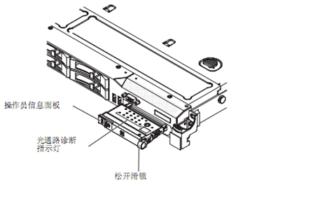
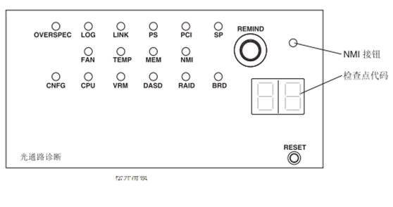
Кнопка напоминания:Эта кнопка устанавливает индикатор системной ошибки на передней панели как режим напоминания. В режиме напоминания загорается индикатор системной ошибки.2 Мигает раз в секунду,Пока проблема не будет исправлена, система перезапустится или возникнет новая проблема. Установив индикатор системной ошибки в режим напоминания, вы можете подтвердить, что знаете о предыдущем сбое, но не принимаете немедленных мер для устранения проблемы. Функция напоминания контролируетсяIMM контроль.
NMI Кнопка:Нажмите эту кнопку, чтобы микропроцессор сгенерировал немаскируемое прерывание. Это позволяет сделать синий экран сервера и выполнить дамп памяти (только еслиIBM Эту кнопку можно использовать только по указанию обслуживающего персонала).
Экран кода контрольной точки:На этом экране отображается код контрольной точки, указывающий, что система остановится в этой точке во время блока загрузки и POST.
Код контрольной точки — это значение байта или слово, сгенерированное UEFI. На этом экране не отображаются коды ошибок или рекомендуемые компоненты для замены.
кнопка сброса:Нажмите эту кнопку, чтобы перезагрузить сервер и запустить самотестирование при включении (POST). Для нажатия кнопки может потребоваться кончик ручки или конец выпрямленной канцелярской скрепки. Кнопка сброса расположена в правом нижнем углу панели диагностики светового тракта.
over spec Индикатор:Когда этот световой индикатор горит, это означает, что потребность в мощности превышает указанный источник питания.
log Индикатор:Когда этот индикатор горит, это означает, что в журнале событий есть ошибка, и вам следует проверить журнал событий.
linkИндикатор: Когда этот индикатор горит, сетевая карта неисправна.
psИндикатор:Когда этот световой индикатор горит, это указывает на отказ источника питания.
pci Индикатор:Если этот индикатор горит, это означает, что на шине PCI возникла ошибка.
sp Индикатор:Когда этот индикатор горит, это указывает на то, что потоковый процессор обнаружил ошибку (роль sp заключается в обработке данных, переданных ЦП, и преобразовании их в цифровой сигнал, который может быть распознан дисплеем после обработки)
fan: Когда этот индикатор горит, это означает, что охлаждающий вентилятор или вентилятор блока питания вышел из строя или работает слишком медленно. Отказ вентилятора также может вызватьtemp Световой индикатор горит.
temp Индикатор: Когда этот индикатор горит, это означает, что температура системы слишком высока.
mem Индикатор: Когда этот индикатор горит, это означает, что произошла ошибка памяти.
nmi Индикатор:Когда этот индикатор горит, это означает, что произошло немаскируемое прерывание (nmi)。
cnfgИндикатор: Когда этот индикатор горит, это означаетBIOSОшибка конфигурации.
cpu Индикатор:Когда этот индикатор горит, это означает, что микропроцессор вышел из строя.
vrm Индикатор:Когда этот индикатор горит, это означает, чтоvrm произошла ошибка.
dasd Индикатор:Когда этот индикатор горит, это означает, что произошел сбой жесткого диска с возможностью горячей замены.
raid Индикатор:Когда этот индикатор горит, это означает, что карта массива неисправна.
brd Индикатор:Когда этот индикатор горит, это означает, что подключенныйi/o Блок расширения неисправен.
2. Информационная панель оператора
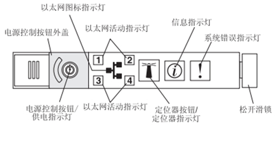
Крышка кнопки управления питанием:Сдвиньте крышку на кнопку управления питанием, чтобы предотвратить случайное выключение сервера.
Кнопка управления питанием:Нажмите эту кнопку, чтобы вручную включить и выключить сервер.
Источник питанияИндикатор:Если индикатор горит и не мигает, это означает, что сервер включен; если индикатор мигает, это означает, что сервер выключен и все еще подключен к источнику переменного тока; если индикатор не горит, это означает, что нет питания переменного тока или источника питания, или сам индикатор неисправен . Заметка:Если этот индикатор не горит, это не означает, что на сервере нет питания. Световой индикатор может перегореть. Чтобы полностью отключить питание сервера, необходимо вынуть шнур питания из розетки.
Индикатор значка Ethernet:Этот индикатор загорается значком Ethernet.
Индикатор активности Ethernet:Если эти индикаторы мигают, это означает, что между сервером и сетью существует активность на указанном ими порте.
Индикатор локатора:Используйте этот индикатор, чтобы найти целевой сервер среди множества серверов невооруженным глазом. можно использоватьIBM Director Световой индикатор можно включить дистанционно или вручную, нажав кнопку локатора. Этот индикатор также загорится при запуске. Если в многоузловой конфигурации этот индикатор мигает, это означает, что соответствующий ему сервер является главным узлом. Если индикатор продолжает гореть, это означает, что соответствующий ему сервер является вторичным узлом.
Кнопка локатора:Нажмите эту кнопку, чтобы вручную включить или выключить индикатор локатора. В многоузловой конфигурации нажмите эту кнопку, чтобы включить или выключить индикаторы локатора всех узлов в конфигурации.
Информационный индикатор:Если этот индикатор горит, это означает, что какой-то аспект сервера находится не в оптимальном состоянии, и при диагностике светового пути загорится еще один индикатор, помогающий определить проблему. Только после того, как проблема будет решена или будет нажата кнопка напоминания, световой индикатор и световой индикатор на диагностической панели светового тракта погаснут.
Индикатор системной ошибки:Если этот индикатор горит, это означает, что произошла системная ошибка. Индикатор на диагностической панели светового тракта также загорится, чтобы помочь найти эту ошибку.
Эта статья перенесена из блога easy80851CTO, исходная ссылка:http://blog.51cto.com/68240021/1970874Если вам нужно перепечатать, пожалуйста, свяжитесь с первоначальным автором