Troubleshooting
Problem
The system powers off immediately after it is powered on, or powers off during runtime.
The system subsequently may or may not power on after removing and connecting AC power.
The following conditions may be observed:
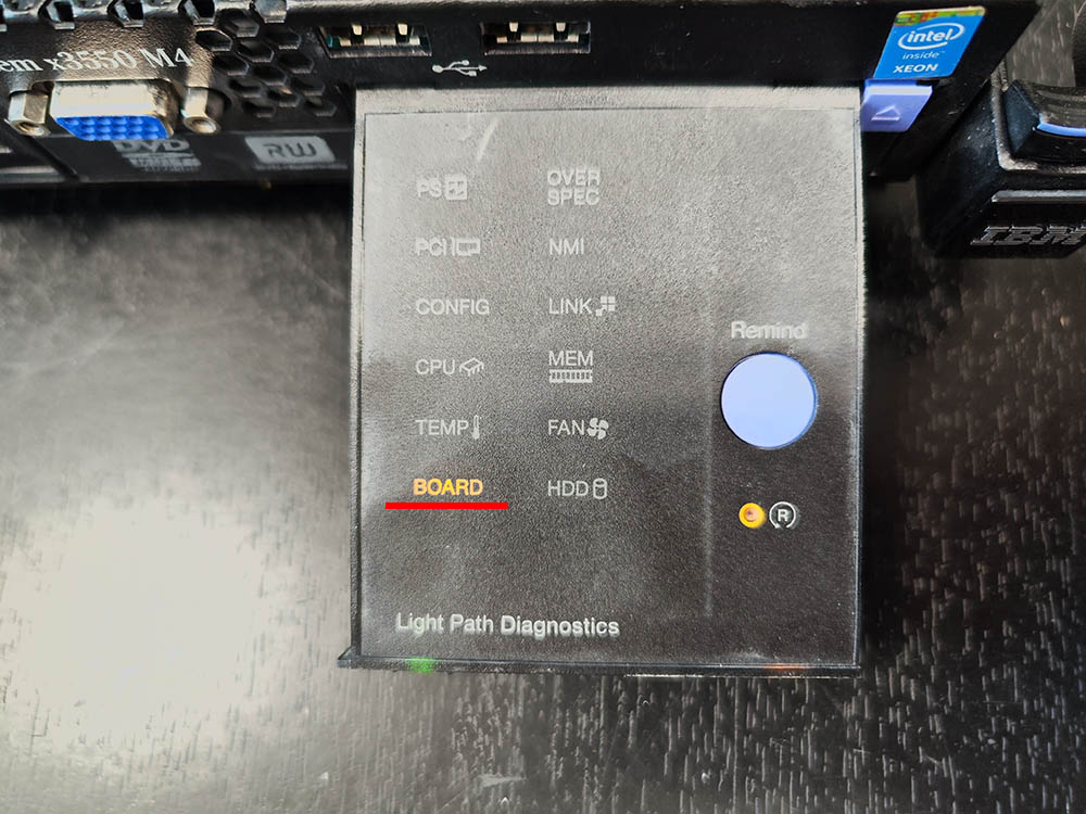
Lightpath display panel: BRD light may be illuminated.
Power supply Light Emitting Diode (LED): AC LED turns on; DC and error LEDs turn off
Integrated Management Module (IMM) event: Sensor system board fault has changed to critical from a less severe state
Dynamic System Analysis (DSA) log: 12V OC Fault
Resolving The Problem
Source
RETAIN tip: H207641
Symptom
The system powers off immediately after it is powered on, or
powers off during runtime.
The system subsequently may or may not power on after removing
and connecting AC power.
The following conditions may be observed:
- Lightpath display panel:
- BRD light may be illuminated.
- Power supply Light Emitting Diode (LED):
- AC LED turns on; DC and error LEDs turn off
- Integrated Management Module (IMM) event:
- Sensor system board fault has changed to critical from a less
severe state
- Sensor system board fault has changed to critical from a less
- Dynamic System Analysis (DSA) log:
- 12V OC Fault
Affected Configurations
The system may be any of the following IBM servers:
- System x3300 M4, type 7382, any model
- System x3500 M4, type 7383, any model
- System x3550 M4, type 7914, any model
- System x3650 M4, type 7915, any model
This tip is not software specific.
This tip is not option specific.
Solution
Update the IMM firmware per the following product list:
- IBM System x3550 M4: Version 1.97 Build ID: 1AOO36R
- IBM System x3650 M4: Version 1.97 Build ID: 1AOO36R
- IBM System x3500 M4: Version 1.97 Build ID: 1AOO36R
- IBM System x3300 M4: Version 2.00 Build ID: 1AOO40E
If the server will not power on, replace the system board and
update the IMM firmware to listed version or later.
The file is available by selecting the appropriate Product
Group, type of System, Product name, Product machine type, and
Operating system on IBM Support’s Fix Central web page, at the
following URL:
-
http://www.ibm.com/support/fixcentral/
Additional Information
Processor and memory Voltage Regulator Device (VRD) faults have
been observed when the processor is performing transitions between
C-state 0 (normal operating mode) and deep C-state modes.
Integrated Management Module II (IMM2) provides dual banks
(primary and backup) to improve system availability and to provide
system recovery function.
During normal operation, IMM2 always starts from the primary
bank. The backup IMM bank is not an exact copy of the primary bank
and should be used only for recovering the primary bank in the
event of a firmware failure.
It is recommended to update the IMM2 backup bank due to the
critical fix. The backup bank update can be performed by using
UpdateXpress System Pack Installer (UXSPI) and the web interface.
Users are allowed to select either bank of IMM2 to perform firmware
update.
Document Location
Worldwide
Operating System
System x:Operating system independent / None
System x Hardware Options:Operating system independent / None
[{«Type»:»HW»,»Business Unit»:{«code»:»BU016″,»label»:»Multiple Vendor Support»},»Product»:{«code»:»HW740″,»label»:»System x Hardware Options->Memory»},»Platform»:[{«code»:»PF025″,»label»:»Platform Independent»}],»Line of Business»:{«code»:»»,»label»:»»}},{«Type»:»HW»,»Business Unit»:{«code»:»BU016″,»label»:»Multiple Vendor Support»},»Product»:{«code»:»HWXG4″,»label»:»System x->System x3300 M4″},»Platform»:[{«code»:»PF025″,»label»:»Platform Independent»}],»Line of Business»:{«code»:»»,»label»:»»}},{«Type»:»HW»,»Business Unit»:{«code»:»BU016″,»label»:»Multiple Vendor Support»},»Product»:{«code»:»QU01DEW»,»label»:»System x->System x3500 M4->7383″},»Platform»:[{«code»:»PF025″,»label»:»Platform Independent»}],»Line of Business»:{«code»:»»,»label»:»»}},{«Type»:»HW»,»Business Unit»:{«code»:»BU016″,»label»:»Multiple Vendor Support»},»Product»:{«code»:»QU01DKP»,»label»:»System x->System x3650 M4->7915″},»Platform»:[{«code»:»PF025″,»label»:»Platform Independent»}],»Line of Business»:{«code»:»»,»label»:»»}},{«Type»:»HW»,»Business Unit»:{«code»:»BU016″,»label»:»Multiple Vendor Support»},»Product»:{«code»:»QU91IPI»,»label»:»System x->System x3550 M4->7914″},»Platform»:[{«code»:»PF025″,»label»:»Platform Independent»}],»Line of Business»:{«code»:»»,»label»:»»}}]
Сервер IBM System x3550/x3650 M4 – отличный выбор в условиях, когда компромисс недопустим. Исключительное время бесперебойной работы, производительность и гибкость ввода-вывода для обеспечения эффективности затрат и высочайшей надежности.
Серверы x3550/x3650 M4 отличаются высокой плотностью и идут в форм-факторе 1U/2U. Они предназначены для установки в стойку, имеют сбалансированные показатели производительности и цены. Развертывание производится в быстром режиме, а интеграцию и управление отличает простота. С равным успехом оборудование подходит для работы с облачными технологиями и критически важными приложениями. Компактный дизайн позволяет применять сервер даже при нехватке свободного пространства.
Любое оборудование подвержено поломкам, даже несмотря на высокую надежность. Так и данный сервер попал к нам в ремонт.
Неисправность сервера IBM System x3550
При подаче питания стартует IMM2, доступ по Web интерфейсу есть.
При попытке включения:
- Разгоняются все кулеры и тут же останавливаются
- Еще через пару секунд на передней выдвижной панельке загорается индикатор BOARD, а на материнской плате сервера — светодиод SYS BRD ERR.
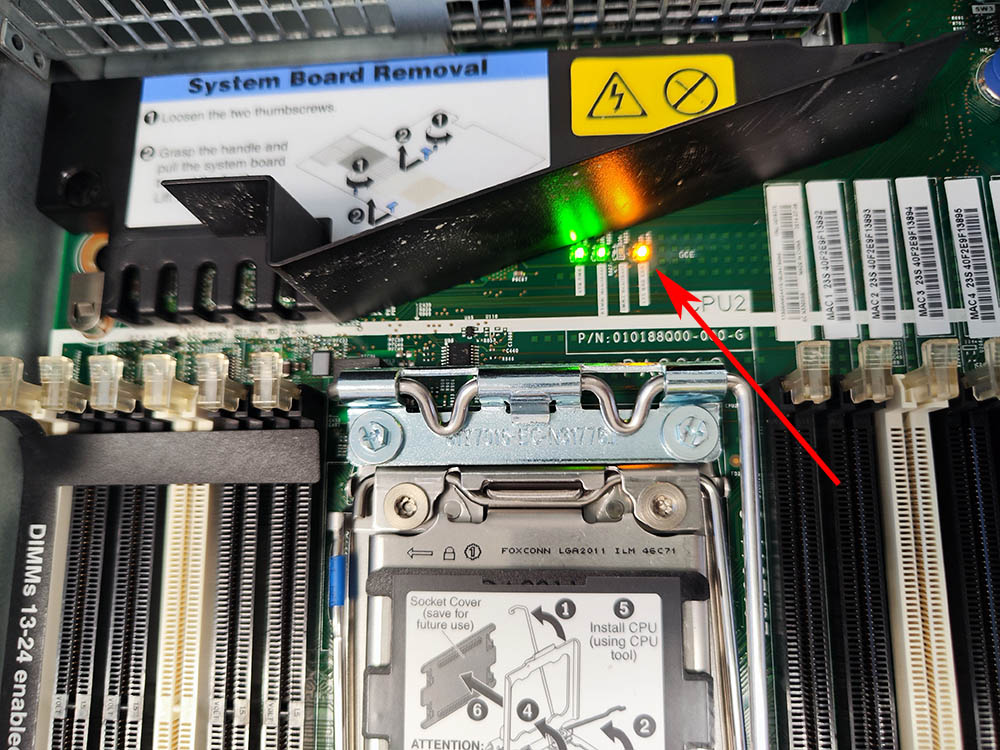
Диагностика сервера IBM System x3550
Заходим в IMM, смотрим логи.

Система показывает ошибку — 80070202-0701ffff: Sensor SysBrd Vol Fault has transitioned to critical from a less severe state.
Категория ошибки указывает на проблемы с питанием на материнской плате сервера.
Ремонт сервера IBM System x3550
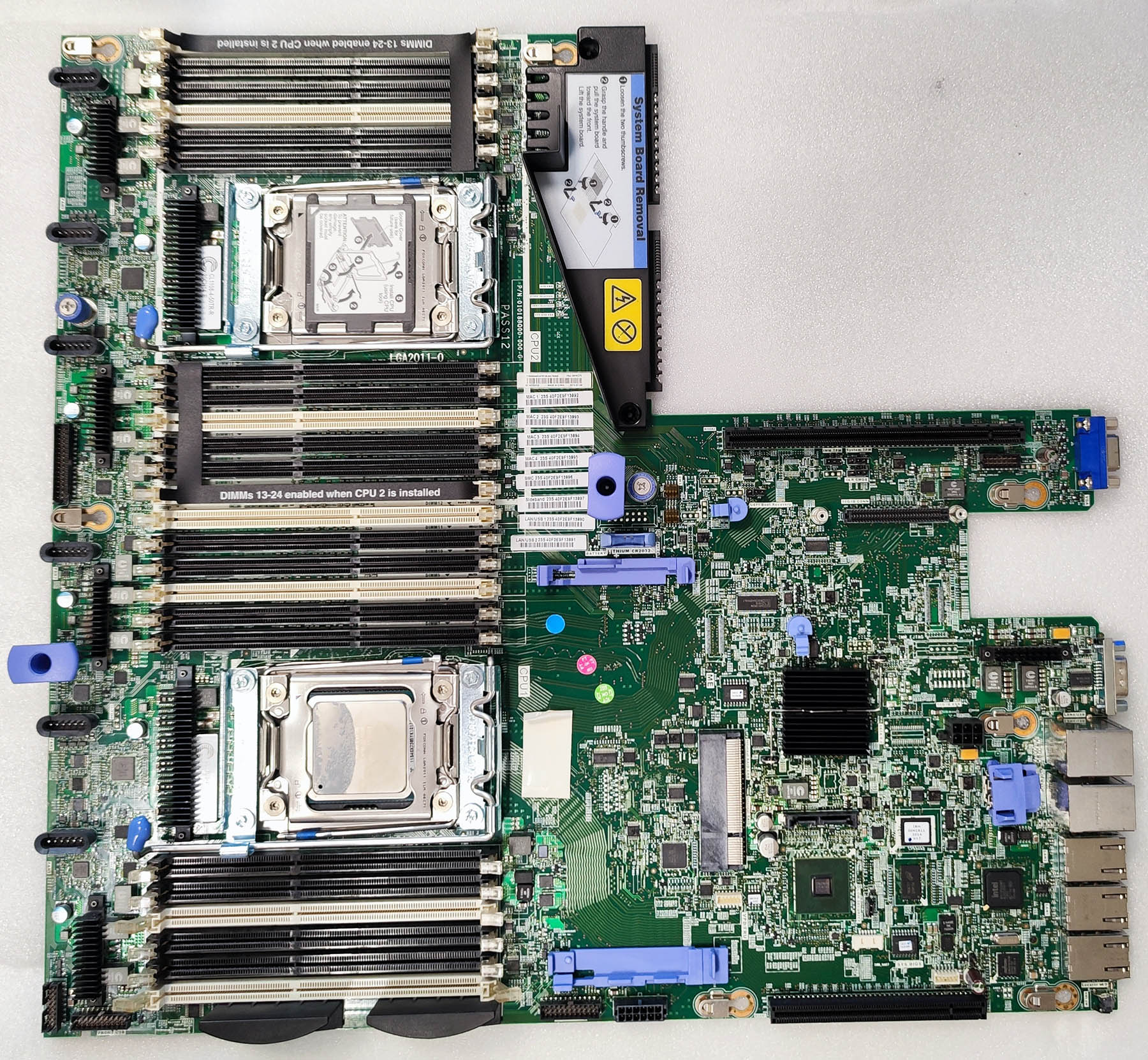
Для проверки, прозвоним все источники вторичного питания системной платы на предмет короткого замыкания. Для этого нужно разобрать сервер, снять материнскую плату.
Для того, чтобы снять материнскую плату, необходимо отключить блоки питания и шлейфы, извлечь платы расширения и вентиляторы охлаждения.
Прозваниваем цепи источников питания.
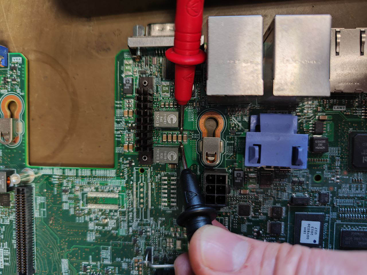
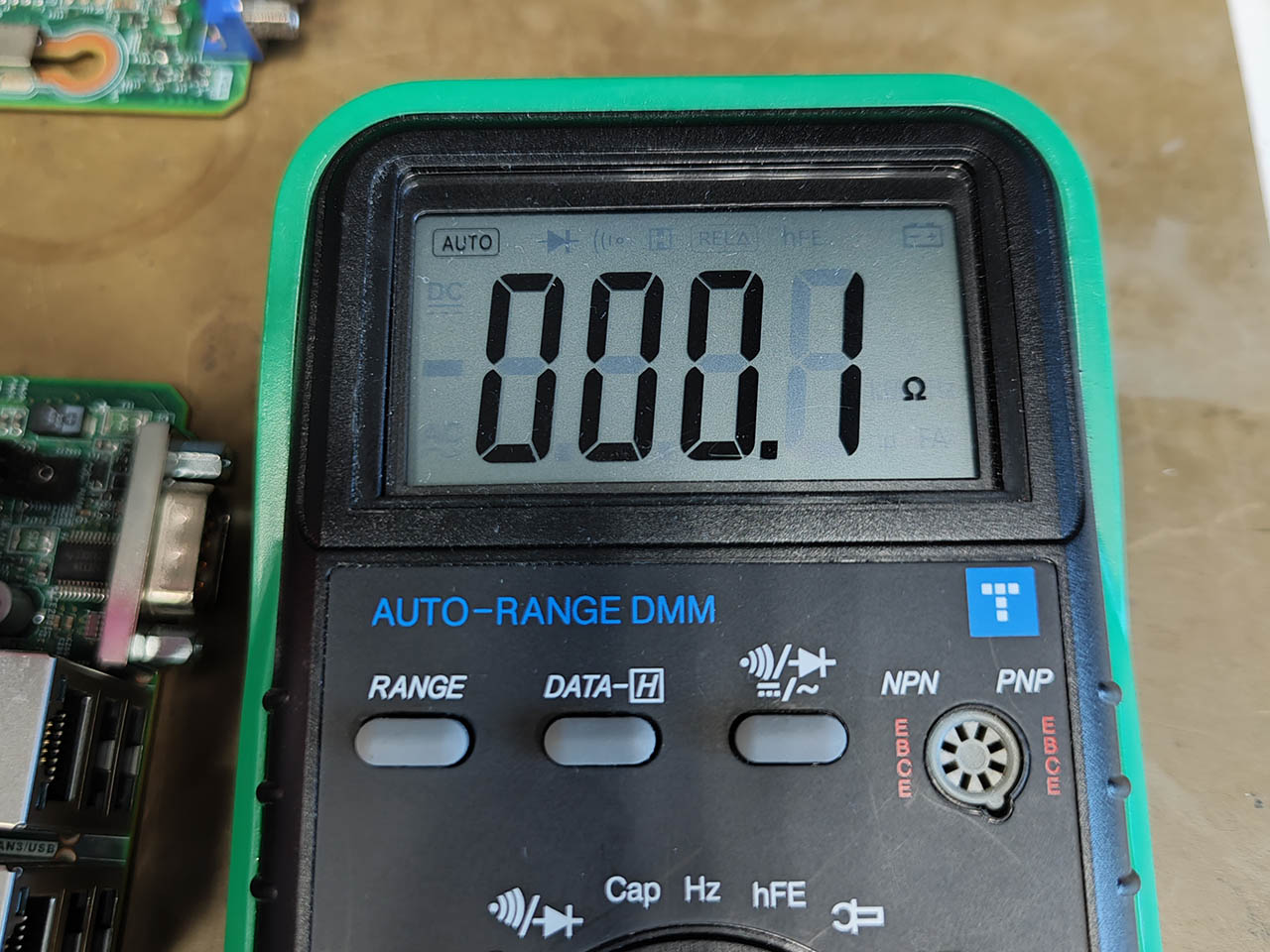
Находим короткое замыкание в одном из источников вторичного питания на системной плате.
Ремонт материнской платы сервера IBM x3550/x3650 состоит в замене ШИМ контроллера питания МЕ261wf.
После замены микросхемы снова проверяем сопротивление по питанию.
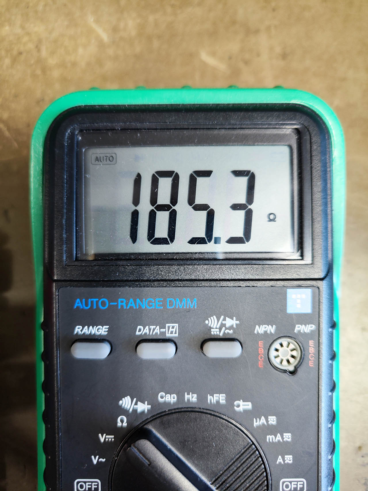
Собираем сервер, запускаем. Все работает, ремонт завершен.
-
Contents
-
Table of Contents
-
Troubleshooting
-
Bookmarks
Quick Links
IBM System x3550 Type 7978 and 1913
Problem Determination and Service Guide
Related Manuals for IBM x3550
Summary of Contents for IBM x3550
-
Page 1
IBM System x3550 Type 7978 and 1913 Problem Determination and Service Guide… -
Page 3
IBM System x3550 Type 7978 and 1913 Problem Determination and Service Guide… -
Page 4
Note: Before using this information and the product it supports, read the general information in Appendix B, “Notices,” on page 171 and the Warranty and Support Information document on the IBM System x Documentation CD. 24th Edition (October 2009) © Copyright International Business Machines Corporation 2006, 2007. -
Page 5: Table Of Contents
Removing a hard disk drive ….47 Installing a hard disk drive….49 © Copyright IBM Corp. 2006, 2007…
-
Page 6
Installing the system-board battery….68 IBM System x3550 dc power supply 670 W … . . 69 Removing and replacing Tier 2 CRUs . -
Page 7
Hardware service and support ….170 IBM Taiwan product service ….170 Appendix B. -
Page 8
IBM System x3550 Type 7978 and 1913: Problem Determination and Service Guide… -
Page 9: Safety
Les sikkerhetsinformasjonen (Safety Information) før du installerer dette produktet. Antes de instalar este produto, leia as Informações sobre Segurança. Antes de instalar este producto, lea la información de seguridad. Läs säkerhetsinformationen innan du installerar den här produkten. © Copyright IBM Corp. 2006, 2007…
-
Page 10: Guidelines For Trained Service Technicians
Use the information in this section to help you identify potential unsafe conditions in an IBM product that you are working on. Each IBM product, as it was designed and manufactured, has required safety items to protect users and service technicians from injury.
-
Page 11
v Do not touch the reflective surface of a dental mirror to a live electrical circuit. The surface is conductive and can cause personal injury or equipment damage if it touches a live electrical circuit. v Some rubber floor mats contain small conductive fibers to decrease electrostatic discharge. -
Page 12: Safety Statements
Be sure to read all caution and danger statements in this documentation before performing the instructions. Read any additional safety information that comes with your server or optional device before you install the device. IBM System x3550 Type 7978 and 1913: Problem Determination and Service Guide…
-
Page 13
Statement 1: DANGER Electrical current from power, telephone, and communication cables is hazardous. To avoid a shock hazard: v Do not connect or disconnect any cables or perform installation, maintenance, or reconfiguration of this product during an electrical storm. v Connect all power cords to a properly wired and grounded electrical outlet. -
Page 14
Statement 2: CAUTION: When replacing the lithium battery, use only IBM Part Number 33F8354 or an equivalent type battery recommended by the manufacturer. If your system has a module containing a lithium battery, replace it only with the same module type made by the same manufacturer. -
Page 15
Statement 3: CAUTION: When laser products (such as CD-ROMs, DVD drives, fiber optic devices, or transmitters) are installed, note the following: v Do not remove the covers. Removing the covers of the laser product could result in exposure to hazardous laser radiation. There are no serviceable parts inside the device. -
Page 16
The device also might have more than one power cord. To remove all electrical current from the device, ensure that all power cords are disconnected from the power source. IBM System x3550 Type 7978 and 1913: Problem Determination and Service Guide… -
Page 17
Statement 8: CAUTION: Never remove the cover on a power supply or any part that has the following label attached. Hazardous voltage, current, and energy levels are present inside any component that has this label attached. There are no serviceable parts inside these components. -
Page 18
IBM System x3550 Type 7978 and 1913: Problem Determination and Service Guide… -
Page 19: Chapter 1. Introduction
Replaceable components are of three types: v Tier 1 customer replaceable unit (CRU): Replacement of Tier 1 CRUs is your responsibility. If IBM installs a Tier 1 CRU at your request, you will be charged for the installation. v Tier 2 customer replaceable unit: You may install a Tier 2 CRU yourself or request IBM to install it, at no additional charge, under the type of warranty service that is designated for your server.
-
Page 20: Notices And Statements In This Document
These updates are available from the IBM Web site. To check for updated documentation and technical updates, complete the following steps.
-
Page 21: Features And Specifications
Features and specifications The following information is a summary of the features and specifications of the server. Depending on the server model, some features might not be available, or some specifications might not apply. Chapter 1. Introduction…
-
Page 22
PCI Expansion slots: – Server off: 8% to 80% will operate. v One PCI Express x8 (half length) v One PCI Express x8 (half length) or PCI-X (half length) IBM System x3550 Type 7978 and 1913: Problem Determination and Service Guide… -
Page 23: Server Controls, Leds, And Connectors
Server controls, LEDs, and connectors This section describes the controls, light-emitting diodes (LEDs), and connectors on the front and rear of the server. Front view The following illustration shows the controls, LEDs, and connectors on the front of the server. This configuration supports up to four 2.5-inch hot-swappable hard disk drives.
-
Page 24
Hard disk drive status LED: This LED is used on SAS hard disk drives. When this LED is lit, it indicates that the drive has failed. If an optional IBM ServeRAID controller is installed in the server, when this LED is flashing slowly (one flash per second), it indicates that the drive is being rebuilt. -
Page 25: Light Path Diagnostics Panel
(POST). You might have to use a pen or the end of a straightened paper clip to press the button. The reset button is to the right of the remind button. For information about light path diagnostics, see the System x3550 Problem Determination and Service Guide on the IBM System x Documentation CD.
-
Page 26: Rear View
This connector is active only if you have installed a Remote Supervisor Adapter II SlimLine, and it is used only by the Remote Supervisor Adapter II SlimLine. IBM System x3550 Type 7978 and 1913: Problem Determination and Service Guide…
-
Page 27: Internal Leds, Connectors, And Jumpers
v Ethernet activity LEDs: When these LEDs are lit, they indicate that the server is transmitting to or receiving signals from the Ethernet LAN that is connected to the Ethernet port. v Ethernet speed LED: When these LEDs are lit, they indicate that there is an active link connection on the 10BASE-T, 100BASE-TX, or 1000BASE-TX interface for the Ethernet port.
-
Page 28: System-Board Internal Connectors
Operator information Video front panel connector panel connector connector (USB3 and USB4) Power backplane card internal connectors The following illustration shows the internal connectors on the power backplane card. IBM System x3550 Type 7978 and 1913: Problem Determination and Service Guide…
-
Page 29: System-Board Switches And Jumpers
Power-supply connectors System-board connector Hard disk drive power connector System-board switches and jumpers The following illustration shows the switches and jumpers on the system board. Note: If a clear protective sticker is present on top of the SW2 switch block, you must remove and discard it in order to access the switches.
-
Page 30
NMI (SW1) Boot block recovery jumper (J14) 8 7 6 5 4 3 2 1 System board switch block (SW2) IBM System x3550 Type 7978 and 1913: Problem Determination and Service Guide… -
Page 31
Changing the position of this switch does not affect the administrator password check if an administrator password is set. See the User’s Guide on the IBM System x Documentation CD for additional information about the power-on password. BMC update switch… -
Page 32: System-Board External Connectors
The following illustration shows the external connectors on the system board. Ethernet connector USB 1 connector Systems- management USB 2 connector Ethernet 2 connector Serial connector Ethernet 1 connector Video connector IBM System x3550 Type 7978 and 1913: Problem Determination and Service Guide…
-
Page 33: System-Board Leds
System-board LEDs The following illustration shows the light-emitting diodes (LEDs) on the system board. Power-on LED System-board battery Location LED error LED System-error LED PCI slot 1 error LED DIMM 5 error LED DIMM 6 error LED DIMM 7 error LED PCI slot 2 error LED DIMM 8 error LED Light path diagnostics…
-
Page 34
When this LED is lit, it indicates that a system error has occurred. An LED on the light path diagnostics panel is also lit to help isolate the error. IBM System x3550 Type 7978 and 1913: Problem Determination and Service Guide… -
Page 35: System-Board Option Connectors
System-board option connectors The following illustration shows the connectors for user-installable options. PCI Express or PCI-X riser-card connector slot 2 (J12) PCI-Express riser card connector slot 1 (J34) RAID controller connector (J3) (some models) Remote Supervisor Adapter II SlimLine DIMM 5 connector connector (J60) DIMM 6 connector DIMM 7 connector…
-
Page 36
IBM System x3550 Type 7978 and 1913: Problem Determination and Service Guide… -
Page 37: Chapter 2. Configuration Information And Instructions
Configuring the server The ServerGuide Setup and Installation CD provides software setup tools and installation tools that are specifically designed for your IBM server. Use this CD during the initial installation of the server to configure basic hardware features and to simplify the operating-system installation.
-
Page 38: Serverguide Features
When you use the ServerGuide Setup and Installation CD, you do not need setup diskettes. You can use the CD to configure any supported IBM server model. The setup program provides a list of tasks that are required to set up your server model.
-
Page 39: Using The Configuration/Setup Utility Program
ServerGuide program to install your operating system, complete the following steps to download the latest operating-system installation instructions from the IBM Web site. Note: Changes are made periodically to the IBM Web site. The actual procedure might vary slightly from what is described in this document. 1. Go to http://www.ibm.com/systems/support/.
-
Page 40: Configuring The Ethernet Controller
Configuration/Setup Utility menu. 3. Follow the instructions on the screen. See the User’s Guide on the IBM System x Documentation CD for more detailed information about the Configuration/Setup Utility program. Configuring the Ethernet controller The Ethernet controller is integrated on the system board.
-
Page 41: Using The Ibm Serveraid Configuration Utility Program
Do not include SAS and SATA drives in the same array. v To update the firmware and BIOS code for an optional ServeRAID controller, you must use the IBM ServeRAID Support CD that comes with the ServeRAID option. Using the IBM ServeRAID Configuration Utility program…
-
Page 42
5. Click the (Add selected drives) icon to add the drives to the array. 6. If you want to configure a hot-spare drive, complete the following steps: a. Click the Spares tab. IBM System x3550 Type 7978 and 1913: Problem Determination and Service Guide… -
Page 43: Configuring Simple-Swap Sata Raid
For additional information about using the Adaptec RAID Configuration Utility program, see the documentation on the Adaptec HostRAID Support CD. If this CD did not come with the server, you can download it from http://www.ibm.com/ support/. Chapter 2. Configuration information and instructions…
-
Page 44: Updating The Uuid
1. Copy the DMI/SMBIOS utility (extrmdmi.exe) from the BIOS flash diskette to a DOS bootable diskette. 2. Insert the diskette into a diskette drive that is connected to the server. IBM System x3550 Type 7978 and 1913: Problem Determination and Service Guide…
-
Page 45
3. Restart the server from the diskette. 4. At the a:\ prompt, type extrmdmi.exe, and press Enter. 5. To change the machine type and model number, type mtm xxxxyyy where xxxx is the model type and yyy is the model number; then, press Enter. 6. -
Page 46
IBM System x3550 Type 7978 and 1913: Problem Determination and Service Guide… -
Page 47: Chapter 3. Parts Listing, Type 7978 And 1913 Server
Chapter 3. Parts listing, Type 7978 and 1913 server The following replaceable components are available for the System x3550 Type 7978 and 1913 servers. To check for an updated parts listing on the Web, complete the following steps: 1. Go to http://www.ibm.com/servers/eserver/support/xseries/index.html 2.
-
Page 48: Replaceable Server Components
Replaceable components are of three types: v Tier 1 customer replaceable unit (CRU): Replacement of Tier 1 CRUs is your responsibility. If IBM installs a Tier 1 CRU at your request, you will be charged for the installation. v Tier 2 customer replaceable unit: You may install a Tier 2 CRU yourself or request IBM to install it, at no additional charge, under the type of warranty service that is designated for your server.
-
Page 49
Table 4. Parts listing, Type 7978 and 1913 (continued) CRU part CRU part number number FRU part Index Description (Tier 1) (Tier 2) number AC Power supply, 670 W 39Y7189 DC Power supply, -48 V (optional) 39Y7186 AC Power supply, 450 W (optional) 39Y7196 Power supply filler panel 39Y9420… -
Page 50
Microprocessor, 3.73 GHz with heat sink (models 45x, 46x, 42C3998 4Sx) Microprocessor, E5335 2.0 GHz with heat sink (model A2x) 42D3801 Microprocessor, E5345 2.33 GHz with heat sink (models 42D3800 C2x, CBx) IBM System x3550 Type 7978 and 1913: Problem Determination and Service Guide… -
Page 51
Table 4. Parts listing, Type 7978 and 1913 (continued) CRU part CRU part number number FRU part Index Description (Tier 1) (Tier 2) number Microprocessor, X5355 2.66 GHz with heat sink (models 42D3802 C3x, CCx) Microprocessor, 2.00 GHz/1333 MHz, 12MB 80W, without 44R5644 heat sink (models B1x, BAx) Microprocessor, 2.50 GHz/1333 MHz, 12MB, 80W, without… -
Page 52: Product Recovery Cds
46M1154 card (optional) Y jumper cord (optional) 39M5450 Consumable parts are not covered by the IBM Statement of Limited Warranty. The following consumable part for MT 7233 is available for purchase from the retail store. Table 5. Consumable parts Description Part number Battery, 3.0 volt…
-
Page 53
Table 6. Product recovery CDs (continued) Description CRU part number Microsoft Windows Server 2003 R2 w/SP2 32 bit Standard 44W4047 Edition 1-4 microprocessors, French Microsoft Windows Server 2003 R2 w/SP2 32 bit Standard 44W4048 Edition 1-4 microprocessors, Italy Microsoft Windows Server 2003 R2 w/SP2 32 bit Standard 44W4049 Edition 1-4 microprocessors, German Microsoft Windows Server 2003 R2 w/SP2 32 bit Standard… -
Page 54
Microsoft Windows Server 2008 Enterprise Edition 32/64 bit 1-8 49Y0897 microprocessors, Traditional Chinese Microsoft Windows HPC Server 2008, English 68Y9455 Microsoft Windows HPC Server 2008, Japanese 68Y9456 Microsoft Windows HPC Server 2008, Simplified Chinese 68Y9457 IBM System x3550 Type 7978 and 1913: Problem Determination and Service Guide… -
Page 55: Power Cords
Power cords For your safety, IBM provides a power cord with a grounded attachment plug to use with this IBM product. To avoid electrical shock, always use the power cord and plug with a properly grounded outlet. IBM power cords used in the United States and Canada are listed by Underwriter’s Laboratories (UL) and certified by the Canadian Standards Association (CSA).
-
Page 56
Colombia, Costa Rica, Cuba, Dominican Republic, Ecuador, El Salvador, Guam, Guatemala, Haiti, Honduras, Jamaica, Mexico, Micronesia (Federal States of), Netherlands Antilles, Nicaragua, Panama, Peru, Philippines, Saudi Arabia, Thailand, Taiwan, United States of America, Venezuela IBM System x3550 Type 7978 and 1913: Problem Determination and Service Guide… -
Page 57: Chapter 4. Removing And Replacing Server Components
Replaceable components are of three types: v Tier 1 customer replaceable unit (CRU): Replacement of Tier 1 CRUs is your responsibility. If IBM installs a Tier 1 CRU at your request, you will be charged for the installation. v Tier 2 customer replaceable unit: You may install a Tier 2 CRU yourself or request IBM to install it, at no additional charge, under the type of warranty service that is designated for your server.
-
Page 58: System Reliability Guidelines
You have kept the preinstalled air deflector in place unless directed to remove it in this publication or by IBM Service. See “Removing the air baffle” on page 43 for the location of the air deflector in the server.
-
Page 59: Returning A Device Or Component
To reduce the possibility of damage from electrostatic discharge, observe the following precautions: v Limit your movement. Movement can cause static electricity to build up around you. v The use of a grounding system is recommended. For example, wear an electrostatic-discharge wrist strap, if one is available.
-
Page 60: Removing And Replacing Tier 1 Crus
Removing and replacing Tier 1 CRUs Replacement of Tier 1 CRUs is your responsibility. If IBM installs a Tier 1 CRU at your request, you will be charged for the installation. The illustrations in this document might differ slightly from your hardware.
-
Page 61: Removing The Air Baffle
Thumbscrew Fan door 4. Close the fan door. 5. Slide the server all the way into the rack until it latches. Removing the air baffle When working with some options, such as DIMMs, you must first remove the air baffle to access certain components or connectors on the system board. The following illustration shows how to remove the air baffle.
-
Page 62
Attention: For proper cooling and airflow, replace the air baffle before turning on the server. Operating the server with the air baffle removed might damage server components. IBM System x3550 Type 7978 and 1913: Problem Determination and Service Guide… -
Page 63: Installing The Air Baffle
Installing the air baffle To install the air baffle, complete the following steps. Air baffle Air baffle with cable guide 1. Read the safety information that begins on page vii and “Installation guidelines” on page 39. 2. Put the baffle into place from the top of the server and slide it forward to engage the bulkhead.
-
Page 64: Removing An Adapter
7. If you are instructed to return the adapter, follow all packaging instructions, and use any packaging materials for shipping that are supplied to you. IBM System x3550 Type 7978 and 1913: Problem Determination and Service Guide…
-
Page 65: Installing An Adapter
Installing an adapter To install an adapter, complete the following steps. Expansion slot cover PCI Express Adapter Adapter support bracket Expansion Riser-card slot 1 assembly Riser card connector 1. Remove the adapter from the static-protective package and set any jumpers or switches on the adapter as directed by the adapter manufacturer.
-
Page 66
1. Read the safety information that begins on page vii and “Installation guidelines” on page 39. 2. Move the handle on the drive to the open position (perpendicular to the drive). 3. Pull the hot-swap drive assembly from the bay. IBM System x3550 Type 7978 and 1913: Problem Determination and Service Guide… -
Page 67: Installing A Hard Disk Drive
Note: If the server has a RAID controller or adapter installed, you might have to reconfigure the disk arrays after installing hard disk drives. See the RAID documentation on the IBM System x Documentation CD for information about RAID adapters.
-
Page 68
Note: If you have a RAID configuration you might have to reconfigure the disk arrays after installing hard disk drives. See the RAID documentation on the IBM System x Documentation CD for information about RAID adapters. Installing a 3.5-inch hot-swap hard disk drive To install a 3.5-inch hot-swap hard disk drive, complete the following steps. -
Page 69: Removing And Installing The Internal Cd-Rw/Dvd Drive
Removing and installing the internal CD-RW/DVD drive Removing the CD-RW/DVD drive To remove the CD-RW/DVD drive, complete the following steps. Release button CD/DVD drive 1. If you are replacing a removed drive with a new drive, make sure that: v You have all the cables and other equipment that is specified in the documentation that comes with the new drive.
-
Page 70
Release button CD/DVD drive 4. Press and hold the release button as you push the drive from the rear to slide it out of the bay. IBM System x3550 Type 7978 and 1913: Problem Determination and Service Guide… -
Page 71
Drive-retention clip Alignment pins 5. Slide the drive-retention clip to remove it from the drive. 6. If you are instructed to return the CD-RW/DVD drive, follow all packaging instructions, and use any packaging materials for shipping that are supplied to you. -
Page 72: Removing A Memory Module (Dimm)
DIMMs at a time, in the order shown in the following table, to maintain performance. Table 7. DIMM installation sequence Pair DIMM connectors 1 and 3 5 and 7 2 and 4 IBM System x3550 Type 7978 and 1913: Problem Determination and Service Guide…
-
Page 73
Table 7. DIMM installation sequence (continued) Pair DIMM connectors 6 and 8 Channel 2 Figure 1. DIMM connectors, channels, and branches Channel 3 DIMM 5 connector DIMM 6 connector Branch 1 DIMM 7 connector DIMM 8 connector DIMM 1 connector DIMM 2 connector DIMM 3 connector DIMM 4 connector… -
Page 74
To avoid breaking the retaining clips or damaging the DIMM connectors, open and close the clips gently. 4. Open the retaining clip on each end of the DIMM connector. IBM System x3550 Type 7978 and 1913: Problem Determination and Service Guide… -
Page 75: Removing The Remote Supervisor Adapter Ii Slimline
5. Touch the static-protective package that contains the DIMM to any unpainted metal surface on the outside of the server. Then, remove the DIMM from the package. 6. Turn the DIMM so that the DIMM keys align correctly with the slot. 7.
-
Page 76: Installing The Remote Supervisor Adapter Ii Slimline
5. Install the cover (see “Installing the cover” on page 42). 6. Slide the server into the rack. IBM System x3550 Type 7978 and 1913: Problem Determination and Service Guide…
-
Page 77: Removing The Raid Controller
7. Reconnect the power cords and any cables that were removed. 8. Turn on the peripheral devices and the server. Removing the RAID controller To remove the RAID controller (some models) from the system board, complete the following steps: 1. Read the safety information that begins on page vii and “Installation guidelines” on page 39.
-
Page 78
RAID controller board. 5. Open the retaining clip on each end of the RAID controller board connector. 6. Slide the RAID controller board out of the connector. IBM System x3550 Type 7978 and 1913: Problem Determination and Service Guide… -
Page 79: Installing The Raid Controller
Installing the RAID controller To install the RAID controller on the system board, complete the following steps. Battery mounting tabs Battery Battery cable Battery mounting clips Battery cable connector RAID controller 1. Read the safety information that begins on page vii and “Installation guidelines” on page 39.
-
Page 80: Removing The Raid-Controller Battery
The battery is a lithium ion battery. To avoid possible explosion, do not burn the battery. Exchange it only with the IBM-approved part. Recycle or discard the battery as instructed by local regulations. In the United States, IBM has a process for collection of this battery. For information, call 1-800-426-4333.
-
Page 81: Installing The Raid-Controller Battery
The battery is a lithium ion battery. To avoid possible explosion, do not burn the battery. Exchange it only with the IBM-approved part. Recycle or discard the battery as instructed by local regulations. In the United States, IBM has a process for collection of this battery. For information, call 1-800-426-4333.
-
Page 82: Removing A Power Supply
4. Press and hold the orange release tab down and pull the power supply out of the server. IBM System x3550 Type 7978 and 1913: Problem Determination and Service Guide…
-
Page 83: Installing A Power Supply
Installing a power supply Statement 8: CAUTION: Never remove the cover on a power supply or any part that has the following label attached. Hazardous voltage, current, and energy levels are present inside any component that has this label attached. There are no serviceable parts inside these components.
-
Page 84: Removing A Hot-Swap Fan Assembly
4. Disconnect the cable of the failing fan from the connector. 5. Pull up on the orange tab to lift the fan out of the server. IBM System x3550 Type 7978 and 1913: Problem Determination and Service Guide…
-
Page 85: Installing A Hot-Swap Fan Assembly
Installing a hot-swap fan assembly Fan 1 A IR Air baffle Fan 3 Fan 4 Fan 5 Fan 2 Fan 6 Attention: To ensure proper server operation, replace a failed fan within two minutes. To replace a hot-swap-fan, complete the following steps: 1.
-
Page 86: Installing The System-Board Battery
After you replace the system-board battery, you must reconfigure the server and reset the system date and time. v To avoid possible danger, read and follow the following safety statement. IBM System x3550 Type 7978 and 1913: Problem Determination and Service Guide…
-
Page 87: Ibm System X3550 Dc Power Supply 670 W
Statement 2: CAUTION: When replacing the lithium battery, use only IBM Part Number 33F8354 or an equivalent type battery recommended by the manufacturer. If your system has a module containing a lithium battery, replace it only with the same module type made by the same manufacturer.
-
Page 88
If you are using terminal screws, see the documentation that came with the terminal for the torque requirements. Use this document with the documentation that comes with the IBM System x3550 server. The information in this document replaces the instructions in the server documentation for connecting and disconnecting the power cable from the rear of the server. -
Page 89
Statement 19: CAUTION: The power-control button on the device does not turn off the electrical current supplied to the device. The device also might have more than one connection to dc power. To remove all electrical current from the device, ensure that all connections to dc power are disconnected at the dc power input terminals. -
Page 90
4. Slide the power supply into the bay until it clicks into place. Make sure that you have pushed the power supply far enough forward that it connects firmly to the power-supply backplane. Power supply release tab DC power supply Power supply handle IBM System x3550 Type 7978 and 1913: Problem Determination and Service Guide… -
Page 91
5. Insert the dc power cords into the power supplies. a. Line up the triangular key on the dc power-cord connector with the triangular notch on the power-supply connector. b. Push the power-cord connector into the power-supply connector until it is well seated. -
Page 92: Removing And Replacing Tier 2 Crus
Store this document with the server for future use. Removing and replacing Tier 2 CRUs You may install a Tier 2 CRU yourself or request IBM to install it, at no additional charge, under the type of warranty service that is designated for your server.
-
Page 93: Removing A Riser Card Assembly
Removing a riser card assembly To remove a riser assembly, complete the following steps. Expansion slot cover PCI Express Adapter Adapter support bracket Expansion Riser-card slot 1 assembly Riser card connector Expansion slot cover Adapter support PCI adapter bracket Expansion slot 2 Riser-card assembly Riser-card…
-
Page 94: Installing A Riser Card Assembly
4. Install the cover (see “Installing the cover” on page 42). 5. Slide the server into the rack. 6. Reconnect the power cords and any cables that were removed. 7. Turn on the peripheral devices and the server. IBM System x3550 Type 7978 and 1913: Problem Determination and Service Guide…
-
Page 95: Removing A Disk Drive Cage Assembly
Removing a disk drive cage assembly Removing a 3.5-inch disk drive cage assembly To remove a 3.5-inch SAS disk drive cage assembly, complete the following steps. Mounting screws 3.5-inch drive cage 1. Read the safety information that begins on page vii and “Installation guidelines” on page 39.
-
Page 96
4. Remove the three drive cage mounting screws; then, slide the drive cage assembly forward out of the server. 5. Remove the SAS backplane. (See “Removing the hot swap backplane or simple swap backplate” on page 80). IBM System x3550 Type 7978 and 1913: Problem Determination and Service Guide… -
Page 97: Installing A Disk Drive Cage Assembly
Installing a disk drive cage assembly Installing a 3.5-inch disk drive cage assembly To install a 3.5-inch disk drive cage assembly, complete the following steps. Mounting screws 3.5-inch drive cage 1. Read the safety information that begins on page vii and “Installation guidelines” on page 39.
-
Page 98: Removing The Hot Swap Backplane Or Simple Swap Backplate
Removing the 3.5-inch backplane or backplate To remove the 3.5-inch SAS backplane or simple-swap SATA backplate, complete the following steps. Note: The following illustration shows removing the 3.5-inch hot-swap SAS backplane. IBM System x3550 Type 7978 and 1913: Problem Determination and Service Guide…
-
Page 99
Mounting channel Locking tab Mounting channel 1. Read the safety information that begins on page vii and “Installation guidelines” on page 39. 2. Turn off the server and peripheral devices and disconnect all power cords. 3. Remove the cover (see “Removing the cover” on page 42). 4. -
Page 100: Installing The Hot Swap Backplane Or Simple Swap Backplate
2. Connect the power cable to the replacement backplane or backplate. 3. Slide the backplane or backplate into the card guides, making sure not to trap or pinch any nearby wires or cables. IBM System x3550 Type 7978 and 1913: Problem Determination and Service Guide…
-
Page 101
4. Press firmly until the backplane or backplate is fully seated and the locking tab snaps into place. 5. Reconnect the backplane or backplate cables. v If the server is a hot-swap model, reconnect the two cables to the backplane. v If the server is a simple-swap model, reconnect the two blue signal cables to the system board and reconnect the power cable to the power supply backplane card. -
Page 102: Removing The Power-Supply Backplane
4. Disconnect the cable connected to the power-supply backplane. 5. Slide the power-supply backplane to the left, disconnecting it from the system board. 6. Lift the power-supply backplane to remove it from the server. IBM System x3550 Type 7978 and 1913: Problem Determination and Service Guide…
-
Page 103: Installing The Power-Supply Backplane
Installing the power-supply backplane To install the power-supply backplane, complete the following steps. 1. Read the safety information that begins on page vii and “Installation guidelines” on page 39. 2. Align the keyhole slots in the power-supply backplane with the mounting pins in the server.
-
Page 104: Removing And Replacing Frus
(this helps to break the bond between the heat sink and the microprocessor). After the captive screws are loosened, remove the heat sink. IBM System x3550 Type 7978 and 1913: Problem Determination and Service Guide…
-
Page 105: Installing A Microprocessor
Microprocessor orientation indicator Microprocessor Microprocessor- release lever Microprocessor orientation indicator Microprocessor connector 4. Open the microprocessor release lever to the fully-open position. 5. Open the microprocessor bracket frame. 6. If you are instructed to return the microprocessor, follow all packaging instructions, and use any packaging materials for shipping that are supplied to you.
-
Page 106
Do not use excessive force when inserting the microprocessor into the socket. Note: The microprocessor fits only one way on the socket. 3. Carefully close the release lever to secure the microprocessor in the socket. IBM System x3550 Type 7978 and 1913: Problem Determination and Service Guide… -
Page 107: Thermal Grease
Heat sink Heat-sink Thermal grease installation label Microprocessor 4. If the new heat sink did not come with thermal grease, you must apply thermal grease on the microprocessor before you install the heat sink (see “Thermal grease”). 5. Install the heat sink on top of the microprocessor, and tighten the captive screws.
-
Page 108: Removing The Operator Information Panel Assembly
(see “Removing the cover” on page 42). 3. Open the fan door. 4. Remove the CD-RW/DVD drive (see “Removing the CD-RW/DVD drive” on page 51). IBM System x3550 Type 7978 and 1913: Problem Determination and Service Guide…
-
Page 109
CD-RW cable connector Video cable connector Air baffle USB cable connector Lightpath cable connector CD-RW cable retainer Fan 3 Interposer card Lightpath cable CD-RW cable Video cable USB cable 5. Slide the CD-RW cable retainer away from the interposer card. Interposer card CD/DVD drive 6. -
Page 110
10. Press the release button on the front of the operator information panel and slide the assembly out of the server. Ribbon cable Operator information panel Release buttons IBM System x3550 Type 7978 and 1913: Problem Determination and Service Guide… -
Page 111: Installing The Operator Information Panel Assembly
11. Press the release buttons on the top of the server and slide the operator information panel assembly rails out of the server as far as it will go. 12. Pull the panel away from the rails and carefully pull the attached lightpath ribbon cable out of the server.
-
Page 112
11. Install the cover (see “Installing the cover” on page 42). 12. Slide the server into the rack. 13. Reconnect the power cords and any cables that were removed. 14. Turn on the peripheral devices and the server. IBM System x3550 Type 7978 and 1913: Problem Determination and Service Guide… -
Page 113: Removing The System Board
Removing the system board To remove the system board, complete the following steps. 1. Read the safety information that begins on page vii and “Installation guidelines” on page 39. 2. Turn off the server and any attached devices. Note: When replacing the system board, you must either update the server with the latest firmware or restore the pre-existing firmware that the customer provides on a diskette or CD image.
-
Page 114: Installing The System Board
Note: When reassembling the components in the server, be sure to route all cables carefully so that they are not exposed to excessive pressure. To reinstall the system board, complete the following steps. IBM System x3550 Type 7978 and 1913: Problem Determination and Service Guide…
-
Page 115
1. Read the safety information that begins on page vii and “Installation guidelines” on page 39. 2. Align the system board with the chassis and replace the six screws that you removed. 3. Replace the microprocessor and microprocessor heat sink (see “Installing a microprocessor”… -
Page 116
CD image. v Update the UUID (see “Updating the UUID” on page 26). v Update the DMI/SMBIOS (see “Updating the DMI/SMBIOS data” on page 26). IBM System x3550 Type 7978 and 1913: Problem Determination and Service Guide… -
Page 117: Chapter 5. Diagnostics
A single problem might cause more than one error message. When this occurs, correct the cause of the first error message. The other error messages usually will not occur the next time POST runs. © Copyright IBM Corp. 2006, 2007…
-
Page 118
RAM refresh verification failed. 1. Reseat the DIMMs. 2. Replace the following components, one at a time, in the order shown: a. DIMMs b. (Trained service technician only) System board IBM System x3550 Type 7978 and 1913: Problem Determination and Service Guide… -
Page 119
v Follow the suggested actions in the order in which they are listed in the Action column until the problem is solved. v See Chapter 3, “Parts listing, Type 7978 and 1913 server,” on page 29 to determine which components are CRUs and which components are FRUs. -
Page 120
1. Reseat the DIMMs. 2. Replace the following components one at a time, in the order shown, restarting the server each time: a. DIMMs b. (Trained service technician only) System board IBM System x3550 Type 7978 and 1913: Problem Determination and Service Guide… -
Page 121
v Follow the suggested actions in the order in which they are listed in the Action column until the problem is solved. v See Chapter 3, “Parts listing, Type 7978 and 1913 server,” on page 29 to determine which components are CRUs and which components are FRUs. -
Page 122
PCI-X/PCI Express adapter (if present) e. DIMMs f. Hard disk drives g. Hard disk drive backplane h. Hard disk drive power cable i. Hard disk drive signal cable (only for SAS drive) IBM System x3550 Type 7978 and 1913: Problem Determination and Service Guide… -
Page 123
v Follow the suggested actions in the order in which they are listed in the Action column until the problem is solved. v See Chapter 3, “Parts listing, Type 7978 and 1913 server,” on page 29 to determine which components are CRUs and which components are FRUs. -
Page 124
(Trained service technician only) Replace the LED is off) system board. See ″Information panel system error LED.″ No beep No beep and no video (system Attention LED is on) IBM System x3550 Type 7978 and 1913: Problem Determination and Service Guide… -
Page 125: Error Logs
Configuration/Setup Utility program (the menu choices are described in the User’s Guide on the IBM System x Documentation CD). When you are troubleshooting an error, be sure to clear both the logs so that you can find current errors more easily.
-
Page 126: Post Error Codes
Replace the following components, one at a time, in the order shown, restarting the server each time: 1. Adapter (if present) 2. DIMMs 3. (Trained service technician only) System board IBM System x3550 Type 7978 and 1913: Problem Determination and Service Guide…
-
Page 127
v Follow the suggested actions in the order in which they are listed in the Action column until the problem is solved. v See Chapter 3, “Parts listing, Type 7978 and 1913 server,” on page 29 to determine which components are customer replaceable units (CRU) and which components are field replaceable units (FRU). -
Page 128
DIMMs b. (Trained service technician only) System board Service processor failure. (Trained service technician only) Replace the system board. IBM System x3550 Type 7978 and 1913: Problem Determination and Service Guide… -
Page 129
v Follow the suggested actions in the order in which they are listed in the Action column until the problem is solved. v See Chapter 3, “Parts listing, Type 7978 and 1913 server,” on page 29 to determine which components are customer replaceable units (CRU) and which components are field replaceable units (FRU). -
Page 130
2. Make sure that the DIMM is installed correctly (see “Installing a memory module” on page 54). 3. Reseat the DIMM. 4. Replace the DIMM. 5. (Trained service technician only) Replace the system board. IBM System x3550 Type 7978 and 1913: Problem Determination and Service Guide… -
Page 131
v Follow the suggested actions in the order in which they are listed in the Action column until the problem is solved. v See Chapter 3, “Parts listing, Type 7978 and 1913 server,” on page 29 to determine which components are customer replaceable units (CRU) and which components are field replaceable units (FRU). -
Page 132
4. Replace the following components one at a time, in the order shown, restarting the server each time: a. Hard disk drive b. Hard disk drive backplate c. (Trained service technician only) System board IBM System x3550 Type 7978 and 1913: Problem Determination and Service Guide… -
Page 133
v Follow the suggested actions in the order in which they are listed in the Action column until the problem is solved. v See Chapter 3, “Parts listing, Type 7978 and 1913 server,” on page 29 to determine which components are customer replaceable units (CRU) and which components are field replaceable units (FRU). -
Page 134
2. If you are using an external USB hub, disconnect the pointing device from the hub and connect it directly to the server. 3. Replace the pointing device. 4. (Trained service technician only) Replace the system board. IBM System x3550 Type 7978 and 1913: Problem Determination and Service Guide… -
Page 135
v Follow the suggested actions in the order in which they are listed in the Action column until the problem is solved. v See Chapter 3, “Parts listing, Type 7978 and 1913 server,” on page 29 to determine which components are customer replaceable units (CRU) and which components are field replaceable units (FRU). -
Page 136
2. Reseat each installed PCI adapter and riser card. 3. (Trained service technician only) Replace the system board. 4. Replace each installed PCI adapter, restarting the server each time. IBM System x3550 Type 7978 and 1913: Problem Determination and Service Guide… -
Page 137
v Follow the suggested actions in the order in which they are listed in the Action column until the problem is solved. v See Chapter 3, “Parts listing, Type 7978 and 1913 server,” on page 29 to determine which components are customer replaceable units (CRU) and which components are field replaceable units (FRU). -
Page 138
If an action step is preceded by “(Trained service technician only),” that step must be performed only by a trained service technician. Error code Description Action I9990650 AC power has been restored. 1. Check the power cables. 2. Check for interruption of the ac power supply. IBM System x3550 Type 7978 and 1913: Problem Determination and Service Guide… -
Page 139: Checkout Procedure
Checkout procedure The checkout procedure is the sequence of tasks that you must follow to diagnose a problem in the server. About the checkout procedure Before performing the checkout procedure for diagnosing hardware problems, review the following information: v Read the safety information that begins on page vii. v The diagnostic programs provide the primary methods of testing the major components of the server, such as the system board, Ethernet controller, keyboard, mouse (pointing device), serial ports, and hard disk drives.
-
Page 140
“Solving undetermined problems” on page 166. v Yes: Find the beep code in “POST beep codes” on page 99; if necessary, see “Solving undetermined problems” on page 166. IBM System x3550 Type 7978 and 1913: Problem Determination and Service Guide… -
Page 141: Troubleshooting Tables
Troubleshooting tables Use the troubleshooting tables to find solutions to problems that have identifiable symptoms. If you cannot find the problem in these tables, see “Running the diagnostic programs” on page 142 for information about testing the server. If you have just added new software or a new optional device and the server is not working, complete the following steps before using the troubleshooting tables: 1.
-
Page 142: General Problems
RAID device errors (see “Error logs” on page 107) and use the RAID device utilities to confirm correct disk drive setup (“Using the Configuration/Setup Utility program” on page 21). IBM System x3550 Type 7978 and 1913: Problem Determination and Service Guide…
-
Page 143: Intermittent Problems
“Diagnostic programs, messages, and error codes” on page 141. 2. If the reset occurs after the operating system starts, disable any automatic server restart (ASR) utilities, such as the IBM Automatic Server Restart IPMI Application for Windows, or ASR devices that may be installed.
-
Page 144: Usb Keyboard, Mouse, Or Pointing-Device Problems
4. Replace the following components one at a time, in the order shown, restarting the server each time: a. Mouse or pointing device b. (Trained service technician only) System board IBM System x3550 Type 7978 and 1913: Problem Determination and Service Guide…
-
Page 145: Memory Problems
Memory problems v Follow the suggested actions in the order in which they are listed in the Action column until the problem is solved. v See Chapter 3, “Parts listing, Type 7978 and 1913 server,” on page 29 to determine which components are customer replaceable units (CRU) and which components are field replaceable units (FRU).
-
Page 146: Microprocessor Problems
2 in the connector for microprocessor 1; then, restart the server. If no beep code occurs, microprocessor 1 might have failed; replace the microprocessor. 5. (Trained service technician only) Replace the microprocessor. IBM System x3550 Type 7978 and 1913: Problem Determination and Service Guide…
-
Page 147: Monitor Problems
Monitor problems Some IBM monitors have their own self-tests. If you suspect a problem with your monitor, see the documentation that comes with the monitor for instructions for testing and adjusting the monitor. If you cannot diagnose the problem, call for service.
-
Page 148
2. Reseat the monitor cable. 3. Replace the following components one at a time, in the order shown, restarting the server each time: a. Monitor b. (Trained service technician only) System board IBM System x3550 Type 7978 and 1913: Problem Determination and Service Guide… -
Page 149: Optional-Device Problems
An IBM optional device that was 1. Make sure that: just installed does not work. v The device is designed for the server (see http://www.ibm.com/servers/ eserver/serverproven/compat/us/). v You followed the installation instructions that came with the device and the device is installed correctly.
-
Page 150: Power Problems
DIMMs b. Power supply c. (Trained service technician only) Power backplane d. (Trained service technician only) System board 6. See “Solving undetermined problems” on page 166. IBM System x3550 Type 7978 and 1913: Problem Determination and Service Guide…
-
Page 151
v Follow the suggested actions in the order in which they are listed in the Action column until the problem is solved. v See Chapter 3, “Parts listing, Type 7978 and 1913 server,” on page 29 to determine which components are customer replaceable units (CRU) and which components are field replaceable units (FRU). -
Page 152: Serial Port Problems
2. Make sure that the hard disk drive is connected correctly. operating system cannot be 3. Make sure that the hard disk drive cables are securely connected. installed. IBM System x3550 Type 7978 and 1913: Problem Determination and Service Guide…
-
Page 153: Software Problems
v Follow the suggested actions in the order in which they are listed in the Action column until the problem is solved. v See Chapter 3, “Parts listing, Type 7978 and 1913 server,” on page 29 to determine which components are customer replaceable units (CRU) and which components are field replaceable units (FRU).
-
Page 154: Universal Serial Bus (Usb) Port Problems
If the system-error LED is lit, it indicates that an error has occurred; go to step 2 on page 137. The following illustration shows the operator information panel. IBM System x3550 Type 7978 and 1913: Problem Determination and Service Guide…
-
Page 155
2. To view the light path diagnostics panel, slide the latch to the left on the front of the light path diagnostics drawer. This reveals the light path diagnostics panel. Lit LEDs on this panel indicate the type of error that has occurred. The following illustration shows the light path diagnostics panel. -
Page 156: Remind Button
The following table describes the LEDs on the light path diagnostics panel and suggested actions to correct the detected problems. Note: Check the system-error log or BMC log for additional information before replacing a FRU. IBM System x3550 Type 7978 and 1913: Problem Determination and Service Guide…
-
Page 157
v Follow the suggested actions in the order in which they are listed in the Action column until the problem is solved. v See Chapter 3, “Parts listing, Type 7978 and 1913 server,” on page 29 to determine which components are customer replaceable units (CRU) and which components are field replaceable units (FRU). -
Page 158: Power-Supply Leds
One power supply v Power backplane v Power cord v Five cooling fans v ServeRAID adapter (SR 8k or 8k-l) The following illustration shows the locations of the power-supply LEDs. IBM System x3550 Type 7978 and 1913: Problem Determination and Service Guide…
-
Page 159: Diagnostic Programs, Messages, And Error Codes
Power connector PCI slot 1 PCI slot 2 AC power DC power Ethernet 1 Video Power-on LED connector System-locator LED USB 2 System-error LED Ethernet 2 USB 1 Systems- Serial management Ethernet connector connector The following table describes the problems that are indicated by various combinations of the power-supply LEDs and the power-on LED on the operator information panel and suggested actions to correct the detected problems.
-
Page 160: Running The Diagnostic Programs
If the diagnostic programs do not detect any hardware errors but the problem remains during normal server operations, a software error might be the cause. If you suspect a software problem, see the information that comes with your software. IBM System x3550 Type 7978 and 1913: Problem Determination and Service Guide…
-
Page 161: Diagnostic Text Messages
A single problem might cause more than one error message. When this happens, correct the cause of the first error message. The other error messages usually will not occur the next time you run the diagnostic programs. Exception: If there are multiple error codes or diagnostics LEDs that indicate a microprocessor error, the error might be in a microprocessor or in a microprocessor socket.
-
Page 162: Diagnostic Error Codes
011-xxx-000 Failed COM1 serial port test. 1. Check the loopback plug that is connected to the serial port. 2. (Trained service technician only) Replace the system board. IBM System x3550 Type 7978 and 1913: Problem Determination and Service Guide…
-
Page 163
v Follow the suggested actions in the order in which they are listed in the Action column until the problem is solved. v See Chapter 3, “Parts listing, Type 7978 and 1913 server,” on page 29 to determine which components are customer replaceable units (CRU) and which components are field replaceable units (FRU). -
Page 164
ASM busy. Refer to the error log and diagnostic panel. 3. Disconnect all server and option power cords from the server, wait 30 seconds, reconnect, and retry. 4. (Trained service technician only) Replace the system board. IBM System x3550 Type 7978 and 1913: Problem Determination and Service Guide… -
Page 165
v Follow the suggested actions in the order in which they are listed in the Action column until the problem is solved. v See Chapter 3, “Parts listing, Type 7978 and 1913 server,” on page 29 to determine which components are customer replaceable units (CRU) and which components are field replaceable units (FRU). -
Page 166
3. Disconnect all server and option power cords from the server, wait 30 seconds, reconnect, and retry. 4. Remote Supervisor Adapter II SlimLine, if installed. 5. (Trained service technician only) Replace the system board. IBM System x3550 Type 7978 and 1913: Problem Determination and Service Guide… -
Page 167
v Follow the suggested actions in the order in which they are listed in the Action column until the problem is solved. v See Chapter 3, “Parts listing, Type 7978 and 1913 server,” on page 29 to determine which components are customer replaceable units (CRU) and which components are field replaceable units (FRU). -
Page 168
2. Reflash or update the firmware for the BMC. 3. Reseat the power backplane 4. Replace the power backplane. 5. (Trained service technician only) Replace the system board. IBM System x3550 Type 7978 and 1913: Problem Determination and Service Guide… -
Page 169
v Follow the suggested actions in the order in which they are listed in the Action column until the problem is solved. v See Chapter 3, “Parts listing, Type 7978 and 1913 server,” on page 29 to determine which components are customer replaceable units (CRU) and which components are field replaceable units (FRU). -
Page 170
Failed diagnostics LED panel test. Trained service technician only: 1. Disconnect the server power cords and reseat the operator information panel cable. Restart the server. 2. Replace the operator information panel. IBM System x3550 Type 7978 and 1913: Problem Determination and Service Guide… -
Page 171
v Follow the suggested actions in the order in which they are listed in the Action column until the problem is solved. v See Chapter 3, “Parts listing, Type 7978 and 1913 server,” on page 29 to determine which components are customer replaceable units (CRU) and which components are field replaceable units (FRU). -
Page 172
1. Adapter in PCI slot n 2. (Trained service technician only) System board IBM System x3550 Type 7978 and 1913: Problem Determination and Service Guide… -
Page 173
v Follow the suggested actions in the order in which they are listed in the Action column until the problem is solved. v See Chapter 3, “Parts listing, Type 7978 and 1913 server,” on page 29 to determine which components are customer replaceable units (CRU) and which components are field replaceable units (FRU). -
Page 174: Recovering The Bios Code
1. Go to http://www.ibm.com/systems/support/. 2. Under Product support, click System x. 3. Under Popular links, click Software and device drivers. 4. Click IBM System x3550 to display the matrix of downloadable files for the server. 5. Download the latest BIOS code update.
-
Page 175
NMI (SW1) Boot block recovery jumper (J14) 8 7 6 5 4 3 2 1 System board switch block (SW2) 4. Move the jumper from pins 1 and 2 to pins 2 and 3 to enable the BIOS recovery mode. 5. -
Page 176: System-Error Log Messages
(see “Installing a microprocessor” on page 87). Attention: If the layer of thermal grease is disturbed, the microprocessor could overheat and be damaged. IBM System x3550 Type 7978 and 1913: Problem Determination and Service Guide…
-
Page 177
v Follow the suggested actions in the order in which they are listed in the Action column until the problem is solved. v See Chapter 3, “Parts listing, Type 7978 and 1913 server,” on page 29 to determine which components are customer replaceable units (CRU) and which components are field replaceable units (FRU). -
Page 178
Information only +1.8v critical over voltage fault Information only +1.8v critical under voltage fault Information only The system real time clock battery is no longer Replace the battery. reliable. IBM System x3550 Type 7978 and 1913: Problem Determination and Service Guide… -
Page 179
v Follow the suggested actions in the order in which they are listed in the Action column until the problem is solved. v See Chapter 3, “Parts listing, Type 7978 and 1913 server,” on page 29 to determine which components are customer replaceable units (CRU) and which components are field replaceable units (FRU). -
Page 180
1. Make sure that there are no obstructions, such as bundled n = the power supply number cables, to the airflow on the power-supply fan. 2. Replace power supply n. IBM System x3550 Type 7978 and 1913: Problem Determination and Service Guide… -
Page 181
v Follow the suggested actions in the order in which they are listed in the Action column until the problem is solved. v See Chapter 3, “Parts listing, Type 7978 and 1913 server,” on page 29 to determine which components are customer replaceable units (CRU) and which components are field replaceable units (FRU). -
Page 182: Solving Power Problems
3. Check for loose cables in the power subsystem. Also check for short circuits, for example, if a loose screw is causing a short circuit on a circuit board. IBM System x3550 Type 7978 and 1913: Problem Determination and Service Guide…
-
Page 183: Solving Ethernet Controller Problems
4. Remove the adapters and disconnect the cables and power cords to all internal and external devices until the server is at the minimum configuration that is required for the server to start (see “Solving undetermined problems” on page 166 for the minimum configuration). 5.
-
Page 184: Solving Undetermined Problems
– If it has been working, what changes were made prior to it failing? – Is this the original reported failure? v Diagnostics version – Type and version level IBM System x3550 Type 7978 and 1913: Problem Determination and Service Guide…
-
Page 185: Calling Ibm For Service
“non-working” systems will often lead to problem resolution. Calling IBM for service See Appendix A, “Getting help and technical assistance,” on page 169 for information about calling IBM for service. When you call for service, have as much of the following information available as possible:…
-
Page 186
Address jumpers, terminators, and cabling v Software versions and levels v Diagnostic program type and version level v Configuration option settings v Operating-system control-file setup IBM System x3550 Type 7978 and 1913: Problem Determination and Service Guide… -
Page 187: Appendix A. Getting Help And Technical Assistance
If you need help, service, or technical assistance or just want more information about IBM products, you will find a wide variety of sources available from IBM to assist you. This section contains information about where to go for additional information about IBM and IBM products, what to do if you experience a problem with your system, and whom to call for service, if it is necessary.
-
Page 188: Software Service And Support
You can find service information for IBM systems and optional devices at http://www.ibm.com/systems/support/. Software service and support Through IBM Support Line, you can get telephone assistance, for a fee, with usage, configuration, and software problems with System x and xSeries servers, BladeCenter products, IntelliStation workstations, and appliances. For information about which products are supported by Support Line in your country or region, see http://www.ibm.com/services/sl/products/.
-
Page 189: Appendix B. Notices
Web sites. The materials at those Web sites are not part of the materials for this IBM product, and use of those Web sites is at your own risk. IBM may use or distribute any of the information you supply in any way it believes appropriate without incurring any obligation to you.
-
Page 190: Important Notes
Maximum internal hard disk drive capacities assume the replacement of any standard hard disk drives and population of all hard disk drive bays with the largest currently supported drives that are available from IBM. IBM System x3550 Type 7978 and 1913: Problem Determination and Service Guide…
-
Page 191: Product Recycling And Disposal
IBM makes no representations or warranties with respect to non-IBM products. Support (if any) for the non-IBM products is provided by the third party, not IBM. Some software might differ from its retail version (if available) and might not include user manuals or all program functionality.
-
Page 192: Battery Return Program
United States, go to http://www.ibm.com/ibm/environment/ products/index.shtml or contact your local waste disposal facility. In the United States, IBM has established a return process for reuse, recycling, or proper disposal of used IBM sealed lead acid, nickel cadmium, nickel metal hydride, and battery packs from IBM equipment.
-
Page 193
For proper collection and treatment, contact your local IBM representative. For California: Perchlorate material – special handling may apply. See http://www.dtsc.ca.gov/ hazardouswaste/perchlorate/. -
Page 194: Electronic Emission Notices
Properly shielded and grounded cables and connectors must be used in order to meet FCC emission limits. IBM is not responsible for any radio or television interference caused by using other than recommended cables and connectors or by unauthorized changes or modifications to this equipment.
-
Page 195: Taiwanese Class A Warning Statement
This is a Class A product. In a domestic environment this product may cause radio interference in which case the user may be required to take adequate measures. European Community contact: IBM Technical Regulations Pascalstr. 100, Stuttgart, Germany 70569 Telephone: 0049 (0)711 785 1176 Fax: 0049 (0)711 785 1283 E-mail: tjahn@de.ibm.com…
-
Page 196: Korean Class A Warning Statement
Korean Class A warning statement IBM System x3550 Type 7978 and 1913: Problem Determination and Service Guide…
-
Page 197: Index
Ethernet 9 POST/BIOS 108 Ethernet systems-management 8 system error 158 power supply 8 error logs 107 serial 8 clearing 107 USB 6, 8 POST 107 video system error 107 front 6 viewing 107 rear 8 © Copyright IBM Corp. 2006, 2007…
-
Page 198
89 ac power 8 CD-RW/DVD drive activity 6 hard disk drive dc power 8 diagnostic tests, types of 142 Ethernet activity 9 hot-swap SATA 48 Ethernet-link status 9 IBM System x3550 Type 7978 and 1913: Problem Determination and Service Guide… -
Page 199
LED (continued) hard disk drive activity 6 slot 1 8 hard disk drive status 6 slot 2 8 hard drive activity 6 PCI expansion slots 4 location 5 pointing device problems 126 power-on 5 POST rear 8 beep codes 99 system information 6 error codes 108 system locator 6… -
Page 200
3 rear 8 starting video controller Array Configuration Utility 26 specifications 4 statements and notices 2 viewing the configuration support, web site 169 Serial ATA controller 26 IBM System x3550 Type 7978 and 1913: Problem Determination and Service Guide… -
Page 201
viewing the configuration (continued) ServeRAID Manager 25 web site publication ordering 169 support 169 support line, telephone numbers 170 Index… -
Page 202
IBM System x3550 Type 7978 and 1913: Problem Determination and Service Guide… -
Page 204
Part Number: 49Y0122 Printed in USA (1P) P/N: 49Y0122…
| Автор |
|
|||
|---|---|---|---|---|
|
[ТС] |
Заголовок сообщения: Сервер IBM System x3560 M4 (7915 K4G) ошибка «BOARD»
|
|||
Сообщения: 49 |
Всем доброго времени! У вас нет доступа для просмотра вложений: |
|||
|
|
|
|||


|
RsM |
Заголовок сообщения: Re: Сервер IBM System x3560 M4 (7915 K4G) ошибка «BOARD»
|
|
Сообщения: 8067 |
Сопротивление хаба по какому напряжению измерено? Если 1,05В — то нормально. Перед посадкой вольтеры залудить свинцом м/с и плату.
|
|
|
|
|
garsiasergei |
Заголовок сообщения: Re: Сервер IBM System x3560 M4 (7915 K4G) ошибка «BOARD»
|
|
Сообщения: 49 |
Спасибо. |
|
|
|
|
garsiasergei |
Заголовок сообщения: Re: Сервер IBM System x3560 M4 (7915 K4G) ошибка «BOARD»
|
|
Сообщения: 49 |
Пришли сегодня вольтеры. Впаял. Прозвонил вокруг. У вас нет доступа для просмотра вложений: |
|
|
|
|
garsiasergei |
Заголовок сообщения: Re: Сервер IBM System x3560 M4 (7915 K4G) ошибка «BOARD»
|
|
Сообщения: 49 |
Продолжение истории с сервером: |
|
|
|
|
RsM |
Заголовок сообщения: Re: Сервер IBM System x3560 M4 (7915 K4G) ошибка «BOARD»
|
|
Сообщения: 8067 |
Есть pinout сокетов, можете в 2 счета отзвонить куда они стоят и понять — норма или нет.
|
|
|
|
|
garsiasergei |
Заголовок сообщения: Re: Сервер IBM System x3560 M4 (7915 K4G) ошибка «BOARD»
|
|
Сообщения: 49 |
Спасибо. |
|
|
|
|
garsiasergei |
Заголовок сообщения: Re: Сервер IBM System x3560 M4 (7915 K4G) ошибка «BOARD»
|
|
Сообщения: 49 |
Доброго времени. |
|
|
|
|
46tolik |
Заголовок сообщения: Re: Сервер IBM System x3560 M4 (7915 K4G) ошибка «BOARD»
|
|
Сообщения: 27 |
garsiasergei писал(а): Нашёл вот это CPU_VTT у вас просто нет. Ищите проблему в питальнике проца. Это самое первое питание на проце |
|
|
|
|
garsiasergei |
Заголовок сообщения: Re: Сервер IBM System x3560 M4 (7915 K4G) ошибка «BOARD»
|
|
Сообщения: 49 |
Сервер пришлось отложить на время , на следующей неделе буду смотреть vtt_cpu ,там правда только VTTD и VTTA . https://yadi.sk/d/LwKf-EEUv2s8zQ |
|
|
|

|
garsiasergei |
Заголовок сообщения: Re: Сервер IBM System x3560 M4 (7915 K4G) ошибка «BOARD»
|
|
Сообщения: 49 |
Проверил напряжение на дросселе , оно есть но можно сказать его нет ! |
|
|
|
|
garsiasergei |
Заголовок сообщения: Re: Сервер IBM System x3560 M4 (7915 K4G) ошибка «BOARD»
|
|
Сообщения: 49 |
Всем доброго времени. У вас нет доступа для просмотра вложений: |
|
|
|
|
garsiasergei |
Заголовок сообщения: Re: Сервер IBM System x3560 M4 (7915 K4G) ошибка «BOARD»
|
|
Сообщения: 49 |
Что-то я вчера не совсем корректно смотрел. http://al-tm.ru/stati/stati-po-mat.-obe … yu/core-i7 Так вот в самом низу страницы есть примечание к таблицам с сигналами : Там про i7 написано конечно но не имеет ли место быть такое и здесь?? У вас нет доступа для просмотра вложений: |
|
|
|
|
garsiasergei |
Заголовок сообщения: Re: Сервер IBM System x3560 M4 (7915 K4G) ошибка «BOARD»
|
|
Сообщения: 49 |
Эпилог : |
|
|
|
|
RsM |
Заголовок сообщения: Re: Сервер IBM System x3560 M4 (7915 K4G) ошибка «BOARD»
|
|
Сообщения: 8067 |
garsiasergei писал(а): Осталось только потестировать его , но чем и как не знаю !? Аида подойдет, как и OCCT/linpack/др.
|
|
|
|

|
garsiasergei |
Заголовок сообщения: Re: Сервер IBM System x3560 M4 (7915 K4G) ошибка «BOARD»
|
|
Сообщения: 49 |
Посоветуйте по времени… |
|
|
|
|
garsiasergei |
Заголовок сообщения: Re: Сервер IBM System x3560 M4 (7915 K4G) ошибка «BOARD» [РЕШЕНО]
|
|
Сообщения: 49 |
Запустил OCCT, по умолчанию 30 мин стояло. |
|
|
|
The following table describes the error codes that the diagnostic programs might
generate and suggested actions to correct the detected problems.
If the diagnostic programs generate error codes that are not listed in the table,
make sure that the latest levels of BIOS, Remote Supervisor Adapter II SlimLine,
and ServeRAID code are installed.
In the error codes, x can be any numeral or letter. However, if the three-digit
number in the central position of the code is 000, 195, or 197, do not replace a
CRU or FRU. These numbers appearing in the central position of the code have the
following meanings:
000
195
197
v Follow the suggested actions in the order in which they are listed in the Action column until the problem
is solved.
v See Chapter 3, «Parts listing, Type 7978 and 1913 server,» on page 29 to determine which components are
customer replaceable units (CRU) and which components are field replaceable units (FRU).
v If an action step is preceded by «(Trained service technician only),» that step must be performed only by a
trained service technician.
Error code
Description
001-250-000
Failed microprocessor board ECC.
001-xxx-000
Failed core tests.
001-xxx-001
Failed core tests.
001-292-000
Failed microprocessor board ECC.
005-xxx-000
Failed video test.
011-xxx-000
Failed COM1 serial port test.
144
IBM System x3550 Type 7978 and 1913: Problem Determination and Service Guide
The server passed the test. Do not replace a CRU or FRU.
The Esc key was pressed to end the test. Do not replace a CRU or FRU.
This is a warning error, but it does not indicate a hardware failure; do not
replace a CRU or FRU. Take the action that is indicated in the Action
column but do not replace a CRU or a FRU. See the description of
Warning in «Diagnostic text messages» on page 143 for more information.
Action
1. Check the system-error log and the BMC log for
messages that indicate the cause of the error
(see «Error logs» on page 107).
2. From the diagnostic programs, run Quick Memory
Test All Banks (see «Running the diagnostic
programs» on page 142).
3. From the diagnostic programs, run the ECC test
again (see «Running the diagnostic programs» on
page 142).
4. (Trained service technician only) Replace the
system board.
(Trained service technician only) Replace the system
board.
(Trained service technician only) Replace the system
board.
Load BIOS code defaults and run the test again.
1. Reseat the optional video adapter, if one is
installed.
2. (Trained service technician only) Replace the
system board.
1. Check the loopback plug that is connected to the
serial port.
2. (Trained service technician only) Replace the
system board.
Время на прочтение
6 мин
Количество просмотров 42K

Привет, Хабр! В прошлых статьях мы касались ошибок и проблем с серверами Dell и HP, и наш рассказ об ошибках refurbished-серверов был бы неполон без упоминания продукции третьего вендора «большой тройки» — IBM. Хотя эта славная корпорация уже отошла от производства серверов, её продукция ещё активно используется. Поэтому спешим поделиться с вами накопленным опытом «укрощения» серверов IBM. Это не исчерпывающий список проблем, но всё же он может оказаться кому-то полезен.
Оперативная память
Серверы IBM чувствительны по отношению к конфигурации модулей памяти. Зачастую после самостоятельного апгрейда — добавления памяти или её замены — сервер не загружается, либо видит меньше памяти, чем установлено на самом деле. К счастью, в подобных ситуациях не приходится долго гадать о причинах сбоя: на диагностической панели (если таковая имеется) загораются два индикатора Config и Memory.
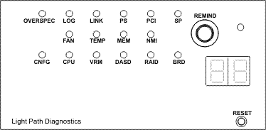
Поэтому, прежде чем апгрейдить память обязательно изучите спецификацию, память какого типа и объёма поддерживается вашим сервером. Также большое значение имеет количество процессоров в сервере — от этого зависит порядок размещения модулей в слотах. Это тоже необходимо уточнить в спецификации.
Вообще, с памятью ровно такая же ситуация, как описано в статье про HP, например. Вкратце:
- Соблюдайте канальность памяти.
- Ставьте ECC REG 1(2)Rx4 память в двухпроцессорные системы и UDIMM — в однопроцессорные.
- Ставьте одинаковый объём памяти на каждый процессор.
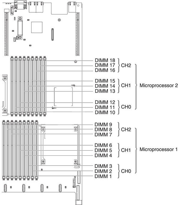
А что делать, если вы вставили память в соответствии с инструкциями, а сервер всё равно не работает и предательски горит индикатор Memory? В этом случае придётся проверять разные варианты:
- Этот тип памяти не поддерживается сервером. Внимательно сверьтесь со спецификациями.
- Память оказалась «битой». Замените линейку на точно такую же и проверьте, заведётся ли сервер.
- Засорился пылью слот на материнской плате. Это довольно популярная причина, если сервер трудится уже несколько лет, а тем более если вы его не первый владелец. Продуйте слоты сжатым воздухом.
- Загнутый контакт в сокете. Такое бывает очень редко, но всё же бывает: память отказывается работать из-за загнутого контакта в сокете процессора. Если предыдущие варианты не помогли найти причину сбоя, снимите процессор и внимательно осмотрите сокет. Если вы оказались в числе немногочисленных «счастливчиков», то можете попробовать осторожно выпрямить погнутый контакт, но это исключительно на ваш страх и риск.
Многие сисадмины сталкиваются с тем, что при проверке оперативной памяти с помощью MemTest86 получают сообщения об ошибках даже в заведомо рабочих модулях, либо на одних и тех же дорожках. Особенно часто это встречается у серверов поколения M4. Это вовсе не вина машин или памяти: MemTest86 не рекомендуется использовать для проверки серверной памяти. Если же память начнёт сбоить, то сервер сообщит об этом через диагностическую панель. Проверять память на серверах IBM лучше стандартными средствами самодиагностики.
Накопители
Мы уже неоднократно упоминали о том, что совсем не обязательно устанавливать в серверах «родные» накопители. Ни IBM, ни другие вендоры их не производят, они лишь приобретают их у всем известных производителей, перепрошивают и клеят свои логотипы. Поэтому вы можете без труда сэкономить на апгрейде или восстановлении дисковых массивов, выбрав аналоги вместо «родных» накопителей. Двух-трёхкратная разница в цене это оправдывает, особенно если речь идёт о refurbished-серверах. В сети можно легко найти таблицы соответствия моделей, например:
| Модель IBM | Оригинал |
|---|---|
| IBM 49Y2003 | Seagate ST9600204SS |
| IBM 90Y8872 | Seagate ST9600205SS |
| IBM 90Y8908 | Seagate ST9600105SS |
| IBM 81Y9650 | Seagate ST900MM0006 |
Тем не менее, ещё возможны ситуации несовместимости «неродных» накопителей с сервером. В этом случае сервер не грузится штатно, либо не видит накопитель. Обычно это решается с помощью установки свежей прошивки RAID-контроллера. К слову, рекомендуется обновить прошивку и бэкплейна/экспандера, в этом вам поможет приложение IBM Bootable Media Creator (BoMC).
При включении сервера и прохождении POST-проверки возможно появление ошибки:
A discovery error has occurred, please powercycle the system and all the enclosures attached to this system.
Это сигнализирует о проблеме с одним из накопителей. Вычислить его просто: индикаторы на его салазках постоянно мигают, даже когда все остальные носители прошли проверку и перестали мигать.
С дисковой подсистемой бывают и более экзотические проблемы. Например, при использовании RAID-1 в фирменном приложении MegaRAID Storage Manager могут появиться ошибки вида:
ID = 63
SEQUENCE NUMBER = 48442
TIME = 24-01-2016 17:03:59
LOCALIZED MESSAGE = Controller ID: 0 Consistency Check found inconsistent parity on VD strip: ( VD = 0, strip = 637679)
Чаще всего это говорит не об умирании диска, а об ошибке контроля чётности — несовпадении данных на основном и вторичном дисках. Возможные причины:
- Нередко такие ошибки появляются сразу после конфигурирования нового массива или после замены одного из дисков.
- Во время сеанса диагностики поверхности блинов происходит инициализация диска и выполнение операций ввода/вывода. На RAID-1 это может привести к временному несоответствию томов, которое автоматически исправляется при следующей проверке на соответствие. Такое возникает не при любом сеансе диагностики, а когда сходятся звёзды:
- o Используется RAID-контроллер без кэширования, либо активирован режим Write Through.
- o Нехватка оперативной памяти, при которой с диска осуществляется активная подкачка страниц.
- o Просто очень интенсивное использование дисков.
Для решения этой проблемы рекомендуется снизить активность подкачки с диска: используйте RAID-контроллер с кэшированием и увеличьте объём оперативной памяти.
Обновление прошивок и ПО
Любопытная проблема может подстерегать при установке с нуля Windows 2012 или Windows 2012 R2 — свежеустановленная операционка не видит ни одного накопителя. Причём такое бывает не только с серверами IBM. Дело в том, что все накопители в сервере подключены через RAID, а упомянутые версии ОС не имеют вшитых драйверов для работы с RAID. И поэтому они их просто игнорируют. Как быть? Самый надёжный способ: использовать утилиту IBM ServerGuide. При установке ОС она принудительно подсовывает все необходимые драйвера для данной модели и версии операционной системы. Обратите внимание, что образ ОС должен устанавливаться с диска, а не с флэшки: ServerGuide не будет работать с образом на том же USB-носителе, с которого запущен сам.
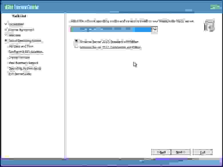
При покупке серверов бывают ситуации, когда нужно сначала обновить все прошивки, а потом уже накатывать систему. Сделать это можно с помощью вышеупомянутой IBM Bootable Media Creator:
- Загрузитесь с загрузочной флешки или диска.
- Запустите BoMC от имени Администратора.
- Выберите, что вы хотите сделать: обновить и/или провести диагностику.
- Программа спросит, где ей взять драйверы: скачать самой или вытащить из указанного вами архива.
- Выберите носитель для записи загрузочного образа: флэшку или диск. Запись может идти несколько часов, не волнуйтесь, программа не зависла.
- По окончании записи загрузитесь с этого носителя, и далее по инструкции.
Эта процедура помогает и в ряде проблемных ситуаций. Например, если вы не дождались завершения обновления Integrated Management Module и нажали кнопку «отмена», то при следующих загрузках сервер может не суметь загрузить IMM и использует настройки по умолчанию. Можно сначала попытаться восстановить с помощью джампера “UEFI & IMM recovery jumper” на материнской плате, благодаря которому загружается прошитый образ IMM.
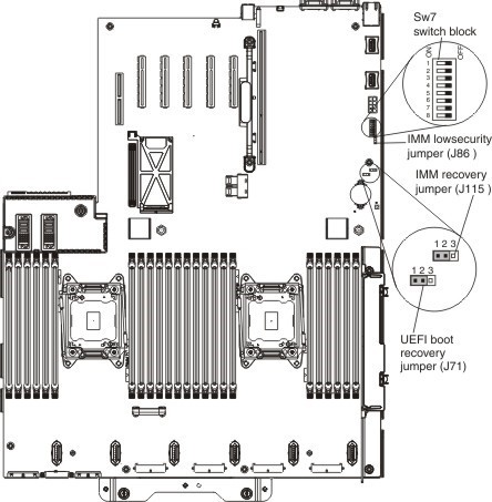
Но если не поможет, то воспользуйтесь процедурой обновления через BoMC.
Бывают и более неприятные ситуации, когда по закону подлости в ходе установки более свежей версии BIOS’а происходит сбой питания.

После этого сервер уже не может загрузить основную прошивку, и использует резервную. Если штатная процедура восстановления BIOS’а не помогает, то сделайте… даунгрейд: установите более старую прошивку, чем та, что была до сбоя питания. Обычно это помогает. После этого уже можно попытаться снова поставить свежую версию BIOS’а. Как говорится, шаг назад — два вперёд.
Другие проблемы
Иногда при попытке удалённого управления сервером возникает ошибка “Login failed with an access denied error.”, причём в любых браузерах. Если перезагрузка сервера и клиента не помогает, то рекомендуется сбросить IMM до заводских настроек.
В статье про ошибки серверов HP мы упоминали о проблемах с системой охлаждения: сразу после запуска сервера вентиляторы выходили на высокие обороты и уже не снижали их. Случается такой недуг и в серверах IBM. Сервер воет, как реактивный лайнер на взлёте. Нам не удалось выяснить причину таких сбоев, но посоветовать можно следующее:
- Проверьте плотность подключения разъёмов питания.
- Отключите все вентиляторы и снимите корзину.
- Проверьте каждый вентилятор на других серверах.
- Соберите корзину снова, поменяв вентиляторы местами. Либо совсем их замените.
Встречался в нашей практике и такой интересный сбой: при загрузке сервера штатно инициализируется IMM, затем начинается инициализация UEFI, и… всё. Дальше сервер не грузится без объяснения причин. Не помогали никакие манипуляции: отключение от сети, полное обесточивание, отключение разных компонентов. Загрузка бэкапа UEFI с помощью джампера на материнской плате тоже не помогла. Опытным путём выяснилось, что если подождать около 20 минут, то всё же можно дождаться загрузки сервера. Так он и работает с тех пор — каждый раз грузится по 20 минут. Выяснить причину сбоя не удалось.
Преимущества серверов IBM
Серверы IBM заслуженно пользуются большой популярностью:
- Это простые и очень надёжные машины.
- Отличная расширяемость даже на начальных моделях и богатый комплект поставки.
- Серверы IBM обычно дешевле конкурентов и не уступают в производительности. Например, поколения M3 и M4 дешевле, чем аналоги у HP (Gen7 и Gen8) и Dell (11G и 12G).
- Самые недорогие расходники. Легко найти в России.
- Удобная диагностическая панель на многих моделях.
Главное, в чём серверы IBM уступают конкурентам — у них очень долгий «холодный» старт.