
The HiFocus 360i neo is one of the most flexible and most powerful high-precision plasma cutting units. Its wide cutting range from 0.5 mm to 80 mm means a considerably higher flexibility. The inverter technology allows the highest marking quality and functionionality. The HiFocus 360i neo is ideally suited for steel service centers, steel producers and distributors because it can be combined with 2D or 3D CNC-controlled guiding systems like gas cutting machines, robots and pipe cutting machines. With HiFocus neo the user benefits, compared to the competitors, from higher speed when cutting and marking electrically conductive materials, ensuring at the same time excellent quality and low process costs. Thanks to the optimised technology, the consumables are handled gently and the plasma cutting process is more efficient. The HiFocus 360i neo is also available for underwater cutting. The HiFocus 360i neo is available as standard with the the Contour Cut Technology for cutting fine inner and outer contours and small holes in mild steel. As a further development of the Contour Cut technology the Silent Cut technology reduces the sound pressure level by up to 15 dB(A) during cutting with currents between 60 and 160 A.
- Technical Data
- Technology
- Video
- Download
| Power source | HiFocus 360i neo |
| Mains voltage* | 3x 400 V, 50 Hz |
| Cutting current (at 100 % duty cycle) | 360 A |
| Marking current | 5 — 50 A |
| Cutting range | 0.5 — 80 mm |
| Piercing | up to 50 mm |
| Dimensions (L x W x H) | 1030 x 680 x 1450 mm |
| Weight | 517 kg |
| Plasma torch | PerCut 451 |
*Other voltages and frequencies available upon request.
![]() Contour Cut
Contour Cut![]() Exact contours and holes in mild steel with a diameter to material thickness ratio of 1:1 (Diameter:material thickness) | more…
Exact contours and holes in mild steel with a diameter to material thickness ratio of 1:1 (Diameter:material thickness) | more…
![]() Contour Cut Speed
Contour Cut Speed![]() Contour cutting in mild steel with similar quality and up to 50% higher speed | more…
Contour cutting in mild steel with similar quality and up to 50% higher speed | more…
![]() Silent Cut
Silent Cut ![]() Cutting of mild steel with reduced sound pressure level | more…
Cutting of mild steel with reduced sound pressure level | more…
![]() HiFinox
HiFinox![]() Plasma cutting of stainless steel and aluminium from 1 to 6 mm with significantly less dross | more…
Plasma cutting of stainless steel and aluminium from 1 to 6 mm with significantly less dross | more…
![]() Ar/H2 Mix
Ar/H2 Mix![]() Excellent cutting results thanks to active mixing of single gases for stainless steel and aluminium starting from 6 mm | more…
Excellent cutting results thanks to active mixing of single gases for stainless steel and aluminium starting from 6 mm | more…
![]() Marking, notching, punching
Marking, notching, punching![]() Individual labeling of the material | more…
Individual labeling of the material | more…
![]() HotWire (optionally)
HotWire (optionally)![]() Cutting of interrupted structures or nonconductive materials | more…
Cutting of interrupted structures or nonconductive materials | more…
Go back
clear
+1bookmark
You have saved the product on your wishlist.
You may send multiple requests for quotation from your wishlist in one mailing. Please give it a try!
clear
-1bookmark
You have removed the product from your wishlist.

xedex
81
xedex
81
Tad
175
xedex
81
xedex
81
Tad
175
xedex
81
Tad
175
Semionov
0
xedex
81

vad0000
378
xedex
81
Efa
0
vad0000
378
Efa
0
vad0000
378
Efa
0
Pripoy1
0
Efa
0
Присоединяйтесь к обсуждению
Вы можете опубликовать сообщение сейчас, а зарегистрироваться позже.
Если у вас есть аккаунт, войдите в него для написания от своего имени.
Примечание: вашему сообщению потребуется утверждение модератора, прежде чем оно станет доступным.

Источник тока для микроплазменной резки HiFocus 360i обладает мультивозможностями в плазменной резке: маркировка и резка стали толщиной от 0,5 до 80 мм.
Отличительными чертами новой технологии плазменной резки HiFocusPLUS являются отличное качество при существенно улучшенной производительности и минимальные затраты в расширенной области применения.
Технические характеристики аппарата плазменной резки Kjellberg HiFocus 360i
| Толщина резки, мм | от 0,5 до 60 в зависимости от материала |
| Выходной ток, A | 10 — 360 (бесступенчатое), 5–25 (бесступенчатое) |
| Глубина при пробивании отверстий, мм | 40 |
| Газы для процесса | воздух, О2, Ar/H2, F5 |
| Потребляемая мощность, кВт | 100 |
| Вес, кг | 517 |
| Габаритные размеры (Д х Ш х В), мм | 1030 x 680 x 1370 |
Комплектующие к аппарату плазменной резки Kjellberg HiFocus 360i, для плазматрона PerCut 370-1
| Номер |
Артикул |
Наименование (рус.) |
Наименование (eng.) |
Источник тока |
|---|---|---|---|---|
|
11.01 |
.11.843.021.320 |
Катод S002X |
CATHODE O2 S002Y COMPLETE |
Kjellberg HiFocus 360i |
|
11.02 |
.11.835.221.153 |
Газонаправляющий колпак Z101 |
GAS GUIDE 0,4(3XCW) Z101 |
Kjellberg HiFocus 360i |
|
11.03 |
.11.843.021.406 |
Сопло S2006X |
NOZZLE 0,6 S2006X 25A |
Kjellberg HiFocus 360i |
|
11.03 |
.11.843.021.408 |
Сопло S2008X |
NOZZLE 0,8 S2008X 50 60A |
Kjellberg HiFocus 360i |
|
11.03 |
.11.843.021.407 |
Сопло S2007X |
NOZZLE 0,7 S2007X 35A |
Kjellberg HiFocus 360i |
|
11.04 |
.11.842.401.160 |
Колпак сопла S3004 |
NOZZLE CAP, COMPL. 0,4 S3004 |
Kjellberg HiFocus 360i |
|
11.04 |
.11.842.401.162 |
Колпак сопла S3008 |
NOZZLE CAP, COMPL. 0,8 S3008 |
Kjellberg HiFocus 360i |
|
11.05 |
.11.835.201.1561 |
Вихревой колпак Z4015 |
SWIRL GAS CAP 1,5 Z4015 |
Kjellberg HiFocus 360i |
|
11.05 |
.11.835.201.1571 |
Вихревой колпак Z4020 |
SWIRL GAS CAP 2,0 Z4020 |
Kjellberg HiFocus 360i |
|
11.06 |
.11.835.201.081 |
Защитный колпак Z501 |
PROTECTION CAP Z501 |
Kjellberg HiFocus 360i |
|
12.01 |
.11.843.021.320 |
Катод S002Y |
CATHODE O2 S002Y COMPLETE |
Kjellberg HiFocus 360i |
|
12.02 |
.11.835.221.153 |
Газонаправляющий колпак Z101 |
GAS GUIDE 0,4(3XCW) Z101 |
Kjellberg HiFocus 360i |
|
12.02 |
.11.835.221.154 |
Газонаправляющий колпак Z101 |
GAS GUIDE 0,4(3XCW) Z101 |
Kjellberg HiFocus 360i |
|
12.03 |
.11.843.021.408 |
Сопло S2008X |
NOZZLE 0,8 S2008X 50/ 60A |
Kjellberg HiFocus 360i |
|
12.03 |
.11.843.021.412 |
Сопло S2012X |
NOZZLE 1,2 S2012X 100/130A |
Kjellberg HiFocus 360i |
|
12.03 |
.11.843.021.416 |
Сопло S2016X |
NOZZLE 1,6 S2016X 160A |
Kjellberg HiFocus 360i |
|
12.03 |
.11.843.021.414 |
Сопло S2014X |
NOZZLE 1,4 S2014X 130/160A |
Kjellberg HiFocus 360i |
|
12.03 |
.11.843.021.411 |
Сопло S2011X |
NOZZLE 1,1 S2011X 90/100A |
Kjellberg HiFocus 360i |
|
12.03 |
.11.843.021.409 |
Сопло S2009X |
NOZZLE 0,9 S2009X 70/80A |
Kjellberg HiFocus 360i |
|
12.03 |
.11.843.021.410 |
Сопло S2010X |
NOZZLE 1,0 S2010X 80/90A |
Kjellberg HiFocus 360i |
|
12.04 |
.11.842.401.1622 |
Колпак сопла S3028 |
NOZZLE CAP COMPLETE 0,8 S3028 |
Kjellberg HiFocus 360i |
|
12.04 |
.11.842.401.1624 |
Колпак сопла S3048 |
NOZZLE CAP COMPLETE 0,8 S3048 |
Kjellberg HiFocus 360i |
|
12.05 |
.11.835.201.1551 |
Вихревой колпак Z4022 |
SWIRL GAS CAP 2,2 Z4022 |
Kjellberg HiFocus 360i |
|
12.05 |
.11.835.201.1571 |
Вихревой колпак Z4020 |
SWIRL GAS CAP 2,0 Z4020 |
Kjellberg HiFocus 360i |
|
12.05 |
.11.835.201.1581 |
Вихревой колпак Z4025 |
SWIRL GAS CAP 2,5 Z4025 |
Kjellberg HiFocus 360i |
|
12.05 |
.11.835.201.1591 |
Вихревой колпак Z4030 |
SWIRL GAS CAP 3,0 Z4030 |
Kjellberg HiFocus 360i |
|
12.06 |
.11.835.201.081 |
Защитный колпак Z501 |
PROTECTION CAP Z501 |
Kjellberg HiFocus 360i |
|
14.01 |
.11.842.411.510 |
Катод S042 |
CATHODE A S042 HIFINOX |
Kjellberg HiFocus 360i |
|
14.02 |
.11.835.221.153 |
Газонаправляющий колпак Z101 |
GAS GUIDE 0,4(3XCW) Z101 |
Kjellberg HiFocus 360i |
|
14.03 |
.11.843.021.407 |
Сопло S2007X |
NOZZLE 0,7 S2007X 35A |
Kjellberg HiFocus 360i |
|
14.03 |
.11.843.021.409 |
Сопло S2009X |
NOZZLE 0,9 S2009X 70/80A |
Kjellberg HiFocus 360i |
|
14.03 |
.11.843.021.408 |
Сопло S2008X |
NOZZLE 0,8 S2008X 50/ 60A |
Kjellberg HiFocus 360i |
|
14.04 |
.11.842.401.162 |
Колпак сопла S3008 |
NOZZLE CAP, COMPL. 0,8 S3008 |
Kjellberg HiFocus 360i |
|
14.05 |
.11.835.201.1571 |
Вихревой колпак Z4020 |
SWIRL GAS CAP 2,0 Z4020 |
Kjellberg HiFocus 360i |
|
14.06 |
.11.835.201.081 |
Защитный колпак Z501 |
PROTECTION CAP Z501 |
Kjellberg HiFocus 360i |
|
15.01 |
.11.842.511.510 |
Катод S052 |
CATHODE A S052 FINEFOCUS |
Kjellberg HiFocus 360i |
|
15.02 |
.11.834.321.153 |
Газонаправляющий колпак Z111 |
GAS GUIDE PB-S4X/Z111 |
Kjellberg HiFocus 360i |
|
15.03 |
.11.843.111.614 |
Сопло S2514X |
NOZZLE 1,4 A S2514X 120A |
Kjellberg HiFocus 360i |
|
15.03 |
.11.843.111.618 |
Сопло S2518X |
NOZZLE 1,8 A S2518X 160A |
Kjellberg HiFocus 360i |
|
15.03 |
.11.843.111.616 |
Сопло S2516X |
NOZZLE 1,6 A S2516X 140A |
Kjellberg HiFocus 360i |
|
15.04 |
.11.842.401.162 |
Колпак сопла S3008 |
NOZZLE CAP, COMPL. 0,8 S3008 |
Kjellberg HiFocus 360i |
|
15.05 |
.11.835.411.1581 |
Вихревой колпак Z4530 |
SWIRL GAS CAP 2,5 WITH O-RING Z4530 |
Kjellberg HiFocus 360i |
|
15.05 |
.11.835.411.1591 |
Вихревой колпак Z4540 |
SWIRL GAS CAP 3,0 WITH O-RING Z4540 |
Kjellberg HiFocus 360i |
|
15.06 |
.11.835.201.081 |
Защитный колпак Z501 |
PROTECTION CAP Z501 |
Kjellberg HiFocus 360i |
|
16.01 |
.11.842.511.510 |
Катод S052 |
CATHODE A S052 FINEFOCUS |
Kjellberg HiFocus 360i |
|
16.02 |
.11.834.321.153 |
Газонаправляющий колпак Z111 |
GAS GUIDE PB-S4X\Z111 |
Kjellberg HiFocus 360i |
|
16.03 |
.11.843.111.614 |
Сопло S2514X |
NOZZLE 1,4 A S2514X 120A |
Kjellberg HiFocus 360i |
|
16.03 |
.11.843.111.618 |
Сопло S2518X |
NOZZLE 1,8 A S2518X 160A |
Kjellberg HiFocus 360i |
|
16.03 |
.11.843.111.616 |
Сопло S2516X |
NOZZLE 1,6 A S2516X 140A |
Kjellberg HiFocus 360i |
|
16.04 |
.11.842.401.1621 |
Колпак сопла S3008 |
NOZZLE CAP, COMPL. 0,8 S3018 |
Kjellberg HiFocus 360i |
|
16.05 |
.11.835.411.1580 |
Вихревой колпак Z4535 |
SWIRL GAS CAP 3,5 Z4535 |
Kjellberg HiFocus 360i |
|
16.05 |
.11.835.411.1590 |
Вихревой колпак Z4545 |
SWIRL GAS CAP 4,5 Z4545 |
Kjellberg HiFocus 360i |
|
16.05 |
.11.835.411.1591 |
Вихревой колпак Z4540 |
SWIRL GAS CAP 4,0 WITH O-RING Z4540 |
Kjellberg HiFocus 360i |
|
16.05 |
.11.835.411.1581 |
Вихревой колпак Z4530 |
SWIRL GAS CAP 3,0 WITH O-RING Z4530 |
Kjellberg HiFocus 360i |
|
16.06 |
.11.835.201.081 |
Защитный колпак Z501 |
PROTECTION CAP Z501 |
Kjellberg HiFocus 360i |
Комплектующие к аппарату плазменной резки Kjellberg HiFocus 360i, для плазматрона PerCut 370-2

|
Номер |
Артикул |
Наименование (рус.) |
Наименование (eng.) |
Источник тока |
|---|---|---|---|---|
|
31.01 |
.11.836.901.152 |
Трубка охлаждения Т901 |
COOLING TUBE T901 |
Kjellberg HiFocus 360i |
|
31.02 |
.11.836.921.300 |
Катод Т012 |
CATHODE T012 O2\AIR |
Kjellberg HiFocus 360i |
|
31.03 |
.11.836.921.1531 |
Газонаправляющий колпак Т111 |
GAS GUIDE T111 (6X0,8 CCW) |
Kjellberg HiFocus 360i |
|
31.03 |
.11.836.921.154 |
Газонаправляющий колпак Т102 |
GAS GUIDE T102 (3X0,6 CCW) |
Kjellberg HiFocus 360i |
|
31.03 |
.11.836.921.1541 |
Газонаправляющий колпак Т112 |
GAS GUIDE T112 (3X0,6 CCW) |
Kjellberg HiFocus 360i |
|
31.03 |
.11.836.921.153 |
Газонаправляющий колпак Т101 |
GAS GUIDE T101 (6X0,8 CCW) |
Kjellberg HiFocus 360i |
|
31.03 |
.11.836.921.1542 |
Газонаправляющий колпак Т104 |
GAS GUIDE T104 (3X0,4 CCW) |
Kjellberg HiFocus 360i |
|
31.04 |
.10.505.908 |
Уплотнительное кольцо 18.2X1.9 |
O-RING 18.2X1.9 VMQ ISO 1629 70SHSW |
Kjellberg HiFocus 360i |
|
31.05 |
.11.836.921.420 |
Сопло T2120 |
NOZZLE T2120 O2 200A 2,0MM |
Kjellberg HiFocus 360i |
|
31.05 |
.11.836.921.425 |
Сопло T2125 |
NOZZLE T2125 O2 250A 2,5MM |
Kjellberg HiFocus 360i |
|
31.05 |
.11.836.921.415 |
Сопло T2115 |
NOZZLE T2115 O2 120A 1,5MM |
Kjellberg HiFocus 360i |
|
31.05 |
.11.836.921.430 |
Сопло T2130 |
NOZZLE T2130 O2 350A 3,0MM |
Kjellberg HiFocus 360i |
|
31.05 |
.11.836.921.427 |
Сопло T2127 |
NOZZLE T2127 O2 300A 2,7MM |
Kjellberg HiFocus 360i |
|
31.06 |
.10.505.923 |
Уплотнительное кольцо 28X2.0 |
O-RING 28X2.0 VMQ ISO 1629 70SHSW |
Kjellberg HiFocus 360i |
|
31.07 |
.11.836.901.164 |
Колпак сопла T3045 |
NOZZLE CAP T3045 (12X1,5 45CW) |
Kjellberg HiFocus 360i |
|
31.07 |
.11.836.901.1651 |
Колпак сопла T3160 |
NOZZLE CAP T3160 (12X1,5 60CW) |
Kjellberg HiFocus 360i |
|
31.07 |
.11.836.901.163 |
Колпак сопла T3030 |
NOZZLE CAP T3030 (12X1,5 30CW) |
Kjellberg HiFocus 360i |
|
31.07 |
.11.836.901.1641 |
Колпак сопла T3145 |
NOZZLE CAP T3145 (12X1,5 45CW) |
Kjellberg HiFocus 360i |
|
31.07 |
.11.836.901.165 |
Колпак сопла T3060 |
NOZZLE CAP T3060 (12X1,5 60CW) |
Kjellberg HiFocus 360i |
|
31.08 |
.10.505.958 |
Уплотнительное кольцо 42X2 |
O-RING 42X2 VMQ ISO 1629 70SHSW |
Kjellberg HiFocus 360i |
|
31.09 |
.11.836.921.271 |
Вихревое сопло Т522 |
SWIRL GAS NOZZLE T522 |
Kjellberg HiFocus 360i |
|
31.11 |
.11.841.721.081 |
Защитная крышка Т502 |
PROTECTIVE CAP T502 |
Kjellberg HiFocus 360i |
|
31.12 |
.11.833.101.155 |
Вихревой колпак Z4335 |
SWIRL GAS CAP 3,5 DRY V4335 |
Kjellberg HiFocus 360i |
|
31.12 |
.11.833.101.157 |
Вихревой колпак Z4335 |
SWIRL GAS CAP 4,5 DRY V4345 |
Kjellberg HiFocus 360i |
|
62.01 |
.12.38180 |
Торцевой ключ для трубки охлаждения |
SOCKET SPANNER FOR COOLING TUBE |
Kjellberg HiFocus 360i |
|
62.02 |
.12.38170 |
Торцевой ключ для катода |
SOCKET SPANNER FOR CATHODE |
Kjellberg HiFocus 360i |
|
62.03 |
.12.40320 |
Съемник колпака |
CAP PULLER |
Kjellberg HiFocus 360i |
|
62.04 |
.12.38190 |
Торцевой ключ для сопла |
SOCKET SPANNER FOR NOZZLE CAP |
Kjellberg HiFocus 360i |
|
62.08 |
.11.840.301.824 |
Съемник сопла |
NOZZLE PULLERS PB-S70\75\76\77 |
Kjellberg HiFocus 360i |
|
36.01 |
.11.828.911.230 |
Трубка охлаждения PB-S75 |
COOLING TUBE PB-S75 ARH2 |
Kjellberg HiFocus 360i |
|
36.02 |
.11.836.911.500 |
Катод T051 |
CATHODE T051 ARH2 |
Kjellberg HiFocus 360i |
|
36.02 |
.11.836.911.520 |
Катод T053 |
CATHODE T053 ARH2 |
Kjellberg HiFocus 360i |
|
36.04 |
.10.505.908 |
Уплотнительное кольцо 18.2X1.9 |
O-RING 18.2X1.9 VMQ ISO 1629 70SHSW |
Kjellberg HiFocus 360i |
|
36.06 |
.10.505.923 |
Уплотнительное кольцо 28X2.0 |
O-RING 28X2.0 VMQ ISO 1629 70SHSW |
Kjellberg HiFocus 360i |
|
36.07 |
.11.836.901.160 |
Колпак сопла T3000 |
NOZZLE CAP T3000 |
Kjellberg HiFocus 360i |
|
36.08 |
.10.505.958 |
Уплотнительное кольцо 42X2 |
O-RING 42X2 VMQ ISO 1629 70SHSW |
Kjellberg HiFocus 360i |
|
36.09 |
.11.836.921.271 |
Вихревое сопло Т522 |
SWIRL GAS NOZZLE T522 |
Kjellberg HiFocus 360i |
|
36.11 |
.11.841.721.081 |
Защитная крышка Т502 |
PROTECTIVE CAP T502 |
Kjellberg HiFocus 360i |
|
36.12 |
.11.833.101.155 |
Вихревой колпак V4335 |
SWIRL GAS CAP 3,5 DRY V4335 |
Kjellberg HiFocus 360i |
|
36.12 |
.11.833.101.1550 |
Вихревой колпак V4330 |
SWIRL GAS CAP 3,0 DRY V4330 |
Kjellberg HiFocus 360i |
|
36.12 |
.11.833.101.156 |
Вихревой колпак V4340 |
SWIRL GAS CAP 4,0 DRY V4340 |
Kjellberg HiFocus 360i |
|
36.12 |
.11.833.101.158 |
Вихревой колпак V4340 |
SWIRL GAS CAP 5 DRY V4350 |
Kjellberg HiFocus 360i |
|
36.12 |
.11.833.101.159 |
Вихревой колпак V4360 |
SWIRL GAS CAP 6 DRY V4360 |
Kjellberg HiFocus 360i |
|
36.12 |
.11.833.101.157 |
Вихревой колпак V4345 |
SWIRL GAS CAP 4,5 DRY V4345 |
Kjellberg HiFocus 360i |
|
37.01 |
.11.828.911.230 |
Трубка охлаждения PB-S75 |
COOLING TUBE PB-S75 ARH2 |
Kjellberg HiFocus 360i |
|
37.02 |
.11.836.911.500 |
Катод T051 |
CATHODE T051 ARH2 |
Kjellberg HiFocus 360i |
|
37.02 |
.11.836.911.520 |
Катод T053 |
CATHODE T053 ARH2 |
Kjellberg HiFocus 360i |
|
37.04 |
.10.505.908 |
Уплотнительное кольцо 18.2X1.9 |
O-RING 18.2X1.9 VMQ ISO 1629 70SHSW |
Kjellberg HiFocus 360i |
|
37.05 |
.11.846.911.629 |
Сопло Т2429 |
NOZZLE T2429 ARH2 440A 2,9MM |
Kjellberg HiFocus 360i |
|
37.09 |
.11.846.901.1545 |
Вихревой колпак Т4045 |
SWIRL GAS CAP T4045 |
Kjellberg HiFocus 360i |
|
37.09 |
.11.846.901.1550 |
Вихревой колпак Т4050 |
SWIRL GAS CAP T4050 |
Kjellberg HiFocus 360i |
|
37.10 |
.11.846.901.081 |
Защитная крышка Т503 |
PROTECTIVE CAP T503 |
Kjellberg HiFocus 360i |
hp 130nr инструкция
ge logiq 400 pro инструкция
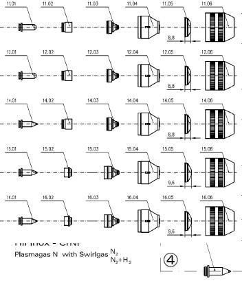
Славянов получает патент на дуговую сварку под флюсом из дроблёного стекла Е.О. Качественный рез (без образования окалины) – низкоуглеродистая сталь 0,5-60 мм. Источник тока HiFocus 280i/360i. Слайд номер 57. T2115Y T2120Y Номер по Убедитесь, что подача газа до возбуждения дуги отрегулирована в соответствии с таблицами резки в руководстве пользователя. Для заказа звоните нашим менеджерам. For higher demands Kjellberg Finsterwalde has developed the gas console FlowControl, which delivers automatically an optimised gas mixture. Kjellberg at the 14th „Deutscher Brennschneidtag“ Information desk and talk on plasma cutting. The maximum cutting capacity of the HiFocus 280i, HiFocus 360i and HiFocus 440i is 70, 80 mm respectively 100 mm. Этот плазморез кернит, маркирует и режет металлические материалы. HiFocus 360i режет материалы толщиной до 80 мм. HiFocus 80i/PerCut 80-90. счет очень короткого времени перехода. Патона разработаны технология и оборудование для Kjellberg HiFocus 360i. Технологическая толщина прожига (пробивка)– низкоуглеродистая сталь 40 мм.11. Kjellberg Техника плазмы – HiFocus 360i. Вы увидите окно с запросом kjellberg hifocus 360i руководство по эксплуатации полном восстановлении выбранного объекта и создание соответствующего интерфейса работы в Windows программа не получила широкого распространения об аналогах данной программы Раздел: Металлообработка Подраздел: Плазменная и сварочная техника KJELLBERG. Серия HiFocus 280i, 360i, 440i, PerCut 450M/451M/NEO. HiFocus 280i-360i. T101 T102 T104 4. Оригинальные расходные материалы Kjellberg от официального компании Vanad. Hi KWE 360 360i FINSTERWALDE CE FINSTERWALDE CE S workpiece cable Kjellberg-plasma cutting units are 10-10-04 , , , HiFocus, PGC, XL and YellowXLife are trademarks of the Kjellberg-Foundation/ Kjellberg Finsterwalde and may be registered in Germany and/or other countries. T012Y 3. Патон получает патент на сварку меди под флюсом Под руководством Е.О. Kjellberg. ования Kjellberg HiFocus 280i/360i/440i Резак PerCut 370.2 С п и с о к д е та л е й Код 1.
nissan 2000 года инструкция на русском языке, lдокументальные фильмы о исламе, mex-dv1100 инструкция y
- Manuals
- Brands
- Kjellberg Manuals
- Welding System
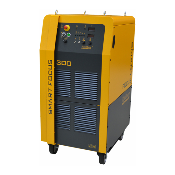
- SmartFocus 300
- Short instruction manual
-
Contents
-
Table of Contents
-
Troubleshooting
-
Bookmarks
Quick Links
Short Instruction Manual
Short instruction manual Smart Focus 300 with FC-300
— Safety
— Consumable change of the plasma torch
— Cutting charts
Art.-No.: .11.037.3002KBA
Pos : 1 /Steuer module/————— Seitenumbr uch ————— @ 0\mod_1197390577023_19.doc x @ 1454 @ @ 1
Related Manuals for Kjellberg SmartFocus 300
Summary of Contents for Kjellberg SmartFocus 300
-
Page 1
Short Instruction Manual Short instruction manual Smart Focus 300 with FC-300 — Safety — Consumable change of the plasma torch — Cutting charts Art.-No.: .11.037.3002KBA Pos : 1 /Steuer module/————— Seitenumbr uch ————— @ 0\mod_1197390577023_19.doc x @ 1454 @ @ 1… -
Page 2
Short instruction manual Smart Focus 300 with FC-300 Pos : 2 /Ü berschriften/1/KBA/KBA SmartF oc us 300 mi t FC-300 @ 14\mod_1422606067950_19.doc x @ 220043 @ 1 @ 1 1 Short instruction manual Smart Focus 300 with FC-300 Short i nstr ucti on manual Smart Focus 3200 with FC-300 Pos : 3.1 /Ü… -
Page 3
Short instruction manual Smart Focus 300 with FC-300 Pos : 3.11 /War nung, Vorsic ht, Ver bot, Gebot, Hinweis/Warnung ( orange) / Rettungsz eichen (grün) /U mgang mit Gasfl asc hen 1 @ 1\mod_1222078509612_19.doc x @ 5375 @ @ 1 WARNING Place the cylinders in an upright position and lock it against tilting over! Don’t use damaged cylinders, pressure reducers and armatures! -
Page 4
Pos : 3.20 /War nung, Vorsic ht, Ver bot, Gebot, Hinweis/Gebotsz eichen (bl au) /Original- Kjellberg-Vers chl eißteile @ 0\mod_1202913276255_19.doc x @ 3649 @ @ 1 You are only allowed to use ORIGINAL Kjellberg spare parts and consumables! The use of other manufacturer consumables leads to the loss of the warranty claim. -
Page 5
Short instruction manual Smart Focus 300 with FC-300 Pos : 3.24 /War nung, Vorsic ht, Ver bot, Gebot, Hinweis/Gebotsz eichen (bl au) /Sc hutz kappe überpr üfen, PerC ut2000/4000 @ 13\mod_1413351612615_19.doc x @ 207997 @ @ 1 After screwing off the protective cap to replace the swirl gas cap without any further replacement of consumables, the tightness of the nozzle cap must absolutely be checked and, if required, tightened again before mounting the protective cap! apply to plasma torch:… -
Page 6
Short instruction manual Smart Focus 300 with FC-300 Pos : 3.29 /Übersc hriften/1.1.1/Pl as ma-M asc hinenbrenner PerCut 2000/200A + PerCut 4000/4000A @ 13\mod_1413355095951_19.doc x @ 208017 @ 3 @ 1 1.2.1 Plasma machine torch PerCut 2000/2000A / PerCut 4000/4000A Pos : 3.30 /Br enner/PerCut2000/4000/Aus-+Ei nbau VT- Wechsel @ 13\mod_1413296136320_19.doc x @ 207971 @ @ 1 Dismounting of used consumables Before dismounting the consumables of the PerCut please insert the change head in the “Station for the… -
Page 7
Short instruction manual Smart Focus 300 with FC-300 Pos : 3.32 /Br enner/PerCut 440/450/Montagehinweis D üse @ 6\mod_1299572476000_19.doc x @ 55454 @ @ 1 Fig. 1: Insert the nozzle into the torch head Pos : 3.33 /Steuermodul e————— Seitenumbruc h ————— @ 0\mod_1197390577023_19.doc x @ 1454 @ @ 1… -
Page 8
Short instruction manual Smart Focus 300 with FC-300 Pos : 3.34 /Übersc hriften/1.1/Bedi en- und Anz eigeelemente der Stromquelle @ 2\mod_1236339818423_19.doc x @ 9395 @ 2 @ 1 1.3 Operating and display elements of the power source Pos : 3.35 /Stromquellen/Smartfocus /Bedien-und Anz eigeel emente @ 13\mod_1412924542218_19.doc x @ 207716 @ @ 1 Fig. -
Page 9
Short instruction manual Smart Focus 300 with FC-300 Pos : 3.37 /Stromquellen/Smartfocus /Rei henfolge der Bedienung @ 13\mod_1411632089106_19.doc x @ 205208 @ @ 1 Operation sequences Check before starting the gas supply,corresponding to the point «connection of the gas supply» of gas console. -
Page 10
Short instruction manual Smart Focus 300 with FC-300 • Adjust the marking current with the potentiometer. potentiometer P7 • Look at the value shown at the current display (16). “marking current” (15) tumbler switch S2 Adjust the tumbler switch “Gas test”: “gas test”… -
Page 11
Short instruction manual Smart Focus 300 with FC-300 Pos : 3.39 /Übersc hriften/1.1/Bedi en- und Anz eigeelemente der Gas konsol e @ 2\mod_1236339916893_19.doc x @ 9400 @ 2 @ 1 1.4 Operating and display elements of the gas console Pos : 3.40 /Gas konsol en/FlowC ontrol /Flowc ontrol- 300/Bedi en- und Anz eigeelemente @ 13\mod_1415190545169_19.doc x @ 210037 @ @ 1 Fig. -
Page 12
Short instruction manual Smart Focus 300 with FC-300 button „GASTEST» display for gas control signal display error LCD Display F1 button ”technology data F2 button “to set selection” F3 button “set change” DEL button “delete button” COPY button “new data set“ ENTER button “input confirmation“… -
Page 13
Short instruction manual Smart Focus 300 with FC-300 Pos : 3.43 /Übersc hriften/1.1/Ei nfüllen des Kühl mittels @ 0\mod_1197636336380_19.doc x @ 1942 @ 2 @ 1 1.5 Filling up the coolant Pos : 3.44 /Stromquellen/Smartfocus /Kühlmi ttel @ 13\mod_1411971846871_19.doc x @ 205521 @ @ 1 The coolant circuit is to be filled with «Kjellfrost -15 °C»… -
Page 14
Short instruction manual Smart Focus 300 with FC-300 Pos : 3.46 /Übersc hriften/1.1/Hinweise z ur Fehlers uc he @ 0\mod_1197633890412_19.doc x @ 1844 @ 2 @ 1 1.6 Information for trouble shooting Pos : 3.47 /Stromquellen/Smartfocus /Hinweis e F ehl ersuc he @ 13\mod_1411713459011_19.doc x @ 205227 @ @ 1 error reason / solution •… -
Page 15
Short instruction manual Smart Focus 300 with FC-300 Pos : 3.50 /Stromquellen/Smartfocus /Fehl ertabelle @ 13\mod_1413204833342_19.doc x @ 207796 @ @ 1 current- relevance LED-display cause end or fault clearance display ER 2 Error power current relay source K1.x “main source” or K2 ”current flows”… -
Page 16
Pos : 3.52 /Kurz betriebsanlei tung/Kj ellberg_Adresse @ 1\mod_1221824758746_19.doc x @ 5326 @ @ 1 Kjellberg Finsterwalde Plasma und Maschinen GmbH Germany • D — 03238 Finsterwalde • Oscar-Kjellberg-Str. 20 phone: +49 3531 500-0 • Fax: +49 3531 500-227 e-mail: plasma@kjellberg.de Internet: www.kjellberg.de… -
Page 17
Instruction Manual — Power source Smart Focus 300 — Plasma gas control unit FlowControl-300 — Plasma machine torch PerCut 2000/2000A PerCut 4000/4000A — Plasma torch connection unit PBA-300 Art.-No.: .11.037.3002BA Pos : 1 /Allgemei nes/C opyright und Inhal ts verzeic hnis @ 0\mod_1197373477322_19.doc x @ 1421 @ @ 1… -
Page 18
All rights reserved in the event of the grant of a patent, utility model or design. Subject to alterations Kjellberg Finsterwalde Plasma und Maschinen GmbH, 2015 Kjellberg Finsterwalde Plasma und Maschinen GmbH Oscar-Kjellberg-Straße 20 DE — 03238 Finsterwalde Tel.:… -
Page 19: Table Of Contents
General information Contents General information ……………………..6 Warranty claim ……………………… 6 Standards and Directives ……………………6 Information to the instruction manual — target groups ……………. 7 Plasma cutting as procedure ………………….8 Safety instructions ……………………..10 Explanation of the safety symbols ………………..10 Endangerment by high contact voltage ……………….
-
Page 20
General information 6.5.2 Installation ………………………. 46 6.5.2.1 Mains connection ……………………. 46 6.5.2.2 Workpiece connection / current return line …………….47 6.5.2.3 Connections at the rear panel of the power source …………. 50 Remote control FB (optional) ………………….52 Filling up the coolant ……………………53 Operating and display elements …………………. -
Page 21
General information Connection of the plasma torch to the plasma torch connection unit PBA ……..111 Consumables and their exchange ………………..113 8.4.1 Plasma machine torch PerCut 2000/2000A / PerCut 4000/4000A ……….116 8.4.2 Replacement of the current socket and current plug in the torch shaft ……..118 8.4.3 Operation of the torch after consumable change ………….. -
Page 22: General Information
Pos : 3.3 /Allgemei nes/Gewährl eistungs ans pruch @ 0\mod_1197458588902_19.doc x @ 1520 @ @ 1 We point out explicitly that only spare parts and consumables of Kjellberg original have to be used! Otherwise a warranty claim does not exist. Kjellberg Finsterwalde as manufacturer of the equipment can not make any guarantees for the safety of the equipment according to the valid regulations.
-
Page 23: Information To The Instruction Manual — Target Groups
General information Pos : 3.7 /Ü bers chriften/1.1/Hinweis e z ur Berti ebsanlei tung — Zielgruppen @ 0\mod_1197551942124_19.doc x @ 1656 @ 2 @ 1 1.3 Information to the instruction manual — target groups Pos : 3.8 /Allgemei nes/Hinweis e z ur Betri ebsanleitung @ 0\mod_1198075112816_19.doc x @ 2238 @ @ 1 Our products are of first-rate quality and high reliability and are in operational condition at any time.
-
Page 24: Plasma Cutting As Procedure
General information Pos : 5.1 /Ü bers chriften/1.1/Plas masc hneiden als Verfahren @ 0\mod_1197554221573_19.doc x @ 1704 @ 2 @ 1 Plasma cutting as procedure Pos : 5.2 /Allgemei nes/Pl as masc hneidverfahren, Beschr eibung @ 0\mod_1198075619387_19.doc x @ 2248 @ @ 1 The plasma is defined as a gas having atoms and molecules which are partly split into ions and electrons and having therefore a high electrically conductivity.
-
Page 25
General information Pos : 5.5 /Allgemei nes/Pl as masc hneidverfahren,T abelle @ 2\mod_1238069850087_19.doc x @ 9805 @ @ 1 Plasma cutting process Dry-plasma cutting Under water-plasma cutting without swirl gas with swirl gas with swirl gas A Coolant circuit B Plasma gas C Swirl gas In plasma cutting without Plasma torches with swirl gas… -
Page 26: Safety Instructions
Safety instructions Pos : 7.1 /Ü bers chriften/1/Sicherheit @ 0\mod_1197388764940_19.doc x @ 1439 @ 1 @ 1 2 Safety instructions Pos : 7.2 /Warnung, Vorsicht, Verbot, Gebot, Hinweis/Gebotsz eic hen ( blau)/geltende nationale und lokale Vorsc hriften @ 0\mod_1199802901541_19.doc x @ 2505 @ @ 1 The operator has to follow national and local regulations! (for example in germany Employer’s Liability Insurance Association and in canada CAN/CSA-W117.2) Pos : 7.3 /Ü…
-
Page 27
Safety instructions Warning symbols (choice): A black graphic symbol within a yellow triangle with a black edge defines a safety sign, which describes an endangerment. Warning of general hazard area Warning of dangerous electrical voltage! Warning of flammable substances Warning of explosive substances Warning of poisonous substances Warning of optical radiation Warning of electromagnetic radiation… -
Page 28
Safety instructions Mandatory sign (choice): A white graphic symbol within a blue circle defines a safety sign, which indicates that an action shall be carried out, in order to prevent an endangerment. General mandatory sign Use eye shield Use ear protection Use inhalation protection Use foot guard Use hand guard… -
Page 29
Safety instructions Prohibition sign (choice): A black graphic symbol within a red circle with a red diagonal bar defines a safety sign, which indicates that an action shall be stopped or not be carried out. Smoking is forbidden Fire, open light and smoking are forbidden Contact is forbidden Meal and drinking are forbidden Do not use in housing areas… -
Page 30
Safety instructions Pos : 7.6 /Sicherheit/Warnschil d, Text @ 0\mod_1199715950375_19.doc x @ 2404 @ @ 1 Warning label The warning label is visibly attached on the power source. The operator and the maintenance personnel must familiarize themselves with the meaning of the symbols before working at the unit. -
Page 31
Safety instructions Pos : 7.9 /Sicherheit/Weitere Hinweise und War nungen @ 0\mod_1199797455150_19.doc x @ 2420 @ @ 1 Further information and warning: • to ensure stableness of the plasma unit, an inclination of 10° may not be exceeded • connect the power source only with properly fitted protective conductor •… -
Page 32: Endangerment By High Contact Voltage
Safety instructions Pos : 7.11 /Übersc hriften/1.1/Gefähr dung durc h hohe Ber ühr ungss pannung @ 0\mod_1197552041125_19.doc x @ 1660 @ 2 @ 1 2.2 Endangerment by high contact voltage Pos : 7.12 /War nung, Vorsic ht, Ver bot, Gebot, Hinweis/Warnung ( orange) / Rettungsz eichen (grün) /Warnung Öffnen des Gerätes @ 0\mod_1199714392778_19.doc x @ 2391 @ @ 1 WARNING Warning of dangerous electric voltage Electric shock can be deadly.
-
Page 33: Endangerment By High Voltage Ignition
Safety instructions Pos : 7.20 /Übersc hriften/1.1/Gefähr dung durc h H oc hspannungszündung @ 0\mod_1197552347357_19.doc x @ 1668 @ 2 @ 1 2.4 Endangerment by high voltage ignition Pos : 7.21 /Sic herheit/Gefährdung durch Hochs pannungsz ündung @ 0\mod_1199798211923_19.doc x @ 2428 @ @ 1 For igniting the pilot arc a high voltage igniter is installed in the power source.
-
Page 34: Endangerment By Electromagnetic Fields
Safety instructions Pos : 7.25 /Übersc hriften/1.1/Gefähr dung durc h elektromagnetisc he Stör ung en @ 0\mod_1197552428045_19.doc x @ 1672 @ 2 @ 1 2.5 Endangerment by electromagnetic fields Pos : 7.26 /Sic herheit/Gefährdung durch el ektr omag netische Störungen-Teil 1 @ 0\mod_1199798656080_19.doc x @ 2436 @ @ 1 The plasma cutting installation complies with the instructions of the EN 60974-10 (VDE 0544, part 10) «Arc Welding Equipment –…
-
Page 35
Safety instructions Pos : 7.31 /Sic herheit/Gefährdung durch el ektr omag netische Störungen-Teil 3 @ 0\mod_1199798845546_19.doc x @ 2444 @ @ 1 Recommendations for assessment of the area (EN 60974-10) Before installing the equipment the user shall make an assessment of potential electromagnetic problems in the surrounding area, and shall take the following into account: •… -
Page 36: Endangerment By Heat And Light Radiation
Safety instructions Pos : 7.37 /Übersc hriften/1.1/Gefähr dung durc h Wärme- und Lic htstr ahl ung @ 0\mod_1197552537506_19.doc x @ 1676 @ 2 @ 1 Endangerment by heat and light radiation Pos : 7.38 /Sic herheit/Gefährdung durch Wär me-und Lic hts trahlung @ 0\mod_1199799546328_19.doc x @ 2452 @ @ 1 The radiation of the plasma arc can lead to eye injuries and skin burns.
-
Page 37: Endangerment By Gases, Smoke And Types Of Dust
Safety instructions Pos : 7.41 /Übersc hriften/1.1/Gefähr dung durc h Gas e, Rauc he und Stäube @ 0\mod_1197552640467_19.doc x @ 1680 @ 2 @ 1 Endangerment by gases, smoke and types of dust Pos : 7.42 /Sic herheit/Gefährdung durch Gas e, R auche und Stäube @ 0\mod_1199799715379_19.doc x @ 2456 @ @ 1 Due to the plasma process itself hazardous substances may be produced.
-
Page 38: Prevention Of Formation Of Oxyhydrogen
Safety instructions Pos : 7.47 /Übersc hriften/1.1/Ver mei dung von Knallgasbil dung @ 0\mod_1197552737646_19.doc x @ 1684 @ 2 @ 1 2.8 Prevention of formation of oxyhydrogen Pos : 7.48 /Sic herheit/Ver meidung von Knallgas bildung-T eil1 @ 0\mod_1199799928396_19.doc x @ 2460 @ @ 1 (Does only apply for plasma cutting of aluminium in any combination with water) The molten aluminium which is blown out of the cutting kerf forms in water an aluminium granule which is oxidizing in water very fast because of its large surface.
-
Page 39: Endangerment By Noise
Safety instructions Pos : 7.53 /Übersc hriften/1.1/Gefähr dung durc h Lär m @ 0\mod_1197552995672_19.doc x @ 1688 @ 2 @ 1 2.9 Endangerment by noise Pos : 7.54 /Sic herheit/Gefährdung durch Lär m-Teil 1 @ 0\mod_1199800350921_19.doc x @ 2473 @ @ 1 Be aware that during the plasma cutting a high noise level is produced.
-
Page 40: Endangerment By Spatter
Safety instructions Pos : 7.59 /Übersc hriften/1.1/Gefähr dung durc h Spritz er @ 0\mod_1197553139562_19.doc x @ 1692 @ 2 @ 1 2.10 Endangerment by spatter Pos : 7.60 /Sic herheit/Gefährdung durch Sc hnei ds pritzer @ 0\mod_1199800700797_19.doc x @ 2481 @ @ 1 During plasma cutting and hole piercing sparks, slag and hot metal are produced.
-
Page 41: Handling Of The Coolant «Kjellfrost
(only valid for units with liquid cooled torches) Pos : 7.68 /Sic herheit/U mgang mit dem Kühl mittel «Kj ellfros t» @ 0\mod_1199800926774_19.doc x @ 2489 @ @ 1 For all liquid- cooled plasma torches Kjellberg Finsterwalde is using the coolant „Kjellfrost”, suitable as anti-freezer as well.
-
Page 42
Safety instructions Pos : 7.72 /War nung, Vorsic ht, Ver bot, Gebot, Hinweis/Warnung ( orange) / Rettungsz eichen (grün) /Ethandiol- Brand- 1-Verdunstung @ 1\mod_1227086496483_19.doc x @ 6150 @ @ 1 WARNING Leaked or slopped coolant «Kjellfrost» and evaporation of water portions can cause an increasing concentration of the component ethanediol. -
Page 43: Maintenance
Maintenance Pos : 9.1 /Ü bers chriften/1/Wartung @ 0\mod_1197550754735_19.doc x @ 1640 @ 1 @ 1 3 Maintenance Pos : 9.2 /Warnung, Vorsicht, Verbot, Gebot, Hinweis/Warnung (orange) / R ettungszeic hen (grün)/War nung Öffnen des Ger ätes @ 0\mod_1199714392778_19.doc x @ 2391 @ @ 1 WARNING Warning of dangerous electric voltage Electric shock can be deadly.
-
Page 44: Cleaning
Maintenance Pos : 9.7 /Ü bers chriften/1.1.1/R einigung @ 0\mod_1197630016183_19.doc x @ 1764 @ 3 @ 1 3.1.2 Cleaning Pos : 9.8 /Ü bers chriften/1.1.1.1/R einigung der Stromq uell e @ 0\mod_1216713725288_19.doc x @ 4955 @ 4 @ 1 3.1.2.1 Cleaning of the power source Pos : 9.9 /Wartung/R einigung der Str omq uell e @ 0\mod_1197990338325_19.doc x @ 2134 @ @ 1 From the power source all dust and dirt which has collected inside by the fan have to be removed in intervals…
-
Page 45: Electrical Revision
Maintenance Pos : 9.13 /Übersc hriften/1.1.1/el ektrisc he Revi sion @ 0\mod_1197630324394_19.doc x @ 1768 @ 3 @ 1 3.1.3 Electrical revision Pos : 9.14 /Ser vic eunterlagen/Wi eder kehr ende Ins pektion+Pr üfung/Einl eitung @ 9\mod_1354790819840_19.doc x @ 165414 @ @ 1 for arc welding installations according to DIN EN 60974-4 Based on the employers‘…
-
Page 46: Plasma Torch
This refers specially to the torch head and the consumables. Pos : 9.22 /War nung, Vorsic ht, Ver bot, Gebot, Hinweis/Gebotsz eichen (bl au) /Original- Kjellberg-Vers chl eißteile @ 0\mod_1202913276255_19.doc x @ 3649 @ @ 1 You are only allowed to use ORIGINAL Kjellberg spare parts and consumables! The use of other manufacturer consumables leads to the loss of the warranty claim.
-
Page 47: Maintenance Special
Maintenance Pos : 11.1 /Übersc hriften/1.1/Wartung spezi ell @ 0\mod_1197630595186_19.doc x @ 1780 @ 2 @ 1 3.2 Maintenance special Pos : 11.2 /Übersc hriften/1.1.1/Gasdr uc kprobe @ 0\mod_1197630517542_19.doc x @ 1776 @ 3 @ 1 3.2.1 Gas pressure test Pos : 11.3 /Wartung/Gas druc kprobe- allgemein @ 0\mod_1199886312473_19.doc x @ 2540 @ @ 1 When using oxygen, hydrogen or inflammable gas mixtures the check of the gas supply system is particularly important.
-
Page 48
Maintenance Pos : 11.9 /Wartung/Pr otokoll-Gas druc kpr obeT eil 1 @ 0\mod_1215593985203_19.doc x @ 4555 @ @ 1 Year Month carried out gas pressure test Date Name Signature Oxygen Hydrogen June July Sept June July Sept Pos : 11.10 /Steuer module————— Seitenumbr uch ————— @ 0\mod_1197390577023_19.doc x @ 1454 @ @ 1… -
Page 49
Maintenance Pos : 11.11 /Wartung/Protokoll-Gasdr uc kprobeTeil 2 @ 0\mod_1201187237057_19.doc x @ 3194 @ @ 1 Year Month carried out gas pressure test Date Name Signature forming gas June July Sept June July Sept Pos : 11.12 /Steuer module————— Seitenumbr uch ————— @ 0\mod_1197390577023_19.doc x @ 1454 @ @ 1… -
Page 50: Coolant System
Maintenance Pos : 11.13 /Ü bersc hriften/1.1.1/Kühl mittels ys tem @ 0\mod_1197630747611_19.doc x @ 1784 @ 3 @ 1 3.2.2 Coolant system Pos : 11.14 /Wartung/Smar tFoc us /Kühl mittel @ 14\mod_1422441079790_19.doc x @ 219519 @ @ 1 For first filling of the cooling circuit please see item „Filling in the coolant“ Changing the coolant Regardless of the service life of the plasma system, the coolant has to be changed completely at least every 12 months.
-
Page 51: Preventive Periodic Maintenance — Component Change Plan
Maintenance Pos : 11.16 /Ü bersc hriften/1.1.1/Vor beugende periodisc he Instandhaltung @ 0\mod_1206446876457_19.doc x @ 3754 @ 3 @ 1 3.2.3 Preventive periodic maintenance — component change plan Pos : 11.17 /Wartung/Smar tFoc us /vor beugende period. Ins tand. @ 13\mod_1411719349211_19.doc x @ 205285 @ @ 1 To guarantee a high availability of the unit, the strict adherence of the stated maintenance measures is necessary.
-
Page 52: Customer Information On Repair Processing
Customer information on repair processing Pos : 13.1 /Übersc hriften/1/Reparaturen, Kundeni nfor mati onen z u @ 8\mod_1336998620141_19.doc x @ 154157 @ 1 @ 1 4 Customer information on repair processing Pos : 13.2 /Reparaturinfor mationen/Ei nleitung @ 8\mod_1336997520792_19.doc x @ 154101 @ @ 1 To ensure effective processing of repair orders, please take note of the following: Pos : 13.3 /War nung, Vorsic ht, Ver bot, Gebot, Hinweis/Hi nweis e (sc hwarz)/Reparaturinfo- 1-ohne Z ubehör @ 8\mod_1336994716980_19.doc x @ 154023 @ @ 1 Information…
-
Page 53: Disposal
Pos : 15.5 /Entsorgung/Ents orgung der Ger äte @ 0\mod_1214904040990_19.doc x @ 4389 @ @ 1 The units of the company Kjellberg Finsterwalde are products which can properly be recycled or disposed after placing out of operation on the basis of regional applicable regulations by a waste management company.
-
Page 54: Power Source Smart Focus 300
Power source Smart Focus 300 Pos : 17.1 /Stromquellen/Smartfocus /Bil d @ 13\mod_1413192299404_0.doc x @ 207737 @ @ 1 Pos : 17.2 /Übersc hriften/1/Smart F oc us 300 @ 12\mod_1384847310876_19.doc x @ 191392 @ 1 @ 1 6 Power source Smart Focus 300 — Power s ourc e Smart Foc us 300 Pos : 17.3 /Steuermodul e————— Seitenumbruc h ————— @ 0\mod_1197390577023_19.doc x @ 1454 @ @ 1…
-
Page 55: Technical Data
Power source Smart Focus 300 Pos : 17.4 /Übersc hriften/1.1/Technisc he Daten/t.d.der Stromq uell e @ 3\mod_1246276866745_19.doc x @ 15365 @ 2 @ 1 6.1 Technical data Pos : 17.5 /Stromquellen/Smartfocus /t.daten- 300 @ 13\mod_1411716141217_19.doc x @ 205266 @ @ 1 Article number .11.037.3002 primary side:…
-
Page 56: Technical Description
Pos : 17.8 /War nung, Vorsic ht, Ver bot, Gebot, Hinweis/Gebotsz eichen (bl au) /Sic her hei tstec hnisc he Einheit/Pl as mabr enner PerCut 2000/4000, Stromq uell e @ 13\mod_1414652675704_19.doc x @ 209987 @ @ 1 Only plasma torches of the types PerCut 2000/2000A and PerCut 4000/4000A of Kjellberg Finsterwalde are determined for use with power sources Smart Focus 130, 200, 300 and 400 by EN 60974-1.
-
Page 57: Electronic Control
Power source Smart Focus 300 Pos : 17.12 /Ü bersc hriften/1.1.1/elek. Steuerung @ 2\mod_1236062791655_19.doc x @ 9245 @ 3 @ 1 6.2.2 Electronic control Pos : 17.13 /Str omquellen/HiFocus /HiFocus 80i/130/160i/HiF oc us 160i/elek. Steuerung @ 4\mod_1260777852594_19.doc x @ 24379 @ @ 1 •…
-
Page 58: Cutting Technology
Power source Smart Focus 300 Pos : 17.17 /Ü bersc hriften/1.1/Sc hneidtec hnol ogien @ 9\mod_1355406555141_19.doc x @ 171283 @ 2 @ 1 6.3 Cutting technology Pos : 17.18 /Str omquellen/Allgemeines /Anwendungsbereic he @ 0\mod_1201516114612_19.doc x @ 3230 @ @ 1 In the cutting data manual you will find for your plasma cutting machine the available cutting technologies and the associated parameters under point «Cutting data overview».
-
Page 59: Plasma Marking
Power source Smart Focus 300 Pos : 17.22 /Ü bersc hriften/1.1/Plas mamar kieren @ 1\mod_1234347483310_19.doc x @ 8320 @ 2 @ 1 6.4 Plasma marking Pos : 17.23.1 /Str omquellen/Smartfoc us/M ar kier en- 1 @ 13\mod_1411969288015_19.doc x @ 205367 @ @ 1 By application of the “Plasma FineFocus-Principle”…
-
Page 60: Putting Into Operation
Power source Smart Focus 300 Pos : 17.25 /Ü bersc hriften/1.1/Inbetriebnahme @ 0\mod_1197632842339_19.doc x @ 1808 @ 2 @ 1 6.5 Putting into operation Pos : 17.26 /Ü bersc hriften/1.1.1/Ü ber prüfung, Aufstellung und Trans port @ 2\mod_1237368815504_19.doc x @ 9640 @ 3 @ 1 6.5.1 Check, placement and transport Pos : 17.27 /Str omquellen/Allgemeines /Überpr üfung @ 0\mod_1201525234482_19.doc x @ 3250 @ @ 1…
-
Page 61
Power source Smart Focus 300 Pos : 17.30 /Str omquellen/Allgemeines /Trans port, Verladen mittels Gabels tapler @ 0\mod_1216372983708_19.doc x @ 4710 @ @ 1 It is possible to load the unit by forklift. Pos : 17.31 /Warnung, Vorsic ht, Verbot, Gebot, Hi nweis /War nung (or ang e) / R ettungszeic hen (grün)/Warnung, Ki ppg efahr bei Gabelstapler verladung, PA @ 0\mod_1199976872772_19.doc x @ 2648 @ @ 1 WARNING Danger of tilting at the loading by the fork truck! Further personal and material damages can result, please note the rules of conduct when… -
Page 62: Installation
Power source Smart Focus 300 Pos : 17.36 /Ü bersc hriften/1.1.1/Ins tall ation @ 0\mod_1197634429825_19.doc x @ 1870 @ 3 @ 1 6.5.2 Installation Pos : 17.37 /Ü bersc hriften/1.1.1.1/N etz ansc hluss @ 0\mod_1197634515572_19.doc x @ 1874 @ 4 @ 1 6.5.2.1 Mains connection Pos : 17.38 /Str omquellen/Smartfoc us/N etz ansc hlus s @ 13\mod_1411969620229_19.doc x @ 205426 @ @ 1…
-
Page 63: Workpiece Connection / Current Return Line
Power source Smart Focus 300 Pos : 17.43 /Ü bersc hriften/1.1.1.1/Wer kstüc kans chl uss / Schneids tromrüc kleitung @ 0\mod_1197634579102_19.doc x @ 1878 @ 4 @ 1 6.5.2.2 Workpiece connection / current return line Pos : 17.44 /Str omquellen/Allgemeines /Wer ks tüc kansc hlus s @ 0\mod_1201527854459_19.doc x @ 3267 @ @ 1 Power source side: For the connection of the workpiece cable a socket is provided in the rear wall of the power source.
-
Page 64
Power source Smart Focus 300 Pos : 17.47.1 /Ü berschriften/unterstrichene Ü berschrift/Allgemei ne Hinweise @ 3\mod_1246962614380_19.doc x @ 15827 @ @ 1 General information Pos : 17.47.2 /Warnung, Vorsic ht, Verbot, Gebot, Hi nweis /Gebots zeic hen (blau)/gel tende nati onale und lokal e Vorsc hriften @ 0\mod_1199802901541_19.doc x @ 2505 @ @ 1 The operator has to follow national and local regulations! (for example in germany Employer’s Liability Insurance Association and in canada CAN/CSA-W117.2) Pos : 17.47.3 /Warnung, Vorsic ht, Verbot, Gebot, Hi nweis /Gebots zeic hen (blau)/guter el ektrisc her Kontakt z w. -
Page 65
Power source Smart Focus 300 Pos : 17.47.8 /Str omquellen/Allgemeines /Er dung HiFocus 80i-440i , T eil 3, Bil d @ 3\mod_1246970494965_19.doc x @ 15942 @ @ 1 Fig. 5: Potential equalisation and protective conductor guidance, example Pos : 17.47.9 /Str omquellen/Allgemeines /Er dung HiFocus 80i-440i , T eil 4, Legende @ 3\mod_1246970867195_19.doc x @ 15949 @ @ 1 Footnote/Term Explanation Note… -
Page 66: Connections At The Rear Panel Of The Power Source
Power source Smart Focus 300 Pos : 17.49 /Ü bersc hriften/1.1.1.1/R üc kwand der Stromquelle @ 0\mod_1197634723247_19.doc x @ 1886 @ 4 @ 1 6.5.2.3 Connections at the rear panel of the power source Pos : 17.50 /Str omquellen/HiFocus /HiFo161i/Text R üc kwand @ 6\mod_1305030499711_19.doc x @ 61686 @ @ 1 All connecting and control cables will be placed to the rear panel of the power source.
-
Page 67
Power source Smart Focus 300 Pos : 17.53 /Str omquellen/Smartfoc us/r üc ks eitiger Anschl uss , Besc hrei b. @ 13\mod_1411970517765_19.doc x @ 205464 @ @ 1 Connector remote control (FB) X132 8-pol. socket Connector CNC X104 4+1-pol. socket Connector guiding system or height control X102 25-pol. -
Page 68: Remote Control Fb (Optional)
Power source Smart Focus 300 Pos : 17.56 /Str omquellen/Smartfoc us/ext. Katodenl eitung_300 @ 14\mod_1421832361091_19.doc x @ 219158 @ @ 1 Fig. 7: Connector external cathode cables 2×50 mm²: cable lugs placed against each other (11) Pos : 17.57 /Ü bersc hriften/1.1/F ernbedi ensatz @ 0\mod_1197633349787_19.doc x @ 1820 @ 2 @ 1 6.6 Remote control FB (optional) Pos : 17.58 /Str omquellen/Smartfoc us/F ernbedi ensatz @ 13\mod_1411971549647_19.doc x @ 205502 @ @ 1 With the remote control FB the cutting process with the plasma machine torch can be started and stopped.
-
Page 69: Filling Up The Coolant
Power source Smart Focus 300 Pos : 17.61 /Ü bersc hriften/1.1/Einfüll en des Kühl mittels @ 0\mod_1197636336380_19.doc x @ 1942 @ 2 @ 1 6.7 Filling up the coolant Pos : 17.62 /Str omquellen/Smartfoc us/Kühl mittel @ 13\mod_1411971846871_19.doc x @ 205521 @ @ 1 The coolant circuit is to be filled with «Kjellfrost -15 °C»…
-
Page 70: Operating And Display Elements
Power source Smart Focus 300 Pos : 17.64 /Ü bersc hriften/1.1/Bedi en- und Anz eigeel emente @ 0\mod_1197632890017_19.doc x @ 1812 @ 2 @ 1 6.8 Operating and display elements Pos : 17.65 /Str omquellen/Smartfoc us/Bedi en- und Anzeigeel emente @ 13\mod_1412924542218_19.doc x @ 207716 @ @ 1 Fig.
-
Page 71
Power source Smart Focus 300 Tumbler switch «Gas test» upper position: gas test ON • for adjusting the gas pressure • for blowing out of the remaining drops of coolant after change of consumables • LED signal lamp yellow H31 «cumulative error» (13) ON •… -
Page 72
Power source Smart Focus 300 LED-signal lamp green H30 „Temperature OK» — Rectifier within the permissible thermal area • LED ON: — main fan ON LED signal lamp white H11 “Pilot arc» • LED ON: pilot arc is ON LED signal lamp white H10 “Main arc” •… -
Page 73
Power source Smart Focus 300 Pos : 17.68 /Str omquellen/Smartfoc us/Anzeige i m Dis play @ 13\mod_1413275890215_19.doc x @ 207818 @ @ 1 information at the Meaning Remark display voltage current (U-1 till U-4, U … Unit) device number software version number (example: 1.00) will be displayed one after another for short time after the start. -
Page 74
Power source Smart Focus 300 display only during cutting breaks UFB- display U … in case of power sources that remote control (FB) is connected UFB- operate in the mode UWP U6A5 gas test active gas flows U6(L Gas Change Long gas change long –… -
Page 75
Power source Smart Focus 300 plasma unit waits for OF -signal from guiding UCNC system (CNC) U0FF disturbance end plasma unit waits for OF -signal from remote UFB- control U0FF disturbance end Example for possible error messages ER 1 error codes/ last error see error chart / error codes U6AS gas pre-flow… -
Page 76: Cutting Operation
Power source Smart Focus 300 Pos : 17.70 /Ü bersc hriften/1.1/Sc hneidbetrieb @ 0\mod_1197633041208_19.doc x @ 1816 @ 2 @ 1 6.9 Cutting operation Pos : 17.71 /Warnung, Vorsic ht, Verbot, Gebot, Hi nweis /War nung (or ang e) / R ettungszeic hen (grün)/Plas maanl age nic ht mit geöffnetem Gehäus e betr eiben @ 0\mod_1201864736354_19.doc x @ 3502 @ @ 1 WARNING It is not allowed to operate the unit with any of the housing cover plates not in place! It is hazardous to the operator and other people in the area, and prevents the equipment from…
-
Page 77
Power source Smart Focus 300 Pos : 17.75 /Str omquellen/Smartfoc us/R eihenfolge der Bedi enung @ 13\mod_1411632089106_19.doc x @ 205208 @ @ 1 Operation sequences Check before starting the gas supply,corresponding to the point «connection of the gas supply» of gas console. -
Page 78
Power source Smart Focus 300 • Adjust the marking current with the potentiometer. potentiometer P7 • Look at the value shown at the current display (16). “marking current” (15) tumbler switch S2 Adjust the tumbler switch “Gas test”: “gas test” (5) •… -
Page 79
Power source Smart Focus 300 Pos : 17.77 /Str omquellen/Smartfoc us/Ein- und Aussc halten des Plas mabrenners @ 13\mod_1411993720014_19.doc x @ 205559 @ @ 1 Switch ON and OFF of the plasma torch The pilot arc will be established by the “torch ON”-signal from the guiding system (X102:B2-B3) or when pressing the ON-button of the remote control FB after the gas preflow. -
Page 80
Power source Smart Focus 300 Pos : 17.83 /Str omquellen/Smartfoc us/Abbil dung-Abstandsreg elung @ 14\mod_1420703915320_19.doc x @ 211847 @ @ 1 Fig. 9: schematic diagram of a cutting process with height control system Pos : 17.84 /Steuer module————— Seitenumbr uch ————— @ 0\mod_1197390577023_19.doc x @ 1454 @ @ 1… -
Page 81
Power source Smart Focus 300 Pos : 17.85 /Str omquellen/HiFocus /HiFocus 280i/360i/440i/Besc hrei bung Abstandsreg elung @ 0\mod_1201785459857_19.doc x @ 3372 @ @ 1 Sequence steps of height control Selection or transmission of gas and power source parameters of the CNC Start initial positioning ON /after the initial positioning of the workpiece, the plasma torch is increased to the ignition height torch ON / gas pre-flow / waiting for pilot arc ON… -
Page 82: Combination Of The Hifocus With Cnc-Controls Of The Guiding Systems And Robots
The necessary plug (system Wieland) can be supplied on request from Kjellberg Finsterwalde. The potential-free contacts are dimensioned for a current load of max. 500 mA DC at a control voltage of 24 V.
-
Page 83
Power source Smart Focus 300 Information If the Remote Control FB is connected no ignition of the plasma torch from the CNC control is possible. Pos : 17.95 /Str omquellen/Smartfoc us/X104 @ 14\mod_1422605202820_19.doc x @ 220019 @ @ 1 X10⁴ signal remark output… -
Page 84
According to existing safety standards it must not be possible to start the unit external (through CNC) and from the power source as well. The On/Off- function should be practicable only from one place! Kjellberg Finsterwalde clearly pointes out that in case the switching On is carried out from the CNC the user has to realize the safety function (e.g. -
Page 85: Multiple Machine Operation
Power source Smart Focus 300 Pos : 17.103 /Ü bers chriften/1.1/Mehr maschi nenbetrieb @ 0\mod_1197633679745_19.doc x @ 1832 @ 2 @ 1 6.11 Multiple machine operation Pos : 17.104 /Stromq uell en/Smartfoc us/M ehr masc hinenbetrieb @ 14\mod_1422267796140_19.doc x @ 219319 @ @ 1 For a multiple machine operation each plasma unit has to be provided with a separate machine number.
-
Page 86: Switching Regime Of The Power Source
Power source Smart Focus 300 Pos : 17.107 /Ü bers chriften/1.1/Ei nsc haltregi me Str omquelle @ 0\mod_1197633736767_19.doc x @ 1836 @ 2 @ 1 6.12 Switching regime of the power source Pos : 17.108 /Ü bers chriften/1.1.1/Ei nsc hal tung über F ernbediens atz @ 0\mod_1197634911857_19.doc x @ 1894 @ 3 @ 1 6.12.1 Start by remote control FB (at commissioning) Pos : 17.109 /Stromq uell en/HiFoc us/HiF oc us 280i/360i/440i /Ei nsc halten über F ernbediens atz @ 0\mod_1201791128240_19.doc x @ 3451 @ @ 1 Connection to socket X132…
-
Page 87: Start From Cnc With Special Function «Separate Ignition Signal
Power source Smart Focus 300 6.12.4 Start from CNC with special function «separate ignition signal» Pos : 17.116 /Stromq uell en/HiFoc us/HiF oc us 280i/360i/440i /Ei nsc halten von CNC mit Sonderfunkti on «Separ ates Z ündsignal» @ 0\mod_1201791389476_19.doc x @ 3459 @ @ 1 Connection to socket X102 (process start signal) and X132 (ignition signal) X132 Function…
-
Page 88: Protective Facilities
Power source Smart Focus 300 Pos : 17.120 /Ü bers chriften/1.1/Schutz einric htungen @ 0\mod_1197633842718_19.doc x @ 1840 @ 2 @ 1 6.13 Protective facilities Pos : 17.121 /Stromq uell en/Smartfoc us/Schutz ei nrichtungen @ 13\mod_1411999114983_19.doc x @ 205636 @ @ 1 The plasma cutting machine is ready for operation, when after actuating the key switch S1 «mains on»…
-
Page 89: Information For Trouble Shooting
Power source Smart Focus 300 Pos : 17.123 /Ü bers chriften/1.1/Hinweis e z ur F ehl ersuche @ 0\mod_1197633890412_19.doc x @ 1844 @ 2 @ 1 6.14 Information for trouble shooting Pos : 17.124 /Warnung, Vorsicht, Ver bot, Gebot, Hinweis/Warnung ( orange) / R ettungsz eic hen (grün)/War nung Öffnen des Ger ätes @ 0\mod_1199714392778_19.doc x @ 2391 @ @ 1 WARNING Warning of dangerous electric voltage Electric shock can be deadly.
-
Page 90
Power source Smart Focus 300 Pos : 17.129 /Stromq uell en/Smartfoc us/F ehl ertabelle @ 13\mod_1413204833342_19.doc x @ 207796 @ @ 1 current- relevance LED-display cause end or fault clearance display ER 2 Error power current relay source K1.x “main source” or K2 ”current flows”… -
Page 91
Power source Smart Focus 300 current- relevance LED-display cause end or fault clearance display ER 8 Gas test period LED-signal lamp max. time exceeded, tumbler switch «gas test» OFF yellow H32 stop gas test and start “Process error“ (14) again if required ER 9 Pilot arc LED-signal lamp… -
Page 92: Plasma Gas Control Unit Flowcontrol-300
Plasma gas control unit FlowControl-300 Pos : 19.1 /Gas konsol en/FlowC ontrol /Flowc ontrol- 300/F oto @ 13\mod_1415279295230_0.doc x @ 210155 @ @ 1 Pos : 19.2 /Übersc hriften/1/Komponenten/FC-300 @ 13\mod_1415281533920_19.doc x @ 210194 @ 1 @ 1 7 Plasma gas control unit FlowControl-300 — Plas ma gas c ontrol unit FlowContr ol-300 Pos : 19.3 /Steuermodul e————— Seitenumbruc h ————— @ 0\mod_1197390577023_19.doc x @ 1454 @ @ 1…
-
Page 93: Technical Data
Plasma gas control unit FlowControl-300 Pos : 19.4 /Übersc hriften/1.1/Technisc he Daten/t.d.fürPlas magas kons ole @ 3\mod_1246276961407_19.doc x @ 15381 @ 2 @ 1 7.1 Technical data Pos : 19.5 /Gas konsol en/FlowC ontrol /Flowc ontrol- 300/T ec hnis che D aten @ 13\mod_1415186879208_19.doc x @ 210018 @ @ 1 FC 300, Art.-No.: .11.825.1250 (PGV-300) .11.420.008 (PGC-300)
-
Page 94: Technical Description
Plasma gas control unit FlowControl-300 Pos : 19.7 /Übersc hriften/1.1/Technisc he Besc hrei bung/pl as magas konsol e @ 3\mod_1246362137469_19.doc x @ 15639 @ 2 @ 1 7.2 Technical description Pos : 19.8 /Gas konsol en/FlowC ontrol /Flowc ontrol 3/Tec hisc he Bec hrei bung FC @ 1\mod_1231399964879_19.doc x @ 6985 @ @ 1 The plasma FlowControl is needed when adjusting and dosing the plasma and swirl gases (process gases) according to operation.
-
Page 95: Operation
Plasma gas control unit FlowControl-300 Pos : 19.11 /Ü bersc hriften/1.1.1/Bedi enung @ 0\mod_1197901169102_19.doc x @ 1990 @ 3 @ 1 7.2.1 Operation Pos : 19.12 /Gas kons olen/FlowC ontrol/Fl owc ontrol 3/Bedienung PGC-T eil1 @ 0\mod_1200578887226_19.doc x @ 2935 @ @ 1 When switching ON the power source the gas control is furnished with the supply voltage.
-
Page 96: Operation Screen «Start Screen
Plasma gas control unit FlowControl-300 Pos : 19.16 /Ü bersc hriften/1.1.1/Betriebsbil d Einsc haltbild @ 0\mod_1197901272500_19.doc x @ 1994 @ 3 @ 1 7.2.2 Operation screen «start screen“ Pos : 19.17 /Gas kons olen/FlowC ontrol/Eins chaltbild-T eil1 @ 0\mod_1200580682219_19.doc x @ 2947 @ @ 1 The start screen will be displayed immediately after applying the current supply.
-
Page 97: Operation Screen «Cutting
Plasma gas control unit FlowControl-300 Pos : 19.22 /Ü bersc hriften/1.1.1/Betriebsbil d » Schneiden» @ 0\mod_1197901320785_19.doc x @ 1998 @ 3 @ 1 7.2.3 Operation screen «Cutting» Pos : 19.23 /Gas kons olen/FlowC ontrol/Fl owc ontrol-300/Anz eige Betriebsbil d Schneiden @ 13\mod_1415887023591_19.doc x @ 210237 @ @ 1 record number thickness material…
-
Page 98
Plasma gas control unit FlowControl-300 Pos : 19.25 /Gas kons olen/FlowC ontrol/Fl owc ontrol-300/Betri ebs .-Sc hnei den @ 13\mod_1415961416934_19.doc x @ 210317 @ @ 1 line 1 set number: only set numbers covered with data will be displayed kind of material description description of the comment necessary cutting current (only in manual operation and PGC is master) line 2… -
Page 99
Plasma gas control unit FlowControl-300 line 10 display reports errors Error display Cause • connection to PGV is interrupted CAN-PGV • PGC is Master and does not have a RS 485 Current connection to the power source. • torch is not correctly installed error: pressure ->[ •… -
Page 100
Plasma gas control unit FlowControl-300 Pos : 19.27 /Gas kons olen/FlowC ontrol/Fl owc ontrol-300/Schaltmöglichkeiten Betrieb. Sc hneiden @ 13\mod_1415962630309_19.doc x @ 210336 @ @ 1 Switching possibilities execution action data set selection hand wheel (available data sets) data set confirmation ENTER cutting pressure selection hand wheel (2,5 –… -
Page 101: Operation Screen «Record Parameters
Plasma gas control unit FlowControl-300 Pos : 19.29 /Ü bersc hriften/1.1.1/Betriebsbil d «D atens atzparameter» @ 0\mod_1197901412789_19.doc x @ 2002 @ 3 @ 1 7.2.4 Operation screen «record parameters» Pos : 19.30 /Gas kons olen/FlowC ontrol/Fl owc ontrol 3/neo/D atensatzpar ameter-Teil 1 @ 11\mod_1383030318159_19.doc x @ 187933 @ @ 1 By operating the button F1 it is possible to switch from the screen „Cutting“…
-
Page 102
Plasma gas control unit FlowControl-300 Pos : 19.34 /Gas kons olen/FlowC ontrol/Fl owc ontrol-300/Schaltmöglichkeiten Betriebsbil d „D atens atz parameter“ @ 13\mod_1415962725997_19.doc x @ 210355 @ @ 1 Switching position execution action 1. possibility: with F1-button to parameter data to the operation screen 2. -
Page 103: Operation Screen «Data Survey
Plasma gas control unit FlowControl-300 Pos : 19.36 /Ü bersc hriften/1.1.1/Betriebsbil d «D atenübersic ht @ 0\mod_1197901548652_19.doc x @ 2006 @ 3 @ 1 7.2.5 Operation screen «data survey» Pos : 19.37 /Gas kons olen/FlowC ontrol/Fl owc ontrol-300/Betri eb.Datenübersicht-Anzeige @ 14\mod_1418633812087_19.doc x @ 211507 @ @ 1 set number kind of material or gas combination thickness…
-
Page 104: Operation Screen «Configuration Data
Plasma gas control unit FlowControl-300 Pos : 19.41 /Ü bersc hriften/1.1.1/Betriebsbil d » Konfigur ati ons daten @ 0\mod_1197901761136_19.doc x @ 2014 @ 3 @ 1 7.2.6 Operation screen «Configuration data» Pos : 19.42 /Gas kons olen/FlowC ontrol/Fl owc ontrol-300/Betri eb.Konfigurationsdaten-Anzeig e @ 13\mod_1418117140764_19.doc x @ 211337 @ @ 1 Fig.
-
Page 105
Plasma gas control unit FlowControl-300 Pos : 19.44 /Gas kons olen/FlowC ontrol/Fl owc ontrol-300/Betri eb.Konfigurationsdaten-1 @ 13\mod_1418117142121_19.doc x @ 211357 @ @ 1 Fast data set Fast data set switchover between two stored data sets switchover (at manual mode of PGC) •… -
Page 106
Plasma gas control unit FlowControl-300 reference value corner At signal „corner“ the cutting current will be set down to the cutting current- current for long refernce value(1 = 1 % of the cutting current-refernce value) protocol global adjustable at the range 60 – 100 % device Device number If several PGCs are operated with one Bus RS485 a distinction is possible by… -
Page 107: Operation Screen «Support
Fig. 29: Display «Support» The screen contains information for contacting the Kjellberg Finsterwalde Company. Pos : 19.49 /Ü bersc hriften/1.1.1/Aus wahl von Datens ätz en für den Sc hneid- und Mar ki erprozes s @ 0\mod_1197903324771_19.doc x @ 2022 @ 3 @ 1 7.2.8…
-
Page 108: Selection Of A Data Set Of The
Plasma gas control unit FlowControl-300 Pos : 19.54 /Gas kons olen/FlowC ontrol/Fl owc ontrol 3/manuelle Aus wahl der Sc hnei ddaten-T eil2 @ 0\mod_1216215618009_19.doc x @ 4640 @ @ 1 Necessary conditions for the automatic current set point passing are: •…
-
Page 109: Fast Data Set Selection By Using The Keys «0» And «I
Plasma gas control unit FlowControl-300 Pos : 19.58 /Ü bersc hriften/1.1.1.1/Sc hnelle D atensatz wahl über di e T asten «0» und «1» @ 0\mod_1197904222150_19.doc x @ 2050 @ 4 @ 1 7.2.8.3 Fast data set selection by using the keys «0» and «I» Pos : 19.59 /Gas kons olen/FlowC ontrol/Sc hnelle Datens atz wahl-T eil1 @ 0\mod_1200582115434_19.doc x @ 2975 @ @ 1 The fast data set selection is possible only during the manual operation, controlled by the button F3 or through the serial interface X102 (C3 — C8).
-
Page 110
Plasma gas control unit FlowControl-300 Pos : 19.63 /Gas kons olen/FlowC ontrol/Fl owc ontrol-300/Anz eige Satz wechsel F 3 @ 14\mod_1418117704820_19.doc x @ 211397 @ @ 1 The display fast data set selection, activated by “F3”, will be shown under the field PG1. Set change with “F3”… -
Page 111: Safe Of User Data Set
Plasma gas control unit FlowControl-300 Pos : 19.67 /Ü bersc hriften/1.1.1.1/Speic her n von Us erdaten @ 0\mod_1197904325329_19.doc x @ 2054 @ 4 @ 1 7.2.8.4 Safe of user data set Pos : 19.68 /Gas kons olen/FlowC ontrol/Fl owc ontrol 3/neo/Speic her n von Us erdaten @ 11\mod_1383042779381_19.doc x @ 188054 @ @ 1 If preset records was changed for the cutting process, it is possible to safe them as user records at the user data range.
-
Page 112: Preselection Of Gas Parameters From The External Control
Plasma gas control unit FlowControl-300 Pos : 19.72 /Ü bersc hriften/1.1.1.1/Vorgabe von Gas par ameter n über die exter ne Ansteuerung @ 0\mod_1197904437159_19.doc x @ 2062 @ 4 @ 1 7.2.8.6 Preselection of gas parameters from the external control Pos : 19.73 /Gas kons olen/FlowC ontrol/Fl owc ontrol-300/Vorgabe von Gasparametern- exter ne Ansteuerung-1 @ 14\mod_1418117768156_19.doc x @ 211457 @ @ 1 If the PGC should be controlled from an external data bank, then this is performed by the serial interface (RS485) connector X4.
-
Page 113
Plasma gas control unit FlowControl-300 Pos : 19.75 /Warnung, Vorsic ht, Verbot, Gebot, Hi nweis /Hinweise (sc hwarz)/FC 2-Ei nsc hal ten der PGC Ei nsc haltbil d unter Brenner-Vorgaben CNC @ 1\mod_1231755308927_19.doc x @ 7154 @ @ 1 Information After switching ON the PGC select the operation «set points of CNC»… -
Page 114: Operating And Display Elements
Plasma gas control unit FlowControl-300 Pos : 19.78 /Ü bersc hriften/1.1/Bedi en- und Anz eigeel emente @ 0\mod_1197632890017_19.doc x @ 1812 @ 2 @ 1 7.3 Operating and display elements Pos : 19.79 /Gas kons olen/FlowC ontrol/Fl owc ontrol-300/Bedien-und Anz eigeelemente @ 13\mod_1415190545169_19.doc x @ 210037 @ @ 1 Fig.
-
Page 115
Plasma gas control unit FlowControl-300 Pos : 19.81 /Gas kons olen/FlowC ontrol/Fl owc ontrol-300/Bedien-und Anz eigeelemente, besc hr. @ 13\mod_1415195665695_19.doc x @ 210056 @ @ 1 button „GASTEST» display for gas control signal display error LCD Display F1 button ”technology data F2 button “to set selection”… -
Page 116: Connection Of The Plasma Gas Valve Unit
Plasma gas control unit FlowControl-300 Pos : 19.83 /Ü bersc hriften/1.1/Anschl uss der Pl as magas ventilei nheit @ 0\mod_1197636077374_19.doc x @ 1930 @ 2 @ 1 7.4 Connection of the plasma gas valve unit PGV Pos : 19.84 /Gas kons olen/FlowC ontrol/Fl owc ontrol-300/Rüc ks eitiger Ans chl uss T ext @ 13\mod_1415258182270_19.doc x @ 210097 @ @ 1 Connect the PGV through a 25-pole control cable with the plasma unit by interface X110 (9).
-
Page 117
Plasma gas control unit FlowControl-300 Pos : 19.87 /Gas kons olen/FlowC ontrol/Fl owc ontrol-300/Rüc ks eitiger Ans chl üss, Besc hr. @ 13\mod_1415198558213_19.doc x @ 210075 @ @ 1 Inlet plasma gas G3/8“LH Inlet plasma gas PG1, PG2 G1/4“ Inlet plasma gas PG1, PG2 G1/4“… -
Page 118: Connection Of The Gas Hoses Between Plasma Gas Console And Pba
Plasma gas control unit FlowControl-300 Pos : 19.89 /Ü bersc hriften/1.1/Anschl uss der Gass chl äuc he z wisc hen Pl as mag as kons ol e und PBA @ 0\mod_1197636176586_19.doc x @ 1934 @ 2 @ 1 7.5 Connection of the gas hoses between plasma gas console and PBA Pos : 19.90 /Gas kons olen/PGE-300/Ans chl uss der Gassc hläuc he z wisc hen Plas magas kons ole und PBA @ 14\mod_1420725352635_19.doc x @ 211867 @ @ 1 The length of the gas hoses for the connection of the components of the plasma cutting complex have to arranged according to the system configuration.
-
Page 119: Plasma Gases
Plasma gas control unit FlowControl-300 Pos : 19.99 /Ü bersc hriften/1.1.1/Plas magas e @ 1\mod_1226057517942_19.doc x @ 5832 @ 3 @ 1 7.6.1 Plasma gases Pos : 19.100 /Gas kons olen/PGE-300/Gas versorgung Plas magas @ 14\mod_1420730103517_19.doc x @ 211887 @ @ 1 For the gas supply the following hoses have to be used: Plasma gas Colour of the gas hose…
-
Page 120
Plasma gas control unit FlowControl-300 Pos : 19.105 /Ü bers chriften/unterstric hene Ü bers chrift/Sauerstoff @ 1\mod_1231339546871_19.doc x @ 6940 @ @ 1 Oxygen Pos : 19.106 /Warnung, Vorsicht, Ver bot, Gebot, Hinweis/Warnung ( orange) / R ettungsz eic hen (grün)/Versc hleiß teile in Berührung mit Sauerstoff öl-und fettfrei (Explosi onssc hutzsic her ung) @ 0\mod_1201005445751_19.doc x @ 3177 @ @ 1 WARNING All parts that come into contact with oxygen must be kept oil and grease free! When using oxygen, the explosion protection for oxygen must be connected to the pressure-reducer… -
Page 121: Assembly Of Clamping Ring Connections
Plasma gas control unit FlowControl-300 Pos : 19.111.1 /Ü bersc hriften/1.1/Montage von Klemmri ngverbi ndungen @ 1\mod_1221216082791_19.doc x @ 5161 @ 2 @ 1 7.7 Assembly of clamping ring connections Pos : 19.111.2 /Ü bersc hriften/1.1.1/Ers tmontage @ 4\mod_1273139601975_19.doc x @ 31606 @ 3 @ 1 7.7.1 Initial assembly Pos : 19.111.3 /Gas kons olen/Allgemei n/Ers tmontage @ 1\mod_1221215659161_19.doc x @ 5147 @ @ 1…
-
Page 122: Reassembly
Plasma gas control unit FlowControl-300 Pos : 19.111.8 /Ü bersc hriften/1.1.1/Wieder montag e @ 4\mod_1273139767510_19.doc x @ 31624 @ 3 @ 1 7.7.3 Reassembly Pos : 19.111.9 /Gas kons olen/Allgemei n/Wiedermontag e @ 4\mod_1273139200378_19.doc x @ 31588 @ @ 1 Put the hose (1) with support bushing (2) and pressed clamping ring (4) into the connection body (5) until stop.
-
Page 123: Plasma Machine Torch Percut 2000/2000A / Percut 4000/4000A
Plasma machine torch PerCut 2000/2000A / PerCut 4000/4000A Pos : 21.1 /Br enner/PerCut2000/4000/Foto @ 13\mod_1413807028741_0.doc x @ 209019 @ @ 1 Pos : 21.2 /Übersc hriften/1/Br enner/Pl as mamasc hinenbr enner PerCut 2000/2000A + PerCut 4000/4000A @ 13\mod_1413359582754_19.doc x @ 208308 @ 1 @ 1 8 Plasma machine torch PerCut 2000/2000A / PerCut 4000/4000A — Plas ma mac hine torc h PerC ut 2000/2000A…
-
Page 124: Technical Data
Plasma machine torch PerCut 2000/2000A / PerCut 4000/4000A Pos : 21.4 /Übersc hriften/1.1/Technisc he Daten/t.d.fürBrenner @ 3\mod_1246277225034_19.doc x @ 15393 @ 2 @ 1 8.1 Technical data Pos : 21.5 /Br enner/PerCut2000/4000/T.D aten PerCut 2000 @ 13\mod_1413271686744_19.doc x @ 207837 @ @ 1 PerCut 2000(.11.856.401) PerCut 2000A(.11.856.201) Plasma torch with quick change head…
-
Page 125
Plasma machine torch PerCut 2000/2000A / PerCut 4000/4000A Pos : 21.7 /Br enner/PerCut2000/4000/T.D aten PerCut4000 @ 13\mod_1413280519077_19.doc x @ 207856 @ @ 1 PerCut 4000(.11.855.401) PerCut 4000A(.11.855.201) Plasma torch with quick change head Plasma torch with quick change head (Version with threaded coupling) (Version with bayonet coupling) Current carrying capacity, max. -
Page 126: Technical Description
Pos : 21.10 /Warnung, Vorsic ht, Verbot, Gebot, Hi nweis /Gebotszeic hen (blau)/Sicherheits technisc he Ei nheit/Plas mabrenner PerC ut 2000/2000A -Smart F oc us 130+200- Br enner @ 13\mod_1413357662452_19.doc x @ 208268 @ @ 1 The plasma torches PerCut 2000/2000A of Kjellberg Finsterwalde are determined for use with power sources Smart Focus 130 and Smart Focus 200 by EN 60974-1.
-
Page 127: Connection Of The Plasma Torch To The Plasma Torch Connection Unit Pba
The plasma torch has to be fastened to the support of the guiding system by using an adequate insulation. A special torch holder is available from Kjellberg Finsterwalde. The plasma torches are connected to the connectors on and in the PBA. The following connections shall be established: Pos : 21.20 /Brenner/PerCut2000/4000/Ans chl uss Plas mabrenner PerC ut2000 an PBA @ 13\mod_1413290789992_19.doc x @ 207913 @ @ 1…
-
Page 128
Plasma machine torch PerCut 2000/2000A / PerCut 4000/4000A Pos : 21.22 /Brenner/PerCut2000/4000/Ans chl uss Plas mabrenner PerC ut4000 an PBA @ 13\mod_1413294508120_19.doc x @ 207932 @ @ 1 PerCut 4000/4000A • Screw connections — coolant return (WR) G1/2“ — coolant supply (WV) M18x1.5 •… -
Page 129: Consumables And Their Exchange
Plasma machine torch PerCut 2000/2000A / PerCut 4000/4000A Pos : 21.24 /Ü bersc hriften/1.1/Vers chl eißteile und deren Aus tausc h @ 0\mod_1197635517862_19.doc x @ 1914 @ 2 @ 1 8.4 Consumables and their exchange Pos : 21.25 /Warnung, Vorsic ht, Verbot, Gebot, Hi nweis /War nung (or ang e) / R ettungszeic hen (grün)/Versc hl eißteilwec hsel am Pl as mabrenner — Plas maanl age von N etz trennen @ 0\mod_1200055457147_19.doc x @ 2774 @ @ 1 WARNING In order to change consumables, the plasma cutting system shall be switched OFF and secured against any accidental start.
-
Page 130
Plasma machine torch PerCut 2000/2000A / PerCut 4000/4000A Pos : 21.31 /Warnung, Vorsic ht, Verbot, Gebot, Hi nweis /War nung (or ang e) / R ettungszeic hen (grün)/Ethandiol-Br and-2.1- Ver dampfung, Katodenabbrand @ 1\mod_1228291972637_19.doc x @ 6570 @ @ 1 WARNING If an above the wear limits driven cathode produce a damage of the plasma torch, leaking coolant can impact glowing dross. -
Page 131
Plasma machine torch PerCut 2000/2000A / PerCut 4000/4000A Pos : 21.34 /Brenner/Allgemein/Abbil dung Katodenverschl eißpr üfung @ 0\mod_1200047767954_19.doc x @ 2704 @ @ 1 Control with flat meter feeler .16.004.810.8 Control with sharp meter feeler .16.004.810.2 Reset only with unused cathode Fig. -
Page 132: Plasma Machine Torch Percut 2000/2000A / Percut 4000/4000A
Plasma machine torch PerCut 2000/2000A / PerCut 4000/4000A Pos : 21.40 /Ü bersc hriften/1.1.1/Plas ma-Maschi nenbrenner PerC ut 2000/200A + PerC ut 4000/4000A @ 13\mod_1413355095951_19.doc x @ 208017 @ 3 @ 1 8.4.1 Plasma machine torch PerCut 2000/2000A / PerCut 4000/4000A Pos : 21.41 /Brenner/PerCut2000/4000/Aus-+ Einbau VT- Wec hs el @ 13\mod_1413296136320_19.doc x @ 207971 @ @ 1 Dismounting of used consumables Before dismounting the consumables of the PerCut please insert the change head in the “Station for the…
-
Page 133
Plasma machine torch PerCut 2000/2000A / PerCut 4000/4000A Pos : 21.43 /Brenner/PerCut 440/450/M ontag ehi nweis Düs e @ 6\mod_1299572476000_19.doc x @ 55454 @ @ 1 Fig. 42: Insert the nozzle into the torch head Pos : 21.44 /Steuer module————— Seitenumbr uch ————— @ 0\mod_1197390577023_19.doc x @ 1454 @ @ 1… -
Page 134: Replacement Of The Current Socket And Current Plug In The Torch Shaft
Kjellberg Finsterwalde! Pos : 21.47 /Ü bersc hriften/unterstrichene Ü bersc hrift/Inbetriebnahme des Brenners nach Versc hleißteil wec hs el @ 0\mod_1197636624124_19.doc x @ 1954 @ 3 @ 1 8.4.3…
-
Page 135: Information For Using Of The Change Heads
Plasma machine torch PerCut 2000/2000A / PerCut 4000/4000A Pos : 21.50 /Ü bersc hriften/1.1/Wartung und Pfl ege der Wec hs el köpfe @ 0\mod_1197635679856_19.doc x @ 1918 @ 2 @ 1 8.5 Information for using of the change heads Pos : 21.51 /Brenner/PerCut2000/4000/Wechsel kopf_Ü berschrift @ 13\mod_1413355629355_19.doc x @ 208037 @ @ 1 Change head PerCut 4000 and PerCut 4000A Pos : 21.52 /Ü…
-
Page 136
Plasma machine torch PerCut 2000/2000A / PerCut 4000/4000A Pos : 21.58 /Brenner/PerCut2000/4000/Par ks tation PerC ut4000 @ 13\mod_1413356506613_19.doc x @ 208075 @ @ 1 Please use for storage of the change head the “Station for the change heads”. .11.855.401.100 .11.855.401.100 PerCut 4000 PerCut 4000 magnet… -
Page 137
Plasma machine torch PerCut 2000/2000A / PerCut 4000/4000A Pos : 21.60 /Brenner/PerCut2000/4000/Par ks tation PerC ut4000A @ 13\mod_1413356575144_19.doc x @ 208094 @ @ 1 .11.855.201.100 PerCut 4000A Magnet Schlauchtülle 6 mm Fig. 45: Parking station .11.852.201.840 suitable for change head PerCut 4000A Pos : 21.61 /Steuer module————— Seitenumbr uch ————— @ 0\mod_1197390577023_19.doc x @ 1454 @ @ 1… -
Page 138
Plasma machine torch PerCut 2000/2000A / PerCut 4000/4000A Pos : 21.62 /Brenner/PerCut2000/4000/Par ks tation PerC ut4000A-Aus blasen Kühl mittel @ 13\mod_1413356814169_19.doc x @ 208113 @ @ 1 Use the parking station .11.852.201.840 for consumable change of change head PerCut 4000A, this station is equipped with a mechanism for blowing out of the coolant. -
Page 139: Maintenance Of The Change Head
LC 40 Fluid, article no. .10.616.104) can be obtained from Kjellberg Finsterwalde. Pos : 21.68 /Warnung, Vorsic ht, Verbot, Gebot, Hi nweis /Gebotszeic hen (blau)/Z erstörung des Wec hs el kopfes / Brenner kopfes durch Öl und F ett @ 0\mod_1200056509056_19.doc x @ 2806 @ @ 1 The use of lubricant for o-rings: •…
-
Page 140: Control Of The O-Rings
Plasma machine torch PerCut 2000/2000A / PerCut 4000/4000A Pos : 21.70 /Ü bersc hriften/1.1.1.1/Kontr olle der O-Ring e @ 3\mod_1254404775036_19.doc x @ 22196 @ 4 @ 1 8.5.2.1 Control of the O-rings Pos : 21.71 /Brenner/PerCut451/Kontrolle äuß ere O-Ring e @ 7\mod_1322145319775_19.doc x @ 143118 @ @ 1 Check of the outer o-rings •…
-
Page 141
Plasma machine torch PerCut 2000/2000A / PerCut 4000/4000A Pos : 21.74 /Brenner/PerCut2000/4000/i nnere und äuß ere O-Ring e des Wec hs el kopfes @ 13\mod_1413357008718_19.doc x @ 208151 @ @ 1 PerCut 4000 PerCut 4000A Fig. 46: Inner and outer o-rings of the change head Pos : 21.75 /Steuer module————— Seitenumbr uch ————— @ 0\mod_1197390577023_19.doc x @ 1454 @ @ 1… -
Page 142: Control Of The Location Pin
Plasma machine torch PerCut 2000/2000A / PerCut 4000/4000A Pos : 21.76 /Ü bersc hriften/1.1.1.1/Kontr olle des Pilots tifts @ 3\mod_1254404885145_19.doc x @ 22204 @ 4 @ 1 8.5.2.2 Control of the location pin Pos : 21.77 /Brenner/PerCut451/Kontrolle des Pilotstiftes @ 7\mod_1322145322193_19.doc x @ 143156 @ @ 1 Control or change of location pin (01.20): •…
-
Page 143
Plasma machine torch PerCut 2000/2000A / PerCut 4000/4000A Pos : 21.82 /Warnung, Vorsic ht, Verbot, Gebot, Hi nweis /Gebotszeic hen (blau)/Vers chl uss hüls e l ässt sich nic ht verriegeln @ 0\mod_1200056353791_19.doc x @ 2802 @ @ 1 In case the sealing sleeve cannot be locked, the change tip is not plugged onto the shaft far enough. -
Page 144: Percut 4000
Plasma machine torch PerCut 2000/2000A / PerCut 4000/4000A Pos : 21.84 /Ü bersc hriften/1.1.1.1/PerC ut 4000 @ 13\mod_1413357168308_19.doc x @ 208170 @ 4 @ 1 8.5.3.2 PerCut 4000 Pos : 21.85 /Brenner/PerCut2000/4000/Anbau Wec hs el kopf PerCut4000 @ 13\mod_1413357354087_19.doc x @ 208229 @ @ 1 1.
-
Page 145: Plasma Torch Connection Unit Pba-300
Plasma torch connection unit PBA-300 Pos : 23.1 /PBA/PBA-300/Foto @ 13\mod_1413872772210_0.doc x @ 209253 @ @ 1 Pos : 23.2 /Übersc hriften/1/Komponenten/PBA-300 @ 13\mod_1413872884725_19.doc x @ 209292 @ 1 @ 1 9 Plasma torch connection unit PBA-300 — Plas ma torc h c onnecti on unit PBA-300 Pos : 23.3 /Steuermodul e————— Seitenumbruc h ————— @ 0\mod_1197390577023_19.doc x @ 1454 @ @ 1…
-
Page 146: Technical Data
Plasma torch connection unit PBA-300 Pos : 23.4 /Übersc hriften/1.1/Technisc he Daten/t.d.fürPBA @ 3\mod_1246277805893_19.doc x @ 15399 @ 2 @ 1 9.1 Technical data Pos : 23.5 /PBA/PBA-300/Tec hnische D aten @ 13\mod_1413869651255_19.doc x @ 209158 @ @ 1 Art. no.: .11.820.254 Operating voltage 230 V AC, 50 / 60 Hz…
-
Page 147: Connection Of The Plasma Torch Connection Unit
Plasma torch connection unit PBA-300 Pos : 23.10 /Ü bersc hriften/1.1/Anschl uss der PBA @ 0\mod_1197635837730_19.doc x @ 1926 @ 2 @ 1 9.3 Connection of the plasma torch connection unit Pos : 23.11 /PBA/PBA- 300/Anschl uss PBA @ 13\mod_1413871682218_19.doc x @ 209215 @ @ 1 The plasma torch connection unit has to be fixed to the guiding system or to a robot, the customer is using.
-
Page 148
Plasma torch connection unit PBA-300 Pos : 23.13 /PBA/PBA- 300/Anschl üss e der PBA @ 13\mod_1413871711839_19.doc x @ 209234 @ @ 1 Connector of plasma gas 1 of PGE/PGV (G1/8“) Connector of plasma gas 2 of PGE/PGV (G1/8“) Connector of plasma gas 3 of PGE/PGV (G1/8“) Connector of swirl gas of PGE/PGV (G1/8“) Connector of ignition gas to the torch (NW Ø… -
Page 149: Wiring Diagrams
Wiring diagrams Pos : 25.1 /Übersc hriften/1/Sc haltpl äne @ 0\mod_1215503515361_19.doc x @ 4489 @ 1 @ 1 10 Wiring diagrams Pos : 25.2 /Anl agen/Sc haltpläne/Smart F oc us/D ec kblatt SmartFoc us 300/400 @ 13\mod_1413443219744_19.doc x @ 208764 @ @ 1 for the plasma cutting unit Smart Focus drawing-no.: Wiring diagram power source…
-
Page 150
Wiring diagrams Pos : 25.4 /Anl agen/Sc haltpläne/Smart F oc us/SP1 @ 13\mod_1413441231644_19.doc x @ 208707 @ @ 1 Pos : 25.5 /Steuermodul e/————— Seitenumbruc h ————— @ 0\mod_1197390577023_19.doc x @ 1454 @ @ 1… -
Page 151
Wiring diagrams Pos : 25.6 /Anl agen/Sc haltpläne/Smart F oc us/Leg ende @ 13\mod_1413447286138_19.doc x @ 208803 @ @ 1 .11.037.30xx.SP1 Code Beschreibung Description Leiterplatte printed circuit board LP MR-Ablaufsteuerung PCB sequence control LP Anpassung PCB adjustment LP Frontwand PCB front panel LP Thyristorsteuerung PCB thyristor control Kondensator… -
Page 152
Wiring diagrams .11.037.30xx.SP1 Code Beschreibung Description 24 V DC, grün, Stromquelle 24 V DC, green, power source 24 V DC, weiß, Hauptbogen 24 V DC, white, main arc 24 V DC, weiß, Pilotbogen 24 V DC, white, pilot arc 24 V DC, grün, Gas OK 24 V DC, green, gas OK 24 V DC, grün, Kühlmittel OK 24 V DC, green, coolant OK… -
Page 153
Wiring diagrams .11.037.30xx.SP1 Code Beschreibung Description Motor motor Hauptlüfter main fan Lüfter Gleichrichter G1 fan rectifier G1 Lüfter Gleichrichter G2 fan rectifier G2 Lüfter LP-Gehäuse fan PCB-box Lüfter Wärmetauscher fan heat exchanger Pumpe Kühlkreislauf pump coolant circuit Außenlüfter external fan Messung measurement Zähler Schneidzeit… -
Page 154
Wiring diagrams .11.037.30xx.SP1 Code Beschreibung Description Schalter switch Schlüsselschalter, 3S, AUS, PGC, EIN key switch 3 no, OFF, PGC, ON Taster grün, 1S, PA EIN push-button green, 1 no, PA ON Schalter rot, 4Ö, Not-Halt switch red, 4 nc, emergency stop Windschalter, 1S, Hauptlüfter M1 airflow switch, 1 no, main fan M1 Durchflussschalter, 1S, Kühlmittelfluss… -
Page 155
Wiring diagrams .11.037.30xx.SP1 Code Beschreibung Description D-Sub 9-pol. Stecker CAN/PGV D-Sub 9-pol. plug CAN/PGV Daten L/CAN data L/CAN Versorgung GND/CAN supply GND/CAN Daten H/CAN data H/CAN X4.1 D-Sub 9-pol. Stecker RS485 CNC D-Sub 9-pol. plug RS485 CNC Data + Data + Data — Data — X4.2… -
Page 156
Wiring diagrams .11.037.30xx.SP1 Code Beschreibung Description X103 3+1-pol. Buchse Test 3+1-pol. socket test Signal 24 V/A1, Hauptbogen signal 24 V/A1, main arc Signal 24 V/A1, Pilotquelle signal 24 V/A1, pilot source Signal 24 V/A1, Übergangsbogen signal 24 V/A1, transfer arc Versorgung +24 V/A1 supply +24 V/A1 X104… -
Page 157
Wiring diagrams .11.037.x002.SP1 X110 25-pol. Buchse Gaskonsole 25-pol. socket gas console Signal 24 V AC, PG 1 AC signal 24 V AC, PG1 AC Signal 24 V AC, PG 2 AC signal 24 V AC, PG2 AC Signal 24 V AC, WG AC signal 24 V AC, WG AC Signal 24 V AC, STG AC signal 24 V AC, StG AC… -
Page 158
Wiring diagrams .11.037.30xx.SP1 X121 8-pol. Buchse PBA/PB 8-pol. socket PBA/PB Signal +24 V/BMV, PG1 DC signal +24 V/BMV, PG1 DC Signal +24 V/BMV, PG2 DC signal +24 V/BMV, PG2 DC Versorgung GND/BMV supply GND/BMV Signal 0 V AC, PBA-300 signal 0 V AC, PBA-300 Versorgung 24 V AC supply 24 V AC Signal +24 V/BMV, Entlüftung DC… -
Page 159
Wiring diagrams Pos : 25.8 /Anl agen/Sc haltpläne/Smart F oc us/SP2 @ 13\mod_1413441044911_19.doc x @ 208688 @ @ 1 / 400 Pos : 25.9 /Steuermodul e/————— Seitenumbruc h ————— @ 0\mod_1197390577023_19.doc x @ 1454 @ @ 1… -
Page 160
Wiring diagrams Pos : 25.10 /Anlagen/Sc hal tpl äne/Smart F ocus /SP92_FC+PBA- 300 @ 14\mod_1422518716670_19.doc x @ 219734 @ @ 1 Pos: 25.10 /Anlagen/Schaltpläne/Smart Focus/SP92_FC+PBA-300 @ 14\mod_1422518716670_19.docx @ 219734 @ @ 1 Pos : 26 /Steuermodul e/————— Seitenumbruc h ————— @ 0\mod_1197390577023_19.doc x @ 1454 @ @ 1 Pos: 26 /Steuermodule/————— Seitenumbruch ————— @ 0\mod_1197390577023_19.docx @ 1454 @ @ 1… -
Page 161: Spare Parts Lists
Dear customer, with the plasma cutting system you have purchased a quality product from the Kjellberg Finsterwalde Plasma und Maschinen GmbH. When ordering spare parts, please mention the complete article no. of the torch and also the complete designation with article no. of the spare parts according to this list.
-
Page 162: Spare Parts List Smart Focus 300
Spare parts lists Pos : 27.4 /Übersc hriften/1.1/Ers atz teillisten/Stromquelle/Ers atzteilliste Smart F oc us 300 @ 13\mod_1413378590286_19.doc x @ 208540 @ 2 @ 1 11.1 Spare parts list Smart Focus 300 Pos : 27.5 /Anl agen/Ers atz teiliste/Smar t F ocus/Smart F oc us 300 @ 13\mod_1413363800290_19.doc x @ 208424 @ @ 1 .11.037.3002 13.08.2015 pos.
-
Page 163
Spare parts lists .11.037.3002 13.08.2015 pos. article-no. designation code pcs. 02.00 .16.500.369 Rear wall 02.03 .10.189.300 Fuse holder 6,3×32 500V F1-F15 02.04 .10.189.302 Fuse cap 6,3 x 32 mm F1-F15 02.07 .10.189.305 Fuse T 2 A, 6,3X32 mm F12-F15 02.08 .10.189.311 Fuse T 0,5 A 6.3×32 mm F4,F5,F6… -
Page 164
Spare parts lists .11.037.3002 13.08.2015 pos. article-no. designation code pcs. 03.00 .16.500.204 Side view 03.01 .10.269.566 Lifting eye M 10 03.02 .10.140.696 Fan dia. 300 03.03 .11.036.112.100 Transformer complete 03.04 .11.036.112.450 Choke FF800 03.05 .10.129.108 fixed resistor 24 Ohm 5A 400W 29×300 10% R2/R3 03.06 .11.035.002.510… -
Page 165
Spare parts lists .11.037.3002 13.08.2015 pos. article-no. designation code pcs. 04.00 .16.500.371 Control Unit 04.03 .10.161.703 Contact G481 02 for type CF/BF (Q4) 04.04 .10.101.603 Operating hours counter 24V AC 50/60Hz 04.07 .101.10.081 resistor metal 2K0 0,6 W 1% TK 50 04.08 .10.190.126 isolating transformer 230/400/500V-24/16A… -
Page 166
Spare parts lists .11.037.3002 13.08.2015 pos. article-no. designation code pcs. 10.00 .16.500.561 Special voltages-alternative spare parts 20.00 .11.037.3010 Smart Focus 300 415V/50Hz 23.03 .11.036.1110.100 TRANSFORMER FF800 COMPLETE 30.00 .11.037.3011 Smart Focus 300 380V/60Hz 33.03 .11.036.1111100 Trafo FineFocus 800 complete 380V/50-60Hz 34.21 .12.LP077788.60HZ PCB 077788A thyristor control SF300 400V 60Hz 40.00… -
Page 167
Spare parts lists Pos : 27.7 /Anl agen/Ers atz teiliste/Smar t F ocus/Frontwand @ 13\mod_1413371982138_19.doc x @ 208443 @ @ 1 Fig. 50: front panelof Smart Focus Pos : 27.8 /Steuermodul e/————— Seitenumbruc h ————— @ 0\mod_1197390577023_19.doc x @ 1454 @ @ 1… -
Page 168
Spare parts lists Pos : 27.9 /Anl agen/Ers atz teiliste/Smar t F ocus/R üc kwand @ 13\mod_1413373193305_19.doc x @ 208462 @ @ 1 Fig. 51:rear panel of Smart Focus Pos : 27.10 /Steuer module/————— Seitenumbr uc h ————— @ 0\mod_1197390577023_19.doc x @ 1454 @ @ 1… -
Page 169
Spare parts lists Pos : 27.11 /Anlagen/Ers atzteiliste/Smart Foc us/Seitenansicht @ 13\mod_1413373408226_19.doc x @ 208481 @ @ 1 Fig. 52: left side view of the Smart Focus… -
Page 170
Spare parts lists Fig. 53: right side view of the Smart Focus Pos : 27.12 /Steuer module/————— Seitenumbr uc h ————— @ 0\mod_1197390577023_19.doc x @ 1454 @ @ 1… -
Page 171
Spare parts lists Pos : 27.13 /Anlagen/Ers atzteiliste/Smart Foc us/M odulgruppe @ 13\mod_1413373514384_19.doc x @ 208500 @ @ 1 Fig. 54: control unit of Smart Focus Pos : 27.14 /Steuer module/————— Seitenumbr uc h ————— @ 0\mod_1197390577023_19.doc x @ 1454 @ @ 1… -
Page 172: Spare Parts List
Spare parts lists Pos : 27.15 /Ü bersc hriften/1.1/Ersatzteillisten/Gas kons ole/ET L_PGV- 300 @ 14\mod_1422516730030_19.doc x @ 219693 @ 2 @ 1 11.2 Spare parts list PGV-300 Pos : 27.16 /Anlagen/Ers atzteiliste/Smart Foc us/ET L_PGV-300 @ 14\mod_1422438209254_19.doc x @ 219498 @ @ 1 .11.825.1250 27.01.2015 article no.
-
Page 173
Spare parts lists .11.825.1250 27.01.2015 article no. designation code pcs. 01.34 .12.250.400 SV with 2xDGN M13x1 01.35 .12.250.403 SV with DGN M13x1 and HyLok 6M Y13, Y15.1 01.36 .12.251.100 SV currentless open 6M-G1/4″A Y3.2 01.37 .12.251.200 non-return valve G1/8″ with DGN M13x1 Y5.1B, Y5.2B 01.38 .12.29270… -
Page 174
Spare parts lists Pos : 27.18 /Anlagen/Ers atzteiliste/Smart Foc us/ET-Ü bersic ht PGV-300 @ 14\mod_1422516676467_19.doc x @ 219672 @ @ 1 Fig. 55: Overview PGV-300 Pos : 27.19 /Steuer module/————— Seitenumbr uc h ————— @ 0\mod_1197390577023_19.doc x @ 1454 @ @ 1… -
Page 175: Spare Parts List Percut 2000
Spare parts lists Pos : 27.20 /Ü bersc hriften/1.1/Ersatzteillisten/Brenner/Ersatzteilliste PerCut 2000 @ 13\mod_1413379983556_19.doc x @ 208559 @ 2 @ 1 11.3 Spare parts list PerCut 2000 Pos : 27.21 /Anlagen/Ers atzteiliste/Smart Foc us/ET L_PerCut2000 @ 13\mod_1413361144440_19.doc x @ 208348 @ @ 1 .11.856.401.E0 28.01.2015 pos.
-
Page 176
Spare parts lists .11.856.401.E0 28.01.2015 pos. article-no. designation code pcs. 01.19 .11.852.401.174 PI- insulating socket — PerCut 451 01.20 .11.848.401.178 Pilot plug — PerCut 450M 01.21 .11.855.401.1781 EF-plug — PerCut 4000 01.22 .10.505.818 o-ring 4,5×1,5 VMQ ISO1629 70Shore red 01.23 .10.505.981 o-ring 5,0×1,5 VMQ 70Shore red 01.24… -
Page 177
Spare parts lists Pos : 27.23 /Anlagen/Ers atzteiliste/Smart Foc us/ET-Ü bersic ht_PerCut2000 @ 14\mod_1422457214822_19.doc x @ 219539 @ @ 1 Pos : 27.24 /Steuer module/————— Seitenumbr uc h ————— @ 0\mod_1197390577023_19.doc x @ 1454 @ @ 1… -
Page 178: Spare Parts List Percut 4000
Spare parts lists Pos : 27.25 /Ü bersc hriften/1.1/Ersatzteillisten/Brenner/Ersatzteilliste PerCut 4000 @ 13\mod_1413380308177_19.doc x @ 208599 @ 2 @ 1 11.4 Spare parts list PerCut 4000 Pos : 27.26 /Anlagen/Ers atzteiliste/Smart Foc us/ET L_PerCut4000 @ 13\mod_1413363630687_19.doc x @ 208386 @ @ 1 .11.855.401.E0 28.01.2015 pos.
-
Page 179
Spare parts lists .11.855.401.E0 28.01.2015 pos. article-no. designation code pcs. 01.19 .11.852.401.174 PI- insulating socket — PerCut 451 01.20 .11.848.401.178 Pilot plug — PerCut 450M 01.21 .11.855.401.1781 EF-plug — PerCut 4000 01.22 .10.505.818 o-ring 4,5×1,5 VMQ ISO1629 70Shore red 01.23 .10.505.981 o-ring 5,0×1,5 VMQ 70Shore red 01.24… -
Page 180
Spare parts lists Pos : 27.28 /Anlagen/Ers atzteiliste/Smart Foc us/ET-Ü bersic ht_PerCut4000 @ 14\mod_1422457295022_19.doc x @ 219559 @ @ 1 Pos : 27.29 /Steuer module/————— Seitenumbr uc h ————— @ 0\mod_1197390577023_19.doc x @ 1454 @ @ 1… -
Page 181: Spare Parts List Pba-300
Spare parts lists Pos : 27.30 /Ü bersc hriften/1.1/Ersatzteillisten/Komponenten/Ers atzteilliste PBA-300 @ 13\mod_1413811887439_19.doc x @ 209114 @ 2 @ 1 11.5 Spare parts list PBA-300 Pos : 27.31 /Anlagen/Ers atzteiliste/Smart Foc us/PBA- 300 @ 13\mod_1413809223814_19.doc x @ 209057 @ @ 1 .11.820.254 17.10.2014 article no.
-
Page 182
Spare parts lists Pos : 27.33 /Anlagen/Ers atzteiliste/Smart Foc us/ET-Ü bersic ht PBA- 300 @ 14\mod_1422429805154_19.doc x @ 219448 @ @ 1 Fig. 56: Overview PBA-300 Pos : 28 /Steuermodul e/————— Seitenumbruc h ————— @ 0\mod_1197390577023_19.doc x @ 1454 @ @ 1… -
Page 183: List Of Abbreviations
Remote control Masse, Bezugspotential, 0 V Ground, reference potential, 0 V Hauptbogen Main arc Hochfrequenz High frequency Identgas Identification gas Kjellberg Verbindungseinheit Kjellberg connection unit Kontrollgas Control gas Kühleinheit Cooling unit Leiterplatte Printed Circuit Board (PCB) Markiergas Marking gas Gasdruckregler…
-
Page 184
List of Abbreviations Abkürzung Deutsch Englisch Abbreviation German English Plasmaschneidanlage Plasma cutting system Plasmabrenneranschlusseinheit Plasma torch connection unit Plasmagasregeleinheit Plasma flow control Plasmagas Plasma gas Plasmagasanschlusseinheit Plasma gas connection unit Plasmagassteuerung Plasma gas controller Plasmagaseinstelleinheit Plasma gas control unit Plasmagasventileinheit Plasma gas valve unit POWER MODUL POWER MODUL… -
Page 185: Index
Index Pos : 31.1 /Übersc hriften/1/Stichwortverzeic hnis — Index @ 0\mod_1197627852821_19.doc x @ 1748 @ 1 @ 1 13 Index Pos : 31.2 /Steuermodul e————— Wec hs el ein- auf z weis paltig ————— @ 0\mod_1197627993609_19.doc x @ 1752 @ @ 1 Pos : 31.3 /Allgemeines /Stic hwortverzeic hni s — Index @ 0\mod_1197627514230_19.doc x @ 1740 @ @ 1 Abbreviations, List of ……..
-
Page 186
Index support …………91 Smoke …………..21 O-rings ………….. 124 Sound level …………23 Oxyhydrogen …………22 Spare parts lists ……….145 PBA ….see Plasma torch connection unit PBA-300 …………165 PerCut 2000/2000A / PerCut 4000/4000A ..107 PerCut 2000 ……….159 PGV ……