-
Contents
-
Table of Contents
-
Troubleshooting
-
Bookmarks
Quick Links
Operator Manual
www.hetronic.com
YOUR #1 PARTNER IN RADIO REMOTE CONTROLS
Hetronic USA
4300 Highline Blvd., Bldg. A
Oklahoma City, OK 73108
405-946-3574
Fax 405-946-3564
© 2004 Hetronic, Inc.
All rights reserved. No part of this publication may be reproduced, transmitted, transcribed, stored in a retrieval
system, or translated into any language in any form by any means without the written permission of Hetronic.
BMS-2 System
RX BMS2-PWM
RX BMS2-VC
Hetronic Canada
45 Sinclair Avenue
Halton Hills, Ontario L7G 4X4
+1-800-816-4459
Fax +1-905-702-0501
OPMN_BMS2_0001.0
12/04
Summary of Contents for HETRONIC RX BMS2-PWM
-
Contents
-
Table of Contents
-
Troubleshooting
-
Bookmarks
Quick Links
Operator Manual
www.hetronic.com
YOUR #1 PARTNER IN RADIO REMOTE CONTROLS
Hetronic USA
4300 Highline Blvd., Bldg. A
Oklahoma City, OK 73108
405-946-3574
Fax 405-946-3564
© 2004 Hetronic, Inc.
All rights reserved. No part of this publication may be reproduced, transmitted, transcribed, stored in a retrieval
system, or translated into any language in any form by any means without the written permission of Hetronic.
BMS-2 System
RX BMS2-PWM
RX BMS2-VC
Hetronic Canada
45 Sinclair Avenue
Halton Hills, Ontario L7G 4X4
+1-800-816-4459
Fax +1-905-702-0501
OPMN_BMS2_0001.0
12/04
Summary of Contents for HETRONIC RX BMS2-PWM
DIAGNOSTIC DISPLAY PANEL CODES
The following table is a brief description of diagnostic,
operational and error codes that may be displayed.
Error codes can be designated for specific customer
requirements and may not be listed here. Refer to the
technical documentation that accompanies your
system for specific customer defined error code
designations.
(VC — Voltage control version only)
(PWM — Pulse width modulation version only)
Operational Codes
x x 0
Receiving correct signal, no E-Stop, system
started
x x 1
Receiving correct signal, BMS-2 in E-Stop, no
E-Stop from TX
x x 2
Receiving correct signal, BMS-2 in E-Stop,
E-Stop transmission from TX
x x 3
RF interference
0 0 4
Not receiving signal, no RF communication, or
TX is turned off
0 0 0 .
Flashing dot after third digit, change the status
with each correct received telegram (green
LED)
0 0 . 0
Flashing dot after second digit indicates
programming mode (Quick-Set)
1 x x
Output 1 (up to activated, joystick not in
neutral position. System will not start if joystick
is not in neutral position.
Error Codes
E x x
Error Codes are assigned numbers based on
customer requirements.The errors listed below
may or may not be applicable to your system.
See Technical Documentation for specific
codes.
E 0 0
Joystick 1 error — joystick 1 out of neutral
without closed safety switch
E 0 1
Joystick 2 error — joystick 2 out of neutral
without closed safety switch
E 0 2
Joystick 3 error — joystick 3 out of neutral
without closed safety switch
E 0 3
Joystick 4 error — joystick 4 out of neutral
without closed safety switch
E 0 4
Joystick 5 error — joystick 5 out of neutral
without closed safety switch
E 0 5
Joystick 6 error — joystick 6 out of neutral
without closed safety switch
E 0 6
Joystick 7 error — joystick 7 out of neutral
without closed safety switch
E 0 7
Joystick 8 error — joystick 8 out of neutral
without closed safety switch
E 0 8
Over-current 0 error, over-current on E-Stop
circuit
E 0 9
Over-current 1 error, over-current on switching
output 1-6
E 1 0
Over-current 2 error, over-current on switching
output 7-12
E 1 1
Over-voltage error >35V
E 1 2
Under-voltage error <8V
E 1 3
DV1 (Y0) read back error
E 1 4
SW output 1 read back error
E 1 5
Valve Supply 1 read back error (VC)
E 1 6
Valve Supply 2 read back error (VC)
E 1 7
Valve Supply 3 read back error (VC)
E 1 8
Valve Supply 4 read back error (VC)
E 1 9
Valve Supply 5 read back error (VC)
E 2 0
Valve Supply 6 read back error (VC)
E 2 1
Valve Supply 7 read back error (VC)
E 2 2
Valve Supply 8 read back error (VC)
E 2 3
AK1 analog output read-back error (VC)
E 2 4
AK2 analog output read-back error (VC)
E 2 5
AK3 analog output read-back error (VC)
E 2 6
AK4 analog output read-back error (VC)
E 2 7
AK5 analog output read-back error (VC)
E 2 8
AK6 analog output read-back error (VC)
E 2 9
AK7 analog output read-back error (VC)
E 3 0
AK8 analog output read-back error (VC)
E 3 1
PWM output shortcut detection (PWM)
E 3 2
Valve 1 error input (VC)
E 3 3
Valve 2 error input (VC)
E 3 4
Valve 3 error input (VC)
E 3 5
Valve 4 error input (VC)
E 3 6
Valve 5 error input (VC)
E 3 7
Valve 6 error input (VC)
E 3 8
Valve 7 error input (VC)
E 3 9
Valve 8 error input (VC)
E 4 0
CAN bus data timeout error (Hetronic and
HMF)
E 4 1
Start locking input error
E 4 2
RF-DK start locking error, start locked DK is not
in neutral position during system start
Error codes of 50 or greater are start-up or online test
errors and require device re-start to clear.
E 5 0
CPU_TEST_FAILED
E 5 1
WATCHDOG_TEST_FAILED
E 5 2
INTERRUPT_TEST_FAILED
E 5 3
TIMER_TEST_FAILED
E 5 4
EXTRAM_TEST_FAILED
E 5 5
INTRAM_TEST_FAILED
E 5 6
INTPRAM_TEST_FAILED
E 5 7
PFLASH_TEST_FAILED
E 5 8
STACK_OVERFLOW_DETECTED
E 5 9
MAIN_LOOP_TIME_FAILED
E 6 0
OP_COUNTER_ERROR
E 6 1
Serial EEPROM checksum error
E 6 2
Internal HW error — E-stop pulses timeout
16
Починил пульт. Мытарств было много. Сначала вышел на производителя этой радиоэлектроники, точнее на представителя в Москве. Предложили заменить основную плату за 42 тысячи рублей. Денег таких в заначке не оказалось, пришлось искать варианты. В итоге после посещения нескольких радиоинженеров сделал вывод, что в Калуге нормальных нет, не в обиду будет сказано. Такое впечатление, что все инженеры только что с тестером научились работать и считают себя уже ассами. А когда открывают коробку то видят там «фигу». Три месяца ушло на разъезды и все впустую. При этом автовышка все это время стояла, а должна приносить деньги. Затем нашел одного знакомого, который не мнил себя инженером, а называл радиолюбителем. Говорит, давай на машине проверю каналы связи. Приехал с чемоданчиком. Показали ему суть проблемы, он поковырялся, разобрал пульт, разобрал плату приемную на автовышке. Ковырялся минут 30 в общей сложности, потом нашел, что на антенне проводок окислился и так сомнительно выглядит. Пропаял его — все заработало. И вот уже работает до сих пор. Взял 1000 рублей за ремонт, улыбнулся на предложенные мною 5000 руб. и сказал, что и такое бывает, что десять человек могут чинить и не починить, а проблема оказывается совершенно простая. С тех пор я сам стал смотреть неисправные детали на предмет выявления каких-то видимых повреждений, так удалось уже сэкономить кучу денег. Починил реле сигнала — отошла пропайка от времени, починил регулятор печки — от перегрева отпаялась пружинка. А детали такие новые на японские автовышки стоят денег приличных: реле сигнала 2500 руб., регулятор печки 4500 руб. Теперь даже самому интересно все стало — паяю направо и налево, что придется. А автовышка эта до сих пор у меня в собственности, вот ее фотографии: Вот так иной раз и сам не заметишь, как найдешь себе новое увлечение, которое еще и экономит приличные деньги.
Провод от аккумулятора на грузовую машину стоит порядка 400-500 рублей. Проще найти во дворе кусок подходящего провода или отрезать от сварочного аппарата :), купить клемму за 70 рублей и все пропаять самому. И таких задач каждый день бывает целая куча. В общем, надо руки отращивать из нужных мест и учиться, учиться и учиться. Тогда удастся сэкономить кучу денег и времени. А если посчитать, сколько экономии за всю жизнь, тогда без этого уже никак. Вот такая история из жизни…
В 17 марта 2016 г. в 18:01, Гость Матёрый мастерюга сказал:
Приезжай , отремонтирую недорого . Адрес тут
Вот я про то и говорю, что инженеров нормальных нет. Могут только послать куда-то
| User Manual | Release Date |
|---|---|
| MFSCANHS1A Users Manual Users Manual | 2022-10-04 |
| WFA1 User Manual 18900 06 Users Guide Rev01x | 2019-10-01 |
| ERGOS2G4 User Manual User Manual | 2019-08-15 |
| MFSERGO120 Users Manual Users Manual | 2018-07-25 |
| PA1 Users Manual PA-1 User Manual | 2018-06-10 |
| IPBRG Usermanual IP-Bridge_User_Guidex | 2018-02-02 |
| CSM400UE User Manual CSM-400UE_Tech-Docx | 2017-06-16 |
| PDM User Manual User_Manual_Document — PDM DOCX | 2017-11-21 |
| RXMFSESCANHS1 User Manual User Manual | 2014-11-13 |
| TX-TC1 User Manual TC1 User Manual Rev02x | 2014-11-13 |
| MFSUSBMDM User Manual User Manual | 2011-11-28 |
| MFSUSBMDM User Manual User Manual | 2011-11-28 |
| ASA3460M Manual ASA-3-460M_User s Manual | 2011-10-18 |
| RXMFS-AC16R Users Manual Rev 5 RX_MFS-AC16R User s Manual Rev 5 | 2011-10-14 |
| MFS-TX-2G4 User manual User s Manual-MFS-TX-2G4 | 2011-02-25 |
| ERGOF-2G4 User Manual ERGOF-2G4_User s Manual | 2011-02-23 |
| MFS-RX-2G4 User Manual MFS-RX-2G4_User s Manual | 2011-02-17 |
| MILLER-RX manual User s Manual-Miller Receiver | 2010-10-25 |
| MILLER-FC manual User s Manual-Miller Foot Control | 2010-10-18 |
| MILLER-HC manual User s Manual-Miller Hand Control | 2010-10-05 |
| MFSHL-BMTX User Manual User s Manual-Bomag-MFSHL | 2006-05-26 |
| POCKET-MFSHL Manual User s manual-Pocket-MFSHL | 2006-03-20 |
| MFSHL915 Users Manual Revised Users Manual Revised | 2006-02-13 |
| CS458TR-1 Manual Users Manual for FB-RX01 | 2005-06-24 |
| CS458TXN Revised Manual Users Manual for FB-RX01 | 2005-03-03 |
| CS434TXN Manual Users Manual for FB-RX01 | 2005-03-15 |
| FBTX-01 Users Manual Exhibit H Users manual | 2003-07-01 |
| GA61-V-1 Manual Operator Instructions | 2002-05-08 |
| CS434 Manual User Instructions | 2000-06-30 |
| LV1 User Man User Man | 2000-03-06 |
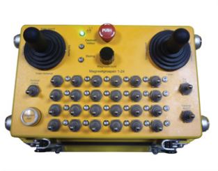
| Условием эффективного и безопасного обслуживания является правильный подбор управления для подъёмно-транспортного оборудования. Он позволяет сократить время обслуживания, повышая производительность производственного процесса. Инженеры NORES уже много лет применяют проверенные решения передовых мировых производителей. На наших кранах применяются системы радиоуправления фирмы HETRONIC (США), одного из лидеров на рынке систем радиоуправления. | |
| Hetronic — это всемирный концерн, имеющий 15 заводов по производству продукции и представительства более чем в 45 странах. Спектр продукции очень широк. Начиная с середины 1980-х годов, Hetronic специализируется в области радиоуправляемых устройств, обеспечивающих безопасность людей и механизмов при работах повышенной сложности.
|
Вашему вниманию предлагаем следующие серии систем радиоуправления GL, NOVA, ERGO:
Серия GL
|
|
-
Серия NOVA
-
Серия NOVA передатчиков HETRONIC — это настоящая новинка в области современного индустриального радиоуправления. Серия NOVA отличается крепким и эргономичным дизайном. Нет никаких компромиссов в ущерб удобства работы оператора и функциональности.

NOVA-S
NOVA-S доступна с переключателями, кнопочными выключателями и тумблерами. Приспособление для быстрого повешения на ремень удобная форма корпуса NOVA-S, обеспечивают свободу движения оператора.
HETRONIC предлагает NOVA-S в нескольких стандартных исполнениях. Как и остальная продукция HETRONIC, NOVA-S запроектирована для широкого применения. Система идеальная для управления бетононасосом, бура и других машин.
— радиус действия, примерно 100м,
— IP65
— аккумулятор 3,6В
Скачать технические характеристики:
- TD_NOVA-S_en.PDF (129КБ)

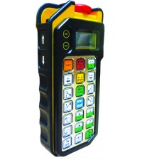
NOVA-M
Эргономическая конструкция NOVA-M позволяет оператору на простой доступ к органам управления. Рычаги обеспечивают плавно управлять машиной. NOVA-M доступна с одном или с двумя джойстиками (цифровыми или с пропорциональными) вместе с прочими вспомогательными функциями, в любой конфигурации, желаемой Заказчиком. Джойстики с удлиненным сроком службы, проверены даже при круглосуточному использованию.
В стандартном исполнении установлен 3-позиционный переключатель с возможностью программирования для работы в Тандеме. Большие возможности программирования. Специальные аккумуляторы 3,6В большой емкости хватают на 10 часов беспрерывной работы. Ремень на шею упрощает работу с передатчиком оператору. Крепкий, надежный корпус о высокой степени защиты IP65. Рабочий радиус действия: 100м.
Как и остальная продукция HETRONIC, NOVA-М запроектирована для широкого применения. Система идеальная для управления кранами, в том числе башенными кранами, подъемниками и другими машинами.
Передатчик простой в эксплуатации и в сервисе. Возможно устранение простых неполадок собственными силами клиента после получения консультаций со стороны авторизованного инженера HETRONIC.
Скачать буклет: Nova-M Brochure.PDF (575КБ)
Скачать технические характеристики:
- TD_NOVA-M_en.PDF (127КБ)
NOVA-L
NOVA-L доступна с 2 джойстиками двойной оси (цифровой или с пропорциональный) или с 6 полностью пропорциональными рычагами «весла».
Скачать буклет: Nova-L Brochure.PDF (270КБ)
Скачать технические характеристики:
- TD_NOVA-L-DIG_en.PDF (130КБ)
- TD_NOVA-L-PROP_en.PDF (139КБ)

NOVA-XL
Максимально объемная, но все же легкая конструкция. NOVA-XL разработана для применений, которые требуют многочисленных функций с цифровыми или с пропорциональными сигналами для точного управления механизмами.
NOVA-XL доступна с 4 джойстиками двойной оси (цифровой или пропорциональный) или даже с 8 полностью пропорциональных рычагами ( «весла»). Джойстики или рычаги «весла» позволяют плавно управлять механизмами, минимизируя усталость оператора.
Дизайн NOVA-XL обеспечивает дополнительное пространство для установки выключателей или графического дисплея.
Скачать буклет: Nova-XL Brochure.PDF (609КБ)
Скачать технические характеристики:
- TD_NOVA-XL-DIG_en.PDF (131КБ)
- TD_NOVA-XL-PROP_en.PDF (139КБ)

GR
Передатчик предназначен в основном для управления большими машинами с многими функциями. GR обеспечивает много места для применения нескольких джойстиков и ряда переключателей и тумблеров. Установлено нагрудное приспособление для носки и защитная рамка позволяют комфортно и безопасно пользоваться передатчиком.
GR имеет большой потенциал для применения в разных аппликациях. Возможно устанавливать в GR даже самые сложные джойстиковые органы управления, на пример производства Spohn&Burkhardt, так как габариты корпуса передатчика достаточно большие. Дисплей ЖК с обратной связью также доступный, как опция.
Скачать технические характеристики:
- TD_GR_en.PDF (1,19МБ)

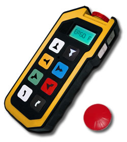
ERGO-F 21
Максимально объемная, но все же легкая конструкция. NOVA-XL разработана для применений, которые требуют многочисленных функций с цифровыми или с пропорциональными сигналами для точного управления механизмами.
NOVA-XL доступна с 4 джойстиками двойной оси (цифровой или пропорциональный) или даже с 8 полностью пропорциональных рычагами ( «весла»). Джойстики или рычаги «весла» позволяют плавно управлять механизмами, минимизируя усталость оператора.
Дизайн NOVA-XL обеспечивает дополнительное пространство для установки выключателей или графического дисплея.
Скачать технические характеристики:
Technical_ERGO_F_RUS 21.pdf (596КБ)
Серия ERGO-F
Передатчик ERGO-F является самой последней разработкой серии ERGO в промышленности, которая имеет 3 различные стандартные конфигурации и возможности индивидуального программирования, технологию Memory Key, новый эргономичный профиль и простую удаленную настройку.
Технология Memory Key позволяет ERGO-F «запоминать» ваши параметры настройки, предотвращать несанкционированное использование и даже сохранять настройки в запасных модулях Memory Key в случае потери носителя — кнопки «СТОП» или повреждения.
Удобный и хорошо уравновешенный, передатчик ERGO-F хорошо лежит в руке. Его профиль обеспечивает контроль за точностью, уменьшая усталость оператора во время действий, выполняемых одной рукой.
С появлением модема H-LINK Hetronic и программного обеспечения, ручная настройка — в прошлом. Удаленный доступ и формирование всех параметров настройки возможно путем использования PocketPC!
Скачать буклет: ERGO-F Brochure.PDF (265КБ)
Скачать технические характеристики:
- TD_ERGO-F_en.PDF (130КБ)
- TD_ERGO-F_2,4GHZ_en.PDF (129КБ)
Серия POCKET
Серия POCKET фирмы HETRONIC была разработана для того, чтобы составить основу для рынка профессиональных систем радиоуправления.
Передатчик позволяет управлять ограниченным количеством цифровых функций без ущерба для безопасности и надежности.POCKET предлагает высокую надежность и качество по конкурентоспособной цене.
В передатчиках POCKET используются 3 батареи типа AA, которых хватает на 500 часов работы. Его тонкий, но эргономичный дизайн позволяет удобно выполнять операции одной рукой. Очень надежные мембранные выключатели доступны в одноступенчатом или двухступенчатом исполнении. Несмотря на компактность корпуса, возможно несколько различных вариантов конфигурации в базовых комплектациях.
Как и большинство продуктов Hetronic, серия POCKET находит множество применений. POCKET идеально подходит для цепных талей, небольших подъемных кранов, систем конвейеров, монорельсовых дорог, крюковых погрузчиков, бетономешалок, эвакуаторов, ворот и многих других машин. Передатчики POCKET полностью совместимы с линией Hetronic приемников MFSHL.
Скачать буклет: Pocket MFSHL Brochure.PDF (262КБ)
Скачать технические характеристики:
TD_Pocket_de.PDF (156КБ)
Серия MINI
МИНИ-Hetronic представляет собой небольшой, но мощный кнопочный передатчик, который может использоваться для многочисленных применений. МИНИ разработан для решения тех задач, которые требуют высокой надежности и небольшого числа цифровых функций.
Все МИНИ системы разработаны таким образом, что легко помещаются на ладонь руки оператора. Когда передатчик не используется, его можно удобно носить на поясе пользователя. В системе МИНИ применяются надежные одноступенчатые или двухступенчатые мембранные кнопки, защищенные от воздействий окружающей среды.
Hetronic предлагает МИНИ в 6 различных вариантах для быстрой поставки. Модуль питается 3 батареями типа AA или дополнительным комплектом аккумуляторов.
Скачать буклет: Mini Brochure.PDF (662КБ)
Скачать технические характеристики:
TD_MINI_en.PDF (156КБ)


Полную информацию о системах радиоуправления HETRONIC можно найти на сайте компании: http://hetronic.com/
Запасные части
Фирма ООО «Норес» предлагает запчасти к системам радиоуправления производства HETRONIC.
Для этого неободимо нам отправить сообщение с информацями:
— какую запчасть необходимо поставить,
— системный номер радиоуправления.
Одновременно предлагем наши услуги:
- — перевод существующих систем управления на радиоуправление,
- — сервис и ремонт.
>>> Перейти на страницу: Наши Услуги
Вы заинтересованы данной продукцией?
При помощи заявок Вы можете получить интересующую Вас информацию. После оформления заявки наши менеджеры обязательно свяжутся с Вами для уточнения деталей. Мы будем рады ответить на все Ваши вопросы и готовы предоставить Вам более подробную информацию о нашей продукции и ценам на нее.
Заявки просим присилать по адресу электронной почты:
или по факсу: + 7 8202 20 20 89.
Приглашаем посетить наш новый интернет-магазин, где также можно заказать системы HETRONIC, комплектующие и запчасти: http://nores.tiu.ru/
Заполните нижеприведенную форму опросного листа, а мы подготовим оферту: Perevod_krana.PDF (230КБ)
ООО «Норес» напоминает, что у всех размещенных на данном сайте фотографий имеется правообладатель.
При размещении фотографий на Ваших сайтах обязательно наличие ссылки на наш сайт.
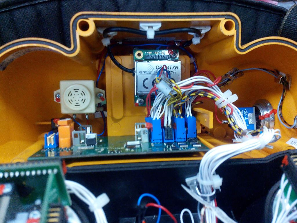
На бетононасосе как дополнительная опция установлен беспроводной пульт управления стрелой HETRONIC. В процессе эксплуатации пульт терял связь и периодичски не работал левый джойстик.
После вскрытия оказалось, что во внутреннее пространство джойстика попала влага, что привело к периодическим отказам платы радиопередатчика.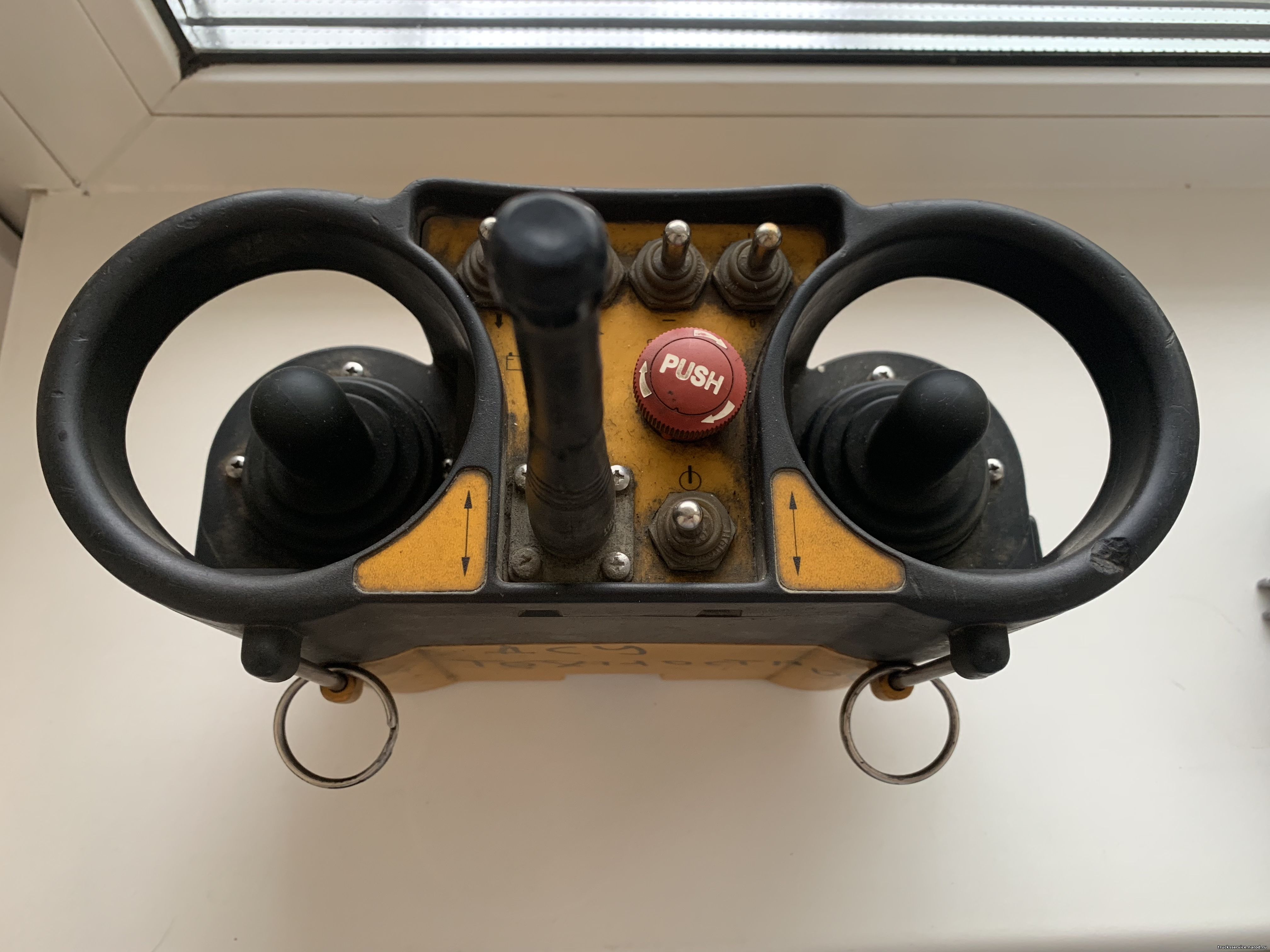
Пришлось полностью заменить радиочастотный модуль, после чего связь больше не прерывалась.
Со второй неисправностью все оказалось гораздо проще, левый джойстик не работал из-за того, что контакт потенциометра в процессе эксплуатации пришел в негодность, но есть методики восстановления неисправных дорожек.
Нашими силами были произведены ремонтно-восстановительные работы, итог которых полное восстановление джойстика HETRONIC
Для записи на ремонт или ответ на интересующие вопросы обращайтесь по телефону:
+7 908 744 98 79
РАБОТАЕМ СО ВСЕЙ РОССИЕЙ, УСЛУГИ ТРАНСПОРТНОЙ КОМПАНИИ НЕ ТАКИЕ ДОРОГИЕ
Для заявки на ремонт ЭЛЕКТРОНИКИ пользуйтесь формой 
Комментариев: 0
Добавлять комментарии могут только зарегистрированные пользователи.
Регистрация | Вход
-
Contents
-
Table of Contents
-
Troubleshooting
-
Bookmarks
Quick Links
Installation and User’s Manual for Radio Remote
Installation and User’s Manual for Radio Remote
Installation and User’s Manual for Radio Remote
Controls used in hazardous environments
Controls used in hazardous environments
Controls used in hazardous environments
Ex manual
Ex manual
Ex manual
HETRONIC
HETRONIC
HETRONIC
Rev 0 — Oct 29, 2014
Rev 0 — Oct 29, 2014
Rev 0 — Oct 29, 2014
Related Manuals for HETRONIC EX Series
Summary of Contents for HETRONIC EX Series
Your radio remote control system has been designed and manufactured using state-of-the-art
technology. Every individual device is subjected to a stringent quality control process at the
manufacturer’s factory before being released for delivery to the customer.
Please check the following points in the event of a fault:
Trouble symptom
On/Off function cannot be
actuated or controlled.
No reaction to keying the
transmitter.
Operating time is too short.
There is interference with the
transmission of the control
commands to the machine.
Individual functions cannot be
actuated or controlled.
Possible causes
Self-test routine
Rechargeable battery/non-
rechargeable batteries run down.
Interruption to receiver power supply.
Rechargeable battery or battery
compartment is defective (contact
corrosion).
Batteries are run down.
A non-compatible transmitter and
receiver combination is being used.
Addresses of transmitter and receiver
do not correspond with each other.
Incorrect or run down rechargeable
batteries/non-rechargeable batteries
were inserted.
No radio link.
Check to see if there is a large metal
surface located between the
transmitter and receiver.
The range has been exceeded. Please
contact your dealer.
The receiver is located in a steel
cabinet or a vehicle, or is installed
inside the machine to be controlled.
The aerial is inadequate.
A radio remote control system with the
same frequency is being used within
the vicinity.
Break in the control lead between the
machine and the receiver.
Output module in receiver is defective.
Remedies
The transmitter is ready for operation after a 3 second self-test
routine.
Insert charged rechargeable battery or check non-rechargeable
batteries. Switch on the master switch of the machine.
Check connectors.
Measure the power supply of the receiver.
Check to see if the same effect occurs with the second
rechargeable battery or with new batteries.
Check the battery compartment and rechargeable battery
compartment and clean if required. Please contact your dealer.
Check the system number on the stickers of the transmitter and
receiver to see if you are using two compatible devices. The device
numbers correspond to the system address and therefore must be
identical.
Check if the power supply for the charger was switched off, or if the
connection is faulty or loose.
Only use rechargeable batteries approved by HETRONIC.
Only use alkaline batteries.
Check that a yellow and red LED flash on the receiver. If not,
please contact your dealer.
A projecting aerial must be installed outside the steel cabinet,
vehicle or the machine to be controlled. Try an alternative
frequency setting for the transmitter and receiver. Please contact
your dealer.
Check that the connector plug is properly seated. Check the
connecting cable to the machine. Check the wiring and carry out
cable-based control checks of the individual functions if necessary.
Check that a LED illuminates on the output modules in the receiver
in response to actuating the corresponding function. Please contact
your dealer.

Paltronic 50 (Codes)Paltronic 50 makes a difference between two different kinds of error – codes
Standard codes. These codes are shown steadily on the display and don’t integrate any further information.
Flashing codes, which are shown with a second additional information code. The main code is shown with a dot behind the number ( e.g. 63.) the additional information is shown without a dot (e.g. 07).
Further the system distinguishes between status codes and error codes.
Status codes are information for the operator, which appear during the normal crane operation. By using the crane in the right way, the status code shifts back automatically to normal operating (00.). For example the code 03. shows an overload situation on the crane, which shifts back automatically to code 00. when reducing the crane moment.
Status codes are characterised with a star ( * ) in the following description.
Error codes are codes signalising a mistake in the system. Even after repairing the mistake, the code will not disappear automatically. The operator or the service technician has to reset the system by pressing the OLP button or by restarting the system.
Error codes are characterised with two stars ( ** ) in the following description.

Paltronic (black box)
Paltronic codes here (decimal place!)

Code Tables
Change or change the main board.Internal error on micro controller.Error safety checkInternal program faultFault internal RAM/RegisterError controller
010203
04.**
Reduce crane load moment by operating a load moment decreasing movement.If necessary use the OLP button to lower the main boom cylinder and get the crane out of a so called ”false overload situation“.If the crane is built for workman basket mode and EN 280 code, check the wiring and the signal. Otherwise deactivate the EN 280mode in the software.If the stabilizers and outriggers are used correctly (stabilizers down, outriggers fully out), check the wiring of the stabilizersswitches.
Crane in overload on the shown load limit. The second code tells, which limit is in overload.Crane outriggers and stabilizers are not used correctly; EN280 mode is activated in the software and the input in P50 tells, that the basket is mounted. (Signal form relay contact K264/1).
Overload on a crane load limitgeneral (until version 2.8)Load limit HPLSLoad limit Nominal loadNegative Load limitSlewing 1, Load limit 1 (SHB)Slewing 1, Load limit 2 (SHB)Slewing 2, Load limit 1 (ISC)Slewing 2, Load limit 2 (ISC)Slewing 3, Load limit 1 (no stab.)Slewing 3, Load limit 2 (no stab.)Workman basket mode not allowed.
00
0102050910171825
26
06
03.*
Change main board.Internal system check is not possible.EEPROM error of hardware version
Checksum EEPROM not ok Crane cannot be operated
0002.**
EPROM (Chip) has to be changed in main board.Internal system check is not possible.EPROM error of hardware version
Checksum EPROM not ok Crane cannot be operated
0001.**
System in normal working condition
0000.*
SolutionReason DescriptionNr.2
Nr.1

Check wiring and connections (U231)Further: Interchange the plug U230 with U231, than reset system by pressing OLP.If code 12 remains – broken wireIf code 11 appears – change pressure transducer U 231.
Broken connection to pressure transducer.Faulty connection on pressure transducer U231.
Broken connection to pressure transducer on main boom piston rod side (signal less than 1.25 mA).
0012.**
Check wiring and connections (U230)Further: Interchange the plug U230 with U231, than reset system by pressing OLP.If code 11 remains – broken wireIf code 12 appears – change pressure transducer U 230.
Broken connection to pressure transducer.Faulty connection on pressure transducer U230.
Broken connection to pressure transducer on main boom piston side (signal less than 1.25 mA).
0011.**
Check magnetic valveEventually the valve is overridden manually.
Spool in control valve is out of centre without a signal from Paltronic.
Error emergency cut off feedback: craneError emergency cut off feedback: stabilizers
01
02
10.**
Check magnetic valve (short circuit)Remove any external power supply.Check output signal from Paltronic (has to be 0 V in overload situation when a lever is acted)
12/24 V on emergency stop valve but no signal from Paltronic (Valve eventually electrically overridden by feed power).
Error on emergency stop feedback.Attention: Crane has no overload system in this condition
0010.**
Reduce force on rope.(Lower the rope or retract extension boom).
Rope winch in overload.(because of too high force on the rope or hoist limiting switch active).
Overload on rope winchLoad moment increasing movements not possible.
0007.**
SolutionReason DescriptionNr.2Nr.1

Check wiring and connections (U236)Further: Interchange the plug U236 with U237, than reset system by pressing OLP.If code 13 remains – broken wireIf code 14 appears – change pressure transducer U236.
Broken connection to pressure transducer.Faulty connection on pressure transducer U236.
Broken connection to pressure transducer on fly-jib boom piston side (signal less than 1.25 mA).
0013.**
Check wiring and connections (U237)Further: Interchange the plug U236 with U237, than reset system by pressing OLP.If code 14 remains – broken wireIf code 13 appears – change pressure transducer U237.
Broken connection to pressure transducer.Faulty connection on pressure transducer U237.
Broken connection to pressure transducer on fly-jib boom piston side (signal less than 1.25 mA).
0014.**
Check wiring to the level indicator on the boom.If activated but not used, deactivate system via computer (Paldiag.NET).If necessary change the switch to the Palfinger standard switch (EEA 4018)
Broken connection to the level indicator or system activated in the software but not mounted on the crane.Eventually wrong switch used.
Broken connection to level indicator on crane (B1).
0015.**
SolutionReason DescriptionNr.2Nr.1

Reduce fly jib load moment by operating a load moment decreasing movement.If necessary use the OLP button to lower the fly jib knuckle boom cylinder and get the jib out of a so called ”false overload situation“.
Fly jib in overload on the shown load limit. The second code tells, which limit is in overload.
Overload on Fly Jibgeneral (until version 2.8)Load limit HPLSLoad limit Nominal loadNegative LastgrenzeReduced load limit
00
01020509
30.*
Interchange plug of the transducer U236 with U237, reset system (OLP or restart).If error 23 remains, short circuit in the cable or main unit defective.If error 22 appears – change pressure transducer U237.
Too high signal (above 19.7 mA) from pressure transducer U237. Short cut in the cable or defective pressure transducer.
Too high signal value from pressure transducer fly jib piston side (U237).
0023.**
Interchange plug of the transducer U236 with U237, reset system (OLP or restart).If error 22 remains, short circuit in the cable or main unit defective.If error 23 appears – change pressure transducer U236.
Too high signal (above 19.7 mA) from pressure transducer U236. Short cut in the cable or defective pressure transducer.
Too high signal value from pressure transducer fly jib piston side (U236).
0022.**
Interchange plug of the transducer U230 with U231, reset system (OLP or restart).If error 21 remains, short cut in the cable or main unit defective.If error 20 appears – change pressure transducer U231.
Too high signal (above 19.7 mA) from pressure transducer U231. Short cut in the cable or defective pressure transducer.
Too high signal value from pressure transducer main boom piston rod side (U231).
0021.**
Interchange plug of the transducer U230 with U231, reset system (OLP or restart).If error 20 remains, short cut in the cable or main unit defective.If error 21 appears – change pressure transducer U230.
Too high signal (above 19.7 mA) from pressure transducer U230. Short cut in the cable or defective pressure transducer.
Too high signal value from pressure transducer main boom piston side (U230).
0020.**
Check wiring to the level indicator on the boom.If activated but not used, deactivate system via computer (Paldiag.NET).If necessary change the switch to the Palfinger standard switch.EEA 4018
Broken connection to the level indicator or system activated in the software but not mounted on the crane. Eventually wrong switch used.
Broken connection to level indicator on fly jib (B301).
0016.**
SolutionReasonDescriptionNr.2Nr.1

Check configuration of the system in the software (PALDIAG), if necessary change and reset the configuration.Check address switches of all CAN-participants (see Paltronic description „Addressing of the system“). Check wiring.Change CAN-participants one by one, always restart system after changing a part by pressing OLP.
Warnung am CAN bus.CAN Warning interrupt, Bus Off .No SpecificationStuff ErrorForm ErrorAcknowledge ErrorBit 1 ErrorBit 0 ErrorCRC Errorunused
0001020304050607
45.**
Check addressing of the bus system, especially check the settingof the display units (remember, that the RRC receiver has address 61).
An address is used more than once in the system. The second code shows, which address is used more than once.
Error CAN addressing.GeneralSpool position feeler boxesDisplay units and RRC SystemEncoder
0051-5F61-6F71-7F
44.**
Restart system. If error remains, check all bus connections.If the error stays, change the CAN participants one by one. Every time restart the system after changing.
CAN bus fault.CAN Error interrupt, Bus Off .No SpecificationStuff ErrorForm ErrorAcknowledge ErrorBit 1 ErrorBit 0 ErrorCRC Errorunused
0001020304050607
42.**
Restart the system. If error remains, check all bus connections.If necessary change main unit.
Internal CAN error.CAN – reading buffer writing error.0041.**
Remove manual extension boom from overload situation (lower the load)Eventually deactivate system if activated but not used (PALDIAG-Software).
Manual extension boom overloaded or system activated in the software but not used on the crane.
Load limit for manual extension boom reached.
0032.**
SolutionReasonDescriptionNr.2Nr.1

Check wiring and connections of the bus system. Restart the system.If the error happens again, change the part with the address shown.If the error 50.00 occur, also check the CAN bus programming. Maybe a CAN part is activated, which does not exist. (example encoder activated but not used on this crane)
CAN participant has got an unexpected restart. This can happen due to a faulty CAN part or a defective wiring. It is also possible, that twice the same address was used.
Error initialisation of CAN participantGeneralSpool position boxDisplay units and RRC systemEncoder
00
51-5F61-6F
71-7F
50.**
Check wiring and connections of the bus system. Restart the system.
It is not possible to receive a data diagram due to a broken cable, a loose connection or a wrong wiring of the bus system. Received data diagram not valid.
CAN receiving not possible.
0047.**
Check wiring and connections of the bus system. Restart the system.
It is not possible to transmit a data diagram due to a broken cable, a loose connection or a wrong wiring of the bus system.
CAN transmitting not possible.
0046.**
SolutionReason DescriptionNr.2Nr.1

Restart system. If error stays, change the part which is shown as the faulty one.
The spool position box found an internal error during start up.The second box shows the address of the faulty participant.
Error CAN document from spool position box to main unitUnknown participantSpool position feeler craneSpool position feeler crane fly jibInput box for ISCThese addresses must not be used at all.
995152
5354-5F
61.**
If error occurs on a new product or right after programming, check the definition in the software. An error during operating can have the following reasons:•During operating from RRC, somebody has moved a spool manually (interrupts the comparison).•A control valve module is defective and makes an uncontrolled movement.
The position of the control valve spool does not fit to the signal from the RRC system. (Possible only on version 3.0 and higher).
Error lever comparisonMain boom loweringMain boom liftingOuter boom liftingOuter boom loweringSlewing leftSlewing rightExtensions extendingRope winch liftingFly jib outer boom liftingFly jib outer boom loweringFly jib extensions extendingAdditional module active in direction AAdditional module active in direction B
010203040506070809101127
28
60.**
SolutionReasonDescriptionNr.2Nr.1

Check wiring and correct connection of the spool position plug.To test a module, one can interchange two plugs and check, if the code changes or stays the same after restart.Code changes- spool sensor , stays the same – broken wireIf necessary, change module or cable.
The spool position sensor does not get a signal in any direction of a function.The cable might be loose or broken (no power supply to the module).
Function operated in both directionsMain boom Outer boom SlewingFly-Jib knuckle boomAdditional module
0103050927
64.**
Check wiring and correct connection of the spool position plug.To test a module, one can interchange two plugs to another function and check, if the code changes or stays the same after restart.Stays the same -broken wire, changes – module defectiveIf necessary, change module or cable.
•The spool of a certain movement is activated.•The wire from the spool position sensor to Paltronic is defective•The plug in the Paltronic spool position box is loose.•The spool position sensor is defective.Check: The diode in the spool position box has to light up, if the spool is in neutral position.
Lever not in neutral position during start up.Main boom loweringMain boom liftingOuter boom liftingOuter boom loweringSlewing leftSlewing rightExtensions extendingSeilwinde LiftingFly-Jib outer boom LiftingFly-Jib outer boom loweringFly-Jib extensions extendingAdditional module in A-directionAdditional module in B-direction
010203040506070809101127
28
63.**
Restart system. If error stays, change the part which is shown as the faulty one.
The spool position box found an internal error during operating.The second box shows the address of the faulty participant.
10 times no data diagram (100 ms)Unknown participantSpool position feeler craneSpool position feeler crane fly jibInput box for ISCThese addresses must not be used at all.
995152
5354-5F
62.**
SolutionReasonDescriptionNr.2Nr.1

Restart system. If code stays change RRC.On new RRC systems, check status code RRC.
RRC system does not react anymore.Error 10 times no diagram on digital channels100 ms no signal.
6171.**
Paltronic has found an error on the RRC system. Only on new RRC systems (Scanreco P2 and Hetronic BMS2):The second code on Paltronic is the first code of the RRC statuscode.
RRC receiver found an internal error.Error on data document from RRC receiver to main unit.
00 -99
70.**
Restart system. If error stays, change the box which is shown asthe faulty one.If a participant has been removed, deactivate it in the software as well.At code 65.99 check CAN bus setting the software and correct it.
Display unit found an internal error during operating.The second box shows the address of the faulty participant.At 65.99: Participant has been activated in the software, which does not exist.
Error during initialisation of display unitUnknown participantAddress of display unit
9962-6F
68.**
Restart system. If error stays change display unit.A display unit has found an internal error or does not react anymore. The second code shows the address of the defective unit.
10 times no data diagramUnknown participantAddress of display unit
9962-6F
67.**
Restart system. If error stays change display unit.A display unit has found an internal error or does not react anymore. The second code shows the address of the defective unit.
Document error from display unit to basic unitUnknown participantAddress of display unit
9962-6F
66.**
Restart system. If error stays, change the box which is shown asthe faulty one.If a participant has been removed, deactivate it in the software as well.At code 65.99 check CAN bus setting the software and correct it.
The spool position box found an internal error during operating.The second box shows the address of the faulty participant.At 65.99:Participant has been activated in the software, which does not exist.
Error initialisation of digital inputsUnknown participantSpool position feeler craneSpool position feeler crane fly jibInput box for ISCThese addresses must not be used at all.
995152
5354-5F
65.**
SolutionReasonDescriptionNr.2Nr.1

Redo the slew angle check via software.Check, if the encoder is mounted correctly.
The switch fort he angle check is active, but the encoder is in a wrong position.
Angle check wrongAddress of encoder (usually 7F).
71-7F79.**
Restart system. If error stays, change encoder.If the encoder has been removed, correct setting via software.At 78.99, an encoder has been activated via software, which does not exist.
The encoder cannot be initialized.The second code is the address of the encoder (usually 7F).
Initialisation error of encoder.Unknown encoderAddress of encoder (usually 7F).
9970-7F
78.**
Restart system. If error stays, change encoder.The encoder turned too quickly.Angle change too quick.Address of encoder.71-7F
77.**
Check wiring.Restart system. If error stays, change encoder.
The encoder has got an internal error.The second code is the address of the encoder (usually 7F).
No answer once per second from encoder.Address of encoder.71-7F
76.**
Restart system. If error stays, change encoder.The encoder has got an internal error.The second code is the address of the encoder (usually 7F).
Error document form encoder to main unit.Address of encoder.71-7F
75.**
Check data bus cable and restart system.If error stays, change RRC.On new RRC systems, check status code on RRC.
At 73.61:RRC system does not react anymore.At 73.99:RRC has been activated in the software but does not exist.
Error of RRC initialisation (start up process)RRC addressUnknown adderss
6199
73.**
Restart system. If code stays change RRC.On new RRC systems, check status code on RRC.
RRC system does not react anymore.10 times no diagram on analogue channels.
6172.**
SolutionReasonDescriptionNr.2Nr.1

Put all levers to neutral position.If code remains, restart the system.
Hand lever still acted after overload situation.
Lever not in neutral position after overload situation.
0094.*
Retract crane extension booms, if necessary lower load by using the OLP-button.
Due to wrong operation, the fly-jib is overloaded 20 bar above the set limit.
Load limit of crane overridden by 20 bar. All load moment increasing movements as well as all lifting movements not possible.
0093.*
Change main unit, restart the system. Power off then restart.It is not possible to program the chip.Writing on EEPROM takes too much time.
0092.**
This is no error or mistake in the system, the jib can be used with all free functions. This code only can appear in version 2.4 or less.
Fly-jib lifting capacity is reached but system not yet in overload.
Electronic main relief valve on fly-jib active. Fly-jib lifting is not possible any more.
0091.*
Retract fly-jib extension booms, if necessary lower load by using the OLP-button.
Due to wrong operation, the fly-jib is overloaded 20 bar above the set limit.
Load limit on fly-jib overridden by 20 bar. All load moment increasing movements as well as all lifting movements not possible.
0090.*
Move crane out of limited area.If the crane is not in the limited area, check the wiring of thesignal switches.If the crane should not have this system, deactivate it in the software.Take the lever back to neutral position and press OLP.
The crane has been turned into the limited area of the high stand imitation system.A crane function has been operated in stabilizer mode.
High stand limitation activeHigh stand 1 (IS001)High stand 2Error crane function in stabilizer mode
011112
81.*
Visit workshop and reset the interval in the software.Crane or rope winch requires service due to the service interval counter
Service interval required.Service interval crane (until version 2.8)Service interval rope winch
01
02
80.**
SolutionReasonDescriptionNr.2Nr.1

Automatically shifts back to normal mode after the programmed delay time is over or the setting via computer is completed.
Programmed delay after overload or load limit overridden via the Paldiag.NET software.
Programmed delay after overload.
0099.*
Start system with On/Off button.(also possible via RRC-feed back system)
Paltronic switched off with On/Off button.System switched off manually.
0098.*
Check feed power.Less than 9 V in the feed line..Power Fail (low voltage)0096.*
This is no error or mistake in the system, the crane can be usedwith all free functions. This code only can appear in version 2.4 or less
Crane lifting capacity is reached but system not yet in overload.
Electronic main relief valve on crane active. Crane lifting is not possible any more.
0095.*
SolutionReasonDescriptionNr.2Nr.1

RRC Codes (Yellow box)
RRC codes here, (decimal Place!)

No entry in error memoryFlashing codeComplete programming, restart systemProgram downloadingLoading new program
0021.
Flashing codeComplete programming / Reset System (feed power off/on)
Data are being deleted or overwritten
Data deleting, overwriting
01
No entry in error memory
Fixed codeComplete programming / Reset System (feed power off/on)System in programming modeProgramming via
transmitter0020.
No entry in error memoryFlashing codeStart system,Transmitter switched off or out
of rangeNo radio signal from transmitter
0111.
Flashing codeChange frequencyInterference in the radio signal, hand lever activated
Radio interference, analogue channel 1-16 active
01-16 No entry in error memory
Fixed codeChange frequencyInterference in the radio signalRadio interference0010.
No entry in error memoryFlashing codeRelease emergency button, restart systemEmergency cut off button has
been pressed
System in Standby, emergency system on transmitter active
0103.
Flashing codeBring lever into neutral position and start system.
Analogue channel used but system not started
System in Standby, analogue channel 1-16 active
01-1602.
No entry in error memoryFlashing codeBring back lever to neutral positionProportional function in use
System active, analogue channel used
01-1601.
No entry in error memoryFixed codeSystem active, all okSystem active, all ok
0000.
FunctionShown asSolutionReasonDescriptionCode 2Code 1
Error Codes

FunctionShown asSolutionReasonDescriptionCode 2Code 1
Internal plausibility check errorInternal plausibility check error
12
Internal hardware self check error
Internal hardware self check error
11
Internal counter errorInternal counter error10
Internal time errorInternal time error09
Error stackError stack08
Error timerError timer07
Error interruptError interrupt06
Error watchdogError watchdog05
Internal bus or COM errorInternal bus or COM error
04
Internal synchronisation errorInternal synchronisation error
03
Flashing code
Reset system by switching it off and on again. Therefore take out feed power completely.If error stays, reload file.If error stays, change receiver.
Internal hardware errorInternal hardware error
02
System emergency stopFlashing codeReset System (Power on/off)Self check errorSelf check error
0130.
Error Codes

FunctionShown asSolutionReasonDescriptionCode 2Code 1
Flashing codeCheck end user on output 1Error on digital output 1Error on digital output 1 feed back error
17
Flashing codeShortcut on one or more digital outputs 7-12
Shortcut on digital output 7-12
16System emergency stop
Flashing codeCheck connected end users. Therefore disconnect all users and reset system. Then reconnect one by one to find out the faulty user. Check faulty user.
Shortcut on one or more digital outputs 1-6
Shortcut on digital output 1-6
15
Flashing codeCheck all connected usersShortcut in emergency loopShortcut in emergency loop
12
System emergency stopFlashing codeCheck valve for damages or short circuit,
check wiring
Voltage on dump valve not correct, valve might be damaged
Not allowed power on dump valve
10
undefined04-09
Check feed line, increase voltage (check quality and size of wires)Feed voltage lower than 35VPower supply < 8V
02Flashing code
Check feed line, reduce voltageFeed voltage higher than 35VPower supply > 35V0133.
Undefiniert (not used)0032.
FLASHPROM errorFLASHPROM error04
EEPROM errorEEPROM error03
External RAM errorExternal RAM error02
Flashing code
Reset system by switching it off and on again. Therefore take out feed power completely.If error stays, change receiver.
Internal RAM errorInternal RAM error0131.
Error Codes

FunctionShown asSolutionReasonDescriptionCode 2Code 1
Bring switch to neutral position, restart system.Change switch if defective.
Start locked digital channel (switch) not in neutral position during start up.
Error on start locked digital channel.
02System emergency stopFlashing code
Reset system.If code stays, change relay.
Relay K0 in receiver is not in neutral position.
Error input from start locking.
0163.
Undefined (not used)0062.
Undefined (not used)0061.
Undefined (not used)0060.
System emergency stopFlashing code
Check valve (Danfoss module, Nordhydraulic magnetic coils). Change if required.Check wiring for quality/damages.
Error signal from valve 1-8.Valve error 1-8 (error input)
01-0852.
System emergency stopFlashing codeCheck lever (Joystick)
Change if required.No safety contact (digital) available. Lever damaged.
Error on analogue channel 1-16 (Comparison analogue/digital AK-DK)
01-1651.
System emergency stopFlashing code
Bring lever back to neutral position, restart system. If code stays, check lever.
Lever 1-16 activated during start up or lever defective.
Lever 1-16 (analogue channel) active during start up.
01-1650.
System emergency stopFlashing code
Check valve (Danfoss module, Nordhydraulic magnetic coils).Check wiring for quality/damages.
Analogue signal to valve not correct.Defective valve.
Feedback error on analogue outputs 1-8 (signal to valve).
01-0835.
System emergency stopFlashing code
Check valve (Danfoss module, Nordhydraulic magnetic coils).Check wiring for quality/damages.
Feed power to valve not correct.Defective valve.
Feedback error on analogue outputs 1-8 (power supply to valve).
01-0834.
Error Codes

Revision Modified Checked Module Name
Date By Date By PDM
A June03-2016 JA June06-2016 AP
B Aug10-2016 JA
Description
Proximity detection module (PDM) is a wireless detection and
distance measurement sensor operating at 2.4Ghz.
Remarks
Supports configuration via serial interface.
Item Number
52451300
User Manual
Documentation
FCC ID: LW9-PDM
Canada: 2119B-PDM

Revision Project: PDM Page
A Description: Proximity detection module (PDM) is a wireless detection and
distance measurement sensor operating at 2.4Ghz. 2 of 11
List Of Contains
1.PROJECT DESCRIPTION ……………………………………………………………………………………………..……………… 3
2.BLOCK DIAGRAM …………………………………………………………………………………………………..…………………. 4
3.TECHNICAL SPECIFICATION ………………………………………………………………………………………….…………. 5
4.CONNECTION DIAGRAM …………………………………………………………………………………………………………… 6
5.CONFIGURATION PARAMETERS ………………………………………………………………………………………………. 7
6.PROGRAMMING CONFIGURATION AND TESTING PROCEDURE …………………………………………….. 9
7.REVISION HISTORY ………………………………………………………………………………………………..……………….. 11
List of Figures
Figure 1: Block Diagram ………………………………………………………………………………………….…………………………… 4
Figure 2: Board Connections …………………………………………………………………………………………………………………. 6
Figure 3: PDM configuration parameters …………………………………………………………………………….………………….. 7
Figure 4: Test setup …………………………………………………………………………………………….………………………………… 9
Figure 5: Opening putty application ……………………………………………………………………………….…………………….. 10
Figure 6: Configuration parameters ………………………………………………………………………………..…………………….. 10
Figure 7: PDM continuous ranging…………………………………………………………………………………..…………………… 11
List of Tables
Table 1: Technical Specifications Details ………………………………………………………………………….…………………….. 5
Table 2: PDM configuration parameters ……………………………………………………………………………..…………………… 8
Table 3: PDM LEDs ……………………………………………………………………………………………….……………………………. 8
Table 4: PCB Specifications Details ……………………………………………………………. Error! Bookmark not defined.

Revision Project: PDM Page
A Description: Proximity detection module (PDM) is a wireless detection and
distance measurement sensor operating at 2.4Ghz. 3 of 11
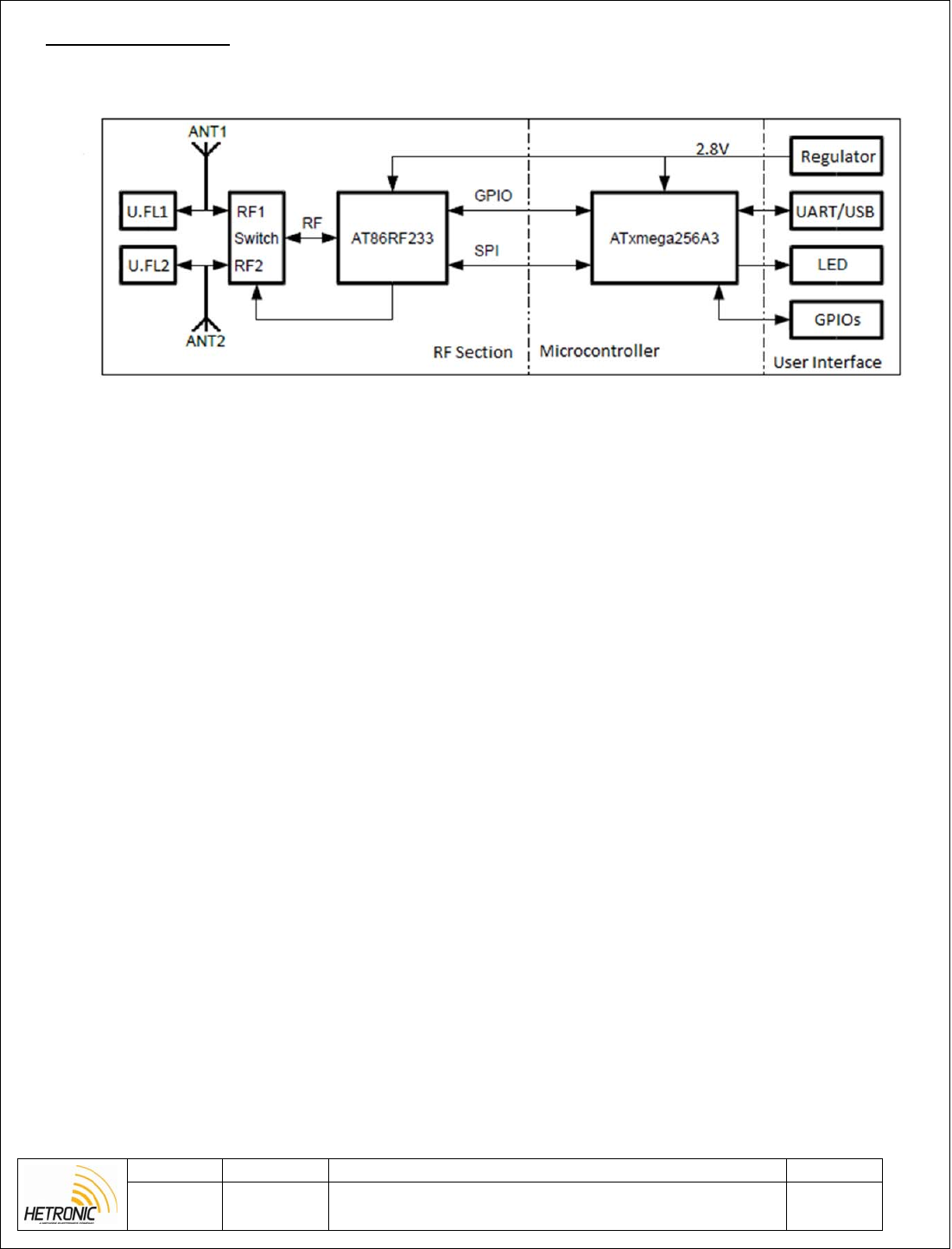
1. PROJECT DESCRIPTION
Proximity Detection Module is an RF module designed to measure the distance between two nodes. The
module uses Atmel AT86R233 phase difference measurement function in order to relate change of signal
phase with distance. The module operates in the 2.4 GHz band in order to communicate between two paired
nodes.
The sensor was designed in order to be integrated with Hetronic standard systems. By adding a PDM
module in a transmitter and receiver one can choose the location where the operator has to be in order to
operate the system. The user can choose to either operate the system when he is less than a configurable
distance to the receiving PDM node or else when he is far away by the selected distance.
Revision Project: PDM Page
A
Description:
Proximity detection module (PDM) is a wireless detection and
distance measurement sensor operating at 2.4Ghz.
4 of 11
2. BLOCK DIAGRAM
Figure 1: Block Diagram

Revision Project: PDM Page
A Description: Proximity detection module (PDM) is a wireless detection and
distance measurement sensor operating at 2.4Ghz. 5 of 11
3. TECHNICAL SPECIFICATION
Table 1: Technical Specifications Details
Operating Temperature -20o to +70o Celsius
Storage Temperature -40o to +85o Celsius
Supply Voltage Range 3-12 VDC, 40mA Max
Communication Interface UART, USB
Outputs/Outputs 3 configurable IOs
High current open drain output
Accuracy (line of sight) <5m – 1m accuracy
>5m – 2m and above
Revision Project: PDM Page
A Description: Proximity detection module (PDM) is a wireless detection and
distance measurement sensor operating at 2.4Ghz. 6 of 11
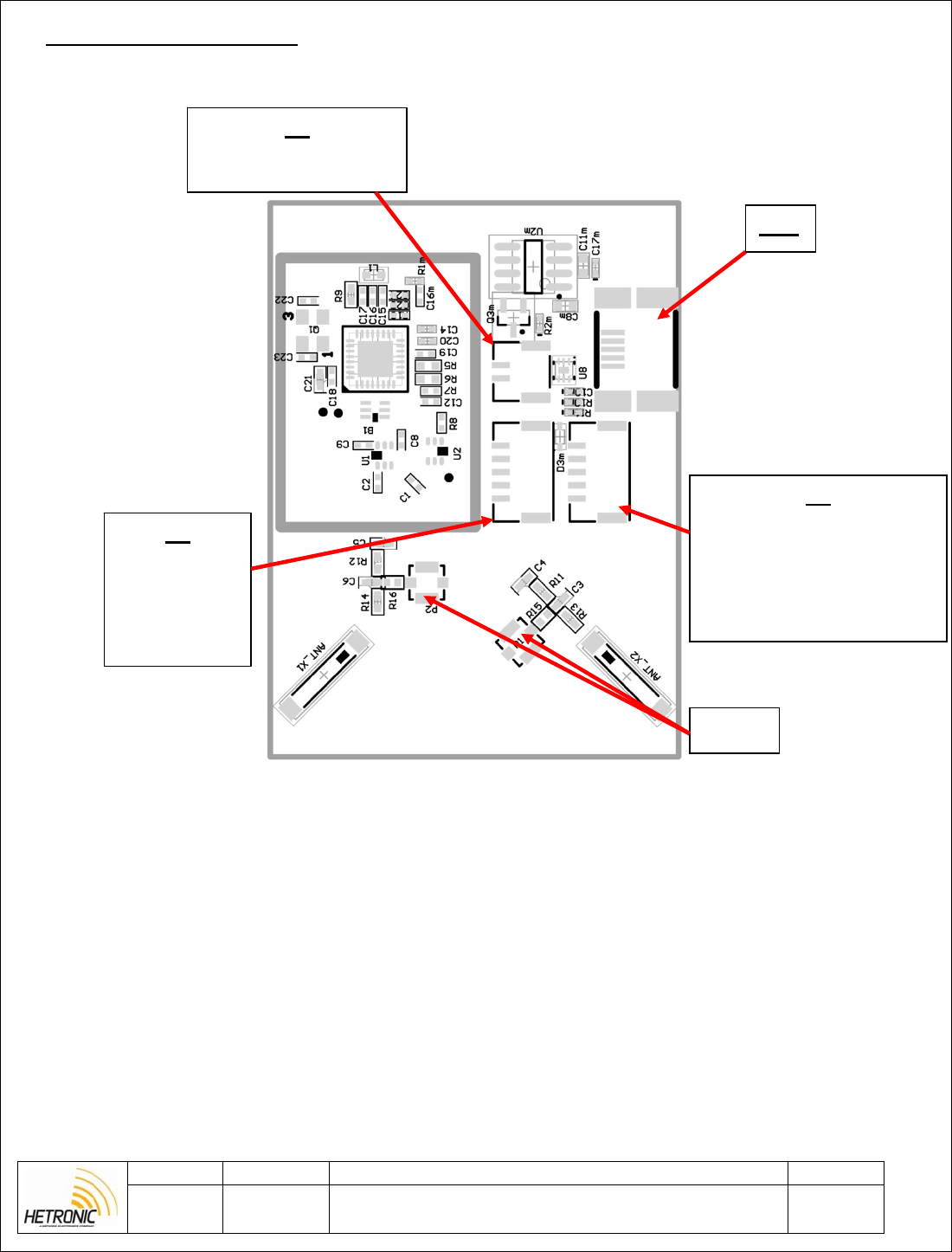
4. CONNECTION DIAGRAM
4.1. Board Connections
Figure 2: Board Connections
X1
1. Vsupply 3-12V
2. GND
X3
1. GND
2. uC_Reset
3. RXD
4. 2.8V
5. TXD
X4
1. GND
2. Open drain output
3. GPIO3
4. Output Low in zone
5. Output High in zone
USB
U.FL
Revision Project: PDM Page
A
Description:
Proximity detection module (PDM) is a wireless detection and
distance measurement sensor operating at 2.4Ghz.
7 of 11
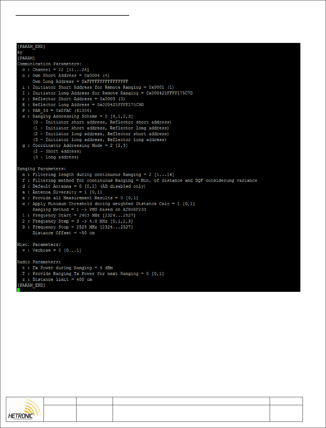
5. CONFIGURATION PARAMETERS
When connecting with a serial interface to the PDM module one can configure the RF parameters and edit
the communications parameters of the sensor. An example of the parameters available is shown below.
Figure 3: PDM configuration parameters
Addresses can be configured via the serial interface and go up to a sixteen bit value. The address for the
receiver has to be the same as the transmitter address plus one. The receiver address has to be updated as the
reflector short address in the transmitter and own short address in the receiver.

Revision Project: PDM Page
A Description: Proximity detection module (PDM) is a wireless detection and
distance measurement sensor operating at 2.4Ghz. 8 of 11
Table 2: PDM configuration parameters
Communication parameters
Command Description Comment
c Channel IEEE802.15.4 channel for basic communication between
nodes [11,12,..26]
o Own Short Address Node Short address. Used when doing local ranging.
i Receiver short address Receiver short address for local ranging.
p PAN-ID PAN-ID of ranging network
s Ranging Addressing scheme 0 – Transmitter short address, receiver short address
g Adressing Mode 2 – Short address
Ranging Parameters
n Filtering length during
continuous ranging Value > 1 starts a continuous ranging with filter depth of n.
Stopped by entering ‘m’ or ‘M’
f Filtering method for
continuous ranging Filtering methode applied during continuous ranging (n!=1)
d Default Antenna Utilized default antenna in case antenna diversity is switched
off [0,1]
a Antenna diversity Utilization of antenna diversity is supported by the PAL[0,1]
1 Frequency start Ranging measurement start frequency in MHz [2324 – 2527]
2 Frequency Step Ranging measurement frequency step mapping [0..3]
3 Frequency stop Ranging measurement stop frequency in MHz [2324 – 2527]
Radio Parameters
t Tx Power during Ranging TX power in dBm utilized during the actual ranging
measurement cycle [-17…4]
z Distance limit The distance value that you want to set and monitor.
5.1. LED Description
Table 3: PDM LEDs
LED Color Description
LED1 Red Power supply is on
LED2 Yellow Blinking once module starts
Revision Project: PDM Page
A Description: Proximity detection module (PDM) is a wireless detection and
distance measurement sensor operating at 2.4Ghz. 9 of 11
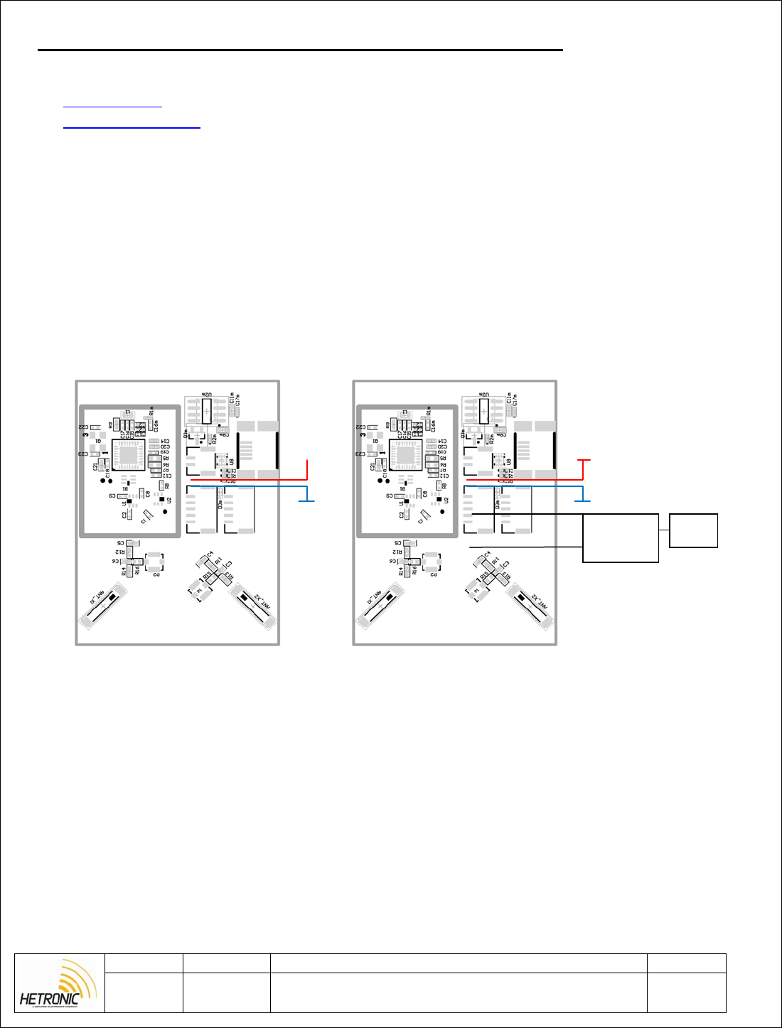
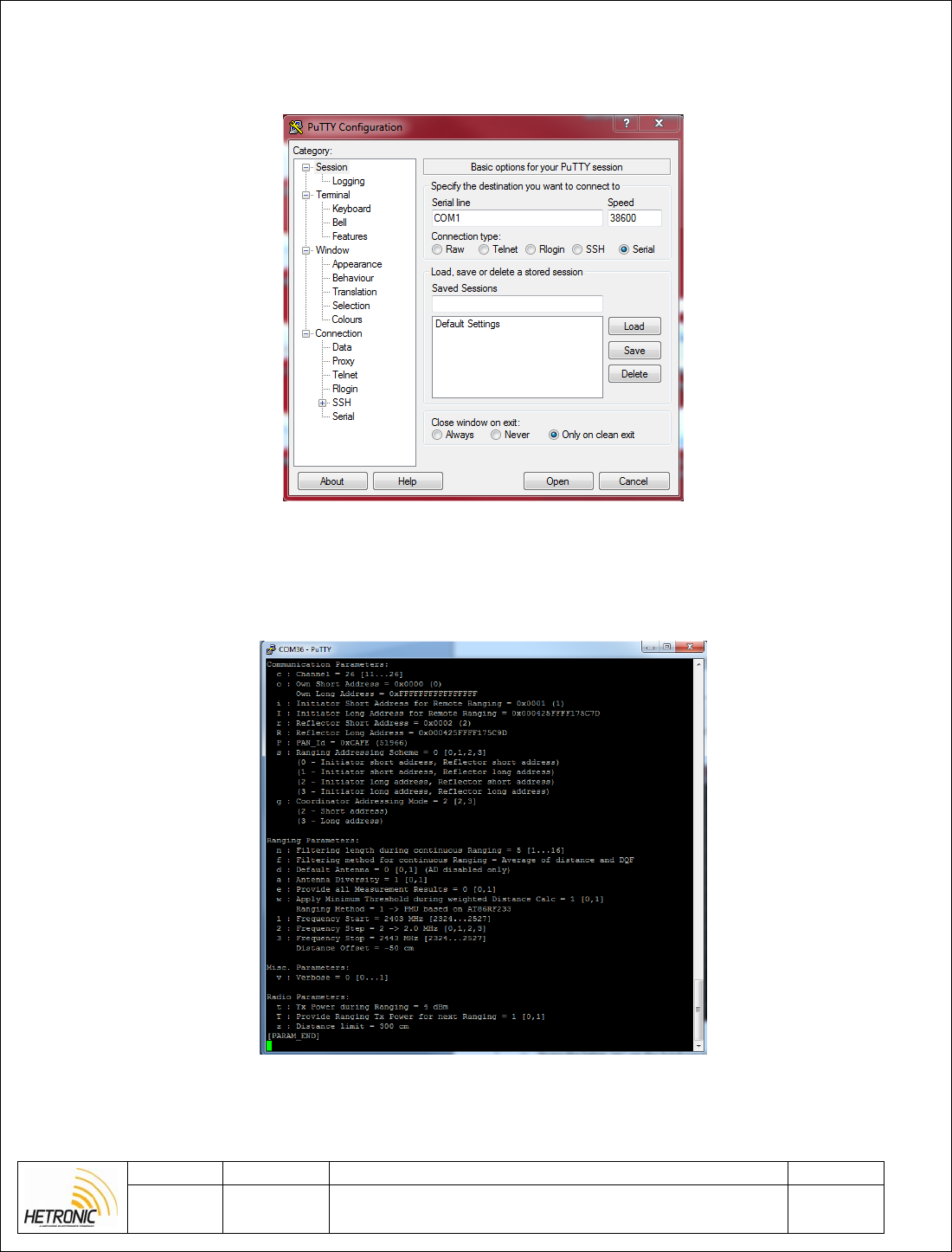
6. PROGRAMMING CONFIGURATION AND TESTING PROCEDURE
[Tools Needed / Requirements]
Putty software
Atmel Flip software
USB to Uart converter cable
Atmel Studio
Atmel ICE with JTAG adaptor
Mini USB cable
1. Connect supply to X1 and see that current consumption is between 30-40mA.
2. Open Putty and connect USB to TTL converter cable to connector X2 as shown below.
[Test Set-Up]
Sample Module Module under test
Figure 4: Test setup
+5
GND
+5
GND
USB to
TTL
onverte
PC
Revision Project: PDM Page
A Description: Proximity detection module (PDM) is a wireless detection and
distance measurement sensor operating at 2.4Ghz. 10 of 11
3. Set the putty baud rate to 38600kb/s and select the COM port of the USB converter and press Open.
Figure 5: Opening putty application
4. A blank black screen should appear. When pressing ‘p’ on the PC the following details should be seen.
Figure 6: Configuration parameters
Revision Project: PDM Page
A Description: Proximity detection module (PDM) is a wireless detection and
distance measurement sensor operating at 2.4Ghz. 11 of 11
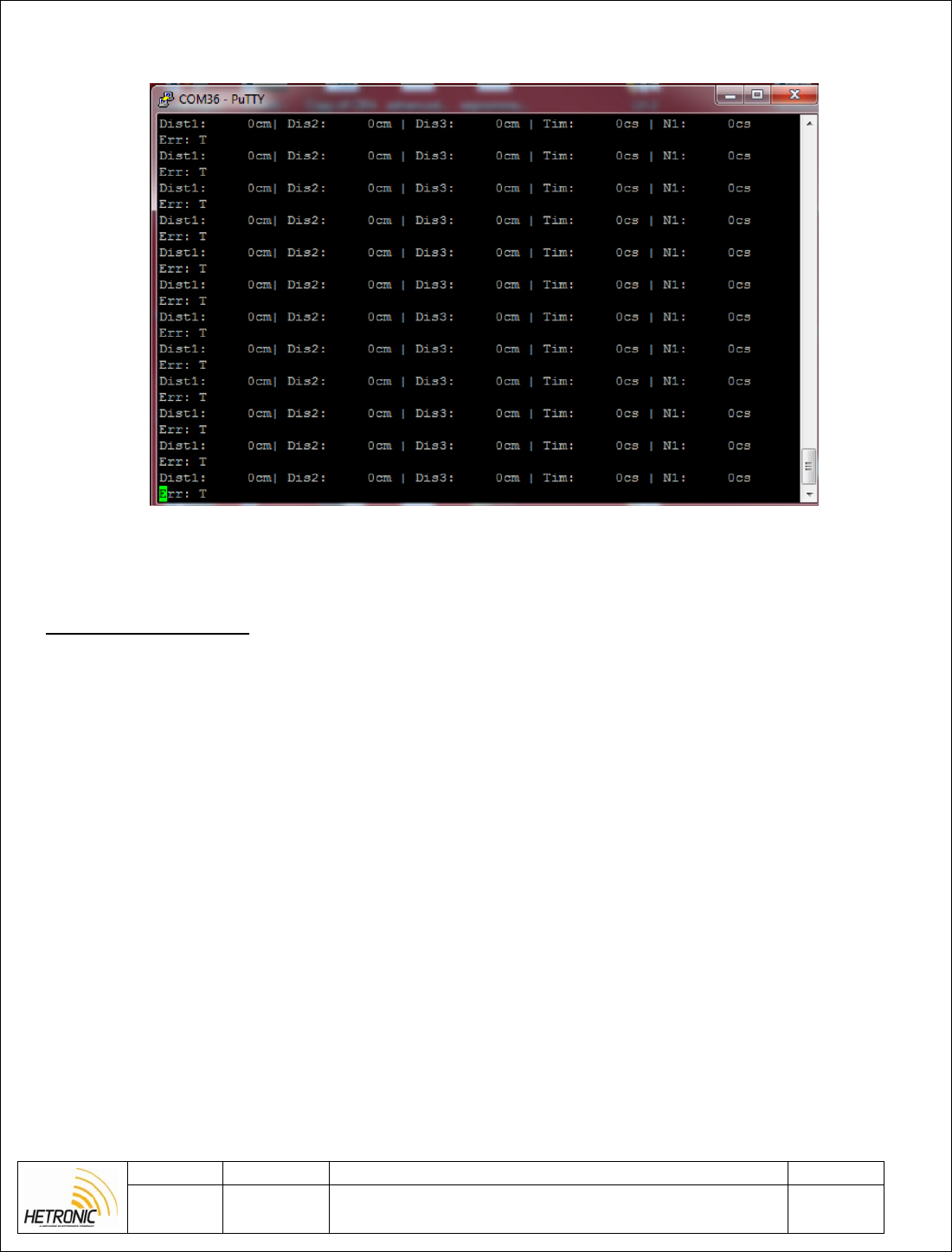
5. If the letter ‘m’ is now pressed on the keyboard then in the Putty terminal various measurements should
start being seen.
Figure 7: PDM continuous ranging
7. REVISION HISTORY
Rev A
— Initial Document, HM0015R02
-
Contents
-
Table of Contents
-
Troubleshooting
-
Bookmarks
Quick Links
Installation and User’s Manual for Radio Remote
Installation and User’s Manual for Radio Remote
Installation and User’s Manual for Radio Remote
Controls used in hazardous environments
Controls used in hazardous environments
Controls used in hazardous environments
Ex manual
Ex manual
Ex manual
HETRONIC
HETRONIC
HETRONIC
Rev 0 — Oct 29, 2014
Rev 0 — Oct 29, 2014
Rev 0 — Oct 29, 2014
Related Manuals for HETRONIC EX Series
Summary of Contents for HETRONIC EX Series
DIAGNOSTIC DISPLAY PANEL CODES
The following table is a brief description of diagnostic,
operational and error codes that may be displayed.
Error codes can be designated for specific customer
requirements and may not be listed here. Refer to the
technical documentation that accompanies your
system for specific customer defined error code
designations.
(VC — Voltage control version only)
(PWM — Pulse width modulation version only)
Operational Codes
x x 0
Receiving correct signal, no E-Stop, system
started
x x 1
Receiving correct signal, BMS-2 in E-Stop, no
E-Stop from TX
x x 2
Receiving correct signal, BMS-2 in E-Stop,
E-Stop transmission from TX
x x 3
RF interference
0 0 4
Not receiving signal, no RF communication, or
TX is turned off
0 0 0 .
Flashing dot after third digit, change the status
with each correct received telegram (green
LED)
0 0 . 0
Flashing dot after second digit indicates
programming mode (Quick-Set)
1 x x
Output 1 (up to  activated, joystick not in
neutral position. System will not start if joystick
is not in neutral position.
Error Codes
E x x
Error Codes are assigned numbers based on
customer requirements.The errors listed below
may or may not be applicable to your system.
See Technical Documentation for specific
codes.
E 0 0
Joystick 1 error — joystick 1 out of neutral
without closed safety switch
E 0 1
Joystick 2 error — joystick 2 out of neutral
without closed safety switch
E 0 2
Joystick 3 error — joystick 3 out of neutral
without closed safety switch
E 0 3
Joystick 4 error — joystick 4 out of neutral
without closed safety switch
E 0 4
Joystick 5 error — joystick 5 out of neutral
without closed safety switch
E 0 5
Joystick 6 error — joystick 6 out of neutral
without closed safety switch
E 0 6
Joystick 7 error — joystick 7 out of neutral
without closed safety switch
E 0 7
Joystick 8 error — joystick 8 out of neutral
without closed safety switch
E 0 8
Over-current 0 error, over-current on E-Stop
circuit
E 0 9
Over-current 1 error, over-current on switching
output 1-6
E 1 0
Over-current 2 error, over-current on switching
output 7-12
E 1 1
Over-voltage error >35V
E 1 2
Under-voltage error <8V
E 1 3
DV1 (Y0) read back error
E 1 4
SW output 1 read back error
E 1 5
Valve Supply 1 read back error (VC)
E 1 6
Valve Supply 2 read back error (VC)
E 1 7
Valve Supply 3 read back error (VC)
E 1 8
Valve Supply 4 read back error (VC)
E 1 9
Valve Supply 5 read back error (VC)
E 2 0
Valve Supply 6 read back error (VC)
E 2 1
Valve Supply 7 read back error (VC)
E 2 2
Valve Supply 8 read back error (VC)
E 2 3
AK1 analog output read-back error (VC)
E 2 4
AK2 analog output read-back error (VC)
E 2 5
AK3 analog output read-back error (VC)
E 2 6
AK4 analog output read-back error (VC)
E 2 7
AK5 analog output read-back error (VC)
E 2 8
AK6 analog output read-back error (VC)
E 2 9
AK7 analog output read-back error (VC)
E 3 0
AK8 analog output read-back error (VC)
E 3 1
PWM output shortcut detection (PWM)
E 3 2
Valve 1 error input (VC)
E 3 3
Valve 2 error input (VC)
E 3 4
Valve 3 error input (VC)
E 3 5
Valve 4 error input (VC)
E 3 6
Valve 5 error input (VC)
E 3 7
Valve 6 error input (VC)
E 3 8
Valve 7 error input (VC)
E 3 9
Valve 8 error input (VC)
E 4 0
CAN bus data timeout error (Hetronic and
HMF)
E 4 1
Start locking input error
E 4 2
RF-DK start locking error, start locked DK is not
in neutral position during system start
Error codes of 50 or greater are start-up or online test
errors and require device re-start to clear.
E 5 0
CPU_TEST_FAILED
E 5 1
WATCHDOG_TEST_FAILED
E 5 2
INTERRUPT_TEST_FAILED
E 5 3
TIMER_TEST_FAILED
E 5 4
EXTRAM_TEST_FAILED
E 5 5
INTRAM_TEST_FAILED
E 5 6
INTPRAM_TEST_FAILED
E 5 7
PFLASH_TEST_FAILED
E 5 8
STACK_OVERFLOW_DETECTED
E 5 9
MAIN_LOOP_TIME_FAILED
E 6 0
OP_COUNTER_ERROR
E 6 1
Serial EEPROM checksum error
E 6 2
Internal HW error — E-stop pulses timeout
16
(Ocr-Read Summary of Contents of some pages of the HETRONIC RX BMS2-PWM Document (Main Content), UPD: 17 September 2023)
-
5, 5 When the transmitter is turned on, it performs a self-test to be sure that the circuitry is within designated parameters. If an error is detected, the transmitter will not transmit any motion signals. The BMS-2 receiver display will show «0 0 4» indicating a passive E-Stop condition in the transmitter. Receiver Safe Mode The following conditions cause the receiver to go into its Safe mode: • Radio signal interference • Transmitter out of opera…
-
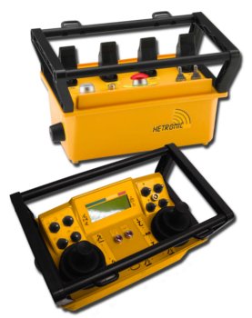
4, 4 10. Always have batteries in the battery charger to ensure the availability of fully charged batteries. 11. Installation, setup and service must be performed by authorized personnel only. 12. Use only Hetronic spare parts. HETRONIC SYSTEM COMPONENTS The Hetronic radio remote control system consists of a receiver and transmitter with belt, battery charger, and two rechargeable batteries. RX BMS2-PWM Receiver Standard Features • 1 E-Stop output • 1 safet…
-
7, 7 Be sure that the Diagnostic Display panel is clearly visible. The receiver wiring is critical for proper system operation. Make all connections with good quality contacts or solder joints to ensure proper electrical contact. Supply voltage and ground wiring are crucial and must be connected to reliable connecting circuitry. Do not use a chassis ground for this equipment. The ground wire must be connected directly to the vehicle battery negative post. IMPORTANT: Power supply wiring mu…
-
15, 15 Transmitter is transmitting (Power LED flashing), but crane/machine will not respond E-Stop switch engaged Pull out the E-Stop pushbutton and press the Start/Horn pushbutton Transmitter out of range Take the transmitter back into the range of the receiver. Press the Start/Horn pushbutton. Joystick, paddle lever or switch not in center position when transmitter turned on Ensure that all control devices are in center (neutral) position wh…
-
12, 12 7. Wait approximately 3 seconds until the second buzzing sound has finished. 8. Twist the key one quarter turn further to the program position. (This is only possible with the red programming key.) Press the «Start/horn» button for at least one second. 9. To set minimum speed — Deflect the requested joystick/paddle slowly until you hear the vehicle’s horn. If the horn is connected to the receiver, it will sound for a brief moment when the joystick/paddle reaches …
-
3, 3 INTRODUCTION Thank you for purchasing the Hetronic radio remote control system. Hetronic radio remote controls are the highest caliber in remote control value, performance and safety. Hetronic radio remote controls use the latest frequency synthesizer technology to eliminate the problems typically associated with radio remote control systems. THE MANUAL Before operation of unit, carefully and completely read your …
-
20, HETRONIC RX BMS2-PWM 20 ABBREVIATIONS A/D Analog to digital conversion AK Analog channel (German: Analog Kanal) AMP Ampere AWG American Wire Gauge BPS Bits per second CPU Central Processing Unit DK Digital channel (German: Digital Kanal) EMC Electromagnetic compatibility EMI Electromagnetic immunity EPROM Electrical programmable read-only memory FM Frequency modulation GND Ground HF High frequency KHz Kilohertz LED Light emitting diode LTO Lift to operate mAH Milliampere ho…
-
14, 14 If the system does not operate after normal start-up as described in Operation Section of this manual, follow the recommended troubleshooting sequence to help isolate the cause and determine corrective action. The BMS-2 Receiver displays Operational Status and Error Codes to help diagnose problems that may occur with the system. The Operational Status codes are shown in the Operation Section of this manual. Error Codes are defined b…
-
21, 21 WARRANTY WRTY_002 Warranty & Terms April 2003 Hetronic USA Limited Warranty and Terms of Sale www.hetronic.com Price: Subject to Change Without Notice Terms: Net 30 Days F.O.B: Hetronic USA, Inc. Oklahoma City, Oklahoma Hetronic, Inc., hereafter referred to as Company, guarantees all items manufactured by it against any defects of material and/or workmanship for a period of one year f…
-
19, HETRONIC RX BMS2-PWM 19 DEFINITIONS Acoustic signal A buzzer or other sound intended to be heard as an alert. Analog signal Proportional — stepless or infinite control Belly box A transmitter that is secured to the front of the operator’s body by a belt, strap or breastplate/harness. Coder Converts parallel signals into a serial data message Decoder Coverts a serial data message into parallel signals Digital signal …
-
11, 11 Dead Man Function With this function activated, it is necessary to press a switch at the same time as a joystick/paddle in order for the crane/machine motion to operate. Hold Function This function makes it possible to «Hold» a position of a joystick without actually holding the joystick in place. Pressing the «Hold» button when the joystick is in its desired position allows the operator to release the joystick while havin…
-
16, 16 DIAGNOSTIC DISPLAY PANEL CODES The following table is a brief description of diagnostic, operational and error codes that may be displayed. Error codes can be designated for specific customer requirements and may not be listed here. Refer to the technical documentation that accompanies your system for specific customer defined error code designations. (VC — Voltage control version only) (PWM — Pulse wi…
-
2, 2 Introduction . . . . . . . . . . . . . . . . . . . . . . . . . . . . . 3 The Manual . . . . . . . . . . . . . . . . . . . . . . . . . . . 3 Production and System Numbers . . . . . . . . . . 3 Unauthorized Replacement Parts . . . . . . . . . . 3 Before Attempting to Operate This System . . . 3 System Components . . . . . . . . . . . . . . . . . . . . 4 RX BMS2-PWM Standard Features . . . . . 4 RX BMS2-VC …
-
8, 8 HOLDING THE TRANSMITTER Hold the transmitter with the control panel facing you. Be sure that you are able to easily read any text and understand operation symbols. If your transmitter contains a Tilt Sensor Switch, be sure it is not activated or the transmitter will not start. If a belt or strap is provided with your transmitter, use it at all times. The belt or strap is designed to reduce stress and increas…
-
18, HETRONIC RX BMS2-PWM 18 This for must be completed and signed by the person responsible for installation of this radio remote control system. Hetronic assumes no responsibility for the correct installation of the radio remote control system. The equipment operator must ensure that the radio remote control system and the crane/machine operate correctly together. The operator must also ensure that all safety devices and features are in place and operating correctly. The operator is responsib…
-
1, HETRONIC RX BMS2-PWM YOUR #1 PARTNER IN RADIO REMOTE CONTROLS Operator Manual Hetronic USA 4300 Highline Blvd., Bldg. A Oklahoma City, OK 73108 405-946-3574 Fax 405-946-3564 OPMN_BMS2_0001.0 12/04 www.hetronic.com Hetronic Canada 45 Sinclair Avenue Halton Hills, Ontario L7G 4X4 +1-800-816-4459 Fax +1-905-702-0501 © 2004 Hetronic, Inc. All rights reserved. No part of this publication may be reproduced, tran…
-
17, 17 SPECIFICATIONS Model BMS-2 (Baseboard Module System) System GA 610 General Data Frequency 70 cm Band (Selectable 458.800 Mhz to 459.175 Mhz) or CS434 Range approx. 100 m ( 328 ft.) Address 20-bit — 1,000,000 possible Operating temperature -30° to +70° C (-22° F to 158° F) Data Format 2400/4800 Baud, even parity, 8 data bits, 2 stop bits, hamming distance 4 Receiver Protective System IP 65 System Synthesizer Technology Voltage Supply 12 to 24 VDC (-50% — +20%) Decoding Multiple bit …
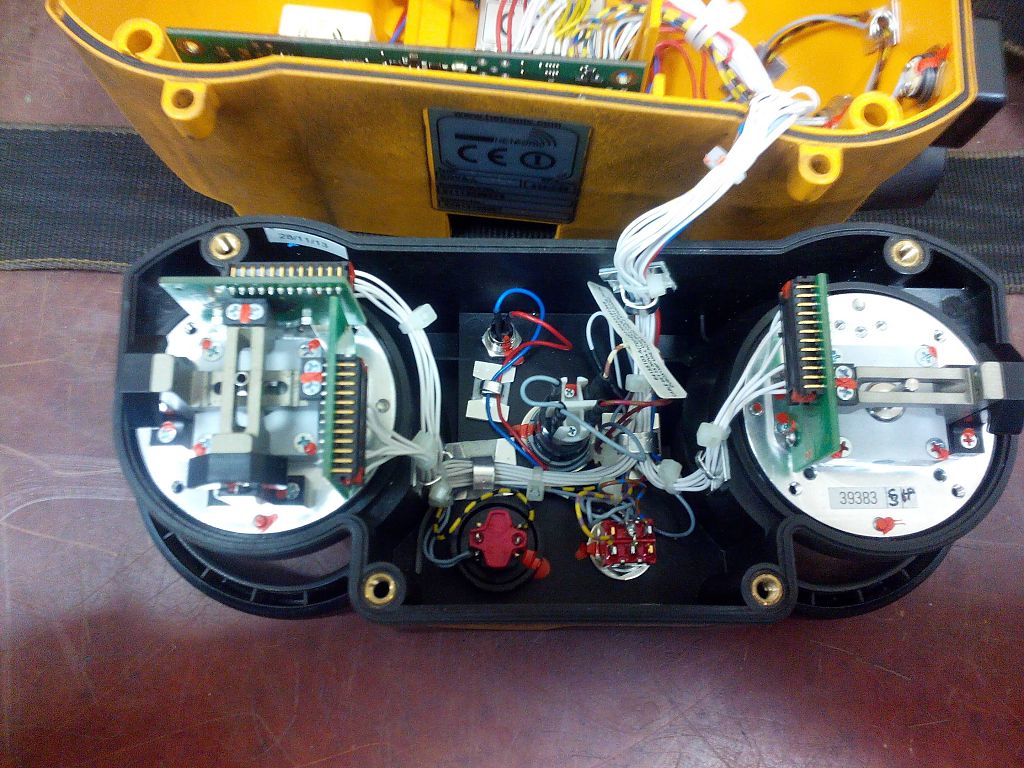
27.11.2019
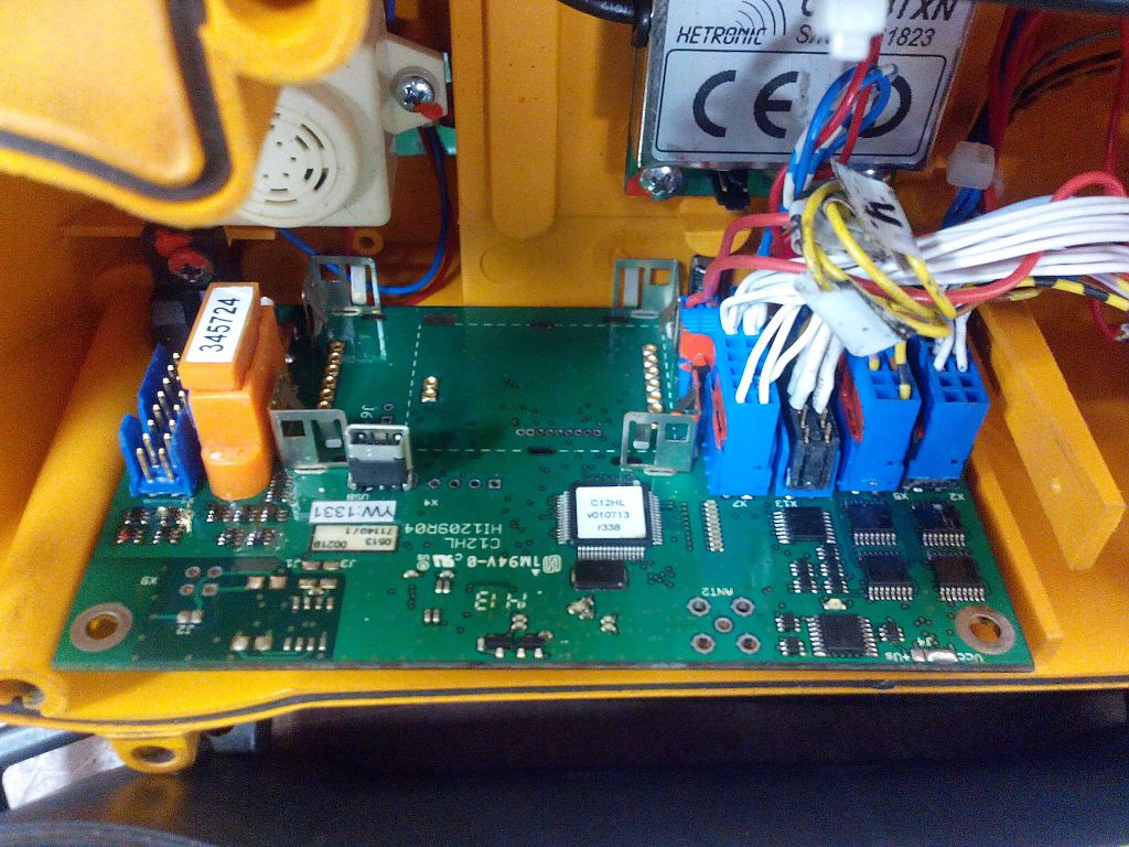
При ремонте системы радиоуправления крана, возникает ошибка красным сигналом на приёмнике.
При вскрытии пульта и смены джойстиков, приёмник стал адекватно воспринимать пульт. И все реле K0 заработали и прозвенел звонок.
(Если требуется ремонт, наладка, помощь в системах радиоуправления, пишите на ватсап или электронную почту)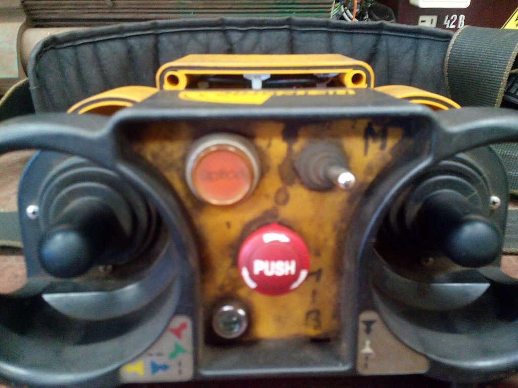
← Ремонт inspection lighting system by unilux inc
Ремонт сварочника ESAB Power cut 1500 →
Комментарии
Пока нет комментариев
Написать комментарий
Имя
Число
