Remedy
•
Выполните повторную
настройку фаз привода с
помощью приложения
Grundfos GO Remote.
8.20 Код 165 (Сбой сигнала)
•
На дисплее отобразится аварийный код 165.
•
Предупреждающий символ на дисплее
становится красного цвета, и насос
останавливается.
•
Аварийный код Signal fault («Сбой сигнала»)
отобразится в приложении Grundfos GO
Remote.
Cause
Сигнал от датчика выходит за
пределы заданного диапазона.
Remedy
•
Перейдите в меню
Настройки > Level Control
(«Настройки» — «Контроль
уровня») в приложении
Grundfos GO Remote и
убедитесь в том, что
заданный диапазон
соответствует типу
физической системы.
•
При необходимости
замените датчик.
8.21 Код 191 (Высокий уровень воды)
•
На дисплее отобразится аварийный код 191.
•
Аварийный символ на дисплее становится
красным, но режим работы насоса не
меняется.
•
Аварийный код High water level («Высокий
уровень воды») отобразится в приложении
Grundfos GO Remote.
Cause
При заданном уровне пуска
насос не запускается.
Remedy
•
Проверьте и настройте
датчик для уровня пуска.
Cause
Размер насоса недостаточен
для удаления воды.
Remedy
•
Обратитесь в компанию
Grundfos или в
соответствующий сервисный
центр.
Cause
Датчик уровня неисправен и не
реагирует на изменения
уровня.
Remedy
•
Проверьте работу датчика
уровня.
Соответствующая информация
3.6 Конфигурирование входных/выходных клемм
с помощью приложения Grundfos GO Remote
8.22 Код 205 (Несоответствие реле
уровня)
•
На дисплее отобразится аварийный код 205.
•
Предупреждающий символ на дисплее
становится красного цвета, и насос
останавливается.
•
Аварийный код Level switch inconsistency
(«Несоответствие реле уровня») отобразится
в приложении Grundfos GO Remote.
Cause
Неисправен или заел
поплавковый выключатель.
Remedy
•
Проверьте исправную работу
каждого поплавкового
выключателя.
Соответствующая информация
3.6 Конфигурирование входных/выходных клемм
с помощью приложения Grundfos GO Remote
8.23 Код 220 (Износ контактора)
•
Код предупреждения 220 отображается на
дисплее при нажатии кнопки Вверх («Вверх»)
или Вниз («Вниз»).
•
На дисплее отобразится аварийный код 220.
•
Предупреждающий символ на дисплее
становится красного цвета, и насос
останавливается.
•
Символ предупреждения на дисплее
становится жёлтым, но рабочий режим насоса
остаётся прежним.
•
Аварийный код или код предупреждения
Contactor wear out («Износ контактора»)
отобразится в приложении Grundfos GO
Remote.
Cause
Контактор достиг своего
максимального числа рабочих
циклов и изношен.
Аварийный сигнал: Контактор
изношен, и насос не может
запуститься.
Remedy
•
Замените блок LC 231.
Обратитесь в компанию
Grundfos.
85
Remedy
•
Выполните повторную
настройку фаз привода с
помощью приложения
Grundfos GO Remote.
8.20 Код 165 (Сбой сигнала)
•
На дисплее отобразится аварийный код 165.
•
Предупреждающий символ на дисплее
становится красного цвета, и насос
останавливается.
•
Аварийный код Signal fault («Сбой сигнала»)
отобразится в приложении Grundfos GO
Remote.
Cause
Сигнал от датчика выходит за
пределы заданного диапазона.
Remedy
•
Перейдите в меню
Настройки > Level Control
(«Настройки» — «Контроль
уровня») в приложении
Grundfos GO Remote и
убедитесь в том, что
заданный диапазон
соответствует типу
физической системы.
•
При необходимости
замените датчик.
8.21 Код 191 (Высокий уровень воды)
•
На дисплее отобразится аварийный код 191.
•
Аварийный символ на дисплее становится
красным, но режим работы насоса не
меняется.
•
Аварийный код High water level («Высокий
уровень воды») отобразится в приложении
Grundfos GO Remote.
Cause
При заданном уровне пуска
насос не запускается.
Remedy
•
Проверьте и настройте
датчик для уровня пуска.
Cause
Размер насоса недостаточен
для удаления воды.
Remedy
•
Обратитесь в компанию
Grundfos или в
соответствующий сервисный
центр.
Cause
Датчик уровня неисправен и не
реагирует на изменения
уровня.
Remedy
•
Проверьте работу датчика
уровня.
Соответствующая информация
3.6 Конфигурирование входных/выходных клемм
с помощью приложения Grundfos GO Remote
8.22 Код 205 (Несоответствие реле
уровня)
•
На дисплее отобразится аварийный код 205.
•
Предупреждающий символ на дисплее
становится красного цвета, и насос
останавливается.
•
Аварийный код Level switch inconsistency
(«Несоответствие реле уровня») отобразится
в приложении Grundfos GO Remote.
Cause
Неисправен или заел
поплавковый выключатель.
Remedy
•
Проверьте исправную работу
каждого поплавкового
выключателя.
Соответствующая информация
3.6 Конфигурирование входных/выходных клемм
с помощью приложения Grundfos GO Remote
8.23 Код 220 (Износ контактора)
•
Код предупреждения 220 отображается на
дисплее при нажатии кнопки Вверх («Вверх»)
или Вниз («Вниз»).
•
На дисплее отобразится аварийный код 220.
•
Предупреждающий символ на дисплее
становится красного цвета, и насос
останавливается.
•
Символ предупреждения на дисплее
становится жёлтым, но рабочий режим насоса
остаётся прежним.
•
Аварийный код или код предупреждения
Contactor wear out («Износ контактора»)
отобразится в приложении Grundfos GO
Remote.
Cause
Контактор достиг своего
максимального числа рабочих
циклов и изношен.
Аварийный сигнал: Контактор
изношен, и насос не может
запуститься.
Remedy
•
Замените блок LC 231.
Обратитесь в компанию
Grundfos.
85
-
Contents
-
Table of Contents
-
Bookmarks
Quick Links
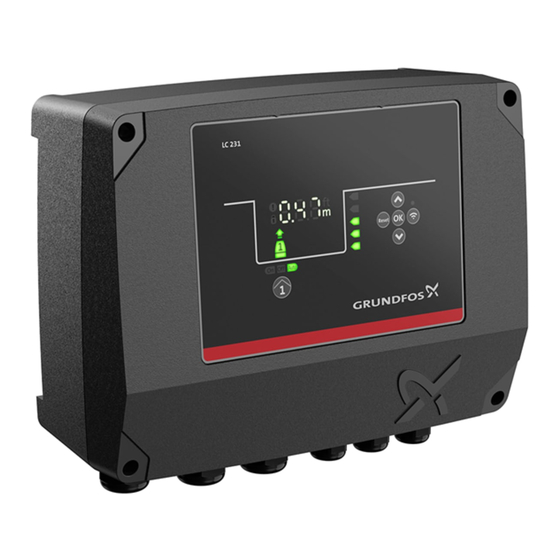
LC 231
Dual pump unit
Installation and operating instructions
LC 231 dual pump unit
Installation and operating instructions
Other languages
http://net.grundfos.com/qr/i/99480674
GRUNDFOS INSTRUCTIONS
Related Manuals for Grundfos LC 231
Summary of Contents for Grundfos LC 231
-
Page 1
GRUNDFOS INSTRUCTIONS LC 231 Dual pump unit Installation and operating instructions LC 231 dual pump unit Installation and operating instructions Other languages http://net.grundfos.com/qr/i/99480674… -
Page 3
LC 231 English (GB) Installation and operating instructions …………5 Български… -
Page 4
…………..541 LC 231… -
Page 5: Table Of Contents
8.14 Code 72 (Internal fault) ….. . 22 Connecting to Grundfos GO Remote ….10 8.15 Code 76 (Internal fault) .
-
Page 6: Installing The Product
2.2.5 Installing a communication interface module 2.3.4 Connecting a level sensor Mount the cable glands on the control unit. 3.6 Configuring the IO terminals using Grundfos GO Remote 2.2.3 Disconnecting the front cover If you need to remove the front cover completely, you must remove the flat cable between the front cover and the back cover.
-
Page 7: Electrical Connection
Pull out the flat cable that is connected to the circuit board. Do Be careful not to damage the cable between the front cover not remove the flat cable from the front cover. and the back cover. Push the module on to the three guide pins and into the socket. Press the module home, using your fingers.
-
Page 8
Before switching the power on, check all voltages with a Changes or modifications not expressly approved by multimeter and ensure that the voltage between neutral and Grundfos may void the user’s authority to operate the each phase does not exceed 250 VAC. equipment. -
Page 9
T2 T3 moisture sensor wire. The common wire must be isolated. In Grundfos GO Remote, you must select that both the PTC wire and the moisture sensor wire are connected, and select a cool- down time for the thermal protection. -
Page 10: Starting Up The Product
Grundfos GO Remote enables you to set functions and gives you or mains failure. The setting is made in Grundfos GO Remote. access to status overviews, technical product information and Go to Settings > LC 231 IO terminals > Relay output > Function. current operating parameters.
-
Page 11: Startup Wizard On The Operating Panel
If the Bluetooth signal on the operating panel has been disabled for some reason, you are not able to connect with Grundfos GO • Test the dry-running function by starting the pump manually Remote.
-
Page 12: Application Types
The liquid is pumped into a second tank • Fill. where the level sensors are installed. You can set the application type with Grundfos GO Remote. The pump will start to fill the second tank when Start level P1 is reached. Empty A second pump will start if the liquid level reaches Start level P2.
-
Page 13: Identification
Factory code CIO1 GND CIO2 GND 24V GND 24V IP class Minimum to maximum ambient temperature Connect to Grundfos GO Remote to see which options are Production site available for the input and output terminals. Markings and approvals Pos. Description 4.6.2 Type key for LC 231…
-
Page 14: Control Functions
• Fill Related information 3.3 Startup wizard on the operating panel 4.4 Application types 6.2 Setting the sensor type 6.2.1 Setting the sensor type with Grundfos GO Remote Pos. Symbol Description Go to Settings > Level control > Sensor type. Display Select the type.
-
Page 15: Setting The Stop Level
For digital sensors: running. The specific level depends on the installed Go to Settings > > LC 231 IO terminals pump type. See the installation and operating Select which terminal to configure.
-
Page 16: Multipump Settings
Remote It is possible to set a time delay before the next pump is started. You can set a time in Grundfos GO Remote in order to get a 6.11.1 Setting the multipump settings with Grundfos GO reminder that the pump needs service when the time comes.
-
Page 17: Motor Protection
If there is moisture in the pump, then the moisture See position 3, curve with tripping. LC 231 cuts out the pump sensor will keep the series connection open until the pump is because the pump startup time exceeds 10 seconds and the opened and serviced.
-
Page 18: Alarm Reset
Alternatively, switch off the main power on the nameplate. supply to LC 231 for a minimum of 30 seconds to clear the alarms. At a motor current of 22.5 A (10 x 2.25), a pump is to cut out after A blockage alarm is typically triggered when the motor starts and in- approx.
-
Page 19: Setting The Buzzer With Grundfos Go Remote
6.22 GENIbus the fault. GENIbus, the Grundfos Electronics Network Intercommunications bus, is a fieldbus developed by Grundfos to meet the need for data 6.18.3 Resetting alarms and warnings on the operating panel transfer in all typical Grundfos motor or pump applications.
-
Page 20: Servicing The Product
Remove the module from the control unit. • The alarm symbol on the display turns red and the pump stops. Fit the new module. • Alarm code Power phase missing is displayed in Grundfos GO Remote. Connect all wires. Cause 8. Fault finding the product The product is configured for 2 or 3 phases but only 1 phase is connected.
-
Page 21: Code 4 (Too Many Motor Restarts)
The alarm symbol on the display turns red and the pump • Check and adjust the level control configuration with Grundfos GO Remote. stops. • Alarm code Too many motor restarts is displayed in Grundfos Cause GO Remote. The IO terminal is not configured correctly. Cause Remedy The pump has been blocked or partly blocked causing overload in •…
-
Page 22: Code 56 (Underload, Current Sensor Measures A Value Too Low)
Alarm code 85 is shown on the display. stops. • The alarm symbol on the display turns red and the pump • Alarm code Dry run is displayed in Grundfos GO Remote. stops. Cause • Alarm code Internal fault is displayed in Grundfos GO Low water level in the pit and the pump stops due to the dry-running Remote.
-
Page 23: Code 163 (Motor-Drive Protection Function Measurement Fault)
Check the functionality of each float switch. Remedy Related information • Go to Settings > Level control in Grundfos GO Remote and ensure that the configured range corresponds to the physical 3.6 Configuring the IO terminals using Grundfos GO Remote application type.
-
Page 24: Code 229 (Water On Floor)
Remedy Sensor cable 5-8 mm (0.19″ — 0.3″) • Order a new LC 231 to avoid downtime. Contact Grundfos. Related information Mains input terminal IEC stranded or solid 2.5 to 16 mm 6.17.4 Setting the motor protection with Grundfos GO Remote UL stranded or solid AWG 20 to 6.
-
Page 25: Disposing Of The Product
This product or parts of it must be disposed of in an environmentally sound way. Use the public or private waste collection service. If this is not possible, contact the nearest Grundfos company or service workshop. Dispose of the waste battery through the national collective schemes.
-
Page 26
Centre Turkey Tel.: +387 33 592 480 29-33 Wing Hong Street & 68 King Lam GRUNDFOS Pumper A/S GRUNDFOS POMPA San. ve Tic. Ltd. Sti. Fax: +387 33 590 465 Street, Cheung Sha Wan Strømsveien 344 Gebze Organize Sanayi Bölgesi www.ba.grundfos.com… -
Page 27
99480674 07.2020 ECM 1288727…
|
|

Ремонт частотного преобразователя Grundfos, впрочем, как и ремонт частотников других производителей имеет ряд особенностей в силу своего конструктива. Частотные преобразователи, точнее их начинка делятся на две части:
- Аппаратная часть,
- Программная часть.
Частотники данного производителя не являются исключением из правил, именно поэтому ремонт частотного преобразователя Grundfos имеет точно такой же ряд особенностей, как и у других преобразователей.
Диагностировать ту или иную неисправность помогают коды ошибок частотного преобразователя, которые отображаются на небольшом дисплее, расположенном на лицевой панели привода. Коды ошибок частотного преобразователя Grundfos в зависимости от серии описаны в инструкции, пользователя которые можно скачать с нашего сайта.
Ремонт частотных преобразователей Grundfos в Веди, как и любых других преобразователей, выпущенных под другими брендами, всегда начинается с аппаратной части, после успешного ремонта аппаратной части наступает очередь программной.
Настройка частотного преобразователя Grundfos также прописана в инструкции завода производителя, для каждой серии частотных преобразователей настройка будет индивидуальной, так как каждая линейка преобразователей решает свои собственные задачи, этим обусловливается широкая номенклатура данного промышленного оборудования.
Ремонт частотных преобразователей Grundfos в сервисном центре

Компания «Кернел» производитремонт частотных преобразователей Grundfos в Веди с 2002 года. За время существования компании наши сотрудники накопили колоссальный опыт в ремонте преобразователей частоты такого известного производителя как Grundfos. Ремонт подобного промышленного оборудования ответственное и сложное занятие, требующие максимальной отдачи, профессионализма и максимально полной материальной базе.
Специалисты нашего сервисного центра максимальное внимание уделяют качеству исполнения ремонта, программирования и настройке промышленных преобразователей частоты, не зависимо от производителя данного промышленного оборудования. Именно поэтому мы смело даем гарантию на все выполненные работы шесть месяцев.
Ремонт частотных преобразователей Grundfos в Веди производится исключительно с использованием оригинальных запасных частей, на компонентном уровне с применением высокотехнологичного диагностического оборудования, квалифицированным персоналом с инженерным образованием.
В случае выхода из строя преобразователя частоты на вашем производстве либо появились проблемы с приводом, которые вы не можете решить самостоятельно, мы всегда рады вам помочь. Специалисты нашего сервисного центра в минимальные сроки проведут глубокую диагностику с последующим ремонтом частотного преобразователя Grundfos.
Инженеры сервисного центра выполняют качественный ремонт частотных преобразователей Grundfos всех серий, когда-либо выпускаемых компанией.
| Серия ПЧ | Типы частотных преобразователей Grundfos |
|---|---|
| Grundfos CUE | CUE 3X380-500V IP55 0.55KW 1.8; CUE 3X380-500V IP20 0.75KW 2.4; CUE 3X380-500V IP55 0.75KW 2.4; CUE 3X380-500V IP20 1.1KW 3A/2; CUE 3X380-500V IP20 1.5KW 4.1A; CUE 3X380-500V IP55 1.5KW 4.1A; CUE 1X200-240V IP21 1.5KW 7.5A; CUE 3X380-500V IP20 2.2KW 5.6A; CUE 1X200-240V IP20 1,1KW; CUE 1X200-240V IP21 1,5KW; CUE 1X200-240V IP21 2,2KW; CUE 1X200-240V IP21 3,0KW; CUE 1X200-240V IP21 3,7KW; CUE 1X200-240V IP21 5,5KW; CUE 1X200-240V IP21 7,5KW; CUE 1X200-240V IP55 1,1KW; CUE 1X200-240V IP55 1,5KW; CUE 1X200-240V IP55 2,2KW; CUE 3X380-500V IP20 11KW; CUE 3X380-500V IP20 18,5KW; CUE 3X380-500V IP20 45KW; CUE 3X380-500V IP20 55KW; CUE 3X380-500V IP20 75KW; CUE 3X380-500V IP20 90KW; CUE 3X380-500V IP21 110KW; CUE 3X380-500V IP21 132KW; CUE 3X380-500V IP21 160KW; CUE 3X380-500V IP21 200KW; CUE 3X380-500V IP55 4,0KW; CUE 3X380-500V IP55 5,5KW; CUE 3X380-500V IP55 7,5KW; CUE 3X380-500V IP55 11KW; CUE 3X380-500V IP55 15KW; CUE 3X380-500V IP55 18,5KW; CUE 3X380-500V IP55 22KW; CUE 3X380-500V IP55 30KW; CUE 3X380-500V IP55 37KW; CUE 3X380-500V IP55 45KW; CUE 3X380-500V IP55 55KW; CUE 3X380-500V IP55 90KW |
В данной таблице присутствуют далеко не все частотные преобразователи Grundfos ремонт которых предлагает наш сервисный центр.
Ошибки частотного преобразователя Grundfos

В процессе работы выходит из строя даже самое надежное промышленное оборудование. Частотники в наше время, нашли широкое применение абсолютно во всех сферах промышленности, управляя как мини моторами в оргтехнике, так и гигантскими двигателями в горнодобывающей промышленности.
Для простоты общения со столь сложной электроникой все частотные преобразователи оснащены небольшими дисплеями с помощью которых выводятся информационные сообщения с кодами ошибок, расшифровав которые можно сразу же узнать причину ее возникновения. Если учесть распространенность данной промышленной электроники, то появляется острая нужда в расшифровке кодов ошибок частотных преобразователей. В этой статье мы рассмотрим одного из самых известных производителей промышленной электроники имеющему уважение во всем мире, Grundfos и серию сервоприводов CUE.
Существует несколько видов ошибок, некоторые из них можно устранить автоматически, а некоторые возможно исправить только, обратившись в специализированный сервисный центр. В руководстве пользователя прописаны все коды ошибок частотного преобразователя Grundfos и их расшифровка.
Коды ошибок частотного преобразователя Grundfos CUE
| Тип | Световой индикатор |
|---|---|
| Предупреждение. | Горит желтый. |
| Аварийный сигнал. | Мигает красным. |
| Код ошибки | Описание |
|---|---|
| 1 | Низкое напряжение 10 В. |
| 2 | Ошибка переменного нуля. |
| 3 | Электродвигатель не подключен. |
| 4 | Потеря фазы сети питания. |
| 5 | Высокое напряжение в звене постоянного тока. |
| 6 | Низкое напряжение в звене постоянного тока. |
| 7 | Перенапряжение в звене постоянного тока. |
| 8 | Пониженное напряжение в звене постоянного тока. |
| 9 | Инвертор перегружен. |
| 10 | Перегрев электродвигателя. |
| 11 | Перегрев терморезистора электродвигателя. |
| 12 | Ограничение по крутящему моменту. |
| 13 | Перегрузка по току. |
| 14 | Короткое замыкание на землю. |
| 15 | Аппаратная несовместимость. |
| 16 | Короткое замыкание. |
| 17 | Тайм-аут командного слова. |
| 18 | Запуск не выполнен. |
| 21 | Ошибка параметра. |
| 23 | Неисправность внутреннего вентилятора. |
| 24 | Неисправность внешнего вентилятора. |
| 25 | Короткое замыкание тормозного резистора. |
| 26 | Предел мощности тормозного резистора. |
| 27 | Неисправность тормозного прерывателя. |
| 28 | Проверка тормоза не удалась. |
| 29 | Температура радиатора. |
| 30 | Отсутствует фаза U электродвигателя. |
| 31 | Отсутствует фаза V электродвигателя. |
| 32 | Отсутствует фаза W электродвигателя. |
| 33 | Отказ из-за броска тока. |
| 34 | Ошибка связи по протоколу обмена данными. |
| 35 | Неисправность дополнительного оборудования. |
| 36 | Неисправность сети электропитания. |
| 38 | Внутренняя ошибка. |
| 39 | Датчик радиатора. |
| 40 | Перегрузка цифрового выхода, клемма 27. |
| 41 | Перегрузка цифрового выхода, клемма 29. |
| 42 | Перегрузка X30/6 или X30/7. |
| 45 | Пробой на землю 2. |
| 46 | Питание силовой платы. |
| 47 | Низкое напряжение питания 24 В. |
| 48 | Низкое напряжение питания 1,8 В. |
| 49 | Предел скорости. |
| 50 | Ошибка калибровки AMA. |
| 51 | AMA: проверить Uном и Iном. |
| 52 | AMA: низкое значение Iном. |
| 53 | AMA: слишком мощный электродвигатель. |
| 54 | AMA: слишком маломощный двигатель. |
| 55 | AMA: параметр вне диапазона. |
| 56 | AMA прервана пользователем. |
| 57 | Тайм-аут AMA. |
| 58 | Внутренний отказ AMA. |
| 59 | Предел по току. |
| 60 | Внешняя блокировка. |
| 61 | Ошибка обратной связи. |
| 62 | Выходная частота на максимальном предельном уровне. |
| 64 | Предельное значение напряжения. |
| 65 | Перегрев платы управления. |
| 66 | Низкая температура радиатора. |
| 67 | Конфигурация дополнительного модуля изменилась. |
| 68 | Активирован безопасный останов. |
| 69 | Температура силовой платы. |
| 70 | Недопустимая конфигурация ПЧ. |
| 71 | Безопасный останов PTC 1. |
| 72 | Опасный отказ. |
| 76 | Настройка силового модуля. |
| 77 | Режим пониженной мощности. |
| 79 | Недопустимая конфигурация силовой части. |
| 80 | Привод приведён к значениям по умолчанию. |
| 81 | Файл настроек параметров привода (CSIV) повреждён. |
| 82 | Ошибка параметра в файле настроек параметров привода CSIV. |
| 90 | Монитор обратной связи. |
| 91 | Аналоговый вход 54, неправильные настройки. |
| 92 | Отсутствует расход. |
| 93 | Сухой ход насоса. |
| 94 | Работа за пределами характеристики. |
| 95 | Отсутствие нагрузки на валу электродвигателя. |
| 96 | Задержка запуска. |
| 97 | Задержка останова. |
| 98 | Неисправность часов. |
| 99 | Блокировка ротора. |
| 100 | Нарушение пределов по очистке. |
| 104 | Ошибка вентилятора подмеса. |
| 148 | Температура системы. |
| 200 | Пожарный режим. |
| 201 | Активирован пожарный режим. |
| 243 | Торможение IGBT. |
| 244 | Температура радиатора. |
| 245 | Датчик радиатора. |
| 246 | Питание силовой платы. |
| 247 | Температура силовой платы. |
| 248 | Недопустимая конфигурация силовой части. |
| 249 | Температура радиатора выпрямителя. |
| 250 | Новая запасная часть. |
| 251 | Новый код типа. |
| 274 | Расход не подтверждён. |
| 275 | Неисправность реле расхода. |
| 2004 | Внешняя неисправность. |
| 2007 | Слишком высокая температура подшипников. |
| 2008 | Слишком высокая температура подшипников. |
| 2010 | Сигнал установленного значения вне диапазона. |
| 2011 | Датчик 1 вне диапазона. |
| 2012 | Датчик 2 вне диапазона. |
| 2013 | Датчик температуры 1 вне диапазона. |
| 2014 | Датчик температуры 2 вне диапазона. |
| 2016 | Предел 1 превышен. |
| 2017 | Предел 2 превышен. |
Документация
|
Руководство по эксплуатации преобразователя частоты Grundfos CUE 0.55 — 90 кВт |
 Скачать PDF Скачать PDF |
|
Руководство по эксплуатации преобразователей частоты Grundfos CUE 110 — 250 кВт |
Скачать PDF |
Схемы подключения частотных преобразователей Grundfos
| Блок-схема подключения преобразователей частоты Grundfos CUE в корпусе B1 | Блок-схема подключения преобразователей частоты Grundfos CUE в корпусе B2 |
|
|

|
| Блок-схема подключения преобразователей частоты Grundfos CUE в корпусе B3 | Блок-схема подключения преобразователей частоты Grundfos CUE в корпусе B4 |

|

|
| Блок-схема подключения преобразователей частоты Grundfos CUE в корпусе C1 — C4 | |
|
|


Для максимально долгой и безаворийной работы частотных преобразователей важно неукоснительно соблюдать все, что прописано в документации.
Обязательно должны соблюдаться все рекомендации, изложенные в инструкции по монтажу и эксплуатации, в особенности требования по технике безопасности!
Преобразователь частоты разработан таким образом, что он пытается избежать аварийных отключений путем ограничения момента, перенапряжения и т.п.
Появление сбоев при вводе в эксплуатацию или вскоре после него обычно свидетельствует о неверной настройке или неправильном подключении.
Возникновение неисправностей или проблем после длительного режима бесперебойной работы обычно происходит по причине изменений в системе или ее окружении (например, в результате износа).
Дополнительную информацию по частотным преобразователям Grundfos можно посмотреть и скачать на офсайте.
Настройка частотного преобразователя Grundfos, программирование

Настройка частотных преобразователей Grundfos (программирование) происходит в рамках установленных производителем правил, существует общий алгоритм по программированию (настройке частотных преобразователей), относящийся ко всем производителям данного промышленного оборудования. Ниже представлена пошаговая инструкция по настройке частотных преобразователей Grundfos.
- Выбор режима управления приводом Grundfos (управление по показанию датчиков, дистанционное управление, дистанционное управление).
- В случае использования отдельного (выносного) монитора, настраивается вывод на него технической информации.
- Далее определяем конфигурацию подключения серводвигателя. На данной стадии задаются такие параметры как- возможность применения обратной связи либо без ее применения, а в память блока заносятся данные по: величине крутящего момента, мощности потребителей, номинальное значения частоты, напряжение, ток и скорости вращения ротора.

- Программируется минимально допустимая величина напряжения и частоты, а также время ускорения ротора от ноля до номинального значения.
- И в завершении, в программу управления частотным преобразователем Grundfos вносятся функциональные данные со значениями отдельных клемм и особенностями сигналов. Отмечаются действия оборудования, выполняющиеся автоматически при отсутствии информации поступающей в оперативном режиме с датчика.

В некоторых частотниках существует пункт наличия/отсутствия фильтра в цепи питания двигателя. Этот пункт отвечает за подключение различных видов нагрузок, в том случае, когда возможно выбрать нормальное или инверсное изменение частоты при повышении уровня сигнала обратной связи.
Все настройки частотных преобразователей Grundfos приведены в технической документации к частотному преобразователю который можно скачать на свой компьютер, распечатать или просто открыть на официальном сайте Grundfos.
Оставить заявку на ремонт частотных преобразователей Grundfos
У вас вышел из строя частотник? Вам необходим срочный ремонт частотных преобразователей Grundfos в Веди? Оставьте заявку на ремонт нажав на одноименную кнопку в верхней правой части экрана либо свяжитесь с нашими менеджерами. Связаться с ними можно несколькими способами:

- Заказав обратный звонок (кнопка в правом нижнем углу сайта)
- Посредством чата (кнопка расположена с левой стороны сайта)
- Позвонив по номеру телефона: +7(8482) 79-78-54; +7(917) 121-53-01
- Написав на электронную почту: 89171215301@mail.ru
Далеко не полный список производителей промышленной электроники и оборудования, ремонтируемой в нашей компании.
- В начало статьи
|
|
Ремонт частотных преобразователей Grundfos
Ремонт частотного преобразователя Grundfos, впрочем, как и ремонт частотников других производителей имеет ряд особенностей в силу своего конструктива. Частотные преобразователи, точнее их начинка делятся на две части:
- Аппаратная часть,
- Программная часть.
Частотники данного производителя не являются исключением из правил, именно поэтому ремонт частотного преобразователя Grundfos имеет точно такой же ряд особенностей, как и у других преобразователей.
Диагностировать ту или иную неисправность помогают коды ошибок частотного преобразователя, которые отображаются на небольшом дисплее, расположенном на лицевой панели привода. Коды ошибок частотного преобразователя Grundfos в зависимости от серии описаны в инструкции, пользователя которые можно скачать с нашего сайта.
Ремонт частотных преобразователей Grundfos в Веди, как и любых других преобразователей, выпущенных под другими брендами, всегда начинается с аппаратной части, после успешного ремонта аппаратной части наступает очередь программной.
Настройка частотного преобразователя Grundfos также прописана в инструкции завода производителя, для каждой серии частотных преобразователей настройка будет индивидуальной, так как каждая линейка преобразователей решает свои собственные задачи, этим обусловливается широкая номенклатура данного промышленного оборудования.
Ремонт частотных преобразователей Grundfos в сервисном центре
Компания «Кернел» производитремонт частотных преобразователей Grundfos в Веди с 2002 года. За время существования компании наши сотрудники накопили колоссальный опыт в ремонте преобразователей частоты такого известного производителя как Grundfos. Ремонт подобного промышленного оборудования ответственное и сложное занятие, требующие максимальной отдачи, профессионализма и максимально полной материальной базе.
Специалисты нашего сервисного центра максимальное внимание уделяют качеству исполнения ремонта, программирования и настройке промышленных преобразователей частоты, не зависимо от производителя данного промышленного оборудования. Именно поэтому мы смело даем гарантию на все выполненные работы шесть месяцев.
Ремонт частотных преобразователей Grundfos в Веди производится исключительно с использованием оригинальных запасных частей, на компонентном уровне с применением высокотехнологичного диагностического оборудования, квалифицированным персоналом с инженерным образованием.
В случае выхода из строя преобразователя частоты на вашем производстве либо появились проблемы с приводом, которые вы не можете решить самостоятельно, мы всегда рады вам помочь. Специалисты нашего сервисного центра в минимальные сроки проведут глубокую диагностику с последующим ремонтом частотного преобразователя Grundfos.
Инженеры сервисного центра выполняют качественный ремонт частотных преобразователей Grundfos всех серий, когда-либо выпускаемых компанией.
| Серия ПЧ | Типы частотных преобразователей Grundfos |
|---|---|
| Grundfos CUE | CUE 3X380-500V IP55 0.55KW 1.8; CUE 3X380-500V IP20 0.75KW 2.4; CUE 3X380-500V IP55 0.75KW 2.4; CUE 3X380-500V IP20 1.1KW 3A/2; CUE 3X380-500V IP20 1.5KW 4.1A; CUE 3X380-500V IP55 1.5KW 4.1A; CUE 1X200-240V IP21 1.5KW 7.5A; CUE 3X380-500V IP20 2.2KW 5.6A; CUE 1X200-240V IP20 1,1KW; CUE 1X200-240V IP21 1,5KW; CUE 1X200-240V IP21 2,2KW; CUE 1X200-240V IP21 3,0KW; CUE 1X200-240V IP21 3,7KW; CUE 1X200-240V IP21 5,5KW; CUE 1X200-240V IP21 7,5KW; CUE 1X200-240V IP55 1,1KW; CUE 1X200-240V IP55 1,5KW; CUE 1X200-240V IP55 2,2KW; CUE 3X380-500V IP20 11KW; CUE 3X380-500V IP20 18,5KW; CUE 3X380-500V IP20 45KW; CUE 3X380-500V IP20 55KW; CUE 3X380-500V IP20 75KW; CUE 3X380-500V IP20 90KW; CUE 3X380-500V IP21 110KW; CUE 3X380-500V IP21 132KW; CUE 3X380-500V IP21 160KW; CUE 3X380-500V IP21 200KW; CUE 3X380-500V IP55 4,0KW; CUE 3X380-500V IP55 5,5KW; CUE 3X380-500V IP55 7,5KW; CUE 3X380-500V IP55 11KW; CUE 3X380-500V IP55 15KW; CUE 3X380-500V IP55 18,5KW; CUE 3X380-500V IP55 22KW; CUE 3X380-500V IP55 30KW; CUE 3X380-500V IP55 37KW; CUE 3X380-500V IP55 45KW; CUE 3X380-500V IP55 55KW; CUE 3X380-500V IP55 90KW |
В данной таблице присутствуют далеко не все частотные преобразователи Grundfos ремонт которых предлагает наш сервисный центр.
Ошибки частотного преобразователя Grundfos
В процессе работы выходит из строя даже самое надежное промышленное оборудование. Частотники в наше время, нашли широкое применение абсолютно во всех сферах промышленности, управляя как мини моторами в оргтехнике, так и гигантскими двигателями в горнодобывающей промышленности.
Для простоты общения со столь сложной электроникой все частотные преобразователи оснащены небольшими дисплеями с помощью которых выводятся информационные сообщения с кодами ошибок, расшифровав которые можно сразу же узнать причину ее возникновения. Если учесть распространенность данной промышленной электроники, то появляется острая нужда в расшифровке кодов ошибок частотных преобразователей. В этой статье мы рассмотрим одного из самых известных производителей промышленной электроники имеющему уважение во всем мире, Grundfos и серию сервоприводов CUE.
Существует несколько видов ошибок, некоторые из них можно устранить автоматически, а некоторые возможно исправить только, обратившись в специализированный сервисный центр. В руководстве пользователя прописаны все коды ошибок частотного преобразователя Grundfos и их расшифровка.
Коды ошибок частотного преобразователя Grundfos CUE
| Тип | Световой индикатор |
|---|---|
| Предупреждение. | Горит желтый. |
| Аварийный сигнал. | Мигает красным. |
| Код ошибки | Описание |
|---|---|
| 1 | Низкое напряжение 10 В. |
| 2 | Ошибка переменного нуля. |
| 3 | Электродвигатель не подключен. |
| 4 | Потеря фазы сети питания. |
| 5 | Высокое напряжение в звене постоянного тока. |
| 6 | Низкое напряжение в звене постоянного тока. |
| 7 | Перенапряжение в звене постоянного тока. |
| 8 | Пониженное напряжение в звене постоянного тока. |
| 9 | Инвертор перегружен. |
| 10 | Перегрев электродвигателя. |
| 11 | Перегрев терморезистора электродвигателя. |
| 12 | Ограничение по крутящему моменту. |
| 13 | Перегрузка по току. |
| 14 | Короткое замыкание на землю. |
| 15 | Аппаратная несовместимость. |
| 16 | Короткое замыкание. |
| 17 | Тайм-аут командного слова. |
| 18 | Запуск не выполнен. |
| 21 | Ошибка параметра. |
| 23 | Неисправность внутреннего вентилятора. |
| 24 | Неисправность внешнего вентилятора. |
| 25 | Короткое замыкание тормозного резистора. |
| 26 | Предел мощности тормозного резистора. |
| 27 | Неисправность тормозного прерывателя. |
| 28 | Проверка тормоза не удалась. |
| 29 | Температура радиатора. |
| 30 | Отсутствует фаза U электродвигателя. |
| 31 | Отсутствует фаза V электродвигателя. |
| 32 | Отсутствует фаза W электродвигателя. |
| 33 | Отказ из-за броска тока. |
| 34 | Ошибка связи по протоколу обмена данными. |
| 35 | Неисправность дополнительного оборудования. |
| 36 | Неисправность сети электропитания. |
| 38 | Внутренняя ошибка. |
| 39 | Датчик радиатора. |
| 40 | Перегрузка цифрового выхода, клемма 27. |
| 41 | Перегрузка цифрового выхода, клемма 29. |
| 42 | Перегрузка X30/6 или X30/7. |
| 45 | Пробой на землю 2. |
| 46 | Питание силовой платы. |
| 47 | Низкое напряжение питания 24 В. |
| 48 | Низкое напряжение питания 1,8 В. |
| 49 | Предел скорости. |
| 50 | Ошибка калибровки AMA. |
| 51 | AMA: проверить Uном и Iном. |
| 52 | AMA: низкое значение Iном. |
| 53 | AMA: слишком мощный электродвигатель. |
| 54 | AMA: слишком маломощный двигатель. |
| 55 | AMA: параметр вне диапазона. |
| 56 | AMA прервана пользователем. |
| 57 | Тайм-аут AMA. |
| 58 | Внутренний отказ AMA. |
| 59 | Предел по току. |
| 60 | Внешняя блокировка. |
| 61 | Ошибка обратной связи. |
| 62 | Выходная частота на максимальном предельном уровне. |
| 64 | Предельное значение напряжения. |
| 65 | Перегрев платы управления. |
| 66 | Низкая температура радиатора. |
| 67 | Конфигурация дополнительного модуля изменилась. |
| 68 | Активирован безопасный останов. |
| 69 | Температура силовой платы. |
| 70 | Недопустимая конфигурация ПЧ. |
| 71 | Безопасный останов PTC 1. |
| 72 | Опасный отказ. |
| 76 | Настройка силового модуля. |
| 77 | Режим пониженной мощности. |
| 79 | Недопустимая конфигурация силовой части. |
| 80 | Привод приведён к значениям по умолчанию. |
| 81 | Файл настроек параметров привода (CSIV) повреждён. |
| 82 | Ошибка параметра в файле настроек параметров привода CSIV. |
| 90 | Монитор обратной связи. |
| 91 | Аналоговый вход 54, неправильные настройки. |
| 92 | Отсутствует расход. |
| 93 | Сухой ход насоса. |
| 94 | Работа за пределами характеристики. |
| 95 | Отсутствие нагрузки на валу электродвигателя. |
| 96 | Задержка запуска. |
| 97 | Задержка останова. |
| 98 | Неисправность часов. |
| 99 | Блокировка ротора. |
| 100 | Нарушение пределов по очистке. |
| 104 | Ошибка вентилятора подмеса. |
| 148 | Температура системы. |
| 200 | Пожарный режим. |
| 201 | Активирован пожарный режим. |
| 243 | Торможение IGBT. |
| 244 | Температура радиатора. |
| 245 | Датчик радиатора. |
| 246 | Питание силовой платы. |
| 247 | Температура силовой платы. |
| 248 | Недопустимая конфигурация силовой части. |
| 249 | Температура радиатора выпрямителя. |
| 250 | Новая запасная часть. |
| 251 | Новый код типа. |
| 274 | Расход не подтверждён. |
| 275 | Неисправность реле расхода. |
| 2004 | Внешняя неисправность. |
| 2007 | Слишком высокая температура подшипников. |
| 2008 | Слишком высокая температура подшипников. |
| 2010 | Сигнал установленного значения вне диапазона. |
| 2011 | Датчик 1 вне диапазона. |
| 2012 | Датчик 2 вне диапазона. |
| 2013 | Датчик температуры 1 вне диапазона. |
| 2014 | Датчик температуры 2 вне диапазона. |
| 2016 | Предел 1 превышен. |
| 2017 | Предел 2 превышен. |
Документация
|
Руководство по эксплуатации преобразователя частоты Grundfos CUE 0.55 — 90 кВт |
Скачать PDF |
|
Руководство по эксплуатации преобразователей частоты Grundfos CUE 110 — 250 кВт |
Скачать PDF |
Схемы подключения частотных преобразователей Grundfos
| Блок-схема подключения преобразователей частоты Grundfos CUE в корпусе B1 | Блок-схема подключения преобразователей частоты Grundfos CUE в корпусе B2 |
|
|
|
| Блок-схема подключения преобразователей частоты Grundfos CUE в корпусе B3 | Блок-схема подключения преобразователей частоты Grundfos CUE в корпусе B4 |
|
|
|
| Блок-схема подключения преобразователей частоты Grundfos CUE в корпусе C1 — C4 | |
|
|
Для максимально долгой и безаворийной работы частотных преобразователей важно неукоснительно соблюдать все, что прописано в документации.
Обязательно должны соблюдаться все рекомендации, изложенные в инструкции по монтажу и эксплуатации, в особенности требования по технике безопасности!
Преобразователь частоты разработан таким образом, что он пытается избежать аварийных отключений путем ограничения момента, перенапряжения и т.п.
Появление сбоев при вводе в эксплуатацию или вскоре после него обычно свидетельствует о неверной настройке или неправильном подключении.
Возникновение неисправностей или проблем после длительного режима бесперебойной работы обычно происходит по причине изменений в системе или ее окружении (например, в результате износа).
Дополнительную информацию по частотным преобразователям Grundfos можно посмотреть и скачать на офсайте.
Настройка частотного преобразователя Grundfos, программирование
Настройка частотных преобразователей Grundfos (программирование) происходит в рамках установленных производителем правил, существует общий алгоритм по программированию (настройке частотных преобразователей), относящийся ко всем производителям данного промышленного оборудования. Ниже представлена пошаговая инструкция по настройке частотных преобразователей Grundfos.
- Выбор режима управления приводом Grundfos (управление по показанию датчиков, дистанционное управление, дистанционное управление).
- В случае использования отдельного (выносного) монитора, настраивается вывод на него технической информации.
- Далее определяем конфигурацию подключения серводвигателя. На данной стадии задаются такие параметры как- возможность применения обратной связи либо без ее применения, а в память блока заносятся данные по: величине крутящего момента, мощности потребителей, номинальное значения частоты, напряжение, ток и скорости вращения ротора.
- Программируется минимально допустимая величина напряжения и частоты, а также время ускорения ротора от ноля до номинального значения.
- И в завершении, в программу управления частотным преобразователем Grundfos вносятся функциональные данные со значениями отдельных клемм и особенностями сигналов. Отмечаются действия оборудования, выполняющиеся автоматически при отсутствии информации поступающей в оперативном режиме с датчика.
В некоторых частотниках существует пункт наличия/отсутствия фильтра в цепи питания двигателя. Этот пункт отвечает за подключение различных видов нагрузок, в том случае, когда возможно выбрать нормальное или инверсное изменение частоты при повышении уровня сигнала обратной связи.
Все настройки частотных преобразователей Grundfos приведены в технической документации к частотному преобразователю который можно скачать на свой компьютер, распечатать или просто открыть на официальном сайте Grundfos.
Оставить заявку на ремонт частотных преобразователей Grundfos
У вас вышел из строя частотник? Вам необходим срочный ремонт частотных преобразователей Grundfos в Веди? Оставьте заявку на ремонт нажав на одноименную кнопку в верхней правой части экрана либо свяжитесь с нашими менеджерами. Связаться с ними можно несколькими способами:
- Заказав обратный звонок (кнопка в правом нижнем углу сайта)
- Посредством чата (кнопка расположена с левой стороны сайта)
- Позвонив по номеру телефона:
- +7(8482) 79-78-54;
- +7(8482) 55-96-39;
- +7(917) 121-53-01
- Написав на электронную почту: 89171215301@mail.ru
Далеко не полный список производителей промышленной электроники и оборудования, ремонтируемой в нашей компании.
- В начало статьи
-
Contents
-
Table of Contents
-
Bookmarks
Quick Links
LC 231
Dual pump unit
Installation and operating instructions
LC 231 dual pump unit
Installation and operating instructions
Other languages
http://net.grundfos.com/qr/i/99480674
GRUNDFOS INSTRUCTIONS
Related Manuals for Grundfos LC 231
Summary of Contents for Grundfos LC 231
-
Page 1
GRUNDFOS INSTRUCTIONS LC 231 Dual pump unit Installation and operating instructions LC 231 dual pump unit Installation and operating instructions Other languages http://net.grundfos.com/qr/i/99480674… -
Page 3
LC 231 English (GB) Installation and operating instructions …………5 Български… -
Page 4
…………..541 LC 231… -
Page 5: Table Of Contents
8.14 Code 72 (Internal fault) ….. . 22 Connecting to Grundfos GO Remote ….10 8.15 Code 76 (Internal fault) .
-
Page 6: Installing The Product
2.2.5 Installing a communication interface module 2.3.4 Connecting a level sensor Mount the cable glands on the control unit. 3.6 Configuring the IO terminals using Grundfos GO Remote 2.2.3 Disconnecting the front cover If you need to remove the front cover completely, you must remove the flat cable between the front cover and the back cover.
-
Page 7: Electrical Connection
Pull out the flat cable that is connected to the circuit board. Do Be careful not to damage the cable between the front cover not remove the flat cable from the front cover. and the back cover. Push the module on to the three guide pins and into the socket. Press the module home, using your fingers.
-
Page 8
Before switching the power on, check all voltages with a Changes or modifications not expressly approved by multimeter and ensure that the voltage between neutral and Grundfos may void the user’s authority to operate the each phase does not exceed 250 VAC. equipment. -
Page 9
T2 T3 moisture sensor wire. The common wire must be isolated. In Grundfos GO Remote, you must select that both the PTC wire and the moisture sensor wire are connected, and select a cool- down time for the thermal protection. -
Page 10: Starting Up The Product
Grundfos GO Remote enables you to set functions and gives you or mains failure. The setting is made in Grundfos GO Remote. access to status overviews, technical product information and Go to Settings > LC 231 IO terminals > Relay output > Function. current operating parameters.
-
Page 11: Startup Wizard On The Operating Panel
If the Bluetooth signal on the operating panel has been disabled for some reason, you are not able to connect with Grundfos GO • Test the dry-running function by starting the pump manually Remote.
-
Page 12: Application Types
The liquid is pumped into a second tank • Fill. where the level sensors are installed. You can set the application type with Grundfos GO Remote. The pump will start to fill the second tank when Start level P1 is reached. Empty A second pump will start if the liquid level reaches Start level P2.
-
Page 13: Identification
Factory code CIO1 GND CIO2 GND 24V GND 24V IP class Minimum to maximum ambient temperature Connect to Grundfos GO Remote to see which options are Production site available for the input and output terminals. Markings and approvals Pos. Description 4.6.2 Type key for LC 231…
-
Page 14: Control Functions
• Fill Related information 3.3 Startup wizard on the operating panel 4.4 Application types 6.2 Setting the sensor type 6.2.1 Setting the sensor type with Grundfos GO Remote Pos. Symbol Description Go to Settings > Level control > Sensor type. Display Select the type.
-
Page 15: Setting The Stop Level
For digital sensors: running. The specific level depends on the installed Go to Settings > > LC 231 IO terminals pump type. See the installation and operating Select which terminal to configure.
-
Page 16: Multipump Settings
Remote It is possible to set a time delay before the next pump is started. You can set a time in Grundfos GO Remote in order to get a 6.11.1 Setting the multipump settings with Grundfos GO reminder that the pump needs service when the time comes.
-
Page 17: Motor Protection
If there is moisture in the pump, then the moisture See position 3, curve with tripping. LC 231 cuts out the pump sensor will keep the series connection open until the pump is because the pump startup time exceeds 10 seconds and the opened and serviced.
-
Page 18: Alarm Reset
Alternatively, switch off the main power on the nameplate. supply to LC 231 for a minimum of 30 seconds to clear the alarms. At a motor current of 22.5 A (10 x 2.25), a pump is to cut out after A blockage alarm is typically triggered when the motor starts and in- approx.
-
Page 19: Setting The Buzzer With Grundfos Go Remote
6.22 GENIbus the fault. GENIbus, the Grundfos Electronics Network Intercommunications bus, is a fieldbus developed by Grundfos to meet the need for data 6.18.3 Resetting alarms and warnings on the operating panel transfer in all typical Grundfos motor or pump applications.
-
Page 20: Servicing The Product
Remove the module from the control unit. • The alarm symbol on the display turns red and the pump stops. Fit the new module. • Alarm code Power phase missing is displayed in Grundfos GO Remote. Connect all wires. Cause 8. Fault finding the product The product is configured for 2 or 3 phases but only 1 phase is connected.
-
Page 21: Code 4 (Too Many Motor Restarts)
The alarm symbol on the display turns red and the pump • Check and adjust the level control configuration with Grundfos GO Remote. stops. • Alarm code Too many motor restarts is displayed in Grundfos Cause GO Remote. The IO terminal is not configured correctly. Cause Remedy The pump has been blocked or partly blocked causing overload in •…
-
Page 22: Code 56 (Underload, Current Sensor Measures A Value Too Low)
Alarm code 85 is shown on the display. stops. • The alarm symbol on the display turns red and the pump • Alarm code Dry run is displayed in Grundfos GO Remote. stops. Cause • Alarm code Internal fault is displayed in Grundfos GO Low water level in the pit and the pump stops due to the dry-running Remote.
-
Page 23: Code 163 (Motor-Drive Protection Function Measurement Fault)
Check the functionality of each float switch. Remedy Related information • Go to Settings > Level control in Grundfos GO Remote and ensure that the configured range corresponds to the physical 3.6 Configuring the IO terminals using Grundfos GO Remote application type.
-
Page 24: Code 229 (Water On Floor)
Remedy Sensor cable 5-8 mm (0.19″ — 0.3″) • Order a new LC 231 to avoid downtime. Contact Grundfos. Related information Mains input terminal IEC stranded or solid 2.5 to 16 mm 6.17.4 Setting the motor protection with Grundfos GO Remote UL stranded or solid AWG 20 to 6.
-
Page 25: Disposing Of The Product
This product or parts of it must be disposed of in an environmentally sound way. Use the public or private waste collection service. If this is not possible, contact the nearest Grundfos company or service workshop. Dispose of the waste battery through the national collective schemes.
-
Page 26
Centre Turkey Tel.: +387 33 592 480 29-33 Wing Hong Street & 68 King Lam GRUNDFOS Pumper A/S GRUNDFOS POMPA San. ve Tic. Ltd. Sti. Fax: +387 33 590 465 Street, Cheung Sha Wan Strømsveien 344 Gebze Organize Sanayi Bölgesi www.ba.grundfos.com… -
Page 27
99480674 07.2020 ECM 1288727…

GRUNDFOS INSTRUCTIONS
LC 231
Single pump unit
Installation and operating instructions
LC 231 single pump unit
Installation and operating instructions
Other languages
http://net.grundfos.com/qr/i/99381576
English (GB)
Installation and operating instructions . . . . . . . . . . . . . . . . . . . . . . . . . . . . . . . . . . 4
Español (ES)
Instrucciones de instalación y funcionamiento. . . . . . . . . . . . . . . . . . . . . . . . . . . . 30
Русский (RU)
Паспорт, Руководство по монтажу и эксплуатации . . . . . . . . . . . . . . . . . . . . . . . 58
中文 (CN)
安装和使用说明书 . . . . . . . . . . . . . . . . . . . . . . . . . . . . . . . . . . . . . . . . . . . . . . . 89
3
Table of contents
LC 231
English (GB)
English (GB) Installation and operating instructions
6.13
Original installation and operating instructions
Table of contents
1.
1.1
1.2
General information . . . . . . . . . . . . . 5
Hazard statements . . . . . . . . . . . . . . 5
Notes . . . . . . . . . . . . . . . . . . . . . 5
2.
2.1
2.2
2.3
Installing the product
Location . . . . . . . .
Mechanical installation
Electrical connection .
3.
3.1
3.2
3.3
3.4
Starting up the product . . . . . . . . . .
Connecting to Grundfos GO Remote. . . .
Startup wizard on Grundfos GO Remote .
Startup wizard on the operating panel . . .
How to enable Bluetooth on the operating
panel . . . . . . . . . . . . . . . . . . . .
How to disable Bluetooth on the
operating panel . . . . . . . . . . . . . . .
Configuring the IO terminals using
Grundfos GO Remote . . . . . . . . . . .
Testing the product . . . . . . . . . . . . .
3.5
3.6
3.7
.
.
.
.
.
.
.
.
.
.
.
.
.
.
.
.
.
.
.
.
.
.
.
.
.
.
.
.
.
.
.
.
.
.
.
.
.
.
.
.
.
.
.
5
5
5
7
. 10
. 10
. 10
. 10
. 10
. 11
. 11
. 11
5.
5.1
Control functions . . . . . . . . . . . . . . 14
Operating panel . . . . . . . . . . . . . . . . 14
6.
6.1
Setting the product . . . . . . . . . . . .
Setting the application type with Grundfos
GO Remote . . . . . . . . . . . . . . . . .
Setting the sensor type . . . . . . . . . . .
Setting the start level . . . . . . . . . . . .
Setting the stop level . . . . . . . . . . . .
Setting the high level . . . . . . . . . . . .
Stop delay . . . . . . . . . . . . . . . . . .
Power-on delay . . . . . . . . . . . . . . .
Dry-running protection . . . . . . . . . . .
Using the same level switch for the start
and stop level . . . . . . . . . . . . . . . .
"Antiseizing" . . . . . . . . . . . . . . . . .
Signal-detection time . . . . . . . . . . . .
Setting the maximum number of restarts
with Grundfos GO Remote . . . . . . . . .
4
.
.
.
.
.
.
.
.
.
.
.
Product introduction . . . . . . .
Product description . . . . . . . . .
Intended use . . . . . . . . . . . .
Features . . . . . . . . . . . . . . .
Application types . . . . . . . . . .
Terminals . . . . . . . . . . . . . .
Identification. . . . . . . . . . . . .
Supported communication interface
modules and protocols . . . . . . .
6.10
6.11
6.12
.
.
.
.
.
.
.
.
.
.
.
4.
4.1
4.2
4.3
4.4
4.5
4.6
4.7
6.2
6.3
6.4
6.5
6.6
6.7
6.8
6.9
.
.
.
.
.
.
.
.
.
.
.
. 11
. 11
. 11
. 11
. 12
. 13
. 13
. . . . . 14
. 15
. 15
. 15
. 15
. 16
. 16
. 16
. 16
. 17
. 17
. 17
. 17
. 17
6.14
6.15
6.16
6.17
6.18
6.19
6.20
6.21
6.22
Setting the service interval with Grundfos
GO Remote . . . . . . . . . . . . . . . . .
Operating the product. . . . . . . . . . . .
Motor protection. . . . . . . . . . . . . . .
Alarm reset . . . . . . . . . . . . . . . . .
Setting the buzzer with Grundfos GO
Remote . . . . . . . . . . . . . . . . . . .
Setting units for Grundfos GO Remote. . .
Setting units for the operating panel with
Grundfos GO Remote . . . . . . . . . . .
GENIbus . . . . . . . . . . . . . . . . . .
Security . . . . . . . . . . . . . . . . . . .
Starting the startup wizard with the
operating panel . . . . . . . . . . . . . . .
.
.
.
.
.
.
.
.
.
.
.
.
.
.
.
.
.
.
.
.
. 21
. 21
. 21
. 22
. 22
. 22
7.
7.1
7.2
7.3
Servicing the product . . . .
Updating the product software
Replacing the battery . . . . .
Replacing the CIM module . .
.
.
.
.
. 22
. 22
. 22
. 23
8.
8.1
8.2
8.3
8.4
8.5
8.6
8.7
8.8
8.9
8.10
8.11
Fault finding the product . . . . . . . . .
Overview of alarm and warning codes . . .
Code 2 (Power phase missing). . . . . . .
Code 4 (Too many motor restarts) . . . . .
Code 9 (Power phase sequence wrong) . .
Code 12 (Service needed) . . . . . . . . .
Code 22 (Moisture in motor of pump) . . .
Code 25 (Wrong configuration) . . . . . . .
Code 26 (Contactor shorted) . . . . . . . .
Code 48 (Motor is overloaded) . . . . . . .
Code 51 (Blocked) . . . . . . . . . . . . .
Code 57 (Missing water in the
application) . . . . . . . . . . . . . . . . .
Code 69 (Winding temperature too high) .
Code 72 (Internal fault) . . . . . . . . . . .
Code 76 (Internal fault) . . . . . . . . . . .
Code 84 (Memory storage media faulty) . .
Code 85 (Internal fault) . . . . . . . . . . .
Code 117 (Door opened) . . . . . . . . . .
Code 159 (Communication error CIMxxx) .
Code 163 (Drive unit configuration fault) .
Code 165 (Signal fault) . . . . . . . . . . .
Code 191 (High water level) . . . . . . . .
Code 205 (Level switch inconsistency) . .
Code 220 (Contactor wear out). . . . . . .
Code 229 (Water on floor) . . . . . . . . .
. 23
. 23
. 23
. 24
. 24
. 24
. 24
. 24
. 24
. 24
. 25
8.12
8.13
8.14
8.15
8.16
8.17
8.18
8.19
8.20
8.21
8.22
8.23
8.24
.
.
.
.
. 17
. 18
. 18
. 21
. 25
. 25
. 25
. 25
. 25
. 26
. 26
. 26
. 26
. 26
. 26
. 27
. 27
. 27
Technical data . . . . . . . . . . . . . . . . 27
10.
Disposing of the product . . . . . . . . . . 29
If these instructions are not observed, it
may result in malfunction or damage to the
equipment.
1. General information
Read this document before you install the
product. Installation and operation must
comply with local regulations and accepted
codes of good practice.
1.1 Hazard statements
The symbols and hazard statements below may
appear in Grundfos installation and operating
instructions, safety instructions and service
instructions.
DANGER
Indicates a hazardous situation which, if
not avoided, will result in death or serious
personal injury.
WARNING
Indicates a hazardous situation which, if
not avoided, could result in death or
serious personal injury.
CAUTION
Indicates a hazardous situation which, if
not avoided, could result in minor or
moderate personal injury.
The hazard statements are structured in the following
way:
SIGNAL WORD
Description of the hazard
Consequence of ignoring the warning
•
Action to avoid the hazard.
Tips and advice that make the work easier.
2. Installing the product
2.1 Location
Install the product in a location that meets the
following requirements:
•
Place the product in a flood-safe place.
•
Make sure that the ambient temperature is within
the limits.
•
Install the product as close as possible to the
connected pumps, sensors, and accessories.
•
The product must be protected from direct
sunlight.
•
The product must be easily accessible.
•
Outdoor installation: the product must be
installed in a protective shed or enclosure, class
IP 54.
•
Indoor installation:The product must be installed
in a well-ventilated room to ensure cooling of its
components.
2.2 Mechanical installation
2.2.1 Removing the front cover
The front cover must be removed to make any
connections or to install the Communication Interface
Module (CIM).
Use an antistatic service kit when handling
electronic components. This prevents
static electricity from damaging the
components.
1.2 Notes
The symbols and notes below may appear in
Grundfos installation and operating instructions,
safety instructions and service instructions.
Observe these instructions for explosionproof products.
A blue or grey circle with a white graphical
symbol indicates that an action must be
taken.
Place the front cover above the control unit, if
possible. This way you do not need to remove the flat
cable between the front cover and the control unit.
1. Loosen the screws.
2.
Carefully separate the front cover from the back
cover.
Be careful not to damage the cable connecting
the front cover and the back cover.
A red or grey circle with a diagonal bar,
possibly with a black graphical symbol,
indicates that an action must not be taken
or must be stopped.
5
English (GB)
9.
4.
To ensure that the front cover does not tilt, insert
the two bottom screws into the open holes at the
top of the back cover.
TM071323
Place the front cover above the back cover on
the support brackets.
2.2.3 Installing the control unit
TM071494
The product is designed to be mounted on a flat and
vertical surface. The cable glands must face
downwards.
1. Loosen the screws and remove the front cover.
Be careful not to damage the cable between the
front cover and the back cover.
2.
Drill holes in the surface.
Related information
2.3.4 Connecting a level sensor
3.6 Configuring the IO terminals using Grundfos GO
Remote
255 (10.0")
2.2.2 Disconnecting the front cover
If you need to remove the front cover completely, you
must remove the flat cable between the front cover
and the back cover.
Use an antistatic service kit when handling
electronic components. This prevents
static electricity from damaging the
components.
1.
Loosen the screws.
2.
Carefully separate the front cover from the back
cover.
3.
Pull out the flat cable that is connected to the
circuit board. Do not remove the flat cable from
the front cover.
115 (4.5")
280 (11.0")
3.
Insert wall plugs, if applicable.
4.
Fit the four screws in the mounting holes and
cross-tighten the screws.
The mounting screws must have a
minimum length of 32 mm (Ø 8.2
mm). If the wall is more than 3 mm
uneven, insert rubber blocks between
the surface and the control unit to
even the surface. The box of the
control unit must not be bent.
Related information
2.2.1 Removing the front cover
2.2.4 Installing a communication interface module
You can fit a communication interface module (CIM)
in the control unit to enable communication with
external systems. The module is optional and is not
6
TM070121
2.2.4 Installing a communication interface module
165 (6.5")
2.2.3 Installing the control unit
215 (8.5")
English (GB)
3.
2.3.1 Cable requirements
Use an antistatic service kit when handling
electronic components. This prevents
static electricity from damaging the
components.
1.
Loosen the screws and remove the front cover.
Be careful not to damage the cable between the
front cover and the back cover.
WARNING
Electric shock
Death or serious personal injury
‐ The wires from the pump phases must
be rated at 90 °C (194 °F).
‐ The wires from the temperature
sensor, if any, must be rated at 480 V
and 70 °C (158 °F).
2.
Push the module on to the three guide pins and
into the socket. Press the module home, using
your fingers.
For the US market only, use flexible metal
conduits (FMC) only.
The wires from the temperature sensor, if
any, must be shielded.
TM070130
Cable cross sections
3.
Fit the screw to lock the module.
4.
Place the labels supplied with the module on the
back of the front cover.
5.
Make the electrical connections to the module as
described in the instructions supplied with the
module.
6.
Route the wires for the module through one of
the cable glands.
For modules with LAN or antenna cables, you
must order an additional cable gland M20.
7.
Fit the cover and cross-tighten the mounting
screws.
Related information
2.2.1 Removing the front cover
4.7 Supported communication interface modules
and protocols
Type of
cable
Stranded with
ferrule
Solid
Cross
section
[mm2]
[AWG]
[mm2]
[AWG]
Contactor
for the
pump
1.5 - 2.5
16-14
1.5 - 4
16-12
Terminal
block for the
power
supply
2.5 - 10
14-8
2.5 - 16 14-6
2.3.2 Protection of controller and supply cables
The controller and the power cables must be overload
protected. Protection must be done by a pre-fuse:
•
Melt type gL and gG
•
Auto fuse of type C
See the rated current for this specific product on the
product nameplate.
Related information
9. Technical data
8.18 Code 159 (Communication error CIMxxx)
7
English (GB)
2.3 Electrical connection
delivered with the product. See the installation and
operating instruction for the module regarding
electrical connections.
Note that all wires must be secured inside the
cabinet using cable ties. All cable glands must be
mounted and plugged even if they are not in use
to ensure correct IP protection level.
Remember to remove the jumper from the PTC
terminal if you are connecting cables from the
temperature sensor to the PTC terminal.
DANGER
Electric shock
Death or serious personal injury
‐ If national legislation requires a
Residual-Current Device (RCD) or
equivalent in the electrical installation,
this must be of at least type A, due to
the nature of the constant DC leakage
current.
Torque [Nm]
Pump contactor
1.2
Power supply
1.2
TM070570
WARNING
Electric shock
Death or serious personal injury
‐ Switch off the power supply before
making any electrical connections.
Make sure that the power supply
cannot be switched on accidentally.
‐ Remember to indicate where the main
switch is located by placing a label or
similar in the control unit.
‐ Make sure that the voltage between
the phase and neutral does not exceed
250 VAC.
‐ Electrical connections must be carried
out according to wiring diagrams.
Terminal block
Connecting a wire to a terminal with spring
clamps
The wires from the temperature sensor, if
any, must be shielded.
5.
The residual-current circuit breaker must be marked
like this:
Tie the pump phase cable(s) to the protection
cover with cable ties.
Example:
Take into account the total leakage current of all the
electrical equipment in the installation.
1. Check that the supply voltage and frequency
correspond to the values stated on the
nameplate.
2.
Cut the power supply and pump supply cables as
short as possible.
3.
Before switching the power on, check all voltages
with a multimeter and ensure that the voltage
between neutral and each phase does not
exceed 250 VAC.
4.
8
Connect the power cables and pump cables
according to the relevant electrical diagram,
including the cables from the motor temperature
and moisture sensor, if any. Tighten the terminal
screws to the correct torque. See table.
T1
T2 T3
L1
L2 L3 N
L
N
N
N
EARTH A
B
PE
PTC1
PE
M
Single-phase connections for one pump
Related information
6.15.4 Setting the motor protection with Grundfos
GO Remote
8.2 Code 2 (Power phase missing)
8.4 Code 9 (Power phase sequence wrong)
TM070127
TM072098
English (GB)
2.3.3 Connecting the pump supply and power
supply
You can either connect an analog level sensor, such
as a pressure sensor, or a digital level sensor, such
as a float switch.
1. Loosen the screws and remove the front cover.
Be careful not to damage the cable between the
front cover and the back cover.
2.
Lead the wires through one of the cable glands.
3.
Depending on the type of wire, take one of the
following actions:
• For a shielded wire, lead it through the cable
clamp.
Sensor
type
Sensor
function
Terminals
Analog
All levels
CIO1 - GND - 24
V
Dry-running
level
CIO2 - GND
Stop level
DIO1 - GND
Start level,
pump 1
DIO2 - GND
Not in use
DI1 - GND
High level
DI2 - GND
Digital
English (GB)
2.3.4 Connecting a level sensor
Related information
CIO1
TM070571
2.2.1 Removing the front cover
GND
3.6 Configuring the IO terminals using Grundfos GO
Remote
2.3.5 Connecting an alarm device
You can connect an alarm device, such as a buzzer
or a lamp, to the output relays Alarm 1 and Alarm 2.
The control unit triggers the alarm device when it
detects an alarm or a warning. You can change the
behaviour of the outputs with Grundfos GO Remote
under Relay output 1 and Relay output 2.
• For a not shielded wire, attach it to the
protection cover with a cable tie.
Default settings of the terminal blocks
GND DI2
GND
TM070760
DIO1 GND DIO2 GND DI1
CIO1 GND CIO2 GND 24V
4.
GND 24V
Terminal block
Default function
Alarm 1
All alarms
Alarm 2
High level
1.
Loosen the screws and remove the front cover.
Be careful not to damage the cable between the
front cover and the back cover.
2.
Lead the wires through one of the cable glands.
GND
Depending on the type and function of the
sensor, connect the wires to the following
terminals. When using an analog sensor, level
switches can be used to add redundance or
security by adding an extra dry-run sensor or
high-level sensor or both.
9
4.
3.3 Startup wizard on the operating panel
Depending on the type of alarm device, connect
the wires to the relevant terminals. Note that all
wires must be secured inside the cabinet using
cable ties.
• NO (Normally Open) and C (Common)
• NC (Normally Closed) and C (Common).
Tie the wires with cable ties.
NC
NC N NO
TM070569
English (GB)
3.
The first time the control unit is switched on, a startup
wizard will guide you through the basic settings. You
can select the sensor type and sensor levels. For
some products, you can also set the nominal pump
current and number of phases.
If you have an analog sensor, select S-1 and set the
height of the different levels, from dry running to high
level.
If you have a digital sensor, select S-2 and enable or
disable the dry-running level, the start level for pump
2, if available and the high level.
To change settings, use the Up and Down buttons on
the operating panel.
Use the OK button to confirm each setting and
navigate to the next setting.
For filling applications, you must use Grundfos GO
Remote.
Units can only be changed with Grundfos GO
Remote.
Designation Description
3. Starting up the product
S-1
Analog sensor
3.1 Connecting to Grundfos GO Remote
S-2
Digital sensor
1.
-- A
Nominal current (see the nameplate
of the pump)
1Ph
Single-phase
3Ph
Three-phase
Open Grundfos GO Remote on your device.
Make sure that Bluetooth is enabled.
Your device must be within reach of the product
to establish Bluetooth connection.
2.
Press the Bluetooth CONNECT button on
Grundfos GO Remote.
3.
Press the connect button on the operating panel.
The blue LED above the connect button is
flashing blue until your device is connected.
Grundfos GO Remote is now loading the data for
the product.
Related information
3.4 How to enable Bluetooth on the operating panel
3.5 How to disable Bluetooth on the operating panel
3.2 Startup wizard on Grundfos GO Remote
The product is designed for Bluetooth communication
with Grundfos GO Remote.
Once you have connected your product to Grundfos
GO Remote, a startup wizard appears. Follow the
instructions to make your settings.
Grundfos GO Remote enables you to set functions
and gives you access to status overviews, technical
product information and current operating
parameters.
10
Related information
6.1 Setting the application type with Grundfos GO
Remote
6.22 Starting the startup wizard with the operating
panel
3.4 How to enable Bluetooth on the
operating panel
If the Bluetooth signal on the operating panel has
been disabled for some reason, you are not able to
connect with Grundfos GO Remote. You must enable
Bluetooth first.
1. Press and hold the connect button on the
operating panel for 15 seconds. Wait for the blue
LED to light up.
2.
Press the Bluetooth CONNECT button on
Grundfos GO Remote.
3.
Press the connect button on the operating panel.
The blue LED above the connect button is
flashing blue until your device is connected
Grundfos GO Remote is now loading the data for
the product.
3.1 Connecting to Grundfos GO Remote
3.5 How to disable Bluetooth on the
operating panel
In some installation areas it is not allowed to have a
Bluetooth signal enabled during operation. After
installation, the Bluetooth signal must be disabled
manually.
1. Press and hold the connect button on the
operating panel for 15 seconds. Wait for the blue
LED to switch off.
Grundfos GO Remote is not connected to the
product anymore.
Related information
3.1 Connecting to Grundfos GO Remote
3.6 Configuring the IO terminals using
Grundfos GO Remote
The control unit is equipped with configurable input
and output terminals. Using Grundfos GO Remote,
you can configure the terminals for different functions,
depending on the device connected to the terminals.
1. Go to Settings > LC 231 IO terminals.
2.
Select the terminal you wish to configure and
follow on-screen instructions.
You can find the names of the
terminals inside the control unit.
Related information
2.2.1 Removing the front cover
2.3.4 Connecting a level sensor
4.5 Terminals
8.7 Code 25 (Wrong configuration)
8.21 Code 191 (High water level)
8.22 Code 205 (Level switch inconsistency)
3.7 Testing the product
When you have made all the electrical installations
and completed the startup wizard, you can test the
system.
For emptying applications:
•
Fill the pit with water and check that the pump
starts automatically at the defined level.
•
Test the dry-running function by starting the
pump manually and wait while the pit with the
pump is emptied. Check that the control unit
indicates an alarm and stops the pump when the
defined level is reached.
•
Test the high-level function by stopping the pump
manually and continue to fill the pit with water.
Check that the control unit indicates an alarm
when the defined level is reached. Set the pump
to Auto and observe that the pump starts and
stops when the stop level has been reached.
For filling applications:
•
Start by draining the tank to be filled. When the
tank is empty and the start level is reached, the
pump must start. When the tank is full and the
stop level is reached, the pump must stop.
•
Test the high-level function by stopping the pump
manually and continue to fill the tank without the
pump with water. Check that the control unit
indicates an alarm when the defined level is
reached.
•
Test the dry-running function by starting the
pump manually and wait while the tank with the
pump is emptied. Check that the control unit
indicates an alarm and stops the pump when the
defined level is reached. If the pump is placed in
a well, this test may not be possible since the
pump cannot empty the well. Alternatively, pull
the dry-run level switch up to simulate a dry-run
situation. The same can be done with a pressure
level sensor.
4. Product introduction
4.1 Product description
The level-control unit switches the pump on and off
according to the liquid level measured by float
switches or a pressure sensor. When the start level is
reached, the pump starts, and when the liquid level
has been lowered to the stop level, the pump is
stopped by the control unit. An alarm is indicated in
case of for example high-water level in the tank or
sensor failure.
Basic settings are configured via the operating panel
and advanced settings are configured with Grundfos
GO Remote. Furthermore, you can read important
operating parameters with Grundfos GO Remote.
4.2 Intended use
The control unit is designed to control one pump.
The product can be configured for two purposes:
emptying a wastewater pit or filling a pit or tank. The
product can be used for network pumping stations,
main pumping stations, commercial buildings and
municipal systems.
If the product is used in an explosive environment,
follow local regulations. If required use additional
equipment.
4.3 Features
The control unit features among others the following
functions:
11
English (GB)
Related information
manual and automatic control of the pump
Bluetooth pairing with Grundfos GO Remote
operating indication, such as power on and pump
running
alarm and warning indication, such as power
phase missing and high-water level
motor and phase failure protection
setting of stop delays matching the actual
operating conditions.
•
•
•
output relay which can then be used to indicate a
visual or acoustic alarm or send a signal to a SCADA
system.
If the pump is running and the liquid level in the tank
or pit falls below the dry-running level, the dry-running
protection will stop the pump to ensure that it is not
damaged mechanically.
Fill
4.4 Application types
1
2
You can choose between two application types:
•
Empty
•
Fill
3
4
You can set the application type with Grundfos GO
Remote.
5
TM073733
Empty
1
2
3
4
5
TM073730
English (GB)
•
•
•
Pos.
Description
1
High level
2
Not in use
3
Start level P1: start level for pump 1
4
Stop level
5
Dry-running level
The pump will start to empty the tank or pit
when Start level P1 is reached.
The pump stops when the liquid level is lowered
to Stop level.
If the inflow of liquid exceeds the capacity of the
installed pump, the level in the tank or pit will rise.
Eventually, the High level sensor will register a high
liquid level in the tank or pit. If set, the signal from
the High level sensor can be used to activate an
Designation
Description
1
High level
2
Stop level
3
Start level P1: start level for pump 1
4
Not in use
5
Dry-running level
In the filling application, the pump is installed in a tank
or well from where it pumps the liquid. The liquid is
pumped into a second tank where the level sensors
are installed.
The pump will start to fill the second tank when Start
level P1 is reached.
The pump stops when the liquid level reaches Stop
level.
If the pump for some reason does not stop at Stop
level and the liquid level keeps rising, the High
level sensor will eventually register this. If set, the
signal from the High level sensor can be used to
activate a relay output which can then be used to
indicate a visual or acoustic alarm or send a signal to
a SCADA system via a communication interface.
If the pump is running and the liquid level in the tank
falls below the dry-running level, the dry-running
protection will stop the pump to ensure that it is not
damaged.
Related information
6.1 Setting the application type with Grundfos GO
Remote
6.14.1 Automatic operation
12
Connect to Grundfos GO Remote to see which
options are available for the input and output
terminals.
2
3
4
5
6
7
8
TM070123
1
English (GB)
4.5 Terminals
Pos.
Description
1
Digital input/output 1, configurable
2
GND
3
Digital input/output 2, configurable
4
GND
5
Digital input 1
6
GND
7
Digital input 2
8
GND
9
Configurable input/output 1
10
GND
Pos.
Description
11
Configurable input/output 2
1
Contactor for pump 1
12
GND
2
Not in use
13
Supply voltage, 24 V, max. 250 mA
3
Terminal block for the power supply
14
GND
4
Terminal block for temperature and
moisture-protection sensor for pump 1
15
Supply voltage, 24 V, max. 250 mA
16
GND
5
Not in use
6
Alarm 1
7
Alarm 2
8
Analog and digital inputs and outputs.
Related information
3.6 Configuring the IO terminals using Grundfos GO
Remote
4.6 Identification
4.6.1 Nameplate
3
4
5
6
7
8
1
14
Type
13
12
DIO1
GND
DIO2
GND
DI1
GND
DI2
10
11
12
13
14
15
P.C.
Tamb
Made in Denmark
GND
24V
GND
24V
8
P1
9
16
GND
TM070124
CIO2
DK - 8850 Bjerringbro Denmark
6
7
ENV
1
GND
5
P. N.
11
GND
4
115 200 230 460 S.N.
V
hp 1PH
IP
°C hp 3PH
Pos.
CIO1
3
UN
10
9
2
TM072267
2
99350749
1
Description
Product name
2
Model
3
Maximum motor power, hp
4
Version number and material number
5
Production code, year and week
13
Description
Communication interface
module
Protocol
CIM 280
Grundfos iSolution
Cloud (GiC)
6
Serial number
7
Enclosure class according to IEC
8
Enclosure class according to NEMA
9
Factory code
10
Production site
11
Markings and approvals
12
Minimum to maximum ambient
temperature
13
Maximum current
5. Control functions
14
Supply voltage
5.1 Operating panel
Modbus TCP
CIM 500
PROFINET IO
GRM IP
Related information
2.2.4 Installing a communication interface module
4.6.2 Type key
1
Example
LC 231
2x
1 - 7.5
DOL
PI
Pos.
1
2
3
4
5
2
3
4
5
6
7
8
9
15
Pos.
14
Description
10
13
1
Type:
•
LC 231: wall-mounted version
2
Number of pumps supported
3
Current range of pump [A]
4
Starting method:
•
DOL: direct-on-line
5
Panel type:
•
PI: Plastic, for indoor use
4.7 Supported communication interface
modules and protocols
The following Grundfos communication interface
modules can be added to the product.
Communication interface
module
Protocol
CIM 050
GENIbus
CIM 150
PROFIBUS DP
CIM 200
Modbus RTU
CIM 260
3G/4G
CIM 270
GRM
14
11
12
8
TM070191
English (GB)
Pos.
Pos.
Symbol
1
2
Description
Display
ft
m
Units
3
High level
4
Not in use
5
Start level
6
Stop level
7
Dry-running level
8
•
Up/Down buttons:
Press these buttons to
navigate between
submenus or change
the value settings.
Symbol
9
•
11
13
OK button:
Press this button to
save changed values.
Related information
3.3 Startup wizard on the operating panel
4.4 Application types
Connect button:
•
Press this button to
connect the control unit
to Grundfos GO Remote
via Bluetooth.
10
12
• Empty
• Fill
Description
•
On Off Auto
Display
6.2 Setting the sensor type
6.2.1 Setting the sensor type with Grundfos GO
Remote
Reset button:
Press this button during
startup to reset settings
and start over or to reset
an alarm or warning.
1.
Go to Settings > Level control > Sensor type.
2.
Select the type.
• Analog sensors
• Digital sensors
6.2.2 Setting the sensor type with the operating
panel
Operating mode for the
pump:
•
On: The pump has
been switched on
manually.
•
Off: The pump has
1 switched off
been
manually.
•
Auto: The pump is
running automatically
based on settings.
1.
Press and hold OK until S-1 or S-2 starts
flashing.
2.
2
Select the sensor type using the Up and Down
buttons.
3
• S-1: Analog sensors
• S-2: Digital sensors.
3.
Press
OK to confirm
Status
Settings
Assist the setting.
4. Continuously press OK to confirm all other
Control
mode
settings
and to exit the setup.
Setpoint
The display
shows the pump
status.
5.00 bar
14
Lock symbol:
If the symbol is lit, the control
unit is locked from making
Operaring mode
changes.
15
Normal
Alarm and warning
symbol:
Red: Alarm
Yellow: Warning
Const. pressure
6.3 Setting the start level
6.3.1 Setting the start level with Grundfos GO
Remote
Actual controlled value
The settings apply to analog sensors. For digital
sensors, the setting is automatically activated.
1. Go to Settings > Level Control > Start level
P1.
4.90 bar
2.
The control unit enables manual setting and
monitoring of the system.
6. Setting the product
English (GB)
Pos.
9
8
Set the start level for pump 1.
6.3.2 Setting the start level with the operating
panel
7 6 5
The settings apply to analog sensors. For digital
sensors, the setting is automatically activated.
Make sure that all settings are entered
according to the pump and system
requirements to avoid malfunction.
6.1 Setting the application type with
Grundfos GO Remote
1.
Go to Settings > Level control > Application
type.
2.
Select the type.
15
Press and hold OK until the display and dry
running start flashing.
2.
Continuously press OK until the indicator light for
the start level for pump 1 starts flashing.
If you are using the same level for the
start and stop level, remember to set
a stop delay. This will prevent the
pump from starting and stopping too
frequently.
6.5 Setting the high level
6.5.1 Setting the high level with Grundfos GO
Remote
For analog sensors:
1. Go to Settings > Level control > High level.
2. Set the high level.
TM072127
English (GB)
1.
For digital sensors:
1. Go to Settings > LC 231 IO terminals
2. Select which terminal to configure.
3.
Set the start level for pump 1 by using
the Up and Down buttons.
6.5.2 Setting the high level with the operating
panel
4.
Continuously press OK until the display stops
flashing.
The settings have now been stored.
The settings apply to analog sensors
1. Press and hold OK until the display starts
flashing.
2. Press OK four times. The current high level is
indicated on the display.
3. Set the high level using
the Up and Down button.
6.4 Setting the stop level
6.4.1 Setting the stop level with Grundfos GO
Remote
The settings apply to analog sensors. For digital
sensors, the setting is automatically activated.
1. Go to Settings > Level control > Stop level
2.
Set the stop level.
If you are using the same level for
start and stop, remember to set a stop
delay. This will prevent the pump from
starting and stopping too frequently.
6.4.2 Setting the stop level with the operating
panel
The settings apply to analog sensors. For digital
sensors, the setting is automatically activated.
1. Press and hold OK until the display starts
flashing.
2.
Press OK once.
The current stop level is indicated on the display.
3.
Set the stop level using
the Up and Down buttons.
4.
Continuously press OK to confirm all other
settings and to exit the setup.
16
For digital sensors, enable or disable the setting.
1. Press OK once to complete the setting.
6.6 Stop delay
The stop delay is the time from when the stop level is
reached until the pump stops. The stop delay
prevents the pump from starting and stopping too
frequently and reduces water hammer in long pipes.
6.6.1 Setting the stop delay with Grundfos GO
Remote
1.
Select Settings > Level control > Stop delay >
State
2.
Select Stop delay time.
3.
Set the Stop delay time.
6.7 Power-on delay
With this function it is possible to delay the startup of
the pump after the power supply has been switched
on. The purpose is to avoid disturbing the main power
network which could happen if several pumps start up
immediately when the power supply is switched on.
6.7.1 Setting the power-on delay with Grundfos
GO Remote
1.
Go to Settings > Power-on delay.
2.
Set the function to Enabled.
3.
Set the time delay.
6.11 Signal-detection time
The signal-detection time is the minimum time a level
has to be active before the control unit initiates an
action, such as starting or stopping a pump.
6.8.1 Setting the dry-running level with Grundfos
GO Remote
1.
Go to Settings > Level control > Dry-running
level.
2.
Set the dry-running level.
The dry-running level must be set to a
value which ensures that the pump is
not damaged due to dry-running. The
specific level depends on the installed
pump type. See the installation and
operating instructions for the product.
6.8.2 Setting the dry-running level with the
operating panel
6.11.1 Setting the signal-detection time with
Grundfos GO Remote
1.
Go to Settings > Level control > Signal
detection time.
2.
Set the signal-detection time.
6.12 Setting the maximum number of
restarts with Grundfos GO Remote
If the pump is seized up as a result of deposits
buildup, it will be stopped automatically due to
overheating, provided that the motor protection has
been set. When the motor has cooled down, the
control unit will unsuccessfully try to restart the pump
and this scenario will be repeated.
In order to prevent this, it is possible to set a
maximum number of restart attempts within a set
interval.
1. Go to Settings > Max number of restarts.
1.
Press and hold OK until the display starts
flashing.
2.
Enable the function.
2.
Set the dry-running level using the Up or Down
button.
3.
Set the interval within which the allowed number
of restarts are to be counted.
3.
Continuously press OK to confirm all other
settings and to exit the setup.
4.
Set the maximum number of pump restarts which
are allowed during the set interval.
6.9 Using the same level switch for the start
and stop level
1.
Set one digital input to Start pump 1 or Stop. All
other digital inputs must be disabled.
2.
Set a stop delay.
This will prevent the pump from starting and
stopping too frequently.
6.10 "Antiseizing"
The Antiseizing function prevents a pump from
choking or seizing up as a result of deposits
buildup. Antiseizing is used in pits that have had no
inlet flow for a long period. The Antiseizing function
ensures that the pump starts as often as set
in Antiseizing > interval. The pump will operate for
the number of seconds indicated by the user.
Related information
6.15.4 Setting the motor protection with Grundfos
GO Remote
6.15.1 Overheat protection
6.15.2 Overload protection
8.3 Code 4 (Too many motor restarts)
6.13 Setting the service interval with
Grundfos GO Remote
You can set a time in Grundfos GO Remote in order
to get a reminder that the pump needs service when
the time comes.
1. Go to Settings > Service > State
2.
Select Enable and press OK.
6.10.1 Setting the "Anti-seizing" function with
Grundfos GO Remote
3.
Select the pump.
1.
Go to Settings > Anti-seizing.
4.
2.
Set the function to Enabled.
Enter the number of hours until next service and
press OK.
3.
Set the time interval.
4.
Set the operating time.
17
English (GB)
6.8 Dry-running protection
If the pump is running and the liquid level in the tank
or pit becomes lower than the dry-running level, the
dry-running protection will stop the pump to ensure
that it is not damaged.
Dry-running protection is dependent on a feedback
signal from a level sensor installed in the tank or pit.
English (GB)
6.14 Operating the product
• Disabled
• Enabled.
6.14.1 Automatic operation
3.
Go one step back in the menu and select Return
to.
4.
Choose one of the following options:
• Auto
• Off.
5.
Go one step back in the menu and select Forced
start time.
6.14.2.1 Starting and stopping the pump manually
with Grundfos GO Remote
6.
Set the time period in which the pump must run
in manual operating mode.
1.
Go to Settings > Control, pump 1.
Related information
2.
Start the pump by selecting On and pressing OK.
3.
Stop the pump by selecting Off and pressing OK.
In automatic operating mode, the control unit starts
and stops the pump based on the signals it receives
from the connected level sensors and the
corresponding level settings within the control unit.
Related information
4.4 Application types
6.14.2 Manual operation
Related information
6.14.2.3 Choosing what the pump must do after
manual start
6.14.2.2 Starting and stopping the pump manually
with the operating panel
1.
To start a pump manually, press and hold
the Pump button until the pump starts.
The On indicator light is lit when the pump is
operating in manual mode.
2.
Stop the pump by pressing the Pump button.
The Off indicator light is lit when the pump is
stopped.
Related information
6.14.2.3 Choosing what the pump must do after
manual start
6.14.2.3 Choosing what the pump must do after
manual start
The following can be configured:
•
Automatic return
Here you select if the pump must automatically
return to a defined operating mode when the
manual start ends.
•
Return to
Here you select whether the pump must return to
automatic operating mode or stop when the
manual start ends and Automatic return has
been enabled.
•
Forced start time
Here you set the time period in which the pump
must run in manual operating mode.
1.
Go to Settings > Manual start.
2.
Select Automatic return and choose one of the
following options:
18
6.14.2.2 Starting and stopping the pump manually
with the operating panel
6.14.2.1 Starting and stopping the pump manually
with Grundfos GO Remote
6.15 Motor protection
Make sure that all settings are entered
according to the pump and system
requirements to avoid malfunction.
6.15.1 Overheat protection
The control unit offers thermal protection for the
connected motors. Two types of thermal-protection
sensor can be connected to the control unit: a PTC
sensor (analog) and a thermal switch (digital).
Under normal running conditions, the sensor will act
as a short circuit, but when its temperature limit is
reached, it will open and tell the control unit that the
temperature is too high, and the pump is stopped.
When the temperature has dropped to the sensortrigger level, the pump will return to normal running
conditions. It will not be possible to start the pump
manually as long as the temperature is too high.
Related information
6.12 Setting the maximum number of restarts with
Grundfos GO Remote
6.15.4 Setting the motor protection with Grundfos
GO Remote
8.12 Code 69 (Winding temperature too high)
6.15.2 Overload protection
The pump is protected by internal software-based
motor-protection.
6.12 Setting the maximum number of restarts with
Grundfos GO Remote
6.15.4 Setting the motor protection with Grundfos
GO Remote
6.15.5 Trip class
The trip delay indicates the maximum period of time
during which the overload condition is allowed to exist
within a period of 0.1 - 30 seconds.
Y
8.9 Code 48 (Motor is overloaded)
6.15.3 Moisture protection
Related information
6.15.4 Setting the motor protection with Grundfos
GO Remote
6.15.4 Setting the motor protection with Grundfos
GO Remote
You can set the current, temperature and moisture
protection via a setup wizard.
1. Go to Settings > Motor protection pump 1.
2.
Follow the on-screen wizard to set the following:
• Nominal pump current
• Trip IEC class
• Pump connection
• Overheat protection.
3
4
1
X
2
TM072271
When a moisture sensor is installed in series with the
temperature sensor, the control unit needs to know
how to determine whether there is a high temperature
or moisture in the pump. If the temperature is too
high, normally the temperature sensor will go back to
its normal stage when the temperature has dropped
to its trigger level. If there is moisture in the pump,
then the moisture sensor will keep the series
connection open until the pump is opened and
serviced.
To determine which sensor has been active, a cool
down time must be entered. This is the time that will
normally pass until the temperature has dropped
enough for the temperature sensor to return to its
normal stage. If the cool down time is exceeded, the
control unit will assume that there is moisture in the
pump, and it will send a moisture alarm.
Curves for trip class "P
Pos.
Description
Y
Current
X
Time
1
Rated motor current
2
10-second trip delay
3
Curve with tripping
4
Curve without tripping
A pump is to cut out after 10 seconds because the
rated current has been exceeded.
1. Select trip class.
2. Set the overload limit to 10 A. The rated motor
current is stated on the nameplate.
See position 3, curve with tripping. LC 231 cuts out
the pump because the pump startup time exceeds 10
seconds and the current exceeds 10 A.
See position 4, curve without tripping. During pump
startup the starting current only briefly exceeds 10 A
and the pump is not cut out.
Related information
2.3.3 Connecting the pump supply and power
supply
6.12 Setting the maximum number of restarts with
Grundfos GO Remote
6.15.1 Overheat protection
6.15.2 Overload protection
6.15.3 Moisture protection
6.15.5 Trip class
8.10 Code 51 (Blocked)
8.23 Code 220 (Contactor wear out)
19
English (GB)
Related information
Y
10000
IEC trip curves
1
1000
Y
10000
100
1000
2
3
4
5
10
500
170
1
100
6
50
10
1
2
3
4
A
5
0.1
1
10
20
30
40
50
60
70
80
Pos.
Description
Y
Trip time [s]
Description
X
Current [A]
Y
Time [s]
1
CCP
X
x Irated
2
Class 30
A
Class "p"
3
Class 20
1
Class 30
4
Class 10
1
Class 20
5
Class 5
3
Class 10
6
CCP + Class 20
4
Class 5
0.0
1.0
2.0
3.0
4.0
5.0
6.0
7.0
8.0
9.0 X
2.25
Pos.
Example:
1. Set the IEC trip class to class 20.
2. Set the overload limit to 10 A. The rated motor
current is stated on the nameplate.
At a motor current of 22.5 A (10 x 2.25), a pump is to
cut out after approx. 170 seconds. In addition to IEC
trip curves, a fixed 4 x Irated in 2 seconds is
implemented to protect especially small motors from
overheating (see grey area on drawing).
Contactor Current Protection (CCP)
In addition to the IEC trip class, a Contactor Current
Protection (CCP) trip class is implemented to protect
the internal contactors in the product from
overheating.
X
Full-load current is set to 10 [A] and trip class 20 is
selected.
•
Motor overload. When the motor is overloaded
with 15 [A], it will take ~800 seconds to trip the
motor protection when trip class 20 is selected.
•
The pump is blocked. If the pump is blocked and
the motor has a locked-rotor current specified to
65 [A], it will take approximately 1 second to trip
the motor protection due to the contactor-current
protection.
The contactor is worn out
LC 231 has a wear-out counter for the contactor(s)
which are based on the actual current when the motor
is switched off by the protection function.
When 90 % of the estimated wear-out for the
contactor is reached, the warning code 220 appears
on the operating panel. In Grundfos GO Remote, the
warning Contactor wear out appears.
When 100 % of the estimated wear-out for the
contactor is reached, the alarm code 220 Contactor
wear out appears on the operating panel and the
controller will not be able to start the pumps.
The pump is blocked
To prevent that the contactor gets worn out too fast if
the pump is blocked, a maximum number of restarts
are allowed by the controller. Maximum number of
blocked motor restart can be set from 1 to 3 via
20
TM072272
5000
TM072668
English (GB)
Note that the curves are examples and cannot be
used for readings.
6.16.3 Resetting alarms and warnings on the
operating panel
You can manually reset alarms and warnings on the
operating panel. However, if the fault causing the
alarm or warning has not been removed, the alarm or
warning will appear again.
1. Press Reset on the operating panel to reset the
alarm or warning.
6.17 Setting the buzzer with Grundfos GO
Remote
The internal buzzer is used to give an acoustic sound
if there is a warning or an alarm.
1. Go to Settings > Buzzer settings.
2.
Select when the buzzer is to be activated:
• All alarms
• All alarms and warnings.
6.18 Setting units for Grundfos GO Remote
6.15.4 Setting the motor protection with Grundfos
GO Remote
6.16 Alarm reset
6.16.1 Resetting alarms and warnings manually
with Grundfos GO Remote
1.
Go to Alarms and warnings.
2.
Press Reset alarm.
All current alarms and warnings have been reset.
However, if the fault causing the alarm or
warning has not been removed, the alarm or
warning will appear again.
3.
If you want to delete all alarms and warnings
from the history log, press Show log > Reset
alarm and warning logs.
Changing units as described here will only change
the units shown in Grundfos GO Remote. It will not
affect the units shown on the operating panel of
products connected to Grundfos GO Remote.
1. Press the Menu button in the upper left corner of
Grundfos GO Remote.
TM070084
Related information
6.16.2 Setting the automatic alarm reset with
Grundfos GO Remote
1.
Go to Settings > Automatic alarm reset.
2.
Select one of the following:
No automatic reset
All except pump
critical
All alarms
English (GB)
Grundfos GO Remote. Tripped by the CCP-curve.
The alarm code 51 Blocked appears on the
operating panel. In Grundfos GO Remote, the
alarm Blocked appears.
If the motor has reached the maximum numbers of
restarts, 1 to 3 times, due to a blocked motor, it is
possible to reset the failure up to 3 times manually.
After that LC 231 will wait 24 hours before trying to
restart the motor again. Alternatively, switch off the
main power supply to LC 231 for a minimum of 30
seconds to clear the alarms.
A blockage alarm is typically triggered when the
motor starts and in-rush current trips the motor. The
maximum allowed blockage situations are limited to 6
times during a 24-hour period. If the Maximum
number of blocked motor restart is set to 3, the
control unit tries to restart the motor 3 times before a
manual reset is needed. If it occurs 3 times again
after the reset, the control unit has reached the
maximum number of blockages.
The control unit does
not reset any alarm or
warning. You must do
it manually.
The control unit resets
alarms and warnings
unless the related fault
can damage the
pump.
The control unit resets
alarms and warnings,
regardless of the fault.
2.
Go to General > Settings > Products > Units.
3.
Select US or Grundfos default units.
6.19 Setting units for the operating panel
with Grundfos GO Remote
Changing units as described below changes the units
shown in the operating panel of the product
connected to Grundfos GO Remote. It does not affect
the units shown in Grundfos GO Remote.
1. Go to Settings > Display units.
2.
Select the units to be used on the operating
panel.
• SI Units
• US Units.
21
English (GB)
6.20 GENIbus
3.
Select Lock GO Remote.
GENIbus, the Grundfos Electronics Network
Intercommunications bus, is a fieldbus developed by
Grundfos to meet the need for data transfer in all
typical Grundfos motor or pump applications.
Grundfos devices with GENIbus can be wired
together in networks and integrated in automation
systems. Each device on the network must have a
unique GENIbus address. GENIbus is based on the
RS485 hardware standard and typically operates at a
baud rate of 9600 bits/s.
4.
Disable the setting and press Done.
6.20.1 Setting the GENIbus address with
Grundfos GO Remote
1.
Go to Settings > GENI bus address.
2.
Set the GENIbus address.
The GENIbus address is a unique identifier for
the product on the network.
All menus in Grundfos GO Remote are unlocked.
6.22 Starting the startup wizard with the
operating panel
•
Press and hold the OK button for 8 seconds
until S-1 or S-2 starts flashing.
Related information
3.3 Startup wizard on the operating panel
7. Servicing the product
WARNING
Electric shock
Death or serious personal injury
‐ Switch off the incoming power supply
before you start any work on the
product or connected pumps.
‐ Make sure that the power supply
cannot be switched on accidentally.
6.21 Security
6.21.1 Locking the operating panel
The operating panel can only be locked with
Grundfos GO Remote.
1. Go to Settings > Security > Lock display.
2.
Enable the setting and press Done.
3.
Select if you want to restrict access to Settings
only or Settings and operation.
4.
Press Done.
7.1 Updating the product software
New features and functions can be made available
during the product's life cycle.
1. Contact Grundfos to get your product software
updated.
7.2 Replacing the battery
The lock symbol on the operating panel is now lit.
CAUTION
Fire and chemical leakage
Minor or moderate personal injury
‐ Risk of explosion if the battery is
replaced by an incorrect type.
6.21.2 Unlocking the operating panel
The operating panel can only be unlocked with
Grundfos GO Remote.
1. Go to Settings > Security > Lock display.
2.
Disable the setting and press Done.
The lock symbol on the operating panel is switched
off.
6.21.3 Locking Grundfos GO Remote
1.
Go to Settings > Security > Lock GO Remote.
2.
Enable the setting and press Done.
3.
Enter a four digit PIN code and press CONFIRM.
A lock symbol indicates which menus are locked. To
view or change settings, you must enter the PIN
code.
6.21.4 Unlocking Grundfos GO Remote
1.
Go to Settings > Security.
2.
Enter the four digit PIN code.
22
To replace the battery, do the following:
1. Remove the front cover.
2.
Gently grab around the battery without touching it
too much.
3.
Push the battery to the side to release it.
4.
Pull the battery up.
5.
Insert a new battery of the correct type.
Related information
9. Technical data
WARNING
Electric shock
Death or serious personal injury
‐ Switch off the power supply before
making any electrical connections.
‐ Make sure that the power supply
cannot be switched on accidentally.
Code number
Description
Code 51
The pump is blocked.
Code 57
Missing water in the
application.
Code 69
The winding temperature
is too high.
Code 72
Internal fault.
1.
Switch off the power supply to the product and
other components with external supply.
Code 76
Internal fault.
2.
Write down the terminal connection of each wire
to ensure correct re-connection.
Code 84
The memory-storage
media is faulty.
3.
Disconnect all wires connected to the CIM
module.
Code 85
Internal fault.
4.
Remove the screws that holds the module.
Code 117
The door is opened.
5.
Remove the module from the control unit.
Code 159
Communication error
CIMxxx.
6.
Fit the new module.
Code 163
Internal fault.
7.
Connect all wires.
Code 165
Signal fault.
Code 191
High water level.
Code 205
Level-switch
inconsistency.
Code 220
Contactor wear out.
Code 229
Water on the floor.
8. Fault finding the product
WARNING
Electric shock
Death or serious personal injury
‐
Switch off the power supply before
you start any work on the product.
‐
Make sure that the power supply
cannot be switched on accidentally.
Fault finding and fault correction must be carried out
by qualified persons.
8.1 Overview of alarm and warning codes
English (GB)
7.3 Replacing the CIM module
8.2 Code 2 (Power phase missing)
•
•
•
Alarm code 2 is shown on the display.
The alarm symbol on the display turns red and
the pump stops.
Alarm code Power phase missing is displayed
in Grundfos GO Remote.
Cause
One of the power supply phases
is not connected.
The power phase is
missing.
Remedy
•
Code 4
Too many motor restarts.
Cause
Code 9
The power-phase
sequence is wrong.
The fuse is blown somewhere on
the incoming power line.
Remedy
•
Code 12
Service is needed.
Related information
Code 22
Moisture in motor of
pump.
Code 25
Wrong configuration.
Code 26
Contactor is shorted.
Code 48
The motor is overloaded.
Code number
Description
Code 2
Connect the phase.
Replace the fuse.
2.3.3 Connecting the pump supply and power
supply
23
English (GB)
8.3 Code 4 (Too many motor restarts)
8.6 Code 22 (Moisture in motor of pump)
•
•
•
•
Alarm code 4 is shown on the display.
The alarm symbol on the display turns red and
the pump stops.
Alarm code Too many motor restarts is
displayed in Grundfos GO Remote.
•
Cause
The pump has been blocked or
partly blocked causing overload
in the motor.
Remedy
•
Remove the blockage from the
pump.
Related information
6.12 Setting the maximum number of restarts with
Grundfos GO Remote
•
Alarm code 22 is shown on the display.
The alarm symbol on the display turns red and
the pump stops.
Alarm code Moisture in motor of pump is
displayed in Grundfos GO Remote.
Cause
Moisture is detected in the motor
of the pump.
Remedy
•
Service is needed on the
pump. Contact Grundfos.
8.7 Code 25 (Wrong configuration)
•
•
Alarm code 25 is shown on the display.
The alarm symbol on the display turns red and
the pump stops.
Alarm code Wrong configuration is displayed in
Grundfos GO Remote.
8.4 Code 9 (Power phase sequence wrong)
•
•
•
Cause
The level control is not
configured correctly.
Remedy
•
Cause
The IO terminal is not configured
correctly.
Remedy
•
Alarm code 9 is shown on the display.
The alarm symbol on the display turns red and
the pump stops.
Alarm code Power phase sequence wrong is
displayed in Grundfos GO Remote.
•
Cause
The power supply phase is set
incorrectly.
Remedy
•
Interchange two phases.
Related information
2.3.3 Connecting the pump supply and power
supply
8.5 Code 12 (Service needed)
•
•
•
Warning code 12 is shown on the display if you
press the Up or Down button.
The warning symbol on the display turns yellow
and the pump's operating mode is unchanged.
Warning code Service needed is displayed in
Grundfos GO Remote.
Cause
Remedy
The pump requires service
based on time to next service
countdown.
•
•
Contact Grundfos or an
authorised service workshop.
In order for the product to
determine the service time,
you must have enabled the
service countdown with
Grundfos GO
Remote: Settings > Service
Select which IO terminal to
change in Grundfos GO
Remote and adjust the
configuration.
Related information
3.6 Configuring the IO terminals using Grundfos GO
Remote
8.8 Code 26 (Contactor shorted)
•
•
•
Alarm code 26 is shown on the display.
The alarm symbol on the display turns red but
the pump's operating mode is unchanged.
Alarm code Contactor shorted is displayed in
Grundfos GO Remote.
Cause
The contactor melts due to
motor overload and the pump is
unable to stop.
Remedy
•
Replace the control unit.
8.9 Code 48 (Motor is overloaded)
•
•
•
24
Check and adjust the level
control configuration with
Grundfos GO Remote.
Alarm code 48 is shown on the display.
The alarm symbol on the display turns red and
the pump stops.
Alarm code Motor is overloaded is displayed in
Grundfos GO Remote.
Remedy
The pump is clogged.
The blockage causes the motor
current to rise, which could damage
the pump.
•
•
Remove the blockage.
Check the pit conditions to
ensure blockage is not
possible again.
Related information
8.12 Code 69 (Winding temperature too
high)
•
•
•
Alarm code 69 is shown on the display.
The alarm symbol on the display turns red and
the pump stops.
Alarm code Winding temperature too high is
displayed in Grundfos GO Remote.
Cause
The pump is clogged, causing
the pump to use more current
and thereby overheat.
Remedy
•
Cause
The pump has run for too long.
Remedy
•
•
6.15.2 Overload protection
8.10 Code 51 (Blocked)
•
•
•
Alarm code 51 is shown on the display.
The alarm symbol on the display turns red and
the pump stops.
Alarm code Blocked is displayed in Grundfos
GO Remote.
Cause
Remedy
The pump is blocked.
The pump cannot rotate due to a
blockage.
•
•
Dismantle the pump by
removing the pump head, and
remove any blockage or
impurities preventing the pump
from rotating.
Check the water quality to
eliminate the risk of lime
precipitation.
Before dismantling the pump,
drain the system or close the
isolating valves on either side
of the pump. The pumped
liquid may be scalding hot and
under high pressure.
Related information
6.15.4 Setting the motor protection with Grundfos
GO Remote
8.11 Code 57 (Missing water in the
application)
•
•
•
Alarm code 57 is shown on the display.
The alarm symbol on the display turns red and
the pump stops.
Alarm code Dry Run is displayed in Grundfos
GO Remote.
Cause
Remedy
Low water level in the pit and the
pump stops due to the dryrunning function.
•
Check and configure the
sensor for stop level.
English (GB)
Cause
Remove the blockage.
Allow the pump to cool down.
Adjust the distance between
start and stop levels.
Related information
6.15.1 Overheat protection
8.13 Code 72 (Internal fault)
•
•
•
Alarm code 72 is shown on the display.
The alarm symbol on the display turns red and
the pump stops.
Alarm code Internal hardware fault is displayed
in Grundfos GO Remote.
Cause
Fault in internal hardware.
Remedy
•
Contact Grundfos or an
authorised service workshop.
8.14 Code 76 (Internal fault)
•
•
•
Alarm code 76 is shown on the display.
The alarm symbol on the display turns red and
the pump stops.
Alarm code Drive unit communication fault is
displayed in Grundfos GO Remote.
Cause
Internal communication fault.
Remedy
•
Contact Grundfos or an
authorised service workshop.
8.15 Code 84 (Memory storage media faulty)
•
•
•
Warning code 84 is shown on the display if you
press the Up or Down button.
The warning symbol on the display turns yellow
and the pump's operating mode is unchanged.
Warning code Memory storage media faulty is
displayed in Grundfos GO Remote.
Cause
An error in the internal memory
has been detected.
25
English (GB)
Remedy
•
•
Replace the control unit.
Contact Grundfos or an
authorised service workshop.
8.16 Code 85 (Internal fault)
•
•
Alarm code 85 is shown on the display.
The alarm symbol on the display turns red and
the pump stops.
Alarm code Drive unit memory fault is
displayed in Grundfos GO Remote.
•
Cause
Internal memory fault.
Remedy
•
Warning code 117 is shown on the display if you
press the Up or Down button.
The warning symbol on the display turns yellow
and the pump's operating mode is unchanged.
Warning code Door opened is displayed in
Grundfos GO Remote.
•
•
•
•
•
Alarm code 163 is shown on the display.
The alarm symbol on the display turns red, but
the pump's operating mode is unchanged.
Alarm code Drive unit configuration fault is
displayed in Grundfos GO Remote.
Cause
The configuration of the motordrive unit is incorrect.
Remedy
•
Contact Grundfos or an
authorised service workshop.
8.17 Code 117 (Door opened)
•
8.19 Code 163 (Drive unit configuration
fault)
Cause
The door to the control-unit
room has been opened.
Remedy
•
8.20 Code 165 (Signal fault)
•
•
•
Alarm code 165 is shown on the display.
The alarm symbol on the display turns red and
the pump stops.
Alarm code Signal fault is displayed in Grundfos
GO Remote.
Cause
The signal from the sensor is
out of the configured range.
Remedy
•
Check the room with the
control unit.
8.18 Code 159 (Communication error
CIMxxx)
•
Warning code 159 is shown on the display if you
press the Up or Down button.
The warning symbol on the display turns yellow
and the pump's operating mode is unchanged.
Warning code Communication error CIMxxx is
displayed in Grundfos GO Remote.
The CIM module is unable to communicate with
the product.
•
•
•
Cause
The CIM module is installed
incorrectly.
Remedy
•
Ensure that the module,
including cables, is fitted
correctly.
Cause
The CIM module is defective.
Remedy
•
2.2.4 Installing a communication interface module
26
•
Go to Settings > Level
Control in Grundfos GO
Remote and ensure that the
configured range corresponds
to the physical application
type.
Change the sensor, if needed.
8.21 Code 191 (High water level)
•
•
•
Alarm code 191 is shown on the display.
The alarm symbol on the display turns red, but
the pump's operating mode is unchanged.
Alarm code High water level is displayed in
Grundfos GO Remote.
Cause
The defined start level did not
start the pump.
Remedy
•
Cause
The pump is not big enough to
remove the water.
Remedy
•
Cause
The level sensor is defective and
not reacting on level changes.
Remedy
•
Contact Grundfos.
Related information
Reconfigure the phase setting
on the unit using Grundfos GO
Remote.
Check and configure the
sensor for start level.
Contact Grundfos or an
authorised service workshop.
Check the functionality of the
level sensor.
3.6 Configuring the IO terminals using Grundfos GO
Remote
•
8.22 Code 205 (Level switch inconsistency)
•
•
•
•
•
Alarm code 205 is shown on the display.
The alarm symbol on the display turns red and
the pump stops.
Alarm code Level switch inconsistency is
displayed in Grundfos GO Remote.
Cause
A float switch could be defective
or stuck.
Remedy
•
Check the functionality of
each float switch.
Related information
3.6 Configuring the IO terminals using Grundfos GO
Remote
8.23 Code 220 (Contactor wear out)
•
•
•
•
•
Warning code 220 is shown on the display if you
press the Up or Down button.
Alarm code 220 is shown on the display.
The alarm symbol on the display turns red and
the pump stops.
The warning symbol on the display turns yellow
and the pump's operating mode is unchanged.
Alarm code or warning code Contactor wear
out is displayed in Grundfos GO Remote.
Cause
Remedy
Cause
Remedy
The contactor has reached its
maximum number of operating
cycles and is worn out.
Alarm: The contactor is worn out
and the pump cannot start.
•
Replace LC 231. Contact
Grundfos.
The contactor is approaching its
maximum number of operating
cycles and must be replaced.
Warning: The contactor is close to
being worn out and the pump will
be unable to start.
•
Order a new LC 231 to avoid
downtime. Contact Grundfos.
Related information
6.15.4 Setting the motor protection with Grundfos
GO Remote
Warning code 229 is shown on the display if you
press the Up or Down button.
The warning symbol on the display turns yellow
and the pump's operating mode is unchanged.
Warning code Water on floor is displayed in
Grundfos GO Remote.
Cause
The sensor detects water on the
floor.
Remedy
•
Check for water leakage.
9. Technical data
Voltage
•
1 x 110-240 V +/-10%, PE
•
3 x 200-460 V +/-10%, PE.
Supported power supply lines:
•
TN-S earthing system
•
TN-C earthing system
•
TN-C-S earthing system.
Frequency
50/60 Hz.
Maximum number of pump starts and stops per
hour
250.
Maximum starting current
IEC: 78 A.
UL: 68 A.
Operating temperature and current
Model
Maximum current and
temperature
combination
IEC: 99369644 LC 231
1x 1-12 DOL PI
12 A and 45 °C (113 °F)
UL: 99369651 LC 231
1x 1-9.6 DOL PI
9.6 A and 45 °C (113 °F)
Storage temperature
Min. storage temperature
-30 °C (-22 °F)
Max. storage temperature
60 °C (140 °F)
Ambient temperature
Minimum
-20 °C (-4 °F)
Maximum
45 °C (113 °F)
27
English (GB)
8.24 Code 229 (Water on floor)
Related information
English (GB)
DIO terminals
Enclosure class
IP54 / NEMA 3R.
Mains input terminal
Current: See nameplate.
IEC stranded or solid 0.5 to 16 mm2.
UL stranded or solid AWG 20 to 6.
Screw torque: 1.2 Nm.
Stripping length: 12 mm (0.47").
Digital input mode
Low logic level below 1.8
V.
High logic level higher
than 2.7 V.
Digital output mode
Open collector.
Current sink capability:
maximum 75 mA, no
sourcing.
Overcurrent protected.
Pump output terminal
Current: See nameplate.
IEC stranded 0.75 to 2.5 mm2.
IEC solid 1.0 to 4.0 mm2.
UL stranded or solid AWG 18 to 12.
Screw torque: 1.2 Nm.
Alarm relay terminals
250 VAC nominal and 24 VDC nominal.
Nominal current 10 mA to 2 A AC/DC.
D300 pilot duty (auxiliary relay).
UL: solid AWG 28-12, stranded AWG 30-12.
DIO terminals
Digital input mode
Low logic level below 1.8
V.
High logic level higher
than 2.7 V.
Digital output mode
Open collector.
Current sink capability:
maximum 75 mA, no
sourcing.
Overcurrent protected.
mm2.
IEC: solid or stranded 0.2 - 2.5
Stripping lenght: 7-8 mm (0.28"-0.31").
Screw torque: 0.5 Nm.
Relay output 1 and 2
Minimum contact load: 10 mA AC/DC.
Potential-free changeover contacts.
IEC: solid or stranded 0.2 - 2.5 mm2.
UL: solid AWG 28-12, stranded AWG 30-12.
Stripping length: 7-8 mm (0.28"-0.31").
Screw torque: 0.5 Nm.
Digital input
IEC: solid or stranded 0.5 - 2.5 mm2, flexible 0.25 1.5 mm2.
UL: solid or stranded AWG 28-12.
Stripping length: 5-6 mm (0.19"-0.24").
Digital input mode
Low logic level below 1.8
V.
High logic level higher
than 2.7 V.
PTC
IEC: solid or stranded 0.2 - 2.5 mm2.
UL: solid AWG 28-12, stranded AWG 30-12.
Stripping length 7-8 mm (0.28"-0.31").
Screw torque: 0.5 Nm.
Trip resistance: greater than 2.2 kΩ +/-5 %.
Automatic reset resistance: less than 1 kΩ +/-5 %.
Pt100 or Pt1000 inputs (Pt)
Use Pt100 for short wires.
Use Pt1000 for long wires.
Solid or stranded wire: AWG 28-12 or maximum 2.5
mm2.
IEC: solid or stranded 0.5 - 2.5 mm2, flexible 0.25 1.5 mm2.
UL: solid or stranded AWG 28-12.
Stripping length: 5-6 mm (0.19"-0.24").
Power supplies, +24 V
Output voltage: 24 VDC - 10 % to + 10 %.
Maximum 250 mA on each terminal.
Weight
See nameplate.
Altitude
Maximum 2000 m (6562 ft).
Pollution degree
Category 3.
28
English (GB)
Motor protection
Software class B.
Action type 2.
Back-up fuse
Maximum 16 A.
Measurement tolerances
24 V external ± 10 %.
Current measurement: ± 5 %.
Power measurement: ± 10 %.
Battery
Size CR2032.
Related information
2.3.2 Protection of controller and supply cables
7.2 Replacing the battery
10. Disposing of the product
This product or parts of it must be disposed of in an
environmentally sound way.
1. Use the public or private waste collection
service.
2.
If this is not possible, contact the nearest
Grundfos company or service workshop.
3.
Dispose of the waste battery through the national
collective schemes. If in doubt, contact your local
Grundfos company.
See also end-of-life information
at www.grundfos.com/product-recycling.
29
Español (ES)
Español (ES) Instrucciones de instalación y funcionamiento
6.12
Traducción de la versión original en inglés
Contenido
Información general . . . . . . . . . . . . . 31
Indicaciones de peligro . . . . . . . . . . . . 31
Notas . . . . . . . . . . . . . . . . . . . . . 31
2.
2.1
2.2
2.3
Instalación del producto
Ubicación . . . . . . . . .
Instalación mecánica . . .
Conexión eléctrica . . . .
.
.
.
.
. 31
. 31
. 31
. 33
3.
3.1
3.2
Puesta en marcha del producto . . . . .
Conexión a Grundfos GO Remote . . . . .
Asistente de puesta en marcha de
Grundfos GO Remote . . . . . . . . . . .
Asistente de puesta en marcha del panel
de control . . . . . . . . . . . . . . . . . .
Activación de la función Bluetooth en el
panel de control . . . . . . . . . . . . . . .
Desactivación de la función Bluetooth del
panel de control . . . . . . . . . . . . . . .
Configuración de los terminales de
entrada/salida (IO) con Grundfos GO
Remote . . . . . . . . . . . . . . . . . . .
Prueba del producto . . . . . . . . . . . .
. 36
. 36
3.4
3.5
3.6
3.7
4.
4.1
4.2
4.3
4.4
4.5
4.6
4.7
.
.
.
.
.
.
.
.
.
.
.
.
.
.
.
.
.
.
.
.
.
.
.
.
.
.
.
.
.
.
.
.
Presentación del producto . . . . . . . .
Descripción del producto . . . . . . . . . .
Uso previsto . . . . . . . . . . . . . . . . .
Características . . . . . . . . . . . . . . .
Tipos de aplicaciones . . . . . . . . . . . .
Terminales. . . . . . . . . . . . . . . . . .
Identificación . . . . . . . . . . . . . . . .
Módulos de interfaz de comunicaciones y
protocolos admitidos . . . . . . . . . . . .
. 36
. 36
. 37
. 37
. 37
. 38
. 38
. 38
. 38
. 38
. 39
. 40
. 40
Funciones de control . . . . . . . . . . . . 41
Panel de control. . . . . . . . . . . . . . . . 41
6.
6.1
Configuración del producto . . . . . .
Configuración del tipo de aplicación con
Grundfos GO Remote . . . . . . . . . .
Ajuste del tipo de sensor . . . . . . . . .
Ajuste del nivel de arranque . . . . . . .
Ajuste del nivel de parada . . . . . . . .
Ajuste del nivel alto . . . . . . . . . . . .
Retardo de parada . . . . . . . . . . . .
Retardo de arranque . . . . . . . . . . .
Protección contra marcha en seco . . . .
Uso del mismo interruptor de nivel para
los niveles de arranque y parada. . . . .
“Antiagarrotam.”. . . . . . . . . . . . . .
Tiempo de detección de la señal . . . . .
6.10
6.11
30
7.
7.1
7.2
7.3
Mantenimiento y revisión del producto .
Actualización del software del producto . .
Sustitución de la pila . . . . . . . . . . . .
Sustitución del módulo CIM . . . . . . . .
. 50
. 50
. 50
. 50
8.
8.1
8.2
8.3
Localización de averías del producto . .
Lista de códigos de alarma y aviso. . . . .
Código 2 (Ausencia de fases) . . . . . . .
Código 4 (Demasiados rearranques del
motor) . . . . . . . . . . . . . . . . . . . .
Código 9 (Secuencia de fases incorrecta) .
Código 12 (Mantenimiento requerido) . . .
Código 22 (Humedad en el motor de la
bomba) . . . . . . . . . . . . . . . . . . .
Código 25 (Configuración incorrecta) . . .
Código 26 (Contactor shorted) . . . . . . .
Código 48 (El motor está sobrecargado) .
Código 51 (La bomba está obstruida) . . .
Código 57 (Falta agua en la aplicación) . .
Código 69 (Temperatura del bobinado
demasiado alta) . . . . . . . . . . . . . . .
Código 72 (Avería interna) . . . . . . . . .
Código 76 (Avería interna) . . . . . . . . .
Código 84 (Fallo del soporte de
almacenamiento de datos) . . . . . . . . .
Código 85 (Avería interna) . . . . . . . . .
Código 117 (Puerta abierta) . . . . . . . .
Código 159 (Error de comunicación del
módulo CIM xxx) . . . . . . . . . . . . . .
Código 163 (Fallo de configuración del
variador) . . . . . . . . . . . . . . . . . . .
Código 165 (Fallo de señal) . . . . . . . .
Código 191 (Nivel de agua alto) . . . . . .
Código 205 (Incoherencia de los
interruptores de nivel). . . . . . . . . . . .
. 50
. 50
. 51
. . 41
.
.
.
.
.
.
.
.
6.14
6.15
6.16
6.17
6.18
6.19
6.20
6.21
6.22
. 36
5.
5.1
6.2
6.3
6.4
6.5
6.6
6.7
6.8
6.9
. 48
6.13
1.
1.1
1.2
3.3
Configuración del número máximo de
rearranques con Grundfos GO Remote . .
Configuración del intervalo de
mantenimiento con Grundfos GO Remote.
Uso del producto . . . . . . . . . . . . . .
Protección del motor . . . . . . . . . . . .
Restablecimiento de alarmas. . . . . . . .
Configuración del zumbador con
Grundfos GO Remote . . . . . . . . . . .
Configuración de las unidades de
Grundfos GO Remote . . . . . . . . . . .
Configuración de las unidades del panel
de control con Grundfos GO Remote . . .
GENIbus . . . . . . . . . . . . . . . . . .
Seguridad . . . . . . . . . . . . . . . . . .
Ejecución del asistente de puesta en
marcha del panel de control . . . . . . . .
. 42
. 42
. 42
. 42
. 43
. 43
. 43
. 43
. . 44
. . 44
. . 44
8.4
8.5
8.6
8.7
8.8
8.9
8.10
8.11
8.12
8.13
8.14
8.15
8.16
8.17
8.18
8.19
8.20
8.21
8.22
. 44
. 44
. 44
. 45
. 48
. 48
. 49
. 49
. 49
. 49
. 51
. 51
. 51
. 52
. 52
. 52
. 52
. 52
. 53
. 53
. 53
. 53
. 53
. 53
. 54
. 54
. 54
. 54
. 54
. 55
Código 220 (Desgaste del contactor) . . . . 55
Código 229 (Agua en el suelo) . . . . . . . . 55
9.
Datos técnicos . . . . . . . . . . . . . . . . 55
10.
Eliminación del producto . . . . . . . . . . 57
Un círculo de color rojo o gris con una
barra diagonal y puede que con un
símbolo gráfico de color negro indica que
debe evitarse o interrumpirse una
determinada acción.
No respetar estas instrucciones puede dar
lugar a un mal funcionamiento del equipo
o a daños en el mismo.
1. Información general
Lea este documento antes de instalar el
producto. La instalación y el
funcionamiento deben tener lugar de
acuerdo con la normativa local vigente y
los códigos aceptados de prácticas
recomendadas.
1.1 Indicaciones de peligro
Las instrucciones de instalación y funcionamiento, de
seguridad y de mantenimiento de Grundfos pueden
contener los siguientes símbolos e indicaciones de
peligro.
PELIGRO
Indica una situación peligrosa que, de no
corregirse, dará lugar a un riesgo de
muerte o lesión personal grave.
ADVERTENCIA
Indica una situación peligrosa que, de no
corregirse, podría dar lugar a un riesgo de
muerte o lesión personal grave.
PRECAUCIÓN
Indica una situación peligrosa que, de no
corregirse, podría dar lugar a un riesgo de
lesión personal leve o moderada.
Las indicaciones de peligro tienen la siguiente
estructura:
PALABRA DE SEÑALIZACIÓN
Descripción del riesgo
Consecuencias de ignorar la advertencia
•
Acciones que deben ponerse en
práctica para evitar el riesgo.
1.2 Notas
Las instrucciones de instalación y funcionamiento, de
seguridad y de mantenimiento de Grundfos pueden
contener los siguientes símbolos y notas.
Respete estas instrucciones para
productos antideflagrantes.
Sugerencias y consejos que facilitan el
trabajo.
2. Instalación del producto
2.1 Ubicación
Instale el producto en un lugar que cumpla los
siguientes requisitos:
•
El producto debe permanecer instalado en un
lugar a salvo de posibles inundaciones.
•
Asegúrese de que la temperatura ambiente no
supere los límites.
•
Instale el producto tan cerca como sea posible
de la estación elevadora.
•
Si instala el producto al aire libre, equípelo con
una cubierta protectora o armario de clase IP55.
•
El producto no debe sufrir exposición directa a la
luz solar.
2.2 Instalación mecánica
2.2.1 Desmontaje de la cubierta delantera
Para poder realizar las conexiones o instalar el
módulo de interfaz de comunicaciones (CIM), habrá
que desmontar la cubierta delantera.
Use siempre un kit de mantenimiento
antiestático cuando manipule
componentes electrónicos. Esto evitará
que la electricidad estática dañe los
componentes.
Si es posible, coloque la cubierta delantera por
encima de la unidad de control. De esta forma, no
será necesario desacoplar el cable plano que
conecta la cubierta delantera y la unidad de control.
1. Afloje los tornillos.
2.
Separe con cuidado la cubierta delantera de la
cubierta trasera.
Tenga cuidado de no dañar el cable que conecta
la cubierta delantera y la cubierta trasera.
Un círculo de color azul o gris con un
signo de admiración en su interior indica
que es preciso poner en práctica una
acción.
31
Español (ES)
8.23
8.24
4.
Para garantizar que la cubierta delantera no se
incline, introduzca los dos tornillos inferiores en
los orificios existentes en la parte superior de la
cubierta trasera.
TM071323
Coloque la cubierta delantera encima de la
cubierta delantera, sujetándola con los soportes.
2.2.3 Instalación de la unidad de control
TM071494
Este producto está diseñado para instalarlo sobre
una superficie lisa y vertical. Los prensacables deben
quedar orientados hacia abajo.
1. Afloje los tornillos y quite la cubierta delantera.
Tenga cuidado de no dañar el cable que conecta
la cubierta delantera y la cubierta trasera.
2.
Taladre los orificios necesarios en la superficie
de instalación.
Información relacionada
2.3.4 Conexión de un sensor de nivel
3.6 Configuración de los terminales de entrada/
salida (IO) con Grundfos GO Remote
255 (10.0")
115 (4.5")
280 (11.0")
2.2.2 Desconexión de la cubierta delantera
Si tiene que desmontar la cubierta delantera por
completo, deberá desacoplar el cable plano que
conecta la cubierta delantera y la cubierta trasera.
Use siempre un kit de mantenimiento
antiestático cuando manipule
componentes electrónicos. Esto evitará
que la electricidad estática dañe los
componentes.
1.
Afloje los tornillos.
2.
Separe con cuidado la cubierta delantera de la
cubierta trasera.
3.
Extraiga el cable plano conectado a la placa de
circuito impreso. No desacople el cable plano de
la cubierta delantera.
32
3.
Coloque tacos en los orificios, si es necesario.
4.
Coloque los cuatro tornillos en los orificios de
montaje y apriételos en cruz.
Los tornillos de montaje deben tener
una longitud mínima de 32 mm (Ø 8,2
mm). Si la pared presenta
irregularidades mayores de 3 mm,
coloque bloques de goma entre la
superficie y la unidad de control para
compensar dichas irregularidades. No
deforme la caja de la unidad de
control.
Información relacionada
2.2.1 Desmontaje de la cubierta delantera
TM070121
2.2.4 Instalación de un módulo de interfaz de
comunicaciones
165 (6.5")
2.2.3 Instalación de la unidad de control
215 (8.5")
Español (ES)
3.
Información relacionada
2.2.1 Desmontaje de la cubierta delantera
Puede instalar un módulo de interfaz de
comunicaciones (CIM) en la unidad de control para
permitir la comunicación con sistemas externos.
Dicho módulo es opcional y no se incluye con el
producto. Consulte las instrucciones de instalación y
funcionamiento del módulo para conocer cómo
realizar las conexiones eléctricas.
4.7 Módulos de interfaz de comunicaciones y
protocolos admitidos
8.18 Código 159 (Error de comunicación del módulo
CIM xxx)
2.3 Conexión eléctrica
2.3.1 Requisitos de los cables
Use siempre un kit de mantenimiento
antiestático cuando manipule
componentes electrónicos. Esto evitará
que la electricidad estática dañe los
componentes.
1.
Afloje los tornillos y quite la cubierta delantera.
Tenga cuidado de no dañar el cable que conecta
la cubierta delantera y la cubierta trasera.
2.
Acople el módulo a los tres pasadores guía y el
hueco. Después, presiónelo con los dedos hasta
que quede encajado.
Español (ES)
2.2.4 Instalación de un módulo de interfaz de
comunicaciones
ADVERTENCIA
Descarga eléctrica
Riesgo de muerte o lesión personal grave
‐ Los cables de las fases de la bomba
deben tener una temperatura nominal
de 90 °C (194 °F).
‐ Los cables del sensor de temperatura,
si está instalado, deben tener una
tensión nominal de 480 V y una
temperatura nominal de 70
°C (158 °F).
Sólo para EE. UU.: únicamente deben
emplearse conductos metálicos flexibles
(FMC).
TM070130
Los cables del sensor de temperatura, si
está instalado, deben estar apantallados.
3.
Monte el tornillo para sujetar el módulo.
4.
Coloque las etiquetas suministradas con el
módulo en la parte posterior de la cubierta
delantera.
5.
6.
7.
Lleve a cabo las conexiones eléctricas del
módulo según lo descrito en las instrucciones
suministradas con el mismo.
Haga pasar los cables del módulo a través de
uno de los prensacables.
Para módulos con cables LAN o de antena,
deberá pedir un prensacables M20 adicional.
Monte la cubierta y apriete en cruz los tornillos
de sujeción.
Grosores de los cables
Tipo de
cable
Multifilar con
casquillo
Unifilar
Grosor
[mm2]
[AWG]
[mm2]
[AWG]
Contactor
de la bomba
1,5-2,5
16-14
1,5-4
16-12
Bloque de
terminales
para
suministro
eléctrico
2,5-10
14-8
2,5-16
14-6
2.3.2 Protección del controlador y los cables de
alimentación
El controlador y los cables de alimentación deben
disponer de protección contra sobrecarga. Como
elemento de protección debe usarse un fusible
instalado antes de estos componentes:
•
un fusible de fusión gL o gC;
•
un fusible automático de tipo C.
Consulte la corriente nominal del producto en
cuestión en la placa de características del producto.
33
si está instalado. Apriete los tornillos de los
terminales aplicando el par de apriete correcto.
Consulte la tabla.
Todos los cables deben fijarse al interior del
cuadro con bridas para cables. Todos los
prensacables deben estar colocados y
conectados, incluso aunque no se estén usando,
para garantizar que el módulo ofrezca el grado
de protección IP correcto.
Retire el puente del terminal del sensor PTC si
va a conectar cables de un sensor de
temperatura a dicho terminal.
PELIGRO
Descarga eléctrica
Riesgo de muerte o lesión personal grave
‐ Si la legislación nacional exige la
incorporación de un interruptor
diferencial (RCD) u otro dispositivo
equivalente a la instalación eléctrica,
este deberá ser, al menos, de tipo A,
dada la naturaleza constante de la
corriente de fuga (c.c.).
Bloque de terminales
Par de apriete [N·m]
Contactor de la bomba
1.2
Suministro eléctrico
1.2
TM070570
ADVERTENCIA
Descarga eléctrica
Riesgo de muerte o lesión personal grave
‐ Desconecte el suministro eléctrico
antes de realizar conexiones
eléctricas. Asegúrese también de que
el suministro eléctrico no se pueda
conectar accidentalmente.
‐ Recuerde indicar la ubicación del
interruptor principal colocando una
etiqueta u otro elemento similar en la
unidad de control.
‐ Asegúrese de que la tensión entre las
fases y el neutro no sea superior a 250
V c.a.
‐ Las conexiones eléctricas deben
realizarse de acuerdo con los
esquemas de conexiones.
Los cables del sensor de temperatura, si
está instalado, deben estar apantallados.
Conexión de un cable a un terminal mediante
una abrazadera de resorte
5.
Fije los cables de las fases de la bomba (pueden
ser uno o varios) a la cubierta de protección con
bridas para cables.
Example:
Debe tenerse en cuenta la corriente de fuga total de
todos los equipos eléctricos de la instalación.
1. Compruebe que los valores de tensión y
frecuencia de alimentación coincidan con los
indicados en la placa de características.
2.
Acorte todo lo que pueda la longitud de los
cables de la bomba y de alimentación.
3.
Antes de conectar el suministro eléctrico,
compruebe todas las tensiones con un
multímetro y asegúrese de que la tensión entre
el neutro y cada una de las fases no sea superior
a 250 V c.a.
4.
34
Conecte los cables de alimentación y los cables
de la bomba de acuerdo con el esquema de
conexiones correspondiente, incluidos los cables
del sensor de temperatura y humedad del motor,
T1
T2 T3
L1
L2 L3 N
L
M
N
N
N
EARTH A
B
PE
PTC1
PE
TM070127
El interruptor diferencial debe estar marcado con el
siguiente símbolo:
TM072098
Español (ES)
2.3.3 Conexión del suministro de la bomba y el
suministro eléctrico
redundancia o seguridad; para ello, puede
instalar un sensor adicional de marcha en seco o
nivel alto (o un sensor de cada tipo).
Información relacionada
6.15.4 Configuración de la protección del motor con
Grundfos GO Remote
8.2 Código 2 (Ausencia de fases)
Tipo de
sensor
Función del
sensor
Terminales
8.4 Código 9 (Secuencia de fases incorrecta)
Analógico
Todos los
niveles
CIO1-GND-24 V
Nivel de
marcha en
seco
CIO2 - GND
Nivel de
parada
DIO1 - GND
Nivel de
arranque
(bomba 1)
DIO2 - GND
Sin uso
DI1 - GND
Nivel alto
DI2 - GND
2.3.4 Conexión de un sensor de nivel
Puede conectar un sensor de nivel analógico, como
un sensor de presión, o digital, como un interruptor
de flotador.
1. Afloje los tornillos y quite la cubierta delantera.
Tenga cuidado de no dañar el cable que conecta
la cubierta delantera y la cubierta trasera.
2.
Haga pasar los cables a través de uno de los
prensacables.
3.
En función del tipo de cable, siga las
instrucciones descritas a continuación:
• Si el cable está apantallado, hágalo pasar a
través de la abrazadera para cables.
Digital
Información relacionada
2.2.1 Desmontaje de la cubierta delantera
3.6 Configuración de los terminales de entrada/
salida (IO) con Grundfos GO Remote
CIO1
TM070571
2.3.5 Conexión de un dispositivo de alarma
GND
• Si el cable no está apantallado, fíjelo a la
cubierta de protección con una brida para
cables.
Puede conectar un dispositivo de alarma, como un
zumbador o una luz, a los relés de salida Alarma 1 y
Alarma 2. La unidad de control activará el dispositivo
de alarma cuando detecte una alarma o un aviso. El
comportamiento de las salidas se puede modificar
mediante los parámetros Salida relé 1 y Salida relé
2 de Grundfos GO Remote.
Funciones predeterminadas de los bloques de
terminales
GND DI2
GND
TM070760
DIO1 GND DIO2 GND DI1
CIO1 GND CIO2 GND 24V
4.
GND 24V
Bloque de terminales
Función predeterminada
Alarm 1
Todas las alarmas
Alarm 2
Nivel alto
1.
Afloje los tornillos y quite la cubierta delantera.
Tenga cuidado de no dañar el cable que conecta
la cubierta delantera y la cubierta trasera.
2.
Haga pasar los cables a través de uno de los
prensacables.
GND
Según el tipo de sensor y la función de este,
conecte los cables a los terminales indicados a
continuación. Si opta por un sensor analógico,
podrá usar interruptores de nivel para añadir
35
Español (ES)
Conexiones monofásicas para una bomba
4.
En función del tipo de dispositivo de alarma,
conecte los cables a los terminales
correspondientes. Todos los cables deben fijarse
al interior del cuadro con bridas para cables.
• NA (normalmente abierto) y C (común).
• NC (normalmente cerrado) y C (común).
Grundfos GO Remote permite ajustar las funciones y
proporciona acceso a información acerca del estado,
los datos técnicos del producto y los parámetros de
funcionamiento presentes.
Sujete los cables con bridas para cables.
La primera vez que se encienda la unidad de control,
un asistente de puesta en marcha le guiará a través
de los ajustes básicos. Podrá seleccionar el tipo de
sensor y los niveles de los sensores. En algunos
productos, también podrá configurar la corriente
nominal de la bomba y el número de fases.
Si ha instalado un sensor analógico, seleccione la
opción S-1 y ajuste los valores de altura de los
diferentes niveles (desde el nivel de marcha en seco
hasta el nivel alto).
Si ha instalado un sensor digital, seleccione la opción
S-2 y active o desactive el nivel de marcha en seco,
el nivel de arranque de la bomba 2 (si está instalada)
y el nivel alto.
Para modificar los ajustes, use los botones Arriba y
Abajo del panel de control.
Use el botón OK para confirmar los cambios y pasar
al ajuste siguiente.
Para las aplicaciones de llenado, deberá usar
Grundfos GO Remote.
Las unidades sólo se pueden modificar con Grundfos
GO Remote.
NC
3.3 Asistente de puesta en marcha del
panel de control
NC N NO
TM070569
Español (ES)
3.
3. Puesta en marcha del producto
3.1 Conexión a Grundfos GO Remote
1.
Abra Grundfos GO Remote en su dispositivo.
Asegúrese de que la función Bluetooth esté
activada.
Para poder establecer la conexión Bluetooth, su
dispositivo debe estar dentro del rango de
alcance del producto.
Denominación Descripción
S-1
Sensor analógico
2.
Pulse el botón CONECTAR de Grundfos GO
Remote para establecer la conexión Bluetooth.
S-2
Sensor digital
3.
Pulse el botón de conexión del panel de control.
El indicador LED azul situado encima del botón
de conexión parpadeará hasta que se establezca
la conexión con su dispositivo.
A continuación, Grundfos GO Remote cargará
los datos del producto.
-- A
Corriente nominal (consulte la
placa de características de la
bomba)
1Ph
Corriente monofásica
3Ph
Corriente trifásica
Información relacionada
Información relacionada
3.4 Activación de la función Bluetooth en el panel de
control
6.1 Configuración del tipo de aplicación con
Grundfos GO Remote
3.5 Desactivación de la función Bluetooth del panel
de control
6.22 Ejecución del asistente de puesta en marcha
del panel de control
3.2 Asistente de puesta en marcha de
Grundfos GO Remote
3.4 Activación de la función Bluetooth en el
panel de control
El producto está diseñado para comunicarse por
Bluetooth con Grundfos GO Remote.
Una vez que haya establecido la conexión entre el
producto y Grundfos GO Remote, aparecerá un
asistente de puesta en marcha. Siga las
instrucciones para efectuar los ajustes oportunos.
Si la señal Bluetooth del panel de control se ha
desactivado por cualquier motivo, no se podrá
establecer conexión con Grundfos GO Remote. Para
ello, primero deberá activar la función Bluetooth.
36
Mantenga pulsado el botón de conexión del
panel de control durante 15 segundos. Espere a
que el indicador LED azul se encienda.
2.
Pulse el botón CONECTAR de Grundfos GO
Remote para establecer la conexión Bluetooth.
3.
Pulse el botón de conexión del panel de control.
El indicador LED azul situado encima del botón
de conexión parpadeará hasta que se establezca
la conexión con su dispositivo.
A continuación, Grundfos GO Remote cargará
los datos del producto.
Información relacionada
3.1 Conexión a Grundfos GO Remote
3.5 Desactivación de la función Bluetooth
del panel de control
En algunas instalaciones, hay zonas en las que no
puede haber ninguna señal Bluetooth activada
durante el funcionamiento del sistema. Una vez
finalizada la instalación, habrá que desactivar la
señal Bluetooth manualmente.
1. Mantenga pulsado el botón de conexión del
panel de control durante 15 segundos. Espere a
que el indicador LED azul se apague.
Eso indicará que ya no existe conexión entre
Grundfos GO Remote y el producto.
Información relacionada
3.1 Conexión a Grundfos GO Remote
3.6 Configuración de los terminales de
entrada/salida (IO) con Grundfos GO
Remote
La unidad de control incorpora terminales
configurables de entrada y salida. Puede usar
Grundfos GO Remote para configurar los terminales
para distintas funciones, según el dispositivo que
haya conectado a los terminales.
1. Vaya a Config. > Terminales IO LC 231.
2.
Seleccione el terminal que desee configurar y
siga las instrucciones que aparecerán en la
pantalla.
Puede encontrar los nombres de los
terminales en el interior de la unidad
de control.
Español (ES)
1.
Información relacionada
2.2.1 Desmontaje de la cubierta delantera
2.3.4 Conexión de un sensor de nivel
4.5 Terminales
8.7 Código 25 (Configuración incorrecta)
8.21 Código 191 (Nivel de agua alto)
8.22 Código 205 (Incoherencia de los interruptores
de nivel)
3.7 Prueba del producto
Una vez que haya realizado todas las conexiones
eléctricas y completado los pasos del asistente de
puesta en marcha, podrá efectuar una prueba del
sistema.
Para aplicaciones de vaciado:
•
Llene el foso con agua y compruebe que la
bomba arranque automáticamente cuando se
alcance el nivel especificado.
•
Haga una prueba de la función de protección
contra marcha en seco; para ello, arranque la
bomba de forma manual y espere mientras el
foso se vacía. Compruebe que la unidad de
control indique una alarma y detenga la bomba
cuando se alcance el nivel especificado.
•
Haga una prueba de la función de nivel alto; para
ello, detenga la bomba de forma manual y deje
que el foso se llene de agua. Compruebe que la
unidad de control indique una alarma cuando se
alcance el nivel especificado. Seleccione el
modo Automático de la bomba y compruebe
que la bomba arranque y se detenga cuando se
alcance el nivel de parada.
Para aplicaciones de llenado:
•
En primer lugar, vacíe el tanque que deba llenar.
Una vez que el tanque esté vacío y se alcance el
nivel de arranque, la bomba debe arrancar.
Cuando el tanque esté lleno y se alcance el nivel
de parada, la bomba debe detenerse.
•
Haga una prueba de la función de nivel alto; para
ello, detenga la bomba de forma manual y siga
llenando el tanque de agua sin usar la bomba.
Compruebe que la unidad de control indique una
alarma cuando se alcance el nivel especificado.
•
Haga una prueba de la función de protección
contra marcha en seco; para ello, arranque la
bomba de forma manual y espere mientras la
bomba vacía el foso. Compruebe que la unidad
de control indique una alarma y detenga la
bomba cuando se alcance el nivel especificado.
Si la bomba está instalada en un pozo, es
posible que no pueda realizarse esta prueba, ya
que la bomba no podrá vaciar el pozo. Una
alternativa es tirar del interruptor de nivel de
protección contra marcha en seco para simular
37
Vaciado
4. Presentación del producto
4.1 Descripción del producto
La unidad de control de nivel pone en marcha la
bomba o la detiene de acuerdo con el nivel de líquido
medido por los interruptores de flotador o el sensor
de presión. Cuando se alcance el nivel de arranque,
la bomba se pondrá en marcha; cuando el nivel de
líquido disminuya y se alcance el nivel de parada, la
unidad de control detendrá la bomba. Si el nivel de
agua en el tanque es demasiado alto, el sensor sufre
un fallo, etc., se activará una alarma.
Los ajustes básicos se configuran mediante el panel
de control; los ajustes avanzados, mediante Grundfos
GO Remote. Además, Grundfos GO Remote también
permite consultar parámetros de funcionamiento
importantes.
4.2 Uso previsto
La unidad de control está diseñada para controlar
una bomba.
El producto puede configurarse para dos fines
distintos: el vaciado de un pozo de aguas residuales
o el llenado de un pozo o un depósito. El producto
puede instalarse en redes de estaciones de bombeo,
estaciones de bombeo principales, edificios
comerciales y sistemas municipales.
Si debe usar el producto en una atmósfera
potencialmente explosiva, siga las disposiciones de
la normativa local en vigor. Si es necesario, use
equipo adicional.
4.3 Características
La unidad de control presenta, entre otras, las
siguientes características:
•
control manual y automático de las bombas;
•
emparejamiento por Bluetooth con Grundfos GO
Remote;
•
indicaciones de funcionamiento (por ejemplo, de
encendido o de funcionamiento de las bombas);
•
indicaciones de alarma y aviso (por ejemplo, de
falta de una fase del suministro eléctrico o de
nivel alto de agua);
•
protección del motor y contra fallos de fases;
•
configuración de retardos de parada adaptados a
las condiciones reales de funcionamiento;
4.4 Tipos de aplicaciones
Puede elegir entre dos tipos de aplicaciones:
•
Empty
•
Rellene
El tipo de aplicación puede configurarse con
Grundfos GO Remote.
38
1
2
3
4
5
TM073730
Español (ES)
una situación de marcha en seco. Esto mismo
también puede hacerse para un sensor de nivel
de presión.
Pos. Descripción
1
High level
2
Sin uso
3
Nivel arranq P1: nivel de arranque de la
bomba 1
4
Nivel parada
5
Nivel marcha en seco
La bomba arrancará para vaciar el tanque o el foso
cuando se alcance el Nivel arranq P1.
La bomba se detendrá cuando el nivel de líquido
disminuya hasta el Nivel parada.
Si el caudal afluente de líquido supera la capacidad
de la bomba instalada, aumentará el nivel en el
tanque o el foso. En última instancia, el sensor de
High level registrará un nivel alto de líquido en el
tanque o el foso. Si se configura la opción
correspondiente, la señal del sensor de High level
podrá usarse para activar una salida de relé, que
podrá utilizarse para generar una alarma visual o
sonora, o para enviar una señal a un sistema
SCADA.
Si la bomba está funcionando y el nivel de líquido en
el tanque o el foso desciende por debajo del nivel de
marcha en seco, la función de protección contra
marcha en seco detendrá la bomba para garantizar
que no sufra daños mecánicos.
Español (ES)
Llenado
1
2
3
4
Pos. Descripción
1
2
3
4
5
6
7
8
TM070123
TM073733
5
1
High level
2
Nivel parada
Pos. Descripción
3
Nivel arranq P1: nivel de arranque de la
bomba 1
1
Contactor de la bomba 1
2
Sin uso
3
Bloque de terminales para suministro
eléctrico
4
Bloque de terminales para el sensor de
protección contra temperatura y humedad de
la bomba 1
5
Sin uso
6
Alarma 1
7
Alarma 2
8
Entradas y salidas analógicas y digitales
4
Sin uso
5
Nivel marcha en seco
En las aplicaciones de llenado, la bomba se instala
en un tanque o un pozo desde donde bombea
líquido. El líquido se bombea a un segundo tanque,
donde están instalados los sensores de nivel.
La bomba comenzará a llenar el segundo tanque
cuando se alcance el Nivel arranq P1.
La bomba se detendrá cuando el nivel de líquido
disminuya hasta el Nivel parada.
Si por algún motivo la bomba no se detiene cuando
se alcance el Nivel parada y el nivel de líquido sigue
aumentando, el sensor de High level registrará esta
situación en última instancia. Si se configura la
opción correspondiente, la señal del sensor de High
level podrá usarse para activar una salida de relé,
que podrá utilizarse para generar una alarma visual o
sonora, o para enviar una señal a un sistema
SCADA.
Si la bomba está funcionando y el nivel de líquido en
el tanque desciende por debajo del nivel de marcha
en seco, la función de protección contra marcha en
seco detendrá la bomba para garantizar que no sufra
daños.
1
2
3
4
5
6
7
8
DIO1
GND
DIO2
GND
DI1
GND
DI2
GND
9
10
11
12
13
14
15
16
CIO1
GND
CIO2
GND
24V
GND
24V
GND
6.1 Configuración del tipo de aplicación con
Grundfos GO Remote
6.14.1 Funcionamiento automático
4.5 Terminales
TM070124
Información relacionada
Conéctese a Grundfos GO Remote para conocer las
opciones disponibles para los terminales de entrada y
salida.
39
Pos. Descripción
1
Entrada/salida digital 1 (configurable)
2
GND
3
Entrada/salida digital 2 (configurable)
4
GND
5
Entrada digital 1
6
GND
7
Entrada digital 2
8
Clase de aislamiento según la normativa
NEMA
9
Código de fábrica
10
Lugar de fabricación
11
Marcas y homologaciones
12
Rango de temperatura ambiente (mín.-máx.)
13
Corriente máxima
14
Tensión de alimentación
8
GND
9
Entrada/salida configurable 1
10
GND
Ejemplo
LC 231
2x
1 - 7.5
DOL
PI
11
Entrada/salida configurable 2
Pos.
1
2
3
4
5
12
GND
13
Tensión de alimentación, 24 V, máx. 250 mA
Pos.
Descripción
14
GND
1
Tipo:
•
LC 231: versión de montaje en pared
15
Tensión de alimentación, 24 V, máx. 250 mA
2
Número admitido de bombas
16
GND
3
Rango de corriente de la bomba [A]
4
Método de arranque:
•
DOL: directo en línea
5
Tipo de panel:
•
PI: de plástico (para uso en interiores)
4.6.2 Nomenclatura
Información relacionada
3.6 Configuración de los terminales de entrada/
salida (IO) con Grundfos GO Remote
4.6 Identificación
4.6.1 Placa de características
14
2
3
Type
13
Tamb
P.C.
115 200 230 460 S.N.
V
hp 1PH
ENV
11
Made in Denmark
10
DK - 8850 Bjerringbro Denmark
El producto permite integrar los siguientes módulos
de interfaz de comunicaciones de Grundfos.
6
7
IP
°C hp 3PH
4.7 Módulos de interfaz de comunicaciones
y protocolos admitidos
5
P. N.
UN
12
4
8
P1
9
Pos. Descripción
TM072267
1
99350749
Español (ES)
Pos. Descripción
Módulo de interfaz de
comunicaciones
Protocolo
CIM 050
GENIbus
CIM 150
PROFIBUS DP
1
Nombre del producto
CIM 200
Modbus RTU
2
Modelo
CIM 260
3G/4G
3
Potencia máxima del motor (HP)
CIM 270
GRM
4
Número de versión y número de material
5
Código de fabricación (año y semana)
6
Número de serie
7
Categoría de aislamiento según norma IEC
40
Protocolo
CIM 280
Grundfos iSolution
Cloud (GiC)
Pos. Símbolo
Descripción
8
Botones Arriba/Abajo:
•
Pulse estos botones para
navegar por los
submenús o cambiar los
valores de los
parámetros.
9
Botón OK:
•
Pulse este botón para
guardar los cambios en
los valores.
10
Botón de conexión:
•
Pulse este botón para
establecer la conexión
Bluetooth entre la unidad
de control y Grundfos GO
Remote.
11
Botón Reajust.:
•
Pulse este botón durante
la puesta en marcha para
restablecer los ajustes, o
bien para restablecer una
alarma o un aviso.
12
Modo de funcionamiento de la
bomba:
•
On: la bomba se ha
puesto en marcha
manualmente.
•
Off: la bomba se ha
detenido manualmente.
1
•
Auto: la bomba está
funcionando de forma
automática según los
ajustes especificados.
Modbus TCP
CIM 500
PROFINET IO
GRM IP
Información relacionada
2.2.4 Instalación de un módulo de interfaz de
comunicaciones
5. Funciones de control
5.1 Panel de control
1
2
3
4
5
6
7
8
9
15
14
10
13
11
12
TM070191
8
Pos. Símbolo
Descripción
1
Pantalla
2
ft
m
Español (ES)
Módulo de interfaz de
comunicaciones
Unidades
13
On Off Auto
Pantalla
2
Status Settings Assist
La pantalla
muestra el estado
Setpoint
de la bomba.
Control mode
5.00 bar
3
Nivel alto
4
Sin uso
5
Nivel de arranque
14
6
Nivel de parada
7
Nivel de marcha en seco
Const. pressure
Símbolo de candado:
Si el símbolo está iluminado,
eso significa que la unidad de
control está
bloqueada
Operaring
modey no
permite hacer cambios.
Actual controlled value
Normal
15
4.90 bar
Símbolo de alarma y aviso:
Rojo: alarma
Amarillo: aviso
La unidad de control permite efectuar ajustes y
monitorizar el sistema de forma manual.
9
3
8
6. Configuración del producto
41
7 6 5
Español (ES)
Asegúrese de que todos los ajustes se
lleven a cabo teniendo en cuenta los
requisitos de la bomba y el sistema para
evitar problemas de funcionamiento.
6.1 Configuración del tipo de aplicación
con Grundfos GO Remote
1.
Vaya a Config. > Contr.nivel > Application
type.
2.
Seleccione el tipo que desee.
• Empty
• Rellene
6.3.2 Configuración del nivel de arranque con el
panel de control
Estos ajustes son válidos para los sensores
analógicos. Para los sensores digitales, el ajuste se
activa automáticamente.
1. Mantenga pulsado OK hasta que la pantalla y el
indicador de marcha en seco comiencen a
parpadear.
2.
Pulse sucesivamente OK hasta que el indicador
luminoso de nivel de arranque de la bomba 1
comience a parpadear.
3.
Configure el nivel de arranque de la bomba 1
usando los botones Arriba y Abajo.
4.
Pulse sucesivamente OK hasta que la pantalla
deje de parpadear.
Una vez hecho todo lo anterior, los ajustes
quedarán guardados.
Información relacionada
3.3 Asistente de puesta en marcha del panel de
control
4.4 Tipos de aplicaciones
TM072127
6.2 Ajuste del tipo de sensor
6.2.1 Configuración del tipo de sensor con
Grundfos GO Remote
1.
Vaya a Config. > Contr.nivel > Tipo sensor.
2.
Seleccione el tipo que desee.
• Analog sensors
• Digital sensors
6.2.2 Configuración del tipo de sensor con el
panel de control
1.
Mantenga pulsado OK hasta que S-1 o S-2
comiencen a parpadear.
2.
Seleccione el tipo de sensor con los botones
Arriba y Abajo.
• S-1: sensores analógicos
• S-2: sensores digitales.
3.
Pulse OK para confirmar el ajuste.
4.
Pulse sucesivamente OK para confirmar los
ajustes del resto de parámetros y salir del menú
de configuración.
6.3 Ajuste del nivel de arranque
6.3.1 Configuración del nivel de arranque con
Grundfos GO Remote
Estos ajustes son válidos para los sensores
analógicos. Para los sensores digitales, el ajuste se
activa automáticamente.
1. Vaya a Configuración > Level control > Nivel
arranq P1.
2.
42
Configure el nivel de arranque de la bomba 1.
6.4 Ajuste del nivel de parada
6.4.1 Configuración del nivel de parada con
Grundfos GO Remote
Estos ajustes son válidos para los sensores
analógicos. Para los sensores digitales, el ajuste se
activa automáticamente.
1. Vaya a Config. > Contr.nivel > Nivel parada
2.
Configure el nivel de parada.
Si va a usar el mismo nivel para el
arranque y la parada, no olvide
configurar un retardo de parada. Esto
evitará que la bomba arranque y se
pare con excesiva frecuencia.
6.4.2 Configuración del nivel de parada con el
panel de control
Estos ajustes son válidos para los sensores
analógicos. Para los sensores digitales, el ajuste se
activa automáticamente.
Mantenga pulsado OK hasta que la pantalla
comience a parpadear.
6.6.1 Configuración del retardo de parada con
Grundfos GO Remote
2.
Pulse OK una vez.
El nivel de parada seleccionado se mostrará en
la pantalla.
1.
Seleccione Config. > Contr.nivel > Stop delay
> Estado
2.
Seleccione Stop delay time.
3.
Configure el nivel de parada usando los botones
Arriba y Abajo.
3.
Ajuste el Stop delay time.
4.
Pulse sucesivamente OK para confirmar los
ajustes del resto de parámetros y salir del menú
de configuración.
Si va a usar el mismo nivel para el
arranque y la parada, no olvide
configurar un retardo de parada. Esto
evitará que la bomba arranque y se
pare con excesiva frecuencia.
6.5 Ajuste del nivel alto
6.5.1 Configuración del nivel alto con Grundfos
GO Remote
Para sensores analógicos:
1. Vaya a Config. > Contr.nivel > High level.
2. Configure el nivel alto.
Para sensores digitales:
1. Vaya a Configuración > Terminales IO LC 231
2. Seleccione el terminal que desee configurar.
6.5.2 Configuración del nivel alto con el panel de
control
Estos ajustes son válidos para los sensores
analógicos.
1. Mantenga pulsado OK hasta que la pantalla
comience a parpadear.
2. Pulse OK cuatro veces. El nivel alto
seleccionado se mostrará en la pantalla.
3. Configure el nivel alto usando los botones Arriba
y Abajo.
Para los sensores digitales, active o desactive el
ajuste correspondiente.
1. Pulse OK una vez para finalizar el ajuste.
6.6 Retardo de parada
El retardo de parada es el tiempo que transcurre
desde que se alcanza el nivel de parada hasta que la
bomba se detiene. El retardo de parada reduce el
golpe de ariete en sistemas con tuberías de entrada
de gran longitud.
El retardo de parada se puede ajustar en el menú de
ajustes T_01.
6.7 Retardo de arranque
Esta función permite retrasar el arranque de la
bomba después de conectar el suministro eléctrico.
El objetivo es evitar que se produzcan perturbaciones
en la red general de suministro eléctrico, lo que
podría suceder si varias bombas arrancan a la vez al
conectar el suministro eléctrico.
6.7.1 Configuración del retardo de arranque con
Grundfos GO Remote
1.
Vaya a Config. > Retard.encend..
2.
Configure la función como Activado.
3.
Ajuste el valor del retardo.
6.8 Protección contra marcha en seco
Si la bomba está funcionando y el nivel de líquido en
el tanque o el foso desciende por debajo del nivel de
marcha en seco, la función de protección contra
marcha en seco detendrá la bomba para garantizar
que no sufra daños.
La función de protección contra marcha en seco
depende de una señal de retroalimentación enviada
por un sensor de nivel instalado en el tanque o el
foso.
6.8.1 Configuración del nivel de marcha en seco
con Grundfos GO Remote
1.
Vaya a Config. > Contr.nivel > Nivel marcha en
seco.
2.
Configure el nivel de marcha en seco.
El nivel de marcha en seco debe
configurarse de forma que garantice
que la bomba no sufra daños debido
a la marcha en seco. El nivel
específico dependerá del tipo de
bomba que se instale. Consulte las
instrucciones de instalación y
funcionamiento del producto.
43
Español (ES)
1.
Español (ES)
6.8.2 Configuración del nivel de marcha en seco
con el panel de control
1.
Mantenga pulsado OK hasta que la pantalla
comience a parpadear.
2.
Configure el nivel de marcha en seco usando los
botones Arriba y Abajo.
3.
Pulse sucesivamente OK para confirmar los
ajustes del resto de parámetros y salir del menú
de configuración.
6.9 Uso del mismo interruptor de nivel para
los niveles de arranque y parada
1.
2.
Configure una entrada digital como Start pump
1 o Parar. Asimismo, desactive el resto de
entradas digitales.
Configure un retardo de parada.
Esto evitará que la bomba arranque y se pare
con excesiva frecuencia.
6.12 Configuración del número máximo de
rearranques con Grundfos GO Remote
Si la acumulación de impurezas provoca que la
bomba se agarrote y se configuró la función de
protección del motor, la bomba se detendrá
automáticamente debido al sobrecalentamiento. Una
vez que el motor se haya enfriado, la unidad de
control intentará volver a arrancar la bomba sin éxito
y el ciclo se repetirá sucesivamente.
Para evitarlo, se puede configurar un número máximo
de intentos de rearranque dentro de un cierto
intervalo de tiempo.
1. Vaya a Config. > Max number of restarts.
2.
Active la función.
3.
Ajuste el intervalo al que se deba aplicar el
número admisible de rearranques.
4.
Ajuste el número máximo admisible de
rearranques de la bomba durante el intervalo
definido.
6.10 “Antiagarrotam.”
La función Antiagarrotam. evita que una bomba se
gripe o agarrote debido a la acumulación de
impurezas. La función Antiagarrotam. se usa en
fosos en los que no haya caudal afluente durante
períodos largos de tiempo. La función
Antiagarrotam. garantiza que la bomba arranque
con la frecuencia deseada, conforme al valor
configurado en Antiagarrotam. > Intervalo. La
bomba funcionará durante el número de segundos
especificado por el usuario.
6.10.1 Configuración de la función
“Antiagarrotam.” con Grundfos GO Remote
1.
Vaya a Config. > Anti-agarrotam..
2.
Configure la función como Activado.
3.
Ajuste el intervalo de tiempo.
4.
Ajuste el tiempo de funcionamiento.
6.11 Tiempo de detección de la señal
El tiempo de detección de la señal es el tiempo
mínimo que un nivel debe permanecer activo antes
de que la unidad de control inicie una acción (por
ejemplo, arrancar o parar la bomba).
6.11.1 Configuración del tiempo de detección de
la señal con Grundfos GO Remote
1.
Vaya a Config. > Contr.nivel > Signal
detection time.
2.
Ajuste el tiempo de detección de la señal.
Información relacionada
6.15.4 Configuración de la protección del motor con
Grundfos GO Remote
6.15.1 Protección contra sobrecalentamiento
6.15.2 Protección contra sobrecarga
8.3 Código 4 (Demasiados rearranques del motor)
6.13 Configuración del intervalo de
mantenimiento con Grundfos GO Remote
Puede configurar un intervalo de tiempo en Grundfos
GO Remote para que se genere un recordatorio de
que debe realizar el mantenimiento de la bomba una
vez llegado ese momento.
1. Vaya a Config. > Mantenimiento > Estado
2.
Seleccione Activar y pulse OK.
3.
Seleccione la bomba.
4.
Introduzca el número de horas hasta la siguiente
operación de mantenimiento y pulse OK.
6.14 Uso del producto
6.14.1 Funcionamiento automático
En el modo de funcionamiento automático, la unidad
de control arranca y para la bomba en función de las
señales recibidas de los sensores de nivel
conectados y de los ajustes de nivel
correspondientes de la unidad de control.
Información relacionada
4.4 Tipos de aplicaciones
44
4.
Seleccione una de las siguientes opciones:
• Auto
• Off.
6.14.2.1 Arranque y parada manuales de la bomba
con Grundfos GO Remote
Español (ES)
6.14.2 Funcionamiento manual
1.
Vaya a Config. > Contr, bomba 1.
5.
2.
Para arrancar la bomba, seleccione la opción On
y pulse OK.
Retroceda a la pantalla anterior del menú y
seleccione Forced start time.
6.
Para parar la bomba, seleccione la opción Off y
pulse OK.
Configure el período de tiempo durante el cual la
bomba deba funcionar en modo manual.
Información relacionada
3.
Información relacionada
6.14.2.3 Selección de la acción que debe realizar la
bomba después del arranque manual
6.14.2.2 Arranque y parada manuales de la bomba
con el panel de control
1.
2.
Para arrancar una bomba manualmente,
mantenga pulsado el botón Bomba hasta que la
bomba arranque.
El indicador luminoso On permanecerá
encendido mientras la bomba esté funcionando
en modo manual.
Para parar la bomba, pulse el botón Bomba.
El indicador luminoso Off permanecerá
encendido mientras la bomba esté parada.
Información relacionada
6.14.2.3 Selección de la acción que debe realizar la
bomba después del arranque manual
6.14.2.3 Selección de la acción que debe realizar
la bomba después del arranque manual
Pueden configurarse las siguientes opciones:
•
Automatic return
Permite seleccionar si la bomba debe regresar
automáticamente a un modo predefinido de
funcionamiento después del arranque manual.
•
Return to
Permite seleccionar si la bomba debe regresar al
modo de funcionamiento automático o detenerse
después del arranque manual, si la opción
Automatic return está activada.
•
Forced start time
Permite configurar el período de tiempo durante
el cual la bomba debe funcionar en modo
manual.
1.
Vaya a Config. > Manual start.
2.
Seleccione Automatic return y elija una de las
siguientes opciones:
• Desactiv.
• Activado.
3.
Retroceda a la pantalla anterior del menú y
seleccione Return to.
6.14.2.2 Arranque y parada manuales de la bomba
con el panel de control
6.14.2.1 Arranque y parada manuales de la bomba
con Grundfos GO Remote
6.15 Protección del motor
Asegúrese de que todos los ajustes se
lleven a cabo teniendo en cuenta los
requisitos de la bomba y el sistema para
evitar problemas de funcionamiento.
6.15.1 Protección contra sobrecalentamiento
La unidad de control incorpora protección térmica
para los motores conectados. La unidad de control
permite conectar dos tipos de sensores de protección
térmica: un sensor PTC (analógico) y un interruptor
térmico (digital).
En condiciones normales de funcionamiento, el
sensor actuará como un cortocircuito; sin embargo, si
se alcanza el límite de temperatura, abrirá el circuito
e indicará a la unidad de control que la temperatura
es demasiado alta, y la bomba se detendrá. Una vez
que la temperatura haya disminuido por debajo del
nivel de activación del sensor, la bomba regresará a
las condiciones normales de funcionamiento. No se
podrá arrancar la bomba manualmente mientras la
temperatura sea demasiado alta.
Información relacionada
6.12 Configuración del número máximo de
rearranques con Grundfos GO Remote
6.15.4 Configuración de la protección del motor con
Grundfos GO Remote
8.12 Código 69 (Temperatura del bobinado
demasiado alta)
6.15.2 Protección contra sobrecarga
La bomba cuenta con un software que actúa como
protección interna del motor.
45
Información relacionada
6.12 Configuración del número máximo de
rearranques con Grundfos GO Remote
2.3.3 Conexión del suministro de la bomba y el
suministro eléctrico
6.15.4 Configuración de la protección del motor con
Grundfos GO Remote
6.12 Configuración del número máximo de
rearranques con Grundfos GO Remote
8.9 Código 48 (El motor está sobrecargado)
6.15.1 Protección contra sobrecalentamiento
6.15.3 Protección contra la humedad
6.15.2 Protección contra sobrecarga
Si se instala un sensor de humedad en serie con el
sensor de temperatura, la unidad de control deberá
saber cómo determinar si hay un nivel elevado de
temperatura o humedad en la bomba. Si la
temperatura es demasiado alta, por lo general, el
sensor de temperatura retornará a su estado normal
una vez que la temperatura haya disminuido por
debajo del nivel de activación. Si hay humedad en la
bomba, el sensor de humedad mantendrá abierta la
conexión en serie hasta que un técnico abra y revise
la bomba.
Para determinar qué sensor se ha activado, habrá
que configurar un tiempo de enfriamiento. Es el
tiempo que debe transcurrir generalmente hasta que
la temperatura haya disminuido lo suficiente como
para que el sensor de temperatura pueda regresar a
su estado normal. Si se supera el tiempo de
enfriamiento, la unidad de control asumirá que hay
humedad en la bomba y generará una alarma de
humedad.
6.15.3 Protección contra la humedad
6.15.5 Clase de disparo
8.10 Código 51 (La bomba está obstruida)
8.23 Código 220 (Desgaste del contactor)
6.15.5 Clase de disparo
El retardo de disparo indica el período máximo de
tiempo (entre 0,1 y 30 segundos) durante el cual
puede producirse el estado de sobrecarga.
Y
X
Información relacionada
6.15.4 Configuración de la protección del motor con
Grundfos GO Remote
6.15.4 Configuración de la protección del motor
con Grundfos GO Remote
Las funciones de protección contra valores anómalos
de corriente, temperatura y humedad se pueden
programar mediante un asistente de configuración.
1. Vaya a Config. > Motor protection pump 2.
2.
Siga las instrucciones indicadas por el asistente
en la pantalla para configurar los siguientes
parámetros:
• Nominal pump current
• Clase desc.IEC
• Pump connection
• protección contra sobrecalentamiento.
3
4
1
2
TM072271
Español (ES)
Información relacionada
Curvas para la clase de disparo “P”
Pos.
Descripción
Y
Corriente
X
Tiempo
1
Corriente nominal del
motor
2
Retardo de disparo de
10 segundos
3
Curva con disparo
4
Curva sin disparo
La bomba se desconectará después de 10 segundos
si se supera la corriente nominal.
1. Seleccione la clase de disparo.
2. Ajuste el límite de sobrecarga a 10 A. La
corriente nominal del motor se especifica en la
placa de características.
Consulte la posición 3 de la curva con disparo. El
módulo LC 231 desconectará la bomba debido a que
el tiempo de arranque es mayor de 10 segundos y la
corriente es superior a 10 A.
46
Español (ES)
Consulte la posición 4 de la curva sin disparo.
Durante el arranque de la bomba, la corriente de
arranque sólo supera brevemente los 10 A; por este
motivo, la bomba no se desconectará.
Tenga en cuenta que las curvas son meros ejemplos
y no pueden utilizarse para extraer valores de ellas.
Y
10000
1
1000
100
Curvas de disparo IEC
2
3
4
5
10
Y
10000
1
6
1000
500
0.1
10
20
30
40
50
60
70
80
X
TM072272
5000
170
100
50
1
2
3
4
A
5
1
0.0
1.0
2.0
3.0
4.0
5.0
6.0
7.0
8.0
9.0 X
2.25
Pos.
Descripción
Y
Tiempo [s]
X
x Inominal
A
Clase “P”
1
Clase 30
1
Clase 20
3
Clase 10
4
Clase 5
Example:
1. Seleccione la clase 20 como clase de disparo
IEC.
2. Ajuste el límite de sobrecarga a 10 A. La
corriente nominal del motor se especifica en la
placa de características.
Con una corriente del motor de 22,5 A (10 x 2,25), la
bomba se desconectará después de unos 170
segundos. Además de las curvas de disparo IEC, se
aplicará un valor fijo de 4 x Inominal durante 2
segundos para proteger los motores (sobre todo los
motores pequeños) contra el sobrecalentamiento
(consulte la zona gris del gráfico).
Protección de los contactores contra
sobrecorriente (CCP)
Además de la clase de disparo IEC, se aplicará una
clase de disparo de protección de los contactores
contra sobrecorriente (CCP) para proteger los
contactores internos del producto contra el
sobrecalentamiento.
TM072668
10
Pos.
Descripción
Y
Tiempo de disparo [s]
X
Corriente [A]
1
CCP
2
Clase 30
3
Clase 20
4
Clase 10
5
Clase 5
6
CCP + clase 20
Si la corriente a plena carga se ajusta a 10 [A] y se
selecciona la clase de disparo 20:
•
Sobrecarga del motor: si el motor se sobrecarga
con una corriente de 15 [A], la protección del
motor tardará unos 800 segundos en dispararse
si se ha seleccionado la clase de disparo 20.
•
Bloqueo de la bomba: si la bomba está
bloqueada y el motor tiene una corriente con
rotor bloqueado de 65 [A], la protección de los
contactores contra sobrecorriente tardará
alrededor de 1 segundo en disparar la protección
del motor.
Contactor desgastado
El módulo LC 231 incorpora un contador de desgaste
para los contactores (puede haber uno o varios)
basado en la corriente real cuando la función de
protección desconecta el motor.
Cuando se alcance el 90 % del desgaste estimado
para los contactores, aparecerá el código de aviso
220 en el panel de control. En Grundfos GO Remote,
aparecerá el aviso Desgaste de los contactores.
Si se alcanza el 100 % del desgaste estimado para
los contactores, aparecerá el código de alarma 220
Desgaste de los contactores en el panel de control
y el controlador no podrá arrancar las bombas.
47
Español (ES)
Bloqueo de la bomba
Para evitar que los contactores se desgasten
demasiado rápido si la bomba está bloqueada, el
controlador limitará el número máximo de
rearranques. El valor del parámetro Número máximo
de rearranques con el motor bloqueado se puede
ajustar entre 1 y 3 mediante Grundfos GO Remote.
Disparo según la curva CCP: aparecerá el código de
alarma 51 Bloqueado en el panel de control. En
Grundfos GO Remote, aparecerá la alarma
Bloqueado.
Si el motor alcanza el número máximo de
rearranques (de 1 a 3) debido a que está bloqueado,
se podrá restablecer el fallo manualmente hasta 3
veces. Si no se consigue resolver el problema, el
módulo LC 231 esperará 24 horas hasta volver a
intentar arrancar el motor. Otra opción es
desconectar el suministro eléctrico principal del
módulo LC 231 durante un mínimo de 30 segundos
para borrar las alarmas.
La alarma de bloqueo se generará normalmente
cuando el motor arranque y la corriente de irrupción
provoque que se dispare el motor. Como máximo,
podrán producirse 6 bloqueos durante un período de
24 horas. Si se selecciona el valor “3” para el
parámetro Número máximo de rearranques con el
motor bloqueado, la unidad de control intentará
volver a arrancar el motor 3 veces; si no lo consigue,
habrá que realizar un restablecimiento manual. Si se
vuelven a producir 3 intentos de rearranque sin éxito
después del restablecimiento, la unidad de control
habrá alcanzado el número máximo de bloqueos.
Información relacionada
6.15.4 Configuración de la protección del motor con
Grundfos GO Remote
6.16 Restablecimiento de alarmas
6.16.1 Restablecimiento manual de alarmas y
avisos con Grundfos GO Remote
1.
Vaya a Alarma y aviso.
2.
Pulse Alarm reajuste.
Una vez hecho todo lo anterior, se habrán
restablecido las alarmas y los avisos. No
obstante, si la avería causante de la alarma o el
aviso no se ha eliminado, la alarma o el aviso
volverán a aparecer.
3.
Si desea eliminar todas las alarmas y los avisos
del registro del historial, pulse Mostr.reg. >
Reset alarm and warning logs.
6.16.2 Configuración del restablecimiento
automático de alarmas en Grundfos GO Remote
1.
Vaya a Config. > Automatic alarm reset.
2.
Seleccione una de las siguientes opciones:
48
No automatic reset
La unidad de control
no restablecerá
ninguna alarma ni
ningún aviso. Esto
deberá hacerse
manualmente.
All except pump
critical
La unidad de control
restablecerá las
alarmas y los avisos,
salvo que la avería
causante pueda
provocar daños en la
bomba.
All alarms
La unidad de control
restablecerá las
alarmas y los avisos,
sea cual sea la avería.
6.16.3 Restablecimiento de alarmas y avisos en el
panel de control
Puede restablecer manualmente las alarmas y los
avisos en el panel de control. No obstante, si la
avería causante de la alarma o el aviso no se ha
eliminado, la alarma o el aviso volverán a aparecer.
1. Pulse Reajust. en el panel de control para
restablecer la alarma o el aviso.
6.17 Configuración del zumbador con
Grundfos GO Remote
El zumbador interno se usa para emitir una señal
sonora si se producen un aviso o una alarma.
1. Vaya a Config. > Buzzer settings.
2.
Seleccione los casos en los que deba activarse
el zumbador:
• All alarms
• All alarms and warnings.
6.18 Configuración de las unidades de
Grundfos GO Remote
Al cambiar las unidades tal como aquí se explica,
sólo se modificarán las unidades de Grundfos GO
Remote. El cambio no afectará a las unidades del
panel de control de los productos conectados a
Grundfos GO Remote.
6.21 Seguridad
Pulse el botón Menú de la esquina superior
izquierda de Grundfos GO Remote.
6.21.1 Bloqueo del panel de control
TM070084
El panel de control sólo se puede bloquear con
Grundfos GO Remote.
1. Vaya a Config. > Security > Bloquear pantalla.
2.
Active la función y pulse Hecho.
3.
Seleccione si desea limitar el acceso a alguna de
las siguientes opciones: Settings only o
Settings and operation.
4.
Pulse Hecho.
Una vez hecho lo anterior, se iluminará el símbolo de
candado del panel de control.
2.
Vaya a General > Conf. > Productos > Units.
6.21.2 Desbloqueo del panel de control
3.
Seleccione US o Unidades Grundfos por
defecto.
El panel de control sólo se puede desbloquear con
Grundfos GO Remote.
1. Vaya a Config. > Security > Bloquear pantalla.
6.19 Configuración de las unidades del
panel de control con Grundfos GO Remote
2.
Desactive la función y pulse Hecho.
Al cambiar las unidades tal como aquí se explica,
sólo se modificarán las unidades del panel de control
del producto conectado a Grundfos GO Remote. El
cambio no afectará a las unidades de Grundfos GO
Remote.
1. Vaya a Config. > Uds pantalla.
Una vez hecho lo anterior, se apagará el símbolo de
candado del panel de control.
1.
Vaya a Config. > Security > Bloquear GO
Remote.
2.
2.
Active la función y pulse Hecho.
3.
Escriba una contraseña de cuatro dígitos y pulse
CONFIRMAR.
Seleccione las unidades que desee usar en el
panel de control.
• SI Units
• US Units.
6.20 GENIbus
GENIbus (acrónimo de “Grundfos Electronics
Network Intercommunications bus”) es un bus de
campo desarrollado por Grundfos para cubrir los
requisitos de transferencia de datos que plantean
habitualmente las aplicaciones Grundfos en las que
intervienen motores o bombas. Los dispositivos
Grundfos con GENIbus se pueden conectar por cable
para formar redes e integrarse en sistemas de
automatización. Cada dispositivo de la red debe
poseer una dirección GENIbus única. El bus de
campo GENIbus se basa en la norma de hardware
RS 485 y funciona normalmente a una velocidad en
baudios de 9600 bit/s.
6.20.1 Configuración de la dirección GENIbus con
Grundfos GO Remote
1.
Vaya a Config. > GENIbus address.
2.
Configure la dirección GENIbus.
La dirección GENIbus es un identificador único
del producto dentro de la red.
6.21.3 Bloqueo de Grundfos GO Remote
En los menús bloqueados aparecerá un símbolo de
candado. Para ver o modificar los ajustes, deberá
introducir la contraseña.
6.21.4 Desbloqueo de Grundfos GO Remote
1.
Vaya a Config. > Security.
2.
Introduzca la contraseña de cuatro dígitos.
3.
Seleccione Bloquear GO Remote.
4.
Desactive la función y pulse Hecho.
Al hacerlo, se desbloquearán todos los menús de
Grundfos GO Remote.
6.22 Ejecución del asistente de puesta en
marcha del panel de control
•
Mantenga pulsado el botón OK durante 8
segundos hasta que S-1 o S-2 comiencen a
parpadear.
Información relacionada
3.3 Asistente de puesta en marcha del panel de
control
49
Español (ES)
1.
Español (ES)
7. Mantenimiento y revisión del
producto
1.
Desconecte el suministro eléctrico del producto y
del resto de componentes que reciban suministro
eléctrico externo.
ADVERTENCIA
Descarga eléctrica
Riesgo de muerte o lesión personal grave
‐ Desconecte el suministro eléctrico
antes de comenzar a trabajar con el
producto o las bombas conectadas.
‐ Asegúrese también de que el
suministro eléctrico no se pueda
conectar accidentalmente.
2.
Anote los terminales de conexión de los cables
para garantizar que pueda volver a conectarlos
correctamente.
3.
Desacople todos los cables conectados al
módulo CIM.
4.
Quite los tornillos de sujeción del módulo.
5.
Desmonte el módulo de la unidad de control.
7.1 Actualización del software del producto
6.
Instale el nuevo módulo.
Durante el ciclo de vida del producto, este puede
actualizarse con nuevas características y funciones.
1. Si desea actualizar el software de su producto,
póngase en contacto con Grundfos.
7.
Conecte todos los cables.
8. Localización de averías del
producto
7.2 Sustitución de la pila
ADVERTENCIA
Descarga eléctrica
Riesgo de muerte o lesión personal grave
‐ Desconecte el suministro eléctrico
antes de comenzar a trabajar con el
producto.
‐ Asegúrese también de que el
suministro eléctrico no se pueda
conectar accidentalmente.
PRECAUCIÓN
Fuego y fugas de productos químicos
Riesgo de lesión personal leve o
moderada
‐ Si la pila se sustituye por otra de un
tipo incorrecto, podría producirse una
explosión.
Para sustituir la pila, siga los pasos descritos a
continuación:
1. Desmonte la cubierta delantera.
2.
Sujete con cuidado la zona de alrededor de la
pila, sin manipularla en exceso.
3.
Empuje la pila hacia un lado para soltarla.
4.
Tire de la pila hacia arriba.
5.
Coloque una pila nueva del tipo correcto.
Información relacionada
Los trabajos de localización y corrección de averías
debe llevarlos a cabo personal cualificado.
8.1 Lista de códigos de alarma y aviso
Número de código
Descripción
Código 2
Ausencia de fases.
Código 4
Demasiados
rearranques del motor.
Código 9
Secuencia de fases
incorrecta.
Código 12
Mantenimiento
requerido.
Código 22
Humedad en el motor de
la bomba.
Código 25
Configuración
incorrecta.
Código 26
Cortocircuito en el
contactor.
Código 48
El motor está
sobrecargado.
Código 51
La bomba está
obstruida.
9. Datos técnicos
7.3 Sustitución del módulo CIM
ADVERTENCIA
Descarga eléctrica
Riesgo de muerte o lesión personal grave
‐ Desconecte el suministro eléctrico
antes de realizar conexiones
eléctricas.
‐ Asegúrese también de que el
suministro eléctrico no se pueda
conectar accidentalmente.
50
Código 57
Falta agua en la
aplicación.
Código 69
Temperatura del
bobinado demasiado
alta.
Código 72
Avería interna.
Código 76
Avería interna.
Código 84
Fallo del soporte de
almacenamiento de
datos.
Código 85
Avería interna.
Código 117
Puerta abierta.
Código 159
Error de comunicación
del módulo CIM xxx.
Código 163
Avería interna.
Código 165
Fallo de señal.
Código 191
Nivel de agua alto.
•
•
Código 205
Incoherencia de los
interruptores de nivel.
•
Código 220
Desgaste del contactor.
Código 229
Agua en el suelo.
•
Aparecerá el código de alarma 2 en la pantalla.
El símbolo de alarma de la pantalla se iluminará
de color rojo y la bomba se detendrá.
Aparecerá el código de alarma Ausencia de
fases en Grundfos GO Remote.
•
•
•
Aparecerá el código de alarma 4 en la pantalla.
El símbolo de alarma de la pantalla se iluminará
de color rojo y la bomba se detendrá.
Aparecerá el código de alarma Demasiados
rearranques del motor en Grundfos GO
Remote.
Cause
La bomba está bloqueada o
parcialmente bloqueada, lo cual
ha dado lugar a una sobrecarga
del motor.
Remedy
•
Información relacionada
6.12 Configuración del número máximo de
rearranques con Grundfos GO Remote
8.4 Código 9 (Secuencia de fases
incorrecta)
Aparecerá el código de alarma 9 en la pantalla.
El símbolo de alarma de la pantalla se iluminará
de color rojo y la bomba se detendrá.
Aparecerá el código de alarma Secuencia de
fases incorrecta en Grundfos GO Remote.
Cause
Las fases del suministro
eléctrico no están en las
posiciones correctas.
Remedy
•
2.3.3 Conexión del suministro de la bomba y el
suministro eléctrico
8.5 Código 12 (Mantenimiento requerido)
Una de las fases del suministro
eléctrico no está conectada.
•
Remedy
•
•
Cause
Se ha fundido un fusible en
algún punto de la línea eléctrica
de entrada.
•
Remedy
•
Cause
Sustituya el fusible.
Información relacionada
2.3.3 Conexión del suministro de la bomba y el
suministro eléctrico
Intercambie dos de las fases.
Información relacionada
Cause
Conecte la fase.
Elimine la causa del bloqueo
de la bomba.
El código de aviso 12 aparecerá en la pantalla al
pulsar los botones Arriba o Abajo.
El símbolo de aviso de la pantalla se volverá
amarillo; el modo de funcionamiento de la bomba
no cambiará.
Aparecerá el código de aviso Mantenimiento
requerido en Grundfos GO Remote.
La bomba requiere
mantenimiento según el tiempo
restante en el temporizador
hasta la siguiente actuación de
mantenimiento.
51
Español (ES)
Descripción
8.2 Código 2 (Ausencia de fases)
•
•
8.3 Código 4 (Demasiados rearranques del
motor)
Número de código
Español (ES)
Remedy
•
•
Póngase en contacto con
Grundfos o con un taller de
mantenimiento autorizado.
Para que el producto pueda
determinar el tiempo hasta la
siguiente actuación de
mantenimiento, deberá
habilitarse el temporizador de
mantenimiento con Grundfos
GO Remote: Config. >
Mantenimiento
8.6 Código 22 (Humedad en el motor de la
bomba)
•
•
Aparecerá el código de alarma 22 en la pantalla.
El símbolo de alarma de la pantalla se iluminará
de color rojo y la bomba se detendrá.
Aparecerá el código de alarma Humedad en el
motor de la bomba en Grundfos GO Remote.
•
Cause
Se detectó humedad en el motor
de la bomba.
Remedy
•
La bomba requiere
mantenimiento. Póngase en
contacto con Grundfos.
8.7 Código 25 (Configuración incorrecta)
•
•
Aparecerá el código de alarma 25 en la pantalla.
El símbolo de alarma de la pantalla se iluminará
de color rojo y la bomba se detendrá.
Aparecerá el código de alarma Configuración
incorrecta en Grundfos GO Remote.
•
Cause
Remedy
8.8 Código 26 (Contactor shorted)
•
•
•
Cause
El contactor se ha fundido
debido a una sobrecarga del
motor y la bomba no puede
detenerse.
Remedy
•
Compruebe y ajuste la
configuración del control de
nivel con Grundfos GO
Remote.
•
•
•
El terminal de entrada/salida (IO)
no está bien configurado.
Remedy
•
Seleccione qué terminal IO
hay que cambiar en Grundfos
GO Remote y ajuste la
configuración.
Aparecerá el código de alarma 48 en la pantalla.
El símbolo de alarma de la pantalla se iluminará
de color rojo y la bomba se detendrá.
Aparecerá el código de alarma El motor está
sobrecargado en Grundfos GO Remote.
Cause
La bomba está obstruida.
La obstrucción causa un aumento
en la corriente del motor que
podría dañar la bomba.
Remedy
•
•
6.15.2 Protección contra sobrecarga
8.10 Código 51 (La bomba está obstruida)
•
•
Aparecerá el código de alarma 51 en la pantalla.
El símbolo de alarma de la pantalla se iluminará
de color rojo y la bomba se detendrá.
Aparecerá el código de alarma Bloqueado en
Grundfos GO Remote.
Cause
La bomba está obstruida.
La bomba no puede girar debido a
una obstrucción.
Remedy
•
Información relacionada
3.6 Configuración de los terminales de entrada/
salida (IO) con Grundfos GO Remote
52
Elimine la obstrucción.
Compruebe las condiciones
del foso y asegúrese de que la
obstrucción no pueda volver a
producirse.
Información relacionada
•
Cause
Sustituya la unidad de control.
8.9 Código 48 (El motor está sobrecargado)
El control de nivel no está bien
configurado.
•
Aparecerá el código de alarma 26 en la pantalla.
El símbolo de alarma de la pantalla se volverá
rojo; el modo de funcionamiento de la bomba no
cambiará.
Aparecerá el código de alarma Contactor
shorted en Grundfos GO Remote.
•
Desmonte la bomba
extrayendo el cabezal y
elimine las obstrucciones o
impurezas que impidan que
gire.
Compruebe la calidad del
agua para eliminar el riesgo de
precipitación de cal.
Antes de desmontar la bomba,
drene el sistema o cierre las
válvulas de corte instaladas a
ambos lados de aquella.
8.13 Código 72 (Avería interna)
•
•
•
Información relacionada
6.15.4 Configuración de la protección del motor con
Grundfos GO Remote
Aparecerá el código de alarma 72 en la pantalla.
El símbolo de alarma de la pantalla se iluminará
de color rojo y la bomba se detendrá.
Aparecerá el código de alarma Fallo interno del
hardware en Grundfos GO Remote.
Cause
Fallo en el hardware interno.
Remedy
•
8.11 Código 57 (Falta agua en la aplicación)
•
•
•
Aparecerá el código de alarma 57 en la pantalla.
El símbolo de alarma de la pantalla se iluminará
de color rojo y la bomba se detendrá.
Aparecerá el código de alarma Funcionamiento
en seco en Grundfos GO Remote.
Cause
Remedy
El nivel de agua en el foso es
bajo y la bomba se detiene
debido a la activación de la
función de protección contra
marcha en seco.
•
Compruebe y configure el
sensor de nivel de parada.
Póngase en contacto con
Grundfos o con un taller de
mantenimiento autorizado.
8.14 Código 76 (Avería interna)
•
•
•
Aparecerá el código de alarma 76 en la pantalla.
El símbolo de alarma de la pantalla se iluminará
de color rojo y la bomba se detendrá.
Aparecerá el código de alarma Fallo de
comunicación del variador en Grundfos GO
Remote.
Cause
Fallo de comunicación interna.
Remedy
•
Póngase en contacto con
Grundfos o con un taller de
mantenimiento autorizado.
8.12 Código 69 (Temperatura del bobinado
demasiado alta)
8.15 Código 84 (Fallo del soporte de
almacenamiento de datos)
•
•
•
•
Aparecerá el código de alarma 69 en la pantalla.
El símbolo de alarma de la pantalla se iluminará
de color rojo y la bomba se detendrá.
Aparecerá el código de alarma Temperatura del
bobinado demasiado alta en Grundfos GO
Remote.
Cause
La bomba está obstruida, lo que
dará lugar a un mayor consumo
de corriente y al
sobrecalentamiento de la
bomba.
Remedy
•
Cause
La bomba ha funcionado durante
demasiado tiempo.
Remedy
•
•
Elimine la obstrucción.
Permita que la bomba se
enfríe.
Ajuste la distancia entre los
niveles de arranque y parada.
Información relacionada
6.15.1 Protección contra sobrecalentamiento
•
•
El código de aviso 84 aparecerá en la pantalla al
pulsar los botones Arriba o Abajo.
El símbolo de aviso de la pantalla se volverá
amarillo; el modo de funcionamiento de la bomba
no cambiará.
Aparecerá el código de aviso Fallo del soporte
de almacenamiento de datos en Grundfos GO
Remote.
Cause
Se ha detectado un error en la
memoria interna.
Remedy
•
•
Sustituya la unidad de control.
Póngase en contacto con
Grundfos o con un taller de
mantenimiento autorizado.
8.16 Código 85 (Avería interna)
•
•
•
Aparecerá el código de alarma 85 en la pantalla.
El símbolo de alarma de la pantalla se iluminará
de color rojo y la bomba se detendrá.
Aparecerá el código de alarma Fallo de
memoria del variador en Grundfos GO Remote.
Cause
Fallo de la memoria interna.
Remedy
•
Póngase en contacto con
Grundfos o con un taller de
mantenimiento autorizado.
53
Español (ES)
Puede que el líquido
bombeado se encuentre a una
temperatura suficiente como
para provocar quemaduras y
sometido a una presión
elevada.
Español (ES)
8.17 Código 117 (Puerta abierta)
•
El código de aviso 117 aparecerá en la pantalla
al pulsar los botones Arriba o Abajo.
El símbolo de aviso de la pantalla se volverá
amarillo; el modo de funcionamiento de la bomba
no cambiará.
Aparecerá el código de aviso Puerta abierta en
Grundfos GO Remote.
•
•
Remedy
•
Reconfigure las fases del
variador usando Grundfos GO
Remote.
8.20 Código 165 (Fallo de señal)
•
•
Aparecerá el código de alarma 165 en la
pantalla.
El símbolo de alarma de la pantalla se iluminará
de color rojo y la bomba se detendrá.
Aparecerá el código de alarma Fallo de señal
en Grundfos GO Remote.
Cause
La puerta de la sala de la unidad
de control está abierta.
•
Remedy
•
Cause
La señal del sensor está fuera
del rango configurado.
Remedy
•
Compruebe la sala en la que
se encuentra la unidad de
control.
8.18 Código 159 (Error de comunicación del
módulo CIM xxx)
•
El código de aviso 159 aparecerá en la pantalla
al pulsar los botones Arriba o Abajo.
El símbolo de aviso de la pantalla se volverá
amarillo; el modo de funcionamiento de la bomba
no cambiará.
Aparecerá el código de aviso Error de
comunicación del módulo CIM xxx en
Grundfos GO Remote.
El módulo CIM no se puede comunicar con el
producto.
•
•
•
Cause
Remedy
El módulo CIM no está bien
instalado.
•
Asegúrese de que el módulo
(incluidos los cables) esté
instalado correctamente.
Cause
El módulo CIM está defectuoso.
Remedy
•
Póngase en contacto con
Grundfos.
•
8.21 Código 191 (Nivel de agua alto)
•
•
•
Aparecerá el código de alarma 191 en la
pantalla.
El símbolo de alarma de la pantalla se volverá
rojo; el modo de funcionamiento de la bomba no
cambiará.
Aparecerá el código de alarma Nivel de agua
alto en Grundfos GO Remote.
Cause
El nivel de arranque definido no
puso en marcha la bomba.
Remedy
•
Cause
La bomba no es lo
suficientemente potente como
para extraer el agua.
Remedy
•
Cause
El sensor de nivel está
defectuoso y no reacciona a los
cambios de nivel.
Remedy
•
Información relacionada
2.2.4 Instalación de un módulo de interfaz de
comunicaciones
8.19 Código 163 (Fallo de configuración del
variador)
•
•
•
Aparecerá el código de alarma 163 en la
pantalla.
El símbolo de alarma de la pantalla se volverá
rojo; el modo de funcionamiento de la bomba no
cambiará.
Aparecerá el código de alarma Fallo de
configuración del variador en Grundfos GO
Remote.
Cause
54
La configuración del variador del
motor no es correcta.
Vaya a Config. > Level
control en Grundfos GO
Remote y asegúrese de que el
rango configurado se
corresponda con el tipo físico
de aplicación.
Si es necesario, cambie el
sensor.
Compruebe y configure el nivel
de arranque del sensor.
Póngase en contacto con
Grundfos o con un taller de
mantenimiento autorizado.
Compruebe que el sensor de
nivel funcione correctamente.
Información relacionada
3.6 Configuración de los terminales de entrada/
salida (IO) con Grundfos GO Remote
•
•
•
Aparecerá el código de alarma 205 en la
pantalla.
El símbolo de alarma de la pantalla se iluminará
de color rojo y la bomba se detendrá.
Aparecerá el código de alarma Incoherencia de
los interruptores de nivel en Grundfos GO
Remote.
Cause
Puede que un interruptor de
flotador esté defectuoso o
atascado.
Remedy
•
Compruebe que todos los
interruptores de flotador
funcionen correctamente.
Información relacionada
6.15.4 Configuración de la protección del motor con
Grundfos GO Remote
8.24 Código 229 (Agua en el suelo)
•
•
•
El código de aviso 229 aparecerá en la pantalla
al pulsar los botones Arriba o Abajo.
El símbolo de aviso de la pantalla se volverá
amarillo; el modo de funcionamiento de la bomba
no cambiará.
Aparecerá el código de aviso Agua en el suelo
en Grundfos GO Remote.
Cause
El sensor ha detectado agua en
el suelo.
Remedy
•
Información relacionada
3.6 Configuración de los terminales de entrada/
salida (IO) con Grundfos GO Remote
8.23 Código 220 (Desgaste del contactor)
•
•
•
•
•
El código de aviso 220 aparecerá en la pantalla
al pulsar los botones Arriba o Abajo.
Aparecerá el código de alarma 220 en la
pantalla.
El símbolo de alarma de la pantalla se iluminará
de color rojo y la bomba se detendrá.
El símbolo de aviso de la pantalla se volverá
amarillo; el modo de funcionamiento de la bomba
no cambiará.
Aparecerá el código de alarma o aviso Desgaste
del contactor en Grundfos GO Remote.
Cause
Remedy
Cause
Remedy
El contactor ha alcanzado el
número máximo de ciclos de
accionamiento y está
desgastado.
Alarma: el contactor está
desgastado y la bomba no puede
arrancar.
•
Sustituya el módulo LC 231.
Póngase en contacto con
Grundfos.
El contactor se acerca a su
número máximo de ciclos de
accionamiento y debe ser
sustituido.
Aviso: el contactor está desgastado
casi por completo y la bomba no
podrá arrancar.
•
Pida un nuevo módulo LC 231
para evitar posibles paradas
por avería. Póngase en
contacto con Grundfos.
Compruebe si existen fugas de
agua.
9. Datos técnicos
Tensión
•
1 x 110-240 V ±10 %, PE;
•
3 x 200-460 V ±10 %, PE.
Líneas de suministro eléctrico compatibles:
•
sistema de conexión a tierra TN-S;
•
sistema de conexión a tierra TN-C;
•
sistema de conexión a tierra TN-C-S.
Frecuencia
50/60 Hz.
Número máximo de arranques y paradas de la
bomba por hora
250.
Corriente máxima de arranque
IEC: 78 A.
UL: 68 A.
Temperatura y corriente de funcionamiento
Modelo
Corriente y temperatura
máximas combinadas
IEC: 99369644 LC
231 1x 1-12 DOL PI
12 A y 45 °C (113 °F)
UL: 99369651 LC 231
1x 1-9.6 DOL PI
9,6 A y 45 °C (113 °F)
Temperatura de almacenamiento
Temperatura mín. de
almacenamiento
-30 °C (-22 °F)
Temperatura máx. de
almacenamiento
60 °C (140 °F)
55
Español (ES)
8.22 Código 205 (Incoherencia de los
interruptores de nivel)
Español (ES)
Terminales DIO
Temperatura ambiente
Mínima
-20 °C (-4 °F)
Máxima
45 °C (113 °F)
Modo de entrada digital
Nivel bajo lógico por
debajo de 1,8 V.
Nivel alto lógico por
encima de 2,7 V.
Modo de salida digital
Colector abierto.
Capacidad como
sumidero de corriente:
75 mA, máximo (sin
consumo).
Protección contra
sobrecorriente.
Categoría de aislamiento
IP54 / NEMA 3R.
Terminal de entrada de alimentación
Corriente: Consulte la placa de características.
Cable IEC multifilar o unifilar, de 0,5 a 16 mm2.
Cable UL multifilar o unifilar, AWG 20 a 6.
Par de apriete: 1,2 N·m.
Longitud de conductor descubierto: 12 mm (0,47").
Terminales DIO
Terminal de salida de la bomba
Corriente: Consulte la placa de características.
Cable IEC multifilar, de 0,75 a 2,5 mm2.
Modo de entrada digital
Nivel bajo lógico por
debajo de 1,8 V.
Nivel alto lógico por
encima de 2,7 V.
Modo de salida digital
Colector abierto.
Capacidad como
sumidero de corriente:
75 mA, máximo (sin
consumo).
Protección contra
sobrecorriente.
Cable IEC unifilar, de 1,0 a 4,0 mm2.
Cable UL multifilar o unifilar, AWG 18 a 12.
Par de apriete: 1,2 N·m.
Terminales de relé de alarma
250 V c.a. y 24 V c.c. (valores nominales).
Corriente nominal de 10 mA a 2 A c.a./c.c.
Capacidad de corte D300 (relé auxiliar).
UL: unifilar, AWG 28 a 12; multifilar, AWG 30 a 12.
IEC: unifilar o multifilar, de 0,2 a 2,5 mm2.
Longitud de conductor descubierto: de 7 a 8 mm (de
0,28" a 0,31").
Par de apriete: 0,5 N·m.
Salidas de relé 1 y 2
Carga mínima de contacto: 10 mA c.a./c.c.
Contactos de conmutación sin tensión.
IEC: unifilar o multifilar, de 0,2 a 2,5 mm2.
UL: unifilar, AWG 28 a 12; multifilar, AWG 30 a 12.
Longitud de conductor descubierto: de 7 a 8 mm (de
0,28" a 0,31").
Par de apriete: 0,5 N·m.
Entradas digitales
IEC: unifilar o multifilar, de 0,5 a 2,5 mm2; flexible, de
0,25 a 1,5 mm2.
UL: unifilar o multifilar, AWG 28 a 12.
Longitud de conductor descubierto: de 5 a 6 mm (de
0,19" a 0,24").
Modo de entrada digital
56
Nivel bajo lógico por
debajo de 1,8 V.
Nivel alto lógico por
encima de 2,7 V.
PTC
IEC: unifilar o multifilar, de 0,2 a 2,5 mm2.
UL: unifilar, AWG 28 a 12; multifilar, AWG 30 a 12.
Longitud de conductor descubierto: de 7 a 8 mm (de
0,28" a 0,31").
Par de apriete: 0,5 N·m.
Resistencia al disparo: superior a 2,2 kΩ ±5 %.
Resistencia de restablecimiento automático: inferior a
1 kΩ ±5 %.
Entradas Pt100 o Pt1000 (Pt)
Use un sensor Pt100 para cables cortos.
Use un sensor Pt1000 para cables largos.
Cable unifilar o multifilar: AWG 28 a 12, o 2,5 mm2
como máximo.
IEC: unifilar o multifilar, de 0,5 a 2,5 mm2; flexible, de
0,25 a 1,5 mm2.
UL: unifilar o multifilar, AWG 28 a 12.
Longitud de conductor descubierto: de 5 a 6 mm (de
0,19" a 0,24").
Fuentes de alimentación (+24 V)
Tensión de salida: 24 V c.c. ±10 %.
250 mA en cada terminal, máximo.
Español (ES)
Peso
Consulte la placa de características.
Altitud
2.000 m (6.562 ft), máximo.
Grado de contaminación
Categoría 3.
Protección del motor
Clase de software B.
Tipo de acción 2.
Fusible de protección
16 A, máximo.
Tolerancias de medida
Tensión externa de 24 V ±10 %.
Medida de corriente: ± 5 %.
Medida de potencia: ± 10 %.
Pila
Tamaño CR2032.
Información relacionada
7.2 Sustitución de la pila
10. Eliminación del producto
Este producto o las piezas que lo componen deben
eliminarse de forma respetuosa con el medio
ambiente.
1. Utilice un servicio público o privado de recogida
de residuos.
2.
Si ello no fuese posible, póngase en contacto
con el distribuidor o taller de mantenimiento de
Grundfos más cercano.
3.
La eliminación de pilas y baterías usadas debe
efectuarse a través de centros de recogida
selectiva de residuos autorizados por las
administraciones competentes. En caso de duda,
póngase en contacto con el distribuidor de
Grundfos más cercano.
Consulte también la información disponible en
www.grundfos.com/product-recycling
57
Русский (RU)
Русский (RU) Паспорт, Руководство по монтажу и эксплуатации
Перевод оригинального документа на
английском языке
6.11
6.12
Содержание
1.
1.1
1.2
Общие сведения . . . . . . . . . . . . . . 59
Краткие характеристики опасности . . . . 59
Примечания . . . . . . . . . . . . . . . . . 59
6.13
2.
2.1
2.2
2.3
Монтаж изделия . . . . . . . . . . .
Место монтажа. . . . . . . . . . . . .
Монтаж механической части . . . . .
Подключение электрооборудования .
. 59
. 59
. 60
. 61
6.14
6.15
6.16
6.17
3.
3.1
3.2
Запуск изделия . . . . . . . . . . . . .
Подключение к Grundfos GO Remote .
Мастер первого пуска в приложении
Grundfos GO Remote . . . . . . . . . .
Мастер первого пуска на панели
управления . . . . . . . . . . . . . . . .
Как включить Bluetooth на панели
управления . . . . . . . . . . . . . . . .
Как отключить Bluetooth на панели
управления . . . . . . . . . . . . . . . .
Конфигурирование входных/выходных
клемм с помощью приложения
Grundfos GO Remote . . . . . . . . . .
Проверка изделия . . . . . . . . . . . .
. . 65
. . 65
6.18
3.3
3.4
3.5
3.6
3.7
4.
4.1
4.2
4.3
4.4
4.5
4.6
4.7
.
.
.
.
Общая информация об изделии . . .
Описание изделия . . . . . . . . . . . .
Использование по назначению . . . . .
Технические особенности . . . . . . . .
Типы применения . . . . . . . . . . . .
Клеммы . . . . . . . . . . . . . . . . . .
Идентификация . . . . . . . . . . . . .
Поддерживаемые модули и протоколы
интерфейса связи . . . . . . . . . . . .
.
.
.
.
. . 65
. . 65
. . 65
. . 66
. . 66
.
.
.
.
.
.
.
. 67
. 67
. 67
. 67
. 67
. 68
. 69
7.2
7.3
8.
8.1
8.2
8.3
. . 70
6.
6.1
Настройка изделия. . . . . . . . . . .
Настройка типа применения с
помощью приложения Grundfos GO
Remote . . . . . . . . . . . . . . . . . .
Настройка типа датчика. . . . . . . . .
Настройка уровня пуска. . . . . . . . .
Настройка уровня останова. . . . . . .
Настройка значения высокого уровня .
Задержка останова . . . . . . . . . . .
Задержка включения электропитания .
Защита от сухого хода. . . . . . . . . .
Использование одного реле контроля
уровня для уровня пуска и останова . .
Antiseizing («Антизаклинивание») . . .
58
7.
7.1
8.4
Функции управления . . . . . . . . . . . 70
Панель управления . . . . . . . . . . . . . 70
6.10
6.20
6.21
6.22
. . 66
5.
5.1
6.2
6.3
6.4
6.5
6.6
6.7
6.8
6.9
6.19
. . 71
.
.
.
.
.
.
.
.
. 71
. 71
. 71
. 72
. 72
. 72
. 73
. 73
. . 73
. . 73
8.5
8.6
8.7
8.8
8.9
8.10
8.11
8.12
8.13
8.14
8.15
8.16
8.17
Время обнаружения сигнала . . . . . .
Настройка максимального количества
повторных включений с помощью
приложения Grundfos GO Remote . . .
Настройка периодичности
технического обслуживания с
помощью приложения Grundfos GO
Remote . . . . . . . . . . . . . . . . . .
Эксплуатация изделия . . . . . . . . .
Защита электродвигателя. . . . . . . .
Сброс аварийного сигнала . . . . . . .
Настройка зуммера с помощью
приложения Grundfos GO Remote . . .
Настройка единиц измерения для
Grundfos GO Remote . . . . . . . . . .
Настройка единиц измерения для
панели управления с помощью
приложения Grundfos GO Remote . . .
GENIbus . . . . . . . . . . . . . . . . .
Безопасность . . . . . . . . . . . . . . .
Активация мастера запуска на панели
управления . . . . . . . . . . . . . . . .
Обслуживание изделия .
Обновление программного
обеспечения продукта . . .
Замена батареи . . . . . .
Замена модуля CIM . . . .
. . 73
. . 74
.
.
.
.
. 74
. 74
. 75
. 78
. . 78
. . 78
. . 79
. . 79
. . 79
. . 80
. . . . . . . . . 80
. . . . . . . . . 80
. . . . . . . . . 80
. . . . . . . . . 80
Поиск и устранение неисправностей .
Обзор кодов аварийных сигналов и
предупреждений . . . . . . . . . . . . . .
Код 2 (Отсутствует фаза питания) . . . .
Код 4 (Слишком много повторных
включений электродвигателя) . . . . . .
Код 9 (Неправильная
последовательность фаз питания) . . . .
Код 12 (Требуется техническое
обслуживание) . . . . . . . . . . . . . . .
Код 22 (Влага в электродвигателе
насоса) . . . . . . . . . . . . . . . . . . .
Код 25 (Неправильная конфигурация) .
Код 26 (Contactor shorted) . . . . . . . . .
Код 48 (Перегрузка электродвигателя) .
Код 51 (Блокировка) . . . . . . . . . . . .
Код 57 (Отсутствие воды в системе) . . .
Код 69 (Слишком высокая температура
обмотки) . . . . . . . . . . . . . . . . . .
Код 72 (Внутренняя ошибка) . . . . . . .
Код 76 (Внутренняя ошибка) . . . . . . .
Код 84 (Неисправное устройство
памяти) . . . . . . . . . . . . . . . . . . .
Код 85 (Внутренняя ошибка) . . . . . . .
Код 117 (Дверь открыта). . . . . . . . . .
. 80
. 81
. 81
. 81
. 81
. 82
. 82
. 82
. 82
. 82
. 83
. 83
. 83
. 83
. 84
. 84
. 84
. 84
8.20
8.21
8.22
8.23
8.24
Код 159 (Ошибка связи, модуль
CIMxxx) . . . . . . . . . . . . . . . . . .
Код 163 (Ошибка конфигурации
привода) . . . . . . . . . . . . . . . . .
Код 165 (Сбой сигнала) . . . . . . . . .
Код 191 (Высокий уровень воды) . . . .
Код 205 (Несоответствие реле уровня)
Код 220 (Износ контактора) . . . . . . .
Код 229 (Вода на полу) . . . . . . . . .
9.
Технические характеристики . . . . . . . 86
10.
Утилизация изделия . . . . . . . . . . . . 88
8.19
. . 84
.
.
.
.
.
.
. 84
. 85
. 85
. 85
. 85
. 86
1. Общие сведения
Перед монтажом изделия необходимо
ознакомиться с настоящим документом.
Монтаж и эксплуатация должны
осуществляться в соответствии с
местным законодательством и
принятыми нормами и правилами.
1.1 Краткие характеристики опасности
Символы и краткие характеристики опасности,
представленные ниже, могут встречаться в
руководствах по монтажу и эксплуатации,
инструкциях по технике безопасности и сервисных
инструкциях компании Grundfos.
ОПАСНО
Обозначает опасную ситуацию, которая
в случае невозможности её
предотвращения приведёт к смерти или
получению серьёзной травмы.
ОСТОРОЖНО
Обозначает опасную ситуацию, которая
в случае невозможности её
предотвращения может привести к
смерти или получению серьёзной
травмы.
ВНИМАНИЕ
Обозначает опасную ситуацию, которая
в случае невозможности её
предотвращения может привести к
получению травмы лёгкой или средней
степени тяжести.
Положения по безопасности оформлены
следующим образом:
СИГНАЛЬНОЕ СЛОВО
Описание угрозы
Последствия игнорирования
предупреждения.
•
Действия по предотвращению
угрозы.
1.2 Примечания
Символы и примечания, представленные ниже,
могут встречаться в руководствах по монтажу и
эксплуатации, инструкциях по технике
безопасности и сервисных инструкциях компании
Grundfos.
Настоящие инструкции должны
соблюдаться при работе со
взрывозащищёнными изделиями.
Синий или серый круг с белым
графическим символом означает, что
необходимо принять соответствующие
меры.
Красный или серый круг с диагональной
чертой, возможно с чёрным
графическим символом, указывает на
то, что никаких мер предпринимать не
нужно или их выполнение необходимо
остановить.
Несоблюдение настоящих инструкций
может вызвать неисправность или
повреждение оборудования.
Советы и рекомендации по облегчению
выполнения работ.
2. Монтаж изделия
2.1 Место монтажа
Установите изделие в месте, соответствующем
следующим требованиям:
•
Установите изделие в защищённом от
затопления месте.
•
Убедитесь в том, что температура
окружающей среды находится в пределах
ограничений.
•
Установите изделие максимально близко к
подключённым насосам, датчикам и
вспомогательным принадлежностям.
•
Изделие должно быть защищено от
воздействия прямого солнечного света.
•
К изделию должен быть обеспечен удобный
доступ.
•
Монтаж вне помещения: изделие необходимо
установить с защитным навесом или
оболочкой, класс IP 54.
•
Монтаж в помещении: Изделие должно быть
установлено в хорошо проветриваемом
помещении для обеспечения охлаждения его
компонентов.
59
Русский (RU)
8.18
2.2.2 Отсоединение передней крышки
2.2.1 Снятие передней крышки
Если вам нужно полностью снять переднюю
крышку, выньте шлейф между передней и задней
крышками.
Переднюю крышку снимают для выполнения
подключений или установки модуля передачи
данных (CIM).
При работе с электроникой примите
меры по предотвращению воздействия
статического электричества на
электронные компоненты во избежание
их повреждения.
При работе с электроникой примите
меры по предотвращению воздействия
статического электричества на
электронные компоненты во избежание
их повреждения.
По возможности поместите переднюю крышку над
блоком управления. Тогда вам не придётся
вынимать шлейф, расположенный между
передней крышкой и блоком управления.
1. Отвинтите винты.
Осторожно разъедините переднюю и заднюю
крышки.
Следите за тем, чтобы не повредить кабель,
соединяющий переднюю и заднюю крышки.
3.
Установите переднюю крышку поверх задней
крышки на опорных кронштейнах.
4.
Чтобы предотвратить опрокидывание
передней крышки, вставьте два нижних винта
в открытые отверстия в верхней части задней
крышки.
Отвинтите винты.
2.
Осторожно разъедините переднюю и заднюю
крышки.
3.
Выньте шлейф, присоединённый к монтажной
плате. Не вынимайте шлейф из передней
крышки.
TM071323
2.
1.
2.2.3 Монтаж шкафа управления
Изделие предназначено для установки на плоской
и вертикальной поверхности. Кабельные вводы
должны быть направлены вниз.
1. Открутите винты и снимите переднюю крышку.
Следите за тем, чтобы не повредить кабель
между передней и задней крышками.
2.
Просверлите отверстия в поверхности.
Соответствующая информация
2.2.3 Монтаж шкафа управления
2.2.4 Установка модуля интерфейса связи
2.3.4 Подключение датчика уровня
3.6 Конфигурирование входных/выходных клемм
с помощью приложения Grundfos GO Remote
60
255 (10.0")
280 (11.0")
115 (4.5")
TM070121
165 (6.5")
215 (8.5")
TM071494
Русский (RU)
2.2 Монтаж механической части
При необходимости вставьте дюбели.
Установите четыре винта в монтажные
отверстия и затяните винты крест-накрест.
Крепёжные винты должны иметь
длину не менее 32 мм (диам. 8,2
мм). Если поверхность неровная и
перепад составляет более 3 мм, её
необходимо выровнять: для этого
вставьте резиновые вставки между
поверхностью и блоком
управления. Коробка блока
управления не должна быть
наклонена.
5.
Выполните электрические
подключения модуля согласно указаниям,
содержащимся в инструкциях из комплекта
поставки модуля.
6.
Проведите кабели для модуля через один из
кабельных вводов.
Если к модулю подключается кабель LAN или
антенный кабель, необходимо заказать
дополнительное уплотнение кабеля M20.
7.
Установите крышку и затяните крепёжные
винты крест-накрест.
Соответствующая информация
2.2.1 Снятие передней крышки
Соответствующая информация
4.7 Поддерживаемые модули и протоколы
интерфейса связи
2.2.1 Снятие передней крышки
2.2.4 Установка модуля интерфейса связи
8.18 Код 159 (Ошибка связи, модуль CIMxxx)
Вы можете установить модуль интерфейса связи
(CIM) в блоке управления, чтобы обеспечить связь
с внешними системами. Данный модуль является
дополнительным и не поставляется с изделием.
См. информацию об электрических соединениях в
руководстве по монтажу и эксплуатации модуля.
2.3 Подключение электрооборудования
2.3.1 Требования, предъявляемые к кабелям
1.
Открутите винты и снимите переднюю крышку.
Следите за тем, чтобы не повредить кабель
между передней и задней крышками.
ПРЕДУПРЕЖДЕНИЕ
Поражение электрическим током
Смерть или серьёзная травма
‐ Кабель питания насоса должен быть
рассчитан на работу при
температуре 90 °C (194 °F).
‐ Сигнальный кабель датчика
температуры (при его наличии),
должен быть рассчитан на работу
при напряжении 480 В и
температуре 70 °C (158 °F).
2.
Установите модуль на три направляющих
стержня и в разъём. Нажмите на модуль
пальцем, чтобы поместить его в разъём.
Только для рынка США: используйте
только гибкие металлические
кабелепроводы (FMC).
При работе с электроникой примите
меры по предотвращению воздействия
статического электричества на
электронные компоненты во избежание
их повреждения.
TM070130
Кабель датчика температуры (при его
наличии) должен быть экранированным.
3.
Установите винт для фиксации модуля.
4.
Разместите таблички, поставляемые с
модулем, на задней стороне передней
крышки.
61
Русский (RU)
3.
4.
Тип кабеля
Многожильный,
с кабельным
Одножильный
зажимом
Поперечное
сечение
[мм2]
[AWG]
[мм2]
[AWG]
Контактор для
насоса
1,5–2,5
16-14
1,5–4
16-12
14-8
2,5–16
14-6
Клеммная
колодка для
2,5–10
подачи
электропитания
ПРЕДУПРЕЖДЕНИЕ
Поражение электрическим током
Смерть или серьёзная травма
‐ Перед выполнением каких-либо
электрических соединений
отключите электропитание. Примите
меры по предотвращению
случайного включения
электропитания.
‐ Не забудьте указать, где расположен
главный выключатель, поместив
табличку или аналогичное
обозначение в блоке управления.
‐ Убедитесь в том, что напряжение
между фазой и нейтралью не
превышает 250 В перем. тока.
‐ Электрические подключения должны
выполняться в соответствии со
схемами электрических соединений.
2.3.2 Защита регулятора и кабелей питания
Необходимо обеспечить защиту регулятора и
кабелей питания от перегрузки. Защита
выполняется с помощью входного
предохранителя:
•
С плавкой вставкой gL и gG
•
Автоматический выключатель типа C
Номинальный ток для данного изделия указан на
фирменной табличке.
Кабель датчика температуры (при его
наличии) должен быть экранированным.
Устройство защитного отключения (УЗО) должно
иметь следующую маркировку:
TM072098
Русский (RU)
Поперечные сечения кабелей
2.3.3 Подключение электропитания насоса и
источника питания
ОПАСНО
Поражение электрическим током
Смерть или серьёзная травма
‐ Если по внутреннему
законодательству в электрической
установке требуется устройство
защитного отключения (УЗО) или
подобное оборудование, то из-за
специфики утечки по постоянному
току оно должно быть типа А или
более высокого класса.
62
Следует учитывать суммарный ток утечки всего
электрооборудования в месте установки.
1. Убедитесь, что значения рабочего напряжения
и частоты тока соответствуют номинальным
данным, указанным на фирменной табличке.
2.
Кабели источника электропитания и
питающие кабели насоса должны быть
максимально короткими.
3.
Перед включением электропитания проверьте
мультиметром все значения напряжения и
убедитесь в том, что напряжение между
нейтралью и каждой фазой не превышает 250
В перем. тока.
1.2
Электропитание
1.2
T1
T2 T3
L1
L2 L3 N
L
N
N
N
EARTH A
B
PE
PTC1
PE
M
Однофазные подключения для одного насоса
Соответствующая информация
6.15.4 Настройка защиты электродвигателя с
помощью приложения Grundfos GO Remote
8.2 Код 2 (Отсутствует фаза питания)
8.4 Код 9 (Неправильная последовательность
фаз питания)
Клеммная колодка Момент затяжки (Н·м)
Контактор насоса
Русский (RU)
Подсоедините кабели источника питания и
кабели насоса (в том числе кабели, идущие от
датчика температуры электродвигателя и
датчика влажности (при их наличии)) согласно
соответствующей схеме электрических
соединений. Затяните винты клемм с
надлежащим моментом затяжки. Смотрите
таблицу.
Следите за тем, чтобы все провода были
закреплены внутри шкафа с помощью
кабельных стяжек. Чтобы обеспечить
надлежащий уровень защиты корпуса, все
кабельные вводы должны быть установлены и
снабжены заглушками, даже если они не
используются.
Не забудьте снять перемычку с клеммы PTCтермистора, если подсоединяете кабели с
датчика температуры к клемме PTCтермистора.
TM070127
4.
2.3.4 Подключение датчика уровня
Вы можете подключить аналоговый датчик уровня,
например, датчик давления, или цифровой датчик
уровня, например, поплавковый выключатель.
1. Открутите винты и снимите переднюю крышку.
Следите за тем, чтобы не повредить кабель
между передней и задней крышками.
Проведите провода через один из кабельных
вводов.
TM070570
2.
Соединение провода с клеммой с помощью
пружинных зажимов
5.
Прикрепите кабель (кабели) фазы насоса к
защитной крышке с помощью кабельных
стяжек.
Example:
63
CIO1
Тип датчика
Функция
датчика
Клеммы
Аналоговый
Все уровни
CIO1 ЗЕМЛЯ - 24
В
Уровень сухого
хода
CIO2 - GND
Уровень
останова
DIO1 - GND
Уровень пуска,
насос 1
DIO2 - GND
Не
используется
DI1 - GND
Высокий
уровень
DI2 - GND
TM070571
В зависимости от типа провода выполните
одно из следующих действий.
• Если провод экранирован, проведите его
через кабельный зажим.
GND
Цифровой
• Если провод не экранирован, прикрепите
его к защитной крышке с помощью
кабельной стяжки.
Соответствующая информация
2.2.1 Снятие передней крышки
DIO1 GND DIO2 GND DI1
GND DI2
3.6 Конфигурирование входных/выходных клемм
с помощью приложения Grundfos GO Remote
GND
2.3.5 Подключение устройства аварийной
сигнализации
TM070760
Русский (RU)
3.
CIO1 GND CIO2 GND 24V
4.
64
GND 24V
GND
В зависимости от типа и функции датчика
присоедините провода к следующим
клеммам. Если используется аналоговый
датчик, можно применить дополнительные
поплавковые выключатели для повышения
надёжности системы: один – для защиты от
сухого хода, второй – для сигнализации
высокого уровня жидкости.
Устройство аварийной сигнализации, например,
зуммер или световой индикатор, можно
подключить к выходным реле Alarm 1
(«Аварийный сигнал 1») и Alarm 2 («Аварийный
сигнал 2»). В случае обнаружения аварийного
сигнала или предупреждения блок управления
активирует устройство аварийной сигнализации.
Настройки можно изменить с помощью
приложения Grundfos GO Remote в меню Relay
output 1 («Релейный выход 1») и Relay output 2
(«Релейный выход 2»).
Настройки клеммных колодок по умолчанию
Клеммная колодка
Функция по умолчанию
Alarm 1
Все аварийные сигналы
Alarm 2
Высокий уровень
1.
Открутите винты и снимите переднюю крышку.
Следите за тем, чтобы не повредить кабель
между передней и задней крышками.
2.
Проведите провода через один из кабельных
вводов.
В зависимости от типа устройства
сигнализации присоедините провода к
соответствующим клеммам. Следите за тем,
чтобы все провода были закреплены внутри
шкафа с помощью кабельных стяжек.
• NO (Нормально разомкнутый) и C (Общий)
• NC (Нормально замкнутый) и C (Общий).
4.
Закрепите провода кабельными стяжками.
3.3 Мастер первого пуска на панели
управления
NC N NO
TM070569
NC
После подключения вашего изделия к приложению
Grundfos GO Remote появляется мастер первого
пуска. Для выполнения настроек следуйте
инструкциям.
Grundfos GO Remote позволяет осуществить
настройку функций и обеспечивает доступ к
обзору состояния, техническим сведениям об
изделии и фактическим рабочим параметрам.
3. Запуск изделия
3.1 Подключение к Grundfos GO Remote
1.
Откройте приложение Grundfos GO Remote на
вашем устройстве. Убедитесь, что Bluetooth
активирован.
Чтобы установить связь по Bluetooth, ваше
устройство должно находиться в пределах
досягаемости сигнала.
2.
Нажмите кнопку СОЕДИНЕНИЕ
(«Подключить») Bluetooth-связи в приложении
Grundfos GO Remote.
3.
Нажмите кнопку подключения на панели
управления. До тех пор пока ваше устройство
не подключится, над кнопкой подключения
будет мигать синий светодиодный индикатор.
В этот момент приложение Grundfos GO
Remote загружает данные для изделия.
Соответствующая информация
При первом включении блока управления мастер
первого пуска проведёт вас по основным
настройкам. Вы можете выбрать тип и уровни
датчика. Для некоторых моделей вы также можете
задать номинальный ток насоса и количество фаз.
Если вы имеете аналоговый датчик, выберите S-1
и задайте высоту различных уровней — от сухого
хода до высокого уровня.
Если у вас цифровой датчик, выберите S-2 и
активируйте или деактивируйте уровень сухого
хода, уровень запуска для насоса 2 (в случае его
наличия) и высокий уровень.
Чтобы изменить настройки, используйте кнопки
Вверх («Вверх») и Вниз («Вниз») на панели
управления.
Для подтверждения каждой настройки и перехода
к следующей настройке нажмите кнопку OK.
Для систем заполнения используйте приложение
Grundfos GO Remote.
Устройства можно заменять только с помощью
приложения Grundfos GO Remote.
Обозначение Описание
S-1
Аналоговый датчик
S-2
Цифровой датчик
-- A
Номинальный ток (см.
фирменную табличку на насосе)
1Ph
Однофазный
3Ph
Трёхфазный
Соответствующая информация
3.4 Как включить Bluetooth на панели
управления
6.1 Настройка типа применения с помощью
приложения Grundfos GO Remote
3.5 Как отключить Bluetooth на панели
управления
6.22 Активация мастера запуска на панели
управления
3.2 Мастер первого пуска в приложении
Grundfos GO Remote
3.4 Как включить Bluetooth на панели
управления
Данное изделие предназначено для связи по
Bluetooth с приложением Grundfos GO Remote.
Если сигнал Bluetooth на панели управления по
какой-либо причине был деактивирован, вы не
сможете подключиться к приложению Grundfos GO
Remote. Сначала нужно активировать Bluetooth.
65
Русский (RU)
3.
Русский (RU)
1.
2.
3.
Нажмите и удерживайте кнопку подключения
на панели управления в течение 15 секунд.
Подождите, пока загорится синий
светодиодный индикатор.
Нажмите кнопку СОЕДИНЕНИЕ
(«Подключить») Bluetooth-связи в приложении
Grundfos GO Remote.
Нажмите кнопку подключения на панели
управления. Пока ваше устройство не
подключится, над кнопкой подключения будет
мигать синий светодиодный индикатор.
В этот момент приложение Grundfos GO
Remote загружает данные для изделия.
Соответствующая информация
3.1 Подключение к Grundfos GO Remote
3.5 Как отключить Bluetooth на панели
управления
В некоторых случаях на объекте заказчика может
быть запрещена постоянная работа модуля
Bluetooth. После настройки необходимо вручную
отключить сигнал Bluetooth.
1. Нажмите и удерживайте кнопку подключения
на панели управления в течение 15 секунд.
Подождите, пока отключится синий
светодиодный индикатор.
Теперь приложение Grundfos GO Remote
больше не подключено к изделию.
Соответствующая информация
3.1 Подключение к Grundfos GO Remote
3.6 Конфигурирование входных/
выходных клемм с помощью
приложения Grundfos GO Remote
Блок управления оснащён конфигурируемыми
входными и выходными клеммами. С помощью
приложения Grundfos GO Remote можно задать
клеммам различные функции в зависимости от
подключённого к ним устройства.
1. Перейдите в меню Настройки > LC 231 IO
terminals («Настройки» - «Входные/выходные
клеммы LC 231»).
2.
Выберите клемму, для которой вы хотите
выполнить настройку, и следуйте инструкциям
на дисплее.
Названия клемм можно найти
внутри блока управления.
66
Соответствующая информация
2.2.1 Снятие передней крышки
2.3.4 Подключение датчика уровня
4.5 Клеммы
8.7 Код 25 (Неправильная конфигурация)
8.21 Код 191 (Высокий уровень воды)
8.22 Код 205 (Несоответствие реле уровня)
3.7 Проверка изделия
После того как будут выполнены все
электрические установки и завершится работа
мастера первого пуска, можно выполнить
тестирование системы.
Для систем опорожнения:
•
Заполните резервуар водой и убедитесь в
том, что при заданном уровне насос
автоматически запускается.
•
Проверьте функцию сухого хода: для этого
запустите насос вручную и подождите, пока
резервуар с насосом опорожнится. Убедитесь
в том, что блок управления подаёт аварийный
сигнал и останавливает насос при достижении
заданного уровня.
•
Проверьте функцию высокого уровня: для
этого остановите насос вручную и продолжите
заполнять резервуар водой. Убедитесь в том,
что блок управления подаёт аварийный
сигнал при достижении заданного уровня.
Переведите насос в режим Auto
(«Автоматический»), запустите и
понаблюдайте за его работой: насос должен
остановиться при достижении уровня
останова.
Для систем заполнения:
•
Сначала опорожните бак, который должен
быть заполнен. Когда бак опорожнится и будет
достигнут уровень запуска, насос должен
запуститься. Когда бак заполнится и будет
достигнут уровень останова, насос должен
остановиться.
•
Проверьте функцию высокого уровня: для
этого остановите насос вручную и продолжите
заполнять бак без насоса водой. Убедитесь в
том, что блок управления подаёт аварийный
сигнал при достижении заданного уровня.
•
Проверьте функцию сухого хода: для этого
запустите насос вручную и подождите, пока
бак с насосом, опорожнится. Убедитесь в том,
что блок управления подаёт аварийный
сигнал и останавливает насос при достижении
заданного уровня. Если насос установлен в
скважине, такая проверка может быть
невозможна, так как насос не сможет
опорожнить скважину. В таком случае
увеличьте установленное значение уровня
4. Общая информация об изделии
Русский (RU)
сухого хода, чтобы имитировать ситуацию
сухого хода. Такое же действие можно
выполнять для датчика давления.
Empty
Заполнение
•
•
Тип применения можно задать с помощью
приложения Grundfos GO Remote.
Опорожнение
4.1 Описание изделия
Блок контроля уровня осуществляет включение/
выключение насоса по сигналам уровня жидкости,
поступающим от поплавковых выключателей или
датчика давления. Блок управления включает и
выключает насос, когда жидкость достигает,
соответственно, уровня пуска и останова.
Недопустимо высокий уровень жидкости в
резервуаре или сбой в работе датчика вызывают
подачу аварийного сигнала.
Установка основных настроек выполняется с
помощью панели управления, а расширенные
настройки задаются с помощью приложения
Grundfos GO Remote. Кроме того, приложение
Grundfos GO Remote позволяет считывать
основные рабочие параметры.
1
2
TM073730
3
4
5
4.2 Использование по назначению
Блок управления предназначен для
регулирования одного насоса.
Изделие может быть настроено для решения двух
задач: опорожнение колодца сточных вод либо
заполнение колодца или резервуара. Данное
изделие может использоваться в сетевых
насосных станциях, основных насосных станциях,
коммерческих зданиях и муниципальных
системах.
Если изделие используется во взрывоопасной
среде, соблюдайте местные нормы. При
необходимости используйте дополнительное
оборудование.
4.3 Технические особенности
Блок управления имеет, в частности, следующие
функции:
•
ручное и автоматическое управление
насосом;
•
режим Bluetooth-соединения с Grundfos GO
Remote;
•
рабочая индикация (например, индикация
включения электропитания и работы насоса);
•
аварийная и предупреждающая сигнализация
(например, об обрыве фазы и высоком уровне
воды);
•
защита электродвигателя и защита от обрыва
фаз;
•
установка времени задержки останова в
соответствии с конкретными условиями
эксплуатации;
4.4 Типы применения
Поз. Описание
1
High level
2
Не используется
3
Уровень пуска Н1: уровень пуска для
насоса 1
4
Уровень останова
5
Уровень сухого хода
Насос начнёт опорожнять резервуар или колодец
при достижении Уровень пуска Н1 («Уровень
пуска для насоса 1»).
Насос останавливается, когда уровень жидкости
понижается до Уровень останова («Уровень
останова»).
Если приток жидкости превысит
производительность насоса, уровень в резервуаре
или колодце повысится. В результате датчик High
level («Высокий уровень») зарегистрирует высокий
уровень жидкости в резервуаре или колодце.
Сигнал от датчика High level («Высокий уровень»)
может быть настроен на активацию выходного
реле, которое, в свою очередь, может
использоваться для индикации визуального или
акустического аварийного сигнала или подачи
сигнала в систему SCADA.
Если во время работы насоса уровень жидкости в
резервуаре или колодце понизится ниже уровня
сухого хода, система защиты от сухого хода
остановит насос, чтобы предотвратить его
механическое повреждение.
Можно выбрать один из двух типов применения:
67
Соответствующая информация
6.1 Настройка типа применения с помощью
приложения Grundfos GO Remote
1
2
6.14.1 Автоматический режим работы
4.5 Клеммы
3
4
5
TM073733
Описание Описание
1
High level
2
Уровень останова
3
Уровень пуска Н1: уровень пуска
для насоса 1
4
Не используется
5
Уровень сухого хода
В системе заполнения насос устанавливается в
резервуаре или скважине, из которой он
выкачивает жидкость. Жидкость закачивается во
второй резервуар, где установлены датчики
уровня.
Насос начнёт заполнять второй резервуар, когда
будет достигнут Уровень пуска Н1 («Уровень
пуска для насоса 1»).
Насос остановится, когда уровень жидкости
достигнет Уровень останова («Уровень
останова»).
Если, по какой-либо причине, насос не
остановится на Уровень останова («Уровень
останова») и уровень жидкости продолжит
повышаться, по прошествии определённого
времени датчик High level («Высокий уровень»)
зарегистрирует это отклонение. Сигнал от датчика
High level («Высокий уровень») может быть
настроен на активацию релейного выхода,
который, в свою очередь, может использоваться
для индикации визуального или акустического
аварийного сигнала или подачи сигнала в систему
SCADA через интерфейс связи.
Если во время работы насоса уровень жидкости в
резервуаре или колодце упадёт ниже уровня
сухого хода, система защиты от сухого хода
остановит насос, чтобы предотвратить его
повреждение.
68
1
2
3
4
5
6
7
8
Поз. Описание
1
Контактор для насоса 1
2
Не используется
3
Клеммная колодка для подачи
электропитания
4
Клеммная колодка для датчика
температуры и влажности для насоса 1
5
Не используется
6
Аварийный сигнал 1
7
Аварийный сигнал 2
8
Аналоговые и цифровые входы и выходы.
TM070123
Русский (RU)
Заполнение
3
2
4
5
6
7
Русский (RU)
1
4.6 Идентификация
8
4.6.1 Фирменная табличка
GND
9
DIO2
10
11
GND
12
DI1
13
GND
DI2
14
15
GND
3
Type
12
4
5
P. N.
UN
P.C.
Tamb
115 200 230 460 S.N.
V
hp 1PH
IP
°C hp 3PH
16
99350749
13
DIO1
2
7
ENV
11
Made in Denmark
10
DK - 8850 Bjerringbro Denmark
6
8
P1
TM072267
1
14
9
CIO1
GND
CIO2
GND
24V
GND
24V
GND
TM070124
Поз. Описание
Подключите приложение Grundfos GO Remote,
чтобы увидеть, какие опции доступны для входных
и выходных клемм.
Поз. Описание
1
Цифровой вход/выход (Цифровой вход/
выход) 1, конфигурируемый
1
Название изделия
2
Модель
3
Максимальная мощность
электродвигателя, л. с.
4
Номер варианта исполнения (Номер
исполнения) и номер материала
5
Дата изготовления (год и неделя)
6
Cерийный номер
7
Степень защиты корпуса в соответствии с
IEC
8
Степень защиты корпуса в соответствии с
NEMA
2
Земля
3
Цифровой вход/выход (Цифровой вход/
выход) 2, конфигурируемый
4
Земля
5
Цифровой вход 1
9
Заводской код
6
Земля
10
Место производства
7
Цифровой вход 2
11
Маркировка и сертификация
8
Земля
12
Минимальная и максимальная
температура окружающей среды
9
Конфигурируемый вход/выход 1
13
Максимальный ток
10
Земля
14
Напряжение питания
11
Конфигурируемый вход/выход 2
12
Земля
13
Напряжение питания (Напряжение
питания), 24 В, макс. 250 мА
14
Земля
15
Напряжение питания (Напряжение
питания), 24 В, макс. 250 мА
16
Земля
4.6.2 Расшифровка типового обозначения
Пример
LC 231
2x
1 - 7.5
DOL
PI
Поз.
1
2
3
4
5
Соответствующая информация
3.6 Конфигурирование входных/выходных клемм
с помощью приложения Grundfos GO Remote
69
1
Тип (Тип):
•
LC 231: настенное исполнение
2
Количество обслуживаемых насосов
3
Диапазон токов насоса (А)
4
Схема пуска:
•
DOL: прямое подключение
5
Тип панели:
•
PI: Пластик, для использования в
помещении
5.1 Панель управления
1
2
3
4
5
6
7
8
9
15
14
10
13
11
12
8
TM070191
Русский (RU)
5. Функции управления
Поз. Описание
4.7 Поддерживаемые модули и
протоколы интерфейса связи
В изделие могут быть встроены следующие
модули интерфейса связи Grundfos.
Поз. Символ
Описание
1
Дисплей
Модуль интерфейса
связи
Протокол
CIM 050
GENIbus
CIM 150
PROFIBUS DP
CIM 200
Modbus RTU
3
Высокий уровень
CIM 260
3G/4G
4
Не используется
CIM 270
GRM
Grundfos iSolution
Cloud (GiC)
5
Уровень пуска
CIM 280
6
Уровень останова
7
Уровень сухого хода
8
Кнопки Вверх/Вниз
(«Вверх»/«Вниз»):
•
Нажимайте эти кнопки
для навигации между
подменю или изменения
установленных
значений.
9
Кнопка OK:
•
Нажмите эту кнопку,
чтобы сохранить
значения.
10
Кнопка подключения:
•
Нажмите эту кнопку,
чтобы подключить блок
управления к
приложению Grundfos
GO Remote через
Bluetooth.
2
ft
m
Единицы измерения
Modbus TCP
CIM 500
PROFINET IO
GRM IP
Соответствующая информация
2.2.4 Установка модуля интерфейса связи
70
Описание
11
Кнопка Reset («Сброс»):
•
Нажмите эту кнопку во
время запуска, чтобы
сбросить настройки и
перезапустить
устройство или
сбросить аварийный
сигнал или
предупреждение.
12
13
On Off Auto
Дисплей
3.3 Мастер первого пуска на панели управления
4.4 Типы применения
6.2 Настройка типа датчика
6.2.1 Настройка типа датчика с помощью
приложения Grundfos GO Remote
Рабочий режим для насоса:
•
On: насос был включён
вручную.
•
Off: насос был
1
выключен
вручную.
•
Auto: насос работает
автоматически в
соответствии с
настройками.
15
Normal
Символ аварийного
сигнала
и предупреждения.
Красный цвет: аварийный
сигнал
Жёлтый цвет:
предупреждение
Панель управления позволяет вручную
настраивать и контролировать систему.
9
Перейдите в меню Настройки > Контроль
уровня > Application type («Настройки» «Контроль уровня» - «Тип применения»).
2.
Выберите тип.
• Empty
• Заполнение
Нажмите и удерживайте кнопку OK до тех пор,
2. Выберите тип датчика с помощью кнопок
Control mode
Вверх («Вверх») и Вниз («Вниз»).
• S-1:
Аналоговые датчики
Const.
pressure
• S-2: Цифровые датчики.
3. Нажмите OK, чтобы подтвердить настройку.
Actual controlled value
4. Удерживайте кнопку OK нажатой, чтобы
подтвердить все другие настройки и выйти из
меню настроек.
4.90 bar
6.3 Настройка уровня пуска
6.3.1 Настройка уровня пуска с помощью
приложения Grundfos GO Remote
8
Во избежание неисправности убедитесь
в том, что все настройки выполнены в
соответствии с требованиями к насосу и
системе.
1.
Выберите тип.
• Analog sensors
• Digital sensors
1.
6. Настройка изделия
6.1 Настройка типа применения с
помощью приложения Grundfos GO
Remote
2.
не начнёт
мигать S-1 или S-2.
Statusпока
Settings
Assist
5.00 bar
14
Перейдите в меню Настройки > Контроль
уровня > Тип датчика («Настройки» «Контроль уровня» - «Тип датчика»).
2 Настройка
3
6.2.2
типа датчика с помощью
панели управления
Setpoint
На дисплее
отображается
состояние насоса.
Символ замка:
если горит данный символ,
внести изменения в блок
Operaring mode
управления невозможно.
1.
7Данные
6 5 настройки распространяются на
аналоговые датчики. Данные настройки
автоматически активируются у цифровых
датчиков.
1. Перейдите в меню Настройки > Level Control
> Уровень пуска Н1 («Настройки» «Контроль уровня» - «Уровень пуска для
насоса 1»).
2.
Задайте уровень пуска для насоса 1.
6.3.2 Настройка уровня пуска с помощью
панели управления
Данные настройки распространяются на
аналоговые датчики. Данные настройки
автоматически активируются у цифровых
датчиков.
71
Русский (RU)
Соответствующая информация
Поз. Символ
Нажмите и удерживайте кнопку OK до тех пор,
пока не начнёт мигать дисплей и символ
сухого хода.
2.
Удерживайте кнопку OK нажатой до тех пор,
пока не начнёт мигать световой индикатор для
уровня пуска для насоса 1.
На дисплее отобразится текущий уровень
останова.
TM072127
Русский (RU)
1.
3.
Задайте уровень останова с помощью кнопок
Вверх («Вверх») и Вниз («Вниз»).
4.
Удерживайте кнопку OK нажатой, чтобы
подтвердить все другие настройки и выйти из
меню настроек.
Если вы используете один и тот же
уровень для пуска и останова, не
забудьте задать время задержки
останова. Это предотвратит
слишком частые запуски и
остановы насоса.
6.5 Настройка значения высокого уровня
3.
Задайте уровень пуска для насоса 1 с
помощью кнопок Вверх («Вверх») и Вниз
(«Вниз»).
4.
Удерживайте кнопку OK нажатой до тех пор,
пока дисплей не перестанет мигать.
Теперь настройки сохранены.
6.4 Настройка уровня останова
6.4.1 Настройка уровня останова с помощью
приложения Grundfos GO Remote
Данные настройки распространяются на
аналоговые датчики. Данные настройки
автоматически активируются у цифровых
датчиков.
1. Перейдите в меню Настройки > Контроль
уровня > Уровень останова
2.
Задайте уровень останова.
Если вы используете один и тот же
уровень для пуска и останова, не
забудьте задать время задержки
останова. Это предотвратит
слишком частые запуски и
остановы насоса.
6.4.2 Настройка уровня останова с помощью
панели управления
Данные настройки распространяются на
аналоговые датчики. Данные настройки
автоматически активируются у цифровых
датчиков.
1. Нажмите и удерживайте кнопку OK до тех пор,
пока дисплей не начнёт мигать.
2.
72
Нажмите кнопку OK один раз.
6.5.1 Настройка значения высокого уровня с
помощью приложения Grundfos GO Remote
Для аналоговых датчиков:
1. Перейдите в меню Настройки > Контроль
уровня > High level («Настройки» - «Контроль
уровня» - «Высокий уровень»).
2. Задайте значение высокого уровня.
Для цифровых датчиков:
1. Перейдите в меню Настройки > LC 231 IO
terminals
2. Выберите клемму для настройки.
6.5.2 Настройка значения высокого уровня с
помощью панели управления
Данные настройки распространяются на
аналоговые датчики.
1. Нажмите и удерживайте кнопку OK до тех пор,
пока дисплей не начнёт мигать.
2. Нажмите OK четыре раза. На дисплее
отобразится текущее значение высокого
уровня.
3. Задайте значение высокого уровня с
помощью кнопок Вверх («Вверх») и Вниз
(«Вниз»).
Для цифровых датчиков активируйте или
деактивируйте настройку.
1. Нажмите OK один раз, чтобы завершить
настройку.
6.6 Задержка останова
Задержка останова представляет собой время с
момента достижения уровня останова до останова
насоса. Задержка останова предотвращает
слишком частые запуски и остановы насоса и
уменьшает гидравлический удар в длинных
трубах.
6.8.2 Настройка уровня сухого хода с помощью
панели управления
1.
Выберите Настройки > Контроль уровня >
Stop delay > State
1.
Нажмите и удерживайте кнопку OK до тех пор,
пока дисплей не начнёт мигать.
2.
Выберите Stop delay time («Время задержки
останова»).
2.
Задайте уровень сухого хода с помощью
кнопок Вверх («Вверх») и Вниз («Вниз»).
3.
Задайте Stop delay time («Время задержки
останова»).
3.
Удерживайте кнопку OK нажатой, чтобы
подтвердить все другие настройки и выйти из
меню настроек.
6.7 Задержка включения электропитания
С помощью этой функции можно задать задержку
пуска насоса после включения электропитания.
Это делается для того, чтобы предотвратить
нарушения в главной сети электропитания,
которые могут возникнуть, если после включения
электропитания сразу же запускаются несколько
насосов.
6.7.1 Настройка задержки включения
электропитания с помощью приложения
Grundfos GO Remote
1.
Перейдите в меню Настройки > Задержка
включ. питания («Настройки» - «Задержка
включения электропитания»).
2.
Задайте функции настройку Активировано
(«Активировано»).
3.
Установите значение задержки времени.
6.8 Защита от сухого хода
Если во время работы насоса уровень жидкости в
резервуаре или колодце упадёт ниже уровня
сухого хода, система защиты от сухого хода
остановит насос, чтобы предотвратить его
повреждение.
Защита от сухого хода зависит от сигнала
обратной связи с датчика уровня, установленного
в резервуаре или колодце.
6.8.1 Настройка уровня сухого хода с помощью
приложения Grundfos GO Remote
1.
2.
Перейдите в меню Настройки > Контроль
уровня > Уровень сухого хода («Настройки»
- «Контроль уровня» - «Уровень сухого хода»).
Задайте уровень сухого хода.
Необходимо задать такое значение
уровня сухого хода, которое
предотвратит повреждение насоса
из-за сухого хода. Конкретный
уровень зависит от типа насоса.
См. руководство по монтажу и
эксплуатации изделия.
6.9 Использование одного реле контроля
уровня для уровня пуска и останова
1.
Задайте одному цифровому входу настройку
Start pump 1 («Пуск насоса 1») или Останов
(«Останов»). Все остальные цифровые входы
должны быть отключены.
2.
Задайте время задержки останова.
Это предотвратит слишком частые запуски и
остановы насоса.
6.10 Antiseizing («Антизаклинивание»)
Функция Antiseizing («Антизаклинивание»)
предотвращает заклинивание или заедание в
насосе из-за скопления отложений. Antiseizing
(«Антизаклинивание») используется в колодцах,
которые не имеют притока в течение длительного
периода. Функция Antiseizing
(«Антизаклинивание») обеспечивает
периодичность пусков, заданную в меню
Antiseizing > interval («Антизаклинивание» «Интервал»). Продолжительность работы насоса в
секундах устанавливается пользователем.
6.10.1 Настройка функции
(«Антизаклинивание») с помощью приложения
Grundfos GO Remote
1.
Перейдите в меню Настройки > Защита от
заклинивания («Настройки» «Антизаклинивание»).
2.
Задайте функции настройку Активировано
(«Активировано»).
3.
Задайте интервал времени.
4.
Задайте время работы.
6.11 Время обнаружения сигнала
Время обнаружения сигнала — минимальное
время, в течение которого уровень должен
сохраняться, прежде чем блок управления
активирует соответствующее действие, например,
пуск или останов насоса.
73
Русский (RU)
6.6.1 Настройка задержки останова с помощью
приложения Grundfos GO Remote
Русский (RU)
6.11.1 Настройка времени обнаружения сигнала
с помощью приложения Grundfos GO Remote
3.
Выберите насос.
4.
Введите количество часов до следующего
технического обслуживания и нажмите кнопку
OK.
1.
Перейдите в меню Настройки > Контроль
уровня > Signal detection time («Настройки»
- «Контроль уровня» - «Время обнаружения
сигнала»).
6.14 Эксплуатация изделия
2.
Задайте время обнаружения сигнала.
6.14.1 Автоматический режим работы
6.12 Настройка максимального
количества повторных включений с
помощью приложения Grundfos GO
Remote
Если насос заклинит в результате скопления
отложений, это приведёт к его перегреву, и насос
будет автоматически остановлен системой защиты
электродвигателя в соответствии с заданными
настройками. Когда электродвигатель охладится,
блок управления будет неоднократно пытаться
перезапустить насос.
Чтобы предотвратить это, можно задать
максимальное количество попыток перезапуска в
течение заданного интервала времени.
1. Перейдите в меню Настройки > Max number
of restarts («Настройки» - «Макс. количество
повторных включений»).
2.
Активируйте функцию.
3.
Задайте интервал времени, в течение
которого будет отсчитываться допустимое
количество повторных включений.
4.
Задайте максимальное количество повторных
включений, выполняемых в течение заданного
интервала времени.
Соответствующая информация
6.15.4 Настройка защиты электродвигателя с
помощью приложения Grundfos GO Remote
В автоматическом режиме работы блок
управления запускает и останавливает насос на
основе сигналов, поступающих с подключённых
датчиков уровня, в зависимости от
соответствующих настроек уровня, заданных в
блоке управления.
Соответствующая информация
4.4 Типы применения
6.14.2 Работа в ручном режиме
6.14.2.1 Запуск и останов насоса в ручном
режиме с помощью приложения Grundfos GO
Remote
1.
Перейдите в меню Настройки > Управление,
насос 1 («Настройки» - «Управление, насос
1»).
2.
Для запуска насоса выберите Вкл. («Вкл.») и
нажмите OK.
3.
Для останова насоса выберите Выкл.
(«Выкл.») и нажмите OK.
Соответствующая информация
6.14.2.3 Выбор операций, которые должен
выполнить насос после ручного запуска
6.14.2.2 Запуск и останов насоса в ручном
режиме с помощью панели управления
1.
Чтобы запустить насос вручную, нажмите и
удерживайте кнопку Pump («Насос»), пока
насос не запустится.
Когда управление насосом осуществляется в
ручном режиме, горит световой индикатор On
(«Вкл.»).
2.
Для останова насоса нажмите кнопку Pump
(«Насос»).
Когда насос остановлен, горит световой
индикатор Off («Выкл.»).
6.15.1 Защита от перегрева
6.15.2 Защита от перегрузки
8.3 Код 4 (Слишком много повторных включений
электродвигателя)
6.13 Настройка периодичности
технического обслуживания с помощью
приложения Grundfos GO Remote
В приложении Grundfos GO Remote можно
установить интервал времени, по окончании
которого появится напоминание о необходимости
проведения технического обслуживания насоса.
1. Перейдите в меню Настройки >
Обслуживание > Состояние
Соответствующая информация
2.
Можно задать следующие параметры:
Automatic return
•
74
Выберите Активировать («Активировать») и
нажмите кнопку OK.
6.14.2.3 Выбор операций, которые должен
выполнить насос после ручного запуска
6.14.2.3 Выбор операций, которые должен
выполнить насос после ручного запуска
блок управления, который остановит насос. При
падении температуры до порогового уровня
датчика, насос вернётся в нормальный рабочий
режим. Запуск насоса невозможен до тех пор,
пока температура остаётся слишком высокой.
1.
Перейдите в меню Настройки > Manual start
(«Настройки» - «Ручной запуск»).
8.12 Код 69 (Слишком высокая температура
обмотки)
2.
Выберите Automatic return («Автоматический
возврат») и одну из следующих опций:
• Деактивировано
• Активировано.
•
•
3.
Вернитесь в меню на один шаг назад и
выберите Return to («Вернуться к»).
4.
Выберите одну из следующих опций:
• Auto
• Выкл..
5.
6.
Вернитесь в меню на один шаг назад и
выберите Forced start time («Время
принудительного запуска»).
Задайте время, в течение которого насос
должен работать в ручном режиме.
Соответствующая информация
6.14.2.2 Запуск и останов насоса в ручном
режиме с помощью панели управления
6.14.2.1 Запуск и останов насоса в ручном
режиме с помощью приложения Grundfos GO
Remote
6.15 Защита электродвигателя
Во избежание неисправности убедитесь
в том, что все настройки выполнены в
соответствии с требованиями к насосу и
системе.
6.15.1 Защита от перегрева
Блок управления обеспечивает термозащиту
подключённых электродвигателей. К блоку
управления можно подключить два типа датчиков
термозащиты: датчик PTC (аналоговый) и
термовыключатель (цифровой).
В нормальных условиях работы датчик
закорачивает цепь, но при достижении заданного
для него предела температуры он разомкнётся и
отправит сигнал о превышении температуры в
Русский (RU)
Здесь вы выбираете, должен ли насос
автоматически вернуться в заданный режим
работы после окончания ручного запуска.
Return to
Здесь вы выбираете, должен ли насос
вернуться в автоматический режим работы
или остановиться после окончания ручного
запуска и активации Automatic return
(«Автоматический возврат»).
Forced start time
Здесь вы задаёте время, в течение которого
насос должен работать в ручном режиме.
Соответствующая информация
6.12 Настройка максимального количества
повторных включений с помощью приложения
Grundfos GO Remote
6.15.4 Настройка защиты электродвигателя с
помощью приложения Grundfos GO Remote
6.15.2 Защита от перегрузки
Насос оснащён внутренней программнореализованной защитой электродвигателя.
Соответствующая информация
6.12 Настройка максимального количества
повторных включений с помощью приложения
Grundfos GO Remote
6.15.4 Настройка защиты электродвигателя с
помощью приложения Grundfos GO Remote
8.9 Код 48 (Перегрузка электродвигателя)
6.15.3 Защита от влаги
Если датчик влаги установлен последовательно с
датчиком температуры, блок управления должен
уметь определять наличие высокой температуры
или влаги в насосе. В случае слишком высокой
температуры датчик температуры, как правило,
возвращается обратно в нормальное состояние,
когда температура снизится до уровня
срабатывания. Если в насосе присутствует влага,
датчик влаги поддерживает цепь последовательно
соединённых датчиков в разомкнутом состоянии
до тех пор, пока насос открыт и на нём проводятся
работы по техническому обслуживанию.
Чтобы определить, какой датчик активирован,
необходимо ввести cool down time («Время
остывания»). Это то время, которое обычно
проходит до момента, когда температура падает
настолько, чтобы датчик температуры вернулся в
нормальное состояние. Если cool down time
(«Время остывания») будет превышено, блок
управления предположит, что в насосе есть влага
и отправит аварийный сигнал о наличии влаги.
Соответствующая информация
6.15.4 Настройка защиты электродвигателя с
помощью приложения Grundfos GO Remote
75
Вы можете установить значения тока,
температуры и защиту от влаги с помощью
мастера настройки.
1. Перейдите в меню Настройки > Motor
protection pump 1 («Настройки» - «Защита
электродвигателя насоса 1»).
2.
Следуйте указаниям мастера настройки на
дисплее, чтобы задать следующие
параметры:
• Nominal pump current
• Класс отключения МЭК
• Pump connection
• Overheat protection («Защита от
перегрева»).
Поз.
Описание
Y
Ток
X
Время
1
Номинальный ток
двигателя
2
10-секундная задержка
отключения
3
Кривая с отключением
4
Кривая без отключения
Насос должен отключиться через 10 секунд, так
как номинальный ток превышен.
1. Выберите класс отключения.
2. Задайте для перегрузки предельное значение
10 А. Номинальный ток электродвигателя
указан на фирменной табличке.
Соответствующая информация
2.3.3 Подключение электропитания насоса и
источника питания
6.15.5 Класс отключения
См. поз. 3, кривая с отключением. Блок
управления LC 231 отключает насос, так как время
запуска насоса превышает 10 секунд, а ток
превышает 10 А.
См. поз. 4, кривая без отключения. Во время
запуска насоса пусковой ток лишь на краткое
время превышает 10 А, и насос не отключается.
Обратите внимание: кривые служат лишь
примерами и не могут использоваться для
считывания данных.
8.10 Код 51 (Блокировка)
Кривые отключения стандарта IEC
6.12 Настройка максимального количества
повторных включений с помощью приложения
Grundfos GO Remote
6.15.1 Защита от перегрева
6.15.2 Защита от перегрузки
6.15.3 Защита от влаги
8.23 Код 220 (Износ контактора)
Y
10000
6.15.5 Класс отключения
5000
Задержка отключения указывает максимальный
период времени, в течение которого допускается
сохранение состояния перегрузки и который лежит
в диапазоне 0,1–30 секунд.
1000
500
170
100
50
Y
1
2
3
4
A
5
1
0.0
3
4
1
Кривые для класса отключения «P»
76
2.0
2.25
X
2
1.0
3.0
4.0
5.0
6.0
7.0
8.0
9.0 X
TM072668
10
TM072271
Русский (RU)
6.15.4 Настройка защиты электродвигателя с
помощью приложения Grundfos GO Remote
Описание
Поз.
Описание
Y
Время [c]
3
Класс 20
X
x Iноминал.
4
Класс 10
A
Класс «p»
5
Класс 5
1
Класс 30
6
ЗТК + класс 20
1
Класс 20
3
Класс 10
4
Класс 5
Example:
1. Для класса отключения IEC задайте класс 20.
2. Задайте для перегрузки предельное значение
10 А. Номинальный ток электродвигателя
указан на фирменной табличке.
При токе электродвигателя 22,5 А (10 x 2,25),
насос отключается примерно через 170 секунд.
Помимо кривых отключения IEС, при 4-кратном
превышении действующего тока над
номинальным (4 x Iноминал. ) через 2 секунды
срабатывает защита небольших
электродвигателей от перегрева (см. серую
область на чертеже).
Y
1
1000
100
2
3
4
5
10
1
6
10
20
30
40
50
60
70
80
X
Поз.
Описание
Y
Время отключения [с]
X
Ток [A]
1
ЗТК
2
Класс 30
TM072272
0.1
Задан ток полной нагрузки 10 А и выбран класс
отключения 20.
•
Перегрузка электродвигателя. Если ток
перегрузки электродвигателя составляет 15
[A] и выбран класс отключения 20, для
отключения защиты электродвигателя
потребуется примерно 800 секунд.
•
Насос заблокирован. Если насос
заблокирован, а ток при заторможенном
роторе электродвигателя составляет 65 [A],
для отключения защиты электродвигателя
потребуется примерно 1 секунда в результате
действия защиты тока контактора.
Контактор изношен.
Блок управления LC 231 имеет счётчик износа для
контактора (контакторов), действие которого
(которых) зависит от фактического тока при
отключении электродвигателя функцией защиты.
Когда износ контактора достигнет 90 % от
расчётного значения, на панели управления
появится код предупреждения 220. В приложении
Grundfos GO Remote появится предупреждение
Contactor wear out («Износ контактора»).
Когда износ контактора достигнет 100 % от
расчётного значения, на панели управления
появится аварийный код 220 Contactor wear out
(«Износ контактора»), и регулятор не сможет
запустить насосы.
Защита тока контактора (ЗТК)
Помимо класса отключения IEC в продукте
предусмотрен класс отключения защиты тока
контактора (ЗТК) для защиты внутренних
контакторов от перегрева.
10000
Русский (RU)
Поз.
Насос заблокирован
Чтобы предотвратить слишком быстрый износ
контактора в случае блокировки насоса,
регулятору разрешается выполнить максимальное
количество повторных включений. Функции
Maximum number of blocked motor restart
(«Максимальное количество повторных включений
заблокированного электродвигателя») можно
задать значение от 1 до 3 через приложение
Grundfos GO Remote. Отключение кривой ЗТК. На
панели управления появляется аварийный код 51
Blocked («Заблокировано»). В приложении
Grundfos GO Remote появляется аварийный
сигнал Blocked («Заблокировано»).
Если количество повторных включений
заблокированного электродвигателя достигло
максимальной величины (от 1 до 3 раз),
неисправность можно сбросить вручную до 3 раз.
После этого блок управления LC 231 будет
ожидать в течение 24 часов, прежде чем
попытается перезапустить электродвигатель ещё
77
Русский (RU)
раз. В качестве альтернативы выключите
основное электропитание блока управления LC
231 минимум на 30 секунд, чтобы сбросить
аварийные сигналы.
Аварийный сигнал блокировки обычно подаётся,
когда бросок тока при включении
электродвигателя приводит к его отключению.
Максимальное количество ситуаций блокировки
составляет 6 раз в течение 24 часов. Если для
функции Maximum number of blocked motor
restart («Максимальное количество повторных
включений заблокированного электродвигателя»)
установлено значение 3, блок управления
попытается перезапустить электродвигатель 3
раза, прежде чем потребуется ручной сброс. Если
после сброса такая ситуация повторится 3 раза,
блок управления достигнет максимального
количества блокировок.
Соответствующая информация
6.15.4 Настройка защиты электродвигателя с
помощью приложения Grundfos GO Remote
6.16 Сброс аварийного сигнала
6.16.1 Ручной сброс аварийных сигналов и
предупреждений с помощью приложения
Grundfos GO Remote
1.
Перейдите в меню Аварии и предупрежд.
(«Аварийные сигналы и предупреждения»).
2.
Нажмите Сброс аварий («Сбросить
аварийный сигнал»).
Все текущие аварийные сигналы и
предупреждения сброшены. Однако если
неисправность, вызвавшая аварийный сигнал
или предупреждение, не устранена,
аварийный сигнал или предупреждение
появится вновь.
3.
Если вы хотите удалить все аварийные
сигналы и предупреждения из
хронологического журнала, нажмите
Показать журнал > Reset alarm and warning
logs («Показать журнал» - «Сбросить журнал
аварийных сигналов и предупреждений»).
6.16.2 Настройка автоматического сброса
аварийных сигналов с помощью приложения
Grundfos GO Remote
1.
2.
78
Перейдите в меню Настройки > Automatic
alarm reset («Настройки» - «Автоматический
сброс аварийных сигналов»).
Выберите одну из следующих опций.
No automatic reset
Блок управления не
сбрасывает
аварийные сигналы
или предупреждения.
Необходимо сделать
это вручную.
All except pump
critical
Блок управления
сбрасывает
аварийные сигналы и
предупреждения,
если только
связанная с ними
неисправность не
может повредить
насос.
All alarms
Блок управления
сбрасывает
аварийные сигналы и
предупреждения
независимо от типа
неисправности.
6.16.3 Сброс аварийных сигналов и
предупреждений на панели управления
Вы можете вручную сбросить аварийные сигналы
и предупреждения на панели управления. Однако
если неисправность, вызвавшая аварийный
сигнал или предупреждение, не устранена,
аварийный сигнал или предупреждение появится
вновь.
1. Нажмите Reset («Сброс») на панели
управления, чтобы сбросить аварийный
сигнал или предупреждение.
6.17 Настройка зуммера с помощью
приложения Grundfos GO Remote
Внутренний зуммер используется для подачи
звукового сигнала в случае наличия аварийного
сигнала или предупреждения.
1. Перейдите в меню Настройки > Buzzer
settings («Настройки» - «Настройка
зуммера»).
2.
Выберите условие, при котором активируется
зуммер:
• All alarms
• All alarms and warnings.
6.18 Настройка единиц измерения для
Grundfos GO Remote
При изменении единиц измерения, описанных в
данном руководстве, изменятся только единицы,
отображаемые в приложении Grundfos GO
Remote. Это не затронет единицы измерения,
отображаемые на панели управления продуктов,
подключённых к приложению Grundfos GO
Remote.
Нажмите кнопку Меню («Меню») в верхнем
левом углу приложения Grundfos GO Remote.
Русский (RU)
1.
6.20.1 Настройка адреса GENIbus с помощью
приложения Grundfos GO Remote
1.
Перейдите в меню Настройки > GENI bus
address («Настройки» - «Адрес GENIbus»).
2.
Задайте адрес GENIbus.
Адрес GENIbus является уникальным
идентификатором для продукта в сети.
6.21 Безопасность
TM070084
6.21.1 Блокировка панели управления
2.
3.
Перейдите в меню Общий > Настройки >
Изделия > Units («Общие» - «Настройки» «Продукты» - «Единицы измерения»).
Выберите US («Единицы США») или
Grundfos default units («Единицы Grundfos по
умолчанию»).
6.19 Настройка единиц измерения для
панели управления с помощью
приложения Grundfos GO Remote
При изменении описанных ниже единиц
измерения меняются единицы, отображаемые на
панели управления продукта, подключённого к
приложению Grundfos GO Remote. Это не влияет
на единицы измерения, отображаемые в
приложении Grundfos GO Remote.
1. Перейдите в меню Настройки > Единицы
отображения («Настройки» - «Показать
единицы измерения»).
2.
Выберите единицы измерения, которые будут
использоваться на панели управления.
• SI Units
• US Units.
6.20 GENIbus
GENIbus — Grundfos Electronics Network
Intercommunications bus — закрытый
промышленный протокол, разработанный
компанией Grundfos для передачи данных во всех
типовых решениях компании Grundfos. Устройства
Grundfos с протоколом GENIbus можно
объединять в сети и автоматизированные
системы. Каждое устройство должно иметь
уникальный адрес GENIbus. Протокол GENIbus
поддерживает интерфейс RS-485 и обычно
работает на скорости 9600 бит/с.
Панель управления можно заблокировать только с
помощью приложения Grundfos GO Remote.
1. Перейдите в меню Настройки > Security >
Lock display («Настройки» - «Безопасность» «Заблокировать дисплей»).
2.
Активируйте настройку и нажмите Готово
(«Готово»).
3.
Выберите опцию доступа: Settings only
(«Только настройки») или Settings and
operation («Настройки и работа»).
4.
Нажмите Готово («Готово»).
Теперь на панели управления загорится символ
замка.
6.21.2 Разблокировка панели управления
Панель управления можно разблокировать только
с помощью приложения Grundfos GO Remote.
1. Перейдите в меню Настройки > Security >
Lock display («Настройки» - «Безопасность» «Заблокировать дисплей»).
2.
Деактивируйте настройку и нажмите Готово
(«Готово»).
Символ замка на панели управления исчезнет.
6.21.3 Блокировка приложения Grundfos GO
Remote
1.
Перейдите в меню Настройки > Security >
Lock GO Remote («Настройки» «Безопасность» - «Заблокировать GO
Remote»).
2.
Активируйте настройку и нажмите Готово
(«Готово»).
3.
Введите четырёхзначный PIN-код и нажмите
CONFIRM («ПОДТВЕРДИТЬ»).
Символ замка показывает, какие меню
заблокированы. Чтобы просмотреть или изменить
настройки, введите PIN-код.
79
Русский (RU)
6.21.4 Разблокировка Grundfos GO Remote
1.
Снимите верхнюю крышку.
1.
Перейдите в меню Настройки > Security
(«Настройки» - «Безопасность»).
2.
Осторожно захватите батарею, прикасаясь к
ней как можно меньше.
2.
Введите четырёхзначный PIN-код.
3.
3.
Выберите Lock GO Remote («Заблокировать
GO Remote»).
Сдвиньте батарею в сторону, чтобы
высвободить её.
4.
Вытолкните батарею вверх.
4.
Деактивируйте настройку и нажмите Готово
(«Готово»).
5.
Вставьте новую батарею подходящего типа.
Все меню в Grundfos GO Remote разблокированы.
6.22 Активация мастера запуска на
панели управления
•
Соответствующая информация
9. Технические характеристики
7.3 Замена модуля CIM
Нажмите и удерживайте кнопку OK в течение
8 секунд до тех пор, пока не начнёт мигать S-1
или S-2 .
ПРЕДУПРЕЖДЕНИЕ
Поражение электрическим током
Смерть или серьёзная травма
‐ Перед выполнением каких-либо
электрических соединений
отключите электропитание.
‐ Примите меры по предотвращению
случайного включения
электропитания.
Соответствующая информация
3.3 Мастер первого пуска на панели управления
7. Обслуживание изделия
ПРЕДУПРЕЖДЕНИЕ
Поражение электрическим током
Смерть или серьёзная травма
‐ Отключите источник электропитания
перед началом любых работ по
техобслуживанию изделия или
подсоединённых насосов.
‐ Примите меры по предотвращению
случайного включения
электропитания.
7.1 Обновление программного
обеспечения продукта
В течение срока службы продукта возможно
добавление в него новых характеристик и
функций.
1. Чтобы обновить программное обеспечение
вашего продукта, обратитесь в компанию
Grundfos.
7.2 Замена батареи
ВНИМАНИЕ
Пожар и утечка химических
продуктов
Травма лёгкой или средней степени
тяжести
‐ Риск взрыва при установке сменной
батареи несоответствующего типа.
Для замены батареи выполните следующие
действия.
80
1.
Отключите питание от продукта и других
компонентов, запитанных от внешних
источников питания.
2.
Запишите клеммное соединение каждого
провода, чтобы обеспечить правильное
повторное соединение.
3.
Отсоедините все провода, подключённые к
модулю CIM.
4.
Выкрутите винты, удерживающие модуль.
5.
Выньте модуль из блока управления.
6.
Установите новый модуль.
7.
Подключите все провода.
8. Поиск и устранение
неисправностей
ПРЕДУПРЕЖДЕНИЕ
Поражение электрическим током
Смерть или серьёзная травма
‐ Перед началом работы с изделием
отключите электропитание.
‐ Примите меры по предотвращению
случайного включения
электропитания.
Поиск и устранение неисправностей должны
выполняться квалифицированным персоналом.
8.2 Код 2 (Отсутствует фаза питания)
•
•
На дисплее отобразится аварийный код 2.
Предупреждающий символ на дисплее
становится красного цвета, и насос
останавливается.
Аварийный код Power phase missing
(«Отсутствует фаза питания») отобразится в
приложении Grundfos GO Remote.
Номер кода
Описание
Код 2
Отсутствует фаза
питания
•
Код 4
Слишком много
повторных включений
электродвигателя
Cause
Одна из фаз питания не
подключена.
Код 9
Неправильная
последовательность
фаз питания
Remedy
•
Код 12
Требуется техническое
обслуживание
Cause
Код 22
Влага в
электродвигателе
насоса
В каком-то месте входящей
линии питания сгорел
предохранитель.
Remedy
•
Код 25
Неправильная
конфигурация
Код 26
Замыкание контактора
Код 48
Перегрузка
электродвигателя
Код 51
Насос заблокирован
Код 57
В системе отсутствует
вода
Код 69
Слишком высокая
температура обмотки
Код 72
Внутренняя ошибка
Код 76
Внутренняя ошибка
Код 84
Устройство памяти
неисправно
Код 85
Внутренняя ошибка
Код 117
Дверь открыта
Код 159
Ошибка связи, модуль
CIMxxx
Код 163
Внутренняя ошибка
Код 165
Сбой сигнала
Код 191
Высокий уровень воды
Код 205
Несоответствие реле
уровня
Код 220
Износ контактора
Код 229
Вода на полу
Подключите отсутствующую
фазу.
Замените предохранитель.
Соответствующая информация
2.3.3 Подключение электропитания насоса и
источника питания
8.3 Код 4 (Слишком много повторных
включений электродвигателя)
•
•
•
На дисплее отобразится аварийный код 4.
Предупреждающий символ на дисплее
становится красного цвета, и насос
останавливается.
Аварийный код Too many motor restarts
(«Слишком много повторных включений
электродвигателя») отобразится в
приложении Grundfos GO Remote.
Cause
Насос полностью или
частично заблокирован из-за
перегрузки электродвигателя.
Remedy
•
Устраните блокировку
насоса.
Соответствующая информация
6.12 Настройка максимального количества
повторных включений с помощью приложения
Grundfos GO Remote
8.4 Код 9 (Неправильная
последовательность фаз питания)
•
•
•
На дисплее отобразится аварийный код 9.
Предупреждающий символ на дисплее
становится красного цвета, и насос
останавливается.
Аварийный код Power phase sequence wrong
(«Неправильная последовательность фаз
питания») отобразится в приложении Grundfos
GO Remote.
81
Русский (RU)
8.1 Обзор кодов аварийных сигналов и
предупреждений
Русский (RU)
Cause
Фаза питания задана
неправильно.
Remedy
•
Поменяйте местами
подключение двух фаз.
Соответствующая информация
2.3.3 Подключение электропитания насоса и
источника питания
8.7 Код 25 (Неправильная конфигурация)
•
•
•
На дисплее отобразится аварийный код 25.
Предупреждающий символ на дисплее
становится красного цвета, и насос
останавливается.
Аварийный код Wrong configuration
(«Неправильная конфигурация») отобразится
в приложении Grundfos GO Remote.
8.5 Код 12 (Требуется техническое
обслуживание)
Cause
Регулятор уровня настроен
неправильно.
•
Remedy
•
Cause
Неправильная настройка
входной/выходной клеммы.
Remedy
•
•
•
Код предупреждения 12 отображается на
дисплее при нажатии кнопки Вверх («Вверх»)
или Вниз («Вниз»).
Символ предупреждения на дисплее
становится жёлтым, но рабочий режим насоса
остаётся прежним.
Код предупреждения Service needed
(«Требуется техническое обслуживание»)
отобразится в приложении Grundfos GO
Remote.
Cause
Насосу требуется техническое
обслуживание на основании
отсчёта времени до
следующего обслуживания.
Remedy
•
•
Обратитесь в компанию
Grundfos или в
соответствующий сервисный
центр.
Чтобы система могла
определять время
технического обслуживания,
необходимо активировать
отсчёт времени для
обслуживания с помощью
приложения Grundfos GO
Remote: Настройки >
Обслуживание
8.6 Код 22 (Влага в электродвигателе
насоса)
•
•
•
На дисплее отобразится аварийный код 22.
Предупреждающий символ на дисплее
становится красного цвета, и насос
останавливается.
Аварийный код Moisture in motor of pump
(«Влага в электродвигателе насоса»)
отобразится в приложении Grundfos GO
Remote.
Cause
Remedy
82
В электродвигателе насоса
обнаружена влага.
•
Насосу требуется
техническое обслуживание.
Обратитесь в компанию
Grundfos.
Проверьте и откорректируйте
конфигурацию регулятора
уровня с помощью
приложения Grundfos GO
Remote.
Выберите, какую входную/
выходную клемму
необходимо изменить в
приложении Grundfos GO
Remote, и откорректируйте
настройку.
Соответствующая информация
3.6 Конфигурирование входных/выходных клемм
с помощью приложения Grundfos GO Remote
8.8 Код 26 (Contactor shorted)
•
•
•
На дисплее отображается аварийный код 26.
Аварийный символ на дисплее становится
красным, но режим работы насоса не
меняется.
Аварийный код Contactor shorted
отображается в приложении Grundfos GO
Remote.
Cause
Пускатель плавится по
причине перегрузки
электродвигателя, и насос не
может отсановиться.
Remedy
•
Замените блок управления.
8.9 Код 48 (Перегрузка электродвигателя)
•
•
•
На дисплее отобразится аварийный код 48.
Предупреждающий символ на дисплее
становится красного цвета, и насос
останавливается.
Аварийный код Motor is overloaded
(«Перегрузка электродвигателя») отобразится
в приложении Grundfos GO Remote.
Remedy
Насос заблокирован.
Блокировка приводит к
повышению тока
электродвигателя, в результате
чего насос может быть
повреждён.
•
•
Устраните блокировку.
Проверьте условия в
колодце, чтобы исключить
возможность повторного
засора.
8.11 Код 57 (Отсутствие воды в системе)
•
•
•
На дисплее отобразится аварийный код 57.
Предупреждающий символ на дисплее
становится красного цвета, и насос
останавливается.
Аварийный код Dry Run («Сухой ход»)
отобразится в приложении Grundfos GO
Remote.
Cause
Низкий уровень воды в
резервуаре, и насос
останавливается под
действием функции сухого
хода.
Remedy
•
Соответствующая информация
6.15.2 Защита от перегрузки
8.10 Код 51 (Блокировка)
•
•
•
На дисплее отобразится аварийный код 51.
Предупреждающий символ на дисплее
становится красного цвета, и насос
останавливается.
Аварийный код Blocked («Блокировка»)
отобразится в приложении Grundfos GO
Remote.
Проверьте и настройте
датчик для уровня останова.
8.12 Код 69 (Слишком высокая
температура обмотки)
•
•
На дисплее отобразится аварийный код 69.
Предупреждающий символ на дисплее
становится красного цвета, и насос
останавливается.
Аварийный код Winding temperature too high
(«Слишком высокая температура обмотки»)
отобразится в приложении Grundfos GO
Remote.
Cause
Насос засорён.
Вал насоса не может вращаться
из-за засора.
•
Remedy
•
Cause
Насос засорён, что приводит к
увеличению потребляемого
насосом тока и, тем самым, к
перегреву.
Remedy
•
Cause
Насос работал слишком долго.
Remedy
•
•
•
Разберите насос, сняв с него
головную часть, и удалите
засор или загрязнения,
мешающие вращению вала
насоса.
Проверьте качество воды,
чтобы исключить риск
образования известковых
отложений.
Перед демонтажом насоса
нужно слить из системы
жидкость или перекрыть
запорные клапаны с обеих
сторон насоса.
Перекачиваемая жидкость
может быть нагрета до
высокой температуры и
находиться под высоким
давлением.
Соответствующая информация
Устраните засор.
Дайте насосу остыть.
Отрегулируйте расстояние
между уровнями пуска и
останова.
Соответствующая информация
6.15.1 Защита от перегрева
8.13 Код 72 (Внутренняя ошибка)
•
•
6.15.4 Настройка защиты электродвигателя с
помощью приложения Grundfos GO Remote
•
На дисплее отобразится аварийный код 72.
Предупреждающий символ на дисплее
становится красного цвета, и насос
останавливается.
Аварийный код Internal hardware fault
(«Неисправность внутреннего оборудования»)
отобразится в приложении Grundfos GO
Remote.
Cause
Неисправность во внутреннем
оборудовании.
83
Русский (RU)
Cause
Русский (RU)
Remedy
•
Обратитесь в компанию
Grundfos или в
соответствующий сервисный
центр.
8.14 Код 76 (Внутренняя ошибка)
•
•
•
На дисплее отобразится аварийный код 76.
Предупреждающий символ на дисплее
становится красного цвета, и насос
останавливается.
Аварийный код Drive unit communication
fault («Ошибка связи в приводе») отобразится
в приложении Grundfos GO Remote.
Cause
Внутренняя ошибка связи.
Remedy
•
Обратитесь в компанию
Grundfos или в
соответствующий сервисный
центр.
8.15 Код 84 (Неисправное устройство
памяти)
•
•
•
Код предупреждения 84 отображается на
дисплее при нажатии кнопки Вверх («Вверх»)
или Вниз («Вниз»).
Символ предупреждения на дисплее
становится жёлтым, но рабочий режим насоса
остаётся прежним.
Код предупреждения Memory storage media
faulty («Неисправное устройство памяти»)
отображается в приложении Grundfos GO
Remote.
Cause
Обнаружена ошибка во
внутренней памяти.
Remedy
•
•
Замените блок управления.
Обратитесь в компанию
Grundfos или в
соответствующий сервисный
центр.
8.16 Код 85 (Внутренняя ошибка)
•
•
•
На дисплее отобразится аварийный код 85.
Предупреждающий символ на дисплее
становится красного цвета, и насос
останавливается.
Аварийный код Drive unit memory fault
(«Ошибка памяти привода») отобразится в
приложении Grundfos GO Remote.
Cause
Внутренняя ошибка памяти.
Remedy
•
Обратитесь в компанию
Grundfos или в
соответствующий сервисный
центр.
8.17 Код 117 (Дверь открыта)
•
•
•
Код предупреждения 117 отображается на
дисплее при нажатии кнопки Вверх («Вверх»)
или Вниз («Вниз»).
Символ предупреждения на дисплее
становится жёлтым, но рабочий режим насоса
остаётся прежним.
Код предупреждения Door opened («Дверь
открыта») отобразится в приложении Grundfos
GO Remote.
Cause
Дверь в помещение блока
управления открыта.
Remedy
•
8.18 Код 159 (Ошибка связи, модуль
CIMxxx)
•
•
•
•
Код предупреждения 159 отображается на
дисплее при нажатии кнопки Вверх («Вверх»)
или Вниз («Вниз»).
Символ предупреждения на дисплее
становится жёлтым, но рабочий режим насоса
остаётся прежним.
Код предупреждения Communication error
CIMxxx («Ошибка связи, модуль CIMxxx»)
отобразится в приложении Grundfos GO
Remote.
Модуль CIM не может связаться с продуктом.
Cause
Модуль CIM установлен
неправильно.
Remedy
•
Cause
Модуль CIM неисправен.
Remedy
•
Убедитесь в том, что модуль
(в том числе кабели)
установлен правильно.
Обратитесь в компанию
Grundfos.
Соответствующая информация
2.2.4 Установка модуля интерфейса связи
8.19 Код 163 (Ошибка конфигурации
привода)
•
•
•
На дисплее отобразится аварийный код 163.
Аварийный символ на дисплее становится
красным, но режим работы насоса не
меняется.
Аварийный код Drive unit configuration fault
(«Ошибка конфигурации привода»)
отобразится в приложении Grundfos GO
Remote.
Cause
84
Проверьте помещение с
блоком управления.
Неправильная конфигурация
привода электродвигателя.
•
Выполните повторную
настройку фаз привода с
помощью приложения
Grundfos GO Remote.
8.20 Код 165 (Сбой сигнала)
•
•
•
На дисплее отобразится аварийный код 165.
Предупреждающий символ на дисплее
становится красного цвета, и насос
останавливается.
Аварийный код Signal fault («Сбой сигнала»)
отобразится в приложении Grundfos GO
Remote.
Cause
Сигнал от датчика выходит за
пределы заданного диапазона.
Remedy
•
•
Перейдите в меню
Настройки > Level Control
(«Настройки» - «Контроль
уровня») в приложении
Grundfos GO Remote и
убедитесь в том, что
заданный диапазон
соответствует типу
физической системы.
При необходимости
замените датчик.
Соответствующая информация
3.6 Конфигурирование входных/выходных клемм
с помощью приложения Grundfos GO Remote
8.22 Код 205 (Несоответствие реле
уровня)
•
•
•
Cause
Неисправен или заел
поплавковый выключатель.
Remedy
•
•
На дисплее отобразится аварийный код 191.
Аварийный символ на дисплее становится
красным, но режим работы насоса не
меняется.
Аварийный код High water level («Высокий
уровень воды») отобразится в приложении
Grundfos GO Remote.
Cause
При заданном уровне пуска
насос не запускается.
Remedy
•
Проверьте и настройте
датчик для уровня пуска.
Cause
Размер насоса недостаточен
для удаления воды.
Remedy
•
Обратитесь в компанию
Grundfos или в
соответствующий сервисный
центр.
Cause
Датчик уровня неисправен и не
реагирует на изменения
уровня.
Remedy
•
Проверьте исправную работу
каждого поплавкового
выключателя.
Соответствующая информация
3.6 Конфигурирование входных/выходных клемм
с помощью приложения Grundfos GO Remote
8.23 Код 220 (Износ контактора)
•
8.21 Код 191 (Высокий уровень воды)
•
•
На дисплее отобразится аварийный код 205.
Предупреждающий символ на дисплее
становится красного цвета, и насос
останавливается.
Аварийный код Level switch inconsistency
(«Несоответствие реле уровня») отобразится
в приложении Grundfos GO Remote.
•
•
•
•
Код предупреждения 220 отображается на
дисплее при нажатии кнопки Вверх («Вверх»)
или Вниз («Вниз»).
На дисплее отобразится аварийный код 220.
Предупреждающий символ на дисплее
становится красного цвета, и насос
останавливается.
Символ предупреждения на дисплее
становится жёлтым, но рабочий режим насоса
остаётся прежним.
Аварийный код или код предупреждения
Contactor wear out («Износ контактора»)
отобразится в приложении Grundfos GO
Remote.
Cause
Контактор достиг своего
максимального числа рабочих
циклов и изношен.
Аварийный сигнал: Контактор
изношен, и насос не может
запуститься.
Remedy
•
Замените блок LC 231.
Обратитесь в компанию
Grundfos.
Проверьте работу датчика
уровня.
85
Русский (RU)
Remedy
Русский (RU)
Cause
Remedy
Контактор приближается к
своему максимальному числу
рабочих циклов и подлежит
замене.
Предупреждение: Контактор
почти изношен, и насос не
сможет запуститься.
•
Закажите новый блок LC 231
во избежание простоя.
Обратитесь в компанию
Grundfos.
Соответствующая информация
6.15.4 Настройка защиты электродвигателя с
помощью приложения Grundfos GO Remote
8.24 Код 229 (Вода на полу)
•
•
•
Код предупреждения 229 отображается на
дисплее при нажатии кнопки Вверх («Вверх»)
или Вниз («Вниз»).
Символ предупреждения на дисплее
становится жёлтым, но рабочий режим насоса
остаётся прежним.
Код предупреждения Water on floor («Вода на
полу») отобразится в приложении Grundfos
GO Remote.
Cause
Датчик обнаруживает воду на
полу.
Remedy
•
Проверьте утечку воды.
9. Технические характеристики
Напряжение
•
1 x 110-240 В +/-10 %, защитное заземление
•
3 x 200-460 В +/-10 %, защитное заземление.
Поддерживаемые линии электропитания:
•
система заземления TN-S;
•
система заземления TN-C;
•
система заземления TN-C-S.
Частота
50/60 Гц.
Максимальное число пусков или остановов
насоса в час
250.
Максимальный ток пуска
IEC: 78 А.
UL: 68 А.
86
Рабочие температура и ток
Модель
Сочетание
максимального тока и
температуры
IEC: 99369644 LC
231 1x 1-12 DOL PI
12 А и 45 °C (113 °F)
UL: 99369651 LC
9,6 А и 45 °C (113 °F)
231 1x 1-9.6 DOL PI
Температура хранения
Мин. температура хранения
-30 °C (-22 °F)
Макс. температура хранения
60 °C (140 °F)
Температура окружающей среды
Минимум
-20 °C (-4 °F)
Максимум
45 °C (113 °F)
Степень защиты
IP54 / NEMA 3R.
Сетевая входная клемма
Ток: См. фирменную табличку.
Стандарт IEC, многожильный или одножильный,
0,5–16 мм2.
Стандарт UL, многожильный или одножильный,
AWG 20–6.
Момент затяжки винта: 1,2 Н·м.
Длина зачистки проводника: 12 мм (0,47 дюйма).
Выходная клемма насоса
Ток: См. фирменную табличку.
Стандарт IEC, многожильный, 0,75–2,5 мм2.
Стандарт IEC, одножильный, 1,0–4,0 мм2.
Стандарт UL, многожильный или одножильный,
AWG 18–12.
Момент затяжки винта: 1,2 Н·м.
Клеммы реле аварийного сигнала
250 В перем. тока (номинал) и 24 В пост. тока
(номинал).
Номинальный ток от 10 мА до 2 А перем. тока/
пост. тока.
Пробный режим D300 (вспомогательное реле).
UL: одножильный AWG 28-12, многожильный AWG
30-12.
IEC: одножильный или многожильный, 0,2–2,5
мм2.
Длина зачистки проводника: 7–8 мм (0,28–0,31
дюйма).
Момент затяжки винта: 0,5 Н·м.
Цифровой вход
IEC: одножильный или многожильный, 0,5–2,5
мм2, гибкий, 0,25–1,5 мм2.
UL: одножильный или многожильный AWG 28-12.
Длина зачистки проводника: 5–6 мм (0,19–0,24
дюйма).
Режим цифрового
входа
Низкий логический
уровень ниже 1,8 В.
Высокий логический
уровень выше 2,7 В.
Клеммы цифрового входа/выхода
Режим цифрового
входа
Низкий логический
уровень ниже 1,8 В.
Высокий логический
уровень выше 2,7 В.
Режим цифрового
выхода
Открытый коллектор.
Допустимая нагрузка
по втекающему току:
максимум 75 мА, без
вытекающего тока.
Защита от перегрузки
по току.
Клеммы цифрового входа/выхода
Режим цифрового
входа
Низкий логический
уровень ниже 1,8 В.
Высокий логический
уровень выше 2,7 В.
Режим цифрового
выхода
Открытый коллектор.
Допустимая нагрузка
по втекающему току:
максимум 75 мА, без
вытекающего тока.
Защита от перегрузки
по току.
PTC
IEC: одножильный или многожильный, 0,2–2,5
мм2.
UL: одножильный AWG 28-12, многожильный AWG
30-12.
Длина зачистки проводника: 7–8 мм (0,28–0,31
дюйма).
Момент затяжки винта: 0,5 Н·м.
Сопротивление срабатывания: больше 2,2 кОм
+/-5 %.
Сопротивление автоматического сброса: меньше 1
кОм +/-5 %.
Входы Pt100 или Pt1000 (Pt)
Для коротких проводов использовать Pt100.
Для длинных проводов использовать Pt1000.
Одножильный или многожильный провод: AWG
28-12 или максимум 2,5 мм2.
IEC: одножильный или многожильный, 0,5–2,5
мм2, гибкий, 0,25–1,5 мм2.
UL: одножильный или многожильный AWG 28-12.
Длина зачистки проводника: 5–6 мм (0,19–0,24
дюйма).
Напряжение питания, +24 В
Выходное напряжение: 24 В пост. тока, от -10 % до
+10 %.
Максимум 250 мА на каждой клемме.
Масса
См. фирменную табличку.
Высота
Максимум 2000 м (6562 фута).
Степень загрязнения
Категория 3.
Защита электродвигателя
Класс ПО B.
Тип действия 2.
Резервный предохранитель
Максимум 16 А.
Допуски при измерениях
24 В внеш. ±10 %.
Измеренный ток: ± 5 %.
Измеренная мощность: ± 10 %.
Аккумуляторная батарея
Размер CR2032.
Соответствующая информация
7.2 Замена батареи
87
Русский (RU)
Релейный выход 1 и 2
Минимальная контактная нагрузка: 10 мА перем.
тока/пост. тока.
Беспотенциальные переключающие контакты.
IEC: одножильный или многожильный, 0,2–2,5
мм2.
UL: одножильный AWG 28-12, многожильный AWG
30-12.
Длина зачистки проводника: 7–8 мм (0,28–0,31
дюйма).
Момент затяжки винта: 0,5 Н·м.
Русский (RU)
10. Утилизация изделия
Данное изделие, а также его части должны
утилизироваться в соответствии с экологическими
нормами и правилами.
1. Воспользуйтесь услугами государственной
или частной службы уборки мусора.
2.
Если это невозможно, обратитесь в
ближайшее представительство или сервисный
центр компании Grundfos.
3.
Утилизация отработанных батарей должна
производиться в соответствии с
государственными правилами. При
возникновении вопросов обратитесь в
местное представительство компании
Grundfos.
Сведения об истечении срока службы даны по
адресу www.grundfos.com/product-recycling
88
中文 (CN)
中文 (CN) 安装和使用说明书
中文版本
1.
1.1
1.2
一般信息. . . . . . . . . . . . . . . . . . . . 89
危险性声明 . . . . . . . . . . . . . . . . . . 89
注意 . . . . . . . . . . . . . . . . . . . . . . 90
2.
2.1
2.2
2.3
安装产品.
位置 . . .
机械安装.
电气连接.
.
.
.
.
.
.
.
.
.
.
.
.
.
.
.
.
. 90
. 90
. 90
. 91
3.
3.1
3.2
3.3
3.4
3.5
3.6
3.7
启动产品. . . . . . . . . . . . . . . .
连接到格兰富 GO Remote . . . . . .
格兰富 GO Remote 上的启动向导 . .
操作面板上的启动向导 . . . . . . . .
如何在操作面板上启用蓝牙 . . . . . .
如何在操作面板上禁用蓝牙 . . . . . .
使用格兰富 GO Remote 配置 IO 终端
测试产品. . . . . . . . . . . . . . . .
.
.
.
.
.
.
.
.
.
.
.
.
.
.
.
.
.
.
.
.
.
.
.
.
. 93
. 93
. 94
. 94
. 94
. 94
. 94
. 94
4.
4.1
4.2
4.3
4.4
4.5
4.6
4.7
产品介绍. . . . . . . . . . .
产品描述. . . . . . . . . . .
设计用途. . . . . . . . . . .
产品特点. . . . . . . . . . .
应用类型. . . . . . . . . . .
端子 . . . . . . . . . . . . .
标识 . . . . . . . . . . . . .
支持的通信接口模块和协议 .
.
.
.
.
.
.
.
.
.
.
.
.
.
.
.
.
.
.
.
.
.
.
.
.
. 95
. 95
. 95
. 95
. 95
. 96
. 97
. 97
5.
5.1
控制功能. . . . . . . . . . . . . . . . . . . . 97
操作面板. . . . . . . . . . . . . . . . . . . . 97
6.
6.1
6.2
6.3
6.4
6.5
6.6
6.7
6.8
6.9
设置产品. . . . . . . . . . . . . . . . . .
使用格兰富 GO Remote 设置应用类型 . .
设置传感器类型 . . . . . . . . . . . . . .
设置启动液位 . . . . . . . . . . . . . . .
设置停止液位 . . . . . . . . . . . . . . .
设置高液位 . . . . . . . . . . . . . . . .
停机延时. . . . . . . . . . . . . . . . . .
开机延迟. . . . . . . . . . . . . . . . . .
干转保护. . . . . . . . . . . . . . . . . .
对于启动和停止液位,使用相同的液位开
关 . . . . . . . . . . . . . . . . . . . . .
“防卡塞” . . . . . . . . . . . . . . . . . .
信号检测时间 . . . . . . . . . . . . . . .
使用格兰富 GO Remote 设置最大重启次
数 . . . . . . . . . . . . . . . . . . . . .
使用格兰富 GO Remote 设置维修间隔 . .
运行产品. . . . . . . . . . . . . . . . . .
电机保护. . . . . . . . . . . . . . . . . .
报警复位. . . . . . . . . . . . . . . . . .
使用格兰富 GO Remote 设置蜂鸣器 . . .
设置格兰富 GO Remote 的单位 . . . . .
6.10
6.11
6.12
6.13
6.14
6.15
6.16
6.17
6.18
6.20
6.21
6.22
使用格兰富 GO Remote 设置操作面板的
单位 . . . . . . . . . . . . . . . . . . . .
GENIbus . . . . . . . . . . . . . . . . .
安全 . . . . . . . . . . . . . . . . . . . .
使用操作面板启动启动向导 . . . . . . . .
103
103
103
104
7.
7.1
7.2
7.3
维修产品. . . .
更新产品软件 .
更换电池. . . .
更换 CIM 模块.
.
.
.
.
.
.
.
.
.
.
.
.
.
.
.
.
.
.
.
.
.
.
.
.
104
104
104
104
8.
8.1
8.2
8.3
8.4
8.5
8.6
8.7
8.8
8.9
8.10
8.11
8.12
8.13
8.14
8.15
8.16
8.17
8.18
8.19
8.20
8.21
8.22
8.23
8.24
对产品进行故障查找 . . . . . .
报警和警告代码概述 . . . . . .
代码 2(电源缺相) . . . . . . .
代码 4(电机重启次数过多) . .
代码 9(电源相序错误) . . . .
代码 12(需要维修) . . . . . .
代码 22(水泵电机内潮湿)。 .
代码 25(配置错误) . . . . . .
代码 26(接触器短路) . . . . .
代码 48(电机过载) . . . . . .
代码 51(堵塞) . . . . . . . .
代码 57(应用缺水)。 . . . . .
代码 69(绕组温度过高) . . .
代码 72(内部故障) . . . . . .
代码 76(内部故障) . . . . . .
代码 84(内存存储介质故障) .
代码 85(内部故障) . . . . . .
代码 117(门打开). . . . . . .
代码 159(通信错误 CIMxxx) .
代码 163(驱动单元配置故障)
代码 165(信号故障) . . . . .
代码 191(高水位) . . . . . .
代码 205(液位开关不一致). .
代码 220(接触器磨损) . . . .
代码 229(地板上有水) . . . .
.
.
.
.
.
.
.
.
.
.
.
.
.
.
.
.
.
.
.
.
.
.
.
.
.
.
.
.
.
.
.
.
.
.
.
.
.
.
.
.
.
.
.
.
.
.
.
.
.
.
.
.
.
.
.
.
.
.
.
.
.
.
.
.
.
.
.
.
.
.
.
.
.
.
.
.
.
.
.
.
.
.
.
.
.
.
.
.
.
.
.
.
.
.
.
.
.
.
.
.
.
.
.
.
.
.
.
.
.
.
.
.
.
.
.
.
.
.
.
.
.
.
.
.
.
104
105
105
105
105
105
105
105
106
106
106
106
106
106
106
107
107
107
107
107
107
107
107
108
108
9.
技术数据. . . . . . . . . . . . . . . . . .
108
10.
产品处置. . . . . . . . . . . . . . . . . .
109
6.19
目录
.
.
.
.
.
.
.
.
.
.
.
.
.
.
.
.
.
.
.
.
.
.
.
.
.
.
.
.
.
.
.
.
.
.
.
.
.
.
.
.
.
.
.
.
.
.
.
.
.
.
.
.
.
.
.
.
.
.
.
.
.
.
.
.
.
.
.
.
.
.
.
.
.
.
.
.
.
.
.
.
.
.
.
.
.
.
.
.
.
.
.
.
.
.
.
.
.
.
.
.
.
.
.
.
.
. 98
. 98
. 98
. 98
. 99
. 99
. 99
. 99
. 99
100
100
100
100
100
100
101
103
103
103
.
.
.
.
.
.
.
.
.
.
.
.
.
.
.
.
.
.
.
.
.
.
.
.
.
.
.
.
.
.
.
.
1. 一般信息
安装产品前请先阅读本文档。 安装和操作
必须遵守当地法规并符合公认的良好操作习
惯。
1.1 危险性声明
以下符号和危险性声明可能出现在格兰富的安装和操
作说明、安全说明和维修说明中。
89
中文 (CN)
危险
指示危险情况,如果不避免,可能导致死亡
或重度人身伤害。
警告
指示危险情况,如果不避免,可能导致死亡
或重度人身伤害。
注意
指示危险情况,如果不避免,可能导致轻度
或中度的人身伤害。
危险性声明的结构如下:
警示语
危险说明
无视警告的后果
•
避免危险的措施。
2.2 机械安装
2.2.1 拆下前盖。
必须卸下前盖才能进行任何连接或安装通信接口模块
(CIM)。
处理电子元件时应使用防静电维修组件。
这可以防止静电对元件造成损伤。
如果可能,将前盖放在控制单元上方。 这样就不需要
拆下前盖和控制单元之间的扁平电缆。
1. 拧松螺丝。
2.
小心地将前盖与后盖分开。
小心不要损坏连接前盖和后盖的电缆。
3.
将前盖放在后盖上方的支撑架上。
4.
为确保前盖不倾斜,请将两个底部螺丝插入后盖
顶部的开孔中。
1.2 注意
以下符号和注释可能出现在格兰富的安装和操作说
明、安全说明和维修说明中。
使用防爆产品时应遵循本说明。
带白色图形符号的蓝色或灰色圆圈表示必须
采取行动。
TM071494
红色或灰色圆圈加一斜线,也可能带黑色图
形符号,表示不得采取或必须停止的行为。
不遵守这些指导可能会造成设备故障或设备
损坏。
相关信息
使工作更轻松的窍门和建议。
2.2.3 安装控制单元
2.2.4 安装一个通信接口模块
2.3.4 连接液位传感器
2. 安装产品
3.6 使用格兰富 GO Remote 配置 IO 终端
2.1 位置
2.2.2 断开前盖的连接
在满足下列要求的位置安装产品:
•
将产品放置在不会被水淹的地方。
如果需要完全拆下前盖,则必须
•
确保环境温度在限制范围内。
•
产品的安装位置应尽量靠近提升站。
•
如果将产品安装在室外,应将其放置在防护棚下
或 IP55 级的外壳内。
不得将产品暴露在阳光直射下。
•
90
处理电子元件时应使用防静电维修组件。
这可以防止静电对元件造成损伤。
拧松螺丝。
2.
小心地将前盖与后盖分开。
3.
拔出连接到电路板的扁平电缆。 切勿从前盖上拆
下扁平电缆。
处理电子元件时应使用防静电维修组件。
这可以防止静电对元件造成损伤。
1.
拧下螺丝,拆下前盖。
小心不要损坏前盖和后盖之间的电缆。
2.
将模块推到三个导销上并插入插座。 用手指将模
块按到位。
3.
装上螺丝以锁紧模块。
4.
将随模块提供的标签贴在前盖背面。
5.
按照与模块一起提供的说明中的描述进行模块的
电气连接。
6.
将模块的电线穿过一根电线密封套。
对于带 LAN 或天线电缆的模块,必须订购单独的
电缆接头 M20。
7.
装上盖子,对称拧紧固定螺丝。
本产品适合安装在平坦垂直的表面上。 电缆密封套必
须朝下。
1. 拧下螺丝,拆下前盖。
小心不要损坏前盖和后盖之间的电缆。
165 (6.5")
相关信息
255 (10.0")
115 (4.5")
280 (11.0")
TM070121
215 (8.5")
在表面上钻孔。
TM070130
TM071323
2.2.3 安装控制单元
2.
中文 (CN)
1.
2.2.1 拆下前盖。
4.7 支持的通信接口模块和协议
8.18 代码 159(通信错误 CIMxxx)
3.
如果适用,插入壁式插头。
2.3 电气连接
4.
将四个螺丝放入安装孔并交叉拧紧。
2.3.1 电缆要求
安装螺丝的最小长度为 32 mm (Ø 8.2
mm)。 如果墙壁不平坦的幅度超过 3
mm,可在表面和控制单元之间插入橡
胶垫,使其均匀。 控制单元的外壳不
得弯曲。
相关信息
警告
电击
死亡或重度人身伤害
‐ 泵各相电线的额定值必须为 90
°C (194 °F)。
‐ 温度传感器的电线(如有)的额定值必
须为 480 V 和 70 °C (158 °F)。
2.2.1 拆下前盖。
2.2.4 安装一个通信接口模块
仅对于美国市场,必须使用柔性金属导管
(FMC)。
您可以在控制单元中安装通信接口模块(CIM),从而
与外部系统进行通信。 该模块是可选的,不随产品一
起提供。 有关电气连接,请参阅模块的安装与使用说
明。
91
中文 (CN)
4.
温度传感器的电线(如有)必须屏蔽。
电缆横截面
电缆类型
分股,带套圈
实心
截面积
[mm2]
[mm2]
[AWG]
泵接触器
1.5 - 2.5 16-14
1.5 - 4
16-12
电源接线端子
2.5 - 10
2.5 - 16 14-6
[AWG]
14-8
根据相关电气图连接电源线和泵电缆,包括电机
温度和湿度传感器的电缆(如有)。 将端子螺丝
拧紧到正确的扭矩。 见下表。
请注意,所有电线必须使用电缆扎带固定在机柜
内。 即使不使用电缆密封套来确保正确的 IP 防护
等级,也必须安装和插入所有电缆密封套。
如果要将电缆从温度传感器连接到 PTC 端子,务
必从 PTC 端子上拔下跳线。
接线端子
扭矩 [Nm]
泵接触器
1.2
电源
1.2
2.3.2 控制器和电源线的保护
控制器和电源线必须过载保护。 必须通过前置保险丝
进行保护:
•
熔体类型 gL 和 gG
•
C 型自动保险丝
请在产品铭牌上查看此特定产品的额定电流。
2.3.3 连接泵供油管路和电源
警告
电击
死亡或重度人身伤害
‐ 在进行任何电气连接前切断电源。 确保
不会意外接通电源。
‐ 注意通过在控制单元中放置标签或类似
物来指示主开关的位置。
‐ 确保各相和中性线之间的电压不超过
250 VAC。
‐ 必须根据接线图进行电气连接。
TM070570
危险
电击
死亡或重度人身伤害
‐ 如果国家法规要求在电气设备中使用剩
余电流装置(RCD)或等效装置,由于
恒定直流泄漏电流的性质,该装置必须
至少为 A 型。
使用弹簧夹将电线连接到端子
5.
使用电缆扎带将泵相电缆连接到保护盖。
Example:
T1
T2 T3
L1
L2 L3 N
L
N
N
N
EARTH A
B
PE
PTC1
PE
M
TM072098
剩余电流断路器须标明:
将安装中所有电气设备的全部泄漏电流考虑在内。
1. 检查电源电压及频率是否与铭牌上列出的数值相
一致。
一台泵的单相连接
相关信息
6.15.4 使用格兰富 GO Remote 设置电机保护
8.2 代码 2(电源缺相)
8.4 代码 9(电源相序错误)
2.
切断电源,泵电源线尽可能短。
2.3.4 连接液位传感器
3.
在接通电源之前,用万用表检查所有电压,确保
中性线和各相之间的电压不超过 250 VAC。
您可以连接模拟液位传感器(如压力传感器)或数字
液位传感器(如浮动开关)。
92
TM070127
温度传感器的电线(如有)必须屏蔽。
拧下螺丝,拆下前盖。
小心不要损坏前盖和后盖之间的电缆。
2.
将电线穿过一个电缆密封套。
3.
根据电线类型,执行以下操作之一:
• 对于屏蔽线,将其引导至电缆夹。
中文 (CN)
1.
相关信息
2.2.1 拆下前盖。
3.6 使用格兰富 GO Remote 配置 IO 终端
2.3.5 连接报警设备
可将报警装置(例如蜂鸣器或灯)连接到输出继电器
报警 1 和报警 2。 控制单元在检测到报警或警告时触
发报警装置。 您可以使用格兰富 GO Remote 在继电
器输出 1 和继电器输出 2 下更改输出行为。
CIO1
TM070571
接线端子的默认设置
GND
• 对于非屏蔽线,使用电缆绑带将其连接到保护
盖。
DIO1 GND DIO2 GND DI1
GND DI2
接线端子
默认功能
Alarm 1
所有报警
Alarm 2
高电平
1.
拧下螺丝,拆下前盖。
小心不要损坏前盖和后盖之间的电缆。
2.
将电线穿过一个电缆密封套。
3.
根据报警装置的类型,将电线连接到相关端子。
请注意,所有电线必须使用电缆扎带固定在机柜
内。
• NO(常开)和 C(通用)
GND
• NC(常闭)和 C(通用)。
用电缆扎带捆扎电线。
TM070760
4.
CIO1 GND CIO2 GND 24V
GND
根据传感器的类型和功能,将电线连接到以下端
子。 使用模拟传感器时,可通过添加额外的干运
行传感器或高级传感器或两者来使用液位开关来
增加冗余度或安全性。
NC
NC N NO
TM070569
4.
GND 24V
传感器型
号
传感器功能
端子
模拟
所有液位
CIO1 - GND 24 V
3. 启动产品
干转液位
CIO2 - GND
3.1 连接到格兰富 GO Remote
停机液位
DIO1 - GND
数字
1.
在您的设备上打开格兰富 GO Remote。 确保已启
用蓝牙。
您的设备必须在产品可及范围内才能建立蓝牙连
接。
2.
按下格兰富 GO Remote 上的蓝牙连接按钮。
3.
按操作面板上的连接按钮。 连接按钮上方的蓝色
LED 呈蓝色闪烁,直至连接设备。
格兰富 GO Remote 正在加载产品的数据。
启动液位,水泵 1 DIO2 - GND
未使用
DI1 - GND
高电平
DI2 - GND
93
中文 (CN)
3.5 如何在操作面板上禁用蓝牙
相关信息
3.4 如何在操作面板上启用蓝牙
3.5 如何在操作面板上禁用蓝牙
3.2 格兰富 GO Remote 上的启动向导
该产品用于与格兰富 GO Remote 进行蓝牙通信。
将产品连接到格兰富 GO Remote 后,会出现启动向
导。 按照说明进行设置。
格兰富 GO Remote 可进行功能设置并可浏览状态、技
术产品信息和当前运行参数。
3.3 操作面板上的启动向导
在控制单元第一次接通电源时,启动向导会指导您完
成基本设置。 您可以选择传感器类型和传感器液位。
对于某些产品,您还可以设置标称水泵电流和相数。
如果您使用模拟传感器,应选择 S-1 并设置不同液位
的高度,从干运转到高液位。
如果您使用数字传感器,应选择 S-2 并启用或禁用干
运转液位、泵 2 的启动液位(如果可用)和高液位。
要更改设置,可使用操作面板上的上移和下移按钮。
使用 OK 按钮确认每个设置并导航到下一项设置。
对于加注应用,必须使用格兰富 GO Remote。
只能使用格兰富 GO Remote 更改单位。
在某些安装区域,不允许在操作期间启用蓝牙信号。
安装后,必须手动禁用蓝牙信号。
1. 按住操作面板上的连接按钮 15 秒。 等待蓝色
LED 熄灭。
格兰富 GO Remote 不再与产品连接。
相关信息
3.1 连接到格兰富 GO Remote
3.6 使用格兰富 GO Remote 配置 IO 终端
控制单元配有可配置的输入和输出端子。 使用格兰富
GO Remote,可根据连接到终端的设备配置不同功能
的终端。
1. 转到设置 > LC 231 IO 终端。
2.
选择要配置的终端,然后按照屏幕上的说明进行
操作。
可在控制单元内找到端子的名称。
相关信息
2.2.1 拆下前盖。
名称
描述
S-1
模拟信号传感器
4.5 端子
S-2
数字传感器
8.7 代码 25(配置错误)
-- A
标称电流(参见泵的铭牌)
8.21 代码 191(高水位)
1Ph
单相
3Ph
三相
相关信息
6.1 使用格兰富 GO Remote 设置应用类型
6.22 使用操作面板启动启动向导
3.4 如何在操作面板上启用蓝牙
如果操作面板上的蓝牙信号由于某种原因被禁用,则
无法连接格兰富 GO Remote。 必须先启用蓝牙。
1. 按住操作面板上的连接按钮 15 秒。 等待蓝色
LED 亮起。
2.
按下格兰富 GO Remote 上的蓝牙连接按钮。
3.
按操作面板上的连接按钮。 连接按钮上方的蓝色
LED 呈蓝色闪烁,直至连接设备
格兰富 GO Remote 正在加载产品的数据。
相关信息
3.1 连接到格兰富 GO Remote
94
2.3.4 连接液位传感器
8.22 代码 205(液位开关不一致)
3.7 测试产品
完成所有电气安装并完成启动向导后,即可测试系
统。
用于清空应用:
•
在坑内注水并检查泵是否在规定的液位自动启
动。
•
通过手动启动水泵测试干运转功能,并等待带有
泵的坑清空。 检查控制单元是否发出报警,并在
达到设定的液位时停止泵。
•
通过手动停止水泵测试高液位功能,并继续向坑
内注水。 检查在达到指定的液位时控制单元是否
显示报警。 将泵设置为自动并观察泵在达到停止
液位时是否启动和停止。
对于加注应用:
•
首先排空要加注的水箱。 当水箱为空并达到启动
液位时,泵必须启动。 当水箱已满并达到停止液
位时,泵必须停止。
•
通过手动停止水泵测试高液位功能,并在没有水
泵的情况下继续向水箱内注水。 检查在达到指定
的液位时控制单元是否显示报警。
•
通过手动启动水泵测试干运转功能,并等待带有
泵的水箱清空。 检查控制单元是否发出报警,并
在达到设定的液位时停止泵。 如果水泵放置在井
中文 (CN)
内,则可能无法进行此测试,因为水泵不能排空
井。 或者,将干转液位开关向上拉,以模拟干运
转情况。 使用压力液位传感器也可以做到这一
点。
空液位
4. 产品介绍
1
4.1 产品描述
根据浮子开关或压力传感器测量的液位,液位控制单
元可自动启动和关闭水泵。 当液位达到启动水平,水
泵将自动开启;当液位降至停止水平,控制单元将关
闭水泵。 若出现水箱内液位过高或传感器发生故障等
问题时,将自动发出报警。
通过操作面板配置基本设置,并使用格兰富 GO
Remote 配置高液位设置。 此外,重要的运行参数也
可通过格兰富 GO Remote 进行读取。
2
TM073730
3
4
5
4.2 设计用途
位置号
描述
1
High level
2
未使用
3
开始水位 P1: 水泵 1 启动液位
4.3 产品特点
4
停止级别
控制单元具有以下功能:
•
泵的手动和自动控制
5
缺水保护水位
•
蓝牙与格兰富 GO Remote 配对
•
操作指示,例如通电和泵运行
•
报警和警告指示,例如电源缺相和高水位
•
电机和缺相保护
•
停止延迟的设置与实际操作条件匹配。
4.4 应用类型
可以选择两种应用类型:
•
Empty
•
填充
可以使用格兰富 GO Remote 设置应用类型。
当达到开始水位 P1 时,水泵开始排空水箱或水坑。
当液位降低到停止级别时,水泵将停止。
如果液体的流入量超过所安装水泵的排量,则水箱或
水坑中的液位将上升。 最终,High level 传感器将在
水箱或水坑中记录到高液位。 如果设置,来自 High
level 传感器的信号可用于激活输出继电器,然后输出
继电器可用于发出声光报警或向 SCADA 系统发送信
号。
如果泵正在运行并且水箱或水坑中的液位低于干运转
液位,则干运转保护将使泵停止,以确保其不发生机
械损坏。
加注
1
2
3
4
5
TM073733
此控制单元用于控制一台泵。
该产品可配置用于两个用途: 排空废水坑或填充水坑
或水箱。 此产品可用于网络泵站、主泵站、商业建筑
和市政系统。
如果产品在爆炸性环境中使用,请遵守当地法规。 如
果需要,请使用额外的设备。
95
描述
位置号 描述
1
High level
5
未使用
2
停止级别
6
报警 1
3
开始水位 P1: 水泵 1 启动液位
7
报警 2
4
未使用
8
模拟和数字输入和输出。
5
缺水保护水位
在加注应用中,泵安装在要泵送液体的水箱或井中。
将液体泵送到安装有液位传感器的第二个水箱。
当达到开始水位 P1 时,水泵开始加注第二个水箱。
当液位达到停止级别时,水泵停止。
如果由于某种原因水泵没有在停止级别停止并且液位
持续上升,则 High level 传感器最终会记录下来。 如
果设置,来自 High level 传感器的信号可用于激活继
电器输出,然后输出继电器可用于发出声光报警或通
过通信接口向 SCADA 系统发送信号。
如果泵正在运行并且水箱中的液位低于干运转液位,
则干运转保护将使泵停止,以确保其不发生损坏。
1
2
3
4
5
6
7
8
DIO1
GND
DIO2
GND
DI1
GND
DI2
GND
9
10
11
12
13
14
15
16
CIO1
GND
CIO2
GND
24V
GND
24V
GND
6.1 使用格兰富 GO Remote 设置应用类型
TM070124
相关信息
6.14.1 自动运行
连接到格兰富 GO Remote 以查看哪些选项可用于输入
和输出端子。
4.5 端子
位置号
描述
1
数字输入/输出 1,可配置
2
地线
3
数字输入/输出 2,可配置
4
地线
5
数字输入 1
6
地线
7
数字输入 2
8
地线
9
可配置的输入/输出 1
10
地线
位置号 描述
11
可配置的输入/输出 2
1
泵 1 接触器
12
地线
2
未使用
13
电源电压, 24 V, 最大 250 mA
3
电源接线端子
14
地线
4
用于泵 1 的温度和湿度保护传感器的接线端
子
15
电源电压, 24 V,最大 250 mA
16
地线
1
96
2
3
4
5
6
7
8
TM070123
中文 (CN)
名称
位置号
描述
1
类型:
•
LC 231: 壁挂式
2
支持的泵的数量
3
泵的电流范围[A]
4
启动方式:
•
DOL: 直接上线
5
面板类型:
•
PI: 塑料,用于室内
3.6 使用格兰富 GO Remote 配置 IO 终端
4.6 标识
4.6.1 铭牌
3
Type
13
5
P. N.
UN
12
4
99350749
14
2
P.C.
115 200 230 460 S.N.
V
hp 1PH
Tamb
7
IP
°C hp 3PH
ENV
11
Made in Denmark
10
DK - 8850 Bjerringbro Denmark
6
8
P1
9
TM072267
1
中文 (CN)
相关信息
4.7 支持的通信接口模块和协议
描述
可以将以下格兰富通信接口模块添加到产品中。
1
产品名称
2
型号
通信接口模块
协议
3
最大电机功率,hp
CIM 050
GENIbus
4
版本号和材料编号
CIM 150
PROFIBUS DP
5
生产日期(年和周)
CIM 200
Modbus RTU
6
序列号
CIM 260
3G/4G
7
依据 IEC 标准的防护等级
CIM 270
GRM
8
符合 NEMA 的防护等级
CIM 280
Grundfos iSolution Cloud (GiC)
9
工厂编码
10
生产现场
11
标记和许可
12
最低至最高环境温度
13
最大电流
14
电源电压
Modbus TCP
CIM 500
PROFINET IO
GRM IP
相关信息
2.2.4 安装一个通信接口模块
5. 控制功能
4.6.2 型号说明
5.1 操作面板
示例
LC 231
2x
1 - 7.5
DOL
PI
位置号
1
2
3
4
5
1
2
3
4
5
6
7
8
9
15
14
10
13
11
12
8
TM070191
位置号
97
中文 (CN)
位
置
号
6. 设置产品
符号
1
2
描述
确保根据泵和系统要求输入所有设置,以避
免发生故障。
显示
ft
m
6.1 使用格兰富 GO Remote 设置应用类型
单位
3
高电平
4
未使用
1.
进入设置 > 液位控制 > Application type。
2.
选择类型。
• Empty
• 填充
相关信息
5
启动液位
6
停机液位
7
干转液位
8
上移/下移按钮:
•
按这些按钮可在子菜单之
间导航或更改数值的设
置。
9
确定按钮:
•
按此按钮可保存更改的
值。
10
连接按钮:
•
按此按钮可通过蓝牙将控
制单元连接到格兰富 GO
Remote。
3.3 操作面板上的启动向导
13
6.2 设置传感器类型
6.2.1 使用格兰富 GO Remote 设置传感器类型
On Off Auto
显示
1.
进入设置 > 液位控制 > 传感器类型。
2.
选择类型。
• Analog sensors
• Digital sensors
6.2.2 使用操作面板设置传感器类型
1.
按住确定直到 S-1 或 S-2 开始闪烁。
2.
使用上移和下移按钮选择传感器类型。
• S-1: 模拟传感器
• S-2: 数字传感器。
重置按钮:
•
启动期间按此按钮可重置
设置并重新启动,或重置
报警或警告。
1
泵的运行模式:
•
On: 泵已手动打开。
11
12
4.4 应用类型
3.
按确定确认设置。
4.
连续按确定以确认所有其他设置并退出设置。
6.3
2 设置启动液位
3
6.3.1 使用格兰富 GO Remote 设置启动液位
这些设置适用于模拟传感器。 对于数字传感器,设置
•
Off: 泵已手动关闭。
•
Auto: 泵根据设置自动运
行。Setpoint
Status
Settings Assist
会自动启用。
1. 进入设置
Control
mode > Level Control > 开始水位 P1。
2. 设置泵 1 的启动液位。
Const.
pressure
5.00 bar
显示屏显示泵的状态。
14
锁定符号:
如果符号亮起,则控制单元无
Operaring mode
法进行更改。
15
报警和警告符号:
Normal
红色: 警报
黄色: 警告
6.3.2 使用操作面板设置启动液位
这些设置适用于模拟传感器。 对于数字传感器,设置
Actual
controlled value
会自动启用。
4.90 bar
可通过控制单元对系统进行手动设置和监控。
9
98
8
7 6 5
按住确定直到显示屏和干运转指示灯开始闪烁。
2.
连续按确定,直到泵 1 启动液位的指示灯开始闪
烁。
1.
2.
中文 (CN)
1.
进入设置 > 液位控制 > High level。
设置高液位。
对于数字传感器:
1. 进入设置 > LC 231 IO 端子
2. 选择要配置的端子。
TM072127
6.5.2 使用操作面板设置高液位
3.
使用上移和下移按钮设置泵 1 的启动液位。
4.
连续按确定直到显示屏停止闪烁。
设置现在已存储。
6.4 设置停止液位
6.4.1 使用格兰富 GO Remote 设置停止液位
这些设置适用于模拟传感器。 对于数字传感器,设置
会自动启用。
1. 进入设置 > 液位控制 > 停止级别
2.
设置停止液位。
如果您使用相同的启动和停止液位,需
要注意设置停止延迟。 这可以防止泵
频繁启动和停止。
这些设置适用于模拟传感器
1. 按住确定直到显示屏开始闪烁。
2. 按确定四次。 当前高液位显示在显示屏上。
3. 使用上移和下移按钮设置高液位。
对于数字传感器,启用或禁用该设置。
1. 按确定一次完成设置。
6.6 停机延时
停机延时是从到达停机液位到水泵真正停机的时间。
停机延时可减少进水管较长的情况下出现的水锤现
象。
您可以在设置菜单 T_01 中设置停机延时。
6.6.1 使用格兰富 GO Remote 设置停止延迟
1.
选择设置 > 液位控制 > Stop delay > 状态
2.
选择 Stop delay time。
3.
设置 Stop delay time。
6.7 开机延迟
通过此功能,可以在电源接通后延迟水泵启动。 目的
是避免干扰主电网,如果几台泵在电源接通时立即启
动,可能会对主电网造成干扰。
6.7.1 使用格兰富 GO Remote 设置开机延迟
6.4.2 使用操作面板设置停止液位
1.
进入设置 > 电源接通延时。
这些设置适用于模拟传感器。 对于数字传感器,设置
会自动启用。
1. 按住确定直到显示屏开始闪烁。
2.
将功能设置为启用。
3.
设置时间延迟。
2.
按一下确定。
当前停止液位显示在显示屏上。
3.
使用上移和下移按钮设置停止液位。
4.
连续按确定以确认所有其他设置并退出设置。
6.8 干转保护
如果泵正在运行并且水箱或水坑中的液位低于干运转
液位,则干运转保护将使泵停止,以确保其不发生损
坏。
干运转保护取决于安装在水箱或水坑中的液位传感器
的反馈信号。
6.8.1 使用格兰富 GO Remote 设置干运转液位
如果您使用相同的启动和停止液位,需
要注意设置停止延迟。 这可以防止泵
频繁启动和停止。
6.5 设置高液位
6.5.1 使用格兰富 GO Remote 设置高液位
1.
进入设置 > 液位控制 > 缺水保护水位。
2.
设置干运转液位。
干运转液位必须设置为能够确保泵不会
因干运转而损坏的值。 具体液位取决
于安装的泵的类型。 参阅产品安装和
操作指导。
对于模拟传感器:
99
中文 (CN)
6.8.2 使用操作面板设置干运转液位
1.
按住 OK 直到显示屏开始闪烁。
2.
使用上移或下移按钮设置干运转液位。
3.
连续按 OK 以确认所有其他设置并退出设置。
6.9 对于启动和停止液位,使用相同的液位开关
1.
2.
将一个数字输入设置为 Start pump 1 或停止。 必
须禁用所有其他数字输入。
设置停止延迟。
这可以防止泵频繁启动和停止。
6.10 “防卡塞”
防卡塞功能可防止泵因沉积物堆积而堵塞或卡住。 防
卡塞用于长期没有输入流量的水坑。 防卡塞功能确保
泵的启动频率与防卡塞 > 间隔中设置的频率相同。 水
泵会以用户指定的秒数运行一段时间。
6.10.1 使用格兰富 GO Remote 设置“防卡塞”功能
1.
进入设置 > 防卡死。
2.
将功能设置为启用。
3.
设置时间间隔。
4.
设定运行时间。
6.11 信号检测时间
信号检测时间是在控制单元启动一个动作(例如启动
或停止泵)之前必须激活液位的最小时间。
6.13 使用格兰富 GO Remote 设置维修间隔
您可以在格兰富 GO Remote 中设置时间,以便在需要
时提醒泵需要维修。
1. 进入 Go to 设置 > 维护 > 状态
2.
选择启用并按确定。
3.
选择泵。
4.
输入下次维修前的小时数,然后按确定。
6.14 运行产品
6.14.1 自动运行
在自动运行模式中,控制单元基于从连接的液位传感
器接收的信号和控制单元内的相应液位设置来启动和
停止泵。
相关信息
4.4 应用类型
6.14.2 手动操作
6.14.2.1 使用格兰富 GO Remote 手动启动和停止泵
1.
进入设置 > 泵控制器 1。
2.
选择开并按 确定以启动泵。
3.
选择关并按确定以停止泵。
相关信息
6.14.2.3 选择手动启动后泵必须执行的操作
6.11.1 使用格兰富 GO Remote 设置信号检测时间
6.14.2.2 使用操作面板手动启动和停止泵
1.
进入设置 > 液位控制 > Signal detection time。
1.
2.
设置信号检测时间。
要手动启动泵,按住泵按钮直到泵启动。
当泵在手动模式下运行时,On 指示灯亮起。
2.
按泵按钮停止泵。
当泵停止时,Off 指示灯亮起。
6.12 使用格兰富 GO Remote 设置最大重启次
数
如果泵由于沉积物积聚而被卡住,如果已经设定了电
机保护,它将由于过热而自动停止。 当电机冷却后,
控制单元将无法尝试重新启动泵,这种情况将重复进
行。
为了防止这种情况,可以在设定的时间间隔内设置最
大重启次数。
1. 进入设置 > Max number of restarts。
2.
启用该功能。
3.
设置计算允许重启次数的时间间隔。
4.
设置在设定的时间间隔内允许的最大泵重启次
数。
相关信息
6.15.4 使用格兰富 GO Remote 设置电机保护
6.15.1 过热保护
6.15.2 过载保护
8.3 代码 4(电机重启次数过多)
100
相关信息
6.14.2.3 选择手动启动后泵必须执行的操作
6.14.2.3 选择手动启动后泵必须执行的操作
可以配置以下操作:
•
Automatic return
在此您可以选择在手动启动结束时泵是否必须自
动返回到设定的运行模式。
•
Return to
在此您可以选择泵是否必须返回自动运行模式,
或者在手动启动结束并且 Automatic return 已启
用时停止。
•
Forced start time
在此设置泵必须在手动运行模式下运行的时间
段。
进入设置 > Manual start。
2.
选择 Automatic return 并选择以下选项之一:
• 禁用
• 启用.
3.
在菜单中后退一步,然后选择 Return to。
4.
选择以下选项之一:
• Auto
• 关.
5.
在菜单中后退一步,然后选择 Forced start time。
6.
设置泵必须在手动运行模式下运行的时间段。
中文 (CN)
1.
要确定哪个传感器处于活动状态,必须输入冷却时
间。 这是温度下降到足以使温度传感器返回其正常阶
段通常所需的时间。 如果超过冷却时间,则控制单元
将假设泵中有湿气,并且将发送潮湿报警。
相关信息
6.15.4 使用格兰富 GO Remote 设置电机保护
6.15.4 使用格兰富 GO Remote 设置电机保护
您可以通过设置向导设置电流、温度和湿度保护。
1. 进入设置 > Motor protection pump 1。
2.
按照屏幕上的向导进行以下设置:
• Nominal pump current
• IEC 触发类型
相关信息
• Pump connection
6.14.2.2 使用操作面板手动启动和停止泵
6.14.2.1 使用格兰富 GO Remote 手动启动和停止泵
6.15 电机保护
• 过热保护。
相关信息
2.3.3 连接泵供油管路和电源
6.12 使用格兰富 GO Remote 设置最大重启次数
确保根据泵和系统要求输入所有设置,以避
免发生故障。
6.15.1 过热保护
控制单元为连接的电机提供过热保护。 控制单元可以
连接两种类型的过热保护传感器: PTC 传感器(模
拟)和热敏开关(数字)。
在正常运行条件下,传感器将作为短路工作,但当达
到其温度极限时,它将启动,并向控制单元发送温度
过高的信号,泵停止。 当温度降至传感器触发液位
时,泵将恢复正常运行状态。 只要温度过高,就无法
手动启动泵。
6.15.1 过热保护
6.15.2 过载保护
6.15.3 防潮
6.15.5 跳闸等级
8.10 代码 51(堵塞)
8.23 代码 220(接触器磨损)
6.15.5 跳闸等级
跳闸延迟表示允许过载条件在 0.1-30 秒的时间内存在
的最大时间段。
Y
相关信息
6.12 使用格兰富 GO Remote 设置最大重启次数
6.15.4 使用格兰富 GO Remote 设置电机保护
8.12 代码 69(绕组温度过高)
3
4
1
泵由内部基于软件的电机保护装置保护。
X
2
相关信息
6.12 使用格兰富 GO Remote 设置最大重启次数
TM072271
6.15.2 过载保护
跳闸等级曲线"P
6.15.4 使用格兰富 GO Remote 设置电机保护
8.9 代码 48(电机过载)
6.15.3 防潮
当湿度传感器与温度传感器串联安装时,控制单元需
要知道如何确定泵中是否存在高温或潮湿。 如果温度
过高,通常温度传感器将在温度降至其触发液位时返
回其正常阶段。 如果泵中有水分,则湿度传感器将保
持串联连接打开,直到泵被打开并进行维修。
101
描述
Y
电流
X
时间
1
额定电机电流
2
10 秒跳闸延迟
3
带跳闸的曲线
4
无跳闸的曲线
接触器电流保护 (CCP)
除了 IEC 跳闸等级外,还采用了接触器电流保护
(CCP) 跳闸等级,以保护产品内部接触器免于过热。
Y
10000
1000
100
Y
10000
2
3
4
5
10
参见位置 3,带跳闸的曲线。 由于泵启动时间超过 10
秒且电流超过 10 A,LC 231 切断泵。
见位置 4,无跳闸曲线。 在泵启动期间,启动电流仅
短暂超过 10 A 且泵未切断。
请注意,曲线仅为示例,不能用于读数。
IEC 跳闸曲线
1
1
0.1
6
10
20
30
40
50
60
70
位置号
描述
Y
跳闸时间[s]
80
X
TM072272
由于超过了额定电流,因此在 10 秒后切断泵。
1. 选择跳闸等级。
2. 将过载限制设置为 10 A。 电机额定电流在铭牌上
注明。
5000
X
电流[A]
500
1
CCP
100
2
30 级
3
20 级
4
10 级
5
5级
6
CCP + 20 级
1000
170
50
10
1
2
3
4
A
5
1
0.0
1.0
2.0
3.0
4.0
5.0
6.0
2.25
7.0
8.0
9.0 X
TM072668
中文 (CN)
在电机电流为 22.5 A (10 x 2.25) 时,泵将在大约 170
秒后切断。 除了 IEC 跳闸曲线外,还可在 2 秒内实现
固定的 4 x I 额定,以防止特别小的电机过热(参见图
纸上的灰色区域)。
位置号
位置号
描述
Y
时间 [s]
X
x I 额定
A
"p"级
满载电流设置为 10 [A],选择跳闸等级 20。
•
电机过载。 当电机在 15[A]下过载时,如果选择
跳闸等级 20,电机保护需要约 800 秒。
•
水泵堵塞。 如果泵被阻塞且电机的锁定转子电流
定为 65[A],由于接触器-电流保护,电机保护需
要大约 1 秒的时间。
1
30 级
接触器磨损
1
20 级
3
10 级
4
5级
Example:
1. 将 IEC 跳闸等级设置为 20 级。
2. 将过载限制设置为 10 A。 电机额定电流在铭牌上
注明。
102
LC 231 有一个接触器磨损计数器,基于通过保护功能
关闭电机时的实际电流进行计数。
当达到接触器估计磨损读的 90%时,操作面板上显示
警告代码 220。 在格兰富 GO Remote 中,显示接触
器磨损警告。
当达到接触器估计磨损度的 100%时,操作面板上会显
示报警代码 220 接触器磨损,控制器将无法启动泵。
• All alarms
如果水泵堵塞,为防止接触器磨损过快,控制器将会
限制允许的最大重启次数。 通过格兰富 GO Remote
可将最大阻塞电机重启次数设置为 1 至 3。 CCP 曲线
跳闸。 操作面板上显示报警代码 51 堵塞。 在格兰富
GO Remote 中,出现堵塞报警。
如果电机达到最大重启次数,1 至 3 次,由于电机阻
塞,可以手动将故障重置最多 3 次。 之后,LC 231 将
等待 24 小时再尝试重新启动电机。 或者,关闭 LC
231 的电源至少 30 秒以清除报警。
通常在电机启动时触发堵塞警报,浪涌电流使电机跳
闸。 在 24 小时内,允许的最大堵塞情况限制为 6
次。 如果最大阻塞电机重启次数设置为 3,则控制单
元在需要手动复位之前尝试重启电机 3 次。 如果在复
位后再重启 3 次,则控制单元已达到最大堵塞次数。
• All alarms and warnings.
中文 (CN)
水泵堵塞。
6.18 设置格兰富 GO Remote 的单位
按本部分所述更改单位只会更改格兰富 GO Remote 中
显示的单位。 不会影响连接到格兰富 GO Remote 的
产品的操作面板上显示的单位。
1. 按格兰富 GO Remote 左上角的菜单按钮。
相关信息
6.15.4 使用格兰富 GO Remote 设置电机保护
TM070084
6.16 报警复位
6.16.1 使用格兰富 GO Remote 手动重置报警和警告
1.
进入报警和警告。
2.
按重置报警。
所有当前报警和警告均已重置。 但是,如果未发
生导致报警或警告的故障,则会再次出现报警或
警告。
3.
如果要从历史记录日志中删除所有报警和警告,
请按显示日志 > Reset alarm and warning logs。
2.
Go to 常规 > 设置 > 产品 > 单位。
3.
选择美制或格兰富默认单位。
6.19 使用格兰富 GO Remote 设置操作面板的
单位
1.
进入设置 > Automatic alarm reset。
如下所述更改单位会更改连接到格兰富 GO Remote 的
产品操作面板中显示的单位。 它不会影响格兰富 GO
Remote 中显示的单位。
1. 进入设置 > 显示单位。
2.
选择以下选项之一:
2.
6.16.2 使用格兰富 GO Remote 设置自动报警重置
No automatic reset
控制单元不重置任何报
警或警告。 必须手动
重置。
All except pump
critical
除非相关故障可能损坏
泵,否则控制单元将重
置报警和警告。
All alarms
无论故障如何,控制单
元都会重置报警和警
告。
6.16.3 重置操作面板上的报警和警告
可在操作面板上手动重置报警和警告。 但是,如果未
发生导致报警或警告的故障,则会再次出现报警或警
告。
1. 在操作面板上按重置以重置报警或警告。
6.17 使用格兰富 GO Remote 设置蜂鸣器
如果有警告或报警,内部蜂鸣器用于发出声音。
1. 进入设置 > Buzzer settings。
2.
选择操作面板上要使用的单位。
• SI Units
• US Units.
6.20 GENIbus
格兰富电子网络互通总线 GENIbus 是格兰富开发的现
场总线,可满足所有典型格兰富电机或泵应用中的数
据传输需求。 带有 GENIbus 的格兰富设备可以在网络
中相互连接并集成到自动化系统中。 网络上的每个设
备都必须具有唯一的 GENIbus 地址。 GENIbus 基于
RS485 硬件标准,通常以 9600 bit/s 的传输速率运
行。
6.20.1 使用格兰富 GO Remote 设置 GENIbus 地址
1.
进入设置 > GENI bus address。
2.
设置 GENIbus 地址。
GENIbus 地址是产品在网络上的唯一标识。
6.21 安全
6.21.1 锁定操作面板
操作面板只能使用格兰富 GO Remote 锁定。
选择何时激活蜂鸣器:
103
中文 (CN)
1.
进入设置 > Security > 锁定显示。
1.
2.
启用设置并按完成。
7.2 更换电池
3.
选择是否要限制访问 Settings only 或 Settings
and operation。
4.
按完成。
联系格兰富以更新您的产品软件。
小心
火灾和化学品泄漏
轻度或中度人身伤害
‐ 如果更换的电池类型不正确,可能会发
生爆炸。
操作面板上的锁定符号现在亮起。
6.21.2 解锁操作面板
操作面板只能使用格兰富 GO Remote 解锁。
1. 进入设置 > Security > 锁定显示。
2.
禁用设置并按完成。
要更换电池,请执行以下操作:
1. 取下前盖。
2.
轻轻抓住电池,不要过多接触。
3.
将电池推向一侧以将其松开。
操作面板上的锁定符号已熄灭。
4.
将电池取出。
6.21.3 锁定格兰富 GO Remote
5.
插入正确类型的新电池。
1.
进入设置 > Security > 锁定 GO Remote。
2.
启用设置并按完成。
3.
输入四位 PIN 码,然后按确认。
相关信息
9. 技术数据
7.3 更换 CIM 模块
锁定符号表示哪些菜单被锁定。 要查看或更改设置,
必须输入 PIN 码。
警告
电击
死亡或重度人身伤害
‐ 在进行任何电气连接前切断电源。
‐ 确保不会意外接通电源。
6.21.4 解锁格兰富 GO Remote
1.
进入设置 > Security。
2.
输入四位 PIN 码。
3.
选择锁定 GO Remote。
4.
禁用设置并按完成。
1.
切断由外部电源供电的产品和其他元件的电源。
2.
记下每根电线的端子连接,以确保重新连接时正
确无误。
格兰富 GO Remote 中的所有菜单均已解锁。
3.
断开连接到 CIM 模块的所有电线。
6.22 使用操作面板启动启动向导
4.
卸下固定模块的螺丝。
•
5.
从控制单元上卸下模块。
6.
安装新的模块。
7.
连接所有接线。
按住确定按钮 8 秒,直到 S-1 或 S-2 开始闪烁。
相关信息
3.3 操作面板上的启动向导
7. 维修产品
警告
电击
死亡或重度人身伤害
‐ 对产品或连接的泵进行任何操作之前必
须关闭输入电源。
‐ 确保不会意外接通电源。
7.1 更新产品软件
在产品的生命周期中可以使用新的特性和功能。
104
8. 对产品进行故障查找
警告
电击
死亡或重度人身伤害
‐ 对产品进行任何操作之前必须关闭电
源。
‐ 确保不会意外接通电源。
故障查找和故障检修必须由具有相关资质的人员进
行。
中文 (CN)
8.1 报警和警告代码概述
8.3 代码 4(电机重启次数过多)
代码
描述
代码 2
电源缺相。
代码 4
电机重启次数过多。
代码 9
电源相序错误。
代码 12
•
显示屏上显示报警代码 4。
•
显示器上的报警符号变为红色,泵停止。
•
在格兰富 GO Remote 中显示报警代码电机重启次
数过多。
Cause
水泵堵塞或部分堵塞,导致电机过
载。
需要维修。
Remedy
•
代码 22
水泵电机内潮湿。
相关信息
代码 25
配置错误。
代码 26
接触器短路。
8.4 代码 9(电源相序错误)
代码 48
电机过载。
•
显示屏上显示报警代码 9。
代码 51
水泵堵塞。
•
显示器上的报警符号变为红色,泵停止。
•
在格兰富 GO Remote 中显示报警代码电源相序错
误。
清除水泵堵塞物。
6.12 使用格兰富 GO Remote 设置最大重启次数
代码 57
应用缺水。
代码 69
绕组温度过高。
Cause
电源相位设置不正确。
代码 72
内部故障。
Remedy
•
代码 76
内部故障。
相关信息
代码 84
内存存储介质故障。
代码 85
内部故障。
8.5 代码 12(需要维修)
•
代码 117
门已打开。
代码 159
通信错误 CIMxxx。
代码 163
内部故障。
代码 165
信号故障。
代码 191
高水位。
代码 205
液位转换不一致。
代码 220
接触器磨损。
代码 229
地板上有水。
交换两个相位。
2.3.3 连接泵供油管路和电源
•
•
如果按上移或下移按钮,显示屏上会显示警告代
码 12。
显示屏上的警告符号变为黄色,泵的运行模式不
变。
在格兰富 GO Remote 中显示警告代码需要维修。
Cause
泵需要根据下次维修倒计时的时间
进行维修。
Remedy
•
联系格兰富或授权维修站。
•
为了便于产品确定维修时间,
必须使用格兰富 GO Remote 启
用维修倒计时: 设置 > 维护
8.2 代码 2(电源缺相)
8.6 代码 22(水泵电机内潮湿)。
•
显示屏上显示报警代码 2。
•
显示屏上显示报警代码 22。
•
显示器上的报警符号变为红色,泵停止。
•
显示器上的报警符号变为红色,泵停止。
•
在格兰富 GO Remote 中显示报警代码电源缺相。
•
在格兰富 GO Remote 中显示报警代码水泵电机内
潮湿。
Cause
其中一个电源相位未连接。
Remedy
•
Cause
保险丝在输入电源线的某处熔断。
8.7 代码 25(配置错误)
Remedy
•
•
显示屏上显示报警代码 25。
•
显示器上的报警符号变为红色,泵停止。
•
在格兰富 GO Remote 中显示报警代码错误配置。
连接相位。
更换保险丝。
相关信息
2.3.3 连接泵供油管路和电源
Cause
在泵电机中检测到水分。
Remedy
•
泵需要维修。 联系格兰富。
105
中文 (CN)
Cause
未正确配置液位控制。
Remedy
•
Cause
Remedy
使用格兰富 GO Remote 检查并
调整液位控制配置。
未正确配置 IO 端子。
•
选择要在格兰富 GO Remote 中
更改的 IO 端子并调整配置。
相关信息
3.6 使用格兰富 GO Remote 配置 IO 终端
8.8 代码 26(接触器短路)
•
显示屏上显示报警代码 26。
•
显示屏上的报警符号变为红色,但泵的运行模式
不变。
在格兰富 GO Remote 中显示报警代码接触器短
路。
•
Cause
接触器由于电机过载而熔化,泵无
法停止。
Remedy
•
更换控制单元。
8.9 代码 48(电机过载)
相关信息
6.15.4 使用格兰富 GO Remote 设置电机保护
8.11 代码 57(应用缺水)。
•
显示屏上显示报警代码 57。
•
显示器上的报警符号变为红色,泵停止。
•
在格兰富 GO Remote 中显示报警代码干运转。
Cause
由于干运转功能,一旦水坑的水位
低,水泵将会停止。
Remedy
•
检查并配置传感器的停止液
位。
8.12 代码 69(绕组温度过高)
•
显示屏上显示报警代码 69。
•
显示器上的报警符号变为红色,泵停止。
•
在格兰富 GO Remote 中显示报警代码绕组温度过
高。
Cause
泵堵塞,导致泵使用更多电流,从
而过热。
Remedy
•
清理堵塞物。
•
显示屏上显示报警代码 48。
Cause
泵运行时间过长。
•
显示器上的报警符号变为红色,泵停止。
Remedy
•
•
让水泵冷却。
在格兰富 GO Remote 中显示报警代码电机过载。
•
调整启动和停止液位之间的距
离。
Cause
水泵堵塞。
堵塞导致电机电流上升,这可能会
损坏泵。
Remedy
•
清理堵塞物。
•
检查泵坑条件,确保不会再次
堵塞。
相关信息
6.15.2 过载保护
相关信息
6.15.1 过热保护
8.13 代码 72(内部故障)
•
显示屏上显示报警代码 72。
•
显示器上的报警符号变为红色,泵停止。
•
在格兰富 GO Remote 中显示报警代码内部硬件故
障。
8.10 代码 51(堵塞)
Cause
内部硬件故障。
•
显示屏上显示报警代码 51。
Remedy
•
•
显示器上的报警符号变为红色,泵停止。
•
在格兰富 GO Remote 中显示报警代码堵塞。
Cause
Remedy
8.14 代码 76(内部故障)
水泵堵塞。
•
显示屏上显示报警代码 76。
由于堵塞,泵不能旋转。
•
显示器上的报警符号变为红色,泵停止。
•
在格兰富 GO Remote 中显示报警代码驱动单元通
信故障。
•
•
106
联系格兰富或授权维修站。
拆下泵头以拆卸水泵,清除任
何使泵无法旋转的堵塞或杂
质。
检查水质,消除石灰沉淀的风
险。
在拆卸水泵前,先排空系统或
关闭水泵两端的隔离阀。 泵送
液体可能是灼热的并带有高压
力。
Cause
内部通讯故障。
Remedy
•
联系格兰富或授权维修站。
中文 (CN)
8.15 代码 84(内存存储介质故障)
8.19 代码 163(驱动单元配置故障)
•
•
显示屏上显示报警代码 163。
•
显示屏上的报警符号变为红色,但泵的运行模式
不变。
在格兰富 GO Remote 中显示报警代码驱动装置配
置错误。
•
•
如果按上移或下移按钮,显示屏上会显示警告代
码 84。
显示屏上的警告符号变为黄色,泵的运行模式不
变。
在格兰富 GO Remote 中显示警告代码内存存储介
质故障。
Cause
检测到内部存储器中的一个错误。
Remedy
•
更换控制单元。
•
联系格兰富或授权维修站。
8.16 代码 85(内部故障)
•
Cause
电机驱动单元的配置不正确。
Remedy
•
使用格兰富 GO Remote 重新配
置单元的相位设置。
8.20 代码 165(信号故障)
•
显示屏上显示报警代码 165。
•
显示屏上显示报警代码 85。
•
显示器上的报警符号变为红色,泵停止。
•
显示器上的报警符号变为红色,泵停止。
•
在格兰富 GO Remote 中显示报警代码信号故障。
•
在格兰富 GO Remote 中显示报警代码驱动单元存
储器故障。
Cause
来自传感器的信号超出配置范围。
Remedy
•
Cause
内部存储器故障。
Remedy
•
联系格兰富或授权维修站。
8.17 代码 117(门打开)
•
•
•
如果按上移或下移按钮,显示屏上会显示警告代
码 117。
显示屏上的警告符号变为黄色,泵的运行模式不
变。
在格兰富 GO Remote 中显示警告代码门打开。
•
进入格兰富 GO Remote 中的设
置 > Level Control,确保配置
的范围与实际应用类型对应。
如果需要,更换传感器。
8.21 代码 191(高水位)
•
显示屏上显示报警代码 191。
•
显示屏上的报警符号变为红色,但泵的运行模式
不变。
在格兰富 GO Remote 中显示报警代码高水位。
•
Cause
控制室的门已经打开。
Cause
水泵在设定的启动液位没有启动。
Remedy
•
Remedy
•
Cause
泵不够大,不能将水全部排出。
Remedy
•
Cause
液位传感器有缺陷,不会对液位变
化做出反应。
Remedy
•
检查装有控制单元的房间。
8.18 代码 159(通信错误 CIMxxx)
•
•
•
•
如果按上移或下移按钮,显示屏上会显示警告代
码 159。
显示屏上的警告符号变为黄色,泵的运行模式不
变。
在格兰富 GO Remote 中显示警告代码通信错误
CIMxxx。
CIM 模块无法与产品通信。
Cause
CIM 模块安装不正确。
Remedy
•
Cause
CIM 模块有故障。
Remedy
•
检查并配置传感器的启动液
位。
联系格兰富或授权维修站。
检查液位传感器的功能。
相关信息
确保正确安装模块(包括电
缆)。
3.6 使用格兰富 GO Remote 配置 IO 终端
8.22 代码 205(液位开关不一致)
联系格兰富。
相关信息
2.2.4 安装一个通信接口模块
•
显示屏上显示报警代码 205。
•
显示器上的报警符号变为红色,泵停止。
•
在格兰富 GO Remote 中显示报警代码液位开关不
一致。
Cause
浮子开关可能出现故障或被堵塞。
Remedy
•
检查每个浮子开关的功能。
107
中文 (CN)
相关信息
每小时水泵最大启动和停止次数
3.6 使用格兰富 GO Remote 配置 IO 终端
8.23 代码 220(接触器磨损)
•
•
如果按上移或下移按钮,显示屏上会显示警告代
码 220。
显示屏上显示报警代码 220。
•
显示器上的报警符号变为红色,泵停止。
•
显示屏上的警告符号变为黄色,泵的运行模式不
变。
在格兰富 GO Remote 中显示报警代码或警告代码
接触器磨损。
•
Cause
接触器已达到其最大工作循环次数
并且已磨损。
报警: 接触器磨损,泵无法启动。
Remedy
•
Cause
接触器接近其最大工作循环次数,
必须更换。
更换 LC 231。 联系格兰富。
警告: 接触器接近磨损,泵无法启
动。
Remedy
•
订购新的 LC 231 以避免停机。
联系格兰富。
相关信息
8.24 代码 229(地板上有水)
如果按上移或下移按钮,显示屏上会显示警告代
码 229。
显示屏上的警告符号变为黄色,泵的运行模式不
变。
在格兰富 GO Remote 中显示警告代码地板上有
水。
•
•
最大启动电流
IEC: 78 A。
UL: 68 A。
工作温度和电流
型号
最大电流和温度组合
IEC: 99369644 LC 231 1x
1-12 DOL PI
12 A,45 °C (113
°F)
UL: 99369651 LC 231 1x
1-9.6 DOL PI
9.6 A,45 °C (113
°F)
储存温度
最小储存温度
-30 °C (-22 °F)
最大储存温度
60 °C (140 °F) .
环境温度
最小
-20 °C (-4 °F)
最大
45 °C (113 °F)
外壳防护等级
6.15.4 使用格兰富 GO Remote 设置电机保护
•
250.
Cause
传感器检测地板上有水。
Remedy
•
检查是否漏水。
IP54 / NEMA 3R.
电源输入端子
电流: 见铭牌。
0.5-16 mm2IEC 绞合或实芯线。
AWG 20 至 6 UL 绞合或实芯线。
螺杆扭矩: 1.2 Nm。
剥线长度: 12 mm (0.47")。
水泵输出端子
电流: 见铭牌。
0.75-2.5 mm2IEC 绞合线。
电压
1.0 至 4.0 mm2IEC 实芯线。
AWG 18 至 12 UL 绞合或实芯线。
螺杆扭矩: 1.2 Nm。
•
1 x 110-240 V +/-10%, PE
报警继电器端子
•
3 x 200-460 V +/-10%, PE.
250 VAC 标称值和 24 VDC 标称值。
标称电流 10 mA 至 2 A AC / DC。
导向器负载 D300(辅助继电器)。
UL: AWG 28-12 实芯线,AWG 30-12 绞合线。
9. 技术数据
支持的电源线:
•
TN-S 接地系统
•
TN-C 接地系统
•
TN-C-S 接地系统。
频率
50/60 Hz。
IEC: 0.2-2.5 mm2 实芯或绞合线。
剥线长度: 7-8 mm (0.28"-0.31")。
螺杆扭矩: 0.5 Nm。
继电器输出 1 和 2
最小触点负荷: 10 mA AC/DC。
108
每个端子最大 250 mA。
IEC: 0.2 至 2.5 mm2 实芯或绞合线。
UL: AWG 28-12 实芯线,AWG 30-12 绞合线。
剥线长度: 7-8 mm (0.28"-0.31")。
螺杆扭矩: 0.5 Nm。
重量
数字输入
IEC: 0.5 - 2.5 mm2 实芯或绞合线,0.25 - 1.5 mm2 柔
性线。
UL: AWG 28-12 实芯线或绞合线。
剥线长度: 5-6 mm (0.19"-0.24")。
数字输入模式
低逻辑液位低于 1.8 V。
高逻辑液位高于 2.7 V。
DIO 端子
中文 (CN)
无电势转换触点。
见铭牌。
海拔
最大 2000 m (6562 ft)。
污染程度
3 类。
电机保护
B 类软件。
操作类型 2。
备用保险丝
最大 16 A。
测量公差
数字输入模式
低逻辑液位低于 1.8 V。
高逻辑液位高于 2.7 V。
数字输出模式
开路集电极。
电流吸收能力: 最大 75
mA,无输入。
过电流保护。
24 V 外部± 10 %。
电流测量: ± 5 %.
功率测量: ± 10 %.
电池
尺寸 CR2032。
相关信息
7.2 更换电池
DIO 端子
数字输入模式
低逻辑液位低于 1.8 V。
高逻辑液位高于 2.7 V。
数字输出模式
开路集电极。
电流吸收能力: 最大 75
mA,无输入。
过电流保护。
PTC
IEC: 0.2 - 2.5 mm2 实芯或绞合线。
UL: AWG 28-12 实芯线,AWG 30-12 绞合线。
剥线长度 7-8 mm (0.28"-0.31")。
螺杆扭矩: 0.5 Nm。
跳闸电阻: 大于 2.2 kΩ +/-5 %。
自动复位电阻: 小于 1 kΩ +/-5 %。
10. 产品处置
本产品或其部件必须按环保方法进行处理。
1. 使用当地的公共和个人废物处理设施。
2.
如果不能采用当地的公共和个人废物处理设施,
请联系最近的格兰富公司或者维修站。
3.
废电池应按照国家统一处理方案进行处置。 如有
疑问,请联系当地的格兰富公司。
另请参阅 www.grundfos.com/product-recycling
Pt100 或 Pt1000 输入 (Pt)
短线使用 Pt100。
长线使用 Pt1000。
实芯或绞合线: AWG 28-12 或最大 2.5 mm2。
IEC: 0.5 - 2.5 mm2 实芯或绞合线,0.25 - 1.5 mm2 柔
性线。
UL: AWG 28-12 实芯线或绞合线。
剥线长度: 5-6 mm (0.19"-0.24")。
电源,+ 24 V
输出电压: 24 VDC - 10 %至+ 10 %。
109
Grundfos companies
Argentina
China
Greece
Bombas GRUNDFOS de Argentina S.A.
Ruta Panamericana km. 37.500 Centro
Industrial Garin
1619 - Garín Pcia. de B.A.
Tel.: +54-3327 414 444
Fax: +54-3327 45 3190
GRUNDFOS Pumps (Shanghai) Co. Ltd.
10F The Hub, No. 33 Suhong Road
Minhang District
Shanghai 201106 PRC
Tel.: +86 21 612 252 22
Fax: +86 21 612 253 33
GRUNDFOS Hellas A.E.B.E.
20th km. Athinon-Markopoulou Av.
P.O. Box 71
GR-19002 Peania
Tel.: +0030-210-66 83 400
Fax: +0030-210-66 46 273
Australia
Columbia
Hong Kong
GRUNDFOS Pumps Pty. Ltd.
P.O. Box 2040
Regency Park
South Australia 5942
Tel.: +61-8-8461-4611
Fax: +61-8-8340-0155
GRUNDFOS Colombia S.A.S.
Km 1.5 vía Siberia-Cota Conj. Potrero
Chico,
Parque Empresarial Arcos de Cota Bod.
1A.
Cota, Cundinamarca
Tel.: +57(1)-2913444
Fax: +57(1)-8764586
GRUNDFOS Pumps (Hong Kong) Ltd.
Unit 1, Ground floor, Siu Wai Industrial
Centre
29-33 Wing Hong Street & 68 King Lam
Street, Cheung Sha Wan
Kowloon
Tel.: +852-27861706 / 27861741
Fax: +852-27858664
Croatia
Hungary
GRUNDFOS CROATIA d.o.o.
Buzinski prilaz 38, Buzin
HR-10010 Zagreb
Tel.: +385 1 6595 400
Fax: +385 1 6595 499
www.hr.grundfos.com
GRUNDFOS Hungária Kft.
Tópark u. 8
H-2045 Törökbálint
Tel.: +36-23 511 110
Fax: +36-23 511 111
Czech Republic
GRUNDFOS Pumps India Private
Limited
118 Old Mahabalipuram Road
Thoraipakkam
Chennai 600 097
Tel.: +91-44 2496 6800
Austria
GRUNDFOS Pumpen Vertrieb
Ges.m.b.H.
Grundfosstraße 2
A-5082 Grödig/Salzburg
Tel.: +43-6246-883-0
Fax: +43-6246-883-30
Belgium
N.V. GRUNDFOS Bellux S.A.
Boomsesteenweg 81-83
B-2630 Aartselaar
Tel.: +32-3-870 7300
Fax: +32-3-870 7301
Belarus
Представительство ГРУНДФОС в
Минске
220125, Минск
ул. Шафарнянская, 11, оф. 56, БЦ
«Порт»
Тел.: +7 (375 17) 286 39 72/73
Факс: +7 (375 17) 286 39 71
E-mail: [email protected]
Bosnia and Herzegovina
GRUNDFOS Sarajevo
Zmaja od Bosne 7-7A
BiH-71000 Sarajevo
Tel.: +387 33 592 480
Fax: +387 33 590 465
www.ba.grundfos.com
E-mail: [email protected]
Brazil
BOMBAS GRUNDFOS DO BRASIL
Av. Humberto de Alencar Castelo
Branco, 630
CEP 09850 - 300
São Bernardo do Campo - SP
Tel.: +55-11 4393 5533
Fax: +55-11 4343 5015
Bulgaria
Grundfos Bulgaria EOOD
Slatina District
Iztochna Tangenta street no. 100
BG - 1592 Sofia
Tel.: +359 2 49 22 200
Fax: +359 2 49 22 201
E-mail: [email protected]
Canada
GRUNDFOS Canada Inc.
2941 Brighton Road
Oakville, Ontario
L6H 6C9
Tel.: +1-905 829 9533
Fax: +1-905 829 9512
GRUNDFOS Sales Czechia and Slovakia
s.r.o.
Čajkovského 21
779 00 Olomouc
Tel.: +420-585-716 111
India
Denmark
Indonesia
GRUNDFOS DK A/S
Martin Bachs Vej 3
DK-8850 Bjerringbro
Tel.: +45-87 50 50 50
Fax: +45-87 50 51 51
E-mail: [email protected]
www.grundfos.com/DK
PT GRUNDFOS Pompa
Graha Intirub Lt. 2 & 3
Jln. Cililitan Besar No.454. Makasar,
Jakarta Timur
ID-Jakarta 13650
Tel.: +62 21-469-51900
Fax: +62 21-460 6910 / 460 6901
Estonia
Ireland
GRUNDFOS Pumps Eesti OÜ
Peterburi tee 92G
11415 Tallinn
Tel.: + 372 606 1690
Fax: + 372 606 1691
GRUNDFOS (Ireland) Ltd.
Unit A, Merrywell Business Park
Ballymount Road Lower
Dublin 12
Tel.: +353-1-4089 800
Fax: +353-1-4089 830
Finland
OY GRUNDFOS Pumput AB
Trukkikuja 1
FI-01360 Vantaa
Tel.: +358-(0) 207 889 500
France
Pompes GRUNDFOS Distribution S.A.
Parc d’Activités de Chesnes
57, rue de Malacombe
F-38290 St. Quentin Fallavier (Lyon)
Tel.: +33-4 74 82 15 15
Fax: +33-4 74 94 10 51
Germany
GRUNDFOS GMBH
Schlüterstr. 33
40699 Erkrath
Tel.: +49-(0) 211 929 69-0
Fax: +49-(0) 211 929 69-3799
E-mail: [email protected]
Service in Deutschland:
[email protected]
Italy
GRUNDFOS Pompe Italia S.r.l.
Via Gran Sasso 4
I-20060 Truccazzano (Milano)
Tel.: +39-02-95838112
Fax: +39-02-95309290 / 95838461
Japan
GRUNDFOS Pumps K.K.
1-2-3, Shin-Miyakoda, Kita-ku
Hamamatsu
431-2103 Japan
Tel.: +81 53 428 4760
Fax: +81 53 428 5005
Korea
GRUNDFOS Pumps Korea Ltd.
6th Floor, Aju Building 679-5
Yeoksam-dong, Kangnam-ku, 135-916
Seoul, Korea
Tel.: +82-2-5317 600
Fax: +82-2-5633 725
Romania
Thailand
GRUNDFOS Pompe România SRL
Bd. Biruintei, nr 103
Pantelimon county Ilfov
Tel.: +40 21 200 4100
Fax: +40 21 200 4101
E-mail: [email protected]
GRUNDFOS (Thailand) Ltd.
92 Chaloem Phrakiat Rama 9 Road
Dokmai, Pravej, Bangkok 10250
Tel.: +66-2-725 8999
Fax: +66-2-725 8998
Lithuania
Russia
GRUNDFOS Pumps UAB
Smolensko g. 6
LT-03201 Vilnius
Tel.: + 370 52 395 430
Fax: + 370 52 395 431
ООО Грундфос Россия
ул. Школьная, 39-41
Москва, RU-109544, Russia
Тел. (+7) 495 564-88-00 (495) 737-30-00
Факс (+7) 495 564 8811
E-mail [email protected]
Malaysia
GRUNDFOS Pumps Sdn. Bhd.
7 Jalan Peguam U1/25
Glenmarie Industrial Park
40150 Shah Alam, Selangor
Tel.: +60-3-5569 2922
Fax: +60-3-5569 2866
Mexico
Bombas GRUNDFOS de México
S.A. de C.V.
Boulevard TLC No. 15
Parque Industrial Stiva Aeropuerto
Apodaca, N.L. 66600
Tel.: +52-81-8144 4000
Fax: +52-81-8144 4010
Netherlands
GRUNDFOS Netherlands
Veluwezoom 35
1326 AE Almere
Postbus 22015
1302 CA ALMERE
Tel.: +31-88-478 6336
Fax: +31-88-478 6332
E-mail: [email protected]
New Zealand
GRUNDFOS Pumps NZ Ltd.
17 Beatrice Tinsley Crescent
North Harbour Industrial Estate
Albany, Auckland
Tel.: +64-9-415 3240
Fax: +64-9-415 3250
Norway
GRUNDFOS Pumper A/S
Strømsveien 344
Postboks 235, Leirdal
N-1011 Oslo
Tel.: +47-22 90 47 00
Fax: +47-22 32 21 50
Poland
GRUNDFOS Pompy Sp. z o.o.
ul. Klonowa 23
Baranowo k. Poznania
PL-62-081 Przeźmierowo
Tel.: (+48-61) 650 13 00
Fax: (+48-61) 650 13 50
Serbia
Grundfos Srbija d.o.o.
Omladinskih brigada 90b
11070 Novi Beograd
Tel.: +381 11 2258 740
Fax: +381 11 2281 769
www.rs.grundfos.com
Singapore
GRUNDFOS (Singapore) Pte. Ltd.
25 Jalan Tukang
Singapore 619264
Tel.: +65-6681 9688
Faxax: +65-6681 9689
Slovakia
GRUNDFOS s.r.o.
Prievozská 4D 821 09 BRATISLAVA
Tel.: +421 2 5020 1426
sk.grundfos.com
Slovenia
GRUNDFOS LJUBLJANA, d.o.o.
Leskoškova 9e, 1122 Ljubljana
Tel.: +386 (0) 1 568 06 10
Fax: +386 (0)1 568 06 19
E-mail: [email protected]
South Africa
GRUNDFOS (PTY) LTD
16 Lascelles Drive, Meadowbrook Estate
1609 Germiston, Johannesburg
Tel.: (+27) 10 248 6000
Fax: (+27) 10 248 6002
E-mail: [email protected]
Spain
Bombas GRUNDFOS España S.A.
Camino de la Fuentecilla, s/n
E-28110 Algete (Madrid)
Tel.: +34-91-848 8800
Fax: +34-91-628 0465
Sweden
GRUNDFOS AB
Box 333 (Lunnagårdsgatan 6)
431 24 Mölndal
Tel.: +46 31 332 23 000
Fax: +46 31 331 94 60
Portugal
Switzerland
Bombas GRUNDFOS Portugal, S.A.
Rua Calvet de Magalhães, 241
Apartado 1079
P-2770-153 Paço de Arcos
Tel.: +351-21-440 76 00
Fax: +351-21-440 76 90
Taiwan
GRUNDFOS Pumpen AG
Bruggacherstrasse 10
CH-8117 Fällanden/ZH
Tel.: +41-44-806 8111
Fax: +41-44-806 8115
GRUNDFOS Pumps (Taiwan) Ltd.
7 Floor, 219 Min-Chuan Road
Taichung, Taiwan, R.O.C.
Tel.: +886-4-2305 0868
Fax: +886-4-2305 0878
Turkey
GRUNDFOS POMPA San. ve Tic. Ltd.
Sti.
Gebze Organize Sanayi Bölgesi
Ihsan dede Caddesi
2. yol 200. Sokak No. 204
41490 Gebze/ Kocaeli
Tel.: +90 - 262-679 7979
Fax: +90 - 262-679 7905
E-mail: [email protected]
Ukraine
Бізнес Центр Європа
Столичне шосе, 103
м. Київ, 03131, Україна
Tel.: (+38 044) 237 04 00
Fax: (+38 044) 237 04 01
E-mail: [email protected]
United Arab Emirates
GRUNDFOS Gulf Distribution
P.O. Box 16768
Jebel Ali Free Zone, Dubai
Tel.: +971 4 8815 166
Fax: +971 4 8815 136
United Kingdom
GRUNDFOS Pumps Ltd.
Grovebury Road
Leighton Buzzard/Beds. LU7 4TL
Tel.: +44-1525-850000
Fax: +44-1525-850011
U.S.A.
GRUNDFOS Pumps Corporation
9300 Loiret Boulevard
Lenexa, Kansas 66219 USA
Tel.: +1 913 227 3400
Fax: +1 913 227 3500
Uzbekistan
Grundfos Tashkent, Uzbekistan
The Representative Office of Grundfos
Kazakhstan in Uzbekistan
38a, Oybek street, Tashkent
Tel.: (+998) 71 150 3290 / 71 150 3291
Fax: (+998) 71 150 3292
Revision Info
Last revised on 14-01-2019
Grundfos companies
Latvia
SIA GRUNDFOS Pumps Latvia
Deglava biznesa centrs
Augusta Deglava ielā 60
LV-1035, Rīga,
Tel.: + 371 714 9640, 7 149 641
Fax: + 371 914 9646
99381576
ECM: 1239457
Trademarks displayed in this material, including but not limited to Grundfos, the Grundfos logo and “be think innovate” are registered trademarks owned by The Grundfos Group. All rights reserved.
0119
© 2019 Grundfos Holding A/S,
all rights reserved.