|
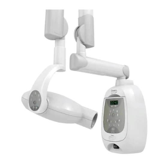
Дентальный рентген KaVo Gendex Expert DC |
||||||
|
||||||
|
||||||
|
||||||
|
||||||
|
||||||
|
||||||
|
||||||
|
||||||
|
||||||
|
||||||
|
||||||
|
||||||
|
||||||
|
||||||
|
||||||
|
||||||
|
||||||
|
||||||
|
||||||
|
||||||
|
||||||
|
||||||
|
||||||
|
||||||
|
||||||
|


 , вопрос с решением проблемки
  а это самое главное

 , но человек рядом с ним не тот …


Symptom
Display flashes «Err1»
and the Ready light is
OFF
Display flashes
«Err2″and the Ready
light is OFF
No exposure with the
remote exposure
switch
Cooling light is ON
032-0207-EN Rev 0
Table 5-1
Common Symptoms and
Possible Remedies (Continued)
Additional Symptoms
Ready light is OFF, other
display functions appear
normal
Ready light is OFF;
exposure terminates
normally, but the output
may be below normal
Normal operation by
design — protects and
extends the life of the
tubehead if too many
exposures are made in
too short a period of time
Printed on: 20 Apr 2012, 11:34:10 am; Printed by: UWE.ZELLER
Possible Cause
Mains voltage
configuration jumper
improperly positioned
Mains voltage out of
range 108 V — 132 V or
198 V — 253 V
Mains voltage drops
below minimum
required during
exposure, or source
resistance may be too
high
Wrong remote cable
selected from the D800
HK kit
Faulty handswitch or
wiring
Mis-wired 110-0160G1
remote cable adapter
kit —customer-supplied
wiring problems
X-ray unit is in the
cooling mode
(Table continued on the next page)
Remedy
Re-configure the
jumper per the
page 4-
instructions on
5
Wait until the line
voltage returns to
normal (indicated by
the lamp being steady)
or have a qualified
electrician check the
power line
Pressing any key
except the exposure
switch on the Master
Control Touch Panel
will clear the display. If
the problem persists,
have a qualified
electrician check the
power line
Verify and correct the
wiring as necessary.
Wait until the lamp
goes out, indicating
that the tube has
properly cooled down.
5-3
-
Contents
-
Table of Contents
-
Bookmarks
Quick Links
Gendex expert
DC
®
Installation Manual
Manual de instalación
Installationshandbuch
Manuale d’installazione
Manual d’installation
Intraoral X-ray System
Related Manuals for Gendex Expert DC
Summary of Contents for Gendex Expert DC
-
Page 1
Gendex expert ® Installation Manual Manual de instalación Installationshandbuch Manuale d’installazione Manual d’installation Intraoral X-ray System… -
Page 3
English Installation Manual… -
Page 5: Table Of Contents
Preinstallation ……….General Information .
-
Page 6
This page intentionally left blank Document No. PEXPERTIM Rev. 1 Release Date: May 2007… -
Page 7: Preinstallation
Certi cation- Complies with FDA radiation REF: 112-0939G1 112-1192G1 performance standards 21 CFR, Subchapter J. 0086 Gendex Dental Systems Des Plaines, IL USA Medical Equipment REF: 110-0205G1 UL60601-1, IEC60601-1, IEC 60601-1-3, IEC 60601-2-7, IEC 60601-2-28, 16VL, 34SL CAN/CSA-C22.2 No. 601.1…
-
Page 8: Certified Component Capability
® The Gendex expert DC is available with three different lengths of the horizontal arm. This allows the system to have three different areas of reach.
-
Page 9
12” (31 cm) CONE TUBE IS ROTATED WITH 8” (20 cm) CONE 79″ (200 cm) MAX REACH Gendex eXpert DC75 W/8″ (20 cm) CONE 26″ (66 cm) MIN REACH Gendex eXpert DC55 W/8″ (20 cm) CONE Figure 2 Maximum and Minimum Reach… -
Page 10
Preinstallation Gendex eXpert DC 75 — Dimension A is as shown Gendex eXpert DC 65 — Subtract 10” (25 cm) from dimension A Gendex eXpert DC 55 — Subtract 20” (51 cm) from dimension A 5-1/2” 4-7/8″ (13.97cm) (12.5 cm) 41-1/4″… -
Page 11
Preinstallation 9” 8″ Gendex eXpert DC 75 — Dimension A is as shown (20.5cm) (22.86cm) Gendex eXpert DC 65 — Subtract 10” (25 cm) from dimension A Gendex eXpert DC 55 — Subtract 20” (51 cm) from 15-0” 14-1/2″ dimension A (36.5cm) -
Page 12
Preinstallation Gendex eXpert DC 75 — Dimension A is as shown Gendex eXpert DC 65 — Subtract 10” (25 cm) from dimension A Gendex eXpert DC 55 — Subtract 20” (51 cm) from dimension A 14″ (35.5cm) DIAMETER W/8″ (20cm) CONE 22″… -
Page 13: Electrical Power Requirements
Preinstallation Electrical Power Requirements The system requires a three-wire electrician-supplied power supply: A ground wire and two power lines: (L) Line and (N) Neutral. Nominal Voltage 120 V ac ± 10% 230 V ac +10%, -14% Line Current (Standby Mode) 0.5 Amp 0.3 Amp Line Current (Exposure Mode) 8 Amp…
-
Page 14
Preinstallation (Continued) Note! The line cord option can be purchased with the system. This option is only permitted for 120 V ac installations. It is not recommended for voltages other than 120 V ac. To prevent damage to the unit, before installing the line cord: •… -
Page 15: Wall Support Considerations
Wall Support Considerations Verifying the wall support capability is the responsibility of the installer. Appropriate fasteners are included for single-stud installation only. ® The wall support and mounting hardware for the Gendex expert DC unit must withstand these maximum forces: Shear load…
-
Page 16
Preinstallation (Continued) Mounting support Install junction box If Operator Panel is to be installed remotely, install junc- tion box (1) Single wooden wall stud Left of the mounting stud at the Left of the mounting stud above appropriate height the power supply junction box Two wooden wall studs Right of the left mounting stud Right of the left mounting stud… -
Page 17: Additional Kits Available
Additional Kits Available Read the installation instruction provided with the kits before starting to ® install Gendex expert DC. Some kit require that additional access holes that need to be made before the Master Control or the Mounting Plate for the Master Control are mounted.
-
Page 18
Preinstallation This page intentionally left blank Document No. PEXPERTIM Rev. 1 Release Date: May 2007… -
Page 19: Installation Steps
Level Install the Master Control Touch Panel ® The recommended configuration is to mount the Gendex expert DC with the Master Control inside the operatory and the Master Control Touch Panel outside of the operatory. (When located apart from the Master Control, the Master Control Touch Panel is referred to as the “Remote Master Control…
-
Page 20
Installation Steps (Continued) 1. Open the shipping carton and locate the Master Control Touch Panel, the Mounting Plate, and the 50-foot (15-meter) Control Cable in the top portion of the shipping carton. Master Control Mounting Plate Touch Panel and Control Cable Figure 1 Locate the Master Control Touch Panel, Mounting Plate, and Control Cable… -
Page 21
Installation Steps (Continued) Note! In the following step, route the Control Cable in compliance with local codes. The cable can also be run to an electrical box. If installing the optional Wall Plate for mounting the Master Control, run the cable through the opening at the top of the Wall Plate. -
Page 22: Install The Master Control
Installation Steps Install the Master Control 1. Locate the Master Control in the top portion of the carton. Master Control Figure 4 Locate the Master Control 2. Remove the two Phillips head screws from the Hinged Cover and carefully open the cover. Place the two screws in a safe location for future reassembly.
-
Page 23: Configuration 1 — Mount To A Single Wood Wall Stud
Installation Steps (Continued) Several possibilities exist for installing the Master Control: • on a single wood wall stud (Configuration 1 — Mount to a single wood wall stud, page 17) • to 16 inch center studs (Configuration 2 — Mount to 16-inch center wood wall studs, page 19) •…
-
Page 24
Installation Steps (Continued) 5. Place the Master Control into position, and start the upper mounting bolt. Do not tighten. Figure 6 Start the Upper Mounting Bolt 6. To complete installation for the Master Control, go to Final Steps to Install Master Control starting on page 25. Document No. -
Page 25: Configuration 2 — Mount To 16-Inch Center Wood Wall Studs
Installation Steps Configuration 2 — Mount to 16-inch center wood wall studs Not included in shipping carton: Mounting bolts appropriate for the wall support This configuration requires the optional Wall Plate (D800WPEXPERT). Note! 1. Determine the proper location for mounting the unit. Referring to the Mounting Template, verify that each electrical box is positioned correctly in relation to location of the mounting studs.
-
Page 26
Installation Steps 4. Using the mounting bolts supplied with the Wall Plate option, start the top two mounting bolts. Do not tighten. NOTE 2 NOTE 1 NOTE 1 NOTE 5 NOTE 4 NOTE 4 MOUNTING WITH D800WP SPECIAL 16″ CENTER WALL PLATE NOTE 1: HOLE LOCATION TO MOUNT THE WALL PLATE VIA LAG BOLTS (SUPPLIED) TO WOODEN WALL STUDS SPACED AT 16″… -
Page 27: Configuration 3 — Mount To A Solid Wall
Installation Steps Configuration 3 — Mount to a solid wall Not included in shipping carton: Mounting bolts appropriate for the wall support 1. Determine the proper location for mounting the unit. Referring to the Mounting Template, verify that each electrical box is positioned correctly in relation to location of the mounting studs.
-
Page 28: Configuration 4 — Mount In A Pass-Through Box Or Cabinet System
Installation Steps Configuration 4 — Mount in a pass-through box or cabinet system Not included in shipping carton: Mounting bolts appropriate for the pass-through box or cabinet sys- Note! Care must also be taken to properly locate the power supply and/or Operator Panel junction boxes.
-
Page 29
Installation Steps (Continued) 5. Place the Master Control into position and start the upper mounting bolt. Do not tighten. Figure 11 Start the Upper Mounting Bolt 6. To complete installation for the Master Control, go to Final Steps to Install Master Control starting on page 25. Document No. -
Page 30: Configuration 5 — Mount To A Wall With Steel Studs
Installation Steps Configuration 5 — Mount to a wall with steel studs Requires the optional Wall Plate (D800WPEXPERT) and the Backing Plate Note! (D800BPEXPERT). This configuration requires drilling through the wall and capturing two steel studs between two plates: the front Wall Plate and the Backing Plate (located on the other side of the wall).
-
Page 31: Final Steps To Install Master Control
Installation Steps Final Steps to Install Master Control 1. Loosen the screw that secures the leveling plate at the bottom mounting location. Center the plate in its range of movement. Start the lower mounting bolt. Lower Mounting Bolt Leveling Plate Screw Figure 13 Loosen the Screw Securing the Leveling Plate and Start the Lower Mounting Bolt 2.
-
Page 32: Install The Horizontal Arm
Installation Steps Install the Horizontal Arm 1. Open the shipping carton and locate the Horizontal Arm in the top portion of the carton. Horizontal Arm Figure 15 Locate the Horizontal Arm 2. Read and remove the warning tag. Remove the plastic bag containing the set screw.
-
Page 33
Installation Steps (Continued) IMPORTANT! Do NOT remove the plastic tube from around the wires. Figure 17 Keep the Wires Enclosed in the Plastic Tube 3. Insert the plastic tube enclosing the wires into the opening at the top of the Master Control. Pull the plastic tube toward you slightly to clear the transformer and insert the arm completely into the Master Control. -
Page 34
Installation Steps (Continued) 4. Remove the plastic tube to free the wires and ensure that the Horizontal Arm is firmly seated in place. Do not make any wire connections at this time. Figure 19 Remove the Plastic Tube and Seat the Horizontal Arm Fully 5. -
Page 35: Install Articulated Arm & Tubehead Assembly
Installation Steps Install Articulated Arm & Tubehead Assembly 1. Remove the top packing material of the shipping carton to gain access to the Articulated Arm and Tubehead Assembly. Remove assembly from the shipping carton. Articulated Arm and Tubehead Assembly Figure 21 Locate the Articulated Arm and Tubehead Assembly Read and remove the red warning tag, but do not remove the strapping IMPORTANT!
-
Page 36
Installation Steps (Continued) 3. Carefully route the plastic tube with the arm cable plugs and wires through the opening in the Horizontal Arm. Insert the shaft of the Articulated Arm into the opening into the Horizontal Arm. Press down until the shaft is completely seated in the Horizontal Arm. Figure 22 Insert the Articulated Arm into the Horizontal Arm 4. -
Page 37
Installation Steps (Continued) 5. Open the plastic bag removed from the Horizontal Arm on page 26, step 2. Remove the set screw (part no. 09-06-080012-05) and insert according to Figure 24, Insert the Set Screw. Tighten until the screw touches the shaft and then turn an extra half-turn. Set Screw Figure 24 Insert the Set Screw Document No. -
Page 38: Connect Cabling And Wires
Installation Steps Connect Cabling and Wires 1. Remove the plastic tube around the cable plugs and wires of the Articulated Arm. 2. Locate the two ground wires from the bundle of cable plugs and wire. Remove the plastic tube and locate the 2 ground wires…
-
Page 39
Installation Steps (Continued) 3. Dress the two ground wires out the end of the Horizontal Arm to the left of the Articulated Arm shaft. Connect both ground wires to the ground stud (Figure 26). 4. Locate the Horizontal Arm ground wire and dress it out the end of the Horizontal Arm to the right of the Articulated Arm shaft. -
Page 40
Installation Steps (Continued) 6. Carefully connect all wiring harnesses between the Horizontal Arm and the Articulated Arm and Tubehead Assembly (P17 to J17, P21 to J21, P20 to J20, and P16 to J16). 7. Dress the cable connections neatly into the arm opening in the Horizontal Arm by pulling them the into the Master Control until the orange cable markers are visible just below the Horizontal Arm shaft as shown below. -
Page 41
Installation Steps (Continued) 8. Assemble the Horizontal Arm Access Cover. Figure 29 Assemble the Horizontal Arm Access Cover (Continued) Document No. PEXPERTIM — Rev. 1 — Release Date: May 2007… -
Page 42
Installation Steps (Continued) 9. If the Master Control Touch Panel is to be installed • on the Master Control (Master Control Touch Panel is referred to as the «Local Master Control Touch Panel»), route the short Control Cable that is attached to the modular plug through the cutout in the hinged cover. Cutout Modular Plug Figure 30 Route the Control Cable Through the Cutout… -
Page 43
Installation Steps (Continued) IMPORTANT! In the following step ensure that you do not reverse connections. 10. Connect plug P9 to connector J9, plug P5 to connector J5, plug P3 to connector J3, and plug P6 to connector J6. Connect the chassis ground. Chassis Ground Figure 32 Connect the Cables and Chassis Ground in the… -
Page 44
Installation Steps (Continued) 11. Before connecting the power wires, set the AC Input Selector Jumper to the proper voltage range of the supplied mains. Figure 33 Set the AC Input Selector Jumper to the Proper Voltage (Continued) Document No. PEXPERTIM Rev. -
Page 45
Installation Steps (Continued) IMPORTANT! Perform the following step only if installing a line cord. 12. If installing a line cord, cut jumper JP1. Figure 34 Cut Jumper JP1 Before Installing a Line Cord 13. Connect the Line and Neutral power wires to the terminal block. Connect the ground wire to the ground stud. -
Page 46: Complete The Installation
Installation Steps Complete the Installation 1. Close the Master Control hinged cover and replace the two screws. Figure 36 Close the Master Control 2. FOR THE LOCAL MASTER CONTROL TOUCH PANEL, secure the Control Cable with the strain relief. Figure 37 Secure the Control Cable with the Strain Relief (Continued) Document No.
-
Page 47
Installation Steps (Continued) 3. FOR THE LOCAL MASTER CONTROL TOUCH PANEL, before installing the Front Cover, pull the Control Cable across the hand grip at the bottom (white arrow) of the Front Cover and through the cutout (black arrow) before continuing to the next step. Figure 38 Route the Coil Cord Through the Back of the Cover 4. -
Page 48
Installation Steps (Continued) WARNING When plugging in or unplugging the Control Cable, make certain that the power is not turned on to the unit. 5. If the Master Control Touch Panel is to be installed locally (on the Master Control), skip to the next step. FOR THE REMOTE MASTER CONTROL TOUCH PANEL, •… -
Page 49
Installation Steps (Continued) • Connect the coil-cord of the Coil-Cord Exposure Switch to the 6- position receptacle. Figure 42 Plug the Coil-Cord into the 6-Position Receptacle • Carefully dress the Control Cable back into the wall and attach the Master Control Touch Panel to the Mounting Plate. Pull downward slightly on the Master Control Touch Panel to snap it in place. -
Page 50
Installation Steps (Continued) WARNING When plugging in or unplugging the Control Cable, make certain that the power is not turned on to the unit. 6. FOR THE LOCAL MASTER CONTROL TOUCH PANEL, • Connect the short Control Cable to the 8-position receptacle at the bottom of the Master Control Touch Panel. -
Page 51
Installation Steps (Continued) • Insert the Master Control Touch Panel into the front cover inset pressing in at the top corners to snap into place. Figure 46 Attach the Master Control Touch Panel to the Front Cover Document No. PEXPERTIM — Rev. 1 — Release Date: May 2007… -
Page 52
Installation Steps This page intentionally left blank Document No. PEXPERTIM Rev. 1 Release Date: May 2007… -
Page 53: Electrical Calibration Checks
Electrical Calibration Checks Electrical Calibration Checks Note! The mA and kV x-ray output factors along with the exposure times are microprocessor controlled and are not adjustable. No calibration is required. Prior to operating the system, verify that the power supply has been properly connected.
-
Page 54: Configure Exposure Settings
Configure Exposure Settings Configure Exposure Settings Refer to the User Manual for instructions on how to use the Master Control Touch Panel to change the default settings for a different film speed or digital imaging system. Also refer to the User Manual for complete information concerning customized anatomical exposure settings The default settings for anatomical exposure times are set at the factory according to the standard configuration: D-speed film or DenOptix imaging…
-
Page 55: Final System Checks
Final System Checks Final System Checks The following must be performed to complete the installation of the Gendex ® expert DC. Failure to perform these checks may result in an installation that does not comply with U.S. Radiation Performance Standards 21 CFR Subchapter J.
-
Page 56
To avoid any potential hazard to operators or patients, any unusual operation Note! or problems with mechanical functions that cannot be eliminated at installation should be reported to Gendex immediately. If problems are found, refer to the Technical Service Manual (PEXPERTTM) for: •…