
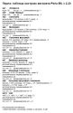
Ошибки снековых аппаратов Fas 900, Fas 1050, Fas Baby.
| Код ошибки или неисправность | Возможная причина |
|---|---|
| 01 (ПОДКОД № кода выбора) | Двигатель заблокирован (спираль не вращается) |
| 02 (ПОДКОД № кода выбора) | Спираль не завершает оборот |
| 05 (ПОДКОД № кода выбора) | Двигатель отсоединён |
| 09 (ПОДКОД № кода выбора) | Возможный дефект микровыключателя или кабельной проводки двигателя спирали |
| 10 (ПОДКОД (*) 38 — 39 — 40) | Зонд внутренней температуры неисправен |
| 11 (ПОДКОД (*) 38 — 39 — 40) | Зонд испарителя неисправен |
| 16 (ПОДКОД (*) 33 — 38 — 39 — 40) | Ошибка связи с периферийным оборудованием (плата электрощита) |
| 17 (ПОДКОД (*) 38 — 39 — 40) | Разрыв связи во время цикла продажи без получения кредита |
| 18 (ПОДКОД (*) 38 — 39 — 40) | Разрыв связи во время цикла продажи с получением кредита |
| 31 (ПОДКОД (*) 38 — 39 — 40) | Ошибка тестирования фотоэлементов |
| 32÷38 (ПОДКОД (*) 38 — 39 — 40) | Ошибка калибровки фотоэлементов |
| 39 (ПОДКОД (*) 38 — 39 — 40) | Предохранитель фотоэлементов |
| 51 (ПОДКОД (*) 38 — 39 — 40) | Прерывание связи периферийного оборудования в начале цикла продажи |
| 55 | Платёжная система не работает |
| 61 (ПОДКОД № кода выбора) | Двигатель заблокирован (спираль не вращается) SLAVE A |
| 62 (ПОДКОД № кода выбора) | Спираль не завершает оборот SLAVE A |
| 65 (ПОДКОД № кода выбора) | Двигатель отсоединён SLAVE A |
| 69 (ПОДКОД № кода выбора) | Возможный дефект микровыключателя или кабельной проводки двигателя спирали SLAVE A |
| 71 (ПОДКОД № кода выбора) | Двигатель заблокирован (спираль не вращается) SLAVE B |
| 72 (ПОДКОД № кода выбора) | Спираль не завершает оборот SLAVE B |
| 75 (ПОДКОД № кода выбора) | Двигатель отсоединён SLAVE B |
| 79 (ПОДКОД № кода выбора) | Возможный дефект микровыключателя или кабельной проводки двигателя спирали SLAVE B |
(*) Спецификация:
- 33 = Фотоэлементы
- 38 = Спирали Master
- 39 = Спирали Slave A
- 40 = Спирали Slave B

")
-
- Поделиться
У меня похожая проблема, насос качает, греется, но вода не поступает. Мне кажется, дело в клапане, через который вода подается в накопительный бачек, завтра буду смотреть.
Ссылка на комментарий
-
Ответов
362 -
Создана
14 г -
Последний ответ
2 г
Топ авторов темы
-

28
-
19
-
15
-
18

Изображения в теме
-
- Поделиться
Подскажите, автомат работает исправно, принимает деньги, наливает напитки и после выдачи напитка сразу появляется ошибка А 03.
Сбрасываешь, опять работает и после выдачи напитка снова А03
У меня дело в клапане было, перебрал продул вроде работает …
Ссылка на комментарий
-
- Поделиться
Вода, прокачиваемая помпой, охлаждает её. Работая без воды, помпа может перегореть. Других причин нагрева не встречал.
У меня помпа нагревалась и с водой т.к. заклинило клапан и вода не протекала дальше, перебрал клапан вроде работает пока …
Ссылка на комментарий
- 3 недели спустя…

")
-
- Поделиться
Ребят, каким раствором почистить клапаны?
Ссылка на комментарий

")
- 2 недели спустя…
-
- Поделиться
хорошо, а как проверить датчик воды?
Ссылка на комментарий
")
-
- Поделиться
А у нас такая проблема была.Пока под давлением не загнали воду в бойлер, работать не хотело. Берёте в рот воду и трубку подачи воды. В момент включения нагнетаете воду, а рядом стаканчик с водой.Сразу трубку в стаканчик.или пару раз так проделайте.Вот тоже кучу причин искали.А так помогло.
Ссылка на комментарий
-
- Поделиться
теперь вообще при включении набирает воду в бачок, потом трещит верхняя помпа и вода из бачка сливается в ведро.
Ссылка на комментарий
-
- Поделиться
Больше недели автомат работает без ошибки. Помпа из уникума только завтра придет, клапан так и не ставила, наверное становлюсь продвинутым техником, от одного взгляда которого автоматы начинают работать сами собой =)))
Так к слову из-за чего у меня возникала такая же ошибка, все очень даже банально: когда закрываем дверцу автомата после обслуживания, то полочка, на которой держится мешок д/жмыха, задвигается вплотную к стенке, а в этой полочке есть вырез под шланги и получается, то что шланг от канистры не попадает в этот вырез и пережимается полкой об заднею стенку автомата. Вот так и выпадает через некоторое время ошибка А03. Будьте внимательнее, не повторяйте ошибок на шкуре других ![]()
Ссылка на комментарий
- 2 месяца спустя…
-
- Поделиться
Добрый вечер. подскажите пожалуйста. Проблема с фас. Примерно через 30 минут после включения на табло автомата появлялась надпись автомат в нагревании. Ошибка а 15. Я так предполагаю сломался температурный датчик. Поменял датчик на новый. Тот который вкручивается в автомат. Запускаю. На табло надпись аппарат не работает. показывает температуру бойлера 14 градусов. Сам бойлер горячий. Делаю промывку вода горячая. Что может быть за проблема
Ссылка на комментарий
- 1 месяц спустя…
-
- Поделиться
Новая трабла. Куп купюры 10, 50 и 100 видит как 0,1 — 0,5 и 1 руб. На некте я еще могу изменить базовую единицу, а на Фасах как быть?
Ссылка на комментарий

")
-
- Поделиться
На некте я еще могу изменить базовую единицу, а на Фасах как быть?
На Некте вы тоже не можете поменять базовую еденицу, речь наверное о десятичной точке. На Фасах не помню как и что, если завтра найду инструкцию, могу скинуть на почту. А по какому протоколу работает Фас?
Кстати… приехали термодатчики.
Изменено 8 мая, 2013 пользователем Holland и Holland
Ссылка на комментарий
-
- Поделиться
На Некте вы тоже не можете поменять базовую еденицу, речь наверное о десятичной точке. На Фасах не помню как и что, если завтра найду инструкцию, могу скинуть на почту. А по какому протоколу работает Фас?
Кстати… приехали термодатчики.
Да, имела в виду десятичную точку. Фас работает по протоколу exe standart. Если найдете, скиньте, пожалуйста, всю голову сломала 
почта raveen@yandex.ru
Изменено 9 мая, 2013 пользователем rebu
Ссылка на комментарий
-
- Поделиться
Здравствуйте. Если не сложно подскажите Проблема при включении аппарата
1) начинает работать редуктор перемещения стаканов и не останавливается
(нашел подгоревший контакт на колодке подключения этого редуктора перепаял проблема осталась)
2)при тестировании стаканов сбрасывает через один а то и через два
(микрики проверял менял эффекта нет)
Ошибка А 23
И еще постоянно выскакивает ошибка 16 (39-40)
Ссылка на комментарий
- 2 недели спустя…
")
-
- Поделиться
Было нечто похожее когда заклинила кофемолка, вылазила ошибка 32 или 23 и плевал стаканами без остановки
Ссылка на комментарий
-
- Поделиться
рАЗОБРАЛСЯ СГОРЕЛ СИМИСТОР НА ПЛАТЕ И МИКРИК ПОМЕНЯЛ ВРОДЕ ВСЕ В НОРМЕ.А вот с ошибеой 16 проблема походу выскакивает когда снек работает в чем проблема не понятно
Ссылка на комментарий
- 2 недели спустя…
-
- Поделиться
А если поставить вместо 5 помпы 7-ую, работать будет?
Ссылка на комментарий
-
- Поделиться
А ошибка 17 это что? в инструкции ее нет.
Ссылка на комментарий
")
-
- Поделиться
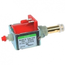
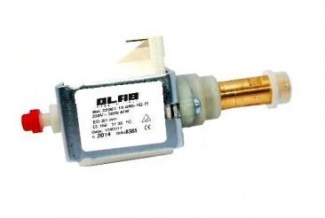
А если поставить вместо 5 помпы 7-ую, работать будет?
Мне думается будет, тут главное чтобы бачок успевал наполнятся.
7 по мощнее 5 будет думается.
Та которая качает в расш. бачок должна быть мощнее.
Изменено 16 июня, 2013 пользователем skid
Ссылка на комментарий
-
- Поделиться
я уже на практике убедилась, что работает)
Ссылка на комментарий
-
- Поделиться
7 по мощнее 5 будет думается.
С точностью до наоборот… для подачи воды в бойлер, желательно ставить ЕХ-5, она создаёт бОльшее давление, а для заполнения расширительного бачка, лучше ЕХ-7, ЕР-8, у них производительность больше (быстрее заполняется бачок).
Ссылка на комментарий
-
- Поделиться
С точностью до наоборот… для подачи воды в бойлер, желательно ставить ЕХ-5, она создаёт бОльшее давление, а для заполнения расширительного бачка, лучше ЕХ-7, ЕР-8, у них производительность больше (быстрее заполняется бачок).
Вот насчёт давления 5-ой и производительности 7-ой не знал.
Главное что бы расшир. бачок был с водой.
Изменено 17 июня, 2013 пользователем skid
Ссылка на комментарий
- 2 недели спустя…
-
- Поделиться
Здравствуйте . Помогите решить проблему. Постоянно появляется ошибка А 32, и потом может пропасть , чаще всего появляется когда вставляешь купюру и после этого сразу ошибка , через 3-5 сек пропадает и виден кредит. Бывает даже автомат на включается пошит ошибку А 32. Что может быть? Платежку полностью менял, тоже самое, на выпадение стакана стоит реле ,а не сенсор.
Ссылка на комментарий
-
- Поделиться
ошибка № 16 на снеке Fas 900. В инструкции данная ошибка описывается как «Ошибка связи с периферийным оборудованием (плата электрощита)»
И как это понять?
Если кто то сталкивался с аналогичной проблемой дайте пожалуйста дельный совет.
За ранние благодарен.
Ссылка на комментарий

-
- Поделиться
Проверить все контакты соединений. Возможно отошёл где.
Ссылка на комментарий
-
2 г
Santiago закрепил тема
-
2 г
Santiago открепил тема
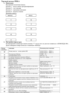
10.7 НАБОР ДЛЯ РАЗГРУЗКИ БУТЫЛОК
Если в ящике есть спиральные пружины с ёмкостью для
шести продуктов, стержень должен быть вставлен в
отверстие “A”; тогда как, если в ящике есть спиральные
пружины с ёмкостью для пяти продуктов, стержень должен
быть вставлен в отверстие “B”; напротив, если в ящике есть
выборы с мостиком, стержень должен быть вставлен в
отверстие “C”.
Внимание: стержень разгрузки бутылок не должен
использоваться для извлечения ящика.
Классы оборудования по снековых аппаратов с лифтовой подачей
- Снек-автоматы конвеерные Jofemar

Combi Snack
Вендинговое оборудование Saeco
Кофейный автомат, который может продавать как горячие напитки, так и упакованные продукты, требующие хранения при низкой температуре.
Запчасти Деталировки
Документация
Программное обеспечение
Спец предложения
Дополнительное оборудование

Perla E6, Руководство по эксплуатации Perla E6 RUS
РУКОВОДСТВО ПО УСТАНОВКЕ
ЭКСПЛУАТАЦИИ И ТЕХОБСЛУЖИВАНИЮ Perla E6 на русском языке
Perla E6, User manual EN
Руководство на английском языке

Perla E6, Схема подключения электрическая
Схема подключения для PERLA ESPRESSO NEW
Perla HP, User manual EN
Инструкция PERLA HP на английском

Fashion V2.0, User manual Fashion_v2 EN
Инструкция на английском

Fashion/R, Схема электрическая
Schema colleg.caffe FASHION/R ESPRESSO 6ev
Wining, Коды ошибок, основные команды
Кратко собраны основные команды и коды основных ошибок
Perla E6 Wining, Команды управления и коды ошибок кратко.
Коды ошибок, основные команды управления от FAS WINING. подходит для PERLA
Fashion V2.0 Команды управления, коды ошибок кратко.
Команды управления, коды ошибок от FAS WINING, подходят для Fashion

Fashion_up, User manual Fashion_up EN
Инструкция на английском

Wining, Схема электрическая
Schema colleg.caffe WINNING ESPRESSO UP 6EU

Wining, Руководство по эксплуатации и техобслуживанию RU
РУКОВОДСТВО ПО УСТАНОВКЕ
ЭКСПЛУАТАЦИИ И ТЕХОБСЛУЖИВАНИЮ
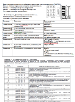
Fast 900, Краткая инструкция Fast
Инструкция-подсказка лдя настройки автомата в ЕХЕ прайс холдинг и коды ошибок
Fast 900 Fast 1050, Руководство по эксплуатации Fast 900 Fast 1050 RUS
РУКОВОДСТВО ПО УСТАНОВКЕ ЭКСПЛУАТАЦИИ И ТЕХОБСЛУЖИВАНИЮ Fast 900 Fast 1050 на русском языке
Fast 1050, Краткая инструкция
Инструкция по настройке в ЕХЕ прайсхолдинг + коды ошибок
Fast 900 Fast 1050, Руководство по эксплуатации Fast 900 Fast 1050 RUS
РУКОВОДСТВО ПО УСТАНОВКЕ ЭКСПЛУАТАЦИИ И ТЕХОБСЛУЖИВАНИЮ Fast 900 Fast 1050 на русском языке
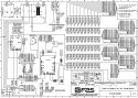
Fast 1050, Схема электрическая
Schema colleg.SPI FAST 750-900-1050 SA

JUST NOW, Руководство по эксплуатации JUST NOW RUS
РУКОВОДСТВО ПО УСТАНОВКЕ ЭКСПЛУАТАЦИИ И ТЕХОБСЛУЖИВАНИЮ JUST NOW на русском языке
JustNow, Схема электрическая для JustNow
Schema colleg.SPI Just Now
Just Now, User manual EN
Инструкция на английском языке
CRISTAL прошивки и электрическая схема.
две прошивки для автомата CRISTAL и электрическая схема.
Aurora, User manual EN
Инструкция Aurora на английском

Perla E6, Этикетки для Perla
Комплект этикеток для кофейного автомата Perla в формате MS Word
Parla E6, Таблица дозировок Perla
Таблица настроек дозировок для торгового автомата FAS Perla
Perla E6, Настройка Perla kраткая памятка
Краткая памятка по меню настроек автомата горячих напитков FAS Perla со значениями типовых настроек
Perla E6, Дозировки Perla Валео
Таблица дозировок, рекомендуемых компанией Вале для торгового атвомата FASperla
Wining,Таблица дозировок и ценники на Winning
Таблица дозировок и ценники на FAS Winning
Fast 900, Схема электрическая
Schema colleg.SPI FAST 750-900-1050 SA

Perla mPerla_7834_v180_L2 старая
Прошивка для старых плат с серийным номером до 300747045
Perla Прошивка mPerla_cf05_v300_L2 NEW!
Русифицированная прошивка новая
Perla Файл настройки мод17, EXE, Стаканы 150гр.
Файл настроек мод17, EXE, Стаканы 150гр. Настройки обкатаны многолетней работой на десятках автоматов.
PERLA PRO Настройки дозировок и программных параметров под ключ-флешку
Файл настроек для ключа. PERLA PRO Подключение по EXE прайс холдинг, Стаканы 150мл.
PERLA PRO, Прошивка PerlaProSA_13d4_v180_L2 RUS
Русифицированная прошивка
Fashion V2.0 Прошивка V130
m_fshupg_F4A7_V130_L2(2001очень старый)
Fashion V2.0 Прошивка V170
m_fsh2_3999_V170_L2(2006г)
Winning Файл настроек для ключа-флешки
Файл настроек для ключа-флешки 6-мод., стакан 150мл. EXE прайс холдинг
Winning прошивка m_Winning_0EBD_V140_L2 RUS
Русифицированная прошивка
Fast 900 прошивка m_fast_1516_V200_L2 RUS
Русифицированная прошивка
Fast 900 Настройки автомата для ключа-флешки
Настройки EXE прайс холдинг, цены устанавливать только в монетнике, прайс линии совпадают с номерами спиралей.
Fas 900 MDB настройки
MDB настройки 900 для ключа-флешки
Fast 1050 прошивка m_fast_1516_V200_L2 RUS
Русифицированная прошивка
Fast 1050 прошивка FAS Fast 1050 2.21 RUS
Исправлены ошибки при настройке платежной системы с двумя знаками после запятой.
Прошивка m_faster_0AB7_V193_L2
Перевернутая клавиатура
JustNow прошивка m_JustNow_7FC0_V103_L2
прошивка для JustNow
Спец цена

На складе: 1977 шт
Склад СПб: 11 шт
Спец цена

На складе: 239 шт
Склад СПб: 1 шт

На складе: 102 шт
Склад СПб: 3 шт

Признанный лидер европейского снекостроения, относительно недавно, в 2004 году решил покорить рынок кофеавтоматов, купив компанию Omnimatic. Путь не оказался лёгок, но FAS прошёл его достойно, в настоящий момент кофейные флагманы Perla и Wininng заняли достойное место в вендинге горячих напитков. Снековые автоматы FAS занимали, занимают и будут занимать лидирующие позиции
Кофейные автоматы FAS делят на 1ое и 2ое поколение, автомат 1го поколения, FAS FASHION V 2.0 имел множество детских болезней характерных для вновь создающейся техники. Последующее поколение, автоматы FASHION UP, PERLA, WININNG по своим надёжностным характеристикам находятся в одном ряду с NECTA, Rheavendors, Bianchi, Saeco. Крупным недостатком остаётся высокая стоимость запчастей и пробелы в номенклатуре, например нет позиции мотор миксера, есть миксер в сборе.
Техническая служба нашей компании знакома с техникой FAS момента появления её на российском рынке. Специалисты нашей компании обладают большим опытом по ремонту и сервисному обслуживанию торговых автоматов FAS. Наличие большого склада запчастей FAS позволяет проводить ремонт оперативно.

Тема: FAS 900 с точкой (Прочитано 1122 раз)
0 Пользователей и 1 Гость просматривают эту тему.
Друзья!
Продаю ФАС 900 в отличном состоянии. Платежки CoinCo и JCM. Работает без нареканий — все моторы крутятся, холодильник морозит, фотодатчик работает.
Находится на точке, можно на ней и остаться. Оборот на точке 20-25 тыс. в месяц. Аренда 10% от оборота
Точка БЦ на западе Москвы — пока заполнен на 30%
Цена за все 90 тысяч

Записан
Записан
Записан
Можно без проблем к этому автомату подключить терминал безналичной оплаты и кассу (в перспективе)
Записан
Записан
-
- Поделиться
У меня похожая проблема, насос качает, греется, но вода не поступает. Мне кажется, дело в клапане, через который вода подается в накопительный бачек, завтра буду смотреть.
Ссылка на комментарий
-
Ответов
362 -
Создана
-
Последний ответ
Топ авторов темы
-
28
-
19
-
15
-
18
Изображения в теме
-
- Поделиться
Подскажите, автомат работает исправно, принимает деньги, наливает напитки и после выдачи напитка сразу появляется ошибка А 03.
Сбрасываешь, опять работает и после выдачи напитка снова А03
У меня дело в клапане было, перебрал продул вроде работает …
Ссылка на комментарий
-
- Поделиться
Вода, прокачиваемая помпой, охлаждает её. Работая без воды, помпа может перегореть. Других причин нагрева не встречал.
У меня помпа нагревалась и с водой т.к. заклинило клапан и вода не протекала дальше, перебрал клапан вроде работает пока …
Ссылка на комментарий
- 3 недели спустя…
-
- Поделиться
Ребят, каким раствором почистить клапаны?
Ссылка на комментарий
- 2 недели спустя…
-
- Поделиться
хорошо, а как проверить датчик воды?
Ссылка на комментарий
-
- Поделиться
А у нас такая проблема была.Пока под давлением не загнали воду в бойлер, работать не хотело. Берёте в рот воду и трубку подачи воды. В момент включения нагнетаете воду, а рядом стаканчик с водой.Сразу трубку в стаканчик.или пару раз так проделайте.Вот тоже кучу причин искали.А так помогло.
Ссылка на комментарий
-
- Поделиться
теперь вообще при включении набирает воду в бачок, потом трещит верхняя помпа и вода из бачка сливается в ведро.
Ссылка на комментарий
-
- Поделиться
Больше недели автомат работает без ошибки. Помпа из уникума только завтра придет, клапан так и не ставила, наверное становлюсь продвинутым техником, от одного взгляда которого автоматы начинают работать сами собой =)))
Так к слову из-за чего у меня возникала такая же ошибка, все очень даже банально: когда закрываем дверцу автомата после обслуживания, то полочка, на которой держится мешок д/жмыха, задвигается вплотную к стенке, а в этой полочке есть вырез под шланги и получается, то что шланг от канистры не попадает в этот вырез и пережимается полкой об заднею стенку автомата. Вот так и выпадает через некоторое время ошибка А03. Будьте внимательнее, не повторяйте ошибок на шкуре других ![]()
Ссылка на комментарий
- 2 месяца спустя…
-
- Поделиться
Добрый вечер. подскажите пожалуйста. Проблема с фас. Примерно через 30 минут после включения на табло автомата появлялась надпись автомат в нагревании. Ошибка а 15. Я так предполагаю сломался температурный датчик. Поменял датчик на новый. Тот который вкручивается в автомат. Запускаю. На табло надпись аппарат не работает. показывает температуру бойлера 14 градусов. Сам бойлер горячий. Делаю промывку вода горячая. Что может быть за проблема
Ссылка на комментарий
- 1 месяц спустя…
-
- Поделиться
Новая трабла. Куп купюры 10, 50 и 100 видит как 0,1 — 0,5 и 1 руб. На некте я еще могу изменить базовую единицу, а на Фасах как быть?
Ссылка на комментарий
-
- Поделиться
На некте я еще могу изменить базовую единицу, а на Фасах как быть?
На Некте вы тоже не можете поменять базовую еденицу, речь наверное о десятичной точке. На Фасах не помню как и что, если завтра найду инструкцию, могу скинуть на почту. А по какому протоколу работает Фас?
Кстати… приехали термодатчики.
Изменено пользователем Holland и Holland
Ссылка на комментарий
-
- Поделиться
На Некте вы тоже не можете поменять базовую еденицу, речь наверное о десятичной точке. На Фасах не помню как и что, если завтра найду инструкцию, могу скинуть на почту. А по какому протоколу работает Фас?
Кстати… приехали термодатчики.
Да, имела в виду десятичную точку. Фас работает по протоколу exe standart. Если найдете, скиньте, пожалуйста, всю голову сломала
почта raveen@yandex.ru
Изменено пользователем rebu
Ссылка на комментарий
-
- Поделиться
Здравствуйте. Если не сложно подскажите Проблема при включении аппарата
1) начинает работать редуктор перемещения стаканов и не останавливается
(нашел подгоревший контакт на колодке подключения этого редуктора перепаял проблема осталась)
2)при тестировании стаканов сбрасывает через один а то и через два
(микрики проверял менял эффекта нет)
Ошибка А 23
И еще постоянно выскакивает ошибка 16 (39-40)
Ссылка на комментарий
- 2 недели спустя…
-
- Поделиться
Было нечто похожее когда заклинила кофемолка, вылазила ошибка 32 или 23 и плевал стаканами без остановки
Ссылка на комментарий
-
- Поделиться
рАЗОБРАЛСЯ СГОРЕЛ СИМИСТОР НА ПЛАТЕ И МИКРИК ПОМЕНЯЛ ВРОДЕ ВСЕ В НОРМЕ.А вот с ошибеой 16 проблема походу выскакивает когда снек работает в чем проблема не понятно
Ссылка на комментарий
- 2 недели спустя…
-
- Поделиться
А если поставить вместо 5 помпы 7-ую, работать будет?
Ссылка на комментарий
-
- Поделиться
А ошибка 17 это что? в инструкции ее нет.
Ссылка на комментарий
-
- Поделиться
А если поставить вместо 5 помпы 7-ую, работать будет?
Мне думается будет, тут главное чтобы бачок успевал наполнятся.
7 по мощнее 5 будет думается.
Та которая качает в расш. бачок должна быть мощнее.
Изменено пользователем skid
Ссылка на комментарий
-
- Поделиться
я уже на практике убедилась, что работает)
Ссылка на комментарий
-
- Поделиться
7 по мощнее 5 будет думается.
С точностью до наоборот… для подачи воды в бойлер, желательно ставить ЕХ-5, она создаёт бОльшее давление, а для заполнения расширительного бачка, лучше ЕХ-7, ЕР-8, у них производительность больше (быстрее заполняется бачок).
Ссылка на комментарий
-
- Поделиться
С точностью до наоборот… для подачи воды в бойлер, желательно ставить ЕХ-5, она создаёт бОльшее давление, а для заполнения расширительного бачка, лучше ЕХ-7, ЕР-8, у них производительность больше (быстрее заполняется бачок).
Вот насчёт давления 5-ой и производительности 7-ой не знал.
Главное что бы расшир. бачок был с водой.
Изменено пользователем skid
Ссылка на комментарий
- 2 недели спустя…
-
- Поделиться
Здравствуйте . Помогите решить проблему. Постоянно появляется ошибка А 32, и потом может пропасть , чаще всего появляется когда вставляешь купюру и после этого сразу ошибка , через 3-5 сек пропадает и виден кредит. Бывает даже автомат на включается пошит ошибку А 32. Что может быть? Платежку полностью менял, тоже самое, на выпадение стакана стоит реле ,а не сенсор.
Ссылка на комментарий
-
- Поделиться
ошибка № 16 на снеке Fas 900. В инструкции данная ошибка описывается как «Ошибка связи с периферийным оборудованием (плата электрощита)»
И как это понять?
Если кто то сталкивался с аналогичной проблемой дайте пожалуйста дельный совет.
За ранние благодарен.
Ссылка на комментарий
-
- Поделиться
Проверить все контакты соединений. Возможно отошёл где.
Ссылка на комментарий
-
Santiago закрепил тема
-
Santiago открепил тема
10.7 НАБОР ДЛЯ РАЗГРУЗКИ БУТЫЛОК
Если в ящике есть спиральные пружины с ёмкостью для
шести продуктов, стержень должен быть вставлен в
отверстие “A”; тогда как, если в ящике есть спиральные
пружины с ёмкостью для пяти продуктов, стержень должен
быть вставлен в отверстие “B”; напротив, если в ящике есть
выборы с мостиком, стержень должен быть вставлен в
отверстие “C”.
Внимание: стержень разгрузки бутылок не должен
использоваться для извлечения ящика.
Классы оборудования по снековых аппаратов с лифтовой подачей
- Снек-автоматы конвеерные Jofemar
21.04
«Битва роботов» 2023
На Госуслугах завершился приём заявок на участие в международном чемпионате инженерных команд «Битва роботов».
31.03
Маркировка напитков
Минпромторг предложил начать проводить эксперимент по маркировке некоторых видов безалкогольных напитков в мае этого года.
01.03
Мораторий на внеплановые проверки ККТ
Постановлением Правительства РФ от 29.12.2022 года №2516 «О внесении изменений в постановление Правительства Российской Федерации от 10 марта 2022 г.№336» на 2023 год продлён мораторий на внеплановые проверки ККТ.

FAS900 Series Appliance Hardware and Service Guide
NetApp, Inc.495 East Java DriveSunnyvale, CA 94089 USATelephone: +1 (408) 822-6000Fax: +1 (408) 822-4501Support telephone: +1 (888) 4-NETAPPDocumentation comments: [email protected] Web: http://www.netapp.com
Part number 215-03895_A0May 2008

Copyright and trademark information
Copyright information
Copyright © 1994–2008 NetApp, Inc. All rights reserved. Printed in the U.S.A.
No part of this document covered by copyright may be reproduced in any form or by any means—graphic, electronic, or mechanical, including photocopying, recording, taping, or storage in an electronic retrieval system—without prior written permission of the copyright owner. NetApp reserves the right to change any products described herein at any time, and without notice. NetApp assumes no responsibility or liability arising from the use of products described herein, except as expressly agreed to in writing by NetApp. The use or purchase of this product does not convey a license under any patent rights, trademark rights, or any other intellectual property rights of NetApp. The product described in this manual may be protected by one or more U.S.A. patents, foreign patents, or pending applications.
RESTRICTED RIGHTS LEGEND: Use, duplication, or disclosure by the government is subject to restrictions as set forth in subparagraph (c)(1)(ii) of the Rights in Technical Data and Computer Software clause at DFARS 252.277-7103 (October 1988) and FAR 52-227-19 (June 1987).
Trademark information
NetApp, the Network Appliance logo, the bolt design, NetApp—the Network Appliance Company, Cryptainer, Cryptoshred, DataFabric, DataFort, Data ONTAP, Decru, FAServer, FilerView, FlexClone, FlexVol, Manage ONTAP, MultiStore, NearStore, NetCache, NOW NetApp on the Web, SANscreen, SecureShare, SnapDrive, SnapLock, SnapManager, SnapMirror, SnapMover, SnapRestore, SnapValidator, SnapVault, Spinnaker Networks, SpinCluster, SpinFS, SpinHA, SpinMove, SpinServer, StoreVault, SyncMirror, Topio, VFM, and WAFL are registered trademarks of NetApp, Inc. in the U.S.A. and/or other countries. gFiler, Network Appliance, SnapCopy, Snapshot, and The evolution of storage are trademarks of NetApp, Inc. in the U.S.A. and/or other countries and registered trademarks in some other countries. The NetApp arch logo; the StoreVault logo; ApplianceWatch; BareMetal; Camera-to-Viewer; ComplianceClock; ComplianceJournal; ContentDirector; ContentFabric; EdgeFiler; FlexShare; FPolicy; Go Further, Faster; HyperSAN; InfoFabric; Lifetime Key Management, LockVault; NOW; ONTAPI; OpenKey, RAID-DP; ReplicatorX; RoboCache; RoboFiler; SecureAdmin; Serving Data by Design; SharedStorage; Simplicore; Simulate ONTAP; Smart SAN; SnapCache; SnapDirector; SnapFilter; SnapMigrator; SnapSuite; SohoFiler; SpinMirror; SpinRestore; SpinShot; SpinStor; vFiler; VFM Virtual File Manager; VPolicy; and Web Filer are trademarks of NetApp, Inc. in the U.S.A. and other countries. NetApp Availability Assurance and NetApp ProTech Expert are service marks of NetApp, Inc. in the U.S.A.
IBM, the IBM logo, AIX, and System Storage are trademarks and/or registered trademarks of International Business Machines Corporation.
Apple is a registered trademark and QuickTime is a trademark of Apple, Inc. in the U.S.A. and/or other countries. Microsoft is a registered trademark and Windows Media is a trademark of Microsoft Corporation in the U.S.A. and/or other countries. RealAudio, RealNetworks, RealPlayer, RealSystem, RealText, and RealVideo are registered trademarks and RealMedia, RealProxy, and SureStream are trademarks of RealNetworks, Inc. in the U.S.A. and/or other countries.
All other brands or products are trademarks or registered trademarks of their respective holders and should be treated as such.
NetApp, Inc. is a licensee of the CompactFlash and CF Logo trademarks. NetApp, Inc. NetCache is certified RealSystem compatible.
ii Copyright and trademark information

Table of Contents
Preface . . . . . . . . . . . . . . . . . . . . . . . . . . . . . . . . . . . . . vii
Safety Information (Sicherheitshinweise) . . . . . . . . . . . . . . . . . . .xi
Chapter 1 Preparing for the Installation. . . . . . . . . . . . . . . . . . . . . . . . . . 1
Required tools, equipment, and documentation . . . . . . . . . . . . . . . . . 2
Appliance dimensions and environmental parameters . . . . . . . . . . . . . . 5
Chapter 2 Installing Your Appliance . . . . . . . . . . . . . . . . . . . . . . . . . . . 9
Installing in a four-post equipment rack . . . . . . . . . . . . . . . . . . . . 10
Installing in a two-post equipment rack . . . . . . . . . . . . . . . . . . . . 12
Chapter 3 Connecting Your Appliance . . . . . . . . . . . . . . . . . . . . . . . . . 15
Connecting to a Fibre Channel network . . . . . . . . . . . . . . . . . . . . 18
Connecting to an Ethernet network. . . . . . . . . . . . . . . . . . . . . . . 19Connecting to an Ethernet port using copper cabling . . . . . . . . . . 21Connecting to an Ethernet port using fiber cabling . . . . . . . . . . . 23
Connecting to a DAFS network . . . . . . . . . . . . . . . . . . . . . . . . 25
Connecting your remote management card. . . . . . . . . . . . . . . . . . . 26
Connecting to third-party devices . . . . . . . . . . . . . . . . . . . . . . . 28Connecting to a third-party SCSI tape backup device . . . . . . . . . . 30Connecting to a third-party Fibre Channel switch . . . . . . . . . . . . 32
Connecting to an ASCII terminal console . . . . . . . . . . . . . . . . . . . 35
Connecting to an AC power source and powering on . . . . . . . . . . . . . 37
Chapter 4 Error Messages and Troubleshooting . . . . . . . . . . . . . . . . . . . . 41
Startup error messages . . . . . . . . . . . . . . . . . . . . . . . . . . . . . 42POST error messages. . . . . . . . . . . . . . . . . . . . . . . . . . . 45Boot error messages . . . . . . . . . . . . . . . . . . . . . . . . . . . 51
Remote management card e-mail notifications. . . . . . . . . . . . . . . . . 55
Table of Contents iii

Operational error messages . . . . . . . . . . . . . . . . . . . . . . . . . . . 57
Interpreting LED messages . . . . . . . . . . . . . . . . . . . . . . . . . . . 59Control panel subassembly LEDs . . . . . . . . . . . . . . . . . . . . 60FC-AL/FC HBA LEDs. . . . . . . . . . . . . . . . . . . . . . . . . . 62GbE NIC LEDs. . . . . . . . . . . . . . . . . . . . . . . . . . . . . . 64NVRAM5 adapter LEDs . . . . . . . . . . . . . . . . . . . . . . . . . 67NVRAM5 media converter LEDs . . . . . . . . . . . . . . . . . . . . 69DAFS network adapter and IB cluster adapter LEDs . . . . . . . . . . 70Remote management card LEDs . . . . . . . . . . . . . . . . . . . . . 71Power supply LEDs . . . . . . . . . . . . . . . . . . . . . . . . . . . 73
Chapter 5 Maintenance and Servicing . . . . . . . . . . . . . . . . . . . . . . . . . . 75
Field-replaceable unit overview . . . . . . . . . . . . . . . . . . . . . . . . 76
Replacing the cable management tray . . . . . . . . . . . . . . . . . . . . . 78
Opening the PCB carrier . . . . . . . . . . . . . . . . . . . . . . . . . . . . 80
Removing the PCB carrier . . . . . . . . . . . . . . . . . . . . . . . . . . . 82
Replacing the motherboard tray . . . . . . . . . . . . . . . . . . . . . . . . 84
Replacing the motherboard lithium battery. . . . . . . . . . . . . . . . . . . 87
Replacing the memory card subassembly . . . . . . . . . . . . . . . . . . . 90
Replacing SDRAM DIMMs on the memory card subassembly . . . . . . . . 93
Replacing expansion adapters . . . . . . . . . . . . . . . . . . . . . . . . . 97Replacing the NVRAM5 adapter . . . . . . . . . . . . . . . . . . . .103
Closing the PCB carrier. . . . . . . . . . . . . . . . . . . . . . . . . . . . .110
Replacing fan subassemblies . . . . . . . . . . . . . . . . . . . . . . . . . .111
Replacing the power supplies. . . . . . . . . . . . . . . . . . . . . . . . . .115
Replacing the control panel subassembly . . . . . . . . . . . . . . . . . . .119
Replacing the NVRAM5 media converter . . . . . . . . . . . . . . . . . . .123
Appendix A Recommended Power Line Sizes . . . . . . . . . . . . . . . . . . . . . . .127
Recommended AC power line sizes . . . . . . . . . . . . . . . . . . . . . .128
Appendix B Communications Regulations. . . . . . . . . . . . . . . . . . . . . . . . .129
Regulatory notices . . . . . . . . . . . . . . . . . . . . . . . . . . . . . . .130
Declaration of Conformity . . . . . . . . . . . . . . . . . . . . . . . . . . .132
iv Table of Contents

Appendix C Feature Update Record . . . . . . . . . . . . . . . . . . . . . . . . . . . .133
Index . . . . . . . . . . . . . . . . . . . . . . . . . . . . . . . . . . . . . .135
Table of Contents v

vi Table of Contents

Preface
About this guide This guide describes the following tasks and topics:
◆ How to install a FAS900 series appliance in a two-post or four-post equipment rack
◆ How to connect it to different types of networks
◆ How to start up the system
◆ How to perform basic troubleshooting
◆ How to replace field-replaceable units (FRUs)
This guide does not cover basic system or network administration, which is covered in the appropriate system administration guides.
Audience This guide is for qualified system administrators and service personnel who are familiar with storage appliances from NetApp, which supports the following protocols: Network File System (NFS), Common Internet File System (CIFS), Hypertext Transfer Protocol (HTTP), FCP (Fibre Channel Protocol), SCSI protocol over TCP/IP (iSCSI), and Direct Access File System (DAFS).
Terminology This guide uses the following terms:
◆ FRU refers to any field-replaceable unit that is replaceable at the customer site.
◆ Appliance refers to a FAS900 series storage appliance.
Command conventions
You can enter commands on the system console or from any client that has access to the system using Telnet. In examples of commands executed on a UNIX workstation, the command syntax and output might differ, depending on your version of UNIX.
Keyboard conventions
This guide uses capitalization and some abbreviations to refer to the keys on the keyboard. The keys on your keyboard might not be labeled exactly as they are in this guide.
Preface vii

Formatting conventions
The following table lists the kinds of formatting this guide uses to identify special information.
What is in this guide… What it means…
hyphen (-) Used to separate individual keys.
Example: Ctrl-D means holding down the Ctrl key while pressing the D key.
Enter Used to refer to the key that generates a carriage return, although the key is named Return on some keyboards.
type Used to mean pressing one or more keys on the keyboard.
enter Used to mean pressing one or more keys and then pressing the Enter key.
Formatting convention Type of information
Italic type ◆ Words or characters that require special attention.
◆ Placeholders for information you must supply. For example, if the guide requires you to enter the arp -d hostname command, you enter the characters “arp -d” followed by the actual name of the host.
◆ Book titles in cross-references.
Monospaced font ◆ Command and daemon names.
◆ Information displayed on the system console or other computer monitors.
◆ Contents of files.
Bold monospaced font
Words or characters you type. What you type is always shown in lowercase letters, unless you must type it in uppercase letters for it to work properly.
viii Preface

Special messages This guide contains special messages that are described as follows:
NoteA note contains important information that helps you install or operate the system efficiently.
CautionA caution contains instructions that you must follow to avoid damage to the equipment, a system crash, or loss of data.
WARNINGWARNINGA warning contains instructions that you must follow to avoid personal injury.
Preface ix

x Preface

Safety Information (Sicherheitshinweise)
Safety rules All products are Class 1 laser devices. You must follow these safety rules when working with this equipment:
WARNINGWARNINGFailure to follow these directions could result in bodily harm or loss of life.
◆ Switzerland only—for FAS900, GF900, R200, and C6200 systems: This equipment relies on fuses/circuit breakers in the building installation for overcurrent protection. Each power supply must receive power from a separately dedicated outlet with a 10A fuse/circuit breaker.
◆ When installing disk shelves and a storage appliance into a movable cabinet or rack, install from the bottom up for best stability.
◆ DC-based systems must be installed in a restricted access location and the two input power terminals for the DC power supply must be connected to separate isolated branch circuits.
◆ To reduce the risk of personal injury or equipment damage, allow internal components time to cool before touching them and ensure that the equipment is properly supported or braced when installing options.
◆ This equipment is designed for connection to a grounded outlet. The grounding type plug is an important safety feature. To avoid the risk of electrical shock or damage to the equipment, do not disable this feature.
◆ This equipment has one or more replaceable batteries. There is danger of explosion if the battery is incorrectly replaced. Replace the battery only with the same or equivalent type recommended by the manufacturer. Dispose of used batteries according to the manufacturer’s instructions.
Warning for units with multiple power cords
If your storage appliance or disk shelf has multiple power cords and you need to turn the unit off, heed the following warning:
WARNINGWARNINGThis unit has more than one power supply cord. To reduce the risk of electrical shock, disconnect all power supply cords before servicing.
Safety Information (Sicherheitshinweise) xi

Sicherheitsvorgaben Alle Produkte sind Lasergeräte der Klasse 1. Die folgenden Sicherheitshinweise sind beim Betreiben des Geräts unbedingt zu beachten:
VorsichtNichtbeachtung dieser Anweisungen kann zu schweren Körperschäden führen oder tödlich sein.
◆ Nur für die Schweiz — Systeme FAS900, GF900, R200 und C6200: Diese Geräte erfordern den Festeinbau von Sicherungen zum Überstromschutz. Jeder Netzanschluss muss mit Strom aus getrennten, speziell für diesen Zweck vorgesehenen Steckdosen versorgt werden, die jeweils mit einer 10A-Sicherung geschützt sind.
◆ Bei der Montage der Diskettenregale und Archivierungsgeräte, des NetCache™ -Geräts oder des NearStore® -Systems in bewegliche Schränke oder Regale sind die Geräte von unten nach oben einzubauen, um optimale Stabilität zu gewährleisten.
◆ Gleichstrom-Systeme müssen an Betriebsstaette mit beschraenktem Zutritt installiert sein und die beiden Eingangsstromklemmen für das Gleichstrom-Netzteil müssen an separate und isolierte Abzweigleitungen angeschlossen sein.
◆ Zum Schutz vor Körperverletzung oder Sachschäden am Gerät lassen Sie die inneren Bauteile stets vor dem Berühren abkühlen. Sorgen Sie dafür, dass das Gerät richtig abgestützt ist oder fest aufrecht steht, bevor Sie neues Zubehör einbauen.
◆ Dieses Gerät ist für die Einspeisung aus einer geerdeten Netzverbindung ausgelegt. Der Netzstecker mit Erdungsvorrichtung ist ein wichtiger Sicherheitsschutz. Zum Schutz vor elektrischem Schlag oder Sachschäden am Gerät die Erdung nicht abschalten.
◆ Das Gerät ist mit einer oder mehreren auswechselbaren Batterien ausgestattet. Bei unsachgemäßem Auswechseln der Batterie besteht Explosionsgefahr. Batterien nur mit dem vom Hersteller empfohlenen Typ oder entsprechenden Typen ersetzen. Gebrauchte Batterien sind gemäß den Anweisungen des Herstellers zu entsorgen.
Warnhinweis für Geräte mit mehr-fachen Netzan-schlussleitungen
Sollte Ihr Archiviergerät, NetCache-Gerät, NearStore-System oder Diskettenregal mehrfache Netzanschlussleitungen aufweisen und Sie wollen das Gerät abschalten, bitte folgenden Warnhinweis beachten.
ACHTUNGGerät besitzt zwei Netzanschlussleitungen. Vor Wartung alle Anschlüsse vom Netz trennen.
xii Safety Information (Sicherheitshinweise)

Chapter 1: Preparing for the Installation
1
Preparing for the Installation
Required materials and information
This chapter identifies the tools, equipment, manuals, and preparation requirements you need for first-time installation of a NetApp® FAS900 series appliance.
This chapter describes the following:
◆ Components you receive with the appliance
◆ Installation tools and equipment you need
◆ Physical characteristics, such as height and weight
◆ Electrical, environmental, and space requirements
Topics in this chapter
This chapter discusses the following topics:
◆ “Required tools, equipment, and documentation” on page 2
◆ “Appliance dimensions and environmental parameters” on page 5
1

Required tools, equipment, and documentation
Equipment you receive with your appliance
In addition to this guide, your shipment should have the following components:
◆ An FAS900 series appliance and bezel
◆ A DB-9 to DB-9 straight-through serial cable and a DB-9 to RJ-45 adapter for your ASCII terminal connection, if ordered
◆ A disposable antistatic grounding leash
◆ The appropriate rack installation kit
◆ Grounding cable kit
◆ FAS900 series documentation
Equipment rack installation components
The following table lists the components you receive to install your appliance in a specific type of equipment rack.
Tools or equipment
Front-mounted on a two-post equipment rack
Center-mounted on a two-post equipment rack
Front-mounted on a four-post equipment rack
Four-post rack adjustable supports
X
Rail mounting screws
X X X
Two-post rack mounts
X X
2 Required tools, equipment, and documentation

Required tools To install your appliance components in an equipment rack, you need the following tools and equipment:
◆ #1 and #2 Phillips screwdrivers
◆ Rack alignment tool and marker
◆ Hand level
◆ Antistatic wrist strap and grounding leash
CautionThe FAS900 series has electronic components that are sensitive to static electricity. Static discharge from your clothing or other fixtures can damage these components. Always wear an antistatic wrist strap and a grounding leash to prevent static discharge.
Required configuration equipment
To configure your system, you need the following equipment on site:
◆ ASCII terminal (also referred to as an ANSI terminal)
◆ Serial console
Required documentation
The following table lists additional documentation you need to help manage your FAS900 series appliance.
Document name When to use Where to find
Site Requirements Guide Use this guide to assist you in preparing your site for your FAS900 series appliance.
Document package and online at now.netapp.com
Data ONTAP Release Notes Use this document to see what is new with your appliance, for a list of new procedures that didn’t make the user documentation, and for a listing of the changes since the last release of the Data ONTAP™ software.
On the Media Kit CD-ROM and online at now.netapp.com
System Configuration Guide Use this guide to configure and optimize your appliance.
Online at now.netapp.com
Disk shelf guide Use this guide to connect your disk shelves to your appliance.
Document package and online at now.netapp.com
Chapter 1: Preparing for the Installation 3

Software Setup Guide Use this guide to set up the system software on your appliance.
Document package and online at now.netapp.com
Cluster guide Use the appropriate cluster guide to set up a clustered configuration of your system.
Document package and online at now.netapp.com
Document name When to use Where to find
4 Required tools, equipment, and documentation

Appliance dimensions and environmental parameters
Installation considerations
You need to consider the following elements:
◆ Physical characteristics, such as height and weight
◆ Space requirements
◆ Environmental requirements, such as temperature and humidity
◆ Electrical requirements
Physical characteristics
The following table lists the physical characteristics of your appliance.
Space requirements The following table lists the recommended minimum clearances for your appliance.
Characteristic U.S. Metric
Height 10.3 in. (5.9 U) 26.12 cm
Width 17 in. 43.18 cm
Depth without cable management tray
22 in. 55.88 cm
Depth with cable management tray
25 in. 63.5 cm
Weight (without power supplies) 77.8 lbs 35.36 kg
Weight (with power supplies inserted)
105 lbs 47.72 kg
Recommended minimum clearance U.S. Metric
Front clearance for cooling
Two-post equipment rack 6 in. 15.2 cm
Four-post equipment rack 6 in. 15.2 cm
Chapter 1: Preparing for the Installation 5

Environmental requirements
The following table lists the environmental ranges for operation and storage temperatures and humidity.
Environmental stress specifications
The following table lists the environmental stress specifications for your appliance.
Rear clearance for cooling
Two-post equipment rack 19 in. 48.3 cm
Four-post equipment rack 12 in. 30.5 cm
Front clearance for maintenance
Two-post equipment rack 45 in. 114.3 cm
Four-post equipment rack 32 in. 81.28 cm
Rear clearance for maintenance
Two-post equipment rack 30 in. 76. 2 cm
Four-post equipment rack 12 in. 30.5 cm
Recommended minimum clearance U.S. Metric
Environmental condition Operating range Storage range
Temperature 10° C to 40° C50° F to 104° F
0° C to 60° C32° F to 140° F
Relative humidity 20% to 80% 8% to 80%
Condition Requirement
Operating shock 5g 10 ms 1/2 sine
Operating vibration .21 grms 5–500 Hz random
Altitude 0 to 7,000 ft (2,133m)
6 Appliance dimensions and environmental parameters

Electrical ratings The following table lists the AC power ratings for your appliance.
Power consumption ratings
The following table lists the power consumption rating for your appliance.
NoteFor detailed environmental and electrical information, see the Site Requirements Guide.
Condition Requirement
Voltage range 100V AC to 240V AC
Frequency 50/60 Hz
Amperage 12-6A
Inrush current 30A at 264V
Power Rating
Watts 330W
Heat dissipation BTU/hr.
1,126 BTU
Chapter 1: Preparing for the Installation 7

8 Appliance dimensions and environmental parameters

Chapter 2: Installing Your Appliance
2
Installing Your Appliance
Types of installation You can perform the following types of installations:
◆ Four-post installation
◆ Two-post equipment rack as a mid-mount or flush-mount installation
Topics in this chapter
This chapter discusses the following topics:
◆ “Installing in a four-post equipment rack” on page 10
◆ “Installing in a two-post equipment rack” on page 12
9

Installing in a four-post equipment rack
Installing the appliance
To install your appliance in a four-post equipment rack, complete the following steps, using the figure for reference.
Screws to rail
Wing nut
Lock washer
WasherAdjustable support
Step Action
1 Attach the clip of each adjustable support to the appropriate slot of each rear post in the equipment rack.
2 Using the wing nut to adjust the length of the support, align the adjustable supports so that they fit between the front and back posts of the rack.
3 Secure each adjustable support to the front post of the rack using two of the supplied Phillips screws, then tighten the wing nut. Use your rack alignment tool or a level to ensure that the adjustable supports are secured in the correct holes in the rack.
10 Installing in a four-post equipment rack

4 Secure each support rail to the back post of the rack using the supplied Phillips screws.
5 Slide your appliance onto the adjustable supports and secure it to the four-post rack by inserting the appropriate screws through the mounting holes on each side of the bezel and into the front posts of the rack.
6 If desired, apply the ear covers over the heads of the mounting screws by peeling the adhesive strip from the back of the ear covers and applying the ear covers to each mounting flange on your appliance.
7 Go to Chapter 3, “Connecting Your Appliance,” on page 15, for instructions about connecting your appliance to your network and connecting an ASCII terminal.
Step Action
Chapter 2: Installing Your Appliance 11

Installing in a two-post equipment rack
Installing the appliance
To install your appliance in a two-post equipment rack as either a mid-mount or flush-mount installation, complete the following steps, using the figure for reference.
Step Action
1 Attach the small support bracket to the equipment rack, using the appropriate screws from the mounting kit. Do not tighten the screws completely. The bracket should wiggle a little.
Support bracket
12 Installing in a two-post equipment rack

2 If you are mounting the appliance as a… Then…
Mid-mount Complete the following substeps, using the figure for reference.
1. Unscrew the mounting brackets from the side of your appliance.
2. Set the mounting bracket to the furthest position back on the side of your appliance.
3. Repeat Steps 1 and 2 for the other side of your appliance.
Flush-mount Go to Step 3.
Step Action
Mounting bracket
Chapter 2: Installing Your Appliance 13

3 Attach the support rack mounts to each post in the rack. Align the mounting brackets with the small brackets attached to the equipment rack, then carefully slide the appliance into place.
4 Secure your appliance to the two-post equipment rack by inserting the appropriate screws from the mounting kit through the mounting holes on each side of the bezel and into the front posts of the rack.
5 Apply the ear covers over the heads of the mounting screws by peeling the adhesive strip from the back of the ear covers and applying the ear covers to each mounting flange on your appliance.
6 Go to Chapter 3, “Connecting Your Appliance,” on page 15, for instructions about connecting your appliance to your network and connecting an ASCII terminal.
Step Action
14 Installing in a two-post equipment rack

Chapter 3: Connecting Your Appliance
3
Connecting Your Appliance
About this chapter This chapter discusses how to connect your appliance to a network through several types of expansion adapters, to third-party devices, to an ASCII terminal console, and to an AC power source.
Topics in this chapter
This chapter discusses the following topics:
◆ “Connecting to a Fibre Channel network” on page 18
◆ “Connecting to an Ethernet network” on page 19
◆ “Connecting to a DAFS network” on page 25
◆ “Connecting your remote management card” on page 26
◆ “Connecting to an ASCII terminal console” on page 35
◆ “Connecting to an AC power source and powering on” on page 37
15

Locating the appropriate connection
Your appliance connects to a network and to power through the chassis.
NoteFor detailed information about your appliance configuration, see the appropriate system administration guide at http://now.netapp.com. For information about how to cable your appliance in a clustered configuration, see the cluster guide.
FAS920, FAS940, and FAS960: The following illustration shows the locations of the onboard ports, PCI slots, and AC connections on a FAS920, FAS940, and FAS960 in three configurations: single filer, clusters using NVRAM4 adapters, and MetroCluster. See the System Configuration Guide for details about slot assignments.
Console portDiag port
LAN port
Slot 1: Remote Management Card
Slot 7: NVRAM4
AC connections
FAS920/FAS940/FAS960
Slot 6: IB or VI cluster interconnect
16 Connecting Your Appliance

FAS900 series cluster and all FAS980 systems: The following illustration shows the locations of the onboard ports, PCI slots, and AC connections on a FAS900 series cluster and all configurations of the FAS980. See the System Configuration Guide for details about slot assignments.
Console port
Diag portLAN port
Slot 1: Remote Management Card
NVRAM5 Slot 10 for stand-alone systems and metroclusters Slot 11 for standard clustered systems
AC connectionsFAS980
NVRAM5
L02 PH2
L01 PH1
1 2 3 4 5 6 7 8 9 10 11
Chapter 3: Connecting Your Appliance 17

Connecting to a Fibre Channel network
Fibre Channel cabling requirements
The following types of cables and connectors are required for a Fibre Channel network:
◆ 50 micron multimode fiber optic cable with LC-to-LC connectors
◆ 62.5 micron multimode fiber optic cable with LC-to-LC connectors
Connecting to a Fibre Channel network
To connect your appliance to a Fibre Channel network, complete the following steps.
Step Action
1 Push the cable with the LC connector into Port 1 on the dual-channel Fibre Channel adapter, until it clicks and locks into place.
2 Push the cable with the LC connector into Port 2 on the Fibre Channel adapter, until it clicks and locks into place.
PORT 1
PORT 2
FIBRECHANNEL
Duplex fiberoptic cable
FCPTARGET
18 Connecting to a Fibre Channel network

Connecting to an Ethernet network
Supported Ethernet NICs
Your appliance has one onboard 10Base-T/100Base-TX Ethernet port. It also supports the following Ethernet network interface cards (NICs) in the PCI slots of your appliance motherboard:
◆ Copper Gigabit Ethernet (GbE) NIC (with an RJ-45 connection)
◆ Fiber optic GbE NIC
NoteSee the System Configuration Guide at http://now.netapp.com for slot assignments.
Supported Ethernet connections
Use the following table to determine the Ethernet connection and cabling requirements of your Ethernet NICs.
CautionDo not exceed the maximum cable length specification.
Ethernet type Supported ports Cabling requirements Distance
10Base-T/100Base-TXCopper
Onboard Category 3 (10Base-T only) or 5 (10Base-T/100Base-TX) unshielded twisted-pair (UTP) copper cable with RJ-45 connectors
100m max.
10Base-T/100Base-TX/1000Base-TCopper
◆ Single
◆ Dual
◆ Quad
Category 5 unshielded twisted-pair (UTP) copper cable with RJ-45 connectors
100m max.
1000Base-SXFiber optic
◆ Single (SC port)
◆ Dual (LC port)
50-micron multimode fiber optic cable with SC or LC connector
550m max.
62.5-micron multimode fiber optic cable with SC or LC connector
220m max.
Chapter 3: Connecting Your Appliance 19

For detailed information
For detailed information about connecting to the Ethernet NICs on your appliance, see the following sections:
◆ “Connecting to an Ethernet port using copper cabling” on page 21
◆ “Connecting to an Ethernet port using fiber cabling” on page 23
20 Connecting to an Ethernet network

Connecting to an Ethernet network
Connecting to an Ethernet port using copper cabling
Types of connections
You can connect to the following types of NICs using copper cabling:
◆ Single-port onboard or GbE NIC
◆ Multiport GbE NIC
Connecting to a single-port GbE NIC using copper cabling
To connect to the onboard Ethernet port or to a single-port GbE NIC using copper cabling, complete the following step.
Step Action
1 Push the RJ-45 connector into the Ethernet port, until it clicks and locks into place.
CautionIf you use a single-port copper GbE NIC, you should place a ferrite on your cable approximately four inches from the NIC port.
The following figure shows a UTP cable with an RJ-45 connector connecting to a single-port copper GbE NIC.
100TX
Data
ACT/LNK
Chapter 3: Connecting Your Appliance 21

Connecting to a multiport GbE NIC using copper cabling
To connect to a multiport GbE NIC using copper cabling, complete the following step.
Step Action
1 Push the RJ-45 connector into the Ethernet port until it clicks and locks into place. Repeat this step to connect another network to the remaining ports.
The following figure shows two UTP cables with RJ-45 connectors connecting to a dual-port copper GbE NIC.
ACT/LNK A
ACT/LNK B10=OFF100=GRN1000=YLW
22 Connecting to an Ethernet network

Connecting to an Ethernet network
Connecting to an Ethernet port using fiber cabling
Types of connections
You can connect to the following types of NICs using fiber cabling:
◆ Single-port GbE NIC
◆ Dual-port GbE NIC
Connecting to a single-port GbE NIC using fiber cabling
To connect to a single-port GbE NIC using fiber cabling, complete the following step.
Step Action
1 Push the SC connector into the Ethernet port until it clicks and locks into place.
The following illustration shows a duplex fiber cable with an SC connector connecting to a single-port fiber optic GbE NIC.
ACT
LINK
Transmit port
Receive port
Chapter 3: Connecting Your Appliance 23

Connecting to a dual-port GbE NIC using fiber optic cabling
To connect to a dual-port GbE NIC using fiber optic cabling, complete the following step.
Step Action
1 Push the LC connector into the Ethernet port NIC, until it clicks and locks into place. Repeat this step for the second port.
The following figure shows two fiber duplex optic cables with LC connectors connecting to a dual-port fiber optic GbE NIC.
Duplex fiberoptic LC cable
ACT/LNK A
ACT/LNK B
24 Connecting to an Ethernet network

Connecting to a DAFS network
Cabling requirements
A 50 micron multimode fiber optic cable with an LC-to-LC connector is required for a DAFS network.
Connecting to a DAFS network
To connect to a DAFS network, complete the following step.
Step Action
1 Push the LC cable connector into the port on the DAFS adapter until it clicks and locks into place.
Chapter 3: Connecting Your Appliance 25

Connecting your remote management card
What your remote management card does
The remote management card optionally sends a message to configured Autosupport recipients, including NetApp technical support, when your appliance needs support.
Connecting your remote management card
To connect your remote management card to a LAN network and to power, complete the following steps, using the figure for reference.
15
V2A
LAN port
Power cord
Networkcable
26 Connecting your remote management card

Step Action
1 Connect your remote management card to the LAN network through the LAN port.
2 Connect the power cord for the remote management card into the socket on the back of the card.
NoteThe remote management card comes with a power cord for connection to its own external power source. NetApp recommends that you connect the remote management card to an uninterruptible power supply in case of a power outage.
3 When you install your equipment into a two-post or four-post rack, use the velcro strips to attach the remote management card power supply to an appropriate space on your rack.
4 Connect the power cord to a separate power source.
NoteIf your system comes with a NetApp System Cabinet, do not plug the remote management card power cable into a power strip inside the cabinet. Instead, you must connect the remote management card to a separate power source.
Chapter 3: Connecting Your Appliance 27

Connecting to third-party devices
Preparing the third-party devices
To prepare the third-party devices, complete the following steps.
Rules for connecting the third-party devices
Observe the following rules for connecting the third-party devices:
◆ Use a cable that is
❖ Appropriate to the tape adapter installed in your appliance
❖ Of an approved length for the third-party device
NoteSee the documentation for the third-party device.
◆ The expansion slots assigned for tape adapters and the type of tape adapters installed in your appliance are identified in the System Configuration Guide at http://now.netapp.com.
◆ Check the System Configuration Guide to verify support for your tape backup device. An unsupported tape backup device might cause the appliance to halt.
Step Action
1 Set the appropriate ID on the tape backup device.
See the documentation for the tape backup device.
2 If you have a robotic loader on the tape backup device or a Fibre Channel switch, set its ID.
See the documentation for the Fibre Channel switch.
3 Turn off all third-party devices and go to the following sections, as applicable:
◆ “Connecting to a third-party SCSI tape backup device” on page 30
◆ “Connecting to a third-party Fibre Channel switch” on page 32.
28 Connecting to third-party devices

For detailed information
For details about connecting third-party devices, see the following topics:
◆ “Connecting to a third-party SCSI tape backup device” on page 30
◆ “Connecting to a third-party Fibre Channel switch” on page 32
Chapter 3: Connecting Your Appliance 29

Connecting to third-party devices
Connecting to a third-party SCSI tape backup device
Connecting a SCSI tape backup device
To connect a third-party SCSI tape backup device to your appliance, complete the following steps.
Step Action
1 Shut down the appliance by entering the following command at the console:
halt
CautionAlways use the halt command to perform a clean shutdown.
2 Turn off the power to your appliance.
3 Connect the cable provided with the tape device to the following points of connection:
1. The appropriate port on the back panel of your appliance
2. The port on the tape device
4 Tighten each end of the cable.
30 Connecting to third-party devices

5 Terminate any open port on the tape backup device with an active SCSI terminator.
For information about terminating the open port, see the documentation for the tape backup device.
6 Go to “Connecting to an ASCII terminal console” on page 35.
Step Action
5
SCSI tapebackup device
FAS900 series
SCSI cable
SCSIterminator
Chapter 3: Connecting Your Appliance 31

Connecting to third-party devices
Connecting to a third-party Fibre Channel switch
Connecting a Fibre Channel switch
To connect your appliance to a third-party Fibre Channel switch, complete the following steps.
NoteSee the third-party documentation about connecting a Fibre Channel tape backup device to the Fibre Channel switch.
Step Action
1 Shut down the appliance by entering the following command at the console:
halt
CautionAlways use the halt command to perform a clean shutdown.
2 Turn off the power to your appliance.
32 Connecting to third-party devices

3 Connect the cable provided with the Fibre Channel switch to the following points of connection:
◆ The appropriate port on the back panel of your appliance
◆ An available port on the Fibre Channel switch
Step Action
1 2 3 4 5 6 7 8
BaseSwitch
Address
Chapter 3: Connecting Your Appliance 33

4 When connecting to a dual-channel Fibre Channel adapter in your appliance, insert the LC cable into Port 1 and the LC loopback plug into Port 2, until they click and lock into place.
5 Go to “Connecting to an ASCII terminal console” on page 35.
Step Action
Loopbackplug
Duplex fiberoptic cable
PORT 1
PORT 2
FIBRECHANNEL
34 Connecting to third-party devices

Connecting to an ASCII terminal console
About the ASCII terminal console
The ASCII terminal console enables you to monitor the boot process and helps you configure the appliance after it boots. Use an ASCII terminal, which can be attached through the serial port on the back of your appliance if you want to do local system administration.
ASCII terminal console cable wiring
The ASCII terminal console is connected to your appliance with a DB-9 serial cable, attached to an RJ-45 converter cable. The DB-9 adapter connects into the DB-9 serial port on the back of your appliance.
The following table lists how the DB-9 serial cable is wired. Input indicates data flow from the ASCII terminal to your appliance and output indicates data flow from the appliance to the ASCII terminal.
Pin number Signal
Data flow direction Description
1 DCD Input Data carrier detect
2 SIN Input Serial input
3 SOUT Output Serial output
4 DTR Output Data terminal ready
5 GND N/A Signal ground
6 DSR Input Data set ready
7 RTS Output Request to send
8 CTS Input Clear to send
9 RI Input Ring indicator
Chapter 3: Connecting Your Appliance 35

Connecting to an ASCII terminal console
To connect an ASCII terminal console to your appliance, complete the following steps.
Step Action
1 Set the following communications parameters to the same values for both your appliance and the ASCII terminal.
Parameter Setting
Baud 9600
Data bit 8
Parity None
Stop bits 1
Flow control None
NoteSee your terminal documentation for information about changing your ASCII console terminal settings.
2 Using an RJ-45 cable with DB-9 connectors on each end, insert one end of the cable into the ASCII terminal console port and the other into the serial port on the back of your appliance.
3 Go to “Connecting to an AC power source and powering on” on page 37.
36 Connecting to an ASCII terminal console

Connecting to an AC power source and powering on
What the power-on sequence does
The power-on sequence for a new installation automatically
◆ Checks all connections to the appliance
◆ Runs the setup command
NoteSee the Getting Started Guide for more information about the resources for configuring your appliance.
Grounding your appliance
To ground your appliance and your disk shelves, complete the following steps.
Step Action
1 Choose one of the grounding holes on the rear of your appliance chassis. The grounding hole is designated by the following symbol:
2 Using the grounding cable and screw that came with your appliance grounding kit, insert the screw through the ring terminal of the grounding cable, and then tighten the screw into the grounding hole on the chassis.
3 Insert a screw through the ring terminal at the other end of the grounding cable into the grounding hole on the disk shelf directly above your appliance.
4 Continue grounding the remaining disk shelves by daisy-chaining them with grounding cables. For more information about grounding your disk shelves, see your disk shelf hardware guide.
5 After you are finished grounding your appliance and disk shelves, go to “Connecting to an AC power source and powering on” on page 37.
Chapter 3: Connecting Your Appliance 37

Connecting and powering on an AC system
To connect your appliance to an AC power source and power it on, complete the following steps.
Step Action
1 Make sure that your appliance and all disk shelves cabled to your appliance are grounded.
2 Make sure that the power switch on each power supply on your appliance is in the Off (0) position.
3 Connect the socket end of the supplied power cord to the recessed power plug on the power supply.
4 Secure the power cord with the retaining adjustable clip on the power supply.
5 Plug the other end of the power cord into a grounded electrical outlet.
6 Repeat Steps 1 through 6 for the second power supply, if needed.
CautionTo obtain power supply redundancy, you must connect the second power supply to a separate AC circuit.
7 Turn on any third-party devices, if applicable.
8 Power on your disk shelves.
To power on the disk shelves, see your disk shelf guide.
CautionIt is important that you power on your appliance after the disk shelves. The disk shelves and disk drives require time to power on, reset, and prepare to respond to your appliance, which expects these units to be ready for input/output when it powers on and performs its reset and self-test.
38 Connecting to an AC power source and powering on

9 Turn the power switch on your appliance power supplies to the On ( | ) position.
Result: The system verifies the hardware and loads the operating system.
NoteMake sure that your CompactFlash™ unit is inserted completely in its slot.
10 Make sure that the following LEDs illuminate:
◆ Front panel LEDs
◆ Power supply LEDs
◆ Network port LEDs
The LED responses are described in “Interpreting LED messages” on page 59.
NoteIf the LEDs do not illuminate, contact Network Appliance Technical Support.
11 Check the startup messages as they appear on the console or LCD.
The system messages are described in Chapter 4, “Error Messages and Troubleshooting,” on page 41.
NoteIf the startup messages do not appear, contact Network Appliance Technical Support.
12 Go to the Getting Started Guide when the following default host name prompt appears on the console screen:
toaster>
Step Action
Chapter 3: Connecting Your Appliance 39

40 Connecting to an AC power source and powering on

Chapter 4: Error Messages and Troubleshooting
4
Error Messages and Troubleshooting
About this chapter This chapter lists error messages you might encounter during the boot process. It also describes the location of the LEDs and how to interpret the information they provide.
Topics in this chapter
This chapter discusses the following topics:
◆ “Startup error messages” on page 42
◆ “Remote management card e-mail notifications” on page 55
◆ “Operational error messages” on page 57
◆ “Interpreting LED messages” on page 59
Where to get more information
The following table lists the guides that can help you with some of the corrective actions.
If you are troubleshooting… Then see…
FAS900 series hardware problems and need to open your appliance
This guide
Fibre Channel disk shelf problems
The disk shelf hardware guide
Software problems The appropriate system administration guide.
41

Startup error messages
Startup sequence When you apply power to the your appliance, it verifies the hardware that is in the system, loads the operating system, and displays two types of startup informational and error messages on the system console:
◆ Power-On Self-Test (POST) messages
◆ Boot messages
POST messages POST is a series of tests run from the motherboard PROM. These tests check the hardware on the motherboard and differ depending on your system configuration. The following series of messages are examples of POST messages displayed on the console.
Header:
Intel Open Firmware by FirmWorks
Copyright 1995-2005 FirmWorks, Network Appliance. All Rights Reserved.
Firmware release x.x_in
POST messages:
Memory size is 6GB
Testing SIO
Testing LCD
Probing devices
Testing 512MB
Complete
Finding image…
Starting
NoteYour appliance LCD displays only the POST messages without the preceding header.
42 Startup error messages

Boot messages After the boot is successfully completed, your appliance loads the operating system. The following message is an example of the boot message that appears on the system console of a FAS940 storage appliance at first boot. The exact boot messages that appear on your system console depend on your system configuration.
Boot messages
NetApp Release x.x.x: Thu January 6 04:06:00: PST 2005
Copyright (c) 1992-2005 Network Appliance, Inc.
Starting boot on Thu January 6 23:42:47 GMT 2005
System ID: 0016777216 ()
slot 0: System Board
Processors: 1
Memory Size: 3072 MB
slot 0: 10/100 Ethernet Controller IV
e0 MAC Address: 00:00:4c:0f:2c:22 (auto-100tx-fd-up)
slot 0: NetApp ATA/IDE Adapter ata0a (1f0)
1 Disk: 0.2GB
slot 3: Fibre Channel Host Adapter 3
7 Disks: 119.0GB
1 shelf with EDM
slot 6: NVRAM
Memory Size: 256 MB
slot 6: NetApp ATA/IDE Adapter ata1a (9fe0)
1 Disk: 0.2GB
slot 11: 10/100/1000 Ethernet Controller IV
e11 MAC Address: 00:02:b3:8f:a4:e7 (auto-unknown-cfg_down)
Please enter the new hostname []:
Chapter 4: Error Messages and Troubleshooting 43

Types of startup error messages
You might encounter two groups of startup error messages during the boot process:
◆ POST error messages
◆ Boot error messages
Both error message types are displayed on the system console, and an e-mail notification is sent out by your remote management card, if it is configured to do so.
For detailed information
For a detailed list of the startup error messages, see the following sections:
◆ “POST error messages” on page 45
◆ “Boot error messages” on page 51
44 Startup error messages

Startup error messages
POST error messages
POST error messages
The following table describes the extended POST error messages that might appear on the system console if your appliance encounters CPU-level system errors during the POST process.
If any Processor 2 error messages are displayed, power cycle the system. If the error message persists, replace the motherboard, as described in “Replacing the motherboard tray” on page 84.
NoteAlways power cycle your appliance when you receive any of the following errors. If the system repeats the error message, follow the corrective action for that error message.
Error message or code Description Corrective action
*BMC disable The baseboard management card (BMC) is in a state where it can not supply environmental data. The message can result from two conditions:
◆ The BMC has an internal error and might not be able to supply correct environmental data. No further environmental error messages are displayed after this message.
Replace the motherboard, as described in “Replacing the motherboard tray” on page 84.
◆ The BMC is in Firmware Update Mode and does nothing else until removed from this mode. Other environmental messages follow this message.
Use your Diagnostics Guide to get the BMC out of the Firmware Update Mode.
*Watchdog error An error occurred during the testing of the Watchdog timer.
Replace the motherboard, as described in “Replacing the motherboard tray” on page 84.
Chapter 4: Error Messages and Troubleshooting 45

*Missing CF-card The CompactFlash card is missing from the front of the machine. The kernel does not boot correctly.
Insert a valid CompactFlash card or replace the control panel subassembly, as described in “Replacing the control panel subassembly” on page 121
*Inv boot device An error with the CompactFlash card occurred. This is usually caused by a card made by an unsupported manufacturer.
Insert a valid CompactFlash card.
*Boot device err A CompactFlash card could not be found to boot from.
Insert a valid CompactFlash card.
*2.5V power bad*3.3V power bad*5V power bad*+12V power bad*-12V power bad
One (or more) of the power voltages is bad. This could be due to a bad power supply or power-regulation device.
Replace the motherboard, as described in “Replacing the motherboard tray” on page 84, or replace the memory card subassembly, as described in “Replacing the memory card subassembly” on page 90.
*Pwr Sup #1 bad An error occurred within the power supply.
Replace the power supply, as described in “Replacing the power supplies” on page 117.
*Pwr Sup #2 bad An error occurred within the power supply.
Replace the power supply, as described in “Replacing the power supplies” on page 117.
*Pwr Sup #1 out The power supply is not connected to the system chassis.
Replace the power supply, as described in “Replacing the power supplies” on page 117.
*Pwr Sup #2 out The power supply is not connected to the system chassis.
Replace the power supply, as described in “Replacing the power supplies” on page 117.
*Boot DeviceErr The CompactFlash card could not be found to boot from.
Insert a CompactFlash card.
Error message or code Description Corrective action
46 Startup error messages

*Clock invalid. Date reset
The system real-time clock (RTC) contains an invalid date value. The system does not boot, but the date is reset to January 1, 1970, to enable a subsequent boot.
Replace your motherboard battery and reset the date immediately to avoid file system problems.
*Clock dead The system RTC failed. Replace the motherboard tray.
*Clock batt dead The system RTC failed and its battery expired.
Replace the failed motherboard battery, and reset the date immediately to avoid file system problems.
*Clock error The system RTC is not operating (counting) correctly.
Replace the motherboard tray.
*Clock reset The system RTC is not running. The system does not boot, but the date is reset to January 1, 1970, to enable a subsequent boot.
Reboot your appliance and reset the date immediately to avoid file system problems.
*CPU ucode err The CPU microcode update did not occur or, in a multiprocessor system, the microcode updates in the CPUs do not match; that is, they have different revisions.
Update the firmware to a version that contains an updated microcode database.
*CPU speed err The CPU’s measured clock speed does not match the expected value for the appliance model. This indicates problems with system clocks and/or buses.
Update the firmware to a version that contains an updated microcode database, or replace the motherboard, as described in “Replacing the motherboard tray” on page 84.
*CPU count err The number of CPUs found by the firmware does not correspond to the expected number based on the system model.
Replace the motherboard.
Error message or code Description Corrective action
Chapter 4: Error Messages and Troubleshooting 47

*FP button stuck The front panel Interrupt button is stuck.
1. Free the Interrupt button.
2. Replace the LED/LCD subassembly.
3. Replace the motherboard.
*LCD won’t open*LCD cmd stall*LCD cursor err*LCD data error
The system LCD device is not operating correctly. All subsequent POST messages are displayed on the console.
Replace the control panel subassembly.
*Env-A rupt err*Env-B rupt err*Env-C rupt err*Env-D rupt err
One of four environmental status monitors on your appliance cannot interrupt the processor, which prevents your appliance from properly monitoring its environmental health.
Replace the motherboard, as described in “Replacing the motherboard tray” on page 84.
*Env-A stat err*Env-B stat err*Env-C stat err*Env-D stat err
One of four environmental status monitors on your appliance indicates that it cannot properly monitor its environmental health.
Replace the motherboard, as described in “Replacing the motherboard tray” on page 84.
*No power info The system is clearly running but no information about the power supply is being reported. Something is wrong with the power supply or the status reporting circuitry.
Replace the power supply or the motherboard.
*Onboard battery low The lithium battery on the motherboard is low.
Replace the lithium battery on the motherboard, as described in “Replacing the motherboard lithium battery” on page 87.
Error message or code Description Corrective action
48 Startup error messages

*Overtemp alert The internal temperature sensor detected a dangerously high temperature that can damage the system components inside the chassis.
1. Power down your appliance.
2. Reduce the ambient temperature to 40° C or lower.
3. Make sure that you have proper air circulation through your appliance.
If the temperature inside your appliance is not excessively hot, the sensor itself might have failed.
4. Replace the motherboard.
*PCCRD init fail*PCCRD reg error*PCCRD seek err*PCCRD track err*PCCRD head err*PCCRD format err*PCCRD read err*PCCRD setup err
These messages indicate that the control panel subassembly failed.
Replace the CompactFlash card, the control panel subassembly, or the motherboard.
*SIO error Your appliance SIO or ISA bridge chip failed its timer interrupt test. The system cannot operate properly without this function.
Replace the motherboard.
*Watchdog failed Your appliance watchdog reset hardware, used to reset your appliance from a system hang condition, is not functioning properly.
Replace the motherboard.
Error message or code Description Corrective action
Chapter 4: Error Messages and Troubleshooting 49

*Fan(s) failed A fan in your appliance stopped and should be replaced as soon as possible. The system console displays information about which fan stopped.
Replace the fan, as described in “Replacing fan subassemblies” on page 113.
*Unknown System The system information in the backplane is incorrect.
Replace your appliance.
*Post error. Rebooting… BMC has taken a CPU out of operation. Open Firmware is rebooting the system.
If your system is in a reboot loop, press Delete to return to the OK prompt and run diagnostics on your system. If pressing the Delete key several times does not end the reboot loop, press Ctrl-Backspace.
Error message or code Description Corrective action
50 Startup error messages

Startup error messages
Boot error messages
When boot error messages appear
Boot error messages might appear after the hardware passes all POSTs and your appliance begins to load the operating system.
Boot error messages
The following table describes the error messages that might appear on the LCD if your appliance encounters errors while starting up.
Boot error message Explanation Corrective action
No /etc/rc The /etc/rc file is corrupted. 1. At the hostname> prompt, enter setup.
2. As the system prompts for system configuration information, use the information you recorded in your appliance configuration information worksheet in the Getting Started Guide.
For more information about your appliance setup program, see the appropriate system administration guide.
No /etc/rc, running setup
The system cannot find the /etc/rc file and automatically starts setup.
As the system prompts for system configuration information, use the information you recorded in your appliance configuration information worksheet in the Getting Started Guide.
For more information about your appliance setup program, see the appropriate system administration guide.
Chapter 4: Error Messages and Troubleshooting 51

Cannot initialize labels
When the system tries to create a new file system, it cannot initialize the disk labels.
Usually, you do not need to create and initialize a file system; do so only after consulting NetApp technical support.
Cannot read labels When your appliance tries to initialize a new file system, it has a problem reading the disk labels it wrote to the disks.
This problem can be because the system failed to read the disk size, or the written disk labels were invalid
Usually, you do not need to create and initialize a file system; do so only after consulting NetApp technical support.
Disk label processing failed
Your appliance detects that the disk is not in the correct drive bay.
Make sure that the disk is in the correct bay.
Dirty shutdown in degraded mode
The file system is inconsistent because you did not shut down the system cleanly when it was in degraded mode.
Contact NetApp technical support for instructions about repairing the file system.
Halted: firmware too old
The disk firmware is an old version. Update the disk firmware by entering the following command:
disk_fw_update
No disks The system cannot detect any FC-AL disks.
Verify that all disks are properly seated in the drive bays.
No disk controllers The system cannot detect any FC-AL disk controllers.
Turn off your appliance power and verify that all NICs are properly seated in the appropriate expansion slots.
Drive %s.%d not supported
%s—The disk number; %d—The disk ID number. The system detects an unsupported disk drive.
1. Remove the drive immediately or the system drops down to the PROM monitor within 30 seconds.
2. Check the System Configuration Guide at http://now.netapp.com to verify support for your disk drive.
Boot error message Explanation Corrective action
52 Startup error messages

FC-AL loop down, adapter %d
The system cannot detect the FC-AL loop or adapter.
1. Identify the adapter by entering the following command:
storage show adapter
2. Turn off the power on your appliance and verify that the adapter is properly seated in the expansion slot.
3. Verify that all Fibre Channel cables are connected.
Halted: Illegal configuration
Incorrect cluster configuration. 1. Check the console for details.
2. Verify that all cables are correctly connected.
File system may be scrambled
One of the following errors causes the file system to be inconsistent:
◆ An unclean shutdown when your appliance is in degraded mode and when NVRAM is not working.
Contact NetApp technical support to learn how to start the system from a system boot diskette and repair the file system.
◆ The number of disks detected in the disk array is different from the number of disks recorded in the disk labels. The system cannot start when more than one disk is missing.
Make sure that all disks on the system are properly installed in the disk shelves.
◆ The system encounters a read error while reconstructing parity.
Contact NetApp technical support for help.
◆ A disk failed at the same time the system crashed.
Contact NetApp technical support to learn how to repair the file system.
Invalid PCI card slot %d
%d—The expansion slot number. The system detects a adapter that is not supported by Network Appliance.
Replace the unsupported adapter with an adapter that is included in the System Configuration Guide at http://now.netapp.com.
Boot error message Explanation Corrective action
Chapter 4: Error Messages and Troubleshooting 53

Configuration exceeds max PCI space
The memory space for mapping PCI adapters has been exhausted, because either
◆ There are too many PCI adapters in the system
◆ An adapter is demanding too many resources
Verify that all expansion adapters in your appliance are supported.
Contact NetApp technical support for help. Have a list ready of all expansion adapters installed in your appliance.
No network interfaces The system cannot detect any network interfaces.
1. Turn off the system and verify that all NICs are seated properly in the appropriate expansion slots.
2. Run diagnostics to check the onboard Ethernet port.
If the problem persists, contact NetApp technical support.
NVRAM: wrong pci slot
The system cannot detect the NVRAM adapter.
◆ For a FAS920, FAS940 or FAS960, make sure that the NVRAM4 adapter is securely installed in slot 7 or the NVRAM5 adapter is securely installed in slot 11.
◆ For a FAS980 in a stand-alone configuration, make sure that the NVRAM adapter is securely installed in expansion slot 10.
◆ For a FAS980 in a clustered configuration, make sure that the NVRAM adapter is securely installed in expansion slot 11.
No NVRAM present The system cannot detect the NVRAM adapter.
Make sure that the NVRAM adapter is securely installed in the appropriate expansion slot.
NVRAM #n downrev n—The serial number of the NVRAM adapter. The NVRAM adapter is an early revision that cannot be used with the system.
Check the console for information about which revision of the NVRAM adapter is required. Replace the NVRAM adapter.
Boot error message Explanation Corrective action
54 Startup error messages

Remote management card e-mail notifications
When the card sends e-mail notification
You can configure your remote management card to send e-mail to designated e-mail addresses, in addition to Autosupport at NetApp. When enabled, your remote management card sends e-mail notification to you if your system fails.
NoteYou cannot use the remote management card to access your appliance.
The following message is an example of an e-mail notification sent by your remote management card:
Subject: RMC ALERT 00000 03200 Down system
Message: 03200 24-jul-2002 21:59:25 Down system
System Information
Server Name: RMC ALERT
Server URL: —
System Info:
SYSTEM_ID=’0050383432’SYS_SERIAL_NUM=’30163’MB_SERIAL_NUM=’30063’MODEL=’FAS960′
Server ID: 00000Server IP:
Card Information
Card Name: RMCCard URL: http://172.22.6.40Card IP: 172.22.6.40Card Serial Number: DE42090466Card Version: RMC_NA_1.1Contact: [email protected]: hw-165Phone Number: —
Chapter 4: Error Messages and Troubleshooting 55

Remote management card messages
The following table explains the error messages your remote management card sends.
Error message Action
Down System 1. Gather information from your LCD and console.
2. Contact NetApp technical support.
Boot error 1. Gather information from your LCD and console.
2. Check to see whether your CompactFlash card is inserted correctly into the control panel subassembly.
3. Contact NetApp technical support.
POST error 1. Gather information from your LCD and console.
2. Run diagnostics on your system.
3. Contact NetApp technical support.
56 Remote management card e-mail notifications

Operational error messages
When operational error messages appear
These error messages might appear on the system console or LCD when the system is operating, when it is halted, or when it is restarting because of system problems.
Error messages The following table describes other error messages that might appear on the LCD if your appliance encounters errors while starting up or during operation.
Error message Explanation Fatal? Corrective action
Disk n is broken n—The RAID group disk number. The solution depends on whether you have a hot spare in the system.
No See the appropriate system administration guide for information about how to locate a disk based on the RAID group disk number and how to replace a faulty disk.
Fans stopped; replace them
One of the fan subassemblies of your appliance failed.
No Replace the failed fan subassembly as soon as possible.
Power supply degraded One of the power supply units is turned off, was removed from your appliance, or failed.
No Verify that both power supplies are installed and turned on. If you still get this error, replace the power supplies one at a time to determine the failed power supply.
Dumping core The system is dumping core after a system crash.
Yes Write down the system crash message on the system console and report the problem to NetApp technical support.
Chapter 4: Error Messages and Troubleshooting 57

Disk hung during swap A disk error occurred as you were hot swapping a disk.
Yes 1. Disconnect the disk from the power supply by opening the latch and pulling it half-way out.
2. Wait 15 seconds to allow all disks to spin down.
3. Reinstall the disk.
4. Restart the system by entering the following command:
boot
Error dumping core The system cannot dump core during a system crash and restarts without dumping core.
Yes Report the problem to NetApp technical support.
Panicking The system is crashing. If the system does not hang while crashing, the message Dumping core appears.
Yes Report the problem to NetApp technical support.
System too hot The temperature sensor indicates that the system temperature is too high.
Yes Verify that the ventilation holes on the top cover of the system are not blocked. If the ventilation holes are not blocked and the problem persists, contact NetApp technical support for help.
Error message Explanation Fatal? Corrective action
58 Operational error messages

Interpreting LED messages
Types of LEDs Two sets of LEDs provide you with basic information about how your system is running. These sets give high-level device status at a glance, along with network activity:
◆ LEDs visible on the front of your appliance with the bezel in place
◆ LEDs visible on the back of your appliance
For detailed information
For detailed information about the LEDs, see the following sections:
◆ “Control panel subassembly LEDs” on page 60
◆ “FC-AL/FC HBA LEDs” on page 62
◆ “GbE NIC LEDs” on page 64
◆ “DAFS network adapter and IB cluster adapter LEDs” on page 70
◆ “NVRAM5 adapter LEDs” on page 67
◆ “Remote management card LEDs” on page 71
◆ “Power supply LEDs” on page 73
Chapter 4: Error Messages and Troubleshooting 59

Interpreting LED messages
Control panel subassembly LEDs
Location of the LEDs
Control panel subassembly LEDs are visible from the front of your appliance.
What the LEDs mean
The following table describes what the control panel subassembly LEDs mean.
Activity
Status
Power
LED label
Status indicator Description
Activity Green The system is operating and is active.
Blinking The system is actively processing data.
Off No activity is detected.
60 Interpreting LED messages

Status Green The system is operating normally.
Amber The system halted or a fault occurred. The fault is displayed in the LCD.
NoteThis LED remains lit during boot, while the operating system loads.
Power Green The system is receiving power.
Off The system is not receiving power.
LED label
Status indicator Description
Chapter 4: Error Messages and Troubleshooting 61

Interpreting LED messages
FC-AL/FC HBA LEDs
Location of the LEDs
The dual-port Fibre Channel Host Bus Adapter (HBA) can be used in two modes: Initiator and Target. The LEDs on both cards are the same color and in the same location, but the Status and Activity indications are different.
The following illustration shows the LED locations for a dual-port Fibre Channel HBA.
What the initiator mode LEDs mean
The following table describes the LEDs on the dual-port Fibre Channel HBA in Initiator mode.
PORT 1
FIBRECHANNEL
PORT 2
Amber LED
GreenLED
Green Amber Description
On On Power
Off Flashing Loss of synch
Off On Signal acquired
On Off Ready
62 Interpreting LED messages

What the target mode LEDs mean
The following table describes the LEDs on the Fibre Channel HBA in Target mode.
Flashing Flashing Adapter firmware error
Green Amber Description
Green Amber Description
On On Power On
Off Flashing Loss of synch
Off On Signal acquired
On Off Online
Flashing Flashing Adapter firmware error
Chapter 4: Error Messages and Troubleshooting 63

Interpreting LED messages
GbE NIC LEDs
Location of the LEDs for single port GbE NICs
The following illustration shows the location of LEDs for both the copper and fiber single port GbE NICs.
LNKACT
Fiber 1000Base-SX
1000=YLW
Copper 10Base-T/100Base-TX/1000Base-T
100=GRN10=OFF
ACT/LNK
64 Interpreting LED messages

Location of LEDS on multiport GbE NICs
The following illustration shows the location of LEDs for both the copper and fiber dual-port GbE NICs.
What the copper GbE NIC LEDs mean
The following table describes the LEDs on your multiport GbE NIC.
NoteThe LEDs on the quad-port copper GbE NIC are the same as those on the dual-port copper GbE NIC.
Fiber 1000Base-SX
Copper 10Base-T/100Base-TX/1000Base-T
Network speed
1000=ORG100=GRN10=OFF
ACT/LNK A
ACT/LNK B
ACT/LNK A
ACT/LNK B
LED type Status indicator Description
ACT/LNK Green A valid network connection is established.
Blinking green There is data activity.
Off There is no network connection present.
Chapter 4: Error Messages and Troubleshooting 65

What the fiber GbE NIC LEDs mean
The following table explains what the LEDs on the fiber GbE NIC mean.
10=OFF
100=GRN
1000=YLWor1000=ORG
Off Data transmits at 10 Mbps.
Green Data transmits at 100 Mbps.
Yellow(single-port)Orange(multiport)
Data transmits at 1000 Mbps.
LED type Status indicator Description
LED typeStatus indicator Description
LNK On A valid network connection is established.
Off There is no network connection present.
ACT On There is data activity.
Off There is no network activity present.
66 Interpreting LED messages

Interpreting LED messages
NVRAM5 adapter LEDs
About NVRAM5 The NVRAM5 adapter is also the cluster interconnect adapter when your appliance is in a clustered configuration. The NVRAM5 adapter is supported in the FAS980 and all FAS900 series cluster configurations except MetroCluster.
Location of LEDs The following illustration shows the LED locations for your NVRAM5 adapter. There are two sets of LEDs by each port that operate when you use NVRAM5 as a cluster interconnect adapter. There is also an internal red LED that you can see through the faceplate.
NVRAM5
L02 PH2
L01 PH1
Chapter 4: Error Messages and Troubleshooting 67

What the LEDs mean
The following table describes the LEDs for an NVRAM5 adapter.
LED Type Indicator Status Description
Internal Red Blinking There is valid data in the NVRAM5.
CautionThis might occur if your system did not shut down properly, as in the case of a power failure or panic. The data is replayed when the system boots up again.
PH1 Green On The physical connection is working.
Off No physical connection.
LO1 Yellow On The logical connection is working.
Off No logical connection.
68 Interpreting LED messages

Interpreting LED messages
NVRAM5 media converter LEDs
About the media converter
The media converter enables you to use fiber cabling to cable your appliances in a clustered configuration.
Location of LEDs The following illustration shows the LED locations for your NVRAM5 media converter.
Media converter LEDs
The following table describes the LEDs for an NVRAM5 adapter media converter.
Media converter
LED
Indicator Status Description
Green On Normal operation.
Green/Amber On Power is present but link is down.
Green Flickering or off
Power is present but link is down.
Chapter 4: Error Messages and Troubleshooting 69

Interpreting LED messages
DAFS network adapter and IB cluster adapter LEDs
Location of LEDs The following illustration shows the LED locations for a DAFS network adapter. The IB cluster adapter has similar LED locations but also has two ports.
What the LEDs mean
The following table describes the LEDs for a DAFS network adapter and IB cluster adapter.
Amber
Green
Green Amber Description
On Off Link.
Off Off No link.
Flashing Off HBA asserted/panicked.
On Flashing or On
HBA transmitting/receiving data.
70 Interpreting LED messages

Interpreting LED messages
Remote management card LEDs
Location of LEDs The following illustration shows the location of the remote management card LEDs.
What the LEDS mean
The following table explains what the LEDs on the remote management card mean.
LAN LEDs
Diagnostic LEDs
LED typeStatus Indicator Description
LAN connection LEDs
Green The LAN connection is valid.
Red There is no connectivity present.
Diagnostic LEDs
Blinks code This LED flashes red consecutively for the first digit of the code, and then subsequently pauses and blinks once with a pause between blinks.
Chapter 4: Error Messages and Troubleshooting 71

3111 Error occurred during the LAN loopback test.
4111 Incorrect data returned during the UART1 test (Universal Asynchronous Receiver/Transmitter).
4112 No data returned during UART1 test.
4211 Incorrect data returned during UART2 test.
4212 No data returned during UART1 test.
4311 Incorrect data returned during UART485 test.
4312 No data returned during UART1 test.
LED typeStatus Indicator Description
72 Interpreting LED messages

Interpreting LED messages
Power supply LEDs
Location of LEDs The following illustration shows the location of the LEDs on your appliance power supplies.
What the LEDs on your power supplies mean
The following table explains what the LEDs on your appliance power supplies mean.
AmberGreen
LED type Amber Green Description
Power supply LED
On On The AC power source is good and is powering the system.
Off Blinking green
The AC power source is good and the power supply is in standby mode.
On Off The AC power source is good, but no power is reaching the power supply or the power supply failed.
Off Off There is no power to this power supply.
Chapter 4: Error Messages and Troubleshooting 73

74 Interpreting LED messages

Chapter 5: Maintenance and Servicing
5
Maintenance and Servicing
About this chapter This chapter lists field-replaceable units (FRUs) that are available for your appliance, and describes the tasks you must complete to replace each type of FRU.
Topics in this chapter
This chapter discusses the following topics:
◆ “Field-replaceable unit overview” on page 76
◆ “Replacing the cable management tray” on page 78
◆ “Opening the PCB carrier” on page 80
◆ “Removing the PCB carrier” on page 82
◆ “Replacing the motherboard tray” on page 84
◆ “Replacing the motherboard lithium battery” on page 87
◆ “Replacing the memory card subassembly” on page 90
◆ “Replacing SDRAM DIMMs on the memory card subassembly” on page 93
◆ “Replacing expansion adapters” on page 97
◆ “Replacing fan subassemblies” on page 113
◆ “Replacing the power supplies” on page 117
◆ “Replacing the control panel subassembly” on page 121
75

Field-replaceable unit overview
About FRUs A FRU is a component in your appliance that you can replace if it fails. FRUs must be purchased through NetApp or from an authorized reseller.
Units you can replace
The following list specifies the FRUs in your appliance:
◆ Cable management bracket
◆ Motherboard tray, including PCB carrier
◆ Motherboard lithium system battery
◆ Memory card subassembly
◆ DDR SDRAM DIMMs on the memory card subassembly
◆ Expansion adapters
❖ NVRAM4 (nonvolatile random access memory) adapter (supported in earlier cluster configurations that use the VI or IB cluster adapter and MetroCluster)
❖ NVRAM5 adapter (supported in the FAS980 and all FAS920/FAS940/FAS960 series cluster configurations except MetroCluster)
❖ Fiber GbE network adapters
❖ Copper GbE network adapters
❖ Remote management card adapter
❖ FC-AL adapters for storage
❖ Fibre Channel target mode adapter
❖ DAFS network adapter
❖ Fibre Channel tape back up adapter
❖ FC-AL NIC for remote SyncMirror
❖ SCSI tape backup adapter
❖ IB cluster adapter in clusters using NVRAM4 adapters
❖ VI cluster adapter in clusters using NVRAM4 adapters
❖ IPSec adapter
◆ Fan subassembly
◆ Power supplies
◆ Bezel
76 Field-replaceable unit overview

◆ Control panel subassembly
◆ CompactFlash card
What to do if the failed item isn’t on the FRU list
If you need to replace a component that is not in the FRU list, call NetApp technical support for instructions.
Chapter 5: Maintenance and Servicing 77

Replacing the cable management tray
About replacing the cable management tray
The cable management tray functions to direct all network cables away from the back of your appliance. You must remove it to replace FRUs inside the PCB carrier.
Removing the cable management tray
To remove the cable management tray, complete the following steps, using the figure for reference.
Step Action
1 Remove all cables from the cable management tray.
2 Unhinge the cable management tray from the back of your appliance by lifting the tray, and then pulling out the tabs from the slots on the PCB carrier.
78 Replacing the cable management tray

Installing the cable management tray
To install your cable management tray, complete the following steps.
Step Action
1 Align the tabs on the tray with the slots on the back of your appliance.
2 Insert the tabs on the tray into the slots and secure it by gently lowering the hinges and locking the tabs into place.
3 After you connect all the cables to your appliance, secure them to your appliance through the tray cable holders, as shown in the following illustration.
Chapter 5: Maintenance and Servicing 79

Opening the PCB carrier
Reasons to open the PCB carrier
You open the PCB carrier to access the motherboard tray, memory card subassembly, expansion adapters, and other FRUs.
Opening the PCB carrier
To open the PCB carrier for access to the internal FRUs, complete the following steps, using the figure for reference.
Thumbscrews
Cam handle
80 Opening the PCB carrier

Step Actions
1 Shut down your appliance by entering the following command at the console:
halt
CautionAlways use the halt command to perform a clean shutdown.
NoteYou must perform a clean shutdown to replace components inside the PCB carrier of your appliance.
2 Turn off and disconnect the power to your appliance.
3 Put on the antistatic wrist strap and attach the grounding leash to the chassis.
4 Remove the cable management tray.
5 Loosen the three thumbscrews on the back panel of the PCB carrier.
6 Carefully pull the cam handle so that the PCB carrier slides out from the chassis until the carrier tabs click to lock the slide rails in place. The PCB carrier has a travel distance of approximately 19 inches (48.26 centimeters).
Chapter 5: Maintenance and Servicing 81

Removing the PCB carrier
Reasons for removing the PCB carrier
You must remove the PCB carrier from your appliance if you are replacing the motherboard tray. You can also remove the PCB carrier to replace components, such as the memory card subassembly and expansion adapters.
Removing the PCB carrier
To remove the PCB carrier from your appliance, complete the following steps, using the figure for reference.
PCB carrier slide
Step Action
1 Open the PCB carrier by following the procedure described in “Opening the PCB carrier” on page 80.
82 Removing the PCB carrier

2 With the PCB carrier completely extended, press inward on the carrier tabs on each slide rail and pull and lift the PCB carrier out of the chassis. Make sure that you remove the slide rails on the PCB carrier before sending it for replacement.
3 Support the PCB carrier with both hands, and set it aside.
4 If you are… Then…
Replacing the motherboard tray Go to “Replacing the motherboard tray” on page 84.
Not replacing the motherboard tray, but you are replacing units on it
Go to the appropriate procedure for the unit you are replacing:
◆ “Replacing the motherboard lithium battery” on page 87
◆ “Replacing the memory card subassembly” on page 90
◆ “Replacing expansion adapters” on page 97
Step Action
Chapter 5: Maintenance and Servicing 83

Replacing the motherboard tray
About replacing the motherboard tray
Replacing the motherboard consists of the following procedures:
◆ “Removing the motherboard tray” on page 84
◆ “Installing the motherboard tray” on page 85
Removing the motherboard tray
To remove the motherboard tray, complete the following steps.
CautionTo prevent shorting the NVRAM4 or NVRAM5 battery, you must perform this procedure on a nonconductive surface. Shorting the NVRAM4 or NVRAM5 battery causes data loss.
Step Action
1 Shut down your appliance by entering the following command at the console:
halt
2 Open the PCB carrier by following the procedure described in “Opening the PCB carrier” on page 80.
NoteWhen the motherboard fails, your appliance performs a “dirty shutdown.” This prevents you from performing the recommended clean shutdown. However, the data from the last transaction is still buffered in the battery-backed memory on the NVRAM4 and NVRAM5 adapter.
3 While properly grounded, remove all adapters by followings steps 2 through 6 of the procedure described in “Removing an existing expansion adapter” on page 98.
4 Remove the memory card subassembly by following the procedure described in “Replacing the memory card subassembly” on page 90.
84 Replacing the motherboard tray

Installing the motherboard tray
To install the motherboard tray, complete the following steps.
5 Remove the PCB carrier from the chassis by following Steps 2 through 4 of the procedure described in “Removing the PCB carrier” on page 82.
6 Unscrew the slides from the PCB carrier using a #2 Phillips screwdriver, and set them aside for your replacement motherboard tray.
The motherboard tray includes the PCB carrier, empty of all other FRUs.
Step Action
Step Action
1 Using a #2 Phillips screwdriver, secure the rails on the side of the PCB carrier. Make sure that you are properly grounded.
2 Install the memory card subassembly by following the procedure described in “Replacing the memory card subassembly” on page 90.
3 Reinstall all other adapters into the expansion slots on the motherboard by following Steps 3 through 6 of the procedure described in “Installing an expansion adapter” on page 101.
4 Pull the inner slides from your appliance’s chassis to full extension, and then carefully align the PCB carrier rails with the inner slides.
5 Slide the PCB carrier into your appliance chassis.
NoteIf the PCB carrier gets stuck while the inner slides are extended, reach inside your appliance chassis and hold the locking mechanism straight so that the slides are not obstructed.
6 Reconnect your appliance to your network.
7 Reconnect your appliance to AC power and power it on.
Chapter 5: Maintenance and Servicing 85

8 Go to the NOW site at http://now.netapp.com to download the latest firmware.
9 Run diagnostics for your system. See the Diagnostics Guide for more information.
Step Action
86 Replacing the motherboard tray

Replacing the motherboard lithium battery
About replacing the motherboard lithium battery
Replacing the 3.3V lithium battery on the motherboard consists of the following procedures:
◆ “Removing the motherboard lithium battery” on page 87
◆ “Installing the motherboard lithium battery” on page 88
Removing the motherboard lithium battery
To remove the motherboard lithium battery, complete the following steps.
CautionYou must perform a clean shutdown before you replace your motherboard battery.
Step Action
1 Open the PCB carrier.
Follow the procedure in “Opening the PCB carrier” on page 80.
CautionPut on an antistatic wrist strap and attach the grounding leash to your appliance chassis.
Chapter 5: Maintenance and Servicing 87

Installing the motherboard lithium battery
To install the motherboard lithium battery, complete the following steps.
WARNINGWARNINGDanger of explosion if battery is incorrectly replaced. Replace only with the same or equivalent type recommended by the manufacturer. Dispose of used batteries according to manufacturer’s instructions.
AVERTISSEMENTIl y a danger d’explosion s’il y a remplacement incorrect de la pile. Remplacer la pile seulement avec une pile du même type ou d’un type équivalent recommandé par le fabricant. Mettre au rebut les piles usagées selon les instructions du fabricant.
ACHTUNGExplosionsgefahr bei unsachgemäßem Austausch der Batterie. Die Batterien nur durch denselben oder einen vom Hersteller empfohlenen gleichwertigen Typ ersetzen. Gebrauchter Batterien nach Angaben des Herstellers loswerden.
2 Carefully lift up the battery toward the open side of the battery holder, as shown.
Step Action
88 Replacing the motherboard lithium battery

Step Action
1 Turn the battery so that the positive side is up (marked with a “+”).
2 Push the battery through the open side of the battery holder so that it sits flush inside the battery holder.
3 Go to “Closing the PCB carrier” on page 112.
Chapter 5: Maintenance and Servicing 89

Replacing the memory card subassembly
About replacing the memory card subassembly
The memory card subassembly contains the SDRAM DIMMs of your system and is connected to the motherboard. Replacing the memory card subassembly consists of the following procedures:
◆ “Removing the memory card subassembly” on page 90
◆ “Installing the memory card subassembly” on page 91
Removing the memory card subassembly
To remove the memory card subassembly, complete the following steps, using the figure for reference.
CautionYou must perform a clean shutdown before you replace your memory card subassembly.
DIMMs
LatchLatch
Memory card subassembly
PBC carrier crossbar
90 Replacing the memory card subassembly

Installing the memory card subassembly
To install the memory card subassembly, complete the following steps.
Step Action
1 Open the PCB carrier. Make sure that you are properly grounded.
Follow the procedure in “Opening the PCB carrier” on page 80.
2 Lift the PCB carrier crossbar from the top of the inside of the PCB carrier by loosening the thumbscrew above the memory card subassembly.
3 Pull apart the latches on both sides of the memory card subassembly to release it from the PCB carrier.
4 Carefully pull the memory card subassembly from its riser slot.
5 Set the memory card subassembly aside in an antistatic bag.
Step Action
1 While grounded, hold the memory card subassembly by the sides to avoid damaging the components.
2 Carefully insert the memory card subassembly straight into its riser slot. The memory card subassembly fits tightly in the slot, but should go in easily. If not, realign the memory card subassembly with its riser slot and try again.
CautionVisually inspect the memory card subassembly to verify that it is evenly aligned and fully inserted into the slot; otherwise, the edge connector on the memory card subassembly does not make complete contact with the slot.
3 Push carefully, but firmly, on the top edge of the memory card subassembly until the latches snap into place.
4 Lower the PCB carrier crossbar and secure it on top of the memory card subassembly by tightening the thumbscrew.
Chapter 5: Maintenance and Servicing 91

5 Go to “Closing the PCB carrier” on page 112.
6 After turning on your appliance, run diagnostics on your new memory card subassembly. See the Diagnostics Guide for more information.
Step Action
92 Replacing the memory card subassembly

Replacing SDRAM DIMMs on the memory card subassembly
About replacing SDRAM DIMMs
This section provides the supported memory configurations for your appliance and describes the procedures for replacing the SDRAM DIMMs on the memory card subassembly.
Replacing the SDRAM DIMMs on the memory card subassembly consists of the following procedures:
◆ “Removing an SDRAM DIMM” on page 94
◆ “Installing an SDRAM DIMM” on page 95
Supported DIMM memory configurations
The following table lists the supported memory configurations for your appliance.
CautionAll DIMMs must be listed on the Network Appliance Approved Parts List. Contact Network Appliance Sales to obtain this list. Unapproved DIMMs have not been tested for reliability and might cause system downtime.
Appliance model DIMM slots
DIMM group numbers
Required memory configuration
FAS920 1–4 Group 1 3.3V, registered, 8 x 512 MB SDRAM DIMMs
5–8 Group 2
FAS940 1–4 Group 1 3.3V, registered, 8 x 512 MB SDRAM DIMMs
5–8 Group 2
FAS960 1–4 Group 1 3.3V, registered, 12 x 512 MB SDRAM DIMMs
5–8 Group 2
9–12 Group 3
FAS980 1–4 Group 1 3.3V registered, 8 x 1 GB SDRAM DIMMs
4–8 Group 2
Chapter 5: Maintenance and Servicing 93

DIMM locations Use the following illustration to determine the location of DIMM slot and DIMM group numbers.
Removing an SDRAM DIMM
To remove an SDRAM DIMM, complete the following steps.
CautionYou must perform a clean shutdown before you replace your SDRAM DIMMs.
Memory Card
DIMM numbers
Group 3
Group 2
Group 1
1197531
1210
8642
DIMM numbers
Step Action
1 Open the PCB carrier. Make sure that you are properly grounded.
Follow the procedure in “Opening the PCB carrier” on page 80.
2 Remove the memory card subassembly, as described in “Removing the memory card subassembly” on page 90.
3 Locate the DIMM that you want to remove.
94 Replacing SDRAM DIMMs on the memory card subassembly

Installing an SDRAM DIMM
To install an SDRAM DIMM, complete the following steps.
4 Push apart the latches on either side of the DIMM to release the DIMM from its slot, as shown.
5 Pull the DIMM out of the slot.
6 Set the DIMM aside in an antistatic bag.
Step Action
Step Action
1 Locate the DIMM slot for the DIMM you are installing. Make sure that you are properly grounded.
2 Hold the DIMM by its top corners to avoid damaging the components.
Chapter 5: Maintenance and Servicing 95

3 Insert the DIMM straight into the slot. The DIMM fits tightly in the slot, but should go in easily. If not, realign the DIMM with the slot and try again.
CautionVisually inspect the DIMM to verify that it is evenly aligned and fully inserted into the slot; otherwise, the edge connector on the DIMM does not make complete contact with the slot.
4 Push carefully, but firmly, on the top edge of the DIMM until the latches snap into place.
5 Install the memory card subassembly, as described in “Installing the memory card subassembly” on page 91.
6 Go to “Closing the PCB carrier” on page 112.
7 After turning on your system, run diagnostics on the SDRAM DIMMs. See the Diagnostics Guide for more information.
Step Action
96 Replacing SDRAM DIMMs on the memory card subassembly

Replacing expansion adapters
About replacing expansion adapters
Replacing an expansion adapter or installing a new expansion adapter consists of one or both of the following procedures:
◆ “Removing an existing expansion adapter” on page 98
◆ “Installing an expansion adapter” on page 101
◆ “Replacing the NVRAM5 adapter” on page 104
Expansion adapters used
Your appliance uses the following expansion adapters:
◆ NVRAM4 adapter
◆ NVRAM5 adapter
NoteIf your appliance uses NVRAM5, go to “Replacing the NVRAM5 adapter” on page 104.
◆ FC-AL adapters or dual Fibre Channel adapters for disk storage
◆ Tape adapters
❖ SCSI
❖ FC-AL
◆ GbE network adapters
❖ Copper
❖ Fiber
◆ DAFS adapter
◆ IB cluster adapter
◆ VI cluster adapter
◆ Remote management card adapter
◆ IPsec adapter
◆ FC-AL NIC for remote SyncMirror
Slot assignments for expansion adapters
If you are adding expansion adapters to your filer, the System Configuration Guide at http://now.netapp.com provides current configuration information for the following:
Chapter 5: Maintenance and Servicing 97

◆ Expansion slots that are available on your appliance
◆ Supported adapters
◆ Expansion slot assignments
CautionInstall only supported expansion adapters in the assigned expansion slots. To ensure compatibility, performance, and reliability, you must obtain expansion adapters for your filer from Network Appliance or an authorized reseller.
Removing an existing expansion adapter
To remove existing expansion adapters, complete the following steps, using the figure for reference.
PCI clamp arm
PCB carrier crossbar
Back panel
98 Replacing expansion adapters

Step Action
1 Note which cables, if any, are connected to the connectors on the faceplate of the expansion adapter before disconnecting the cables.
CautionDo not disconnect or connect SCSI cables while your appliance is on. You could cause permanent damage to the hardware.
2 Open the PCB carrier. Make sure that you are properly grounded.
Follow the procedure in “Opening the PCB carrier” on page 80.
3 Unlatch the PCI clamp arm and pull it aside.
4 If you are replacing the… Then…
NVRAM4 Remove the PCB carrier crossbar by loosening the thumbscrew and lifting the crossbar away from the top of the PCB carrier, and then go to Step 5.
CautionIf you did not perform a clean shutdown using the halt command, disconnecting the NVRAM battery from the NVRAM4 adapter results in data loss.
NVRAM5 Go to “Replacing the NVRAM5 adapter” on page 104.
Remote administration card Carefully unplug the internal cable that connects to the motherboard, and then go to Step 5.
5 Remove the PCI clamp arm holding the expansion adapter faceplate to the back panel bracket and save it for reinstalling the adapter.
Chapter 5: Maintenance and Servicing 99

6 Pull upward on the top edge of the expansion adapter and lift it out of the chassis, as shown.
7 If you are… Then…
Not installing a replacement expansion adapter
Install a slot cover for the empty PCI slot.
Installing a replacement expansion adapter
Go to “Installing an expansion adapter” on page 101.
Step Action
PCI clamp arm
100 Replacing expansion adapters

Installing an expansion adapter
To install an expansion adapter, complete the following steps. Make sure that you are properly grounded before proceeding.
Step Action
1 If you are… Then…
Installing a new adapter Take the adapter out of the antistatic bag and discard the bag.
Installing a replacement adapter
Take the replacement adapter out of the antistatic bag and place the used adapter into that bag.
Reinstalling all other adapters
You reinstall all other adapters when you replace the motherboard. Keep these adapters nearby on an antistatic surface while you are replacing your motherboard tray.
2 Unlatch the PCI slot clamp arm from the back panel.
3 If you are… Then…
Removing the NVRAM4 Remove the PCB carrier cross-bar by loosening the thumbscrews
Removing the NVRAM5 Go to “Replacing the NVRAM5 adapter” on page 104.
All other expansion adapters Go to Step 6.
4 Holding the adapter by its top edge, with the faceplate near the back of the machine, lower the adapter into the slot until its connector edge meets the grooves in the expansion slot.
The faceplate of the adapter should be in position against the back panel, and should cover the endplate slot on the back panel.
5 Press carefully on the top edge of the adapter until the edge connector is seated in the expansion slot.
6 If applicable, replace the faceplate screw to secure the adapter to the back panel.
7 Reconnect the cables to the external connectors on the adapter.
Chapter 5: Maintenance and Servicing 101

8 If you are… Then…
Replacing the NVRAM4 adapter
Lock down the PCB carrier crossbar over the NVRAM4, and then secure the crossbar to the side of the PCB carrier by tightening the thumbscrew.
Replacing the NVRAM5 adapter
Go to “Replacing the NVRAM5 adapter” on page 104.
Replacing the remote management card
Remove the connector from the motherboard, as shown in the figure.
NoteYou must install the RMC in slot 1.
9 Go to “Closing the PCB carrier” on page 112.
Step Action
15
V2A
View of motherboard
Slot 1: for remote management card
102 Replacing expansion adapters

10 After turning on your appliance, run diagnostics on the expansion adapter you replaced. See the Diagnostics Guide for more information.
11 If… Then…
You are replacing an NVRAM in a clustered system with SnapMover enabled vFiler migration using disk-based ownership
1. Boot your Data ONTAP software by entering the command:
boot_ONTAP
2. Go to step 12.
You are replacing the NVRAM in all other systems
Boot your Data ONTAP software by entering the command:
boot_ONTAP
12 Press ctrl-c to enter the maintenance menu.
13 Select option 5 to enter maintenance mode.
14 Fix disk ownership.
To see all disks and the old CPU module name, enter the following command:
disk show -v
15 Reassign disk ownership by entering the following command:
disk reassign -o systemname
16 Shut down the appliance by entering the following command at the console:
halt
17 Boot Data ONTAP by entering the following command:
boot_ontap
Step Action
Chapter 5: Maintenance and Servicing 103

Replacing expansion adapters
Replacing the NVRAM5 adapter
About replacing the NVRAM5 adapter
Replacing the NVRAM5 adapter consists of the following procedures:
◆ “Removing the NVRAM5 adapter” on page 105
◆ “Installing an NVRAM5 adapter” on page 108
NoteYou use your NVRAM5 adapter in cluster mode when your appliance is in a cluster configuration. See the Cluster Guide for more information.
CautionYou must perform a clean shutdown before you replace your NVRAM5 adapter.
About NVRAM5 cabling
When your FAS900 system is in a clustered configuration, you cable the NVRAM5 adapter on each appliance to each other.
NoteMetroCluster configurations do not use the NVRAM5 adapter.
There are two types of cables for NVRAM5 cluster interconnect adapter:
◆ Copper
◆ Fiber optic
NoteIf you plan on using a cable with a distance greater than 10 meters, you must use fiber cabling.
104 Replacing expansion adapters

Removing the NVRAM5 adapter
To remove your NVRAM5 adapter, complete the following steps, using the figure for reference. Make sure that you are properly grounded before proceeding.
NoteThere are two varieties of copper cables, both of which are shown in the following illustration.
LO2 PH2
NVRAM5
LO1 PH1
Pull handle
Press latch
Chapter 5: Maintenance and Servicing 105

Step Action
1 If you are… Then…
Disconnecting copper cables with a pull-back handle
Complete the steps, using the illustration for reference.
1. Hold the copper IB connector with one hand, and then carefully pull back the latch of the top cable and slowly pull the IB connector from the NVRAM5 adapter port.
2. Repeat this step for the cable connecting to the bottom port.
3. Go to Step 2.
Disconnecting copper cables with press-latches
Complete the steps, using the illustration for reference.
1. Press the latches of the top cable and slowly pull the IB connector from the NVRAM5 adapter port.
2. Repeat this step for the cable connecting to the bottom port.
3. Go to Step 2.
Using fiber cables with a media converter
Go to “Replacing the NVRAM5 media converter” on page 125 to remove your media converter.
2 Open your PCB carrier, as described in “Opening the PCB carrier” on page 80.
106 Replacing expansion adapters

3 By completing the following substeps, disengage your NVRAM5 adapter from the motherboard, using the figure for reference.
1. Remove the PCB carrier crossbar by loosening the thumbscrew and lifting the crossbar away from the top of the PCB carrier.
2. Remove the PCI clamp arm by loosening the thumbscrew and lifting the arm away from the back panel.
4 Pull upward on the top edge of the expansion adapter and lift it out of the chassis, as shown in Step 6 of “Replacing expansion adapters” on page 97.
5 If you are installing a replacement adapter, go to “Installing an NVRAM5 adapter” on page 108.
Step Action
PCI clamp arm
PCB carrier crossbar
Back panel
Chapter 5: Maintenance and Servicing 107

Installing an NVRAM5 adapter
To install an NVRAM5 adapter in cluster mode, complete the following steps.
6 If you are… Then…
Converting your appliance from cluster mode to stand-alone mode
1. Install your NVRAM5 adapter in slot 10, as described in “Installing an NVRAM5 adapter” on page 108.
2. Install a slot cover for PCI slot 11, if unused.
3. Close the PCB carrier, as described in “Closing the PCB carrier” on page 112.
Installing a replacement NVRAM5 adapter for cluster mode
Go to “Installing an NVRAM5 adapter” on page 108.
Step Action
Step Action
1 Open your PCB carrier, as described in “Opening the PCB carrier” on page 80. Make sure that you are properly grounded.
2 Unlatch the PCI clamp arm by loosening the thumbscrew, and then remove it from the back panel.
3 Remove the PCB carrier crossbar arm by loosening the thumbscrew and lifting it from the PCB carrier.
108 Replacing expansion adapters

4 If you are… Then…
Installing a new NVRAM5 adapter in a stand-alone system or converting your appliance from a clustered to stand-alone system
1. Take the adapter out of the antistatic bag and remove the port protectors from the adapter.
2. Install the NVRAM5 adapter in slot 10, as described in Step 5.
Installing a new NVRAM5 adapter in a clustered system or converting your appliance from stand-alone to clustered system
1. Take the adapter out of the antistatic bag and remove the port protectors from the adapter.
2. Install the NVRAM5 adapter in slot 11, as described in Step 5.
NoteFor fabric attached clusters, the NVRAM5 adapter is installed in slot 10.
5 Holding the NVRAM5 adapter by its top edge, with the faceplate near the back of the machine, lower the adapter into the slot until its connector edge meets the grooves in the expansion slot.
The faceplate of the adapter should be in position against the back panel, and should cover the endplate slot on the back panel.
6 Press carefully on the top edge of the adapter until the edge connector is seated in the expansion slot.
7 Bring the PCB carrier crossbar over the top of the NVRAM5 adapter and secure it by tightening the thumbscrew.
8 Push the PCI clamp arm back into place and tighten the thumbscrew to secure it to the back panel.
9 Close your PCB carrier, as described in “Closing the PCB carrier” on page 112.
Step Action
Chapter 5: Maintenance and Servicing 109

10 If you have… Then…
Installed an NVRAM5 adapter in a stand-alone system
Go to Step 11.
Installed an NVRAM5 adapter in a clustered system
1. Reconnect the clustered nodes by cabling the NVRAM5 cluster interconnect adapters, as described in the cluster guide.
NoteIf you are using fiber optic cables, go to “Installing a media converter” on page 127.
2. Go to Step 11.
11 Power on your appliance, as described in “Connecting to an AC power source and powering on” on page 37.
12 Run diagnostics on your entire system.
13 If… Then…
You are replacing an NVRAM in a clustered system with SnapMover enabled vFiler migration using disk-based ownership
1. Boot your Data ONTAP software by entering the command:
boot_ONTAP
2. Go to step 14.
You are replacing the NVRAM in all other systems
Boot your Data ONTAP software by entering the command:
boot_ONTAP
14 Press ctrl-c to enter the maintenance menu.
15 Select option 5 to enter maintenance mode.
Step Action
110 Replacing expansion adapters

16 Fix disk ownership.
To see all disks and the old CPU module name, enter the following command:
disk show -v
17 Reassign disk ownership by entering the following command:
disk reassign -o systemname
18 Shut down the appliance by entering the following command at the console:
halt
19 Boot Data ONTAP by entering the following command:
boot_ontap
Step Action
Chapter 5: Maintenance and Servicing 111

Closing the PCB carrier
Closing the PCB carrier
To close the PCB carrier, complete the following steps.
Step Action
1 If you removed the PCB carrier, screw in the carrier rails on each side of the PCB carrier, and then carefully place it on the extended slides of your appliance chassis so that the tabs on the rails fit into the slots on the slides.
2 Using the cam handle, slide the PCB carrier into your appliance chassis.
If the PCB carrier is locked in position, press inward on the carrier tabs on each carrier slide rail while pushing the PCB carrier into the chassis.
3 Tighten the three thumbscrews on the back of the chassis.
4 Reinstall the cable management tray by following the procedure described in “Replacing the cable management tray” on page 78
5 Reconnect any cables you removed from the back panel of your appliance.
6 Reconnect the power to your appliance, and if applicable, your disk shelves.
7 Turn on your disk shelves, your tape backup, and fibre channel switches, if applicable, and then your appliance.
8 Interrupt the boot process by pressing the Delete key during the memory test.
9 Run diagnostics by entering the following command at the ok> prompt:
sys-diag
See the Diagnostics Guide for more information.
10 Run the specific diagnostics that apply to the unit you installed or replaced.
112 Closing the PCB carrier

Replacing fan subassemblies
About replacing fan subassemblies
Replacing a fan subassembly consists of the following procedures:
◆ “Removing a subassembly” on page 114
◆ “Installing a subassembly” on page 116
Identifying the subassembly to replace
Each of the three fan subassemblies secured to the front of the chassis contains two fans. If a problem occurs in a fan, the system console displays an error message identifying the specific fan that has the problem, rather than the subassembly it belongs to.
NoteYou cannot replace the individual fan; you must replace the subassembly.
The following table lists the individual fan numbers that the console might display and their corresponding subassemblies.
NoteTo maintain UL, CSA, and TUV safety certifications, you must obtain replacement fan subassemblies from Network Appliance. Using unapproved replacement fan subassemblies voids the safety certifications.
Fan number (as indicated on your console)
Subassembly(as indicated on your chassis)
Baseboard fan 1 Subassembly 1
Baseboard fan 2
Baseboard fan 3 Subassembly 2
Baseboard fan 4
Baseboard fan 5 Subassembly 3
Baseboard fan 6
Chapter 5: Maintenance and Servicing 113

Removing a subassembly
To remove a subassembly, complete the following steps.
NoteBecause the fan subassemblies are hot-swappable,you do not need to shut down your appliance. However, the system performs an automatic shutdown if you remove more than one of the three fan subassemblies at once, or if you remove any fan subassembly for more than 2 minutes.
Step Action
1 From the console, note the identification of the fan that failed and identify the subassembly that it belongs to.
2 Pull the bezel straight off the front panel of your appliance by using the grooves on the left and right edges of the bezel. Make sure that you are properly grounded.
3 Using a #1 Phillips screwdriver, loosen the thumbscrews on the chassis fan subassembly that failed.
114 Replacing fan subassemblies

4 Using both the upper and lower lips, pull the subassembly out of your appliance chassis. The sheet metal below the subassemblies is silk-screened with the labels Fan 1, Fan 2, and Fan 3.
NoteIf your appliance is running Data ONTAP™ software, it reports a failure for the removed fan subassembly.
5 Set the subassembly aside.
Step Action
22
3
Fan 1
Fan 2
Fan 3
Chapter 5: Maintenance and Servicing 115

Installing a subassembly
To install a subassembly, complete the following steps.
Step Action
1 While properly grounded, slide the subassembly straight into your appliance chassis.
2 Tighten the subassembly thumbscrews.
3 Align the pins on the bezel with the holes on the front panel of your appliance, then push the bezel straight onto the front panel.
4 If you powered off your appliance for any reason, reconnect and turn on the power to the appliance before continuing with the following steps.
If you did not turn off your appliance, stop here.
NoteYou do not need to power off your appliance to install a hot-swappable fan subassembly.
5 Interrupt the boot process by pressing the Delete key during the memory test.
6 Insert the CompactFlash unit and run diagnostics by entering the following command at the ok> prompt:
sys-diag
See the Diagnostics Guide for more information.
7 Run the diagnostics that apply to the unit that you installed or replaced.
116 Replacing fan subassemblies

Replacing the power supplies
About replacing a power supply
Your appliance has two power supplies in two separate power supply bays at the back.
NoteBecause you have two power supplies that are hot swappable, you do not have to shut down your appliance when you are replacing one of them.
Replacing a power supply consists of the following procedures:
◆ “Removing a power supply” on page 117
◆ “Installing a power supply” on page 119
Power supply compatibility
Be aware of the following caution regarding the compatibility between the two power supplies in your appliance.
CautionWhen replacing a power supply, be sure not to mix power supplies from different systems. The two power supplies in your appliance must have the same part number.
Removing a power supply
To remove a power supply, complete the following steps, using the figure for reference.
WARNINGWARNINGTo avoid an electric shock hazard, you must disconnect the power supply before removing it from your appliance.
Chapter 5: Maintenance and Servicing 117

Step Action
1 From the console or LCD screen, identify the failed power supply.
NoteThe power supply identifiers, PS1 and PS2, are silk-screened onto your appliance chassis.
2 Put on the antistatic wrist strap and grounding leash.
3 Turn off the switch on the power supply that you are replacing.
4 Lift up the clip lock and unplug the power cord from your appliance power supply.
5 Loosen the power supply thumbscrews by turning each thumbscrew counterclockwise.
Thumbscrews
118 Replacing the power supplies

Installing a power supply
To install a power supply, complete the following steps.
6 Use the cam handle to slide the power supply out of the power supply bay.
WARNINGWARNINGThe power supply is heavy. Support the bottom of the unit while removing the unit from its bay.
7 Set the power supply aside.
NoteIf your appliance is running Data ONTAP, it reports a failure for the removed power supply.
Step Action
Step Action
1 Verify that the switch on the power supply is turned off.
2 Slowly and firmly push the power supply into the bay until the power supply is firmly seated in the bay.
3 Secure the power supply by turning the thumbscrew clockwise until it stops.
Chapter 5: Maintenance and Servicing 119

4 Plug the power cord into the power cord receptacle on the power supply and secure it with the adjustable clip lock, shown below.
5 Turn on the power to the new power supply.
Step Action
120 Replacing the power supplies

Replacing the control panel subassembly
About replacing the control panel subassembly
The control panel subassembly includes your CompactFlash unit. Replacing the control panel subassembly consists of the following procedures:
◆ “Removing the control panel subassembly” on page 121
◆ “Installing the control panel subassembly” on page 123
Removing the control panel subassembly
To remove the control panel subassembly, complete the following steps.
Step Action
1 Shut down your appliance by entering the following command at the console:
halt
CautionAlways use the halt command to perform a clean shutdown of your appliance. If you do not perform a clean shutdown before removing the CompactFlash unit, your system panics.
2 Turn off and disconnect the power to your filer.
3 Put on the antistatic wrist strap and attach the grounding leash to your appliance chassis.
Chapter 5: Maintenance and Servicing 121

4 Remove the CompactFlash card by pulling the lever on the side of the CompactFlash bay and pushing to release the unit, as shown in the following illustration.
5 Loosen the two thumbscrews on each side of your control panel subassembly.
Step Action
CompactFlash card
122 Replacing the control panel subassembly

Installing the control panel subassembly
To install the control panel subassembly, complete the following steps.
6 Pull the control panel subassembly out of the drive bay.
Step Action
Control panel subassembly
Step Action
1 Slide the control panel subassembly into the drive bay.
2 Tighten the two thumbscrews to secure the control panel subassembly to the chassis.
3 Slide the CompactFlash unit into the slot on the front of the CompactFlash reader.
Chapter 5: Maintenance and Servicing 123

4 Reconnect and turn on the power to your appliance.
5 Interrupt the boot process by pressing the Delete key during the memory test.
6 Insert the CompactFlash unit and run diagnostics by entering the following command at the ok> prompt:
sys-diag
See the Diagnostics Guide for more information.
7 Reinstall the front bezel by aligning the pins on the bezel with the holes on the front panel of your appliance, and then pushing the bezel straight onto the front panel.
Step Action
124 Replacing the control panel subassembly

Replacing the NVRAM5 media converter
About replacing the NVRAM5 media converter
Your NVRAM5 media converter attaches to an MPO connector and plugs into the IB port on the NVRAM5 adapter when your appliance is in a clustered configuration. Replacing the NVRAM5 media converter consists of the following procedures:
◆ “Removing the media converter” on page 125
◆ “Installing a media converter” on page 127
Removing the media converter
To remove your media converter, complete the following steps using the figure for reference.
CautionYou must perform a clean shutdown before you replace your media converter.
LO2 PH2
NVRAM5
LO1 PH1
Media converter
Fiber cable
Handle
MPO connector
Sheath
CopperIB ports
Chapter 5: Maintenance and Servicing 125

Step Action
1 Starting with the top port, grasp the media converter firmly with one hand. With your other hand, pull the handle so that the latches open, and then gently remove the media converter IB connector from your NVRAM5 adapter port.
2 To disconnect the cable, grip the connector sheath by the top and bottom between your finger and thumb, hold the sides of the media converter firmly with your other hand, and then gently remove the cable MPO connector from the media converter.
3 Repeat steps 1 through 2 for the bottom cable, if applicable.
4 If… Then…
You are replacing the media converter
Go to “Installing a media converter” on page 127.
You are replacing your NVRAM5 adapter in cluster mode
Go to “Replacing expansion adapters” on page 104.
You are converting your system to a stand-alone configuration
1. You must move the NVRAM5 adapter from slot 11 of your appliance to slot 10. To remove your NVRAM5 adapter, go to “Removing an existing expansion adapter” on page 98.
2. For reinstalling your NVRAM5 adapter, go to “Installing an expansion adapter” on page 101.
You are switching from fiber to copper cabling
1. Gently plug the IB connector on the copper cable into the NVRAM5 adapter top port.
2. Repeat Step 1 for the bottom port on your NVRAM5 adapter.
126 Replacing the NVRAM5 media converter

Installing a media converter
To install a media converter, complete the following steps.
Step Action
1 For each converter, plug the MPO connector on the fiber cable into your media converter.
2 Plug the media converter IB connector into the bottom port on your NVRAM5 adapter. Repeat this step for the top port on your NVRAM5 adapter.
3 Check LED status to ensure that you have physical connectivity.
◆ For media converter LEDs, go to “NVRAM5 media converter LEDs” on page 69.
◆ For NVRAM5 LED descriptions, go to “NVRAM5 adapter LEDs” on page 67.
Chapter 5: Maintenance and Servicing 127

128 Replacing the NVRAM5 media converter

Appendix A: Recommended Power Line Sizes
A
Recommended Power Line Sizes
About this appendix The information in this appendix discusses how to determine the power line lengths running from your appliance to the power source.
129

Recommended AC power line sizes
About AC power feeds
Longer AC power feeds need to be properly designed to preserve voltage levels to the equipment. The wiring from the breaker panel to the power strip, which supplies power to your appliance and disk shelves, can often exceed 50 feet.
NoteTotal AC wire length = breaker to wall or ceiling outlet + extension cable or ceiling drop.
Recommended conductor size
The following table lists the recommended conductor size for a 2% voltage drop for a particular distance in feet (taken from the Radio Engineer’s Handbook).
Wire gauge approximates
The following table lists the approximate equivalent of American Wire Gauge (AWG) to Harmonized Cordage.
110V, single-phase20A circuit
30A circuit
40A circuit
50A circuit
25 ft 12 AWG 10 AWG 8 AWG 8 AWG
50 ft 8 AWG 6 AWG 6 AWG 4 AWG
75 ft 6 AWG 4 AWG 4 AWG 2 AWG
220V, single-phase20A circuit
30A circuit
40A circuit
50A circuit
25 ft 14 AWG 12 AWG 12 AWG 10 AWG
50 ft 12 AWG 10 AWG 8 AWG 8 AWG
75 ft 10 AWG 8 AWG 6 AWG 6 AWG
AWG 8 10 12
Harmonized, mm-mm 4.0 2.5 1.5
130 Recommended AC power line sizes

Appendix B: Communications Regulations
B
Communications Regulations
About this appendix This appendix lists the regulatory notices you need to be aware of when installing and operating your Network Appliance equipment.
131

Regulatory notices
FCC notices (U.S. only)
Network Appliance devices are designed for a CFR 47 (Code Federal Regulations) Part 15 Class A environment.
The FCC and Network Appliance guarantee the user’s rights to operate this equipment only if the user complies with the following rules and regulations:
◆ Install and operate this equipment in accordance with the specifications and instructions in this guide.
◆ Modify this equipment only in the ways specified by Network Appliance.
◆ Use shielded cables with metallic RFI/EMI connector hoods to maintain compliance with applicable emissions standards.
Compliance with Part 15 of CFR 47
This equipment has been tested and found compliant with Part 15 of the CFR 47 rules for Class A digital devices. These rules are designed to provide reasonable protection from interference to electronics equipment operated in a commercial environment.
Operation of this device is subject to the following two conditions:
◆ This device cannot cause harmful interference.
◆ This device must accept any interference received, including interference that may cause undesired operation.
Compliance with ICES-003
This Class A digital apparatus complies with Canadian ICES-003.
Cet appareil numérique de la classe A conforme à la norme NMB-003 du Canada.
Compliance with EN regulations
Marking by the symbol indicates compliance of this Network Appliance device to the EMC Directive and the Low Voltage Directive of the European Union. Such marking is indicative that this Network Appliance device meets the technical standards listed in “Declaration of Conformity,” later in this appendix.
CautionThis is a Class A product. In a domestic environment this product may cause radio interference, in which case the user may be required to take adequate measures.
132 Regulatory notices

Bureau of Standards, Metrology, and Inspections notice (BSMI, Taiwan only)
Translation of the BSMI notice:
Warning: This is a Class A product. In a domestic environment this product may cause radio interference, in which case the user may be required to take adequate measures.
Voluntary Control Council for Interference by Information Technology Equipment (VCCI, Japan)
Translation of the VCCI-A notice:
This is a Class A product based on the standard of the Voluntary Control Council for Interference by Information Technology Equipment (VCCI). If this equipment is used in a domestic environment, radio disturbance may arise. If such trouble occurs, the user may be required to take corrective actions.
Appendix B: Communications Regulations 133

Declaration of Conformity
declare under our sole responsibility that the products
to which this declaration relates conform to the following standards:
EN 60950:2002, Information Technology Equipment (Safety)
EN 55022:1998, Emissions Requirements for Information Technology Equipment
EN 50024:1998, Immunity Requirements for Information Technology Equipment
EN 60825-1: 1994+All, Safety of Laser/LED Equipment
EN 61000-3-2:2000 Limits for Harmonic Current Emissions
EN 61000-3-3:1995/A1:2001 Limitation of Voltage Fluctuations and Flicker in Low-Voltage Supply Systems
following the provisions of the directives listed below:
73/23/EEC, Low Voltage Directive (Product Safety)
89/336/EEC, Electromagnetic Compatibility Directive
Part number: 210-00679
Network Appliance, Inc.,495 East Java Drive
Sunnyvale, California, 94089, U.S.A.,
Type of equipment Description Model number Year of introduction
Network File Server NetApp FAS900 series appliances
FAS920
FAS940
FAS960
FAS980
2004
2002
2002
2003
134 Declaration of Conformity

Appendix C: Feature Update Record
C
Feature Update Record
Feature update history
The following table lists and describes the history of changes made to this manual. When a change is implemented, it applies to the release in which it was implemented and all subsequent releases, unless otherwise specified.
Feature updates Feature first implemented in Feature release date
◆ Initial release of this manual Data ONTAP 6.3 August 2002
◆ Update for the dual port copper and fiber GbE NICs
◆ BURT info on PSU LEDs
Data ONTAP 6.3.1 November 2002
◆ Editorial Data ONTAP 6.4 March 2003
◆ Quad port GbE NIC
◆ BURT on IB cluster interconnect adapter
Data ONTAP 6.4.1 May 2003
◆ Updates for FAS980
◆ Update for NVRAM5
◆ Update for NVRAM5 media converter
◆ Update of Declaration of Conformity
Data ONTAP 6.5 November 2003
◆ Updates for FAS920
◆ Update for NVRAM5 media converter
◆ Updates of Declaration of Conformity
Data ONTAP 6.5.1 May 2004
◆ Updates for NVRAM5 support in FAS900 series clusters except MetroCluster.
Data ONTAP 6.5.3 Data ONTAP 7.0
November 2004
◆ BURT fix on PSU LEDs
◆ Editorial
Data ONTAP 7.0.1 April 2005
◆ BURT fix on NVRAM replacement with SnapMover enabled vFiler migration using disk-based ownership in a clustered system.
Data ONTAP 7.0.3 December 2005
135

136 Feature Update Record

Index
Numerics1000Base-SX network
cabling requirements 19connecting 24
10Base-T/100Base-TX Ethernet networkcabling requirements 19connecting 22
10Base-T/100Base-TX/1000Base-T Ethernet network
cabling requirements 19connecting 22
-12V power bad 4612V power bad 463.3V power bad 465V power bad 46
AAbout 103AC power
connecting 38recommended power line sizes 128
adapters, expansion, Ethernet types 19ASCII console
cable wiring 35cabling to your system 36
audience vii
Bboot error messages
Cannot initialize labels 52Cannot read labels 52Configuration exceeds max PCI space 54Dirty shutdown in degraded mode 52Disk label processing failed 52Drive %s.%d not supported 52FC-AL loop down, adapter %d 53File system may be scrambled 53Halted firmware too old 52Halted illegal configuration 53
Invalid PCI card slot %d 53No /etc/rc 51No /etc/rc running setup 51no disk controllers 52No disks 52No network interfaces 54No NVRAM present 54NVRAM #n downrev 54NVRAM wrong pci slot 54
boot messagesexample of boot message 43
Ccabling requirements
1000Base-SX fiber 1910Base-T/100Base-TX Ethernet network 1910Base-T/100Base-TX/1000Base-T Ethernet
network 19characteristics
electrical ratings 7environmental requirements 6physical requirements 5space requirements 5
connectionsAC power 38Fibre Channel switch 32remote management card 26SCSI tape backup device 30
consolecabling 36wiring 35
control panel assemblyLEDs 60
control panel subassemblyinstalling 121removing 119
conventionscommand viiformatting viiikeyboard vii
Index 137

DDAFS network
cabling 25connecting 25LEDs on DAFS adapter 70
DIMMs SeeSDRAM DIMMs 93
documentation, required 3
Eequipment racks
four-post 10two-post flush-mount 12two-post midmount 12
equipment racks, components in 2error messages
See POST error messages 45See boot error messages 51See operational error messages 57
Ethernet connections supported 19expansion adapters
Ethernet types 19installing 101list of 97list of expansion adapter FRUs 76removing 98replacing 97
Ffan subassemblies
identifying 112installing 114numbering 111
FC-AL HBALEDs 62
fiber optic cable with SC connectoron 1000Base-SX networks 19
Fibre Channel switch, connecting 32FRUs
See expansion adapters 76
GGbE network
GbE NICs LEDs 65grounding 37
IIB cluster interconnect adapter
LEDs on IB cluster interconnect adapter 70installation
about POST messages 42flush-mount in a two-post rack 12in a four-post equipment rack 10mid-mount in a two-post rack 12required manuals for 3startup error messages 42
installation of 78control panel subassembly 121expansion adapter 101fan subassemblies 114media converter 125memory card subassembly 91motherboard lithium battery 88motherboard tray 85NVRAM5 adapter 107power supplies 117remote management card 102SDRAM DIMMs 95
LLEDs
control panel assembly 60DAFS adapter 70FC-AL HBA 62GbE NIC 65IB cluster interconnect adapter 70NVRAM5 adapter 67NVRAM5 cluster interconnect adapter 67nvram5 media converter 69remote management card 71visible from the front 60
138 Index

Mmaintenance, closing the PCB carrier 110maintenance, opening the PCB carrier 80media converter, for NVRAM5
installing 125removing 123
memory card subassemblyinstalling 91removing 90replacing 90
messages See operational error messages 57 See POST error messages 45See boot error messages 51
motherboard lithium batteryinstalling 88removing 87replacing 87
motherboard trayinstalling 85replacing 84
Nnetwork connections
1000Base-SX fiber 23, 2410Base-T/100Base-TX 22DAFS 25Fibre Channel 18
nonconductive surface caution, during motherboard tray replacement procedure 84NVRAM5 adapter
LEDs on NVRAM5 adapter 67media converter 123removing 104removing cluster interconnect cables 104replacing 103
nvram5 adaptermedia converter LEDs 69
NVRAM5 cluster interconnect adapterLEDs on NVRAM5 cluster interconnect
adapter 67
Ooperational error messages
Disk hung during swap 58Disk n is broken 57Dumping core 57Error dumping core 58Fans stopped 57Panicking 58Power supply degraded 57System too hot 58
PPCB carrier
closing 110opening 80removing 82
PCB carrier slide railstravel distance of 81
POST error messages2.5 V power bad 46BMC disable 45boot device err 46Boot DeviceErr 46Clock batt dead 47Clock bogus date reset 47Clock dead 47Clock error 47Clock reset 47CPU count err 47CPU speed err 47CPU ucode err 47Env-A/B/C/D rupt err 48Env-A/B/C/D stat err 48Fan stopped 50FP button stuck 48inv boot device 46LCD cmd stall 48LCD cursor error 48LCD data error 48LCD won’t open 48missing CF-card 46No power info! 48Onboard battery low 48Overtemp alert 49
Index 139

PCCRD format err 49PCCRD head err 49PCCRD init fail 49PCCRD read err 49PCCRD regerror 49PCCRD seek err 49PCCRD setup err 49PCCRD track err 49Post error. Rebooting… 50pwr sup #1 bad 46pwr sup #1 out 46pwr sup #2 bad 46pwr sup #2 out 46SIO error 49unknown system 45, 50watchdog error 45Watchdog failed 49
POST messagesexample of POST message 42
power consumption ratings 7power supplies
connecting AC power to 38installing 117removing 115
Rracks
four-post 10two-post flush-mount 12two-post midmount 12
recommended AC power line sizes 128remote management card
installing 102LEDs on 71network connection of 26replacing 102
removal ofcable management tray 78control panel subassembly 119fan subassemblies 112media converter 123memory card subassembly 90motherboard lithium battery 87NVRAM5 adapter 104
PCB carrier 82power supplies 115SDRAM DIMMs 94
replacement ofcable management tray 78expansion adapters 97, 103media converter 123memory card subassembly 90motherboard tray 84NVRAM5 adapter 103remote management card 102
replacingmedia converter 123
requirementselectrical 7environmental 6physical 5power consumption 7space 5
SSCSI tape backup device, connecting 30SDRAM DIMMs
configurations 93group numbers 93installing 95removing 94replacing 93slots 93
special messages ixsystem startup 38
Ttape backup devices 28
Fibre Channel switch 28robotic loader 28termination port on tape device 31
terminology viitools and equipment
rack parts 2required tools 3what you receive 2
140 Index

Wwire gauge approximates 128
Index 141

142 Index