
Search
CNC Machine Control Manufacturer
Fanuc
Control Model
16/18/21, 16i/18i/21i, 160i/180i/210i, ,
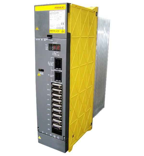
439 — n AXIS : CNV. OVERVOLT POWER
Alarm Description
1) PSM: The DC link voltage is too high. 2) PSMR: The DC link voltage is too high. 3) a series SVU: The C link voltage is too high. 4) b series SVU: The link voltage is too high.
Additional Suggestions & Alarm Clarification
None currently
Help Others
Post troubleshooting recommendations for (Fanuc alarm: 439 — n AXIS : CNV. OVERVOLT POWER) error message below.
- Log in to post comments
Fanuc Servo Amplifier Alarm 439 — n AXIS : CNV. OVERVOLT POWER
FANUC Alarm Codes >> FANUC Servo Amplifier Alarms >> Servo Amplifier Alarm 439
Description:
- PSM: The DC link voltage is too high.
- PSMR: The DC link voltage is too high.
- α series SVU: The C link voltage is too high.
- β series SVU: The link voltage is too high.

Nationwide FANUC Servo Alarm 439 Troubleshooting, Repairs & Replacement Service
Give Tri Star CNC a call and we’ll help you determine the source of the FANUC servo 439 error and find solutions ASAP. We offer FREE phone support (call 815-578-9145 now), competitive repair pricing, or quick turnaround on a replacement component from our exchange stock if necessary. If you need on-site support we can point you in the right direction through our field service network.
FANUC-GE Parts Exchange & Repair Warranty Information
Exchange FANUC parts and repaired parts include a 1-year warranty. Tri Star CNC, LLC warrants the COMPLETE ASSEMBLY REPAIR – not just the parts and labor.
Get more details on our FANUC warranty and please contact us for further CNC machine support.
|
|
Ремонт сервопривода Fanuc Alfa и Beta series

Сервисный центр «Кернел» предлагает выполнить качественный ремонт сервопривода Fanuc Alfa и Beta series в на компонентном уровне в максимально сжатые сроки.
Сервопривода относятся к сложной промышленной электронике именно поэтому ремонтом серводрайверов Fanuc Alfa и Beta series, впрочем, как и сервоприводов других производителей должны заниматься специалисты, имеющие не только высшее техническое образование, но и солидный опыт в ремонте подобной промышленной электроники.
Также для восстановления подобного промышленного оборудования понадобится хорошая материально-техническая база. При выполнении этих условий шансы на успешный ремонт сервопривода Fanuc Alfa и Beta series возрастают в геометрической прогрессии.
Именно поэтому за ремонтом сервоприводов Fanuc Alfa и Beta series или другого производителя лучше всего обращаться в специализированный сервисный центр, который отвечает всем техническим требованиям, такой как Кернел.
Наш цент имеет отличную материально-техническую ремонтную базу, а за время существования с 2002 года специалисты компании накопили бесценный опыт в том числе опыт в ремонте сервоприводов Fanuc Alfa и Beta series.
Инженеры сервисного центра выполняют качественный ремонт сервоприводов Fanuc всех серий, когда-либо выпускаемых компанией.
| Серия | Тип сервоусилителя |
|---|---|
|
Fanuc Alfa series Fanuc Beta series |
A06B-6111-H037#H550; A06B-6111-H030#H570/P; A06B-6111-H030#H553; A06B-6111-H030#H550#P; A06B-6111-H030#H550#C; A06B-6111-H026#H570; A06B-6111-H026#H553; A06B-6111-H026#H550#P; A06B-6111-H026#H550#C; A06B-6111-H022#H570/P; A06B-6111-H022#H553; A06B-6111-H022#H550/C; A06B-6164-H244#H580; A06B-6164-H312#H580; A06B-6164-H332#H580; A06B-6165-H201#H560; A06B-6165-H202#H560; A06B-6164-H201#H580; A06B-6165-H311#H560; A06B-6165-H312#H560; A06B-6165-H333#H560; A06B-6165-H343#H560; A06B-6166-H201; A06B-6166-H201#A; A06B-6058-H225; A06B-6200-H011; A06B-6089-H104; A06B-6117-H105; A06B-6114-H205; A06B-6114-H109; A06B-6166-H203; A06B-6050-H103; A06B-6127-H209; A06B-6102-H206#H520; A06B-6121-H006#H550; A06B-6140-H037; A06B-6134-H303#A; A06B-6088-H215; A06B-6082-H222; A06B-6064-H230; A06B-6044-H017; A06B-6064-H201#H520; A06B-6088-H245; A06B-6088-H222; A06B-6057-H204; A06B-6089-H207; A06B-6052-H004; A06B-6117-H208; A06B-6082-H215#H511; A06B-6082-H215#H510; A06B-6082-H211#H512; A06B-6082-H211#H511/EM; A06B-6082-H211#H510; A06B-6082-H206#H511; A06B-6082-H206#H510/EM; A06B-6082-H206#H510; A06B-6082-H202#H512; A06B-6082-H202#H511; A06B-6082-H202#H510; A06B-6080-H307; A06B-6059-H215#H545; A06B-6059-H215#H515; A06B-6059-H212#H759; A06B-6059-H212#H758; A06B-6059-H212#H757; A06B-6059-H212#H713; A06B-6059-H212#H712; A06B-6059-H212#H711; A06B-6059-H212#H611; A06B-6059-H212#H610; A06B-6059-H212#H601; A06B-6059-H212#H590; A06B-6045-H006; A06B-6045-H005; A06B-6045-H002; A06B-6045-H001; A06B-6045-C009; A06B-6045-C006; A06B-6045-C005; A06B-6044-H742; A06B-6044-H736; A06B-6044-H725; A06B-6044-H722; A06B-6044-H712 |
В данной таблице присутствуют далеко не все сервоприводы Fanuc Alfa и Beta series ремонт которых предлагает наш сервисный центр.
Особенности ремонта сервопривода Fanuc Alfa и Beta series
 Ремонт сервопривода Fanuc Alfa и Beta series имеет ряд индивидуальных особенностей, это связано с конструктивными особенностями сервоприводов. По аналогии частотными преобразователями, сервопривод состоит из двух частей, это:
- Аппаратная часть;
- Программная часть.
В первую очередь ремонтируется аппаратная часть промышленного сервопривода. После глубокой диагностики неисправного блока выявляются все неисправные компоненты, которые в последствии заменяются на оригинальные запасные части (по возможности), в случае если сервопривод уже давно снят с производства и найти оригинальные запчасти просто невозможно они заменяются на аналоги.
Данный вид ремонта называется компонентным. От других видов его отличает две немаловажные вещи.
- Значительное удешевление ремонта;
- Существенное сокращение времени ремонта.
По завершении ремонта аппаратной части сервопривода наступает очередь программной. В зависимости от серии выбирается программный продукт и зашивается в блок.
Заключительный этап ремонта сервопривода Fanuc Alfa и Beta series в это проверка на специализированном стенде, без нагрузки и с нагрузкой максимально приближенна к реальным условиям эксплуатации.
Ошибки сервоприводов Fanuc Alfa и Beta series
 В процессе работы выходит из строя даже самое надежное промышленное оборудование. В данной статье мы приведем ошибки сервоприводов Fanuc, а точнее Fanuc Alfa и Beta series. Привода в наше время, нашли широкое применение абсолютно во всех сферах промышленности, управляя как мини моторами в оргтехнике, так и гигантскими двигателями в горнодобывающей промышленности.
Для простоты общения со столь сложной электроникой все сервопривода оснащены небольшими дисплеями с помощью которых выводятся информационные сообщения с кодами ошибок, расшифровав которые можно сразу же узнать причину ее возникновения. Если учесть распространенность данной промышленной электроники, то появляется острая нужда в расшифровке кодов ошибок сервопривода. В этой статье мы рассмотрим одного из самых известных производителей промышленной электроники имеющему уважение во всем мире, Fanuc и севрво усилители Alfa и Beta series.
Существует несколько видов ошибок, некоторые из них можно устранить автоматически, а некоторые возможно исправить только, обратившись в специализированный сервисный центр. В таблицах ниже приведены коды ошибок сервоприводов Fanuc Alfa и Beta series и их расшифровка.
Fanuc Servo Amplifier Beta is 6130 сигналы тревоги (ошибки)
| Сигнал тревоги | Оисание |
|---|---|
|
SV0027 or 027 |
Неверная настройка параметров цифрового сервопривода |
|
SV0361 or 361 |
Фазовая ошибка импульсного кодера (встроенная) |
|
SV0364 or 364 |
Мягкая фазовая сигнализация (встроенная) |
|
SV0365 or 365 |
Светодиод ошибки (встроенный) |
|
SV0366 or 366 |
Импульсная ошибка (встроенная) |
|
SV0367 or 367 |
Ошибка подсчета (встроенная) |
|
SV0368 or 368 |
Ошибка серийных данных (встроенная) |
|
SV0369 or 369 |
Ошибка передачи данных (встроенная) |
|
SV0380 or 380 |
Ошибка светодиода (отдельно) |
|
SV0381 or 381 |
Фазовая ошибка импульсного кодера (отдельно) |
|
SV0382 or 382 |
Ошибка подсчета (отдельно) |
|
SV0383 or 383 |
Ошибка импульса (отдельно) |
|
SV0384 or 384 |
Мягкая фазовая сигнализация (отдельно) |
|
SV0385 or 385 |
Ошибка серийных данных (отдельно) |
|
SV0386 or 386 |
Ошибка передачи данных (отдельно) |
|
SV0387 or 387 |
Ошибка датчика (отдельно) |
|
SV0417 or 417 |
Неверный параметр |
|
SV0421 or 421 |
Чрезмерная полуполная ошибка |
|
SV0430 or 430 |
Серводвигатель перегревается |
|
SV0432 or 432 |
Преобразователь: управление пониженным напряжением питания |
|
SV0433 or 433 |
Преобразователь: пониженное напряжение в звене постоянного тока |
|
SV0436 or 436 |
Мягкая термальная (OVC) |
|
SV0438 or 438 |
Инвертор: аварийный сигнал тока двигателя |
|
SV0439 or 439 |
Преобразователь: перенапряжение в звене постоянного тока |
|
SV0440 or 440 |
Преобразователь: Чрезмерная мощность торможения |
|
SV0441 or 441 |
Текущая ошибка смещения |
|
SV0444 or 444 |
Инвертор: внутренний охлаждающий вентилятор остановлен или неисправна цепь |
|
SV0445 or 445 |
Сигнализация мягкого отключения |
|
SV0447 or 447 |
Сигнализация жесткого отключения (отдельно) |
|
SV0448 or 448 |
Сигнализация несоответствия обратной связи |
|
SV0449 or 449 |
Инвертор: тревога IPM |
|
SV0453 or 453 |
Сигнализация мягкого отключения (α Pulsecoder) |
|
SV0601 or 601 |
Инвертор: вентилятор охлаждения радиатора остановился |
|
SV0603 or 603 |
Инвертор: Аварийный сигнал IPM (OH) |
Fanuc Servo Amplifier 400 Коды аварийных сигналов
| Код ошибки | Сообщение | Описание |
|---|---|---|
|
400 |
SERVO ALARM: n–TH AXIS OVERLOAD |
Сигнал перегрузки оси n (оси 1–8) включен. Подробную информацию см. на диагностическом дисплее № 201, 720 или 721. |
|
401 |
SERVO ALARM: n–TH AXIS VRDY OFF |
Сработал сигнал ГОТОВНОСТИ (DRDY) сервоусилителя n-й оси (оси 1–8). |
|
402 |
SERVO ALARM 3, 4TH AXIS OVERLOAD |
3-осевой, 4-осевой сигнал перегрузки включен. Подробную информацию см. на диагностическом дисплее 722 или 723. |
|
404 |
SERVO ALARM: n–TH AXIS VRDY ON |
Несмотря на то, что сигнал ГОТОВНОСТИ (MCON) оси n (оси 1–8) был отключен, сигнал ГОТОВНОСТИ сервоусилителя (DRDY) все еще включен. Или, когда питание было включено, DRDY включился, хотя MCON был выключен. Убедитесь, что интерфейсный модуль сервопривода и сервоусилитель подключены. |
|
405 |
SERVO ALARM: (ZERO POINT RETURN FAULT) |
Ошибка системы управления положением. Из-за ошибки ЧПУ или сервосистемы при возврате в референтную позицию существует вероятность того, что возврат в референтную позицию не может быть выполнен правильно. Повторите попытку из ручного возврата в референтную позицию. |
|
407 |
SERVO ALARM: EXCESS ERROR |
Разница в отклонении положения синхронной оси превысила установленное значение. |
|
409 |
SERVO ALARM: n AXIS TORQUE ALM |
Обнаружена аномальная нагрузка серводвигателя. Кроме того, в режиме Cs была обнаружена аномальная нагрузка на двигатель шпинделя. |
|
410 |
SERVO ALARM: n–TH AXIS – EXCESS ERROR |
Значение отклонения положения при остановке n–й оси (оси 1–8) больше установленного значения. |
|
411 |
SERVO ALARM: n–TH AXIS – EXCESS ERROR |
Значение отклонения положения при перемещении n–й оси (оси 1–8) больше заданного значения. |
|
413 |
SERVO ALARM: n–th AXIS – LSI OVERFLOW |
Содержимое регистра ошибок для n-й оси (оси 1–8) превышало 231 степень. Эта ошибка обычно возникает в результате неправильно заданных параметров. |
|
414 |
SERVO ALARM: n–TH AXIS – DETECTION RELATED ERROR |
Неисправность цифровой сервосистемы N–й оси (оси 1–8). Подробности см. в диагностическом дисплее № 200 и № 204. Также посмотрите на сервоусилитель для кода тревоги. |
|
415 |
SERVO ALARM: n–TH AXIS – EXCESS SHIFT |
Была предпринята попытка задать скорость выше 511875 ед/с по оси n–th (оси 1–8). Эта ошибка возникает в результате неправильно настроенного CMR. |
|
416 |
SERVO ALARM: n–TH AXIS – DISCONNECTION |
Неисправность системы определения положения импульсного шифратора n–й оси (оси 1–8) (сигнализация отключения). Подробности см. на дисплее диагностики № 201. |
|
417 |
SERVO ALARM: n–TH AXIS – PARAMETER INCORRECT |
Этот аварийный сигнал возникает, когда n–я ось (ось 1–8) находится в одном из состояний, перечисленных ниже. (Аварийный сигнал цифровой сервосистемы)
Если вы хотите использовать этот усилитель, сбросьте функциональный бит 2209#4 на 0. Если вы хотите использовать функцию предотвращения тревоги HC, используйте усилитель, который ее поддерживает. |
|
420 |
SERVO ALARM: n AXIS SYNC TORQUE (M series) |
При простом синхронном управлении разница между командами крутящего момента для ведущей и ведомой осей превысила значение, установленное в параметре № 2031. |
|
421 |
SERVO ALARM: n AXIS EXCESS ER (D) |
Разница между ошибками в полузамкнутом контуре и замкнутом контуре стала чрезмерной во время двойной обратной связи по положению. Проверьте значения коэффициентов преобразования двойной позиции в параметрах № 2078 и 2079. |
|
422 |
SERVO ALARM: n AXIS |
При управлении крутящим моментом управления осью PMC превышена заданная допустимая скорость. |
|
423 |
SERVO ALARM: n AXIS |
При управлении крутящим моментом управления осями PMC было превышено заданное параметром допустимое совокупное расстояние перемещения. |
|
430 |
n AXIS : SV. MOTOR OVERHEAT |
Произошел перегрев серводвигателя. |
|
431 |
n AXIS : CNV. OVERLOAD |
|
|
432 |
n AXIS : CNV. LOWVOLT CON. |
|
|
434 |
n AXIS : INV. LOWVOLT CONTROL |
SVM: Напряжение питания системы управления упало. |
|
435 |
n AXIS : INV. LOWVOLT DC LINK |
SVM: Напряжение в звене постоянного тока упало. |
|
436 |
n AXIS : SOFTTHERMAL (OVC) |
Программное обеспечение цифрового сервопривода обнаружило мягкое тепловое состояние (OVC). |
|
437 |
n AXIS : CNV. OVERCURRENT POWER |
PSM: Перегрузка по току во входную цепь. |
|
438 |
n AXIS : INV. ABNORMAL CURRENT |
|
|
439 |
n AXIS : CNV. OVERVOLT POWER |
|
|
440 |
n AXIS : CNV. EX DECELERATION POWER |
|
|
441 |
n AXIS : ABNORMAL CURRENT OFFSET |
Программное обеспечение цифрового сервопривода обнаружило неисправность в цепи обнаружения тока двигателя. |
|
442 |
n AXIS : CNV. CHARGE FAILURE |
|
|
443 |
n AXIS : CNV. COOLING FAN FAILURE |
|
|
444 |
n AXIS : INV. COOLING FAN FAILURE |
SVM: Отказ внутреннего вентилятора охлаждения. |
|
445 |
n AXIS : SOFT DISCONNECT ALARM |
Программное обеспечение цифрового сервопривода обнаружило обрыв провода в импульсном кодере. |
|
446 |
n AXIS : HARD DISCONNECT ALARM |
Обрыв провода во встроенном импульсном кодере был обнаружен аппаратно. |
|
447 |
n AXIS : HARD DISCONNECT (EXT) |
Обрыв провода в отдельном детекторе был обнаружен аппаратно. |
|
448 |
n AXIS : UNMATCHED FEEDBACK ALARM |
Знак данных обратной связи от встроенного импульсного кодера отличается от знака данных обратной связи от отдельного детектора. |
|
449 |
n AXIS : INV. IPM ALARM |
|
|
453 |
n AXIS : SPC SOFT DISCONNECT ALARM |
Программная сигнализация об отключении импульсного кодера α. Отключите питание ЧПУ, затем отсоедините и вставьте кабель импульсного кодера. Если этот аварийный сигнал появляется снова, замените импульсный шифратор. |
|
456 |
ILLEGAL CURRENT LOOP |
Текущие настройки цикла управления (параметр № 2004, бит 0 параметра № 2003 и бит 0 параметра № 2013) неверны. Возможные проблемы следующие.
|
|
457 |
ILLEGAL HI HRV (250US) |
Использование высокоскоростного HRV указано, хотя текущий цикл управления составляет 200 мкс. |
|
458 |
CURRENT LOOP ERROR |
Текущая настройка цикла управления не соответствует фактическому текущему циклу управления. |
|
459 |
HI HRV SETTING ERROR |
Из двух осей, имеющих соседние номера сервоосей (параметр № 1023), нечетные и четные номера, высокоскоростное управление HRV может выполняться для одной оси, а не для другой. |
|
460 |
n AXIS : FSSB DISCONNECT |
Связь с ФСБ внезапно прервалась. Возможные причины следующие:
|
|
461 |
n AXIS : ILLEGAL AMP INTERFACE |
Оси 2-х осевого усилителя были отнесены к интерфейсу быстрого типа. |
|
462 |
n AXIS : SEND CNC DATA FAILED |
Из-за ошибки связи FSSB ведомое устройство не могло получить правильные данные. |
|
463 |
n AXIS : SEND SLAVE DATA FAILED |
Из-за ошибки связи FSSB ведомое устройство не могло получить правильные данные. |
|
464 |
n AXIS : WRITE ID DATA FAILED |
Была предпринята попытка записать информацию об обслуживании на экране обслуживания усилителя, но она не удалась. |
|
465 |
n AXIS : READ ID DATA FAILED |
При включении питания исходная идентификационная информация усилителя не может быть считана. |
|
466 |
n AXIS : MOTOR/AMP COMBINATION |
Максимальный номинальный ток усилителя не соответствует номинальному току двигателя. |
|
467 |
n AXIS : ILLEGAL SETTING OF AXIS |
Функция сервопривода для следующего не была включена, когда ось, занимающая один DSP (соответствующий двум обычным осям), указана на экране настройки оси.
|
|
468 |
HI HRV SETTING ERROR(AMP) |
Использование высокоскоростной HRV указано для управляемой оси усилителя, которая не поддерживает высокоскоростную HRV. |
Для более длительной безаварийной работы промышленного оборудования должны соблюдаться все рекомендации, изложенные в инструкции по монтажу и настройке сервопривода.
Сервопривод Fanuc Alfa и Beta series, скачать инструкции по эксплуатации
Ниже вы можете скачать руководства по эксплуатации сервоприводов Fanuc Alfa и Beta series для практически всех серий, когда-либо выпущенных данным производителем.
Преимущество ремонта сервоприводов в нашем сервисном центре

- Предварительный осмотр на возможность восстановления бесплатный;
- Мы производим ремонт сервопривода Fanuc Alfa и Beta series в на компонентном уровне (экономия бюджета и времени)
- При ремонте ни каких конструктивных изменений не вносим;
- Ремонт блоков с применением оригинальных запасных частей (по возможности).
- Вы платите исключительно за результат — работающий сервопривод;
- Гарантия на ремонт сервопривода Fanuc Alfa и Beta series и запасные части, замененные в процессе ремонта 6 месяцев;
- Сроки ремонта варьируются от 5 до 15 рабочих дней;
За два десятилетия существования сервисного центра нашими специалистами были успешно проведены тысячи подобных ремонтов с каждым разом поднимая квалификацию наших инженеров.В случае выхода из строя промышленного сервопривода на вашем производстве либо появились проблемы с приводом, которые вы не можете решить самостоятельно, мы всегда рады вам помочь. Специалисты нашего сервисного центра в минимальные сроки проведут глубокую диагностику и последующий ремонт сервопривода Fanuc Alfa и Beta series в .
Схемы подключения серво привода Fanuc Alfa series
В некоторых случает может понадобится схема подключения сервоприводов, ниже мы показаны схемы сервопривода Fanuc Alfa series
|
Блок-схема подключения сервопривода Fanuc Alfa series SVMl-240,360 — вариант (А) |
Блок-схема подключения сервопривода Fanuc Alfa series SVMl-240,360 — вариант (В) |
|
|

|

Оставить заявку на ремонт сервопривода Fanuc Alfa и Beta series
У вас есть проблемы с приводом? Вам нужен срочный ремонт, сброс ошибок или программирование и настройка? Оставьте заявку на ремонт сервопривода Fanuc Alfa и Beta series в воспользовавшись одноименной кнопкой на сайте либо обратитесь к нашим менеджерам. Связаться с ними можно несколькими способами:

- Заказав обратный звонок (кнопка в правом нижнем углу сайта)
- Посредством чата (кнопка расположена с левой стороны сайта)
- Позвонив по номеру телефона:
- +7(8482) 79-78-54;
- +7(8482) 55-96-39;
- +7(917) 121-53-01
- Написав на электронную почту: 89171215301@mail.ru
- В начало статьи
Вот далеко не полный список производителей промышленного оборудования, ремонт которого производит наша компания.
Номер
Сообщение
Описание
0001
ОШИБКА TH
Во время считывания с устройства ввода обнаружена ошибка TH. Код, вызвавший при считывании ошибку TH, и количество операторов до него от блока можно проверить в окне диагностики.
0002
ОШИБКА TV
Ошибка TV обнаружена в единичном блоке.
Проверка TV может быть отменена присвоением TVC в параметре ном. 0000#0 значения «0».
0003
СЛИШКОМ МНОГО ЗНАКОВ
Данные введены с большим количеством символов, чем разрешено для оператора ЧПУ. Количество допустимых символов варьируется в зависимости от функции и слова.
0004
АДРЕС НЕ НАЙДЕН
Адрес слов(а) ЧПУ + числовое значение не соответствуют формату слова. Данный сигнал тревоги выдается также, если пользовательская макрокоманда не содержит зарезервированного слова или не соответствует синтаксису.
0005
ОТСУТСТВУЮТ ДАННЫЕ ПОСЛЕ АДРЕСА
Адрес слов(а) ЧПУ + числовое значение не соответствуют формату слова. Данный сигнал тревоги выдается также, если пользовательская макрокоманда не содержит зарезервированного слова или не соответствует синтаксису.
0006
НЕВЕРНОЕ ИСПОЛЬЗОВАНИЕ ЗНАКА МИНУС
Знак минус (-) был задан в команде ЧПУ или в системной переменной, где задание знак минус не разрешено.
0007
НЕВЕРНОЕ ИСПОЛЬЗОВАНИЕ ДЕСЯТИЧНОЙ ТОЧКИ
Десятичная точка (.) была задана в адресе, где нельзя задать десятичную точку, либо были заданы две десятичные точки.
0009
НЕВЕРНЫЙ АДРЕС ЧУ
Был задан неверный адрес, либо не задан параметр 1020.
0010
НЕВЕРНЫЙ G-КОД
Задан неиспользуемый G-код.
0011
НУЛЕВАЯ ПОДАЧА (КОМАНДА)
Скорость подачи резания, предписанная F кодом, была задана равной 0. Данный сигнал тревоги порождается также, если задан чрезвычайно малый F-код, предписанный для S-кода в команде жесткого нарезания резьбы, так как инструмент не может нарезать при заданном шаге.
0015
СЛИШКОМ МНОГО ОСЕЙ ОДНОВРЕМЕННО
Команда перемещения была задана для большего числа осей, чем доступно для функции одновременного управления осями.
Либо разделите запрограммированные оси перемещения на два блока.
0020
ПРЕВЫШЕНИЕ ДОПУСКА ПО РАДИУСУ
Была задана дуга, для которой разность по радиусу в начальной и конечной точках превышает значение, заданное в параметре ном. 3410. Проверьте коды центра дуги I, J и K в программе. Траектория инструмента, если в параметре ном. 3410 задано большое значение, представляет собой спираль.
0021
НЕВЕРНЫЙ ВЫБОР ПЛОСКОСТИ
Команды выбора плоскости с G17 по G19 ошибочны. Перепрограммируйте так, чтобы те же 3 основные параллельные оси не были заданы одновременно.
Этот сигнал тревоги порождается также, если задана ось, которая не должна быть указана для обработки плоскости, например, для круговой интерполяции.
Для 0i -TD опция винтовой интерполяции необходима для активации спецификации 3 или более осей для блока G02/G03.
0022
НЕ ОБНАРУЖЕНА КОМАНДА R ИЛИ I, J, K
В команде круговой интерполяции отсутствует радиус дуги R или координата I, J или K расстояния между начальной точкой и центром дуги.
0023
НЕВЕРНАЯ КОМАНДА РАДИУСА
Для команды радиуса дуги R задано отрицательное значение. В серии T дуга с углом более 180° не может быть задана посредством команды R. Измените программу.
0025
КРУГОВОЕ РЕЗАНИЕ В УСКОРЕННОМ РЕЖИМЕ (F0)
F0 (ускоренный подвод при подаче с однозначным F-кодом или обратной подаче) был задан во время круговой интерполяции (G02, G03).
0027
НЕ ЗАДАНЫ ОСИ В G43/G44
Не заданы оси в блоках G43 и G44 для коррекции на длину инструмента типа С.
Коррекция не отменена, но другая ось смещена для коррекции на длину инструмента типа С.
Несколько осей задано для одного блока, когда тип коррекции на длину инструмента — C.
0028
НЕВЕРНЫЙ ВЫБОР ПЛОСКОСТИ
Команды выбора плоскости с G17 по G19 ошибочны. Перепрограммируйте так, чтобы те же 3 основные параллельные оси не были заданы одновременно. Этот сигнал тревоги порождается также, если задана ось, которая не должна быть указана для обработки плоскости, например, для круговой интерполяции.
Для 0i -TD опция винтовой интерполяции необходима для активации спецификации 3 или более осей для блока G02/G03.
0029
НЕВЕРНАЯ ВЕЛИЧИНА КОРРЕКЦИИ
Коррекция с неверным номером
0030
НЕВЕРНЫЙ НОМЕР КОРРЕКЦИИ
Был задан неверный номер коррекции.
0031
НЕВЕРНАЯ КОМАНДА Р В G10
Ввод данных для ном. L команды G10 или соответствующей функции не активирован. Не задан адрес настройки данных, например, P или R. Была задана команда адреса, не связанная с настройкой данных. Адрес меняется вместе с номером L.
Знак или десятичная запятая заданного адреса ошибочны, или заданный адрес находится за пределами диапазона.
0032
НЕВЕРНАЯ ВЕЛИЧИНА КОРРЕКЦИИ В G10
При установке величины коррекции с помощью G10 или при записи величины коррекции с помощью системных переменных величина коррекции оказалась избыточной.
0033
НЕТ ПЕРЕСЕЧЕНИЯ ПРИ КОРРЕКЦИИ НА РЕЖУЩИЙ ИНСТРУМЕНТ
Нет пересечения при расчете пересечения для коррекции на радиус инструмента/на радиус вершины инструмента. Измените программу.
0034
КРУГОВОЕ ДВИЖЕНИЕ В БЛОКЕ ЗАПУСКА/ВЫХОДА ЗАПРЕЩЕНО
При коррекции на радиус инструмента / на радиус вершины инструмента запуск или отмена выполняются в режиме G02 или G03. Измените программу.
0035
НЕЛЬЗЯ ЗАДАТЬ G31
1) Нельзя задать G31. Этот сигнал тревоги генерируется, если не отменен G-код (например, для коррекции на радиус инструмента / на радиус вершины инструмента) группы 07.
2) Пропуск по пределу крутящего момента не был задан в команде пропуска по пределу крутящего момента (G31P98 или P99). Задайте пропуск по пределу крутящего момента в окне РМС или другим способом.
0037
НЕВОЗМОЖНО ИЗМЕНИТЬ ПЛОСКОСТЬ В G41/G42
Плоскость коррекции G17/G18/G19 была изменена в ходе коррекции на режущий инструмент или на радиус вершины инструмента. Измените программу.
0038
СТОЛКНОВЕНИЕ В БЛОКЕ КРУГОВОГО ПЕРЕМЕЩЕНИЯ
Зарез происходит при коррекции на радиус инструмента / на радиус вершины инструмента, так как начальная или конечная точки дуги совпадают с центром дуги. Измените программу.
0039
CHF/CNR НЕ РАЗРЕШЕНЫ В G41, G42
Снятие фаски или скругление угла R заданы при запуске, отмене или переключении между G41 и G42 в командах G41 и G42 (коррекция на радиус вершины инструмента). Программа может привести к зарезу при снятии фаски или скруглении угла. Измените программу.
0041
СТОЛКНОВЕНИЕ ПРИ КОРРЕКЦИИ НА РЕЖУЩИЙ ИНСТРУМЕНТ
При коррекции на радиус инструмента / на радиус вершины инструмента возможно избыточное резание. Измените программу.
0042
G45/G48 НЕ РАЗРЕШЕНЫ ПРИ CRC
Смещение инструмента (от G45 до G48) задано в режиме коррекции на радиус инструмента. Измените программу.
0044
G27-G30 НЕ ДОПУСКАЮТСЯ ПРИ ФИКСИРОВАННОМ ЦИКЛЕ
Одна из команд от G27 до G30 (G29 только для серии M) задана в режиме постоянного цикла. Измените программу.
0045
НЕ НАЙДЕН АДРЕС Q (G73/G83)
В цикле скоростного сверления с периодическим выводом или в цикле сверления с периодическим выводом величина реза за раз не задается адресом Q, либо задано Q0. Измените программу.
0046
НЕВЕРНАЯ КОМАНДА ВОЗВРАТА НА РЕФЕРЕНТНУЮ ПОЗИЦИЮ
Ошибка команды возврата во вторую, третью или четвертую референтную позицию. (Ошибка команды P-адреса.)
0050
ЗАПРЕЩЕНО СНЯТИЕ ФАСКИ/ СКРУГЛЕНИЕ УГЛА В БЛОКЕ НАРЕЗАНИЯ РЕЗЬБЫ
Блок снятия фаски или скругления угла задан в блоке нарезания резьбы. Измените программу.
0051
НЕТ ПЕРЕМЕЩЕНИЯ ПОСЛЕ СКРУГЛЕНИЯ УГЛА / СНЯТИЯ ФАСКИ
Неверное перемещение или расстояние перемещения в блоке, идущем за снятием фаски или скруглением угла. Измените программу.
0052
КОД ПОСЛЕ СНЯТИЯ ФАСКИ/СКРУГЛЕНИЯ УГЛА НЕ G01
Блоком, следующим за блоком снятия фаски или блоком скругления угла, является не блок G01 (или вертикальная линия). Измените программу.
0053
СЛИШКОМ МНОГО АДРЕСНЫХ КОМАНД
В командах снятия фаски или скругления угла задано два или более I, J, K и R.
0054
ОБРАБОТКА КОНУСА ПОСЛЕ СНЯТИЯ ФАСКИ/ СКРУГЛЕНИЯ УГЛА НЕ РАЗРЕШЕНА
Блок, в котором задано снятие фаски под заданным углом или скругление угла, включает команду обработки конической поверхности. Измените программу.
0055
ОТСУТСТВУЕТ ВЕЛИЧИНА ПЕРЕМЕЩЕНИЯ ПРИ СНЯТИИ ФАСКИ/ СКРУГЛЕНИИ УГЛА
Расстояние перемещения по оси, заданное в блоке, содержащем снятие фаски или скругление угла, меньше, чем величина снятия фаски или скругления угла. Измените программу.
0056
ОТСУТСТВУЮТ КОНЕЧНАЯ ТОЧКА И УГОЛ ПРИ СНЯТИИ ФАСКИ/ СКРУГЛЕНИИ УГЛА
При прямом программировании размеров чертежа и конечная точка, и угол были заданы в блоке, следующим за блоком, в котором был задан только угол (Aa). Измените программу.
0057
НЕТ РЕШЕНИЯ КОНЦА БЛОКА
В программировании непосредственно по размерам чертежа неверно вычислена конечная точка блока. Измените программу.
0058
НЕ НАЙДЕНА КОНЕЧНАЯ ТОЧКА
В программировании непосредственно по размерам чертежа не найдена конечная точка блока. Измените программу.
0060
НЕ НАЙДЕН ПОРЯДКОВЫЙ НОМЕР
[Внешний ввод данных/вывод данных]
Заданный номер не найден при поиске по номеру программы и по порядковому номеру.
Был выдан запрос на ввод/выод для величины коррекции для данных инструмента, но номер инструмента после включения питания не вводился. Данные инструмента, соответствующие введенному номеру инструмента, не найдены.
[Поиск номера внешней заготовки]
Программа, соответствующую заданной заготовке, не найдена. [Перезапуск программы]
В спецификации порядкового номера перезапуска программы не найден заданный порядковый номер.
0061
КОМАНДА P ИЛИ Q ОТСУТСТВУЕТ В БЛОКЕ МНОГОКРАТНО ПОВТОРЯЕМЫХ ЦИКЛОВ
Не задан адрес Р или Q в команде многократно повторяемого цикла (G70, G71, G72 или G73).
0062
ВЕЛИЧИНА РЕЗАНИЯ НЕВЕРНА В ЦИКЛЕ ЧЕРНОВОГО РЕЗАНИЯ
Был задан ноль или отрицательное значение многократно повторяемого цикла черновой обработки резанием (G71 или G72) в качестве глубины реза.
0063
НЕ НАЙДЕН БЛОК ЗАДАННОГО НОМЕРА ПОСЛЕДОВАТЕЛЬНОСТИ
Не найден порядковый номер, заданный адресами P и Q в команде многократно повторяемого цикла (G70, G71, G72 или G73).
0064
ФОРМА ЧИСТОВОЙ ОБРАБОТКИ НЕ ИЗМЕНЯЕТСЯ МОНОТОННО (ПЕРВЫЕ ОСИ)
В программе чистовой обработки для многократно повторяемого цикла черновой обработки резанием (G71 или G72) команда для первой оси плоскости задавала монотонное увеличение или уменьшение.
0065
G00/G01 НЕ ЯВЛЯЕТСЯ ПЕРВЫМ БЛОКОМ ПРОГРАММЫ ОБРАБОТКИ ФОРМЫ
В первом блоке программы обработки формы, задаваемый P многократно повторяемый стандартный цикл (G70, G71, G72 или G73), G00 или G01 не был заданы.
0066
НЕДОСТУПНАЯ КОМАНДА В БЛОКЕ МНОГОКРАТНО ПОВТОРЯЕМЫХ ЦИКЛОВ
Недоступная команда была обнаружена в командном блоке многократно повторяемых циклов (G70, G71, G72 или G73).
0067
МНОГОКРАТНО ПОВТОРЯЕМЫЕ ЦИКЛЫ НЕ НАХОДЯТСЯ В ПАМЯТИ ПРОГРАММЫ ОБРАБОТКИ ДЕТАЛЕЙ
Команда многократно повторяемого постоянного цикла (G70, G71, G72, или G73) не зарегистрирована в области памяти на магнитных лентах.
0069
ПОСЛЕДНИЙ БЛОК ПРОГРАММЫ ОБРАБОТКИ ФОРМЫ ЯВЛЯЕТСЯ НЕВЕРНОЙ КОМАНДОЙ
В программе чистовой обработки в многократно повторяемом цикле черновой обработки резанием (G70, G71, G72 или G73) команда снятия фаски или скругления угла R в последнем блоке прерывается на середине.
0070
В ПАМЯТИ ОТСУТСТВУЕТ МЕСТО ДЛЯ ПРОГРАММЫ
Недостаточно памяти.
Удалите ненужные программы и повторите попытку.
0071
ДАННЫЕ НЕ НАЙДЕНЫ
1) Не найден адрес по запросу.
2) При поиске по номеру программы не найдена программа с заданным номером.
3) В спецификации номера блока перезапуска программы не найден заданный номер блока.
Проверьте данные.
0072
ДАННЫЕ НЕ НАЙДЕНЫ
Число программ для хранения превысило 400 (одноконтурная система) или 800 (двухконтурная система серии T). Удалите ненужные программы и выполните регистрацию программы снова.
0073
НОМЕР ПРОГРАММЫ УЖЕ ИСПОЛЬЗУЕТСЯ
Заданный номер программы уже используется. Измените номер программы или удалите ненужные программы и выполните регистрацию программы снова.
0074
НОМЕР ПРОГРАММЫ УЖЕ ИСПОЛЬЗУЕТСЯ
Номер программы не входит в диапазон от 1 до 9999. Измените номер программы.
0075
ЗАЩИТА
Сделана попытка зарегистрировать программу, номер которой защищен. При согласовании программы был неверно введен пароль для защищенной программы. Была предпринята попытка выбора программы, редактируемой в фоновом режиме, в качестве главной программы. Была предпринята попытка вызова программы, редактируемой в фоновом режиме, в качестве подпрограммы.
0076
ПРОГРАММА НЕ НАЙДЕНА
Заданная программа не найдена при вызове подпрограммы или вызове макрокоманды. Коды M, G, T или S вызываются командой P, отличной от команды в M98, M198, G65, G66 или пользовательской макропрограммы типа прерывания, а программа вызывается специальным адресом. Данный сигнал тревоги также порождается, если программа не найдена при данных вызовах.
0077
СЛИШКОМ МНОГО ВЛОЖЕННЫХ ПОДПРОГРАММ, МАКРОПРОГРАММ
Общее число вызовов подпрограмм и пользовательских макрокоманд превышает допустимый диапазон. Во время подпрограммы из внешней памяти был выполнен вызов подпрограммы.
0078
НЕ НАЙДЕН ПОРЯДКОВЫЙ НОМЕР
Заданный порядковый номер не был найден при поиске по порядковому номеру. Не найден порядковый номер, заданный в переходном пункте назначения в GOTO— и M99P—.
0079
НЕСООТВЕТСТВИЕ ПРОГРАММ
Программа в памяти не соответствует программе, хранящейся на ленте. Несколько программ не подлежат непрерывному согласованию, если параметр ном. 2200#3 имеет значение «1». Задайте в параметре ном. 2200#3 значение «0» перед выполнением сопоставления.
0080
НЕПРАВИЛЬНО ВВЕДЕН СИГНАЛ ДОСТИЖЕНИЯ ПОЛОЖЕНИЯ ИЗМЕРЕНИЯ G37
Если выполняется функция измерения длины инструмента (G37), сигнал достижения положения измерения доходит до 1 во фронтальной части, определенной значением £, заданным в параметре ном.6254. Как альтернатива, сигнал не доходит до 1.
Если используется функция автоматической коррекции на инструмент (G36, G37), сигналы достижения положения измерения (XAE1, XAE2) не доходят до 1 в диапазоне, определенном значением £, заданном в параметрах ном.6254 и ном.6255.
0081
НОМ. КОРРЕКЦИИ G37 НЕ ЗАДАН
Функция измерения длины инструмента (G37) задана без задания H кода. Исправьте программу.
Функция автоматической коррекции ни инструмент (G36, G37) задана без задания Т кода. Исправьте программу.
0082
G37 ЗАДАНО С Н-КОДОМ
Функция измерения длины инструмента (G37) задано вместе с Н кодом в том же блоке.
Исправьте программу.
Функция автоматической коррекции на инструмент (G37) задана в одном блоке с Т-кодом.
Исправьте программу.
0083
НЕВЕРНАЯ КОМАНДА ОСИ G37
Была обнаружена ошибка в спецификации оси функции измерения длины инструмента (G37). Как альтернатива, задана команда перемещения как команда приращения. Исправьте программу.
Была обнаружена ошибка в спецификации оси функции автоматической коррекции на инструмент (G36, G37). Как альтернатива, задана команда перемещения как команда приращения.
Исправьте программу.
0085
ОШИБКА ПЕРЕПОЛНЕНИЯ
Следующий символ был получен от устройства ввода/вывода, подключенного к интерфейсу считывающего перфоратора 1 до того, как он смог считать полученный предварительно символ. Переполнение, ошибка четности или ошибка кадрирования возникли во время считывания интерфейсом устройства считывания/вывода на перфоленту 1. Неверны число битов введенных данных, настройка скорости передачи данных в бодах или номер спецификации устройства ввода/вывода.
0086
DR ОТКЛ.
В ходе процесса ввода/вывода интерфейсом считывания/вывода не перфоленту 1 сигнал готовности ввода набора данных устройства ввода/вывода (DR) был отключен. Возможными причинами являются не включение устройства ввода/вывода, порванный кабель и дефектная печатная плата.
0087
ПЕРЕПОЛНЕНИЕ БУФЕРА
В ходе считывания интерфейс считывающего перфоратора 1, хотя и была дана команда остановки считывания, была введено более 10 символов. Устройство ввода/вывода или печатная плата были дефектными.
0090
НЕ ЗАВЕРШЕН ВОЗВРАТ НА РЕФЕРЕНТНУЮ ПОЗИЦИЮ
1) Нельзя выполнить возврат на референтную позицию обычным образом, поскольку начальная точка возврата на референтную позицию расположена слишком близко к референтному положению, или скорость слишком низкая. Переместите начальную точку от референтной позиции на достаточное расстояние или задайте достаточно высокую скорость для выполнения возврата на референтную позицию.
2) Была попытка задать нулевое положение для детектора абсолютного положения с помощью возврата на референтную позицию, если необходимо задать нулевую точку.
Проверните двигатель вручную минимум на один оборот и установите нулевое положение датчика абсолютного положения, отключив и снова включив ЧПУ и сервоусилитель.
0091
РУЧНОЙ ВОЗВРАТ НА РЕФЕРЕНТНУЮ ПОЗИЦИЮ НЕ ВЫПОЛНЕН ПРИ ОСТАНОВЕ ПОДАЧИ
Невозможно выполнить ручной возврат на референтную позицию, когда автоматическая операция приостановлена. Выполните ручной возврат на референтную позицию, когда автоматическая операция остановлена или сброшена.
0092
ОШИБКА ПРОВЕРКИ ВОЗВРАТА К НАЧАЛУ КООРДИНАТ (G27)
Ось, заданная в G27, не вернулась на референтную позицию. Перепрограммируйте, чтобы ось вернулась на референтную позицию.
0094
ЗАПРЕЩЕН ТИП Р (ИЗМЕНЕНИЕ КООРДИНАТ)
При повторном пуске программы тип Р задать нельзя. (После прерывания автоматической работы выполнена операция установки системы координат). Выполните надлежащую операцию в соответствии с руководством пользователя.
0095
ЗАПРЕЩЕН ТИП Р (ИЗМЕНЕНИЕ ВНЕШНЕГО СМЕЩЕНИЯ)
При повторном пуске программы тип Р задать нельзя. (После прерывания автоматической работы изменена величина внешней коррекции начала координат заготовки). Выполните надлежащую операцию в соответствии с руководством пользователя.
0096
ЗАПРЕЩЕН ТИП Р (ИЗМЕНЕНИЕ СМЕЩЕНИЯ ЗАГОТОВКИ)
При повторном пуске программы тип Р задать нельзя. (После прерывания автоматической работы изменена величина коррекции начала координат заготовки). Выполните надлежащую операцию в соответствии с руководством пользователя.
0097
ЗАПРЕЩЕН ТИП Р (АВТОМАТИЧЕСКОЕ ВЫПОЛНЕНИЕ)
Нельзя указать тип Р при повторном пуске программы. (После включения питания, после аварийного останова или сброса сигналов тревоги 0094 — 0097 автоматическая операция не выполняется). Выполните автоматическую операцию.
0099
ИСПОЛН. MDI НЕ ДОПУСКАЕТСЯ ПОСЛЕ ПОИСКА
После завершения поиска при перезапуске программы с помощью MDI дана команда перемещения.
0109
ОШИБКА ФОРМАТА В G08
В коде G08 после Р задано значение, отличное от 0 или 1, или не задано значение.
0110
ПЕРЕПОЛНЕНИЕ: ЦЕЛАЯ ЧАСТЬ
Целая часть числа вышла за пределы диапазона при арифметических вычислениях.
0111
ПЕРЕПОЛНЕНИЕ: ПЛАВАЮЩ.
Десятичная точка (числовые данные в формате с плавающей точкой) вышла за пределы диапазона при арифметических вычислениях.
0112
ДЕЛЕНИЕ НА НОЛЬ
Была сделана попытка деления на ноль в пользовательской макрокоманде.
0113
НЕВЕРНАЯ КОМАНДА
Запрограммирована функция, которую нельзя использовать в макрокоманде пользователя. Измените программу.
0114
НЕВЕРНЫЙ ФОРМАТ ВЫРАЖЕНИЯ
Формат, используемый в выражении в пользовательском макрооператоре, ошибочный. Ошибка формата записи параметра.
0115
НОМЕР ПЕРЕМЕННОЙ ВНЕ ДИАПАЗОНА
Номер, который нельзя использовать для локальной переменной, общей переменной или системной переменной, заданный в пользовательской макрокоманде.
0116
ПЕРЕМЕННАЯ С ЗАЩИТОЙ ОТ ЗАПИСИ
Была произведена попытка использовать в пользовательской макрокоманде на левой стороне выражение переменной, что можно использовать на правой стороне выражения.
0118
СЛИШКОМ МНОГО ВЛОЖЕНИЙ В СКОБКИ
Слишком много скобок»[ ]» вложено в пользовательской макрокоманде. Уровень вложения, включая функциональные скобки, равен 5.
0119
ЗНАЧЕНИЕ АРГУМЕНТА ВНЕ ДИАПАЗОНА
Значение аргумента функции пользовательской макрокоманды находится вне диапазона.
0122
СЛИШКОМ МНОГО ВЛОЖЕНИЙ МАКРОКОМАНД
В пользовательскую макрокоманду было вложено слишком много вызовов макрокоманд.
0123
НЕВЕРНЫЙ РЕЖИМ ДЛЯ GOTO/WHILE/DO
Оператор GOTO или оператор WHILE-DO обнаружен в главной программе в режиме MDI или прямого ЧПУ.
0124
ОТСУТСТВУЕТ КОНЕЧНЫЙ ОПЕРАТОР
Команда END, соответствующая команде DO, отсутствовала в пользовательской макрокоманде^
0125
ОШИБКА ФОРМАТА МАКРООПЕРАТОРА
Формат, используемый в макрооператоре в пользовательской макрокоманде, ошибочный.
0126
НЕВЕРНЫЙ НОМЕР ЦИКЛА
Номера DO и END в пользовательской макрокоманде ошибочны или превышают допустимый диапазон (диапазон действительных значений: от 1 до 3).
0127
ДУБЛИРОВАНИЕ ОПЕРАТОРА ЧУ, МАКРООПЕРАТОРА
Оператор ЧПУ и макрооператор были заданы в одном блоке.
0128
НЕВЕРНЫЙ ПОРЯДКОВЫЙ НОМЕР МАКРОПРОГРАММЫ
Заданный порядковый номер не найден при поиске порядкового номера. Не найден порядковый номер, заданный как пункт назначения перехода GOTO— и M99P—.
0129
ИСПОЛЬЗОВАНИЕ ‘G’ В КАЧЕСТВЕ АРГУМЕНТА
G используется в качестве аргумента при вызове пользовательской макрокоманды. G нельзя использовать в качестве аргумента.
0130
КОНФЛИКТ ЧПУ И ОСИ РМС
Команда ЧПУ и команда управления осью РМС не были согласованы. Измените программу или цепную схему.
0136
ОСЬ ПОЗИЦИОНИРОВАНИЯ ШПИНДЕЛЯ ОДНОВРЕМЕНО С ДРУГОЙ ОСЬЮ
Ось позиционирования шпинделя и другая ось заданы в одном блоке.
0137
M-КОД И КОМАНДА ПЕРЕМЕЩЕНИЯ В ОДНОМ БЛОКЕ
т
Ось позиционирования шпинделя и другая ось заданы в одном блоке.
0139
НЕЛЬЗЯ ИЗМЕНИТЬ ОСЬ, УПРАВЛЯЕМУЮ РМС
Ось PMC была выбрана для оси, для которой направляется ось PMC.
0140
НОМЕР ПРОГРАММЫ УЖЕ ИСПОЛЬЗУЕТСЯ
Сделана попытка выбрать или удалить в фоновом режиме программу, выбранную в основном режиме. Выполнить правильную операцию для фоновой версии.
0142
НЕВЕРНЫЙ МАСШТАБ
Коэффициент масштабирования составляет 0 раз или 10000 раз или более. Измените настройку коэффициента масштабирования.
(G51P… или G51I J K… или параметр (ном. 5411 или 5421))
0143
ПЕРЕПОЛНЕНИЕ УПРАВЛЯЮЩИХ ДАННЫХ
Переполнение при хранении внутренних данных ЧПУ. Данный сигнал тревоги также порождается, если результаты внутреннего вычисления масштабирования (серия M), поворота системы координат (серия M) и цилиндрической интерполяции переполняют память данных. Он также порождается в ходе ввода величины ручного вмешательства.
0144
НЕВЕРНО ВЫБРАНА ПЛОСКОСТЬ
Плоскость поворота системы координат и плоскость дуги или компенсации на режущий инструмент должны совпадать. Измените программу.
0145
НЕВЕРНОЕ ИСПОЛЬЗОВАНИЕ G12.1/G13.1
Номер оси параметров выбора плоскости ном. 5460 (линейная ось) и ном. 5461(ось вращения) в режиме интерполяции в полярных координатах вне диапазонв (от 1 до числа управляемых осей).
0146
НЕВЕРНОЕ ИСПОЛЬЗОВАНИЕ G-КОДА
При задании или отмене режима интерполяции в полярных координатах G-код должен быть модальной командой G40. В режиме интерполяции в полярных координатах был задан неверный G-код.
В этом режиме могут быть заданы следующие следующие G-коды: G01,G02,G03,G04,G40,G41,G42,G65,G66,G67,
(G90 и G91 для системы G-кодов B или C), G98,G99
0148
ОШИБКА НАСТРОЙКИ
Уровень замедления автоматического изменения скорости подачи при обработке углов находится вне устанавливаемого диапазона оцениваемого угла. Измените параметры (ном.1710-1714)
0149
ОШИБКА ФОРМАТА В G10L3
При регистрации (от G10L3 до G11) данных управления ресурсом инструмента был задан адрес, отличный от Q1, Q2, P1, и P2, или недопустимый адрес.
0150
НЕВЕРНЫЙ НОМЕР ГРУППЫ РЕСУРСА
Номер группы инструментов превысил максимальное допустимое значение. Номер группы инструментов (P после задания G10 L3;) или номер группы, указанный T-кодом управления ресурсом инструмента в программе обработки.
0151
ГРУППА НЕ НАЙДЕНА В ДАННЫХ РЕСУРСА
Группа инструментов, указанная в программе обработки, не задана в данных управления ресурсом инструмента.
0152
ПРЕВЫШЕНО МАКСИМАЛЬНОЕ ЧИСЛО ИНСТРУМЕНТОВ
Число инструментов, зарегистрированных в группе, превысило максимально допустимое число инструментов для регистрации.
01 53
T-КОД НЕ ОБНАРУЖЕН
При регистрации данных ресурса инструмента блок, в котором должен быть задан T-код, не содержит T-кода. Либо, при методе замены инструмента D, задано только M06. Измените программу.
0154
ИНСТРУМЕНТ НЕ ИСПОЛЬЗУЕТСЯ В ГРУППЕ РЕСУРСА
Команда H99, команда D99 или код H/D, заданный параметрами ном. 13265 и ном. 13266, была задана, когда не использовался ни один из входящих в группу инструментов.
0155
НЕВЕРНАЯ КОМАНДА T-КОДА
В программе обработки T-код в блоке, содержащем M06, не соответствует текущей используемой группе. Измените программу.
0156
НЕ НАЙДЕНА КОМАНДА P/L
Команды P и L не заданы в начале программы для настройки группы инструментов. Измените программу.
0157
СЛИШКОМ МНОГО ГРУПП ИНСТРУМЕНТОВ
При регистрации данных управления ресурсом инструмента значения счетчиков блока команды групповой настройки P (номер группы) и L (срок службы инструмента) превысили максимальное число для группы.
0158
ЗНАЧЕНИЕ СРОКА СЛУЖБЫ ИНСТРУМЕНТА ВНЕ ДИАПАЗОНА
Задаваемое значение срока службы слишком большое. Измените настройку.
0159
НЕВЕРНЫЕ ДАННЫЕ РЕСУРСА ИНСТРУМЕНТА
Данные управления ресурсом инструмента повреждены по какой-то причине. Зарегистрируйте данные инструмента в группе инструментов или данные инструмента в группе снова посредством G10L3 или ввода в режиме MDI.
0160
НЕСООТВЕТСТВИЕ М-КОДА ОЖИДАНИЯ
М-код ожидания ошибочный.
Для контуров 1 и 2 заданы различные М-коды ожидания.
0163
НЕВЕРНАЯ КОМАНДА В G68/G69
G68 и G69 не запрограммированы независимо при сбалансированном резании.
0169
НЕВЕРНЫЕ ГЕОМЕТРИЧЕСКИЕ ДАННЫЕ ИНСТРУМЕНТА
Неверные данные о форме инструмента при проверке столкновений. Установите правильные данные или выберите верные данные о форме инструмента.
0175
НЕВЕРНАЯ ОСЬ G07.1
Задана ось, по которой нельзя выполнять цилиндрическую интерполяцию. В блоке G07.1 задана более чем одна ось. Была сделана попытка отмены цилиндрической интерполяции по оси, которая не была в режиме цилиндрической интерполяции.
В режиме цилиндрической интерполяции для задания круговой интерполяции, включая ось вращения (если бит 0 (ROT) параметра ном. 1006 имеет значение 1, и задан параметр ном. 1260), значение параметра оси вращения ном. 1022 для назначения параллельной оси должно быть не 0, а 5, 6 или 7.
0176
ИСПОЛЬЗОВАНИЕ НЕВЕРНОГО G-КОДА (РЕЖИМ G07.1)
Был задан G-код, который не может быть задан в режиме цилиндрической интерполяции. Этот сигнал тревоги также срабатывает, если G-код группы 01 был в задан в модальной группе G00, или был задан код G00. Перед тем, как задать код G00, следует отменить режим цилиндрической интерполяции
0190
ВЫБРАНА НЕВЕРНАЯ ОСЬ (G96)
Неверное значение было задано в P в блоке G96 или в параметре ном. 3770.
0194
КОМАНДА ШПИНДЕЛЯ В СИНХРОННОМ РЕЖИМЕ
Режим управления контуром Cs, команда позиционирования шпинделей или режим жесткого нарезания резьбы метчиком были заданы в режиме синхронного управления шпинделями.
Режим управления контуром Cs или режим жесткого нарезания резьбы метчиком были заданы в режиме синхронного управления шпинделями или простого синхронного управления шпинделями.
0197
ОСЬ С ЗАДАНА В РЕЖИМЕ ШПИНДЕЛЯ
Программа задала перемещение вдоль оси Сб, когда сигнал переключения управления контуром Cs был отключен.
0199
МАКРОСЛОВО НЕ ОПРЕДЕЛЕНО
Использовано не определенное макрослово. Измените макрокоманду пользователя.
0200
НЕВЕРНАЯ КОМАНДА S-КОДА
В режиме жесткого нарезания резьбы метчиком задано значение S, не входящее в диапазон, или не задано совсем. Параметры (ном. 5241 -5243) заданы равными S значению, которое можно задать для жесткого нарезания резьбы. Исправьте параметры или измените программу.
0201
В РЕЖИМЕ ЖЕСТКОГО НАРЕЗАНИЯ РЕЗЬБЫ МЕТЧИКОМ НЕ НАЙДЕНА СКОРОСТЬ ПОДАЧИ
Команда F кода для скорости подачи резания равна нулю.
Если значение F команды гораздо меньше, чем значение команды S, если задана команда жесткого нарезания резьбы метчиком, порождается данный сигнал тревоги. Это происходит потому, что резание невозможно с шагом, заданным программой.
0202
ПЕРЕПОЛНЕНИЕ ПОЛОЖЕНИЯ LSI
В режиме жесткого нарезания резьбы метчиком слишком большая величина распределения импульсов для шпинделей. (Системная ошибка)
0203
ПРОГРАММНОЕ НЕСООТВЕТСТВИЕ ПРИ ЖЕСТКОМ НАРЕЗАНИИ РЕЗЬБЫ МЕТЧИКОМ
В режиме жесткого нарезания резьбы метчиком неверно положение М-кода жесткого режима (М29) или S-команды. Измените программу.
0204
НЕВЕРНАЯ ОПЕРАЦИЯ ОСИ
В режиме жесткого нарезания резьбы метчиком между блоком М-кода жесткого режима (М29) и блоком G84 (или G74) задано перемещение по оси. Измените программу.
0205
СИГНАЛ DI ЖЕСТКОГО РЕЖИМА ВЫКЛЮЧЕН
Несмотря на то, что при жестком нарезании резьбы метчиком задан М-код (М29), во время выполнения блока G84 (или G74) не включен сигнал жесткого режим DI (DGN G061.0). Проверьте цепную схему РМС для выяснения причины, по которой сигнал DI не был включен.
0206
НЕЛЬЗЯ ИЗМЕНИТЬ ПЛОСКОСТЬ (ЖЕСТКОЕ НАРЕЗАНИЕ РЕЗЬБЫ)
Переключение плоскости было задано в жестком режиме. Измените программу.
0207
НЕСООТВЕТСТВИЕ ДАННЫХ ЖЕСТКОГО РЕЖИМА
При жестком нарезании резьбы метчиком заданное расстояние -слишком короткое или слишком длинное.
0210
НЕЛЬЗЯ ЗАДАТЬ М198/М99
1) Во время операции по графику была предпринята попытка выполнения команды М198 или М99. Либо во время работы с прямым ЧПУ была предпринята попытка выполнения команды М198. Измените программу.
2) Во время фрезерования глубоких выемок в многократно повторяющемся постоянном цикле была предпринята попытка выполнения команды М99 с помощью макропрерывания.
0213
НЕВЕРНАЯ КОМАНДА В СИНХРОННОМ РЕЖИМЕ
При управлении осью подачи в ходе синхронной работы произошли следующие ошибки.
1) Программа выдала команду перемещения ведомой оси.
2) Программа выдала команду ручной работы ведомой оси.
3) Программа выдала команду автоматического возврата на референтную позицию без задания ручного возврата на референтную позицию после включения питания.
0214
НЕВЕРНАЯ КОМАНДА В СИНХРОННОМ РЕЖИМЕ
В режиме синхронного управления установлена система координат или выполнена коррекция на длину инструмента (серия M) типа смещения. Исправьте программу.
0217
ДУБЛИРОВАНИЕ G51.2 (КОМАНДЫ)
В режиме G51.2 дополнительно задан G51.2. Измените программу.
0218
НЕ НАЙДЕНА КОМАНДА P/Q
В блоке G51.2 не задано P или Q, либо значение команды вне диапазона. Измените программу. Более подробные сведения о причине появления этого сигнала тревоги при полигональной обточке между шпинделями приведены в DGN ном. 471.
0219
НЕЗАВИСИМОЕ ЗАДАНИЕ G51.2/G50.2
G51.2 и 50.2 были заданы в одном блоке для других команд. Изменить программу в другом блоке.
0220
НЕВЕРНАЯ КОМАНДА В СИНХРОННОМ РЕЖИМЕ
При синхронной операции для синхронной оси задано перемещение с помощью программы ЧПУ или интерфейса РМС осевого управления. Измените программу или проверьте цепную схему PMC.
0221
НЕВЕРНАЯ КОМАНДА В СИНХРОННОМ РЕЖИМЕ
Синхронная операция полигональной обработки и контурное осевое управление Cs или сбалансированное резание выполняются одновременно. Измените программу.
0222
РАБОТА С ПРЯМЫМ ЧПУ ПРИ ФОНОВОМ РЕДАКТИРОВАНИИ ЗАПРЕЩЕНА
Ввод и вывод выполняются одновременно с фоновым редактированием. Выполните правильное действие.
0224
ВОЗВРАТ НА НОЛЬ НЕ ЗАВЕРШЕН
Перед запуском автоматической работы не был выполнен возврат на референтрую позицию.
(Только если бит 0 (ZRNx) параметра ном. 1005 имеет значение 0) Выполните возврат на референтную позицию.
0230
R-КОД НЕ ОБНАРУЖЕН
Глубина реза R не задана в блоке, включающем G161. Либо для R задано отрицательное значение.
Измените программу.
0231
НЕВЕРНЫЙ ФОРМАТ В G10 L52
При вводе программируемого параметра возникли ошибки в заданном формате.
0232
СЛИШКОМ МНОГО КОМАНД ДЛЯ ВИНТОВОЙ ОСИ
В режиме винтовой интерполяции заданы две или три оси в качестве винтовых осей.
0233
УСТРОЙСТВО ЗАНЯТО
При попытке использовать устройство, например, устройство, подсоединенное через интерфейс RS-232-C, обнаружено, что оно используется другими пользователями.
0245
В ЭТОМ БЛОКЕ Т-КОД ЗАПРЕЩЕН
Один из G-кодов, G04, G10, G28, G29 (серия M), G30, G50 (серия T) и G53, который не может быть задан в одном блока с T-кодом, был задан с T-кодом.
0247
НАЙДЕНА ОШИБКА В КОДЕ ВЫВОДА ДАННЫХ
При выводе закодированной программы в качестве кода вывода задано EIA. Задайте ISO.
0314
НЕВЕРНАЯ НАСТРОЙКА ПОЛИГОНАЛЬНОЙ ОСИ
Неверно задана ось при полигональной обточке.
Для полигональной обточки:
1) Не задана ось вращения инструмента.
(Параметр ном. 7610)
Для полигональной обточки между шпинделями:
1) Не заданы действительные шпиндели.
(Параметры ном. 7640 — 7643).
2) Шпиндель, не являющийся последовательным шпинделем.
3) Шпиндель не подсоединен.
0315
НЕВЕРНАЯ КОМАНДА УГЛА КРОМКИ В ЦИКЛЕ РЕЗЬБОНАРЕЗАНИЯ
Неверный угол режущей кромки инструмента задан в многократно повторяемом постоянном цикле резьбонарезания (G76).
0316
НЕВЕРНАЯ ВЕЛИЧИНА РЕЗА В ЦИКЛЕ РЕЗЬБОНАРЕЗАНИЯ
Минимальная глубина реза больше, чем высота резьбы, задана в многократно повторяемом постоянном цикле резьбонарезания (G76).
0317
НЕВЕРНАЯ КОМАНДА НАРЕЗАНИЯ РЕЗЬБЫ В ЦИКЛЕ РЕЗЬБОНАРЕЗАНИЯ
Был задан ноль или отрицательное значение в многократно повторяемом постоянном цикле резьбонарезания (G76) в качестве высоты резьбы или глубины реза.
0318
НЕВЕРНАЯ ВЕЛИЧИНА ОТВОДА В ЦИКЛЕ СВЕРЛЕНИЯ
Хотя направления отвода заданы в многократно повторяемом постоянном цикле отрезания (G74 или G75), задано отрицательное значение для Ad.
0319
НЕВЕРНА КОМАНДА КОНЕЧНОЙ ТОЧКИ В ЦИКЛЕ СВЕРЛЕНИЯ
Хотя расстояние перемещения Ai или Ak задано равным 0 в многократно повторяемом постоянном цикле отрезания (G74 или G75), значение, отличное от 0, задано для U или W.
0320
НЕВЕРНАЯ ВЕЛИЧИНА ПЕРЕМЕЩЕНИЯ/ВЕЛИЧИНА РЕЗА В ЦИКЛЕ СВЕРЛЕНИЯ
Было задано отрицательное значение в многократно повторяемом постоянном цикле отрезания (G74 или G75) как Ai или Ak (расстояние перемещения / глубина реза).
0321
НЕВЕРНОЕ ВРЕМЯ ПОВТОРЕНИЯ В ЦИКЛЕ ПОВТОРЕНИЯ СХЕМЫ
Задан нуль или отрицательное значение в многократно повторяемом постоянном замкнутом цикле (G73) в качестве значения времени повторения.
0322
ЧИСТОВАЯ ОБРАБОТКА ПОСЛЕ ЗАПУСКА
Неверная форма, которая после запуска цикла задана в программе обработки для многократно повторяемого постоянного цикла черновой обработки резанием (G71 или G72).
0323
ПЕРВЫЙ БЛОК ПРОГРАММЫ ОБРАБОТКИ ЯВЛЯЕТСЯ КОМАНДОЙ ТИПА II
Тип II задан в первом блоке программы обработки, заданном командой P в многократно повторяемом постоянном цикле (G71 или G72). Для G71 задано Z(W). Для G72 задано X(U).
0324
МАКРОПРОГРАММА ТИПА ПРЕРЫВАНИЯ ЗАДАНА В МНОГОКРАТНО ПОВТОРЯЕМЫХ ЦИКЛАХ
Макропрограмма типа прерывания была дана в ходе многократно повторяемого постоянного цикла (G70, G71, G72 или G73).
0325
НЕДОСТУПНАЯ КОМАНДА В ПРОГРАММЕ ОБРАБОТКИ ФОРМЫ
Используемая команда была дана в программе обработки для многократно повторяемого постоянного цикла (G70, G71, G72 или G73).
0326
ПОСЛЕДНИЙ БЛОК ПРОГРАММЫ ОБРАБОТКИ ФОРМЫ СОДЕРЖИТ ПРЯМЫЕ РАЗМЕРЫ ЧЕРТЕЖА
В программе чистовой обработки в многократно повторяемом цикле черновой обработки резанием (G70, G71, G72 или G73) команда прямого ввода размеров чертежа в последнем блоке прерывается на середине.
0327
МОДАЛЬНОЕ СОСТОЯНИЕ, НЕ ДОПУСКАЮЩЕЕ МНОГОКРАТНО ПОВТОРЯЕМЫХ ЦИКЛОВ
Многократно повторяемый постоянный цикл (G70, G71, G72 или G73) был задан в модальном состоянии, в котором нельзя задавать многократно повторяемый постоянный цикл.
0328
НЕВЕРНОЕ РАБОЧЕЕ ПОЛОЖЕНИЕ ПРИ КОРРЕКЦИИ НА РАДИУС ВЕРШИНЫ ИНСТРУМЕНТА
Неверная спецификация для стороны заготовки для коррекции на радиус вершины инструмента (G41 или G42) в многократно повторяемом постоянном цикле (G71 или G72).
0329
ФОРМА ЧИСТОВОЙ ОБРАБОТКИ НЕ ИЗМЕНЯЕТСЯ МОНОТОННО (ВТОРЫЕ ОСИ)
В программе чистовой обработки для многократно повторяемого цикла черновой обработки резанием (G71 или G72) команда для второй оси плоскости задавала монотонное увеличение или уменьшение.
0330
НЕВЕРНАЯ КОМАНДА ОСИ В ПОСТОЯННОМ ЦИКЛЕ ОБТОЧКИ
Ось, отличная от плоскости, задана в постоянном цикле (G90, G92 и. G94).
0334
КОРРЕКЦИЯ ВНЕ РАБОЧЕГО ДИАПАЗОНА
Данные коррекции, которая была вне рабочего диапазона, были заданы. (функция предотвращения неисправности)
0336
КОРРЕКЦИЯ НА ИНСТРУМЕНТ ЗАДАНА БОЛЕЕ, ЧЕМ ДВУМ ОСЯМ
Для коррекции на длину инструмента C была сделана попытка задать коррекцию по другим осям без отмены коррекции. Либо для коррекции на длину инструмента C задано несколько осей в блоке G43 или G44.
0337
ПРЕВЫШЕНИЕ МАКСИМАЛЬНОГО ЗНАЧЕНИЯ ПРИРАЩЕНИЯ
Значение команды превысило максимальную величину приращения. (функция предотвращения неисправности)
0338
ОШИБКА КОНТРОЛЬНОЙ СУММЫ
Неверное значение обнаружено в контрольной сумме. (функция предотвращения неисправности)
0345
НЕВЕРНОЕ ПОЛОЖЕНИЕ ОСИ Z ПРИ СМЕНЕ ИНСТРУМЕНТА
Положение смены инструмента по оси Z неверное.
0346
НЕВЕРНЫЙ НОМЕР ИНСТРУМЕНТА ПРИ СМЕНЕ ИНСТРУМЕНТА
Неверный номер инструмента для смены инструмента.
0347
НЕВЕРНАЯ КОМАНДА СМЕНЫ ИНСТРУМЕНТА В ОДНОМ БЛОКЕ.
Смена инструмент задана дважды или более в одном и том же блоке.
0348
НЕ НАЗНАЧЕНО ПОЛОЖЕНИЕ ОСИ Z ПРИ СМЕНЕ ИНСТРУМЕНТА
Шпиндель смены инструмента по оси Z не задан.
0349
ШПИНДЕЛЬ СМЕНЫ ИНСТРУМЕНТА НЕ ОСТАНАВЛИВАЕТСЯ
Остановка шпинделя смены инструмента не задана.
0350
ОШИБКА ПАРАМЕТРА ИНДЕКСА ЗАДАННОЙ ОСИ СИНХРОННОГО УПРАВЛЕНИЯ
Задан неверный номер оси синхронного управления (параметр ном. 8180).
0351
ПОСКОЛЬКУ ОСЬ ПЕРЕМЕЩАЕТСЯ, СИНХРОННОЕ УПРАВЛЕНИЕ ИСПОЛЬЗОВАТЬ НЕЛЬЗЯ.
Пока ось при синхронном управлении перемещалась, была сделана попытка запуска или отмены синхронного управления посредством сигнала выбора синхронного управления осью.
0352
ОШИБКА СОСТАВЛЕНИЯ ОСИ СИНХРОННОГО УПРАВЛЕНИЯ
Данная ошибка произошла, когда:
1) Была произведена попытка выполнить синхронное управление для оси во время синхронного, комплексного или наложенного управления.
2) Была произведена попытка синхронизировать правнука для отношения предок-потомок-внук.
3) Была произведена попытка выполнить синхронное управление, хотя отношение «предок»-«потомок»-«внук» задано не было.
0353
КОМАНДА БЫЛА ДАНА ДЛЯ ОСИ, КОТОРАЯ НЕ МОГЛА ДВИГАТЬСЯ.
T
Данная ошибка произошла, когда:
1) Команда перемещения была выполнена для оси, для которой бит 7 (NUMx) параметра ном. 8163 имел значение 1.
2) Команда перемещения была выполнена для ведомой оси при синхронном управлении.
3) Команда перемещения была выполнена для оси, для которой бит 7 (MUMx) параметра ном. 8162 имел значение 1 при комплексном управлении.
0354
G28 БЫЛО ЗАДАНО С РЕФЕРЕНТНОЙ ПОЗИЦИЕЙ, НЕ ЗАФИКСИРОВАННОЙ В РЕЖИМЕ СИНХРОННОГО УПРАВЛЕНИЯ
Данная ошибка произошла, когда G28 было задано для ведущей оси при ожидании во время синхронного управления, но референтная позиция не была задана для ведомой оси.
0355
ОШИБКА ПАРАМЕТРА ИНДЕКСА ЗАДАННОЙ ОСИ КОМПЛЕКСНОГО УПРАВЛЕНИЯ.
Задан неверный номер оси комплексного управления (параметр ном. 8183).
0356
ПОСКОЛЬКУ ОСЬ ПЕРЕМЕЩАЕТСЯ, КОМПЛЕКСНОЕ УПРАВЛЕНИЕ ИСПОЛЬЗОВАТЬ НЕЛЬЗЯ
Пока ось при комплексном управлении перемещалась, была сделана попытка запуска или отмены с помощью сигнала выбора комплексного управления оси.
0357
ОШИБКА СОСТАВЛЕНИЯ ОСИ КОМПЛЕКСНОГО УПРАВЛЕНИЯ
Данная ошибка произошла, когда была сделана попытка выполнить комплексное управление для оси во время синхронного, комплексного или наложенного управления.
0359
G28 ЗАДАНО ПРИ НЕФИКСИРОВАННОМ РЕФЕРЕНТНОМ ПОЛОЖЕНИИ В КОМПЛ. РЕЖИМЕ
Данная ошибка произошла, когда команда G28 была задана сложной оси в ходе комплексного управления, но референтная позиция не была задана для другой части составления.
0360
ОШИБКА ЗАДАНИЯ ПАРАМЕТРА ИНДЕКСА ОСИ С НАЛОЖЕННЫМ УПРАВЛЕНИЕМ
Задан неверный номер оси наложенного управления (парам. ном. 8186).
0361
ПОСКОЛЬКУ ОСЬ ПЕРЕМЕЩАЕТСЯ, НАЛОЖЕННОЕ УПРАВЛЕНИЕ ИСПОЛЬЗОВАТЬ НЕЛЬЗЯ
Пока ось при наложенном управлении перемещалась, была сделана попытка запуска или отмены наложенного управления посредством сигнала выбора наложенного управления осью.
0362
ОШИБКА СОСТАВЛЕНИЯ ОСИ НАЛОЖЕННОГО УПРАВЛЕНИЯ
Данная ошибка произошла, когда:
1) Была произведена попытка выполнить наложенное управление для оси во время синхронного, комплексного или наложенного управления.
2) Была произведена попытка синхронизировать правнука для отношения предок-потомок-внук.
0363
КОМАНДА G28 ЗАДАНА ДЛЯ ВЕДОМОЙ ОСИ НАЛОЖЕННОГО УПРАВЛЕНИЯ.
Данная ошибка произошла, когда была дана команда G28 для ведомой оси наложенного управления при наложенном управлении.
0364
КОМАНДА G53 ЗАДАНА ДЛЯ ВЕДОМОЙ ОСИ НАЛОЖЕННОГО УПРАВЛЕНИЯ.
Данная ошибка произошла, когда была дана команда G53 для ведомой оси, перемещающейся при наложенном управлении.
0365
СЛИШКОМ МНОГО МАКСИМАЛЬНЫХ НОМЕРОВ ОСИ SV/SP НА КОНТУР
Неверно задано число управляемых осей или шпинделей для использования в одном контуре. Проверьте параметры ном. 981 и ном. 982. Если порождается этот сигнал тревоги, то состояние аварийного останова нельзя сбросить.
0369
ОШИБКА ФОРМАТА G31
1) Не задана ось либо заданы две или более осей в команде переключения по пределу крутящего момента (G31P98/P99).
2) Нельзя задать G31P90.
0370
ОШИБКА G31P/G04Q
1) Заданное значение адреса P для G31 вне диапазона. Адрес P имеет диапазон от 1 до 4 в функции многошагового пропуска.
2) Заданное значение адреса Q для G04 вне диапазона. Адрес Q имеет диапазон от 1 до 4 в функции многошагового пропуска.
3) P1 -4 для G31, или Q1 -4 для G04 было задана без опции функции многошагового пропуска.
4) Для G72 или G74 в постоянных циклах шлифования заданное значение адреса P вне диапазона. Адрес P имеет диапазон от 1 до 4 в функции многошагового пропуска. P1-4 было задано в G72 или G74 несмотря на отсутствие опции функции многошагового пропуска.
0372
НЕ ЗАВЕРШЕН ВОЗВРАТ НА РЕФЕРЕНТНУЮ ПОЗИЦИЮ
Была сделана попытка выполнить автоматический возврат на референтную позицию на ортогональной оси до завершения возврата на референтную позицию на наклонной оси. Однако, эта попытка не удалась, поскольку не был задан ручной возврат на референтную позицию при управлении наклонной осью или при автоматическом возврате на референтную позицию после включения питания. Сначала вернитесь на референтную позицию по наклонной оси, затем вернитесь на референтную позицию на ортогональной оси.
0373
НЕВЕРНЫЙ СИГНАЛ СКОРОСТНОГО ПРОПУСКА
В командах пропуска (G31, с G31P1 по G31P4) и командах выстоя (G04, с G04Q1 по G04Q4) один и тот же скоростной сигнал выбран в разных контурах^
0375
НЕВОЗМОЖНО УПРАВЛЕНИЕ НАКЛОННОЙ ОСЬЮ (СИНХ:СМЕШ:НАЛОЖ)
Управление осью наклона отключено для данной конфигурации оси.
1) Все задействованные оси при управлении наклонной осью не находятся в режиме синхронного управления. Либо необходимо выполнить настройки для обеспечения синхронного управления между наклонными осями, а также между ортогональными осями.
2) Все задействованные оси при управлении наклонной осью не находятся в режиме комплексного управления. Либо необходимо выполнить настройки для обеспечения комплексного управления между наклонными осями, а также между ортогональными осями.
3) Задействованные оси при управлении наклонной осью находятся в режиме наложенного управления.
0376
ПОСЛЕД. DCL: НЕВЕРНЫЙ ПАРАМЕТР
1) Если параметр ном. 1815#1 имеет значение «1», параметр ном. 2002#3 имеет значение «0»
2) Активирована функция регистрации абсолютной позиции. (Параметр ном.1815#5 имеет значение «1».)
0412
НЕВЕРНЫЙ G-КОД
Использован недопустимый G-код.
0445
НЕВЕРНАЯ ОПЕРАЦИЯ ОСИ
Команда позиционирования была выдана в режиме управления скоростью. Проверьте сигнал режима управления скоростью SV (Fn521).
0446
НЕВЕРНАЯ КОМАНДА В G96.1/G96.2/G96.3/G96.4
G96.1, G96.2, G96.3 и G96.4 заданы в блоке, включающем другие команды. Измените программу.
0447
НЕВЕРНЫЕ ДАННЫЕ НАСТРОЙКИ
Шпиндель, управляемый серводвигателем, задан неверно. Проверьте параметры для функции управления шпинделем при помощи серводвигателя.
0455
НЕВЕРНАЯ КОМАНДА ШЛИФОВАНИЯ
В постоянных циклах шлифования:
1) Не совпадают знаки команд I, J и K.
2) Не задана величина перемещения для оси шлифования.
0456
НЕВЕРНЫЙ ПАРАМЕТР ШЛИФОВАНИЯ
Неверно заданы параметры для постоянных циклов шлифования.
Вероятные причины приведены ниже.
1) Неверно задан номер оси шлифования (параметры от ном. 5176 до ном. 5179).
2) Неверно задан номер оси правки (параметры от ном. 5180 до ном. 5183).
3) Совпадают номера осей резания, шлифования и правки (только для серии M).
0601
НЕВЕРНАЯ ОПЕРАЦИЯ ОСИ ДЛЯ ШПИНДЕЛЯ С СЕРВОДВИГАТЕЛЕМ
Команда перемещения выполнена для шпинделя, управляемого серводвигателем. Измените программу.
0602
ОШИБКА КОМАНДЫ ВЫБОРА ШПИНДЕЛЯ (ШПИНДЕЛЬ СЕРВОДВИГАТЕЛЯ)
Не был правильно выбран исполнитель для шпинделя, управляемого серводвигателем.
1001
НЕВЕРНЫЙ РЕЖИМ УПРАВЛЕНИЯ ОСЬЮ
Неверный режим управления осью.
1013
НЕВЕРНАЯ ПОЗ. НОМ. ПРОГРАММЫ
Адрес O или N задан в неправильном месте (после макрооператора т. д.).
1014
НЕВЕРНЫЙ ФОРМАТ НОМЕРА ПРОГРАММЫ
Адрес O или N не сопровождается числом.
1016
НЕ НАЙДЕН КОНЕЦ БЛОКА
Код EOB (Конец блока) отсутствует в конце ввода программы в режиме MDI.
1077
ПРОГРАММА ИСПОЛЬЗУЕТСЯ
Сделана попытка исполнения на переднем плане программы, находящейся в режиме фонового редактирования. Редактируемую в настоящее время программу нельзя выполнить, поэтому прекратите редактирование и перезапустите выполнение программы.
1079
НЕ НАЙДЕН ПРОГРАММНЫЙ ФАЙЛ
Программа заданного номера файла не зарегистрирована во внешнем устройстве. (вызов подпрограммы внешнего устройства)
1080
ДУБЛИРОВАНИЕ ВЫЗОВА ПОДПРОГРАММЫ УСТРОЙСТВА
Еще один вызов подпрограммы внешнего устройства был выполнен из подпрограммы, после того как подпрограмма была вызвана подпрограммой внешнего устройства.
1081
ВЫЗОВ ПОДПРОГРАММЫ ВНЕШНЕГО УСТРОЙСТВА ОШИБКА РЕЖИМА
Вызов подпрограммы внешнего устройства невозможен в данном режиме.
1091
ДУБЛИРОВАНИЕ СЛОВА ВЫЗОВА ПОДПРОГРАММЫ
Больше одной команды вызова подпрограммы было задано в одном блоке.
1092
ДУБЛИРОВАНИЕ СЛОВА ВЫЗОВА МАКРОКОМАНДЫ
Больше одной команды вызова макрокоманды было задано в одном блоке.
1093
ДУБЛИРОВАНИЕ СЛОВА ЧУ И М99
Адрес, отличный от O, N, P или L, был задан в том же блоке, что и M99 в состоянии вызова модальной макрокоманды.
1095
СЛИШКОМ МНОГО АРГУМЕНТОВ ТИПА 2
Более десяти наборов аргументов I, J и K задано в аргументах типа-II (A, B, C, I, J, K, I, J, K,…) для пользовательских макрокоманд.
1096
НЕВЕРНОЕ ИМЯ ПЕРЕМЕННОЙ
Было задано неверное имя переменной. Код, который нельзя задать в качестве имени переменной, был задан. Команда [#_OFSxx] не соответствует типу (A или C) текущей используемой памяти коррекции на инструмент.
1097
СЛИШКОМ ДЛИННОЕ ИМЯ ПЕРЕМЕННОЙ
Заданное имя переменной слишком длинное.
1098
ОТСУТСТВУЕТ ИМЯ ПЕРЕМЕННОЙ
Заданное имя переменной нельзя использовать, поскольку оно не зарегистрировано.
1099
НЕВЕРНЫЙ ИНДЕКС[]
Индекс не задан для имени переменной, требующей индекса, заключенного в [ ].
Индекс задан для имени переменной, не требующей индекса, заключенного в [ ].
Значение, заключенное в заданные [ ], не попало в диапазон.
1100
ОТМЕНА БЕЗ МОДАЛЬНОГО ВЫЗОВА
Отмена режима вызова (G67) была задана, хотя режим постоянного вызова макрокоманд (G66) не был включен.
1101
НЕВЕРНОЕ ПРЕРЫВАНИЕ ОПЕРАТОРА ЧПУ
Было произведено прерывание в состоянии, в котором прерывание пользовательской макрокоманды, содержащей команду перемещения, нельзя было выполнить.
1115
ПЕРЕМЕННАЯ С ЗАЩИТОЙ ОТ ЧТЕНИЯ
Была произведена попытка использовать в пользовательской макрокоманде на правой стороне выражение переменной, которое можно использовать только на левой стороне выражения.
1120
НЕВЕРНЫЙ ФОРМАТ АРГУМЕНТА
Заданный аргумент в функции аргумента (ATAN, POW) ошибочен.
1124
ОТСУТСТВУЕТ ОПЕРАТОР DO
Команда DO, соответствующая команде END, отсутствовала в пользовательской макрокоманде.
1125
НЕВЕРНЫЙ ФОРМАТ ВЫРАЖЕНИЯ
Описание выражения в пользовательском макрооператоре содержит ошибку. Ошибка формата программного параметра. Окно, отображенное для ввода периодических данных по техобслуживанию или меню выбора наименований (станков), не соответствует типу данных.
1128
ПОРЯДКОВЫЙ НОМЕР ВНЕ ДИАПАЗОНА
Последовательность ном. пункта назначения при команде перехода в пользовательском макрооператоре GOTO находилась вне диапазона (диапазон действительных значений: от 1 до 99999).
1131
НЕ ХВАТАЕТ ОТКРЫВАЮЩЕЙ СКОБКИ
Число левых скобок ([) меньше числа правых скобок (]) в пользовательском макрооператоре.
1132
НЕ ХВАТАЕТ ЗАКРЫВАЮЩЕЙ СКОБКИ
Число правых скобок ([) меньше числа левых скобок (]) в пользовательском макрооператоре.
1133
ОТСУТСТВУЕТ ‘=’
Знак равенства (=) отсутствует в команде арифметических вычислений в пользовательском макрооператоре.
1134
ОТСУТСТВУЕТ
Отсутствует ограничитель (,) в пользовательском макрооператоре.
1137
ОШИБКА ФОРМАТА ОПЕРАТОРА IF
Формат, используемый в операторе IF в пользовательской макрокоманде, ошибочный.
1138
ОШИБКА ФОРМАТА ОПЕРАТОРА WHILE
Формат, используемый в операторе WHILE в пользовательской макрокоманде, ошибочный.
1139
ОШИБКА ФОРМАТА ОПЕРАТОРА SETVN
Формат, используемый в операторе SETVN в пользовательской макрокоманде, ошибочный.
1141
НЕВЕРНЫЙ СИМВОЛ В ИМЕНИ ПЕРМЕННОЙ
Оператор SETVN в пользовательской макрокоманде относится к символу, который нельзя использовать в имени переменной.
1142
СЛИШКОМ ДЛИННОЕ ИМЯ ПЕРЕМЕННОЙ (SETVN)
Имя переменной, используемой в SETVN операторе в пользовательской макрокоманде, превышает 8 символов.
1143
ОШИБКА ФОРМАТА ОПЕРАТОРА BPRNT/DPRNT
Формат, используемый в операторе BPRNT или в операторе DPRNT, ошибочный.
1144
ОШИБКА ФОРМАТА G10
Ввод данных для ном. L команды G10 или соответствующей функции не активирован.
Адреса задания данных P или R не заданы.
Был задан адрес, не связанный с установкой данных. Какой адрес задать различается в соответствии с L ном.
Знак, десятичная точка или диапазон заданного адреса ошибочны.
1160
ПЕРЕПОЛНЕНИЕ УПРАВЛЯЮЩИХ ДАННЫХ
Переполнение произошло в данных позиции в ЧПУ.
Данный сигнал тревоги также порождается, если целевое положение команды превышает максимальный ход в результате вычислений, таких как преобразование системы координат, коррекция или введение величины ручного вмешательства.
1180
ВСЕ ПАРАЛЛЕЛЬНЫЕ ОСИ В РЕЖИМЕ ОЖИДАНИЯ
Все оси, заданные для автоматической работы, находятся в режиме ожидания.
1196
НЕВЕРНЫЙ ВЫБОР ОСИ СВЕРЛЕНИЯ
Ось сверления, заданная для сверления в постоянном цикле сверления, неверна.
В блоке команды G-кода в постоянном цикле точка Z не задана для оси сверления.
1200
НЕВЕРНЫЙ ВОЗВРАТ НА НОЛЬ ИМПУЛЬСНОГО ШИФРАТОРА
Положение сетки нельзя было подсчитать при возврате на референтную позицию сетки при использовании системы сетки, поскольку сигнал одного оборота не был получен перед отходом от упора замедления.
Данный сигнал тревоги также возникает в том случае, если инструмент не достигает скорости подачи, которая превышает величину погрешности сервосистемы, предварительно заданную в параметре ном. 1841, прежде чем отработает ограничитель хода замедления (сигнал замедления *DEC опять становится «1»).
1202
ОТСУТСТВУЕТ КОМАНДА F В G93
F коды в режиме спецификации обратного времени (G93) не обрабатываются как модальные и должны быть заданы в отдельных блоках.
1223
НЕВЕРНЫЙ ВЫБОР ШПИНДЕЛЯ
Была сделана попытка выполнить команду, применимую к шпинделю, в то время как шпиндель, подлежащий управлению, задан неправильно.
1298
НЕВЕРНОЕ ПРЕОБРАЗОВАНИЕ ДЮЙМЫ/МЕТРИЧЕСКИЕ ЕДИНИЦЫ
Произошла ошибка при преобразовании дюймовых/метрических единиц.
1300
НЕВЕРНЫЙ АДРЕС
Номер оси был задан, хотя параметр не относится к оси при загрузке данных параметров или коррекции межмодульного смещения с ленты или при вводе параметра G10.
Ось ном. нельзя задать в данных коррекции межмодульного смещения.
1301
ОТСУТСТВУЕТ АДРЕС
Номер оси не был задан, хотя параметр относится к оси при загрузке данных параметров или коррекции межмодульного смещения с ленты или при вводе параметра G10.
Или данные ном. адреса ном или адрес задания адреса P или R не заданы.
1302
НЕВЕРНЫЙ НОМЕР ДАННЫХ
Был обнаружен несуществующий номер данных при загрузке данных параметров или коррекции межмодульного смещения с ленты или введением параметра G10.
Данный сигнал тревоги также порождается, если обнаружены недопустимые значения слов.
1303
НЕВЕРНЫЙ НОМЕР ОСИ
Был обнаружен адрес номера оси, превышающий максимальное число управляемых осекй при загрузке данных параметров или коррекции межмодульного смещения с ленты или введении параметра G10.
1304
СЛИШКОМ МНОГО ЗНАКОВ
Было обнаружено слишком много цифр при загрузке данных параметров или коррекции межмодульного смещения с ленты.
1305
ДАННЫЕ ВНЕ ДИАПАЗОНА
Были обнаружены данные вне диапазона при загрузке данных параметров или коррекции межмодульного смещения с ленты. Значения адресов задания данных, соответствующих L ном., пока ввод данных с помощью G10 был вне диапазона.
Данный сигнал тревоги также порождается, если программируемые слова ЧПУ содержат значения не из диапазона.
1306
ОТСУТСВУЕТ НОМЕР ОСИ
Параметр, требующий указания оси, обнаружен без номера оси (адрес A) при загрузке параметров с перфоленты.
1307
НЕВЕРНОЕ ИСПОЛЬЗОВАНИЕ ЗНАКА МИНУС
Были обнаружены данные с неверным обозначением при загрузке данных параметров или коррекции межмодульного смещения с ленты или введением параметра G10. Знак был задан для адреса, не поддерживающего использование знаков.
1308
ОТСУТСТВУЮТ ДАННЫЕ
Адрес, в конце которого не ставится числовое значение, был обнаружен при загрузке данных параметров или коррекции межмодульного смещения с ленты.
1329
НЕВЕРНЫЙ НОМЕР ГРУППЫ СТАНКОВ
Был обнаружен адрес номера групп станков, превышающий максимальное число управляемых станков при загрузке данных параметров или коррекции межмодульного смещения с ленты или введении параметра G10.
1330
НЕВЕРНЫЙ НОМЕР ШПИНДЕЛЯ
Был обнаружен адрес номера шпинделя, превышающий максимальное число управляемых шпинделей при загрузке данных параметров или коррекции межмодульного смещения с ленты или введении параметра G10.
1331
НЕВЕРНЫЙ НОМЕР КОНТУРА
Был обнаружен адрес номера контуров, превышающий максимальное число управляемых контуров при загрузке данных параметров или коррекции межмодульного смещения с ленты или введении параметра G10.
1332
ОШИБКА БЛОКИРОВКИ ЗАПИСИ ДАННЫХ
Невозможно загрузить данные при загрузке данных параметров, коррекции межмодульного смещения или рабочих координат введении параметра с ленты.
1333
ОШИБКА ЗАПИСИ ДАННЫХ
Не может записать данные при загрузке данных с ленты.
1470
ОТСУТСТВУЮТ ПАРАМЕТРЫ G40.1 -G42.1
Задание параметра, связанное с управлением нормальным направлением, неверное.
Номер оси для оси управления нормальным направлением задан в параметре ном. 5480, но этот номер оси входит в область номеров управляемых осей.
Ось, заданная как ось управления нормальным направлением, не задана как ось вращения (ROTx, бит 0 параметра ном. 1006) = 1 и ном. 1022=0).
Задайте скорость подачи, при которой должно выполняться вращение вокруг оси управления нормальным направлением движения, в параметре ном. 5481, в диапазоне от 1 до 15000 мм/мин.
1508
ДУБЛИРОВАНИЕ М КОДА(ИЗМЕНЕНИЕ НАПРАВЛЕНИЯ ДЕЛИТЕЛЬНОПОВОРОТНОГО СТОЛА)
Имеется функция, которой задан такой же М-код. (индексирование делительно-поворотного стола)
1509
ДУБЛИРОВАНИЕ М-КОДА (ОРИЕНТИРОВАНИЕ ОСИ ПОЗИЦИОНИРОВАНИЯ ШПИНДЕЛЯ)
Имеется функция, которой задан такой же М-код. (позиционирование шпинделя, ориентация)
1510
ДУБЛИРОВАНИЕ М-КОДА (ПОЗИЦИОНИРОВАНИЕ ОСИ ПОЗИЦИОНИРОВАНИЯ ШПИНДЕЛЯ)
Имеется функция, которой задан такой же М-код. (позиционирование шпинделя, позиционирование)
1511
ДУБЛИРОВАНИЕ М-КОДА (РАЗБЛОКИРОВКА ОСИ ПОЗИЦИОНИРОВАНИЯ ШПИНДЕЛЯ)
Имеется функция, которой задан такой же М-код. (позиционирование шпинделя, отмена режима)
1533
ПОТЕРЯ ЗНАЧИМОСТИ АДРЕСА F (G95)
Скорость подачи оси сверления отверстий, рассчитанная по кодам F и S, слишком медленная в режиме подачи за один оборот.
1534
ПЕРЕПОЛНЕНИЕ АДРЕСА F (G95)
Скорость подачи оси сверления отверстий, рассчитанная по кодам F и S, слишком быстрая в режиме подачи за один оборот.
1537
ПОТЕРЯ ЗНАЧИМОСТИ АДРЕСА F (ПЕРЕРЕГУЛИРОВАНИЕ)
Скорость, полученная применением перерегулирования к функции F, слишком медленная.
1538
ПЕРЕПОЛНЕНИЕ АДРЕСА F (ПЕРЕРЕГУЛИРОВАНИЕ)
Скорость, полученная применением перерегулирования к функции F, слишком быстрая.
1541
НУЛЕВОЙ S-КОД
«0» был задан в качестве S-кода.
1543
НЕВЕРНАЯ НАСТРОЙКА ПЕРЕДАЧИ
Передаточное число между шпинделем и шифратором положения или заданный номер шифратора положения импульсов неверен в функции позиционирования шпинделей.
1544
S-КОД ПРЕВЫСИЛ МАКСИМУМ
S команда превышает максимальное число вращений шпинделя.
1548
НЕВЕРНЫЙ РЕЖИМ ОСИ
Ось позиционирования шпинделя (серия T)/ ось контурного управления Cs была задана во время переключения режима управления осью.
1561
НЕВЕРНЫЙ УГОЛ ИНДЕКСИРОВАНИЯ
Заданный угол вращения не является целым множителем минимального угла индексирования.
1564
ОСЬ ДЕЛИТЕЛЬНО-ПОВОРОТНОГО СТОЛА СОВМЕСТНО С ДРУГОЙ ОСЬЮ
Ось делительно-поворотного стола и другая ось были заданы в одном блоке.
1567
ДУБЛИРОВАНИЕ КОМАНДЫ ОСИ ДЕЛИТЕЛЬНО-ПОВОРОТНОГО СТОЛА
Индексирование делительно-поворотного стола было задано при перемещении оси, или ось, для которой последовательность индексирования делительно-поворотного стола не была завершена.
1590
ОШИБКА TH
Во время считывания с устройства ввода обнаружена ошибка TH. Код, вызвавший при считывании ошибку TH, и количество операторов до него от блока можно проверить в окне диагностики.
1591
ОШИБКА TV
Ошибка TV обнаружена в единичном блоке. Проверка TV может быть отменена присвоением TVC в параметре ном. 0000#0 значения «0».
1592
КОНЕЦ ЗАПИСИ
Код EOR (Конец записи) задан в середине блока. Данный сигнал тревоги также порождается, если процентное отношение в конце программы ЧПУ считывается. Для функции перезапуска программы данный сигнал тревоги порождается, если заданный блок не найден.
1593
ОШИБКА ЗАДАНИЯ ПАРАМЕТРА EGB
Ошибка в задании параметра, связанного с EGB
1) Неверная настройка SYN, бит 0 параметра ном. 2011.
2) Ведомая ось, заданная G81, не задана как ось вращения. (ROT, бит 0 параметра ном. 1006)
3) Число импульсов за оборот (не задан параметр (ном. 7772 или ном. 7773)).
1594
ОШИБКА ФОРМАТА EGB
Ошибка в формате блока команды EGB
1) T (число зубьев) не задано в блоке G81.
2) В блоке G81 данные, заданные для T, L, P или Q, находятся вне соответствующего диапазона действительных значений.
3) В блоке G81 задана только одна из команд P и Q.
1595
НЕПРАВИЛЬНАЯ КОМАНДА В РЕЖИМЕ EGB
В ходе синхронизации с EGB была дана команда, которую нельзя было давать.
(1) Команда ведомой оси с использованием G27, G28, G29, G30, G33, G53 и т. д.
2) Команда преобразования дюймовых/метрических единиц с использованием G20, G21, и т.д.
1596
ПЕРЕПОЛНЕНИЕ EGB
Возникло переполнение в расчете коэффициента синхронизации.
1805
НЕВЕРНАЯ КОМАНДА
[Устройство ввода/вывода]
Была произведена попытка задать неверную команду в ходе обработки в устройстве ввода/вывода.
[Возврат на референтную позицию G30]
Номера адреса P для задания возврата на 2-ю, 3-ю и 4-ю референтную позицию — не 2, 3 и 4.
[Выстой единичного оборота]
Заданное вращение шпинделя равно «0», если задан выстой единичного оборота.
1806
НЕСООТВЕТСТВИЕ ТИПА УСТРОЙСТВА
Операция, невозможная на устройстве ввода/вывода, которая в настоящий момент выбрана в настройке, была задана. Данный сигнал тревоги также порождается, если перемотка файла задана несмотря на то, что устройство ввода/вывода не является кассетой FANUC.
1807
ОШИБКА НАСТРОЙКИ ПАРАМЕТРА
Задан неверный интерфейс ввода/вывода.
Настройки внешнего устройства ввода/вывода и скорость двоичной передачи, стоповый бит и настройки выбора протокола ошибочны.
1808
УСТРОЙСТВО ОТКРЫТО ДВАЖДЫ
Была сделана попытка открыть устройство, к которому была попытка доступа.
1820
НЕВЕРНОЕ СОСТОЯНИЕ СИГНАЛА DI
1) Предварительно заданный сигнал оси системы координат заготовки был изменен на «1» в состоянии, когда все оси на контуре, включая ось, по которой выполняется преднастройка для осей системы координат заготовки, не были остановлены, или в момент выполнения команды.
2) Когда был задан М-код для выполнения преднастройки с предварительно заданным сигналом для осей системы координат заготовки, не был введен сигнал для каждой оси системы координат заготовки.
3) Активна блокировка вспомогательной функции.
1823
ОШИБКА КАДРА (1)
Стоповый бит символа, полученный от устройства ввода/вывода, соединенный с интерфейсом считывающего перфоратора 1, не был обнаружен.
1830
DR ОТКЛ. (2)
Сигнал готовности ввода набора данных DR устройства ввода/вывода, подключенного к интерфейсу считывающего перфоратора 2, отключен.
1832
ОШИБКА ПЕРЕПОЛНЕНИЯ (2)
Следующий символ был получен от устройства ввода/вывода, подключенного к интерфейсу считывающего перфоратора 2 до того, как он смог считать полученный предварительно символ.
1833
ОШИБКА КАДРА (2)
Стоповый бит символа, полученный от устройства ввода/вывода, соединенный с интерфейсом считывающего перфоратора 2, не был обнаружен.
1834
ОШИБКА БУФЕРИЗАЦИИ (2)
ЧПУ получило более 10 символов данных от устройства ввода/ вывода, подключенного к интерфейсу считывающего перфоратора 2, хотя ЧПУ послало код останова (DC3) в ходе принятия данных.
1912
ОШИБКА ДРАЙВЕРА V-УСТРОЙСТВА (ОТКРЫТО)
При управлении драйвером устройства возникла ошибка.
1960
ОШИБКА ДОСТУПА (КАРТА ПАМЯТИ)
Неправильный доступ к карте памяти
Данный сигнал тревоги также порождается в ходе считывания, если считывание осуществляется до конца файла без регистрации кода EOR.
1961
НЕ ГОТОВО (КАРТА ПАМЯТИ)
Плата памяти не готова.
1962
КАРТА ЗАПОЛНЕНА (КАРТА ПАМЯТИ)
Карта памяти заполнена полностью.
1963
КАРТА ЗАЩИЩЕНА (КАРТА ПАМЯТИ)
Карта памяти защищена от записи.
1964
НЕ УСТАНОВЛЕНА (КАРТА ПАМЯТИ)
Невозможна установка карты памяти.
1965
КАТАЛОГ ЗАПОЛНЕН (КАРТА ПАМЯТИ)
Файл нельзя создать в корневом каталоге карты памяти.
1966
ФАЙЛ НЕ НАЙДЕН (КАРТА ПАМЯТИ)
Заданный файл не найден в карте памяти.
1967
ФАЙЛ ЗАЩИЩЕН (КАРТА ПАМЯТИ)
Карта памяти защищена от записи.
1968
НЕВЕРНОЕ ИМЯ ФАЙЛА (КАРТА ПАМЯТИ)
Неверное имя файла карты памяти
1969
НЕВЕРНЫЙ ФОРМАТ (КАРТА ПАМЯТИ)
Проверить имя файла.
1970
НЕВЕРНАЯ КАРТА (КАРТА ПАМЯТИ)
Нельзя использовать эту карту памяти.
1971
ОШИБКА УДАЛЕНИЯ (КАРТА ПАМЯТИ)
Во время удаления информации с карты памяти возникла ошибка.
1972
НИЗКИЙ ЗАРЯД БАТАРЕИ (КАРТА ПАМЯТИ)
Садится батарея карты памяти.
1973
ФАЙЛ УЖЕ СУЩЕСТВУЕТ
Файл, имеющий то же имя, уже существует на карте памяти.
2032
ОШИБКА ВСТРОЕННОЙ СЕТИ ETHERNET/СЕРВЕРА данных
От функции встроенной сети Ethernet/сервера данных вернулось сообщение об ошибке.
Подробные сведения см. в окне сообщений об ошибках встроенной сети Ethernet или сервера данных.
2051
#200-#499 НЕВЕРНЫЙ Р-КОД ОБЩЕГО ВВОДА МАКРОКОМАНД (НЕТ ОПЦИИ)
Была произведена попытка ввести общую переменную пользовательской макрокоманды, не существующей в системе.
2052
#500-#549P ОБЩИЙ ВЫБОР КОДА МАКРОКОМАНДЫ (НЕЛЬЗЯ ИСПОЛЬЗОВАТЬ SETVN)
Нельзя ввести имя переменной.
Нельзя использовать команду SETVN с общими переменными макрокоманды кода P #500 — #549.
2053
НОМЕР #30000 НЕ ИМЕЕТ СООТВЕТСТВИЯ
Была произведена попытка ввести переменную только Р-кода, не существующую в системе.
2054
НОМЕР #40000 НЕ ИМЕЕТ СООТВЕТСТВИЯ
Была произведена попытка ввести расширенную переменную только Р-кода, не существующую в системе.
4010
НЕВЕРНОЕ ДЕЙСТВИТЕЛЬНОЕ ЗНАЧЕНИЕ OBUF:
Действительное значение буфера вывода ошибочно.
5006
СЛИШКОМ МНОГО СЛОВ В ОДНОМ БЛОКЕ
Число слов в блоке превышает максимально допустимое. Максимум 26 слов. Однако эта цифра варьируется в зависимости от опций ЧПУ. Разделите команду на два блока.
5007
СЛИШКОМ БОЛЬШОЕ РАССТОЯНИЕ
Из-за коррекции, вычисления точки пересечения, интерполяции или подобных причин было задано расстояние перемещения, превышающее максимально допустимое расстояние.
Проверьте заданные координаты или величины коррекции.
5009
НУЛЕВОЙ ПАРАМЕТР (ХОЛОСТОЙ ХОД)
Параметр скорости подачи холостого хода ном. 1410 или параметр максимальной скорости рабочей подачи ном. 1430 для каждой оси был установлен на 0.
5010
КОНЕЦ ЗАПИСИ
Код EOR (Конец записи) задан в середине блока. Данный сигнал тревоги также порождается, если процентное отношение в конце программы ЧПУ считывается.
5011
НУЛЕВОЙ ПАРАМЕТР (МАКС. РЕЗАНИЕ)
Параметр максимальной скорости рабочей подачи ном. 1430 был установлен на 0.
5014
НЕ НАЙДЕНЫ ДАННЫЕ ТРАССИРОВКИ
Нельзя произвести трассировку из-за отсутствия данных трассировки.
5016
НЕВЕРНАЯ КОМБИНАЦИЯ М-КОДОВ
В блоке заданы М-коды, принадлежащие одной группе. Или же М-код, который необходимо задать в блоке без других М-кодов, задан в блоке вместе с другими М-кодами.
5018
ОШИБКА СКОРОСТИ ШПИНДЕЛЯ ПРИ ПОЛИГОНАЛЬНОЙ ОБРАБОТКЕ
В режиме G51.2 скорость шпинделя или полигональной синхронной оси либо превышает значение фиксации, либо слишком низкая. Таким образом, невозможно поддерживать заданное соотношение скорости вращения.
Для полигональной обточки между шпинделями: Более подробные сведения о причине этого сигнала тревоги см. в DGN ном. 471.
5020
ОШИБКА ПАРАМЕТРА ПЕРЕЗАПУСКА
Недействительное значение задано в параметре ном. 7310, указывающем порядок осей для перемещения по ним инструмента в позицию возобновления обработки на холостом ходу. В этом параметре можно задавать значение в диапазоне от 1 до числа управляемых осей.
5046
НЕВЕРНЫЙ ПАРАМЕТР (КОРРЕКЦИЯ ПРЯМОЛИНЕЙНОСТИ)
Заданное значение параметра, связанное с простой коррекцией
прямолинейности, содержит ошибку.
Возможные причины:
1) Несуществующий номер оси задан в параметре оси перемещения или коррекции.
2) Неправильное соотношение величины номеров точек коррекции прямолинейности.
3) Не обнаружена точка простой коррекции прямолинейности между крайними удаленными точками коррекции в отрицательной и положительной областях.
4) Коррекция на точку коррекции слишком велика или слишком мала.
5064
РАЗЛИЧНЫЕ ЕДИНИЦЫ ОСЕЙ
Круговая интерполяция была задана в плоскости, состоящей из осей, имеющих различные системы приращений.
5065
РАЗЛИЧНЫЕ ЕДИНИЦЫ ОСЕЙ (ОСЬ PMC)
Оси, имеющие различные системы приращений, были заданы в одной и той же группе DI/DO для осевого управления с помощью РМС. Измените настройку параметра ном. 8010.
5073
НЕТ ДЕСЯТИЧНОЙ ТОЧКИ
В адресе, предусматривающем десятичную точку, не задана десятичная точка.
5074
ОШИБКА ДУБЛИРОВАНИЯ АДРЕСА
В одном блоке один и тот же адрес задан два или более раз. Или в одном блоке задано два или более G-кодов, принадлежащих к одной группе.
5110
НЕВЕРНЫЙ G-КОД (РЕЖИМ КОНТ. УПР. AI)
Недопустимый G-код был задан при управлении с расширенным предпросмотром, управлении AI с расширенным предпросмотром или контурном управлении AI.
5131
НЕСОВМЕСТИМАЯ КОМАНДА ЧПУ
Управление осью PMC и интерполяция в полярных координатах были заданы одновременно.
5195
НЕВОЗМОЖНО ОПРЕДЕЛИТЬ НАПРАВЛЕНИЕ
Измерение недействительно при функции прямого ввода измеренного значения коррекции на инструмент B.
[Для 1-контактного ввода]
1) Направление записанных импульсов непостоянно.
Например, состояние останова может быть задано во время режима записи коррекции, может быть введено состояние отключения сервосистемы, или возможно изменение направления.
2) Инструмент перемещается вдоль двух осей (ось X и ось Y). [Для определения направления перемещения при 4-контактном вводе]
1) Направление записанных импульсов непостоянно.
Например, состояние останова может быть задано во время режима записи коррекции, может быть введено состояние отключения сервосистемы, или возможно изменение направления.
2) Инструмент перемещается вдоль двух осей (ось X и ось Z).
3) Направление, указанное сигналом записи коррекции на инструмент, не соответствует направлению перемещения оси.
5220
РЕЖИМ РЕГУЛИРОВКИ РЕФЕРЕНТНОЙ ТОЧКИ
Для линейной шкалы кодировки расстояния I/F параметр автоматического задания референтной точки (ном.1819#2) имеет значение «1». Переместить станок на референтную позицию вручную и выполнить возврат на референтную позицию вручную.
5257
G41/G42 ЗАПРЕЩЕНЫ В РЕЖИМЕ MDI
Коррекция на радиус инструмента/на радиус вершины инструмента была задана в режиме MDI. (В зависимости от настройки параметра MCR (ном. 5008#4))
5303
ОШИБКА СЕНСОРНОЙ ПАНЕЛИ
Сенсорная панель не подключена правильно или не может быть инициализирована при включении питания. Устраните причину, затем снова включите питание.
5305
НЕВЕРНЫЙ НОМЕР ШПИНДЕЛЯ
В функции выбора шпинделя по адресу P для управления несколькими шпинделями,
1) Адрес P не задан.
2) P-код для выбора шпинделя не задан в параметре ном. 3781.
3) Задан неверный G-код, невозможный с командой S_P_;.
4) Многошпиндельное управление не активировано, так как бит 1 (EMS) параметра ном. 3702 имеет значение 1.
5) Номер усилителя шпинделя для каждого шпинделя не задан в параметре ном. 3717.
6) Команда шпинделя выполнена из контура, в котором она запрещена (параметр ном. 11090).
7) Неверная настройка параметра ном. 11090.
5306
ОШИБКА ПЕРЕКЛЮЧЕНИЯ РЕЖИМА
Не удалось выполнить переключение режима при активации. Попытка выполнить быстрый вызов макропрограммы была сделана не в состоянии сброса или во время сброса либо аварийного останова.
5329
М98 И КОМАНДА ЧПУ В ОДНОМ БЛОКЕ
Вызов подпрограммы, не являющейся единичным блоком, был задан в режиме постоянного цикла.
5339
КОМАНДА В НЕВЕРНОМ ФОРМАТЕ ВЫПОЛНЕНА ПРИ
СИНХ./СМЕШ./НАЛОЖ. УПРАВЛЕНИИ.
1. Недействительно значение P, Q или L, заданное посредством G51.4/G50.4/G51.5/G50.5/G51.6/G50.6.
2. Двойное значение задан параметром ном. 12600.
5346
ВОЗВРАТ НА РЕФЕРЕНТНУЮ ТОЧКУ
Не выполнено назначение координат для оси контурного управления
Cs. Выполните ручной возврат на референтную позицию.
1) Если назначение координат Cs выполнено для оси Cs, для которой сигнал состояния референтной позиции оси CsCSPENx имеет значение 0
2) Если данные позиции не отправлены усилителем шпинделя
3) Если состояние отключения сервосистемы введено во время запуска назначения координат оси Cs
4) Если состояние аварийного останова введено во время назначения координат оси Cs
5) Если ось Cs находится в режиме синхронного или наложенного управления
6) Если предпринята попытка отменить комплексное управление для оси Cs во время назначения координат оси Cs
7) Если предпринята попытка запустить синхронное, комплексное или наложенное управление для оси Cs во время назначения координат оси Cs
5362
ПРЕОБРАЗОВАНИЕ ДЮЙМ/ММ В РЕФ. ПОЗ.
Преобразование дюймы/метрические единицы было выполнено в позиции, отличной от референтной позиции. Выполните преобразование дюймы/метрические единицы после возврата на референтную позицию.
5391
НЕВОЗМОЖНО ИСПОЛЬЗОВАТЬ G92
Невозможно задать настройку системы координат заготовки G92.
1) После того, как коррекция на длину инструмента была изменена коррекция по типу смещения на длину инструмента, команда G92 была задана без абсолютной команды.
2) Команда G92 была задана в блоке, содержащем G49.
5395
ПРЕВЫШЕНИЕ КОЛИЧЕСТВА ОСЕЙ CS
Число осей, назначаемых для осевого контурного управления Cs, превышает максимально допустимое в системе число. Проверьте параметр ном. 1023. При возникновении этого сигнала тревоги состояние аварийного останова нельзя сбросить.
5445
НЕВОЗМОЖНО ЗАДАТЬ ПЕРЕМЕЩЕНИЕ В G39
Круговая интерполяция в углу (G39) для коррекции на радиус инструмента/на радиус вершины инструмента задана не отдельно, а с командой перемещения.
5446
ИЗБЕЖАНИЕ В G41/G42 НЕВОЗМОЖНО
Поскольку отсутствует вектор избежания столкновения, функция избежания столкновения для коррекции на радиус инструмента/на радиус вершины инструмента не работает.
5447
ОПАСНОЕ ИЗБЕЖАНИЕ В G41/G42
Операция функции избежания столкновения для коррекции на радиус инструмента/на радиус вершины инструмента ведет к опасности.
5448
ИЗБЕЖАНИЕ СТОЛКНОВЕНИЯ В G41/G42
В функции избежания столкновения для коррекции на радиус инструмента/на радиус вершины инструмента созданный вектор избежания столкновения приводит к последующему столкновению.
A FANUC alarm code, also called a FANUC fault or error code, is how a CNC control indicates there is a problem. This error message could indicate issues with either the machine itself, be that electric or mechanical. The FANUC error code might also indicate an issue with the g-code program.
Use the list below to interpret what exactly the fault code is trying to communicate. If you require a replacement part, know that MRO Electric stocks thousands of FANUC CNC replacements. Get your new FANUC servo amplifier or check out our FANUC servo motors. To order a replacement part or a repair job, please call 800-691-8511 or email sales@mroelectric.com. Curious about other common FANUC CNC problems? Check out our FAQ here.
• 0i Model A
• 0i/0iMate Model B
• 16/18 Model PB
• 16/18 Model C
• 16i/18i Model A
• 16i/18i Model B
• 16iL Model A
• 20i
• 21 Model B
• 21i Model A
• 21i Model B
• 21i Model A
Alarm
Description
0 PLEASE TURN OFF POWER
A parameter which requires the power off was input, turn off power.
1 TH PARITY ALARM
TH alarm (A character with incorrect parity was input). Correct the tape.
2 TV PARITY ALARM
TV alarm (The number of characters in a block is odd). This alarm will be generated only when the TV check is effective.
3 TOO MANY DIGITS
Data exceeding the maximum allowable number of digits was input. (Refer to the item of max. programmable dimensions.)
4 ADDRESS NOT FOUND
A numeral or the sign “ – ” was input without an address at the beginning of a block. Modify the program.
5 NO DATA AFTER ADDRESS
The address was not followed by the appropriate data but was followed by another address or EOB code. Modify the program.
6 ILLEGAL USE OF NEGATIVE SIGN
Sign “ – ” input error (Sign “ – ” was input after an address with which it cannot be used. Or two or more “ – ” signs were input.) Modify the program.
7 ILLEGAL USE OF DECIMAL POINT
Decimal point “.” input error (A decimal point was input after an address with which it can not be used. Or two decimal points were input.) Modify the program.
9 ILLEGAL ADDRESS INPUT
Unusable character was input in significant area. Modify the program.
10 IMPROPER G–CODE
An unusable G code or G code corresponding to the function not provided is specified. Modify the program.
11 NO FEEDRATE COMMANDED
Feedrate was not commanded to a cutting feed or the feedrate was inadequate. Modify the program.
14 CAN NOT COMMAND G95 (M Series)
A synchronous feed is specified without the option for threading / synchronous feed.
14 ILLEGAL LEAD COMMAND (T Series)
In variable lead threading, the lead incremental and decremental outputted by address K exceed the maximum command value or a command such that the lead becomes a negative value is given. Modify the program.
15 TOO MANY AXES COMMANDED
M Series;An attempt was made to move the machine along the axes, but the number of the axes exceeded the specified number of axes controlled simultaneously. Modify the program.
20 OVER TOLERANCE OF RADIUS
In circular interpolation (G02 or G03), difference of the distance between the start point and the center of an arc and that between the end point and the center of the arc exceeded the value specified in parameter No. 3410.
21 ILLEGAL PLANE AXIS COMMANDED
An axis not included in the selected plane (by using G17, G18, G19) was commanded in circular interpolation. Modify the program.
22 NO CIRCULAR RADIUS
When circular interpolation is specified, neither R (specifying an arc radius), nor I, J, and K (specifying the distance from a start point to the center) is specified.
23 ILLEGAL RADIUS COMMAND (T series)
In circular interpolation by radius designation, negative value was commanded for address R. Modify the program.
25 CANNOT COMMAND F0 IN G02/G03
F0 (fast feed) was instructed by F1 –digit column feed in circular interpolation. Modify the program.
27 NO AXES COMMANDED IN G43/G44
No axis is specified in G43 and G44 blocks for the tool length offset type C. Offset is not canceled but another axis is offset for the tool length offset type C. Modify the program.
28 ILLEGAL PLANE SELECT
In the plane selection command, two or more axes in the same direction are commanded. Modify the program.
29 ILLEGAL OFFSET VALUE
M Series;The offset values specified by H code is too large. Modify the program.
30 ILLEGAL OFFSET NUMBER
M Series;The offset values specified by D/H code for tool length offset, cutter compensation or 3–dimensional cutter compensation is too large. Otherwise, the number specified by P code for the additional workpiece coordinate system is too large. Modify the program.
31 ILLEGAL P COMMAND IN G10
In setting an offset amount by G10, the offset number following address P was excessive or it was not specified. Modify the program.
32 ILLEGAL OFFSET VALUE IN G10
In setting an offset amount by G10 or in writing an offset amount by system variables, the offset amount was excessive.
33 NO SOLUTION AT CRC
M Series: A point of intersection cannot be determined for cutter compensation C. Modify the program. T Series: A point of intersection cannot be determined for tool nose radius compensation. Modify the program.
34 NO CIRC ALLOWED IN ST–UP /EXT BLK
M Series;The start up or cancel was going to be performed in the G02 or G03 mode in cutter compensation C. Modify the program.
35 CAN NOT COMMANDED G39 (M Series)
G39 is commanded in cutter compensation B cancel mode or on the plane other than offset plane. Modify the program.
35 CAN NOT COMMANDED G31
T series;Skip cutting (G31) was specified in tool nose radius compensation mode. Modify the program.
36 CAN NOT COMMANDED G31
Skip cutting (G31) was specified in cutter compensation mode.Modify the program.
37 CAN NOT CHANGE PLANE IN CRC
M seires;G40 is commanded on the plane other than offset plane in cutter compensation B. The plane selected by using G17, G18 or G19 is changed in cutter compensation C mode. Modify the program.
38 INTERFERENCE IN CIRCULAR BLOCK
Overcutting will occur in tool radius/tool nose radius/cutter compensation because the arc start point or end point coincides with the arc center. Modify the program.
39 CHF/CNR NOT ALLOWED IN NRC
Chamfering or corner R was specified with a start–up, a cancel, or switching between G41 and G42 in tool nose radius compensation. The program may cause overcutting to occur in chamfering or corner R. Modify the program.
40 INTERFERENCE IN G90/G94 BLOCK
Overcutting will occur in tool nose radius compensation in canned cycle G90 or G94. Modify the program.
41 INTERFERENCE IN CRC
M seires;Overcutting will occur in cutter compensation C. Two or more blocks are consecutively specified in which functions such as the auxiliary function and dwell functions are performed without movement in the cutter compensation mode. Modify the program.
42 G45/G48 NOT ALLOWED IN CRC
Tool offset (G45 to G48) is commanded in cutter compensation. Modify the program.
44 G27–G30 NOT ALLOWED IN FIXED CYC
One of G27 to G30 is commanded in canned cycle mode.Modify the program.
45 ADDRESS Q NOT FOUND(G73/G83)
In canned cycle G73/G83, the depth of each cut (Q) is not specified. Alternatively,Q0 is specified. Correct the program.
46 ILLEGAL REFERENCE RETURN COMMAND
Other than P2, P3 and P4 are commanded for 2nd, 3rd and 4th reference position return command.
47 ILLEGAL AXIS SELECT
Two or more parallel axes (in parallel with a basic axis) have been specified upon start–up of three–dimensional tool compensation or three–dimensional coordinate conversion.
48 BASIC 3 AXIS NOT FOUND
For startup of three–dimensional tool compensation or three–dimensional coordinate conversion, the three basic axes used when Xp,Yp and Zp are omitted were not specified in parameter No. 1022.
49 ILLEGAL OPERATION (G68/G69)
The commands for three–dimensional coordinate conversion (G68,G69) and tool length compensation (G43, G44, G45) are not nested.Modify the program.
50 CHF/CNR NOT ALLOWED IN THRD BLK
Chamfering or corner R is commanded in the thread cutting block. Modify the program.
51 MISSING MOVE AFTER CHF/CNR
T series;Improper movement or the move distance was specified in the block next to the chamfering or corner R block.Modify the program.
52 CODE IS NOT G01 AFTER CHF/CNR
The block next to the chamfering or corner R block is not G01, G02,or G03.Modify the program.
53 TOO MANY ADDRESS COMMANDS
M series;For systems without the arbitary angle chamfering or corner R cutting, a comma was specified. For systems with this feature, a comma was followed by something other than R or C Correct the program.
54 NO TAPER ALLOWED AFTER CHF/CNR
T series;A block in which chamfering in the specified angle or the corner R was specified includes a taper command. Modify the program.
55 MISSING MOVE VALUE IN CHF/CNR
In chamfering or corner R block, the move distance is less than chamfer or corner R amount. Modify the program.
56 NO END POINT & ANGLE IN CHF/CNR
T series;Neither the end point nor angle is specified in the command for the block next to that for which only the angle is specified (A). In the chamfering comman, I(K) is commanded for the X(Z) axis.
57 NO SOLUTION OF BLOCK END
Block end point is not calculated correctly in direct dimension drawing programming. Modify the program.
58 END POINT NOT FOUND
In a arbitrary angle chamfering or corner R cutting block, a specified axis is not in the selected plane. Correct the program.
59 PROGRAM NUMBER NOT FOUND
In an external program number search, a specified program number was not found. Otherwise, a program specified for searching is being edited in background processing. Alternatively, the program with the program number specified in a one–touch macro call is not found in memory. Check the program number and external signal. Or discontinue the background editing.
60 SEQUENCE NUMBER NOT FOUND
Commanded sequence number was not found in the sequence number search.Check the sequence number.
61 ADDRESS P/Q NOT FOUND IN G70–G73
T series;Address P or Q is not specified in G70, G71, G72, or G73 command. Modify the program.
62 ILLEGAL COMMAND IN G71–G76
T series;1. The depth of cut in G71 or G72 is zero or negative value.;2. The repetitive count in G73 is zero or negative value.;3. the negative value is specified to Δi or Δk is zero in G74 or G75.;4. A value other than zero is specified to address U or W though Δi or Δk is zero in G74 or G75.;5. A negative value is specified to Δd, though the relief direction in G74 or G75 is determined.;6. Zero or a negative value is specified to the height of thread or depth of cut of first time in G76.;7. The specified minimum depth of cut in G76 is greater than the height of thread.;8. An unusable angle of tool tip is specified in G76.;Modify the program.
63 SEQUENCE NUMBER NOT FOUND
T series;The sequence number specified by address P in G70, G71, G72, or G73 command cannot be searched. Modify the program.
64 SHAPE PROGRAM NOT MONOTONOUSLY
T series;A target shape which cannot be made by monotonic machining was specified in a repetitive canned cycle (G71 or G72).
65 ILLEGAL COMMAND IN G71–G73
T series;1. G00 or G01 is not commanded at the block with the sequence number which is specified by address P in G71, G72, or G73 command.;2. Address Z(W) or X(U) was commanded in the block with a sequence number which is specified by address P in G71 or G72, respectively. Modify the program.
66 IMPROPER G–CODE IN G71–G73
T series;An unallowable G code was commanded beween two blocks specified by address P in G71, G72, or G73. Modify the program.
67 CAN NOT ERROR IN MDI MODE
T series;G70, G71, G72, or G73 command with address P and Q. Modify the program.
69 FORMAT ERROR IN G70–G73
T series;The final move command in the blocks specified by P and Q of G70, G71, G72, and G73 ended with chamfering or corner R. Modify the program.
70 NO PROGRAM SPACE IN MEMORY
The memory area is insufficient.Delete any unnecessary programs, then retry.
71 DATA NOT FOUND
The address to be searched was not found.Or the program with specified program number was not found in program number search.Check the data.
72 TOO MANY PROGRAMS
The number of programs to be stored exceeded 63 (basic), 125 (option),200 (option), or 400 (option) or 1000 (option). Delete unnecessary programs and execute program registeration again.
73 PROGRAM NUMBER ALREADY IN USE
The commanded program number has already been used. Change the program number or delete unnecessary programs and execute program registeration again.
74 ILLEGAL PROGRAM NUMBER
The program number is other than 1 to 9999.Modify the program number.
75 PROTECT
An attempt was made to register a program whose number was protected.
76 ADDRESS P NOT DEFINED
Address P (program number) was not commanded in the block which includes an M98, G65, or G66 command. Modify the program.
77 SUB PROGRAM NESTING ERROR
The subprogram was called in five folds. Modify the program.
78 NUMBER NOT FOUND
A program number or a sequence number which was specified by address P in the block which includes an M98, M99, M65 or G66 was not found.The sequence number specified by a GOTO statement was not found. Otherwise, a called program is being edited in background processing.Correct the program, or discontinue the background editing.
79 PROGRAM VERIFY ERROR
In memory or program collation,a program in memory does not agree with that read from an external I/O device. Check both the programs in memory and those from the external device.
80 G37 ARRIVAL SIGNAL NOT ASSERTED
M series;In the automatic tool length measurement function (G37), the measurement position reach signal (XAE, YAE,or ZAE) is not turned on within an area specified in parameter 6254 (value ε).This is due to a setting or operator error.
81 OFFSET NUMBER NOT FOUND IN G37
M series;Tool length automatic measurement (G37) was specified without a H code.(Automatic tool length measurement function) Modify the program.
82 H–CODE NOT ALLOWED IN G37
M series;H code and automatic tool compensation (G37) were specified in the same block. (Automatic tool length measurement function) Modify the program.
82 T–CODE NOT ALLOWED IN G37
T series;T code and automatic tool compensation (G36, G37) were specified in the same block. (Automatic tool compensation function) Modify the program.
83 ILLEGAL AXIS COMMAND IN G37
M series;In automatic tool length measurement, an invalid axis was specified or the command is incremental.Modify the program.
85 COMMUNICATION ERROR
When entering data in the memory by using Reader / Puncher interface,an overrun, parity or framing error was generated. The number of bits of input data or setting of baud rate or specification No. of I/O unit is incorrect.
86 DR SIGNAL OFF
When entering data in the memory by using Reader / Puncher interface,the ready signal (DR) of reader / puncher was off.Power supply of I/O unit is off or cable is not connected or a P.C.B. is defective.
87 BUFFER OVERFLOW
When entering data in the memory by using Reader / Puncher interface,though the read terminate command is specified, input is not interrupted after 10 characters read. I/O unit or P.C.B. is defective.
88 LAN FILE TRANS ERROR (CHANNEL–1)
File data transfer over the OSI–Ethernet was terminated as a result of a transfer error.
89 LAN FILE TRANS ERROR (CHANNEL–2)
File data transfer over the OSI–Ethernet was terminated as a result of a transfer error.
90 REFERENCE RETURN INCOMPLETE
21 Model B;The reference position return cannot be performed normally because the reference position return start point is too close to the reference position or the speed is too slow. Separate the start point far enough from the reference position, or specify a sufficiently fast speed for reference position return. Check the program contents.
91 REFERENCE RETURN INCOMPLETE
In the automatic operation halt state, manual reference position return cannot be performed.
92 AXES NOT ON THE REFERENCE POINT
The commanded axis by G27 (Reference position return check) did not return to the reference position.
94 P TYPE NOT ALLOWED (COORD CHG)
P type cannot be specified when the program is restarted. (After the automatic operation was interrupted, the coordinate system setting operation was performed.) Perform the correct operation according to the operator’s manual.
95 P TYPE NOT ALLOWED (EXT OFS CHG)
P type cannot be specified when the program is restarted.(After the automatic operation was interrupted, the external workpiece offset amount changed.) Perform the correct operation according to the User’s manual.
96 P TYPE NOT ALLOWED (WRK OFS CHG)
P type cannot be specified when the program is restarted.(After the automatic operation was interrupted, the workpiece offset amount changed.) Perform the correct operation according to the User’s manual.
97 P TYPE NOT ALLOWED (AUTO EXEC)
P type cannot be directed when the program is restarted.(After power ON, after emergency stop or P/S alarm 94 to 97 were reset, no automatic operation is performed).Perform automatic operation.
98 G28 FOUND IN SEQUENCE RETURN
A command of the program restart was specified without the reference position return operation after power ON or emergency stop, and G28 was found during search. Perform the reference position return.
99 MDI EXEC NOT ALLOWED AFT.SEARCH
After completion of search in program restart, a move command is given with MDI. Move axis before a move command or don’t interrupt MDI operation.
100 PARAMETER WRITE ENABLE
On the PARAMETER(SETTING) screen, PWE(parameter writing enabled) is set to 1. Set it to 0, then reset the system.
101 PLEASE CLEAR MEMORY
The power turned off while rewriting the memory by program edit operation.If this alarm has occurred, press (RESET) while pressing (PROG),and only the program being edited will be deleted.Register the deleted program.
109 FORMAT ERROR IN G08
A value other than 0 or 1 was specified after P in the G08 code, or no value was specified.
110 DATA OVERFLOW
The absolute value of fixed decimal point display data exceeds the allowable range. Modify the program.
111 CALCULATED DATA OVERFLOW
The result of calculation turns out to be invalid, an alarm No.111 is issued. –10 47 to –10 –29, 0, 10 –29 to 10 47 Modify the program.
112 DIVIDED BY ZERO
Division by zero was specified.(including tan 90°) Modify the program.
113 IMPROPER COMMAND
A function which cannot be used in custom macro is commanded. Modify the program.
114 FORMAT ERROR IN MACRO
There is an error in other formats than (Formula). Modify the program.
115 ILLEGAL VARIABLE NUMBER
A value not defined as a variable number is designated in the custom macro. Modify the program.
116 WRITE PROTECTED VARIABLE
The left side of substitution statement is a variable whose substitution is inhibited. Modify the program.
118 PARENTHESIS NESTING ERROR
The nesting of bracket exceeds the upper limit (quintuple). Modify the program.
119 ILLEGAL ARGUMENT
The SQRT argument is negative, BCD argument is negative, or other values than 0 to 9 are present on each line of BIN argument. Modify the program.
122 FOUR FOLD MACRO MODAL–CALL
The macro modal call is specified four fold. Modify the program.
123 CAN NOT USE MACRO COMMAND IN DNC
Macro control command is used during DNC operation. Modify the program.
124 MISSING END STATEMENT
DO – END does not correspond to 1: 1. Modify the program.
125 FORMAT ERROR IN MACRO
(Formula) format is erroneous. Modify the program.
126 ILLEGAL LOOP NUMBER
In DOn, 1 = n = 3 is not established. Modify the program.
127 NC, MACRO STATEMENT IN SAME BLOCK
NC and custom macro commands coexist. Modify the program.
128 ILLEGAL MACRO SEQUENCE NUMBER
The sequence number specified in the branch command was not 0 to 9999. Or, it cannot be searched.Modify the program.
129 ILLEGAL ARGUMENT ADDRESS
An address which is not allowed in (Argument Designation) is used.Modify the program.
130 ILLEGAL AXIS OPERATION
An axis control command was given by PMC to an axis controlled by CNC.Or an axis control command was given by CNC to an axis controlled by PMC. Modify the program.
131 TOO MANY EXTERNAL ALARM MESSAGES
Five or more alarms have generated in external alarm message.Consult the PMC ladder diagram to find the cause.
132 ALARM NUMBER NOT FOUND
No alarm No.concerned exists in external alarm message clear.Check the PMC ladder diagram.
133 ILLEGAL DATA IN EXT. ALARM MSG
Small section data is erroneous in external alarm message or external operator message. Check the PMC ladder diagram.
135 ILLEGAL ANGLE COMMAND
M series;The index table indexing positioning angle was instructed in other than an integral multiple of the value of the minimum angle. Modify the program.
135 SPINDLE ORIENTATION PLEASE
T series;Without any spindle orientation, an attept was made for spindle indexing. Perform spindle orientation.
136 ILLEGAL AXIS COMMAND
M series;In index table indexing.Another control axis was instructed together with the B axis. Modify the program.
136 C/H–CODE & MOVE CMD IN SAME BLK.
T series;A move command of other axes was specified to the same block as spindle indexing addresses C, H. Modify the program.
137 M–CODE & MOVE CMD IN SAME BLK.
A move command of other axes was specified to the same block as M–code related to spindle indexing. Modify the program.
138 SUPERIMPOSED DATA OVERFLOW
The total distribution amount of the CNC and PMC is too large during superimposed control of the extended functions for PMC axis control.
139 CAN NOT CHANGE PMC CONTROL AXIS
An axis is selected in commanding by PMC axis control. Modify the program.
141 CAN NOT COMMAND G51 IN CRC
M series;G51 (Scaling ON) is commanded in the tool offset mode. Modify the program.
142 ILLEGAL SCALE RATE
M series;Scaling magnification is commanded in other than 1 to 999999. Correct the scaling magnification setting (G51 Pp………………… or parameter 5411 or 5421).
143 SCALED MOTION DATA OVERFLOW
M series;The scaling results, move distance, coordinate value and circular radius exceed the maximum command value. Correct the program or scaling mangification.
144 ILLEGAL PLANE SELECTED
M series;The coordinate rotation plane and arc or cutter compensation C plane must be the same. Modify the program.
145 ILLEGAL CONDITIONS IN POLAR COORDINATE INTERPOLATION
The conditions are incorrect when the polar coordinate interpolation starts or it is canceled.;1) In modes other than G40, G12.1/G13.1 was specified.;2) An error is found in the plane selection. Parameters No. 5460 and No. 5461 are incorrectly specified.;Modify the value of program or parameter.
146 IMPROPER G CODE
G codes which cannot be specified in the polar coordinate interpolation mode was specified. See section II to 4.4 and modify the program.
148 ILLEGAL SETTING DATA
M series;Automatic corner override deceleration rate is out of the settable range of judgement angle. Modify the parameters (No.1710 to No.1714)
149 FORMAT ERROR IN G10L3
M series;A code other than Q1,Q2,P1 or P2 was specified as the life count type in the extended tool life management.
150 ILLEGAL TOOL GROUP NUMBER
Tool Group No. exceeds the maximum allowable value. Modify the program.
151 TOOL GROUP NUMBER NOT FOUND
The tool group commanded in the machining program is not set. Modify the value of program or parameter.
152 NO SPACE FOR TOOL ENTRY
The number of tools within one group exceeds the maximum value registerable. Modify the number of tools.
153 T–CODE NOT FOUND
In tool life data registration, a T code was not specified where one should be. Correct the program.
154 NOT USING TOOL IN LIFE GROUP
M series;When the group is not commanded, H99 or D99 was commanded. Correct the program.
155 ILLEGAL T–CODE IN M06
M series;In the machining program, M06 and T code in the same block do not correspond to the group in use. Correct the program.
156 P/L COMMAND NOT FOUND
P and L commands are missing at the head of program in which the tool group is set. Correct the program.
157 TOO MANY TOOL GROUPS
The number of tool groups to be set exceeds the maximum allowable value. (See parameter No. 6800 bit 0 and 1) Modify the program.
158 ILLEGAL TOOL LIFE DATA
The tool life to be set is too excessive. Modify the setting value.
159 TOOL DATA SETTING INCOMPLETE
During executing a life data setting program, power was turned off. Set again.
163 COMMAND G68/G69 INDEPENDENTLY
G68 and G69 are not independently commanded in balance cut. Modify the program.
175 ILLEGAL G107 COMMAND
Conditions when performing circular interpolation start or cancel not correct. To change the mode to the cylindrical interpolation mode, specify the command in a format of “G07.1 rotation to axis name radius of cylinder.”
176 IMPROPER G–CODE IN G107
M series;Any of the following G codes which cannot be specified in the cylindrical interpolation mode was specified.;1) G codes for positioning: G28,, G73, G74, G76, G81 – G89, including the codes specifying the rapid traverse cycle;2) G codes for setting a coordinate system: G52,G92;3) G code for selecting coordinate system: G53 G54–G59 Modify the program.
177 CHECK SUM ERROR (G05 MODE)
Check sum error Modify the program.
178 G05 COMMANDED IN G41/G42 MODE
G05 was commanded in the G41/G42 mode. Correct the program.
179 PARAM. (NO. 7510) SETTING ERROR
The number of controlled axes set by the parameter 7510 exceeds the maximum number. Modify the parameter setting value.
180 COMMUNICATION ERROR (REMOTE BUF)
Remote buffer connection alarm has generated. Confirm the number of cables, parameters and I/O device.
181 FORMAT ERROR IN G81 BLOCK
G81 block format error (hobbing machine);1) T (number of teeth) has not been instructed.;2) Data outside the command range was instructed by either T, L, Q or P.;3) An overflow occurred in synchronization coefficient calculation. Modify the program.
182 G81 NOT COMMANDED
G83 (C axis servo lag quantity offset) was instructed though synchronization by G81 has not been instructed. Correct the program. (hobbing machine)
183 DUPLICATE G83 (COMMANDS)
G83 was instructed before canceled by G82 after compensating for the C axis servo lag quantity by G83. (hobbing machine)
184 ILLEGAL COMMAND IN G81
A command not to be instructed during synchronization by G81 was instructed. (hobbing machine);1) A C axis command by G00, G27, G28, G29, G30, etc. was instructed.;2) Inch/Metric switching by G20, G21 was instructed.
185 RETURN TO REFERENCE POINT
G81 was instructed without performing reference position return after power on or emergency stop. (hobbing machine) Perform reference position return.
186 PARAMETER SETTING ERROR
Parameter error regarding G81 (hobbing machine);1) The C axis has not been set to be a rotary axis.;2) A hob axis and position coder gear ratio setting error Modify the parameter.
187 HOB COMMAND IS NOT ALLOWED
Error in the modal state when G81.4 or G81 is specified;1. The canned cycle mode (G81 to G89) is set.;2. The thread cutting mode is set.;3. The C–axis is under synchronous, composite, or superimposed control.
190 ILLEGAL AXIS SELECT
M series;In the constant surface speed control, the axis specification is wrong. (See parameter No. 3770.) The specified axis command (P) contains an illegal value. Correct the program.
194 SPINDLE COMMAND IN SYNCHRO–MODE
A contour control mode, spindle positioning (Cs–axis control) mode, or rigid tapping mode was specified during the serial spindle synchronous control mode. Correct the program so that the serial spindle synchronous control mode is released in advance.
195 MODE CHANGE ERROR
Switching command to contouring mode, Cs axis control or rigid tap mode or switching to spindle command mode is not correctly completed. (This occurs when the response to switch to the spindle control unit side with regard to the switching command from the NC is incorrect. This alarm is not for the purposes of warning against mistakes in operation, but because continuing operation in this condition can be dangerous it is a P/S alarm.)
197 C–AXIS COMMANDED IN SPINDLE MODE
The program specified a movement along the Cs–axis when the signal CON(DGN=G027#7) was off. Correct the program, or consult the PMC ladder diagram to find the reason the signal is not turned on.
199 MACRO WORD UNDEFINED
Undefined macro word was used. Modify the custom macro.
200 ILLEGAL S CODE COMMAND
In the rigid tap, an S value is out of the range or is not specified. Modify the program.
201 FEEDRATE NOT FOUND IN RIGID TAP
In the rigid tap, no F value is specified. Correct the program.
202 POSITION LSI OVERFLOW
In the rigid tap, spindle distribution value is too large. (System error)
203 PROGRAM MISS AT RIGID TAPPING
In the rigid tap, position for a rigid M code (M29) or an S command is incorrect. Modify the program.
204 ILLEGAL AXIS OPERATION
In the rigid tap, an axis movement is specified between the rigid M code (M29) block and G84 or G74 for M series (G84 or G88 for T series) block. Modify the program.
205 RIGID MODE DI SIGNAL OFF
Rigid mode DI signal is not ON when G84 or G74 for M series (G84 or G88 for T series) is executed though the rigid M code (M29) is specified. Consult the PMC ladder diagram to find the reason the DI signal (DGNG061.1) is not turned on.
206 CAN NOT CHANGE PLANE (RIGID TAP)
M series;Plane changeover was instructed in the rigid mode. Correct the program.
207 RIGID DATA MISMATCH
The specified distance was too short or too long in rigid tapping.
210 CAN NOT COMAND M198/M199
M198 and M199 are executed in the schedule operation. M198 is executed in the DNC operation. Modify the program.;1) The execution of an M198 or M99 command was attempted during scheduled operation. Alternatively, the execution of an M198 command was attempted during DNC operation. Correct the program.;2) The execution of an M99 command was attempted by an interrupt macro during pocket machining in a multiple repetitive canned cycle.
211 G31 (HIGH) NOT ALLOWED IN G99
G31 is commanded in the per revolution command when the high– speed skip option is provided. Modify the program.
212 ILLEGAL PLANE SELECT
M series;The arbitrary angle chamfering or a corner R is commanded or the plane including an additional axis. Correct the program.
213 ILLEGAL COMMAND IN SYNCHRO–MODE
Movement is commanded for the axis to be synchronously controlled. Any of the following alarms occurred in the operation with the simple synchronization control.;1) The program issued the move command to the slave axis.;2) The program issued the manual continuous feed/manual handle feed/incremental feed command to the slave axis.;3) The program issued the automatic reference position return command without specifying the manual reference position return after the power was turned on.;4) The difference between the position error amount of the master and slave axes exceeded the value specified in parameter NO.8313.
214 ILLEGAL COMMAND IN SYNCHRO–MODE
Coordinate system is set or tool compensation of the shift type is executed in the synchronous control. Correct the program.
217 DUPLICATE G51.2 (COMMANDS)
T series;G51.2/G251 is further commanded in the G51.2/G251 mode. Modify the program.
218 NOT FOUND P/Q COMMAND IN G251 (T series)
T series;P or Q is not commanded in the G251 block, or the command value is out of the range. Modify the program.
219 COMMAND G250/G251 INDEPENDENTLY
T series;G251 and G250 are not independent blocks.
220 ILLEGAL COMMAND IN SYNCHR–MODE
T series;In the synchronous operation, movement is commanded by the NC program or PMC axis control interface for the synchronous axis.
221 ILLEGAL COMMAND IN SYNCHR–MODE
T series;Polygon machining synchronous operation and axis control or balance cutting are executed at a time. Modify the program.
222 DNC OP. NOT ALLOWED IN BG.–EDIT
M series;Input and output are executed at a time in the background edition. Execute a correct operation.
224 RETURN TO REFERENCE POINT
M series;Reference position return has not been performed before the automatic operation starts. Perform reference position return only when bit 0 of parameter 1005 is 0.
225 SYNCHRONOUS/MIXED CONTROL ERROR
T series (At two–path);This alarm is generated in the following circumstances. (Searched for during synchronous and mixed control command.;1 When there is a mistake in axis number parameter (No. 1023) setting.;2 When there is a mistake in control commanded. During hobbing synchronization, a command to bring the C–axis under synchronous, composite, or superimposed control is made. Modify the program or the parameter.
226 ILLEGAL COMMAND IN SYNCHRO– MODE
T series (At two–path);A travel command has been sent to the axis being synchronized in synchronous mode. Modify the program or the parameter.
229 CAN NOT KEEP SYNCHRO–STATE
T series;This alarm is generated in the following circumstances.;1 When the synchro/mixed state could not be kept due to system overload.;2 The above condition occurred in CMC devices (hardware) and synchro– state could not be kept.;(This alarm is not generated in normal use conditions.)
230 R CODE NOT FOUND
The infeed quantity R has not been instructed for the G161 block. Or the R command value is negative. Correct the program.
231 ILLEGAL FORMAT IN G10 OR L50
Any of the following errors occurred in the specified format at the programmable– parameter input.;1 Address N or R was not entered.;2 A number not specified for a parameter was entered.;3 The axis number was too large.;4 An axis number was not specified in the axis–type parameter.;5 An axis number was specified in the parameter which is not an axis type. Correct the program.;6 An attempt was made to reset bit 4 of parameter 3202 (NE9) or change parameter 3210 (PSSWD) when they are protected by a password.;Correct the program.
233 DEVICE BUSY
When an attempt was made to use a unit such as that connected via the RS–232–C interface, other users were using it.
239 BP/S ALARM
While punching was being performed with the function for controlling external I/O units,background editing was performed.
240 BP/S ALARM
Background editing was performed during MDI operation
244 P/S ALARM
T series;In the skip function activated by the torque limit signal, the number of accumulated erroneous pulses exceed 32767 before the signal was input. Therefore, the pulses cannot be corrected with one distribution. Change the conditions, such as feed rates along axes and torque limit, and try again.
245 T–CODE NOT ALOWEE IN THIS BLOCK
T series;One of the G codes, G50, G10, and G04, which cannot be specified in the same block as a T code, was specified with a T code.
251 ATC ERROR
This alarm is issued in the following cases;– An M06T_ command contains an unusable T code.;– An M06 command has been specified when the Z machine coordi nate is positive.;– The parameter for the current tool number (No. 7810) is set to 0.;– An M06 command has been specified in canned cycle mode.;– A reference position return command (G27 to G44) and M06 command have been specified in the same block.;– An M06 command has been specified in tool compensation mode (G41 to G44).;– An M06 command has been specified without performing reference position return after power–on or the release of emergency stop.;– The machine lock signal or Z–axis ignore signal has been turned on during tool exchange.;– A pry alarm has been detected during tool exchange. Refer to diagnosis No. 530 to determine the cause. (Only for ROBODRILL)
252 ATC SPINDLE ALARM
An excessive error arose during spindle positioning for ATC. For details, refer to diagnosis No. 531. (Only for ROBODRILL)
253 G05 IS NOT AVAILABLE
M series;Alarm details Binary input operation using high–speed remote buffer (G05) or high– speed cycle machining (G05) has been specified in advance control mode (G08P1). Execute G08P0, to cancel advance control mode, before executing these G05 commands.
4500 REPOSITIONING INHIBITED
A repositioning command was specified in the circular interpolation (G02, G03) mode.
4502 ILLEGAL COMMAND IN BOLT HOLE
In a bolt hole circle (G26) command, the radius (I) was set to zero or a negative value, or the number of holes (K) was set to zero. Alternatively, I, J, or K was not specified.
4503 ILLEGAL COMMAND IN LINE AT ANGLE
In a line-at-angle (G76) command, the number of holes (K) was set to zero or a negative value. Alternatively, I, J, or K was not specified.
4504 ILLEGAL COMMAND IN ARC
In an arc (G77) command, the radius (I) or the number of holes (K) was set to zero or a negative value. Alternatively, I, J, K, or P was not specified.
4505 ILLEGAL COMMAND IN GRID
In a grid (G78, G79) command, the number of holes (P, K) was set to zero or a negative value. Alternatively, I, J, K, or P was not specified.
4506 ILLEGAL COMMAND IN SHARE PROOFS
In a shear proof (G86) command, the tool size (P) was set to zero, or the blanking length (I) was 1.5 times larger than the tool size (P) or less. Alternatively, I, J, or P was not specified.
4507 ILLEGAL COMMAND IN SQUARE
In a square (G87) command, the tool size (P,Q) was set to zero or a negative value, or the blanking length (I, J) was three times larger than the tool size (P, Q) or less. Alternatively, I, J, P, or Q was not specified.
4508 ILLEGAL COMMAND IN RADIUS
In a radius (G88) command, the traveling pitch (Q) or radius (I) was set to zero or a negative value, or the traveling pitch (Q) was greater than or equal to the arc length. Alternatively, I, J, K, P, or Q was not specified.
4509 ILLEGAL COMMAND IN CUT AT ANGLE
In a cut-at-angle (G89) command, the traveling pitch (Q) was set to zero, negative value, or another value larger than or equal to the length (I). Alternatively, I, J, P, or Q was not specified.
4510 ILLEGAL COMMAND IN LINE-PUNCH
In a linear punching (G45) command, the traveling distance was set to zero or a value 1.5 times larger than the tool size (P) or less. Alternatively, P was not specified.
4511 ILLEGAL COMMAND IN CIRCLE-PUNCH
In a circular punching (G46, G47) command, the same position was specified for both start and end points of the arc, radius (R) of the arc was set to zero, or the pitch (Q) was set to a value exceeding the arc length. Alternatively, R or Q was not specified.
4520 T, M INHIBITED IN NIBBLING-MODE
T code, M code, G04, G70 or G75 was specified in the nibbling mode.
4521 EXCESS NIBBLING MOVEMENT (X, Y)
In the nibbling mode, the X-axis or Y-axis traveling distance was larger than or equal to the limit (No. 16188 to 16193).
4522 EXCESS NIBBLING MOVEMENT (C)
In the circular nibbling (G68) or usual nibbling mode, the C-axis traveling distance was larger than or equal to the limit (No. 16194).
4523 ILLEGAL COMMAND IN CIRCLE-NIBBL
In a circular nibbling (G68) command, the traveling pitch (Q) was set to zero, a negative value, or a value larger than or equal to the limit (No. 16186, 16187), or the radius (I) was set to zero or a negative value. Alternatively, I, J, K, P, or Q was not specified.
4524 ILLEGAL COMMAND IN LINE-NIBBL
In a linear nibbling (G69) command, the traveling pitch (Q) was set to zero, negative value, or a value larger than or equal to the limit (No. 16186, 16187). Alternatively, I, J, P, or Q was not specified.
4530 A/B MACRO NUMBER ERROR
The number for storing and calling by an A or B macro was set to a value beyond the range from 1 to 5.
4531 U/V MACRO FORMAT ERROR
An attempt was made to store a macro while storing another macro using a U or V macro. A V macro was specified although the processing to store a macro was not in progress. A U macro number and V macro number do not correspond with each other.
4532 IMPROPER U/V MACRO NUMBER
The number of an inhibited macro (number beyond the range from 01 to 99) was specified in a U or V macro command.
4533 U/V MACRO MEMORY OVERFLOW
An attempt was made to store too many macros with a U or V macro command.
4534 W MACRO NUMBER NOT FOUND
Macro number W specified in a U or V macro command is not stored.
4535 U/V MACRO NESTING ERROR
An attempt was made to call a macro which is defined three times or more using a U or V macro command. An attempt was made to store 15 or more macros in the storage area for macros of number 90 to 99.
4536 NO W, Q COMMAND IN MULTI-PIECE
W or Q was not specified in the command for taking multiple workpieces (G73, G74).
4537 ILLEGAL Q VALUE IN MULTI-PIECE
In the command for taking multiple workpieces (G73, G74), Q is set to a value beyond the range from 1 to 4.
4538 W NO. NOT FOUND IN MULTI-PIECE
Macro number W specified in the command for taking multiple workpieces (G73, G74) is not stored.
4539 MULTI-PIECE SETTING IS ZERO
The command for taking multiple workpieces (G73, G74) was specified although zero is specified for the function to take multiple workpieces (No. 16206 or signals MLP1 and MLP2 (PMC address G231, #0 and #1)).
4540 MULTI-PIECE COMMAND WITHIN MACRO
The command for taking multiple workpieces (G73, G74) was specified when a U or V macro was being stored.
4542 MULTI-PIECE COMMAND ERROR
Although G98P0 was specified, the G73 command was issued. Although G98K0 was specified, the G74 command was issued.
4543 MULTI-PIECE Q COMMAND ERROR
Although G98P0 was specified, the Q value for the G74 command was not 1 or 3. Although G98K0 was specified, the Q value for the G73 command was not 1 or 2.
4544 MULTI-PIECE RESTART ERROR
In the command for resuming taking multiple workpieces, the resume position (P) is set to a value beyond the range from 1 to total number of workpieces to be machined.
4549 ILLEGAL TOOL DATA FORMAT
The quantity of tool data patterns to be saved is too large to fit the usable area (16 KB).
4600 T, C COMMAND IN INTERPOLATION
In the linear interpolation (G01) mode or circular interpolation (G02, G03) mode, a T command or C-axis command was specified.
4601 INHIBITED T, M COMMAND
In the block of G52, G72, G73, or G74, a T or M command was specified.
4602 ILLEGAL T-CODE
The specified T command is not cataloged on the tool register screen.
4603 C AXIS SYNCHRONOUS ERROR
The difference between the position deviation value of C1 axis and C2 axis exceeds the parameter value (No. 16364, 16365) with the C–axis synchronous control function.
4604 ILLEGAL AXIS OPERATION
A C-axis command was specified in the block containing a T command for multiple tools.
4605 NEED ZRN
C–axis synchronization failed.
4630 ILLEGAL COMMAND IN LASER MODE
In the laser mode, a nibbling command or pattern command was specified. In the tracing mode, an attempt was made to make a switch to the punching mode.
4650 IMPROPER G-CODE IN OFFSET MODE
In the cutter compensation mode, an inhibited G code (pattern command, G73, G74, G75, etc.) was specified.
4700 PROGRAM ERROR (OT +)
The value specified in the X-axis move command exceeded the positive value of stored stroke limit 1. (Advance check)
4701 PROGRAM ERROR (OT –)
The value specified in the X-axis move command exceeded the negative value of stored stroke limit 1. (Advance check)
4702 PROGRAM ERROR (OT +)
The value specified in the Y-axis move command exceeded the positive value of stored stroke limit 1. (Advance check)
4703 PROGRAM ERROR (OT –)
The value specified in the Y-axis move command exceeded the negative value of stored stroke limit 1. (Advance check)
4704 PROGRAM ERROR (OT +)
The value specified in the Z-axis move command exceeded the positive value of stored stroke limit 1. (Advance check)
4705 PROGRAM ERROR (OT –)
The value specified in the Z-axis move command exceeded the negative value of stored stroke limit 1. (Advance check)
5000 ILLEGAL COMMAND CODE
The specified code was incorrect in the high–precision contour control (HPCC) mode.
5003 ILLEGAL PARAMETER
There is an invalid parameter.
5004 HPCC NOT READY
(M series) High–precision contour control is not ready.
5006 TOO MANY WORD IN ONE BLOCK
The number of words specified in a block exceeded 26 in the HPCC mode.
5007 TOO LARGE DISTANCE
In the HPCC mode, the machine moved beyond the limit.
5009 PARAMETER ZERO
The maximum feedrate (parameter No. 1422) or the feedrate in dry run (parameter No. 1410) is 0 in the HPCC model.
5010 END OF RECORD
The end of record (%) was specified. I/O is incorrect. modify the program.
5012 G05 P10000 ILLEGAL START UP
Function category: High–precision contour control;Alarm details: G05 P10000 has been specified in a mode from which the system cannot enter HPCC mode.
5013 HPCC: CRC OFS REMAIN AT CANCEL
G05P0 has been specified in G41/G42 mode or with offset remaining
5014 TRACE DATA NOT FOUND
M series;Transfer cannot be performed because no trace data exists.
5018 POLYGON SPINDLE SPEED ERROR
Function category: Polygon turning;Alarm details: In G51.2 mode, the speed of the spindle or polygon synchronous axis either exceeds the clamp value or is too small. The specified rotation speed ratio thus cannot be maintained.
5020 PARAMETER OF RESTART ERROR
An erroneous parameter was specified for restarting a program. A parameter for program restart is invalid.
5030 ILLEGAL COMMAND (G100)
T series;The end command (G110) was specified before the registratioin start command (G101, G102, or G103) was specified for the B–axis.
5031 ILLEGAL COMMAND (G100, G102, G103)
T series;While a registration start command (G101, G102, or G103) was being executed, another registration start command was specified for the B–axis.
5032 NEW PRG REGISTERED IN B–AXS MOVE
T series;While the machine was moving about the B–axis, at attempt was made to register another move command.
5033 NO PROG SPACE IN MEMORY B–AXS
T series;Commands for movement about the B–axis were not registered because of insufficient program memory
5034 PLURAL COMMAND IN G110
T series;Multiple movements were specified with the G110 code for the B–axis.
5035 NO FEEDRATE COMMANDED B–AXS
T series;A feedrate was not specified for cutting feed about the B–axis.
5036 ADDRESS R NOT DEFINED IN G81–G86
T series;Point R was not specified for the canned cycle for the B–axis.
5037 ADDRESS Q NOT DEFINED IN G83
T series;Depth of cut Q was not specified for the G83 code (peck drilling cycle). Alternatively, 0 was specified in Q for the B–axis.
5038 TOO MANY START M–CODE COMMAND
T series;More than six M codes for starting movement about the B–axis were specified.
5039 START UNREGISTERED B–AXS PROG
T series;An attempt was made to execute a program for the B–axis which had not been registered.
5040 CAN NOT COMMANDED B–AXS MOVE
T series;The machine could not move about the B–axis because parameter No.8250 was incorrectly specified, or because the PMC axis system could not be used.
5041 CAN NOT COMMANDED G110 BLOCK
T series;Blocks containing the G110 codes were successively specified in tool– tip radius compensation for the B–axis.
5044 G68 FORMAT ERROR
M series;A G68 command block contains a format error. This alarm is issued in the following cases;1. I, J, or K is missing from a G68 command block (missing coordinate rotation option).;2. I, J, and K are 0 in a G68 command block.;3. R is missing from a G68 command block.
5046 ILLEGAL PARAMETER (ST.COMP)
The parameter settings for straightness compensation contain an error. Possible causes are as follows;1. A parameter for a movement axis or compensation axis contains an axis number which is not used.;2. More than 128 pitch error compensation points exist between the negative and positive end points.;3. Compensation point numbers for straightness compensation are not assigned in the correct order.;4. No straightness compensation point exists between the pitch error compensation points at the negative and positive ends.;5. The compensation value for each compensation point is too large or too small.
5050 ILL–COMMAND IN CHOPPING MODE
A command for switching the major axis has been specified for circular threading. Alternatively, a command for setting the length of the major axis to 0 has been specified for circular threading.
5051 M–NET CODE ERROR
Abnormal character received (other than code used for transmission)
5052 M–NET ETX ERROR
Abnormal ETX code
5053 M–NET CONNECT ERROR
Connection time monitoring error (parameter No. 175)
5054 M–NET RECEIVE ERROR
Polling time monitoring error (parameter No. 176)
5055 M–NET PRT/FRT ERROR
Vertical parity or framing error
5057 M–NET BOARD SYSTEM DOWN
Transmission timeout error (parameter No. 177) ROM parity error CPU interrupt other than the above
5058 G35/G36 FORMAT ERROR
A command for switching the major axis has been specified for circular threading. Alternatively, a command for setting the length of the major axis to 0 has been specified for circular threading.
5059 RADIUS IS OUT OF RANGE
A radius exceeding nine digits has been specified for circular interpolation with the center of the arc specified with I, J, and K.
5060 ILLEGAL PARAMETER IN G02.3/G03.3
There is a parameter setting error. Parameter No. 5641 (setting of the linear axis) is not set. The axis set in parameter No. 5641 is not a linear axis. Parameter No. 5642 (setting of a rotation axis) is not set. The axis set in parameter No. 5642 is not a rotation axis. The linear and rotation axes cannot be controlled by the CNC. (The value set in parameter No. 1010 is exceeded.)
5061 ILLEGAL FORMAT IN G02.3/G03.3
The exponential interpolation command (G02.3/G03.3) has a format error. Address I, J, or K is not specified. The value of address I, J, or K is 0.
5062 ILLEGAL COMMAND IN G02.3/G03.3
The value specified in an exponential interpolation command (G02.3/03.3) is illegal. A value that does not allow exponential interpolation is specified. (For example, a negative value is specified in In.)
5063 IS NOT PRESET AFTER REF.
Function category: Workpiece thickness measurement Alarm details The position counter was not preset before the start of workpiece thickness measurement. This alarm is issued in the following cases;(1) An attempt has been made to start measurement without first establishing the origin.;(2) An attempt has been made to start measurement without first presetting the position counter after manual return to the origin.
5064 DIFFERRENT AXIS UNIT (IS–B, IS–C)
Circular interpolation has been specified on a plane consisting of axes having different increment systems.
5065 DIFFERENT AXIS UNIT (PMC AXIS)
Axes having different increment systems have been specified in the same DI/DO group for PMC axis control. Modify the setting of parameter No. 8010.
5067 (HPCC)
HPCC mode cannot be canceled during G51 (scaling) or G68 (coordinate system rotation). Correct the program.
5068 G31 FORMAT ERROR
The continuous high–speed skip command (G31 P90) has one of the following errors;1. The axis along which the tool is moved is not specified.;2. More than one axis is specified as the axis along which the tool is moved.
5069 WHL–C:ILLEGA P–DATA
The P data in selection of the grinding–wheel wear compensation center is illegal.
5073 NO DECIMAL POINT
A decimal point is not specified for a command for which a decimal point must be specified.
5074 ADDRESS DUPLICATION ERROR
The same address has been specified two or more times in a single block. Alternatively, two or more G codes in the same group have been specified in a single block.
5082 DATA SERVER ERROR
This alarm is detailed on the data server message screen.
5085 SMOOTH IPL ERROR 1
A block for specifying smooth interpolation contains a syntax error.
5096 MISMATCH WAITING M–CODE
Different wait codes (M codes) were specified in HEAD1 and HEAD2. Correct the program.
5110 IMPROPER G–CODE
An illegal G code was specified in look–ahead control mode (multi blocks are read in advance). A command was specified for the index table indexing axis in look– ahead control mode (multi blocks are read in advance).
5111 IMPROPER MODAL G–CODE
M series;An illegal G code is left modal when look–ahead control mode was specified.
5112 G08 CAN NOT BE COMMANDED
M series;Look–ahead control (G08) was specified in look–ahead control mode (multi blocks are read in advance).
5113 CAN NOT ERROR IN MDI MODE
Look–ahead control (multi blocks are read in advance) (G05.1) was specified in MDI mode.
5114 NOT STOP POSITION (G05.1 Q1)
At the time of restart after manual intervention, the coordinates at which the manual intervention occurred have not been restored.
5115 SPL: ERROR
There is an error in the specification of the rank. No knot is specified. The knot specification has an error. The number of axes exceeds the limits. Other program errors
5116 SPL: ERROR
There is a program error in a block under look–ahead control. Monotone increasing of knots is not observed. In NURBS interpolation mode, a mode that cannot be used together is specified.
5117 SPL: ERROR
The first control point of NURBS is incorrect.
5118 SPL: ERROR
After manual intervention with manual absolute mode set to on, NURBS interpolation was restarted.
5122 ILLEGAL COMMAND IN SPIRAL
A spiral interpolation or conical interpolation command has an error. Specifically, this error is caused by one of the following;1) L = 0 is specified.;2) Q = 0 is specified.;3) R/, R/, C is specified.;4) Zero is specified as height increment.;5) Three or more axes are specified as the height axes.;6) A height increment is specified when there are two height axes.;7) Conical interpolation is specified when the helical interpolation function is not selected.;8) Q 0 is specified when radius difference 0.;9) Q 0 is specified when radius difference 0.;10) A height increment is specified when no height axis is specified.
5123 OVER TOLERANCE OF END POINT
The difference between a specified end point and the calculated end point exceeds the allowable range (parameter 3471).
5124 CAN NOT COMMAND SPIRAL
A spiral interpolation or conical interpolation was specified in any of the following modes;1) Scaling;2) Programmable mirror image;3) Polar coordinate interpolation In cutter compensation C mode, the center is set as the start point or end point.
5134 FSSB: OPEN READY TIME OUT
Initialization did not place FSSB in the open ready state.
5135 FSSB: ERROR MODE
FSSB has entered error mode.
5136 FSSB: NUMBER OF AMPS IS SMALL
In comparison with the number of controlled axes, the number of amplifiers recognized by FSSB is not enough.
5137 FSSB: CONFIGURATION ERROR
FSSB detected a configuration error.
5138 FSSB: AXIS SETTING NOT COMPLETE
In automatic setting mode, axis setting has not been made yet. Perform axis setting on the FSSB setting screen.
5139 FSSB: ERROR
Servo initialization did not terminate normally. The optical cable may be defective, or there may be an error in connection to the amplifier or another module. Check the optical cable and the connection status.
5155 NOT RESTART PROGRAM BY G05
During servo leaning control by G05, an attempt was made to perform restart operation after feed hold or interlock. This restart operation cannot be performed. (G05 leaning control terminates at the same time.)
5156 ILLEGAL AXIS OPERATION
In look–ahead control mode (multi blocks are read in advance), the controlled axis selection signal (PMC axis control) changes. In look–achead control mode (multi blocks are read in advance), the simple synchronous axis selection signal changes.
5157 PARAMETER ZERO
Zero is set in the parameter for the maximum cutting feedrate (parameter No. 1422 or 1432). Zero is set in the parameter for the acceleration/deceleration before interpolation (parameter No. 1770 or 1771). Set the parameter correctly.
5195 DIRECTION CAN NOT BE JUDGED
When the touch sensor with a single contact signal input is used in the direct input B function for tool offset measurement values, the stored pulse direction is not constant. One of the following conditions exists;· The stop state exists in offset write mode.;· Servo off state;· The direction varies.;· Movement takes place simultaneously along two axes.
5196 ILLEGAL OPERATION (HPCC)
Detach operation was performed in HPCC mode. (If detach operation is performed in HPCC mode, this alarm is issued after the currently executed block terminates.)
5197 FSSB: OPEN TIME OUT
The CNC permitted FSSB to open, but FSSB was not opened.
5198 FSSB: ID DATA NOT READ
Temporary assignment failed, so amplifier initial ID information could not be read.
5199 FINE TORQUE SENSING PARAMETER
A parameter related to the fine torque sensing function is illegal.;· The storage interval is invalid.;· An invalid axis number is set as the target axis. Correct the parameter.
5212 SCREEN COPY: PARAMETER ERROR
There is a parameter setting error. Check that 4 is set as the I/O channel.
5213 SCREEN COPY: COMMUNICATION ERROR
The memory card cannot be used. Check the memory card. (Check whether the memory card is write–protected or defective.)
5214 SCREEN COPY: DATA TRANSFER ERROR
Data transfer to the memory card failed. Check whether the memory card space is insufficient and whether the memory card was removed during data transfer.
5218 ILLEGAL PARAMETER (INCL. COMP)
There is an inclination compensation parameter setting error. Cause;1. The number of pitch error compensation points between the negative (–) end and positive (+) end exceeds 128.;2. The relationship in magnitude among the inclination compensation point numbers is incorrect.;3. An inclination compensation point is not located between the negative (–) end and positive (+) end of the pitch error compensation points.;4. The amount of compensation per compensation point is too large or too small. Correct the parameter.
5219 CAN NOT RETURN
Manual intervention or return is not allowed during three–dimensional coordinate conversion.
5220 REFERENCE POINT ADJUSTMENT MODE
A parameter for automatically set a reference position is set. (Bit 2 of parameter No. 1819 = 1) Perform automatic setting. (Position the machine at the reference position manually, then perform manual reference position return.) Supplementary: Automatic setting sets bit 2 of parameter No. 1819 to 0.
5222 SRAM CORRECTABLE ERROR
The SRAM correctable error cannot be corrected. Cause: A memory problem occurred during memory initialization. Action: Replace the master printed circuit board (SRAM module).
5227 FILE NOT FOUND
A specified file is not found during communication with the built–in Handy File.
5228 SAME NAME USED
There are duplicate file names in the built–in Handy File.
5229 WRITE PROTECTED
A floppy disk in the built–in Handy File is write protected.
5231 TOO MANY FILES
The number of files exceeds the limit during communication with the built–in Handy File.
5232 DATA OVER–FLOW
There is not enough floppy disk space in the built–in Handy File.
5235 COMMUNICATION ERROR
A communication error occurred during communication with the built–in Handy File.
5237 READ ERROR
A floppy disk in the built–in Handy File cannot be read from. The floppy disk may be defective, or the head may be dirty. Alternatively, the Handy File is defective.
5238 WRITE ERROR
A floppy disk in the built–in Handy File cannot be written to. The floppy disk may be defective, or the head may be dirty. Alternatively, the Handy File is defective.
5242 ILLEGAL AXIS NUMBER
The axis number of the synchronous master axis or slave axis is incorrect. (This alarm is issued when flexible synchronization is turned on.) Alternatively, the axis number of the slave axis is smaller than that of the master axis.
5243 DATA OUT OF RANGE
The gear ratio is not set correctly. (This alarm is issued when flexible synchronization is turned on.)
5244 TOO MANY DI ON
Even when an M code was encountered in automatic operation mode, the flexible synchronization mode signal was not driven on or off. Check the ladder and M codes.
5245 OTHER AXIS ARE COMMANDED
One of the following command conditions was present during flexible synchronization or when flexible synchronization was turned on;1. The synchronous master axis or slave axis is the EGB axis.;2. The synchronous master axis or slave axis is the chopping axis.;3. In reference position return mode
5251 ILLEGAL PARAMETER IN G54.2
A fixture offset parameter (No. 7580 to 7588) is illegal. Correct the parameter.
5252 ILLEGAL P COMMAND IN G54.2
The P value specifying the offset number of a fixture offset is too large. Correct the program.
5257 G41/G42 NOT ALLOWED IN MDI MODE
M series;G41/G42 (cutter compensation C: M series) was specified in MDI mode. (Depending on the setting of bit 4 of parameter No. 5008)
5300 SET ALL OFFSET DATAS AGAIN
After the inch/metric automatic conversion function (OIM: Bit 0 of parameter No. 5006) for tool offset data is enabled or disabled, all the tool offset data must be reset. This message reminds the operator to reset the data. If this alarm is issued, reset all the tool offset data. Operating the machine without resetting the data will result in a malfunction.
5302 ILLEGAL COMMAND IN G68 MODE
A command to set the coordinate system is specified in the coordinate system rotation mode.
5303 TOUCH PANEL ERROR
A touch panel error occurred. Cause;1. The touch panel is kept pressed.;2. The touch panel was pressed when power was turned on. Remove the above causes, and turn on the power again.
5306 MODE CHANGE ERROR
In a one–touch macro call, mode switching at the time of activation is not performed correctly.
5307 INTERNAL DATA OVER FLOW
In the following function, internal data exceeds the allowable range.;1) Improvement of the rotation axis feedrate
5311 FSSB:ILLEGAL CONNECTION
A connection related to FSSB is illegal. This alarm is issued when either of the following is found;1. Two axes having adjacent servo axis numbers (parameter No. 1023), odd number and even number, are assigned to amplifiers to which different FSSB systems are connected.;2. The system does not satisfy the requirements for performing HRV control, and use of two pulse modules connected to different FSSB systems having different FSSB current control cycles is specified.
5321 S–COMP. VALUE OVERFLOW
The straightness compensation value has exceeded the maximum value of 32767.After this alarm is issued, make a manual reference position return.
5400 SPL:ILLEGAL AXIS COMMAND
An axis specified for spline interpolation or smooth interpolation is incorrect. If an axis that is not the spline axis is specified in spline interpolation mode, this alarm is issued. The spline axis is the axis specified in a block containing G06.1 or the next block. For smooth interpolation, the axis specified in G5.1Q2 is incorrect.
5401 SPL:ILLEGAL COMMAND
In a G code mode in which specification of G06.1 is not permitted, G06.1 is specified.
5402 SPL:ILLEGAL AXIS MOVING
A movement is made along an axis that is not the spline interpolation axis. For example, in three–dimensional tool compensation mode using an offset vector of which components are the X–, Y–, and Z–axes, when two–axis spline interpolation is performed with the two spline axes set to the X– and Y–axes, a movement along the Z–axis occurs, resulting in this alarm.
5403 SPL:CAN NOT MAKE VECTOR
Three–dimensional tool compensation vectors cannot be generated.;· When a three–dimensional tool compensation vector is created for the second or subsequent point, that point, previous point, and next point are on the same straight line, and that straight line and the three– dimensional tool compensation vector for the previous point are in parallel.;· When a three–dimensional tool compensation vector is created at the end point of smooth interpolation or spline interpolation, the end point and the point two points before are the same.
5405 ILLEGAL PARAMETER IN G41.2/ G42.2
The parameter setting that determines the relationship between the rotation axis and rotation plane is incorrect.
5406 G41.3/G40 FORMAT ERROR
1) A G41.3 or G40 block contains a move command.;2) A G1.3 block contains a G code or M code for which buffering is suppressed.
5407 ILLEGAL COMMAND IN G41.3
1) A G code that belongs to group 01 except G00 and G01 is specified in G41.3 mode.;2) An offset command (a G code belonging to group 07) is specified in G41.3 mode.;3) The block next to G41.3 (startup) contains no movement.
5408 G41.3 ILLEGAL START_UP
1) In a mode of group 01 except G00 and G01, G41.3 (startup) is specified.;2) At startup, the included angle of the tool direction vector and move direction vector is 0 or 180 degrees.
5409 ILLEGAL PARAMETER IN G41.3
The parameter setting (No. xxxx to xxxx) that determines the relationship between the rotation axis and rotation plane is incorrect.
5411 NURBS:ILLEGAL ORDER
The number of steps is specified incorrectly.
5412 NURBS:NO KNOT COMMAND
No knot is specified. Alternatively, in NURBS interpolation mode, a block not relating to NURBS interpolation is specified.
5413 NURBS:ILLEGAL AXIS COMMAND
An axis not specified with controlled points is specified in the first block.
5414 NURBS:ILLEGAL KNOT
The number of blocks containing knots only is insufficient.
5415 NURBS:ILLEGAL CANCEL
Although NURBS interpolation is not completed yet, the NURBS interpolation mode is turned off.
5416 NURBS:ILLEGAL MODE
A mode that cannot be used with NURBS interpolation mode is specified in NURBS interpolation mode.
5417 NURBS:ILLEGAL MULTI–KNOT
As many knots as the number of steps are not specified at the start and end points.
5418 NURBS:ILLEGAL KNOT VALUE
Knots do not increase in monotone.
5420 ILLEGAL PARAMETER IN G43.4/ G43.5
A parameter related to pivot tool length compensation is incorrect.
5421 ILLEGAL COMMAND IN G43.4/ G43.5
In pivot tool length compensation (type 2) mode, a rotation axis is specified.
5422 EXCESS VELOCITY IN G43.4/ G43.5
As a result of pivot tool length compensation, an attempt was made to move the tool along an axis at a feedrate exceeding the maximum cutting feedrate.
5425 ILLEGAL OFFSET VALUE
The offset number is incorrect.
5430 ILLEGAL COMMAND IN 3–D CIR
In a modal state in which three–dimensional circular interpolation cannot be specified, a three–dimensional circular interpolation (G02.4/G03.4) is specified. Alternatively, in three–dimensional circular interpolation mode, a code that cannot be specified is specified.
5432 G02.4/G03.4 FORMAT ERROR
A three–dimensional circular interpolation command (G02.4/G03.4) is incorrect.
5433 MANUAL INTERVENTION IN 3–D CIR
In three–dimensional circular interpolation mode (G02.4/G03.4), manual intervention was made when the manual absolute switch was on.
5435 PARAMETER OUT OF RANGE
Incorrect parameter setting (set value range)
5436 PARAMETER SETTING ERROR 1
Incorrect parameter setting (setting of the rotation axis)
5437 PARAMETER SETTING ERROR 2
Incorrect parameter setting (setting of the tool axis)
5440 ILLEGAL DRILLING AXIS SELECTED
The drilling axis specified for the drilling canned cycle is incorrect. The G code command block of the canned cycle does not specify the Z point of the drilling axis. When there is a parallel axis with the drilling axis, the parallel axis is also specified at the same time.
5445 CRC:MOTION IN G39
Corner circular interpolation (G39) of cutter compensation is not specified alone but is specified with a move command.
5446 CRC:NO AVOIDANCE
Because there is no interference evade vector, the interference check evade function of cutter compensation cannot evade interference.
5447 CRC:DANGEROUS AVOIDANCE
The interference check evade function of cutter compensation determines that an evade operation will lead to danger.
5448 CRC:INTERFERENCE TO AVD.
In the interference check evade function of cutter compensation, a further interference occurs for an already created interference evade vector.
5452 IMPROPER G–CODE (5AXIS MODE)
A G code that cannot be specified is found. (5–axis mode) This alarm is issued when;1) Three–dimensional cutter compensation (side–face offset and leading– edge offset) is applied during cutter compensation, or cutter compensation is applied during three–dimensional cutter compensation (side–face offset and leading–edge offset).;2) A leading–edge offset of three–dimensional cutter compensation is applied during side–face offsetting of three–dimensional cutter compensation, or a side–face offset of three–dimensional cutter compensation is applied during leading–edge offsetting of three–dimensional cutter compensation.;3) Tool axis direction tool length compensation is applied during tool length compensation, or tool length compensation is applied during tool axis direction tool length compensation.;4) Tool center point control is provided during tool length compensation, or tool length compensation is applied during tool center point control.;5) Tool center point control is provided during tool axis direction tool length compensation, or tool axis direction tool length compensation is applied during tool center point control.;If this alarm is issued, cancel the relevant mode, then specify a different mode.
5453 NOTE: G68 IS CANCELED
When bit 2 of parameter No. 5400 is set to 1, and a reset does not cancel G68, this alarm is issued at the time of program restart. To release this alarm, press RESET and CAN. Once this operation is performed, the alarm will not be issued at the next restart.
5455 ILLEGAL ACC. PARAMETER
A permissible acceleration parameter for optimum torque acceleration/ deceleration is incorrect. The cause is one of the following;1) The ratio of the deceleration rate to the acceleration rate is below the limit.;2) The time required for deceleration to a speed of 0 exceeds the maximum value.
400 SERVO ALARM: n–TH AXIS OVERLOAD
The n–th axis (axis 1–4) overload signal is on. Refer to diagnosis display No. 200, 201 for details.
401 SERVO ALARM: n–TH AXIS VRDY OFF
The n–th axis (axis 1–8) servo amplifier READY signal (DRDY) went off. Refer to procedure of trouble shooting.
402 SERVO ALARM: SV CARD NOT EXIST
The axis control card is not provided.
403 SERVO ALARM: CARD/SOFT MISMATCH
The combination of the axis control card and servo software is illegal.
404 SERVO ALARM: n–TH AXIS VRDY ON
Even though the n–th axis (axis 1–8) READY signal (MCON) went off, the servo amplifier READY signal (DRDY) is still on. Or, when the power was turned on, DRDY went on even though MCON was off. Check that the servo interface module and servo amp are connected.
405 SERVO ALARM: (ZERO POINT RETURN FAULT)
Position control system fault. Due to an NC or servo system fault in the reference position return, there is the possibility that reference position return could not be executed correctly. Try again from the manual reference position return.
407 SERVO ALARM: EXCESS ERROR
The difference in synchronous axis position deviation exceeded the set value.
409 SERVO ALARM: n AXIS TORQUE ALM
Abnormal load has been detected on the servo motor(s). Alternatively, abnormal spindle motor load has been detected in Cs mode.
410 SERVO ALARM: n–TH AXIS – EXCESS ERROR
The position deviation value when the n–th axis (axis 1–8) stops is larger than the set value. Refer to procedure of trouble shooting.
411 SERVO ALARM: n–TH AXIS – EXCESS ERROR
The position deviation value when the n–th axis (axis 1–8) moves is larger than the set value. Refer to procedure of trouble shooting.
413 SERVO ALARM: n–th AXIS – LSI OVERFLOW
The contents of the error register for the n–th axis (axis 1–8) exceeded ±231 power. This error usually occurs as the result of an improperly set parameters.
414 SERVO ALARM: n–TH AXIS – DETECTION RELATED ERROR
N–th axis (axis 1–4) digital servo system fault. Refer to diagnosis display No. 200, 201, and No.204 for details.
415 SERVO ALARM: n–TH AXIS – EXCESS SHIFT
A speed higher than 524288000 units/s was attempted to be set in the n–th axis (axis 1–8). This error occurs as the result of improperly set CMR.
416 SERVO ALARM: n–TH AXIS – DISCONNECTION
Position detection system fault in the n–th axis (axis 1–4) pulse coder (disconnection alarm). Refer to diagnosis display No. 200, 201 for details.
417 SERVO ALARM: n–TH AXIS – PARAMETER INCORRECT
420 SERVO ALARM: n AXIS SYNC TORQUE
421 SERVO ALARM: n AXIS EXCESS ER (D)
422 SERVO ALARM: n AXIS
423 SERVO ALARM: n AXIS
430 n AXIS: SV. MOTOR OVERHEAT
431 n AXIS: CNV. OVERLOAD
432 n AXIS: CNV. LOW VOLT CONTROL
433 n AXIS: CNV. LOW VOLT DC LINK
434 n AXIS: INV. LOW VOLT CONTROL
435 n AXIS: INV. LOW VOLT DC LINK
436 n AXIS: SOFTTHERMAL (OVC)
437 n AXIS: CNV. OVERCURRENT POWER
438 n AXIS: INV. ABNORMAL CURRENT
439 n AXIS: CNV. OVER VOLT DC LINK
440 n AXIS: CNV. EX DECELERATION POW.
441 n AXIS: ABNORMAL CURRENT OFFSET
442 n AXIS: CNV. CHARGE FAILURE
443 n AXIS: CNV. COOLING FAN FAILURE
444 n AXIS: INV. COOLING FAN FAILURE
445 n AXIS: SOFT DISCONNECT ALARM
446 n AXIS: HARD DISCONNECT ALARM
447 n AXIS: HARD DISCONNECT (EXT)
448 n AXIS: UNMATCHED FEEDBACK ALARM
449 n AXIS: INV. IPM ALARM
453 n AXIS: SPC SOFT DISCONNECT ALARM
456 n AXIS: ILLEGAL CURRENT LOOP
457 n AXIS: ILLEGAL HI HRV (250US)
458 n AXIS: CURRENT LOOP ERROR
459 n AXIS: HI HRV SETTING ERROR
460 n AXIS: FSSB DISCONNECT
461 n AXIS: ILLEGAL AMP INTERFACE
462 n AXIS: SEND CNC DATA FAILED
463 n AXIS: SEND SLAVE DATA FAILED
464 n AXIS: WRITE ID DATA FAILED
465 n AXIS: READ ID DATA FAILED
466 n AXIS: MOTOR/AMP COMBINATION
467 n AXIS: ILLEGAL SETTING OF AXIS
468 n AXIS: HI HRV SETTING ERROR (AMP)
360 n AXIS: ABNORMAL CHECKSUM (INT)
361 n AXIS: ABNORMAL PHASE DATA (INT)
362 n AXIS: ABNORMAL REV.DATA (INT)
363 n AXIS: ABNORMAL CLOCK (INT)
364 n AXIS: SOFT PHASE ALARM (INT)
365 n AXIS: BROKEN LED (INT)
366 n AXIS: PULSE MISS (INT)
367 n AXIS: COUNT MISS (INT)
368 n AXIS: SERIAL DATA ERROR (INT)
369 n AXIS: DATA TRANS. ERROR (INT)
380 n AXIS: BROKEN LED (EXT)
381 n AXIS: ABNORMAL PHASE (EXT LIN)
382 n AXIS: COUNT MISS (EXT)
383 n AXIS: PULSE MISS (EXT)
384 n AXIS: SOFT PHASE ALARM (EXT)
385 n AXIS: SERIAL DATA ERROR (EXT)
386 n AXIS: DATA TRANS. ERROR (EXT)
387 n AXIS: ABNORMAL ENCODER (EXT)
500 OVER TRAVEL: +n
501 OVER TRAVEL: –n
502 OVER TRAVEL: +n
503 OVER TRAVEL: –n
504 OVER TRAVEL: +n
505 OVER TRAVEL: –n
506 OVER TRAVEL: +n
507 OVER TRAVEL: –n
700 OVERHEAT: CONTROL UNIT
701 OVERHEAT: FAN MOTOR
704 OVERHEAT: SPINDLE
740 RIGID TAP ALARM: EXCESS ERROR
741 RIGID TAP ALARM: EXCESS ERROR
742 RIGID TAP ALARM: LSI OVER FLOW
749 S–SPINDLE LSI ERROR
750 SPINDLE SERIAL LINK START FAULT
751 FIRST SPINDLE ALARM DETECTION (AL–XX)
752 FIRST SPINDLE MODE CHANGE FAULT
754 SPINDLE–1 ABNORMAL TORQUE ALM
761 SECOND SPINDLE ALARM DETECTION (AL–XX)
762 SECOND SPINDLE MODE CHANGE FAULT
764 SPINDLE–2 ABNORMAL TORQUE ALM
771 SPINDLE–3 ALARM DETECT (AL–XX)
772 SPINDLE–3 MODE CHANGE ERROR
774 SPINDLE–3 ABNORMAL TORQUE ALM
782 SPINDLE–4 MODE CHANGE ERROR
784 SPINDLE–4 ABNORMAL TORQUE ALM
4800 ZONE: PUNCHING INHIBITED 1
4801 ZONE: PUNCHING INHIBITED 2
4802 ZONE: PUNCHING INHIBITED 3
4803 ZONE: PUNCHING INHIBITED 4
4810 ZONE: ENTERING INHIBITED 1 +X
4811 ZONE: ENTERING INHIBITED 1 –X
4812 ZONE: ENTERING INHIBITED 2 +X
4813 ZONE: ENTERING INHIBITED 2 –X
4814 ZONE: ENTERING INHIBITED 3 +X
4815 ZONE: ENTERING INHIBITED 3 –X
4816 ZONE: ENTERING INHIBITED 4 +X
4817 ZONE: ENTERING INHIBITED 4 –X
4830 ZONE: ENTERING INHIBITED 1 +Y
4831 ZONE: ENTERING INHIBITED 1 –Y
4832 ZONE: ENTERING INHIBITED 2 +Y
4833 ZONE: ENTERING INHIBITED 2 –Y
4834 ZONE: ENTERING INHIBITED 3 +Y
4835 ZONE: ENTERING INHIBITED 3 –Y
4836 ZONE: ENTERING INHIBITED 4 +Y
4837 ZONE: ENTERING INHIBITED 4 –Y
4870 AUTO SETTING FEED ERROR
4871 AUTO SETTING PIECES ERROR
4872 AUTO SETTING COMMAND ERROR
900 ROM PARITY
910 SRAM PARITY: (BYTE 0)
911 SRAM PARITY: (BYTE 1)
912 DRAM PARITY: (BYTE 0)
913 DRAM PARITY: (BYTE 1)
914 DRAM PARITY: (BYTE 2)
915 DRAM PARITY: (BYTE 3)
916 DRAM PARITY: (BYTE 4)
917 DRAM PARITY: (BYTE 5)
918 DRAM PARITY: (BYTE 6)
919 DRAM PARITY: (BYTE 7)
920 SERVO ALARM (1–4 AXIS)
921 SERVO ALARM (5–8 AXIS)
926 FSSB ALARM
930 CPU INTERRUPT
935 SRAM ECC ERROR
950 PMC SYSTEM ALARM
951 PMC WATCH DOG ALARM
970 NMI OCCURRED IN PMCLSI
971 NMI OCCURRED IN SLC
972 NMI OCCURRED IN OTHER MODULE
973 NON MASK INTERRUPT
974 F–BUS ERROR
975 BUS ERROR
976 L–BUS ERROR
A FANUC alarm code, also called a FANUC fault or error code, is how a CNC control indicates there is a problem. This error message could indicate issues with either the machine itself, be that electric or mechanical. The FANUC error code might also indicate an issue with the g-code program.
Use the list below to interpret what exactly the fault code is trying to communicate. If you require a replacement part, know that MRO Electric stocks thousands of FANUC CNC replacements. Get your new FANUC servo amplifier or check out our FANUC servo motors. To order a replacement part or a repair job, please call 800-691-8511 or email sales@mroelectric.com. Curious about other common FANUC CNC problems? Check out our FAQ here.
• 0i Model A
• 0i/0iMate Model B
• 16/18 Model PB
• 16/18 Model C
• 16i/18i Model A
• 16i/18i Model B
• 16iL Model A
• 20i
• 21 Model B
• 21i Model A
• 21i Model B
• 21i Model A