|
IVECO DAILY |
||||||
|
||||||
|
||||||
|
||||||
|
||||||
|
||||||
|
||||||
|
||||||
|
||||||
|
||||||
|
||||||
|
||||||
|
||||||
|
||||||
|
||||||
|
||||||
|
||||||
|
||||||
|
||||||
|
||||||
|
||||||
|


![]()
Error Tree IVECO — PDF manual.pdf
Adobe Acrobat Document
1.0 MB
![]()
Iveco truck OBD Error Codes Table.xls
Microsoft Excel Table
3.0 MB
![]()
Iveco Trakker Euro 4-5 Fault Codes List.
Portable Network Image Format
104.3 KB
![]()
Iveco LA Vehicles Error Codes — ET-TN-44
Adobe Acrobat Document
433.9 KB
Code Description
111 Malfunction in vehicle speed sensor circuit
112 Accelerator pedal position sensor circuit 1 malfunction
113 Mismatch of brake switch signals and accelerator pedal sensors
116 Clutch pedal switch circuit failure
117 Incorrect brake pedal switch signal
119 Loss of voltage on-board network on the controller from the terminal «15»
122 MIL (Check Engine) Lamp Control Circuit Malfunction
126 On-board network voltage outside the operating range of the controller
131 Coolant Temperature Sensor Circuit Malfunction
132 Incorrect coolant temperature sensor circuit signal
133 Intake air temperature sensor circuit malfunction
134 Malfunction of the circuit of the charge air pressure sensor
135 Fuel Temperature Sensor Circuit Malfunction
136 Rail Pressure Sensor Circuit Malfunction
013A Oil Temperature Sensor Circuit Malfunction
013E Low signal in the coolant pressure sensor circuit
013F Incorrect signal in the coolant pressure circuit
141 Malfunction or break in the sensor circuit (frequency) crankshaft position
143 Camshaft Position (Phase) Sensor Circuit Malfunction
144 Discrepancy of synchronization sensor signals (frequency and phase)
145 FAN relay 1 control circuit malfunction
149 Fuel heater circuit malfunction
014D Maximum allowable engine speed
151 High level fuel rail sensor circuit signal
152 Increased fuel rail pressure
153 Reduced fuel rail pressure
154 Fuel rail pressure above maximum allowed
155 Fuel rail pressure below the minimum
159 Malfunction of the high-pressure fuel pump circuit.
015C Incorrect fuel injection time for cylinder 1 injector
015D Incorrect fuel injection time for cylinder 3 nozzle
015E Incorrect fuel injection time for cylinder 5 injector
015F Fuel system malfunction affecting toxic emissions
161 Injector Control Circuit 1 Fault
162 Injector Control Circuit 2 Fault
163 Injector Control Circuit 3 Fault
164 Injector Control Circuit Malfunction 4
165 Injector Control Circuit 5 Fault
166 Injector Control Circuit Malfunction 6
167 Open or short to ground in the injector 4 control circuit
168 Injector Control Circuit 1 Fault
169 Injector Control Circuit 1 Fault
016A Injector Control Circuit 1 Fault
016B Injector Control Circuit 1 Fault
016C Ultimate torque drop in cylinder 1
016E The minimum required number of injections is not met.
171 Injector control channel 1 malfunction
173 Injector control channel 2 malfunction
017C Controller: Channel 1 Injector Control Fault (Driver)
017D General malfunction of the air-fuel mixture
017F Controller: incorrect entry or no entry of injector IMA-codes
182 Fault in the intake air temperature sensor circuit (DFID)
183 Low level signal in the air flow sensor circuit
185 High level signal in the air flow sensor circuit
187 Increased air flow through the exhaust gas recirculation valve
188 Reduced air flow through exhaust gas recirculation valve
189 Short circuit on the onboard network of the control circuit of the recirculation valve
018B short circuit on the onboard network of the control circuit of the throttle valve of the exhaust gas recirculation valve
018C Fuel delivery system too “poor” at its maximum enrichment
018D Toxic emissions of nitrogen oxides (NOx) above the first threshold
192 Short circuit on the on-board network of the control circuit of the turbocharger
194 Improved performance (power) of the turbocharger
195 Reduced performance (power) of the turbocharger
019E Torque limitation caused by malfunctions of ICE systems
01A8 Maximum allowable temperature of urea dosing valve
01B1 Break of CAN information line «H»
01B3 Break of CAN information line “L”
01B7 CAN Information Bus Busy
01BA CAN-bus: no response from the instrument cluster car
01C3 CAN-bus: no response from the tachograph
01D1 Controller: SPI channel malfunction
01D2 Controller: EEPROM Memory Fault
01D3 Controller: locked for engine start
01D4 Controller: firmware reset failure
01D5 Controller: initialization program error
01D6 Controller: internal synchronization error
01D7 Controller: incorrect engine control calibration option
01D8 Controller: firmware reset failure
01D9 Controller: A / D converter malfunction
01DA Controller: flash ROM malfunction (checksum error)
03D3 Controller: initialization program error
1.00E + 002 Immobilizer: malfunction of the unit or its chains (fuel supply is blocked)
1.00E + 003 Engine System Monitoring Program Error
1.00E + 004 Increased engine speed
1.00E + 006 Controller: Type 1 voltage to power sensors out of range
1.00E + 007 Controller: Type 2 voltage to power sensors out of range
1.00E + 008 Controller: Type 3 voltage to power sensors out of range
1.00E + 009 Controller: supply voltage higher than acceptable
01EA Controller: supply voltage below permissible
01EB Malfunction of the circuit of the atmospheric (absolute) air pressure sensor
01F1 Malfunction of the particulate filter contamination sensor circuit
01F2 Incorrect signal in the particulate filter debris sensor circuit
01F3 Malfunction of the diesel particulate filter blockage sensor circuit
01F4 Low level signal in the particulate filter debris sensor circuit
01F5 High signal level of the particulate filter debris sensor circuit
01F6 Malfunction of exhaust gas temperature sensor to neutralizer
01F7 Exhaust Temperature Sensor Circuit Malfunction
01F8 Incorrect signal in the exhaust gas temperature sensor circuit
01F9 High level of regeneration of the black filter
01FA Low level of regeneration of the black filter
01FB Neutralizer efficiency below acceptable standard
01FC Slow response to temperature change of the sensor to the neutralizer
212 Accelerator pedal position sensor circuit 2 malfunction
215 Fatal failure of automatic on-board control system
225 Main relay control circuit failure
022B Malfunction of the power circuit of the glow plugs
022E Malfunction of the control circuit of the pumping-up electric fuel pump
232 Coolant temperature sensor signal out of range
236 Incorrect signal in the rail pressure sensor circuit when the engine is stopped
023A High level signal in the circuit of the oil temperature sensor
251 Increased fuel rail pressure
259 Short circuit on the on-board network of the control circuit of the injection pump
025C Incorrect fuel injection time for cylinder 2 nozzle
025D Incorrect fuel injection time for cylinder 4 nozzle
025E Incorrect fuel injection time for cylinder 6 injector
025F Malfunctioning fuel injection system affecting NOx emissions
275 Poor combustion of the air-fuel mixture in cylinder 1
276 Poor combustion of the air-fuel mixture in cylinder 2
277 Poor combustion of the air-fuel mixture in cylinder 3
278 Poor combustion of the fuel-air mixture in the cylinder 4
279 Poor combustion of the fuel-air mixture in the cylinder 5
027A Poor combustion of the fuel-air mixture in the cylinder 6
027C Controller: Channel (driver) failure 2 injector controls
281 Invalid air flow through exhaust gas recirculation valve
283 Maximum allowable deviation of air flow in the operating mode
285 Maximum allowable deviation of air flow at idle
286 Mass air flow sensor signal out of range
287 Increased air flow through the exhaust gas recirculation valve
288 Reduced air flow through exhaust gas recirculation valve
289 Short to ground in the control circuit of the exhaust gas recirculation valve
028B short circuit to ground in the control circuit of the throttle valve of the exhaust gas recirculation valve
292 Open or short to ground of the turbocharger control circuit
02B4 CAN-bus: no response from the routing computer or test equipment
02C9 CAN-bus: incorrect data from the instrument cluster or tachograph
02F8 Incorrect signal in the exhaust gas temperature sensor circuit
02FF Critical injection time for dissolving oil in engine cylinder
315 Disposable automatic on-board control system failure
032B Malfunction of the glow plug control circuit
359 Short circuit to ground on the control circuit of the pump
035F Air supply malfunction affecting toxic emissions
385 Maximum allowable deviation of air flow in load mode
386 Mass air flow sensor signal out of range
389 Recirculation valve open or high exhaust gas temperature
038B Open state of the CRC throttle or increased exhaust gas temperature
392 short circuit to the onboard network of the turbocharger control circuit and high temperature
039D Probable excess of toxic emissions (OBD) — a rich mixture
039E Engine torque limit to protect the turbocharger
03C9 CAN-bus: high channel load
03F3 Incorrect signal in the particulate filter debris sensor circuit
03F8 Exhaust gas temperature sensor circuit malfunction after filter
03FA Low level 2 regeneration particulate filter
045F Lambda regulator malfunction affecting toxic emissions
486 Invalid signal in the intake air temperature sensor circuit
04FA Low level 3 regeneration particulate filter
055F Malfunction of the exhaust gas recirculation system, affecting toxic emissions
601 Malfunction of the signal circuit or loss of oxygen sensor activity 1
602 Oxygen Sensor Heater Circuit 1 Fault
603 Oxygen sensor 1 out of range
604 Oxygen Sensor Heater Circuit 1 Fault
605 Oxygen sensor 1 out of range
606 Malfunction of the signal circuit or loss of activity of the oxygen sensor 1
607 Oxygen sensor 1 out of range
609 Controller: Invalid Oxygen Sensor 1 Signal
060A Controller: open or short to ground on the oxygen sensor heater 1 circuit
060C Open or short to ground on the oxygen sensor heater 1 circuit
060D Oxygen sensor 1 signal out of range (full load)
060E Oxygen sensor 1 signal out of range (partial load)
060F Oxygen sensor 1 signal out of range (engine stop)
069E Engine Torque Limit due to Injection Malfunctions
See also:
- Iveco Stralis Fault Codes List
- Iveco Workshop Manuals PDF

Iveco Trakker
Iveco Trakker Euro 4/5 Fault Codes List
|
DTC |
FMI | Failing component | Type of Failure | Visible failure | Possible Cause | Repair action |
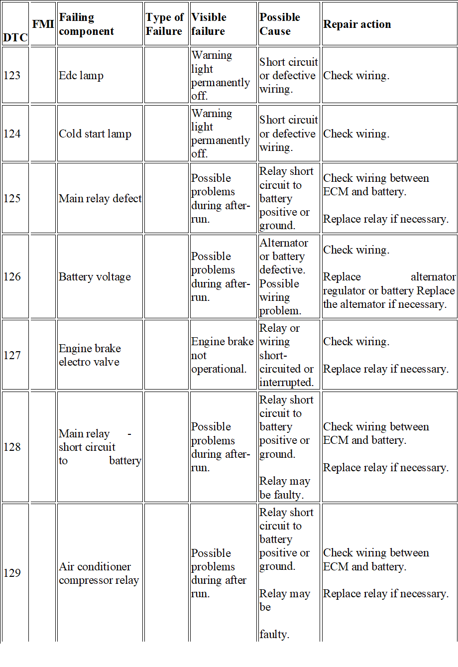
| 123 | Edc lamp | Warning light permanently off. | Short circuit or defective wiring. | Check wiring. | ||
| 124 | Cold start lamp | Warning light permanently off. | Short circuit or defective wiring. | Check wiring. | ||
| 125 | Main relay defect | Possible problems during after-run. | Relay short circuit to battery positive or ground. | Check wiring between ECM and battery.
Replace relay if necessary. |
||
| 126 | Battery voltage | Possible problems during after-run. | Alternator or battery defective. Possible wiring problem. | Check wiring.
Replace alternator regulator or battery Replace the alternator if necessary. |
||
| 127 | Engine brake electro valve | Engine brake not operational. | Relay or wiring short-circuited or interrupted. | Check wiring.
Replace relay if necessary. |
||
| 128 | Main relay – short circuit to battery | Possible problems during after-run. | Relay short circuit to battery positive or ground.
Relay may be faulty. |
Check wiring between ECM and battery.
Replace relay if necessary. |
||
| 129 | Air conditioner compressor relay | Possible problems during after run. | Relay short circuit to battery positive or ground.
Relay may be faulty. |
Check wiring between ECM and battery.
Replace relay if necessary. |
|
DTC |
FMI |
Failing component | Type of Failure |
Visible failure |
Possible Cause |
Repair action |
| 113 | Accelerator pedal/ brake pedal suspect | Vehicle acceleration very slow. Engine idle speed: 500 rpm. | Accelerator pedal and brake pressed simultaneously (for too long); Accelerator pedal blocked or faulty;
Incorrect use of vehicle. |
Check the accelerator pedal signal and pedal mechanical movement. | ||
| 116 | Clutch signal suspect | The parameter reading shows that the clutch is pressed. | Clutch switch faulty or wiring problems in pedal. | Check clutch pedal switch and wiring. | ||
| 117 | Brake pedal signal error | Slight power re- duction | Main and secondary brake switch not synchronised. One of the two brake pedal switches may be stuck. | Check the synchronisation of both switches (signal) and wiring. | ||
| 119 | Plausibility + 15 | Possible mechanical problem (in pawl) or electrical problem. | Check wiring. | |||
| 121 | Speed limiter w / light | Warning light permanently off. | Short circuit or defective wiring. | Check wiring. | ||
| 122 | Warning light ODB | Warning light permanently off. | Short circuit or defective wiring. | Check wiring. |
|
DTC |
FMI |
Failing component | Type of Failure |
Visible failure |
Possible Cause |
Repair action |
| 12A | Relays for engine brake valve | Possible problems during after run. | Relay short circuit to battery positive or ground.
Relay may be faulty. |
Check wiring between ECM and battery.
Replace relay if necessary. |
||
| 12B | Thermostarter relay 1 (heater) | Heater not working. | Relay or wiring short circuited or interrupted. | Check wiring.
Replace relay if necessary. |
||
| 12C | Thermostarter relay 2 | Heater not working. | Relay or wiring short circuited or interrupted. | Check wiring.
Replace relay if necessary. |
||
| 12E | Management system pre/ post heating (active) | Grid heater permanently operating. | Grid heater short circuited to ground. | Check wiring and component. | ||
| 131 | Coolant temperature sensor | No reaction noticeable on behalf of the driver. | Sensor short -circuited or value implausible. | Check the wiring. Replace sensor if necessary. | ||
| 132 | Coolant temperature sensor (test) | Slight power reduction. | Operation in extreme environmental conditions or sensor inaccurate. | Ensure the engine is not working in extreme environmental conditions.
Check the wiring and the sensor accuracy. Replace sensor if necessary. |
|
DTC |
FMI | Failing component | Type of Failure | Visible failure | Possible Cause | Repair action |
| 133 | Air temperature sensor boost air | Slight power re- duction. | Sensor short circuited or value implausible. | Check the wiring. Re- place sensor if necessary. | ||
| 134 | Boost pressure sensor | No reaction perceivable by the driver.
Parameter recovery value: 2700 mbar. |
Sensor short circuited or difference between environmental pressure and turbo pressure implausible. | Check the wiring. Also check the environ- mental pressure sensor. Replace sensor if necessary. | ||
| 135 | Fuel temperature sensor | Slight power re- duction. | Sensor short-circuited or value implausible. | Check the wiring. Re- place sensor if necessary. | ||
| 138 | Oil pressure sensor | No reaction perceivable by the driver.
Parameter recovery value: 3000 mbar. |
Sensor short-circuited or value implausible. | Check the wiring and oil level.
Replace sensor if necessary. |
||
| 13A | Oil temperature sensor | No reaction perceivable by the driver.
Parameter recovery value: coolant temperature value (if intact) otherwise 120 C). |
Sensor short-circuited or value implausible. | Check the wiring. Replace sensor if necessary. | ||
| 13C | Atmospheric temperature sensor (humidtiy?) | No reaction perceivable by the driver.
Parameter recovery value: 40 C. |
Sensor short-circuited or value implausible. | Check the wiring. Replace sensor if necessary. |
|
DTC |
FMI |
Failing component | Type of Failure |
Visible failure |
Possible Cause |
Repair action |
| 141 | Crankshaft speed | No reaction noticeable on behalf of the driver. | Signal interrupted or wiring problem.
Sensor installation may not be correct. |
Check wiring and installation.
Replace sensor if necessary. |
||
| 142 | Engine working only
With camshaft sensor |
No reaction perceivable by the driver. | Signal interrupted or wiring problem.
Sensor installation may not be correct. |
Check wiring and installation.
Replace sensor if necessary. |
||
| 143 | Camshaft sensor | No reaction perceivable by the driver. | Signal interrupted or wiring problem.
Sensor installation may not be correct. |
Check wiring and installation.
Replace sensor if necessary. |
||
| 144 | Fault between fly-Wheel sensor and camshaft | No reaction noticeable on behalf of the driver. | Signal interrupted or wiring problem.
Flywheel and timing sensor installation may be incorrect. |
Check wiring and installation of both sensors. | ||
| 145 | Fan relay | No reaction perceivable by the driver.
Fan off. |
Short circuit or fan actuator faulty. | Check the wiring and the fan actuator.
Replace the actuator if necessary. |
||
| 148 | Air conditioner compressor relay | Air conditioner permanently off. | Wiring or relay short-circuited. | Check the wiring. Replace relay if necessary. |
|
DTC |
FMI | Failing component | Type of Failure | Visible failure | Possible Cause | Repair action |
| 149 | Preheating relay fuel
Filter |
Filter heater not working. | Wiring or filter heater short-circuited. | Check the wiring. Re- place the filter heater if necessary. | ||
| 151 | Injector cylinder 1 | The engine runs on 5 cylinders. | Injector no.1 electric trouble. | Check correct tightness to torque of the connectors on the solenoid valve of the injector (1.36 – 1.92 Nm). Check the integrity of the injector coil and replace the injector if defective. If the coil is integral, check the wiring between the solenoid valve and EDC -connector. | ||
| 152 | Injector cylinder 2 | The engine runs on 5 cylinders. | Injector no.2 electric trouble. | Check correct tightness to torque of the connectors on the solenoid valve of the injector (1.36 – 1.92 Nm). Check the integrity of the injector coil and replace the injector if defective. If the coil is integral, check the wiring between the solenoid valve and EDC connector. | ||
| 153 | Injector cylinder 3 | The engine runs on 5 cylinders. | Injector no.3 electric trouble | Check correct tightness to torque of the connectors on the solenoid valve of the injector (1.36 – 1.92 Nm). Check the integrity of the injector coil and replace the injector if defective. If the coil is integral, check the wiring between the solenoid valve and EDC connector. |
|
DTC |
FMI | Failing component | Type of Failure | Visible failure | Possible Cause | Repair action |
| 149 | Pre-heating relay fuel
Filter |
Filter heater not working. | Wiring or filter heater short-circuited. | Check the wiring. Replace the filter heater if necessary. | ||
| 151 | Injector cylinder 1 | The engine runs on 5 cylinders. | Injector no.1 electric trouble. | Check correct tightness to torque of the connectors on the solenoid valve of the injector (1.36 – 1.92 Nm). Check the integrity of the injector coil and replace the injector if defective. If the coil is integral, check the wiring between the solenoid valve and EDC- connector. | ||
| 152 | Injector cylinder 2 | The engine runs on 5 cylinders. | Injector no.2 electric trouble. | Check correct tightness to torque of the connectors on the solenoid valve of the injector (1.36 – 1.92 Nm). Check the integrity of the injector coil and replace the injector if defective. If the coil is integral, check the wiring be- tween the solenoid valve and EDC-connector. | ||
| 153 | Injector cylinder 3 | The engine runs on 5 cylinders. | Injector no.3 electric trouble | Check correct tightness to torque of the connectors on the solenoid valve of the injector (1.36 – 1.92 Nm). Check the integrity of the injector coil and replace the injector if defective. If the coil is integral, check the wiring between the solenoid valve and EDC-connector. |
|
DTC |
FMI |
Failing component | Type of Failure |
Visible failure |
Possible Cause |
Repair action |
| 154 | Injector Cylinder 4 | The engine runs
on 5 cylinders |
Injector no.4
electric trouble |
Check correct tightness to torque of the connectors on the solenoid valve of the injector (1.36 – 1.92 Nm). Check the integrity of the injector coil and replace the injector if defective. If the coil is integral, check the wiring between the solenoid valve and EDC connector. | ||
| 155 | Injector Cylinder 5 | The engine runs on 5 cylinders | Injector no.5 electric trouble | Check correct tightness to torque of the connectors on the solenoid valve of the injector (1.36 – 1.92 Nm). Check the integrity of the injector coil and replace the injector if defective. If the coil is integral, check the wiring between the solenoid valve and EDC connector. | ||
| 156 | Injector Cylinder 6 | The engine runs on 5 cylinders | Injector no.6 electric trouble | Check correct tightness to torque of the connectors on the solenoid valve of the injector (1.36 – 1.92 Nm). Check the integrity of the injector coil and replace the injector if defective. If the coil is integral, check the wiring between the solenoid valve and EDC connector. |
|
DTC |
FMI | Failing component | Type of Failure | Visible failure | Possible Cause | Repair action |
| 161 | Injector Cylinder 1 / short-Circuit | One or more injectors (bank 1 or bank 2) not operating. | Possible short-circuit in connections. Possible problem in
Injector coil . Possible problem in control unit. |
Check wiring. Possible internal problem also in ECM. Replace the injector if necessary. | ||
| 162 | Injector Cylinder 2 / short-Circuit | One or more injectors (bank 1 or bank 2) not operating. | Possible short-circuit in connections. Possible problem in injector coil . Possible problem in control unit. | Check wiring. Possible internal problem also in ECM. Replace the injector if necessary. | ||
| 163 | Injector Cylinder 3 / short-Circuit | One or more injectors (bank 1 or bank 2) not operating. | Possible short circuit in connections. Possible problem in injector coil . Possible problem in control unit. | Check wiring. Possible internal problem also in ECM. Replace the injector if necessary. | ||
| 164 | Injector Cylinder 4 / short-Circuit | One or more injectors (bank 1 or bank 2) not operating. | Possible short-circuit in connections. Possible problem in injector coil . Possible problem in control unit. | Check wiring. Possible internal problem also in ECM. Replace the injector if necessary. | ||
| 165 | Injector Cylinder 5 / short-Circuit | One or more injectors (bank 1 or bank 2) not operating. | Possible short circuit in connections. Possible problem in injector coil . Possible problem in control unit. | Check wiring. Possible internal problem also in ECM. Replace the injector if necessary. |
|
DTC |
FMI |
Failing component | Type of Failure |
Visible failure |
Possible Cause |
Repair action |
| 166 | Injector Cylinder 6 / short-Circuit | One or more injectors (bank 1 or bank 2) not operating. | Possible short-circuit in connections. Possible problem in injector coil. Possible problem in control unit. | Check wiring. Possible internal problem also in ECM. Replace the injector if necessary. | ||
| 167 | Injector Cylinder 1 / open circuit | One or more injectors (bank 1 orbank 2) not operating. | Possible injector
Connection problem (or disconnected internally). Possible problem in control unit (capacitor). |
Check wiring. Possible internal problem also in ECM. Replace the injector if necessary. | ||
| 168 | Injector
Cylinder 2 / open Circuit |
One or more injectors (bank 1 or bank 2) not operating. | Possible injector connection problem (or disconnected internally). Possible problem in control
unit (capacitor). |
Check wiring. Possible internal problem also in ECM. Replace the injector if necessary. | ||
| 169 | Injector
Cylinder 3 / open Circuit |
One or more injectors (bank 1 or bank 2) not operating. | Possible injector connection problem (or disconnected internally). Possible problem in control
unit (capacitor). |
Check wiring. Possible internal problem also in ECM. Replace the injector if necessary. |
|
DTC |
FMI | Failing component | Type of Failure | Visible failure | Possible Cause | Repair action |
| 16A | Injector cylinder 4 / open circuit | One or more injectors (bank 1 or bank 2) not operating. | Possible injector connection problem (or disconnected internally). Possible problem in control unit (capacitor). | Check wiring. Possible internal problem also in ECM. Replace the injector if necessary. | ||
| 16B | Injector cylinder 5 / open Circuit | One or more injectors (bank 1 or bank 2) not operating. | Possible injector connection problem (or disconnected internally). Possible problem in control unit (capacitor). | Check wiring. Possible internal problem also in ECM. Replace the injector if necessary. | ||
| 16C | Injector cylinder 6 / open circuit | One or more injectors (bank 1 or bank 2) not operating. | Possible injector connection problem (or disconnected internally). Possible problem in control unit (capacitor). | Check wiring. Possible internal problem also in ECM. Replace the injector if necessary. | ||
| 16D | Compression test in progress | Compression Test in progress. | After carrying out the compression test, turn the key OFF (after-run). |
|
DTC |
FMI |
Failing component | Type of Failure |
Visible failure |
Possible Cause |
Repair action |
| 16E | The minimum number of injections
Was not reached: stop the Engine |
More than 2 injectors not operating. | See individual faults in injectors. | |||
| 171 | Bench 1 cc | One or more injectors (bank 1 or bank 2) not operating. | Possible injector connection problem.
Injectors short-circuited. |
Check wiring. Possible internal problem also in ECM. Replace the injector if necessary. | ||
| 173 | Bench 2 cc | One or more injectors (bank 1 or bank 2) not operating. | Possible injector connection problem.
Injectors short-circuited. |
Check wiring. Possible internal problem also in ECM. Replace the injector if necessary. | ||
| 17C | Bench 1 injectors check (internal ecu) | One or more injectors (bank 1 or bank 2) may not be operating. | Fault in control unit. | Replace the engine control unit. | ||
| 189 | Egr power St. Short To batt. | No fault perceived by the driver. EGR not working. | Short circuit or EGR actuator faulty. | Check wiring.
Replace the EGR actuator if necessary. |
||
| 191 | Turbine actuator control
Electro-valve |
Poor performance | VGT actuator or wiring defective. | Check VGT wiring and actuator. |
|
DTC |
FMI | Failing component | Type of Failure | Visible failure | Possible Cause | Repair action |
| 192 | TURBINE
ACTUATOR CONTROL ELECTRO-VALVE SHORT-CIRCUIT TO POSITIVE |
Poor performance | VGT actuator or wiring defective. | Check VGT wiring and actuator. | ||
| 193 | TURBINE WHEEL REVS SENSOR | Poor performance | Air filter blocked or turbine rpm sensor signal implausible. | Check the air filter and check parameters linked with the turbine by performing a road test (parameter acquisition). | ||
| 198 | FAULT ON AT LEAST TWO OF THE FOLLOWING SENSORS: TURBINE SPEED, BOOT PRESSUR AND EXHAUST GAS PRESSURE | Poor performance | Sensor signal implausible. Sensor may be faulty. | Determine which turbine component caused the problem. | ||
| 199 | TURBO-CHARGER CONTRO BOOST PRESSURE FAILURE (PCR) | Poor performance | Turbo sensor or actuator may be faulty. Air filter may be blocked. | Check turbine sensors and actuator (parameter acquisition). Check whether air filter is blocked. |
|
DTC |
FMI |
Failing component | Type of Failure |
Visible failure |
Possible Cause |
Repair action |
| 19A | TURBINE SPEED EXCEEDING EVERY PERMITTED RANGE | Poor performance | Turbo sensor or actuator may be faulty. Air filter may be blocked. | Check turbine sensors and actuator (parameter acquisition). Check whether air filter is blocked. | ||
| 19B | TURBINE IN OVERSPEED (THE FAULT IS NOT DISPLAYED IF IT IS CAUSED BY A LOW ATMOSPERIC PRESSURE) | Poor performance | Air filter blocked or turbine rpm sensor signal implausible. | Check the air filter and check parameters linked with the turbine by performing a road test (parameter acquisition). | ||
| 19F | NOx SENSOR ERROR | No effect perceived by the driver. | Sensor signal implausible. Nox sensor may be faulty. | Check the Nox sensor. | ||
| 1A5 | TIMEOUT OF CAN MESSAGE
DM1DCU |
No effect perceived by the driver. | Problems in the Denoxtronic (on the CAN line). | Check wiring.
Check and correct any faults in the Denoxtronic control unit. |
||
| 1A6 | TIMEOUT OF CAN MESSAGE SCR1 | No effect perceived by the driver. | CAN configuration incorrect. CAN connection defective. Terminal resistance not suit-
able. |
Check CAN line wiring. Check Denoxtronic control unit wiring and operation. | ||
| 1AE | HUMIDITY SENSOR | No effect perceived by the driver. | Sensor short-circuited or faulty. | Check wiring Replace sensor if necessary. |
|
DTC |
FMI | Failing component | Type of Failure | Visible failure | Possible Cause | Repair action |
| 1AF | SERIOUSE OBD FAULT
FROM DENOXTRONIC (EOBD FLASHING LIGHT) |
No effect perceived by the driver. | Problems in AdBlue dosing system. | Check the faults in the Denoxtronic and consult the control unit troubleshooting guide. | ||
| 1B1 | ERROR ON CAN CONTROLLER A | No effect perceived by the driver. | CAN configuration incorrect. CAN connections defective. Terminal resistance not suitable. | Check CAN line wiring. Check terminal resistances. | ||
| 1B2 | ERROR ONCAN CONTROLLER B | No effect perceived by the driver. | CAN configuration incorrect. CAN connections defective. Terminal resistance not suitable. | Check CAN line wiring. Check terminal resistances. | ||
| 1B3 | ERROR ON CAN CONTROLLER C | No effect perceived by the driver. | CAN configuration incorrect. CAN connections defective. Terminal resistance not suitable. | Check CAN line wiring. Check terminal resistances. | ||
| 1B4 | TIMEOUT CAN MESSAGE BC2EDC1 | No effect perceived by the driver. | CAN configuration incorrect. CAN connections defective. Terminal resistance not suitable. | Check CAN line wiring. Check BC wiring and operation. |
|
DTC |
FMI |
Failing component | Type of Failure |
Visible failure |
Possible Cause |
Repair action |
| 1B5 | TIMEOUT CAN MESSAGE VM2EDC | No effect perceived by the driver. | CAN configuration incorrect. CAN connections defective. Terminal resistance not suitable. | Check CAN line wiring. Check VCM wiring and operation. | ||
| 1B7 | ERROR ON MESSAGES CAN IN TRANSMISSION | No effect perceived by the driver. | CAN configuration incorrect. CAN connections defective. Terminal resistance not suitable. | Check CAN line wiring. Check ECM wiring and operation. | ||
| 1B9 | ERROR ON THE EOBD LIGHT MANAGED BY THE CLUSTER) | No effect perceived by the driver. | MIL/Body Controller warning light defective. | Consult the Body Controller troubleshooting guide and check the CAN line. | ||
| 1BA | TIMEOUT CAN MESSAGE DASH DISPLAY | No effect perceived by the driver. | CAN messages from VCM inconsistent. | Consult the VCM troubleshooting guide and check the CAN line. | ||
| 1BC | TIMEOUT CAN MESSAGE AMBCOND | No effect perceived by the driver. | CAN messages from VCM in- consistent. | Consult the VCM troubleshooting guide and check the CAN line. | ||
| 1BD | TIMEOUT CAN MESSAGE CCVS | No effect perceived by the driver. | CAN messages from VCM or BC inconsistent. | Consult the VCM /BC troubleshooting guide and check the CAN line. |
|
DTC |
FMI | Failing component | Type of Failure | Visible failure | Possible Cause | Repair action |
| 1C2 | ERROR MESSAGE CAN ETC1 | No effect perceived by the driver. | CAN messages from ETC (gearbox) inconsistent. | Check the ETC connection with the CAN line. | ||
| 1C3 | TIMEOUT IN RECEIVING TC01 CAN MESSAGE | No effect perceived by the driver. | CAN messages from TCO in- consistent. | Check the TCO connection with the CAN line. | ||
| 1C6 | ERROR MESSAGE CAN TSC1PE | No effect perceived by the driver. | CAN messages from TCU (Transmission Control Unit) inconsistent. | Check the TCU connection with the CAN line. | ||
| 1C8 | ERROR MESSAGE CAN TSC1VE | No effect perceived by the driver. | CAN messages from TCU (Transmission Control Unit) inconsistent. | Check the TCU connection with the CAN line. | ||
| 1D1 | ECU OVERRUN MONITORING ERROR | No effect perceived by the driver. | Electrical interference or internal control unit problems. | If the error persists to replace ECU. | ||
| 1D2 | ECU OVERRUN MONITORING ERROR | No effect perceived by the driver. | Poor control unit programming/flash Possible internal fault. | Reprogram the central unit. If the error is repeated, replace the central unit, if needed. | ||
| 1D3 | ECU OVERRUN MONITORING ERROR | No effect perceived by the driver. | Poor control unit programming/flash Possible internal fault. | Reprogram the central unit. If the error is repeated, replace the central unit, if needed. |
|
DTC |
FMI |
Failing component | Type of Failure |
Visible failure |
Possible Cause |
Repair action |
| 1D4 | ECU OVERRUN MONITORING ERROR | No effect perceived by the driver. | Ecu internal failure. | If the error persists to replace ECU. | ||
| 1D5 | ECU OVERRUN MONI- TORING ERROR | No effect perceived by the driver. | Ecu internal failure. | If the error persists to replace ECU. | ||
| 1D6 | ECU INTERNAL ERROR (TPU) | Control unit deactivation. | Electronic interference or control unit faulty. | If the error persists to replace ECU. | ||
| 1D8 | ECU OVERRUN MONI TORING ERROR | No effect perceived by the driver. | Ecu internal failure. | If the error persists to replace ECU. | ||
| 1E2 | IMMOBILIZER | The engine fails to start. | Problem in CAN line or immobiliser control unit. | Check the Immobiliser control unit is correctly connected.
Enter the Immobiliser PIN code during the emergency procedure. |
||
| 1E3 | ERROR FOR ECU INTERNAL MONI TORING | No effect perceived by the driver. | Ecu internal failure. | If the error persists to replace ECU. | ||
| 1E4 | ERROR FOR ECU INTERNAL MONITORING | No effect perceived by the driver. | Ecu internal failure. | If the error persists to replace ECU. |
|
DTC |
FMI | Failing component | Type of Failure | Visible failure | Possible | Cause | Repair action |
| 1E5 | SENSORS POWER SUPPLY FAULT (12V) | No effect perceived by the driver. | Excessive/insufficient
Battery voltage or possible internal control unit problem. |
Check battery voltage or connections with the ECM. Replace the control unit if necessary. | |||
| 1E6 | SENSOR POWER SUPPLY 1 | No effect perceived by the driver. | Excessive/insufficient
Battery voltage or possible internal control unit problem |
Check battery voltage or connections with the ECM. Replace the control unit if necessary. | |||
| 1E7 | SENSOR POWER SUPPLY 2 | No effect perceived by the driver. | Excessive/insufficient
Battery voltage or possible internal control unit problem |
Check battery voltage or connections with the ECM. Check ECU, if required. | |||
| 1E8 | SENSOR POWER SUPPLY 3 | No effect perceived by the driver. | Excessive/insufficient
Battery voltage or possible internal control unit problem |
Check battery voltage or connections with the ECM. Replace the control unit if necessary. | |||
| 1E9 | ECU OVERRUN MONITORIN ERROR | No effect perceived by the driver. | Excessive/insufficient
Battery voltage or possible internal control unit problem |
Check battery voltage or connections with the ECM. Replace the control unit if necessary. | |||
| 1EA | ECU OVERRUN MONITORIN ERROR | No effect perceived by the driver. | Excessive/insufficient
Battery voltage or possible internal control unit problem |
Check battery voltage or connections with the ECM. Replace the control unit if necessary. | |||
| 1EB | ATMOSPHERIC PRESSURE SENSOR | No effect perceived by the driver. | Excessive/insufficient
Battery voltage or possible internal control unit problem |
Change ECU. |
|
DTC |
FMI |
Failing component | Type of Failure |
Visible failure |
Possible Cause |
Repair action |
| 1FA | TOO HIGH NUMBER OF REGENERATIONS DEMAND | No reaction perceivable by the driver. Too many filter regenerations carried out. | Particulate filter may be blocked. | Check filter. | ||
| 1FB | PERMANENT RIGENERATION ON TRAP PARTICLE | No reaction perceivable by the driver. | Catalytic converter not installed or damaged. | Check catalytic converter visually. | ||
| 1FC | FIRST SENSOR EXAUSTED GAS TEMPERATURE | No reaction perceivable by the driver. | Temperature sensors damaged or incorrectly fitted. | Check information and condition of sensors. | ||
| 21F | TOO HIGH EFFICIENCY OF CATALYST SYSTEM | No reaction noticeable on behalf of the driver. | Actuator coil faulty or not within specified tolerance limits. | Check actuator condition. | ||
| 225 | INTERRUPTED
AFTERRUN |
Slight power reduction. | The control unit is turned off by the general switch instead of by the key (k15). Possible problem in main relay or connections. | Check wiring and then replace the main relay. | ||
| 228 | MAIN RELAY – SHORT CIRCUIT TO GROUND | Slight power reduction. | Short circuit in main relay or relay faulty. | Check wiring between battery and ECM and then replace the main relay. |
|
DTC |
FMI | Failing component | Type of Failure | Visible failure | Possible Cause | Repair action |
| 232 | COOLANT TEMPERATURE SENSOR ABSOLUTE TEST | Slight power reduction | Extreme environmental conditions or sensor incorrectly adjusted. | Ensure the engine is working in non-critical conditions. Check the sensor connections and accuracy. Replace sensor if necessary. | ||
| 238 | OIL LOW PRESSURE | Slight power re- duction | Sensor incorrectly adjusted or faults in lubrication system. | Check the sensor connections and accuracy. Check the lubrication system. | ||
| 23A | OIL TEMPERATURE ABOVE NORMAL | Slight power reduction | Sensor incorrectly adjusted or faults in lubrication system. | Check the sensor connections and accuracy. Check the lubrication system. | ||
| 27C | BENCH 2 INJECTORS CHECK (INTERNAL ECU) | One or more injectors (bank 1 or bank 2) may not be operating | Fault in control unit. | Replace the engine control unit. | ||
| 292 | TURBINE ACTUATOR CONTROL
ELECTROVALVE SHORT CIRCUIT TO GROUND |
Poor performance | VGT actuator or wiring defective. | Check VGT wiring and actuator. | ||
| 2A6 | TIMEOUT OF CAN MESSAGE SCR2 | No effect perceived by the driver | Problem in the Denoxtronic
(on the CAN line). |
Check the faults in the Denoxtronic and consult the control unit troubleshooting guide. Check wiring. |
|
DTC |
FMI |
Failing component | Type of Failure |
Visible failure |
Possible Cause |
Repair action |
| 2AF | SERIOUS EOBD FAULT FROM DENOXTRONIC (EOBD FLASHING
LIGHT) |
No effect perceived by the driver. | Problems in AdBlue dosing system. | Check the faults in the Denoxtronic and consult the control unit troubleshooting guide. | ||
| 2B4 | TIMEOUT CAN MESSAGE BC2EDC2 | No effect perceived by the driver. | CAN configuration incorrect. CAN connections defective. Terminal resistance not suitable. | Check CAN line wiring. Check BC wiring and operation. | ||
| 2C6 | TIMEOUT OF CAN MESSAGE TSC1-PE PASSIVE | No effect perceived by the driver. | CAN messages from TCU (Transmission Control Unit) inconsistent. | Check the TCU connection with the CAN line. | ||
| 2C8 | ERROR MESSAGE CAN TSC1VR | No effect perceived by the driver. | CAN messages from TCU (Transmission Control Unit) inconsistent. | Check the TCU connection with the CAN line. | ||
| 2C9 | ERROR MESSAGE CAN TIMEDATE | No effect perceived by the driver. | CAN messages from TC (tachograph) inconsistent. | Check the tachograph connection with the CAN line. | ||
| 2D3 | ECU OVERRUN MONITORING ERROR | No effect perceived by the driver. | Poor control unit programming/flash Possible internal fault. | Reprogram the central unit. If the error is repeated, replace the central unit, if needed. |
|
DTC |
FMI | Failing component | Type of Failure | Visible failure | Possible Cause | Repair action |
| 2FF | ERROR CHECK OF CRITICAL TIME FOR OIL DILUTION | Slight power reduction | Oil overdiluted. | Change the engine oil . | ||
| 392 | TURBINE ACTUATOR
CONTROL ELECTRO-VALVE |
Poor performance | Connection damaged. Battery voltage excessive (ECU overheating). | Check VGT connection and actuator. | ||
| 3AF | SERIOUSE OBD FAULT FROM DENOXTRONIC (EOBD FLASHING LIGHT) | No effect perceived by the driver. | Problems in AdBlue dosing system. | Check the faults in the Denoxtronic and consult the control unit troubleshooting guide. | ||
| 3C8 | TIMEOUT OF CAN MESSAGE TSC1-VE PASSIVE | No effect perceived by the driver. | CAN messages from TCU (Transmission
Control Unit) inconsistent. |
Check the TCU connection with the CAN line. | ||
| 3C9 | ERROR MESSAGE CAN HRDV | No effect perceived by the driver. | CAN configuration incorrect. CAN connections defective. Terminal resistance not suitable. | Check CAN line wiring. Check BC wiring and operation. | ||
| 3D3 | ECU OVERRUN MONITORING ERROR | No effect perceived by the driver. | Poor control unit programming/flash Possible internal
fault. |
Reprogram the central unit. If the error is repeated, replace the central unit, if needed. |
|
DTC |
FMI |
Failing component | Type of Failure |
Visible failure |
Possible Cause |
Repair action |
| 3FA | REGENERATION DEMAND NUMBER 2 | No effect perceived by the driver. | Too many regenerations carried out. | Check particulate filter and faults in sensors. | ||
| 4AF | SERIOUSE OBD FAULT FROM DENOXTRONIC (EOBD FLASHING LIGHT) | No effect perceived by the driver. | Problems in AdBlue dosing system. | Check the faults in the Denoxtronic and consult the control unit troubleshooting guide. | ||
| 4C8 | TIMEOUT OF CAN MESSAGE TSC1-VR PASSIVE | No effect perceived by the driver. | CAN messages from TCU (Transmission Control Unit) inconsistent. | Check the TCU connection with the CAN line. | ||
| 4FA | REGENERATION DEMAND NUMBER 3 | No effect perceived by the driver. | Too many regenerations carried out. | Check particulate filter and faults in sensors. | ||
| 5AF | DM1DCU SPN5 MESSAGE | No effect perceived by the driver. | Problems in AdBlue dosing system. | Check the faults in the Denoxtronic and consult the control unit troubleshooting guide. |
Iveco Trakker Fault Codes in PDF free download
Iveco Trakker Euro 4-5 Fault Codes List
Всем привет!
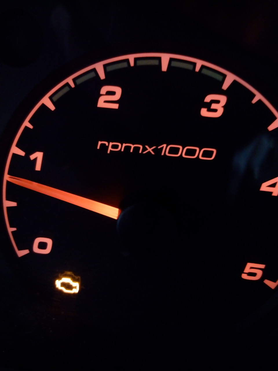
Загорелся у меня недели две назад чек. Но машина ехала, заводилась и не дымила, по-этому работал в прежнем режиме. На улице был дождь, хотя тогда я этому значения не предал)
На следующий день погодка устаканилась, все просохло и вместе с этим потухла лампочка чека.
Настроение улучшилось ровно до звонка в сервис. Ближайшее время свободное только на следующей неделе, что меня не устраивало в принципе. Решил поездить пока так, до следующего дождя, который не заставил себя долго ждать. И как результат мокрых дорог, опять лампочка горит.
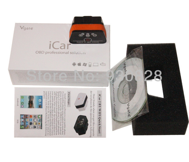
Нашел знакомого с прибором LAUNCH, попытались подключить, но двигатель «ругается», зажигает сразу лампу EDC, и перестает заводиться вообще, пока не перезагрузишь мозги снятием клеммы. Неприятные секунды я пережил, скажу я Вам. Тем же вечером полистал Драйв, нашел товарища k2-SPb, он удачно использует приблуду ELM327 фирмы ICAR2. Утром поехал в магазин китайской продукции, плюнул и отдал 1400 за этот приборчик, переплатил рублей 700-800, да и хрен с ними, лампочка чека разждражала уже до нельзя.
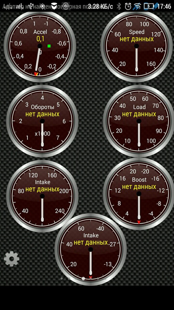
Подключил, значит этот сканер, скачал прогу Torque на мобилу, прочитала она ошибку P0130.
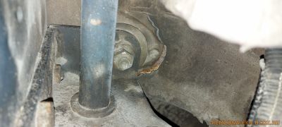
Это означает неисправность электрической цепи кислородного датчика, в простонародье, лямбда-зонда.
Залез под машину вчера уже, глянул, ничего там криминального не оказалось, но позже буду дергать штекера и осматривать на предмет отгнивания провода. Всем советую тоже заглянуть туда и во избежание танцев с бубном и сканером, прыснуть какой нибудь неведомой хрени на штекер, что бы не происходила коррозия.
Вопрос: у кого нибудь выскакивал чек по такому поводу? Пишет, что именно неисправность цепи, а не низкое напряжение или неправильные данные, там есть отдельные коды этих ошибок.