На данной странице приведены часто встречающиеся диагностические коды ошибок автомобилей марки Volvo с расшифровкой ошибок на русском языке. На картинке ниже видно, как правильно считать код ошибки, чтобы выполнить точную диагностику автомобилей Volvo.
Полный список кодов неисправностей с расшифровкой рассмотрен для следующих моделей авто:
- 850, 940, 960;
- С30, С40, С60, С80;
- FH12 (ФШ12), FH13 (ФШ13), FH16 (ФШ16);
- FM9 (ФМ9), FM13 (ФМ13);
- S40, S60, S70, S80;
- V50 (В 50), V70 (В 70);
- VNL 670 (ВНЛ 670);
- ХС60, ХС70, XC90.
Как диагностировать ошибку?
 Самым эффективным способом диагностики кодов ошибок Вольво является компьютерное сканирование, которое позволяет определить тип неполадки и обнаружить конкретную неисправность.
Алгоритм действий при диагностике, выполняющейся с помощью компьютера или сканера:
- Оборудование для проверки подключается к специальному выходу OBD2 в автомобиле.
- Включается зажигание или запускается двигатель (в зависимости от условий, прописанных в сервисном руководстве).
- Производится считывание кодов неисправностей с помощью сканера или специальной программы, установленной на ноутбук.
- Полученные комбинации расшифровываются и устраняются.
Кроме компьютерной проверки, есть другие способы выявления неполадок:
- диагностика с применением приборной комбинации, которая осуществляется с использованием кнопок, расположенных на центральной консоли;
- диагностика с использованием специального разъема тестирования (метод актуален для Volvo, выпущенных в период с 1985 до 1995 гг.), колодка находится либо в районе левого крыла, либо рядом с корпусом воздухофильтра.
Диагностическая колодка на старых версиях автомобилей Volvo
На автомобилях с более ранней версией диагностического разъема проверка производится следующим образом:
- Провод для проверки подключается к контакту 2 на диагностической колодке секции А.
- Выполняется включение зажигания (для этого ключ прокручивается в режим АСС замка).
- Нажимается кнопка начала теста.
- Если ошибок в работе транспортного средства нет, светодиодный индикатор неисправности покажет код 111, который будет выведен в виде трех коротких вспышек с трехсекундной паузой. При наличии неполадок коды выводятся в виде морганий.
- Записываются все коды ошибок. После того, как бортовой компьютер закончит процедуру вывода комбинаций, вспышки начнут повторяться по кругу.
- Для завершения диагностики нажимается кнопка тестирования.
На транспортных средствах, выпущенных после 2000 года, процедура диагностики выполняется следующим образом:
- Автовладелец производит запуск силового агрегата.
- На боковой части лепестка подрулевого переключателя имеется кнопка с надписью «Read», пользователю нужно ее зажать. Если Вольво выпущено в 2005 году, то пользователю необходимо два раза нажать на клавишу включения задних противотуманных огней. Если речь идет о Volvo XC 90 2007 года выпуска, автовладельцу нужно трижды «кликнуть» на данную клавишу.
- На экране приборной комбинации после выполнения этих действий появится значок с надписью «DTCS in Vehicle».
- Переключение блоков при диагностике производится посредством нажатия на клавишу «Read».

Первый знак – буква, определяющая тип дефектной системы:
- Р – неисправности силового агрегата или трансмиссии (АКПП).
- В – неполадки в работе кузовных систем: подушек безопасности, электрических стеклоподъемников, центрального замка и т. д.;
- С – неисправности в ходовой части транспортного средства;
- U – ошибки, связанные со взаимодействием электронных модулей.
Второй знак – цифра, которая определяет специфичность неисправности:
- 0 – общий символ для OBD колодки;
- 1 и 2 – персональные коды автопроизводителя;
- 3 – зарезервированная информация.
Третий знак определяет тип поломки:
- 1 и 2 – подача воздуха или топлива;
- 3 – узел зажигания, система фиксации пропусков воспламенения топливовоздушной смеси;
- 4 – дополнительный механизм контроля выбросов;
- 5 – контроль скорости движения автомобиля и холостых оборотов;
- 6 – электронные модули управления и их проводка;
- 7, 8 – ошибки в работе коробки передач;
- 9, 0 — резерв.
Четвертый и пятый знаки ошибки – это числа, которые соответствуют порядковому номеру неисправности.
Все ошибки в автомобилях Вольво могут выводиться в двух-, трех- и четырехзначном видах, в зависимости от версии блока управления (года производства авто) и метода диагностики. Коды неисправностей для грузовых транспортных средств имеют префикс «PID», который стоит перед цифрами, а ошибки OBD2 всегда выводятся с буквой «P».
| Сообщение |
Расшифровка текстовых сообщений |
|---|---|
| ABS BRAKE SERVICE REQUIRED | Неполадки в работе антипробуксовочной системы.
Возможные причины:
|
| ALARM SYSTEM SERVICE REQUIRED | Выход из строя или некорректная работа штатной сигнализации |
| ALARM TRIGGERED CHECK CAR | Срабатывание охранной противоугонной системы |
| BOOT LID OPEN | Открыта дверь багажного отсека |
| BRAKE FAILURE SERVICE URGENT | Сбой в работе тормозной системы |
| BRAKE FAILURE STOP SAFELY ASAP | Критическая неисправность в работе тормозной системы. Дальнейшее передвижение на авто невозможно. |
| BULB FAILURE DIPPED BEAM | Неисправность в работе системы ближнего освещения. Если проводка, лампочка и предохранители исправны, пользователю необходимо тестировать работу подрулевого переключателя. |
| BULB FAILURE POSITION LIGHT | Неполадки в работе габаритной оптики. Проблема может быть обусловлена плохим контактом с проводкой или неисправностью реле. |
| BULB FAILURE REAR FOG LIGHT | Выход из строя одной из противотуманных фар. Причину ошибки следует искать в предохранителях, реле или проводке. Если все элементы целые — меняется источник освещения. |
| BULB FAILURE RIGHT TURN SIGN | Неисправность в работе правого поворотного указателя |
| BULB FAILURE LEFT TURN SIGNAL | Выход из строя левого поворотника |
| CHANGE TRANS OIL AT NEXT SERVICE | Необходимость замены трансмиссионной жидкости. Предупреждение может быть связано с нехваткой рабочей жидкости, обусловленной повреждением коробки передач. |
| CHECK BRAKE LIGHT | Неисправность работы стоповых огней |
| CHECK COOLANT | Недостаток антифриза, требуется диагностика системы на предмет утечки |
| COOLANT LEVEL LO, STOP ENGINE | |
| COOLANT LEVEL LO STOP SAFELY ASAP | |
| DOORS OPEN | Одна или несколько дверей автомобиля не заперты |
| DRIVE SLOWLY SERVICE URGENT | Необходимость прохождения техобслуживания |
| DSTC SERVICE REQUIRED | Нарушения в работе системы контроля стабилизации и динамической тяги |
| DSTC OFF | Сообщение об отключении системы динамической тяги и стабилизации, водителю рекомендуется двигаться максимально медленно |
| EL. POWER SYSTEM SERVICE REQUIRED | Неисправности в электросети автомобиля. Необходимо проверить работу аккумуляторной батареи и генератора, проблема может быть связана с плохим питанием либо некачественным подключением. |
| ELECTRIC HEATER ON | Активирована система электрического подогрева |
| EMISSION SYSTEM SERVICE REQUIRED | Неисправность в работе выпускной системы |
| ENGINE SERVICE REQUIRED | Неполадки в работе ДВС (двигателя внутреннего сгорания) |
| ENGINE SYSTEM FIX NEXT SERVICE | Неисправность в работе микропроцессора |
| ENGINE SYSTEM SERVICE REQUIRED | Неполадки электронного блока управления двигателем (ЭБУ) |
| FILL WASHER FLUID | Недостаточный уровень жидкости в расширительном бачке стеклоомывателя |
| FUEL FILLER CAP OPEN-LOOSE | Топливозаправочное отверстие в автомобиле не заперто |
| HEATER STOPPED LOW BATTERY | Отключение системы дополнительного обогрева в результате недостаточного заряда аккумуляторной батареи |
| HEATER STOPPED LOW FUEL LEVEL | Дополнительный обогрев салона отключен в результате недостатка горючего в баке |
| HIGH ENGINE TEMP | Повышенная температура двигателя |
| HIGH ENGINE TEMP STOP SAFELY ASAP | Критически высокая температура двигателя.
Возможные причины:
|
| IMMOBILIZER SEE MANUAL | Некорректная работа штатной противоугонной системы |
| LEFT REAR DOOR OPEN | Левая задняя дверь автомобиля не заперта |
| MAX ENGINE SPEED REDUCE SPEED | Критически высокие обороты силового агрегата |
| NO IMMOBILIZER SERVICE REQUIRED | Штатная противоугонная система не работает. Такая проблема может носить программный или механический характер. В первом случае проблема решается методом перепрограммирования, поскольку заключается в рассинхронизации между моторным модулем и чипом системы защиты от угона.
К механическим неполадкам относятся:
|
| NO OIL PRESSURE STOP SAFELY ASAP | Критически низкий уровень масляного давления, требуется остановить силовой агрегат и обратиться в сервис. |
| POWER STEERING SERVICE REQUIRED | Выход из строя системы усилителя рулевого колеса |
| REDUCED GUARD SEE MANUAL | Сбои или некорректная работа противоугонной системы |
| SKID WARNING SERVICE REQUIRED | Сбои в функционировании стабилизационной системы |
| SRS-AIRBAG SERVICE URGENT | Сбои в работе подушек безопасности |
| START PREVENTED TRY AGAIN | Силовой агрегат автомобиля заблокирован, нужно попробовать еще раз запустить мотор |
| STC SERVICE REQUIRED | Некорректная работа системы контроля сцепления колес |
| STC OFF REDUCE SPEED | Неисправность системы контроля стабилизации колес, рекомендуется притормозить |
| TRANSMISSION FIX NEXT SERVICE | Неисправность автоматической коробки передач (проблема некритическая) |
| TRANSMISSION OIL TEMP HIGH | Критически высокая температура масла в коробке передач |
| Код |
Описание кодов ошибок |
| PSID21 | Неисправность в работе системы торможения прицепа |
| Е3 | Неполадки, связанные с работой автохолодильника. Проблема может заключаться в повреждении проводки или компрессорного устройства. |
| Е003 | Сбой в работе конфигурации системы SRS |
| UEM 0004 | Ошибка связи с сиреной |
| DEM 0006 | Неверный сигнал подающего насоса. |
| Код |
Неисправности топливной системы |
| ECM 002C | На автомобилях 2003, 2004, 2007 и других годов выпуска данный код обозначает неверный объем горючего, фиксирующийся при пуске или остановке силового агрегата |
| ECM 440С | Код 440 C появляется при неисправности контроллера уровня горючего |
| ECM 2520 | Критически низкое давление горючего, зафиксированное в топливной системе, возможная причина — неисправность датчика |
| Р0001 | Код 0001 указывает на сбои в работе регуляторного устройства подачи горючего. Проблема может заключаться в обрыве проводки. |
| Р0004 | Высокий сигнал, поступающий с контроллера подачи топлива |
| Р0006 | На авто 2000г, 2001, 2002г и других годов выпуска код обозначает неисправность в работе клапана отсечки подачи горючего. Проблема может быть обусловлена критически низким сигналом, поступающим с устройства. |
| Р0180 | Регулятор температуры горючего А не работает или на блок управления подается сигнал, выходящий за пределы допустимого диапазона |
| Р0185 | Повреждение или дефект электролинии, подключенной к регулятору температуры горючего В |
| Р0191 | Выход из строя или некорректная работа датчика давления, установленного в топливной рампе. Импульс, подающийся с контроллера, находится вне диапазона допустимых характеристик. |
| Р0232 | Повышенный уровень сигнала, зафиксированный во вторичной электролинии топливного насоса |
| Код |
Неисправности двигателя |
| ECM 671D | Неверное положение распределительного вала. Проблема может заключаться в некорректной работе датчика или повреждении самого шкива. |
| ECM 1507 | Неисправность в работе турбины, с устройства подается критически низкий сигнал |
| ECM 3501 | Управляющий модуль сообщает о фиксации пропусков воспламенения в первом цилиндре двигателя.
Возможные причины проблемы:
|
| ECM 3502 | Пропуски зажигания горючей смеси во втором цилиндре мотора |
| P0300 (ЕСМ 3503) | Пропуски воспламенения топливовоздушной смеси в третьем цилиндре силового агрегата |
| ECM 3504 | Пропуски зажигания в четвертом цилиндре мотора |
| ECM 6140 | Сбои в работе системы регулировки положения распределительного вала |
| P2089 (ECM 6400) | Восстановительный клапан впускного распредвала работает некорректно или отключен |
| Р0011 (ЕСМ 640 А) | Ошибка положения распределительного вала автомобиля.
Возможные причины неисправности:
|
| P0014 (ЕСМ 641) | На Вольво Kodtruck, F12, FH13 ACM и других версиях этот код обозначает неисправности, связанные с функционированием системы регулировки выпускного вала |
| P0026 | Комбинация Р0026 (0026) появляется при поломке электромагнитного клапана управления впускными клапанами. Проблему следует искать в первом банке двигателя авто. |
| P0027 | Код Р0027 связан с неполадками в работе электромагнитного устройства управления выпускными клапанами. Проблема может отразиться на функционировании двигателя, включая снижение мощности и появление детонации. |
| P0170 | Нарушения при формировании топливовоздушной смеси. Код может выводиться в виде комбинации P017068 в зависимости от диагностируемого оборудования и версии программного обеспечения. |
| P0171 (ЕСМ 261 А) | Переобеднение горючей смеси, связанное с подсосом воздуха |
| Р0243 (ЕСМ 6800) | Выход из строя или сбои в работе соленоида затвора выхлопных газов турбины А |
| P0420 | Низкая эффективность функционирования катализаторного устройства |
| Р1137 | Нарушения в работе системы дополнительной адаптации горючей смеси воздухом. Проблема находится в первом ряду двигателя и может привести к его некорректной работе. |
| P1238 | Неисправности второго цилиндра двигателя. Устройство могло застрять в одном из положений. |
| P1889 | Данный код может выводиться в виде комбинации P188918 и указывает на нарушение герметизации рабочего поршня двигателя |
| Код |
Описание ошибок в работе датчиков |
| REM 4F43 | На Вольво 480 и других моделях данных код обозначает неисправность в работе системы помощи при парковке, которая может быть связана с выходом из строя одного или нескольких датчиков |
| ECM 1300 | На Вольво ФШ 12, 13 и других моделях код 1300 или 130А указывает на неполадки в работе датчика массового расхода воздуха |
| ECM 1400,
ECM 140A |
Неполадки в работе контроллера давления надува. Проблема может быть связана с неисправностью самого регулятора или указывать на некорректный сигнал, поступающий с устройства. |
| ECM 2900 | Данный код может иметь две расшифровки:
|
| ECM 5000 | Возможные неполадки:
|
| B0001 | Ошибка в работе датчика фронтальной подушки безопасности, расположенной со стороны водителя. |
| В0004 | Неисправность в работе механизма развертывания нижней подушки безопасности, установленной со стороны водителя |
| P042D | Сбои в работе или выход из строя вторичного контроллера температуры каталитического нейтрализатора |
| Р0100 | Неисправность контроллера массового расхода воздуха или сбои в работе его электролинии, возможно повреждение кабеля. При такой проблеме двигатель будет функционировать нестабильно, поскольку горючая смесь формируется с неправильными пропорциями. При появлении ошибок в работе датчика необходимо проверить расходомер, поскольку он мог забиться. Для удаления загрязнений используется специальный очиститель карбюратора. |
| P0101 (ЕСМ 130А) | Сигнал контроллера расхода воздуха находится вне допустимого диапазона. При появлении на дисплее Вольво с дизелем или бензином этого кода необходимо протестировать расходомер и выполнить его очистку. |
| P0106 | Сигнал, поступающий с контроллера давления воздуха, находится вне допустимого диапазона. Проблема может быть связана с неполадками в работе самого регулятора или его некорректным подключением. |
| Р0335 (ЕСМ 5200) | Ошибка контроллера положения коленчатого вала с маркировкой А. |
| Р0340 (ЕСМ 3000) | Неисправность в работе датчика распредвала, зафиксирован перемежающийся или некорректный сигнал, поступающий с устройства |
| P1332 | Неисправность в работе четвертого контроллера детонации, с датчика поступает пониженный сигнал |
| P2135 | Неполадки в работе контроллера положения педали дросселя |
| Код |
Неисправности датчиков системы стабилизации |
| BCM 0030 | Сбой в работе контроллера оборотов, установленного на заднем левом колесе |
| BCM 0080 | Контроллер поперечного ускорения неисправен или работает с перебоями, возможно повреждение проводки |
| BCM 0090 | Неисправность контроллера поперечного ускорения, с датчика не подается импульс или сигнал неверный |
| BCM 0103 | Контроллер фиксации положения педали тормоза подает неверный сигнал на управляющий модуль |
| BCM 0109 | Неисправность датчика угла поворота рулевого колеса, устройство подлежит замене |
| BCM 0112 | Сбой в работе системы калибровки датчиков |
| BCM 0114 | Неисправность в работе контроллера вращения при заносе |
| BCM 0115 | Сбой контроллера поворота руля, блок управления не смог установить связь с устройством |
| BCM 0116 | Неисправность регулятора уровня вращения при заносе транспортного средства. С датчика на блок управления поступает некорректный сигнал или в автомобиле был установлен неправильный сенсор. |
| BCM 0125 | Контроллер поперечного ускорения не работает либо с устройства подается некорректный сигнал |
| BCM 0129 | Неисправность датчика длины пути ускорения. Импульс, подающийся на управляющий модуль, находится за пределами допустимого диапазона. |
| BCM 0139 | Выход из строя или сбои в функционировании электромагнитного клапана усилителя тормозного привода |
| BCM 0147 | Контроллер положения тормозной педали неисправен или с устройства подается некорректный сигнал |
| BCM 0148 | Регулятор угла поворота рулевого колеса не работает либо его конфигурация неправильная |
| BCM 0150 | Неисправность переключателя стоповых огней, возможен обрыв на линии управления и питания |
| Код |
Ошибки кислородных датчиков |
| ECM 2210 | На Вольво ФШ 16 и других версиях данный код обозначает выход из строя заднего нагреваемого кислородного контроллера. На управляющий модуль от лямбда-зонда поступает некорректный сигнал. |
| Р0030 (ЕСМ 2810) | Повреждение проводки или выход из строя нагревательного элемента первичного лямбда-зонда. Если кабель питания целый и его контакт качественный, необходимо менять сам кислородный регулятор. |
| Р0031 (ЕСМ 2810) | Низкий сигнал, зафиксированный на линии управления и питания нагревателя первичного лямбда-зонда. Проблема находится в первом банке двигателя и может заключаться в скачках напряжения. |
| Р0032 (ЕСМ 2810) | Высокий уровень напряжения на линии питания подогревательного элемента кислородного регулятора. Диагностике подлежат вторичный лямбда-зонд и его проводка. |
| Р0042 | Сбои в работе механизма подогрева. Вероятно повреждение провода, подключенного к кислородному контроллеру 3, установленному в первом банке мотора. |
| Р0044 | Микропроцессорный модуль сообщает о критически высоком уровне сигнала на линии, подключенной к подогревательному датчику кислорода 3 |
| Р0056 (ЕСМ 2В20) | Сбой в работе вторичного кислородного датчика, расположенного во втором банке силового агрегата |
| Р0137 (ЕСМ 2А0А) | Код 0137 или 137 указывает на выход из строя заднего кислородного регулятора |
| Р0154 (ЕСМ 290А) | Отсутствие активности выходного импульса первичного кислородного регулятора, расположенного в первом банке мотора |
| Р0157 (ЕСМ 2В0А) | Импульс, подающийся на управляющий модуль от вторичного кислородного контроллера, расположенного во втором банке двигателя, не соответствует нормированным параметрам и выходит за пределы допустимого диапазона |
| Р0165 | Медленный отклик третьего кислородного регулятора на обогащение или обеднение горючей смеси. Проблему следует искать во втором банке силового агрегата. |
| Р0166 | Отсутствие активности выходного импульса кислородного контроллера 3, расположенного во втором банке двигателя |
| Р0167 | Данный код ошибки Вольво указывает на выход из строя или сбои в работе нагревательного элемента третьего датчика кислорода, расположенного в банке 2 силового агрегата |
| Р1138 | Неисправность кислородного датчика, которая привела к некорректному формированию топливовоздушной смеси в цилиндрах мотора. Необходимо проверить проводку и качество контакта. |
| P2188 | Сбой в работе системы регулировки кислородного контроллера, установленного в первом ряду двигателя |
| Код |
Ошибки антипробуксовочной системы ABS |
| А030 | Отсутствие инициализации шины данных CAN |
| С0001 | Неисправность в работе клапана управления А тормозной системы |
| Е000 | Центральный электронный модуль антиблокировочной тормозной системы неисправен |
| Е003 | Сбой в работе управляющего модуля силовым агрегатом |
| Код |
Ошибки, связанные с работой проводки |
| DIM 0002 | Повреждение электролинии или ошибка в электроцепи тока сигнального индикатора антиблокировочной тормозной системы |
| DIM 0003 | Неисправность электроцепи или ошибка тока линии сигнального индикатора подушек безопасности, установленного на приборной панели |
| DIM 0005 | Общая лампочка красного цвета на приборной панели неисправна или повреждена ее электроцепь |
| Р0111 | Повреждение кабеля, подключенного к контроллеру температуры всасываемого воздуха. Сигнал, поступающий с регулятора, выходит за пределы допустимых параметров. |
| Р0121, P0122, Р0123 (ЕСМ 9150) | Неисправность датчика положения заслонки A дроссельного узла:
|
| Р0177 | Импульс контроллера выброса СНх находится вне допустимого диапазона характеристик |
| Р0180 | Повреждение электролинии или дефект цепи, связанный с замыканием, контроллера температуры горючего А |
| Р0200 | Повреждение либо обрыв проводки, питающей одну или несколько форсунок |
| Р0213 | Дефект или обрыв линии управления форсункой холодного старта 1 |
| Р0216 | Неисправности электролинии контроля времени впрыска |
| P0700 | Код Р0700 указывает на неисправности в работе экологического индикатора ТСМ |
| Код |
Описание ошибок в работе систем связи |
| Е000 | Внутренняя неисправность или нарушение связи с модулем управления мотором |
| Е003 | Ошибочный импульс или ошибка в конфигурации управляющего модуля мотора |
| TCM 0A31 | Нарушение связи между модулями трансмиссии TCM и блоком управления двигателем ECM |
| ECM 530D | Ошибка сигнала скорости, импульс критически низкий |
| ECM 644А | Неисправность в работе модуля контроля распределительного вала |
| BCM 0094 | Отсутствие связи с системой электроники полного привода. Проблему следует искать в цифровом интерфейсе, модуле или аккумуляторной батарее. |
| BCM 0100 | Неисправность, связанная с функционированием электронной системы стабилизации. Сообщается об ошибке установления связи с микропроцессорным модулем управления силовым агрегатом. |
| EСM 7100 | Нарушение связи с блокиратором двигателя.
Возможные причины:
|
| EСM 7300 | Нарушение связи с контроллером выбранной передачи |
| P0124 | Данный код может выводиться в виде комбинации 124 и указывать на проблемы со связью между блоком управления и системой противоскольжения |
| P1618 | Нарушение взаимосвязи и некорректная передача сигналов, поступающих по BUS-шине |
| U0001 | Высокая скорость, зафиксированная при передаче данных по цифровому интерфейсу CAN |
| U0401 | Код U040168 связан с нарушением связи при обмене данными по CAN-интерфейсу |
| Код |
Неисправности модуля управления дверьми Вольво ХС90 с 2002 года выпуска |
| DDM 000B | Сбой в работе или выход из строя реле стеклоподъемника для опускания стекла |
| 000C | Внутренняя ошибка блока управления, проблема может носить программный характер |
| 000D | Электродвигатель централизованного устройства закрытия дверных замков неисправен |
| DDM 001A | Критически низкий сигнал, поступающий на блок управления двигателем от замка передней левой двери |
| 002D | Неисправность в работе устройства обогрева внешнего зеркала, проблема состоит в критически низком сигнале |
| 002E | Проблема в работе системы обогрева наружного зеркала, импульс очень высокий и выходит за предел допустимого диапазона |
| DDM 002F | Электрический моторчик перестановки зеркала неисправен, на управляющий модуль подается критически высокий сигнал |
| DDM 003B | Активатор стеклоподъемника, установленного в двери водителя, неисправен |
| DDM 0044 | Фонарь наружного зеркала неисправен, на блок управления подается высокий сигнал |
| E001 | Неисправность в работе шины данных CAN управляющего модуля дверью |
| Код |
Неисправности трансмиссии |
| EСM 002F | Проскальзывание или невозможность активации гидротрансформатора автоматической коробки передач на авто 1999, 2008 и других годов выпуска.
Возможные причины проблемы:
|
| EСM 5100 | Неисправности в работе модуля управления коробкой передач, с устройства подается некорректный сигнал |
| Р0218 | Перегрев трансмиссионного агрегата.
Возможные причины проблемы:
Если ошибка неслучайна, она сопровождается следующими признаками:
|
| Код |
Трехзначные коды ошибок самодиагностики |
| 017 | Код 17 указывает на пониженный уровень хладагента в охладительной системе. Надо остановить авто и заглушить мотор, есть опасность повреждения агрегата. |
| 021 | Неверная калибровка датчика уровня масла, установленного в моторе, возможен плохой контакт устройства с сетью или повреждение электролинии |
| 025 | Код 25 — общая комбинация, не указывающая на конкретную неисправность, она появляется при любых неполадках |
| 042 | Неисправность в работе контроллера массового расхода воздуха |
| 056 | Сбои в работе системы стабилизации хода при заносе |
| 063 | Короткое замыкание на линии управления потенциометром |
| 104 | Необходимость проведения обслуживания фар |
| 106 | Сбои в работе парктроника. Возможно нарушение связи с блоком управления парковочной системой или неисправность одного из датчиков. |
| 111 | Отсутствие неисправностей в работе систем транспортного средства |
| 112 | Короткое замыкание на аккумулятор на линии управления и питания в электромагнитном устройстве S1 |
| 113 | Сбои в работе или некорректное функционирование управляющего модуля трансмиссионным агрегатом |
| 114 | Обрыв электролинии или короткое замыкание на аккумулятор в переключателе режимов |
| 121 | Замыкание на заземление в электромагнитном устройстве S1 либо неполадки, связанные с функционированием управляющего модуля |
| 122 | Повреждение или обрыв электролинии в клапане S1 |
| 123 | Короткое замыкание на аккумулятор в клапане STH |
| 124 | Неисправность в работе переключательного устройства режимов, вероятно короткое замыкание на заземлении |
| 131 | Обрыв электролинии или замыкание на кузов на цепи питания устройства STH. Появление данного кода может быть связано с неполадками в работе микропроцессора. |
| 132 | Сбои в работе управляющего модуля трансмиссионным агрегатом |
| 134 | Некорректный импульс нагрузки в топливной системе |
| 141 | Короткое замыкание на заземление в контроллере температуры моторной жидкости |
| 142 | Обрыв цепи питания и управления датчиком температуры масла |
| 143 | Короткое замыкание либо обрыв линии управления переключателя опции «kick down» |
| 147 | Неисправность в работе системы фиксации «слепых» зон, проблема может касаться парковочного радара |
| 160 | Неисправность в работе системы определения слепых зон |
| 163 | Общий код неисправности, указывающий на наличие проблем в работе автомобиля |
| 167 | Система динамической стабилизации автомобиля функционирует некорректно |
| 169 | Низкий уровень моторной жидкости в двигателе |
| 211 | Сбои в функционировании управляющего модуля трансмиссией, проблема может состоять в некачественном подключении или повреждении контактов на проводе питания |
| 213 | Повышенный импульс, поступающий от механизма положения дроссельной заслонкой |
| 221 | Управляющее устройство зафиксировало короткое замыкание на заземление в электромагнитном клапане S2 либо сбои в функционировании микропроцессорного модуля |
| 222 | Обрыв на линии питания и управления клапаном S2 |
| 223 | Критически низкий импульс, выходящий за нормированный диапазон, фиксирующийся на линии управления дроссельной заслонкой |
| 231 | Нерегулярный сигнал, поступающий с контроллера положения заслонки дросселя |
| 232 | На микропроцессорный модуль не поступает сигнал от спидометра |
| 233 | Импульс от спидометра выходит за пределы допустимого диапазона |
| 235 | Критически высокая температуре масла |
| 245 | Короткое замыкание либо обрыв на линии подключения к механизму крутящего момента |
| 311 | Отсутствие импульса частоты вращения коленвала силового агрегата с коробкой передач |
| 312 | Неверный сигнал вращения коленчатого вала мотора с трансмиссией |
| 313 | Некорректный импульс, подающийся с контроллера выбранной скорости коробки передач |
| 321 | Слишком медленное переключение скоростей |
| 322 | Неправильное передаточное отношение |
| 323 | Проскальзывание или невозможность активации запирающей муфты |
| 331 | Микропроцессор зарегистрировал короткое замыкание на аккумулятор на линии управления электромагнитом с маркировкой SL |
| 332 | Сбои в работе управляющего модуля или обрыв линии электромагнитного клапана SL |
| 333 | Неисправность клапана SL. Проблема состоит в управляющем устройстве либо замыкании на заземление |
| 460 | Необходимость проведения планового техобслуживания автомобиля |
| Код |
Описание сервисных сообщений |
| 34 | В автомобиле открыта топливозаливочная горловина |
| 35 | Активирован дополнительный обогреватель |
| 36 | Включен режим полной охраны транспортного средства |
| 37 | Дополнительное подогревательное устройство выключено в результате пониженного напряжения аккумулятора |
| 38 | Дополнительный обогреватель выключен из-за пониженного объема топлива в баке |
| 40 | Критически высокая температура мотора |
| 41 | Сообщаетcя о необходимости остановки двигателя в результате его перегрева |
| 42 | Высокая температуре мотора, есть возможность серьезного повреждения |
| 43 | Неисправность иммобилайзера |
| 44 | Сообщение об открытой левой двери в авто (сзади) |
| 45 | Аккумулятор разряжен или в электросети автомобиля зафиксировано слабое напряжение в результате неисправности генератора |
| 46 | Высокий уровень оборотов двигателя, возможна неисправность датчика холостого хода |
| 47 | Сбой в работе штатного противоугонного устройства |
| 51 | Открыта передняя правая дверь или на ней установлен нерабочий замок |
| 52 | Выход из строя или сбои в работе усилителя руля. Если датчик системы и блок управления работоспособны, необходимо проверить уровень жидкости гидроусилителя в бачке под капотом. Проблема может заключаться в утечке расходного материала, связанной с повреждением патрубков или ослаблением хомутов на шлангах. |
| 56 | Сбои в функционировании системы стабилизации при заносе |
| 57 | Неисправности в работе надувных подушек безопасности, требуется диагностика датчиков и проводки, а также управляющего модуля |
| 58 | |
| 59 | Неисправности в работе двигателя, запуск агрегата запрещен |
| 74 | На автомобилях Вольво 740 и других версиях данное сообщение указывает на активацию таймера дополнительного подогрева через определенный временной интервал |
| 75 | Срабатывание системы подогрева. Неисправность может заключаться в проводке или работе управляющего модуля. В первую очередь необходимо проверить целостность и функциональность реле или предохранителя. |
| 77 | Сообщение о необходимости срочного проведения обслуживания энергосистемы |
| Код |
Описание ошибок грузовых авто с блоком управления MID 144 |
| 29 | Неисправность контроллера педали акселератора №2. Сигнал, поступающий с регулятора на блок управления, не соответствует нормированным значениям. Эта проблема диагностируется только на транспортных средствах, оснащенных двойным управлением. |
| 46 | Некорректное давление воздуха в первичном ресивере. Данная ошибка диагностируется только на авто с пневматической подвеской.
Возможные причины проблемы:
|
| 84 | Некорректный сигнал о скорости движения авто. Разница между импульсами, поступающими с тахографа, может быть критически высокой. Проблема часто заключается в проводке или неисправности скоростного контроллера. |
| 86 | Проблемы в работе системы круиз-контроля, связанные с неисправностью модуля или передающих сигнал датчиков по каналу информации SAE |
| 91 | Некорректное положение педали газа, важно проверить все датчики и проводку |
| 150 | Отбор мощности силового агрегата. Требуется проверка целостности кабеля питания электромагнитного клапана активации системы отбора тяги. Возможно окисление контактов на разъемах, а также обрыв проводника между клапаном и блоком управления. |
| 152 | Внутренний сбой программного обеспечения. При появлении такой ошибки происходит активация опции перезапуска управляющего модуля транспортным средством. |
| Код |
Описание неисправностей на грузовиках с блоком управления MID 140 |
| PID 96 | Сбои в работе контроллера уровня топлива.
Возможные причины проблемы:
|
| PID 114 | Сбой в работе амперметра. Причина может находиться в сигнальном проводнике. |
| PID 117 | Неисправность контроллера давления воздушного потока в переднем контуре |
| PID 118 | Выход из строя или сбои в работе датчика давления воздушного потока в заднем контуре |
| PID 158 | Уровень напряжения аккумуляторной батареи составляет более 31 вольта. Если устройство для запуска двигателя не подключено, то проблему надо искать в самой батарее либо генераторной установке. |
| PID 171 | Датчик температуры наружного воздуха неисправен или поврежден провод его питания |
| PID 177 | Сбои в работе или отказ контроллера температуры трансмиссионной жидкости в коробке. Если датчик работоспособный, причина проблемы может заключаться в плохом контакте устройства с проводкой или повреждением кабеля. Иногда ошибка появляется при использовании низкокачественной смазки. |
| PID 252 | Информация о дате или времени, подающаяся с управляющего модуля авто или модуля тахографа по каналу данных, некорректная либо полностью отсутствует |
| Код |
Описание ошибок авто с блоком MID 130 |
| PID 31 | Неправильное положение цилиндра демультипликатора. Проблему надо искать в работе датчика, установленного в корпусе управления коробки передач. |
| PID 32 | Неисправность в работе системы определения положения цилиндра делителя.
Возможные причины:
|
| PID 33 | Неисправность датчика положения цилиндра сцепления. Чаще всего проблема состоит в отсутствии калибровки регулятора. |
| PID 36 | Износ диска сцепления превышает допустимую норму |
| PID 37 | Неисправность датчика фиксации уровня давления воздуха. Устройство располагается в трансмиссионном агрегате. Проблема может быть связана с тем, что уровень давления воздуха выходит за пределы допустимого диапазона 4,5-9,2 Бар. |
| PID 124 | Пониженный уровень трансмиссионной жидкости в коробке передач |
| PID 127 | Низкий уровень давления смазки в трансмиссии |
| PID 158 | Некорректное напряжение, появившееся на входе в управляющий модуль от аккумуляторов |
| PID 160 | Неисправность контроллера частоты вращения вала в коробке передач. Причина проблемы может заключаться в несоответствующем уровне сигнала, поступающего с регулятора. Если датчик работоспособный, причины могут заключаться в повреждении проводки или снижении напряжения. |
| PID 161 | Поломка или сбои в работе датчика частоты вращения первичного вала |
| PID 177 | Уровень температуры смазочной жидкости в коробке передач не соответствует норме |
| PID 190 | Частота вращения силового агрегата не соответствует норме |
| PID 191 | Неверная частота вращения выходного вала |
Как сбросить ошибку на автомобиле Volvo?
Полезно знать
Если панель приборов показывает Чек, самый простой способ скинуть ошибку — отключить аккумуляторную батарею не несколько минут. Но надо учитывать, что таким образом убрать из памяти бортового компьютера или панели приборов можно только сам код, однако стереть непосредственно неисправность не удастся. Поэтому удалять комбинации нужно после ремонта.
Для обнуления памяти на автомобилях Volvo 1992г, 1993, 1994 и 1995 годов выпуска со старой системой тестирования производятся следующие действия:
- В автомобиле активируется система зажигания путем прокручивания ключа в замке.
- Нажимается клавиша запуска процесса диагностики, которую необходимо удерживать в течение 6-8 секунд.
- Подождать, пока на бортовом компьютере приборной панели загорится светодиодный индикатор (он должен появиться примерно через 3 секунды).
- Затем клавиша активации процесса тестирования еще раз зажимается на 6-8 секунд, что приведет к отключению диодного элемента.
- Производится проверка наличия кодов неисправностей в памяти блока управления. Если действия по обнулению памяти выполнены правильно, то светодиод подаст код 111.
Если требуется убрать индикатор необходимости проведения межсервисного интервала на автомобилях Вольво ХС60, ХС70 и ХС90, выполняются следующие действия:
- Ключ вставляется в замок и прокручивается в режим «I».
- Кнопка на одометре нажимается и удерживается в течение нескольких секунд, во время которых должен произойти сброс суточных показаний пробега.
- В течение двух секунд после обнуления значений пользователь должен перевести ключ в замке в позицию «II». Кнопку одометра при выполнении этих действий необходимо удерживать, пока на табло приборной панели не появится индикатор в виде оранжевого треугольника.
- Затем клавиша сброса пробега отпускается, а система зажигания отключается. После этого индикация межсервисного интервала должна быть удалена из памяти блока управления.
Для автомобилей Камминз, С 60, С 80, XC70 и других моделей Вольво процедура удаления случайных кодов неисправностей выполняется следующим образом:
- Водитель садится за руль транспортного средства и закрывает за собой дверь. При проведении этой процедуры все дверные замки автомобиля должны быть заперты.
- В замок вставляется ключ и проворачивается сначала в режим «I», а затем возвращается обратно. Извлекать устройство из выключателя не нужно.
- Кнопка сброса суточного пробега на приборной панели нажимается. Одновременно с этим пользователь должен прокрутить ключ в замке в положение «I».
- Затем, удерживая клавишу в зажатом состоянии, пользователь должен выждать 10-15 секунд. На табло должен моргнуть индикатор непристегнутых ремешков безопасности или подушек. Приборная панель издаст звуковой сигнал. Длительность импульсов должна составить около 1 с.
- Затем на панели приборов машины, в левой части дисплея появятся коды неисправностей. Все ошибки разделяются между собой с помощью запятой. На этом процедура сброса ошибок грузовиков и легковых транспортных средств считается завершенной.
Одной из особенностей конструкции автомобилей Вольво является функция ограничения параметров работы узлов, активирующаяся при появлении неполадок в электронике машины. Автомобиль при этом сохраняет подвижность, но не в полном объеме. Понять причину такого поведения помогут коды ошибок Вольво, часть которых водитель может узнать и расшифровать самостоятельно.
Содержание
- 1
Диагностика
- 1.1
На машинах выпуска 1985-1995 годов
- 1.2
На машинах выпуска после 1996 года
- 1.3
На машинах выпуска после 2000 года
- 1.1
- 2
Расшифровка кодов
- 2.1
Датчики
- 2.2
Двигатель
- 2.3
Другие ошибки
- 2.1
- 3
Как стереть?
- 4
Фотогалерея
- 5
Видео «Самодиагностика Вольво»
[ Скрыть]
Диагностика
Для чтения ошибок, хранящихся в блоках управления машин Вольво, применяется несколько методик:
- Самодиагностика на комбинации приборов. При таком способе выполняется определенный алгоритм действий на кнопках панели, в результате которого на экране приборки появляются коды неисправностей.
- Диагностика при помощи сканера и компьютера. В данном случае необходим специальный адаптер, который подключается к разъему в машине и к компьютеру или другому устройству. При помощи программы, которую необходимо скачать с интернета, коды ошибок считываются и расшифровываются.
- Способ, распространенный на машинах 90-х годов – при помощи разъема самотестирования. Специальный разъем располагается в моторном отсеке автомобилей в районе левого крыла (машины выпуска с 1985 по 1995 год). И представляет собой коробку, в которой установлен светодиод, кнопка запуска тестирования, кабель выбора режима тестирования и несколько разъемов для подключения этого кабеля. На Вольво 960, 850 и 940 разъем размещен рядом с корпусом воздушного фильтра. Сверху он закрывается пластиковым кожухом. Для выполнения самодиагностики необходимо вставить кабель в гнездо и по числу миганий светодиода определить ошибки.

Разъем для диагностики
На машинах выпуска 1985-1995 годов
Код последнего способа диагностики имеет трехзначный формат, при этом каждая цифра передается соответствующим числом частых вспышек (1 – одна, 3 – три и т. д.). Между собой группы разделяются паузой в три секунды. В блоке имеются две секции, позволяющие получать коды неисправностей различных узлов, в каждой из которых находится по шесть разъемов.

Типовой вид раннего варианта разъема Вольво
Назначение разъемов следующее.
| Номер | Секция А | Секция Б |
| 1 | АКПП (коробка автомат) | Система микроклимата (ручная и автоматическая) |
| 2 | Подача топлива | Круиз-контроль |
| 3 | Система АБС | Резерв |
| 4 | Система TCU на АКПП | Подушки безопасности и их блок управления |
| 5 | Система зажигания | Управление параметрами сидений |
| 6 | Исправность щитка приборов | Исправность комбинации приборов |
Для выполнения диагностики необходимо выполнить стандартную тестовую проверку:
- Вставить кабель в гнездо 2 секции А.
- Включить зажигание и кратковременно нажать кнопку запуска теста.
- При отсутствии ошибки светодиод отобьет код 111 (три короткие вспышки с интервалом по 3 секунды). При наличии ошибки она будет сообщена иными комбинациями вспышек.
- Нажать кнопку теста.
Проводить тестирование необходимо до начала повторения списка ошибок. Полученные коды нужно расшифровывать.
На машинах выпуска после 1996 года
После 1996 года на всех машинах Вольво внедрили стандартный диагностический разъем OBD-II с 16-ю пинами. Этот разъем всегда располагается в салоне возле консоли центрального тоннеля или на панели приборов (на грузовых машинах). На машинах моделей C70, V70 или S70 выпуска до 1999 года он установлен внутри подлокотника и закрыт съемной пластиковой крышкой. На Вольво 850 разъем размещен перед рычагом переключения скоростей, а на 960 – сбоку от рычага ручного тормоза.
Диагностика таких машин может производиться по аналогичной схеме, описанной выше, но с использованием отдельного диода, который подключают к контакту 16 (положительный вывод) и 4. Схема устройства приведена в картинках ниже.
Оба способа диагностики не дают абсолютно точной информации о состоянии систем автомобиля. Более подробную диагностику следует проводить полноценным сканером, который подключают к разъему Volvo.
На машинах выпуска после 2000 года
На более современных машинах начиная с начала 2000-х годов появилась возможность чтения ошибок из блока управления двигателем на приборной панели.
Самостоятельная диагностика кодов ошибок двигателя при загорании лампы Check Engine на Volvo XC90 S60 и S80 дизель или бензин проводится по следующей методике:
- Сесть за руль автомобиля, вставить ключ в замок зажигания и включить двигатель (положение 2).
- Нажать и удерживать кнопку «Read», расположенную на торцевой части левого лепестка подрулевого переключателя.
- На машине 2005 года следует два раза нажать на клавишу включения заднего противотуманного фонаря. На некоторых машинах, например, ХС90 D5 выпуска 2007 года необходимо выполнить троекратное нажатие, это связано с типом блока управления электрикой.
- После второго или третьего нажатия на экране комбинации приборов появится надпись «DTCS in Vehicle».
- Поочередным нажатием кнопки «Read» происходит переключение модулей.
При проведении диагностики и считывания ошибок нужно учитывать, что на современных автомобилях Вольво могут быть различные блоки управления:
- ВСМ – система управления тормозами, включая системы АБС и ЕСП;
- SAS – отслеживание углов поворота рулевого колеса;
- SRS – управление пассивной безопасностью (подушки и ремни);
- ECM – управление параметрами работы двигателя;
- AUM – аудиосистема;
- CEM – центральный блок управления электроникой;
- DIM – комбинация приборов;
- DDM – электроника в водительской двери;
- CCM – система микроклимата;
- PDM – электроника в передней правой двери;
- PSM – управление передними сидениями и системами в них;
- REM – электронные компоненты задней части машины;
- SWM – рулевое управление;
- UEM – дополнительные устройства (сигнализация, люк, автозатемнение зеркал и т. д.);
- TCM – управление коробкой перемены передач;
- DEM – подключение полного привода (блок муфты Халдекс).
При наличии ошибок в любом из модулей, например, ВСМ на экране появится надпись типа «ВСМ DTC SET». При отсутствии ошибки текст будет выглядеть в виде«ВСМ Ready». Если необходим более глубокий анализ блока, на комбинации появится надпись «ВСМ Checking».
При анализе информации надо иметь в виду, что многие данные являются указанием на активированную систему. Например, распространенный на ХС90 код вида «DSTC on – 167» сигнализирует о включенной системе DSTC – динамической стабилизации и контроля тяги.
На современных грузовых автомобилях Volvo серии FH12 или FH13 ошибки выводятся на панель приборов в виде текстовых сообщений и горящих символов. Для более детального анализа ошибок на блоке подрулевых переключателей имеются несколько клавиш, при помощи которых можно зайти в меню бортового компьютера и прочитать код ошибки. Данный код расшифровывается по таблицам или сообщается при передаче грузовика на сервисное обслуживание.
Автор видео Andrei Bosun демонстрирует чтение ошибок на комбинации приборов грузового автомобиля Вольво.
Расшифровка кодов
Всего существует порядка тысячи различных кодов неисправностей, характерных именно для автомобилей Вольво. Ниже будут рассмотрены ошибки, которые наиболее часто встречаются на машинах.
Датчики
При выходе из строя датчиков нарушаются параметры работы двигателя. В этом случае необходимо добраться до сервиса и произвести ремонт, замену устройств или проводки к ним. Например, одна из частых ошибок самодиагностики с кодом 124 на Вольво ХС90 указывает на повреждение сенсора подушек безопасности.
Распространенные ошибки датчиков Вольво V50 или S40.
| Ошибка | Причины |
| Р0100 – Р0103 | Выход из строя самого датчика расхода воздуха или его проводки |
| Р0105 – Р0108 | Неисправен датчик давления, характерно для моторов турбо |
| Р0110 – Р0113 | Выход из строя цепей и датчика температуры воздуха |
| Р0115 – Р0118 | Аналогично для датчика температуры двигателя |
| Р0120 – Р0123 | Неисправен датчик положения заслонки дросселя |
| Р0137 – Р0141 | Выход из строя лямбда-зонда |
| Р0142 – Р0147 | Повреждение третьего лямбда-зонда (есть не на всех машинах) |
| ЕСМ4400 | Характерная проблема на ХС90, отказ датчика уровня топлива |
| Р0451 – Р0453 | Поломка датчика давления в баке |
На машинах со старой системой диагностики встречаются ошибки.
| Код | Описание |
| 121 | Разрыв цепи датчика расхода воздуха |
| 122 | Отказ датчика измерения температуры воздуха на впуске |
| 123 и 133 | Обрыв цепи датчика температуры двигателя |
| 131 | Нет данных о частоте вращения вала двигателя |
| 132 | Параметры напряжения сети вне поля допуска |
| 143 | Неисправен датчик детонации |
| 212 | Неисправен лямбда-зонд и его проводка |
| 214 | Датчик оборотов коленчатого вала имеет неполадки |
| 221 | Проблема в лямбда-зонде |
| 243 | Нет сигнала от датчика дросселя (не на всех моделях) |
| 312 | Неисправен датчик детонации |
| 344 | Нет сигнала от датчика температуры отработавших газов (только турбо) |
| 332 и 333 | Требуется регулировка положения датчика дроссельной заслонки |

Пример ошибки 124
Для грузовых автомобилей распространены следующие ошибки в работе датчиков.
| Ошибка | Обозначение |
| PID170 и 171 | Выход из строя датчиков температуры в кабине и на улице |
| PID117 и 118 | Поломки датчиков давления в контурах тормозов |
| PID177 | Отказ датчика температуры масла в коробке передач |
Двигатель
На Вольво ХС90 с большими пробегами часто возникает ошибка Р0027, которая указывает на засорение клапанов системы регулировки фаз. Такая проблема исправляется промывкой клапана или заменой на новый. Однако нередки случаи, когда ошибка появляется случайно и после удаления больше не беспокоит владельца.
Есть еще ряд часто встречающихся кодов ошибок на Вольво.
| Ошибка | Причины |
| Р0171 и Р0172 | Обогащение топливной смеси |
| Р0174 и Р0175 | Чрезмерное обеднение смеси |
| Р0200 | Неисправность блока управления форсунками впрыска |
| Р0201 – Р0212 | Отказ форсунок по цилиндрам |
| Р0217 | Превышение критической отметки температуры двигателя |
| Р0218 | Перегрев узлов трансмиссии |
| Р0243 – Р0250 | Недостаточное давление в системе наддува (только для турбо) |
| Р0231 – Р0233 | Неисправности бензонасоса |
| Р0267 – Р0296 | Отказ драйвера форсунки (по цилиндрам) |
| Р0300 | Общие пропуски зажигания |
| Р0301 – Р0312 | Пропуски по цилиндрам |
| Р0351 – Р0356 | Неисправны катушки зажигания (по цилиндрам) |
| Р0380 | Неисправность свечей накаливания дизеля |
Для старых Вольво (до 1995 года) в работе двигателя наиболее характерны ошибки.
| Код | Описание |
| 112 | Отказ системы управления впрыском топлива |
| 113 | Поломка одной или всех форсунок |
| 134 | Неисправно реле системы впрыска |
| 143 | Неисправен датчик детонации |
| 211 | Регулятор СО (на карбюраторном двигателе) |
| 222 | Отказ реле системы впрыска топлива |
| 223, 232 и 233 | Неисправности системы холостого хода |
Для грузовых автомобилей коды имеют двойную структуру, т. е. каждой неполадке соответствуют несколько подклассов ошибки. Например, при достаточно частой ошибке PID21, обозначающей выход параметров частоты вращения вентилятора за максимальные пределы, могут быть два подкласса так называемые FMI. Один из них равен 3, что обозначает замыкание проводки, которая выводит частоту вращения на максимальный предел. Другой – 8, говорит об ошибке от датчика частоты вращения, зафиксированного на блоке управления двигателя.
Некоторые наиболее распространенные ошибки приведены в таблице.
| Ошибка | Обозначение |
| PID84 | Поломка датчика скорости |
| PID91 | Выход из строя датчика положения педали газа |
| PID94 | Проблемы с давлением в системе подачи топлива |
| PID97 | Попадание воды в систему |
| PID98 | Падение уровня масла |
| PID100 | Снижение давления масла |
| PID102 | Падение давления нагнетаемого воздуха |
| PID108 | Негерметичность блока двигателя (измеряется датчиком давления внутри блока) |
| PID110 | Перегрев двигателя |
| PID190 | Превышение оборотов двигателя |
Видео о сканере для диагностики Вольво поделился пользователь Scantruck.
Другие ошибки
Повреждение датчика или проводки парктроника являются причинами ошибки 106, которая часто встречается на различных легковых Вольво. Исправляется проблема заменой поврежденных деталей. На некоторых ХС90 встречается ошибка 025, которая сопровождается звуковым сигналом и показывается только на комбинации приборов. Причина этой неполадки в повреждении элементов самой комбинации, которые необходимо заменить.
Кроме этого, наиболее распространенные неисправности указаны в таблице.
| Ошибка | Причины |
| Р1672 и 1673 | Снижение напряжения питания |
| Р1680 | Постоянное или частичное пропадание связи с иммобилайзером |
На старых машинах встречаются такие ошибки.
| Код | Описание |
| 132 | Параметры напряжения сети вне поля допуска |
| 311 | Нет сигнала связи со спидометром |
| 321 и 322 | Не работает система подогрева расходомера |
На грузовиках наибольшее распространение имеют следующие ошибки.
| Ошибка | Обозначение |
| PID158 | Падение напряжения ниже допустимого |
| PID252 | Ошибка текущей даты в системе тахографа |
| SID240 и 254 | Поломки охранной сигнализации |
| SID231, 240, 250, 253 | Ошибки в блоке управления светом |
Как стереть?
Удаление ошибок на Вольво 940 выпуска 1995 года со старой системой диагностики выполняется следующим образом:
- Включить зажигание двигателя.
- Нажать на кнопку запуска теста на 6-8 секунд и отпустить.
- Дождаться включения светодиода (примерно 3 секунды).
- Нажать еще раз кнопку на 6-8 секунд – светодиод должен погаснуть.
- Проверить наличие ошибок в памяти. Если все сделано верно, то светодиод сообщит об их отсутствии передачей кода 111.
Для удаления индикации межсервисного интервала на Volvo ХС60, ХС70 и XC90 необходимо:
- Поставить ключ зажигания в положение 1.
- Нажать кнопку сброса пробега и удерживать ее. Данные суточного пробега при этом обнуляются.
- Сразу после сброса (в течение двух секунд) перевести ключ в замке зажигания в положение 2, не отпуская кнопку. Удерживать ее до появления на экране комбинации приборов символа оранжевого треугольника.
- Отпустить кнопку и выключить зажигание.
В случае неожиданного включения символа Check Engine и уверенности, что с системами автомобиля проблем нет, можно попробовать сбросить ошибку.
Процедура выполняется следующим образом:
- Сесть за руль автомобиля и закрыть за собой дверь, остальные двери также должны быть закрыты.
- Вставить ключ в замок зажигания, повернуть в положение 1 и вернуть в нулевую позицию, но не вынимать.
- Нажать кнопку сброса суточного одометра и одновременно повернуть ключ в позицию 1.
- Выждать от 10 до 15 секунд, не отпуская кнопки сброса. Комбинация приборов подаст звуковой и световой сигнал (лампой непристегнутых ремней или подушек безопасности) с продолжительностью около 1 секунды.
- На дисплее в левой части комбинации будут отображены ошибки. Коды разделены между собой запятой. Процесс сброса окончен.
![]() Загрузка …
Загрузка …
Фотогалерея
На серии фотографий ниже показаны этапы самодиагностики комбинации приборов на Volvo XC90 2004 года выпуска.
Видео «Самодиагностика Вольво»
На данном видео, предоставленном каналом lumega1234, показаны все шаги по проведению самодиагностики на Volvo V50 и S40.
VOLVO FH Truck Fault Codes EM-EU5 / EMS
VOLVO Trucks Diagnostic Trouble Code — DTC Code Name — DTC Type
P000041 — Control Module — Total Checksum Error
P001676 — Crankshaft position — correlation with camshaft position — Incorrect installation position
P007087 — Outside temperature sensor «A» — Missing message
P007100 — Outside temperature sensor — range / characteristics — No subtype information
P008A00 — Pressure in the low pressure fuel system — too low — No subtype information
P010513 — Manifold Absolute Pressure / Barometric Pressure Sensor — Open Circuit
P010662 — Manifold Absolute Pressure / Barometric Pressure Sensor Circuit — Range / Characteristics — Signal Comparison Error
P010800 — Manifold Absolute Pressure / Barometric Pressure Sensor Circuit High Level — No Subtype Information
P011013 — Intake Air Temperature Sensor 1, Bank 1 — Open circuit
P011164 — Circuit of the intake air temperature sensor 1, bank 1 — range / characteristics — Signal reliability violation
P011200 — Intake Air Temperature Sensor Circuit 1, Bank 1 — Low — Subtype Information Not Available
P011513 — Engine Coolant Temperature Sensor 1 — Open circuit
P011700 — Engine Coolant Temperature Circuit — Low — No Subtype Information
P019513 — Engine oil temperature sensor «A» — Open circuit
P019700 — Oil temperature sensor — short circuit, low level — No subtype information
P020113 — Cylinder 1 nozzle «A» — Open circuit
P020213 — Cylinder 2 nozzle «A» — Open circuit
P020313 — Cylinder 3 nozzle «A» — Open circuit
P020413 — Cylinder 4 nozzle «A» — Open circuit
P020513 — Cylinder 5 nozzle «A» — Open circuit
P020613 — Cylinder 6 nozzle «A» — Open circuit
P021700 — Excessive engine coolant temperature — No subtype information
P021900 — Overspeed Condition — No subtype information
P023400 — Turbocharger / Supercharger Overcharging Status — No subtype information
P024313 — Turbocharger / supercharger bypass flap solenoid “A” — Open circuit
P024471 — Bypass damper stuck in closed position — Stuck drive
P024500 — Bypass damper — short circuit, low — No subtype information
P024600 — Bypass damper — short circuit, high level — No subtype information
P026200 — Injector 1 — short circuit, high level — No subtype information
P026500 — Injector 2 — short circuit, high level — No subtype information
P026800 Injector 3 — short circuit, high level — No subtype information
P027100 — Injector 4 — short circuit, high level — No subtype information
P027400 — Injector 5 — short circuit, high level — No subtype information
P027700 — Injector 6 — short circuit, high level — No subtype information
P029800 — Engine oil temperature exceeded — Subtype information not available
P029900 — Insufficient turbocharger / supercharger — No subtype information
P02CD00 — Fuel Injector 1 — Determination of Correction at Maximum Limit — No subtype information
P02CF00 — Cylinder 2 fuel injector — determination of correction at maximum limit — Subtype information not available
P02D100 — Fuel Injector 3 — Determination of Correction at Maximum Limit — No subtype information
P02D300 — Fuel Injector 4 — Determination of Correction at Maximum Limit — No subtype information
P02D500 — Fuel Injector 5 — Determination of Correction at Maximum Limit — No subtype information
P02D700 — Fuel Injector 6 — Determination of Correction at Maximum Limit — No subtype information
P033531 — Crankshaft Position Sensor «A» — No Signal
P033638 — Crankshaft Position Sensor Circuit «A» — Range / Characteristics — Invalid signal frequency
P033900 — Crankshaft Position Sensor «A» Circuit — Alternating Signal — No subtype information
P034031 — Camshaft Position Sensor «A» — Bank 1 or Separate Sensor — No signal
P034138 — Camshaft Position Sensor Circuit «A» — Range / Characteristics — Invalid signal frequency
P042000 — Catalyst System Efficiency Below Threshold — No subtype information
P047013 — Exhaust Pressure Sensor «A» — Open circuit
P047164 — Engine Exhaust Pressure Circuit — Range / Characteristics — Signal Violation
P047300 — Engine Exhaust Pressure Control Circuit High — No subtype information
P047513 — Exhaust Pressure Control Valve «A» — Open circuit
P047700 — Exhaust Pressure Control Valve «A» — Low — No subtype information
P047800 — Exhaust Pressure Control Valve «A» — High — No subtype information
P047F71 — Exhaust Pressure Control Valve «A» — Seized Open — Stuck drive
P048013 — Calculated fan speed level in percent — Open circuit
P051A13 — Crankcase pressure sensor — Open circuit
P051B64 — Crankcase Pressure Circuit High Resolution — Range / Performance — Signal Violation
P051D00 — Crankcase pressure high-resolution engine — No subtype information
P052013 — Engine oil pressure sensor / switch «A» — Open circuit
P052300 — Engine Oil Pressure Circuit High — No subtype information
P052400 — Engine Oil Pressure — Too Low — No subtype information
P052612 — Fan Speed Sensor — Circuit Short to Battery Voltage
P053E00 — Crankcase pressure too high — Subtype information not available
P054070 — Intake air heater control «A» — Drive stuck on
P054300 — Intake Air Heater Circuit Open — No subtype information
P055A13 — Engine Oil Pressure Sensor / Switch «B»- Open circuit
P055B64 — Oil Pressure Sensor For Piston Cooling — Range / Characteristics — Signal Violation
P055D00 — Piston Cooling Oil Pressure Sensor Circuit High — No subtype information
P060141 — Internal control module, checksum mismatch — Total Checksum Error
P060200 — Program memory — Subtype information not available
P060400 — Command memory, ECC error — No subtype information
P060700 — Control Module Specifications — Subtype No Information
P06151C — Starter Relay Out of voltage range in the circuit
P061600 — Starter Relay Circuit — Low Subtype No Information
P061700 — Starter Relay Circuit — High Subtype No Information
P065800 — ACM actuator, high voltage 1, short circuit, low signal — No subtype information
P065900 — ACM actuator, high voltage 1, short circuit, high signal — No subtype information
P066613 Internal temperature sensor control module «A»
Open circuit
P066800 — PCM / ECM / TCM Internal Temperature Sensor Circuit Low — No subtype information
P069100 — Fan Control Circuit 1 — Low — No subtype information
P069200 — Fan Control Circuit 1 — High — No subtype information
P06B100 — Sensor A Circuit A Low Signal — No Subtype Information
P06B200 — Sensor A Circuit A High Signal — No Subtype Information
P06B400 — Sensor B Circuit Low Signal — No subtype information
P06B500 — Circuit B sensor power, high signal — Subtype information not available
P06E970 — Motor Starter Specifications — Drive Stuck On
P06E998 — Engine Starter Specifications — Overheating of a component or system
P100211 — Pre-heater relay — Short circuit to ground
P100212 — Pre-heater relay — Relay short to battery voltage
P100213 — Pre-heater relay — Open circuit
P100629 — Intake Air Temperature Sensor 1 — Sticking on Bank 1 — Invalid Signal
P100713 — Air filter indicator — Open circuit
P100D18 — Injector 1 — Circuit current below threshold
P100E18 — Injector 2 — Circuit current below threshold
P100F18 — Injector 3 — Circuit current below threshold
P101018 — Injector 4 — Circuit current below threshold
P101518 — Injector 5 — Circuit current below threshold
P101618 — Injector 6 — Current in the circuit below a threshold
P101711 — Valve for draining water from fuel — Short circuit to ground
P101712 — Fuel Drain Valve — Short circuit to battery voltage
P101713 — Fuel Drain Valve — Open circuit
P102111 — Volvo Compression Brake Control Circuit (VCB) — Short circuit to ground
P102112 — Volvo Compression Brake Control Circuit (VCB) — Short circuit to battery voltage
P102113 — Volvo Compression Brake Control Circuit (VCB) — Open circuit
P108600 — Oil level moderately low — Subtype information not available
P109000 — High Start Transmission — No subtype information
P109541 — Post-treatment control unit — General checksum error
P109641 — Transmission Control Unit — General Checksum Error
P10F200 — Air Filter Indicator Circuit Low — No subtype information
P10F300 — Air Filter Indicator Circuit High — No subtype information
P10F824 — Air Filter Indicator — Critical High — Constantly high signal
P110400 — Factory Mode — No Subtype Information
P111600 — Manifold Absolute Pressure Sensor — Moderate Excess — No subtype information
P111800 — Manifold Absolute Pressure Sensor — Strong Excess — No subtype information
P111D00 — Engine Coolant Level — Moderately Low — No subtype information
P111E00 — Engine Coolant Temperature — Moderately High — No subtype information
P112500 — Engine Oil Temperature — Moderately High — No subtype information
P112800 — Oil pressure for piston cooling — moderately low — No subtype information
P113500 — Crankcase pressure is too high relative to atmospheric pressure — No subtype information
P113711 — Oil thermostat — Short to ground
P113712 — Oil thermostat — Circuit short to battery voltage
P113713 — Oil thermostat — Open circuit
P114000 — Volvo Compression Brake Control (VCB) — Oil Temperature Too Low — No subtype information
ECM-112C Датчик атмосферного давления. Сигнал слишком сильный, B5254T2
ECM-112D Датчик атмосферного давления. Сигнал слишком слабый, B5254T2
ECM-1130 Датчик атмосферного давления. Ошибочный сигнал, B5254T2
ECM-113C Датчик атмосферного давления. Сигнал слишком сильный, B5254T2
ECM-113D Датчик атмосферного давления. Сигнал слишком слабый, B5254T2
ECM-113В Датчик атмосферного давления. Сигнал отсутствует, B5254T2
ECM-120C Массовый расход воздуха. Сигнал слишком сильный, B5254T2
ECM-120D Массовый расход воздуха. Сигнал слишком слабый, B5254T2
ECM-1210 Датчик массового расхода воздуха. Поток слишком сильный, B5254T2
ECM-121C Датчик массового расхода воздуха. Сигнал слишком сильный, B5254T2
ECM-121D Датчик массового расхода воздуха. Сигнал слишком слабый, B5254T2
ECM-121В Датчик массового расхода воздуха. Поток слишком слабый, B5254T2
ECM-125C Датчик давления наддува. Сигнал слишком сильный, B5254T2
ECM-125D Датчик давления наддува. Сигнал слишком слабый, B5254T2
ECM-1260 Датчик давления наддува. Ошибочный сигнал, B5254T2
ECM-126C Датчик давления наддува. Сигнал слишком сильный, B5254T2
ECM-126D Датчик давления наддува. Сигнал слишком слабый, B5254T2
ECM-126В Датчик давления наддува. Сигнал отсутствует, B5254T2
ECM-131C Датчик температуры поступающего воздуха. Сигнал слишком сильный, B5254T2
ECM-131D Датчик температуры поступающего воздуха. Сигнал слишком слабый, B5254T2
ECM-1320 Датчик температуры поступающего воздуха. Ошибочный сигнал, B5254T2
ECM-132C Датчик температуры поступающего воздуха. Сигнал слишком сильный, B5254T2
ECM-132D Датчик температуры поступающего воздуха. Сигнал слишком слабый, B5254T2
ECM-133C Вход датчика температуры поступающего воздуха. Сигнал слишком сильный, B5254T2
ECM-133D Вход датчика температуры поступающего воздуха. Сигнал слишком слабый, B5254T2
ECM-140C Датчик наружной температуры. Сигнал слишком сильный, B5254T2
ECM-140D Датчик наружной температуры. Сигнал слишком слабый, B5254T2
ECM-1410 Датчик наружной температуры. Ошибочный сигнал, B5254T2
ECM-141В Датчик наружной температуры. Сигнал отсутствует, B5254T2
ECM-142C Датчик температуры окружающего воздуха. Сигнал слишком сильный, B5254T2
ECM-142D Датчик температуры окружающего воздуха. Сигнал слишком слабый, B5254T2
ECM-143C Датчик температуры окружающего воздуха. Сигнал слишком сильный, B5254T2
ECM-143D Датчик температуры окружающего воздуха. Сигнал слишком слабый, B5254T2
ECM-200C Форсунка, цилиндр 1. Сигнал слишком сильный, B5254T2
ECM-200D Форсунка, цилиндр 1. Сигнал слишком слабый, B5254T2
ECM-200В Форсунка, цилиндр 1. Сигнал отсутствует, B5254T2
ECM-201C Форсунка, цилиндр 2. Сигнал слишком сильный, B5254T2
ECM-201D Форсунка, цилиндр 2. Сигнал слишком слабый, B5254T2
ECM-201В Форсунка, цилиндр 2. Сигнал отсутствует, B5254T2
ECM-202C Форсунка, цилиндр 3. Сигнал слишком сильный, B5254T2
ECM-202D Форсунка, цилиндр 3. Сигнал слишком слабый, B5254T2
ECM-202В Форсунка, цилиндр 3. Сигнал отсутствует, B5254T2
ECM-203C Форсунка, цилиндр 4. Сигнал слишком сильный, B5254T2
ECM-203D Форсунка, цилиндр 4. Сигнал слишком слабый, B5254T2
ECM-203В Форсунка, цилиндр 4. Сигнал отсутствует, B5254T2
ECM-204C Форсунка, цилиндр 5. Сигнал слишком сильный, B5254T2
ECM-204D Форсунка, цилиндр 5. Сигнал слишком слабый, B5254T2
ECM-204В Форсунка, цилиндр 5. Сигнал отсутствует, B5254T2
ECM-210C Долгосрочная регулировка подачи топлива, блок 1. Сигнал слишком сильный, B5254T2
ECM-210D Долгосрочная регулировка подачи топлива, блок 1. Сигнал слишком слабый, B5254T2
ECM-212C Долгосрочная регулировка подачи топлива, блок 1. Сигнал слишком сильный, B5254T2
ECM-212D Долгосрочная регулировка подачи топлива, блок 1. Сигнал слишком слабый, B5254T2
ECM-216C Долгосрочная регулировка подачи топлива, блок 1. Сигнал слишком сильный, B5254T2
ECM-216D Долгосрочная регулировка подачи топлива, блок 1. Сигнал слишком слабый, B5254T2
ECM-217C Долгосрочная регулировка подачи топлива, блок 2. Сигнал слишком сильный, B5254T2
ECM-21E0 Долгосрочная регулировка подачи топлива, блок 1 Ошибочный сигнал, B5254T2
ECM-21EB Долгосрочная регулировка подачи топлива, блок 1. Сигнал отсутствует, B5254T2
ECM-21EC Долгосрочная регулировка подачи топлива, блок 1. Сигнал слишком сильный, B5254T2
ECM-21ED Долгосрочная регулировка подачи топлива, блок 1. Сигнал слишком слабый, B5254T2
ECM-21FC Долгосрочная регулировка подачи топлива, блок 2. Сигнал слишком сильный, B5254T2
ECM-2200 Задний нагреваемый датчик кислорода, блок 1, нагрев. Ошибочный сигнал, B5254T2
ECM-221B Задний нагреваемый датчик кислорода, старение, блок 1. Сигнал отсутствует, B5254T2
ECM-221C Задний нагреваемый датчик кислорода, старение, блок 1. Сигнал слишком сильный, B5254T2
ECM-221D Задний нагреваемый датчик кислорода, старение, блок 1. Сигнал слишком слабый, B5254T2
ECM-2220 Задний нагреваемый датчик кислорода, блок 1. Ошибочный сигнал, B5254T2
ECM-222B Задний нагреваемый датчик кислорода, блок 1. Сигнал отсутствует, B5254T2
ECM-222C Задний нагреваемый датчик кислорода, блок 1. Сигнал слишком сильный, B5254T2
ECM-222D Задний нагреваемый датчик кислорода, блок 1. Сигнал слишком слабый, B5254T2
ECM-223B Задний нагреваемый датчик кислорода, блок 1. Сигнал отсутствует, B5254T2
ECM-223C Задний нагреваемый датчик кислорода, блок 1. Сигнал слишком сильный, B5254T2
ECM-223D Задний нагреваемый датчик кислорода, блок 1. Сигнал слишком слабый, B5254T2
ECM-2240 Задние нагреваемые датчики кислорода, перепутаны. Ошибочный сигнал, B5254T2
ECM-2400 Передний нагреваемый датчик кислорода, блок 1, нагрев. Ошибочный сигнал, B5254T2
ECM-240B Передний нагреваемый датчик кислорода, блок 1, нагрев. Сигнал отсутствует, B5254T2
ECM-240C Передний нагреваемый датчик кислорода, блок 1, нагрев. Сигнал слишком сильный, B5254T2
ECM-242D Передний нагреваемый датчик кислорода, блок 1. Сигнал отсутствует, B5254T2
ECM-243B Передний нагреваемый датчик кислорода, блок 1. Сигнал отсутствует, B5254T2
ECM-243C Передний кислородный зонд, нагрев блока 1. Сигнал слишком сильный, B5254T2
ECM-244B Передний нагреваемый датчик кислорода, блок 1, нагрев. Сигнал отсутствует, B5254T2
ECM-244C Передний нагреваемый датчик кислорода, блок 1, нагрев. Сигнал слишком сильный, B5254T2
ECM-244D Передний нагреваемый датчик кислорода, блок 1, нагрев. Сигнал слишком слабый, B5254T2
ECM-2450 Передний нагреваемый датчик кислорода, блок 1. Ошибочный сигнал, B5254T2
ECM-245B Передний нагреваемый датчик кислорода, блок 1. Сигнал отсутствует, B5254T2
ECM-245C Передний нагреваемый датчик кислорода, блок 1. Сигнал слишком сильный, B5254T2
ECM-245D Передний нагреваемый датчик кислорода, блок 1. Сигнал слишком слабый, B5254T2
ECM-246B Передний нагреваемый датчик кислорода, блок 1. Сигнал отсутствует, B5254T2
ECM-2470 Передний нагреваемый датчик кислорода, блок 1. Ошибочный сигнал, B5254T2
ECM-247B Передний нагреваемый датчик кислорода, блок 1. Сигнал отсутствует, B5254T2
ECM-247C Передний нагреваемый датчик кислорода, блок 1. Сигнал слишком сильный, B5254T2
ECM-248C Передний нагреваемый датчик кислорода, блок 1. Сигнал слишком сильный, B5254T2
ECM-248D Передний нагреваемый датчик кислорода, блок 1. Сигнал слишком слабый, B5254T2
ECM-249B Передний нагреваемый датчик кислорода, блок 1. Сигнал отсутствует, B5254T2
ECM-24AB Передний нагреваемый датчик кислорода, блок 1. Сигнал отсутствует, B5254T2
ECM-24B0 Передний нагреваемый датчик кислорода, блок 1. Ошибочный сигнал, B5254T2
ECM-24BB Передний нагреваемый датчик кислорода, блок 1. Сигнал отсутствует, B5254T2
ECM-24BC Передний нагреваемый датчик кислорода, блок 1. Сигнал слишком сильный, B5254T2
ECM-24BD Передний нагреваемый датчик кислорода, блок 1. Сигнал слишком слабый, B5254T2
ECM-24C0 Передний нагреваемый датчик кислорода, блок 1. Ошибочный сигнал, B5254T2
ECM-24А0 Перепутанные передние нагреваемые датчики кислорода. Ошибочный сигнал, B5254T2
ECM-273D Датчик температуры охлаждающей жидкости двигателя. Сигнал слишком слабый, B5254T2
ECM-2740 Датчик температуры охлаждающей жидкости в двигателе. Сигнал неверен, B5254T2
ECM-274C Датчик температуры охлаждающей жидкости в двигателе. Сигнал слишком сильный, B5254T2
ECM-274D Датчик температуры охлаждающей жидкости в двигателе. Сигнал слишком слабый, B5254T2
ECM-275C Датчик температуры охлаждающей жидкости в двигателе. Сигнал слишком сильный, B5254T2
ECM-275D Датчик температуры охлаждающей жидкости в двигателе. Сигнал слишком слабый, B5254T2
ECM-2800 Датчик давления топлива. Сигнал слишком слабый, B5254T2
ECM-280B Датчик давления топлива. Сигнал отсутствует, B5254T2
ECM-280C Датчик давления топлива. Сигнал слишком сильный, B5254T2
ECM-280D Датчик давления топлива. Сигнал слишком слабый, B5254T2
ECM-2900 Давление топлива. Ошибочный сигнал, B5254T2
ECM-290C Давление топлива. Сигнал слишком сильный, B5254T2
ECM-290D Давление топлива. Сигнал слишком слабый, B5254T2
ECM-290В Давление топлива. Сигнал отсутствует, B5254T2
ECM-291C Модуль управления топливного насоса. Сигнал слишком сильный, B5254T2
ECM-291D Модуль управления топливного насоса. Сигнал слишком слабый, B5254T2
ECM-291В Модуль управления топливного насоса. Сигнал отсутствует, B5254T2
ECM-2A00 Датчик температуры топлива. Сигнал неверен, B5254T2
ECM-2A0B Датчик температуры топлива. Сигнал отсутствует, B5254T2
ECM-2A10 Датчик температуры топлива. Сигнал слишком сильный, B5254T2
ECM-2A1B Датчик температуры топлива. Сигнал слишком слабый, B5254T2
ECM-2A1C Датчик температуры топлива. Сигнал слишком сильный, B5254T2
ECM-2A1D Датчик температуры топлива. Сигнал слишком слабый, B5254T2
ECM-2B00 Термостат. Ошибочный сигнал, B5254T2
ECM-2А0C Датчик температуры топлива. Сигнал слишком сильный, B5254T2
ECM-2А0D Датчик температуры топлива. Сигнал слишком слабый, B5254T2
ECM-3000 Модуль управления двигателя, внутренняя неисправность. Ошибочный сигнал, B5254T2
ECM-3010 Модуль управления двигателя, внутренняя неисправность. Ошибочный сигнал, B5254T2
ECM-3020 Модуль управления двигателя, внутренняя неисправность. Ошибочный сигнал, B5254T2
ECM-303C Передний датчик детонации. Сигнал слишком сильный, B5254T2
ECM-303D Передний датчик детонации. Сигнал слишком слабый, B5254T2
ECM-304C Задний датчик детонации. Сигнал слишком сильный, B5254T2
ECM-304D Задний датчик детонации. Сигнал слишком слабый, B5254T2
ECM-3100 Пропуск зажигания, по крайней мере один цилиндр. Запуск, B5254T2
ECM-310C Пропуск зажигания по крайней мере в одном цилиндре. Повреждение каталитического преобразователя, B5254T2
ECM-310D Пропуск зажигания по крайней мере в одном цилиндре. Влияет на выбросы, B5254T2
ECM-3110 Пропуск зажигания, цилиндр 1. Запуск, B5254T2
ECM-311C Пропуск зажигания в цилиндре 1. Повреждение каталитического преобразователя, B5254T2
ECM-311D Пропуск зажигания в цилиндре 1. Влияние на выбросы, B5254T2
ECM-3120 Пропуск зажигания, цилиндр 2. Запуск, B5254T2
ECM-312C Пропуск зажигания в цилиндре 2. Повреждение каталитического преобразователя, B5254T2
ECM-312D Пропуск зажигания в цилиндре 2. Влияние на выбросы, B5254T2
ECM-3130 Пропуск зажигания, цилиндр 3. Запуск, B5254T2
ECM-313C Пропуск зажигания в цилиндре 3. Повреждение каталитического преобразователя, B5254T2
ECM-313D Пропуск зажигания в цилиндре 3. Влияние на выбросы, B5254T2
ECM-3140 Пропуск зажигания, цилиндр 4. Запуск, B5254T2
ECM-314C Пропуск зажигания в цилиндре 4. Повреждение каталитического преобразователя, B5254T2
ECM-314D Пропуск зажигания в цилиндре 4. Влияние на выбросы, B5254T2
ECM-3150 Пропуск зажигания, цилиндр 5. Запуск, B5254T2
ECM-315C Пропуск зажигания в цилиндре 5. Повреждение каталитического преобразователя, B5254T2
ECM-315D Пропуск зажигания в цилиндре 5. Влияние на выбросы, B5254T2
ECM-330B Датчик частоты вращения коленчатого вала. Сигнал отсутствует, B5254T2
ECM-3400 Датчик положения распределительного вала, впуск. Ошибочный сигнал, B5254T2
ECM-340B Датчик положения распределительного вала, впуск. Сигнал отсутствует, B5254T2
ECM-340C Датчик положения распределительного вала, впуск. Сигнал слишком сильный, B5254T2
ECM-340D Датчик положения распределительного вала, впуск. Сигнал слишком слабый, B5254T2
ECM-3410 Датчик положения распределительного вала, выпуск. Ошибочный сигнал, B5254T2
ECM-341B Датчик положения распределительного вала, выпуск. Сигнал отсутствует, B5254T2
ECM-341C Датчик положения распределительного вала, выпуск. Сигнал слишком сильный, B5254T2
ECM-341D Датчик положения распределительного вала, выпуск. Сигнал слишком слабый, B5254T2
ECM-350C Катушка зажигания, цилиндр 1, сигнал. Сигнал слишком сильный, B5254T2
ECM-350D Катушка зажигания, цилиндр 1, сигнал. Сигнал слишком слабый, B5254T2
ECM-350В Катушка зажигания, цилиндр 1, сигнал. Сигнал отсутствует, B5254T2
ECM-351C Катушка зажигания, цилиндр 2, сигнал. Сигнал слишком сильный, B5254T2
ECM-351D Катушка зажигания, цилиндр 2, сигнал. Сигнал слишком слабый, B5254T2
ECM-351В Катушка зажигания, цилиндр 2, сигнал. Сигнал отсутствует, B5254T2
ECM-352C Катушка зажигания, цилиндр 3, сигнал. Сигнал слишком сильный, B5254T2
ECM-352D Катушка зажигания, цилиндр 3, сигнал. Сигнал слишком слабый, B5254T2
ECM-352В Катушка зажигания, цилиндр 3, сигнал. Сигнал отсутствует, B5254T2
ECM-353C Катушка зажигания, цилиндр 4, сигнал. Сигнал слишком сильный, B5254T2
ECM-353D Катушка зажигания, цилиндр 4, сигнал. Сигнал слишком слабый, B5254T2
ECM-353В Катушка зажигания, цилиндр 4, сигнал. Сигнал отсутствует, B5254T2
ECM-354C Катушка зажигания, цилиндр 5, сигнал. Сигнал слишком сильный, B5254T2
ECM-354D Катушка зажигания, цилиндр 5, сигнал. Сигнал слишком слабый, B5254T2
ECM-354В Катушка зажигания, цилиндр 5, сигнал. Сигнал отсутствует, B5254T2
ECM-400C Эффективность каталитического преобразователя тройного действия, блок 1. Сигнал слишком сильный, B5254T2
ECM-401C Эффективность каталитического преобразователя тройного действия, блок 2. Сигнал слишком сильный, B5254T2
ECM-420C Клапан системы выделения паров топлива. Открыть, B5254T2
ECM-420D Система выделения паров топлива. Закрыто, B5254T2
ECM-421B Продувочный клапан. Сигнал отсутствует, B5254T2
ECM-421C Клапан системы выделения паров топлива. Сигнал слишком сильный, B5254T2
ECM-421D Клапан системы выделения паров топлива. Сигнал слишком слабый, B5254T2
ECM-430C Система топливного бака, утечка. Крышка заливной горловины топливного бака отсутствует, B5254T2
ECM-431C Блок диагностики утечек, предварительный нагрев. Сигнал слишком сильный, B5254T2
ECM-431D Блок диагностики утечек, предварительный нагрев. Сигнал слишком слабый, B5254T2
ECM-431В Блок диагностики утечек, предварительный нагрев. Сигнал отсутствует, B5254T2
ECM-432B Блок диагностики утечек, клапан. Сигнал отсутствует, B5254T2
ECM-432C Блок диагностики утечек, предварительный нагрев. Сигнал слишком сильный, B5254T2
ECM-432D Блок диагностики утечек, предварительный нагрев. Сигнал слишком слабый, B5254T2
ECM-433B Блок диагностики утечек, насос. Сигнал отсутствует, B5254T2
ECM-433C Блок диагностики утечек, насос. Сигнал слишком сильный, B5254T2
ECM-433D Блок диагностики утечек, насос. Сигнал слишком слабый, B5254T2
ECM-434C Система топливного бака, утечка. Небольшая утечка, B5254T2
ECM-4360 Блок диагностики утечек. Ошибочный сигнал, B5254T2
ECM-436C Блок диагностики утечек. Сигнал слишком сильный, B5254T2
ECM-436D Блок диагностики утечек. Сигнал слишком слабый, B5254T2
ECM-436В Блок диагностики утечек. Сигнал отсутствует, B5254T2
ECM-4380 Крышка заливной горловины топливного бака. Отсутствует, B5254T2
ECM-439C Система топливного бака, утечка. Большая утечка, B5254T2
ECM-4420 Датчик уровня топлива. Сигнал неверен, B5254T2
ECM-443B Датчик уровня топлива. Сигнал слишком слабый, B5254T2
ECM-443C Датчик уровня топлива. Сигнал слишком сильный, B5254T2
ECM-443D Датчик уровня топлива. Сигнал отсутствует, B5254T2
ECM-5000 Сигнал датчика частоты вращения коленчатого вала. Ошибочный сигнал, B5254T2
ECM-500B Сигнал датчика частоты вращения коленчатого вала. Сигнал отсутствует, B5254T2
ECM-500C Сигнал датчика частоты вращения коленчатого вала. Сигнал слишком сильный, B5254T2
ECM-500D Сигнал датчика частоты вращения коленчатого вала. Сигнал слишком слабый, B5254T2
ECM-5100 Индикаторная лампа неисправности, модуль управления коробки передач (ТСМ). Ошибочный сигнал, B5254T2
ECM-5110 Индикаторная лампа неисправности, центральный электронный модуль (CEM). Ошибочный сигнал, B5254T2
ECM-512B Связь индикаторной лампы неисправности. Сигнал отсутствует, B5254T2
ECM-5130 Индикаторная лампа неисправности, модуль управления коробки передач (ТСМ). Ошибочный сигнал, B5254T2
ECM-513B Индикаторная лампа неисправности, модуль управления коробки передач (ТСМ). Сигнал отсутствует, B5254T2
ECM-5200 Датчик давления системы кондиционирования. Ошибочный сигнал, B5254T2
ECM-520B Датчик давления системы кондиционирования. Сигнал отсутствует, B5254T2
ECM-520C Датчик давления системы кондиционирования. Сигнал слишком сильный, B5254T2
ECM-520D Датчик давления системы кондиционирования. Сигнал слишком слабый, B5254T2
ECM-5300 Сигнал скорости автомобиля. Ошибочный сигнал, B5254T2
ECM-530B Сигнал скорости автомобиля. Сигнал отсутствует, B5254T2
ECM-530C Сигнал скорости. Сигнал слишком сильный, B5254T2
ECM-530D Сигнал скорости. Сигнал слишком слабый, B5254T2
ECM-540B Сорт масла, датчик уровня и температуры. Ошибочный сигнал, B5254T2
ECM-540C Сорт масла, датчик уровня и температуры. Сигнал слишком сильный, B5254T2
ECM-540D Сорт масла, датчик уровня и температуры. Сигнал слишком слабый, B5254T2
ECM-550D Уровень масла. Сигнал слишком слабый, B5254T2
ECM-6110 Управление распределительным валом, впуск. Медленное, B5254T2
ECM-611B Управление распределительным валом, впуск. Неисправно, B5254T2
ECM-612C Восстановительный клапан распределительного вала, впуск. Сигнал слишком сильный, B5254T2
ECM-612D Восстановительный клапан распределительного вала, впуск. Сигнал слишком слабый, B5254T2
ECM-612В Восстановительный клапан распределительного вала, впуск. Сигнал отсутствует, B5254T2
ECM-6140 Управление распределительным валом, выпуск. Медленное, B5254T2
ECM-614B Управление распределительным валом, выпуск. Неисправно, B5254T2
ECM-616C Восстановительный клапан распределительного вала, выпуск. Сигнал слишком сильный, B5254T2
ECM-616D Восстановительный клапан распределительного вала, выпуск. Сигнал слишком слабый, B5254T2
ECM-616В Восстановительный клапан распределительного вала, выпуск. Сигнал отсутствует, B5254T2
ECM-6220 Вентилятор охлаждения двигателя. Сигнал неверен, B5254T2
ECM-630C Реле системы кондиционирования. Сигнал слишком сильный. Неустойчивая неисправность, B5254T2
ECM-630C Реле системы кондиционирования. Сигнал слишком сильный. Постоянная неисправность, B5254T2
ECM-630D Реле системы кондиционирования. Сигнал слишком слабый. Неустойчивая неисправность, B5254T2
ECM-630D Реле системы кондиционирования. Сигнал слишком слабый. Постоянная неисправность, B5254T2
ECM-630В Реле системы кондиционирования. Сигнал отсутствует. Неустойчивая неисправность, B5254T2
ECM-630В Реле системы кондиционирования. Сигнал отсутствует. Постоянная неисправность, B5254T2
ECM-650C Вентилятор охлаждения двигателя. Сигнал слишком сильный, B5254T2
ECM-650D Вентилятор охлаждения двигателя. Сигнал слишком слабый, B5254T2
ECM-650В Вентилятор охлаждения двигателя. Сигнал отсутствует, B5254T2
ECM-660B Индикаторная лампа неисправности. Сигнал отсутствует, B5254T2
ECM-660C Индикаторная лампа неисправности. Сигнал слишком сильный, B5254T2
ECM-660D Индикаторная лампа неисправности. Сигнал слишком слабый, B5254T2
ECM-6700 Положение распределительного вала, впуск. Сигнал неверен, B5254T2
ECM-670C Положение распределительного вала, впуск. Высокое, B5254T2
ECM-670D Положение распределительного вала, впуск. Низкое, B5254T2
ECM-6710 Положение распределительного вала, выпуск. Сигнал неверен, B5254T2
ECM-671C Положение распределительного вала, выпуск. Высокое, B5254T2
ECM-671D Положение распределительного вала, выпуск. Низкое, B5254T2
ECM-700C Модуль управления двигателя (ECM), внутренняя неисправность. Сигнал слишком сильный, B5254T2
ECM-700D Модуль управления двигателя (ECM), внутренняя неисправность. Сигнал слишком слабый, B5254T2
ECM-7010 Модуль управления двигателя (ECM), высокая температура. Ошибочный сигнал, B5254T2
ECM-7020 Модуль управления двигателя (ECM), высокая температура. Ошибочный сигнал, B5254T2
ECM-7100 Связь иммобилайзера. Ошибочный сигнал, B5254T2
ECM-710B Связь иммобилайзера. Сигнал отсутствует, B5254T2
ECM-720B Модуль управления двигателя (ECM), внутренняя неисправность. Сигнал отсутствует, B5254T2
ECM-7300 Датчик выбранной передачи. Ошибочный сигнал, B5254T2
ECM-800B Реле системы. Сигнал слишком слабый, B5254T2
ECM-810C Электропитание 5 Вольт. Сигнал слишком сильный, B5254T2
ECM-810D Электропитание 5 Вольт. Сигнал слишком слабый, B5254T2
ECM-8200 Напряжение аккумуляторной батареи. Ошибочный сигнал, B5254T2
ECM-820C Напряжение аккумулятора. Сигнал слишком сильный, B5254T2
ECM-820D Напряжение аккумулятора. Сигнал слишком слабый, B5254T2
ECM-8210 Реле системы. Ошибочный сигнал, B5254T2
ECM-821B Реле системы. Сигнал отсутствует, B5254T2
ECM-9000 Датчик педали тормоза. Ошибочный сигнал, B5254T2
ECM-900C Датчик педали тормоза. Сигнал слишком сильный, B5254T2
ECM-900В Датчик педали тормоза. Сигнал отсутствует, B5254T2
ECM-9100 Датчик положения педали сцепления. Ошибочный сигнал, B5254T2
ECM-910C Датчик педали сцепления. Сигнал слишком сильный, B5254T2
ECM-910D Датчик педали сцепления. Сигнал слишком слабый, B5254T2
ECM-910В Датчик педали сцепления. Сигнал отсутствует, B5254T2
ECM-9210 Блок электронной дроссельной заслонки, потенциометр 1. Ошибочный сигнал, B5254T2
ECM-921C Блок электронной дроссельной заслонки, потенциометр 1. Сигнал слишком сильный, B5254T2
ECM-921D Блок электронной дроссельной заслонки, потенциометр 1. Сигнал слишком слабый, B5254T2
ECM-9220 Блок электронной дроссельной заслонки, потенциометр 2. Ошибочный сигнал, B5254T2
ECM-922C Блок электронной дроссельной заслонки, потенциометр 2. Сигнал слишком сильный, B5254T2
ECM-922D Блок электронной дроссельной заслонки, потенциометр 2. Сигнал слишком слабый, B5254T2
ECM-9240 Модуль управления двигателя (ЕСМ). Ошибочный сигнал, B5254T2
ECM-925C Блок электронной дроссельной заслонки. Сигнал слишком сильный, B5254T2
ECM-925D Блок электронной дроссельной заслонки. Сигнал слишком слабый, B5254T2
ECM-926C Блок электронной дроссельной заслонки. Сигнал слишком сильный, B5254T2
ECM-926D Блок электронной дроссельной заслонки. Сигнал слишком слабый, B5254T2
ECM-9270 Блок дроссельной заслонки. Ошибочный сигнал, B5254T2
ECM-9280 Блок дроссельной заслонки. Ошибочный сигнал, B5254T2
ECM-9290 Модуль управления двигателя (ЕСМ). Ошибочный сигнал, B5254T2
ECM-929C Модуль управления двигателя (ЕСМ). Сигнал слишком сильный, B5254T2
ECM-929D Модуль управления двигателя (ЕСМ). Сигнал слишком слабый, B5254T2
ECM-92D0 Блок электронной дроссельной заслонки. Ошибочный сигнал, B5254T2
ECM-92В0 Блок электронной дроссельной заслонки. Ошибочный сигнал, B5254T2
ECM-92Е0 Модуль управления двигателя (ЕСМ). Внутренняя неисправность, B5254T2
ECM-92СC Блок электронной дроссельной заслонки. Сигнал слишком сильный, B5254T2
ECM-92СD Блок электронной дроссельной заслонки. Сигнал слишком слабый, B5254T2
ECM-9300 Модуль управления, нарушения связи. Ошибочный сигнал, B5254T2
ECM-930B Модуль управления, нарушения связи. Сигнал отсутствует, B5254T2
ECM-930C Модуль управления, нарушения связи. Сигнал слишком сильный, B5254T2
ECM-930D Модуль управления, нарушения связи. Сигнал слишком слабый, B5254T2
ECM-9400 Датчик положения педали акселератора, аналоговый сигнал. Ошибочный сигнал, B5254T2
ECM-940C Датчик положения педали акселератора, аналоговый сигнал. Сигнал слишком сильный, B5254T2
ECM-940D Датчик положения педали акселератора, аналоговый сигнал. Сигнал слишком слабый, B5254T2
ECM-941C Датчик положения педали акселератора, аналоговый сигнал. Сигнал слишком сильный, B5254T2
ECM-941D Датчик положения педали акселератора, аналоговый сигнал. Сигнал слишком слабый, B5254T2
ECM-951C Модуль управления двигателя (ECM), регулировка подачи воздуха на холостом ходу. Сигнал слишком сильный, B5254T2
ECM-951D Модуль управления двигателя (ECM), регулировка подачи воздуха на холостом ходу. Сигнал слишком слабый, B5254T2
ECM-960C Модуль управления двигателя (ЕСМ), сигнал крутящего момента. Внутренняя неисправность, B5254T2
ECM-9700 Датчик положения педали акселератора, цифровой сигнал. Ошибочный сигнал, B5254T2
ECM-970В Датчик положения педали акселератора, цифровой сигнал. Сигнал отсутствует, B5254T2
ECM-9800 Модуль управления двигателя (ЕСМ), сигнал крутящего момента. Внутренняя неисправность, B5254T2
ECM-9810 Модуль управления двигателя (ECM), частота вращения коленчатого вала. Внутренняя неисправность, B5254T2
ECM-9820 Модуль управления двигателя (ЕСМ), сигнал нагрузки. Внутренняя неисправность, B5254T2
ECM-983B Модуль управления двигателя (ECM). Внутренняя неисправность, B5254T2
ECM-983C Модуль управления двигателя (ЕСМ). Внутренняя неисправность, B5254T2
ECM-983D Модуль управления двигателя (ЕСМ). Внутренняя неисправность, B5254T2
ECM-9840 Модуль управления двигателя (ЕСМ). Внутренняя неисправность, B5254T2
ECM-984B Модуль управления двигателя (ECM). Внутренняя неисправность, B5254T2
ECM-9850 Модуль управления двигателя (ЕСМ). Внутренняя неисправность, B5254T2
ECM-9860 Модуль управления двигателя (ЕСМ). Внутренняя неисправность, B5254T2
ECM-9970 Ошибка в памяти RAM. Ошибочный сигнал, B5254T2
ECM-9980 Ошибка памяти в ПЗУ. Ошибочный сигнал, B5254T2
ECM-9990 Модуль управления двигателя (ЕСМ). Ошибочный сигнал, B5254T2
ECM-A12B Сигнал скорости. Сигнал отсутствует, B5254T2
ECM-A12C Сигнал скорости. Сигнал слишком сильный, B5254T2
ECM-XXXX Неизвестный код неисправности для настоящей версии модуля управления, B5254T2
ЕCM-A130 Связь модуля управления, B5254T2
ЕCM-E000 Связь модуля управления. Внутренняя неисправность, B5254T2
ЕСM-E003 Ошибка в конфигурации. Ошибочный сигнал, B5254T2
ЕСМ-4400 Датчик уровня топлива. Ошибочный сигнал, B5254T2
ЕСМ-440C Датчик уровня топлива. Сигнал слишком сильный, B5254T2
ЕСМ-440D Датчик уровня топлива. Сигнал слишком слабый, B5254T2
ЕСМ-440В Датчик уровня топлива. Сигнал отсутствует, B5254T2
ЕСМ-5500 Уровень масла. Ошибочный сигнал, B5254T2
ЕСМ-600C Клапан управления турбонагнетателя. Сигнал слишком сильный. Неустойчивая неисправность, B5254T2
ЕСМ-600C Клапан управления турбонагнетателя. Сигнал слишком сильный. Постоянная неисправность, B5254T2
ЕСМ-600D Клапан управления турбонагнетателя. Сигнал слишком слабый. Неустойчивая неисправность, B5254T2
ЕСМ-600D Клапан управления турбонагнетателя. Сигнал слишком слабый. Постоянная неисправность, B5254T2
ЕСМ-600В Клапан управления турбонагнетателя. Сигнал отсутствует. Неустойчивая неисправность, B5254T2
ЕСМ-600В Клапан управления турбонагнетателя. Сигнал отсутствует. Постоянная неисправность, B5254T2
ЕСМ-601C Система управления турбонагнетателя, нарушение давления наддува. Сигнал слишком сильный, B5254T2
ЕСМ-602D Система управления турбонагнетателя, нарушение потока. Сигнал слишком слабый, B5254T2
ЕСМ-6200 Модуль управления вентилятора охлаждения двигателя. Ошибочный сигнал, B5254T2
ЕСМ-620C Модуль управления вентилятора охлаждения двигателя. Сигнал слишком сильный, B5254T2
ЕСМ-620D Модуль управления вентилятора охлаждения двигателя. Сигнал слишком слабый, B5254T2
ЕСМ-620В Модуль управления вентилятора охлаждения двигателя. Сигнал слишком слабый, B5254T2
ЕСМ-640C Клапан управления турбонагнетателя. Сигнал слишком сильный, B5254T2
ЕСМ-640D Клапан управления турбонагнетателя. Сигнал слишком слабый, B5254T2
ЕСМ-680C Модули управления вентилятора охлаждения двигателя. Сигнал слишком сильный, B5254T2
ЕСМ-680D Модули управления вентилятора охлаждения двигателя. Сигнал слишком слабый, B5254T2
ЕСМ-680В Модули управления вентилятора охлаждения двигателя. Сигнал отсутствует, B5254T2
ЕСМ-9200 Датчик положения дроссельной заслонки. Ошибочный сигнал, B5254T2
Volvo All Engines (2013 Emissions) Fault Code: P116300 PID: EMS NOx Exceedence – NOx Control Monitoring System (First Level)
This DTC is a legal requirement and is set when the emission standards are not met
The DTC will only become active when related DTCs are set In order to correct the active DTC P1163-00, related DTCs must be corrected first
When the problem is resolved, this?DTC will be stored as inactive in the?control module?for?400 days, it cannot be erased
Related
Categories All Engines (2013 Emissions), VOLVO
Tags 2013, All, Code, Control, Emissions, EMS, Engines, Exceedence, Fault, First, Level, Monitoring, NOx, P116300, PID, System, Volvo


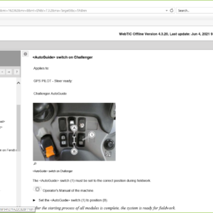
![download Hitachi Construction Machinery MPDr Ver 3.7.0.0 [10.2020] Diagnostic Software](https://i0.wp.com/www.ecuforcetruck.com/wp-content/uploads/2023/05/MPDR-3.7.00.png?resize=300%2C300&ssl=1&is-pending-load=1)
![download Hitachi Construction Machinery MPDr Ver 3.7.0.0 [10.2020] Diagnostic Software](https://www.ecuforcetruck.com/wp-content/uploads/2023/05/MPDR.png?is-pending-load=1)


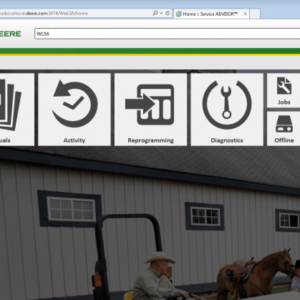


Related products

————————————————————————————————————————————————————————————
U000188
It has not been possible to send frames on High Speed CAN Communication Bus and It has not been possible to receive frames on High Speed CAN Communication Bus
Bus off
.
Diagnostic Service 14. No additional action is needed
.
CAN Communication Backbone 2 Net
————————————————————————————————————————————————————————————
U001088
It has not been possible to send frames on Medium Speed CAN Communication Bus and It has not been possible to receive frames on Medium Speed CAN Communication Bus
Bus off
.
Diagnostic Service 14. No additional action is needed
.
CAN Communication Backbone 1 Net
————————————————————————————————————————————————————————————
U010187
Missing Message
ETC2 not responding
.
Diagnostic Service 14. No additional action is needed
Check:
ETC2 not responding
Lost Communication with TECU
Node
DTC ISO
FailureEvent
FTB_Name
FunctBehaviorDesc
PossibleRootCause
ProcedureEraseConfirmedDtc
ProposedWorkshopAction
ProprietaryName
————————————————————————————————————————————————————————————
P034031
No Signal
The engine start time will increase.
Possible loss of power
Sensor/Harness Harness
Diagnostic Service 14. No additional action is needed
Check: Harness
Camshaft Position Sensor “A” Bank 1 or Single
Sensor
————————————————————————————————————————————————————————————
P034138
Signal Frequency Incorrect
The engine start time will increase.
Possible loss of power
Harness/sensor monting Harness
Sensor
Diagnostic Service 14. No additional action is needed
Check: Harness
Sensor
Camshaft Position Sensor A Circuit
Range/Performance
————————————————————————————————————————————————————————————
P052612
Measured voltage above limit
Circuit Short To Battery
Either
1. Fan will work as on/off fan. 100% fan speed if cooling is needed. Higher fuel consumption.
Or
2. Fan will work in open loop mode. Deteriorated fan control, but might not be noticable to driver.
Broken sensor/Harness Harness
Sensor
Diagnostic Service 14. No additional action is needed
Check: Harness Sensor
Fan Speed Sensor Circuit
————————————————————————————————————————————————————————————
P054300
Measured voltage outside the limits specified by the sensor
No Sub Type Information
Might get start problems in cold climate.
Heating element or wire broken.
Preheat sense 1
Diagnostic Service 14. No additional action is needed
Check:
Preheat sense 1
Intake Air Heater A Circuit Open
————————————————————————————————————————————————————————————
P054415
Measured voltage outside the limits specified by the sensor
Circuit Short To Battery or Open
Fault code set by ACM: IDTC_ENGEXHTEMP_OC
Diagnostic Service 14. No additional action is needed
Check:
Fault code set by ACM: IDTC_ENGEXHTEMP_OC
Exhaust Gas Temperature Sensor Bank 1 Sensor 1
————————————————————————————————————————————————————————————
P001676
Wrong Mounting Position
Fuel consumption increased
Bad correlation between cam and crank, engine transmission not correct
Engine transmission
Diagnostic Service 14. No additional action is needed
Check:
Engine transmission
Crankshaft Position – Camshaft Position Correlation
————————————————————————————————————————————————————————————
P007100
No Sub Type Information
Ambient air temp sensor or boost temp sensor faulty Ambient air temp sensor or Boost temp sensor
Diagnostic Service 14. No additional action is needed
Check:
Ambient air temp sensor or Boost temp sensor
Ambient Air Temperature Sensor Range/Performance
————————————————————————————————————————————————————————————
P02CD00
No Sub Type Information
Larger errors can be noticeable at engine idle speed
– PTO is connected incorrectly so that ECM is not informed if it is engaged.
– Low or high flow injector.
– Uneven spaced tooth on flywheel.
– Bad compression.
Injector, see Probable errors
Diagnostic Service 14. No additional action is needed
Check:
Injector, see Probable errors
Cylinder 1 Fuel Injector Offset Learning at Max Limit
————————————————————————————————————————————————————————————
P02CF00
No Sub Type Information
Larger errors can be noticeable at engine idle speed
– PTO is connected incorrectly so that ECM is not informed if it is engaged.
– Low or high flow injector.
– Uneven spaced tooth on flywheel.
– Bad compression.
Injector, see Probable errors
Diagnostic Service 14. No additional action is needed
Check:
Injector, see Probable errors
Cylinder 2 Fuel Injector Offset Learning at Max Limit
Node
DTC ISO
FailureEvent
FTB_Name
FunctBehaviorDesc
PossibleRootCause
ProcedureEraseConfirmedDtc
ProposedWorkshopAction
ProprietaryName
————————————————————————————————————————————————————————————
P02D100
No Sub Type Information
Larger errors can be noticeable at engine idle speed
– PTO is connected incorrectly so that ECM is not informed if it is engaged.
– Low or high flow injector.
– Uneven spaced tooth on flywheel.
– Bad compression.
Injector, see Probable errors
Diagnostic Service 14. No additional action is needed
Check:
Injector, see Probable errors
Cylinder 3 Fuel Injector Offset Learning at Max Limit
————————————————————————————————————————————————————————————
P02D300
No Sub Type Information
Larger errors can be noticeable at engine idle speed
– PTO is connected incorrectly so that ECM is not informed if it is engaged.
– Low or high flow injector.
– Uneven spaced tooth on flywheel.
– Bad compression.
Injector, see Probable errors
Diagnostic Service 14. No additional action is needed
Check:
Injector, see Probable errors
Cylinder 4 Fuel Injector Offset Learning at Max Limit
————————————————————————————————————————————————————————————
P02D500
No Sub Type Information
Larger errors can be noticeable at engine idle speed
– PTO is connected incorrectly so that ECM is not informed if it is engaged.
– Low or high flow injector.
– Uneven spaced tooth on flywheel.
– Bad compression.
Injector, see Probable errors
Diagnostic Service 14. No additional action is needed
Check:
Injector, see Probable errors
Cylinder 5 Fuel Injector Offset Learning at Max Limit
————————————————————————————————————————————————————————————
P02D700
No Sub Type Information
Larger errors can be noticeable at engine idle speed
– PTO is connected incorrectly so that ECM is not informed if it is engaged.
– Low or high flow injector.
– Uneven spaced tooth on flywheel.
– Bad compression.
Injector, see Probable errors
Diagnostic Service 14. No additional action is needed
Check:
Injector, see Probable errors
Cylinder 6 Fuel Injector Offset Learning at Max Limit
————————————————————————————————————————————————————————————
P033531
No Signal
Engine is running with imprecise timing causing risk of high fuel consumption and smoke. Cylinder balancing not working with risk of uneven running. Possible loss of power
Harness/sensor monting Harness
Sensor
Diagnostic Service 14. No additional action is needed
Check: Harness Sensor
Crankshaft Position Sensor “A”
Node
DTC ISO
FailureEvent
FTB_Name
FunctBehaviorDesc
PossibleRootCause
ProcedureEraseConfirmedDtc
ProposedWorkshopAction
ProprietaryName
————————————————————————————————————————————————————————————
P033638
Signal Frequency Incorrect
Engine is running with imprecise timing causing risk of high fuel consumption and smoke. Cylinder balancing not working with risk of uneven running. Possible loss of power
Sensor monting Sensor/Lack of shims
Diagnostic Service 14. No additional action is needed
Check:
Sensor/Lack of shims
Crankshaft Position Sensor A Circuit Range/Performance
————————————————————————————————————————————————————————————
P033900
No Sub Type Information
The engine start time will increase.Engine is running with imprecise timing causing risk of high fuel consumption and smoke. Cylinder balancing not working with risk of uneven running.
Possible loss of power
Harness/sensor monting Harness
Sensor
Diagnostic Service 14. No additional action is needed
Check: Harness Sensor
Crankshaft Position Sensor A Circuit Intermittent
————————————————————————————————————————————————————————————
P203F00
No Sub Type Information
No urea dosing
Urea symbol in cluster
Tank almost empty, stop dosing to maintain cooling ECM interpretation of raw value. Urea level. DST problem.
Diagnostic Service 14. No additional action is needed
Check:
ECM interpretation of raw value. Urea level. DST problem.
Reductant Level Low
————————————————————————————————————————————————————————————
P205A13
Measured voltage outside the limits specified by the sensor
Circuit Open
None
AdBlue tank temp sensor Cables
Connectors
Urea tank temp sensor, Cables, Connectors
Diagnostic Service 14. No additional action is needed
Check:
Urea tank temp sensor, Cables, Connectors
Reductant Tank Temperature Sensor
————————————————————————————————————————————————————————————
P208064
Signal Plausibility Failure
None
The sensor is not plausible Leakage in exhaust system Leakage in intake system Sensor
Diagnostic Service 14. No additional action is needed
Check:
Leakage in exhaust system Leakage in intake system Sensor
Exhaust Gas Temperature Sensor Circuit Range/Performance Bank 1 Sensor 1
————————————————————————————————————————————————————————————
P220013
Measured voltage outside the limits specified by the sensor
Circuit Open
Cabling between Nox- sensor and Nox-sensor ECU Nox-sensor
Nox-sensor cabling Nox-sensor
Diagnostic Service 14. No additional action is needed
Check:
Nox-sensor cabling Nox-sensor
NOx Sensor Bank 1 Sensor 1
————————————————————————————————————————————————————————————
P220164
Signal Plausibility Failure
Excessive urea dosing (only for SCR system)
Exhaust system leakage Air intake leakage
Nox-sensor
Dosing system (only for SCR system)
Exhaust system Air intake system
Nox-sensor
Diagnostic Service 14. No additional action is needed
Check:
Dosing system (only for SCR system) Exhaust system
Air intake system Nox-sensor
NOx Sensor Circuit Range/Performance
————————————————————————————————————————————————————————————
P060100
No Sub Type Information
Engine derate
signature failure
.
Diagnostic Service 14. No additional action is needed
Check: signature failure
Internal Control Module Memory Check Sum Error
————————————————————————————————————————————————————————————
P060700
No Sub Type
Information
Not possible to reprogram
ECU
.
Diagnostic Service 14. No additional
action is needed
.
Control Module
Performance
————————————————————————————————————————————————————————————
P06151C
Measured voltage outside the limits specified by the sensor
Circuit Voltage Out of Range
Impossible to activate starter motor
Start relay/harness
Diagnostic Service 14. No additional action is needed
Check:
Start relay/Harness
Starter Relay
Node
DTC ISO
FailureEvent
FTB_Name
FunctBehaviorDesc
PossibleRootCause
ProcedureEraseConfirmedDtc
ProposedWorkshopAction
ProprietaryName
————————————————————————————————————————————————————————————
P061600
Measured voltage
below limit
No Sub Type
Information
EMS can not control starter
Start relay/harness
Diagnostic Service 14. No additional
action is needed
Check:
Start relay/Harness
Starter Relay Circuit Low
————————————————————————————————————————————————————————————
P061700
Measured voltage above limit
No Sub Type Information
Impossible to activate starter motor.
Start relay/harness
Diagnostic Service 14. No additional action is needed
Check:
Start relay/Harness
Starter Relay Circuit High
————————————————————————————————————————————————————————————
P066800
Measured voltage below limit
No Sub Type Information
None
Internal fault in ECM ECM
Diagnostic Service 14. No additional action is needed
Check: ECM
PCM/ECM/TCM Internal
Temperature Sensor Circuit Low
————————————————————————————————————————————————————————————
P06B100
No Sub Type Information
Incorrect sensor readings
Harness/Sensor power supply
Harness
Diagnostic Service 14. No additional action is needed
Check: Harness
Sensor Power Supply A Circuit Low
————————————————————————————————————————————————————————————
P06B200
No Sub Type Information
Incorrect sensor readings
Harness/Sensor power supply
Harness
Diagnostic Service 14. No additional action is needed
Check: Harness
Sensor Power Supply A Circuit High
————————————————————————————————————————————————————————————
P06B400
No Sub Type Information
Incorrect sensor readings
Harness/Sensor power supply
Harness
Diagnostic Service 14. No additional action is needed
Check: Harness
Sensor Power Supply B Circuit Low
————————————————————————————————————————————————————————————
P06B500
No Sub Type Information
Incorrect sensor readings
Harness/Sensor power supply
Harness
Diagnostic Service 14. No additional action is needed
Check: Harness
Sensor Power Supply B Circuit High
————————————————————————————————————————————————————————————
P20EE00
No Sub Type Information
NOx-conversion reduced by appr. 50%
Possible ammonia smell
Regent out of specification, Dosing performance low Urea specification
Dosing system
Diagnostic Service 14. No additional action is needed
Check:
Urea specification Dosing system
SCR NOx Catalyst Efficiency Below Threshold (Bank 1)
————————————————————————————————————————————————————————————
P260013
Measured voltage outside the limits specified by the sensor
Circuit Open
Pump always at half speed. High coolant temperatures may be seen.
Broken actuator or wire. Actuator/Harness
Diagnostic Service 14. No additional action is needed
Check: Actuator/Harness
Coolant Pump Control Circuit/Open
————————————————————————————————————————————————————————————
P260200
Measured voltage below limit
No Sub Type Information
Pump always runs at full speed. Increased fuel consumption may be seen.
Broken actuator, wire or ECM driver output Actuator/Harness
Diagnostic Service 14. No additional action is needed
Check: Actuator/Harness
Coolant Pump Control Circuit Low
————————————————————————————————————————————————————————————
P260300
Measured voltage above limit
No Sub Type Information
Pump always at half speed. High coolant temperatures may be seen.
Broken actuator, wire or ECM driver output Actuator/Harness
Diagnostic Service 14. No additional action is needed
Check: Actuator/Harness
Coolant Pump Control Circuit High
————————————————————————————————————————————————————————————
P261087
Missing Message
Timestamps from Cluster not available
J1708 time data failure and J1939 message does not exist. (Cluster error).
Cluster
Diagnostic Service 14. No additional action is needed
Check: Cluster
ECM/PCM Internal Engine Off Timer Performance
————————————————————————————————————————————————————————————
P2BA700
No Sub Type Information
.
Not possible to erase, will be healed after 400 days. In production, please re- flash the control unit and make sure to enter factory mode next time
.
NOx Exceedence – Empty Reagent Tank
————————————————————————————————————————————————————————————
P023400
No Sub Type Information
Too high pressure Turbine , Compressor
Diagnostic Service 14. No additional action is needed
Check:
Turbine , Compressor
Turbocharger/Supercharg er Overboost Condition
————————————————————————————————————————————————————————————
P029900
No Sub Type Information
Too low pressure
Boost leakage, wastegate, VGT, compressor.
Diagnostic Service 14. No additional action is needed
Check:
Boost leakage, wastegate, VGT, compressor.
Turbocharger/Supercharg er Underboost
————————————————————————————————————————————————————————————
U300001
Measured voltage outside the limits specified by the sensor
General Electrical Failure
Possible damage on EMS system components depending on the high voltage (>36V)
Generator, external charger
Diagnostic Service 14. No additional action is needed
Check:
Generator, external charger
Electronic control unit
————————————————————————————————————————————————————————————
U300041
Program memory corruption
General Checksum Failure
The engine can not be started
No software Software download
application
Diagnostic Service 14. No additional action is needed
Check:
Software download application
Electronic control unit
Node
DTC ISO
FailureEvent
FTB_Name
FunctBehaviorDesc
PossibleRootCause
ProcedureEraseConfirmedDtc
ProposedWorkshopAction
ProprietaryName
————————————————————————————————————————————————————————————
P007087
Missing Message
None
J1708 and CAN ambient air temperature message does not exist.
Harness. Cluster
Diagnostic Service 14. No additional action is needed
Check:
Harness. Cluster
Ambient Air Temperature Sensor “A”
————————————————————————————————————————————————————————————
P011013
Measured voltage outside the limits specified by the
sensor
Circuit Open
Engine is running but could be difficult to start in cold climate.
Connectors. Harness.
Sensor
Diagnostic Service 14. No additional action is needed
Check: Connectors. Harness.
Sensor
Intake Air Temperature Sensor 1 Bank 1
————————————————————————————————————————————————————————————
P011200
Measured voltage below limit
No Sub Type Information
Engine is running but could be difficult to start in cold climate.
Connectors. Harness.
Sensor
Diagnostic Service 14. No additional action is needed
Check: Connectors. Harness.
Sensor
Intake Air Temperature Sensor 1 Circuit Low Bank 1
————————————————————————————————————————————————————————————
P011700
Measured voltage below limit
No Sub Type Information
Engine is difficult to start. Idle run regulation is
detoriated.
Harness Sensor
Sensor/Harness
Diagnostic Service 14. No additional action is needed
Check: Sensor/Harness
Engine Coolant Temperature Circuit Low
————————————————————————————————————————————————————————————
P021700
No Sub Type Information
Powerloss
Extreme Driving conditions Extreme driving conditions Coolant thermostat
Fan
Blocked radiator
Diagnostic Service 14. No additional action is needed
Check:
Extreme driving conditions Coolant thermostat
Fan
Blocked radiator
Engine Coolant Over Temperature Condition
————————————————————————————————————————————————————————————
P048013
Measured voltage outside the limits specified by the sensor
Circuit Open
Fan runs at full speed. Increased fuel consumption may be seen.
Broken actuator or wire. Actuator/Harness
Diagnostic Service 14. No additional action is needed
Check: Actuator/Harness
Fan 1 Control Circuit
————————————————————————————————————————————————————————————
P051B64
Signal Plausibility Failure
Powerloss (minor) P3524:
Black smoke (minor)
The crank case pressure is showing either too high or to low value.
(abnormal value) Sensor
ECM
Diagnostic Service 14. No additional action is needed
Check: Sensor ECM
Engine High Resolution Crankcase Pressure Circuit Range/Performance
————————————————————————————————————————————————————————————
P051A13
Measured voltage outside the limits specified by the sensor
Circuit Open
None
Sensor/Harness Harness
Sensor
Diagnostic Service 14. No additional action is needed
Check: Harness Sensor
Crankcase Pressure Sensor
————————————————————————————————————————————————————————————
P051D00
Measured voltage above limit
No Sub Type Information
None
Sensor/Harness Harness
Sensor
Diagnostic Service 14. No additional action is needed
Check: Harness Sensor
Engine High Resolution Crankcase Pressure
————————————————————————————————————————————————————————————
P052300
Measured voltage above limit
No Sub Type Information
Oil pressure shows 0 in the cluster. Engine is running.
Sensor/Harness Harness
Sensor
Diagnostic Service 14. No additional action is needed
Check: Harness Sensor
Engine Oil Pressure Circuit High
————————————————————————————————————————————————————————————
P052400
No Sub Type Information
Low pressure, powerloss
Oil leakage, broken oil pump, clogged oil system Oil system
Diagnostic Service 14. No additional action is needed
Check:
Oil system
Engine Oil Pressure Too Low
————————————————————————————————————————————————————————————
P222800
Measured voltage below limit
No Sub Type Information
None
Internal fault in ECM Sensor
ECM
Diagnostic Service 14. No additional action is needed
Check: Sensor ECM
Barometric Pressure Circuit Low
————————————————————————————————————————————————————————————
P222900
Measured voltage above limit
No Sub Type Information
None
Internal fault in ECM Sensor
ECM
Diagnostic Service 14. No additional action is needed
Check: Sensor ECM
Barometric Pressure Circuit High
————————————————————————————————————————————————————————————
P226400
No Sub Type Information
None
No error: Used for indication
when priming pump is active
None
Diagnostic Service 14. No additional action is needed
Check:
No error: Used for indication when priming pump is active
Water in Fuel Sensor
————————————————————————————————————————————————————————————
P226600
Measured voltage
below limit
No Sub Type
Information
Will give water in fuel
indication.
Harness
Diagnostic Service 14. No additional
action is needed
Check:
Harness
Water In Fuel Indicator
Circuit Low
————————————————————————————————————————————————————————————
P226700
Measured voltage above limit
No Sub Type Information
Undetected water in fuel can lead to engine stop
Harness
Diagnostic Service 14. No additional action is needed
Check: Harness
Water In Fuel Indicator Circuit High
Node
DTC ISO
FailureEvent
FTB_Name
FunctBehaviorDesc
PossibleRootCause
ProcedureEraseConfirmedDtc
ProposedWorkshopAction
ProprietaryName
————————————————————————————————————————————————————————————
P250C00
Measured voltage below limit
No Sub Type Information
Oil level can not be measured.
Sensor/Harness Harness
Sensor
Diagnostic Service 14. No additional action is needed
Check: Harness
Sensor
Engine Oil Level Circuit Low
————————————————————————————————————————————————————————————
P250F00
No Sub Type Information
None
Critically low oil level Leakage
Leakage
Sensor
Diagnostic Service 14. No additional action is needed
Check: Leakage Sensor
Engine Oil Level Too Low
————————————————————————————————————————————————————————————
P255613
Measured voltage outside the limits specified by the
sensor
Circuit Open
Coolant level can not be detected.
Harness Harness connector
sensor
Diagnostic Service 14. No additional action is needed
Check: Harness connector
sensor
Engine Coolant Level Sensor/Switch
————————————————————————————————————————————————————————————
P255900
Measured voltage above limit
No Sub Type Information
Coolant level can not be detected.
Harness Harness connector
sensor
Diagnostic Service 14. No additional action is needed
Check: Harness connector
sensor
Engine Coolant Level Circuit High
————————————————————————————————————————————————————————————
P256000
No Sub Type Information
Powerloss
Coolant level below range if not Harness
Coolant system
Diagnostic Service 14. No additional action is needed
Check:
Coolant system
Engine Coolant Level Low
————————————————————————————————————————————————————————————
P108600
No Sub Type Information
None
Low oil level Leakage Leakage
Sensor
Diagnostic Service 14. No additional action is needed
Check: Leakage Sensor
Oil Level Moderately Low
————————————————————————————————————————————————————————————
P20BF00
Measured voltage below limit
No Sub Type Information
.
Diagnostic Service 14. No additional action is needed
.
Aftertreatment Reagent Hose Heater 2 Short Circuit Low
————————————————————————————————————————————————————————————
U014100
Lost communication with the node on Medium Speed CAN Communication Bus
No Sub Type Information
.
Diagnostic Service 14. No additional action is needed
.
Lost Communication With VMCU
————————————————————————————————————————————————————————————
U012A87
Lost communication with the node
Missing Message
.
Diagnostic Service 14. No additional action is needed
.
Lost Communication With CCIOM
————————————————————————————————————————————————————————————
P109000
No Sub Type Information
Display of the message, without bip, simultaneously with the gear engaged pictogram
Driver started at too high gear at start
Protective alert for
clutch/transmission
Diagnostic Service 14. No additional action is needed
Check:
Protective alert for clutch/transmission
Transmission High Gear At Start
————————————————————————————————————————————————————————————
P208E00
No Sub Type Information
No urea dosing
Sensor/Harness dosing valve
injector, clogged hoses
Diagnostic Service 14. No additional action is needed
Check:
dosing valve
injector, clogged hoses
Aftertreatment Reagent Dosing Valve Clogged
————————————————————————————————————————————————————————————
P109541
General Checksum Failure
Engine derate
.
Diagnostic Service 14. No additional action is needed
.
Aftertreatment Control Unit
————————————————————————————————————————————————————————————
P109641
General Checksum
Failure
Engine derate
.
Diagnostic Service 14. No additional
action is needed
.
Transmission Control Unit
————————————————————————————————————————————————————————————
P069200
Measured voltage above limit
No Sub Type Information
Fan runs at full speed. Increased fuel consumption may be seen.
Broken actuator, wire or ECM driver output Actuator/Harness
Diagnostic Service 14. No additional action is needed
Check: Actuator/Harness
Fan 1 Control Circuit High
————————————————————————————————————————————————————————————
P069100
Measured voltage below limit
No Sub Type Information
Fan always deactivated or always activated if fault is
intermittent.
Broken actuator, wire or ECM driver output
Actuator/Harness
Diagnostic Service 14. No additional action is needed
Check: Actuator/Harness
Fan 1 Control Circuit Low
————————————————————————————————————————————————————————————
U015500
Lost communication with the node on Medium Speed CAN Communication Bus
No Sub Type Information
.
Diagnostic Service 14. No additional action is needed
.
Lost Communication With Instrument Panel Cluster (IPC) Control Module
Node
DTC ISO
FailureEvent
FTB_Name
FunctBehaviorDesc
PossibleRootCause
ProcedureEraseConfirmedDtc
ProposedWorkshopAction
ProprietaryName
————————————————————————————————————————————————————————————
P052013
Measured voltage outside the limits specified by the
sensor
Circuit Open
Oil pressure shows 0 in the cluster. Engine is running.
Sensor/Harness Harness
Sensor
Diagnostic Service 14. No additional action is needed
Check: Harness Sensor
Engine Oil Pressure Sensor/Switch “A”
————————————————————————————————————————————————————————————
P066613
Measured voltage outside the limits specified by the
sensor
Circuit Open
None
Internal fault in ECM ECM
Diagnostic Service 14. No additional action is needed
Check: ECM
Control Module Internal Temperature Sensor “A”
————————————————————————————————————————————————————————————
P020113
Measured voltage outside the limits specified by the
sensor
Circuit Open
Loss of power and uneven running. Run on three to five cylinders
Harness/Broken solenoid Injector/Harness
Diagnostic Service 14. No additional action is needed
Check: Injector/Harness
Cylinder 1 Injector “A”
————————————————————————————————————————————————————————————
P020313
Measured voltage outside the limits specified by the
sensor
Circuit Open
Loss of power and uneven running. Run on three to five cylinders
Harness/Broken solenoid Injector/Harness
Diagnostic Service 14. No additional action is needed
Check: Injector/Harness
Cylinder 3 Injector “A”
————————————————————————————————————————————————————————————
P020413
Measured voltage outside the limits specified by the sensor
Circuit Open
Loss of power and uneven running. Run on three to five cylinders
Harness/Broken solenoid Injector/Harness
Diagnostic Service 14. No additional action is needed
Check: Injector/Harness
Cylinder 4 Injector “A”
————————————————————————————————————————————————————————————
P020513
Measured voltage outside the limits specified by the sensor
Circuit Open
Loss of power and uneven running. Run on three to five cylinders
Harness/Broken solenoid Injector/Harness
Diagnostic Service 14. No additional action is needed
Check: Injector/Harness
Cylinder 5 Injector “A”
————————————————————————————————————————————————————————————
P020613
Measured voltage outside the limits specified by the
sensor
Circuit Open
Loss of power and uneven running. Run on three to five cylinders
Harness/Broken solenoid Injector/Harness
Diagnostic Service 14. No additional action is needed
Check: Injector/Harness
Cylinder 6 Injector “A”
————————————————————————————————————————————————————————————
P220E93
No Operation
Sensor
Diagnostic Service 14. No additional action is needed
Check: Sensor
NOx Sensor Heater Control Circuit Range/Performance (Bank
1 Sensor 1)
————————————————————————————————————————————————————————————
P250A13
Measured voltage outside the limits specified by the
sensor
Circuit Open
Oil level can not be measured.
Sensor/Harness Harness
Sensor
Diagnostic Service 14. No additional action is needed
Check: Harness Sensor
Engine Oil Level Sensor
————————————————————————————————————————————————————————————
P020213
Measured voltage outside the limits specified by the
sensor
Circuit Open
Loss of power and uneven running. Run on three to five cylinders
Harness/Broken solenoid Injector/Harness
Diagnostic Service 14. No additional action is needed
Check: Injector/Harness
Cylinder 2 Injector “A”
————————————————————————————————————————————————————————————
P100E18
Circuit Current Below Threshold
None
Injector/Harness resistance too high.
Injector/Harness
Diagnostic Service 14. No additional action is needed
Check: Injector/Harness
Injector 2
————————————————————————————————————————————————————————————
P100F18
Circuit Current Below Threshold
None
Injector/Harness resistance too high.
Injector/Harness
Diagnostic Service 14. No additional action is needed
Check: Injector/Harness
Injector 3
————————————————————————————————————————————————————————————
P101018
Circuit Current Below Threshold
None
Injector/Harness resistance too high.
Injector/Harness
Diagnostic Service 14. No additional action is needed
Check: Injector/Harness
Injector 4
————————————————————————————————————————————————————————————
P101518
Circuit Current Below Threshold
None
Injector/Harness resistance too high.
Injector/Harness
Diagnostic Service 14. No additional action is needed
Check: Injector/Harness
Injector 5
————————————————————————————————————————————————————————————
P101618
Circuit Current Below Threshold
None
Injector/Harness resistance too high.
Injector/Harness
Diagnostic Service 14. No additional action is needed
Check: Injector/Harness
Injector 6
————————————————————————————————————————————————————————————
P101711
Measured voltage below limit
Circuit Short To Ground
High fuel consumption due to fuel leakage.
Broken solenoid, wire or ECM driver output
Water-in-fuel valve driver
Diagnostic Service 14. No additional action is needed
Check:
Water-in-fuel valve driver
Water In Fuel Drainage Valve
Node
DTC ISO
FailureEvent
FTB_Name
FunctBehaviorDesc
PossibleRootCause
ProcedureEraseConfirmedDtc
ProposedWorkshopAction
ProprietaryName
————————————————————————————————————————————————————————————
P101712
Measured voltage above limit
Circuit Short To Battery
Valve constantly shut.
Broken solenoid, wire or ECM driver output
Water-in-fuel valve driver
Diagnostic Service 14. No additional action is needed
Check:
Water-in-fuel valve driver
Water In Fuel Drainage Valve
————————————————————————————————————————————————————————————
P101713
Measured voltage outside the limits specified by the
sensor
Circuit Open
Valve constantly shut.
Broken solenoid or wire. Water-in-fuel valve driver
Diagnostic Service 14. No additional action is needed
Check:
Water-in-fuel valve driver
Water In Fuel Drainage Valve
————————————————————————————————————————————————————————————
P220300
No Sub Type Information
Cabling between Nox- sensor and Nox-sensor ECU Nox-sensor
Nox-sensor cabling Nox-sensor
Diagnostic Service 14. No additional action is needed
Check:
Nox-sensor cabling Nox-sensor
NOx Sensor Circuit High Bank 1 Sensor 1
————————————————————————————————————————————————————————————
P2BA800
No Sub Type Information
.
Not possible to erase, will be healed after 400 days. In production, please re- flash the control unit and make sure to enter factory mode next time
.
NOx Exceedence – Interruption of Reagent Dosing Activity
————————————————————————————————————————————————————————————
P2BA900
No Sub Type Information
.
Not possible to erase, will be healed after 400 days. In production, please re- flash the control unit and make sure to enter factory mode next time
.
NOx Exceedence – Insufficient Reagent Quality
————————————————————————————————————————————————————————————
P2BAA00
No Sub Type Information
.
Not possible to erase, will be healed after 400 days. In production, please re- flash the control unit and make sure to enter factory mode next time
.
NOx Exceedence – Low Reagent Consumption
————————————————————————————————————————————————————————————
P2BAD00
No Sub Type Information
.
Not possible to erase, will be healed after 400 days. In production, please re- flash the control unit and make sure to enter factory mode next time
.
NOx Exceedence – Root Cause Unknown
————————————————————————————————————————————————————————————
P2BAE96
Component Internal Failure
.
Not possible to erase, will be healed after 400 days. In production, please re- flash the control unit and make sure to enter factory mode next time
.
NOx Exceedence – NOx Control Monitoring System
————————————————————————————————————————————————————————————
P100211
Measured voltage below limit
Circuit Short To Ground
Induction air is hot. Preheat relay is impossible to turn off.
Harness
Diagnostic Service 14. No additional action is needed
Check: Harness
Preheat Relay
————————————————————————————————————————————————————————————
P100212
Measured voltage above limit
Circuit Short To Battery
Preheat relay not activated. White smoke for cold start. Start problems in cold climate.
Preheat relay solenoid shorted
Preheat relay.
Diagnostic Service 14. No additional action is needed
Check: Preheat relay.
Preheat Relay
————————————————————————————————————————————————————————————
P100213
Measured voltage outside the limits specified by the sensor
Circuit Open
Preheat relay not activated. White smoke for cold start. Start problems in cold climate.
Harness or Preheat relay solenoid
Harness. Preheat relay.
Diagnostic Service 14. No additional action is needed
Check:
Harness. Preheat relay.
Preheat Relay
————————————————————————————————————————————————————————————
P100629
Signal invalid
None
The boost temperature sensor output is showing constant value.
Harness
Sensor
Diagnostic Service 14. No additional action is needed
Check: Harness Sensor
Intake Air Temperature Sensor 1 Stuck Bank 1
————————————————————————————————————————————————————————————
P100713
Measured voltage outside the limits specified by the
sensor
Circuit Open
None
Pressure switch / Harness Pressure switch/Harness
Diagnostic Service 14. No additional action is needed
Check:
Pressure switch/Harness
Air Filter Indicator
Node
DTC ISO
FailureEvent
FTB_Name
FunctBehaviorDesc
PossibleRootCause
ProcedureEraseConfirmedDtc
ProposedWorkshopAction
ProprietaryName
————————————————————————————————————————————————————————————
P100D18
Circuit Current Below Threshold
None
Injector/Harness resistance too high.
Injector/Harness
Diagnostic Service 14. No additional action is needed
Check: Injector/Harness
Injector 1
————————————————————————————————————————————————————————————
P102111
Measured voltage below limit
Circuit Short To Ground
VCB can not be turned off. Causes engine to stop.
Engine impossible to
restart.
Broken actuator/Harness VCB actuator
Diagnostic Service 14. No additional action is needed
Check:
VCB actuator
Volvo Compression Brake (VCB) Control Circuit
————————————————————————————————————————————————————————————
P102112
Measured voltage above limit
Circuit Short To Battery
VCB can not be turned on. Engine break function derated. Gear shift performance derated for some automatic transmission boxes.
Broken actuator/Harness VCB actuator
Diagnostic Service 14. No additional action is needed
Check:
VCB actuator
Volvo Compression Brake (VCB) Control Circuit
————————————————————————————————————————————————————————————
P102113
Measured voltage outside the limits specified by the sensor
Circuit Open
VCB can not be turned on. Engine break function derated. Gear shift performance derated for some automatic transmission boxes.
Broken actuator/Harness VCB actuator
Diagnostic Service 14. No additional action is needed
Check:
VCB actuator
Volvo Compression Brake (VCB) Control Circuit
————————————————————————————————————————————————————————————
U010E00
Lost communication with the node
No Sub Type Information
.
Diagnostic Service 14. No additional action is needed
.
Lost Communication With Reductant Control
Module
————————————————————————————————————————————————————————————
P019513
Measured voltage outside the limits specified by the
sensor
Circuit Open
None
Harness Sensor
Diagnostic Service 14. No additional action is needed
Check: Harness Sensor
Engine Oil Temperature Sensor “A”
————————————————————————————————————————————————————————————
P204A13
Measured voltage outside the limits specified by the sensor
Circuit Open
No urea dosing
ACM Pump module: AdBlue pressure sensor
ACM Pump module: Internal cabling
ACM Pump module: Urea pressure sensor, ACM Pump module: Internal cabling
Diagnostic Service 14. No additional action is needed
Check:
ACM Pump module: Urea pressure sensor, ACM Pump module: Internal cabling
Reductant Pressure Sensor
————————————————————————————————————————————————————————————
P203D00
Measured voltage above limit
No Sub Type Information
None
AdBlue tank level sensor, Cables, Connectors
Diagnostic Service 14. No additional action is needed
Check:
AdBlue tank level sensor, Cables, Connectors
Aftertreatment Reagent Level Short Circuit High
————————————————————————————————————————————————————————————
P208A13
Measured voltage outside the limits specified by the
sensor
Circuit Open
No urea dosing
Wiring harness internal error in pump
Diagnostic Service 14. No additional action is needed
Check:
Wiring harness internal error in pump
Reductant Pump “A” Control
————————————————————————————————————————————————————————————
P026500
Measured voltage above limit
No Sub Type Information
Loss of power and uneven
running. Run on three to five cylinders
Harness shorted Harness
Diagnostic Service 14. No additional action is needed
Check: Harness
Injector 2 Short Circuit High
————————————————————————————————————————————————————————————
P026800
Measured voltage above limit
No Sub Type Information
Loss of power and uneven
running. Run on three to five cylinders
Harness shorted Harness
Diagnostic Service 14. No additional action is needed
Check: Harness
Injector 3 Short Circuit High
————————————————————————————————————————————————————————————
P027100
Measured voltage above limit
No Sub Type Information
Loss of power and uneven running. Run on three to
five cylinders
Harness shorted Harness
Diagnostic Service 14. No additional action is needed
Check: Harness
Injector 4 Short Circuit High
————————————————————————————————————————————————————————————
P027400
Measured voltage above limit
No Sub Type Information
Loss of power and uneven
running. Run on three to five cylinders
Harness shorted Harness
Diagnostic Service 14. No additional action is needed
Check: Harness
Injector 5 Short Circuit High
————————————————————————————————————————————————————————————
P027700
Measured voltage above limit
No Sub Type Information
Loss of power and uneven running. Run on three to
five cylinders
Harness shorted Harness
Diagnostic Service 14. No additional action is needed
Check: Harness
Injector 6 Short Circuit High
————————————————————————————————————————————————————————————
P054500
Measured voltage below limit
No Sub Type Information
Fault code set by ACM: IDTC_ENGEXHTEMP_SCL
Diagnostic Service 14. No additional action is needed
Check:
Fault code set by ACM: IDTC_ENGEXHTEMP_SCL
Exhaust Gas Temperature Short Circuit Low
Node
DTC ISO
FailureEvent
FTB_Name
FunctBehaviorDesc
PossibleRootCause
ProcedureEraseConfirmedDtc
ProposedWorkshopAction
ProprietaryName
————————————————————————————————————————————————————————————
P20B300
Measured voltage below limit
No Sub Type Information
None
.
Diagnostic Service 14. No additional action is needed
.
Reductant Heater Coolant Control Valve Circuit Low
————————————————————————————————————————————————————————————
P204800
Measured voltage below limit
No Sub Type Information
No urea dosing
ACM Pump module: DCU ACM Pump module: internal cabling
ACM Pump module: DCU,
ACM Pump module: internal cabling
Diagnostic Service 14. No additional action is needed
Check:
ACM Pump module: DCU, ACM Pump module: internal cabling
Aftertreatment Reagent Dosing Valve Short Circuit Low
————————————————————————————————————————————————————————————
P204713
Measured voltage outside the limits specified by the sensor
Circuit Open
no urea dosing
Cable / Connectors
ACM Dosing module: Dosing valve
Cable / Connectors ACM Dosing module: Dosing
valve
Diagnostic Service 14. No additional action is needed
Check:
Cable / Connectors ACM Dosing module: Dosing valve
Reductant Injection Valve Control Bank 1 Unit 1
————————————————————————————————————————————————————————————
P20C300
Measured voltage below limit
No Sub Type Information
.
Diagnostic Service 14. No additional action is needed
.
Aftertreatment Reagent Hose Heater 3 Short Circuit Low
————————————————————————————————————————————————————————————
P20BB00
Measured voltage below limit
No Sub Type Information
.
Diagnostic Service 14. No additional action is needed
.
Aftertreatment Reagent Hose Heater 1 Short Circuit Low
————————————————————————————————————————————————————————————
P20A200
Measured voltage below limit
No Sub Type Information
Not possible to perform afterrun
Internal electrical failure in valve within the ACM
Diagnostic Service 14. No additional action is needed
Check:
Internal electrical failure in valve within the ACM
Aftertreatment Reagent Direction Valve Short
Circuit Low
————————————————————————————————————————————————————————————
P065900
Measured voltage above limit
No Sub Type Information
.
Diagnostic Service 14. No additional action is needed
.
ACM Actuator High Supply 1 Short Circuit
High
————————————————————————————————————————————————————————————
P065800
Measured voltage below limit
No Sub Type Information
.
Diagnostic Service 14. No additional action is needed
.
ACM Actuator High Supply 1 Short Circuit Low
————————————————————————————————————————————————————————————
P208D00
Measured voltage above limit
No Sub Type Information
No urea dosing
Wiring harness internal error in pump
Diagnostic Service 14. No additional action is needed
Check:
Wiring harness internal error in pump
Aftertreatment Reagent
Pump Control Short Circut High
————————————————————————————————————————————————————————————
P208C00
Measured voltage below limit
No Sub Type Information
No urea dosing
Wiring harness internal error in pump
Diagnostic Service 14. No additional action is needed
Check:
Wiring harness internal error in pump
Aftertreatment Reagent Pump Control Short
Circuit Low
————————————————————————————————————————————————————————————
P203A13
Measured voltage outside the limits specified by the
sensor
Circuit Open
None
AdBlue tank level sensor, Cables, Connectors
Diagnostic Service 14. No additional action is needed
Check:
AdBlue tank level sensor, Cables, Connectors
Reductant Level Sensor “A”
————————————————————————————————————————————————————————————
P108700
No Sub Type
Information
None
No fault
None
Diagnostic Service 14. No additional
action is needed
Check:
No fault
Injector 1 Missing Glitch
Signature
————————————————————————————————————————————————————————————
P107B00
No Sub Type
Information
.
Diagnostic Service 14. No additional
action is needed
.
Injector 2 Missing Glitch
Signature
————————————————————————————————————————————————————————————
P019700
Measured voltage below limit
No Sub Type Information
None
Harness Sensor
Diagnostic Service 14. No additional action is needed
Check: Harness Sensor
Oil Temperature Short Circuit Low
————————————————————————————————————————————————————————————
P024313
Measured voltage outside the limits specified by the sensor
Circuit Open
Powerloss
Broken actuator or wire. Wastegate
Diagnostic Service 14. No additional action is needed
Check: Wastegate
Turbocharger/Supercharg er Wastegate Solenoid “A”
————————————————————————————————————————————————————————————
P024471
Actuator Stuck
Possible turbo damage
Wategate mechanically damaged
Wastegate
Diagnostic Service 14. No additional action is needed
Check: Wastegate
Wastegate Stuck Close
————————————————————————————————————————————————————————————
P024500
Measured voltage below limit
No Sub Type Information
Broken actuator, wire or ECM driver output Wastegate
Diagnostic Service 14. No additional action is needed
Check: Wastegate
Wastegate Short Circuit Low
————————————————————————————————————————————————————————————
P024600
Measured voltage above limit
No Sub Type Information
Powerloss
Broken actuator, wire or ECM driver output Wastegate
Diagnostic Service 14. No additional action is needed
Check: Wastegate
Wastegate Short Circuit High
Node
DTC ISO
FailureEvent
FTB_Name
FunctBehaviorDesc
PossibleRootCause
ProcedureEraseConfirmedDtc
ProposedWorkshopAction
ProprietaryName
————————————————————————————————————————————————————————————
P026200
Measured voltage above limit
No Sub Type Information
Loss of power and uneven running. Run on three to
five cylinders
Harness shorted Harness
Diagnostic Service 14. No additional action is needed
Check: Harness
Injector 1 Short Circuit High
————————————————————————————————————————————————————————————
P204300
No Sub Type Information
None
Urea tank temp sensor stuck high
Urea tank temp sensor
Diagnostic Service 14. No additional action is needed
Check:
Urea tank temp sensor
Aftertreatment Reagent Tank Temperature Sensor Stuck
————————————————————————————————————————————————————————————
P209F73
Actuator Stuck Closed
None
Urea tank temp sensor or Urea tank heating system Urea tank temp sensor, Urea tank heating system
Diagnostic Service 14. No additional action is needed
Check:
Urea tank temp sensor, Urea tank heating system
Aftertreatment Reagent Tank Temperature
————————————————————————————————————————————————————————————
P20F400
No Sub Type Information
Too low urea consumption
Urea level sensor stuck Clogged urea system Wrong urea tank Wrong dosing module Nozzle or
ACM Dosing module: dosing
valve
Diagnostic Service 14. No additional action is needed
Check:
Nozzle or
ACM Dosing module: dosing valve
AdBlue Consumption Too Low
————————————————————————————————————————————————————————————
P108900
No Sub Type
Information
.
Diagnostic Service 14. No additional
action is needed
.
Injector 3 Missing Glitch
Signature
————————————————————————————————————————————————————————————
P108B00
No Sub Type Information
.
Diagnostic Service 14. No additional action is needed
.
Injector 4 Missing Glitch Signature
————————————————————————————————————————————————————————————
P108D00
No Sub Type
Information
.
Diagnostic Service 14. No additional
action is needed
.
Injector 5 Missing Glitch
Signature
————————————————————————————————————————————————————————————
P108F00
No Sub Type
Information
.
Diagnostic Service 14. No additional
action is needed
.
Injector 6 Missing Glitch
Signature
————————————————————————————————————————————————————————————
U029D00
Lost communication with the node
No Sub Type Information
MS from Nox-sensor ECU Nox-sensor power supply CAN communication between ECM and Nox-EUC
Diagnostic Service 14. No additional action is needed
Check:
Nox-sensor power supply
CAN communication between ECM and Nox-EUC
Lost Communication With NOx Sensor “A”
————————————————————————————————————————————————————————————
P204C00
Measured voltage below limit
No Sub Type Information
No urea dosing
ACM Pump module: AdBlue pressure sensor
ACM Pump module: Internal cabling
ACM Pump module: Urea pressure sensor, ACM Pump module: Internal cabling
Diagnostic Service 14. No additional action is needed
Check:
ACM Pump module: Urea pressure sensor, ACM Pump module: Internal cabling
Aftertreatment Reagent Pressure Sensor Circuit Low
————————————————————————————————————————————————————————————
U016700
No Sub Type Information
The engine can not be started
Immobilizer unit not installed. (When Immo in Cluster is used, the Cluster maybe did not wake up properly)
Immo system
Diagnostic Service 14. No additional action is needed
Check:
Immo system
Lost Communication With Vehicle Immobilizer Control Module
————————————————————————————————————————————————————————————
P220A1C
Circuit Voltage Out of Range
Too high voltage to NOx- sensor ECU
Battery voltage
Diagnostic Service 14. No additional action is needed
Check:
Battery voltage
NOx Sensor Supply Voltage Circuit (Bank 1 Sensor 1)
————————————————————————————————————————————————————————————
U042600
No Sub Type Information
The engine can not be started
ECM and Immobilizer(or Cluster) unit security codes do not match.
Immo system
Diagnostic Service 14. No additional action is needed
Check:
Immo system
Invalid Data Received From Vehicle Immobilizer Control Module
————————————————————————————————————————————————————————————
P114000
No Sub Type Information
No VCB
low engine oil temperature
.
Diagnostic Service 14. No additional action is needed
Check:
low engine oil temperature
Volvo Compression Brake (VCB) Control Oil Temperature Too Low
————————————————————————————————————————————————————————————
P113711
Measured voltage below limit
Circuit Short To Ground
Oil thermostat alwaysclosed.
Broken actuator, wire or ECM driver output Actuator/Harness
Diagnostic Service 14. No additional action is needed
Check: Actuator/Harness
Oil Thermostat
Node
DTC ISO
FailureEvent
FTB_Name
FunctBehaviorDesc
PossibleRootCause
ProcedureEraseConfirmedDtc
ProposedWorkshopAction
ProprietaryName
————————————————————————————————————————————————————————————
P113712
Measured voltage above limit
Circuit Short To Battery
Oil thermostat always open. Increased fuel consumption may be seen.
Broken actuator, wire or ECM driver output Actuator/Harness
Diagnostic Service 14. No additional action is needed
Check: Actuator/Harness
Oil Thermostat
————————————————————————————————————————————————————————————
P113713
Measured voltage outside the limits specified by the
sensor
Circuit Open
Oil thermostat always open. Increased fuel consumption may be seen.
Broken actuator or wire. Actuator/Harness
Diagnostic Service 14. No additional action is needed
Check: Actuator/Harness
Oil Thermostat
————————————————————————————————————————————————————————————
P011164
Signal Plausibility Failure
None
The boost temperature sensor output is showing either too high or to low value.
(abnormal value) Harness
Sensor
Ambient air temperature sensor.
Diagnostic Service 14. No additional action is needed
Check:
Harness Sensor
Ambient air temperature sensor.
Intake Air Temperature Sensor 1 Circuit Range/Performance Bank 1
————————————————————————————————————————————————————————————
P20E892
Performance or Incorrect Operation
No urea dosing
ACM dosing module: Dosing valve leakage.
Bleed orifice leakage, pressure hose lekage, pump internal leakage, empty ureatank
Tank frozen.
if pump/tank-lines are mixed-up when connecting them to the pump unit there will be no pressure built (check color mar Empty Urea tank, Urea filter clogged, Urea inlet pipe leakage/blocked, Urea tank ventilation, ACM Pump module: Pump
Diagnostic Service 14. No additional action is needed
Check:
Empty Urea tank, Urea filter clogged, Urea inlet pipe leakage/blocked, Urea tank ventilation, ACM Pump module: Pump
Reductant Pressure Too Low
————————————————————————————————————————————————————————————
P21CA00
No Sub Type Information
No dozing
Voltage supply to ACM.
Voltage supply to Urea pump.
Diagnostic Service 14. No additional action is needed
Check:
Voltage supply to Urea pump.
Reductant Control Module Supply Voltage
————————————————————————————————————————————————————————————
P114411
Measured voltage
below limit
Circuit Short To Ground
EMS can not control starter
Start relay/harness
Diagnostic Service 14. No additional
action is needed
Check:
Start relay/Harness
Starter Relay Highside
————————————————————————————————————————————————————————————
P114412
Measured voltage above limit
Circuit Short To Battery
Impossible to activate starter motor.
Start relay/harness
Diagnostic Service 14. No additional action is needed
Check:
Start relay/Harness
Starter Relay Highside
————————————————————————————————————————————————————————————
P114413
Measured voltage outside the limits specified by the
sensor
Circuit Open
Impossible to activate starter motor
Start relay/harness
Diagnostic Service 14. No additional action is needed
Check:
Start relay/Harness
Starter Relay Highside
————————————————————————————————————————————————————————————
P116A13
Measured voltage outside the limits specified by the
sensor
Circuit Open
No urea dosing
.
Diagnostic Service 14. No additional action is needed
.
Reductant Pump “A” Control Low Side
————————————————————————————————————————————————————————————
P116B00
Measured voltage below limit
No Sub Type Information
No urea dosing
.
Diagnostic Service 14. No additional action is needed
.
Reductant Pump “A”
Control Low Side Circuit Low
————————————————————————————————————————————————————————————
P116C00
Measured voltage above limit
No Sub Type Information
No urea dosing
.
Diagnostic Service 14. No additional action is needed
.
Reductant Pump “A” Control Low Side Circuit
High
————————————————————————————————————————————————————————————
P020A25
Signal Shape /
Waveform Failure
None
No fault
None
Diagnostic Service 14. No additional
action is needed
Check:
No fault
Cylinder 1 Injection
Timing
Node
DTC ISO
FailureEvent
FTB_Name
FunctBehaviorDesc
PossibleRootCause
ProcedureEraseConfirmedDtc
ProposedWorkshopAction
ProprietaryName
————————————————————————————————————————————————————————————
P021900
No Sub Type Information
Engine speed is limited (to commonly 1200rpm). VCB and EPD activated to lower espd below deactivation limit (commonly 1000rpm).
Engine is/was overspeeding. Engine could be running on oil, due to e.g. faulty crankcase oil filter.
Diagnostic Service 14. No additional action is needed
Check:
Engine could be running on oil, due to e.g. faulty crankcase oil filter.
Engine Overspeed Condition
————————————————————————————————————————————————————————————
P115C00
Measured voltage above limit
No Sub Type Information
.
Diagnostic Service 14. No additional action is needed
.
Reductant Control Module Sensor Power Supply “C” Circuit High
————————————————————————————————————————————————————————————
P115D00
Measured voltage below limit
No Sub Type Information
.
Diagnostic Service 14. No additional action is needed
.
Reductant Control Module Sensor Power Supply “C” Circuit Low
————————————————————————————————————————————————————————————
P06E970
Actuator Stuck On
The starter motor is deactivated
The starter motor is deactivated due to that the cogwheels of the starter and engine are stuck
None
Diagnostic Service 14. No additional action is needed
Check:
The starter motor is deactivated due to that the cogwheels of the starter and engine are stuck
Engine Starter Performance
————————————————————————————————————————————————————————————
P06E998
Component or System Over Temperature
The starter motor is deactivated
The starter motor is deactivated due to overheat None
Diagnostic Service 14. No additional action is needed
Check:
The starter motor is deactivated due to overheat
Engine Starter Performance
————————————————————————————————————————————————————————————
P115E97
Component or System Operation Obstructed or Blocked
No dozing
Bleed orifice clogged
Bleed orifice, Urea pressure sensor,
Diagnostic Service 14. No additional action is needed
Check:
Bleed orifice, Urea pressure sensor,
Reductant Return No Flow Detected
————————————————————————————————————————————————————————————
P11609B
High/Excessive Flow
.
Not possible to erase, will be healed after 400 days. In production, please re- flash the control unit and make sure to enter factory mode next time
.
NOx Exceedence – Root Cause Unknown (First Level)
————————————————————————————————————————————————————————————
P116192
Performance or Incorrect Operation
.
Not possible to erase, will be healed after 400 days. In production, please re- flash the control unit and make sure to enter factory mode next time
.
NOx Exceedence – Insufficient Reagent Quality (First Level)
————————————————————————————————————————————————————————————
P116300
No Sub Type Information
.
Not possible to erase, will be healed after 400 days. In production, please re- flash the control unit and make sure to enter factory mode next time
.
NOx Exceedence – NOx Control Monitoring System (First Level)
————————————————————————————————————————————————————————————
P26047F
Measured voltage below limit
Actuator Stuck Off
Preheat relay problem or sense SC-.
Shorting wire may break when attempt
Preheat sense 1
Preheat relay
Diagnostic Service 14. No additional action is needed
Check:
Preheat sense 1 Preheat relay
Intake Air Heater “A” Circuit Range/Performance
————————————————————————————————————————————————————————————
P115600
No Sub Type Information
.
Diagnostic Service 14. No additional action is needed
.
Reductant Control Module Sensor Power
Supply “A” Circuit High
————————————————————————————————————————————————————————————
P115700
No Sub Type Information
.
Diagnostic Service 14. No additional action is needed
.
Reductant Control Module Sensor Power
Supply “A” Circuit Low
————————————————————————————————————————————————————————————
P115800
No Sub Type Information
Incorrect sensor readings
Harness/Sensor power supply
Harness
Diagnostic Service 14. No additional action is needed
Check: Harness
Reductant Control
Module Sensor Power Supply “B” Circuit High
————————————————————————————————————————————————————————————
P115900
No Sub Type Information
Incorrect sensor readings
Harness/Sensor power supply
Harness
Diagnostic Service 14. No additional action is needed
Check: Harness
Reductant Control Module Sensor Power
Supply “B” Circuit Low
————————————————————————————————————————————————————————————
P115A00
No Sub Type Information
Possible incread risk of crystalization
Sensor
Diagnostic Service 14. No additional action is needed
Check: Sensor
Exhaust Gas Temperature Sensor Circuit Signal Compare Failure Bank 1
Sensor 1
Node
DTC ISO
FailureEvent
FTB_Name
FunctBehaviorDesc
PossibleRootCause
ProcedureEraseConfirmedDtc
ProposedWorkshopAction
ProprietaryName
————————————————————————————————————————————————————————————
P115B00
No Sub Type Information
None
The sensor is stuck Leakage in exhaust system Leakage in intake system Sensor
Diagnostic Service 14. No additional action is needed
Check:
Leakage in exhaust system Leakage in intake system Sensor
Exhaust Gas Temperature Sensor Circuit Stuck Bank 1 Sensor 1
————————————————————————————————————————————————————————————
P116441
General Checksum Failure
All ACM functionality disabled, no urea dosing
No software in ACM
.
Diagnostic Service 14. No additional action is needed
Check:
No software in ACM
Reductant Control Module Internal Control Module Memory Checksum Error
————————————————————————————————————————————————————————————
P116500
No Sub Type Information
Buzzer signal (alert), Display of the message, with bip, simultaneously with the gear engaged pictogram.
Driver is at low speed but still shifts to high gear, range high.
Protective measure for
clutch/transmission
Diagnostic Service 14. No additional action is needed
Check:
Protective measure for clutch/transmission
Driver Selected Too High Gear
————————————————————————————————————————————————————————————
P116600
No Sub Type Information
Buzzer signal (alert), Display of the message, with bip, simultaneously with the gear engaged pictogram.
Driver is at high speed but still down-shift to low gear, range low.
Protective measure for
clutch/transmission
Diagnostic Service 14. No additional action is needed
Check:
Protective measure for clutch/transmission
Driver Selected Too Low Gear
————————————————————————————————————————————————————————————
P116700
No Sub Type Information
The starter motor is deactivated
The starter motor is deactivated due to that the PTO switch is active.
None
Diagnostic Service 14. No additional action is needed
Check:
The starter motor is deactivated due to that the PTO switch is active.
Starter Activated When PTO Is Active
————————————————————————————————————————————————————————————
P000041
General Checksum
Failure
The engine can not be
started
.
Diagnostic Service 14. No additional
action is needed
.
Control Module
————————————————————————————————————————————————————————————
P24FF00
No Sub Type Information
If tank temp is too high, no urea dosing
Urea tank temp is too high Sensor
Diagnostic Service 14. No additional action is needed
Check: Sensor
Reductant Temperature Too High
————————————————————————————————————————————————————————————
U1FFF68
Event Information
None
None
Diagnostic Service 14. No additional action is needed
.
Factory Mode Active
————————————————————————————————————————————————————————————
P117A00
No Sub Type Information
Possible ammonia smell
SCR catalyst removed, Regent out of specification, Clogged dosing system Urea specification
Dosing system Catalyst deactivated
Diagnostic Service 14. No additional action is needed
Check:
Urea specification Dosing system Catalyst deactivated
SCR NOx Catalyst Efficiency Critically Below Threshold Bank 1
————————————————————————————————————————————————————————————
P047800
Measured voltage
above limit
No Sub Type
Information
Powerloss, engine break is
reduced
Broken actuator/Harness
AVU
Diagnostic Service 14. No additional
action is needed
Check:
AVU
Exhaust Pressure Control
Valve “A” High
————————————————————————————————————————————————————————————
P047700
Measured voltage
below limit
No Sub Type
Information
Powerloss, engine break is
reduced
Broken actuator/Harness
AVU
Diagnostic Service 14. No additional
action is needed
Check:
AVU
Exhaust Pressure Control
Valve “A” Low
————————————————————————————————————————————————————————————
P047513
Measured voltage outside the limits specified by the sensor
Circuit Open
Powerloss, engine break is reduced
Broken actuator/Harness AVU
Diagnostic Service 14. No additional action is needed
Check: AVU
Exhaust Pressure Control Valve “A”
————————————————————————————————————————————————————————————
P222764
Signal Plausibility Failure
Powerloss (minor) P3524:
Black smoke (minor)
The ambient air pressure is showing either too high or to low value.
(abnormal value) Sensor
ECM
Diagnostic Service 14. No additional action is needed
Check: Sensor ECM
Barometric Pressure Sensor “A” Circuit Range/Performance
————————————————————————————————————————————————————————————
P011513
Measured voltage outside the limits specified by the sensor
Circuit Open
Engine is difficult to start. Idle run regulation is detoriated.
Harness Sensor
Sensor/Harness
Diagnostic Service 14. No additional action is needed
Check: Sensor/Harness
Engine Coolant Temperature Sensor 1
————————————————————————————————————————————————————————————
P020D25
Signal Shape /
Waveform Failure
.
Diagnostic Service 14. No additional
action is needed
.
Cylinder 4 Injection
Timing
————————————————————————————————————————————————————————————
P020E25
Signal Shape /
Waveform Failure
.
Diagnostic Service 14. No additional
action is needed
.
Cylinder 5 Injection
Timing
————————————————————————————————————————————————————————————
P020F25
Signal Shape /
Waveform Failure
.
Diagnostic Service 14. No additional
action is needed
.
Cylinder 6 Injection
Timing
Node
DTC ISO
FailureEvent
FTB_Name
FunctBehaviorDesc
PossibleRootCause
ProcedureEraseConfirmedDtc
ProposedWorkshopAction
ProprietaryName
————————————————————————————————————————————————————————————
P020B25
Signal Shape /
Waveform Failure
.
Diagnostic Service 14. No additional
action is needed
.
Cylinder 2 Injection
Timing
————————————————————————————————————————————————————————————
P020C25
Signal Shape / Waveform Failure
.
Diagnostic Service 14. No additional action is needed
.
Cylinder 3 Injection Timing
————————————————————————————————————————————————————————————
P205E1F
Circuit Intermittent
Urea tank temp sensor, Cables, Connectors
Diagnostic Service 14. No additional action is needed
Check:
Urea tank temp sensor, Cables, Connectors
Reductant Tank Temperature Sensor Circuit
Intermittent/Erratic
————————————————————————————————————————————————————————————
P053E00
No Sub Type Information
Forced idle Engine shut down
The non-filtered pressure difference (between crankcase pressure and ambient air pressure) is/was above limit. (The fault code will remain during the entire driving cycle (unless reset).)
E.g. Blow-by at piston ring. NOT Crankcase pressure sensor or ambient air pressure sensor!!!
Diagnostic Service 14. No additional action is needed
Check:
E.g. Blow-by at piston ring.
NOT Crankcase pressure sensor or ambient air pressure sensor!!!
Crankcase Pressure Too High
————————————————————————————————————————————————————————————
P25AB00
Measured voltage above limit
No Sub Type Information
Possible black smoke during start.
Harness/Broken actuator Harness/Valve
Diagnostic Service 14. No additional action is needed
Check: Harness/Valve
Piston Cooling Oil Control Circuit High
————————————————————————————————————————————————————————————
P25AA00
Measured voltage below limit
No Sub Type Information
No piston cooling=>major engine damage if high
loads.
Harness/Broken actuator Harness/Valve
Diagnostic Service 14. No additional action is needed
Check: Harness/Valve
Piston Cooling Oil Control Circuit Low
————————————————————————————————————————————————————————————
P010513
Measured voltage outside the limits specified by the sensor
Circuit Open
Powerloss
Connectors. Harness. Sensor
Connectors. Harness.
Sensor
Diagnostic Service 14. No additional action is needed
Check: Connectors. Harness.
Sensor
Manifold Absolute Pressure/Barometric Pressure Sensor
————————————————————————————————————————————————————————————
P010800
Measured voltage above limit
No Sub Type Information
Powerloss
Connectors. Harness. Sensor
Connectors. Harness.
Sensor
Diagnostic Service 14. No additional action is needed
Check: Connectors. Harness.
Sensor
Manifold Absolute Pressure/Barometric Pressure Sensor Circuit High
————————————————————————————————————————————————————————————
P010662
Signal Compare Failure
Powerloss Black smoke
The boost pressure sensor output is showing either too high or to low value.
(abnormal value) Harness
Sensor
Diagnostic Service 14. No additional action is needed
Check: Harness Sensor
Manifold Absolute Pressure/Barometric Pressure Sensor Circuit Range/Performance
————————————————————————————————————————————————————————————
P25AE00
No Sub Type
Information
.
Diagnostic Service 14. No additional
action is needed
.
Piston Cooling Oil
Pressure Too Low
————————————————————————————————————————————————————————————
P25A913
Measured voltage outside the limits specified by the
sensor
Circuit Open
Possible black smoke during start.
Harness/Broken actuator Harness/Valve
Diagnostic Service 14. No additional action is needed
Check: Harness/Valve
Piston Cooling Oil Control
————————————————————————————————————————————————————————————
P054070
Measured voltage above limit
Actuator Stuck On
Fuse for shorting wire breaks.
Sense wire SC+ or preheat relay broken
Preheat sense 1
Preheat relay
Diagnostic Service 14. No additional action is needed
Check:
Preheat sense 1 Preheat relay
Intake Air Heater “A” Control
————————————————————————————————————————————————————————————
P225D00
No Sub Type Information
None except fault code and lamp
Sensor removed (measures surround air)
Sensor
Diagnostic Service 14. No additional action is needed
Check: Sensor
NOx Sensor Performance – Signal Stuck Low Bank 1 Sensor 1
————————————————————————————————————————————————————————————
P10F200
Measured voltage below limit
No Sub Type Information
None
Pressure switch / Harness Pressure switch/Harness
Diagnostic Service 14. No additional action is needed
Check:
Pressure switch/Harness
Air Filter Indicator Circuit Low
Node
DTC ISO
FailureEvent
FTB_Name
FunctBehaviorDesc
PossibleRootCause
ProcedureEraseConfirmedDtc
ProposedWorkshopAction
ProprietaryName
————————————————————————————————————————————————————————————
P10F300
Measured voltage
above limit
No Sub Type
Information
None
Harness
Diagnostic Service 14. No additional
action is needed
Check:
Harness
Air Filter Indicator Circuit
High
————————————————————————————————————————————————————————————
P22FB00
No Sub Type Information
Sensor
Diagnostic Service 14. No additional action is needed
Check: Sensor
NOx Sensor Performance – Sensing Element Bank 1 Sensor 1
————————————————————————————————————————————————————————————
P110F90
Stuck On
Stop switch can not be activated
Switch
Engine stop switch
Diagnostic Service 14. No additional action is needed
Check:
Engine stop switch
Engine Stop Switch Stuck
————————————————————————————————————————————————————————————
P110400
No Sub Type Information
The engine can not be started
Bad software configuration Software download application
Diagnostic Service 14. No additional action is needed
Check:
Software download application
Factory Mode
————————————————————————————————————————————————————————————
P10F824
Signal Stuck High
.
Diagnostic Service 14. No additional action is needed
.
Air Filter Clogged
————————————————————————————————————————————————————————————
P055A13
Measured voltage outside the limits specified by the
sensor
Circuit Open
.
Diagnostic Service 14. No additional action is needed
.
Engine Oil Pressure Sensor/Switch “B”
————————————————————————————————————————————————————————————
P055B64
Signal Plausibility Failure
The control function closes the PCJ valve. When the fault is set, the PCJ oil pressure is forced to max (if calibrated so in the pcj_ function).
The sensor is stuck, has an offset or another kind of rationality fault. It could also be the valve that cannot be closed.
Sensor/Valve
Diagnostic Service 14. No additional action is needed
Check: Sensor/Valve
Piston Cooling Oil Pressure Sensor Range/Performance
————————————————————————————————————————————————————————————
P055D00
Measured voltage above limit
No Sub Type Information
.
Diagnostic Service 14. No additional action is needed
.
Piston Cooling Oil Pressure Sensor Circuit High
————————————————————————————————————————————————————————————
P112800
No Sub Type Information
.
Diagnostic Service 14. No additional action is needed
.
Piston Cooling Oil Pressure Moderately Low
————————————————————————————————————————————————————————————
P029800
No Sub Type Information
Powerloss
Extreme driving conditions Extreme driving conditions Fan
Oil thermostat Coolant system Clogged oil cooler
Diagnostic Service 14. No additional action is needed
Check:
Extreme driving conditions Fan
Oil thermostat Coolant system Clogged oil cooler
Engine Oil Over Temperature
————————————————————————————————————————————————————————————
P111600
No Sub Type Information
Intermittent Powerloss
VGT stuck, Wastegate stuck VGT Turbo, Wastegate
Diagnostic Service 14. No additional action is needed
Check:
VGT Turbo, Wastegate
Manifold Absolute Pressure Moderately Too
High
————————————————————————————————————————————————————————————
P111800
No Sub Type Information
Intermittent Powerloss
VGT stuck, Wastegate stuck VGT Turbo, Wastegate
Diagnostic Service 14. No additional action is needed
Check:
VGT Turbo, Wastegate
Manifold Absolute Pressure Too High
————————————————————————————————————————————————————————————
P111D00
No Sub Type Information
.
Diagnostic Service 14. No additional action is needed
.
Engine Coolant Level Moderately Low
————————————————————————————————————————————————————————————
P111E00
No Sub Type Information
Powerloss
Extreme Driving conditions
Extreme driving conditions Coolant thermostat
Fan
Blocked radiator
Diagnostic Service 14. No additional action is needed
Check:
Extreme driving conditions Coolant thermostat
Fan
Blocked radiator
Engine Coolant Temperature Moderately High
Node
DTC ISO
FailureEvent
FTB_Name
FunctBehaviorDesc
PossibleRootCause
ProcedureEraseConfirmedDtc
ProposedWorkshopAction
ProprietaryName
————————————————————————————————————————————————————————————
P112500
No Sub Type Information
Powerloss
Extreme driving conditions Extreme driving conditions Fan
Oil thermostat Coolant system Clogged oil cooler
Diagnostic Service 14. No additional action is needed
Check:
Extreme driving conditions Fan
Oil thermostat Coolant system Clogged oil cooler
Engine Oil Temperature Moderately High
————————————————————————————————————————————————————————————
U117888
It has not been possible to send frames on Vehicle Communication Powertrain CAN and It has not been possible to receive frames on Vehicle Communication Powertrain CAN
Bus off
.
Diagnostic Service 14. No additional action is needed
.
Vehicle Communication Powertrain CAN
————————————————————————————————————————————————————————————
P253913
Measured voltage outside the limits specified by the
sensor
Circuit Open
None
Sensor/Harness Harness
Sensor
Diagnostic Service 14. No additional action is needed
Check: Harness Sensor
Low Pressure Fuel System Sensor Circuit
————————————————————————————————————————————————————————————
P254200
Measured voltage above limit
No Sub Type Information
None
Sensor/Harness Harness
Sensor
Diagnostic Service 14. No additional action is needed
Check:
Harness Sensor
Low Pressure Fuel System Sensor Circuit High
————————————————————————————————————————————————————————————
P008A00
No Sub Type Information
Fuel injection can be affected.
High differential pressure over filter.
Leakage Filter
Sensor
Diagnostic Service 14. No additional action is needed
Check: Filter Sensor
Low Pressure Fuel System Pressure – Too Low
————————————————————————————————————————————————————————————
P113500
No Sub Type Information
Engine speed is limited (to commonly 1200rpm). VCB and EPG activated to lower espd below deactivation limit (commonly 1000rpm).
The non-filtered pressure difference (between crankcase pressure and ambient air pressure) is/was above limit. (The fault code will remain during the entire driving cycle (unless reset).)
E.g. Blow-by at piston ring. NOT Crankcase pressure sensor or ambient air pressure sensor!!!
Diagnostic Service 14. No additional action is needed
Check:
E.g. Blow-by at piston ring.
NOT Crankcase pressure sensor or ambient air pressure sensor!!!
Crankcase Pressure Relative To Ambient Pressure Too High
————————————————————————————————————————————————————————————
U000188
It has not been possible to send frames on High Speed CAN Communication Bus and It has not been possible to receive frames on High Speed CAN Communication Bus
Bus off
.
Diagnostic Service 14. No additional action is needed
.
CAN Communication Backbone 2 Net
Node
DTC ISO
FailureEvent
FTB_Name
FunctBehaviorDesc
PossibleRootCause
ProcedureEraseConfirmedDtc
ProposedWorkshopAction
ProprietaryName
————————————————————————————————————————————————————————————
U001088
It has not been possible to send frames on Medium Speed CAN Communication Bus and It has not been possible to receive frames on Medium Speed CAN Communication Bus
Bus off
.
Diagnostic Service 14. No additional action is needed
.
CAN Communication Backbone 1 Net
————————————————————————————————————————————————————————————
U010187
Missing Message
ETC2 not responding
.
Diagnostic Service 14. No additional
action is needed
Check:
ETC2 not responding
Lost Communication with
TECU
————————————————————————————————————————————————————————————
P034031
No Signal
The engine start time will increase.
Possible loss of power
Sensor/Harness Harness
Diagnostic Service 14. No additional action is needed
Check: Harness
Camshaft Position Sensor “A” Bank 1 or Single Sensor
————————————————————————————————————————————————————————————
P034138
Signal Frequency Incorrect
The engine start time will increase.
Possible loss of power
Harness/sensor monting Harness
Sensor
Diagnostic Service 14. No additional action is needed
Check: Harness Sensor
Camshaft Position Sensor A Circuit Range/Performance
————————————————————————————————————————————————————————————
P052612
Measured voltage above limit
Circuit Short To Battery
Either
1. Fan will work as on/off fan. 100% fan speed if cooling is needed. Higher fuel consumption.
Or
2. Fan will work in open loop mode. Deteriorated fan control, but might not be noticable to driver.
Broken sensor/Harness Harness
Sensor
Diagnostic Service 14. No additional action is needed
Check: Harness Sensor
Fan Speed Sensor Circuit
————————————————————————————————————————————————————————————
P054300
Measured voltage outside the limits specified by the
sensor
No Sub Type Information
Might get start problems in cold climate.
Heating element or wire broken.
Preheat sense 1
Diagnostic Service 14. No additional action is needed
Check:
Preheat sense 1
Intake Air Heater A Circuit Open
————————————————————————————————————————————————————————————
P054415
Measured voltage outside the limits specified by the
sensor
Circuit Short To Battery or Open
Fault code set by ACM: IDTC_ENGEXHTEMP_OC
Diagnostic Service 14. No additional action is needed
Check:
Fault code set by ACM: IDTC_ENGEXHTEMP_OC
Exhaust Gas Temperature Sensor Bank 1 Sensor 1
————————————————————————————————————————————————————————————
P001676
Wrong Mounting Position
Fuel consumption increased
Bad correlation between cam and crank, engine transmission not correct
Engine transmission
Diagnostic Service 14. No additional action is needed
Check:
Engine transmission
Crankshaft Position – Camshaft Position Correlation
————————————————————————————————————————————————————————————
P007100
No Sub Type Information
Ambient air temp sensor or boost temp sensor faulty Ambient air temp sensor or Boost temp sensor
Diagnostic Service 14. No additional action is needed
Check:
Ambient air temp sensor or Boost temp sensor
Ambient Air Temperature Sensor Range/Performance
Node
DTC ISO
FailureEvent
FTB_Name
FunctBehaviorDesc
PossibleRootCause
ProcedureEraseConfirmedDtc
ProposedWorkshopAction
ProprietaryName
————————————————————————————————————————————————————————————
P02CD00
No Sub Type Information
Larger errors can be noticeable at engine idle speed
– PTO is connected incorrectly so that ECM is not informed if it is engaged.
– Low or high flow injector.
– Uneven spaced tooth on flywheel.
– Bad compression.
Injector, see Probable errors
Diagnostic Service 14. No additional action is needed
Check:
Injector, see Probable errors
Cylinder 1 Fuel Injector Offset Learning at Max Limit
————————————————————————————————————————————————————————————
P02CF00
No Sub Type Information
Larger errors can be noticeable at engine idle speed
– PTO is connected incorrectly so that ECM is not informed if it is engaged.
– Low or high flow injector.
– Uneven spaced tooth on flywheel.
– Bad compression.
Injector, see Probable errors
Diagnostic Service 14. No additional action is needed
Check:
Injector, see Probable errors
Cylinder 2 Fuel Injector Offset Learning at Max Limit
————————————————————————————————————————————————————————————
P02D100
No Sub Type Information
Larger errors can be noticeable at engine idle speed
– PTO is connected incorrectly so that ECM is not informed if it is engaged.
– Low or high flow injector.
– Uneven spaced tooth on flywheel.
– Bad compression.
Injector, see Probable errors
Diagnostic Service 14. No additional action is needed
Check:
Injector, see Probable errors
Cylinder 3 Fuel Injector Offset Learning at Max Limit
————————————————————————————————————————————————————————————
P02D300
No Sub Type Information
Larger errors can be noticeable at engine idle speed
– PTO is connected incorrectly so that ECM is not informed if it is engaged.
– Low or high flow injector.
– Uneven spaced tooth on flywheel.
– Bad compression.
Injector, see Probable errors
Diagnostic Service 14. No additional action is needed
Check:
Injector, see Probable errors
Cylinder 4 Fuel Injector Offset Learning at Max Limit
Node
DTC ISO
FailureEvent
FTB_Name
FunctBehaviorDesc
PossibleRootCause
ProcedureEraseConfirmedDtc
ProposedWorkshopAction
ProprietaryName
————————————————————————————————————————————————————————————
P02D500
No Sub Type Information
Larger errors can be noticeable at engine idle speed
– PTO is connected incorrectly so that ECM is not informed if it is engaged.
– Low or high flow injector.
– Uneven spaced tooth on flywheel.
– Bad compression.
Injector, see Probable errors
Diagnostic Service 14. No additional action is needed
Check:
Injector, see Probable errors
Cylinder 5 Fuel Injector Offset Learning at Max Limit
————————————————————————————————————————————————————————————
P02D700
No Sub Type Information
Larger errors can be noticeable at engine idle speed
– PTO is connected incorrectly so that ECM is not informed if it is engaged.
– Low or high flow injector.
– Uneven spaced tooth on flywheel.
– Bad compression.
Injector, see Probable errors
Diagnostic Service 14. No additional action is needed
Check:
Injector, see Probable errors
Cylinder 6 Fuel Injector Offset Learning at Max Limit
————————————————————————————————————————————————————————————
P033531
No Signal
Engine is running with imprecise timing causing risk of high fuel consumption and smoke. Cylinder balancing not working with risk of uneven running. Possible loss of power
Harness/sensor monting Harness
Sensor
Diagnostic Service 14. No additional action is needed
Check: Harness Sensor
Crankshaft Position Sensor “A”
————————————————————————————————————————————————————————————
P033638
Signal Frequency Incorrect
Engine is running with imprecise timing causing risk of high fuel consumption and smoke. Cylinder balancing not working with risk of uneven running. Possible loss of power
Sensor monting Sensor/Lack of shims
Diagnostic Service 14. No additional action is needed
Check:
Sensor/Lack of shims
Crankshaft Position Sensor A Circuit Range/Performance
————————————————————————————————————————————————————————————
P033900
No Sub Type Information
The engine start time will increase.Engine is running with imprecise timing causing risk of high fuel consumption and smoke. Cylinder balancing not working with risk of uneven running.
Possible loss of power
Harness/sensor monting Harness
Sensor
Diagnostic Service 14. No additional action is needed
Check: Harness Sensor
Crankshaft Position Sensor A Circuit Intermittent
————————————————————————————————————————————————————————————
P203F00
No Sub Type Information
No urea dosing
Urea symbol in cluster
Tank almost empty, stop dosing to maintain cooling ECM interpretation of raw value. Urea level. DST problem.
Diagnostic Service 14. No additional action is needed
Check:
ECM interpretation of raw value. Urea level. DST problem.
Reductant Level Low
Node
DTC ISO
FailureEvent
FTB_Name
FunctBehaviorDesc
PossibleRootCause
ProcedureEraseConfirmedDtc
ProposedWorkshopAction
ProprietaryName
————————————————————————————————————————————————————————————
P205A13
Measured voltage outside the limits specified by the sensor
Circuit Open
None
AdBlue tank temp sensor Cables
Connectors
Urea tank temp sensor, Cables, Connectors
Diagnostic Service 14. No additional action is needed
Check:
Urea tank temp sensor, Cables, Connectors
Reductant Tank Temperature Sensor
————————————————————————————————————————————————————————————
P208064
Signal Plausibility Failure
None
The sensor is not plausible Leakage in exhaust system Leakage in intake system Sensor
Diagnostic Service 14. No additional action is needed
Check:
Leakage in exhaust system Leakage in intake system Sensor
Exhaust Gas Temperature Sensor Circuit Range/Performance Bank 1 Sensor 1
————————————————————————————————————————————————————————————
P220013
Measured voltage outside the limits specified by the sensor
Circuit Open
Cabling between Nox- sensor and Nox-sensor ECU Nox-sensor
Nox-sensor cabling Nox-sensor
Diagnostic Service 14. No additional action is needed
Check:
Nox-sensor cabling Nox-sensor
NOx Sensor Bank 1 Sensor 1
————————————————————————————————————————————————————————————
P220164
Signal Plausibility Failure
Excessive urea dosing (only for SCR system)
Exhaust system leakage Air intake leakage
Nox-sensor
Dosing system (only for SCR system)
Exhaust system Air intake system
Nox-sensor
Diagnostic Service 14. No additional action is needed
Check:
Dosing system (only for SCR system) Exhaust system
Air intake system Nox-sensor
NOx Sensor Circuit Range/Performance
————————————————————————————————————————————————————————————
P060100
No Sub Type Information
Engine derate
signature failure
.
Diagnostic Service 14. No additional action is needed
Check: signature failure
Internal Control Module Memory Check Sum Error
————————————————————————————————————————————————————————————
P060700
No Sub Type
Information
Not possible to reprogram
ECU
.
Diagnostic Service 14. No additional
action is needed
.
Control Module
Performance
————————————————————————————————————————————————————————————
P06151C
Measured voltage outside the limits specified by the
sensor
Circuit Voltage Out of Range
Impossible to activate starter motor
Start relay/harness
Diagnostic Service 14. No additional action is needed
Check:
Start relay/Harness
Starter Relay
————————————————————————————————————————————————————————————
P061600
Measured voltage
below limit
No Sub Type
Information
EMS can not control starter
Start relay/harness
Diagnostic Service 14. No additional
action is needed
Check:
Start relay/Harness
Starter Relay Circuit Low
————————————————————————————————————————————————————————————
P061700
Measured voltage
above limit
No Sub Type
Information
Impossible to activate
starter motor.
Start relay/harness
Diagnostic Service 14. No additional
action is needed
Check:
Start relay/Harness
Starter Relay Circuit High
————————————————————————————————————————————————————————————
P066800
Measured voltage below limit
No Sub Type Information
None
Internal fault in ECM ECM
Diagnostic Service 14. No additional action is needed
Check: ECM
PCM/ECM/TCM Internal Temperature Sensor Circuit Low
————————————————————————————————————————————————————————————
P06B100
No Sub Type Information
Incorrect sensor readings
Harness/Sensor power supply
Harness
Diagnostic Service 14. No additional action is needed
Check: Harness
Sensor Power Supply A Circuit Low
————————————————————————————————————————————————————————————
P06B200
No Sub Type Information
Incorrect sensor readings
Harness/Sensor power supply
Harness
Diagnostic Service 14. No additional action is needed
Check: Harness
Sensor Power Supply A Circuit High
————————————————————————————————————————————————————————————
P06B400
No Sub Type Information
Incorrect sensor readings
Harness/Sensor power supply
Harness
Diagnostic Service 14. No additional action is needed
Check: Harness
Sensor Power Supply B Circuit Low
————————————————————————————————————————————————————————————
P06B500
No Sub Type Information
Incorrect sensor readings
Harness/Sensor power supply
Harness
Diagnostic Service 14. No additional action is needed
Check: Harness
Sensor Power Supply B Circuit High
————————————————————————————————————————————————————————————
P20EE00
No Sub Type Information
NOx-conversion reduced by appr. 50%
Possible ammonia smell
Regent out of specification, Dosing performance low Urea specification
Dosing system
Diagnostic Service 14. No additional action is needed
Check:
Urea specification Dosing system
SCR NOx Catalyst Efficiency Below Threshold (Bank 1)
Node
DTC ISO
FailureEvent
FTB_Name
FunctBehaviorDesc
PossibleRootCause
ProcedureEraseConfirmedDtc
ProposedWorkshopAction
ProprietaryName
————————————————————————————————————————————————————————————
P260013
Measured voltage outside the limits specified by the
sensor
Circuit Open
Pump always at half speed. High coolant temperatures may be seen.
Broken actuator or wire. Actuator/Harness
Diagnostic Service 14. No additional action is needed
Check: Actuator/Harness
Coolant Pump Control Circuit/Open
————————————————————————————————————————————————————————————
P260200
Measured voltage below limit
No Sub Type Information
Pump always runs at full speed. Increased fuel consumption may be seen.
Broken actuator, wire or ECM driver output Actuator/Harness
Diagnostic Service 14. No additional action is needed
Check: Actuator/Harness
Coolant Pump Control Circuit Low
————————————————————————————————————————————————————————————
P260300
Measured voltage above limit
No Sub Type Information
Pump always at half speed. High coolant temperatures may be seen.
Broken actuator, wire or ECM driver output Actuator/Harness
Diagnostic Service 14. No additional action is needed
Check: Actuator/Harness
Coolant Pump Control Circuit High
————————————————————————————————————————————————————————————
P261087
Missing Message
Timestamps from Cluster not available
J1708 time data failure and J1939 message does not exist. (Cluster error).
Cluster
Diagnostic Service 14. No additional action is needed
Check: Cluster
ECM/PCM Internal Engine Off Timer Performance
————————————————————————————————————————————————————————————
P2BA700
No Sub Type Information
.
Not possible to erase, will be healed after 400 days. In production, please re- flash the control unit and make sure to enter factory mode next time
.
NOx Exceedence – Empty Reagent Tank
————————————————————————————————————————————————————————————
P023400
No Sub Type Information
Too high pressure Turbine , Compressor
Diagnostic Service 14. No additional action is needed
Check:
Turbine , Compressor
Turbocharger/Supercharg er Overboost Condition
————————————————————————————————————————————————————————————
P029900
No Sub Type Information
Too low pressure
Boost leakage, wastegate, VGT, compressor.
Diagnostic Service 14. No additional action is needed
Check:
Boost leakage, wastegate, VGT, compressor.
Turbocharger/Supercharg er Underboost
————————————————————————————————————————————————————————————
U300001
Measured voltage outside the limits specified by the
sensor
General Electrical Failure
Possible damage on EMS system components depending on the high
voltage (>36V)
Generator, external charger
Diagnostic Service 14. No additional action is needed
Check:
Generator, external charger
Electronic control unit
————————————————————————————————————————————————————————————
U300041
Program memory corruption
General Checksum Failure
The engine can not be started
No software Software download
application
Diagnostic Service 14. No additional action is needed
Check:
Software download application
Electronic control unit
————————————————————————————————————————————————————————————
P007087
Missing Message
None
J1708 and CAN ambient air temperature message does not exist.
Harness. Cluster
Diagnostic Service 14. No additional action is needed
Check:
Harness. Cluster
Ambient Air Temperature Sensor “A”
————————————————————————————————————————————————————————————
P011013
Measured voltage outside the limits specified by the sensor
Circuit Open
Engine is running but could be difficult to start in cold climate.
Connectors. Harness.
Sensor
Diagnostic Service 14. No additional action is needed
Check: Connectors. Harness.
Sensor
Intake Air Temperature Sensor 1 Bank 1
————————————————————————————————————————————————————————————
P011200
Measured voltage below limit
No Sub Type Information
Engine is running but could be difficult to start in cold climate.
Connectors. Harness.
Sensor
Diagnostic Service 14. No additional action is needed
Check: Connectors. Harness.
Sensor
Intake Air Temperature Sensor 1 Circuit Low Bank 1
————————————————————————————————————————————————————————————
P011700
Measured voltage below limit
No Sub Type Information
Engine is difficult to start.
Idle run regulation is detoriated.
Harness Sensor
Sensor/Harness
Diagnostic Service 14. No additional action is needed
Check: Sensor/Harness
Engine Coolant Temperature Circuit Low
————————————————————————————————————————————————————————————
P021700
No Sub Type Information
Powerloss
Extreme Driving conditions Extreme driving conditions Coolant thermostat
Fan
Blocked radiator
Diagnostic Service 14. No additional action is needed
Check:
Extreme driving conditions Coolant thermostat
Fan
Blocked radiator
Engine Coolant Over Temperature Condition
————————————————————————————————————————————————————————————
P048013
Measured voltage outside the limits specified by the
sensor
Circuit Open
Fan runs at full speed. Increased fuel consumption may be seen.
Broken actuator or wire. Actuator/Harness
Diagnostic Service 14. No additional action is needed
Check: Actuator/Harness
Fan 1 Control Circuit
Node
DTC ISO
FailureEvent
FTB_Name
FunctBehaviorDesc
PossibleRootCause
ProcedureEraseConfirmedDtc
ProposedWorkshopAction
ProprietaryName
————————————————————————————————————————————————————————————
P051B64
Signal Plausibility Failure
Powerloss (minor) P3524:
Black smoke (minor)
The crank case pressure is showing either too high or to low value.
(abnormal value) Sensor
ECM
Diagnostic Service 14. No additional action is needed
Check: Sensor ECM
Engine High Resolution Crankcase Pressure Circuit Range/Performance
————————————————————————————————————————————————————————————
P051A13
Measured voltage outside the limits specified by the sensor
Circuit Open
None
Sensor/Harness Harness
Sensor
Diagnostic Service 14. No additional action is needed
Check: Harness Sensor
Crankcase Pressure Sensor
————————————————————————————————————————————————————————————
P051D00
Measured voltage above limit
No Sub Type Information
None
Sensor/Harness Harness
Sensor
Diagnostic Service 14. No additional action is needed
Check: Harness
Sensor
Engine High Resolution Crankcase Pressure
————————————————————————————————————————————————————————————
P052300
Measured voltage above limit
No Sub Type Information
Oil pressure shows 0 in the cluster. Engine is running.
Sensor/Harness Harness
Sensor
Diagnostic Service 14. No additional action is needed
Check: Harness
Sensor
Engine Oil Pressure Circuit High
————————————————————————————————————————————————————————————
P052400
No Sub Type Information
Low pressure, powerloss
Oil leakage, broken oil pump, clogged oil system Oil system
Diagnostic Service 14. No additional action is needed
Check:
Oil system
Engine Oil Pressure Too Low
————————————————————————————————————————————————————————————
P222800
Measured voltage below limit
No Sub Type Information
None
Internal fault in ECM Sensor
ECM
Diagnostic Service 14. No additional action is needed
Check: Sensor
ECM
Barometric Pressure Circuit Low
————————————————————————————————————————————————————————————
P222900
Measured voltage above limit
No Sub Type Information
None
Internal fault in ECM Sensor
ECM
Diagnostic Service 14. No additional action is needed
Check:
Sensor ECM
Barometric Pressure Circuit High
————————————————————————————————————————————————————————————
P226400
No Sub Type Information
None
No error: Used for indication
when priming pump is active
None
Diagnostic Service 14. No additional action is needed
Check:
No error: Used for indication when priming pump is active
Water in Fuel Sensor
————————————————————————————————————————————————————————————
P226600
Measured voltage
below limit
No Sub Type
Information
Will give water in fuel
indication.
Harness
Diagnostic Service 14. No additional
action is needed
Check:
Harness
Water In Fuel Indicator
Circuit Low
————————————————————————————————————————————————————————————
P226700
Measured voltage above limit
No Sub Type Information
Undetected water in fuel can lead to engine stop
Harness
Diagnostic Service 14. No additional action is needed
Check: Harness
Water In Fuel Indicator Circuit High
————————————————————————————————————————————————————————————
P250C00
Measured voltage below limit
No Sub Type Information
Oil level can not be measured.
Sensor/Harness Harness
Sensor
Diagnostic Service 14. No additional action is needed
Check:
Harness Sensor
Engine Oil Level Circuit Low
————————————————————————————————————————————————————————————
P250F00
No Sub Type Information
None
Critically low oil level Leakage
Leakage
Sensor
Diagnostic Service 14. No additional action is needed
Check: Leakage Sensor
Engine Oil Level Too Low
————————————————————————————————————————————————————————————
P255613
Measured voltage outside the limits specified by the
sensor
Circuit Open
Coolant level can not be detected.
Harness Harness connector
sensor
Diagnostic Service 14. No additional action is needed
Check: Harness connector
sensor
Engine Coolant Level Sensor/Switch
————————————————————————————————————————————————————————————
P255900
Measured voltage above limit
No Sub Type Information
Coolant level can not be detected.
Harness Harness connector
sensor
Diagnostic Service 14. No additional action is needed
Check: Harness connector
sensor
Engine Coolant Level Circuit High
————————————————————————————————————————————————————————————
P256000
No Sub Type Information
Powerloss
Coolant level below range if not Harness
Coolant system
Diagnostic Service 14. No additional action is needed
Check:
Coolant system
Engine Coolant Level Low
————————————————————————————————————————————————————————————
P108600
No Sub Type Information
None
Low oil level Leakage Leakage
Sensor
Diagnostic Service 14. No additional action is needed
Check: Leakage Sensor
Oil Level Moderately Low
————————————————————————————————————————————————————————————
P20BF00
Measured voltage below limit
No Sub Type Information
.
Diagnostic Service 14. No additional action is needed
.
Aftertreatment Reagent Hose Heater 2 Short Circuit Low
Node
DTC ISO
FailureEvent
FTB_Name
FunctBehaviorDesc
PossibleRootCause
ProcedureEraseConfirmedDtc
ProposedWorkshopAction
ProprietaryName
————————————————————————————————————————————————————————————
U014100
Lost communication with the node on Medium Speed CAN Communication Bus
No Sub Type Information
.
Diagnostic Service 14. No additional action is needed
.
Lost Communication With VMCU
————————————————————————————————————————————————————————————
U012A87
Lost communication with the node
Missing Message
.
Diagnostic Service 14. No additional action is needed
.
Lost Communication With CCIOM
————————————————————————————————————————————————————————————
P109000
No Sub Type Information
Display of the message, without bip, simultaneously with the gear engaged
pictogram
Driver started at too high gear at start
Protective alert for
clutch/transmission
Diagnostic Service 14. No additional action is needed
Check:
Protective alert for clutch/transmission
Transmission High Gear At Start
————————————————————————————————————————————————————————————
P208E00
No Sub Type Information
No urea dosing
Sensor/Harness dosing valve
injector, clogged hoses
Diagnostic Service 14. No additional action is needed
Check:
dosing valve
injector, clogged hoses
Aftertreatment Reagent Dosing Valve Clogged
————————————————————————————————————————————————————————————
P109541
General Checksum
Failure
Engine derate
.
Diagnostic Service 14. No additional
action is needed
.
Aftertreatment Control
Unit
————————————————————————————————————————————————————————————
P109641
General Checksum
Failure
Engine derate
.
Diagnostic Service 14. No additional
action is needed
.
Transmission Control Unit
————————————————————————————————————————————————————————————
P069200
Measured voltage above limit
No Sub Type Information
Fan runs at full speed. Increased fuel consumption may be seen.
Broken actuator, wire or ECM driver output Actuator/Harness
Diagnostic Service 14. No additional action is needed
Check: Actuator/Harness
Fan 1 Control Circuit High
————————————————————————————————————————————————————————————
P069100
Measured voltage below limit
No Sub Type Information
Fan always deactivated or always activated if fault is intermittent.
Broken actuator, wire or ECM driver output Actuator/Harness
Diagnostic Service 14. No additional action is needed
Check: Actuator/Harness
Fan 1 Control Circuit Low
————————————————————————————————————————————————————————————
U015500
Lost communication with the node on Medium Speed CAN Communication Bus
No Sub Type Information
.
Diagnostic Service 14. No additional action is needed
.
Lost Communication With Instrument Panel Cluster (IPC) Control Module
————————————————————————————————————————————————————————————
P052013
Measured voltage outside the limits specified by the sensor
Circuit Open
Oil pressure shows 0 in the cluster. Engine is running.
Sensor/Harness Harness
Sensor
Diagnostic Service 14. No additional action is needed
Check: Harness Sensor
Engine Oil Pressure Sensor/Switch “A”
————————————————————————————————————————————————————————————
P066613
Measured voltage outside the limits specified by the
sensor
Circuit Open
None
Internal fault in ECM ECM
Diagnostic Service 14. No additional action is needed
Check: ECM
Control Module Internal Temperature Sensor “A”
————————————————————————————————————————————————————————————
P020113
Measured voltage outside the limits specified by the
sensor
Circuit Open
Loss of power and uneven running. Run on three to five cylinders
Harness/Broken solenoid Injector/Harness
Diagnostic Service 14. No additional action is needed
Check: Injector/Harness
Cylinder 1 Injector “A”
————————————————————————————————————————————————————————————
P020313
Measured voltage outside the limits specified by the
sensor
Circuit Open
Loss of power and uneven running. Run on three to five cylinders
Harness/Broken solenoid Injector/Harness
Diagnostic Service 14. No additional action is needed
Check: Injector/Harness
Cylinder 3 Injector “A”
————————————————————————————————————————————————————————————
P020413
Measured voltage outside the limits specified by the
sensor
Circuit Open
Loss of power and uneven running. Run on three to five cylinders
Harness/Broken solenoid Injector/Harness
Diagnostic Service 14. No additional action is needed
Check: Injector/Harness
Cylinder 4 Injector “A”
————————————————————————————————————————————————————————————
P020513
Measured voltage outside the limits specified by the sensor
Circuit Open
Loss of power and uneven running. Run on three to five cylinders
Harness/Broken solenoid Injector/Harness
Diagnostic Service 14. No additional action is needed
Check: Injector/Harness
Cylinder 5 Injector “A”
Node
DTC ISO
FailureEvent
FTB_Name
FunctBehaviorDesc
PossibleRootCause
ProcedureEraseConfirmedDtc
ProposedWorkshopAction
ProprietaryName
————————————————————————————————————————————————————————————
P020613
Measured voltage outside the limits specified by the
sensor
Circuit Open
Loss of power and uneven running. Run on three to five cylinders
Harness/Broken solenoid Injector/Harness
Diagnostic Service 14. No additional action is needed
Check: Injector/Harness
Cylinder 6 Injector “A”
————————————————————————————————————————————————————————————
P220E93
No Operation
Sensor
Diagnostic Service 14. No additional action is needed
Check: Sensor
NOx Sensor Heater Control Circuit Range/Performance (Bank
1 Sensor 1)
————————————————————————————————————————————————————————————
P250A13
Measured voltage outside the limits specified by the
sensor
Circuit Open
Oil level can not be measured.
Sensor/Harness Harness
Sensor
Diagnostic Service 14. No additional action is needed
Check: Harness Sensor
Engine Oil Level Sensor
————————————————————————————————————————————————————————————
P020213
Measured voltage outside the limits specified by the
sensor
Circuit Open
Loss of power and uneven running. Run on three to five cylinders
Harness/Broken solenoid Injector/Harness
Diagnostic Service 14. No additional action is needed
Check: Injector/Harness
Cylinder 2 Injector “A”
————————————————————————————————————————————————————————————
P100E18
Circuit Current Below Threshold
None
Injector/Harness resistance too high.
Injector/Harness
Diagnostic Service 14. No additional action is needed
Check: Injector/Harness
Injector 2
————————————————————————————————————————————————————————————
P100F18
Circuit Current Below Threshold
None
Injector/Harness resistance too high.
Injector/Harness
Diagnostic Service 14. No additional action is needed
Check: Injector/Harness
Injector 3
————————————————————————————————————————————————————————————
P101018
Circuit Current Below Threshold
None
Injector/Harness resistance too high.
Injector/Harness
Diagnostic Service 14. No additional action is needed
Check: Injector/Harness
Injector 4
————————————————————————————————————————————————————————————
P101518
Circuit Current Below Threshold
None
Injector/Harness resistance too high.
Injector/Harness
Diagnostic Service 14. No additional action is needed
Check: Injector/Harness
Injector 5
————————————————————————————————————————————————————————————
P101618
Circuit Current Below Threshold
None
Injector/Harness resistance too high.
Injector/Harness
Diagnostic Service 14. No additional action is needed
Check: Injector/Harness
Injector 6
————————————————————————————————————————————————————————————
P101711
Measured voltage below limit
Circuit Short To Ground
High fuel consumption due to fuel leakage.
Broken solenoid, wire or ECM driver output
Water-in-fuel valve driver
Diagnostic Service 14. No additional action is needed
Check:
Water-in-fuel valve driver
Water In Fuel Drainage Valve
————————————————————————————————————————————————————————————
P101712
Measured voltage above limit
Circuit Short To Battery
Valve constantly shut.
Broken solenoid, wire or ECM driver output
Water-in-fuel valve driver
Diagnostic Service 14. No additional action is needed
Check:
Water-in-fuel valve driver
Water In Fuel Drainage Valve
————————————————————————————————————————————————————————————
P101713
Measured voltage outside the limits specified by the sensor
Circuit Open
Valve constantly shut.
Broken solenoid or wire. Water-in-fuel valve driver
Diagnostic Service 14. No additional action is needed
Check:
Water-in-fuel valve driver
Water In Fuel Drainage Valve
————————————————————————————————————————————————————————————
P220300
No Sub Type Information
Cabling between Nox- sensor and Nox-sensor ECU Nox-sensor
Nox-sensor cabling Nox-sensor
Diagnostic Service 14. No additional action is needed
Check:
Nox-sensor cabling Nox-sensor
NOx Sensor Circuit High Bank 1 Sensor 1
————————————————————————————————————————————————————————————
P2BA800
No Sub Type Information
.
Not possible to erase, will be healed after 400 days. In production, please re- flash the control unit and make sure to enter factory mode next time
.
NOx Exceedence – Interruption of Reagent Dosing Activity
————————————————————————————————————————————————————————————
P2BA900
No Sub Type Information
.
Not possible to erase, will be healed after 400 days. In production, please re- flash the control unit and make sure to enter factory mode next time
.
NOx Exceedence – Insufficient Reagent Quality
Node
DTC ISO
FailureEvent
FTB_Name
FunctBehaviorDesc
PossibleRootCause
ProcedureEraseConfirmedDtc
ProposedWorkshopAction
ProprietaryName
————————————————————————————————————————————————————————————
P2BAA00
No Sub Type Information
.
Not possible to erase, will be healed after 400 days. In production, please re- flash the control unit and make sure to enter factory mode next time
.
NOx Exceedence – Low Reagent Consumption
————————————————————————————————————————————————————————————
P2BAD00
No Sub Type Information
.
Not possible to erase, will be healed after 400 days. In production, please re- flash the control unit and make sure to enter factory mode next time
.
NOx Exceedence – Root Cause Unknown
————————————————————————————————————————————————————————————
P2BAE96
Component Internal Failure
.
Not possible to erase, will be healed after 400 days. In production, please re- flash the control unit and make sure to enter factory mode next time
.
NOx Exceedence – NOx Control Monitoring System
————————————————————————————————————————————————————————————
P100211
Measured voltage below limit
Circuit Short To Ground
Induction air is hot. Preheat relay is impossible to turn
off.
Harness
Diagnostic Service 14. No additional action is needed
Check: Harness
Preheat Relay
————————————————————————————————————————————————————————————
P100212
Measured voltage above limit
Circuit Short To Battery
Preheat relay not activated. White smoke for cold start. Start problems in cold climate.
Preheat relay solenoid shorted
Preheat relay.
Diagnostic Service 14. No additional action is needed
Check: Preheat relay.
Preheat Relay
————————————————————————————————————————————————————————————
P100213
Measured voltage outside the limits specified by the sensor
Circuit Open
Preheat relay not activated. White smoke for cold start. Start problems in cold climate.
Harness or Preheat relay solenoid
Harness. Preheat relay.
Diagnostic Service 14. No additional action is needed
Check:
Harness. Preheat relay.
Preheat Relay
————————————————————————————————————————————————————————————
P100629
Signal invalid
None
The boost temperature sensor output is showing constant value.
Harness
Sensor
Diagnostic Service 14. No additional action is needed
Check: Harness Sensor
Intake Air Temperature Sensor 1 Stuck Bank 1
————————————————————————————————————————————————————————————
P100713
Measured voltage outside the limits specified by the
sensor
Circuit Open
None
Pressure switch / Harness Pressure switch/Harness
Diagnostic Service 14. No additional action is needed
Check:
Pressure switch/Harness
Air Filter Indicator
————————————————————————————————————————————————————————————
P100D18
Circuit Current Below Threshold
None
Injector/Harness resistance too high.
Injector/Harness
Diagnostic Service 14. No additional action is needed
Check: Injector/Harness
Injector 1
————————————————————————————————————————————————————————————
P102111
Measured voltage below limit
Circuit Short To Ground
VCB can not be turned off. Causes engine to stop.
Engine impossible to
restart.
Broken actuator/Harness VCB actuator
Diagnostic Service 14. No additional action is needed
Check:
VCB actuator
Volvo Compression Brake (VCB) Control Circuit
————————————————————————————————————————————————————————————
P102112
Measured voltage above limit
Circuit Short To Battery
VCB can not be turned on. Engine break function derated. Gear shift performance derated for some automatic transmission boxes.
Broken actuator/Harness VCB actuator
Diagnostic Service 14. No additional action is needed
Check:
VCB actuator
Volvo Compression Brake (VCB) Control Circuit
————————————————————————————————————————————————————————————
P102113
Measured voltage outside the limits specified by the sensor
Circuit Open
VCB can not be turned on. Engine break function derated. Gear shift performance derated for some automatic transmission boxes.
Broken actuator/Harness VCB actuator
Diagnostic Service 14. No additional action is needed
Check:
VCB actuator
Volvo Compression Brake (VCB) Control Circuit
————————————————————————————————————————————————————————————
U010E00
Lost communication with the node
No Sub Type Information
.
Diagnostic Service 14. No additional action is needed
.
Lost Communication With Reductant Control
Module
Node
DTC ISO
FailureEvent
FTB_Name
FunctBehaviorDesc
PossibleRootCause
ProcedureEraseConfirmedDtc
ProposedWorkshopAction
ProprietaryName
————————————————————————————————————————————————————————————
P019513
Measured voltage outside the limits specified by the
sensor
Circuit Open
None
Harness Sensor
Diagnostic Service 14. No additional action is needed
Check: Harness Sensor
Engine Oil Temperature Sensor “A”
————————————————————————————————————————————————————————————
P204A13
Measured voltage outside the limits specified by the sensor
Circuit Open
No urea dosing
ACM Pump module: AdBlue pressure sensor
ACM Pump module: Internal cabling
ACM Pump module: Urea pressure sensor, ACM Pump module: Internal cabling
Diagnostic Service 14. No additional action is needed
Check:
ACM Pump module: Urea pressure sensor, ACM Pump module: Internal cabling
Reductant Pressure Sensor
————————————————————————————————————————————————————————————
P203D00
Measured voltage above limit
No Sub Type Information
None
AdBlue tank level sensor, Cables, Connectors
Diagnostic Service 14. No additional action is needed
Check:
AdBlue tank level sensor, Cables, Connectors
Aftertreatment Reagent Level Short Circuit High
————————————————————————————————————————————————————————————
P208A13
Measured voltage outside the limits specified by the sensor
Circuit Open
No urea dosing
Wiring harness internal error in pump
Diagnostic Service 14. No additional action is needed
Check:
Wiring harness internal error in pump
Reductant Pump “A” Control
————————————————————————————————————————————————————————————
P026500
Measured voltage above limit
No Sub Type Information
Loss of power and uneven running. Run on three to five cylinders
Harness shorted Harness
Diagnostic Service 14. No additional action is needed
Check: Harness
Injector 2 Short Circuit High
————————————————————————————————————————————————————————————
P026800
Measured voltage above limit
No Sub Type Information
Loss of power and uneven running. Run on three to five cylinders
Harness shorted Harness
Diagnostic Service 14. No additional action is needed
Check: Harness
Injector 3 Short Circuit High
————————————————————————————————————————————————————————————
P027100
Measured voltage above limit
No Sub Type Information
Loss of power and uneven running. Run on three to five cylinders
Harness shorted Harness
Diagnostic Service 14. No additional action is needed
Check: Harness
Injector 4 Short Circuit High
————————————————————————————————————————————————————————————
P027400
Measured voltage above limit
No Sub Type Information
Loss of power and uneven running. Run on three to five cylinders
Harness shorted Harness
Diagnostic Service 14. No additional action is needed
Check: Harness
Injector 5 Short Circuit High
————————————————————————————————————————————————————————————
P027700
Measured voltage above limit
No Sub Type Information
Loss of power and uneven running. Run on three to five cylinders
Harness shorted Harness
Diagnostic Service 14. No additional action is needed
Check: Harness
Injector 6 Short Circuit High
————————————————————————————————————————————————————————————
P054500
Measured voltage below limit
No Sub Type Information
Fault code set by ACM: IDTC_ENGEXHTEMP_SCL
Diagnostic Service 14. No additional action is needed
Check:
Fault code set by ACM: IDTC_ENGEXHTEMP_SCL
Exhaust Gas Temperature Short Circuit Low
————————————————————————————————————————————————————————————
P20B300
Measured voltage below limit
No Sub Type Information
None
.
Diagnostic Service 14. No additional action is needed
.
Reductant Heater Coolant Control Valve Circuit Low
————————————————————————————————————————————————————————————
P204800
Measured voltage below limit
No Sub Type Information
No urea dosing
ACM Pump module: DCU ACM Pump module: internal cabling
ACM Pump module: DCU,
ACM Pump module: internal cabling
Diagnostic Service 14. No additional action is needed
Check:
ACM Pump module: DCU, ACM Pump module: internal cabling
Aftertreatment Reagent Dosing Valve Short Circuit Low
————————————————————————————————————————————————————————————
P204713
Measured voltage outside the limits specified by the sensor
Circuit Open
no urea dosing
Cable / Connectors
ACM Dosing module: Dosing valve
Cable / Connectors ACM Dosing module: Dosing
valve
Diagnostic Service 14. No additional action is needed
Check:
Cable / Connectors ACM Dosing module: Dosing valve
Reductant Injection Valve Control Bank 1 Unit 1
————————————————————————————————————————————————————————————
P20C300
Measured voltage below limit
No Sub Type Information
.
Diagnostic Service 14. No additional action is needed
.
Aftertreatment Reagent Hose Heater 3 Short
Circuit Low
————————————————————————————————————————————————————————————
P20BB00
Measured voltage below limit
No Sub Type Information
.
Diagnostic Service 14. No additional action is needed
.
Aftertreatment Reagent Hose Heater 1 Short
Circuit Low
————————————————————————————————————————————————————————————
P20A200
Measured voltage below limit
No Sub Type Information
Not possible to perform afterrun
Internal electrical failure in valve within the ACM
Diagnostic Service 14. No additional action is needed
Check:
Internal electrical failure in valve within the ACM
Aftertreatment Reagent Direction Valve Short
Circuit Low
Node
DTC ISO
FailureEvent
FTB_Name
FunctBehaviorDesc
PossibleRootCause
ProcedureEraseConfirmedDtc
ProposedWorkshopAction
ProprietaryName
————————————————————————————————————————————————————————————
P065900
Measured voltage above limit
No Sub Type Information
.
Diagnostic Service 14. No additional action is needed
.
ACM Actuator High Supply 1 Short Circuit
High
————————————————————————————————————————————————————————————
P065800
Measured voltage below limit
No Sub Type Information
.
Diagnostic Service 14. No additional action is needed
.
ACM Actuator High Supply 1 Short Circuit Low
————————————————————————————————————————————————————————————
P208D00
Measured voltage above limit
No Sub Type Information
No urea dosing
Wiring harness internal error in pump
Diagnostic Service 14. No additional action is needed
Check:
Wiring harness internal error in pump
Aftertreatment Reagent
Pump Control Short Circut High
————————————————————————————————————————————————————————————
P208C00
Measured voltage below limit
No Sub Type Information
No urea dosing
Wiring harness internal error in pump
Diagnostic Service 14. No additional action is needed
Check:
Wiring harness internal error in pump
Aftertreatment Reagent Pump Control Short
Circuit Low
————————————————————————————————————————————————————————————
P203A13
Measured voltage outside the limits specified by the
sensor
Circuit Open
None
AdBlue tank level sensor, Cables, Connectors
Diagnostic Service 14. No additional action is needed
Check:
AdBlue tank level sensor, Cables, Connectors
Reductant Level Sensor “A”
————————————————————————————————————————————————————————————
P108700
No Sub Type
Information
None
No fault
None
Diagnostic Service 14. No additional
action is needed
Check:
No fault
Injector 1 Missing Glitch
Signature
————————————————————————————————————————————————————————————
P107B00
No Sub Type Information
.
Diagnostic Service 14. No additional action is needed
.
Injector 2 Missing Glitch Signature
————————————————————————————————————————————————————————————
P019700
Measured voltage below limit
No Sub Type Information
None
Harness Sensor
Diagnostic Service 14. No additional action is needed
Check:
Harness Sensor
Oil Temperature Short Circuit Low
————————————————————————————————————————————————————————————
P024313
Measured voltage outside the limits specified by the
sensor
Circuit Open
Powerloss
Broken actuator or wire. Wastegate
Diagnostic Service 14. No additional action is needed
Check: Wastegate
Turbocharger/Supercharg er Wastegate Solenoid “A”
————————————————————————————————————————————————————————————
P024471
Actuator Stuck
Possible turbo damage
Wategate mechanically damaged
Wastegate
Diagnostic Service 14. No additional action is needed
Check: Wastegate
Wastegate Stuck Close
————————————————————————————————————————————————————————————
P024500
Measured voltage below limit
No Sub Type Information
Broken actuator, wire or ECM driver output
Wastegate
Diagnostic Service 14. No additional action is needed
Check: Wastegate
Wastegate Short Circuit Low
————————————————————————————————————————————————————————————
P024600
Measured voltage above limit
No Sub Type Information
Powerloss
Broken actuator, wire or ECM driver output
Wastegate
Diagnostic Service 14. No additional action is needed
Check: Wastegate
Wastegate Short Circuit High
————————————————————————————————————————————————————————————
P026200
Measured voltage above limit
No Sub Type Information
Loss of power and uneven running. Run on three to
five cylinders
Harness shorted Harness
Diagnostic Service 14. No additional action is needed
Check: Harness
Injector 1 Short Circuit High
————————————————————————————————————————————————————————————
P204300
No Sub Type Information
None
Urea tank temp sensor stuck high
Urea tank temp sensor
Diagnostic Service 14. No additional action is needed
Check:
Urea tank temp sensor
Aftertreatment Reagent Tank Temperature Sensor Stuck
————————————————————————————————————————————————————————————
P209F73
Actuator Stuck Closed
None
Urea tank temp sensor or Urea tank heating system Urea tank temp sensor, Urea tank heating system
Diagnostic Service 14. No additional action is needed
Check:
Urea tank temp sensor, Urea tank heating system
Aftertreatment Reagent Tank Temperature
————————————————————————————————————————————————————————————
P20F400
No Sub Type Information
Too low urea consumption
Urea level sensor stuck Clogged urea system Wrong urea tank Wrong dosing module Nozzle or
ACM Dosing module: dosing
valve
Diagnostic Service 14. No additional action is needed
Check:
Nozzle or
ACM Dosing module: dosing valve
AdBlue Consumption Too Low
————————————————————————————————————————————————————————————
P108900
No Sub Type
Information
.
Diagnostic Service 14. No additional
action is needed
.
Injector 3 Missing Glitch
Signature
————————————————————————————————————————————————————————————
P108B00
No Sub Type
Information
.
Diagnostic Service 14. No additional
action is needed
.
Injector 4 Missing Glitch
Signature
————————————————————————————————————————————————————————————
P108D00
No Sub Type Information
.
Diagnostic Service 14. No additional action is needed
.
Injector 5 Missing Glitch Signature
Node
DTC ISO
FailureEvent
FTB_Name
FunctBehaviorDesc
PossibleRootCause
ProcedureEraseConfirmedDtc
ProposedWorkshopAction
ProprietaryName
————————————————————————————————————————————————————————————
P108F00
No Sub Type
Information
.
Diagnostic Service 14. No additional
action is needed
.
Injector 6 Missing Glitch
Signature
————————————————————————————————————————————————————————————
U029D00
Lost communication with the node
No Sub Type Information
MS from Nox-sensor ECU Nox-sensor power supply CAN communication between ECM and Nox-EUC
Diagnostic Service 14. No additional action is needed
Check:
Nox-sensor power supply
CAN communication between ECM and Nox-EUC
Lost Communication With NOx Sensor “A”
————————————————————————————————————————————————————————————
P204C00
Measured voltage below limit
No Sub Type Information
No urea dosing
ACM Pump module: AdBlue pressure sensor
ACM Pump module: Internal cabling
ACM Pump module: Urea pressure sensor, ACM Pump module: Internal cabling
Diagnostic Service 14. No additional action is needed
Check:
ACM Pump module: Urea pressure sensor, ACM Pump module: Internal cabling
Aftertreatment Reagent Pressure Sensor Circuit Low
————————————————————————————————————————————————————————————
U016700
No Sub Type Information
The engine can not be started
Immobilizer unit not installed. (When Immo in Cluster is used, the Cluster maybe did not wake up properly)
Immo system
Diagnostic Service 14. No additional action is needed
Check:
Immo system
Lost Communication With Vehicle Immobilizer Control Module
————————————————————————————————————————————————————————————
P220A1C
Circuit Voltage Out of Range
Too high voltage to NOx- sensor ECU
Battery voltage
Diagnostic Service 14. No additional action is needed
Check:
Battery voltage
NOx Sensor Supply Voltage Circuit (Bank 1 Sensor 1)
————————————————————————————————————————————————————————————
U042600
No Sub Type Information
The engine can not be started
ECM and Immobilizer(or Cluster) unit security codes do not match.
Immo system
Diagnostic Service 14. No additional action is needed
Check:
Immo system
Invalid Data Received From Vehicle Immobilizer Control Module
————————————————————————————————————————————————————————————
P114000
No Sub Type Information
No VCB
low engine oil temperature
.
Diagnostic Service 14. No additional action is needed
Check:
low engine oil temperature
Volvo Compression Brake (VCB) Control Oil Temperature Too Low
————————————————————————————————————————————————————————————
P113711
Measured voltage below limit
Circuit Short To Ground
Oil thermostat alwaysclosed.
Broken actuator, wire or ECM driver output Actuator/Harness
Diagnostic Service 14. No additional action is needed
Check: Actuator/Harness
Oil Thermostat
————————————————————————————————————————————————————————————
P113712
Measured voltage above limit
Circuit Short To Battery
Oil thermostat always open. Increased fuel consumption may be seen.
Broken actuator, wire or ECM driver output Actuator/Harness
Diagnostic Service 14. No additional action is needed
Check: Actuator/Harness
Oil Thermostat
————————————————————————————————————————————————————————————
P113713
Measured voltage outside the limits specified by the
sensor
Circuit Open
Oil thermostat always open. Increased fuel consumption may be seen.
Broken actuator or wire. Actuator/Harness
Diagnostic Service 14. No additional action is needed
Check: Actuator/Harness
Oil Thermostat
————————————————————————————————————————————————————————————
P011164
Signal Plausibility Failure
None
The boost temperature sensor output is showing either too high or to low value.
(abnormal value) Harness
Sensor
Ambient air temperature sensor.
Diagnostic Service 14. No additional action is needed
Check:
Harness Sensor
Ambient air temperature sensor.
Intake Air Temperature Sensor 1 Circuit Range/Performance Bank 1
Node
DTC ISO
FailureEvent
FTB_Name
FunctBehaviorDesc
PossibleRootCause
ProcedureEraseConfirmedDtc
ProposedWorkshopAction
ProprietaryName
————————————————————————————————————————————————————————————
P20E892
Performance or Incorrect Operation
No urea dosing
ACM dosing module: Dosing valve leakage.
Bleed orifice leakage, pressure hose lekage, pump internal leakage, empty ureatank
Tank frozen.
if pump/tank-lines are mixed-up when connecting them to the pump unit there will be no pressure built (check color mar Empty Urea tank, Urea filter clogged, Urea inlet pipe leakage/blocked, Urea tank ventilation, ACM Pump module: Pump
Diagnostic Service 14. No additional action is needed
Check:
Empty Urea tank, Urea filter clogged, Urea inlet pipe leakage/blocked, Urea tank ventilation, ACM Pump module: Pump
Reductant Pressure Too Low
————————————————————————————————————————————————————————————
P21CA00
No Sub Type Information
No dozing
Voltage supply to ACM.
Voltage supply to Urea pump.
Diagnostic Service 14. No additional action is needed
Check:
Voltage supply to Urea pump.
Reductant Control Module Supply Voltage
————————————————————————————————————————————————————————————
P114411
Measured voltage below limit
Circuit Short To Ground
EMS can not control starter
Start relay/harness
Diagnostic Service 14. No additional action is needed
Check:
Start relay/Harness
Starter Relay Highside
————————————————————————————————————————————————————————————
P114412
Measured voltage
above limit
Circuit Short To Battery
Impossible to activate
starter motor.
Start relay/harness
Diagnostic Service 14. No additional
action is needed
Check:
Start relay/Harness
Starter Relay Highside
————————————————————————————————————————————————————————————
P114413
Measured voltage outside the limits specified by the
sensor
Circuit Open
Impossible to activate starter motor
Start relay/harness
Diagnostic Service 14. No additional action is needed
Check:
Start relay/Harness
Starter Relay Highside
————————————————————————————————————————————————————————————
P116A13
Measured voltage outside the limits specified by the
sensor
Circuit Open
No urea dosing
.
Diagnostic Service 14. No additional action is needed
.
Reductant Pump “A” Control Low Side
————————————————————————————————————————————————————————————
P116B00
Measured voltage below limit
No Sub Type Information
No urea dosing
.
Diagnostic Service 14. No additional action is needed
.
Reductant Pump “A” Control Low Side Circuit
Low
————————————————————————————————————————————————————————————
P116C00
Measured voltage above limit
No Sub Type Information
No urea dosing
.
Diagnostic Service 14. No additional action is needed
.
Reductant Pump “A” Control Low Side Circuit
High
————————————————————————————————————————————————————————————
P020A25
Signal Shape /
Waveform Failure
None
No fault
None
Diagnostic Service 14. No additional
action is needed
Check:
No fault
Cylinder 1 Injection
Timing
————————————————————————————————————————————————————————————
P021900
No Sub Type Information
Engine speed is limited (to commonly 1200rpm). VCB and EPD activated to lower espd below deactivation limit (commonly 1000rpm).
Engine is/was overspeeding. Engine could be running on oil, due to e.g. faulty crankcase oil filter.
Diagnostic Service 14. No additional action is needed
Check:
Engine could be running on oil, due to e.g. faulty crankcase oil filter.
Engine Overspeed Condition
————————————————————————————————————————————————————————————
P115C00
Measured voltage above limit
No Sub Type Information
.
Diagnostic Service 14. No additional action is needed
.
Reductant Control Module Sensor Power Supply “C” Circuit High
————————————————————————————————————————————————————————————
P115D00
Measured voltage below limit
No Sub Type Information
.
Diagnostic Service 14. No additional action is needed
.
Reductant Control Module Sensor Power Supply “C” Circuit Low
————————————————————————————————————————————————————————————
P06E970
Actuator Stuck On
The starter motor is deactivated
The starter motor is deactivated due to that the cogwheels of the starter and engine are stuck
None
Diagnostic Service 14. No additional action is needed
Check:
The starter motor is deactivated due to that the cogwheels of the starter and engine are stuck
Engine Starter Performance
Node
DTC ISO
FailureEvent
FTB_Name
FunctBehaviorDesc
PossibleRootCause
ProcedureEraseConfirmedDtc
ProposedWorkshopAction
ProprietaryName
————————————————————————————————————————————————————————————
P06E998
Component or System Over Temperature
The starter motor is deactivated
The starter motor is deactivated due to overheat None
Diagnostic Service 14. No additional action is needed
Check:
The starter motor is deactivated due to overheat
Engine Starter Performance
————————————————————————————————————————————————————————————
P115E97
Component or System Operation Obstructed or Blocked
No dozing
Bleed orifice clogged
Bleed orifice, Urea pressure sensor,
Diagnostic Service 14. No additional action is needed
Check:
Bleed orifice, Urea pressure sensor,
Reductant Return No Flow Detected
————————————————————————————————————————————————————————————
P11609B
High/Excessive Flow
.
Not possible to erase, will be healed after 400 days. In production, please re- flash the control unit and make sure to enter factory mode next time
.
NOx Exceedence – Root Cause Unknown (First Level)
————————————————————————————————————————————————————————————
P116192
Performance or Incorrect Operation
.
Not possible to erase, will be healed after 400 days. In production, please re- flash the control unit and make sure to enter factory mode next time
.
NOx Exceedence – Insufficient Reagent Quality (First Level)
————————————————————————————————————————————————————————————
P116300
No Sub Type Information
.
Not possible to erase, will be healed after 400 days. In production, please re- flash the control unit and make sure to enter factory mode next time
.
NOx Exceedence – NOx Control Monitoring System (First Level)
————————————————————————————————————————————————————————————
P26047F
Measured voltage below limit
Actuator Stuck Off
Preheat relay problem or sense SC-.
Shorting wire may break when attempt
Preheat sense 1
Preheat relay
Diagnostic Service 14. No additional action is needed
Check:
Preheat sense 1 Preheat relay
Intake Air Heater “A” Circuit Range/Performance
————————————————————————————————————————————————————————————
P115600
No Sub Type Information
.
Diagnostic Service 14. No additional action is needed
.
Reductant Control Module Sensor Power
Supply “A” Circuit High
————————————————————————————————————————————————————————————
P115700
No Sub Type Information
.
Diagnostic Service 14. No additional action is needed
.
Reductant Control Module Sensor Power
Supply “A” Circuit Low
————————————————————————————————————————————————————————————
P115800
No Sub Type Information
Incorrect sensor readings
Harness/Sensor power supply
Harness
Diagnostic Service 14. No additional action is needed
Check: Harness
Reductant Control
Module Sensor Power Supply “B” Circuit High
————————————————————————————————————————————————————————————
P115900
No Sub Type Information
Incorrect sensor readings
Harness/Sensor power supply
Harness
Diagnostic Service 14. No additional action is needed
Check: Harness
Reductant Control Module Sensor Power Supply “B” Circuit Low
————————————————————————————————————————————————————————————
P115A00
No Sub Type Information
Possible incread risk of crystalization
Sensor
Diagnostic Service 14. No additional action is needed
Check: Sensor
Exhaust Gas Temperature Sensor Circuit Signal Compare Failure Bank 1 Sensor 1
————————————————————————————————————————————————————————————
P115B00
No Sub Type Information
None
The sensor is stuck Leakage in exhaust system Leakage in intake system Sensor
Diagnostic Service 14. No additional action is needed
Check:
Leakage in exhaust system Leakage in intake system Sensor
Exhaust Gas Temperature Sensor Circuit Stuck Bank 1 Sensor 1
————————————————————————————————————————————————————————————
P116441
General Checksum Failure
All ACM functionality disabled, no urea dosing
No software in ACM
.
Diagnostic Service 14. No additional action is needed
Check:
No software in ACM
Reductant Control Module Internal Control Module Memory Checksum Error
————————————————————————————————————————————————————————————
P116500
No Sub Type Information
Buzzer signal (alert), Display of the message, with bip, simultaneously with the gear engaged pictogram.
Driver is at low speed but still shifts to high gear, range high.
Protective measure for
clutch/transmission
Diagnostic Service 14. No additional action is needed
Check:
Protective measure for clutch/transmission
Driver Selected Too High Gear
Node
DTC ISO
FailureEvent
FTB_Name
FunctBehaviorDesc
PossibleRootCause
ProcedureEraseConfirmedDtc
ProposedWorkshopAction
ProprietaryName
————————————————————————————————————————————————————————————
P116600
No Sub Type Information
Buzzer signal (alert), Display of the message, with bip, simultaneously with the gear engaged pictogram.
Driver is at high speed but still down-shift to low gear, range low.
Protective measure for
clutch/transmission
Diagnostic Service 14. No additional action is needed
Check:
Protective measure for clutch/transmission
Driver Selected Too Low Gear
————————————————————————————————————————————————————————————
P116700
No Sub Type Information
The starter motor is deactivated
The starter motor is deactivated due to that the PTO switch is active.
None
Diagnostic Service 14. No additional action is needed
Check:
The starter motor is deactivated due to that the PTO switch is active.
Starter Activated When PTO Is Active
————————————————————————————————————————————————————————————
P000041
General Checksum Failure
The engine can not be started
.
Diagnostic Service 14. No additional action is needed
.
Control Module
————————————————————————————————————————————————————————————
P24FF00
No Sub Type Information
If tank temp is too high, no urea dosing
Urea tank temp is too high Sensor
Diagnostic Service 14. No additional action is needed
Check: Sensor
Reductant Temperature Too High
————————————————————————————————————————————————————————————
U1FFF68
Event Information
None
None
Diagnostic Service 14. No additional
action is needed
.
Factory Mode Active
————————————————————————————————————————————————————————————
P117A00
No Sub Type Information
Possible ammonia smell
SCR catalyst removed, Regent out of specification, Clogged dosing system Urea specification
Dosing system Catalyst deactivated
Diagnostic Service 14. No additional action is needed
Check:
Urea specification Dosing system Catalyst deactivated
SCR NOx Catalyst Efficiency Critically Below Threshold Bank 1
————————————————————————————————————————————————————————————
P047800
Measured voltage
above limit
No Sub Type
Information
Powerloss, engine break is
reduced
Broken actuator/Harness
AVU
Diagnostic Service 14. No additional
action is needed
Check:
AVU
Exhaust Pressure Control
Valve “A” High
————————————————————————————————————————————————————————————
P047700
Measured voltage below limit
No Sub Type Information
Powerloss, engine break is reduced
Broken actuator/Harness AVU
Diagnostic Service 14. No additional action is needed
Check: AVU
Exhaust Pressure Control Valve “A” Low
————————————————————————————————————————————————————————————
P047513
Measured voltage outside the limits specified by the
sensor
Circuit Open
Powerloss, engine break is reduced
Broken actuator/Harness AVU
Diagnostic Service 14. No additional action is needed
Check: AVU
Exhaust Pressure Control Valve “A”
————————————————————————————————————————————————————————————
P222764
Signal Plausibility Failure
Powerloss (minor) P3524:
Black smoke (minor)
The ambient air pressure is showing either too high or to low value.
(abnormal value) Sensor
ECM
Diagnostic Service 14. No additional action is needed
Check: Sensor ECM
Barometric Pressure Sensor “A” Circuit Range/Performance
————————————————————————————————————————————————————————————
P011513
Measured voltage outside the limits specified by the
sensor
Circuit Open
Engine is difficult to start. Idle run regulation is detoriated.
Harness Sensor
Sensor/Harness
Diagnostic Service 14. No additional action is needed
Check: Sensor/Harness
Engine Coolant Temperature Sensor 1
————————————————————————————————————————————————————————————
P020D25
Signal Shape /
Waveform Failure
.
Diagnostic Service 14. No additional
action is needed
.
Cylinder 4 Injection
Timing
————————————————————————————————————————————————————————————
P020E25
Signal Shape /
Waveform Failure
.
Diagnostic Service 14. No additional
action is needed
.
Cylinder 5 Injection
Timing
————————————————————————————————————————————————————————————
P020F25
Signal Shape / Waveform Failure
.
Diagnostic Service 14. No additional action is needed
.
Cylinder 6 Injection Timing
————————————————————————————————————————————————————————————
P020B25
Signal Shape /
Waveform Failure
.
Diagnostic Service 14. No additional
action is needed
.
Cylinder 2 Injection
Timing
————————————————————————————————————————————————————————————
P020C25
Signal Shape /
Waveform Failure
.
Diagnostic Service 14. No additional
action is needed
.
Cylinder 3 Injection
Timing
————————————————————————————————————————————————————————————
P205E1F
Circuit Intermittent
Urea tank temp sensor, Cables, Connectors
Diagnostic Service 14. No additional action is needed
Check:
Urea tank temp sensor, Cables, Connectors
Reductant Tank Temperature Sensor Circuit Intermittent/Erratic
Node
DTC ISO
FailureEvent
FTB_Name
FunctBehaviorDesc
PossibleRootCause
ProcedureEraseConfirmedDtc
ProposedWorkshopAction
ProprietaryName
————————————————————————————————————————————————————————————
P053E00
No Sub Type Information
Forced idle Engine shut down
The non-filtered pressure difference (between crankcase pressure and ambient air pressure) is/was above limit. (The fault code will remain during the entire driving cycle (unless reset).)
E.g. Blow-by at piston ring. NOT Crankcase pressure sensor or ambient air pressure sensor!!!
Diagnostic Service 14. No additional action is needed
Check:
E.g. Blow-by at piston ring.
NOT Crankcase pressure sensor or ambient air pressure sensor!!!
Crankcase Pressure Too High
————————————————————————————————————————————————————————————
P25AB00
Measured voltage
above limit
No Sub Type
Information
Possible black smoke during
start.
Harness/Broken actuator
Harness/Valve
Diagnostic Service 14. No additional
action is needed
Check:
Harness/Valve
Piston Cooling Oil Control
Circuit High
————————————————————————————————————————————————————————————
P25AA00
Measured voltage below limit
No Sub Type Information
No piston cooling=>major engine damage if high
loads.
Harness/Broken actuator Harness/Valve
Diagnostic Service 14. No additional action is needed
Check: Harness/Valve
Piston Cooling Oil Control Circuit Low
————————————————————————————————————————————————————————————
P010513
Measured voltage outside the limits specified by the sensor
Circuit Open
Powerloss
Connectors. Harness. Sensor
Connectors. Harness.
Sensor
Diagnostic Service 14. No additional action is needed
Check: Connectors. Harness.
Sensor
Manifold Absolute Pressure/Barometric Pressure Sensor
————————————————————————————————————————————————————————————
P010800
Measured voltage above limit
No Sub Type Information
Powerloss
Connectors. Harness. Sensor
Connectors. Harness.
Sensor
Diagnostic Service 14. No additional action is needed
Check: Connectors. Harness.
Sensor
Manifold Absolute Pressure/Barometric Pressure Sensor Circuit High
————————————————————————————————————————————————————————————
P010662
Signal Compare Failure
Powerloss Black smoke
The boost pressure sensor output is showing either too high or to low value.
(abnormal value) Harness
Sensor
Diagnostic Service 14. No additional action is needed
Check: Harness Sensor
Manifold Absolute Pressure/Barometric Pressure Sensor Circuit Range/Performance
————————————————————————————————————————————————————————————
P25AE00
No Sub Type
Information
.
Diagnostic Service 14. No additional
action is needed
.
Piston Cooling Oil
Pressure Too Low
————————————————————————————————————————————————————————————
P25A913
Measured voltage outside the limits specified by the sensor
Circuit Open
Possible black smoke during start.
Harness/Broken actuator Harness/Valve
Diagnostic Service 14. No additional action is needed
Check: Harness/Valve
Piston Cooling Oil Control
————————————————————————————————————————————————————————————
P054070
Measured voltage above limit
Actuator Stuck On
Fuse for shorting wire breaks.
Sense wire SC+ or preheat relay broken
Preheat sense 1
Preheat relay
Diagnostic Service 14. No additional action is needed
Check:
Preheat sense 1 Preheat relay
Intake Air Heater “A” Control
————————————————————————————————————————————————————————————
P225D00
No Sub Type Information
None except fault code and lamp
Sensor removed (measures surround air)
Sensor
Diagnostic Service 14. No additional action is needed
Check: Sensor
NOx Sensor Performance – Signal Stuck Low Bank 1 Sensor 1
————————————————————————————————————————————————————————————
P10F200
Measured voltage below limit
No Sub Type Information
None
Pressure switch / Harness Pressure switch/Harness
Diagnostic Service 14. No additional action is needed
Check:
Pressure switch/Harness
Air Filter Indicator Circuit Low
————————————————————————————————————————————————————————————
P10F300
Measured voltage
above limit
No Sub Type
Information
None
Harness
Diagnostic Service 14. No additional
action is needed
Check:
Harness
Air Filter Indicator Circuit
High
————————————————————————————————————————————————————————————
P22FB00
No Sub Type Information
Sensor
Diagnostic Service 14. No additional action is needed
Check: Sensor
NOx Sensor Performance – Sensing Element Bank 1 Sensor 1
————————————————————————————————————————————————————————————
P110F90
Stuck On
Stop switch can not be activated
Switch
Engine stop switch
Diagnostic Service 14. No additional action is needed
Check:
Engine stop switch
Engine Stop Switch Stuck
Node
DTC ISO
FailureEvent
FTB_Name
FunctBehaviorDesc
PossibleRootCause
ProcedureEraseConfirmedDtc
ProposedWorkshopAction
ProprietaryName
————————————————————————————————————————————————————————————
P110400
No Sub Type Information
The engine can not be started
Bad software configuration Software download application
Diagnostic Service 14. No additional action is needed
Check:
Software download application
Factory Mode
————————————————————————————————————————————————————————————
P10F824
Signal Stuck High
.
Diagnostic Service 14. No additional
action is needed
.
Air Filter Clogged
————————————————————————————————————————————————————————————
P055A13
Measured voltage outside the limits specified by the sensor
Circuit Open
.
Diagnostic Service 14. No additional action is needed
.
Engine Oil Pressure Sensor/Switch “B”
————————————————————————————————————————————————————————————
P055B64
Signal Plausibility Failure
The control function closes the PCJ valve. When the fault is set, the PCJ oil pressure is forced to max (if calibrated so in the pcj_ function).
The sensor is stuck, has an offset or another kind of rationality fault. It could also be the valve that cannot be closed.
Sensor/Valve
Diagnostic Service 14. No additional action is needed
Check: Sensor/Valve
Piston Cooling Oil Pressure Sensor Range/Performance
————————————————————————————————————————————————————————————
P055D00
Measured voltage above limit
No Sub Type Information
.
Diagnostic Service 14. No additional action is needed
.
Piston Cooling Oil Pressure Sensor Circuit
High
————————————————————————————————————————————————————————————
P112800
No Sub Type Information
.
Diagnostic Service 14. No additional action is needed
.
Piston Cooling Oil Pressure Moderately Low
————————————————————————————————————————————————————————————
P029800
No Sub Type Information
Powerloss
Extreme driving conditions Extreme driving conditions Fan
Oil thermostat Coolant system Clogged oil cooler
Diagnostic Service 14. No additional action is needed
Check:
Extreme driving conditions Fan
Oil thermostat Coolant system Clogged oil cooler
Engine Oil Over Temperature
————————————————————————————————————————————————————————————
P111600
No Sub Type Information
Intermittent Powerloss
VGT stuck, Wastegate stuck VGT Turbo, Wastegate
Diagnostic Service 14. No additional action is needed
Check:
VGT Turbo, Wastegate
Manifold Absolute Pressure Moderately Too
High
————————————————————————————————————————————————————————————
P111800
No Sub Type Information
Intermittent Powerloss
VGT stuck, Wastegate stuck VGT Turbo, Wastegate
Diagnostic Service 14. No additional action is needed
Check:
VGT Turbo, Wastegate
Manifold Absolute Pressure Too High
————————————————————————————————————————————————————————————
P111D00
No Sub Type
Information
.
Diagnostic Service 14. No additional
action is needed
.
Engine Coolant Level
Moderately Low
————————————————————————————————————————————————————————————
P111E00
No Sub Type Information
Powerloss
Extreme Driving conditions
Extreme driving conditions Coolant thermostat
Fan
Blocked radiator
Diagnostic Service 14. No additional action is needed
Check:
Extreme driving conditions Coolant thermostat
Fan
Blocked radiator
Engine Coolant Temperature Moderately High
————————————————————————————————————————————————————————————
P112500
No Sub Type Information
Powerloss
Extreme driving conditions Extreme driving conditions Fan
Oil thermostat Coolant system Clogged oil cooler
Diagnostic Service 14. No additional action is needed
Check:
Extreme driving conditions Fan
Oil thermostat Coolant system Clogged oil cooler
Engine Oil Temperature Moderately High
Node
DTC ISO
FailureEvent
FTB_Name
FunctBehaviorDesc
PossibleRootCause
ProcedureEraseConfirmedDtc
ProposedWorkshopAction
ProprietaryName
————————————————————————————————————————————————————————————
U117888
It has not been possible to send frames on Vehicle Communication Powertrain CAN and It has not been possible to receive frames on Vehicle Communication Powertrain CAN
Bus off
.
Diagnostic Service 14. No additional action is needed
.
Vehicle Communication Powertrain CAN
————————————————————————————————————————————————————————————
P253913
Measured voltage outside the limits specified by the
sensor
Circuit Open
None
Sensor/Harness Harness
Sensor
Diagnostic Service 14. No additional action is needed
Check: Harness Sensor
Low Pressure Fuel System Sensor Circuit
————————————————————————————————————————————————————————————
P254200
Measured voltage above limit
No Sub Type Information
None
Sensor/Harness Harness
Sensor
Diagnostic Service 14. No additional action is needed
Check: Harness Sensor
Low Pressure Fuel System Sensor Circuit High
————————————————————————————————————————————————————————————
P008A00
No Sub Type Information
Fuel injection can be affected.
High differential pressure over filter.
Leakage Filter
Sensor
Diagnostic Service 14. No additional action is needed
Check: Filter Sensor
Low Pressure Fuel System Pressure – Too Low
————————————————————————————————————————————————————————————
P113500
No Sub Type Information
Engine speed is limited (to commonly 1200rpm). VCB and EPG activated to lower espd below deactivation limit (commonly 1000rpm).
The non-filtered pressure difference (between crankcase pressure and ambient air pressure) is/was above limit. (The fault code will remain during the entire driving cycle (unless reset).)
E.g. Blow-by at piston ring. NOT Crankcase pressure sensor or ambient air pressure sensor!!!
Diagnostic Service 14. No additional action is needed
Check:
E.g. Blow-by at piston ring.
NOT Crankcase pressure sensor or ambient air pressure sensor!!!
Crankcase Pressure Relative To Ambient Pressure Too High
————————————————————————————————————————————————————————————
U000188
It has not been possible to send frames on High Speed CAN Communication Bus and It has not been possible to receive frames on High Speed CAN Communication Bus
Bus off
.
Diagnostic Service 14. No additional action is needed
.
CAN Communication Backbone 2 Net
————————————————————————————————————————————————————————————
U001088
It has not been possible to send frames on Medium Speed CAN Communication Bus and It has not been possible to receive frames on Medium Speed CAN Communication Bus
Bus off
.
Diagnostic Service 14. No additional action is needed
.
CAN Communication Backbone 1 Net
Node
DTC ISO
FailureEvent
FTB_Name
FunctBehaviorDesc
PossibleRootCause
ProcedureEraseConfirmedDtc
ProposedWorkshopAction
ProprietaryName
————————————————————————————————————————————————————————————
U010187
Missing Message
ETC2 not responding
.
Diagnostic Service 14. No additional
action is needed
Check:
ETC2 not responding
Lost Communication with
TECU
————————————————————————————————————————————————————————————
P034031
No Signal
The engine start time will increase.
Possible loss of power
Sensor/Harness Harness
Diagnostic Service 14. No additional action is needed
Check: Harness
Camshaft Position Sensor “A” Bank 1 or Single Sensor
————————————————————————————————————————————————————————————
P034138
Signal Frequency Incorrect
The engine start time will increase.
Possible loss of power
Harness/sensor monting Harness
Sensor
Diagnostic Service 14. No additional action is needed
Check: Harness Sensor
Camshaft Position Sensor A Circuit Range/Performance
————————————————————————————————————————————————————————————
P052612
Measured voltage above limit
Circuit Short To Battery
Either
1. Fan will work as on/off fan. 100% fan speed if cooling is needed. Higher fuel consumption.
Or
2. Fan will work in open loop mode. Deteriorated fan control, but might not be noticable to driver.
Broken sensor/Harness Harness
Sensor
Diagnostic Service 14. No additional action is needed
Check: Harness Sensor
Fan Speed Sensor Circuit
————————————————————————————————————————————————————————————
P054300
Measured voltage outside the limits specified by the
sensor
No Sub Type Information
Might get start problems in cold climate.
Heating element or wire broken.
Preheat sense 1
Diagnostic Service 14. No additional action is needed
Check:
Preheat sense 1
Intake Air Heater A Circuit Open
————————————————————————————————————————————————————————————
P054415
Measured voltage above limit
Circuit Short To Battery or Open
None
Harness Sensor
Diagnostic Service 14. No additional action is needed
Check: Harness
Sensor
Exhaust Gas Temperature Sensor Bank 1 Sensor 1
————————————————————————————————————————————————————————————
P001676
Wrong Mounting Position
Fuel consumption increased
Bad correlation between cam and crank, engine transmission not correct
Engine transmission
Diagnostic Service 14. No additional action is needed
Check:
Engine transmission
Crankshaft Position – Camshaft Position Correlation
————————————————————————————————————————————————————————————
P02CD00
No Sub Type Information
Larger errors can be noticeable at engine idle speed
– PTO is connected incorrectly so that ECM is not informed if it is engaged.
– Low or high flow injector.
– Uneven spaced tooth on flywheel.
– Bad compression.
Injector, see Probable errors
Diagnostic Service 14. No additional action is needed
Check:
Injector, see Probable errors
Cylinder 1 Fuel Injector Offset Learning at Max Limit
————————————————————————————————————————————————————————————
P02CF00
No Sub Type Information
Larger errors can be noticeable at engine idle speed
– PTO is connected incorrectly so that ECM is not informed if it is engaged.
– Low or high flow injector.
– Uneven spaced tooth on flywheel.
– Bad compression.
Injector, see Probable errors
Diagnostic Service 14. No additional action is needed
Check:
Injector, see Probable errors
Cylinder 2 Fuel Injector Offset Learning at Max Limit
Node
DTC ISO
FailureEvent
FTB_Name
FunctBehaviorDesc
PossibleRootCause
ProcedureEraseConfirmedDtc
ProposedWorkshopAction
ProprietaryName
————————————————————————————————————————————————————————————
P02D100
No Sub Type Information
Larger errors can be noticeable at engine idle speed
– PTO is connected incorrectly so that ECM is not informed if it is engaged.
– Low or high flow injector.
– Uneven spaced tooth on flywheel.
– Bad compression.
Injector, see Probable errors
Diagnostic Service 14. No additional action is needed
Check:
Injector, see Probable errors
Cylinder 3 Fuel Injector Offset Learning at Max Limit
————————————————————————————————————————————————————————————
P02D300
No Sub Type Information
Larger errors can be noticeable at engine idle speed
– PTO is connected incorrectly so that ECM is not informed if it is engaged.
– Low or high flow injector.
– Uneven spaced tooth on flywheel.
– Bad compression.
Injector, see Probable errors
Diagnostic Service 14. No additional action is needed
Check:
Injector, see Probable errors
Cylinder 4 Fuel Injector Offset Learning at Max Limit
————————————————————————————————————————————————————————————
P02D500
No Sub Type Information
Larger errors can be noticeable at engine idle speed
– PTO is connected incorrectly so that ECM is not informed if it is engaged.
– Low or high flow injector.
– Uneven spaced tooth on flywheel.
– Bad compression.
Injector, see Probable errors
Diagnostic Service 14. No additional action is needed
Check:
Injector, see Probable errors
Cylinder 5 Fuel Injector Offset Learning at Max Limit
————————————————————————————————————————————————————————————
P02D700
No Sub Type Information
Larger errors can be noticeable at engine idle speed
– PTO is connected incorrectly so that ECM is not informed if it is engaged.
– Low or high flow injector.
– Uneven spaced tooth on flywheel.
– Bad compression.
Injector, see Probable errors
Diagnostic Service 14. No additional action is needed
Check:
Injector, see Probable errors
Cylinder 6 Fuel Injector Offset Learning at Max Limit
————————————————————————————————————————————————————————————
P033531
No Signal
Engine is running with imprecise timing causing risk of high fuel consumption and smoke. Cylinder balancing not working with risk of uneven running. Possible loss of power
Harness/sensor monting Harness
Sensor
Diagnostic Service 14. No additional action is needed
Check: Harness Sensor
Crankshaft Position Sensor “A”
Node
DTC ISO
FailureEvent
FTB_Name
FunctBehaviorDesc
PossibleRootCause
ProcedureEraseConfirmedDtc
ProposedWorkshopAction
ProprietaryName
————————————————————————————————————————————————————————————
P033638
Signal Frequency Incorrect
Engine is running with imprecise timing causing risk of high fuel consumption and smoke. Cylinder balancing not working with risk of uneven running. Possible loss of power
Sensor monting Sensor/Lack of shims
Diagnostic Service 14. No additional action is needed
Check:
Sensor/Lack of shims
Crankshaft Position Sensor A Circuit Range/Performance
————————————————————————————————————————————————————————————
P033900
No Sub Type Information
The engine start time will increase.Engine is running with imprecise timing causing risk of high fuel consumption and smoke. Cylinder balancing not working with risk of uneven running.
Possible loss of power
Harness/sensor monting Harness
Sensor
Diagnostic Service 14. No additional action is needed
Check: Harness Sensor
Crankshaft Position Sensor A Circuit Intermittent
————————————————————————————————————————————————————————————
P060100
No Sub Type Information
Engine derate
signature failure
.
Diagnostic Service 14. No additional action is needed
Check: signature failure
Internal Control Module Memory Check Sum Error
————————————————————————————————————————————————————————————
P060700
No Sub Type Information
Not possible to reprogram ECU
.
Diagnostic Service 14. No additional action is needed
.
Control Module Performance
————————————————————————————————————————————————————————————
P06151C
Measured voltage outside the limits specified by the
sensor
Circuit Voltage Out of Range
Impossible to activate starter motor
Start relay/harness
Diagnostic Service 14. No additional action is needed
Check:
Start relay/Harness
Starter Relay
————————————————————————————————————————————————————————————
P061600
Measured voltage below limit
No Sub Type Information
EMS can not control starter
Start relay/harness
Diagnostic Service 14. No additional action is needed
Check:
Start relay/Harness
Starter Relay Circuit Low
————————————————————————————————————————————————————————————
P061700
Measured voltage
above limit
No Sub Type
Information
Impossible to activate
starter motor.
Start relay/harness
Diagnostic Service 14. No additional
action is needed
Check:
Start relay/Harness
Starter Relay Circuit High
————————————————————————————————————————————————————————————
P066800
Measured voltage below limit
No Sub Type Information
None
Internal fault in ECM ECM
Diagnostic Service 14. No additional action is needed
Check: ECM
PCM/ECM/TCM Internal Temperature Sensor
Circuit Low
————————————————————————————————————————————————————————————
P06B100
No Sub Type Information
Incorrect sensor readings
Harness/Sensor power supply
Harness
Diagnostic Service 14. No additional action is needed
Check: Harness
Sensor Power Supply A Circuit Low
————————————————————————————————————————————————————————————
P06B200
No Sub Type Information
Incorrect sensor readings
Harness/Sensor power supply
Harness
Diagnostic Service 14. No additional action is needed
Check: Harness
Sensor Power Supply A Circuit High
————————————————————————————————————————————————————————————
P06B400
No Sub Type Information
Incorrect sensor readings
Harness/Sensor power supply
Harness
Diagnostic Service 14. No additional action is needed
Check: Harness
Sensor Power Supply B Circuit Low
————————————————————————————————————————————————————————————
P06B500
No Sub Type Information
Incorrect sensor readings
Harness/Sensor power supply
Harness
Diagnostic Service 14. No additional action is needed
Check: Harness
Sensor Power Supply B Circuit High
————————————————————————————————————————————————————————————
U300001
Measured voltage outside the limits specified by the sensor
General Electrical Failure
Possible damage on EMS system components depending on the high voltage (>36V)
Generator, external charger
Diagnostic Service 14. No additional action is needed
Check:
Generator, external charger
Electronic control unit
————————————————————————————————————————————————————————————
U300041
Program memory corruption
General Checksum Failure
The engine can not be started
No software
Software download application
Diagnostic Service 14. No additional action is needed
Check:
Software download application
Electronic control unit
————————————————————————————————————————————————————————————
P011013
Measured voltage outside the limits specified by the sensor
Circuit Open
Engine is running but could be difficult to start in cold climate.
Connectors. Harness.
Sensor
Diagnostic Service 14. No additional action is needed
Check: Connectors. Harness.
Sensor
Intake Air Temperature Sensor 1 Bank 1
————————————————————————————————————————————————————————————
P011200
Measured voltage below limit
No Sub Type Information
Engine is running but could be difficult to start in cold climate.
Connectors. Harness.
Sensor
Diagnostic Service 14. No additional action is needed
Check: Connectors. Harness.
Sensor
Intake Air Temperature Sensor 1 Circuit Low Bank 1
Node
DTC ISO
FailureEvent
FTB_Name
FunctBehaviorDesc
PossibleRootCause
ProcedureEraseConfirmedDtc
ProposedWorkshopAction
ProprietaryName
————————————————————————————————————————————————————————————
P011700
Measured voltage below limit
No Sub Type Information
Engine is difficult to start. Idle run regulation is
detoriated.
Harness Sensor
Sensor/Harness
Diagnostic Service 14. No additional action is needed
Check: Sensor/Harness
Engine Coolant Temperature Circuit Low
————————————————————————————————————————————————————————————
P021700
No Sub Type Information
Powerloss
Extreme Driving conditions Extreme driving conditions Coolant thermostat
Fan
Blocked radiator
Diagnostic Service 14. No additional action is needed
Check:
Extreme driving conditions Coolant thermostat
Fan
Blocked radiator
Engine Coolant Over Temperature Condition
————————————————————————————————————————————————————————————
P048013
Measured voltage outside the limits specified by the
sensor
Circuit Open
Fan runs at full speed. Increased fuel consumption may be seen.
Broken actuator or wire. Actuator/Harness
Diagnostic Service 14. No additional action is needed
Check: Actuator/Harness
Fan 1 Control Circuit
————————————————————————————————————————————————————————————
P051A13
Measured voltage outside the limits specified by the
sensor
Circuit Open
None
Sensor/Harness Harness
Sensor
Diagnostic Service 14. No additional action is needed
Check: Harness Sensor
Crankcase Pressure Sensor
————————————————————————————————————————————————————————————
P051D00
Measured voltage above limit
No Sub Type Information
None
Sensor/Harness Harness
Sensor
Diagnostic Service 14. No additional action is needed
Check: Harness
Sensor
Engine High Resolution Crankcase Pressure
————————————————————————————————————————————————————————————
P052300
Measured voltage above limit
No Sub Type Information
Oil pressure shows 0 in the cluster. Engine is running.
Sensor/Harness Harness
Sensor
Diagnostic Service 14. No additional action is needed
Check: Harness
Sensor
Engine Oil Pressure Circuit High
————————————————————————————————————————————————————————————
P052400
No Sub Type Information
Low pressure, powerloss
Oil leakage, broken oil pump, clogged oil system Oil system
Diagnostic Service 14. No additional action is needed
Check:
Oil system
Engine Oil Pressure Too Low
————————————————————————————————————————————————————————————
P222800
Measured voltage below limit
No Sub Type Information
None
Internal fault in ECM Sensor
ECM
Diagnostic Service 14. No additional action is needed
Check: Sensor
ECM
Barometric Pressure Circuit Low
————————————————————————————————————————————————————————————
P222900
Measured voltage above limit
No Sub Type Information
None
Internal fault in ECM Sensor
ECM
Diagnostic Service 14. No additional action is needed
Check: Sensor
ECM
Barometric Pressure Circuit High
————————————————————————————————————————————————————————————
P226400
No Sub Type Information
None
No error: Used for indication
when priming pump is active
None
Diagnostic Service 14. No additional action is needed
Check:
No error: Used for indication when priming pump is active
Water in Fuel Sensor
————————————————————————————————————————————————————————————
P226600
Measured voltage
below limit
No Sub Type
Information
Will give water in fuel
indication.
Harness
Diagnostic Service 14. No additional
action is needed
Check:
Harness
Water In Fuel Indicator
Circuit Low
————————————————————————————————————————————————————————————
P226700
Measured voltage above limit
No Sub Type Information
Undetected water in fuel can lead to engine stop
Harness
Diagnostic Service 14. No additional action is needed
Check: Harness
Water In Fuel Indicator Circuit High
————————————————————————————————————————————————————————————
P250C00
Measured voltage below limit
No Sub Type Information
Oil level can not be measured.
Sensor/Harness Harness
Sensor
Diagnostic Service 14. No additional action is needed
Check:
Harness Sensor
Engine Oil Level Circuit Low
————————————————————————————————————————————————————————————
P250F00
No Sub Type Information
None
Critically low oil level Leakage
Leakage
Sensor
Diagnostic Service 14. No additional action is needed
Check: Leakage Sensor
Engine Oil Level Too Low
————————————————————————————————————————————————————————————
P255613
Measured voltage outside the limits specified by the sensor
Circuit Open
Coolant level can not be detected.
Harness Harness connector sensor
Diagnostic Service 14. No additional action is needed
Check: Harness connector sensor
Engine Coolant Level Sensor/Switch
————————————————————————————————————————————————————————————
P255900
Measured voltage above limit
No Sub Type Information
Coolant level can not be detected.
Harness Harness connector sensor
Diagnostic Service 14. No additional action is needed
Check: Harness connector sensor
Engine Coolant Level Circuit High
————————————————————————————————————————————————————————————
P256000
No Sub Type Information
Powerloss
Coolant level below range if not Harness
Coolant system
Diagnostic Service 14. No additional action is needed
Check:
Coolant system
Engine Coolant Level Low
Node
DTC ISO
FailureEvent
FTB_Name
FunctBehaviorDesc
PossibleRootCause
ProcedureEraseConfirmedDtc
ProposedWorkshopAction
ProprietaryName
————————————————————————————————————————————————————————————
P108600
No Sub Type Information
None
Low oil level Leakage Leakage
Sensor
Diagnostic Service 14. No additional action is needed
Check: Leakage Sensor
Oil Level Moderately Low
————————————————————————————————————————————————————————————
U014100
Lost communication with the node on Medium Speed CAN Communication Bus
No Sub Type Information
.
Diagnostic Service 14. No additional action is needed
.
Lost Communication With VMCU
————————————————————————————————————————————————————————————
U012A87
Lost communication with the node
Missing Message
.
Diagnostic Service 14. No additional action is needed
.
Lost Communication With CCIOM
————————————————————————————————————————————————————————————
P109000
No Sub Type Information
Display of the message, without bip, simultaneously with the gear engaged
pictogram
Driver started at too high gear at start
Protective alert for
clutch/transmission
Diagnostic Service 14. No additional action is needed
Check:
Protective alert for clutch/transmission
Transmission High Gear At Start
————————————————————————————————————————————————————————————
P109641
General Checksum
Failure
Engine derate
.
Diagnostic Service 14. No additional
action is needed
.
Transmission Control Unit
————————————————————————————————————————————————————————————
P069200
Measured voltage above limit
No Sub Type Information
Fan runs at full speed. Increased fuel consumption may be seen.
Broken actuator, wire or ECM driver output Actuator/Harness
Diagnostic Service 14. No additional action is needed
Check: Actuator/Harness
Fan 1 Control Circuit High
————————————————————————————————————————————————————————————
P069100
Measured voltage below limit
No Sub Type Information
Fan always deactivated or always activated if fault is
intermittent.
Broken actuator, wire or ECM driver output
Actuator/Harness
Diagnostic Service 14. No additional action is needed
Check: Actuator/Harness
Fan 1 Control Circuit Low
————————————————————————————————————————————————————————————
U015500
Lost communication with the node on Medium Speed CAN Communication Bus
No Sub Type Information
.
Diagnostic Service 14. No additional action is needed
.
Lost Communication With Instrument Panel Cluster (IPC) Control Module
————————————————————————————————————————————————————————————
P052013
Measured voltage outside the limits specified by the
sensor
Circuit Open
Oil pressure shows 0 in the cluster. Engine is running.
Sensor/Harness Harness
Sensor
Diagnostic Service 14. No additional action is needed
Check: Harness Sensor
Engine Oil Pressure Sensor/Switch “A”
————————————————————————————————————————————————————————————
P066613
Measured voltage outside the limits specified by the
sensor
Circuit Open
None
Internal fault in ECM ECM
Diagnostic Service 14. No additional action is needed
Check: ECM
Control Module Internal Temperature Sensor “A”
————————————————————————————————————————————————————————————
P020113
Measured voltage outside the limits specified by the sensor
Circuit Open
Loss of power and uneven running. Run on three to five cylinders
Harness/Broken solenoid Injector/Harness
Diagnostic Service 14. No additional action is needed
Check: Injector/Harness
Cylinder 1 Injector “A”
————————————————————————————————————————————————————————————
P020313
Measured voltage outside the limits specified by the sensor
Circuit Open
Loss of power and uneven running. Run on three to five cylinders
Harness/Broken solenoid Injector/Harness
Diagnostic Service 14. No additional action is needed
Check: Injector/Harness
Cylinder 3 Injector “A”
————————————————————————————————————————————————————————————
P020413
Measured voltage outside the limits specified by the
sensor
Circuit Open
Loss of power and uneven running. Run on three to five cylinders
Harness/Broken solenoid Injector/Harness
Diagnostic Service 14. No additional action is needed
Check: Injector/Harness
Cylinder 4 Injector “A”
————————————————————————————————————————————————————————————
P020513
Measured voltage outside the limits specified by the
sensor
Circuit Open
Loss of power and uneven running. Run on three to five cylinders
Harness/Broken solenoid Injector/Harness
Diagnostic Service 14. No additional action is needed
Check: Injector/Harness
Cylinder 5 Injector “A”
————————————————————————————————————————————————————————————
P020613
Measured voltage outside the limits specified by the
sensor
Circuit Open
Loss of power and uneven running. Run on three to five cylinders
Harness/Broken solenoid Injector/Harness
Diagnostic Service 14. No additional action is needed
Check: Injector/Harness
Cylinder 6 Injector “A”
Node
DTC ISO
FailureEvent
FTB_Name
FunctBehaviorDesc
PossibleRootCause
ProcedureEraseConfirmedDtc
ProposedWorkshopAction
ProprietaryName
————————————————————————————————————————————————————————————
P250A13
Measured voltage outside the limits specified by the
sensor
Circuit Open
Oil level can not be measured.
Sensor/Harness Harness
Sensor
Diagnostic Service 14. No additional action is needed
Check: Harness Sensor
Engine Oil Level Sensor
————————————————————————————————————————————————————————————
P020213
Measured voltage outside the limits specified by the
sensor
Circuit Open
Loss of power and uneven running. Run on three to five cylinders
Harness/Broken solenoid Injector/Harness
Diagnostic Service 14. No additional action is needed
Check: Injector/Harness
Cylinder 2 Injector “A”
————————————————————————————————————————————————————————————
P100E18
Circuit Current Below Threshold
None
Injector/Harness resistance too high.
Injector/Harness
Diagnostic Service 14. No additional action is needed
Check: Injector/Harness
Injector 2
————————————————————————————————————————————————————————————
P100F18
Circuit Current Below Threshold
None
Injector/Harness resistance too high.
Injector/Harness
Diagnostic Service 14. No additional action is needed
Check: Injector/Harness
Injector 3
————————————————————————————————————————————————————————————
P101018
Circuit Current Below Threshold
None
Injector/Harness resistance too high.
Injector/Harness
Diagnostic Service 14. No additional action is needed
Check: Injector/Harness
Injector 4
————————————————————————————————————————————————————————————
P101518
Circuit Current Below Threshold
None
Injector/Harness resistance too high.
Injector/Harness
Diagnostic Service 14. No additional action is needed
Check: Injector/Harness
Injector 5
————————————————————————————————————————————————————————————
P101618
Circuit Current Below Threshold
None
Injector/Harness resistance too high.
Injector/Harness
Diagnostic Service 14. No additional action is needed
Check: Injector/Harness
Injector 6
————————————————————————————————————————————————————————————
P101711
Measured voltage below limit
Circuit Short To Ground
High fuel consumption due to fuel leakage.
Broken solenoid, wire or ECM driver output
Water-in-fuel valve driver
Diagnostic Service 14. No additional action is needed
Check:
Water-in-fuel valve driver
Water In Fuel Drainage Valve
————————————————————————————————————————————————————————————
P101712
Measured voltage above limit
Circuit Short To Battery
Valve constantly shut.
Broken solenoid, wire or ECM driver output
Water-in-fuel valve driver
Diagnostic Service 14. No additional action is needed
Check:
Water-in-fuel valve driver
Water In Fuel Drainage Valve
————————————————————————————————————————————————————————————
P101713
Measured voltage outside the limits specified by the
sensor
Circuit Open
Valve constantly shut.
Broken solenoid or wire. Water-in-fuel valve driver
Diagnostic Service 14. No additional action is needed
Check:
Water-in-fuel valve driver
Water In Fuel Drainage Valve
————————————————————————————————————————————————————————————
P100211
Measured voltage below limit
Circuit Short To Ground
Induction air is hot. Preheat relay is impossible to turn off.
Harness
Diagnostic Service 14. No additional action is needed
Check: Harness
Preheat Relay
————————————————————————————————————————————————————————————
P100212
Measured voltage above limit
Circuit Short To Battery
Preheat relay not activated. White smoke for cold start. Start problems in cold climate.
Preheat relay solenoid shorted
Preheat relay.
Diagnostic Service 14. No additional action is needed
Check: Preheat relay.
Preheat Relay
————————————————————————————————————————————————————————————
P100213
Measured voltage outside the limits specified by the sensor
Circuit Open
Preheat relay not activated. White smoke for cold start. Start problems in cold climate.
Harness or Preheat relay solenoid
Harness. Preheat relay.
Diagnostic Service 14. No additional action is needed
Check:
Harness. Preheat relay.
Preheat Relay
————————————————————————————————————————————————————————————
P100713
Measured voltage outside the limits specified by the sensor
Circuit Open
None
Pressure switch / Harness Pressure switch/Harness
Diagnostic Service 14. No additional action is needed
Check:
Pressure switch/Harness
Air Filter Indicator
————————————————————————————————————————————————————————————
P100D18
Circuit Current Below Threshold
None
Injector/Harness resistance too high.
Injector/Harness
Diagnostic Service 14. No additional action is needed
Check: Injector/Harness
Injector 1
————————————————————————————————————————————————————————————
P102111
Measured voltage below limit
Circuit Short To Ground
VCB can not be turned off. Causes engine to stop.
Engine impossible to
restart.
Broken actuator/Harness VCB actuator
Diagnostic Service 14. No additional action is needed
Check:
VCB actuator
Volvo Compression Brake (VCB) Control Circuit
Node
DTC ISO
FailureEvent
FTB_Name
FunctBehaviorDesc
PossibleRootCause
ProcedureEraseConfirmedDtc
ProposedWorkshopAction
ProprietaryName
————————————————————————————————————————————————————————————
P102112
Measured voltage above limit
Circuit Short To Battery
VCB can not be turned on. Engine break function derated. Gear shift performance derated for some automatic transmission boxes.
Broken actuator/Harness VCB actuator
Diagnostic Service 14. No additional action is needed
Check:
VCB actuator
Volvo Compression Brake (VCB) Control Circuit
————————————————————————————————————————————————————————————
P102113
Measured voltage outside the limits specified by the sensor
Circuit Open
VCB can not be turned on. Engine break function derated. Gear shift performance derated for some automatic transmission boxes.
Broken actuator/Harness VCB actuator
Diagnostic Service 14. No additional action is needed
Check:
VCB actuator
Volvo Compression Brake (VCB) Control Circuit
————————————————————————————————————————————————————————————
P019513
Measured voltage outside the limits specified by the
sensor
Circuit Open
None
Harness Sensor
Diagnostic Service 14. No additional action is needed
Check: Harness Sensor
Engine Oil Temperature Sensor “A”
————————————————————————————————————————————————————————————
P026500
Measured voltage above limit
No Sub Type Information
Loss of power and uneven running. Run on three to
five cylinders
Harness shorted Harness
Diagnostic Service 14. No additional action is needed
Check: Harness
Injector 2 Short Circuit High
————————————————————————————————————————————————————————————
P026800
Measured voltage above limit
No Sub Type Information
Loss of power and uneven running. Run on three to
five cylinders
Harness shorted Harness
Diagnostic Service 14. No additional action is needed
Check: Harness
Injector 3 Short Circuit High
————————————————————————————————————————————————————————————
P027100
Measured voltage above limit
No Sub Type Information
Loss of power and uneven running. Run on three to
five cylinders
Harness shorted Harness
Diagnostic Service 14. No additional action is needed
Check: Harness
Injector 4 Short Circuit High
————————————————————————————————————————————————————————————
P027400
Measured voltage above limit
No Sub Type Information
Loss of power and uneven
running. Run on three to five cylinders
Harness shorted Harness
Diagnostic Service 14. No additional action is needed
Check: Harness
Injector 5 Short Circuit High
————————————————————————————————————————————————————————————
P027700
Measured voltage above limit
No Sub Type Information
Loss of power and uneven running. Run on three to
five cylinders
Harness shorted Harness
Diagnostic Service 14. No additional action is needed
Check: Harness
Injector 6 Short Circuit High
————————————————————————————————————————————————————————————
P054500
Measured voltage below limit
No Sub Type Information
None
Sensor/Harness
Diagnostic Service 14. No additional action is needed
Check: Sensor/Harness
Exhaust Gas Temperature Short Circuit Low
————————————————————————————————————————————————————————————
P019700
Measured voltage below limit
No Sub Type Information
None
Harness Sensor
Diagnostic Service 14. No additional action is needed
Check: Harness
Sensor
Oil Temperature Short Circuit Low
————————————————————————————————————————————————————————————
P026200
Measured voltage above limit
No Sub Type Information
Loss of power and uneven
running. Run on three to five cylinders
Harness shorted Harness
Diagnostic Service 14. No additional action is needed
Check: Harness
Injector 1 Short Circuit High
————————————————————————————————————————————————————————————
U016700
No Sub Type Information
The engine can not be started
Immobilizer unit not installed. (When Immo in Cluster is used, the Cluster maybe did not wake up properly)
Immo system
Diagnostic Service 14. No additional action is needed
Check:
Immo system
Lost Communication With Vehicle Immobilizer Control Module
————————————————————————————————————————————————————————————
U042600
No Sub Type Information
The engine can not be started
ECM and Immobilizer(or Cluster) unit security codes do not match.
Immo system
Diagnostic Service 14. No additional action is needed
Check:
Immo system
Invalid Data Received From Vehicle Immobilizer Control Module
————————————————————————————————————————————————————————————
P114000
No Sub Type Information
No VCB
low engine oil temperature
.
Diagnostic Service 14. No additional action is needed
Check:
low engine oil temperature
Volvo Compression Brake (VCB) Control Oil
Temperature Too Low
————————————————————————————————————————————————————————————
P114411
Measured voltage
below limit
Circuit Short To Ground
EMS can not control starter
Start relay/harness
Diagnostic Service 14. No additional
action is needed
Check:
Start relay/Harness
Starter Relay Highside
————————————————————————————————————————————————————————————
P114412
Measured voltage above limit
Circuit Short To Battery
Impossible to activate starter motor.
Start relay/harness
Diagnostic Service 14. No additional action is needed
Check:
Start relay/Harness
Starter Relay Highside
Node
DTC ISO
FailureEvent
FTB_Name
FunctBehaviorDesc
PossibleRootCause
ProcedureEraseConfirmedDtc
ProposedWorkshopAction
ProprietaryName
————————————————————————————————————————————————————————————
P114413
Measured voltage outside the limits specified by the
sensor
Circuit Open
Impossible to activate starter motor
Start relay/harness
Diagnostic Service 14. No additional action is needed
Check:
Start relay/Harness
Starter Relay Highside
————————————————————————————————————————————————————————————
P021900
No Sub Type Information
Engine speed is limited (to commonly 1200rpm). VCB and EPD activated to lower espd below deactivation limit (commonly 1000rpm).
Engine is/was overspeeding. Engine could be running on oil, due to e.g. faulty crankcase oil filter.
Diagnostic Service 14. No additional action is needed
Check:
Engine could be running on oil, due to e.g. faulty crankcase oil filter.
Engine Overspeed Condition
————————————————————————————————————————————————————————————
P06E970
Actuator Stuck On
The starter motor is deactivated
The starter motor is deactivated due to that the cogwheels of the starter and engine are stuck
None
Diagnostic Service 14. No additional action is needed
Check:
The starter motor is deactivated due to that the cogwheels of the starter and engine are stuck
Engine Starter Performance
————————————————————————————————————————————————————————————
P06E998
Component or System Over Temperature
The starter motor is deactivated
The starter motor is deactivated due to overheat None
Diagnostic Service 14. No additional action is needed
Check:
The starter motor is deactivated due to overheat
Engine Starter Performance
————————————————————————————————————————————————————————————
P26047F
Measured voltage below limit
Actuator Stuck Off
Preheat relay problem or sense SC-.
Shorting wire may break when attempt
Preheat sense 1
Preheat relay
Diagnostic Service 14. No additional action is needed
Check:
Preheat sense 1 Preheat relay
Intake Air Heater “A” Circuit Range/Performance
————————————————————————————————————————————————————————————
P116500
No Sub Type Information
Buzzer signal (alert), Display of the message, with bip, simultaneously with the gear engaged pictogram.
Driver is at low speed but still shifts to high gear, range high.
Protective measure for
clutch/transmission
Diagnostic Service 14. No additional action is needed
Check:
Protective measure for clutch/transmission
Driver Selected Too High Gear
————————————————————————————————————————————————————————————
P116600
No Sub Type Information
Buzzer signal (alert), Display of the message, with bip, simultaneously with the gear engaged pictogram.
Driver is at high speed but still down-shift to low gear, range low.
Protective measure for
clutch/transmission
Diagnostic Service 14. No additional action is needed
Check:
Protective measure for clutch/transmission
Driver Selected Too Low Gear
————————————————————————————————————————————————————————————
P116700
No Sub Type Information
The starter motor is deactivated
The starter motor is deactivated due to that the PTO switch is active.
None
Diagnostic Service 14. No additional action is needed
Check:
The starter motor is deactivated due to that the PTO switch is active.
Starter Activated When PTO Is Active
————————————————————————————————————————————————————————————
P000041
General Checksum
Failure
The engine can not be
started
.
Diagnostic Service 14. No additional
action is needed
.
Control Module
————————————————————————————————————————————————————————————
U1FFF68
Event Information
None
None
Diagnostic Service 14. No additional
action is needed
.
Factory Mode Active
————————————————————————————————————————————————————————————
P047800
Measured voltage
above limit
No Sub Type
Information
Powerloss, engine break is
reduced
Broken actuator/Harness
AVU
Diagnostic Service 14. No additional
action is needed
Check:
AVU
Exhaust Pressure Control
Valve “A” High
————————————————————————————————————————————————————————————
P047700
Measured voltage
below limit
No Sub Type
Information
Powerloss, engine break is
reduced
Broken actuator/Harness
AVU
Diagnostic Service 14. No additional
action is needed
Check:
AVU
Exhaust Pressure Control
Valve “A” Low
————————————————————————————————————————————————————————————
P047513
Measured voltage outside the limits specified by the sensor
Circuit Open
Powerloss, engine break is reduced
Broken actuator/Harness AVU
Diagnostic Service 14. No additional action is needed
Check: AVU
Exhaust Pressure Control Valve “A”
————————————————————————————————————————————————————————————
P011513
Measured voltage outside the limits specified by the
sensor
Circuit Open
Engine is difficult to start. Idle run regulation is detoriated.
Harness Sensor
Sensor/Harness
Diagnostic Service 14. No additional action is needed
Check: Sensor/Harness
Engine Coolant Temperature Sensor 1
Node
DTC ISO
FailureEvent
FTB_Name
FunctBehaviorDesc
PossibleRootCause
ProcedureEraseConfirmedDtc
ProposedWorkshopAction
ProprietaryName
————————————————————————————————————————————————————————————
P053E00
No Sub Type Information
Forced idle Engine shut down
The non-filtered pressure difference (between crankcase pressure and ambient air pressure) is/was above limit. (The fault code will remain during the entire driving cycle (unless reset).)
E.g. Blow-by at piston ring. NOT Crankcase pressure sensor or ambient air pressure sensor!!!
Diagnostic Service 14. No additional action is needed
Check:
E.g. Blow-by at piston ring.
NOT Crankcase pressure sensor or ambient air pressure sensor!!!
Crankcase Pressure Too High
————————————————————————————————————————————————————————————
P010513
Measured voltage outside the limits specified by the sensor
Circuit Open
Powerloss
Connectors. Harness. Sensor
Connectors. Harness.
Sensor
Diagnostic Service 14. No additional action is needed
Check: Connectors. Harness.
Sensor
Manifold Absolute Pressure/Barometric Pressure Sensor
————————————————————————————————————————————————————————————
P010800
Measured voltage above limit
No Sub Type Information
Powerloss
Connectors. Harness. Sensor
Connectors. Harness.
Sensor
Diagnostic Service 14. No additional action is needed
Check: Connectors. Harness.
Sensor
Manifold Absolute Pressure/Barometric Pressure Sensor Circuit High
————————————————————————————————————————————————————————————
P054070
Measured voltage above limit
Actuator Stuck On
Fuse for shorting wire breaks.
Sense wire SC+ or preheat relay broken
Preheat sense 1
Preheat relay
Diagnostic Service 14. No additional action is needed
Check:
Preheat sense 1 Preheat relay
Intake Air Heater “A” Control
————————————————————————————————————————————————————————————
P10F200
Measured voltage below limit
No Sub Type Information
None
Pressure switch / Harness Pressure switch/Harness
Diagnostic Service 14. No additional action is needed
Check:
Pressure switch/Harness
Air Filter Indicator Circuit Low
————————————————————————————————————————————————————————————
P10F300
Measured voltage
above limit
No Sub Type
Information
None
Harness
Diagnostic Service 14. No additional
action is needed
Check:
Harness
Air Filter Indicator Circuit
High
————————————————————————————————————————————————————————————
P110F90
Stuck On
Stop switch can not be
activated
Switch
Engine stop switch
Diagnostic Service 14. No additional
action is needed
Check:
Engine stop switch
Engine Stop Switch Stuck
————————————————————————————————————————————————————————————
P110400
No Sub Type Information
The engine can not be started
Bad software configuration Software download application
Diagnostic Service 14. No additional action is needed
Check:
Software download application
Factory Mode
————————————————————————————————————————————————————————————
P10F824
Signal Stuck High
.
Diagnostic Service 14. No additional action is needed
.
Air Filter Clogged
————————————————————————————————————————————————————————————
P029800
No Sub Type Information
Powerloss
Extreme driving conditions Extreme driving conditions Fan
Oil thermostat Coolant system Clogged oil cooler
Diagnostic Service 14. No additional action is needed
Check:
Extreme driving conditions Fan
Oil thermostat Coolant system Clogged oil cooler
Engine Oil Over Temperature
————————————————————————————————————————————————————————————
P111600
No Sub Type Information
Intermittent Powerloss
VGT stuck, Wastegate stuck VGT Turbo, Wastegate
Diagnostic Service 14. No additional action is needed
Check:
VGT Turbo, Wastegate
Manifold Absolute
Pressure Moderately Too High
————————————————————————————————————————————————————————————
P111800
No Sub Type Information
Intermittent Powerloss
VGT stuck, Wastegate stuck VGT Turbo, Wastegate
Diagnostic Service 14. No additional action is needed
Check:
VGT Turbo, Wastegate
Manifold Absolute Pressure Too High
————————————————————————————————————————————————————————————
P111D00
No Sub Type Information
.
Diagnostic Service 14. No additional action is needed
.
Engine Coolant Level Moderately Low
Node
DTC ISO
FailureEvent
FTB_Name
FunctBehaviorDesc
PossibleRootCause
ProcedureEraseConfirmedDtc
ProposedWorkshopAction
ProprietaryName
————————————————————————————————————————————————————————————
P111E00
No Sub Type Information
Powerloss
Extreme Driving conditions
Extreme driving conditions Coolant thermostat
Fan
Blocked radiator
Diagnostic Service 14. No additional action is needed
Check:
Extreme driving conditions Coolant thermostat
Fan
Blocked radiator
Engine Coolant Temperature Moderately High
————————————————————————————————————————————————————————————
P112500
No Sub Type Information
Powerloss
Extreme driving conditions Extreme driving conditions Fan
Oil thermostat Coolant system Clogged oil cooler
Diagnostic Service 14. No additional action is needed
Check:
Extreme driving conditions Fan
Oil thermostat Coolant system Clogged oil cooler
Engine Oil Temperature Moderately High
————————————————————————————————————————————————————————————
U117888
It has not been possible to send frames on Vehicle Communication Powertrain CAN and It has not been possible to receive frames on Vehicle Communication Powertrain CAN
Bus off
.
Diagnostic Service 14. No additional action is needed
.
Vehicle Communication Powertrain CAN
————————————————————————————————————————————————————————————
P253913
Measured voltage outside the limits specified by the
sensor
Circuit Open
None
Sensor/Harness Harness
Sensor
Diagnostic Service 14. No additional action is needed
Check: Harness Sensor
Low Pressure Fuel System Sensor Circuit
————————————————————————————————————————————————————————————
P254200
Measured voltage above limit
No Sub Type Information
None
Sensor/Harness Harness
Sensor
Diagnostic Service 14. No additional action is needed
Check: Harness
Sensor
Low Pressure Fuel System Sensor Circuit High
————————————————————————————————————————————————————————————
P008A00
No Sub Type Information
Fuel injection can be affected.
High differential pressure over filter.
Leakage Filter
Sensor
Diagnostic Service 14. No additional action is needed
Check: Filter Sensor
Low Pressure Fuel System Pressure – Too Low
————————————————————————————————————————————————————————————
P113500
No Sub Type Information
Engine speed is limited (to commonly 1200rpm). VCB and EPG activated to lower espd below deactivation limit (commonly 1000rpm).
The non-filtered pressure difference (between crankcase pressure and ambient air pressure) is/was above limit. (The fault code will remain during the entire driving cycle (unless reset).)
E.g. Blow-by at piston ring. NOT Crankcase pressure sensor or ambient air pressure sensor!!!
Diagnostic Service 14. No additional action is needed
Check:
E.g. Blow-by at piston ring.
NOT Crankcase pressure sensor or ambient air pressure sensor!!!
Crankcase Pressure Relative To Ambient Pressure Too High
Node
DTC ISO
FailureEvent
FTB_Name
FunctBehaviorDesc
PossibleRootCause
ProcedureEraseConfirmedDtc
ProposedWorkshopAction
ProprietaryName
————————————————————————————————————————————————————————————
U000188
It has not been possible to send frames on High Speed CAN Communication Bus and It has not been possible to receive frames on High Speed CAN Communication Bus
Bus off
.
Diagnostic Service 14. No additional action is needed
.
CAN Communication Backbone 2 Net
————————————————————————————————————————————————————————————
U001088
It has not been possible to send frames on Medium Speed CAN Communication Bus and It has not been possible to receive frames on Medium Speed CAN Communication Bus
Bus off
.
Diagnostic Service 14. No additional action is needed
.
CAN Communication Backbone 1 Net
————————————————————————————————————————————————————————————
U010187
Missing Message
ETC2 not responding
.
Diagnostic Service 14. No additional
action is needed
Check:
ETC2 not responding
Lost Communication with
TECU
————————————————————————————————————————————————————————————
P034031
No Signal
The engine start time will increase.
Possible loss of power
Sensor/Harness Harness
Diagnostic Service 14. No additional action is needed
Check: Harness
Camshaft Position Sensor “A” Bank 1 or Single
Sensor
————————————————————————————————————————————————————————————
P034138
Signal Frequency Incorrect
The engine start time will increase.
Possible loss of power
Harness/sensor monting Harness
Sensor
Diagnostic Service 14. No additional action is needed
Check: Harness
Sensor
Camshaft Position Sensor A Circuit
Range/Performance
————————————————————————————————————————————————————————————
P052612
Measured voltage above limit
Circuit Short To Battery
Either
1. Fan will work as on/off fan. 100% fan speed if cooling is needed. Higher fuel consumption.
Or
2. Fan will work in open loop mode. Deteriorated fan control, but might not be noticable to driver.
Broken sensor/Harness Harness
Sensor
Diagnostic Service 14. No additional action is needed
Check: Harness Sensor
Fan Speed Sensor Circuit
————————————————————————————————————————————————————————————
P054300
Measured voltage outside the limits specified by the
sensor
No Sub Type Information
Might get start problems in cold climate.
Heating element or wire broken.
Preheat sense 1
Diagnostic Service 14. No additional action is needed
Check:
Preheat sense 1
Intake Air Heater A Circuit Open
————————————————————————————————————————————————————————————
P054415
Measured voltage above limit
Circuit Short To Battery or Open
None
Harness Sensor
Diagnostic Service 14. No additional action is needed
Check: Harness Sensor
Exhaust Gas Temperature Sensor Bank 1 Sensor 1
————————————————————————————————————————————————————————————
P001676
Wrong Mounting Position
Fuel consumption increased
Bad correlation between cam and crank, engine transmission not correct Engine transmission
Diagnostic Service 14. No additional action is needed
Check:
Engine transmission
Crankshaft Position – Camshaft Position Correlation
Node
DTC ISO
FailureEvent
FTB_Name
FunctBehaviorDesc
PossibleRootCause
ProcedureEraseConfirmedDtc
ProposedWorkshopAction
ProprietaryName
————————————————————————————————————————————————————————————
P02CD00
No Sub Type Information
Larger errors can be noticeable at engine idle speed
– PTO is connected incorrectly so that ECM is not informed if it is engaged.
– Low or high flow injector.
– Uneven spaced tooth on flywheel.
– Bad compression.
Injector, see Probable errors
Diagnostic Service 14. No additional action is needed
Check:
Injector, see Probable errors
Cylinder 1 Fuel Injector Offset Learning at Max Limit
————————————————————————————————————————————————————————————
P02CF00
No Sub Type Information
Larger errors can be noticeable at engine idle speed
– PTO is connected incorrectly so that ECM is not informed if it is engaged.
– Low or high flow injector.
– Uneven spaced tooth on flywheel.
– Bad compression.
Injector, see Probable errors
Diagnostic Service 14. No additional action is needed
Check:
Injector, see Probable errors
Cylinder 2 Fuel Injector Offset Learning at Max Limit
————————————————————————————————————————————————————————————
P02D100
No Sub Type Information
Larger errors can be noticeable at engine idle speed
– PTO is connected incorrectly so that ECM is not informed if it is engaged.
– Low or high flow injector.
– Uneven spaced tooth on flywheel.
– Bad compression.
Injector, see Probable errors
Diagnostic Service 14. No additional action is needed
Check:
Injector, see Probable errors
Cylinder 3 Fuel Injector Offset Learning at Max Limit
————————————————————————————————————————————————————————————
P02D300
No Sub Type Information
Larger errors can be noticeable at engine idle speed
– PTO is connected incorrectly so that ECM is not informed if it is engaged.
– Low or high flow injector.
– Uneven spaced tooth on flywheel.
– Bad compression.
Injector, see Probable errors
Diagnostic Service 14. No additional action is needed
Check:
Injector, see Probable errors
Cylinder 4 Fuel Injector Offset Learning at Max Limit
Node
DTC ISO
FailureEvent
FTB_Name
FunctBehaviorDesc
PossibleRootCause
ProcedureEraseConfirmedDtc
ProposedWorkshopAction
ProprietaryName
————————————————————————————————————————————————————————————
P02D500
No Sub Type Information
Larger errors can be noticeable at engine idle speed
– PTO is connected incorrectly so that ECM is not informed if it is engaged.
– Low or high flow injector.
– Uneven spaced tooth on flywheel.
– Bad compression.
Injector, see Probable errors
Diagnostic Service 14. No additional action is needed
Check:
Injector, see Probable errors
Cylinder 5 Fuel Injector Offset Learning at Max Limit
————————————————————————————————————————————————————————————
P02D700
No Sub Type Information
Larger errors can be noticeable at engine idle speed
– PTO is connected incorrectly so that ECM is not informed if it is engaged.
– Low or high flow injector.
– Uneven spaced tooth on flywheel.
– Bad compression.
Injector, see Probable errors
Diagnostic Service 14. No additional action is needed
Check:
Injector, see Probable errors
Cylinder 6 Fuel Injector Offset Learning at Max Limit
————————————————————————————————————————————————————————————
P033531
No Signal
Engine is running with imprecise timing causing risk of high fuel consumption and smoke. Cylinder balancing not working with risk of uneven running. Possible loss of power
Harness/sensor monting Harness
Sensor
Diagnostic Service 14. No additional action is needed
Check: Harness Sensor
Crankshaft Position Sensor “A”
————————————————————————————————————————————————————————————
P033638
Signal Frequency Incorrect
Engine is running with imprecise timing causing risk of high fuel consumption and smoke. Cylinder balancing not working with risk of uneven running. Possible loss of power
Sensor monting Sensor/Lack of shims
Diagnostic Service 14. No additional action is needed
Check:
Sensor/Lack of shims
Crankshaft Position Sensor A Circuit Range/Performance
————————————————————————————————————————————————————————————
P033900
No Sub Type Information
The engine start time will increase.Engine is running with imprecise timing causing risk of high fuel consumption and smoke. Cylinder balancing not working with risk of uneven running.
Possible loss of power
Harness/sensor monting Harness
Sensor
Diagnostic Service 14. No additional action is needed
Check: Harness Sensor
Crankshaft Position Sensor A Circuit Intermittent
————————————————————————————————————————————————————————————
P060100
No Sub Type Information
Engine derate
signature failure
.
Diagnostic Service 14. No additional action is needed
Check: signature failure
Internal Control Module Memory Check Sum Error
————————————————————————————————————————————————————————————
P060700
No Sub Type
Information
Not possible to reprogram
ECU
.
Diagnostic Service 14. No additional
action is needed
.
Control Module
Performance
Node
DTC ISO
FailureEvent
FTB_Name
FunctBehaviorDesc
PossibleRootCause
ProcedureEraseConfirmedDtc
ProposedWorkshopAction
ProprietaryName
————————————————————————————————————————————————————————————
P06151C
Measured voltage outside the limits specified by the
sensor
Circuit Voltage Out of Range
Impossible to activate starter motor
Start relay/harness
Diagnostic Service 14. No additional action is needed
Check:
Start relay/Harness
Starter Relay
————————————————————————————————————————————————————————————
P061600
Measured voltage
below limit
No Sub Type
Information
EMS can not control starter
Start relay/harness
Diagnostic Service 14. No additional
action is needed
Check:
Start relay/Harness
Starter Relay Circuit Low
————————————————————————————————————————————————————————————
P061700
Measured voltage above limit
No Sub Type Information
Impossible to activate starter motor.
Start relay/harness
Diagnostic Service 14. No additional action is needed
Check:
Start relay/Harness
Starter Relay Circuit High
————————————————————————————————————————————————————————————
P066800
Measured voltage below limit
No Sub Type Information
None
Internal fault in ECM ECM
Diagnostic Service 14. No additional action is needed
Check: ECM
PCM/ECM/TCM Internal Temperature Sensor
Circuit Low
————————————————————————————————————————————————————————————
P06B100
No Sub Type Information
Incorrect sensor readings
Harness/Sensor power supply
Harness
Diagnostic Service 14. No additional action is needed
Check: Harness
Sensor Power Supply A Circuit Low
————————————————————————————————————————————————————————————
P06B200
No Sub Type Information
Incorrect sensor readings
Harness/Sensor power supply
Harness
Diagnostic Service 14. No additional action is needed
Check: Harness
Sensor Power Supply A Circuit High
————————————————————————————————————————————————————————————
P06B400
No Sub Type Information
Incorrect sensor readings
Harness/Sensor power supply
Harness
Diagnostic Service 14. No additional action is needed
Check: Harness
Sensor Power Supply B Circuit Low
————————————————————————————————————————————————————————————
P06B500
No Sub Type Information
Incorrect sensor readings
Harness/Sensor power supply
Harness
Diagnostic Service 14. No additional action is needed
Check: Harness
Sensor Power Supply B Circuit High
————————————————————————————————————————————————————————————
U300001
Measured voltage outside the limits specified by the
sensor
General Electrical Failure
Possible damage on EMS system components depending on the high
voltage (>36V)
Generator, external charger
Diagnostic Service 14. No additional action is needed
Check:
Generator, external charger
Electronic control unit
————————————————————————————————————————————————————————————
U300041
Program memory corruption
General Checksum Failure
The engine can not be started
No software Software download
application
Diagnostic Service 14. No additional action is needed
Check:
Software download application
Electronic control unit
————————————————————————————————————————————————————————————
P011013
Measured voltage outside the limits specified by the
sensor
Circuit Open
Engine is running but could be difficult to start in cold climate.
Connectors. Harness.
Sensor
Diagnostic Service 14. No additional action is needed
Check: Connectors. Harness.
Sensor
Intake Air Temperature Sensor 1 Bank 1
————————————————————————————————————————————————————————————
P011200
Measured voltage below limit
No Sub Type Information
Engine is running but could be difficult to start in cold climate.
Connectors. Harness.
Sensor
Diagnostic Service 14. No additional action is needed
Check: Connectors. Harness.
Sensor
Intake Air Temperature Sensor 1 Circuit Low Bank 1
————————————————————————————————————————————————————————————
P011700
Measured voltage below limit
No Sub Type Information
Engine is difficult to start. Idle run regulation is detoriated.
Harness Sensor
Sensor/Harness
Diagnostic Service 14. No additional action is needed
Check: Sensor/Harness
Engine Coolant Temperature Circuit Low
————————————————————————————————————————————————————————————
P021700
No Sub Type Information
Powerloss
Extreme Driving conditions Extreme driving conditions Coolant thermostat
Fan
Blocked radiator
Diagnostic Service 14. No additional action is needed
Check:
Extreme driving conditions Coolant thermostat
Fan
Blocked radiator
Engine Coolant Over Temperature Condition
————————————————————————————————————————————————————————————
P048013
Measured voltage outside the limits specified by the sensor
Circuit Open
Fan runs at full speed. Increased fuel consumption may be seen.
Broken actuator or wire. Actuator/Harness
Diagnostic Service 14. No additional action is needed
Check: Actuator/Harness
Fan 1 Control Circuit
————————————————————————————————————————————————————————————
P051A13
Measured voltage outside the limits specified by the
sensor
Circuit Open
None
Sensor/Harness Harness
Sensor
Diagnostic Service 14. No additional action is needed
Check: Harness Sensor
Crankcase Pressure Sensor
————————————————————————————————————————————————————————————
P051D00
Measured voltage above limit
No Sub Type Information
None
Sensor/Harness Harness
Sensor
Diagnostic Service 14. No additional action is needed
Check: Harness
Sensor
Engine High Resolution Crankcase Pressure
————————————————————————————————————————————————————————————
P052300
Measured voltage above limit
No Sub Type Information
Oil pressure shows 0 in the cluster. Engine is running.
Sensor/Harness Harness
Sensor
Diagnostic Service 14. No additional action is needed
Check: Harness
Sensor
Engine Oil Pressure Circuit High
Node
DTC ISO
FailureEvent
FTB_Name
FunctBehaviorDesc
PossibleRootCause
ProcedureEraseConfirmedDtc
ProposedWorkshopAction
ProprietaryName
————————————————————————————————————————————————————————————
P052400
No Sub Type Information
Low pressure, powerloss
Oil leakage, broken oil pump, clogged oil system Oil system
Diagnostic Service 14. No additional action is needed
Check:
Oil system
Engine Oil Pressure Too Low
————————————————————————————————————————————————————————————
P222800
Measured voltage below limit
No Sub Type Information
None
Internal fault in ECM Sensor
ECM
Diagnostic Service 14. No additional action is needed
Check:
Sensor ECM
Barometric Pressure Circuit Low
————————————————————————————————————————————————————————————
P222900
Measured voltage above limit
No Sub Type Information
None
Internal fault in ECM Sensor
ECM
Diagnostic Service 14. No additional action is needed
Check:
Sensor ECM
Barometric Pressure Circuit High
————————————————————————————————————————————————————————————
P226400
No Sub Type Information
None
No error: Used for indication
when priming pump is active
None
Diagnostic Service 14. No additional action is needed
Check:
No error: Used for indication when priming pump is active
Water in Fuel Sensor
————————————————————————————————————————————————————————————
P226600
Measured voltage below limit
No Sub Type Information
Will give water in fuel indication.
Harness
Diagnostic Service 14. No additional action is needed
Check: Harness
Water In Fuel Indicator Circuit Low
————————————————————————————————————————————————————————————
P226700
Measured voltage above limit
No Sub Type Information
Undetected water in fuel can lead to engine stop
Harness
Diagnostic Service 14. No additional action is needed
Check: Harness
Water In Fuel Indicator Circuit High
————————————————————————————————————————————————————————————
P250C00
Measured voltage below limit
No Sub Type Information
Oil level can not be measured.
Sensor/Harness Harness
Sensor
Diagnostic Service 14. No additional action is needed
Check: Harness
Sensor
Engine Oil Level Circuit Low
————————————————————————————————————————————————————————————
P250F00
No Sub Type Information
None
Critically low oil level Leakage
Leakage
Sensor
Diagnostic Service 14. No additional action is needed
Check: Leakage Sensor
Engine Oil Level Too Low
————————————————————————————————————————————————————————————
P255613
Measured voltage outside the limits specified by the
sensor
Circuit Open
Coolant level can not be detected.
Harness Harness connector
sensor
Diagnostic Service 14. No additional action is needed
Check: Harness connector
sensor
Engine Coolant Level Sensor/Switch
————————————————————————————————————————————————————————————
P255900
Measured voltage above limit
No Sub Type Information
Coolant level can not be detected.
Harness Harness connector
sensor
Diagnostic Service 14. No additional action is needed
Check: Harness connector
sensor
Engine Coolant Level Circuit High
————————————————————————————————————————————————————————————
P256000
No Sub Type Information
Powerloss
Coolant level below range if not Harness
Coolant system
Diagnostic Service 14. No additional action is needed
Check:
Coolant system
Engine Coolant Level Low
————————————————————————————————————————————————————————————
P108600
No Sub Type Information
None
Low oil level Leakage Leakage Sensor
Diagnostic Service 14. No additional action is needed
Check: Leakage Sensor
Oil Level Moderately Low
————————————————————————————————————————————————————————————
U014100
Lost communication with the node on Medium Speed CAN Communication Bus
No Sub Type Information
.
Diagnostic Service 14. No additional action is needed
.
Lost Communication With VMCU
————————————————————————————————————————————————————————————
U012A87
Lost communication with the node
Missing Message
.
Diagnostic Service 14. No additional action is needed
.
Lost Communication With CCIOM
————————————————————————————————————————————————————————————
P109000
No Sub Type Information
Display of the message, without bip, simultaneously with the gear engaged pictogram
Driver started at too high gear at start
Protective alert for
clutch/transmission
Diagnostic Service 14. No additional action is needed
Check:
Protective alert for clutch/transmission
Transmission High Gear At Start
————————————————————————————————————————————————————————————
P109641
General Checksum
Failure
Engine derate
.
Diagnostic Service 14. No additional
action is needed
.
Transmission Control Unit
————————————————————————————————————————————————————————————
P069200
Measured voltage above limit
No Sub Type Information
Fan runs at full speed. Increased fuel consumption may be seen.
Broken actuator, wire or ECM driver output Actuator/Harness
Diagnostic Service 14. No additional action is needed
Check: Actuator/Harness
Fan 1 Control Circuit High
Node
DTC ISO
FailureEvent
FTB_Name
FunctBehaviorDesc
PossibleRootCause
ProcedureEraseConfirmedDtc
ProposedWorkshopAction
ProprietaryName
————————————————————————————————————————————————————————————
P069100
Measured voltage below limit
No Sub Type Information
Fan always deactivated or always activated if fault is
intermittent.
Broken actuator, wire or ECM driver output
Actuator/Harness
Diagnostic Service 14. No additional action is needed
Check: Actuator/Harness
Fan 1 Control Circuit Low
————————————————————————————————————————————————————————————
U015500
Lost communication with the node on Medium Speed CAN Communication Bus
No Sub Type Information
.
Diagnostic Service 14. No additional action is needed
.
Lost Communication With Instrument Panel Cluster (IPC) Control Module
————————————————————————————————————————————————————————————
P052013
Measured voltage outside the limits specified by the
sensor
Circuit Open
Oil pressure shows 0 in the cluster. Engine is running.
Sensor/Harness Harness
Sensor
Diagnostic Service 14. No additional action is needed
Check: Harness Sensor
Engine Oil Pressure Sensor/Switch “A”
————————————————————————————————————————————————————————————
P066613
Measured voltage outside the limits specified by the
sensor
Circuit Open
None
Internal fault in ECM ECM
Diagnostic Service 14. No additional action is needed
Check: ECM
Control Module Internal Temperature Sensor “A”
————————————————————————————————————————————————————————————
P020113
Measured voltage outside the limits specified by the
sensor
Circuit Open
Loss of power and uneven running. Run on three to five cylinders
Harness/Broken solenoid Injector/Harness
Diagnostic Service 14. No additional action is needed
Check: Injector/Harness
Cylinder 1 Injector “A”
————————————————————————————————————————————————————————————
P020313
Measured voltage outside the limits specified by the sensor
Circuit Open
Loss of power and uneven running. Run on three to five cylinders
Harness/Broken solenoid Injector/Harness
Diagnostic Service 14. No additional action is needed
Check: Injector/Harness
Cylinder 3 Injector “A”
————————————————————————————————————————————————————————————
P020413
Measured voltage outside the limits specified by the sensor
Circuit Open
Loss of power and uneven running. Run on three to five cylinders
Harness/Broken solenoid Injector/Harness
Diagnostic Service 14. No additional action is needed
Check: Injector/Harness
Cylinder 4 Injector “A”
————————————————————————————————————————————————————————————
P020513
Measured voltage outside the limits specified by the
sensor
Circuit Open
Loss of power and uneven running. Run on three to five cylinders
Harness/Broken solenoid Injector/Harness
Diagnostic Service 14. No additional action is needed
Check: Injector/Harness
Cylinder 5 Injector “A”
————————————————————————————————————————————————————————————
P020613
Measured voltage outside the limits specified by the
sensor
Circuit Open
Loss of power and uneven running. Run on three to five cylinders
Harness/Broken solenoid Injector/Harness
Diagnostic Service 14. No additional action is needed
Check: Injector/Harness
Cylinder 6 Injector “A”
————————————————————————————————————————————————————————————
P250A13
Measured voltage outside the limits specified by the
sensor
Circuit Open
Oil level can not be measured.
Sensor/Harness Harness
Sensor
Diagnostic Service 14. No additional action is needed
Check: Harness Sensor
Engine Oil Level Sensor
————————————————————————————————————————————————————————————
P020213
Measured voltage outside the limits specified by the
sensor
Circuit Open
Loss of power and uneven running. Run on three to five cylinders
Harness/Broken solenoid Injector/Harness
Diagnostic Service 14. No additional action is needed
Check: Injector/Harness
Cylinder 2 Injector “A”
————————————————————————————————————————————————————————————
P100E18
Circuit Current Below Threshold
None
Injector/Harness resistance too high.
Injector/Harness
Diagnostic Service 14. No additional action is needed
Check: Injector/Harness
Injector 2
————————————————————————————————————————————————————————————
P100F18
Circuit Current Below Threshold
None
Injector/Harness resistance too high.
Injector/Harness
Diagnostic Service 14. No additional action is needed
Check: Injector/Harness
Injector 3
————————————————————————————————————————————————————————————
P101018
Circuit Current Below Threshold
None
Injector/Harness resistance too high.
Injector/Harness
Diagnostic Service 14. No additional action is needed
Check: Injector/Harness
Injector 4
————————————————————————————————————————————————————————————
P101518
Circuit Current Below Threshold
None
Injector/Harness resistance too high.
Injector/Harness
Diagnostic Service 14. No additional action is needed
Check: Injector/Harness
Injector 5
————————————————————————————————————————————————————————————
P101618
Circuit Current Below Threshold
None
Injector/Harness resistance too high.
Injector/Harness
Diagnostic Service 14. No additional action is needed
Check: Injector/Harness
Injector 6
Node
DTC ISO
FailureEvent
FTB_Name
FunctBehaviorDesc
PossibleRootCause
ProcedureEraseConfirmedDtc
ProposedWorkshopAction
ProprietaryName
————————————————————————————————————————————————————————————
P101711
Measured voltage below limit
Circuit Short To Ground
High fuel consumption due to fuel leakage.
Broken solenoid, wire or ECM driver output
Water-in-fuel valve driver
Diagnostic Service 14. No additional action is needed
Check:
Water-in-fuel valve driver
Water In Fuel Drainage Valve
————————————————————————————————————————————————————————————
P101712
Measured voltage above limit
Circuit Short To Battery
Valve constantly shut.
Broken solenoid, wire or ECM driver output
Water-in-fuel valve driver
Diagnostic Service 14. No additional action is needed
Check:
Water-in-fuel valve driver
Water In Fuel Drainage Valve
————————————————————————————————————————————————————————————
P101713
Measured voltage outside the limits specified by the
sensor
Circuit Open
Valve constantly shut.
Broken solenoid or wire. Water-in-fuel valve driver
Diagnostic Service 14. No additional action is needed
Check:
Water-in-fuel valve driver
Water In Fuel Drainage Valve
————————————————————————————————————————————————————————————
P100211
Measured voltage below limit
Circuit Short To Ground
Induction air is hot. Preheat relay is impossible to turn
off.
Harness
Diagnostic Service 14. No additional action is needed
Check: Harness
Preheat Relay
————————————————————————————————————————————————————————————
P100212
Measured voltage above limit
Circuit Short To Battery
Preheat relay not activated. White smoke for cold start. Start problems in cold climate.
Preheat relay solenoid shorted
Preheat relay.
Diagnostic Service 14. No additional action is needed
Check: Preheat relay.
Preheat Relay
————————————————————————————————————————————————————————————
P100213
Measured voltage outside the limits specified by the sensor
Circuit Open
Preheat relay not activated. White smoke for cold start. Start problems in cold climate.
Harness or Preheat relay solenoid
Harness. Preheat relay.
Diagnostic Service 14. No additional action is needed
Check:
Harness. Preheat relay.
Preheat Relay
————————————————————————————————————————————————————————————
P100713
Measured voltage outside the limits specified by the
sensor
Circuit Open
None
Pressure switch / Harness Pressure switch/Harness
Diagnostic Service 14. No additional action is needed
Check:
Pressure switch/Harness
Air Filter Indicator
————————————————————————————————————————————————————————————
P100D18
Circuit Current Below Threshold
None
Injector/Harness resistance too high.
Injector/Harness
Diagnostic Service 14. No additional action is needed
Check: Injector/Harness
Injector 1
————————————————————————————————————————————————————————————
P102111
Measured voltage below limit
Circuit Short To Ground
VCB can not be turned off. Causes engine to stop.
Engine impossible to
restart.
Broken actuator/Harness VCB actuator
Diagnostic Service 14. No additional action is needed
Check:
VCB actuator
Volvo Compression Brake (VCB) Control Circuit
————————————————————————————————————————————————————————————
P102112
Measured voltage above limit
Circuit Short To Battery
VCB can not be turned on. Engine break function derated. Gear shift performance derated for some automatic transmission boxes.
Broken actuator/Harness VCB actuator
Diagnostic Service 14. No additional action is needed
Check:
VCB actuator
Volvo Compression Brake (VCB) Control Circuit
————————————————————————————————————————————————————————————
P102113
Measured voltage outside the limits specified by the sensor
Circuit Open
VCB can not be turned on. Engine break function derated. Gear shift performance derated for some automatic transmission boxes.
Broken actuator/Harness VCB actuator
Diagnostic Service 14. No additional action is needed
Check:
VCB actuator
Volvo Compression Brake (VCB) Control Circuit
————————————————————————————————————————————————————————————
P019513
Measured voltage outside the limits specified by the
sensor
Circuit Open
None
Harness Sensor
Diagnostic Service 14. No additional action is needed
Check: Harness Sensor
Engine Oil Temperature Sensor “A”
————————————————————————————————————————————————————————————
P026500
Measured voltage above limit
No Sub Type Information
Loss of power and uneven
running. Run on three to five cylinders
Harness shorted Harness
Diagnostic Service 14. No additional action is needed
Check: Harness
Injector 2 Short Circuit High
————————————————————————————————————————————————————————————
P026800
Measured voltage above limit
No Sub Type Information
Loss of power and uneven running. Run on three to
five cylinders
Harness shorted Harness
Diagnostic Service 14. No additional action is needed
Check: Harness
Injector 3 Short Circuit High
Node
DTC ISO
FailureEvent
FTB_Name
FunctBehaviorDesc
PossibleRootCause
ProcedureEraseConfirmedDtc
ProposedWorkshopAction
ProprietaryName
————————————————————————————————————————————————————————————
P027100
Measured voltage above limit
No Sub Type Information
Loss of power and uneven running. Run on three to
five cylinders
Harness shorted Harness
Diagnostic Service 14. No additional action is needed
Check: Harness
Injector 4 Short Circuit High
————————————————————————————————————————————————————————————
P027400
Measured voltage above limit
No Sub Type Information
Loss of power and uneven running. Run on three to
five cylinders
Harness shorted Harness
Diagnostic Service 14. No additional action is needed
Check: Harness
Injector 5 Short Circuit High
————————————————————————————————————————————————————————————
P027700
Measured voltage above limit
No Sub Type Information
Loss of power and uneven running. Run on three to
five cylinders
Harness shorted Harness
Diagnostic Service 14. No additional action is needed
Check: Harness
Injector 6 Short Circuit High
————————————————————————————————————————————————————————————
P054500
Measured voltage below limit
No Sub Type Information
None
Sensor/Harness
Diagnostic Service 14. No additional action is needed
Check: Sensor/Harness
Exhaust Gas Temperature Short Circuit Low
————————————————————————————————————————————————————————————
P019700
Measured voltage below limit
No Sub Type Information
None
Harness Sensor
Diagnostic Service 14. No additional action is needed
Check:
Harness Sensor
Oil Temperature Short Circuit Low
————————————————————————————————————————————————————————————
P026200
Measured voltage above limit
No Sub Type Information
Loss of power and uneven running. Run on three to five cylinders
Harness shorted Harness
Diagnostic Service 14. No additional action is needed
Check: Harness
Injector 1 Short Circuit High
————————————————————————————————————————————————————————————
U016700
No Sub Type Information
The engine can not be started
Immobilizer unit not installed. (When Immo in Cluster is used, the Cluster maybe did not wake up properly)
Immo system
Diagnostic Service 14. No additional action is needed
Check:
Immo system
Lost Communication With Vehicle Immobilizer Control Module
————————————————————————————————————————————————————————————
U042600
No Sub Type Information
The engine can not be started
ECM and Immobilizer(or Cluster) unit security codes do not match.
Immo system
Diagnostic Service 14. No additional action is needed
Check:
Immo system
Invalid Data Received From Vehicle Immobilizer Control Module
————————————————————————————————————————————————————————————
P114000
No Sub Type Information
No VCB
low engine oil temperature
.
Diagnostic Service 14. No additional action is needed
Check:
low engine oil temperature
Volvo Compression Brake (VCB) Control Oil Temperature Too Low
————————————————————————————————————————————————————————————
P114411
Measured voltage below limit
Circuit Short To Ground
EMS can not control starter
Start relay/harness
Diagnostic Service 14. No additional action is needed
Check:
Start relay/Harness
Starter Relay Highside
————————————————————————————————————————————————————————————
P114412
Measured voltage
above limit
Circuit Short To Battery
Impossible to activate
starter motor.
Start relay/harness
Diagnostic Service 14. No additional
action is needed
Check:
Start relay/Harness
Starter Relay Highside
————————————————————————————————————————————————————————————
P114413
Measured voltage outside the limits specified by the
sensor
Circuit Open
Impossible to activate starter motor
Start relay/harness
Diagnostic Service 14. No additional action is needed
Check:
Start relay/Harness
Starter Relay Highside
————————————————————————————————————————————————————————————
P021900
No Sub Type Information
Engine speed is limited (to commonly 1200rpm). VCB and EPD activated to lower espd below deactivation limit (commonly 1000rpm).
Engine is/was overspeeding. Engine could be running on oil, due to e.g. faulty crankcase oil filter.
Diagnostic Service 14. No additional action is needed
Check:
Engine could be running on oil, due to e.g. faulty crankcase oil filter.
Engine Overspeed Condition
————————————————————————————————————————————————————————————
P06E970
Actuator Stuck On
The starter motor is deactivated
The starter motor is deactivated due to that the cogwheels of the starter and engine are stuck
None
Diagnostic Service 14. No additional action is needed
Check:
The starter motor is deactivated due to that the cogwheels of the starter and engine are stuck
Engine Starter Performance
————————————————————————————————————————————————————————————
P06E998
Component or System Over Temperature
The starter motor is deactivated
The starter motor is deactivated due to overheat None
Diagnostic Service 14. No additional action is needed
Check:
The starter motor is deactivated due to overheat
Engine Starter Performance
————————————————————————————————————————————————————————————
P26047F
Measured voltage below limit
Actuator Stuck Off
Preheat relay problem or sense SC-.
Shorting wire may break when attempt
Preheat sense 1
Preheat relay
Diagnostic Service 14. No additional action is needed
Check:
Preheat sense 1 Preheat relay
Intake Air Heater “A” Circuit Range/Performance
Node
DTC ISO
FailureEvent
FTB_Name
FunctBehaviorDesc
PossibleRootCause
ProcedureEraseConfirmedDtc
ProposedWorkshopAction
ProprietaryName
————————————————————————————————————————————————————————————
P116500
No Sub Type Information
Buzzer signal (alert), Display of the message, with bip, simultaneously with the gear engaged pictogram.
Driver is at low speed but still shifts to high gear, range high.
Protective measure for
clutch/transmission
Diagnostic Service 14. No additional action is needed
Check:
Protective measure for clutch/transmission
Driver Selected Too High Gear
————————————————————————————————————————————————————————————
P116600
No Sub Type Information
Buzzer signal (alert), Display of the message, with bip, simultaneously with the gear engaged pictogram.
Driver is at high speed but still down-shift to low gear, range low.
Protective measure for
clutch/transmission
Diagnostic Service 14. No additional action is needed
Check:
Protective measure for clutch/transmission
Driver Selected Too Low Gear
————————————————————————————————————————————————————————————
P116700
No Sub Type Information
The starter motor is deactivated
The starter motor is deactivated due to that the PTO switch is active.
None
Diagnostic Service 14. No additional action is needed
Check:
The starter motor is deactivated due to that the PTO switch is active.
Starter Activated When PTO Is Active
————————————————————————————————————————————————————————————
P000041
General Checksum
Failure
The engine can not be
started
.
Diagnostic Service 14. No additional
action is needed
.
Control Module
————————————————————————————————————————————————————————————
U1FFF68
Event Information
None
None
Diagnostic Service 14. No additional action is needed
.
Factory Mode Active
————————————————————————————————————————————————————————————
P047800
Measured voltage
above limit
No Sub Type
Information
Powerloss, engine break is
reduced
Broken actuator/Harness
AVU
Diagnostic Service 14. No additional
action is needed
Check:
AVU
Exhaust Pressure Control
Valve “A” High
————————————————————————————————————————————————————————————
P047700
Measured voltage
below limit
No Sub Type
Information
Powerloss, engine break is
reduced
Broken actuator/Harness
AVU
Diagnostic Service 14. No additional
action is needed
Check:
AVU
Exhaust Pressure Control
Valve “A” Low
————————————————————————————————————————————————————————————
P047513
Measured voltage outside the limits specified by the sensor
Circuit Open
Powerloss, engine break is reduced
Broken actuator/Harness AVU
Diagnostic Service 14. No additional action is needed
Check: AVU
Exhaust Pressure Control Valve “A”
————————————————————————————————————————————————————————————
P011513
Measured voltage outside the limits specified by the
sensor
Circuit Open
Engine is difficult to start. Idle run regulation is detoriated.
Harness Sensor
Sensor/Harness
Diagnostic Service 14. No additional action is needed
Check: Sensor/Harness
Engine Coolant Temperature Sensor 1
————————————————————————————————————————————————————————————
P053E00
No Sub Type Information
Forced idle Engine shut down
The non-filtered pressure difference (between crankcase pressure and ambient air pressure) is/was above limit. (The fault code will remain during the entire driving cycle (unless reset).)
E.g. Blow-by at piston ring. NOT Crankcase pressure sensor or ambient air pressure sensor!!!
Diagnostic Service 14. No additional action is needed
Check:
E.g. Blow-by at piston ring.
NOT Crankcase pressure sensor or ambient air pressure sensor!!!
Crankcase Pressure Too High
————————————————————————————————————————————————————————————
P010513
Measured voltage outside the limits specified by the sensor
Circuit Open
Powerloss
Connectors. Harness. Sensor
Connectors. Harness.
Sensor
Diagnostic Service 14. No additional action is needed
Check: Connectors. Harness.
Sensor
Manifold Absolute Pressure/Barometric Pressure Sensor
————————————————————————————————————————————————————————————
P010800
Measured voltage above limit
No Sub Type Information
Powerloss
Connectors. Harness. Sensor
Connectors. Harness.
Sensor
Diagnostic Service 14. No additional action is needed
Check: Connectors. Harness.
Sensor
Manifold Absolute Pressure/Barometric Pressure Sensor Circuit High
————————————————————————————————————————————————————————————
P054070
Measured voltage above limit
Actuator Stuck On
Fuse for shorting wire breaks.
Sense wire SC+ or preheat relay broken
Preheat sense 1
Preheat relay
Diagnostic Service 14. No additional action is needed
Check:
Preheat sense 1 Preheat relay
Intake Air Heater “A” Control
————————————————————————————————————————————————————————————
P10F200
Measured voltage below limit
No Sub Type Information
None
Pressure switch / Harness Pressure switch/Harness
Diagnostic Service 14. No additional action is needed
Check:
Pressure switch/Harness
Air Filter Indicator Circuit Low
Node
DTC ISO
FailureEvent
FTB_Name
FunctBehaviorDesc
PossibleRootCause
ProcedureEraseConfirmedDtc
ProposedWorkshopAction
ProprietaryName
————————————————————————————————————————————————————————————
P10F300
Measured voltage
above limit
No Sub Type
Information
None
Harness
Diagnostic Service 14. No additional
action is needed
Check:
Harness
Air Filter Indicator Circuit
High
————————————————————————————————————————————————————————————
P110F90
Stuck On
Stop switch can not be activated
Switch
Engine stop switch
Diagnostic Service 14. No additional action is needed
Check:
Engine stop switch
Engine Stop Switch Stuck
————————————————————————————————————————————————————————————
P110400
No Sub Type Information
The engine can not be started
Bad software configuration Software download application
Diagnostic Service 14. No additional action is needed
Check:
Software download application
Factory Mode
————————————————————————————————————————————————————————————
P10F824
Signal Stuck High
.
Diagnostic Service 14. No additional
action is needed
.
Air Filter Clogged
————————————————————————————————————————————————————————————
P029800
No Sub Type Information
Powerloss
Extreme driving conditions Extreme driving conditions Fan
Oil thermostat Coolant system Clogged oil cooler
Diagnostic Service 14. No additional action is needed
Check:
Extreme driving conditions Fan
Oil thermostat Coolant system Clogged oil cooler
Engine Oil Over Temperature
————————————————————————————————————————————————————————————
P111600
No Sub Type Information
Intermittent Powerloss
VGT stuck, Wastegate stuck VGT Turbo, Wastegate
Diagnostic Service 14. No additional action is needed
Check:
VGT Turbo, Wastegate
Manifold Absolute Pressure Moderately Too High
————————————————————————————————————————————————————————————
P111800
No Sub Type Information
Intermittent Powerloss
VGT stuck, Wastegate stuck VGT Turbo, Wastegate
Diagnostic Service 14. No additional action is needed
Check:
VGT Turbo, Wastegate
Manifold Absolute Pressure Too High
————————————————————————————————————————————————————————————
P111D00
No Sub Type
Information
.
Diagnostic Service 14. No additional
action is needed
.
Engine Coolant Level
Moderately Low
————————————————————————————————————————————————————————————
P111E00
No Sub Type Information
Powerloss
Extreme Driving conditions
Extreme driving conditions Coolant thermostat
Fan
Blocked radiator
Diagnostic Service 14. No additional action is needed
Check:
Extreme driving conditions Coolant thermostat
Fan
Blocked radiator
Engine Coolant Temperature Moderately High
————————————————————————————————————————————————————————————
P112500
No Sub Type Information
Powerloss
Extreme driving conditions Extreme driving conditions Fan
Oil thermostat Coolant system Clogged oil cooler
Diagnostic Service 14. No additional action is needed
Check:
Extreme driving conditions Fan
Oil thermostat Coolant system Clogged oil cooler
Engine Oil Temperature Moderately High
————————————————————————————————————————————————————————————
U117888
It has not been possible to send frames on Vehicle Communication Powertrain CAN and It has not been possible to receive frames on Vehicle Communication Powertrain CAN
Bus off
.
Diagnostic Service 14. No additional action is needed
.
Vehicle Communication Powertrain CAN
————————————————————————————————————————————————————————————
P253913
Measured voltage outside the limits specified by the
sensor
Circuit Open
None
Sensor/Harness Harness
Sensor
Diagnostic Service 14. No additional action is needed
Check: Harness Sensor
Low Pressure Fuel System Sensor Circuit
————————————————————————————————————————————————————————————
P254200
Measured voltage above limit
No Sub Type Information
None
Sensor/Harness Harness
Sensor
Diagnostic Service 14. No additional action is needed
Check: Harness Sensor
Low Pressure Fuel System Sensor Circuit High
Node
DTC ISO
FailureEvent
FTB_Name
FunctBehaviorDesc
PossibleRootCause
ProcedureEraseConfirmedDtc
ProposedWorkshopAction
ProprietaryName
————————————————————————————————————————————————————————————
P008A00
No Sub Type Information
Fuel injection can be affected.
High differential pressure over filter.
Leakage Filter
Sensor
Diagnostic Service 14. No additional action is needed
Check: Filter Sensor
Low Pressure Fuel System Pressure – Too Low
————————————————————————————————————————————————————————————
P113500
No Sub Type Information
Engine speed is limited (to commonly 1200rpm). VCB and EPG activated to lower espd below deactivation limit (commonly 1000rpm).
The non-filtered pressure difference (between crankcase pressure and ambient air pressure) is/was above limit. (The fault code will remain during the entire driving cycle (unless reset).)
E.g. Blow-by at piston ring. NOT Crankcase pressure sensor or ambient air pressure sensor!!!
Diagnostic Service 14. No additional action is needed
Check:
E.g. Blow-by at piston ring.
NOT Crankcase pressure sensor or ambient air pressure sensor!!!
Crankcase Pressure Relative To Ambient Pressure Too High
————————————————————————————————————————————————————————————
U000188
It has not been possible to send frames on High Speed CAN Communication Bus and It has not been possible to receive frames on High Speed CAN Communication Bus
Bus off
.
Diagnostic Service 14. No additional action is needed
.
CAN Communication Backbone 2 Net
————————————————————————————————————————————————————————————
U001088
It has not been possible to send frames on Medium Speed CAN Communication Bus and It has not been possible to receive frames on Medium Speed CAN Communication Bus
Bus off
.
Diagnostic Service 14. No additional action is needed
.
CAN Communication Backbone 1 Net
————————————————————————————————————————————————————————————
U010187
Missing Message
ETC2 not responding
.
Diagnostic Service 14. No additional
action is needed
Check:
ETC2 not responding
Lost Communication with
TECU
————————————————————————————————————————————————————————————
P034031
No Signal
The engine start time will increase.
Possible loss of power
Sensor/Harness Harness
Diagnostic Service 14. No additional action is needed
Check: Harness
Camshaft Position Sensor “A” Bank 1 or Single Sensor
————————————————————————————————————————————————————————————
P034138
Signal Frequency Incorrect
The engine start time will increase.
Possible loss of power
Harness/sensor monting Harness
Sensor
Diagnostic Service 14. No additional action is needed
Check: Harness Sensor
Camshaft Position Sensor A Circuit Range/Performance
Node
DTC ISO
FailureEvent
FTB_Name
FunctBehaviorDesc
PossibleRootCause
ProcedureEraseConfirmedDtc
ProposedWorkshopAction
ProprietaryName
————————————————————————————————————————————————————————————
P052612
Measured voltage above limit
Circuit Short To Battery
Either
1. Fan will work as on/off fan. 100% fan speed if cooling is needed. Higher fuel consumption.
Or
2. Fan will work in open loop mode. Deteriorated fan control, but might not be noticable to driver.
Broken sensor/Harness Harness
Sensor
Diagnostic Service 14. No additional action is needed
Check: Harness Sensor
Fan Speed Sensor Circuit
————————————————————————————————————————————————————————————
P054300
Measured voltage outside the limits specified by the sensor
No Sub Type Information
Might get start problems in cold climate.
Heating element or wire broken.
Preheat sense 1
Diagnostic Service 14. No additional action is needed
Check:
Preheat sense 1
Intake Air Heater A Circuit Open
————————————————————————————————————————————————————————————
P001676
Wrong Mounting Position
Fuel consumption increased
Bad correlation between cam and crank, engine transmission not correct Engine transmission
Diagnostic Service 14. No additional action is needed
Check:
Engine transmission
Crankshaft Position – Camshaft Position Correlation
————————————————————————————————————————————————————————————
P007100
No Sub Type Information
Ambient air temp sensor or boost temp sensor faulty Ambient air temp sensor or Boost temp sensor
Diagnostic Service 14. No additional action is needed
Check:
Ambient air temp sensor or Boost temp sensor
Ambient Air Temperature Sensor Range/Performance
————————————————————————————————————————————————————————————
P02CD00
No Sub Type Information
Larger errors can be noticeable at engine idle speed
– PTO is connected incorrectly so that ECM is not informed if it is engaged.
– Low or high flow injector.
– Uneven spaced tooth on flywheel.
– Bad compression.
Injector, see Probable errors
Diagnostic Service 14. No additional action is needed
Check:
Injector, see Probable errors
Cylinder 1 Fuel Injector Offset Learning at Max Limit
————————————————————————————————————————————————————————————
P02CF00
No Sub Type Information
Larger errors can be noticeable at engine idle speed
– PTO is connected incorrectly so that ECM is not informed if it is engaged.
– Low or high flow injector.
– Uneven spaced tooth on flywheel.
– Bad compression.
Injector, see Probable errors
Diagnostic Service 14. No additional action is needed
Check:
Injector, see Probable errors
Cylinder 2 Fuel Injector Offset Learning at Max Limit
Node
DTC ISO
FailureEvent
FTB_Name
FunctBehaviorDesc
PossibleRootCause
ProcedureEraseConfirmedDtc
ProposedWorkshopAction
ProprietaryName
————————————————————————————————————————————————————————————
P02D100
No Sub Type Information
Larger errors can be noticeable at engine idle speed
– PTO is connected incorrectly so that ECM is not informed if it is engaged.
– Low or high flow injector.
– Uneven spaced tooth on flywheel.
– Bad compression.
Injector, see Probable errors
Diagnostic Service 14. No additional action is needed
Check:
Injector, see Probable errors
Cylinder 3 Fuel Injector Offset Learning at Max Limit
————————————————————————————————————————————————————————————
P02D300
No Sub Type Information
Larger errors can be noticeable at engine idle speed
– PTO is connected incorrectly so that ECM is not informed if it is engaged.
– Low or high flow injector.
– Uneven spaced tooth on flywheel.
– Bad compression.
Injector, see Probable errors
Diagnostic Service 14. No additional action is needed
Check:
Injector, see Probable errors
Cylinder 4 Fuel Injector Offset Learning at Max Limit
————————————————————————————————————————————————————————————
P02D500
No Sub Type Information
Larger errors can be noticeable at engine idle speed
– PTO is connected incorrectly so that ECM is not informed if it is engaged.
– Low or high flow injector.
– Uneven spaced tooth on flywheel.
– Bad compression.
Injector, see Probable errors
Diagnostic Service 14. No additional action is needed
Check:
Injector, see Probable errors
Cylinder 5 Fuel Injector Offset Learning at Max Limit
————————————————————————————————————————————————————————————
P02D700
No Sub Type Information
Larger errors can be noticeable at engine idle speed
– PTO is connected incorrectly so that ECM is not informed if it is engaged.
– Low or high flow injector.
– Uneven spaced tooth on flywheel.
– Bad compression.
Injector, see Probable errors
Diagnostic Service 14. No additional action is needed
Check:
Injector, see Probable errors
Cylinder 6 Fuel Injector Offset Learning at Max Limit
————————————————————————————————————————————————————————————
P033531
No Signal
Engine is running with imprecise timing causing risk of high fuel consumption and smoke. Cylinder balancing not working with risk of uneven running. Possible loss of power
Harness/sensor monting Harness
Sensor
Diagnostic Service 14. No additional action is needed
Check: Harness Sensor
Crankshaft Position Sensor “A”
Node
DTC ISO
FailureEvent
FTB_Name
FunctBehaviorDesc
PossibleRootCause
ProcedureEraseConfirmedDtc
ProposedWorkshopAction
ProprietaryName
————————————————————————————————————————————————————————————
P033638
Signal Frequency Incorrect
Engine is running with imprecise timing causing risk of high fuel consumption and smoke. Cylinder balancing not working with risk of uneven running. Possible loss of power
Sensor monting Sensor/Lack of shims
Diagnostic Service 14. No additional action is needed
Check:
Sensor/Lack of shims
Crankshaft Position Sensor A Circuit Range/Performance
————————————————————————————————————————————————————————————
P033900
No Sub Type Information
The engine start time will increase.Engine is running with imprecise timing causing risk of high fuel consumption and smoke. Cylinder balancing not working with risk of uneven running.
Possible loss of power
Harness/sensor monting Harness
Sensor
Diagnostic Service 14. No additional action is needed
Check: Harness Sensor
Crankshaft Position Sensor A Circuit Intermittent
————————————————————————————————————————————————————————————
P203F00
No Sub Type Information
No urea dosing
Urea symbol in cluster
Tank almost empty, stop dosing to maintain cooling ECM interpretation of raw value. Urea level. DST problem.
Diagnostic Service 14. No additional action is needed
Check:
ECM interpretation of raw value. Urea level. DST problem.
Reductant Level Low
————————————————————————————————————————————————————————————
P205A13
Measured voltage outside the limits specified by the sensor
Circuit Open
None
AdBlue tank temp sensor Cables
Connectors
Urea tank temp sensor, Cables, Connectors
Diagnostic Service 14. No additional action is needed
Check:
Urea tank temp sensor, Cables, Connectors
Reductant Tank Temperature Sensor
————————————————————————————————————————————————————————————
P208064
Signal Plausibility Failure
None
The sensor is not plausible Leakage in exhaust system Leakage in intake system Sensor
Diagnostic Service 14. No additional action is needed
Check:
Leakage in exhaust system Leakage in intake system Sensor
Exhaust Gas Temperature Sensor Circuit Range/Performance Bank 1 Sensor 1
————————————————————————————————————————————————————————————
P220013
Measured voltage outside the limits specified by the sensor
Circuit Open
Cabling between Nox- sensor and Nox-sensor ECU Nox-sensor
Nox-sensor cabling Nox-sensor
Diagnostic Service 14. No additional action is needed
Check:
Nox-sensor cabling Nox-sensor
NOx Sensor Bank 1 Sensor 1
————————————————————————————————————————————————————————————
P220164
Signal Plausibility Failure
Excessive urea dosing (only for SCR system)
Exhaust system leakage Air intake leakage
Nox-sensor
Dosing system (only for SCR system)
Exhaust system Air intake system
Nox-sensor
Diagnostic Service 14. No additional action is needed
Check:
Dosing system (only for SCR system) Exhaust system
Air intake system Nox-sensor
NOx Sensor Circuit Range/Performance
————————————————————————————————————————————————————————————
P060100
No Sub Type Information
Engine derate
signature failure
.
Diagnostic Service 14. No additional action is needed
Check: signature failure
Internal Control Module Memory Check Sum Error
————————————————————————————————————————————————————————————
P060700
No Sub Type
Information
Not possible to reprogram
ECU
.
Diagnostic Service 14. No additional
action is needed
.
Control Module
Performance
————————————————————————————————————————————————————————————
P06151C
Measured voltage outside the limits specified by the sensor
Circuit Voltage Out of Range
Impossible to activate starter motor
Start relay/harness
Diagnostic Service 14. No additional action is needed
Check:
Start relay/Harness
Starter Relay
Node
DTC ISO
FailureEvent
FTB_Name
FunctBehaviorDesc
PossibleRootCause
ProcedureEraseConfirmedDtc
ProposedWorkshopAction
ProprietaryName
————————————————————————————————————————————————————————————
P061600
Measured voltage
below limit
No Sub Type
Information
EMS can not control starter
Start relay/harness
Diagnostic Service 14. No additional
action is needed
Check:
Start relay/Harness
Starter Relay Circuit Low
————————————————————————————————————————————————————————————
P061700
Measured voltage above limit
No Sub Type Information
Impossible to activate starter motor.
Start relay/harness
Diagnostic Service 14. No additional action is needed
Check:
Start relay/Harness
Starter Relay Circuit High
————————————————————————————————————————————————————————————
P066800
Measured voltage below limit
No Sub Type Information
None
Internal fault in ECM ECM
Diagnostic Service 14. No additional action is needed
Check: ECM
PCM/ECM/TCM Internal
Temperature Sensor Circuit Low
————————————————————————————————————————————————————————————
P06B100
No Sub Type Information
Incorrect sensor readings
Harness/Sensor power supply
Harness
Diagnostic Service 14. No additional action is needed
Check: Harness
Sensor Power Supply A Circuit Low
————————————————————————————————————————————————————————————
P06B200
No Sub Type Information
Incorrect sensor readings
Harness/Sensor power supply
Harness
Diagnostic Service 14. No additional action is needed
Check: Harness
Sensor Power Supply A Circuit High
————————————————————————————————————————————————————————————
P06B400
No Sub Type Information
Incorrect sensor readings
Harness/Sensor power supply
Harness
Diagnostic Service 14. No additional action is needed
Check: Harness
Sensor Power Supply B Circuit Low
————————————————————————————————————————————————————————————
P06B500
No Sub Type Information
Incorrect sensor readings
Harness/Sensor power supply
Harness
Diagnostic Service 14. No additional action is needed
Check: Harness
Sensor Power Supply B Circuit High
————————————————————————————————————————————————————————————
P20EE00
No Sub Type Information
NOx-conversion reduced by appr. 50%
Possible ammonia smell
Regent out of specification, Dosing performance low Urea specification
Dosing system
Diagnostic Service 14. No additional action is needed
Check:
Urea specification Dosing system
SCR NOx Catalyst Efficiency Below Threshold (Bank 1)
————————————————————————————————————————————————————————————
P260013
Measured voltage outside the limits specified by the sensor
Circuit Open
Pump always at half speed. High coolant temperatures may be seen.
Broken actuator or wire. Actuator/Harness
Diagnostic Service 14. No additional action is needed
Check: Actuator/Harness
Coolant Pump Control Circuit/Open
————————————————————————————————————————————————————————————
P260200
Measured voltage below limit
No Sub Type Information
Pump always runs at full speed. Increased fuel consumption may be seen.
Broken actuator, wire or ECM driver output Actuator/Harness
Diagnostic Service 14. No additional action is needed
Check: Actuator/Harness
Coolant Pump Control Circuit Low
————————————————————————————————————————————————————————————
P260300
Measured voltage above limit
No Sub Type Information
Pump always at half speed. High coolant temperatures may be seen.
Broken actuator, wire or ECM driver output Actuator/Harness
Diagnostic Service 14. No additional action is needed
Check: Actuator/Harness
Coolant Pump Control Circuit High
————————————————————————————————————————————————————————————
P261087
Missing Message
Timestamps from Cluster not available
J1708 time data failure and J1939 message does not exist. (Cluster error).
Cluster
Diagnostic Service 14. No additional action is needed
Check: Cluster
ECM/PCM Internal Engine Off Timer Performance
————————————————————————————————————————————————————————————
P2BA700
No Sub Type Information
.
Not possible to erase, will be healed after 400 days. In production, please re- flash the control unit and make sure to enter factory mode next time
.
NOx Exceedence – Empty Reagent Tank
————————————————————————————————————————————————————————————
P023400
No Sub Type Information
Too high pressure Turbine , Compressor
Diagnostic Service 14. No additional action is needed
Check:
Turbine , Compressor
Turbocharger/Supercharg er Overboost Condition
————————————————————————————————————————————————————————————
P029900
No Sub Type Information
Too low pressure
Boost leakage, wastegate, VGT, compressor.
Diagnostic Service 14. No additional action is needed
Check:
Boost leakage, wastegate, VGT, compressor.
Turbocharger/Supercharg er Underboost
————————————————————————————————————————————————————————————
U300001
Measured voltage outside the limits specified by the sensor
General Electrical Failure
Possible damage on EMS system components depending on the high voltage (>36V)
Generator, external charger
Diagnostic Service 14. No additional action is needed
Check:
Generator, external charger
Electronic control unit
————————————————————————————————————————————————————————————
U300041
Program memory corruption
General Checksum Failure
The engine can not be started
No software Software download
application
Diagnostic Service 14. No additional action is needed
Check:
Software download application
Electronic control unit
Node
DTC ISO
FailureEvent
FTB_Name
FunctBehaviorDesc
PossibleRootCause
ProcedureEraseConfirmedDtc
ProposedWorkshopAction
ProprietaryName
————————————————————————————————————————————————————————————
P007087
Missing Message
None
J1708 and CAN ambient air temperature message does not exist.
Harness. Cluster
Diagnostic Service 14. No additional action is needed
Check:
Harness. Cluster
Ambient Air Temperature Sensor “A”
————————————————————————————————————————————————————————————
P011013
Measured voltage outside the limits specified by the
sensor
Circuit Open
Engine is running but could be difficult to start in cold climate.
Connectors. Harness.
Sensor
Diagnostic Service 14. No additional action is needed
Check: Connectors. Harness.
Sensor
Intake Air Temperature Sensor 1 Bank 1
————————————————————————————————————————————————————————————
P011200
Measured voltage below limit
No Sub Type Information
Engine is running but could be difficult to start in cold climate.
Connectors. Harness.
Sensor
Diagnostic Service 14. No additional action is needed
Check: Connectors. Harness.
Sensor
Intake Air Temperature Sensor 1 Circuit Low Bank 1
————————————————————————————————————————————————————————————
P011700
Measured voltage below limit
No Sub Type Information
Engine is difficult to start. Idle run regulation is
detoriated.
Harness Sensor
Sensor/Harness
Diagnostic Service 14. No additional action is needed
Check: Sensor/Harness
Engine Coolant Temperature Circuit Low
————————————————————————————————————————————————————————————
P021700
No Sub Type Information
Powerloss
Extreme Driving conditions Extreme driving conditions Coolant thermostat
Fan
Blocked radiator
Diagnostic Service 14. No additional action is needed
Check:
Extreme driving conditions Coolant thermostat
Fan
Blocked radiator
Engine Coolant Over Temperature Condition
————————————————————————————————————————————————————————————
P047013
Measured voltage outside the limits specified by the sensor
Circuit Open
Open loop control enabled. Decreased brake power.
.
Diagnostic Service 14. No additional action is needed
.
Exhaust Pressure Sensor “A”
————————————————————————————————————————————————————————————
P047164
Signal Plausibility Failure
Open loop control enabled. Decreased brake power.
sensor, Closed loop butterfly, AVU sensor, butterfly, AVU
Diagnostic Service 14. No additional action is needed
Check:
sensor, butterfly, AVU
Engine Exhaust Back Pressure Circuit Range/Performance
————————————————————————————————————————————————————————————
P047300
Measured voltage above limit
No Sub Type Information
Open loop control enabled. Decreased brake power.
.
Diagnostic Service 14. No additional action is needed
.
Engine Exhaust Back Pressure Circuit High
————————————————————————————————————————————————————————————
P048013
Measured voltage outside the limits specified by the sensor
Circuit Open
Fan runs at full speed. Increased fuel consumption may be seen.
Broken actuator or wire. Actuator/Harness
Diagnostic Service 14. No additional action is needed
Check: Actuator/Harness
Fan 1 Control Circuit
————————————————————————————————————————————————————————————
P051B64
Signal Plausibility Failure
Powerloss (minor) P3524:
Black smoke (minor)
The crank case pressure is showing either too high or to low value.
(abnormal value) Sensor
ECM
Diagnostic Service 14. No additional action is needed
Check: Sensor ECM
Engine High Resolution Crankcase Pressure Circuit Range/Performance
————————————————————————————————————————————————————————————
P051A13
Measured voltage outside the limits specified by the sensor
Circuit Open
None
Sensor/Harness Harness
Sensor
Diagnostic Service 14. No additional action is needed
Check: Harness Sensor
Crankcase Pressure Sensor
————————————————————————————————————————————————————————————
P051D00
Measured voltage above limit
No Sub Type Information
None
Sensor/Harness Harness
Sensor
Diagnostic Service 14. No additional action is needed
Check: Harness Sensor
Engine High Resolution Crankcase Pressure
————————————————————————————————————————————————————————————
P052300
Measured voltage above limit
No Sub Type Information
Oil pressure shows 0 in the cluster. Engine is running.
Sensor/Harness Harness
Sensor
Diagnostic Service 14. No additional action is needed
Check: Harness Sensor
Engine Oil Pressure Circuit High
————————————————————————————————————————————————————————————
P052400
No Sub Type Information
Low pressure, powerloss
Oil leakage, broken oil pump, clogged oil system Oil system
Diagnostic Service 14. No additional action is needed
Check:
Oil system
Engine Oil Pressure Too Low
————————————————————————————————————————————————————————————
P222800
Measured voltage below limit
No Sub Type Information
None
Internal fault in ECM Sensor
ECM
Diagnostic Service 14. No additional action is needed
Check: Sensor
ECM
Barometric Pressure Circuit Low
————————————————————————————————————————————————————————————
P222900
Measured voltage above limit
No Sub Type Information
None
Internal fault in ECM Sensor
ECM
Diagnostic Service 14. No additional action is needed
Check: Sensor ECM
Barometric Pressure Circuit High
Node
DTC ISO
FailureEvent
FTB_Name
FunctBehaviorDesc
PossibleRootCause
ProcedureEraseConfirmedDtc
ProposedWorkshopAction
ProprietaryName
————————————————————————————————————————————————————————————
P226400
No Sub Type Information
None
No error: Used for indication
when priming pump is active
None
Diagnostic Service 14. No additional action is needed
Check:
No error: Used for indication when priming pump is active
Water in Fuel Sensor
————————————————————————————————————————————————————————————
P226600
Measured voltage
below limit
No Sub Type
Information
Will give water in fuel
indication.
Harness
Diagnostic Service 14. No additional
action is needed
Check:
Harness
Water In Fuel Indicator
Circuit Low
————————————————————————————————————————————————————————————
P226700
Measured voltage above limit
No Sub Type Information
Undetected water in fuel can lead to engine stop
Harness
Diagnostic Service 14. No additional action is needed
Check: Harness
Water In Fuel Indicator Circuit High
————————————————————————————————————————————————————————————
P250C00
Measured voltage below limit
No Sub Type Information
Oil level can not be measured.
Sensor/Harness Harness
Sensor
Diagnostic Service 14. No additional action is needed
Check: Harness
Sensor
Engine Oil Level Circuit Low
————————————————————————————————————————————————————————————
P250F00
No Sub Type Information
None
Critically low oil level Leakage
Leakage
Sensor
Diagnostic Service 14. No additional action is needed
Check: Leakage Sensor
Engine Oil Level Too Low
————————————————————————————————————————————————————————————
P255613
Measured voltage outside the limits specified by the
sensor
Circuit Open
Coolant level can not be detected.
Harness Harness connector
sensor
Diagnostic Service 14. No additional action is needed
Check: Harness connector
sensor
Engine Coolant Level Sensor/Switch
————————————————————————————————————————————————————————————
P255900
Measured voltage above limit
No Sub Type Information
Coolant level can not be detected.
Harness Harness connector
sensor
Diagnostic Service 14. No additional action is needed
Check: Harness connector
sensor
Engine Coolant Level Circuit High
————————————————————————————————————————————————————————————
P256000
No Sub Type Information
Powerloss
Coolant level below range if not Harness
Coolant system
Diagnostic Service 14. No additional action is needed
Check:
Coolant system
Engine Coolant Level Low
————————————————————————————————————————————————————————————
P108600
No Sub Type Information
None
Low oil level Leakage Leakage
Sensor
Diagnostic Service 14. No additional action is needed
Check: Leakage Sensor
Oil Level Moderately Low
————————————————————————————————————————————————————————————
P20BF00
Measured voltage below limit
No Sub Type Information
.
Diagnostic Service 14. No additional action is needed
.
Aftertreatment Reagent Hose Heater 2 Short Circuit Low
————————————————————————————————————————————————————————————
U014100
Lost communication with the node on Medium Speed CAN Communication Bus
No Sub Type Information
.
Diagnostic Service 14. No additional action is needed
.
Lost Communication With VMCU
————————————————————————————————————————————————————————————
U012A87
Lost communication with the node
Missing Message
.
Diagnostic Service 14. No additional action is needed
.
Lost Communication With CCIOM
————————————————————————————————————————————————————————————
P109000
No Sub Type Information
Display of the message, without bip, simultaneously with the gear engaged pictogram
Driver started at too high gear at start
Protective alert for
clutch/transmission
Diagnostic Service 14. No additional action is needed
Check:
Protective alert for clutch/transmission
Transmission High Gear At Start
————————————————————————————————————————————————————————————
P208E00
No Sub Type Information
No urea dosing
Sensor/Harness dosing valve
injector, clogged hoses
Diagnostic Service 14. No additional action is needed
Check:
dosing valve
injector, clogged hoses
Aftertreatment Reagent Dosing Valve Clogged
————————————————————————————————————————————————————————————
P109541
General Checksum Failure
Engine derate
.
Diagnostic Service 14. No additional action is needed
.
Aftertreatment Control Unit
————————————————————————————————————————————————————————————
P109641
General Checksum
Failure
Engine derate
.
Diagnostic Service 14. No additional
action is needed
.
Transmission Control Unit
————————————————————————————————————————————————————————————
P069200
Measured voltage above limit
No Sub Type Information
Fan runs at full speed. Increased fuel consumption may be seen.
Broken actuator, wire or ECM driver output Actuator/Harness
Diagnostic Service 14. No additional action is needed
Check: Actuator/Harness
Fan 1 Control Circuit High
Node
DTC ISO
FailureEvent
FTB_Name
FunctBehaviorDesc
PossibleRootCause
ProcedureEraseConfirmedDtc
ProposedWorkshopAction
ProprietaryName
————————————————————————————————————————————————————————————
P069100
Measured voltage below limit
No Sub Type Information
Fan always deactivated or always activated if fault is
intermittent.
Broken actuator, wire or ECM driver output
Actuator/Harness
Diagnostic Service 14. No additional action is needed
Check: Actuator/Harness
Fan 1 Control Circuit Low
————————————————————————————————————————————————————————————
U015500
Lost communication with the node on Medium Speed CAN Communication Bus
No Sub Type Information
.
Diagnostic Service 14. No additional action is needed
.
Lost Communication With Instrument Panel Cluster (IPC) Control Module
————————————————————————————————————————————————————————————
P052013
Measured voltage outside the limits specified by the
sensor
Circuit Open
Oil pressure shows 0 in the cluster. Engine is running.
Sensor/Harness Harness
Sensor
Diagnostic Service 14. No additional action is needed
Check: Harness Sensor
Engine Oil Pressure Sensor/Switch “A”
————————————————————————————————————————————————————————————
P066613
Measured voltage outside the limits specified by the
sensor
Circuit Open
None
Internal fault in ECM ECM
Diagnostic Service 14. No additional action is needed
Check: ECM
Control Module Internal Temperature Sensor “A”
————————————————————————————————————————————————————————————
P020113
Measured voltage outside the limits specified by the
sensor
Circuit Open
Loss of power and uneven running. Run on three to five cylinders
Harness/Broken solenoid Injector/Harness
Diagnostic Service 14. No additional action is needed
Check: Injector/Harness
Cylinder 1 Injector “A”
————————————————————————————————————————————————————————————
P020313
Measured voltage outside the limits specified by the sensor
Circuit Open
Loss of power and uneven running. Run on three to five cylinders
Harness/Broken solenoid Injector/Harness
Diagnostic Service 14. No additional action is needed
Check: Injector/Harness
Cylinder 3 Injector “A”
————————————————————————————————————————————————————————————
P020413
Measured voltage outside the limits specified by the sensor
Circuit Open
Loss of power and uneven running. Run on three to five cylinders
Harness/Broken solenoid Injector/Harness
Diagnostic Service 14. No additional action is needed
Check: Injector/Harness
Cylinder 4 Injector “A”
————————————————————————————————————————————————————————————
P020513
Measured voltage outside the limits specified by the
sensor
Circuit Open
Loss of power and uneven running. Run on three to five cylinders
Harness/Broken solenoid Injector/Harness
Diagnostic Service 14. No additional action is needed
Check: Injector/Harness
Cylinder 5 Injector “A”
————————————————————————————————————————————————————————————
P020613
Measured voltage outside the limits specified by the
sensor
Circuit Open
Loss of power and uneven running. Run on three to five cylinders
Harness/Broken solenoid Injector/Harness
Diagnostic Service 14. No additional action is needed
Check: Injector/Harness
Cylinder 6 Injector “A”
————————————————————————————————————————————————————————————
P220E93
No Operation
Sensor
Diagnostic Service 14. No additional action is needed
Check: Sensor
NOx Sensor Heater Control Circuit Range/Performance (Bank
1 Sensor 1)
————————————————————————————————————————————————————————————
P250A13
Measured voltage outside the limits specified by the
sensor
Circuit Open
Oil level can not be measured.
Sensor/Harness Harness
Sensor
Diagnostic Service 14. No additional action is needed
Check: Harness Sensor
Engine Oil Level Sensor
————————————————————————————————————————————————————————————
P020213
Measured voltage outside the limits specified by the sensor
Circuit Open
Loss of power and uneven running. Run on three to five cylinders
Harness/Broken solenoid Injector/Harness
Diagnostic Service 14. No additional action is needed
Check: Injector/Harness
Cylinder 2 Injector “A”
————————————————————————————————————————————————————————————
P100E18
Circuit Current Below Threshold
None
Injector/Harness resistance too high.
Injector/Harness
Diagnostic Service 14. No additional action is needed
Check: Injector/Harness
Injector 2
————————————————————————————————————————————————————————————
P100F18
Circuit Current Below Threshold
None
Injector/Harness resistance too high.
Injector/Harness
Diagnostic Service 14. No additional action is needed
Check: Injector/Harness
Injector 3
————————————————————————————————————————————————————————————
P101018
Circuit Current Below Threshold
None
Injector/Harness resistance too high.
Injector/Harness
Diagnostic Service 14. No additional action is needed
Check: Injector/Harness
Injector 4
————————————————————————————————————————————————————————————
P101518
Circuit Current Below Threshold
None
Injector/Harness resistance too high.
Injector/Harness
Diagnostic Service 14. No additional action is needed
Check: Injector/Harness
Injector 5
Node
DTC ISO
FailureEvent
FTB_Name
FunctBehaviorDesc
PossibleRootCause
ProcedureEraseConfirmedDtc
ProposedWorkshopAction
ProprietaryName
————————————————————————————————————————————————————————————
P101618
Circuit Current Below Threshold
None
Injector/Harness resistance too high.
Injector/Harness
Diagnostic Service 14. No additional action is needed
Check: Injector/Harness
Injector 6
————————————————————————————————————————————————————————————
P101711
Measured voltage below limit
Circuit Short To Ground
High fuel consumption due to fuel leakage.
Broken solenoid, wire or ECM driver output
Water-in-fuel valve driver
Diagnostic Service 14. No additional action is needed
Check:
Water-in-fuel valve driver
Water In Fuel Drainage Valve
————————————————————————————————————————————————————————————
P101712
Measured voltage above limit
Circuit Short To Battery
Valve constantly shut.
Broken solenoid, wire or ECM driver output
Water-in-fuel valve driver
Diagnostic Service 14. No additional action is needed
Check:
Water-in-fuel valve driver
Water In Fuel Drainage Valve
————————————————————————————————————————————————————————————
P101713
Measured voltage outside the limits specified by the
sensor
Circuit Open
Valve constantly shut.
Broken solenoid or wire. Water-in-fuel valve driver
Diagnostic Service 14. No additional action is needed
Check:
Water-in-fuel valve driver
Water In Fuel Drainage Valve
————————————————————————————————————————————————————————————
P220300
No Sub Type Information
Cabling between Nox- sensor and Nox-sensor ECU Nox-sensor
Nox-sensor cabling Nox-sensor
Diagnostic Service 14. No additional action is needed
Check:
Nox-sensor cabling Nox-sensor
NOx Sensor Circuit High Bank 1 Sensor 1
————————————————————————————————————————————————————————————
P2BA800
No Sub Type Information
.
Not possible to erase, will be healed after 400 days. In production, please re- flash the control unit and make sure to enter factory mode next time
.
NOx Exceedence – Interruption of Reagent Dosing Activity
————————————————————————————————————————————————————————————
P2BA900
No Sub Type Information
.
Not possible to erase, will be healed after 400 days. In production, please re- flash the control unit and make sure to enter factory mode next time
.
NOx Exceedence – Insufficient Reagent Quality
————————————————————————————————————————————————————————————
P2BAA00
No Sub Type Information
.
Not possible to erase, will be healed after 400 days. In production, please re- flash the control unit and make sure to enter factory mode next time
.
NOx Exceedence – Low Reagent Consumption
————————————————————————————————————————————————————————————
P2BAD00
No Sub Type Information
.
Not possible to erase, will be healed after 400 days. In production, please re- flash the control unit and make sure to enter factory mode next time
.
NOx Exceedence – Root Cause Unknown
————————————————————————————————————————————————————————————
P2BAE96
Component Internal Failure
.
Not possible to erase, will be healed after 400 days. In production, please re- flash the control unit and make sure to enter factory mode next time
.
NOx Exceedence – NOx Control Monitoring System
————————————————————————————————————————————————————————————
P100211
Measured voltage below limit
Circuit Short To Ground
Induction air is hot. Preheat relay is impossible to turn off.
Harness
Diagnostic Service 14. No additional action is needed
Check: Harness
Preheat Relay
————————————————————————————————————————————————————————————
P100212
Measured voltage above limit
Circuit Short To Battery
Preheat relay not activated. White smoke for cold start. Start problems in cold climate.
Preheat relay solenoid shorted
Preheat relay.
Diagnostic Service 14. No additional action is needed
Check: Preheat relay.
Preheat Relay
————————————————————————————————————————————————————————————
P100213
Measured voltage outside the limits specified by the sensor
Circuit Open
Preheat relay not activated. White smoke for cold start. Start problems in cold climate.
Harness or Preheat relay solenoid
Harness. Preheat relay.
Diagnostic Service 14. No additional action is needed
Check:
Harness. Preheat relay.
Preheat Relay
Node
DTC ISO
FailureEvent
FTB_Name
FunctBehaviorDesc
PossibleRootCause
ProcedureEraseConfirmedDtc
ProposedWorkshopAction
ProprietaryName
————————————————————————————————————————————————————————————
P100629
Signal invalid
None
The boost temperature sensor output is showing constant value.
Harness
Sensor
Diagnostic Service 14. No additional action is needed
Check: Harness Sensor
Intake Air Temperature Sensor 1 Stuck Bank 1
————————————————————————————————————————————————————————————
P100713
Measured voltage outside the limits specified by the
sensor
Circuit Open
None
Pressure switch / Harness Pressure switch/Harness
Diagnostic Service 14. No additional action is needed
Check:
Pressure switch/Harness
Air Filter Indicator
————————————————————————————————————————————————————————————
P100D18
Circuit Current Below Threshold
None
Injector/Harness resistance too high.
Injector/Harness
Diagnostic Service 14. No additional action is needed
Check: Injector/Harness
Injector 1
————————————————————————————————————————————————————————————
P102111
Measured voltage below limit
Circuit Short To Ground
VCB can not be turned off. Causes engine to stop.
Engine impossible to
restart.
Broken actuator/Harness VCB actuator
Diagnostic Service 14. No additional action is needed
Check:
VCB actuator
Volvo Compression Brake (VCB) Control Circuit
————————————————————————————————————————————————————————————
P102112
Measured voltage above limit
Circuit Short To Battery
VCB can not be turned on. Engine break function derated. Gear shift performance derated for some automatic transmission boxes.
Broken actuator/Harness VCB actuator
Diagnostic Service 14. No additional action is needed
Check:
VCB actuator
Volvo Compression Brake (VCB) Control Circuit
————————————————————————————————————————————————————————————
P102113
Measured voltage outside the limits specified by the sensor
Circuit Open
VCB can not be turned on. Engine break function derated. Gear shift performance derated for some automatic transmission boxes.
Broken actuator/Harness VCB actuator
Diagnostic Service 14. No additional action is needed
Check:
VCB actuator
Volvo Compression Brake (VCB) Control Circuit
————————————————————————————————————————————————————————————
U010E00
Lost communication with the node
No Sub Type Information
.
Diagnostic Service 14. No additional action is needed
.
Lost Communication With
Reductant Control Module
————————————————————————————————————————————————————————————
P019513
Measured voltage outside the limits specified by the
sensor
Circuit Open
None
Harness Sensor
Diagnostic Service 14. No additional action is needed
Check: Harness Sensor
Engine Oil Temperature Sensor “A”
————————————————————————————————————————————————————————————
P204A13
Measured voltage outside the limits specified by the sensor
Circuit Open
No urea dosing
ACM Pump module: AdBlue pressure sensor
ACM Pump module: Internal cabling
ACM Pump module: Urea pressure sensor, ACM Pump module: Internal cabling
Diagnostic Service 14. No additional action is needed
Check:
ACM Pump module: Urea pressure sensor, ACM Pump module: Internal cabling
Reductant Pressure Sensor
————————————————————————————————————————————————————————————
P203D00
Measured voltage above limit
No Sub Type Information
None
AdBlue tank level sensor, Cables, Connectors
Diagnostic Service 14. No additional action is needed
Check:
AdBlue tank level sensor, Cables, Connectors
Aftertreatment Reagent Level Short Circuit High
————————————————————————————————————————————————————————————
P208A13
Measured voltage outside the limits specified by the sensor
Circuit Open
No urea dosing
Wiring harness internal error in pump
Diagnostic Service 14. No additional action is needed
Check:
Wiring harness internal error in pump
Reductant Pump “A” Control
————————————————————————————————————————————————————————————
P026500
Measured voltage above limit
No Sub Type Information
Loss of power and uneven running. Run on three to five cylinders
Harness shorted Harness
Diagnostic Service 14. No additional action is needed
Check: Harness
Injector 2 Short Circuit High
————————————————————————————————————————————————————————————
P026800
Measured voltage above limit
No Sub Type Information
Loss of power and uneven running. Run on three to five cylinders
Harness shorted Harness
Diagnostic Service 14. No additional action is needed
Check: Harness
Injector 3 Short Circuit High
————————————————————————————————————————————————————————————
P027100
Measured voltage above limit
No Sub Type Information
Loss of power and uneven running. Run on three to five cylinders
Harness shorted Harness
Diagnostic Service 14. No additional action is needed
Check: Harness
Injector 4 Short Circuit High
Node
DTC ISO
FailureEvent
FTB_Name
FunctBehaviorDesc
PossibleRootCause
ProcedureEraseConfirmedDtc
ProposedWorkshopAction
ProprietaryName
————————————————————————————————————————————————————————————
P027400
Measured voltage above limit
No Sub Type Information
Loss of power and uneven running. Run on three to
five cylinders
Harness shorted Harness
Diagnostic Service 14. No additional action is needed
Check: Harness
Injector 5 Short Circuit High
————————————————————————————————————————————————————————————
P027700
Measured voltage above limit
No Sub Type Information
Loss of power and uneven running. Run on three to
five cylinders
Harness shorted Harness
Diagnostic Service 14. No additional action is needed
Check: Harness
Injector 6 Short Circuit High
————————————————————————————————————————————————————————————
P20B300
Measured voltage below limit
No Sub Type Information
None
.
Diagnostic Service 14. No additional action is needed
.
Reductant Heater Coolant Control Valve Circuit Low
————————————————————————————————————————————————————————————
P204800
Measured voltage below limit
No Sub Type Information
No urea dosing
ACM Pump module: DCU ACM Pump module: internal cabling
ACM Pump module: DCU,
ACM Pump module: internal cabling
Diagnostic Service 14. No additional action is needed
Check:
ACM Pump module: DCU, ACM Pump module: internal cabling
Aftertreatment Reagent Dosing Valve Short Circuit Low
————————————————————————————————————————————————————————————
P204713
Measured voltage outside the limits specified by the sensor
Circuit Open
no urea dosing
Cable / Connectors
ACM Dosing module: Dosing valve
Cable / Connectors ACM Dosing module: Dosing
valve
Diagnostic Service 14. No additional action is needed
Check:
Cable / Connectors ACM Dosing module: Dosing valve
Reductant Injection Valve Control Bank 1 Unit 1
————————————————————————————————————————————————————————————
P20C300
Measured voltage below limit
No Sub Type Information
.
Diagnostic Service 14. No additional action is needed
.
Aftertreatment Reagent Hose Heater 3 Short
Circuit Low
————————————————————————————————————————————————————————————
P20BB00
Measured voltage below limit
No Sub Type Information
.
Diagnostic Service 14. No additional action is needed
.
Aftertreatment Reagent Hose Heater 1 Short
Circuit Low
————————————————————————————————————————————————————————————
P20A200
Measured voltage below limit
No Sub Type Information
Not possible to perform afterrun
Internal electrical failure in valve within the ACM
Diagnostic Service 14. No additional action is needed
Check:
Internal electrical failure in valve within the ACM
Aftertreatment Reagent Direction Valve Short
Circuit Low
————————————————————————————————————————————————————————————
P065900
Measured voltage above limit
No Sub Type Information
.
Diagnostic Service 14. No additional action is needed
.
ACM Actuator High Supply 1 Short Circuit
High
————————————————————————————————————————————————————————————
P065800
Measured voltage below limit
No Sub Type Information
.
Diagnostic Service 14. No additional action is needed
.
ACM Actuator High Supply 1 Short Circuit Low
————————————————————————————————————————————————————————————
P208D00
Measured voltage above limit
No Sub Type Information
No urea dosing
Wiring harness internal error in pump
Diagnostic Service 14. No additional action is needed
Check:
Wiring harness internal error in pump
Aftertreatment Reagent
Pump Control Short Circut High
————————————————————————————————————————————————————————————
P208C00
Measured voltage below limit
No Sub Type Information
No urea dosing
Wiring harness internal error in pump
Diagnostic Service 14. No additional action is needed
Check:
Wiring harness internal error in pump
Aftertreatment Reagent Pump Control Short
Circuit Low
————————————————————————————————————————————————————————————
P203A13
Measured voltage outside the limits specified by the
sensor
Circuit Open
None
AdBlue tank level sensor, Cables, Connectors
Diagnostic Service 14. No additional action is needed
Check:
AdBlue tank level sensor, Cables, Connectors
Reductant Level Sensor “A”
————————————————————————————————————————————————————————————
P019700
Measured voltage below limit
No Sub Type Information
None
Harness Sensor
Diagnostic Service 14. No additional action is needed
Check:
Harness Sensor
Oil Temperature Short Circuit Low
————————————————————————————————————————————————————————————
P024313
Measured voltage outside the limits specified by the
sensor
Circuit Open
Powerloss
Broken actuator or wire. Wastegate
Diagnostic Service 14. No additional action is needed
Check: Wastegate
Turbocharger/Supercharg er Wastegate Solenoid “A”
————————————————————————————————————————————————————————————
P024471
Actuator Stuck
Possible turbo damage
Wategate mechanically damaged
Wastegate
Diagnostic Service 14. No additional action is needed
Check: Wastegate
Wastegate Stuck Close
————————————————————————————————————————————————————————————
P024500
Measured voltage below limit
No Sub Type Information
Broken actuator, wire or ECM driver output
Wastegate
Diagnostic Service 14. No additional action is needed
Check: Wastegate
Wastegate Short Circuit Low
————————————————————————————————————————————————————————————
P024600
Measured voltage above limit
No Sub Type Information
Powerloss
Broken actuator, wire or ECM driver output
Wastegate
Diagnostic Service 14. No additional action is needed
Check: Wastegate
Wastegate Short Circuit High
Node
DTC ISO
FailureEvent
FTB_Name
FunctBehaviorDesc
PossibleRootCause
ProcedureEraseConfirmedDtc
ProposedWorkshopAction
ProprietaryName
————————————————————————————————————————————————————————————
P026200
Measured voltage above limit
No Sub Type Information
Loss of power and uneven running. Run on three to
five cylinders
Harness shorted Harness
Diagnostic Service 14. No additional action is needed
Check: Harness
Injector 1 Short Circuit High
————————————————————————————————————————————————————————————
P204300
No Sub Type Information
None
Urea tank temp sensor stuck high
Urea tank temp sensor
Diagnostic Service 14. No additional action is needed
Check:
Urea tank temp sensor
Aftertreatment Reagent Tank Temperature Sensor Stuck
————————————————————————————————————————————————————————————
P209F73
Actuator Stuck Closed
None
Urea tank temp sensor or Urea tank heating system Urea tank temp sensor, Urea tank heating system
Diagnostic Service 14. No additional action is needed
Check:
Urea tank temp sensor, Urea tank heating system
Aftertreatment Reagent Tank Temperature
————————————————————————————————————————————————————————————
P20F400
No Sub Type Information
Too low urea consumption
Urea level sensor stuck Clogged urea system Wrong urea tank Wrong dosing module Nozzle or
ACM Dosing module: dosing
valve
Diagnostic Service 14. No additional action is needed
Check:
Nozzle or
ACM Dosing module: dosing valve
AdBlue Consumption Too Low
————————————————————————————————————————————————————————————
U029D00
Lost communication with the node
No Sub Type Information
MS from Nox-sensor ECU Nox-sensor power supply CAN communication between ECM and Nox-EUC
Diagnostic Service 14. No additional action is needed
Check:
Nox-sensor power supply
CAN communication between ECM and Nox-EUC
Lost Communication With NOx Sensor “A”
————————————————————————————————————————————————————————————
P204C00
Measured voltage below limit
No Sub Type Information
No urea dosing
ACM Pump module: AdBlue pressure sensor
ACM Pump module: Internal cabling
ACM Pump module: Urea pressure sensor, ACM Pump module: Internal cabling
Diagnostic Service 14. No additional action is needed
Check:
ACM Pump module: Urea pressure sensor, ACM Pump module: Internal cabling
Aftertreatment Reagent Pressure Sensor Circuit Low
————————————————————————————————————————————————————————————
U016700
No Sub Type Information
The engine can not be started
Immobilizer unit not installed. (When Immo in Cluster is used, the Cluster maybe did not wake up properly)
Immo system
Diagnostic Service 14. No additional action is needed
Check:
Immo system
Lost Communication With Vehicle Immobilizer Control Module
————————————————————————————————————————————————————————————
P220A1C
Circuit Voltage Out of Range
Too high voltage to NOx- sensor ECU
Battery voltage
Diagnostic Service 14. No additional action is needed
Check:
Battery voltage
NOx Sensor Supply Voltage Circuit (Bank 1
Sensor 1)
————————————————————————————————————————————————————————————
U042600
No Sub Type Information
The engine can not be started
ECM and Immobilizer(or Cluster) unit security codes do not match.
Immo system
Diagnostic Service 14. No additional action is needed
Check:
Immo system
Invalid Data Received From Vehicle Immobilizer Control Module
————————————————————————————————————————————————————————————
P114000
No Sub Type Information
No VCB
low engine oil temperature
.
Diagnostic Service 14. No additional action is needed
Check:
low engine oil temperature
Volvo Compression Brake
(VCB) Control Oil Temperature Too Low
————————————————————————————————————————————————————————————
P113700
DUMMY fault. Not intented for fault
tracing
No Sub Type Information
DUMMY fault. Not intented for fault tracing
DUMMY fault. Not intented for fault tracing
DUMMY fault. Not intented for fault tracing
Check:
DUMMY fault. Not intented for fault tracing
Oil Thermostat
————————————————————————————————————————————————————————————
P113711
Measured voltage below limit
Circuit Short To Ground
Oil thermostat alwaysclosed.
Broken actuator, wire or
ECM driver output Actuator/Harness
Diagnostic Service 14. No additional action is needed
Check: Actuator/Harness
Oil Thermostat
————————————————————————————————————————————————————————————
P113712
Measured voltage above limit
Circuit Short To Battery
Oil thermostat always open. Increased fuel consumption may be seen.
Broken actuator, wire or ECM driver output Actuator/Harness
Diagnostic Service 14. No additional action is needed
Check: Actuator/Harness
Oil Thermostat
Node
DTC ISO
FailureEvent
FTB_Name
FunctBehaviorDesc
PossibleRootCause
ProcedureEraseConfirmedDtc
ProposedWorkshopAction
ProprietaryName
————————————————————————————————————————————————————————————
P113713
Measured voltage outside the limits specified by the
sensor
Circuit Open
Oil thermostat always open. Increased fuel consumption may be seen.
Broken actuator or wire. Actuator/Harness
Diagnostic Service 14. No additional action is needed
Check: Actuator/Harness
Oil Thermostat
————————————————————————————————————————————————————————————
P011164
Signal Plausibility Failure
None
The boost temperature sensor output is showing either too high or to low value.
(abnormal value) Harness
Sensor
Ambient air temperature sensor.
Diagnostic Service 14. No additional action is needed
Check:
Harness Sensor
Ambient air temperature sensor.
Intake Air Temperature Sensor 1 Circuit Range/Performance Bank 1
————————————————————————————————————————————————————————————
P20E892
Performance or Incorrect Operation
No urea dosing
ACM dosing module: Dosing valve leakage.
Bleed orifice leakage, pressure hose lekage, pump internal leakage, empty ureatank
Tank frozen.
if pump/tank-lines are mixed-up when connecting them to the pump unit there will be no pressure built (check color mar Empty Urea tank, Urea filter clogged, Urea inlet pipe leakage/blocked, Urea tank ventilation, ACM Pump module: Pump
Diagnostic Service 14. No additional action is needed
Check:
Empty Urea tank, Urea filter clogged, Urea inlet pipe leakage/blocked, Urea tank ventilation, ACM Pump module: Pump
Reductant Pressure Too Low
————————————————————————————————————————————————————————————
P21CA00
No Sub Type Information
No dozing
Voltage supply to ACM. Voltage supply to Urea pump.
Diagnostic Service 14. No additional action is needed
Check:
Voltage supply to Urea pump.
Reductant Control Module Supply Voltage
————————————————————————————————————————————————————————————
P114411
Measured voltage below limit
Circuit Short To Ground
EMS can not control starter
Start relay/harness
Diagnostic Service 14. No additional action is needed
Check:
Start relay/Harness
Starter Relay Highside
————————————————————————————————————————————————————————————
P114412
Measured voltage
above limit
Circuit Short To Battery
Impossible to activate
starter motor.
Start relay/harness
Diagnostic Service 14. No additional
action is needed
Check:
Start relay/Harness
Starter Relay Highside
————————————————————————————————————————————————————————————
P114413
Measured voltage outside the limits specified by the
sensor
Circuit Open
Impossible to activate starter motor
Start relay/harness
Diagnostic Service 14. No additional action is needed
Check:
Start relay/Harness
Starter Relay Highside
————————————————————————————————————————————————————————————
P116A13
Measured voltage outside the limits specified by the
sensor
Circuit Open
No urea dosing
.
Diagnostic Service 14. No additional action is needed
.
Reductant Pump “A” Control Low Side
————————————————————————————————————————————————————————————
P116B00
Measured voltage below limit
No Sub Type Information
No urea dosing
.
Diagnostic Service 14. No additional action is needed
.
Reductant Pump “A” Control Low Side Circuit
Low
————————————————————————————————————————————————————————————
P116C00
Measured voltage above limit
No Sub Type Information
No urea dosing
.
Diagnostic Service 14. No additional action is needed
.
Reductant Pump “A”
Control Low Side Circuit High
————————————————————————————————————————————————————————————
P021900
No Sub Type Information
Engine speed is limited (to commonly 1200rpm). VCB and EPD activated to lower espd below deactivation limit (commonly 1000rpm).
Engine is/was overspeeding. Engine could be running on oil, due to e.g. faulty crankcase oil filter.
Diagnostic Service 14. No additional action is needed
Check:
Engine could be running on oil, due to e.g. faulty crankcase oil filter.
Engine Overspeed Condition
————————————————————————————————————————————————————————————
P115C00
Measured voltage above limit
No Sub Type Information
.
Diagnostic Service 14. No additional action is needed
.
Reductant Control Module Sensor Power
Supply “C” Circuit High
Node
DTC ISO
FailureEvent
FTB_Name
FunctBehaviorDesc
PossibleRootCause
ProcedureEraseConfirmedDtc
ProposedWorkshopAction
ProprietaryName
————————————————————————————————————————————————————————————
P115D00
Measured voltage below limit
No Sub Type Information
.
Diagnostic Service 14. No additional action is needed
.
Reductant Control Module Sensor Power
Supply “C” Circuit Low
————————————————————————————————————————————————————————————
P06E970
Actuator Stuck On
The starter motor is deactivated
The starter motor is deactivated due to that the cogwheels of the starter and engine are stuck
None
Diagnostic Service 14. No additional action is needed
Check:
The starter motor is deactivated due to that the cogwheels of the starter and engine are stuck
Engine Starter Performance
————————————————————————————————————————————————————————————
P06E998
Component or System Over Temperature
The starter motor is deactivated
The starter motor is deactivated due to overheat None
Diagnostic Service 14. No additional action is needed
Check:
The starter motor is deactivated due to overheat
Engine Starter Performance
————————————————————————————————————————————————————————————
P115E97
Component or System Operation Obstructed or Blocked
No dozing
Bleed orifice clogged
Bleed orifice, Urea pressure sensor,
Diagnostic Service 14. No additional action is needed
Check:
Bleed orifice, Urea pressure sensor,
Reductant Return No Flow Detected
————————————————————————————————————————————————————————————
P11609B
High/Excessive Flow
.
Not possible to erase, will be healed after 400 days. In production, please re- flash the control unit and make sure to enter factory mode next time
.
NOx Exceedence – Root Cause Unknown (First Level)
————————————————————————————————————————————————————————————
P116192
Performance or Incorrect Operation
.
Not possible to erase, will be healed after 400 days. In production, please re- flash the control unit and make sure to enter factory mode next time
.
NOx Exceedence – Insufficient Reagent Quality (First Level)
————————————————————————————————————————————————————————————
P116300
No Sub Type Information
.
Not possible to erase, will be healed after 400 days. In production, please re- flash the control unit and make sure to enter factory mode next time
.
NOx Exceedence – NOx Control Monitoring System (First Level)
————————————————————————————————————————————————————————————
P26047F
Measured voltage below limit
Actuator Stuck Off
Preheat relay problem or sense SC-.
Shorting wire may break when attempt
Preheat sense 1
Preheat relay
Diagnostic Service 14. No additional action is needed
Check:
Preheat sense 1 Preheat relay
Intake Air Heater “A” Circuit Range/Performance
————————————————————————————————————————————————————————————
P115600
No Sub Type Information
.
Diagnostic Service 14. No additional action is needed
.
Reductant Control Module Sensor Power Supply “A” Circuit High
————————————————————————————————————————————————————————————
P115700
No Sub Type Information
.
Diagnostic Service 14. No additional action is needed
.
Reductant Control Module Sensor Power Supply “A” Circuit Low
————————————————————————————————————————————————————————————
P115800
No Sub Type Information
Incorrect sensor readings
Harness/Sensor power supply
Harness
Diagnostic Service 14. No additional action is needed
Check: Harness
Reductant Control Module Sensor Power Supply “B” Circuit High
————————————————————————————————————————————————————————————
P115900
No Sub Type Information
Incorrect sensor readings
Harness/Sensor power supply
Harness
Diagnostic Service 14. No additional action is needed
Check: Harness
Reductant Control Module Sensor Power Supply “B” Circuit Low
————————————————————————————————————————————————————————————
P115A00
No Sub Type Information
Possible incread risk of crystalization
Sensor
Diagnostic Service 14. No additional action is needed
Check: Sensor
Exhaust Gas Temperature Sensor Circuit Signal Compare Failure Bank 1 Sensor 1
————————————————————————————————————————————————————————————
P115B00
No Sub Type Information
None
The sensor is stuck Leakage in exhaust system Leakage in intake system Sensor
Diagnostic Service 14. No additional action is needed
Check:
Leakage in exhaust system Leakage in intake system Sensor
Exhaust Gas Temperature Sensor Circuit Stuck Bank 1 Sensor 1
————————————————————————————————————————————————————————————
P116441
General Checksum Failure
All ACM functionality disabled, no urea dosing
No software in ACM
.
Diagnostic Service 14. No additional action is needed
Check:
No software in ACM
Reductant Control Module Internal Control Module Memory Checksum Error
Node
DTC ISO
FailureEvent
FTB_Name
FunctBehaviorDesc
PossibleRootCause
ProcedureEraseConfirmedDtc
ProposedWorkshopAction
ProprietaryName
————————————————————————————————————————————————————————————
P116500
No Sub Type Information
Buzzer signal (alert), Display of the message, with bip, simultaneously with the gear engaged pictogram.
Driver is at low speed but still shifts to high gear, range high.
Protective measure for
clutch/transmission
Diagnostic Service 14. No additional action is needed
Check:
Protective measure for clutch/transmission
Driver Selected Too High Gear
————————————————————————————————————————————————————————————
P116600
No Sub Type Information
Buzzer signal (alert), Display of the message, with bip, simultaneously with the gear engaged pictogram.
Driver is at high speed but still down-shift to low gear, range low.
Protective measure for
clutch/transmission
Diagnostic Service 14. No additional action is needed
Check:
Protective measure for clutch/transmission
Driver Selected Too Low Gear
————————————————————————————————————————————————————————————
P116700
No Sub Type Information
The starter motor is deactivated
The starter motor is deactivated due to that the PTO switch is active.
None
Diagnostic Service 14. No additional action is needed
Check:
The starter motor is deactivated due to that the PTO switch is active.
Starter Activated When PTO Is Active
————————————————————————————————————————————————————————————
P000041
General Checksum
Failure
The engine can not be
started
.
Diagnostic Service 14. No additional
action is needed
.
Control Module
————————————————————————————————————————————————————————————
P24FF00
No Sub Type Information
If tank temp is too high, no urea dosing
Urea tank temp is too high Sensor
Diagnostic Service 14. No additional action is needed
Check: Sensor
Reductant Temperature Too High
————————————————————————————————————————————————————————————
U1FFF68
Event Information
None
None
Diagnostic Service 14. No additional action is needed
.
Factory Mode Active
————————————————————————————————————————————————————————————
P117A00
No Sub Type Information
Possible ammonia smell
SCR catalyst removed, Regent out of specification, Clogged dosing system Urea specification
Dosing system Catalyst deactivated
Diagnostic Service 14. No additional action is needed
Check:
Urea specification Dosing system Catalyst deactivated
SCR NOx Catalyst Efficiency Critically Below Threshold Bank 1
————————————————————————————————————————————————————————————
P047800
Measured voltage
above limit
No Sub Type
Information
Powerloss, engine break is
reduced
Broken actuator/Harness
AVU
Diagnostic Service 14. No additional
action is needed
Check:
AVU
Exhaust Pressure Control
Valve “A” High
————————————————————————————————————————————————————————————
P047700
Measured voltage
below limit
No Sub Type
Information
Powerloss, engine break is
reduced
Broken actuator/Harness
AVU
Diagnostic Service 14. No additional
action is needed
Check:
AVU
Exhaust Pressure Control
Valve “A” Low
————————————————————————————————————————————————————————————
P047513
Measured voltage outside the limits specified by the sensor
Circuit Open
Powerloss, engine break is reduced
Broken actuator/Harness AVU
Diagnostic Service 14. No additional action is needed
Check: AVU
Exhaust Pressure Control Valve “A”
————————————————————————————————————————————————————————————
P222764
Signal Plausibility Failure
Powerloss (minor) P3524:
Black smoke (minor)
The ambient air pressure is showing either too high or to low value.
(abnormal value) Sensor
ECM
Diagnostic Service 14. No additional action is needed
Check: Sensor ECM
Barometric Pressure Sensor “A” Circuit Range/Performance
————————————————————————————————————————————————————————————
P011513
Measured voltage outside the limits specified by the sensor
Circuit Open
Engine is difficult to start. Idle run regulation is detoriated.
Harness Sensor
Sensor/Harness
Diagnostic Service 14. No additional action is needed
Check: Sensor/Harness
Engine Coolant Temperature Sensor 1
————————————————————————————————————————————————————————————
P205E1F
Circuit Intermittent
Urea tank temp sensor, Cables, Connectors
Diagnostic Service 14. No additional action is needed
Check:
Urea tank temp sensor, Cables, Connectors
Reductant Tank Temperature Sensor Circuit
Intermittent/Erratic
Node
DTC ISO
FailureEvent
FTB_Name
FunctBehaviorDesc
PossibleRootCause
ProcedureEraseConfirmedDtc
ProposedWorkshopAction
ProprietaryName
————————————————————————————————————————————————————————————
P053E00
No Sub Type Information
Forced idle Engine shut down
The non-filtered pressure difference (between crankcase pressure and ambient air pressure) is/was above limit. (The fault code will remain during the entire driving cycle (unless reset).)
E.g. Blow-by at piston ring. NOT Crankcase pressure sensor or ambient air pressure sensor!!!
Diagnostic Service 14. No additional action is needed
Check:
E.g. Blow-by at piston ring.
NOT Crankcase pressure sensor or ambient air pressure sensor!!!
Crankcase Pressure Too High
————————————————————————————————————————————————————————————
P25AB00
Measured voltage
above limit
No Sub Type
Information
Possible black smoke during
start.
Harness/Broken actuator
Harness/Valve
Diagnostic Service 14. No additional
action is needed
Check:
Harness/Valve
Piston Cooling Oil Control
Circuit High
————————————————————————————————————————————————————————————
P25AA00
Measured voltage below limit
No Sub Type Information
No piston cooling=>major engine damage if high
loads.
Harness/Broken actuator Harness/Valve
Diagnostic Service 14. No additional action is needed
Check: Harness/Valve
Piston Cooling Oil Control Circuit Low
————————————————————————————————————————————————————————————
P010513
Measured voltage outside the limits specified by the sensor
Circuit Open
Powerloss
Connectors. Harness. Sensor
Connectors. Harness.
Sensor
Diagnostic Service 14. No additional action is needed
Check: Connectors. Harness.
Sensor
Manifold Absolute Pressure/Barometric Pressure Sensor
————————————————————————————————————————————————————————————
P010800
Measured voltage above limit
No Sub Type Information
Powerloss
Connectors. Harness. Sensor
Connectors. Harness.
Sensor
Diagnostic Service 14. No additional action is needed
Check: Connectors. Harness.
Sensor
Manifold Absolute Pressure/Barometric Pressure Sensor Circuit High
————————————————————————————————————————————————————————————
P010662
Signal Compare Failure
Powerloss Black smoke
The boost pressure sensor output is showing either too high or to low value.
(abnormal value) Harness
Sensor
Diagnostic Service 14. No additional action is needed
Check: Harness Sensor
Manifold Absolute Pressure/Barometric Pressure Sensor Circuit Range/Performance
————————————————————————————————————————————————————————————
P25AE00
No Sub Type
Information
.
Diagnostic Service 14. No additional
action is needed
.
Piston Cooling Oil
Pressure Too Low
————————————————————————————————————————————————————————————
P25A900
DUMMY fault. Not intented for fault tracing
No Sub Type Information
DUMMY fault. Not intented for fault tracing
DUMMY fault. Not intented for fault tracing
DUMMY fault. Not intented for fault tracing
Check:
DUMMY fault. Not intented for fault tracing
Piston Cooling Oil Control
————————————————————————————————————————————————————————————
P25A913
Measured voltage outside the limits specified by the sensor
Circuit Open
Possible black smoke during start.
Harness/Broken actuator Harness/Valve
Diagnostic Service 14. No additional action is needed
Check: Harness/Valve
Piston Cooling Oil Control
————————————————————————————————————————————————————————————
P054070
Measured voltage above limit
Actuator Stuck On
Fuse for shorting wire breaks.
Sense wire SC+ or preheat relay broken
Preheat sense 1
Preheat relay
Diagnostic Service 14. No additional action is needed
Check:
Preheat sense 1 Preheat relay
Intake Air Heater “A” Control
————————————————————————————————————————————————————————————
P225D00
No Sub Type Information
None except fault code and lamp
Sensor removed (measures surround air)
Sensor
Diagnostic Service 14. No additional action is needed
Check: Sensor
NOx Sensor Performance – Signal Stuck Low Bank 1 Sensor 1
————————————————————————————————————————————————————————————
P10F200
Measured voltage below limit
No Sub Type Information
None
Pressure switch / Harness Pressure switch/Harness
Diagnostic Service 14. No additional action is needed
Check:
Pressure switch/Harness
Air Filter Indicator Circuit Low
————————————————————————————————————————————————————————————
P10F300
Measured voltage
above limit
No Sub Type
Information
None
Harness
Diagnostic Service 14. No additional
action is needed
Check:
Harness
Air Filter Indicator Circuit
High
————————————————————————————————————————————————————————————
P22FB00
No Sub Type Information
Sensor
Diagnostic Service 14. No additional action is needed
Check: Sensor
NOx Sensor Performance – Sensing Element Bank 1 Sensor 1
Node
DTC ISO
FailureEvent
FTB_Name
FunctBehaviorDesc
PossibleRootCause
ProcedureEraseConfirmedDtc
ProposedWorkshopAction
ProprietaryName
————————————————————————————————————————————————————————————
P110F90
Stuck On
Stop switch can not be
activated
Switch
Engine stop switch
Diagnostic Service 14. No additional
action is needed
Check:
Engine stop switch
Engine Stop Switch Stuck
————————————————————————————————————————————————————————————
P110400
No Sub Type Information
The engine can not be started
Bad software configuration Software download application
Diagnostic Service 14. No additional action is needed
Check:
Software download application
Factory Mode
————————————————————————————————————————————————————————————
P10F824
Signal Stuck High
.
Diagnostic Service 14. No additional action is needed
.
Air Filter Clogged
————————————————————————————————————————————————————————————
P055A00
DUMMY fault. Not intented for fault
tracing
No Sub Type Information
DUMMY fault. Not intented for fault tracing
DUMMY fault. Not intented for fault tracing
DUMMY fault. Not intented for fault tracing
Check:
DUMMY fault. Not intented for fault tracing
Engine Oil Pressure Sensor/Switch “B”
————————————————————————————————————————————————————————————
P055A13
Measured voltage outside the limits specified by the
sensor
Circuit Open
.
Diagnostic Service 14. No additional action is needed
.
Engine Oil Pressure Sensor/Switch “B”
————————————————————————————————————————————————————————————
P055B64
Signal Plausibility Failure
The control function closes the PCJ valve. When the fault is set, the PCJ oil pressure is forced to max (if calibrated so in the pcj_ function).
The sensor is stuck, has an offset or another kind of rationality fault. It could also be the valve that cannot be closed.
Sensor/Valve
Diagnostic Service 14. No additional action is needed
Check: Sensor/Valve
Piston Cooling Oil Pressure Sensor Range/Performance
————————————————————————————————————————————————————————————
P055D00
Measured voltage above limit
No Sub Type Information
.
Diagnostic Service 14. No additional action is needed
.
Piston Cooling Oil Pressure Sensor Circuit High
————————————————————————————————————————————————————————————
P112800
No Sub Type Information
.
Diagnostic Service 14. No additional action is needed
.
Piston Cooling Oil Pressure Moderately Low
————————————————————————————————————————————————————————————
P029800
No Sub Type Information
Powerloss
Extreme driving conditions Extreme driving conditions Fan
Oil thermostat Coolant system Clogged oil cooler
Diagnostic Service 14. No additional action is needed
Check:
Extreme driving conditions Fan
Oil thermostat Coolant system Clogged oil cooler
Engine Oil Over Temperature
————————————————————————————————————————————————————————————
P111600
No Sub Type Information
Intermittent Powerloss
VGT stuck, Wastegate stuck VGT Turbo, Wastegate
Diagnostic Service 14. No additional action is needed
Check:
VGT Turbo, Wastegate
Manifold Absolute
Pressure Moderately Too High
————————————————————————————————————————————————————————————
P111800
No Sub Type Information
Intermittent Powerloss
VGT stuck, Wastegate stuck VGT Turbo, Wastegate
Diagnostic Service 14. No additional action is needed
Check:
VGT Turbo, Wastegate
Manifold Absolute Pressure Too High
————————————————————————————————————————————————————————————
P111D00
No Sub Type
Information
.
Diagnostic Service 14. No additional
action is needed
.
Engine Coolant Level
Moderately Low
————————————————————————————————————————————————————————————
P111E00
No Sub Type Information
Powerloss
Extreme Driving conditions
Extreme driving conditions Coolant thermostat
Fan
Blocked radiator
Diagnostic Service 14. No additional action is needed
Check:
Extreme driving conditions Coolant thermostat
Fan
Blocked radiator
Engine Coolant Temperature Moderately High
————————————————————————————————————————————————————————————
P112500
No Sub Type Information
Powerloss
Extreme driving conditions Extreme driving conditions Fan
Oil thermostat Coolant system Clogged oil cooler
Diagnostic Service 14. No additional action is needed
Check:
Extreme driving conditions Fan
Oil thermostat Coolant system Clogged oil cooler
Engine Oil Temperature Moderately High
Node
DTC ISO
FailureEvent
FTB_Name
FunctBehaviorDesc
PossibleRootCause
ProcedureEraseConfirmedDtc
ProposedWorkshopAction
ProprietaryName
————————————————————————————————————————————————————————————
U117888
It has not been possible to send frames on Vehicle Communication Powertrain CAN and It has not been possible to receive frames on Vehicle Communication Powertrain CAN
Bus off
.
Diagnostic Service 14. No additional action is needed
.
Vehicle Communication Powertrain CAN
————————————————————————————————————————————————————————————
P253913
Measured voltage outside the limits specified by the
sensor
Circuit Open
None
Sensor/Harness Harness
Sensor
Diagnostic Service 14. No additional action is needed
Check: Harness Sensor
Low Pressure Fuel System Sensor Circuit
————————————————————————————————————————————————————————————
P254200
Measured voltage above limit
No Sub Type Information
None
Sensor/Harness Harness
Sensor
Diagnostic Service 14. No additional action is needed
Check: Harness Sensor
Low Pressure Fuel System Sensor Circuit High
————————————————————————————————————————————————————————————
P008A00
No Sub Type Information
Fuel injection can be affected.
High differential pressure over filter.
Leakage Filter
Sensor
Diagnostic Service 14. No additional action is needed
Check: Filter Sensor
Low Pressure Fuel System Pressure – Too Low
————————————————————————————————————————————————————————————
P113500
No Sub Type Information
Engine speed is limited (to commonly 1200rpm). VCB and EPG activated to lower espd below deactivation limit (commonly 1000rpm).
The non-filtered pressure difference (between crankcase pressure and ambient air pressure) is/was above limit. (The fault code will remain during the entire driving cycle (unless reset).)
E.g. Blow-by at piston ring. NOT Crankcase pressure sensor or ambient air pressure sensor!!!
Diagnostic Service 14. No additional action is needed
Check:
E.g. Blow-by at piston ring.
NOT Crankcase pressure sensor or ambient air pressure sensor!!!
Crankcase Pressure Relative To Ambient Pressure Too High
————————————————————————————————————————————————————————————
P047F71
Actuator Stuck
Decreased brake power.
sensor, Closed loop butterfly
sensor, butterfly
Diagnostic Service 14. No additional action is needed
Check:
sensor, butterfly
Exhaust Pressure Control Valve “A” Stuck Open
————————————————————————————————————————————————————————————
U000188
It has not been possible to send frames on High Speed CAN Communication Bus and It has not been possible to receive frames on High Speed CAN Communication Bus
Bus off
.
Diagnostic Service 14. No additional action is needed
.
CAN Communication Backbone 2 Net
Node
DTC ISO
FailureEvent
FTB_Name
FunctBehaviorDesc
PossibleRootCause
ProcedureEraseConfirmedDtc
ProposedWorkshopAction
ProprietaryName
————————————————————————————————————————————————————————————
U001088
It has not been possible to send frames on Medium Speed CAN Communication Bus and It has not been possible to receive frames on Medium Speed CAN Communication Bus
Bus off
.
Diagnostic Service 14. No additional action is needed
.
CAN Communication Backbone 1 Net
————————————————————————————————————————————————————————————
U010187
Missing Message
ETC2 not responding
.
Diagnostic Service 14. No additional
action is needed
Check:
ETC2 not responding
Lost Communication with
TECU
————————————————————————————————————————————————————————————
P034031
No Signal
The engine start time will increase.
Possible loss of power
Sensor/Harness Harness
Diagnostic Service 14. No additional action is needed
Check: Harness
Camshaft Position Sensor “A” Bank 1 or Single Sensor
————————————————————————————————————————————————————————————
P034138
Signal Frequency Incorrect
The engine start time will increase.
Possible loss of power
Harness/sensor monting Harness
Sensor
Diagnostic Service 14. No additional action is needed
Check: Harness Sensor
Camshaft Position Sensor A Circuit Range/Performance
————————————————————————————————————————————————————————————
P052612
Measured voltage above limit
Circuit Short To Battery
Either
1. Fan will work as on/off fan. 100% fan speed if cooling is needed. Higher fuel consumption.
Or
2. Fan will work in open loop mode. Deteriorated fan control, but might not be noticable to driver.
Broken sensor/Harness Harness
Sensor
Diagnostic Service 14. No additional action is needed
Check: Harness Sensor
Fan Speed Sensor Circuit
————————————————————————————————————————————————————————————
P054300
Measured voltage outside the limits specified by the
sensor
No Sub Type Information
Might get start problems in cold climate.
Heating element or wire broken.
Preheat sense 1
Diagnostic Service 14. No additional action is needed
Check:
Preheat sense 1
Intake Air Heater A Circuit Open
————————————————————————————————————————————————————————————
P001676
Wrong Mounting Position
Fuel consumption increased
Bad correlation between cam and crank, engine transmission not correct
Engine transmission
Diagnostic Service 14. No additional action is needed
Check:
Engine transmission
Crankshaft Position – Camshaft Position Correlation
————————————————————————————————————————————————————————————
P007100
No Sub Type Information
Ambient air temp sensor or boost temp sensor faulty Ambient air temp sensor or Boost temp sensor
Diagnostic Service 14. No additional action is needed
Check:
Ambient air temp sensor or Boost temp sensor
Ambient Air Temperature Sensor Range/Performance
————————————————————————————————————————————————————————————
P02CD00
No Sub Type Information
Larger errors can be noticeable at engine idle speed
– PTO is connected incorrectly so that ECM is not informed if it is engaged.
– Low or high flow injector.
– Uneven spaced tooth on flywheel.
– Bad compression.
Injector, see Probable errors
Diagnostic Service 14. No additional action is needed
Check:
Injector, see Probable errors
Cylinder 1 Fuel Injector Offset Learning at Max Limit
Node
DTC ISO
FailureEvent
FTB_Name
FunctBehaviorDesc
PossibleRootCause
ProcedureEraseConfirmedDtc
ProposedWorkshopAction
ProprietaryName
————————————————————————————————————————————————————————————
P02CF00
No Sub Type Information
Larger errors can be noticeable at engine idle speed
– PTO is connected incorrectly so that ECM is not informed if it is engaged.
– Low or high flow injector.
– Uneven spaced tooth on flywheel.
– Bad compression.
Injector, see Probable errors
Diagnostic Service 14. No additional action is needed
Check:
Injector, see Probable errors
Cylinder 2 Fuel Injector Offset Learning at Max Limit
————————————————————————————————————————————————————————————
P02D100
No Sub Type Information
Larger errors can be noticeable at engine idle speed
– PTO is connected incorrectly so that ECM is not informed if it is engaged.
– Low or high flow injector.
– Uneven spaced tooth on flywheel.
– Bad compression.
Injector, see Probable errors
Diagnostic Service 14. No additional action is needed
Check:
Injector, see Probable errors
Cylinder 3 Fuel Injector Offset Learning at Max Limit
————————————————————————————————————————————————————————————
P02D300
No Sub Type Information
Larger errors can be noticeable at engine idle speed
– PTO is connected incorrectly so that ECM is not informed if it is engaged.
– Low or high flow injector.
– Uneven spaced tooth on flywheel.
– Bad compression.
Injector, see Probable errors
Diagnostic Service 14. No additional action is needed
Check:
Injector, see Probable errors
Cylinder 4 Fuel Injector Offset Learning at Max Limit
————————————————————————————————————————————————————————————
P02D500
No Sub Type Information
Larger errors can be noticeable at engine idle speed
– PTO is connected incorrectly so that ECM is not informed if it is engaged.
– Low or high flow injector.
– Uneven spaced tooth on flywheel.
– Bad compression.
Injector, see Probable errors
Diagnostic Service 14. No additional action is needed
Check:
Injector, see Probable errors
Cylinder 5 Fuel Injector Offset Learning at Max Limit
Node
DTC ISO
FailureEvent
FTB_Name
FunctBehaviorDesc
PossibleRootCause
ProcedureEraseConfirmedDtc
ProposedWorkshopAction
ProprietaryName
————————————————————————————————————————————————————————————
P02D700
No Sub Type Information
Larger errors can be noticeable at engine idle speed
– PTO is connected incorrectly so that ECM is not informed if it is engaged.
– Low or high flow injector.
– Uneven spaced tooth on flywheel.
– Bad compression.
Injector, see Probable errors
Diagnostic Service 14. No additional action is needed
Check:
Injector, see Probable errors
Cylinder 6 Fuel Injector Offset Learning at Max Limit
————————————————————————————————————————————————————————————
P033531
No Signal
Engine is running with imprecise timing causing risk of high fuel consumption and smoke. Cylinder balancing not working with risk of uneven running. Possible loss of power
Harness/sensor monting Harness
Sensor
Diagnostic Service 14. No additional action is needed
Check: Harness Sensor
Crankshaft Position Sensor “A”
————————————————————————————————————————————————————————————
P033638
Signal Frequency Incorrect
Engine is running with imprecise timing causing risk of high fuel consumption and smoke. Cylinder balancing not working with risk of uneven running. Possible loss of power
Sensor monting Sensor/Lack of shims
Diagnostic Service 14. No additional action is needed
Check:
Sensor/Lack of shims
Crankshaft Position Sensor A Circuit Range/Performance
————————————————————————————————————————————————————————————
P033900
No Sub Type Information
The engine start time will increase.Engine is running with imprecise timing causing risk of high fuel consumption and smoke. Cylinder balancing not working with risk of uneven running.
Possible loss of power
Harness/sensor monting Harness
Sensor
Diagnostic Service 14. No additional action is needed
Check: Harness Sensor
Crankshaft Position Sensor A Circuit Intermittent
————————————————————————————————————————————————————————————
P203F00
No Sub Type Information
No urea dosing
Urea symbol in cluster
Tank almost empty, stop dosing to maintain cooling ECM interpretation of raw value. Urea level. DST problem.
Diagnostic Service 14. No additional action is needed
Check:
ECM interpretation of raw value. Urea level. DST problem.
Reductant Level Low
————————————————————————————————————————————————————————————
P205A13
Measured voltage outside the limits specified by the sensor
Circuit Open
None
AdBlue tank temp sensor Cables
Connectors
Urea tank temp sensor, Cables, Connectors
Diagnostic Service 14. No additional action is needed
Check:
Urea tank temp sensor, Cables, Connectors
Reductant Tank Temperature Sensor
————————————————————————————————————————————————————————————
P208064
Signal Plausibility Failure
None
The sensor is not plausible Leakage in exhaust system Leakage in intake system Sensor
Diagnostic Service 14. No additional action is needed
Check:
Leakage in exhaust system Leakage in intake system Sensor
Exhaust Gas Temperature Sensor Circuit Range/Performance Bank 1 Sensor 1
Node
DTC ISO
FailureEvent
FTB_Name
FunctBehaviorDesc
PossibleRootCause
ProcedureEraseConfirmedDtc
ProposedWorkshopAction
ProprietaryName
————————————————————————————————————————————————————————————
P220013
Measured voltage outside the limits specified by the sensor
Circuit Open
Cabling between Nox- sensor and Nox-sensor ECU Nox-sensor
Nox-sensor cabling Nox-sensor
Diagnostic Service 14. No additional action is needed
Check:
Nox-sensor cabling Nox-sensor
NOx Sensor Bank 1 Sensor 1
————————————————————————————————————————————————————————————
P220164
Signal Plausibility Failure
Excessive urea dosing (only for SCR system)
Exhaust system leakage Air intake leakage
Nox-sensor
Dosing system (only for SCR system)
Exhaust system Air intake system
Nox-sensor
Diagnostic Service 14. No additional action is needed
Check:
Dosing system (only for SCR system) Exhaust system
Air intake system Nox-sensor
NOx Sensor Circuit Range/Performance
————————————————————————————————————————————————————————————
P060100
No Sub Type Information
Engine derate
signature failure
.
Diagnostic Service 14. No additional action is needed
Check: signature failure
Internal Control Module Memory Check Sum Error
————————————————————————————————————————————————————————————
P060700
No Sub Type
Information
Not possible to reprogram
ECU
.
Diagnostic Service 14. No additional
action is needed
.
Control Module
Performance
————————————————————————————————————————————————————————————
P06151C
Measured voltage outside the limits specified by the
sensor
Circuit Voltage Out of Range
Impossible to activate starter motor
Start relay/harness
Diagnostic Service 14. No additional action is needed
Check:
Start relay/Harness
Starter Relay
————————————————————————————————————————————————————————————
P061600
Measured voltage below limit
No Sub Type Information
EMS can not control starter
Start relay/harness
Diagnostic Service 14. No additional action is needed
Check:
Start relay/Harness
Starter Relay Circuit Low
————————————————————————————————————————————————————————————
P061700
Measured voltage
above limit
No Sub Type
Information
Impossible to activate
starter motor.
Start relay/harness
Diagnostic Service 14. No additional
action is needed
Check:
Start relay/Harness
Starter Relay Circuit High
————————————————————————————————————————————————————————————
P066800
Measured voltage below limit
No Sub Type Information
None
Internal fault in ECM ECM
Diagnostic Service 14. No additional action is needed
Check: ECM
PCM/ECM/TCM Internal Temperature Sensor
Circuit Low
————————————————————————————————————————————————————————————
P06B100
No Sub Type Information
Incorrect sensor readings
Harness/Sensor power supply
Harness
Diagnostic Service 14. No additional action is needed
Check: Harness
Sensor Power Supply A Circuit Low
————————————————————————————————————————————————————————————
P06B200
No Sub Type Information
Incorrect sensor readings
Harness/Sensor power supply
Harness
Diagnostic Service 14. No additional action is needed
Check: Harness
Sensor Power Supply A Circuit High
————————————————————————————————————————————————————————————
P06B400
No Sub Type Information
Incorrect sensor readings
Harness/Sensor power supply
Harness
Diagnostic Service 14. No additional action is needed
Check: Harness
Sensor Power Supply B Circuit Low
————————————————————————————————————————————————————————————
P06B500
No Sub Type Information
Incorrect sensor readings
Harness/Sensor power supply
Harness
Diagnostic Service 14. No additional action is needed
Check: Harness
Sensor Power Supply B Circuit High
————————————————————————————————————————————————————————————
P20EE00
No Sub Type Information
NOx-conversion reduced by appr. 50%
Possible ammonia smell
Regent out of specification, Dosing performance low Urea specification
Dosing system
Diagnostic Service 14. No additional action is needed
Check:
Urea specification Dosing system
SCR NOx Catalyst Efficiency Below Threshold (Bank 1)
————————————————————————————————————————————————————————————
P260013
Measured voltage outside the limits specified by the
sensor
Circuit Open
Pump always at half speed. High coolant temperatures may be seen.
Broken actuator or wire. Actuator/Harness
Diagnostic Service 14. No additional action is needed
Check: Actuator/Harness
Coolant Pump Control Circuit/Open
————————————————————————————————————————————————————————————
P260200
Measured voltage below limit
No Sub Type Information
Pump always runs at full speed. Increased fuel consumption may be seen.
Broken actuator, wire or ECM driver output Actuator/Harness
Diagnostic Service 14. No additional action is needed
Check: Actuator/Harness
Coolant Pump Control Circuit Low
————————————————————————————————————————————————————————————
P260300
Measured voltage above limit
No Sub Type Information
Pump always at half speed. High coolant temperatures may be seen.
Broken actuator, wire or ECM driver output Actuator/Harness
Diagnostic Service 14. No additional action is needed
Check: Actuator/Harness
Coolant Pump Control Circuit High
Node
DTC ISO
FailureEvent
FTB_Name
FunctBehaviorDesc
PossibleRootCause
ProcedureEraseConfirmedDtc
ProposedWorkshopAction
ProprietaryName
————————————————————————————————————————————————————————————
P261087
Missing Message
Timestamps from Cluster not available
J1708 time data failure and J1939 message does not exist. (Cluster error).
Cluster
Diagnostic Service 14. No additional action is needed
Check: Cluster
ECM/PCM Internal Engine Off Timer Performance
————————————————————————————————————————————————————————————
P2BA700
No Sub Type Information
.
Not possible to erase, will be healed after 400 days. In production, please re- flash the control unit and make sure to enter factory mode next time
.
NOx Exceedence – Empty Reagent Tank
————————————————————————————————————————————————————————————
P023400
No Sub Type Information
Too high pressure Turbine , Compressor
Diagnostic Service 14. No additional action is needed
Check:
Turbine , Compressor
Turbocharger/Supercharg er Overboost Condition
————————————————————————————————————————————————————————————
P029900
No Sub Type Information
Too low pressure
Boost leakage, wastegate, VGT, compressor.
Diagnostic Service 14. No additional action is needed
Check:
Boost leakage, wastegate, VGT, compressor.
Turbocharger/Supercharg er Underboost
————————————————————————————————————————————————————————————
U300001
Measured voltage outside the limits specified by the sensor
General Electrical Failure
Possible damage on EMS system components depending on the high voltage (>36V)
Generator, external charger
Diagnostic Service 14. No additional action is needed
Check:
Generator, external charger
Electronic control unit
————————————————————————————————————————————————————————————
U300041
Program memory corruption
General Checksum Failure
The engine can not be started
No software Software download
application
Diagnostic Service 14. No additional action is needed
Check:
Software download application
Electronic control unit
————————————————————————————————————————————————————————————
P007087
Missing Message
None
J1708 and CAN ambient air temperature message does not exist.
Harness. Cluster
Diagnostic Service 14. No additional action is needed
Check:
Harness. Cluster
Ambient Air Temperature Sensor “A”
————————————————————————————————————————————————————————————
P011013
Measured voltage outside the limits specified by the
sensor
Circuit Open
Engine is running but could be difficult to start in cold climate.
Connectors. Harness.
Sensor
Diagnostic Service 14. No additional action is needed
Check: Connectors. Harness.
Sensor
Intake Air Temperature Sensor 1 Bank 1
————————————————————————————————————————————————————————————
P011200
Measured voltage below limit
No Sub Type Information
Engine is running but could be difficult to start in cold climate.
Connectors. Harness.
Sensor
Diagnostic Service 14. No additional action is needed
Check: Connectors. Harness.
Sensor
Intake Air Temperature Sensor 1 Circuit Low Bank 1
————————————————————————————————————————————————————————————
P011700
Measured voltage below limit
No Sub Type Information
Engine is difficult to start. Idle run regulation is
detoriated.
Harness Sensor
Sensor/Harness
Diagnostic Service 14. No additional action is needed
Check: Sensor/Harness
Engine Coolant Temperature Circuit Low
————————————————————————————————————————————————————————————
P021700
No Sub Type Information
Powerloss
Extreme Driving conditions Extreme driving conditions Coolant thermostat
Fan
Blocked radiator
Diagnostic Service 14. No additional action is needed
Check:
Extreme driving conditions Coolant thermostat
Fan
Blocked radiator
Engine Coolant Over Temperature Condition
————————————————————————————————————————————————————————————
P047013
Measured voltage outside the limits specified by the
sensor
Circuit Open
Open loop control enabled. Decreased brake power.
.
Diagnostic Service 14. No additional action is needed
.
Exhaust Pressure Sensor “A”
————————————————————————————————————————————————————————————
P047164
Signal Plausibility Failure
Open loop control enabled. Decreased brake power.
sensor, Closed loop butterfly, AVU sensor, butterfly, AVU
Diagnostic Service 14. No additional action is needed
Check:
sensor, butterfly, AVU
Engine Exhaust Back Pressure Circuit Range/Performance
————————————————————————————————————————————————————————————
P047300
Measured voltage above limit
No Sub Type Information
Open loop control enabled. Decreased brake power.
.
Diagnostic Service 14. No additional action is needed
.
Engine Exhaust Back Pressure Circuit High
————————————————————————————————————————————————————————————
P048013
Measured voltage outside the limits specified by the sensor
Circuit Open
Fan runs at full speed. Increased fuel consumption may be seen.
Broken actuator or wire. Actuator/Harness
Diagnostic Service 14. No additional action is needed
Check: Actuator/Harness
Fan 1 Control Circuit
Node
DTC ISO
FailureEvent
FTB_Name
FunctBehaviorDesc
PossibleRootCause
ProcedureEraseConfirmedDtc
ProposedWorkshopAction
ProprietaryName
————————————————————————————————————————————————————————————
P051B64
Signal Plausibility Failure
Powerloss (minor) P3524:
Black smoke (minor)
The crank case pressure is showing either too high or to low value.
(abnormal value) Sensor
ECM
Diagnostic Service 14. No additional action is needed
Check: Sensor ECM
Engine High Resolution Crankcase Pressure Circuit Range/Performance
————————————————————————————————————————————————————————————
P051A13
Measured voltage outside the limits specified by the sensor
Circuit Open
None
Sensor/Harness Harness
Sensor
Diagnostic Service 14. No additional action is needed
Check: Harness Sensor
Crankcase Pressure Sensor
————————————————————————————————————————————————————————————
P051D00
Measured voltage above limit
No Sub Type Information
None
Sensor/Harness Harness
Sensor
Diagnostic Service 14. No additional action is needed
Check: Harness
Sensor
Engine High Resolution Crankcase Pressure
————————————————————————————————————————————————————————————
P052300
Measured voltage above limit
No Sub Type Information
Oil pressure shows 0 in the cluster. Engine is running.
Sensor/Harness Harness
Sensor
Diagnostic Service 14. No additional action is needed
Check: Harness
Sensor
Engine Oil Pressure Circuit High
————————————————————————————————————————————————————————————
P052400
No Sub Type Information
Low pressure, powerloss
Oil leakage, broken oil pump, clogged oil system Oil system
Diagnostic Service 14. No additional action is needed
Check:
Oil system
Engine Oil Pressure Too Low
————————————————————————————————————————————————————————————
P222800
Measured voltage below limit
No Sub Type Information
None
Internal fault in ECM Sensor
ECM
Diagnostic Service 14. No additional action is needed
Check: Sensor
ECM
Barometric Pressure Circuit Low
————————————————————————————————————————————————————————————
P222900
Measured voltage above limit
No Sub Type Information
None
Internal fault in ECM Sensor
ECM
Diagnostic Service 14. No additional action is needed
Check:
Sensor ECM
Barometric Pressure Circuit High
————————————————————————————————————————————————————————————
P226400
No Sub Type Information
None
No error: Used for indication
when priming pump is active
None
Diagnostic Service 14. No additional action is needed
Check:
No error: Used for indication when priming pump is active
Water in Fuel Sensor
————————————————————————————————————————————————————————————
P226600
Measured voltage
below limit
No Sub Type
Information
Will give water in fuel
indication.
Harness
Diagnostic Service 14. No additional
action is needed
Check:
Harness
Water In Fuel Indicator
Circuit Low
————————————————————————————————————————————————————————————
P226700
Measured voltage above limit
No Sub Type Information
Undetected water in fuel can lead to engine stop
Harness
Diagnostic Service 14. No additional action is needed
Check: Harness
Water In Fuel Indicator Circuit High
————————————————————————————————————————————————————————————
P250C00
Measured voltage below limit
No Sub Type Information
Oil level can not be measured.
Sensor/Harness Harness
Sensor
Diagnostic Service 14. No additional action is needed
Check:
Harness Sensor
Engine Oil Level Circuit Low
————————————————————————————————————————————————————————————
P250F00
No Sub Type Information
None
Critically low oil level Leakage
Leakage
Sensor
Diagnostic Service 14. No additional action is needed
Check: Leakage Sensor
Engine Oil Level Too Low
————————————————————————————————————————————————————————————
P255613
Measured voltage outside the limits specified by the
sensor
Circuit Open
Coolant level can not be detected.
Harness Harness connector
sensor
Diagnostic Service 14. No additional action is needed
Check: Harness connector
sensor
Engine Coolant Level Sensor/Switch
————————————————————————————————————————————————————————————
P255900
Measured voltage above limit
No Sub Type Information
Coolant level can not be detected.
Harness Harness connector
sensor
Diagnostic Service 14. No additional action is needed
Check: Harness connector
sensor
Engine Coolant Level Circuit High
————————————————————————————————————————————————————————————
P256000
No Sub Type Information
Powerloss
Coolant level below range if not Harness
Coolant system
Diagnostic Service 14. No additional action is needed
Check:
Coolant system
Engine Coolant Level Low
————————————————————————————————————————————————————————————
P108600
No Sub Type Information
None
Low oil level Leakage Leakage
Sensor
Diagnostic Service 14. No additional action is needed
Check: Leakage Sensor
Oil Level Moderately Low
————————————————————————————————————————————————————————————
P20BF00
Measured voltage below limit
No Sub Type Information
.
Diagnostic Service 14. No additional action is needed
.
Aftertreatment Reagent Hose Heater 2 Short Circuit Low
Node
DTC ISO
FailureEvent
FTB_Name
FunctBehaviorDesc
PossibleRootCause
ProcedureEraseConfirmedDtc
ProposedWorkshopAction
ProprietaryName
————————————————————————————————————————————————————————————
U014100
Lost communication with the node on Medium Speed CAN Communication Bus
No Sub Type Information
.
Diagnostic Service 14. No additional action is needed
.
Lost Communication With VMCU
————————————————————————————————————————————————————————————
U012A87
Lost communication with the node
Missing Message
.
Diagnostic Service 14. No additional action is needed
.
Lost Communication With CCIOM
————————————————————————————————————————————————————————————
P109000
No Sub Type Information
Display of the message, without bip, simultaneously with the gear engaged
pictogram
Driver started at too high gear at start
Protective alert for
clutch/transmission
Diagnostic Service 14. No additional action is needed
Check:
Protective alert for clutch/transmission
Transmission High Gear At Start
————————————————————————————————————————————————————————————
P208E00
No Sub Type Information
No urea dosing
Sensor/Harness dosing valve
injector, clogged hoses
Diagnostic Service 14. No additional action is needed
Check:
dosing valve
injector, clogged hoses
Aftertreatment Reagent Dosing Valve Clogged
————————————————————————————————————————————————————————————
P109541
General Checksum
Failure
Engine derate
.
Diagnostic Service 14. No additional
action is needed
.
Aftertreatment Control
Unit
————————————————————————————————————————————————————————————
P109641
General Checksum
Failure
Engine derate
.
Diagnostic Service 14. No additional
action is needed
.
Transmission Control Unit
————————————————————————————————————————————————————————————
P069200
Measured voltage above limit
No Sub Type Information
Fan runs at full speed. Increased fuel consumption may be seen.
Broken actuator, wire or ECM driver output Actuator/Harness
Diagnostic Service 14. No additional action is needed
Check: Actuator/Harness
Fan 1 Control Circuit High
————————————————————————————————————————————————————————————
P069100
Measured voltage below limit
No Sub Type Information
Fan always deactivated or always activated if fault is intermittent.
Broken actuator, wire or ECM driver output Actuator/Harness
Diagnostic Service 14. No additional action is needed
Check: Actuator/Harness
Fan 1 Control Circuit Low
————————————————————————————————————————————————————————————
U015500
Lost communication with the node on Medium Speed CAN Communication Bus
No Sub Type Information
.
Diagnostic Service 14. No additional action is needed
.
Lost Communication With Instrument Panel Cluster (IPC) Control Module
————————————————————————————————————————————————————————————
P052013
Measured voltage outside the limits specified by the sensor
Circuit Open
Oil pressure shows 0 in the cluster. Engine is running.
Sensor/Harness Harness
Sensor
Diagnostic Service 14. No additional action is needed
Check: Harness Sensor
Engine Oil Pressure Sensor/Switch “A”
————————————————————————————————————————————————————————————
P066613
Measured voltage outside the limits specified by the
sensor
Circuit Open
None
Internal fault in ECM ECM
Diagnostic Service 14. No additional action is needed
Check: ECM
Control Module Internal Temperature Sensor “A”
————————————————————————————————————————————————————————————
P020113
Measured voltage outside the limits specified by the
sensor
Circuit Open
Loss of power and uneven running. Run on three to five cylinders
Harness/Broken solenoid Injector/Harness
Diagnostic Service 14. No additional action is needed
Check: Injector/Harness
Cylinder 1 Injector “A”
————————————————————————————————————————————————————————————
P020313
Measured voltage outside the limits specified by the
sensor
Circuit Open
Loss of power and uneven running. Run on three to five cylinders
Harness/Broken solenoid Injector/Harness
Diagnostic Service 14. No additional action is needed
Check: Injector/Harness
Cylinder 3 Injector “A”
————————————————————————————————————————————————————————————
P020413
Measured voltage outside the limits specified by the
sensor
Circuit Open
Loss of power and uneven running. Run on three to five cylinders
Harness/Broken solenoid Injector/Harness
Diagnostic Service 14. No additional action is needed
Check: Injector/Harness
Cylinder 4 Injector “A”
————————————————————————————————————————————————————————————
P020513
Measured voltage outside the limits specified by the sensor
Circuit Open
Loss of power and uneven running. Run on three to five cylinders
Harness/Broken solenoid Injector/Harness
Diagnostic Service 14. No additional action is needed
Check: Injector/Harness
Cylinder 5 Injector “A”
Node
DTC ISO
FailureEvent
FTB_Name
FunctBehaviorDesc
PossibleRootCause
ProcedureEraseConfirmedDtc
ProposedWorkshopAction
ProprietaryName
————————————————————————————————————————————————————————————
P020613
Measured voltage outside the limits specified by the
sensor
Circuit Open
Loss of power and uneven running. Run on three to five cylinders
Harness/Broken solenoid Injector/Harness
Diagnostic Service 14. No additional action is needed
Check: Injector/Harness
Cylinder 6 Injector “A”
————————————————————————————————————————————————————————————
P220E93
No Operation
Sensor
Diagnostic Service 14. No additional action is needed
Check: Sensor
NOx Sensor Heater Control Circuit Range/Performance (Bank
1 Sensor 1)
————————————————————————————————————————————————————————————
P250A13
Measured voltage outside the limits specified by the
sensor
Circuit Open
Oil level can not be measured.
Sensor/Harness Harness
Sensor
Diagnostic Service 14. No additional action is needed
Check: Harness Sensor
Engine Oil Level Sensor
————————————————————————————————————————————————————————————
P020213
Measured voltage outside the limits specified by the
sensor
Circuit Open
Loss of power and uneven running. Run on three to five cylinders
Harness/Broken solenoid Injector/Harness
Diagnostic Service 14. No additional action is needed
Check: Injector/Harness
Cylinder 2 Injector “A”
————————————————————————————————————————————————————————————
P100E18
Circuit Current Below Threshold
None
Injector/Harness resistance too high.
Injector/Harness
Diagnostic Service 14. No additional action is needed
Check: Injector/Harness
Injector 2
————————————————————————————————————————————————————————————
P100F18
Circuit Current Below Threshold
None
Injector/Harness resistance too high.
Injector/Harness
Diagnostic Service 14. No additional action is needed
Check: Injector/Harness
Injector 3
————————————————————————————————————————————————————————————
P101018
Circuit Current Below Threshold
None
Injector/Harness resistance too high.
Injector/Harness
Diagnostic Service 14. No additional action is needed
Check: Injector/Harness
Injector 4
————————————————————————————————————————————————————————————
P101518
Circuit Current Below Threshold
None
Injector/Harness resistance too high.
Injector/Harness
Diagnostic Service 14. No additional action is needed
Check: Injector/Harness
Injector 5
————————————————————————————————————————————————————————————
P101618
Circuit Current Below Threshold
None
Injector/Harness resistance too high.
Injector/Harness
Diagnostic Service 14. No additional action is needed
Check: Injector/Harness
Injector 6
————————————————————————————————————————————————————————————
P101711
Measured voltage below limit
Circuit Short To Ground
High fuel consumption due to fuel leakage.
Broken solenoid, wire or ECM driver output
Water-in-fuel valve driver
Diagnostic Service 14. No additional action is needed
Check:
Water-in-fuel valve driver
Water In Fuel Drainage Valve
————————————————————————————————————————————————————————————
P101712
Measured voltage above limit
Circuit Short To Battery
Valve constantly shut.
Broken solenoid, wire or ECM driver output
Water-in-fuel valve driver
Diagnostic Service 14. No additional action is needed
Check:
Water-in-fuel valve driver
Water In Fuel Drainage Valve
————————————————————————————————————————————————————————————
P101713
Measured voltage outside the limits specified by the sensor
Circuit Open
Valve constantly shut.
Broken solenoid or wire. Water-in-fuel valve driver
Diagnostic Service 14. No additional action is needed
Check:
Water-in-fuel valve driver
Water In Fuel Drainage Valve
————————————————————————————————————————————————————————————
P220300
No Sub Type Information
Cabling between Nox- sensor and Nox-sensor ECU Nox-sensor
Nox-sensor cabling Nox-sensor
Diagnostic Service 14. No additional action is needed
Check:
Nox-sensor cabling Nox-sensor
NOx Sensor Circuit High Bank 1 Sensor 1
————————————————————————————————————————————————————————————
P2BA800
No Sub Type Information
.
Not possible to erase, will be healed after 400 days. In production, please re- flash the control unit and make sure to enter factory mode next time
.
NOx Exceedence – Interruption of Reagent Dosing Activity
————————————————————————————————————————————————————————————
P2BA900
No Sub Type Information
.
Not possible to erase, will be healed after 400 days. In production, please re- flash the control unit and make sure to enter factory mode next time
.
NOx Exceedence – Insufficient Reagent Quality
Node
DTC ISO
FailureEvent
FTB_Name
FunctBehaviorDesc
PossibleRootCause
ProcedureEraseConfirmedDtc
ProposedWorkshopAction
ProprietaryName
————————————————————————————————————————————————————————————
P2BAA00
No Sub Type Information
.
Not possible to erase, will be healed after 400 days. In production, please re- flash the control unit and make sure to enter factory mode next time
.
NOx Exceedence – Low Reagent Consumption
————————————————————————————————————————————————————————————
P2BAD00
No Sub Type Information
.
Not possible to erase, will be healed after 400 days. In production, please re- flash the control unit and make sure to enter factory mode next time
.
NOx Exceedence – Root Cause Unknown
————————————————————————————————————————————————————————————
P2BAE96
Component Internal Failure
.
Not possible to erase, will be healed after 400 days. In production, please re- flash the control unit and make sure to enter factory mode next time
.
NOx Exceedence – NOx Control Monitoring System
————————————————————————————————————————————————————————————
P100211
Measured voltage below limit
Circuit Short To Ground
Induction air is hot. Preheat relay is impossible to turn
off.
Harness
Diagnostic Service 14. No additional action is needed
Check: Harness
Preheat Relay
————————————————————————————————————————————————————————————
P100212
Measured voltage above limit
Circuit Short To Battery
Preheat relay not activated. White smoke for cold start. Start problems in cold climate.
Preheat relay solenoid shorted
Preheat relay.
Diagnostic Service 14. No additional action is needed
Check: Preheat relay.
Preheat Relay
————————————————————————————————————————————————————————————
P100213
Measured voltage outside the limits specified by the sensor
Circuit Open
Preheat relay not activated. White smoke for cold start. Start problems in cold climate.
Harness or Preheat relay solenoid
Harness. Preheat relay.
Diagnostic Service 14. No additional action is needed
Check:
Harness. Preheat relay.
Preheat Relay
————————————————————————————————————————————————————————————
P100629
Signal invalid
None
The boost temperature sensor output is showing constant value.
Harness
Sensor
Diagnostic Service 14. No additional action is needed
Check: Harness Sensor
Intake Air Temperature Sensor 1 Stuck Bank 1
————————————————————————————————————————————————————————————
P100713
Measured voltage outside the limits specified by the
sensor
Circuit Open
None
Pressure switch / Harness Pressure switch/Harness
Diagnostic Service 14. No additional action is needed
Check:
Pressure switch/Harness
Air Filter Indicator
————————————————————————————————————————————————————————————
P100D18
Circuit Current Below Threshold
None
Injector/Harness resistance too high.
Injector/Harness
Diagnostic Service 14. No additional action is needed
Check: Injector/Harness
Injector 1
————————————————————————————————————————————————————————————
P102111
Measured voltage below limit
Circuit Short To Ground
VCB can not be turned off. Causes engine to stop.
Engine impossible to
restart.
Broken actuator/Harness VCB actuator
Diagnostic Service 14. No additional action is needed
Check:
VCB actuator
Volvo Compression Brake (VCB) Control Circuit
————————————————————————————————————————————————————————————
P102112
Measured voltage above limit
Circuit Short To Battery
VCB can not be turned on. Engine break function derated. Gear shift performance derated for some automatic transmission boxes.
Broken actuator/Harness VCB actuator
Diagnostic Service 14. No additional action is needed
Check:
VCB actuator
Volvo Compression Brake (VCB) Control Circuit
————————————————————————————————————————————————————————————
P102113
Measured voltage outside the limits specified by the sensor
Circuit Open
VCB can not be turned on. Engine break function derated. Gear shift performance derated for some automatic transmission boxes.
Broken actuator/Harness VCB actuator
Diagnostic Service 14. No additional action is needed
Check:
VCB actuator
Volvo Compression Brake (VCB) Control Circuit
————————————————————————————————————————————————————————————
U010E00
Lost communication with the node
No Sub Type Information
.
Diagnostic Service 14. No additional action is needed
.
Lost Communication With Reductant Control
Module
Node
DTC ISO
FailureEvent
FTB_Name
FunctBehaviorDesc
PossibleRootCause
ProcedureEraseConfirmedDtc
ProposedWorkshopAction
ProprietaryName
————————————————————————————————————————————————————————————
P019513
Measured voltage outside the limits specified by the
sensor
Circuit Open
None
Harness Sensor
Diagnostic Service 14. No additional action is needed
Check: Harness Sensor
Engine Oil Temperature Sensor “A”
————————————————————————————————————————————————————————————
P204A13
Measured voltage outside the limits specified by the sensor
Circuit Open
No urea dosing
ACM Pump module: AdBlue pressure sensor
ACM Pump module: Internal cabling
ACM Pump module: Urea pressure sensor, ACM Pump module: Internal cabling
Diagnostic Service 14. No additional action is needed
Check:
ACM Pump module: Urea pressure sensor, ACM Pump module: Internal cabling
Reductant Pressure Sensor
————————————————————————————————————————————————————————————
P203D00
Measured voltage above limit
No Sub Type Information
None
AdBlue tank level sensor, Cables, Connectors
Diagnostic Service 14. No additional action is needed
Check:
AdBlue tank level sensor, Cables, Connectors
Aftertreatment Reagent Level Short Circuit High
————————————————————————————————————————————————————————————
P208A13
Measured voltage outside the limits specified by the sensor
Circuit Open
No urea dosing
Wiring harness internal error in pump
Diagnostic Service 14. No additional action is needed
Check:
Wiring harness internal error in pump
Reductant Pump “A” Control
————————————————————————————————————————————————————————————
P026500
Measured voltage above limit
No Sub Type Information
Loss of power and uneven running. Run on three to five cylinders
Harness shorted Harness
Diagnostic Service 14. No additional action is needed
Check: Harness
Injector 2 Short Circuit High
————————————————————————————————————————————————————————————
P026800
Measured voltage above limit
No Sub Type Information
Loss of power and uneven running. Run on three to five cylinders
Harness shorted Harness
Diagnostic Service 14. No additional action is needed
Check: Harness
Injector 3 Short Circuit High
————————————————————————————————————————————————————————————
P027100
Measured voltage above limit
No Sub Type Information
Loss of power and uneven running. Run on three to five cylinders
Harness shorted Harness
Diagnostic Service 14. No additional action is needed
Check: Harness
Injector 4 Short Circuit High
————————————————————————————————————————————————————————————
P027400
Measured voltage above limit
No Sub Type Information
Loss of power and uneven running. Run on three to five cylinders
Harness shorted Harness
Diagnostic Service 14. No additional action is needed
Check: Harness
Injector 5 Short Circuit High
————————————————————————————————————————————————————————————
P027700
Measured voltage above limit
No Sub Type Information
Loss of power and uneven running. Run on three to five cylinders
Harness shorted Harness
Diagnostic Service 14. No additional action is needed
Check: Harness
Injector 6 Short Circuit High
————————————————————————————————————————————————————————————
P20B300
Measured voltage below limit
No Sub Type Information
None
.
Diagnostic Service 14. No additional action is needed
.
Reductant Heater Coolant Control Valve Circuit Low
————————————————————————————————————————————————————————————
P204800
Measured voltage below limit
No Sub Type Information
No urea dosing
ACM Pump module: DCU ACM Pump module: internal cabling
ACM Pump module: DCU,
ACM Pump module: internal cabling
Diagnostic Service 14. No additional action is needed
Check:
ACM Pump module: DCU, ACM Pump module: internal cabling
Aftertreatment Reagent Dosing Valve Short Circuit Low
————————————————————————————————————————————————————————————
P204713
Measured voltage outside the limits specified by the sensor
Circuit Open
no urea dosing
Cable / Connectors
ACM Dosing module: Dosing valve
Cable / Connectors ACM Dosing module: Dosing
valve
Diagnostic Service 14. No additional action is needed
Check:
Cable / Connectors ACM Dosing module: Dosing valve
Reductant Injection Valve Control Bank 1 Unit 1
————————————————————————————————————————————————————————————
P20C300
Measured voltage below limit
No Sub Type Information
.
Diagnostic Service 14. No additional action is needed
.
Aftertreatment Reagent Hose Heater 3 Short
Circuit Low
————————————————————————————————————————————————————————————
P20BB00
Measured voltage below limit
No Sub Type Information
.
Diagnostic Service 14. No additional action is needed
.
Aftertreatment Reagent Hose Heater 1 Short
Circuit Low
————————————————————————————————————————————————————————————
P20A200
Measured voltage below limit
No Sub Type Information
Not possible to perform afterrun
Internal electrical failure in valve within the ACM
Diagnostic Service 14. No additional action is needed
Check:
Internal electrical failure in valve within the ACM
Aftertreatment Reagent Direction Valve Short
Circuit Low
————————————————————————————————————————————————————————————
P065900
Measured voltage above limit
No Sub Type Information
.
Diagnostic Service 14. No additional action is needed
.
ACM Actuator High Supply 1 Short Circuit
High
Node
DTC ISO
FailureEvent
FTB_Name
FunctBehaviorDesc
PossibleRootCause
ProcedureEraseConfirmedDtc
ProposedWorkshopAction
ProprietaryName
————————————————————————————————————————————————————————————
P065800
Measured voltage below limit
No Sub Type Information
.
Diagnostic Service 14. No additional action is needed
.
ACM Actuator High Supply 1 Short Circuit Low
————————————————————————————————————————————————————————————
P208D00
Measured voltage above limit
No Sub Type Information
No urea dosing
Wiring harness internal error in pump
Diagnostic Service 14. No additional action is needed
Check:
Wiring harness internal error in pump
Aftertreatment Reagent
Pump Control Short Circut High
————————————————————————————————————————————————————————————
P208C00
Measured voltage below limit
No Sub Type Information
No urea dosing
Wiring harness internal error in pump
Diagnostic Service 14. No additional action is needed
Check:
Wiring harness internal error in pump
Aftertreatment Reagent Pump Control Short
Circuit Low
————————————————————————————————————————————————————————————
P203A13
Measured voltage outside the limits specified by the
sensor
Circuit Open
None
AdBlue tank level sensor, Cables, Connectors
Diagnostic Service 14. No additional action is needed
Check:
AdBlue tank level sensor, Cables, Connectors
Reductant Level Sensor “A”
————————————————————————————————————————————————————————————
P019700
Measured voltage below limit
No Sub Type Information
None
Harness Sensor
Diagnostic Service 14. No additional action is needed
Check: Harness
Sensor
Oil Temperature Short Circuit Low
————————————————————————————————————————————————————————————
P024313
Measured voltage outside the limits specified by the
sensor
Circuit Open
Powerloss
Broken actuator or wire. Wastegate
Diagnostic Service 14. No additional action is needed
Check: Wastegate
Turbocharger/Supercharg er Wastegate Solenoid “A”
————————————————————————————————————————————————————————————
P024471
Actuator Stuck
Possible turbo damage
Wategate mechanically damaged
Wastegate
Diagnostic Service 14. No additional action is needed
Check: Wastegate
Wastegate Stuck Close
————————————————————————————————————————————————————————————
P024500
Measured voltage below limit
No Sub Type Information
Broken actuator, wire or
ECM driver output Wastegate
Diagnostic Service 14. No additional action is needed
Check: Wastegate
Wastegate Short Circuit Low
————————————————————————————————————————————————————————————
P024600
Measured voltage above limit
No Sub Type Information
Powerloss
Broken actuator, wire or ECM driver output
Wastegate
Diagnostic Service 14. No additional action is needed
Check: Wastegate
Wastegate Short Circuit High
————————————————————————————————————————————————————————————
P026200
Measured voltage above limit
No Sub Type Information
Loss of power and uneven running. Run on three to
five cylinders
Harness shorted Harness
Diagnostic Service 14. No additional action is needed
Check: Harness
Injector 1 Short Circuit High
————————————————————————————————————————————————————————————
P204300
No Sub Type Information
None
Urea tank temp sensor stuck high
Urea tank temp sensor
Diagnostic Service 14. No additional action is needed
Check:
Urea tank temp sensor
Aftertreatment Reagent Tank Temperature Sensor Stuck
————————————————————————————————————————————————————————————
P209F73
Actuator Stuck Closed
None
Urea tank temp sensor or Urea tank heating system Urea tank temp sensor, Urea tank heating system
Diagnostic Service 14. No additional action is needed
Check:
Urea tank temp sensor, Urea tank heating system
Aftertreatment Reagent Tank Temperature
————————————————————————————————————————————————————————————
P20F400
No Sub Type Information
Too low urea consumption
Urea level sensor stuck Clogged urea system Wrong urea tank Wrong dosing module Nozzle or
ACM Dosing module: dosing
valve
Diagnostic Service 14. No additional action is needed
Check:
Nozzle or
ACM Dosing module: dosing valve
AdBlue Consumption Too Low
————————————————————————————————————————————————————————————
U029D00
Lost communication with the node
No Sub Type Information
MS from Nox-sensor ECU Nox-sensor power supply CAN communication between ECM and Nox-EUC
Diagnostic Service 14. No additional action is needed
Check:
Nox-sensor power supply
CAN communication between ECM and Nox-EUC
Lost Communication With NOx Sensor “A”
Node
DTC ISO
FailureEvent
FTB_Name
FunctBehaviorDesc
PossibleRootCause
ProcedureEraseConfirmedDtc
ProposedWorkshopAction
ProprietaryName
————————————————————————————————————————————————————————————
P204C00
Measured voltage below limit
No Sub Type Information
No urea dosing
ACM Pump module: AdBlue pressure sensor
ACM Pump module: Internal cabling
ACM Pump module: Urea pressure sensor, ACM Pump module: Internal cabling
Diagnostic Service 14. No additional action is needed
Check:
ACM Pump module: Urea pressure sensor, ACM Pump module: Internal cabling
Aftertreatment Reagent Pressure Sensor Circuit Low
————————————————————————————————————————————————————————————
U016700
No Sub Type Information
The engine can not be started
Immobilizer unit not installed. (When Immo in Cluster is used, the Cluster maybe did not wake up properly)
Immo system
Diagnostic Service 14. No additional action is needed
Check:
Immo system
Lost Communication With Vehicle Immobilizer Control Module
————————————————————————————————————————————————————————————
P220A1C
Circuit Voltage Out of Range
Too high voltage to NOx- sensor ECU
Battery voltage
Diagnostic Service 14. No additional action is needed
Check:
Battery voltage
NOx Sensor Supply Voltage Circuit (Bank 1
Sensor 1)
————————————————————————————————————————————————————————————
U042600
No Sub Type Information
The engine can not be started
ECM and Immobilizer(or Cluster) unit security codes do not match.
Immo system
Diagnostic Service 14. No additional action is needed
Check:
Immo system
Invalid Data Received From Vehicle Immobilizer Control Module
————————————————————————————————————————————————————————————
P114000
No Sub Type Information
No VCB
low engine oil temperature
.
Diagnostic Service 14. No additional action is needed
Check:
low engine oil temperature
Volvo Compression Brake (VCB) Control Oil
Temperature Too Low
————————————————————————————————————————————————————————————
P113700
DUMMY fault. Not intented for fault
tracing
No Sub Type Information
DUMMY fault. Not intented for fault tracing
DUMMY fault. Not intented for fault tracing
DUMMY fault. Not intented for fault tracing
Check:
DUMMY fault. Not intented for fault tracing
Oil Thermostat
————————————————————————————————————————————————————————————
P113711
Measured voltage below limit
Circuit Short To Ground
Oil thermostat alwaysclosed.
Broken actuator, wire or
ECM driver output Actuator/Harness
Diagnostic Service 14. No additional action is needed
Check: Actuator/Harness
Oil Thermostat
————————————————————————————————————————————————————————————
P113712
Measured voltage above limit
Circuit Short To Battery
Oil thermostat always open. Increased fuel consumption may be seen.
Broken actuator, wire or ECM driver output Actuator/Harness
Diagnostic Service 14. No additional action is needed
Check: Actuator/Harness
Oil Thermostat
————————————————————————————————————————————————————————————
P113713
Measured voltage outside the limits specified by the
sensor
Circuit Open
Oil thermostat always open. Increased fuel consumption may be seen.
Broken actuator or wire. Actuator/Harness
Diagnostic Service 14. No additional action is needed
Check: Actuator/Harness
Oil Thermostat
————————————————————————————————————————————————————————————
P011164
Signal Plausibility Failure
None
The boost temperature sensor output is showing either too high or to low value.
(abnormal value) Harness
Sensor
Ambient air temperature sensor.
Diagnostic Service 14. No additional action is needed
Check:
Harness Sensor
Ambient air temperature sensor.
Intake Air Temperature Sensor 1 Circuit Range/Performance Bank 1
Node
DTC ISO
FailureEvent
FTB_Name
FunctBehaviorDesc
PossibleRootCause
ProcedureEraseConfirmedDtc
ProposedWorkshopAction
ProprietaryName
————————————————————————————————————————————————————————————
P20E892
Performance or Incorrect Operation
No urea dosing
ACM dosing module: Dosing valve leakage.
Bleed orifice leakage, pressure hose lekage, pump internal leakage, empty ureatank
Tank frozen.
if pump/tank-lines are mixed-up when connecting them to the pump unit there will be no pressure built (check color mar Empty Urea tank, Urea filter clogged, Urea inlet pipe leakage/blocked, Urea tank ventilation, ACM Pump module: Pump
Diagnostic Service 14. No additional action is needed
Check:
Empty Urea tank, Urea filter clogged, Urea inlet pipe leakage/blocked, Urea tank ventilation, ACM Pump module: Pump
Reductant Pressure Too Low
————————————————————————————————————————————————————————————
P21CA00
No Sub Type Information
No dozing
Voltage supply to ACM.
Voltage supply to Urea pump.
Diagnostic Service 14. No additional action is needed
Check:
Voltage supply to Urea pump.
Reductant Control Module Supply Voltage
————————————————————————————————————————————————————————————
P114411
Measured voltage below limit
Circuit Short To Ground
EMS can not control starter
Start relay/harness
Diagnostic Service 14. No additional action is needed
Check:
Start relay/Harness
Starter Relay Highside
————————————————————————————————————————————————————————————
P114412
Measured voltage
above limit
Circuit Short To Battery
Impossible to activate
starter motor.
Start relay/harness
Diagnostic Service 14. No additional
action is needed
Check:
Start relay/Harness
Starter Relay Highside
————————————————————————————————————————————————————————————
P114413
Measured voltage outside the limits specified by the
sensor
Circuit Open
Impossible to activate starter motor
Start relay/harness
Diagnostic Service 14. No additional action is needed
Check:
Start relay/Harness
Starter Relay Highside
————————————————————————————————————————————————————————————
P116A13
Measured voltage outside the limits specified by the
sensor
Circuit Open
No urea dosing
.
Diagnostic Service 14. No additional action is needed
.
Reductant Pump “A” Control Low Side
————————————————————————————————————————————————————————————
P116B00
Measured voltage below limit
No Sub Type Information
No urea dosing
.
Diagnostic Service 14. No additional action is needed
.
Reductant Pump “A” Control Low Side Circuit
Low
————————————————————————————————————————————————————————————
P116C00
Measured voltage above limit
No Sub Type Information
No urea dosing
.
Diagnostic Service 14. No additional action is needed
.
Reductant Pump “A” Control Low Side Circuit
High
————————————————————————————————————————————————————————————
P021900
No Sub Type Information
Engine speed is limited (to commonly 1200rpm). VCB and EPD activated to lower espd below deactivation limit (commonly 1000rpm).
Engine is/was overspeeding. Engine could be running on oil, due to e.g. faulty crankcase oil filter.
Diagnostic Service 14. No additional action is needed
Check:
Engine could be running on oil, due to e.g. faulty crankcase oil filter.
Engine Overspeed Condition
————————————————————————————————————————————————————————————
P115C00
Measured voltage above limit
No Sub Type Information
.
Diagnostic Service 14. No additional action is needed
.
Reductant Control
Module Sensor Power Supply “C” Circuit High
————————————————————————————————————————————————————————————
P115D00
Measured voltage below limit
No Sub Type Information
.
Diagnostic Service 14. No additional action is needed
.
Reductant Control Module Sensor Power
Supply “C” Circuit Low
————————————————————————————————————————————————————————————
P06E970
Actuator Stuck On
The starter motor is deactivated
The starter motor is deactivated due to that the cogwheels of the starter and engine are stuck
None
Diagnostic Service 14. No additional action is needed
Check:
The starter motor is deactivated due to that the cogwheels of the starter and engine are stuck
Engine Starter Performance
————————————————————————————————————————————————————————————
P06E998
Component or System Over Temperature
The starter motor is deactivated
The starter motor is deactivated due to overheat None
Diagnostic Service 14. No additional action is needed
Check:
The starter motor is deactivated due to overheat
Engine Starter Performance
Node
DTC ISO
FailureEvent
FTB_Name
FunctBehaviorDesc
PossibleRootCause
ProcedureEraseConfirmedDtc
ProposedWorkshopAction
ProprietaryName
————————————————————————————————————————————————————————————
P115E97
Component or System Operation Obstructed or Blocked
No dozing
Bleed orifice clogged
Bleed orifice, Urea pressure sensor,
Diagnostic Service 14. No additional action is needed
Check:
Bleed orifice, Urea pressure sensor,
Reductant Return No Flow Detected
————————————————————————————————————————————————————————————
P11609B
High/Excessive Flow
.
Not possible to erase, will be healed after 400 days. In production, please re- flash the control unit and make sure to enter factory mode next time
.
NOx Exceedence – Root Cause Unknown (First Level)
————————————————————————————————————————————————————————————
P116192
Performance or Incorrect Operation
.
Not possible to erase, will be healed after 400 days. In production, please re- flash the control unit and make sure to enter factory mode next time
.
NOx Exceedence – Insufficient Reagent Quality (First Level)
————————————————————————————————————————————————————————————
P116300
No Sub Type Information
.
Not possible to erase, will be healed after 400 days. In production, please re- flash the control unit and make sure to enter factory mode next time
.
NOx Exceedence – NOx Control Monitoring System (First Level)
————————————————————————————————————————————————————————————
P26047F
Measured voltage below limit
Actuator Stuck Off
Preheat relay problem or sense SC-.
Shorting wire may break when attempt
Preheat sense 1
Preheat relay
Diagnostic Service 14. No additional action is needed
Check:
Preheat sense 1 Preheat relay
Intake Air Heater “A” Circuit Range/Performance
————————————————————————————————————————————————————————————
P115600
No Sub Type Information
.
Diagnostic Service 14. No additional action is needed
.
Reductant Control Module Sensor Power Supply “A” Circuit High
————————————————————————————————————————————————————————————
P115700
No Sub Type Information
.
Diagnostic Service 14. No additional action is needed
.
Reductant Control Module Sensor Power Supply “A” Circuit Low
————————————————————————————————————————————————————————————
P115800
No Sub Type Information
Incorrect sensor readings
Harness/Sensor power supply
Harness
Diagnostic Service 14. No additional action is needed
Check: Harness
Reductant Control Module Sensor Power Supply “B” Circuit High
————————————————————————————————————————————————————————————
P115900
No Sub Type Information
Incorrect sensor readings
Harness/Sensor power supply
Harness
Diagnostic Service 14. No additional action is needed
Check: Harness
Reductant Control Module Sensor Power Supply “B” Circuit Low
————————————————————————————————————————————————————————————
P115A00
No Sub Type Information
Possible incread risk of crystalization
Sensor
Diagnostic Service 14. No additional action is needed
Check: Sensor
Exhaust Gas Temperature Sensor Circuit Signal Compare Failure Bank 1 Sensor 1
————————————————————————————————————————————————————————————
P115B00
No Sub Type Information
None
The sensor is stuck Leakage in exhaust system Leakage in intake system Sensor
Diagnostic Service 14. No additional action is needed
Check:
Leakage in exhaust system Leakage in intake system Sensor
Exhaust Gas Temperature Sensor Circuit Stuck Bank 1 Sensor 1
————————————————————————————————————————————————————————————
P116441
General Checksum Failure
All ACM functionality disabled, no urea dosing
No software in ACM
.
Diagnostic Service 14. No additional action is needed
Check:
No software in ACM
Reductant Control Module Internal Control Module Memory Checksum Error
————————————————————————————————————————————————————————————
P116500
No Sub Type Information
Buzzer signal (alert), Display of the message, with bip, simultaneously with the gear engaged pictogram.
Driver is at low speed but still shifts to high gear, range high.
Protective measure for
clutch/transmission
Diagnostic Service 14. No additional action is needed
Check:
Protective measure for clutch/transmission
Driver Selected Too High Gear
————————————————————————————————————————————————————————————
P116600
No Sub Type Information
Buzzer signal (alert), Display of the message, with bip, simultaneously with the gear engaged pictogram.
Driver is at high speed but still down-shift to low gear, range low.
Protective measure for
clutch/transmission
Diagnostic Service 14. No additional action is needed
Check:
Protective measure for clutch/transmission
Driver Selected Too Low Gear
Node
DTC ISO
FailureEvent
FTB_Name
FunctBehaviorDesc
PossibleRootCause
ProcedureEraseConfirmedDtc
ProposedWorkshopAction
ProprietaryName
————————————————————————————————————————————————————————————
P116700
No Sub Type Information
The starter motor is deactivated
The starter motor is deactivated due to that the PTO switch is active.
None
Diagnostic Service 14. No additional action is needed
Check:
The starter motor is deactivated due to that the PTO switch is active.
Starter Activated When PTO Is Active
————————————————————————————————————————————————————————————
P000041
General Checksum
Failure
The engine can not be
started
.
Diagnostic Service 14. No additional
action is needed
.
Control Module
————————————————————————————————————————————————————————————
P24FF00
No Sub Type Information
If tank temp is too high, no urea dosing
Urea tank temp is too high Sensor
Diagnostic Service 14. No additional action is needed
Check: Sensor
Reductant Temperature Too High
————————————————————————————————————————————————————————————
U1FFF68
Event Information
None
None
Diagnostic Service 14. No additional action is needed
.
Factory Mode Active
————————————————————————————————————————————————————————————
P117A00
No Sub Type Information
Possible ammonia smell
SCR catalyst removed, Regent out of specification, Clogged dosing system Urea specification
Dosing system Catalyst deactivated
Diagnostic Service 14. No additional action is needed
Check:
Urea specification Dosing system Catalyst deactivated
SCR NOx Catalyst Efficiency Critically Below Threshold Bank 1
————————————————————————————————————————————————————————————
P047800
Measured voltage above limit
No Sub Type Information
Powerloss, engine break is reduced
Broken actuator/Harness AVU
Diagnostic Service 14. No additional action is needed
Check: AVU
Exhaust Pressure Control Valve “A” High
————————————————————————————————————————————————————————————
P047700
Measured voltage
below limit
No Sub Type
Information
Powerloss, engine break is
reduced
Broken actuator/Harness
AVU
Diagnostic Service 14. No additional
action is needed
Check:
AVU
Exhaust Pressure Control
Valve “A” Low
————————————————————————————————————————————————————————————
P047513
Measured voltage outside the limits specified by the sensor
Circuit Open
Powerloss, engine break is reduced
Broken actuator/Harness AVU
Diagnostic Service 14. No additional action is needed
Check: AVU
Exhaust Pressure Control Valve “A”
————————————————————————————————————————————————————————————
P222764
Signal Plausibility Failure
Powerloss (minor) P3524:
Black smoke (minor)
The ambient air pressure is showing either too high or to low value.
(abnormal value) Sensor
ECM
Diagnostic Service 14. No additional action is needed
Check: Sensor ECM
Barometric Pressure Sensor “A” Circuit Range/Performance
————————————————————————————————————————————————————————————
P011513
Measured voltage outside the limits specified by the sensor
Circuit Open
Engine is difficult to start. Idle run regulation is detoriated.
Harness Sensor
Sensor/Harness
Diagnostic Service 14. No additional action is needed
Check: Sensor/Harness
Engine Coolant Temperature Sensor 1
————————————————————————————————————————————————————————————
P205E1F
Circuit Intermittent
Urea tank temp sensor, Cables, Connectors
Diagnostic Service 14. No additional action is needed
Check:
Urea tank temp sensor, Cables, Connectors
Reductant Tank Temperature Sensor Circuit
Intermittent/Erratic
————————————————————————————————————————————————————————————
P053E00
No Sub Type Information
Forced idle Engine shut down
The non-filtered pressure difference (between crankcase pressure and ambient air pressure) is/was above limit. (The fault code will remain during the entire driving cycle (unless reset).)
E.g. Blow-by at piston ring. NOT Crankcase pressure sensor or ambient air pressure sensor!!!
Diagnostic Service 14. No additional action is needed
Check:
E.g. Blow-by at piston ring.
NOT Crankcase pressure sensor or ambient air pressure sensor!!!
Crankcase Pressure Too High
————————————————————————————————————————————————————————————
P25AB00
Measured voltage
above limit
No Sub Type
Information
Possible black smoke during
start.
Harness/Broken actuator
Harness/Valve
Diagnostic Service 14. No additional
action is needed
Check:
Harness/Valve
Piston Cooling Oil Control
Circuit High
————————————————————————————————————————————————————————————
P25AA00
Measured voltage below limit
No Sub Type Information
No piston cooling=>major engine damage if high
loads.
Harness/Broken actuator Harness/Valve
Diagnostic Service 14. No additional action is needed
Check: Harness/Valve
Piston Cooling Oil Control Circuit Low
Node
DTC ISO
FailureEvent
FTB_Name
FunctBehaviorDesc
PossibleRootCause
ProcedureEraseConfirmedDtc
ProposedWorkshopAction
ProprietaryName
————————————————————————————————————————————————————————————
P010513
Measured voltage outside the limits specified by the sensor
Circuit Open
Powerloss
Connectors. Harness. Sensor
Connectors. Harness.
Sensor
Diagnostic Service 14. No additional action is needed
Check: Connectors. Harness.
Sensor
Manifold Absolute Pressure/Barometric Pressure Sensor
————————————————————————————————————————————————————————————
P010800
Measured voltage above limit
No Sub Type Information
Powerloss
Connectors. Harness. Sensor
Connectors. Harness.
Sensor
Diagnostic Service 14. No additional action is needed
Check: Connectors. Harness.
Sensor
Manifold Absolute Pressure/Barometric Pressure Sensor Circuit High
————————————————————————————————————————————————————————————
P010662
Signal Compare Failure
Powerloss Black smoke
The boost pressure sensor output is showing either too high or to low value.
(abnormal value) Harness
Sensor
Diagnostic Service 14. No additional action is needed
Check: Harness Sensor
Manifold Absolute Pressure/Barometric Pressure Sensor Circuit Range/Performance
————————————————————————————————————————————————————————————
P25AE00
No Sub Type
Information
.
Diagnostic Service 14. No additional
action is needed
.
Piston Cooling Oil
Pressure Too Low
————————————————————————————————————————————————————————————
P25A900
DUMMY fault. Not intented for fault tracing
No Sub Type Information
DUMMY fault. Not intented for fault tracing
DUMMY fault. Not intented for fault tracing
DUMMY fault. Not intented for fault tracing
Check:
DUMMY fault. Not intented for fault tracing
Piston Cooling Oil Control
————————————————————————————————————————————————————————————
P25A913
Measured voltage outside the limits specified by the sensor
Circuit Open
Possible black smoke during start.
Harness/Broken actuator Harness/Valve
Diagnostic Service 14. No additional action is needed
Check: Harness/Valve
Piston Cooling Oil Control
————————————————————————————————————————————————————————————
P054070
Measured voltage above limit
Actuator Stuck On
Fuse for shorting wire breaks.
Sense wire SC+ or preheat relay broken
Preheat sense 1
Preheat relay
Diagnostic Service 14. No additional action is needed
Check:
Preheat sense 1 Preheat relay
Intake Air Heater “A” Control
————————————————————————————————————————————————————————————
P225D00
No Sub Type Information
None except fault code and lamp
Sensor removed (measures surround air)
Sensor
Diagnostic Service 14. No additional action is needed
Check: Sensor
NOx Sensor Performance – Signal Stuck Low Bank 1 Sensor 1
————————————————————————————————————————————————————————————
P10F200
Measured voltage below limit
No Sub Type Information
None
Pressure switch / Harness Pressure switch/Harness
Diagnostic Service 14. No additional action is needed
Check:
Pressure switch/Harness
Air Filter Indicator Circuit Low
————————————————————————————————————————————————————————————
P10F300
Measured voltage
above limit
No Sub Type
Information
None
Harness
Diagnostic Service 14. No additional
action is needed
Check:
Harness
Air Filter Indicator Circuit
High
————————————————————————————————————————————————————————————
P22FB00
No Sub Type Information
Sensor
Diagnostic Service 14. No additional action is needed
Check: Sensor
NOx Sensor Performance – Sensing Element Bank 1 Sensor 1
————————————————————————————————————————————————————————————
P110F90
Stuck On
Stop switch can not be
activated
Switch
Engine stop switch
Diagnostic Service 14. No additional
action is needed
Check:
Engine stop switch
Engine Stop Switch Stuck
————————————————————————————————————————————————————————————
P110400
No Sub Type Information
The engine can not be started
Bad software configuration Software download application
Diagnostic Service 14. No additional action is needed
Check:
Software download application
Factory Mode
————————————————————————————————————————————————————————————
P10F824
Signal Stuck High
.
Diagnostic Service 14. No additional action is needed
.
Air Filter Clogged
————————————————————————————————————————————————————————————
P055A00
DUMMY fault. Not
intented for fault tracing
No Sub Type Information
DUMMY fault. Not intented for fault tracing
DUMMY fault. Not intented for fault tracing
DUMMY fault. Not intented for fault tracing
Check:
DUMMY fault. Not intented for fault tracing
Engine Oil Pressure Sensor/Switch “B”
————————————————————————————————————————————————————————————
P055A13
Measured voltage outside the limits specified by the
sensor
Circuit Open
.
Diagnostic Service 14. No additional action is needed
.
Engine Oil Pressure Sensor/Switch “B”
Node
DTC ISO
FailureEvent
FTB_Name
FunctBehaviorDesc
PossibleRootCause
ProcedureEraseConfirmedDtc
ProposedWorkshopAction
ProprietaryName
————————————————————————————————————————————————————————————
P055B64
Signal Plausibility Failure
The control function closes the PCJ valve. When the fault is set, the PCJ oil pressure is forced to max (if calibrated so in the pcj_ function).
The sensor is stuck, has an offset or another kind of rationality fault. It could also be the valve that cannot be closed.
Sensor/Valve
Diagnostic Service 14. No additional action is needed
Check: Sensor/Valve
Piston Cooling Oil Pressure Sensor Range/Performance
————————————————————————————————————————————————————————————
P055D00
Measured voltage above limit
No Sub Type Information
.
Diagnostic Service 14. No additional action is needed
.
Piston Cooling Oil
Pressure Sensor Circuit High
————————————————————————————————————————————————————————————
P112800
No Sub Type Information
.
Diagnostic Service 14. No additional action is needed
.
Piston Cooling Oil Pressure Moderately Low
————————————————————————————————————————————————————————————
P029800
No Sub Type Information
Powerloss
Extreme driving conditions Extreme driving conditions Fan
Oil thermostat Coolant system Clogged oil cooler
Diagnostic Service 14. No additional action is needed
Check:
Extreme driving conditions Fan
Oil thermostat Coolant system Clogged oil cooler
Engine Oil Over Temperature
————————————————————————————————————————————————————————————
P111600
No Sub Type Information
Intermittent Powerloss
VGT stuck, Wastegate stuck VGT Turbo, Wastegate
Diagnostic Service 14. No additional action is needed
Check:
VGT Turbo, Wastegate
Manifold Absolute Pressure Moderately Too
High
————————————————————————————————————————————————————————————
P111800
No Sub Type Information
Intermittent Powerloss
VGT stuck, Wastegate stuck VGT Turbo, Wastegate
Diagnostic Service 14. No additional action is needed
Check:
VGT Turbo, Wastegate
Manifold Absolute Pressure Too High
————————————————————————————————————————————————————————————
P111D00
No Sub Type
Information
.
Diagnostic Service 14. No additional
action is needed
.
Engine Coolant Level
Moderately Low
————————————————————————————————————————————————————————————
P111E00
No Sub Type Information
Powerloss
Extreme Driving conditions
Extreme driving conditions Coolant thermostat
Fan
Blocked radiator
Diagnostic Service 14. No additional action is needed
Check:
Extreme driving conditions Coolant thermostat
Fan
Blocked radiator
Engine Coolant Temperature Moderately High
————————————————————————————————————————————————————————————
P112500
No Sub Type Information
Powerloss
Extreme driving conditions Extreme driving conditions Fan
Oil thermostat Coolant system Clogged oil cooler
Diagnostic Service 14. No additional action is needed
Check:
Extreme driving conditions Fan
Oil thermostat Coolant system Clogged oil cooler
Engine Oil Temperature Moderately High
————————————————————————————————————————————————————————————
U117888
It has not been possible to send frames on Vehicle Communication Powertrain CAN and It has not been possible to receive frames on Vehicle Communication Powertrain CAN
Bus off
.
Diagnostic Service 14. No additional action is needed
.
Vehicle Communication Powertrain CAN
————————————————————————————————————————————————————————————
P253913
Measured voltage outside the limits specified by the
sensor
Circuit Open
None
Sensor/Harness Harness
Sensor
Diagnostic Service 14. No additional action is needed
Check: Harness Sensor
Low Pressure Fuel System Sensor Circuit
Node
DTC ISO
FailureEvent
FTB_Name
FunctBehaviorDesc
PossibleRootCause
ProcedureEraseConfirmedDtc
ProposedWorkshopAction
ProprietaryName
————————————————————————————————————————————————————————————
P254200
Measured voltage above limit
No Sub Type Information
None
Sensor/Harness Harness
Sensor
Diagnostic Service 14. No additional action is needed
Check: Harness
Sensor
Low Pressure Fuel System Sensor Circuit High
————————————————————————————————————————————————————————————
P008A00
No Sub Type Information
Fuel injection can be affected.
High differential pressure over filter.
Leakage Filter
Sensor
Diagnostic Service 14. No additional action is needed
Check: Filter Sensor
Low Pressure Fuel System Pressure – Too Low
————————————————————————————————————————————————————————————
P113500
No Sub Type Information
Engine speed is limited (to commonly 1200rpm). VCB and EPG activated to lower espd below deactivation limit (commonly 1000rpm).
The non-filtered pressure difference (between crankcase pressure and ambient air pressure) is/was above limit. (The fault code will remain during the entire driving cycle (unless reset).)
E.g. Blow-by at piston ring. NOT Crankcase pressure sensor or ambient air pressure sensor!!!
Diagnostic Service 14. No additional action is needed
Check:
E.g. Blow-by at piston ring.
NOT Crankcase pressure sensor or ambient air pressure sensor!!!
Crankcase Pressure Relative To Ambient Pressure Too High
————————————————————————————————————————————————————————————
P047F71
Actuator Stuck
Decreased brake power.
sensor, Closed loop butterfly
sensor, butterfly
Diagnostic Service 14. No additional action is needed
Check:
sensor, butterfly
Exhaust Pressure Control Valve “A” Stuck Open
————————————————————————————————————————————————————————————
U000188
It has not been possible to send frames on High Speed CAN Communication Bus and It has not been possible to receive frames on High Speed CAN Communication Bus
Bus off
.
Diagnostic Service 14. No additional action is needed
.
CAN Communication Backbone 2 Net
————————————————————————————————————————————————————————————
U001088
It has not been possible to send frames on Medium Speed CAN Communication Bus and It has not been possible to receive frames on Medium Speed CAN Communication Bus
Bus off
.
Diagnostic Service 14. No additional action is needed
.
CAN Communication Backbone 1 Net
————————————————————————————————————————————————————————————
U010187
Missing Message
ETC2 not responding
.
Diagnostic Service 14. No additional
action is needed
Check:
ETC2 not responding
Lost Communication with
TECU
————————————————————————————————————————————————————————————
P034031
No Signal
The engine start time will increase.
Possible loss of power
Sensor/Harness Harness
Diagnostic Service 14. No additional action is needed
Check: Harness
Camshaft Position Sensor “A” Bank 1 or Single Sensor
————————————————————————————————————————————————————————————
P034138
Signal Frequency Incorrect
The engine start time will increase.
Possible loss of power
Harness/sensor monting Harness
Sensor
Diagnostic Service 14. No additional action is needed
Check: Harness Sensor
Camshaft Position Sensor A Circuit Range/Performance
Node
DTC ISO
FailureEvent
FTB_Name
FunctBehaviorDesc
PossibleRootCause
ProcedureEraseConfirmedDtc
ProposedWorkshopAction
ProprietaryName
————————————————————————————————————————————————————————————
P052612
Measured voltage above limit
Circuit Short To Battery
Either
1. Fan will work as on/off fan. 100% fan speed if cooling is needed. Higher fuel consumption.
Or
2. Fan will work in open loop mode. Deteriorated fan control, but might not be noticable to driver.
Broken sensor/Harness Harness
Sensor
Diagnostic Service 14. No additional action is needed
Check: Harness Sensor
Fan Speed Sensor Circuit
————————————————————————————————————————————————————————————
P054300
Measured voltage outside the limits specified by the sensor
No Sub Type Information
Might get start problems in cold climate.
Heating element or wire broken.
Preheat sense 1
Diagnostic Service 14. No additional action is needed
Check:
Preheat sense 1
Intake Air Heater A Circuit Open
————————————————————————————————————————————————————————————
P001676
Wrong Mounting Position
Fuel consumption increased
Bad correlation between cam and crank, engine transmission not correct Engine transmission
Diagnostic Service 14. No additional action is needed
Check:
Engine transmission
Crankshaft Position – Camshaft Position Correlation
————————————————————————————————————————————————————————————
P007100
No Sub Type Information
Ambient air temp sensor or boost temp sensor faulty Ambient air temp sensor or Boost temp sensor
Diagnostic Service 14. No additional action is needed
Check:
Ambient air temp sensor or Boost temp sensor
Ambient Air Temperature Sensor Range/Performance
————————————————————————————————————————————————————————————
P02CD00
No Sub Type Information
Larger errors can be noticeable at engine idle speed
– PTO is connected incorrectly so that ECM is not informed if it is engaged.
– Low or high flow injector.
– Uneven spaced tooth on flywheel.
– Bad compression.
Injector, see Probable errors
Diagnostic Service 14. No additional action is needed
Check:
Injector, see Probable errors
Cylinder 1 Fuel Injector Offset Learning at Max Limit
————————————————————————————————————————————————————————————
P02CF00
No Sub Type Information
Larger errors can be noticeable at engine idle speed
– PTO is connected incorrectly so that ECM is not informed if it is engaged.
– Low or high flow injector.
– Uneven spaced tooth on flywheel.
– Bad compression.
Injector, see Probable errors
Diagnostic Service 14. No additional action is needed
Check:
Injector, see Probable errors
Cylinder 2 Fuel Injector Offset Learning at Max Limit
Node
DTC ISO
FailureEvent
FTB_Name
FunctBehaviorDesc
PossibleRootCause
ProcedureEraseConfirmedDtc
ProposedWorkshopAction
ProprietaryName
————————————————————————————————————————————————————————————
P02D100
No Sub Type Information
Larger errors can be noticeable at engine idle speed
– PTO is connected incorrectly so that ECM is not informed if it is engaged.
– Low or high flow injector.
– Uneven spaced tooth on flywheel.
– Bad compression.
Injector, see Probable errors
Diagnostic Service 14. No additional action is needed
Check:
Injector, see Probable errors
Cylinder 3 Fuel Injector Offset Learning at Max Limit
————————————————————————————————————————————————————————————
P02D300
No Sub Type Information
Larger errors can be noticeable at engine idle speed
– PTO is connected incorrectly so that ECM is not informed if it is engaged.
– Low or high flow injector.
– Uneven spaced tooth on flywheel.
– Bad compression.
Injector, see Probable errors
Diagnostic Service 14. No additional action is needed
Check:
Injector, see Probable errors
Cylinder 4 Fuel Injector Offset Learning at Max Limit
————————————————————————————————————————————————————————————
P02D500
No Sub Type Information
Larger errors can be noticeable at engine idle speed
– PTO is connected incorrectly so that ECM is not informed if it is engaged.
– Low or high flow injector.
– Uneven spaced tooth on flywheel.
– Bad compression.
Injector, see Probable errors
Diagnostic Service 14. No additional action is needed
Check:
Injector, see Probable errors
Cylinder 5 Fuel Injector Offset Learning at Max Limit
————————————————————————————————————————————————————————————
P02D700
No Sub Type Information
Larger errors can be noticeable at engine idle speed
– PTO is connected incorrectly so that ECM is not informed if it is engaged.
– Low or high flow injector.
– Uneven spaced tooth on flywheel.
– Bad compression.
Injector, see Probable errors
Diagnostic Service 14. No additional action is needed
Check:
Injector, see Probable errors
Cylinder 6 Fuel Injector Offset Learning at Max Limit
————————————————————————————————————————————————————————————
P033531
No Signal
Engine is running with imprecise timing causing risk of high fuel consumption and smoke. Cylinder balancing not working with risk of uneven running. Possible loss of power
Harness/sensor monting Harness
Sensor
Diagnostic Service 14. No additional action is needed
Check: Harness Sensor
Crankshaft Position Sensor “A”
Node
DTC ISO
FailureEvent
FTB_Name
FunctBehaviorDesc
PossibleRootCause
ProcedureEraseConfirmedDtc
ProposedWorkshopAction
ProprietaryName
————————————————————————————————————————————————————————————
P033638
Signal Frequency Incorrect
Engine is running with imprecise timing causing risk of high fuel consumption and smoke. Cylinder balancing not working with risk of uneven running. Possible loss of power
Sensor monting Sensor/Lack of shims
Diagnostic Service 14. No additional action is needed
Check:
Sensor/Lack of shims
Crankshaft Position Sensor A Circuit Range/Performance
————————————————————————————————————————————————————————————
P033900
No Sub Type Information
The engine start time will increase.Engine is running with imprecise timing causing risk of high fuel consumption and smoke. Cylinder balancing not working with risk of uneven running.
Possible loss of power
Harness/sensor monting Harness
Sensor
Diagnostic Service 14. No additional action is needed
Check: Harness Sensor
Crankshaft Position Sensor A Circuit Intermittent
————————————————————————————————————————————————————————————
P203F00
No Sub Type Information
No urea dosing
Urea symbol in cluster
Tank almost empty, stop dosing to maintain cooling ECM interpretation of raw value. Urea level. DST problem.
Diagnostic Service 14. No additional action is needed
Check:
ECM interpretation of raw value. Urea level. DST problem.
Reductant Level Low
————————————————————————————————————————————————————————————
P205A13
Measured voltage outside the limits specified by the sensor
Circuit Open
None
AdBlue tank temp sensor Cables
Connectors
Urea tank temp sensor, Cables, Connectors
Diagnostic Service 14. No additional action is needed
Check:
Urea tank temp sensor, Cables, Connectors
Reductant Tank Temperature Sensor
————————————————————————————————————————————————————————————
P208064
Signal Plausibility Failure
None
The sensor is not plausible Leakage in exhaust system Leakage in intake system Sensor
Diagnostic Service 14. No additional action is needed
Check:
Leakage in exhaust system Leakage in intake system Sensor
Exhaust Gas Temperature Sensor Circuit Range/Performance Bank 1 Sensor 1
————————————————————————————————————————————————————————————
P220013
Measured voltage outside the limits specified by the sensor
Circuit Open
Cabling between Nox- sensor and Nox-sensor ECU Nox-sensor
Nox-sensor cabling Nox-sensor
Diagnostic Service 14. No additional action is needed
Check:
Nox-sensor cabling Nox-sensor
NOx Sensor Bank 1 Sensor 1
————————————————————————————————————————————————————————————
P220164
Signal Plausibility Failure
Excessive urea dosing (only for SCR system)
Exhaust system leakage Air intake leakage
Nox-sensor
Dosing system (only for SCR system)
Exhaust system Air intake system
Nox-sensor
Diagnostic Service 14. No additional action is needed
Check:
Dosing system (only for SCR system) Exhaust system
Air intake system Nox-sensor
NOx Sensor Circuit Range/Performance
————————————————————————————————————————————————————————————
P060100
No Sub Type Information
Engine derate
signature failure
.
Diagnostic Service 14. No additional action is needed
Check: signature failure
Internal Control Module Memory Check Sum Error
————————————————————————————————————————————————————————————
P060700
No Sub Type
Information
Not possible to reprogram
ECU
.
Diagnostic Service 14. No additional
action is needed
.
Control Module
Performance
————————————————————————————————————————————————————————————
P06151C
Measured voltage outside the limits specified by the sensor
Circuit Voltage Out of Range
Impossible to activate starter motor
Start relay/harness
Diagnostic Service 14. No additional action is needed
Check:
Start relay/Harness
Starter Relay
Node
DTC ISO
FailureEvent
FTB_Name
FunctBehaviorDesc
PossibleRootCause
ProcedureEraseConfirmedDtc
ProposedWorkshopAction
ProprietaryName
————————————————————————————————————————————————————————————
P061600
Measured voltage
below limit
No Sub Type
Information
EMS can not control starter
Start relay/harness
Diagnostic Service 14. No additional
action is needed
Check:
Start relay/Harness
Starter Relay Circuit Low
————————————————————————————————————————————————————————————
P061700
Measured voltage above limit
No Sub Type Information
Impossible to activate starter motor.
Start relay/harness
Diagnostic Service 14. No additional action is needed
Check:
Start relay/Harness
Starter Relay Circuit High
————————————————————————————————————————————————————————————
P066800
Measured voltage below limit
No Sub Type Information
None
Internal fault in ECM ECM
Diagnostic Service 14. No additional action is needed
Check: ECM
PCM/ECM/TCM Internal
Temperature Sensor Circuit Low
————————————————————————————————————————————————————————————
P06B100
No Sub Type Information
Incorrect sensor readings
Harness/Sensor power supply
Harness
Diagnostic Service 14. No additional action is needed
Check: Harness
Sensor Power Supply A Circuit Low
————————————————————————————————————————————————————————————
P06B200
No Sub Type Information
Incorrect sensor readings
Harness/Sensor power supply
Harness
Diagnostic Service 14. No additional action is needed
Check: Harness
Sensor Power Supply A Circuit High
————————————————————————————————————————————————————————————
P06B400
No Sub Type Information
Incorrect sensor readings
Harness/Sensor power supply
Harness
Diagnostic Service 14. No additional action is needed
Check: Harness
Sensor Power Supply B Circuit Low
————————————————————————————————————————————————————————————
P06B500
No Sub Type Information
Incorrect sensor readings
Harness/Sensor power supply
Harness
Diagnostic Service 14. No additional action is needed
Check: Harness
Sensor Power Supply B Circuit High
————————————————————————————————————————————————————————————
P20EE00
No Sub Type Information
NOx-conversion reduced by appr. 50%
Possible ammonia smell
Regent out of specification, Dosing performance low Urea specification
Dosing system
Diagnostic Service 14. No additional action is needed
Check:
Urea specification Dosing system
SCR NOx Catalyst Efficiency Below Threshold (Bank 1)
————————————————————————————————————————————————————————————
P261087
Missing Message
Timestamps from Cluster not available
J1708 time data failure and J1939 message does not exist. (Cluster error).
Cluster
Diagnostic Service 14. No additional action is needed
Check: Cluster
ECM/PCM Internal Engine Off Timer Performance
————————————————————————————————————————————————————————————
P2BA700
No Sub Type Information
.
Not possible to erase, will be healed after 400 days. In production, please re- flash the control unit and make sure to enter factory mode next time
.
NOx Exceedence – Empty Reagent Tank
————————————————————————————————————————————————————————————
P023400
No Sub Type Information
Too high pressure Turbine , Compressor
Diagnostic Service 14. No additional action is needed
Check:
Turbine , Compressor
Turbocharger/Supercharg er Overboost Condition
————————————————————————————————————————————————————————————
P029900
No Sub Type Information
Too low pressure
Boost leakage, wastegate, VGT, compressor.
Diagnostic Service 14. No additional action is needed
Check:
Boost leakage, wastegate, VGT, compressor.
Turbocharger/Supercharg er Underboost
————————————————————————————————————————————————————————————
U300001
Measured voltage outside the limits specified by the
sensor
General Electrical Failure
Possible damage on EMS system components depending on the high
voltage (>36V)
Generator, external charger
Diagnostic Service 14. No additional action is needed
Check:
Generator, external charger
Electronic control unit
————————————————————————————————————————————————————————————
U300041
Program memory corruption
General Checksum Failure
The engine can not be started
No software
Software download application
Diagnostic Service 14. No additional action is needed
Check:
Software download application
Electronic control unit
————————————————————————————————————————————————————————————
P007087
Missing Message
None
J1708 and CAN ambient air temperature message does not exist.
Harness. Cluster
Diagnostic Service 14. No additional action is needed
Check:
Harness. Cluster
Ambient Air Temperature Sensor “A”
————————————————————————————————————————————————————————————
P011013
Measured voltage outside the limits specified by the sensor
Circuit Open
Engine is running but could be difficult to start in cold climate.
Connectors. Harness.
Sensor
Diagnostic Service 14. No additional action is needed
Check: Connectors. Harness.
Sensor
Intake Air Temperature Sensor 1 Bank 1
————————————————————————————————————————————————————————————
P011200
Measured voltage below limit
No Sub Type Information
Engine is running but could be difficult to start in cold climate.
Connectors. Harness.
Sensor
Diagnostic Service 14. No additional action is needed
Check: Connectors. Harness.
Sensor
Intake Air Temperature Sensor 1 Circuit Low Bank 1
————————————————————————————————————————————————————————————
P011700
Measured voltage below limit
No Sub Type Information
Engine is difficult to start. Idle run regulation is
detoriated.
Harness Sensor
Sensor/Harness
Diagnostic Service 14. No additional action is needed
Check: Sensor/Harness
Engine Coolant Temperature Circuit Low
Node
DTC ISO
FailureEvent
FTB_Name
FunctBehaviorDesc
PossibleRootCause
ProcedureEraseConfirmedDtc
ProposedWorkshopAction
ProprietaryName
————————————————————————————————————————————————————————————
P021700
No Sub Type Information
Powerloss
Extreme Driving conditions Extreme driving conditions Coolant thermostat
Fan
Blocked radiator
Diagnostic Service 14. No additional action is needed
Check:
Extreme driving conditions Coolant thermostat
Fan
Blocked radiator
Engine Coolant Over Temperature Condition
————————————————————————————————————————————————————————————
P047013
Measured voltage outside the limits specified by the
sensor
Circuit Open
Open loop control enabled. Decreased brake power.
.
Diagnostic Service 14. No additional action is needed
.
Exhaust Pressure Sensor “A”
————————————————————————————————————————————————————————————
P047164
Signal Plausibility Failure
Open loop control enabled. Decreased brake power.
sensor, Closed loop
butterfly, AVU sensor, butterfly, AVU
Diagnostic Service 14. No additional action is needed
Check:
sensor, butterfly, AVU
Engine Exhaust Back
Pressure Circuit Range/Performance
————————————————————————————————————————————————————————————
P047300
Measured voltage above limit
No Sub Type Information
Open loop control enabled. Decreased brake power.
.
Diagnostic Service 14. No additional action is needed
.
Engine Exhaust Back Pressure Circuit High
————————————————————————————————————————————————————————————
P048013
Measured voltage outside the limits specified by the
sensor
Circuit Open
Fan runs at full speed. Increased fuel consumption may be seen.
Broken actuator or wire. Actuator/Harness
Diagnostic Service 14. No additional action is needed
Check: Actuator/Harness
Fan 1 Control Circuit
————————————————————————————————————————————————————————————
P051B64
Signal Plausibility Failure
Powerloss (minor) P3524:
Black smoke (minor)
The crank case pressure is showing either too high or to low value.
(abnormal value) Sensor
ECM
Diagnostic Service 14. No additional action is needed
Check: Sensor ECM
Engine High Resolution Crankcase Pressure Circuit Range/Performance
————————————————————————————————————————————————————————————
P051A13
Measured voltage outside the limits specified by the
sensor
Circuit Open
None
Sensor/Harness Harness
Sensor
Diagnostic Service 14. No additional action is needed
Check: Harness Sensor
Crankcase Pressure Sensor
————————————————————————————————————————————————————————————
P051D00
Measured voltage above limit
No Sub Type Information
None
Sensor/Harness Harness
Sensor
Diagnostic Service 14. No additional action is needed
Check: Harness
Sensor
Engine High Resolution Crankcase Pressure
————————————————————————————————————————————————————————————
P052300
Measured voltage above limit
No Sub Type Information
Oil pressure shows 0 in the cluster. Engine is running.
Sensor/Harness Harness
Sensor
Diagnostic Service 14. No additional action is needed
Check: Harness
Sensor
Engine Oil Pressure Circuit High
————————————————————————————————————————————————————————————
P052400
No Sub Type Information
Low pressure, powerloss
Oil leakage, broken oil pump, clogged oil system Oil system
Diagnostic Service 14. No additional action is needed
Check:
Oil system
Engine Oil Pressure Too Low
————————————————————————————————————————————————————————————
P222800
Measured voltage below limit
No Sub Type Information
None
Internal fault in ECM Sensor
ECM
Diagnostic Service 14. No additional action is needed
Check:
Sensor ECM
Barometric Pressure Circuit Low
————————————————————————————————————————————————————————————
P222900
Measured voltage above limit
No Sub Type Information
None
Internal fault in ECM Sensor
ECM
Diagnostic Service 14. No additional action is needed
Check: Sensor
ECM
Barometric Pressure Circuit High
————————————————————————————————————————————————————————————
P226400
No Sub Type Information
None
No error: Used for indication
when priming pump is active
None
Diagnostic Service 14. No additional action is needed
Check:
No error: Used for indication when priming pump is active
Water in Fuel Sensor
————————————————————————————————————————————————————————————
P226600
Measured voltage below limit
No Sub Type Information
Will give water in fuel indication.
Harness
Diagnostic Service 14. No additional action is needed
Check: Harness
Water In Fuel Indicator Circuit Low
————————————————————————————————————————————————————————————
P226700
Measured voltage above limit
No Sub Type Information
Undetected water in fuel can lead to engine stop
Harness
Diagnostic Service 14. No additional action is needed
Check: Harness
Water In Fuel Indicator Circuit High
————————————————————————————————————————————————————————————
P250C00
Measured voltage below limit
No Sub Type Information
Oil level can not be measured.
Sensor/Harness Harness
Sensor
Diagnostic Service 14. No additional action is needed
Check: Harness
Sensor
Engine Oil Level Circuit Low
Node
DTC ISO
FailureEvent
FTB_Name
FunctBehaviorDesc
PossibleRootCause
ProcedureEraseConfirmedDtc
ProposedWorkshopAction
ProprietaryName
————————————————————————————————————————————————————————————
P250F00
No Sub Type Information
None
Critically low oil level Leakage
Leakage
Sensor
Diagnostic Service 14. No additional action is needed
Check: Leakage Sensor
Engine Oil Level Too Low
————————————————————————————————————————————————————————————
P255613
Measured voltage outside the limits specified by the
sensor
Circuit Open
Coolant level can not be detected.
Harness Harness connector
sensor
Diagnostic Service 14. No additional action is needed
Check: Harness connector
sensor
Engine Coolant Level Sensor/Switch
————————————————————————————————————————————————————————————
P255900
Measured voltage above limit
No Sub Type Information
Coolant level can not be detected.
Harness Harness connector
sensor
Diagnostic Service 14. No additional action is needed
Check: Harness connector
sensor
Engine Coolant Level Circuit High
————————————————————————————————————————————————————————————
P256000
No Sub Type Information
Powerloss
Coolant level below range if not Harness
Coolant system
Diagnostic Service 14. No additional action is needed
Check:
Coolant system
Engine Coolant Level Low
————————————————————————————————————————————————————————————
P108600
No Sub Type Information
None
Low oil level Leakage Leakage
Sensor
Diagnostic Service 14. No additional action is needed
Check: Leakage Sensor
Oil Level Moderately Low
————————————————————————————————————————————————————————————
P20BF00
Measured voltage below limit
No Sub Type Information
.
Diagnostic Service 14. No additional action is needed
.
Aftertreatment Reagent Hose Heater 2 Short Circuit Low
————————————————————————————————————————————————————————————
U014100
Lost communication with the node on Medium Speed CAN Communication Bus
No Sub Type Information
.
Diagnostic Service 14. No additional action is needed
.
Lost Communication With VMCU
————————————————————————————————————————————————————————————
U012A87
Lost communication with the node
Missing Message
.
Diagnostic Service 14. No additional action is needed
.
Lost Communication With CCIOM
————————————————————————————————————————————————————————————
P208E00
No Sub Type Information
No urea dosing
Sensor/Harness dosing valve
injector, clogged hoses
Diagnostic Service 14. No additional action is needed
Check:
dosing valve
injector, clogged hoses
Aftertreatment Reagent Dosing Valve Clogged
————————————————————————————————————————————————————————————
P109541
General Checksum Failure
Engine derate
.
Diagnostic Service 14. No additional action is needed
.
Aftertreatment Control Unit
————————————————————————————————————————————————————————————
P109641
General Checksum
Failure
Engine derate
.
Diagnostic Service 14. No additional
action is needed
.
Transmission Control Unit
————————————————————————————————————————————————————————————
P069200
Measured voltage above limit
No Sub Type Information
Fan runs at full speed. Increased fuel consumption may be seen.
Broken actuator, wire or ECM driver output Actuator/Harness
Diagnostic Service 14. No additional action is needed
Check: Actuator/Harness
Fan 1 Control Circuit High
————————————————————————————————————————————————————————————
P069100
Measured voltage below limit
No Sub Type Information
Fan always deactivated or
always activated if fault is intermittent.
Broken actuator, wire or
ECM driver output Actuator/Harness
Diagnostic Service 14. No additional action is needed
Check: Actuator/Harness
Fan 1 Control Circuit Low
————————————————————————————————————————————————————————————
U015500
Lost communication with the node on Medium Speed CAN Communication Bus
No Sub Type Information
.
Diagnostic Service 14. No additional action is needed
.
Lost Communication With Instrument Panel Cluster (IPC) Control Module
————————————————————————————————————————————————————————————
P052013
Measured voltage outside the limits specified by the
sensor
Circuit Open
Oil pressure shows 0 in the cluster. Engine is running.
Sensor/Harness Harness
Sensor
Diagnostic Service 14. No additional action is needed
Check: Harness Sensor
Engine Oil Pressure Sensor/Switch “A”
————————————————————————————————————————————————————————————
P066613
Measured voltage outside the limits specified by the
sensor
Circuit Open
None
Internal fault in ECM ECM
Diagnostic Service 14. No additional action is needed
Check: ECM
Control Module Internal Temperature Sensor “A”
Node
DTC ISO
FailureEvent
FTB_Name
FunctBehaviorDesc
PossibleRootCause
ProcedureEraseConfirmedDtc
ProposedWorkshopAction
ProprietaryName
————————————————————————————————————————————————————————————
P020113
Measured voltage outside the limits specified by the
sensor
Circuit Open
Loss of power and uneven running. Run on three to five cylinders
Harness/Broken solenoid Injector/Harness
Diagnostic Service 14. No additional action is needed
Check: Injector/Harness
Cylinder 1 Injector “A”
————————————————————————————————————————————————————————————
P020313
Measured voltage outside the limits specified by the
sensor
Circuit Open
Loss of power and uneven running. Run on three to five cylinders
Harness/Broken solenoid Injector/Harness
Diagnostic Service 14. No additional action is needed
Check: Injector/Harness
Cylinder 3 Injector “A”
————————————————————————————————————————————————————————————
P020413
Measured voltage outside the limits specified by the
sensor
Circuit Open
Loss of power and uneven running. Run on three to five cylinders
Harness/Broken solenoid Injector/Harness
Diagnostic Service 14. No additional action is needed
Check: Injector/Harness
Cylinder 4 Injector “A”
————————————————————————————————————————————————————————————
P020513
Measured voltage outside the limits specified by the
sensor
Circuit Open
Loss of power and uneven running. Run on three to five cylinders
Harness/Broken solenoid Injector/Harness
Diagnostic Service 14. No additional action is needed
Check: Injector/Harness
Cylinder 5 Injector “A”
————————————————————————————————————————————————————————————
P020613
Measured voltage outside the limits specified by the sensor
Circuit Open
Loss of power and uneven running. Run on three to five cylinders
Harness/Broken solenoid Injector/Harness
Diagnostic Service 14. No additional action is needed
Check: Injector/Harness
Cylinder 6 Injector “A”
————————————————————————————————————————————————————————————
P220E93
No Operation
Sensor
Diagnostic Service 14. No additional action is needed
Check: Sensor
NOx Sensor Heater Control Circuit Range/Performance (Bank 1 Sensor 1)
————————————————————————————————————————————————————————————
P250A13
Measured voltage outside the limits specified by the
sensor
Circuit Open
Oil level can not be measured.
Sensor/Harness Harness
Sensor
Diagnostic Service 14. No additional action is needed
Check: Harness Sensor
Engine Oil Level Sensor
————————————————————————————————————————————————————————————
P020213
Measured voltage outside the limits specified by the
sensor
Circuit Open
Loss of power and uneven running. Run on three to five cylinders
Harness/Broken solenoid Injector/Harness
Diagnostic Service 14. No additional action is needed
Check: Injector/Harness
Cylinder 2 Injector “A”
————————————————————————————————————————————————————————————
P100E18
Circuit Current Below Threshold
None
Injector/Harness resistance too high.
Injector/Harness
Diagnostic Service 14. No additional action is needed
Check: Injector/Harness
Injector 2
————————————————————————————————————————————————————————————
P100F18
Circuit Current Below Threshold
None
Injector/Harness resistance too high.
Injector/Harness
Diagnostic Service 14. No additional action is needed
Check: Injector/Harness
Injector 3
————————————————————————————————————————————————————————————
P101018
Circuit Current Below Threshold
None
Injector/Harness resistance too high.
Injector/Harness
Diagnostic Service 14. No additional action is needed
Check: Injector/Harness
Injector 4
————————————————————————————————————————————————————————————
P101518
Circuit Current Below Threshold
None
Injector/Harness resistance too high.
Injector/Harness
Diagnostic Service 14. No additional action is needed
Check: Injector/Harness
Injector 5
————————————————————————————————————————————————————————————
P101618
Circuit Current Below Threshold
None
Injector/Harness resistance too high.
Injector/Harness
Diagnostic Service 14. No additional action is needed
Check: Injector/Harness
Injector 6
————————————————————————————————————————————————————————————
P101711
Measured voltage below limit
Circuit Short To Ground
High fuel consumption due to fuel leakage.
Broken solenoid, wire or ECM driver output
Water-in-fuel valve driver
Diagnostic Service 14. No additional action is needed
Check:
Water-in-fuel valve driver
Water In Fuel Drainage Valve
————————————————————————————————————————————————————————————
P101712
Measured voltage above limit
Circuit Short To Battery
Valve constantly shut.
Broken solenoid, wire or ECM driver output
Water-in-fuel valve driver
Diagnostic Service 14. No additional action is needed
Check:
Water-in-fuel valve driver
Water In Fuel Drainage Valve
————————————————————————————————————————————————————————————
P101713
Measured voltage outside the limits specified by the
sensor
Circuit Open
Valve constantly shut.
Broken solenoid or wire. Water-in-fuel valve driver
Diagnostic Service 14. No additional action is needed
Check:
Water-in-fuel valve driver
Water In Fuel Drainage Valve
Node
DTC ISO
FailureEvent
FTB_Name
FunctBehaviorDesc
PossibleRootCause
ProcedureEraseConfirmedDtc
ProposedWorkshopAction
ProprietaryName
————————————————————————————————————————————————————————————
P220300
No Sub Type Information
Cabling between Nox- sensor and Nox-sensor ECU Nox-sensor
Nox-sensor cabling Nox-sensor
Diagnostic Service 14. No additional action is needed
Check:
Nox-sensor cabling Nox-sensor
NOx Sensor Circuit High Bank 1 Sensor 1
————————————————————————————————————————————————————————————
P2BA800
No Sub Type Information
.
Not possible to erase, will be healed after 400 days. In production, please re- flash the control unit and make sure to enter factory mode next time
.
NOx Exceedence – Interruption of Reagent Dosing Activity
————————————————————————————————————————————————————————————
P2BA900
No Sub Type Information
.
Not possible to erase, will be healed after 400 days. In production, please re- flash the control unit and make sure to enter factory mode next time
.
NOx Exceedence – Insufficient Reagent Quality
————————————————————————————————————————————————————————————
P2BAA00
No Sub Type Information
.
Not possible to erase, will be healed after 400 days. In production, please re- flash the control unit and make sure to enter factory mode next time
.
NOx Exceedence – Low Reagent Consumption
————————————————————————————————————————————————————————————
P2BAD00
No Sub Type Information
.
Not possible to erase, will be healed after 400 days. In production, please re- flash the control unit and make sure to enter factory mode next time
.
NOx Exceedence – Root Cause Unknown
————————————————————————————————————————————————————————————
P2BAE96
Component Internal Failure
.
Not possible to erase, will be healed after 400 days. In production, please re- flash the control unit and make sure to enter factory mode next time
.
NOx Exceedence – NOx Control Monitoring System
————————————————————————————————————————————————————————————
P100211
Measured voltage below limit
Circuit Short To Ground
Induction air is hot. Preheat relay is impossible to turn
off.
Harness
Diagnostic Service 14. No additional action is needed
Check: Harness
Preheat Relay
————————————————————————————————————————————————————————————
P100212
Measured voltage above limit
Circuit Short To Battery
Preheat relay not activated. White smoke for cold start. Start problems in cold climate.
Preheat relay solenoid shorted
Preheat relay.
Diagnostic Service 14. No additional action is needed
Check: Preheat relay.
Preheat Relay
————————————————————————————————————————————————————————————
P100213
Measured voltage outside the limits specified by the sensor
Circuit Open
Preheat relay not activated. White smoke for cold start. Start problems in cold climate.
Harness or Preheat relay solenoid
Harness. Preheat relay.
Diagnostic Service 14. No additional action is needed
Check:
Harness. Preheat relay.
Preheat Relay
————————————————————————————————————————————————————————————
P100629
Signal invalid
None
The boost temperature sensor output is showing constant value.
Harness
Sensor
Diagnostic Service 14. No additional action is needed
Check: Harness Sensor
Intake Air Temperature Sensor 1 Stuck Bank 1
————————————————————————————————————————————————————————————
P100713
Measured voltage outside the limits specified by the sensor
Circuit Open
None
Pressure switch / Harness Pressure switch/Harness
Diagnostic Service 14. No additional action is needed
Check:
Pressure switch/Harness
Air Filter Indicator
————————————————————————————————————————————————————————————
P100D18
Circuit Current Below Threshold
None
Injector/Harness resistance too high.
Injector/Harness
Diagnostic Service 14. No additional action is needed
Check: Injector/Harness
Injector 1
————————————————————————————————————————————————————————————
P102111
Measured voltage below limit
Circuit Short To Ground
VCB can not be turned off. Causes engine to stop.
Engine impossible to
restart.
Broken actuator/Harness VCB actuator
Diagnostic Service 14. No additional action is needed
Check:
VCB actuator
Volvo Compression Brake (VCB) Control Circuit
Node
DTC ISO
FailureEvent
FTB_Name
FunctBehaviorDesc
PossibleRootCause
ProcedureEraseConfirmedDtc
ProposedWorkshopAction
ProprietaryName
————————————————————————————————————————————————————————————
P102112
Measured voltage above limit
Circuit Short To Battery
VCB can not be turned on. Engine break function derated. Gear shift performance derated for some automatic transmission boxes.
Broken actuator/Harness VCB actuator
Diagnostic Service 14. No additional action is needed
Check:
VCB actuator
Volvo Compression Brake (VCB) Control Circuit
————————————————————————————————————————————————————————————
P102113
Measured voltage outside the limits specified by the sensor
Circuit Open
VCB can not be turned on. Engine break function derated. Gear shift performance derated for some automatic transmission boxes.
Broken actuator/Harness VCB actuator
Diagnostic Service 14. No additional action is needed
Check:
VCB actuator
Volvo Compression Brake (VCB) Control Circuit
————————————————————————————————————————————————————————————
U010E00
Lost communication with the node
No Sub Type Information
.
Diagnostic Service 14. No additional action is needed
.
Lost Communication With Reductant Control
Module
————————————————————————————————————————————————————————————
P019513
Measured voltage outside the limits specified by the
sensor
Circuit Open
None
Harness Sensor
Diagnostic Service 14. No additional action is needed
Check: Harness Sensor
Engine Oil Temperature Sensor “A”
————————————————————————————————————————————————————————————
P204A13
Measured voltage outside the limits specified by the sensor
Circuit Open
No urea dosing
ACM Pump module: AdBlue pressure sensor
ACM Pump module: Internal cabling
ACM Pump module: Urea pressure sensor, ACM Pump module: Internal cabling
Diagnostic Service 14. No additional action is needed
Check:
ACM Pump module: Urea pressure sensor, ACM Pump module: Internal cabling
Reductant Pressure Sensor
————————————————————————————————————————————————————————————
P203D00
Measured voltage above limit
No Sub Type Information
None
AdBlue tank level sensor, Cables, Connectors
Diagnostic Service 14. No additional action is needed
Check:
AdBlue tank level sensor, Cables, Connectors
Aftertreatment Reagent Level Short Circuit High
————————————————————————————————————————————————————————————
P208A13
Measured voltage outside the limits specified by the sensor
Circuit Open
No urea dosing
Wiring harness internal error in pump
Diagnostic Service 14. No additional action is needed
Check:
Wiring harness internal error in pump
Reductant Pump “A” Control
————————————————————————————————————————————————————————————
P026500
Measured voltage above limit
No Sub Type Information
Loss of power and uneven running. Run on three to
five cylinders
Harness shorted Harness
Diagnostic Service 14. No additional action is needed
Check: Harness
Injector 2 Short Circuit High
————————————————————————————————————————————————————————————
P026800
Measured voltage above limit
No Sub Type Information
Loss of power and uneven running. Run on three to
five cylinders
Harness shorted Harness
Diagnostic Service 14. No additional action is needed
Check: Harness
Injector 3 Short Circuit High
————————————————————————————————————————————————————————————
P027100
Measured voltage above limit
No Sub Type Information
Loss of power and uneven
running. Run on three to five cylinders
Harness shorted Harness
Diagnostic Service 14. No additional action is needed
Check: Harness
Injector 4 Short Circuit High
————————————————————————————————————————————————————————————
P027400
Measured voltage above limit
No Sub Type Information
Loss of power and uneven running. Run on three to five cylinders
Harness shorted Harness
Diagnostic Service 14. No additional action is needed
Check: Harness
Injector 5 Short Circuit High
————————————————————————————————————————————————————————————
P027700
Measured voltage above limit
No Sub Type Information
Loss of power and uneven running. Run on three to five cylinders
Harness shorted Harness
Diagnostic Service 14. No additional action is needed
Check: Harness
Injector 6 Short Circuit High
————————————————————————————————————————————————————————————
P20B300
Measured voltage below limit
No Sub Type Information
None
.
Diagnostic Service 14. No additional action is needed
.
Reductant Heater Coolant Control Valve Circuit Low
————————————————————————————————————————————————————————————
P204800
Measured voltage below limit
No Sub Type Information
No urea dosing
ACM Pump module: DCU ACM Pump module: internal cabling
ACM Pump module: DCU,
ACM Pump module: internal cabling
Diagnostic Service 14. No additional action is needed
Check:
ACM Pump module: DCU, ACM Pump module: internal cabling
Aftertreatment Reagent Dosing Valve Short Circuit Low
Node
DTC ISO
FailureEvent
FTB_Name
FunctBehaviorDesc
PossibleRootCause
ProcedureEraseConfirmedDtc
ProposedWorkshopAction
ProprietaryName
————————————————————————————————————————————————————————————
P204713
Measured voltage outside the limits specified by the sensor
Circuit Open
no urea dosing
Cable / Connectors
ACM Dosing module: Dosing valve
Cable / Connectors ACM Dosing module: Dosing
valve
Diagnostic Service 14. No additional action is needed
Check:
Cable / Connectors ACM Dosing module: Dosing valve
Reductant Injection Valve Control Bank 1 Unit 1
————————————————————————————————————————————————————————————
P20C300
Measured voltage below limit
No Sub Type Information
.
Diagnostic Service 14. No additional action is needed
.
Aftertreatment Reagent Hose Heater 3 Short Circuit Low
————————————————————————————————————————————————————————————
P20BB00
Measured voltage below limit
No Sub Type Information
.
Diagnostic Service 14. No additional action is needed
.
Aftertreatment Reagent Hose Heater 1 Short Circuit Low
————————————————————————————————————————————————————————————
P20A200
Measured voltage below limit
No Sub Type Information
Not possible to perform afterrun
Internal electrical failure in valve within the ACM
Diagnostic Service 14. No additional action is needed
Check:
Internal electrical failure in valve within the ACM
Aftertreatment Reagent Direction Valve Short Circuit Low
————————————————————————————————————————————————————————————
P065900
Measured voltage above limit
No Sub Type Information
.
Diagnostic Service 14. No additional action is needed
.
ACM Actuator High Supply 1 Short Circuit High
————————————————————————————————————————————————————————————
P065800
Measured voltage below limit
No Sub Type Information
.
Diagnostic Service 14. No additional action is needed
.
ACM Actuator High Supply 1 Short Circuit Low
————————————————————————————————————————————————————————————
P208D00
Measured voltage above limit
No Sub Type Information
No urea dosing
Wiring harness internal error in pump
Diagnostic Service 14. No additional action is needed
Check:
Wiring harness internal error in pump
Aftertreatment Reagent Pump Control Short Circut High
————————————————————————————————————————————————————————————
P208C00
Measured voltage below limit
No Sub Type Information
No urea dosing
Wiring harness internal error in pump
Diagnostic Service 14. No additional action is needed
Check:
Wiring harness internal error in pump
Aftertreatment Reagent Pump Control Short Circuit Low
————————————————————————————————————————————————————————————
P203A13
Measured voltage outside the limits specified by the sensor
Circuit Open
None
AdBlue tank level sensor, Cables, Connectors
Diagnostic Service 14. No additional action is needed
Check:
AdBlue tank level sensor, Cables, Connectors
Reductant Level Sensor “A”
————————————————————————————————————————————————————————————
P019700
Measured voltage below limit
No Sub Type Information
None
Harness Sensor
Diagnostic Service 14. No additional action is needed
Check: Harness Sensor
Oil Temperature Short Circuit Low
————————————————————————————————————————————————————————————
P024313
Measured voltage outside the limits specified by the sensor
Circuit Open
Powerloss
Broken actuator or wire. Wastegate
Diagnostic Service 14. No additional action is needed
Check: Wastegate
Turbocharger/Supercharg er Wastegate Solenoid “A”
————————————————————————————————————————————————————————————
P024471
Actuator Stuck
Possible turbo damage
Wategate mechanically damaged
Wastegate
Diagnostic Service 14. No additional action is needed
Check: Wastegate
Wastegate Stuck Close
————————————————————————————————————————————————————————————
P024500
Measured voltage below limit
No Sub Type Information
Broken actuator, wire or ECM driver output Wastegate
Diagnostic Service 14. No additional action is needed
Check: Wastegate
Wastegate Short Circuit Low
————————————————————————————————————————————————————————————
P024600
Measured voltage above limit
No Sub Type Information
Powerloss
Broken actuator, wire or ECM driver output Wastegate
Diagnostic Service 14. No additional action is needed
Check: Wastegate
Wastegate Short Circuit High
————————————————————————————————————————————————————————————
P026200
Measured voltage above limit
No Sub Type Information
Loss of power and uneven running. Run on three to five cylinders
Harness shorted Harness
Diagnostic Service 14. No additional action is needed
Check: Harness
Injector 1 Short Circuit High
————————————————————————————————————————————————————————————
P204300
No Sub Type Information
None
Urea tank temp sensor stuck high
Urea tank temp sensor
Diagnostic Service 14. No additional action is needed
Check:
Urea tank temp sensor
Aftertreatment Reagent Tank Temperature Sensor Stuck
————————————————————————————————————————————————————————————
P209F73
Actuator Stuck Closed
None
Urea tank temp sensor or Urea tank heating system Urea tank temp sensor, Urea tank heating system
Diagnostic Service 14. No additional action is needed
Check:
Urea tank temp sensor, Urea tank heating system
Aftertreatment Reagent Tank Temperature
Node
DTC ISO
FailureEvent
FTB_Name
FunctBehaviorDesc
PossibleRootCause
ProcedureEraseConfirmedDtc
ProposedWorkshopAction
ProprietaryName
————————————————————————————————————————————————————————————
P20F400
No Sub Type Information
Too low urea consumption
Urea level sensor stuck Clogged urea system Wrong urea tank Wrong dosing module Nozzle or
ACM Dosing module: dosing
valve
Diagnostic Service 14. No additional action is needed
Check:
Nozzle or
ACM Dosing module: dosing valve
AdBlue Consumption Too Low
————————————————————————————————————————————————————————————
U029D00
Lost communication with the node
No Sub Type Information
MS from Nox-sensor ECU Nox-sensor power supply CAN communication between ECM and Nox-EUC
Diagnostic Service 14. No additional action is needed
Check:
Nox-sensor power supply
CAN communication between ECM and Nox-EUC
Lost Communication With NOx Sensor “A”
————————————————————————————————————————————————————————————
P204C00
Measured voltage below limit
No Sub Type Information
No urea dosing
ACM Pump module: AdBlue pressure sensor
ACM Pump module: Internal cabling
ACM Pump module: Urea pressure sensor, ACM Pump module: Internal cabling
Diagnostic Service 14. No additional action is needed
Check:
ACM Pump module: Urea pressure sensor, ACM Pump module: Internal cabling
Aftertreatment Reagent Pressure Sensor Circuit Low
————————————————————————————————————————————————————————————
U016700
No Sub Type Information
The engine can not be started
Immobilizer unit not installed. (When Immo in Cluster is used, the Cluster maybe did not wake up properly)
Immo system
Diagnostic Service 14. No additional action is needed
Check:
Immo system
Lost Communication With Vehicle Immobilizer Control Module
————————————————————————————————————————————————————————————
U042600
No Sub Type Information
The engine can not be started
ECM and Immobilizer(or Cluster) unit security codes do not match.
Immo system
Diagnostic Service 14. No additional action is needed
Check:
Immo system
Invalid Data Received From Vehicle Immobilizer Control Module
————————————————————————————————————————————————————————————
P114000
No Sub Type Information
No VCB
low engine oil temperature
.
Diagnostic Service 14. No additional action is needed
Check:
low engine oil temperature
Volvo Compression Brake (VCB) Control Oil
Temperature Too Low
————————————————————————————————————————————————————————————
P011164
Signal Plausibility Failure
None
The boost temperature sensor output is showing either too high or to low value.
(abnormal value) Harness
Sensor
Ambient air temperature sensor.
Diagnostic Service 14. No additional action is needed
Check:
Harness Sensor
Ambient air temperature sensor.
Intake Air Temperature Sensor 1 Circuit Range/Performance Bank 1
————————————————————————————————————————————————————————————
P20E892
Performance or Incorrect Operation
No urea dosing
ACM dosing module: Dosing valve leakage.
Bleed orifice leakage, pressure hose lekage, pump internal leakage, empty ureatank
Tank frozen.
if pump/tank-lines are mixed-up when connecting them to the pump unit there will be no pressure built (check color mar Empty Urea tank, Urea filter clogged, Urea inlet pipe leakage/blocked, Urea tank ventilation, ACM Pump module: Pump
Diagnostic Service 14. No additional action is needed
Check:
Empty Urea tank, Urea filter clogged, Urea inlet pipe leakage/blocked, Urea tank ventilation, ACM Pump module: Pump
Reductant Pressure Too Low
Node
DTC ISO
FailureEvent
FTB_Name
FunctBehaviorDesc
PossibleRootCause
ProcedureEraseConfirmedDtc
ProposedWorkshopAction
ProprietaryName
————————————————————————————————————————————————————————————
P21CA00
No Sub Type Information
No dozing
Voltage supply to ACM. Voltage supply to Urea
pump.
Diagnostic Service 14. No additional action is needed
Check:
Voltage supply to Urea pump.
Reductant Control Module Supply Voltage
————————————————————————————————————————————————————————————
P114411
Measured voltage
below limit
Circuit Short To Ground
EMS can not control starter
Start relay/harness
Diagnostic Service 14. No additional
action is needed
Check:
Start relay/Harness
Starter Relay Highside
————————————————————————————————————————————————————————————
P114412
Measured voltage above limit
Circuit Short To Battery
Impossible to activate starter motor.
Start relay/harness
Diagnostic Service 14. No additional action is needed
Check:
Start relay/Harness
Starter Relay Highside
————————————————————————————————————————————————————————————
P114413
Measured voltage outside the limits specified by the
sensor
Circuit Open
Impossible to activate starter motor
Start relay/harness
Diagnostic Service 14. No additional action is needed
Check:
Start relay/Harness
Starter Relay Highside
————————————————————————————————————————————————————————————
P116A13
Measured voltage outside the limits specified by the
sensor
Circuit Open
No urea dosing
.
Diagnostic Service 14. No additional action is needed
.
Reductant Pump “A” Control Low Side
————————————————————————————————————————————————————————————
P116B00
Measured voltage below limit
No Sub Type Information
No urea dosing
.
Diagnostic Service 14. No additional action is needed
.
Reductant Pump “A” Control Low Side Circuit Low
————————————————————————————————————————————————————————————
P116C00
Measured voltage above limit
No Sub Type Information
No urea dosing
.
Diagnostic Service 14. No additional action is needed
.
Reductant Pump “A” Control Low Side Circuit High
————————————————————————————————————————————————————————————
P021900
No Sub Type Information
Engine speed is limited (to commonly 1200rpm). VCB and EPD activated to lower espd below deactivation limit (commonly 1000rpm).
Engine is/was overspeeding. Engine could be running on oil, due to e.g. faulty crankcase oil filter.
Diagnostic Service 14. No additional action is needed
Check:
Engine could be running on oil, due to e.g. faulty crankcase oil filter.
Engine Overspeed Condition
————————————————————————————————————————————————————————————
P115211
Measured voltage below limit
Circuit Short To Ground
Priming pump permanently on. Possible damage of priming pump.
Actuator/harness Priming pump
Diagnostic Service 14. No additional action is needed
Check: Priming pump
Fuel Priming Pump
————————————————————————————————————————————————————————————
P115212
Measured voltage
above limit
Circuit Short To Battery
Priming or drain aborted
and inhibited
Actuator/harness
Priming pump
Diagnostic Service 14. No additional
action is needed
Check:
Priming pump
Fuel Priming Pump
————————————————————————————————————————————————————————————
P115213
Measured voltage outside the limits specified by the
sensor
Circuit Open
Priming or drain inhibited
Actuator/harness Priming pump
Diagnostic Service 14. No additional action is needed
Check: Priming pump
Fuel Priming Pump
————————————————————————————————————————————————————————————
P115C00
Measured voltage above limit
No Sub Type Information
.
Diagnostic Service 14. No additional action is needed
.
Reductant Control Module Sensor Power
Supply “C” Circuit High
————————————————————————————————————————————————————————————
P115D00
Measured voltage below limit
No Sub Type Information
.
Diagnostic Service 14. No additional action is needed
.
Reductant Control
Module Sensor Power Supply “C” Circuit Low
————————————————————————————————————————————————————————————
P06E970
Actuator Stuck On
The starter motor is deactivated
The starter motor is deactivated due to that the cogwheels of the starter and engine are stuck
None
Diagnostic Service 14. No additional action is needed
Check:
The starter motor is deactivated due to that the cogwheels of the starter and engine are stuck
Engine Starter Performance
————————————————————————————————————————————————————————————
P06E998
Component or System Over Temperature
The starter motor is deactivated
The starter motor is deactivated due to overheat None
Diagnostic Service 14. No additional action is needed
Check:
The starter motor is deactivated due to overheat
Engine Starter Performance
————————————————————————————————————————————————————————————
P115E97
Component or System Operation Obstructed or Blocked
No dozing
Bleed orifice clogged
Bleed orifice, Urea pressure sensor,
Diagnostic Service 14. No additional action is needed
Check:
Bleed orifice, Urea pressure sensor,
Reductant Return No Flow Detected
————————————————————————————————————————————————————————————
P11609B
High/Excessive Flow
.
Not possible to erase, will be healed after 400 days. In production, please re- flash the control unit and make sure to enter factory mode next time
.
NOx Exceedence – Root Cause Unknown (First Level)
Node
DTC ISO
FailureEvent
FTB_Name
FunctBehaviorDesc
PossibleRootCause
ProcedureEraseConfirmedDtc
ProposedWorkshopAction
ProprietaryName
————————————————————————————————————————————————————————————
P116192
Performance or Incorrect Operation
.
Not possible to erase, will be healed after 400 days. In production, please re- flash the control unit and make sure to enter factory mode next time
.
NOx Exceedence – Insufficient Reagent Quality (First Level)
————————————————————————————————————————————————————————————
P116300
No Sub Type Information
.
Not possible to erase, will be healed after 400 days. In production, please re- flash the control unit and make sure to enter factory mode next time
.
NOx Exceedence – NOx Control Monitoring System (First Level)
————————————————————————————————————————————————————————————
P26047F
Measured voltage below limit
Actuator Stuck Off
Preheat relay problem or sense SC-.
Shorting wire may break when attempt
Preheat sense 1
Preheat relay
Diagnostic Service 14. No additional action is needed
Check:
Preheat sense 1 Preheat relay
Intake Air Heater “A” Circuit Range/Performance
————————————————————————————————————————————————————————————
P115600
No Sub Type Information
.
Diagnostic Service 14. No additional action is needed
.
Reductant Control
Module Sensor Power Supply “A” Circuit High
————————————————————————————————————————————————————————————
P115700
No Sub Type Information
.
Diagnostic Service 14. No additional action is needed
.
Reductant Control Module Sensor Power
Supply “A” Circuit Low
————————————————————————————————————————————————————————————
P115800
No Sub Type Information
Incorrect sensor readings
Harness/Sensor power supply
Harness
Diagnostic Service 14. No additional action is needed
Check: Harness
Reductant Control Module Sensor Power
Supply “B” Circuit High
————————————————————————————————————————————————————————————
P115900
No Sub Type Information
Incorrect sensor readings
Harness/Sensor power supply
Harness
Diagnostic Service 14. No additional action is needed
Check: Harness
Reductant Control
Module Sensor Power Supply “B” Circuit Low
————————————————————————————————————————————————————————————
P115A00
No Sub Type Information
Possible incread risk of crystalization
Sensor
Diagnostic Service 14. No additional action is needed
Check: Sensor
Exhaust Gas Temperature Sensor Circuit Signal Compare Failure Bank 1
Sensor 1
————————————————————————————————————————————————————————————
P115B00
No Sub Type Information
None
The sensor is stuck Leakage in exhaust system Leakage in intake system Sensor
Diagnostic Service 14. No additional action is needed
Check:
Leakage in exhaust system Leakage in intake system Sensor
Exhaust Gas Temperature Sensor Circuit Stuck Bank 1 Sensor 1
————————————————————————————————————————————————————————————
P116441
General Checksum Failure
All ACM functionality disabled, no urea dosing
No software in ACM
.
Diagnostic Service 14. No additional action is needed
Check:
No software in ACM
Reductant Control Module Internal Control Module Memory Checksum Error
————————————————————————————————————————————————————————————
P116700
No Sub Type Information
The starter motor is deactivated
The starter motor is deactivated due to that the PTO switch is active.
None
Diagnostic Service 14. No additional action is needed
Check:
The starter motor is deactivated due to that the PTO switch is active.
Starter Activated When PTO Is Active
————————————————————————————————————————————————————————————
P000041
General Checksum
Failure
The engine can not be
started
.
Diagnostic Service 14. No additional
action is needed
.
Control Module
————————————————————————————————————————————————————————————
P24FF00
No Sub Type Information
If tank temp is too high, no urea dosing
Urea tank temp is too high Sensor
Diagnostic Service 14. No additional action is needed
Check: Sensor
Reductant Temperature Too High
————————————————————————————————————————————————————————————
U1FFF68
Event Information
None
None
Diagnostic Service 14. No additional
action is needed
.
Factory Mode Active
————————————————————————————————————————————————————————————
P117A00
No Sub Type Information
Possible ammonia smell
SCR catalyst removed, Regent out of specification, Clogged dosing system Urea specification
Dosing system Catalyst deactivated
Diagnostic Service 14. No additional action is needed
Check:
Urea specification Dosing system Catalyst deactivated
SCR NOx Catalyst Efficiency Critically Below Threshold Bank 1
————————————————————————————————————————————————————————————
P047800
Measured voltage above limit
No Sub Type Information
Powerloss, engine break is reduced
Broken actuator/Harness AVU
Diagnostic Service 14. No additional action is needed
Check: AVU
Exhaust Pressure Control Valve “A” High
————————————————————————————————————————————————————————————
P047700
Measured voltage
below limit
No Sub Type
Information
Powerloss, engine break is
reduced
Broken actuator/Harness
AVU
Diagnostic Service 14. No additional
action is needed
Check:
AVU
Exhaust Pressure Control
Valve “A” Low
Node
DTC ISO
FailureEvent
FTB_Name
FunctBehaviorDesc
PossibleRootCause
ProcedureEraseConfirmedDtc
ProposedWorkshopAction
ProprietaryName
————————————————————————————————————————————————————————————
P047513
Measured voltage outside the limits specified by the
sensor
Circuit Open
Powerloss, engine break is reduced
Broken actuator/Harness AVU
Diagnostic Service 14. No additional action is needed
Check: AVU
Exhaust Pressure Control Valve “A”
————————————————————————————————————————————————————————————
P222764
Signal Plausibility Failure
Powerloss (minor) P3524:
Black smoke (minor)
The ambient air pressure is showing either too high or to low value.
(abnormal value) Sensor
ECM
Diagnostic Service 14. No additional action is needed
Check: Sensor ECM
Barometric Pressure Sensor “A” Circuit Range/Performance
————————————————————————————————————————————————————————————
P011513
Measured voltage outside the limits specified by the
sensor
Circuit Open
Engine is difficult to start. Idle run regulation is detoriated.
Harness Sensor
Sensor/Harness
Diagnostic Service 14. No additional action is needed
Check: Sensor/Harness
Engine Coolant Temperature Sensor 1
————————————————————————————————————————————————————————————
P205E1F
Circuit Intermittent
Urea tank temp sensor, Cables, Connectors
Diagnostic Service 14. No additional action is needed
Check:
Urea tank temp sensor, Cables, Connectors
Reductant Tank Temperature Sensor Circuit
Intermittent/Erratic
————————————————————————————————————————————————————————————
P053E00
No Sub Type Information
Forced idle Engine shut down
The non-filtered pressure difference (between crankcase pressure and ambient air pressure) is/was above limit. (The fault code will remain during the entire driving cycle (unless reset).)
E.g. Blow-by at piston ring. NOT Crankcase pressure sensor or ambient air pressure sensor!!!
Diagnostic Service 14. No additional action is needed
Check:
E.g. Blow-by at piston ring.
NOT Crankcase pressure sensor or ambient air pressure sensor!!!
Crankcase Pressure Too High
————————————————————————————————————————————————————————————
P010513
Measured voltage outside the limits specified by the sensor
Circuit Open
Powerloss
Connectors. Harness. Sensor
Connectors. Harness.
Sensor
Diagnostic Service 14. No additional action is needed
Check: Connectors. Harness.
Sensor
Manifold Absolute Pressure/Barometric Pressure Sensor
————————————————————————————————————————————————————————————
P010800
Measured voltage above limit
No Sub Type Information
Powerloss
Connectors. Harness. Sensor
Connectors. Harness.
Sensor
Diagnostic Service 14. No additional action is needed
Check: Connectors. Harness.
Sensor
Manifold Absolute Pressure/Barometric Pressure Sensor Circuit High
————————————————————————————————————————————————————————————
P010662
Signal Compare Failure
Powerloss Black smoke
The boost pressure sensor output is showing either too high or to low value.
(abnormal value) Harness
Sensor
Diagnostic Service 14. No additional action is needed
Check: Harness Sensor
Manifold Absolute Pressure/Barometric Pressure Sensor Circuit Range/Performance
————————————————————————————————————————————————————————————
P054070
Measured voltage above limit
Actuator Stuck On
Fuse for shorting wire breaks.
Sense wire SC+ or preheat relay broken
Preheat sense 1
Preheat relay
Diagnostic Service 14. No additional action is needed
Check:
Preheat sense 1 Preheat relay
Intake Air Heater “A” Control
————————————————————————————————————————————————————————————
P225D00
No Sub Type Information
None except fault code and lamp
Sensor removed (measures surround air)
Sensor
Diagnostic Service 14. No additional action is needed
Check: Sensor
NOx Sensor Performance – Signal Stuck Low Bank 1 Sensor 1
————————————————————————————————————————————————————————————
P10F200
Measured voltage below limit
No Sub Type Information
None
Pressure switch / Harness Pressure switch/Harness
Diagnostic Service 14. No additional action is needed
Check:
Pressure switch/Harness
Air Filter Indicator Circuit Low
————————————————————————————————————————————————————————————
P10F300
Measured voltage
above limit
No Sub Type
Information
None
Harness
Diagnostic Service 14. No additional
action is needed
Check:
Harness
Air Filter Indicator Circuit
High
Node
DTC ISO
FailureEvent
FTB_Name
FunctBehaviorDesc
PossibleRootCause
ProcedureEraseConfirmedDtc
ProposedWorkshopAction
ProprietaryName
————————————————————————————————————————————————————————————
P22FB00
No Sub Type Information
Sensor
Diagnostic Service 14. No additional action is needed
Check: Sensor
NOx Sensor Performance – Sensing Element Bank 1 Sensor 1
————————————————————————————————————————————————————————————
P110400
No Sub Type Information
The engine can not be started
Bad software configuration Software download application
Diagnostic Service 14. No additional action is needed
Check:
Software download application
Factory Mode
————————————————————————————————————————————————————————————
P10F824
Signal Stuck High
.
Diagnostic Service 14. No additional
action is needed
.
Air Filter Clogged
————————————————————————————————————————————————————————————
P029800
No Sub Type Information
Powerloss
Extreme driving conditions Extreme driving conditions Fan
Oil thermostat Coolant system Clogged oil cooler
Diagnostic Service 14. No additional action is needed
Check:
Extreme driving conditions Fan
Oil thermostat Coolant system Clogged oil cooler
Engine Oil Over Temperature
————————————————————————————————————————————————————————————
P111600
No Sub Type Information
Intermittent Powerloss
VGT stuck, Wastegate stuck VGT Turbo, Wastegate
Diagnostic Service 14. No additional action is needed
Check:
VGT Turbo, Wastegate
Manifold Absolute Pressure Moderately Too
High
————————————————————————————————————————————————————————————
P111800
No Sub Type Information
Intermittent Powerloss
VGT stuck, Wastegate stuck VGT Turbo, Wastegate
Diagnostic Service 14. No additional action is needed
Check:
VGT Turbo, Wastegate
Manifold Absolute Pressure Too High
————————————————————————————————————————————————————————————
P111D00
No Sub Type
Information
.
Diagnostic Service 14. No additional
action is needed
.
Engine Coolant Level
Moderately Low
————————————————————————————————————————————————————————————
P111E00
No Sub Type Information
Powerloss
Extreme Driving conditions
Extreme driving conditions Coolant thermostat
Fan
Blocked radiator
Diagnostic Service 14. No additional action is needed
Check:
Extreme driving conditions Coolant thermostat
Fan
Blocked radiator
Engine Coolant Temperature Moderately High
————————————————————————————————————————————————————————————
P112500
No Sub Type Information
Powerloss
Extreme driving conditions Extreme driving conditions Fan
Oil thermostat Coolant system Clogged oil cooler
Diagnostic Service 14. No additional action is needed
Check:
Extreme driving conditions Fan
Oil thermostat Coolant system Clogged oil cooler
Engine Oil Temperature Moderately High
————————————————————————————————————————————————————————————
U117888
It has not been possible to send frames on Vehicle Communication Powertrain CAN and It has not been possible to receive frames on Vehicle Communication Powertrain CAN
Bus off
.
Diagnostic Service 14. No additional action is needed
.
Vehicle Communication Powertrain CAN
————————————————————————————————————————————————————————————
P253913
Measured voltage outside the limits specified by the
sensor
Circuit Open
None
Sensor/Harness Harness
Sensor
Diagnostic Service 14. No additional action is needed
Check: Harness Sensor
Low Pressure Fuel System Sensor Circuit
————————————————————————————————————————————————————————————
P254200
Measured voltage above limit
No Sub Type Information
None
Sensor/Harness Harness
Sensor
Diagnostic Service 14. No additional action is needed
Check: Harness
Sensor
Low Pressure Fuel System Sensor Circuit High
Node
DTC ISO
FailureEvent
FTB_Name
FunctBehaviorDesc
PossibleRootCause
ProcedureEraseConfirmedDtc
ProposedWorkshopAction
ProprietaryName
————————————————————————————————————————————————————————————
P008A00
No Sub Type Information
Fuel injection can be affected.
High differential pressure over filter.
Leakage Filter
Sensor
Diagnostic Service 14. No additional action is needed
Check: Filter Sensor
Low Pressure Fuel System Pressure – Too Low
————————————————————————————————————————————————————————————
P113500
No Sub Type Information
Engine speed is limited (to commonly 1200rpm). VCB and EPG activated to lower espd below deactivation limit (commonly 1000rpm).
The non-filtered pressure difference (between crankcase pressure and ambient air pressure) is/was above limit. (The fault code will remain during the entire driving cycle (unless reset).)
E.g. Blow-by at piston ring. NOT Crankcase pressure sensor or ambient air pressure sensor!!!
Diagnostic Service 14. No additional action is needed
Check:
E.g. Blow-by at piston ring.
NOT Crankcase pressure sensor or ambient air pressure sensor!!!
Crankcase Pressure Relative To Ambient Pressure Too High
————————————————————————————————————————————————————————————
P047F71
Actuator Stuck
Decreased brake power.
sensor, Closed loop butterfly
sensor, butterfly
Diagnostic Service 14. No additional action is needed
Check:
sensor, butterfly
Exhaust Pressure Control Valve “A” Stuck Open
 Первый знак – буква, определяющая тип дефектной системы:
- Р – неисправности силового агрегата или трансмиссии (АКПП).
- В – неполадки в работе кузовных систем: подушек безопасности, электрических стеклоподъемников, центрального замка и т. д.;
- С – неисправности в ходовой части транспортного средства;
- U – ошибки, связанные со взаимодействием электронных модулей.
Второй знак – цифра, которая определяет специфичность неисправности:
- 0 – общий символ для OBD колодки;
- 1 и 2 – персональные коды автопроизводителя;
- 3 – зарезервированная информация.
Третий знак определяет тип поломки:
- 1 и 2 – подача воздуха или топлива;
- 3 – узел зажигания, система фиксации пропусков воспламенения топливовоздушной смеси;
- 4 – дополнительный механизм контроля выбросов;
- 5 – контроль скорости движения автомобиля и холостых оборотов;
- 6 – электронные модули управления и их проводка;
- 7, 8 – ошибки в работе коробки передач;
- 9, 0 – резерв.
Четвертый и пятый знаки ошибки – это числа, которые соответствуют порядковому номеру неисправности.
Все ошибки в автомобилях Вольво могут выводиться в двух-, трех- и четырехзначном видах, в зависимости от версии блока управления (года производства авто) и метода диагностики. Коды неисправностей для грузовых транспортных средств имеют префикс «PID», который стоит перед цифрами, а ошибки OBD2 всегда выводятся с буквой «P».
Таблица с ошибками
| Сообщение |
Расшифровка тектовых сообщений |
|---|---|
| ABS BRAKE SERVICE REQUIRED | Неполадки в работе антипробуксовочной системы.
Возможные причины:
|
| ALARM SYSTEM SERVICE REQUIRED | Выход из строя или некорректная работа штатной сигнализации |
| ALARM TRIGGERED CHECK CAR | Срабатывание охранной противоугонной системы |
| BOOT LID OPEN | Открыта дверь багажного отсека |
| BRAKE FAILURE SERVICE URGENT | Сбой в работе тормозной системы |
| BRAKE FAILURE STOP SAFELY ASAP | Критическая неисправность в работе тормозной системы. Дальнейшее передвижение на авто невозможно. |
| BULB FAILURE DIPPED BEAM | Неисправность в работе системы ближнего освещения. Если проводка, лампочка и предохранители исправны, пользователю необходимо тестировать работу подрулевого переключателя. |
| BULB FAILURE POSITION LIGHT | Неполадки в работе габаритной оптики. Проблема может быть обусловлена плохим контактом с проводкой или неисправностью реле. |
| BULB FAILURE REAR FOG LIGHT | Выход из строя одной из противотуманных фар. Причину ошибки следует искать в предохранителях, реле или проводке. Если все элементы целые – меняется источник освещения. |
| BULB FAILURE RIGHT TURN SIGN | Неисправность в работе правого поворотного указателя |
| BULB FAILURE LEFT TURN SIGNAL | Выход из строя левого поворотника |
| CHANGE TRANS OIL AT NEXT SERVICE | Необходимость замены трансмиссионной жидкости. Предупреждение может быть связано с нехваткой рабочей жидкости, обусловленной повреждением коробки передач. |
| CHECK BRAKE LIGHT | Неисправность работы стоповых огней |
| CHECK COOLANT |
Недостаток антифриза, требуется диагностика системы на предмет утечки |
| COOLANT LEVEL LO, STOP ENGINE | |
| COOLANT LEVEL LO STOP SAFELY ASAP | |
| DOORS OPEN | Одна или несколько дверей автомобиля не заперты |
| DRIVE SLOWLY SERVICE URGENT | Необходимость прохождения техобслуживания |
| DSTC SERVICE REQUIRED | Нарушения в работе системы контроля стабилизации и динамической тяги |
| DSTC OFF | Сообщение об отключении системы динамической тяги и стабилизации, водителю рекомендуется двигаться максимально медленно |
| EL. POWER SYSTEM SERVICE REQUIRED | Неисправности в электросети автомобиля. Необходимо проверить работу аккумуляторной батареи и генератора, проблема может быть связана с плохим питанием либо некачественным подключением. |
| ELECTRIC HEATER ON | Активирована система электрического подогрева |
| EMISSION SYSTEM SERVICE REQUIRED | Неисправность в работе выпускной системы |
| ENGINE SERVICE REQUIRED | Неполадки в работе ДВС (двигателя внутреннего сгорания) |
| ENGINE SYSTEM FIX NEXT SERVICE | Неисправность в работе микропроцессора |
| ENGINE SYSTEM SERVICE REQUIRED | Неполадки электронного блока управления двигателем (ЭБУ) |
| FILL WASHER FLUID | Недостаточный уровень жидкости в расширительном бачке стеклоомывателя |
| FUEL FILLER CAP OPEN-LOOSE | Топливозаправочное отверстие в автомобиле не заперто |
| HEATER STOPPED LOW BATTERY | Отключение системы дополнительного обогрева в результате недостаточного заряда аккумуляторной батареи |
| HEATER STOPPED LOW FUEL LEVEL | Дополнительный обогрев салона отключен в результате недостатка горючего в баке |
| HIGH ENGINE TEMP | Повышенная температура двигателя |
| HIGH ENGINE TEMP STOP SAFELY ASAP | Критически высокая температура двигателя.
Возможные причины:
|
| IMMOBILIZER SEE MANUAL | Некорректная работа штатной противоугонной системы |
| LEFT REAR DOOR OPEN | Левая задняя дверь автомобиля не заперта |
| MAX ENGINE SPEED REDUCE SPEED | Критически высокие обороты силового агрегата |
| NO IMMOBILIZER SERVICE REQUIRED | Штатная противоугонная система не работает. Такая проблема может носить программный или механический характер. В первом случае проблема решается методом перепрограммирования, поскольку заключается в рассинхронизации между моторным модулем и чипом системы защиты от угона.
К механическим неполадкам относятся:
|
| NO OIL PRESSURE STOP SAFELY ASAP | Критически низкий уровень масляного давления, требуется остановить силовой агрегат и обратиться в сервис. |
| POWER STEERING SERVICE REQUIRED | Выход из строя системы усилителя рулевого колеса |
| REDUCED GUARD SEE MANUAL | Сбои или некорректная работа противоугонной системы |
| SKID WARNING SERVICE REQUIRED | Сбои в функционировании стабилизационной системы |
| SRS-AIRBAG SERVICE URGENT | Сбои в работе подушек безопасности |
| START PREVENTED TRY AGAIN | Силовой агрегат автомобиля заблокирован, нужно попробовать еще раз запустить мотор |
| STC SERVICE REQUIRED | Некорректная работа системы контроля сцепления колес |
| STC OFF REDUCE SPEED | Неисправность системы контроля стабилизации колес, рекомендуется притормозить |
| TRANSMISSION FIX NEXT SERVICE | Неисправность автоматической коробки передач (проблема некритическая) |
| TRANSMISSION OIL TEMP HIGH | Критически высокая температура масла в коробке передач |
| Код |
Описание кодов ошибок |
| PSID21 | Неисправность в работе системы торможения прицепа |
| Е3 | Неполадки, связанные с работой автохолодильника. Проблема может заключаться в повреждении проводки или компрессорного устройства. |
| Е003 | Сбой в работе конфигурации системы SRS |
| UEM 0004 | Ошибка связи с сиреной |
| DEM 0006 | Неверный сигнал подающего насоса. |
| Код |
Неисправности топливной системы |
| ECM 002C | На автомобилях 2003, 2004, 2007 и других годов выпуска данный код обозначает неверный объем горючего, фиксирующийся при пуске или остановке силового агрегата |
| ECM 440С | Код 440 C появляется при неисправности контроллера уровня горючего |
| ECM 2520 | Критически низкое давление горючего, зафиксированное в топливной системе, возможная причина – неисправность датчика |
| Р0001 | Код 0001 указывает на сбои в работе регуляторного устройства подачи горючего. Проблема может заключаться в обрыве проводки. |
| Р0004 | Высокий сигнал, поступающий с контроллера подачи топлива |
| Р0006 | На авто 2000г, 2001, 2002г и других годов выпуска код обозначает неисправность в работе клапана отсечки подачи горючего. Проблема может быть обусловлена критически низким сигналом, поступающим с устройства. |
| Р0180 | Регулятор температуры горючего А не работает или на блок управления подается сигнал, выходящий за пределы допустимого диапазона |
| Р0185 | Повреждение или дефект электролинии, подключенной к регулятору температуры горючего В |
| Р0191 | Выход из строя или некорректная работа датчика давления, установленного в топливной рампе. Импульс, подающийся с контроллера, находится вне диапазона допустимых характеристик. |
| Р0232 | Повышенный уровень сигнала, зафиксированный во вторичной электролинии топливного насоса |
| Код |
Неисправности двигателя |
| ECM 671D | Неверное положение распределительного вала. Проблема может заключаться в некорректной работе датчика или повреждении самого шкива. |
| ECM 1507 | Неисправность в работе турбины, с устройства подается критически низкий сигнал |
| ECM 3501 | Управляющий модуль сообщает о фиксации пропусков воспламенения в первом цилиндре двигателя.
Возможные причины проблемы:
|
| ECM 3502 | Пропуски зажигания горючей смеси во втором цилиндре мотора |
| P0300 (ЕСМ 3503) | Пропуски воспламенения топливовоздушной смеси в третьем цилиндре силового агрегата |
| ECM 3504 | Пропуски зажигания в четвертом цилиндре мотора |
| ECM 6140 | Сбои в работе системы регулировки положения распределительного вала |
| P2089 (ECM 6400) | Восстановительный клапан впускного распредвала работает некорректно или отключен |
| Р0011 (ЕСМ 640 А) | Ошибка положения распределительного вала автомобиля.
Возможные причины неисправности:
|
| P0014 (ЕСМ 641) | На Вольво Kodtruck, F12, FH13 ACM и других версиях этот код обозначает неисправности, связанные с функционированием системы регулировки выпускного вала |
| P0026 | Комбинация Р0026 (0026) появляется при поломке электромагнитного клапана управления впускными клапанами. Проблему следует искать в первом банке двигателя авто. |
| P0027 | Код Р0027 связан с неполадками в работе электромагнитного устройства управления выпускными клапанами. Проблема может отразиться на функционировании двигателя, включая снижение мощности и появление детонации. |
| P0170 | Нарушения при формировании топливовоздушной смеси. Код может выводиться в виде комбинации P017068 в зависимости от диагностируемого оборудования и версии программного обеспечения. |
| P0171 (ЕСМ 261 А) | Переобеднение горючей смеси, связанное с подсосом воздуха |
| Р0243 (ЕСМ 6800) | Выход из строя или сбои в работе соленоида затвора выхлопных газов турбины А |
| P0420 | Низкая эффективность функционирования катализаторного устройства |
| Р1137 | Нарушения в работе системы дополнительной адаптации горючей смеси воздухом. Проблема находится в первом ряду двигателя и может привести к его некорректной работе. |
| P1238 | Неисправности второго цилиндра двигателя. Устройство могло застрять в одном из положений. |
| P1889 | Данный код может выводиться в виде комбинации P188918 и указывает на нарушение герметизации рабочего поршня двигателя |
| Код |
Описание ошибок в работе датчиков |
| REM 4F43 | На Вольво 480 и других моделях данных код обозначает неисправность в работе системы помощи при парковке, которая может быть связана с выходом из строя одного или нескольких датчиков |
| ECM 1300 | На Вольво ФШ 12, 13 и других моделях код 1300 или 130А указывает на неполадки в работе датчика массового расхода воздуха |
| ECM 1400,
ECM 140A |
Неполадки в работе контроллера давления надува. Проблема может быть связана с неисправностью самого регулятора или указывать на некорректный сигнал, поступающий с устройства. |
| ECM 2900 | Данный код может иметь две расшифровки:
|
| ECM 5000 | Возможные неполадки:
|
| B0001 | Ошибка в работе датчика фронтальной подушки безопасности, расположенной со стороны водителя. |
| В0004 | Неисправность в работе механизма развертывания нижней подушки безопасности, установленной со стороны водителя |
| P042D | Сбои в работе или выход из строя вторичного контроллера температуры каталитического нейтрализатора |
| Р0100 | Неисправность контроллера массового расхода воздуха или сбои в работе его электролинии, возможно повреждение кабеля. При такой проблеме двигатель будет функционировать нестабильно, поскольку горючая смесь формируется с неправильными пропорциями. При появлении ошибок в работе датчика необходимо проверить расходомер, поскольку он мог забиться. Для удаления загрязнений используется специальный очиститель карбюратора. |
| P0101 (ЕСМ 130А) | Сигнал контроллера расхода воздуха находится вне допустимого диапазона. При появлении на дисплее Вольво с дизелем или бензином этого кода необходимо протестировать расходомер и выполнить его очистку. |
| P0106 | Сигнал, поступающий с контроллера давления воздуха, находится вне допустимого диапазона. Проблема может быть связана с неполадками в работе самого регулятора или его некорректным подключением. |
| Р0335 (ЕСМ 5200) | Ошибка контроллера положения коленчатого вала с маркировкой А. |
| Р0340 (ЕСМ 3000) | Неисправность в работе датчика распредвала, зафиксирован перемежающийся или некорректный сигнал, поступающий с устройства |
| P1332 | Неисправность в работе четвертого контроллера детонации, с датчика поступает пониженный сигнал |
| P2135 | Неполадки в работе контроллера положения педали дросселя |
| Код |
Неисправности датчиков системы стабилизации |
| BCM 0030 | Сбой в работе контроллера оборотов, установленного на заднем левом колесе |
| BCM 0080 | Контроллер поперечного ускорения неисправен или работает с перебоями, возможно повреждение проводки |
| BCM 0090 | Неисправность контроллера поперечного ускорения, с датчика не подается импульс или сигнал неверный |
| BCM 0103 | Контроллер фиксации положения педали тормоза подает неверный сигнал на управляющий модуль |
| BCM 0109 | Неисправность датчика угла поворота рулевого колеса, устройство подлежит замене |
| BCM 0112 | Сбой в работе системы калибровки датчиков |
| BCM 0114 | Неисправность в работе контроллера вращения при заносе |
| BCM 0115 | Сбой контроллера поворота руля, блок управления не смог установить связь с устройством |
| BCM 0116 | Неисправность регулятора уровня вращения при заносе транспортного средства. С датчика на блок управления поступает некорректный сигнал или в автомобиле был установлен неправильный сенсор. |
| BCM 0125 | Контроллер поперечного ускорения не работает либо с устройства подается некорректный сигнал |
| BCM 0129 | Неисправность датчика длины пути ускорения. Импульс, подающийся на управляющий модуль, находится за пределами допустимого диапазона. |
| BCM 0139 | Выход из строя или сбои в функционировании электромагнитного клапана усилителя тормозного привода |
| BCM 0147 | Контроллер положения тормозной педали неисправен или с устройства подается некорректный сигнал |
| BCM 0148 | Регулятор угла поворота рулевого колеса не работает либо его конфигурация неправильная |
| BCM 0150 | Неисправность переключателя стоповых огней, возможен обрыв на линии управления и питания |
| Код |
Ошибки кислородных датчиков |
| ECM 2210 | На Вольво ФШ 16 и других версиях данный код обозначает выход из строя заднего нагреваемого кислородного контроллера. На управляющий модуль от лямбда-зонда поступает некорректный сигнал. |
| Р0030 (ЕСМ 2810) | Повреждение проводки или выход из строя нагревательного элемента первичного лямбда-зонда. Если кабель питания целый и его контакт качественный, необходимо менять сам кислородный регулятор. |
| Р0031 (ЕСМ 2810) | Низкий сигнал, зафиксированный на линии управления и питания нагревателя первичного лямбда-зонда. Проблема находится в первом банке двигателя и может заключаться в скачках напряжения. |
| Р0032 (ЕСМ 2810) | Высокий уровень напряжения на линии питания подогревательного элемента кислородного регулятора. Диагностике подлежат вторичный лямбда-зонд и его проводка. |
| Р0042 | Сбои в работе механизма подогрева. Вероятно повреждение провода, подключенного к кислородному контроллеру 3, установленному в первом банке мотора. |
| Р0044 | Микропроцессорный модуль сообщает о критически высоком уровне сигнала на линии, подключенной к подогревательному датчику кислорода 3 |
| Р0056 (ЕСМ 2В20) | Сбой в работе вторичного кислородного датчика, расположенного во втором банке силового агрегата |
| Р0137 (ЕСМ 2А0А) | Код 0137 или 137 указывает на выход из строя заднего кислородного регулятора |
| Р0154 (ЕСМ 290А) | Отсутствие активности выходного импульса первичного кислородного регулятора, расположенного в первом банке мотора |
| Р0157 (ЕСМ 2В0А) | Импульс, подающийся на управляющий модуль от вторичного кислородного контроллера, расположенного во втором банке двигателя, не соответствует нормированным параметрам и выходит за пределы допустимого диапазона |
| Р0165 | Медленный отклик третьего кислородного регулятора на обогащение или обеднение горючей смеси. Проблему следует искать во втором банке силового агрегата. |
| Р0166 | Отсутствие активности выходного импульса кислородного контроллера 3, расположенного во втором банке двигателя |
| Р0167 | Данный код ошибки Вольво указывает на выход из строя или сбои в работе нагревательного элемента третьего датчика кислорода, расположенного в банке 2 силового агрегата |
| Р1138 | Неисправность кислородного датчика, которая привела к некорректному формированию топливовоздушной смеси в цилиндрах мотора. Необходимо проверить проводку и качество контакта. |
| P2188 | Сбой в работе системы регулировки кислородного контроллера, установленного в первом ряду двигателя |
| Код |
Ошибки антипробуксовочной системы ABS |
| А030 | Отсутствие инициализации шины данных CAN |
| С0001 | Неисправность в работе клапана управления А тормозной системы |
| Е000 | Центральный электронный модуль антиблокировочной тормозной системы неисправен |
| Е003 | Сбой в работе управляющего модуля силовым агрегатом |
| Код |
Ошибки, связанные с работой проводки |
| DIM 0002 | Повреждение электролинии или ошибка в электроцепи тока сигнального индикатора антиблокировочной тормозной системы |
| DIM 0003 | Неисправность электроцепи или ошибка тока линии сигнального индикатора подушек безопасности, установленного на приборной панели |
| DIM 0005 | Общая лампочка красного цвета на приборной панели неисправна или повреждена ее электроцепь |
| Р0111 | Повреждение кабеля, подключенного к контроллеру температуры всасываемого воздуха. Сигнал, поступающий с регулятора, выходит за пределы допустимых параметров. |
| Р0121, P0122, Р0123 (ЕСМ 9150) | Неисправность датчика положения заслонки A дроссельного узла:
|
| Р0177 | Импульс контроллера выброса СНх находится вне допустимого диапазона характеристик |
| Р0180 | Повреждение электролинии или дефект цепи, связанный с замыканием, контроллера температуры горючего А |
| Р0200 | Повреждение либо обрыв проводки, питающей одну или несколько форсунок |
| Р0213 | Дефект или обрыв линии управления форсункой холодного старта 1 |
| Р0216 | Неисправности электролинии контроля времени впрыска |
| P0700 | Код Р0700 указывает на неисправности в работе экологического индикатора ТСМ |
| Код |
Описание ошибок в работе систем связи |
| Е000 | Внутренняя неисправность или нарушение связи с модулем управления мотором |
| Е003 | Ошибочный импульс или ошибка в конфигурации управляющего модуля мотора |
| TCM 0A31 | Нарушение связи между модулями трансмиссии TCM и блоком управления двигателем ECM |
| ECM 530D | Ошибка сигнала скорости, импульс критически низкий |
| ECM 644А | Неисправность в работе модуля контроля распределительного вала |
| BCM 0094 | Отсутствие связи с системой электроники полного привода. Проблему следует искать в цифровом интерфейсе, модуле или аккумуляторной батарее. |
| BCM 0100 | Неисправность, связанная с функционированием электронной системы стабилизации. Сообщается об ошибке установления связи с микропроцессорным модулем управления силовым агрегатом. |
| EСM 7100 | Нарушение связи с блокиратором двигателя.
Возможные причины:
|
| EСM 7300 | Нарушение связи с контроллером выбранной передачи |
| P0124 | Данный код может выводиться в виде комбинации 124 и указывать на проблемы со связью между блоком управления и системой противоскольжения |
| P1618 | Нарушение взаимосвязи и некорректная передача сигналов, поступающих по BUS-шине |
| U0001 | Высокая скорость, зафиксированная при передаче данных по цифровому интерфейсу CAN |
| U0401 | Код U040168 связан с нарушением связи при обмене данными по CAN-интерфейсу |
| Код |
Неисправности модуля управления дверьми Вольво ХС90 с 2002 года выпуска |
| DDM 000B | Сбой в работе или выход из строя реле стеклоподъемника для опускания стекла |
| 000C | Внутренняя ошибка блока управления, проблема может носить программный характер |
| 000D | Электродвигатель централизованного устройства закрытия дверных замков неисправен |
| DDM 001A | Критически низкий сигнал, поступающий на блок управления двигателем от замка передней левой двери |
| 002D | Неисправность в работе устройства обогрева внешнего зеркала, проблема состоит в критически низком сигнале |
| 002E | Проблема в работе системы обогрева наружного зеркала, импульс очень высокий и выходит за предел допустимого диапазона |
| DDM 002F | Электрический моторчик перестановки зеркала неисправен, на управляющий модуль подается критически высокий сигнал |
| DDM 003B | Активатор стеклоподъемника, установленного в двери водителя, неисправен |
| DDM 0044 | Фонарь наружного зеркала неисправен, на блок управления подается высокий сигнал |
| E001 | Неисправность в работе шины данных CAN управляющего модуля дверью |
| Код |
Неисправности трансмиссии |
| EСM 002F | Проскальзывание или невозможность активации гидротрансформатора автоматической коробки передач на авто 1999, 2008 и других годов выпуска.
Возможные причины проблемы:
|
| EСM 5100 | Неисправности в работе модуля управления коробкой передач, с устройства подается некорректный сигнал |
| Р0218 | Перегрев трансмиссионного агрегата.
Возможные причины проблемы:
Если ошибка неслучайна, она сопровождается следующими признаками:
|
| Код |
Трехзначные коды ошибок самодиагностики |
| 017 | Код 17 указывает на пониженный уровень хладагента в охладительной системе. Надо остановить авто и заглушить мотор, есть опасность повреждения агрегата. |
| 021 | Неверная калибровка датчика уровня масла, установленного в моторе, возможен плохой контакт устройства с сетью или повреждение электролинии |
| 025 | Код 25 – общая комбинация, не указывающая на конкретную неисправность, она появляется при любых неполадках |
| 042 | Неисправность в работе контроллера массового расхода воздуха |
| 056 | Сбои в работе системы стабилизации хода при заносе |
| 063 | Короткое замыкание на линии управления потенциометром |
| 104 | Необходимость проведения обслуживания фар |
| 106 | Сбои в работе парктроника. Возможно нарушение связи с блоком управления парковочной системой или неисправность одного из датчиков. |
| 111 | Отсутствие неисправностей в работе систем транспортного средства |
| 112 | Короткое замыкание на аккумулятор на линии управления и питания в электромагнитном устройстве S1 |
| 113 | Сбои в работе или некорректное функционирование управляющего модуля трансмиссионным агрегатом |
| 114 | Обрыв электролинии или короткое замыкание на аккумулятор в переключателе режимов |
| 121 | Замыкание на заземление в электромагнитном устройстве S1 либо неполадки, связанные с функционированием управляющего модуля |
| 122 | Повреждение или обрыв электролинии в клапане S1 |
| 123 | Короткое замыкание на аккумулятор в клапане STH |
| 124 | Неисправность в работе переключательного устройства режимов, вероятно короткое замыкание на заземлении |
| 131 | Обрыв электролинии или замыкание на кузов на цепи питания устройства STH. Появление данного кода может быть связано с неполадками в работе микропроцессора. |
| 132 | Сбои в работе управляющего модуля трансмиссионным агрегатом |
| 134 | Некорректный импульс нагрузки в топливной системе |
| 141 | Короткое замыкание на заземление в контроллере температуры моторной жидкости |
| 142 | Обрыв цепи питания и управления датчиком температуры масла |
| 143 | Короткое замыкание либо обрыв линии управления переключателя опции «kick down» |
| 147 | Неисправность в работе системы фиксации “слепых” зон, проблема может касаться парковочного радара |
| 160 | Неисправность в работе системы определения слепых зон |
| 163 | Общий код неисправности, указывающий на наличие проблем в работе автомобиля |
| 167 | Система динамической стабилизации автомобиля функционирует некорректно |
| 169 | Низкий уровень моторной жидкости в двигателе |
| 211 | Сбои в функционировании управляющего модуля трансмиссией, проблема может состоять в некачественном подключении или повреждении контактов на проводе питания |
| 213 | Повышенный импульс, поступающий от механизма положения дроссельной заслонкой |
| 221 | Управляющее устройство зафиксировало короткое замыкание на заземление в электромагнитном клапане S2 либо сбои в функционировании микропроцессорного модуля |
| 222 | Обрыв на линии питания и управления клапаном S2 |
| 223 | Критически низкий импульс, выходящий за нормированный диапазон, фиксирующийся на линии управления дроссельной заслонкой |
| 231 | Нерегулярный сигнал, поступающий с контроллера положения заслонки дросселя |
| 232 | На микропроцессорный модуль не поступает сигнал от спидометра |
| 233 | Импульс от спидометра выходит за пределы допустимого диапазона |
| 235 | Критически высокая температуре масла |
| 245 | Короткое замыкание либо обрыв на линии подключения к механизму крутящего момента |
| 311 | Отсутствие импульса частоты вращения коленвала силового агрегата с коробкой передач |
| 312 | Неверный сигнал вращения коленчатого вала мотора с трансмиссией |
| 313 | Некорректный импульс, подающийся с контроллера выбранной скорости коробки передач |
| 321 | Слишком медленное переключение скоростей |
| 322 | Неправильное передаточное отношение |
| 323 | Проскальзывание или невозможность активации запирающей муфты |
| 331 | Микропроцессор зарегистрировал короткое замыкание на аккумулятор на линии управления электромагнитом с маркировкой SL |
| 332 | Сбои в работе управляющего модуля или обрыв линии электромагнитного клапана SL |
| 333 | Неисправность клапана SL. Проблема состоит в управляющем устройстве либо замыкании на заземление |
| 460 | Необходимость проведения планового техобслуживания автомобиля |
| Код |
Описание сервисных сообщений |
| 34 | В автомобиле открыта топливозаливочная горловина |
| 35 | Активирован дополнительный обогреватель |
| 36 | Включен режим полной охраны транспортного средства |
| 37 | Дополнительное подогревательное устройство выключено в результате пониженного напряжения аккумулятора |
| 38 | Дополнительный обогреватель выключен из-за пониженного объема топлива в баке |
| 40 | Критически высокая температура мотора |
| 41 | Сообщаетcя о необходимости остановки двигателя в результате его перегрева |
| 42 | Высокая температуре мотора, есть возможность серьезного повреждения |
| 43 | Неисправность иммобилайзера |
| 44 | Сообщение об открытой левой двери в авто (сзади) |
| 45 | Аккумулятор разряжен или в электросети автомобиля зафиксировано слабое напряжение в результате неисправности генератора |
| 46 | Высокий уровень оборотов двигателя, возможна неисправность датчика холостого хода |
| 47 | Сбой в работе штатного противоугонного устройства |
| 51 | Открыта передняя правая дверь или на ней установлен нерабочий замок |
| 52 | Выход из строя или сбои в работе усилителя руля. Если датчик системы и блок управления работоспособны, необходимо проверить уровень жидкости гидроусилителя в бачке под капотом. Проблема может заключаться в утечке расходного материала, связанной с повреждением патрубков или ослаблением хомутов на шлангах. |
| 56 | Сбои в функционировании системы стабилизации при заносе |
| 57 | Неисправности в работе надувных подушек безопасности, требуется диагностика датчиков и проводки, а также управляющего модуля |
| 58 | |
| 59 | Неисправности в работе двигателя, запуск агрегата запрещен |
| 74 | На автомобилях Вольво 740 и других версиях данное сообщение указывает на активацию таймера дополнительного подогрева через определенный временной интервал |
| 75 | Срабатывание системы подогрева. Неисправность может заключаться в проводке или работе управляющего модуля. В первую очередь необходимо проверить целостность и функциональность реле или предохранителя. |
| 77 | Сообщение о необходимости срочного проведения обслуживания энергосистемы |
| Код |
Описание ошибок грузовых авто с блоком управления MID 144 |
| 29 | Неисправность контроллера педали акселератора №2. Сигнал, поступающий с регулятора на блок управления, не соответствует нормированным значениям. Эта проблема диагностируется только на транспортных средствах, оснащенных двойным управлением. |
| 46 | Некорректное давление воздуха в первичном ресивере. Данная ошибка диагностируется только на авто с пневматической подвеской.
Возможные причины проблемы:
|
| 84 | Некорректный сигнал о скорости движения авто. Разница между импульсами, поступающими с тахографа, может быть критически высокой. Проблема часто заключается в проводке или неисправности скоростного контроллера. |
| 86 | Проблемы в работе системы круиз-контроля, связанные с неисправностью модуля или передающих сигнал датчиков по каналу информации SAE |
| 91 | Некорректное положение педали газа, важно проверить все датчики и проводку |
| 150 | Отбор мощности силового агрегата. Требуется проверка целостности кабеля питания электромагнитного клапана активации системы отбора тяги. Возможно окисление контактов на разъемах, а также обрыв проводника между клапаном и блоком управления. |
| 152 | Внутренний сбой программного обеспечения. При появлении такой ошибки происходит активация опции перезапуска управляющего модуля транспортным средством. |
|
Код |
Описание неисправностей на грузовиках с блоком управления MID 140 |
| PID 96 | Сбои в работе контроллера уровня топлива.
Возможные причины проблемы:
|
| PID 114 | Сбой в работе амперметра. Причина может находиться в сигнальном проводнике. |
| PID 117 | Неисправность контроллера давления воздушного потока в переднем контуре |
| PID 118 | Выход из строя или сбои в работе датчика давления воздушного потока в заднем контуре |
| PID 158 | Уровень напряжения аккумуляторной батареи составляет более 31 вольта. Если устройство для запуска двигателя не подключено, то проблему надо искать в самой батарее либо генераторной установке. |
| PID 171 | Датчик температуры наружного воздуха неисправен или поврежден провод его питания |
| PID 177 | Сбои в работе или отказ контроллера температуры трансмиссионной жидкости в коробке. Если датчик работоспособный, причина проблемы может заключаться в плохом контакте устройства с проводкой или повреждением кабеля. Иногда ошибка появляется при использовании низкокачественной смазки. |
| PID 252 | Информация о дате или времени, подающаяся с управляющего модуля авто или модуля тахографа по каналу данных, некорректная либо полностью отсутствует |
| Код |
Описание ошибок авто с блоком MID 130 |
| PID 31 | Неправильное положение цилиндра демультипликатора. Проблему надо искать в работе датчика, установленного в корпусе управления коробки передач. |
| PID 32 | Неисправность в работе системы определения положения цилиндра делителя.
Возможные причины:
|
| PID 33 | Неисправность датчика положения цилиндра сцепления. Чаще всего проблема состоит в отсутствии калибровки регулятора. |
| PID 36 | Износ диска сцепления превышает допустимую норму |
| PID 37 | Неисправность датчика фиксации уровня давления воздуха. Устройство располагается в трансмиссионном агрегате. Проблема может быть связана с тем, что уровень давления воздуха выходит за пределы допустимого диапазона 4,5-9,2 Бар. |
| PID 124 | Пониженный уровень трансмиссионной жидкости в коробке передач |
| PID 127 | Низкий уровень давления смазки в трансмиссии |
| PID 158 | Некорректное напряжение, появившееся на входе в управляющий модуль от аккумуляторов |
| PID 160 | Неисправность контроллера частоты вращения вала в коробке передач. Причина проблемы может заключаться в несоответствующем уровне сигнала, поступающего с регулятора. Если датчик работоспособный, причины могут заключаться в повреждении проводки или снижении напряжения. |
| PID 161 | Поломка или сбои в работе датчика частоты вращения первичного вала |
| PID 177 | Уровень температуры смазочной жидкости в коробке передач не соответствует норме |
| PID 190 | Частота вращения силового агрегата не соответствует норме |
| PID 191 | Неверная частота вращения выходного вала |
Полный список кодов неисправностей с расшифровкой рассмотрен для следующих моделей авто:
- 850;
- 940;
- 960;
- С30;
- С40;
- С60;
- С80;
- FH12 (ФШ12;
- FH13 (ФШ13);
- FH16 (ФШ16);
- FM9 (ФМ9);
- FM13 (ФМ13);
- S40;
- S60;
- S70;
- S80;
- V50 (В 50);
- V70 (В 70);
- VNL 670 (ВНЛ 670);
- ХС60;
- ХС70;
- XC90.
Как диагностировать ошибку?
Самым эффективным способом диагностики кодов ошибок Вольво является компьютерное сканирование, которое позволяет определить тип неполадки и обнаружить конкретную неисправность.
Алгоритм действий при диагностике, выполняющейся с помощью компьютера или сканера:
- Оборудование для проверки подключается к специальному выходу OBD2 в автомобиле.
- Включается зажигание или запускается двигатель (в зависимости от условий, прописанных в сервисном руководстве).
- Производится считывание кодов неисправностей с помощью сканера или специальной программы, установленной на ноутбук.
- Полученные комбинации расшифровываются и устраняются.
Кроме компьютерной проверки, есть другие способы выявления неполадок:
- диагностика с применением приборной комбинации, которая осуществляется с использованием кнопок, расположенных на центральной консоли;
- диагностика с использованием специального разъема тестирования (метод актуален для Volvo, выпущенных в период с 1985 до 1995 гг.), колодка находится либо в районе левого крыла, либо рядом с корпусом воздухофильтра.

Диагностическая колодка на старых версиях автомобилей Volvo
На автомобилях с более ранней версией диагностического разъема проверка производится следующим образом:
- Провод для проверки подключается к контакту 2 на диагностической колодке секции А.
- Выполняется включение зажигания (для этого ключ прокручивается в режим АСС замка).
- Нажимается кнопка начала теста.
- Если ошибок в работе транспортного средства нет, светодиодный индикатор неисправности покажет код 111, который будет выведен в виде трех коротких вспышек с трехсекундной паузой. При наличии неполадок коды выводятся в виде морганий.
- Записываются все коды ошибок. После того, как бортовой компьютер закончит процедуру вывода комбинаций, вспышки начнут повторяться по кругу.
- Для завершения диагностики нажимается кнопка тестирования.
На транспортных средствах, выпущенных после 2000 года, процедура диагностики выполняется следующим образом:
- Автовладелец производит запуск силового агрегата.
- На боковой части лепестка подрулевого переключателя имеется кнопка с надписью «Read», пользователю нужно ее зажать. Если Вольво выпущено в 2005 году, то пользователю необходимо два раза нажать на клавишу включения задних противотуманных огней. Если речь идет о Volvo XC 90 2007 года выпуска, автовладельцу нужно трижды «кликнуть» на данную клавишу.
- На экране приборной комбинации после выполнения этих действий появится значок с надписью «DTCS in Vehicle».
- Переключение блоков при диагностике производится посредством нажатия на клавишу «Read».
Видео: компьютерная диагностика двигателя Вольво
В видеоролике канала «TruckПодбор» продемонстрировано описание процедуры компьютерного тестирования дизельных силовых агрегатов на грузовых автомобилях Volvo.
Как сбросить ошибку?
Полезно знать
Если панель приборов показывает Чек, самый простой способ скинуть ошибку – отключить аккумуляторную батарею не несколько минут. Но надо учитывать, что таким образом убрать из памяти бортового компьютера или панели приборов можно только сам код, однако стереть непосредственно неисправность не удастся. Поэтому удалять комбинации нужно после ремонта.
Для обнуления памяти на автомобилях Volvo 1992г, 1993, 1994 и 1995 годов выпуска со старой системой тестирования производятся следующие действия:
- В автомобиле активируется система зажигания путем прокручивания ключа в замке.
- Нажимается клавиша запуска процесса диагностики, которую необходимо удерживать в течение 6-8 секунд.
- Подождать, пока на бортовом компьютере приборной панели загорится светодиодный индикатор (он должен появиться примерно через 3 секунды).
- Затем клавиша активации процесса тестирования еще раз зажимается на 6-8 секунд, что приведет к отключению диодного элемента.
- Производится проверка наличия кодов неисправностей в памяти блока управления. Если действия по обнулению памяти выполнены правильно, то светодиод подаст код 111.
Если требуется убрать индикатор необходимости проведения межсервисного интервала на автомобилях Вольво ХС60, ХС70 и ХС90, выполняются следующие действия:
- Ключ вставляется в замок и прокручивается в режим «I».
- Кнопка на одометре нажимается и удерживается в течение нескольких секунд, во время которых должен произойти сброс суточных показаний пробега.
- В течение двух секунд после обнуления значений пользователь должен перевести ключ в замке в позицию «II». Кнопку одометра при выполнении этих действий необходимо удерживать, пока на табло приборной панели не появится индикатор в виде оранжевого треугольника.
- Затем клавиша сброса пробега отпускается, а система зажигания отключается. После этого индикация межсервисного интервала должна быть удалена из памяти блока управления.
Для автомобилей Камминз, С 60, С 80, XC70 и других моделей Вольво процедура удаления случайных кодов неисправностей выполняется следующим образом:
- Водитель садится за руль транспортного средства и закрывает за собой дверь. При проведении этой процедуры все дверные замки автомобиля должны быть заперты.
- В замок вставляется ключ и проворачивается сначала в режим «I», а затем возвращается обратно. Извлекать устройство из выключателя не нужно.
- Кнопка сброса суточного пробега на приборной панели нажимается. Одновременно с этим пользователь должен прокрутить ключ в замке в положение «I».
- Затем, удерживая клавишу в зажатом состоянии, пользователь должен выждать 10-15 секунд. На табло должен моргнуть индикатор непристегнутых ремешков безопасности или подушек. Приборная панель издаст звуковой сигнал. Длительность импульсов должна составить около 1 с.
- Затем на панели приборов машины, в левой части дисплея появятся коды неисправностей. Все ошибки разделяются между собой с помощью запятой. На этом процедура сброса ошибок грузовиков и легковых транспортных средств считается завершенной.
Стоимость диагностики ошибок для Volvo на СТО Москвы и Питера
Примерные цены на проведение диагностики с использованием компьютера или специального сканера на станциях техобслуживания Москвы и Санкт-Петербурга:
| Город | Название компании | Адрес | Номер телефона | Цена |
| Москва | Север Моторс | Ул. Дубнинская, 83 | +7 499 685-18-21 | 2500 руб. |
| Серебряный слон | Ул. Пяловская, 7 | +7 499 488-18-88 | 3500 руб. | |
| Санкт-Петербург | Автомагия | Ул. Учительская, 23 | +7 812 701-02-01 | 2000 руб. |
| ClinliCar | Большой Сампсониевский пр., 61к2 | +7 812 200-95-63 | 3000 руб. |
Видео: компьютерная диагностика и расшифровка ошибок
В видеоролике канала «НИКОЛАЙ ПНР» представлена подробная инструкция о том, как считать и расшифровывать комбинации неисправностей в работе автомобилей Вольво.
Все ошибки Volvo 850, 940, 960, C30, C70, S40, S60, S80, S90, V40, V50, V60, V70, V90, XC, XC40, XC60, XC70, XC90
FE, FH, FM, FMX, VNL
Ошибки Volvo по протоколу OBDI. Самодиагностика.
Двигатель
1-1-1 – Неисправностей не обнаружено
1-1-2 – Неисправность электронного блока управления (ЭБУ)
1-1-3 – Бедная смесь при асинхронном впрыске
1-1-5 – Форсунка № 1 – некорректный сигнал
1-2-1 – Датчик массового расхода воздуха / датчик абсолютного давления – некорректный сигнал или отсутствует
1-2-2 – Датчика температуры впускного воздуха – некорректный сигнал или отсутствует
1-2-3 – Датчик температуры охлаждающей жидкости – некорректный сигнал или отсутствует
1-2-5 – Форсунка № 2 – некорректный сигнал
1-3-1 – Датчик оборотов двигателя (ДПКВ) – некорректный сигнал
1-3-2 – Слишком низкое или слишком высокое напряжение аккумулятора
1-3-5 – Форсунка № 3 – некорректный сигнал
1-4-3 – Датчик детонации (передний) – некорректный сигнал или отсутствует
1-4-4 – Сигнал нагрузки отсутствует или дефектный
1-4-5 – Форсунка № 4 – некорректный сигнал
1-5-2 – Клапан воздушного нагнетателя – некорректный сигнал или отсутствует
1-5-4 – Система EGR – утечка
1-5-5 – Форсунка № 5 – некорректный сигнал
2-1-2 – Подогреваемый датчик кислорода – некорректный сигнал или отсутствует
2-1-4 – Датчик числа оборотов двигателя – некорректный сигнал или отсутствует
2-2-1 – Топливная смесь при синхронном впрыске слишком бедна на средних нагрузках
2-2-2 – Главное реле – некорректный сигнал или отсутствует
2-2-3 Воздушный клапан холостого хода – некорректный сигнал или отсутствует
2-2-5 – Датчик давления кондиционированного воздуха – некорректный сигнал или отсутствует
2-3-1 – Топливная смесь при синхронном впрыске слишком богата на средних нагрузках
2-3-2 – Топливная смесь при синхронном впрыске слишком бедна на холостых оборотах
2-3-3 – Расход воздуха при синхронном впрыске на холостом ходу вне диапазона управления
2-3-5 – EGR контроллер – некорректный сигнал или отсутствует
2-4-1 – Нарушение потока системы EGR
2-4-2 – Клапан управления турбонагнетателя (TС) – сигнал отсутствует / слишком сильный / слишком слабый
2-4-3 – Сигнал положения дроссельной заслонки за пределами диапазона напряжения
2-4-4 – Контроль детонации на пределе
2-4-5 – Управляющий клапан подачи воздуха на холостом ходу – некорректный сигнал или отсутствует
2-5-1 – Датчик наружной температуры – сигнал слишком сильный / слишком слабый
3-1-1 – Датчик скорости транспортного средства – некорректный сигнал или отсутствует
3-1-3 – EVAP клапан – некорректный сигнал или отсутствует
3-1-4 – Датчик положения распределительных валов – некорректный сигнал или отсутствует
3-1-5 – Система EVAP – неисправность
3-2-3 – Лампа индикатора неисправности (Check Engine) – некорректный сигнал или отсутствует
3-2-5 – Потеря памяти блока электронного управления
3-3-5 – Посылка сигнала на лампу индикатора неисправности (Check Engine) из блока управления трансмиссии
3-4-2 – Некорректный сигнал управления реле системы кондиционирования воздуха
3-4-3 – Некорректный сигнал управления реле топливного насоса
4-1-1 – Сигнал датчика положения дроссельной заслонки за пределами допустимого напряжения
4-1-3 – Датчик температуры EGR – некорректный сигнал или отсутствует
4-1-4 – Слишком высокое давление турбонагнетателя
4-1-5 – Давление турбонагнетателя снижено блоком управления трансмиссией
4-1-6 – Снижение давления наддува от блока управления трансмиссией AW50-42
4-2-2 – Датчик атмосферного давления – сигнал отсутствует / слишком сильный / слишком слабый
4-2-5 – Датчик кислорода (задний) – некорректный сигнал
4-3-2 – Высокая температура в блоке электронного управления – более 90° C
4-3-3 – Датчик детонации (задний) – некорректный сигнал или отсутствует
4-3-5 – Датчик кислорода – медленная реакция
4-3-6 – Датчик кислорода (задний) – максимальная компенсация
4-4-2 – Реле нагнетателя воздуха – некорректный сигнал или отсутствует
4-4-3 – Низкая эффективность каталитического нейтрализатора
4-4-4 – Датчик ускорения – неисправность
4-4-5 – Насос системы импульсного вторичного впрыска воздуха – сигнал слишком сильный / слишком слабый
4-4-6 – Насос системы импульсного вторичного впрыска воздуха – утечка
4-4-7 – Клапан соленоида системы импульсного вторичного впрыска воздуха – сигнал отсутствует / слишком сильный / слишком слабый
4-4-8 – Насос системы импульсного вторичного впрыска воздуха – утеска или слишком слабый поток
4-5-1 – Пропуск зажигания, увеличение токсичности отработавших газов цилиндра № 1
4-5-2 – Пропуск зажигания, увеличение токсичности отработавших газов цилиндра № 2
4-5-3 – Пропуск зажигания, увеличение токсичности отработавших газов цилиндра № 3
4-5-4 – Пропуск зажигания, увеличение токсичности отработавших газов цилиндра № 4
4-5-5 – Пропуск зажигания, увеличение токсичности отработавших газов цилиндра № 5
5-1-1 – Топливная смесь при синхронном впрыске слишком богата на холостом ходу
5-1-2 – Топливная смесь при асинхронном впрыске слишком богата
5-1-3 – Чрезмерно высокая температура в блоке электронного управления – более 95° C
5-1-4 – Вентилятор системы охлаждения на средней скорости – неисправность
5-1-5 – Вентилятор системы охлаждения на полной скорости – неисправность
5-2-1 – Нагреватель датчика кислорода – неисправность
5-2-2 – Датчик кислорода (задний) – неисправность
5-2-3 – Сигнал к вентилятору охлаждения блока управления (ЭБУ) закорочен на +12 В
5-2-4 – Ошибочный сигнал управления крутящего момента трансмиссии
5-3-1 – Силовой каскад – группа A
5-3-2 – Силовой каскад – группа B
5-3-3 – Силовой каскад – группа C
5-3-4 – Силовой каскад – группа D
5-3-5 – Клапан регулятора турбокомпрессора – неисправность
5-4-1 – Клапана EVAP – неисправность
5-4-2 – Пропуски зажигания более чем в одном цилиндре
5-4-3 – Пропуски зажигания не менее чем в одном цилиндре
5-4-4 – Повреждение каталитического нейтрализатора, вследствие пропуска зажигания более чем в одном цилиндре
5-4-5 – Повреждение каталитического нейтрализатора вследствие пропуска зажигания не менее чем в одном цилиндре
5-5-1 Повреждение каталитического нейтрализатора вследствие пропуска зажигания в цилиндре №1
5-5-2 – Повреждение каталитического нейтрализатора вследствие пропуска зажигания в цилиндре №2
5-5-3 – Повреждение каталитического нейтрализатора вследствие пропуска зажигания в цилиндре №3
5-5-4 – Повреждение каталитического нейтрализатора вследствие пропуска зажигания в цилиндре – №4
5-5-5 – Повреждение каталитического нейтрализатора вследствие пропуска зажигания в цилиндре – №5
6-2-1 – Датчик давления в топливном баке – сигнал слишком сильный / слишком слабый
6-6-6 – Обнаружен код неисправности в модуле управления коробки передач (ТСМ)
Трансмиссия (АКПП)
1-1-1 – Неисправностей не обнаружено
1-1-2 – Цепь соленоида 31 закорочена на +12 В
1-1-3 – Блоку управления (ЭБУ) – неисправность
1-1-4 – Селектор режима управления трансмиссией – неисправность электрической цепи
1-2-1 – Цепь соленоида SI закорочена на массу
1-2-2 – Соленоид S1 – неисправность электрической цепи
1-2-3 – Нет +12 В в цепи соленоида STH
1-2-4 – Цепь режима управления трансмиссией закорочена на массу
1-3-1 – Цепь соленоида STH оборвана или закорочена на массу
1-3-2 – Неисправность в блоке управления (ЭБУ)
1-3-4 – Некорректный сигнал нагрузки
1-4-1 – Цепь датчика температуры масла закорочена на массу
1-4-2 – Датчик температуры масла – неисправность электрической цепи
1-4-3 – Цепь выключателя “kickdown” (включения пониженной передачи) закорочена на массу
2-1-1 – Неисправность в блоке управления (ЭБУ)
2-1-2 – Цепь соленоида S2 цепь закорочена на +12 В
2-1-3 – Датчик положения дроссельной заслонки – слишком высокий уровень сигнала
2-2-1 – В цепи соленоида S2 прервана связь с массой
2-2-2 – Соленоид S2 – неисправность электрической цепи
2-2-3 – Датчик положения дроссельной заслонки – низкий уровень сигнала
2-3-1 – Положение дроссельной заслонки – некорректный сигнал
2-3-2 – Нет сигнала от спидометра
2-3-3 – Некорректный сигнал спидометра
2-3-5 – Слишком высокая температура масла
2-4-5 – Ограничение крутящего момента с ЕСМ – неисправность электрической цепи
3-1-1 – Датчик тахометра трансмиссии – отсутствует сигнал
3-1-2 – Датчик тахометра трансмиссии – некорректный сигнал
3-1-3 – Датчик номера передачи – некорректный сигнал
3-2-1 – Передача 1 – Передаточное соотношение неверно (AW50-42)
3-2-2 – Передача 2 – Передаточное соотношение неверно (AW50-42)
3-2-3 – Передача 3 – Передаточное соотношение неверно (AW50-42)
3-2-4 – Передача 4 – Передаточное соотношение неверно (AW50-42)
3-2-2 – Некорректная передача для данной скорости движения
3-2-3 – Не включена блокировка селекторного рычага
3-3-1 – Цепь соленоида SL закорочена на +12 В
3-3-2 – Соленоид SL – неисправность электрической цепи
3-3-3 – Цепь соленоида SL закорочена на массу
3-4-1 – Блокировочная муфта гидротрансформатора – проскальзывание или не включается
4-1-1 – Ошибка в памяти блока управления (ЭБУ)
4-2-1 – Напряжение питания ниже нормы
Ошибки Volvo по протоколу OBDII
Топливная система и воздухоподача
P0000-P0099, P0100-P0199, P0200-P0299
P0010 – Привод системы изменения фаз газораспределения, впуск/левый/передний, банк 1 — неисправность электрической цепи
P0011 – Положение распределительного вала, впуск/левый/передний, банк 1 — слишком ранний угол открывания клапанов / нарушение функционирования системы
P0012 – Положение распределительного вала, впуск/левый/передний, банк 1 — слишком поздний угол открывания клапанов
P0013 – Привод системы изменения фаз газораспределения, впуск/левый/передний, банк 1 — неисправность электрической цепи
P0014 – Привод системы изменения фаз газораспределения, выпуск/правый/задний, банк 1 — слишком ранний угол открывания / функционирование системы
P0015 – Привод системы изменения фаз газораспределения, выпуск/правый/задний, банк 1 — слишком поздний угол открывания
P0016 – Положение коленчатого и распределительного валов, банк 1, датчик А — нет соответствия
P0017 – Положение коленчатого и распределительного валов, банк 1, датчик В — корреляция
P0018 – Положение коленчатого и распределительного валов, банк 2, датчик А — корреляция
P0019 – Положение коленчатого и распределительного валов, банк 2, датчик B — корреляция
P0020 – Привод системы изменения фаз газораспределения, впуск/левый/передний, банк 2 — неисправность электрической цепи
P0021 – Положение распределительного вала, впуск/левый/передний, банк 2 — слишком ранний угол открывания клапанов / нарушение функционирования системы
P0022 – Положение распределительного вала, впуск/левый/передний, банк 2 — слишком поздний угол открывания клапанов
P0023 – Привод системы изменения фаз газораспределения, выпуск/правый/задний, банк 2 — неисправность электрической цепи
P0024 – Положение распределительного вала, выпуск/правый/задний, банк 2 — слишком ранний угол открывания / функционирование системы
P0025 – Положение распределительного вала, выпуск/правый/задний, банк 2 — слишком поздний угол открывания
P0026 – Э/м клапан управления впускными клапанами, банк 1 — диапазон/функционирование
P0027 – Э/м клапан управления выпускными клапанами, банк 1 — диапазон/функционирование
P0028 – Э/м клапан управления впускными клапанами, банк 2 — диапазон/функционирование
P0029 – Э/м клапан управления выпускными клапанами, банк 2 — диапазон/функционирование
P0030 – Подогреваемый кислородный датчик 1, банк 1, управление нагревателем — неисправность электрической цепи
P0031 – Подогреваемый кислородный датчик 1, банк 1, управление нагревателем — низкое напряжение цепи
P0032 – Подогреваемый кислородный датчик 1, банк 1, управление нагревателем — высокое напряжение цепи
P0033 – Перепускной клапан турбокомпрессора — неисправность электрической цепи
P0034 – Перепускной клапан турбокомпрессора — низкий уровень сигнала
P0035 – Перепускной клапан турбокомпрессора — высокий уровень сигнала
P0036 – Подогреваемый кислородный датчик 2, банк 1, управление нагревателем — неисправность электрической цепи
P0037 – Подогреваемый кислородный датчик 2, банк 1, управление нагревателем — низкое напряжение цепи
P0038 – Подогреваемый кислородный датчик 2, банк 1, управление нагревателем — высокое напряжение цепи
P0039 – Перепускной клапан турбокомпрессора/перепускной клапан приводного нагнетателя, управление — диапазон/функционирование
P0040 – Перепутано подключение кислородных датчиков 1, банка 1 и банка 2
P0041 – Перепутано подключение кислородных датчиков 2, банка 1 и банка 2
P0042 – Подогреваемый кислородный датчик 3, банк 1, управление нагревателем — неисправность электрической цепи
P0043 – Подогреваемый кислородный датчик 3, банк 1, управление нагревателем — низкое напряжение цепи
P0044 – Подогреваемый кислородный датчик 3, банк 1, управление нагревателем — высокое напряжение цепи
P0045 – Э/м клапан управления давлением турбонаддува/ клапан управления давлением наддува приводного нагнетателя — обрыв цепи
P0046 – Э/м клапан управления давлением турбонаддува / давлением наддува приводного нагнетателя — диапазон/функционирование
P0047 – Э/м клапан управления давлением турбонаддува / давлением наддува приводного нагнетателя — низкий уровень сигнала
P0048 – Э/м клапан управления давлением турбонаддува / давлением наддува приводного нагнетателя — высокий уровень сигнала
P0049 – Турбина турбокомпрессора / нагнетателя — превышение скорости
P0050 – Подогреваемый кислородный датчик 1, банк 2, управление нагревателем — неисправность электрической цепи
P0051 – Подогреваемый кислородный датчик 1, банк 2, управление нагревателем — низкий уровень сигнала
P0052 – Подогреваемый кислородный датчик 1, банк 2, управление нагревателем — высокий уровень сигнала
P0053 – Подогреваемый кислородный датчик 1, банк 1 — сопротивление нагревателя
P0054 – Подогреваемый кислородный датчик 1, банк 2 — сопротивление нагревателя
P0055 – Подогреваемый кислородный, банк 1, датчик 3 — сопротивление нагревателя
P0056 – Подогреваемый кислородный датчик 2, банк 2, управление нагревателем — неисправность электрической цепи
P0057 – Подогреваемый кислородный датчик 2, банк 2, управление нагревателем — низкое напряжение цепи нагревателя
P0058 – Подогреваемый кислородный датчик 2, банк 2, управление нагревателем — высокий уровень сигнала
P0059 – Подогреваемый кислородный датчик 1, банк 2 — сопротивление нагревателя
P0060 – Подогреваемый кислородный датчик, банк 2, датчик 2 — сопротивление нагревателя
P0061 – Подогреваемый кислородный датчик, банк 2, датчик 3 — сопротивление нагревателя
P0062 – Подогреваемый кислородный датчик 3, банк 2, управление нагревателем — неисправность электрической цепи
P0063 – Подогреваемый кислородный датчик 3, банк 2, управление нагревателем — низкий уровень сигнала
P0064 – Подогреваемый кислородный датчик 3, банк 2, управление нагревателем — высокий уровень сигнала
P0087 – Давление в системе / в топливном коллекторе — слишком низкое
P0088 – Давление в системе / в топливном коллекторе — слишком высокое
P0089 – Регулятор давления топлива 1 — функционирование
P0090 – Регулятор давления топлива 1 — обрыв цепи
P0091 – Регулятор давления топлива 1 — короткое замыкание на массу
P0092 – Регулятор давления топлива 1 — короткое замыкание на «+»
P0093 – Значительная утечка в топливной системе
P0094 – Незначительная утечка в топливной системе
P0095 – Датчик 2 температуры воздуха на впуске — неисправность электрической цепи
P0096 – Датчик 2 температуры воздуха на впуске — диапазон/функционирование
P0097 – Датчик 2 температуры воздуха на впуске — низкий уровень входного сигнала
P0098 – Датчик 2 температуры воздуха на впуске — высокий уровень входного сигнала
P0099 – Датчик 2 температуры воздуха на впуске — ненадежный / пропадающий контакт электрической цепи
P0100 – Датчик расхода воздуха (массового — MAF) / (объемного — VAF) — неисправность электрической цепи
P0101 – Датчик расхода воздуха (MAF) / (VAF) — диапазон/функционирование
P0102 – Датчик расхода воздуха (MAF) / (VAF) — низкий уровень входного сигнала
P0103 – Датчик расхода воздуха (MAF) / (VAF) — высокий уровень входного сигнала
P0104 – Датчик расхода воздуха (MAF) / (VAF) — ненадежный контакт электрической цепи
P0105 – Датчик абсолютного давления во впускном коллекторе (МАР) / датчик атмосферного давления — неисправность электрической цепи
P0106 – Датчик абсолютного давления во впускном коллекторе/датчик атмосферного давления — диапазон/функционирование
P0107 – Датчик абсолютного давления во впускном коллекторе/датчик атмосферного давления — низкий уровень сигнала
P0108 – Датчик абсолютного давления во впускном коллекторе/датчик атмосферного давления — высокий уровень сигнала
P0109 – Датчик абсолютного давления во впускном коллекторе (МАР) / датчик атмосферного давления — ненадежный контакт электрической цепи
P0110 – Датчик температуры воздуха на впуске — неисправность электрической цепи
P0111 – Датчик температуры воздуха на впуске — диапазон/функционирование
P0112 – Датчик температуры воздуха на впуске — низкий уровень сигнала
P0113 – Датчик температуры воздуха на впуске — высокий уровень входного сигнала
P0114 – Датчик температуры воздуха на впуске — ненадежный контакт электрической цепи
P0115 – Датчик температуры охлаждающей жидкости — неисправность электрической цепи
P0116 – Датчик температуры охлаждающей жидкости — диапазон/функционирование
P0117 – Датчик температуры охлаждающей жидкости — низкий уровень сигнала
P0118 – Датчик температуры охлаждающей жидкости — высокий уровень входного сигнала
P0119 – Датчик температуры охлаждающей жидкости — ненадежный контакт электрической цепи
P0120 – Датчик А положения дроссельной заслонки / датчик А положения педали акселератора — неисправность электрической цепи
P0121 – Датчик А положения дроссельной заслонки / датчик А положения педали акселератора — диапазон/функционирование
P0122 – Датчик «А» положения дроссельной заслонки / датчик «А» положения педали акселератора — низкий уровень сигнала
P0123 – Датчик А положения дроссельной заслонки / датчик А положения педали акселератора — высокий уровень сигнала
P0124 – Датчик А положения дроссельной заслонки / датчик А положения педали акселератора — ненадежный контакт электрической цепи
P0125 – Температура охлаждающей жидкости недостаточна для управления топливоподачей с обратной связью
P0126 – Температура охлаждающей жидкости недостаточна для стабильной работы
P0127 – Слишком высокая температура воздуха на впуске
P0128 – Термостат системы охлаждения — температура охлаждающей жидкости ниже температуры открывания термостата
P0129 – Слишком низкое атмосферное давление
P0130 – Кислородный датчик 1, банк 1 — неисправность электрической цепи
P0131 – Кислородный датчик 1, банк 1 — низкое напряжение
P0132 – Кислородный датчик 1, банк 1 — высокое напряжение
P0133 – Кислородный датчик 1, банк 1 — малое быстродействие
P0134 – Кислородный датчик 1, банк 1 — нет отклика
P0135 – Подогреваемый кислородный датчик 1, банк 1, управление нагревателем — неисправность электрической цепи
P0136 – Кислородный датчик 2, банк 1 — неисправность электрической цепи
P0137 – Кислородный датчик 2, банк 1 — низкое напряжение
P0138 – Кислородный датчик 2, банк 1 — высокое напряжение
P0139 – Кислородный датчик 2, банк 1 — малое быстродействие
P0140 – Кислородный датчик 2, банк 1 — нет отклика
P0141 – Подогреваемый кислородный датчик 2, банк 1, управление нагревателем — неисправность электрической цепи
P0142 – Подогреваемый кислородный датчик 3, банк 1 — неисправность электрической цепи
P0143 – Кислородный датчик 3, банк 1 — низкое напряжение
P0144 – Кислородный датчик 3, банк 1 — высокое напряжение
P0145 – Кислородный датчик 3, банк 1 — малое быстродействие
P0146 – Кислородный датчик 3, банк 1 — нет отклика
P0147 – Подогреваемый кислородный датчик 3, банк 1, управление нагревателем — неисправность электрической цепи
P0148 – Неправильная подача топлива
P0149 – Неправильный угол опережения впрыска
P0150 – Кислородный датчик 1, банк 2 — неисправность электрической цепи
P0151 – Кислородный датчик 1, банк 2 — низкое напряжение
P0152 – Кислородный датчик 1, банк 2 — высокое напряжение
P0153 – Кислородный датчик 1, банк 2 — малое быстродействие
P0154 – Кислородный датчик 1, банк 2 — нет отклика
P0155 – Кислородный датчик 1, банк 2, управление нагревателем — неисправность электрической цепи
P0156 – Кислородный датчик 2, банк 2 — неисправность электрической цепи
P0157 – Кислородный датчик 2, банк 2 — низкое напряжение
P0158 – Кислородный датчик 2, банк 2 — высокое напряжение
P0159 – Кислородный датчик 2, банк 2 — малое быстродействие
P0160 – Кислородный датчик 2, банк 2 — нет отклика
P0161 – Подогреваемый кислородный датчик 2, банк 2, управление нагревателем — неисправность электрической цепи
P0162 – Кислородный датчик 3, банк 2 — неисправность электрической цепи
P0163 – Кислородный датчик 3, банк 2 — низкое напряжение
P0164 – Кислородный датчик 3, банк 2 — высокое напряжение
P0165 – Кислородный датчик 3, банк 2 — малое быстродействие
P0166 – Кислородный датчик 3, банк 2 — нет отклика
P0167 – Подогреваемый кислородный датчик 3, банк 2, управление нагревателем — неисправность электрической цепи
P0168 – Слишком высокая температура топлива
P0169 – Несоответствующий состав топлива
P0170 – Топливный баланс, банк 1 — неисправность
P0171 – Слишком бедная топливовоздушная смесь, банк 1
P0172 – Слишком богатая топливовоздушная смесь, банк 1
P0173 – Топливный баланс, банк 2 — неисправность
P0174 – Слишком бедная топливовоздушная смесь, банк 2
P0175 – Слишком богатая топливовоздушная смесь, банк 2
P0176 – Датчик состава смеси — неисправность электрической цепи
P0177 – Датчик состава смеси — диапазон/функционирование
P0178 – Датчик состава смеси — низкий уровень сигнала
P0179 – Датчик состава смеси — высокий уровень сигнала
P0180 – Датчик температуры топлива A — неисправность электрической цепи
P0181 – Датчик температуры топлива A — диапазон/функционирование
P0182 – Датчик температуры топлива A — низкий уровень сигнала
P0183 – Датчик температуры топлива A — высокий уровень входного сигнала
P0184 – Датчик температуры топлива A — ненадежный контакт электрической цепи
P0185 – Датчик температуры топлива B — неисправность электрической цепи
P0186 – Датчик температуры топлива B — диапазон/функционирование
P0187 – Датчик температуры топлива B — низкий уровень входного сигнала
P0188 – Датчик температуры топлива B — высокий уровень входного сигнала
P0189 – Датчик температуры топлива B — ненадежный контакт электрической цепи
P0190 – Датчик давления в топливном коллекторе — неисправность электрической цепи
P0191 – Датчик давления в топливном коллекторе — диапазон/функционирование
P0192 – Датчик давления в топливном коллекторе — низкий уровень сигнала
P0193 – Датчик давления в топливном коллекторе — высокий уровень входного сигнала
P0194 – Датчик давления в топливном коллекторе — ненадежный контакт электрической цепи
P0195 – Датчик температуры моторного масла — неисправность электрической цепи
P0196 – Датчик температуры моторного масла — диапазон/функционирование
P0197 – Датчик температуры моторного масла — низкий уровень сигнала
P0198 – Датчик температуры моторного масла — высокий уровень входного сигнала
P0199 – Датчик температуры моторного масла — ненадежный контакт электрической цепи
P0200 – Форсунка — неисправность электрической цепи
P0201 – Форсунка 1 — неисправность электрической цепи
P0202 – Форсунка 2 — неисправность электрической цепи
P0203 – Форсунка 3 — неисправность электрической цепи
P0204 – Форсунка 4 — неисправность электрической цепи
P0205 – Форсунка 5 — неисправность электрической цепи
P0206 – Форсунка 6 — неисправность электрической цепи
P0213 – Форсунка холодного пуска 1 — неисправность электрической цепи
P0214 – Форсунка холодного пуска 2 — неисправность электрической цепи
P0215 – Э/м клапан отсечки подачи топлива — неисправность электрической цепи
P0216 – Управление углом опережения впрыска топлива — неисправность электрической цепи
P0217 – Перегрев двигателя
P0218 – Перегрев коробки передач
P0219 – Превышение допустимой частоты вращения коленчатого вала
P0220 – Датчик В положения дроссельной заслонки / датчик В положения педали акселератора — неисправность электрической цепи
P0221 – Датчик В положения дроссельной заслонки / датчик В положения педали акселератора — диапазон/функционирование
P0222 – Датчик В положения дроссельной заслонки / датчик В положения педали акселератора — низкий уровень входного сигнала
P0223 – Датчик В положения дроссельной заслонки / датчик В положения педали акселератора — высокий уровень входного сигнала
P0224 – Датчик В положения дроссельной заслонки / датчик В положения педали акселератора — ненадежный контакт электрической цепи
P0225 – Датчик С положения дроссельной заслонки / датчик С положения педали акселератора — неисправность электрической цепи
P0226 – Датчик С положения дроссельной заслонки / датчик С положения педали акселератора — диапазон/функционирование
P0227 – Датчик С положения дроссельной заслонки / датчик С положения педали акселератора — низкий уровень входного сигнала
P0228 – Датчик С положения дроссельной заслонки / датчик С положения педали акселератора — высокий уровень входного сигнала
P0229 – Датчик С положения дроссельной заслонки / датчик С положения педали акселератора — ненадежный контакт электрической цепи
P0230 – Реле топливного насоса — неисправность электрической цепи
P0231 – Реле топливного насоса — низкое напряжение цепи
P0232 – Реле топливного насоса — высокое напряжение цепи
P0233 – Реле топливного насоса — ненадежный контакт электрической цепи
P0234 – Давление турбонаддува — превышен верхний предел
P0235 – Датчик давления наддува A турбокомпрессора/приводного нагнетателя — неисправность электрической цепи
P0236 – Датчик давления наддува A турбокомпрессора/приводного нагнетателя — диапазон/функционирование
P0237 – Датчик давления наддува A турбокомпрессора/приводного нагнетателя — низкий уровень входного сигнала
P0238 – Датчик давления наддува A турбокомпрессора/приводного нагнетателя — высокий уровень входного сигнала
P0239 – Датчик давления наддува B турбокомпрессора/приводного нагнетателя — неисправность электрической цепи
P0240 – Датчик давления наддува B турбокомпрессора/приводного нагнетателя — диапазон/функционирование
P0241 – Датчик давления наддува B турбокомпрессора/приводного нагнетателя — низкий уровень входного сигнала
P0242 – Датчик давления наддува B турбокомпрессора/приводного нагнетателя — высокий уровень входного сигнала
P0243 – Клапан А управления перепуском газов мимо турбины — неисправность цепи
P0244 – Клапан А управления перепуском газов мимо турбины — диапазон/функционирование
P0245 – Клапан А управления перепуском газов мимо турбины — низкое напряжение цепи
P0246 – Клапан А управления перепуском газов мимо турбины — высокое напряжение цепи
P0247 – Клапан управления перепуском газов мимо турбины B — неисправность цепи
P0248 – Клапан В управления перепуском газов мимо турбины — диапазон/функционирование
P0249 – Клапан управления перепуском газов мимо турбины B — низкий уровень сигнала
P0250 – Клапан управления перепуском газов мимо турбины B — высокий уровень сигнала
P0251 – Дозатор топлива А, ротор/кулачок/форсунка — неисправность электрической цепи
P0252 – Дозатор топлива А, ротор/кулачок/форсунка — диапазон/функционирование
P0253 – Дозатор топлива А, ротор/кулачок/форсунка — низкий уровень сигнала
P0254 – Дозатор топлива А, ротор/кулачок/форсунка — высокий уровень сигнала
P0255 – Дозатор топлива А, ротор/кулачок/форсунка — ненадежный контакт электрической цепи
P0256 – Дозатор топлива B, ротор/кулачок/форсунка — неисправность электрической цепи
P0257 – Дозатор топлива B, ротор/кулачок/форсунка — диапазон/функционирование
P0258 – Дозатор топлива B, ротор/кулачок/форсунка — низкий уровень сигнала
P0259 – Дозатор топлива B, ротор/кулачок/форсунка — высокий уровень сигнала
P0260 – Дозатор топлива B, ротор/кулачок/форсунка — ненадежный контакт электрической цепи
P0261 – Форсунка 1 — низкий уровень сигнала
P0262 – Форсунка 1 — высокий уровень сигнала
P0263 – Цилиндр 1 — неправильный баланс мощности
P0264 – Форсунка 2 — низкий уровень сигнала
P0265 – Форсунка 2 — высокий уровень сигнала
P0266 – Цилиндр 2 — неправильный баланс мощности
P0267 – Форсунка 3 — низкий уровень сигнала
P0268 – Форсунка 3 — высокий уровень сигнала
P0269 – Цилиндр 3 — неправильный баланс мощности
P0270 – Форсунка 4 — низкий уровень сигнала
P0271 – Форсунка 4 — высокий уровень сигнала
P0272 – Цилиндр 4 — неправильный баланс мощности
P0273 – Форсунка 5 — низкий уровень сигнала
P0274 – Форсунка 5 — высокий уровень сигнала
P0275 – Цилиндр 5 — неправильный баланс мощности
P0276 – Форсунка 6 — низкий уровень сигнала
P0277 – Форсунка 6 — высокий уровень сигнала
P0278 – Цилиндр 6 — неправильный баланс мощности
P0297 – Превышение допустимой скорости автомобиля
P0298 – Слишком высокая температура моторного масла
P0299 – Турбокомпрессор / приводной нагнетатель — низкое давление наддува
Система зажигания
P0300-P0399
P0300 – Случайные / множественные пропуски зажигания (воспламенения)
P0301 – Цилиндр 1 — пропуски зажигания (воспламенения)
P0302 – Цилиндр 2 — пропуски зажигания (воспламенения)
P0303 – Цилиндр 3 — пропуски зажигания (воспламенения)
P0304 – Цилиндр 4 — пропуски зажигания (воспламенения)
P0305 – Цилиндр 5 — пропуски зажигания (воспламенения)
P0306 – Цилиндр 6 — пропуски зажигания (воспламенения)
P0313 – Пропуски зажигания (воспламенения) — низкий уровень топлива
P0314 – Пропуск зажигания (воспламенения) в одном цилиндре — номер цилиндра не распознается
P0315 – Коленчатый вал — отсутствие изменения положения
P0316 – Пропуски зажигания (воспламенения) при запуске — первые 1000 оборотов
P0317 – Нет данных по характеристикам неровностей дорожного покрытия
P0318 – Датчик состояния дорожного покрытия A — неисправность электрической цепи
P0319 – Датчик состояния дорожного покрытия B — неисправность электрической цепи
P0320 – Датчик положения коленчатого вала / датчик частоты вращения коленчатого вала — неисправность электрической цепи
P0321 – Датчик положения коленчатого вала / датчик частоты вращения коленчатого вала — диапазон/функционирование
P0322 – Датчик положения коленчатого вала/датчик частоты вращения коленчатого вала — нет сигнала
P0323 – Датчик положения коленчатого вала / датчик частоты вращения коленчатого вала — ненадежный контакт электрической цепи
P0324 – Ошибка в системе управления по детонации
P0325 – Датчик детонации 1, банк 1 — неисправность электрической цепи
P0326 – Датчик детонации 1, банк 1 — диапазон/функционирование
P0327 – Датчик детонации 1, банк 1 — низкий уровень сигнала
P0328 – Датчик детонации 1, банк 1 — высокий уровень входного сигнала
P0329 – Датчик детонации 1, банк 1 — ненадежный контакт электрической цепи
P0330 – Датчик детонации 2, банк 2 — неисправность электрической цепи
P0331 – Датчик детонации 2, банк 2 — диапазон/функционирование
P0332 – Датчик детонации 2, банк 2 — низкий уровень сигнала
P0333 – Датчик детонации 2, банк 2 — высокий уровень входного сигнала
P0334 – Датчик детонации 2, банк 2 — ненадежный контакт электрической цепи
P0335 – Датчик положения коленчатого вала — неисправность электрической цепи
P0336 – Датчик положения коленчатого вала — диапазон/функционирование
P0337 – Датчик положения коленчатого вала — низкий уровень сигнала
P0338 – Датчик положения коленчатого вала — высокий уровень сигнала
P0339 – Датчик положения коленчатого вала — ненадежный контакт электрической цепи
P0340 – Датчик положения распределительного вала A, банк 1 — неисправность электрической цепи
P0341 – Датчик положения распределительного вала A, банк 1 — диапазон/функционирование
P0342 – Датчик положения распределительного вала A, банк 1 — низкий уровень сигнала
P0343 – Датчик положения распределительного вала A, банк 1 — высокий уровень входного сигнала
P0344 – Датчик положения распределительного вала A, банк 1 — ненадежный контакт электрической цепи
P0345 – Датчик положения распределительного вала A, банк 2 — неисправность электрической цепи
P0346 – Датчик положения распределительного вала A, банк 2 — диапазон/функционирование
P0347 – Датчик положения распределительного вала A, банк 2 — низкий уровень сигнала
P0348 – Датчик положения распределительного вала A, банк 2 — высокий уровень сигнала
P0349 – Датчик положения распределительного вала A, банк 2 — ненадежный контакт электрической цепи
P0350 – Катушка зажигания, первичная/вторичная обмотки — неисправность электрической цепи
P0351 – Катушка зажигания A, первичная/вторичная обмотки — неисправность электрической цепи
P0352 – Катушка зажигания В, первичная/вторичная обмотки — неисправность электрической цепи
P0353 – Катушка зажигания С, первичная/вторичная обмотки — неисправность электрической цепи
P0354 – Катушка зажигания D, первичная/вторичная обмотки — неисправность электрической цепи
P0355 – Катушка зажигания Е, первичная/вторичная обмотки — неисправность электрической цепи
P0356 – Катушка зажигания F, первичная/вторичная обмотки — неисправность электрической цепи
P0357 – Катушка зажигания G, первичная/вторичная обмотки — неисправность электрической цепи
P0358 – Катушка зажигания H, первичная/вторичная обмотки — неисправность электрической цепи
P0359 – Катушка зажигания I, первичная/вторичная обмотки — неисправность электрической цепи
P0360 – Катушка зажигания J, первичная/вторичная обмотки — неисправность электрической цепи
P0361 – Катушка зажигания K, первичная/вторичная обмотки — неисправность электрической цепи
P0362 – Катушка зажигания L, первичная/вторичная обмотки — неисправность электрической цепи
P0363 – Пропуск зажигания (воспламенения) — отсутствие подачи топлива
P0370 – Опорная точка синхронизации фаз, сигнал А высокого разрешения — неисправность
P0371 – Опорная точка синхронизации фаз, сигнал А высокого разрешения — слишком много импульсов
P0372 – Опорная точка синхронизации фаз, сигнал А высокого разрешения — слишком мало импульсов
P0373 – Опорная точка синхронизации фаз, сигнал А высокого разрешения — хаотичные/пропадающие импульсы
P0374 – Опорная точка синхронизации фаз, сигнал А высокого разрешения — нет импульсов
P0375 – Опорная точка синхронизации фаз, сигнал В высокого разрешения — неисправность
P0376 – Опорная точка синхронизации фаз, сигнал В высокого разрешения — слишком много импульсов
P0377 – Опорная точка синхронизации фаз, сигнал В высокого разрешения — слишком мало импульсов
P0378 – Опорная точка синхронизации фаз, сигнал B высокого разрешения — хаотичные/пропадающие импульсы
P0379 – Опорная точка синхронизации фаз, сигнал В высокого разрешения — нет импульсов
P0380 – Свечи накаливания, цепь А — неисправность
P0381 – Индикатор свечей накаливания — неисправность электрической цепи
P0382 – Свечи накаливания, цепь В — неисправность
P0383 – Блок управления свечами накаливания — низкий уровень сигнала
P0384 – Блок управления свечами накаливания — высокий уровень сигнала
P0395 – Датчик давления в цилиндре, цилиндр 1 — неисправность электрической цепи
P0396 – Датчик давления в цилиндре, цилиндр 1 — диапазон/функционирование
P0397 – Датчик давления в цилиндре, цилиндр 1 — низкий уровень сигнала
P0398 – Датчик давления в цилиндре, цилиндр 1 — высокий уровень сигнала
P0399 – Датчик давления в цилиндре, цилиндр 1 — ненадежный/пропадающий контакт электрической цепи
Контроль выбросов
P0400-P0499
P0400 – Система рециркуляции отработавших газов (EGR) — неисправность каналов системы
P0401 – Система рециркуляции отработавших газов (EGR) — недостаточный уровень рециркуляции
P0402 – Система рециркуляции отработавших газов (EGR) — чрезмерный уровень рециркуляции
P0403 – Система рециркуляции отработавших газов (EGR) — неисправность электрической цепи
P0404 – Система рециркуляции отработавших газов (EGR) — диапазон/функционирование
P0405 – Датчик положения клапана А системы рециркуляции ОГ (EGR) — низкий уровень сигнала
P0406 – Датчик положения клапана А системы рециркуляции ОГ (EGR) — высокий уровень сигнала
P0407 – Датчик положения клапана B системы рециркуляции ОГ (EGR) — низкий уровень входного сигнала
P0408 – Датчик положения клапана B системы рециркуляции ОГ (EGR) — высокий уровень входного сигнала
P0409 – Датчик А системы рециркуляции отработавших газов (EGR) — неисправность электрической цепи
P0410 – Система подачи воздуха на выпуск — неисправность
P0411 – Система подачи воздуха на выпуск — некорректный расход
P0412 – Э/м клапан А подачи воздуха на выпуск — неисправность электрической цепи
P0413 – Э/м клапан А подачи воздуха на выпуск — обрыв цепи
P0414 – Э/м клапан А подачи воздуха на выпуск — короткое замыкание
P0415 – Э/м клапан B подачи воздуха на выпуск — неисправность электрической цепи
P0416 – Э/м клапан B подачи воздуха на выпуск — обрыв цепи
P0417 – Э/м клапан B подачи воздуха на выпуск — короткое замыкание в цепи
P0418 – Реле насоса А подачи воздуха на выпуск — неисправность электрической цепи
P0419 – Реле B насоса системы подачи воздуха на выпуск — неисправность электрической цепи
P0420 – Каталитический нейтрализатор, банк 1 — эффективность ниже требуемой
P0421 – Прогрев каталитического нейтрализатора, банк 1 — эффективность ниже требуемой
P0422 – Основной каталитический нейтрализатор, банк 1 — эффективность ниже требуемой
P0423 – Подогреваемый каталитический нейтрализатор, банк 1 — эффективность ниже требуемой
P0424 – Подогреваемый каталитический нейтрализатор, банк 1 — эффективность ниже требуемой
P0425 – Датчик температуры каталитического нейтрализатора, банк 1
P0426 – Датчик температуры каталитического нейтрализатора, банк 1 — диапазон/функционирование
P0427 – Датчик температуры каталитического нейтрализатора, банк 1 — низкий уровень сигнала
P0428 – Датчик температуры каталитического нейтрализатора, банк 1 — высокий уровень входного сигнала
P0429 – Нагреватель каталитического нейтрализатора, банк 1 — неисправность электрической цепи
P0430 – Каталитический нейтрализатор, банк 2 — эффективность ниже требуемой
P0431 – Прогрев каталитического нейтрализатора, банк 2 — эффективность ниже требуемой
P0432 – Основной каталитический нейтрализатор, банк 2 — эффективность ниже требуемой
P0433 – Подогреваемый каталитический нейтрализатор, банк 2 — эффективность ниже требуемой
P0434 – Подогреваемый каталитический нейтрализатор, банк 2 — температура ниже требуемой
P0435 – Датчик температуры каталитического нейтрализатора, банк 2
P0436 – Датчик температуры каталитического нейтрализатора, банк 2 — диапазон/функционирование
P0437 – Датчик температуры каталитического нейтрализатора, банк 2 — низкий уровень входного сигнала
P0438 – Датчик температуры каталитического нейтрализатора, банк 2 — высокий уровень входного сигнала
P0439 – Нагреватель каталитического нейтрализатора, банк 2 — неисправность электрической цепи
P0440 – Система улавливания паров топлива — неисправность
P0441 – Система улавливания паров топлива — некорректный расход
P0442 – Система улавливания паров топлива — незначительная утечка
P0443 – Э/м клапан аккумулятора паров топлива — неисправность электрической цепи
P0444 – Э/м клапан аккумулятора паров топлива — обрыв цепи
P0445 – Э/м клапан аккумулятора паров топлива — короткое замыкание
P0446 – Система улавливания паров топлива, управление продувкой — неисправность электрической цепи
P0447 – Система улавливания паров топлива, управление продувкой — обрыв цепи
P0448 – Система улавливания паров топлива, управление продувкой — короткое замыкание
P0449 – Система улавливания паров топлива, клапан управления продувкой — неисправность электрической цепи
P0450 – Датчик давления системы улавливания паров топлива — неисправность электрической цепи
P0451 – Датчик давления системы улавливания паров топлива — диапазон/функционирование
P0452 – Датчик давления системы улавливания паров топлива — низкий уровень сигнала
P0453 – Датчик давления системы улавливания паров топлива — высокий уровень сигнала
P0454 – Датчик давления системы улавливания паров топлива — ненадежный контакт электрической цепи
P0455 – Система улавливания паров топлива — значительная утечка
P0456 – Система улавливания паров топлива — крайне незначительная утечка
P0457 – Система улавливания паров топлива — утечка (ослабла или открыта крышка топливозаливной горловины)
P0458 – Система улавливания паров топлива, клапан аккумулятора паров топлива — низкий уровень сигнала
P0459 – Система улавливания паров топлива, клапан аккумулятора паров топлива — высокий уровень сигнала
P0460 – Датчик уровня топлива — неисправность электрической цепи
P0461 – Датчик уровня топлива — диапазон/функционирование
P0462 – Датчик уровня топлива — низкий уровень сигнала
P0463 – Датчик уровня топлива — высокий уровень входного сигнала
P0464 – Датчик уровня топлива — ненадежный контакт электрической цепи
P0465 – Датчик расхода через аккумулятор паров топлива — неисправность электрической цепи
P0466 – Датчик расхода через аккумулятор паров топлива — диапазон/функционирование
P0467 – Датчик расхода через аккумулятор паров топлива — низкий уровень сигнала
P0468 – Датчик расхода через аккумулятор паров топлива — высокий уровень сигнала
P0469 – Датчик расхода через аккумулятор паров топлива — ненадежный контакт электрической цепи
P0470 – Датчик давления отработавших газов — неисправность электрической цепи
P0471 – Датчик давления отработавших газов — диапазон/функционирование
P0472 – Датчик давления отработавших газов — низкий уровень сигнала
P0473 – Датчик давления отработавших газов — высокий уровень входного сигнала
P0474 – Датчик давления отработавших газов — ненадежный контакт электрической цепи
P0475 – Клапан управления давлением отработавших газов — неисправность электрической цепи
P0476 – Клапан управления давлением отработавших газов — диапазон/функционирование
P0477 – Клапан управления давлением отработавших газов — низкий уровень сигнала
P0478 – Клапан управления давлением отработавших газов — высокий уровень входного сигнала
P0479 – Клапан управления давлением отработавших газов — ненадежный контакт электрической цепи
P0480 – Электродвигатель вентилятора 1 системы охлаждения — неисправность электрической цепи
P0481 – Электродвигатель вентилятора 2 системы охлаждения — неисправность электрической цепи
P0482 – Электродвигатель вентилятора системы охлаждения 3 — неисправность электрической цепи
P0483 – Электродвигатель вентилятора системы охлаждения, нормальная проверка — неисправность
P0484 – Электродвигатель вентилятора системы охлаждения — превышение допустимой силы тока в цепи
P0485 – Электродвигатель вентилятора системы охлаждения, питание / масса — неисправность электрической цепи
P0486 – Датчик положения клапана В системы рециркуляции ОГ (EGR) — неисправность электрической цепи
P0487 – Система рециркуляции отработавших газов (EGR), управление положением дроссельной заслонки — неисправность электрической цепи
P0488 – Система рециркуляции отработавших газов (EGR), управление положением заслонки — проблемы диапазона / функционирования
P0489 – Система рециркуляции отработавших газов (EGR) — низкое напряжение цепи
P0490 – Система рециркуляции отработавших газов (EGR) — высокое напряжение цепи
P0491 – Система подачи воздуха на выпуск, банк 1 — неисправность
P0492 – Система подачи воздуха на выпуск, банк 2 — неисправность
P0493 – Превышение частоты вращения электродвигателя вентилятора системы охлаждения (блокировка муфты)
P0494 – Электродвигатель вентилятора системы охлаждения — низкая скорость
P0495 – Электродвигатель вентилятора системы охлаждения — высокая скорость
P0496 – Система улавливания паров топлива — высокий расход при продувке
P0497 – Система улавливания паров топлива — низкий расход при продувке
P0498 – Система улавливания паров топлива, управление продувкой — низкий уровень сигнала
P0499 – Система улавливания паров топлива, управление продувкой — высокий уровень сигнала
Контроль скорости и холостого хода
P0500-P0599
P0500 – Датчик скорости автомобиля — неисправность электрической цепи
P0501 – Датчик скорости автомобиля — диапазон/функционирование
P0502 – Датчик скорости автомобиля — низкий уровень сигнала
P0503 – Датчик скорости автомобиля — сигналы хаотичные / пропадающие / высокого уровня
P0504 – Выключатель А/В стоп-сигналов (датчик положения педали тормоза) — корреляция
P0505 – Система управления частотой вращения холостого хода — неисправность
P0506 – Система управления частотой вращения холостого хода — частота вращения ниже допустимой
P0507 – Система управления частотой вращения холостого хода — частота вращения выше допустимой
P0508 – Управление перепуском воздуха на холостом ходу — низкий уровень сигнала
P0509 – Управление перепуском воздуха на холостом ходу — высокий уровень сигнала
P0510 – Датчик полностью закрытого положения дроссельной заслонки — неисправность электрической цепи
P0511 – Управление перепуском воздуха на холостом ходу — неисправность электрической цепи
P0512 – Цепь управления стартером — неисправность
P0513 – Некорректный ключ иммобилайзера (неправильный код)
P0514 – Датчик температуры аккумуляторной батареи — диапазон/функционирование
P0515 – Датчик температуры аккумуляторной батареи — диапазон/функционирование
P0516 – Датчик температуры аккумуляторной батареи — низкое напряжение цепи
P0517 – Датчик температуры аккумуляторной батареи — высокое напряжение цепи
P0518 – Управление перепуском воздуха на холостом ходу — ненадежный контакт электрической цепи
P0519 – Управление перепуском воздуха на холостом ходу — функционирование
P0520 – Датчик давления моторного масла — неисправность электрической цепи
P0521 – Датчик давления моторного масла — диапазон/функционирование
P0522 – Датчик давления моторного масла — низкое напряжение
P0523 – Датчик давления моторного масла — высокое напряжение
P0524 – Давление моторного масла слишком низкое
P0525 – Система поддержания скорости (круиз-контроль), управление приводом — диапазон/функционирование
P0526 – Электродвигатель вентилятора системы охлаждения, датчик скорости — неисправность электрической цепи
P0527 – Электродвигатель вентилятора системы охлаждения, датчик скорости — диапазон/функционирование
P0528 – Электродвигатель вентилятора системы охлаждения, датчик скорости — нет сигнала
P0529 – Электродвигатель вентилятора системы охлаждения, датчик скорости — ненадежный контакт электрической цепи
P0530 – Датчик давления хладагента системы кондиционирования — неисправность электрической цепи
P0531 – Датчик давления хладагента системы кондиционирования — диапазон/функционирование
P0532 – Датчик давления хладагента системы кондиционирования — низкий уровень сигнала
P0533 – Датчик давления хладагента системы кондиционирования — высокий уровень входного сигнала
P0534 – Недостаток хладагента в системе кондиционирования
P0535 – Датчик температуры за испарителем (кондиционер) — неисправность электрической цепи
P0536 – Датчик температуры за испарителем (кондиционер) — диапазон/функционирование
P0537 – Датчик температуры за испарителем системы кондиционирования — низкий уровень сигнала
P0538 – Датчик температуры за испарителем системы кондиционирования — высокий уровень сигнала
P0539 – Датчик температуры за испарителем системы кондиционирования — ненадежный контакт электрической цепи
P0540 – Нагреватель А воздуха на впуске — неисправность электрической цепи
P0541 – Нагреватель А воздуха на впуске — низкое напряжение цепи
P0542 – Нагреватель А воздуха на впуске — высокое напряжение цепи
P0543 – Нагреватель A воздуха на впуске — обрыв цепи
P0544 – Датчик температуры отработавших газов 1, банк 1 — неисправность электрической цепи
P0545 – Датчик температуры отработавших газов 1, банк 1 — низкий уровень входного сигнала
P0546 – Датчик температуры отработавших газов 1, банк 1 — высокий уровень входного сигнала
P0547 – Датчик температуры отработавших газов 1, банк 2 — неисправность электрической цепи
P0548 – Датчик температуры отработавших газов 1, банк 2 — низкий уровень сигнала
P0549 – Датчик температуры отработавших газов 1, банк 2 — высокий уровень сигнала
P0550 – Датчик/выключатель по давлению усилителя рулевого управления — неисправность электрической цепи
P0551 – Датчик-выключатель по давлению усилителя рулевого управления — диапазон/функционирование
P0552 – Датчик/выключатель по давлению усилителя рулевого управления — низкий уровень сигнала
P0553 – Датчик/выключатель по давлению усилителя рулевого управления — высокий уровень сигнала
P0554 – Датчик/выключатель по давлению усилителя рулевого управления — ненадежный контакт электрической цепи
P0555 – Датчик давления в системе усилителя тормозной системы — неисправность электрической цепи
P0556 – Датчик давления в системе усилителя тормозной системы — диапазон/функционирование
P0557 – Датчик давления в системе усилителя тормозной системы — низкий уровень сигнала
P0558 – Датчик давления в системе усилителя тормозной системы — высокий уровень входного сигнала
P0559 – Датчик давления в системе усилителя тормозной системы — ненадежный контакт электрической цепи
P0560 – Напряжение системы (бортовой сети) — неисправность
P0561 – Напряжение системы (бортовой сети) — нестабильность
P0562 – Напряжение системы (бортовой сети) — низкое
P0563 – Напряжение системы (бортовой сети) — высокое
P0564 – Система поддержания скорости (круиз-контроль), многофункциональный переключатель (входной сигнал А) — неисправность электрической цепи
P0565 – Главный выключатель системы поддержания скорости (круиз-контроля), сигнал «ON» — неисправность
P0566 – Главный выключатель системы поддержания скорости (круиз-контроля), сигнал «OFF» — неисправность
P0567 – Переключатель выбора режима работы системы поддержания скорости (круиз-контроля), сигнал «RESUME» — неисправность
P0568 – Главный выключатель системы поддержания скорости (круиз-контроля), сигнал «SET» — неисправность
P0569 – Переключатель выбора режима работы системы поддержания скорости (круиз-контроля), сигнал «COAST» — неисправность
P0570 – Система поддержания скорости (круиз-контроль), сигнал датчика положения педали акселератора — неисправность
P0571 – Выключатель педали тормоза A (система поддержания скорости) — неисправность электрической цепи
P0572 – Концевой выключатель А педали тормоза (система поддержания скорости) — низкий уровень сигнала
P0573 – Концевой выключатель А педали тормоза (система поддержания скорости) — высокий уровень сигнала
P0574 – Система поддержания скорости (круиз-контроль) — слишком высокая скорость автомобиля
P0575 – Система поддержания скорости (круиз-контроль) — неисправность цепи входного сигнала
P0576 – Система поддержания скорости (круиз-контроль) — низкий уровень входного сигнала
P0577 – Система поддержания скорости (круиз-контроль) — высокий уровень входного сигнала
P0578 – Система поддержания скорости (круиз-контроль), многофункциональный переключатель (входной сигнал А) — цепь блокирована
P0579 – Система поддержания скорости (круиз-контроль), многофункциональный переключатель (входной сигнал А) — диапазон/функционирование
P0580 – Система поддержания скорости (круиз-контроль), многофункциональный переключатель (входной сигнал А) — низкий уровень сигнала
P0581 – Система поддержания скорости (круиз-контроль), многофункциональный переключатель (входной сигнал А) — высокий уровень сигнала
P0582 – Система поддержания скорости (круиз-контроль), управление разрежением — обрыв цепи
P0583 – Система поддержания скорости (круиз-контроль), управление разрежением — низкое напряжение цепи
P0584 – Система поддержания скорости (круиз-контроль), управление разрежением — высокое напряжение цепи
P0585 – Система поддержания скорости (круиз-контроль), многофункциональный переключатель (входной сигнал А/В) — корреляция
P0586 – Система поддержания скорости (круиз-контроль), управление продувкой — обрыв цепи
P0587 – Система поддержания скорости (круиз-контроль), управление продувкой — низкое напряжение цепи
P0588 – Система поддержания скорости (круиз-контроль), управление продувкой — высокое напряжение цепи
P0589 – Система поддержания скорости (круиз-контроль), многофункциональный переключатель (входной сигнал B) — неисправность электрической цепи
P0590 – Система поддержания скорости (круиз-контроль), многофункциональный переключатель (входной сигнал B) — неисправность электрической цепи (блокировка)
P0591 – Система поддержания скорости (круиз-контроль), многофункциональный переключатель (входной сигнал B) — диапазон/функционирование
P0592 – Система поддержания скорости (круиз-контроль), многофункциональный переключатель (входной сигнал B) — низкий уровень сигнала
P0593 – Система поддержания скорости (круиз-контроль), многофункциональный переключатель (входной сигнал B) — высокий уровень сигнала
P0594 – Система поддержания скорости (круиз-контроль), управление приводом — обрыв цепи
P0595 – Система поддержания скорости (круиз-контроль), управление приводом — низкий уровень сигнала
P0596 – Система поддержания скорости (круиз-контроль), управление приводом — высокий уровень сигнала
P0597 – Система управления нагревателем термостата — обрыв цепи
P0598 – Система управления нагревателем термостата — низкое напряжение цепи
P0599 – Система управления нагревателем термостата — высокое напряжение цепи
Электронный блок управления (ЭБУ) и его подсистемы
P0600-P0699
P0600 – Шина данных CAN — неисправность
P0601 – Электронный блок управления двигателем — ошибка контрольной суммы памяти
P0602 – Электронный блок управления двигателем — ошибка программирования
P0625 – Вывод обмотки возбуждения генератора — низкий уровень сигнала
P0626 – Вывод обмотки возбуждения генератора — высокий уровень сигнала
P0627 – Управление топливным насосом — обрыв цепи
P0628 – Управление топливным насосом — низкий уровень сигнала
P0629 – Управление топливным насосом — высокий уровень сигнала
P0630 – VIN не запрограммирован или не подходит — ECM/PCM
P0631 – Не запрограммирован электронный блок управления АКПП или не соответствует идентификационному номеру автомобиля
P0632 – Не запрограммирован одометр — ECM/PCM
P0633 – Не запрограммирован ключ иммобилайзера — ECM/PCM
P0634 – Электронный блок управления силовым агрегатом/двигателем/КПП (PCM/ECM/TCM) — высокая внутренняя температура
P0635 – Управление усилителем рулевого управления — неисправность электрической цепи
P0636 – Управление усилителем рулевого управления — низкий уровень сигнала
P0637 – Управление усилителем рулевого управления — высокий уровень сигнала
P0638 – Управление приводом дроссельной заслонки, банк 1 — диапазон/функционирование
P0639 – Управление приводом дроссельной заслонки, банк 2 — диапазон/функционирование
P0640 – Управление подогревом воздуха на впуске — неисправность электрической цепи
P0641 – Опорное напряжение датчика A — обрыв цепи
P0642 – Опорное напряжение датчика A — низкий уровень сигнала
P0643 – Опорное напряжение датчика A — высокий уровень сигнала
P0644 – Дисплей водителя, обмен данными (последовательный) — неисправность электрической цепи
P0645 – Реле электромагнитной муфты компрессора кондиционера — неисправность электрической цепи
P0646 – Реле электромагнитной муфты компрессора кондиционера — низкий уровень сигнала
P0647 – Реле электромагнитной муфты компрессора кондиционера — высокий уровень сигнала
P0648 – Индикатор иммобилайзера, управление — неисправность электрической цепи
P0649 – Индикатор системы поддержания скорости (круиз-контроля), управление — неисправность цепи
P0650 – Индикатор неисправности (MIL), управление — неисправность электрической цепи
P0651 – Опорное напряжение датчика B — обрыв цепи
P0652 – Опорное напряжение датчика B — низкий уровень
P0653 – Опорное напряжение датчика B — высокое напряжение цепи
P0654 – Частота вращения коленчатого вала, выходной сигнал — неисправность электрической цепи
P0655 – Индикатор перегрева двигателя — неисправность электрической цепи
P0656 – Индикация уровня топлива — неисправность электрической цепи
P0657 – Напряжение питания привода — обрыв цепи
P0658 – Напряжение питания привода — низкое напряжение цепи
P0659 – Напряжение питания привода — высокое напряжение цепи
P0660 – Э/м клапан системы изменения геометрии впускного коллектора, банк 1 — обрыв цепи
P0661 – Э/м клапан системы изменения геометрии впускного коллектора, банк 1 — низкий уровень сигнала
P0662 – Э/м клапан системы изменения геометрии впускного коллектора, банк 1 — высокий уровень сигнала
P0663 – Э/м клапан системы изменения геометрии впускного коллектора, банк 2 — обрыв цепи
P0664 – Э/м клапан системы изменения геометрии впускного коллектора, банк 2 — низкий уровень сигнала
P0665 – Э/м клапан системы изменения геометрии впускного коллектора, банк 2 — высокий уровень сигнала
P0666 – Датчик внутренней температуры электронного блока управления двигателем/КПП/силового агрегата (ECM/PCM/TCM) — неисправность электрической цепи
P0667 – Датчик внутренней температуры электронного блока управления двигателем/КПП/силового агрегата (ECM/PCM/TCM) — диапазон/функционирование
P0668 – Датчик внутренней температуры электронного блока управления двигателем/КПП/силового агрегата (ECM/PCM/TCM) — низкий уровень сигнала
P0669 – Датчик внутренней температуры электронного блока управления двигателем/КПП/силового агрегата (ECM/PCM/TCM) — высокий уровень сигнала
P0670 – Блок управления свечами накаливания — неисправность электрической цепи
P0671 – Свеча накаливания, цилиндр 1 — неисправность электрической цепи
P0672 – Свеча накаливания, цилиндр 2 — неисправность электрической цепи
P0673 – Свеча накаливания, цилиндр 3 — неисправность электрической цепи
P0674 – Свеча накаливания, цилиндр 4 — неисправность электрической цепи
P0675 – Свеча накаливания, цилиндр 5 — неисправность электрической цепи
P0676 – Свеча накаливания, цилиндр 6 — неисправность электрической цепи
P0683 – Связь блока управления свечами накаливания с ECM/PCM
P0684 – Связь блока управления свечами накаливания с ECM/PCM, ошибка связи — диапазон/функционирование
P0685 – Реле системы управления двигателем — обрыв цепи
P0686 – Реле системы управления двигателем — низкий уровень сигнала
P0687 – Реле системы управления двигателем — короткое замыкание на массу
P0688 – Реле системы управления двигателем — короткое замыкание на «+»
P0689 – Реле системы управления двигателем — низкий уровень сигнала в контрольной цепи
P0690 – Реле системы управления двигателем — высокий уровень сигнала в контрольной цепи
P0691 – Электродвигатель вентилятора 1 системы охлаждения — низкий уровень сигнала
P0692 – Электродвигатель вентилятора 1 системы охлаждения — высокий уровень сигнала
P0693 – Электродвигатель вентилятора 2 системы охлаждения — низкий уровень сигнала
P0694 – Электродвигатель вентилятора 2 системы охлаждения — высокий уровень сигнала
P0695 – Электродвигатель вентилятора 3 системы охлаждения — низкий уровень сигнала
P0696 – Электродвигатель вентилятора 3 системы охлаждения — высокий уровень сигнала
P0697 – Опорное напряжение C датчика — обрыв цепи
P0698 – Опорное напряжение C датчика — низкий уровень
P0699 – Опорное напряжение C датчика — высокое напряжение цепи
Трансмиссия
P0700-P0799, P0800-P0899, P0900-P0999
P0700 – Управление АКПП, запрос неисправностей (MIL) — неисправность электрической цепи
P0701 – Система управления АКПП — диапазон/функционирование
P0702 – Система управления АКПП — электрическая неисправность
P0703 – Выключатель стоп-сигналов B — неисправность электрической цепи
P0704 – Концевой выключатель (датчик положения) педали сцепления — неисправность электрической цепи
P0705 – Датчик положения селектора АКПП, входной сигнал PRNDL — неисправность электрической цепи
P0706 – Датчик положения селектора КПП — диапазон/функционирование
P0707 – Датчик положения селектора АКПП — низкий уровень сигнала
P0708 – Датчик положения селектора АКПП — высокий уровень входного сигнала
P0709 – Датчик положения селектора АКПП — ненадежный контакт электрической цепи
P0710 – Датчик температуры рабочей жидкости АКПП — неисправность электрической цепи
P0711 – Датчик температуры рабочей жидкости КПП — диапазон/функционирование
P0712 – Датчик температуры рабочей жидкости КПП — низкий уровень сигнала
P0713 – Датчик температуры рабочей жидкости КПП — высокий уровень входного сигнала
P0714 – Датчик температуры рабочей жидкости КПП — ненадежный контакт электрической цепи
P0715 – Датчик частоты вращения входного вала АКПП (турбины гидротрансформатора) — неисправность электрической цепи
P0716 – Датчик частоты вращения входного вала АКПП (турбины гидротрансформатора) — диапазон/функционирование
P0717 – Датчик частоты вращения входного вала АКПП (турбины гидротрансформатора) — нет сигнала
P0718 – Датчик частоты вращения входного вала АКПП (турбины гидротрансформатора) — ненадежный контакт электрической цепи
P0719 – Выключатель стоп-сигналов B — низкий уровень сигнала
P0720 – Датчик частоты вращения выходного вала — неисправность электрической цепи
P0721 – Датчик частоты вращения выходного вала — диапазон/функционирование
P0722 – Датчик частоты вращения выходного вала — нет сигнала
P0723 – Датчик частоты вращения выходного вала — ненадежный контакт электрической цепи
P0724 – Выключатель стоп-сигналов B — высокий уровень сигнала
P0725 – Частота вращения коленчатого вала, входной сигнал — неисправность электрической цепи
P0726 – Частота вращения коленчатого вала, входной сигнал — диапазон/функционирование
P0727 – Частота вращения коленчатого вала, входной сигнал — нет сигнала
P0728 – Частота вращения коленчатого вала, входной сигнал — ненадежный контакт электрической цепи
P0729 – 6-я передача — некорректное передаточное отношение
P0730 – Некорректное передаточное отношение
P0731 – 1-я передача — некорректное передаточное отношение
P0732 – 2-я передача — некорректное передаточное отношение
P0733 – 3-я передача — некорректное передаточное отношение
P0734 – 4-я передача — некорректное передаточное отношение
P0735 – 5-я передача — некорректное передаточное отношение
P0736 – Передача заднего хода — некорректное передаточное отношение
P0737 – Электронный блок управления АКПП, частота вращения — выходная цепь
P0738 – Электронный блок управления АКПП, частота вращения — низкий уровень выходного сигнала
P0739 – Электронный блок управления АКПП, частота вращения — высокий уровень выходного сигнала
P0740 – Электромагнитный клапан муфты блокировки гидротрансформатора — неисправность электрической цепи
P0741 – Электромагнитный клапан муфты блокировки гидротрансформатора — функционирование или «залипание» в закрытом состоянии
P0742 – Электромагнитный клапан муфты блокировки гидротрансформатора — «залипание» в открытом состоянии
P0743 – Электромагнитный клапан муфты блокировки гидротрансформатора — электрическая неисправность
P0744 – Электромагнитный клапан муфты блокировки гидротрансформатора — ненадежный контакт электрической цепи
P0745 – Электромагнитный клапан управления давлением рабочей жидкости КПП — неисправность электрической цепи
P0746 – Электромагнитный клапан управления давлением рабочей жидкости КПП — функционирование или «залипание» в закрытом состоянии
P0747 – Электромагнитный клапан управления давлением рабочей жидкости КПП — «залипание» в открытом состоянии
P0748 – Электромагнитный клапан управления давлением рабочей жидкости КПП — электрическая неисправность
P0749 – Электромагнитный клапан управления давлением рабочей жидкости КПП — ненадежный контакт электрической цепи
P0750 – Э/м клапан А переключения передач — неисправность электрической цепи
P0751 – Э/м клапан А переключения передач — функционирование или «залипание» в закрытом состоянии
P0752 – Э/м клапан А переключения передач — «залипание» в открытом состоянии
P0753 – Э/м клапан А переключения передач — электрическая неисправность
P0754 – Э/м клапан А переключения передач — ненадежный контакт электрической цепи
P0755 – Э/м клапан В переключения передач — неисправность электрической цепи
P0756 – Э/м клапан В переключения передач — функционирование или «залипание» в закрытом состоянии
P0757 – Э/м клапан В переключения передач — «залипание» в открытом состоянии
P0758 – Э/м клапан В переключения передач — электрическая неисправность
P0759 – Э/м клапан B переключения передач — ненадежный контакт электрической цепи
P0760 – Э/м клапан С переключения передач — неисправность электрической цепи
P0761 – Э/м клапан С переключения передач — функционирование или «залипание» в закрытом состоянии
P0762 – Э/м клапан С переключения передач — «залипание» в открытом состоянии
P0763 – Э/м клапан С переключения передач — электрическая неисправность
P0764 – Э/м клапан C переключения передач — ненадежный контакт электрической цепи
P0765 – Э/м клапан D переключения передач — неисправность электрической цепи
P0766 – Э/м клапан D переключения передач — функционирование или «залипание» в закрытом состоянии
P0767 – Э/м клапан D переключения передач — «залипание» в открытом состоянии
P0768 – Э/м клапан D переключения передач — электрическая неисправность
P0769 – Э/м клапан D переключения передач — ненадежный контакт электрической цепи
P0770 – Э/м клапан E переключения передач — неисправность электрической цепи
P0771 – Э/м клапан E переключения передач — функционирование или «залипание» в закрытом состоянии
P0772 – Э/м клапан E переключения передач — «залипание» в открытом состоянии
P0773 – Э/м клапан E переключения передач — электрическая неисправность
P0774 – Э/м клапан E переключения передач — ненадежный контакт электрической цепи
P0775 – Э/м клапан В управления давлением — неисправность
P0776 – Э/м клапан B управления давлением — функционирование или «залипание» в закрытом состоянии
P0777 – Э/м клапан В управления давлением — «залипание» в открытом состоянии
P0778 – Э/м клапан В управления давлением — электрическая неисправность
P0779 – Э/м клапан В управления давлением — ненадежный контакт электрической цепи
P0780 – Выбор передачи — неисправность переключения
P0781 – Выбор передачи, 1-2 — неисправность переключения
P0782 – Выбор передачи, 2-3 — неисправность переключения
P0783 – Выбор передачи, 3-4 — неисправность переключения
P0784 – Выбор передачи, 4-5 — неисправность переключения
P0785 – Электромагнитный клапан переключения / синхронизации передач — неисправность электрической цепи
P0786 – Электромагнитный клапан переключения / синхронизации передач — диапазон/функционирование
P0787 – Электромагнитный клапан синхронизации переключения передач — низкий уровень
P0788 – Электромагнитный клапан синхронизации переключения передач — высокий уровень
P0789 – Электромагнитный клапан синхронизации переключения передач — ненадежный контакт электрической цепи
P0790 – Переключатель выбора режима работы АКПП — неисправность электрической цепи
P0791 – Датчик частоты вращения промежуточного вала КПП — неисправность электрической цепи
P0792 – Датчик частоты вращения промежуточного вала КПП — диапазон/функционирование
P0793 – Датчик частоты вращения промежуточного вала КПП — нет сигнала
P0794 – Датчик частоты вращения промежуточного вала КПП — ненадежный контакт электрической цепи
P0795 – Э/м клапан С управления давлением рабочей жидкости КПП — неисправность электрической цепи
P0796 – Э/м клапан C управления давлением рабочей жидкости КПП — функционирование или «залипание» в закрытом состоянии
P0797 – Э/м клапан C управления давлением рабочей жидкости КПП — «залипание» в открытом состоянии
P0798 – Э/м клапан С управления давлением рабочей жидкости КПП — электрическая неисправность
P0799 – Э/м клапан C управления давлением рабочей жидкости КПП — ненадежный контакт электрической цепи
P0800 – Управление раздаточной коробкой, запрос неисправностей (MIL) — неисправность электрической цепи
P0801 – Цепь блокировки включения передачи заднего хода — неисправность электрической цепи
P0802 – Управление АКПП, запрос неисправностей (MIL) — обрыв цепи
P0803 – Электромагнитный клапан цепи повышения передачи (1-4 передача), пропуски при переключении — неисправность электрической цепи
P0804 – Индикатор пропуска переключения в цепи повышения передачи (1-4 передача) — неисправность электрической цепи
P0805 – Датчик положения сцепления (муфты) — неисправность электрической цепи
P0806 – Датчик положения сцепления (муфты) — диапазон/функционирование
P0807 – Датчик положения сцепления (муфты) — низкий уровень сигнала
P0808 – Датчик положения сцепления (муфты) — высокий уровень сигнала
P0809 – Датчик положения сцепления (муфты) — ненадежный контакт электрической цепи
P0810 – Ошибка в управлении сцеплением (муфтой)
P0811 – Повышенное проскальзывание сцепления (муфты)
P0812 – Передача заднего хода — неисправность входной цепи
P0813 – Передача заднего хода — неисправность выходной цепи
P0814 – Индикатор положения селектора — неисправность электрической цепи
P0815 – Переключатель выбора передач КПП, повышение передачи — неисправность электрической цепи
P0816 – Переключатель выбора передач КПП, понижение передачи — неисправность электрической цепи
P0817 – Цепь блокировки стартера — неисправность
P0818 – Датчик-выключатель разъединения потока мощности — неисправность электрической цепи
P0819 – Переключатель выбора передач КПП, повышение/понижение передачи — корреляция с диапазоном
P0820 – Датчик положения X-Y рычага переключения — неисправность электрической цепи
P0821 – Датчик положения X рычага переключения — неисправность электрической цепи
P0822 – Датчик положения Y рычага переключения — неисправность электрической цепи
P0823 – Датчик положения X рычага переключения — ненадежный контакт электрической цепи
P0824 – Датчик положения Y рычага переключения — ненадежный контакт электрической цепи
P0825 – Переключатель положения (рычаг переключения качающегося типа) — неисправность электрической цепи
P0826 – Переключатель выбора передач КПП, повышение/понижение передачи — неисправность электрической цепи
P0827 – Переключатель выбора передач КПП, повышение/понижение передачи — низкий уровень сигнала
P0828 – Переключатель выбора передач КПП, повышение/понижение передачи — высокий уровень сигнала
P0829 – Переключение с 5-й на 6-ю передачу
P0830 – Концевой выключатель (датчик положения) А педали сцепления — неисправность электрической цепи
P0831 – Концевой выключатель (датчик положения) А педали сцепления — низкий уровень сигнала
P0832 – Концевой выключатель (датчик положения) А педали сцепления — высокий уровень сигнала
P0833 – Концевой выключатель (датчик положения) B педали сцепления — неисправность электрической цепи
P0834 – Концевой выключатель (датчик положения) B педали сцепления — низкий уровень входного сигнала
P0835 – Концевой выключатель (датчик положения) В педали сцепления — высокий уровень входного сигнала
P0836 – Выключатель режима 4WD — неисправность электрической цепи
P0837 – Выключатель режима 4WD — диапазон/функционирование
P0838 – Выключатель режима 4WD — низкий уровень сигнала
P0839 – Выключатель режима 4WD — высокий уровень входного сигнала
P0840 – Датчик А давления рабочей жидкости КПП — неисправность электрической цепи
P0841 – Датчик А давления рабочей жидкости КПП — диапазон/функционирование
P0842 – Датчик А давления рабочей жидкости КПП — низкий уровень сигнала
P0843 – Датчик А давления рабочей жидкости КПП — высокий уровень сигнала
P0844 – Датчик А давления рабочей жидкости АКПП — ненадежный контакт электрической цепи
P0845 – Датчик B давления рабочей жидкости КПП — неисправность электрической цепи
P0846 – Датчик В давления рабочей жидкости КПП — диапазон/функционирование
P0847 – Датчик B давления рабочей жидкости КПП — низкий уровень входного сигнала
P0848 – Датчик В давления рабочей жидкости КПП — высокий уровень входного сигнала
P0849 – Датчик B давления рабочей жидкости КПП — ненадежный контакт электрической цепи
P0850 – Выключатель запрещения запуска («P»/»N») — неисправность цепи входного сигнала
P0851 – Выключатель запрещения запуска («P»/»N») — низкий уровень входного сигнала
P0852 – Выключатель запрещения запуска («P»/»N») — высокий уровень входного сигнала
P0853 – Выключатель режима движения — неисправность цепи входного сигнала
P0854 – Выключатель режима движения — низкий уровень входного сигнала
P0855 – Выключатель режима движения — высокий уровень входного сигнала
P0856 – Входной сигнал противобуксовочной системы — неисправность
P0857 – Входной сигнал противобуксовочной системы — диапазон/функционирование
P0858 – Входной сигнал противобуксовочной системы — низкий уровень
P0859 – Входной сигнал противобуксовочной системы — высокий уровень
P0860 – Линия связи блока управления переключением — неисправность
P0861 – Линия связи блока управления переключением — низкий уровень сигнала
P0862 – Линия связи блока управления переключением — высокий уровень входного сигнала
P0863 – Электронный блок управления КПП (TCM), связь — неисправность электрической цепи
P0864 – Электронный блок управления КПП (TCM), связь — диапазон/функционирование
P0865 – Электронный блок управления КПП (TCM), связь — низкий уровень входного сигнала
P0866 – Электронный блок управления КПП (TCM), связь — высокий уровень входного сигнала
P0867 – Датчик давления рабочей жидкости АКПП
P0868 – Датчик давления рабочей жидкости АКПП — низкое
P0869 – Датчик давления рабочей жидкости АКПП — высокое
P0870 – Датчик C давления рабочей жидкости КПП — неисправность электрической цепи
P0871 – Датчик С давления рабочей жидкости КПП — диапазон/функционирование
P0872 – Датчик C давления рабочей жидкости КПП — низкий уровень сигнала
P0873 – Датчик C давления рабочей жидкости КПП — высокий уровень сигнала
P0874 – Датчик C давления рабочей жидкости КПП — ненадежный контакт электрической цепи
P0875 – Датчик D давления рабочей жидкости АКПП — неисправность электрической цепи
P0876 – Датчик D давления рабочей жидкости КПП — диапазон/функционирование
P0877 – Датчик D давления рабочей жидкости АКПП — низкое напряжение цепи
P0878 – Датчик D давления рабочей жидкости АКПП — высокое напряжение цепи
P0879 – Датчик D давления рабочей жидкости КПП — ненадежный контакт электрической цепи
P0880 – Электронный блок управления АКПП — неисправность цепи питания
P0881 – Электронный блок управления АКПП — неисправность цепи питания (диапазон / функционирование)
P0882 – Электронный блок управления АКПП — низкое напряжение цепи питания
P0883 – Электронный блок управления АКПП — высокое напряжение цепи питания
P0884 – Электронный блок управления КПП (TCM), входной сигнал питания — ненадежный контакт электрической цепи
P0885 – Реле питания электронного блока управления КПП (TCM), управление — обрыв цепи
P0886 – Реле питания электронного блока управления КПП (TCM), управление — низкий уровень сигнала
P0887 – Реле питания электронного блока управления КПП (TCM), управление — высокий уровень сигнала
P0888 – Реле питания электронного блока управления КПП (TCM) — неисправность контрольной цепи
P0889 – Реле питания электронного блока управления КПП (TCM) — диапазон/функционирование контрольной цепи
P0890 – Реле питания электронного блока управления КПП (TCM) — низкий уровень сигнала в контрольной цепи
P0891 – Реле питания электронного блока управления КПП (TCM) — высокий уровень сигнала в контрольной цепи
P0892 – Реле питания электронного блока управления КПП (TCM) — ненадежный контакт контрольной цепи
P0893 – Одновременное включение нескольких передач
P0894 – Проскальзывание компонентов АКПП
P0895 – Слишком малое время переключения
P0896 – Слишком большое время переключения
P0897 – Ухудшение качества рабочей жидкости
P0898 – Управление АКПП, запрос неисправностей (MIL) — низкое напряжение цепи
P0899 – Управление АКПП, запрос неисправностей (MIL) — высокое напряжение цепи
P0900 – Привод сцепления — обрыв цепи
P0901 – Привод сцепления — диапазон/функционирование
P0902 – Привод сцепления — низкое напряжение цепи
P0903 – Привод сцепления — высокое напряжение цепи
P0904 – Цепь выбора диапазона коробки передач — неисправность
P0905 – Цепь выбора диапазона коробки передач — диапазон/функционирование
P0906 – Цепь выбора диапазона коробки передач — низкое напряжение
P0907 – Цепь выбора диапазона коробки передач — высокое напряжение
P0908 – Цепь выбора диапазона коробки передач — ненадежный контакт электрической цепи
P0909 – Ошибка выбора диапазона коробки передач
P0910 – Привод выбора диапазона коробки передач — обрыв цепи
P0911 – Привод выбора диапазона коробки передач — диапазон/функционирование
P0912 – Привод выбора диапазона коробки передач — низкое напряжение цепи
P0913 – Привод выбора диапазона коробки передач — высокое напряжение цепи
P0914 – Цепь определения включенной передачи — неисправность
P0915 – Цепь определения включенной передачи — диапазон/функционирование
P0916 – Цепь определения включенной передачи — низкое напряжение цепи
P0917 – Цепь определения включенной передачи — высокое напряжение цепи
P0918 – Цепь определения включенной передачи — ненадежный контакт электрической цепи
P0919 – Контроль включенной передачи — ошибка
P0920 – Привод включения передач переднего хода — обрыв цепи
P0921 – Привод включения передач переднего хода — диапазон/функционирование
P0922 – Привод включения передач переднего хода — низкое напряжение цепи
P0923 – Привод включения передач переднего хода — высокое напряжение цепи
P0924 – Привод включения передачи заднего хода — обрыв цепи
P0925 – Привод включения передачи заднего хода — диапазон/функционирование
P0926 – Привод включения передачи заднего хода — низкое напряжение цепи
P0927 – Привод включения передачи заднего хода — высокое напряжение цепи
P0928 – Электромагнитный клапан блокировки переключения передач — обрыв цепи
P0929 – Электромагнитный клапан блокировки переключения передач — диапазон/функционирование
P0930 – Электромагнитный клапан блокировки переключения передач — низкое напряжение цепи
P0931 – Электромагнитный клапан блокировки переключения передач — высокое напряжение цепи
P0932 – Датчик давления в гидросистеме — неисправность электрической цепи
P0933 – Датчик давления в гидросистеме — диапазон/функционирование
P0934 – Датчик давления в гидросистеме — низкий уровень сигнала
P0935 – Датчик давления в гидросистеме — высокий уровень входного сигнала
P0936 – Датчик давления в гидросистеме — ненадежный контакт электрической цепи
P0937 – Датчик температуры рабочей жидкости в гидросистеме — неисправность электрической цепи
P0938 – Датчик температуры рабочей жидкости в гидросистеме — диапазон/функционирование
P0939 – Датчик температуры рабочей жидкости в гидросистеме — низкий уровень сигнала
P0940 – Датчик температуры рабочей жидкости в гидросистеме — высокий уровень входного сигнала
P0941 – Датчик температуры рабочей жидкости в гидросистеме — ненадежный контакт электрической цепи
P0942 – Блок создания давления в гидросистеме
P0943 – Блок создания давления в гидросистеме — цикл работы слишком короткий
P0944 – Блок создания давления в гидросистеме — потеря давления
P0945 – Реле насоса гидросистемы — обрыв цепи
P0946 – Реле насоса гидросистемы — диапазон/функционирование
P0947 – Реле насоса гидросистемы — низкое напряжение цепи
P0948 – Реле насоса гидросистемы — высокое напряжение цепи
P0949 – Коробка передач с автоматизированным переключением (ASM) — не проведено адаптивное обучение
P0950 – Коробка передач с автоматизированным переключением (ASM), управление — неисправность электрической цепи
P0951 – Коробка передач с автоматизированным переключением (ASM), управление — диапазон/функционирование
P0952 – Коробка передач с автоматизированным переключением (ASM), управление — низкий уровень сигнала
P0953 – Коробка передач с автоматизированным переключением (ASM), управление — высокий уровень сигнала
P0954 – Коробка передач с автоматизированным переключением (ASM), управление — ненадежный контакт электрической цепи
P0955 – Коробка передач с автоматизированным переключением (ASM), режим — неисправность электрической цепи
P0956 – Коробка передач с автоматизированным переключением (ASM), режим — диапазон/функционирование
P0957 – Коробка передач с автоматизированным переключением (ASM), режим — низкий уровень сигнала
P0958 – Коробка передач с автоматизированным переключением (ASM), режим — высокий уровень сигнала
P0959 – Коробка передач с автоматизированным переключением (ASM), режим — ненадежный контакт электрической цепи
P0960 – Э/м клапан А управления давлением — обрыв цепи
P0961 – Э/м клапан А управления давлением — диапазон/функционирование
P0962 – Э/м клапан А управления давлением — низкий уровень сигнала
P0963 – Э/м клапан А управления давлением — высокий уровень сигнала
P0964 – Э/м клапан B управления давлением — обрыв цепи
P0965 – Э/м клапан B управления давлением — диапазон/функционирование
P0966 – Э/м клапан B управления давлением — низкий уровень сигнала
P0967 – Э/м клапан B управления давлением — высокий уровень сигнала
P0968 – Э/м клапан C управления давлением — обрыв цепи
P0969 – Э/м клапан C управления давлением — диапазон/функционирование
P0970 – Э/м клапан C управления давлением — низкий уровень сигнала
P0971 – Э/м клапан C управления давлением — высокий уровень сигнала
P0972 – Э/м клапан A переключения передач — диапазон/функционирование
P0973 – Э/м клапан А переключения передач — низкий уровень сигнала
P0974 – Э/м клапан А переключения передач — высокий уровень сигнала
P0975 – Э/м клапан В переключения передач — диапазон/функционирование
P0976 – Э/м клапан B переключения передач — низкий уровень сигнала
P0977 – Э/м клапан B переключения передач — высокий уровень сигнала
P0978 – Э/м клапан C переключения передач — диапазон/функционирование
P0979 – Э/м клапан С переключения передач — низкий уровень сигнала
P0980 – Э/м клапан C переключения передач — высокий уровень сигнала
P0981 – Э/м клапан D переключения передач — диапазон/функционирование
P0982 – Э/м клапан D переключения передач — низкий уровень сигнала
P0983 – Э/м клапан D переключения передач — высокий уровень сигнала
P0984 – Э/м клапан E переключения передач — диапазон/функционирование
P0985 – Э/м клапан E переключения передач — низкий уровень сигнала
P0986 – Э/м клапан E переключения передач — высокий уровень сигнала
P0987 – Датчик Е давления рабочей жидкости АКПП — неисправность электрической цепи
P0988 – Датчик E давления рабочей жидкости КПП — диапазон/функционирование
P0989 – Датчик Е давления рабочей жидкости АКПП — низкое напряжение цепи
P0990 – Датчик Е давления рабочей жидкости АКПП — высокое напряжение цепи
P0991 – Датчик Е давления рабочей жидкости АКПП — ненадежный контакт электрической цепи
P0992 – Датчик F давления рабочей жидкости АКПП — неисправность электрической цепи
P0993 – Датчик E давления рабочей жидкости КПП — диапазон/функционирование
P0994 – Датчик F давления рабочей жидкости АКПП — низкое напряжение цепи
P0995 – Датчик F давления рабочей жидкости АКПП — высокое напряжение цепи
P0996 – Датчик F давления рабочей жидкости АКПП — ненадежный контакт электрической цепи
P0997 – Э/м клапан F переключения передач — диапазон/функционирование
P0998 – Э/м клапан F переключения передач — низкий уровень сигнала
P0999 – Э/м клапан F переключения передач — высокий уровень сигнала
Коды ошибок грузовых автомобилей
MID128, MID250
Volvo vehicles, like any other vehicles, also generate many unwarranted error codes. Error codes often occur in heavy duty vehicles due to high torque and high load. The error codes most frequently encountered by users are from from the Adblue system.
When we say Adblue systems, we often think about system that breaks very easily. These systems are often used in heavy loads and commercial vehicles. Lately, it has begun to be used in passenger cars. these systems are not used in most countries, even if they are mandatory in Europe. Because it is not structured correctly. Even the adblue liquid, that this system uses, is very difficult to find on the market. Like we said, the system is unstable and users are having trouble. It is a very difficult situation when the systems breaks in the middle of road . Repair of the system is very costly and you lose precious time. For this reason, users are often looking for solutions. One of the solution is an Adblue Emulator developed by SAIL TECHNOLOGY. It is a permanent solution and will be there right beside you in every situation. Adblue Emulators, which many users prefer, will not let you down.
So what do these emulators do and what information do they give? Below are the benefits and fault code information of the SAIL Technology Adblue Emulator we have listed for you.
The instructional models are designed for: Volvo B11R (3), Volvo B5LH (3), Volvo B5TL (3), Volvo B8R (3), Volvo FH (4).
Attention: Please visit https://canbusemulator.com for more detailed information about diagnostic trouble codes
DTC DTC
DTC Code Name
Type of malfunction
P001676
Crankshaft Position — Correlation with Camshaft Position
Incorrect installation position
P003A99
Turbocharger / turbocharger supercharging control position «A» has exceeded the training threshold
Parameter limit exceeded
P004513
Open in turbocharger / turbocharger supercharging control circuit «A»
Open circuit
P004519
Open in turbocharger / turbocharger supercharging control circuit «A»
Current in the circuit above the threshold
P004577
Open in turbocharger / turbocharger supercharging control circuit «A»
The required position is unattainable
P004591
Open in turbocharger / turbocharger supercharging control circuit «A»
Parametric
P004592
Open in turbocharger / turbocharger supercharging control circuit «A»
Characteristics or malfunctioning
P00459A
Open in turbocharger / turbocharger supercharging control circuit «A»
Working conditions of a component or system
P006964
Correlation of absolute pressure in the reservoir and barometric pressure
Violation of signal reliability
P006E16
Supply voltage control circuit turbocharger / turbocharger «A»
Voltage in the circuit below the threshold
P006E17
Supply voltage control circuit turbocharger / turbocharger «A»
Voltage in the circuit above the threshold
P007011
Outdoor temperature sensor «A»
Short to ground
P007015
Outdoor temperature sensor «A»
Circuit short to battery voltage or break
P008700
The pressure in the fuel distribution pipe / system is too low, row 1
No subtype information
P008800
The pressure in the fuel distribution pipe / system is too high, row 1
No subtype information
P008A00
The pressure in the low-pressure fuel system is too low
No subtype information
P008B00
The pressure in the low-pressure fuel system is too high
No subtype information
P008B97
The pressure in the low-pressure fuel system is too high
The operation of the component or system is difficult or blocked
P009011
Control of fuel pressure regulator 1
Short to ground
P009012
Control of fuel pressure regulator 1
Circuit Short to Battery Voltage
P009013
Control of fuel pressure regulator 1
Open circuit
P009400
A leak in the fuel system — a small leak
No subtype information
P009A00
Air temperature at engine intake — correlation
No subtype information
P009B11
Fuel Pressure Relief Control
Short to ground
P009B12
Fuel Pressure Relief Control
Circuit Short to Battery Voltage
P009B13
Fuel Pressure Relief Control
Open circuit
P009B73
Fuel Pressure Relief Control
The actuator jammed in the closed position
P00AF41
Performance characteristics of the turbocharger / turbocharger supercharger control module «A»
Total checksum error
P00C600
Too low pressure in the fuel distribution pipe — engine crankshaft rotation
No subtype information
P010501
Absolute pressure sensor in the manifold / barometric pressure
General electrical fault
P010512
Absolute pressure sensor in the manifold / barometric pressure
Circuit Short to Battery Voltage
P010513
Absolute pressure sensor in the manifold / barometric pressure
Open circuit
P010562
Absolute pressure sensor in the manifold / barometric pressure
Signal comparison error
P011001
Intake air temperature sensor 1, row 1
General electrical fault
P011011
Intake air temperature sensor 1, row 1
Short to ground
P011013
Intake air temperature sensor 1, row 1
Open circuit
P011501
Engine Coolant Temperature Sensor 1
General electrical fault
P011511
Engine Coolant Temperature Sensor 1
Short to ground
P011513
Engine Coolant Temperature Sensor 1
Open circuit
P01152A
Engine Coolant Temperature Sensor 1
Stuck signal in the range
P012011
Throttle / Pedal Position Sensor «A»
Short to ground
P012012
Throttle / Pedal Position Sensor «A»
Circuit Short to Battery Voltage
P012800
Coolant thermostat (coolant temperature below the thermostat control temperature)
No subtype information
P016800
Fuel temperature in engine too high
No subtype information
P016E00
Control of the fuel pressure in a closed loop at the limit is too high a pressure
No subtype information
P016F00
Controlling the fuel pressure in a closed loop at the limit is too low a pressure
No subtype information
P018501
Fuel temperature sensor «B»
General electrical fault
P018511
Fuel temperature sensor «B»
Short to ground
P018513
Fuel temperature sensor «B»
Open circuit
P018564
Fuel temperature sensor «B»
Violation of signal reliability
P019001
Pressure sensor in the fuel distributor pipe, row 1
General electrical fault
P019011
Pressure sensor in the fuel distributor pipe, row 1
Short to ground
P019013
Pressure sensor in the fuel distributor pipe, row 1
Open circuit
P019062
Pressure sensor in the fuel distributor pipe, row 1
Signal comparison error
P019064
Pressure sensor in the fuel distributor pipe, row 1
Violation of signal reliability
P019511
Engine oil temperature sensor «A»
Short to ground
P019513
Engine oil temperature sensor «A»
Open circuit
P019564
Engine oil temperature sensor «A»
Violation of signal reliability
P01B901
Engine oil temperature sensor «B»
General electrical fault
P01B911
Engine oil temperature sensor «B»
Short to ground
P01B913
Engine oil temperature sensor «B»
Open circuit
P020111
Cylinder 1 nozzle «A»
Short to ground
P020112
Cylinder 1 nozzle «A»
Circuit Short to Battery Voltage
P020113
Cylinder 1 nozzle «A»
Open circuit
P020156
Cylinder 1 nozzle «A»
Invalid / incompatible configuration
P020211
Cylinder 2 injector «A»
Short to ground
P020212
Cylinder 2 injector «A»
Circuit Short to Battery Voltage
P020213
Cylinder 2 injector «A»
Open circuit
P020256
Cylinder 2 injector «A»
Invalid / incompatible configuration
P020311
Cylinder 3 injector «A»
Short to ground
P020312
Cylinder 3 injector «A»
Circuit Short to Battery Voltage
P020313
Cylinder 3 injector «A»
Open circuit
P020356
Cylinder 3 injector «A»
Invalid / incompatible configuration
P020411
Cylinder 4 nozzle «A»
Short to ground
P020412
Cylinder 4 nozzle «A»
Circuit Short to Battery Voltage
P020413
Cylinder 4 nozzle «A»
Open circuit
P020456
Cylinder 4 nozzle «A»
Invalid / incompatible configuration
P020511
Cylinder 5 injector «A»
Short to ground
P020512
Cylinder 5 injector «A»
Circuit Short to Battery Voltage
P020513
Cylinder 5 injector «A»
Open circuit
P020556
Cylinder 5 injector «A»
Invalid / incompatible configuration
P020611
Cylinder 6 nozzle «A»
Short to ground
P020612
Cylinder 6 nozzle «A»
Circuit Short to Battery Voltage
P020613
Cylinder 6 nozzle «A»
Open circuit
P020656
Cylinder 6 nozzle «A»
Invalid / incompatible configuration
P021700
Engine coolant temperature exceeded status
No subtype information
P021800
The condition of the transmission oil temperature rise
No subtype information
P021900
State of excess of engine speed
No subtype information
P023400
Overcharging state of turbocharger / supercharger
No subtype information
P024311
Solenoid of the bypass damper «A» of the turbocharger / supercharger
Short to ground
P024312
Solenoid of the bypass damper «A» of the turbocharger / supercharger
Circuit Short to Battery Voltage
P024313
Solenoid of the bypass damper «A» of the turbocharger / supercharger
Open circuit
P025612
Fuel Injector Diesel Injector
Circuit Short to Battery Voltage
P025614
Fuel Injector Diesel Injector
Short to ground or open
P025692
Fuel Injector Diesel Injector
Characteristics or malfunctioning
P026A00
The efficiency of the charge air cooler is below the threshold
No subtype information
P029800
Excess temperature of engine oil
No subtype information
P029900
Insufficient supercharging of the turbocharger / supercharger
No subtype information
P02CC00
Fuel injector cylinder 1 — determination of the correction at the minimum limit
No subtype information
P02CD00
Fuel injector cylinder 1 — determination of the correction at the maximum limit
No subtype information
P02CE00
Fuel injector cylinder 2 — determination of the correction at the minimum limit
No subtype information
P02CF00
Fuel injector cylinder 2 — determination of the correction at the maximum limit
No subtype information
P02D000
Fuel injector cylinder 3 — determination of the correction at the minimum limit
No subtype information
P02D100
Fuel injector cylinder 3 — determination of the correction at the maximum limit
No subtype information
P02D200
Fuel injector of the cylinder 4 — determination of the correction at the minimum limit
No subtype information
P02D300
Fuel injector cylinder 4 — determination of the correction at the maximum limit
No subtype information
P02D400
Fuel injector cylinder 5 — determination of the correction at the minimum limit
No subtype information
P02D500
Fuel injector cylinder 5 — determination of the correction at the maximum limit
No subtype information
P02D600
Fuel injector of the cylinder 6 — determination of the correction at the minimum limit
No subtype information
P02D700
Fuel injector of the cylinder 6 — determination of the correction at the maximum limit
No subtype information
P02E011
Airflow control at the diesel engine inlet
Short to ground
P02E012
Airflow control at the diesel engine inlet
Circuit Short to Battery Voltage
P02E013
Airflow control at the diesel engine inlet
Open circuit
P02E07C
Airflow control at the diesel engine inlet
Slow reaction
P02E09B
Airflow control at the diesel engine inlet
High / excessive flow
P02E09C
Airflow control at the diesel engine inlet
Low / insufficient flow
P02E601
Diesel Engine Admission Regulator Position Sensor
General electrical fault
P02E612
Diesel Engine Admission Regulator Position Sensor
Circuit Short to Battery Voltage
P02E613
Diesel Engine Admission Regulator Position Sensor
Open circuit
P02E697
Diesel Engine Admission Regulator Position Sensor
The operation of the component or system is difficult or blocked
P02E699
Diesel Engine Admission Regulator Position Sensor
Parameter limit exceeded
P03351F
Crankshaft Position Sensor «A»
Intermittent signal in the circuit
P033531
Crankshaft Position Sensor «A»
Missing signal
P033538
Crankshaft Position Sensor «A»
Incorrect signal frequency
P034031
Camshaft position sensor «A» — row 1 or separate sensor
Missing signal
P034038
Camshaft position sensor «A» — row 1 or separate sensor
Incorrect signal frequency
P04007C
Exhaust gas recirculation flow «A»
Slow reaction
P04009B
Exhaust gas recirculation flow «A»
High / excessive flow
P04009C
Exhaust gas recirculation flow «A»
Low / insufficient flow
P040311
Control of EGR «A»
Short to ground
P040312
Control of EGR «A»
Circuit Short to Battery Voltage
P040313
Control of EGR «A»
Open circuit
P040341
Control of EGR «A»
Total checksum error
P040371
Control of EGR «A»
Driven drive
P040392
Control of EGR «A»
Characteristics or malfunctioning
P040901
The differential pressure sensor EGR
General electrical fault
P040912
The differential pressure sensor EGR
Circuit Short to Battery Voltage
P040913
The differential pressure sensor EGR
Open circuit
P040964
The differential pressure sensor EGR
Violation of signal reliability
P040A01
Temperature sensor «A» of the exhaust gas recirculation system
General electrical fault
P040A11
Temperature sensor «A» of the exhaust gas recirculation system
Short to ground
P040A13
Temperature sensor «A» of the exhaust gas recirculation system
Open circuit
P040A64
Temperature sensor «A» of the exhaust gas recirculation system
Violation of signal reliability
P041A11
Temperature sensor circuit «B» of the exhaust gas recirculation system
Short to ground
P041A12
Temperature sensor circuit «B» of the exhaust gas recirculation system
Circuit Short to Battery Voltage
P041A2A
Temperature sensor circuit «B» of the exhaust gas recirculation system
Stuck signal in the range
P042000
The efficiency of the catalyst system is below the threshold
No subtype information
P047001
The gauge of pressure of exhaust gases «A»
General electrical fault
P047012
The gauge of pressure of exhaust gases «A»
Circuit Short to Battery Voltage
P047013
The gauge of pressure of exhaust gases «A»
Open circuit
P047064
The gauge of pressure of exhaust gases «A»
Violation of signal reliability
P047511
Exhaust Pressure Control Valve «A»
Short to ground
P047512
Exhaust Pressure Control Valve «A»
Circuit Short to Battery Voltage
P047513
Exhaust Pressure Control Valve «A»
Open circuit
P047572
Exhaust Pressure Control Valve «A»
The actuator jammed in the open position
P048011
Fan control circuit 1
Short to ground
P048012
Fan control circuit 1
Circuit Short to Battery Voltage
P048013
Fan control circuit 1
Open circuit
P048613
Sensor «B» of the EGR system
Open circuit
P049D99
Control position «A» EGR exceeded the threshold of training
Parameter limit exceeded
P04D900
Control of the closed loop EGR system at the limit — the flow is too small
No subtype information
P04DA00
Control of the closed loop EGR system at the limit — the flow is too strong
No subtype information
P050011
Vehicle speed by wheel
Short to ground
P050013
Vehicle speed by wheel
Open circuit
P051A01
Crankcase Pressure Sensor
General electrical fault
P051A12
Crankcase Pressure Sensor
Circuit Short to Battery Voltage
P051A13
Crankcase Pressure Sensor
Open circuit
P051A64
Crankcase Pressure Sensor
Violation of signal reliability
P052001
Engine oil pressure switch / relay «A»
General electrical fault
P052012
Engine oil pressure switch / relay «A»
Circuit Short to Battery Voltage
P052013
Engine oil pressure switch / relay «A»
Open circuit
P052064
Engine oil pressure switch / relay «A»
Violation of signal reliability
P052400
Engine oil pressure too low
Engine oil pressure too low
P052607
Fan Speed Sensor Circuit
Mechanical faults
P052612
Fan Speed Sensor Circuit
Circuit Short to Battery Voltage
P053E00
Crankcase pressure — too high
No subtype information
P054001
Control of the inlet air heater «A»
General electrical fault
P054011
Control of the inlet air heater «A»
Short to ground
P054013
Control of the inlet air heater «A»
Open circuit
P054070
Control of the inlet air heater «A»
Drive stuck when on
P05407F
Control of the inlet air heater «A»
Drive stuck when turned off
P054464
Exhaust temperature sensor — Row 1 Sensor 1
Violation of signal reliability
P055A01
Engine oil pressure switch / relay «B»
General electrical fault
P055A12
Engine oil pressure switch / relay «B»
Circuit Short to Battery Voltage
P055A13
Engine oil pressure switch / relay «B»
Open circuit
P055A64
Engine oil pressure switch / relay «B»
Violation of signal reliability
P055F00
Engine oil pressure out of range
No subtype information
P05E311
Parking brake sensor / switch circuit
Short to ground
P05E362
Parking brake sensor / switch circuit
Signal comparison error
P05E364
Parking brake sensor / switch circuit
Violation of signal reliability
P061511
Starter relay
Short to ground
P061512
Starter relay
Circuit Short to Battery Voltage
P061513
Starter relay
Open circuit
P06279C
Fuel pump control «A»
Low / insufficient flow
P064111
Sensor reference voltage «A»
Short to ground
P064112
Sensor reference voltage «A»
Circuit Short to Battery Voltage
P06411C
Sensor reference voltage «A»
Output from the voltage range in the circuit
P065111
Sensor reference voltage «V»
Short to ground
P066601
Internal temperature sensor for control module «A»
General electrical fault
P066611
Internal temperature sensor for control module «A»
Short to ground
P06B016
Sensor supply voltage «A»
Voltage in the circuit below the threshold
P06B017
Sensor supply voltage «A»
Voltage in the circuit above the threshold
P06B316
Sensor supply «B»
Voltage in the circuit below the threshold
P06B317
Sensor supply «B»
Voltage in the circuit above the threshold
P06DA71
Engine Oil Pressure Adjustment
Driven drive
P06E616
Sensor supply voltage «C»
Voltage in the circuit below the threshold
P06E617
Sensor supply voltage «C»
Voltage in the circuit above the threshold
P073021
Recommended transfer
The amplitude of the signal is less than the minimum
P073022
Recommended transfer
The amplitude of the signal above the maximum value
P07307C
Recommended transfer
Slow reaction
P100101
Engine stop switch
General electrical fault
P100111
Engine stop switch
Short to ground
P100112
Engine stop switch
Circuit Short to Battery Voltage
P100190
Engine stop switch
Clogged in the open position
P100192
Engine stop switch
Characteristics or malfunctioning
P100211
Pre-heater heater relay
Short to ground
P100212
Pre-heater heater relay
Circuit Short to Battery Voltage
P100213
Pre-heater heater relay
Open circuit
P100701
Air filter indicator
General electrical fault
P100711
Air filter indicator
Short to ground
P100712
Air filter indicator
Circuit Short to Battery Voltage
P100713
Air filter indicator
Open circuit
P101711
Valve for draining water from fuel
Short to ground
P101E11
The valve of full blocking of the channel of a transmission
Short to ground
P101E12
The valve of full blocking of the channel of a transmission
Circuit Short to Battery Voltage
P101E13
The valve of full blocking of the channel of a transmission
Open circuit
P102111
Volvo Compression Brake Control Circuit (VCB)
Short to ground
P102112
Volvo Compression Brake Control Circuit (VCB)
Circuit Short to Battery Voltage
P102113
Volvo Compression Brake Control Circuit (VCB)
Open circuit
P108600
The oil level is moderately low
No subtype information
P109300
Engine oil pressure is moderately low
No subtype information
P10C011
Volvo Compression Brake Control Circuit (VCB) «2»
Short to ground
P10C012
Volvo Compression Brake Control Circuit (VCB) «2»
Circuit Short to Battery Voltage
P10C013
Volvo Compression Brake Control Circuit (VCB) «2»
Open circuit
P10E100
Differential pressure in particulate filter is critical
No subtype information
P10E200
Differential pressure on particulate filter moderately high
No subtype information
P10F800
Air filter clogged
No subtype information
P10FE00
Clogging of particulate filter — soot accumulation moderately high — row 1
No subtype information
P110400
Factory setting
No subtype information
P110501
Back-up switch circuit «A» of the engine
General electrical fault
P110511
Back-up switch circuit «A» of the engine
Short to ground
P110512
Back-up switch circuit «A» of the engine
Circuit Short to Battery Voltage
P110573
Back-up switch circuit «A» of the engine
The actuator jammed in the closed position
P111600
Absolute pressure sensor in the reservoir is a moderate excess
No subtype information
P111800
Absolute pressure sensor in the collector — a strong excess
No subtype information
P111945
The intake manifold temperature is too high at a moderate level
Failure of program memory
P111A00
Intake manifold temperature too high
No subtype information
P111D00
The engine coolant level is moderately low
No subtype information
P111E00
Engine coolant temperature is moderately high
No subtype information
P112500
Engine oil temperature — moderately high
No subtype information
P112800
The oil pressure for cooling the pistons is moderately low
No subtype information
P112900
Transmission oil temperature moderately high
No subtype information
P112B00
The turbocharger / turbocharger drive temperature «A»
No subtype information
P112E00
Exhaust gas temperature moderately high — row 1
No subtype information
P113411
Air purge valve for fuel injection into the exhaust aftertreatment system
Short to ground
P113413
Air purge valve for fuel injection into the exhaust aftertreatment system
Open circuit
P113472
Air purge valve for fuel injection into the exhaust aftertreatment system
The actuator jammed in the open position
P113473
Air purge valve for fuel injection into the exhaust aftertreatment system
The actuator jammed in the closed position
P113500
Crankcase pressure too high relative to atmospheric pressure
No subtype information
P113600
Error of calibration of the correlation of NOx 1/2 sensors — row 1
No subtype information
P113711
Oil thermostat
Short to ground
P113712
Oil thermostat
Circuit Short to Battery Voltage
P113713
Oil thermostat
Open circuit
P113F11
Idling switch confirmation cable with buffering — VECU side
Short to ground
P113F12
Idling switch confirmation cable with buffering — VECU side
Circuit Short to Battery Voltage
P114000
Volvo Compression Brake Control (VCB) — too low oil temperature
No subtype information
P114101
Idling switch confirmation cable with buffering — ECM side
General electrical fault
P114113
Idling switch confirmation cable with buffering — ECM side
Open circuit
P114123
Idling switch confirmation cable with buffering — ECM side
Constantly low signal level
P114124
Idling switch confirmation cable with buffering — ECM side
Constantly high signal level
P114411
High voltage side of the starter relay
Short to ground
P114412
High voltage side of the starter relay
Circuit Short to Battery Voltage
P114413
High voltage side of the starter relay
Open circuit
P114500
The level of the reducing agent is moderately low
No subtype information
P114700
Pressure in the fuel distribution pipe / system, row 1 — moderately too high
No subtype information
P114B00
The turbocharger / turbocharger drive temperature «A» is too low
No subtype information
P114E00
EGR drive temperature outside the operating range
No subtype information
P115000
Correlation of Sensor / Switch Voltage «A» / «D» Throttle Position / Pedal Position
No subtype information
P115100
Excess temperature of the post-treatment system
No subtype information
P115211
Starting fuel pump
Short to ground
P115212
Starting fuel pump
Circuit Short to Battery Voltage
P115213
Starting fuel pump
Open circuit
P115400
The connection between the bodywork control module «A» and the instrument cluster control module (IPC)
No subtype information
P117311
Low Transmission Range Authorization Valve
Short to ground
P117312
Low Transmission Range Authorization Valve
Circuit Short to Battery Voltage
P117313
Low Transmission Range Authorization Valve
Open circuit
P117401
Transmission range inquiry
General electrical fault
P117411
Transmission range inquiry
Short to ground
P117412
Transmission range inquiry
Circuit Short to Battery Voltage
P117600
Starter motor is deactivated — temperature rise
No subtype information
P117700
Starter motor is deactivated — gearbox is not in neutral position
No subtype information
P117800
The starter motor is deactivated — the gear of the electric motor of the starter motor is stuck
No subtype information
P117900
Starter motor is deactivated — power take-off is active
No subtype information
P117B01
Temperature sensor switch in engine compartment
General electrical fault
P117B11
Temperature sensor switch in engine compartment
Short to ground
P117B12
Temperature sensor switch in engine compartment
Circuit Short to Battery Voltage
P117C00
The requested range of gears is too high
No subtype information
P117D00
Requested driver transfer too low
No subtype information
P117E00
Driver’s request is too high
No subtype information
P117F11
Bypass valve of the hydraulic valve
Short to ground
P117F12
Bypass valve of the hydraulic valve
Circuit Short to Battery Voltage
P117F13
Bypass valve of the hydraulic valve
Open circuit
P203164
Exhaust temperature sensor — Row 1 Sensor 2
Violation of signal reliability
P203A86
Reagent level sensor «A»
Invalid signal
P203F00
Reducer level is low
No subtype information
P204F93
Characteristics of the SCR system — dosing failure
Does not work
P207F9A
Quality of the reducing agent
Working conditions of a component or system
P20D711
Controlling the fuel supply to the exhaust aftertreatment system
Short to ground
P20D713
Controlling the fuel supply to the exhaust aftertreatment system
Open circuit
P20D773
Controlling the fuel supply to the exhaust aftertreatment system
The actuator jammed in the closed position
P20DD01
Fuel pressure sensor for exhaust gas aftertreatment
General electrical fault
P20DD12
Fuel pressure sensor for exhaust gas aftertreatment
Circuit Short to Battery Voltage
P20DD13
Fuel pressure sensor for exhaust gas aftertreatment
Open circuit
P20EE00
The efficiency of the SCR NOx catalyst is below the threshold (row 1)
No subtype information
P20F400
AdBlue consumption is too low
No subtype information
P20F500
Reducer consumption too high
No subtype information
P210900
Performance characteristics of the «A» minimum limiter of the throttle / pedal position
No subtype information
P213600
Correlation of Sensor / Switch Voltage «A» / «C» Throttle Position / Pedal Position
No subtype information
P215A62
Correlation of vehicle speed with wheel speed
Signal comparison error
P215A64
Correlation of vehicle speed with wheel speed
Violation of signal reliability
P216300
Performance characteristics of the maximum limit sensor «A» of the throttle / pedal position
No subtype information
P220012
NOx sensor — series 1 sensor 1
Circuit Short to Battery Voltage
P220013
NOx sensor — series 1 sensor 1
Open circuit
P22001C
NOx sensor — series 1 sensor 1
Output from the voltage range in the circuit
P220064
NOx sensor — series 1 sensor 1
Violation of signal reliability
P220093
NOx sensor — series 1 sensor 1
Does not work
P222601
Barometric pressure circuit
General electrical fault
P222612
Barometric pressure circuit
Circuit Short to Battery Voltage
P222613
Barometric pressure circuit
Open circuit
P222664
Barometric pressure circuit
Violation of signal reliability
P225C00
Characteristics of the NOx sensor — high level signaling — row 1 sensor 1
No subtype information
P225D00
Characteristics of the NOx sensor — low level of the signal — row 1 sensor 1
No subtype information
P225E67
Characteristics of the NOx sensor — high level signaling — row 1 sensor 2
Wrong signal after event
P225F00
Characteristics of the NOx sensor — low level of the signal — row 1 sensor 2
No subtype information
P226401
Water sensor in fuel
General electrical fault
P226411
Water sensor in fuel
Short to ground
P226413
Water sensor in fuel
Open circuit
P228D72
The fuel pressure regulator 1 has exceeded the control limits — too high a pressure
The actuator jammed in the open position
P228E00
The fuel pressure regulator 1 has exceeded the training limits — too low a pressure
No subtype information
P228F00
The fuel pressure regulator 1 has exceeded the training limits — too high a pressure
No subtype information
P229E12
NOx sensor — row 1 sensor 2
Circuit Short to Battery Voltage
P229E13
NOx sensor — row 1 sensor 2
Open circuit
P229E1C
NOx sensor — row 1 sensor 2
Output from the voltage range in the circuit
P229E64
NOx sensor — row 1 sensor 2
Violation of signal reliability
P229E93
NOx sensor — row 1 sensor 2
Does not work
P22FB92
Sensor Specifications NOx — Sensor — Row 1 Sensor 1
Characteristics or malfunctioning
P22FE00
Sensor Specifications NOx — Sensor — Row 1 Sensor 2
No subtype information
P242800
Exhaust gas temperature too high
No subtype information
P242A64
Exhaust temperature sensor — Row 1 Sensor 3
Violation of signal reliability
P244A00
Differential pressure on the diesel particulate filter after-treatment 1 is too small (row 1)
No subtype information
P244B00
The differential pressure on the diesel particulate filter after-treatment 1 is too large (row 1)
No subtype information
P244C00
The exhaust gas temperature is too low to regenerate the particulate filter (row 1)
No subtype information
P245264
Particulate filter pressure sensor «A»
Violation of signal reliability
P245700
Coolant efficiency of the exhaust gas recirculation system is below the threshold value
No subtype information
P246300
Clogged particulate filter — soot accumulation — row 1
No subtype information
P249D00
Control of the injection of the reducing agent in a closed loop at the limit — the flow is too small
No subtype information
P249E00
Injection of the reducing agent in a closed loop at the limit — the flow is too high
No subtype information
P249F92
Excessive time for switching to the closed-loop diesel particulate filter regeneration control mode
Characteristics or malfunctioning
P24A000
Control of DPF regeneration in a closed loop at the limit — the temperature is too low
No subtype information
P24A100
Control of DPF regeneration in a closed loop at the limit — the temperature is too high
No subtype information
P24A200
The regeneration of the diesel particulate filter is not complete (row 1)
No subtype information
P24A400
Clogging of the diesel particulate filter — soot accumulation too large (row 1)
No subtype information
P250A11
Engine oil level sensor
Short to ground
P250A13
Engine oil level sensor
Open circuit
P250F00
Engine oil level too low
No subtype information
P253901
Low Fuel Pressure Sensor Circuit
General electrical fault
P253912
Low Fuel Pressure Sensor Circuit
Circuit Short to Battery Voltage
P253913
Low Fuel Pressure Sensor Circuit
Open circuit
P255601
Engine Coolant Level Sensor / Relay
General electrical fault
P255611
Engine Coolant Level Sensor / Relay
Short to ground
P255612
Engine Coolant Level Sensor / Relay
Circuit Short to Battery Voltage
P255613
Engine Coolant Level Sensor / Relay
Open circuit
P256000
Engine Coolant Level — Low
No subtype information
P256214
Sensor «A» turbocharger supercharging control position
Short to ground or open
P256214
Sensor «A» turbocharger supercharging control position
Short to ground or open
P259C00
Excessive time for entering the supercharging control of the turbocharger «A» in a closed loop
No subtype information
P25A911
Control oil supply for cooling pistons
Short to ground
P25A912
Control oil supply for cooling pistons
Circuit Short to Battery Voltage
P25A913
Control oil supply for cooling pistons
Open circuit
P25A971
Control oil supply for cooling pistons
Driven drive
P25AE00
The oil pressure for cooling the pistons is too low
No subtype information
P260011
Coolant Pump Control Circuit / Break
Short to ground
P260012
Coolant Pump Control Circuit / Break
Circuit Short to Battery Voltage
P260013
Coolant Pump Control Circuit / Break
Open circuit
P268111
Control of the bypass valve «A» of the engine coolant
Short to ground
P268112
Control of the bypass valve «A» of the engine coolant
Circuit Short to Battery Voltage
P268113
Control of the bypass valve «A» of the engine coolant
Open circuit
P269711
Injection Fuel Injector «A»
Short to ground
P269713
Injection Fuel Injector «A»
Open circuit
P269773
Injection Fuel Injector «A»
The actuator jammed in the closed position
P26977A
Injection Fuel Injector «A»
Fluid leakage or seal failure
P2A1612
Control unit «D» fuel flow meter injection pump (cam / rotor / nozzle)
Circuit Short to Battery Voltage
P2A1614
Control unit «D» fuel flow meter injection pump (cam / rotor / nozzle)
Short to ground or open
P2A1692
Control unit «D» fuel flow meter injection pump (cam / rotor / nozzle)
Characteristics or malfunctioning
P2A1E12
Control unit «F» fuel flow meter injection pump (cam / rotor / injector)
Circuit Short to Battery Voltage
P2A1E14
Control unit «F» fuel flow meter injection pump (cam / rotor / injector)
Short to ground or open
P2A1E92
Control unit «F» fuel flow meter injection pump (cam / rotor / injector)
Characteristics or malfunctioning
U000188
CAN Backbone bus 2 communication network
Bus Off
U001088
CAN Backbone bus 1 of the communication network
Bus Off
U008088
Communication Subnet of the car engine
Bus Off
U010100
Lost Communication With TECU
No subtype information
U010A00
Lost communication with the A module of the exhaust gas recirculation system
No subtype information
U010C00
The communication with the turbocharger / supercharger control module is broken
No subtype information
U012100
The communication with the anti-lock braking system (ABS)
No subtype information
U012900
Lost Communication With Brake Control Module
No subtype information
U014100
Lost connection with VMCU
No subtype information
U014200
Lost connection with the body control module «B»
No subtype information
U015500
Communication with the instrument cluster control module (IPC) is broken
No subtype information
U016700
Lost communication with the car immobilizer control module
No subtype information
U029D00
Communication with NOx sensor «A» is broken
No subtype information
U029E00
The communication with the NOx sensor «B» is broken
No subtype information
U032300
Software incompatibility with the dashboard control module
No subtype information
U033100
Incompatibility of software with the bodywork control module «A»
No subtype information
U042600
From the immobilizer control module of the car, unreliable data
No subtype information
U116600
Lost communication with CIOM
No subtype information
U116900
Lost connection with DACU
No subtype information
U116B00
Communication with TCM on the high-speed communication bus CAN
No subtype information
U116C00
Communication with TCM on the CAN bus of the power plant is broken
No subtype information
U116F00
Communication with the control module of the supply of the reducing agent via the engine subnetwork is broken
No subtype information
U117100
The communication with the control unit of the body equipment via the high-speed communication bus CAN
No subtype information
U117300
The communication with the IPC control unit via the high-speed communication CAN
No subtype information
U117888
CAN bus communication system bus
Bus Off
U1FFF68
Factory mode active
Event details
U300001
Electronic control module
General electrical fault
U300041
Electronic control module
Total checksum error
U300044
Electronic control module
Data memory failure
U300045
Electronic control module
Failure of program memory
U300049
Electronic control module
Internal failure of electronics
U300257
Vehicle Identification Number
Invalid / incompatible software component
ECM-112C Датчик атмосферного давления. Сигнал слишком сильный, B5254T2
ECM-112D Датчик атмосферного давления. Сигнал слишком слабый, B5254T2
ECM-1130 Датчик атмосферного давления. Ошибочный сигнал, B5254T2
ECM-113C Датчик атмосферного давления. Сигнал слишком сильный, B5254T2
ECM-113D Датчик атмосферного давления. Сигнал слишком слабый, B5254T2
ECM-113В Датчик атмосферного давления. Сигнал отсутствует, B5254T2
ECM-120C Массовый расход воздуха. Сигнал слишком сильный, B5254T2
ECM-120D Массовый расход воздуха. Сигнал слишком слабый, B5254T2
ECM-1210 Датчик массового расхода воздуха. Поток слишком сильный, B5254T2
ECM-121C Датчик массового расхода воздуха. Сигнал слишком сильный, B5254T2
ECM-121D Датчик массового расхода воздуха. Сигнал слишком слабый, B5254T2
ECM-121В Датчик массового расхода воздуха. Поток слишком слабый, B5254T2
ECM-125C Датчик давления наддува. Сигнал слишком сильный, B5254T2
ECM-125D Датчик давления наддува. Сигнал слишком слабый, B5254T2
ECM-1260 Датчик давления наддува. Ошибочный сигнал, B5254T2
ECM-126C Датчик давления наддува. Сигнал слишком сильный, B5254T2
ECM-126D Датчик давления наддува. Сигнал слишком слабый, B5254T2
ECM-126В Датчик давления наддува. Сигнал отсутствует, B5254T2
ECM-131C Датчик температуры поступающего воздуха. Сигнал слишком сильный, B5254T2
ECM-131D Датчик температуры поступающего воздуха. Сигнал слишком слабый, B5254T2
ECM-1320 Датчик температуры поступающего воздуха. Ошибочный сигнал, B5254T2
ECM-132C Датчик температуры поступающего воздуха. Сигнал слишком сильный, B5254T2
ECM-132D Датчик температуры поступающего воздуха. Сигнал слишком слабый, B5254T2
ECM-133C Вход датчика температуры поступающего воздуха. Сигнал слишком сильный, B5254T2
ECM-133D Вход датчика температуры поступающего воздуха. Сигнал слишком слабый, B5254T2
ECM-140C Датчик наружной температуры. Сигнал слишком сильный, B5254T2
ECM-140D Датчик наружной температуры. Сигнал слишком слабый, B5254T2
ECM-1410 Датчик наружной температуры. Ошибочный сигнал, B5254T2
ECM-141В Датчик наружной температуры. Сигнал отсутствует, B5254T2
ECM-142C Датчик температуры окружающего воздуха. Сигнал слишком сильный, B5254T2
ECM-142D Датчик температуры окружающего воздуха. Сигнал слишком слабый, B5254T2
ECM-143C Датчик температуры окружающего воздуха. Сигнал слишком сильный, B5254T2
ECM-143D Датчик температуры окружающего воздуха. Сигнал слишком слабый, B5254T2
ECM-200C Форсунка, цилиндр 1. Сигнал слишком сильный, B5254T2
ECM-200D Форсунка, цилиндр 1. Сигнал слишком слабый, B5254T2
ECM-200В Форсунка, цилиндр 1. Сигнал отсутствует, B5254T2
ECM-201C Форсунка, цилиндр 2. Сигнал слишком сильный, B5254T2
ECM-201D Форсунка, цилиндр 2. Сигнал слишком слабый, B5254T2
ECM-201В Форсунка, цилиндр 2. Сигнал отсутствует, B5254T2
ECM-202C Форсунка, цилиндр 3. Сигнал слишком сильный, B5254T2
ECM-202D Форсунка, цилиндр 3. Сигнал слишком слабый, B5254T2
ECM-202В Форсунка, цилиндр 3. Сигнал отсутствует, B5254T2
ECM-203C Форсунка, цилиндр 4. Сигнал слишком сильный, B5254T2
ECM-203D Форсунка, цилиндр 4. Сигнал слишком слабый, B5254T2
ECM-203В Форсунка, цилиндр 4. Сигнал отсутствует, B5254T2
ECM-204C Форсунка, цилиндр 5. Сигнал слишком сильный, B5254T2
ECM-204D Форсунка, цилиндр 5. Сигнал слишком слабый, B5254T2
ECM-204В Форсунка, цилиндр 5. Сигнал отсутствует, B5254T2
ECM-210C Долгосрочная регулировка подачи топлива, блок 1. Сигнал слишком сильный, B5254T2
ECM-210D Долгосрочная регулировка подачи топлива, блок 1. Сигнал слишком слабый, B5254T2
ECM-212C Долгосрочная регулировка подачи топлива, блок 1. Сигнал слишком сильный, B5254T2
ECM-212D Долгосрочная регулировка подачи топлива, блок 1. Сигнал слишком слабый, B5254T2
ECM-216C Долгосрочная регулировка подачи топлива, блок 1. Сигнал слишком сильный, B5254T2
ECM-216D Долгосрочная регулировка подачи топлива, блок 1. Сигнал слишком слабый, B5254T2
ECM-217C Долгосрочная регулировка подачи топлива, блок 2. Сигнал слишком сильный, B5254T2
ECM-21E0 Долгосрочная регулировка подачи топлива, блок 1 Ошибочный сигнал, B5254T2
ECM-21EB Долгосрочная регулировка подачи топлива, блок 1. Сигнал отсутствует, B5254T2
ECM-21EC Долгосрочная регулировка подачи топлива, блок 1. Сигнал слишком сильный, B5254T2
ECM-21ED Долгосрочная регулировка подачи топлива, блок 1. Сигнал слишком слабый, B5254T2
ECM-21FC Долгосрочная регулировка подачи топлива, блок 2. Сигнал слишком сильный, B5254T2
ECM-2200 Задний нагреваемый датчик кислорода, блок 1, нагрев. Ошибочный сигнал, B5254T2
ECM-221B Задний нагреваемый датчик кислорода, старение, блок 1. Сигнал отсутствует, B5254T2
ECM-221C Задний нагреваемый датчик кислорода, старение, блок 1. Сигнал слишком сильный, B5254T2
ECM-221D Задний нагреваемый датчик кислорода, старение, блок 1. Сигнал слишком слабый, B5254T2
ECM-2220 Задний нагреваемый датчик кислорода, блок 1. Ошибочный сигнал, B5254T2
ECM-222B Задний нагреваемый датчик кислорода, блок 1. Сигнал отсутствует, B5254T2
ECM-222C Задний нагреваемый датчик кислорода, блок 1. Сигнал слишком сильный, B5254T2
ECM-222D Задний нагреваемый датчик кислорода, блок 1. Сигнал слишком слабый, B5254T2
ECM-223B Задний нагреваемый датчик кислорода, блок 1. Сигнал отсутствует, B5254T2
ECM-223C Задний нагреваемый датчик кислорода, блок 1. Сигнал слишком сильный, B5254T2
ECM-223D Задний нагреваемый датчик кислорода, блок 1. Сигнал слишком слабый, B5254T2
ECM-2240 Задние нагреваемые датчики кислорода, перепутаны. Ошибочный сигнал, B5254T2
ECM-2400 Передний нагреваемый датчик кислорода, блок 1, нагрев. Ошибочный сигнал, B5254T2
ECM-240B Передний нагреваемый датчик кислорода, блок 1, нагрев. Сигнал отсутствует, B5254T2
ECM-240C Передний нагреваемый датчик кислорода, блок 1, нагрев. Сигнал слишком сильный, B5254T2
ECM-242D Передний нагреваемый датчик кислорода, блок 1. Сигнал отсутствует, B5254T2
ECM-243B Передний нагреваемый датчик кислорода, блок 1. Сигнал отсутствует, B5254T2
ECM-243C Передний кислородный зонд, нагрев блока 1. Сигнал слишком сильный, B5254T2
ECM-244B Передний нагреваемый датчик кислорода, блок 1, нагрев. Сигнал отсутствует, B5254T2
ECM-244C Передний нагреваемый датчик кислорода, блок 1, нагрев. Сигнал слишком сильный, B5254T2
ECM-244D Передний нагреваемый датчик кислорода, блок 1, нагрев. Сигнал слишком слабый, B5254T2
ECM-2450 Передний нагреваемый датчик кислорода, блок 1. Ошибочный сигнал, B5254T2
ECM-245B Передний нагреваемый датчик кислорода, блок 1. Сигнал отсутствует, B5254T2
ECM-245C Передний нагреваемый датчик кислорода, блок 1. Сигнал слишком сильный, B5254T2
ECM-245D Передний нагреваемый датчик кислорода, блок 1. Сигнал слишком слабый, B5254T2
ECM-246B Передний нагреваемый датчик кислорода, блок 1. Сигнал отсутствует, B5254T2
ECM-2470 Передний нагреваемый датчик кислорода, блок 1. Ошибочный сигнал, B5254T2
ECM-247B Передний нагреваемый датчик кислорода, блок 1. Сигнал отсутствует, B5254T2
ECM-247C Передний нагреваемый датчик кислорода, блок 1. Сигнал слишком сильный, B5254T2
ECM-248C Передний нагреваемый датчик кислорода, блок 1. Сигнал слишком сильный, B5254T2
ECM-248D Передний нагреваемый датчик кислорода, блок 1. Сигнал слишком слабый, B5254T2
ECM-249B Передний нагреваемый датчик кислорода, блок 1. Сигнал отсутствует, B5254T2
ECM-24AB Передний нагреваемый датчик кислорода, блок 1. Сигнал отсутствует, B5254T2
ECM-24B0 Передний нагреваемый датчик кислорода, блок 1. Ошибочный сигнал, B5254T2
ECM-24BB Передний нагреваемый датчик кислорода, блок 1. Сигнал отсутствует, B5254T2
ECM-24BC Передний нагреваемый датчик кислорода, блок 1. Сигнал слишком сильный, B5254T2
ECM-24BD Передний нагреваемый датчик кислорода, блок 1. Сигнал слишком слабый, B5254T2
ECM-24C0 Передний нагреваемый датчик кислорода, блок 1. Ошибочный сигнал, B5254T2
ECM-24А0 Перепутанные передние нагреваемые датчики кислорода. Ошибочный сигнал, B5254T2
ECM-273D Датчик температуры охлаждающей жидкости двигателя. Сигнал слишком слабый, B5254T2
ECM-2740 Датчик температуры охлаждающей жидкости в двигателе. Сигнал неверен, B5254T2
ECM-274C Датчик температуры охлаждающей жидкости в двигателе. Сигнал слишком сильный, B5254T2
ECM-274D Датчик температуры охлаждающей жидкости в двигателе. Сигнал слишком слабый, B5254T2
ECM-275C Датчик температуры охлаждающей жидкости в двигателе. Сигнал слишком сильный, B5254T2
ECM-275D Датчик температуры охлаждающей жидкости в двигателе. Сигнал слишком слабый, B5254T2
ECM-2800 Датчик давления топлива. Сигнал слишком слабый, B5254T2
ECM-280B Датчик давления топлива. Сигнал отсутствует, B5254T2
ECM-280C Датчик давления топлива. Сигнал слишком сильный, B5254T2
ECM-280D Датчик давления топлива. Сигнал слишком слабый, B5254T2
ECM-2900 Давление топлива. Ошибочный сигнал, B5254T2
ECM-290C Давление топлива. Сигнал слишком сильный, B5254T2
ECM-290D Давление топлива. Сигнал слишком слабый, B5254T2
ECM-290В Давление топлива. Сигнал отсутствует, B5254T2
ECM-291C Модуль управления топливного насоса. Сигнал слишком сильный, B5254T2
ECM-291D Модуль управления топливного насоса. Сигнал слишком слабый, B5254T2
ECM-291В Модуль управления топливного насоса. Сигнал отсутствует, B5254T2
ECM-2A00 Датчик температуры топлива. Сигнал неверен, B5254T2
ECM-2A0B Датчик температуры топлива. Сигнал отсутствует, B5254T2
ECM-2A10 Датчик температуры топлива. Сигнал слишком сильный, B5254T2
ECM-2A1B Датчик температуры топлива. Сигнал слишком слабый, B5254T2
ECM-2A1C Датчик температуры топлива. Сигнал слишком сильный, B5254T2
ECM-2A1D Датчик температуры топлива. Сигнал слишком слабый, B5254T2
ECM-2B00 Термостат. Ошибочный сигнал, B5254T2
ECM-2А0C Датчик температуры топлива. Сигнал слишком сильный, B5254T2
ECM-2А0D Датчик температуры топлива. Сигнал слишком слабый, B5254T2
ECM-3000 Модуль управления двигателя, внутренняя неисправность. Ошибочный сигнал, B5254T2
ECM-3010 Модуль управления двигателя, внутренняя неисправность. Ошибочный сигнал, B5254T2
ECM-3020 Модуль управления двигателя, внутренняя неисправность. Ошибочный сигнал, B5254T2
ECM-303C Передний датчик детонации. Сигнал слишком сильный, B5254T2
ECM-303D Передний датчик детонации. Сигнал слишком слабый, B5254T2
ECM-304C Задний датчик детонации. Сигнал слишком сильный, B5254T2
ECM-304D Задний датчик детонации. Сигнал слишком слабый, B5254T2
ECM-3100 Пропуск зажигания, по крайней мере один цилиндр. Запуск, B5254T2
ECM-310C Пропуск зажигания по крайней мере в одном цилиндре. Повреждение каталитического преобразователя, B5254T2
ECM-310D Пропуск зажигания по крайней мере в одном цилиндре. Влияет на выбросы, B5254T2
ECM-3110 Пропуск зажигания, цилиндр 1. Запуск, B5254T2
ECM-311C Пропуск зажигания в цилиндре 1. Повреждение каталитического преобразователя, B5254T2
ECM-311D Пропуск зажигания в цилиндре 1. Влияние на выбросы, B5254T2
ECM-3120 Пропуск зажигания, цилиндр 2. Запуск, B5254T2
ECM-312C Пропуск зажигания в цилиндре 2. Повреждение каталитического преобразователя, B5254T2
ECM-312D Пропуск зажигания в цилиндре 2. Влияние на выбросы, B5254T2
ECM-3130 Пропуск зажигания, цилиндр 3. Запуск, B5254T2
ECM-313C Пропуск зажигания в цилиндре 3. Повреждение каталитического преобразователя, B5254T2
ECM-313D Пропуск зажигания в цилиндре 3. Влияние на выбросы, B5254T2
ECM-3140 Пропуск зажигания, цилиндр 4. Запуск, B5254T2
ECM-314C Пропуск зажигания в цилиндре 4. Повреждение каталитического преобразователя, B5254T2
ECM-314D Пропуск зажигания в цилиндре 4. Влияние на выбросы, B5254T2
ECM-3150 Пропуск зажигания, цилиндр 5. Запуск, B5254T2
ECM-315C Пропуск зажигания в цилиндре 5. Повреждение каталитического преобразователя, B5254T2
ECM-315D Пропуск зажигания в цилиндре 5. Влияние на выбросы, B5254T2
ECM-330B Датчик частоты вращения коленчатого вала. Сигнал отсутствует, B5254T2
ECM-3400 Датчик положения распределительного вала, впуск. Ошибочный сигнал, B5254T2
ECM-340B Датчик положения распределительного вала, впуск. Сигнал отсутствует, B5254T2
ECM-340C Датчик положения распределительного вала, впуск. Сигнал слишком сильный, B5254T2
ECM-340D Датчик положения распределительного вала, впуск. Сигнал слишком слабый, B5254T2
ECM-3410 Датчик положения распределительного вала, выпуск. Ошибочный сигнал, B5254T2
ECM-341B Датчик положения распределительного вала, выпуск. Сигнал отсутствует, B5254T2
ECM-341C Датчик положения распределительного вала, выпуск. Сигнал слишком сильный, B5254T2
ECM-341D Датчик положения распределительного вала, выпуск. Сигнал слишком слабый, B5254T2
ECM-350C Катушка зажигания, цилиндр 1, сигнал. Сигнал слишком сильный, B5254T2
ECM-350D Катушка зажигания, цилиндр 1, сигнал. Сигнал слишком слабый, B5254T2
ECM-350В Катушка зажигания, цилиндр 1, сигнал. Сигнал отсутствует, B5254T2
ECM-351C Катушка зажигания, цилиндр 2, сигнал. Сигнал слишком сильный, B5254T2
ECM-351D Катушка зажигания, цилиндр 2, сигнал. Сигнал слишком слабый, B5254T2
ECM-351В Катушка зажигания, цилиндр 2, сигнал. Сигнал отсутствует, B5254T2
ECM-352C Катушка зажигания, цилиндр 3, сигнал. Сигнал слишком сильный, B5254T2
ECM-352D Катушка зажигания, цилиндр 3, сигнал. Сигнал слишком слабый, B5254T2
ECM-352В Катушка зажигания, цилиндр 3, сигнал. Сигнал отсутствует, B5254T2
ECM-353C Катушка зажигания, цилиндр 4, сигнал. Сигнал слишком сильный, B5254T2
ECM-353D Катушка зажигания, цилиндр 4, сигнал. Сигнал слишком слабый, B5254T2
ECM-353В Катушка зажигания, цилиндр 4, сигнал. Сигнал отсутствует, B5254T2
ECM-354C Катушка зажигания, цилиндр 5, сигнал. Сигнал слишком сильный, B5254T2
ECM-354D Катушка зажигания, цилиндр 5, сигнал. Сигнал слишком слабый, B5254T2
ECM-354В Катушка зажигания, цилиндр 5, сигнал. Сигнал отсутствует, B5254T2
ECM-400C Эффективность каталитического преобразователя тройного действия, блок 1. Сигнал слишком сильный, B5254T2
ECM-401C Эффективность каталитического преобразователя тройного действия, блок 2. Сигнал слишком сильный, B5254T2
ECM-420C Клапан системы выделения паров топлива. Открыть, B5254T2
ECM-420D Система выделения паров топлива. Закрыто, B5254T2
ECM-421B Продувочный клапан. Сигнал отсутствует, B5254T2
ECM-421C Клапан системы выделения паров топлива. Сигнал слишком сильный, B5254T2
ECM-421D Клапан системы выделения паров топлива. Сигнал слишком слабый, B5254T2
ECM-430C Система топливного бака, утечка. Крышка заливной горловины топливного бака отсутствует, B5254T2
ECM-431C Блок диагностики утечек, предварительный нагрев. Сигнал слишком сильный, B5254T2
ECM-431D Блок диагностики утечек, предварительный нагрев. Сигнал слишком слабый, B5254T2
ECM-431В Блок диагностики утечек, предварительный нагрев. Сигнал отсутствует, B5254T2
ECM-432B Блок диагностики утечек, клапан. Сигнал отсутствует, B5254T2
ECM-432C Блок диагностики утечек, предварительный нагрев. Сигнал слишком сильный, B5254T2
ECM-432D Блок диагностики утечек, предварительный нагрев. Сигнал слишком слабый, B5254T2
ECM-433B Блок диагностики утечек, насос. Сигнал отсутствует, B5254T2
ECM-433C Блок диагностики утечек, насос. Сигнал слишком сильный, B5254T2
ECM-433D Блок диагностики утечек, насос. Сигнал слишком слабый, B5254T2
ECM-434C Система топливного бака, утечка. Небольшая утечка, B5254T2
ECM-4360 Блок диагностики утечек. Ошибочный сигнал, B5254T2
ECM-436C Блок диагностики утечек. Сигнал слишком сильный, B5254T2
ECM-436D Блок диагностики утечек. Сигнал слишком слабый, B5254T2
ECM-436В Блок диагностики утечек. Сигнал отсутствует, B5254T2
ECM-4380 Крышка заливной горловины топливного бака. Отсутствует, B5254T2
ECM-439C Система топливного бака, утечка. Большая утечка, B5254T2
ECM-4420 Датчик уровня топлива. Сигнал неверен, B5254T2
ECM-443B Датчик уровня топлива. Сигнал слишком слабый, B5254T2
ECM-443C Датчик уровня топлива. Сигнал слишком сильный, B5254T2
ECM-443D Датчик уровня топлива. Сигнал отсутствует, B5254T2
ECM-5000 Сигнал датчика частоты вращения коленчатого вала. Ошибочный сигнал, B5254T2
ECM-500B Сигнал датчика частоты вращения коленчатого вала. Сигнал отсутствует, B5254T2
ECM-500C Сигнал датчика частоты вращения коленчатого вала. Сигнал слишком сильный, B5254T2
ECM-500D Сигнал датчика частоты вращения коленчатого вала. Сигнал слишком слабый, B5254T2
ECM-5100 Индикаторная лампа неисправности, модуль управления коробки передач (ТСМ). Ошибочный сигнал, B5254T2
ECM-5110 Индикаторная лампа неисправности, центральный электронный модуль (CEM). Ошибочный сигнал, B5254T2
ECM-512B Связь индикаторной лампы неисправности. Сигнал отсутствует, B5254T2
ECM-5130 Индикаторная лампа неисправности, модуль управления коробки передач (ТСМ). Ошибочный сигнал, B5254T2
ECM-513B Индикаторная лампа неисправности, модуль управления коробки передач (ТСМ). Сигнал отсутствует, B5254T2
ECM-5200 Датчик давления системы кондиционирования. Ошибочный сигнал, B5254T2
ECM-520B Датчик давления системы кондиционирования. Сигнал отсутствует, B5254T2
ECM-520C Датчик давления системы кондиционирования. Сигнал слишком сильный, B5254T2
ECM-520D Датчик давления системы кондиционирования. Сигнал слишком слабый, B5254T2
ECM-5300 Сигнал скорости автомобиля. Ошибочный сигнал, B5254T2
ECM-530B Сигнал скорости автомобиля. Сигнал отсутствует, B5254T2
ECM-530C Сигнал скорости. Сигнал слишком сильный, B5254T2
ECM-530D Сигнал скорости. Сигнал слишком слабый, B5254T2
ECM-540B Сорт масла, датчик уровня и температуры. Ошибочный сигнал, B5254T2
ECM-540C Сорт масла, датчик уровня и температуры. Сигнал слишком сильный, B5254T2
ECM-540D Сорт масла, датчик уровня и температуры. Сигнал слишком слабый, B5254T2
ECM-550D Уровень масла. Сигнал слишком слабый, B5254T2
ECM-6110 Управление распределительным валом, впуск. Медленное, B5254T2
ECM-611B Управление распределительным валом, впуск. Неисправно, B5254T2
ECM-612C Восстановительный клапан распределительного вала, впуск. Сигнал слишком сильный, B5254T2
ECM-612D Восстановительный клапан распределительного вала, впуск. Сигнал слишком слабый, B5254T2
ECM-612В Восстановительный клапан распределительного вала, впуск. Сигнал отсутствует, B5254T2
ECM-6140 Управление распределительным валом, выпуск. Медленное, B5254T2
ECM-614B Управление распределительным валом, выпуск. Неисправно, B5254T2
ECM-616C Восстановительный клапан распределительного вала, выпуск. Сигнал слишком сильный, B5254T2
ECM-616D Восстановительный клапан распределительного вала, выпуск. Сигнал слишком слабый, B5254T2
ECM-616В Восстановительный клапан распределительного вала, выпуск. Сигнал отсутствует, B5254T2
ECM-6220 Вентилятор охлаждения двигателя. Сигнал неверен, B5254T2
ECM-630C Реле системы кондиционирования. Сигнал слишком сильный. Неустойчивая неисправность, B5254T2
ECM-630C Реле системы кондиционирования. Сигнал слишком сильный. Постоянная неисправность, B5254T2
ECM-630D Реле системы кондиционирования. Сигнал слишком слабый. Неустойчивая неисправность, B5254T2
ECM-630D Реле системы кондиционирования. Сигнал слишком слабый. Постоянная неисправность, B5254T2
ECM-630В Реле системы кондиционирования. Сигнал отсутствует. Неустойчивая неисправность, B5254T2
ECM-630В Реле системы кондиционирования. Сигнал отсутствует. Постоянная неисправность, B5254T2
ECM-650C Вентилятор охлаждения двигателя. Сигнал слишком сильный, B5254T2
ECM-650D Вентилятор охлаждения двигателя. Сигнал слишком слабый, B5254T2
ECM-650В Вентилятор охлаждения двигателя. Сигнал отсутствует, B5254T2
ECM-660B Индикаторная лампа неисправности. Сигнал отсутствует, B5254T2
ECM-660C Индикаторная лампа неисправности. Сигнал слишком сильный, B5254T2
ECM-660D Индикаторная лампа неисправности. Сигнал слишком слабый, B5254T2
ECM-6700 Положение распределительного вала, впуск. Сигнал неверен, B5254T2
ECM-670C Положение распределительного вала, впуск. Высокое, B5254T2
ECM-670D Положение распределительного вала, впуск. Низкое, B5254T2
ECM-6710 Положение распределительного вала, выпуск. Сигнал неверен, B5254T2
ECM-671C Положение распределительного вала, выпуск. Высокое, B5254T2
ECM-671D Положение распределительного вала, выпуск. Низкое, B5254T2
ECM-700C Модуль управления двигателя (ECM), внутренняя неисправность. Сигнал слишком сильный, B5254T2
ECM-700D Модуль управления двигателя (ECM), внутренняя неисправность. Сигнал слишком слабый, B5254T2
ECM-7010 Модуль управления двигателя (ECM), высокая температура. Ошибочный сигнал, B5254T2
ECM-7020 Модуль управления двигателя (ECM), высокая температура. Ошибочный сигнал, B5254T2
ECM-7100 Связь иммобилайзера. Ошибочный сигнал, B5254T2
ECM-710B Связь иммобилайзера. Сигнал отсутствует, B5254T2
ECM-720B Модуль управления двигателя (ECM), внутренняя неисправность. Сигнал отсутствует, B5254T2
ECM-7300 Датчик выбранной передачи. Ошибочный сигнал, B5254T2
ECM-800B Реле системы. Сигнал слишком слабый, B5254T2
ECM-810C Электропитание 5 Вольт. Сигнал слишком сильный, B5254T2
ECM-810D Электропитание 5 Вольт. Сигнал слишком слабый, B5254T2
ECM-8200 Напряжение аккумуляторной батареи. Ошибочный сигнал, B5254T2
ECM-820C Напряжение аккумулятора. Сигнал слишком сильный, B5254T2
ECM-820D Напряжение аккумулятора. Сигнал слишком слабый, B5254T2
ECM-8210 Реле системы. Ошибочный сигнал, B5254T2
ECM-821B Реле системы. Сигнал отсутствует, B5254T2
ECM-9000 Датчик педали тормоза. Ошибочный сигнал, B5254T2
ECM-900C Датчик педали тормоза. Сигнал слишком сильный, B5254T2
ECM-900В Датчик педали тормоза. Сигнал отсутствует, B5254T2
ECM-9100 Датчик положения педали сцепления. Ошибочный сигнал, B5254T2
ECM-910C Датчик педали сцепления. Сигнал слишком сильный, B5254T2
ECM-910D Датчик педали сцепления. Сигнал слишком слабый, B5254T2
ECM-910В Датчик педали сцепления. Сигнал отсутствует, B5254T2
ECM-9210 Блок электронной дроссельной заслонки, потенциометр 1. Ошибочный сигнал, B5254T2
ECM-921C Блок электронной дроссельной заслонки, потенциометр 1. Сигнал слишком сильный, B5254T2
ECM-921D Блок электронной дроссельной заслонки, потенциометр 1. Сигнал слишком слабый, B5254T2
ECM-9220 Блок электронной дроссельной заслонки, потенциометр 2. Ошибочный сигнал, B5254T2
ECM-922C Блок электронной дроссельной заслонки, потенциометр 2. Сигнал слишком сильный, B5254T2
ECM-922D Блок электронной дроссельной заслонки, потенциометр 2. Сигнал слишком слабый, B5254T2
ECM-9240 Модуль управления двигателя (ЕСМ). Ошибочный сигнал, B5254T2
ECM-925C Блок электронной дроссельной заслонки. Сигнал слишком сильный, B5254T2
ECM-925D Блок электронной дроссельной заслонки. Сигнал слишком слабый, B5254T2
ECM-926C Блок электронной дроссельной заслонки. Сигнал слишком сильный, B5254T2
ECM-926D Блок электронной дроссельной заслонки. Сигнал слишком слабый, B5254T2
ECM-9270 Блок дроссельной заслонки. Ошибочный сигнал, B5254T2
ECM-9280 Блок дроссельной заслонки. Ошибочный сигнал, B5254T2
ECM-9290 Модуль управления двигателя (ЕСМ). Ошибочный сигнал, B5254T2
ECM-929C Модуль управления двигателя (ЕСМ). Сигнал слишком сильный, B5254T2
ECM-929D Модуль управления двигателя (ЕСМ). Сигнал слишком слабый, B5254T2
ECM-92D0 Блок электронной дроссельной заслонки. Ошибочный сигнал, B5254T2
ECM-92В0 Блок электронной дроссельной заслонки. Ошибочный сигнал, B5254T2
ECM-92Е0 Модуль управления двигателя (ЕСМ). Внутренняя неисправность, B5254T2
ECM-92СC Блок электронной дроссельной заслонки. Сигнал слишком сильный, B5254T2
ECM-92СD Блок электронной дроссельной заслонки. Сигнал слишком слабый, B5254T2
ECM-9300 Модуль управления, нарушения связи. Ошибочный сигнал, B5254T2
ECM-930B Модуль управления, нарушения связи. Сигнал отсутствует, B5254T2
ECM-930C Модуль управления, нарушения связи. Сигнал слишком сильный, B5254T2
ECM-930D Модуль управления, нарушения связи. Сигнал слишком слабый, B5254T2
ECM-9400 Датчик положения педали акселератора, аналоговый сигнал. Ошибочный сигнал, B5254T2
ECM-940C Датчик положения педали акселератора, аналоговый сигнал. Сигнал слишком сильный, B5254T2
ECM-940D Датчик положения педали акселератора, аналоговый сигнал. Сигнал слишком слабый, B5254T2
ECM-941C Датчик положения педали акселератора, аналоговый сигнал. Сигнал слишком сильный, B5254T2
ECM-941D Датчик положения педали акселератора, аналоговый сигнал. Сигнал слишком слабый, B5254T2
ECM-951C Модуль управления двигателя (ECM), регулировка подачи воздуха на холостом ходу. Сигнал слишком сильный, B5254T2
ECM-951D Модуль управления двигателя (ECM), регулировка подачи воздуха на холостом ходу. Сигнал слишком слабый, B5254T2
ECM-960C Модуль управления двигателя (ЕСМ), сигнал крутящего момента. Внутренняя неисправность, B5254T2
ECM-9700 Датчик положения педали акселератора, цифровой сигнал. Ошибочный сигнал, B5254T2
ECM-970В Датчик положения педали акселератора, цифровой сигнал. Сигнал отсутствует, B5254T2
ECM-9800 Модуль управления двигателя (ЕСМ), сигнал крутящего момента. Внутренняя неисправность, B5254T2
ECM-9810 Модуль управления двигателя (ECM), частота вращения коленчатого вала. Внутренняя неисправность, B5254T2
ECM-9820 Модуль управления двигателя (ЕСМ), сигнал нагрузки. Внутренняя неисправность, B5254T2
ECM-983B Модуль управления двигателя (ECM). Внутренняя неисправность, B5254T2
ECM-983C Модуль управления двигателя (ЕСМ). Внутренняя неисправность, B5254T2
ECM-983D Модуль управления двигателя (ЕСМ). Внутренняя неисправность, B5254T2
ECM-9840 Модуль управления двигателя (ЕСМ). Внутренняя неисправность, B5254T2
ECM-984B Модуль управления двигателя (ECM). Внутренняя неисправность, B5254T2
ECM-9850 Модуль управления двигателя (ЕСМ). Внутренняя неисправность, B5254T2
ECM-9860 Модуль управления двигателя (ЕСМ). Внутренняя неисправность, B5254T2
ECM-9970 Ошибка в памяти RAM. Ошибочный сигнал, B5254T2
ECM-9980 Ошибка памяти в ПЗУ. Ошибочный сигнал, B5254T2
ECM-9990 Модуль управления двигателя (ЕСМ). Ошибочный сигнал, B5254T2
ECM-A12B Сигнал скорости. Сигнал отсутствует, B5254T2
ECM-A12C Сигнал скорости. Сигнал слишком сильный, B5254T2
ECM-XXXX Неизвестный код неисправности для настоящей версии модуля управления, B5254T2
ЕCM-A130 Связь модуля управления, B5254T2
ЕCM-E000 Связь модуля управления. Внутренняя неисправность, B5254T2
ЕСM-E003 Ошибка в конфигурации. Ошибочный сигнал, B5254T2
ЕСМ-4400 Датчик уровня топлива. Ошибочный сигнал, B5254T2
ЕСМ-440C Датчик уровня топлива. Сигнал слишком сильный, B5254T2
ЕСМ-440D Датчик уровня топлива. Сигнал слишком слабый, B5254T2
ЕСМ-440В Датчик уровня топлива. Сигнал отсутствует, B5254T2
ЕСМ-5500 Уровень масла. Ошибочный сигнал, B5254T2
ЕСМ-600C Клапан управления турбонагнетателя. Сигнал слишком сильный. Неустойчивая неисправность, B5254T2
ЕСМ-600C Клапан управления турбонагнетателя. Сигнал слишком сильный. Постоянная неисправность, B5254T2
ЕСМ-600D Клапан управления турбонагнетателя. Сигнал слишком слабый. Неустойчивая неисправность, B5254T2
ЕСМ-600D Клапан управления турбонагнетателя. Сигнал слишком слабый. Постоянная неисправность, B5254T2
ЕСМ-600В Клапан управления турбонагнетателя. Сигнал отсутствует. Неустойчивая неисправность, B5254T2
ЕСМ-600В Клапан управления турбонагнетателя. Сигнал отсутствует. Постоянная неисправность, B5254T2
ЕСМ-601C Система управления турбонагнетателя, нарушение давления наддува. Сигнал слишком сильный, B5254T2
ЕСМ-602D Система управления турбонагнетателя, нарушение потока. Сигнал слишком слабый, B5254T2
ЕСМ-6200 Модуль управления вентилятора охлаждения двигателя. Ошибочный сигнал, B5254T2
ЕСМ-620C Модуль управления вентилятора охлаждения двигателя. Сигнал слишком сильный, B5254T2
ЕСМ-620D Модуль управления вентилятора охлаждения двигателя. Сигнал слишком слабый, B5254T2
ЕСМ-620В Модуль управления вентилятора охлаждения двигателя. Сигнал слишком слабый, B5254T2
ЕСМ-640C Клапан управления турбонагнетателя. Сигнал слишком сильный, B5254T2
ЕСМ-640D Клапан управления турбонагнетателя. Сигнал слишком слабый, B5254T2
ЕСМ-680C Модули управления вентилятора охлаждения двигателя. Сигнал слишком сильный, B5254T2
ЕСМ-680D Модули управления вентилятора охлаждения двигателя. Сигнал слишком слабый, B5254T2
ЕСМ-680В Модули управления вентилятора охлаждения двигателя. Сигнал отсутствует, B5254T2
ЕСМ-9200 Датчик положения дроссельной заслонки. Ошибочный сигнал, B5254T2