Форум
Форум » Форум » Продажи и сервис ИБП Eaton » Коды ошибок
 Автор Автор |
Тема: Коды ошибок |
|---|
| David
Новичок |
|
| masenergo
Модератор |
|
| David
Новичок |
|
| masenergo
Модератор |
|
| harko2nen
Новичок |
|
| masenergo
Модератор |
|
| Edison
Новичок |
|
| ffort
Новичок |
|
| masenergo
Модератор |
|
Mingle Forum by cartpauj
Версия: 1.0.34
;
Страница загружена за 0.023 секунд.
Перейти к содержанию
На чтение 4 мин Опубликовано Обновлено
Код ошибки 194 на ИБП Eaton 9130 может возникнуть в случае проблем с проводкой. ИБП (источник бесперебойного питания) Eaton 9130 предназначен для обеспечения надежной работы электронной аппаратуры. Ошибка 194 указывает на нарушение электрической цепи внутри ИБП или при подключении к сети.
Для решения проблемы с проводкой необходимо проверить следующие моменты:
- Проверьте, правильно ли подключены все электрические провода. Убедитесь, что провода не повреждены и надежно закреплены в разъемах.
- Перепроверьте правильность подключения ИБП к электрической сети. Убедитесь, что ИБП подключен к надежному и безопасному источнику питания, соответствующему требованиям ИБП.
- Если ИБП был подвергнут повреждению или попал в контакт с водой, немедленно обратитесь к эксперту по ремонту или технической поддержке Eaton.
В некоторых случаях причиной ошибки может быть неисправность внутренних компонентов ИБП. В таком случае, самостоятельное решение проблемы может быть невозможным. Рекомендуется обратиться к сервисному центру Eaton для диагностики и ремонта ИБП.
Причины возникновения ошибки 194 на ИБП Eaton 9130
Код ошибки 194 на ИБП Eaton 9130 указывает на проблему с проводкой. Причины возникновения этой ошибки могут быть разными:
- Неправильное подключение ИБП к электропитанию. Если ИБП не подключен правильно, например, если фазы перепутаны или земля не подключена корректно, это может привести к возникновению ошибки 194.
- Неисправность внутренних проводов ИБП. Возможно, внутренние провода ИБП повреждены или оборваны, что приводит к ошибке 194.
- Превышение номинальной мощности ИБП. Если нагрузка на ИБП превышает его номинальную мощность, это может вызвать ошибку 194. В этом случае необходимо перераспределить нагрузку или установить более мощный ИБП.
- Проблемы с электропитанием. Нестабильное или неправильное электропитание может вызывать ошибку 194. Например, высокое напряжение, низкий коэффициент мощности, помехи в сети – все это может привести к появлению данной ошибки.
Для решения проблемы и устранения ошибки 194 на ИБП Eaton 9130 рекомендуется следующее:
- Проверить правильность подключения ИБП к электропитанию: обратить внимание на правильное подключение фаз и заземления.
- Проверить внутренние провода ИБП на наличие повреждений или обрывов, при необходимости заменить их.
- Убедиться, что нагрузка на ИБП не превышает его номинальную мощность, при необходимости перераспределить нагрузку или установить более мощный ИБП.
- Проверить качество электропитания, убедиться, что напряжение находится в норме, коэффициент мощности соответствует требованиям и нет помех в сети.
Если вы не можете самостоятельно устранить проблему и ошибка 194 на ИБП Eaton 9130 продолжает возникать, рекомендуется обратиться к специалистам или сервисному центру для проведения более детальной диагностики и ремонта.
Решение проблемы с проводкой при ошибке 194 на ИБП Eaton 9130
Ошибка 194 на ИБП Eaton 9130 обычно указывает на проблемы с проводкой. Эта ошибка может возникать из-за различных причин, таких как неправильное подключение кабелей, повреждение кабелей или проблемы с электрической сетью.
Если вы столкнулись с ошибкой 194 на ИБП Eaton 9130, следуйте этим шагам, чтобы решить проблему с проводкой:
- Проверьте подключение кабелей. Убедитесь, что все кабели правильно подключены к ИБП и к источнику питания. Проверьте, что кабели надежно закреплены и не повреждены. Если есть повреждения, замените кабель.
- Проверьте, что кабель электрической сети работает исправно. Подключите другое электропитание к ИБП и проверьте, возникает ли ошибка 194. Если ошибка исчезает, проблема могла быть вызвана неправильной работой источника питания.
- Проверьте напряжение электрической сети. Иногда низкий уровень напряжения или неравномерное питание может вызывать ошибку 194. Используйте вольтметр для измерения напряжения и проверьте, что оно соответствует рекомендованным значениям.
- Если все вышеперечисленные шаги не решают проблему, обратитесь за помощью к специалистам по ИБП Eaton 9130 или свяжитесь с технической поддержкой Eaton.
Не забывайте, что безопасность должна быть важным предметом внимания во время работы с электрическим оборудованием. Перед выполнением каких-либо действий отключите ИБП Eaton 9130 от сети электропитания и следуйте инструкциям производителя.
EATON 9130 UPS Manual

Class A EMC Statements
Directives references
This UPS is classified in the C2 category according to:
EMC: IEC 62040-2 Ed2: 2005
Safety: IEC 62040-1: 2008 (IEC 60950-1)
Performance: IEC 62040-3: 1999
For immunity and safety tests, see Table 22.
Emission testing level as C2 (class A) category according to CISPR 22 Ed5.2:2006 (EN 55022).
In a residential environment, this product may cause radio interference in which case the user may be required to take additional measures.
Requesting a Declaration of Conformity
Units that are labeled with a CE mark comply with the following harmonized standards and EU directives:
- Harmonized Standards: IEC 61000-3-12
- EU Directives: 2006/95/EC, Council Directive on equipment designed for use within certain voltage limits; 2004/108/EC, Council Directive relating to electromagnetic compatibility
The EC Declaration of Conformity is available upon request for products with a CE mark.
For copies of the EC Declaration of Conformity, contact Eaton Power Quality or check Eaton website: www.powerquality.eaton.com
Special Symbols
The following are examples of symbols used on the UPS or accessories to alert you to important information:
RISK OF ELECTRIC SHOCK — Observe the warning associated with the risk of electric shock symbol.
REFER TO OPERATOR’S MANUAL — Refer to your operator’s manual for additional information, such as important operating and maintenance instructions.
 Do not discard the UPS or the UPS batteries in the trash. This product contains sealed lead acid batteries and must be disposed as it’s explain in this manual. For more information, contact your local recycling/reuse or hazardous waste center.
 This symbol indicates that you should not discard waste electrical or electronic equipment (WEEE) in the trash. For proper disposal, contact your local recycling/reuse or hazardous waste center.
Information, advice, help.
Introduction
The Eaton® 9130 uninterruptible power system (UPS) protects your sensitive electronic equipment from the most common power problems, including power failures, power sags, power surges, brownouts, line noise, high voltage spikes, frequency variations, switching transients, and harmonic distortion.
Power outages can occur when you least expect it and power quality can be erratic. These power problems have the potential to corrupt critical data, destroy unsaved work sessions, and damage hardware — causing hours of lost productivity and expensive repairs.
With the Eaton 9130, you can safely eliminate the effects of power disturbances and guard the integrity of your equipment. Providing outstanding performance and reliability, the Eaton 9130’s unique benefits include:
- True online double-conversion technology with high power density, utility frequency independence, and generator compatibility.
- ABM® technology that uses advanced battery management to increase battery service life, optimize recharge time, and provide a warning before the end of useful battery life.
- Selectable High Efficiency mode of operation.
- Standard communication options: one RS-232 communication port, one USB communication port, and relay output contacts.
- Optional connectivity cards with enhanced communication capabilities.
- Extended runtime with up to four Extended Battery Modules (EBMs) per UPS.
- Firmware that is easily upgradable without a service call. l Remote shutdown control through the Remote Power-off (RPO) port. l Backed by worldwide agency approvals.
.")
Figure 1. The Eaton 9130 Tower UPS and EBM (5000–6000 VA Models Shown).
Installation
This section explains:
- Equipment inspection
- Unpacking the cabinet
- Checking the Accessory Kit
- Product installation
- Connecting the internal battery
- Connecting the EBM(s)
- Installation requirements
Inspecting the Equipment
If any equipment has been damaged during shipment, keep the shipping cartons and packing materials for the carrier or place of purchase and file a claim for shipping damage. If you discover damage after acceptance, file a claim for concealed damage.
To file a claim for shipping damage or concealed damage:
- File with the carrier within 15 days of receipt of the equipment;
- Send a copy of the damage claim within 15 days to your service representative.
Check the battery recharge date on the shipping carton label. If the date has passed and the batteries were never recharged, do not use the UPS. Contact your service representative.
Unpacking the Cabinet
- Unpacking the cabinet in a low-temperature environment may cause condensation to occur in and on the cabinet. Do not install the cabinet until the inside and outside of the cabinet are absolutely dry (hazard of electric shock).
- The cabinet is heavy. Use caution to unpack and move the cabinet.
Unpack the equipment and remove all the packing materials and shipping cartoon (see figure 2 for unpacking 5000 & 6000 VA UPS and External battery cabinets).
Note! Do not lift the UPS or External Battery Cabinets from the front panel.

Figure 2. Unpacking 5000/6000 VA UPS and external battery cabinet.
Discard or recycle the packaging in a responsible manner, or store it for future use. Place the cabinet in a protected area that has adequate airflow and is free of humidity, flammable gas, and corrosion.
Checking the Accessory Kit
Verify that the following additional items are included with the UPS:
- UPS user’s guide
- Software Suite CD
- USB cable
- RS232 cable

Figure 3. UPS Accessory kit.
If you ordered an optional Extended Battery Module (EBM), verify that the following additional item is included with the EBM:
- EBM user’s guide
- Power cable

Figure 4. EBM Accessory kit.
Discard the EBM user’s guide if you are installing the EBM with a new UPS at the same time. Use the UPS user’s guide to install both the UPS and the EBM.
Product Installation
The cabinet is heavy. Removing the cabinet from its carton requires a minimum of two people.
To install the cabinet:
- Place the UPS on a flat, stable surface in its final location.
- Always keep 150mm of free space behind the UPS rear panel.
- If installing additional cabinets, place them next to the UPS in their final location.
Connecting the internal battery
Do not make unauthorized changes to the UPS; otherwise, damage may occur to your equipment and void your warranty. Do not connect the UPS to utility until installation is completed.
To install the UPS:
- Remove the UPS front cover (see figure 5).
To remove the cover:
Remove the 2 fixing screws on the bottom of the cover.
Push upon the bottom of the cover and pull the cover toward you to unclip it from the cabinet.A ribbon cable connects the LCD control panel to the UPS. Do not pull on the cable or disconnect it.

Figure 5. Removing the UPS front cover.A small amount of arcing may occur when connecting the internal batteries. This is normal and will not harm personnel. Connect the cables quickly and firmly.
- Connect the internal battery connector (see figure 6).
Connect the black connectors together.
Press the two parts tightly together to ensure a proper connection.
Figure 6. Connecting the UPS internal batteries. - Replace the UPS front cover.
To replace the cover, verify that the ribbon cable is protected, then insert the clips on the back of the cover into the cabinet and push firmly to snap the cover into place.
Put back the 2 fixing screws on the bottom of the front. - If you are installing power management software, connect your computer to one of the communication ports or optional connectivity card. For the communication ports, use an appropriate cable (not supplied).
- If an remote power-off (disconnect) switch is required by local codes, see «Remote Power-off» (RPO) to install the RPO switch before powering on the UPS.
- If you are installing EBM(s), continue to the following section, «Connecting the EBM(s)». Otherwise, continue to «Installation requirements».


Connecting the EBM(s)
To install the optional EBM(s) for a UPS:
A small amount of arcing may occur when connecting an EBM to the UPS. This is normal and will not harm personnel. Insert the EBM cable into the UPS battery connector quickly and firmly.
- Plug the EBM cable(s) into the battery connector(s) as shown in figure 7. Up to four EBMs may be connected to the UPS.
- Verify that the EBM connections are tight and that adequate bend radius and strain relief exist for each cable.
- When using external battery cabinets, the number of EBMs should be set throw the LCD panel in the «Battery settings» section, see «Configuring battery settings».
- Continue to «Installation requirements».

Figure 7. Connecting the EBMs.
Installation requirements
Required protective devices and cable cross-sections
- Recommended upstream protection (see figure 8)
Table 1. Upstream circuit breaker rating
UPS power rating Upstream circuit breaker 5000 VA / 6000 VA D curve – 40 A
Figure 8. Upstream protection. - Required cable cross-sections
Table 2. Cable cross sections
UPS power rating 5000 VA / 6000 VA Minimum of section required Terminal-block capacity Phase and neutral solid or stranded wire 6 mm² AWG 10 10 mm² AWG 8 Earthing solid or stranded wire 6 mm² AWG 10 10 mm² AWG 8

Installation depending on the system earthing arrangement (SEA)
UPS with common Normal and Bypass inputs (Figure 9)")
Change in SEA between upstream and downstream or galvanic isolation required (Figure 10)")
UPS with separate Normal and Bypass inputs (Figure 11)")
Change in SEA between upstream and downstream or galvanic isolation required (Figure 12)")
 The transformer is not necessary if:
- Normal and Bypass inputs are connected to the same source,
- and wires cross sections and wires lengths on Input and Bypass inputs are identical,
- and upstream protection is provided by only one switch with RCD (residual current device) for Input and Bypass inputs.
UPS with separate Input and Bypass inputs, supplied by separate sources (Figure 13)")
Change in SEA between upstream and downstream or galvanic isolation required (Figure 14)")
Frequency converter (without Bypass input) (Figure 15) (Figure 15)")
Configuration used when the frequency of the application differs from the Mains, example: marine requirements.
Power cables connection & Startup
This section explains:
- Access to terminal block
- Common input sources connection
- Separate input sources connection
- Frequency converter connection
- UPS Initial startup
Access to terminal block
- Access to terminal block: remove the 4 screws of the terminal block cover (see figure 16)

Figure 16. Access to terminal block.
High leakage current:
Earth connection essential before connecting supply.
Common input sources connection
This type of connection must be carried out by qualified electrical personnel
Before carrying out any connection, check that the upstream protection device Input source is open («O») (OFF).
Always connect the earthing wire first.

Figure 17.
- Make sure the metal jumper is connected (see figure 17).
- Insert the Input source cable through the cable gland.
- Connect the 3 cables to the Input source terminal block.
- Insert the Output cable through the cable gland.
- Connect the 3 cables to the output terminal block.
- Put back and secure the terminal block cover with the 4 screws.
- Tightened the cable glands.
Separate input sources connection
This type of connection must be carried out by qualified electrical personnel.
Before carrying out any connection, check that the upstream protection device Input source is open («O») (OFF).
Always connect the earthing wire first.

Figure 18.
- Remove the metal jumper (see figure 18).
- Insert the Input source cable through the cable gland.
- Connect the 3 cables to the Input terminal block.
- Insert the Bypass source cable through the cable gland.
- Connect the 3 cables to the Bypass terminal block.
- Insert the Output cable through the cable gland.
- Connect the 3 cables to the output terminal block.
- Put back and secure the terminal block cover with the 2 screws.
- Tightened the cable glands.
Frequency converter connection
This type of connection must be carried out by qualified electrical personnel.
Before carrying out any connection, check that the upstream protection device Input source is open («O») (OFF).
Always connect the earthing wire first.

Figure 19.
- Remove the metal jumper (see figure 19).
- Insert the Input source cable through the cable gland.
Do not connect anything to the Bypass terminal block.
- Connect the 3 cables to the Input terminal block.
- Insert the Output cable through the cable gland.
- Connect the 3 cables to the output terminal block.
- Put back and secure the terminal block cover with the 2 screws.
- Tightened the cable glands.
UPS Initial Startup
To start up the UPS:
Verify that the total equipment ratings do not exceed the UPS capacity to prevent an overload alarm.
- Verify that the internal batteries are connected. See «Connecting the internal battery».
- If optional EBMs are installed, verify that the EBMs are connected to the UPS. See «Connecting the EBM(s)».
- Set the upstream circuit breaker (not included) to the «I» position (ON). The UPS front panel display illuminates and shows a status of «UPS initializing…»
- Verify that the UPS transfers to Standby mode («UPS on standby»).
- Press the
 button on the UPS front panel for at least one second. The UPS front panel display changes status to «UPS starting…»
 - Check the UPS front panel display for active alarms or notices. Resolve any active alarms before continuing. See «Troubleshooting». If the
 indicator is on, do not proceed until all alarms are clear. Check the UPS status from the front panel to view the active alarms. Correct the alarms and restart if necessary.
 - Verify that the
 indicator illuminates solid, indicating that the UPS is operating normally and any loads are powered. The UPS should be in Normal mode.
 - Press the
 button until the start screen appears.
 - If optional EBMs are installed, see «Configuring the UPS for EBMs» to set the number of installed EBMs.
- To change any other factory-set defaults, see «Operation».
If you are powering RCD type loads, with high inrush current, it is possible to first start on bypass:
- In standby mode, enable the user setting «Start on Bypass» (disabled by default).
- Press the on button to start the UPS. The UPS will start on Bypass for 5~15 seconds, and then transfer automatically to Normal mode.
Eaton recommends setting the date and time.
At initial startup, the UPS sets system frequency according to input line frequency (input frequency auto-sensing is enabled by default). After initial startup, auto-sensing is disabled until manually re-enabled by output frequency setting.
At initial startup, input voltage auto-sensing is disabled by default. When manually enabled by output voltage setting, at the next AC startup the UPS sets output voltage according to input line voltage. After the subsequent startup, auto-sensing is disabled until manually re-enabled by output voltage setting.
- If you installed an optional RPO, test the RPO function:
Activate the external RPO switch. Verify the status change on the UPS display.
Deactivate the external RPO switch and restart the UPS.
The internal batteries charge to 90% capacity in less than 3 hours. However, Eaton recommends that the batteries charge for 48 hours after installation or long-term storage. If optional EBMs are installed, see the recharge times listed in table 24.
Operation
This chapter contains information on how to use the Eaton 9130, including front panel operation, operating modes, UPS startup and shutdown, transferring the UPS between modes, retrieving the Event Log, setting the power strategy, and configuring bypass settings, load segments, and battery settings.
Control Panel Functions
The UPS has a four-button graphical LCD with backlight. It provides useful information about the UPS itself, load status, events, measurements, and settings (see figure 20).

Figure 20. Eaton 9130 Control Panel.
The
![]() button controls only the UPS output. The
button controls only the UPS output. The ![]() button has no effect on equipment connected to the UPS.
button has no effect on equipment connected to the UPS.
Table 3 shows the indicator status and description.
Table 3 — Indicator Descriptions
| Indicator | Status | Description |
 Green |
On | The UPS is operating normally on bypass during High Efficiency operation. |
| Flashing | A new information message is active. | |
 Yellow |
On | The UPS is in Battery mode. |
| Flashing | The battery voltage is below the warning level. | |
 Yellow |
On | The UPS is in Bypass mode. |
 Red |
On | The UPS has an active alarm or fault. See «Troubleshooting» for additional information. |
Changing the Language
Press and hold the first button on the left for approximately three seconds to select the language menu. This action is possible from any LCD menu screen.
Display Functions
As the default or after 15 minutes of inactivity, the LCD displays the start screen. The backlit LCD automatically dims after 15 minutes of inactivity. Press any button to restore the screen.
Press any button to activate the menu options. Use the two middle buttons (![]() and
and ![]() ) to scroll through the menu structure. Press the Enter (
) to scroll through the menu structure. Press the Enter (![]() ) button to select an option. Press the
) button to select an option. Press the ![]() button to cancel or return to the previous menu.
button to cancel or return to the previous menu.
The table 4 shows the basic menu structure.
Table 4. Menu Map for Display Functions
| Main Menu | Submenu | Display Information or Menu Function |
| UPS Status | Main status (mode and load) / Notice or Alarm status (if any) / Battery status (state and charge level) | |
| Event Log | Displays up to 127 events and alarms. The Event Log is also available through the serial port. See «Retrieving the Event Log». | |
| Measurements | Load W VA / Load A pf / Output V Hz / Input V Hz / Bypass V Hz / Input Line Events / Battery V min | |
| Control | Go to Bypass | Transfers the UPS system to internal Bypass mode. When this command is active, the option changes to «Go to Normal». |
| Start Battery Test | Starts a manual battery test. See «Testing New Batteries». | |
| Reset Error State | Clears a «Battery Test Failed» alarm | |
| Restore Factory Settings | Returns all settings to original values | |
| Identification | UPS Type / Part Number / Serial Number / Firmware | |
| Settings | User Settings | See Table 5 for details. |
| Service Settings | This menu is password-protected. |
User Settings
The following table displays the options that can be changed by the user.
Table 5. User Settings
| Description | Available Settings | Default Setting |
| Change Language | [English] [French] [Spanish] [German] [Russian] Menus, status, notices, and alarms are in all supported languages. UPS faults, Event Log data, and settings are in English only. |
English |
| User Password | [Enabled] [Disabled] If Enabled is selected, the password is USER. |
Disabled |
| Audible Alarms | [Enabled] [Disabled] | Enabled |
| Set Date and Time NOTE: time is a 24-hour clock. |
Set Year, Month, Day, Hours, Minutes Date: yyyy/mm/dd Time: hh: mm |
2008/01/01 12:00 |
| Signal Inputs | Setup: [Not Used] [Force Bypass] [Remote Shutdown] [Delayed Shutdown] [On Generator] [Building Alarm 1] Active: [High] [Low] See «Programmable Signal Inputs». |
RS232-3: Not Used, High cXSlot Serial: Delayed Shutdown, High cXSlot Signal: Remote Shutdown, Low |
| Relay Configuration | [UPS ok] [On Bypass] [On Battery] [Battery Low] [Ext. Charger On] See «Relay Output Contacts». |
Standard: UPS ok RS232-1: Battery Low RS232-8: On Battery cXSlot-K1: On Battery cXSlot-K2: Battery Low cXSlot-K3: UPS ok cXSlot-K4: On Bypass |
| Serial Port Configuration | [1200 bps] [2400 bps] [9600 bps] NOTE: USB communication requires 9600 bps. |
RS232: 9600 bps cXSlot: 9600 bps |
| Control Commands from Serial Port | [Enabled] [Disabled] | RS232: Enabled cXSlot: Enabled |
| Output Voltage | [208V] [220V] [230V] [240V] [Autosensing] | 230 V |
| Output Frequency | [50Hz] [60Hz] [Autosensing] | Autosensing |
| Frequency Converter | [Enabled] [Disabled] If Enabled, the UPS operates as a frequency converter, with bypass operation and all bypassrelated alarms disabled. |
Disabled |
| Overload Alarm Level | [10%] [20%] [30%]… [100%] These values affect alarm level only, not UPS operation such as transfers or shutdown. |
100 % Generates the Output. Overload alarm at the set level. |
| Transfer to Bypass When Overload* | [Immediate] [After Delay] If Immediate, transfer occurs at load > 102%. If After Delay, transfer occurs according to table 20. |
After Delay |
| Power Strategy | [Normal] [High Efficiency] See «Setting Power Strategy». |
Normal |
| Automatic start delay | [No Delay] [Disabled] [1,2,…,32767 s] To define if the load turns automatically on, with the delay set after the utility return, if it has been shutdown by:
|
No Delay |
| Automatic on battery shutdown | [Disabled] [No Delay] [1,2,…,32767 s] To define if the load turns automatically off when «UPS on battery» state activates. |
Disabled |
| Start on Battery NOTE: utility must be present and output enabled at initial UPS startup. |
[Enabled] [Disabled] After initial startup, battery voltage must exceed 2.10 volts per cell to start on battery. |
Enabled |
| Energy Saving Mode | [Disabled] [50W] [100W]… [1000W] UPS output is turned off (after 5 min) if the UPS is on battery and output power is below the selected level. |
Disabled |
| Remote Shutdown Delay | [No Delay] [1s] [2s]…[10800s] | No Delay |
| Delayed Shutdown Delay | [No Delay] [1s] [2s]…[10800s] | 120 s |
| On Battery Notice Delay | [0] [1s] [2s]…[99s] | 5 s |
| Site Wiring Fault Alarm | [Enabled] [Disabled] An active site wiring fault alarm prevents startup or, if operating, forces operation to Battery mode and disables bypass. |
Enabled |
| Bypass Voltage Low Limit* | [-4%] [-5%]… [-20%] of nominal | -15% of nominal |
| Bypass Voltage High Limit* | [+4%] [+5%]… [+20%] of nominal | +10% of nominal |
| Qualify Bypass* | [Never] [When in Spec] [Always on UPS Fault] [Always] | When in Spec |
| Synchronization Window* | [Sync Disabled] [±0.5 Hz] [±1.0 Hz] [±2.0 Hz] [±3.0 Hz] | ±3 Hz |
| Unsynchronized Transfers* | [Enabled] [Disabled] | Enabled |
| Number of Battery Strings | [0] [1] [2]… [10] See «Configuring the UPS for EBMs». |
1 |
| Battery Charge Mode | [ABM Cycling] [Constant] | ABM Cycling |
| Temperature Compensated Charging | [Enabled] [Disabled] If Disabled, the default charger voltages for 25°C (77°F) are assumed. |
Enabled |
| Battery Charge % to Restart | [Not Checked] [10] [20]… [100] If a percentage is selected, automatic restart (if enabled) occurs when the battery’s charge reaches the selected level. |
Not Checked |
| Battery Low Alarm | [Immediate] [2 min] [3 min] [5 min] The «Battery Low» alarm triggers when the set amount of backup time (approximately) remains in the batteries. If set to Immediate, the alarm activates at the same time as the «UPS on Battery» notice. |
3 min |
| Automatic Battery Support Tests | [Enabled] [Disabled] See «Running Automatic Battery Tests» |
Enabled |
| Deep discharge protection | [Enabled] [Disabled] Protection against deep discharge. If disabled, Eaton warranty will be void. |
Enabled |
| Start on Bypass | [Disabled] [Enabled] During start up sequence, transfer first on Bypass (for 5~15 seconds) then transfer online. |
Disabled |
| Ambient Temperature Warning | [Enabled] [Disabled] | Enabled |
| Predictive Maintenance Notices | [Enabled] [Disabled] | Enabled |
| Remote Power-off (RPO) Input Polarity | [Open] [Closed] | Open |
* See «Configuring Bypass Settings».
Operating Modes
The Eaton 9130 front panel indicates the UPS status through the UPS indicators (see figure 20).
Normal Mode
During Normal mode, the ![]() indicator illuminates solid and the UPS is powered from the utility. The UPS monitors and charges the batteries as needed and provides filtered power protection to your equipment.
indicator illuminates solid and the UPS is powered from the utility. The UPS monitors and charges the batteries as needed and provides filtered power protection to your equipment.
The UPS may at times silently implement a High Alert mode, usually when incoming utility conditions are unfavorable. In High Alert mode, the UPS disables the battery support test to ensure maximum capacity from the batteries if needed. The UPS will remain in High Alert for 24 hours or until changed by a Power Strategy command before returning to its previous mode.
Optional High Efficiency and Energy Saving settings minimize heat contribution to the rack environment. See «User Settings».
Battery Mode
When the UPS is operating during a power outage, the alarm beeps once every five seconds and the ![]() indicator illuminates solid.
indicator illuminates solid.
When the utility power returns, the UPS transfers to Normal mode operation while the battery recharges.
If battery capacity becomes low while in Battery mode, the ![]() indicator flashes slowly and the audible alarm beeps once every second. If the «Battery Low» alarm is set, the
indicator flashes slowly and the audible alarm beeps once every second. If the «Battery Low» alarm is set, the ![]() indicator also illuminates solid. This warning is approximate, and the actual time to shutdown may vary significantly.
indicator also illuminates solid. This warning is approximate, and the actual time to shutdown may vary significantly.
Depending on the UPS load and the number of Extended Battery Modules (EBMs) connected, the «Battery Low» warning may occur before the batteries reach 25% capacity. See table 23 for estimated runtimes.
When utility power is restored after the UPS shuts down, the UPS automatically restarts.
Bypass Mode
In the event of a UPS overload or internal failure, the UPS transfers your equipment to utility power. Battery mode is not available and your equipment is not protected; however, the utility power continues to be passively filtered by the UPS. The ![]() indicator illuminates.
indicator illuminates.
The UPS remains in Bypass mode for at least 5 seconds (if the bypass source remains acceptable). If three transfers to Bypass occur within 10 minutes for any reason other than user command, the UPS locks in Bypass for 1 hour or until any control button is pressed.
The UPS transfers to Bypass mode when:
- the user activates Bypass mode through the front panel.
- the UPS detects an internal failure.
- the UPS has an overtemperature condition. l the UPS has an overload condition listed in table 20.
The UPS shuts down after a specified delay for overload conditions listed in table 20. The UPS remains on to alarm the fault
Standby Mode
When the UPS is turned off and remains plugged into a power outlet, the UPS is in Standby mode. The ![]() indicator is off, indicating that power is not available to your equipment. The battery recharges when necessary, and the communication bay is powered.
indicator is off, indicating that power is not available to your equipment. The battery recharges when necessary, and the communication bay is powered.
If utility fails and output turns off due to drained batteries or UPS internal failure, the UPS alarms in Standby mode and powers the communication bay for 1 hour 30 minutes or until battery voltage drops below 1.75 volts per cell (whichever occurs first).
If utility fails while the UPS is in Standby mode, the logic power supply turns off in approximately 10 seconds.
If the UPS is waiting on commands and utility fails, unit and logic power turn off in approximately 30 seconds.
UPS Startup and Shutdown
To start up or shut down the UPS, see:
- «Starting the UPS»
- «Starting the UPS on Battery»
- «UPS Shutdown».
Starting the UPS
«Start on Bypass» settings can be used to power on capacitive loads.
To start the UPS:
- Verify that the UPS power cord is plugged in.
- Switch on utility power where the UPS is connected. The UPS front panel display illuminates and shows a status of «UPS initializing…».
- Verify that the UPS transfers to Standby mode («UPS on standby»).
- Press the
 button on the UPS front panel for at least one second. The UPS front panel display changes status to «UPS starting…».
 - Check the UPS front panel display for active alarms or notices. Resolve any active alarms before continuing. See «Troubleshooting». If the indicator is on, do not proceed until all alarms are clear. Check the UPS status from the front panel to view the active alarms. Correct the alarms and restart if necessary.
- Verify that the
 indicator illuminates solid, indicating that the UPS is operating normally and any loads are powered. The UPS should be in Normal mode.
 - Press the
 button until the start screen appears.
Starting the UPS on Battery
Before using this feature, the UPS must have been powered by utility power with output enabled at least once. Battery start can be disabled. See the «Start on Battery» setting in «User Settings».
To start the UPS on battery:
- Press the button on the UPS front panel until the UPS front panel display illuminates and shows a status of «UPS starting…». The UPS cycles through Standby mode to Battery mode. The indicator illuminates solid. The UPS supplies power to your equipment.
- Check the UPS front panel display for active alarms or notices besides the «UPS on Battery» notice and notices that indicate missing utility power. Resolve any active alarms before continuing. See «Troubleshooting». Check the UPS status from the front panel to view the active alarms. Correct the alarms and restart if necessary.
- Press the button until the start screen appears.
UPS Shutdown
To shut down the UPS:
- Press the button on the front panel for three seconds. The UPS starts to beep and shows a status of «UPS off pending…». The UPS then transfers to Standby mode, and the indicator turns off. Releasing the button before three seconds returns the UPS to its original operating mode.
- Switch off utility power where the UPS is connected.
Transferring the UPS Between Modes
From Normal to Bypass Mode. Press any button to activate the menu options, then select CONTROL and GO TO BYPASS.
From Bypass to Normal Mode. Press any button to activate the menu options, then select CONTROL and GO TO NORMAL.
Retrieving the Event Log
To retrieve the Event Log through the display:
- Press any button to activate the menu options, then select EVENT LOG.
- Scroll through the listed events.
To retrieve the Event Log through the serial port:
- From the communication device connected to the serial port, send one of the following command sequences: ESC-L (ASCII characters 27 and 76) or ESC-I (ASCII characters 27 and 108). The UPS returns a header containing the UPS identification (UPS type, part number, and serial number), firmware version, and the current date and time, followed by the event history.
- Use the connected communication device to view or print the information. The report is delivered in ASCII format.
Setting Power Strategy
On the High Efficiency setting, the UPS operates normally on Bypass, transfers to inverter in less than 10 ms when utility fails, and transfers back to Bypass in 1 minute after utility returns.
High Efficiency operation is available after one minute of stable power.
To set the power strategy:
- Press any button to activate the menu options, then select SETTINGS, USER SETTINGS, and POWER STRATEGY.
- Select HIGH EFFICIENCY or NORMAL, and ENTER to confirm.
Configuring Bypass Settings
The following settings are available for configuring Bypass operation.
Transfer to Bypass When Overload. The default forces a transfer to Bypass when any overload condition occurs. You can configure the setting for a delayed transfer, with the amount of delay determined by the amount of overload, as shown in table 20.
Bypass Voltage Low Limit. The default disables a transfer to Bypass if the measured bypass voltage level is below the nominal output voltage minus 15%. You can configure the setting for another percentage of nominal. This setting can be overruled by the «Qualify Bypass» setting.
Bypass Voltage High Limit. The default disables a transfer to Bypass if the measured bypass voltage level is above the nominal output voltage plus 10%. You can configure the setting for another percentage of nominal. This setting can be overruled by the «Qualify Bypass» setting.
Qualify Bypass. The default allows a transfer to Bypass only when Bypass is within the following specifications:
- Bypass voltage is between the «Bypass Voltage Low Limit» and «Bypass Voltage High Limit» settings.
- Bypass frequency is within nominal frequency ±3 Hz.
- the inverter is synchronized with Bypass when the «Unsynchronized Transfers» setting is disabled.
You can prohibit Bypass («Never») or always allow Bypass with no specification checking («Always»). For «Always on UPS Fault», transfer to Bypass is always made on UPS fault; otherwise, operation proceeds as with the default setting.
Synchronization Window. The UPS tries to synchronize with Bypass when the Bypass frequency is less than the value set for the «Synchronization Window» setting. When the Bypass frequency is more than the set value, the UPS goes to nominal frequency. On Bypass the synchronization window is ±3 Hz. If synchronization is disabled («Sync Disabled»), the UPS will synchronize only when operating on Bypass.
Unsynchronized Transfers. The default allows an unsynchronized transfer to Bypass. You can configure the setting to not allow such transfers. This setting can be overruled by the «Qualify Bypass» setting.
Configuring Battery Settings
Set the UPS for the number of EBMs installed whether to run automatic battery tests, and automatic restart configuration.
Configuring the UPS for EBMs
To ensure maximum battery runtime, configure the UPS for the correct number of EBMs:
- Press any button on the front panel display to activate the menu options, then select SETTINGS, USER SETTINGS, and NUMBER OF BATTERY STRINGS.
- Use the or buttons to select the number of battery strings according to your UPS configuration:
Table 6. EBM vs number of Battery strings
All UPS and EBM Cabinets Number of Battery Strings UPS only (internal batteries) 1 (default) UPS + 1 EBM 3 UPS + 2 EBMs 5 UPS + 3 EBMs 7 UPS + 4 EBMs 9 NOTE: if 0 is selected, no batteries are connected and all battery-related alarms are disabled.
NOTE: the UPS contains one battery string; each EBM contains two battery strings. - Press the button to save the setting.
- Press the button until the start screen appears.
 or
or  buttons to select the number of battery strings according to your UPS configuration:
 button to save the setting.
Running Automatic Battery Tests
Automatic battery tests run approximately every 30 days, unless disabled. During the test, the UPS transfers to Battery mode and discharges the batteries for 25 seconds under the existing load.
The «UPS on Battery» notice and the «Battery Low» alarm do not activate during a battery test.
For automatic battery tests to run:
- the «Automatic Battery Support Tests» setting must be enabled.
- the UPS must be in Normal mode, with no active alarms.
- the batteries must be fully charged.
- the bypass voltage must be acceptable.
- no manual battery test was initiated previously in the same charging cycle.
To pass the battery test, the battery voltage must remain above the threshold value during discharge.
Configuring Automatic Restart
The UPS automatically restarts if utility returns after the output was shut off due to exhausted batteries, a shutdown input signal, or automatic shutdown command.
You can set the load segment for the amount of time to delay the restart once utility returns, using the «Automatic Start Delay» setting. You can also configure UPS restart to depend on the battery charge level, using the «Battery Charge % to Restart» setting.
Communication
This section describes the:
- Communication ports (RS-232 and USB)
- Connectivity cards
- Remote Power-off (RPO)
- Relay output contacts
- Programmable signal inputs
- Modem operation
- EATON® Power Management Software
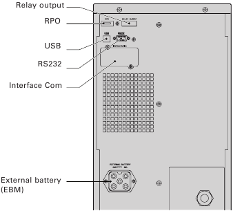
Figure 21. Communication Options and Control Terminals.
Installing Communication Options and Control Terminals
To install the communication options and control terminals:
- Install the appropriate connectivity card and/or necessary cable(s) and connect the cables to the appropriate location. See Figure 21 and the following section, «Communication Options», for detailed information.
- Route and tie the cable(s) out of the way.
- Continue to «Operation» to start up the UPS.
Communication Options
The Eaton 9130 has serial communication capabilities through the USB and RS-232 communication ports or through a connectivity card in the available communication bay.
The UPS supports two serial communication devices according to the following table 7:
| Independent Communication Bay | Multiplexed | |
| USB | RS-232 | |
| Any connectivity card | Available | Not in use |
| Any connectivity card | Not in use | Available |
You can configure relays, signal inputs, and the serial port baud rate through the front panel menus (see table 4). The communication speed of the USB port is fixed at 9600 bps.
RS 232 and USB Communication Ports
To establish communication between the UPS and a computer, connect your computer to one of the UPS communication ports using an appropriate communication cable. See Figure 21 for the communication port locations.
When the communication cable is installed, power management software can exchange data with the UPS. The software polls the UPS for detailed information on the status of the power environment. If a power emergency occurs, the software initiates the saving of all data and an orderly shutdown of the equipment.
The cable pins for the RS 232 communication port are identified in figure 22, and the pin functions are described in Table 8.
.")
Figure 22. RS 232 Communication Port (DB-9 Connector).
Table 8. RS 232 Communication Port Pin Assignment
| Pin Number | Signal Name | Function | Direction from the UPS |
| 1 | DCD | Battery Low signal(1)(3) | Out |
| 2 | RxD | Transmit to external device | Out |
| 3 | TxD | Receive from external device(2) | In |
| 4 | DTR | PnP from external device (tied to Pin 6) | In |
| 5 | GND | Signal common (tied to chassis) | — |
| 6 | DSR | To external device (tied to Pin 4) | Out |
| 7 | RTS | No connection | In |
| 8 | CTS | On Battery signal(1)(3) | Out |
| 9 | RI | +8-12 Vdc power | Out |
(1) Configurable; see the «Relay Configuration» setting in «User Settings».
(2) If Pin 3 receives a Low (+V) signal for ≥ 5 seconds, the UPS executes the command selected by the «Signal Inputs» setting in «User Settings».
(3) When the selected condition is active, output signals on Pins 1 and 8 shift from Low (positive voltage) to High (negative voltage). When the condition no longer exists, the output signal returns to Low.
Connectivity Cards
Connectivity cards allow the UPS to communicate in a variety of networking environments and with different types of devices.
The Eaton 9130 has one available communication bay for the following connectivity cards:
- Connect UPS-MS Web/SNMP Card — has SNMP and HTTP capabilities as well as monitoring through a Web browser interface; connects to Ethernet network. In addition, a Environmental Monitoring Probe can be attached to obtain humidity, temperature, smoke alarm, and security information.
- Relay Interface Card — has isolated dry contact (Form-C) relay outputs for UPS status: Utility failure, Low battery, UPS alarm/OK, or On bypass.
See figure 21 for the location of the communication bay.

Figure 23. Optional Connectivity Cards.
Remote Power-off
RPO is used to shut down the UPS from a distance. This feature can be used for shutting down the load and the UPS by thermal relay, for instance in the event of room over temperature. When RPO is activated, the UPS shuts down the output and all its power converters immediately. The UPS remains on to alarm the fault.
The RPO circuit is an IEC 60950 safety extra low voltage (SELV) circuit. This circuit must be separated from any hazardous voltage circuits by reinforced insulation.
- The RPO must not be connected to any utility connected circuits. Reinforced insulation to the utility is required. The RPO switch must have a minimum rating of 24 Vdc and 20 mA and be a dedicated latching-type switch not tied into any other circuit. The RPO signal must remain active for at least 250 ms for proper operation.
- To ensure the UPS stops supplying power to the load during any mode of operation, the input power must be disconnected from the UPS when the remote power-off function is activated.
Table 9. RPO connections
| RPO Connections | |||
| Wire Function | Terminal Wire Size Rating | Suggested Wire Size | |
| RPO | L1 | 4–0.32 mm² (12–22 AWG) | 0.82 mm² (18 AWG) |
| L2 |
Leave the RPO connector installed in the RPO port on the UPS even if the RPO function is not needed.
Remote control connection and test (see figure 21 for RPO location.)
- Check the UPS is shut down and the electrical supply network disconnected.
- Remove RPO connector from the UPS by unfitting the screws.
- Connect a normally closed volt-free contact between the two pins of connector, see picture 24.
Figure 24.
Contact open: shut down of UPS
To return to normal operation, deactivate the external remote shut down contact and restart the UPS from the front panel. - Plug the RPO connector into the back of the UPS and fix the screws.
- Connect and restart the UPS according to the previously described procedures.
- Activate the external remote shut down contact to test the function.

You can set the RPO polarity. See the «RPO Input Polarity» setting in «User Settings». Depending on user configuration, the pins must be shorted or open to keep the UPS running. To restart the UPS, reconnect (re-open) the RPO connector pins and turn on the UPS manually. Maximum resistance in the shorted loop is 10 ohm. Always test the RPO function before applying your critical load to avoid accidental load loss.
Relay Output Contacts
The UPS incorporates three programmable relay outputs with potential free contacts for remote alarm indications: a standard relay port and two outputs in the RS 232 communication port. See figure 21 for the locations of the ports. An additional four relay outputs can be obtained with the compatible Relay Interface Card. Configure the relay outputs with the «Relay Configuration» setting in «User Settings».
The relay output contacts must not be connected to any utility connected circuits. Reinforced insulation to the utility is required. The relay output contacts have a maximum rating of 30 Vac/1A and 60 Vdc/2A nominal values.
The table 10 shows the options for the relay output contacts.
Table 10. Relay Output Configuration Options
| Relay Signal | Description |
| UPS ok | Activated when the UPS is feeding the load on inverter or on bypass and no alarms are active |
| On Bypass | Activated when the UPS is NOT on bypass operation |
| On Battery | Activated when the UPS operates on battery and the «On Battery Notice Delay» time has expired |
| Battery Low | Activated with the «Battery Low» alarm according to the «Battery Low Alarm» setting |
| Ext. Charger On | Controls an optional external battery charger on and off |
The figure 25 shows the connection of the relay output contacts.

Figure 25. Standard Relay Port Connections.
The figure 26 shows an example where a lamp is connected on the relay output contacts.

Figure 26. Example of Standard Relay Port Connections with lamp.
| Relay signal | L1 | L2 |
| True |  |
 |
| Not true | |
|
| G: external power supply |
Programmable Signal Inputs
The UPS incorporates four programmable signal inputs: one RS 232 input, two connectivity card inputs, and one RPO terminal input. See figure 21 for the locations of the ports. Configure the inputs with the «Signal Inputs» setting in «User Settings».
The table 11 shows the programmable settings for the signal inputs. Table 12 shows the operation logic for the signal inputs.
Table 11. Programmable Signal Inputs
| Signal | Description |
| Not Used | The input operates only as a serial input (RxD) or has no function. |
| Force Bypass | If active, the UPS is forced to static bypass operation regardless of the bypass status. |
| Remote Shutdown | If active, the UPS output turns off after a user-defined remote shutdown delay. The batteries continue charging. Inactive input does not abort the shutdown countdown and does not cause the UPS to start up automatically. |
| Delayed Shutdown (and restart) | If active, the UPS output turns off after a user-defined delayed shutdown delay. The batteries continue charging. Inactive input does not abort the shutdown countdown but will cause the UPS to start up automatically if the input voltage exists. |
| On Generator | If active, synchronization is disabled and the UPS transfers to bypass. |
| Building Alarm 1 | If active, the UPS generates the «Building Alarm 1» alarm. |
Table 12. Polarity Options
| Input | Description |
| High | Active state on high voltage (+Udc) level |
| Low | Active state on low voltage (GND or -Udc) level |
Eaton Power Management Software Suite
Each Eaton 9130 UPS ships with Eaton Power Management Software Suite. To begin installing, see the instructions accompanying the Software Suite CD.
When installing software, select serial port installation. For the UPS manufacturer and model, select Eaton and Eaton 9130. If the Eaton brand options are not available in your version of the software, select Generic UPSs for the manufacturer and Generic XCP for the model.
Eaton software suite provides up-to-date graphics of UPS power and system data and power flow. It also gives you a complete record of critical power events, and it notifies you of important UPS or power information.
If there is a power outage and the Eaton 9130 UPS battery power becomes low, Eaton Sofwtare suite can automatically shut down your computer system to protect your data before the UPS shutdown occurs.
UPS Maintenance
This section explains how to:
- Care for the UPS and batteries
- Replace the UPS internal batteries and Extended Battery Modules (EBMs)
- Test new batteries
- Recycle used batteries or UPS
UPS and Battery Care
For the best preventive maintenance, keep the area around the UPS clean and dust free. If the atmosphere is very dusty, clean the outside of the system with a vacuum cleaner. For full battery life, keep the UPS at an ambient temperature of 25°C (77°F).
If the UPS requires any type of transportation, verify that the UPS is disconnected and turned off and then disconnect the UPS internal battery connector (see figure 28).
The batteries in the UPS are rated for a 3–5 year service life. The length of service life varies, depending on the frequency of usage and ambient temperature. Batteries used beyond expected service life will often have severely reduced runtimes. Replace batteries at least every 5 years to keep units running at peak efficiency.
Storing the UPS and Batteries
If you store the UPS for a long period, recharge the battery every 6 months by connecting the UPS to utility power. The internal batteries charge to 90% capacity in less than 3 hours. However, Eaton recommends that the batteries charge for 48 hours after long-term storage. If optional EBMs are installed, see the recharge times listed in table 24.
Check the battery recharge date on the shipping carton label. If the date has passed and the batteries were never recharged, do not use the UPS. Contact your service representative.
When to Replace Batteries
When the ![]() indicator illuminates, the audible alarm beeps, and the «Battery Needs Service» alarm displays, the batteries may need replacing. Contact your service representative to order new batteries.
indicator illuminates, the audible alarm beeps, and the «Battery Needs Service» alarm displays, the batteries may need replacing. Contact your service representative to order new batteries.
Replacing Batteries
DO NOT DISCONNECT the batteries while the UPS is in Battery mode.
Batteries can be replaced easily without turning the UPS off or disconnecting the load. If you prefer to remove input power to change the batteries, see «UPS Shutdown». Consider all warnings, cautions, and notes before replacing batteries.
- Servicing should be performed by qualified service personnel knowledgeable of batteries and required precautions. Keep unauthorized personnel away from batteries.
- Batteries can present a risk of electrical shock or burn from high short circuit current. Observe the following precautions: 1) Remove watches, rings, or other metal objects; 2) Use tools with insulated handles; 3) Do not lay tools or metal parts on top of batteries, 4) Wear rubber gloves and boots.
- When replacing batteries, replace with the same type and number of batteries or battery packs. Contact your service representative to order new batteries.
- Proper disposal of batteries is required. Refer to your local codes for disposal requirements.
- Never dispose of batteries in a fire. Batteries may explode when exposed to flame.
- Do not open or mutilate the battery or batteries. Released electrolyte is harmful to the skin and eyes and may be extremely toxic.
- Determine if the battery is inadvertently grounded. If inadvertently grounded, remove source from ground. Contact with any part of a grounded battery can result in electrical shock. The likelihood of such shock can be reduced if such grounds are removed during installation and maintenance (applicable to equipment and remote battery supplies not having a grounded supply circuit).
- ELECTRIC ENERGY HAZARD. Do not attempt to alter any battery wiring or connectors. Attempting to alter wiring can cause injury.
- Disconnect charging source prior to connecting or disconnecting battery terminals.
Replacing UPS Internal Batteries
- The UPS internal batteries are heavy. Use caution when handling the heavy batteries.
The internal batteries are located behind the UPS front cover. The internal batteries are packaged together as one unit for easier handling.
To replace the batteries in the UPS:
- Remove the UPS front cover (see figure 27).
To remove the cover:
Remove the 2 fixing screws on the bottom of the cover. Push upon the bottom of the cover and pull the cover toward you to unclip it from the cabinet.A ribbon cable connects the LCD control panel to the UPS. Do not pull on the cable or disconnect it.
Figure 27. Removing the UPS front cover. - Disconnect the internal battery connector (see figure 28).
Figure 28. Disconnecting the UPS internal batteries. - Disconnect one of the 4 battery trays. Remove the plastic protection above the connector and disconnect the battery tray (see figure 29).
Figure 29. Disconnecting the internal battery tray. - Remove the metal fixing part to free the battery tray (see figure 30).
Figure 30. Free the battery tray. - Carefully pull the handle on the battery tray and slide the battery package slowly out onto a flat, stable surface; use two hands to support the battery package. See «Recycling the Used Battery or UPS» for proper disposal.
Verify that the replacement batteries have the same rating as the batteries being replaced. Repeat step 3-4-5 if several battery tray need to be removed.
- Slide the new battery package into the cabinet. Push the battery package in firmly.
- Screw the metal part to fix the battery tray.
Make sure main internal battery connector is disconnected.
- Connect the battery tray and put back the plastic protection above the connector.
A small amount of arcing may occur when connecting the internal batteries. This is normal and will not harm personnel. Connect the cables quickly and firmly.
- Reconnect the internal battery connector. Press the two parts tightly together to ensure a proper connection.
- Place the connector between the screw mounts and reinstall the retained screws.
- Replace the UPS front cover.
To replace the cover, verify that the ribbon cable is protected, then insert the clips on the back of the cover into the cabinet and push firmly to snap the cover into place.
Put back the 2 fixing screws on the bottom of the cover. - Continue to «Testing New Batteries».


Replacing EBMs
The EBM is heavy. Lifting the cabinet into the rack requires a minimum of two people.
To replace the EBMs:
- Unplug the EBM cable from the UPS. If additional EBMs are installed, unplug the EBM cable from the battery connector on each EBM.
- Replace the EBM(s). See «Recycling the Used Battery or UPS» for proper disposal.
A small amount of arcing may occur when connecting an EBM to the UPS. This is normal and will not harm personnel. Insert the EBM cable into the UPS battery connector quickly and firmly.
- Plug the EBM cable(s) into the battery connector(s) as shown in figure 7. Up to four EBMs may be connected to the UPS.
- Verify that the EBM connections are tight and that adequate bend radius and strain relief exist for each cable.
Testing New Batteries
To test new batteries:
- Plug the UPS into a power outlet for 48 hours to charge the batteries.
- Press any button to activate the menu options.
- Select CONTROL then START BATTERY TEST.
The UPS starts a battery test if the batteries are fully charged, the UPS is in Normal mode with no active alarms, and the bypass voltage is acceptable.
During the battery test, the UPS transfers to Battery mode and discharges the batteries for 25 seconds. The front panel displays «Battery test running» and the percentage of the test completed.
Recycling the Used Battery or UPS
Contact your local recycling or hazardous waste center for information on proper disposal of the used battery or UPS.
- Do not dispose of the battery or batteries in a fire. Batteries may explode. Proper disposal of batteries is required. Refer to your local codes for disposal requirements.
- Do not open or mutilate the battery or batteries. Released electrolyte is harmful to the skin and eyes. It may be toxic.
 Do not discard the UPS or the UPS batteries in the trash. This product contains sealed, lead acid batteries and must be disposed of properly. For more information, contact your local recycling/ reuse or hazardous waste center.
 Do not discard waste electrical or electronic equipment (WEEE) in the trash. For proper disposal, contact your local recycling/reuse or hazardous waste center.
Specifications
Model Specifications
This section provides the following specifications:
- Communication options
- Model lists
- Weights and dimensions
- Electrical input and output
- Environmental and safety
- Battery
Table 13. Communication Options
| Communication Bay | (1) available independent communication bay for connectivity cards |
| Compatible Connectivity Cards | Connect UPS-MS Web/SNMP Card Relay Interface Card |
| Communication Ports | RS-232 (DB-9): 1200–9600 bps USB: 9600 bps |
| Signal Inputs | (4) programmable signal inputs (signal and signal return) for indicating building alarms or other use |
| Relay Output Contacts | (1) three-pole connector with (1) contact closure |
Table 14. Extended Battery Module Model List
| EBM Model | Configuration | Battery Voltage | For Power Ratings |
| PW9130N6000T-EBM | Tower | 240 Vdc | 5000–6000 VA |
Table 15. UPS Model List
| Model | Power Level | Rear Panel Diagram |
| PW9130i5000T-XL | 5000 VA / 4500 W | Figure 21 |
| PW9130i6000T-XL | 6000 VA / 5400 W | Figure 21 |
Table 16. Weights and Dimensions
| Model (Tower UPS) | Dimensions (H W D) | Weight |
| PW9130i5000T-XL PW9130i6000T-XL |
575* 242 542 mm (22.64″* 9.53″ 21,34″) | 105 kg (231.5 lb) |
| Model (Tower EBM) | Dimensions (H W D) | Weight |
| PW9130N6000T-EBM | 575* 242 542 mm (22.64″* 9.53″ 21.34″) | 120 kg (264.55 lb) |
Table 17. Electrical Input
| Nominal Frequency | 50/60 Hz auto-sensing |
| Frequency Range | 40–70 Hz before transfer to battery |
| Bypass Voltage Range | +10 / -15% of nominal (default) |
| Noise Filtering | MOVs for normal and common mode noise |
Table 18. Electrical Input
| Model | Default Input (Voltage/Current) | Selectable Input Voltage Range | Voltages at 100% Load |
| PW9130i5000T-XL | 230 V / 21.7 A | 200*, 208*, 220, 230, 240 | 180–276 Vac |
| PW9130i6000T-XL | 230 V / 26.1 A | 200*, 208*, 220, 230, 240 | 180–276 Vac |
208 V are derated by 10%.
Table 19. Electrical Input Connections
| Model | Input Connection | Input Cable |
| PW9130i5000T-XL PW9130i6000T-XL |
Hardwired | None |
Table 20. Electrical Output
| All Models | Normal Mode | Battery Mode |
| Voltage Regulation | ±2 % | Nominal output voltage ±3 % |
| Efficiency | > 98% (High Efficiency mode), > 94 % |
> 92 % |
| Frequency Regulation | Sync with line ±3 Hz of nominal line frequency (outside this range: ±0.1 Hz of auto-selected nominal frequency) | ±0.1 Hz of auto-selected nominal frequency |
| High Voltage Models | ||
| Nominal Outputs | 200/208/220/230/240V (voltage configurable or auto-sensing) 5000/6000 VA 4.5/5.4 kW |
|
| Frequency | 50 or 60 Hz, autosensing or configurable as a frequency converter | |
| Output Overload | 100–102%: Activates Overload alarm (Level 1) 102–129%: Load transfers to Bypass mode after 2 minutes (Level 2) 130–149%: Load transfers to Bypass mode after 30 seconds (Level 3) ≥ 150%: Load transfers to Bypass mode after 100 ms (Level 4) |
|
| Output Overload (Bypass Mode) | 100–109%: Activates Overload alarm (Level 1) 110–129%: UPS shuts down after 5 minutes (Level 2) 130–149%: UPS shuts down after 30 seconds (Level 3) ≥ 150%: UPS shuts down after 300 ms (Level 4) |
|
| Voltage Waveform | Sine wave | |
| Harmonic Distortion | < 3% THD on linear load; < 5% THD on non-linear load |
|
| Transfer Time | Online mode: 0 ms (no break) High Efficiency mode: 10 ms maximum (due to loss of utility) |
|
| Power Factor | 0.9 | |
| Load Crest Factor | 3 to 1 |
Table 21. Electrical Output Connections
| Model | Output Connections | Output Cables |
| PW9130i5000T-XL PW9130i6000T-XL |
Hardwired | None |
Table 22. Environmental and Safety
| Surge Suppression | EN 61000-2-2 EN 61000-4-2, Level 3 EN 61000-4-3, Level 3 EN 61000-4-4, Level 3 (also on signal ports) EN 6100-4-5, Level 3 Criteria A (IEEE C62.41 6 KV) EN 61000-4-6, Level 3 EN 61000-4-8, Level 4 EN 6100-4-11 |
| EMC Certifications | CE per IEC/EN 62040-2, Emissions: Category C2, Immunity: Category C2 |
| EMC (Emissions) | IEC 62040-2:ed2:2005 / EN 62040-2:2006 |
| Safety Conformance | IEC 62040-1-1, IEC 60950-1 |
| Agency Markings | CE |
| Operating Temperature | 0°C to 40°C (32°F to 104°F) in Online mode, with linear derating for altitude NOTE: Thermal protection switches load to Bypass in case of overheating. |
| Storage Temperature | -20°C to 40°C (-4°F to 104°F) with batteries -25°C to 55°C (-13°F to 131°F) without batteries |
| Transit Temperature | -25°C to 55°C (-13°F to 131°F) |
| Relative Humidity | 5–90% noncondensing |
| Operating Altitude | Up to 3,000 meters (9,843 ft) above sea level |
| Transit Altitude | Up to 10,000 meters (32,808 ft) above sea level |
| Audible Noise | < 55 dBA at 1 meter typical |
| Leakage Current | < 1.5 mA |
Table 23. Battery Runtimes (in Minutes) at 100% Load
| Model | Internal Batteries | + 1 EBM | + 2 EBMs | + 3 EBMs | + 4 EBMs |
| PW9130i5000T-XL | 9 min | 41 min | 1 h 19 min | 1 h 57 min | 2 h 42 min |
| PW9130i6000T-XL | 6 min | 32 min | 1 h 03 min | 1 h 37 min | 2 h 08 min |
Note: Battery times are approximate and vary depending on the load configuration and battery charge.
Table 24. Battery
| Internal Batteries | EBMs | |
| Tower Configuration | 5000–6000 VA models: 240 Vdc (20 12 V, 7 Ah) | PW9130N6000T-EBM: 240 Vdc (2 x 20 12 V, 7 Ah) |
| Fuses | 30 A* 2/600 Vdc | 30 A* 2/600 Vdc fuses per EBM |
| Type | Sealed, maintenance-free, valve-regulated, lead-acid, with minimum 3-year float service life at 25°C (77°F) | |
| Monitoring | Advanced monitoring for earlier failure detection and warning | |
| Recharge Time (to 90%) | Internal batteries: 3 hours 1 EBM: 9 hours; 2 EBMs: 15 hours; 3 EBMs: 21 hours; 4 EBMs: 27 hours | |
| Battery Port | External five-pole Banana connector on UPS for connection to EBM | |
| EBM battery cable length | 50 cm |
Troubleshooting
The Eaton 9130 is designed for durable, automatic operation and also alerts you whenever potential operating problems may occur. Usually the alarms shown by the control panel do not mean that the output power is affected. Instead, they are preventive alarms intended to alert the user.
In general:
- Events are silent conditions that are recorded in the Event Log as status information, such as «Clock Set Done».
- Notices are announced by a beep every 5 seconds, recorded in the Event Log, and displayed on the LCD. Examples are «UPS on Battery» and «UPS on Bypass».
- Alarms are announced by a beep every second, recorded in the Event Log, displayed on the LCD, and the Alarm indicator illuminates. Examples are «Output Overload» and «Heatsink Overtemperature».
Use the following troubleshooting chart to determine the UPS alarm condition.
Typical Alarms and Conditions
To check the UPS Status menu for a list of active alarms:
- Press any button on the front panel display to activate the menu options.
- Press the
 button until UPS STATUS displays.
 - Press the Enter button to display the list of active alarms.
To check the Event Log for a history of conditions:
- Press any button on the front panel display to activate the menu options.
- Press the button until EVENT LOG displays.
- Press the Enter button to display the list of conditions.
You can also retrieve the entire Event Log in ASCII format. See «Retrieving the Event Log».
The following table describes typical alarms and conditions.
| Alarm or Condition | Possible Cause | Action |
| On battery LED is on. 1 beep every 5 seconds. |
A utility failure has occurred and the UPS is in Battery mode. | The UPS is powering the equipment with battery power. Prepare your equipment for shutdown. |
| Battery low LED is flashing slowly. 1 beep every second. |
The UPS is in Battery mode and the battery is running low. | This warning is approximate, and the actual time to shutdown may vary significantly. Depending on the UPS load and number of Extended Battery Modules (EBMs), the «Battery Low» warning may occur before the batteries reach 25% capacity. See table 23 for estimated runtimes. |
| On Bypass LED is on. 1 beep every 5 seconds. |
The UPS is in Bypass mode. | The equipment transferred to bypass utility power. Battery mode is not available and your equipment is not protected; however, the utility power continues to be passively filtered by the UPS. Check for one of the following alarms: overtemperature, overload, or UPS failure. |
| Batteries disconnected LED is on. 1 beep every second. |
The UPS does not recognize the internal batteries. | If the condition persists, contact your service representative. |
| The batteries are disconnected. | Verify that all batteries are properly connected. If the condition persists, contact your service representative. | |
| Overload LED is on. 1 beep every second. |
Power requirements exceed the UPS capacity (greater than 100% of nominal) | Remove some of the equipment from the UPS. The UPS continues to operate, but may switch to Bypass mode or shut down if the load increases. The alarm resets when the condition becomes inactive. |
| Overtemperature LED is on. 1 beep every second. |
The UPS internal temperature is too high or a fan has failed. At the warning level, the UPS generates the alarm but remains in the current operating state. If the temperature rises another 10°C, the UPS transfers to Bypass mode or shuts down if bypass is unusable. | If the UPS transferred to Bypass mode, the UPS will return to normal operation when the temperature drops 5°C below the warning level. If the condition persists, shut down the UPS. Clear vents and remove any heat sources. Allow the UPS to cool. Ensure the airflow around the UPS is not restricted. Restart the UPS. If the condition continues to persist, contact your service representative. |
| Battery overvoltage LED is on. 1 beep every second. |
The UPS battery voltage is too high. | The UPS turns off the charger until the next power recycle. Contact your service representative. |
| The UPS does not provide the expected backup time. | The batteries need charging or service. | Apply utility power for 48 hours to charge the batteries. If the condition persists, contact your service representative. |
| Power is not available at the UPS output receptacles. | The UPS is in Standby mode. | Supply power to the connected equipment: press the On/Off button for at least 1 second, until the front panel displays «UPS starting…». |
| The UPS does not start. | The power cord is not connected correctly. | Check the power cord connections. |
| The Remote Power-off (RPO) switch is active or the RPO connector is missing. | If the UPS Status menu displays the «Remote Power Off» notice, inactivate the RPO input. | |
| The UPS operates normally, but some or all of the protected equipment is not on. | The equipment is not connected correctly to the UPS. | Verify that the equipment is plugged into the UPS receptacles. |
| Battery test did not run or was interrupted. | One of the conditions listed in «Running Automatic Battery Tests» was not present. | Resolve the condition, then restart the test. |
| The UPS does not transfer to Bypass mode. | The bypass utility does not qualify. | Check the bypass utility. The UPS is receiving bypass utility power that may be unstable or in brownout conditions. |
| Bypass mode is disabled. | Check that the Bypass settings are configured correctly. See «Configuring Bypass Settings». | |
| USB communication does not work. | The serial port communication speed is set incorrectly for USB. USB requires 9600 bps. | Check that the «Serial Port Configuration» setting is set to 9600 bps. See «User Settings». |
Silencing the Alarm
Press any button on the front panel display to silence the alarm. Check the alarm condition and perform the applicable action to resolve the condition. If the alarm status changes, the alarm beeps again, overriding the previous alarm silencing.
Service and Support
If you have any questions or problems with the UPS, call your Local Distributor or your local service representative and ask for a UPS technical representative.
Please have the following information ready when you call for service:
- Model number
- Serial number
- Firmware version number
- Date of failure or problem
- Symptoms of failure or problem
- Customer return address and contact information
If repair is required, you will be given a Returned Material Authorization (RMA) Number. This number must appear on the outside of the package and on the Bill Of Lading (if applicable). Use the original packaging or request packaging from the Help Desk or distributor. Units damaged in shipment as a result of improper packaging are not covered under warranty. A replacement or repair unit will be shipped, freight prepaid for all warrantied units.
For critical applications, immediate replacement may be available. Call the Help Desk for the dealer or distributor nearest you.
Service and support:
Call your local service representative

Copyright © 2010 EATON
All rights reserved.
Documents / Resources
Download manual
Here you can download full pdf version of manual, it may contain additional safety instructions, warranty information, FCC rules, etc.
Download EATON 9130 UPS Manual
Наш адрес: г. Москва, ул. Полярная, д. 31, стр. 1. Телефон: +7 495 649 16 77 (Skype, ICQ). Режим работы: понедельник — пятница с 9:00 до 18:00; суббота и воскресенье — выходной. Доставка по России, Белоруссии, Украине, Казахстану: Москва, Подольск, Сергиев Посад, Истра, Рязань, Курск, Липецк, Тула, Иваново, Воронеж, Ярославль, Тверь, Смоленск, Калуга, Белгород, Орел,
Тамбов, Кострома, Брянск, Красноярск, Норильск, Кемерово, Новокузнецк, Новосибирск, Омск, Барнаул, Иркутск, Братск, Бийск, Улан-Удэ, Томск, Абакан, Чита, Горно-Алтайск, Кызыл, Санкт-Петербург,
СПб, Выборг, Вологда, Череповец, Мурманск, Сыктывкар, Ухта, Архангельск, Северодвинск, Великий Новгород, Петрозаводск, Гомель, Гродно, Витебск, Могилев, Брест, Минск, Алма-Ата, Астана,
Ереван, Киев, Днепропетровск, Львов, Ташкент, Могилев, Псков, Калининград, Нарьян-Мар, Уфа, Стерлитамак, Самара, Тольятти, Сызрань, Нижний Новгород, Арзамас, Саратов, Энгельс, Пермь,
Ижевск, Казань, Набережные Челны, Бугульма, Пенза, Оренбург, Орск, Чебоксары, Новочебоксарск, Ульяновск, Киров, Йошкар-Ола, Саранск, Екатеринбург, Верхняя Пышма, Серов, Челябинск,
Магнитогорск, Снежинск, Тюмень, Курган, Нижневартовск, Сургут, Надым, Ростов-на-Дону, Волгодонск, Таганрог, Волгоград, Волжский, Краснодар, Армавир, Астрахань, Майкоп, Владивосток,
Уссурийск, Хабаровск, Комсомольск-на-Амуре, Советская Гавань, Южно-Сахалинск, Благовещенск, Петропавловск-Камчатский, Мирный, Ставрополь, Минеральные Воды, Махачкала, Нальчик, Алушта, Армянск, Джанкой, Евпатория, Керчь, Севастополь, Симферополь, Судак, Крым, Феодосия, Ялта. Сайт отвечает на вопросы: Как отремонтировать, настроить, установить оборудование? Где скачать документацию (инструкцию, мануал)? Где посмотреть партномер? Где купить запчасти (запасные
части, зип), комплектующие, аксессуары и термоэтикетка, чековая лента для весов, термопринтеров штрих-кода, чековых принтеров? Обслуживание весов, кассовых аппаратов, термопринтеров,
терминалов сбора данных, сканеров штрих-кода: каким образом возможно своими силами? Вас интересует наличие, цена, купить запчасти за наличный и безналичный расчет? — сделайте запрос
нашим менеджерам. Официальный сайт компании Zipstore.ru.

Попался в ремонт ИПБ EATON PW9130i3000T-XL, при включении на передней панели загорался индикатор ошибки, ИБП издавал периодический писк, на дисплее непропадающая надпись «ИБП включается». Смена фаз в розетке не помогла. Журнал выдавал кучу сообщений, суть которых – не стартует инвертор (при событии #298 ABM разряд — тестирование останавливалось). Значит ИБП сломался и требуется ремонт. Как и ожидалось, схем в инете не нашлось, может, конечно, плохо искали.

Рис. 2 ИБП EATON 9130, силовая плата.

Рис. 3 ИБП EATON 9130, силовая плата.
Неисправность была выявлена путем визуального осмотра, а вот ценник на силовые ключи заставил взгрустнуть механика, просто поменять и посмотреть бахнет или нет – дорого выходит. Пришлось рисовать схему драйвера на силовые ключи.
Рис.4 ИБП EATON 9130, cхема №1, силовые ключи

Рис. 5 Как видно из фото, с диагностикой проблем не было.
Силовые ключи 4 штуки, n-канальные IGBT G4PH50UD (1200В, 24А). Два ключа стоят параллельно между собой для увеличения пропускаемого тока, и обе пары включены в классическую пару на пол периода, что позволяет снизить прикладываемое напряжение на транзисторе на 40%.

Рис. 6. Силовая часть — R32,R30 (22 Ом) неисправны. Силовые ключи и драйвера – демонтированы.
Как видно из схемы, резисторы в затворе R30, R32,R36, R39 (22Ом) первые кандидаты на замену, что и подтверждается прозвонкой на плате, хотя R36, R39 (22Ом) выжили. Хорошим признаком является целостность резисторов в затворе R33, R37,R40, R153 (27Ом), скорее всего их закрыл диод, включенный параллельно, а значит вероятность того что драйвера выжили очень велика.

Рис. 7 Драйвер силовых ключей 61800, вид сверху

Рис. 8 Драйвер силовых ключей 61800, вид снизу
Драйвера силовых ключей для самоуспокоения снимаем и проверяем. Общий принцип работы драйвера понятен, а вот как это работает в целом непонятно, но если честно нет желания разбираться.
Рис. 9 ИБП EATON 9130, схема №2 драйвер силовых ключей.
Драйвер состоит из специализированного драйвера для IGBT транзисторов U701 (TLP250), на выходе которой стоит инвертор сигнала из двух транзисторов Q702,Q703.
Так как драйвера живые неисправные резисторы заменены, можно включать. Необходимо заметить, что изоляционные прокладки были тоже замены, демонтажа транзисторов они не выдержали. Меняем все четыре. силовых ключа, желательно с одной партии, любой перекос и все опять насмарку, хотя схема допускает замену только двух парных ключей, но мы решили не эксперементировать.
Но выясняется, что аккумуляторная батарея из 8 последовательно включенных аккумуляторов, кстати 96В на выходе опасны для жизни, неисправна. Два аккумулятора предательски проваливаются. Так что меняем и аккумуляторы. Можете представить себе в какую копеечку выходит ремонт!
Включаем – заряжаем, смотрим. Заряд до 90% идет струйным способом, после 90% капельным способом. Так, что аккумуляторы лучше заряжать на стороне, но у нас не было зарядника на 115В, поэтому заряжали в составе ИБП — итого ремонт затянулся на 72 часа. Неприятные часы, ИБП шумит как хороший трактор, и легко перешумливает микроволновку, скажем так, ИБП годен только для серверной, но ни как ни для дома.
Попался в ремонт ИПБ EATON PW9130i3000T-XL, при включении на передней панели загорался индикатор ошибки, ИБП издавал периодический писк, на дисплее непропадающая надпись «ИБП включается». Смена фаз в розетке не помогла. Журнал выдавал кучу сообщений, суть которых – не стартует инвертор (при событии #298 ABM разряд — тестирование останавливалось). Значит ИБП сломался и требуется ремонт. Как и ожидалось, схем в инете не нашлось, может, конечно, плохо искали.
Рис. 2 ИБП EATON 9130, силовая плата.
Рис. 3 ИБП EATON 9130, силовая плата.
Неисправность была выявлена путем визуального осмотра, а вот ценник на силовые ключи заставил взгрустнуть механика, просто поменять и посмотреть бахнет или нет – дорого выходит. Пришлось рисовать схему драйвера на силовые ключи.
Рис.4 ИБП EATON 9130, cхема №1, силовые ключи
Рис. 5 Как видно из фото, с диагностикой проблем не было.
Силовые ключи 4 штуки, n-канальные IGBT G4PH50UD (1200В, 24А). Два ключа стоят параллельно между собой для увеличения пропускаемого тока, и обе пары включены в классическую пару на пол периода, что позволяет снизить прикладываемое напряжение на транзисторе на 40%.
Рис. 6. Силовая часть — R32,R30 (22 Ом) неисправны. Силовые ключи и драйвера – демонтированы.
Как видно из схемы, резисторы в затворе R30, R32,R36, R39 (22Ом) первые кандидаты на замену, что и подтверждается прозвонкой на плате, хотя R36, R39 (22Ом) выжили. Хорошим признаком является целостность резисторов в затворе R33, R37,R40, R153 (27Ом), скорее всего их закрыл диод, включенный параллельно, а значит вероятность того что драйвера выжили очень велика.
Рис. 7 Драйвер силовых ключей 61800, вид сверху
Рис. 8 Драйвер силовых ключей 61800, вид снизу
Драйвера силовых ключей для самоуспокоения снимаем и проверяем. Общий принцип работы драйвера понятен, а вот как это работает в целом непонятно, но если честно нет желания разбираться.
Рис. 9 ИБП EATON 9130, схема №2 драйвер силовых ключей.
Драйвер состоит из специализированного драйвера для IGBT транзисторов U701 (TLP250), на выходе которой стоит инвертор сигнала из двух транзисторов Q702,Q703.
Так как драйвера живые неисправные резисторы заменены, можно включать. Необходимо заметить, что изоляционные прокладки были тоже замены, демонтажа транзисторов они не выдержали. Меняем все четыре. силовых ключа, желательно с одной партии, любой перекос и все опять насмарку, хотя схема допускает замену только двух парных ключей, но мы решили не эксперементировать.
Но выясняется, что аккумуляторная батарея из 8 последовательно включенных аккумуляторов, кстати 96В на выходе опасны для жизни, неисправна. Два аккумулятора предательски проваливаются. Так что меняем и аккумуляторы. Можете представить себе в какую копеечку выходит ремонт!
Включаем – заряжаем, смотрим. Заряд до 90% идет струйным способом, после 90% капельным способом. Так, что аккумуляторы лучше заряжать на стороне, но у нас не было зарядника на 115В, поэтому заряжали в составе ИБП — итого ремонт затянулся на 72 часа. Неприятные часы, ИБП шумит как хороший трактор, и легко перешумливает микроволновку, скажем так, ИБП годен только для серверной, но ни как ни для дома.
UPS, ИБП, источники бесперебойного питания — вопросы и ответы
1. Зачем настраивать UPS?
П осле подключения ИБП, его можно было бы сразу ввести в эксплуатацию — заводские уставки (настройки по умолчанию) могут вполне подойти для большого числа случаев. Да и настройки есть не у всех UPS. Но, если мы собираемся эксплуатировать действительно высококлассный ИБП с двойным преобразованием, то было бы глупо не использовать все возможности для повышения надежности, удобства и эффективности системы бесперебойного питания.
М ы будем настраивать online UPS Powerware 9130-T (Eaton) мощностью 2000 ВА. ИБП уже подключен. Он будет работать в офисе с тремя компьютерами, телефонной станцией и МФУ (лазерный принтер, факс, копир, сканер). Хоть это и не имеет прямого отношения к теме, но начитавшимся про «не подключайте лазерные принтеры к UPS» скажем, что это песня 20-летней давности, которая даже и тогда имела не много смысла — нужно просто соотносить максимальные токи принтера (и любого другого потребителя) с максимальными выходными токами UPS, и все будет хорошо.
В нашем офисе не очень хорошая электрическая сеть. Раз в неделю бывают отключения минут по 5-10 (секундные просечки бывают, конечно, еще чаще), а пару раз в год могут отключить электричество и на несколько часов. Напряжение в сети обычно от 185 до 215 вольт, но вечерами, когда в здании отключаются основные потребители, может подскочить и до 250 В. В офисе есть свой щиток, и начальство требует, чтобы уходя все выключали. Вот, в основном, и все основные условия, которые имеют отношение к настройке UPS. Можно начинать настройку.
2. Простые настройки ИБП
В лючаем сеть. На передней панели Powerware 9130 (Eaton) на пару минут появляется логотип Eaton. Если UPS пищит, возможно мы забыли подключить аккумуляторную батарею, хотя это нужно было сделать на этапе подключения UPS — исправляем ошибку.
Н ажимаем кнопку включения — на дисплее надпись «ИБП готов к работе». Приятно, что по-русски (все ИБП Powerware 9130 (Eaton) приходят в Россию с предустановленным русским языком). Но UPS еще не включен, чтобы он включился, нужно нажать и удерживать кнопку включения в течение секунды. Делаем это, на дисплее надпись: «ИБП включается», которая через несколько секунд сменяется сообщением «ИБП online, мощность 0%» — ИБП включился и на его выходе появилось напряжение.
К акое, говорите, напряжение на выходе? Проверим заводскую установку. Нажимаем и удерживаем кнопку «esc» пока на дисплее не появляется сообщение «Установки пользователя». Нажимаем кнопку входа в пункт меню и кнопками со стрелками доходим до пункта «Output voltage ( 230V )» (русский язык куда-то делся — придется привыкать к английскому). Эту установку легко исправить на 220 В (вход в пункт меню и кнопки со стрелками). Вопрос заключается в том, нужно ли это делать? Нашему ИБП Powerware 9130 (Eaton) все равно, какое напряжение поддерживать на выходе: 220 В или 230 В, в обоих случаях оно будет идеальным. Потребители (компьютеры, МФУ и телефонная станция) наверняка рассчитаны на 230 В (можно проверить в инструкциях), поэтому заводская установка 230 В представляется правильной. Оставляем ее. Сразу проверяем соседний пункт меню и убеждаемся, что выходная частота равна 50 Гц.
Е ще одна несложная настройка — дата и время. Входим в пользовательские настройки (см. предыдущий абзац) и кнопками со стрелками идем до пункта «Set date and time». Входим в этот пункт меню и кнопками со стрелками устанавливаем дату и время, подтверждая каждую установку нажатием кнопки ввода.
Ч тобы UPS не отвлекал людей от работы при очень коротких сбоях электрической сети, установим задержку включения звукового сигнала при сбое электропитания в 5 с. Для этого идем в меню пользовательских настроек, пункт «On battery notice delay» и устанавливаем соответствующую задержку.
2. Настройки параметров байпаса ИБП Powerware 9130 (Eaton)
К ак у любого ИБП с двойным преобразованием энергии, есть статический байпас. ИБП переключается на работу через него в случае перегрузки или поломки. Нам нужно убедиться, что условия переключения на байпас (и обратно) установлены в соответствии с характеристиками нашей электрической сети и потребителей.
П режде всего, установим граничные условия для переключения ИБП на байпас. В пользовательских настройках ищем пункт «Synchronization window». По умолчанию там должно стоять ±3.0 Гц. В этом диапазоне частота инвертора сможет следить за частотой электрической сети. Для нашего случая, эта установка не имеет значения, т. к., с одной стороны, мы питаемся от городской электрической сети с очень стабильной частотой (она вряд ли отклонится от 50 Гц больше, чем на 0.2 Гц), а с другой стороны, для наших потребителей точное поддержание частоты не имеет никакого значения — там нет ни синхронных двигателей ни каких-либо блоков, синнхронизующихся с сетью. Оставляем настройку по умолчанию.
А вот диапазон напряжений сети, при которых возможно переключение на байпас, лучше бы установить в соответствии с реальным диапазоном напряжений в нашей электрической сети. Тогда большую часть времени ИБП будет иметь возможность переключиться на байпас в случае перегрузки, а скачок напряжения при переключении (см. страницу про online UPS (ИБП с двойным преобразованием)) будет не слишком велик. Находим среди пользовательских настроек пункты «Bypass voltage high limit» и «Bypass voltage low limit» и устанавливаем, соответственно «230V + 9%» (250 В) и «230V — 18%» (190 В). Чтобы включить в действие эти пороги («окна» ограниченные порогами) ищем среди пользовательских настроек пункт «Qualify bypass» (разрешить переход на байпас) и устанавливаем в нем значение «when in cpec» (когда в «окне»).
В случае переключения в отсутствие синхронизации инвертора с сетью (байпасом), потребители испытают большой скачок напряжения. Поэтому такое переключение нужно запретить. Находим пункт «Unsynchronized transfers» (несинхронизованные переходы на байпас) и устанавливаем параметр «disabled» (запрещены). Теперь переключение на байпас возможно только в случае, если выполняются следующие условия:
В случае перегрузки, ИБП должен мгновенно переключаться на байпас. Заводская установка параметра «Transfer to bypass when overload» (= «Immediate») как раз и должна это обеспечить. Наша задача — только убедиться, что этот параметр не настроен иначе.
3. Настройка параметров аккумуляторной батареи
К аккумуляторной батарее относятся всего несколько пунктов пользовательских настроек. Сначала проверим параметр «Number of battery strings» (количество параллельных линеек аккумуляторной батареи). У нас нет дополнительных аккумуляторных батарей, поэтому здесь должна стоять 1. Правильная установка этого параметра поможет ИБП Powerware 9130 (Eaton) правильно индицировать время работы от батареи. Настройка влияет только на индикацию, на сам процесс разряда аккумуляторов и защитное отключение этот параметр влияния не оказывает.
У бедимся теперь, что Powerware 9130 (Eaton) будет правильно заряжать свои аккумуляторы. Установка параметра «Battery charge mode» (режим зарядки аккумуляторов) в «ABM cycling» позволит ИБП применить фирменную методику зарядки свинцовых аккумуляторов фирмы Eaton — Advanced Battery Management. Eaton обещает, что ее применение увеличивает ресурс аккумуляторов чуть ли не вдвое. Так что, — пусть будет. А вот температурную компенсацию зарядного тока нужно включить обязательно: «Temperature compensated charging» = «enabled», теперь при повышенной температуре аккумуляторы в ИБП не будут перезаряжаться.
У нас есть возможность запретить включение ИБП Powerware 9130 (Eaton), когда после полного разряда аккумуляторной батареи, снова появляется напряжение в сети, пока батарея ИБП не зарядится хоть немного (в параметре «Battery charge % to restart» можно поставить от 10 до 90 %). У нас нет оснований предполагать частые повторные отключения сети, поэтому оставляем этот параметр без изменения («Not checked» — не выбрано).
А втоматическую проверку аккумуляторной батареи («Automatic battery support test» = «Enabled») нужно обязательно включить, чтобы раз в месяц ИБП переходил на работу от батареи на 25 секунд и проверял напряжение на батарее под нагрузкой. Если вдруг аккумуляторная батарея не пройдет тест, у нас всегда есть возможность проверить аккумуляторы индикатором емкости свинцовых аккумуляторов и, при необходимости, заменить аккумуляторы в ИБП.
С игнал о приближающимся полном разряде аккумуляторов ИБП подаст примерно за 3 минуты до отключения. Мы имеем возможность установить параметр «Battery low alarm» в 2 или 5 минут, но делать этого не станем — трех минут нам вполне хватит, чтобы даже в аварийной ситуации успеть выключить компьютеры.
4. Настройка управления сегментами нагрузки ИБП Powerware 9130 (Eaton)
С реднюю суммарную мощность всех наших потребителей можно оценить в 500-600 Вт. В ИБП Powerware 9130 (Eaton), установлены 8 аккумуляторов по 9 А*час. Если рассчитать время работы нашего UPS от аккумулятора, мы получим около 50 минут. Этого нам в общем-то достаточно. Но ИБП Powerware 9130 (Eaton) может программно управлять нагрузкой. Глупо было бы этим не воспользоваться — мы сумеем еще увеличить время работы ИБП от аккумуляторов.
О дин компьютер, МФУ и телефонную станцию мы подключили к первой группе выходных разъемов ИБП (первый сегмент нагрузки). А все остальное — к разъемам второго выхода (2-й сегмент нагрузки). Оценим среднюю мощность сегмента 1 в 200 Вт и мощность сегмента 2 в 300 Вт. Если отключить 2-й сегмент нагрузки через 10 минут после перехода ИБП Powerware 9130 (Eaton) на работу от аккумуляторов, то оставшийся заряд аккумуляторной батареи можно будет истратить на питание 1-го сегмента нагрузки. И наш самый важный компьютер с принтером и телефонной станцией проработает дольше. Насколько дольше?
М ожно рассчитать время работы ИБП от аккумулятора при условии, что к нему подключен только первый сегмент нагрузки. Получим около 2.5 часов. Учтем, что в реальных условиях, часть заряда (примерно 20% = 10 мин / 50 мин) аккумуляторы UPS отдадут на питание суммарной мощности обоих сегментов, и уменьшим полученный результат на 20%. Получается примерно 2 часа. Более точный расчет времени работы ИБП от аккумулятора для случая ступенчатого изменения нагрузки, можно провести по разрядным кривым аккумуляторов. Но нам достаточно сейчас и сделанной оценки.
И так, мы хотим, чтобы после отключения электрической сети, второй сегмент нагрузки отключился через 10 минут, а первый сегмент продолжал работать до полного исчерпания заряда аккумуляторной батареи (еще примерно 2 часа). Это позволит нам более, чем вдвое продлить (хоть и в урезанном режиме) работу офиса в условиях очень длительного отключения электрической сети, которые у нас, по условиям задачи, бывают примерно дважды в год.
Ч тобы реализовать задумку, находим в пользовательских настройках параметр «Automatic on battery shutdown» (автоматическое отключение нагрузки при работе от батареи) и устанавливаем «Outlets: segment 1» = «disabled», а «Outlets: segment 2» = «600 s» (10 минут).
У ИБП Powerware 9130 (Eaton) есть еще одна полезная возможность. Изменив параметр «Automatic start delay» (задержка включения) на «Load segment 1» = «No delay» (без задержки) и «Load segment 2″ = » 3600 s» (1 час), мы заставим UPS включать напряжение для 1-го сегмента нагрузки сразу после появления напряжения в сети, а вот на сегменте 2 напряжение появится только через час. В случае повторного отключения, это позволит расходовать весь заряд только-только начавшей заряжаться батареи на питание первого (самого важного) сегмента нагрузки. А когда аккумуляторная батарея немного зарядится — включится и второй сегмент нагрузки.
5. Преобразователь частоты из ИБП Powerware 9130 (Eaton)
И ногда (отвлечемся сейчас от нашей офисной задачи) встречается потребность — запитать оборудование, рассчитанное на иноземную электрическую сеть (скажем 110 В, 60 Гц). Преобразование напряжения не является проблемой — есть автотрансформаторы. В большинстве случаев, частота не имеет значения, поскольку потребители оснащены импульсными блоками питания. Но иногда. Иногда речь идет об измерительных комплексах или медицинском оборудовании, для питания которых требуется частота 60 Гц. Решить эту проблему поможет ИБП Powerware 9130 (Eaton) — он может работать в экзотическом режиме преобразователя частоты.
В самом деле — как в любом online UPS (ИБП с двойным преобразованием), в ИБП Powerware 9130 (Eaton) выходное напряжение очень слабо связано с входным. ИБП с двойным преобразованием энергии строит на выходе свою собственную синусоиду, просто черпая электрическую энергию со входа. Обычно выходное напряжение синхронизовано с входным (т. е. имеет ту же частоту и фазу) — это нужно для «гладкого» переключения на байпас. Но ведь синхронизацию можно и отменить.
У Eaton Powerware 9130 есть специальная пользовательская настройка, предназначенная для реализации преобразователя частоты — устройства, у которого на входе одна частота (скажем, 50 Гц), а на выходе — совсем другая (хоть бы и 60 Гц). Для переключения Eaton 9130 в этот режим работы нужно установить следующие пользовательские настройки:
Входная частота подстроится под 50 Гц сама. Все настройки байпаса будут отменены, а сам байпас — недоступен.
6. Экзотические настройки ИБП Powerware 9130 (Eaton)
У ИБП Powerware 9130 (Eaton) есть несколько редких возможностей, которые останутся не использованными в нашем вполне банальном случае, но которые было бы жалко оставлять без рассмотрения.
З аводскую установку сигнала перегрузки можно изменить. Для этого достаточно пользовательскую установку «Overload alarm level» (уровень сигнализации перегрузки) изменить на 50% (или другую величину от 10 % до 90 %), и ИБП Powerware 9130 (Eaton) будет сигнализировать о перегрузке при достижении установленной величины нагрузки. Это нужно редко — например, чтобы сигнализировать о несанкционированном подключении потребителей к ИБП.
Д ля уменьшения количества потребляемой ИБП энергии, можно установить параметр «Power strategy» = «High efficiency» и КПД Eaton Powerware 9130 увеличится. Он будет работать на байпасе всегда, пока в электрической сети есть напряжение. Если напряжение пропадет, ИБП Powerware 9130 (Eaton) менее, чем за 10 мс переключится на работу от батареи. Таким образом мы получим некий, более совершенный, аналог ИБП с переключением (off-line).
Е ще увеличить эффективность системы электропитания можно установив минимальную нагрузку ИБП «Energy saving mode» = » 50W. 100W. 1000W». Если нагрузка будет меньше установленной величины, UPS отключит выходное напряжение.
Код ошибки P0451 – несоответствие диапазона рабочих характеристик датчика давления системы улавливания паров топлива
Код ошибки P0451 звучит как «несоответствие диапазона рабочих характеристик датчика давления системы улавливания паров топлива». Часто, в программах, работающих со сканером OBD-2, название может иметь английское написание «Evaporative Emission (EVAP) Control System Pressure Sensor Range/Performance».
Техническое описание и расшифровка ошибки P0451
Этот диагностический код неисправности (DTC) является общим кодом трансмиссии. Ошибка P0451 считается общим кодом, поскольку применяется ко всем маркам и моделям транспортных средств. Хотя конкретные этапы ремонта могут несколько отличаться в зависимости от модели.

Код указывает на то, что часть системы управления EVAP больше не функционирует должным образом. Система EVAP состоит из множества деталей, включая (но не ограничиваясь) крышку бака, топливопроводы, угольный баллон, воздушный клапан и другие.
Система контроля выхлопов (EVAP) предотвращает выброс паров топлива из топливной системы транспортного средства. Пары топлива по шлангам направляются в угольную канистру для хранения. Позднее, при рабочем двигателе, открывается клапан контроля продувки, позволяющий всасывать пары топлива под вакуумом.
Продувка канистры EVAP регулируется клапаном, который благодаря вакууму, создаваемому работой двигателя, позволяет втягивать пары топлива. Они поступают из топливного бака в двигатель для сжигания, а не выходят в атмосферу.
Датчик давления EVAP позволяет PCM контролировать давление в системе EVAP. Он почти всегда находится в топливном баке и встроен в корпус топливного насоса.
Если давление в системе EVAP и в топливном баке не соответствует диапазону рабочих характеристик запрограммированных производителем. В течение заданного периода времени и при определенных обстоятельствах. Будет сохранен код P0451 и может загореться индикаторная лампа неисправности (MIL).
Симптомы неисправности
Основным симптомом появления ошибки P0451 для водителя является подсветка MIL (индикатор неисправности). Также его называют Check engine или просто «горит чек».
Также они могут проявляться как:
Степень серьезности кода P0451 является средней. Автомобиль сможет продолжать движение, но возрастут вредные выбросы в атмосферу. Что на практике не позволит пройти проверку на токсичность.
Причины возникновения ошибки
Код P0451 может означать, что произошла одна или несколько следующих проблем:
Как устранить или сбросить код неисправности P0451
Некоторые предлагаемые шаги для устранения неполадок и исправления кода ошибки P0451:
Диагностика и решение проблем
Убедитесь, что все шланги EVAP подсоединены правильно и в хорошем состоянии. Проверьте жгуты проводов на предмет очевидных повреждений, из-за истирания или неправильной прокладки. Осмотрите электрические разъемы не предмет коррозии, штифты должны быть прямые и правильно установлены.
Убедитесь, что прокладка крышки бака находится в хорошем состоянии, а сама крышка правильно установлена . После этого очистите код P0451 и проведите тест драйв, чтобы посмотреть, вернется ли ошибка снова.
Если прокладка крышки бака, потрескавшаяся, раздавленная или повреждена иным образом, замените ее.
Убедитесь, что выпускной шланг, по которому свежий воздух попадает в канистру, не заблокирован, не засорен и не раздавлен. Если во время цикла продувки поступает недостаточно воздуха, это может вызвать срабатывание этого кода неисправности.
Визуальный осмотр
Поскольку код P0451 является общим кодом неисправности, он часто может быть связан с поврежденной или корродированной проводкой. А также с неисправным или отключенным датчиком.
Найдите канистру EVAP под автомобилем. Она может быть прикреплена к топливному баку или быть отделена от него с помощью шлангов, идущих к топливному насосу. Убедитесь, что разъем датчика давления системы управления EVAP полностью вставлен и зафиксирован.
Осмотрите разъем на предмет коррозии, отсоедините датчик и осмотрите штыри клеммы. Чтобы убедиться, что они чистые и не содержат влаги. Проверьте проводку от датчика, чтобы определить, есть ли какие-либо разрывы, вздутия на изоляции проводов. Которые могут указывать на коррозию внутри провода.
Проверяем напряжение на датчике
Убедитесь, что на контрольном проводе имеется напряжение 5 Вольт, и проверьте целостность цепи заземления. Проверьте сигнальный провод датчика с помощью мультиметра, чтобы определить напряжение, оно должно быть около 3 вольт.
Снимите шланг, прикрепленный к датчику давления EVAP, и создайте вакуум с помощью вакуумметра, отслеживая изменения напряжения на мультиметре. Если напряжение изменяется при подаче вакуума, датчик работает. Если напряжение не меняется, датчик неисправен.
Выполните тест на покачивание проводки, чтобы определить, есть ли проблемы. Покачивая или сминая провода, следите за показаниями на мультиметре, чтобы увидеть, есть ли колебания напряжения. Если напряжение резко возрастает или падает, когда вы поворачиваете отрезок провода, скорее всего, у вас есть обрыв, который необходимо отремонтировать.
В случае, когда тест на покачивание не дает результата, отключите датчик давления EVAP и проверьте напряжение. Если напряжение остается высоким при отключенном датчике, проверьте жгут проводов на предмет замыкания сигнального провода.
При исправных показателях опорного напряжение и заземления, скорее всего проблемой является неисправный датчик давления EVAP. Поэтому, для исправления ошибки P0451 его придется заменить.
Бывает, что при отключении датчика пропадет высокое напряжение, цепь заземления исправна, а эталонное напряжение правильное. Это свидетельствует о засорении шланга системы продувки EVAP. Отсоедините шланг от продувочного клапана и продуйте его сжатым воздухом. Если засор невозможно устранить, замените шланг.
На каких автомобилях чаще встречается данная проблема
Проблема с кодом P0451 может встречаться на различных машинах, но всегда есть статистика, на каких марках эта ошибка присутствует чаще. Вот список некоторых из них:
С кодом неисправности Р0451 иногда можно встретить и другие ошибки. Наиболее часто встречаются следующие: P0132, P0191, P0328, P0446, P0450, P0452, P0453, P0454, P0455, P0456, P0457, P0458, P0459, P0496, P1450.
Источники:
https://vemiru. ru/info/eaton-9130-oshibka-194-neispravnost-provodki/
https://autonevod. ru/obd2-codes/p0451
List of event codes
Use this table for 9130 UPS.
To retrieve Alarm logs, navigate to
Below codes are the one to be used to add «Exceptions on events notification» on email sending configurations.
Some zeros maybe added in front of the code when displayed in emails or logs.
7.5.3.1 Critical
Code
Severity
2012
Critical
2019
Critical
2020
Critical
2024
Critical
2026
Critical
2030
Critical
2031
Critical
2034
Critical
2056
Critical
2058
Critical
2070
Critical
2075
Critical
2077
Critical
2102
Critical
2111
Critical
2112
Critical
2132
Critical
2143
Critical
2188
Critical
2191
Critical
2192
Critical
2193
Critical
2199
Critical
2200
Critical
2259
Critical
2260
Critical
2261
Critical
2323
Critical
2324
Critical
Information – 232
Contextual help>>>Alarms
Active message
Emergency power OFF
Building alarm
Bypass temperature alarm
Temperature alarm
Rectifier overload
Rectifier failure
Inverter internal failure
Battery charger fault
Battery low state of charge
Output short circuit
UPS power supply fault
Rectifier overload
Input AC module failure
Inverter limitation
Inverter thermal overload
DCDC converter failure
Parallel UPS protection lost
Maintenance bypass
Bypass AC module failure
Battery fault
Fuse fault
Fan fault
No battery
Temperature out of range
Rectifier short circuit
Rectifier short circuit
Rectifier short circuit
Inverter overload
Inverter short circuit
section and press the Download alarms button.
Non-active message
No emergency OFF
No building alarm
Bypass temperature OK
Temperature OK
Rectifier OK
Rectifier OK
UPS OK
Battery charger OK
Battery state of charge OK
Output OK
UPS power supply OK
Rectifier OK
Input AC module OK
No current limitation
No power overload
DCDC converter OK
Parallel UPS protection OK
Not on maintenance bypass
Bypass AC module OK
Battery OK
Fuse OK
Fan OK
Battery present
Temperature in range
Rectifier OK
Rectifier OK
Rectifier OK
No power overload
End of inverter short circuit
Advice
—
—
—
—
—
—
—
—
—
—
—
—
—
—
—
—
—
—
—
Check battery
—
—
Check battery
—
—
—
—
—
—