-
-
Mark & Mary Ann Weiss
- posted
18 years ago
We started having a consistent problem with our submersible well pump since the temperatures have started dipping to 0ºF this winter. The first time it happened was the first week of December, when the temperature hit zero. The water pressure in the house dropped to a trickle and the tank pressure gauge was down to 10PSI range. After some troubleshooting, I hit the ‘overload reset’ and the pump started up and all was well… until January, when the temperature hit zero again. Then the same scenario—no water pressure, go down and reset the pump controller and pump starts up. All is well for the rest of the week. Until the next time the temp hit zero or below. There is a clear pattern. The pump overload cutout occurs when the temperature reaches zero or below. The pump is submerged some 220′ below ground surface. The lines leading from the well casing is 4′ below surface of ground all the way to the house. That should be below the frost line. And since 1973, we have had much colder winters and no problems with the pump overloading and shutting down like this. Once I reset the controller, the pump kicks on and refills the Extrol pressure tank at the usual rate of speed and reaches the upper cutoff pressure and shuts off until needed again. It usually stays working until the next bought of cold weather. I’m at a loss as to what the cause of this behavior is. I doubt that the pipes at 4′ depth are freezing (and if they were, we would not get water at all once reset), but the overloads only happen on the coldest nights of the season, and with predictable consistency. Does anyone have another idea as to what could be causing the overloads on cold nights?
— Take care,
Mark & Mary Ann Weiss
VIDEO PRODUCTION . FILM SCANNING . DVD MASTERING . AUDIO RESTORATION Hear my Kurzweil Creations at:
formatting link
sites at:
formatting link
formatting link
formatting link
—
-
-
D
-
David Martel
-
- posted
18 years ago
Mark,
Though your problem seems to be temp related I’d recommend looking at the pressure switch. You indicate that your water pressure is 10 psi and the pump does not engage until you hit the reset switch. When this happens what voltage readings do you see at the switch before and after the reset? I’d clean and tighten all connections and clean the relay contacts. If there is a small diameter water line running to the switch I’d check that for crud. If this doesn’t help it may be time to replace the switch. Your description makes it clear that the pump and it’s lines are not freezing but you do not mention whether the holding tank and pressure switch are in an unheated space. This may be important.
Dave M.
-
-
D
-
Duane Bozarth
-
- posted
18 years ago
…about submersible well pump overload trip on cold mornings…
Amazing! Have started identical problem here over last couple of months, although not clearly correlated w/ temperature.
I gather your controller/pressure tank are in house basement from you’re «down» to reset…the controller here is outside on the pole near the pump while the pressure tank/switch are in the old well house. Also in an unusual coincidence, the pump is set at 220′ here as well!
So far, only real thing I’ve been able to detect is an apparent increase in pump amps indicating some impeller wear on the pump, but not nearly enough that it should be kicking the overload. I’ve not been able to determine a root cause so far…
How old is the pump/controller? This one is less than 10 years (’96, if I remember correctly). The only real problem has been a pipe leak in the hole two years ago that went undetected until we read the meter so that it ran continuously for quite some (undetermined) time that could have shortened lifetime some.
I’m probably going to replace start/run capacitors just as a preventive measure as they seem to be showing some signs of age—the controller is quite a bit older than this pump. All I know to do at present is continue to watch it.
If you haven’t, I’d check the starting and running current and balance on legs and the neutral and also see that it doesn’t go up excessively as pressure builds up. It should hold steady or drop a little, not rise.
-
-
D
-
Duane Bozarth
-
- posted
18 years ago
If it were the pressure switch not closing, it wouldn’t start on resetting the overload…
It’s the overload that’s tripping, and the reset there that he’s resetting.
-
-
D
-
Duane Bozarth
-
- posted
18 years ago
One more interesting phenomenon w/ mine…it’s on a separate meter from the rest of the house/farm load (required by local water conservation rules for farm wells) and the meter seems to have crapped last month….dead stop. I’m wondering now if whether the last time it tripped the reset was somehow related to that, sorta’ like when a light bulb pops and trips the breaker…reminded of that just now as they came to replace the meter…  [
[  ]
]
-
-
M
-
Mark & Mary Ann Weiss
-
- posted
18 years ago
I agree. This is a separate overload ‘breaker’ on the pump controller, so the pressure switch can be calling for the pump to start, but the pump is unable to.
— Take care,
Mark & Mary Ann Weiss
VIDEO PRODUCTION . FILM SCANNING . DVD MASTERING . AUDIO RESTORATION Hear my Kurzweil Creations at:
formatting link
sites at:
formatting link
formatting link
formatting link
—
-
-
M
-
Mark & Mary Ann Weiss
-
- posted
18 years ago
One could debate whether ‘3 in a row’ constitutes a clear correlation, but it sure seems like more than coincidence in this case!
Yes, they are in the cellar, sharing space with furnace and hot water heater (oil-fired). But on these cold nights, the temperature gets down as low at
60ºF. I wonder if the start capacitor is getting marginal and malfunctioning at the lower temperature, but not at the normal 66ºF that the cellar is usually at on warmer nights?
I’ll have to break open some wiring and insert my DVM in line to see what’s what. Maybe it would be useful to install a permanent current metering system so I can see at a glance if the current is normal. I have no track history of current. The only indication is a stamped rating on the tag that says 6.9 amps 220VAC. I know it has a high starting current because all the lights blink when it starts up (always has done that) and our previous emergency generator of 5500W would just about stall when the pump tried to kick on, so we’d have to do without water during power outages until we replaced with a 12kW genset). Perhaps that high starting current is stressing the breaker?
The pump and controller were replaced in summer 1985. They replaced a Gould pump that had completely rusted out after only 13 years’ service. The new pump is a Sears Best model, their premium line, made of stainless steel throughout. I pulled it in Jan 1999 because the 4″ long iron nipple that joins the pump to the plastic pipe at the bottom of the well had rusted through a nice hole in it. Pump looked to be in good shape, but with the expected sludge of rusty/iron deposits. I cleaned the filter screen, washed the impellers as best I could, replaced the iron nipple and put it back in service. Been fine until now. Incidentally, the rusted through nipple caused our pump to run 24/7 for possibly a few weeks, until it got bad enough to not be able to keep up with a shower and wash load running simultaneously.
I’m thinking about the start capacitor here as being a suspect. The first time this overload tripped in December, I was able to reset with just one press of the reset button. This morning, I pressed the reset, but it popped a few seconds later. I could not reset it for about another 2 minutes, but when I did, the pump finally started moving water, as I could hear it rushing through the pipes coming in from the cellar floor.
Our system is really odd. I see no ground on the neutral terminal. I mean that the ground/neutral is not connected to earth ground by any means that I can see.
Also, somewhere in this thread I read that a worn impeller can cause the current to rise. I wonder how so, since there would be less water resistance if the impeller were to wear out completely, the resistance reaching zero?
Logic would seem to suggest that current is at maximum during locked rotor, dropping 90% as the rotor starts turning, then rising, as the resistance of tank pressure works against the pump. I can’t imagine current going down as the tank pressure rises.
I think what I’ll do is hunt for a replacement start capacitor and see if that corrects the problem. If anyone has additional thoughts on this, I’d appreciate your sharing those.
— Take care,
Mark & Mary Ann Weiss
VIDEO PRODUCTION . FILM SCANNING . DVD MASTERING . AUDIO RESTORATION Hear my Kurzweil Creations at:
formatting link
sites at:
formatting link
formatting link
formatting link
—
-
-
P
-
Playintennis5274
-
- posted
18 years ago
the original authors w/ prob , tell me what is problem yer having? could’nt find any previous posts on this.
-
-
D
-
Duane Bozarth
-
- posted
18 years ago
Identical symptoms other than no apparent correlation w/ temperature (although it is winter now…)
-
-
M
-
Mark & Mary Ann Weiss
-
- posted
18 years ago
My submersible pump is failing to start up when the outdoor temperature dips to 0ºF and I have to press the overload reset button to start it again. After that, it works fine until the next time the temperature gets down to
0º. Since the pump is 220′ below surface, and all the lines are buried at least 4′ below surface, I find it odd that the pump overloads only on very cold nights. The cellar gets down to 60ºF when it’s 0ºF outside. Normally, it’s around 66ºF when the temps are in the teens and twenties. The controller box (containing start/run capacitors and reset breaker) is in the cellar. Am wondering if the caps are failing in the cooler room temps?
— Take care,
Mark & Mary Ann Weiss
VIDEO PRODUCTION ? FILM SCANNING ? DVD MASTERING ? AUDIO RESTORATION Hear my Kurzweil Creations at:
formatting link
sites at:
formatting link
formatting link
formatting link
—
-
-
D
-
Duane Bozarth
-
- posted
18 years ago
Mark & Mary Ann Weiss wrote: …
I don’t think so…my starter is on the pole outside and has never been an issue for as long as its been there…something going on towards 30 years now….it looks from Dad’s records that this starter was put in in ’96 w/ the new pump although it’s a piecemeal one contrived from parts of two to (I assume) save some rerouting of the conduit.
It looks to me like the only piece that is that new is the actually interposing relay between the pressure switch leads and the starter box relay itself. The start unit itself looks to me to be more nearly the vintage of the original when this well was dug (that was ’78). I’m thinking possibly these caps are weak from age, but don’t believe temperature has much effect. We aren’t as cold typically as you, but it’s routinely in the 10 — 20F w/ highs in the 30-40 F during most of the winter w/ days of below zero. (And, of course, the opposite extremes in summer—110F not uncommon). I don’t have a capacitance tester big enough for these.
BTW, you mentioned putting current probe inline…what really need is a clamp-on meter—maybe you can find a buddy to borrow one from.
On reflection, I’m thinking I’m w/ you wrt the current characteristics…I don’t follow why the service tech who came out to check out the pump said the current should drop slightly now, either. His was a statement he made and while it seemed a little funny at the time I let it pass…
I had to be away the last time it failed and called them to come out so the wife would have water when she got home…I was concerned it might be drawing way too much current and burn out a pump where a little maintenance/prevention might save a lot. It was so long before they showed up I got home while he was still there but he was packing up to go w/ an inconclusive result other than the somewhat higher than historical current draw but not sufficient to warrant pulling the well…
-
-
M
-
Mark & Mary Ann Weiss
-
- posted
18 years ago
Well I guess that rules out the capacitors as a temperature sensitive issue.
Add to that the fact that our pump overloaded today (27ºF outside) and it took THREE reset attempts (accompanied by house lights dimming for 4 seconds until the breaker tripped) before I got water flow.
My next step is to just shotgun replace all the caps. But I fear the 20 year old pump may be the problem.
I went to Sears’ web site and perused their pump models. The only have ONE model that can handle 220′ depths and it’s over $800 and weighs 70lbs.
Oddly, our pump weighed more like 25-30lbs. I don’t think two guys would easily handle a 70lb pump and 220′ of water-filled 1-1/4″ pipe very easily. We barely managed to pull the lighter pump six years ago.
The original pump is 3/4 HP. But Sears specifies their 3HP pump for our well depth. Their 1-1/2HP pump maxes out at 175′. I am baffled as to how our 3/4 HP pump manages to fill a 30 gallon tank in two minutes, when their top of the line pump only does 25 gallons/minute with 3HP! Someone who’s in the well business please set me straight here… have pumps become less efficient in the past 20 years?
I would just get the 3HP model without concern, except that I think all the wiring to the well head will have to be dug up and replaced. We have about a
300′ run of #12AWG 3-wire going from controller to pump now. That will have to be replace with #8AWG (adding MUCH weight to the pump/pipe assembly that goes into the well) and requiring excavation.
Bracing for the worst, in actic temperatures..
— Take care,
Mark & Mary Ann Weiss
VIDEO PRODUCTION . FILM SCANNING . DVD MASTERING . AUDIO RESTORATION Hear my Kurzweil Creations at:
formatting link
sites at:
formatting link
formatting link
formatting link
—
-
-
D
-
DT
-
- posted
18 years ago
70lbs.
Be careful — the depth in question is the lift necessary to move the water from pumping level to ground surface plus head needed in the application. Not the same as pump depth. The pump is usually set deeper than the amount of water lift which is needed.
-
-
D
-
Duane Bozarth
-
- posted
18 years ago
‘Fraid so from that description of the problem w/ starting, but you might just get lucky…it be a weak starting cap if it only does it on start.
I personally wouldn’t trust Sears, but that’s a prejudice thing…basically, my problem w/ them is one just never knows who’s the «vendor of the week». I’d suggest looking at Gould or one of the other name manufacturers.
I’m quite surprised that a 3/4 hp rated pump would survive anywhere near that long—the one here is a 2 hp Gould. Of course, the supply pipe is
2″ rather than 1-1/4″, too, and it supplied enough water for 1500 head of cattle daily as well as house use. The one prior to this one did last from ’78 to ’96. I’m hoping this is a temporary aberration…I’ve had no more problem so far.
I’d sure guess pulling even that would be a real chore by hand—you got a gin pole or some other set up to use?
I think I’d bite the bullet on that one and go for the well service guys, particularly if it were my only source of water and the weather issue makes it even more of a pita. I told the guy here it’ll be sure to finally crap out entirely during the next real blizzard or this summer when it’s 110 in the shade (and there’s no shade where the well sits…
Good luck, but changing out a start cap can’t hurt and just get luck and extend life a little…
-
-
P
-
Playintennis5274
-
- posted
18 years ago
normallyif a cap goes bad , it’s bad ,and the moter won’t run period til caps replaced . is there a pressure sw. there w/ a set of conrtacts ? I would first take an amp reading and compare w/ motors plate. it’s not gonna pull more amps due to temp. if amps ok look at the o-load mechanism or make sure all connections are good including grd & nuetral
-
-
A
-
aa6lk
-
- posted
18 years ago
greetings,
I originally posted this to the wrong group (dang newsreader):
I went through a similar process a few years ago with my well pump (Franklin 1-1/2 HP). In addition to the capacitors and the overload breaker in the control box, there was a start relay that had developed an open winding. It would stay in the «start» position drawing ~11 amps for about 10 seconds until the overload breaker popped.
This happened shortly after an electrical storm where there was a strike within a quarter mile. I didn’t see any obvious damage to the relay — no burn/scorch marks or anything. Very fine gauge wire is used to wind the relay coil, so it may have opened up just because. Your’s may have developed a temperature-dependent fault.
hope that helps, L
Mark & Mary Ann Weiss wrote:
-
-
M
-
Mark & Mary Ann Weiss
-
- posted
18 years ago
I dunno.. it IS a 20 year old pump.
Just the opposite experience here. The original pump was a Goulds and it lasted only 13 years. We put the Sears Craftsman pump in there in ’85 and it’s served well til now.
Yeah, I’m rather confused as to why we put this in here to begin with. Worse, the Goulds it replaced was 1/3HP! So this was a significant upgrade. The Goulds delivered maybe 12-13gpm. The Craftsman seems to be doing about
15 right now, as it fills my 30 gallon pressure tank to capacity in 1:40, taking it from less than 10PSI to 60PSI cutoff. It always provided more than adequate water pressure for simultaneous usage, like running the garden hose, washing laundry and taking a shower without a pressure drop. So I’m really wondering if it is wise to replace this pump (assuming it needs to be replaced) with a 3HP model, when 3/4HP has been doing the job adequately for
20 years.
Nope. Just lots of manual effort and a good neighbor. But I can see that if we upgrade the pump and the wiring, the dead weight is going to be more than Walt and I can safely handle. How much does 220′ of a column of 1-1/4″ of water weigh, plus 200′ of three wire #8awg cable, plus 22 sections of plastic pipe, plus the 70lbs known weight of the pump all add up to? Got to be a couple hundred pounds easily. We use three people in the past to do this: two at the well head and one very tall person back about 20′ to hold the beginning of the pipe as high up as possible to form a gentle bend in the pipe and guide it to prevent it from breaking. It was a real chore. And we had to discard our clothing afterwards because of the rust stains. And the last time we did this job was in January, with a foot of snow on the ground and raining at 55ºF—the one day the temperature was above freezing all that month.
The Sears web site mentions that they will replace and install this new pump for $185. If that’s not a misprint, then I’d be inclined to let them do the work. But the last time I heard about any well work being done, the labor was more like $4,000. That would be out of the question. And as it goes, we will have to save up for the pump. My savings is wiped out from paying the second installment on our real estate tax bill. I’d take the 110 degree weather over -4ºF right now. At least the pipe isn’t brittle at 110.
It’s relatively easy and cheap to do, but yeah, I’m not holding out any great hope. Pump is getting worse with each start. Failed a second time today, just three hours after the previous overload.
I don’t even have any jugs to fill up for reserves in case it goes out altogether. Gonna make some phonecalls and see if I can line up some parts and also find out about the total cost of installing a new pump. That might have to wait til we get our tax refund.
— Take care,
Mark & Mary Ann Weiss
VIDEO PRODUCTION . FILM SCANNING . DVD MASTERING . AUDIO RESTORATION Hear my Kurzweil Creations at:
formatting link
sites at:
formatting link
formatting link
formatting link
—
-
-
D
-
Duane Bozarth
-
- posted
18 years ago
….
Phew!!! Hate to even think of it! I don’t think it would be possible w/o a good winch for our well…it sets the truck down pretty good to break the snubber loose before it will actually lift…
The pipe leak episode here from the local well service company was well under $1000 — I’d think anything much over that to be robbery…not inexpensive but $4k??? Ugh!
But if Sears will do it w/ a reasonable warranty, etc., I’d sure be tempted…
-
-
M
-
Mark & Mary Ann Weiss
-
- posted
18 years ago
You must have a 10″ well diameter and a really huge pump weighing several hundred pounds. The well digger originally used something that looked like a small crane to lower the assembly down into the well, but he put the plastic pipe sections together one by one and lowered it another 10′ and repeated the process. The installer had it easy compared to us folks having to pull it up for repair. I suppose being 6′ 10-1/2 and 360lbs does help and my neighbor is a real backwoodsman type, so let two of us grizzlies at it and we pull the whole thing out of the well in 5-10 minutes. Lifting the weight isn’t the problem as much as not having any rest until the whole thing is out of the well. It’s 5-10 minutes of agony. I can lift the back of a Ford F150 pickup clear off the ground for a second or two, but try holding it there for 10 minutes? Nah.
Yeah, friend of mine had to have his well serviced and it was a major expense. Anything submersible is the ticket to big fees.
Me too. But I keep thinking «what’s the catch?» Seems too good to be true.
Well, I’ve gone through all the connections, contacts and ground checks earlier this evening. Took out the main Cutler-Hammer breaker and, using a longnose pliers, squeezed the spring clips that hold the clamp on contacts together a little tighter and reinstalled. Then I cut up some strips of rough cardboard and used them to burnish the pressure switch contacts while pressing the contacts closed with a piece of wooden shim material. Next, I installed a ground wire from the secondary fuse box above the pump controller and connected it to the controller cabinet where the 3rd wire from the lightning arrestor was bolted. Then I powered everything up and used a piece of wood to push the pressure switch contacts closed. Pump kicked on without any issues. Switched it on and off a few times and the pump started every time. Pressure rapidly reached 100PSI on the tank gauge and then water started gushing all over me and the pressure switch I was operating—the pressure relief valve let go without warning. It appears that the pump is quite capable of filling the tank and raising the pressure to danger levels in a matter of seconds. Next, I opened a spigot for the outdoor hose. Let the pressure drop to 40PSI and heard the pressure switch close. Closed the valve and watched as the pressure came back up to 59PSI and shut off. Repeated process about a dozen times. Pump never failed to start up each time. Pressure builds from 40 to
59 in about 15 seconds. I guess we’ll see how it goes over the next month. If no more problems, I’ll consider that it was a bad connection somewhere. Perhaps one leg of 220 was intermittent and the pump wasn’t getting enough juice to kick over, causing the other leg to overload and shut down. Hopefully that’s all it was. Time will tell!
— Take care,
Mark & Mary Ann Weiss
VIDEO PRODUCTION . FILM SCANNING . DVD MASTERING . AUDIO RESTORATION Hear my Kurzweil Creations at:
formatting link
sites at:
formatting link
formatting link
formatting link
—
-
-
T
-
Treetops
-
- posted
18 years ago
Had a similiar problem last winter. Found that line voltage was = sometimes very high, above 250volts, and controller had an overvoltage = detector which tripped when it hit 252volts. Most of time voltage was at =
240 — 250 but would sometimes peak to >252. It was random and hitting = reset would fix the problem until next time…sometimes days later. It = seemed that higher volts occured during very cold weather. Don’t know = why…maybe power company increasing voltage to compensate for heavy = cold weather draws?? or less resistance in lines at below 0 degrees??? = Who knows. Problem was fixed when utility stung new wires during highway = reconstruction. Probably not your problem but may be worth checking. = Good luck.
>
Protection & Error Codes
To determine which Error codes apply to your system, look at the serial number of your Outdoor Unit. The prefix will tell you which M series Error Codes are correct for your unit
Example:
Serial #: M3-XXXXXX-WMMS-XXXXXXX(XX)-XXXXXXXXX
Use M3 Error Codes to diagnose
- M6 (56)(57)(58)(59)Error Codes
- M3 Error Codes
- M2 Error Codes
- (78) Series Error Codes
- M1 13 SEER Error Codes
- M1 (57) 16 SEER Error Codes
- M1 (48) Series Error Codes
- M1 (46) Series Error Codes
- VRF System Error Codes
- PTAC Systems Error Codes
{tab title=»M6 (56),(57),(58),(59) Systems» class=»red»}
M6 Single & Multi Zone (56),(57),(58),(59)
| Error Code | Description | Indoor Unit LED Display |
| C1 | Current arc protection | Running LED-Off 3S, Blinks 12 times |
| C2 | Current leakage protection | Running LED-Off 3S, Blinks 13 times |
| C3 | Mis-wiring protection | Running LED-Off 3S, Blinks 14 times |
| C5 | Jumper error protection | Running LED-Off 3S, Blinks 15 times |
| C6 | No-ground | Running LED-Off 3S, Blinks 16 times |
| Cd | Too much CO2 protection | TBD |
| CF | Current short-out protection | TBD (Buzzer will sound once every 2 sec.) |
| d1 | WSHP: UV light error | TBD |
| E0 | Commercial: Water pump overload/error/flow switch error | Running LED-Off 3S, Blinks 10 times |
| E1 | System high pressure protection | Running LED-Off 3S, Blinks 1 time |
| E2 | Anti-freezing protection (heat exchanger-ID, OD) | Running LED-Off 3S, Blinks 2 times |
| E3 | Low pressure protection (run cooling when OD is too cold) | Running LED-Off 3S, Blinks 3 times |
| E4 | Compressor dischage pressure too high | Running LED-Off 3S, Blinks 4 times |
| E5 | System/compressor current too high | Running LED-Off 3S, Blinks 5 times |
| E6 | Communication error (ID-OD) | Running LED-Off 3S, Blinks 6 times |
| E7 | Mode clash (some Indoor Units set to run cooling/fan, some set to run heating) | Running LED-Off 3S, Blinks 7 times |
| E9 | Indoor Unit Water Full Error | Cooling LED Flashing/Heating LED Flashing (both flashing) |
| EA | VRF: Oil valve protection | TBD |
| Ec | Commercial & VRF: Water flow protection (lack of water flow) | TBD |
| Ed | System temperature too high | TBD |
| EE | Memory chip error (U5) | Heating LCD-Off 3S, Blinks 15 times |
| EF | Outdoor fan motor overload | TBD |
| EL | Fire alarm | TBD |
| EP | Shell top high temperature protection | TBD |
| F0 | System refrigerant lack or restriction protection | Cooling LED-Off 3S, Blinks 10 times |
| F3 | Outdoor abmient temperature sensor error | Cooling LED-Off 3S, Blinks 3 times |
| F8 | Incoming water temperature sensor error | Cooling LED-Off 3S, Blinks 8 times |
| F9 | Outgoing water temperature sensor error | Cooling LED-Off 3S, Blinks 9 times |
| FA | Oil temperature sensor error | TBD |
| Fd | Suction gas temperature sensor error | TBD |
| FE | User side water sensor error | TBD |
| FL | Water tank-middle sensor error | TBD |
| FP | CO2 checking error | TBD |
| FU | Shell top temperature sensor error protection | TBD |
| H1 | Heating-Defrosting, or oil return | TBD |
| H2 | Static electric de-dust protection | Heating LED-Off 3S, Blinks 2 times |
| H3 | Compressor over-temperature protection | Heating LED-Off 3S, Blinks 3 times |
| H4 | System abnormal (many different other reasons…) | Heating LED-Off 3S, Blinks 4 times |
| H5 | IPM abnormal / Control Module Protection IPM Module protection, could be caused by over-charged refrigerant/high pressure (bad manifold gauge), restricted refrigerant flow or kinks on refrigerant pipes. |
Heating LED-Off 3S, Blinks 5 times |
| H6 | Indoor fan motor-no feedback. | Running LED-Off 3S, Blinks 11 times |
| H7 | Compressor loses steps, not being able to check rotor position | Heating LED-Off 3S, Blinks 7 times |
| HC | PFC board abnormal / PFC protection | Heating LED-Off 3S, Blinks 6 times |
| HE | Compressor de-managet protection (rotor locked /doesn’t rotate) | Heating LED-Off 3S, Blinks 14 times |
| L0 | Airflow switch error | TBD |
| L1 | Humidity sensor error | TBD |
| L2 | Water level switch error / hot water tank level switch error | TBD |
| L3 | Outdoor DC motor error (L3 for dual -mtor 1, LA for motor 2) | Running LED-Off 3S, Blinks 23 times |
| L4 | Filter clogged | TBD |
| L5 | Circulating water temperature sensor error | TBD |
| L6 | System capacity insufficient | TBD |
| L7 | Water pressure switch protection | TBD |
| Lc | Starting failure | Heating LED-Off 3S, Blinks 11 times |
| Ld | Power phase loss/lack | TBD |
| LE | Compressor locked | Running LED-Off 3S, Blinks 22 times |
| LF | Compressor over-speed protection | TBD |
| LH | Indoor ambient temperature too high | TBD |
| LL | Indoor ambient temperature too low | TBD |
| LP | Indoor-Outdoor units don’t match or power line connection error | Running LED-Off 3S, Blinks 19 times |
| P0 | Driving module resumed | TBD |
| P5 | Driving board checking-compressor current too high | Heating LED-Off 3S, Blinks 15 times |
| P6 | Driving board checking-communication error with indoor board | Heating LED-Off 3S, Blinks 16 times |
| P7 | Radiator loose, or IPM /PFC board sensor abnormal /error | Heating LED-Off 3S, Blinks 18 times |
| P8 | Radiator loose, or IPM /PFC board too hot | Heating LED-Off 3S, Blinks 19 times |
| P9 | AC contactor protection | TBD |
| PA | AC current protection (incoming) | TBD |
| Pc | Current checking-circuit error or current sensor error | TBD |
| Pd | Current checking-connection error (U-V-W not connected accordingly) | TBD |
| PE | Temperature sensor drifting protection | TBD |
| PF | Driving board-ambient temperature sensor error | TBD |
| PH | DC incoming voltage too high (program checking) | Cooling LED-Off 3S, Blinks 11 times |
| PL | DC incoming voltage too low (program checking) | Cooling LED-Off 3S, Blinks 21 times |
| PP | AC incoming power abnormal (too low or too high) | TBD |
| PU | Capacitor-charging circuit error | Heating LED-Off 3S, Blinks 17 times |
| U7 | 4-way switch valve abnormal | Heating LED-Off 3S, Blinks 20 times |
| U6 | Oil temperature too high | Heating LED-Off 3S, Blinks 16 times |
| U4 | Compressor rotation reversed | Heating LED-Off 3S, Blinks 14 times |
| U5 | Rectifying current checking error | Heating LED-Off 3S, Blinks 13 times |
| U3 | DC main bus voltage drop | Heating LED-Off 3S, Blinks 20 times |
| U1 | Compressor phase current checking circuit error | Heating LED-Off 3S, Blinks 13 times |
| U2 | Compressor phase loss protection | Heating LED-Off 3S, Blinks 12 times |
| UC | Filter needs to be cleaned | TBD |
| U8 | PG motor (indoor) checking circuit error | Running LED-Off 3S, Blinks 17 times |
| U9 | Outdoor fan motor checking circuit error | Running LED-Off 3S, Blinks 18 times |
| UF | De-actuate remote or control, from a long distance | TBD |
| C7 | PTC heater sensor error | Heating LED-Off 3S, Blinks 9 times |
| FJ | Discharge/vent air temperature sensor error | TBD |
| L8 | Storage tank water level switch error | TBD |
| d3 | AC condensate: anti-freezing sensor error | TBD |
| d4 | Domestic water: anti-freezing sensor error | TBD |
| d5 | Return water sensor error | TBD |
| d6 | Defrost coil sensor error | TBD |
| d7 | Back-up hot water temperature sensor error | TBD |
| d8 | Hot water outlet temperature sensor error | TBD |
| d9 | Hot water inlet temperature sensor error | TBD |
| db | Temp. Sensor Error-after metering device (cap. Tube, or EXV) | TBD |
| dc | Temp. Sensor Error-suction tube | TBD |
| dP | Temp. Sensor Error-discharge tube | TBD |
| dL | Low voltage reluctance/reluctor error | TBD |
| L9 | Compressor Protection-calculated input is too high | Running LED-Off 3S, Blinks 20 times |
| dF | Temp. Sensor Error-solar water heater-water outlet | TBD |
| dH | Temp. Sensor Error-solar water heater-assistant ele. heater | TBD |
| dU | Door-lock sensor: card is not in | TBD |
| dJ | AC phase protection (lost or reversed) | TBD |
| d0 | Fan motor speed communication error | TBD |
| Eo | Special function board error | TBD |
| dn | Mulitiple zone-pipe connection doesn’t match with comm. wire connection | TBD |
| Cn | Not for AC: Buring gas density too high | Cooling LED-Off 3S, Blinks 23 times |
| Fn | Not for AC: Buring gas sensor error | Running LED-Off 3S, Blinks 21 times |
| HP | Solar AC: solar power input voltage is higher than 180V | TBD |
| dA | AHU or RT: discharge air-relative humidity sensor error | TBD |
| dE | AHU or RT: fresh air-relative humidity sensor error | TBD |
| Fr | AHU or RT: fresh air-temp. sensor error | TBD |
| UA | DC inverter driving error 1 | TBD |
| dr | AHU or RT: air flow pressure sensor error | TBD |
| Ub | DC inverter driving error 2 | TBD |
| Ud | DC inverter driving error 3 | TBD |
| UE | DC inverter driving error 4 | TBD |
| LU | Compressor power input limit / decrease HZ (system power input) | Cooling LED-Off 3S, Blinks 24 times |
| LA | Outdoor unit fan motor protection (not rotating, or not connected). If 2 motors, motor 1-L3, motor 2-LA | Running LED-Off 3S, Blinks 24 times |
| A5 | Condensing coil-inlet temp. sensor error (=F5 in commercial units) | TBD |
| A7 | Condensing coil-outlet temp. sensor error (=F7 in commercial units) | TBD |
| e4 | Compressor dischage temp. (=pressure) too high | TBD |
| e8 | Over-load protection (outdoor coil temp. too high) | TBD |
| e1 | Dicharge pressure sensor error | TBD |
| ee | DC inverter driving chip error | TBD |
| JF | Indoor unit-testing board comm. Error (after 3-minutes) | TBD |
| rF | RF module error (once powered, the MCU tries to send commands, via SPI, to RF, if RF doesn’t receives it, error shows) | TBD |
| Uu | Solar AC: battery bank discharged too much and the output voltage is lower than 295V | TBD |
| no | For VRF groups: DC unit’s display board can not receive any data from the fixed speed comp. unit, will show «no» after 8 seconds | TBD |
| E6+IDU Temp. | Communication error (ID display-OD main board) and outdoor temperature sensor error | TBD |
| E7+ODU Temp. | Communication error (ID unit-OD unit) and outdoor temperature sensor error | TBD |
| Fu | AHU or RT: dust sensor error | TBD |
| e2 | Warning: water flow low | TBD |
| e3 | Oil level low protection | TBD |
| e7 | System pressure difference protection | TBD |
| eA | Heat exchanger-pressure transducer sensor error (similar to lower pressure transducer protection) | TBD |
| eC | Oil-pressure transducer sensor error (similar to lower pressure transducer protection) | TBD |
| e0 | Economizer-discharge temp. sensor error | TBD |
| e9 | Economizer-discharge pressure sensor error | TBD |
| eF | Compressor brand sensor error | TBD |
| bH | Water pump temp. sensor | TBD |
| oE | Any other error that the outdoor unit needs to stop | TBD |
| E8 | Anti-high temperature protection | Running LED-Off 3S, Blinks 8 times |
| E9 | Anti-cold blowing (discharging) protection | Running LED-Off 3S, Blinks 9 times |
| F1 | Indoor air temp. sensor error/bad-broken, shorted | Cooling LED-Off 3S, Blinks 1 time |
| F2 | Indoor coil temp. sensor error/bad-broken, shorted… | Cooling LED-Off 3S, Blinks 2 times |
| F4 | Outdoor coil temp. sensor error/bad-broken, shorted… | Cooling LED-Off 3S, Blinks 4 times |
| F5 | Compressor discharge temp. sensor error/bad-broken, shorted… | Cooling LED-Off 3S, Blinks 5 times |
| F7 | Cooling-oil return error | Cooling LED-Off 3S, Blinks 7 times |
| FC | Slide door error, or air louver mechanism error | TBD |
| FE | Over-load sensor error | TBD |
| H8 | Water level-high /overflow protection | Heating LED-Off 3S, Blinks 8 times |
| H9 | Ele. heater error | Heating LED-Off 3S, Blinks 9 times |
| b7 | Outlet temp. sensor error | Cooling LED-Off 3S, Blinks 22 times |
| b5 | Inlet temp. sensor error | Cooling LED-Off 3S, Blinks 19 times |
| d1 | DRM running mode 1 | |
| d2 | DRM running mode 2 | |
| d3 | DRM running mode 3 |
{tab title=»M8-(56)-G1-1198YM On-Grid Solar Heat Pump»}
M8-(56)-G1-1198YM Single Zone On-Grid Solar Heat Pump
M8-(56)-G1-1198YM Error Code list online
| E0 | Driving board communication error |
| E1 | Indoor unit air temperature sensor error |
| E3 | Indoor unit tube temperature sensor error |
| E6 | System refrigerant high pressure protection |
| E7 | System refrigerant low pressure protection |
| E8 | Indoor unit fan motor no feedback |
| F1 | Outdoor board IPM abnormal |
| F2 | Outdoor board inverter abnormal |
| F3 | Outdoor temperature sensor errors-discharge, tube, ambient air, etc. |
| F4 | Anti-freeze protection |
| F5 | Outdoor compressor discharge temperature too high |
| F6 | Outdoor compressor overload protection |
| F7 | Over current protection |
{tab title=»M8-G2-1201YM (56) On-Grid Solar Heat Pump» class=»red»}
M8-G2-1201YM Single Zone (56) On-Grid Solar Heat Pump
| Code# | Code Descriptions | What to check |
| H1 | Protection-Refrigeration System High Pressure | Copper line vacuumed, leakage, refrigerant charge, fan motors working properly, filters/coils are clean |
| H2 | Protection-Refrigeration System Low Pressure | Copper line leakage, refrigerant charge, ambient temperatures |
| E1 | AC Voltage too high or too low | AC voltage ranges |
| E2 | DC Voltage too high | AC voltage ranges |
| E3 | DC Voltage too low | DC voltage ranges |
| E4 | Protection-AC input current too high | AC current ranges, surge protector |
| E5 | Protection-Compressor current too high | Compressor-resistances between any 2 leads (less than 1 Ohm), and any 1 lead against ground (must be OL), refrigerant charge too much, fan motor failure |
| E6 | System Pressure too high | Check refrigerant levels |
| E7 | Compressor-Phase loss | Compressor-lead wire connections matched diagrams, correct circuit breaker/wire connections |
| E8 | Protection-IPM not working properly | IPM board components |
| E9 | Starting failure | AC input, DC input, compressor, control boards, etc. |
| F0 | Driving board-communication error | Control board |
| F1 | Indoor unit temperature sensor error | Temperature sensor connection and resistance |
| F2 | Outdoor unit ambient temperature sensor error | Temperature sensor connection/contact and resistance |
| F3 | Indoor unit coil sensor error | Temperature sensor connection/contact and resistance |
| F4 | Outdoor unit defrost sensor error | Temperature sensor connection/contact and resistance |
| F5 | Compressor discharge temperature sensor error | Temperature sensor connection/contact and resistance |
| F6 | Protection-Indoor unit coil anti-freeze | Filter/coil clean, fan motor working, refrigerant charge |
| F7 | Protection-compressor discharge tube high temperature | Copper line vacuumed properly, filter/coil clean, temperature sensor connection/contact and resistance |
| F8 | Outdoor fan motor speed is not satisfied | Fan blade clogged, motor resistance, control board |
| F9 | Protection-Refrigerant leaking | Refrigerant leaking, all connections especially flare/nuts |
| FA | Protection-indoor fan motor no feedback | Fan motor wire connection/resistances, control board |
| FC | Outdoor unit fan motor error | Fan motor wire connection/resistances, control board |
{tab title=»M8 (86) All DC Solar Heat Pump» class=»red»}
M8 Single Zone (86) All DC Solar Heat Pump
| ERROR CODE | DESCRIPTION | TROUBLE SHOOTING |
| E1 | Indoor Unit-Air Temperature Sensor error | Check resistances, contacts to the board |
| E2 | Indoor Unit-Tube Temperature Sensor error | Check resistances, contacts to the board |
| E3 | Indoor Unit-Fan Motor no feedback/error | Check motor, resistances, contacts to the board and filter |
| E4 | Outdoor Unit-voltage between + and – lower than 40VDC (12-24K 48V) or 20V (09K 24V) | Check charge controller, panel specs/connections |
| E5 | Outdoor Unit-voltage between + and – higher than 60VDC (12-24K 48V) or 30V (09K 24V) | Check charge controller, panel specs/connections |
| E6 | Outdoor Unit-refrigeration pressure too low | Check refrigerant pressure, and low pressure switch |
| E7 | Outdoor Unit-refrigeration pressure too high | Check fan motor, high pressure switch, and clean the filter |
| E8 | Outdoor Unit-refrigerant is low | Check refrigerant pressure, sensor, potential leak points before recharging |
| E9 | Indoor Unit-Protecting the coil from becoming frozen | Check refrigerant pressure, charge, sensor, potential leak points before recharge. Check Indoor fan motor, filter, and clean the coil. |
{tab title=»(78)1 SERIES 18.8-21.5 SEER Systems» class=»red»}
Symphony SOLO (78)1 SERIES 18.8-21.5 SEER Systems
Error and Protection Codes
Indication on the outdoor unit When the unit has an issue, or the compressor stops running, the LEDs on the outdoor control board will show the error sequence automatically. Key: ★ : LIGHT ○ : FLASHING LIGHT X : OFF
| Outdoor Unit Failure Description | LED 1 | LED 2 | LED 3 | Possible Cause |
| Lights will flash every second for the following faults | ||||
| Normal Operation | x | x | x | |
| Outdoor coil temperature sensor issue | ★ | X | ★ |
|
| Compressor exhaust temperature sensor issue | ★ | X | X |
|
| Communication failure between Indoor Unit and Outdoor Unit | X | X | ○ |
|
| Current Overload Protection | ★ | ○ | X |
|
| Maximum Current Protection | ★ | ○ | ★ |
|
| Communication issue between Outdoor Unit and Driver | X | ★ | ★ |
|
| Outdoor EEPROM issue | ★ | ★ | ★ |
|
| Compressor exhaust temperature is too high protection | X | ○ | ★ |
|
| Outdoor ambient temperature sensor issue | ★ | ★ | X |
|
| Compressor shell temperature too high protection | X | ★ | ○ |
|
| Anti-freeze protection with cooling or Overload protection with heating in Indoor Unit | X | ○ | ○ |
|
| Compressor drive issue | ○ | X | ○ |
|
| Locked rotor outdoor fan motor protection | ○ | ○ | ★ |
|
| Outdoor coil anti-overload protection with cooling | X | ★ | X |
|
| IPM module protection | X | ○ | X |
|
| PFC protection | ○ | X | X |
|
| Compressor preheating process | ○ | ★ | ○ |
|
| Outdoor board chip issue | ★ | X | ○ |
|
| AC voltage too high or too low protection | ★ | ★ | ○ |
|
| DC compressor | ○ | ○ | X |
|
| Outdoor ambient temperature too low protection | ★ | ○ | ○ |
|
| Light flash every 2 seconds for the following faults | ||||
| Outdoor radiator overheated protection | ○ | X | X |
|
| System high pressure failure protection | ○ | ○ | X |
|
When the compressor is in operation
Key: ★ : LIGHT ○ : FLASHING LIGHT X : OFF Flash cycle is 1 second
| No. | LED 1 | LED 2 | LED 3 | Reason current operating frequency of the compressor is limited |
| Lights will flash every second for the following faults | ||||
| 1 | ○ | ○ | ○ | Normal frequency increasing and decreasing. No limitation |
| 2 | x | x | ★ | Frequency decreasing or prohibition of frequency increasing caused by over current |
| 3 | x | ★ | ★ | Frequency decreasing or prohibition of frequency increasing caused by anti-freezing of refrigeration or anti-overload in heating |
| 4 | ★ | x | ★ | Frequency decreasing or prohibition of frequency increasing caused by compressor discharge temperature is too high |
| 5 | Limit to maximum operating frequency caused by low voltage | |||
| 6 | ★ | ★ | ★ | Operation at fixed frequency (in case of capability measuring or compulsory operation at fixed frequency) |
| 7 | ○ | x | x | Protective frequency decreasing against outdoor overload (over power, over frequency conversion rate, over torque, and detection of DC under-voltage) |
| 8 | ★ | x | x | Frequency decreasing caused by indoor and outdoor communication fault |
| 9 | x | ★ | ○ | Frequency decreasing or prohibition of frequency rising protection against overload of outdoor coiled pipe |
| 10 | x | ★ | x | Frequency decreasing or prohibition of frequency increasing for power-saving when it is being used simultaneously with other applications |
Indication on the Indoor Unit The 88 display of the indoor display board will show the error code automatically when the unit has the following issue
| Error Code | Error | Reason current operating frequency of the compressor is limited |
| EA | Error code indicates an issue with communication between the display board and control board |
|
If the unit has the following issue, and the compressor stops running, press the sleep button on the remote controller 10 times in 10 seconds, and the Indoor unit 88 display on the display board will show the error code. If two malfunctions happen at the same time, pressing the sleep button an additional 10 times in 10 seconds will display the second error code. Note: When you perform a troubleshooting inquiry using the Indoor unit 88 display, the error code will be displayed after entering the command with the remote control. If the error code can’t be displayed on the indoor unit, you will need to check the LED display board on the outdoor unit.
Key:★ : LIGHT ○ : FLASHING LIGHT X : OFF Flash cycle is 1 second
| Error Code | Running | Timer | Sleep | Power | Issue | Cause may be one of the following: |
| 1 | 2 | 3 | 4 | |||
| 0 | Normal Operation | |||||
| 1 | X | ○ | X | X | Outdoor coil temperature sensor failure |
|
| 2 | X | ○ | ★ | X | Compressor exhaust temperature sensor issue |
|
| 5 | ★ | ○ | X | X | IPM module protection |
|
| 6 | ★ | ○ | X | ★ | AC voltage out of range protection |
|
| 7 | ★ | ○ | ★ | X | Communication failure between Indoor Unit and Outdoor Unit |
|
| 8 | ★ | ○ | ★ | ★ | Current overload protection |
|
| 9 | X | X | ○ | X | Maximum current protection |
|
| 10 | X | X | ○ | ★ | Communication issue between Outdoor unit and driver |
|
| 11 | X | ★ | ○ | X | Outdoor EEPROM issue |
|
| 12 | X | ★ | ○ | ★ | Outdoor ambient temperature too low |
|
| 13 | ★ | X | ○ | X | Compressor exhaust temperature too high protection |
|
| 14 | ★ | X | ○ | ★ | Outdoor ambient temperature sensor issue |
|
| 15 | ★ | ★ | ○ | X | Compressor shell temperature too high protection |
|
| 16 | Anti-freeze protection during cooling, or overload protection during heating |
|
||||
| 17 | PFC protection |
|
||||
| 18 | DC compressor start failure |
|
||||
| 19 | X | X | X | ○ | Compressor drive issue |
|
| 20 | ★ | X | X | ○ | Outdoor fan motor-locked rotor protection |
|
| 21 | Outdoor coil anti-overload protection while cooling |
|
||||
| 22 | Compressor preheating process |
|
||||
| 24 | Outdoor board chip issue |
|
||||
| 26 | Outdoor unit radiator overheated |
|
||||
| 27 | High system pressure protection |
|
||||
| 33 | ○ | X | X | ★ | Indoor unit temperature sensor failure |
|
| 34 | ○ | X | ★ | X | Indoor unit coil temperature sensor failure |
|
| 36 | ○ | ★ | X | ★ | Communication failure between Indoor unit and Outdoor unit |
|
| 38 | ○ | ★ | ★ | ★ | Indoor EEPROM failure |
|
| 39 | ○ | X | ★ | ★ | Indoor fan motor running abnormally |
|
| 41 | ★ | ★ | ○ | ★ | Indoor grounding protection failure |
|
LED Display
Key: ★ : LIGHT ○ : FLASHING LIGHT X : OFF Flash cycle is 1 second
| Error Code | Sleep | Timer | Running | Issue | Cause may be one of the following: |
| 1 | 2 | 3 | |||
| 0 | Normal Operation | ||||
| 1 | ○ | ★ | ★ | Outdoor coil temperature sensor failure |
|
| 2 | Compressor exhaust temperature sensor issue |
|
|||
| 5 | ★ | ○ | X | IPM module protection |
|
| 6 | X | ○ | X | AC voltage high or low protection |
|
| 7 | ★ | ★ | X | Communication failure between Indoor unit and Outdoor unit |
|
| 8 | Current overload protection |
|
|||
| 9 | Maximum current protection |
|
|||
| 10 | ★ | X | X | Communication issue between Outdoor unit and driver |
|
| 11 | ○ | X | X | Outdoor EEPROM issue |
|
| 12 | Low outdoor ambient temperature protection |
|
|||
| 13 | ○ | X | ★ | High compressor exhaust temperature protection |
|
| 14 | ★ | ★ | ○ | Outdoor ambient temperature sensor issue |
|
| 15 | X | ○ | ★ | High compressor shell temperature protection |
|
| 16 | ★ | X | ★ | Anti-freeze protection in cooling, or overload protection in heating |
|
| 17 | X | ★ | X | PFC protection |
|
| 18 | X | ★ | ★ | DC compressor start failure |
|
| 19 | X | ★ | ○ | Compressor drive issue |
|
| 20 | ★ | X | ○ | Outdoor fan motor locked rotor protection |
|
| 21 | X | X | ○ | Outdoor coil anti-overload protection while cooling |
|
| 22 | Compressor preheating protection |
|
|||
| 24 | Outdoor board chip issue |
|
|||
| 26 | Outdoor radiator overheated |
|
|||
| 27 | High system pressure protection |
|
|||
| 33 | ★ | ○ | ○ | Indoor temperature sensor failure |
|
| 36 | ○ | ★ | ○ | Communication failure between indoor and outdoor unit |
|
| 38 | ○ | ○ | X | Indoor EEPROM failure |
|
| 39 | ○ | ○ | ★ | Indoor fan motor running abnormally |
|
| 41 | X | X | ★ | Indoor ground protection failure |
|
A room temperature sensor failure is displayed if the sensor does not respond for over 5 seconds. A heat exchange temperature sensor failure is displayed if the sensor does not respond for over 5 seconds. A failure is displayed when the settings data does not match after the EEPROM self-checks two times. A ground signal failure is displayed if the signal is not detected after the air conditioning system is powered ON.
{tab title=»M2 13 & 14 SEER Systems» class=»red»}
M2 13 & 14 SEER Systems Error Codes
| Codes | Description | Possible Reasons | Suggestion for User | Technician Trouble-Shooting |
| E1 | Condensate Full in drain pan |
|
|
|
| E2 | Indoor air temp. sensor failure |
|
|
|
| E3 | Indoor coil copper tube sensor failure |
|
||
| E4 | Abnormal cooling |
|
|
|
| E5 | Abnormal heating | |||
| E6 | Cooling-outdoor coil low temp. protection |
|
|
|
| E7 | Cooling-Indoor coil anti-freeze protection |
|
||
| E8 | Heating-outdoor coil high temperature protection |
|
||
| E9 | Heating-indoor coil anti-over heat protection |
|
||
| E0 | Heating-outdoor coil too cold protection |
|
{tab title=»M3 Single Zone 13 SEER Systems» class=»red»}
M3 Single Zone 13 SEER Systems Error Codes
| Error Code | Error Code — Light Signal | Error Indicated | Trouble Shooting |
| F4 | SLEEP & TIME light blink | Over-current protection | Check for abnomalities in the incoming power voltages, wire sizing/connections, system refrigerant charge level, vacuum level, restrictions etc. |
| F5 | WARM, SLEEP & TIME lights solid | EEPROM read error | Check wire connections. Shut off power, wait 30 seconds and restore power. |
| F6 | POWER, TIME light blink, SLEEP light solid | PG motor error | Check and debug the PG motor, its driving circuit, or feedback control circuit |
| F7 | POWER, SLEEP lights blink & TIME light solid | RT indoor air temperature sensor error | Chech sensor wire continuity, sensor resistance and installation |
| F8 | POWER, TIME & SLEEP light blink | PT indoor coil pipe temperature sensor error | Check sensor wire continuity, sensor resistance and installation |
| F9 | POWER & SLEEP light blink | OT outdoor coil pipe termperature sensor error | Check sensor wire continuity, sensor resistance and installation |
{tab title=»M1 16 SEER (57)2,3 Systems» class=»red»}
M1 16 SEER (57)2,3 Systems
Fault Code Display Table.
| Check parts | Serial number | Malfunction content | Indoor unit display status Code |
| Indoor parts | 1 | The communication faults in the indoor and outdoor units | F1 |
| 2 | Indoor ambient temp. sensor fault | F2 | |
| 3 | Indoor coil temperature sensor fault (Includes: Inlet, middle of pipe, outlet.) | F3 | |
| 4 | Indoor fan fault | F4 | |
| Outdoor parts | 1 | Outdoor module fault | F5 |
| 2 | Outdoor ambient temp. sensor fault | F6 | |
| 3 | Outdoor coil temp. sensor fault | F7 | |
| 4 | Compressor discharge temp. sensor fault | F9 | |
| 5 | Compressor drive abnormal fault | FC | |
| 6 | Phase lacking or phase sequence fault | FD | |
| 7 | Outdoor DC Motor | FH |
Note:
The above error code information is applicable to several models of air conditioners, but because of product changes or improvements, they can change. Please refer to the User’s Manual for more information, or have a technician contact YMGI.
Protection Display Table.
| Check parts | Serial number | Protection content | Indoor unit display status Code |
| Indoor parts | 1 | Evaporator temp protection | P1 |
| Outdoor parts | 1 | Overheat, over current protection of inverter module | P2 |
| 2 | Over current protection | P3 | |
| 3 | Compressor discharging temp. protection | P4 | |
| 4 | Overheat of compressor top protection | P5 | |
| 6 | Power supply over current/over voltage protection | P7 | |
| 9 | High temp of condenser protection | PA | |
| 10 | High temp of outdoor ambient protection | PC |
{tab title=»M1 13 SEER Systems» class=»red»}
M1 13 SEER Systems
| Error Code | Self-Check code of Running Lamp | Error Indicated |
| «dF» or Heating Icon blinks | Blinks 1 time/sec | Defrost Indication |
| Fan Motor Icon not Lit | Blinks 1 time/ sec | Anti-cold Wind |
| E2 | Blinks 1 time/ 8 sec | Room Temperature Sensor fault |
| E3 | Blinks 2 times / 8 sec | Coil Temperature Sensor |
| E8 | Blinks 3 times / 8 sec | Overheat Protection/Defrosting |
| E5 | Blinks 6 times / 8 sec | Indoor Fan Fault |
| E7 | Blinks 7 times / 8 sec | External Feedback Fault |
| E0 | Blinks 3 times / 8 sec | Open Door Fault |
| E1 | Blinks 4 times / 8 sec | Outdoor Tube Temperature Sensor Fault |
| E6 | Blinks 6 times / 8 sec | (EEPROM) Communication Failure(s) |
| FF | Blinks 1 time / sec | Outdoor Temperature Exceeds Operating Limits of System. |
{tab title=»M1 48 Series Systems» class=»red»}
M1 48 Series Systems
| LED | Running Lamp Blinks | Error | The reason of fault and solution |
| F1 | 1 | communication fault |
|
| F2 | 2 | ambient temp. sensor fault |
|
| F3 | 3 | coil pipe temp. sensor of indoor unit fault (inlet, middle, outlet) |
|
| F4 | 4 | fan motor of indoor |
|
| F5 | 5 | module of outdoor unit fault |
|
| F6 | 6 | ambient temp. sensor of outdoor fault |
|
| F7 | 7 | coil pipe temp. sensor of outdoor unit fault |
|
| F8 | 8 | suction temp. sensor of compressor fault |
|
| F9 | 9 | discharge temp. sensor of compressor fault |
|
| FA | 10 | inductor of current or voltage fault |
|
| FC | 11 | compressor drive fault |
|
| FD | 12 | phase lacking or phase sequence fault |
|
| FE | 13 | gas return sensor fault (include A,B,C,D) |
|
| FF | 14 | other fault | |
| P1 | 1 | temp. of evaporator protection |
|
| P2 | 2 | overheat, over current protection of inverter module |
|
| P3 | 3 | over current protection |
|
| P4 | 4 | discharge temp. of compressor |
|
| P5 | 5 | over heat of compressor top protection |
|
| P6 | 6 | suction temp. of compressor protection |
|
| P7 | 7 | low or high voltage protection |
|
| P8 | 8 | low presser of gas return protection |
|
| P9 | 9 | high pressure of discharge protection |
|
| PA | 10 | high temp. of condenser protection |
|
| PC | 11 | high temp. of outdoor ambient protection |
|
| PF | 12 | other protection |
{tab title=»M1 46 Series Systems» class=»red»}
M1 46 Series Systems
| LED | failure | The reason of fault and solution |
| F1 | communicate fault |
|
| F2 | indoor temp. sensor fault |
|
| F3 | outlet e temp. sensor of indoor unit coil pipe fault |
|
| F3 | suction temp. sensor of indoor unit coil pipe fault |
|
| F3 | middle temp. sensor of indoor unit coil pipe fault |
|
| F4 | PG motor fault |
|
| P2 | protection of module fault |
|
| P3 | over current of outdoor unit |
|
| P4 | discharge temp. of compressor too high, outside ambient temp. too high, temp. switch of compressor crust cut off, temp. of module too high. |
|
| P7 | DC voltage abnormal of outdoor unit |
|
| P8 | lack refrigerant or reverse valve fault |
|
| F6 | outside sensor fault |
|
| FC | outdoor unit drive fault, start compressor failure |
|
{tab title=»VRF Systems» class=»red»}
VRF System Error Codes
TABLE OF ERROR CODES FOR OUTDOOR UNIT
| Error Code | Content | Error Code | Content | Error Code | Content |
| E0 | Outdoor Unit Error | FL | Compressor 3 Current Sensor Error | b4 | Subcooler Liquid-out Temperature Sensor Error |
| E1 | High Pressure Protection | Fn | Mode Exchanger Inlet Pipe Temperature Sensor Error | b5 | Subcooler Gas-out Temperature Sensor Error |
| E2 | Discharge Low Temperature Protection | FP | Malfunction of DC motor | b6 | Gas-liquid separator inlet temperature sensor error |
| E3 | Low Pressure Protection | FU | Compressor 2 Top Temperature Sensor Error | b7 | Gas-liquid separator outlet temperature sensor error |
| E4 | Excess Discharge Temperature Protection of Compressor | J1 | Compressor 1 Over-current Protection | b8 | Outdoor Humidity Sensor Error |
| F0 | Bad Performance of the Outdoor Mainboard | J2 | Compressor 2 Over-current Protection | b9 | Heat Exchanger Gas-out Temperature Sensor Error |
| F1 | High Pressure Sensor Error | J3 | Compressor 3 Over-current Protection | bA | Oil-return Temperature Sensor Error |
| F3 | Low Pressure Sensor Error | J4 | Compressor 4 Over-current Protection | bC | Compressor 1 Top Temperature Sensor Detachment Protection |
| F5 | Compressor 1 Discharge Temperature Sensor | J5 | Compressor 5 Over-current Protection | bE | Malfunction of entry tube temperature sensor of condensor |
| F6 | Compressor 2 Discharge Temperature Sensor Error | J6 | Compressor 6 Over-current Protection | bF | Malfunction of exit tube temperature sensor of condenser |
| F7 | Compressor 3 Discharge Temperature Sensor Error | J7 | 4-way Valve Blow-by Protection | bH | System Clock Malfunction |
| F8 | Compressor 4 Discharge Temperature Sensor Error | J8 | System Pressure Over-Ratio Protection | bJ | High and low pressure sensors are connected inversely |
| F9 | Compressor 5 Discharge Temperature Sensor Error | J9 | System Pressure Under-Ratio Protection | bL | Compressor 2 Top Temperature Sensor Detachment Protection |
| FA | Compressor 6 Discharge Temperature Sensor Error | JA | Protection of Abnormal Pressure | P0 | Compressor Drive Board Error |
| Fb | Compressor 2 Top Temperature Sensor Error | JC | Protectionof Water Flow Switch | P1 | Compressor Drive Board Malfunction |
| FC | Compressor 2 Current Sensor Error | JE | Oil return pipe is blocked | P2 | Protection of Compressor Drive Board Power Supply |
| Fd | Mode Exchanger Outlet Pipe Temperature Sensor Error | JF | Oil return pipe is leaking | P3 | Protection of Compressor Drive Board Module Reset |
| FE | Compressor 4 Current Sensor Error | JL | Protection of Low High-pressure | H0 | Error of Fan Drive Board |
| FF | Compressor 5 Current Sensor Error | b1 | Outdoor Ambient Temperature Sensor Error | H1 | Malfunction of Fan Drive Board |
| FH | Compressor 1 Current Sensor Error | b2 | Defrosting Temperature Sensor 1 Error | H2 | Protection of Fan Drive Board Power Supply |
| FJ | Compressor 6 Current Sensor Error | b3 | Defrosting Temperature Sensor 2 Error | — | — |
TABLE OF ERROR CODES FOR INDOOR UNIT
| Error Code | Content | Error Code | Content | Error Code | Content |
| L0 | Indoor Unit Error | LF | Shunt Valve Setting Error | d9 | Jumper Cap Error |
| L1 | Indoor Fan Protection | LH | Low Air Quanlity Warning | dA | Indoor Unit Hardware Address Error |
| L2 | E-heater Protection | LJ | Wrong Setting ofFunction DIP Switch | db | Special Code:Field Debugging Code |
| L3 | Water Full Protection | LP | Zero-crossing malfunction of PG motor | dC | Capacity DIP Switch Setting Error |
| L4 | Wired Controller Power Supply Error | LU | Inconsistent Branch of Group-controlled Indoor Units in Heat Recovery System | dE | Indoor Unit CO2 Sensor Error |
| L5 | Anti-Frosting Protection | d1 | Indoor Unit PC-Board Error | dH | Wired Controller PC-Board Error |
| L7 | No Master Indoor Unit Error | d3 | Ambient Temperature Sensor Error | dL | Outlet Air Temperature Sensor Error |
| L8 | Power Insufficiency Protection | d4 | Inlet Pipe Temperature Sensor Error | dn | Swing AssemblyError |
| L9 | Quantity Of Group Control Indoor Units Setting Error | d5 | Malfunction of middle tube temperature sensor | y7 | Fresh Air Inflow Temperature Sensor Error |
| LA | Indoor Units Incompatibility Error | d6 | Outlet Pipe TemperatureSensor Error | y8 | Indoor Air Box Sensor Error |
| Lb | Inconsistency of Group-controlled Indoor Units in Reheat Dehumidification System | d7 | Humidity Sensor Error | y9 | Outdoor AirBox Sensor Error |
| LC | Outdoor-Indoor Incompatibility Error | d8 | Water Temperature Abnormality | — | — |
TABLE OF DEBUGGING CODES
| Error Code | Content | Error Code | Content | Error Code | Content |
| U2 | Outdoor Unit Capacity Code/Jumper Cap Setting Error | UL | Emergency Operation DIP switch setting of the compressor is wrong | CE | Communication Failure Between Mode Exchanger and Indoor Unit |
| U3 | Phase Sequence Protection of Power Supply | C0 | Communication between indoor unit and outdoor unit and the communication between indoor unit and wired controller have malfunction | CF | Error of Multiple Master Indoor Unit |
| U4 | Protection of Lack of Refrigerant | C2 | Communication error between master control and inverter compressor drive | CH | Rated capacity is too high. |
| U5 | Wrong Address of Compressor Drive Board | C3 | Communication error between master control and inverter fan motor drive | CJ | System addresses is incompatible. |
| U6 | Valve Abnormal Alarm | C4 | Error of Lack of Indoor Unit | CL | Rated capacity is too low. |
| U8 | Indoor Unit Tube Malfunction | C5 | Alarm of Indoor Unit Project Number Collision | Cn | Indoor and Outdoor NetworkError of Mode Exchanger |
| U9 | Outdoor Unit Tube Malfunction | C6 | Alarm of Wrong Number of Outdoor Unit | CP | Error of Multiple Master Wired Controller |
| UC | Master indoor unit is successfully set | C7 | Mode Exchanger Communication Error | CU | Communication Error between Indoor Unit and Remote Receiver |
| UE | Refrigerant Charging is ineffective | Cb | Outflow of Units IPAddress | Cy | CommunicationError of No Master in Mode Exchanger |
| UF | Indoor Unit Identification Error of Mode Exchanger | Cd | CommunicationFailure Between Mode Exchanger and Outdoor Unit |
TABLE OF STATUS CODES
| Error Code | Content | Error Code | Content | Error Code | Content |
| A0 | Unit is waiting for debugging | A8 | Vacuum-pumping Mode | AJ | Filter Clean Reminder |
| A1 | Check the compressor operation parameters | Ab | Emergency Stop | AU | Remote Urgent Stop |
| A2 | After-sales Refrigerant Reclaim | Ad | Operation Restriction | n3 | Compulsory defrosting |
| A3 | Defrosting | AC | Cooling | qE | EVI Operating Mode |
| A4 | Oil return | AF | Fan | ||
| A5 | Online Testing | AH | Heating |
{tab title=»SHCR Error Codes» class=»red»}
SHCR Error Codes
| NO. | LED1 (GREEN) |
LED2 (RED) |
LED3 (RED) |
Status | Trouble Shooting |
| 1 | On | Off | Off | Cooling mode — normal operation | N/A |
| 2 | On | On | Off | Heating mode — normal operation | N/A |
| 3 | On | On | On | Defrosting mode — ongoing | N/A |
| 4 | On/On (AC/HP) |
Off/On (AC/HP) |
Blinks 3 times/ 5 seconds | Outdoor defrost temperature sensor failure | Check connectivity or resistance of this sensor, or replace with a new sensor. |
| 5 | On | Off | Blinks 1 times/ 5 seconds | Cooling Mode, High Pressure Protection is ON. The whole unit stops working until the problem is cleared, or power is turned off, and then restored, or another unit function is selected. | Check possible causes: Mechanical or refrigerant blockage at the filter/drier. Too much refrigerant. 4-way valve is damaged. Faulty TEV or others. Electrical wiring connection is faulty. Component is damaged. Or switch Unit funtion. |
| 6 | On | Off | Blinks 2 times/ 5 seconds | Cooling Mode, Low Pressure Protection is ON. The whole unit stops working until the problem is cleared, or power is turned off, and then restored, or another unit function is selected. | Check possible causes: Refrigerant is very low 4-way valve is damaged. Faulty TEV or others. Electrical wiring connection is faulty. Component is damaged. Or switch Unit funtion. |
| 7 | On | On | Blinks 1 times/ 5 seconds | Heating Mode, High Pressure Protection is ON. The whole unit stops working until the problem is cleared, or power is turned off, and then restored, or another unit function is selected. | Check possible causes: Mechanical or refrigerant blockage at the filter/drier. Too much refrigerant. 4-way valve is damaged. Faulty TEV or others. Electrical wiring connection is faulty. Component is damaged. Or switch Unit funtion. |
| 8 | On | On | Blinks 2 times/ 5 seconds | Heating Mode, Low Pressure Protection is ON. The whole unit stops working until the problem is cleared, or power is turned off, and then restored, or another unit function is selected. | Check possible causes: Refrigerant is very low 4-way valve is damaged. Faulty TEV or others. Electrical wiring connection is faulty. Component is damaged. Or switch Unit funtion. |
{tab title=»PTAC Systems» class=»red»}
PTAC Systems
| Malfunction | Possible Causes |
| Indoor ambient temperature sensor is open/short circuited |
|
| Indoor evaporator temperature sensor is open/short circuited |
|
| Outdoor ambient temperature sensor is open/short circuited |
|
| Low temperature prevention protection |
|
PTAC Series 0 Error Codes
Protective Auto Diagnostics
| Failure code | Content of defect |
| E2 | Indoor temperature sensor failure |
| E3 | Indoor coil temperature sensor failure |
| E4 | High temperature protection of air outlet |
| E5 | Outdoor coil temperature sensor failure |
| E8 | Overheating protection/defrosting |
| E9 | High temperature protection of outdoor coil |
{/tabs}
Chillers are complex systems that need to maintain an appropriate balance of pressure to function effectively. Any pressure anomalies, such as high pressure, can lead to operational issues and efficiency loss. Here, we explore some common causes of high pressure in chillers, along with recommended solutions.
In Air-cooled Chiller
An air-cooled chiller condenser is blown by a fan to dissipate heat, and the causes of high-pressure failures are:
1. Inadequate Condenser Function or High Ambient Temperature
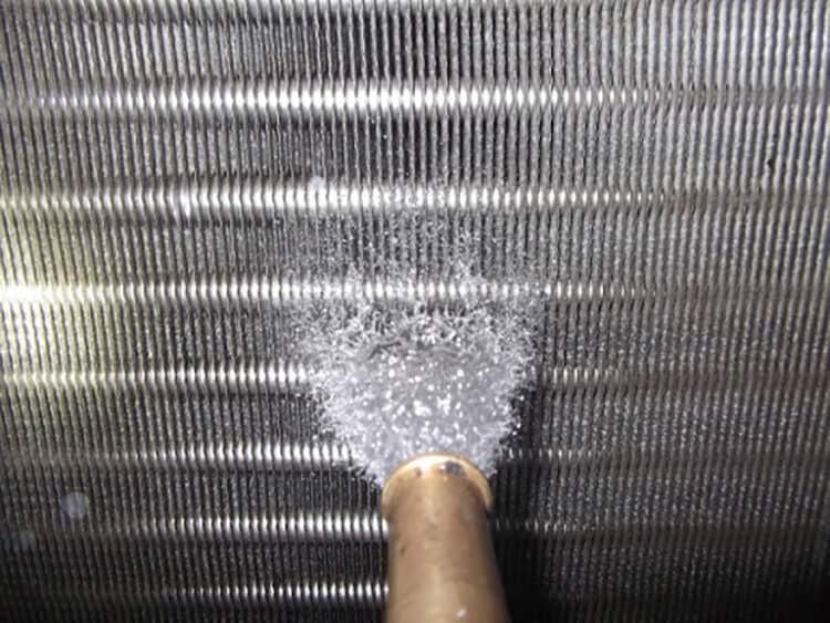
In this scenario, heat dissipation from the condenser is inefficient, meaning the heat generated within the refrigeration cycle can’t be effectively removed. This failure can trigger a high-pressure alarm.
Solution: Inspect the fan for any mechanical issues and clear any dust or debris around the fan cover. After the system is powered down, consider cleaning it with compressed air or a water gun to enhance cooling efficiency.
2. Condenser Blockage
Blockage in the condenser impedes the condensation of high-pressure refrigerant gas within the system. This blockage leads to gas build-up, prompting a high-pressure alarm.
Solution: Clean and decontaminate the condenser. It’s advisable to contact the manufacturer for detailed guidance on the cleaning procedure to prevent damaging the unit.
3. Air Entrapment in the System
This issue typically occurs in newly installed machines or after compressor maintenance, where air gets mixed in with the refrigeration system. The trapped air can’t be condensed and remains in the condenser, leading to a high-pressure alarm.
Solution: Open the air separation valve, exhaust port, or condenser inlet/outlet to vent the trapped air.
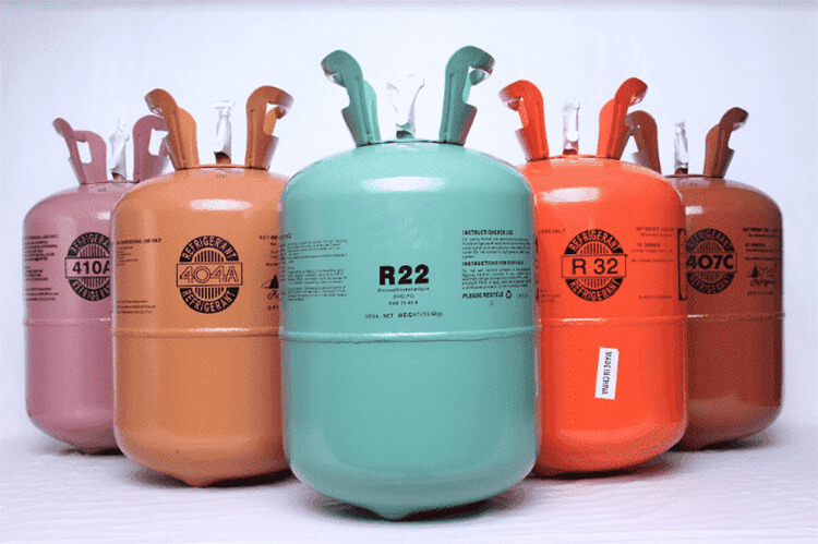
4. Excess Refrigerant in the System
Overcharging the system with refrigerant can yield a similar effect as air entrapment. If too much refrigerant is introduced, it can’t fully condense into liquid form. This excess refrigerant occupies a large section of the condensing pipe, reducing the condensing effect and increasing the pressure.
Solution: Carefully vent some refrigerant from the low-pressure side until the system reaches its optimal pressure.
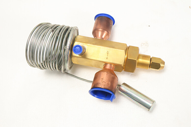
5. Expansion Valve with Insufficient Opening or Damage
The expansion valve is crucial for converting high-pressure liquid refrigerant into a vapor state. If the valve opening is too small, it can create high pressure at the condenser’s front side.
Solution: Gradually increase the expansion valve’s opening to reduce pressure. If the valve is damaged, it may need replacement.
In Water-cooled Chiller
Water-cooled chillers are intricate systems with high-pressure alarms that signal issues primarily related to the cooling water system. Below, we discuss some common causes of high pressure in water-cooled chillers, along with the recommended corrective actions:
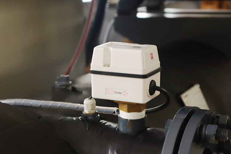
1. Cooling Water Valve is Closed
In a water-cooled unit, a cooling water tower supplies circulating cooling water. If the cooling water valve isn’t open, the cooling water won’t circulate, and the chiller can’t receive the supply.
Solution: Open the cooling water valve to allow circulation.
2. Insufficient Cooling Water Flow or Excessive Cooling Water Temperature
Both these conditions hinder heat dissipation, preventing the refrigerant’s temperature from being lowered, which in turn triggers a high-pressure alarm.
Solution: Verify that the size of the installed piping matches the chiller’s size. Check if the pump is functioning correctly and if the water valve is fully open.
3. Cooling Water Tower Malfunction
A high-pressure alarm can be triggered if the cooling tower fails, interrupting the circulation and supply of cooling water to the chiller.
Solution: Inspect the cooling tower for any operational issues or defects.
4. Water Scale Accumulation
Water-cooled chillers operating for extended periods without maintenance can accumulate scale and other debris on the tube wall. This accumulation hampers the condenser’s effectiveness.
Solution: Consider hiring a professional descaling company to clean the chiller and remove the water scale.
5. Overfilled Refrigerant
Overfilling with refrigerant is similar to the issue of air entrapment. Excessive refrigerant can’t condense into liquid form, occupies a significant part of the condensing pipe area, reducing condensing effectiveness, and consequently, raising the pressure.
Solution: Gradually vent some refrigerant from the low-pressure side to reach the system’s optimal pressure.
6. Expansion Valve Malfunction or Inadequate Opening
The expansion valve throttles the high-pressure liquid refrigerant into a vapor state. If the valve opening is too small, it can create high pressure at the condenser’s front side.
Solution: Gradually increase the expansion valve’s opening. If the valve is damaged, consider replacing it.
In summary, high-pressure alarms in water-cooled chillers can arise from a variety of causes, requiring careful and systematic troubleshooting. Always ensure qualified professionals perform any maintenance or adjustments to the chiller system.
For information on troubleshooting low-pressure alarms, please refer to our related guide here.