День добрый,
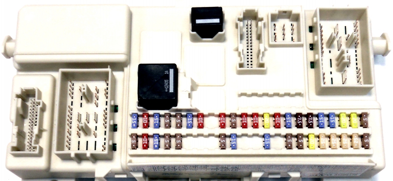
После замены ЕСМ надеялся, что проблемы решены. Но вчера сначало выбило 7С (или 9С, 5А, SRS) предохранитель, погасли блоки магнитолы и климата, после замены предохранителя проблемы пропали. Через пару часов, включив зажигание, поработав на холостом ходу пару минут, выбило 25С предохранитель, вырубились все приборы в кокпите… все идентично как припервых симптомах проблемы. После замены 25С проблемы пропали, я смог 70км доехать до дома, с 5 остановками, без каких-либо проблем…
Результаты диагностики:
AUM-41FF Усилитель, субантенна Сигнал отсутствует
CEM-1A07 Электропитание 15 Сигнал слишком сильный
CEM-1A08 Электропитание 50 Сигнал отсутствует
CEM-6A01 Левая задняя дверь отперта Сигнал слишком сильный
CEM-1A04 Электропитание Х Сигнал слишком слабый
SRS-00D0 Замок ремня безопасности водителя Сигнал отсутствует
SRS-00D1 Замок ремня безопасности пассажира Сигнал отсутствует
UEM-0004 Сирена Нарушение связи
На одном английском форуме вольвофан обращался с идентичным списком ошибок, жаль до него уже не достучаться.
Я думаю, что после включения зажигания, при проверке связи СЕМа с другими модулями, где-то в цепи происходит короткое замыкание и рубит предохранитель. Возможно что-то глючит в SRS системе, при SRS ошибках было зафиксировано напряжение 13.37 V.
Может кто сталкивался? Подсобите дельным советом. Заранее спасибо.
Проблемы с электричеством Volvo обычно вызваны неисправным соединением или корродированной землей. Довольно часто проблема заключается в подключениях к центральному электронному модулю Volvo (CEM) .
Центральный электронный модуль (CEM) – это основной электрический модуль в автомобилях Volvo, который связывается с остальными модулями и компонентами вашего автомобиля. Если он выходит из строя, это может привести к непредсказуемым перемежающимся электрическим проблемам.
Гораздо дешевле восстановить Volvo CEM, чем заменить его у дилера.
описание проблемы
С 2001 по 2013 год Автомобили Volvo подвержены неустойчивым электрическим проблемам из-за попадания воды в центральный электронный модуль .
Коррозия на терминалах CEM может развиваться, если вы:
- жить во влажном климате,
- забыть окна, когда идет дождь
- если ваш автомобиль был в наводнении.
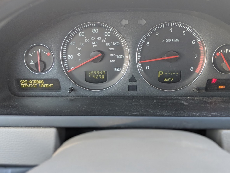
Например, у вас двигатель выключается самостоятельно или не запускается. Случайные предупреждающие огни , такие как ABS, подушка безопасности, предупреждение о торможении. Вход без ключа не работает.
Замена модуля CEM у дилера стоит $ 1000 +. Более дешевое решение – отремонтировать существующий модуль. Снимите существующий модуль и отправьте его на ремонт в предприятие, которое предлагает ремонт модуля Volvo CEM.
симптомы
Модуль CEM (или коррозионные соединения в CEM) вызывают прерывистые электрические проблемы.
Вот некоторые проблемы, которые вы можете заметить.
- Система безопасности не работает
- Тормоз, пожалуйста, сделайте ошибку безопасного останова на приборной панели
- Проблемы с зажиганием, не заводится машина
- Waring Lights On/Индикаторы не работают
- Дворники включаются случайно
- Руль трудно повернуть
- Подсветка комбинации приборов включается
- Датчики не работают
- Радио работает с перебоями
- Аксессуары перестают работать
- Свет не работает с перерывами
- Дворники не работают или приходят спорадически
- CAN сообщает о неисправности диагностического прибора
- ABS свет включается случайно
- Нет связи с блоком CEM
- Отказ тормоза
- Слабый режим
- Не начинай
- Immo вина
- Двигатель выключается случайно
Это некоторые из наиболее распространенных проблем. Имейте в виду, что вы можете испытывать только один или два из этих симптомов в зависимости от того, как и где произошла ошибка вашей CEM. Некоторые из этих проблем могут быть связаны с неисправным модулем управления кузовом или модулем управления освещением (LCM).
Автомобиль может нормально работать в холодное время, но возникают случайные проблемы с электричеством, когда жарко, холодно или на улице влажно.
Диагностировать модуль Volvo CEM
Для устранения неисправности электропитания Volvo вы можете начать с чтения кодов неисправностей из модуля CEM. Вам понадобится сканер Volvo, так как базовые сканеры OBD2 не могут считывать коды ошибок CEM. В этом видео показано, как читать и удалять коды из модуля Volvo CEM с помощью iCarsoft для Volvo.
Если вы не можете установить связь с модулем CEM, клеммы на модуле могут быть подвержены коррозии. Вы можете удалить модуль и осмотреть его. Если вы не можете отремонтировать его самостоятельно, отправьте его в стороннюю службу по ремонту модуля Volvo CEM. Поиск Volvo CEM Ремонт Сервис.
Как снять и почистить Volvo CEM
Чтобы снять и почистить модуль Volvo CEM, следуйте приведенным ниже инструкциям или посмотрите это видео.
-
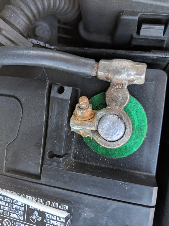
Отключите аккумулятор. Если ваша батарея находится в моторном отсеке, откройте капот, потянув за крышку капота под приборной панелью. Используйте 10-миллиметровую розетку для отсоединения отрицательной клеммы аккумулятора. Если у вас нет аккумулятора в моторном отсеке, аккумулятор будет находиться в багажнике под ковровым покрытием. Откройте багажник. Поднимите ковер. Снимите металлическую пластину с верхней части аккумулятора, затем отсоедините отрицательный контакт аккумулятора.

-
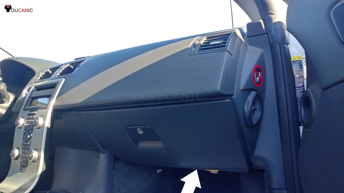
Найдите модуль CEM под приборной панелью на стороне пассажира для моделей с 2003 по 2013 годы. В 1999 – 2004 годах XC90, XC70, V70, S60, S80 CEM находятся под приборной панелью со стороны водителя.
- Снимите защитную панель или тканевую крышку под приборной панелью. Вам нужно будет снять пластиковые фиксаторы, чтобы снять крышку.
- Теперь модуль CEM выставлен. Заверните два винта на CEM и опустите модуль.
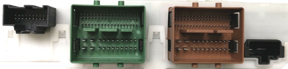
- Отсоедините электрические разъемы от CEM. Чтобы снять разъемы, сначала потяните рычаг назад, чтобы разблокировать его, затем выньте.
- Отсоедините электрические разъемы также от нижней части модуля CEM.
- Осмотрите разъемы и контакты на CEM на предмет коррозии.
- Снимите черные реле с CEM и осмотрите их.
- Используйте небольшую щетку для очистки контактов в сочетании с очистителем контактов.
- Как только вы очистите все контакты, дайте CEM полностью высохнуть.
- Нанесите легкий слой электронного контактного предохранителя (диэлектрической смазки) на каждую клемму для улучшения проводимости.
- Подсоедините все разъемы к CEM. Каждый разъем имеет уникальную форму и поэтому будет входить только в свой порт.
- Закрепите CEM на двух кронштейнах, которые находятся под приборной панелью.
- Затянуть два винта
- Установите крышку под приборной панелью.
- Подсоедините отрицательную клемму аккумулятора.
- Заведите машину и убедитесь, что все работает правильно.
Часто задаваемые вопросы
Моя машина не заводится после очистки CEM.
Убедитесь, что разъемы к CEM полностью вставлены и правильно заблокированы. Убедитесь, что отрицательный вывод аккумулятора затянут.
Какие модели Volvo имеют эту проблему?
Первичный вольво на платформе P1. Volvos с 2004 по 2013, у которых есть модуль CEM под приборной панелью на стороне пассажира.
Какие автомобили Volvo основаны на платформе P1?
2004–2012 Volvo S40 II (P11)
2004–2012 Volvo V50 (P12)
2006–2013 гг. Volvo C70 II (P15)
2007–2013 Volvo C30 (P14)
Эта проблема влияет на другие автомобили?
Да. Эта проблема может коснуться других автомобилей на базе платформы P1. Примеры включают модели Ford C1, такие как Focus, Kuga, Escort, Escape, Transit, Linkon MKC, Mazda Alexa, Mazda3, Biante. Транспортные средства Sabb также.
Вычитали следующее:
- Код: Выделить всё
BCM-0021 Правый передний колесный датчик Сигнал неверен
BCM-0100 Связь между блоками управления Проблемы связи с модулем управления двигателя
CCM-001B Нижний выключатель Отсутствует идентификатор
CCM-0021 Датчик качества воздуха Внутренняя неисправность
CEM-E000 Обмен данными с модулем управления Нарушение связи
PDM-003E Модуль управления Сигнал слишком сильный
С двигателем связання ошибка CEM-E000
Условие
Модули управления передают и получают информацию стандартным методом последовательной связи — по контроллерной локальной сети. Код неисправности регистрируется, если модуль управления регистрирует серьезные помехи в сети высокой скорости (заблокирована связь контроллерной локальной сети).
Примечание
В случае нарушений связи в системе поддерживать связь с модулем управления невозможно. Поэтому считывание неисправности будет возможно, только если эта неисправность неустойчивая.
Заменяемое значение
Модуль управления выключается (“шина выключена”).
Информация:
Модуль управления останется выключенным, пока не будет прервано электропитание (15, 30, X). Когда электропитание подключается, модуль управления предпринимает новую попытку установить связь.
Возможные причины
- Короткое замыкание в проводке контроллерной локальной сети
Разрыв цепи в проводке контроллерной локальной сети
Внутренняя неисправность в модуле управления
Внутренняя неисправность в другом модуле управления в той же части контроллерной локальной сети.
Симптом (симптомы) дефекта
- Стартер проворачивается, но двигатель не заводится
Спидометр не работает
Не работает тахометр
Указатель температуры охлаждающей жидкости двигателя не работает
Система поддержания выбранной скорости не работает совсем
Функционирование рывками.
Устанавливается на всех VOLVO выпуска с 1999 модельного года по сегодняшний день.
Напоминаю что новый модельный год у Volvo начинается обычно с 25 недели.
Т.е. автомобиль выпущенный в 1998 году на 25 неделе будет уже по VIN 1999 модельного года, и вся начинка у него будет соответствовать этому модельному году. Схемотехника естественно то же.
Определить модельный год просто, это десятый символ в VIN.
Например YV1CM59H841077777 — означает 2004 м.г.
Какие есть на данный момент проблемы с этими модулями.
Р2 платформа ( это все Вольво S60, S80, V\XC 70\90 )
1999-2001 — сбоит в движении.
Как проявляется дефект
Вылезает надпись на приборке о неисправности тормозов, падают стрелки все кроме уровня топлива, гаснут все лампочки приборки. АКПП начинает пинаться. Если заглушить машину она не заводится, даже простояв полчаса, час или даже всю ночь. «Помогает» отключение АКБ.
Чем многие из вас и пользуются.
В один прекрасный момент стартер перестает крутиться и машина не откликается на поворот ключа в замке зажигания. » Поздравляю » вы стерли всю информацию в СЕМ, мучать машину больше не стоит.
Что делать ?
Ремонт
С таким дефектом СЕМ не ремонтируется.
Его нужно заменить новым.
Сделать это можно у любого дилера VOLVO доставив авто к нему на эвакуаторе.
Либо прислать, привезти СЕМ к нам.
Да это дорогой ремонт, предупреждаю сразу, обойти это никак не получится.
2002-2004 — сбоит в жару или в холод
Как проявляется дефект
Чаще всего летом или когда похолодало и включили обогрев салона. Но было несколько (значительно меньше) случаев когда модуль начинал сбоить в замерзшем состоянии, с прогревом он восстанавливал свою работу. При комнатной температуре 20 — 25 гр С, дефект не проявляется. Ролик небольшой снят мной по этой проблеме :
На машине выглядит обычно точно так же всё. Внезапно включается ближний свет фар. Если заглушить двигатель, он не заведется пока СЕМ не остынет. Было несколько ситуаций, они все не придуманы, написаны на форуме клуба Вольво, когда машина на ходу вырубала двигатель, свет и т.д.
Учитывайте что выключенный двигатель, это отключенный ГУР, т.е. руль становится настолько тугим, что растерявшийся водитель, может подумать что его заклинило. На самом деле нет. Нужно просто прикладывать к повороту руля усилия в несколько раз большие к которым вы привыкли крутя баранку одним пальцем. Ночью при обгоне авто или просто на ходу погасший свет фар и вы летите в темноту не видя дороги. Ощущения просто обалденные. Хорошо если просеку новую не сделаете вдоль трассы.
«Ремонтировать» отключением АКБ бесполезно. Можно так же стереть всю информацию в СЕМе, и попасть на крупную сумму денег.
Ремонт
Сделать ремонт такого СЕМ можно. Меняется вышедшая из строя микросхема, перепрограммируется.
И модуль будет работать очень долго.
В моей практике я поддерживаю дружескую связь со своими клиентами . Отремонтированные с 2010 года модули работают по сей день ( февраль 2016 года) после ремонта без каких либо попыток сбойнуть. То есть шесть лет. Гарантию на их ремонт я давал год. В общем результат очень даже неплохой, согласитесь.
Я не рассмотрел в этот период «СЕМ — утопленников» . Причина одна — дренаж люка или плохая вклейка лобового стекла. К сожалению это проблема не только 2002-2004 года, об этом наверное стоит потом рассказать в отдельной статье. Так как это не электронная проблема, а скорее кузовная.
2005-2014 для ХС90
2005-2007 для S80 и V/XC 70
2005-2011 для S60
Основная проблема — утопленники из-за поступления воды по кабельной трассе из колодца лобового стекла.
Трасса выполнена в виде короба, короб проложен аккурат под обрезом нижней части лобового стекла.
Вся грязь, вода, стекают туда . Хоть короб и перфорированный, со временем он забивается пылью, с дороги. Смоченный водой, масляными парами из под капота он начинает превращать проводку в болотистую жижу. Наступает момент когда очередной сильный ливень накрывает машину в дороге или на стоянке . Это может быть вовсе и не ливень, а резкая смена температуры с минуса на плюс зимой, и сопровождающим ее снегопадом. Вода естественно не минеральная, а со всей таблицей Менделеева, что летит из под колес машин, течет по проводам капиллярным эффектом, через СЕМ в салон. Хорошо если вы доехать успеете до сервиса или гаража. В худшем случае цветомузыка фар, габаритных огней, стоп-сигналов, не работающие дворники, или наоборот не выключающиеся дворники замучают вас всю дорогу.
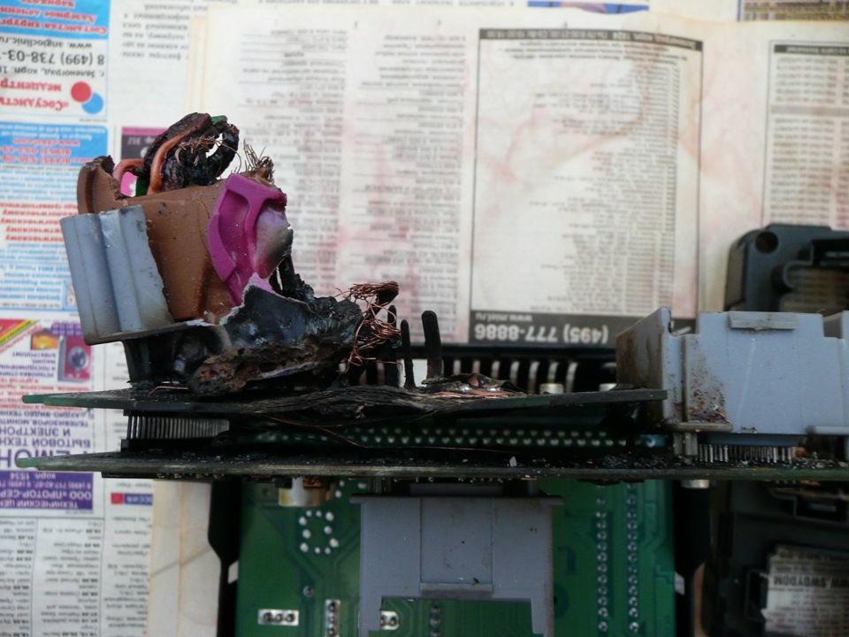
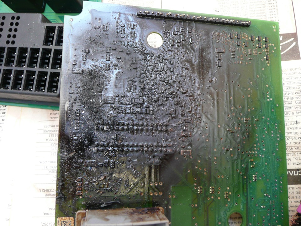
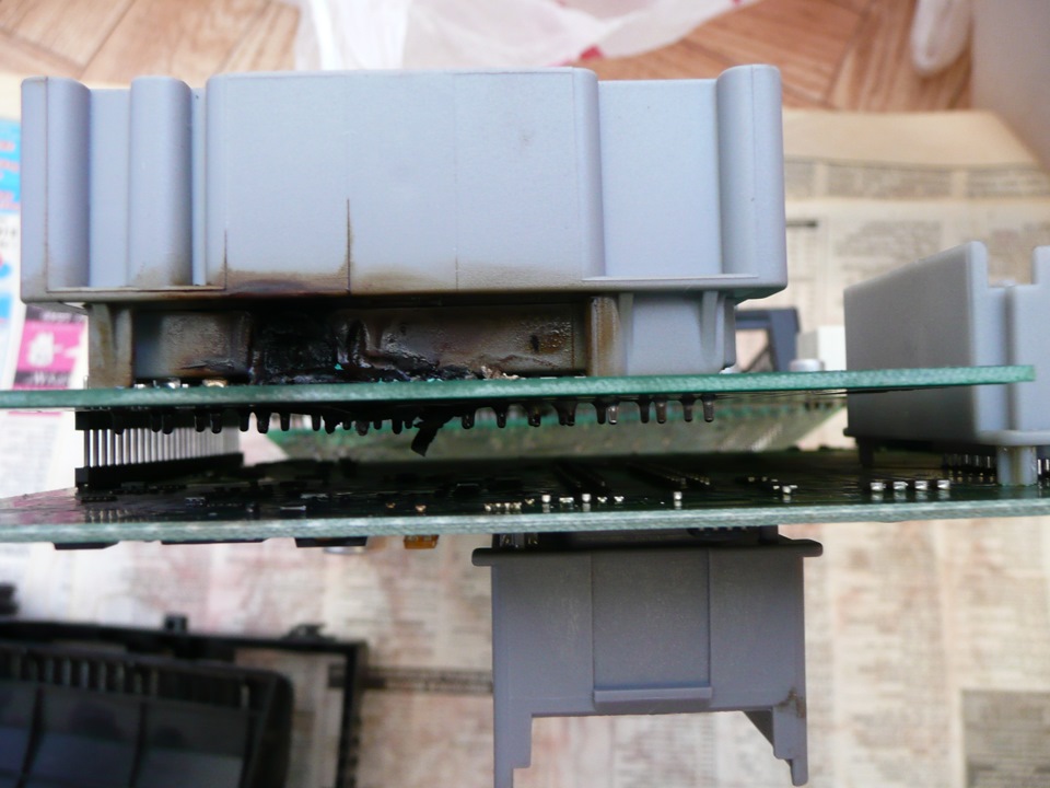
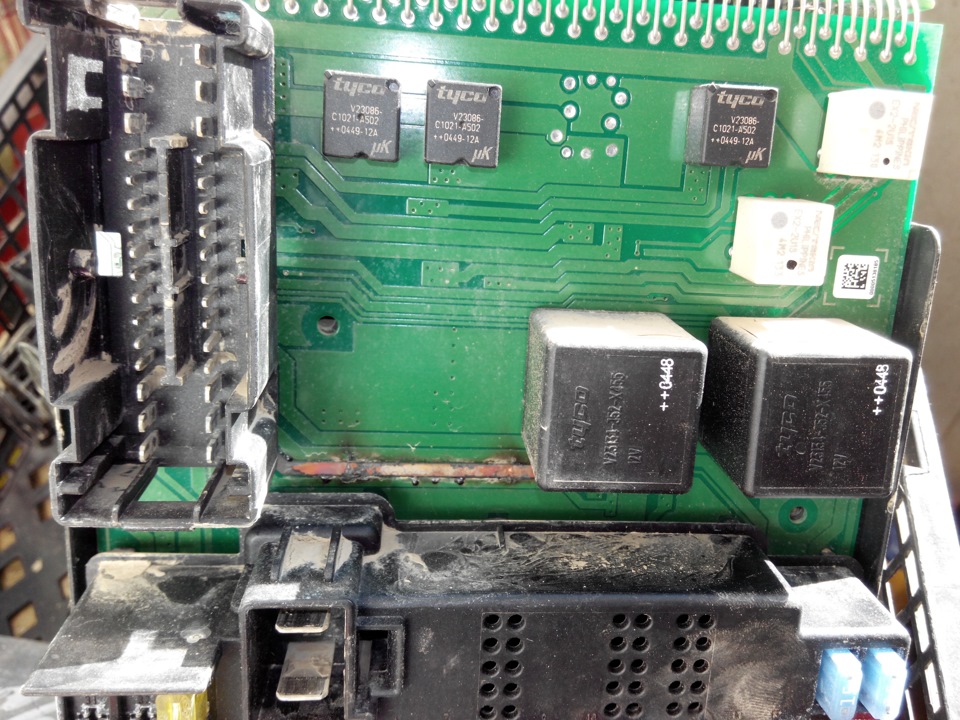
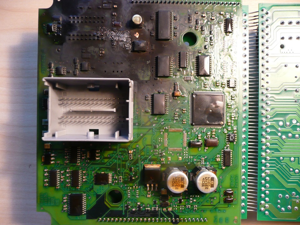
После чего СЕМ обычно умирает. Увы иногда бывают случаи пожара. Силовые цепи внутри СЕМ замыкают и он начинает гореть, при этом сильно воняя. Сгореть может и вся машина кстати. Чтоб не подумали что я преувеличиваю возможные последствия, смотрите серию документальных фото:

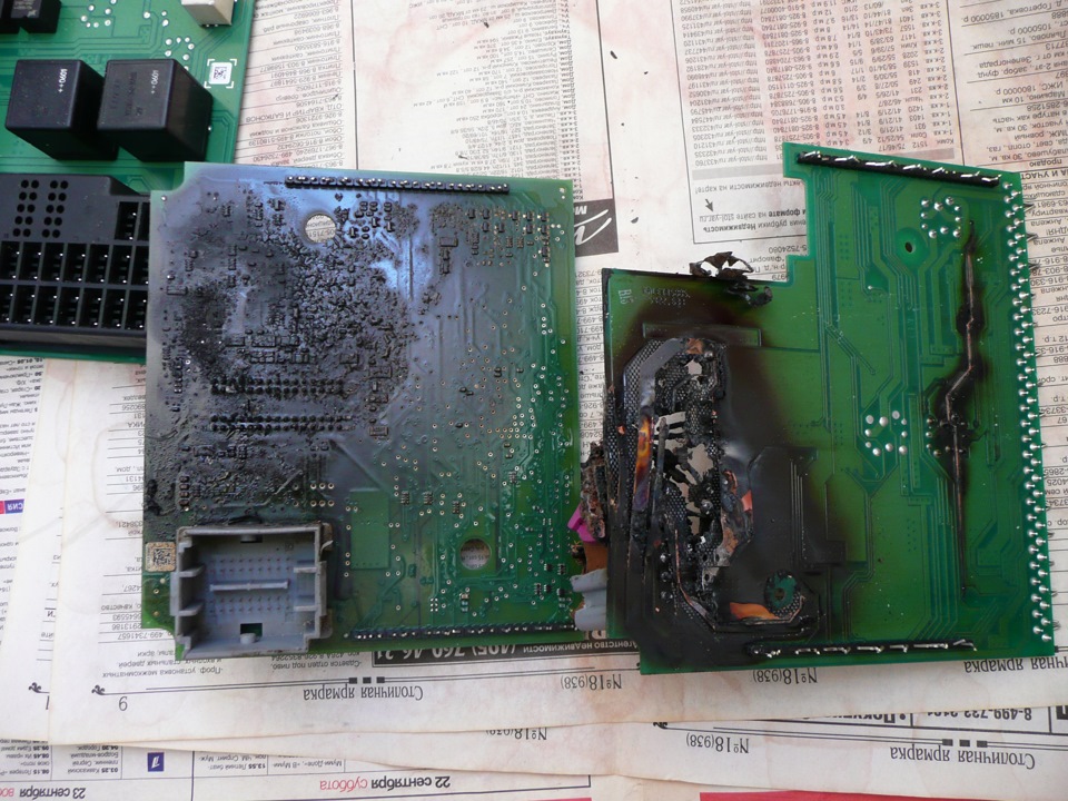
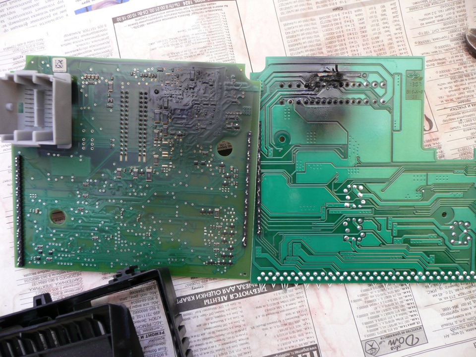
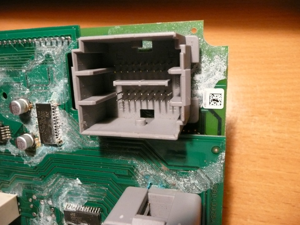
А вот еще вариант засахарившегося модуля
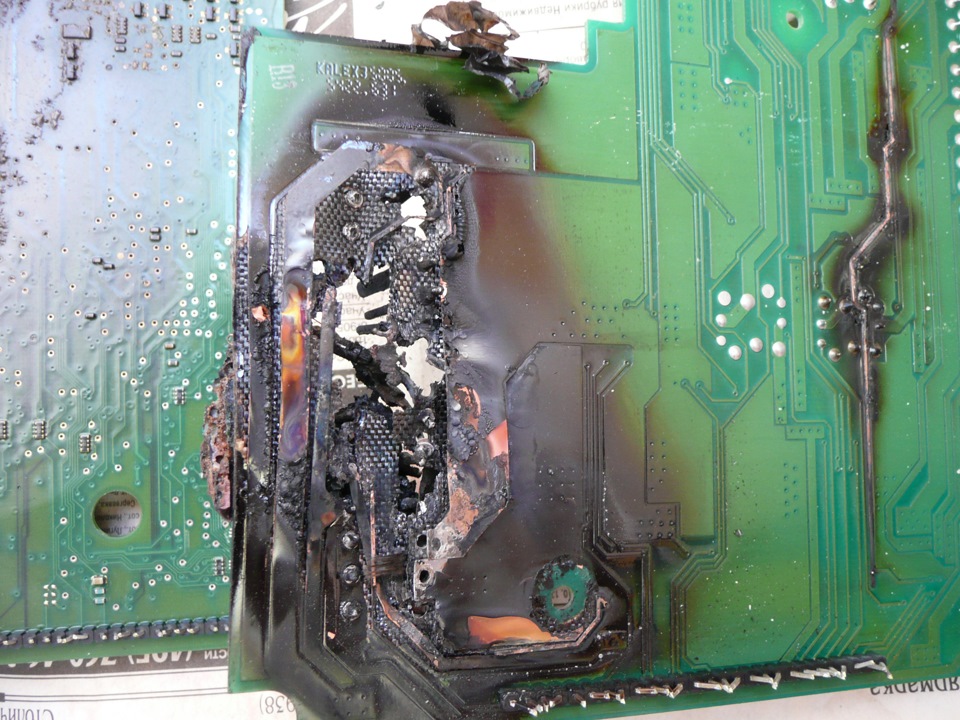
Последствия замены предохранителя розетки 12В (прикуривателя).
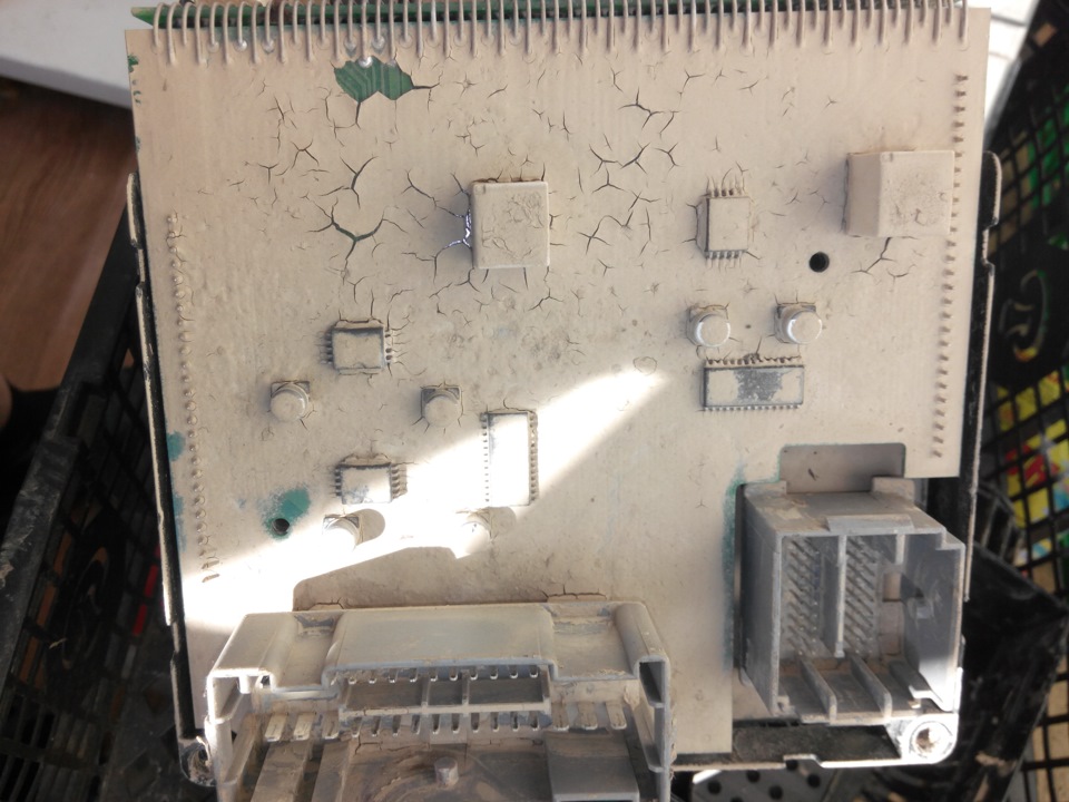
И еще поджарочка

Одинаковых ремонтов по таким случаям практически нет.
Если владелец авто вовремя обратил внимание на это, то СЕМ обычно удается спасти и после чистки и герметизации жгута проводки, он еще послужит верой и правдой.
Если же ездить до победного конца, пока совсем что-нибудь не отвалится, тогда либо замена плат, деталей сгнивших, разъемов обязательно, по другому никак. По фото выше вы сами понимаете что там уже ремонтировать нечего. В худшем варианте замена СЕМ на бушный или новый с перепрограммированием.
Почему то в последнее время худшие варианты встречаются чаще всего. Владелец хватается за голову, но ничего уже не поделаешь.
На сегодня пожалуй всё про СЕМ. Продолжение следует на этой же странице.
-
Contents
-
Table of Contents
-
Bookmarks
Quick Links
INSTRUCTION MANUAL
PROFESSIONAL
DIGITAL CONTROL UNIT CEM7
Summary of Contents for Himoinsa CEM7
-
Page 1
INSTRUCTION MANUAL PROFESSIONAL DIGITAL CONTROL UNIT CEM7… -
Page 2: Table Of Contents
CONTENTS 1. Introduction 2. Front of the display module 3. Operating modes 4. Operation 5. CEM7 control unit inputs and outputs 6. CEM7 control unit alarms 7. Maintenance 8. Options (expansions) 9. Appendix I: parameters table 10. Appendix II. CEM7 control unit screens 11.
-
Page 3: Introduction
1. INTRODUCTION The CEM7 control unit is a generator set power supervision and control device. The control unit consists of 2 different modules: • Display module. The display module is responsible for carrying out the information tasks regarding the status of the device and allows actions to be performed by the user;…
-
Page 4
The measurements module provides the following electrical signal characteristics, • Tariff change warning both those generated and those from the network itself: • Tariff change (CEM7 + CEA7CC2) • Phase-neutral voltage • Start up disabling • Phase-to-phase voltage •… -
Page 5
• Timer device • Telesignal device • CCJ1939 device • Repetitive display • Telecontrol device • Announcement panel device • CAN/USB • CAN/232 + MODEM LINE • CAN/232 + MODEM GSM • CAN/232 + MODEM GSM/GPS POSITIONING • CAN/232 + MODEM GPRS HG FLEET MANAGER •… -
Page 6: Front Of The Display Module
The display module has a backlit display and various LEDs for monitoring the status of the control unit. It also has keys that allow the user to control and program the control unit. Fig.1 CEM7 display module Fig.2 CEM7P display module FRONT OF THE DISPLAY MODULE | PAGE 6…
-
Page 7
1. Backlit display 4 lines by 20 digits. 2.1.2 CONTROL UNIT COMMAND BUTTONS Engine start button (only in manual mode) NOTE The display goes into low power mode (backlight off) after 10 minutes have Controls the start up with a single push. passed without any keystroke. -
Page 8
These LEDs only appear active when the switching control unit is connected. Alternator status Off: Stopped engine or engine running Start up option due to Network Voltage Failure (CEM7 + CEA7CC2) battery charging without voltage in the battery charging The M and G symbols on the front of the control unit only appear activated when alternator the switching control unit is connected. -
Page 9
2.3 PASSWORDS The CEM7 control unit has 2 levels of 4-digit password to protect against unauthorized access. The different levels of access are as follows: • User (default password: 1111). User level access allows the operator to access the main menu of the CEM7 control unit. -
Page 10: Operating Modes
START and STOP keys respectively. Pressing the START key initiates the engine starting procedure (without deactivating the network contactor CEM7 + CEA7CC2). Pressing the STOP key initiates the engine stopping procedure with cooling; a second press of the STOP key causes the engine to stop immediately without waiting for the cooling time.
-
Page 11
3.3 MODE LOCKING FUNCTION Pressing the Auto or Man keys for 5 seconds activates the locking of the mode. This control unit state is indicated by the flashing of the mode key currently active. To deactivate the mode lock and allow normal operation of the control unit, press the key associated to the active mode for 5 seconds. -
Page 12: Operation
1. Start delay. Once activation conditions are detected, it is possible to program a time delay (Times table, parameter 3) before continuing the engine start up procedure only in automatic (CEM7 + CEA7CC2 or CEM7 + AE) 2. Preheating of the motor (PR). The control unit activates preheating output (PR) for the programmed time (Times table, parameter 4).
-
Page 13
4. Starting the motor (ARR). For a maximum time (Times table, parameter 5), 4.1.2 GAS ENGINE the start output of the measurements module is activated while waiting to detect 1. Checking the engine gas train (PR). The process of checking the gas train at least one of the programmed start conditions. -
Page 14
7. Generator stabilisation. Once any start condition is detected, the control unit PRACTICAL EXAMPLE OF A START OPERATION waits for a fixed time for stabilization of the generator signal before monitoring the quality of the generator signal. NOTE 8. Nominal condition. After achieving engine stabilisation, verification of the Before starting the start cycle it is advisable to ensure the genset’s main circuit generator signal is performed. -
Page 15
Fig.2 Fig.4 Once it has been detected that the engine is running the LED switches on ( ), If during the start cycle, the engine started condition is not detected after 5 this indicates the end of the start cycle and the START button turns off. (3) seconds, the ARR output deactivates and the corresponding LED turns off ). -
Page 16
NOTE • Pickup frequency (Regulations table, parameter 21). The engine is considered stopped when the pickup frequency is below the start The display shows the engine status screen, where the engine status is displayed up threshold (Threshold table, parameter 22). To activate the pickup during the start up operation. -
Page 17
PRACTICAL EXAMPLE OF A STOP OPERATION NOTE Before starting the stop cycle it is advisable to ensure the genset’s main circuit breaker is in the off position (OFF). The genset stop can be performed in various ways: 1. Manual: Pressing the STOP button once. To perform a stop with cooling cycle. 2. -
Page 18
4.3 FUEL TRANSFER PUMP It is possible to activate the fuel transfer pump of the CEM7 control unit by associating its operation with the BT relay of the measurements module (Regulations table, parameter 4). Once the fuel transfer pump option is enabled, the operating mode is then set (Regulations table, parameter 1): 1. -
Page 19
4.5 BATTERY CHARGING ALTERNATOR managing the fuel transfer pump and fuel level alarm) a calibration of the tank The battery charging alternator is connected to the CEM7 control unit via the gauge should be performed. This requires access to the minimum and maximum gauge level parameters (Measurements table, parameters 12 and 13). -
Page 20
From the firmware versions of control units: Display 3.20 / Measurements 2.50 4.6 START/STOP KEY 4.8 ELECTRONIC PROTECTION The start/stop key in the ON position causes power to be supplied to the CEM7 control unit’s electronic devices (measurements module and display module). DESCRIPTION The start/stop key in the OFF position causes a controlled stop if it is running;… -
Page 21
4.9 MOTORPUMP MODE 4.10 GENSET IN RESERVE DESCRIPTION DESCRIPTION The motorpump mode configures the CEM 7 control unit to display only engine The genset in reserve function allows the operation of several generator sets in measurements, hiding generator set voltage measurements. This configuration the same installation. -
Page 22: Cem7 Control Unit Inputs And Outputs
15-24) which requires that the value of the input is stable over a time interval. Also, all of the CEM7 control unit’s inputs can be configured to be active with contact closed to earth or be inactive with contact closed to earth (Regulations table parameters 5 to 15).
-
Page 23
Detection of an active output is indicated by the following characters: 5.1 DIGITAL INPUTS • OUT 1. Alarm active (AL) The CEM7 control unit’s measurements module has 5 digital inputs with • OUT 2. Motor started (MA) operation that is already preset. -
Page 24
TEST SIGNAL (TEST) The CEM7 control unit’s measurements module has 5 digital inputs with This function is only managed in automatic mode of the CEM7 control unit with operation that can be programmed. The programmable inputs can be configured the motorised circuit breaker option. -
Page 25
5.3 ANALOGUE INPUTS There are 2 additional programmable alarms available (Settings table, parameters The CEM7 control unit has 5 analogue inputs for measuring the engine operation 22 and 23) that can be associated with any of the programmable inputs and values. -
Page 26
52 to 54) when the fuel level is detected to be below this limit. The CEM7 control unit allows you to add 8 analogue temperature inputs to the PT100 sensor through the expansion of up to 2 CCPT100 devices. 2 maximum… -
Page 27
PREHEATING OUTPUT. (PR). POWER OUTPUT FUEL TRANSFER PUMP/HEATING/ELECTRONIC PROTECTION OUTPUT (BT). The preheating output (PR) of the CEM7 control unit is an output connected to a RELAY OUTPUT high power shortable driver (70 A) which regulates the heating process of the The fuel transfer pump/heating output (BT) of the CEM7 control unit is a relay engine’s spark plugs during the starting process. -
Page 28
STARTED ENGINE OUTPUT (MA). DIGITAL OUTPUT The alarm output (AL) is responsible for communicating the different states of The started engine output (MA) of the CEM7 control unit is activated when any the CEM7 control unit. The AL output simultaneously activates the flashing of the started engine condition is detected and remains active while the engine is Reset key LED and display module buzzer of the CEM7 control unit. -
Page 29
(Thresholds table, is detected (Thresholds table, parameter 32) during a set time (Times table, parameter 35). Both with the activation and deactivation of the load demand CEM7 CONTROL UNIT INPUTS AND OUTPUTS | PAGE 29… -
Page 30
The output remains active if the correct operation of the generator set’s control system is verified. The CEM7 control unit has 4 additional programmable outputs installed in the Second Zero Suppression expansion, the operation of which can be configured to indicate certain states (Settings table, parameters 18 to 21). -
Page 31: Cem7 Control Unit Alarms
6. CEM7 CONTROL UNIT ALARMS The CEM7 control unit has a list of alarms, the operation of which can be configured so that actions are performed or so that they are shown on the display module screen. The CEM7 control unit distinguishes between errors that cause the engine to stop (alarms) and errors do not cause the engine to stop (warnings).
-
Page 32
2. Pressing the RESET button eliminates the acoustic warning. The RESET LED remains lit and the type of alarm is shown on the display (which stops flashing). Ex: Alarm active “EN” High Water Temperature. CEM7 CONTROL UNIT ALARMS | PAGE 32… -
Page 33
2. Pressing the RESET button eliminates the acoustic warning. The RESET LED TEMPERATURE remains LIT and the type of warning is shown on the display (which stops flashing). Active warning “AN”. NOTICE HIGH WATER TEMPERATURE Fig.3 Fig.2 CEM7 CONTROL UNIT ALARMS | PAGE 33… -
Page 34
1. Upon detection of an alarm or warning, the control unit produces an acoustic Fig.5 signal, the LED of the RESET button and the display flashes and the alarm digital output (AL) is activated. Fig.4 CEM7 CONTROL UNIT ALARMS | PAGE 34… -
Page 35
LEDS Aux1 and Aux2. Low oil pressure by sensor Lit LED Notice Not for engine Not for engine Low fuel level by sensor Lit LED Notice Unexpected stop Stop failure CEM7 CONTROL UNIT ALARMS | PAGE 35… -
Page 36
All alarms except those which are non-programmable, can be configured as LOW OIL PRESSURE follows: The CEM7 control unit’s low oil pressure alarm is associated with the digital To be activated: input specifically for the low oil pressure (BPA) or errors detected by the engine’s •… -
Page 37
LOW WATER LEVEL measurements module (stops engine) ensuring the engine shutdown is set as The CEM7 control unit’s low water level alarm is associated with the digital input stop via de-energisation (Regulations table, parameter 18) independently of the specifically for the low water level (NA) or errors detected by the engine’s CIU control unit’s electronics. -
Page 38
FUEL RESERVE The CEM7 control unit’s under speed alarm is associated with the measurement The CEM7 control unit’s fuel reserve alarm is associated with the digital input of the engine flywheel ring gear’s rotation speed or through the J1939 channel of specifically provided for the fuel reserve (RC). -
Page 39
MAXIMUM GENSET FREQUENCY GENSET VOLTAGE ASYMMETRY The CEM7 control unit’s maximum genset frequency alarm is associated with the The CEM7 control unit’s genset voltage asymmetry alarm is associated with the condition that the frequency generated by the genset is above the maximum fact that the difference between any two RMS voltages between genset voltage frequency limit set (Thresholds table, parameter 5). -
Page 40
LOW OIL PRESSURE BY SENSOR The CEM7 control unit’s low oil pressure by sensor alarm is associated with the LOW BATTERY VOLTAGE analogue input for the oil pressure (T). The low oil pressure by sensor alarm is… -
Page 41
LOW FUEL LEVEL BY SENSOR The CEM7 control unit’s high battery voltage alarm is activated when the battery The CEM7 control unit’s low fuel level by sensor alarm is associated with the voltage measured is above a set limit (Thresholds table, parameter 36). -
Page 42
SHORT CIRCUIT The CEM7 control unit’s minimum genset frequency alarm is associated with the The CEM7 control unit’s short circuit alarm is associated with the condition that condition that the frequency generated by the genset is below the minimum the measurement of the RMS current is above the maximum short circuit limit frequency limit set (Thresholds table, parameter 6). -
Page 43
GENSET SIGNAL FAILURE detected. The CEM7 control unit’s genset failure signal alarm is generated if no genset voltage is detected during any phase while the engine is running. PROGRAMMABLE ALARM 2 Detection of the genset failure signal alarm is set by default (Alarms table, parameter 76) to be activated under nominal engine conditions. -
Page 44
PROGRAMMABLE ALARM 5 PROGRAMMABLE ALARM 3 The CEM7 control unit’s programmable alarm 5 is activated associating the The CEM7 control unit’s programmable alarm 3 is activated associating the operating mode of the programmable alarms (Settings table, parameter 23) to operating mode of the programmable alarms (Settings table, parameter 15) to… -
Page 45
(Alarms table, parameter 131) to perform no action (warning). The CEM7 control unit’s high temperature alarm for PT100 level 2 probes 1 to 4 is associated to the analogue inputs for PT100 temperature of the analogue input expansion. -
Page 46
IDMT ALARM EXAMPLE CALCULATION OF THE IDMT CURVE TIME CONSTANT (T) The CEM7 control unit’s IDMT alarm is associated to the measurement of the For a genset current (I) with a value of 110% of the nominal value, the desired genset current. -
Page 47: Maintenance
7. MAINTENANCE 7.1 OPERATION COUNTERS The CEM7 control unit records different accumulated readings related to control unit operation. The counters that record the control unit are: • Total operating hours counter. The control unit records the number of hours that the genset engine has been operating. The total operating hours counter cannot be reset to zero.
-
Page 48
7.2 MAINTENANCE COUNTERS 7.3 LIST OF PREVIOUS ERRORS The CEM7 control unit has 3 programmable counters that are loaded for a certain The CEM7 control unit keeps a record of the detected alarms saving the status time which decreases while the engine is detected as running. The maintenance… -
Page 49
For display modules (CEM7 and CEA7), the Master display module The CEM7 control unit has a series of temperature and pressure sensors curves must have the same ID as the associated measurement module. -
Page 50
4. The first programmable fuel curve corresponds to the generator set’s main fuel sensor. This curve is used for gauges with nonlinear responses that need more than 2 points for programming. If the CEM7 control unit detects a curve programmed in the first fuel curve, it cancels the parameters corresponding to the linear calibration of the generator set’s main gauge (Measurements table, parameters 12 and 13 ). -
Page 51: Options (Expansions
8. OPTIONS (EXPANSIONS) New functions can be added to the CEM7 control unit using the CAN bus connection via expansion modules. 8.1 DISPLAY SCREEN (REPETITIVE) The control units CEA7 and CEM7 allow display screens to be added to the installation. This device displays the current status of the control unit, and if it is in automatic mode, can control the functioning of the genset.
-
Page 52
• Energy counters (day, month, year) 3. It will be slightly elevated so that it can be accessed easily. The maximum timer limit is 5 daily programs. The CEM7 control unit must be in automatic mode in order to manage the incorporated programming. -
Page 53
INPUT/OUTPUT screen if it is detected that the J1939 extension is installed or option CEM7J. Both the CEM7J option and the CEM7 control unit with the expansion CCJ1939 can monitor the following engine operating parameters depending on the… -
Page 54
16 LEDs each one of connection using TCP/IP connections. The CCLan device allows the following: which can be associated with one of the following states of the CEM7 control unit: • Remote monitoring and control via a TCP/IP connection as well as •… -
Page 55
8.11 ANALOGUE INPUTS EXPANSION PT100 The CEM7 control unit allows the connection of a CPT100 device for measuring up to 4 temperature probes for display and management of the generator set alarms. 8.12 PRECISION GAUGE EXPANSION The CEM7 control unit allows the connection of a precision gauge device for measuring the level in fuel tanks. -
Page 56: Appendix I: Parameters Table
9. APPENDIX I: PARAMETERS TABLE The CEM7 control unit allows 3 levels of access for settings. To modify any of the CEM7 control unit’s parameters validation is required by entering the correspond- ing password. The 3 levels of access are: 1.
-
Page 57
Table 1 Times Table Default Default Parameter Description Range Parameter Description Range value value Number of Starts 1..10 Filtering of the ENT5 input 1.0’’ 0.0’’.. 120.0’’ Time between Starts Filtering of the ENT1 input 1.0’’ 0.0’’.. 120.0’’ Period between starts during which all the outputs 5’’… -
Page 58
Table 3 Regulations Table Default Default Parameter Description Range Parameter Description Range value value 0-Off Phase voltage as starting condition 1-Manual 0- No consultation Fuel transfer pump operating mode 2-Automatic Alternator voltage as starting condition 1 3-Control unit mode/ 1- Motor started Combined mode 2- Motor stopped PICK-UP input as starting condition. -
Page 59
Table 4 Table 6 Analogue sensors. Related to parameter 29 in the Regulations table External start-up configuration table. Related to parameter 31 in the regulations table Value Coolant temperature Oil pressure Oil temperature Value Fitting property 9 10 11 12 13 14 15 VDO: 323-803-001-008 VDO: 360-081-030-009 ѵ… -
Page 60
Table 8 Default Parameter PSW Description Range Alarms Table value Starting speed (PICK UP) 1000 rpm 300-1000 Parameter PSW Description Default value Range Engine flywheel teeth 0-300 0- Not checked 1- Always checked Low fuel level 0..30 2- When starting Management alarm 0 3- From start condition Low oil pressure threshold… -
Page 61
Parameter PSW Description Default value Range Parameter PSW Description Default value Range Management alarm 10 Mode alarm 19 0..2 0..4 Asymmetry Management alarm 20 0..4 Filter alarm 10 8” 0”…255” Minimum Unit Voltage Mode alarm 10 0..2 Filter alarm 20 8”… -
Page 62
Parameter PSW Description Default value Range Parameter PSW Description Default value Range Management alarm extension 2 Mode alarm probe 3 0..2 Programmable alarm 5 0..4 Management alarm probe 4 (from version PHG6/7 v250) Temperature probe 4 0..4 Delay alarm extension 2 0’… -
Page 63
Table 9 Default Parameter PSW Description Range Settings Table (I/O) value Input associated to CKG mode Default Parameter PSW Description Range value Input associated to EJP1 mode 0- Not programmed Input associated to EJP2 mode 2- BPA (option CEM7J) 0- Not programmed Input associated to IA mode 3- ATA (option CEM7J) 1- RC Input… -
Page 64
Table 12 Parameter PSW Description Default value Range Parameters clearance selector Table 0- Not programmed Default Input associated to AL4 mode Parameter PSW Description Range 2- BPA (option CEM7J) value 3- ATA (option CEM7J) 0- Three-phase without 4- NA (option CEM7J) neutral 5- ENT4 Input associated to AL5 mode… -
Page 65
Table 13 Table 14 Table J1939 Screen Table Parameter PSW Description Default value Range Parameter PSW Description Default value Range SCANIA EMS 0: Buzzer enabled Inhibition of buzzer VOLVO EDC4 1: Buzzer disabled VOLVO EMS2 VOLVO EMS1 0: Enable PD activation in IVECO CURSOR PD inhibition in inputs/outputs I/O menu… -
Page 66: Appendix Ii. Cem7 Control Unit Screens
10. APPENDIX II. CEM7 CONTROL UNIT SCREENS 10.1 CONTROL UNIT STATUS The status of the CEM7 control unit is shown on the display, allowing access to different display options using the up and down navigation keys. 10.1.1 GENERATOR MEASUREMENT SCREENS 1.
-
Page 67
RPM, H operating hours, NC fuel level, DI battery charging alternator voltage, TM Fig.1 engine temperature, VB battery voltage, PA oil pressure and, either AA auxiliary CEM7 + CEA7CC2 temperature or NC2 fuel level in auxiliary tank. G E N S E T :… -
Page 68
1. Measurements of actual power and cos phi per phase. 10.1.6 TEMPERATURES BY PT100 PROBES (ONLY IF EXPANSION MODULE PT100 PROBES) P O W E R : FP: Total power factor Fig.1 Temperature from probes FP1: Power factor phase 1 FP2: Power factor phase 2 FP3: Power factor phase 3 2. -
Page 69
10.2.2 MAIN MENU 1. INPUTS AND OUTPUTS DISPLAY The main menu screen gives access to the different menus, to enter each menu select it with the cursor (+) (-) and confirm (v): I N P U T S / O U T P U T S 1. -
Page 70
The second screen displaying J1939 measurements is available for firmware A N A L O G U E I N P U T S versions 3.36 and higher for genset and automatic display modules. NC: Fuel level PA: Oil pressure TM: Engine temperature AA: Auxiliary analogue IM: Intake Manifold Temperature… -
Page 71
* * * * F a i l e d S t a r t s The scheduling in the CEM7 control unit is conditioned so that the option of a T o t a l timer is enabled. The scheduling is carried out via the fifth option of the maintenance menu. -
Page 72
* * * * * S C H E D U L E S * * * * * S u n d a y * * * * * M o n d a y * * * * * … -
Page 73
6. DATE AND TIME * * * L A N G U A G E * * * Select the hour and confirm (V), adjust the time (+) (-) and confirm (V), adjust the minutes (+) (-) and confirm (V), adjust the seconds (+) (-) and confirm (V). 8. -
Page 74
10. SYNCHRONIZATION See Second Zero expansion manual. Confirm key (v) 11. HARMONICS The control unit performs a calculation of the different voltage and current harmonics. The information shown is: • Spectrum graphic in frequencies Confirm key (v) … -
Page 75
10.3 CONTROL UNIT PROGRAMMING * * * * M E A S U R E M E N T S * * * * To enter each menu select it with the cursor (+) (-), and confirm (v): … -
Page 76
10.3.3 CUSTOMISING THE MANUFACTURER’S SCREEN Programming the response curves of the sensors entering decreasing resistance value points. For curve 1 associated with temperature sensors, positive and From the programming texts option of the control unit it is possible to customise negative values temperature are permitted;… -
Page 77
10.3.6 LIST OF ERRORS J1939 From the J1939 option it is possible to display the active and passive past errors stored in the engine’s electronic configuration. E N G I N E H I S T O R Y … -
Page 78
10.3.7 LIST OF STARTS (ONLY EXPANSION CCJ1939) 10.4 ACCESS TO MENUS From the J1939 option it is possible to display the starts carried out from the CEACC2 MENU Associ- J1939 extension in standalone mode. External ated Inputs/Outputs … -
Page 79: Appendix Iii: Dimensions, Wiring And Mechanical Parts
11. APPENDIX III: DIMENSIONS, WIRING AND MECHANICAL PARTS 11.1 MEASUREMENTS MODULE PHG7 VOLTAGE FREE DIGITAL RELAY OUTPUT OUTPUTS DIGITAL OUTPUTS VOLTAGE FREE ANALOGUE RELAY OUTPUT INPUTS PICK-UP DIGITAL CURRENT INPUTS NETWORK CANBUS VOLTAGE POWER SUPPLY GENSET VOLTAGE Fig.1 Measurements module wiring (APPENDIX III) DIMENSIONS, WIRING AND MECHANICAL PARTS | PAGE 79…
-
Page 80
WARNING The equipment must be isolated or disconnected before performing this wiring, there is a risk of danger. Fig.2 Measurements module wiring 2 FUEL TRANSFER NETWORK GENSET PUMP OR HEATING CONTACTOR CONTACTOR ACTIVATION CONTACTOR Fig.5 Measurements module wiring 5 Fig.3 Measurements module wiring 3 EMERGENCY OVERLOAD AND… -
Page 81
Table 1 SIGNAL DESCRIPTION TYPE Characteristics Measurements module wiring PHG7 SAL3 Output 3 Output PNP digital output SIGNAL DESCRIPTION TYPE Characteristics SETA Emergency stop button Output NPN digital input 8÷36V Positive battery terminal Power supply Control unit supply voltage from 8 to 36V Configurable stop Output PNP digital output of power… -
Page 82
Table 2 Electrical Characteristics Mini- Typi- Maxi- Symbol Parameter Conditions Unit POWER SUPPLY (TERMINALS 8÷36V, –BAT, +BAT) 8÷36V Power supply of the control unit +BAT Power supply of the outputs Supply current 8÷36V=12V Supply current 8÷36V=24V Power consumption CAN BUS (TERMINALS CANS, CANL, CANH) Input voltage in CANH and CANL Baud rate Kbps… -
Page 83
11.2 DISPLAY MODULE CEM7 Mini- Typi- Maxi- Symbol Parameter Conditions Unit PNP OUTPUTS (TERMINALS D+, AL, MA, SAL1, SAL2, SAL3) Output voltage +BAT Output current Output resistance D+ Ω PNP POWER OUTPUTS (TERMINALS PC, PR, ARR) Output voltage +BAT Output current T = ∞… -
Page 84
Table 4 Electrical characteristics Mini- Typi- Maxi- Symbol Parameter Conditions Unit POWER SUPPLY (TERMINALS 8÷36 V, –BAT, +BAT) 8÷36 V Power supply of the control unit +BAT Power supply of the outputs 8÷36 V = Supply current 12 V 8÷36 V = Supply current 24 V Power consumption… -
Page 85
11.3 MEASUREMENTS MODULE PHG7J Mini- Typi- Maxi- Symbol Parameter Conditions Unit Input frequency = 12 VAC 3600 VOLTAGE FREE DIGITAL RELAY OUTPUT OUTPUTS ANALOGUE INPUTS (TERMINALS NC, P, T, AnC=TC, DI, GND) Input voltage Fuel level resistance Ω DIGITAL Pressure resistance Ω… -
Page 86
Fig.2 Measurements module wiring section 1 OVERLOAD AND EMERGENCY SHORT CIRCUIT STOP CONTACTOR To power the plate it is recommended that a cable be used with a cross-section of 1 mm POWER OUTPUTS MAC: 40 A Fig.5 Measurements module wiring section 4 To carry out the wiring a cable with a cross-section of 2.5 mm must be used for +BAT, ARR, PR and PC connections. -
Page 87
Table 5 Signal Description Type Characteristics Measurements module wiring PHG7J SETA Emergency stop button Output Low-level digital input active Signal Description Type Characteristics Configurable stop Output High-level power digital output active Control unit supply voltage from 8 to 8÷36 V Positive battery terminal Power supply Preheating… -
Page 88
Table 6 Electrical Characteristics Mini- Typi- Maxi- Mini- Typi- Maxi- Symbol Parameter Conditions Unit Symbol Parameter Conditions Unit POWER SUPPLY (TERMINALS 8÷36V, –BAT, +BAT) ANALOGUE INPUTS (TERMINALS NC, P, T, AnC, DI, GND) 8÷36 V Power supply of the control unit Input voltage +BAT Power supply of the outputs… -
Page 89
11.4 DISPLAY MODULE: CEM7.1 POWER SUPPLY Fig.1 Measurements module display 1 Fig.2 Measurements module display 1 To power the plate it is recommended that a cable be used with a cross-section of 1 mm Fig.7 Measurements module dimensions. (APPENDIX III) DIMENSIONS, WIRING AND MECHANICAL PARTS | PAGE 89… -
Page 90
Table 7 Display module wiring CEM7.1 SIGNAL DESCRIPTION TYPE CHARACTERISTICS 8÷36V Positive battery terminal Power supply Control unit supply voltage from 8 to 36V Negative battery -BAT Power supply Control unit supply negative terminal Manual Input PNP digital input AUTO… -
Page 91
For proper protection of the equipment, the following elements must be installed in the control panel: Fuses Amps General Positive Power Digital Automatic Control Unit CEM7 Phase U Phase V Phase W Differential Relay + Tripping Coil Battery Charger… -
Page 92: Appendix Iv: Can Communications
12. APPENDIX IV: CAN COMMUNICATIONS 12.1 INTRODUCTION The CAN BUS, is an industrial bus characterized by great strength and reliability and ensures proper communication between the devices in noisy environments. Devices with CAN controller can be integrated into an industrial automation and control system.
-
Page 93
NOTE Table 2 The existing impedance must be measured when all the equipment is no longer working Characteristics of the cable depending on the number of nodes or does not have physical access to the network. For more information, please see the ISO 11898 specification and the different notes that apply in this respect. -
Page 94
12.4 WIRING DIAGRAMS MANUAL SWITCHING MEASUREMENTS MEASUREMENTS MEASUREMENTS DISPLAY DISPLAY Fig.3 Manual / automatic control unit CCrs MANUAL SWITCHING MEASUREMENTS MEASUREMENTS Fig.6 Manual control unit + switching + CCrs DISPLAY DISPLAY Fig.4 Manual control unit + switching MEASUREMENTS CCrs DISPLAY Fig.5 Manual / automatic control unit + CCrs option (APPENDIX IV) CAN COMMUNICATIONS | PAGE 94… -
Page 95: Appendix V: Calibration Of The Control Unit
13. APPENDIX V: CALIBRATION OF THE CONTROL UNIT The CEx7 control unit allows calibration adjustments to be made to the voltage measurements of the genset and network (only control units CEA7 and CE- A7CC2). For this purpose, it is enabled in the Parameters menu Measurements …
-
Page 96
Using the keys the voltage between phase and neutral measured by the con- trol unit is adjusted to match the actual value. * * * * M E A S U R E M E N T S * * * * … -
Page 97: Appendix Vi: Expanding Inputs
14. APPENDIX VI: EXPANDING INPUTS 15. APPENDIX VII: COMMUNICATIONS FAILURE The CEx7 control unit allows you to add digital inputs, analogue inputs (0-10 V, The user interface of the CEx7 control unit displays the text COMMUNICATIONS 4-2 0mA and resistant) and PT100 by connecting input expansion module devic- FAILURE when it cannot establish communication with the PHG7 control module.
-
Page 98
Fax +34 968 19 12 17 | Export Fax +34 968 33 43 03 www.himoinsa.com HIMOINSA reserves the right to modify any characteristic without prior notice. Illustrations may include optional equipment and/or accessories. Non contractual images. The technical information described in this manual corresponds to the information available at the time of printing.
This manual is also suitable for:
Cem7.2