-
#1
Приветствую! Помогите пжл справиться с неисправностью? Диагностика при сканировании выдает активную ошибку P0231, связанную с питанием топливного насоса(отсутствие питания, замыкание и т.п.). Снять ошибку программа не может, так как она постоянная. Снегоход оглушающе ругается и показывает неисправность на приборной панели. Проводка вроде целая. Все предохранители в блоке под сиденьем целые. Согласно чтения различных тем в интернете сделал вывод, что питание на топливный насос идет с мозгов. Подключая диагностику мы фактически питаем мозги, которые дают напряжение на топливный насос, но обратного сигнала по вторичной проводке в мозги не приходит. Есть ли отдельно на топливный насос предохранитель либо реле? Что еще можно посмотреть?
-
#2
Может дело в самом насосе?
-
#3
Что еще можно посмотреть?
Вы похоже не в курсе, что в БАДСе по каждой ошибке есть описание вероятной причины неисправности и описание проверок, которые надо выполнить для устранения.
Давайте я переведу вам эту информацию.
231 = Цепь топливного насоса разорвана или имеет контакт на массу.
Возможные причины:
Топливный насос отсоединен.
Топливный насос поврежден, повреждены разъемы или провода.
Нужно проверить:
Проверить целостность проводки между J2-4 и пином 1 разъема топливного насоса.
Проверить целостность проводки между J2-12 и пином 2 разъема топливного насоса
Проверить J2-12 и J2-4 на отсутствие контакта на корпус.
Вот разъемы на мозгах

Вот пины на разъеме которые надо проверить.
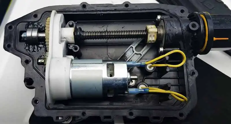
На этом рисунке разъем топливного насоса, показаны 2 контакта датчика уровня топлива, остальные два, это управление топливным насосом, вот их и надо проверять.
-
#4
Вы похоже не в курсе, что в БАДСе по каждой ошибке есть описание вероятной причины неисправности и описание проверок, которые надо выполнить для устранения.
Давайте я переведу вам эту информацию.231 = Цепь топливного насоса разорвана или имеет контакт на массу.
Возможные причины:
Топливный насос отсоединен.
Топливный насос поврежден, повреждены разъемы или провода.
Нужно проверить:
Проверить целостность проводки между J2-4 и пином 1 разъема топливного насоса.
Проверить целостность проводки между J2-12 и пином 2 разъема топливного насоса
Проверить J2-12 и J2-4 на отсутствие контакта на корпус.Вот разъемы на мозгах
Посмотреть вложение 1470016
Вот пины на разъеме которые надо проверить.
Посмотреть вложение 1470014
На этом рисунке разъем топливного насоса, показаны 2 контакта датчика уровня топлива, остальные два, это управление топливным насосом, вот их и надо проверять.
Посмотреть вложение 1470017
-
#5
Большое спасибо! Но запутался ещё больше. Снял фишкуJ2. Прозвонил. Изначально J2-12 с одновременно отключённой от топливного насоса фишкой показывал коротыш на массу. Когда стал идти по данному белому с красной полосой проводу оказалась, что он питает масляный насос, форсунки, катушки свечей и ещё какой-то боченок, похожий на большой конденсатор. Поковырявшись в проводах коротыш перестал звониться, но диагностика также показывает туже активную ошибку. Получается коротыш может быть на всех вышеперечисленных местах, но как его найти когда то он есть, то его нет?
-
#6
Большое спасибо! Но запутался ещё больше. Снял фишкуJ2. Прозвонил. Изначально J2-12
Все верно, это «шина» +55 В. Остальные проверки вы сделали? Может у вас действительно сам топливный насос сгорел.
-
#7
Все верно, это «шина» +55 В. Остальные проверки вы сделали? Может у вас действительно сам топливный насос сгорел.
Посмотреть вложение 1470714
Да, всё оказалось банально просто. Сгорел насос. Подключал его на прямую, но признаков жизни нет. Тестером так же не прозванивается. Осталось дело за малым найти и купить насос. Порекомендуйте проверенных продавцов? И можно ли туда подобрать насос от авто?
-
#8
Да, всё оказалось банально просто. Сгорел насос. Подключал его на прямую, но признаков жизни нет. Тестером так же не прозванивается. Осталось дело за малым найти и купить насос. Порекомендуйте проверенных продавцов? И можно ли туда подобрать насос от авто?
Читайте https://www.snowmobile.ru/forum/index.php?threads/132439/
-
#9
Оказалось не все так просто. Купили новый насос. Поставил его, но опять какая-то жопа. Подключая диагностику насос начинает качать, но не отключается. Отсоединил обратку — топливо качает. насос же должен отключается набирая давление. Диагностика выдает туже ошибку, панель орёт. Двигатель не заводится. Что делать мужики? Руки опускаются.
-
#10
Да, ещё загадка. Отключая фишку питания насоса начинает заводится двигатель. Бренд какой то, но работает на холостых четко и без перебоев. Насос при этом не качает.
-
#11
Завел два раза с отключённой фишкой бензонасоса сгорел 30А предохранитель. Что за х..ня. может всё таки ещё где-то замыкает?
-
#12
температуру ецм смотрели в истории? двление мерили?
-
#13
Оказалось не все так просто. Купили новый насос. Поставил его, но опять какая-то жопа. Подключая диагностику насос начинает качать, но не отключается. Отсоединил обратку — топливо качает. насос же должен отключается набирая давление. Диагностика выдает туже ошибку, панель орёт. Двигатель не заводится. Что делать мужики? Руки опускаются.
Насос не родной? Если — да, то возможно ЕСМ не может им нормально управлять.
-
#14
Насос не родной? Если — да, то возможно ЕСМ не может им нормально управлять.
Насос я так понял не оригинал, а аналог, но встал как родной. И фишка и входы одинаковы.
-
#15
Но почему при подключённом насосе двигатель не заводится, а выключив фишку начинает работать? Чудо какое-то!
-
#16
температуру ецм смотрели в истории? двление мерили?
Давление не мерил! А что может показать история температуры ECM?
-
#17
если давление больше нормы 300 кп что бывает из за неисправности регулятора давления насос работает на затык как следствие растет темп ецм тк охлаждается бензином сгорают цепи питания насоса бывает сам насос иеще целый букет думаю вашему блоку ецм пришел капец
-
#18
в итоге что было то? имею такуюже беду неможем разобратся насос новый ставили тоже
-
#19
в итоге что было то? имею такуюже беду неможем разобратся насос новый ставили тоже
Из-за отсутствия охлаждения топливом накрылся ЕСМ, пришлось менять мозги.
-
#20
я
Из-за отсутствия охлаждения топливом накрылся ЕСМ, пришлось менять мозги.
мои мозги сгорели я купил бу вот такая проблема появилась
-
#21
я
мои мозги сгорели я купил бу вот такая проблема появилась
Возможно купил ЕСМ как раз который сняли из-за этой проблемы.

Если хотите разместить ссылку на Гидрик.ру — Клуб любителей гидроциклов и другой техники для активного отдыха, используйте этот HTML-код:
Всего 5 посетителей :: 0 зарегистрированных, 0 скрытых и 5 гостей
Сейчас этот форум просматривают: нет зарегистрированных пользователей и 5 гостей
| Автор | Сообщение | ||||
|---|---|---|---|---|---|
|
Заголовок сообщения: BRP RXP 155 проблема с запуском СообщениеДобавлено: 27 июл 2013, 20:28 |
|||||
|
Уважаемые гуру, помогите советом, ошибки P0505 и P0231, насос разбирали, напрямую подключали все качает, а после сборки не качает и после вынимания ключа сигнал продолжается, 4 коротких через 3 сек, пока клему не скинешь |
||||
| Вернуться к началу |
Профиль Ответить с цитатой |
||||

|
fatra3x |
||||
Имя: Александр |
P0505 Клапан системы управления частотой вращения холостого хода. Вот нахуй хочеться послать, но я сегодня добрый. В яндексе или гуглисе можно откопать все то угодно, кроме своего мозга… Замыкалово гдето в проводке — насоса, предохранители проводка, клеммы, наверно какуюто клемму на мозгах неправильно запиздюхали в разъем. Датчик ХХ, выполнен в виде сервомотора и перекрывающего канал подачи воздуха, на 155 думаю также все. На дроссельной заслонке с низу, датчик с 4мя проводами вроде. Снять разъем и до мозгов прозвонкой на КЗ и обрыв. Если спросите что такае КЗ и обрыв — я всетаки разозлюсь и буду напрявления нахуй выписывать бесплатно! _________________ |
|||
| Вернуться к началу | ||||


|
Chuprovv |
|
|
|
Подождите, подождите, пока не шлите! Правильно ли я понял, что обе ошибки относятся к топливному насосу? Если поставить новый насос в сборе и конечно фишечку воткнуть правильно, все должно заработать? И нормально ли, что после вынимания ключа, гидроцикл продолжает пикать пока клему не снимешь, еще и может стартер запустить? |
| Вернуться к началу | |
|
Chuprovv |
|
|
|
Такс, с P0231 разобрались, был плохой контакт в разъемчиках. Теперь заводится. решаем с датчиком ХХ сняли его, на фишку напряжение приходит, обмотки датчика вроде тоже прозвонили. Попробуем на воду спустить, а после на диагностику, может скинуть надо ошибку, по тел сервисмен сказал, что она будет всегда высвечиваться, если не сбросить. |
| Вернуться к началу | |
|
fatra3x |
||||
Имя: Александр |
ошибка в мозгах будет прописакак как «бывшая» врятли она будет джекичанить. По насосу в фишке был загнутый контакт? или фишку не вставили на место? Пикает — неправильно, в руле куда ключ втыкаете, в десс пост считывателе может геркон залегать. _________________ |
|||
| Вернуться к началу | ||||
|
Chuprovv |
|
|
|
В фишке контакты поджали, хотя при соединении фишек вроде бы все плотно было, но начинаешь шевелить и обрыв. После этого и ошибка P0231 пропала и нормально на вынимание ключа стал реагировать, то есть вытаскиваешь ключ и все пики пропадают, вставляешь опять все трестируется и к запуску готово, ну и насос приятно жужжит |
| Вернуться к началу | |
|
Chuprovv |
|
|
|
Забыл спросить, можно ли без сканера ошибки стереть накопленные? И по какому протоколу сканер dtc коды считывает? Может есть какой переходник, который с obd2 на разъем гидроцикла можно сканер авто подцепить, может конечно чушь пишу, просветите! |
| Вернуться к началу | |
|
fatra3x |
||||
Имя: Александр |
софт + адаптер 35-40тр. забудьте об этом, переходника аля обд2-усб нету. _________________ |
|||
| Вернуться к началу | ||||
|
fatra3x |
||||
Имя: Александр |
Chuprovv писал(а): В фишке контакты поджали, хотя при соединении фишек вроде бы все плотно было, но начинаешь шевелить и обрыв. После этого и ошибка P0231 пропала и нормально на вынимание ключа стал реагировать, то есть вытаскиваешь ключ и все пики пропадают, вставляешь опять все трестируется и к запуску готово, ну и насос приятно жужжит Дилеры — это всегда бабки в пустоту, ибо у них только замена на новое, и дорогое! _________________ |
|||
| Вернуться к началу | ||||

|
Raider |
||||
Имя: Юрий |
fatra3x писал(а): Есть тут Фим-92, и он старается для таких как Вы облегчить жизнь, пишет факи, и тд.
|
|||
| Вернуться к началу | ||||


|
fatra3x |
||||
Имя: Александр |
Raider писал(а): fatra3x писал(а): Есть тут Фим-92, и он старается для таких как Вы облегчить жизнь, пишет факи, и тд.
Может эта? _________________ |
|||
| Вернуться к началу | ||||
 платные консультации открыть?
|
Raider |
||||
Имя: Юрий |
fatra3x писал(а): Может эта? Думаешь поможет??? |
|||
| Вернуться к началу | ||||
 Здесь проблема одна, купить гидр за пол-лимона, а от Тазика насос как вкрячить ??
|
fatra3x |
||||
Имя: Александр |
Raider писал(а): fatra3x писал(а): Может эта? Думаешь поможет??? эээ брат это святое….! _________________ |
|||
| Вернуться к началу | ||||
|
Chuprovv |
|
|
|
Блин, писал писал, вроде бы все что нужно описал, а оно раз и не добавилось http://www.jetskiplus.com/servlet/the-2 … uel/Detail всего 139$ + доставка баксов 40, по моему вполне |
| Вернуться к началу | |
|
grigoryan |
||||
Имя: Юра |
200 то часов ещё накатать надо…. _________________ |
|||
| Вернуться к началу | ||||

Кто сейчас на конференции |
|
Сейчас этот форум просматривают: нет зарегистрированных пользователей и 5 гостей |
| Вы не можете начинать темы Вы не можете отвечать на сообщения Вы не можете редактировать свои сообщения Вы не можете удалять свои сообщения Вы не можете добавлять вложения |
-
#1
Здравствуйте, заходили квадроцикл брп оутлендер 800 2008 года. Забыли переключить тумблер на руле на положение заткнуть. Качал бензонасос и все. Потом когда переключил появилась ошибка p0231 посмотрели все предохранители все целые но в заде 1 был перегоревший заменили но ошибка не пропала. Подсоединить бензонасос на прямую он качает. Подскажите в чем может быть причина, нет возможности привезти квадрик стоит в трудном месте и нет возможности вытащить.

-
#2
Странный и загадочный диалект русского языка, отвечу по английски.
p0231
Damaged or disconnected fuel pump, damaged circuit wires, damaged connectors or damaged ECM output pins.
Check for damaged or disconnected connector on fuel pump.
Check for approximately 1 ohm between pins 5-FP-3 and 5-FP-4 of the fuel pump connector.
Check for approximately 1 ohm between pins F5 and 2-B-29.

-
#3
Маладэц, билят… 
Еще бы надо сразу ссылку на гугл переводчик.
-
#4
Маладэц, билят…
Еще бы надо сразу ссылку на гугл переводчик.
это расшифровка ошибки из BUDS
|
Статистика
Онлайн всего: 1 Гостей: 1 Пользователей: 0 |
RXT 255 2008 года после ремонта турбины, стал выдавать ошибку P0325 на высоких оборотах. Это проблема с турбиной? Ответ Molchan:
Преревод:
Ошибка связана с нарушением работы датчика детонации, иногда возникает из-за некачественного топлива. Проверьте сопротивление датчика и участок цепи, от датчика до ECM. Если неисправности не выявите, замените топливо. Добавил: Андрей (Андрэ) Гидроцикл GTS 130 — постоянно пищит и выводит ошибку P1550. Ответ Molchan:
Перевод:
Повреждения этого датчика вызваны попаданием в него влаги, очень распространённая проблема. На работу двигателя ошибка не влияет, но отключается система iTC (интелектуальный контроль дросселем) Необходима проверка цепей датчика, но в большинстве случаев замена датчика. В крайнем случае возможна эмуляция этого датчика… Добавил: edik (feoed) Пытался завести гидрик после зимней стоянки GTI 130 2007 года, а он не заводится мигает моторчик и ошибка P0340. что случилось ? Ответ Molchan:
Перевод:
Как видите проблема серьёзная… Для начала необходимо убедиться в исправности датчика и его связи с ECM. Если с датчиком порядок, то скорее всего проблемы с цепью, судя по году гидроцикла вполне вероятно. Вам лучше обратиться в сервис… Новый гидроцикл постоянно пищит и пишет maint, масло меняли, работал нормально. Ответ Molchan: Необходимо подключиться компьютером, и сбросить сервисный таймер… гидроцикл 2007 RXP не могу найти описание ошибки.горит чек и код РО326 Ответ Molchan: К Вашему гидроциклу P0326 аналогичен коду P0325 описанному ранее. Проблема абсолютно та-же, отличие по коду связано с различием в моделях и прошивки ECM…
Перевод:
Ошибка связана с нарушением работы датчика детонации, иногда возникает из-за некачественного топлива. Проверьте сопротивление датчика и участок цепи, от датчика до ECM. Если неисправности не выявите, замените топливо. В некоторых случаях (очень редко) необходим сброс ошибки программой диагностики. Настоятельно не рекомендую использовать высокооктановый бензин из серии Super или Vip Power, уж лучше 92 с хорошей заправки. Обе ошибки топливного насоса других нет но движек не заводится не смотря на то что топливо в реику подается инжекторы не окрываются при запуске. Может быть причина в неисправном MPEM модуле и как можно определить в рабочем он состоянии или нет Ответ: Молчан В первую очередь необходимо проверить цепи топливного насоса (и редукционный клапан), давление в топливной рейке, цепи форсунок, форму и уровень сигнала на форсунки (или его отсутствие). Возможно форсунки не открываются из-за запрета на запуск модулем ECM, ввиду критической неисправности… После можно будет делать выводы о исправности MPEM. Добавил: Иракли (meore) Доброго времени суток !!! Господа подскажите , спустил на воду гидроцикл (RXP255) и после старта через пару минут он заполнился водой и соответственно заглох, кто сталкивался подскажите с чего начинать искать причину столь быстрого затопления Ответ: Молчан Затопление гидроцикла довольно хлопотная проблема… 1. В кротчайшие сроки необходимо заменить масло (3-х кратно с прогревами), предварительно удалив воду из цилиндров, топливного бака, воздухозаборного короба и впускного коллектора. 2. Провести ревизию проводки (обработать антикоррозийными материалами и диэлектриком все разъёмы и контактные группы). Имейте ввиду, что каждый час после затопления значительно снижает ресурс гидроцикла, и уменьшает шансы к безболезненного возврата к жизни. Причины затопления довольно банальны: 1. Не закрытые кингстоны… 2. Сорваный или прогнивший, надломленный патрубок системы охлаждения выхлопа… 3. Прогнившая или размороженная рубашка глушителя… 4. Размороженный резонатор… Опытный аквабайкер при каждом спуске на воду, в первую очередь проверяет отсутствие течи. А после длительной стоянки или зимнего хранения «сам бог велел»… Для полной реанимации лучше обратиться в сервисный центр (ремонт потом обойдётся дороже)… Добавил: arseniy (arseniy) Все по впуску новое подкинули все равно светит Ответ: Molchan
Для того, что-бы правильно определить методику устранения проблемы необходимо знать точно модель и год аппарата. Каждая модель имеет свои особенности и болячки. при эксплуатации после некоторого времени работы (примерно 5-7 мин.) гидроцикл выдает ошибку P0544. гидроцикл GTI 4tec PRO 2006 года выпуска. На холостом ходу немного нестабилен на средних и низких оборотах. Подскажите что за ошибка а как ее надо устранять, так как ближайший сервис совсем не близко((( Ответ: Molchan
Доля правды в стандартных рекомендациях BRP присутствует но не факт… И всё же — в первую очередь необходимо проверить датчик температуры выпускного тракта согласно рекомендаций, при его исправности проверить все патрубки охлаждения выпуска и рубашку глушителя на предмет посторонних предметов (мелких камушков, ракушек или песка). Т.к. охлаждение выпуска осуществляется по средством давления при работе водомёта, износ вставки или повреждение винта тоже может снизить интенсивность охлаждения… Прошу прощения за задержку ответа, очень много работы… Добавил: Коновалов Антон (Tony) Здравствуйте. Ответ : Molchan Необходимо знать первопричину такого поведения гидроцикла т.е. при каких условиях возникла неисправность… 1. Проверьте датчик OTAS (датчик управления дросселем в повороте), такое поведение похоже на работу системы динамического подруливания … Если есть возможность просто подмените OTAS. Если нет — необходима комп. диагностика (проверить активность датчика, должен быть активен только при крайнем повороте руля). Проверьте цепь датчика на сопротивление — 0 или не более 1-2 Ом. Если здесь всё в порядке далее… 2. Выполнить компьютерную диагностику (проверить показания TAS и TPS, при отклонении от норматива провести калибровку). 3. В случае неудачи по пункту (2) измерить сопротивление на участках цепи между TAS/ECM и TPS/ECM должно быть 0 или не боле 1 — 2 ОМ. 4. Проверить давление воздуха во впускном коллекторе(при отклонениях устранить причину). Я склоняюсь к пункту 1 но на 100% не уверен, сложно проводить диагностику не общаясь с самим пациентом… При неудачных «танцах с бубнами» лучше обратиться в оф. сервис… Добавил: Иван (Nike) GTI-130 2011г, ошибка связанная с IBR, проблема может быть програмная или связана с эл.проводкой. Помогите с схемой на него. С меня «могорыч» Ответ: Molchan B2214 — проблема с клавиатурой управления VTS, клавиша «вниз». Распространённая проблема связана с проникновением воды внутрь клавиатуры или окислением разъёма клавиш. В первом случае скорее всего замена клавиш, во втором очистка и обработка антикором для эл.разъёмов. Добавил: сергей коссе (kosse) Добрый день! Хочу увеличить мощность своего BRP 130 GTI 2008 года, знаю что для этого его нужно перепрошивать, возможно ли получить от Вас подробную инструкцию как это сделать? Сколько сил можно добавить за счет перепрошивки и как это повлияет на динамику? Ответ: Molchan Если утверждаете, что нужно перепрошивать, должны знать и как… По ЭТОЙ ССЫЛКЕ найдёте средство для выполнения… Вообще, если вы считаете, что изменением програмного обеспечения добьётесь приемлемых результатов, то глубоко ошибаетесь… Для полноценнго, эффективного тюнинга необходим целый комплекс конструктивных модификаций — как пример ССЫЛКА … В противном случае, рискуете просто погубить аквабайк и попасть на преждевременный дорогостоящий ремонт… Проще купить более мощный гидроцикл например RXP или RXT…
Добавил: Александр (akim) У меня на приборной панели загорается enge p 044 если есть профи подскажите что это за ошибка и как ее устранить и нужно реле стартера,куплю. Ответ Molchan: Уточните код ошибки… Должно быть четыре цифры в коде после «P»… Кода ошибки P044 не существует. Опишите поведение гидроцикла, укажите симптомы неисправности (ограничение оборотов, потеря динамики разгона и т.п.)… Единственный код содержащий две цифры четыре под грифом «P» см. далее:
Далее думаю всё понятно… Добавил: Алексей (Alex) |

I have been working and repairing Sea-doo jet skis for the last 20 years. They are very reliable machines but occasionally things go wrong and like all smart vehicles that just display a fault code, it can be confusing. That’s why with the help of a few different Sea-doo workshop manuals I will be showing the full Sea-doo fault code list.
I have split the sections up into areas such as Cluster, iBR, Intelligent Suspension, VTS, and Engine Control Management to make codes simple to read.
As this is a very large document you can either scroll in alphabetic/numeric order or use the browser search function to find a specific Sea-doo fault code to fix it yourself.
Having access to the BRP BUDS or Candoo Pro scanning software is beneficial in tracking down faults but not necessary. I have used both and they work very well. I would recommend the BRP BUDS2 scanner when working on newer 4-Tec Sea-doos. It comes with an ALL-DEALER license to help fix your jet-ski and your friends.
Table of Contents
- 1 Mega Sea-doo fault code list
- 2 Sea doo fault codes for iBR
- 3 Sea-doo “iS” Faults (Stands for Intelligent Suspension)
- 4 Sea-doo ECM Fault codes
- 5 Sea-doo Electrical Fault Codes Continued
- 6 Sea-doo Throttle, CAN-BUS, and VTS Fault Codes List
- 7 Seadoo Code Reader – Candoo Pro and BRP BUDS.
- 7.1 BRP Sea-doo code reader specs
- 8 How to get a list of stored codes from your Sea-doo for 4TEC skis up to 2003
- 9 How to read Sea-doo fault codes on 2004 to 2021 models without a scanner.
- 10 Sea-doo warning lights messages and display meaning
- 11 Conclusion
| SEA-DOO FAULT CODES |
REPORTING MODULE |
DESCRIPTION | POSSIBLE CAUSE | REPAIR ACTION |
| B2210 | CLUSTER | Left keypad fault (Switch kept activated more than 60 seconds) |
Problem with left keypad. |
The switch may be defective, verify the functionality of the switch or the wires. Refer to the shop manual for switch diagnosis/testing procedure. |
| B2211 | CLUSTER | Suspension UP/DOWN switches shorted to ground fault |
Problem with left keypad. |
Look for pin B if shorted to ground or pin C. |
| B2212 | CLUSTER | Suspension UP/DOWN switches disconnected fault |
Problem with left keypad. |
Look for pin B if disconnected to pin 14 on the cluster. Look for pin C if disconnected to pin 15 on the cluster. |
| B2213 | CLUSTER | VTS UP/DOWN switches shorted to ground fault |
Problem with left keypad. |
Look for pin A if shorted to ground or if pin C is grounded. |
| B2214 | CLUSTER | VTS UP/DOWN switches disconnected fault |
Problem with left keypad. |
Look for pin A if disconnected to pin 13 on the cluster. Look for pin C if disconnected to pin 15 on the cluster. |
| B2220 | CLUSTER | Right keypad fault (Switch kept activated more than 60 seconds) |
Problem with the right keypad. |
The switch may be defective, verify the functionality of the switch or the wires. Refer to the shop manual for switch diagnosis/testing procedure. |
| B2221 | CLUSTER | MODE/SET switches shorted to ground fault |
Problem with the right keypad. |
Look for pin B if shorted to ground or pin C. |
| B2222 | CLUSTER | MODE/SET switches disconnected fault |
Problem with the right keypad. |
Look for pin B if disconnected to pin 17 on the cluster. Look for pin C if disconnected to pin 18 on the cluster. |
| B2223 | CLUSTER | UP/DOWN switches shorted to ground fault |
Problem with the right keypad. |
Look for pin A if shorted to ground or pin C. |
| B2224 | CLUSTER | UP/DOWN switches disconnected fault |
Problem with the right keypad. |
Look for pin A if disconnected to pin 16 on the cluster. Look for pin C if disconnected to pin 18 on the cluster. |
Sea doo fault codes for iBR
The Intelligent brake and reverse (iBR) helps the jetski stop sooner, improves safety, and gives you the ability to engage forward, neutral, and reverse. This is important for stable, easy maneuvers at low speeds. But occasionally things go wrong when the iBR gets jammed with sticks or debris.
| SEA-DOO FAULT CODE LIST | REPORTING MODULE | DESCRIPTION | POSSIBLE CAUSE | REPAIR ACTION |
| C0042 | iBR | Brake Lever Sensor (BRLS) signals A open/shorted to ground |
Damaged sensor, damaged circuit wires, damaged connector, or damaged iBR pins. Fault detected when the engine is running or stopped. |
Check for 0.5 to 3 V on pin F. and 0.25 to 1.5V on pin C. |
| C0043 | iBR | Brake Lever Sensor (BRLS) signals B open/shorted to ground |
The sensors calibration is corrupted | Check for 0.5 to 3 V on pin F and 0.25 to 1.5 on pin C. |
| C0073 | iBR | Torque request failure | ECM software failure. CPS wires shorted. | Perform ECM software updates if available or replace ECM. Verify CPS connection. |
| C2100 | iBR | Motor current is too high. | Incompatible firmware or memory failure. | Replace the iBR unit. Refer to the Service Manual for more details. |
| C2101 | iBR | Actuator movement warning | The reverse gate cannot move to the desired position within the expected time. | Clean and check for damage in the reverse gate and nozzle area. Refer to the Service Manual for more details. |
| C2100 There are a few with the same code. |
iBR | Actuator movement | The reverse gate cannot move to the desired position. | Clean and check for damage in the reverse gate and nozzle area. Refer to the Service Manual for more details. |
| C2110 | iBR | Reverse gate position sensor error | iBR malfunction. | Check for correct movement of iBR.Replace the iBR unit. Refer to the Service Manual for more details. |
| C2110 | iBR | Angle position sensor warning | iBR malfunction. | Replace the iBR unit. Refer to the Service Manual for more details. |
| C2110 | iBR | iBR overheat | iBR cooling system failure. iBR unit failure. |
Check the iBR cooling circuit. Replace the iBR unit. Refer to the Service Manual for more details. |
| C2110 | iBR | Monitoring CPU message timeout or validity | iBR malfunction. | Perform an iBR software update if available. Replace the iBR unit. Refer to the Service Manual for more details. |
| C2110 | iBR | Monitoring CPU limp force | iBR malfunction. | Perform an iBR software update if available. Replace the iBR unit. Refer to the Service Manual for more details. |
| C2111 | iBR | ECM erratic RPM signal | RPM signal received from engine ECM not plausible | Check CPS sensor connection |
| C2120 | iBR | Application calibration is corrupted | Incompatible firmware or memory failure. | Perform an iBR software update if available. Replace the iBR unit. Refer to the Service Manual for more details. |
| C2121 | iBR | Application parameters corrupted (backup #1 or #2) | Battery power loss or memory failure. | Perform an electrical system shut download to clear the fault. Verify starting and charging system circuits. Refer to the Service Manual for more details. |
| 02122 | iBR | The last session interrupted |
Unexpected battery power lost. | Perform an electrical system shut down and clear fault. Verify starting and charging system circuits. Refer to the Service Manual for more details. |
| C2130 | iBR | Motor current software breaker | The brake Lever Sensor (BRLS) signals A shorted to battery | Clean and check for damage in the reverse gate and nozzle area. Refer to the Service Manual for more details. |
| C2130 | iBR | Internal motor drive failure | Motor voltage feedback not fitting with the command. | Check that the power cable to the motor is connected |
| C2131 | iBR | iBR DC motor shorted to ground or 12 V | iBR motor failure. iBR motor wires damaged or moisture detected |
Check iBR circuits A and B. Refer to the Service Manual for more details. |
| C2132 | iBR | Motor Open | No current while activated. | Check the power cables are connected. |
| C2142 | iBR | System is disabled and need activation | Damaged sensor, damaged circuit wires, damaged connector, or damaged iBR pins. Fault detected when the engine is running or stopped. |
Check for 0.5 to 3 V on pin F and 0.25 to 1.5 on pin C. |
| C2143 | iBR | Brake Lever Sensor (BRLS) signals B shorted to battery | Damaged sensor, damaged circuit wires, damaged connector, or damaged iBR pins. Fault detected when the engine is running or stopped. |
Check for 0.5 to 3 Von pin F and 0.25 to 1.5 on pin C. |
| C2144 | iBR | Brake Lever Sensor (BRLS) power shorted to battery | Damaged sensor, damaged circuit wires, damaged connector, or damaged iBR pins. Fault detected when the engine is running or stopped. |
Check for 4.5 to 5 volts on sensor connector pin A & D. Refer to the Service Manual for more details. |
| C2145 | iBR | Brake Lever Sensor (BRLS) power shorted to ground | Damaged sensor, damaged circuit wires, damaged connector, or damaged iBR pins. Fault detected when the engine is running or stopped. |
Check for 4.5 to 5 volts on sensor connector pin A & D. Refer to the Service Manual for more details. |
| C2146 | iBR | Brake Lever Sensor (BRLS) signals A/B reading difference | Damaged sensor, damaged circuit wires, damaged connector, or damaged iBR pins. Fault detected when the engine is running or stopped. |
Check for 0.5 to 3 V on pin F and 0.25 to 1.5 on pin C. |
| C2150 | iBR | System current software breaker | iBR input current too high. | Clean and check for damage in the reverse gate and nozzle area. Refer to the Service Manual for more details. |
| C2151 | iBR | The water temperature sensor overheat | The system is locked. Need activation. | Use B.U.D.S. iBR unlock function. Refer to the Service Manual for more details. |
| C2155 | iBR | Water temperature sensor overheat | iBR cooling system failure. iBR unit failure. |
Check the iBR cooling circuit. Sea-Doo coolant flush procedure. Replace the iBR unit. Refer to the Service Manual for more details. |
| C2161 | iBR | Low voltage detected | Battery failure, rectifier failure, damaged circuit wires, battery terminal connection, damaged AC generator or damaged connectors. |
Check fuses #6 (refer to WIRING DIAGRAM). Check ground continuity to the engine block. Refer to the Service Manual for more details. |
Sea-doo “iS” Faults (Stands for Intelligent Suspension)
Sea-Doo discontinued its Intelligent Suspension system in 2017 possibly due to costs, weight and for me, it just didn’t work very well. But there are a number of Jet-skis out there with this feature so below are the fault codes that can occur with Intelligent Suspension.
| SEA-DOO FAULT CODES | REPORTING MODULE |
DESCRIPTION | POSSIBLE CAUSE | REPAIR ACTION |
| C2200 | iS | Sensors calibration is corrupted | Incompatible firmware or memory failure (Internal memory failure, return to supplier). | Defective iS module, replace the module and return to supplier. |
| C2210 | iS | Bridge/CPU temperature sensor overheat |
Hardware failure or external heat source. | Check for overutilization/heat. |
| C2220 | iS | Application calibration is corrupted | Incompatible firmware or memory failure (B.U.D.S. should repair that). | Program calibration with B.U.D.S. software. |
| C2221 | iS | Application parameters corrupted (backup #1 or #2) | Battery power lost or memory failure (Reset after power-down-up, clear fault. If happens often, verify supply voltage). |
Check power wiring and fuse. |
| C2222 | iS | Last session interrupted |
Unexpected battery power lost. | Check power wiring and fuse. |
| C2230 | iS | Internal motor drive failure | Motor voltage feedback not fitting with the command. | Defective iS module, replace the module and return to supplier. |
| C2231 | iS | Motor shorted to ground/battery | Motor shorted to ground/battery | Check suspension actuator pump wiring. |
| C2232 | iS | Motor open | No current while activated. | Check suspension actuator pump and/or wiring. |
| C2233 | iS | Motor current software breaker | System is disabled and need activation | Check suspension actuator pump. |
| C2240 | iS | Seat position sensor error Open, Shorted to Ground | Sensor not connected | Check system circuit at iS module, (refer to WIRING DIAGRAM) |
| C2250 | iS | System current software breaker | The battery input current is too high. | Check suspension actuator pump. |
| C2251 | iS | System is disabled and needs activation | The system is locked for safety. Need activation. | Activate iS using BRP B.U.D.S. fault scanner activation function. |
| C2252 | iS | TOPS active Tip-over protection |
Warning only! TOPS detected by the system, the suspension is disabled while the TOPS is “ON’. | Refer to the Service Manual for more details. |
| C2260 | iS | System under voltage | The system has an under-voltage warning. | Check battery and charging system. Replace Seadoo battery. |
Sea-doo ECM Fault codes
The Engine Control Module (ECM), also called the Engine Control Unit (ECU), ensures that your Sea-doo jetski operates at optimal performance. The ECM is looking at hundreds of parameters every second and will throw up a fault code if something is wrong to protect the engine.
| SEA-DOO FAULT CODE LIST |
REPORTING MODULE |
DESCRIPTION | POSSIBLE CAUSE | REPAIR ACTION |
| P0008 | ECM | Engine phase-detection fault | ||
| P0030 | ECM | Heater Power Stage fault for lambda sensor upstreams of catalyst |
||
| P0031 | ECM | Heater Power Stage fault for lambda sensor upstreams of catalyst short circuit to GNI) |
It can have several problems, but wiring being damaged by excessive heat from the exhaust is the most common. Make certain the wiring is in good condition and has proper voltage and ground to the sensor before replacing the sensor. Check if the ground wire on the HO2 sensor circuit is corroded |
|
| P0032 | ECM | Heater Power Stage fault for lambda sensor upstreams of catalyst short circuit to V+ |
It can have several problems, but wiring being damaged by excessive heat from the exhaust is most common. Make certain the wiring is in good condition and has proper voltage and ground to the sensor before replacing the sensor. Check if the ground wire on the HO2 sensor circuit is corroded |
|
| P0036 | ECM | Heater Power Stage fault for lambda sensor downstream of the catalyst |
This can mean that the specified sensor is not sending the right data to the PCM (powertrain control module). | |
| P0037 | ECM | Heater Power Stage fault for lambda sensor downstream of catalyst – short circuit to GND |
||
| P0038 | ECM | Heater Power Stage fault for lambda sensor downstream of catalyst – short circuit to V+ |
||
| P0106 | ECM | Intake pressure sensor out of range | Sensing port dirty or blocked. Sensor failure or unexpected reading at idle. The sensor has fallen out of housing or leaking inlet. |
Check system circuits A-64, A-G4, A-H2. Make sure that the sensor housing is correctly inserted into the manifold. Check sensor connector for: a)5 volts on pin 1. b)0 volt on pin 2. c)0 volt on pin 3. Refer to the Service Manual for more details |
| P0107 | ECM | Manifold absolute pressure sensor shorted to ground or not connected. |
Sensing port dirty or blocked. Sensor failure or unexpected reading at idle. The sensor has fallen out of housing or leaking inlet. Connector disconnected |
Check system circuits A-B4, A-G4, A-H2. Make sure that the sensor housing is correctly inserted into the manifold. Check sensor connector for: a)5 volts on pin 1. b)0 volt on pin 2. c)0 volt on pin 3. Refer to the Service Manual for more details. |
| P0108 | ECM | Manifold absolute pressure sensor open circuit or shorted to battery | Sensing port dirty or blocked. A sensor failure or unexpected reading at idle. The sensor has fallen out of housing or leaking inlet. |
Check system circuits A-B4, A-G4, A-H2. Make sure that the sensor housing is correctly inserted into the manifold. Check sensor connector for: a)5 volts on pin 1. b)0 volt on pin 2. c)0 volt on pin 3. Refer to the Service Manual for more details. |
| P0112 | ECM | Intake manifold temperature sensor shorted to ground | Damaged sensor, damaged circuit wires, damaged connector, or damaged ECM pins. | Check the sensor for approximately 2280 to 2736 ohms at 19 to 21°C (66 to 70°F). Check for approximately 2280 to 2736 ohms at 19 to 21°C (66 to 70°F) between ECM connector pins A-H3 and A-J3. Refer to the Service Manual for more details. |
| P0113 | ECM | Intake manifold temperature sensor open circuit or shorted to battery | Damaged sensor, damaged circuit wires, damaged connector, or damaged ECM pins. | heck the sensor for approximately 2280 to 2736 ohms at 19 to 21°C (66 to 70°F). Check for approximately 2280 to 2736 ohms at 19 to 21°C (66 to 70°F) between ECM connector pins A-H3 and A-J3. Refer to the Service Manual for more details. |
| P0116 | ECM | Engine coolant temperature signal not plausible | Damaged sensor, damaged circuit wires, damaged connector, or damaged ECM pins. | Check for debris Dr blockage in the cooling system. Check the sensor for approximately 2280 to 2736 ohms at 19 to 21°C (66 to 70°F). Check for approximately 2280 to 2736 Ohms at 19 to 21°C (66 to 70°F) between ECM connector pins A-Al and A-J2. Refer to the Service Manual for more details. |
| P0117 | ECM | Engine coolant temperature sensor fault – Short circuit to GND | Damaged sensor, damaged circuit wires, damaged connector, or damaged ECM pins. | Check for debris or blockage in the cooling system. Check the sensor for approximately 2280 to 2736 ohms at 19 to 21°C (66 to 70°F). Check for approximately 2280 to 2736 Ohms at 19 to 21°C (66 to 70°F) between ECM connector pins A-Al and A-J2. Refer to the Service Manual for more details. |
| P0118 | ECM | Engine coolant temperature sensor fault – Short circuit to V+ or connector disconnected. | Engine overheated or damaged sensor. Connector disconnected. | Check for debris or blockage in the cooling system. Check the sensor for approximately 2280 to 2736 ohms at 19 to 21°C (66 to 70°F). Check for approximately 2280 to 2736 ohms at 19 to 21°C (66 to 70°F) between ECM connector pins A-A1 and A-J2. Refer to the Service Manual for more details. |
| P0122 | ECM | TAS (Throttle Accelerator sensor) 1 fault (short circuit to GND) | Damaged sensor, damaged circuit wires, damaged connector or damaged ECM pins, | Check system circuits B-E1, B-K1, B-K3. Check for 0 volts on sensor connector pin E. Check for 5 volts on sensor connector pin D. Check for 0.5 to 3 volts on sensor connector pin F. Refer to the Service Manual for more details. |
| P0123 | ECM | TAS (Throttle Accelerator sensor) 1 fault (short circuit to the battery) | Damaged sensor, damaged circuit wires, damaged connector, or damaged ECM pins. | Check system circuits B-E1, B-K1, B-K3. Check for 0 volts on sensor connector pin E. Check for 5 volts on sensor connector pin D. Check for 0.5 to 3 volts on sensor connector pin F. Refer to the Service Manual for more details. |
| P0127 | ECM | Intercooler system fault | High air intake temperature detected. Fault detected when the engine is running and stopped. Blocked intercooler water circuit. | Clean intercooler water circuit system. Refer to the Service Manual for more details. |
| P0130 | ECM | Lambda Sensor fault upstreams of catalyst signal not plausible | ||
| P0131 | ECM | Lambda Sensor fault upstreams of catalyst short circuit to GND | Replace oxygen sensor find ground fault | |
| P0132 | ECM | Lambda Sensor fault upstreams of catalyst short circuit to V+ | Replace oxygen sensor | |
| P0133 | ECM | Oxygen sensor upstreams of catalyst react too slow —› contaminated | Clean replace the oxygen sensor | |
| P0134 | ECM | Oxygen sensor upstreams of catalyst react too slow —> defective | Clean replace the oxygen sensor | |
| P0135 | ECM | Lambda Sensor heating fault upstreams of catalyst | It can have several problems, but wiring being damaged by excessive heat from the exhaust is most common. Make certain the wiring is good and has proper voltage and ground to the sensor before replacing the sensor. Check if the ground wire on the HO2 sensor circuit is corroded |
|
| P0136 | ECM | Lambda Sensor fault downstream of catalyst – signal not plausible | It can have several problems, but wiring being damaged by excessive heat from the exhaust is most common. Make certain the wiring is good and has proper voltage and ground to the sensor before replacing the sensor. Check if the ground wire on the O2 sensor circuit is corroded |
|
| P0137 | ECM | Lambda Sensor fault downstream of catalyst – short circuit to GROUND | It can have several problems, but wiring being damaged by excessive heat from the exhaust is most common. Make certain the wiring is good and has proper voltage and ground to the sensor before replacing the sensor. Check if the ground wire on the O2 sensor circuit is corroded |
|
| P0138 | ECM | Lambda Sensor fault downstream of catalyst – short circuit to V+ | It can have several problems, but wiring being damaged by excessive heat from the exhaust is most common. Make certain the wiring is good and has proper voltage and ground to the sensor before replacing the sensor. Check if the ground wire on the O2 sensor circuit is corroded |
|
| P0141 | ECM | Lambda Sensor heating fault downstream of the catalyst | It can have several problems, but wiring being damaged by excessive heat from the exhaust is most common. Make certain the wiring is good and has proper voltage and ground to the sensor before replacing the sensor. Check if the ground wire on the O2 sensor circuit is corroded |
|
| P0171 | ECM | Multiplicative mixture adaptation exceeds the upper limit—> mixture too lean | ||
| P0172 | ECM | Multiplicative mixture adaptation below lower limit—> mixture too rich | ||
| P0201 | ECM | Injection Power Stage fault – open line/Cylinder 1 | Damaged injector, damaged circuit wires, damaged connector, or damaged ECM Output pins. | Check for 11.4 to 12.6 ohms between engine connector pin 2 and ECM connector pin A-B3. Check for 12 volts on pin 2 of injector connector. Check fuse #13 (refer to WIRING DIAGRAM). Check for damaged circuit wires. Refer to the Service Manual for more details. |
| P0202 | ECM | Injection Power Stage fault – Open line/Cylinder 2 | Damaged injector, damaged circuit wires, damaged connector, or damaged ECM output pins. | Check for 11.4 to 12.6 ohms between engine connector pin 2 and ECM connector pin A-K1. Check for 12 volts on pin 2 of the injector connector. Check fuse #14 (refer to WIRING DIAGRAM). Check for damaged circuit wires Refer to the Service Manual for more details. |
| P0203 | ECM | Injection Power Stage fault – open line/Cylinder 3 | Damaged injector, damaged circuit wires, damaged connector, or damaged ECM output pins. | Check for 11.4 to 12.6 ohms between engine connector pin 3 and ECM connector pin A-J1, Check for 12 volts on pin 2 of the injector connector. Check fuse #15 (refer to WIRING DIAGRAM). . Check for damaged circuit wires. Refer to the Service Manual for more details. |
| P0217 | ECM | High engine coolant temperature detected | High engine coolant temperature detected caused by a blockage in coolant ride plate, cooling system, or low coolant.
This Sea-doo fault code comes up often when seaweed is blocking the intake grate. |
Check for debris or blockage in the cooling system. Check the sensor for approximately 2280 to 2736 ohms at 19 to 21°C (66 to 70°F). Check for approximately 2280 to 2736 ohms at 19 to 21°C (66 to 70°F) between ECM connector pins A-Al and A-J2. Refer to the Service Manual for more details. |
| P0222 | ECM | TAS (Throttle Accelerator sensor) 2 fault (short circuit to GND) | Damaged sensor, damaged circuit wires, damaged connector, or damaged ECM pins. | Check system circuits B-A3, B-B3, B-J3. Check for 0 volts on sensor connector pin B. Check for 5 volts on sensor connector pin A. Check for 0.25 to 1.5 volts on sensor connector pin C, Refer to the Service Manual for more details. |
| P0223 | ECM | TAS (Throttle Accelerator sensor) 2 fault (short circuit to the battery) | Damaged sensor, damaged circuit wires, damaged connector, or damaged ECM pins. | Check system circuits B-A3, B-B3, 8-J3. Check for 0 volt Dn sensor connector pin B. Check for 5 volts on sensor connector pin A. Check for 0.25 to 1.5 volts on sensor connector pin C. Refer to the Service Manual for more details. |
| P0231 | ECM | Fuel pump open circuit or short to ground | Damaged pump, damaged circuit wires, damaged connector, or damaged ECM output pins. | Check for approximately 1 ohm between pins A and B of the fuel pump connector. Check fuse #18 (refer to WIRING DIAGRAM). Check for damaged circuit wires. Check for damaged connector, damaged ECM Output pins or ECM failure. Refer to the Service Manual for more details. |
| P0232 | ECM | Fuel pump short circuit to battery | Damaged pump, damaged circuit wires, damaged connector, or damaged ECM Output pins. | Check for approximately 1 ohm between pins A and B of the fuel pump connector. Check fuse #16 (refer to WIRING DIAGRAM). Check for damaged circuit wires. Check for damaged connector, damaged ECM output pins or ECM failure. Refer to the Service Manual for more details. |
| P0261 | ECM | Injector 1 open circuit or shorted to ground |
Damaged injector, damaged circuit wires, damaged connector, or damaged ECM output pins. | Check for 11.4 to 12.6 ohms between engine connector pin 1 and ECM connector pin A-B3. Check for 12 volts on pin 2 of the injector connectors. Check fuse #13 (refer to WIRING DIAGRAM), Check for damaged circuit wires. Refer to the Service Manual for more details. |
| P0262 | ECM | Injector 1 shorted to battery | Damaged injector, damaged circuit wires, damaged connector, or damaged ECM output pins. | Check for 11.4 to 12.6 ohms between engine connector pin 1 and ECM connector pin A-83. Check for 12 volts on pin 2 of the injector connector. Check fuse #13 (refer to WIRING DIAGRAM). Check for damaged circuit wires. Refer to the Service Manual for more details. |
| P0264 | ECM | Injector 2 open circuit or shorted to ground | Damaged injector, damaged circuit wires, damaged connector, or damaged ECM output pins. | Check for 11.4 to 12.6 ohms between engine connector pin 2 and ECM connector pin A-K1. Check for 12 volts on pin 2 of the injector connectors. Check fuse #14 (refer to WIRING DIAGRAM). Check for damaged circuit wires. Refer to the Service Manual for more details. |
| P0265 | ECM | Injector 2 shorted to battery | Damaged injector, damaged circuit wires, damaged connector, or damaged ECM output pins. | Check for 11.4 to 12.6 ohms between engine connector pin 2 and ECM connector pin A-KI. Check for 12 volts on pin 2 of the injector connector. Check fuse #14 (refer to WIRING DIAGRAM). Check for damaged circuit wires. Refer to the Service Manual for more details. |
| P0267 | ECM | Injector 3 open circuit or shorted to ground | Damaged injector, damaged circuit wires, damaged connector, or damaged ECM Output pins. | Check for 11.4 to 12.6 ohms between engine connector pin 3 and ECM connector pin A-.11. Check for 12 volts on pin 2 of the injector connector. Check fuse #15 (refer to WIRING DIAGRAM). Check for damaged circuit wires. Refer to the Service Manual for more details. |
| P0268 | ECM | Injector 3 shorted to battery | Damaged injector, damaged circuit wires, damaged connector, or damaged ECM output pins. | Check for 11.4 to 12.6 ohms between engine connector pin 3 and ECM connector pin A-J1. Check for 12 volts on pin 2 of the injector connector. Check fuse #15 (refer to WIRING DIAGRAM). Check for damaged circuit wires. Refer to the Service Manual for more details. |
| P0300 | ECM | Multiple misfires detected | Check coil and spark plugs. | |
| P0301 | ECM | Misfire cylinder 2 (physical cylinder 1) | Check coil and spark plugs. | Replace Sea-doo spark plugs and coil |
| P0302 | ECM | Misfire cylinder 2 (physical cylinder 1) | Check coil and spark plugs. Water ingress into the electrical system. | Replace spark plugs and coil |
| P0303 | ECM | Misfire cylinder 1 (physical cylinder 3) | Check coil and spark plugs. Water ingress. | Replace spark plugs and coil |
| P0325 | ECM | Knock sensor 1 fault | Damaged sensor, damaged circuit wires, damaged connector, or damaged ECM output pins. Open circuit. | Bring the engine to 5000 RPM. If fault code appears then check for approximately 5 M ohms between system circuits A-C3 and A-G2. Refer to the Service Manual for more details. |
| P0330 | ECM | Knock sensor 2 fault | Damaged sensor, damaged circuit wires, damaged connector, or damaged ECM output pins. Open circuit. | Bring the engine to 5000 RPM. If fault code appears then check for approximately 5 Mohms between system circuits A-C3 and A-G2. Refer to the Service Manual for more details. |
Sea-doo Electrical Fault Codes Continued
| SEA-DOO FAULT CODES | REPORTING MODULE |
DESCRIPTION | POSSIBLE CAUSE |
REPAIR ACTION |
| P0335 | ECM | Crankshaft signal error | Damaged sensor, damaged circuit wires, damaged connector, damaged ECM pins, or damaged tooth wheel. Connector disconnected. | For the CPS, check for 700 to 900 ohms between terminals A-H1 and A-K2 of the ECM connector. Refer to the Service Manual for more details. |
| P0340 | ECM | Camshaft 1 signal error | Damaged sensor, damaged circuit wires, damaged connector, damaged ECM pins, or damaged tooth wheel. Connector disconnected. | For the CAPS, check for 12 volts on sensor connector pin 3. Check continuity for circuits A-D4, A-E2, and terminal 4 on engine connector. Check fuse #12 (refer to WIRING DIAGRAM). Engine must run to erase the corrected fault. Refer to the Service Manual for more details. |
| P0351 | ECM | Ignition coil 1 open circuit or shorted to ground or to battery |
Damaged coil, damaged circuit wires, damaged connector, or damaged ECM output pins. | Check for 0.85 to 1.15 Ohms between engine connector pin 1 and ECM connector pin A-M4. Check for 12 volts on pin 2 of the coil connector. Check fuse #13 (refer to WIRING DIAGRAM). Refer to the Service Manual for more details. |
| P0352 | ECM | Ignition coil 2 open circuit or shorted to ground or to battery |
Damaged coil, damaged circuit wires, damaged connector, or damaged ECM output pins. | Check for 0.85 to 1.15 ohms between engine connector pin 1 and ECM connector pin A-M2. Check for 12 volts on pin 2 of the coil connector. Check fuse #14 (refer to WIRING DIAGRAM). Refer to the Service Manual for more details. |
| P0353 | ECM | Ignition coil 3 open circuit or shorted to ground or to battery |
Damaged coil, damaged circuit wires, damaged connector, or damaged ECM output pins. | Check for 0.85 to 1.15 ohms between engine connector pin 3 and ECM connector pin A-M1. Check for 12 volts on pin 2 of the coil connector. Check fuse #15 (refer to WIRING DIAGRAM). Refer to the Service Manual for more details. |
| P0354 | ECM | Ignition Power Stage fault – short circuit to GND/Cylinder 1 | Damaged coil, damaged circuit wires, damaged connector, or damaged ECM output pins. | Check for 0.85 to 1.15 ohms between engine connector pin 1 and ECM connector pin A-M4. Check for 12 volts on pin 2 of the coil connector. Check fuse #13 (refer to WIRING DIAGRAM). Refer to the Service Manual for more details. |
| P0355 | ECM | Ignition Power Stage fault – short circuit to GND/Cylinder 2 | Damaged coil, damaged circuit wires, damaged connector, or damaged ECM output pins. | Check for 0.85 to 1.15 ohms between engine connector pin 1 and ECM connector pin A-M2. Check for 12 volts on pin 2 of the coil connector. Check fuse #14 (refer to WIRING DIAGRAM). Refer to the Service Manual for more details. |
| P0356 | ECM | Ignition Power Stage fault – short circuit to GND/Cylinder 3 | Damaged coil, damaged circuit wires, damaged connector, or damaged ECM output pins. | Check for 0.85 to 1,15 ohms between engine connector pin 3 and ECM connector pin A-M1. Check for 12 volts on pin 2 of the coil connector. Check fuse #15 (refer to WIRING DIAGRAM). Refer to the Service Manual for more details. |
| P0357 | ECM | Ignition Power Stage fault – short circuit to V+/Cylinder 1 | Damaged coil, damaged circuit wires, damaged connector Dr damaged ECM output pins. | Check for 0.85 to 1,15 ohms between engine connector pin 1 and ECM connector pin A-M4. Check for 12 volts on pin 2 of the coil connector. Check fuse #13 (refer to WIRING DIAGRAM). Refer to the Service Manual for more details. |
| P0358 | ECM | Ignition Power Stage fault – short circuit to V+/Cylinder 2 | Damaged coil, damaged circuit wires, damaged connector, or damaged ECM output pins. | Check for 0.85 to 1.15 ohms between engine connector pin 1 and ECM connector pin A-M2. Check for 12 volts Dn pin 2 of coil connector. Check fuse #14 (refer to WIRING DIAGRAM). Refer to the Service Manual for more details. |
| P0359 | ECM | Ignition Power Stage fault – short circuit to V+/Cylinder 3 | Damaged coil, damaged circuit wires, damaged connector Dr damaged ECM output pins. | Check for 0.85 to 1.15 ohms between engine connector pin 3 and ECM connector pin A-M1. Check for 12 volts on pin 2 of the coil connector. Check fuse #15 (refer to WIRING DIAGRAM). Refer to the Service Manual for more details. |
| P0360 | ECM | Ignition Power stage max error & false detection of low battery voltage/Cylinder 1 | Signal not plausible, verify battery voltage too low during ignition. | Check for 0.85 to 1.15 Ohms between engine connector pin 1 and ECM connector pin A-M4. Check for 12 volts on pin 2 of the coil connector. Check fuse #13 (refer to WIRING DIAGRAM). Refer to the Service Manual for more details. |
| P0361 | ECM | Ignition Power stage max error & false detection of low battery voltage/Cylinder 2 | Signal not plausible, verify battery voltage too low during ignition. | Check for 0.85 to 1.15 ohms between engine connector pin 1 and ECM connector pin A-M2. Check for 12 volts on pin 2 of the coil connector. Check fuse #14 (refer to WIRING DIAGRAM). Refer to the Service Manual for more details. |
| P0362 | ECM | Ignition Power stage max error & false detection of low battery voltage/Cylinder 3 | Signal not plausible, verify battery voltage too low during ignition. | Check for 0.86 to 1.15 ohms between engine connector pin 3 and ECM connector pin A-M1. Check for 12 volts on pin 2 of the coil connector. Check fuse #15 (refer to WIRING DIAGRAM). Refer to the Service Manual for more details. |
| P0365 | ECM | Camshaft 2 signal error | Replacement of the sensor, along with a repair of the oil leak responsible for contaminating the sensor. Wiring damage and corroded connectors and earth are also often common problems. |
|
| P0500 | ECM | Vehicle speed signal fault | Cluster fault detected by ECM C.A.N. circuit failure, Instrument cluster, or ECM failure | Check C.A.N. circuits wires. Replace instrument Cluster. Verify Outside of the building if the GPS LED becomes active after 1 minute and stays steady Refer to the Service Manual for more details. |
| P0501 | ECM | Vehicle speed not plausible | Cluster or iBR fault detected by ECM. C.A.N. circuit failure, Instrument cluster, iBR, or ECM failure. | Check C.A.N. circuits wires. Replace instrument Cluster. Verify outside of the building if the GPS LED becomes active after 1 minute and stays steady Refer to the Service Manual for more details. |
| P0504 | ECM | Vehicle speed not plausible | iBR fault detected by ECM. C.A.N. circuit failure, ECM software failure. |
Check C.A.N. circuits wires. Replace iBR. Refer to the Service Manual for more details. |
| P0512 | ECM | The starter power stage detects high current | Damaged solenoid, damaged circuit wires, damaged connector, or damaged ECM. | Verify fuse #16 (5AIVIP). Check for 12 volts on pin 2 of the starter relay. Check earth. Refer to the Service Manual for more details. |
| P0513 | ECM | Invalid D.E.S.S. Key detected | Key not programmed in ECU. | Replace or program a good key. |
| P0520 | ECM | Oil pressure switch functional problem | Engine leak, oil pump failure, damaged sensor, damaged circuit wires, damaged connector, or damaged ECM pins | Check the oil level in the engine. Blocked oil filter. How to do an easy Oil Change on a Sea-doo PWC. Check the impedance of the sensor. Refer to the Service Manual for more details. |
| P0523 | ECM | Oil pressure sensor fault | Engine leak, oil pump failure, damaged sensor, damaged circuit wires, damaged connector, or damaged ECM pins. Fault detected when the engine is running or stopped. | Check resistance at 0 RPM and above 3500 RPM. When blow-by pressure exceeds 40 kPa (6 PSI), the resistance is infinitely high. Refer to the Service Manual for more details. |
| P0524 | ECM | Low oil pressure condition | Low Oil level, engine leak, oil pump fault. | Check the oil level in the engine. Blocked oil filter. How to do an easy Oil Change on a Sea-doo PWC. Check impedance of the sensor. Refer to the Service Manual for more details. |
| P0544 | ECM | Exhaust gas temperature sensor functional problem | Damaged sensor, damaged circuit wires, damaged connecter, or damaged ECM output pins. | Check for approximately 2280 to 2736 ohms at a temperature of 19 to 21°C (66 to 70°F) between system circuits A-H4 and A-J4. Refer to the Shop Manual for more details. |
| P0545 | ECM | Exhaust gas temperature sensor shorted to ground |
Damaged sensor, damaged circuit wires, damaged connecter, or damaged ECM output pins. | Check for approximately 2280 to 2736 ohms at a temperature of 19 to 21°C (66 to 70°F) between system circuits A-H4 and A-J4. Refer to the Service Manual for more details |
| P0546 | ECM | Exhaust gas temperature sensor open circuit or shorted to battery | Damaged sensor, damaged circuit wires, damaged connector, or damaged ECM output pins. | Check for approximately 2280 to 2736 ohms at a temperature of 19 to 21°C (86 to 70°F) between system circuits A-H4 and A-J4. Refer to the Service Manual for more details. |
| P0560 | ECM | Battery voltage is not plausible | Battery failure, rectifier failure, damaged circuit wires, battery terminal connection, damaged AC generator or damaged connectors. | Check fuses #6 (refer to WIRING DIAGRAM). Check ground continuity to the engine block. Refer to the Service Manual for more details |
| P0562 | ECM | Battery voltage too low | Battery failure, rectifier failure, damaged circuit wires, battery terminal connection, damaged AC generator, or damaged connectors. |
Check fuses #6 (refer to WIRING DIAGRAM). Check ground continuity to the engine block. Charge the battery with a smart charger. Refer to the Service Manual for more details |
| P0563 | ECM | Battery voltage too high | Battery failure, rectifier failure, or battery terminal connection. | Check for regulator-rectifier failure. Make sure if jump-starting the battery that you are connected in parallel and not series. Refer to the Service Manual for more details. |
| P0564 | CLUSTER | Cruise switch fault | The cruise switch is shorted or activated for more than 60 seconds. | Verify the cruise switch if it is normally open and close when activated. Sticky switch replace. |
| P0606 | ECM | ECM ADC fault | Damaged ECM. | Replace damaged ECM. |
| P060D | ECM | TAS (Throttle Accelerator sensor) synchronization error | Damaged sensor, damaged circuit wires, damaged connector, or damaged ECM pins. | Check system circuits B-El, B-K1, B-K3, B-A3, B-B3, B-J3. Check for 0 volts on sensor connector pin B and E. Check for 5 volts on sensor connector pin A and D. Check for 0.5 to 3 volts on sensor connector pin F and 0.25 to 1.5 volts on C Refer to the Service Manual for more details. |
| P060E | ECM | Throttle Actuator – Controller Fault-digital position control exceeds the limit. | ||
| P0610 | ECM | Variant coding fault | ||
| P0629 | CLUSTER | Fuel sensor disconnected fault |
Damaged sensor, damaged circuit wires, damaged connector Dr damaged ECM output pins. | Check for 2.6 ohms (full tank) to 93.6 ohms (empty tank) between pin C and pin D at the fuel pump connector. Check the system circuit at the gauge Pin 19 and 20. (refer to WIRING DIAGRAM). |
| P062C | ECM | Cluster CAN error – Loss of vehicle speed information from the cluster | Cluster fault detected by ECM. C.A.N. circuit failure, Instrument cluster, or ECM failure. | Check C.A.N. circuits wires. Replace instrument Cluster. Verify outside of the building if the GPS LED becomes active after 1 minute and stays steady Refer to the Service Manual for more details. |
| P062F | ECM | ECM EEPROM fault – exchange ECM | Damaged ECM. | Replace damaged ECM. |
| P06B6 | ECM | ECM Fast ADC fault (knock detection line) | ||
| P1030 P1036 |
ECM | Heater Power Stage | ||
| P1106 | ECM | Altitude correction | ||
| P1120 | ECM | Throttle positions calculated from TPS 1 and TPS 2 not corresponding | Damaged throttle actuator, damaged circuit wires, damaged connector, or damaged ECM. | Check system circuit, perform closed throttle with B.U.D.S code scanner. Replace throttle actuator, replace ECM. |
| P1130 P1136 |
ECM | Lambda Sensor fault | Lambda Sensor fault upstream of the catalyst, replace the sensor. | |
| P1171 | ECM | Additive mixture too lean | An open signal on the coolant temperature sensor (CTS) can trigger this fault. | |
| P1172 | ECM | Additive mixture too rich | An open signal on the coolant temperature sensor (CTS) can trigger this fault. | |
| P1264 | ECM | Ignition Power stage overload | Damaged coil, replace. Damaged circuit wires, damaged connector, or damaged ECM output pins. |
|
| P1502 | ECM | T.O.P.S functional problem | Boat, Jet-ski, or sensor upside down, damaged circuit wires, damaged connector, or damaged ECM output pins. | Check continuity for circuits A-C4, A-G1, A-F4. Refer to the Service Manual for more details. |
| P1503 | ECM | T.O.P.S switch short circuit to 12 V | Boat or sensor upside down, damaged circuit wires, damaged connector, or damaged ECM output pins. | Check continuity circuits A-C4, A-G1, A-F4. Refer to the Service Manual for more details. |
| P1504 | ECM | T.O.P.S switch short circuit ground | Boat or sensor upside down, damaged circuit wires, damaged connector, or damaged ECM output pins. | Check continuity circuits A-C4, A-G1, A-F4. Refer to the Service Manual for more details. |
| P1505 | ECM | T.O.P.S switch fault non-plausible state | Boat or sensor upside down, damaged circuit wires, damaged connector, or damaged ECM output pins. Open circuit. | Check continuity for circuits A-C4, A-G1, A-F4. Refer to the Service Manual for more details. |
| P1506 | ECM | T.O.P.S switch open circuit | Boat or sensor upside down, damaged circuit wires, damaged connector, or damaged ECM output pins. Open circuit. | Check continuity for circuits A-C4, A-G1, A-F4. Refer to the Service Manual for more details. |
| P1509 | ECM | Lake Water Temperature sensor fault |
Clean or replace the sensor |
Sea-doo Throttle, CAN-BUS, and VTS Fault Codes List
| SEA-DOO FAULT CODES | REPORTING MODULE |
DESCRIPTION | POSSIBLE CAUSE | REAPIR ACTION |
| P1550 | ECM | O.T.A.S sensor voltage not plausible | Sensor or a magnet out of place | Check for rust on the magnet or sensor. Clean. Replace magnet or sensor. See this post on P1550 OTAS fix for more information. |
| P1590 | ECM | VTS position sensor circuit out of range | ||
| P1591 | ECM | VTS position sensor circuit voltage low | ||
| P1592 | ECM | VTS position sensor circuit voltage high | ||
| P1593 | ECM | VTS malfunction | ||
| P1606 | ECM | ECM ADC fault – exchange ECM | Damaged ECM. | Check C.A.N. circuits wires, and replace instrument Cluster. Refer to the Service Manual for more details. |
| P160E | ECM | Throttle Actuator – Controller Fault – digital position control below the limit | Damaged throttle actuator, damaged circuit wires, damaged connector, or damaged ECM. | Check system circuit, perform closed throttle with BRP B.U.D.S Diagnostic Scanner. Replace throttle actuator, replace ECM module. |
| P1610 | ECM | Throttle Actuator – Power Stage fault | Damaged throttle actuator, damaged circuit wires, damaged connector, or damaged ECM. | Check system circuit, perform closed throttle with B.U.D.S. Replace throttle actuator, replace ECM. |
| P1611 | ECM | Throttle Actuator – Power Stage fault | Damaged throttle actuator, damaged circuit wires, damaged connector or damaged ECM, | Check system circuit, perform closed throttle with B.U.D.S. Replace throttle actuator, replace ECM. |
| P1612 | ECM | Throttle Actuator – Power Stage fault | Damaged throttle actuator, damaged circuit wires, damaged connector, or damaged ECM. | Check system circuit, perform closed throttle with B.U.D.S. Replace throttle actuator, replace ECM. |
| P1613 | ECM | Throttle Actuator – Power Stage fault | Damaged throttle actuator, damaged circuit wires, damaged connector, or damaged ECM. | Check system circuit, perform closed throttle with B.U.D.S. Replace throttle actuator, replace ECM. |
| P1614 | ECM | Throttle Actuator – Return-Spring check not passed/Spring does not close | Damaged throttle actuator, damaged circuit wires, damaged connector, or damaged ECM. | Check system circuit, perform closed throttle with B.U.D.S. Replace throttle actuator, cable, replace ECM. |
| P1615 | ECM | Throttle Actuator – Position monitoring fault | Damaged throttle actuator, damaged circuit wires, damaged connector, or damaged ECM. | Check system circuit, perform closed throttle with B.U.D.S. Replace throttle actuator, replace ECM. |
| P1616 | ECM | Throttle Actuator – Default position check or learning fault | Damaged throttle actuator, damaged circuit wires, damaged connector, or damaged ECM. | Check system circuit, perform closed throttle with B.U.D.S. Replace throttle actuator, replace ECM. |
| P1619 | ECM | Throttle Actuator – Adaptation of upper mechanical limit failed | Damaged throttle actuator, damaged circuit wires, damaged connector, or damaged ECM. | Check system circuit, perform closed throttle with B.U.D.S. Replace throttle actuator, replace ECM. |
| P1619 | ECM | Throttle Actuator – Adaptation of upper mechanical limit failed | Damaged throttle actuator, damaged circuit wires, damaged connector, or damaged ECM. | Check system circuit, perform closed throttle with B.U.D.S. Replace throttle actuator, replace ECM. |
| P1620 | ECM | Throttle Actuator – Adaptation of lower mechanical limit failed | Damaged throttle actuator, damaged circuit wires, damaged connector, or damaged ECM. | Check system circuit, perform closed throttle with B.U.D.S. Replace throttle actuator, replace ECM. |
| P1621 | ECM | Throttle Actuator – Abortion of adaptation | Damaged throttle actuator, damaged circuit wires, damaged connector, or damaged ECM. | Check system circuit, perform closed throttle with B.U.D.S. Replace throttle actuator, replace ECM. |
| P1622 | ECM | Throttle Actuator – Repeated abortion of adaptation | Damaged throttle actuator, damaged circuit wires, damaged connector, or damaged ECM. | Check system circuit, perform closed throttle with B.U.D.S. Replace throttle actuator, replace ECM. |
| P1654 | ECM | The voltage of D.E.S.S, key switch out of range. DESS stands for ‘digital encoded security system’. |
Damaged D.E.S.S. key switch, damaged circuit wires, damaged connector, or damaged ECM output pins. | Remove the D.E.S.S. key and check system circuit B-B2. Refer to the Service Manual for more details. |
| P1657 | ECM | Electrical- fault of D.E.S.S. key communication line |
Damaged D.E.S.S. key switch, damaged circuit wires, damaged connector, or damaged ECM output pins. | Remove the D.E.S.S. key and check system circuit B-B2. Refer to the Service Manual for more details. |
| P1658 | ECM | Faulty D.E.S.S. key communication | Damaged D.E.S.S. key switch, damaged circuit wires, damaged connector, or damaged ECM output pins. | Remove the D.E.S.S. key and check system circuit B-B2. Refer to the Service Manual for more details. |
| P1661 | ECM | iBR malfunction | iBR fault detected by ECM. | Remove D.E.S.S. key Perform an electrical system shut down. Clear fault. |
| P1662 | ECM | iBR torque request is not plausible | iBR fault detected by ECM. | Perform iBR software update if available or replace iBR. |
| P1679 | ECM | Main Relay Sticking | Permanent 12 V is present on ECM Pin B-M4. | ECU pin B-M4 is permanently supplied thru a 15 amp fuse and it should be accessory 12 Vdc. |
| P1690 | ECM | VTS control up circuit open circuit or shorted to ground | ||
| P1691 | ECM | VTS control up circuit shorted to battery | ||
| P1692 | ECM | VTS control down circuit open circuit or shorted to ground | ||
| P1693 | ECM | VTS control down circuit shorted to battery |
||
| P1694 | ECM | VTS Power stage fault | ||
| P1695 | ECM | VTS Power stage fault | ||
| P1686 | ECM | ECU Fast ADC fault (knock detection line) | ||
| P1687 P1688 P16B7 P16B8 |
ECM | ECU Fast ADC fault (knock detection line) | ||
| P16C0 P16C1 |
ECM | The fault of ECM ADC | ||
| P16C2 | ECM | The fault of ECM monitoring module | ||
| P16C3 | ECM | Monitoring fault due to Accelerator Sensor check | ||
| P16C4 | ECM | Monitoring fault due to engine speed check | ||
| P16C5 | ECM | Safety fuel cut off active – Monitoring level 1 | ||
| P16C6 | ECM | Safety fuel cut off active – Monitoring level 2 | ||
| P1607 | ECM | Monitoring fault due to throttle valve plausibility check | Damaged throttle actuator, damaged circuit wires, damaged connector, or damaged ECM. | Check system circuit, perform closed throttle with B.U.D.S. Replace throttle actuator, replace ECM. |
| P1608 | ECM | Monitoring fault due to exceeding permitted throttle valve position | Damaged throttle actuator, damaged circuit wires, damaged connector, or damaged ECM. | Check system circuit, perform closed throttle with B.U.D.S. Replace throttle actuator, replace ECM. |
| P1609 | ECM | Monitoring detected non-plausible D.E.S.S. key state | Damaged D.E.S.S. key switch, damaged circuit wires, damaged connector, or damaged. | Remove D.E.S.S. key and check system circuit B-B2. Refer to the Service Manual for more details. |
| P16CA | ECM | ECU detected faulty watchdog line ECU defect | Damaged ECM. | Replace Damaged ECM. |
| P160B | ECM | ECU switch off through watchdog line (hardware fault) ECU defect | Damaged ECM. | Replace Damaged ECM. |
| P2080 | ECM | Exhaust temperature not plausible | Damaged sensor, damaged circuit wires, damaged connector Dr damaged ECM output pins. | Check for approximately 2280 to 2736 ohms at a temperature of 19 to 21°C (66 to 70°F) between system circuits A-H4 and A-J4. Refer to the Service Manual for more details. |
| P2081 | ECM | Exhaust temperature sensor fault | Intermittent connection. Damaged sensor, damaged circuit wires, damaged connector, or damaged ECM output pins. | Check for approximately 2280 to 2736 ohms at a temperature of 19 to 21°C (66 to 70°F) between system circuits A-H4 and A-J4. Refer to the Service Manual for more details. |
| P212C | ECM | Electrical lower-range violation TPS 2 | Damaged throttle actuator, damaged circuit wires, damaged connector, or damaged ECM. | Check system circuit, perform closed throttle with B.U.D.S. Replace throttle actuator, replace ECM |
| P212D | ECM | Electrical upper-range violation TPS 2 | Damaged throttle actuator, damaged circuit wires, damaged connector, or damaged ECM. | Check system circuit, perform closed throttle with B.U.D.S. Replace throttle actuator, replace ECM |
| P2159 | ECM | TAS (Throttle Accelerator sensor) signal not plausible | ||
| P2245 | ECM | Lambda Sensor aging fault downstream of catalyst Sensor Voltage too low | Replace sensor | |
| P2246 | ECM | Lambda Sensor aging fault downstream of catalyst Sensor Voltage too high | Replace sennsor | |
| P2428 | ECM | High exhaust temperature detected |
Exhaust system overheating, damaged sensor, or damaged circuit wires. | Check the cooling system for blockage. Check if the exhaust injection valve is properly calibrated. Refer to the Service Manual for more details. |
| P2620 | ECM | TPS value not plausible | Damaged throttle actuator, damaged circuit wires, damaged connector, or damaged ECM. | Check system circuit, perform closed throttle with B.U.D.S. Replace throttle actuator, replace ECM. |
| P2621 | ECM | Electrical lower-range violation TPS 1 | Damaged throttle actuator, damaged circuit wires, damaged connector, or damaged ECM. | Check system circuit, perform closed throttle with B.U.D.S. Replace throttle actuator, replace ECM. |
| P2622 | ECM | Electrical upper-range violation TPS 1 | Damaged throttle actuator, damaged circuit wires, damaged connector, or damaged ECM. | Check system circuit, perform closed throttle with B.U.D.S. Replace throttle actuator, replace ECM. |
| U0129 | ECM | CAN-BUS communication error between ECM and iBR module | iBR fault detected by ECM. C.A.N. circuit failure, iBR, or ECM failure. Disconnected connector. |
Check C.A.N. circuits wires. Replace iBR. Refer to the Service Manual for more details. |
| U0129 | iS | IBR CAN messages timeout or validity | Warning only: the iS module lost communication with the iBR. | If fault ACTIVE, verify CAN connection between iBR and iS. |
| U016A | ECM | Loss of vehicle speed | Instrument cluster fault detected by ECM. C.A.N. circuit failure, instrument Cluster, or ECM failure. | Install the proper recommended ECM or cluster for the vehicle. |
| U0300 | ECM | Exchange security – Wrong ECM | Incorrect ECM or cluster for the engine. | If fault ACTIVE, verify the CAN connection between ECM and iS. |
| U0401 | iBR | ECM CAN messages timeout or validity | C.A.N. circuit failure, ECM software failure. | Check C.A.N. circuits wires. Replace ECM. Refer to the Service Manual for more details. |
| U0401 | iS | ECM CAN messages timeout or validity | Warning only: the iS module lost communication with the engine ECU. | Check C.A.N BUS circuit wires. Replace instrument Cluster. Refer to the Service Manual for more details. |
| U0457 | iBR | Cluster CAN messages timeout or validity | C.A.N. circuit failure, Cluster software failure. | Check C.A.N. circuits wires. Replace instrument Cluster. Refer to the Service Manual for more details. |
| U0457 | iS | Cluster CAN messages timeout Dr validity | Warning only: the iS module lost communication with the Cluster. | If fault ACTIVE, verify CAN connection between Cluster and iS. |
| U16A1 | ECM | Cluster CAN Timeout error-Missing CAN ID 514h | Cluster fault detected by ECM. C.A.N. circuit failure, Instrument cluster, or ECM failure. | Check C.A.N. circuits wires. Replace instrument Cluster. Refer to the Service Manual for more details. |
| U16A2 | ECM | Cluster CAN Timeout error-Missing CAN ID 230h | Cluster fault detected by ECM. C.A.N. circuit failure, Instrument cluster, or ECM failure | Check C.A.N. circuits wires. Replace instrument Cluster. Refer to the Service Manual for more details. |
| U16A3 | ECM | Cluster CAN Timeout error-Missing CAN ID 40Bh | Cluster fault detected by ECM. C.A.N. circuit failure, Instrument cluster, or ECM failure. | Check C.A.N. circuits wires. Replace instrument Cluster. Refer to the Service Manual for more details. |
| U16A4 | ECM | iBR CAN Timeout error-Missing CAN ID 010h | iBR fault detected by ECM. C.A.N. circuit failure, iBR, or ECM failure. Disconnected connector. |
Check C.A.N. circuits wires. Replace iBR. Refer to the Service Manual for more details. |
| U16A5 | ECM | iBR CAN Timeout error-Missing CAN ID 012h | iBR fault detected by ECM. C.A.N. circuit failure, iBR, or ECM failure. Disconnected connector. |
Check C.A.N. circuits wires. Replace instrument iBR. Refer to the Service Manual for more details. |
| U16A6 | ECM | Cluster checksum error – CAN ID230h | Cluster fault detected by ECM. C.A.N. circuit failure, Instrument cluster, or ECM failure. | Check C.A.N BUS circuits wires. Replace instrument Cluster. Refer to the Service Manual for more details. |
| U16A7 | ECM | Cluster checksum error – CAN ID408h | Cluster fault detected by ECM. C.A.N. circuit failure, Instrument cluster, or ECM failure | Check C.A.N. circuits wires. Replace instrument Cluster. Refer to the Service Manual for more details. |
| U16A8 | ECM | 1131-i checksum error – CAN ID010h | iBR fault detected by ECM. C.A.N. circuit failure, ECM software failure. |
Check C.A.N. circuits wires. Replace iBR. Refer to the Service Manual for more details. |
| U16A9 | ECM | 1131-i checksum error – CAN ID020h | iBR fault detected by ECM. C.A.N. circuit failure, ECM software failure. |
Check C.A.N. circuits wires. Replace iBR. Refer to the Service Manual for more details. |
| U16AA | ECM | Cluster CAN Timeout Error missing CAN 1D 410h |
||
| U16AB | ECM | Cluster checksum error – CAN ID410h |
Seadoo Code Reader – Candoo Pro and BRP BUDS.
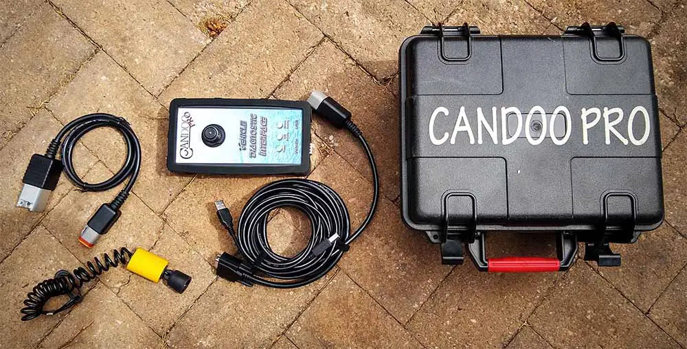
There are two great Sea-doo code readers on the market.
- BRP BUDS / BUDS2 MPI-3 Diagnostic Scanner 4TEC/ETEC for Sea-doo, Ski-doo, Canam, Lynx
- Candoo Pro for all BRP Seadoo model Jetki and Ski-doos.
In the past, you could only get public access to the Candoo Pro code reader. Lately, BRP has made their dealer and technician Seadoo code reader available to the public. They are both slightly pricey but you will save on dealer workshop fees. I can work on my own Sea-doo now and after a few Sea-doo oil changes, my costs are only oil, filters, and spark plugs.
I have the Candoo Pro but my mate has the BRP BUDS2 and they are very similar in features. I even changed my spare learner’s DESS key and turned it into a full-speed key.
BRP Sea-doo code reader specs
- BRP MPI-3 Interface (main unit, is used for diagnosis of all BRP vehicles)
- Diagnostic Cable (for connection of MPI-3 Interface to 4-TEC/E-TEC vehicles
- BRP B.U.D.S. Diagnostic software with ALL-DEALER license (supports BRP vehicle till 2016)
- BRP B.U.D.S.2 Diagnostic software with DEALER TECHNICIAN license (supports BRP vehicle from 2016 and after)
How to get a list of stored codes from your Sea-doo for 4TEC skis up to 2003
With the engine, off, plug in your lanyard and hit SET 5 times. You will be able to cycle through these codes. You will see a list of codes on the display. If nothing comes up you need a dealer to read the codes.
How to read Sea-doo fault codes on 2004 to 2021 models without a scanner.
- Press the MODE button repeatedly until the Fault Code function is displayed on the console.
- Press the SET button and the UP/DOWN buttons to cycle through any stores or active fault codes to select them.
- Continue to press the UP/Down buttons to scroll to the next fault code.
- If there are no faults active then the console will display NO ACTIVE FAULT CODES.
- To exit out of the Fault code section press MODE or SET once.
Sea-doo warning lights messages and display meaning
If you see the following pictures pop up on your Sea-doo GTI, GTR, GTS, RXT, GTX, or RXP display you will need to rectify the problem.
- High temperature
- Check Engine or Limp mode
- Low/High battery voltage
- iBR module error
- Low oil pressure
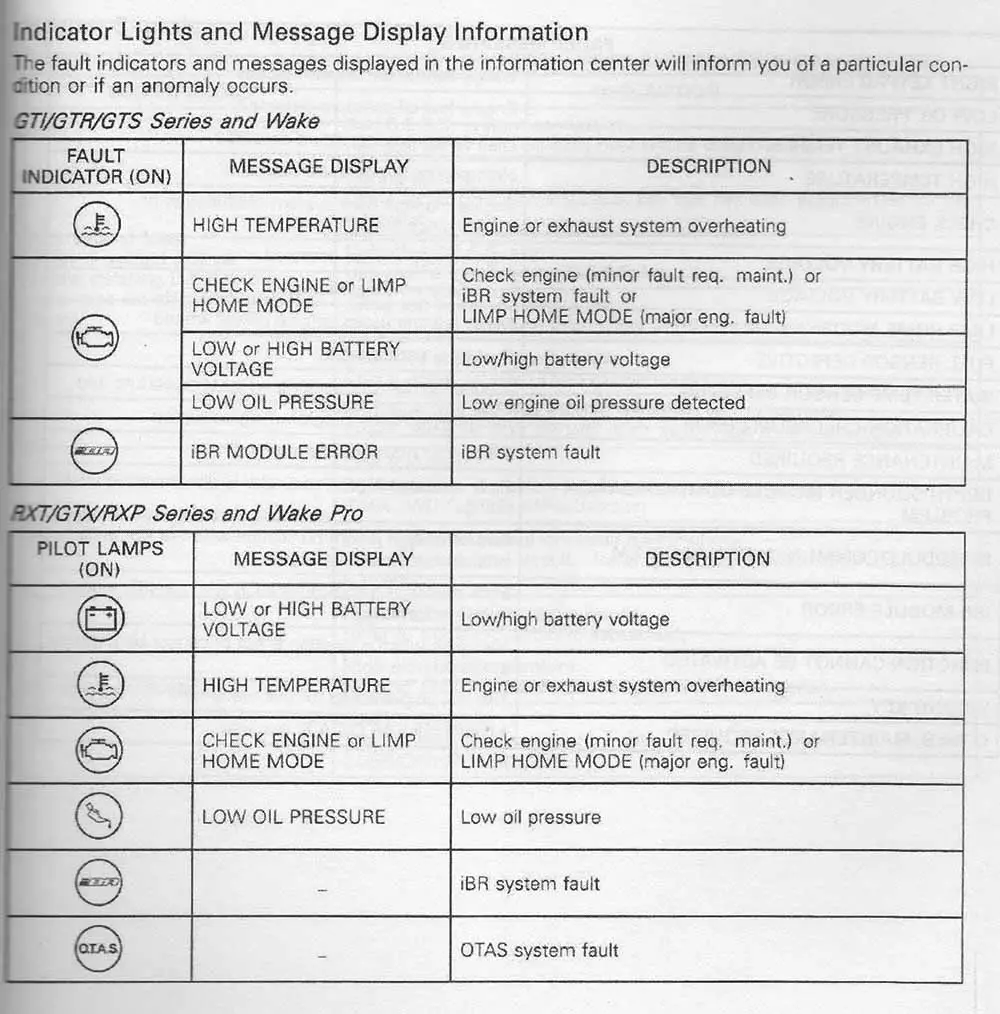
Conclusion
There are over 230 Sea-doo fault codes listed here and even though the solution is basic it will give you a good starting point to repair your Sea-doo jet-ski. Often the fix will be simple such as why your Jetski turns over but won’t start.
These alarm codes give you a very good indication of where to start. Most of the faults that I have come across are because of people not taking care of their Jes-ski. Remember to winterize your Sea-doo so it will be ready for next season.
Let me know in the comments below if I have missed any Sea doo fault codes and I will add them to the list.

I am a qualified Industrial Electrician for the past 20 years and I love to share my knowledge on home repair and maintenance jobs.
I love fast toys like Motorcycles, Cars, Jetskis, Boats, and Computers so writing about them is easy. Working on them is fun.
To keeps costs down I do all my own mods, repairs, and servicing. These skills I want to share with everyone. DIY is a skill everyone can learn.