-
#2
А что инструкция говорит про Ko и ococ ?
-
#3
К сожалению про это ничего не написано в инструкции
-
#4
Ждите — есть спец по Талиям … заглянет — ответит
-
#5
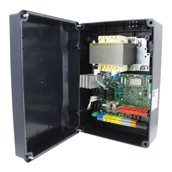
Такая проблема на одном блоке управления
-

IMG_20220519_162648_1.jpg
5 MB
· Просмотры: 52

-
#7
при запуске AutoSet происходит обратный отсчет, после чего появляется надпись Ко и никаких движений. При нажатии с пульта появляется надпись ococ привода не работают.
Два блока стоят рядом с одним проблем вообще нет, со вторым вышеописанные проблемы. Вообще в чем ещё разница между ko и okВложения
Добрый вечер. Не прописан или неправильно прописан тип двигателя ,необходимо через расширенное меню в логических функциях первый параметр выбрать тип двигателя .
-
#8
Такая проблема на одном блоке управления
Близко поставили , между блоками должен быть зазор , иначе дверку не открыть либо открывать в разные стороны, я правша поэтому открывается влево .
-
#9
Добрый вечер. Не прописан или неправильно прописан тип двигателя ,необходимо через расширенное меню в логических функциях первый параметр выбрать тип двигателя .
ok — функция прописана правильно и обратное — не прописана .
-
#10
Добрый вечер. Не прописан или неправильно прописан тип двигателя ,необходимо через расширенное меню в логических функциях первый параметр выбрать тип двигателя .
Спасибо посмотрю какой тип двигателя прописан.
-
#11
Спасибо посмотрю какой тип двигателя прописан.
Судя по фото , у вас Фобос А 40 либо А 25 , значит мотор номер 7 , не путать с Фобосом номер 2 .
-
#12
Судя по фото , у вас Фобос А 40 либо А 25 , значит мотор номер 7 , не путать с Фобосом номер 2 .
В инструкции на блок управления возможно только выбрать 0,1,2,3,4?
-

Screenshot_2022-05-19-23-10-57-691_com.google.android.apps.docs.jpg
439.8 KB
· Просмотры: 51

-
#13
Судя по фото , у вас Фобос А 40 либо А 25 , значит мотор номер 7 , не путать с Фобосом номер 2 .
Точнее 0,1,2,3
-
#14
В инструкции на блок управления возможно только выбрать 0,1,2,3,4?
У Вас «старая» инструкция, посмотрите эту…
-
THALIA V2.14.pdf
12.1 MB
· Просмотры: 139
-
#15
У Вас «старая» инструкция, посмотрите эту…
Спасибо
-
#16
Да , инструкция столетняя ,уже 3 версия с начала выпуска Фобоса ,по ней и работаем .
-
#17
У Вас «старая» инструкция, посмотрите эту…
Специально посмотрел в этой редакции- по моему это 4 версия , видно переводил русскоговорящий .
-
#18
Всем спасибо, проблема решилась, поменяли тип привода на 7 и все заработало. Надпись ko — это ошибка (ответ от сервиса bft).
- Manuals
- Brands
- BFT Manuals
- Control Panel
- THALIA
- Installation manual
-
Bookmarks
Quick Links
CONTROL PANEL
Attenzione! Leggere attentamente le «Avvertenze» all’interno! Caution! Read «Warnings» inside carefully! Attention! Veuillez lire attentivement les Avertissements qui se trouvent à l’intérieur! Achtung! Bitte lesen Sie
aufmerksam die „Hinweise» im Inneren! ¡Atención¡ Leer atentamente las «Advertencias» en el interior! Let op! Lees de «Waarschuwingen»tigre aan de binnenkant zorgvuldig!
Related Manuals for BFT THALIA
Summary of Contents for BFT THALIA
-
Page 1
CONTROL PANEL Attenzione! Leggere attentamente le “Avvertenze” all’interno! Caution! Read “Warnings” inside carefully! Attention! Veuillez lire attentivement les Avertissements qui se trouvent à l’intérieur! Achtung! Bitte lesen Sie aufmerksam die „Hinweise“ im Inneren! ¡Atención¡ Leer atentamente las “Advertencias” en el interior! Let op! Lees de “Waarschuwingen”tigre aan de binnenkant zorgvuldig! -
Page 2: Quick Installation
SWC 1 / SW 1 / ENC1A + REF SWE — REF SWE AUX 3 (MAX 24V 1A) JP20 Motor F1 1.25 AT (220-230V) Power supply F1 2.5 AT (120V) 220-230V ~ AUX 3 ≠ 1 AUX 3 = 1 26 27 50 51 THALIA…
-
Page 3
— In GIUNO ULTRA BT A 20 — GIUNO ULTRA BT A 50 — E5 BT A18 — E5 BT A12 motors: phase 1 (end stop adjustment) is included in the simplified menu. — In other motors: phase 1 (end stop adjustment) must be carried out before activating the simplified menu THALIA -… -
Page 4
40 41 42 43 44 45 10 11 14 15 Maximum power 1 2 3 1 2 3 continuous cycle Maximum cycle = 0 (int) = 1 (ext) open in other direct. open in other direct. change mot change mot THALIA… -
Page 5
1 2 3 1 2 3 Maximum power — S3 13s-1-13s-1 x30 S3 13s-1-13s-1 x30 pause pause Maximum cycle 90min. 90min. = 0 (int) = 1 (ext) open in other direct. open in other direct. change mot change mot THALIA -… -
Page 6
TYPE OF USE — SEMI-INTENSIVE = 0 (int) open in other direct. = 1 (ext) open in other direct. change mot change mot ATTENTION: with actuators with integrated locks, the permanently active slowdown to a value higher than 5 is mandatory. THALIA… -
Page 7
/ inv.mot / inv.mot mot.tausch / inv.mot / inv.mot mot.tausch / inv.mot / inv.mot mot.tausch / inv.mot / inv.mot ATTENTION: with actuators with integrated locks, the permanently active slowdown to a value higher than 5 is mandatory. THALIA -… -
Page 8
For intermediate values, use the higher value: if the leaf weighs 75 kg consider a value of 80 kg, if its width is 1100 mm use a value of 1200 mm. IMPORTANT: Low-energy operation is not considered a proper safety measure if the leaf is used by elderly, invalid, disabled people and children. In this case, provide additional safety measures, according to the provisions of the legislation in force. THALIA… -
Page 9
*White **Brown ***Green Maximum power 180W Maximum cycle continuous cycle 10 11 14 15 40 41 42 43 44 45 = 1 (ext) open in other direct. = 0 (int) open in other direct. change mot change mot THALIA -… -
Page 10
*White **Brown ***Green Maximum power 40 41 42 43 44 45 10 11 14 15 Maximum cycle 40 cycles/h = 1 (ext) open in other direct. = 0 (int) open in other direct. change mot change mot 10 — THALIA… -
Page 11
GIUNO ULTRA motor manual. ersu autoset MIN 1 — MAX 3 ..AUTO CLOSE AUTO OPEN mem. r emotes hidden button release desidered button O 01 12 — THALIA… -
Page 12
Nombre maximum dispositif vérifés: 6 (mais pas plus de 4 par type), Max. Anzahl der überprüften Geräte: 6 (jedoch nicht mehr als 4 je Typ), Número máximo dispositivos comprobados: 6 (pero no más de 4 por tipo), Maximumaantal “trusted devices”: 6 (maar niet meer dan 4 per type) THALIA -… -
Page 13
OPEN OPEN THALIA UNIDA ME BT 1 2 3 4 5 Programmatore palmare universale Universal palmtop programmer Programmateur palmaire universel ECB 24 V Universal-Handprogrammiergerät Programador portátil universal 20 21 50 51 Universele programmeerbare palmtop (versione x.40 e successive) Scheda di espansione (x.40 and later versions) -
Page 14
64 prg. cod rh ia9c 22fd default language ..autoset E5 A18 — E5 A12 op 1 op 2 l. s w adj cl 2 ersu cl 1 GIUNO ULTRA manual mouvement THALIA -… -
Page 15
ACCESS MENUS FIG. 1 Control unit software version bft. . . stat vers No total manoeuvres (in hundreds) n. cycles 0000 No radio control devices memorised 0000 n. re otes List of last 30 errors 01. 3 3 02. 0 1 . -
Page 16: General Information
Usable transmitter versions: All ROLLING CODE transmitters compatible with TESTING The THALIA panel controls (checks) the start relays and safety devices (photocells) 4) TUBE ARRANGEMENT Fi g. A before performing each opening and closing cycle. If there is a malfunction, make sure that the connected devices are working 5) TERMINAL BOARD WIRING Fig.
-
Page 17
Switches safety edge testing on at start of operation. The command reverses movement for 2 sec. SAFE logic= 8 — Input configured as Bar 8k2 (fig.F, ref.5). Input for resistive edge 8K2. The command reverses movement for 2 sec. 32 — THALIA… -
Page 18
Fig. I shows a sample connection of an ECB 24V~ solenoid latch connected to Used to set the programmer’s language on the display. the THALIA control panel. In order to control the solenoid lock, the THALIA panel needs a special board 8.6) AUTOSET MENU (AUTOset) mod. ME BT. -
Page 19
AUX output configured as Maintenance or Flashing Light and threshold nance Maintenance . [in hundreds] (*) In the European Union, apply standard EN 12453 for force limitations, and standard EN 12445 for measuring method. (**) Impact forces can be reduced by using deformable edges. 34 — THALIA… -
Page 20
This feature is useful when dealing with installations running at low temperatures. WARNING: once this feature has been activated, you will need to perform an autoset opening and closing cycle. Both motors active (2 leaves). 1 motor active OT. O N Only motor 1 active (1 leaf ). THALIA -… -
Page 21
E — The option of editing the board’s parameters via the U-link network is disabled. Transmitters are memorized only using the relevant Radio menu. IMPORTANT: This high level of security stops unwanted clones from gaining access and also stops radio interference, if any. 36 — THALIA… -
Page 22
SERIAL is configured in a BFT Standard MASTER: board sends activation commands (START, OPEN, CLOSE, PED, STOP) to other boards. network connection). Identifies board address from 0 to 119 in a local BFT network connection. Address [ ___ ] ADDRESS (see U-LINK OPTIONAL MODULES section) Push&Go… -
Page 23
Displays receiver code required for cloning transmitters. ON = Enables remote programming of cards via a previously memorized W LINK transmitter. It remains enabled for 3 minutes from the time the W LINK transmitter is last pressed. OFF= W LINK programming disabled. 38 — THALIA… -
Page 24
www.bftme.ae…

11040 руб.
Блок 24V для распашных моторов
-
Описание
-
Технические характеристики
Описание
Область применения: Панель управления с дисплеем для одного или двух электромеханических приводов на 24 В для распашных ворот
Питание: 230V однофазное Питание приводов: 24В пост. тока максимум 180 Вт для каждого привода
Основные характеристики: разработанные в соответствии с новым стандартом цветные съемные терминальные блоки, упрощенное программирование на основе сценария с дисплеем и двухканальным ресивером, защитная система D-Track, система замедления при открытии и закрытии, а также электронное самообучение.
Основные функции: автоматическое повторное закрытие, быстрое закрытие, частичное открытие, кнопка безопасности
Совместимость: LIBRA C MA, LIBRA, LIBRA R, LIBRA MA R
24V максимальная мощность 180W+180W, настройка по концевикам моторов или по дожиму в упор, автоматическое закрывание, встроенный 2-х канальный приёмник, второй канал для подключения любых внешних устройств, режим калитки, D-TRACK, обнаружение препятствий. Возможно подключение эл. мех. и эл. магнитных замков. Разъем U-LINK под платы расширения (типа B EBA).
Технические характеристики
| Взаимосвязь | ДА |
| Maximum output | 180+180 W |
| Питание | 220-230 V |
| Max. n. transmitters | 63 |
| Programming | Дисплей |
| Power supply accessories | 24V — 1A |
| Light sensor | ДА |
| Safefy edge | ДА |
| Resistive edge | ДА |
| Tested photocell | ДА |
| Tested safety edge | ДА |
| STOP | ДА |
| START | ДА |
| Traffic light control | ДА |
| Open | ДА |
| CLOSE | ДА |
| Pedestrian open | ДА |
| Open with timer | ДА |
| Pedestrian open with timer | ДА |
| Сигнальная лампа | ДА |
| Configurable AUX 1 | нет |
| Configurable AUX 2 | нет |
| Configurable AUX 3 | 24V — 1A |
| Электрический замок | нет |
* With reverse logic, opening direction = 000 (DIR=INT)
** With reverse logic, opening direction = 001 (DIR=ext)
*** Blu
**** Red
VIRGO SMART BT A (5 wires)
tipo
otore — type de
oteur —
otorentyp —
10 11
14 15
M1
M2
M1= VIRGO SMART BT A (Left) / M2= VIRGO SMART BT A SQ (Right)
open in other direct.
M1
M2
= 0
inv.mot / change mot / inv.mot
mot.tausch / inv.mot / inv.mot
(
M1= VIRGO SMART BT A
Right
open in other direct.
M2
M1
= 0
inv.mot / change mot / inv.mot
mot.tausch / inv.mot / inv.mot
ATTENTION: with actuators with integrated locks, the permanently active slowdown to a value higher than 5 is mandatory.
SWO* / SWC**
9
otor type — tipo
otor:
40 41 42 43 44 45
= 0 (int)
M1
M2
= 1
inv.mot / change mot / inv.mot
mot.tausch / inv.mot / inv.mot
)
(
/ M2= VIRGO SMART BT A SQ
Left
= 1 (ext)
M2
M1
= 1
inv.mot / change mot / inv.mot
mot.tausch / inv.mot / inv.mot
SWC * / SWO **
Maximum power
Maximum cycle
VIRGO SMART BT A ( 3 wires )
tipo
otore — type de
oteur —
10 11
14 15
M2
M1
open in other direct. :
M1
inv.mot / change mot / inv.mot
mot.tausch / inv.mot / inv.mot
)
open in other direct.
M2
inv.mot / change mot / inv.mot
mot.tausch / inv.mot / inv.mot
1= +Red ****
2= — Blu ***
3= SWO*/SWC**
4= SWC*/SWO**
5= +REF SWE
VIRGO SMART BT A
110W
20 cycles/h
otorentyp —
otor type — tipo
otor:
40 41 42 43 44 45
M1
M2
1 2 3
1 2 3
= 1 (ext)
M2
M1
= 0
inv.mot / change mot / inv.mot
mot.tausch / inv.mot / inv.mot
= 0 (int)
M1
M2
= 0
inv.mot / change mot / inv.mot
mot.tausch / inv.mot / inv.mot
E
10
M2
= 1
M1
= 1
7
THALIA —
File Specifications:1605/1605118-zara_btl2.pdf file (24 Apr 2023) |
Accompanying Data:
BFT ZARA BTL2 Control Panel PDF Installation Manual (Updated: Monday 24th of April 2023 05:01:11 AM)
Rating: 4.4 (rated by 45 users)
Compatible devices: SIRIO CBA 230 INV, Rigel 6 QRG, LEO B CBB DL2 3 230 L02, VEGA-VEGA ULTRA, RIGEL 6, PERSEO CBD 230.P SD, VISTA SEL, LUNA AC B.
Recommended Documentation:
Installation Manual (Text Version):
(Ocr-Read Summary of Contents of some pages of the BFT ZARA BTL2 Document (Main Content), UPD: 24 April 2023)
-
1, BFT ZARA BTL2 ZARA BTL2 D812059 00100_03 15-05-15 ZARA BTL2 QUADRO COMANDO CONTROL PANEL CENTRALE DE COMMANDE SELBSTÜBERWACHENDE STEUERUNG CUADRO DE MANDOS BEDIENINGSPANEEL ISTRUZIONI DI INSTALLAZIONE INSTALLATION MANUAL INSTRUCTIONS D’INSTALLATION MONTAGEANLEITUNG INSTRUCCIONES DE INSTALACION INSTALLATIEVOORSCHRIFTEN Attenzione! Leggere attentamente le “Avverten…
-
2, 2 — ZARA BTL2 D812059 00100_03 A C 0,75 0,75 0,75 0,75 * 3×2,5 mm 2 * 3×2,5 mm 2 D JP3 725150 70 24V ~ 2 1 TX1 2 1 RX1 4 5 3 DIP 3 = OFF ELS Y # F2 4 AT F1 1.25 AT(220-230V) F1 2.5 AT (120V) ANT. ANT SHIELD 230V (*) 24V (*) 110V 220 S4 T1 T2 T3 T4 PWR ON FLT2 FLT1 PHOT STOP OPEN START SW02 SW01 SWC2 SWC1 BAR 10 11 M1 14 15 20 21 28 29 40 41 42 43 44 45 50 51 52 60 61 62 70 71 72 73 74 75 M2 24V 24V — 24V + 24 VSafe+ COM NO NO NC NC NC 24V-max15…
-
3, ZARA BTL2 — 3 D812059 00100_03 ENGLISH FRANÇAIS ESPAÑOL NEDERLANDS DEUTSCHITALIANO A C 0,75 0,75 0,75 0,75 * * 3×2,5 mm 2 * 3×2,5 mm 2 D JP3 725150 70 24V ~ 2 1 TX1 2 1 RX1 4 5 3 DIP 3 = OFF ELS Y # F2 4 AT F1 1.25 AT(220-230V) F1 2.5 AT (120V) ANT. ANT SHIELD 230V (*) 24V (*) 110V 220 S4 T1 T2 T3 T4 PWR ON FLT2 FLT1 PHOT STOP OPEN START SW02 SW01 SWC2 SWC1 BAR 10 11 M1 14 15 20 21 28 29 40 41 42 43 44 45 50 51 52 60 61 62 70 71 72 73 74 75 M2 24V 24V — 24V…
-
4, 4 — ZARA BTL2 D812059 00100_03 H 50 51 52 70 71 72 73 74 75 24V — 24V + 24 VSafe+ COM PHOT BAR STOP FAULT 1 FAULT 2 NC NC NC PHOT 1 2 1 2 3 4 5 51 TX1 RX1 1 2 1 2 3 4 5 52 50 TX1 RX1 1 2 1 2 3 4 5 TX1 RX1 1 2 1 2 3 4 5 TX2 RX2 1 2 1 2 3 4 5 TX1 RX1 1 2 1 2 3 4 5 TX1 RX1 1 2 1 2 3 4 5 TX1 RX1 1 2 1 2 3 4 5 TX2 RX2 1 PHOT / 1 PHOT CL 1 PHOT / 1 PHOT CL 2 PHOT / 2 PHOT CL BAR 8K2 50 52 50 52 50 51 50 51 50 51 50 51 50 70 72 70 72 73 70 70 72 73 BAR Bar 1 1…
-
5, ZARA BTL2 — 9 D812059 00100_03 ENGLISH INSTALLATION MANUAL INSTALLER WARNINGS Anything that is not explicitly provided for in the installation ma- nual is not allowed. The operator’s proper operation can only be guaranteed if the information given is complied with. The Firm shall not be answerable for damage caused by failure to comply with the instructions featured herein. While we will not alter the product’s essential features, the Firm reserves the…
-
6, BFT ZARA BTL2 10 — ZARA BTL2 D812059 00100_03 INSTALLATION MANUAL 1) GENERAL INFORMATION The ZARA BTL2 control panel comes with standard factory settings. Any change must be set by means of the TRIMMER and DIP SWITCH settings. The Control unit completely supports the EELINK protocol. Its main features are: — Control of 1 or 2 24V BT motors Note: 2 motors of the same type must be used. — Electronic torque control with obstacle detection — S…
-
7, ZARA BTL2 — 11 D812059 00100_03 ENGLISH INSTALLATION MANUAL 5) LOCAL COMMANDS Fig. C Pressing the S3 key commands one START. By pressing the key again while the automated device is moving a STOP is commanded. 6) SAFETY DEVICES Note: only use receiving safety devices with free changeover contact. 6.1) TESTED DEVICES Fig. H 6.2 CONNECTION OF 1 PAIR OF NON-TESTED PHOTOCELLS Fig. D 7 MEMORIZING TRAN…
-
8, 12 — ZARA BTL2 D812059 00100_03 INSTALLATION MANUAL ATTENTION ! Instructions de sécurité importantes. Veuillez lire et suivre attentivement tous les avertissements et toutes les instructions fournis avec le produit sachant qu’une installation incorrecte peut provoquer des préjudices aux personnes, aux animaux ou aux biens. Les avertissements fournissent des indications importantes concernant la sécurité, l’installation, l’utilisation et l’entretien. Veuille…
-
9, 30 — ZARA BTL2 D812059 00100_03 cannot be held liable for any damage as a result of improper, incorrect or unreasonable use. GENERAL SAFETY Thank you for choosing this product. The Firm is condent that its performance will meet your ope- rating needs. This product meets recognized technical standards and complies with safety provisions when installed correctly by qualied, expert personnel (professional installer). If installed and used …
-
BFT ZARA BTL2 User Manual
-
BFT ZARA BTL2 User Guide
-
BFT ZARA BTL2 PDF Manual
-
BFT ZARA BTL2 Owner’s Manuals
Recommended: 437921, CHS60, 8123, 43T319
Links & Tools
Operating Impressions, Questions and Answers: