- Печать
Страницы: [1] Вниз

Тема: Adrive (Прочитано 3728 раз)
0 Пользователей и 1 Гость просматривают эту тему.
Всем доброго времени суток.Кто-нибудь устанавливал программу ADrive-WinSimulator на ноут.При попытке поставить на Win7(32/64) , выскакивают ошибки по поводу замены файлов.Игнорю.После установки программа запускается,но не реагирует ни на что.

Записан
А чем еще может заниматься мужчина в расцвете лет в свободное от школьных уроков время?
Программа давнишняя и больше не обновляется. Точно нормально работает на WinXP и Win10. Еще важный момент — USB-com конвертер. Некоторые «вешают» программу при попытке подключения.
Записан
Техническая поддержка по продукции ARKEL
Всем добрых выходных.
Лифт Хас частотник Adrive 16 этажей 450 кг без компенсирующих цепей при полной загрузке кабины с первого этажа не может набрать скорость 19 ошибка частотника ,убираю 50 кг с кабины и всё работает нормально,скорость лифта 1.6м/с
Записан
ПЧ установлен без запаса по мощности.
Записан
Добрый день.
1. Номинальные токи лебедки и частотника?
2. Была ли выполнена балансировка?
3. Тип и модель лебедки и энкодера?
4. Если редукторная, то какой режим управления установлен: открытый или закрытый контур?
Записан
Техническая поддержка по продукции ARKEL
Добрый день.лебедка безредукторная ,частотник5,5 KW все данные по лебедке завтра напишу
Записан
Здравствуйте. Две машины Могилев. На обоих в монтажном режиме при прекращении движения ошибка 12. Точно выяснил, что ЧП встает по кривой замедления в ревизии, а пускатель отпадает мгновенно (речь о монтажный режим).
Это призван устранить вход EN ЧП и реле 12 в станции. В дальнейшем он же и устраняет ложный сбой ЧП при разрыве ЦБ. Все это указано в инструкции.
Вопрос почему это не работает? Встал монтаж.
« Последнее редактирование: Август 30, 2022, 12:12:00 от Алексей- »
Записан
Здравствуйте. Подскажите, пожалуйста. Могилев ПУ3 и ADrive. Нет параметра 11.18 Binary Speed. Достаточно обновиться до прошивки 11.8 с сайта или для могилы нужна спец. версия?
Записан
С Могилёва прошивку присылали.
Записан
Ленивые всё делают быстро. Чтобы поскорее отделаться от работы.
И делают качественно. Чтобы потом не переделывать.
Дайте совет пожалуйста. Могилев 400 кг, ЧП Adrive , при движении на малой скорости не удается избавиться от вибрации.
Смонтировали несколько лифтов. Проявляется на всех лифтах, но на одном уж очень сильно заметно. При движении на большой скорости вибрации нет.
После перехода на малую скорость и движения в течении 1,5-3 сек. очень не комфортно. Двигатель без инкодера. Прошивка Adrive версия 11.2.
Записан
Саняchel,
Здравствуйте, подскажите пожалуйста как вы решили проблему с вибрацией на маленькой скорости частотника Adraiv? Просто у нас такая же история. Не что не помогает(
Записан
Анатолий Герасимов, Здравствуйте, на данный момент решения, похоже, нет. Представители скидывают новую версию прошивки, которая должна решить проблему, но по факту после установки нового ПО ничего не меняется.
Записан
![]()
Добрый день. Подскажите, как побороть ошибку 39 на ADrive. Появилась после прошивки с версии10.7 на 12.1
Из шести прошитых лифтов на трёх стабильно выскакивает, два не в работе, поэтому пока не знаю. Подключение двигателя нормальное. Нашел только рекомендацию выключить 11.19- контроль 3 фаз
Записан
- Печать
Страницы: [1] Вверх
|
|
Ремонт частотных преобразователей ARKEL A-DRIVE
 Ремонт частотного преобразователя ARKEL A-DRIVE, впрочем, как и ремонт частотников других производителей имеет ряд особенностей в силу своего конструктива. Частотные преобразователи, точнее их начинка делятся на две части:
- Аппаратная часть,
- Программная часть.
Частотники данного производителя не являются исключением из правил, именно поэтому ремонт частотного преобразователя ARKEL A-DRIVE имеет точно такой же ряд особенностей, как и у других преобразователей.
Диагностировать ту или иную неисправность помогают коды ошибок частотного преобразователя, которые отображаются на небольшом дисплее, расположенном на лицевой панели привода. Коды ошибок частотного преобразователя ARKEL A-DRIVE в зависимости от серии описаны в инструкции, пользователя которые можно скачать с нашего сайта.
Ремонт частотных преобразователей ARKEL A-DRIVE в Тольятти, как и любых других преобразователей, выпущенных под другими брендами, всегда начинается с аппаратной части, после успешного ремонта аппаратной части наступает очередь программной.
Настройка частотного преобразователя ARKEL A-DRIVE также прописана в инструкции завода производителя, для каждой серии частотных преобразователей настройка будет индивидуальной, так как каждая линейка преобразователей решает свои собственные задачи, этим обусловливается широкая номенклатура данного промышленного оборудования.
Ремонт частотных преобразователей ARKEL A-DRIVE в сервисном центре
 Компания «Кернел» производит ремонт частотных преобразователей ARKEL A-DRIVE в Тольятти с 2002 года. За время существования компании наши сотрудники накопили колоссальный опыт в ремонте преобразователей частоты такого известного производителя как ARKEL A-DRIVE. Ремонт подобного промышленного оборудования ответственное и сложное занятие, требующие максимальной отдачи, профессионализма и максимально полной материальной базе.
Специалисты нашего сервисного центра максимальное внимание уделяют качеству исполнения ремонта, программирования и настройке промышленных преобразователей частоты, не зависимо от производителя данного промышленного оборудования. Именно поэтому мы смело даем гарантию на все выполненные работы шесть месяцев.
Ремонт частотных преобразователей ARKEL A-DRIVE в Тольятти производится исключительно с использованием оригинальных запасных частей, на компонентном уровне с применением высокотехнологичного диагностического оборудования, квалифицированным персоналом с инженерным образованием.
В случае выхода из строя преобразователя частоты на вашем производстве либо появились проблемы с приводом, которые вы не можете решить самостоятельно, мы всегда рады вам помочь. Специалисты нашего сервисного центра в минимальные сроки проведут глубокую диагностику с последующим ремонтом частотного преобразователя ARKEL A-DRIVE.
Инженеры сервисного центра выполняют качественный ремонт частотных преобразователей ARKEL A-DRIVE всех серий, когда-либо выпускаемых компанией.
|
Типы частотных преобразователей ARKEL A-DRIVE |
|
LW-0013101; LW-0022030; LW-0009186; LW-0015214; LW-0017288; LW-0017389; LW-0021695; LW-0023801 |
В данной таблице присутствуют далеко не все частотные преобразователи ARKEL A-DRIVE ремонт которых предлагает наш сервисный центр.
Ошибки частотного преобразователя ARKEL A-DRIVE
 В процессе работы выходит из строя даже самое надежное промышленное оборудование. Частотники в наше время, нашли широкое применение абсолютно во всех сферах промышленности, управляя как мини моторами в оргтехнике, так и гигантскими двигателями в горнодобывающей промышленности.
Для простоты общения со столь сложной электроникой все частотные преобразователи оснащены небольшими дисплеями с помощью которых выводятся информационные сообщения с кодами ошибок, расшифровав которые можно сразу же узнать причину ее возникновения. Если учесть распространенность данной промышленной электроники, то появляется острая нужда в расшифровке кодов ошибок частотных преобразователей. В этой статье мы рассмотрим одного из самых известных производителей промышленной электроники имеющему уважение во всем мире, ARKEL.
Существует несколько видов ошибок, некоторые из них можно устранить автоматически, а некоторые возможно исправить только, обратившись в специализированный сервисный центр. В руководстве пользователя прописаны все коды ошибок частотного преобразователя ARKEL A-DRIVE и их расшифровка.

Обязательно должны соблюдаться все рекомендации, изложенные в инструкции по монтажу и эксплуатации насосов, в особенности требования по технике безопасности!
Преобразователь частоты разработан таким образом, что он пытается избежать аварийных отключений путем ограничения момента, перенапряжения и т.п.
Появление сбоев при вводе в эксплуатацию или вскоре после него обычно свидетельствует о неверной настройке или неправильном подключении.
ВозникнARKEL A-DRIVEие неисправностей или проблем после длительного режима бесперебойной работы обычно происходит по причине изменений в системе или ее окружении (например, в результате износа).
Дополнительную информацию по частотным преобразователям ARKEL A-DRIVE можно посмотреть и скачать в файлах ниже.
Настройка частотного преобразователя ARKEL A-DRIVE, программирование
 Настройка частотных преобразователей ARKEL A-DRIVE (программирование) происходит в рамках установленных производителем правил, существует общий алгоритм по программированию (настройке частотных преобразователей), относящийся ко всем производителям данного промышленного оборудования. Ниже представлена пошаговая инструкция по настройке частотных преобразователей ARKEL A-DRIVE.
- Выбор режима управления приводом ARKEL A-DRIVE (управление по показанию датчиков, дистанционное управление, дистанционное управление).
- В случае использования отдельного (выносного) монитора, настраивается вывод на него технической информации.
- Далее определяем конфигурацию подключения серводвигателя. На данной стадии задаются такие параметры как- возможность применения обратной связи либо без ее применения, а в память блока заносятся данные по: величине крутящего момента, мощности потребителей, номинальное значения частоты, напряжение, ток и скорости вращения ротора.

- Программируется минимально допустимая величина напряжения и частоты, а также время ускорения ротора от ноля до номинального значения.
- И в завершении, в программу управления частотным преобразователем ARKEL A-DRIVE вносятся функциональные данные со значениями отдельных клемм и особенностями сигналов. Отмечаются действия оборудования, выполняющиеся автоматически при отсутствии информации поступающей в оперативном режиме с датчика.

В некоторых частотниках существует пункт наличия/отсутствия фильтра в цепи питания двигателя. Этот пункт отвечает за подключение различных видов нагрузок, в том случае, когда возможно выбрать нормальное или инверсное изменение частоты при повышении уровня сигнала обратной связи.
Все настройки частотных преобразователей ARKEL A-DRIVE приведены в технической документации ниже в удобном формате (PDF) который можно скачать на свой компьютер, распечатать или просто открыть на нашем сайте.
Частотный преобразователь ARKEL A-DRIVE, скачать инструкции по эксплуатации
Ниже вы можете скачать руководства по эксплуатации частотных преобразователей ARKEL A-DRIVE для всех серий, когда-либо выпущенных данным производителем.
|
Частотный преобразователь ARKEL A-DRIVE инструкция, руководство пользователя. |
 Скачать PDF Скачать PDF |
Оставьте заявку на ремонт промышленного оборудования, используя форму на сайте, либо свяжетесь с нашими менеджерами, сделать это очень просто.
Оставить заявку на ремонт частотных преобразователей ARKEL A-DRIVE
У вас вышел из строя частотник? Вам необходим срочный ремонт частотных преобразователей ARKEL A-DRIVE в Тольятти? Оставьте заявку на ремонт нажав на одноименную кнопку в верхней правой части экрана либо свяжитесь с нашими менеджерами. Связаться с ними можно несколькими способами:

- Заказав обратный звонок (кнопка в правом нижнем углу сайта)
- Посредством чата (кнопка расположена с левой стороны сайта)
- Позвонив по номеру телефона:
- +7(8482) 79-78-54;
- +7(8482) 55-96-39;
- +7(917) 121-53-01
- Написав на электронную почту: 89171215301@mail.ru
Далеко не полный список производителей промышленной электроники и оборудования, ремонтируемой в нашей компании.
-
Contents
-
Table of Contents
-
Bookmarks
Quick Links
ADrive
VVVF Inverter
F
o
r
E
l
e
v
a
t
o
r
s
F
o
r
E
l
e
v
a
t
o
r
s
USER MANUAL
08.2012
Document Version:
4.0
Summary of Contents for Arkel ADrive Size-B
-
Page 1
ADrive VVVF Inverter USER MANUAL 08.2012 Document Version:… -
Page 2: Table Of Contents
ARKEL Elektrik Elektronik Ltd. Şti. www.arkel.com.tr CONTENT CONTENT …………………………….1 INTRODUCTION …………………………4 EMC CONFORMITY ……………………….4 WARNINGS …………………………..5 DELIVERY CONTENTS ……………………….6 TECHNICAL SPECIFICATIONS ……………………7 …
-
Page 3
ARKEL Elektrik Elektronik Ltd. Şti. www.arkel.com.tr 2-MOTOR SETUP …………………………55 3-CONTROLLER SETUP ……………………….60 4-KEY READ/WRITE ……………………….62 5-FAULT HISTORY ………………………… 62 6-CONTROL TYPE …………………………62 7-LANGUAGE …………………………. 62 8-FACTORY DEFAULT ……………………….62 … -
Page 4
The containing information specifies the properties of the products without ensuring them. The right for technical changes is reserved. Copyright Copyright by Arkel Elektrik Elektronik Tic. Ltd. Sti. It is not allowed to redistribute the manual in its entirety or parts of it. Violations will be prosecuted and lead to indemnity. -
Page 5: Introduction
ARKEL Elektrik Elektronik Ltd. Şti. www.arkel.com.tr 1. INTRODUCTION ADrive is a high performance motor driver designed for elevators. Can be used with asynchronous (open loop/closed loop) and synchronous lift motors. Provides an evacuation operation by driving the motor with back-up power (60-120V battery or 1-phase 220V UPS).
-
Page 6: Warnings
ARKEL Elektrik Elektronik Ltd. Şti. www.arkel.com.tr 3. WARNINGS After switching off the device do not touch any electronic board or components until the power capacitors are discharged (Min.5 minutes). Do not make any connection to inverter when the power is on. Do not check components and the signs on the electronic boards while device is running.
-
Page 7: Delivery Contents
ARKEL Elektrik Elektronik Ltd. Şti. www.arkel.com.tr 4. DELIVERY CONTENTS ● User manual (This product) ● Documentation and software CD ● PC RS-232 connection cable ● Data Key for transferring parameters ● RFI Filter (Zero-phase reactor) ● Braking resistor (Optional) ● EMI line filter (Optional) ●…
-
Page 8: Technical Specifications
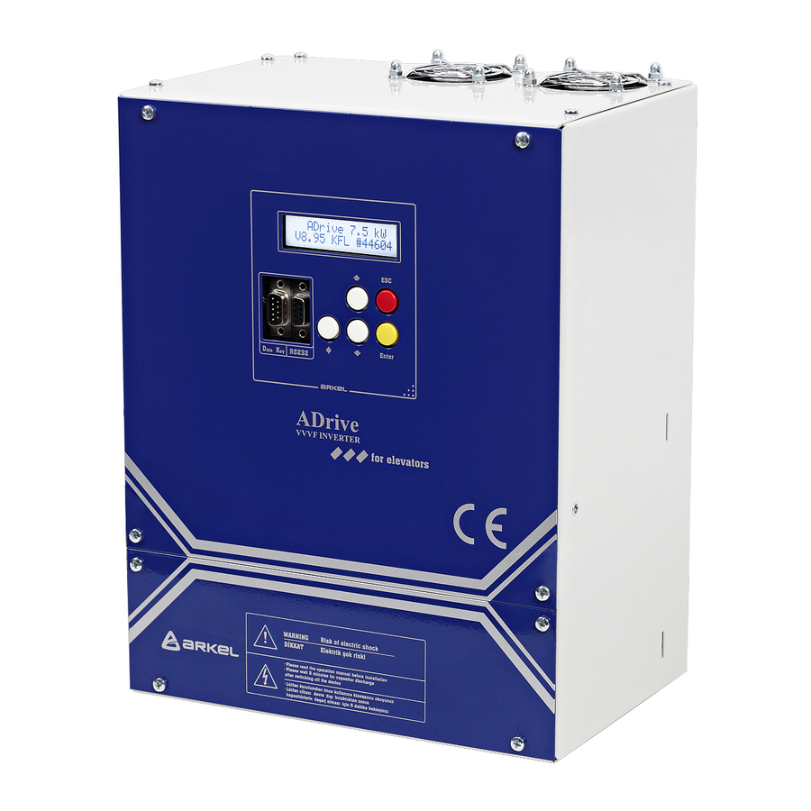
ARKEL Elektrik Elektronik Ltd. Şti. www.arkel.com.tr 5. TECHNICAL SPECIFICATIONS Type Size-B Size-C Size-D Model 4B055 4B075 4B110 4C150 4C220 4D370 Motor Power (HP) 5.5 kW 7.5 kW 11 kW 15 kW 22 kW 37 kW 7.5HP 10HP 15HP 20HP 30HP…
-
Page 9: Fuse, Contactor And Cable Cross-Section
ARKEL Elektrik Elektronik Ltd. Şti. www.arkel.com.tr 6. FUSE, CONTACTOR and CABLE CROSS-SECTION 7.5HP 10HP 15HP 20HP 30HP 50HP Fuses (Amper) 5.5kW 7.5kW 11kW 15kW 22kW 37kW Mains fuse (Type B) Battery fuse (Type C) 1.5 x battery_capacity (Ah) UPS fuse (Type B) 1.5 x (UPS_power (W) / 220V)
-
Page 10: Dimensions And Mounting Of Adrive
To ensure this allow a gap of at least 10 cm above and underneath the unit. Mount using the mounting holes and using at most 12 mm M6 nuts. 7.1. Physical Dimensions of ADrive Size-B and Size-C ADrive Size-B (7.5HP / 10HP / 15HP)
-
Page 11
ARKEL Elektrik Elektronik Ltd. Şti. www.arkel.com.tr 7.2. Physical Dimensions of ADrive Size-D ADrive Size-D (50HP) Dimensions (mm) ADrive Size-D 236,5 ADrive 08.2012… -
Page 12
ARKEL Elektrik Elektronik Ltd. Şti. www.arkel.com.tr 7.2.1 Mounting of ADrive Size-D Unlike ADrive Size-B and Size-C, ADrive Size-D has 2 mounting brackets while mounting. Size-D mounting device For mounting the device ADrive Size-D, follow the steps below: Step 1: Screw one of the mounting devices… -
Page 13: Adrive Line Filter (Emi)
ARKEL Elektrik Elektronik Ltd. Şti. www.arkel.com.tr 8. ADrive Line Filter (EMI) Two types of EMI filter are used for ADrive Inverter models. ADrive Recommended EMI Filter Description Size-B 7.5 HP EMC-30 3x400VAC, 50-60HZ, 30A 10 HP 15 HP Size-C 20 HP…
-
Page 14: Adrive Braking Resistors
ARKEL Elektrik Elektronik Ltd. Şti. www.arkel.com.tr 9. ADrive Braking Resistors Recommended braking resistors for ADrive models are shown below: Recommended Braking Resistor ADrive Resistance (Ω) / Power (kW) Type-A Type-B Type-C 50Ω / 1kW 50Ω / 1kW 40Ω / 1kW 25Ω…
-
Page 15
ARKEL Elektrik Elektronik Ltd. Şti. www.arkel.com.tr 9.1. Dimensions of Braking Resistors 9.1.1. Braking Resistor Type-A (7.5 HP, 10 HP, 15 HP) 325 mm 115 mm 180 mm 20 mm 9.1.2. Braking Resistor Type-B (20 HP, 30 HP) 305 mm 155 mm… -
Page 16: Rfi Filter (Zero-Phase Reactor)
C = 25 mm Toroidal transformer core 10.1. The wiring of ADrive Size-B and Size-C to RFI Filter The toroidal transformer core comes with the inverter is used for RFI filter. The wiring must go through the opening (U, V, W) to reduce the RF component of the electrical noise. Loop the wires two times to attain the full RFI filtering effect.
-
Page 17: Ac Line Reactor (Line Choke)
ARKEL Elektrik Elektronik Ltd. Şti. www.arkel.com.tr 11. AC line reactor (Line choke) A 3-phase AC line reactor must be used to comply with the harmonic current limits required by the EN 61000-3-12 standard. Note: A DC reactor is integrated inside all ADrive models.
-
Page 18: Encabit-Plus Module
ARKEL Elektrik Elektronik Ltd. Şti. www.arkel.com.tr 12. ENCABIT-Plus Module 12.1. Description An external ENCABIT-Plus module is mounted to the device for synchronous applications. The absolute encoder connection and other functions used for synchronous motors are provided with the support of ENCABIT-Plus module.
-
Page 19: Adrive Connections
ARKEL Elektrik Elektronik Ltd. Şti. www.arkel.com.tr 13. ADrive Connections 13.1. Connections of ADrive Size-B and Size-C Control Terminal Inputs Motor Output Line Inputs FAN GROUP Bottom view of ADrive Inverter 13.2. Connections of ADrive Size-D Control Terminal Inputs Line Inputs…
-
Page 20: Power Terminal Connections
ARKEL Elektrik Elektronik Ltd. Şti. www.arkel.com.tr 13.1. POWER TERMINAL CONNECTIONS Symbol Description L1(R) L2(S) Mains inputs L3(T) Earthing terminal. Braking resistor transistor output (-) DC Bus positive voltage, Braking resistor transistor output (+) DC Bus negative voltage (This terminal is located in only ADrive…
-
Page 21: Motor Connection
ARKEL Elektrik Elektronik Ltd. Şti. www.arkel.com.tr 13.1.3. Motor connection: 13.1.3.1. Asynchronous motor connection: ADrive Motor 13.1.3.2. Synchronous motor connection: ADrive Motor ADrive 08.2012…
-
Page 22
ARKEL Elektrik Elektronik Ltd. Şti. www.arkel.com.tr 13.1.3.3. Consider the following statements for motor connection: 2 serial contactors must be used at motor circuit for conformity to EN-81. The drive enable signal (EN) must be switched by the open contacts of KPA and KPB. -
Page 23: Control Terminal Connections
ARKEL Elektrik Elektronik Ltd. Şti. www.arkel.com.tr 13.2. CONTROL TERMINAL CONNECTIONS 13.2.1. Drive command inputs: 12-24Vdc, min. 100mA 15Vdc, max. 100mA external supply internal supply a) Connection with internal power supply b) Connection with external power Digital input specifications: Max. voltage…
-
Page 24
ARKEL Elektrik Elektronik Ltd. Şti. www.arkel.com.tr 13.2.1.1. Recommended connection of enable signal (EN) for synchronous drive Adrive motor driver checks the activation-releasing of the main contactors (KPA, KPB) with ENABLE input. The main contactors must be activated before the inverter starts driving. Similarly, before the main contactors are released, device must stop driving. -
Page 25: Control Input-Output Signals
ARKEL Elektrik Elektronik Ltd. Şti. www.arkel.com.tr 13.2.2. Control input-output signals: 13.2.2.1. Relay outputs: Error outputs Driver running output Mechanical brake output Relay output specifications: Output type Potential-free contact Max. switching capacity 10A/250VAC, 10A/30V DC Clamping range Max. 2,5 mm Relay output terminals: RHK Error relay NC contact Error output.
-
Page 26
ARKEL Elektrik Elektronik Ltd. Şti. www.arkel.com.tr Recommended mechanical brake connection: According to EN 81-1, disconnection of the mechanical brake coils from electrical current mus be ensured by at least two contactors. The main-contactors disconnecting the motor current may be used for this purpose also. -
Page 27
ARKEL Elektrik Elektronik Ltd. Şti. www.arkel.com.tr 13.2.2.2. Additional transistor outputs: Transistor output specifications: Output type Open collector Output voltage 24VDC Overload protection Max. 200mA per output Clamping range Max. 2,5 mm Additional transistor output terminals: Additional transistor Lower load direction (with lowest power consumption). This output 1 output is renewed during each brake releasing. -
Page 28: Incremental Encoder Connection For Asynchronous Motors
ARKEL Elektrik Elektronik Ltd. Şti. www.arkel.com.tr 13.2.3. Incremental encoder connection for asynchronous motors Incremental encoder connection for closed loop asynchronous drive is made to the terminals on the ADrive. Encoder connection terminals: Encoder –A Encoder phase A inverse Encoder A Encoder phase A Encoder –B…
-
Page 29
ARKEL Elektrik Elektronik Ltd. Şti. www.arkel.com.tr 13.2.3.2. Incremental encoder connection examples: Below in the connection diagram, most of commonly used encoder types are shown. Please contact authorized seller for different types of encoder. Also the electrical diagram of encoder input circuit will help to arrange different types of encoder. -
Page 30
ARKEL Elektrik Elektronik Ltd. Şti. www.arkel.com.tr 13.2.3.3. ADrive incremental encoder input circuit IO-15V IO-15V 10nF LM339N IO-GND IO-GND IO-15V 10nF LM339N IO-GND 13.2.3.4. ADrive incremental encoder simulation output circuit IO-15V IO-15V 100R LM339N IO-GND IO-15V IO-15V 100R LM339N IO-GND ADrive… -
Page 31: Absolute Encoder Connection For Synchronous Motors
ARKEL Elektrik Elektronik Ltd. Şti. www.arkel.com.tr 13.2.4. Absolute encoder connection for synchronous motors ADrive supports absolute value encoders with EnDat, SSI and SinCos interface. The absolute encoder connection for synchronous motors is made to ENCABIT-Plus module which is externally mounted to the device for synchronous applications.
-
Page 32
ARKEL Elektrik Elektronik Ltd. Şti. www.arkel.com.tr 13.2.4.2. Encoder connection with terminal strips (for EnDat, SSI and SinCos encoders): If the encoder connection cable has no ready-made SUB-D connector on driver side end, you can use the terminals on the ENCABIT-Plus module. Make the connection in accordance with the description shown below. -
Page 33
ARKEL Elektrik Elektronik Ltd. Şti. www.arkel.com.tr 13.2.4.3. Consider the following statements when connecting the encoder: The inverter must be switched off before connecting the encoder. The motor must be properly grounded before connecting the encoder. Do not ground the encoder through both the motor and inverter side. If the encoder is isolated from the motor, and from ground, then connect the cable shield to the grounding conductor on the inverter. -
Page 34
ARKEL Elektrik Elektronik Ltd. Şti. www.arkel.com.tr 13.2.4.4. Absolute encoder simulation outputs: If the lift controller needs the absolute encoder for shaft copying then use the absolute encoder simulation outputs on ENCABIT-Plus module. Absolute encoder simulation outputs: Encoder –A Encoder phase A inverse… -
Page 35: Mechanical Brake Release Monitoring
ARKEL Elektrik Elektronik Ltd. Şti. www.arkel.com.tr 13.2.5. Mechanical brake release monitoring Self-monitoring function of the correct operation of the machine brake as a part of protection against unintended car movement (UCM) fulfils EN 81-1+A3. The type-examination certificate number is NL12-400-1002-048-10 rev. 1. Refer to “ADrive A3 Test Instructions” for further information.
-
Page 36: Motor & Brake Resistor Temperature Monitoring
— The direction of car — The speed of car — Door unlocking zone We recommend using one of ARKEL products LEVELED board for indicating the door unlocking zone information. ADrive 08.2012…
-
Page 37: External 24Vdc Power Supply
ARKEL Elektrik Elektronik Ltd. Şti. www.arkel.com.tr 13.2.8. External 24Vdc power supply An external 24V power supply can be applied to +/- 24V terminals on ADrive. In this way even in case of mains failure the processor unit of ADrive and ENCABIT-Plus module remain active.
-
Page 38: Inputs/Outputs On Encabit-Plus Module
ARKEL Elektrik Elektronik Ltd. Şti. www.arkel.com.tr 13.2.10. Inputs/Outputs on ENCABIT-Plus module ENCABIT-Plus module provides an absolute encoder connection as well as 5 digital inputs and 2 transistor outputs. Inputs and outputs are reserved for functions required for synchronous drives. 12.2.10.1. ENCABIT-Plus digital inputs: Digital input specifications: Max.
-
Page 39: Serial Communication With Arl-500 Lift Controller
ARKEL Elektrik Elektronik Ltd. Şti. www.arkel.com.tr 13.2.11. Serial communication with ARL-500 Lift Controller This serial communication is an RS-485 protocol designed specifically for ARL-500 lift controller for data exchange between ADrive and ARL-500. It is used instead of parallel signals and also for remote control of ADrive from ARL-500 controller.
-
Page 40: Emergency Evacuation Operation
ARKEL Elektrik Elektronik Ltd. Şti. www.arkel.com.tr 13.3. EMERGENCY EVACUATION OPERATION ADrive is capable of performing an automatic evacuation by driving the motor with connection of a set of batteries or a 1-phase 230Vac UPS in case of a mains power failure.
-
Page 41: Evacuation In The Lower Load Direction
ARKEL Elektrik Elektronik Ltd. Şti. www.arkel.com.tr 13.3.3. Evacuation in the lower load direction: Performing the evacuation in the lower load direction can help to minimize the power requirement during the evacuation operation. It is highly recommended to use this facility when the evacuation direction is not mandatory.
-
Page 42: Evacuation Towards Command Direction
ARKEL Elektrik Elektronik Ltd. Şti. www.arkel.com.tr b) With UPS Supply: A UPS having the power of 1/5 of the motor power should be sufficient. For example: A 1.1kW UPS may be used for a 5.5kW motor. The power that will be drawn from the UPS must be limited by “12.4-UPS POWER” parameter. If power is not limited, the UPS may be overloaded.
-
Page 43
ARKEL Elektrik Elektronik Ltd. Şti. www.arkel.com.tr b) With UPS Supply: Assuming the evacuation speed to limited to 1/4 of nominal motor speed; a rule of thumb is to use a UPS with power rating of at least half the motor power. For example: A 5 kW UPS may be used for a 10 kW motor. -
Page 44: Back-Up Power Wirings For Evacuation Operation
ARKEL Elektrik Elektronik Ltd. Şti. www.arkel.com.tr 13.3.5. Back-up power wirings for evacuation operation: The back-up power supply connections are shown in this section. 13.3.5.1. With battery supply: The battery supply must be connected to the input terminals L1 and L3.
-
Page 45
ARKEL Elektrik Elektronik Ltd. Şti. www.arkel.com.tr 13.3.5.2. With UPS Supply: UPS must be connected to the input terminals L1 and L3. FUPS +24V -24V FM: Mains fuse LF: Line filter UPS: 1-phase 220Vac uninterruptible power supply LCS: Lift control system… -
Page 46: Process Of An Evacuation Travel
ARKEL Elektrik Elektronik Ltd. Şti. www.arkel.com.tr 13.3.6. Process of an evacuation travel: The elevator controller must be capable of performing an evacuation operation in case of a power failure. The following operations must be carried out respectively by the elevator control system: ●…
-
Page 47: Pc Connection
Detail information is given in the ADrive-Win User Manual. 14.2. Firmware Upgrading It is possible to upgrade ADrive’s firmware via ARKEL Firmware Updater software. By this way new features/facilities can be added to the product. ARKEL Firmware Updater is an utility software which connects your computer and the device, enabling you to load the firmware file to your device.
-
Page 48: Data Key
ARKEL Elektrik Elektronik Ltd. Şti. www.arkel.com.tr 15. Data Key The Data Key which is memory device and comes with ADrive can save parameters from the ADrive Inverter or can transfer the parameters inside to the ADrive Inverter. The plug on ADrive which is used for Data Key connection is 9-pin D-type male. Do not use this plug for PC connection.
-
Page 49: Lcd Screen And Keypad Usage
ARKEL Elektrik Elektronik Ltd. Şti. www.arkel.com.tr 16. LCD SCREEN AND KEYPAD USAGE ADrive user panel ADrive has an LCD screen with 2-row / 16-character and 5-key keypad. These buttons function as follows: Enter menu/submenu Select parameter / edit value Exit menu/submenu…
-
Page 50: Startup Screen
ARKEL Elektrik Elektronik Ltd. Şti. www.arkel.com.tr 1.1. STARTUP SCREEN ADrive 7.5kW STARTUP SCREEN SW:6.5 SN:63012 After switching on, the startup screen is displayed. The information of ADrive power rating, software version (SW) and serial number (SN) are displayed on this screen.
-
Page 51
ARKEL Elektrik Elektronik Ltd. Şti. www.arkel.com.tr TOTAL WORKING: TOTAL WORKING TIME SCREEN 00004197 Minute The total working time of driver in minutes is displayed on this screen. TOTAL DISTANCE: TOTAL TRAVEL DISTANCE SCREEN 00003581 Meter The total travel distance of elevator in meters is displayed on this screen. -
Page 52: Adrive Parameters
ARKEL Elektrik Elektronik Ltd. Şti. www.arkel.com.tr 17. ADrive Parameters The parameters of the inverter can be adjusted by using the buttons and the LCD on the device or by a PC or Laptop on which ADrive-Win software is installed. Parameters are grouped according to their functions.
-
Page 53: 1-Travel Curve
ARKEL Elektrik Elektronik Ltd. Şti. www.arkel.com.tr 1-TRAVEL CURVE 1.1-HIGH SPEED 1.2-MIDDLE SPEED 1.3-INSPECTION SPEED 1.4-LOW SPEED 1.5-ACCELERATION 1.6-ACCELERATION BEGIN SOFTEN S1 1.7-ACCELERATION END SOFTEN S2 1.8-SLOWING DISTANCE 1.9-STOPPING DISTANCE 1.10-STOPPING TYPE 1.11-DECELERATION 1.12-DECELERATION BEGIN SOFTEN S3 1.13-DECELERATION END SOFTEN S4 1.14-MECHANICAL BRAKE ON DELAY…
-
Page 54
ARKEL Elektrik Elektronik Ltd. Şti. www.arkel.com.tr 1.1 — 1.4 – High Speed / Middle Speed / Inspection Speed / Low Speed (V3, V2, V1, V0) The speed which is selected by the V3, V2, V1, V0 input terminals of the inverter. In a case of more than one speed inputs applied the higher one is activated. -
Page 55
ARKEL Elektrik Elektronik Ltd. Şti. www.arkel.com.tr 1.13-Deceleration End Soften (S4: 0.10 – 5 .00 m/s³) At the end of acceleration while passing to constant speed the acceleration is decreased smoothly to prevent sharp changes in the acceleration. Consequently the acceleration is felt less by the passenger. -
Page 56: 2-Motor Setup
ARKEL Elektrik Elektronik Ltd. Şti. www.arkel.com.tr 2-MOTOR SETUP 2.0 – Motor type 2.1 – Nominal speed 2.2 – Motor RPM at nominal speed 2.3 – Incremental encoder resolution 2.4 – Line voltage. 2.5 – Motor nominal voltage 2.6 – Motor nominal current 2.7 –…
-
Page 57
ARKEL Elektrik Elektronik Ltd. Şti. www.arkel.com.tr 2.0 – Motor type (Induction / Synchronous) The type of lift motor. If synchronous motor is selected, 6.1 control type parameter can only be set to closed loop. 2.1-Nominal Speed (VN: 0.10 – 5.00 m/s ) The nominal speed of the elevator machine. -
Page 58
ARKEL Elektrik Elektronik Ltd. Şti. www.arkel.com.tr 2.8-Motor Power Factor (COS Q: 0.1 – 1.0) Motor power factor. This value is specified on the motor plate by the motor manufacturer. 2.9-Rotor Slip (R_slip: 1.0 – 9.0 Hz) Asynchronous motors have a slip between rotor and electrical rotating field applied to stator. -
Page 59
ARKEL Elektrik Elektronik Ltd. Şti. www.arkel.com.tr 2.12-2.15 Motor V/F Table Values (Fmiddle, Vmiddle, Fmin, Vmin) In open loop mode the inverter applies output voltage vs. output frequency according to this table. Vmax Vnom Vmid Vmin Fmin Fmid Fnom Motor V/F Chart 2.16 — Thermal Mod (Motor_Ther: %20 — %250) -
Page 60
ARKEL Elektrik Elektronik Ltd. Şti. www.arkel.com.tr 2.19 – Number of poles (M_Poles: 2, 4, 6, … , 64) The number of poles of the motor. Enter the data on the motor name plate. Note: This value is not the number of pole pairs. -
Page 61: 3-Controller Setup
ARKEL Elektrik Elektronik Ltd. Şti. www.arkel.com.tr 3-CONTROLLER SETUP 3.1 – PI speed controller KP0 gain 3.2 – PI speed controller KI0 gain 3.3 – PI speed controller KP1 gain 3.4 – PI speed controller KI1 gain 3.5 – Anti-Rollback position controller 3.6 –…
-
Page 62
ARKEL Elektrik Elektronik Ltd. Şti. www.arkel.com.tr 3.5 – Anti-Rollback position controller (Disabled / Enabled) This function is used only for closed loop applications. After the mechanical brake is released a rollback may occur because the motor has not yet developed enough torque to hold the car. The car may move up or down depending on the load balance. -
Page 63: 4-Key Read/Write
ARKEL Elektrik Elektronik Ltd. Şti. www.arkel.com.tr 4-KEY READ/WRITE All parameter of ADrive can be saved to data key and read out from key. 4.1-KEY READ Parameters in the data key are transferred to inverter. 4.2-KEY WRITE Parameters of the inverter are transferred to data key 5-FAULT HISTORY ADrive saves last 256 errors in its memory.
-
Page 64: 9-Auto Tune
ARKEL Elektrik Elektronik Ltd. Şti. www.arkel.com.tr 9-AUTO TUNE 9.1 – Auto Tune (ENABLE / DISABLE / ENABLE_STATIC) a) Auto tune for Asynchronous motors Enable auto tune function after entering the motor parameters from the motor plate to determine the V/F values automatically. Device will tune with first command and sets the V/F table.
-
Page 65: 11-Advanced Set
ARKEL Elektrik Elektronik Ltd. Şti. www.arkel.com.tr 11-ADVANCED SET. 11.1 – Switching frequency 11.2 – The current controller KI gain 11.3 – The current controller KP gain 11.4 – PIN programmable input function 11.5 – Flim Frequency 11.6 – Brake release monitoring 11.7 –…
-
Page 66
ARKEL Elektrik Elektronik Ltd. Şti. www.arkel.com.tr Brake mon. input: For self-monitoring of the brake micro-switches when Encabit-Plus module is not used especially for geared machines with traction sheave or shaft brake. A normally close contact (N.C.) of each brake microswitch (closed when the brake coil is de-energized) must be connected to the programmable input PIN in serial. -
Page 67
ARKEL Elektrik Elektronik Ltd. Şti. www.arkel.com.tr 11.10 – Trip Imax (Err_Imax: 4 — 99 A), 11.11-Trip ImaxT (Err_Imaxt: 0.1 – 9.9 s) These parameters are used to limit the motor current. ADrive will give the “Imax_Trip limit” error when the motor current exceeds the value set in parameter 11.10 during the period of time set in parameter 11.11 . -
Page 68: 12-Battery Operation
ARKEL Elektrik Elektronik Ltd. Şti. www.arkel.com.tr 12-BATTERY OPERATION 12.1 – Battery voltage 12.2 – Battery direction 12.3 – Battery speed 12.4 – UPS power 12.1 – Battery voltage (BAT_Volt: 60-120V, 220V UPS) This is the setting of the back-up power which will be used during evacuation. Either a 60-120V battery pack or a suitably rated 1-phase 220VAC UPS may be used.
-
Page 69: 13-Drive Mode
ARKEL Elektrik Elektronik Ltd. Şti. www.arkel.com.tr 13-DRIVE MODE 13.1 – Drive Mode (Normal / Full Torque Test / S.GearUnjamming) This is the setting of the drive mode. The setting is not stored in the memory. It turns back to normal setting when the power of the ADrive is switched off and on again.
-
Page 70: How To Adjust For Open Loop Practically
ARKEL Elektrik Elektronik Ltd. Şti. www.arkel.com.tr 18. HOW TO ADJUST FOR OPEN LOOP PRACTICALLY To run the device in open loop mode(without encoder) apply the below step by step. ● Read the motor plate and enter these values to the inverter using MOTOR SETUP menu.
-
Page 71: How To Adjust For Closed Loop Practically
ARKEL Elektrik Elektronik Ltd. Şti. www.arkel.com.tr 19. HOW TO ADJUST FOR CLOSED LOOP PRACTICALLY To run the device in closed loop mode (with encoder) apply the below step by step. ● First make the adjustments for open loop and be sure that the elevator is running in open loop mode.
-
Page 72: Driving Synchronous Machines With Adrive
ARKEL Elektrik Elektronik Ltd. Şti. www.arkel.com.tr 20. DRIVING SYNCHRONOUS MACHINES with ADrive 20.1. Encoder connection To be able to communicate with absolute encoders which have to be used with synchronous motors, an additional ENCABIT-Plus communication board is necessary. The encoder wirings to this board must be done as explained in section 13.2.4 .
-
Page 73
ARKEL Elektrik Elektronik Ltd. Şti. www.arkel.com.tr c) The autotuning procedure will determine the correct “2.20- Offset angle”, “11.2- Current Controller KI Gain” and “11.3-Current Controller KP Gain” values. It is wise to note these values and store them in a safe place for future reference. So that you will be able to enter these values manually (without autotuning) in case of a driver replacement. -
Page 74
ARKEL Elektrik Elektronik Ltd. Şti. www.arkel.com.tr 20.5. Improving travel comfort Travel comfort depends on 2 main factors: 1. Shape of the reference speed curve 2. Ability to follow the reference speed curve reliably without vibrations To achive a good travel comfort, initially a smooth driving without vibrations should be ensured and then the reference speed curve must be adjusted to give the desired travel. -
Page 75: Trips
ARKEL Elektrik Elektronik Ltd. Şti. www.arkel.com.tr 21. TRIPS Trip Meaning Probable Causes / Corrective Actions A fault signal is detected from 1- A short-circuit or ground fault occurred at the IPM ERROR Inverter’s IPM power U,V,W motor output. Check motor connection.
-
Page 76
ARKEL Elektrik Elektronik Ltd. Şti. www.arkel.com.tr Trip Meaning Probable Causes / Corrective Actions The main supply voltage L1, 1- The main supply voltage is too low. POWER FAILURE L2, L3 oscillates unusually. 2- An open-phase error occurred at the input power supply. -
Page 77
ARKEL Elektrik Elektronik Ltd. Şti. www.arkel.com.tr Trip Meaning Probable Causes / Corrective Actions The up and down direction Check the connection of direction signals of UP/DOWN signals are activated at the ADrive and controller. UP terminal must be used TOGETHER same time. -
Page 78
2- If the device is being supplied from an external 24 VDC source, check the voltage of this external source. 3- If the circuit voltages are all normal, unplug the device and contact ARKEL technical support. ApRe and over-speed 1- The ApRe self-monitoring function is APRE MON. ERROR… -
Page 79: Notes
ARKEL Elektrik Elektronik Ltd. Şti. www.arkel.com.tr 22. NOTES ADrive 08.2012…
-
Page 80: Adrive Parameter List
ARKEL Elektrik Elektronik Ltd. Şti. www.arkel.com.tr 23. ADrive PARAMETER LIST FACTORY DEFAULTS USER ADrive MENU Induction Synchronous SETTINGS 5,5 kW 7,5 kW 11kW 15kW 22kW 37kW 5,5 kW 7,5 kW 11kW 15kW 22kW 37kW 1-TRAVEL CURVE 1,0 m/s High speed (V3)
-
Page 81
ARKEL Elektrik Elektronik Ltd. Şti. www.arkel.com.tr FACTORY DEFAULTS USER ADrive MENU Induction Synchronous SETTINGS 5,5 kW 7,5 kW 11kW 15kW 22kW 37kW 5,5 kW 7,5 kW 11kW 15kW 22kW 37kW 12-BATTERY OPERATION 12.1 220-UPS Battery voltage 12.2 Easiest direction Battery direction 12.3… -
Page 82
ARKEL Elektrik Elektronik Ltd. Şti. www.arkel.com.tr ARKEL Elektrik Elektronik Ticaret Ltd. Şti. Şerifali Mah. Bayraktar Bulvarı Şehit Sok. No:32 Ümraniye İstanbul TÜRKİYE Tel: (+90 216) 540 03 10 (pbx) Fax: (+90 216) 540 03 09 E-mail: info@arkel.com.tr www.arkel.com.tr ADrive 08.2012…
ARKEL Elektrik Elektronik Ltd. Şti.
21. TRIPS
Trip
No
01
IPM ERROR
02
LOW DC BUS
03
HIGH DC BUS
04
OVER CURRENT
05
PAR.DATA
CORRUPT
06
MOTOR
OVER LOAD
08.2012
Meaning
A fault signal is detected from
Inverter’s IPM power
transistors block.
The DC Bus voltage is below
the undervoltage detection
level.
If mains power is active:
Vbus < 400 V
If battery power is active:
Vbus < (Vbat x %70)
If UPS power is active:
Vbus < 200V
The DC Bus voltage exceeded
the overvoltage detection
level.
If mains power is active:
Vbus > 715 V
If UPS power is active:
Vbus > 420V
The inverter output current
exceeded the overcurrent
detection level.
The parameters of the inverter
is erased or corrupted.
The motor overload protection
function has operated based on
the internal electronic thermal
value.
74
Probable Causes / Corrective Actions
1- A short-circuit or ground fault occurred at the
U,V,W motor output. Check motor connection.
2- The IPM temperature may be too high because
of the Inverter’s cooling fan has stopped. Check
cooling fan.
3- An over-current may be occured on the output
of inverter so that inverter may have overheated
because of the incorrect parameter setting. Check
the parameter setting.
4- The main supply voltage may be too low.
Check the L1, L2, L3 voltages.
5- The main contactors of motor output have not
to change its position while the inverter driving
the motor. If the contactors drop after the inverter
stops driving and waits as the brake delay time,
increase the contactor delay time. Check the
contactor’s supply voltage if the contactor
changes its position while the inverter driving the
motor.
1- If mains power is active: The main supply
voltage may be too low. Check the L1, L2, L3
voltages.
2- If battery power is active: Check the battery
voltage on the terminals L1 and L3.
1- Braking resistor may not be connected
properly. Check broken or disconnected wiring.
2- Braking resistor’s resistance may be incorrect.
Be sure that the braking resistor is suitable for
Inverter’s power and motor power.
1- Because of the acceleration time of the elevator
is too short motor current may increase. Decrease
the acceleration parameter PA.
2- Check the V/f characteristics. Decrease Vmid
(Middle frequency voltage) and Vmin (Minimum
frequency voltage).
3- The motor being used has a capacity more than
Inverter’s maximum motor capacity. Check the
Inverter’s motor power.
1- Change the parameters of the inverter to
factory defaults. Then reenter your configuration.
1- Check the motor rated current.
2- Check the «Motor Setup — Thermal Mod»
parameter. The parameter may be too low.
www.arkel.com.tr
ADrive
| Автор | Сообщение | ||
|---|---|---|---|
|
Заголовок сообщения: Arkel-ADrive
|
|||
|
Добрый вечер, помогите разобраться с ошибкой на ADrive:»ENCABIT TIME OUT».Пробовали менять ENCABIT, но на частотнике продолжает гореть ошибка. Попытка сбросить её ничего не даёт, при этом частотник не подаёт сигнал на главную плату. Если кто знает как сбросить ошибку или какой сигнал должен быть подан на частотник что-бы пошёл сигнал на плату. |
||
| Вернуться к началу |
|
||