-
Contents
-
Table of Contents
-
Bookmarks
Quick Links
Operating manual
az
Control terminal
AmaLog+
Please read and observe this
operating manual before initial
MG3828
operation of the implement!
BAH0017.6
08.19
Keep it in a safe place for future use!
en
Related Manuals for Amazone AmaLog+
Summary of Contents for Amazone AmaLog+
-
Page 1
Operating manual Control terminal AmaLog+ Please read and observe this operating manual before initial MG3828 operation of the implement! BAH0017.6 08.19 Keep it in a safe place for future use! -
Page 2
READING THE INSTRUCTION manual and to adhere to it should not appear to be inconvenient and superfluous as it is not enough to hear from others and to realise that a machine is good, to buy it and to believe that now everything would work by itself. -
Page 3
+ 49 (0) 5405 50 1-0 E-mail: amazone@amazone.de Spare part orders Spare parts lists are freely accessible in the spare parts portal at www.amazone.de. Please send orders to your AMAZONE dealer. Formalities of the operating manual Document number: MG3828 Compilation date: 08.19 … -
Page 4
Foreword Dear Customer, You have chosen one of the quality products from the wide product range of AMAZONEN-WERKE, H. DREYER GmbH & Co. KG. We thank you for your trust in our products Before initial operation, read and observe this operating manual, and particularly the safety information. -
Page 5: Table Of Contents
User information ………………7 Purpose of the document ………………….7 Locations in the operating manual ………………. 7 Diagrams ……………………..7 General safety instructions …………….. 8 Obligations and liability ………………….8 …
-
Page 6
Fault display A4 ……………………34 Fault display A5 ……………………35 Fault display A6 (DMC Primera, Condor and Citan 01 only) ……….36 Tables ………………….37 Machine data table …………………… 37 Table for adjustable tramline rhythms ………………. -
Page 7: User Information
User information User information The User Information section provides information on use of the oper- ating manual. Purpose of the document This operating manual describes the operation of the control terminal provides important information on safe and efficient handling …
-
Page 8: General Safety Instructions
General safety instructions General safety instructions This section contains important instructions for operating the control terminal safely. Obligations and liability Comply with the instructions in the operating manual Knowledge of the basic safety instructions and safety regulations is a basic prerequisite for safe handling and fault-free operation of the control terminal.
-
Page 9: Safety-Conscious Working
General safety instructions Safety-conscious working Besides the safety information in this operating manual, the generally applicable national workplace safety and accident prevention regula- tions are binding. Handling the product Do not subject the control terminal to any mechanical vibrations or impact.
-
Page 10: Representation Of Safety Symbols
General safety instructions Representation of safety symbols Safety instructions are marked with the triangular safety symbol and the preceding signal word. The signal word (DANGER, WARNING, CAUTION) describes the severity of the risk, and carries the following meaning: DANGER Indicates a direct threat at high risk which will result in death or most serious bodily harm (loss of limbs or long-term harm), should it not be prevented.
-
Page 11: Product Description
Product description Product description Fig. 1 Standard equipment Fig. 1/… Special equipment Fig. 1/… (1) Control terminal with fastening bracket (4) Bracket with battery cable choice of (2) Socket connection, 12V one or two sockets (3) Wiring harness with 20-pin connector AMALOG BAH0017.6 08.19…
-
Page 12: Intended Use
Product description Intended use The control terminal is intended exclusively for conventional use as a display and monitoring device in agricultural applications. Intended use also includes observing all instructions in this operating manual. Other uses to those specified above are forbidden and shall be considered as improper. For any damage resulting from improper use …
-
Page 13: Layout And Function
Layout and function Layout and function The following section provides information on the structure of the control terminal and the functions of the individual components. The control terminal has 6-digit display (Fig. 3/1). The control terminal is equipped with an EEPROM (memory chip) for storing data.
-
Page 14: Operation With Seed Drills
Layout and function Operation with seed drills The AmaLog+ measures the covered part area [ha]. stores the cultivated total area [ha]. indicates the forward speed [km/h]. controls the tramline control and the tramline marker indicates the position of the hydraulically operated track markers …
-
Page 15: Operation With Pneumatic Seed Drills
Layout and function 4.3.2 Operation with pneumatic seed drills AmaLog+ monitors the tramline control in the dis- tributor head (Fig. 5/1). An acoustic alarm sounds in the event of incorrect shutter position. Fig. 5 AmaLog+ monitors the fan speed. If the actual speed deviates by more than 10 % from the target speed, an acoustic signal is initi- ated and in the display the control lamp (Fig.
-
Page 16: Work Display
Layout and function Work display The work display (Fig. 7) appears with the first pulse from the distance sensor. The flashing circle symbol (Fig. 7/1) during work indicates that The control terminal receives pulses from the distance sensor The control terminal is working correctly.
-
Page 17
Layout and function Fig. 8/… Display and/or control symbol sensor Forward speed [km/h] pulses from the distance sensor Tramline counter position Control terminal data Left track marker Control symbol in working position pulse, e.g. from track marker sensor Right track marker Control symbol in working position Display appears automatically in event of faults:… -
Page 18: Button Assignment
Layout and function Button assignment Button Button assignment Button Button assignment Switching on/off Correction button Data input confirmation Reduction Increasing of the value displayed of the value displayed Input/display Input/display of of a soil-dependent number of working width [m] pulses of a 100 m-long calibration distance Input/display Input of tramline rhythm…
-
Page 19: Creation Of Tramlines
Layout and function Creation of tramlines As described in the operating manual for the seed drill, the tramline control allows the creation of tram- lines at pre-selected intervals on the field. When creating the tramlines the tramline counter shows the number «0» on the control terminal …
-
Page 20
Layout and function The creation of tramlines is shown in Figure (Fig. 10) using various examples: Working width of the seed drill Tramline spacing (= working width fertiliser spreader/field sprayer) Tramline rhythm (entered on the control terminal) D = Tramline counter (during operation, the field passes are numbered consecutively and displayed on the control terminal). -
Page 21
Layout and function Fig. 10 AMALOG BAH0017.6 08.19… -
Page 22: Commissioning
Commissioning Commissioning Installing the control terminal 1. Screw the bracket (Fig. 11/1) so that is free from vibrations and electrically connected to the right of the driver’s position in the tractor cab, within visual range and easy to access (Fig. 11/2). The distance from the radio unit or aerial must be at least 1 m.
-
Page 23: Switching The Control Terminal On/Off
Commissioning 2. Insert the power cable (Fig. 13/1) into the bracket and the 12V tractor socket. 3. Connect the bracket and the control termi- nal with the power cable (Fig. 13/2). 4. Couple the seed drill or soil tillage imple- ment to the tractor vehicle (see operating manual for seed drill or soil tillage imple- ment).
-
Page 24: Settings
Settings Settings Enter implement data The control terminal requires input of the implement data in coded form (see Fig. 14). Refer to the machine data in the table (see section «Machine data table», Seite 37). Digit 1 (1) shows the mode Digit 2 (2) shows the coding Fig.
-
Page 25: Displaying / Altering The Working Width
Settings Displaying / altering the working width 1. Press Display: stored working width [m], e.g. 3.0 m (Fig. 15). 2. Change the working width [m] with the buttons. Fig. 15 3. Press Store the selected value. Displaying / altering the target blower fan speed (during standstill) This setting is only possible for pneumatic seed drills.
-
Page 26: Displaying / Altering The Target Blower Fan Speed (During Operation)
Settings Displaying / altering the target blower fan speed (during operation) This setting is only possible for pneumatic seed drills. 1. Press the button (blue). Display of (Fig. 17) current blower fan speed (e.g. 3600 [rpm.]). Fig. 17 2. Press the button and button (yellow) simultaneously.
-
Page 27: Calibration Value (Pulses Per 100 M)
Settings Calibration value (pulses per 100 m) The control terminal requires the calibration value «Pulses per 100 m» to determine the forward speed [km/h] determine the worked area [ha]. If the calibration value is unknown, determine the «pulses per 100 m» calibration value by means of a calibration run (see section «Determining / storing the calibration value (pulses per 100 m)», unterhalb).
-
Page 28: Displaying / Editing The Stored Calibration Value (Pulses Per 100 M)
Settings 6. Stop after exactly 100 m. The display (Fig. 20) shows the calibration value (e.g. 1005 imp./100 m). 7. The determined calibration value can be en- tered in the table, Seite 43. 8. Press Store the calibration value (imp./100 m). Fig.
-
Page 29: Calculating The Number Of Crank Turns For The Calibration Test
Settings 6.5.3 Calculating the number of crank turns for the calibration test If the calibration value differs from the values in the Table (see Chap. 9.3, Seite 40) recalculate the number of crank turns for the calibration test (see below) …
-
Page 30: Work Commencement
Work commencement Work commencement 1. Place machine in starting position (standstill). Display at standstill: Digit 1 (Fig. 22/1) shows the travel speed (0 km/h). Digit 2 (Fig. 22/2) shows the tramline counter 4. Fig. 22 2. Lower the correct track marker (see seed drill operating manual). The tramline control can be coupled with the track marker control.
-
Page 31: Tramline Counter
Work commencement Tramline counter 7.1.1 Setting the tramline counter Press the button several times until the right tramline counter is displayed [e.g.: Tramline counter 2, see Seite 21, Fig. 10, under the lettering «START»]. 7.1.2 Block the tramline counter Press …
-
Page 32: Worked Area
Work commencement Worked area 7.2.1 Displaying the worked part area Press Display (Fig. 24): worked part area (e.g. 10.5 ha). Fig. 24 7.2.2 Erasing the part area memory 1. Press and hold the button. 2. Press The part area memory is set to 0 [ha]. 3.
-
Page 33: Display During Work
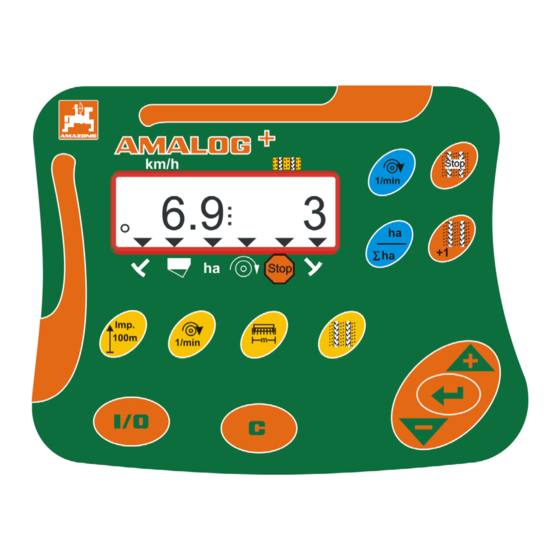
Work commencement Display during work During operation, the AmaLog+ shows the travel speed (Fig. 26/1), e.g. 6.9 km/h the setting of the tramline counter (Fig. 26/2), e.g. Switching position 3 the left track marker (Fig. 26/3) is in the working position …
-
Page 34: Faults
Faults Faults Fault display A3 Tramline fault message The occurrence of a tramline fault activates the display (Fig. 28) an acoustic signal. Fig. 28 Fault display A4 Alarm message at standstill of the universal joint shaft of the active soil tillage implement (e.g.
-
Page 35
Faults Fault display A5 Alarm message in the event of insufficient seed quantity for machines with fill level sensor in the event of a malfunction of the seed seeding shaft only on DMC Primera, Condor and Citan 01 … -
Page 36
Faults Fault display A6 (DMC Primera, Condor and Citan 01 only) Alarm message in the event of insufficient fertiliser in the event of a malfunction of the ferti- liser seeding shaft In the event of an alarm the display (Fig. -
Page 37
Tables Tables Machine data table Mode 1 Code Activating functions of the control terminal Activate all functions of the control terminal Only activate the hectare counter of the control terminal Mode 2 Code Number of track marker sensors Machine with 2 track marker sensors, e.g. -
Page 38
Tables Mode 3 Code Implement type D9 Super/Special D9 6000 TC Cam wheel seed drills Cataya Special D9 Super/Special Cam wheel seed drills D9 6000 TC with seed shaft monitoring Cataya Special AD-P Pneumatic seed drills Citan 6000 Pneumatic seed drills Citan 01 With 2 separate hoppers and Condor… -
Page 39
Tables Table for adjustable tramline rhythms Tramline rhythms Fig. 37 Tramline rhythms * No tramlines are created Fig. 38 AMALOG BAH0017.6 08.19… -
Page 40
Tables Tables: calibration values / crank turns (guide values) The table values in the Chapter are guide values. If the actual calibration value (imp./100 m) deviates from the table value, the number of crank turns for the calibration test will also change. -
Page 41
Tables Pneumatic seeding technology Working width 2.5 m 3.0 m 3.5 m 4.0 m Pack top seed drills Calibration value (pneumatic) (imp./100 m) Crank turns on 1/40 ha AD-P 03 Special 1409 38.5 33.0 29.0 with star wheel drive AD-P 03 Super … -
Page 42
Tables Predecessor machines Working width 2.5 m 3.0 m 4.0 m Pack top seed drills Calibration value (mechanical) (imp./100 m) Crank turns on 1/40 ha AD 03 27.0 22.5 17.0 RP-AD 03 59.0 49.0 37.0 Working width 2.5 m 3.0 m 4.0 m Pack top seed drills Calibration value… -
Page 43
Tables Table for calibration values / crank turns for the calibration test Calibration value Field Crank rotations pul./100 m Fig. 39 AMALOG BAH0017.6 08.19… -
Page 46
H. DREYER GmbH & Co. KG Postfach 51 Tel.: + 49 (0) 5405 501-0 D-49202 Hasbergen-Gaste email: amazone@amazone.de Germany http:// www.amazone.de…
Faults
8.4
Fault display A6 (DMC Primera, Condor and Citan 01 only)
Alarm message
in the event of insufficient fertiliser
in the event of a malfunction of the ferti-
liser seeding shaft
In the event of an alarm
the display (Fig. 32) appears
an acoustic signal
(triple signal tone) is emitted.
The display switches in the event of insufficient
fertiliser.
The control symbol (Fig. 33/1) marks the fill level
symbol.
The alarm is repeated when the machine is used
again, e.g. after turning at the end of the field.
Switching off the alarm message
1. Press and hold button (blue)
2. Press
.
The warning message is switched off.
36
Fig. 32
Fig. 33
The alarm message can only be switched off after the alarm has been
triggered.
Alarm deactivation only applies until the control terminal is switched
off.
AMALOG BAH0017.6 08.19
 |
[Page 1] Amazone AmaLog+ Operating manual az Control terminal AmaLog+ MG3828 BAH0017.6 08.19 Please read and observe this operating manual before initial operation of the implement! Keep it in a safe place for future use! en |
 |
[Page 2] Amazone AmaLog+ 2 AMALOG BAH0017.6 08.19 READING THE INSTRUCTION manual and to adhere to it should not appear to be inconvenient and superfluous as it is not enough to hear from others and to realise that a machine is good, to buy it and to… |
 |
[Page 3] Amazone AmaLog+ AMALOG BAH0017.6 08.19 3 Identification data Control terminal AMALOG Manufacturer’s address AMAZONEN-WERKE H. DREYER GmbH & Co. KG Postfach 51 D-49202 Tel.: E-mail: Hasbergen, Germany + 49 (0) 5405 50 1-0 amazon… |
 |
[Page 4] Amazone AmaLog+ 4 AMALOG BAH0017.6 08.19 Foreword Dear Customer, You have chosen one of the quality products from the wide product range of AMAZONEN-WERKE, H. DREYER GmbH & Co. KG. We thank you for your trust in our products Before initia… |
 |
[Page 5] Amazone AmaLog+ AMALOG BAH0017.6 08.19 5 1 User information ……………………………………………………………………………… 7 1.1 Purpose of the document …………………………………………………………. |
 |
[Page 6] Amazone AmaLog+ 6 AMALOG BAH0017.6 08.19 8.2 Fault display A4 ……………………………………………………………………………………………………… 34 8.3 Fault display A5 ………………………………… |
 |
[Page 7] Amazone AmaLog+ User information AMALOG BAH0017.6 08.19 7 1 User information The User Information section provides information on use of the oper- ating manual. 1.1 Purpose of the document This operating manual describes the operation of t… |
 |
[Page 8] Amazone AmaLog+ General safety instructions 8 AMALOG BAH0017.6 08.19 2 General safety instructions This section contains important instructions for operating the control terminal safely. 2.1 Obligations and liability Comply with the instructi… |
 |
[Page 9] Amazone AmaLog+ General safety instructions AMALOG BAH0017.6 08.19 9 2.4 Safety-conscious working Besides the safety information in this operating manual, the generally applicable national workplace safety and accident prevention regula- tions are b… |
 |
[Page 10] Amazone AmaLog+ General safety instructions 10 AMALOG BAH0017.6 08.19 2.6 Representation of safety symbols Safety instructions are marked with the triangular safety symbol and the preceding signal word. The signal word (DANGER, WARNING, CAUTION… |
 |
[Page 11] Amazone AmaLog+ Product description AMALOG BAH0017.6 08.19 11 3 Product description Fig. 1 Standard equipment Fig. 1/… Special equipment Fig. 1/… (1) Control terminal with fastening bracket (2) Socket connection, 12V (3) Wiring har… |
 |
[Page 12] Amazone AmaLog+ Product description 12 AMALOG BAH0017.6 08.19 3.1 Intended use The control terminal is intended exclusively for conventional use as a display and monitoring device in agricultural applications. Intended use also includes observing… |
 |
[Page 13] Amazone AmaLog+ Layout and function AMALOG BAH0017.6 08.19 13 4 Layout and function The following section provides information on the structure of the control terminal and the functions of the individual components. The control terminal has 6-digit… |
 |
[Page 14] Amazone AmaLog+ Layout and function 14 AMALOG BAH0017.6 08.19 4.3 Operation with seed drills The AmaLog+ measures the covered part area [ha]. stores the cultivated total area [ha]. indicates the forward speed [km/h]. control… |
 |
[Page 15] Amazone AmaLog+ Layout and function AMALOG BAH0017.6 08.19 15 4.3.2 Operation with pneumatic seed drills AmaLog+ monitors the tramline control in the dis- tributor head (Fig. 5/1). An acoustic alarm sounds in the event of incorrect shutter position. … |
 |
[Page 16] Amazone AmaLog+ Layout and function 16 AMALOG BAH0017.6 08.19 4.4 Work display The work display (Fig. 7) appears with the first pulse from the distance sensor. The flashing circle symbol (Fig. 7/1) during work indicates that The control te… |
 |
[Page 17] Amazone AmaLog+ Layout and function AMALOG BAH0017.6 08.19 17 Fig. 8/… Display and/or control symbol sensor 1 Forward speed [km/h] pulses from the distance sensor 2 Tramline counter position Control terminal data 3 or 4 Control symbol Le… |
 |
[Page 18] Amazone AmaLog+ Layout and function 18 AMALOG BAH0017.6 08.19 4.5 Button assignment Button Button assignment Button Button assignment Switching on/off Correction button Data input confirmation Reduction of the value displayed … |
 |
[Page 19] Amazone AmaLog+ Layout and function AMALOG BAH0017.6 08.19 19 4.6 Creation of tramlines As described in the operating manual for the seed drill, the tramline control allows the creation of tram- lines at pre-selected intervals on the field. When creat… |
 |
[Page 20] Amazone AmaLog+ Layout and function 20 AMALOG BAH0017.6 08.19 The creation of tramlines is shown in Figure (Fig. 10) using various examples: A = Working width of the seed drill B = Tramline spacing (= working width fertiliser spreader/field spr… |
 |
[Page 21] Amazone AmaLog+ Layout and function AMALOG BAH0017.6 08.19 21 Fig. 10 |
 |
[Page 22] Amazone AmaLog+ Commissioning 22 AMALOG BAH0017.6 08.19 5 Commissioning 5.1 Installing the control terminal 1. Screw the bracket (Fig. 11/1) so that is free from vibrations and electrically connected to the right of the driver’s posit… |
 |
[Page 23] Amazone AmaLog+ Commissioning AMALOG BAH0017.6 08.19 23 2. Insert the power cable (Fig. 13/1) into the bracket and the 12V tractor socket. 3. Connect the bracket and the control termi- nal with the power cable (Fig. 13/2). 4. Couple the seed … |
 |
[Page 24] Amazone AmaLog+ Settings 24 AMALOG BAH0017.6 08.19 6 Settings 6.1 Enter implement data The control terminal requires input of the implement data in coded form (see Fig. 14). Refer to the machine data in the table (see section «Machine da… |
 |
[Page 25] Amazone AmaLog+ Settings AMALOG BAH0017.6 08.19 25 6.2 Displaying / altering the working width 1. Press . Display: stored working width [m], e.g. 3.0 m (Fig. 15). 2. Change the working width [m] with the and buttons. 3. Press… |
 |
[Page 26] Amazone AmaLog+ Settings 26 AMALOG BAH0017.6 08.19 6.4 Displaying / altering the target blower fan speed (during operation) This setting is only possible for pneumatic seed drills. 1. Press the button (blue). Display of (Fig. 17) curr… |
 |
[Page 27] Amazone AmaLog+ Settings AMALOG BAH0017.6 08.19 27 6.5 Calibration value (pulses per 100 m) The control terminal requires the calibration value «Pulses per 100 m» to determine the forward speed [km/h] determine the worked area … |
 |
[Page 28] Amazone AmaLog+ Settings 28 AMALOG BAH0017.6 08.19 6. Stop after exactly 100 m. The display (Fig. 20) shows the calibration value (e.g. 1005 imp./100 m). 7. The determined calibration value can be en- tered in the table, Seite 43. 8… |
 |
[Page 29] Amazone AmaLog+ Settings AMALOG BAH0017.6 08.19 29 6.5.3 Calculating the number of crank turns for the calibration test If the calibration value differs from the values in the Table (see Chap. 9.3, Seite 40) recalculate the number of crank turns … |
 |
[Page 30] Amazone AmaLog+ Work commencement 30 AMALOG BAH0017.6 08.19 7 Work commencement 1. Place machine in starting position (standstill). Display at standstill: Digit 1 (Fig. 22/1) shows the travel speed (0 km/h). Digit 2 (Fig. 22/2) shows the … |
 |
[Page 31] Amazone AmaLog+ Work commencement AMALOG BAH0017.6 08.19 31 7.1 Tramline counter 7.1.1 Setting the tramline counter Press the button several times until the right tramline counter is displayed [e.g.: Tramline counter 2, see Seite 21, Fig. 10, u… |
 |
[Page 32] Amazone AmaLog+ Work commencement 32 AMALOG BAH0017.6 08.19 7.2 Worked area 7.2.1 Displaying the worked part area Press . Display (Fig. 24): worked part area (e.g. 10.5 ha). Fig. 24 7.2.2 Erasing the part area memory 1. Pre… |
 |
[Page 33] Amazone AmaLog+ Work commencement AMALOG BAH0017.6 08.19 33 7.3 Display during work During operation, the AmaLog+ shows the travel speed (Fig. 26/1), e.g. 6.9 km/h the setting of the tramline counter (Fig. 26/2), e.g. Switching positi… |
 |
[Page 34] Amazone AmaLog+ Faults 34 AMALOG BAH0017.6 08.19 8 Faults 8.1 Fault display A3 Tramline fault message The occurrence of a tramline fault activates the display (Fig. 28) an acoustic signal. Fig. 28 8.2 Fault display A4 Alarm… |
 |
[Page 35] Amazone AmaLog+ Faults AMALOG BAH0017.6 08.19 35 8.3 Fault display A5 Alarm message in the event of insufficient seed quantity for machines with fill level sensor in the event of a malfunction of the seed seeding shaft only on… |
 |
[Page 36] Amazone AmaLog+ Faults 36 AMALOG BAH0017.6 08.19 8.4 Fault display A6 (DMC Primera, Condor and Citan 01 only) Alarm message in the event of insufficient fertiliser in the event of a malfunction of the ferti- liser seeding shaft In t… |
 |
[Page 37] Amazone AmaLog+ Tables AMALOG BAH0017.6 08.19 37 9 Tables 9.1 Machine data table Mode 1 Code Activating functions of the control terminal 1 Activate all functions of the control terminal 2 Only activate the hectare counter of the control term… |
 |
[Page 38] Amazone AmaLog+ Tables 38 AMALOG BAH0017.6 08.19 Mode 3 Code Implement type 0 Cam wheel seed drills D9 Super/Special D9 6000 TC AD Cataya Special 3 Cam wheel seed drills with seed shaft monitoring D9 Super/Special D9 6000 TC AD Cataya… |
 |
[Page 39] Amazone AmaLog+ Tables AMALOG BAH0017.6 08.19 39 9.2 Table for adjustable tramline rhythms Tramline rhythms 1 2 3 4 5 6 7 8 9 10 11 12 13 14 Tramline counter, controlled and displayed by the control ter- minal 0 0 0 0 0 0 0 0… |
 |
[Page 40] Amazone AmaLog+ Tables 40 AMALOG BAH0017.6 08.19 9.3 Tables: calibration values / crank turns (guide values) The table values in the Chapter are guide values. If the actual calibration value (imp./100 m) deviates from the table value, the numb… |
 |
[Page 41] Amazone AmaLog+ Tables AMALOG BAH0017.6 08.19 41 Pneumatic seeding technology Pack top seed drills (pneumatic) Working width 2.5 m 3.0 m 3.5 m 4.0 m Calibration value (imp./100 m) Crank turns on 1/40 ha AD-P 03 Special with star wheel drive … |
 |
[Page 42] Amazone AmaLog+ Tables 42 AMALOG BAH0017.6 08.19 Predecessor machines Pack top seed drills (mechanical) Working width 2.5 m 3.0 m 4.0 m Calibration value (imp./100 m) Crank turns on 1/40 ha AD 03 617 27.0 22.5 17.0 RP-AD 03 672 59.0… |
 |
[Page 43] Amazone AmaLog+ Tables AMALOG BAH0017.6 08.19 43 9.4 Table for calibration values / crank turns for the calibration test Field Calibration value pul./100 m Crank rotations … |
 |
[Page 44] Amazone AmaLog+ … |
 |
[Page 45] Amazone AmaLog+ … |
 |
[Page 46] Amazone AmaLog+ H. DREYER GmbH & Co. KG Postfach 51 D-49202 Hasbergen-Gaste Germany Tel.: + 49 (0) 5405 501-0 email: [email protected] http:// www.amazone.de |
(Ocr-Read Summary of Contents of some pages of the Amazone AmaLog+ Document (Main Content), UPD: 23 April 2023)
-
37, Tables AMALOG BAH0017.6 08.19 37 9 Tables 9.1 Machine data table Mode 1 Code Activating functions of the control terminal 1 Activate all functions of the control terminal 2 Only activate the hectare counter of the control terminal Mode 2 Code Number of track marker sensors 0 Machine with 2 track marker sensors, e.g. front tank seeding combination with 2 track marker sensors (Fig. 34/1). Fig. 34 1 Machine with 1 track marker sensor on …
-
5, AMALOG BAH0017.6 08.19 5 1 User information ……………………………………………………………………………… 7 1.1 Purpose of the document …………………………………………………………………………………………… 7 1.2 Locations in the operating manual ………………………………………………………………………………. 7 1.1 Diagrams ……………………………
-
42, Amazone AmaLog+ Tables 42 AMALOG BAH0017.6 08.19 Predecessor machines Pack top seed drills (mechanical) Working width 2.5 m 3.0 m 4.0 m Calibration value (imp./100 m) Crank turns on 1/40 ha AD 03 617 27.0 22.5 17.0 RP-AD 03 672 59.0 49.0 37.0 Pack top seed drills (pneumatic) Working width 2.5 m 3.0 m 4.0 m Calibration value (imp./100 m) Crank turns on 1/40 ha AD-P 02 with star wheel Ø 1.18 1053 27.0 22.5 17.0 RPA…
-
26, Settings 26 AMALOG BAH0017.6 08.19 6.4 Displaying / altering the target blower fan speed (during operation) This setting is only possible for pneumatic seed drills. 1. Press the button (blue). Display of (Fig. 17) current blower fan speed (e.g. 3600 [rpm.]). Fig. 17 2. Press the button and button (yellow) simultaneously. 3. Press . Store the selected value. 6.4.1 Displaying / altering the tramline rhythm 1. Press . �…
-
34, Faults 34 AMALOG BAH0017.6 08.19 8 Faults 8.1 Fault display A3 Tramline fault message The occurrence of a tramline fault activates the display (Fig. 28) an acoustic signal. Fig. 28 8.2 Fault display A4 Alarm message at standstill of the universal joint shaft of the active soil tillage implement (e.g. of the rotary cultivator) The control terminal issues an alarm as soon as the overload clutch of the universa…
-
40, Tables 40 AMALOG BAH0017.6 08.19 9.3 Tables: calibration values / crank turns (guide values) The table values in the Chapter are guide values. If the actual calibration value (imp./100 m) deviates from the table value, the number of crank turns for the calibration test will also change. You can enter your determined calibration values in the table (Fig. 39). Mechanical seeding technology Mounted seed drills D9 Super / Special Workin…
-
38, Tables 38 AMALOG BAH0017.6 08.19 Mode 3 Code Implement type 0 Cam wheel seed drills D9 Super/Special D9 6000 TC AD Cataya Special 3 Cam wheel seed drills with seed shaft monitoring D9 Super/Special D9 6000 TC AD Cataya Special 1 Pneumatic seed drills AD-P Citan 6000 2 Pneumatic seed drills With 2 separate hoppers and with seed shaft monitoring Citan 01 Condor DMC Primera 4 Pneumati…
-
28, Settings 28 AMALOG BAH0017.6 08.19 6. Stop after exactly 100 m. The display (Fig. 20) shows the calibration value (e.g. 1005 imp./100 m). 7. The determined calibration value can be en- tered in the table, Seite 43. 8. Press . Store the calibration value (imp./100 m). Fig. 20 The calibration value (imp./100 m) must not be less than 250. Otherwise the control terminal will not work properly. 6.…
-
15, Amazone AmaLog+ Layout and function AMALOG BAH0017.6 08.19 15 4.3.2 Operation with pneumatic seed drills AmaLog+ monitors the tramline control in the dis- tributor head (Fig. 5/1). An acoustic alarm sounds in the event of incorrect shutter position. Fig. 5 AmaLog+ monitors the fan speed. If the actual speed deviates by more than 10 % from the target speed, an acoustic signal is initi- ated and in the display the control lamp (Fig. 6/1) above the speed symbol (Fig. 6…
-
41, Tables AMALOG BAH0017.6 08.19 41 Pneumatic seeding technology Pack top seed drills (pneumatic) Working width 2.5 m 3.0 m 3.5 m 4.0 m Calibration value (imp./100 m) Crank turns on 1/40 ha AD-P 03 Special with star wheel drive 1409 38.5 33.0 29.0 AD-P 03 Super with star wheel drive 1575 29.5 22.0 Large-area seed drill Citan 8000 Citan 9000 Citan 12000 Crank tur…
-
8, Amazone AmaLog+ General safety instructions 8 AMALOG BAH0017.6 08.19 2 General safety instructions This section contains important instructions for operating the control terminal safely. 2.1 Obligations and liability Comply with the instructions in the operating manual Knowledge of the basic safety instructions and safety regulations is a basic prerequisite for safe handling and fault-free operation of the control terminal. Guarantee and liability …
-
32, Work commencement 32 AMALOG BAH0017.6 08.19 7.2 Worked area 7.2.1 Displaying the worked part area Press . Display (Fig. 24): worked part area (e.g. 10.5 ha). Fig. 24 7.2.2 Erasing the part area memory 1. Press and hold the button. 2. Press . The part area memory is set to 0 [ha]. 3. Press the button Back to the work display (Fig. 26). 7.2.3 Display the total area 1. Press the button twic…
-
10, Amazone AmaLog+ General safety instructions 10 AMALOG BAH0017.6 08.19 2.6 Representation of safety symbols Safety instructions are marked with the triangular safety symbol and the preceding signal word. The signal word (DANGER, WARNING, CAUTION) describes the severity of the risk, and carries the following meaning: DANGER Indicates a direct threat at high risk which will result in death or most serious bodily harm…
-
7, User information AMALOG BAH0017.6 08.19 7 1 User information The User Information section provides information on use of the oper- ating manual. 1.1 Purpose of the document This operating manual describes the operation of the control terminal provides important information on safe and efficient handling is a component of the control terminal and must always kept with the implement or carried in the towing vehicle …
-
24, Settings 24 AMALOG BAH0017.6 08.19 6 Settings 6.1 Enter implement data The control terminal requires input of the implement data in coded form (see Fig. 14). Refer to the machine data in the table (see section «Machine data table», Seite 37). Digit 1 (1) shows the mode Digit 2 (2) shows the coding Fig. 14 Open the necessary modes (1, 2, 3, etc.) and enter the machine data in coded form…
-
22, Commissioning 22 AMALOG BAH0017.6 08.19 5 Commissioning 5.1 Installing the control terminal 1. Screw the bracket (Fig. 11/1) so that is free from vibrations and electrically connected to the right of the driver’s position in the tractor cab, within visual range and easy to access (Fig. 11/2). The distance from the radio unit or aerial must be at least 1 m. Fig. 11 T…
-
31, Work commencement AMALOG BAH0017.6 08.19 31 7.1 Tramline counter 7.1.1 Setting the tramline counter Press the button several times until the right tramline counter is displayed [e.g.: Tramline counter 2, see Seite 21, Fig. 10, under the lettering «START»]. 7.1.2 Block the tramline counter Press . The further shifting of the tramline counter is blocked. The number (Fig. 23/1) of the tramline counter flashes in the dis…
-
30, Work commencement 30 AMALOG BAH0017.6 08.19 7 Work commencement 1. Place machine in starting position (standstill). Display at standstill: Digit 1 (Fig. 22/1) shows the travel speed (0 km/h). Digit 2 (Fig. 22/2) shows the tramline counter 4. Fig. 22 2. Lower the correct track marker (see seed drill operating manual). The tramline control can be coupled with the track marker control. The tramline counter can continue counting wh…
AmaLog+ – Просто и надежно

AmaLog+ представляет собой простой, но надежный компьютер управления для Cataya Special с механическим приводом от приводного колеса. Возможна также работа без ISOBUS-оснащения трактора.
Функции Вашего AmaLog+
- Включение технологической колеи
- Маркировка технологической колеи
- Контроль уровня в бункере
- Счетчик гектаров
- Индикация скорости