Присоединяйтесь к обсуждению
Вы можете написать сейчас и зарегистрироваться позже.
Если у вас есть аккаунт, авторизуйтесь, чтобы опубликовать от имени своего аккаунта.
-
Page 1
F0081.0002 Operator’s Guide WA 80 Version 1.8/2007… -
Page 2: Table Of Contents
Index Foreword ………………..1 Technical data ………………2 Machine identification …………….2 Machine data ………………. 3 Noise figures ……………….. 4 Assessment of dust emission …………..4 Intended use ……………….. 4 Safety …………………. 6 Explanation of symbols …………….6 Operational safety details ……………. 6 Safety devices ………………
-
Page 3
Index Motor protection ………………34 Scorer saw ………………..35 7.9.1 Saw blade change ………………. 36 7.9.2 Adjustment of the saw blade width …………37 7.10 Rip fence with DIGIT X …………….39 Trouble ………………..41 Maintenance ………………. 43 Lubrication ………………..44 9.1.1 Saw drive shaft ……………… -
Page 4: Foreword
– Operating including set-up, troubleshooting during operation, elimination of production waste, care, disposal of operating and auxiliary materials – Maintenance, repair, inspection – Transport © ALTENDORF 2007…
-
Page 5: Technical Data
Appendix I of Guideline 98/37/EWG for modifying Guideline 89/392/EWG (Machine Guideline) the machine is identified by the following test symbol: CE symbol, GS symbol and wood dust test symbol Fig. 2-1: Type label © ALTENDORF 2007…
-
Page 6: Machine Data
Main saw Diameter of tool holder 30 mm Machine data Tilting range of the Manufacturer saw blade 0-46° Wilhelm Altendorf GmbH & Co. KG No-load speed Wettinerallee 43 / 45 3000/4000/ D-32429 Minden 5000 [1/min] Fon (+49) 571 95500 Scorer…
-
Page 7: Noise Figures
Veneer with a suitable clamping device – Gypsum plasterboard – Cardboard – Dimensionally stable plastics (thermoset plastics, thermoplastics). Sawing these materials does not normally involve any risks in respect of dust, chips, and thermal degradation products. – Aluminium and aluminium alloys © ALTENDORF 2007…
-
Page 8
– Any use extending beyond this counts as maintenance and repair conditions and the unintended. ALTENDORF will not be liable for safety information contained in the operating any kind of injury or damage that may result instructions. from such unintended use; the risk thereof is –… -
Page 9: Safety
Such riving knifes can be obtained from safety. the trade or directly from ALTENDORF. – Before all work, make sure that the protective –…
-
Page 10
– Regular cleaning of the machine and, in particular, the main table, sliding table and guides (e.g. rip fence) is an important safety factor. Before starting this work, make sure that machine cannot switched unintentionally. © ALTENDORF 2007… -
Page 11: Safety Devices
Favorable airflow design of the lower extraction duct and the top safety hood to reduce dust emission to below 2 mg/m³, providing that the machine is connected at both extraction sockets to an extraction system having a min. airspeed of 20 m/s. © ALTENDORF 2007…
-
Page 12: Upper Safety Hood
Switch off the main switch and prevent it from being switched on again – Release the clamping screw – The safety device can be moved out of the way After you have finished move the safety hood back into its normal working position! © ALTENDORF 2007…
-
Page 13: Riving Knives
8 mm in the area of the cutting height. The sensible gap in practice is around 5 mm. Use of the positively guided Altendorf riving knife automatically ensures with this gap that the height adjustment of the riving knife matches the tip appr.
-
Page 14: Clamping Shoe
Push blocks should be used for cutting narrower workpieces and if necessary, for pressing the work- piece against the fence. A push block can easily be made by the operator and be fitted with the push block handle suppled with the machine. © ALTENDORF 2007…
-
Page 15: Other Risks
Emission of dust that can damage your health if operating the machine without dust extraction. Avoid any dangers that may arise from these other risks by taking extra care when setting up, operating and maintaining the machine! © ALTENDORF 2007…
-
Page 16: Working Safely With The Sliding Table Saw
Use: For handling wood and boards up to 600 tilt stop is actually against the fence of the cut- mm width out! The operator pulls the workpiece against the cut- ting direction to the fence Cutting direction © ALTENDORF 2007…
-
Page 17: Rip Fence
(e.g. tenon cutting) or other procedures in which pieces falling off could jam between fence and saw blade, the extension fence is pulled far enough for- ward for its rear end to be in front of the saw blade. © ALTENDORF 2007…
-
Page 18: Working Examples
3.5.4 Working examples Edge cutting (trimming) General The Altendorf sliding table saw Type WA80 is a uni- versal machine which can be used for different cut- ting jobs. To do this however it is necessary to equip the machine accordingly.
-
Page 19
(otherwise there is to be removed beyond the rising blade tip. the danger of an unintentional insert process) For crossrouting of narrow workpieces always use the mitre fence. © ALTENDORF 2007… -
Page 20
Only feed the workpiece using the mitre fence. Do not remove fallen pieces from the vicinity of the tool with your hands. © ALTENDORF 2007… -
Page 21: Transport
During transport buildup of condensation as a re- sult of variations in temperature as well as shocks are to be avoided. © ALTENDORF 2007…
-
Page 22: Assembly
Secure loosely to the table plate with two M10 nuts and shake proof washers – Tighten the M10 nuts Installing the safety hood – Push the safety hood support onto the attach- ment bolts – Put on shake proof washers and secure with nuts © ALTENDORF 2007…
-
Page 23: Electrical Connection
Fig. 5-1: Main switch briefly turning the machine on and if necessary corrected by swapping two external leads in the mains connection box. Note the arrow indicating direction of rotation on the saw blade cover! Fig. 5-2: Main switch, POT-contakt © ALTENDORF 2007…
-
Page 24
Control fuse (primary) F7-F9 Control fuse (secondary) F15-F16 Fuses, brake current Safety switch 30S1 sliding table 34S1 Cover plate safety switch Brake module LCS 20GL1 Rectifier Main saw motor 30M1 30M2 Scoring saw motor 30MR1 Main motor temperature monitor © ALTENDORF 2007… -
Page 25: Connection Of Extraction System(Customer Side!)
In addition, make sure that the extraction system is switched on together with the machine. For this, you can use the existing potential-free contact (POT — refer to circuit diagram) or a current transformer installed in the supply line. © ALTENDORF 2007…
-
Page 26: Machine Configuration
Table plate must lie about 1/10mm lower Adjustment of the table plate Loosen the locknuts on the 4 fixed bolts, Adjust the table plate, tighten the nuts. Then lay the straight- edge in parallel to the sliding table on the table plate. © ALTENDORF 2007…
-
Page 27: Free Cut Adjustment Of Sliding Table
When a scorer is used ensure that both free nuts on the fence screws. Make the appropriate ad- cuts are set to approximately the same! justments and re tighten the lock nuts. Then read- just the sliding table and tighten all securing screws again. © ALTENDORF 2007…
-
Page 28: Adjustment Angle Cut
On the 5th cut cut off a strip about 10 mm wide. Measure the width of the strip at both ends with a gage. The difference between the two dimen- sions divided by 4 gives the angular error per meter cutting length. Fig. 6-1: Angle cut © ALTENDORF 2007…
-
Page 29: 0° — Position Of The Saw Blade
If the setting is exact the cut edges are parallel, i.e. there is no air gap detect- able between the cut edges. Adjustment Recalibrate the machine! © ALTENDORF 2007…
-
Page 30: Machine Operation
When the 0° key or the 45° key are held down the saw blade moves for 2 sec. in creep mode and then switches automatically to fast mode – Tapping the 0°/ 45° keys briefly makes an ad- justment of 0.1° in each case! © ALTENDORF 2007…
-
Page 31: Changing The Main Saw Blade
Warning! After the saw blade has been changed it is vital to make the correct riving knife adjustments! Check saw blade retaining disc for tightness before operating machine! © ALTENDORF 2007…
-
Page 32: Saw Blade Recommendation
72 W 60 W 72 W 84 W Aluminium-Profiles * 60 — 70 60 TF 72 TF 90 TF 80 TF 96 TF 108 TF Abbreviations negative tensioning angle – – Alternate tooth Trapezoidal flat tooth – © ALTENDORF 2007…
-
Page 33
A selection of saw blades for the Altendorf sliding table saw is shown in the table (p.29). This table makes no claims to be complete. Since the figures for the… -
Page 34: Setting The Speed
Move lever down until it engages – Set speed control to the desired speed setting, position the belt accordingly – Lift the lever Fig. 7-2: Changing the speed Speed control Lever The belt tension is set automatically after the belt is moved! © ALTENDORF 2007…
-
Page 35: Main Switch
Fig. 7-3: Locking With an additional locking adjustment the sliding ta- ble can be blocked in its center setting with the car- riage lock. © ALTENDORF 2007…
-
Page 36: Switching Drives On And Off
(after around 5 seconds.), by pressing the white button I which is also located in the panel and identified by the sym- bol for the scorer saw. After the scorer saw is switched on this button lights. © ALTENDORF 2007…
-
Page 37: Motor Protection
The resistance figure (750 Ohm ± 200 Ohm) of the PTC resistors is to be checked at least once a year in the motor terminal box by a specialist electrician. The test voltage of the meter may not exceed 1.5V for this test! © ALTENDORF 2007…
-
Page 38: Scorer Saw
Scorer saw Scorer saw The Altendorf scorer saw was developed to enable boards coated on both sides to be cut on the under- side without damage. The material is only cut into by around 1-2 mm by the scorer or the underside and then separated from the main sheet.
-
Page 39: Saw Blade Change
Place the saw blade and front flange on the – saw drive shaft and tighten the nut in a clockwise direction © ALTENDORF 2007…
-
Page 40: Adjustment Of The Saw Blade Width
Release the clamping screw, appr. 2 turns – Turn the spindle until the desired dimension is reached. (1 turn = 0.5 mm) – Tighten the clamping screw – Test cut, if necessary correct the cutting width again as described above. © ALTENDORF 2007…
-
Page 41
– Only turn clamping screw (1) slightly to the contact surface – Screw in screws (5) and tighten to a torque of 8,6Nm – Proceed in the same way with the other half of the adjuster unit © ALTENDORF 2007… -
Page 42: Rip Fence With Digit X
90 to 15 mm stop height, the dimensional cor- rection in the measuring system is automatic. Battery change Fig. 7-10: Loosen clamping screws Fig. 7-12: Detach the display housing Fig. 7-11: Loosen and withdraw screws and remove co- Fig. 7-13: Insert/replace batteries, ensuring correct polarity! © ALTENDORF 2007…
-
Page 43
0 – The value of the flashing digit can be decreased by 1 with each actuation of the — key. – Release the F key – The set dimensions is saved as a basic setting value © ALTENDORF 2007… -
Page 44: Trouble
Tilt arm moves jerk- Tilt arm moves jerkily Clean telescopic tube or track rollers; Test stripper © ALTENDORF 2007…
-
Page 45
Emergency switch actuated Control emergency switches/door/cover Error positioning drive quick blinking (4Hz) Overtemperature mainsaw in the ON-switch motor slow blinking (1Hz) Error brake: Mains relay is in the ON-switch not in 0-position LED rotation speed No input signal blinking © ALTENDORF 2007… -
Page 46: Maintenance
If contaminated with resin, the guides are to be cleaned with petroleum and possibly using Scotch Brite pads for example. It is not advisable to use steel wool or sandpaper since this than irreparably damages the guide tracks. © ALTENDORF 2007…
-
Page 47: Lubrication
9.1.2 Tilt segments The tilt segments are to be cleaned and lubricated on a regular basis. The intervals for such work (2 weeks) depend on the period of use © ALTENDORF 2007…
-
Page 48: Customer Service — Spare Parts
No liability or warranty claims are accepted by Wettinerallee 43-45 Postfach 20 09 Wilhelm Altendorf GmbH & Co KG for damage aris- ing from use on non-original spare parts. D-32429 Minden D-32377 Minden…
If limit switches are activated, the <strong>error</strong>s are displayed on the screen. They aredifferentiated into 2 functional groups:Group 1:– motor temperature– machine door– lower saw blade / chip-channel cover– emergency buttons– limit switch sliding tableGroup 2:– brake servo unitThe functional groups show the following characteristics when activated:• Group 1: electrical drives are deactivated and cannot be started.• Group 2: electrical drives are deactivated and cannot be re-started. Aninformation is displayed to call a service technician.Error code Reason ClearanceE 01Limit switch ES_MIN1 Move the machine from thereachedlimit switchE 02Limit switch ES_MIN2 Move the machine from thereachedlimit switchE 03Limit switch ES_MAX Move the machine from thereachedlimit switchE 06Fault, collision fast cutoutCall Altendorf serviceE 07 Drive positioning fault Call Altendorf serviceE 40Control voltage 35V ACmissingCheck fuse F9E 41Control voltage 24V AVmissingCheck fuse F8E 42Scoring motor overheated Allow motor to cool downE 43Main saw motoroverheatedAllow motor to cool downE 44Double roller carriage Move the machine from thelimit switchlimit switchE 45 Saw blade cover open Close the coverE 46 Open machine door Close the machine doorE 47Emergenca stop button 1 Button position is displayedE 48Emergenca stop button 2 Button position is displayedE 49Emergenca stop button 3 Button position is displayed
- Page 2: E 51E 52E 53E 54E 55E 56E 08E 99Bra
- Page 1
F0081.0002 Operator’s Guide WA 80 Version 1.8/2007… -
Page 2: Table Of Contents
Index Foreword ………………..1 Technical data ………………2 Machine identification …………….2 Machine data ………………. 3 Noise figures ……………….. 4 Assessment of dust emission …………..4 Intended use ……………….. 4 Safety …………………. 6 Explanation of symbols …………….6 Operational safety details ……………. 6 Safety devices ………………
- Page 3
Index Motor protection ………………34 Scorer saw ………………..35 7.9.1 Saw blade change ………………. 36 7.9.2 Adjustment of the saw blade width …………37 7.10 Rip fence with DIGIT X …………….39 Trouble ………………..41 Maintenance ………………. 43 Lubrication ………………..44 9.1.1 Saw drive shaft ……………… -
Page 4: Foreword
– Operating including set-up, troubleshooting during operation, elimination of production waste, care, disposal of operating and auxiliary materials – Maintenance, repair, inspection – Transport © ALTENDORF 2007…
-
Page 5: Technical Data
Appendix I of Guideline 98/37/EWG for modifying Guideline 89/392/EWG (Machine Guideline) the machine is identified by the following test symbol: CE symbol, GS symbol and wood dust test symbol Fig. 2-1: Type label © ALTENDORF 2007…
-
Page 6: Machine Data
Main saw Diameter of tool holder 30 mm Machine data Tilting range of the Manufacturer saw blade 0-46° Wilhelm Altendorf GmbH & Co. KG No-load speed Wettinerallee 43 / 45 3000/4000/ D-32429 Minden 5000 [1/min] Fon (+49) 571 95500 Scorer…
-
Page 7: Noise Figures
Veneer with a suitable clamping device – Gypsum plasterboard – Cardboard – Dimensionally stable plastics (thermoset plastics, thermoplastics). Sawing these materials does not normally involve any risks in respect of dust, chips, and thermal degradation products. – Aluminium and aluminium alloys © ALTENDORF 2007…
- Page 8
– Any use extending beyond this counts as maintenance and repair conditions and the unintended. ALTENDORF will not be liable for safety information contained in the operating any kind of injury or damage that may result instructions. from such unintended use; the risk thereof is –… -
Page 9: Safety
Such riving knifes can be obtained from safety. the trade or directly from ALTENDORF. – Before all work, make sure that the protective –…
- Page 10
– Regular cleaning of the machine and, in particular, the main table, sliding table and guides (e.g. rip fence) is an important safety factor. Before starting this work, make sure that machine cannot switched unintentionally. © ALTENDORF 2007… -
Page 11: Safety Devices
Favorable airflow design of the lower extraction duct and the top safety hood to reduce dust emission to below 2 mg/m³, providing that the machine is connected at both extraction sockets to an extraction system having a min. airspeed of 20 m/s. © ALTENDORF 2007…
-
Page 12: Upper Safety Hood
Switch off the main switch and prevent it from being switched on again – Release the clamping screw – The safety device can be moved out of the way After you have finished move the safety hood back into its normal working position! © ALTENDORF 2007…
-
Page 13: Riving Knives
8 mm in the area of the cutting height. The sensible gap in practice is around 5 mm. Use of the positively guided Altendorf riving knife automatically ensures with this gap that the height adjustment of the riving knife matches the tip appr.
-
Page 14: Clamping Shoe
Push blocks should be used for cutting narrower workpieces and if necessary, for pressing the work- piece against the fence. A push block can easily be made by the operator and be fitted with the push block handle suppled with the machine. © ALTENDORF 2007…
-
Page 15: Other Risks
Emission of dust that can damage your health if operating the machine without dust extraction. Avoid any dangers that may arise from these other risks by taking extra care when setting up, operating and maintaining the machine! © ALTENDORF 2007…
-
Page 16: Working Safely With The Sliding Table Saw
Use: For handling wood and boards up to 600 tilt stop is actually against the fence of the cut- mm width out! The operator pulls the workpiece against the cut- ting direction to the fence Cutting direction © ALTENDORF 2007…
-
Page 17: Rip Fence
(e.g. tenon cutting) or other procedures in which pieces falling off could jam between fence and saw blade, the extension fence is pulled far enough for- ward for its rear end to be in front of the saw blade. © ALTENDORF 2007…
-
Page 18: Working Examples
3.5.4 Working examples Edge cutting (trimming) General The Altendorf sliding table saw Type WA80 is a uni- versal machine which can be used for different cut- ting jobs. To do this however it is necessary to equip the machine accordingly.
- Page 19
(otherwise there is to be removed beyond the rising blade tip. the danger of an unintentional insert process) For crossrouting of narrow workpieces always use the mitre fence. © ALTENDORF 2007… - Page 20
Only feed the workpiece using the mitre fence. Do not remove fallen pieces from the vicinity of the tool with your hands. © ALTENDORF 2007… -
Page 21: Transport
During transport buildup of condensation as a re- sult of variations in temperature as well as shocks are to be avoided. © ALTENDORF 2007…
-
Page 22: Assembly
Secure loosely to the table plate with two M10 nuts and shake proof washers – Tighten the M10 nuts Installing the safety hood – Push the safety hood support onto the attach- ment bolts – Put on shake proof washers and secure with nuts © ALTENDORF 2007…
-
Page 23: Electrical Connection
Fig. 5-1: Main switch briefly turning the machine on and if necessary corrected by swapping two external leads in the mains connection box. Note the arrow indicating direction of rotation on the saw blade cover! Fig. 5-2: Main switch, POT-contakt © ALTENDORF 2007…
- Page 24
Control fuse (primary) F7-F9 Control fuse (secondary) F15-F16 Fuses, brake current Safety switch 30S1 sliding table 34S1 Cover plate safety switch Brake module LCS 20GL1 Rectifier Main saw motor 30M1 30M2 Scoring saw motor 30MR1 Main motor temperature monitor © ALTENDORF 2007… -
Page 25: Connection Of Extraction System(Customer Side!)
In addition, make sure that the extraction system is switched on together with the machine. For this, you can use the existing potential-free contact (POT — refer to circuit diagram) or a current transformer installed in the supply line. © ALTENDORF 2007…
-
Page 26: Machine Configuration
Table plate must lie about 1/10mm lower Adjustment of the table plate Loosen the locknuts on the 4 fixed bolts, Adjust the table plate, tighten the nuts. Then lay the straight- edge in parallel to the sliding table on the table plate. © ALTENDORF 2007…
-
Page 27: Free Cut Adjustment Of Sliding Table
When a scorer is used ensure that both free nuts on the fence screws. Make the appropriate ad- cuts are set to approximately the same! justments and re tighten the lock nuts. Then read- just the sliding table and tighten all securing screws again. © ALTENDORF 2007…
-
Page 28: Adjustment Angle Cut
On the 5th cut cut off a strip about 10 mm wide. Measure the width of the strip at both ends with a gage. The difference between the two dimen- sions divided by 4 gives the angular error per meter cutting length. Fig. 6-1: Angle cut © ALTENDORF 2007…
-
Page 29: 0° — Position Of The Saw Blade
If the setting is exact the cut edges are parallel, i.e. there is no air gap detect- able between the cut edges. Adjustment Recalibrate the machine! © ALTENDORF 2007…
-
Page 30: Machine Operation
When the 0° key or the 45° key are held down the saw blade moves for 2 sec. in creep mode and then switches automatically to fast mode – Tapping the 0°/ 45° keys briefly makes an ad- justment of 0.1° in each case! © ALTENDORF 2007…
-
Page 31: Changing The Main Saw Blade
Warning! After the saw blade has been changed it is vital to make the correct riving knife adjustments! Check saw blade retaining disc for tightness before operating machine! © ALTENDORF 2007…
-
Page 32: Saw Blade Recommendation
72 W 60 W 72 W 84 W Aluminium-Profiles * 60 — 70 60 TF 72 TF 90 TF 80 TF 96 TF 108 TF Abbreviations negative tensioning angle – – Alternate tooth Trapezoidal flat tooth – © ALTENDORF 2007…
- Page 33
A selection of saw blades for the Altendorf sliding table saw is shown in the table (p.29). This table makes no claims to be complete. Since the figures for the… -
Page 34: Setting The Speed
Move lever down until it engages – Set speed control to the desired speed setting, position the belt accordingly – Lift the lever Fig. 7-2: Changing the speed Speed control Lever The belt tension is set automatically after the belt is moved! © ALTENDORF 2007…
-
Page 35: Main Switch
Fig. 7-3: Locking With an additional locking adjustment the sliding ta- ble can be blocked in its center setting with the car- riage lock. © ALTENDORF 2007…
-
Page 36: Switching Drives On And Off
(after around 5 seconds.), by pressing the white button I which is also located in the panel and identified by the sym- bol for the scorer saw. After the scorer saw is switched on this button lights. © ALTENDORF 2007…
-
Page 37: Motor Protection
The resistance figure (750 Ohm ± 200 Ohm) of the PTC resistors is to be checked at least once a year in the motor terminal box by a specialist electrician. The test voltage of the meter may not exceed 1.5V for this test! © ALTENDORF 2007…
-
Page 38: Scorer Saw
Scorer saw Scorer saw The Altendorf scorer saw was developed to enable boards coated on both sides to be cut on the under- side without damage. The material is only cut into by around 1-2 mm by the scorer or the underside and then separated from the main sheet.
-
Page 39: Saw Blade Change
Place the saw blade and front flange on the – saw drive shaft and tighten the nut in a clockwise direction © ALTENDORF 2007…
-
Page 40: Adjustment Of The Saw Blade Width
Release the clamping screw, appr. 2 turns – Turn the spindle until the desired dimension is reached. (1 turn = 0.5 mm) – Tighten the clamping screw – Test cut, if necessary correct the cutting width again as described above. © ALTENDORF 2007…
- Page 41
– Only turn clamping screw (1) slightly to the contact surface – Screw in screws (5) and tighten to a torque of 8,6Nm – Proceed in the same way with the other half of the adjuster unit © ALTENDORF 2007… -
Page 42: Rip Fence With Digit X
90 to 15 mm stop height, the dimensional cor- rection in the measuring system is automatic. Battery change Fig. 7-10: Loosen clamping screws Fig. 7-12: Detach the display housing Fig. 7-11: Loosen and withdraw screws and remove co- Fig. 7-13: Insert/replace batteries, ensuring correct polarity! © ALTENDORF 2007…
- Page 43
0 – The value of the flashing digit can be decreased by 1 with each actuation of the — key. – Release the F key – The set dimensions is saved as a basic setting value © ALTENDORF 2007… -
Page 44: Trouble
Tilt arm moves jerk- Tilt arm moves jerkily Clean telescopic tube or track rollers; Test stripper © ALTENDORF 2007…
- Page 45
Emergency switch actuated Control emergency switches/door/cover Error positioning drive quick blinking (4Hz) Overtemperature mainsaw in the ON-switch motor slow blinking (1Hz) Error brake: Mains relay is in the ON-switch not in 0-position LED rotation speed No input signal blinking © ALTENDORF 2007… -
Page 46: Maintenance
If contaminated with resin, the guides are to be cleaned with petroleum and possibly using Scotch Brite pads for example. It is not advisable to use steel wool or sandpaper since this than irreparably damages the guide tracks. © ALTENDORF 2007…
-
Page 47: Lubrication
9.1.2 Tilt segments The tilt segments are to be cleaned and lubricated on a regular basis. The intervals for such work (2 weeks) depend on the period of use © ALTENDORF 2007…
-
Page 48: Customer Service — Spare Parts
No liability or warranty claims are accepted by Wettinerallee 43-45 Postfach 20 09 Wilhelm Altendorf GmbH & Co KG for damage aris- ing from use on non-original spare parts. D-32429 Minden D-32377 Minden…
-

Vladimir85
- Сообщения: 1
- Зарегистрирован: 08 окт 2014 19:25

Калибровка?
Сообщение
Vladimir85 » 08 окт 2014 21:07
При попытке откалибровать ход основной пилы выбивает ошибку Е07 (ошибка позиционирования привода), на + — отзывается. Подскажите что нужно проверить в первую очередь. Техника в плачевном состоянии (местные утырки постарались). Даже линейки сбиты!!!!!!! КАК? там ведь одним винтом все регулируется! Что смог в мозгах то подправил дальше нужны советы.
-

M95K
- Сообщения: 67
- Зарегистрирован: 06 дек 2012 07:43

Re: Калибровка?
#3
Сообщение
M95K » 07 авг 2015 14:22
Доброго времени суток! Есть пила ALTENDORF но нет к ней мануала.
Выставляет неправильный размер,и не хочет выставлять размер меньше 30мм. Вероятно надо как то поправить калибровку,но не получается. Калибровочный размер вроде как изменяем,но на попытку изменить размер — выставляет с ошибкой.
Может у кого есть в электронном виде инструкция как его настраивать?
Спасибо.
-
M95K
- Сообщения: 67
- Зарегистрирован: 06 дек 2012 07:43
Re: Калибровка?
#7
Сообщение
M95K » 10 авг 2015 10:24
Спасибо.
Но у меня станок с установкой размера детали. Вот этот размер и не попадает. Смотрел энкодер с двиг — закреплены крепко. Зубчатый ремень свободно — но это не должно вроде влиять.
Вопрос — если энкодер начнёт врать это ошибку не даст? Есть мысль заказатькупить новый энкодер,но хотелось бы услышать совет более опытного пользователя. Возможно я просто чего нибудь про калибровку не знаю.Как бы не в мозгах станочных дело оказалось
-
M95K
- Сообщения: 67
- Зарегистрирован: 06 дек 2012 07:43
Re: Калибровка?
#9
Сообщение
M95K » 10 авг 2015 10:53
Думаю вы AleksanderG ошибаетесь. У меня был случай когда врал именно энкодер. То есть неисправность ушла после замены энкодера. Правда это было на станке стрим (древнем) где считалась длина кромки очень точно для приклейки без послед торцовочной обрезки.
-
prn21
- Сообщения: 8
- Зарегистрирован: 25 янв 2015 20:38
Re: Калибровка?
#13
Сообщение
prn21 » 02 фев 2018 21:39
Помогите найти неисправность.
Проблема такая:
На «+» отзывается корректно плавным ходом, на «-» пила сразу опускается вниз до срабатывания датчика «лимит внизу».
Калибровка проводится, значение «0» запоминается. При попытке с клавиатуры ввести нужную высоту пила остается на месте и на экране появляется старая позиция пилы. Периодически выбивает ошибку Е07 (ошибка позиционирования привода).
И может поможете мне найти мануал по разборке станка.
-

Aleksandr_59
- Сообщения: 81
- Зарегистрирован: 14 мар 2018 11:41
- Поблагодарили: 1 раз

Re: Калибровка?
#14
Сообщение
Aleksandr_59 » 15 мар 2018 14:19
Диск с прорезями для оптопар. Чему там врать?
Как это ни странно, но тоже есть прецендент. Там кроме прорезей ещё и контроллер стоит, может и сбоить.
Полного отказа нет, а вот данные искажает.
-
maxvalin
- Опытный

- Сообщения: 138
- Зарегистрирован: 23 окт 2011 11:19
- Благодарил (а): 1 раз

Калибровка?
#15
Сообщение
maxvalin » 15 июл 2020 16:50
demonlibra писал(а): ↑09 окт 2014 21:44Может поможет
demonlibra день добрый!
извиняюсь- там случайно файлы были не о методах калибровки?
если да, можно еще раз перезалить?

Тема: Altendorf F 45 (Прочитано 25629 раз)
0 Пользователей и 1 Гость просматривают эту тему.
Скорости меняются перекидыванием ремня по шкивам
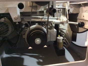
Справа рычаг, он поднимается вверх, чуть левее флажок, на нем написаны обороты, ставишь его на нужные обороты, он дает ориентацию ремня на нужные шкивы,
по электронике, от сервисных инженеров, я понял что она однофазная, запитана от одной из фаз,
в моей практике у меня сгорел один трехфазный двигатель ( точную причину не установил, возможно перекос фаз или окислился контакт в пускателе)
Позже добавлено автором:
Еще понравился вот такой девайс :
« Последнее редактирование: Ноября 04, 2015, 09:29:55 pm от Кузнец 16 »

Записан
в моей практике у меня сгорел один трехфазный двигатель
Поставьте автомат по защите двигателя. Делов то копейки по сравнению со стабилизатором
Записан
Пользователи, которые поблагодарили этот пост: Кузнец 16
При распиле длинной (3,1..3,4м) и широкой (300..400мм) доски будет мешать. Бесполезная штуковина.
Позже добавлено автором:
Алексей!
На Алеке уже ВСЕ стоит!!!
Записан
Пользователи, которые поблагодарили этот пост: Кузнец 16
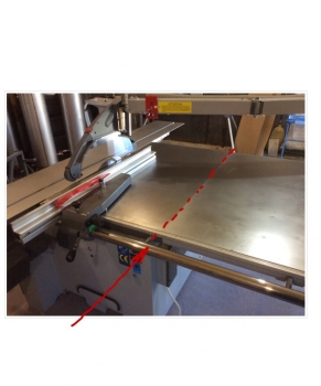
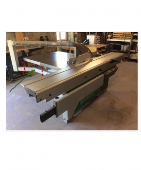
Еще одна проблемка, станок занимает очень много места в мастерской,
раздумываю снять стол расширения, но это довольно не просто ,
нужно сделать короткую штангу параллельного упора :
Позже добавлено автором:
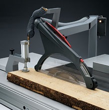
Разрезать, сварить, покрасить кронштейн пылеудаляющего колпака над пилой :
Позже добавлено автором:
И укоротить верхнюю часть кронштейна, опять же резать, варить, красить :
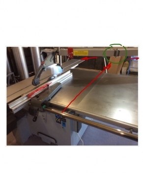
Позже добавлено автором:
Переделки значительные и по кронштейну сложно обратимые в первоначальное состояние,
поэтому пока думаю, попробую поработать в тесноте, посмотрю насколько тяжко,
с другой стороны, подумал, что появилась лишняя горизонтальная поверхность, нужно поработать время покажет
Позже добавлено автором:
А можно ограничится изготовлением лишь короткой штанги и снять стол расширения, воздуху станет больше
« Последнее редактирование: Ноября 04, 2015, 09:52:54 pm от Кузнец 16 »
Записан
zaArt
Вот видео значит с вашим смотрел — по смене скоростей….поэтому и ремень один. Вообще сейчас и на 3-ку идут парные клиновые, малошумные, с повышенным ресурсом и т.д.
Будете резать штангу паралельного упора — не ошибитесь…вообще лучше стороннюю закажите. Там учтите ширину упора с линейкой, а то места на столе будет мало…
Кронштейн колпака проще убрать и поставить стандартный итальянский колпак на расклинивающий нож..новый под ваше стандартное крепление…
Это всё позволит сохранить станок..на всякий случай.
А стол аутригера есть?
Записан
На предыдущем станке штангу короткую заказывал у токарей отдельно и снимал расширитель. На сегодняшнем все оставил в родном исполнении. Глаз радует , хотя и занимает лишних полметра. Места все равно много не бывает. Надо правильно и рационально им распоряжаться!!!. Поставьте пылесборник в продолжение расширителя!!!!
Записан
Пользователи, которые поблагодарили этот пост: Кузнец 16
WOODMAN.
От души Вас поздравляю. Достойный выбор.Я хотя и «фанат» другой марки, но
Альтендорф есть Альтендорф.Ваша работа Вам приносит и так удовольствие , но
когда начинаешь работать на таких станках, то понимаешь, что границ у получения
удовольствия нет.
Всех благ.
Записан
Пользователи, которые поблагодарили этот пост: Кузнец 16
семь раз подумать, один раз отрезать (а лучше вообще не резать)
Записан
Пользователи, которые поблагодарили этот пост: Кузнец 16
Штангу короткую я нашел как сделать,
шток гидроцилиндра с твердым хромированием,
но стандартный 50 мм,
у Altendorf 49,7 мм, но нашел завод, где штоки изготавливают, они могут перешлифовать в нужный диаметр и сделать твердое хромирование,
для zaArt :
стол аутригера конечно есть, не отмыл его еще, да и если его поставить, все — закончится место в моей мастерской,
ставится и застегивается он быстро и быстро снимается, когда нужно будет пилить что-то габаритное, поставлю его на место
Записан
А попробуйте переставить все свое оборудование (даже на листе бумаги). Форматка — вплотную расширительным столом к стене!!! А она у Вас по центру мастерской. Неразумно!
Записан
Пользователи, которые поблагодарили этот пост: Кузнец 16
А видео про смену скоростей, наверно это :
http://youtu.be/takmOuS-VWA,
ну чего, душевное видео, порядок образцовый, парень так трепетно относится к станку, пильные диски на стенде висят с расклинивающими ножами, мне видео нравится
Позже добавлено автором:
Спасибо за совет, попробую попереставлять станки в модельной схемке,
хотя это я так ворчу, для работы места хватает, около всех станков работать удобно
« Последнее редактирование: Ноября 04, 2015, 10:30:54 pm от Кузнец 16 »
Записан
WOODMAN.
все свое оборудование (даже на листе бумаги
Я тоже так делал для оптимального рассположения оборудывания.
В масштабе вырезал из бумаги силуэт (плановый) станка с обслуживающим пространством
и на плане мастерской искал лучшее положение станков.Потом перевёл данные в М1:1
и уже расставлял станки по намеченому плану.Можно было сделать на компе, но это другая история…
« Последнее редактирование: Ноября 04, 2015, 10:46:51 pm от WOODMAN. »
Записан
Спасибо, наверное так и сделаю,
Записан
zaArt
Да, это видео. Душевно, но чудно. Столько электрики и под стол)
Наверно — это класика жанра.
Успешной вам работы.
Записан
Еще хотел спросить совета о пазовании на этом станке,
в инструкции написано максимальная толщина диска для пазования 7 мм, наверное это толщина тела диска, поскольку толщина снимаемой шайбы 10 мм и 2 мм толщины было от штатного пильного диска, получается 12 мм,
где найти диски различной толщины от 4 мм до 12 мм и каких диаметров они должны быть ?
Позже добавлено автором:
для zaArt :
это klein problem, как говорят немцы,
в реальности, там дверца такая, что первое желание, которое возникает, когда ее открываешь, залезть внутрь и посмотреть и пощупать все поближе, там довольно просторно и комфортно, останавливает лишь мысль, а если не вылезу и застряну ?
Я бы на месте конструктора там еще лампочку сделал бы как в холодильнике, дверь открываешь, она загорается,
но и с фонариком там все видно и доступно для обслуживания,
Для серьезного ремонта или обслуживания, да верхнюю чугунную плиту снимать обязательно,
в новых станках пильный агрегат крепится к чугунной плите, для ремонта, вместе с плитой наверно поднимать нужно,
« Последнее редактирование: Ноября 04, 2015, 10:57:32 pm от Кузнец 16 »
Записан
Страницы: 1 [2] 3 4 Вверх
- Мастеровой »
- Инструмент, приспособления и мастерская »
- Станки »
- Форматно-раскроечные (Модератор: Klausss) »
- Altendorf F 45
Fault message
B000 — B063
E01
E02
E03
E06
E07
E08
E18
E21
E22
E40
E41
E42
E43
E44
E45
E46
E47
E48
E49
E51
0000010038-003- GB
Cause
Internal faults
Limit switch ES_MIN1 reached
Limit switch ES_MIN2 reached
Limit switch ES_MAX reached
Fault, collision, fast shutdown
Drive positioning fault
Axis reference run error
Fresh oil lubricator empty
Error during update:
File error on the USB stick
Error during update:
File errors on the USB stick (vari-
ous)
20VAC control voltage missing
24VAC control voltage missing
Scoring saw motor overheated
Main saw motor overheated
Sliding table limit switch
Saw blade cover open
Machine door open
EMERGENCY STOP button 1
pressed
EMERGENCY STOP button 2
pressed
EMERGENCY STOP button 3
pressed
Brake unit fault: Phase failure/rota-
tional direction
Faults/problems/troubleshooting
Troubleshooting
Request a service technician to check the
function.
Perform new reference run
Change cartridge
Check fuse F9
Check fuse F8
Allow motor to cool down.
Allow motor to cool down.
Check fusing in the factory and fuses F15 /
F16.
Faults/problems/troubleshooting
197