Table of
fault codes,
Automatic transmission Series 3000, 4000 with electronic control system Gen4
|
Error code |
Description |
Lamp Check Trans |
Control system response |
|
C1312 |
Low voltage signal to turn on the retarder |
OFF |
Retarder does not |
|
C1313 |
High voltage signal to turn on the retarder |
OFF |
Retarder does not |
|
P0122 |
Intermittent or low gas pedal position sensor signal |
OFF |
The default value is used. |
|
P0123 |
High signal level pedal position sensor gas |
OFF |
The default value is used. |
|
P0218 |
Oil temperature too high |
OFF |
A control pattern is used when the temperature is exceeded. Keeps 4 |
|
P0562 |
Low supply voltage control unit |
OFF |
The ban on locking torque converter. DNA |
|
P0602 |
Control unit not programmed |
ON |
Remains neutral |
|
P0610 |
Error of the additional equipment of the car with the control unit |
ON |
TID A calibration data is used. |
|
P0613 |
Control unit processor error |
OFF |
All solenoids are OFF. |
|
P0614 |
Incompatibility of ECM and TCM data to adjust engine torque |
ON |
Only neutral, rear and second gear. Torque lock |
|
P0634 |
Control unit temperature exceeded |
ON |
DNS, SOL OFF, active hydraulic control. |
|
P063E |
No auto throttle |
ON |
The default value is used. |
|
P063f |
No auto coolant |
OFF |
— |
|
P0657 |
HSD1 open circuit |
ON |
SOL OFF, DNA. Interlocking |
|
P0658 |
HSD1 low voltage |
ON |
DNS, SOL OFF, hydraulic control active |
|
P0659 |
HSD1 high voltage |
ON |
DNS, SOL OFF, hydraulic control active |
|
P0702 |
The control unit did not recognize the automatic transmission configuration. |
ON |
Uses standard configuration |
|
P0703 |
Brake Sensor Circuit Malfunction |
OFF |
On the garbage trucks cannot enable ND. If the code |
|
P0708 |
High level signal from the current transmission sensor. |
ON |
Ignore the signal of the strip switch |
|
P070C |
Low oil level sensor signal |
OFF |
— |
|
P070D |
High oil level sensor signal |
OFF |
— |
|
P0711 |
Non-standard oil temperature sensor signal |
ON |
Uses the default temperature |
|
P0712 |
Low oil temperature sensor signal |
ON |
Uses standard temperature value |
|
P0713 |
High oil temperature sensor signal |
ON |
Uses standard temperature value |
|
P0716 |
Non-standard Turbine Wheel Speed Sensor Signal |
ON |
DNS, automatic transmission is blocked on the current transfer |
|
P0717 |
Turbine wheel speed sensor signal missing |
ON |
DNS, automatic transmission is blocked on the current transfer |
|
P0719 |
ABS braking sensor signal low |
OFF |
Considers ABS OFF |
|
P071A |
Incompatible RELS input |
ON |
RELS OFF |
|
P071D |
Wrong input signal of the special function (wire 101 and 142) |
ON |
— |
|
P0721 |
Non-standard output speed sensor signal |
ON |
DNS, automatic transmission remains on the current transfer |
|
P0722 |
No output speed sensor signal |
ON |
DNS, automatic transmission stays on current |
|
P0726 |
Non-standard engine speed sensor signal |
OFF |
Uses standard turbine |
|
P0727 |
Missing engine speed sensor signal |
OFF |
Uses standard turbine |
|
P0729 |
Wrong gear ratio in 6th gear |
ON |
DNS, trying to enable 5th, then 3rd |
|
P0731 |
Incorrect gear ratio in 1st gear |
ON |
DNS, trying to enable 2nd, then 5th |
|
P0732 |
Wrong gear ratio in 2nd gear |
ON |
DNS, trying to enable 3rd, then 5th |
|
P0733 |
Incorrect gear ratio in 3rd gear |
ON |
DNS, trying to enable 4th, then 6th |
|
P0734 |
Incorrect gear ratio in 4th gear |
ON |
DNS, trying to enable 5th, then 3rd |
|
P0735 |
Invalid gear ratio in 5th gear |
ON |
DNS trying to enable 6th then the |
|
P0736 |
Wrong gear ratio in reverse gear |
ON |
DNS blocked on neutral |
|
P0741 |
Slipping clutch locking torque converter |
ON |
— |
|
P0752 |
Stuck solenoid SS1 pressure regulating valve |
ON |
DNS |
|
P0776 |
Malfunction in the PCS2 solenoid hydraulic circuit |
ON |
DNS, RPR |
|
P0777 |
Malfunction in the PCS2 |
ON |
DNS, RPR |
|
P0796 |
Fault in the hydraulic circuit of the PCS3 solenoid |
ON |
DNS, RPR |
|
P0797 |
Fault in the hydraulic circuit of the PCS3 solenoid |
ON |
DNS, RPR |
|
P0842 |
PS1 pressure sensor low voltage. |
ON |
DNS, automatic transmission stays on current |
|
P0843 |
PS1 pressure sensor high voltage. |
ON |
DNS, automatic transmission stays on current |
|
P0847 |
PS2 Pressure Sensor Low Voltage |
ON |
— |
|
P0848 |
PS2 Pressure Sensor High Voltage |
ON |
— |
|
P0880 |
The disappearance of the power control unit during engine operation |
OFF |
— |
|
P0881 |
Control unit voltage too low or jumping |
OFF |
— |
|
P0882 |
The voltage on the control unit is below normal |
ON |
DNS, SOL OFF, hydraulic |
|
P0883 |
The voltage on the control unit is above normal |
OFF |
— |
|
P088A |
Oil filter clogged |
OFF |
— |
|
P088B |
Oil filter heavily clogged |
OFF |
— |
|
P0894 |
No transfer of the moment in first gear |
ON |
DNS remains on 1 transmission |
|
P0897 |
Gear oil requires replacement |
ON |
— |
|
P0960 |
Open circuit solenoid valve modulation pressure |
ON |
— |
|
P0962 |
Low voltage in the solenoid circuit of the pressure modulating valve |
ON |
DNS, SOL OFF, hydraulic |
|
P0963 |
Modulation valve solenoid circuit high voltage pressure |
ON |
— |
|
P0964 |
PCS2 solenoid open circuit |
ON |
DNS, SOL OFF, hydraulic |
|
P0966 |
PCS2 solenoid circuit low voltage |
ON |
DNS, SOL OFF, hydraulic |
|
P0967 |
PCS2 solenoid circuit high voltage |
ON |
DNS, SOL OFF, hydraulic control active |
|
P0968 |
PCS3 solenoid open circuit |
ON |
DNS, SOL OFF, hydraulic control active |
|
P0970 |
PCS3 solenoid circuit low voltage |
ON |
DNS, SOL OFF, hydraulic control active |
|
P0971 |
PCS3 solenoid circuit high voltage |
ON |
DNS, SOL OFF, hydraulic control active |
|
P0973 |
Low voltage in the circuit of the solenoid SS1 |
ON |
DNS, SOL OFF, hydraulic control active |
|
P0974 |
High voltage in the solenoid circuit SS1 |
ON |
DNS, SOL OFF, hydraulic control active |
|
P0975 |
SS2 solenoid open circuit |
ON |
On 7-speed automatic transmissions, 1st and 7th gears are not included. |
|
P0976 |
Low voltage in the solenoid circuit SS2 |
ON |
On 7-speed automatic transmissions, 1st and 7th gears are not included, prohibition of locking the torque converter |
|
P0977 |
High voltage in the solenoid circuit SS2 |
ON |
On 7-speed automatic transmissions, 1st and 7th gears are not included. |
|
P0989 |
The signal from the retarder has |
OFF |
Retarder does not |
|
P0990 |
The signal from the retarder has a short |
OFF |
Retarder does not |
|
P1739 |
Wrong gear ratio in low gear |
ON |
DNS, prohibition of work on 1 transfer |
|
P1891 |
Accelerator pedal position sensor signal below normal |
OFF |
Uses the standard pedal depression value. |
|
P1892 |
Accelerator pedal position sensor signal is above normal |
OFF |
Uses the standard pedal depression value. |
|
P2184 |
Low voltage signal coolant temperature sensor |
OFF |
Uses standard temperature value |
|
P2185 |
Coolant temperature sensor signal high voltage |
OFF |
Uses standard temperature value |
|
P2637 |
Disturbance in the operation of the torque control system when changing gears SEM |
ON |
Prohibition of the SEM system |
|
P2641 |
Disturbance in the system of torque limiting on the lower gears LRTP |
ON |
Disable LRTP system operation |
|
P2669 |
HSD2 open circuit |
ON |
SOL OFF, blocking the torque converter, banning the main modulation, DNA |
|
P2670 |
HSD2 low voltage |
ON |
DNS, SOL OFF, hydraulic control active |
|
P2671 |
HSD2 high voltage |
ON |
DNS, SOL OFF, hydraulic control active |
|
P2684 |
HSD3 open circuit |
ON |
SOL OFF, blocking the torque converter, banning the main modulation, DNA |
|
P2685 |
HSD3 low voltage |
ON |
DNS, SOL OFF, hydraulic control active |
|
P2686 |
HSD3 high voltage |
ON |
DNS, SOL OFF, hydraulic control active |
|
P2714 |
Fault in the hydraulic circuit of the PCS4 solenoid |
ON |
DNS, RPR |
|
P2715 |
Fault in the hydraulic circuit of the PCS4 solenoid |
ON |
DNS, SOL OFF, hydraulic control active |
|
P2718 |
PCS4 solenoid open circuit |
ON |
DNS, SOL OFF, hydraulic control active |
|
P2720 |
PCS4 solenoid circuit low voltage |
ON |
DNS, SOL OFF, hydraulic control active |
|
P2721 |
PCS4 solenoid circuit high voltage |
ON |
DNS, SOL OFF, hydraulic control active |
|
P2723 |
Malfunction in the PCS1 solenoid hydraulic circuit |
ON |
DNS, RPR |
|
P2724 |
Malfunction in the PCS1 solenoid hydraulic circuit |
ON |
DNS, RPR |
|
P2727 |
PCS1 solenoid open circuit |
ON |
DNS, SOL OFF, hydraulic control active |
|
P2729 |
PCS1 solenoid circuit low voltage |
ON |
DNS, SOL OFF, hydraulic control active |
|
P2730 |
PCS1 solenoid circuit high voltage |
ON |
DNS, SOL OFF, hydraulic control active |
|
P2736 |
PCS5 solenoid open circuit |
ON |
The ban on the work of the retarder |
|
P2738 |
PCS5 solenoid circuit low voltage |
ON |
The prohibition of work on the 1st gear, the work of the retarder, |
|
P2739 |
PCS5 solenoid circuit high voltage |
ON |
The ban on the work of the retarder |
|
P2740 |
High oil retarder temperature |
OFF |
— |
|
P2742 |
Low signal level of the retarder oil |
OFF |
Uses standard oil temperature |
|
P2743 |
High signal level of the oil retarder temperature |
OFF |
Uses standard oil temperature |
|
P2761 |
Open circuit solenoid lockout torque converter |
ON |
Prohibition of locking torque converter |
|
P2763 |
Low voltage in the lock-up torque converter solenoid circuit |
ON |
Prohibition of locking torque converter |
|
P2764 |
High voltage in the torque converter lock-up solenoid circuit |
ON |
Prohibition of locking torque converter |
|
P2789 |
Friction clutch wear reaches the limit value |
ON |
— |
|
P278A |
Erroneous signal Kickdown |
OFF |
Kickdown mode ban |
|
P2793 |
Communication error with gear switch |
ON |
Ignores pulse width modulation, if the signal through the CAN bus is also lost, it is blocked in the last direction selected |
|
P2808 |
Fault in the hydraulic circuit of the PCS6 solenoid |
ON |
DNS, RPR |
|
P2809 |
Fault in the hydraulic circuit of the PCS6 solenoid |
ON |
DNS, RPR |
|
P2812 |
PCS6 solenoid open circuit |
ON |
DNS, SOL OFF, hydraulic control active |
|
P2814 |
PCS6 solenoid circuit low voltage |
ON |
DNS, SOL OFF, hydraulic control active |
|
P2815 |
PCS6 solenoid circuit high voltage |
ON |
DNS, SOL OFF, hydraulic control active |
|
U0001 |
High Speed CAN Bus Counter (IESCAN) overflow |
OFF |
Uses standard values, prohibiting the operation of the torque control system when changing gears |
|
U0010 |
CAN Bus Counter Overflow (IESCAN) |
OFF |
Uses standard values, prohibiting the operation of the torque control system when changing gears |
|
U0100 |
Loss of communication with engine / powertrain unit (J1586) |
ON |
Uses standard values |
|
U0103 |
Loss of communication with the first gear selector |
ON |
Remains in the selected gear, monitors the signal to change the direction of movement. The display goes out for 10 seconds, then shows — / — — / — |
|
U0115 |
Communication error with engine control unit |
ON |
Uses standard values, DNA |
|
U0291 |
Communication error with secondary gear selector |
ON |
Remains in the selected gear, monitors the signal to change the direction of movement. The display |
|
U0304 |
Primary gear selector not compatible with J1939 protocol |
ON |
DNS blocked in neutral |
|
U0333 |
Secondary switch not compatible with J1939 protocol |
ON |
DNS blocked in neutral |
|
U0400 |
Violation of data transmission protocol J1939 |
ON |
— |
|
U0404 |
Inadequate information from the primary gear selector |
ON |
Remains in the selected gear, monitors the signal to change the direction of movement. The display goes out for 10 seconds, then shows — / — — / — |
|
U0442 |
The control unit receives incorrect data from the engine / power unit control unit that is included in the J1939 data bus. |
OFF |
— |
|
U0592 |
Inadequate information from the secondary gear selector |
ON |
Remains in the selected gear, monitors the signal to change the direction of movement. The display 10 sec, then shows — / — — / — |
When the control unit recognizes an error of control,
the corresponding error code
is stored in
memory. To save there
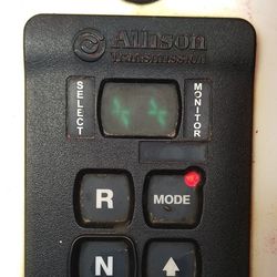
are 5 memory cells, the contents of which can be read through the display switch gear. Cells have
names from «d1» to «d5».
Stop the car to read the codes. Ignition must
be on!
·
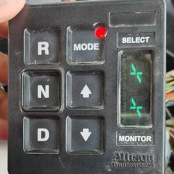
Read on button switch: Both buttons ↑ ↓ at the same time hold — With engine running
1 time; With the engine running 2 times.
·
Reading on lever switch: Press the button menu — With the engine stopped 1 time; With the engine running 2 times.
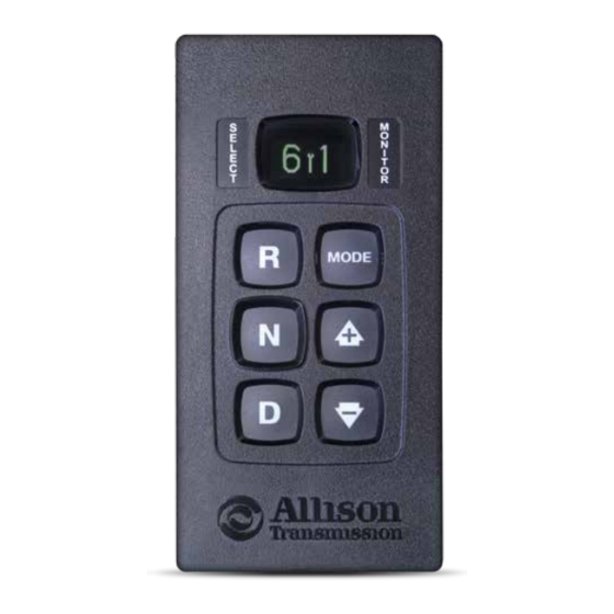
The display will show the error code stored in the «d1» field. Codes consist of a letter and a four-digit number. The code in this field will be
displayed until the next field is selected with the Mode button or the reading of codes is completed.
Important note: with active codes, the lamp « Mode ON» lights
up (Red LED on
the mode switching button). Only active
codes lead to blocking of automatic transmission functions.
End reading. To leave
the diagnostic mode,
select the neutral or press the «Menu» button or simultaneously two arrow keys until the display shows «N N «
In case of errors, call the
service center.
CAN (Controller Area Network) — Data bus Network via SAE J1939 protocol for connecting various vehicle systems.
DNA (Do Not Adapt)
— Prohibition of
adaptive mode automatic transmission.
DNS (Do Not Shift) — Prohibition of shifting. Automatic transmission remains on a certain gear and does not respond to commands. Torque converter is not
locked.
ECM (Engine Control Module)
— Engine control
unit.
HSD 1, 2,
… (High Side Driver)
— Power supply
control valves 1, 2, …
LRTP (Low Range Torque Protection) — Engine torque limitation on 1-3 gears.
PCS (Pressure Control Solenoid) — Pressure control solenoid.
RPR (Return to Previous Range)
— Switch to the
previous transfer.
SEM (Shift Energy Management) — Control system of the engine torque M during gear changes.
SOL OFF (Solenoids OFF) All solenoids are electrically disconnected. Until the engine is running, and the oil pump is spinning, movement is possible.
SS (Shift Solenoid)
— Solenoid gear
shift.
TID (Trans ID ) — TCM function to determine the configuration of the automatic transmission and the connected devices.
TCC — Torque
converter lock -up clutch.
TCM — Transmission Control Module
![]()
Allison Transmission 1000/2000 series fault codes
Allison Transmission 1000/2000 series fault codes
Allison Transmission 1000,2000 series fa
Adobe Acrobat Document
1.5 MB
![]()
Shift Selector Operation and Code Manual PDF
Oil level information, diagnostic codes and prognostic features for 3000/4000 Series Allison Transmissions
Allison Transmission Fault Codes Manual
Adobe Acrobat Document
2.3 MB
![]()
Allison Transmission TS3989EN Troubleshooting Manual
3000 and 4000 Product Families Troubleshooting Manual — Allison 4th Generation Controls
Allison Transmission TS3989EN Troublesho
Adobe Acrobat Document
9.6 MB
![]()
Shift Selector 5 Generation Fault Codes Manual PDF
Oil Level Information, Diagnostic Codes and Prognostic Features For 3000/4000 Series™ And Tc10™ Allison Transmissions
Allison Transmission 5th Gen Operation F
Adobe Acrobat Document
489.9 KB
![]()
Allison Transmission 3000/4000 series fault codes
Allison Transmission 3000/4000 series fault codes
Allison Transmission 3000,4000 series fa
Adobe Acrobat Document
318.1 KB
![]()
Allison Transmission Troubleshooting Code Manuals PDF
Allison Transmission Troubleshooting Code Manuals PDF
Allison Transmission TROUBLESHOOTING Cod
Adobe Acrobat Document
711.0 KB
![]()
Shift Selector Operation and Code Manual (MY 09 4th Generation — 4TH GENERATION ELECTRONIC CONTROLS)
Double-digit display and was release after July 2008, equipped with Model Year ’09 prognostics
Shift Selector Operation and Code Manual
Adobe Acrobat Document
664.8 KB
![]()
Allison Transmission 3000/4000 Operator’s Codes Manual PDF
Motorhome Series (MH) Transmissions : 3000 and 4000 Product Families WTEC III Controls and Aliison 4th Generation Controls
Allison Transmission 3000-4000.pdf
Adobe Acrobat Document
2.1 MB
Password: https://www.pdfmanual4trucks.com/
|
Title |
File Size |
Download Links |
|
Allison Transmission 1000 and 2000 Product Families Troubleshooting |
13.1Mb |
Download |
|
Allison Transmission 1000 and 2000 Series Fault Codes List |
18kb |
Download |
|
Allison Transmission 1000,2000 series fault code list [PDF] |
1.5Mb |
Download |
|
Allison Transmission DOC 7.0 PC Service Tools — User Guide PDF |
6.8Mb |
Download |
|
Allison Transmission Electronic Controls Troubleshooting Manual |
54.4Mb |
Download |
|
Allison Transmission TROUBLESHOOTING Codes Manual PDF [PDF] |
713.7kb |
Download |
Password: https://www.pdfmanual4trucks.com/
|
Title |
File Size |
Download Links |
|
Allison 3000-4000 Series Troubleshooting Manual [PDF] |
13.2Mb |
Download |
|
Allison Transmission — Shift Selector — Operator and Diagnostic |
148.3kb |
Download |
|
Allison Transmission 3000,4000 series fault code list [PDF] |
289.6kb |
Download |
|
Allison Transmission 30004000 series fault code list – download PDF |
320.1kb |
Download |
|
Allison Transmission Fault Codes Manual PDF [PDF] |
1.5Mb |
Download |
|
Allison Transmission Troubleshooting Manual GEN4 [PDF] |
2Mb |
Download |
|
Allison Transmission TS2973EN Troubleshooting Manual PDF [PDF] |
5.2Mb |
Download |
|
Shift Selector — Operator and Diagnostic Trouble Code manual |
1.3Mb |
Download |

|
Error code |
Description |
Lamp Check trans |
Control system response |
|
C1312 |
Retarder trigger low voltage |
off |
Retarder does not turn on |
|
C1313 |
Retarder trigger signal high voltage |
off |
Retarder does not turn on |
|
P0122 |
Intermittent or low gas pedal position sensor signal |
off |
Default value is used |
|
P0123 |
High gas pedal position sensor |
off |
Default value is used |
|
P0218 |
Oil temperature is too high |
off |
A control pattern is used in case of temperature |
|
P0562 |
Control unit low voltage |
off |
Prohibition of torque converter lockout. DNA |
|
P0602 |
The control unit is not programmed |
On |
Remains neutral |
|
P0610 |
Error of additional equipment of the car with the control unit |
On |
Uses TID A Calibration Data |
|
P0613 |
Control Unit CPU Error |
off |
All solenoids are off |
|
P0614 |
Incompatibility of ECM and TCM data for engine torque control |
On |
Only neutral, reverse and second gear. Torque lock inhibit, shift adaptation disabled |
|
P0634 |
Control unit temperature exceeded |
On |
DNS , SOL OFF , actively hydraulic control. |
|
P063E |
There is no input signal about the position of the throttle during auto detection |
On |
Default value is used |
|
P063F |
No coolant temperature signal during auto detection |
off |
— |
|
P0657 |
Open circuit HSD1 |
On |
SOL OFF , DNA . Prohibition of torque converter lock, prohibition of main |
|
P0658 |
Low voltage in the HSD circuit 1 |
On |
DNS , SOL OFF , hydraulic control is active |
|
P0659 |
High voltage in the HSD circuit 1 |
On |
DNS , SOL OFF , hydraulic control is active |
|
P0702 |
The control unit did not recognize the automatic transmission configuration |
On |
Uses standard configuration |
|
P0703 |
Malfunction in a chain of the gauge of a brake |
off |
On garbage trucks, the inclusion of N — D is not possible . If the code is active, then |
|
P0708 |
High signal from the current gear sensor. |
On |
Ignores the signal of the strip switch |
|
P070C |
Low oil level sensor signal |
off |
— |
|
P070D |
High oil level sensor signal |
off |
— |
|
P0711 |
Abnormal oil temperature sensor signal |
On |
Uses the default temperature |
|
P0712 |
Low oil temperature sensor signal |
On |
Uses standard temperature |
|
P0713 |
High oil temperature sensor signal |
On |
It uses the standard value tamper Aturi |
|
P0716 |
Turbine wheel speed sensor abnormal signal |
On |
DNS , automatic transmission is blocked on the current transfer |
|
P0717 |
No turbine wheel speed sensor signal |
On |
DNS , automatic transmission is blocked on the current transfer |
|
P0719 |
ABS brake signal low |
off |
Takes ABS off |
|
P071A |
Incompatible RELS Input |
On |
RELS function is disabled |
|
P071D |
Incorrect special function input (wire 101 and 142) |
On |
— |
|
P0721 |
Abnormal output speed sensor signal |
On |
DNS , automatic transmission remains in the current transmission |
|
P0722 |
No output speed sensor signal |
On |
DNS , automatic transmission remains in the current transmission |
|
P0726 |
Abnormal engine speed sensor signal |
off |
Uses standard turbine speed |
|
P0727 |
Missing engine speed sensor signal |
off |
Uses standard turbine speed |
|
P0729 |
6th gear ratio incorrect |
On |
DNS , trying to enable 5th , then 3rd gear |
|
P0731 |
1st gear ratio incorrect |
On |
DNS , trying to enable 2nd, then 5th gear |
|
P0732 |
2nd gear ratio incorrect |
On |
DNS , trying to enable 3rd, then 5th gear |
|
P0733 |
3rd gear ratio incorrect |
On |
DNS , trying to enable 4th, then 6th gear |
|
P0734 |
4th gear ratio incorrect |
On |
DNS , trying to turn on 5th, then 3rd gear |
|
P0735 |
5th gear ratio incorrect |
On |
DNS , trying to turn on the 6th, then 3rd, then 2nd gear |
|
P0736 |
Incorrect gear ratio in reverse gear |
On |
DNS blocked on neutral |
|
P0741 |
Torque converter slip clutch slides |
On |
— |
|
P0752 |
Jamming solenoid SS 1 pressure control valve |
On |
DNS |
|
P0776 |
Malfunction in the hydraulic circuit of the PCS 2 solenoid |
On |
DNS, RPR |
|
P0777 |
Malfunction in the hydraulic circuit of the PCS 2 solenoid |
On |
DNS, RPR |
|
P0796 |
Malfunction in the hydraulic circuit of the PCS 3 solenoid |
On |
DNS, RPR |
|
P0797 |
Malfunction in the hydraulic circuit of the PCS 3 solenoid |
On |
DNS, RPR |
|
P0842 |
PS voltage sensor low voltage 1. |
On |
DNS , automatic transmission remains in the current transmission |
|
P0843 |
Pressure Sensor High Voltage PS 1. |
On |
DNS , automatic transmission remains in the current transmission |
|
P0847 |
PS 2 pressure sensor low voltage |
On |
— |
|
P0848 |
High voltage pressure sensor PS 2 |
On |
— |
|
P0880 |
Power failure of the control unit during engine operation |
off |
— |
|
P0881 |
The voltage at the control unit is too low or is skipping |
off |
— |
|
P0882 |
The voltage at the control unit is below normal. |
On |
DNS , SOL OFF , hydraulic control is active |
|
P0883 |
The voltage on the control unit is above normal |
off |
— |
|
P088A |
Oil filter clogged |
off |
— |
|
P088B |
Oil filter heavily clogged |
off |
— |
|
P0894 |
No torque transmission in first gear |
On |
DNS remains in 1st gear |
|
P0897 |
Gear oil needs to be replaced |
On |
— |
|
P0960 |
Open circuit pressure modulation valve solenoid |
On |
— |
|
P0962 |
Low voltage modulation valve solenoid circuit |
On |
DNS , SOL OFF , hydraulic control active |
|
P0963 |
High voltage in the pressure modulation valve solenoid circuit |
On |
— |
|
P0964 |
PCS2 Solenoid Open Circuit |
On |
DNS , SOL OFF , hydraulic control active |
|
P0966 |
PCS 2 Solenoid Circuit Low Voltage |
On |
DNS , SOL OFF , hydraulic control is active |
|
P0967 |
PCS 2 Solenoid High Voltage |
On |
DNS , SOL OFF , hydraulic control is active |
|
P0968 |
PCS3 Solenoid Open Circuit |
On |
DNS , SOL OFF , hydraulic control is active |
|
P0970 |
PCS 3 Solenoid Circuit Low Voltage |
On |
DNS , SOL OFF , hydraulic control is active |
|
P0971 |
PCS 3 Solenoid Circuit High Voltage |
On |
DNS , SOL OFF , hydraulic control is active |
|
P0973 |
Low voltage in the solenoid circuit SS 1 |
On |
DNS , SOL OFF , hydraulic control is active |
|
P0974 |
High voltage in the solenoid circuit SS 1 |
On |
DNS , SOL OFF , hydraulic control is active |
|
P0975 |
Open circuit solenoid SS2 |
On |
On 7-speed automatic transmissions, 1st and 7th gears are not included |
|
P0976 |
Low voltage in the solenoid circuit SS 2 |
On |
On 7-speed automatic transmissions, 1st and 7th gears are not activated, torque converter lockout |
|
P0977 |
High voltage in the solenoid circuit SS 2 |
On |
On 7-speed automatic transmissions, 1st and 7th gears are not included |
|
P0989 |
The signal from the retarder is intermittent |
off |
Retarder does not turn on |
|
P0990 |
Retarder sensor signal has a short circuit |
off |
Retarder does not turn on |
|
P1739 |
Incorrect gear ratio in low gear |
On |
DNS , prohibition of work in 1 gear |
|
P1891 |
Accelerator pedal position sensor signal below normal |
off |
Uses the standard value for pedal depression |
|
P1892 |
Accelerator Pedal Position Sensor Signal Above Normal |
off |
Uses the standard value for pedal depression |
|
P2184 |
Coolant temperature sensor signal low voltage |
off |
Uses standard temperature |
|
P2185 |
Coolant Temperature Sensor High Voltage |
off |
Uses standard temperature |
|
P2637 |
Malfunction of the torque control system when shifting gears SEM |
On |
Disabling SEM |
|
P2641 |
Violation of the torque limiting system in the lower gears of LRTP |
On |
Disabling LRTP |
|
P2669 |
Open circuit HSD2 |
On |
SOL OFF , torque converter inhibit inhibit, main modulation |
|
P2670 |
HSD 2 low voltage |
On |
DNS , SOL OFF , hydraulic control active |
|
P2671 |
High voltage in the HSD 2 circuit |
On |
DNS , SOL OFF , hydraulic control active |
|
P2684 |
Open circuit HSD3 |
On |
SOL OFF , torque converter inhibit inhibit, main modulation |
|
P2685 |
HSD 3 Low Voltage |
On |
DNS , SOL OFF , hydraulic control is active |
|
P2686 |
HSD 3 High Voltage |
On |
DNS , SOL OFF , hydraulic control is active |
|
P2714 |
Malfunction in the hydraulic circuit of the PCS 4 solenoid |
On |
DNS, RPR |
|
P2715 |
Malfunction in the hydraulic circuit of the PCS 4 solenoid |
On |
DNS , SOL OFF , hydraulic control is active |
|
P2718 |
PCS4 Solenoid Open Circuit |
On |
DNS , SOL OFF , hydraulic control is active |
|
P2720 |
PCS 4 Solenoid Circuit Low Voltage |
On |
DNS , SOL OFF , hydraulic control is active |
|
P2721 |
PCS 4 Solenoid High Voltage |
On |
DNS , SOL OFF , hydraulic control is active |
|
P2723 |
Malfunction in the hydraulic circuit of the PCS 1 solenoid |
On |
DNS, RPR |
|
P2724 |
Malfunction in the hydraulic circuit of the PCS 1 solenoid |
On |
DNS, RPR |
|
P2727 |
PCS1 Solenoid Open Circuit |
On |
DNS , SOL OFF , hydraulic control is active |
|
P2729 |
Low voltage in the PCS 1 solenoid |
On |
DNS , SOL OFF , hydraulic control is active |
|
P2730 |
High voltage in the PCS 1 solenoid |
On |
DNS , SOL OFF , hydraulic control is active |
|
P2736 |
PCS5 Solenoid Open Circuit |
On |
Prohibition of retarder operation |
|
P2738 |
PCS 5 Solenoid Circuit Low Voltage |
On |
Prohibition of work in 1st gear, retarder operation, torque converter lock |
|
P2739 |
PCS 5 Solenoid Circuit High Voltage |
On |
Prohibition of retarder operation |
|
P2740 |
High temperature oil retarders |
off |
— |
|
P2742 |
Retarder oil temperature sensor low signal |
off |
Uses standard oil temperature |
|
P2743 |
Retarder oil temperature sensor high signal |
off |
Uses standard oil temperature |
|
P2761 |
Torque converter solenoid open circuit |
On |
Torque converter lockout |
|
P2763 |
Low voltage in the torque converter lock-up solenoid circuit |
On |
Torque converter lockout |
|
P2764 |
High voltage lock-up torque converter solenoid circuit |
On |
Torque converter lockout |
|
P2789 |
Clutch wear reaches limit value |
On |
— |
|
P278A |
Wrong Kickdown Signal |
off |
Kickdown mode ban |
|
P2793 |
Gear Shift Communication Error |
On |
Ignores PWM control, if the signal through the CAN — bus is also lost, the latter is locked in a selected direction |
|
P2808 |
Malfunction in the hydraulic circuit of the PCS 6 solenoid |
On |
DNS, RPR |
|
P2809 |
Malfunction in the hydraulic circuit of the PCS 6 solenoid |
On |
DNS, RPR |
|
P2812 |
PCS6 Solenoid Open Circuit |
On |
DNS , SOL OFF , hydraulic control is active |
|
P2814 |
PCS 6 Solenoid Circuit Low Voltage |
On |
DNS , SOL OFF , hydraulic control is active |
|
P2815 |
PCS 6 Solenoid Circuit High Voltage |
On |
DNS , SOL OFF , hydraulic control is active |
|
U0001 |
High Speed CAN Bus Counter Overflow ( IESCAN ) |
off |
Uses standard values; disables torque control when shifting gears |
|
U0010 |
CAN Bus Counter Overflow ( IESCAN ) |
off |
Uses standard values; disables torque control when shifting gears |
|
U0100 |
Loss of communication with the engine / power unit ( J 1586) |
On |
Uses default values |
|
U0103 |
Lost Communication With First Gear Shift |
On |
Remains in the selected gear, monitors the signal for changing the direction of movement. The display |
|
U0115 |
Communication error with engine control unit |
On |
Uses standard values, DNA |
|
U0291 |
Communication error with the secondary gear shifter |
On |
Remains in the selected gear, monitors the signal for changing the direction of movement. The display |
|
U0304 |
Primary gear selector not compatible with J 1939 protocol |
On |
DNS blocked in neutral |
|
U0333 |
Secondary switch not compatible with J 1939 protocol |
On |
DNS blocked in neutral |
|
U0400 |
Violation of data transmission protocol J 1939 |
On |
— |
|
U0404 |
Inadequate information from the primary gear shifter |
On |
Remains in the selected gear, monitors the signal for changing the direction of movement. The display |
|
U0442 |
The control unit receives incorrect data from the engine / powertrain control unit included in data bus J 1939 |
off |
— |
|
U0592 |
Inadequate information from the secondary gear shifter |
On |
Remains in the selected gear, monitors the signal for changing the direction of movement. The display |
To make work easier auto component makers have relied on the fault code system. These fault codes are supposed to cu the guesswork out of doing car repairs. However, like Allison, many companies have their own fault code system and it doesn’t line up with the SPN FMI code system.
The Allison fault code system uses 3 letters to identify the source and location of the problem. Those letters are C, P, and U. However, be careful of the instructions as they may throw the letter D in there as well.
To learn these codes and how to read them, just continue to read our article. It has the information you want to know about so you can figure out your transmission issue faster than you could before the fault code system was implemented.
Allison Transmission Fault Code List
1. Diagnostic Transmission Codes- (D)
| Main code | Sub code | Description |
| 13 | 12 | ECU INPUT VOLTAGE LOW |
| 13 | ECU INPUT VOLTAGE MEDIUM LOW | |
| 23 | ECU INPUT VOLTAGE HIGH | |
| 14 | 12 | OIL LEvEL SENSOR, FAILED LOW |
| 23 | OIL LEVEL SENSOR, FAILED HIGH | |
| 21 | 12 | THROTTLE POSITION SENSOR, FAILED LOW |
| 23 | THROTTLE POSITION SENSOR, FAILED HIGH | |
| 22 | 14 | ENGINE SPEED SENSOR |
| 15 | TURBINE SPEED SENSOR | |
| 16 | OUTPUT SPEED SENSOR | |
| 23 | 12 | PRIMARY SHIFT SELECTOR FAULT |
| 13 | PRIMARY SHIFT SELECTOR MODE FAULT | |
| 14 | SECONDARY SHIFT SELECTOR FAULT | |
| 15 | SECONDARY SHIFT SELECTOR MODE FAULT | |
| 16 | SHIFT SELECTOR DISPLAY LINE FAULT | |
| 24 | 12 | SUMP FLUID TEMPERATURE, COLD |
| 23 | SUMP FLUID TEMPERATURE, HOT | |
| 25 | 00 | OUTPUT SPEED SENSOR @ 0 RPM, LOW |
| 11 | OUTPUT SPEED SENSOR @ 0 RPM, 1ST | |
| 22 | OUTPUT SPEED SENSOR @ 0 RPM, 2ND | |
| 33 | OUTPUT SPEED SENSOR @ 0 RPM, 3RD | |
| 44 | OUTPUT SPEED SENSOR @ 0 RPM, 4TH | |
| 55 | OUTPUT SPEED SENSOR @ 0 RPM, 5TH | |
| 66 | OUTPUT SPEED SENSOR @ 0 RPM, 6TH | |
| 77 | OUTPUT SPEED SENSOR @ 0 RPM, REvERSE | |
| 26 | 00 | THROTTLE SOURCE NOT DETECTED |
| 11 | ENGINE COOLANT SOURCE NOT DETECTED | |
| 32 | 00 | C3 PRESSURE SWITCH OPEN IN LOW |
| 33 | C3 PRESSURE SWITCH OPEN IN 3RD | |
| 55 | C3 PRESSURE SWITCH OPEN IN 5TH | |
| 77 | C3 PRESSURE SWITCH OPEN IN REVERSE | |
| 33 | 12 | SUMP OIL TEMPERATURE SENSOR, FAILED LOW |
| 23 | SUMP OIL TEMPERATURE SENSOR, FAILED HIGH | |
| 34 | 12 | CALIBRATION COMPATIBILITY WRONG |
| 13 | CALIBRATION BLOCK CHECKSUM | |
| 14 | POWER OFF BLOCK CHECKSUM | |
| 15 | DIAGNOSE QUEUE BLOCK CHECKSUM | |
| 16 | REAL TIME BLOCK CHECKSUM | |
| 17 | CUSTOMER MODIFIABLE CONSTANTS CHECKSUM | |
| 35 | 00 | POWER INTERRUPTION |
| 16 | REAL TIME WRITE INTERRUPTION | |
| 36 | 00 | HARDWARE/SOFTWARE NOT COMPATIBLE |
| 01 | TID NOT COMPATIBLE W/HARDWARE/SOFTWARE | |
| 02 | TID DID NOT COMPLETE | |
| 42 | 12 | A SOLENOID SHORTED TO BATTERY |
| 13 | B SOLENOID SHORTED TO BATTERY | |
| 14 | C SOLENOID SHORTED TO BATTERY | |
| 15 | D SOLENOID SHORTED TO BATTERY | |
| 16 | E SOLENOID SHORTED TO BATTERY | |
| 21 | F SOLENOID SHORTED TO BATTERY | |
| 22 | G SOLENOID SHORTED TO BATTERY | |
| 23 | H SOLENOID SHORTED TO BATTERY | |
| 24 | J SOLENOID SHORTED TO BATTERY | |
| 26 | N SOLENOID SHORTED TO BATTERY | |
| 44 | 12 | A SOLENOID SHORTED TO GROUND |
| 13 | B SOLENOID SHORTED TO GROUND | |
| 14 | C SOLENOID SHORTED TO GROUND | |
| 15 | D SOLENOID SHORTED TO GROUND | |
| 16 | E SOLENOID SHORTED TO GROUND | |
| 21 | F SOLENOID SHORTED TO GROUND | |
| 22 | G SOLENOID SHORTED TO GROUND | |
| 23 | H SOLENOID SHORTED TO GROUND | |
| 24 | J SOLENOID SHORTED TO GROUND | |
| 26 | N SOLENOID SHORTED TO GROUND | |
| 45 | 12 | A SOLENOID CIRCUIT OPEN |
| 13 | B SOLENOID CIRCUIT OPEN | |
| 14 | C SOLENOID CIRCUIT OPEN | |
| 15 | D SOLENOID CIRCUIT OPEN | |
| 16 | E SOLENOID CIRCUIT OPEN | |
| 21 | F SOLENOID CIRCUIT OPEN | |
| 22 | G SOLENOID CIRCUIT OPEN | |
| 23 | H SOLENOID CIRCUIT OPEN | |
| 24 | J SOLENOID CIRCUIT OPEN | |
| 26 | N SOLENOID CIRCUIT OPEN |
| Main code | Sub code | Description |
| 46 | 21 | F SOLENOID CIRCUIT OvERCURRENT |
| 26 | N & H SOLENOID CIRCUIT OvERCURRENT | |
| 27 | A-HI SOLENOID CIRCUIT OvERCURRENT | |
| 51 | 01 | OFFgOINg RATIO TEST, LOW TO 1 |
| 10 | OFFGOING RATIO TEST, 1 TO LOW | |
| 12 | OFFGOING RATIO TEST, 1 TO 2 | |
| 21 | OFFGOING RATIO TEST, 2 TO 1 | |
| 23 | OFFGOING RATIO TEST, 2 TO 3 | |
| 24 | OFFGOING RATIO TEST, 2 TO 4 | |
| 35 | OFFGOING RATIO TEST, 3 TO 5 | |
| 42 | OFFGOING RATIO TEST, 4 TO 2 | |
| 43 | OFFGOING RATIO TEST, 4 TO 3 | |
| 45 | OFFGOING RATIO TEST, 4 TO 5 | |
| 46 | OFFGOING RATIO TEST, 4 TO 6 | |
| 53 | OFFGOING RATIO TEST, 5 TO 3 | |
| 64 | OFFGOING RATIO TEST, 6 TO 4 | |
| 65 | OFFGOING RATIO TEST, 6 TO 5 | |
| XY | OFFGOING RATIO TEST, X TO Y | |
| 52 | 01 | OFFGOING C3PS TEST, LOW TO 1 |
| 08 | OFFGOING C3PS TEST, LOW TO N1 | |
| 32 | OFFGOING C3PS TEST, 3 TO 2 | |
| 34 | OFFGOING C3PS TEST, 3 TO 4 | |
| 54 | OFFGOING C3PS TEST, 5 TO 4 | |
| 56 | OFFGOING C3PS TEST, 5 TO 6 | |
| 71 | OFFGOING C3PS TEST, REVERSE TO 1 | |
| 72 | OFFGOING C3PS TEST, REVERSE TO 2 | |
| 78 | OFFGOING C3PS TEST, REVERSE TO N1 | |
| 99 | OFFGOING C3PS TEST, N3 TO N2 | |
| XY | OFFGOING C3PS TEST, X TO Y | |
| 53 | 08 | OFFGOING SPEED TEST, LOW TO N1 |
| 09 | OFFGOING SPEED TEST, L TO NNC | |
| 18 | OFFGOING SPEED TEST, 1 TO N1 | |
| 19 | OFFGOING SPEED TEST, 1 TO RELS | |
| 28 | OFFGOING SPEED TEST, 2 TO N1 | |
| 29 | OFFGOING SPEED TEST, 2 TO N2 | |
| 38 | OFFGOING SPEED TEST, 3 TO N1 | |
| 39 | OFFGOING SPEED TEST, 3 TO N3 | |
| 48 | OFFGOING SPEED TEST, 4 TO N1 | |
| 49 | OFFGOING SPEED TEST, 4 TO N3 | |
| 58 | OFFGOING SPEED TEST, 5 TO N1 | |
| 59 | OFFGOING SPEED TEST, 5 TO N3 | |
| 68 | OFFGOING SPEED TEST, 6 TO N1 | |
| 69 | OFFGOING SPEED TEST, 6 TO N4 | |
| 78 | OFFGOING SPEED TEST, REVERSE TO N1 | |
| 99 | OFFGOING SPEED TEST, N2 TO N3 OR N3 TO N2 | |
| XY | OFFGOING SPEED TEST, X TO Y | |
| 54 | 01 | ONCOMING RATIO TEST, LOW TO 1 |
| 07 | ONCOMING RATIO TEST, LOW TO REVERSE | |
| 10 | ONCOMING RATIO TEST, 1 TO LOW | |
| 12 | ONCOMING RATIO TEST, 1 TO 2 | |
| 17 | ONCOMING RATIO TEST, 1 TO REVERSE | |
| 21 | ONCOMING RATIO TEST, 2 TO 1 | |
| 23 | ONCOMING RATIO TEST, 2 TO 3 | |
| 24 | ONCOMING RATIO TEST, 2 TO 4 | |
| 27 | ONCOMING RATIO TEST, 2 TO REVERSE | |
| 32 | ONCOMING RATIO TEST, 3 TO 2 | |
| 34 | ONCOMING RATIO TEST, 3 TO 4 | |
| 35 | ONCOMING RATIO TEST, 3 TO 5 | |
| 42 | ONCOMING RATIO TEST, 4 TO 2 | |
| 43 | ONCOMING RATIO TEST, 4 TO 3 | |
| 45 | ONCOMING RATIO TEST, 4 TO 5 | |
| 46 | ONCOMING RATIO TEST, 4 TO 6 | |
| 53 | ONCOMING RATIO TEST, 5 TO 3 | |
| 54 | ONCOMING RATIO TEST, 5 TO 4 | |
| 56 | ONCOMING RATIO TEST, 5 TO 6 | |
| 64 | ONCOMING RATIO TEST, 6 TO 4 | |
| 65 | ONCOMING RATIO TEST, 6 TO 5 | |
| 70 | ONCOMING RATIO TEST, REV. TO LOW | |
| 71 | ONCOMING RATIO TEST, REVERSE TO 1 | |
| 72 | ONCOMING RATIO TEST, REVERSE TO 2 | |
| 80 | ONCOMING RATIO TEST, N1 TO LOW | |
| 81 | ONCOMING RATIO TEST, N1 TO 1 | |
| 82 | ONCOMING RATIO TEST, N1 TO 2 | |
| 83 | ONCOMING RATIO TEST, N1 TO 3 |
| Main code | Sub code | Description |
| 54 | 85 | ONCOMING RATIO TEST, N1 TO 5 |
| 86 | ONCOMING RATIO TEST, N1 TO 6 | |
| 87 | ONCOMING RATIO TEST, N1 TO REVERSE | |
| 92 | ONCOMING RATIO TEST, N2 TO 2 | |
| 93 | ONCOMING RATIO TEST, N3 TO 3 | |
| 95 | ONCOMING RATIO TEST, N3 TO 5 | |
| 96 | ONCOMING RATIO TEST, N4 TO 6 | |
| XY | ONCOMING RATIO TEST, X TO Y | |
| 55 | 07 | ONCOMING C3PS TEST, LOW TO REVERSE |
| 17 | ONCOMING C3PS TEST, 1 TO REVERSE | |
| 27 | ONCOMING C3PS TEST, 2 TO REVERSE | |
| 87 | ONCOMING C3PS TEST, N1 TO REVERSE | |
| 97 | ONCOMING C3PS TEST, NVL TO REVERSE | |
| XY | ONCOMING C3PS TEST, X TO Y | |
| 56 | 00 | LOW RANGE VERIFICATION TEST |
| 11 | 1ST RANGE VERIFICATION TEST | |
| 22 | 2ND RANGE VERIFICATION TEST | |
| 33 | 3RD RANGE VERIFICATION TEST | |
| 44 | 4TH RANGE VERIFICATION TEST | |
| 55 | 5TH RANGE VERIFICATION TEST | |
| 66 | 6TH RANGE VERIFICATION TEST | |
| 77 | REVERSE RANGE VERIFICATION TEST | |
| 57 | 11 | 1ST RANGE VERIFICATION C3PS TEST |
| 22 | 2ND RANGE VERIFICATION C3PS TEST | |
| 44 | 4TH RANGE VERIFICATION C3PS TEST | |
| 66 | 6TH RANGE VERIFICATION C3PS TEST | |
| 88 | N1 RANGE VERIFICATION C3PS TEST | |
| 99 | N2 OR N4 RANGE VERIFICATION C3PS TEST | |
| 61 | 00 | RETARDER OIL TEMPERATURE, HOT |
| 62 | 12 | RETARDER TEMP. SENSOR, FAILED LOW |
| 23 | RETARDER TEMP. SENSOR, FAILED HIGH | |
| 32 | ENGINE COOLANT TEMP. SENSOR, FAILED LOW | |
| 33 | ENGINE COOLANT TEMP. SENSOR, FAILED HIGH | |
| 63 | 00 | INPUT FUNCTION FAULT |
| 26 | KICKDOWN INPUT, FAILED ON | |
| 40 | SERVICE BRAKE STATUS INPUT, FAILED ON | |
| 41 | PUMP/PACK AND NEUTRAL GENERALPURPOSE INPUT | |
| 47 | RELS INPUT, FAILED ON | |
| 64 | 12 | RETARDER MODULATION SENSOR, FAILED LOW |
| 23 | RETARDER MODULATION SENSOR, FAILED HIGH | |
| 65 | 00 | ENGINE RATING TOO HIGH |
| 11 | ENGINE NOT RESPONDING TO LRTPTORQUE REDUCTION | |
| 12 | ENGINE NOT RESPONDING TO DEFAULTTRANSMISSION TORQUE LIMIT | |
| 66 | 00 | SERIAL COMMUNICATION INTERFACE FAULT |
| 11 | S. C. I. ENGINE COOLANT SOURCE FAULT | |
| 22 | J1939 RETARDER REQUEST FAULT | |
| 33 | J1939 DRIVER DEMAND TORQUE FAULT | |
| 34 | ENGINE NOT RESPONDING TO J1939SEM CONTROL | |
| 69 | 27 | A-HIGH SWITCH INOPERATIVE IN ECU |
| 28 | F-HIGH SWITCH INOPERATIVE IN ECU | |
| 29 | N & H-HIGH SWITCH INOPERATIVE IN ECU | |
| 33 | COMPUTER OPERATING PROPERLY TIMEOUTIN ECU | |
| 34 | ECU WRITE TIMEOUT | |
| 35 | ECU CHECKSUM TEST | |
| 36 | RAM SELF TEST IN ECU | |
| 39 | COMMUNICATION CHIP ADDRESSING ERROR | |
| 41 | I/O ASIC ADDRESSING TEST IN ECU | |
| 42 | SPI OUTPUT FAILURE | |
| 43 | SPI INPUT FAILURE | |
| 70 | 12 | MINOR LOOP OVERRUN IN SOFTWARE |
| 13 | ILLEGAL WRITE TO ADDRESS $0000 | |
| 14 | MAJOR LOOP OVERRUN IN SOFTWARE |
2. Diagnostic transmission Codes- (C, P, & U)
| Code | Description |
| C1312 | RETARDER REQUEST SENSOR, FAILED LOW |
| C1313 | RETARDER REQUEST SENSOR, FAILED HIGH |
| P0122 | PEDAL POSITION SENSOR, LOW VOLTAGE |
| P0123 | PEDAL POSITION SENSOR, HIGH VOLTAGE |
| P0218 | TRANSMISSION FLUID OVER TEMPERATURE |
| P0602 | TCM NOT PROgRAMMED |
| P0610 | TCM VEHICLE OPTIONS (TRANSID) ERROR |
| P0613 | TCM PROCESSOR |
| P0614 | TORQUE CONTROL DATA MISMATCH—ECM/TCM |
| P0634 | TCM INTERNAL TEMPERATURE TOO HIGH |
| P063E | AUTO CONFIGURATION THROTTLE INPUT NOT PRESENT |
| P063F | AUTO CONFIGURATION ENGINE COOLANT TEMP INPUT NOT PRESENT |
| P0658 | ACTUATOR SUPPLY VOLTAGE 1 (HSD1), LOW |
| P0659 | ACTUATOR SUPPLY VOLTAGE 1 (HSD1), HIGH |
| P0701 | TRANSMISSION CONTROL SYSTEM PERFORMANCE |
| P0702 | TRANSMISSION CONTROL SYSTEM ELECTRICAL (TRANSID) |
| P0703 | BRAKE SWITCH CIRCUIT MALFUNCTION |
| P0708 | TRANSMISSION RANGE SENSOR, HIGH |
| P070C | TRANSMISSION FLUID LEVEL SENSOR, LOW |
| P070D | TRANSMISSION FLUID LEVEL SENSOR, HIGH |
| P0711 | TRANSMISSION FLUID TEMPERATURE SENSOR PERFORMANCE |
| P0712 | TRANSMISSION FLUID TEMPERATURE SENSOR, LOW |
| P0713 | TRANSMISSION FLUID TEMPERATURE SENSOR, HIGH |
| P0716 | TURBINE SPEED SENSOR PERFORMANCE |
| P0717 | TURBINE SPEED SENSOR, NO SIGNAL |
| P0719 | BRAKE SWITCH ABS, INPUT LOW |
| P071A | RELS INPUT, FAILED ON |
| P071D | GENERAL PURPOSE FAULT |
| P0721 | OUTPUT SPEED SENSOR PERFORMANCE |
| P0722 | OUTPUT SPEED SENSOR, NO SIGNAL |
| P0726 | ENGINE SPEED SENSOR PERFORMANCE |
| P0727 | ENGINE SPEED SENSOR, NO SIGNAL |
| P0729 | INCORRECT 6TH GEAR RATIO |
| P0731 | INCORRECT 1ST GEAR RATIO |
| P0732 | INCORRECT 2ND GEAR RATIO |
| P0733 | INCORRECT 3RD GEAR RATIO |
| P0734 | INCORRECT 4TH GEAR RATIO |
| P0735 | INCORRECT 5TH GEAR RATIO |
| P0736 | INCORRECT REVERSE GEAR RATIO |
| P0741 | TORQUE CONVERTER CLUTCH SYSTEM, STUCK OFF |
| P0776 | PRESSURE CONTROL SOLENOID 2, STUCK OFF |
| P0777 | PRESSURE CONTROL SOLENOID 2, STUCK ON |
| P0796 | PRESSURE CONTROL SOLENOID 3, STUCK OFF |
| P0797 | PRESSURE CONTROL SOLENOID 3, STUCK ON |
| P0842 | TRANSMISSION PRESSURE SWITCH 1, LOW |
| P0843 | TRANSMISSION PRESSURE SWITCH 1, HIGH |
| P0880 | TCM POWER INPUT SIGNAL |
| P0881 | TCM POWER INPUT SIGNAL PERFORMANCE |
| P0882 | TCM POWER INPUT SIGNAL, LOW |
| P0883 | TCM POWER INPUT SIGNAL, HIGH |
| P0894 | TRANSMISSION COMPONENT SLIPPING |
| P0960 | PRESSURE CONTROL SOLENOID MAIN MOD CONTROL, OPEN |
| P0962 | PRESSURE CONTROL SOLENOID MAIN MOD CONTROL, LOW |
| P0963 | PRESSURE CONTROL SOLENOID MAIN MOD CONTROL, HIGH |
| P0964 | PRESSURE CONTROL SOLENOID 2 CONTROL, OPEN |
| P0966 | PRESSURE CONTROL SOLENOID 2 CONTROL, LOW |
| P0967 | PRESSURE CONTROL SOLENOID 2 CONTROL, HIGH |
| P0968 | PRESSURE CONTROL SOLENOID 3 CONTROL, OPEN |
| P0970 | PRESSURE CONTROL SOLENOID 3 CONTROL, LOW |
| P0971 | PRESSURE CONTROL SOLENOID 3 CONTROL, HIGH |
| P0973 | SHIFT SOLENOID 1 CONTROL, LOW |
| P0974 | SHIFT SOLENOID 1 CONTROL, HIGH |
| P0975 | SHIFT SOLENOID 2 CONTROL, OPEN |
| P0976 | SHIFT SOLENOID 2 CONTROL, LOW |
| Code | Description |
| P0977 | SHIFT SOLENOID 2 CONTROL, HIGH |
| P0989 | RETARDER PRESSURE SENSOR, FAILED LOW |
| P0990 | RETARDER PRESSURE SENSOR, FAILED HIGH |
| P1739 | INCORRECT LOW GEAR RATIO |
| P1891 | THROTTLE POSITION SENSOR PWM SIGNAL, LOW |
| P1892 | THROTTLE POSITION SENSOR PWM SIGNAL, HIGH |
| P2184 | ENGINE COOLANT TEMPERATURE SENSOR, LOW |
| P2185 | ENGINE COOLANT TEMPERATURE SENSOR, HIGH |
| P2637 | TORQUE MANAGEMENT FEEDBACK SIGNAL (SEM) |
| P2641 | TORQUE MANAGEMENT FEEDBACK SIGNAL (LRTP) |
| P2670 | ACTUATOR SUPPLY VOLTAGE 2 (HSD2), LOW |
| P2671 | ACTUATOR SUPPLY VOLTAGE 2 (HSD2), HIGH |
| P2685 | ACTUATOR SUPPLY VOLTAGE 3 (HSD3), LOW |
| P2686 | ACTUATOR SUPPLY VOLTAGE 3 (HSD3), HIGH |
| P2714 | PRESSURE CONTROL SOLENOID 4, STUCk OFF |
| P2715 | PRESSURE CONTROL SOLENOID 4, STUCk ON |
| P2718 | PRESSURE CONTROL SOLENOID 4 CONTROL, OPEN |
| P2720 | PRESSURE CONTROL SOLENOID 4 CONTROL, LOW |
| P2721 | PRESSURE CONTROL SOLENOID 4 CONTROL, HIGH |
| P2723 | PRESSURE CONTROL SOLENOID 1, STUCk OFF |
| P2724 | PRESSURE CONTROL SOLENOID 1, STUCk ON |
| P2727 | PRESSURE CONTROL SOLENOID 1 CONTROL, OPEN |
| P2729 | PRESSURE CONTROL SOLENOID 1 CONTROL, LOW |
| P2730 | PRESSURE CONTROL SOLENOID 1 CONTROL, HIGH |
| P2736 | PRESSURE CONTROL SOLENOID 5 CONTROL, OPEN |
| P2738 | PRESSURE CONTROL SOLENOID 5 CONTROL, LOW |
| P2739 | PRESSURE CONTROL SOLENOID 5 CONTROL, HIGH |
| P2740 | RETARDER OIL TEMPERATURE, HOT |
| P2742 | RETARDER OIL TEMPERATURE SENSOR, LOW |
| P2743 | RETARDER OIL TEMPERATURE SENSOR, HIGH |
| P2761 | TCC PCS CONTROL, OPEN |
| P2763 | TCC PCS CONTROL, HIGH |
| P2764 | TCC PCS CONTROL, LOW |
| P278A | KICKDOWN INPUT, FAILED ON |
| P2793 | GEAR SHIFT DIRECTION |
| P2808 | PRESSURE CONTROL SOLENOID 6, STUCk OFF |
| P2809 | PRESSURE CONTROL SOLENOID 6, STUCk ON |
| P2812 | PRESSURE CONTROL SOLENOID 6 CONTROL, OPEN |
| P2814 | PRESSURE CONTROL SOLENOID 6 CONTROL, LOW |
| P2815 | PRESSURE CONTROL SOLENOID 6 CONTROL, HIGH |
| U0001 | HIGH SPEED CAN BUS RESET COUNTER OVERRUN (IESCAN) |
| U0010 | CAN BUS RESET COUNTER OVERRUN |
| U0100 | LOST COMMUNICATION WITH ECM/PCM (J1587) |
| U0103 | LOST COMMUNICATION WITH GEAR SHIFT MODULE(SHIFT SELECTOR) 1 |
| U0115 | LOST COMMUNICATION WITH ECM |
| U0291 | LOST COMMUNICATION WITH GEAR SHIFT MODULE(SHIFT SELECTOR) 2 |
| U0304 | INCOMPATIBLE GEAR SHIFT MODULE 1 (SHIFT SELECTOR ID) |
| U0333 | INCOMPATIBLE GEAR SHIFT MODULE 2 (SHIFT SELECTOR ID) |
| U0404 | INVALID DATA RECEIVED FROM GEAR SHIFT MODULE(SHIFT SELECTOR) 1 |
| U0592 | INVALID DATA RECEIVED FROM GEAR SHIFT MODULE(SHIFT SELECTOR) 2 |
How To Read Allison Transmission Codes
It just takes a little practice and to recognize which fault code system your vehicle has. For example for Allison transmissions there will be vehicles with a single digit entry for their fault codes.
For other vehicles, there will be a double digit readout and that should be easier to read. One thing to take note, we mentioned the letter D before but that seems to only stand for diagnostic come.
It will appear on both the single and double digit readouts in the first position. The reason for this is this code is telling you where in the fault code line up its position is.
For example if you see D then a 1 in the second box of the single digit readout, you are being told this is the first code in the line of codes that has been set. In the double digit readout this code should read D1 but with the D above the 1.
D2 followed by the code will tell you that it is the second code that has been set by the problem. To read the single digit code, and the readout may be vertical in your vehicle, you will see D1 13 12.
The first two digits are for the position of the code, first , second, third, and so on. The 13 tells you the main code and the 12 will tell you the sub code. In this example the problem is caused by ECU Input Voltage Low.
For the double digit code, you will see the D1 (or 2, etc). then the letter P (or C or U) by itself, then a pair of numbers vertically,, for example 07 then another pair of numbers 22 vertically.
That code would look like this- D1 P0722 and to find the meaning of this code you just look up P0722 which stands for- Output Speed Sensor, No Signal. That is how you read this code system.
Just be careful about the position of the numbers. They will go according to how your read out is set up in your vehicle.
How To Reset Allison Transmission Fault Codes
One way to do this., and there may be more than one depending on your Allison transmission model, you simply press the ‘Mode’ button and hold it. Keep holding it till you hear 2 beeps and then release the ‘Mode’ button.
Or if you have an older Allison transmission, the way to reset the transmission is to disconnect the battery cables for 30 seconds. This should clear all codes and give you a new start. You may have to clear the ECU as well and that only takes 10 seconds with the cables off.
If you own a newer Allison transmission, you may be restricted to using a code reader to reset the codes. It seems that a standard code reader you can get from the auto parts outlets will do the job here.
Just connect the reader to your diagnostic part of the transmission and then push the clear codes buttons.
Clearing Allison Transmission Codes
There are two sets of instructions. One is for the single digit readout and the other is for the double digit model. First the single digit read out:
1. Press and hold the ‘mode’ button for 3 seconds. The LED indicator light should start to flash. Release the mode button and the active codes should not be illuminated.
To clear inactive codes, you simply press and hold the ‘Mode’ button for 10 seconds. Some codes require engine cycling to clear and others are self-clearing.
2. Record all fault codes before you clear them. This will help your repair work go smoother.
3. Drive your vehicle around a little bit to see if any of the fault codes you cleared return or not. If they do return then take your vehicle to an authorized Allison transmission expert and have them fix the problem.
For the double digit display #2 and 3 are the same. It is just #1 that is different.
1. This step is very simple, just press the ‘Mode’ button for 10 seconds and both the active and inactive codes will be cleared.
That is all you have to do for the Allison 3000 and 4000 transmission series.
Some Additional Words
Now that you have the Allison transmission codes, you should be able to talk intelligently with the transmission repair man and understand what is wrong with this valuable part.
Also, with the right code reader you should be able to make your own diagnosis and see if you are able to make the repair yourself or not. Information is always king and when you have it, you are not at the mercy of the unethical repairmen.
![]()
Allison Transmission 1000 — 2000 Fault Codes DTC
Allison Transmission 1000 — 2000 Fault Codes DTC
Allison Transmission 1000 — 2000 Fault C
Adobe Acrobat Document
19.7 KB
ALLISON 1000, 2000 & 24000 Transmission Fault Codes DTC
DTC Description
Check
Trans
Light Page
P0121 Pedal Postion Sensor Performance Problem No 5-15
P0122 Pedal Postion Sensor Circuit Low Voltage No 5-16
P0123 Pedal Postion Sensor Circuit High Voltage No 5-19
P0218 Transmission Fluid Over Temperature No 5-22
P0562 System Voltage Low Yes 5-26
P0563 System Voltage High Yes 5-29
P0602 TCM Not Programmed Yes 5-33
P0606 Controller Internal Performance Yes 5-34
P0701 Transmission Control System Performance No 5-35
P0703 Brake Switch Circuit No 5-37
P0705 Transmission Range Sensor Circuit (PRNDL Input) No 5-41
P0706 Transmission Range Sensor Circuit Performance Yes 5-45
P0708 Transmission Range Sensor Circuit High Input Yes 5-49
P0710 Transmission Fluid Temperature Sensor Malfunction No 5-53
P0711 Transmission Fluid Temperature Sensor Circuit Performance Yes 5-57
P0712 Transmission Fluid Temperature Sensor Circuit Low Input (High Temperature) Yes 5-61
P0713 Transmission Fluid Temperature Sensor Circuit Low Input (Low Temperature) Yes 5-65
P0716 Turbine Speed Sensor Circuit Performance Yes 5-69
P0717 Turbine Speed Sensor Circuit No Signal Yes 5-73
P0721 Output Speed Sensor Circuit Performance Yes 5-77
P0722 Output Speed Sensor Circuit No Signal Yes 5-81
P0726 Engine Speed Input Circuit Performance Yes 5-85
P0727 Engine Speed Sensor Circuit No Signal Yes 5-89
P0731 Incorrect 1st Gear Ratio Yes 5-93
P0732 Incorrect 2nd Gear Ratio Yes 5-97
P0733 Incorrect 3rd Gear Ratio Yes 5-101
P0734 Incorrect 4th Gear Ratio Yes 5-105
P0735 Incorrect 5th Gear Ratio Yes 5-109
P0736 Incorrect Reverse Ratio Yes 5-113
P0741 Torque Converter Clutch System Stuck Off Yes 5-117
P0742 Torque Converter Clutch System Stuck On Yes 5-120
P0748 Pressure Control Solenoid A Electrical Yes 5-123
P0763 Shift Solenoid C Electrical Yes 5-127
P0768 Shift Solenoid D Electrical Yes 5-131
P0773 Shift Solenoid E Electrical Yes 5-135
P0778 Pressure Control Solenoid B Electrical Yes 5-139
P0840 Transmission Pressure Switch Solenoid C Circuit Yes 5-143
P0841 Transmission Pressure Switch Solenoid C Circuit Stuck Open Yes 5-147
P0842 Transmission Pressure Switch Solenoid C Circuit Stuck Closed Yes 5-151
P0843 Transmission Pressure Switch Solenoid C Circuit High Yes 5-155
P0845 Transmission Pressure Switch Solenoid D Circuit Yes 5-159
P0846 Transmission Pressure Switch Solenoid D Circuit Yes 5-163
P0847 Transmission Pressure Swtich Solenoid D Circuit Yes 5-167
P0848 Transmission Pressure Switch Solenoid D Circuit Yes 5-171
P1688 Unmanaged Engine Torque Delivered to TCM Yes 5-175
P1709 Transmission Pressure Switch Solenoid E Circuit Yes 5-177
P1710 Transmission Pressure Switch Solenoid E Circuit Stuck Open Yes 5-181
P1711 Transmission Pressure Switch Solenoid E Circuit Stuck Closed Yes 5-185
P1712 Transmission Pressure Switch Solenoid E Circuit High Yes 5-189
P1713 Transmission Pressure Switch Reverse Circuit Yes 5-193
P1714 Transmission Pressure Switch Reverse Circuit Stuck On Yes 5-197
P1716 Transmission Pressure Switch Reverse Circuit High no 5-201
P1718 Incorrect Neutral Gear Ration No 5-205
P1720 Solenoid A Controlled Clutch Not Engaged Yes 5-209
P1721 Solenoid B Controlled Clutch Not Engaged Yes 5-213
P1723 Solenoid A Controlled Clutch Engaged Yes 5-217
P1724 Solenoid B Controlled Clutch Engaged Yes 5-221
P1726 Shift Solenoid D Controlled Clutch Engaged No 5-225
P1727 Shift Controlled E Clutch Engaged No 5-229
P1760 TCM Supply Voltage No 5-233
P1779 Engine Torque Delivered To ECM Yes 5-236
P1835 Kickdown Circuit Yes 5-238
P1860 Torque Converter Clutch PWM Solenoid Circuit —Electrical Yes 5-241
P1875 4WD Low Switch Circuit Yes 5-245
P1891 Throttle Postion Sensor Pulse Width Modulation (PWM) Signal Low Input No 5-249
P1892 Throttle Postion Sensor Pulse Width Modulation (PWM) Signal High Input No 5-252
U1000 Serial Data Communication Link Malfunction (Class2) No* 5-255
U1016 Class 2 Powertrain Controller State of Health Failure No* 5-258
U1041 Class 2 ABS Controller State of Health Failure No* 5-261
U1064 Class 2 TBC Controller State of Health Failure No* 5-264
U1096 Class 2 IPC Controller State of Health Failure No* 5-267
U1300 Serial Data Communication Link Low (Class2) No 5-270
U1301 Serial Data Communication Link High (Class2) No 5-273
U2104 Can Bus Rest Counter Overrun Yes 5-276
U2105 Can Bus Error ECM Yes 5-279
-
Contents
-
Table of Contents
-
Bookmarks
Quick Links
OPERATION
+ CODE MANUAL
SHIFT SELECTOR
OIL LEVEL INFORMATION, DIAGNOSTIC CODES AND PROGNOSTIC FEATURES
FOR 3000/4000 SERIES
AND TC10
ALLISON TRANSMISSIONS
™
™
Related Manuals for Allison Transmission shift selector
Summary of Contents for Allison Transmission shift selector
-
Page 1
OPERATION + CODE MANUAL SHIFT SELECTOR OIL LEVEL INFORMATION, DIAGNOSTIC CODES AND PROGNOSTIC FEATURES FOR 3000/4000 SERIES AND TC10 ALLISON TRANSMISSIONS ™ ™… -
Page 2: Table Of Contents
Table of Contents General Information . . . . . . . . . . . . . . . . . . . . . . . . . . . . . . . . . . . . . 1 Basic Operation .
-
Page 3: General Information
. Through readouts on your shift selector, you will be able to monitor transmission oil levels, read diagnostic codes and prognostic information . This manual will help you understand shift selector readouts and enjoy long, trouble-free operation of your Allison Automatic .
-
Page 4: Basic Operation
5th Generation Electronic Controls Shift Selectors As the world leader in medium- and heavy-duty commercial transmissions, Allison Transmission continues its ongoing improvement initiative with the introduction of 5th Generation Electronic Controls Shift Selectors . All 5th Generation Electronic Controls Shift Selectors feature easy-to-read graphic displays that show both text and symbols .
-
Page 5: Section 1 — With Prognostics + With Oil Level Sensor
1 . Park the vehicle on a level surface, shift to N (NEUTRAL) and apply the parking brake . 2 . Using a pushbutton shift selector, simultaneously press the UP and DOWN arrows one time . For a bump lever shift selector, press the DIAGNOSTICS button one time .
-
Page 6: Prognostic Features
4 . The shift selector displays the oil level data as follows: • CORRECT FLUID LEVEL – The fluid is within the correct fluid level zone when OK is shown . • LOW FLUID LEVEL – The display shows the number of quarts the transmission oil is low .
-
Page 7: Accessing Prognostics
The status of transmission health is displayed as OK or LO . Accessing Prognostics When you are alerted via the WRENCH ICON on the shift selector that service is due, you can check the status by toggling through the shift selector display as follows .
-
Page 8: Resetting Prognostics
MODE button for approximately 10 seconds while in Filter Life Monitor mode . For either a pushbutton or bump lever shift selector, perform the following shift sequence with the ignition on, but the engine off . Do not stop the sequence for more than three seconds once you have started .
-
Page 9: Diagnostics Codes
To exit the diagnostic code function: Any of the following methods may be used . 1 . For a pushbutton shift selector, press the N (NEUTRAL) range button . 2 . For a bump lever shift selector, press the DIAGNOSTICS range button until back to range display .
-
Page 10: Section 2 — With Prognostics + Without Oil Level Sensor
SECTION 2 WITH PROGNOSTICS + WITHOUT OIL LEVEL SENSOR Prognostic Features 5th Generation Electronic Controls Shift Selectors display prognostics in text form to provide at-a-glance status of Oil Life, Filter Life and Transmission Health . PUSHBUTTON The WRENCH ICON will illuminate briefly after you turn the key to the run position on your Allison-equipped vehicle to indicate that prognostics are enabled .
-
Page 11: Accessing Prognostics
Accessing Prognostics When you are alerted via the WRENCH ICON on the shift selector that service is due, you can check the status by toggling through the shift selector display as follows . Be sure to park the vehicle on a level surface, shift to N (NEUTRAL) and apply the parking brake before accessing prognostics through the shift selector.
-
Page 12: Resetting Prognostics
MODE button for approximately 10 seconds while in Filter Life Monitor mode . For either a pushbutton or bump lever shift selector, perform the following shift sequence with the ignition on, but the engine off . Do not stop the sequence for more than three seconds once you have started .
-
Page 13: Diagnostics Codes
To exit the diagnostic code function: Any of the following methods may be used . 1 . For a pushbutton shift selector, press the N (NEUTRAL) range button . 2 . For a bump lever shift selector, press the DIAGNOSTICS range button until back to range display .
-
Page 14: Section 3 — Without Prognostics + With Oil Level Sensor
1 . Park the vehicle on a level surface, shift to N (NEUTRAL) and apply the parking brake . 2 . Using a pushbutton shift selector, simultaneously press the UP and DOWN arrows one time . For a bump lever shift selector, press the DIAGNOSTICS button one time .
-
Page 15
4 . The shift selector displays the oil level data as follows: • CORRECT FLUID LEVEL – The fluid is within the correct fluid level zone when OK is shown . • LOW FLUID LEVEL – The display shows the number of quarts the transmission oil is low . -
Page 16: Diagnostics Codes
To exit the diagnostic code function: Any of the following methods may be used . 1 . For a pushbutton shift selector, press the N (NEUTRAL) range button . 2 . For a bump lever shift selector, press the DIAGNOSTICS range button until back to range display .
-
Page 17: Section 4 — Without Prognostics + Without Oil Level Sensor
To enter the diagnostic code function: 1 . Bring the vehicle to a complete stop . Apply the parking brake . 2 . For a pushbutton shift selector, simultaneously press the UP and DOWN arrows one time . For a bump lever shift selector, press the DIAGNOSTICS button one time .
-
Page 18
To exit the diagnostic code function: Any of the following methods may be used . 1 . For a pushbutton shift selector, press the N (NEUTRAL) range button . 2 . For a bump lever shift selector, press the DIAGNOSTICS range button until back to range display . -
Page 19
Diagnostic Transmission Codes DIAGNOSTIC CODE CODE DESCRIPTION P0122 PEDAL POSITION SENSOR CIRCUIT LOW VOLTAGE P0123 PEDAL POSITION SENSOR CIRCUIT HIGH VOLTAGE P0218 TRANSMISSION FLUID OVER TEMPERATURE CONDITION P0562 SYSTEM VOLTAGE LOW P057C BRAKE PEDAL POSITION SENSOR LOW P057D BRAKE PEDAL POSITION SENSOR HIGH P0602 TCM NOT PROGRAMMED P0603… -
Page 20
DIAGNOSTIC CODE CODE DESCRIPTION P0796 PRESSURE CONTROL SOLENOID (PCS) 3 STUCK OFF P0797 PRESSURE CONTROL SOLENOID (PCS) 3 STUCK ON P07D9 INCORRECT 8TH GEAR RATIO P07F6 INCORRECT 9TH GEAR RATIO P07F7 INCORRECT 10TH GEAR RATIO P081B CRANK ENABLE CIRCUIT HIGH P0837 FOUR WHEEL DRIVE (4WD) SWITCH CIRCUIT RANGE/PERFORMANCE P083C… -
Page 21
DIAGNOSTIC CODE CODE DESCRIPTION P0994 TRANSMISSION FLUID PRESSURE SWITCH 5 CIRCUIT LOW P0995 TRANSMISSION FLUID PRESSURE SWITCH 5 CIRCUIT HIGH P0995 TRANSMISSION FLUID PRESSURE SWITCH 5 CIRCUIT HIGH P0A0B HIGH VOLTAGE INTERLOCK LOOP 1 INVALID P0A2F DRIVE MOTOR OVER TEMPERATURE P0A44 DRIVE MOTOR OVERSPEED P0A7D… -
Page 22
DIAGNOSTIC CODE CODE DESCRIPTION P2641 TORQUE MANAGEMENT FEEDBACK SIGNAL B P2669 ACTUATOR SUPPLY CIRCUIT VOLTAGE 2 OPEN (HSD 2) P2670 ACTUATOR SUPPLY CIRCUIT VOLTAGE 2 LOW (HSD 2) P2671 ACTUATOR SUPPLY CIRCUIT VOLTAGE 2 HIGH (HSD 2) P2684 ACTUATOR SUPPLY CIRCUIT VOLTAGE 3 OPEN (HSD 3) P2685 ACTUATOR SUPPLY CIRCUIT VOLTAGE 3 LOW (HSD 3) P2686… -
Page 23
DIAGNOSTIC CODE CODE DESCRIPTION P281D PRESSURE CONTROL SOLENOID (PCS) 7 CONTROL CIRCUIT LOW P281E PRESSURE CONTROL SOLENOID (PCS) 7 CONTROL CIRCUIT HIGH P2824 PRESSURE CONTROL SOLENOID (PCS) 8 CONTROL CIRCUIT OPEN P2826 PRESSURE CONTROL SOLENOID (PCS) 8 CONTROL CIRCUIT LOW P2827 PRESSURE CONTROL SOLENOID (PCS) 8 CONTROL CIRCUIT HIGH P2832… -
Page 24
To order an Operator’s Manual, go to allisontransmission.com or call toll free 888-666-5799 . One Allison Way SA7497EN (2014/10) Indianapolis, Indiana, USA 46222-3271 ISO/QS 9000 and ISO 14001 Certified Information or specifications subject to © 2014 Allison Transmission Inc. change without notice or obligation. All rights reserved. allisontransmission.com…