Тема: помогите! мультизон
-
09.09.2011, 23:38
#1

Новичок
помогите! мультизон
Очень нужны коды ошибок на мультизональник GENERAL Fujitsu DLR-400W/BP.
В аварии внешний и все 11 внутренних.
-
10.09.2011, 00:04
#2
Новичок
С Fujitsu сталкивался не часто. на шильдике модель AJY126LATF DLR-400W/BP
-
10.09.2011, 10:36
#3
Мастер
у себя гляну.. Много по фуджикам инфы. Вечером..
-
10.09.2011, 10:42
#4
Новичок
мне достаточно описание одной конкретной ошибки — LED1 постоянное мигание, LED2 8 миганий.
-
10.09.2011, 12:23
#5
Молодой и перспективны
акуеть) видать косяк с наружкой.. неужели никаких мануалов не осталось?
обратитесь в сервисный центр фуджицу
-
10.09.2011, 13:32
#6
Местный
Носить зло — все равно, что пить яд и думать, что умрет кто-то другой. )
-
10.09.2011, 18:15
#7
Новичок
Спасибо zausenets! думаю, теперь я его победЮ!
-
10.09.2011, 23:31
#8
-
11.09.2011, 17:53
#9
Местный
Сообщение от Gelezis
Вован не дремлет))
Ага, не дремлет. )
Вован.jpg
Носить зло — все равно, что пить яд и думать, что умрет кто-то другой. )
-
11.09.2011, 21:08
#10
Молодой и перспективны
ну в чём проблема то была?)
-
11.09.2011, 21:24
#11
Новичок
проблема в следуюшем, сейчас мне смешно, а сегодня 5 часов с такой подробной инструкцией (громадное спасибо zausenets) я разобраться не мог)))
Итак: была утечка, я нашел и устранил. При включении сразу же появляется ошибка «низкое давление» и все молчит. В системе 12.5 бар 410го. По инструкции проверил ВСЕ!!! Все в норме — ошибка не уходит))). Голова кипела…. сигареты заканчивались… от кофе тошнило…. В громадном разочаровании уехал домой. Грустно попивая пивко просматривал мануал….. Потом позвонил человеку, обслуживающему здание и через 3 минуты все заработало!!!
Если вам интересно и не лень решите задачку))))
-
11.09.2011, 21:30
#12
Мастер
-
11.09.2011, 21:41
#13
Молодой и перспективны
ну начнём с того что не важно сколько БАР в системе))
-
11.09.2011, 21:42
#14
Новичок
в данном случае ошибка по низкому давлению!
-
11.09.2011, 21:43
#15
-
11.09.2011, 21:44
#16
Новичок
Я только 2 года как «понаехавший»))), но уже вредный))
-
11.09.2011, 21:49
#17
Мастер
Выключите внутренние блоки. Одновременно нажмите кнопки и ТЫЦ и ДЫЦ удерживайте их больше 2 секунд.
-
11.09.2011, 21:50
#18
Новичок
ошибка 32 — «ошибка внешнего блока»
-
11.09.2011, 21:51
#19
Новичок
при отключении автомата и включении через 3-5 минут, сразу же появляется ошибка на внешнем и через минуту на всех внутренних
-
11.09.2011, 22:23
#20
Новичок
После устранения ниесправности и включения питания надо на внешнем блоке установить dip переключатель sw 4-4 из положения off в on и через несколько секунд обратно. Только после этого ошибка перестанет отображаться, она будет хранится в памяти. sw 4-4 это сброс ошибки.


Похожие темы
-
Ответов: 1
Последнее сообщение: 06.06.2014, 09:23
Социальные закладки
Социальные закладки
-
Google

Ваши права

- Вы не можете создавать новые темы
- Вы не можете отвечать в темах
- Вы не можете прикреплять вложения
- Вы не можете редактировать свои сообщения
- BB коды Вкл.
- Смайлы Вкл.
- [IMG] код Вкл.
- [VIDEO] код Вкл.
- HTML код Выкл.
Правила форума
Продукция японской корпорации Fujitsu известна во всем мире своей инновационностью, технологичностью и надежностью. Система интеллектуальной диагностики позволяет с высокой точностью определить ошибки и неисправности в работе кондиционера.
Индикация неисправностей отображается как с помощью кодов на пульте управления климатической системой, так и в виде мигания светодиодных индикаторов на внутреннем блоке кондиционера.
Обслуживание кондиционеров Fujitsu предполагает привлечение высококвалифицированных специалистов, поэтому в случае возникновения проблем в работе Вашей техники, позвоните в сервисный центр “Сервис-Климата”, назовите код ошибки оборудования и ожидайте приезда специалистов.
Кондиционер Fujitsu: коды неисправности, контроль ошибок системы или System Controller Error.
Когда EE: EE отображается на пульте дистанционного управления нажмите “энергосбережение” и “кнопка изменения режима” одновременно кнопки удерживайте более 3 секунд.
Коды ошибок будут показаны на дисплее.
(1) остановить работы кондиционера.
(2) Нажмите кнопку Мастер управления и Ремонтируем Fujitsu(Фуджитсу) – кнопка управления вентилятором одновременно в течение 2 секунд или больше, чтобы начать тестовый запуск
(3) Нажмите кнопку Пуск / Стоп, чтобы остановить тестовый запуск
Само-диагностика.
При E индикация ошибки:
Е. Е. отображается, выполните следующие пункты для выполнения самодиагностики.
E: EE указывает на ошибку.
1. Дисплей пульта дистанционного управления
1) Остановите работу кондиционера.
2) Нажмите кнопки установки температуры в течение 5 секунд или больше, чтобы начать само-диагностику кондиционера Fujitsu .
Обратитесь к следующей таблице для описания каждого кода ошибки Fujitsu .
(3) Нажмите кнопки установки температуры в течение 5 секунд или больше, чтобы остановить самодиагностики.
Код ошибки = 00
Ошибка содержимое = Ошибка связи (внутренний блок с пультом дистанционного управления)
Код ошибки = 01
Неисправность = Ошибка связи (внутренний блок с наружным блоком)
Код ошибки = 02
Неисправность = датчик температуры Fujitsu в помещении разомкнут, обрыв
Код ошибки = 03
Неисправность = Датчик температуры внутреннего блока, — короткое замыкание
Код ошибки = 04
Неисправность = Разомкнут датчик температуры внутреннего блока кондиционера Fujitsu.
Код ошибки = 05
Неисправность = Датчик температуры внутреннего блока неисправен. Сопротивление датчика 10 Ом.
Код ошибки = 06
Неисправность Fujitsu = наружный теплообменник датчик температуры разомкнут
Код ошибки = 07
Неисправность = наружный теплообменник короткое замыкание датчика температуры
Код ошибки = 08
Неисправность = мощность для подключения к источнику ошибки
Код ошибки = 09
Неисправность = Поплавковый выключатель работает
Код ошибки = 0A
Неисправность = Датчик температуры наружного блока открыт или разомкнут
Код ошибки = 0b
Неисправность = Датчик температуры наружного блока сплит системы, — короткое замыкание
Код ошибки = 0c
Неисправность = Трубка датчика температуры Fujitsu открытым
Код ошибки = 0d
Неисправность = Трубка датчика температуры короткое замыкание
Код ошибки = 0E
Неисправность = Открытый высокого давления ненормальное
Код ошибки = 0F
Неисправность = Трубка температуры ненормальный
Код ошибки = 11
Неисправность = Модель ненормальным
Код ошибки = 12
Неисправность = вентилятор внутреннего блока ненормальным
Код ошибки = 13
Неисправность = нет сигнала от Fujitsu, не нормально
Код ошибки = 14
Неисправность = нет сигнала с комнатного датчика
2. Наружнего блока светодиодов Fujitsu .
Когда температура наружного воздуха падает, не хватает давление в системе. Добавь фреон.
ошибка: тепло и охлаждение (ОБРАТНЫЙ ЦИКЛ) неправильное подключение Fujitsu .
Светодиодные лампы Fujitsu работают следующим образом в соответствии с ошибкой содержание.
Настенные сплит системы Fujitsu, General-Fujitsu ASY, ASH, ASHB и ASYB неисправности кондиционеров.
Включает Модели AWHZ, AWYZ Nokria
Красная лампочка = Off
Зелёный индикатор таймера = 2 вспышки
Неправильная коммутация межблочной сети
Красная лампочка = Off
Зелёный индикатор таймера = 3 вспышки
Подключение вентилятора наружнего блока, спутаны провода. Путаем педали, пионеры.
Красная лампочка = Off
Зелёный индикатор таймера = 4 вспышки
Не подключен провод термо-датчика
Красная лампочка = Off
Зелёный индикатор таймера = 5 Вспышек
Проверь напряжение.
Красная лампочка = Off
Зелёный индикатор таймера = 8 Мигает
не работает пульт дистанционного управления
Красная лампочка = 2 Мигает
Зелёный индикатор таймера = 2 вспышки
Замкнут датчик температуры
Красная лампочка Fujitsu = 2 Мигает
Зелёный индикатор таймера = 3 вспышки
Замкнут датчик влажности
Красная лампочка = 3 Мигает
Зелёный индикатор таймера = 2 вспышки OD
Сопротивление датчика не соответствует
Красная лампочка = 3 Мигает
Зелёный индикатор таймера = 3 вспышки OD
Труба датчика влаги Fujitsu , замыкание.
Красная лампочка = 3 Мигает
Зелёный индикатор таймера = 4 вспышки OD
Сбой датчика температуры, возможно датчик Fujitsu грязный или влажный, мокрый
Красная лампочка = 3 Мигает
Зелёный индикатор таймера = 8 Мигает
Компрессор, — сработал датчик температуры, перегрев. Смотрите напряжение в сети и залом меж.блочной трассы.
Красная лампочка = 4 Мигает
Зелёный индикатор таймера = 2 вспышки
Принудительное Автоматическое переключение Fujitsu. Короткое замыкание эл. провода.
Красная лампочка = 4 Мигает
Зелёный индикатор таймера = 3 вспышки
Главное реле неисправно
Красная лампочка = 4 Мигает
Зелёный индикатор таймера = 4 вспышки
Сбой питания, вынуть батарейки из пульта, обесточить кондиционер. подождать 5 минут. Далее всунуть батарейки, включить питание. Кондиционер должен заработать.
Красная лампочка = 4 Мигает
Зелёный индикатор таймера = 7 Вспышки
Сработала защита Fujitsu от перегрузки. Проверьте напряжение в сети
Красная лампочка = 4 Мигает
Зелёный индикатор таймера = 8 Мигает
Обрыв провода, неисправность розетки.
Красная лампочка = 5 Вспышек
Зелёный индикатор таймера = 2 вспышки
Не хватает Fujitsu напряжения, падение напряжения. Звоните Чубайсу. Тел. легко найти в интернете.
Красная лампочка = 5 Вспышек
Зелёный индикатор таймера = 3 вспышки
Напряжение сети пониженное
Красная лампочка = 5 Вспышек
Зелёный индикатор таймера = 5 Вспышек
Компрессор не включается, сработала защита .
Красная лампочка Fujitsu = 5 Вспышек
Зелёный индикатор таймера = 6 Вспышек
Разрыв цепи вентилятора нар. блока.
Красная лампочка = 6 Вспышек
Зелёный индикатор таймера = 2 вспышки
замыкание обмотки вентилятора
Красная лампочка = 6 Вспышек
Зелёный индикатор таймера = 3 вспышки
Скорость вращения вентилятора внутреннего блока, ошибка. Очистите от грязи вентилятор, смажте подшипник, замените подшипник двигателя, поменяйте двигатель вентилятора, выбросте на внутренний блок, со злости перед этим хорошо постучите молотком, помогает. Успокаивает нервы и снимает стресс. Можно попинать немного.
Красная лампочка = 7 Вспышек
Зелёный индикатор таймера Fujitsu = 2 вспышки
Высокая температура нагнетания, перегрев. Не хватает газа- фреона. Добавь.
Красный свет = 7 Вспышек
Зелёный индикатор таймера = 3 вспышки
Высокое давление. Много газа, очень жарко, — убавь, выставь давление по токовым клещам или смотри залом медной трассы.
Красный свет = 7 Вспышек
Зелёный индикатор таймера = 5 Вспышки
Датчик давления сбой, не работает.
Красный свет = 8 Мигает
Зелёный индикатор таймера = 2 вспышки
Забиты фильтры Fujitsu . Почисть меня. Ну откройте наконец-то панель внутреннего блока. Засрались… господа.
Красный свет = 8 Мигает
Зелёный индикатор таймера = 3 вспышки
Ошибка активного фильтра повторная через время, см. забиты фильтра.
Red Light Операция = 8 Мигает
Зелёный индикатор таймера = 4 вспышки
Мозги Fujitsu не работают. Нужна прошивка процессора. Дешевле поменять плату сразу.
Красный свет = Операция Мигающий
Зеленый свет = Таймер Мигающий
Реверсивный клапан Fujitsu . Постучи, погреми, выбрось, замени.
Не откладывайте, звоните по номеру +7 (495) 920 98 00 закажите ремонт кондиционера сейчас и Ваш кондиционер дольше прослужит!
Test operation setting method
Use the «MODE/EXIT», «SELECT», and «ENTER» buttons on the indoor unit PC board to
configure settings according to the procedures below.
First 2 digits Last 2 digits
Set to Function mode [F3].
(When [F4] to [F9] are displayed, continue to press
the «SELECT» button until [F3] is displayed.)
For heating operation, press the «SELECT»
button until «01» is displayed.
Press the «ENTER» button for
more than 3 seconds.
This will be displayed
when the cooling test
operation is complete.
This will be displayed after 5 seconds.
Press the «ENTER» button for more than 3 seconds.
This will be displayed when the cooling operation mode is
canceled.
This will be displayed after 5 seconds.
EXIT
After the test operation is complete, turn off the power. Attach the cover of the electrical
component box and the front panel of the outdoor unit.
NOTES:
• Check that the indoor and outdoor units connected to the same refrigerant system are
operating normally.
• When indoor or outdoor units are not operating, or when the indoor and outdoor units
of other refrigerant systems are operating, the indoor/outdoor unit address are not
configured correctly.
• The system will not operate normally with an incorrect DIP switch setting.
Stop the system immediately and recheck the DIP switch setting.
Check description
High and low pressure values
1
are normal.
Drain water is discharged
2
smoothly through the drain
hose.
Indoor and outdoor unit fans
3
are operating.
Compressor operates after
4
the indoor unit operates.
Difference between inlet and
5
outlet temperatures is normal.
6
Error is not displayed.
En-17
Function settings
Settings for starting test run
operation
Press the «ENTER» button for
more than 3 seconds.
This will be displayed
when the heating test
operation is complete.
Settings for stopping test run
operation
Check method
Criteria
Cooling: low pressure ap-
Check it with a pres-
prox. 0.8 MPa
sure gauge.
Heating: high pressure
approx. 3.0 MPa
Check it by pouring
―
water.
Check them visually.
―
Check the operating
―
sound.
Measure the inlet and
Temperature difference
outlet temperatures.
10 degrees
Check the 7 segment
Error blinking or no error
display.
code display
10. LED STATUS
You can determine the operating status by the lighting up and blinking of the LED display.
Check the status using the table below.
10.1. Normal operation codes
Mode
CODE
C
L
Cooling
H
t
Heating
o
r
During oil recovery operation
Operation
d
F
During defrosting operation
P
C
During power saving operation
L
n
During low noise operation
10.2. Error codes
Mode
CODE
Communication
E
1
4.
2 Outdoor unit network communication 2 error
error
E
1
4.
5 The number of indoor unit shortage
E
2
2.
1 Indoor unit capacity error
E
2
4.
2 Connection unit number error (Indoor unit)
Function setting
E
2
6.
1 Indoor unit duplicate address error
error
E
2
8.
1 Auto address setting error
E
2
8.
4 Signal amplifier auto address error
Indoor unit
E
5
U.
1 Indoor unit miscellaneous error
actuator error
E
6
1.
5 Outdoor unit reverse/missing phase & wiring error
E
6
2.
3 Outdoor unit EEPROM access error
E
6
2.
6 Outdoor unit inverters communication error
E
6
2.
8 Outdoor unit EEPROM data corruption error
Outdoor unit
E
6
3.
1 Outdoor unit inverter error
PCB/Electrical
Outdoor unit inverter PCB power short interruption
component/
E
6
7.
2
error
Switch error
Outdoor unit rush current limiting resister temp. rise
E
6
8.
2
error (protective operation)
Outdoor unit transmission PCB parallel communica-
E
6
9.
1
tion error
E
7
1.
1 Outdoor unit discharge temp. thermistor 1 error
E
7
2.
1 Outdoor unit compressor temp. thermistor 1 error
E
7
3.
3 Outdoor unit heat ex. liquid temp. thermistor error
E
7
4.
1 Outside air temp. thermistor error
E
7
5.
1 Outdoor unit suction gas temp. thermistor error
E
7
7.
1 Outdoor unit heat sink temp. thermistor error
Outdoor unit sub-cool heat ex. gas inlet temp.
E
8
2.
1
Outdoor unit
thermistor error
sensor error
Outdoor unit sub-cool heat ex. gas outlet temp.
E
8
2.
2
thermistor error
E
8
3.
2 Outdoor unit liquid pipe temp. thermistor 2 error
Outdoor unit current sensor 1 error
E
8
4.
1
(permanent stop)
E
8
6.
1 Outdoor unit discharge pressure sensor error
E
8
6.
3 Outdoor unit suction pressure sensor error
E
8
6.
4 Outdoor unit high pressure switch 1 error
E
9
3.
1 Outdoor unit inverter compressor start up error
E
9
4.
1 Outdoor unit trip detection
Outdoor unit compressor motor loss of synchroniza-
E
9
5.
5
tion
E
9
7.
1 Outdoor unit fan motor 1 lock error
E
9
7.
4 Outdoor unit fan motor 1 undervoltage error
Outdoor unit fan motor 1 temperature error
E
9
7.
5
Outdoor unit
(protective action)
actuator error
E
9
7.
9 Outdoor unit fan motor 1 driver error.
E
9
8.
1 Outdoor unit fan motor 2 lock error
Outdoor unit fan motor 2 temperature error
E
9
8.
5
(protective action)
E
9
8.
9 Outdoor unit fan motor 2 driver error.
E
9
A.
1 Outdoor unit coil 1 (expansion valve 1) error
E
9
A.
2 Outdoor unit coil 2 (expansion valve 2) error
Outdoor unit discharge temperature 1 error (perma-
E
A
1.
1
nent stop)
E
A
3.
1 Outdoor unit compressor 1 temperature error
Refrigerant
E
A
4.
1 Outdoor unit high pressure error
system error
E
A
4.
2 Outdoor unit high pressure protective action 1
E
A
5.
1 Outdoor unit low pressure error
E
A
C.
4 Outdoor unit heat sink temperature error
7 segment LED indicator:
A:
C:
E:
F:
H:
J:
L:
, ,
,
,
,
,
,
1:
2:
3:
4:
5:
6:
7:
,
,
,
,
,
,
DESCRIPTION
DESCRIPTION
U:
d:
n:
o:
r:
S:
P:
,
,
,
,
,
,
,
8:
9:
0:
,
,
,
t:
,

Тема: ВРФ-система Fujitsu AJY126LALH VRF (Прочитано 12951 раз)
0 Пользователей и 1 Гость просматривают эту тему.
Помогите с литературов про эту машинку

Записан
Ремонт кондиционеров

Фото отправляю не отправляется.модель Fujitsu AJY126LALH VRF
Записан
Записан
а что именно интересует ?
Записан
Интересуют коды ошибок мануалы
Записан
Записан
Пока не смотрел но спасибо огромное.и ещё один вопрос про хайсенс врв ошибка 55 что может быть???
Записан
Записан
Viktor 555 спасибо огромное за внимание.Раскажу как было.было 20 систем все запустили кроме одной.и мы не первые там.вот только одна шалит и нервничает и пишет ошибку 55.я понимаю что это инверторный блок но какой???наружки исключаю потому что все не просто а буквально все платы помечены. Я думаю что внутрении шалят.как бы вот так интересно что вы скажете
Записан
Мануалы и ошибки все есть.что 55 это инвертор.внутрянки тоже инверторные
Записан
как вариант проверить работу ЭРВ ЗЫ. в вашем случае ошибка 55
Ошибка конфликта моделей
ТОЛЬКО ДЛЯ универсальных моделей и
моделей с VRF
Записан
Записан

Записан
Записан
в талмуде говорится, что ошибка 55 есть — Настройки пользователя привели к конфликту режимов работы более двух внутренних блоков
1. Выполните сброс режима работы внутреннего блока, для одного наружного блока, пользователь должен выбирать только такой режим работы, который не будет приводить к конфликту с работой внутренних блоков. http://kp-air.ru/assets/files/service-manual-heavy-dc-inverter-kan.pdf ЗЫ. землить только в одной точке — дайкин прав.
Записан
- Manuals
- Brands
- Fujitsu Manuals
- Air Conditioner
- AJ*126LBTF
Manuals and User Guides for Fujitsu AJ*126LBTF. We have 2 Fujitsu AJ*126LBTF manuals available for free PDF download: Service Manual, Installation Instruction Sheet
Fujitsu AJ*126LBTF Service Manual (323 pages)
Multi Air Conditioning System for Buildings
Brand: Fujitsu
|
Category: Air Conditioner
|
Size: 65.04 MB
Table of Contents
-
Service Manual
1
-
Table of Contents
2
-
1 Test Run
6
-
Checking Items before Test Run
7
-
Test Run Method
9
-
Procedure
9
-
Turn Power on
9
-
Operation Check
9
-
-
Test Run from Outdoor PC Board
10
-
Test Run from Remote Controller
10
-
Standard Wired Remote Controller
10
-
Standard Wireless Remote Controller
10
-
Simple Remote Controller
11
-
Central Remote Controller
11
-
-
-
Test Run Control
12
-
When the Test Run Signal Is Transmitted from Standard Wired, Wireless Remote Controller, Simple Remote Controller and Central Remote Controller
12
-
When the Test Run Signal Is Transmitted from the Outdoor Unit
12
-
-
-
2 Function of Printed Circuit Board
13
-
PCB Layouts
14
-
Indoor Unit Control Circuit Board
14
-
Switch Position
14
-
Compact Wall Mounted Type
15
-
-
Outdoor Unit Control Circuit Board
16
-
Wired, Simple Remote Controller Circuit Board
17
-
Central Remote Controller Circuit Board
18
-
Network Convertor Circuit Board
19
-
Network Convertor (UTR-YLLA)
20
-
Signal Amplifier Circuit Board
21
-
Group Remote Controller Circuit Board
22
-
External Switch Controller Circuit Board
23
-
-
Microprocessor Function List
24
-
Indoor Unit
24
-
Outdoor Unit
27
-
Function and Setting of each Switch — Indoor Unit
28
-
SW1 Setting
28
-
SW2 Setting
28
-
Auto Restart Validity / Invalidity
28
-
SW3 Setting
29
-
SW4 Setting
30
-
SW5 Setting
30
-
Connected Outdoor Unit Series
30
-
Draft Prevention Setting Switch (Only for Cassette Type)
30
-
Rotary Switch Setting
31
-
SW6,7 Setting
31
-
SW8,9 Setting
31
-
External Input and Output
31
-
Function and Setting of each Switch — Indoor Unit (Compact Wall Mounted Type)
32
-
Wireless Remote Controller Custom Code Switch
33
-
Refrigerant Type
33
-
Indoor Unit Address Switch
33
-
Rotary Switch Settings
34
-
SW6 Setting — Indoor Unit Address Switch
34
-
SW7 Setting — Refrigerant Circuit Address Switch
34
-
SW9 Setting — Remote Controller Address Switch
34
-
Function and Setting of each Switch — Outdoor Unit
35
-
DIP Switch Setting
35
-
DIP SW Setting
36
-
Silent Operation Mode (Cooling Mode Only) (Setting for Master and Slave Unit)
36
-
Sequential Start Shift
36
-
Outdoor Unit Capacity Switch (Setting for each Unit. Never Change at the Site)
37
-
Number of Slave Unit
37
-
Error Reset (Setting for Master and Slave Unit)
37
-
Cooling Capacity Shift SW
38
-
Pipe Length Setting SW
38
-
System Type of the Outdoor Unit (Setting for Master and Slave Unit)
38
-
Indoor Unit Small Capacity Setting (Only for Master Unit)
38
-
Rotary Switch Setting (Setting for each Unit)
39
-
Set the Refrigerant Circuit Address
39
-
External Input and Output (Only for Master Unit)
39
-
-
Wired, Simple Remote Controller
40
-
Dual Remote Controller Setting
40
-
Group Control Setting
40
-
Model Setting
40
-
External Input Validity / Invalidity
41
-
External Input Select Edge / Pulse
41
-
Filter Sign Indication on / off
41
-
-
Central Remote Controller
41
-
Memory Backup Setting
42
-
SW42 Initial Setting Button
42
-
-
Network Convertor
43
-
DIP- SW103 (5, 6, 7,
Setting the Number of Connected Indoor Units44
-
DIP-SW 107 Setting
44
-
DIP-SW 108 Setting
44
-
DIP-SW109 Setting
44
-
-
Signal Amplifier
45
-
Group Remote Controller
45
-
Set SW1 to on to Enable the Memory Backup
45
-
External Switch Controller
46
-
Delay-Time Setting
46
-
External Switch Controller and Remote Controller, or Dual External Switch Controllers Setting
46
-
Operation Mode Setting
47
-
Contact Input
47
-
Operation Conditions
47
-
DIP SW5-6 Setting Forbidden
48
-
External Input and Output — Indoor Unit
49
-
Control Input (Operation/Stop)
49
-
Output
50
-
External Input and Output — Indoor Unit (Compact Wall Mounted)
51
-
External Input and Output — Outdoor Unit
53
-
External Input and Output — Central Remote Controller/Pc Controller
54
-
-
Central Remote Controller / PC Controller
54
-
External Input and Output — Network Convertor
56
-
-
-
3 Inverter Control
58
-
DC Inverter Control Method
59
-
Inverter Block of Outdoor Unit
59
-
Voltage Conversion Chart
59
-
Basic Circuit of 3 Phase Inverter
60
-
PWM Control (General Consideration)
60
-
Rectangularwave Inverter
60
-
Sinewave Inverter (for V Series)
60
-
-
Circuit Description
61
-
Filter PCB
61
-
Current Transformer
61
-
IGBT (Insulated Gate Bipolar Transistor)
61
-
Power Relay & Resistor
61
-
Coil (Reactor)
61
-
Smoothing Capacitor
61
-
Outdoor Unit Operation Control
62
-
-
-
4 Outdoor Unit Operation Control
63
-
Input / Output List
63
-
Compressor Operation
64
-
Operation / Stop Condition
64
-
Capacity Control
64
-
Target Low-Pressure and High-Pressure Control
64
-
Frequency Range of Start,Stop,And Operation (for DC Inverter Scroll Compressor)
65
-
-
Oil Return Control
65
-
Compressor Sequence Operation
66
-
-
Fan Control
67
-
Cooling Operation
67
-
Heating Operation
67
-
-
Expansion Valve Control
68
-
Special Operation
68
-
Snow Falling Protection Fan Mode
68
-
Oil Recovery Operation
68
-
Oil Balance Operation
69
-
Pre-Heat Operation
70
-
Defrost Operation Control
71
-
Protective Function List
72
-
-
-
5 Indoor Unit Operation
74
-
«AUTO» Position
75
-
Dry Operation
75
-
Fan Control Info
75
-
Fan Speed Setting
75
-
Master Control
76
-
Operation Mode Control
76
-
Auto Changeover
76
-
«COOL» Position
77
-
«Heat» Position
77
-
«FAN» Position
77
-
-
-
Louver Control
78
-
Vertical Air Direction Adjustment
78
-
Horizontal Air Direction Adjustment
79
-
Swing Operation
79
-
About Vertical Airflow SWING Operation
80
-
To Select Horizontal Airflow SWING Operation
80
-
To Stop Horizontal Airflow SWING Operation
80
-
About Horizontal Airflow Swing Operation
80
-
-
Electronic Expansion Valve Control
81
-
Drain Pump Operation
81
-
Function
82
-
Auto Restart
82
-
Icing Protection Control
82
-
Oil Recovery Operation
82
-
-
Timer Control
83
-
Wireless Remote Controller
83
-
Program Timer
83
-
Sleep Timer
83
-
Group Remote Controller Info
85
-
Weekly Timer
85
-
-
Wired Remote Controller
87
-
To Start/Cancel the WEEKLY Timer Operation
88
-
To Set the DAY off (for a Holiday)
88
-
To Set the Temperature SET BACK Timer
89
-
To Start/ Cancel the Temperature SET BACK Timer Operation
89
-
-
-
-
6 Trouble Shooting
90
-
Indoor Unit Display Troubleshooting
91
-
Normal Operation Troubleshooting
91
-
Outdoor Unit Display Troubleshooting
92
-
Operation Not Trouble
93
-
Abnormal Operation Troubleshooting
94
-
Error Indication Flashing Pattern
94
-
-
Indoor Unit Display
94
-
Remote Controller Troubleshooting
95
-
Outdoor Unit Display
96
-
System Condition When Outdoor Unit Error Is Occurred
97
-
Trouble Level of System
97
-
How to Trouble Shoot from the Symptom
98
-
Trouble Shooting with Error Code (INDOOR UNIT)
99
-
Troubleshooting 1 — Indoor Unit Error Method: Model Information Error
99
-
Troubleshooting 2 — Indoor Unit Error Method: Power Frequency Abnormal
100
-
Troubleshooting 3 — Indoor Unit Error Method: EEPROM Access Abnormal
101
-
Troubleshooting 4 — Indoor Unit Error Method: Indoor Temperature Sensor Error
102
-
Troubleshooting 5 — Indoor Unit Error Method: Heat Exchanger Inlet Sensor Error
103
-
Troubleshooting 6 — Indoor Unit Error Method: Heat Exchanger Middle Sensor Error
104
-
Troubleshooting 7 — Indoor Unit Error Method: Water Drain Abnormal
105
-
Troubleshooting 8 — Indoor Unit Error Method: Indoor Unit Fan Motor Abnormal
106
-
Troubleshooting 10 — Indoor Unit Error Method: Standard Wired Token Error
107
-
Troubleshooting 9 — Indoor Unit Error Method: Standard Wired Remote Error
107
-
Troubleshooting 11 — Indoor Unit Error Method: Communication Error between Controller PCB and Transmission PCB
108
-
Troubleshooting 12 — Indoor Unit Error Method: Network Communication Error
109
-
Troubleshooting 12-A — Indoor Unit Error Method: Indoor Unit Number Shortage Error
110
-
-
Trouble Shooting with Error Code (OUTDOOR UNIT)
111
-
Troubleshooting 13 — OUTDOOR UNIT Error Method: Compressor 1 Abnormal (Inverter Compressor)
111
-
Troubleshooting 13 — OUTDOOR UNIT Error Method: Compressor 1 Abnormal (Constant Speed)
112
-
Troubleshooting 14 — OUTDOOR UNIT Error Method: Compressor 2 Abnormal (Constant Speed)
114
-
Troubleshooting 15 — OUTDOOR UNIT Error Method: Compressor 3 Abnormal (Constant Speed)
116
-
Troubleshooting 16 — OUTDOOR UNIT Error Method: Discharge Temperature 1 Error
118
-
Troubleshooting 17 — OUTDOOR UNIT Error Method: Discharge Temperature 2 Error
119
-
Troubleshooting 18 — OUTDOOR UNIT Error Method: Discharge Temperature 3 Error
120
-
Troubleshooting 19 — OUTDOOR UNIT Error Method: High Pressure Error
121
-
Troubleshooting 20 — OUTDOOR UNIT Error Method: Low Pressure Error
122
-
Troubleshooting 21 — OUTDOOR UNIT Error Method: Pump down Error
123
-
Troubleshooting 22 — OUTDOOR UNIT Error Method: Discharge Temp. Sensor 1 Error
124
-
Troubleshooting 23 — OUTDOOR UNIT Error Method: Discharge Temp. Sensor 2 Error
125
-
Troubleshooting 24 — OUTDOOR UNIT Error Method: Discharge Temp. Sensor 3 Error
126
-
Troubleshooting 25 — OUTDOOR UNIT Error Method: Heat Ex. Liquid Temp. Sensor Error
127
-
Troubleshooting 26 — OUTDOOR UNIT Error Method: RCV Liquid Surface Sensor 1 (Lower Limit) Error
128
-
Troubleshooting 27 — OUTDOOR UNIT Error Method: RCV Liquid Surface Sensor 2 (Middle Limit) Error
129
-
Troubleshooting 28 — OUTDOOR UNIT Error Method: RCV Liquid Surface Sensor 3 (Higher Limit) Error
130
-
Troubleshooting 29-1 — OUTDOOR UNIT Error Method: SC Heat Exchanger Outlet Temp Sensor Error
131
-
Troubleshooting 30 — OUTDOOR UNIT Error Method: Liquid Pipe Temp. Sensor 1 Error
132
-
Troubleshooting 31 — OUTDOOR UNIT Error Method: Liquid Pipe Temp. Sensor 2 Error
133
-
Troubleshooting 32 — OUTDOOR UNIT Error Method: Suction Gas Temp. Sensor Error
134
-
Troubleshooting 33 — OUTDOOR UNIT Error Method: Outdoor Temperature Sensor Error
135
-
Troubleshooting 34 — OUTDOOR UNIT Error Method: Discharge Pressure Sensor Error
136
-
Troubleshooting 35 — OUTDOOR UNIT Error Method: Suction Pressure Sensor Error
136
-
Troubleshooting 36 — OUTDOOR UNIT Error Method: Current Sensor Error (Only for Master Unit)
137
-
Troubleshooting 37 — OUTDOOR UNIT Error Method: Reverse Phase/Missing Phase Error
138
-
Troubleshooting 38 — OUTDOOR UNIT Error Method: Inverter Error (Only for Main Unit)
139
-
Troubleshooting 39 — OUTDOOR UNIT Error Method: EEPROM Access Error
140
-
Troubleshooting 40 — OUTDOOR UNIT Error Method: Inverter Start-Up Current Error (Only for Main Unit)
141
-
Troubleshooting 41 — OUTDOOR UNIT Error Method: Inverter Normal Current Error (Only for Main Unit)
142
-
Troubleshooting 42 — OUTDOOR UNIT Error Method: Inverter Communication Error (Only for Main Unit)
143
-
Troubleshooting 43 — OUTDOOR UNIT Error Method: Parallel Communication Error
144
-
Troubleshooting 44 — OUTDOOR UNIT Error Method: Communication Error between Outdoor Units
145
-
Troubleshooting 45 — OUTDOOR UNIT Error Method: Network Communication Error (Only for Main Unit)
146
-
Troubleshooting 46 — OUTDOOR UNIT Error Method: Main/Slave Unit Setting Error (Only for Slave Unit)
147
-
Troubleshooting 47 — OUTDOOR UNIT Error Method: Slave Unit Error (Only for Main Unit)
147
-
Troubleshooting 48 — OUTDOOR UNIT Error Method: Initial Setting Error
148
-
Troubleshooting 49 — OUTDOOR UNIT Error Method: 4-Way Valve Error
149
-
Troubleshooting 50 — OUTDOOR UNIT Error Method: All Compressors Abnormal of 1 Unit
150
-
-
Trouble Shooting with no Error Code
151
-
Troubleshooting 51: Indoor Unit — no Power
151
-
Troubleshooting 52: Outdoor Unit — no Power
152
-
Troubleshooting 53: no Operation (Power Is On)
153
-
Troubleshooting 54: no Cooling or no Heating
154
-
Troubleshooting 55: Abnormal Noise
155
-
Troubleshooting 56: Water Leaking
155
-
Trouble Shooting 57 — Error Contents: Power Supply Error
156
-
Trouble Shooting 58 — Error Contents: the Abnormality in Connection of Remote Controller Cable
156
-
-
Trouble Shooting for Optional Parts
156
-
Trouble Shooting 60 — Error Contents: Switch Operation Error
157
-
Trouble Shooting 60 — Error Contents: Transmission Error
157
-
Trouble Shooting 61 — Error Contents: Power Supply Error
158
-
Trouble Shooting 62 — Error Contents: Communication Error
158
-
Troubleshooting 63 — Error Contents: Address Setting Error
159
-
Troubleshooting 64 — Error Contents: Parallel Communication Error B
159
-
Troubleshooting 65 — Error Contents: Parallel Communication Error a
159
-
Troubleshooting 66 — Error Contents: Communication Error B
160
-
Troubleshooting 67 — Error Contents: Communication Error a
160
-
Troubleshooting 69 — Error Contents: PCB Error 2
161
-
Troubleshooting 70 — Error Contents: Communication Error with Group Remote Controller
162
-
Troubleshooting 71 — Error Contents: Communication Error with VRF System
163
-
Troubleshooting 72 — Error Contents: Software Error
164
-
Troubleshooting 73 — Error Contents: PCB Error 1
165
-
Troubleshooting 74 — Error Contents: PCB Error 2
165
-
Troubleshooting 75 — Error Contents: Communication Error with Standard Remote Controller
166
-
Troubleshooting 76 — Error Contents: Communication Error with Indoor Unit
167
-
Troubleshooting 77 — Error Contents: Communication Error with VRF System
168
-
Troubleshooting 78 — Error Contents: Software Error
169
-
Troubleshooting 79 — Error Contents: Indoor/Outdoor Unit Error
169
-
Troubleshooting 80 — Error Contents: PCB Error
170
-
Troubleshooting 81 — Error Contents: Connection Error
171
-
Troubleshooting 82 — Error Contents: Address Setting Error
171
-
Troubleshooting 83 — Error Contents: System Error
172
-
Troubleshooting 84 — Error Contents: Transmission Error
172
-
Troubleshooting 85 — Error Contents: Unit Not Detected
173
-
-
Service Information
174
-
Cooling Backup Operation
174
-
Backup Operation When Compressor of the Slave Unit 1 Is Defective
175
-
Heating Backup Operation
176
-
Backup Operation When Compressor of the Master Unit Is Defective
176
-
Backup Operation When the Compressor of the Slave Unit 1 Is Defective
177
-
-
Work Procedure after the Backup Operation
178
-
Refrigerant Shortage at the Backup Operation
178
-
Refrigerant Charging after the Compressor Replacement
178
-
-
-
Service Parts Information
179
-
Diagnosis Method of Compressor
179
-
Constant Speed Compressor
180
-
Inverter Compressor
181
-
Inverter PCB, Noise Filter PCB
182
-
Indoor Unit Electronic Expansion Valve (EEV)
183
-
Indoor Unit Electronic Expansion Valve (EEV1)
184
-
Indoor Unit Electronic Expansion Valve (EEV2)
185
-
Outdoor Unit Solenoid Valve (SV1, SV2, SV3, SV6, SV7, SV8, SV8-2, SV8-3)
186
-
Protection Function
186
-
Outdoor Unit Solenoid Valve (SV4,SV5)
187
-
Normal Operation
187
-
Protection Function
187
-
4-Way Valve
188
-
Indoor Unit Fan Motor
189
-
Check Point : ABYA12 / 14LATF
189
-
Check Point : ABYA18LATF
189
-
Check Point : ABYA24LATF
189
-
Check Point : ABYA30 / 36 / 45 / 54LATF
190
-
Check Point : AUXB07 / 09LATF
190
-
Check Point : AUXB12 / 14LATF
190
-
Check Point : AUXB18LATF
191
-
Check Point : AUYA20 / 25 / 30LJATF
191
-
Check Point : AUYA36 / 45 / 54LATF
191
-
Check Point : ARXB07 / 09LALF
192
-
Check Point : ARXB12 /14LALF
192
-
Check Point : ARXB18LALF
192
-
Check Point : ARXB25 / 30LATF
193
-
Check Point : ARXB36LATF, ARXA25 / 30LATF
193
-
Check Point : ARXB45LATF
193
-
Check Point : ARXA36 / 45LATF
194
-
Check Point : ARXC36LATF
194
-
Check Point : ARXC45 / 60LATF
194
-
Check Point : ARXC90LATF
195
-
Check Point : ASYA18 / 24 / 30LATF
195
-
Outdoor Unit Fan Motor
196
-
Check Point : AJ*126L / AJ*126U
196
-
Check Point : AJ*A90/72L / AJ*A90/72U
196
-
Resistor, Cement
197
-
Reactor
197
-
Diode Bridge (Mounted on Transistor PCB)
198
-
Appending Data (Unit)
199
-
Refrigerant Pipe System Diagram — Models: AJ *A72LBTF ,AJ*A90LBTF ,AJ*A72UBTF , AJ *A90UBTF
200
-
Refrigerant Pipe System Diagram — Models: AJ *126LBTF , AJ *126UBTF
202
-
-
Characteristics of Sensors
204
-
Pressure Sensor
204
-
Check Point of Replacing Pressure Sensor
204
-
Thermistor Resistance Values (Outdoor Unit Side)
205
-
Thermistor Resistance Values (Indoor Unit Side)
206
-
-
-
Wiring Diagram
207
-
Compact Cassette Type Wiring Diagram
207
-
Indoor Unit
207
-
Compact Duct Type Wiring Diagram
210
-
Low Static Pressure Duct Type Wiring Diagram
211
-
Duct Type Wiring Diagram
212
-
High Static Pressure Duct Type Wiring Diagram
213
-
Floor/Ceiling Type Wiring Diagram
215
-
Ceiling Type Wiring Diagram
216
-
Compact Wall Mounted Type (Comfort Model) Wiring Diagram
217
-
Wall Mounted Type Wiring Diagram
218
-
Ceiling Wall Type Wiring Diagram
219
-
Outdoor Unit Wiring Diagram
220
-
-
-
Outdoor Internal Layout
224
-
Control Box (Inverter) Layout (for AJ*126LBTF/ AJ*A90LBTF/ AJ*A72LBTF)
227
-
Control Box Layout (for AJ*126LATF)
227
-
Control Box Layout (for AJ*126UBTF)
228
-
Control Box Layout (for AJ*A90UBTF/ AJ*A72UBTF)
228
-
-
Model Designation
229
-
Disassembly Illustration and Parts List
230
-
Outdoor Unit Exploded View — Model: AJ*126LBTF
231
-
Outdoor Unit Exploded View — Model: AJ*126UBTF
237
-
Outdoor Unit Exploded View — Model: AJ*A90LBTF, AJ*A72LBTF
242
-
Outdoor Unit Exploded View — Model: AJ*A90UBTF, AJ*A72UBTF
248
-
Indoor Unit Exploded View — Models: AUXB07, AUXB09, AUXB12, AUXB14, AUXB18
253
-
Indoor Unit Exploded View — Models: UTG-UD*D-W
257
-
Indoor Unit Exploded View — Models: AU*A20, AU*A25, AU*A30
258
-
Indoor Unit Exploded View — Models: AU*A36, AU*A45, AU*A54
263
-
Indoor Unit Exploded View — Models: ARXB07, ARXB09
268
-
Indoor Unit Exploded View — Models: ARXB12, ARXB14, ARXB18
270
-
Indoor Unit Exploded View — Models: ARXB07, ARXB09, ARXB12, ARXB14, ARXB18
272
-
Indoor Unit Exploded View — Models: ARXB25, ARXB30, ARXB36, ARXB45, ARXA25, ARXA30, ARXA36, ARXA45
273
-
Indoor Unit Exploded View — Models: ARXC36, ARXC45, ARXC60
276
-
Indoor Unit Exploded View — Models: ARXC45, ARXC60
277
-
Indoor Unit Exploded View — Models: ARXC90
280
-
Indoor Unit Exploded View — Models: AB*A12, AB*A14, AB*A18, AB*A24
284
-
Indoor Unit Exploded View — Models: AB*A30, AB*A36, AB*A45, AB*A54
291
-
Indoor Unit Exploded View — Models: AB*A30/ AB*A36, AB*A45, AB*A54
293
-
Indoor Unit Exploded View — Models: AS*E07, AS*E09, AS*E12, AS*E14
297
-
Indoor Unit Exploded View — Models: AS*A18, AS*A24, AS*A30
300
-
Indoor Unit Exploded View — Models: AS*A18, AS*A24
303
-
Indoor Unit Exploded View — Models: AW*A07, AW*A09, AW*A12, AW*A14, AW*A18, AW*A24, AW*A30
305
-
Indoor Unit Exploded View — Models: AW*A07, AW*A09
309
-
Standard Accessories — Models: AUXB07, AUXB09, AUXB12, AUXB14, AUXB18
311
-
Standard Accessories — Models: UTG-UD*D-W
311
-
Standard Accessories — Models: AU*A20, AU*A25, AU*A30, AU*A36, AU*A45, AU*A54
312
-
Standard Accessories — Models: ARXB07, ARXB09, ARXB12, ARXB14, ARXB18
313
-
Standard Accessories — Models: ARXB25, ARXB30, ARXB36, ARXB45, ARXA25, ARXA30, ARXA36, ARXA45
314
-
Standard Accessories — Models: ARXC36, ARXC45, ARXC60
315
-
Standard Accessories — Models: ARXC90
316
-
Standard Accessories — Models: AB*A12, AB*A14, AB*A18, AB*A24
317
-
Standard Accessories — Models: AB*A30, AB*A36, AB*A45, AB*A54
318
-
Standard Accessories — Models: AS*E07, AS*E09, AS*E12, AS*E14
319
-
Standard Accessories — Models: AS*A18, AS*A24, AS*A30
320
-
Standard Accessories — Models: AW*A07, AW*A09, AW*A12, AW*A14, AW*A18, AW*A24, AW*A30
321
-
-
 Setting the Number of Connected Indoor Units
Advertisement
Fujitsu AJ*126LBTF Installation Instruction Sheet (36 pages)
Multi Air Conditioning System for Buildings (VRF System)
Brand: Fujitsu
|
Category: Air Conditioner
|
Size: 1.47 MB
Table of Contents
-
Table of Contents
1
-
1 Safety Precautions
2
-
2 Precautions for Using the Alternative Refrigerant
3
-
3 Accessories
4
-
4 Installation Work
5
-
Selecting an Installation Location
5
-
Transporting the Product
6
-
Installation Dimensions
7
-
Installation the Unit
9
-
System Layout
10
-
Pipe Selection
11
-
Pipe Installation
12
-
Installing Insulation
17
-
Drain Processing
17
-
Electrical Wiring
18
-
Field Setting
23
-
Rotary Switch Setting
26
-
-
5 Charging with Refrigerant
28
-
Sealing Test
28
-
Vacuum Process
29
-
Additional Charging
29
-
-
6 Test Run
31
-
Pre-Test Run Check Items
31
-
Test Run Method
31
-
Checklist
31
-
-
7 Error Display
32
-
Normal Operation Mode
32
-
Error Operation Mode
33
-
-
8 Pump down
34
-
9 Option Parts
35
-
10 Information
36
Advertisement
Related Products
-
Fujitsu AJ*126UBTF
-
Fujitsu AJ*126LALH Series
-
Fujitsu AJ*108LALH Series
-
Fujitsu AJ*144LALH Series
-
Fujitsu Airstage AJH108LALH
-
Fujitsu AJYA54LALH
-
Fujitsu AIRSTAGE AJH090LALBH
-
Fujitsu AIRSTAGE AJY126GALH
-
Fujitsu AirStage AJH054LELAH
-
Fujitsu AirStage AJH045LELAH
Fujitsu Categories
![]()
Air Conditioner
![]()
Laptop
Server
![]()
Scanner
![]()
Storage
More Fujitsu Manuals
Fujitsu General Limited is a Japanese-based manufacturer and marketer of residential and commercial humidity control systems, and air conditioning units. With its head office in Japan, the company actually runs production in Thailand, India, and other parts of the world to grasp its hold on the world. Offering some of the best appliances in the market today the company has come a long way from its inception.
Fujitsu General is still considered to be a powerhouse when it comes to air conditioning units and VRF systems. Making them a reliable choice for your home and office use. What makes them stand out in the market is its tough-to-crack system and long life of appliances. Ensuring customers are in for the long haul.
Regardless of how high a company is ranked, or how well the appliance is reviewed, you are at the risk of an error. An error is not here to tell you it’s time to switch out your appliance, it’s a direct signal from the device – one that tells the owner something is wrong with the system that needs to be fixed. So rather than ignoring the error codes, your appliance is showing its time to note down the Fujitsu General VRF error code and get to the bottom of the problem. To help you out we have listed down the most common error codes of Fujitsu General VRF.
Outdoor Unit Codes
Airstage V2 Series, Multi AC System for Buildings
| Error Codes | Problem |
|---|---|
| 1 3 . 1 | Communication Error Between Outdoor Unit |
| 1 4 . 1 | Outdoor Unit Network communication 1 Error |
| 1 4 . 2 | Outdoor Unit Network communication 2 Error |
| 2 8 . 1 | Auto Address Setting Error |
| 2 8 . 4 | Signal Amplifier Auto Address Setting Error |
| 5 U . 1 | Indoor Unit Error |
| 6 1 . 5 | Outdoor Unit Reverse Phase, Missing Phase Wire Error |
| 6 2 . 3 | Outdoor Unit EEPROM Access Error |
| 6 2 . 6 | Inverter Communication Error |
| 6 2 . 8 | Outdoor Unit EEPROM Data Error |
| 6 3 . 1 | Inverter Error |
| 6 7 . 2 | Inverter PCB Momentary Power Failure Detection |
| 6 8 . 1 | Magnetic Relay Error |
| 6 8 . 2 | Rush Current Limiting Resistor Temp Rise Protection |
| 6 9 . 1 | Outdoor Unit Communication PCB Parallel Communication Error |
| 7 1 . 1 | Discharge Temp Sensor 1 Error |
| 7 1 . 2 | Discharge Temp Sensor 2 Error |
| 7 2 . 1 | Compressor Temp Sensor 1 Error |
| 7 2 . 2 | Compressor Temp Sensor 2 Error |
| 7 3 . 3 | Outdoor Unit Heat Ex. Liquid Temp. Sensor Error |
| 7 4 . 1 | Outdoor Temp Sensor Error |
| 7 5 . 1 | Suction Gas Temp Sensor Error |
| 7 7 . 1 | Heat Sink Temp Sensor Error |
| 8 2 . 1 | Sub-cool Heat Ex. Gas Inlet Temp. Sensor Error |
| 8 2 . 2 | Sub-cool Heat Ex. Gas Outlet Temp. Sensor Error |
| 8 3 . 1 | Liquid Pipe Temp. Sensor 1 Error |
| 8 3 . 2 | Liquid Pipe Temp. Sensor 2 Error |
| 8 4 . 1 | Current Sensor 1 Error |
| 8 6 . 1 | Discharge Pressure Sensor Error |
| 8 6 . 3 | Suction Pressure Sensor Error |
| 8 6 . 4 | High Pressure Switch 1 Error |
| 8 6 . 5 | High Pressure Switch 2 Error |
| 9 2 . 1 | Compressor 2 Error |
| 9 2 . 2 | Compressor 2 Current Value Error |
| 9 3 . 1 | Inverter Compressor Start Up Error |
| 9 4 . 1 | Trip Detection |
| 9 5 . 5 | Compressor Motor Loss of Synchronization |
| 9 7 . 1 | Outdoor Unit Fan Motor Lock Error |
| 9 7 . 4 | Outdoor Unit Fan Motor Undervoltage |
| 9 7 . 5 | Outdoor Unit Fan Motor Temperature Abnormal |
| 9 U . 2 | Slave Unit Error |
| A 1 . 1 | Discharge Temperature 1 Abnormal |
| A 2 . 1 | Discharge Temperature 2 Abnormal |
| A 3 . 1 | Compressor 1 Temperature Abnormal |
| A 3 . 2 | Compressor 2 Temperature Abnormal |
| A 4 . 1 | High Pressure Abnormal |
| A 4 . 2 | High Pressure Protection 1 |
| A 4 . 3 | High Pressure Protection 2 |
| A 5 . 1 | Low Pressure Abnormal |
| A C . 4 | Heat Sink Temperature Abnormal |
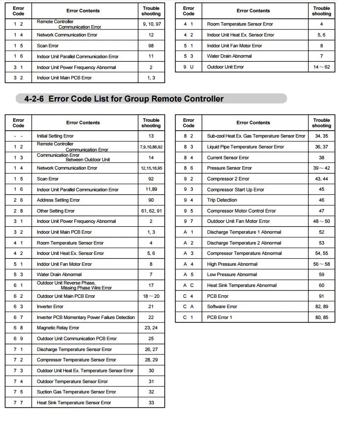
Wired Remote Controller Codes
| Error Codes | Meaning |
|---|---|
| 1 2 | Remote Controller Communication Error |
| 1 4 | Network Communication Error |
| 1 5 | Scan Error |
| 1 6 | Indoor Unit Parallel Communication Error |
| 3 1 | Indoor Unit Power Frequency Abnormal |
| 3 2 | Indoor Unit Main PCB Error |
| 4 1 | Room Temperature Sensor Error |
| 4 2 | Indoor Unit Heat Ex. Sensor Error |
| 5 1 | Inddor Unit Fan Motor Error |
| 5 3 | Water Drain Abnormal |
| 9 U | Outdoor Unit Error |
Group Remote Controller Codes
| Error Codes | Meaning |
|---|---|
| 1 2 | Remote Controller Communication Error |
| 1 3 | Communication Error Between Outdoor Unit |
| 1 4 | Network Communication Error |
| 1 5 | Scan Error |
| 1 6 | Indoor Unit Parallel Communication Error |
| 2 6 | Address Setting Error |
| 2 8 | Other Setting Error |
| 3 1 | Indoor Unit Power Frequency Abnorma |
| 3 2 | Indoor Unit Main PCB Error |
| 4 1 | Room Temperature Sensor Error |
| 4 2 | Indoor Unit Heat Ex. Sensor Error |
| 5 1 | Inddor Unit Fan Motor Error |
| 5 3 | Water Drain Abnormal |
| 6 1 | Outdoor Unit Reverse Phase, Missing Phase Wire Error |
| 6 2 | Outdoor Unit Main PCB Error |
| 6 3 | Inverter Error |
| 6 7 | Inverter PCB Momentary Power Failure Detection |
| 6 8 | Magnetic Relay Error |
| 6 9 | Outdoor Unit Communication PCB Error |
| 7 1 | Discharge Temperature Sensor Error |
| 7 2 | Compressor Temperature Sensor Error |
| 7 3 | Outdoor Unit Heat Ex. Temperature Sensor Error |
| 7 4 | Outdoor Temperature Sensor Error |
| 7 5 | Suction Gas Temperature Sensor Error |
| 7 7 | Heat Sink Temperature Sensor Error |
| 8 2 | Sub-cool Heat Ex. Gas Temperature Sensor Error |
| 8 3 | Liquid Pipe Temperature Sensor Error |
| 8 4 | Current Sensor Error |
| 8 6 | Pressure Sensor Error |
| 9 2 | Compressor 2 Error |
| 9 3 | Compressor Start Up Error |
| 9 4 | Trip Detection |
| 9 5 | Compressor Motor Control Error |
| 9 7 | Outdoor Unit Fan Motor Error |
| A 1 | Discharge Temperature 1 Abnormal |
| A 2 | Discharge Temperature 2 Abnormal |
| A 3 | Compressor Temperature Abnormal |
| A 4 | High Pressure Abnormal |
| A 5 | Low Pressure Abnormal |
| A C | Heat Sink Temperature Abnormal |
| C 4 | PCB Error |
| C A | Software Error |
| C 1 | PCB Error 1 |
Manual Pdf
Fujitsu General Airstage V2 Series Manual PDF
Fujitsu AC Error Codes
source: fujitsu-general.com
- Author
- Recent Posts

Regarding error and fault codes, we believe sharing knowledge is the best way to help everyone. That is why we established ACErrorCode.com, to give you every bit of info you need as a customer. HVAC Expert Contact: dannyreese@acerrorcode.com Call: 916-954-2677
*If you can’t find the code you’re looking for on our site, please let us know, and we’ll update our database as soon as possible.