Стандарт E1 — это Европейский эквивалент стандарта T1, но имеющий групповую скорость 2.048Mbps и имеющий 32 канала по 64Kbps DS0.
Сигналы тревоги (Alarms), которые могут случаться в стандартом интерфейсе E1:
- ЖЕЛТАЯ (YELLOW): индикатор сбоя связи с удаленным абонентом — remote alarm indication (RAI): Сигнал RAI указывает на потерю работоспособности интерфейса между пользователем и сетью на первом уровне. Сигнал RAI распространяется в направлении сети, если работоспособности интерфейса между пользователем и сетью на первом уровне потеряна в направлении пользователя, и сигнал RAI распространяется в направлении пользователя, если эта работоспособность потеряна в направлении от пользователя к сети.
- СИНЯЯ (BLUE): сигнал сбоя связи — alarm indication signal (AIS): Сигнал AIS (alarm indication signal) используется для индикации потери работоспособности соединения на 1 уровне в направлении ET -> TE в сетевой части интерфейса между пользователем и сетью. Особенностью сигнала AIS является то, что его наличие указывает на то, что метки времени, предоставляемые в сторону TE, могут и не быть метками времени полученными из сети. Сигнал AIS передается в режиме non-framed и кодируется как «all binary ONEs».
- КРАСНАЯ (RED): Потеря сигнала — Loss of signal (LOS): Оборудование должно определить состояние «потеря сигнала», когда амплитуда поступающего сигнала: по временной продолжительности, как минимум 1 ms, более чем на 20 dB меньше, чем нормальная амплитуда. Оборудование должно отреагировать на эту ситуацию в течение 12 ms, генерируя сигнал AIS.
Хоть в стандарте E1 не используется понятий ЖЕЛТОЙ, СИНЕЙ и КРАСНОЙ тревоги, они приведены для сравнения со стандартом T1.
Ссылки по теме:
- DSx Digital Signal X
- ISDN
- PRI

+7(495) 797-3311
Москва, Новозаводская ул., 18, стр. 1
info@qtech.ru
www.qtech.ru
8
4.4. АВАРИИ И ПАРАМЕТРЫ
Наименование аварии
Описание причины
Маска индикатора
Состояние индикатора
LINKDOWN электриче-
ский интерфейс
Кабель не подключен или терминальное сетевое
оборудование выключено
LNK/ACT OFF
SFP not in place
SFP модуль не установлен
—
—
SFP RXLOS
Отсутствие сигнала (LOS) на приёмнике SFP
модуля
— —
SFP TXFAULT
Лазер SFP модуля не готов к передаче
—
—
E1-LOS
Потеря сигнала (LOS) на приеме интерфейса Е1 E1
LOS
ON
E1-AIS
Индикация отсутствия передачи от удалённой
стороны по потоку Е1
—
—
E1-LOF
Потеря фрейма —
—
E1-LOMF
Потеря мультифрейма
—
—
E1-CRC-ERR
Ошибки по CRC-4
—
—
E1 RAI
Авария удаленного конца, указывает на потерю
фреймов
—
—
VCAT-LOM
Потеря индикатора мультифрейма MFI
—
—
VCAT-CRC
Ошибка CRC по LCAS
—
—
VCAT-SQM
Ошибка в значении SQ в VCAT: индикатор несо-
ответствия значения принимаемого SQ и пере-
даваемого.
— —
VCAT-MND
Сообщение LCAS указывает,
что соответствующий член в VCG недоступен.
—
—
VCAT-LCASSO
Обнаружение исходного члена VCG.
—
—
LOA
Потеря действительной(виртуальной) каскадной
ориентации:
Указывает задержку чека(проверки) среди VCG
Внутренние члены слишком большие, особенно
Когда LCAS калечит.
—
—
PLCR
Потеря части пропускной способности на приём,
при активном LCAS
— —
TLCR
Потеря всей пропускной способности на приём,
при активном LCAS
—
—
PLCT
Потеря части пропускной способности на пере-
дачу, при активном LCAS
— —
TLCT
Потеря всей пропускной способности на переда-
чу, при активном LCAS
—
—
LFD
Потеря GFP фреймов в установленных границах —
—
CSF
Индикатор потери клиентского сигнала на уда-
лённой стороне.
—
—
greedisbad писал(а):Пытаюсь соединить АТС panasonic kx-TDA600 с АТС panasonic kx-tda200 платами pri30 через передачу потока E1 по сети ethernet при помощи мультиплексоров eltex topgate-1e1-1fg. При соединении платы с мультиплексором eltex topgate-1e1-1fg патчкордом не поднимается линк на мультиплексоре. Только лишь частые мигания оранжевого светодиода. (причем индикация не меняется даже при отключенном патчкорде) На плате pri30 в мануале соединение проходит по 1,2,4,5 жилам, на мультиплексоре по 1,2,3,6. Перепробовал все возможные комбинации, линк так и не поднялся. Вопрос: должен ли он вообще подниматься, если нет связи со вторым мультиплексором? По таблице индикации в мануале написано, что должен моргать зеленый светодиод
Bravo прав. В данной ситуации можете рассматривать в логическом плане пару topgate как простой патч корд для передачи потока Е1. Если есть сомнения в правильности определения пар на разъемах интерфейсов Е1 для определения пары TX можно использовать обычный светодиод. При подключении к паре TX активного потока Е1 светодиод должен светиться вне зависимости от полярности подключения светодиода.
Просьба загрузить с нашего сайта актуальную версию документации на обсуждаемое оборудование
http://eltex.nsk.ru/upload/iblock/5fd/t … tatsii.pdf
В документации подробно описано как анализировать статус порта Е1 TopGatr
3.2.1 Пункт /Е1
StrStatus Отображает состояние приемника/передатчика порта Е1.
OK — отсутствие ошибок в работе приемника/передатчика порта Е1;
AIS — присутствие сигнала AIS в принимаемом/передаваемом потоке Е1;
RAI — присутствие сигнала RAI в принимаемом/передаваемом потоке Е1;
LOS — присутствие сигнала LOS в принимаемом/передаваемом потоке Е1;
AZS — присутствие сигнала AZS в принимаемом/передаваемом потоке Е1;
NOS — отсутствие сигнала на приемнике/передатчике порта Е1;
CodeErr — наличие ошибок кодирования (AMI/HDB3) на приёмнике/передатчике порта Е1;
PRBSErr — наличие ошибок псевдослучайной двоичной последовательности PRBS (PRBS — pseudo-random binary sequence) на приёмнике/передатчике порта Е1 (возможен, если на порту установлен формат передачи PRBS);
TestErr — наличие ошибок работы тестера Е1 на приёмнике/передатчике порта Е1 (возможен, если на порту установлен формат передачи Test); MfASErr – наличие ошибок мультикадровой синхронизации;
CRC4Err – наличие ошибок в CRC-4;
RCRC4Err – наличие установленных битов индикации ошибок CRC-4 в двух последних нечетных кадрах мультифрейма;
RarePulseErr — наличие ошибок, говорящих о том, что импульсы приходят реже, чем положено при кодировании AMI/HDB3;
TXlock -на порту короткое замыкание (TX+ и TX-);
Unframed — порт работает в нефреймированном режиме;
Loop — на порту включен локальный шлейф;
Remote loop — на порту включен удалённый шлейф.
RTT — время от момента посылки запроса до момента получения ответа.
LinkStatus Отображает состояние порта.
Up — есть соединение;
Down — нет соединения.
Стандарт E1 — это Европейский эквивалент стандарта T1, но имеющий групповую скорость 2.048Mbps и имеющий 32 канала по 64Kbps DS0.
Сигналы тревоги (Alarms), которые могут случаться в стандартом интерфейсе E1:
- ЖЕЛТАЯ (YELLOW): индикатор сбоя связи с удаленным абонентом — remote alarm indication (RAI): Сигнал RAI указывает на потерю работоспособности интерфейса между пользователем и сетью на первом уровне. Сигнал RAI распространяется в направлении сети, если работоспособности интерфейса между пользователем и сетью на первом уровне потеряна в направлении пользователя, и сигнал RAI распространяется в направлении пользователя, если эта работоспособность потеряна в направлении от пользователя к сети.
- СИНЯЯ (BLUE): сигнал сбоя связи — alarm indication signal (AIS): Сигнал AIS (alarm indication signal) используется для индикации потери работоспособности соединения на 1 уровне в направлении ET -> TE в сетевой части интерфейса между пользователем и сетью. Особенностью сигнала AIS является то, что его наличие указывает на то, что метки времени, предоставляемые в сторону TE, могут и не быть метками времени полученными из сети. Сигнал AIS передается в режиме non-framed и кодируется как «all binary ONEs».
- КРАСНАЯ (RED): Потеря сигнала — Loss of signal (LOS): Оборудование должно определить состояние «потеря сигнала», когда амплитуда поступающего сигнала: по временной продолжительности, как минимум 1 ms, более чем на 20 dB меньше, чем нормальная амплитуда. Оборудование должно отреагировать на эту ситуацию в течение 12 ms, генерируя сигнал AIS.
Хоть в стандарте E1 не используется понятий ЖЕЛТОЙ, СИНЕЙ и КРАСНОЙ тревоги, они приведены для сравнения со стандартом T1.
Ссылки по теме:
- DSx Digital Signal X
- ISDN
- PRI
From Wikipedia, the free encyclopedia
Alarm indication signal (AIS) (also called “all ones” because of the data and framing pattern) is a signal transmitted by an intermediate element of a multi-node transport circuit that is part of a concatenated telecommunications system to alert the receiving end of the circuit that a segment of the end-to-end link has failed at a logical or physical level, even if the system it is directly connected to is still working. The AIS replaces the failed data, allowing the higher order system in the concatenation to maintain its transmission framing integrity. Downstream intermediate elements of the transport circuit propagate the AIS onwards to the destination element.
There are various AIS formats based on the signaling level of the errored circuit. When an element of T1 or (DS1) circuit loses signal (LOS) or framing (OOF), the device replaces the erroneous data bits with a series of ones. This is where the term All Ones originates. At the DS3 signal level, the intermediate element receiving an errored signal replaces the errored channel data with a signal consisting of a valid DS3 frame with the overhead bits (the M-subframe alignment bits, M-frame alignment bits, and P bits) with the payload set to a 1010… sequence, the C bits all set to zero, and the X bits set to one. This way, the integrity of the DS3 frame is maintained even though the underlying data was compromised.
There are a number of types of AIS signals, which signal failure of different logical or physical segments of the system, including:
- Alarm indication signal path (AIS-P)
- Alarm indication signal line (AIS-L)12
These are SONET OC-xx level indications that indicate if the errored element is in a section, segment, line segment, or path segment of the SONET circuit.
Middle 20th century analog carrier systems had Carrier Group Alarms by which the failure of a pilot signal was alerted to telephone exchange equipment, imposing an automated make-busy condition so the trunks carried by the failed system would not be used. The improved AIS originated with the T-carrier system, and became a standard feature of subsequent plesiochronous and synchronous circuit-based communication systems, and is also part of the Asynchronous Transfer Mode standards.
As the use of Ethernet for long-distance data links has increased, the need for a similar end-to-end OA&M function has led to the development of a similar Ethernet alarm indication signal (EthAIS).
Contents
Introduction
This document explains common alarm types that may appear during E1 operation. It also provides troubleshooting techniques. Use this document in conjunction with E1 Error Events Troubleshooting and the Internetwork Troubleshooting Handbook.
Prerequisites
Requirements
There are no specific prerequisites for this document.
Components Used
The information in this document is based on this software version.
-
Cisco IOS® Software Release 12.0
The information presented in this document was created from devices in a specific lab environment. All of the devices used in this document started with a cleared (default) configuration. If you are working in a live network, ensure that you understand the potential impact of any command before you use it.
Conventions
For more information on document conventions, refer to the Cisco Technical Tips Conventions.
Identify the Alarm
The show controller e1 command displays the controller status specific to the controller hardware. This information is useful for technical support personnel who perform diagnostic tasks. The Network Processor Module (NPM) or MultiChannel Interface Processor (MIP) can query the port adapters to determine their current status.
The show controller e1 EXEC command also provides:
-
Statistics about the E1 link. If you specify a slot and a port number, you can see statistics for each 15-minute period.
-
Information to troubleshoot physical layer and data link layer problems.
-
Local or remote alarm information, if any, on the E1 line.
Issue the show controller command to see if there are alarms or errors displayed by the controller. To see if the frame, line code, and slip seconds error counters register increasing counts, issue the show controller e1 command repeatedly. Note the values the counters indicate for the current interval.
Contact your service provider for frame and line code settings. HDB3 is the only defined line code for E1 lines, while CRC4 framing is most widely used. Look for «Clock Source is Line Primary» in the show controller e1 command output to verify that the clock source is derived from the network.
Troubleshooting the Alarm
This section addresses alarms and procedures to correct them. After each step, issue the show controller e1 command to determine if any alarms occur.
Receive Alarm Indication Signal
A receive (rx) Alarm Indication Signal (AIS) means that there is an alarm on the line upstream from the equipment connected to the port. The AIS failure is declared when an AIS defect is detected at the input and still exists after the Loss of Frame (LoF) failure is declared (caused by the unframed nature of the all «1s» signal). The AIS failure is clears when you clear the LoF failure.
To correct rxAIS errors, complete these steps:
-
Check the show controller e1 slot/port command output to see if the framing format configured on the port matches the framing format of the line.
If not, change the framing format on the controller to match the line.
To change the framing format, issue the framing {crc4 | no-crc4} command in controller configuration mode, for example:
bru-nas-03#configure terminal
Enter configuration commands, one per line. End with CNTL/Z.
bru-nas-03(config)#controller e1 0
bru-nas-03(config-controlle)#framing crc4
-
Contact your service provider to check for an incorrect configuration within the telephone company or a failure in its upstream connections.
Receive Remote Alarm Indication
A Remote Alarm Indication (RAI) means that the far-end equipment has a problem with the signal it is receiving from the local equipment.
The RAI failure is declared when the A-bit (bit three in timeslot zero of frames not containing Frame Alignment Signal [FAS]) becomes one (1). The RAI failure is not declared when a Loss of Signal (LoS) or LoF is detected.
To correct rxRAI errors, complete these steps:
-
Insert an external loopback cable into the port.
For more information, see the Hard Plug Loopback Tests for E1 Lines document.
-
Issue the show controller e1 EXEC command to determine if any alarms occur.
If you do not find any alarms, then the local hardware is probably in good condition. In that case, complete these steps:
-
Check the cabling. Ensure that you have correctly connected the cable between the interface port and the E1 service provider equipment or E1 terminal equipment. Ensure that you have connected the cable to the correct ports. Correct the cable connections if necessary.
-
Check the cable integrity by looking for breaks or other physical abnormalities in the cable. Ensure the pinouts are set correctly. Replace the cable if necessary.
-
Check the settings at the remote end and verify that they match your port settings.
If the problem persists, contact your service provider.
-
-
Remove the loopback plug, and reconnect your E1 line.
-
Check the cabling.
-
Power cycle the router.
-
Connect the E1 line to a different port. Configure the port with the same settings as the line.
If the problem does not persist, then the fault lies with the port. In this case, complete the following steps:
-
Reconnect the E1 line to the original port.
-
Perform a hardware loop test. For more information, see the Hard Plug Loopback Tests for E1 Lines document.
-
Transmit Remote Alarm Indication
A transmit (tx) RAI at an E1 interface means that the interface has a problem with the signal it receives from the far-end equipment.
To correct txRAI errors, complete the following steps:
-
Check the settings at the remote end to ensure that they match your port settings.
-
Another alarim accompanies the txRAI. This alarm indicates the problem that the E1 port/card has with the signal from the far-end equipment. Troubleshoot the condition to resolve the txRAI.
Transmit Alarm Indication Signal
A txAIS alarm is declared when the E1 controller is shut down. A message consisting of all «1»s is sent in an unframed E1 signal.
To correct txAIS errors, complete these steps:
-
Issue the show controller e1 number command to ensure that the E1 controller is up (number is the interface number).
-
If the E1 controller is not up, issue the no shutdown command to bring it up.
Related Information
- E1 Error Events Troubleshooting
- Configuring Channelized E1 and Channelized T1
- Hard Plug Loopback Tests for E1 Lines
- Access Technology Support Pages
- Technical Support — Cisco Systems
This post defines and describes the AIS (Alarm Indication Signal). It also describes how and when Network Equipment will transmit this type of signal.
What does the term AIS Mean?
AIS is an acronym for Alarm Indication Signal.
Where is the AIS Signal Used?
The AIS signal is a particular type of alarm (or maintenance) signal that a Network Element (within a Telecom/Datacom application) will generate and transmit (in its downstream path) anytime it detects some service-affecting defect upstream.
For example:
Suppose a Network Element (NE) was to declare the LOS (Loss of Signal) or the LOF (Loss of Frame) defect within its incoming telecom/datacom signal. In that case, it will respond to this defect condition by transmitting the AIS signal downstream.
Whenever the Network Element transmits this AIS signal downstream, it is (in effect) replacing its defective incoming signal with the AIS signal.
What EXACTLY is an AIS signal?
The exact pattern/signature of an AIS signal depends upon the telecom/datacom standard and network layer we use.
For some datacom/telecom standards, the AIS signal is transmitted (and received) as an Unframed All One’s pattern.
In other standards, we will transmit the AIS indicator as a Framed All One’s pattern (e.g., where the framing alignment fields still use typical values, but the payload fields are filled with an All One’s pattern).
Finally, the OTUk AIS pattern is an Unframed PN-11 (PRBS11) pattern.
In all cases, the NE will generate and transmit the AIS signal at the nominal line rate (of the customarily transmitted signal).
The frequency accuracy requirements for this AIS signal also depend on the governing standards for the Telecom/Datacom system.
I have included posts that define the AIS patterns for OTUk and ODUk types of signals (for OTN applications).
When do we transmit the AIS pattern?
We will go through a couple of examples to illustrate how and when we will transmit the AIS signal.
Example # 1 – The Unerred/Normal Condition
Figure 1 presents a straightforward illustration of a portion of a 3R Repeater/Regenerator, which consists of the following components:
- Two (2) Receive Line Interface blocks (one block is labeled W for West, and the other block is labeled E for East)
- Two (2) Receive Framer blocks (W – West and E – East)
- Two (2) Transmit Line Interface blocks (W – West and E – East)
- Two (2) Transmit Framer blocks (W – West and E – East)
- CS (Clock Smoothing/Jitter Attenuation) PLL (Phase-Locked Loop)
- AIS OSC (Stand-Alone Oscillator).
- FIFO/Buffer
- Two (2) Defect Decoder blocks (W – West and E – East)
In this figure, our 3R Repeater/Regenerator receives a good (error-free) signal from the “West Terminal.”
The 3R Repeater/Regenerator will first receive this signal through its Receive Line Interface (W) block.
Afterward, this signal passes through to the Receive Framer (W) block.
Suppose the Receive Line Interface (W) and the Receive Framer (W) blocks were to detect no problems within this signal. In that case, the 3R Repeater/Regenerator will allow this signal to pass through the Transmit Framer (E) and Transmit Line Interface (E) blocks as is.
Our 3R Repeater/Regenerator will transmit this same data to the East Terminal.
Additionally, the Transmit Framer (E) and Transmit Line Interface (E) blocks would transmit the outbound data (towards the East Terminal) based upon the Recovered Clock signal (which originated from the West Terminal and has been routed through the Clock Smoothing PLL for Jitter Attenuation purposes).
Figure 1 presents an illustration of this Normal (No Defect) Condition.

Figure 1, Illustration of the 3R Repeater/Regenerator – during Good/Normal Conditions.
Please note that I have grayed out the non-relevant portions of Figure 1 so we can focus our discussion on this Defect Declaration to AIS Generation mechanism in the West-to-East Terminal Path.
Now we will illustrate the case where we will transmit the AIS indicator.
Example # 2 – The dLOS/Abnormal Condition
Figure 2 presents another straightforward illustration of a 3R Repeater/Regenerator.
However, in this figure, there is an impairment in the signal that originates from the West Terminal such that our Network Element is now declaring the dLOS (Loss of Signal) defect with this signal.
It is possible that a backhoe or some other mishap severed this signal.
Nonetheless, our 3R Repeater/Regenerator is no longer receiving its signal from the West Terminal.
This also means that our 3R Repeater/Regenerator has no data to send to the East Terminal.
In this situation, our 3R Repeater/Regenerator will respond by doing the following things.
The Receive Line Interface (W) or the Receive Framer (W) blocks will declare the dLOS (Loss of Signal) defect with the signal that it is receiving from the West Terminal.
The Transmit Framer (E) and Transmit Line Interface (E) (which resides directly behind the Receiving Line Interface and Framer blocks – that are declaring the dLOS condition) will proceed to transmit the AIS indicator (to the East Terminal) as a replacement signal for the signal that we are no longer receiving from the West Terminal.
Additionally, the Transmit Framer (E) and Transmit Line Interface (E) blocks would transmit the AIS pattern (towards the East Terminal) based upon the output frequency of the AIS Oscillator (which is a stand-alone oscillator – that operates at the specified line-rate/clock frequency).
Figure 2 illustrates the dLOS/AIS Transmission Condition for our 3R Regenerator/Repeater.
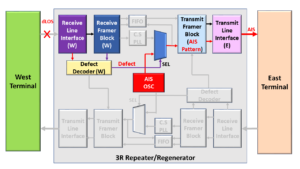
Figure 2, Illustration of the 3R Repeater/Regenerator – during the dLOS/Abnormal Condition.
The Transmit Framer (E) and Transmit Line Interface (E) blocks will continue to transmit the AIS indicator to the East Terminal for the duration that the Receive Line Interface (W) and the Receive Framer (W) blocks are declaring the dLOS defect with the signal that they are receiving from the West Terminal.
The Transmit Framer (E) and Transmit Line Interface (E) blocks will cease to transmit the AIS indicator once the Receive Line Interface (W) and the Receive Framer (W) blocks clear the dLOS defect and start to receive good/normal data from the West Terminal.
At this point, the Transmit Framer (E) and Transmit Line Interface (E) blocks will transmit good/normal data to the East Terminal.
In addition to the dLOS defect, the Network Element will typically transmit the AIS indicator (downstream) in response to the following other defects.
- dLOF (Loss of Frame Defect)
- dLOM (Loss of Multi-Frame Defect)
- dLOFLANE (Loss of Frame of Logical Lane) – for OTL3.4 or OTL4.4 applications (*)
- dLOL (Loss of Lane Alignment) – for OTL3.4 or OTL4.4 applications (*)
- dTIM (Trail Trace Identifier Mismatch)
(*) – Need to be a member of THE BEST DARN OTN TRAINING PRESENTATION…PERIOD!!! to access these links.
Why do we bother to transmit the AIS signal as a replacement signal?
We transmit the AIS indicator downstream in response to service-affecting defects for several reasons.
I will list some of those reasons below.
- Alerts downstream equipment that we have detected and declared a service-affect defect upstream.
- To suppress (or prevent) the downstream equipment from declaring their service-affecting defect.
- Aids in troubleshooting and system debugging. It is easier to isolate the causes of defect conditions if we know exactly which NE is declaring the defect and not the whole chain of NEs downstream.
- The downstream Receive Circuitry provides a much-needed clock signal at the correct bit rate. Clock Recovery PLLs (Phase-Locked-Loops) and Bias Controllers (for Optical Receive circuitry) all need upstream NEs to provide them with a line signal with the appropriate timing (bit-rate).
The AIS signal accomplishes these goals.
Has Inflation got You Down? Our Price Discounts Can Help You Fight Inflation and Help You Become an Expert on OTN!! Click on the Banner Below to Learn More!!!
Discount Available Temporarily

![]()
Darrell Smith has more than 30 years of experience as an Electrical Engineer. He has about 20 years of experience as an Applications Engineer and the remainder of his time was spent in Hardware Design and Product Marketing. He will now be sharing his wealth of knowledge on this blog.
View all posts by Darrell Smith