- Manuals
- Brands
- Advanced Control Manuals
- DC Drives
- M420 Series
- Basic reference manual
-
Bookmarks
Quick Links
Summary of Contents for Advanced Control M420 Series
-
Page 2
M420 General Flux Vector Control Inverter Basic Reference Guide 1. Typical wiring Braking resistor The three- phase 380V power input +24V 485+ Default Serial Multi function input terminal 1 485- communication port Default Multi function input terminal 2 Matching Analog output voltage or resistance Multi function input terminal 3 current through the CN2… -
Page 3
CN3 dial switch voltage or current for a given Relay output 2 Fig.2. Inverters of 22~75Kw Attention: This figure is just for M420 series of inverter (22~75KW brake unit is the selective part, plese declare it in order request if it’s needed.) -
Page 4
M420 General Flux Vector Control Inverter Basic Reference Guide Braking resistor DC reactor BR420 The three- phase 380V power input +24V 485+ Default Serial Multi function input terminal 1 485- communication port Default Multi function input terminal 2 Matching Analog output voltage or resistance Multi function input terminal 3 current through the CN2… -
Page 5
M420 General Flux Vector Control Inverter Basic Reference Guide 2. Main circuit terminals and wiring Main circuit terminals of single-phase Terminal Terminal Name Description Single-phase power supply input Connect to the single-phase 220 VAC L1、L2 terminals power supply Positive and negative terminals Common DC bus input point. -
Page 6
M420 General Flux Vector Control Inverter Basic Reference Guide The capacitor or surge absorber can’t be connected to the output side of the inverter, or it may damage the inverter. If the motor cable is too long, for the influence of the distribute capacitance, it’s easily to have electrical resonance, causing the damage of the insulation or large leakage current which make the inverter over-current protection. -
Page 7
M420 General Flux Vector Control Inverter Basic Reference Guide mode. DI4-COM Digital input 4 2) Impedance: 3.3 kΩ. 3) Input voltage range: 9 ~30V HDI5-COM Digital input 5 4) HDI5 can be used as high-speed input port. Voltage or current output is decided by dial AO1-GND Analog output 1 switches CN2 and CN7. -
Page 8
Trouble Shooting M420 General Flux Vector Control Inverter User Manual 3. Operation and Display 3.1. Operation and Display Interface Introduction We can change the function parameter, monitor the working status and control (start up/stop) the running inverter through the operation panel. The appearance and function are like below: Fig.4. -
Page 9
Trouble Shooting M420 General Flux Vector Control Inverter User Manual 3.1.1. Description of Function LED Indicator LED Symbol Unit Implication Color Freq. Unit LED on— current parameter is frequency Green value Current Unit LED on— current parameter is current value Green Voltage Unit LED on—… -
Page 10
The meaning of the function code group of M420 as follows: Function code Function Explanation group description Basic function Compatible with M420 series of function code F0~FF parameter group motor parameter motor parameter, acceleration and deceleration H0~H3 group time, control method, all can be set independently. -
Page 11
Trouble Shooting M420 General Flux Vector Control Inverter User Manual 3.3. Instruction of Function Code Viewing and Modification Methods Function code parameter of M420 inverter adopts three-level menu, it can view and monitor the parameter by operation panel. The three-level menu includes function parameter set (level 1 menu) →Function code (level 2 menu) →Function code setup value (level 3 menu). -
Page 12
M420 General Flux Vector Control Inverter User Manual Trouble Shooting 4. Trouble Shooting 4.1. Fault Warnings and Solutions If faults happened on the running process, the inverter will stop to output immediately to protect the motor, and the corresponding fault relay of the inverter has contact action at the same time so the panel will display the fault code. -
Page 13
Trouble Shooting M420 General Flux Vector Control Inverter User Manual Display Fault Name Possible Causes Solutions 1: Eliminate external faults. 1: The output circuit is grounded 2: Perform the motor auto- or short circuited. tuning. 2: Motor parameter is not right. 3: Increase the deceleration 3: The deceleration time is too short. -
Page 14
M420 General Flux Vector Control Inverter User Manual Trouble Shooting Display Fault Name Possible Causes Solutions or install a braking resistor. 1. Instantaneous power failure occurs. 2. The input voltage exceeds the 1. Reset the fault. allowed range. 2. Adjust the input voltage to Err12 Undervoltage 3. -
Page 15
Trouble Shooting M420 General Flux Vector Control Inverter User Manual Display Fault Name Possible Causes Solutions 1: The three-phase power input is abnormal. Power input 2: The drive board is faulty. 1: Eliminate external faults. Err23 3: The lightening board is faulty. 2: Seek for maintenance. -
Page 16
M420 General Flux Vector Control Inverter User Manual Trouble Shooting Display Fault Name Possible Causes Solutions 1: Reduce the load, or 1: The load is too heavy or the change the inverter with Fast current rotor is locked. Err33 larger power. limit fault 2: The acceleration time is 2: Increase the acceleration… -
Page 17
Trouble Shooting M420 General Flux Vector Control Inverter User Manual 4.2. Common Faults and Treating Methods The inverter will possibly be confront with below faults, please refer to the mentioned methods to have simple diagnosis and find the solutions. Tab.4. Common faults and treating methods serial Fault Name Possible Causes… -
Page 18
M420 General Flux Vector Control Inverter User Manual Trouble Shooting serial Fault Name Possible Causes Solutions number 1: The parameters are set 1:Check and reset the incorrectly. parameters in group F5. 2: The external signal is incorrect. 2: Re-connect the external The DI 3:Wrong location of the DI dial signal cables. -
Page 19
Function Code Table M420 General Flux Vector Control Inverter User Manual 5. Function code table The symbols in the function code table are described as follows: «☆»:The parameter can be modified when the AC drive is in either stop or running state. «★»:The parameter cannot be modified when the AC drive is in the running state. -
Page 20
M420 General Flux Vector Control Inverter User Manual Function code Table Function Parameter Name Setting Range Default Property Code Group F0: Standard Function Parameters Drive model: 5 digital display, ● F0-00 Drive model 53#.## 2 decimal point 0: for general purpose 0: for general purpose ●… -
Page 21
Function Code Table M420 General Flux Vector Control Inverter User Manual Function Parameter Name Setting Range Default Property Code (Retentive after stop). 2: AI1 3: AI2 4: Multi-reference. 5: Simple PLC. 6: PID 7: Communication setting. 8: Pulse setting. 0: Relative to maximum frequency. -
Page 22
M420 General Flux Vector Control Inverter User Manual Function code Table Function Parameter Name Setting Range Default Property Code 0: Same direction ☆ F0-13 Rotation direction 1: Reverse direction 2: Reverse forbidden 50.0Hz–1200.0 Hz(F0-20=1) Maximum output ★ F0-14 50.00Hz frequency 50.0Hz–600.00 Hz(F0-20=2) 0: Set by F0-16 1: AI1… -
Page 23
Function Code Table M420 General Flux Vector Control Inverter User Manual Function Parameter Name Setting Range Default Property Code Unit’s digit: Binding operation keypad command to frequency source. 0: No Binding 1:Digital setting 2: AI1 3: AI2 4: Multi-speed 5: Simple PLC ☆… -
Page 24
M420 General Flux Vector Control Inverter User Manual Function code Table Function Parameter Name Setting Range Default Property Code 0.00s~300.00s (F0-21 = 2) Over modulation voltage ★ F0-25 0% to 10% boost Model ☆ Carrier frequency 0.5kHz~16.0kHz F0-26 dependent Carrier frequency 0: No ☆… -
Page 25
Function Code Table M420 General Flux Vector Control Inverter User Manual Function Parameter Name Setting Range Default Property Code time Startup DC braking ★ F1-06 current/ Pre-excited 0%~100% current Startup DC braking time/ ★ F1-07 0.0s~100.0s 0.0s Pre-excited time 0: Linear Acceleration/Deceleration ★… -
Page 26
M420 General Flux Vector Control Inverter User Manual Function code Table Function Parameter Name Setting Range Default Property Code 2: Decelerate to stop. Deceleration time of ★ nonstop at instantaneous F1-24 0.0s to 100.0s 10.0s stop Effective voltage of ★ nonstop at instantaneous F1-25 60% to 85%… -
Page 27
Function Code Table M420 General Flux Vector Control Inverter User Manual Function Parameter Name Setting Range Default Property Code Multi-point V/F ★ F2-03 0.00Hz to F2-05 3.00Hz frequency 1 (F1) Multi-point V/F voltage 1 ★ F2-04 0.0% to 100.0% 8.0% (V1) Multi-point V/F ★… -
Page 28
M420 General Flux Vector Control Inverter User Manual Function code Table Function Parameter Name Setting Range Default Property Code V/F separation Frequency voltage declining independently. Stop mode selection upon ☆ F2-19 V/F separation 1: Frequency declining after voltage declines to 0. Group F3:Vector Control Parameters ☆… -
Page 29
Function Code Table M420 General Flux Vector Control Inverter User Manual Function Parameter Name Setting Range Default Property Code Speed loop feedback filter ☆ F3-18 0.000s to 1.000s 0.015s time Speed loop output filter ☆ 0.000s to 1.000s F3-19 0.000s time 0: F3-21 1: AI1… -
Page 30
M420 General Flux Vector Control Inverter User Manual Function code Table Function Parameter Name Setting Range Default Property Code 0.1A to 6000.0 A (motor rated power >30kW). ★ Rated motor frequency 0.01Hz to F0-14 F4-05 50.00Hz Rated motor 1 rotational F4-01 ★… -
Page 31
Function Code Table M420 General Flux Vector Control Inverter User Manual Function Parameter Name Setting Range Default Property Code 7:Speed Decrease 8:Coast to stop 9:Fault reset (RESET) 10:RUN pause ★ F5-05 DI6 function selection 11 : External fault normally open (NO) input. 12:Constant speed 1 13:Constant speed 2 14:Constant speed 3… -
Page 32
M420 General Flux Vector Control Inverter User Manual Function code Table Function Parameter Name Setting Range Default Property Code deceleration time selection 17:DI for acceleration/ deceleration time selection : Frequency source switchover 19 : MOTPOT setting clear (terminal, keypad) : Command source switchover terminal 1… -
Page 33
Function Code Table M420 General Flux Vector Control Inverter User Manual Function Parameter Name Setting Range Default Property Code frequency source X and preset frequency 40:Switchover between auxiliary frequency source Y and preset frequency 41:Switchover between motor 1 and motor 2 42:Reserved 43:PID parameter switchover 44 :… -
Page 34
M420 General Flux Vector Control Inverter User Manual Function code Table Function Parameter Name Setting Range Default Property Code Unit’s:DI1; Ten’s:DI2; Hundred’s:DI3; Kilobit:DI4; Myriabit:DI5 ☆ F5-15 AI1 minimum input 0.00V to 10.00V 0.00V Corresponding setting of ☆ F5-16 -100.0% to 100.00% 0.0% AI1 minimum input ☆… -
Page 35
Function Code Table M420 General Flux Vector Control Inverter User Manual Function Parameter Name Setting Range Default Property Code ☆ F5-37 0.0s DI2 On delay time 0.0s to 3600.0s ☆ F5-38 0.0s DI2 Off delay time 0.0s to 3600.0s ☆ F5-39 0.0s DI3 On delay time… -
Page 36
M420 General Flux Vector Control Inverter User Manual Function code Table Function Parameter Name Setting Range Default Property Code 0:Voltage style 1:Current style Group F6: Output Terminals ☆ 0:No output F6-00 Relay 1 function 1:AC drive running ☆ F6-01 Relay 2 function 2:Fault output 3:Frequency-level detection FDT1 reached… -
Page 37
Function Code Table M420 General Flux Vector Control Inverter User Manual Function Parameter Name Setting Range Default Property Code 23:Frequency 1 reached 24:Module temperature reached 25:Load lost 26:Accumulative power-on time reached 27:Clocking reached output 28:Current running time reached 29:Set count value reached 30:Designated count value reached 31: Motor 1 and motor 2… -
Page 38
M420 General Flux Vector Control Inverter User Manual Function code Table Function Parameter Name Setting Range Default Property Code ☆ Same as Y1 output selection F6-05 FMR output selection 0: Running frequency AO1 output function ☆ F6-09 1: Set frequency selection 2: Output current 3: Output power… -
Page 39
Function Code Table M420 General Flux Vector Control Inverter User Manual Function Parameter Name Setting Range Default Property Code Minimum corresponds to ☆ 0.00V to 10.00V 0.00v F6-18 AO2 output ☆ F6-19 AO2 maximum output F6-17 to 100.0% 100.0% Maximum corresponds to ☆… -
Page 40
M420 General Flux Vector Control Inverter User Manual Function code Table Function Parameter Name Setting Range Default Property Code 0: Default mode 1: 0.1Hz 2: 0.5Hz ☆ F7-16 Keypad knob accuracy 3: 1Hz 4: 2Hz 5: 4Hz 6: 5Hz 7: 8Hz 8: 10Hz 0: Run at frequency lower limit Running mode when set… -
Page 41
Function Code Table M420 General Flux Vector Control Inverter User Manual Function Parameter Name Setting Range Default Property Code 1: STOP/RESET key enabled in any operation mode. 0: Forward JOG. 1: Switchover between forward rotation and reverse rotation. Quick/JOG function ★… -
Page 42
M420 General Flux Vector Control Inverter User Manual Function code Table Function Parameter Name Setting Range Default Property Code 1 to 0xffff Bit00: Set frequency 0001 Bit01: Bus voltage (V) 0002 Bit02: DI input status 0004 Bit03: DO output status 0008 Bit04: AI1 voltage (V) 0010 Bit05: AI2 voltage (V) -
Page 43
Function Code Table M420 General Flux Vector Control Inverter User Manual Function Parameter Name Setting Range Default Property Code Setting of current running ☆ F7-38 0.0min to 6500.0min 0.0min time ☆ F7-39 High level timing 0.0s to 6000.0s 2.0s ☆ F7-40 Low level timing 0.0s to 6000.0s… -
Page 44
M420 General Flux Vector Control Inverter User Manual Function code Table Function Parameter Name Setting Range Default Property Code Frequency reached ☆ F7-57 0.00Hz to F0-14 50.00Hz detection value 2 Frequency reached ☆ F7-58 0% to 100% detection duration 2 Zero current detection ☆… -
Page 45
Function Code Table M420 General Flux Vector Control Inverter User Manual Function Parameter Name Setting Range Default Property Code Module temperature ☆ F7-69 0℃ to 90℃ 70℃ threshold Output power correction ☆ F7-70 0.001 to 3.000 1.000 coefficient Linear speed display Linear speed = F-71 * HDI1 ☆… -
Page 46
M420 General Flux Vector Control Inverter User Manual Function code Table Function Parameter Name Setting Range Default Property Code 0 to 247 ☆ F8-02 Local address (0 is Broadcast address) ☆ 0ms to 30ms F8-03 Response delay ☆ 0.0s to 30.0s F8-04 Communication timeout 0.0s… -
Page 47
Function Code Table M420 General Flux Vector Control Inverter User Manual Function Parameter Name Setting Range Default Property Code 0: Disable Input phase loss protection ☆ F9-14 selection 1: Enable 0: Disable Output phase loss ☆ F9-15 protection selection 1: Enable 0: Disable Short-circuit to ground ☆… -
Page 48
M420 General Flux Vector Control Inverter User Manual Function code Table Function Parameter Name Setting Range Default Property Code 0 to 22222 Unit’s digit: Communication fault – Err27 0: Coast to stop 1: Stop according to stop mode 2:Continue to run Fault protection action Ten’s digit: External equipment ☆… -
Page 49
Function Code Table M420 General Flux Vector Control Inverter User Manual Function Parameter Name Setting Range Default Property Code 0: Current running frequency 1: Set frequency Frequency selection for ☆ F9-26 continuing to run upon 2: Frequency upper limit fault 3: Frequency lower limit 4: Backup frequency(F9-27) Backup frequency upon… -
Page 50
M420 General Flux Vector Control Inverter User Manual Function code Table Function Parameter Name Setting Range Default Property Code ☆ FA-02 PID setting change time Response time:0.00s to 650.00s 0.00s 0: AI1 1: AI2 2: AI1 — AI2 3: Communication setting ☆… -
Page 51
Function Code Table M420 General Flux Vector Control Inverter User Manual Function Parameter Name Setting Range Default Property Code 0: No switchover PID parameter switchover 1: Switchover via DI ☆ FA-21 condition 2: Automatic switchover based on deviation PID parameter switchover 0.0% to FA-23 ☆… -
Page 52
M420 General Flux Vector Control Inverter User Manual Function code Table Function Parameter Name Setting Range Default Property Code amplitude Jump frequency ☆ Fb-02 0.0% to 50.0% 0.0% amplitude ☆ Fb-03 Swing frequency cycle 0.1s to 3000.0s 10.0s Triangular wave rising ☆… -
Page 53
Function Code Table M420 General Flux Vector Control Inverter User Manual Function Parameter Name Setting Range Default Property Code ☆ FC-12 Reference 12 -100.0% to 100.0% 0.0% ☆ FC-13 Reference 13 -100.0% to 100.0% 0.0% ☆ FC-14 Reference 14 -100.0% to 100.0% 0.0% ☆… -
Page 54
M420 General Flux Vector Control Inverter User Manual Function code Table Function Parameter Name Setting Range Default Property Code 0 to 3 Acceleration/deceleration ☆ FC-23 time of simple PLC (Means acceleration/deceleration reference 2 time 1 to 4 respectively ) Running time of simple ☆… -
Page 55
Function Code Table M420 General Flux Vector Control Inverter User Manual Function Parameter Name Setting Range Default Property Code reference 8 (Means acceleration/deceleration time 1 to 4 respectively ) Running time of simple ☆ FC-36 0.0~6500.0 PLC reference 9 0 to 3 Acceleration/deceleration ☆… -
Page 56
M420 General Flux Vector Control Inverter User Manual Function code Table Function Parameter Name Setting Range Default Property Code Running time of simple ☆ FC-48 0.0~6500.0 PLC reference 15 0 to 3 Acceleration/deceleration ☆ FC-49 time of simple PLC (Means acceleration/deceleration reference 15 time 1 to 4 respectively )… -
Page 57
Function Code Table M420 General Flux Vector Control Inverter User Manual Function Parameter Name Setting Range Default Property Code ☆ -200.0% to 200.0% Fd-01 Torque digital setting 150.0% Forward maximum 0.00Hz to maximum ☆ Fd-03 50.00Hz frequency(F0-14) frequency in torque Reverse maximum 0.00Hz to maximum ☆… -
Page 58
M420 General Flux Vector Control Inverter User Manual Function code Table Function Parameter Name Setting Range Default Property Code ☆ FE-10 AI curve 2 inflexion 1 input FE-00 to FE-04 3.00 Corresponding setting of ☆ FE-11 -100.0% to 100.0% 30.0% AI curve 2 inflexion 1 input ☆… -
Page 59
Function Code Table M420 General Flux Vector Control Inverter User Manual Function Parameter Name Setting Range Default Property Code 3: Acceleration/deceleration time 3 4: Acceleration/deceleration time 4 Group H1: Motor 2 Parameters 0: No auto-tuning ★ Auto-tuning selection 1: Static auto-tuning H1-00 2: Complete auto-tuning Model… -
Page 60
M420 General Flux Vector Control Inverter User Manual Function code Table Function Parameter Name Setting Range Default Property Code Acceleration time of ☆ 1.0s to 600.0s H1-12 10.0s complete auto-tuning Deceleration time of ☆ 1.0s to 600.0s H1-13 10.0s complete auto-tuning Group H2: Motor 2 V/F Control Parameters ☆… -
Page 61
Function Code Table M420 General Flux Vector Control Inverter User Manual Function Parameter Name Setting Range Default Property Code 0 to 30000 Excitation adjustment ☆ H3-14 1300 integral gain Ki 100 to 200 ☆ Flux braking gain H3-15 50% to 200% Field weakening torque ☆… -
Page 62
M420 General Flux Vector Control Inverter User Manual Function code Table Function Parameter Name Setting Range Default Property Code Group L0: System Parameters 0: Disable Parameters only for ☆ L0-00 reading 1: Enable Group L1: User — defined Parameters 0: Disable Clear user-defined ☆… -
Page 63
Function Code Table M420 General Flux Vector Control Inverter User Manual Function Parameter Name Setting Range Default Property Code ☆ L1-19 User-defined parameters 19 uF0-00 uF0-00 to uU1-xx ☆ L1-20 User-defined parameters 20 uF0-00 to uU1-xx uF0-00 ☆ L1-21 User-defined parameters 21 uF0-00 uF0-00 to uU1-xx ☆… -
Page 64
M420 General Flux Vector Control Inverter User Manual Function code Table Function Parameter Name Setting Range Default Property Code 350.0V ☆ L2-06 Random PWM depth 0 to 6 0: No current output 1: Normal operation ☆ L2-07 0Hz running way 2: Output with DC braking current F1-16 0: Limitation mode 0… -
Page 65
Function Code Table M420 General Flux Vector Control Inverter User Manual Function Parameter Name Setting Range Default Property Code ☆ L3-18 AO2 measured voltage 2 -9.999V to 10.000V 8.000V ☆ L3-19 AO2 target voltage 2 -9.999V to 10.000V 8.000V Group L4: Master-slave Control Parameters 0: Disable Master-slave control ★… -
Page 66
M420 General Flux Vector Control Inverter User Manual Function code Table Function Parameter Name Setting Range Default Property Code holding time Braking period current ★ L5-03 50.0% to 200.0% 120.0% threshold Braking actuation ★ L5-04 0.00Hz to 20.00Hz 1.50Hz frequency Braking actuation delay 0.0s to 20.0s ★… -
Page 67
Function Code Table M420 General Flux Vector Control Inverter User Manual Function Parameter Name Min. Unit Property Code Err04: Overcurrent during acceleration Err05: Overcurrent during deceleration Err06: Over current at constant speed Err08: Overvoltage during acceleration Err09: Overvoltage during deceleration Err10: Overvoltage at constant speed Err12: Under voltage… -
Page 68
M420 General Flux Vector Control Inverter User Manual Function code Table Function Parameter Name Min. Unit Property Code Err34: Load becoming 0 Err35: Control power supply fault Err37: Control power supply fault Err39: Current running time reached Err40: Accumulative running time reached Err42: Motor switchover fault during running… -
Page 69
Function Code Table M420 General Flux Vector Control Inverter User Manual Function Parameter Name Min. Unit Property Code ● U0-19 Power-on time upon the 2 fault 1min ● U0-20 Running time upon the 2 fault 1min ● U0-21 Reserved ● U0-22 Reserved ●… -
Page 70
M420 General Flux Vector Control Inverter User Manual Function code Table Function Parameter Name Min. Unit Property Code ● U1-10 PID setting, PID setting ( percentage)×FA-05 ● U1-11 PID feedback, PID feedback ( percentage)×FA-05 ● U1-12 Count value ● U1-13 Length value ●… -
Page 71
Function Code Table M420 General Flux Vector Control Inverter User Manual Function Parameter Name Min. Unit Property Code ● U1-33 Target voltage upon V/F separation ● Output voltage upon V/F separation U1-34 ● Reserved U1-35 ● U1-36 Current motor number ●…
|
|
Ремонт MICROMASTER 420
 Компания «Кернел» производит ремонт частотных преобразователей с 2002 года. За это время мы накопили колоссальный опыт в том числе опыт в ремонте MICROMASTER 420 такого известного производителя как SIEMENS. Ремонт подобной промышленной электроники ответственное и сложное занятие, требующие максимальной отдачи, профессионализма и максимально полной материальной базе.
По причине особой сложности Ремонт MICROMASTER 420 производится исключительно на территории сервисного центра. Частотный преобразователь MICROMASTER 420 является крайне сложной промышленной электроникой соответственно ремонт MICROMASTER 420 можно доверить только настоящим профессионалам своего дела с богатым опытом работы в данном направлении.
Все специалисты нашего сервисного центра имеют высшее техническое образование, огромный опыт и максимально полную материальную базу включая новейшее высокотехнологичное диагностическое оборудование благодаря чему ремонт MICROMASTER 420 проходит максимально эффективно.
Инженеры сервисного центра уделяют максимальное внимание к качеству исполнения ремонта, программирования и настройке частотного преобразователя, не зависимо от производителя данного промышленного оборудования. Именно поэтому мы смело даем гарантию на ремонт MICROMASTER 420 и замененные в процессе ремонта компоненты шесть месяцев.
Особое внимание заслуживает тот факт, что ремонт MICROMASTER 420 в производится исключительно с использованием оригинальных запасных частей, на компонентном уровне с применением высокотехнологичного оборудования, квалифицированным персоналом с инженерным образованием.
Ремонт распространенных частотнрых преобразователей MICROMASTER 420
Если на вашем производстве появились проблемы с частотным преобразователем MICROMASTER 420, ошибка которую вы не можете сбросить самостоятельно, мы всегда рады вам помочь. Обращайтесь в сервисный центр «Кернел». Специалисты нашей компании в минимальные сроки проведут глубокую диагностику частотного преобразователя и последующий ремонт MICROMASTER 420 в . Оставьте заявку на ремонт частотного преобразователя используя форму на сайте.
Ниже приведен далеко не полный список частотных преобразователей MICROMASTER 420 ремонт которых выполняет наш сервисный центр.
|
6SE6420-2UC11-2AA1 6SE6420-2UC12-5AA1 6SE6420-2UC13-7AA1 6SE6420-2UC15-5AA1 6SE6420-2UC17-5AA1 6SE6420-2UC21-1BA1 6SE6420-2UC21-5BA1 6SE6420-2UC22-2BA1 6SE6420-2UC23-0CA1 6SE6420-2AB11-2AA1 |
6SE6420-2AB12-5AA1 6SE6420-2AB13-7AA1 6SE6420-2AB15-5AA1 6SE6420-2AB17-5AA1 6SE6420-2AB21-1BA1 6SE6420-2AB21-5BA1 6SE6420-2AB22-2BA1 6SE6420-2AB23-0CA1 6SE6420-2UC25-5CA1 6SE6420-2UC24-0CA1 |
Ошибки MICROMASTER 420
При появлении неисправности на дисплее частотного преобразователя MICROMASTER 420 отобразится код ошибки, в файле ниже приведены все ошибки MICROMASTER 420 и возможные способы их устранения.
При возникновении ошибки преобразователь отключается и на индикации появляется код ошибки.
УКАЗАНИЕ
Сообщения об ошибках могут квитироваться следующим образом:
- Возможность 1: Отключить преобразователь от сети и снова подключить
- Возможность 2: на AOP или BOP
- Возможность 3: Через цифровой вход 3
 Сообщения об ошибках сохраняются в параметре r0947 под своим кодовым номером (к примеру, F0003 = 3). Соответствующее слово ошибки находится в параметре r0949. Если слово ошибки у ошибки отсутствует, то вносится значение 0. Кроме этого, можно запросить момент времени возникновения ошибки (r0948) и число сохраненных в параметре r0947 сообщений об ошибках (P0952). Подробное описание всех сообщений об ошибках можно найти в Списке параметров.
Предупреждения
Предупреждения сохраняются в параметре r2110 под своим кодовым номером (к примеру, A0503 = 503) и могут загружаться оттуда. Подробное описание всех предупреждений можно найти в Списке параметров.
Сброс сообщений об ошибках, предупреждений
Работа без сбоев с точки зрения приложения является решающим критерием приемлемости приводной системы. Но для специальных приложений бесперебойная работа требуется и тогда, когда имеет место перегрузка или внешние обстоятельства вызывают ошибку. В таких приложениях (к примеру, мешалка) бесперебойная работа более важна, чем защита приводной системы. В MICROMASTER 420 можно подавить до 3-х сообщений об ошибках/предупреждений с индексированными параметрами P2100 и P2101. Выбор сообщений об ошибках/предупреждений (см. раздел «Сообщения об ошибках/предупреждения») устанавливается с помощью параметра P2100, а реакция выбирается с помощью параметра P2101. Корреляция между подавлением и реакцией осуществляется через индекс 0 — 2 обоих параметров. Для реакций возможны следующие установки:
- 0 нет реакции, нет индикации
- 1 реакция останова ВЫКЛ1
- 2 реакция останова ВЫКЛ2
- 3 реакция останова ВЫКЛ3
- 4 нет реакции, только предупреждение
Пример:
Предупреждение A0911 указывает на то, что привод увеличивает врем выбега по рампе, чтобы не допустить перенапряжения. Для подавления этого сообщения установить следующие параметры:
p2100[0] = 911 (выбор предупреждения A0911)
P2101[0] = 0 (нет реакции, нет индикации)
Все возможные предупреждения и ошибки MICROMASTER 420 описаны в руководстве пользователя, которое вы можете скачать с нашего сайта в удобном формате- pdf.
Скачать руководство пользователя MICROMASTER 420 мануал.pdf
Устранение причины ошибки частотного преобразователя MICROMASTER 420 и ее сброс позволит в кратчайшие сроки возобновить работу дорогостоящего оборудования. К сожалению не все ошибки можно исправить самостоятельно, некоторые ошибки MICROMASTER 420 возможно исправить только в специализированных сервисных центрах.
MICROMASTER 420 программирование
 На ряду с ремонтом, специалисты сервисного центра «Кернел» выполняют программирование MICROMASTER 420 и настройку параметров системы частотного преобразователя. Подобную услугу мы оказываем на территории сервисного центра, также в исключительных случаях инженер компании может выполнить программирование MICROMASTER 420 на территории заказчика.
Настройка параметров, программирование MICROMASTER 420 в является заключительным звеном в процессе ремонта частотного преобразователя и требует профессионального подхода. Именно финальный этап программирования MICROMASTER 420 наглядно покажет качество выполненного ремонта MICROMASTER 420.
К слову, мы уделяем особое внимание качеству и смело даем гарантию на все выполненные ремонтно-восстановительные работы шесть месяцев, гарантия так же распространяется на запасные части, которые были заменены в процессе ремонта.
Хочется обратить внимание на то, что мы стараемся провести ремонт и программирование MICROMASTER 420 в максимально сжатые сроки, тем самым минимизируем простой дорогостоящего промышленного оборудования.
MICROMASTER 420 ввод в эксплуатацию
Инженеры сервисного центра «Кернел» не только выполняют качественный ремонт MICROMASTER 420 и программирование частотного преобразователя. Так же мы предоставляем услугу запуска в эксплуатацию оборудования от стадии проектирования до выпуска первой продукции.
Именно этап запуска в эксплуатацию MICROMASTER 420 отвечает за долгий и безаварийный процесс работы промышленного оборудования, тем самым позволяя получить максимальную прибыль и сэкономить на незапланированном ремонте.
По-настоящему качественный ввод в эксплуатацию MICROMASTER 420 может выполнить только высококвалифицированный специалист с богатым опытом работы в данном направлении. Найти подобного специалиста достаточно сложно, но, если вы обращаетесь в наш сервисный центр вам не придется об этом думать.
ДляпараметрированияпреобразователяВыможетеиспользоватьоднуизоп-ционныхоператорскихпанелей, таких как «Базовая Операторская Панель»(BOP) или «Расширенная Панель Оператора» (AOP). Для более удобного обслуживания и параметрирования преобразователей можно использовать специальный инструмент – Drive Monitor – программу для настройки и документирования.
|
Блок схема MICROMASTER 420 |
|
|
В нашей команде работают исключительно профессионалы своего дела, а за время существования нашей компании мы ввели в эксплуатацию не одну сотню частотных преобразователей в том числе и MICROMASTER 420, с каждым разом получая и накапливая драгоценный опыт.
О MICROMASTER 420
 Частотный преобразователь MICROMASTER 420 снабжен пультом отображения состояния (Status Display Panel) (SDP). Чтобы изменять и устанавливать требуемые параметры, необходимо использовать базовый пульт оператора (Basic Operator Panel) (BOP), расширенный пульт оператора (Advanced Operator Panel) (AOP) или последовательный интерфейс связи.
Базовая панель оператора (BOP), поставляемая как опция, дает возможность доступа к параметрам преобразователя и обеспечивает специфическую пользовательскую настройку MICROMASTER 420. BOP может использоваться для конфигурирования большинства преобразователей MICROMASTER 420. Поэтому нет необходимости покупать свою панель BOP для каждого преобразователя. Панель имеет сегментные индикаторы для чтения и записи параметров преобразователя. Панель не имеет возможности собственного хранения информации и параметров после её снятия.
Линейка промышленной электроники, которую восстанавливают специалисты сервисного центра «Кернел» не имеет ограничений, мы выполняем качественный ремонт промышленной электроники и оборудования абсолютно любых производителей не зависимо от года выпуска и наличия технической документации.
Оставить заявку на ремонт MICROMASTER 420
Оставить заявку на ремонт или программирование MICROMASTER 420 в можно с помощью специальной формы, которая вызывается нажатием одноименной кнопки в верхней части страницы. Все вопросы, связанные с ремонтом MICROMASTER 420 в вы можете задать нашим менеджерам. Связаться с ними можно несколькими способами:

- Заказав обратный звонок (кнопка в правом нижнем углу сайта)
- Посредством чата (кнопка расположена с левой стороны сайта)
- Позвонив по номеру телефона: +7(8482) 79-78-54; +7(917) 121-53-01
- Написав на электронную почту: 89171215301@mail.ru
Вот далеко не полный список производителей промышленной электроники и оборудования, ремонтируемой в нашей компании.
International English
6.3
In the event of a failure, the inverter switches off and a fault code appears on the display.
Table 6-2
Fault Code
F0001
Overcurrent
F0002
Overvoltage
F0003
Undervoltage
F0004
Inverter
Overtemperature
F0005
Inverter I
F0011
Motor Overtemperature
2
I
F0041
Stator resistance
measurement failure
94
MICROMASTER 420 Fault Codes
Description
1. Motor power does not
correspond to the inverter
power.
2. Motor lead short circuit
3. Earth fault
Supply voltage out of tolerance
load is regenerating.
Mains supply removed when
inverter is running.
Ambient temperature outside of
limits,
Fan failure
2
T
Inverter is overloaded
1. Motor overloaded.
T
2. Motor data incorrect.
3. Check parameter for motor
thermal time constant.
4. Check parameter for motor I
warning level.
5. Long time period operating at
low speeds
Stator resistance measurement
failure
Possible Causes
2
t
6. TROUBLESHOOTING
Diagnosis & Remedy
1. Check whether the motor power
corresponds to the inverter
power.
2. Check that the cable length limits
have not been exceeded.
3. Check motor cable and motor for
short-circuits and earth faults.
4. Check whether the motor
parameters correspond with the
motor being used.
5. Check the stator resistance
(P0350).
6. Increase the ramp-up-time
(P1120).
7. Reduce the boost set in (P1310),
(P1311) and (P1312).
8. Check whether the motor is
obstructed or overloaded.
1. Check whether the supply voltage
is within the limits indicated on the
rating plate.
2. Check if dc-link voltage
controller (P1240) is enabled and
parameterized correctly.
3. Increase the ramp-down time
(P1121).
1. Check whether the supply voltage
is within the limits indicated on the
rating plate.
2. Check the supply is not subject to
temporary failures or voltage
reductions.
1. Check that the integral fan rotates
when drive is running.
2. Check if pulse frequency is set to
default value.
3. Ambient temperature could be
higher than specified for the
inverter.
4. Check that air inlet and outlet
points are not obstructed.
1. Check if load duty-cycle is within
specified limits.
2. Check that motor power
corresponds to inverter power
1. Check motor data.
2. Check loading on motor.
3. Boost settings too high (P1310,
P1311, P1312)
1. Check if the motor is connected to
the inverter
2. Check that the motor data has
been entered correctly.
MICROMASTER 420 Operating Instructions
6SE6400-5AA00-0BP0
- Manuals
- Brands
- Siemens Manuals
- DC Drives
- MICROMASTER 420
- Operating instruction
-
Contents
-
Table of Contents
-
Troubleshooting
-
Bookmarks
Quick Links
MICROMASTER
Operating Instructions
Issue A2
User Documentation
Related Manuals for Siemens Micromaster 420
Summary of Contents for Siemens Micromaster 420
- Page 1
MICROMASTER Operating Instructions Issue A2 User Documentation… - Page 3
Overview Installation Commissioning MICROMASTER 420 Using the MICROMASTER 420 Operating Instructions System Parameters User Documentation Troubleshooting MICROMASTER 420 Specifications Supplementary Information Appendices Valid for Release Inverter Type Control Version MICROMASTER 420 October 2000 Index Issue: A2… - Page 4
We welcome suggestions for improvement. MICROMASTER® is a registered trademark of Siemens. Siemens handbooks are printed on chlorine-free paper that has been produced from managed sustainable forests. No solvents have been used in the printing or binding process. - Page 5
♦ Getting Started Guide The Getting Started Guide is designed to give you quick access to all the basic information required to install and set up your MICROMASTER 420 for operation. ♦ Operating Instructions The Operating Instructions provide detailed information for installation and operation of your MICROMASTER 420. -
Page 6: Using The
Siemens. Contact address Should any questions or problems arise while reading this manual, please contact the Siemens office concerned using the form provided at the back this manual. MICROMASTER 420 Operating Instructions 6SE6400-5AA00-0BP0…
-
Page 7: Micromaster
Please read the information carefully, since it is provided for your personal safety and will also help prolong the service life of your MICROMASTER 420 Inverter and the equipment you connect to it. General Warnings ♦…
- Page 8
The connection of power, motor and control cables to the inverter must be carried out as shown in Figure 2-4 on page 25, to prevent inductive and capacitive interference from affecting the correct functioning of the inverter. MICROMASTER 420 Operating Instructions 6SE6400-5AA00-0BP0… - Page 9
EN 60204, 9.2.5.4) Repair Warnings ♦ Repairs on equipment may only be carried out by Siemens Service, by repair centers authorized by Siemens or by qualified personnel who are thoroughly acquainted with all the warnings and operating procedures contained in this manual. - Page 10
International English FOREWORD MICROMASTER 420 Operating Instructions 6SE6400-5AA00-0BP0… -
Page 11: Table Of Contents
Ambient operating conditions ………………19 Mechanical Installation ………………..20 Electrical Installation ………………..21 Commissioning ………………….27 Front Panels for the MICROMASTER 420 …………..29 General operation ………………….. 34 Using the MICROMASTER 420 …………….37 Frequency Setpoint………………… 38 Command Sources (P0700) ………………38 OFF and braking Functions ………………
- Page 12
D — Removing ‘Y’ Cap Frame Size A ………………115 E — Removing ‘Y’ Cap Frame Sizes B and C …………….117 F — User Parameter Settings …………………. 119 G — Applicable Standards ………………….121 H — List of Abbreviations………………….123 Index ……………………..125 MICROMASTER 420 Operating Instructions 6SE6400-5AA00-0BP0… - Page 13
Motor and Power Connections ………………23 Figure 2-4 Wiring Guidelines to Minimize the Effects of EMI …………. 25 Figure 3-1 Panels available for the MICROMASTER 420 Inverter ………… 29 Figure 3-2 Basic operation with SDP………………..30 Figure 3-3 Buttons on the Basic Operator Panel…………….31 Figure 3-4 Changing parameters via the BOP……………… - Page 14
MICROMASTER 420 Operating Instructions 6SE6400-5AA00-0BP0… -
Page 15: Overview
OVERVIEW International English Overview This Chapter contains: A summary of the major features of the MICROMASTER 420 range. The MICROMASTER 420………………. 16 Features ……………………16 MICROMASTER 420 Operating Instructions 6SE6400-5AA00-0BP0…
-
Page 16: The Micromaster 420
Comprehensive protective functions provide excellent inverter and motor protection. The MICROMASTER 420 with its default factory settings, is ideal for a large range of simple motor control applications. The MICROMASTER 420 can also be used for more advanced motor control applications via its comprehensive parameter lists.
-
Page 17: Installation
General data relating to installation ♦ Dimensions of Inverter ♦ Wiring guidelines to minimize the effects of EMI ♦ Details concerning electrical installation General……………………18 Ambient operating conditions ………………19 Mechanical Installation ………………..20 Electrical Installation ………………..21 MICROMASTER 420 Operating Instructions 6SE6400-5AA00-0BP0…
-
Page 18: General
Apply 25% of input voltage for 2 hours Increase volts to 50% for a further 2 hours Increase volts to 75% for a further 2 hours Increase volts to 100% for a further 2 hours Inverter ready for run signal MICROMASTER 420 Operating Instructions 6SE6400-5AA00-0BP0…
-
Page 19: Ambient Operating Conditions
Overheating Mount the inverter vertically to ensure optimum cooling. Additional ventilation may be required for horizontal mounting. Ensure that the inverter’s air vents are not obstructed. Allow 100 mm clearance above and below the inverter. MICROMASTER 420 Operating Instructions 6SE6400-5AA00-0BP0…
-
Page 20: Mechanical Installation
4 washers M5 204 mm 8.03″ 245 mm Tightening 9.65″ torque (unit to cabinet) with washers fitted: 3 Nm 174 mm 185 mm 195 mm 6.85″ 7.28″ 7.68″ Figure 2-1 Drill pattern for MICROMASTER 420 MICROMASTER 420 Operating Instructions 6SE6400-5AA00-0BP0…
-
Page 21: Electrical Installation
A type B RCD is used. The trip limit of the RCD is 300mA. The neutral of the supply is grounded. Only one inverter is supplied from each RCD. The output cables are less than 50m (screened) or 100m (unscreened). MICROMASTER 420 Operating Instructions 6SE6400-5AA00-0BP0…
- Page 22
To tighten up the power terminal screws use a 4 — 5 mm cross-tip screwdriver. Access to the power and motor terminals The procedure for accessing the power and motor terminals on the MICROMASTER 420 Inverter is illustrated in Appendices B and C. Please also refer to the photographs showing the Power Terminal connections and the Control Terminal connections on the inside of the back cover of this manual. - Page 23
2. INSTALLATION International English N/L2 L/L1 (Ground) (Ground) Figure 2-2 MICROMASTER 420 Connection Terminals OPTIONAL FILTER (Class B only) CONTACTOR MICROMASTER MOTOR FUSE L/L1 N/L2 SINGLE PHASE TYPICAL INSTALLATION OPTIONAL FILTER CONTACTOR MICROMASTER MOTOR FUSE THREE PHASE Figure 2-3 Motor and Power Connections… - Page 24
♦ Use screened or armored cables for the motor connections and ground the screen at both ends using the cable clamps Warning Safety regulations must not be compromised when installing inverters! MICROMASTER 420 Operating Instructions 6SE6400-5AA00-0BP0… - Page 25
Use suitable clips to fix motor and control cable screens securely to metal back plate Note To enhance the screening of the motor and control cables, the optional Gland Plate can be used (not shown in Figure 2-4). MICROMASTER 420 Operating Instructions 6SE6400-5AA00-0BP0… - Page 26
International English 2. INSTALLATION MICROMASTER 420 Operating Instructions 6SE6400-5AA00-0BP0… -
Page 27: Commissioning
Basic Operator Panel (BOP) ♦ An 8-step guide at the end of the Chapter, which provides a simple procedure for changing parameters Front Panels for the MICROMASTER 420 …………..29 General operation ………………….. 34 MICROMASTER 420 Operating Instructions 6SE6400-5AA00-0BP0…
- Page 28
Only qualified personnel may enter settings in the control panels. Particular attention must be paid to safety precautions and warnings at all times. The MICROMASTER 420 is supplied with a Status Display Panel (SDP) and default parameter settings that cover the following requirements: ♦… -
Page 29: Front Panels For The Micromaster 420
Front Panels for the MICROMASTER 420 Front panels The front panels shown below are available for use with the MICROMASTER 420 Inverters. The panel on the left is supplied with the inverter as standard and is referred to as the Status Display Panel (SDP). The Basic Operator Panel (BOP) and Advanced Operator Panel (AOP) are available as options.
-
Page 30: Table 3-2 Default Settings For Operation Using The Bop
Commissioning with the Basic Operator Panel (BOP) The Basic Operator Panel (BOP), which is available as an option, provides access to the inverter parameters and enables you to customize the settings of your MICROMASTER 420. The BOP can be used to configure several MICROMASTER 420 150.00 Inverters.
-
Page 31: Figure 3-3 Buttons On The Basic Operator Panel
To change the Frequency Setpoint via the BOP set P1000 = 1. Pressing this button decreases the displayed value. Decrease value To change the Frequency Setpoint via the BOP set P1000 = 1. Figure 3-3 Buttons on the Basic Operator Panel MICROMASTER 420 Operating Instructions 6SE6400-5AA00-0BP0…
-
Page 32: Figure 3-4 Changing Parameters Via The Bop
Note — Busy Message In some cases — when changing parameter values — the display on the BOP shows » — — — -«. This means the inverter is busy with tasks of higher priority. MICROMASTER 420 Operating Instructions 6SE6400-5AA00-0BP0…
-
Page 33: Figure 3-5 Typical Motor Rating Plate Example
Figure 3-6. 1 kΩ Figure 3-6 Motor Overload PTC Connection Note: To enable the trip function, set parameter P0701, P0702 or P0703 = 29. MICROMASTER 420 Operating Instructions 6SE6400-5AA00-0BP0…
-
Page 34: General Operation
(P0005 = 21) the corresponding setpoint is displayed approximately every 1.0 seconds while the inverter is stopped. 3. The inverter is programmed at the factory for standard applications on Siemens four- pole standard motors that have the same power rating as the inverters. When using other motors it is necessary to enter the specifications from the motor’s rating plate.
- Page 35
3. When the inverter reaches 50 Hz, press the ‘DOWN’ Button. Motor speed and display is decreased. 4. Change the direction of rotation with the FORWARD / REVERSE Button. 5. The red button STOPS the motor. MICROMASTER 420 Operating Instructions 6SE6400-5AA00-0BP0… - Page 36
AOUT + 12 0-20mA AOUT — Serial Link (RS485) The Analogue input circuit can be alternatively configured to provide an additional digital input (DIN4) as shown. DIN4 – 0V (Isolated) Figure 3-7 Inverter block diagram MICROMASTER 420 Operating Instructions 6SE6400-5AA00-0BP0… -
Page 37: Using The Micromaster 420
4. USING THE MICROMASTER 420 International English Using the MICROMASTER 420 This Chapter contains: ♦ An explanation of the various methods of controlling your inverter Frequency Setpoint………………… 38 Command Sources (P0700) ………………38 OFF and braking Functions ………………39 Control Modes (P1300)………………..40 Faults and warnings………………..
-
Page 38: Frequency Setpoint
International English 4. USING THE MICROMASTER 420 Warnings ♦ When operating electrical devices, it is impossible to avoid applying hazardous voltages to certain parts of the equipment. ♦ Emergency Stop facilities according to EN 60204 IEC 204 (VDE 0113) must remain operative in all operating modes of the control equipment.
-
Page 39: Off And Braking Functions
4. USING THE MICROMASTER 420 International English Reversing the motor Standard Terminal 6 (DIN 2) Options see P0700 to P0704 OFF and braking Functions 4.3.1 OFF1 This command (produced by canceling the ON command) causes the inverter to come to a standstill at the selected ramp-down rate.
-
Page 40: Control Modes (P1300)
P1236 Control Modes (P1300) The various modes of operation of the MICROMASTER 420 control the relationship between the speed of the motor and the voltage supplied by the inverter. There are four modes of operation:…
-
Page 41: System Parameters
♦ An in-depth description of what the parameter actually does Overview of MICROMASTER System Parameters ..Error! Bookmark not defined. Introduction to MICROMASTER System Parameters… Error! Bookmark not defined. System Parameters and Definitions ……Error! Bookmark not defined. MICROMASTER 420 Operating Instructions 6SE6400-5AA00-0BP0…
-
Page 42: Overview Of Micromaster System Parameters
The MM420 is therefore delivered with the following default settings: ♦ Motor Parameters to suit a Siemens 4 pole motor to match the drive power and voltage. ♦ Setpoint control from the Analog input; 0 – 10V corresponding to 0 to 50 Hz or 0 to 60 Hz (North America).
-
Page 43: Introduction To Micromaster System Parameters
♦ If an attempt is made to change a parameter that cannot be changed in this status, for example, cannot be changed whilst running or can only be changed in quick commissioning, then will be displayed. MICROMASTER 420 Operating Instructions 6SE6400-5AA00-0BP0…
- Page 44
Reset to Factory default To reset all parameters to the factory default settings; the following parameters should be set as follows: 1. Set P0010=30. 2. Set P0970=1. Note The reset process takes approximately 10 seconds to complete. MICROMASTER 420 Operating Instructions 6SE6400-5AA00-0BP0… - Page 45
0340 Calculation of motor parameters 0350 Stator resistance, line-to-line 0611 Motor I t time constant 0614 Motor I t overload warning level 0640 Motor overload factor 1910 Select motor data identification 1912 Identified stator resistance MICROMASTER 420 Operating Instructions 6SE6400-5AA00-0BP0… - Page 46
0010 Commissioning Parameter filter 0010 Commissioning Parameter filter 0918 Profibus address 0947 Last fault code 0927 Parameters changeable via 2110 Warning history 2000 Reference frequency 2197 CO/BO: Status word 1 monitor 2010 USS baud rate 2011 USS address MICROMASTER 420 Operating Instructions 6SE6400-5AA00-0BP0… - Page 47
PI: tranducer type 2272 CO: PI scaled feedback signal 2273 CO: PI error 2280 PI: proportional gain 2285 PI: integral time 2291 PI: output upper limit 2292 PI: output lower limit 2294 CO: PI output MICROMASTER 420 Operating Instructions 6SE6400-5AA00-0BP0… -
Page 48: System Parameters And Definitions
“User defined parameter list – see P0013 (Level 3) for details on use” “Standard”: allows access into most frequently used parameters “Extended”: allows extended access to inverter I/O functions “Expert”: for expert use only. “Service”: only for use by authorized service personnel –password protected. MICROMASTER 420 Operating Instructions 6SE6400-5AA00-0BP0…
- Page 49
Quick Commissioning Factory setting Notes: This parameter must be reset to 0 before the inverter will run (Automatic when P3900 ≠ 0 (default)). The accessible parameters are also affected by the User Access Level parameter (P0003). MICROMASTER 420 Operating Instructions 6SE6400-5AA00-0BP0… - Page 50
P0040. P0040 Reset energy consumption meter Resets energy consumption display to zero. Possible Settings: 0 = No reset 1 = Reset r0039 to 0 Note: Reset occurs when “P” is pressed. MICROMASTER 420 Operating Instructions 6SE6400-5AA00-0BP0… - Page 51
Inverter overload Notes: The individual status bits can be configured to the digital output using P0731. To enable the user to read the relevant parameter bits display, refer to the diagram below: > & » MICROMASTER 420 Operating Instructions 6SE6400-5AA00-0BP0… - Page 52
Actual frequency ≥ setpoint Bit 6 Voltage < threshold Bit 7 Voltage > threshold Bit 8 Bit 9 reserve PI frequency < threshold Bit A Bit b PI saturation Note: Refer to the bitmap diagram on page 51. MICROMASTER 420 Operating Instructions 6SE6400-5AA00-0BP0… - Page 53
Rated drive power [kW] or [hp] Displays the nominal motor power rating, which can be supplied by the inverter. Note: The display will be in kW or hp dependent on the setting of P0100 MICROMASTER 420 Operating Instructions 6SE6400-5AA00-0BP0… - Page 54
Υ Υ Υ Υ = = = = 440-480 95.75% == == == ==∆/Υ ∆/Υ ∆/Υ ∆/Υ= = = = 220-240/380-420 V 45kg P0344 11.1-11.3 A 19.7-20.6/11.4-11.9 A P0308 P0311 P0309 Note: This parameter can only be changed when P0010=1. MICROMASTER 420 Operating Instructions 6SE6400-5AA00-0BP0… - Page 55
This parameter is only visible when P0100 = 1, i.e. when the motor power is entered in hp. Note: A setting of 0 will cause the value to be calculated internally. P0310 Motor frequency rating [50] ‘ ’ Nominal motor frequency (Hz) from rating plate — see diagram P0304 MICROMASTER 420 Operating Instructions 6SE6400-5AA00-0BP0… - Page 56
The value entered in P0350 is the one from the method last used. P0611 Motor I t time constant 16000 [***] Defines motor thermal time constant and is automatically calculated from the motor data (P0340). Note: Larger number increases time taken for calculated motor temperature to change. MICROMASTER 420 Operating Instructions 6SE6400-5AA00-0BP0… - Page 57
29 External trip 33 Disable additional setpoint (defined in P1000) 99 Enable BICO parameterization – for expert use only Can only be reset via P0700 or P3900 = 1, 2 or factory setting P0970 = 1 MICROMASTER 420 Operating Instructions 6SE6400-5AA00-0BP0… - Page 58
29 External trip 33 Disable additional setpoint (defined in P1000) Enable BICO parameterization – for expert use only Can only be reset via P0700 or P3900 = 1, 2 or factory setting P0970 = 1. MICROMASTER 420 Operating Instructions 6SE6400-5AA00-0BP0… - Page 59
Bit 01 «Digital input 2» 0 OFF 1 Active Bit 02 «Digital input 3» 0 OFF 1 Active Bit 03 «Digital input 4 (Via AIN)» 1 Active Note When the signal is active the segment is lit. MICROMASTER 420 Operating Instructions 6SE6400-5AA00-0BP0… - Page 60
Controller output at lower limit (P2291) Closed Open Note These are the most common settings. Other settings are possible in Expert mode. r0752 Analog input voltage Displays the smohthed analog input value in volts before the characteristic block MICROMASTER 420 Operating Instructions 6SE6400-5AA00-0BP0… - Page 61
When monitoring is enabled and a deadband is defined (P0761), a fault condition will be generated (F0080) when the analog input voltage falls below 50% of the deadband voltage. Note: This function is disabled if the analog scaling block (see P0757 – P0760) is programmed to output negative setpoints. MICROMASTER 420 Operating Instructions 6SE6400-5AA00-0BP0… - Page 62
Value X2 of analog input scaling Sets value of X2 as described in P0757 [10] ‘•’ P0760 Value Y2 of analog input scaling -99999 99999 Sets value of Y2 as described in P0757 [100] ‘•’ MICROMASTER 420 Operating Instructions 6SE6400-5AA00-0BP0… - Page 63
P0758 = -100% P0761 = 0.1 (0.1V either side of center) P2000 = 50Hz Note: Fmin (P1080) should be zero when using center zero setup. There is no hysteresis at the end of the dead band MICROMASTER 420 Operating Instructions 6SE6400-5AA00-0BP0… - Page 64
Defines x2 of output characteristic P0780 Value Y2 of analog output characteristics [20] ‘•’ Defines y2 of output characteristic P0781 Analog output deadband ‘•’ Sets the width of a dead-band in mA for the analog output. MICROMASTER 420 Operating Instructions 6SE6400-5AA00-0BP0… - Page 65
E.g. if you want to set value 15, you will need to set the display to indicate 15 in Binary (with the separating bars in-between “b — — n n” or if you wanted to set 11 – “b — — r n” etc. MICROMASTER 420 Operating Instructions 6SE6400-5AA00-0BP0… - Page 66
Index 2 is only used if a 2 fault occurs before the 1 is acknowledged. P0970 Factory reset Resets all parameters to their default values. To do this, you need to set P0010=30, then P0970=1 P0100 is set according DIP Switch setting MICROMASTER 420 Operating Instructions 6SE6400-5AA00-0BP0… - Page 67
The most common settings are: Keypad (Motor potentiometer) setpoint Analog input Fixed frequency setpoint USS via RS232 USS via RS485 terminals Optional Communication Board Other settings including an additional setpoint can be selected using the table above. MICROMASTER 420 Operating Instructions 6SE6400-5AA00-0BP0… - Page 68
P1002 Fixed frequency 2 -650 ‘ • ’ Defines fixed frequency setpoint 2 See description for P1001 P1003 Fixed frequency 3 -650 [10] ‘ • ’ Defines fixed frequency setpoint 3 See description for P1001 MICROMASTER 420 Operating Instructions 6SE6400-5AA00-0BP0… - Page 69
Reverse direction is allowed – it is possible to change motor direction using the keypad (Motor potentiometer) setpoint (increase / decrease frequency either by using digital inputs or keypad up / down buttons) Reverse direction inhibited MICROMASTER 420 Operating Instructions 6SE6400-5AA00-0BP0… - Page 70
JOG ramp-up time [10] ‘•’ Sets ramp-up time. This is the time used while jogging or when the function “use jog ramp times” is activated. f (Hz) f max (P1082) time (s) Jog Ramp up time (P1060) MICROMASTER 420 Operating Instructions 6SE6400-5AA00-0BP0… - Page 71
3 x the nominal rating plate motor frequency. The maximum frequency can be exceeded if either of the following is active: Slip compensation (f slip comp max Flying restart slip nom MICROMASTER 420 Operating Instructions 6SE6400-5AA00-0BP0… - Page 72
Notes Setting the ramp-down time too short can cause the inverter to trip (overvoltage (F0002) / overcurrent (F0001)). Changes to the ramp-up or ramp-down times are not active until confirmed by pressing the P key. MICROMASTER 420 Operating Instructions 6SE6400-5AA00-0BP0… - Page 73
Defines smoothing time at end of ramp-up as shown in P1130. P1132 Ramp-down initial rounding time ‘•’ Defines smoothing time at start of ramp-down as shown in P1130. P1133 Ramp-down final rounding time ‘•’ Defines smoothing time at end of ramp-down as shown in P1130. MICROMASTER 420 Operating Instructions 6SE6400-5AA00-0BP0… - Page 74
Defines continuous smoothing (default) or discontinuous smoothing as a response to OFF commands or setpoint reduction. The total smoothing time must be set > 0s; otherwise this parameter will have no effect. Possible settings: Continuous Discontinuous freq Continuous Discontinuous Stop Time MICROMASTER 420 Operating Instructions 6SE6400-5AA00-0BP0… - Page 75
Once this happens, the motor will run up to its setpoint using the normal ramp time. Note: Settings 1 to 3 search in both directions. In order to search only in direction of setpoint it is necessary to set 4 to 6. MICROMASTER 420 Operating Instructions 6SE6400-5AA00-0BP0… - Page 76
The brake relay opens at Point 1 if enabled using P0731. The brake relay closes at Point 2. P1216 Holding brake release delay Defines the time at which the inverter runs at f before ramping up at point 1 (as shown in P1215 diagram). MICROMASTER 420 Operating Instructions 6SE6400-5AA00-0BP0… - Page 77
Increasing the value will generally improve braking performance; however, if you set the value too high, an overvoltage trip may result. Possible settings: Compound braking disabled 1 – 250 Level of DC braking current defined as a % of motor rated current (P0305) MICROMASTER 420 Operating Instructions 6SE6400-5AA00-0BP0… - Page 78
Controls the relationship between the speed of the motor and the voltage supplied by the inverter. Possible values Linear V/f (default) FCC(Flux Current Control) – maintains motor flux current for improved efficiency Quadratic V/f – suitable for centrifugal fans/pumps Multi-point V/f (programmable – in Expert Mode only. MICROMASTER 420 Operating Instructions 6SE6400-5AA00-0BP0… - Page 79
♦ The achievable boost value is limited by the setting in P0640. ♦ Increasing the Boost Levels increases the heating of the motor especially at standstill. ♦ Σ Boosts < 300/I mot * R S MICROMASTER 420 Operating Instructions 6SE6400-5AA00-0BP0… - Page 80
ON command and is active until setpoint is reached for the 1 time. This is useful for starting loads with high inertia. V Max V Max V Nom (P0304) Normal V/f P1312 F Nom F Max (P0310) (P1082) MICROMASTER 420 Operating Instructions 6SE6400-5AA00-0BP0… - Page 81
4 kHz 6 kHz 8 kHz 10 kHz 12 kHz 14 kHz 16 kHz Power 0.37 0.55 0.75 10.2 10.2 13.2 13.2 13.2 13.2 18.4 18.4 13.2 13.2 26.0 26.0 17.9 17.9 13.5 13.5 10.4 MICROMASTER 420 Operating Instructions 6SE6400-5AA00-0BP0… - Page 82
Identified stator resistance Displays measured stator resistance value (line-to-line) in Ohms (measured using P1910 = Ohms 1 or 2). P2000 Reference frequency [***] Full-scale frequency setting used by serial link, analog I/O. This corresponds to 4000H. MICROMASTER 420 Operating Instructions 6SE6400-5AA00-0BP0… - Page 83
If a warning is active, the keypad will be flashing: the LED’s indicate warning status. If an AOP is in use, the display shows active Warning history and text. Indices 0 and 1are not stored. MICROMASTER 420 Operating Instructions 6SE6400-5AA00-0BP0… - Page 84
P1 control can lead to instabilities. Note 4 In level 3, the PI controller source enable can also come from the digital inputs in settings 722.0 to 722.2 for DIN1 – DIN3 or any other BICO source. MICROMASTER 420 Operating Instructions 6SE6400-5AA00-0BP0… - Page 85
Fixed PI setpoint 3 -130 [20] ‘•’ Refer to the description in P2201 for Fixed Setpoint 1. P2204 Fixed PI setpoint 4 -130 [30] ‘•’ Refer to the description in P2201 for Fixed Setpoint 1. MICROMASTER 420 Operating Instructions 6SE6400-5AA00-0BP0… - Page 86
BOP or by setting P0702 or P0703 to 13 and 14. r2250 CO: Source of PI setpoint -130 Displays the active digital PI setpoint in %. [10.00] ‘•’ P2253 CI: PI setpoint 2248.0 ‘•’ MICROMASTER 420 Operating Instructions 6SE6400-5AA00-0BP0… - Page 87
The PI ramp time is only effective on the PI setpoint and only active when the PI setpoint is changed, or when a RUN command is given (when the PI uses this ramp to reach its value from 0%). MICROMASTER 420 Operating Instructions 6SE6400-5AA00-0BP0… - Page 88
P756 – P760. Note 2 Refer to “Using BICO” description for further details of other settings. P2265 PI: feedback filter timeconst. ‘•’ Defines PI feedback filter time constant. r2266 CO: PI feedback Displays PI feedback signal MICROMASTER 420 Operating Instructions 6SE6400-5AA00-0BP0… - Page 89
If the P term is set to 0 the I term acts on the square of the error signal. P2285 PI: integral time ‘•’ Allows the User to set the PI controller integral time constant. Refer to P2280 above for detail. MICROMASTER 420 Operating Instructions 6SE6400-5AA00-0BP0… - Page 90
Calculates a variety of motor parameters – overwriting previous values, including P0344 (motor weight), P0350 (Level 3) stator resistance), P0346 (Level 3, magnetization time) and P0347 ((Level 3 demagnetization time), P2000 (reference frequency), P2002 (reference current). MICROMASTER 420 Operating Instructions 6SE6400-5AA00-0BP0… -
Page 91: Troubleshooting
♦ A list of the fault codes that may appear on the display of the BOP. The cause and recommended corrective action are indicated for each fault code listed. Troubleshooting with the Status Display Panel…………92 Troubleshooting with the Basic Operator Panel…………93 MICROMASTER 420 fault codes …………….94 MICROMASTER 420 Operating Instructions 6SE6400-5AA00-0BP0…
-
Page 92: Troubleshooting With The Status Display Panel
6. TROUBLESHOOTING Warnings ♦ Repairs on equipment may only be carried out by Siemens Service, by repair centers authorized by Siemens or by qualified personnel who are thoroughly acquainted with all the warnings and operating procedures contained in this manual.
-
Page 93: Troubleshooting With The Basic Operator Panel
P to reset the inverter to the factory default parameter values. Now use a switch between terminals 5 and 8 on the control board. The drive should now run to the defined setpoint by analogue input. MICROMASTER 420 Operating Instructions 6SE6400-5AA00-0BP0…
-
Page 94: Micromaster 420 Fault Codes
International English 6. TROUBLESHOOTING MICROMASTER 420 fault codes In the event of a failure, the inverter switches off and a fault code appears on the display. Table 6-2 MICROMASTER 420 Fault Codes Fault Code Description Possible Causes Diagnosis & Remedy…
- Page 95
2 — Some of the control board tests have failed 4 — Some of the functional tests have failed 8 — Some of the IO module tests have failed. Vector only 16 — The Internal Ram has failed its check on power-up MICROMASTER 420 Operating Instructions 6SE6400-5AA00-0BP0… -
Page 96: Table 6-3 Micromaster 420 Warning Codes
International English 6. TROUBLESHOOTING Table 6-3 MICROMASTER 420 Warning Codes Warning Description Possible Cause Diagnosis & Remedy Code A0501 Current Limit 1. Check whether the motor power corresponds to the inverter power. 2. Check that the cable length limits have not been exceeded.
- Page 97
A0923 JOG right and JOG left JOG right and JOG left signals Make sure that JOG right and JOG signals active active together left signals are not applied simultaneously MICROMASTER 420 Operating Instructions 6SE6400-5AA00-0BP0… - Page 98
International English 6. TROUBLESHOOTING MICROMASTER 420 Operating Instructions 6SE6400-5AA00-0BP0… -
Page 99: Micromaster 420 Specifications
7. MICROMASTER 420 SPECIFICATIONS International English MICROMASTER 420 Specifications Table 7-1 MICROMASTER 420 Specifications 230 V Single Phase MICROMASTER Inverters (with built in Class A Filter) Order No. (6SE6420-2AB) 11-2AA0 12-5AA0 13-7AA0 15-5AA0 17-5AA0 21-1BA0 21-5BA0 22-2BA0 23-0CA0 Input voltage range…
- Page 100
International English 7. MICROMASTER 420 SPECIFICATIONS 230 V Three Phase MICROMASTER Inverters (unfiltered) Order No. (6SE6420-2UC) 24-0CA0 25-5CA0 Input voltage range 3AC 200V — 240V +10% -10% Motor output rating kW (hp) 4 (5) 5.5 (7.5) Output KVA Output current Max. A 17.5… -
Page 101: Table 7-2 Micromaster Performance Ratings
7. MICROMASTER 420 SPECIFICATIONS International English Table 7-2 MICROMASTER Performance Ratings Feature Specification 200 to 240 V ± 10% 1AC Mains Operating Voltage 200 to 240 V ± 10% 3AC 380 to 480 V ± 10% 3AC 200 to 240 V ± 10% 1AC Power Ranges 0.12kW –…
-
Page 102: Table 7-4 Micromaster 420 Fuses — Sizes And Types
International English 7. MICROMASTER 420 SPECIFICATIONS Table 7-4 MICROMASTER 420 Fuses – Sizes and Types Inverter Power Inverter Voltage Inverter Filter Frame Inverter Order Standard (kW) Power (hp) Class Size Number (MLFB) Fuses 0.12 0.16 230 1ph Unfiltered FS A…
-
Page 103: Supplementary Information
8. SUPPLEMENTARY INFORMATION International English Supplementary Information This Chapter contains: Supplementary information. Available options …………Error! Bookmark not defined. Electro-Magnetic Compatibility (EMC) ……Error! Bookmark not defined. MICROMASTER 420 Operating Instructions 6SE6400-5AA00-0BP0…
-
Page 104: Available Options
Available options The following accessories are available as options for your MICROMASTER MM420 Inverter. For more details please refer to the Reference Manual or contact your local Siemens sales office if you require assistance. • Additional RFI suppression filter •…
-
Page 105: Table 8-1 Class 1 — General Industrial
Radio Frequency Electromagnetic Field, ENV 50 140 80-1000 MHz, 10 V/m, 80% AM, amplitude modulated power and signal lines Radio-frequency Electromagnetic Field, ENV 50 204 900 MHz, 10 V/m 50% duty pulse modulated cycle, 200 Hz repetition rate MICROMASTER 420 Operating Instructions 6SE6400-5AA00-0BP0…
-
Page 106: Table 8-3 Class 3 — Filtered For Residential, Commercial And Light Industry
The MICROMASTER inverters are intended exclusively for professional applications. Therefore, they do not fall within the scope of the harmonics emissions specification EN 61000-3-2. • Maximum mains supply voltage when filters are fitted is 460V. MICROMASTER 420 Operating Instructions 6SE6400-5AA00-0BP0…
-
Page 107: Table 8-4 Compliance Table
Frame size A units 400-480 V with external Class A footprint filters 6SE6400-2FA00-6AD0 Class 3 – Filtered for residential, commercial and light industry 6SE6420-2U***-**A0 with Unfiltered units fitted with external Class B footprint filters. 6SE6400-2FB0*-***0 * denotes any value is allowed. MICROMASTER 420 Operating Instructions 6SE6400-5AA00-0BP0…
- Page 108
International English 8. SUPPLEMENTARY INFORMATION MICROMASTER 420 Operating Instructions 6SE6400-5AA00-0BP0… -
Page 109: A — Changing The Operator Panel
APPENDIX A International English A — Changing the Operator Panel MICROMASTER 420 Operating Instructions 6SE6400-5AA00-0BP0…
- Page 110
International English APPENDIX A MICROMASTER 420 Operating Instructions 6SE6400-5AA00-0BP0… -
Page 111: B — Removing Covers Frame Size A
APPENDIX B International English B — Removing Covers Frame Size A » MICROMASTER 420 Operating Instructions 6SE6400-5AA00-0BP0…
- Page 112
International English APPENDIX B MICROMASTER 420 Operating Instructions 6SE6400-5AA00-0BP0… -
Page 113: C — Removing Covers Frame Sizes B And C
APPENDIX C International English C — Removing Covers Frame Sizes B and C MICROMASTER 420 Operating Instructions 6SE6400-5AA00-0BP0…
- Page 114
International English APPENDIX C » MICROMASTER 420 Operating Instructions 6SE6400-5AA00-0BP0… -
Page 115: D — Removing ‘Y’ Cap Frame Size A
APPENDIX D International English D — Removing ‘Y’ Cap Frame Size A LK 700 MICROMASTER 420 Operating Instructions 6SE6400-5AA00-0BP0…
- Page 116
International English APPENDIX D MICROMASTER 420 Operating Instructions 6SE6400-5AA00-0BP0… -
Page 117: E — Removing ‘Y’ Cap Frame Sizes B And C
APPENDIX E International English E — Removing ‘Y’ Cap Frame Sizes B and C LK700 MICROMASTER 420 Operating Instructions 6SE6400-5AA00-0BP0…
- Page 118
International English APPENDIX E MICROMASTER 420 Operating Instructions 6SE6400-5AA00-0BP0… -
Page 119: F — User Parameter Settings
P2264 P0731 52:3 P1133 P2265 r0752 P1134 r2266 r0754 P1135 P2271 r0755 P1200 r2272 P0756 P1210 r2273 P0757 P1215 P2280 P0758 P1216 P2285 P0759 P1217 P2291 P0760 P1232 P2292 P0761 P1233 r2294 P0771 P1236 P3900 MICROMASTER 420 Operating Instructions 6SE6400-5AA00-0BP0…
- Page 120
International English APPENDIX F MICROMASTER 420 Operating Instructions 6SE6400-5AA00-0BP0… -
Page 121: G — Applicable Standards
Product Standard for Power Drive Systems EN61800-3. Underwriters Laboratories UL and CUL LISTED POWER CONVERSION EQUIPMENT 5B33 for use in a pollution degree 2 ISO 9001 Siemens plc operates a quality management system, which complies with the requirements of ISO 9001. MICROMASTER 420 Operating Instructions 6SE6400-5AA00-0BP0…
- Page 122
International English APPENDIX G MICROMASTER 420 Operating Instructions 6SE6400-5AA00-0BP0… -
Page 123: H — List Of Abbreviations
Fast Current Limitation IGBT Insulated Gate Bipolar Transistor Liquid Crystal Display Light Emitting Diode Proportional and Integral Programmable Logic Controller Positive Temperature Coefficient RCCB Residual Current Circuit breaker Residual Current Device Revolutions Per Minute Standard Display Panel MICROMASTER 420 Operating Instructions 6SE6400-5AA00-0BP0…
- Page 124
International English APPENDIX H MICROMASTER 420 Operating Instructions 6SE6400-5AA00-0BP0… -
Page 125: Index
BOP fitted · 40 Performance characteristics · 16 SDP fitted · 40 Power and motor connections · 22 Frame sizes single phase · 23 removing the Y Cap from frame size A · 115 Power and motor terminals MICROMASTER 420 Operating Instructions 6SE6400-5AA00-0BP0…
- Page 126
& disposal · 9 warnings and faults states · 30 general · 7 System Parameters and Definitions · 48 operation · 9 repair · 9 transport & storage · 8 Water hazard · 19 MICROMASTER 420 Operating Instructions 6SE6400-5AA00-0BP0… - Page 127
Date of Issue: A1 Should you come across any printing Company/Service Department errors when reading this publication, Address: please notify us on this sheet. Suggestions for improvement are also welcome. Telephone: __________ / Telefax: ________ / MICROMASTER 420 Operating Instructions 6SE6400-5AA00-0BP0… - Page 128
MICROMASTER 420 Operating Instructions 6SE6400-5AA00-0BP0… - Page 129
VIEW OF UNITS International English Frame Size A Frame Size B & C View of Unit Standard Display Panel fitted Power Terminal Connections Control Terminal Connections Access to “Y Cap“ MICROMASTER 420 Operating Instructions 6SE6400-5AA00-0BP0… - Page 130
Order Number *6SE6400-5AA00-0BP0* Drawing Number *G85139-K1790-U201-A2* A&D SD VM 4 © Siemens AG, 2000 Subject to change without prior notice Siemens Aktiengesellschaft Order No.: 6SE6400-5AA00-0BP0Operating Instructions Printed in UK. Date: October 2000…
-
2, Advanced Control M420 Series M420 General Flux Vector Control Inverter Basic Reference Guide 1 1. Typical wiring Braking resistor M U V W R S T The three- phase 380V power input DI 1 DI2 DI3 DI4 DI 5 COM AI1 AI2 GND 485 + 485- Serial communication port AO1 GND analog output of 1 0/ 2~10 V 0/4~20 mA Y1 COM CME TA TB TC Relay output 1 Multi funct…
-
3, Advanced Control M420 Series M420 General Flux Vector Control Inverter Basic Reference Guide Braking resistor M U V W R S T The three — phase 380V power input DI 1 DI2 DI 3 DI 4 HDI 5 COM AI1 AI 2 GND 485+ 485- Serial communication port AO 1 GND analog output of 1 0 / 2~10V 0/4 ~20 mA Y1 COM CME TA TB TC Relay output 1 Multi function input terminal 1 Multi function i…
-
4, Advanced Control M420 Series M420 General Flux Vector Control Inverter Basic Reference Guide 3 Braking resistor M U V W R S T The three- phase 380V power input DI1 DI2 DI3 DI4 HDI5 COM AI1 AI2 GND 485+ 485- Serial communication port AO1 GND analog output of 1 0/ 2~10V 0/4~20mA Y1 COM CME TA TB TC Relay output 1 Multi function input terminal 1 Multi functi…
-
5, Advanced Control M420 Series M420 General Flux Vector Control Inverter Basic Reference Guide 2. Main circuit terminals and wiring Main circuit terminals of single-phase Terminal Terminal Name Description L1 、 L2 Single-phase power supply input terminals Connect to the single-phase 220 VAC power supply P(+) 、 (-) Posit…
-
6, M420 General Flux Vector Control Inverter Basic Reference Guide 5 The capacitor or surge absorber can’t be connected to the output side of the inverter, or it may damage the inverter. If the motor cable is too long, for the influence of the distribute capacitance, it’s easily to have electrical resonance, causing the dama…
-
7, Advanced Control M420 Series M420 General Flux Vector Control Inverter Basic Reference Guide DI4-COM Digital input 4 mode. 2) Impedance: 3.3 kΩ. 3) Input voltage range: 9 ~30V 4) HDI5 can be used as high-speed input port. HDI5-COM Digital input 5 Analog output AO1-GND Analog output 1 Voltage or current output is decided by dial switches CN2 and C…
-
8, Advanced Control M420 Series Trouble Shooting M420 General Flux Vector Control Inverter User Manual 7 3. Operation and Display 3.1. Operation and Display Interface Introduction We can change the function parameter, monitor the working status and control (start up/stop) the running inverter through the operation panel. The appearance and function are like below: Fig.…
-
9, Advanced Control M420 Series Trouble Shooting M420 General Flux Vector Control Inverter User Manual 3.1.1. Description of Function LED Indicator LED Symbol Unit Implication Color Unit LED Hz Freq. Unit LED on— current parameter is frequency value Green A Current Unit LED on— current parameter is current value Green V Voltage Unit LED on— current parameter is voltage…
-
10, Advanced Control M420 Series M420 General Flux Vector Control Inverter User Manual Trouble Shooting 9 3.1.3. Keyboard instruction Tab.2. Keyboard function table Key Name Function PRG/ESC Program/ Exit entry or exit ,return to primary menu + — ENTER ENTER entry into the menu interface ,confirm the setup parameters increase (+) Increase in the data or function code…
-
11, Trouble Shooting M420 General Flux Vector Control Inverter User Manual 3.3. Instruction of Function Code Viewing and Modification Methods Function code parameter of M420 inverter adopts three-level menu, it can view and monitor the parameter by operation panel. The three-level menu includes function parameter set (level 1 menu) →Function code (level 2 …
-
12, Advanced Control M420 Series M420 General Flux Vector Control Inverter User Manual Trouble Shooting 11 4. Trouble Shooting 4.1. Fault Warnings and Solutions If faults happened on the running process, the inverter will stop to output immediately to protect the motor, and the corresponding fault relay of the inverter has contact action at the same time so the panel will display the faul…
-
13, Advanced Control M420 Series Trouble Shooting M420 General Flux Vector Control Inverter User Manual Display Fault Name Possible Causes Solutions Err05 Over current during deceleration 1: The output circuit is grounded or short circuited. 2: Motor parameter is not right. 3: The deceleration time is too short. 4: The voltage is too low. 5: A sudden load is added dur…
-
14, M420 General Flux Vector Control Inverter User Manual Trouble Shooting 13 Display Fault Name Possible Causes Solutions or install a braking resistor. Err12 Undervoltage 1. Instantaneous power failure occurs. 2. The input voltage exceeds the allowed range. 3. The DC bus voltage is too low. 4. The rectifier bridge and Bu…
-
15, Advanced Control M420 Series Trouble Shooting M420 General Flux Vector Control Inverter User Manual Display Fault Name Possible Causes Solutions Err23 Power input phase loss 1: The three-phase power input is abnormal. 2: The drive board is faulty. 3: The lightening board is faulty. 4: The main control board is faulty. 1: Eliminate external faults. 2: Seek for maintenance. Er…
-
16, M420 General Flux Vector Control Inverter User Manual Trouble Shooting 15 Display Fault Name Possible Causes Solutions Err33 Fast current limit fault 1: The load is too heavy or the rotor is locked. 2: The acceleration time is too short. 1: Reduce the load, or change the inverter with larger power. 2: Increase the acce…
-
17, Advanced Control M420 Series Trouble Shooting M420 General Flux Vector Control Inverter User Manual 4.2. Common Faults and Treating Methods The inverter will possibly be confront with below faults, please refer to the mentioned methods to have simple diagnosis and find the solutions. Tab.4. Common faults and treating methods serial number Fault Name Possi…
-
18, Advanced Control M420 Series M420 General Flux Vector Control Inverter User Manual Trouble Shooting 17 serial number Fault Name Possible Causes Solutions 5 The DI terminals are disabled. 1: The parameters are set incorrectly. 2: The external signal is incorrect. 3:Wrong location of the DI dial switch. 4: The control board is faulty. 1:Check and reset the parame…
-
19, Advanced Control M420 Series Function Code Table M420 General Flux Vector Control Inverter User Manual 18 5. Function code table The symbols in the function code table are described as follows: «☆»:The parameter can be modified when the AC drive is in either stop or running state. «★»:The parameter cannot be modified when the AC…
-
20, Advanced Control M420 Series M420 General Flux Vector Control Inverter User Manual Function code Table 19 Function Code Parameter Name Setting Range Default Property Group F0: Standard Function Parameters F0-00 Drive model Drive model: 5 digital display, 2 decimal point 53#.## ● F0-01 0: for general purpose 1: for pump application 0: for general purpose…
-
21, Advanced Control M420 Series Function Code Table M420 General Flux Vector Control Inverter User Manual Function Code Parameter Name Setting Range Default Property (Retentive after stop). 2: AI1 3: AI2 4: Multi-reference. 5: Simple PLC. 6: PID 7: Communication setting. 8: Pulse setting. F0-08 Range of auxiliary frequency Y selection 0: Relative to maximum frequency. …
-
22, M420 General Flux Vector Control Inverter User Manual Function code Table 21 Function Code Parameter Name Setting Range Default Property F0-13 Rotation direction 0: Same direction 1: Reverse direction 2: Reverse forbidden 0 ☆ F0-14 Maximum output frequency 50.0Hz–1200.0 Hz(F0-20=1) 50.0Hz–600.00 Hz(F0-20=2…
-
23, Function Code Table M420 General Flux Vector Control Inverter User Manual Function Code Parameter Name Setting Range Default Property F0-19 Command source binding select Unit’s digit: Binding operation keypad command to frequency source. 0: No Binding 1:Digital setting 2: AI1 3: AI2 4: Multi-speed 5: Simple PLC 6: PID 7: Communication setting. …
-
24, M420 General Flux Vector Control Inverter User Manual Function code Table 23 Function Code Parameter Name Setting Range Default Property 0.00s ~ 300.00s (F0-21 = 2) F0-25 Over modulation voltage boost 0% to 10% 3% ★ F0-26 Carrier frequency 0.5kHz ~ 16.0kHz Model dependent ☆ F0-27 Carrier frequency adj…
-
25, Advanced Control M420 Series Function Code Table M420 General Flux Vector Control Inverter User Manual Function Code Parameter Name Setting Range Default Property time F1-06 Startup DC braking current/ Pre-excited current 0% ~ 100% 0% ★ F1-07 Startup DC braking time/ Pre-excited time 0.0s ~ 100.0s 0.0s ★ F1-08 Acceleration/Deceleration mode …
-
26, Advanced Control M420 Series M420 General Flux Vector Control Inverter User Manual Function code Table 25 Function Code Parameter Name Setting Range Default Property 2: Decelerate to stop. F1-24 Deceleration time of nonstop at instantaneous stop 0.0s to 100.0s 10.0s ★ F1-25 Effective voltage of nonstop at instantaneous stop 60% to …
-
27, Function Code Table M420 General Flux Vector Control Inverter User Manual Function Code Parameter Name Setting Range Default Property F2-03 Multi-point V/F frequency 1 (F1) 0.00Hz to F2-05 3.00Hz ★ F2-04 Multi-point V/F voltage 1 (V1) 0.0% to 100.0% 8.0% ★ F2-05 Multi-point V/F frequency 2 (F2) F0-05 to F2-07 …
-
28, M420 General Flux Vector Control Inverter User Manual Function code Table 27 Function Code Parameter Name Setting Range Default Property V/F separation F2-19 Stop mode selection upon V/F separation 0: Frequency and voltage declining independently. 1: Frequency declining after voltage declines to 0. 0 ☆ Group F3: Vector Control …
-
29, Function Code Table M420 General Flux Vector Control Inverter User Manual Function Code Parameter Name Setting Range Default Property F3-18 Speed loop feedback filter time 0.000s to 1.000s 0.015s ☆ F3-19 Speed loop output filter time 0.000s to 1.000s 0.000s ☆ F3-20 Source of power-driven torque upper limit 0: F3-21 1:…
-
30, Advanced Control M420 Series M420 General Flux Vector Control Inverter User Manual Function code Table 29 Function Code Parameter Name Setting Range Default Property 0.1A to 6000.0 A (motor rated power >30kW). F4-05 Rated motor frequency 0.01Hz to F0-14 50.00Hz ★ F4-06 Rated motor 1 rotational speed 0rpm to 60000rpm F4-01 dependent ★ F4-07 Motor 1 …
-
31, Function Code Table M420 General Flux Vector Control Inverter User Manual Function Code Parameter Name Setting Range Default Property F5-05 DI6 function selection 7 : Speed Decrease 8 : Coast to stop 9 : Fault reset (RESET) 10 : RUN pause 11 : External fault normally open (NO) input. 12 : Constant speed 1 13 : Constant …
-
32, M420 General Flux Vector Control Inverter User Manual Function code Table 31 Function Code Parameter Name Setting Range Default Property deceleration time selection 17 : DI for acceleration/ deceleration time selection 18 : Frequency source switchover 19 : MOTPOT s etting clear (terminal, keypad) 20 : Command source switchov…
-
33, Function Code Table M420 General Flux Vector Control Inverter User Manual Function Code Parameter Name Setting Range Default Property frequency source X and preset frequency 40 : Switchover between auxiliary frequency source Y and preset frequency 41 : Switchover between motor 1 and motor 2 42 : Reserved 43 : PID parameter switchover 44 : …
-
34, M420 General Flux Vector Control Inverter User Manual Function code Table 33 Function Code Parameter Name Setting Range Default Property Unit’s:DI1; Ten’s:DI2; Hundred’s:DI3; Kilobit:DI4; Myriabit:DI5 F5-15 AI1 minimum input 0.00V to 10.00V 0.00V ☆ F5-16 Corresponding setting of AI1 minimum input -100.0% to 100.00% 0.0% …
-
35, Advanced Control M420 Series Function Code Table M420 General Flux Vector Control Inverter User Manual Function Code Parameter Name Setting Range Default Property F5-37 DI2 On delay time 0.0s to 3600.0s 0.0s ☆ F5-38 DI2 Off delay time 0.0s to 3600.0s 0.0s ☆ F5-39 DI3 On delay time 0.0s to 3600.0s 0.0s ☆ F5-40 DI3 Off delay time 0.0s to 3600.0s 0.0s ☆ F5-41 …
-
36, Advanced Control M420 Series M420 General Flux Vector Control Inverter User Manual Function code Table 35 Function Code Parameter Name Setting Range Default Property 0:Voltage style 1:Current style Group F6: Output Terminals F6-00 Relay 1 function 0 : No output 1 : AC drive running 2 : Fault output 3 : Frequency-level detection FDT1 reached 4 : Frequenc…
-
37, Function Code Table M420 General Flux Vector Control Inverter User Manual Function Code Parameter Name Setting Range Default Property 23 : Frequency 1 reached 24 : Module temperature reached 25 : Load lost 26 : Accumulative power-on time reached 27 : Clocking reached output 28 : Current running time reac…
-
38, Advanced Control M420 Series M420 General Flux Vector Control Inverter User Manual Function code Table 37 Function Code Parameter Name Setting Range Default Property F6-05 FMR output selection Same as Y1 output selection 0 ☆ F6-09 AO1 output function selection 0: Running frequency 1: Set frequency 2: Output current 3: Output power 4: Output vo…
-
39, Advanced Control M420 Series Function Code Table M420 General Flux Vector Control Inverter User Manual Function Code Parameter Name Setting Range Default Property F6-18 Minimum corresponds to AO2 output 0.00V to 10.00V 0.00v ☆ F6-19 AO2 maximum output F6-17 to 100.0% 100.0% ☆ F6-20 Maximum corresponds to AO2 output 0.00V to 10.00V 10.…
-
40, Advanced Control M420 Series M420 General Flux Vector Control Inverter User Manual Function code Table 39 Function Code Parameter Name Setting Range Default Property F7-16 Keypad knob accuracy 0: Default mode 1: 0.1Hz 2: 0.5Hz 3: 1Hz 4: 2Hz 5: 4Hz 6: 5Hz 7: 8Hz 8: 10Hz 0 ☆ F7-17 Running mode when set frequency lower th…
-
41, Function Code Table M420 General Flux Vector Control Inverter User Manual Function Code Parameter Name Setting Range Default Property 1: STOP/RESET key enabled in any operation mode. F7-28 Quick/JOG function selection 0: Forward JOG. 1: Switchover between forward rotation and reverse rotation. 2: Reverse JOG. 3: Switchover between operatio…
-
42, Advanced Control M420 Series M420 General Flux Vector Control Inverter User Manual Function code Table 41 Function Code Parameter Name Setting Range Default Property F7-30 LED display stop parameters 1 to 0xffff Bit00: Set frequency 0001 Bit01: Bus voltage (V) 0002 Bit02: DI input status 0004 Bit03: DO output status 0008 Bit04: AI1 …
-
43, Advanced Control M420 Series Function Code Table M420 General Flux Vector Control Inverter User Manual Function Code Parameter Name Setting Range Default Property F7-38 Setting of current running time 0.0min to 6500.0min 0.0min ☆ F7-39 High level timing 0.0s to 6000.0s 2.0s ☆ F7-40 Low level timing 0.0s to 6000.0s 2.0s ☆ F7-41 Startup protection 0: No 1: Yes …
-
44, M420 General Flux Vector Control Inverter User Manual Function code Table 43 Function Code Parameter Name Setting Range Default Property F7-57 Frequency reached detection value 2 0.00Hz to F0-14 50.00Hz ☆ F7-58 Frequency reached detection duration 2 0% to 100% 0% ☆ F7-59 Zero current detection level 0% to…
-
45, Advanced Control M420 Series Function Code Table M420 General Flux Vector Control Inverter User Manual Function Code Parameter Name Setting Range Default Property F7-69 Module temperature threshold 0 ℃ to 90 ℃ 70 ℃ ☆ F7-70 Output power correction coefficient 0.001 to 3.000 1.000 ☆ F7-71 Linear speed display coefficient Lin…
-
46, Advanced Control M420 Series M420 General Flux Vector Control Inverter User Manual Function code Table 45 Function Code Parameter Name Setting Range Default Property F8-02 Local address 0 to 247 (0 is Broadcast address) 1 ☆ F8-03 Response delay 0ms to 30ms 2ms ☆ F8-04 Communication timeout 0.0s to 30.0s 0.0s ☆ F8-05 Communication data format sel…
-
47, Advanced Control M420 Series Function Code Table M420 General Flux Vector Control Inverter User Manual Function Code Parameter Name Setting Range Default Property F9-14 Input phase loss protection selection 0: Disable 1: Enable 1 ☆ F9-15 Output phase loss protection selection 0: Disable 1: Enable 1 ☆ F9-16 Short-circuit to ground upon power-on 0: Disable 1: En…
-
48, Advanced Control M420 Series M420 General Flux Vector Control Inverter User Manual Function code Table 47 Function Code Parameter Name Setting Range Default Property F9-23 Fault protection action selection 2 0 to 22222 Unit’s digit: Communication fault – Err27 0: Coast to stop 1: Stop according to stop mode 2: Continue to run Ten’s digit: Exte…
-
49, Function Code Table M420 General Flux Vector Control Inverter User Manual Function Code Parameter Name Setting Range Default Property F9-26 Frequency selection for continuing to run upon fault 0: Current running frequency 1: Set frequency 2: Frequency upper limit 3: Frequency lower limit 4: Backup frequency(F9-27) 1 ☆ F9-27 Backu…
-
50, M420 General Flux Vector Control Inverter User Manual Function code Table 49 Function Code Parameter Name Setting Range Default Property FA-02 PID setting change time Response time:0.00s to 650.00s 0.00s ☆ FA-03 PID feedback source 0: AI1 1: AI2 2: AI1 — AI2 3: Communication setting 4: Pulse setting (DI5) 5: AI1 + AI2 6: MAX(|AI…
-
51, Function Code Table M420 General Flux Vector Control Inverter User Manual Function Code Parameter Name Setting Range Default Property FA-21 PID parameter switchover condition 0: No switchover 1: Switchover via DI 2: Automatic switchover based on deviation 0 ☆ FA-22 PID parameter switchover deviation 1 0.0% to FA-2…
-
52, M420 General Flux Vector Control Inverter User Manual Function code Table 51 Function Code Parameter Name Setting Range Default Property amplitude Fb-02 Jump frequency amplitude 0.0% to 50.0% 0.0% ☆ Fb-03 Swing frequency cycle 0.1s to 3000.0s 10.0s ☆ Fb-04 Triangular wave rising time coefficient 0.1% to 100.0% 50.0% ☆ …
-
53, Advanced Control M420 Series Function Code Table M420 General Flux Vector Control Inverter User Manual Function Code Parameter Name Setting Range Default Property FC-12 Reference 12 -100.0% to 100.0% 0.0% ☆ FC-13 Reference 13 -100.0% to 100.0% 0.0% ☆ FC-14 Reference 14 -100.0% to 100.0% 0.0% ☆ FC-15 Reference 15 -100.0% to…
-
54, M420 General Flux Vector Control Inverter User Manual Function code Table 53 Function Code Parameter Name Setting Range Default Property FC-23 Acceleration/deceleration time of simple PLC reference 2 0 to 3 (Means a cceleration/deceleration time 1 to 4 respectively ) 0 ☆ FC-24 Running time of simple PLC re…
-
55, Advanced Control M420 Series Function Code Table M420 General Flux Vector Control Inverter User Manual Function Code Parameter Name Setting Range Default Property reference 8 (Means a cceleration/deceleration time 1 to 4 respectively ) FC-36 Running time of simple PLC reference 9 0.0~6500.0 0.0 ☆ FC-37 Acceleration/deceleration time of simple PLC …
-
56, Advanced Control M420 Series M420 General Flux Vector Control Inverter User Manual Function code Table 55 Function Code Parameter Name Setting Range Default Property FC-48 Running time of simple PLC reference 15 0.0~6500.0 0.0 ☆ FC-49 Acceleration/deceleration time of simple PLC reference 15 0 to 3 (Means a cceleration/deceleration time 1 to …
-
57, Advanced Control M420 Series Function Code Table M420 General Flux Vector Control Inverter User Manual Function Code Parameter Name Setting Range Default Property Fd-01 Torque digital setting -200.0% to 200.0% 150.0% ☆ Fd-03 Forward maximum frequency in torque 0.00Hz to maximum frequency(F0-14) 50.00Hz ☆ Fd-04 Reverse maximum frequency in torque 0.00Hz to …
-
58, M420 General Flux Vector Control Inverter User Manual Function code Table 57 Function Code Parameter Name Setting Range Default Property FE-10 AI curve 2 inflexion 1 input FE-00 to FE-04 3.00 ☆ FE-11 Corresponding setting of AI curve 2 inflexion 1 input -100.0% to 100.0% 30.0% ☆ FE-12 AI curve 2 inflexion 2 input FE-02to…
-
59, Function Code Table M420 General Flux Vector Control Inverter User Manual Function Code Parameter Name Setting Range Default Property 3: Acceleration/deceleration time 3 4: Acceleration/deceleration time 4 Group H1: Motor 2 Parameters H1-00 Auto-tuning selection 0: No auto-tuning 1: Static auto-tuning 2: Complete auto-tuning 0 …
-
60, Advanced Control M420 Series M420 General Flux Vector Control Inverter User Manual Function code Table 59 Function Code Parameter Name Setting Range Default Property H1-12 Acceleration time of complete auto-tuning 1.0s to 600.0s 10.0s ☆ H1-13 Deceleration time of complete auto-tuning 1.0s to 600.0s 10.0s ☆ Group H2: Motor 2 V/F Control Parameters H2-00 …
-
61, Advanced Control M420 Series Function Code Table M420 General Flux Vector Control Inverter User Manual Function Code Parameter Name Setting Range Default Property H3-14 Excitation adjustment integral gain Ki 0 to 30000 1300 ☆ H3-15 Flux braking gain 100 to 200 110 ☆ H3-16 Field weakening torque correction ratio 50% to 200% 100% ☆ H3-17 …
-
62, M420 General Flux Vector Control Inverter User Manual Function code Table 61 Function Code Parameter Name Setting Range Default Property Group L0: System Parameters L0-00 Parameters only for reading 0: Disable 1: Enable 1 ☆ Group L1: User — defined Parameters L1-00 Clear user-defined parameters 0: Disable 1: Enable 0 ☆ L1…
-
63, Function Code Table M420 General Flux Vector Control Inverter User Manual Function Code Parameter Name Setting Range Default Property L1-19 User-defined parameters 19 uF0-00 to uU1-xx uF0-00 ☆ L1-20 User-defined parameters 20 uF0-00 to uU1-xx uF0-00 ☆ L1-21 User-defined parameters 21 uF0-00 to uU1-xx uF0-00 ☆ L1-22 Use…
-
64, M420 General Flux Vector Control Inverter User Manual Function code Table 63 Function Code Parameter Name Setting Range Default Property 350.0V L2-06 Random PWM depth 0 to 6 0 ☆ L2-07 0Hz running way 0: No current output 1: Normal operation 2: Output with DC braking current F1-16 0 ☆ L2-08 Limitation of low…
-
65, Advanced Control M420 Series Function Code Table M420 General Flux Vector Control Inverter User Manual Function Code Parameter Name Setting Range Default Property L3-18 AO2 measured voltage 2 -9.999V to 10.000V 8.000V ☆ L3-19 AO2 target voltage 2 -9.999V to 10.000V 8.000V ☆ Group L4: Master-slave Control Parameters L4-00 Master-slave …
-
66, Advanced Control M420 Series M420 General Flux Vector Control Inverter User Manual Function code Table 65 Function Code Parameter Name Setting Range Default Property holding time L5-03 Braking period current threshold 50.0% to 200.0% 120.0% ★ L5-04 Braking actuation frequency 0.00Hz to 20.00Hz 1.50Hz ★ L5-05 Braking actuation delay time 0.0s to 20.0…
-
67, Advanced Control M420 Series Function Code Table M420 General Flux Vector Control Inverter User Manual Function Code Parameter Name Min. Unit Property U0-01 2 nd fault type Err04: Overcurrent during acceleration Err05: Overcurrent during deceleration Err06: Over current at constant speed Err08: Overvoltage during acc eleration Err09: Overvo…
-
68, Advanced Control M420 Series M420 General Flux Vector Control Inverter User Manual Function code Table 67 Function Code Parameter Name Min. Unit Property Err34: Load becoming 0 Err35: Control power supply fault Err37: Control power supply fault Err39: Current running time reached Err40: Accumulative running time reached Err42: Motor sw …
-
69, Advanced Control M420 Series Function Code Table M420 General Flux Vector Control Inverter User Manual Function Code Parameter Name Min. Unit Property U0-19 Power-on time upon the 2 nd fault 1min ● U0-20 Running time upon the 2 nd fault 1min ● U0-21 Reserved ● U0-22 Reserved ● U0-23 Frequency upon the 1 st fault 0.01Hz ● U0-24 Curre…
-
70, Advanced Control M420 Series M420 General Flux Vector Control Inverter User Manual Function code Table 69 Function Code Parameter Name Min. Unit Property U1-10 PID setting, PID setting ( percentage)×FA-05 1 ● U1-11 PID feedback, PID feedback ( percentage)×FA-05 1 ● U1-12 Count value 1 ● U1-13 Length value 1 ● U1-14 Mot…
-
71, Advanced Control M420 Series Function Code Table M420 General Flux Vector Control Inverter User Manual Function Code Parameter Name Min. Unit Property U1-33 Target voltage upon V/F separation 1V ● U1-34 Output voltage upon V/F separation 1V ● U1-35 Reserved ● U1-36 Current motor number ● U1-37 AO1 target voltage 0.01V ● U1-38 AO2 targ…
Обновлено: 07.06.2023
Компания «Кернел» производит ремонт частотных преобразователей с 2002 года. За это время мы накопили колоссальный опыт в том числе опыт в ремонте MICROMASTER 420 такого известного производителя как SIEMENS. Ремонт подобной промышленной электроники ответственное и сложное занятие, требующие максимальной отдачи, профессионализма и максимально полной материальной базе.
По причине особой сложности Ремонт MICROMASTER 420 производится исключительно на территории сервисного центра. Частотный преобразователь MICROMASTER 420 является крайне сложной промышленной электроникой соответственно ремонт MICROMASTER 420 можно доверить только настоящим профессионалам своего дела с богатым опытом работы в данном направлении.
Все специалисты нашего сервисного центра имеют высшее техническое образование, огромный опыт и максимально полную материальную базу включая новейшее высокотехнологичное диагностическое оборудование благодаря чему ремонт MICROMASTER 420 проходит максимально эффективно.
Инженеры сервисного центра уделяют максимальное внимание к качеству исполнения ремонта, программирования и настройке частотного преобразователя, не зависимо от производителя данного промышленного оборудования. Именно поэтому мы смело даем гарантию на ремонт MICROMASTER 420 и замененные в процессе ремонта компоненты шесть месяцев.
Особое внимание заслуживает тот факт, что ремонт MICROMASTER 420 в производится исключительно с использованием оригинальных запасных частей, на компонентном уровне с применением высокотехнологичного оборудования, квалифицированным персоналом с инженерным образованием.
Алгоритм настройки ПИД для преобразователя частоты серии М420 03.08.2016 04:36
Алгоритм настройки ПИД регулирования для серии М420
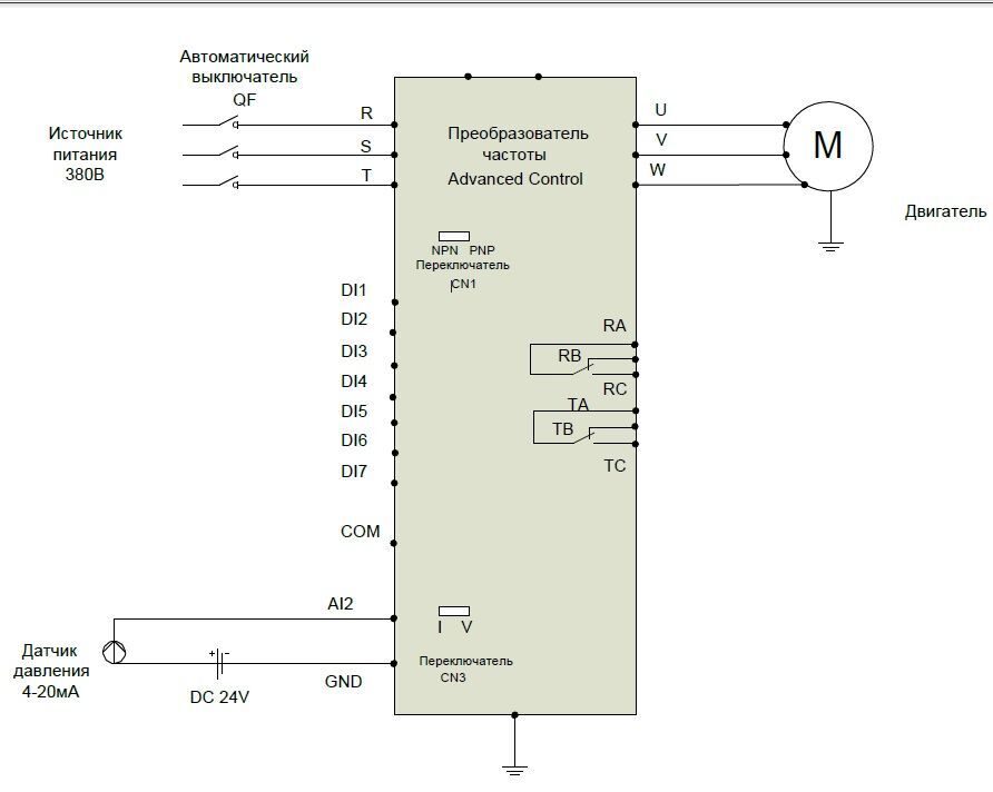
Алгоритм настройки ПИД регулирования для серии М420
F4-01 Мощность двигателя
F4-04 Ток двигателя
F4-06 Скорость вращения двигателя
F7-29=2049 Индикация: частота вращения и поддерживаемое давление (переключается «SHIFT»)
FA-01= (—60—) % Значение поддерживаемого давления в водопроводе
FA-03=1 К клемме «AI2» подключить датчик давления (4-20 мА) и переключить перемычку CN3 на I (налево)
FA-05= (—100—) Верхний предел масштаба отображения измерения датчика давления


В нашей команде работают исключительно профессионалы своего дела, а за время существования нашей компании мы ввели в эксплуатацию не одну сотню частотных преобразователей в том числе и MICROMASTER 420, с каждым разом получая и накапливая драгоценный опыт.
О MICROMASTER 420
Частотный преобразователь MICROMASTER 420 снабжен пультом отображения состояния (Status Display Panel) (SDP). Чтобы изменять и устанавливать требуемые параметры, необходимо использовать базовый пульт оператора (Basic Operator Panel) (BOP), расширенный пульт оператора (Advanced Operator Panel) (AOP) или последовательный интерфейс связи.
Базовая панель оператора (BOP), поставляемая как опция, дает возможность доступа к параметрам преобразователя и обеспечивает специфическую пользовательскую настройку MICROMASTER 420. BOP может использоваться для конфигурирования большинства преобразователей MICROMASTER 420. Поэтому нет необходимости покупать свою панель BOP для каждого преобразователя. Панель имеет сегментные индикаторы для чтения и записи параметров преобразователя. Панель не имеет возможности собственного хранения информации и параметров после её снятия.
Линейка промышленной электроники, которую восстанавливают специалисты сервисного центра «Кернел» не имеет ограничений, мы выполняем качественный ремонт промышленной электроники и оборудования абсолютно любых производителей не зависимо от года выпуска и наличия технической документации.
Оставить заявку на ремонт MICROMASTER 420
Оставить заявку на ремонт или программирование MICROMASTER 420 в можно с помощью специальной формы, которая вызывается нажатием одноименной кнопки в верхней части страницы. Все вопросы, связанные с ремонтом MICROMASTER 420 в вы можете задать нашим менеджерам. Связаться с ними можно несколькими способами:
- Заказав обратный звонок (кнопка в правом нижнем углу сайта)
- Посредством чата (кнопка расположена с левой стороны сайта)
- Позвонив по номеру телефона: +7(8482) 79-78-54; +7(917) 121-53-01
- Написав на электронную почту: 89171215301@mail.ru
Вот далеко не полный список производителей промышленной электроники и оборудования, ремонтируемой в нашей компании.
International English
6.3
In the event of a failure, the inverter switches off and a fault code appears on the display.
Table 6-2
Fault Code
F0001
Overcurrent
F0002
Overvoltage
F0003
Undervoltage
F0004
Inverter
Overtemperature
F0005
Inverter I
F0011
Motor Overtemperature
2
I
F0041
Stator resistance
measurement failure
94
MICROMASTER 420 Fault Codes
Description
1. Motor power does not
correspond to the inverter
power.
2. Motor lead short circuit
3. Earth fault
Supply voltage out of tolerance
load is regenerating.
Mains supply removed when
inverter is running.
Ambient temperature outside of
limits,
Fan failure
2
T
Inverter is overloaded
1. Motor overloaded.
T
2. Motor data incorrect.
3. Check parameter for motor
thermal time constant.
4. Check parameter for motor I
warning level.
5. Long time period operating at
low speeds
Stator resistance measurement
failure
Possible Causes
2
t
6. TROUBLESHOOTING
Diagnosis & Remedy
1. Check whether the motor power
corresponds to the inverter
power.
2. Check that the cable length limits
have not been exceeded.
3. Check motor cable and motor for
short-circuits and earth faults.
4. Check whether the motor
parameters correspond with the
motor being used.
5. Check the stator resistance
(P0350).
6. Increase the ramp-up-time
(P1120).
7. Reduce the boost set in (P1310),
(P1311) and (P1312).
8. Check whether the motor is
obstructed or overloaded.
1. Check whether the supply voltage
is within the limits indicated on the
rating plate.
2. Check if dc-link voltage
controller (P1240) is enabled and
parameterized correctly.
3. Increase the ramp-down time
(P1121).
1. Check whether the supply voltage
is within the limits indicated on the
rating plate.
2. Check the supply is not subject to
temporary failures or voltage
reductions.
1. Check that the integral fan rotates
when drive is running.
2. Check if pulse frequency is set to
default value.
3. Ambient temperature could be
higher than specified for the
inverter.
4. Check that air inlet and outlet
points are not obstructed.
1. Check if load duty-cycle is within
specified limits.
2. Check that motor power
corresponds to inverter power
1. Check motor data.
2. Check loading on motor.
3. Boost settings too high (P1310,
P1311, P1312)
1. Check if the motor is connected to
the inverter
2. Check that the motor data has
been entered correctly.
MICROMASTER 420 Operating Instructions
6SE6400-5AA00-0BP0
- Manuals
- Brands
- Siemens Manuals
- DC Drives
- MICROMASTER 420
- Operating instruction
-
Contents
-
Table of Contents
-
Troubleshooting
-
Bookmarks
Quick Links
MICROMASTER
Operating Instructions
Issue A2
User Documentation
Related Manuals for Siemens Micromaster 420
Summary of Contents for Siemens Micromaster 420
- Page 1
MICROMASTER Operating Instructions Issue A2 User Documentation… - Page 3
Overview Installation Commissioning MICROMASTER 420 Using the MICROMASTER 420 Operating Instructions System Parameters User Documentation Troubleshooting MICROMASTER 420 Specifications Supplementary Information Appendices Valid for Release Inverter Type Control Version MICROMASTER 420 October 2000 Index Issue: A2… - Page 4
We welcome suggestions for improvement. MICROMASTER® is a registered trademark of Siemens. Siemens handbooks are printed on chlorine-free paper that has been produced from managed sustainable forests. No solvents have been used in the printing or binding process. - Page 5
♦ Getting Started Guide The Getting Started Guide is designed to give you quick access to all the basic information required to install and set up your MICROMASTER 420 for operation. ♦ Operating Instructions The Operating Instructions provide detailed information for installation and operation of your MICROMASTER 420. -
Page 6: Using The
Siemens. Contact address Should any questions or problems arise while reading this manual, please contact the Siemens office concerned using the form provided at the back this manual. MICROMASTER 420 Operating Instructions 6SE6400-5AA00-0BP0…
-
Page 7: Micromaster
Please read the information carefully, since it is provided for your personal safety and will also help prolong the service life of your MICROMASTER 420 Inverter and the equipment you connect to it. General Warnings ♦…
- Page 8
The connection of power, motor and control cables to the inverter must be carried out as shown in Figure 2-4 on page 25, to prevent inductive and capacitive interference from affecting the correct functioning of the inverter. MICROMASTER 420 Operating Instructions 6SE6400-5AA00-0BP0… - Page 9
EN 60204, 9.2.5.4) Repair Warnings ♦ Repairs on equipment may only be carried out by Siemens Service, by repair centers authorized by Siemens or by qualified personnel who are thoroughly acquainted with all the warnings and operating procedures contained in this manual. - Page 10
International English FOREWORD MICROMASTER 420 Operating Instructions 6SE6400-5AA00-0BP0… -
Page 11: Table Of Contents
Ambient operating conditions ………………19 Mechanical Installation ………………..20 Electrical Installation ………………..21 Commissioning ………………….27 Front Panels for the MICROMASTER 420 …………..29 General operation ………………….. 34 Using the MICROMASTER 420 …………….37 Frequency Setpoint………………… 38 Command Sources (P0700) ………………38 OFF and braking Functions ………………
- Page 12
D — Removing ‘Y’ Cap Frame Size A ………………115 E — Removing ‘Y’ Cap Frame Sizes B and C …………….117 F — User Parameter Settings …………………. 119 G — Applicable Standards ………………….121 H — List of Abbreviations………………….123 Index ……………………..125 MICROMASTER 420 Operating Instructions 6SE6400-5AA00-0BP0… - Page 13
Motor and Power Connections ………………23 Figure 2-4 Wiring Guidelines to Minimize the Effects of EMI …………. 25 Figure 3-1 Panels available for the MICROMASTER 420 Inverter ………… 29 Figure 3-2 Basic operation with SDP………………..30 Figure 3-3 Buttons on the Basic Operator Panel…………….31 Figure 3-4 Changing parameters via the BOP……………… - Page 14
MICROMASTER 420 Operating Instructions 6SE6400-5AA00-0BP0… -
Page 15: Overview
OVERVIEW International English Overview This Chapter contains: A summary of the major features of the MICROMASTER 420 range. The MICROMASTER 420………………. 16 Features ……………………16 MICROMASTER 420 Operating Instructions 6SE6400-5AA00-0BP0…
-
Page 16: The Micromaster 420
Comprehensive protective functions provide excellent inverter and motor protection. The MICROMASTER 420 with its default factory settings, is ideal for a large range of simple motor control applications. The MICROMASTER 420 can also be used for more advanced motor control applications via its comprehensive parameter lists.
-
Page 17: Installation
General data relating to installation ♦ Dimensions of Inverter ♦ Wiring guidelines to minimize the effects of EMI ♦ Details concerning electrical installation General……………………18 Ambient operating conditions ………………19 Mechanical Installation ………………..20 Electrical Installation ………………..21 MICROMASTER 420 Operating Instructions 6SE6400-5AA00-0BP0…
-
Page 18: General
Apply 25% of input voltage for 2 hours Increase volts to 50% for a further 2 hours Increase volts to 75% for a further 2 hours Increase volts to 100% for a further 2 hours Inverter ready for run signal MICROMASTER 420 Operating Instructions 6SE6400-5AA00-0BP0…
-
Page 19: Ambient Operating Conditions
Overheating Mount the inverter vertically to ensure optimum cooling. Additional ventilation may be required for horizontal mounting. Ensure that the inverter’s air vents are not obstructed. Allow 100 mm clearance above and below the inverter. MICROMASTER 420 Operating Instructions 6SE6400-5AA00-0BP0…
-
Page 20: Mechanical Installation
4 washers M5 204 mm 8.03″ 245 mm Tightening 9.65″ torque (unit to cabinet) with washers fitted: 3 Nm 174 mm 185 mm 195 mm 6.85″ 7.28″ 7.68″ Figure 2-1 Drill pattern for MICROMASTER 420 MICROMASTER 420 Operating Instructions 6SE6400-5AA00-0BP0…
-
Page 21: Electrical Installation
A type B RCD is used. The trip limit of the RCD is 300mA. The neutral of the supply is grounded. Only one inverter is supplied from each RCD. The output cables are less than 50m (screened) or 100m (unscreened). MICROMASTER 420 Operating Instructions 6SE6400-5AA00-0BP0…
- Page 22
To tighten up the power terminal screws use a 4 — 5 mm cross-tip screwdriver. Access to the power and motor terminals The procedure for accessing the power and motor terminals on the MICROMASTER 420 Inverter is illustrated in Appendices B and C. Please also refer to the photographs showing the Power Terminal connections and the Control Terminal connections on the inside of the back cover of this manual. - Page 23
2. INSTALLATION International English N/L2 L/L1 (Ground) (Ground) Figure 2-2 MICROMASTER 420 Connection Terminals OPTIONAL FILTER (Class B only) CONTACTOR MICROMASTER MOTOR FUSE L/L1 N/L2 SINGLE PHASE TYPICAL INSTALLATION OPTIONAL FILTER CONTACTOR MICROMASTER MOTOR FUSE THREE PHASE Figure 2-3 Motor and Power Connections… - Page 24
♦ Use screened or armored cables for the motor connections and ground the screen at both ends using the cable clamps Warning Safety regulations must not be compromised when installing inverters! MICROMASTER 420 Operating Instructions 6SE6400-5AA00-0BP0… - Page 25
Use suitable clips to fix motor and control cable screens securely to metal back plate Note To enhance the screening of the motor and control cables, the optional Gland Plate can be used (not shown in Figure 2-4). MICROMASTER 420 Operating Instructions 6SE6400-5AA00-0BP0… - Page 26
International English 2. INSTALLATION MICROMASTER 420 Operating Instructions 6SE6400-5AA00-0BP0… -
Page 27: Commissioning
Basic Operator Panel (BOP) ♦ An 8-step guide at the end of the Chapter, which provides a simple procedure for changing parameters Front Panels for the MICROMASTER 420 …………..29 General operation ………………….. 34 MICROMASTER 420 Operating Instructions 6SE6400-5AA00-0BP0…
- Page 28
Only qualified personnel may enter settings in the control panels. Particular attention must be paid to safety precautions and warnings at all times. The MICROMASTER 420 is supplied with a Status Display Panel (SDP) and default parameter settings that cover the following requirements: ♦… -
Page 29: Front Panels For The Micromaster 420
Front Panels for the MICROMASTER 420 Front panels The front panels shown below are available for use with the MICROMASTER 420 Inverters. The panel on the left is supplied with the inverter as standard and is referred to as the Status Display Panel (SDP). The Basic Operator Panel (BOP) and Advanced Operator Panel (AOP) are available as options.
-
Page 30: Table 3-2 Default Settings For Operation Using The Bop
Commissioning with the Basic Operator Panel (BOP) The Basic Operator Panel (BOP), which is available as an option, provides access to the inverter parameters and enables you to customize the settings of your MICROMASTER 420. The BOP can be used to configure several MICROMASTER 420 150.00 Inverters.
-
Page 31: Figure 3-3 Buttons On The Basic Operator Panel
To change the Frequency Setpoint via the BOP set P1000 = 1. Pressing this button decreases the displayed value. Decrease value To change the Frequency Setpoint via the BOP set P1000 = 1. Figure 3-3 Buttons on the Basic Operator Panel MICROMASTER 420 Operating Instructions 6SE6400-5AA00-0BP0…
-
Page 32: Figure 3-4 Changing Parameters Via The Bop
Note — Busy Message In some cases — when changing parameter values — the display on the BOP shows » — — — -«. This means the inverter is busy with tasks of higher priority. MICROMASTER 420 Operating Instructions 6SE6400-5AA00-0BP0…
-
Page 33: Figure 3-5 Typical Motor Rating Plate Example
Figure 3-6. 1 kΩ Figure 3-6 Motor Overload PTC Connection Note: To enable the trip function, set parameter P0701, P0702 or P0703 = 29. MICROMASTER 420 Operating Instructions 6SE6400-5AA00-0BP0…
-
Page 34: General Operation
(P0005 = 21) the corresponding setpoint is displayed approximately every 1.0 seconds while the inverter is stopped. 3. The inverter is programmed at the factory for standard applications on Siemens four- pole standard motors that have the same power rating as the inverters. When using other motors it is necessary to enter the specifications from the motor’s rating plate.
- Page 35
3. When the inverter reaches 50 Hz, press the ‘DOWN’ Button. Motor speed and display is decreased. 4. Change the direction of rotation with the FORWARD / REVERSE Button. 5. The red button STOPS the motor. MICROMASTER 420 Operating Instructions 6SE6400-5AA00-0BP0… - Page 36
AOUT + 12 0-20mA AOUT — Serial Link (RS485) The Analogue input circuit can be alternatively configured to provide an additional digital input (DIN4) as shown. DIN4 – 0V (Isolated) Figure 3-7 Inverter block diagram MICROMASTER 420 Operating Instructions 6SE6400-5AA00-0BP0… -
Page 37: Using The Micromaster 420
4. USING THE MICROMASTER 420 International English Using the MICROMASTER 420 This Chapter contains: ♦ An explanation of the various methods of controlling your inverter Frequency Setpoint………………… 38 Command Sources (P0700) ………………38 OFF and braking Functions ………………39 Control Modes (P1300)………………..40 Faults and warnings………………..
-
Page 38: Frequency Setpoint
International English 4. USING THE MICROMASTER 420 Warnings ♦ When operating electrical devices, it is impossible to avoid applying hazardous voltages to certain parts of the equipment. ♦ Emergency Stop facilities according to EN 60204 IEC 204 (VDE 0113) must remain operative in all operating modes of the control equipment.
-
Page 39: Off And Braking Functions
4. USING THE MICROMASTER 420 International English Reversing the motor Standard Terminal 6 (DIN 2) Options see P0700 to P0704 OFF and braking Functions 4.3.1 OFF1 This command (produced by canceling the ON command) causes the inverter to come to a standstill at the selected ramp-down rate.
-
Page 40: Control Modes (P1300)
P1236 Control Modes (P1300) The various modes of operation of the MICROMASTER 420 control the relationship between the speed of the motor and the voltage supplied by the inverter. There are four modes of operation:…
-
Page 41: System Parameters
♦ An in-depth description of what the parameter actually does Overview of MICROMASTER System Parameters ..Error! Bookmark not defined. Introduction to MICROMASTER System Parameters… Error! Bookmark not defined. System Parameters and Definitions ……Error! Bookmark not defined. MICROMASTER 420 Operating Instructions 6SE6400-5AA00-0BP0…
-
Page 42: Overview Of Micromaster System Parameters
The MM420 is therefore delivered with the following default settings: ♦ Motor Parameters to suit a Siemens 4 pole motor to match the drive power and voltage. ♦ Setpoint control from the Analog input; 0 – 10V corresponding to 0 to 50 Hz or 0 to 60 Hz (North America).
-
Page 43: Introduction To Micromaster System Parameters
♦ If an attempt is made to change a parameter that cannot be changed in this status, for example, cannot be changed whilst running or can only be changed in quick commissioning, then will be displayed. MICROMASTER 420 Operating Instructions 6SE6400-5AA00-0BP0…
- Page 44
Reset to Factory default To reset all parameters to the factory default settings; the following parameters should be set as follows: 1. Set P0010=30. 2. Set P0970=1. Note The reset process takes approximately 10 seconds to complete. MICROMASTER 420 Operating Instructions 6SE6400-5AA00-0BP0… - Page 45
0340 Calculation of motor parameters 0350 Stator resistance, line-to-line 0611 Motor I t time constant 0614 Motor I t overload warning level 0640 Motor overload factor 1910 Select motor data identification 1912 Identified stator resistance MICROMASTER 420 Operating Instructions 6SE6400-5AA00-0BP0… - Page 46
0010 Commissioning Parameter filter 0010 Commissioning Parameter filter 0918 Profibus address 0947 Last fault code 0927 Parameters changeable via 2110 Warning history 2000 Reference frequency 2197 CO/BO: Status word 1 monitor 2010 USS baud rate 2011 USS address MICROMASTER 420 Operating Instructions 6SE6400-5AA00-0BP0… - Page 47
PI: tranducer type 2272 CO: PI scaled feedback signal 2273 CO: PI error 2280 PI: proportional gain 2285 PI: integral time 2291 PI: output upper limit 2292 PI: output lower limit 2294 CO: PI output MICROMASTER 420 Operating Instructions 6SE6400-5AA00-0BP0… -
Page 48: System Parameters And Definitions
“User defined parameter list – see P0013 (Level 3) for details on use” “Standard”: allows access into most frequently used parameters “Extended”: allows extended access to inverter I/O functions “Expert”: for expert use only. “Service”: only for use by authorized service personnel –password protected. MICROMASTER 420 Operating Instructions 6SE6400-5AA00-0BP0…
- Page 49
Quick Commissioning Factory setting Notes: This parameter must be reset to 0 before the inverter will run (Automatic when P3900 ≠ 0 (default)). The accessible parameters are also affected by the User Access Level parameter (P0003). MICROMASTER 420 Operating Instructions 6SE6400-5AA00-0BP0… - Page 50
P0040. P0040 Reset energy consumption meter Resets energy consumption display to zero. Possible Settings: 0 = No reset 1 = Reset r0039 to 0 Note: Reset occurs when “P” is pressed. MICROMASTER 420 Operating Instructions 6SE6400-5AA00-0BP0… - Page 51
Inverter overload Notes: The individual status bits can be configured to the digital output using P0731. To enable the user to read the relevant parameter bits display, refer to the diagram below: > & » MICROMASTER 420 Operating Instructions 6SE6400-5AA00-0BP0… - Page 52
Actual frequency ≥ setpoint Bit 6 Voltage < threshold Bit 7 Voltage > threshold Bit 8 Bit 9 reserve PI frequency < threshold Bit A Bit b PI saturation Note: Refer to the bitmap diagram on page 51. MICROMASTER 420 Operating Instructions 6SE6400-5AA00-0BP0… - Page 53
Rated drive power [kW] or [hp] Displays the nominal motor power rating, which can be supplied by the inverter. Note: The display will be in kW or hp dependent on the setting of P0100 MICROMASTER 420 Operating Instructions 6SE6400-5AA00-0BP0… - Page 54
Υ Υ Υ Υ = = = = 440-480 95.75% == == == ==∆/Υ ∆/Υ ∆/Υ ∆/Υ= = = = 220-240/380-420 V 45kg P0344 11.1-11.3 A 19.7-20.6/11.4-11.9 A P0308 P0311 P0309 Note: This parameter can only be changed when P0010=1. MICROMASTER 420 Operating Instructions 6SE6400-5AA00-0BP0… - Page 55
This parameter is only visible when P0100 = 1, i.e. when the motor power is entered in hp. Note: A setting of 0 will cause the value to be calculated internally. P0310 Motor frequency rating [50] ‘ ’ Nominal motor frequency (Hz) from rating plate — see diagram P0304 MICROMASTER 420 Operating Instructions 6SE6400-5AA00-0BP0… - Page 56
The value entered in P0350 is the one from the method last used. P0611 Motor I t time constant 16000 [***] Defines motor thermal time constant and is automatically calculated from the motor data (P0340). Note: Larger number increases time taken for calculated motor temperature to change. MICROMASTER 420 Operating Instructions 6SE6400-5AA00-0BP0… - Page 57
29 External trip 33 Disable additional setpoint (defined in P1000) 99 Enable BICO parameterization – for expert use only Can only be reset via P0700 or P3900 = 1, 2 or factory setting P0970 = 1 MICROMASTER 420 Operating Instructions 6SE6400-5AA00-0BP0… - Page 58
29 External trip 33 Disable additional setpoint (defined in P1000) Enable BICO parameterization – for expert use only Can only be reset via P0700 or P3900 = 1, 2 or factory setting P0970 = 1. MICROMASTER 420 Operating Instructions 6SE6400-5AA00-0BP0… - Page 59
Bit 01 «Digital input 2» 0 OFF 1 Active Bit 02 «Digital input 3» 0 OFF 1 Active Bit 03 «Digital input 4 (Via AIN)» 1 Active Note When the signal is active the segment is lit. MICROMASTER 420 Operating Instructions 6SE6400-5AA00-0BP0… - Page 60
Controller output at lower limit (P2291) Closed Open Note These are the most common settings. Other settings are possible in Expert mode. r0752 Analog input voltage Displays the smohthed analog input value in volts before the characteristic block MICROMASTER 420 Operating Instructions 6SE6400-5AA00-0BP0… - Page 61
When monitoring is enabled and a deadband is defined (P0761), a fault condition will be generated (F0080) when the analog input voltage falls below 50% of the deadband voltage. Note: This function is disabled if the analog scaling block (see P0757 – P0760) is programmed to output negative setpoints. MICROMASTER 420 Operating Instructions 6SE6400-5AA00-0BP0… - Page 62
Value X2 of analog input scaling Sets value of X2 as described in P0757 [10] ‘•’ P0760 Value Y2 of analog input scaling -99999 99999 Sets value of Y2 as described in P0757 [100] ‘•’ MICROMASTER 420 Operating Instructions 6SE6400-5AA00-0BP0… - Page 63
P0758 = -100% P0761 = 0.1 (0.1V either side of center) P2000 = 50Hz Note: Fmin (P1080) should be zero when using center zero setup. There is no hysteresis at the end of the dead band MICROMASTER 420 Operating Instructions 6SE6400-5AA00-0BP0… - Page 64
Defines x2 of output characteristic P0780 Value Y2 of analog output characteristics [20] ‘•’ Defines y2 of output characteristic P0781 Analog output deadband ‘•’ Sets the width of a dead-band in mA for the analog output. MICROMASTER 420 Operating Instructions 6SE6400-5AA00-0BP0… - Page 65
E.g. if you want to set value 15, you will need to set the display to indicate 15 in Binary (with the separating bars in-between “b — — n n” or if you wanted to set 11 – “b — — r n” etc. MICROMASTER 420 Operating Instructions 6SE6400-5AA00-0BP0… - Page 66
Index 2 is only used if a 2 fault occurs before the 1 is acknowledged. P0970 Factory reset Resets all parameters to their default values. To do this, you need to set P0010=30, then P0970=1 P0100 is set according DIP Switch setting MICROMASTER 420 Operating Instructions 6SE6400-5AA00-0BP0… - Page 67
The most common settings are: Keypad (Motor potentiometer) setpoint Analog input Fixed frequency setpoint USS via RS232 USS via RS485 terminals Optional Communication Board Other settings including an additional setpoint can be selected using the table above. MICROMASTER 420 Operating Instructions 6SE6400-5AA00-0BP0… - Page 68
P1002 Fixed frequency 2 -650 ‘ • ’ Defines fixed frequency setpoint 2 See description for P1001 P1003 Fixed frequency 3 -650 [10] ‘ • ’ Defines fixed frequency setpoint 3 See description for P1001 MICROMASTER 420 Operating Instructions 6SE6400-5AA00-0BP0… - Page 69
Reverse direction is allowed – it is possible to change motor direction using the keypad (Motor potentiometer) setpoint (increase / decrease frequency either by using digital inputs or keypad up / down buttons) Reverse direction inhibited MICROMASTER 420 Operating Instructions 6SE6400-5AA00-0BP0… - Page 70
JOG ramp-up time [10] ‘•’ Sets ramp-up time. This is the time used while jogging or when the function “use jog ramp times” is activated. f (Hz) f max (P1082) time (s) Jog Ramp up time (P1060) MICROMASTER 420 Operating Instructions 6SE6400-5AA00-0BP0… - Page 71
3 x the nominal rating plate motor frequency. The maximum frequency can be exceeded if either of the following is active: Slip compensation (f slip comp max Flying restart slip nom MICROMASTER 420 Operating Instructions 6SE6400-5AA00-0BP0… - Page 72
Notes Setting the ramp-down time too short can cause the inverter to trip (overvoltage (F0002) / overcurrent (F0001)). Changes to the ramp-up or ramp-down times are not active until confirmed by pressing the P key. MICROMASTER 420 Operating Instructions 6SE6400-5AA00-0BP0… - Page 73
Defines smoothing time at end of ramp-up as shown in P1130. P1132 Ramp-down initial rounding time ‘•’ Defines smoothing time at start of ramp-down as shown in P1130. P1133 Ramp-down final rounding time ‘•’ Defines smoothing time at end of ramp-down as shown in P1130. MICROMASTER 420 Operating Instructions 6SE6400-5AA00-0BP0… - Page 74
Defines continuous smoothing (default) or discontinuous smoothing as a response to OFF commands or setpoint reduction. The total smoothing time must be set > 0s; otherwise this parameter will have no effect. Possible settings: Continuous Discontinuous freq Continuous Discontinuous Stop Time MICROMASTER 420 Operating Instructions 6SE6400-5AA00-0BP0… - Page 75
Once this happens, the motor will run up to its setpoint using the normal ramp time. Note: Settings 1 to 3 search in both directions. In order to search only in direction of setpoint it is necessary to set 4 to 6. MICROMASTER 420 Operating Instructions 6SE6400-5AA00-0BP0… - Page 76
The brake relay opens at Point 1 if enabled using P0731. The brake relay closes at Point 2. P1216 Holding brake release delay Defines the time at which the inverter runs at f before ramping up at point 1 (as shown in P1215 diagram). MICROMASTER 420 Operating Instructions 6SE6400-5AA00-0BP0… - Page 77
Increasing the value will generally improve braking performance; however, if you set the value too high, an overvoltage trip may result. Possible settings: Compound braking disabled 1 – 250 Level of DC braking current defined as a % of motor rated current (P0305) MICROMASTER 420 Operating Instructions 6SE6400-5AA00-0BP0… - Page 78
Controls the relationship between the speed of the motor and the voltage supplied by the inverter. Possible values Linear V/f (default) FCC(Flux Current Control) – maintains motor flux current for improved efficiency Quadratic V/f – suitable for centrifugal fans/pumps Multi-point V/f (programmable – in Expert Mode only. MICROMASTER 420 Operating Instructions 6SE6400-5AA00-0BP0… - Page 79
♦ The achievable boost value is limited by the setting in P0640. ♦ Increasing the Boost Levels increases the heating of the motor especially at standstill. ♦ Σ Boosts < 300/I mot * R S MICROMASTER 420 Operating Instructions 6SE6400-5AA00-0BP0… - Page 80
ON command and is active until setpoint is reached for the 1 time. This is useful for starting loads with high inertia. V Max V Max V Nom (P0304) Normal V/f P1312 F Nom F Max (P0310) (P1082) MICROMASTER 420 Operating Instructions 6SE6400-5AA00-0BP0… - Page 81
4 kHz 6 kHz 8 kHz 10 kHz 12 kHz 14 kHz 16 kHz Power 0.37 0.55 0.75 10.2 10.2 13.2 13.2 13.2 13.2 18.4 18.4 13.2 13.2 26.0 26.0 17.9 17.9 13.5 13.5 10.4 MICROMASTER 420 Operating Instructions 6SE6400-5AA00-0BP0… - Page 82
Identified stator resistance Displays measured stator resistance value (line-to-line) in Ohms (measured using P1910 = Ohms 1 or 2). P2000 Reference frequency [***] Full-scale frequency setting used by serial link, analog I/O. This corresponds to 4000H. MICROMASTER 420 Operating Instructions 6SE6400-5AA00-0BP0… - Page 83
If a warning is active, the keypad will be flashing: the LED’s indicate warning status. If an AOP is in use, the display shows active Warning history and text. Indices 0 and 1are not stored. MICROMASTER 420 Operating Instructions 6SE6400-5AA00-0BP0… - Page 84
P1 control can lead to instabilities. Note 4 In level 3, the PI controller source enable can also come from the digital inputs in settings 722.0 to 722.2 for DIN1 – DIN3 or any other BICO source. MICROMASTER 420 Operating Instructions 6SE6400-5AA00-0BP0… - Page 85
Fixed PI setpoint 3 -130 [20] ‘•’ Refer to the description in P2201 for Fixed Setpoint 1. P2204 Fixed PI setpoint 4 -130 [30] ‘•’ Refer to the description in P2201 for Fixed Setpoint 1. MICROMASTER 420 Operating Instructions 6SE6400-5AA00-0BP0… - Page 86
BOP or by setting P0702 or P0703 to 13 and 14. r2250 CO: Source of PI setpoint -130 Displays the active digital PI setpoint in %. [10.00] ‘•’ P2253 CI: PI setpoint 2248.0 ‘•’ MICROMASTER 420 Operating Instructions 6SE6400-5AA00-0BP0… - Page 87
The PI ramp time is only effective on the PI setpoint and only active when the PI setpoint is changed, or when a RUN command is given (when the PI uses this ramp to reach its value from 0%). MICROMASTER 420 Operating Instructions 6SE6400-5AA00-0BP0… - Page 88
P756 – P760. Note 2 Refer to “Using BICO” description for further details of other settings. P2265 PI: feedback filter timeconst. ‘•’ Defines PI feedback filter time constant. r2266 CO: PI feedback Displays PI feedback signal MICROMASTER 420 Operating Instructions 6SE6400-5AA00-0BP0… - Page 89
If the P term is set to 0 the I term acts on the square of the error signal. P2285 PI: integral time ‘•’ Allows the User to set the PI controller integral time constant. Refer to P2280 above for detail. MICROMASTER 420 Operating Instructions 6SE6400-5AA00-0BP0… - Page 90
Calculates a variety of motor parameters – overwriting previous values, including P0344 (motor weight), P0350 (Level 3) stator resistance), P0346 (Level 3, magnetization time) and P0347 ((Level 3 demagnetization time), P2000 (reference frequency), P2002 (reference current). MICROMASTER 420 Operating Instructions 6SE6400-5AA00-0BP0… -
Page 91: Troubleshooting
♦ A list of the fault codes that may appear on the display of the BOP. The cause and recommended corrective action are indicated for each fault code listed. Troubleshooting with the Status Display Panel…………92 Troubleshooting with the Basic Operator Panel…………93 MICROMASTER 420 fault codes …………….94 MICROMASTER 420 Operating Instructions 6SE6400-5AA00-0BP0…
-
Page 92: Troubleshooting With The Status Display Panel
6. TROUBLESHOOTING Warnings ♦ Repairs on equipment may only be carried out by Siemens Service, by repair centers authorized by Siemens or by qualified personnel who are thoroughly acquainted with all the warnings and operating procedures contained in this manual.
-
Page 93: Troubleshooting With The Basic Operator Panel
P to reset the inverter to the factory default parameter values. Now use a switch between terminals 5 and 8 on the control board. The drive should now run to the defined setpoint by analogue input. MICROMASTER 420 Operating Instructions 6SE6400-5AA00-0BP0…
-
Page 94: Micromaster 420 Fault Codes
International English 6. TROUBLESHOOTING MICROMASTER 420 fault codes In the event of a failure, the inverter switches off and a fault code appears on the display. Table 6-2 MICROMASTER 420 Fault Codes Fault Code Description Possible Causes Diagnosis & Remedy…
- Page 95
2 — Some of the control board tests have failed 4 — Some of the functional tests have failed 8 — Some of the IO module tests have failed. Vector only 16 — The Internal Ram has failed its check on power-up MICROMASTER 420 Operating Instructions 6SE6400-5AA00-0BP0… -
Page 96: Table 6-3 Micromaster 420 Warning Codes
International English 6. TROUBLESHOOTING Table 6-3 MICROMASTER 420 Warning Codes Warning Description Possible Cause Diagnosis & Remedy Code A0501 Current Limit 1. Check whether the motor power corresponds to the inverter power. 2. Check that the cable length limits have not been exceeded.
- Page 97
A0923 JOG right and JOG left JOG right and JOG left signals Make sure that JOG right and JOG signals active active together left signals are not applied simultaneously MICROMASTER 420 Operating Instructions 6SE6400-5AA00-0BP0… - Page 98
International English 6. TROUBLESHOOTING MICROMASTER 420 Operating Instructions 6SE6400-5AA00-0BP0… -
Page 99: Micromaster 420 Specifications
7. MICROMASTER 420 SPECIFICATIONS International English MICROMASTER 420 Specifications Table 7-1 MICROMASTER 420 Specifications 230 V Single Phase MICROMASTER Inverters (with built in Class A Filter) Order No. (6SE6420-2AB) 11-2AA0 12-5AA0 13-7AA0 15-5AA0 17-5AA0 21-1BA0 21-5BA0 22-2BA0 23-0CA0 Input voltage range…
- Page 100
International English 7. MICROMASTER 420 SPECIFICATIONS 230 V Three Phase MICROMASTER Inverters (unfiltered) Order No. (6SE6420-2UC) 24-0CA0 25-5CA0 Input voltage range 3AC 200V — 240V +10% -10% Motor output rating kW (hp) 4 (5) 5.5 (7.5) Output KVA Output current Max. A 17.5… -
Page 101: Table 7-2 Micromaster Performance Ratings
7. MICROMASTER 420 SPECIFICATIONS International English Table 7-2 MICROMASTER Performance Ratings Feature Specification 200 to 240 V ± 10% 1AC Mains Operating Voltage 200 to 240 V ± 10% 3AC 380 to 480 V ± 10% 3AC 200 to 240 V ± 10% 1AC Power Ranges 0.12kW –…
-
Page 102: Table 7-4 Micromaster 420 Fuses — Sizes And Types
International English 7. MICROMASTER 420 SPECIFICATIONS Table 7-4 MICROMASTER 420 Fuses – Sizes and Types Inverter Power Inverter Voltage Inverter Filter Frame Inverter Order Standard (kW) Power (hp) Class Size Number (MLFB) Fuses 0.12 0.16 230 1ph Unfiltered FS A…
-
Page 103: Supplementary Information
8. SUPPLEMENTARY INFORMATION International English Supplementary Information This Chapter contains: Supplementary information. Available options …………Error! Bookmark not defined. Electro-Magnetic Compatibility (EMC) ……Error! Bookmark not defined. MICROMASTER 420 Operating Instructions 6SE6400-5AA00-0BP0…
-
Page 104: Available Options
Available options The following accessories are available as options for your MICROMASTER MM420 Inverter. For more details please refer to the Reference Manual or contact your local Siemens sales office if you require assistance. • Additional RFI suppression filter •…
-
Page 105: Table 8-1 Class 1 — General Industrial
Radio Frequency Electromagnetic Field, ENV 50 140 80-1000 MHz, 10 V/m, 80% AM, amplitude modulated power and signal lines Radio-frequency Electromagnetic Field, ENV 50 204 900 MHz, 10 V/m 50% duty pulse modulated cycle, 200 Hz repetition rate MICROMASTER 420 Operating Instructions 6SE6400-5AA00-0BP0…
-
Page 106: Table 8-3 Class 3 — Filtered For Residential, Commercial And Light Industry
The MICROMASTER inverters are intended exclusively for professional applications. Therefore, they do not fall within the scope of the harmonics emissions specification EN 61000-3-2. • Maximum mains supply voltage when filters are fitted is 460V. MICROMASTER 420 Operating Instructions 6SE6400-5AA00-0BP0…
-
Page 107: Table 8-4 Compliance Table
Frame size A units 400-480 V with external Class A footprint filters 6SE6400-2FA00-6AD0 Class 3 – Filtered for residential, commercial and light industry 6SE6420-2U***-**A0 with Unfiltered units fitted with external Class B footprint filters. 6SE6400-2FB0*-***0 * denotes any value is allowed. MICROMASTER 420 Operating Instructions 6SE6400-5AA00-0BP0…
- Page 108
International English 8. SUPPLEMENTARY INFORMATION MICROMASTER 420 Operating Instructions 6SE6400-5AA00-0BP0… -
Page 109: A — Changing The Operator Panel
APPENDIX A International English A — Changing the Operator Panel MICROMASTER 420 Operating Instructions 6SE6400-5AA00-0BP0…
- Page 110
International English APPENDIX A MICROMASTER 420 Operating Instructions 6SE6400-5AA00-0BP0… -
Page 111: B — Removing Covers Frame Size A
APPENDIX B International English B — Removing Covers Frame Size A » MICROMASTER 420 Operating Instructions 6SE6400-5AA00-0BP0…
- Page 112
International English APPENDIX B MICROMASTER 420 Operating Instructions 6SE6400-5AA00-0BP0… -
Page 113: C — Removing Covers Frame Sizes B And C
APPENDIX C International English C — Removing Covers Frame Sizes B and C MICROMASTER 420 Operating Instructions 6SE6400-5AA00-0BP0…
- Page 114
International English APPENDIX C » MICROMASTER 420 Operating Instructions 6SE6400-5AA00-0BP0… -
Page 115: D — Removing ‘Y’ Cap Frame Size A
APPENDIX D International English D — Removing ‘Y’ Cap Frame Size A LK 700 MICROMASTER 420 Operating Instructions 6SE6400-5AA00-0BP0…
- Page 116
International English APPENDIX D MICROMASTER 420 Operating Instructions 6SE6400-5AA00-0BP0… -
Page 117: E — Removing ‘Y’ Cap Frame Sizes B And C
APPENDIX E International English E — Removing ‘Y’ Cap Frame Sizes B and C LK700 MICROMASTER 420 Operating Instructions 6SE6400-5AA00-0BP0…
- Page 118
International English APPENDIX E MICROMASTER 420 Operating Instructions 6SE6400-5AA00-0BP0… -
Page 119: F — User Parameter Settings
P2264 P0731 52:3 P1133 P2265 r0752 P1134 r2266 r0754 P1135 P2271 r0755 P1200 r2272 P0756 P1210 r2273 P0757 P1215 P2280 P0758 P1216 P2285 P0759 P1217 P2291 P0760 P1232 P2292 P0761 P1233 r2294 P0771 P1236 P3900 MICROMASTER 420 Operating Instructions 6SE6400-5AA00-0BP0…
- Page 120
International English APPENDIX F MICROMASTER 420 Operating Instructions 6SE6400-5AA00-0BP0… -
Page 121: G — Applicable Standards
Product Standard for Power Drive Systems EN61800-3. Underwriters Laboratories UL and CUL LISTED POWER CONVERSION EQUIPMENT 5B33 for use in a pollution degree 2 ISO 9001 Siemens plc operates a quality management system, which complies with the requirements of ISO 9001. MICROMASTER 420 Operating Instructions 6SE6400-5AA00-0BP0…
- Page 122
International English APPENDIX G MICROMASTER 420 Operating Instructions 6SE6400-5AA00-0BP0… -
Page 123: H — List Of Abbreviations
Fast Current Limitation IGBT Insulated Gate Bipolar Transistor Liquid Crystal Display Light Emitting Diode Proportional and Integral Programmable Logic Controller Positive Temperature Coefficient RCCB Residual Current Circuit breaker Residual Current Device Revolutions Per Minute Standard Display Panel MICROMASTER 420 Operating Instructions 6SE6400-5AA00-0BP0…
- Page 124
International English APPENDIX H MICROMASTER 420 Operating Instructions 6SE6400-5AA00-0BP0… -
Page 125: Index
BOP fitted · 40 Performance characteristics · 16 SDP fitted · 40 Power and motor connections · 22 Frame sizes single phase · 23 removing the Y Cap from frame size A · 115 Power and motor terminals MICROMASTER 420 Operating Instructions 6SE6400-5AA00-0BP0…
- Page 126
& disposal · 9 warnings and faults states · 30 general · 7 System Parameters and Definitions · 48 operation · 9 repair · 9 transport & storage · 8 Water hazard · 19 MICROMASTER 420 Operating Instructions 6SE6400-5AA00-0BP0… - Page 127
Date of Issue: A1 Should you come across any printing Company/Service Department errors when reading this publication, Address: please notify us on this sheet. Suggestions for improvement are also welcome. Telephone: __________ / Telefax: ________ / MICROMASTER 420 Operating Instructions 6SE6400-5AA00-0BP0… - Page 128
MICROMASTER 420 Operating Instructions 6SE6400-5AA00-0BP0… - Page 129
VIEW OF UNITS International English Frame Size A Frame Size B & C View of Unit Standard Display Panel fitted Power Terminal Connections Control Terminal Connections Access to “Y Cap“ MICROMASTER 420 Operating Instructions 6SE6400-5AA00-0BP0… - Page 130
Order Number *6SE6400-5AA00-0BP0* Drawing Number *G85139-K1790-U201-A2* A&D SD VM 4 © Siemens AG, 2000 Subject to change without prior notice Siemens Aktiengesellschaft Order No.: 6SE6400-5AA00-0BP0Operating Instructions Printed in UK. Date: October 2000…
- Manuals
- Brands
- Siemens Manuals
- DC Drives
- MICROMASTER 420
- Operating instruction
-
Contents
-
Table of Contents
-
Troubleshooting
-
Bookmarks
Quick Links
MICROMASTER
Operating Instructions
Issue A2
User Documentation
Related Manuals for Siemens Micromaster 420
Summary of Contents for Siemens Micromaster 420
- Page 1
MICROMASTER Operating Instructions Issue A2 User Documentation… - Page 3
Overview Installation Commissioning MICROMASTER 420 Using the MICROMASTER 420 Operating Instructions System Parameters User Documentation Troubleshooting MICROMASTER 420 Specifications Supplementary Information Appendices Valid for Release Inverter Type Control Version MICROMASTER 420 October 2000 Index Issue: A2… - Page 4
We welcome suggestions for improvement. MICROMASTER® is a registered trademark of Siemens. Siemens handbooks are printed on chlorine-free paper that has been produced from managed sustainable forests. No solvents have been used in the printing or binding process. - Page 5
♦ Getting Started Guide The Getting Started Guide is designed to give you quick access to all the basic information required to install and set up your MICROMASTER 420 for operation. ♦ Operating Instructions The Operating Instructions provide detailed information for installation and operation of your MICROMASTER 420. -
Page 6: Using The
Siemens. Contact address Should any questions or problems arise while reading this manual, please contact the Siemens office concerned using the form provided at the back this manual. MICROMASTER 420 Operating Instructions 6SE6400-5AA00-0BP0…
-
Page 7: Micromaster
Please read the information carefully, since it is provided for your personal safety and will also help prolong the service life of your MICROMASTER 420 Inverter and the equipment you connect to it. General Warnings ♦…
- Page 8
The connection of power, motor and control cables to the inverter must be carried out as shown in Figure 2-4 on page 25, to prevent inductive and capacitive interference from affecting the correct functioning of the inverter. MICROMASTER 420 Operating Instructions 6SE6400-5AA00-0BP0… - Page 9
EN 60204, 9.2.5.4) Repair Warnings ♦ Repairs on equipment may only be carried out by Siemens Service, by repair centers authorized by Siemens or by qualified personnel who are thoroughly acquainted with all the warnings and operating procedures contained in this manual. - Page 10
International English FOREWORD MICROMASTER 420 Operating Instructions 6SE6400-5AA00-0BP0… -
Page 11: Table Of Contents
Ambient operating conditions ………………19 Mechanical Installation ………………..20 Electrical Installation ………………..21 Commissioning ………………….27 Front Panels for the MICROMASTER 420 …………..29 General operation ………………….. 34 Using the MICROMASTER 420 …………….37 Frequency Setpoint………………… 38 Command Sources (P0700) ………………38 OFF and braking Functions ………………
- Page 12
D — Removing ‘Y’ Cap Frame Size A ………………115 E — Removing ‘Y’ Cap Frame Sizes B and C …………….117 F — User Parameter Settings …………………. 119 G — Applicable Standards ………………….121 H — List of Abbreviations………………….123 Index ……………………..125 MICROMASTER 420 Operating Instructions 6SE6400-5AA00-0BP0… - Page 13
Motor and Power Connections ………………23 Figure 2-4 Wiring Guidelines to Minimize the Effects of EMI …………. 25 Figure 3-1 Panels available for the MICROMASTER 420 Inverter ………… 29 Figure 3-2 Basic operation with SDP………………..30 Figure 3-3 Buttons on the Basic Operator Panel…………….31 Figure 3-4 Changing parameters via the BOP……………… - Page 14
MICROMASTER 420 Operating Instructions 6SE6400-5AA00-0BP0… -
Page 15: Overview
OVERVIEW International English Overview This Chapter contains: A summary of the major features of the MICROMASTER 420 range. The MICROMASTER 420………………. 16 Features ……………………16 MICROMASTER 420 Operating Instructions 6SE6400-5AA00-0BP0…
-
Page 16: The Micromaster 420
Comprehensive protective functions provide excellent inverter and motor protection. The MICROMASTER 420 with its default factory settings, is ideal for a large range of simple motor control applications. The MICROMASTER 420 can also be used for more advanced motor control applications via its comprehensive parameter lists.
-
Page 17: Installation
General data relating to installation ♦ Dimensions of Inverter ♦ Wiring guidelines to minimize the effects of EMI ♦ Details concerning electrical installation General……………………18 Ambient operating conditions ………………19 Mechanical Installation ………………..20 Electrical Installation ………………..21 MICROMASTER 420 Operating Instructions 6SE6400-5AA00-0BP0…
-
Page 18: General
Apply 25% of input voltage for 2 hours Increase volts to 50% for a further 2 hours Increase volts to 75% for a further 2 hours Increase volts to 100% for a further 2 hours Inverter ready for run signal MICROMASTER 420 Operating Instructions 6SE6400-5AA00-0BP0…
-
Page 19: Ambient Operating Conditions
Overheating Mount the inverter vertically to ensure optimum cooling. Additional ventilation may be required for horizontal mounting. Ensure that the inverter’s air vents are not obstructed. Allow 100 mm clearance above and below the inverter. MICROMASTER 420 Operating Instructions 6SE6400-5AA00-0BP0…
-
Page 20: Mechanical Installation
4 washers M5 204 mm 8.03″ 245 mm Tightening 9.65″ torque (unit to cabinet) with washers fitted: 3 Nm 174 mm 185 mm 195 mm 6.85″ 7.28″ 7.68″ Figure 2-1 Drill pattern for MICROMASTER 420 MICROMASTER 420 Operating Instructions 6SE6400-5AA00-0BP0…
-
Page 21: Electrical Installation
A type B RCD is used. The trip limit of the RCD is 300mA. The neutral of the supply is grounded. Only one inverter is supplied from each RCD. The output cables are less than 50m (screened) or 100m (unscreened). MICROMASTER 420 Operating Instructions 6SE6400-5AA00-0BP0…
- Page 22
To tighten up the power terminal screws use a 4 — 5 mm cross-tip screwdriver. Access to the power and motor terminals The procedure for accessing the power and motor terminals on the MICROMASTER 420 Inverter is illustrated in Appendices B and C. Please also refer to the photographs showing the Power Terminal connections and the Control Terminal connections on the inside of the back cover of this manual. - Page 23
2. INSTALLATION International English N/L2 L/L1 (Ground) (Ground) Figure 2-2 MICROMASTER 420 Connection Terminals OPTIONAL FILTER (Class B only) CONTACTOR MICROMASTER MOTOR FUSE L/L1 N/L2 SINGLE PHASE TYPICAL INSTALLATION OPTIONAL FILTER CONTACTOR MICROMASTER MOTOR FUSE THREE PHASE Figure 2-3 Motor and Power Connections… - Page 24
♦ Use screened or armored cables for the motor connections and ground the screen at both ends using the cable clamps Warning Safety regulations must not be compromised when installing inverters! MICROMASTER 420 Operating Instructions 6SE6400-5AA00-0BP0… - Page 25
Use suitable clips to fix motor and control cable screens securely to metal back plate Note To enhance the screening of the motor and control cables, the optional Gland Plate can be used (not shown in Figure 2-4). MICROMASTER 420 Operating Instructions 6SE6400-5AA00-0BP0… - Page 26
International English 2. INSTALLATION MICROMASTER 420 Operating Instructions 6SE6400-5AA00-0BP0… -
Page 27: Commissioning
Basic Operator Panel (BOP) ♦ An 8-step guide at the end of the Chapter, which provides a simple procedure for changing parameters Front Panels for the MICROMASTER 420 …………..29 General operation ………………….. 34 MICROMASTER 420 Operating Instructions 6SE6400-5AA00-0BP0…
- Page 28
Only qualified personnel may enter settings in the control panels. Particular attention must be paid to safety precautions and warnings at all times. The MICROMASTER 420 is supplied with a Status Display Panel (SDP) and default parameter settings that cover the following requirements: ♦… -
Page 29: Front Panels For The Micromaster 420
Front Panels for the MICROMASTER 420 Front panels The front panels shown below are available for use with the MICROMASTER 420 Inverters. The panel on the left is supplied with the inverter as standard and is referred to as the Status Display Panel (SDP). The Basic Operator Panel (BOP) and Advanced Operator Panel (AOP) are available as options.
-
Page 30: Table 3-2 Default Settings For Operation Using The Bop
Commissioning with the Basic Operator Panel (BOP) The Basic Operator Panel (BOP), which is available as an option, provides access to the inverter parameters and enables you to customize the settings of your MICROMASTER 420. The BOP can be used to configure several MICROMASTER 420 150.00 Inverters.
-
Page 31: Figure 3-3 Buttons On The Basic Operator Panel
To change the Frequency Setpoint via the BOP set P1000 = 1. Pressing this button decreases the displayed value. Decrease value To change the Frequency Setpoint via the BOP set P1000 = 1. Figure 3-3 Buttons on the Basic Operator Panel MICROMASTER 420 Operating Instructions 6SE6400-5AA00-0BP0…
-
Page 32: Figure 3-4 Changing Parameters Via The Bop
Note — Busy Message In some cases — when changing parameter values — the display on the BOP shows » — — — -«. This means the inverter is busy with tasks of higher priority. MICROMASTER 420 Operating Instructions 6SE6400-5AA00-0BP0…
-
Page 33: Figure 3-5 Typical Motor Rating Plate Example
Figure 3-6. 1 kΩ Figure 3-6 Motor Overload PTC Connection Note: To enable the trip function, set parameter P0701, P0702 or P0703 = 29. MICROMASTER 420 Operating Instructions 6SE6400-5AA00-0BP0…
-
Page 34: General Operation
(P0005 = 21) the corresponding setpoint is displayed approximately every 1.0 seconds while the inverter is stopped. 3. The inverter is programmed at the factory for standard applications on Siemens four- pole standard motors that have the same power rating as the inverters. When using other motors it is necessary to enter the specifications from the motor’s rating plate.
- Page 35
3. When the inverter reaches 50 Hz, press the ‘DOWN’ Button. Motor speed and display is decreased. 4. Change the direction of rotation with the FORWARD / REVERSE Button. 5. The red button STOPS the motor. MICROMASTER 420 Operating Instructions 6SE6400-5AA00-0BP0… - Page 36
AOUT + 12 0-20mA AOUT — Serial Link (RS485) The Analogue input circuit can be alternatively configured to provide an additional digital input (DIN4) as shown. DIN4 – 0V (Isolated) Figure 3-7 Inverter block diagram MICROMASTER 420 Operating Instructions 6SE6400-5AA00-0BP0… -
Page 37: Using The Micromaster 420
4. USING THE MICROMASTER 420 International English Using the MICROMASTER 420 This Chapter contains: ♦ An explanation of the various methods of controlling your inverter Frequency Setpoint………………… 38 Command Sources (P0700) ………………38 OFF and braking Functions ………………39 Control Modes (P1300)………………..40 Faults and warnings………………..
-
Page 38: Frequency Setpoint
International English 4. USING THE MICROMASTER 420 Warnings ♦ When operating electrical devices, it is impossible to avoid applying hazardous voltages to certain parts of the equipment. ♦ Emergency Stop facilities according to EN 60204 IEC 204 (VDE 0113) must remain operative in all operating modes of the control equipment.
-
Page 39: Off And Braking Functions
4. USING THE MICROMASTER 420 International English Reversing the motor Standard Terminal 6 (DIN 2) Options see P0700 to P0704 OFF and braking Functions 4.3.1 OFF1 This command (produced by canceling the ON command) causes the inverter to come to a standstill at the selected ramp-down rate.
-
Page 40: Control Modes (P1300)
P1236 Control Modes (P1300) The various modes of operation of the MICROMASTER 420 control the relationship between the speed of the motor and the voltage supplied by the inverter. There are four modes of operation:…
-
Page 41: System Parameters
♦ An in-depth description of what the parameter actually does Overview of MICROMASTER System Parameters ..Error! Bookmark not defined. Introduction to MICROMASTER System Parameters… Error! Bookmark not defined. System Parameters and Definitions ……Error! Bookmark not defined. MICROMASTER 420 Operating Instructions 6SE6400-5AA00-0BP0…
-
Page 42: Overview Of Micromaster System Parameters
The MM420 is therefore delivered with the following default settings: ♦ Motor Parameters to suit a Siemens 4 pole motor to match the drive power and voltage. ♦ Setpoint control from the Analog input; 0 – 10V corresponding to 0 to 50 Hz or 0 to 60 Hz (North America).
-
Page 43: Introduction To Micromaster System Parameters
♦ If an attempt is made to change a parameter that cannot be changed in this status, for example, cannot be changed whilst running or can only be changed in quick commissioning, then will be displayed. MICROMASTER 420 Operating Instructions 6SE6400-5AA00-0BP0…
- Page 44
Reset to Factory default To reset all parameters to the factory default settings; the following parameters should be set as follows: 1. Set P0010=30. 2. Set P0970=1. Note The reset process takes approximately 10 seconds to complete. MICROMASTER 420 Operating Instructions 6SE6400-5AA00-0BP0… - Page 45
0340 Calculation of motor parameters 0350 Stator resistance, line-to-line 0611 Motor I t time constant 0614 Motor I t overload warning level 0640 Motor overload factor 1910 Select motor data identification 1912 Identified stator resistance MICROMASTER 420 Operating Instructions 6SE6400-5AA00-0BP0… - Page 46
0010 Commissioning Parameter filter 0010 Commissioning Parameter filter 0918 Profibus address 0947 Last fault code 0927 Parameters changeable via 2110 Warning history 2000 Reference frequency 2197 CO/BO: Status word 1 monitor 2010 USS baud rate 2011 USS address MICROMASTER 420 Operating Instructions 6SE6400-5AA00-0BP0… - Page 47
PI: tranducer type 2272 CO: PI scaled feedback signal 2273 CO: PI error 2280 PI: proportional gain 2285 PI: integral time 2291 PI: output upper limit 2292 PI: output lower limit 2294 CO: PI output MICROMASTER 420 Operating Instructions 6SE6400-5AA00-0BP0… -
Page 48: System Parameters And Definitions
“User defined parameter list – see P0013 (Level 3) for details on use” “Standard”: allows access into most frequently used parameters “Extended”: allows extended access to inverter I/O functions “Expert”: for expert use only. “Service”: only for use by authorized service personnel –password protected. MICROMASTER 420 Operating Instructions 6SE6400-5AA00-0BP0…
- Page 49
Quick Commissioning Factory setting Notes: This parameter must be reset to 0 before the inverter will run (Automatic when P3900 ≠ 0 (default)). The accessible parameters are also affected by the User Access Level parameter (P0003). MICROMASTER 420 Operating Instructions 6SE6400-5AA00-0BP0… - Page 50
P0040. P0040 Reset energy consumption meter Resets energy consumption display to zero. Possible Settings: 0 = No reset 1 = Reset r0039 to 0 Note: Reset occurs when “P” is pressed. MICROMASTER 420 Operating Instructions 6SE6400-5AA00-0BP0… - Page 51
Inverter overload Notes: The individual status bits can be configured to the digital output using P0731. To enable the user to read the relevant parameter bits display, refer to the diagram below: > & » MICROMASTER 420 Operating Instructions 6SE6400-5AA00-0BP0… - Page 52
Actual frequency ≥ setpoint Bit 6 Voltage < threshold Bit 7 Voltage > threshold Bit 8 Bit 9 reserve PI frequency < threshold Bit A Bit b PI saturation Note: Refer to the bitmap diagram on page 51. MICROMASTER 420 Operating Instructions 6SE6400-5AA00-0BP0… - Page 53
Rated drive power [kW] or [hp] Displays the nominal motor power rating, which can be supplied by the inverter. Note: The display will be in kW or hp dependent on the setting of P0100 MICROMASTER 420 Operating Instructions 6SE6400-5AA00-0BP0… - Page 54
Υ Υ Υ Υ = = = = 440-480 95.75% == == == ==∆/Υ ∆/Υ ∆/Υ ∆/Υ= = = = 220-240/380-420 V 45kg P0344 11.1-11.3 A 19.7-20.6/11.4-11.9 A P0308 P0311 P0309 Note: This parameter can only be changed when P0010=1. MICROMASTER 420 Operating Instructions 6SE6400-5AA00-0BP0… - Page 55
This parameter is only visible when P0100 = 1, i.e. when the motor power is entered in hp. Note: A setting of 0 will cause the value to be calculated internally. P0310 Motor frequency rating [50] ‘ ’ Nominal motor frequency (Hz) from rating plate — see diagram P0304 MICROMASTER 420 Operating Instructions 6SE6400-5AA00-0BP0… - Page 56
The value entered in P0350 is the one from the method last used. P0611 Motor I t time constant 16000 [***] Defines motor thermal time constant and is automatically calculated from the motor data (P0340). Note: Larger number increases time taken for calculated motor temperature to change. MICROMASTER 420 Operating Instructions 6SE6400-5AA00-0BP0… - Page 57
29 External trip 33 Disable additional setpoint (defined in P1000) 99 Enable BICO parameterization – for expert use only Can only be reset via P0700 or P3900 = 1, 2 or factory setting P0970 = 1 MICROMASTER 420 Operating Instructions 6SE6400-5AA00-0BP0… - Page 58
29 External trip 33 Disable additional setpoint (defined in P1000) Enable BICO parameterization – for expert use only Can only be reset via P0700 or P3900 = 1, 2 or factory setting P0970 = 1. MICROMASTER 420 Operating Instructions 6SE6400-5AA00-0BP0… - Page 59
Bit 01 «Digital input 2» 0 OFF 1 Active Bit 02 «Digital input 3» 0 OFF 1 Active Bit 03 «Digital input 4 (Via AIN)» 1 Active Note When the signal is active the segment is lit. MICROMASTER 420 Operating Instructions 6SE6400-5AA00-0BP0… - Page 60
Controller output at lower limit (P2291) Closed Open Note These are the most common settings. Other settings are possible in Expert mode. r0752 Analog input voltage Displays the smohthed analog input value in volts before the characteristic block MICROMASTER 420 Operating Instructions 6SE6400-5AA00-0BP0… - Page 61
When monitoring is enabled and a deadband is defined (P0761), a fault condition will be generated (F0080) when the analog input voltage falls below 50% of the deadband voltage. Note: This function is disabled if the analog scaling block (see P0757 – P0760) is programmed to output negative setpoints. MICROMASTER 420 Operating Instructions 6SE6400-5AA00-0BP0… - Page 62
Value X2 of analog input scaling Sets value of X2 as described in P0757 [10] ‘•’ P0760 Value Y2 of analog input scaling -99999 99999 Sets value of Y2 as described in P0757 [100] ‘•’ MICROMASTER 420 Operating Instructions 6SE6400-5AA00-0BP0… - Page 63
P0758 = -100% P0761 = 0.1 (0.1V either side of center) P2000 = 50Hz Note: Fmin (P1080) should be zero when using center zero setup. There is no hysteresis at the end of the dead band MICROMASTER 420 Operating Instructions 6SE6400-5AA00-0BP0… - Page 64
Defines x2 of output characteristic P0780 Value Y2 of analog output characteristics [20] ‘•’ Defines y2 of output characteristic P0781 Analog output deadband ‘•’ Sets the width of a dead-band in mA for the analog output. MICROMASTER 420 Operating Instructions 6SE6400-5AA00-0BP0… - Page 65
E.g. if you want to set value 15, you will need to set the display to indicate 15 in Binary (with the separating bars in-between “b — — n n” or if you wanted to set 11 – “b — — r n” etc. MICROMASTER 420 Operating Instructions 6SE6400-5AA00-0BP0… - Page 66
Index 2 is only used if a 2 fault occurs before the 1 is acknowledged. P0970 Factory reset Resets all parameters to their default values. To do this, you need to set P0010=30, then P0970=1 P0100 is set according DIP Switch setting MICROMASTER 420 Operating Instructions 6SE6400-5AA00-0BP0… - Page 67
The most common settings are: Keypad (Motor potentiometer) setpoint Analog input Fixed frequency setpoint USS via RS232 USS via RS485 terminals Optional Communication Board Other settings including an additional setpoint can be selected using the table above. MICROMASTER 420 Operating Instructions 6SE6400-5AA00-0BP0… - Page 68
P1002 Fixed frequency 2 -650 ‘ • ’ Defines fixed frequency setpoint 2 See description for P1001 P1003 Fixed frequency 3 -650 [10] ‘ • ’ Defines fixed frequency setpoint 3 See description for P1001 MICROMASTER 420 Operating Instructions 6SE6400-5AA00-0BP0… - Page 69
Reverse direction is allowed – it is possible to change motor direction using the keypad (Motor potentiometer) setpoint (increase / decrease frequency either by using digital inputs or keypad up / down buttons) Reverse direction inhibited MICROMASTER 420 Operating Instructions 6SE6400-5AA00-0BP0… - Page 70
JOG ramp-up time [10] ‘•’ Sets ramp-up time. This is the time used while jogging or when the function “use jog ramp times” is activated. f (Hz) f max (P1082) time (s) Jog Ramp up time (P1060) MICROMASTER 420 Operating Instructions 6SE6400-5AA00-0BP0… - Page 71
3 x the nominal rating plate motor frequency. The maximum frequency can be exceeded if either of the following is active: Slip compensation (f slip comp max Flying restart slip nom MICROMASTER 420 Operating Instructions 6SE6400-5AA00-0BP0… - Page 72
Notes Setting the ramp-down time too short can cause the inverter to trip (overvoltage (F0002) / overcurrent (F0001)). Changes to the ramp-up or ramp-down times are not active until confirmed by pressing the P key. MICROMASTER 420 Operating Instructions 6SE6400-5AA00-0BP0… - Page 73
Defines smoothing time at end of ramp-up as shown in P1130. P1132 Ramp-down initial rounding time ‘•’ Defines smoothing time at start of ramp-down as shown in P1130. P1133 Ramp-down final rounding time ‘•’ Defines smoothing time at end of ramp-down as shown in P1130. MICROMASTER 420 Operating Instructions 6SE6400-5AA00-0BP0… - Page 74
Defines continuous smoothing (default) or discontinuous smoothing as a response to OFF commands or setpoint reduction. The total smoothing time must be set > 0s; otherwise this parameter will have no effect. Possible settings: Continuous Discontinuous freq Continuous Discontinuous Stop Time MICROMASTER 420 Operating Instructions 6SE6400-5AA00-0BP0… - Page 75
Once this happens, the motor will run up to its setpoint using the normal ramp time. Note: Settings 1 to 3 search in both directions. In order to search only in direction of setpoint it is necessary to set 4 to 6. MICROMASTER 420 Operating Instructions 6SE6400-5AA00-0BP0… - Page 76
The brake relay opens at Point 1 if enabled using P0731. The brake relay closes at Point 2. P1216 Holding brake release delay Defines the time at which the inverter runs at f before ramping up at point 1 (as shown in P1215 diagram). MICROMASTER 420 Operating Instructions 6SE6400-5AA00-0BP0… - Page 77
Increasing the value will generally improve braking performance; however, if you set the value too high, an overvoltage trip may result. Possible settings: Compound braking disabled 1 – 250 Level of DC braking current defined as a % of motor rated current (P0305) MICROMASTER 420 Operating Instructions 6SE6400-5AA00-0BP0… - Page 78
Controls the relationship between the speed of the motor and the voltage supplied by the inverter. Possible values Linear V/f (default) FCC(Flux Current Control) – maintains motor flux current for improved efficiency Quadratic V/f – suitable for centrifugal fans/pumps Multi-point V/f (programmable – in Expert Mode only. MICROMASTER 420 Operating Instructions 6SE6400-5AA00-0BP0… - Page 79
♦ The achievable boost value is limited by the setting in P0640. ♦ Increasing the Boost Levels increases the heating of the motor especially at standstill. ♦ Σ Boosts < 300/I mot * R S MICROMASTER 420 Operating Instructions 6SE6400-5AA00-0BP0… - Page 80
ON command and is active until setpoint is reached for the 1 time. This is useful for starting loads with high inertia. V Max V Max V Nom (P0304) Normal V/f P1312 F Nom F Max (P0310) (P1082) MICROMASTER 420 Operating Instructions 6SE6400-5AA00-0BP0… - Page 81
4 kHz 6 kHz 8 kHz 10 kHz 12 kHz 14 kHz 16 kHz Power 0.37 0.55 0.75 10.2 10.2 13.2 13.2 13.2 13.2 18.4 18.4 13.2 13.2 26.0 26.0 17.9 17.9 13.5 13.5 10.4 MICROMASTER 420 Operating Instructions 6SE6400-5AA00-0BP0… - Page 82
Identified stator resistance Displays measured stator resistance value (line-to-line) in Ohms (measured using P1910 = Ohms 1 or 2). P2000 Reference frequency [***] Full-scale frequency setting used by serial link, analog I/O. This corresponds to 4000H. MICROMASTER 420 Operating Instructions 6SE6400-5AA00-0BP0… - Page 83
If a warning is active, the keypad will be flashing: the LED’s indicate warning status. If an AOP is in use, the display shows active Warning history and text. Indices 0 and 1are not stored. MICROMASTER 420 Operating Instructions 6SE6400-5AA00-0BP0… - Page 84
P1 control can lead to instabilities. Note 4 In level 3, the PI controller source enable can also come from the digital inputs in settings 722.0 to 722.2 for DIN1 – DIN3 or any other BICO source. MICROMASTER 420 Operating Instructions 6SE6400-5AA00-0BP0… - Page 85
Fixed PI setpoint 3 -130 [20] ‘•’ Refer to the description in P2201 for Fixed Setpoint 1. P2204 Fixed PI setpoint 4 -130 [30] ‘•’ Refer to the description in P2201 for Fixed Setpoint 1. MICROMASTER 420 Operating Instructions 6SE6400-5AA00-0BP0… - Page 86
BOP or by setting P0702 or P0703 to 13 and 14. r2250 CO: Source of PI setpoint -130 Displays the active digital PI setpoint in %. [10.00] ‘•’ P2253 CI: PI setpoint 2248.0 ‘•’ MICROMASTER 420 Operating Instructions 6SE6400-5AA00-0BP0… - Page 87
The PI ramp time is only effective on the PI setpoint and only active when the PI setpoint is changed, or when a RUN command is given (when the PI uses this ramp to reach its value from 0%). MICROMASTER 420 Operating Instructions 6SE6400-5AA00-0BP0… - Page 88
P756 – P760. Note 2 Refer to “Using BICO” description for further details of other settings. P2265 PI: feedback filter timeconst. ‘•’ Defines PI feedback filter time constant. r2266 CO: PI feedback Displays PI feedback signal MICROMASTER 420 Operating Instructions 6SE6400-5AA00-0BP0… - Page 89
If the P term is set to 0 the I term acts on the square of the error signal. P2285 PI: integral time ‘•’ Allows the User to set the PI controller integral time constant. Refer to P2280 above for detail. MICROMASTER 420 Operating Instructions 6SE6400-5AA00-0BP0… - Page 90
Calculates a variety of motor parameters – overwriting previous values, including P0344 (motor weight), P0350 (Level 3) stator resistance), P0346 (Level 3, magnetization time) and P0347 ((Level 3 demagnetization time), P2000 (reference frequency), P2002 (reference current). MICROMASTER 420 Operating Instructions 6SE6400-5AA00-0BP0… -
Page 91: Troubleshooting
♦ A list of the fault codes that may appear on the display of the BOP. The cause and recommended corrective action are indicated for each fault code listed. Troubleshooting with the Status Display Panel…………92 Troubleshooting with the Basic Operator Panel…………93 MICROMASTER 420 fault codes …………….94 MICROMASTER 420 Operating Instructions 6SE6400-5AA00-0BP0…
-
Page 92: Troubleshooting With The Status Display Panel
6. TROUBLESHOOTING Warnings ♦ Repairs on equipment may only be carried out by Siemens Service, by repair centers authorized by Siemens or by qualified personnel who are thoroughly acquainted with all the warnings and operating procedures contained in this manual.
-
Page 93: Troubleshooting With The Basic Operator Panel
P to reset the inverter to the factory default parameter values. Now use a switch between terminals 5 and 8 on the control board. The drive should now run to the defined setpoint by analogue input. MICROMASTER 420 Operating Instructions 6SE6400-5AA00-0BP0…
-
Page 94: Micromaster 420 Fault Codes
International English 6. TROUBLESHOOTING MICROMASTER 420 fault codes In the event of a failure, the inverter switches off and a fault code appears on the display. Table 6-2 MICROMASTER 420 Fault Codes Fault Code Description Possible Causes Diagnosis & Remedy…
- Page 95
2 — Some of the control board tests have failed 4 — Some of the functional tests have failed 8 — Some of the IO module tests have failed. Vector only 16 — The Internal Ram has failed its check on power-up MICROMASTER 420 Operating Instructions 6SE6400-5AA00-0BP0… -
Page 96: Table 6-3 Micromaster 420 Warning Codes
International English 6. TROUBLESHOOTING Table 6-3 MICROMASTER 420 Warning Codes Warning Description Possible Cause Diagnosis & Remedy Code A0501 Current Limit 1. Check whether the motor power corresponds to the inverter power. 2. Check that the cable length limits have not been exceeded.
- Page 97
A0923 JOG right and JOG left JOG right and JOG left signals Make sure that JOG right and JOG signals active active together left signals are not applied simultaneously MICROMASTER 420 Operating Instructions 6SE6400-5AA00-0BP0… - Page 98
International English 6. TROUBLESHOOTING MICROMASTER 420 Operating Instructions 6SE6400-5AA00-0BP0… -
Page 99: Micromaster 420 Specifications
7. MICROMASTER 420 SPECIFICATIONS International English MICROMASTER 420 Specifications Table 7-1 MICROMASTER 420 Specifications 230 V Single Phase MICROMASTER Inverters (with built in Class A Filter) Order No. (6SE6420-2AB) 11-2AA0 12-5AA0 13-7AA0 15-5AA0 17-5AA0 21-1BA0 21-5BA0 22-2BA0 23-0CA0 Input voltage range…
- Page 100
International English 7. MICROMASTER 420 SPECIFICATIONS 230 V Three Phase MICROMASTER Inverters (unfiltered) Order No. (6SE6420-2UC) 24-0CA0 25-5CA0 Input voltage range 3AC 200V — 240V +10% -10% Motor output rating kW (hp) 4 (5) 5.5 (7.5) Output KVA Output current Max. A 17.5… -
Page 101: Table 7-2 Micromaster Performance Ratings
7. MICROMASTER 420 SPECIFICATIONS International English Table 7-2 MICROMASTER Performance Ratings Feature Specification 200 to 240 V ± 10% 1AC Mains Operating Voltage 200 to 240 V ± 10% 3AC 380 to 480 V ± 10% 3AC 200 to 240 V ± 10% 1AC Power Ranges 0.12kW –…
-
Page 102: Table 7-4 Micromaster 420 Fuses — Sizes And Types
International English 7. MICROMASTER 420 SPECIFICATIONS Table 7-4 MICROMASTER 420 Fuses – Sizes and Types Inverter Power Inverter Voltage Inverter Filter Frame Inverter Order Standard (kW) Power (hp) Class Size Number (MLFB) Fuses 0.12 0.16 230 1ph Unfiltered FS A…
-
Page 103: Supplementary Information
8. SUPPLEMENTARY INFORMATION International English Supplementary Information This Chapter contains: Supplementary information. Available options …………Error! Bookmark not defined. Electro-Magnetic Compatibility (EMC) ……Error! Bookmark not defined. MICROMASTER 420 Operating Instructions 6SE6400-5AA00-0BP0…
-
Page 104: Available Options
Available options The following accessories are available as options for your MICROMASTER MM420 Inverter. For more details please refer to the Reference Manual or contact your local Siemens sales office if you require assistance. • Additional RFI suppression filter •…
-
Page 105: Table 8-1 Class 1 — General Industrial
Radio Frequency Electromagnetic Field, ENV 50 140 80-1000 MHz, 10 V/m, 80% AM, amplitude modulated power and signal lines Radio-frequency Electromagnetic Field, ENV 50 204 900 MHz, 10 V/m 50% duty pulse modulated cycle, 200 Hz repetition rate MICROMASTER 420 Operating Instructions 6SE6400-5AA00-0BP0…
-
Page 106: Table 8-3 Class 3 — Filtered For Residential, Commercial And Light Industry
The MICROMASTER inverters are intended exclusively for professional applications. Therefore, they do not fall within the scope of the harmonics emissions specification EN 61000-3-2. • Maximum mains supply voltage when filters are fitted is 460V. MICROMASTER 420 Operating Instructions 6SE6400-5AA00-0BP0…
-
Page 107: Table 8-4 Compliance Table
Frame size A units 400-480 V with external Class A footprint filters 6SE6400-2FA00-6AD0 Class 3 – Filtered for residential, commercial and light industry 6SE6420-2U***-**A0 with Unfiltered units fitted with external Class B footprint filters. 6SE6400-2FB0*-***0 * denotes any value is allowed. MICROMASTER 420 Operating Instructions 6SE6400-5AA00-0BP0…
- Page 108
International English 8. SUPPLEMENTARY INFORMATION MICROMASTER 420 Operating Instructions 6SE6400-5AA00-0BP0… -
Page 109: A — Changing The Operator Panel
APPENDIX A International English A — Changing the Operator Panel MICROMASTER 420 Operating Instructions 6SE6400-5AA00-0BP0…
- Page 110
International English APPENDIX A MICROMASTER 420 Operating Instructions 6SE6400-5AA00-0BP0… -
Page 111: B — Removing Covers Frame Size A
APPENDIX B International English B — Removing Covers Frame Size A » MICROMASTER 420 Operating Instructions 6SE6400-5AA00-0BP0…
- Page 112
International English APPENDIX B MICROMASTER 420 Operating Instructions 6SE6400-5AA00-0BP0… -
Page 113: C — Removing Covers Frame Sizes B And C
APPENDIX C International English C — Removing Covers Frame Sizes B and C MICROMASTER 420 Operating Instructions 6SE6400-5AA00-0BP0…
- Page 114
International English APPENDIX C » MICROMASTER 420 Operating Instructions 6SE6400-5AA00-0BP0… -
Page 115: D — Removing ‘Y’ Cap Frame Size A
APPENDIX D International English D — Removing ‘Y’ Cap Frame Size A LK 700 MICROMASTER 420 Operating Instructions 6SE6400-5AA00-0BP0…
- Page 116
International English APPENDIX D MICROMASTER 420 Operating Instructions 6SE6400-5AA00-0BP0… -
Page 117: E — Removing ‘Y’ Cap Frame Sizes B And C
APPENDIX E International English E — Removing ‘Y’ Cap Frame Sizes B and C LK700 MICROMASTER 420 Operating Instructions 6SE6400-5AA00-0BP0…
- Page 118
International English APPENDIX E MICROMASTER 420 Operating Instructions 6SE6400-5AA00-0BP0… -
Page 119: F — User Parameter Settings
P2264 P0731 52:3 P1133 P2265 r0752 P1134 r2266 r0754 P1135 P2271 r0755 P1200 r2272 P0756 P1210 r2273 P0757 P1215 P2280 P0758 P1216 P2285 P0759 P1217 P2291 P0760 P1232 P2292 P0761 P1233 r2294 P0771 P1236 P3900 MICROMASTER 420 Operating Instructions 6SE6400-5AA00-0BP0…
- Page 120
International English APPENDIX F MICROMASTER 420 Operating Instructions 6SE6400-5AA00-0BP0… -
Page 121: G — Applicable Standards
Product Standard for Power Drive Systems EN61800-3. Underwriters Laboratories UL and CUL LISTED POWER CONVERSION EQUIPMENT 5B33 for use in a pollution degree 2 ISO 9001 Siemens plc operates a quality management system, which complies with the requirements of ISO 9001. MICROMASTER 420 Operating Instructions 6SE6400-5AA00-0BP0…
- Page 122
International English APPENDIX G MICROMASTER 420 Operating Instructions 6SE6400-5AA00-0BP0… -
Page 123: H — List Of Abbreviations
Fast Current Limitation IGBT Insulated Gate Bipolar Transistor Liquid Crystal Display Light Emitting Diode Proportional and Integral Programmable Logic Controller Positive Temperature Coefficient RCCB Residual Current Circuit breaker Residual Current Device Revolutions Per Minute Standard Display Panel MICROMASTER 420 Operating Instructions 6SE6400-5AA00-0BP0…
- Page 124
International English APPENDIX H MICROMASTER 420 Operating Instructions 6SE6400-5AA00-0BP0… -
Page 125: Index
BOP fitted · 40 Performance characteristics · 16 SDP fitted · 40 Power and motor connections · 22 Frame sizes single phase · 23 removing the Y Cap from frame size A · 115 Power and motor terminals MICROMASTER 420 Operating Instructions 6SE6400-5AA00-0BP0…
- Page 126
& disposal · 9 warnings and faults states · 30 general · 7 System Parameters and Definitions · 48 operation · 9 repair · 9 transport & storage · 8 Water hazard · 19 MICROMASTER 420 Operating Instructions 6SE6400-5AA00-0BP0… - Page 127
Date of Issue: A1 Should you come across any printing Company/Service Department errors when reading this publication, Address: please notify us on this sheet. Suggestions for improvement are also welcome. Telephone: __________ / Telefax: ________ / MICROMASTER 420 Operating Instructions 6SE6400-5AA00-0BP0… - Page 128
MICROMASTER 420 Operating Instructions 6SE6400-5AA00-0BP0… - Page 129
VIEW OF UNITS International English Frame Size A Frame Size B & C View of Unit Standard Display Panel fitted Power Terminal Connections Control Terminal Connections Access to “Y Cap“ MICROMASTER 420 Operating Instructions 6SE6400-5AA00-0BP0… - Page 130
Order Number *6SE6400-5AA00-0BP0* Drawing Number *G85139-K1790-U201-A2* A&D SD VM 4 © Siemens AG, 2000 Subject to change without prior notice Siemens Aktiengesellschaft Order No.: 6SE6400-5AA00-0BP0Operating Instructions Printed in UK. Date: October 2000…
-
2, Advanced Control M420 Series M420 General Flux Vector Control Inverter Basic Reference Guide 1 1. Typical wiring Braking resistor M U V W R S T The three- phase 380V power input DI 1 DI2 DI3 DI4 DI 5 COM AI1 AI2 GND 485 + 485- Serial communication port AO1 GND analog output of 1 0/ 2~10 V 0/4~20 mA Y1 COM CME TA TB TC Relay output 1 Multi funct…
-
3, Advanced Control M420 Series M420 General Flux Vector Control Inverter Basic Reference Guide Braking resistor M U V W R S T The three — phase 380V power input DI 1 DI2 DI 3 DI 4 HDI 5 COM AI1 AI 2 GND 485+ 485- Serial communication port AO 1 GND analog output of 1 0 / 2~10V 0/4 ~20 mA Y1 COM CME TA TB TC Relay output 1 Multi function input terminal 1 Multi function i…
-
4, Advanced Control M420 Series M420 General Flux Vector Control Inverter Basic Reference Guide 3 Braking resistor M U V W R S T The three- phase 380V power input DI1 DI2 DI3 DI4 HDI5 COM AI1 AI2 GND 485+ 485- Serial communication port AO1 GND analog output of 1 0/ 2~10V 0/4~20mA Y1 COM CME TA TB TC Relay output 1 Multi function input terminal 1 Multi functi…
-
5, Advanced Control M420 Series M420 General Flux Vector Control Inverter Basic Reference Guide 2. Main circuit terminals and wiring Main circuit terminals of single-phase Terminal Terminal Name Description L1 、 L2 Single-phase power supply input terminals Connect to the single-phase 220 VAC power supply P(+) 、 (-) Posit…
-
6, M420 General Flux Vector Control Inverter Basic Reference Guide 5 The capacitor or surge absorber can’t be connected to the output side of the inverter, or it may damage the inverter. If the motor cable is too long, for the influence of the distribute capacitance, it’s easily to have electrical resonance, causing the dama…
-
7, Advanced Control M420 Series M420 General Flux Vector Control Inverter Basic Reference Guide DI4-COM Digital input 4 mode. 2) Impedance: 3.3 kΩ. 3) Input voltage range: 9 ~30V 4) HDI5 can be used as high-speed input port. HDI5-COM Digital input 5 Analog output AO1-GND Analog output 1 Voltage or current output is decided by dial switches CN2 and C…
-
8, Advanced Control M420 Series Trouble Shooting M420 General Flux Vector Control Inverter User Manual 7 3. Operation and Display 3.1. Operation and Display Interface Introduction We can change the function parameter, monitor the working status and control (start up/stop) the running inverter through the operation panel. The appearance and function are like below: Fig.…
-
9, Advanced Control M420 Series Trouble Shooting M420 General Flux Vector Control Inverter User Manual 3.1.1. Description of Function LED Indicator LED Symbol Unit Implication Color Unit LED Hz Freq. Unit LED on— current parameter is frequency value Green A Current Unit LED on— current parameter is current value Green V Voltage Unit LED on— current parameter is voltage…
-
10, Advanced Control M420 Series M420 General Flux Vector Control Inverter User Manual Trouble Shooting 9 3.1.3. Keyboard instruction Tab.2. Keyboard function table Key Name Function PRG/ESC Program/ Exit entry or exit ,return to primary menu + — ENTER ENTER entry into the menu interface ,confirm the setup parameters increase (+) Increase in the data or function code…
-
11, Trouble Shooting M420 General Flux Vector Control Inverter User Manual 3.3. Instruction of Function Code Viewing and Modification Methods Function code parameter of M420 inverter adopts three-level menu, it can view and monitor the parameter by operation panel. The three-level menu includes function parameter set (level 1 menu) →Function code (level 2 …
-
12, Advanced Control M420 Series M420 General Flux Vector Control Inverter User Manual Trouble Shooting 11 4. Trouble Shooting 4.1. Fault Warnings and Solutions If faults happened on the running process, the inverter will stop to output immediately to protect the motor, and the corresponding fault relay of the inverter has contact action at the same time so the panel will display the faul…
-
13, Advanced Control M420 Series Trouble Shooting M420 General Flux Vector Control Inverter User Manual Display Fault Name Possible Causes Solutions Err05 Over current during deceleration 1: The output circuit is grounded or short circuited. 2: Motor parameter is not right. 3: The deceleration time is too short. 4: The voltage is too low. 5: A sudden load is added dur…
-
14, M420 General Flux Vector Control Inverter User Manual Trouble Shooting 13 Display Fault Name Possible Causes Solutions or install a braking resistor. Err12 Undervoltage 1. Instantaneous power failure occurs. 2. The input voltage exceeds the allowed range. 3. The DC bus voltage is too low. 4. The rectifier bridge and Bu…
-
15, Advanced Control M420 Series Trouble Shooting M420 General Flux Vector Control Inverter User Manual Display Fault Name Possible Causes Solutions Err23 Power input phase loss 1: The three-phase power input is abnormal. 2: The drive board is faulty. 3: The lightening board is faulty. 4: The main control board is faulty. 1: Eliminate external faults. 2: Seek for maintenance. Er…
-
16, M420 General Flux Vector Control Inverter User Manual Trouble Shooting 15 Display Fault Name Possible Causes Solutions Err33 Fast current limit fault 1: The load is too heavy or the rotor is locked. 2: The acceleration time is too short. 1: Reduce the load, or change the inverter with larger power. 2: Increase the acce…
-
17, Advanced Control M420 Series Trouble Shooting M420 General Flux Vector Control Inverter User Manual 4.2. Common Faults and Treating Methods The inverter will possibly be confront with below faults, please refer to the mentioned methods to have simple diagnosis and find the solutions. Tab.4. Common faults and treating methods serial number Fault Name Possi…
-
18, Advanced Control M420 Series M420 General Flux Vector Control Inverter User Manual Trouble Shooting 17 serial number Fault Name Possible Causes Solutions 5 The DI terminals are disabled. 1: The parameters are set incorrectly. 2: The external signal is incorrect. 3:Wrong location of the DI dial switch. 4: The control board is faulty. 1:Check and reset the parame…
-
19, Advanced Control M420 Series Function Code Table M420 General Flux Vector Control Inverter User Manual 18 5. Function code table The symbols in the function code table are described as follows: «☆»:The parameter can be modified when the AC drive is in either stop or running state. «★»:The parameter cannot be modified when the AC…
-
20, Advanced Control M420 Series M420 General Flux Vector Control Inverter User Manual Function code Table 19 Function Code Parameter Name Setting Range Default Property Group F0: Standard Function Parameters F0-00 Drive model Drive model: 5 digital display, 2 decimal point 53#.## ● F0-01 0: for general purpose 1: for pump application 0: for general purpose…
-
21, Advanced Control M420 Series Function Code Table M420 General Flux Vector Control Inverter User Manual Function Code Parameter Name Setting Range Default Property (Retentive after stop). 2: AI1 3: AI2 4: Multi-reference. 5: Simple PLC. 6: PID 7: Communication setting. 8: Pulse setting. F0-08 Range of auxiliary frequency Y selection 0: Relative to maximum frequency. …
-
22, M420 General Flux Vector Control Inverter User Manual Function code Table 21 Function Code Parameter Name Setting Range Default Property F0-13 Rotation direction 0: Same direction 1: Reverse direction 2: Reverse forbidden 0 ☆ F0-14 Maximum output frequency 50.0Hz–1200.0 Hz(F0-20=1) 50.0Hz–600.00 Hz(F0-20=2…
-
23, Function Code Table M420 General Flux Vector Control Inverter User Manual Function Code Parameter Name Setting Range Default Property F0-19 Command source binding select Unit’s digit: Binding operation keypad command to frequency source. 0: No Binding 1:Digital setting 2: AI1 3: AI2 4: Multi-speed 5: Simple PLC 6: PID 7: Communication setting. …
-
24, M420 General Flux Vector Control Inverter User Manual Function code Table 23 Function Code Parameter Name Setting Range Default Property 0.00s ~ 300.00s (F0-21 = 2) F0-25 Over modulation voltage boost 0% to 10% 3% ★ F0-26 Carrier frequency 0.5kHz ~ 16.0kHz Model dependent ☆ F0-27 Carrier frequency adj…
-
25, Advanced Control M420 Series Function Code Table M420 General Flux Vector Control Inverter User Manual Function Code Parameter Name Setting Range Default Property time F1-06 Startup DC braking current/ Pre-excited current 0% ~ 100% 0% ★ F1-07 Startup DC braking time/ Pre-excited time 0.0s ~ 100.0s 0.0s ★ F1-08 Acceleration/Deceleration mode …
-
26, Advanced Control M420 Series M420 General Flux Vector Control Inverter User Manual Function code Table 25 Function Code Parameter Name Setting Range Default Property 2: Decelerate to stop. F1-24 Deceleration time of nonstop at instantaneous stop 0.0s to 100.0s 10.0s ★ F1-25 Effective voltage of nonstop at instantaneous stop 60% to …
-
27, Function Code Table M420 General Flux Vector Control Inverter User Manual Function Code Parameter Name Setting Range Default Property F2-03 Multi-point V/F frequency 1 (F1) 0.00Hz to F2-05 3.00Hz ★ F2-04 Multi-point V/F voltage 1 (V1) 0.0% to 100.0% 8.0% ★ F2-05 Multi-point V/F frequency 2 (F2) F0-05 to F2-07 …
-
28, M420 General Flux Vector Control Inverter User Manual Function code Table 27 Function Code Parameter Name Setting Range Default Property V/F separation F2-19 Stop mode selection upon V/F separation 0: Frequency and voltage declining independently. 1: Frequency declining after voltage declines to 0. 0 ☆ Group F3: Vector Control …
-
29, Function Code Table M420 General Flux Vector Control Inverter User Manual Function Code Parameter Name Setting Range Default Property F3-18 Speed loop feedback filter time 0.000s to 1.000s 0.015s ☆ F3-19 Speed loop output filter time 0.000s to 1.000s 0.000s ☆ F3-20 Source of power-driven torque upper limit 0: F3-21 1:…
-
30, Advanced Control M420 Series M420 General Flux Vector Control Inverter User Manual Function code Table 29 Function Code Parameter Name Setting Range Default Property 0.1A to 6000.0 A (motor rated power >30kW). F4-05 Rated motor frequency 0.01Hz to F0-14 50.00Hz ★ F4-06 Rated motor 1 rotational speed 0rpm to 60000rpm F4-01 dependent ★ F4-07 Motor 1 …
-
31, Function Code Table M420 General Flux Vector Control Inverter User Manual Function Code Parameter Name Setting Range Default Property F5-05 DI6 function selection 7 : Speed Decrease 8 : Coast to stop 9 : Fault reset (RESET) 10 : RUN pause 11 : External fault normally open (NO) input. 12 : Constant speed 1 13 : Constant …
-
32, M420 General Flux Vector Control Inverter User Manual Function code Table 31 Function Code Parameter Name Setting Range Default Property deceleration time selection 17 : DI for acceleration/ deceleration time selection 18 : Frequency source switchover 19 : MOTPOT s etting clear (terminal, keypad) 20 : Command source switchov…
-
33, Function Code Table M420 General Flux Vector Control Inverter User Manual Function Code Parameter Name Setting Range Default Property frequency source X and preset frequency 40 : Switchover between auxiliary frequency source Y and preset frequency 41 : Switchover between motor 1 and motor 2 42 : Reserved 43 : PID parameter switchover 44 : …
-
34, M420 General Flux Vector Control Inverter User Manual Function code Table 33 Function Code Parameter Name Setting Range Default Property Unit’s:DI1; Ten’s:DI2; Hundred’s:DI3; Kilobit:DI4; Myriabit:DI5 F5-15 AI1 minimum input 0.00V to 10.00V 0.00V ☆ F5-16 Corresponding setting of AI1 minimum input -100.0% to 100.00% 0.0% …
-
35, Advanced Control M420 Series Function Code Table M420 General Flux Vector Control Inverter User Manual Function Code Parameter Name Setting Range Default Property F5-37 DI2 On delay time 0.0s to 3600.0s 0.0s ☆ F5-38 DI2 Off delay time 0.0s to 3600.0s 0.0s ☆ F5-39 DI3 On delay time 0.0s to 3600.0s 0.0s ☆ F5-40 DI3 Off delay time 0.0s to 3600.0s 0.0s ☆ F5-41 …
-
36, Advanced Control M420 Series M420 General Flux Vector Control Inverter User Manual Function code Table 35 Function Code Parameter Name Setting Range Default Property 0:Voltage style 1:Current style Group F6: Output Terminals F6-00 Relay 1 function 0 : No output 1 : AC drive running 2 : Fault output 3 : Frequency-level detection FDT1 reached 4 : Frequenc…
-
37, Function Code Table M420 General Flux Vector Control Inverter User Manual Function Code Parameter Name Setting Range Default Property 23 : Frequency 1 reached 24 : Module temperature reached 25 : Load lost 26 : Accumulative power-on time reached 27 : Clocking reached output 28 : Current running time reac…
-
38, Advanced Control M420 Series M420 General Flux Vector Control Inverter User Manual Function code Table 37 Function Code Parameter Name Setting Range Default Property F6-05 FMR output selection Same as Y1 output selection 0 ☆ F6-09 AO1 output function selection 0: Running frequency 1: Set frequency 2: Output current 3: Output power 4: Output vo…
-
39, Advanced Control M420 Series Function Code Table M420 General Flux Vector Control Inverter User Manual Function Code Parameter Name Setting Range Default Property F6-18 Minimum corresponds to AO2 output 0.00V to 10.00V 0.00v ☆ F6-19 AO2 maximum output F6-17 to 100.0% 100.0% ☆ F6-20 Maximum corresponds to AO2 output 0.00V to 10.00V 10.…
-
40, Advanced Control M420 Series M420 General Flux Vector Control Inverter User Manual Function code Table 39 Function Code Parameter Name Setting Range Default Property F7-16 Keypad knob accuracy 0: Default mode 1: 0.1Hz 2: 0.5Hz 3: 1Hz 4: 2Hz 5: 4Hz 6: 5Hz 7: 8Hz 8: 10Hz 0 ☆ F7-17 Running mode when set frequency lower th…
-
41, Function Code Table M420 General Flux Vector Control Inverter User Manual Function Code Parameter Name Setting Range Default Property 1: STOP/RESET key enabled in any operation mode. F7-28 Quick/JOG function selection 0: Forward JOG. 1: Switchover between forward rotation and reverse rotation. 2: Reverse JOG. 3: Switchover between operatio…
-
42, Advanced Control M420 Series M420 General Flux Vector Control Inverter User Manual Function code Table 41 Function Code Parameter Name Setting Range Default Property F7-30 LED display stop parameters 1 to 0xffff Bit00: Set frequency 0001 Bit01: Bus voltage (V) 0002 Bit02: DI input status 0004 Bit03: DO output status 0008 Bit04: AI1 …
-
43, Advanced Control M420 Series Function Code Table M420 General Flux Vector Control Inverter User Manual Function Code Parameter Name Setting Range Default Property F7-38 Setting of current running time 0.0min to 6500.0min 0.0min ☆ F7-39 High level timing 0.0s to 6000.0s 2.0s ☆ F7-40 Low level timing 0.0s to 6000.0s 2.0s ☆ F7-41 Startup protection 0: No 1: Yes …
-
44, M420 General Flux Vector Control Inverter User Manual Function code Table 43 Function Code Parameter Name Setting Range Default Property F7-57 Frequency reached detection value 2 0.00Hz to F0-14 50.00Hz ☆ F7-58 Frequency reached detection duration 2 0% to 100% 0% ☆ F7-59 Zero current detection level 0% to…
-
45, Advanced Control M420 Series Function Code Table M420 General Flux Vector Control Inverter User Manual Function Code Parameter Name Setting Range Default Property F7-69 Module temperature threshold 0 ℃ to 90 ℃ 70 ℃ ☆ F7-70 Output power correction coefficient 0.001 to 3.000 1.000 ☆ F7-71 Linear speed display coefficient Lin…
-
46, Advanced Control M420 Series M420 General Flux Vector Control Inverter User Manual Function code Table 45 Function Code Parameter Name Setting Range Default Property F8-02 Local address 0 to 247 (0 is Broadcast address) 1 ☆ F8-03 Response delay 0ms to 30ms 2ms ☆ F8-04 Communication timeout 0.0s to 30.0s 0.0s ☆ F8-05 Communication data format sel…
-
47, Advanced Control M420 Series Function Code Table M420 General Flux Vector Control Inverter User Manual Function Code Parameter Name Setting Range Default Property F9-14 Input phase loss protection selection 0: Disable 1: Enable 1 ☆ F9-15 Output phase loss protection selection 0: Disable 1: Enable 1 ☆ F9-16 Short-circuit to ground upon power-on 0: Disable 1: En…
-
48, Advanced Control M420 Series M420 General Flux Vector Control Inverter User Manual Function code Table 47 Function Code Parameter Name Setting Range Default Property F9-23 Fault protection action selection 2 0 to 22222 Unit’s digit: Communication fault – Err27 0: Coast to stop 1: Stop according to stop mode 2: Continue to run Ten’s digit: Exte…
-
49, Function Code Table M420 General Flux Vector Control Inverter User Manual Function Code Parameter Name Setting Range Default Property F9-26 Frequency selection for continuing to run upon fault 0: Current running frequency 1: Set frequency 2: Frequency upper limit 3: Frequency lower limit 4: Backup frequency(F9-27) 1 ☆ F9-27 Backu…
-
50, M420 General Flux Vector Control Inverter User Manual Function code Table 49 Function Code Parameter Name Setting Range Default Property FA-02 PID setting change time Response time:0.00s to 650.00s 0.00s ☆ FA-03 PID feedback source 0: AI1 1: AI2 2: AI1 — AI2 3: Communication setting 4: Pulse setting (DI5) 5: AI1 + AI2 6: MAX(|AI…
-
51, Function Code Table M420 General Flux Vector Control Inverter User Manual Function Code Parameter Name Setting Range Default Property FA-21 PID parameter switchover condition 0: No switchover 1: Switchover via DI 2: Automatic switchover based on deviation 0 ☆ FA-22 PID parameter switchover deviation 1 0.0% to FA-2…
-
52, M420 General Flux Vector Control Inverter User Manual Function code Table 51 Function Code Parameter Name Setting Range Default Property amplitude Fb-02 Jump frequency amplitude 0.0% to 50.0% 0.0% ☆ Fb-03 Swing frequency cycle 0.1s to 3000.0s 10.0s ☆ Fb-04 Triangular wave rising time coefficient 0.1% to 100.0% 50.0% ☆ …
-
53, Advanced Control M420 Series Function Code Table M420 General Flux Vector Control Inverter User Manual Function Code Parameter Name Setting Range Default Property FC-12 Reference 12 -100.0% to 100.0% 0.0% ☆ FC-13 Reference 13 -100.0% to 100.0% 0.0% ☆ FC-14 Reference 14 -100.0% to 100.0% 0.0% ☆ FC-15 Reference 15 -100.0% to…
-
54, M420 General Flux Vector Control Inverter User Manual Function code Table 53 Function Code Parameter Name Setting Range Default Property FC-23 Acceleration/deceleration time of simple PLC reference 2 0 to 3 (Means a cceleration/deceleration time 1 to 4 respectively ) 0 ☆ FC-24 Running time of simple PLC re…
-
55, Advanced Control M420 Series Function Code Table M420 General Flux Vector Control Inverter User Manual Function Code Parameter Name Setting Range Default Property reference 8 (Means a cceleration/deceleration time 1 to 4 respectively ) FC-36 Running time of simple PLC reference 9 0.0~6500.0 0.0 ☆ FC-37 Acceleration/deceleration time of simple PLC …
-
56, Advanced Control M420 Series M420 General Flux Vector Control Inverter User Manual Function code Table 55 Function Code Parameter Name Setting Range Default Property FC-48 Running time of simple PLC reference 15 0.0~6500.0 0.0 ☆ FC-49 Acceleration/deceleration time of simple PLC reference 15 0 to 3 (Means a cceleration/deceleration time 1 to …
-
57, Advanced Control M420 Series Function Code Table M420 General Flux Vector Control Inverter User Manual Function Code Parameter Name Setting Range Default Property Fd-01 Torque digital setting -200.0% to 200.0% 150.0% ☆ Fd-03 Forward maximum frequency in torque 0.00Hz to maximum frequency(F0-14) 50.00Hz ☆ Fd-04 Reverse maximum frequency in torque 0.00Hz to …
-
58, M420 General Flux Vector Control Inverter User Manual Function code Table 57 Function Code Parameter Name Setting Range Default Property FE-10 AI curve 2 inflexion 1 input FE-00 to FE-04 3.00 ☆ FE-11 Corresponding setting of AI curve 2 inflexion 1 input -100.0% to 100.0% 30.0% ☆ FE-12 AI curve 2 inflexion 2 input FE-02to…
-
59, Function Code Table M420 General Flux Vector Control Inverter User Manual Function Code Parameter Name Setting Range Default Property 3: Acceleration/deceleration time 3 4: Acceleration/deceleration time 4 Group H1: Motor 2 Parameters H1-00 Auto-tuning selection 0: No auto-tuning 1: Static auto-tuning 2: Complete auto-tuning 0 …
-
60, Advanced Control M420 Series M420 General Flux Vector Control Inverter User Manual Function code Table 59 Function Code Parameter Name Setting Range Default Property H1-12 Acceleration time of complete auto-tuning 1.0s to 600.0s 10.0s ☆ H1-13 Deceleration time of complete auto-tuning 1.0s to 600.0s 10.0s ☆ Group H2: Motor 2 V/F Control Parameters H2-00 …
-
61, Advanced Control M420 Series Function Code Table M420 General Flux Vector Control Inverter User Manual Function Code Parameter Name Setting Range Default Property H3-14 Excitation adjustment integral gain Ki 0 to 30000 1300 ☆ H3-15 Flux braking gain 100 to 200 110 ☆ H3-16 Field weakening torque correction ratio 50% to 200% 100% ☆ H3-17 …
-
62, M420 General Flux Vector Control Inverter User Manual Function code Table 61 Function Code Parameter Name Setting Range Default Property Group L0: System Parameters L0-00 Parameters only for reading 0: Disable 1: Enable 1 ☆ Group L1: User — defined Parameters L1-00 Clear user-defined parameters 0: Disable 1: Enable 0 ☆ L1…
-
63, Function Code Table M420 General Flux Vector Control Inverter User Manual Function Code Parameter Name Setting Range Default Property L1-19 User-defined parameters 19 uF0-00 to uU1-xx uF0-00 ☆ L1-20 User-defined parameters 20 uF0-00 to uU1-xx uF0-00 ☆ L1-21 User-defined parameters 21 uF0-00 to uU1-xx uF0-00 ☆ L1-22 Use…
-
64, M420 General Flux Vector Control Inverter User Manual Function code Table 63 Function Code Parameter Name Setting Range Default Property 350.0V L2-06 Random PWM depth 0 to 6 0 ☆ L2-07 0Hz running way 0: No current output 1: Normal operation 2: Output with DC braking current F1-16 0 ☆ L2-08 Limitation of low…
-
65, Advanced Control M420 Series Function Code Table M420 General Flux Vector Control Inverter User Manual Function Code Parameter Name Setting Range Default Property L3-18 AO2 measured voltage 2 -9.999V to 10.000V 8.000V ☆ L3-19 AO2 target voltage 2 -9.999V to 10.000V 8.000V ☆ Group L4: Master-slave Control Parameters L4-00 Master-slave …
-
66, Advanced Control M420 Series M420 General Flux Vector Control Inverter User Manual Function code Table 65 Function Code Parameter Name Setting Range Default Property holding time L5-03 Braking period current threshold 50.0% to 200.0% 120.0% ★ L5-04 Braking actuation frequency 0.00Hz to 20.00Hz 1.50Hz ★ L5-05 Braking actuation delay time 0.0s to 20.0…
-
67, Advanced Control M420 Series Function Code Table M420 General Flux Vector Control Inverter User Manual Function Code Parameter Name Min. Unit Property U0-01 2 nd fault type Err04: Overcurrent during acceleration Err05: Overcurrent during deceleration Err06: Over current at constant speed Err08: Overvoltage during acc eleration Err09: Overvo…
-
68, Advanced Control M420 Series M420 General Flux Vector Control Inverter User Manual Function code Table 67 Function Code Parameter Name Min. Unit Property Err34: Load becoming 0 Err35: Control power supply fault Err37: Control power supply fault Err39: Current running time reached Err40: Accumulative running time reached Err42: Motor sw …
-
69, Advanced Control M420 Series Function Code Table M420 General Flux Vector Control Inverter User Manual Function Code Parameter Name Min. Unit Property U0-19 Power-on time upon the 2 nd fault 1min ● U0-20 Running time upon the 2 nd fault 1min ● U0-21 Reserved ● U0-22 Reserved ● U0-23 Frequency upon the 1 st fault 0.01Hz ● U0-24 Curre…
-
70, Advanced Control M420 Series M420 General Flux Vector Control Inverter User Manual Function code Table 69 Function Code Parameter Name Min. Unit Property U1-10 PID setting, PID setting ( percentage)×FA-05 1 ● U1-11 PID feedback, PID feedback ( percentage)×FA-05 1 ● U1-12 Count value 1 ● U1-13 Length value 1 ● U1-14 Mot…
-
71, Advanced Control M420 Series Function Code Table M420 General Flux Vector Control Inverter User Manual Function Code Parameter Name Min. Unit Property U1-33 Target voltage upon V/F separation 1V ● U1-34 Output voltage upon V/F separation 1V ● U1-35 Reserved ● U1-36 Current motor number ● U1-37 AO1 target voltage 0.01V ● U1-38 AO2 targ…
Обновлено: 07.06.2023
Компания «Кернел» производит ремонт частотных преобразователей с 2002 года. За это время мы накопили колоссальный опыт в том числе опыт в ремонте MICROMASTER 420 такого известного производителя как SIEMENS. Ремонт подобной промышленной электроники ответственное и сложное занятие, требующие максимальной отдачи, профессионализма и максимально полной материальной базе.
По причине особой сложности Ремонт MICROMASTER 420 производится исключительно на территории сервисного центра. Частотный преобразователь MICROMASTER 420 является крайне сложной промышленной электроникой соответственно ремонт MICROMASTER 420 можно доверить только настоящим профессионалам своего дела с богатым опытом работы в данном направлении.
Все специалисты нашего сервисного центра имеют высшее техническое образование, огромный опыт и максимально полную материальную базу включая новейшее высокотехнологичное диагностическое оборудование благодаря чему ремонт MICROMASTER 420 проходит максимально эффективно.
Инженеры сервисного центра уделяют максимальное внимание к качеству исполнения ремонта, программирования и настройке частотного преобразователя, не зависимо от производителя данного промышленного оборудования. Именно поэтому мы смело даем гарантию на ремонт MICROMASTER 420 и замененные в процессе ремонта компоненты шесть месяцев.
Особое внимание заслуживает тот факт, что ремонт MICROMASTER 420 в производится исключительно с использованием оригинальных запасных частей, на компонентном уровне с применением высокотехнологичного оборудования, квалифицированным персоналом с инженерным образованием.
Алгоритм настройки ПИД для преобразователя частоты серии М420 03.08.2016 04:36
Алгоритм настройки ПИД регулирования для серии М420
Алгоритм настройки ПИД регулирования для серии М420
F4-01 Мощность двигателя
F4-04 Ток двигателя
F4-06 Скорость вращения двигателя
F7-29=2049 Индикация: частота вращения и поддерживаемое давление (переключается «SHIFT»)
FA-01= (—60—) % Значение поддерживаемого давления в водопроводе
FA-03=1 К клемме «AI2» подключить датчик давления (4-20 мА) и переключить перемычку CN3 на I (налево)
FA-05= (—100—) Верхний предел масштаба отображения измерения датчика давления
Диагно стика неис прав н осте й Преобразов ател ь М 420 общег о назна чения с уп равлением век тором поток а.
и мер ы по их устра нени ю Руков одство п ользовател я
Глава 7. Диагностика неисправностей и меры
по их устра нению
7.1 Аварийный сигнал неисправности и меры
по устранению неисправности
Преобразов атель серии М420 обеспечив ает 28 преду преждений и функций защиты. При возни кн овении
ненормаль ной неисправности а ктивизируется функци я защиты, преобразователь п рекратит выдачу выхо дного
напряжения , контакт реле неисп равности пр еобразов ателя сработ ает, и на пан ели дисплея преобразоват еля
появи тся код неисправн ости. Перед обра щением в отдел обслужива ния польз ователь може т провести
самопрове рку согласно указаниям в данной г лаве, пр оанализироват ь причину неис правности и найти решения.
Если неисправност ь така я, как указано в следующей штрихпун ктирной рамке, следует напрямую обратиться к
Ремонт распространенных частотнрых преобразователей MICROMASTER 420
Если на вашем производстве появились проблемы с частотным преобразователем MICROMASTER 420, ошибка которую вы не можете сбросить самостоятельно, мы всегда рады вам помочь. Обращайтесь в сервисный центр «Кернел». Специалисты нашей компании в минимальные сроки проведут глубокую диагностику частотного преобразователя и последующий ремонт MICROMASTER 420 в . Оставьте заявку на ремонт частотного преобразователя используя форму на сайте.
Ниже приведен далеко не полный список частотных преобразователей MICROMASTER 420 ремонт которых выполняет наш сервисный центр.
Читайте также:
- Royal high school roblox коды
- Код активации да винчи резолв 17
- Майкл гелб расшифрованный код да винчи
- Extrimhack приватный чит для cs go extrimhack
- Секрет гта ментовский беспредел
|
|
Ремонт MICROMASTER 420
Компания «Кернел» производит ремонт частотных преобразователей с 2002 года. За это время мы накопили колоссальный опыт в том числе опыт в ремонте MICROMASTER 420 такого известного производителя как SIEMENS. Ремонт подобной промышленной электроники ответственное и сложное занятие, требующие максимальной отдачи, профессионализма и максимально полной материальной базе.
По причине особой сложности Ремонт MICROMASTER 420 производится исключительно на территории сервисного центра. Частотный преобразователь MICROMASTER 420 является крайне сложной промышленной электроникой соответственно ремонт MICROMASTER 420 можно доверить только настоящим профессионалам своего дела с богатым опытом работы в данном направлении.
Все специалисты нашего сервисного центра имеют высшее техническое образование, огромный опыт и максимально полную материальную базу включая новейшее высокотехнологичное диагностическое оборудование благодаря чему ремонт MICROMASTER 420 проходит максимально эффективно.
Инженеры сервисного центра уделяют максимальное внимание к качеству исполнения ремонта, программирования и настройке частотного преобразователя, не зависимо от производителя данного промышленного оборудования. Именно поэтому мы смело даем гарантию на ремонт MICROMASTER 420 и замененные в процессе ремонта компоненты шесть месяцев.
Особое внимание заслуживает тот факт, что ремонт MICROMASTER 420 в производится исключительно с использованием оригинальных запасных частей, на компонентном уровне с применением высокотехнологичного оборудования, квалифицированным персоналом с инженерным образованием.
Ремонт распространенных частотнрых преобразователей MICROMASTER 420
Если на вашем производстве появились проблемы с частотным преобразователем MICROMASTER 420, ошибка которую вы не можете сбросить самостоятельно, мы всегда рады вам помочь. Обращайтесь в сервисный центр «Кернел». Специалисты нашей компании в минимальные сроки проведут глубокую диагностику частотного преобразователя и последующий ремонт MICROMASTER 420 в . Оставьте заявку на ремонт частотного преобразователя используя форму на сайте.
Ниже приведен далеко не полный список частотных преобразователей MICROMASTER 420 ремонт которых выполняет наш сервисный центр.
|
6SE6420-2UC11-2AA1 6SE6420-2UC12-5AA1 6SE6420-2UC13-7AA1 6SE6420-2UC15-5AA1 6SE6420-2UC17-5AA1 6SE6420-2UC21-1BA1 6SE6420-2UC21-5BA1 6SE6420-2UC22-2BA1 6SE6420-2UC23-0CA1 6SE6420-2AB11-2AA1 |
6SE6420-2AB12-5AA1 6SE6420-2AB13-7AA1 6SE6420-2AB15-5AA1 6SE6420-2AB17-5AA1 6SE6420-2AB21-1BA1 6SE6420-2AB21-5BA1 6SE6420-2AB22-2BA1 6SE6420-2AB23-0CA1 6SE6420-2UC25-5CA1 6SE6420-2UC24-0CA1 |
Ошибки MICROMASTER 420
При появлении неисправности на дисплее частотного преобразователя MICROMASTER 420 отобразится код ошибки, в файле ниже приведены все ошибки MICROMASTER 420 и возможные способы их устранения.
При возникновении ошибки преобразователь отключается и на индикации появляется код ошибки.
УКАЗАНИЕ
Сообщения об ошибках могут квитироваться следующим образом:
- Возможность 1: Отключить преобразователь от сети и снова подключить
- Возможность 2: на AOP или BOP
- Возможность 3: Через цифровой вход 3
Сообщения об ошибках сохраняются в параметре r0947 под своим кодовым номером (к примеру, F0003 = 3). Соответствующее слово ошибки находится в параметре r0949. Если слово ошибки у ошибки отсутствует, то вносится значение 0. Кроме этого, можно запросить момент времени возникновения ошибки (r0948) и число сохраненных в параметре r0947 сообщений об ошибках (P0952). Подробное описание всех сообщений об ошибках можно найти в Списке параметров.
Предупреждения
Предупреждения сохраняются в параметре r2110 под своим кодовым номером (к примеру, A0503 = 503) и могут загружаться оттуда. Подробное описание всех предупреждений можно найти в Списке параметров.
Сброс сообщений об ошибках, предупреждений
Работа без сбоев с точки зрения приложения является решающим критерием приемлемости приводной системы. Но для специальных приложений бесперебойная работа требуется и тогда, когда имеет место перегрузка или внешние обстоятельства вызывают ошибку. В таких приложениях (к примеру, мешалка) бесперебойная работа более важна, чем защита приводной системы. В MICROMASTER 420 можно подавить до 3-х сообщений об ошибках/предупреждений с индексированными параметрами P2100 и P2101. Выбор сообщений об ошибках/предупреждений (см. раздел «Сообщения об ошибках/предупреждения») устанавливается с помощью параметра P2100, а реакция выбирается с помощью параметра P2101. Корреляция между подавлением и реакцией осуществляется через индекс 0 — 2 обоих параметров. Для реакций возможны следующие установки:
- 0 нет реакции, нет индикации
- 1 реакция останова ВЫКЛ1
- 2 реакция останова ВЫКЛ2
- 3 реакция останова ВЫКЛ3
- 4 нет реакции, только предупреждение
Пример:
Предупреждение A0911 указывает на то, что привод увеличивает врем выбега по рампе, чтобы не допустить перенапряжения. Для подавления этого сообщения установить следующие параметры:
p2100[0] = 911 (выбор предупреждения A0911)
P2101[0] = 0 (нет реакции, нет индикации)
Все возможные предупреждения и ошибки MICROMASTER 420 описаны в руководстве пользователя, которое вы можете скачать с нашего сайта в удобном формате- pdf.
Скачать руководство пользователя MICROMASTER 420 мануал.pdf
Устранение причины ошибки частотного преобразователя MICROMASTER 420 и ее сброс позволит в кратчайшие сроки возобновить работу дорогостоящего оборудования. К сожалению не все ошибки можно исправить самостоятельно, некоторые ошибки MICROMASTER 420 возможно исправить только в специализированных сервисных центрах.
MICROMASTER 420 программирование
На ряду с ремонтом, специалисты сервисного центра «Кернел» выполняют программирование MICROMASTER 420 и настройку параметров системы частотного преобразователя. Подобную услугу мы оказываем на территории сервисного центра, также в исключительных случаях инженер компании может выполнить программирование MICROMASTER 420 на территории заказчика.
Настройка параметров, программирование MICROMASTER 420 в является заключительным звеном в процессе ремонта частотного преобразователя и требует профессионального подхода. Именно финальный этап программирования MICROMASTER 420 наглядно покажет качество выполненного ремонта MICROMASTER 420.
К слову, мы уделяем особое внимание качеству и смело даем гарантию на все выполненные ремонтно-восстановительные работы шесть месяцев, гарантия так же распространяется на запасные части, которые были заменены в процессе ремонта.
Хочется обратить внимание на то, что мы стараемся провести ремонт и программирование MICROMASTER 420 в максимально сжатые сроки, тем самым минимизируем простой дорогостоящего промышленного оборудования.
MICROMASTER 420 ввод в эксплуатацию
Инженеры сервисного центра «Кернел» не только выполняют качественный ремонт MICROMASTER 420 и программирование частотного преобразователя. Так же мы предоставляем услугу запуска в эксплуатацию оборудования от стадии проектирования до выпуска первой продукции.
Именно этап запуска в эксплуатацию MICROMASTER 420 отвечает за долгий и безаварийный процесс работы промышленного оборудования, тем самым позволяя получить максимальную прибыль и сэкономить на незапланированном ремонте.
По-настоящему качественный ввод в эксплуатацию MICROMASTER 420 может выполнить только высококвалифицированный специалист с богатым опытом работы в данном направлении. Найти подобного специалиста достаточно сложно, но, если вы обращаетесь в наш сервисный центр вам не придется об этом думать.
ДляпараметрированияпреобразователяВыможетеиспользоватьоднуизоп-ционныхоператорскихпанелей, таких как «Базовая Операторская Панель»(BOP) или «Расширенная Панель Оператора» (AOP). Для более удобного обслуживания и параметрирования преобразователей можно использовать специальный инструмент – Drive Monitor – программу для настройки и документирования.
|
Блок схема MICROMASTER 420 |
|
|
В нашей команде работают исключительно профессионалы своего дела, а за время существования нашей компании мы ввели в эксплуатацию не одну сотню частотных преобразователей в том числе и MICROMASTER 420, с каждым разом получая и накапливая драгоценный опыт.
О MICROMASTER 420
Частотный преобразователь MICROMASTER 420 снабжен пультом отображения состояния (Status Display Panel) (SDP). Чтобы изменять и устанавливать требуемые параметры, необходимо использовать базовый пульт оператора (Basic Operator Panel) (BOP), расширенный пульт оператора (Advanced Operator Panel) (AOP) или последовательный интерфейс связи.
Базовая панель оператора (BOP), поставляемая как опция, дает возможность доступа к параметрам преобразователя и обеспечивает специфическую пользовательскую настройку MICROMASTER 420. BOP может использоваться для конфигурирования большинства преобразователей MICROMASTER 420. Поэтому нет необходимости покупать свою панель BOP для каждого преобразователя. Панель имеет сегментные индикаторы для чтения и записи параметров преобразователя. Панель не имеет возможности собственного хранения информации и параметров после её снятия.
Линейка промышленной электроники, которую восстанавливают специалисты сервисного центра «Кернел» не имеет ограничений, мы выполняем качественный ремонт промышленной электроники и оборудования абсолютно любых производителей не зависимо от года выпуска и наличия технической документации.
Оставить заявку на ремонт MICROMASTER 420
Оставить заявку на ремонт или программирование MICROMASTER 420 в можно с помощью специальной формы, которая вызывается нажатием одноименной кнопки в верхней части страницы. Все вопросы, связанные с ремонтом MICROMASTER 420 в вы можете задать нашим менеджерам. Связаться с ними можно несколькими способами:
- Заказав обратный звонок (кнопка в правом нижнем углу сайта)
- Посредством чата (кнопка расположена с левой стороны сайта)
- Позвонив по номеру телефона: +7(8482) 79-78-54; +7(917) 121-53-01
- Написав на электронную почту: 89171215301@mail.ru
Вот далеко не полный список производителей промышленной электроники и оборудования, ремонтируемой в нашей компании.
International English
6.3
In the event of a failure, the inverter switches off and a fault code appears on the display.
Table 6-2
Fault Code
F0001
Overcurrent
F0002
Overvoltage
F0003
Undervoltage
F0004
Inverter
Overtemperature
F0005
Inverter I
F0011
Motor Overtemperature
2
I
F0041
Stator resistance
measurement failure
94
MICROMASTER 420 Fault Codes
Description
1. Motor power does not
correspond to the inverter
power.
2. Motor lead short circuit
3. Earth fault
Supply voltage out of tolerance
load is regenerating.
Mains supply removed when
inverter is running.
Ambient temperature outside of
limits,
Fan failure
2
T
Inverter is overloaded
1. Motor overloaded.
T
2. Motor data incorrect.
3. Check parameter for motor
thermal time constant.
4. Check parameter for motor I
warning level.
5. Long time period operating at
low speeds
Stator resistance measurement
failure
Possible Causes
2
t
6. TROUBLESHOOTING
Diagnosis & Remedy
1. Check whether the motor power
corresponds to the inverter
power.
2. Check that the cable length limits
have not been exceeded.
3. Check motor cable and motor for
short-circuits and earth faults.
4. Check whether the motor
parameters correspond with the
motor being used.
5. Check the stator resistance
(P0350).
6. Increase the ramp-up-time
(P1120).
7. Reduce the boost set in (P1310),
(P1311) and (P1312).
8. Check whether the motor is
obstructed or overloaded.
1. Check whether the supply voltage
is within the limits indicated on the
rating plate.
2. Check if dc-link voltage
controller (P1240) is enabled and
parameterized correctly.
3. Increase the ramp-down time
(P1121).
1. Check whether the supply voltage
is within the limits indicated on the
rating plate.
2. Check the supply is not subject to
temporary failures or voltage
reductions.
1. Check that the integral fan rotates
when drive is running.
2. Check if pulse frequency is set to
default value.
3. Ambient temperature could be
higher than specified for the
inverter.
4. Check that air inlet and outlet
points are not obstructed.
1. Check if load duty-cycle is within
specified limits.
2. Check that motor power
corresponds to inverter power
1. Check motor data.
2. Check loading on motor.
3. Boost settings too high (P1310,
P1311, P1312)
1. Check if the motor is connected to
the inverter
2. Check that the motor data has
been entered correctly.
MICROMASTER 420 Operating Instructions
6SE6400-5AA00-0BP0
- Manuals
- Brands
- Siemens Manuals
- DC Drives
- MICROMASTER 420
- Operating instruction
-
Contents
-
Table of Contents
-
Troubleshooting
-
Bookmarks
Quick Links
MICROMASTER
Operating Instructions
Issue A2
User Documentation
Related Manuals for Siemens Micromaster 420
Summary of Contents for Siemens Micromaster 420
- Page 1
MICROMASTER Operating Instructions Issue A2 User Documentation… - Page 3
Overview Installation Commissioning MICROMASTER 420 Using the MICROMASTER 420 Operating Instructions System Parameters User Documentation Troubleshooting MICROMASTER 420 Specifications Supplementary Information Appendices Valid for Release Inverter Type Control Version MICROMASTER 420 October 2000 Index Issue: A2… - Page 4
We welcome suggestions for improvement. MICROMASTER® is a registered trademark of Siemens. Siemens handbooks are printed on chlorine-free paper that has been produced from managed sustainable forests. No solvents have been used in the printing or binding process. - Page 5
♦ Getting Started Guide The Getting Started Guide is designed to give you quick access to all the basic information required to install and set up your MICROMASTER 420 for operation. ♦ Operating Instructions The Operating Instructions provide detailed information for installation and operation of your MICROMASTER 420. -
Page 6: Using The
Siemens. Contact address Should any questions or problems arise while reading this manual, please contact the Siemens office concerned using the form provided at the back this manual. MICROMASTER 420 Operating Instructions 6SE6400-5AA00-0BP0…
-
Page 7: Micromaster
Please read the information carefully, since it is provided for your personal safety and will also help prolong the service life of your MICROMASTER 420 Inverter and the equipment you connect to it. General Warnings ♦…
- Page 8
The connection of power, motor and control cables to the inverter must be carried out as shown in Figure 2-4 on page 25, to prevent inductive and capacitive interference from affecting the correct functioning of the inverter. MICROMASTER 420 Operating Instructions 6SE6400-5AA00-0BP0… - Page 9
EN 60204, 9.2.5.4) Repair Warnings ♦ Repairs on equipment may only be carried out by Siemens Service, by repair centers authorized by Siemens or by qualified personnel who are thoroughly acquainted with all the warnings and operating procedures contained in this manual. - Page 10
International English FOREWORD MICROMASTER 420 Operating Instructions 6SE6400-5AA00-0BP0… -
Page 11: Table Of Contents
Ambient operating conditions ………………19 Mechanical Installation ………………..20 Electrical Installation ………………..21 Commissioning ………………….27 Front Panels for the MICROMASTER 420 …………..29 General operation ………………….. 34 Using the MICROMASTER 420 …………….37 Frequency Setpoint………………… 38 Command Sources (P0700) ………………38 OFF and braking Functions ………………
- Page 12
D — Removing ‘Y’ Cap Frame Size A ………………115 E — Removing ‘Y’ Cap Frame Sizes B and C …………….117 F — User Parameter Settings …………………. 119 G — Applicable Standards ………………….121 H — List of Abbreviations………………….123 Index ……………………..125 MICROMASTER 420 Operating Instructions 6SE6400-5AA00-0BP0… - Page 13
Motor and Power Connections ………………23 Figure 2-4 Wiring Guidelines to Minimize the Effects of EMI …………. 25 Figure 3-1 Panels available for the MICROMASTER 420 Inverter ………… 29 Figure 3-2 Basic operation with SDP………………..30 Figure 3-3 Buttons on the Basic Operator Panel…………….31 Figure 3-4 Changing parameters via the BOP……………… - Page 14
MICROMASTER 420 Operating Instructions 6SE6400-5AA00-0BP0… -
Page 15: Overview
OVERVIEW International English Overview This Chapter contains: A summary of the major features of the MICROMASTER 420 range. The MICROMASTER 420………………. 16 Features ……………………16 MICROMASTER 420 Operating Instructions 6SE6400-5AA00-0BP0…
-
Page 16: The Micromaster 420
Comprehensive protective functions provide excellent inverter and motor protection. The MICROMASTER 420 with its default factory settings, is ideal for a large range of simple motor control applications. The MICROMASTER 420 can also be used for more advanced motor control applications via its comprehensive parameter lists.
-
Page 17: Installation
General data relating to installation ♦ Dimensions of Inverter ♦ Wiring guidelines to minimize the effects of EMI ♦ Details concerning electrical installation General……………………18 Ambient operating conditions ………………19 Mechanical Installation ………………..20 Electrical Installation ………………..21 MICROMASTER 420 Operating Instructions 6SE6400-5AA00-0BP0…
-
Page 18: General
Apply 25% of input voltage for 2 hours Increase volts to 50% for a further 2 hours Increase volts to 75% for a further 2 hours Increase volts to 100% for a further 2 hours Inverter ready for run signal MICROMASTER 420 Operating Instructions 6SE6400-5AA00-0BP0…
-
Page 19: Ambient Operating Conditions
Overheating Mount the inverter vertically to ensure optimum cooling. Additional ventilation may be required for horizontal mounting. Ensure that the inverter’s air vents are not obstructed. Allow 100 mm clearance above and below the inverter. MICROMASTER 420 Operating Instructions 6SE6400-5AA00-0BP0…
-
Page 20: Mechanical Installation
4 washers M5 204 mm 8.03″ 245 mm Tightening 9.65″ torque (unit to cabinet) with washers fitted: 3 Nm 174 mm 185 mm 195 mm 6.85″ 7.28″ 7.68″ Figure 2-1 Drill pattern for MICROMASTER 420 MICROMASTER 420 Operating Instructions 6SE6400-5AA00-0BP0…
-
Page 21: Electrical Installation
A type B RCD is used. The trip limit of the RCD is 300mA. The neutral of the supply is grounded. Only one inverter is supplied from each RCD. The output cables are less than 50m (screened) or 100m (unscreened). MICROMASTER 420 Operating Instructions 6SE6400-5AA00-0BP0…
- Page 22
To tighten up the power terminal screws use a 4 — 5 mm cross-tip screwdriver. Access to the power and motor terminals The procedure for accessing the power and motor terminals on the MICROMASTER 420 Inverter is illustrated in Appendices B and C. Please also refer to the photographs showing the Power Terminal connections and the Control Terminal connections on the inside of the back cover of this manual. - Page 23
2. INSTALLATION International English N/L2 L/L1 (Ground) (Ground) Figure 2-2 MICROMASTER 420 Connection Terminals OPTIONAL FILTER (Class B only) CONTACTOR MICROMASTER MOTOR FUSE L/L1 N/L2 SINGLE PHASE TYPICAL INSTALLATION OPTIONAL FILTER CONTACTOR MICROMASTER MOTOR FUSE THREE PHASE Figure 2-3 Motor and Power Connections… - Page 24
♦ Use screened or armored cables for the motor connections and ground the screen at both ends using the cable clamps Warning Safety regulations must not be compromised when installing inverters! MICROMASTER 420 Operating Instructions 6SE6400-5AA00-0BP0… - Page 25
Use suitable clips to fix motor and control cable screens securely to metal back plate Note To enhance the screening of the motor and control cables, the optional Gland Plate can be used (not shown in Figure 2-4). MICROMASTER 420 Operating Instructions 6SE6400-5AA00-0BP0… - Page 26
International English 2. INSTALLATION MICROMASTER 420 Operating Instructions 6SE6400-5AA00-0BP0… -
Page 27: Commissioning
Basic Operator Panel (BOP) ♦ An 8-step guide at the end of the Chapter, which provides a simple procedure for changing parameters Front Panels for the MICROMASTER 420 …………..29 General operation ………………….. 34 MICROMASTER 420 Operating Instructions 6SE6400-5AA00-0BP0…
- Page 28
Only qualified personnel may enter settings in the control panels. Particular attention must be paid to safety precautions and warnings at all times. The MICROMASTER 420 is supplied with a Status Display Panel (SDP) and default parameter settings that cover the following requirements: ♦… -
Page 29: Front Panels For The Micromaster 420
Front Panels for the MICROMASTER 420 Front panels The front panels shown below are available for use with the MICROMASTER 420 Inverters. The panel on the left is supplied with the inverter as standard and is referred to as the Status Display Panel (SDP). The Basic Operator Panel (BOP) and Advanced Operator Panel (AOP) are available as options.
-
Page 30: Table 3-2 Default Settings For Operation Using The Bop
Commissioning with the Basic Operator Panel (BOP) The Basic Operator Panel (BOP), which is available as an option, provides access to the inverter parameters and enables you to customize the settings of your MICROMASTER 420. The BOP can be used to configure several MICROMASTER 420 150.00 Inverters.
-
Page 31: Figure 3-3 Buttons On The Basic Operator Panel
To change the Frequency Setpoint via the BOP set P1000 = 1. Pressing this button decreases the displayed value. Decrease value To change the Frequency Setpoint via the BOP set P1000 = 1. Figure 3-3 Buttons on the Basic Operator Panel MICROMASTER 420 Operating Instructions 6SE6400-5AA00-0BP0…
-
Page 32: Figure 3-4 Changing Parameters Via The Bop
Note — Busy Message In some cases — when changing parameter values — the display on the BOP shows » — — — -«. This means the inverter is busy with tasks of higher priority. MICROMASTER 420 Operating Instructions 6SE6400-5AA00-0BP0…
-
Page 33: Figure 3-5 Typical Motor Rating Plate Example
Figure 3-6. 1 kΩ Figure 3-6 Motor Overload PTC Connection Note: To enable the trip function, set parameter P0701, P0702 or P0703 = 29. MICROMASTER 420 Operating Instructions 6SE6400-5AA00-0BP0…
-
Page 34: General Operation
(P0005 = 21) the corresponding setpoint is displayed approximately every 1.0 seconds while the inverter is stopped. 3. The inverter is programmed at the factory for standard applications on Siemens four- pole standard motors that have the same power rating as the inverters. When using other motors it is necessary to enter the specifications from the motor’s rating plate.
- Page 35
3. When the inverter reaches 50 Hz, press the ‘DOWN’ Button. Motor speed and display is decreased. 4. Change the direction of rotation with the FORWARD / REVERSE Button. 5. The red button STOPS the motor. MICROMASTER 420 Operating Instructions 6SE6400-5AA00-0BP0… - Page 36
AOUT + 12 0-20mA AOUT — Serial Link (RS485) The Analogue input circuit can be alternatively configured to provide an additional digital input (DIN4) as shown. DIN4 – 0V (Isolated) Figure 3-7 Inverter block diagram MICROMASTER 420 Operating Instructions 6SE6400-5AA00-0BP0… -
Page 37: Using The Micromaster 420
4. USING THE MICROMASTER 420 International English Using the MICROMASTER 420 This Chapter contains: ♦ An explanation of the various methods of controlling your inverter Frequency Setpoint………………… 38 Command Sources (P0700) ………………38 OFF and braking Functions ………………39 Control Modes (P1300)………………..40 Faults and warnings………………..
-
Page 38: Frequency Setpoint
International English 4. USING THE MICROMASTER 420 Warnings ♦ When operating electrical devices, it is impossible to avoid applying hazardous voltages to certain parts of the equipment. ♦ Emergency Stop facilities according to EN 60204 IEC 204 (VDE 0113) must remain operative in all operating modes of the control equipment.
-
Page 39: Off And Braking Functions
4. USING THE MICROMASTER 420 International English Reversing the motor Standard Terminal 6 (DIN 2) Options see P0700 to P0704 OFF and braking Functions 4.3.1 OFF1 This command (produced by canceling the ON command) causes the inverter to come to a standstill at the selected ramp-down rate.
-
Page 40: Control Modes (P1300)
P1236 Control Modes (P1300) The various modes of operation of the MICROMASTER 420 control the relationship between the speed of the motor and the voltage supplied by the inverter. There are four modes of operation:…
-
Page 41: System Parameters
♦ An in-depth description of what the parameter actually does Overview of MICROMASTER System Parameters ..Error! Bookmark not defined. Introduction to MICROMASTER System Parameters… Error! Bookmark not defined. System Parameters and Definitions ……Error! Bookmark not defined. MICROMASTER 420 Operating Instructions 6SE6400-5AA00-0BP0…
-
Page 42: Overview Of Micromaster System Parameters
The MM420 is therefore delivered with the following default settings: ♦ Motor Parameters to suit a Siemens 4 pole motor to match the drive power and voltage. ♦ Setpoint control from the Analog input; 0 – 10V corresponding to 0 to 50 Hz or 0 to 60 Hz (North America).
-
Page 43: Introduction To Micromaster System Parameters
♦ If an attempt is made to change a parameter that cannot be changed in this status, for example, cannot be changed whilst running or can only be changed in quick commissioning, then will be displayed. MICROMASTER 420 Operating Instructions 6SE6400-5AA00-0BP0…
- Page 44
Reset to Factory default To reset all parameters to the factory default settings; the following parameters should be set as follows: 1. Set P0010=30. 2. Set P0970=1. Note The reset process takes approximately 10 seconds to complete. MICROMASTER 420 Operating Instructions 6SE6400-5AA00-0BP0… - Page 45
0340 Calculation of motor parameters 0350 Stator resistance, line-to-line 0611 Motor I t time constant 0614 Motor I t overload warning level 0640 Motor overload factor 1910 Select motor data identification 1912 Identified stator resistance MICROMASTER 420 Operating Instructions 6SE6400-5AA00-0BP0… - Page 46
0010 Commissioning Parameter filter 0010 Commissioning Parameter filter 0918 Profibus address 0947 Last fault code 0927 Parameters changeable via 2110 Warning history 2000 Reference frequency 2197 CO/BO: Status word 1 monitor 2010 USS baud rate 2011 USS address MICROMASTER 420 Operating Instructions 6SE6400-5AA00-0BP0… - Page 47
PI: tranducer type 2272 CO: PI scaled feedback signal 2273 CO: PI error 2280 PI: proportional gain 2285 PI: integral time 2291 PI: output upper limit 2292 PI: output lower limit 2294 CO: PI output MICROMASTER 420 Operating Instructions 6SE6400-5AA00-0BP0… -
Page 48: System Parameters And Definitions
“User defined parameter list – see P0013 (Level 3) for details on use” “Standard”: allows access into most frequently used parameters “Extended”: allows extended access to inverter I/O functions “Expert”: for expert use only. “Service”: only for use by authorized service personnel –password protected. MICROMASTER 420 Operating Instructions 6SE6400-5AA00-0BP0…
- Page 49
Quick Commissioning Factory setting Notes: This parameter must be reset to 0 before the inverter will run (Automatic when P3900 ≠ 0 (default)). The accessible parameters are also affected by the User Access Level parameter (P0003). MICROMASTER 420 Operating Instructions 6SE6400-5AA00-0BP0… - Page 50
P0040. P0040 Reset energy consumption meter Resets energy consumption display to zero. Possible Settings: 0 = No reset 1 = Reset r0039 to 0 Note: Reset occurs when “P” is pressed. MICROMASTER 420 Operating Instructions 6SE6400-5AA00-0BP0… - Page 51
Inverter overload Notes: The individual status bits can be configured to the digital output using P0731. To enable the user to read the relevant parameter bits display, refer to the diagram below: > & » MICROMASTER 420 Operating Instructions 6SE6400-5AA00-0BP0… - Page 52
Actual frequency ≥ setpoint Bit 6 Voltage < threshold Bit 7 Voltage > threshold Bit 8 Bit 9 reserve PI frequency < threshold Bit A Bit b PI saturation Note: Refer to the bitmap diagram on page 51. MICROMASTER 420 Operating Instructions 6SE6400-5AA00-0BP0… - Page 53
Rated drive power [kW] or [hp] Displays the nominal motor power rating, which can be supplied by the inverter. Note: The display will be in kW or hp dependent on the setting of P0100 MICROMASTER 420 Operating Instructions 6SE6400-5AA00-0BP0… - Page 54
Υ Υ Υ Υ = = = = 440-480 95.75% == == == ==∆/Υ ∆/Υ ∆/Υ ∆/Υ= = = = 220-240/380-420 V 45kg P0344 11.1-11.3 A 19.7-20.6/11.4-11.9 A P0308 P0311 P0309 Note: This parameter can only be changed when P0010=1. MICROMASTER 420 Operating Instructions 6SE6400-5AA00-0BP0… - Page 55
This parameter is only visible when P0100 = 1, i.e. when the motor power is entered in hp. Note: A setting of 0 will cause the value to be calculated internally. P0310 Motor frequency rating [50] ‘ ’ Nominal motor frequency (Hz) from rating plate — see diagram P0304 MICROMASTER 420 Operating Instructions 6SE6400-5AA00-0BP0… - Page 56
The value entered in P0350 is the one from the method last used. P0611 Motor I t time constant 16000 [***] Defines motor thermal time constant and is automatically calculated from the motor data (P0340). Note: Larger number increases time taken for calculated motor temperature to change. MICROMASTER 420 Operating Instructions 6SE6400-5AA00-0BP0… - Page 57
29 External trip 33 Disable additional setpoint (defined in P1000) 99 Enable BICO parameterization – for expert use only Can only be reset via P0700 or P3900 = 1, 2 or factory setting P0970 = 1 MICROMASTER 420 Operating Instructions 6SE6400-5AA00-0BP0… - Page 58
29 External trip 33 Disable additional setpoint (defined in P1000) Enable BICO parameterization – for expert use only Can only be reset via P0700 or P3900 = 1, 2 or factory setting P0970 = 1. MICROMASTER 420 Operating Instructions 6SE6400-5AA00-0BP0… - Page 59
Bit 01 «Digital input 2» 0 OFF 1 Active Bit 02 «Digital input 3» 0 OFF 1 Active Bit 03 «Digital input 4 (Via AIN)» 1 Active Note When the signal is active the segment is lit. MICROMASTER 420 Operating Instructions 6SE6400-5AA00-0BP0… - Page 60
Controller output at lower limit (P2291) Closed Open Note These are the most common settings. Other settings are possible in Expert mode. r0752 Analog input voltage Displays the smohthed analog input value in volts before the characteristic block MICROMASTER 420 Operating Instructions 6SE6400-5AA00-0BP0… - Page 61
When monitoring is enabled and a deadband is defined (P0761), a fault condition will be generated (F0080) when the analog input voltage falls below 50% of the deadband voltage. Note: This function is disabled if the analog scaling block (see P0757 – P0760) is programmed to output negative setpoints. MICROMASTER 420 Operating Instructions 6SE6400-5AA00-0BP0… - Page 62
Value X2 of analog input scaling Sets value of X2 as described in P0757 [10] ‘•’ P0760 Value Y2 of analog input scaling -99999 99999 Sets value of Y2 as described in P0757 [100] ‘•’ MICROMASTER 420 Operating Instructions 6SE6400-5AA00-0BP0… - Page 63
P0758 = -100% P0761 = 0.1 (0.1V either side of center) P2000 = 50Hz Note: Fmin (P1080) should be zero when using center zero setup. There is no hysteresis at the end of the dead band MICROMASTER 420 Operating Instructions 6SE6400-5AA00-0BP0… - Page 64
Defines x2 of output characteristic P0780 Value Y2 of analog output characteristics [20] ‘•’ Defines y2 of output characteristic P0781 Analog output deadband ‘•’ Sets the width of a dead-band in mA for the analog output. MICROMASTER 420 Operating Instructions 6SE6400-5AA00-0BP0… - Page 65
E.g. if you want to set value 15, you will need to set the display to indicate 15 in Binary (with the separating bars in-between “b — — n n” or if you wanted to set 11 – “b — — r n” etc. MICROMASTER 420 Operating Instructions 6SE6400-5AA00-0BP0… - Page 66
Index 2 is only used if a 2 fault occurs before the 1 is acknowledged. P0970 Factory reset Resets all parameters to their default values. To do this, you need to set P0010=30, then P0970=1 P0100 is set according DIP Switch setting MICROMASTER 420 Operating Instructions 6SE6400-5AA00-0BP0… - Page 67
The most common settings are: Keypad (Motor potentiometer) setpoint Analog input Fixed frequency setpoint USS via RS232 USS via RS485 terminals Optional Communication Board Other settings including an additional setpoint can be selected using the table above. MICROMASTER 420 Operating Instructions 6SE6400-5AA00-0BP0… - Page 68
P1002 Fixed frequency 2 -650 ‘ • ’ Defines fixed frequency setpoint 2 See description for P1001 P1003 Fixed frequency 3 -650 [10] ‘ • ’ Defines fixed frequency setpoint 3 See description for P1001 MICROMASTER 420 Operating Instructions 6SE6400-5AA00-0BP0… - Page 69
Reverse direction is allowed – it is possible to change motor direction using the keypad (Motor potentiometer) setpoint (increase / decrease frequency either by using digital inputs or keypad up / down buttons) Reverse direction inhibited MICROMASTER 420 Operating Instructions 6SE6400-5AA00-0BP0… - Page 70
JOG ramp-up time [10] ‘•’ Sets ramp-up time. This is the time used while jogging or when the function “use jog ramp times” is activated. f (Hz) f max (P1082) time (s) Jog Ramp up time (P1060) MICROMASTER 420 Operating Instructions 6SE6400-5AA00-0BP0… - Page 71
3 x the nominal rating plate motor frequency. The maximum frequency can be exceeded if either of the following is active: Slip compensation (f slip comp max Flying restart slip nom MICROMASTER 420 Operating Instructions 6SE6400-5AA00-0BP0… - Page 72
Notes Setting the ramp-down time too short can cause the inverter to trip (overvoltage (F0002) / overcurrent (F0001)). Changes to the ramp-up or ramp-down times are not active until confirmed by pressing the P key. MICROMASTER 420 Operating Instructions 6SE6400-5AA00-0BP0… - Page 73
Defines smoothing time at end of ramp-up as shown in P1130. P1132 Ramp-down initial rounding time ‘•’ Defines smoothing time at start of ramp-down as shown in P1130. P1133 Ramp-down final rounding time ‘•’ Defines smoothing time at end of ramp-down as shown in P1130. MICROMASTER 420 Operating Instructions 6SE6400-5AA00-0BP0… - Page 74
Defines continuous smoothing (default) or discontinuous smoothing as a response to OFF commands or setpoint reduction. The total smoothing time must be set > 0s; otherwise this parameter will have no effect. Possible settings: Continuous Discontinuous freq Continuous Discontinuous Stop Time MICROMASTER 420 Operating Instructions 6SE6400-5AA00-0BP0… - Page 75
Once this happens, the motor will run up to its setpoint using the normal ramp time. Note: Settings 1 to 3 search in both directions. In order to search only in direction of setpoint it is necessary to set 4 to 6. MICROMASTER 420 Operating Instructions 6SE6400-5AA00-0BP0… - Page 76
The brake relay opens at Point 1 if enabled using P0731. The brake relay closes at Point 2. P1216 Holding brake release delay Defines the time at which the inverter runs at f before ramping up at point 1 (as shown in P1215 diagram). MICROMASTER 420 Operating Instructions 6SE6400-5AA00-0BP0… - Page 77
Increasing the value will generally improve braking performance; however, if you set the value too high, an overvoltage trip may result. Possible settings: Compound braking disabled 1 – 250 Level of DC braking current defined as a % of motor rated current (P0305) MICROMASTER 420 Operating Instructions 6SE6400-5AA00-0BP0… - Page 78
Controls the relationship between the speed of the motor and the voltage supplied by the inverter. Possible values Linear V/f (default) FCC(Flux Current Control) – maintains motor flux current for improved efficiency Quadratic V/f – suitable for centrifugal fans/pumps Multi-point V/f (programmable – in Expert Mode only. MICROMASTER 420 Operating Instructions 6SE6400-5AA00-0BP0… - Page 79
♦ The achievable boost value is limited by the setting in P0640. ♦ Increasing the Boost Levels increases the heating of the motor especially at standstill. ♦ Σ Boosts < 300/I mot * R S MICROMASTER 420 Operating Instructions 6SE6400-5AA00-0BP0… - Page 80
ON command and is active until setpoint is reached for the 1 time. This is useful for starting loads with high inertia. V Max V Max V Nom (P0304) Normal V/f P1312 F Nom F Max (P0310) (P1082) MICROMASTER 420 Operating Instructions 6SE6400-5AA00-0BP0… - Page 81
4 kHz 6 kHz 8 kHz 10 kHz 12 kHz 14 kHz 16 kHz Power 0.37 0.55 0.75 10.2 10.2 13.2 13.2 13.2 13.2 18.4 18.4 13.2 13.2 26.0 26.0 17.9 17.9 13.5 13.5 10.4 MICROMASTER 420 Operating Instructions 6SE6400-5AA00-0BP0… - Page 82
Identified stator resistance Displays measured stator resistance value (line-to-line) in Ohms (measured using P1910 = Ohms 1 or 2). P2000 Reference frequency [***] Full-scale frequency setting used by serial link, analog I/O. This corresponds to 4000H. MICROMASTER 420 Operating Instructions 6SE6400-5AA00-0BP0… - Page 83
If a warning is active, the keypad will be flashing: the LED’s indicate warning status. If an AOP is in use, the display shows active Warning history and text. Indices 0 and 1are not stored. MICROMASTER 420 Operating Instructions 6SE6400-5AA00-0BP0… - Page 84
P1 control can lead to instabilities. Note 4 In level 3, the PI controller source enable can also come from the digital inputs in settings 722.0 to 722.2 for DIN1 – DIN3 or any other BICO source. MICROMASTER 420 Operating Instructions 6SE6400-5AA00-0BP0… - Page 85
Fixed PI setpoint 3 -130 [20] ‘•’ Refer to the description in P2201 for Fixed Setpoint 1. P2204 Fixed PI setpoint 4 -130 [30] ‘•’ Refer to the description in P2201 for Fixed Setpoint 1. MICROMASTER 420 Operating Instructions 6SE6400-5AA00-0BP0… - Page 86
BOP or by setting P0702 or P0703 to 13 and 14. r2250 CO: Source of PI setpoint -130 Displays the active digital PI setpoint in %. [10.00] ‘•’ P2253 CI: PI setpoint 2248.0 ‘•’ MICROMASTER 420 Operating Instructions 6SE6400-5AA00-0BP0… - Page 87
The PI ramp time is only effective on the PI setpoint and only active when the PI setpoint is changed, or when a RUN command is given (when the PI uses this ramp to reach its value from 0%). MICROMASTER 420 Operating Instructions 6SE6400-5AA00-0BP0… - Page 88
P756 – P760. Note 2 Refer to “Using BICO” description for further details of other settings. P2265 PI: feedback filter timeconst. ‘•’ Defines PI feedback filter time constant. r2266 CO: PI feedback Displays PI feedback signal MICROMASTER 420 Operating Instructions 6SE6400-5AA00-0BP0… - Page 89
If the P term is set to 0 the I term acts on the square of the error signal. P2285 PI: integral time ‘•’ Allows the User to set the PI controller integral time constant. Refer to P2280 above for detail. MICROMASTER 420 Operating Instructions 6SE6400-5AA00-0BP0… - Page 90
Calculates a variety of motor parameters – overwriting previous values, including P0344 (motor weight), P0350 (Level 3) stator resistance), P0346 (Level 3, magnetization time) and P0347 ((Level 3 demagnetization time), P2000 (reference frequency), P2002 (reference current). MICROMASTER 420 Operating Instructions 6SE6400-5AA00-0BP0… -
Page 91: Troubleshooting
♦ A list of the fault codes that may appear on the display of the BOP. The cause and recommended corrective action are indicated for each fault code listed. Troubleshooting with the Status Display Panel…………92 Troubleshooting with the Basic Operator Panel…………93 MICROMASTER 420 fault codes …………….94 MICROMASTER 420 Operating Instructions 6SE6400-5AA00-0BP0…
-
Page 92: Troubleshooting With The Status Display Panel
6. TROUBLESHOOTING Warnings ♦ Repairs on equipment may only be carried out by Siemens Service, by repair centers authorized by Siemens or by qualified personnel who are thoroughly acquainted with all the warnings and operating procedures contained in this manual.
-
Page 93: Troubleshooting With The Basic Operator Panel
P to reset the inverter to the factory default parameter values. Now use a switch between terminals 5 and 8 on the control board. The drive should now run to the defined setpoint by analogue input. MICROMASTER 420 Operating Instructions 6SE6400-5AA00-0BP0…
-
Page 94: Micromaster 420 Fault Codes
International English 6. TROUBLESHOOTING MICROMASTER 420 fault codes In the event of a failure, the inverter switches off and a fault code appears on the display. Table 6-2 MICROMASTER 420 Fault Codes Fault Code Description Possible Causes Diagnosis & Remedy…
- Page 95
2 — Some of the control board tests have failed 4 — Some of the functional tests have failed 8 — Some of the IO module tests have failed. Vector only 16 — The Internal Ram has failed its check on power-up MICROMASTER 420 Operating Instructions 6SE6400-5AA00-0BP0… -
Page 96: Table 6-3 Micromaster 420 Warning Codes
International English 6. TROUBLESHOOTING Table 6-3 MICROMASTER 420 Warning Codes Warning Description Possible Cause Diagnosis & Remedy Code A0501 Current Limit 1. Check whether the motor power corresponds to the inverter power. 2. Check that the cable length limits have not been exceeded.
- Page 97
A0923 JOG right and JOG left JOG right and JOG left signals Make sure that JOG right and JOG signals active active together left signals are not applied simultaneously MICROMASTER 420 Operating Instructions 6SE6400-5AA00-0BP0… - Page 98
International English 6. TROUBLESHOOTING MICROMASTER 420 Operating Instructions 6SE6400-5AA00-0BP0… -
Page 99: Micromaster 420 Specifications
7. MICROMASTER 420 SPECIFICATIONS International English MICROMASTER 420 Specifications Table 7-1 MICROMASTER 420 Specifications 230 V Single Phase MICROMASTER Inverters (with built in Class A Filter) Order No. (6SE6420-2AB) 11-2AA0 12-5AA0 13-7AA0 15-5AA0 17-5AA0 21-1BA0 21-5BA0 22-2BA0 23-0CA0 Input voltage range…
- Page 100
International English 7. MICROMASTER 420 SPECIFICATIONS 230 V Three Phase MICROMASTER Inverters (unfiltered) Order No. (6SE6420-2UC) 24-0CA0 25-5CA0 Input voltage range 3AC 200V — 240V +10% -10% Motor output rating kW (hp) 4 (5) 5.5 (7.5) Output KVA Output current Max. A 17.5… -
Page 101: Table 7-2 Micromaster Performance Ratings
7. MICROMASTER 420 SPECIFICATIONS International English Table 7-2 MICROMASTER Performance Ratings Feature Specification 200 to 240 V ± 10% 1AC Mains Operating Voltage 200 to 240 V ± 10% 3AC 380 to 480 V ± 10% 3AC 200 to 240 V ± 10% 1AC Power Ranges 0.12kW –…
-
Page 102: Table 7-4 Micromaster 420 Fuses — Sizes And Types
International English 7. MICROMASTER 420 SPECIFICATIONS Table 7-4 MICROMASTER 420 Fuses – Sizes and Types Inverter Power Inverter Voltage Inverter Filter Frame Inverter Order Standard (kW) Power (hp) Class Size Number (MLFB) Fuses 0.12 0.16 230 1ph Unfiltered FS A…
-
Page 103: Supplementary Information
8. SUPPLEMENTARY INFORMATION International English Supplementary Information This Chapter contains: Supplementary information. Available options …………Error! Bookmark not defined. Electro-Magnetic Compatibility (EMC) ……Error! Bookmark not defined. MICROMASTER 420 Operating Instructions 6SE6400-5AA00-0BP0…
-
Page 104: Available Options
Available options The following accessories are available as options for your MICROMASTER MM420 Inverter. For more details please refer to the Reference Manual or contact your local Siemens sales office if you require assistance. • Additional RFI suppression filter •…
-
Page 105: Table 8-1 Class 1 — General Industrial
Radio Frequency Electromagnetic Field, ENV 50 140 80-1000 MHz, 10 V/m, 80% AM, amplitude modulated power and signal lines Radio-frequency Electromagnetic Field, ENV 50 204 900 MHz, 10 V/m 50% duty pulse modulated cycle, 200 Hz repetition rate MICROMASTER 420 Operating Instructions 6SE6400-5AA00-0BP0…
-
Page 106: Table 8-3 Class 3 — Filtered For Residential, Commercial And Light Industry
The MICROMASTER inverters are intended exclusively for professional applications. Therefore, they do not fall within the scope of the harmonics emissions specification EN 61000-3-2. • Maximum mains supply voltage when filters are fitted is 460V. MICROMASTER 420 Operating Instructions 6SE6400-5AA00-0BP0…
-
Page 107: Table 8-4 Compliance Table
Frame size A units 400-480 V with external Class A footprint filters 6SE6400-2FA00-6AD0 Class 3 – Filtered for residential, commercial and light industry 6SE6420-2U***-**A0 with Unfiltered units fitted with external Class B footprint filters. 6SE6400-2FB0*-***0 * denotes any value is allowed. MICROMASTER 420 Operating Instructions 6SE6400-5AA00-0BP0…
- Page 108
International English 8. SUPPLEMENTARY INFORMATION MICROMASTER 420 Operating Instructions 6SE6400-5AA00-0BP0… -
Page 109: A — Changing The Operator Panel
APPENDIX A International English A — Changing the Operator Panel MICROMASTER 420 Operating Instructions 6SE6400-5AA00-0BP0…
- Page 110
International English APPENDIX A MICROMASTER 420 Operating Instructions 6SE6400-5AA00-0BP0… -
Page 111: B — Removing Covers Frame Size A
APPENDIX B International English B — Removing Covers Frame Size A » MICROMASTER 420 Operating Instructions 6SE6400-5AA00-0BP0…
- Page 112
International English APPENDIX B MICROMASTER 420 Operating Instructions 6SE6400-5AA00-0BP0… -
Page 113: C — Removing Covers Frame Sizes B And C
APPENDIX C International English C — Removing Covers Frame Sizes B and C MICROMASTER 420 Operating Instructions 6SE6400-5AA00-0BP0…
- Page 114
International English APPENDIX C » MICROMASTER 420 Operating Instructions 6SE6400-5AA00-0BP0… -
Page 115: D — Removing ‘Y’ Cap Frame Size A
APPENDIX D International English D — Removing ‘Y’ Cap Frame Size A LK 700 MICROMASTER 420 Operating Instructions 6SE6400-5AA00-0BP0…
- Page 116
International English APPENDIX D MICROMASTER 420 Operating Instructions 6SE6400-5AA00-0BP0… -
Page 117: E — Removing ‘Y’ Cap Frame Sizes B And C
APPENDIX E International English E — Removing ‘Y’ Cap Frame Sizes B and C LK700 MICROMASTER 420 Operating Instructions 6SE6400-5AA00-0BP0…
- Page 118
International English APPENDIX E MICROMASTER 420 Operating Instructions 6SE6400-5AA00-0BP0… -
Page 119: F — User Parameter Settings
P2264 P0731 52:3 P1133 P2265 r0752 P1134 r2266 r0754 P1135 P2271 r0755 P1200 r2272 P0756 P1210 r2273 P0757 P1215 P2280 P0758 P1216 P2285 P0759 P1217 P2291 P0760 P1232 P2292 P0761 P1233 r2294 P0771 P1236 P3900 MICROMASTER 420 Operating Instructions 6SE6400-5AA00-0BP0…
- Page 120
International English APPENDIX F MICROMASTER 420 Operating Instructions 6SE6400-5AA00-0BP0… -
Page 121: G — Applicable Standards
Product Standard for Power Drive Systems EN61800-3. Underwriters Laboratories UL and CUL LISTED POWER CONVERSION EQUIPMENT 5B33 for use in a pollution degree 2 ISO 9001 Siemens plc operates a quality management system, which complies with the requirements of ISO 9001. MICROMASTER 420 Operating Instructions 6SE6400-5AA00-0BP0…
- Page 122
International English APPENDIX G MICROMASTER 420 Operating Instructions 6SE6400-5AA00-0BP0… -
Page 123: H — List Of Abbreviations
Fast Current Limitation IGBT Insulated Gate Bipolar Transistor Liquid Crystal Display Light Emitting Diode Proportional and Integral Programmable Logic Controller Positive Temperature Coefficient RCCB Residual Current Circuit breaker Residual Current Device Revolutions Per Minute Standard Display Panel MICROMASTER 420 Operating Instructions 6SE6400-5AA00-0BP0…
- Page 124
International English APPENDIX H MICROMASTER 420 Operating Instructions 6SE6400-5AA00-0BP0… -
Page 125: Index
BOP fitted · 40 Performance characteristics · 16 SDP fitted · 40 Power and motor connections · 22 Frame sizes single phase · 23 removing the Y Cap from frame size A · 115 Power and motor terminals MICROMASTER 420 Operating Instructions 6SE6400-5AA00-0BP0…
- Page 126
& disposal · 9 warnings and faults states · 30 general · 7 System Parameters and Definitions · 48 operation · 9 repair · 9 transport & storage · 8 Water hazard · 19 MICROMASTER 420 Operating Instructions 6SE6400-5AA00-0BP0… - Page 127
Date of Issue: A1 Should you come across any printing Company/Service Department errors when reading this publication, Address: please notify us on this sheet. Suggestions for improvement are also welcome. Telephone: __________ / Telefax: ________ / MICROMASTER 420 Operating Instructions 6SE6400-5AA00-0BP0… - Page 128
MICROMASTER 420 Operating Instructions 6SE6400-5AA00-0BP0… - Page 129
VIEW OF UNITS International English Frame Size A Frame Size B & C View of Unit Standard Display Panel fitted Power Terminal Connections Control Terminal Connections Access to “Y Cap“ MICROMASTER 420 Operating Instructions 6SE6400-5AA00-0BP0… - Page 130
Order Number *6SE6400-5AA00-0BP0* Drawing Number *G85139-K1790-U201-A2* A&D SD VM 4 © Siemens AG, 2000 Subject to change without prior notice Siemens Aktiengesellschaft Order No.: 6SE6400-5AA00-0BP0Operating Instructions Printed in UK. Date: October 2000…
- Manuals
- Brands
- Siemens Manuals
- DC Drives
- MICROMASTER 420
- Operating instruction
-
Contents
-
Table of Contents
-
Troubleshooting
-
Bookmarks
Quick Links
MICROMASTER
Operating Instructions
Issue A2
User Documentation
Related Manuals for Siemens Micromaster 420
Summary of Contents for Siemens Micromaster 420
- Page 1
MICROMASTER Operating Instructions Issue A2 User Documentation… - Page 3
Overview Installation Commissioning MICROMASTER 420 Using the MICROMASTER 420 Operating Instructions System Parameters User Documentation Troubleshooting MICROMASTER 420 Specifications Supplementary Information Appendices Valid for Release Inverter Type Control Version MICROMASTER 420 October 2000 Index Issue: A2… - Page 4
We welcome suggestions for improvement. MICROMASTER® is a registered trademark of Siemens. Siemens handbooks are printed on chlorine-free paper that has been produced from managed sustainable forests. No solvents have been used in the printing or binding process. - Page 5
♦ Getting Started Guide The Getting Started Guide is designed to give you quick access to all the basic information required to install and set up your MICROMASTER 420 for operation. ♦ Operating Instructions The Operating Instructions provide detailed information for installation and operation of your MICROMASTER 420. -
Page 6: Using The
Siemens. Contact address Should any questions or problems arise while reading this manual, please contact the Siemens office concerned using the form provided at the back this manual. MICROMASTER 420 Operating Instructions 6SE6400-5AA00-0BP0…
-
Page 7: Micromaster
Please read the information carefully, since it is provided for your personal safety and will also help prolong the service life of your MICROMASTER 420 Inverter and the equipment you connect to it. General Warnings ♦…
- Page 8
The connection of power, motor and control cables to the inverter must be carried out as shown in Figure 2-4 on page 25, to prevent inductive and capacitive interference from affecting the correct functioning of the inverter. MICROMASTER 420 Operating Instructions 6SE6400-5AA00-0BP0… - Page 9
EN 60204, 9.2.5.4) Repair Warnings ♦ Repairs on equipment may only be carried out by Siemens Service, by repair centers authorized by Siemens or by qualified personnel who are thoroughly acquainted with all the warnings and operating procedures contained in this manual. - Page 10
International English FOREWORD MICROMASTER 420 Operating Instructions 6SE6400-5AA00-0BP0… -
Page 11: Table Of Contents
Ambient operating conditions ………………19 Mechanical Installation ………………..20 Electrical Installation ………………..21 Commissioning ………………….27 Front Panels for the MICROMASTER 420 …………..29 General operation ………………….. 34 Using the MICROMASTER 420 …………….37 Frequency Setpoint………………… 38 Command Sources (P0700) ………………38 OFF and braking Functions ………………
- Page 12
D — Removing ‘Y’ Cap Frame Size A ………………115 E — Removing ‘Y’ Cap Frame Sizes B and C …………….117 F — User Parameter Settings …………………. 119 G — Applicable Standards ………………….121 H — List of Abbreviations………………….123 Index ……………………..125 MICROMASTER 420 Operating Instructions 6SE6400-5AA00-0BP0… - Page 13
Motor and Power Connections ………………23 Figure 2-4 Wiring Guidelines to Minimize the Effects of EMI …………. 25 Figure 3-1 Panels available for the MICROMASTER 420 Inverter ………… 29 Figure 3-2 Basic operation with SDP………………..30 Figure 3-3 Buttons on the Basic Operator Panel…………….31 Figure 3-4 Changing parameters via the BOP……………… - Page 14
MICROMASTER 420 Operating Instructions 6SE6400-5AA00-0BP0… -
Page 15: Overview
OVERVIEW International English Overview This Chapter contains: A summary of the major features of the MICROMASTER 420 range. The MICROMASTER 420………………. 16 Features ……………………16 MICROMASTER 420 Operating Instructions 6SE6400-5AA00-0BP0…
-
Page 16: The Micromaster 420
Comprehensive protective functions provide excellent inverter and motor protection. The MICROMASTER 420 with its default factory settings, is ideal for a large range of simple motor control applications. The MICROMASTER 420 can also be used for more advanced motor control applications via its comprehensive parameter lists.
-
Page 17: Installation
General data relating to installation ♦ Dimensions of Inverter ♦ Wiring guidelines to minimize the effects of EMI ♦ Details concerning electrical installation General……………………18 Ambient operating conditions ………………19 Mechanical Installation ………………..20 Electrical Installation ………………..21 MICROMASTER 420 Operating Instructions 6SE6400-5AA00-0BP0…
-
Page 18: General
Apply 25% of input voltage for 2 hours Increase volts to 50% for a further 2 hours Increase volts to 75% for a further 2 hours Increase volts to 100% for a further 2 hours Inverter ready for run signal MICROMASTER 420 Operating Instructions 6SE6400-5AA00-0BP0…
-
Page 19: Ambient Operating Conditions
Overheating Mount the inverter vertically to ensure optimum cooling. Additional ventilation may be required for horizontal mounting. Ensure that the inverter’s air vents are not obstructed. Allow 100 mm clearance above and below the inverter. MICROMASTER 420 Operating Instructions 6SE6400-5AA00-0BP0…
-
Page 20: Mechanical Installation
4 washers M5 204 mm 8.03″ 245 mm Tightening 9.65″ torque (unit to cabinet) with washers fitted: 3 Nm 174 mm 185 mm 195 mm 6.85″ 7.28″ 7.68″ Figure 2-1 Drill pattern for MICROMASTER 420 MICROMASTER 420 Operating Instructions 6SE6400-5AA00-0BP0…
-
Page 21: Electrical Installation
A type B RCD is used. The trip limit of the RCD is 300mA. The neutral of the supply is grounded. Only one inverter is supplied from each RCD. The output cables are less than 50m (screened) or 100m (unscreened). MICROMASTER 420 Operating Instructions 6SE6400-5AA00-0BP0…
- Page 22
To tighten up the power terminal screws use a 4 — 5 mm cross-tip screwdriver. Access to the power and motor terminals The procedure for accessing the power and motor terminals on the MICROMASTER 420 Inverter is illustrated in Appendices B and C. Please also refer to the photographs showing the Power Terminal connections and the Control Terminal connections on the inside of the back cover of this manual. - Page 23
2. INSTALLATION International English N/L2 L/L1 (Ground) (Ground) Figure 2-2 MICROMASTER 420 Connection Terminals OPTIONAL FILTER (Class B only) CONTACTOR MICROMASTER MOTOR FUSE L/L1 N/L2 SINGLE PHASE TYPICAL INSTALLATION OPTIONAL FILTER CONTACTOR MICROMASTER MOTOR FUSE THREE PHASE Figure 2-3 Motor and Power Connections… - Page 24
♦ Use screened or armored cables for the motor connections and ground the screen at both ends using the cable clamps Warning Safety regulations must not be compromised when installing inverters! MICROMASTER 420 Operating Instructions 6SE6400-5AA00-0BP0… - Page 25
Use suitable clips to fix motor and control cable screens securely to metal back plate Note To enhance the screening of the motor and control cables, the optional Gland Plate can be used (not shown in Figure 2-4). MICROMASTER 420 Operating Instructions 6SE6400-5AA00-0BP0… - Page 26
International English 2. INSTALLATION MICROMASTER 420 Operating Instructions 6SE6400-5AA00-0BP0… -
Page 27: Commissioning
Basic Operator Panel (BOP) ♦ An 8-step guide at the end of the Chapter, which provides a simple procedure for changing parameters Front Panels for the MICROMASTER 420 …………..29 General operation ………………….. 34 MICROMASTER 420 Operating Instructions 6SE6400-5AA00-0BP0…
- Page 28
Only qualified personnel may enter settings in the control panels. Particular attention must be paid to safety precautions and warnings at all times. The MICROMASTER 420 is supplied with a Status Display Panel (SDP) and default parameter settings that cover the following requirements: ♦… -
Page 29: Front Panels For The Micromaster 420
Front Panels for the MICROMASTER 420 Front panels The front panels shown below are available for use with the MICROMASTER 420 Inverters. The panel on the left is supplied with the inverter as standard and is referred to as the Status Display Panel (SDP). The Basic Operator Panel (BOP) and Advanced Operator Panel (AOP) are available as options.
-
Page 30: Table 3-2 Default Settings For Operation Using The Bop
Commissioning with the Basic Operator Panel (BOP) The Basic Operator Panel (BOP), which is available as an option, provides access to the inverter parameters and enables you to customize the settings of your MICROMASTER 420. The BOP can be used to configure several MICROMASTER 420 150.00 Inverters.
-
Page 31: Figure 3-3 Buttons On The Basic Operator Panel
To change the Frequency Setpoint via the BOP set P1000 = 1. Pressing this button decreases the displayed value. Decrease value To change the Frequency Setpoint via the BOP set P1000 = 1. Figure 3-3 Buttons on the Basic Operator Panel MICROMASTER 420 Operating Instructions 6SE6400-5AA00-0BP0…
-
Page 32: Figure 3-4 Changing Parameters Via The Bop
Note — Busy Message In some cases — when changing parameter values — the display on the BOP shows » — — — -«. This means the inverter is busy with tasks of higher priority. MICROMASTER 420 Operating Instructions 6SE6400-5AA00-0BP0…
-
Page 33: Figure 3-5 Typical Motor Rating Plate Example
Figure 3-6. 1 kΩ Figure 3-6 Motor Overload PTC Connection Note: To enable the trip function, set parameter P0701, P0702 or P0703 = 29. MICROMASTER 420 Operating Instructions 6SE6400-5AA00-0BP0…
-
Page 34: General Operation
(P0005 = 21) the corresponding setpoint is displayed approximately every 1.0 seconds while the inverter is stopped. 3. The inverter is programmed at the factory for standard applications on Siemens four- pole standard motors that have the same power rating as the inverters. When using other motors it is necessary to enter the specifications from the motor’s rating plate.
- Page 35
3. When the inverter reaches 50 Hz, press the ‘DOWN’ Button. Motor speed and display is decreased. 4. Change the direction of rotation with the FORWARD / REVERSE Button. 5. The red button STOPS the motor. MICROMASTER 420 Operating Instructions 6SE6400-5AA00-0BP0… - Page 36
AOUT + 12 0-20mA AOUT — Serial Link (RS485) The Analogue input circuit can be alternatively configured to provide an additional digital input (DIN4) as shown. DIN4 – 0V (Isolated) Figure 3-7 Inverter block diagram MICROMASTER 420 Operating Instructions 6SE6400-5AA00-0BP0… -
Page 37: Using The Micromaster 420
4. USING THE MICROMASTER 420 International English Using the MICROMASTER 420 This Chapter contains: ♦ An explanation of the various methods of controlling your inverter Frequency Setpoint………………… 38 Command Sources (P0700) ………………38 OFF and braking Functions ………………39 Control Modes (P1300)………………..40 Faults and warnings………………..
-
Page 38: Frequency Setpoint
International English 4. USING THE MICROMASTER 420 Warnings ♦ When operating electrical devices, it is impossible to avoid applying hazardous voltages to certain parts of the equipment. ♦ Emergency Stop facilities according to EN 60204 IEC 204 (VDE 0113) must remain operative in all operating modes of the control equipment.
-
Page 39: Off And Braking Functions
4. USING THE MICROMASTER 420 International English Reversing the motor Standard Terminal 6 (DIN 2) Options see P0700 to P0704 OFF and braking Functions 4.3.1 OFF1 This command (produced by canceling the ON command) causes the inverter to come to a standstill at the selected ramp-down rate.
-
Page 40: Control Modes (P1300)
P1236 Control Modes (P1300) The various modes of operation of the MICROMASTER 420 control the relationship between the speed of the motor and the voltage supplied by the inverter. There are four modes of operation:…
-
Page 41: System Parameters
♦ An in-depth description of what the parameter actually does Overview of MICROMASTER System Parameters ..Error! Bookmark not defined. Introduction to MICROMASTER System Parameters… Error! Bookmark not defined. System Parameters and Definitions ……Error! Bookmark not defined. MICROMASTER 420 Operating Instructions 6SE6400-5AA00-0BP0…
-
Page 42: Overview Of Micromaster System Parameters
The MM420 is therefore delivered with the following default settings: ♦ Motor Parameters to suit a Siemens 4 pole motor to match the drive power and voltage. ♦ Setpoint control from the Analog input; 0 – 10V corresponding to 0 to 50 Hz or 0 to 60 Hz (North America).
-
Page 43: Introduction To Micromaster System Parameters
♦ If an attempt is made to change a parameter that cannot be changed in this status, for example, cannot be changed whilst running or can only be changed in quick commissioning, then will be displayed. MICROMASTER 420 Operating Instructions 6SE6400-5AA00-0BP0…
- Page 44
Reset to Factory default To reset all parameters to the factory default settings; the following parameters should be set as follows: 1. Set P0010=30. 2. Set P0970=1. Note The reset process takes approximately 10 seconds to complete. MICROMASTER 420 Operating Instructions 6SE6400-5AA00-0BP0… - Page 45
0340 Calculation of motor parameters 0350 Stator resistance, line-to-line 0611 Motor I t time constant 0614 Motor I t overload warning level 0640 Motor overload factor 1910 Select motor data identification 1912 Identified stator resistance MICROMASTER 420 Operating Instructions 6SE6400-5AA00-0BP0… - Page 46
0010 Commissioning Parameter filter 0010 Commissioning Parameter filter 0918 Profibus address 0947 Last fault code 0927 Parameters changeable via 2110 Warning history 2000 Reference frequency 2197 CO/BO: Status word 1 monitor 2010 USS baud rate 2011 USS address MICROMASTER 420 Operating Instructions 6SE6400-5AA00-0BP0… - Page 47
PI: tranducer type 2272 CO: PI scaled feedback signal 2273 CO: PI error 2280 PI: proportional gain 2285 PI: integral time 2291 PI: output upper limit 2292 PI: output lower limit 2294 CO: PI output MICROMASTER 420 Operating Instructions 6SE6400-5AA00-0BP0… -
Page 48: System Parameters And Definitions
“User defined parameter list – see P0013 (Level 3) for details on use” “Standard”: allows access into most frequently used parameters “Extended”: allows extended access to inverter I/O functions “Expert”: for expert use only. “Service”: only for use by authorized service personnel –password protected. MICROMASTER 420 Operating Instructions 6SE6400-5AA00-0BP0…
- Page 49
Quick Commissioning Factory setting Notes: This parameter must be reset to 0 before the inverter will run (Automatic when P3900 ≠ 0 (default)). The accessible parameters are also affected by the User Access Level parameter (P0003). MICROMASTER 420 Operating Instructions 6SE6400-5AA00-0BP0… - Page 50
P0040. P0040 Reset energy consumption meter Resets energy consumption display to zero. Possible Settings: 0 = No reset 1 = Reset r0039 to 0 Note: Reset occurs when “P” is pressed. MICROMASTER 420 Operating Instructions 6SE6400-5AA00-0BP0… - Page 51
Inverter overload Notes: The individual status bits can be configured to the digital output using P0731. To enable the user to read the relevant parameter bits display, refer to the diagram below: > & » MICROMASTER 420 Operating Instructions 6SE6400-5AA00-0BP0… - Page 52
Actual frequency ≥ setpoint Bit 6 Voltage < threshold Bit 7 Voltage > threshold Bit 8 Bit 9 reserve PI frequency < threshold Bit A Bit b PI saturation Note: Refer to the bitmap diagram on page 51. MICROMASTER 420 Operating Instructions 6SE6400-5AA00-0BP0… - Page 53
Rated drive power [kW] or [hp] Displays the nominal motor power rating, which can be supplied by the inverter. Note: The display will be in kW or hp dependent on the setting of P0100 MICROMASTER 420 Operating Instructions 6SE6400-5AA00-0BP0… - Page 54
Υ Υ Υ Υ = = = = 440-480 95.75% == == == ==∆/Υ ∆/Υ ∆/Υ ∆/Υ= = = = 220-240/380-420 V 45kg P0344 11.1-11.3 A 19.7-20.6/11.4-11.9 A P0308 P0311 P0309 Note: This parameter can only be changed when P0010=1. MICROMASTER 420 Operating Instructions 6SE6400-5AA00-0BP0… - Page 55
This parameter is only visible when P0100 = 1, i.e. when the motor power is entered in hp. Note: A setting of 0 will cause the value to be calculated internally. P0310 Motor frequency rating [50] ‘ ’ Nominal motor frequency (Hz) from rating plate — see diagram P0304 MICROMASTER 420 Operating Instructions 6SE6400-5AA00-0BP0… - Page 56
The value entered in P0350 is the one from the method last used. P0611 Motor I t time constant 16000 [***] Defines motor thermal time constant and is automatically calculated from the motor data (P0340). Note: Larger number increases time taken for calculated motor temperature to change. MICROMASTER 420 Operating Instructions 6SE6400-5AA00-0BP0… - Page 57
29 External trip 33 Disable additional setpoint (defined in P1000) 99 Enable BICO parameterization – for expert use only Can only be reset via P0700 or P3900 = 1, 2 or factory setting P0970 = 1 MICROMASTER 420 Operating Instructions 6SE6400-5AA00-0BP0… - Page 58
29 External trip 33 Disable additional setpoint (defined in P1000) Enable BICO parameterization – for expert use only Can only be reset via P0700 or P3900 = 1, 2 or factory setting P0970 = 1. MICROMASTER 420 Operating Instructions 6SE6400-5AA00-0BP0… - Page 59
Bit 01 «Digital input 2» 0 OFF 1 Active Bit 02 «Digital input 3» 0 OFF 1 Active Bit 03 «Digital input 4 (Via AIN)» 1 Active Note When the signal is active the segment is lit. MICROMASTER 420 Operating Instructions 6SE6400-5AA00-0BP0… - Page 60
Controller output at lower limit (P2291) Closed Open Note These are the most common settings. Other settings are possible in Expert mode. r0752 Analog input voltage Displays the smohthed analog input value in volts before the characteristic block MICROMASTER 420 Operating Instructions 6SE6400-5AA00-0BP0… - Page 61
When monitoring is enabled and a deadband is defined (P0761), a fault condition will be generated (F0080) when the analog input voltage falls below 50% of the deadband voltage. Note: This function is disabled if the analog scaling block (see P0757 – P0760) is programmed to output negative setpoints. MICROMASTER 420 Operating Instructions 6SE6400-5AA00-0BP0… - Page 62
Value X2 of analog input scaling Sets value of X2 as described in P0757 [10] ‘•’ P0760 Value Y2 of analog input scaling -99999 99999 Sets value of Y2 as described in P0757 [100] ‘•’ MICROMASTER 420 Operating Instructions 6SE6400-5AA00-0BP0… - Page 63
P0758 = -100% P0761 = 0.1 (0.1V either side of center) P2000 = 50Hz Note: Fmin (P1080) should be zero when using center zero setup. There is no hysteresis at the end of the dead band MICROMASTER 420 Operating Instructions 6SE6400-5AA00-0BP0… - Page 64
Defines x2 of output characteristic P0780 Value Y2 of analog output characteristics [20] ‘•’ Defines y2 of output characteristic P0781 Analog output deadband ‘•’ Sets the width of a dead-band in mA for the analog output. MICROMASTER 420 Operating Instructions 6SE6400-5AA00-0BP0… - Page 65
E.g. if you want to set value 15, you will need to set the display to indicate 15 in Binary (with the separating bars in-between “b — — n n” or if you wanted to set 11 – “b — — r n” etc. MICROMASTER 420 Operating Instructions 6SE6400-5AA00-0BP0… - Page 66
Index 2 is only used if a 2 fault occurs before the 1 is acknowledged. P0970 Factory reset Resets all parameters to their default values. To do this, you need to set P0010=30, then P0970=1 P0100 is set according DIP Switch setting MICROMASTER 420 Operating Instructions 6SE6400-5AA00-0BP0… - Page 67
The most common settings are: Keypad (Motor potentiometer) setpoint Analog input Fixed frequency setpoint USS via RS232 USS via RS485 terminals Optional Communication Board Other settings including an additional setpoint can be selected using the table above. MICROMASTER 420 Operating Instructions 6SE6400-5AA00-0BP0… - Page 68
P1002 Fixed frequency 2 -650 ‘ • ’ Defines fixed frequency setpoint 2 See description for P1001 P1003 Fixed frequency 3 -650 [10] ‘ • ’ Defines fixed frequency setpoint 3 See description for P1001 MICROMASTER 420 Operating Instructions 6SE6400-5AA00-0BP0… - Page 69
Reverse direction is allowed – it is possible to change motor direction using the keypad (Motor potentiometer) setpoint (increase / decrease frequency either by using digital inputs or keypad up / down buttons) Reverse direction inhibited MICROMASTER 420 Operating Instructions 6SE6400-5AA00-0BP0… - Page 70
JOG ramp-up time [10] ‘•’ Sets ramp-up time. This is the time used while jogging or when the function “use jog ramp times” is activated. f (Hz) f max (P1082) time (s) Jog Ramp up time (P1060) MICROMASTER 420 Operating Instructions 6SE6400-5AA00-0BP0… - Page 71
3 x the nominal rating plate motor frequency. The maximum frequency can be exceeded if either of the following is active: Slip compensation (f slip comp max Flying restart slip nom MICROMASTER 420 Operating Instructions 6SE6400-5AA00-0BP0… - Page 72
Notes Setting the ramp-down time too short can cause the inverter to trip (overvoltage (F0002) / overcurrent (F0001)). Changes to the ramp-up or ramp-down times are not active until confirmed by pressing the P key. MICROMASTER 420 Operating Instructions 6SE6400-5AA00-0BP0… - Page 73
Defines smoothing time at end of ramp-up as shown in P1130. P1132 Ramp-down initial rounding time ‘•’ Defines smoothing time at start of ramp-down as shown in P1130. P1133 Ramp-down final rounding time ‘•’ Defines smoothing time at end of ramp-down as shown in P1130. MICROMASTER 420 Operating Instructions 6SE6400-5AA00-0BP0… - Page 74
Defines continuous smoothing (default) or discontinuous smoothing as a response to OFF commands or setpoint reduction. The total smoothing time must be set > 0s; otherwise this parameter will have no effect. Possible settings: Continuous Discontinuous freq Continuous Discontinuous Stop Time MICROMASTER 420 Operating Instructions 6SE6400-5AA00-0BP0… - Page 75
Once this happens, the motor will run up to its setpoint using the normal ramp time. Note: Settings 1 to 3 search in both directions. In order to search only in direction of setpoint it is necessary to set 4 to 6. MICROMASTER 420 Operating Instructions 6SE6400-5AA00-0BP0… - Page 76
The brake relay opens at Point 1 if enabled using P0731. The brake relay closes at Point 2. P1216 Holding brake release delay Defines the time at which the inverter runs at f before ramping up at point 1 (as shown in P1215 diagram). MICROMASTER 420 Operating Instructions 6SE6400-5AA00-0BP0… - Page 77
Increasing the value will generally improve braking performance; however, if you set the value too high, an overvoltage trip may result. Possible settings: Compound braking disabled 1 – 250 Level of DC braking current defined as a % of motor rated current (P0305) MICROMASTER 420 Operating Instructions 6SE6400-5AA00-0BP0… - Page 78
Controls the relationship between the speed of the motor and the voltage supplied by the inverter. Possible values Linear V/f (default) FCC(Flux Current Control) – maintains motor flux current for improved efficiency Quadratic V/f – suitable for centrifugal fans/pumps Multi-point V/f (programmable – in Expert Mode only. MICROMASTER 420 Operating Instructions 6SE6400-5AA00-0BP0… - Page 79
♦ The achievable boost value is limited by the setting in P0640. ♦ Increasing the Boost Levels increases the heating of the motor especially at standstill. ♦ Σ Boosts < 300/I mot * R S MICROMASTER 420 Operating Instructions 6SE6400-5AA00-0BP0… - Page 80
ON command and is active until setpoint is reached for the 1 time. This is useful for starting loads with high inertia. V Max V Max V Nom (P0304) Normal V/f P1312 F Nom F Max (P0310) (P1082) MICROMASTER 420 Operating Instructions 6SE6400-5AA00-0BP0… - Page 81
4 kHz 6 kHz 8 kHz 10 kHz 12 kHz 14 kHz 16 kHz Power 0.37 0.55 0.75 10.2 10.2 13.2 13.2 13.2 13.2 18.4 18.4 13.2 13.2 26.0 26.0 17.9 17.9 13.5 13.5 10.4 MICROMASTER 420 Operating Instructions 6SE6400-5AA00-0BP0… - Page 82
Identified stator resistance Displays measured stator resistance value (line-to-line) in Ohms (measured using P1910 = Ohms 1 or 2). P2000 Reference frequency [***] Full-scale frequency setting used by serial link, analog I/O. This corresponds to 4000H. MICROMASTER 420 Operating Instructions 6SE6400-5AA00-0BP0… - Page 83
If a warning is active, the keypad will be flashing: the LED’s indicate warning status. If an AOP is in use, the display shows active Warning history and text. Indices 0 and 1are not stored. MICROMASTER 420 Operating Instructions 6SE6400-5AA00-0BP0… - Page 84
P1 control can lead to instabilities. Note 4 In level 3, the PI controller source enable can also come from the digital inputs in settings 722.0 to 722.2 for DIN1 – DIN3 or any other BICO source. MICROMASTER 420 Operating Instructions 6SE6400-5AA00-0BP0… - Page 85
Fixed PI setpoint 3 -130 [20] ‘•’ Refer to the description in P2201 for Fixed Setpoint 1. P2204 Fixed PI setpoint 4 -130 [30] ‘•’ Refer to the description in P2201 for Fixed Setpoint 1. MICROMASTER 420 Operating Instructions 6SE6400-5AA00-0BP0… - Page 86
BOP or by setting P0702 or P0703 to 13 and 14. r2250 CO: Source of PI setpoint -130 Displays the active digital PI setpoint in %. [10.00] ‘•’ P2253 CI: PI setpoint 2248.0 ‘•’ MICROMASTER 420 Operating Instructions 6SE6400-5AA00-0BP0… - Page 87
The PI ramp time is only effective on the PI setpoint and only active when the PI setpoint is changed, or when a RUN command is given (when the PI uses this ramp to reach its value from 0%). MICROMASTER 420 Operating Instructions 6SE6400-5AA00-0BP0… - Page 88
P756 – P760. Note 2 Refer to “Using BICO” description for further details of other settings. P2265 PI: feedback filter timeconst. ‘•’ Defines PI feedback filter time constant. r2266 CO: PI feedback Displays PI feedback signal MICROMASTER 420 Operating Instructions 6SE6400-5AA00-0BP0… - Page 89
If the P term is set to 0 the I term acts on the square of the error signal. P2285 PI: integral time ‘•’ Allows the User to set the PI controller integral time constant. Refer to P2280 above for detail. MICROMASTER 420 Operating Instructions 6SE6400-5AA00-0BP0… - Page 90
Calculates a variety of motor parameters – overwriting previous values, including P0344 (motor weight), P0350 (Level 3) stator resistance), P0346 (Level 3, magnetization time) and P0347 ((Level 3 demagnetization time), P2000 (reference frequency), P2002 (reference current). MICROMASTER 420 Operating Instructions 6SE6400-5AA00-0BP0… -
Page 91: Troubleshooting
♦ A list of the fault codes that may appear on the display of the BOP. The cause and recommended corrective action are indicated for each fault code listed. Troubleshooting with the Status Display Panel…………92 Troubleshooting with the Basic Operator Panel…………93 MICROMASTER 420 fault codes …………….94 MICROMASTER 420 Operating Instructions 6SE6400-5AA00-0BP0…
-
Page 92: Troubleshooting With The Status Display Panel
6. TROUBLESHOOTING Warnings ♦ Repairs on equipment may only be carried out by Siemens Service, by repair centers authorized by Siemens or by qualified personnel who are thoroughly acquainted with all the warnings and operating procedures contained in this manual.
-
Page 93: Troubleshooting With The Basic Operator Panel
P to reset the inverter to the factory default parameter values. Now use a switch between terminals 5 and 8 on the control board. The drive should now run to the defined setpoint by analogue input. MICROMASTER 420 Operating Instructions 6SE6400-5AA00-0BP0…
-
Page 94: Micromaster 420 Fault Codes
International English 6. TROUBLESHOOTING MICROMASTER 420 fault codes In the event of a failure, the inverter switches off and a fault code appears on the display. Table 6-2 MICROMASTER 420 Fault Codes Fault Code Description Possible Causes Diagnosis & Remedy…
- Page 95
2 — Some of the control board tests have failed 4 — Some of the functional tests have failed 8 — Some of the IO module tests have failed. Vector only 16 — The Internal Ram has failed its check on power-up MICROMASTER 420 Operating Instructions 6SE6400-5AA00-0BP0… -
Page 96: Table 6-3 Micromaster 420 Warning Codes
International English 6. TROUBLESHOOTING Table 6-3 MICROMASTER 420 Warning Codes Warning Description Possible Cause Diagnosis & Remedy Code A0501 Current Limit 1. Check whether the motor power corresponds to the inverter power. 2. Check that the cable length limits have not been exceeded.
- Page 97
A0923 JOG right and JOG left JOG right and JOG left signals Make sure that JOG right and JOG signals active active together left signals are not applied simultaneously MICROMASTER 420 Operating Instructions 6SE6400-5AA00-0BP0… - Page 98
International English 6. TROUBLESHOOTING MICROMASTER 420 Operating Instructions 6SE6400-5AA00-0BP0… -
Page 99: Micromaster 420 Specifications
7. MICROMASTER 420 SPECIFICATIONS International English MICROMASTER 420 Specifications Table 7-1 MICROMASTER 420 Specifications 230 V Single Phase MICROMASTER Inverters (with built in Class A Filter) Order No. (6SE6420-2AB) 11-2AA0 12-5AA0 13-7AA0 15-5AA0 17-5AA0 21-1BA0 21-5BA0 22-2BA0 23-0CA0 Input voltage range…
- Page 100
International English 7. MICROMASTER 420 SPECIFICATIONS 230 V Three Phase MICROMASTER Inverters (unfiltered) Order No. (6SE6420-2UC) 24-0CA0 25-5CA0 Input voltage range 3AC 200V — 240V +10% -10% Motor output rating kW (hp) 4 (5) 5.5 (7.5) Output KVA Output current Max. A 17.5… -
Page 101: Table 7-2 Micromaster Performance Ratings
7. MICROMASTER 420 SPECIFICATIONS International English Table 7-2 MICROMASTER Performance Ratings Feature Specification 200 to 240 V ± 10% 1AC Mains Operating Voltage 200 to 240 V ± 10% 3AC 380 to 480 V ± 10% 3AC 200 to 240 V ± 10% 1AC Power Ranges 0.12kW –…
-
Page 102: Table 7-4 Micromaster 420 Fuses — Sizes And Types
International English 7. MICROMASTER 420 SPECIFICATIONS Table 7-4 MICROMASTER 420 Fuses – Sizes and Types Inverter Power Inverter Voltage Inverter Filter Frame Inverter Order Standard (kW) Power (hp) Class Size Number (MLFB) Fuses 0.12 0.16 230 1ph Unfiltered FS A…
-
Page 103: Supplementary Information
8. SUPPLEMENTARY INFORMATION International English Supplementary Information This Chapter contains: Supplementary information. Available options …………Error! Bookmark not defined. Electro-Magnetic Compatibility (EMC) ……Error! Bookmark not defined. MICROMASTER 420 Operating Instructions 6SE6400-5AA00-0BP0…
-
Page 104: Available Options
Available options The following accessories are available as options for your MICROMASTER MM420 Inverter. For more details please refer to the Reference Manual or contact your local Siemens sales office if you require assistance. • Additional RFI suppression filter •…
-
Page 105: Table 8-1 Class 1 — General Industrial
Radio Frequency Electromagnetic Field, ENV 50 140 80-1000 MHz, 10 V/m, 80% AM, amplitude modulated power and signal lines Radio-frequency Electromagnetic Field, ENV 50 204 900 MHz, 10 V/m 50% duty pulse modulated cycle, 200 Hz repetition rate MICROMASTER 420 Operating Instructions 6SE6400-5AA00-0BP0…
-
Page 106: Table 8-3 Class 3 — Filtered For Residential, Commercial And Light Industry
The MICROMASTER inverters are intended exclusively for professional applications. Therefore, they do not fall within the scope of the harmonics emissions specification EN 61000-3-2. • Maximum mains supply voltage when filters are fitted is 460V. MICROMASTER 420 Operating Instructions 6SE6400-5AA00-0BP0…
-
Page 107: Table 8-4 Compliance Table
Frame size A units 400-480 V with external Class A footprint filters 6SE6400-2FA00-6AD0 Class 3 – Filtered for residential, commercial and light industry 6SE6420-2U***-**A0 with Unfiltered units fitted with external Class B footprint filters. 6SE6400-2FB0*-***0 * denotes any value is allowed. MICROMASTER 420 Operating Instructions 6SE6400-5AA00-0BP0…
- Page 108
International English 8. SUPPLEMENTARY INFORMATION MICROMASTER 420 Operating Instructions 6SE6400-5AA00-0BP0… -
Page 109: A — Changing The Operator Panel
APPENDIX A International English A — Changing the Operator Panel MICROMASTER 420 Operating Instructions 6SE6400-5AA00-0BP0…
- Page 110
International English APPENDIX A MICROMASTER 420 Operating Instructions 6SE6400-5AA00-0BP0… -
Page 111: B — Removing Covers Frame Size A
APPENDIX B International English B — Removing Covers Frame Size A » MICROMASTER 420 Operating Instructions 6SE6400-5AA00-0BP0…
- Page 112
International English APPENDIX B MICROMASTER 420 Operating Instructions 6SE6400-5AA00-0BP0… -
Page 113: C — Removing Covers Frame Sizes B And C
APPENDIX C International English C — Removing Covers Frame Sizes B and C MICROMASTER 420 Operating Instructions 6SE6400-5AA00-0BP0…
- Page 114
International English APPENDIX C » MICROMASTER 420 Operating Instructions 6SE6400-5AA00-0BP0… -
Page 115: D — Removing ‘Y’ Cap Frame Size A
APPENDIX D International English D — Removing ‘Y’ Cap Frame Size A LK 700 MICROMASTER 420 Operating Instructions 6SE6400-5AA00-0BP0…
- Page 116
International English APPENDIX D MICROMASTER 420 Operating Instructions 6SE6400-5AA00-0BP0… -
Page 117: E — Removing ‘Y’ Cap Frame Sizes B And C
APPENDIX E International English E — Removing ‘Y’ Cap Frame Sizes B and C LK700 MICROMASTER 420 Operating Instructions 6SE6400-5AA00-0BP0…
- Page 118
International English APPENDIX E MICROMASTER 420 Operating Instructions 6SE6400-5AA00-0BP0… -
Page 119: F — User Parameter Settings
P2264 P0731 52:3 P1133 P2265 r0752 P1134 r2266 r0754 P1135 P2271 r0755 P1200 r2272 P0756 P1210 r2273 P0757 P1215 P2280 P0758 P1216 P2285 P0759 P1217 P2291 P0760 P1232 P2292 P0761 P1233 r2294 P0771 P1236 P3900 MICROMASTER 420 Operating Instructions 6SE6400-5AA00-0BP0…
- Page 120
International English APPENDIX F MICROMASTER 420 Operating Instructions 6SE6400-5AA00-0BP0… -
Page 121: G — Applicable Standards
Product Standard for Power Drive Systems EN61800-3. Underwriters Laboratories UL and CUL LISTED POWER CONVERSION EQUIPMENT 5B33 for use in a pollution degree 2 ISO 9001 Siemens plc operates a quality management system, which complies with the requirements of ISO 9001. MICROMASTER 420 Operating Instructions 6SE6400-5AA00-0BP0…
- Page 122
International English APPENDIX G MICROMASTER 420 Operating Instructions 6SE6400-5AA00-0BP0… -
Page 123: H — List Of Abbreviations
Fast Current Limitation IGBT Insulated Gate Bipolar Transistor Liquid Crystal Display Light Emitting Diode Proportional and Integral Programmable Logic Controller Positive Temperature Coefficient RCCB Residual Current Circuit breaker Residual Current Device Revolutions Per Minute Standard Display Panel MICROMASTER 420 Operating Instructions 6SE6400-5AA00-0BP0…
- Page 124
International English APPENDIX H MICROMASTER 420 Operating Instructions 6SE6400-5AA00-0BP0… -
Page 125: Index
BOP fitted · 40 Performance characteristics · 16 SDP fitted · 40 Power and motor connections · 22 Frame sizes single phase · 23 removing the Y Cap from frame size A · 115 Power and motor terminals MICROMASTER 420 Operating Instructions 6SE6400-5AA00-0BP0…
- Page 126
& disposal · 9 warnings and faults states · 30 general · 7 System Parameters and Definitions · 48 operation · 9 repair · 9 transport & storage · 8 Water hazard · 19 MICROMASTER 420 Operating Instructions 6SE6400-5AA00-0BP0… - Page 127
Date of Issue: A1 Should you come across any printing Company/Service Department errors when reading this publication, Address: please notify us on this sheet. Suggestions for improvement are also welcome. Telephone: __________ / Telefax: ________ / MICROMASTER 420 Operating Instructions 6SE6400-5AA00-0BP0… - Page 128
MICROMASTER 420 Operating Instructions 6SE6400-5AA00-0BP0… - Page 129
VIEW OF UNITS International English Frame Size A Frame Size B & C View of Unit Standard Display Panel fitted Power Terminal Connections Control Terminal Connections Access to “Y Cap“ MICROMASTER 420 Operating Instructions 6SE6400-5AA00-0BP0… - Page 130
Order Number *6SE6400-5AA00-0BP0* Drawing Number *G85139-K1790-U201-A2* A&D SD VM 4 © Siemens AG, 2000 Subject to change without prior notice Siemens Aktiengesellschaft Order No.: 6SE6400-5AA00-0BP0Operating Instructions Printed in UK. Date: October 2000…
Предложите, как улучшить StudyLib
(Для жалоб на нарушения авторских прав, используйте
другую форму
)
Ваш е-мэйл
Заполните, если хотите получить ответ
Оцените наш проект
1
2
3
4
5
|
|
Ремонт MICROMASTER 420
Компания «Кернел» производит ремонт частотных преобразователей с 2002 года. За это время мы накопили колоссальный опыт в том числе опыт в ремонте MICROMASTER 420 такого известного производителя как SIEMENS. Ремонт подобной промышленной электроники ответственное и сложное занятие, требующие максимальной отдачи, профессионализма и максимально полной материальной базе.
По причине особой сложности Ремонт MICROMASTER 420 производится исключительно на территории сервисного центра. Частотный преобразователь MICROMASTER 420 является крайне сложной промышленной электроникой соответственно ремонт MICROMASTER 420 можно доверить только настоящим профессионалам своего дела с богатым опытом работы в данном направлении.
Все специалисты нашего сервисного центра имеют высшее техническое образование, огромный опыт и максимально полную материальную базу включая новейшее высокотехнологичное диагностическое оборудование благодаря чему ремонт MICROMASTER 420 проходит максимально эффективно.
Инженеры сервисного центра уделяют максимальное внимание к качеству исполнения ремонта, программирования и настройке частотного преобразователя, не зависимо от производителя данного промышленного оборудования. Именно поэтому мы смело даем гарантию на ремонт MICROMASTER 420 и замененные в процессе ремонта компоненты шесть месяцев.
Особое внимание заслуживает тот факт, что ремонт MICROMASTER 420 в производится исключительно с использованием оригинальных запасных частей, на компонентном уровне с применением высокотехнологичного оборудования, квалифицированным персоналом с инженерным образованием.
Ремонт распространенных частотнрых преобразователей MICROMASTER 420
Если на вашем производстве появились проблемы с частотным преобразователем MICROMASTER 420, ошибка которую вы не можете сбросить самостоятельно, мы всегда рады вам помочь. Обращайтесь в сервисный центр «Кернел». Специалисты нашей компании в минимальные сроки проведут глубокую диагностику частотного преобразователя и последующий ремонт MICROMASTER 420 в . Оставьте заявку на ремонт частотного преобразователя используя форму на сайте.
Ниже приведен далеко не полный список частотных преобразователей MICROMASTER 420 ремонт которых выполняет наш сервисный центр.
|
6SE6420-2UC11-2AA1 6SE6420-2UC12-5AA1 6SE6420-2UC13-7AA1 6SE6420-2UC15-5AA1 6SE6420-2UC17-5AA1 6SE6420-2UC21-1BA1 6SE6420-2UC21-5BA1 6SE6420-2UC22-2BA1 6SE6420-2UC23-0CA1 6SE6420-2AB11-2AA1 |
6SE6420-2AB12-5AA1 6SE6420-2AB13-7AA1 6SE6420-2AB15-5AA1 6SE6420-2AB17-5AA1 6SE6420-2AB21-1BA1 6SE6420-2AB21-5BA1 6SE6420-2AB22-2BA1 6SE6420-2AB23-0CA1 6SE6420-2UC25-5CA1 6SE6420-2UC24-0CA1 |
Ошибки MICROMASTER 420
При появлении неисправности на дисплее частотного преобразователя MICROMASTER 420 отобразится код ошибки, в файле ниже приведены все ошибки MICROMASTER 420 и возможные способы их устранения.
При возникновении ошибки преобразователь отключается и на индикации появляется код ошибки.
УКАЗАНИЕ
Сообщения об ошибках могут квитироваться следующим образом:
- Возможность 1: Отключить преобразователь от сети и снова подключить
- Возможность 2: на AOP или BOP
- Возможность 3: Через цифровой вход 3
Сообщения об ошибках сохраняются в параметре r0947 под своим кодовым номером (к примеру, F0003 = 3). Соответствующее слово ошибки находится в параметре r0949. Если слово ошибки у ошибки отсутствует, то вносится значение 0. Кроме этого, можно запросить момент времени возникновения ошибки (r0948) и число сохраненных в параметре r0947 сообщений об ошибках (P0952). Подробное описание всех сообщений об ошибках можно найти в Списке параметров.
Предупреждения
Предупреждения сохраняются в параметре r2110 под своим кодовым номером (к примеру, A0503 = 503) и могут загружаться оттуда. Подробное описание всех предупреждений можно найти в Списке параметров.
Сброс сообщений об ошибках, предупреждений
Работа без сбоев с точки зрения приложения является решающим критерием приемлемости приводной системы. Но для специальных приложений бесперебойная работа требуется и тогда, когда имеет место перегрузка или внешние обстоятельства вызывают ошибку. В таких приложениях (к примеру, мешалка) бесперебойная работа более важна, чем защита приводной системы. В MICROMASTER 420 можно подавить до 3-х сообщений об ошибках/предупреждений с индексированными параметрами P2100 и P2101. Выбор сообщений об ошибках/предупреждений (см. раздел «Сообщения об ошибках/предупреждения») устанавливается с помощью параметра P2100, а реакция выбирается с помощью параметра P2101. Корреляция между подавлением и реакцией осуществляется через индекс 0 — 2 обоих параметров. Для реакций возможны следующие установки:
- 0 нет реакции, нет индикации
- 1 реакция останова ВЫКЛ1
- 2 реакция останова ВЫКЛ2
- 3 реакция останова ВЫКЛ3
- 4 нет реакции, только предупреждение
Пример:
Предупреждение A0911 указывает на то, что привод увеличивает врем выбега по рампе, чтобы не допустить перенапряжения. Для подавления этого сообщения установить следующие параметры:
p2100[0] = 911 (выбор предупреждения A0911)
P2101[0] = 0 (нет реакции, нет индикации)
Все возможные предупреждения и ошибки MICROMASTER 420 описаны в руководстве пользователя, которое вы можете скачать с нашего сайта в удобном формате- pdf.
Скачать руководство пользователя MICROMASTER 420 мануал.pdf
Устранение причины ошибки частотного преобразователя MICROMASTER 420 и ее сброс позволит в кратчайшие сроки возобновить работу дорогостоящего оборудования. К сожалению не все ошибки можно исправить самостоятельно, некоторые ошибки MICROMASTER 420 возможно исправить только в специализированных сервисных центрах.
MICROMASTER 420 программирование
На ряду с ремонтом, специалисты сервисного центра «Кернел» выполняют программирование MICROMASTER 420 и настройку параметров системы частотного преобразователя. Подобную услугу мы оказываем на территории сервисного центра, также в исключительных случаях инженер компании может выполнить программирование MICROMASTER 420 на территории заказчика.
Настройка параметров, программирование MICROMASTER 420 в является заключительным звеном в процессе ремонта частотного преобразователя и требует профессионального подхода. Именно финальный этап программирования MICROMASTER 420 наглядно покажет качество выполненного ремонта MICROMASTER 420.
К слову, мы уделяем особое внимание качеству и смело даем гарантию на все выполненные ремонтно-восстановительные работы шесть месяцев, гарантия так же распространяется на запасные части, которые были заменены в процессе ремонта.
Хочется обратить внимание на то, что мы стараемся провести ремонт и программирование MICROMASTER 420 в максимально сжатые сроки, тем самым минимизируем простой дорогостоящего промышленного оборудования.
MICROMASTER 420 ввод в эксплуатацию
Инженеры сервисного центра «Кернел» не только выполняют качественный ремонт MICROMASTER 420 и программирование частотного преобразователя. Так же мы предоставляем услугу запуска в эксплуатацию оборудования от стадии проектирования до выпуска первой продукции.
Именно этап запуска в эксплуатацию MICROMASTER 420 отвечает за долгий и безаварийный процесс работы промышленного оборудования, тем самым позволяя получить максимальную прибыль и сэкономить на незапланированном ремонте.
По-настоящему качественный ввод в эксплуатацию MICROMASTER 420 может выполнить только высококвалифицированный специалист с богатым опытом работы в данном направлении. Найти подобного специалиста достаточно сложно, но, если вы обращаетесь в наш сервисный центр вам не придется об этом думать.
ДляпараметрированияпреобразователяВыможетеиспользоватьоднуизоп-ционныхоператорскихпанелей, таких как «Базовая Операторская Панель»(BOP) или «Расширенная Панель Оператора» (AOP). Для более удобного обслуживания и параметрирования преобразователей можно использовать специальный инструмент – Drive Monitor – программу для настройки и документирования.
|
Блок схема MICROMASTER 420 |
|
|
В нашей команде работают исключительно профессионалы своего дела, а за время существования нашей компании мы ввели в эксплуатацию не одну сотню частотных преобразователей в том числе и MICROMASTER 420, с каждым разом получая и накапливая драгоценный опыт.
О MICROMASTER 420
Частотный преобразователь MICROMASTER 420 снабжен пультом отображения состояния (Status Display Panel) (SDP). Чтобы изменять и устанавливать требуемые параметры, необходимо использовать базовый пульт оператора (Basic Operator Panel) (BOP), расширенный пульт оператора (Advanced Operator Panel) (AOP) или последовательный интерфейс связи.
Базовая панель оператора (BOP), поставляемая как опция, дает возможность доступа к параметрам преобразователя и обеспечивает специфическую пользовательскую настройку MICROMASTER 420. BOP может использоваться для конфигурирования большинства преобразователей MICROMASTER 420. Поэтому нет необходимости покупать свою панель BOP для каждого преобразователя. Панель имеет сегментные индикаторы для чтения и записи параметров преобразователя. Панель не имеет возможности собственного хранения информации и параметров после её снятия.
Линейка промышленной электроники, которую восстанавливают специалисты сервисного центра «Кернел» не имеет ограничений, мы выполняем качественный ремонт промышленной электроники и оборудования абсолютно любых производителей не зависимо от года выпуска и наличия технической документации.
Оставить заявку на ремонт MICROMASTER 420
Оставить заявку на ремонт или программирование MICROMASTER 420 в можно с помощью специальной формы, которая вызывается нажатием одноименной кнопки в верхней части страницы. Все вопросы, связанные с ремонтом MICROMASTER 420 в вы можете задать нашим менеджерам. Связаться с ними можно несколькими способами:
- Заказав обратный звонок (кнопка в правом нижнем углу сайта)
- Посредством чата (кнопка расположена с левой стороны сайта)
- Позвонив по номеру телефона:
- +7(8482) 79-78-54;
- +7(8482) 55-96-39;
- +7(917) 121-53-01
- Написав на электронную почту: 89171215301@mail.ru
Вот далеко не полный список производителей промышленной электроники и оборудования, ремонтируемой в нашей компании.

- Поставка оборудования и пусконаладка
- Автоматика безопасности конвейеров
- Системы промышленной безопасности
- Инструменты общепромышленного исполнения
- Шахтная автоматика
- Станции управления электродвигателями
- Частотные преобразователи, УПП, дроссели, фильтры
- Средства автоматизации
- Регулирующая арматура и детали трубопроводов
- Системы для сжатого воздуха
- Системы очистки воздуха для промышленности
- Коммутационная аппаратура
- Оборудование КИПиА
- Манометры
- Измерение температуры
- Регулирование температуры
- Бесконтактные датчики и выключатели
- Приборы измерения давления
- Приборы измерения расхода
- Приборы измерения уровня
- Шкафы обогрева КИПиА и термочехлы
- аппараты и технологические установки
| Серия | Наименование документа | Файл для скачивания |
| C220/C420 |
Техническое описание |
 |
| M420 |
Техническое описание |
|
| M430 |
Техническое описание |
|
| C220/C420 |
Инструкция по эксплуатации |
|
| M420 |
Инструкция по эксплуатации |
|
| M430 |
Инструкция по эксплуатации |
|
| M420 |
Настройка ПИД-регулятора |
|
| M430 |
Настройка ПИД-регулятора |
|
Предложите, как улучшить StudyLib
(Для жалоб на нарушения авторских прав, используйте
другую форму
)
Ваш е-мэйл
Заполните, если хотите получить ответ
Оцените наш проект
1
2
3
4
5